Application of Self-Propelled Rotary Tools for Turning of Difficult-to-machine Materials
6
Procedia CIRP 1 (2012) 425 – 430 Available online at www.sciencedirect.com 2212-8271 © 2012 The Authors. Published by Elsevier B.V. Selection and/or peer-review under responsibility of Professor Konrad Wegener http://dx.doi.org/10.1016/j.procir.2012.04.076 5 th CIRP Conference on High Performance Cutting 2012 Application of Self-Propelled Rotary Tools for turning of difficult-to- machine materials Joanna Kossakowska a Krzysztof Jemielniak b * a Warsaw University of Technology, Nartbutta 86 Warszawa 02-524, Poland * Corresponding author. Tel.: +48222348656; fax: +48 228490285.E-mail address: [email protected]. Abstract The paper presents some aspects of turning of difficult to machine materials with self-propelled rotary tools (SPRT). The main criterion of the rotary tools performance was the attainable surface quality, waviness and adhered chips. The dependence of the insert rotational speed on cutting parameters was also investigated. Original method of measurement of this speed was developed. Obtained results showed, that the speed is lower than theoretical, reported in literature. Stiffness and run out of the tools were measured. Cutting force measurements revealed substantial run-out of the rotating insert. Some important drawbacks and limitations of SPRT application were revealed. Keywords : Self-propelled rotary tools; turning; machined surface quality; cutting forces 1. Introduction Turning of hard to machine materials like aerospace alloys, hardened steels or high alloy steels is always a challenge in manufacturing industry due to excessive wear of cutting tools. The development of rotary tool tools is one of the approaches to decrease the tool wear and increase the material removal rate. A circular insert rotates freely about its axis. The rotation causes that the tool face can be cooled down during air cutting, and that tool wear may be averaged around the whole tool circumference [1]. The performance assessment of rotary tool during machining hardened steel proved that the self-propelled coated carbide tools showed superior wear resistance [2, 3]. This was demonstrated by evenly distributed flank wear with no evidence of crater wear. Reduced tool temperature eliminated the diffusion wear thus the abrasion wear dominated [2]. Also the tool rotational speed shifted the maximum temperature at the chip–tool interface towards the cutting edge. SPRT provides lower cutting temperatures (by ~50 °C) compared to that obtained with a conventional non- rotating circular fixed tool under identical cutting conditions [4] which prevents increases in tool wear under the high temperatures at the tool-workpiece contact area [5]. Larger thrust force component was observed due to the large effective nose radius, which can excite chatter. Therefore rigidity of tool-workpiece system is essential for successful hard turning with rotary tools [2]. There are two kinds of rotary tools. The first, self- propelled rotary tool (SPRT) can be used on any lathes. The second one is actively driven rotary tool (ADRT), used on multi-tasking lathes with a milling spindle [3,5]. Figure 1 shows a schematic model of rotary cutting for SPRT. The rotation of the insert is achieved by the interaction between the tool and the chip. The insert axis should be inclined with respect to the workpiece axis at a cutting edge inclination angle λ s . The peripheral insert velocity is passively determined by the cutting speed and the inclination angle [1, 3]: v it = v c sin λ s (1) where v it is theoretical peripheral speed of the insert, λ s is inclination angle and v c is cutting speed. © 2012 The Authors. Published by Elsevier B.V. Selection and/or peer-review under responsibility of Professor Konrad Wegener
Transcript of Application of Self-Propelled Rotary Tools for Turning of Difficult-to-machine Materials
Procedia CIRP 1 ( 2012 ) 425 – 430
Available online at www.sciencedirect.com
2212-8271 © 2012 The Authors. Published by Elsevier B.V. Selection and/or peer-review under responsibility of Professor Konrad Wegenerhttp://dx.doi.org/ 10.1016/j.procir.2012.04.076
5th CIRP Conference on High Performance Cutting 2012
Application of Self-Propelled Rotary Tools for turning of difficult-to-machine materials
Joanna Kossakowskaa Krzysztof Jemielniakb* a Warsaw University of Technology, Nartbutta 86 Warszawa 02-524, Poland
* Corresponding author. Tel.: +48222348656; fax: +48 228490285.E-mail address: [email protected].
Abstract
The paper presents some aspects of turning of difficult to machine materials with self-propelled rotary tools (SPRT). The main criterion of the rotary tools performance was the attainable surface quality, waviness and adhered chips. The dependence of the insert rotational speed on cutting parameters was also investigated. Original method of measurement of this speed was developed. Obtained results showed, that the speed is lower than theoretical, reported in literature. Stiffness and run out of the tools were measured. Cutting force measurements revealed substantial run-out of the rotating insert. Some important drawbacks and limitations of SPRT application were revealed. © 2012 Published by Elsevier BV. Selection and/or peer-review under responsibility of Prof. Konrad Wegener
Keywords : Self-propelled rotary tools; turning; machined surface quality; cutting forces
1. Introduction
Turning of hard to machine materials like aerospace alloys, hardened steels or high alloy steels is always a challenge in manufacturing industry due to excessive wear of cutting tools. The development of rotary tool tools is one of the approaches to decrease the tool wear and increase the material removal rate. A circular insert rotates freely about its axis. The rotation causes that the tool face can be cooled down during air cutting, and that tool wear may be averaged around the whole tool circumference [1]. The performance assessment of rotary tool during machining hardened steel proved that the self-propelled coated carbide tools showed superior wear resistance [2, 3]. This was demonstrated by evenly distributed flank wear with no evidence of crater wear. Reduced tool temperature eliminated the diffusion wear thus the abrasion wear dominated [2]. Also the tool rotational speed shifted the maximum temperature at the chip–tool interface towards the cutting edge. SPRT provides lower cutting temperatures (by ~50 °C) compared to that obtained with a conventional non-rotating circular fixed tool under identical cutting
conditions [4] which prevents increases in tool wear under the high temperatures at the tool-workpiece contact area [5].
Larger thrust force component was observed due to the large effective nose radius, which can excite chatter. Therefore rigidity of tool-workpiece system is essential for successful hard turning with rotary tools [2].
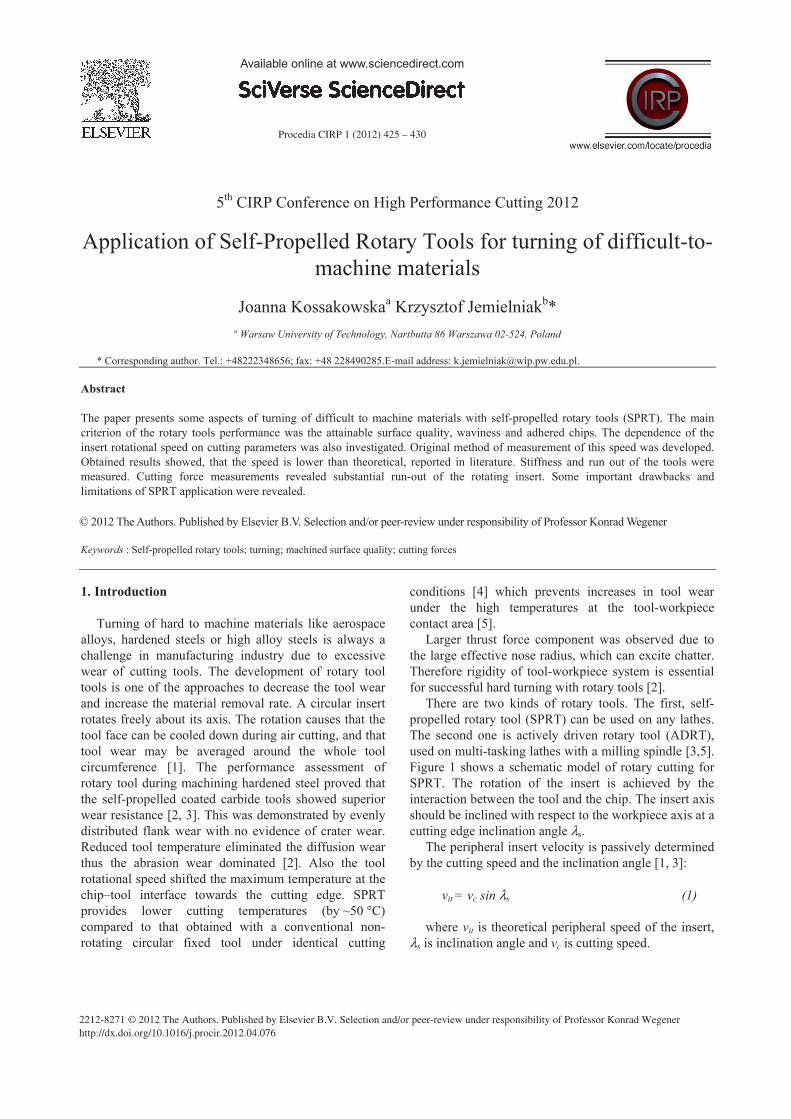
There are two kinds of rotary tools. The first, self-propelled rotary tool (SPRT) can be used on any lathes. The second one is actively driven rotary tool (ADRT), used on multi-tasking lathes with a milling spindle [3,5]. Figure 1 shows a schematic model of rotary cutting for SPRT. The rotation of the insert is achieved by the interaction between the tool and the chip. The insert axis should be inclined with respect to the workpiece axis at a cutting edge inclination angle λs.
The peripheral insert velocity is passively determined by the cutting speed and the inclination angle [1, 3]:
vit = vc sin λs (1)
where vit is theoretical peripheral speed of the insert, λs is inclination angle and vc is cutting speed.
© 2012 The Authors. Published by Elsevier B.V. Selection and/or peer-review under responsibility of Professor Konrad Wegener
Joanna Kossakowska and Krzysztof Jemielniak / Procedia CIRP 1 ( 2012 ) 425 – 430 426
Fig. 1. Schematic model of rotary cutting for SPRT
However Kishawy and Wilcox [2] observed that in spite the insert speed vi is linearly dependent on cutting speed vc:
vi = C vc (2)
the relation in much more complex that given by equation (1), as the constant C is a function of the tool material, the chip–tool contact condition (wet or dry), the tool inclination angle, and the tool rake angle.
Extensive cutting tests performed to assess the performance of self-propelled rotary tool during machining of waspaloy and titanium alloys revealed that a distinct surface topography have been obtained by rotating inserts due to the relative motion between the rotating tool and the workpiece [6].
Kishawy and El-Wahab [7] studied chip flow direction during tube-end machining process using self-propelled rotary tools. They observed that the cutting velocity and feed have no obvious effect on the absolute chip flow direction.
Despite SPRT are commercially available, and some reports inform on their successful applications, there still are some doubts concerning achievable surface finish. The cutting edge in motion always generates more errors than a stationary one. Severe chatter may occur due to the large tool radius and poor stiffness of the rotary system [8]. The rotational speed of the insert cannot be repeated consistently in production environments and the SPRT were therefore not successful commercially. These failures are probably associated with the sensitivity of the rotational speed of the tool to subtle changes in cutting situation [3]. These problems, especially the rotational speed of the insert and achievable surface finish, are addressed in the paper.
2. Experimental procedure
Self-propelled cutting tools (SPRT) used in the experiments were commercially available turning tools RRSDL 2525M12 with an inclination angle λs = -24° and rake angle γp = -24° (see Figure 1). The tools were
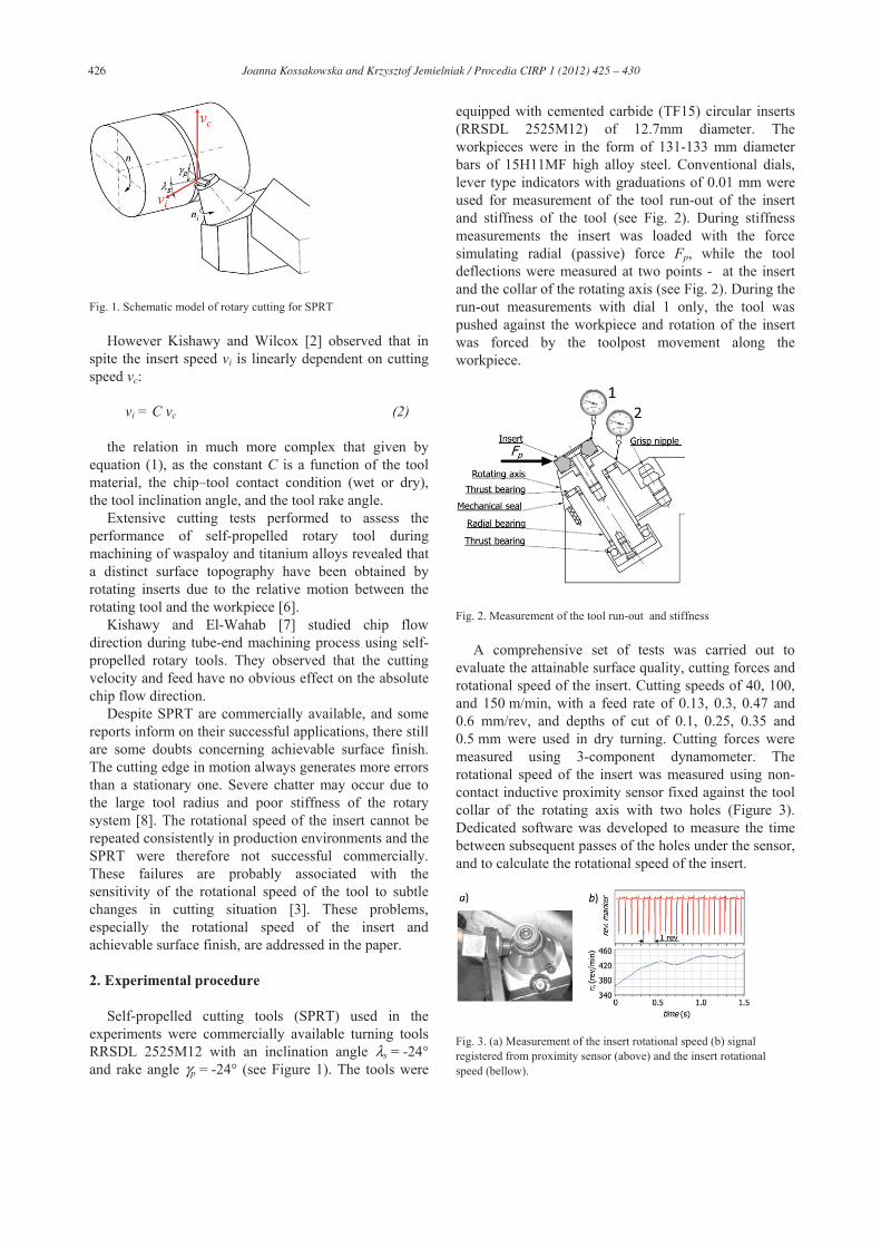
equipped with cemented carbide (TF15) circular inserts (RRSDL 2525M12) of 12.7mm diameter. The workpieces were in the form of 131-133 mm diameter bars of 15H11MF high alloy steel. Conventional dials, lever type indicators with graduations of 0.01 mm were used for measurement of the tool run-out of the insert and stiffness of the tool (see Fig. 2). During stiffness measurements the insert was loaded with the force simulating radial (passive) force Fp, while the tool deflections were measured at two points - at the insert and the collar of the rotating axis (see Fig. 2). During the run-out measurements with dial 1 only, the tool was pushed against the workpiece and rotation of the insert was forced by the toolpost movement along the workpiece.
Fig. 2. Measurement of the tool run-out and stiffness
A comprehensive set of tests was carried out to evaluate the attainable surface quality, cutting forces and rotational speed of the insert. Cutting speeds of 40, 100, and 150 m/min, with a feed rate of 0.13, 0.3, 0.47 and 0.6 mm/rev, and depths of cut of 0.1, 0.25, 0.35 and 0.5 mm were used in dry turning. Cutting forces were measured using 3-component dynamometer. The rotational speed of the insert was measured using non-contact inductive proximity sensor fixed against the tool collar of the rotating axis with two holes (Figure 3). Dedicated software was developed to measure the time between subsequent passes of the holes under the sensor, and to calculate the rotational speed of the insert.
Fig. 3. (a) Measurement of the insert rotational speed (b) signal registered from proximity sensor (above) and the insert rotational speed (bellow).
Joanna Kossakowska and Krzysztof Jemielniak / Procedia CIRP 1 ( 2012 ) 425 – 430 427
The Chip flow angle was measured from videos taken
while cutting with a feed rate of 0.3mm/rev, depth of cut 0.1mm and with cutting speeds of 20, 25, 30, 35, 40, 60, 80, 100, 120 and 150 m/min.
3. Results and discussion
3.1. Stiffness and run-out of the tool
The results of the tool stiffness measurements revealed, that – not surprisingly – it is rather low. The stiffness measured in point 1 (the insert), which is most important, was only 5.8 N/μm. Stiffness measured on the rotating axis collar was much higher (26.4 N/μm) which shows, that the weakest point of the SPRT is the insert fixture. It seems to be too low for finish turning. Run-out of the insert was also high - some 0.04 mm.
3.2. Rotational speed of the insert
The insert rotational speed was registered and analyzed in all tests. Examples of such recordings are shown in Figure 4. Four characteristic stages of the insert speed were observed and marked on this figure. Fist, rather short, was a tool engagement in the workpiece. Then there was a period in which the speed rose, reaching stable value, lasting through the third period, until the end of the cut, and tool disengagement (the fourth period).
Fig. 4. Examples of the insert rotational speed changes in time; 1- tool engagement, 2 – speed stabilization, 3 – stable speed, 4 – tool disengagement.
As the rotation of the insert is its main feature, delay in reaching a full rotational speed is disadvantageous. Figure 5 shows the dependence of the insert rotational speed stabilization time on cutting parameters for two selected depths of cut 0.1 mm and 0.25 mm. It shows that stabilization time decreases with all three cutting parameters. It seems that for too small uncut chip area, tangential force acting on the insert is not sufficient to speed it up immediately. Low cutting speeds also prolong stabilization of the insert rotational speed.
Fig. 5. The dependence of the insert rotational speed stabilization time on cutting parameters.
The dependence of the insert peripheral speed vi on cutting speed for different depths of cut and feeds, measured after its stabilization, is presented in Figure 6. The theoretical insert speed vit calculated according to equation (1) is marked with a dashed line. It can be noticed, that the observed vi(vc) relationship is linear, as predicted by formulas (1) and (2), but the slope coefficient is visibly lower than theoretical, described by equation (1). Here it is C ~ 0.25 instead of C = sin 24º = 0.41. Moreover the relationship established for cutting speeds 40-150 m/min does not start from zero. It means there also is the intercept coefficient dependent on the feed and depth of cut. Example of dependence of the insert peripheral speed on feed and depth of cut is presented in Figure 7.
Fig. 6. Insert peripheral speed vs. cutting speed; (a) for ap=0.1mm and various feeds, (b) for f=0.13mm/rev and various depths of cut.
Finally dependence of the measured peripheral speed of the insert, on cutting parameters, obtained for dry machining of 15H11MF high alloy steel, can be statistically described as:
vi =11.6f + 0.25vc – 0.33ap + 1.9 (3)
Joanna Kossakowska and Krzysztof Jemielniak / Procedia CIRP 1 ( 2012 ) 425 – 430 428
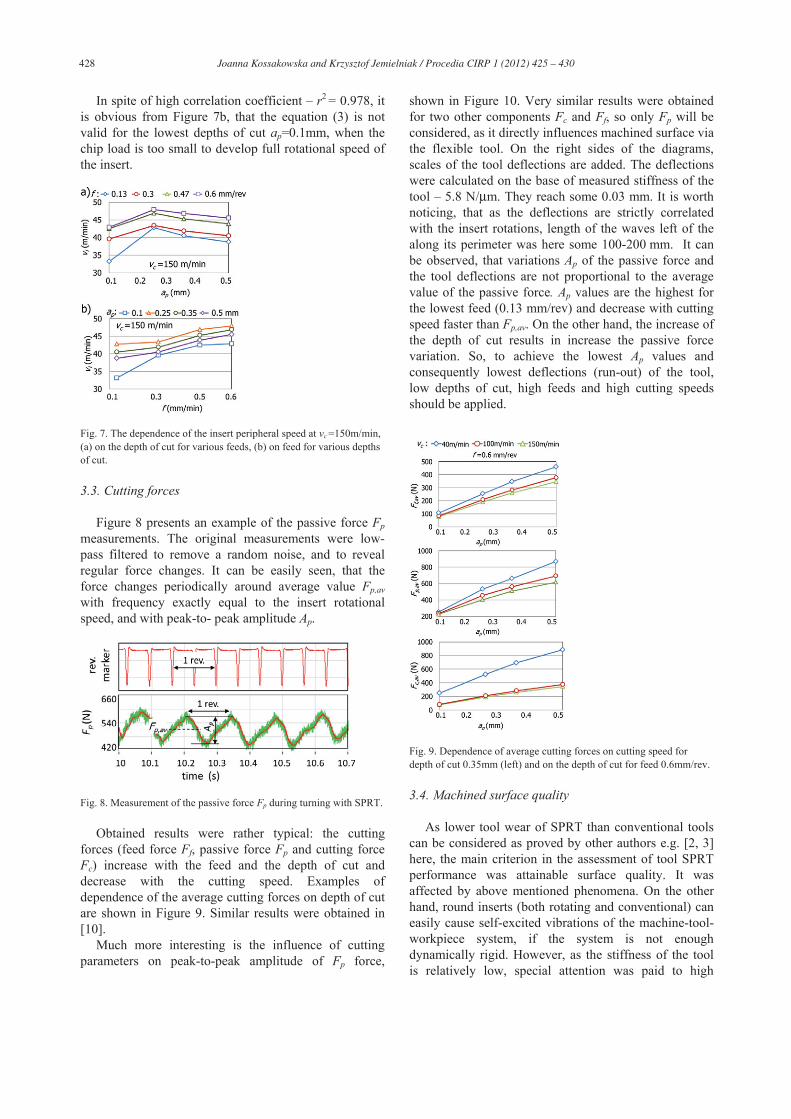
In spite of high correlation coefficient – r2 = 0.978, it
is obvious from Figure 7b, that the equation (3) is not valid for the lowest depths of cut ap=0.1mm, when the chip load is too small to develop full rotational speed of the insert.
Fig. 7. The dependence of the insert peripheral speed at vc =150m/min, (a) on the depth of cut for various feeds, (b) on feed for various depths of cut.
3.3. Cutting forces
Figure 8 presents an example of the passive force Fp measurements. The original measurements were low-pass filtered to remove a random noise, and to reveal regular force changes. It can be easily seen, that the force changes periodically around average value Fp,av with frequency exactly equal to the insert rotational speed, and with peak-to- peak amplitude Ap.
Fig. 8. Measurement of the passive force Fp during turning with SPRT.
Obtained results were rather typical: the cutting forces (feed force Ff, passive force Fp and cutting force Fc) increase with the feed and the depth of cut and decrease with the cutting speed. Examples of dependence of the average cutting forces on depth of cut are shown in Figure 9. Similar results were obtained in [10].
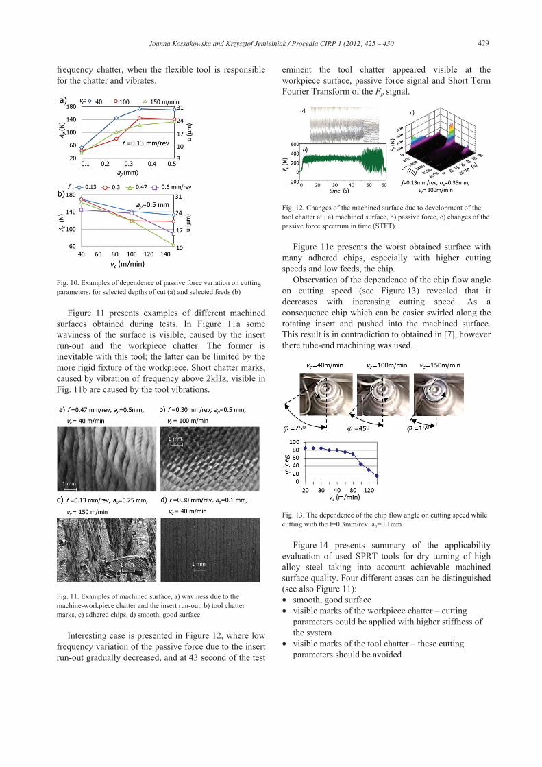
Much more interesting is the influence of cutting parameters on peak-to-peak amplitude of Fp force,
shown in Figure 10. Very similar results were obtained for two other components Fc and Ff, so only Fp will be considered, as it directly influences machined surface via the flexible tool. On the right sides of the diagrams, scales of the tool deflections are added. The deflections were calculated on the base of measured stiffness of the tool – 5.8 N/μm. They reach some 0.03 mm. It is worth noticing, that as the deflections are strictly correlated with the insert rotations, length of the waves left of the along its perimeter was here some 100-200 mm. It can be observed, that variations Ap of the passive force and the tool deflections are not proportional to the average value of the passive force. Ap values are the highest for the lowest feed (0.13 mm/rev) and decrease with cutting speed faster than Fp,av. On the other hand, the increase of the depth of cut results in increase the passive force variation. So, to achieve the lowest Ap values and consequently lowest deflections (run-out) of the tool, low depths of cut, high feeds and high cutting speeds should be applied.
Fig. 9. Dependence of average cutting forces on cutting speed for depth of cut 0.35mm (left) and on the depth of cut for feed 0.6mm/rev.
3.4. Machined surface quality
As lower tool wear of SPRT than conventional tools can be considered as proved by other authors e.g. [2, 3] here, the main criterion in the assessment of tool SPRT performance was attainable surface quality. It was affected by above mentioned phenomena. On the other hand, round inserts (both rotating and conventional) can easily cause self-excited vibrations of the machine-tool-workpiece system, if the system is not enough dynamically rigid. However, as the stiffness of the tool is relatively low, special attention was paid to high
Joanna Kossakowska and Krzysztof Jemielniak / Procedia CIRP 1 ( 2012 ) 425 – 430 429
frequency chatter, when the flexible tool is responsible for the chatter and vibrates.
Fig. 10. Examples of dependence of passive force variation on cutting parameters, for selected depths of cut (a) and selected feeds (b)
Figure 11 presents examples of different machined surfaces obtained during tests. In Figure 11a some waviness of the surface is visible, caused by the insert run-out and the workpiece chatter. The former is inevitable with this tool; the latter can be limited by the more rigid fixture of the workpiece. Short chatter marks, caused by vibration of frequency above 2kHz, visible in Fig. 11b are caused by the tool vibrations.
Fig. 11. Examples of machined surface, a) waviness due to the machine-workpiece chatter and the insert run-out, b) tool chatter marks, c) adhered chips, d) smooth, good surface
Interesting case is presented in Figure 12, where low frequency variation of the passive force due to the insert run-out gradually decreased, and at 43 second of the test
eminent the tool chatter appeared visible at the workpiece surface, passive force signal and Short Term Fourier Transform of the Fp signal.
Fig. 12. Changes of the machined surface due to development of the tool chatter at ; a) machined surface, b) passive force, c) changes of the passive force spectrum in time (STFT).
Figure 11c presents the worst obtained surface with many adhered chips, especially with higher cutting speeds and low feeds, the chip.
Observation of the dependence of the chip flow angle on cutting speed (see Figure 13) revealed that it decreases with increasing cutting speed. As a consequence chip which can be easier swirled along the rotating insert and pushed into the machined surface. This result is in contradiction to obtained in [7], however there tube-end machining was used.
Fig. 13. The dependence of the chip flow angle on cutting speed while cutting with the f=0.3mm/rev, ap=0.1mm.
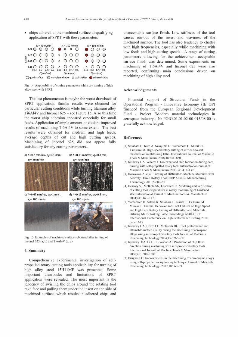
Figure 14 presents summary of the applicability evaluation of used SPRT tools for dry turning of high alloy steel taking into account achievable machined surface quality. Four different cases can be distinguished (see also Figure 11): • smooth, good surface • visible marks of the workpiece chatter – cutting
parameters could be applied with higher stiffness of the system
• visible marks of the tool chatter – these cutting parameters should be avoided
Joanna Kossakowska and Krzysztof Jemielniak / Procedia CIRP 1 ( 2012 ) 425 – 430 430
• chips adhered to the machined surface disqualifying
application of SPRT with these parameters
Fig. 14. Applicability of cutting parameters while dry turning of high alloy steel with SPRT.
The last phenomenon is maybe the worst drawback of SPRT application. Similar results were obtained for particular cutting conditions while turning titanium alloy Ti6Al4V and Inconel 625 – see Figure 15. Also this time the worst chip adhesion appeared especially for small feeds. Application of ample amount of coolant improved results of machining Ti6Al4V to some extent. The best results were obtained for medium and high feeds, average depths of cut and high cutting speeds. Machining of Inconel 625 did not appear fully satisfactory for any cutting parameters..
Fig. 15. Examples of machined surfaces obtained after turning of Inconel 625 (a, b) and Ti6Al4V (c, d)
4. Summary
Comprehensive experimental investigation of self-propelled rotary cutting tools applicability for turning of high alloy steel 15H11MF was presented. Some important drawbacks and limitations of SPRT application were revealed. The most important is the tendency of swirling the chips around the rotating tool rake face and pulling them under the insert on the side of machined surface, which results in adhered chips and
unacceptable surface finish. Low stiffness of the tool causes run-out of the insert and waviness of the machined surface. The tool has also tendency to chatter with high frequencies, especially while machining with low feeds and high cutting speeds. A range of cutting parameters allowing for the achievement acceptable surface finish was determined. Some experiments on machining of Ti6Al4V and Inconel 625 were also reported, confirming main conclusions driven on machining of high alloy steel.
Acknowledgements
Financial support of Structural Funds in the Operational Program - Innovative Economy (IE OP) financed from the European Regional Development Fund - Project "Modern material technologies in aerospace industry", Nr POIG.01.01.02-00-015/08-00 is gratefully acknowledged.
References
[1] Sasahara H. Kato A. Nakajima H. Yamamoto H. Muraki T. Tsutsumi M. High-speed rotary cutting of difficult-to-cut materials on multitasking lathe. International Journal of Machin`e Tools & Manufacture 2008;48:841–850
[2] Kishawy HA, Wilcox J. Tool wear and chip formation during hard turning with self-propelled rotary tools International Journal of Machine Tools & Manufacture 2003, 43:433–439
[3] Hosokawa A. et al. Turning of Difficult-to-Machine Materials with Actively Driven Rotary Tool CIRP Annals - Manufacturing Technology 2010;59:89–92
[4] Dessoly V,. Melkote SN, Lescalier Ch. Modeling and verification of cutting tool temperatures in rotary tool turning of hardened steel International Journal of Machine Tools & Manufacture 2004;44:1463–1470
[5] Yamamoto H. Satake K. Sasahara H. Narita T. Tsutsumi M. Muraki T. Thermal Behavior and Tool Failures on High Speed and High Feed Rotary Cutting of Difficult-to-cut Materials utilizing Multi-Tasking Lathe Proceedings of 4th CIRP International Conference on High Performance Cutting 2010; paper A17
[6] Kishawy HA, Becze CE. McIntosh DG. Tool performance and attainable surface quality during the machining of aerospace alloys using self-propelled rotary tools Journal of Materials Processing Technology 2004;152:266–271
[6] Kishawy. HA. Li L. EL-Wahab AI. Prediction of chip flow direction during machining with self-propelled rotary tools International Journal of Machine Tools & Manufacture 2006;46:1680–1688
[7] Ezugwu EO. Improvements in the machining of aero-engine alloys using self-propelled rotary tooling technique Journal of Materials Processing Technology. 2007;185:60–71