Self-Propelled Modular Transporters (SPMTs): A brief guide
24
Self-Propelled Modular Transporters (SPMTs): A brief guide Published – March 2022 This TWF Guidance is available as a free download from www.twforum.org.uk Document: TWf2022: 01 NOTE: If you need to print this document, be aware that the pages are prepared with alternate (even) pages offset for your duplex (double sided) printing.
-
Upload
khangminh22 -
Category
Documents
-
view
2 -
download
0
Transcript of Self-Propelled Modular Transporters (SPMTs): A brief guide

Self-Propelled Modular Transporters (SPMTs): A brief guide
Published – March 2022
This TWF Guidance is available as a free download from www.twforum.org.uk
Document: TWf2022: 01
NOTE: If you need to print this document, be aware that the pages are prepared with alternate (even) pages offset for your duplex (double sided) printing.

2 Return to the contents
Temporary Works forum Self-Propelled Modular Transporters (SPMTs): A brief guide – TWf2022: 01
Acknowledgement
The Temporary Works Forum gratefully acknowledges the contribution made by the working group and contributors in the preparation of this guidance:
Working Group 35
Convenor Nick Jones Mammoet
Secretary David Thomas TWf UK
Ashley Daniels EDF - Hinkley Point C and Temp Tag (Temporary Worx) Edward Britton Mammoet Heindre Rabie Hochtief UK Construction Ltd Ian Simpson The Construction Plant-Hire Association Jim Tod Tony Gee and Partners LLP Nicholas Lake Tony Gee and Partners LLP Steve Williams Network Rail
Contributors also included: Andrew Wright Osborne Infrastructure Greg Wall Osborne Infrastructure Phil Simmonds Tony Gee and Partners LLP
Classification of temporary works: 6.0.3
Synopsis
With the prevalence of Self-Propelled Modular Transport (SPMT) operations in the temporary works realm increasing, it was considered that a wider base of foundation knowledge should be available to those who are inclined to pursue this option. Accordingly, a Working Group (WG) - with a range of experience and perspectives on SPMT-led projects in civil engineering settings - was convened. The WG’s aim was to prepare guidance that summarised the key elements of SPMT operations and provides a basic understanding of how SPMT capabilities, site preparation and project planning elements should be considered when reviewing project requirements (both from the point of view of the client and the provider/operator).
The range of variables involved in heavy transport, such as required by the use of SPMTs, means that it is not feasible to create an all-encompassing concept-to-execution ‘how to’ guide. However, the guidance provided should assist the reader with valuable questions and background information with the aim of ensuring that there are fewer ‘blind spots’ when considering their next heavy transportation project.
Disclaimer
Although the Temporary Works Forum (TWf) does its best to ensure that any advice, recommendations, or information it may give either in this publication or elsewhere is accurate, no liability or responsibility of any kind (including liability for negligence) howsoever and from whatsoever cause arising, is accepted in this respect by the Forum, its servants or agents.
Readers should note that the documents referenced in this TWf Guide are subject to revision from time to time and should therefore ensure that they are in possession of the latest version.

Return to the contents 3
Self-Propelled Modular Transporters (SPMTs): A brief guide – TWf2022: 01 Temporary Works forum
Section Page
1.0 Introduction . . . . . . . . . . . . . . . . . . . . . . . . . . . . 4
1.1 General . . . . . . . . . . . . . . . . . . . . . . . . . . . . 4
1.2 SPMT versus SPT . . . . . . . . . . . . . . . . . . . . 5
1.3 Manufacturers . . . . . . . . . . . . . . . . . . . . . . . 5
2.0 Technical review . . . . . . . . . . . . . . . . . . . . . . . . 6
2.1 Nomenclature . . . . . . . . . . . . . . . . . . . . . . . 6
2.2 Control box . . . . . . . . . . . . . . . . . . . . . . . . . 6
3.0 Basic make-up. . . . . . . . . . . . . . . . . . . . . . . . . . 7
3.1 Mechanical . . . . . . . . . . . . . . . . . . . . . . . . . 7
3.2 Hydraulic . . . . . . . . . . . . . . . . . . . . . . . . . . . 73.2.1 Suspension . . . . . . . . . . . . . . . . . . . 83.2.2 Drive force . . . . . . . . . . . . . . . . . . . . 83.2.3 Brake force . . . . . . . . . . . . . . . . . . . 83.2.4 Steering . . . . . . . . . . . . . . . . . . . . . . 8
4.0 Hydraulic suspension concept. . . . . . . . . . . . 10
5.0 Stability. . . . . . . . . . . . . . . . . . . . . . . . . . . . . . . 12
5.1 Inputs . . . . . . . . . . . . . . . . . . . . . . . . . . . . 12
5.2 Outputs . . . . . . . . . . . . . . . . . . . . . . . . . . . 125.2.1 Geometric/mechanical stability. . . . 125.2.2 Hydraulic stability . . . . . . . . . . . . . . 12
5.3 Dynamic loads to be considered . . . . . . . . 125.3.1 Wind loads. . . . . . . . . . . . . . . . . . . 125.3.2 Turning loads . . . . . . . . . . . . . . . . . 135.3.3 Acceleration (braking) loads . . . . . . 13
6.0 Structural capacity . . . . . . . . . . . . . . . . . . . . . 13
6.1 Structural strength - transporter. . . . . . . . . 13
6.2 Structural strength - load. . . . . . . . . . . . . . 14
6.3 Other considerations . . . . . . . . . . . . . . . . . 14
7.0 Lashing and restraint of loads . . . . . . . . . . . . 14
8.0 Self-loading and unloading operations . . . . . 15
9.0 Traction and propulsion . . . . . . . . . . . . . . . . . 15
9.1 General . . . . . . . . . . . . . . . . . . . . . . . . . . . 15
9.2 Traction . . . . . . . . . . . . . . . . . . . . . . . . . . . 15
9.3 Propulsion . . . . . . . . . . . . . . . . . . . . . . . . . 15
10.0 Ground bearing pressure . . . . . . . . . . . . . . . . 15
Section Page
11.0 Working platforms. . . . . . . . . . . . . . . . . . . . . . 16
11.1 Overview . . . . . . . . . . . . . . . . . . . . . . . . . . 16
11.2 Definitions . . . . . . . . . . . . . . . . . . . . . . . . . 16
11.3 General requirements . . . . . . . . . . . . . . . . 17
11.4 Installation requirements . . . . . . . . . . . . . . 17
12.0 Ground investigation. . . . . . . . . . . . . . . . . . . . 18
12.1 Ground investigation - general . . . . . . . . . . 18
12.2 Ground investigation - detail . . . . . . . . . . . 18
13.0 Designing an operation - general . . . . . . . . . 18
13.1 Overview - designer. . . . . . . . . . . . . . . . . . 18
13.2 Typical project stages . . . . . . . . . . . . . . . . 1813.2.1 Appointments and scheme
design . . . . . . . . . . . . . . . . . . . . . . 1913.2.2 Detailed design stage. . . . . . . . . . . 1913.2.3 Temporary works input during
detailed design stage – including SPMT supplier . . . . . . . . . . . . . . . . 19
13.2.4 Tender stage . . . . . . . . . . . . . . . . . 19
13.3 Overview – Specialist contractor . . . . . . . . 19
14.0 Designing an operation – temporary works . . . . . . . . . . . . . . . . . . . . . . . 20
15.0 Designing an operation – Pre-construction . . . . . . . . . . . . . . . . . . . . . . . 21
15.1 Planning for stability. . . . . . . . . . . . . . . . . . 21
15.2 Procedural controls . . . . . . . . . . . . . . . . . . 21
15.3 Temporary works co-ordinator (TWC) . . . . 21
16.0 Contractual arrangements . . . . . . . . . . . . . . . 21
16.1 Introduction . . . . . . . . . . . . . . . . . . . . . . . . 21
16.2 Options . . . . . . . . . . . . . . . . . . . . . . . . . . . 21
16.3 Sub-contracted operation . . . . . . . . . . . . . 21
16.4 Hired equipment . . . . . . . . . . . . . . . . . . . . 21
16.5 The role of the TWC . . . . . . . . . . . . . . . . . 22
References . . . . . . . . . . . . . . . . . . . . . . . . . . . . . . . . 23
Bibliography . . . . . . . . . . . . . . . . . . . . . . . . . . . . . . . 23
Contents
To navigate to page - hover over an item below and ‘click’. Return to contents by clicking on the ‘Return to the contents’ at the bottom of every page.

4 Return to the contents
Temporary Works forum Self-Propelled Modular Transporters (SPMTs): A brief guide – TWf2022: 01
1.0 Introduction
1.1 General
1.1.1 Transport technology allows for the movement of exceptionally heavy loads over a variety of surfaces using multi-axle transporters. In the temporary works environment these come, typically, in three forms:
(a) Hydraulic trailers Examples include low-loaders, step-decks, extendables, etc. (see Figure 1)
(b) ‘Conventional’ modular axles These can be tractor-drawn or self-propelled using hydraulically driven axles (and typically referred to as SPTs (Self-Propelled Transporters)) (see Figure 2). Special configurations of conventional modular axles can include girder frame transports for suspending high loads close to the ground to clear under structures such as bridges.
(c) Self-propelled modular transporters Usually referred to as SPMTs (see Figure 3).
Figure 1 – Hydraulic trailer
Figure 2 - ‘Conventional’ modular axles

Return to the contents 5
Self-Propelled Modular Transporters (SPMTs): A brief guide – TWf2022: 01 Temporary Works forum
1.1.2 This guidance focuses primarily on the latter, SPMTs. However, it is useful to understand, from a high-level perspective, the differences in capabilities between conventional transporters and SPMT operations; and this is also mentioned.
1.2 SPMT versus SPT
1.2.1 SPMT (Self-Propelled Modular Transporters) and SPTs (Self-Propelled Transporters) look quite similar. They both have transporter units that can be connected with pins and deck bolts and are powered with a Power Pack Unit (PPU) and controlled via a joystick input.
1.2.2 However, SPMTs in this guidance, refers to modular transporters whose steering is controlled and manipulated electro-hydraulically at each pendulum and whose drive motion is provided by drive axles within each installed module, allowing typically for more complex transport arrangements.
1.2.3 SPTs, on the other hand, are driven from a single specific drive module next to the PPU with steering provided through steering rods in the top of the chassis, reducing the possible steering configurations and limiting the steering angles to that of the trailer specification (usually around 55° lock).
1.3 Manufacturers
1.3.1 There are several manufacturers of SPMT modules. This is analogous to crane technology in-so-far as there are several manufacturers of mobile crane. Clearly, they are not identical. However, much like mobile cranes, they have similar components and functions. The most common manufacturers likely to be encountered in the UK are:
• Scheuerle
• Kamag
• Goldhofer
• Cometto
1.3.2 Each manufacturer offers different specifications of transporter. With this in mind, the reader should note that there is not a ‘standard’ SPMT.
1.3.3 Whilst many share dimensions and payload specifications, they are not all the same and it is not always possible to allow electronic communication between the different models and specifications.
Figure 3 – Self-propelled modular transporters (SPMTs)

6 Return to the contents
Temporary Works forum Self-Propelled Modular Transporters (SPMTs): A brief guide – TWf2022: 01
2.0 Technical review
2.1 Nomenclature
2.1.1 Within this guidance SPMTs components, whilst not universal, are described using the following identifications:
(i) Overview of parts
The trailer is the complete transport arrangement. Each trailer can be broken down into a number of trains. The trains are built up of modules which are typically four or six axle lines long – these parts are mechanically connected as shown in Section 3.1. and each module is comprised of a number of bogies (see Figure 4).
(ii) PPU: Power Pack Unit
Suspended diesel-powered hydraulic oil pump and reservoir (see Figure 5).
2.2 Control box
2.2.1 The SPMT is driven from a control box using joystick inputs for movement and push-buttons to increase pressure in a given hydraulic group. The modules can be connected both longitudinally and transversely by linking through the mechanical coupling connection points giving a larger transport bed as well as a higher payload capacity. The modules are also linked hydraulically to pass hydraulic pressure between the modules, creating a stable surface to work on.
Figure 4 – Overview of Trailer
Figure 5 – Power Pack Unit (left)

Return to the contents 7
Self-Propelled Modular Transporters (SPMTs): A brief guide – TWf2022: 01 Temporary Works forum
3.0 Basic make-up
3.1 Mechanical
3.1.1 SPMT modules, in their simplest form, are a strong central spine beam attached to a number of pendulums (see Figure 6). The pendulums are connected to the spine beam on secondary steel structures on a hydraulically-actuated bearing with allowable rotation to give any effective orientation at the wheel. They make contact to the ground via specialised tyres. Mechanical connections are typically made with pinned joints and deck bolts for longitudinal connections allowing transfer of moment and shear along
the spine beams (see Figure 7). Transverse connections can be made through coupling blocks linking the sides of the transporter modules together using bolts (see Figure 8).
3.2 Hydraulic
There are four main hydraulic functions of the SPMT:
• Suspension
• Drive force
• Brake force
• Steering
Figure 6 – Spine beam: longitudinal section
Figure 8 – Area where connecting blocks are located between transversely positioned transporters
Figure 7 – Typical pin connection

8 Return to the contents
Temporary Works forum Self-Propelled Modular Transporters (SPMTs): A brief guide – TWf2022: 01
3.2.1 Suspension
3.2.1.1 The suspension of the transporter is built on a knuckle-type joint, connected top and bottom with a hydraulic ram (see Figure 9). By increasing or reducing the volume of oil in a given cylinder the transporter bed will either be raised or lowered respectively.
3.2.1.2 As a result of the construction of the knuckle joint raising and lowering the transporter deck causes the bed to move forwards and backwards a small amount, following the arc of the joint. This is important in self-loading and self-offloading operations where the stroke of the transporter is used to lift or lower loads to and from grade.
3.2.1.3 The ‘stroke’ or total distance between maximum and minimum height of the transporter bed is dependent on the model in use. However, typically this is 600mm. It is best practice to drive the transporter at mid-stroke where feasible (1500 mm for a typical SPMT) and for pick-up levels to be towards the lower range of the stroke without ‘bottoming the transporter out’.
3.2.1.4 The maximum stroke available can be affected by several factors, for example:
• the deflection in the transporter spine beam;
• the levelness or the undulations in the ground;
• transitions between gradients;
• any requirement to keep the load level; and
• the squash of the tyres.
3.2.1.5 For this reason, consultation with expert transport operators is necessary for understanding the capabilities of the transport configuration.
3.2.1.6 Transitions between gradients need special attention paying towards them, especially when considering long and wide transport arrangements.
3.2.2 Drive force
3.2.2.1 Hydraulic pressure is used to move the SPMT’s drive hubs. Not all pendulums on an SPMT are fitted with drive hubs. In fact, they are typically a mixture of drive hubs, brake hubs and dummy (neither drive nor brake) hubs.
3.2.2.2 The total drive force available is partly dependant on the number of drive pendulums available. This can be used, in part, to determine the grade at which the SPMT can be driven.
3.2.3 Brake force
3.2.3.1 Similarly to the concept of drive axles, hydraulic pressure is used to slow and stop the SPMT via the brake axles. The difference between the two typically being that whilst an increase in drive pressure provides an increase in drive force the brakes are at maximum effect at zero pressure and are released with the addition of pressure.
3.2.3.2 Total brake force is partly dependant on the number of brake axles. This will also be used for determining the loads in an emergency brake situation which can occur, for example, if the on-board electronics recognises a loss of contact with the control box (a safety feature to stop the potential of runaway). Emergency braking loads are often a critical function of the stability of the transportation operation.
3.2.4 Steering
3.2.4.1 Each pendulum is fitted to a bearing with movement that allows for effective 359° of movement (see 3.1.1) meaning that, in theory, each axle can be operated to point in a different direction independently. This means that there are several steering modes available to the operator which can make movement of the SPMT in challenging locations possible. Typical steering modes are shown in Figure 10.
Figure 9 – Schematic showing the hydraulic action of the ram in the transporter pendulum and how it actuates the knuckle joint on the pendulum

Return to the contents 9
Self-Propelled Modular Transporters (SPMTs): A brief guide – TWf2022: 01 Temporary Works forum
NOTES:
1 The transporter will go straight in line with the longitudinal axis of the transport bed
2 The transporter will steer around the centre axles of the transport bed making tight turns
3 The transporter will steer in in any angle with all the wheels aligned together making diagonal movement possible
4 The transporter will transversely steer across the transport bed – with the axles ‘facing one another’
5 The transporter will steer concentrically around the centre of the transport bed
6 The transporter will steer similarly to 1. however, the point at which the transporter is made to turn is fixed differently. This point can be moved to any axle from the front of the transport to the rear of the transport. The example above shows steering around the second axle from the PPU.
1. Straight
2. Normal
3. Crab
4. Transverse
Figure 10 – Various transport modes in SPMT
6. Steering around a point
5. Carousel

10 Return to the contents
Temporary Works forum Self-Propelled Modular Transporters (SPMTs): A brief guide – TWf2022: 01
3.2.4.2 Transport arrangements do not have to be simple blocks of modules, complex arrangements are possible (see Figure 11). It should be noted this increased complexity requires highly experienced and properly-trained personnel to ensure that the modules are:
(a) designed correctly; and
(b) set up correctly and the various components communicating with each other.
3.2.4.3 Operations such as these are not ordinary and should only be planned and conducted with the guidance of a skilled specialist contractor.
4.0 Hydraulic suspension concept
4.1 In an hydraulic suspension set-up the wheels follow the road and wheel loadings remain constant. This is because the individual pendulums are grouped into zones. Each zone has its own pressure and the flow of hydraulic fluid between the linked pendulums means that pressures in individual pendulums remain constant with reference to that zone. (See Figure 12.)
Figure 11 – Steering coordinates for SPMT
Figure 12 – Distribution of hydraulic oil as wheels pass over obstacles on the ground where all axles are in the same group

Return to the contents 11
Self-Propelled Modular Transporters (SPMTs): A brief guide – TWf2022: 01 Temporary Works forum
4.2 The pendulums are separated into their zones by using valves to stop the flow of oil between pendulums. Typically, the arrangement is built into a three-point or a four-point system. By preference, three-point is more desirable since the system is then statically determinate and requires less onerous monitoring and inputs. However, other factors sometimes mean that a four-point system is necessary.
NOTE: Three-point stability arrangements are statically determinate whilst four-point and multi-point stability arrangements are statically indeterminate. Therefore, the impact that these support conditions have must be coordinated with the permanent works designer.
4.3 Multiple-point (greater than four) systems are feasible. However, their utilisation should only be when absolutely necessary and only then when designed by an experienced and competent user.
4.4 Figure 13 shows the typical grouping for a six axle, two-file transporter. It also shows the lateral distance that the centre of gravity (CoG) can move the ‘tipping lines’ or the virtual lines that link the hydraulic groups.
Figure 13 – Traditional 3-point arrangements
(a) Traditional 3-point arrangement for a 2 file, 6 axle arrangement.
The point on the left is known as the ‘floating point’ and the points on the right are known as the ‘trimming lines’.
(b) Distribution of hydraulic oil as wheels pass over obstacles on the ground where two groups have been defined along the longitudinal view of the transporter.

12 Return to the contents
Temporary Works forum Self-Propelled Modular Transporters (SPMTs): A brief guide – TWf2022: 01
4.5 For the purposes of illustration (see Figure 14):
• When all axles are in one hydraulic zone the platform can move in all directions.
• With two zones the platform is stable sideways - there is one tip line.
• With three zones the platform is stable in all directions - there are three tip lines.
• With four zones the platform is stable in all directions - there are four tip lines.
5.0 Stability
5.1 Inputs
To determine stability of a transport arrangement the following is required:
• the mass of the transported load;
• the centre of gravity (CoG) of the transporter load;
• the mass of the transporter;
• the centre of gravity of the transporter;
• dynamic loads, e.g. accelerations due to turning, braking or wind loads.
These are typically the inputs.
5.2 Outputs
Transporter stability is limited in two ways:
• geometric/mechanical stability;
• hydraulic stability.
These are typically the outputs. The outputs can be reviewed as both static stability and dynamic stability.
5.2.1 Geometric/mechanical stability
Geometric/mechanical stability is the point at which the sum of the forces acting upon the centre of gravity of a transported item cause it to fall outside of the tipping lines, e.g. unlevel surface and/or an unlevelled transporter bed. This causes the item to fall off the transporter or the transporter to fall over (see Figure 15).
5.2.2 Hydraulic stability
Hydraulic stability is the point at which the sum of the forces acting upon the centre of gravity of a transported item cause the hydraulic capacity in the SPMT’s hydraulic group to become overloaded, leading to the possibility of failure in the systems including hydraulic rupture, pneumatic failure, inability to lift or one of the above leading to tipping of the load (see Figure 16).
5.3 Dynamic loads to be considered
5.3.1 Wind loads
Wind acts upon the face of a load (in both the transverse and longitudinal directions, independently). The shape of the load – both the sail area and the shape coefficient factor have an effect – and the allowable transport conditions determines the loads. These need to be resolved. Typically, wind loading alone is unlikely to result in a catastrophic failure of an operation. However, when added to all the other loads, must be considered.
Figure 14 – Simplified diagrams illustrating the how separating the groups of axles works in terms of forming supports for the transporter bed
NOTE: One and two-point set ups are inherently instable and at least three points are required to define a stable transporter bed.

Return to the contents 13
Self-Propelled Modular Transporters (SPMTs): A brief guide – TWf2022: 01 Temporary Works forum
5.3.2 Turning loads
When driving through a corner, centrifugal forces are generated by the curve and speed of the trailer. These loads impact the axle loads, as they generate an overturning moment on the trailer. Calculated formulae can be difficult to apply to the many possible combinations of speed and curvature on a transport, so transport operators often use empirical values. These loads are then resolved; taking the moment as a couple over the axles by using the CoG height and group distance.
5.3.3 Acceleration (braking) loads
Braking loads can have a significant impact on the operation of SPMT transportations. Similarly, this load must be resolved through the moment-
couple over the axles by using the CoG height and group distances.
6.0 Structural capacity
6.1 Structural strength - transporter
6.1.1 When the hydraulics of the transport arrangement are satisfied, the structural strength of the arrangement must also be considered. This includes understanding the loads introduced locally on the transporter bed, the stress this induces in the spine beam, the resulting deflection in the beam and the loads in the coupling connections between transporter modules. Only if all these conditions are satisfied is the transporter considered to be structurally safe.
Figure 15 – Schematic of how geometric instability can occur.
Figure 16 – Schematic of how hydraulic instability can occur

14 Return to the contents
Temporary Works forum Self-Propelled Modular Transporters (SPMTs): A brief guide – TWf2022: 01
6.2 Structural strength - load
6.2.1 As well as the transporter bed / beam / hydraulic capacity being sufficient, the cargo itself must be able to take the loads that are being imposed upon it during transportation. The stiffness of the cargo has an impact on the operation and the owner of the cargo must be able to ensure that it has the structural capacity to be moved in the manner proposed. Close communication between the transport operator and cargo owner should ensure that this risk is addressed.
6.3 Other considerations
6.3.1 When considering the impact of four-point conditions, measuring and surveying can be a useful way of ensuring that structural limits are not exceeded during transport. These limits should be developed by the permanent works designer and should be checked for practicality by the heavy transport operator.
6.3.2 An SPMT chassis is made up from a central spine beam and strong elements connecting the pendulums to the central spine beam. Typically, relatively thin plate connects these elements at the chassis bed level and care should be taken to ensure that loads are not concentrated on these plate as they are not usually structurally effective. Load spreading over the plates, to pick up strong points on the trailer, can be an effective solution to this challenge.
7.0 Lashing and restraint of loads
7.1 SPMTs tend not to move very quickly, typically below 5 km/h. Therefore, the lashing loads are generally less onerous than road-transport operations. However, securing a load may still be necessary dependent on the conditions that must be met to complete the operation safely.
7.2 Methods of lashing cargo can include the following:
• frictional lashing – use of high friction materials between the bed and the cargo, e.g. ranging from simple plywood to special neoprene (or similar) materials.
• direct lashing using chains.
• blocking – use of fixed elements, i.e. physical elements that restrain movement.
7.3 Materials can range into combinations of the following:
• chains and ratchet binders or tension-levers;
• ratchet tie down;
• steel wires and wire clips;
• shackles;
• welded ring;
• turnbuckles;
• (welded) stoppers.
Figure 17 – Schematic showing three stages of load transfer for self-loading / off-loading
NOTES:
Step one: Cargo is on transporter
Step two: Cargo is driven over pre-positioned supports
Step three: Cargo is lowered off to the supports and transporter removed from under cargo
Return to the contents 15
Self-Propelled Modular Transporters (SPMTs): A brief guide – TWf2022: 01 Temporary Works forum
7.4 In the event that simple plywood or neoprene interfaces are not suitable, appropriate lashing points on the cargo must be provided for safe transport.
7.5 SPMT operations often rely on friction between loaded components in order to satisfy stability checks. This can involve the use of, for example, rubber layers between steel, tropical hardwood and plywood layers to ensure satisfactory frictional resistance and forms part of the heavy transport operator’s calculations when designing a transport operation.
NOTE: Some advice on friction is available in HSE Research Report 71 [1.] although this is not exhaustive.
8.0 Self-loading and unloading operations
8.1 One of the benefits of transporters such as SPMTs is that they allow for the relocation of equipment without the use of cranes. This is beneficial in two respects:
• cranes can be subject to restrictions due to wind speeds that are typically more onerous than transportation restrictions.
• the cost of mobilising and utilising heavy cranes to lift and load / offload the cargo may be avoided by using the integrated transporter hydraulics to lift and lower cargo onto pre-determined positions.
8.2 This may require the use of saddles to transfer the load between the cargo and the transporter bed and considerations for load-spreading across the transporter bed and/or the ground (see Figure 17). All of these items should be considered with a transport operator.
9.0 Traction and propulsion
9.1 General
9.1.1 Suspension capacity is of primary concern when considering SPMT operations. The arrangement must also be able to move the cargo to its destination and over the area in between.
9.2 Traction
9.2.1 Traction is a function of the load on the tyres and the make-up of the ground surface. Surfaces with grit / dirt or wet and slick surfaces will have less friction and therefore will limit the tractive effort that can be exerted. The friction is driven by the normal force applied to the surface also, so in some cases, it might be that there is not enough load on a wheel in order to exert the required traction to propel a load up a gradient.
9.2.2 Weather can impact transport operations much as it can almost any construction activity. Traction can affect both the available drive and the brake capacities and should be considered by the transport operator when designing the transport operation.
9.3 Propulsion
9.3.1 Propulsion is a function of several elements, namely:
• gradient of the roadway;
• rolling resistance of the surface;
• force required to accelerate the gross vehicle weight from a stand-still.
9.3.2 Consideration of the worst-case combination of these elements versus the available tractive effort - and the traction available given the environmental conditions - ensures that the transport arrangement is not unable to move during its operation.
10.0 Ground bearing pressure
NOTE: Further advice on working platforms is given in Clause 11.0.
10.1 Ground bearing pressure can be considered to act somewhat analogously to structural design, requiring both local and global stresses should be considered.
10.2 In broad terms:
• solid concrete and rock are generally acceptable.
• good quality asphalt is generally acceptable, but care must be taken when undertaking operations in high temperature conditions.
• steel is generally acceptable. Noting that a gripped top surface is required in order to provide adequate traction.
• sand/gravel, when well-compacted, can be acceptable. However, it can be affected by weather conditions, especially precipitation. It may be prudent to reinforce the top layer of granular platforms with ‘trackway’ or a similar product.
• wherever soft and/or loose ground is encountered plans must be made to provision for additional engineering. This is usually the responsibility of the site owner.
NOTE: In all instances, the site owner has a responsibility to ensure that the running surface is capable of taking the loads that are imparted by the transport operation. This may require structural and/or geotechnical considerations to be undertaken, including investigation and/or calculations.

16 Return to the contents
Temporary Works forum Self-Propelled Modular Transporters (SPMTs): A brief guide – TWf2022: 01
10.3 Locally, the tyre pressures at the road surface must be considered. Typically, these are not much greater than the pressures found on normal road-going transportation vehicles. As a result, it is uncommon for these local pressures to cause significant issues. That said, during steering mode turning operations, i.e. where the cargo is static and the operator is changing between, say, a normal steer mode and a carousel, the load on the wheel and its motion against the ground surface can have a ‘screw’ effect. It is recommended that where these sorts of activities are located that additional protection measures are implemented.
10.4 For information see Figure 18:
Figure 18 – Typical contact area for a tyre in contact with the ground
10.5 The area is a function of:
• weight;
• air pressure in the tyre.
• secondarily, the type of tyre (e.g. solid, foamed, pneumatic or other).
10.6 Air pressure in the tyre and local ground pressure under the tyre is a classic action/reaction interface, i.e. pressure in tyre equals pressure to surface. For example, if the tyre is at 10-bar of pressure, the area of the tyre will be squashed to create an area equal to 10-bar on the ground (see Figure 19).
Figure 19 – Schematic showing how internal tyre pressure and ground bearing pressure are equal
NOTE: This is a simplification and negates for tyre wall stiffness, for example.
10.7 For platform transporters, like SPMTs, it is necessary to consider the loads globally.
10.8 Ground bearing pressure (GBP) is expressed as the mass spread over the complete trailer area. This complete area is sometimes called the ‘shadow area’. The reason for this is that, from an engineering perspective, multiple tyres (relatively) close together equate to a uniformly distributed load.
10.9 Permissible ground bearing, as given by client, may be based on bending capacity of concrete slab/beams.
10.10 The GBP over the ‘shadow area’ is shown in Figure 20.
Figure 20 – Schematic showing how the ground bearing pressure can be considered as acting on a ‘shadow area’ under the transporter below the
initial circa 300mm of the roadway
NOTE: This is the load at a small distance below the surface of the roadway.
11.0 Working platforms
11.1 Overview
11.1.1 Working platforms are an essential component of temporary works for many construction activities, including (but not limited to) support for piling operations, drilling operations, lifting operations using cranes, MEWP support and SPMT operations.
11.1.2 There is much existing guidance on working platform design and execution, some of which is referenced in this guidance. However, there is little available guidance on working platforms aimed specifically at SPMT operations. This guidance aims to fill that gap.
11.2 Definitions
Working platform
The designed surface on which the SPMT is supported and operated.
NOTE: The entire end-to-end traveling route is constituted a working platform

Return to the contents 17
Self-Propelled Modular Transporters (SPMTs): A brief guide – TWf2022: 01 Temporary Works forum
11.3 General requirements
11.3.1 A key hazard to safe operation is failure of the working platform supporting the SPMT or by a failure in the maintenance of that platform (and, generally, not by mechanical failure of the transporter itself or by human error).
11.3.2 A workmanship and materials specification should be provided as part of the detailed design of the working platform. This is the responsibility of the Principal Contractor.
11.3.3 All working platform designs shall be informed by a full understanding of the underlying ground conditions, including supporting ground investigation where necessary (see Section 12.0 for more details).
11.3.4 Inspection and Test Plans (ITP) should be specified prior to works beginning on site to meet all requirements of the designer’s specification and ensure that all ultimate limit state (ULS), serviceability limit state (SLS) and longevity criteria are met.
11.3.5 The ITP shall be executed accordingly.
11.4 Installation requirements
11.4.1 Installation of the platform, in accordance with the design, should be undertaken by the Principal Contractor or (as agreed with the Client) a competent specialist contractor appointed by the Principal Contractor.
11.4.2 Once the installation of the working platform has been completed, the structure should be inspected and a “Working Platform Certificate” should be completed and a copy held on site.
NOTE: An example prepared by Federation of Piling Specialists (FPS) is available [2.].
11.4.3 The specialist contractor should provide all relevant rigging and equipment loadings and bearing pressure calculations in advance of the working platform being designed.
11.4.4 If the rigging and equipment delivered to site is not the same as that for which the loadings have been supplied, then the working platform shall be reviewed for adequacy and, if necessary, re-designed for the actual loads; the design checked; and the installation tested and approved (as required) prior to it being loaded.
11.4.5 The following factors should be considered:
(a) Size and positioning
The size and position of the working platform should be determined by the Principal Contractor and should include all temporary conditions, e.g. rigging and de-rigging of the SPMT and ancillary plant.
(b) Extent
For best practice – as opposed to good practice - working platforms should be designed and constructed to be at least 2 m greater in width/length than the theoretical working area. Physical demarcation (typically timber baulks or similar) should be placed to delineate the edge of the working area effectively. The extent shall consider the walking route of the SPMT controller.
(c) Capacity
Working platforms shall be designed for the full capacity of any equipment proposed to be used.
11.4.6 Where appropriate, and following assessment of sustainability principles, consideration may be given to the use of lean mix/reinforced concrete platforms as these can provide additional safety margins. Special consideration should, however, be given to the use of rigid platforms when ground collapse beneath the platform may be a factor. Also, the bearing pressure for tracked or wheeled plant may be greater for a rigid platform than for a flexible granular platform.
11.4.7 Other issues to consider are:
(a) Drainage
Working platforms should be designed and constructed with positive drainage and, where practicable, with sealed surfaces to avoid local softening.
(b) Site access and egress
Any access to the work site - and in particular the provision of any sloped access - should allow for the delivery of materials as well as for any specialist rigs, cranes and other equipment.
(c) Inspection, testing and maintenance
A programmed working platform inspection, testing and maintenance regime should be proposed by the platform designer. The frequency of inspections, which should be approved by the Principal Contractor and accepted by the Client’s representative, may be daily (or at the most weekly) dependent on the programme of works and operations being undertaken. Testing may include plate bearing tests on completion of the working platform installation and/or when major repairs have been undertaken. Maintenance should include the levelling of the platform and building up where thickness has been reduced.
18 Return to the contents
Temporary Works forum Self-Propelled Modular Transporters (SPMTs): A brief guide – TWf2022: 01
(d) Initial loading
When a working platform is first loaded it should be inspected by a competent person to ensure that settlement is within design criteria (as specified in the ITP).
(e) Completion of SPMT operations
The project should be planned so that there is no excavation/removal of the working platform until SPMT operations have been completed.
(f) Punctures
The use of recycled materials requires a higher level of screening on site due to the higher risk of contaminants being present, e.g. rebar within crushed concrete, which could increase the risk of puncture.
12.0 Ground investigation
12.1 Ground investigation - general
12.1.1 Ground investigation (including ground water levels) is fundamental to platform design (and the amount of investigation needed depends on the quality of the ground).
12.1.2 The Client and Principal Designer, in particular, and the Principal Contractor should ensure that an adequate ground investigation – and working platform design – is undertaken at an early point in the project.
NOTE: The temporary works designer and TWC (and others, as required) should also agree on the ground investigation required prior to the detailed design of any working platform.
12.1.3 For SPMTs, there are shallow high load effects under each wheel and the possibility of deeper failures - from the effects of the footprint of the SPMT module(s) - measuring several metres across.
12.1.4 Advice from a specialist geotechnical engineer should be sought. They should have adequate knowledge to be able to assess the ground, calculate its capacity and design the upper levels of the foundation, i.e. the working platform.
12.1.5 SPMT moves often include the need for the working platforms to withstand heavy sets of closely-spaced point loads with axles which can turn about the vertical axis. Engaging with the specialist suppliers of this equipment is vital.
12.2 Ground investigation - detail
12.2.1 Bespoke design of the working platform should include a satisfactory ground investigation to ensure performance of the working platform.
a) Scope of ground investigation
The TWf’s ‘Working Platforms for construction plant: A guide to good practice’ [3.] is recommended. Section 3.4.1.3 therein - which refers to Section 4.2.3 - provides recommendations for the scope of the ground investigation.
b) Depth of investigation
The depth of investigation should be a minimum of 1.5 x largest dimension of the outrigger pad (for cranes) or shadow area of the transporter dimensions. It should be noted, however, that there is still a risk that weaker soil layers below this minimum depth could be affected by the imposed loading.
c) Eurocode – Robust roadway or foundation
BS EN 1997-2, Annex B (B.3) [4.], provides guidance for scoping ground investigations for a variety of structures including foundations, embankments, linear structures, etc. It is not obvious what an SPMT working platform come under, although it is essentially a robust roadway. It also needs to support concentrated loading from plant and equipment so could also be considered a foundation. Nevertheless, there is guidance for both in BS EN 1997-2, including spacing along linear structures and minimum depth to achieve. Appendix B3 includes examples of recommendations for the spacing and depth of investigations.
d) BRE470 – and testing
BRE470 [5.] also provides some guidance for ground investigations stating investigations should investigate the upper 2m of ground across the likely area of the platform. Strength determination should be carried out by plate load tests, CBR tests or vane tests.
13.0 Designing an operation - general
13.1 Overview - designer
13.1.1 SPMTs are a versatile and useful piece of equipment that, in the context of civil infrastructure projects, often enable complex structures, constructed offline in a convenient location, to be transported and installed in their final position during a relatively short possession period. This installation operation, however, usually requires significant design preparation and planning.
13.2 Typical project stages
The following breakdown considers the designer’s requirements for a typical transport operation using SPMTs:

Return to the contents 19
Self-Propelled Modular Transporters (SPMTs): A brief guide – TWf2022: 01 Temporary Works forum
13.2.1 Appointments and scheme design
(a) At the outset of a project, a Client defines the requirement for a structure and appoints a designer to generate a scheme design solution. At this stage the construction methodology constraints should be considered and, where an offline construction method may be required, an SPMT-based solution may be identified as either one of, or perhaps the only, viable options.
(b) A geotechnical desk study should be completed at the earliest possible stage within this process and should include the compound (where is assumed the cargo is constructed and loaded onto the SPMTs), the travel route, and permanent location of the cargo. This should identify as a minimum the following key underlying risks:
(i) flooding;
(ii) historic mining;
(iii) buried structures (e.g. culverts);
(iv) statutory service interfaces.
(c) There will also be some circumstances where an SPMT based solution is not appropriate, such as:
(i) poor ground conditions along the potential transport route that cannot be economically rectified;
(ii) transport route gradients to accord with the SPMT’s capacity;
(iii) insufficient possession windows for the operation to be completed.
13.2.2 Detailed design stage
(a) As the project develops to detailed design stage, particularly where construction methodology is critical, early contractor involvement is recommended. In addition, input from an experienced specialist contractor (e.g. SPMT supplier) should enable temporary support and loading conditions to be considered holistically as part of the permanent works design.
(b) Typically, provision for local strengthening at support positions and temporary members for the control of deflected shape may be required, depending on the maturity of the structure at the time of transport.
13.2.3 Temporary works input during detailed design stage – including SPMT supplier
(a) Most commonly, detailed analysis and design of an installation scheme can only progress beyond outline scheme once the permanent works design is largely completed. However, an assessment of the permanent works in
the temporary condition should always be undertaken as part of the permanent works design stage. This should be undertaken using input from a specialist subcontractor and ensure that the feasibility of scheme design is not compromised and minimise the risk of substantial re-work of the permanent works once this input is provided.
13.2.4 Tender stage
13.2.4.1 If a tender process is applicable to a project requiring the use of SPMTs, the Principal Designer should:
• Identify the construction methods, constraints, structural limitations, relevant pre-construction information. This should include but not limited to:
• providing details of the structure, weights, centre of gravity, and assumed temporary conditions.
• engage the services of a specialist contractor and temporary works designer; ensuring appropriate skill, knowledge and experience.
• ensure that a high-level brief (scope definition) is prepared by the tender team and bid manager.
• Identify methods / constraints, expected loads – allowances for contingencies, e.g. load increase.
• Identify environments constraints, e.g. spaces, route, ground conditions, laydown areas, build areas.
• Establish the level of checking required, appropriate checking organisation, codes to be used.
13.3 Overview – Specialist contractor
13.3.1 Every transport operation involving transport equipment should be:
(a) properly planned by a competent person;
(b) appropriately supervised;
(c) carried out in a safe manner.
13.3.3 The person planning the specialist transport operation should have adequate practical and theoretical knowledge and experience of planning transport operations. Within this guide this person is referred to as the “Competent Person-SPMT” (CP-SPMT).
NOTE: Competent Person is sometime referred to as SQEP, Suitably Qualified and Experienced Person.

20 Return to the contents
Temporary Works forum Self-Propelled Modular Transporters (SPMTs): A brief guide – TWf2022: 01
13.3.4 The specialist contractor / temporary works designer should:
• be engaged as early as possible in the planning phase and is responsible for:
• the selection of equipment / method(s).
• defining the limits and/or constraints of equipment and/or any environmental conditions.
• identifying any additional or missing information required for detailed design (e.g. weights, sizes, CoG).
• define the output, e.g. drawings, calculations, BIM, etc.
• define the requirements for any foundations, roads, etc.
• define the loads on any structure to be transported (with assumptions on stiffness) and the interface(s) between the permanent and temporary works designers.
14.0 Designing an operation – temporary works
14.1 This section contains a list of design elements that shall be considered by the temporary works designer and specialist contractor during the design of the system being used to install an object using SPMTs.
14.2 The design of the scheme, any support structures, and specification of the equipment to be used is typically undertaken by the specialist contractor.
14.3 The strength of the ground or surface, the stability load, the design of spreader plates, working platforms, haul roads, etc. are all considered to be ‘temporary works’. All temporary works should be designed by a competent temporary works designer.
14.4 This list is not intended to be exhaustive and should be considered as a minimum level of detail:
i) Specification of the SPMT type, positions and axle grouping as this defines the centre of reaction of the jacking groups. The design of any support structure used to distribute load from the permanent works onto the SPMTs.
NOTE: This design work may require more than one iteration between the permanent works designer, temporary works designer and the specialist contractor.
ii) Definition of loads. The size and nature of the load, centre of gravity, tolerances and envelopes (e.g. whether the load itself is unstable). The maximum wind loading that may occur and any tidal influences, topographical constraints on site, e.g. when transport equipment operates on a slope there are horizontal as well as vertical forces. Equipment should be operated within its range.
iii) Determine the resulting reaction forces in each group including tolerances. In some cases a three-group system can be used and, therefore, the reactions are determinate and self-balancing. For more flexible structures, four or more groups may be required. These must be actively adjusted to control the suspended geometry of the structure and maintain this as the SPMTs travel along the transport route. Dynamic effects, and transverse and longitudinal loading should also be considered.
iv) Verification of the structure in the temporary support condition (interfacing with the permanent work designer where required).
v) Calculation of the deflection(s) to ensure adequate clearance to any physical constraints; sufficient jack stroke capacity to transition from one support condition to another; adequate jack stroke to account for unevenness or deflection of the transport route surface.
vi) Review the transport route details and swept path, including an assessment of underground and overhead services, trees, adjacent buildings and structures at the point of installation, e.g. the interface with demolition cut lines for a bridge installation and any temporary service bridge present on site.
vii) Stability of the ground under load, e.g. transport equipment that is too close to an excavation may cause the ground to subside slowly or collapse suddenly.
viii) Final verification of the details of the interface between the permanent works, and the lifting and transport equipment, and the resulting local load paths (interfacing with the permanent work designer where required).
ix) Final verification of the lifting equipment including any support steelwork, stools, packing arrangement, etc.
x) Design of the running surface including the ground bearing capacity and stiffness, temporary cut and fill requirements, planning for temporary removal of obstructions such as signage, lighting columns, etc. The design shall consider whether spreader plates or matting are needed so that the SPMT can safely support the weight of the equipment and the maximum load to be transported.
xi) Any other temporary works identified by the Principal Contractor and specialist contractor
14.5 Specification of running surface testing, trial lift and transport, operational hold points, structural monitoring, operation method statements, and definition of operational responsibilities.

Return to the contents 21
Self-Propelled Modular Transporters (SPMTs): A brief guide – TWf2022: 01 Temporary Works forum
14.6 For complex lift and transport operations, Category 2 and 3 checks are generally required for the verification of the permanent works in its temporary condition, and the design of any support structures and lifting equipment specification.
15.0 Designing an operation – Pre-construction
15.1 Planning for stability
15.1.1 Transport equipment should remain safe over the range in which it might be used. This includes the strength of the ground or surface and the stability of the surface under load conditions. Equipment requires adequate stability for its proposed use, taking into account any combination of destabilising forces that may adversely affect its stability, e.g. load, ground conditions.
15.2 Procedural controls
15.2.1 Recommendations and guidance on the procedural controls to be applied to all aspects of temporary works in the construction industry are set out ion BS 5975: 2019 [6.]. The person designated as responsible for the co ordination of the temporary works is the Temporary Works Co ordinator.
15.3 Temporary works co-ordinator (TWC)
15.3.1 It is imperative that the CP-SPMT liaise with their TWC. The CP-SPMT should not proceed with a transport operation without confirmation that the design of the ground or surface - and the stability of the surface under load conditions - has been checked; and any appropriate information supplied.
15.3.2 The TWC should ensure that:
a) a ‘design brief’ is prepared.
b) the design brief is issued to the temporary works designer and/or specialist contractor for a satisfactory temporary works design to be carried out.
c) a design check (to the appropriate design check category) is carried out by someone who was not involved in the original design.
d) information on the certificated temporary works design is made available to other interested parties (including the CP-SPMT).
e) checks, inspections and tests are made at appropriate stages (as defined in the ITP).
f) a ‘permit to load’ or ‘permit to proceed’ (bring into use) is issued after a final check, which is satisfactory. This should be both for the foundations and the transport equipment; and include any packing/stooling arrangements as well as the transport equipment.
15.3.3 The TWC should advise the temporary works designer, specialist contractor and SPMT supplier
(if different) of any changes or modifications to the scheme or differences from the envisaged conditions (use or environmental).
16.0 Contractual arrangements
16.1 Introduction
16.1.1 It is important to ensure that the wide variety of contractual arrangements used in the construction industry do not compromise the organisation and control of transport operations.
16.1.2 Every SPMT operation (see 13.3) must be:
(a) properly planned by a competent person;
(b) appropriately supervised; and
(c) carried out in a safe manner by suitably-qualified and experienced personnel.
16.1.3 The plan should ensure that the equipment remains safe for the range of operations for which it might be used. This includes the strength of the ground or surface and the stability of the surface under load conditions. Equipment should have adequate stability for its proposed use, taking account of any combination of destabilising forces that may adversely affect its stability.
16.2 Options
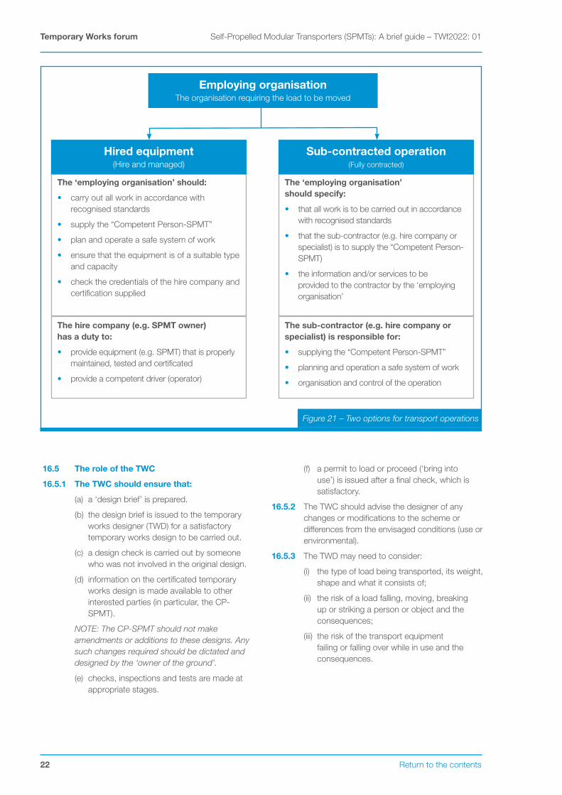
16.2.1 There are two options for transport operations (see Figure 21):
• sub-contracted operation;
• hired equipment.
16.3 Sub-contracted operation
16.3.1 Sub-contract transport operations, where an organisation enters a contract with a specialist contractor who will undertake the transport operation on their behalf (i.e. the contractor plans the transport, provides the equipment and the operator, supervisor, slingers and signallers etc), the contractor has the duty to ensure that the equipment is properly maintained, thoroughly examined and safe to use and that the transport operation is carried out safely.
16.4 Hired equipment
16.4.1 As a hired equipment arrangement, the equipment hire company has a duty under PUWER [7.] to ensure that when equipment is hired out, physical evidence that it is safe for use accompanies it and the user should ensure that this evidence is available.
16.4.2 The user has the duty to manage the subsequent operations in a safe manner and the duty to ensure that the periodic thorough examinations are undertaken at the frequencies laid down in PUWER or the examination scheme if there is one.
22 Return to the contents
Temporary Works forum Self-Propelled Modular Transporters (SPMTs): A brief guide – TWf2022: 01
16.5 The role of the TWC
16.5.1 The TWC should ensure that:
(a) a ‘design brief’ is prepared.
(b) the design brief is issued to the temporary works designer (TWD) for a satisfactory temporary works design to be carried out.
(c) a design check is carried out by someone who was not involved in the original design.
(d) information on the certificated temporary works design is made available to other interested parties (in particular, the CP-SPMT).
NOTE: The CP-SPMT should not make amendments or additions to these designs. Any such changes required should be dictated and designed by the ‘owner of the ground’.
(e) checks, inspections and tests are made at appropriate stages.
(f) a permit to load or proceed (‘bring into use’) is issued after a final check, which is satisfactory.
16.5.2 The TWC should advise the designer of any changes or modifications to the scheme or differences from the envisaged conditions (use or environmental).
16.5.3 The TWD may need to consider:
(i) the type of load being transported, its weight, shape and what it consists of;
(ii) the risk of a load falling, moving, breaking up or striking a person or object and the consequences;
(iii) the risk of the transport equipment failing or falling over while in use and the consequences.
The ‘employing organisation’ should:
• carry out all work in accordance with recognised standards
• supply the “Competent Person-SPMT”
• plan and operate a safe system of work
• ensure that the equipment is of a suitable type and capacity
• check the credentials of the hire company and certification supplied
The hire company (e.g. SPMT owner) has a duty to:
• provide equipment (e.g. SPMT) that is properly maintained, tested and certificated
• provide a competent driver (operator)
Hired equipment(Hire and managed)
The ‘employing organisation’ should specify:
• that all work is to be carried out in accordance with recognised standards
• that the sub-contractor (e.g. hire company or specialist) is to supply the “Competent Person-SPMT)
• the information and/or services to be provided to the contractor by the ‘employing organisation’
The sub-contractor (e.g. hire company or specialist) is responsible for:
• supplying the “Competent Person-SPMT”
• planning and operation a safe system of work
• organisation and control of the operation
Sub-contracted operation(Fully contracted)
Employing organisationThe organisation requiring the load to be moved
Figure 21 – Two options for transport operations

Return to the contents 23
Self-Propelled Modular Transporters (SPMTs): A brief guide – TWf2022: 01 Temporary Works forum
References
[1.] Friction in temporary works, Prepared by the University of Birmingham for the Health and Safety Executive (HSE), 2003, https://www.hse.gov.uk/research/rrpdf/rr071.pdf
[2.] Working platform certificate, Federation of Piling Specialists (FPS), https://www.fps.org.uk/content/uploads/2018/12/FPS-WPC4d-June-2015-updated-logo.pdf
[3.] Working Platforms for construction plant: A guide to good practice, TWf2019:02, April 2019 (TWf) (https://bit.ly/3AyStyZ) and Corrigendum (https://bit.ly/3r2e7sh)
[4.] BS EN 1997-2:2007, Eurocode 7. Geotechnical design - Ground investigation and testing, Annex B (B.3)
[5.] BRE470, Working platforms for tracked plant: good practice guide to the design, installation, maintenance and repair of ground-supported working platforms (BRE), 2004 https://www.brebookshop.com
[6.] BS 5975: 2019, Code of practice for temporary works procedures and the permissible stress design of falsework (BSI)
[7.] Safe use of work equipment, Provision and Use of Work Equipment Regulations 1998. Approved Code of Practice and guidance (PUWER), L22 (HSE), https://www.hse.gov.uk/pubns/books/l22.htm
Bibliography
Temporary Works Toolkit, Part 14: Lifting, moving and jacking, Jim Tod, The Structural Engineer, August 2017
https://www.istructe.org/sitefiles/handlers/DownloadFile.ashx?productId=756
Best Practice Guide for Self-Propelled Modular Transporters, ESTA
https://estaeurope.eu/wp-content/uploads/2021/07/ESTA-BPG-SPMT-UK.pdf
Manual on Use of Self-Propelled Modular Transporters to Remove and Replace Bridges, June 2007, Federal Highways Administration, U.S. Department of Transport
https://www.fhwa.dot.gov/bridge/pubs/07022/hif07022.pdf
Engineering Advice Note 204, Guidance on Self-Propelled Modular Transport (SPMT) and associated Working Platforms, Version No.: Issue 1, 28.04.2021
Safe-by-Design-Early-Focus-on-Constructability-and-Temporary-Works-Guidance-V3-15.5.19
https://safety.networkrail.co.uk/wp-content/uploads/2016/04/Safe-by-Design-Early-Focus-on-Constructability-and-Temporary-Works-Guidance-V3-15.5.19.pdf
NR Standard NR/L3/CIV/0063; Piling, Drilling, Crane, MEWP and SPMT operations adjacent to the Railway
https://bit.ly/3G3xtSc
NOTE: Network Rail have recently announced they will provide their standards and catalogue free of charge to their supply chain and partners. See https://global.ihs.com/csf_home.cfm?&csf=NR

Chairman: Tim Lohmann, CEng, FICE, FIStructESecretary: David Thomas, CEng, FICE, CFIOSH, MInstRE
The Temporary Works Forum is a not for profit company (7525376) registered address (c/o Institution of Civil Engineers), 1 Great George St., London, SW1P 3AA. Correspondence address: 31, Westmorland Road, Sale, Cheshire, M33 3QX
www.twforum.org.ukEmail: [email protected]