Self-propelled Tracked Platform LIGHT LIFT 20.10 - GT Access
202
Operator, Safety, Maintenance and service Manual Original Instructions ‐ Keep this manual with the machine at all times Self‐propelled Tracked Platform LIGHT LIFT 20.10 MULL2010021401 2014, rev 01
-
Upload
khangminh22 -
Category
Documents
-
view
1 -
download
0
Transcript of Self-propelled Tracked Platform LIGHT LIFT 20.10 - GT Access

Operator, Safety, Maintenance and service Manual
Original Instructions ‐ Keep this manual with the machine at all times
Self‐propelled Tracked PlatformLIGHT LIFT 20.10
MULL20100214012014, rev 01


MULL2010021401
1Self‐propelled Tracked Platform LIGHT LIFT 20.10
Table of contents
1. Preface ......................................................................................................Pag. 81.1. Attention ‐ danger ...................................................................................Pag. 81.2. Warning ....................................................................................................Pag. 81.3. Note ...........................................................................................................Pag. 8
2. How to use the manual .........................................................................Pag. 9
3. Normative reference ............................................................................Pag. 11
4. Warranty ................................................................................................Pag. 12
5. Liability ..................................................................................................Pag. 13
6. EC Declaration Conformity ................................................................Pag. 14
7. Technical informations ........................................................................Pag. 157.1. Description of the machine ..................................................................Pag. 157.2. Machine identification plate ...............................................................Pag. 167.3. Overall dimensions of the machine....................................................Pag. 177.4. Technical data ........................................................................................Pag. 187.4.1. Technical data petrol engine................................................................Pag. 197.4.2. Technical data Diesel engine ...............................................................Pag. 197.4.3. Hydraulic system technical specifications.........................................Pag. 207.4.4. Electrical system technical specifications thermal engine...............Pag. 207.4.5. Electrical system technical specifications lithium ............................Pag. 207.5. Terminology...........................................................................................Pag. 227.6. General safety standards......................................................................Pag. 247.7. Clothing and protective equipment ...................................................Pag. 257.8. Safety valves and electrical system safety components...................Pag. 257.9. Fire prevention ......................................................................................Pag. 267.10. Preventing damage caused by washing the machine......................Pag. 267.10.1. Cleaning the machine ...........................................................................Pag. 267.10.2. Washing the outside of the machine ..................................................Pag. 277.10.3. Cleaning the electrical system .............................................................Pag. 277.10.4. After cleaning.........................................................................................Pag. 277.11. Preventing damage that may be caused by the machine during work.....
Pag. 287.12. Safety warnings .....................................................................................Pag. 29

MULL2010021401
2 Self‐propelled Tracked Platform LIGHT LIFT 20.10
7.12.1. Generalities ............................................................................................Pag. 297.12.2. Noise and Vibration..............................................................................Pag. 297.12.3. Decals on the machine..........................................................................Pag. 30
8. Safety device .........................................................................................Pag. 408.1. Battery cut‐out switch...........................................................................Pag. 418.2. Distributor pressure relief valves .......................................................Pag. 418.3. Cylinder stop valves .............................................................................Pag. 428.4. Alignment photocells of the aerial part .............................................Pag. 438.5. Stabilizer position micro switches ......................................................Pag. 438.6. JIB position micro switch .....................................................................Pag. 448.7. Ropes integrity micro switch...............................................................Pag. 448.8. Basket load sensor.................................................................................Pag. 468.9. Control protection .................................................................................Pag. 488.10. Spirit and electronic level.....................................................................Pag. 498.11. Pin locking bolts and nuts....................................................................Pag. 508.12. Safety device electronic control board ...............................................Pag. 518.13. Booms position sensors ........................................................................Pag. 51
9. Instruments and controls ....................................................................Pag. 539.1. Remote control.......................................................................................Pag. 539.1.1. Display....................................................................................................Pag. 549.1.2. Joystick....................................................................................................Pag. 589.1.3. Push buttons ..........................................................................................Pag. 609.2. Foot switch (optional)...........................................................................Pag. 639.3. Control position.....................................................................................Pag. 649.3.1. Control position in the basket .............................................................Pag. 649.3.2. Control position at the ground............................................................Pag. 649.3.3. Emergency control position.................................................................Pag. 659.3.4. Maintenance control position..............................................................Pag. 66
10. Emergency device ................................................................................Pag. 6810.1. Emergency stop button ........................................................................Pag. 6810.2. Hand pump............................................................................................Pag. 6910.3. Solenoid valves for emergency descent .............................................Pag. 7010.4. Safety device bypass key......................................................................Pag. 7010.5. Emergency position controls ...............................................................Pag. 7110.5.1. Selection panel, emergency stop and starting...................................Pag. 7110.5.2. Aerial part hydraulic distributor ........................................................Pag. 7310.5.3. Tracked undercarriage hydraulic distributor ...................................Pag. 76

MULL2010021401
3Self‐propelled Tracked Platform LIGHT LIFT 20.10
11. Using the machine ................................................................................Pag. 7911.1. Safety standards to adopt before using the platform.......................Pag. 7911.1.1. Risk of electrocution .............................................................................Pag. 7911.1.2. Danger due to atmospheric conditions..............................................Pag. 7911.1.3. Danger due to the work area ...............................................................Pag. 8111.2. Procedures for correct use....................................................................Pag. 8111.2.1. Summary table of operator safety standards ....................................Pag. 8211.3. Working area..........................................................................................Pag. 8411.4. Use of the elevating work platform (MEWP)....................................Pag. 8511.4.1. Preliminary checks before starting work...........................................Pag. 8611.4.2. Starting the Petrol/Diesel engine.........................................................Pag. 8611.4.3. Starting the electric motor....................................................................Pag. 8811.4.4. Stopping the engine/motor ..................................................................Pag. 8911.4.5. Stopping the motor Lithium version..................................................Pag. 9011.4.6. Travel ......................................................................................................Pag. 9111.4.7. JIB boom movement for travel ............................................................Pag. 9311.4.8. Parking the machine on a slope or on uneven ground....................Pag. 9511.4.9. Stabilising and levelling the machine.................................................Pag. 9511.4.10. Automatic lowering and raising of the stabilisers ...........................Pag. 9911.4.11. Track extension....................................................................................Pag. 10111.4.12. Moving the basket ...............................................................................Pag. 10311.4.13. Manually levelling of the basket .......................................................Pag. 10611.5. Aerial part emergency manoeuvres .................................................Pag. 10911.5.1. Activation of emergency descent from the basket .........................Pag. 10911.5.2. Operating the machine from the emergency control position on the
ground if the operator is taken ill .....................................................Pag. 11111.5.3. Emergency descent in the case where the stabilisers are accidentally
retracted................................................................................................Pag. 11411.5.4. Emergency descent controlled from the ground using the hand pump in
the event of faults on all energy supply systems............................Pag. 11711.5.5. Emergency operation of the undercarriage in the event of movements of
the aerial part .......................................................................................Pag. 12111.5.5.1.Machine realignment ..........................................................................Pag. 12111.5.5.2.Moving the undercarriage with the machine not aligned.............Pag. 12211.5.6. Emergency operations on the carriage: moving the platform stabilisers
using the hand pump to allow the machine to be transported ....Pag. 12511.6. Electrical connection of remote control............................................Pag. 12811.7. Recharging the battery .......................................................................Pag. 12911.7.1. Battery charging Petrol/Diesel engine..............................................Pag. 12911.7.2. Charging Lithium batteries................................................................Pag. 130

MULL2010021401
4 Self‐propelled Tracked Platform LIGHT LIFT 20.10
11.8. Main intended uses of the platform .................................................Pag. 13411.8.1. Systems .................................................................................................Pag. 13411.8.2. Closed environments ..........................................................................Pag. 13411.8.3. Pruning .................................................................................................Pag. 13411.8.4. Repair and maintenance of roofing and gutters.............................Pag. 13411.8.5. Painting, sand‐blasting and plastering ............................................Pag. 13511.8.6. Use in marine environments .............................................................Pag. 135
12. Maintenance ........................................................................................Pag. 13612.1. Safety instructions for greasing and lubrication.............................Pag. 13612.1.1. Table of recommended lbrificants ....................................................Pag. 13612.1.2. Greasing points....................................................................................Pag. 13912.1.3. Greasing the telescopic boom............................................................Pag. 13912.2. Safety instructions for maintenance operations .............................Pag. 14012.3. Maintenance control position with remote control from the ground Pag.
14112.4. Periodical maintenance intervals......................................................Pag. 14412.5. Electric motor maintenance ...............................................................Pag. 14612.6. Inspection and maintenance intervals .............................................Pag. 14812.6.1. A‐ Daily inspections before starting.................................................Pag. 14812.6.2. B‐ Periodical inspections ....................................................................Pag. 14812.6.3. C‐ Annual inspections ........................................................................Pag. 14912.6.4. D‐ Structural inspection .....................................................................Pag. 15012.6.5. E‐ Maintenance ....................................................................................Pag. 15012.7. General periodical checks ..................................................................Pag. 15112.8. Maintenance on rubber tracks...........................................................Pag. 15212.8.1. Rubber tracks tension check ..............................................................Pag. 15212.8.2. Tensioning rubber track .....................................................................Pag. 15312.8.3. Removing rubber track.......................................................................Pag. 15312.8.4. Installing rubber track ........................................................................Pag. 15512.9. Checking tightness of nuts and bolts ...............................................Pag. 15512.10. Hydraulic oil level check....................................................................Pag. 16012.11. Checking for leaks in the hydraulic system ....................................Pag. 16012.12. Checking the condition of the filter cartridge.................................Pag. 16012.13. Checking that all the plates are present on the machine and intact ...Pag.
16112.14. Checking the operating pressures in the hydraulic system..........Pag. 16212.15. Checking extension ropes ..................................................................Pag. 16412.15.1. Checking wear and deformation of ropes and pulleys .................Pag. 16412.15.2. Three‐monthly inspection..................................................................Pag. 165

MULL2010021401
5Self‐propelled Tracked Platform LIGHT LIFT 20.10
12.15.3. Ropes Tension Adjustment Procedure.............................................Pag. 16612.15.4. Five‐yearly inspection ........................................................................Pag. 16712.16. Checking wear of the telescopic arm slide blocks ..........................Pag. 16812.17. Battery Petrol/Diesel engine: maintenance ‐ replacement ‐ disposal .Pag.
16912.18. Battery pack maintenance operating specifications .......................Pag. 17112.18.1. Handling in dangerous conditions...................................................Pag. 17212.18.1.1.Personal protective equipment ........................................................Pag. 17212.18.1.2.Procedure for handling hot cells......................................................Pag. 17212.18.1.3.Procedure for handling vented cells ...............................................Pag. 17312.18.1.4.Procedure for exploded cells ............................................................Pag. 17512.18.1.5.Lithium battery fire............................................................................Pag. 17612.19. Servicing the engine thermic version ...............................................Pag. 17812.20. Start‐up of the machine after maintenance .....................................Pag. 178
13. Safety standards for transport ..........................................................Pag. 17913.1. Removing the basket...........................................................................Pag. 17913.2. Loading and unloading the machine on transport vehicles using ramps
Pag. 18113.3. Lifting the machine .............................................................................Pag. 18413.3.1. Lifting the machine using a forklift ..................................................Pag. 18413.3.2. Lifting the machine using ropes or chains.......................................Pag. 18613.4. Transporting the machine..................................................................Pag. 188
14. Service menu on the remote control ................................................Pag. 18914.1. Input menu...........................................................................................Pag. 18914.2. Language menù...................................................................................Pag. 18914.3. Errors menu .........................................................................................Pag. 18914.4. Working hours menu..........................................................................Pag. 19014.5. Joystick menu.......................................................................................Pag. 190
15. Hydraulic system ...............................................................................Pag. 191
16. Wiring diagram ..................................................................................Pag. 194

MULL2010021401
6 Self‐propelled Tracked Platform LIGHT LIFT 20.10

7
MULL2010021401
Self‐propelled Tracked Platform LIGHT LIFT 20.10
HINOWA SPAVia Fontana37054 Nogara ‐ VeronaItalyPhone: +39 0442 539100Fax: +39 0442 539075Email: [email protected]

8 Self‐propelled Tracked Platform LIGHT LIFT 20.10
PREFACE MULL2010021401
1. PREFACEThe aim of this manual is to provide the user with the necessary instructions andessential operating procedures to ensure correct and safe use of the machine forits intended purposes, as well as to prevent serious injury to the operator andother persons.This manual describes the warning signs used to draw the readerʹs attention toseveral particularly important warnings. The safety warnings are divided intothree main types, which are identified and described below.
1.1. ATTENTION ‐ DANGER
1.2. WARNING
1.3. NOTE
Original languages of the manufacturer: Italian and English. All other languagesare copies of the original instructions.
This symbol indicates that the situation described, if not prevented,can lead to serious injury or death of the persons involved (operator,ground staff, staff present in proximity to the machine, maintenancetechnicians etc.).
This symbol indicates that the situation described represents a potential riskfor the structure of the machine. Dangerous situations may be determined bythis condition (including injury or death) for the persons involved.
This symbol indicates tips or additional notes useful for the operator or for thosewho must perform maintenance/repair on the machine.

HOW TO USE THE MANUAL
9
MULL2010021401
Self‐propelled Tracked Platform LIGHT LIFT 20.10
2. HOW TO USE THE MANUALIt is mandatory to keep to all the instructions given in this manual. This ma‐nual must be carefully read and understood before operating the machine.As this manual is an essential work tool, it must be kept with the machine at alltimes, in the special compartment, so as to be available for clarification wheneverrequired.
As the manufacturer cannot control the conditions of the machine and the opera‐tions this is used for, the user is responsible for ensuring compliance with the sa‐fety procedures described in this manual.Every machine supplied is thoroughly adjusted and tested before being delive‐red. The operator does not need to perform any adjustments before using the ma‐chine. Every alteration and/or modification of the features of the original machinedesign without previous written authorization from the constructor are prohibi‐ted and the responsibility for these actions falls on the operator.
Fig. 1 Position of manual on machine

10 Self‐propelled Tracked Platform LIGHT LIFT 20.10
HOW TO USE THE MANUAL MULL2010021401
The employer must make sure that the operator has the requisites necessary tooperate the machine correctly and that such operator has carefully examinedand understood the information given in this user and operation manual, re‐ceiving suitable training regarding use of the machine in standard and emer‐gency conditions.The employer must also train operators regarding any national standards thatare in addition to the instructions contained in this document.
If the manual is damaged or lost, a copy must be requested directly from the ma‐nufacturer.
All of the photos and drawings in this manual have been added to simplify com‐prehension by the reader. Your machine may differ from the photos and drawingsprovided.

NORMATIVE REFERENCE
11
MULL2010021401
Self‐propelled Tracked Platform LIGHT LIFT 20.10
3. NORMATIVE REFERENCEThe machine has been designed, built and inspected according to that prescribedin the EN280 harmonised standard, which supplies the presumption of conformi‐ty with the Essential Safety Requisites of the 2006/42/CE Machinery Directiveeven if a type C Voluntary Technical Standard.According to that stated in EN280, the platform is classified in GROUP B, as thevertical projection of the centre of gravity of the load can be outside of the tiltinglines and in TYPE 1 as traversing is only allowed with the platform at rest.The stability tests of the machine have been made in accordance with what de‐scribed in the EN280 and have been successful.In addition what prescribed in this manual it is necessary to apply the technicalrequirements of the following national/international safety standards:• UNI ISO 18893• ISO 16368 • ISO 18878With the exception of stricter local or national regulations in the working area ofthe MEWP.

12 Self‐propelled Tracked Platform LIGHT LIFT 20.10
WARRANTY MULL2010021401
4. WARRANTYOn purchasing a machine, a warranty and inspection certificate is issued that cle‐arly indicates the warranty terms and where any interventions on the machinemust be reported.
LIABILITY
13
MULL2010021401
Self‐propelled Tracked Platform LIGHT LIFT 20.10
5. LIABILITYThe Constructor is exonerated from any liability and obligation for any injury/da‐mage caused to persons/objects due to any of the reasons listed below:• Failure to comply with the instructions indicated in this USE AND MAINTE‐NANCE MANUAL regarding running, use and maintenance of the machine;• Violent or sudden actions or incorrect manoeuvres when using or servicingthe machine;• Modifications made to the structure or machine components without pre‐vious authorisation from the Constructor and/or without the use of suitable equi‐pment;• Strange events with respect to normal and correct use of the machine, descri‐bed in this USE AND MAINTENANCE MANUAL;• Use of non‐original spare parts not authorised by the manufacturer;

14 Self‐propelled Tracked Platform LIGHT LIFT 20.10
EC DECLARATION CONFORMITY MULL2010021401
6. EC DECLARATION CONFORMITY
Fig. 2 EC Declaration Conformity

TECHNICAL INFORMATIONS
15
MULL2010021401
Self‐propelled Tracked Platform LIGHT LIFT 20.10
7. TECHNICAL INFORMATIONS
7.1. DESCRIPTION OF THE MACHINE
The machine is a self‐propelled hydraulic lifting device, equipped with a rotatingwork basket positioned at the top of an extensible articulated structure, whichalso rotates. The lifting device is destined for the positioning of persons and theirequipment and materials in high positions with respect to ground level.Refer to relevant paragraph in respect of the control stations ʺControl position(p. 64)ʺ
16 Self‐propelled Tracked Platform LIGHT LIFT 20.10
TECHNICAL INFORMATIONS MULL2010021401
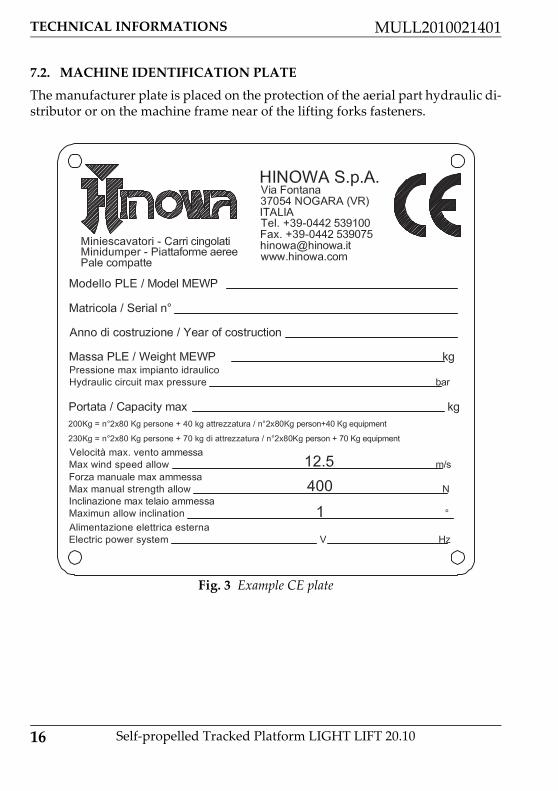
7.2. MACHINE IDENTIFICATION PLATE
The manufacturer plate is placed on the protection of the aerial part hydraulic di‐stributor or on the machine frame near of the lifting forks fasteners.
Fig. 3 Example CE plate

TECHNICAL INFORMATIONS
17
MULL2010021401
Self‐propelled Tracked Platform LIGHT LIFT 20.10
7.3. OVERALL DIMENSIONS OF THE MACHINE
Maximum length in travel configuration with basket in‐stalled
5011 mm
Track width closed/open 795/1095 mm
Maximum height in travel configuration with foot plates removed
1998 mm
Maximum attachment angle 20° / 21°
Maximum stabilisation angle 15°
Max stabiliser base side (disc centre) 2922x2925 mm
Fig. 4 Standard version with 2 person basket

18 Self‐propelled Tracked Platform LIGHT LIFT 20.10
TECHNICAL INFORMATIONS MULL2010021401
7.4. TECHNICAL DATA
Platform capacity 230 Kg
Platform height (floor) 18.05m
Max working height 20.15m
Standard basket dimensions 1335x690xH1100mm
Max horizontal extension in basket 9.20m
Max horizontal outreach 9.70m
Rotation (non‐continuous) 360°
Basket rotation 124° (+/‐ 62°)
Max ground reaction force for each stabilizer 2150 daN
Max ground pressure for each stabilizer 3.04 daN/cm2
No. Of operators 2
No. Of operators with optional single‐operator basket
1
JIB ‐ type of articulated joint 89° (+0° / ‐89°)
Max working gradient 1°/ 1,75%
Max stabilization slope 15°
Total weight in transport configuration petrol en‐gine
2840Kg
Total weight in transport configuration diesel 2940Kg
Total weight in transport configuration lithium 2950Kg
Electrical system voltage 12V
Max translation speed with standard 2nd speed (thermic motor)
0,5/1,3/2,5 Km/h
Max translation speed with standard 2nd speed (lithium)
0,83/1,6 Km/h
Travel/stab. System pressure 165bar
Aerial part system pressure 210bar

TECHNICAL INFORMATIONS
19
MULL2010021401
Self‐propelled Tracked Platform LIGHT LIFT 20.10
7.4.1. Technical data petrol engine
7.4.2. Technical data Diesel engine
Approach angle 20° / 21°
Max slope allowed in travel direction 16° / 28,7%
Max wind speed 12,5 m/s
Max manual force allowed 400N
Make/Model HONDA iGX440
Fuel/Cooling Petrol / Air
Power 9,5 Kw (12,7cv) / 3600rpm
Max speed 3600 rpm
Maximum torque 29,8 Nm / 2500rpm
Number of cylinders 1
Displacement 440 cm³
Sound power level at operatorʹs ear 88 dB
Measured sound power level 102 dB
Granted sound power level 104 dB
Make/Model PERKINS 402.05
Fuel/Cooling Diesel / Liquid
Power 10,2 kW (14cv) / 3600rpm
Max speed 3500 rpm
Maximum torque 29,7 Nm / 2400rpm
Number of cylinders 2
Displacement 510 cm³
Sound power level at operatorʹs ear 90 dB
Measured sound power level 102 dB

20 Self‐propelled Tracked Platform LIGHT LIFT 20.10
TECHNICAL INFORMATIONS MULL2010021401
7.4.3. Hydraulic system technical specifications
For further information, see the hydraulic diagram enclosed with the manual andthe paragraph on maintenance of the hydraulic components.
7.4.4. Electrical system technical specifications thermal engine
For further information, see wiring diagram enclosed with the manual and theparagraph on maintenance of electrical components.
7.4.5. Electrical system technical specifications lithium
Granted sound power level 104 dB
Hydraulic oil tank capacity 40 l
Pump petrol engine 2x4 cm³
Pump diesel engine 2x4 cm³
Hydraulic system max pressure 220 bar
Battery 55Ah ‐ 240A ‐ 12V
Alternator petrol engine 20 A (3600rpm)
Alternator Diesel engine 14‐15 A (3600rpm)
Electric motor rated voltage 230V ‐ 110V ‐ 120V
Electric motor frequency 50Hz ‐ 50Hz ‐ 60Hz
Electric motor rated power 2,2 kW ‐ 2,2 kW ‐ 1,2 kW
Battery 90‐100 Ah
Electric motor rated voltage 72 V
Electric motor rated power 3,5 kW
Onboard battery charger 220V+‐30V 50‐60 Hz
110V+‐30V 50‐60 Hz
Full weight of the battery pack 180 Kg

TECHNICAL INFORMATIONS
21
MULL2010021401
Self‐propelled Tracked Platform LIGHT LIFT 20.10
For further information, see wiring diagram enclosed with the manual and theparagraph on maintenance of electrical components.
Sound power level at operatorʹs ear 70 dB
Measured sound power level 86 dB
Granted sound power level 88 dB

22 Self‐propelled Tracked Platform LIGHT LIFT 20.10
TECHNICAL INFORMATIONS MULL2010021401
7.5. TERMINOLOGY
To make the contents of this manual easier to understand, the diagram providedbelow illustrates the terms used to identify the parts of the machine.
LEGENDA
Fig. 5 Terminology machine components
1 Tracked undercarriage
2 Revolving turret
3 Turntable + rotation motor
4 Emergency controls
5 Base+electrical component compartment+oil tank
6 Double gear pump
7 Petrol/diesel engine / Battery pack + inverter + battery charger (LITHIUM MOTOR)
8 Stabilizer

TECHNICAL INFORMATIONS
23
MULL2010021401
Self‐propelled Tracked Platform LIGHT LIFT 20.10
9 Stabilizer cylinder
10 Second arm tie rod
11 Second arm
12 Second‐third arm cylinder
13 Second‐third arm transmission
14 Second‐third arm connecting rod
15 Basket levelling cylinder on the transmission
16 Third arm
17 Stabilizer plate
18 JIB tie rod
19 First extension arm
20 Jib cylinder
21 Right and left JIB arm
22 Second extension arm
23 Remote control
24 Basket or cage
25 Basket support
26 Rotary actuator for basket rotation
27 Basket levelling cylinder on the basket
28 JIB transmission
29 First‐second arm transmission
30 First‐second arm cylinder
31 First arm
32
33 Electric motor
34 Double gear pump
35 Emergency hand pump

24 Self‐propelled Tracked Platform LIGHT LIFT 20.10
TECHNICAL INFORMATIONS MULL2010021401
7.6. GENERAL SAFETY STANDARDS
The functioning of the MEWP must be in compliance with international stan‐dards of reference see ʺNormative reference (p. 11)ʺ, and national or regionalstandards if stricter. The operator must read, understand and follow all the in‐structions and warnings, contained in this manual and on the machine, regardingthe safe use of the MEWP.
FAILURE TO COMPLY WITH THE SAFETY PRECAUTIONS LISTED IN THIS SECTION AND PROVIDED ON THE MACHINE CAN DAMAGE THE MACHI‐NE AND CAUSE INJURY OR EVEN DEATH, AND CONSTITUTES A SERIOUS BREACH OF THE SAFETY RULES.This section of the USER AND OPERATION MANUAL describes those procedu‐res or dangerous situations that can cause damage/injury to objects/persons andexplains what the operator must do to prevent them.• Operators must always act professionally, complying with safety standards,making sure not to underestimate their responsibility to themselves and the sur‐rounding objects and persons.• Before starting work, operators must receive complete and clear training re‐garding the use of the machine in standard and emergency conditions. • They must examine, understand and take in all the instructions given inthis user manual. They must be sure that the safety devices are in perfect wor‐king order, perform the necessary checks on the machine and be familiar withthe conditions of the ground on which the machine is going to be operated andstabilised.• The presence of at least one specialist operator is necessary on the ground du‐ring work. This person must know how to use the machine, be aware of the con‐tents of the USER AND OPERATION MANUAL and be able to intervene ifnecessary.
Warning
Attention ‐ danger

TECHNICAL INFORMATIONS
25
MULL2010021401
Self‐propelled Tracked Platform LIGHT LIFT 20.10
• It is prohibited to make modifications to the machine that could jeopardisefunctioning and safety, without previous written authorisation from The Con‐structor which is not liable for any injury or damage caused by this behaviour.
7.7. CLOTHING AND PROTECTIVE EQUIPMENT
USE THE TYPE‐APPROVED AND CERTIFIED SAFETY HARNESSES. BEFORE WORKING AT A HEIGHT, MAKE SURE THAT THE SAFETY HARNESSES ARE CORRECTLY FASTENED AND CONNECTED TO THE ANCHORAGE POINTS ON THE BASKET.THE USE OF HARNESSES IS COMPULSORY IN ACCORDANCE WITH LO‐CAL LEGISLATION IN EACH INDIVIDUAL COUNTRY. IN COUNTRIES WHERE THE LAW DOES NOT REQUIRE THE USE OF SUCH SAFETY SY‐STEMS, THE EMPLOYER AND/OR USER IS RESPONSIBLE FOR CHOOSING THE SYSTEM TO BE USED.
7.8. SAFETY VALVES AND ELECTRICAL SYSTEM SAFETY COMPONEN‐TS
It is prohibited to modify and/or tamper with the safety and control valves ofthe main hydraulic system and the adjustments of the electric plant. The Con‐structor is not liable for injury to persons and damage to objects or to the ma‐chine if the standard calibration of any hydraulic and electric/electroniccomponent is tampered with.
Avoid wearing loose clothing, rings,watches or anything else that may getcaught in moving parts. When usingthe machine or performing maintenan‐ce, wear a hard hat, glasses, safety fo‐otwear, gloves and acoustic earmuffsafter making sure these and all otherPPE that the safety manager considersnecessary based on the risk analysisperformed are in perfect working con‐dition.
Warning

26 Self‐propelled Tracked Platform LIGHT LIFT 20.10
TECHNICAL INFORMATIONS MULL2010021401
7.9. FIRE PREVENTION
7.10.PREVENTING DAMAGE CAUSED BY WASHING THE MACHINE
BEFORE WASHING THE MACHINE, ALWAYS REMEMBER TO REMOVE THE REMOTE CONTROL AND CORRECTLY CLOSE THE REMOTE CON‐TROL AND EQUIPMENT CONNECTION SOCKETS LOCATED ON THE MA‐CHINE.
7.10.1.Cleaning the machine
Keep the area around the motor clean,removing fragments of wood, paperand other flammable products; cleanany fuel leaks as these may be a poten‐tial cause of fire. Petrol is extremelyflammable and explosive in particularconditions. Refuel in well ventilatedareas and with the engine at rest.Avoid smoking and producing sparksin the refuelling and fuel storage area.After refuelling, make sure to put backthe cap correctly. Take care to avoidtouching the exhaust silencer whenthis is hot, i.e. with the machine run‐ning or soon after stopping the engine.
Do not direct high pressure jetstowards the electrical componentswhile washing the machine. Do not usechemical detergents or petrol thatwould damage the plastic parts and thepainting.
When washing the machine, the ignition block must be disengaged, the keyremoved and the emergency stop button pressed.

TECHNICAL INFORMATIONS
27
MULL2010021401
Self‐propelled Tracked Platform LIGHT LIFT 20.10
7.10.2.Washing the outside of the machineAlways park the machine as shown in the figure ʺTerminology (p. 22)ʺ Never use flammable liquids.Clean the machine using water‐soluble detergents. Follow the instructions provi‐ded by the manufacturer of the detergent.Do not remove protective covers and casings of any kind.
7.10.3.Cleaning the electrical system
7.10.4.After cleaningDry the machine carefully before starting it again (for example using compressedair).
If washing the machine with water cleaners, do not aim the spray di‐rectly onto adhesive labels and rating plates. carefully protect all theimportant parts and above all the electrical components.
The more the elevating platform is cleaned, the more it will need to be greased
Never clean the electric components with water, as this may cause damage tothe electrical system of the machine.
Only use dry detergents, in accordance with the manufacturerʹs in‐structions. Never remove covers, guards and the like.

28 Self‐propelled Tracked Platform LIGHT LIFT 20.10
TECHNICAL INFORMATIONS MULL2010021401
7.11.PREVENTING DAMAGE THAT MAY BE CAUSED BY THE MACHINE DURING WORK
When the machine has been stabilised and work has started, never enter its ope‐rating area.Always operate the controls slowly and smoothly and avoid reversing the move‐ments suddenly.When operating outside of the basket, ALWAYS keep a MINIMUM distance of 1METRE from the machine.
If, despite all the precautions, moisture has penetrated into the electric motoror other parts of the electric system, these must be dried before starting themachine.

TECHNICAL INFORMATIONS
29
MULL2010021401
Self‐propelled Tracked Platform LIGHT LIFT 20.10
7.12.SAFETY WARNINGS
7.12.1.Generalities
Carefully read all the safety messages provided in this manual and the safety si‐gns on the machine. Keep the safety signs in good condition and replace them ifthey are damaged. Make sure that any new components on the machine are pro‐vided with the correct safety signs.
7.12.2.Noise and VibrationThe Constructor declares that the platforms have been tested according to the pa‐rameters of European directive 2000/14 EC, with the guaranteed sound power le‐vel measurement shown on the machineʹs EC declaration of conformity. Whenoperating the aerial part of the machine, this value is reduced even further as thebasket moves away from the main source of noise. The vibrations transmitted tothe operator from the controls and directly from the floor of the basket are lowerthan the maximum allowed limits.
To avoid accidents, before startingwork and before performing anymaintenance operations, it is neces‐sary to read, understand and followall the precautions and warnings con‐tained in this manual. The user/opera‐tor of the machine must decline allresponsibility for operation until ha‐ving read this manual and fully un‐derstood how to use the machineunder the supervision of an expertand qualified operator.

30 Self‐propelled Tracked Platform LIGHT LIFT 20.10
TECHNICAL INFORMATIONS MULL2010021401
7.12.3.Decals on the machineHere we report the positions of the various boards with pictogram on the machi‐ne.

TECHNICAL INFORMATIONS
31
MULL2010021401
Self‐propelled Tracked Platform LIGHT LIFT 20.10

32 Self‐propelled Tracked Platform LIGHT LIFT 20.10
TECHNICAL INFORMATIONS MULL2010021401

TECHNICAL INFORMATIONS
33
MULL2010021401
Self‐propelled Tracked Platform LIGHT LIFT 20.10
Position Code Quantity Position Code Quantity
01 06555500 02 28 06998800 01
02 06555600 01 29 07242000 01
03 06555700 01 30 06227100 01
04 06555800 01 31 06226900 01
05 06041200 04 32 06164700 01
06 06506700 06 33 06165000 01
07 06068700 01 34 06060000 01
08 06924300 01 35 06227200 01
09 06040400 01 36 06041600 01
10 06040500 02 36 06043900 01
11 06040900 06 37 06056300 01
12 06041300 11 38 06164600 01
13 06086200 04 39 06232100 01
14 06044000 04 40 07240300 01
15 06086600 02 41 07320400 04
16 1704277 02 42 07034200 02
17 06136900 01 43 07299900 01
18 06396200 04 44 1608710001
01
19 06311200 04 45 1608710002
01
20 07058800 02 46 07199100 01
21 06040800 04 47 06254800 01
22 06704400 02 48 06922700 02
23 07349200 01 49 07350300 04
24 06665700 03 50 06214200 01

34 Self‐propelled Tracked Platform LIGHT LIFT 20.10
TECHNICAL INFORMATIONS MULL2010021401
Language decals
25 06086000 01 51 06594500 01
26 06085900 01 52 07508200 01
27 06706500 01
Position Code Quantity Position Code Quantity
172831IT 172831GB
L1 06555300 01 L1 06562600 01
L2 06561200 04 L2 06561200 04
L3 06448200 02 L2 06042400 04
L4 06448100 02 L2 06257300 04
L5 07348900 01 L3 06462700 02
L4 06462100 02
L5 073489GB 01
172831FR 172831DE
L1 06562700 01 L1 06562800 01
L2 06561200 04 L2 06561200 04
L3 06462800 02 L3 06462900 02
L4 06462200 02 L4 06462300 02
L5 073489FR 01 L5 073489DE 01
172831ES 172831NL
L1 06562900 01 L1 06563000 01
L2 06561200 04 L2 06561200 04
Position Code Quantity Position Code Quantity

TECHNICAL INFORMATIONS
35
MULL2010021401
Self‐propelled Tracked Platform LIGHT LIFT 20.10
L3 06463000 02 L3 06463100 02
L4 06462400 02 L4 06462500 02
L5 073489ES 01 L5 073489NL 01
172831PT 172831DA
L1 06563100 01 L1 07138100 01
L2 06561200 04 L2 06561200 04
L3 06463200 02 L3 07138000 02
L4 06462600 02 L4 07137900 02
L5 073489PT 01 L5 073489DA 01
172831NO 172831SW
L1 07162000 01 L1 07137300 01
L2 06561200 04 L2 06561200 04
L3 07161800 02 L3 07137500 02
L4 07161900 02 L4 07137400 02
L5 073489NO 01 L5 073489SW 01
Position Code Quantity Position Code Quantity

36 Self‐propelled Tracked Platform LIGHT LIFT 20.10
TECHNICAL INFORMATIONS MULL2010021401
Decals description
Warning keep safe distance
Sense of moving undercarriage defined as the direction forward.
Obligation to read the manual before use of machine.
Fixing point for transport indicates correct fixing point for transportof the machine.
Crushing hazard feet indicates areas where there is a danger of cru‐shing lower limbs for the operator.
Crushing hazard person indicates areas where there is a danger ofcrushing upper limbs for the operator.
Lifting point indicates correct lifting points for lift the machine.

TECHNICAL INFORMATIONS
37
MULL2010021401
Self‐propelled Tracked Platform LIGHT LIFT 20.10
Danger hight temperature.
Engine oil level.
Emergency device for aerial part device that allows to exclude thesafety of the aerial part in case of emergency operations.
Emergency device for undercarriage device that allows to excludethe safety of the undercarriage in case of emergency operations.
Hydraulic oil level.
Forbidden lifting point.

38 Self‐propelled Tracked Platform LIGHT LIFT 20.10
TECHNICAL INFORMATIONS MULL2010021401
Do not wash with water.
Hand pump legend quick instructions for using the emergencyhand pump.
Use safety harnesses, use protective equipment (helmet), prohibi‐tion of weld on the machine, prohibition of use systems to increasethe area of work inside the basket , prohibition of working in the vi‐cinity of voltage electric, prohibition of use of the platform for rai‐sing loads.
Battery pack warnings.Corrosive liquid, presence of highly corrosive liquid, dangerous tothe body and eyes.High voltage, presence of high voltage with danger of electric shock.Danger of explosion, formation of potentially explosive mixture in‐side the battery.No naked flames, do not smoke or use naked flames when rechar‐ging and near the vehicle. Risk of explosion.Recycling, it is highly recommended to comply with legislative andenvironmental standards as regards the demolition, reuse, recyclingand recovery of materials.
Lifting points with forklift, indicates the lifting points with forklift.
Crushing hazard person.

TECHNICAL INFORMATIONS
39
MULL2010021401
Self‐propelled Tracked Platform LIGHT LIFT 20.10
Warning keep safe distance.
Replace stickers and plates if there is any sign of wear.
Failure to heed any warnings due to a safety sticker being damaged,lost or ignored may cause serious accidents.
Anchor position in basket indicates the position of the anchor hooksto which fasten the operatorʹs safety sling.

40 Self‐propelled Tracked Platform LIGHT LIFT 20.10
SAFETY DEVICE MULL2010021401
8. SAFETY DEVICEThe information given below concerning the safety devices are provided to theuser in order to allow him/her to understand the machine behaviour and possiblework sequences; moreover, in this way it is possible to identify any breakdownswith greater precision and to supply more detailed information to the after salesservice for quicker, less expensive interventions.
The machine is fitted with safety devices used to prevent dangerous situa‐tions for the operator. It is important that before starting any operation, theoperator checks the perfect working order of these devices.
The non‐functioning of a safety device, whether caused by a fault ortampering, can cause serious damage to the machine and consequent‐ly put the operatorʹs life at risk. The Constructor has designed themachine and safety devices in order to guarantee the maximum to itscustomers, however the devices must be checked periodically accor‐ding to that described in this manual and they must never be tampe‐red with.
The service function on the remote control can be used as an aid for checkingelectric safety devices.
Never intervene on the safety devices. If they are tampered with, themanufacturer declines all liability regarding any accidents that maybe due to such tampering.
It is prohibited to tamper with the lead sealing or setting of the ma‐ximum pressure valves and the adjustments of the electrical compo‐nents. If they are tampered with the manufacturer declines allliability for any accidents that may be due to such tampering.
The Constructor is not liable for any damage/injury caused by the machineto objects and/or persons due to failure to comply with the above in‐structions.

SAFETY DEVICE
41
MULL2010021401
Self‐propelled Tracked Platform LIGHT LIFT 20.10
8.1. BATTERY CUT‐OUT SWITCH
This device is used to isolate the machineʹs electrical circuit. It is well visible andeasily accessed without using tools. It only needs to be activated for prolongedmachine downtime or maintenance operations. Turning the key clockwise closesthe machineʹs electrical circuit, while turning it anticlockwise isolates the machi‐neʹs electrical circuit and the key can be removed.
8.2. DISTRIBUTOR PRESSURE RELIEF VALVES
Fig. 6 Battery cut out switch thermal En‐gine version
Fig. 7 Battery cut out switch Lithium ver‐sion
Before disconnecting the battery by means of this device, make surethat the engine key is in position “off” and the remote control andelectronic board are off.
Fig. 8 Aerial part pressure relief valve Fig. 9 Ground part pressure relief valve 1

42 Self‐propelled Tracked Platform LIGHT LIFT 20.10
SAFETY DEVICE MULL2010021401
All platform distributors have a pressure relief valve that limits the pressure in‐side the system to the value set for the same valve. These valves are set when theplatform is tested by qualified personnel and must not be tampered with for anyreason whatsoever.
8.3. CYLINDER STOP VALVES
The stabiliser cylinders have a double stop valve which in case of system break‐down or hose breakage stops the cylinder preventing dangerous platform insta‐bility situations. All cylinders that move the aerial part of the platform structureare fitted with a stop valve which in case of system breakdown or hose breakagestops the cylinder preventing the basket from falling due to gravity.
Fig. 10 Cylinder stop valves Fig. 11 Cylinder stop valves
These valves are calibrated in the platform inspection phase by theconstructor and must not be tampered with for any reason.

SAFETY DEVICE
43
MULL2010021401
Self‐propelled Tracked Platform LIGHT LIFT 20.10
8.4. ALIGNMENT PHOTOCELLS OF THE AERIAL PART
The platform has two safety photocells that ensure that the aerial part of the ma‐chine is completely lowered and aligned with the base and that the telescopic armis completely retracted. When these conditions are not met, a signal is sent thatdisables the movement of the stabilisers.
8.5. STABILIZER POSITION MICRO SWITCHES
The position of the stabilisers and their contact with the ground are detected by4 micro switches positioned near the stabiliser cylinder rod fastening pin. The mi‐cro switches fixed to the stabiliser must be released when the stabiliser rests onthe ground.
Fig. 12 Photocells Fig. 13 Reflector
Fig. 14 Stabilizer micro switches Fig. 15 Indicator light plate on the ground

44 Self‐propelled Tracked Platform LIGHT LIFT 20.10
SAFETY DEVICE MULL2010021401
8.6. JIB POSITION MICRO SWITCH
The position of the jib arm is detected by a micro switch that is secured to the jibarm itself. The micro switch must be released when the jib arm is closed.
8.7. ROPES INTEGRITY MICRO SWITCH
The integrity of the ropes system that moves the telescopic arm is verified by amicro switch that detects the position of the rope pull balancing system.
Check the correct operation of the micro switches every day.
Fig. 16 JIB micro switch
Check the condition and correct operation of the JIB micro switch every day.

SAFETY DEVICE
45
MULL2010021401
Self‐propelled Tracked Platform LIGHT LIFT 20.10
When both ropes are integral, the balancing system is parallel to the machine axleand the micro switch must be released. If the micro switch is not released due toan anomaly on one of the two ropes, a warning message appears on the remotecontrol display.
Fig. 17 Ropes micro switch Fig. 18 Micro switch posi‐tion
Fig. 19 Ropes error

46 Self‐propelled Tracked Platform LIGHT LIFT 20.10
SAFETY DEVICE MULL2010021401
8.8. BASKET LOAD SENSOR
The load sensor on the basket is made up of a basket support with two shafts thatonly allow the vertical movement of the basket. The basket support is suppliedby the load cell itself. Two strain gauges are positioned inside the sensor positio‐ned under the basket and convert the relative weight inside the basket into anelectrical signal. The electrical signal is then sent to the electronic board, whichprocesses it and identifies any dangerous conditions. The remote control displayalways shows the maximum load allowed according to the work mode. When themaximum allowable load is reached, an icon appears on the remote control di‐splay, a sound signal is emitted and all platform movements are disabled. To re‐store platform operation the excess weight must be removed in order to returnbelow the maximum allowable weight.
Fig. 20 Basket load sensor

SAFETY DEVICE
47
MULL2010021401
Self‐propelled Tracked Platform LIGHT LIFT 20.10
The Constructor recommends that maximum attention is paid to the condi‐tions of all safety components and in particular of the system that makes upthe basket load sensor; always check correct operation whenever objects arestruck with the basket or if performing operations that may damage the sy‐stem (e.g. pruning, painting etc.).
Before any elevating manoeuvre, always make sure that the two clo‐sing covers on the vertical pins are completely screwed in.
Fig. 21 Lock pin cap

48 Self‐propelled Tracked Platform LIGHT LIFT 20.10
SAFETY DEVICE MULL2010021401
8.9. CONTROL PROTECTION
A protection structure is provided to protect the remote control against the acci‐dental fall of objects from above and involuntary activation by the operator.
Fig. 22 Basket control protection
Always make sure that this protection structure is intact before usingthe machine.

SAFETY DEVICE
49
MULL2010021401
Self‐propelled Tracked Platform LIGHT LIFT 20.10
8.10.SPIRIT AND ELECTRONIC LEVEL
The spirit level is positioned on the turret and it is readily visible from the basketand from the ground. The spirit level must be used to make sure that during theplatform levelling phase the maximum allowable gradient of 1° is complied with.This condition is met when the air bubble is inside the green area.A second electronic level contained in the control board makes sure that this con‐dition is effectively satisfied and checks the power supply to the controls for theaerial part.
Fig. 23 Visible spirit level Fig. 24 Electronic level
Always check the correct levelling of the machine after every self le‐velling operation.
Approximate levelling outside of the limits set by the manufactureris very dangerous and can affect the stability of the platform, whichrepresents a risk, even deadly, for the operator and other personsworking on the machine and near it.
Never intervene on the spirit level adjustments; this device is calibrated bythe Constructor during the inspection before sale. Only technicians authori‐sed by the Constructor and in possession of suitable tools can intervene onthe spirit level.

50 Self‐propelled Tracked Platform LIGHT LIFT 20.10
SAFETY DEVICE MULL2010021401
8.11.PIN LOCKING BOLTS AND NUTS
All the pins used on the platform were treated against wear and are fitted withflanges to prevent them from rotating inside their seat. Some pins have bolts tostop rotation while others pins have a joint in the structure of the machine. Thepins in the most delicate positions are threaded at the ends and are fitted with selflocking nuts or self locking threaded ring nuts to prevent the structure from sub‐siding. Check the correct tightness of all the pin locking devices according to theintervals indicated by the manufacturer of the machine.
Fig. 25 Flange Fig. 26 Bolts to stop rota‐tion
Fig. 27 Selflocking nuts
Never loosen the pin locking devices and periodically check they arecorrectly tightened. A pin that comes off its housing, even partially,may cause unexpected and uncontrollable movements and even causethe machine to lose stability and/or the basket to fall.

SAFETY DEVICE
51
MULL2010021401
Self‐propelled Tracked Platform LIGHT LIFT 20.10
8.12.SAFETY DEVICE ELECTRONIC CONTROL BOARD
The platform has an electronic control board that enables the power supply to theON‐OFF proportional coils after verification of the safety conditions by the sen‐sors positioned on the machine. The control procedure on the electronic boardmay be bypassed using the key selector switch with spring return: “safety devicebypass key”. The electronic board records every bypass action carried out by theoperator on the safety devices, filing them by date, time and lapse of time duringwhich the operator held the “safety device bypass key” in position. The board isalso provided with an event record that stores all the operations performed on themachine for a variable period of time.
8.13.BOOMS POSITION SENSORS
One or more cylinders of the aerial part arm are equipped with an internal posi‐tion sensor that allows the circuit board to know the position of the cylinders andadjust the speed. The electric connection of the sensors is visible on the bottom ofthe cylinders. When one of the sensors is broken or its signal no longer reaches
Fig. 28 Electronic board position

52 Self‐propelled Tracked Platform LIGHT LIFT 20.10
SAFETY DEVICE MULL2010021401
the main circuit board an icon appears in position 7 of the remote control ̋ Display(p. 54)ʺ. If one or both sensors should break, contact the after sales service.

INSTRUMENTS AND CONTROLS
53
MULL2010021401
Self‐propelled Tracked Platform LIGHT LIFT 20.10
9. INSTRUMENTS AND CONTROLSBelow is a description of all the controls and indicators present on the machine;each device has a sticker that briefly describes its function applied nearby, oftencontaining symbols that are used to ensure quick and clear understanding. Beforeusing the machine, the following descriptions must be read in order to gain in‐depth knowledge of the functions of each device and to be aware of any sugge‐stions provided by the manufacturer.
9.1. REMOTE CONTROL
The remote control contains most of the controls required for normal operationof the machine. It is made up of buttons, joysticks, a key selector switch and a di‐splay. The remote control continuously exchanges data with the machineʹs mainboard, which in turn transmits the information to be shown on the display.
Before starting to use the machine, the operator must read and per‐fectly understand all the instructions contained in this manual.

54 Self‐propelled Tracked Platform LIGHT LIFT 20.10
INSTRUMENTS AND CONTROLS MULL2010021401
9.1.1. DisplayThe display is used to view the status of the machine and the operating informa‐tion necessary or useful for the operator. When the machineʹs main control boardis powered via the engine key, the information to be shown on the display is sentto the remote control. This operation has a variable duration. Normally a few se‐conds are sufficient, however the following screen may appear on the display:
In this case about 10‐15 minutes are needed to send all the information from themain board to the remote control. The machine cannot work during this period.
Display main screenWhen the machine is started, the main screen is displayed, giving a general over‐view of the machine status. For the sake of simplicity and clarity a layout is pro‐vided with 8 icon display positions.
Fig. 29 Download icons remote control
Do not stop the machine or operate it during this period.
Fig. 30 Main screen example Fig. 31 Location diagram icons

INSTRUMENTS AND CONTROLS
55
MULL2010021401
Self‐propelled Tracked Platform LIGHT LIFT 20.10
POSITION 3:Position 3 displays the selected engine and the engine status.
An X on the icon indicates that the engine/motor is off, no X indicates that it is on.POSITION 4:Position 4 displays the selected speed or the reduced speed for the Lithium:
POSITION 5:Position 5 displays the icon confirming that overhead movements are enabled.
This icon means that all conditions for using the overhead movements have beenchecked and the aerial part can be lifted. No icon on means that the aerial partcannot be lifted. In place of this icon, the basket overload icon may be shown.
Fig. 32 Petrol/Diesel engine Fig. 33 Electric motor
Fig. 34 Slow Fig. 35 Normal Fig. 36 Fast
Fig. 37 Reduced
Fig. 38 Stabilized machine

56 Self‐propelled Tracked Platform LIGHT LIFT 20.10
INSTRUMENTS AND CONTROLS MULL2010021401
When the load sensor measures a load exceeding the allowed work load the mainscreen disappears for three seconds, replaced by the overload error display, theaudible warning is activated, then the overload icon appears in position 5 in placeof the icon enabling the overhead movements.
POSITION 6:Position 6 displays the icon confirming that track movements (stabilisers, tracks,track extension) are enabled.
This icon means that all conditions for operating the track movements have beenchecked. No icon on means the stabilisers cannot be used and the track cannot beextended. The machine, however, can travel even when the icon is off, as long asall 4 stabilisers are lifted from the ground.POSITION 7:Position 7 is used for functional signals:
Fig. 39 Overload
Fig. 40 Overload error
Fig. 41 Aerial part closed and aligned

INSTRUMENTS AND CONTROLS
57
MULL2010021401
Self‐propelled Tracked Platform LIGHT LIFT 20.10
Signals that one of the emergency stop buttons on the machine has not been rele‐ased.
Indicates that the battery charge level is below the minimum limit allowed. If thismessage appears, it is advisable to recharge the battery, either by keeping the die‐sel or petrol engine on, or by connecting to the network.
Signals an error in the battery management system of Lithium version.
The machine has a CANBUS line connection fault.
A faulty or incorrect electronic board (card) has been installed, or alternatively anincorrect software version has been loaded.
Fig. 42 Emergency stop pressed
Fig. 43 Low battery level
Fig. 44 Lithium error
Fig. 45 CAN BUS error communication
Fig. 46 Card fail

58 Self‐propelled Tracked Platform LIGHT LIFT 20.10
INSTRUMENTS AND CONTROLS MULL2010021401
The sensor inside the cylinder is not working properly.POSITION 8:Position 8 displays the battery charge status or the icon indicating the battery isbeing recharged in the Lithium version.
Position 8 is used to show the selection of the emergency descent operation fromthe basket with solenoid valves on the cylinders.
9.1.2. JoystickUsing the joysticks the operator selects the movement to be performed, the di‐rection and the speed. The direction of the joystick determines the direction of themovement. The degree of movement of the joystick determines the speed. Themore the joystick is moved away from the central neutral position, the faster themovements obtained.Starting from the left in the figure shown below, the joysticks are numbered from1 to 9. The following table shows the movement controlled and its direction de‐pending on the joystick shifting direction.A=ForwardB=Backward
Fig. 47 Reading error sensor cylinder 1 Fig. 48 Reading error sensor cylinder 3
Fig. 49 Lithium battery status Fig. 50 Lithium battery charging
Fig. 51 Gravity emergency descend
In addition to the main screen described above, there are other functional displaysthat will be described successively.

INSTRUMENTS AND CONTROLS
59
MULL2010021401
Self‐propelled Tracked Platform LIGHT LIFT 20.10
Fig. 52 Joystick controls
Joystick Direzione movimento Joystick
Movimento comandato
1 FORWARDS LEFT TRACK FORWARDS
BACKWARDS LEFT TRACK BACKWARDS
2 FORWARDS 1°‐2°ARM UP
BACKWARDS 1°‐2° ARM DOWN
3 FORWARDS 3° ARM UP
BACKWARDS 3° ARM DOWN
4 FORWARDS EXTENSION ARM IN
BACKWARDS EXTENSION ARM OUT
1 2 543
9
876A
B

60 Self‐propelled Tracked Platform LIGHT LIFT 20.10
INSTRUMENTS AND CONTROLS MULL2010021401
9.1.3. Push buttonsThe buttons have a dual function: they can be used to select machine functions oras numerical keys in the service sub menus. They in fact feature an icon that re‐presents their meaning and a number for use as a numerical keypad. An emer‐gency STOP button is also available which, when pressed, stops the motor andbrings the machine to a standstill. The pressed position of the emergency STOPbutton is represented on the display in position 7 ʺDisplay (p. 54)ʺ. To make themachine operational again, the button must be turned and released.For the description of the individual functions, refer to ʺUsing the machine(p. 79)ʺ.BUTTON 1:
BUTTON 2:
5 FORWARDS ROTAZIONE CESTO ANTIORARIA
BACKWARDS ROTAZIONE CESTO ORARIA
6 FORWARDS JIB OPENING
BACKWARDS JIB CLOSING
7 FORWARDS ANTICLOCKWISE ROTATION
BACKWARDS CLOCKWISE ROTATION
8 FORWARDS RIGHT TRACK FORWARDS
BACKWARDS RIGHT TRACK BACKWARDS
9 RIGHT CLOSE BASKET LEVELLING
LEFT OPEN BASKET LEVELLING
Used to automatically raise the stabilisers.
Joystick Direzione movimento Joystick
Movimento comandato

INSTRUMENTS AND CONTROLS
61
MULL2010021401
Self‐propelled Tracked Platform LIGHT LIFT 20.10
BUTTON 3:
BUTTON 4:
BUTTON 5:
There are three speeds available:• SLOW: engine at 1500 (1800) rpm for the operation of the aerial part, at 2200rpm for the operation of the carriage. Minimum possible speed for the tracks.• NORMAL: variable rpm according to the selected movement. Travel motorsalways with maximum displacement, therefore medium travel speed.• FAST: variable rpm according to the selected movement. Travel motors in au‐tomatic displacement variation mode, therefore maximum travel speed.The three speeds are selected by pressing button 5 in sequence, with a cyclicalroutine. The selected speed is displayed on the screen in position 4.BUTTON 6:
Enters the menu for the manual movements of the individual stabi‐lisers.
Used to extend the tracked undercarriage.
Used to enable control of the emergency descent from the basket.Confirmation that the operation is enabled is displayed on the scre‐en in position 8 ʺDisplay (p. 54)ʺ.
Used to select the travel speed and the engine/motor speed.

62 Self‐propelled Tracked Platform LIGHT LIFT 20.10
INSTRUMENTS AND CONTROLS MULL2010021401
BUTTON 7:
BUTTON 9:
BUTTON 0 (10):
BUTTON 11:
BUTTON 12:
Enters the auto service menu ʺService menu on the remote control(p. 189)ʺ.
Used to automatically lower the stabilisers.
Used to narrow the tracked undercarriage.
Allows the preheating of the engine.
Allows the engine to be switched on/off. If the button is pressed withthe engine on, this will be stopped.

INSTRUMENTS AND CONTROLS
63
MULL2010021401
Self‐propelled Tracked Platform LIGHT LIFT 20.10
If the start buttons are pressed with an emergency STOP button pressed, startingwill be impossible. This condition is indicated by the icon STOP in position 7 ʺDi‐splay (p. 54)ʺ. If the operator attempts to start one of the two motors while theother is already running, starting will be impossible and the icon showing themotor already on will appear at the centre of the screen.
9.2. FOOT SWITCH (OPTIONAL)
Inside of the basket is fitted a foot switch device that must be pushed to allow themovement of the machine from the basket. If you try to move the machine wi‐thout the foot switch pushed the movement will be prohibited and a message onthe display will appear informing that it is necessary push the pedal to work. Ifyou have not made moves to 7 seconds after pressing the pedal this must be rele‐ase and pressed again to resume work.
Allows the electric motor to be switched on/off. If the button is pres‐sed with the engine on, this will be stopped.
Buttons 5 and 6 when pressed simultaneously also activate the horn (optional).
Fig. 53 Foot switch Fig. 54 Icon push foot switch

64 Self‐propelled Tracked Platform LIGHT LIFT 20.10
INSTRUMENTS AND CONTROLS MULL2010021401
9.3. CONTROL POSITION
9.3.1. Control position in the basketThe aerial work platform has been designed to be controlled by the operator inthe basket using a remote control, where all of the machine functional controls aregathered, positioned in the relevant support inside the basket. A pedal (optional)is also present in the basket in order to allow the movement of the aerial part.From this control position it is possible to control the extendible structure andmachine stabilisation. When the machine is manoeuvred from the control posi‐tion in the basket, the remote control must be positioned in the appropriate seat,and the foot switch must be activated (the foot switch must be release and activa‐ted again if no movements are made for more than 7 second). The remote controlis connected to the machine using a flexible cable that allowsto shift it if the basket is to be removed or the ground control unit is to be used.Stabilisation of the machine must be preferably controlled from the basket dri‐ve position. Machine traversing must be carried out from the control positionon the ground.
9.3.2. Control position at the groundThere is a second control position available for the tracked part of the machine.This is not in a fixed position but rather can be located on the ground within a ra‐dius of 2.5 m from the basket attachment. To control the machine from this posi‐
After accessing or leaving the control position in the basket,ALWAYS remember to close the ladder, to avoid any damage whenoperating the machine.
Fig. 55 Foot switch Fig. 56 Remote control

INSTRUMENTS AND CONTROLS
65
MULL2010021401
Self‐propelled Tracked Platform LIGHT LIFT 20.10
tion, the operator uses the same remote control, removing it from its housing inthe basket and using the cable provided.
9.3.3. Emergency control positionThere is a control position which will be identified as the emergency control po‐sition. This is located on the ground part of the machine, next to the distributorfor the aerial part. To enable it, press the special selector positioned on the baseof the turret until the green warning light comes on. The light indicates that themovements of the aerial part are enabled.
From this position, the movements of the machine can be controlled directlyusing the levers on the various hydraulic distributors, aerial part and proportio‐nal.
From this control position, the operator IS NOT enabled to control the aerialpart of the machine, but only the tracks, stabilisers and track extension fun‐ction.
When controlling the machine from the ground position, keep a di‐stance of at least 1 m from the tracks.
When controlling the machine from the ground position, alwaysmake sure that the component that is being moved is completely vi‐sible and constantly check its trajectory.
Fig. 57 Selector Petrol/Diesel version Fig. 58 Selector Lithium version

66 Self‐propelled Tracked Platform LIGHT LIFT 20.10
INSTRUMENTS AND CONTROLS MULL2010021401
The emergency control position was designed to operate on the extensiblestructure only for emergency operations by emergency service personnel onthe ground, who must in any case be trained and know the operation of the ma‐chine and its safety devices, as well as for maintenance and checks before star‐ting work.If an operator is in the basket, it is forbidden to move the structure from theground position, unless in an emergency situation (sudden operator illness, te‐chnical fault).
9.3.4. Maintenance control positionThere is a control position usable only for operations of ordinary and extraordi‐nary maintenance operations, position placed next the machine near the electriccomponents box.At the back of the protection box of the circuit board an auxiliary connector is pla‐ced for the connection of the optional second remote control.
Fig. 59 Carter hydraulic control ground part
Fig. 60 Carter hydraulic control aerial part
DANGER

INSTRUMENTS AND CONTROLS
67
MULL2010021401
Self‐propelled Tracked Platform LIGHT LIFT 20.10
To enable this position it is necessary to operate on the key selector placed on thebase of the turret and connect the optional second remote control to the machine.Before proceeding with the connection read carefully paragraph regarding theuse of the optional second remote control ʺMaintenance control position withremote control from the ground (p. 141)ʺ.
Fig. 61 Position connector optional second remote
This control position is usable only to carry out controls and maintenance onthe machine. Do not use this position to control the machine during normalworking operations.
It is absolutely forbidden to move the machine from this position ifone ore more operators are in the basket.

68 Self‐propelled Tracked Platform LIGHT LIFT 20.10
EMERGENCY DEVICE MULL2010021401
10.EMERGENCY DEVICEThe following information concerning the emergency devices is provided to helpunderstand the behaviour of the machine and the possible work sequences; mo‐reover, the devices can thus be identified more clearly and quicker action can betaken if emergencies occur.
10.1.EMERGENCY STOP BUTTON
Allows immediate shut‐down of all machine functions in emergency conditions.The machine is provided with two emergency stop devices: the first is located onthe carriage just above the turntable, the second on the remote control. Once thedevice has been activated, the button must be turned and released to allow themachine to operate again. Selection of the emergency stop is indicated on the re‐mote control display ʺDisplay (p. 54)ʺ.
It is important that before starting any operation the operator checks the per‐fect working order of the emergency devices.
Fig. 62 Emergency stop button ground part
Fig. 63 Emergency stop button on remote control
It is strongly recommended to comply with the rule whereby the platformmust not be operated without personnel available on the ground. Indeed, ac‐cidental operation (e.g. due to a falling branch) or voluntary operation of theemergency button by unauthorised persons on the ground would put the oc‐cupants of the basket in the unpleasant situation of not being able to performany movements, except descent using the emergency descent devices.

EMERGENCY DEVICE
69
MULL2010021401
Self‐propelled Tracked Platform LIGHT LIFT 20.10
10.2.HAND PUMP
The hand pump is used to pressurise oil for emergency movements made neces‐sary by any breakdown of the main hydraulic system. The hand pump has a ma‐nual switch used to select whether part of machine to control depending on theselection made according to the logic described in the legend above.
Fig. 64 Hand pump Fig. 65 Hand pump hy‐draulic diverter
Fig. 66 Hand pump decals instructions
The hand pump is provided with a re‐movable handle which is fixed on thecarriage of the machine.

70 Self‐propelled Tracked Platform LIGHT LIFT 20.10
EMERGENCY DEVICE MULL2010021401
10.3.SOLENOID VALVES FOR EMERGENCY DESCENT
The cylinders of the first‐second booms, of the third boom and the JIB have a so‐lenoid valve for emergency descent. Activating the emergency descent button onthe remote control ʺPush buttons (p. 60)ʺ energises these solenoid valves, whichallow the descent of the aerial part of the structure due to gravity. The use of thisemergency device depends on the platformʹs electrical system being powered.
10.4.SAFETY DEVICE BYPASS KEY
The machine has a key device that acts on the electrical circuit, bypassing the pla‐tform safety systems. The device is situated on the cover of the electrical compo‐nents compartment. The use of this selector switch is illustrated in the followingparagraphs on how to use the machine.
Fig. 67 Solenoid valves for emergency descent

EMERGENCY DEVICE
71
MULL2010021401
Self‐propelled Tracked Platform LIGHT LIFT 20.10
The key used to activate the safety device bypass is lead sealed on the side of theelectrical components compartment near the battery. Force the lead sealing to re‐move it. After using the safety device bypass an after sales centre must be con‐tacted in order to verify the causes that determined the need to use the safetydevice bypass and to lead seal the key.
10.5.EMERGENCY POSITION CONTROLS
10.5.1.Selection panel, emergency stop and starting
Considering the hazard deriving from the use of the platform duringthe bypass of the safety devices, carefully read the paragraphs regar‐ding the use of the safety device release key selector switch.
The safety device bypass system is used to move the machine with ahigher load than the limit load allowed inside the basket; the overlo‐ad alarm is nonetheless displayed and the beeper warns the operatorof the dangerous conditions. This device must only be used by expertpersonnel trained on how to use the machine, while the end user, whodoes not fully know the machineʹs operating principles, is not al‐lowed to use this device.
The safety device electronic control board records when the safety device bypasskey is used and the movements carried out during these operations.
Fig. 68 Selector Petrol/Diesel version Fig. 69 Selector Lithium version

72 Self‐propelled Tracked Platform LIGHT LIFT 20.10
EMERGENCY DEVICE MULL2010021401
This panel houses the following controls:• Three position control for selecting the control position.
Fig. 70 Engine start button Fig. 71 Electric motor start button
Fig. 72 Aerial part movements enabled light

EMERGENCY DEVICE
73
MULL2010021401
Self‐propelled Tracked Platform LIGHT LIFT 20.10
– The central (neutral) position of the selector enables the use of the primaryremote control in the basket.
– Turning clockwise and holding it in position enables the emergency con‐trol position and energises the main proportional valve on the hydraulicsystem for moving the arms. On the Lithium version, it also starts theelectric motor. The main proportional valve can only be enabled if all theconditions that allow the movement of the aerial part have been satisfied.This is signalled by the icon on the remote control in position 5 ʺDisplay(p. 54)ʺ, and repeated on this panel by the green light coming on.
– Turning anticlockwise enables the control position for maintenance usingthe remote control on the ground; this option can only be used for mainte‐nance operations and for it to be enabled the primary remote control mustbe in the basket or the remote control cable in the basket must be connectedto the special adapter. To connection of the remote control to the ground,and its use see ̋ Maintenance control position with remote control from theground (p. 141)ʺ.
• Emergency STOP. If pressed stops the motor and stops the machine. To makethe machine operational again, the button must be turned and released.• START BUTTONS: Enable the selected engine/motor to be started, providedthat all the emergency stop buttons have been released and all the conditions ne‐cessary for the start of the engine/motor are satisfied.
10.5.2.Aerial part hydraulic distributorThe hydraulic distributor is fitted with levers and buttons for the selection of therequired movement, its direction and speed. The structure is moved by using thelevers after holding the key in position.The meanings of the levers on the distributor are described below:

74 Self‐propelled Tracked Platform LIGHT LIFT 20.10
EMERGENCY DEVICE MULL2010021401
Fig. 73 Controls distributor of aerial part
Fig. 74 Decals near the control
Ref. Description Drive / Motion
1 Basket levelling control
Moving lever upwards:basket closes

EMERGENCY DEVICE
75
MULL2010021401
Self‐propelled Tracked Platform LIGHT LIFT 20.10
2 Basket rotation control Moving lever downwards:basket rotates clockwise
Moving lever upwards:basket rotates anticlockwise
3 JIB control Moving lever upwards:il JIB opens
Moving lever downwards:il JIB closes
4 Extension arm control Moving lever upwards:extension arm out
Moving lever downwards:extension arm in
5 Third arm control Moving lever upwards:3° arm up
Moving lever downwards:3° arm down
6 First‐Second arm con‐trol
Moving lever upwards:1‐2° arm up
Moving lever downwards:1‐2° arm down
7 Rotation control Moving lever upwards:clockwise rotation
Moving lever downwards:anticlockwise rotation
Ref. Description Drive / Motion

76 Self‐propelled Tracked Platform LIGHT LIFT 20.10
EMERGENCY DEVICE MULL2010021401
At the distributor there is also the main proportional valve aerial part. The valveis equipped with a manual control for the drive in case of failure.
10.5.3.Tracked undercarriage hydraulic distributorThe meanings of the levers on the distributor are described below:
Fig. 75 Knob activation proportional valve aerial part
Never operate the manual control of the proportional valve duringnormal operation of the machine.

EMERGENCY DEVICE
77
MULL2010021401
Self‐propelled Tracked Platform LIGHT LIFT 20.10
Fig. 76 Controls left distributor Fig. 77 Controls right distributor
Fig. 78 Decals near the control ground 1 Fig. 79 Decals near the control ground 2
Ref. Description Drive / Motion
1 Rear left stabiliser con‐trol
Moving lever downwards:stabilizer down
Moving lever upwards:stabilizer up
2 Front left stabiliser con‐trol
Moving lever downwards:stabilizer down
Moving lever upwards:stabilizer up
3 Left track control Moving lever upwards:moves left track forward
Moving lever downwards:moves left track backward

78 Self‐propelled Tracked Platform LIGHT LIFT 20.10
EMERGENCY DEVICE MULL2010021401
At the hydraulic distributors there are also the main proportional valves groundpart. The valves is equipped with a manual control for the drive in case of failure
4 Track extension Moving lever upwards:extends track
Moving lever downwards:narrows track
5 Right track control Moving lever upwards:moves right track forward
Moving lever downwards:moves right track backward
6 Front right stabiliser control
Moving lever downwards:stabilizer down
Moving lever upwards:stabilizer up
7 Rear right stabiliser con‐trol
Moving lever downwards:stabilizer down
Moving lever upwards:stabilizer up
Never operate the manual control of the proportional valve duringnormal operation of the machine.
Ref. Description Drive / Motion

USING THE MACHINE
79
MULL2010021401
Self‐propelled Tracked Platform LIGHT LIFT 20.10
11.USING THE MACHINE
11.1.SAFETY STANDARDS TO ADOPT BEFORE USING THE PLATFORM
11.1.1.Risk of electrocutionIf the machine must be used near electric power lines, the user must remain at asuitable distance from the latter. The table below supplies the values relating tothe minimum distance from electric power lines depending on the type of volta‐ge.
11.1.2.Danger due to atmospheric conditionsDO NOT WORK IN UNFAVOURABLE ATMOSPHERIC CONDITIONSDo not work in the presence of storms, snow, fog or wind exceeding 12 m/s. Donot operate the machine when the ambient temperature drops below ‐20°C or
SAFETY DISTANCE FROM POWER LINES
LINE RATED VOLTAGE SAFETY DISTANCE (ME‐TRES)
FROM TO
0 V 300 V 5
300 V 50 KV 5
50 KV 200 KV 5
200 KV 350 KV 6.1
350 KV 500 KV 7.6
500 KV 750 KV 10.7
750 KV 1000 KV 13.7
Keep a safe distance from mains power lines and electrical systems,considering the possible range of movement of the machine and itsoscillation, as well as the possible oscillation of the power lines.
Before starting operation, examine the work area, taking note ofoverhead power lines, moving machinery, such as overhead cranesand road, rail and building equipment.

80 Self‐propelled Tracked Platform LIGHT LIFT 20.10
USING THE MACHINE MULL2010021401
exceeds +40°C. Do not recharge the machine when the temperature is below 0°Cor above 40°C.
Beaufort Scale (For Reference Only)
Should it unexpectedly rain, before resuming work always remember tocheck correct stabilisation of the platform and make sure that the ground issolid. Make sure that water has not penetrated into the electrical contacts.
Beaufort Number
Wind Speed Description Land Condi‐tionsmph m/s
0 0 0‐0.2 Calm Smoke rises vertically
1 1‐3 0.3‐1.5 Light air Wind motion visible in smoke
2 4‐7 1.6‐3.3 Light breeze Wind felt on exposed skin. Leaves rustle
3 8‐12 3.4‐5.4 Gentle breeze Leaves and smaller twigs in constant motion
4 13‐18 5.5‐7.9 Moderate bre‐eze
Dust and loose paper raised. Small bran‐ches begin to
move.
5 19‐24 8.0‐10.7 Fresh breeze Smaller trees sway.

USING THE MACHINE
81
MULL2010021401
Self‐propelled Tracked Platform LIGHT LIFT 20.10
11.1.3.Danger due to the work areaTHE MACHINE CAN ONLY WORK ON COMPACT AND LEVEL GROUND.Always verify that the slope of the ground in the platform positioning area doesnot exceed the stabilization max inclination. During the stabilisation phase, usethe spirit level positioned in proximity to the main controls to check that the ma‐ximum inclination of the coupling with respect to horizontal does not exceed 1°.Check the route for the presence of persons, holes, overhangs, obstacles, debrisand coverings which may hide holes.
11.2.PROCEDURES FOR CORRECT USE
Below find the procedures for use of the platform as declared by the Constructor.Any use different to that stated below, unless authorised in writing by the Con‐structor. is prohibited.
6 25‐31 10.8‐13.8 Strong breeze Large bran‐ches in mo‐tion. Flags waving near horizontal.
Umbrella use becomes diffi‐
cult.
7 32‐38 13.9‐17.1 Near Gale/Moderate
Gale
Whole trees in motion. Effort needed to
walk against the wind.
8 39‐46 17.2‐20.7 Fresh Gale Twigs broken from trees. Cars veer on
road.
9 47‐54 20.8‐24.4 Strong Gale Light structu‐re damage.
Before entering any high risk areas (refineries, power stations etc.) check ac‐cessibility with plant safety staff.

82 Self‐propelled Tracked Platform LIGHT LIFT 20.10
USING THE MACHINE MULL2010021401
11.2.1.Summary table of operator safety standardsThe summary table shown below lists the general safety standards that must befollowed scrupulously by the operator before using the platform. Remember thata sticker with this table can be found near the controls positioned on the basket,where it is well visible from the control position.• The elevating platform can only be used by specialised, previously trainedpersonnel.• All operations of the extensible structures must be performed from the controlposition in the basket. The travel and stabilisation operations must be carried outafter checking that there is complete visibility of the work area. Before startingoperation, examine the work area, taking note of overhead power lines, movingmachinery, such as overhead cranes and road, rail and building equipment.• The instructions contained in the USER AND OPERATION MANUAL that isprovided together with the machine must be followed scrupulously.• Do not exceed the maximum allowed capacity indicated in the USER ANDOPERATION MANUAL and on the basket.• The operator must wear a hard hat and a safety harness appropriately atta‐ched to the relevant anchorage points on the basket. Remember that the safetyharnesses must be checked periodically. The use of harnesses is compulsory in ac‐cordance with local legislation in each individual country. In countries where thelaw does not require the use of such safety systems, the employer and/or user isresponsible for choosing the system to be used.• Before starting work, the operator must make sure that all the safety devicesare in good working order, and check the efficiency of the main mechanical partsas well as the fuel and hydraulic oil level.• Never operate on soft, rough, slimy ground or on slopes that exceed the al‐lowable gradient, in order to ensure that the platform is completely stable. Makesure that the stabilisers rest on stable HORIZONTAL surfaces.• Level the machineʹs chassis perfectly respecting the maximum allowable gra‐dient indicated in the USER AND OPERATION MANUAL and visible on the spi‐rit level.• Before performing any movement, check that there are no obstacles in thework area and that no people are in the trajectory.• It is prohibited to carry out work at a distance of less than 5 metres from powerlines and electrical equipment.• It is prohibited to operate in unfavourable atmospheric conditions.• It is prohibited to anchor cables, ropes or the like to the platform and to usethe platform as a lifting device.

USING THE MACHINE
83
MULL2010021401
Self‐propelled Tracked Platform LIGHT LIFT 20.10
• It is prohibited to secure ladders, stools or the like to the platform basket to in‐crease the working height.• Always operate the controls slowly and smoothly, without reversing move‐ments suddenly.• Remember that the basket must only be loaded and unloaded FROM THEGROUND.• Do not use the machine or recharge the batteries at temperatures below orabove the functional limits, ref ʺDanger due to atmospheric conditions (p. 79)ʺ.

84 Self‐propelled Tracked Platform LIGHT LIFT 20.10
USING THE MACHINE MULL2010021401
11.3.WORKING AREA
Fig. 80 Working area

USING THE MACHINE
85
MULL2010021401
Self‐propelled Tracked Platform LIGHT LIFT 20.10
11.4.USE OF THE ELEVATING WORK PLATFORM (MEWP)
• Failure to comply with even one safety provision may cause injury/damage tothe operators and/or the machine.• Keep a first aid box and a fire extinguisher near the work area. These must beused in compliance with the regulations in force.• Do not remain within the platform operating range. The area below must becordoned off; it is prohibited to throw objects from or towards the basket.• Wear tight clothing and use all the PPE considered necessary based on the riskanalysis of each individual site (shoes, hard hats, gloves and safety belts).• When the work needs to be performed by two or more persons, before startingalways agree on the correct procedure to follow. Always inform your fellow wor‐kers before starting the procedure.• At low temperatures start the motor and let it run for a few minutes, so thatthe hydraulic oil circulates and reaches at least 20°C before operating the pla‐tform.• When climbing into the basket, fasten the safety harnesses immediately to theappropriate fixing points before carrying out any operations. Remember that thesafety harnesses must be checked and TESTED PERIODICALLY
In the explanations contained in the following paragraphs, it is assumed thatthe operator has already read and understood the contents of the previoussections of this manual. Therefore, warnings and photos which are alreadyprovided in other sections of this document will be repeated only when abso‐lutely necessary.
The elevating work platforms are suitable for overhead jobs that are perfor‐med by an operator from inside the basket. The platform must be used exclu‐sively by skilled personnel who are aware of the position and functions of allcontrols, instruments, indicators, warning lights and the meaning of the sti‐ckers and indications on the machine. The operator must have understood theplatform operating procedures before using it. Correct use of the platform re‐quires, as well as the presence of the operator (or operators) in the basket, alsothe presence of an expert operator on the ground who has to supervise workand be ready to intervene in case of dangerous situations and for any emer‐gency operations. This implies that the personnel on the ground must be su‐itably trained regarding the functions of the controls and the procedures foruse and that they have read the manual.

86 Self‐propelled Tracked Platform LIGHT LIFT 20.10
USING THE MACHINE MULL2010021401
• If the pressure of the stabilisers on the ground exceeds the allowable pressureon the ground, the support surface must be increased by inserting appropriateplates or a substrate of stable material (e.g. wood) between the ground and thestabiliser plate. This material must ensure good friction with the underlyingground and with the stabiliser plate. Any risk of the machine sliding on theground must be eliminated.
11.4.1.Preliminary checks before starting workCarry out the following checks every day before using the machine:• Check that there are no leaks from the hydraulic system. If leaks are present,carry out the necessary repairs and top up ʺMaintenance (p. 136)ʺ. Clean the areausing a solvent or a pressurised solution of water and detergent, taking care toprevent contact with the electrical parts.• Make sure there is no corrosion and there are no cracks around welded points.• Check the condition and correct tensioning of the track belts ʺMaintenance(p. 136)ʺ.• Check that there are no broken, damaged or missing components. Check thecorrect tightness of the pin locking bolts and nuts or the safety locknut. Beforeusing the machine replace, tighten and adjust them according to the instructionsof the platform manufacturer• Eliminate debris that may cause fire or breakage, paying particular attentionto the machine control area and the area around the diesel/petrol engine.• Clean the handrails, foot boards and control levers removing any oil residuesand debris that may affect safety during the operations, thus putting the operatorat risk. Check the condition of the indicators and electric controls on the controlboard positioned on the basket.• Check the condition of the adhesive labels positioned on the machine to ensu‐re they are easily visible.• Check that the quantity of fuel in the fuel tank is sufficient, in order to avoiduseless down time and emergency descents.• Check the correct operation of all safety devices.
11.4.2.Starting the Petrol/Diesel engineBefore starting the engine it is necessary to:• Become familiar with all the procedures described in the USER AND OPERA‐TION MANUAL of the machine and of the engine, and to know the meaning ofthe safety labels;

USING THE MACHINE
87
MULL2010021401
Self‐propelled Tracked Platform LIGHT LIFT 20.10
• Examine the safety rule summary table in the manual and follow all the in‐structions given therein;• Make sure that the fuel cap is properly tightened;• Make sure that there are no residues of petrol or flammable materials near theexhaust silencer or other areas subject to overheating;• Make sure that no one is standing near the machine;• Make sure that all the emergency STOP buttons are released; this conditioncan be checked on the remote control display, where no icon should appear in po‐sition 7 ʺDisplay (p. 54)ʺ. If the operator attempts to start the machine with theemergency stop button still pressed, an error message will appear on the displaywhen the start button is pressed.
• Once positioned the engine ignition key to the ON position to wait for thecomplete ignition of the electronic systems of the machine and the activation ofthe remote control. At this point, press the button on the remote control to startthe engine.• The petrol engine starter is automatic.• If the operator attempts to start one of the two motors while the other is alre‐ady running, starting will be impossible and the icon showing the motor alreadyon will appear at the centre of the screen.The machines with petrol engines are equipped with an automatic preheating sy‐stem. Pushing button 0 (10) on remote control the running system is automatical‐ly set at 2200 rpm for 20 seconds in order to preheat the engine and improve thestarting phases of use. If with this function active a movement that needs a diffe‐rent rotation system is attempted, the machine will automatically exit from thepreheating mode and will perform the movement at the necessary speed. See pa‐ragraph concerning the functions of the remote control ʺPush buttons (p. 60)ʺ be‐fore using this option.
Fig. 81 Error, ignition attempt with stop pressed

88 Self‐propelled Tracked Platform LIGHT LIFT 20.10
USING THE MACHINE MULL2010021401
The machines with Diesel engines are equipped with an automatic preheating sy‐stem. Pushing button 0 (10) on remote control will be activated a preheat of 10 se‐conds. If the engine will be started during this time the preheat is stopped. Seeparagraph concerning the functions of the remote control ʺPush buttons (p. 60)ʺbefore using this option.
11.4.3.Starting the electric motor• Before starting the motor, be clearly aware of all the procedures described inthe USER AND OPERATION MANUAL and get familiar with the meaning of thesafety stickers.• Examine the safety rule summary table in the manual and follow all the in‐structions given therein.• Power the machine with an electric cable through the connection positionedat the bottom near the electric motor. Close the switch located in the electrical pa‐nel near the motor.
The engine must be started with all the control buttons and joysticksin neutral position. Always make sure there are no foreign objects(e.g. Branches) that may accidentally operate a control, as the pla‐tform may move suddenly out of the operatorʹs control and cause se‐rious harm to things and/or people. Make sure that all the manualcontrols for the proportional valves are at rest.
Fig. 82 Power line connection Fig. 83 Main electric switch
Before connecting the machine to the main power supply:

USING THE MACHINE
89
MULL2010021401
Self‐propelled Tracked Platform LIGHT LIFT 20.10
a Make sure that the specifications of the power line correspond to the voltageand frequency indicated on the electric motor rating plate.
b Check the condition of the power cable; it must be sized for a rated power of2.2 kW. For connection use a 3x2.5 mm2 three‐wire cable with F47 ground clamp,double insulation and 16A plug. The maximum cable length must be 10 m.c Place an earth plate in the ground and connect it to the machineʹs groundclamp or, if this is not possible, make sure the power connection is earthed (e.g.indoors).• Make sure that all the emergency STOP buttons are released; this conditioncan be checked on the remote control display, where no icon should appear in po‐sition 7 ʺFig. 42 Emergency stop pressed(p. 57)ʺ. If the operator attempts to startthe machine with the emergency stop button still pressed, an error message willappear on the display when the start button is pressed.
• Use the button on the remote control to start the motor.• If the operator attempts to start one of the two motors while the other is alre‐ady running, starting will be impossible and the icon showing the motor alreadyon will appear at the centre of the screen.
11.4.4.Stopping the engine/motorTo stop the engine, press again button 11 on the remote control; it allows the en‐gine to be switched off or on depending on its status.
Fig. 84 Error, ignition attempt with stop pressed
The engine must be started with all the control buttons and joysticksin neutral position. Always make sure there are no foreign objects(e.g. Branches) that may accidentally operate a control, as the pla‐tform may move suddenly out of the operatorʹs control and cause se‐rious harm to things and/or people. Make sure that all the manualcontrols for the proportional valves are at rest.

90 Self‐propelled Tracked Platform LIGHT LIFT 20.10
USING THE MACHINE MULL2010021401
To stop the electric motor, press button 12; it allows the electric motor to be swi‐tched off or on depending on its status ʺPush buttons (p. 60)ʺ.
11.4.5.Stopping the motor Lithium versionTo switch off the electric motor, release the button or the lever on the remote con‐trol or release the emergency control key. The motor will stop automatically in 3‐4seconds.
The electric motor can only be considered stopped if one of the emer‐gency stop buttons on the machine is pressed.Whenever a movement of the machine has been completed and workneeds to continue with the machine off, one of the emergency stopbuttons must be pressed and left activated.The machine must not be left off with the electronic board and the re‐mote control powered.

USING THE MACHINE
91
MULL2010021401
Self‐propelled Tracked Platform LIGHT LIFT 20.10
11.4.6.TravelThe MEWPS is a self‐propelled machine able to easily move on any type ofground, able to pass slopes and, considering the small dimensions, to enter nar‐row openings. A condition for traversing is that the four outriggers are liftedfrom the ground and the machine is in the transport or stabilisation configura‐tion.
When controlling the machine, before traversing, make sure that the control po‐sition guarantees an optimal view of the entire machine and EVERY obstacle thatmay be in the trajectory to be followed by the machine. If a very precise controlof traversing movements is required, engine rotation can be reduced by acting onthe speed selector button on the remote control ʺPush buttons (p. 60)ʺ. Pay atten‐tion to the complete clearance of the machine especially if the outriggers are notturned into the transport position.
• During control operations, remember always to stay at a minimum distanceof 1 metre from the machine.• It is advised to traverse on flat surface with the outriggers completely liftedand placed in the transport position in order to reduce overall clearance of themachine.
For the translation the control position on the ground is foreseen.
It is prohibited to climb onto or off of the basket if it is not comple‐tely lowered.
The machine is not type‐approved for road circulation. The work and auto‐nomous shifting areas must be appropriately delimited and with signs accor‐ding to the laws in force regarding this subject. The machine must be loadedonto type‐approved machines for any movement on public roads.
DANGER

92 Self‐propelled Tracked Platform LIGHT LIFT 20.10
USING THE MACHINE MULL2010021401
• It is mandatory to make new traversing movements positioning the carriageat maximum width, every time the place you are traversing allows it. This willmake steering easier and increase machine stability.• The second travel speed can only be used during straight, flat traversing onsolid ground.
OPERATIONAL PHASES FOR TRAVEL
a Before travelling, proceed as follows:– Check that all instructions previously given in this chapter have been com‐
plied with;– Make sure that the ground is compact and can support the weight of the
machine;– Check that there are no obstacles in the travel area, considering the overall
dimensions of the machine;– The machine is completely closed and aligned, in the transport or stabilisa‐
tion position or with the JIB arm partially or totally lifted in the transportor stabilisation position. This configuration is only allowed when strictlynecessary.
b Select the travel speed according to the need and as described above, opera‐ting the relevant button and checking the selection on display;c Operate joysticks 1 and 8 to move the tracks;
If the operator attempts to travel with one or more stabilisers on the ground, anerror message will appear on the display warning the user to raise the stabilisersin order to allow the machine to travel.
Fig. 85 Error, raise the outriggers from the ground before travelling

USING THE MACHINE
93
MULL2010021401
Self‐propelled Tracked Platform LIGHT LIFT 20.10
TRAVELLING ON SLOPES
11.4.7.JIB boom movement for travelTo take on slopes from 10° to 15° in a longitudinal direction during travel, the JIBarm can be raised.
The maximum slope for travel isshown in the machine specifications atthe beginning of this manual ʺTechni‐cal data (p. 18)ʺ. When travelling on in‐clined surfaces, lower the stabilisers onthe downward side for further safety inthe event of sudden changes in slope.
The machine is equipped with an automatic system of inclinationsensing during translation, the possible translation speeds are adju‐sted according to the weight in basket, undercarriage closed or ope‐ned, position of JIB and inclination of the ground. In case of approachto dangerous inclinations for machineʹs stability, both lateral and longitudi‐nal, a beeper is activated and afterwards the translation is forbidden. Theonly allowed operation to exit this condition is activate the consent to move‐ment pressing button 8 on remote control and bring the machine in safetycondition reducing the inclination, it is absolutely forbidden to increase theinclination of the machine as it could cause overturning with consequentdanger for operator or people nearby the machine.
The safety systems introduced to limit the risks of the manoeuvre are a validhelp to the operator but unfortunately cannot eliminate dangers caused byimproper or regardless use of the machine. It is operatorʹs responsibility torun the machine safely, checking the ground conditions, evaluating the ob‐stacles and dangers in the working area and following the rules of this ma‐nual and indications on decals and display of the machine.

94 Self‐propelled Tracked Platform LIGHT LIFT 20.10
USING THE MACHINE MULL2010021401
Enabling of the JIB is indicated by the icon in position 5 on the remote control.
The JIB arm can be raised during travel only from the control position on theground.Before raising the JIB boom for travel, check the following conditions:• All the stabilisers must be lifted from the ground;• No operators must be in the basket;• The control position on the ground must be used (the remote control must notbe in place in the basket);• The aerial part safety device bypass key must not have been activated after themachine has been closed and aligned.If one or more of these conditions is not satisfied, the JIB boom cannot be used andone of the following error screens will be shown.
Perform this operation only when really necessary. In all other situa‐tions, travel with the machine closed and aligned.
Fig. 86 Consent to use JIB during travelling
Fig. 87 Error machine not stabilized

USING THE MACHINE
95
MULL2010021401
Self‐propelled Tracked Platform LIGHT LIFT 20.10
After the conditions described above have been checked, make sure there are noobstacles in the working area of the JIB boom, and proceed as follows:• Use joystick 6 to move the JIB boom ʺFig. 52 Joystick controls(p. 59)ʺ. Ifanother joystick is used, an error message will be shown on the display:
• After passing the incline that required the jib arm to be opened, return themachine to the closed configuration to continue travelling.• With the JIB boom raised always travel at minimum speed and keep the jibarm as close to the ground as possible.• DO NOT travel downhill if the JIB boom is not completely folded.
11.4.8.Parking the machine on a slope or on uneven groundWhen parking the machine on a slope or uneven ground with the stabilisers clo‐sed, make sure that the carriage is in the open position and block the tracks usingchocks to prevent the machine from moving.
11.4.9.Stabilising and levelling the machineOnce having decided where to park the machine, this can be stabilised and level‐led. First of all check that the surface can support the pressure exerted on theground by the machine, see the paragraph ʺTechnical data (p. 18)ʺ, and can con‐tain the overall dimensions of the machine with stabilisers lowered.
Fig. 88 Error JIB ONLY
Stabilising the machine on a slope exceeding the allowed limits maycause instability and consequently harm to or even death of opera‐tors or other persons in and around the working area. Work mustonly be performed with the machine stabilised at an inclination un‐der the limits specified by the manufacturer.

96 Self‐propelled Tracked Platform LIGHT LIFT 20.10
USING THE MACHINE MULL2010021401
STABILISATION PROCEDURE
Before moving the stabilisers make sure that:• All instructions provided in this chapter have been complied with• The ground where the machine is stabilised is compact and can support theweight of the machine and the maximum possible reaction force on one stabiliser;
• there are no obstacles on the stabilisation area and in the trajectory of each in‐dividual stabiliser;• the machine is completely closed and aligned, in the stabilisation position.
• Stabilisation can be carried out from the control position in the basket or onthe ground. If performing the operation from the ground, make sure there is com‐plete visibility of the trajectory of each individual stabiliser before moving it andcheck that at the end of the stabilisation procedure the distance between the
Always keep a distance from embankments or ditches that is equivalent to thedepth of such and observe the required safety distance from power lines.Avoid any contact with objects or persons when lowering the stabilisers.
When working the load on one individual stabiliser can increase greatly due to theshifting of weight, especially if extension and/or rotation operations are performed.THIS MUST ALSO BE CONSIDERED WHEN EXAMINING THEGROUND.
The complete closure and alignment isdisplayed by the arrows on the machi‐ne and the display of the icon in posi‐tion 6 on the remote control ʺFig.41 Aerial part closed andaligned(p. 56)ʺ.
Fig. 89 Arrows feedback alignment
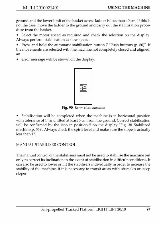
USING THE MACHINE
97
MULL2010021401
Self‐propelled Tracked Platform LIGHT LIFT 20.10
ground and the lower limit of the basket access ladder is less than 40 cm. If this isnot the case, move the ladder to the ground and carry out the stabilisation proce‐dure from the basket.• Select the motor speed as required and check the selection on the display.Always perform stabilisation at slow speed.• Press and hold the automatic stabilisation button 7 ʺPush buttons (p. 60)ʺ. Ifthe movements are selected with the machine not completely closed and aligned,an• error message will be shown on the display.
• Stabilisation will be completed when the machine is in horizontal positionwith tolerance of 1° and lifted at least 5 cm from the ground. Correct stabilisationwill be confirmed by the icon in position 5 on the display ʺFig. 38 Stabilizedmachine(p. 55)ʺ. Always check the spirit level and make sure the slope is actuallyless than 1°.
MANUAL STABILISER CONTROL
The manual control of the stabilisers must not be used to stabilise the machine butonly to correct its inclination in the event of stabilisation in difficult conditions. Itcan also be used to lower or lift the stabilisers individually in order to increase thestability of the machine, if it is necessary to transit areas with obstacles or steepslopes.
Fig. 90 Error close machine

98 Self‐propelled Tracked Platform LIGHT LIFT 20.10
USING THE MACHINE MULL2010021401
Pressing the button once shows the screen for the manual operation of stabiliser1, pressing it a second time shows the screen for stabiliser 2 and so on until stabi‐liser 4. Pressing it once again shows the initial display. In the manual menu, pres‐sing buttons 1 and 7 raises or lowers the selected stabiliser. To verify theinclination of the chassis a spirit level is provided on the machine; when the airbubble it contains is completely inside the green area (see photo below) the ma‐chine is in conditions that allow operation.Please note that stabilize the machine on slopes greater than allowable limits (seetechnical data of the machine ̋ Technical data (p. 18)ʺ) does not permit correct sta‐bilization and is a serious danger for users.On each stabiliser (see photo below), near the cylinder coupling, there is an oran‐ge light. This light flashes to indicate that the stabiliser is resting on the ground.An electronic level on the electronic control board checks that the machine iseffectively levelled within the allowable tolerance and enables the movementsof the aerial part.
Fig. 91 Manual stabiliser selection
Fig. 92 Visible spirit level Fig. 93 Indicator light plate on the ground

USING THE MACHINE
99
MULL2010021401
Self‐propelled Tracked Platform LIGHT LIFT 20.10
11.4.10.Automatic lowering and raising of the stabilisersThe elevating platform is fitted with an innovative automatic levelling procedurethat acts on the stabilisers and uses the electronic spirit level provided on themain control board. For the self‐levelling procedure, all the precautions describedto this point apply. Before starting the self‐stabilization make sure that the machi‐ne is on a slope less than the total permitted limit for stabilization ʺTechnical data(p. 18)ʺ and verify that the trajectory of the stabilizers is free of obstacles and im‐pediments.
It is important to remind that when the stabilisers are lowered thecarriage must always be raised from the ground.
After using the manual stabiliser control, remember to pressurise thebottom of the stabiliser cylinders. To do this, run an auto‐stabilisa‐tion cycle or lower each stabiliser for one second.
Incorrect machine stabilisation does not ensure suitable stability toperform operations. The Constructor prohibits the use of the machineif it is not stabilised as described in this manual; the machine over‐turning may cause serious injury to or even death of its occupantsand personnel on the ground.
If one of the orange lights positioned on each stabiliser should flash evenwhen the stabiliser is lifted from the ground, stop the machine immediatelyand call the after‐sales service as this signals the breakage of the correspon‐ding stabiliser micro switch.
If working with the machine stabilised on slippery surfaces (marble,porphyry, polished cement, smooth damp surfaces etc.) check that themovements of the basket do not cause the tracks to move. If so, stopthe operations and restore the safe operating conditions prescribedby the manufacturer.Make sure that the stabilisers rest on horizontal ground.DO NOT REST THE STABILISERS ON VERTICAL OR INCLINEDSURFACES.]

100 Self‐propelled Tracked Platform LIGHT LIFT 20.10
USING THE MACHINE MULL2010021401
AUTOMATIC LOWERING OF THE STABILISERS
The success of the self‐levelling procedure is confirmed by an icon displayed onthe screen for several seconds.
If the self‐stabilization procedure has not been completed and the OK messagehas not appeared on the display it will not be possible to move the aerial part ofthe machine and at every attempt to do it an error message will appear: AUTO‐STAB NO. Repeat the Self‐stabilization operation to enable movements.After the end of the procedure, always control that the spirit level is in the gre‐en zone. If this does not occur contact the after sales service.If during lowering one of the stabilisers does not touch the ground, the machinewill continue to operate the cylinder at the end of its stroke until the motor swi‐tches off or the self‐levelling procedure ends. This situation is normal and indica‐tes that the slope the machine is situated on exceeds the allowable limit for
The automatic procedure for levelling the machine extends and re‐tracts the stabilisers, and consequently moves the machine. Alwayscheck that there are no people, animals or things in the stabilisationarea.
Press and hold button 7 on the remote control.
Fig. 94 Auto‐Stabilization completed successfully

USING THE MACHINE
101
MULL2010021401
Self‐propelled Tracked Platform LIGHT LIFT 20.10
stabilisation. If at the end of the stabilisation phase the machine has to be liftedeven further from the ground, a new self‐levelling procedure can be run.
AUTOMATIC RAISING OF THE STABILISERS
The four stabilisers will start to lower the machine and then will retract comple‐tely. The automatic stabiliser raising procedure can still be considered completedonce all the four stabilisers have been completely retracted and consequently therelevant cylinders are at the end of their stroke.
11.4.11.Track extensionTo adjust the track gauge, proceed as follows:
Using the self‐levelling procedure does not affect the operation of the stabilisers inmanual mode.
Press and hold button 1 on the remote control.
If problems occur during either of these procedures, immediately release theselected button to stop all the movements. Stabilising the machine on a slopeexceeding the allowed limits may cause instability and consequently harm toor even death of operators or other persons in and around the working area.Work must only be performed with the machine stabilised at an inclinationunder the limits specified by the manufacturer.
The elevating platform is considered stabilised when the slope is lessthan 1° and the tracks are raised at least 5 cm from the ground. Neverwork at a height with the tracks not completely raised from theground.

102 Self‐propelled Tracked Platform LIGHT LIFT 20.10
USING THE MACHINE MULL2010021401
Press and hold button 3 on the remote control for extend the track.
Press and hold button 9 on the remote control for narrow the track.
The track extension operations should be performed with the machine stabilisedand lifted from the ground. If this is not possible, perform the extension operationswith the tracks moving.

USING THE MACHINE
103
MULL2010021401
Self‐propelled Tracked Platform LIGHT LIFT 20.10
11.4.12.Moving the basketOnce the machine has been stabilised correctly, check the icon in pos. 5 ʺFig.38 Stabilized machine(p. 55)ʺ, the basket can be moved.
It is prohibited to load material of any type into the basket if the machine is notstabilised and completely closed. To load and unload the basket the icon in po‐sition 6 on the remote control must be displayed ̋ Fig. 41 Aerial part closed andaligned(p. 56)ʺ. Loading material into the basket when it is lifted (e.g. from ro‐ofs, balconies etc.) causes the machine to overturn, exposing the occupants andpersonnel on the ground to potential risk of death.It is absolutely forbidden to use the machine to lift loads both in the basket andconnected in other way to the structure; the machine can lift two persons andtheir tools. See ʺTechnical data (p. 18)ʺ for data related to the admitted load onbasket.During machine lowering, near where the upper arms rest on the lower ones, apotential shearing risk is created, appropriately signalled by stickers; it is theuserʹs responsibility to move any persons away from this area.
Pay maximum attention to obstacles that may collide with the various parts ofthe machine during movement. Before carrying out ANY movement, makesure that nothing can interfere with ANY part of the machine (branches, pro‐truding parts of buildings, etc.).It is prohibited to introduce objects into the basket that provide high resistanceto wind pressure (e.g. large signs) even if they are within the machineʹs capaci‐ty limits.
DANGER
Fig. 95 Example potential shearing risk zone 1
Fig. 96 Example potential shearing risk zone 2
Fig. 97 Example potential shearing risk zone 3

104 Self‐propelled Tracked Platform LIGHT LIFT 20.10
USING THE MACHINE MULL2010021401
PROCEDURE FOR ROUTINE MOVEMENT OF THE AERIAL PART
a Before moving the aerial part, make sure that:– All instructions provided in this chapter have been complied with.– There are no obstacles in the work area.– All the conditions necessary for working at a height are met.– The machine is stabilised and levelled: icon 5 shown on the display.– The weight in the basket is below the maximum allowed.– The remote control is positioned in the basket.– The basket access ladder has been folded into the raised position so as not
to risk contact during movement of the aerial part.b The aerial part can ONLY be moved from the control position in the basket.c Select the motor speed as required and check the selection on the display.d Use joysticks on the remote control to move the aerial part as described in theparagraph regarding the description of the controls ʺJoystick (p. 58)ʺ.e If the movements are selected when one of the conditions listed above is notsatisfied, an error message will be shown on the display indicating what condi‐tions are OK and what are not satisfied (FAIL). If the missing condition is stabili‐sation, the message will also indicate what stabiliser is not resting on the ground.
ST1: if OK stabiliser 1 is resting on thegroundST2: if OK stabiliser 2 is resting on thegroundST3: if OK stabiliser 3 is resting on thegroundST4: if OK stabiliser 4 is resting on thegroundINLC: if OK the machine is under themaximum inclination limitLOAD: if OK, the load is less than themaximum working load allowedBASKET: if OK the remote control is inplace in the basketPEDAL: if OK the foot switch is pushed
Fig. 98 Error machine not stabilised

USING THE MACHINE
105
MULL2010021401
Self‐propelled Tracked Platform LIGHT LIFT 20.10
OVERLOAD ALARM
If during the basket loading phases the max allowable load is exceeded based onthe position of the JIB boom, all movements of the aerial part will be disabled andan error message will be shown on the display, first on the entire screen and thenin position 5.
The alarm will only be reset when the overload is removed. Normal machine ope‐ration can be resumed only then.
BASKET LIFTING ALARM
If when using the machine at a height, for whatever reason, the basket is liftedfrom its position on the load sensor, an alarm prevents all movements of the ma‐chine and the display on the remote control shows an error message.
The alarm is reset only when the basket is fitted back on the load sensor.
Fig. 99 Overload alarm Fig. 100 Overload
Fig. 101 Basket lifting alarm

106 Self‐propelled Tracked Platform LIGHT LIFT 20.10
USING THE MACHINE MULL2010021401
ROTATION WITH1°‐2° BOOM FOLDED AND 1°‐2° BOOM DESCENT ON THE THERMIC/LITHIUM ENGINE
If the turret is rotated with the first or second boom folded or nearly folded, thereis the risk of the first boom hitting against the engine / battery pack. For this rea‐son, free rotation areas and limited rotation areas are defined. When using themachine from the remote control is not possible to enter in the limited rotationarea. If you arrive in the vicinity of one of these areas the movement in progresswill be blocked and a message will appear on the remote display that indicatesthe possible movements in this situation, which allow you to go back in a zone offree rotation.• LIMITED ROTATION AREA: is an area near the engine / battery pack wherethis may be hit by the first boom.• FREE ROTATION AREA: is the rest of the rotation area that does not coincidewith the limited rotation area.These two areas are identified through the combined control of two sensors: a mi‐cro switch that verifies the height of the first and second arm, and a proximityswitch mounted inside the turntable that senses the position of the turret while itturns.
11.4.13.Manually levelling of the basketThe platform has an automatic levelling device for the cage. This device has beendesigned in a way that the floor of the basket remains always parallel with theground independently from the movements of the platform booms.
Fig. 102 1° boom micro switch Fig. 103 Proximity sensor

USING THE MACHINE
107
MULL2010021401
Self‐propelled Tracked Platform LIGHT LIFT 20.10
However, due to causes deriving from leaks and malfunctioning, it may be neces‐sary to operate manually to take the basket to the optimal position. Act as followsto make this adjustment:• try to take the basket to the traversing position by closing the extendablestructure completely (this, only if the problem was met while the basket was at ahigh position);
• only carry out this operation if no basket levelling exceeds 10°. If this is not thecase carry out manual levelling at minimum height possible, compatibly with thelimit of 10°. The minimum height is reached by completely closing 1° and 2° bo‐om, extension, jib and when possible the 3° boom;• introduce the key into the relevant slot in the remote control;
Fig. 104 Levelling basket key

108 Self‐propelled Tracked Platform LIGHT LIFT 20.10
USING THE MACHINE MULL2010021401
• Rotate the key in the direction related to the necessary movement;
levelling of the basket is only envisioned as an exceptional manoeu‐vre in the case of slight malfunctioning of automatic levelling, there‐fore if the problem should be repeated frequently, have the basketchecked by an authorised workshop;
the manual levelling control is only allowed from the basket, withthe extendible structure completely closed and aligned. Differently,the operator could be seriously injured by contact with moving ma‐chine parts;
it is prohibited to use the levelling manoeuvre for different aims thanthose described (e.g. to lift objects, too increase the working reach ofthe platform etc.), similar use could cause serious even fatal acciden‐ts.

USING THE MACHINE
109
MULL2010021401
Self‐propelled Tracked Platform LIGHT LIFT 20.10
11.5.AERIAL PART EMERGENCY MANOEUVRES
The machine has been designed also considering possible emergency situationssuch as mechanical and electrical breakdown, sudden indisposition of the opera‐tor etc. In all of these cases interventions can be made on the machine from thebasket and from the ground in a way to take the machine back to the transportconfiguration or however into a way to be able to rescue the occupant/s from thebasket. The intervention procedures are given below.
11.5.1.Activation of emergency descent from the basketThe emergency descent procedure of the basket can be actuated from the basketitself only if the machine electric plant is not compromised; act in the followingway:
Remember that the presence of staff on the ground is mandatory du‐ring platform functioning.
The manoeuvres described below must be performed in SEQUENCEstarting from the first paragraph and passing to the next ones till thelast one only if the emergency manoeuvre that is being performed isnot functioning.
1 Hold down button 4 onthe remote control
Fig. 105 Remote control

110 Self‐propelled Tracked Platform LIGHT LIFT 20.10
USING THE MACHINE MULL2010021401
As descent is due to gravity, the platform and basket cannot be rotated and thetelescopic boom cannot be extended or retracted, therefore the basket is loweredvertically at a distance from the centre of rotation that depends on the configura‐tion of the machine at the time when the emergency situation occurred.
2 Check the control bymeans of icon 8 on thedisplay
Fig. 106 Display icons
3 Activate the joystick re‐lative to the arm that isto be closed until the de‐sired height is reachedand release the button 4
Fig. 107 Joystick controls
If a joystick corresponding to a move‐ment without emergency descent, isactivated an error icon will be shownon the display that disappear when thejoystick is released.
1 2 543
9
876A
B

USING THE MACHINE
111
MULL2010021401
Self‐propelled Tracked Platform LIGHT LIFT 20.10
11.5.2.Operating the machine from the emergency control position on the ground if the operator is taken ill
This function is only used if the operator in the basket becomes suddenly ill andunable to perform ordinary movements and the emergency descent of the basket.
For information on the controls in the emergency position, see the paragraphʺEmergency position controls (p. 71)ʺ
The sole purpose of the emergency descent from the ground is to operate inthe event of system breakdown and to bring the basket to the ground, allother uses are prohibited.
1 Withdraw the keyenabling the emergencydescent and a key ope‐ning the distributor con‐trolsʹ protection, if any,from the engine keysgroup inside the electri‐cal components com‐partment.
Fig. 108 Emergency key location
2 Insert the key to openthe distributorʹs controlsprotection and accessthe controls.
Fig. 109 Aerial part distributor protection

112 Self‐propelled Tracked Platform LIGHT LIFT 20.10
USING THE MACHINE MULL2010021401
3 Operate on the enablingselector in the controlpanel of the emergencyposition, rotating itclockwise and keeping itin position (in the Li‐thium version this startsthe engine). Start themotor using the corre‐sponding button in caseof Petrol/Diesel version.If the switch needs keyto be operated withdrawit from the engine keysgroup.
Fig. 110 Emergency control panel switch and buttons
4 Make sure that the greenindicator light on theemergency position con‐trol panel comes on, i.e.that the conditions ne‐cessary to be able tomove the aerial part aresatisfied.
Fig. 111 Emergency control panel lamp

USING THE MACHINE
113
MULL2010021401
Self‐propelled Tracked Platform LIGHT LIFT 20.10
When the operators and the machine are in safety condition close the protectionand put the keys back in their original position.
5 Move the aerial part ofthe machine using themanual levers positio‐ned on the distributoron the ground as descri‐bed on the decal placednear them and as speci‐fied in this manual ʺAe‐rial part hydraulicdistributor (p. 73)ʺ.
Fig. 112 Aerial part distributor controls

114 Self‐propelled Tracked Platform LIGHT LIFT 20.10
USING THE MACHINE MULL2010021401
11.5.3.Emergency descent in the case where the stabilisers are accidentally re‐tracted
While it is recommended to follow the instructions provided in the paragraph onstabilising the machine, for various reasons one of the stabilisers may lose contactwith the ground, thus changing the angle of the machine or causing a foot plateto lift from the ground. If this occurs when the machine is at a height, movementsare stopped and disabled immediately. To restore operation of the platform (closethe aerial part and then stabilise the machine again) the electrical emergency de‐scent function can be used, which involves only the return of the aerial part. If thisis not possible due to the presence of objects that interfere with the operation, per‐sonnel on the ground can allow the operator in the basket to close the machine.The operators on the ground can bypass the machineʹs safety devices and allowthe operator in the basket to close the machine or allow the manual operations asdescribed in the previous paragraphs, in order to bring the operator back to theground.
Proceed as follows:
Read the instructions provided below before performing the opera‐tion as it is potentially dangerous for the operator in the basket.
1 Open the electrical com‐ponents compartment.
Fig. 113 Electric box

USING THE MACHINE
115
MULL2010021401
Self‐propelled Tracked Platform LIGHT LIFT 20.10
The display on the remote control shows the safety device BY‐PASS icon.
2 Position the emergencykey on the electricalcomponents compart‐ment, removing it fromthe side where this is le‐ad‐sealed
Fig. 114 Emergency key location
3 Turn the emergency keyanticlockwise and holdit in position
Fig. 115 Emergency BY‐PASS decal
Fig. 116 Emergency BY‐PASS icon Fig. 117 Emergency BY‐PASS activated

116 Self‐propelled Tracked Platform LIGHT LIFT 20.10
USING THE MACHINE MULL2010021401
When the operators and the machine are in safety condition release the key, re‐move it and put it back in its original position.
Control the machine with the remote control ONLY carrying out operationsthat allow the machine to be closed: first/second boom folding, extensionboom in, JIB boom folding. The third boom can be rotated and lowered onlywith the extension boom completely retracted. Do not carry out any opera‐tions other than those listed or operations than may affect the stability of themachine. The arm movement sequence must be carried out in such a way asto avoid any operation that may affect the stability of the machine.
The electronic control board records every time the safety device by‐pass key isused.

USING THE MACHINE
117
MULL2010021401
Self‐propelled Tracked Platform LIGHT LIFT 20.10
11.5.4.Emergency descent controlled from the ground using the hand pump in the event of faults on all energy supply systems
This emergency descent function is only used if the electrical system and motorsbreak down, meaning one of the previous emergency operations cannot be per‐formed.
The emergency descent from the ground can only be carried out using the hy‐draulic hand pump; to move the basket, pump oil manually and simultaneouslyuse the ground controls for the arm movements.
To perform the emergency descent in the conditions described above, proceed asfollows:
The sole purpose of the emergency descent from the ground is to operate inthe event of system breakdown and to bring the basket to the ground, allother uses are prohibited.
During this procedure it is prohibited to perform any operations other thanthose described above, for example to extend the telescopic arm or the jib arm,to move the stabilisers and generally to perform operations that may causethe machine to lose stability.
1 Position on OFF the en‐gine key and disconnectcompletely the machinefrom the battery remo‐ving the battery cut‐off.
Fig. 118 Battery cut out switch

118 Self‐propelled Tracked Platform LIGHT LIFT 20.10
USING THE MACHINE MULL2010021401
2 Remove the hand pumpprotection cover,whether there is. Movethe manual selector lo‐cated on the hand pumpto the position corre‐sponding to movementof the aerial part.
Fig. 119 Hand pump manual selector
3 Withdraw the keyenabling the emergencydescent and a key ope‐ning the distributor con‐trolsʹ protection, if any,from the engine keysgroup inside the electri‐cal components com‐partment.
Fig. 120 Emergency key location
4 Insert the key to openthe distributorʹs controlsprotection and accessthe controls.
Fig. 121 Aerial part distributor protection

USING THE MACHINE
119
MULL2010021401
Self‐propelled Tracked Platform LIGHT LIFT 20.10
At the end of the emergency operation close the protection, remove the key andput it back in its original position. Remove the hand pump lever and put it backin its original position.
5 Activate the valveenabling knob.
Fig. 122 Knob proportional valve aerial part enable
6 Use the levers and/orbuttons correspondingto the ON‐OFF coils ac‐cessible from the bottomof the distributor pro‐tection so as toenable the required mo‐vement, following theinstructions on the sti‐cker positioned near thecontrols ʺAerial part hy‐draulic distributor(p. 73)ʺ and at the sametime operate the handpump to obtain the mo‐vement. The sequence ofmovements is the fol‐lowing:‐ retract extension boom‐ fold JIB boom‐ fold first‐second boom‐ fold third boom.
Fig. 123 Aerial part distributor controls

120 Self‐propelled Tracked Platform LIGHT LIFT 20.10
USING THE MACHINE MULL2010021401
If this device has been used to move the machine, before using the machineagain to work at a height it is compulsory to set it in the transport configura‐tion (machine closed and aligned), to raise the stabilisers and lower themagain. Only then it will be possible to work with the machine at a height con‐trolling it from the basket.
It is prohibited to release the aerial part proportional valve from therest position with the motor running. This operation would be veryrisky for the safety of the operator on the platform.

USING THE MACHINE
121
MULL2010021401
Self‐propelled Tracked Platform LIGHT LIFT 20.10
11.5.5.Emergency operation of the undercarriage in the event of movements of the aerial part
During transport, the aerial part of the machine may turn, consequently beco‐ming misaligned. If this occurs, one of the two EMERGENCY PROCEDURES de‐scribed below can be applied:
11.5.5.1.Machine realignment
The manoeuvre described below must be carried out only and exclusively withthe machine closed.
1 Open the electrical com‐ponents compartment.
Fig. 124 Electric box
2 Place the emergency keyon the electrical compo‐nents compartment, re‐moving it from themachineʹs key holder,where it is sealed withlead;
Fig. 125 Emergency key location

122 Self‐propelled Tracked Platform LIGHT LIFT 20.10
USING THE MACHINE MULL2010021401
The display on the remote control shows the safety device BYPASS icon.
Once the machine has been aligned, release the key, remove it, put it back in itsoriginal position and close the electrical components compartment.
11.5.5.2.Moving the undercarriage with the machine not aligned
3 Turn the emergency keyanticlockwise and holdit in position;
Fig. 126 Emergency BY‐PASS decals
Fig. 127 Emergency BY‐PASS icon Fig. 128 Emergency BY‐PASS activated
Realign the machine, controlling it from the basket by means of theremote control.Perform exclusively the rotation manoeuvre.]
Operation allowed only to reach the conditions necessary to perform the proce‐dure described in the ʺMachine realignment (p. 121)ʺ. Any other use is prohibi‐ted.

USING THE MACHINE
123
MULL2010021401
Self‐propelled Tracked Platform LIGHT LIFT 20.10
The display on the remote control shows the safety device BYPASS icon.
1 Open the electrical com‐ponents compartment;
Fig. 129 Electrical box
2 Place the emergency keyon the electrical compo‐nents compartment, re‐moving it from themachineʹs key holder,where it is sealed withlead;
Fig. 130 Emergency key location
3 Turn the emergency keyclockwise and hold it inposition;
Fig. 131 Emergency BY‐PASS decals

124 Self‐propelled Tracked Platform LIGHT LIFT 20.10
USING THE MACHINE MULL2010021401
At the end of the operation release the key, remove it, put it back in its originalposition and close the electrical components compartment.
Fig. 132 Emergency BY‐PASS icon Fig. 133 Emergency BY‐PASS actived
Use the travel control with extreme care to avoid causing damage tothe machine or people. Move to a suitable position for carrying outprocedure described in ʺMachine realignment (p. 121)ʺ, used to reali‐gn the machine.
The electronic control board records every time the safety device bypass key is used.

USING THE MACHINE
125
MULL2010021401
Self‐propelled Tracked Platform LIGHT LIFT 20.10
11.5.6.Emergency operations on the carriage: moving the platform stabilisers using the hand pump to allow the machine to be transported
To raise the stabilisers from the ground in order to be able to transport the machi‐ne, proceed as follows:
The hydraulic hand pump can be used to move the stabilisers and set the ma‐chine in the transport configuration only after closing completely the aerial partof the platform.
1 Place the emergency keyon the electrical compo‐nents compartment, re‐moving it from themachineʹs key holder,where it is sealed withlead;
Fig. 134 Battery cut‐out
2 Check that the machineis completely closed andaligned;
Fig. 135 Machine closed and aligned

126 Self‐propelled Tracked Platform LIGHT LIFT 20.10
USING THE MACHINE MULL2010021401
3 Remove the hand pumpprotection cover,whether there is. Movethe manual selector lo‐cated on the hand pumpto the position corre‐sponding to side of ma‐chine to move (right orleft);
Fig. 136 Hand pump manual selector
4 Manually switch the ae‐rial‐tracked part switchvia the fuse in the centreof the magnet using thecorresponding handwheel;
Fig. 137 Aerial‐tracked part switch
5 Activate one of the pro‐portional valve moun‐ted on the twodistributors through theproper devices;
Fig. 138 Knob proportional valve

USING THE MACHINE
127
MULL2010021401
Self‐propelled Tracked Platform LIGHT LIFT 20.10
At the end of these emergency operations, close all the protection covers, fully un‐screw the knob of the aerial part/undercarriage part switch and proportional val‐ve and put the hand pump handle in the original position.
6 While keeping operatedthe proportional valveuse the ON‐OFF coil le‐vers and buttons toenable the required mo‐vement ʺTracked under‐carriage hydraulicdistributor (p. 76)ʺ;
Fig. 139 Example distributor controls
7 Simultaneously operatethe hand pump to deli‐ver oil to allow the mo‐vement;
Fig. 140 Hand pump

128 Self‐propelled Tracked Platform LIGHT LIFT 20.10
USING THE MACHINE MULL2010021401
11.6.ELECTRICAL CONNECTION OF REMOTE CONTROL
• Disconnect the cable from the remote control using the corresponding screwconnection.
• Make sure there is no moisture in the remote control connector and close theremote control sealing plug.• Make sure there is no moisture in the electric cable connector and close theelectric cable sealing plug.• To reconnect the remote control, follow the same process in the reverse order.
The electrical disconnection/connection of the remote control MUST be car‐ried out exclusively with the motor key in position OFF and with the mainspower disconnected.
Fig. 141 Remote control connection

USING THE MACHINE
129
MULL2010021401
Self‐propelled Tracked Platform LIGHT LIFT 20.10
11.7.RECHARGING THE BATTERY
11.7.1.Battery charging Petrol/Diesel engineThe machine is equipped with a charging system of the battery. Using the Petrol/Diesel engine to a regime of revolutions exceeding 2200rpm the battery is rechar‐ged by the current generator. There is also the possibility of recharging the bat‐tery by the power supply.To do this, proceed as follows:• Check that the battery cut‐out is connected.• Power the machine by an electric cable connecting it to the socket on the chas‐sis near the electric motor and activate the main supply switch in the control ca‐binet of the motor.
• In this condition the battery charger mounted on the machine recharges thebattery.
both connectors must be closed with the respective sealing plugs to preventmoisture from entering.
Fig. 142 Main supply socket Fig. 143 Main supply switch
Recharging battery must be carried out in an ventilated area awayfrom open flames or sources of ignition. In order not to cause damageto the battery is appropriate to recharge the same only when the am‐bient temperature is between 0 and 40 ° C

130 Self‐propelled Tracked Platform LIGHT LIFT 20.10
USING THE MACHINE MULL2010021401
11.7.2.Charging Lithium batteriesTo check the battery charge, always use the special indicator shown on the di‐splay on the remote control ʺDisplay (p. 54)ʺ. The batteries can be recharged evenwhen using the machine (obviously the recharging times in this case will be lon‐ger). The batteries can be recharged even when they are not completely down.If the charge is less than 20% an audible warning signal will be activated whene‐ver the electric motor is started, to warn the user to charge the machine. If thecharge is less than 10%, in addition to the audible warning signal, reduced speedis activated and an icon comes on in position 4 ʺFig. 37 Reduced(p. 55)ʺ.
To start recharging the battery simply connect the main power supply to thesocket and close the circuit breaker.
During charging, the machine must be continuously monitored bytrained personnel.Do not leave the machine in continuous charging for time periodsexceeding 24 hours. Pay attention, the charger works even if the electronic board of themachine is turned off. So the batteries can be charging even if the re‐mote control is off.Charge the machine using only the battery charger installed on it. Theuse of a charger other than that provided voids any kind of warrantyon batteries and can cause damage to people or things
The battery charging from power supply works even if the machine is working withthe electric motor running. Obviously the more features you use, the smaller theenergy the charger will be able to provide to the battery. Consequently, the char‐ging will be less efficient.
During charging, the machine must be continuously monitored bytrained personnel.Do not leave the machine in continuous charging for time periodsexceeding 24 hours. Pay attention, the charger works even if theelectronic board of the machine is turned off. So the batteries can becharging even if the remote control is off.Charge the machine using only the battery charger installed on it. Theuse of a charger other than that provided voids any kind of warrantyon batteries and can cause damage to people or things

USING THE MACHINE
131
MULL2010021401
Self‐propelled Tracked Platform LIGHT LIFT 20.10
Is also possible check the battery charging through the charge indicator locatednear the battery pack.
Fig. 144 Main supply socket Fig. 145 Main supply switch
If the machine is on, the display on the remote control also shows themachine recharge indicator.

132 Self‐propelled Tracked Platform LIGHT LIFT 20.10
USING THE MACHINE MULL2010021401
Fig. 146 Charging indicator
The battery charger features just one charge curve (IUIa) plus balan‐cing and maintenance, designed specially for recharging the batterypack of the elevating platform.RED LED indicates that the battery is in the initial charging phase.YELLOW LED indicates that the battery has reached 80% of rechar‐ge.GREEN LED, staggered with red flashings, indicates that battery re‐ached the balance/maintenance phase.
The battery charger supplied with the elevating platform was desi‐gned to ensure safety and reliable performance. It is already fitted onthe machine and does not need any adjustment or configuration bythe user; nonetheless, to avoid injury and damage to the battery char‐ger, the following essential precautions should be observed.

USING THE MACHINE
133
MULL2010021401
Self‐propelled Tracked Platform LIGHT LIFT 20.10
• Carefully read the installation instructions contained in this manual. For futu‐re reference, keep the manual in a safe place.• Do not place the battery charger near sources of heat.• As the battery charger is sealed and without forced ventilation, its performan‐ce depends on the temperature and the type of installation.• Make sure that the type of power supply available corresponds to the voltagespecified and indicated on the battery charger rating plate or in this user and ope‐ration manual. In case of doubt, contact your reseller or the local electrical com‐pany.• An AC class circuit breaker can be used as protection device for the batterycharger power supply, however it is recommended to use a class A or class B de‐vice.• With regards to safety and electromagnetic compatibility, the battery chargerfeatures a three‐pins plug with earth, which can only be plugged into an earthedsocket. If the plug does not go into the socket, most probably the socket is old andnot earthed. In this case, contact an electrician to have the socket replaced.• Do not use adapters to resolve earth plug problems.• Make sure the power cable does not represent an obstacle. If the cable is wornor damaged, have it replaced immediately.• If extensions or multiple sockets are used, make sure that these support the to‐tal rated current.• Disconnect the power supply before connecting or disconnecting the battery.• The battery charger installed was specially designed to recharge the type of li‐thium batteries used on the platform. Do not attempt to recharge any other typeof batteries.• Do not attempt to repair the battery charger. Opening the cover may exposethe user to the risk of electric shock.• Do not open the battery charger, opening it may affect the index of protection(IP) even after it has been closed again.• If the battery charger is not working correctly or is damaged, disconnect it im‐mediately from the power outlet and the battery socket and contact an authorizedservicing entity.

134 Self‐propelled Tracked Platform LIGHT LIFT 20.10
USING THE MACHINE MULL2010021401
11.8.MAIN INTENDED USES OF THE PLATFORM
Below are the specific warnings for the most frequent uses of the machine. Theinformation provided must be considered as an addition to and not a replace‐ment for the contents of the User and Operation manual.
11.8.1.SystemsMake sure the parts where maintenance is to be performed are not live, if in doubtrequest verification from personnel on the ground. Do not operate near power li‐nes. Keep a suitable distance away based on the voltage see paragraph ʺRisk ofelectrocution (p. 79)ʺ.
11.8.2.Closed environmentsTo perform the operations in closed places the Constructor recommends the useof the machine with the electric engine. If this is not possible, make sure there isenough ventilation to prevent the accumulation of gases that are damaging to thehealth. If lighting in the workplace should be insufficient, additional lighting de‐vices must be supplied.
11.8.3.PruningThis activity requires very important skills in order to prevent the machine fromlosing stability. Remember that:• if branches or logs fall on the safety devices these will be broken;• falling plant parts may damage the machine;• falling plant parts may press the emergency button on the ground. In this casethe machine cannot be controlled and the personnel on the ground must interve‐ne;• the tools used for pruning, such as chainsaws, exert considerable forcetowards the outside of the basket edge;• it is compulsory to check in advance that the plants being pruned cannot fallon any part of the platform or the basket.
11.8.4.Repair and maintenance of roofing and guttersRemember that it is prohibited to use the platform for the transport of material ata height even if this is within the capacity limits specified by the manufacturer;the MEWP is not a lifting device. It is also very important to remember that oncethe basket has been lifted from the chassis it is prohibited to load objects. Remem‐ber that no safety device can help if the basket is overloaded at a height. Theemergency descent procedure does not prevent overturning. The only way to

USING THE MACHINE
135
MULL2010021401
Self‐propelled Tracked Platform LIGHT LIFT 20.10
make things safe is to unload the basket and return as quickly as possible withinthe allowable limits based on the work configuration.
11.8.5.Painting, sand‐blasting and plasteringThis type of use requires meticulous protection of the delicate parts of the machi‐ne such as hydraulic cylinder rods, gaskets, safety devices, hydraulic telescopicextension arms and markings on the machine (e.g. Rating plate, warning stickers,capacity table etc.). If sand enters the grease protecting the extension arms it pro‐duces an extremely abrasive mixture, affecting the quality of the movements andworking life of the machine.
11.8.6.Use in marine environmentsIf the machine is used in particularly corrosive environments and atmospheres,the formation of rust and the greasing and lubrication conditions of the movingparts must be checked more frequently than recommended by the manufacturerfor normal operating conditions. It is also good practice to protect the machine ca‐refully every time it is not used, even for short periods, by covering it to shield itagainst salt and sand carried by the wind.

136 Self‐propelled Tracked Platform LIGHT LIFT 20.10
MAINTENANCE MULL2010021401
12.MAINTENANCE
12.1.SAFETY INSTRUCTIONS FOR GREASING AND LUBRICATION
• Errors can be extremely dangerous. Before greasing or making repairs readthe user and operation manual carefully.• Handle all parts with special care. Keep hands and fingers away from conce‐aled spaces, gearing and similar. Always use approved safety devices, such asgoggles, gloves and safety footwear• Do not dispose of lubricants in the environment but rather collect and disposeof them in compliance with laws in force in the country in question.• It is prohibited to carry out any maintenance operations with the working armnot completely lowered and/or with stabilised machine.• If operations are being carried out, apply a visible sign on the control position,stating “DANGER. Do not move the machine, service in progress”.
12.1.1.Table of recommended lbrificants
ENGINE OIL (M)For the petrol/Diesel engine we recommend the use of oil with the following cha‐racteristics
OIL HYDRAULIC DRIVE MOTORS (T)For gear, we recommend the use of gear oils with EP additives viscosity class ac‐cording to ISO VG150 or SAE 80W / 90 (‐20 ° / +30 °) or SAE 85W / 140 (+ 10 ° / +45 °).
GREASE BEARING AND IDLER (G)
When lubricating the slew ring and tensioning the rubber tracks we recommendthe use of grease suitable for use in the construction equipment industry. Type EPNLGI 2 with the thickener base Soaps lithium or molybdenum disulphide.

MAINTENANCE
137
MULL2010021401
Self‐propelled Tracked Platform LIGHT LIFT 20.10
HYDRAULIC OIL (I)
* Readily biodegradable classification indicates one of the following: CO2 Con‐version > 60% per EPA 560/6‐82‐003 / CO2 Conversion > 80% per CEC‐L‐33‐A‐93.** Virtually Non‐toxic classification indicates an LC50 > 5000 per OECD 203.*** Fire Resistant classification indicates Factory Mutual Research Corp. (FMRC)Approval.
Fig. 147 Working temperatures used oil
Fig. 148 Table of oils

138 Self‐propelled Tracked Platform LIGHT LIFT 20.10
MAINTENANCE MULL2010021401
Flash point (C.O.C) for 68‐46‐32‐22: 210°C.
If the machine has been produced with biodegradable hydraulic oilin near the hydraulic tank filler cap is a decal indicating the type ofoil used and those that are compatible in the case of refilling.
When topping up or replacing hydraulic oil is recommended to use only pro‐ducts listed in this paragraph.

MAINTENANCE
139
MULL2010021401
Self‐propelled Tracked Platform LIGHT LIFT 20.10
12.1.2.Greasing points
12.1.3.Greasing the telescopic boom
Fig. 149 Greasing points diagram
Respect the greasing intervals indicated and use only the recommended lu‐bricants in order to protect pins and connections from wear.
Use a brush to apply grease onto the telescopic extension boom.

140 Self‐propelled Tracked Platform LIGHT LIFT 20.10
MAINTENANCE MULL2010021401
12.2.SAFETY INSTRUCTIONS FOR MAINTENANCE OPERATIONS
• Spare parts must correspond to the technical provisions established by theConstructor. This is guaranteed by the use of original spare parts.• Errors can be extremely dangerous. Before greasing or making repairs readthe user and operation manual carefully.• Handle all parts with special care. Keep hands and fingers away from conce‐aled spaces, gearing and similar. Always use approved safety devices, such asgoggles, gloves and safety footwear.• When working on the electrical system always wear protective goggles andremove rings, watches and any other metal jewellery. As a general rule, do notuse petrol to clean parts.• Always disconnect the batteries before working on the electrical system.• Hydraulic hoses must be correctly laid and fitted.• Tampering with the hydraulic circuit may cause serious danger during use ofthe platform.• Do not dispose of lubricants in the environment but rather collect and disposeof them in compliance with laws in force in the country in question.• Check the vehicle at least once per day or shift for any external damage (cor‐rosion, structural parts, welds). The person in charge must be informed immedia‐tely of any change observed (including functional behaviour). In this case, stopthe vehicle immediately and carry out more detailed checks.• Fluid that leaks under pressure may penetrate the skin. Always dischargepressure before removing the hydraulic hoses and tighten connections correctlybefore pressurising. Keep hands and body away from small holes and nozzleswhere high pressure liquids may be released. Use cardboard or paper to identifyleaks.• Heavy parts must be lifted using a lifting device with suitable capacity.• It is prohibited to carry out any maintenance operations with the working armnot completely lowered and/or with stabilised machine.• If operations are being carried out, apply a visible sign on the start panel, sta‐ting “DANGER. Do not move the machine, service in progress”.

MAINTENANCE
141
MULL2010021401
Self‐propelled Tracked Platform LIGHT LIFT 20.10
12.3.MAINTENANCE CONTROL POSITION WITH REMOTE CONTROL FROM THE GROUND
As a control device for maintenance, you can use the remote control in the basket(or a second remote control optional) connecting it to the appropriate seat on themachine.This type of operation is only allowed in case of machine maintenance by quali‐fied personnel.Proceed as follows to use this function:
1 If you have not already,or is not installed on themachine ask the kit touse remote control fromthe ground at an autho‐rized service.
Fig. 150 Kit use remote control from the ground
2 With the unit off (igni‐tion key to OFF), con‐nect the cable of the kitto the connector locatedin the electrical box un‐der the guard. Now con‐nect the remote to thecable service. If the kit isalready installed on themachine connect direct‐ly the remote control tothe cable service.Fig. 151 Position connector optional second remote

142 Self‐propelled Tracked Platform LIGHT LIFT 20.10
MAINTENANCE MULL2010021401
3 If you use the remotecontrol to the basket ascontrol device from theground connect the re‐mained free cable in thebasket to the connectorprovided with the optio‐nal kit to use servicefrom the ground.Otherwise, leave it con‐nected to the main re‐mote.Fig. 152 Service connector on the basket
4 Select the commandfrom the ground actingon the selector switch onthe control box. The po‐sition rotated anti‐clockwise switchenables the control sta‐tion for maintenance ifthe remote control isconnected to theground.
Fig. 153 Basket/ground selector

MAINTENANCE
143
MULL2010021401
Self‐propelled Tracked Platform LIGHT LIFT 20.10
5 Start the machine, key inthe ON position, checkthat the icons are cor‐rectly shown on the di‐splay on the remotecontrol in theground position. Nowyou can move the aerialpart of the machinethrough the remote con‐trol to the ground as gi‐ven in the paragraphsrelating to the use of themachine ʺRemote con‐trol (p. 53)ʺ.
Fig. 154 Ground remote control example visualization
The remote control from the ground allows to perform all the operations possiblewithin the safety limits if in the basket there is a load less than 50 kg. If the load inthe basket exceeds 50 kg (always within the limits of the machine load), to use theremote control from the ground hold button 8 and then activate the required mo‐vement.
It ʹabsolutely forbidden to use the remote control from the ground tomove the MEWPS if an operator is inside of the basket.

144 Self‐propelled Tracked Platform LIGHT LIFT 20.10
MAINTENANCE MULL2010021401
12.4.PERIODICAL MAINTENANCE INTERVALS
Part Opera‐tion
Before starting
As nee‐ded
10 H
50 H
100 H
250 H
500 H
1000 H
2000 H
Dry air filter
(Petrol‐Diesel)
Check, Clean
X
Replace‐ment
X
Engine oil (Pe‐trol‐Die‐
sel)
Check level
X
Replace‐ment
X* X
Engine oil filter (Diesel)
Check, Clean
X
Replace‐ment
X
Fuel fil‐ter (Die‐
sel)
Clean X
Replace‐ment
X
Coolin sistem (Diesel, if fitted)
Check level
X
Liquid add and replace‐ment
X
Water separa‐tor (Die‐
sel)
Clean and drai‐
ning wa‐ter
X X* X
Coppa motore (Benzi‐na)
Clean X

MAINTENANCE
145
MULL2010021401
Self‐propelled Tracked Platform LIGHT LIFT 20.10
Fuel tank and net (Ben‐zina)
Clean X
Hydrau‐lic oil
Check level
X
Replace‐ment
X
Hydrau‐lic oil fil‐
ter
Replace‐ment cartrid‐
ge
X* X
Articu‐lated joint points
Grea‐sing
X* X
Battery Check X
Re‐duction gear oil
Check level
X
Replace‐ment
X* X
Machine General periodic check
X X*
Exten‐sion arm internal sliding ring (if fitted)
Check wear
X
Replace‐ment
X
Part Opera‐tion
Before starting
As nee‐ded
10 H
50 H
100 H
250 H
500 H
1000 H
2000 H

146 Self‐propelled Tracked Platform LIGHT LIFT 20.10
MAINTENANCE MULL2010021401
* First operation.** At least every 3 months.*** At least every 5 years. Anyway every year. If the tightening is not correct replace the nuts with two newwith the same specifications and restore the connection without using oil or gre‐ase.As regards complete service of the engine, see the manual supplied by the enginemanufacturer or download it from the website:www.honda‐engines‐eu.comwww.perkins.com
12.5.ELECTRIC MOTOR MAINTENANCE
The electric motor is located under a protection cover on the chassis of the machi‐ne.
Turn‐table bolt ti‐ghte‐ning
Check X* X
Nut fixing pins basket
Check torque 200 Nm
X
Exten‐sion ro‐pes and pulleys (if fitted)
Check wear
X** X*
Replace‐ment
X***
Part Opera‐tion
Before starting
As nee‐ded
10 H
50 H
100 H
250 H
500 H
1000 H
2000 H

MAINTENANCE
147
MULL2010021401
Self‐propelled Tracked Platform LIGHT LIFT 20.10
Periodically check the condition of the following electric motor components.• POWER SUPPLY TERMINALS• Check tightness of the nuts on the power supply terminals and make sure theinsulation is intact.• FAN• Keep air intakes clean and make sure the fan can rotate freely.• BEARINGS• Check the condition of the bearings, in the event of noise contact service de‐partment for replacement, as the life of the bearings is reduced significantly in he‐avy duty operating conditions.
Fig. 155 Electric motor location
in the Lithium version the motor is “brushless” therefore no brushes need to bechecked or replaced.

148 Self‐propelled Tracked Platform LIGHT LIFT 20.10
MAINTENANCE MULL2010021401
12.6.INSPECTION AND MAINTENANCE INTERVALS
All aerial platforms must be inspected, tested and serviced according to the fol‐lowing instructions. See the user and operation manual for the complete list of re‐commended inspection intervals and the correct checking and servicingprocedures.
12.6.1.A‐ Daily inspections before startingAll the components that have a direct influence on the safe operation of the aerialplatform and whose conditions may change from day to day must be visually in‐spected by the operator on a daily basis.The following must be regularly inspected and must also be checked during ope‐ration and between regular inspection intervals:1 Level of all fluids, such as fuel, engine oil, coolant and battery fluid.2 Hydraulic hoses for leaks or loose connections.3 All quick disconnection hoses for proper connection.4 Structural components for obvious damage, broken parts, and cracks in
welds.5 Ladder or steps for damage and debris (ladders must be firmly secured to the
platform).6 Operating and emergency controls for proper functioning.7 Placards and warning signs for cleanliness, readability of control signs, rated
capacity, and operating manual.8 Platform assembly for loose and missing parts, missing or loose lock pins and
bolts.9 Platform base for structural damage, holes or cracked welds, dirt, grease, or
oil that can create a hazard.10 Access ways for ease of movement.11 Protection system operation.12 Correct operation of the safety devices.13 Correct operation of elevating, rotating, and drive functions.14 Brakes.15 Stabilisers.
12.6.2.B‐ Periodical inspectionsThese inspections must be performed after 200 h of operation or every month,whichever comes first. The interval between inspections may vary depending on

MAINTENANCE
149
MULL2010021401
Self‐propelled Tracked Platform LIGHT LIFT 20.10
the aerial platformʹs applications, severity of use, and working environment. Pe‐riodical inspections must be performed by a qualified operator.These inspections must include those described in point A as well as, but not li‐mited to, the following:1 Loose bolts, nuts, and pins.2 Hydraulic oil filters for cracks and leaks, pieces of metal on the filter that may
cause pump, motor or cylinder malfunction; rubber particles on the filter thatmay indicate deterioration of hoses, o‐rings or other rubber components.
Fuel filters.3 Check belt radiator for regulation and excessive wear (diesel only).4 Hydraulic hoses for cracks, leaks and buckling, and signs of excessive abra‐
sion on all hoses and pipes.5 Hydraulic pumps and motors for cracks or leaks, leaks at joints and gaskets,
loss of operating speed, excessive heating of fluid, and loss of pressure.6 Hydraulic cylinders for drifting caused by fluid leaks across the sealing valve
or the piston, rod seal leakage, scored and damaged cylinder rods, and unu‐sual noises or vibration.
7 All safety mechanisms for wear and response time.8 Interlocks, gradient warning system, and limit switches.9 All chain and cable mechanisms for setting and worn or damaged parts.
12.6.3.C‐ Annual inspectionsThese inspections must be performed annually. A complete inspection of the ae‐rial platform must be performed by a qualified operator. Theinspection must comply with the requirements of points A and B and must inclu‐de, but not be limited to, all critical and suspect areas and all accessible structuralelements and welds, such as the following:1 Stabiliser and stabiliser housing (boxes), including the underside of the hou‐
sing.2 Platform rotating, elevating, and levelling mechanisms.3 Main turret rotating mechanism.4 Brakes.5 All secured points.6 Arm sections, pins, cylinder rods, and levelling devices.7 Switches for wiring and all electrical connections.8 The constructorʹs outstanding safety bulletins.

150 Self‐propelled Tracked Platform LIGHT LIFT 20.10
MAINTENANCE MULL2010021401
12.6.4.D‐ Structural inspectionA structural inspection is required to verify the structural soundness of criticalcomponents of the aerial platform and must be performed:1 10 years after the date of manufacture and every 5 years thereafter2 After every accident that may actually, presumably, or potentially cause da‐
mage and affect the structural soundness or stability of the aerial platform.Such accidents include short circuits, impacts, falls, collisions, or cases of over‐stress or stability failure.
3 After a change of ownership, unless a complete service history is provided, in‐cluding maintenance and inspection records.
The structural inspection must be carried out under the supervision of a profes‐sional engineer.This inspection must:1 Consider the service history of the aerial platform in terms of hours of service,
severity of use, and number and variability of users;2 Review the inspection and maintenance record of the aerial platform;3 Verify the efficiency of all operating controls;4 Perform a visual inspection of the aerial platform;5 Consider recommendations of the manufacturer regarding the aerial pla‐
tform, including manufacturerʹs safety bulletins.
12.6.5.E‐ MaintenanceBefore adjustments and repairs are started on the aerial platform, the followingprecautions must be taken:1 The power system must be stopped, and the starting devices must be rende‐
red inoperative;2 All controls must be in the OFF position and all operating systems must be se‐
cured against accidental activation by brakes, chocks or other means;3 Elevating and rotating assembly and platform must be completely lowered, if
possible, or otherwise secured by blocking or propping;4 The hydraulic oil pressure must be released from all hydraulic circuits before
loosening or removing hydraulic components;5 Safety props or latches must be installed where applicable;6 Other precautions must be adopted as specified in the user and operation ma‐
nual.

MAINTENANCE
151
MULL2010021401
Self‐propelled Tracked Platform LIGHT LIFT 20.10
12.7.GENERAL PERIODICAL CHECKS
After the first 2000 hours of operation, have a general check run on the machi‐ne, at a certified service centre, where the general condition of the machine willbe assessed and the form in Appendix 1 of this manual will be filled in. Sub‐sequent checks should be performed every 1000 hours of operation. To find thenearest certified service centre, contact your reseller.

152 Self‐propelled Tracked Platform LIGHT LIFT 20.10
MAINTENANCE MULL2010021401
12.8.MAINTENANCE ON RUBBER TRACKS
12.8.1.Rubber tracks tension checkStop the machine on a flat and solid ground. Raise the machine off the ground sa‐fely and, if needed, support it by applying stable blocks or jack stands under theundercarriage frame. In correspondence with the undercarriage central roller,measure distance ʺAʺ of the bottom of the roller to the hard internal part of therubber belt. Track tension is normal if measure ʺAʺ is between 10 and 15 mm. Ifthe tension is not within the above measure, or too tight, please follow the proce‐dure illustrated in the following paragraph.
As an alternative to the above‐mentioned procedure, you can follow the procedu‐re below. In this case, the check is less accurate and precise. However, effectivefor evaluating if the rubber track is too slack.Stop the machine on a flat and solid ground. In correspondence of the upper skidof the carriage, measure distance a of the bottom of the skid to the hard internalpart of the rubber belt, lifting the belt manually. The track tension is normal if me‐asure ʺAʺ is between 10 and 15 mm. If the tension is not within the above measu‐re, or too tight, please follow the procedure illustrated in the followingparagraph.
Fig. 156 Tensioning check 1
Fig. 157 Tensioning check 2

MAINTENANCE
153
MULL2010021401
Self‐propelled Tracked Platform LIGHT LIFT 20.10
12.8.2.Tensioning rubber track
12.8.3.Removing rubber trackStop the machine on a flat and solid ground. Raise the machine off the ground sa‐fely and, if needed, support it by applying stable blocks or jack stands under theundercarriage frame.
The grease contained in the hydraulic tracks is under pressure. If thevalve track tension is too loose, it could be expelled under the effectof the pressure of grease, seriously endangering the safety of the ope‐rator.
When gravel or mud is stuck between the sprocket teeth and track links, re‐move it before tightening the tracks.
To tighten the tracks, connect a greasegun to grease fitting 2 and add greaseuntil the track tension reaches the indi‐cated values (preferably use a pneuma‐tic pump with 100 bar operatingpressure). Before start the machine cle‐an up any grease spillage. For the choi‐ce of the type of grease to use, seeʺTable of recommended lbrificants(p. 136)ʺ.Fig. 158 Tensioning valve

154 Self‐propelled Tracked Platform LIGHT LIFT 20.10
MAINTENANCE MULL2010021401
1 To loosen the track,slowly unscrew greaserelease valve (1) coun‐ter‐clockwise for nomore than a turn. If thegrease does not startdrain, slowly rotate thetrack. If also in this casethe grease not emergesrepeat the rotation of alap of the valve and thenslowly rotate the track.Repeat these steps untilthe grease begins todrain by unscrewing thevalve of not more thanone turn at a time.
Fig. 159 Draining valve
The grease contained in the hydraulic tracks is under pressure. If thevalve track tension is too loose, it could be expelled under the effectof the pressure of grease, seriously endangering the safety of the ope‐rator.
2 Use a pry bar (4) of ade‐quate length to force atooth of the central whe‐el out of the idler, thenrotate the track slowly(5) using the pry bar tohelp it out, if necessary.Force (6) sideways to sli‐de the track and lift itfrom the idler.
Fig. 160 Removing rubber track example

MAINTENANCE
155
MULL2010021401
Self‐propelled Tracked Platform LIGHT LIFT 20.10
12.8.4.Installing rubber track1 Starting with the machine undercarriage raised in conditions of safety provi‐
ded of suitable supports stable below the undercarriage frame to support themachine.
2 Check that the grease contained in the hydraulic cylinder has been removed.3 Mesh the track links with the track teeth of sprocket wheel and place the other
end of the track on the idler.4 Rotate the drive wheel to reverse slowly (7) pushing into the frame. If neces‐
sary, help yourself with a pry bar (8), especially to “walk” the first teeth in pastthe idler.
5 Make sure that the track links are properly meshed in the sprocket and idler.6 Adjust the track tensioning ʺTensioning rubber track (p. 153)ʺ.7 Lower the undercarriage down to the ground.
12.9.CHECKING TIGHTNESS OF NUTS AND BOLTS
Depending on the use of the platform, it is essential to check the parts and thenuts and bolts which are subject to loosening. Pay particular attention to the chas‐sis components, such as idler roller, travel gear motors, sprockets and guide rol‐lers. Check that they are tightened sufficiently, according to the following table.
Before installing the rubber tracks, make sure that you are always insafe conditions with the machine suspended from the ground,
Fig. 161 Rubber track installation example

156 Self‐propelled Tracked Platform LIGHT LIFT 20.10
MAINTENANCE MULL2010021401
The values indicated are to be applied unless different instructions are givenin this manual.
Pay special attention to the screws of the stop pins, the nuts of bolts andscrews of the slew ring in both the top and the bottom.

MAINTENANCE
157
MULL2010021401
Self‐propelled Tracked Platform LIGHT LIFT 20.10

158 Self‐propelled Tracked Platform LIGHT LIFT 20.10
MAINTENANCE MULL2010021401
Siz
eTP
IB
olt D
iaTe
nsile
Stre
ss A
rea
Cla
mp
Load
See
Not
e 4
Cla
mp
Load
See
Not
e 4
InS
q In
LBIN
-LB
[N.m
]IN
-LB
[N.m
]IN
-LB
[N.m
]LB
IN-L
B
[N
.m]
IN-L
B
[N
.m]
IN-L
B
[N
.m]
440
0,11
200,
0060
448
0,11
200,
0066
16
320,
1380
0,00
909
400,
1380
0,01
015
832
0,16
400,
0140
036
0,16
400,
0147
410
240,
1900
0,01
750
320,
1900
0,02
000
51921
61341
068231
41141
2210682
8130,00052,0
024/1
71841
91461
082351
13161
9310823
4630,00052,0
82In
Sq
InLB
FT-L
B
[N
.m]
FT-L
B
[N
.m]
FT-L
B
[N
.m]
LBFT
-LB
[N.m
]FT
-LB
[N.m
]FT
-LB
[N.m
]5/
1618
0,31
250,
0524
4720
2025
2025
2025
4720
2535
2025
2025
240,
3125
0,05
8052
2025
3520
2520
2552
2025
3525
3520
253/
816
0,37
500,
0775
7000
3550
3550
3550
7000
4560
4055
3550
240,
3750
0,08
7879
0040
5540
5535
5079
0050
7045
6035
507/
1614
0,43
750,
1063
9550
6080
5575
5070
9550
7095
6590
5070
200,
4375
0,11
8710
700
6590
6080
6080
1070
080
110
7095
6080
1/2
130,
5000
0,14
1912
750
9012
085
115
8011
012
750
105
145
9513
080
110
200,
5000
0,15
9914
400
100
135
9513
090
120
1440
012
016
511
015
090
120
9/16
120,
5625
0,18
2016
400
130
175
125
170
115
155
1640
015
521
014
019
011
515
518
0,56
250,
2030
1825
014
519
513
518
513
017
518
250
170
230
155
210
130
175
5/8
110,
6250
0,22
6020
350
180
245
170
230
160
220
2035
021
028
519
026
016
022
018
0,62
500,
2560
2300
020
528
019
026
018
024
523
000
240
325
215
290
180
245
3/4
100,
7500
0,33
4030
100
320
435
300
280
380
3010
037
551
034
046
028
038
016
0,75
000,
3730
3360
035
548
533
545
531
543
033
600
420
570
380
515
315
430
7/8
90,
8750
0,46
2041
600
515
700
485
660
455
620
4160
060
582
554
574
045
562
014
0,87
500,
5090
4580
057
077
553
573
050
068
045
800
670
910
600
815
500
680
18
1,00
000,
6060
5150
073
099
568
593
064
587
551
500
860
1170
775
1055
645
875
121,
0000
0,66
3059
700
845
1150
795
1080
745
1015
5970
099
513
5589
512
1574
510
151
1/8
71,
1250
0,76
3068
700
1095
1490
1030
1400
965
1310
6870
012
9017
5511
6015
8096
513
1012
1,12
500,
8560
7700
012
2516
6511
5515
7010
8514
7577
000
1445
1965
1300
1770
1085
1475
1 1/
47
1,25
000,
9690
8720
015
4521
0014
5519
8013
6518
5587
200
1815
2470
1635
2225
1365
1855
121,
2500
1,07
3096
600
1710
2325
1610
2190
1510
2055
9660
020
1527
4018
1024
6015
1020
551
3/8
61,
3750
1,15
5010
4000
2025
2755
1905
2590
1785
2430
1040
0023
8532
4521
4529
1517
8524
3012
1,37
501,
3150
1181
0023
0031
3021
6529
4520
3027
6011
8100
2705
3680
2435
3310
2030
2760
1 1/
26
1,50
001,
4050
1265
0026
9036
6025
3034
4023
7032
2512
6500
3165
4305
2845
3870
2370
3225
121,
5000
1,58
0014
2200
3020
4105
2845
3870
2665
3625
1422
0035
5548
3532
0043
5026
6536
25
4. C
LAM
P L
OA
D L
ISTE
D F
OR
SH
CS
IS S
AM
E A
S G
RA
DE
8 O
R C
LAS
S 1
0.9
AN
D D
OE
S N
OT
RE
PR
ES
EN
T FU
LL S
TRE
NG
TH C
AP
AB
ILIT
Y O
F S
HC
S. I
F H
IGH
ER
LO
AD
IS R
EQ
UIR
ED
, AD
DIT
ION
AL
TES
TIN
G IS
RE
QU
IRE
D.
SO
CK
ET
HE
AD
CA
P S
CR
EW
S
Torq
ue(D
ry)
K =
.20
Torq
ue(L
octit
e® 2
42TM
or 2
71TM
OR
Vib
ra-T
ITE
TM11
1 or
14
0 O
R P
reco
at 8
5®K
=0.1
8
Torq
ue(L
octit
e® 2
62TM
or V
ibra
-TI
TETM
131
)
K
=0.1
5
Zin
c Y
ello
w C
hrom
ate
Fast
ener
s (R
ef 4
1507
07)*
Mag
ni C
oatin
g (R
ef 4
1507
01)*
Torq
ue(D
ry)
K =
.17
Torq
ue(L
octit
e® 2
42TM
or 2
71TM
OR
Vib
ra-T
ITE
TM11
1 or
14
0 O
R P
reco
at 8
5®K
=0.1
6
Torq
ue(L
octit
e® 2
62TM
or V
ibra
-TI
TETM
131
)
K
=0.1
5
2. A
LL T
OR
QU
E V
ALU
ES
AR
E S
TATI
C T
OR
QU
E M
EA
SU
RE
D P
ER
STA
ND
AR
D A
UD
IT M
ETH
OD
S T
OLE
RA
NC
E =
±10
% N
OTE
S: 1
. TH
ES
E T
OR
QU
E V
ALU
ES
DO
NO
T A
PP
LY T
O C
AD
MIU
M P
LATE
D F
AS
TEN
ER
S
*3. A
SS
EM
BLY
US
ES
HA
RD
EN
ED
WA
SH
ER
OR
FA
STE
NE
R IS
PLA
CE
D A
GA
INS
T P
LATE
D S
TEE
L O
R R
AW
ALU
MIN
UM
Torq
ue S
pecs

MAINTENANCE
159
MULL2010021401
Self‐propelled Tracked Platform LIGHT LIFT 20.10
Siz
eP
ITC
HTe
nsile
Stre
ssA
rea
Cla
mp
Load
Torq
ue(D
ry o
r Loc
tite®
26
3TM)
Torq
ue(L
ub)
Torq
ue(L
octit
e® 2
62TM
OR
Vib
ra-
TITE
TM13
1)
Torq
ue(L
octit
e®24
2TM o
r 271
TM
OR
Vib
ra-
TITE
TM11
1 or
14
0)
Cla
mp
Load
Torq
ue(D
ry o
r Loc
tite®
26
3TM)
K =
0.2
0
Torq
ue(L
ub O
R L
octit
e®
242TM
or 2
71TM
OR
V
ibra
-TIT
ETM
111
or
140)
K=
0.18
Torq
ue(L
octit
e® 2
62TM
OR
V
ibra
-TIT
ETM
131)
K=0
.15
Cla
mp
Load
S
ee N
ote
4
Torq
ue(D
ry o
r Loc
tite®
26
3TM)
K =
.17
Torq
ue(L
ub O
R L
octit
e®
242TM
or 2
71TM
OR
Vib
ra-T
ITE
TM
111
or 1
40)
K =
.16
Torq
ue(L
octit
e® 2
62TM
OR
Vib
ra-T
ITE
TM
131)
K =
.15
Sq
mm
KN
[N.m
][N
.m]
[N.m
][N
.m]
KN
[N.m
][N
.m]
[N.m
]kN
[N.m
][N
.m]
[N.m
]
30,
55,
032,
191,
31,
01,
21,
43,
133.
50,
66,
782,
952,
11,
61,
92,
34,
224
0,7
8,78
3,82
3,1
2,3
2,8
3,4
5,47
50,
814
,20
6,18
6,2
4,6
5,6
6,8
8,85
61
20,1
08,
7411
7,9
9,4
1212
,512
,513
1211
71
28,9
012
,618
1316
1918
,025
2319
18,0
2120
198
1,25
36,6
015
,926
1923
2822
,837
3327
22,8
3129
2710
1,5
58,0
025
,250
3845
5536
,170
6555
36,1
6158
5412
1,75
84,3
036
,788
6679
9752
,512
511
595
52,5
105
100
9514
211
550
,014
010
512
615
471
,620
018
015
071
,617
016
015
016
215
768
,321
916
419
724
197
,831
528
023
597
,826
525
023
518
2,5
192
83,5
301
226
271
331
119,
543
038
532
511
9,5
365
345
325
202,
524
510
6,5
426
320
383
469
152,
561
055
046
015
2,5
520
490
460
222,
530
313
2,0
581
436
523
639
189,
083
075
062
518
9,0
705
665
625
243
353
153,
573
755
366
381
122
2,0
1065
960
800
220,
090
084
579
027
345
919
9,5
1080
810
970
1130
286,
015
4513
9011
6028
6,0
1315
1235
1160
303,
556
124
4,0
1460
1100
1320
1530
349,
520
9518
8515
7534
9,5
1780
1680
1575
333,
569
430
2,0
1990
1490
1790
2090
432,
528
5525
7021
4043
2,5
2425
2285
2140
364
817
355,
525
6019
2023
0026
9050
9,0
3665
3300
2750
509,
031
1529
3027
5042
4,5
1120
487,
040
9030
7036
8042
9069
8,0
5865
5275
4395
698,
049
8546
9043
95
4. C
LAM
P L
OA
D L
ISTE
D F
OR
SH
CS
IS S
AM
E A
S G
RA
DE
8 O
R C
LAS
S 1
0.9
AN
D D
OE
S N
OT
RE
PR
ES
EN
T FU
LL S
TRE
NG
TH C
AP
AB
ILIT
Y O
F S
HC
S. I
F H
IGH
ER
LO
AD
IS R
EQ
UIR
ED
, AD
DIT
ION
AL
TES
TIN
G IS
RE
QU
IRE
D.
*3. A
SS
EM
BLY
US
ES
HA
RD
EN
ED
WA
SH
ER
OR
FA
STE
NE
R IS
PLA
CE
D A
GA
INS
T P
LATE
D S
TEE
L O
R R
AW
ALU
MIN
UM
Spe
c #4
1507
01V
alue
s fo
r Zin
c Y
ello
w C
hrom
ate
Fast
ener
s (R
ef 4
1507
07)
CLA
SS
10.
9 M
ETR
IC (H
EX
HE
AD
) BO
LTS
CLA
SS
10
ME
TRIC
NU
TSC
LAS
S 1
2.9
SO
CK
ET
HE
AD
CA
P S
CR
EW
S M
3 - M
5*
CLA
SS
8.8
ME
TRIC
(HE
X H
EA
D) B
OLT
SC
LAS
S 8
ME
TRIC
NU
TSC
LAS
S 1
2.9
SO
CK
ET
HE
AD
CA
P S
CR
EW
SM
6 A
ND
AB
OV
E*
NO
TES
: 1. T
HE
SE
TO
RQ
UE
VA
LUE
S D
O N
OT
AP
PLY
TO
CA
DM
IUM
PLA
TED
FA
STE
NE
RS
2. A
LL T
OR
QU
E V
ALU
ES
AR
E S
TATI
C T
OR
QU
E M
EA
SU
RE
D P
ER
STA
ND
AR
D A
UD
IT M
ETH
OD
S T
OLE
RA
NC
E =
±10
%
Torq
ue S
pecs

160 Self‐propelled Tracked Platform LIGHT LIFT 20.10
MAINTENANCE MULL2010021401
12.10.HYDRAULIC OIL LEVEL CHECK
Check the oil level on indicator; the oil must be half way up the level indicator. Ifthis is not the case, top up through the relative cap. For the characteristics of thehydraulic oil to be used see the relative paragraph ʺTable of recommended lbrifi‐cants (p. 136)ʺ.
12.11.CHECKING FOR LEAKS IN THE HYDRAULIC SYSTEM
Visually check all hoses, connections and all other components in the hydraulicsystem, in order to identify any possible leaks. Leaks from hoses can normally beresolved by tightening the fittings. Leaks from gaskets (O rings, sealing rings etc.)cannot be eliminated by simply tightening, as gaskets usually leak because theyare damaged or have become hard. The correct tightness can only be restored byreplacing the gasket.
12.12.CHECKING THE CONDITION OF THE FILTER CARTRIDGE
The cartridge must be replaced on every oil change and according to the intervalsspecified in the maintenance table.
The check must be carried out with the machine and the stabilisers in the re‐sting position on flat ground.
Fig. 162 Hydraulic oil level indicator Fig. 163 Hydraulic oil tank cap

MAINTENANCE
161
MULL2010021401
Self‐propelled Tracked Platform LIGHT LIFT 20.10
For the cartridge check follow the below instructions:1 Unscrew the cap of the filter and remove the filter cartridge.2 If it is very dirty, replace it with a new one having the same characteristics.3 Tighten cap of the filter.
12.13.CHECKING THAT ALL THE PLATES ARE PRESENT ON THE MACHI‐NE AND INTACT
Make sure that the prohibition, warning, danger and control plates positioned onthe machine are all present and visible.See the paragraph regarding decals ̋ Safety warnings (p. 29)ʺ, to identify any mis‐sing or damaged plates.
Fig. 164 Hydraulic oil filter position
It is very important to replace the cartridge for the first time after 50 opera‐ting hours, to eliminate hose and hydraulic component processing residuesfrom the hydraulic system.

162 Self‐propelled Tracked Platform LIGHT LIFT 20.10
MAINTENANCE MULL2010021401
12.14.CHECKING THE OPERATING PRESSURES IN THE HYDRAULIC SY‐STEM
1 Connect the pressure gauge to the pressure intake on the aluminium deliverymanifold block. First connect fitting upper pressure intake.
2 Go to the control position and switch the machine on.
A pressure gauge, with a minimum scale of 250 bars, must be used to carry outthis check.
Make sure that the machine is closed and in the resting position.Make sure that no one is standing within the machine operating range.All the specified checks must be carried out from the control position in thebasket.
Fig. 165 Pressure check on the machine

MAINTENANCE
163
MULL2010021401
Self‐propelled Tracked Platform LIGHT LIFT 20.10
3 Close one of the two right stabilisers completely and maintain the movementactivated. Read the pressure value. This value relates to the right track distri‐butor. Switch the machine off.
4 Connect the pressure gauge to fitting lower pressure intake.5 Go to the control position and switch the machine on.6 Close one of the two left stabilisers completely and maintain the movement
activated. Read the pressure value. This value relates to the left track distribu‐tor.
7 Stabilise the machine.8 Set the second boom cylinder to the FOLDING mode. Keep the joystick in po‐
sition. Read the pressure value. This value relates to the aerial part distributor.

164 Self‐propelled Tracked Platform LIGHT LIFT 20.10
MAINTENANCE MULL2010021401
12.15.CHECKING EXTENSION ROPES
The operations described in this paragraph must be carried out by qualified staff.It is recommended to contact an authorised centre to have the state of the pulleysand ropes by expert skilled staff. A detailed procedure is given below for the exe‐cution of the control of the state of the ropes and pulleys and for the check andany reset of the correct degree of rope tension.
12.15.1.Checking wear and deformation of ropes and pulleys
1 Check that there are no broken threads on the surface of the rope, in the inter‐nal area or in correspondence with the cable socket.
2 Check that there are no signs of corrosion on the rope.3 Check that there are no signs of kinking, crushing or deformations of any type
on the rope.
Respecting the times indicated in the Periodic maintenance table ʺPeriodicalmaintenance intervals (p. 144)ʺ it is important to check wear and replaceany extension ropes, if necessary.
Remember that ropes and pulleys must be replaced by an Authorisedcentre. The Constructor is not liable for damage/injury caused toobjects/persons/animals in the case of incorrect assembly of the li‐fting systems by unqualified staff.
If only one of the following situations is detected the ropes or pulleys must bereplaced.
Fig. 166 Broken threads example

MAINTENANCE
165
MULL2010021401
Self‐propelled Tracked Platform LIGHT LIFT 20.10
4 Check the condition of the fixing pins of the outlet pulley and extensions re‐turn.
5 Check the wear of the pulley grooving using a profile comparator. As indica‐ted in the figure it is necessary to check that the outline of the comparator cor‐responds with the base of the grooving.
6 Check that there are no signs of ovalisation, wear or any other type of defor‐mation on the pulleys.
12.15.2.Three‐monthly inspection• Remove all protection sumps from the third arm and the two extensions. Usean electric torch to visually check the state of the ropes and the extension pulleys.• Check the correct rope tension, trying to bend them manually. If they are pul‐led correctly they should not be able to move more than a few millimetres.• Check that in the extension arms exit phase the return ropes are sufficiently intraction in a way not to allow relative contact with the third boom.• Vice versa in the extension return phase, check that the outlet ropes are subjectto a tension that allows them not to come into contact with the second extensionor the cylinder.
Fig. 167 Kinking example
Fig. 168 Pulley check example

166 Self‐propelled Tracked Platform LIGHT LIFT 20.10
MAINTENANCE MULL2010021401
• Use a dynamometric wrench to check the correct torque of al rope fixing nutsand the respective rocker arms; recommended torque 10 Nm.If the tension of the ropes should not be adequate the conditions for use must berestored by scrupulously following the Ropes Tension Adjustment procedure re‐ported below.
12.15.3.Ropes Tension Adjustment Procedure1 Stabilise the machine on the flat.2 Remove the cover in the rear part of the third boom.3 Loosen the register counter‐nuts by a few turns, position them in a way to ac‐
cess the adjustment nuts in order to make the adjustment. (2 nuts with relativecounter‐nut for outlet ropes and one nut with relative counter‐nut for returnropes rocker arm).
4 Completely retract both extendible arms and make them escape for about30‐40cm.
5 Tighten the nut for the traction of the fixing rocker arm of the return ropes toa torque of 10Nm.
6 Completely extend the extensions and retract them by about 30‐40cm.7 Tighten the bolts of the two output cables so that the threaded terminals come
out of 65±3 mm from the rocker arm. During adjustment keep the ropesblocked to prevent them turning with the nuts. Make use of the relevant seatfor the wrench on the cable socket.
Fig. 169 Return fixing ropes

MAINTENANCE
167
MULL2010021401
Self‐propelled Tracked Platform LIGHT LIFT 20.10
8 Activate the movement of the extendible arms several times and check that theresidual loads on the ropes are 10Nm.
9 This procedure could require several attempts before it is completed correctly.10 The adjustment is correct when the ropes do not emit any noise during ex‐tension or return and the torque value prescribed is reached on all of the ro‐pes.
11 Once calibration has been concluded, tighten the counternuts and re‐mountthe sump.
12.15.4.Five‐yearly inspectionThe replacement of the cables and pulleys is advisable every 5 years, even in shor‐ter time according to the working hours.Further inspections of the extension system are required in the following situa‐tions:• Machine exposed to extreme environmental conditions (for example low tem‐peratures, sea environments, etc.).• Incorrect movement of the arms or noises caused by the movement of the ex‐tensions.• Unused machine for long periods.• Overloaded machine or subject to collisions.• Machine subject to short circuit, the ropes could be damaged internally.
Fig. 170 Exit ropes nuts fixing
Fig. 171 Ropes terminal Fig. 172 Tension ropes re‐gulation
Do not subject the ropes to torsion.

168 Self‐propelled Tracked Platform LIGHT LIFT 20.10
MAINTENANCE MULL2010021401
Remember that in all cases the Constructor envisions a mandatory check of theentire machine, including ropes and pulleys, every 1000 hours of use, whichmust be performed at a certified assistance centre.
12.16.CHECKING WEAR OF THE TELESCOPIC ARM SLIDE BLOCKS
• Visually check play of the extension boom.• In case the play exceeds 3 mm it is necessary to operate on the plastic registersscrewing them in order to lean to the arm in case of the upper ones, or bringingthem to 1 mm circa in case of the lower ones. Check the support and the correctdistance, slipping off and closing the arm completely.• The slide blocks must be replaced at an authorised workshop.
After having carried out any maintenance intervention, before al‐lowing an operator to use the machine to ascend to height it s com‐pulsory to carry out allm achine movements from the ground in orderto check the correct functioning of the hydraulic and electrical parts.Check the functioning of all safety devicesand their correctSignalling on the machine remote control. Moreover, after havingcarried out a series of movements, re‐contrl the balance and the de‐gree of tension of the ropes and the extension of the extensions. Onlyat this point is the machine ready for use.
Fig. 173 Check wear

MAINTENANCE
169
MULL2010021401
Self‐propelled Tracked Platform LIGHT LIFT 20.10
12.17.BATTERY PETROL/DIESEL ENGINE: MAINTENANCE ‐ REPLACE‐MENT ‐ DISPOSAL
• The battery contains diluted sulphuric acid, which is highly explosive. Do notuse naked flames or produce sparks near the battery (explosive gases). Proceedwith care, shielding your eyes and face. In case of accidental contact with the sul‐phuric acid, rinse immediately with plenty of running water.
In the case of AGM (Absorbed Glass Mat) the battery not require any maintenan‐ce.In the case of lead acid battery maintenance is reduced and in most cases not ne‐cessary. However, if the electrolyte, with the machine on a level surface, is belowthe minimum allowed level (MIN.), it is possible to top up by removing the sea‐ling caps and adding distilled water without exceeding the maximum level(MAX.).
When the battery cannot accumulate electric energy any longer, replace it with anew one having the same characteristics. See the specifications table on the bat‐tery. Follow the steps below to replace:• With the machine off and engine key in the OFF position disconnect the bat‐tery switch;• Disconnect the battery terminals, always starting from the negative pole (‐).• Remove the battery and install the new one;• Reconnect the cables, always starting from the positive pole (+).
Before working on the battery, ALWAYS disconnect the battery cut‐out swi‐tch.
If the machine is going to remain unused for more than one month, it is ad‐visable to insulate the battery.

170 Self‐propelled Tracked Platform LIGHT LIFT 20.10
MAINTENANCE MULL2010021401
The batteries must be disposed of in compliance with the specific regulationsin force.

MAINTENANCE
171
MULL2010021401
Self‐propelled Tracked Platform LIGHT LIFT 20.10
12.18.BATTERY PACK MAINTENANCE OPERATING SPECIFICATIONS
The battery pack must be used and handled with care to ensure safe operationand maximum machine performance. Any modifications made by unauthorisedpersonnel invalidate the warranty and may cause damage to the machine andharm to people and things. Only qualified personnel are authorised to handleand access the battery pack. The battery pack is made up of just one module po‐sitioned at the rear of the machine. In case of problems, only authorized person‐nel are authorised to access the battery pack and replace it. Additional electronicdevices may have a negative influence on the correct operation of the electroniccomponents provided on the machine. For this reason it is absolutely forbiddento use any devices on the vehicle that do not comply with directive 72/245/EECand its subsequent amendments (2005/49/EC, 2005/83/EC, 2006/28/EC). The con‐structor accepts no liability for any damage due to failure to comply with thiswarning.
The batteries and all electrical / electronic components that compose the batterypack does not require maintenance. The only action required by the system is re‐charging the batteries according to the frequency of use of the machine and in‐struction written in this manual. For charging the battery to see ʺChargingLithium batteries (p. 130)ʺ.Avoid leaving the machine in sunny and badly ventilated places for long periods.The battery pack is connected to the motor control via a fuse.The fuse may be replaced only by qualified personnel. Always keep the batterycharged. Recharge the battery pack whenever considered necessary,even if the battery has not completely run down. To check the battery level usethe special indicator provided. The battery level depends on many factors, forthis reason, to avoid incorrect reading of the indicator, always keep the batteriescharged. If the machine is not used for extended periods, recharge at least every3 months.
NEVER OPEN THE BATTERY PACKOpening and handling the battery pack is dangerous. Failure to ob‐serve this warning automatically voids the warranty.The battery pack works at peak performance and in safe conditionswith an ambient temperature between 0°C and 40°C. Using the bat‐tery pack out of this temperature range may be dangerous.Before working on the battery pack in any way read the paragraphrelating to the technical data of it ʺTechnical data (p. 18)ʺ.

172 Self‐propelled Tracked Platform LIGHT LIFT 20.10
MAINTENANCE MULL2010021401
12.18.1.Handling in dangerous conditionsThe battery cells must be handled correctly in order to ensure proper and safeuse. However, if mistakes are made in handling the cells, causing explosion orventing, the user has to be equipped so as to be able to face this emergency. Theaim of this section is to adequately train the user on safe handling of the cells thathave been subjected to extreme conditions like:1 Hot cells2 Cells that have released substances or vented3 Exploded cells4 Fire enveloping the lithium batteries
12.18.1.1.Personal protective equipmentWhen recharging the battery pack and during any other maintenance operationon the battery pack, it is necessary to use at least the Personal Protective Equip‐ment (PPE) listed below.
12.18.1.2.Procedure for handling hot cellsAs soon as it has been established that the temperature of a cell has risen consi‐derably, the first action is the evacuation of personnel from the affected area. Thearea has to be isolated and nobody can enter if not strictly necessary. If possible,before leaving the area, the person who first identified the problem has to checkif there is an external short‐circuit and resolve it as soon as possible. After the
Protective glasses in accordance with EN 166, for protection againstsprays of hazardous materials.
Hand protection gloves in accordance with EN 60903, for protectionand insulation during work on live parts.
Shoes with antistatic coating able to insulate the worker duringwork on the electrical parts of the system.

MAINTENANCE
173
MULL2010021401
Self‐propelled Tracked Platform LIGHT LIFT 20.10
short‐circuit has been resolved, the cell will start to cool down. However, the areahas to remain isolated until the cell reaches ambient temperature and is removedfrom the area. The temperature of the cell has to be checked periodically using aremote sensor such as an infra‐red sensor. If the cell remains hot the followingactions must be assessed.
MINIMUM EQUIPMENT REQUIRED:• Infra‐red temperature probe• Safety glasses• Hard hat with impact resistant face visor• Non‐conductive pliers• Hand, arm and body protection
PROCEDURE:• Evacuate the area as soon as abnormal cell temperature has been established.• Periodically check the temperature of the cell using a remote sensor for thefirst two hours or until one of the following cases occur:
– The cell starts to cool down– The cell vents– The cell explodes
• If the cell starts cooling, check the temperature every hour until ambient tem‐perature has been reached.• If a temperature sensor is not available, do not handle the cell for a minimumof 24 hours.• Remove the cell from the work area when ambient temperature has been rea‐ched and return to normal operations.• Dispose of the cell in accordance with existing legislation (in the country inquestion) on hazardous goods.• The procedures in cases of venting or explosion are examined in the followingparagraphs.
12.18.1.3.Procedure for handling vented cellsIn normal conditions a cell does not show leaks or venting, however a cell mayvent or release substances if the critical temperature is reached or if the protectiveglass‐metal seal breaks due to severe mechanical conditions. The severity of theleak consequent to venting ranges from slight leak around the seal to a violentleak of substances through the vent. In some cases, if the cell is not plugged, it

174 Self‐propelled Tracked Platform LIGHT LIFT 20.10
MAINTENANCE MULL2010021401
may behave as a projectile. The electrolyte inside the cell may cause very seriousirritation to the respiratory tract, eyes and skin. In addition, venting may causethe emission of highly corrosive vapours in the work environment. In this case,all protective equipment suited to limit exposure to toxic fumes must be avai‐lable.
MINIMUM EQUIPMENT REQUIRED:• Class D fire extinguisher• Eye protection or face shield• Respirator with filter for hydrochloric acid and sulphur dioxide• Neoprene gloves• Acid‐resistant lab coats• Baking soda, calcium oxide or acid absorbent in kit form• Vermiculite• Plastic bags
PROCEDURE:In the event of electrolyte release from the cells, proceed as follows:• Evacuate the people exposed to fumes from the area.• Air the environment until the complete removal of the cell and until the cha‐racteristic pungent odour has disappeared.• If the cell is too hot, allow it to cool to ambient temperature before handling it.• Wear safety equipment: coat, gloves, mask and filters, and move the cell to awell‐ventilated area.• Place every cell in a sealable plastic bag and remove the excess air, then sealthe bag.• Place a cup of vermiculite in a second bag, place the first bag in the second andseal it.• Place everything in a third bag with some soda and seal the bag.• Absorb and collect the leaked electrolyte with absorbent material or soda.• Place the absorbent material in a bag and seal it.• Clean the area with plenty of water.• Dispose of the hazardous material in accordance with the local legislation inforce.
FIRST AID IN THE EVENT OF CONTACT WITH THE ELECTROLYTE:

MAINTENANCE
175
MULL2010021401
Self‐propelled Tracked Platform LIGHT LIFT 20.10
EYESImmediately wash the eyes in abundant running water for at least 15 minutes, ke‐eping the eyelids open and flushing the eye and back of the eyelid. Immediatelyseek medical help.SKINWash in cold water under a shower, remove contaminated garments. Continuewashing for at least 15 minutes. Seek medical help where necessary.RESPIRATORY TRACTMove the casualty outdoors into the open air. If the casualty has difficulty brea‐thing, have oxygen administered by trained personnel. If breathing stops, applymouth‐to‐mouth resuscitation and immediately seek emergency medical help.
12.18.1.4.Procedure for exploded cellsThe explosion of lithium batteries is not likely, it is a rare event that only occurswhen an abnormal condition causes the temperature to rise and reach a criticalpoint. However, in the event of lithium battery explosion the environment willquickly be filled with dense white smoke which will cause serious irritation to therespiratory tract, eyes and skin. Precautions must be taken to limit exposure tothese fumes.
MINIMUM EQUIPMENT REQUIRED:• Class D fire extinguisher• Class ABC extinguisher for any secondary fires• Eye protection or face shield• Respirator with filter for hydrochloric acid and sulphur dioxide• Neoprene gloves• Acid‐resistant lab coats• Baking soda, calcium oxide or acid absorbent in kit form• Vermiculite• Plastic bags
PROCEDURE:In the event of cell explosion, proceed as follows:• Evacuate personnel from the areas contaminated by smoke.• Ventilate the rooms until the cell has been removed from the area and until thecharacteristic pungent odour has disappeared.

176 Self‐propelled Tracked Platform LIGHT LIFT 20.10
MAINTENANCE MULL2010021401
• Even if this is quite unlikely, there may be fires as a consequence of the explo‐sion. The ways these emergencies are faced are described in the following para‐graph.• The exploded cell may be hot. Allow it to cool down to ambient temperaturebefore handling it (see Procedure for handling hot cells).• Wear safety equipment: coat, gloves, mask and filters.• In case of explosion the area around the cell will be covered by a black carbo‐naceous material which contains metallic parts of the cell. Cover the carbonace‐ous residues with a 50/50 mixture of soda and vermiculite or other absorbentmaterial. Avoid contact between the metallic residues and charged cells, as thiscondition may cause a short‐circuit.• Place the contaminated material in a sealable plastic bag and remove theexcess air. Seal the bag.• Place a cup of vermiculite in a second bag, place the first bag in the second andseal it.• Clean the area with plenty of water and keep cleaning with water and soap.• Dispose of the hazardous material in accordance with the local legislation inforce.
FOR THE FIRST AID IN THE EVENT OF CONTACT WITH THE ELECTROLYTE SEE THE PREVIOUS PARAGRAPH ʺPROCEDURE FOR HAN‐DLING VENTED CELLS (P. 173)ʺ.
12.18.1.5.Lithium battery fireAll metals may burn in certain conditions, which depend on certain factors suchas: physical state, presence of oxidising atmospheres and severity of the source ofignition. Alkali metals such as lithium may burn in normal atmospheres. In addi‐tion, lithium reacts explosively with water to form hydrogen and the presence ofsmall quantities of water may set fire to the material and the hydrogen gas that isreleased. Once metal fires start they are very hard to extinguish with ordinaryequipment. This is partly due to the strong heat produced by the burning metal,whose temperature may reach 1000°C. In addition, lithium may react with certainmaterials commonly used in fire extinguishers, like water and CO2. Special extin‐guishers are required, designed for controlling and extinguishing lithium fires. Inparticular, graphite‐based extinguishers (Lith‐x) are used. Usually these extingui‐shers work by forming a crust or a layer of material on the surface of the burningmetal. Lith‐x, which is a common graphite‐based agent, may be used with an ex‐tinguisher or spread over the fire. In the event of lithium fire, the room may fillwith a dense white smoke, mostly formed by lithium oxide and other metal oxi‐

MAINTENANCE
177
MULL2010021401
Self‐propelled Tracked Platform LIGHT LIFT 20.10
des. This condition may cause serious damage to the respiratory tract, skin andeyes. All precautions needed to limit exposure to these fumes must be adopted.It should be noted that this procedure is applicable only to fires on individual cel‐ls. Larger fires have to be managed only by professionally trained personnel. Fi‐nally, it should be noted that in the presence of combustible materials other thanlithium it is advisable to use different types of extinguishers in conjunction to bet‐ter ensure the extinguishing action of each on the appropriate material, howeverdo not use water or CO2 extinguishers directly on lithium fires.
MINIMUM EQUIPMENT REQUIRED:• Class D fire extinguisher• Class ABC extinguisher for any secondary fires• Breathing apparatus• Fireproof clothing• Fireproof gloves• Mask or protective glasses• Non‐conductive pliers• Dustpan, mineral oil
PROCEDURE:• In the event of fire on one cell, a team of experienced fire‐fighting personnelhas to be contacted. The personnel must be properly trained to fight lithium bat‐tery fires.• Evacuate personnel from all areas and sound the fire alarm.• The fire‐fighting personnel go to the area where the fire is located and gatherall the information regarding the situation and the person who gave the alarm.• Quarantine the area. Air the rooms until the burning material has been remo‐ved from the area and the characteristic pungent odour has disappeared.• Two members of the team enter the area with appropriate safety equipment.Lithium melts at 180°C. It becomes highly reactive and when it catches fire it mayeject molten lithium particles. For this reason the surrounding cells may overheatand cause a violent explosion. The fire‐fighting personnel must pay attention toany dangerous materials located near the fire. Completely cover the fire with ex‐tinguishing material. Never leave the fire unattended as it may develop again.• If necessary, extinguish the secondary fires with suitable extinguishers.• After all the material has burned and cooled down, carefully mix the residualmaterial to prevent resumption of the fire.

178 Self‐propelled Tracked Platform LIGHT LIFT 20.10
MAINTENANCE MULL2010021401
• Put the material in a metal drum, cover the surface with plenty of extingui‐shing material. The residual material may contain unreacted lithium, therefore li‐mit exposure to rain by covering, for example, with mineral oil.• Wear safety equipment: coat, gloves, mask and filters.• The area around the cell will be covered by a black carbonaceous deposit whi‐ch contains metallic parts of the cell. Cover the carbonaceous residue with a 50/50 mixture of soda and vermiculite or other absorbent material. Avoid contactbetween the metallic residue and charged cells as this condition may cause ashort‐circuit.• Place the contaminated material in a sealable plastic bag and remove theexcess air. Seal the bag.• Place a cup of vermiculite in a second bag, place the first bag in the second andseal it.• Clean the area with plenty of water and keep cleaning with water and soap.• Dispose of hazardous material in accordance with the local legislation in force.
FOR THE FIRST AID IN THE EVENT OF CONTACT WITH THE ELECTROLYTE SEE THE PREVIOUS PARAGRAPH ʺPROCEDURE FOR HAN‐DLING VENTED CELLS (P. 173)ʺ.
12.19.SERVICING THE ENGINE THERMIC VERSION
Refer to the engine manual provided herewith.
12.20.START‐UP OF THE MACHINE AFTER MAINTENANCE
After any maintenance operation, before using the machine to workat a height it is compulsory to perform all the movements controllingthem from the ground, in order to make sure that the hydraulic andelectrical system are in good working order. Make sure that all thesafety devices are functioning and are correctly shown on the remotecontrol. Furthermore, after performing a series of movements, checkagain the balance and the degree of tension of the ropes, as well as thecentring of the extension arms.Only then will the machine be ready for use.

SAFETY STANDARDS FOR TRANSPORT
179
MULL2010021401
Self‐propelled Tracked Platform LIGHT LIFT 20.10
13.SAFETY STANDARDS FOR TRANSPORT
During transport, cover the remote control with the special protection casingprovided, or disconnect it and store it in a safe place.
13.1.REMOVING THE BASKET
Is permitted remove the basket only to allow passage through the openings of awidth less than the basket but more than the machine.
To remove the basket, proceed as follows:• remove the remote control from the support;• loosen the aluminium covers on the basket fixing pins;
Always make sure that the vehicle used to transport the platform has suitablecapacity and that no part of the MEWP protrudes from the size limits pre‐scribed by the road traffic regulations.
If the machine is without basket, only the tracks can be moved, kee‐ping at a minimum distance of 1 metre from the machine.
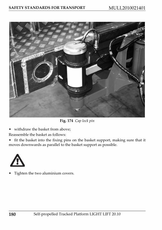
180 Self‐propelled Tracked Platform LIGHT LIFT 20.10
SAFETY STANDARDS FOR TRANSPORT MULL2010021401
• withdraw the basket from above;Reassemble the basket as follows:• fit the basket into the fixing pins on the basket support, making sure that itmoves downwards as parallel to the basket support as possible.
• Tighten the two aluminium covers.
Fig. 174 Cap lock pin

SAFETY STANDARDS FOR TRANSPORT
181
MULL2010021401
Self‐propelled Tracked Platform LIGHT LIFT 20.10
13.2.LOADING AND UNLOADING THE MACHINE ON TRANSPORT VEHICLES USING RAMPS
The platform offers high manoeuvrability and stability even in travelling confi‐guration. Despite this, the user must work with care even when carrying out thesimplest operations.During the loading and unloading from the truck or trailer through the use oframps follow the following guidelines:• Make sure the truck or trailer is rated accordingly for the transport of PLE. Re‐fer to the weight indicated in the technical data section of this manual ʺTechnicaldata (p. 18)ʺ.• Park the lorry or trailer on a flat surface.• Select ramps of adequate length to ensure a maximum angle of inclination re‐spect to the ground less than or equal to 15 °. As a general rule, if the ramps andthe truck / trailer rely on free surface without slope variations, this requirementis met if the ratio between the length of the ramps and the height of the arrival ofthe ground is greater than or equal to 3.7.• Make sure that the ramps have a sufficient capacity to support the machine.Refer to the weight indicated in the technical data section of this manual ʺTechni‐cal data (p. 18)ʺ.• Make sure that the ramps are free from debris or slippery material.• The truck or the trailer must be stopped with the wheels locked, the parkingbrake engaged, the engine shut off and the dump level.• Ramps shall be securely supported and fixed to the structure of the plan of ar‐rival. Check the validity of the engagement to the truck / trailer before using theramps.• The highest point of the ramp must be coplanar with the arrival. No steps shallbe presented to the machine in the transition from the ramp the floor arrival ordeparture.
Fig. 175 Loading on the ramps

182 Self‐propelled Tracked Platform LIGHT LIFT 20.10
SAFETY STANDARDS FOR TRANSPORT MULL2010021401
• Widen the carriage platform before tackling the ramps.• Adjust the distance between the ramps in function of the roadway of the twotracks.• Always empty the basket before tackling the ramps.
• Climb the ramps proceeding with the machine oriented with the baskettowards the rear.• Close to the variation of inclination between ramp and floor truck / trailer,proceed with great caution to avoid jolts.• Proceed very slowly on the ramps adjusting the speed with the proportionallevers. In the elevation changes proceed at minimum speed possible. MAKESURE THAT THE ENGINE IS AT IDLE SPEED (turtle speed select). Maintaina constant speed. Avoid abrupt starts and braking. Make sure before procee‐ding on the ramps that each track is FULLY content on the surface of each ramp.In tackling the ramps proceed with PERFECTLY straight trajectory makingsure at ALL times that each track is FULLY contained on the surface of eachramp.• Place the machine so that no part of it comes out of the shape of the vehicle.For the descent follow the requirements above.
• Ensure that ramps are equipped with side profile of containment with sizeand shape as per the following schematic:
During the translation phases and stages of change of slope careful not to da‐mage the safety devices placed under the basket and near the end of the firstextension. In the case of the change of slope would be too high change the slo‐pe of ramps or use ramps longer.

SAFETY STANDARDS FOR TRANSPORT
183
MULL2010021401
Self‐propelled Tracked Platform LIGHT LIFT 20.10
Fig. 176 Ramp profile

184 Self‐propelled Tracked Platform LIGHT LIFT 20.10
SAFETY STANDARDS FOR TRANSPORT MULL2010021401
13.3.LIFTING THE MACHINE
To lift the machine, first of all a lifting device is required that has a suitable capa‐city depending on the distance and the height to which the MEWP is to be lifted.
• For lifting operations necessary for maintenance or loading onto transportvehicles, only use machinery (e.g. forklifts, crane, overhead cranes etc.) and loadpick‐up devices (e.g. ropes, chains, hooks) with suitable capacity and in perfectworking order; for the weight of the machine, consult the paragraph relative tothe technical features of the MEWP ʺTechnical data (p. 18)ʺ. The photograph be‐low shows how and where the MEWP must be attached.• When lifting the machine, it must be in transport configuration (extensiblestructure completely closed and aligned, stabilisers completely lifted and under‐carriage extended). Otherwise, the machine would be unbalanced and liftingdangerous.• Never lift the machine with the operator on board.• During lifting, make sure that no people are in the area affected by the opera‐tions and do not move the suspended machine over persons.
Never lift the machine if it is not secured as shown herein; if, for example, it werelifted by attaching it to the arm, using devices for anchorage to the ground (aboveall not designed to support the weight of the MEWP) or simply passing a straparound any element of the arm, the turntable and other machine parts would beloaded with forces they are not designed for. There is a high risk of damaging themachine.
13.3.1.Lifting the machine using a forkliftThe machine is equipped with two tubular designed to lift the machine using aforklift of suitable capacity.

SAFETY STANDARDS FOR TRANSPORT
185
MULL2010021401
Self‐propelled Tracked Platform LIGHT LIFT 20.10
It is absolutely forbidden to lift the machine if it is not completely closed and ali‐gned in transport position with the 4 stabilizers completely closed and lifted fromground. Before proceeding verify the weight of the machine in the technical dataof this manual and make sure that the forklift is suitable for this weight. Verifyalso the dimensions of the forks and make sure that the positioning of the load isin compliance with the requirements of the forklift. Proceed approaching careful‐ly to the machine paying attention not to collide with parts of it and cause dama‐ges to the structure. During the operations of lifting and transport follow therequirements and dispositions prescribed for the use of the lifting device and/orby the security officer of the working environment in which the operation is per‐formed. This operation must be performed by appropriate personnel possessingthe regulatory requirements to the use of the lifting device chosen.
Fig. 177 Forklift lifting points
The manufacturer of the Platform is not responsible in any way for damagescaused to the machine, lifting device or persons and/or objects due to impro‐per execution of this operation.

186 Self‐propelled Tracked Platform LIGHT LIFT 20.10
SAFETY STANDARDS FOR TRANSPORT MULL2010021401
13.3.2.Lifting the machine using ropes or chainsThe machine is equipped with 4 eyelets, positioned on the base, allowing to liftthe machine through 4 ropes or chains of suitable length and capacity.
To properly lift the platform it is necessary to use a sling bar of adequate size andfeatures, with a distance between hooks from 550 to 730 mm. The minimum ca‐pacity required for each rope, chain or sling used must be sufficient to ensure thesupport of the whole structure to be lifted and their length must ensure that thesling bar is positioned higher than the machine and that it does not touch the pla‐tform during the lifting phases. The following pictures are the guidelines for ma‐chine lifting.
Fig. 178 Ropes or chains lifting points
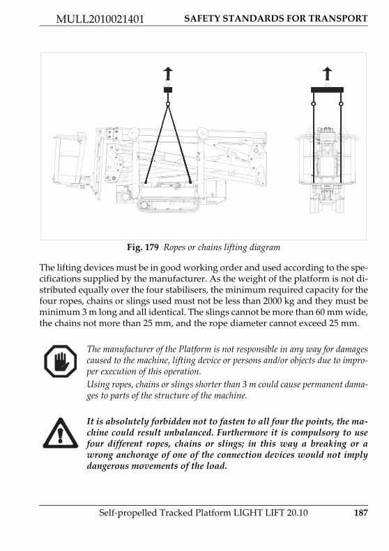
SAFETY STANDARDS FOR TRANSPORT
187
MULL2010021401
Self‐propelled Tracked Platform LIGHT LIFT 20.10
The lifting devices must be in good working order and used according to the spe‐cifications supplied by the manufacturer. As the weight of the platform is not di‐stributed equally over the four stabilisers, the minimum required capacity for thefour ropes, chains or slings used must not be less than 2000 kg and they must beminimum 3 m long and all identical. The slings cannot be more than 60 mm wide,the chains not more than 25 mm, and the rope diameter cannot exceed 25 mm.
Fig. 179 Ropes or chains lifting diagram
The manufacturer of the Platform is not responsible in any way for damagescaused to the machine, lifting device or persons and/or objects due to impro‐per execution of this operation.Using ropes, chains or slings shorter than 3 m could cause permanent dama‐ges to parts of the structure of the machine.
It is absolutely forbidden not to fasten to all four the points, the ma‐chine could result unbalanced. Furthermore it is compulsory to usefour different ropes, chains or slings; in this way a breaking or awrong anchorage of one of the connection devices would not implydangerous movements of the load.

188 Self‐propelled Tracked Platform LIGHT LIFT 20.10
SAFETY STANDARDS FOR TRANSPORT MULL2010021401
13.4.TRANSPORTING THE MACHINE
Once on the trailer the machine must be fixed using tie rods as shown in the photobelow. Make sure that the dimensions of the machine and the trailer are compa‐tible with road traffic regulations.
Fig. 180 Fixing hook 1 Fig. 181 Fixing hook 2
The fixing system connection points are identified by the sticker.
Do not make connections in points other than those identified by the sticker.This could cause permanent damage to the structure with risk of collapse.

SERVICE MENU ON THE REMOTE CONTROL
189
MULL2010021401
Self‐propelled Tracked Platform LIGHT LIFT 20.10
14.SERVICE MENU ON THE REMOTE CONTROLA SERVICE button ʺPush buttons (p. 60)ʺ is available on the remote control andis used to display the status of the machine parameters and as assisting device forthe safety checks to be carried out on the machine, as specified in this manual.Pressing button 6 accesses a numerical menu, controlled by the number buttonson the remote control. The meaning of these menus is explained in this manual.If after reading the manual you still have some doubts, contact the after sales ser‐vice.1 INPUTLANGUAGEERRORSRAMPSCURRENTSWORKING HOURSSETTINGJOYSTICKESC
14.1.INPUT MENU
This displays the signals received by the board from the various sensors fitted onthe machine and from the controls on the remote control. Each screen shows thestatus of the input and options to scroll the menu.
14.2.LANGUAGE MENÙ
Allows you to select menu language among those available.
14.3.ERRORS MENU
Indicates correspondence between the double sensors, either (OK) or (FAULT). Ifthe OK symbol is shown next to the sensor, this means that both elements on thesame sensor are sending congruent information. If the FAULT symbol is shownnext to the sensor, this means that the elements on the same sensor are sendingcontradictory information.
The 4‐5‐7 menu items are not normally used except for setting operations and dia‐gnosis by qualified personnel.

190 Self‐propelled Tracked Platform LIGHT LIFT 20.10
SERVICE MENU ON THE REMOTE CONTROL MULL2010021401
The last page of the error menu describes the error code relating to the batterycharger system, inverter and battery pack. Errors are indicated by the “spanner”icon ʺFig. 44 Lithium error(p. 57)ʺ in position 7 on the remote control display.If the machine has problems in the functioning and the icon ʺspannerʺ on the di‐splay will not reset turning off and restarting the machine, contact the after salesdepartment.
14.4.WORKING HOURS MENU
Indicates the number of machine operating hours.
14.5.JOYSTICK MENU
Displays the signal that each individual joystick sends to the main board.

HYDRAULIC SYSTEM
191
MULL2010021401
Self‐propelled Tracked Platform LIGHT LIFT 20.10
15.HYDRAULIC SYSTEM

192 Self‐propelled Tracked Platform LIGHT LIFT 20.10
HYDRAULIC SYSTEM MULL2010021401
Riferimento Descrizione
1 Hand pump
2 Electric motor
3 Honda iGX440 petrol engine / Perkins diesel engine
4 Double gear pump
5 Pump outlet manifold block
6 Discharge filter
7 Discharge manifold
8 Distributor
9 Distributor
10 Stabiliser stop valve
11 Stabilizer cylinder
12 Motorgear
13 Track gauge extension cylinder
14 Directional solenoid valve
16 Accumulator
17 Rotation motor
18 Distributor
19 Manifold
20 Balancing valve double
21 Extension regenerative balancing valve
22 Balancing valve double
23 1‐2° boom cylinder
24 3° boom cylinder
25 Extension cylinder
26 JIB cylinder

HYDRAULIC SYSTEM
193
MULL2010021401
Self‐propelled Tracked Platform LIGHT LIFT 20.10
27 Rotary actuator for basket rotation
28 Basket levelling cylinder on the basket
29 Basket levelling cylinder on the transmission
30 Deflection block for closed loop
31 Levelling balancing valve double
Riferimento Descrizione

194 Self‐propelled Tracked Platform LIGHT LIFT 20.10
WIRING DIAGRAM MULL2010021401
16.WIRING DIAGRAM
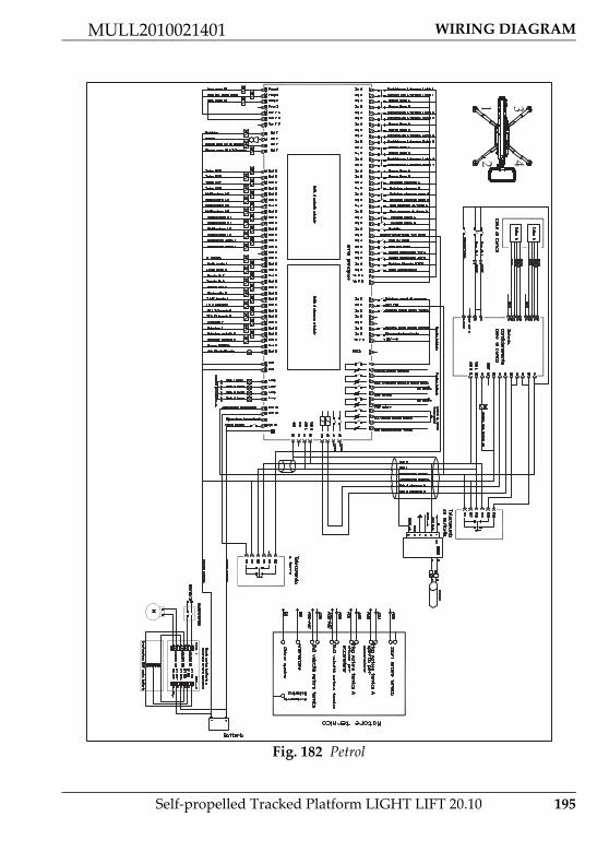
WIRING DIAGRAM
195
MULL2010021401
Self‐propelled Tracked Platform LIGHT LIFT 20.10
Fig. 182 Petrol
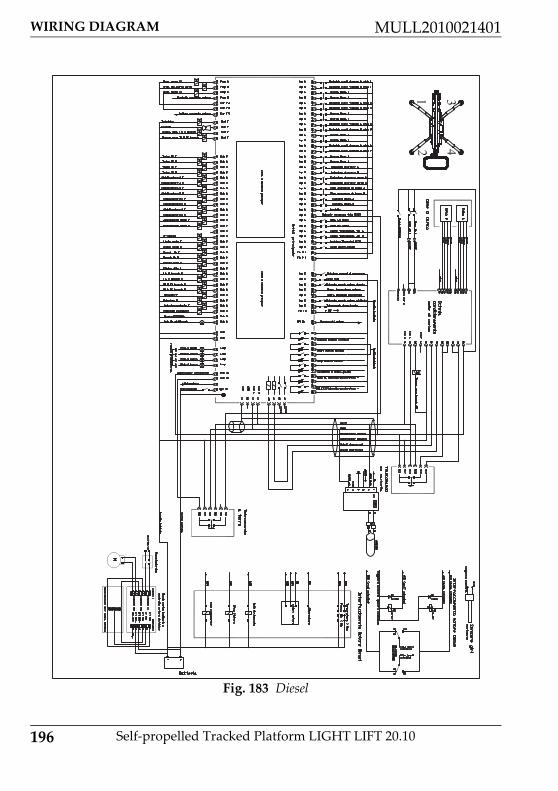
196 Self‐propelled Tracked Platform LIGHT LIFT 20.10
WIRING DIAGRAM MULL2010021401
Fig. 183 Diesel

WIRING DIAGRAM
197
MULL2010021401
Self‐propelled Tracked Platform LIGHT LIFT 20.10
Fig. 184 Lithium

198 Self‐propelled Tracked Platform LIGHT LIFT 20.10
WIRING DIAGRAM MULL2010021401


HINOWA S.p.A.I ‐ 37054 NOGARA (VR) via Fontana
Tel. +39 0442 539100 Fax +39 0442 [email protected]
marketing: [email protected]
Legal and administrative seat: