SYSTEM AIR CONDITIONER - GT Phelan
130
1. Precautions 2. Product Specifications 3. Disassembly and Reassembly 4. Troubleshooting 5. PCB Diagram 6. Wiring Diagram 7. Reference Sheet CONTENTS SYSTEM AIR CONDITIONER INDOOR UNIT OUTDOOR UNIT SYSTEM AIR CONDITIONER CIRCULAR CASSETTE SERIES AC071MN4PKH AC090MN4PKH AC100MN4PKH AC120MN4PKH AC140MN4PKH AC090MXADKH AC100MXAD*H AC120MXAD*H AC140MXAD*H
-
Upload
khangminh22 -
Category
Documents
-
view
2 -
download
0
Transcript of SYSTEM AIR CONDITIONER - GT Phelan

1. Precautions
2. Product Specifications
3. Disassembly and Reassembly
4. Troubleshooting
5. PCB Diagram
6. Wiring Diagram
7. Reference Sheet
CONTENTSSYSTEM AIR CONDITIONER
INDOOR UNIT OUTDOOR UNIT
SYSTEM AIR CONDITIONER
CIRCULAR CASSETTE SERIES
AC071MN4PKHAC090MN4PKH AC100MN4PKH AC120MN4PKH AC140MN4PKH
AC090MXADKH AC100MXAD*H AC120MXAD*H AC140MXAD*H

Section 0
1
Contents
1. Precautions .............................................................................................................................................................................................. 1-1
1-1. Precautions for the Service ......................................................................................................................................................... 1-1
1-2. Precautions related to static electricity and PL ................................................................................................................... 1-1
1-3. Precautions related to product safety ................................................................................................................................... 1-2
1-4. Other precautions .......................................................................................................................................................................... 1-2
2. Product Specifications .................................................................................................................................................................... 2-1
2-1. The Feature of Product ................................................................................................................................................................. 2-1
2-2. Product Specifications .................................................................................................................................................................. 2-2
2-3. Specifications of optional items ............................................................................................................................................... 2-8
2-3-1. Accessories ........................................................................................................................................................................... 2-8
2-3-2. Wireless remote controller (AR-KH0O) ..................................................................................................................... 2-9
2-3-3. Wired remote controller (AWR-WE10N) .................................................................................................................. 2-10
2-3-4. Filter specifications ............................................................................................................................................................ 2-11
3. Disassembly and Reassembly .................................................................................................................................................. 3-1
3-1. Necessary Tools ............................................................................................................................................................................... 3-1
3-2. Indoor Unit ........................................................................................................................................................................................ 3-2
3-3. Outdoor Unit ..................................................................................................................................................................................... 3-11
4. Troubleshooting .......................................................................................................................................................................... 4-1
4-1. Setting an indoor unit address and installation option .................................................................................................. 4-1
4-1-1. The procedure of setting option .................................................................................................................................. 4-1
4-1-2. The procedure of setting option ................................................................................................................................. 4-2
4-1-3. Order for Setting Options (Wired Remote Controller) ........................................................................................ 4-12
4-1-4. Indoor address(MAIN/RMC)setting ............................................................................................................................ 4-13
4-1-5. Set the indoor installation options(Option to set for the installation site conditions) ........................... 4-14
4-1-6. Changing the addresses and options individually ............................................................................................... 4-15
4-2. Model-specific option code ............................................................................................................................................................ 4-16
4-3. Diagnostic Checklist ago .............................................................................................................................................................. 4-17
4-3-1. Test operation mode and check mode .................................................................................................................... 4-17
4-3-2. Eco Mode [Power Save Mode] ...................................................................................................................................... 4-18
4-3-3. Error code [indoor] ........................................................................................................................................................... 4-19
4-3-4. Error code [outdoor] .......................................................................................................................................................... 4-20
4-3-5.Wired remote controller .................................................................................................................................................. 4-33
4-4. Troubleshooting by symptoms ................................................................................................................................................... 4-25
4-1-1. When the outdoor unit power is not ON – Initial Diagnosis : 1-phase products .................................... 4-25
4-4-2. Indoor temperature sensor error (E121) .................................................................................................................. 4-26
4-4-3. Indoor heat exchanger temperature sensor error (E122) .................................................................................. 4-27
4-4-4. Indoor Fan error (E154) .................................................................................................................................................... 4-28
4-4-5. Communication error after finishing Tracking (E202) ......................................................................................... 4-29
4-4-6. Indoor unit float sensor error ........................................................................................................................................ 4-30
4-4-7. EEPROM circuit failure (E162) ........................................................................................................................................ 4-31
4-4-8. The whistling noise from the indoor unit in low wind mode .......................................................................... 4-32
4-4-9. When the outdoor unit power is not ON - Initial Diagnosis : 3-phase products ..................................... 4-33
4-4-10. Indoor/outdoor communication error (1min.) (Error Code : E202) ............................................................ 4-37
Section 0
2
Contents
4-4-11. Communication error between outdoor unit INV MAIN MICOM (1 min.)(Error Code: E203) ... 4-39
4-4-12. Outdoor sensor error(Error Code : E221, E231, E251, E320)............................................................................ 4-40
4-4-13.Reverse phase / Loss phase detection (3-phase outdoor unit) (Error Code : E425 ).............................. 4-41
4-4-14. Compressor down due to freezing control (Error Code : E403) .................................................................... 4-42
4-4-15. Outdoor unit Fan error (Error Code : E458, E475) ............................................................................................... 4-43
4-4-16. Compressor starting error / rotation error (Error Code : E461, E467) .......................................................... 4-44
4-4-17. Full current error / PFC over-current error (Error Code : E462, E484)........................................................... 4-46
4-4-18. IPM IPM (Over Current) error (Error Code : E464) ................................................................................................ 4-47
4-4-19. DC LINK over-current / low-voltage error (Error Code : E466)
H/W DC_Link Over Voltage Error (Error Code : E483)
AC Input Voltage Sensor Error (Error Code : E488) ...................................................................................................................................... 4-50
4-4-20. Gas leakage error(Error Code : E554) ............................................................................................................................................................................. 4-51
4-4-21. Pipe blockage error(Error Code : E422) ....................................................................................................................................................................... 4-53
4-4-22. Smart install mode was not carried out (Error Code : E508 ) ........................................................................................................... 4-54
4-4-23. Others .................................................................................................................................................................................................................................................................... 4-56
5. PCB Diagram and Parts List ........................................................................................................................................................ 5-1
5-1. PCB Diagram .................................................................................................................................................................................... 5-1
5-1-1. Indoor Unit Main PBA ....................................................................................................................................................... 5-1
5-1-2 Display PCB ............................................................................................................................................................................ 5-3
5-1-3. Outdoor PCB ......................................................................................................................................................................... 5-4
6. Wiring Diagram .................................................................................................................................................................................... 6-1
6-1. Indoor Unit ........................................................................................................................................................................................ 6-1
6-2. Outdoor Unit .................................................................................................................................................................................... 6-2
7. SW update ................................................................................................................................................................................................ 7-1
7-1. S-net pro Download ...................................................................................................................................................................... 7-1
7-2. RS485 VS RS232(UART) ................................................................................................................................................................ 7-1
7-3. How to update the Micom(RS485) ......................................................................................................................................... 7-2
7-4. How to update the Micom(UART) .......................................................................................................................................... 7-7
7-5. How to write the EEPROM .......................................................................................................................................................... 7-9
8. Reference Sheet ................................................................................................................................................................................... 8-1
8-1. Index for model name .................................................................................................................................................................. 8-1
8-1-1. Indoor Unit ............................................................................................................................................................................ 8-1
8-1-2. Outdoor Unit ........................................................................................................................................................................ 8-3
8-1-3. Panel ........................................................................................................................................................................................ 8-3
8-2. Refrigerating Cycle Diagram ...................................................................................................................................................... 8-4

1-1
1. Precautions
1-1 Precautions for the Service
Use the standard parts when replacing the electric parts.
– Confirm the model name, rated voltage, rated current of the electric parts.
When repairing the equipment, connection of the harness parts must be firm and solid.
– A loose connection may cause noise or other malfunction.
When assembling and disassembling the equipment while it is laid down, lay it on soft cloth.
– Otherwise it may scratch the back of the exterior of the product.
Remove dust or dirt completely from the housing block, wiring block and service parts during repair.
– This helps prevent the danger of fire caused by tracking or short circuit.
Fasten the valve caps of service valves and charging valves of outdoor unit as much as possible using adjustable wrenches.
Check the status of the components’ assembly after repair service.
– The status must be the same as before the repair service.
1-2 Precautions related to static electricity and PL
The PCB power supply block is susceptible to static electricity. Therefore, care must be taken during repair or measuring
while the power is on.
– Wear insulation gloves for PCB repair or measuring.
Check whether the installation location is at least two meters away from other electronic products such as TV, video, or
audio.
– Otherwise, the video quality might be degraded or noise might be generated.
Do not let end users repair the products themselves.
– Unauthorized disassembly might cause electric shock or fire.

1-2
1-3 Precautions related to product safety
Do not pull the power cord and do not touch the power plug or aux power switch
with wet hands.
– It might cause electric shock or fire.
A damaged power line or power plug must be replaced to prevent danger.
Do not bend the power cable with excessive force, and do not place a heavy weight
on the case as it might damage the cable.
– It might cause electric shock or fire.
Do not use multiple electric outlets.
– This might cause electric shock or fire.
Connect the ground terminal when necessary.
– Y ou must connect the ground terminal if you determine that there is a danger of electric
leakage due to moisture or water.
Unplug the power cable or turn off the auxiliary power switch for electric part
replacement and repair service.
– Otherwise it might cause electric shock.
Instruct end users to separate the batteries from the remote controllers and store
them separately when the product is not used for long time.
– Otherwise leakage from the dry cell may cause problems with the remote controller.
1-4 Other precautions
The pipes should have no leaks during installation, and the compressor must be stopped before removing connecting
pipes for pump down work. Operating the compressor while the service valve is open and coolant pipe is not properly
connected may cause explosion or injury due to abnormal high pressure created inside the coolant cycle as the air can be
absorbed through the pipe.
Pump Down work procedure (When uninstalling the product)
– Turn on the air conditioner, select cooling operation, and run the compressor for more than three minutes.
– Release the high pressure and low pressure valve caps.
– Close the high pressure valve completely using an L-wrench
– After about two minutes, close the low pressure valve completely.
– Stop running the air conditioner.
– Separate the connecting pipe.

2-1
□ 360 Cassette
□ Differentiated innovation air cooling
It delivers a cool air evenly with the circular air current and provides a wide and agreeable cooling area than general ceiling
air conditioners.
□ Refreshing and soft wind
It provides a horizontal air current that form natural convection instead of unpleasant direct wind.
It is consumer-friendly product that prevents the sudden effective temperature tumble.
□ High quality circular design
It applied the wind direction control technology (Coanda effect) which uses the booster fan. Epoch-making circular design
that eliminates the blade.
□ Eco-friendly air conditioner
It is eco-friendly air conditioner that is certified a RoHS technology as well as realize high effectiveness, low noise, super
power saving.
□ Electricity savings through S- Inverter System
Apply S-inverter system that change capacity to 10~160% according to circumstance by one compressor and reduce
optimum cooling effect and unnecessary electricity consumption.
□ Clearness function of four seasons high efficiency
Energy consumption and driving noise decrease more because can operate clearness function separately.
Make healthy and clean environment by bacillus exclusion function and active oxygen neutralization function that virus
doctor at air conditioner driving removes air various hazardous substances operating always..
2. Product Specifications
2-1 The Feature of Product
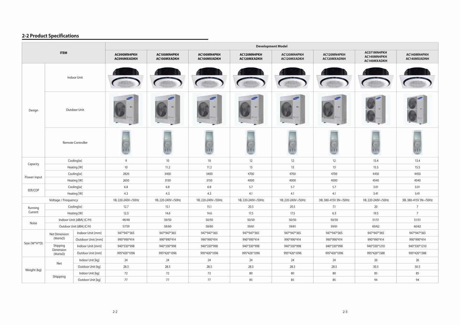
2-2 2-3
ITEM
Development Model
AC090MN4PKH
AC090MXADKH
AC100MN4PKH
AC100MXADKH
AC100MN4PKH
AC100MXADKH
AC120MN4PKH
AC120MXADKH
AC120MN4PKH
AC120MXADKH
AC120MN4PKH
AC120MXADNH
AC071MN4PKH
AC140MN4PKH
AC140MXADKH
AC140MN4PKH
AC140MXADNH
Design
Indoor Unit
Outdoor Unit
Remote Controller
CapacityCooling[w] 9 10 10 12 12 12 13.4 13.4
Heating [W] 10 11.2 11.2 13 13 13 15.5 15.5
Power inputCooling[w] 2820 3400 3400 4700 4700 4700 4450 4450
Heating [W] 2650 3150 3150 4000 4000 4000 4540 4540
EER/COPCooling[w] 6.8 6.8 6.8 5.7 5.7 5.7 3.01 3.01
Heating [W] 4.3 4.3 4.3 4.1 4.1 4.1 3.41 3.41
Voltage / Frequency 1Φ, 220-240V~/50Hz 1Φ, 220-240V~/50Hz 1Φ, 220-240V~/50Hz 1Φ, 220-240V~/50Hz 1Φ, 220-240V~/50Hz 3Φ, 380-415V 3N~/50Hz 1Φ, 220-240V~/50Hz 3Φ, 380-415V 3N~/50Hz
Running
Current
Cooling[w] 12.7 15.1 15.1 20.5 20.5 7.1 20 7
Heating [W] 12.5 14.6 14.6 17.5 17.5 6.3 19.5 7
NoiseIndoor Unit [dBA] (C/H) 48/48 50/50 50/50 50/50 50/50 50/50 51/51 51/51
Outdoor Unit [dBA] (C/H) 57/59 58/60 58/60 59/61 59/61 59/61 60/62 60/62
Size (W*H*D)
Net Dimension
(WxHxD)
Indoor Unit [mm] 947*947*365 947*947*365 947*947*365 947*947*365 947*947*365 947*947*365 947*947*365 947*947*365
Outdoor Unit [mm] 990*990*414 990*990*414 990*990*414 990*990*414 990*990*414 990*990*414 990*990*414 990*990*414
Shipping
Dimension
(WxHxD)
Indoor Unit [mm] 940*330*998 940*330*998 940*330*998 940*330*998 940*330*998 940*330*998 940*330*1210 940*330*1210
Outdoor Unit [mm] 995*426*1096 995*426*1096 995*426*1096 995*426*1096 995*426*1096 995*426*1096 995*426*1388 995*426*1388
Weight (kg)
NetIndoor Unit [kg] 24 24 24 24 24 24 26 26
Outdoor Unit [kg] 28.5 28.5 28.5 28.5 28.5 28.5 30.5 30.5
ShippingIndoor Unit [kg] 72 72 72 80 80 80 85 85
Outdoor Unit [kg] 77 77 77 85 85 85 94 94
2-2 Product Specifications

2-4 2-5
ITEM
Development Model
AC090MN4PKH
AC090MXADKH
AC100MN4PKH
AC100MXADKH
AC100MN4PKH
AC100MXADKH
AC120MN4PKH
AC120MXADKH
AC120MN4PKH
AC120MXADKH
AC120MN4PKH
AC120MXADNH
AC071MN4PKH
AC140MN4PKH
AC140MXADKH
AC140MN4PKH
AC140MXADNH
Harness spec
Indoor fan motor DB31-00577D DB31-00577D DB31-00577D DB31-00577D DB31-00577D DB31-00577D DB31-00577D DB31-00577D
Compressor UG8T300FUBJUSG UG8T300FUBJUSG UG8T300FUBJUSG UG5TK1450FJX UG5TK1450FJX UG5TK1450FJX UG5TK1450FJX UG5TK1450FJX
Outdoor fan motor DB31-00579B DB31-00579B DB31-00579B DB31-00579B DB31-00579B DB31-00579B DB31-00658A DB31-00658A
Designed
pressure
High presssure 4.1 Mpa 4.1 Mpa 4.1 Mpa 4.1 Mpa 4.1 Mpa 4.1 Mpa 4.1 Mpa 4.1 Mpa
Low pressure 1.4 Mpa 1.4 Mpa 1.4 Mpa 1.4 Mpa 1.4 Mpa 1.4 Mpa 1.4 Mpa 1.4 Mpa
Refrigerant / Factory charging 3000 3000 3000 3000 3000 3000 3400 3400
Additional refrigerant 50g/m 50g/m 50g/m 50g/m 50g/m 50g/m 50g/m 50g/m
Basic piping length 5 5 5 5 5 5 5 5
Max. piping length 50 50 50 50 50 50 75 75
Max. level different 30 30 30 30 30 30 30 30
Option code
01007F-19547C-275A64-370040 01007F-19548C-276470-370040 01007F-19548C-276470-370040 01007F-19549D-277882-370040 01007F-19549D-277882-370040 01007F-19549D-277882-370040 01107F-1954AF-278CA0-370040 01107F-1954AF-278CA0-370040
020000-100000-
200000-300000
020000-100000-
200000-300000
020000-100000-
200000-300000
020000-100000-
200000-300000
020000-100000-
200000-300000
020000-100000-
200000-300000
020000-100000-
200000-300000
020000-100000-
200000-300000
030000-100000-
200000-300000
030000-100000-
200000-300000
030000-100000-
200000-300000
030000-100000-
200000-300000
030000-100000-
200000-300000
030000-100000-
200000-300000
030000-100000-
200000-300000
030000-100000-
200000-300000

2-6
2-3 Specifications of optional items
2-3-1 Accessories
Item Description Code No. Q’ty Remark
ASSY DRAIN- HOSE DB94-02719B 1
Standard / Indoor unit
Cable tie DB65-00191A 6
Seal-drain ass'y DB62-05810A 1
Seal-drain ass'y DB94-05810F 1
Seal-drain ass'y DB94-05810G 1
Indoor unit installation manual DB68-05899A1
USER MANUAL DB68-05918A1
Drain cap DB63-10355C3
(AC071KX4DKH : 4)
Standard / Outdoor
unit
Pipe plug DB67-00806A 1
Rubber Leg
DB73-20134A
(AC071KX4DKH :
DB73-00179A)
4
Outdoor unit installation manual DB68-05565A 1
Bolt-flange 6009-001435 4
Standard / Panel
INSTALL MANUAL DB68-05903A 1

Product Specifications
2-7
Item Description Code No. Q’ty Remark
Wireless remote controller DB93-15771C 1
Optional
Batteries for remote controller
(specification: "AAA" type) 4301-000121 2
Remote controller holder DB61-06607A 1
M4×16 Screw 6002-000581 2
User’s manual DB68-05911A 1
2-3-2 Wireless remote controller (AR-KH00E)

Product Specifications
2-8
2-3-3 Wired remote controller (MWR-WE10N)
Item Description Code No. Q’ty Remark
Wired remote controller DB93-11251F 1
Optional
Cable tie DB65-10088B 2
Cable clamp DB65-10074E 3
M4×16 Screw 6002-000474 5
User's manual DB68-03732A 1
Installation manual DB68-03716A 1

Product Specifications
2-9
2-3-4 Filter specifications
Item Description Code No. Remark
FILTER-AIR DB63-03764A

3-1
Item Remark
+ Screw Driver
Monkey Spanner
(8mm, 10mm, 13mm)
M6, M8 Hex Wrench
Spanner Torque Wrench
3. Disassembly and Reassembly
3-1 Necessary Tools

3-2
3-2 Indoor Unit
No. Parts Procedure Remark
1 Panel ▶ Ceiling type Panel
1) Pull up the corner 4 places of Panel and
separate it.
2) Remove the 4 screws from the corner of
Panel. (Use +Screw Driver)
3) Pull the hook of Panel and then separate the
Panel from the Indoor Unit.
1 Panel ▶ Open type Panel
1) Rotate the outside Panel to counterclockwise
direction and then separate it.

Disassembly and Reassembly
3-3
No. Parts Procedure Remark
1 Panel 2) Rotate the Grille to counterclockwise
direction.
3) Remove the safety clip of Grill inside and then
separate the Panel from the Indoor Unit.
4) Pull up the Filter from the Grill and separate it.
2 Control Box 1) Reomove the 2 screws which is fixed to the
Indoor Unit upper part.(Use +Screw Driver)
2) Rotate the Guard Fan to counterclockwise
direction and separate it

Disassembly and Reassembly
3-4
No. Parts Procedure Remark
2 Control Box 3) Reomove the 1 screw which is fixed to the
Indoor Unit upper part.(Use +Screw Driver)
4) Put finger in the "PULL" marked groove and
then pull up the Cover
5) Put finger in the "PULL" marked groove and
then avoids the hook and it opens the Control
Box Cover

Disassembly and Reassembly
3-5
No. Parts Procedure Remark
2 Control Box 6) Separate the connectors from the Control Box.
7) Remove the ground screw.
(Use +Screw Driver)
3 Top Cover & Drain Pan 1) Remove the 3 screws. (Use +Screw Driver)
2) Push the hook and separate the Cover.
Damage can occur to product in case of use a
sharp tool.
3) Remove the screw which is fixed to Booster
Fan. (Use +Screw Driver)

Disassembly and Reassembly
3-6
No. Parts Procedure Remark
3 Top Cover & Drain Pan 4) Pull the Booster Fan connector and separate
the connector.
5) Remove the 4 screws. (Use +Screw Driver)
6) Push the hook and separate the Cover.

Disassembly and Reassembly
3-7
No. Parts Procedure Remark
3 Top Cover & Drain Pan 7) Remove the screw and separate the Display
Cover. (Use +Screw Driver)
8) ) Remove the 2 screws. (Use +Screw Driver)
9) Push the hook and separate the Cover.
10) Remove the 8 screws. (Use +Screw Driver)
11) Separate the Indoor Unit upper part from
the Body

Disassembly and Reassembly
3-8
No. Parts Procedure Remark
3 Top Cover & Drain Pan 12) Remove the 3 screws. (Use +Screw Driver)
13) Pull the hook that is on the side and separate
the Cover.
4 Drain Pump & Hose 1) Separate the Drain Hose from the Drain Pump.

Disassembly and Reassembly
3-9
No. Parts Procedure Remark
4 Drain Pump & Hose 2) Remove the 2 screws and separate the Drain
Hose that is on the side lower part of Indoor
Unit (Use +Screw Driver)
5 Fan & Motor 1) Remove the hex nut which is fixed to top of
Fan and separate the Fan from the Motor.
(Use Monkey Spanner)
2) Remove the 3 hex nuts which is fixed to Motor
and separate the Motor from the Indoor Unit.
(Use Monkey Spanner)
6 Temperature Sensor 1) Remove the 6 screws which is fixed to
Evaporator and separate the Partition.
2) Separates the Temperature Sensor which is
fixed to Evaporator Pipe with the fixing clip
together by the hand.

Disassembly and Reassembly
3-10
No. Parts Procedure Remark
4 Evaporator 1) Remove the screws which is fixed to Indoor
Unit and separate the Evaporator fixing
bracket. (Use +Screw Driver)
2) Remove screws which is fixed to Indoor Unit
and pull the hook and then separate the Drain
Cover. (Use +Screw Driver)
When assemble, be careful with the
interference structure of piping
projecting part.
3) Separate the Evaporator from the Indoor Unit.
If you remove the Evaporator withbare hands,
it may injure your hands, gloves must be worn.

Disassembly and Reassembly
3-11
No. Parts Procedure Remark
1 Cabinet Front RH Turn off the power before disassembly
necessarily.
1) Remove the 2 screws from the Cabinet Front
RH and separate it. (Use +Screw Driver)
2 Cabinet Upper 1) Remove the 9 screws which is fixed to each
side of Cabinet Upper and separate it. (Use
+Screw Driver)
3 Cabinet-Installation
Front Part
1) Remove the 1 screw which is fixed to
Cabinet-Installation Front Part and separate
it. (Use +Screw Driver)
■ AC090/100/120MXAD*H
3-3. Outdoor Unit
Disassembly and Reassembly
3-12
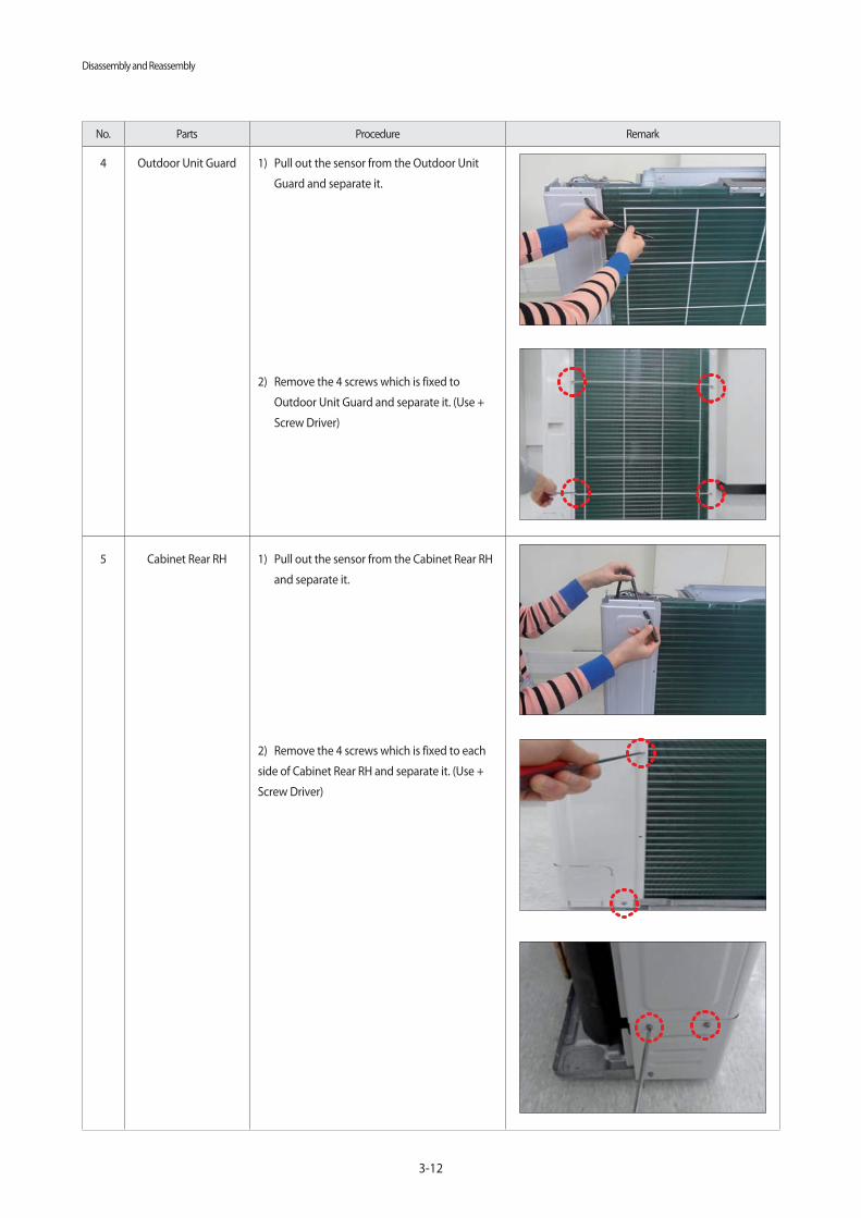
No. Parts Procedure Remark
4 Outdoor Unit Guard 1) Pull out the sensor from the Outdoor Unit
Guard and separate it.
2) Remove the 4 screws which is fixed to
Outdoor Unit Guard and separate it. (Use +
Screw Driver)
5 Cabinet Rear RH 1) Pull out the sensor from the Cabinet Rear RH
and separate it.
2) Remove the 4 screws which is fixed to each
side of Cabinet Rear RH and separate it. (Use +
Screw Driver)

Disassembly and Reassembly
3-13
No. Parts Procedure Remark
6 Cabinet-Installation
Rear Part
1) Remove the 1 screw from the Cabinet-
Installation Rear Part and separate it.(Use +
Screw Driver)
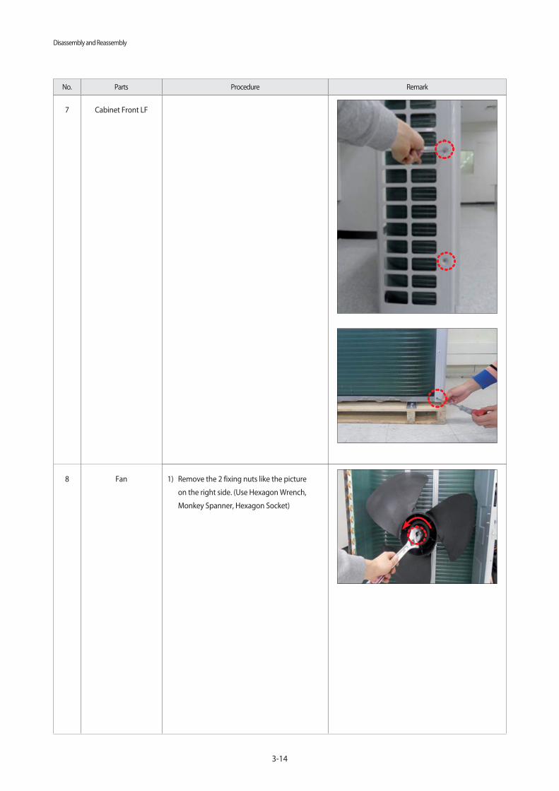
7 Cabinet Front LF 1) Remove the 10 screws from the Cabinet
Front LF and separate it. (Use +Screw Driver)
Disassembly and Reassembly
3-14
No. Parts Procedure Remark
7 Cabinet Front LF
8 Fan 1) Remove the 2 fixing nuts like the picture
on the right side. (Use Hexagon Wrench,
Monkey Spanner, Hexagon Socket)

Disassembly and Reassembly
3-15
No. Parts Procedure Remark
9 Motor 1) Separate the Fan Propeller.
2) Remove the 8 screws which is fixed to
Motor. (Use +Screw Driver)
3) Separate the Motor Wire connector from the
Outdoor Unit Control Part.
10 Bracket Motor 1) Remove the 2 screws from the Bracket Motor
and separate it. (Use +Screw Driver)
Disassembly and Reassembly
3-16
No. Parts Procedure Remark
11 Control Part 1) Separate the 4 connectors from the Outdoor
Unit Control part.
2) Remove the 1 screw which is fixed to Control
Part. (Use +Screw Driver)
3) Separate the Control Part.

Disassembly and Reassembly
3-17
No. Parts Procedure Remark
12 4 Way Valve 1) First, discharge the refrigerant.
2) Remove the 2 screws which is fixed to
Service Valve and separate it. (Use +Screw
Driver)
3) Separate the inlet and outlet pipes by
welding torch.
If you separate the Compressor, Heat
Exchanger or Pipe, please fully discharge
refrigerant in the Compressor and then
separate the Pipe by welding torch.

Disassembly and Reassembly
3-18
No. Parts Procedure Remark
13 EEV Valve 1) Remove the 2 screws which is fixed to
Service Valve and separate it. (Use +Screw
Driver)
2) Separate the inlet and outlet pipes by
welding torch.
14 Compressor 1) Remove the 1 fixing nut from the end of
Cover and separate it. (Use Hexagon Wrench,
Monkey Spanner, Hexagon Socket)
2) Separate the Felt Compressor.

Disassembly and Reassembly
3-19
No. Parts Procedure Remark
14 Compressor 3) Remove the 3 bolts from the bottom of
Compressor like the picture on the right side.
(Use Hexagon Wrench, Monkey Spanner,
Hexagon Socket)
15 Condenser Connection
Part
1) Remove the 3 screws which is fixed to each
side of Condenser Connection Part and
separate it. (Use + Screw Driver)

Disassembly and Reassembly
3-20
■ AC140MXAD*H
No. Parts Procedure Remark
1 Cabinet Front RH Turn off the power before disassembly
necessarily.
1) Remove the 2 screws from the Cabinet Front
RH and separate it. (Use + Screw Driver)
2 Cabinet Upper 1) Remove the 9 screws which is fixed to each
side of Cabinet Upper and separate it.(Use +
Screw Driver)
3 Cabinet-Installation
Front Part
1) Remove the 1 screw which is fixed to
Cabinet-Installation Front Part and separate
it.(Use + Screw Driver)

Disassembly and Reassembly
3-21
No. Parts Procedure Remark
4 Outdoor Unit Guard 1) Pull out the sensor from the Outdoor Unit
Guard and separate it.
2) Remove the 4 screws which is fixed to
Outdoor Unit Guard and separate it. (Use +
Screw Driver)
5 Cabinet Rear RH 1) Pull out the sensor from the Cabinet Rear RH
and separate it.
2) Remove the 4 screws which is fixed to each
side of Cabinet Rear RH and separate it.(Use +
Screw Driver)

Disassembly and Reassembly
3-22
No. Parts Procedure Remark
6 Cabinet-Installation
Rear Part
1) Remove the 1 screw from the Cabinet-
Installation Rear Part and separate it.(Use
+Screw Driver)
7 Cabinet Front LF 1) Remove the 10 screws from the Cabinet
Front LF and separate it. (Use +Screw Driver)

Disassembly and Reassembly
3-23
No. Parts Procedure Remark
7 Cabinet Front LF
8 Fan 1) Remove the 2 fixing nuts like the picture
on the right side. (Use Hexagon Wrench,
Monkey Spanner, Hexagon Socket)

Disassembly and Reassembly
3-24
No. Parts Procedure Remark
9 Motor 1) Separate the Fan Propeller.
2) Remove the 8 screws which is fixed to
Motor. (Use +Screw Driver)
3) Separate the Motor Wire connector from the
Outdoor Unit Control Part.
10 Bracket Motor 1) Remove the 2 screws from the Bracket Motor
and separate it. (Use +Screw Driver)

Disassembly and Reassembly
3-25
No. Parts Procedure Remark
11 Control Part 1) Separate the 4 connectors from the Outdoor
Unit Control part.
2) Remove the 1 screw which is fixed to Control
Part. (Use +Screw Driver)
3) Separate the Control Part.

Disassembly and Reassembly
3-26
No. Parts Procedure Remark
12 4 Way Valve 1) First, discharge the refrigerant.
2) Remove the 2 screw which is fixed to Service
Valve. (Use +Screw Driver)
3) Separate the inlet and outlet pipes by
welding torch.
If you separate the Compressor, Heat
Exchanger or Pipe, please fully discharge
refrigerant in the Compressor and then
separate the Pipe by welding torch.
13 EEV Valve 1) Remove the 2 screws which is fixed to
Service Valve and separate it. (Use +Screw
Driver)
2) Separate the inlet and outlet pipes by
welding torch

Disassembly and Reassembly
3-27
No. Parts Procedure Remark
14 Compressor 1) Remove the 1 fixing nut from the end of
Cover and separate it. (Use Hexagon Wrench,
Monkey Spanner, Hexagon Socket)
2) Separate the Felt Compressor.
3) Remove the 3 bolts from the bottom of
Compressor like the picture on the right side.
(Use Hexagon Wrench, Monkey Spanner,
Hexagon Socket)

Disassembly and Reassembly
3-28
No. Parts Procedure Remark
15 Condenser Connection
Part
1) Remove the 3 screws which is fixed to each
side of Condenser Connection Part and separate
it. (Use + Screw Driver)

4-1
▶ Indoor address set-up and installation options, set the remote control option..
ADDRESS setting and indoor settings option haohni setting is not possible at the same time, set each of the options.
If necessary, set up the indoor address setting installation options, you must enter twice.
4-1-1. The procedure of setting option▶ MR-EC00 and MR-EH00 remote controls
CAUTION
SEG1 SEG2 SEG3 SEG4 SEG5 SEG6 SEG7 SEG8 SEG9 SEG10 SEG11 SEG12
0 X X X X X 1 X X X X X
SEG13 SEG14 SEG15 SEG16 SEG17 SEG18 SEG19 SEG20 SEG21 SEG22 SEG23 SEG24
2 X X X X X 3 X X X X X
On (SEG1~12) Off (SEG13~24)
High Temp button High Fan buttonMode button
Low Temp button Low Fan button
Entering themode for settingthe options
Setting theoption values
set values for these options are skipped automatically.
SEG4 and SEG5
SEG6 and SEG8 SEG9 and SEG10 SEG11 andSEG12 SEG14 and SEG15 SEG16 and SEG17 SEG18 and
SEG20 SEG21 and SEG22 SEG23 and SEG24
4. Troubleshooting
4-1 Setting an indoor unit address and installation option
1.Enter the mode for setting the options :
a. R1emove the batteries from the remote control,and then insert them again.
b. While holding down the (High Temp) and (Low Temp) buttons simultaneously, insert thebatteries into the remote control.
c. Make sure that you are entered to the mode forsetting the options:batteries into the remote control.
2. Set the option values.
Step 1 Enter the mode for setting the options

Troubleshooting
4-2
Steps Remote control display
1 Set the SEG2 and SEG3 values:
a Set the SEG2 value by pressing the (Low Fan) button repeatedly until thevalue you want to set appears on the remote control display.
b Set the SEG3 value by pressing the (High Fan) button repeatedly until the value you want
to set appears on the remote control display.
When you press the (Low Fan) or (High Fan) button, values appear in the
following order:
SEG 2
SEG 3
2 Press the (Mode) button. Cool and On appear on the remote control display.
3 Set the SEG4 and SEG5 values:
a Set the SEG4 value by pressing the (Low Fan) button repeatedly until
the value you want to set appears on the remote control display.
b Set the SEG5 value by pressing the (High Fan) button repeatedly until the value you want to set appears on the remote control display.
When you press the (Low Fan) or (High Fan) button, values appear in the following order:
SEG 4
SEG 5
4 Press the (Mode) button. Dry and On appear on the remote control display.
5 Set the SEG6 and SEG8 values:
a Set the SEG6 value by pressing the (Low Fan) button repeatedly until
the value you want to set appears on the remote control display.
b Set the SEG8 value by pressing the (High Fan) button repeatedly until the value you want to set appears on the remote control display.
When you press the (Low Fan) or (High Fan) button, values appear in the following order:
SEG 6
SEG 8
6 Press the (Mode) button. Fan and On appear on the remote control display.
4-1-2. The procedure of setting option

Troubleshooting
4-3
The procedure of setting option(Cont.)
Steps Remote control display
7 Set the SEG9 and SEG10 values:
a Set the SEG9 value by pressing the (Low Fan) button repeatedly until thevalue you want to set appears on the remote control display.
b Set the SEG10 value by pressing the (High Fan) button repeatedly until thevalue you want to set appears on the remote control display.
When you press the (Low Fan) or (High Fan) button, values appear in thefollowing order:
SEG 9
SEG 10
8 Press the (Mode) button. Heat and On appear on the remote control display.
9 Set the SEG11 and SEG12 values:
a Set the SEG11 value by pressing the (Low Fan) button repeatedly until the value you want to set appears on the remote control display.
b Set the SEG12 value by pressing the (High Fan) button repeatedly until
the value you want to set appears on the remote control display.
When you press the (Low Fan) or (High Fan) button, values appear in the
following order:
SEG 11
SEG 12
10 Press the (Mode) button. Auto and Off appear on the remote control display.
11 Set the SEG14 and SEG15 values:
a Set the SEG14 value by pressing the (Low Fan) button repeatedly until
the value you want to set appears on the remote control display.
b Set the SEG15 value by pressing the (High Fan) button repeatedly until thevalue you want to set appears on the remote control display.
When you press the (Low Fan) or (High Fan) button, values appear in the following order:
SEG 14
SEG 15

Troubleshooting
4-4
The procedure of setting option(Cont.)
Steps Remote control display
12 Press the (Mode) button. Cool and Off appear on the remote control display.
13 Set the SEG16 and SEG17 values:
a Set the SEG16 value by pressing the (Low Fan) button repeatedly until the value you want to set appears on the remote control display.
b Set the SEG17 value by pressing the (High Fan) button repeatedly until the value you want to set appears on the remote control display.
When you press the (Low Fan) or (High Fan) button, values appear in thefollowing order:
SEG 16
SEG 17
14 Press the (Mode) button. Dry and Off appear on the remote control display.
15 Set the SEG18 and SEG20 values:
a Set the SEG18 value by pressing the (Low Fan) button repeatedly until the value you want to set appears on the remote control display.
b Set the SEG20 value by pressing the (High Fan) button repeatedly until
the value you want to set appears on the remote control display.
When you press the (Low Fan) or (High Fan) button, values appear in
the following order:
SEG 18
SEG 20
16 Press the (Mode) button. Fan and Off appear on the remote control display.
17 Set the SEG21 and SEG22 values:
a Set the SEG21 value by pressing the (Low Fan) button repeatedly until
the value you want to set appears on the remote control display.
b Set the SEG22 value by pressing the (High Fan) button repeatedly until thevalue you want to set appears on the remote control display.
When you press the (Low Fan) or (High Fan) button, values appear in the following order:
SEG 21
SEG 22

Troubleshooting
4-5
The procedure of setting option(Cont.)
Steps Remote control display
18 Press the (Mode) button. Heat and Off appear on the remote control display.
19 Set the SEG23 and SEG24 values:
a Set the SEG23 value by pressing the (Low Fan) button repeatedly until the value you want to set appears on the remote control display.
b Set the SEG24 value by pressing the (High Fan) button repeatedly until the value you want to set appears on the remote control display.
When you press the (Low Fan) or (High Fan) button, values appear in thefollowing order:
SEG 23
SEG 24

Troubleshooting
4-6
Step 4 Save the option values into the indoor unit
Point the remote control to the remote control sensoron the indoor unit and then press the (Power)button on the remote control. Make
sure that this command is received by the indoor unit; if it is notreceived, press the (Power) button again.
Step 5 Check whether the air conditioner operates in accordance with the option values you have set
1. Reset the indoor unit by disconnecting and then reconnecting the power cable of the indoor unit or by pressing the RESET button on the
outdoor unit.
2. Remove the batteries from the remote control,insert them again, and then press the (Power) button on the remote control.
Step 3 Check the option you have set
Check whether the option values that you have set are correct by pressing the (Mode) button repeatedly
[ SEG2, SEG3 ] [ SEG4, SEG5 ] [ SEG6, SEG8 ]
[ SEG11, SEG12 ]
[ SEG9, SEG10 ]
[ SEG14, SEG15 ] [ SEG16, SEG17 ] [ SEG18, SEG20 ]
[ SEG21, SEG22 ] [ SEG23, SEG24 ]
The procedure of setting option(Cont.)

Troubleshooting
4-7
The total number of available options are 24: SEG1 to SEG24.
Because SEG1, SEG7, SEG13, and SEG19 are the page options used by the previous remote control models,the modes to set values for these options are skipped automatically.
Set a 2-digit value for each option pair in the following order: SEG2 and SEG3 → SEG4 and SEG5→ SEG6 and SEG8 → SEG9 and SEG10 → SEG11 andSEG12 → SEG14 and SEG15 → SEG16 and SEG17 →SEG18 and SEG20 → SEG21 and SEG22 → SEG23 and SEG24
SEG1 SEG2 SEG3 SEG4 SEG5 SEG6 SEG7 SEG8 SEG9 SEG10 SEG11 SEG12
SEG13 SEG14 SEG15 SEG16 SEG17 SEG18 SEG19 SEG20 SEG21 SEG22 SEG23 SEG24
On (SEG1 to SEG12) Off (SEG13 to SEG24)
Entering themode for settingthe options
Setting theoption values
AR-KH00E remote control (for 360 cassette only)
Temperature button
Temperature button
Mode button
Wheel
NO TE
The r emote c ontr ol display may vary depending on the model.
1 Enter the mode f or setting the options:
a Rem ove the batteries from the r emote control.
b While holding down the (T emp) and (Timer) bu ttons simultaneously, insert the batteries into the remote control.
c Make sure that you are entered to the mode for setting the options:
CAUTION

Troubleshooting
4-8
The procedure of setting option
Steps Remote control display
1 Set the SEG2 and SEG3 values:
a Set the SEG2 value by rotating the Wheel counterclockwise until the
value you want to set appears on the remote control display.
b Set the SEG3 value by rotating the Wheel clockwise until the value
you want to set appears on the remote control display.
When you rotate the Wheel, values appear in the following order:
SEG 2
SEG 3
2 Press the (Mode) button. Cool and On appear on the remote control display.
3 Set the SEG4 and SEG5 values:
a Set the SEG4 value by rotating the Wheel counterclockwise until
the value you want to set appears on the remote control display.
b Set the SEG5 value by rotating the Wheel clockwise until the value you want to set appears on the remote control display.
When you rotate the Wheel, values appear in the following order:
SEG 4
SEG 5
4 Press the (Mode) button. Dry and On appear on the remote control display.
5 Set the SEG6 and SEG8 values:
a Set the SEG6 value by rotating the Wheel counterclockwise until the value you want to set appears on the remote control display.
b Set the SEG8 value by rotating the Wheel clockwise until the value you want to set appears on the remote control display.
When you rotate the Wheel, values appear in the following order:
SEG 6
SEG 8
6 Press the (Mode) button. Fan and On appear on the remote control display.

Troubleshooting
4-9
The procedure of setting option(Cont.)
Steps Remote control display
7 Set the SEG9 and SEG10 values:
a Set the SEG9 value by rotating the Wheel counterclockwise until
the value you want to set appears on the remote control display.
b Set the SEG10 value by rotating the Wheel clockwise until the value
you want to set appears on the remote control display.
When you rotate the Wheel, values appear in the following order:
SEG 9
SEG 10
8 Press the (Mode) button. Heat and On appear on the remote control display.
9 Set the SEG11 and SEG12 values:
a Set the SEG11 value by rotating the Wheel counterclockwise until
the value you want to set appears on the remote control display.
b Set the SEG12 value by rotating the Wheel clockwise until the value you want to set appears on the remote control display.
When you rotate the Wheel, values appear in the following order:
SEG 11
SEG 12
10 Press the (Mode) button. Auto and Off appear on the remote control display.
11 Set the SEG14 and SEG15 values:
a Set the SEG14 value by rotating the Wheel counterclockwise until
the value you want to set appears on the remote control display.
b Set the SEG15 value by rotating the Wheel clockwise until the value you want to set appears on the remote control display.
When you rotate the Wheel, values appear in the following order:
SEG 14
SEG 15
12 Press the (Mode) button. Cool and Off appear on the remote control display.

Troubleshooting
4-10
The procedure of setting option(Cont.)
Steps Remote control display
13 Set the SEG16 and SEG17 values:
a Set the SEG16 value by rotating the Wheel counterclockwise until
the value you want to set appears on the remote control display.
b Set the SEG17 value by rotating the Wheel clockwise until the value
you want to set appears on the remote control display.
When you rotate the Wheel, values appear in the following order:
SEG 16
SEG 17
14 Press the (Mode) button. Dry and Off appear on the remote control display.
15 Set the SEG18 and SEG20 values:
a Set the SEG18 value by rotating the Wheel counterclockwise until
the value you want to set appears on the remote control display.
b Set the SEG20 value by rotating the Wheel clockwise until the value
you want to set appears on the remote control display.
When you rotate the Wheel, values appear in the following order:
SEG 18
SEG 20
16 Press the (Mode) button. Fan and Off appear on the remote control display.
17 Set the SEG21 and SEG22 values:
a Set the SEG21 value by rotating the Wheel counterclockwise until
the value you want to set appears on the remote control display.
b Set the SEG22 value by rotating the Wheel clockwise until the value
you want to set appears on the remote control display.
When you rotate the Wheel, values appear in the following order:
SEG 21
SEG 22
18 Press the (Mode) button. Heat and Off appear on the remote control display.

Troubleshooting
4-11
The procedure of setting option(Cont.)
Steps Remote control display
19 Set the SEG23 and SEG24 values:
a Set the SEG23 value by rotating the Wheel counterclockwise until the value you want to set appears on the remote control display.
b Set the SEG24 value by rotating the Wheel clockwise until the value you want to set appears on the remote control display.
When you rotate the Wheel, values appear in the following order:
SEG 23
SEG 24

Troubleshooting
4-12
4-1-3. Order for Setting Options (Wired Remote Controller)
1. If you want to use the various additional functions for your Wired Remote Controller, press the Set and Esc buttons at the
same time for more than three seconds.
You will enter the additional function settings, and the [main menu] will be displayed.
2. Refer to the list of additional functions for your Wired Remote Controller on the next page, and select the desired menu.
Using the [ ]/[ ] buttons, select a main menu number and press the [ ] button to enter the sub-menu setting screen.
Using the [ ]/[ ] buttons, select a sub-menu number and press the [ ] button to enter data setting screen.
When you enter the setting stage, the current setting will be displayed.
Refer to the chart for data settings.
Using the [ ]/[ ] buttons, select the settings. Press the [ ] button to move to the next setting.
Press the Set button to save the settings and exit to the sub-menu setting screen.
Press the Esc button to exit to normal mode.
While setting the data, you can use the [ ]/[ ] buttons to set the range of Data bit.
While configuring the setting, press the Esc button to exit to the setting sub-menu without saving your changes.
Main Menu Sub-menu 1 2 3 54 6
SEGs for Use

Troubleshooting
4-13
4-1-4. Indoor address(MAIN/RMC)setting
Before installing an indoor unit, be sure to set an address
for the indoor unit by taking the following steps:
1. Make sure that the power is supplied to the indoor unit. If the indoor unit is not plugged in, it must
include a power supply.
2. Make sure that the panel is connected to the indoor unit so that it can receive options
3. Set an address for each indoor unit using the remote control, according to your air conditioning system
plan, by referring to the following table and by following the steps in Common steps for setting theaddresses and options on page 16.
set to MANUAL ADDRESS.
The main address must be set to a value in the range0 to 3. If you set other values, communication error will occur.
If any of SEG5 and SEG6 is set to a value in the range A to F, the main address of the indoor unit does not change.
If SEG3 is set to 0, the indoor unit maintains theexisting main address even if SEG6 is set to a new value.
If SEG9 is set 0, the indoor unit maintains the existing RMC address even if SEG11 and SET12 are set to new values.
CAUTION
Option SEG1 SEG2 SEG3 SEG4 SEG5 SEG6
Function Page ModeSetting main
address
Reserved Reserved
Indoor unitnumber
Indicationand
details
Indication Details Indication Details Indication Details Indication Details
0 A
0No mainaddress
0 to 3A single
digit1
Mainaddresssettingmode
Option SEG7 SEG8 SEG9 SEG10 SEG11 SEG12
Function Page
Reserved
Setting RMCaddress
Reserved
Group channel(x16)
Group address
Indicationand
details
Indication Details Indication Details Indication Details Indication Details
1
0No RMCaddress
RMC1 0 to 2 RMC2 0 to F
1
RMCaddresssettingmode
Option No. for an indoor unit address: 0AXXXX-1XXXXX-2XXXXX-3XXXXX
Indoor unit
F1F2
LN

Troubleshooting
4-14
Option No. for an indoor unit address:02XXXX-1XXXXX-2XXXXX-3XXXXX
Option SEG1 SEG2 SEG3 SEG4 SEG5 SEG6
Function Page Mode
Reserved
Use of external
temperature sensor
Use of central
control
Compensation of
the fan RPM
Indication
and
details
Indication Details Indication Details Indication Details Indication Details Indication Details
0 2
0 Disuse 0 Disuse
0Disuse
(recessed installation)
1High-ceiling mode
(recessed installation)
1 Use 1 Use
4Disuse
(exposed installation)
5High-ceiling mode
(exposed installation)
Option SEG7 SEG8 SEG9 SEG10 SEG11 SEG12
Function PageUse of drain
pump
Reserved Reserved Reserved ReservedIndication
and
details
Indication Details Indication Details
1
0 Disuse
1 Use
2
Use with
3 minute
delay
Option SEG13 SEG14 SEG15 SEG16 SEG17 SEG18
Function PageUse of external
control
Setting the output of
external controlS-Plasma ion Buzzer control
Maximum filter
usage time
Indication
and
details
Indication Details Indication Details Indication Details Indication Details Indication Details Indication Details
2
0 Disuse 0thermo
on0 Disuse 0
Use of
buzzer2
1000
hours
1On/Off
control1
Operation
on1 Use 1
Disuse of
buzzer6
2000
hours2
Off
control
Option SEG19 SEG20 SEG21 SEG22 SEG23 SEG24
Function Pagecontrol with
remote control
Heating setting
compensation
No function
assigned
No function
assigned
Cycle time of
Swing
Indication
and
details
Indication Details Indication Details Indication Details Indication Details
3
0 or 1 Indoor 1 0 Disuse 034 seconds
(default)
2 Indoor 2 1 2°C1 30 seconds
3 Indoor 32 5°C
4 Indoor 4 2 38 seconds
1. Make sure that the power is supplied to the indoor unit.
If the indoor unit is not plugged in, it must include a power supply.
2. Make sure that the panel is connected to the indoor unit so that it can receive options
3. Set the functional options of indoor units, by referring to the following table and by following the steps in
Common steps for setting the addresses and optionson page 16.
control.
4-1-5. Set the indoor installation options(Option to set for the installation site conditions)
Indoor unit
F1F2
LN

Troubleshooting
4-15
When you want to change the value of a specific option, refer to the following table and follow the steps in Common
steps for setting the addresses and options
Option SEG1 SEG2 SEG3 SEG4 SEG5 SEG6
Function Page ModeType of the
option to change
Tens position
of the option
number
Units position
of the option
number
New value
Indication
and
details
Indication Details Indication Details Indication Details Indication Details Indication Details Indication Details
0 DOption
type0 to F
Tens
position
value
0 to 9
Units
position
value
0 to 9eNew
value0 to F
Example: Changing the Buzzer control (SEG17) option of the functional options to 1 disuse.
Option SEG1 SEG2 SEG3 SEG4 SEG5 SEG6
Function Page ModeType of the
option to change
Tens position
of the option
number
Units position
of the option
number
New value
Indication 0 D 2 1 7 1
4-1-6. Changing the addresses and options individually

Troubleshooting
4-16
Model SEG1 SEG2 SEG3 SEG4 SEG5 SEG6 SEG7 SEG8 SEG9 SEG10 SEG11 SEG12
AC071MN4PKH 0 1 1 0 7 F 1 9 5 4 A F
AC090MN4PKH 0 1 0 0 7 F 1 9 5 4 7 C
AC100MN4PKH 0 1 0 0 7 F 1 9 5 4 8 C
AC120MN4PKH 0 1 0 0 7 F 1 9 5 4 9 D
AC140MN4PKH 0 1 1 0 7 F 1 9 5 4 A F
Model SEG13 SEG14 SEG15 SEG16 SEG17 SEG18 SEG19 SEG20 SEG21 SEG22 SEG23 SEG24
AC071MN4PKH 2 7 8 C A 0 3 7 0 0 4 0
AC090MN4PKH 2 7 5 A 6 4 3 7 0 0 4 0
AC100MN4PKH 2 7 6 4 7 0 3 7 0 0 4 0
AC120MN4PKH 2 7 7 8 8 2 3 7 0 0 4 0
AC140MN4PKH 2 7 8 C A 0 3 7 0 0 4 0
4-2. Model-specific option code

Troubleshooting
4-17
4-3. Diagnostic Checklist ago
4-3-1. Test operation mode and check mode
▒ Display Options key
▒ Verify mode display
※ Pressing the K4 switch, you can view the following information about the system status
Short push Screen content SEG1 SEG2 SEG3 SEG4 Unit
1 Oder Frequency 1 Hundreds digit Tens digit Units digit Hz2 Current Frequency 2 Hundreds digit Tens digit Units digit Hz3 The number of current indoor units 3 Hundreds digit Tens digit Units digit Unit4 The sensor for outdoor air intake 4 +/- Tens digit Units digit °C5 Discharge sensor 5 Hundreds digit Tens digit Units digit °C6 Eva-Mid sensor 6 +/- Tens digit Units digit °C7 Cond sensor 7 +/- Tens digit Units digit °C
8 Current 8 Tens digit Units digitThe first place of
decimalsA
9 Fan RPM 9 Thousands digit Hundreds digit Tens digit rpm10 Target discharge temperature A Hundreds digit Tens digit Units digit °C11 EEV B Hundreds digit Tens digit Units digit step
12 The capacity sum of indoor units C Tens digit Unit digitThe first place of
decimalskW
13 Protective control D0: Cooling
1: Heating
Protective control
0: No Protective control
1: Freezing
2: Non-stop defrosting
3: Over-load
4: Discharge
5: Total electric current
Frequency status
0: Normal
1: Hold
2: Down
3: Up_limit
4: Down_limit
-
14 The temperature of heat radiating plate E Hundreds digit Tens digit Units digit -15 S/W check F - - - -
Long push 1 Main micom version Year (Hex) month (Hex) Date (Tens digit) Date (Units digit)
After short push 1 Inverter micom version Year (Hex) month (Hex) Date (Tens digit) Date (Units digit)
After short push 1 E2P version Year (Hex) month (Hex) Date (Tens digit) Date (Units digit)
※ Press and hold the K4 button(The main micom version) Press once more shortly Press once more shortly(E2P version)
7-segment display
Key Switch
< AC090/100/120/140MXAD*H >
▒ K3 switch
standby mode(Eco Mode) release
KEY Push type ModeDisplay
SEG1 SEG2 SEG3 SEG4
K1 Short
1st Heating test mode
2nd Defrost test mode
3rd Stop
K2 Short
1st Cooling test
2nd Inverter check
3rd Pump down
K3 Short 1st Reset Release Eco mode
※ Defrost test mode
Condition 1: The outdoor temperature is below 10°C.
Condition 2: All the temperature conditions should meetthe defrost conditions.

Troubleshooting
4-18
4-3-2. Eco Mode [Power Save Mode]
Models series AC090/100/120/140MXAD*H
modeDisplay Eco-mode lamp
SEG 1 SEG 2 SEG 3 SEG 4 Red color
Eco Mode “BLANK” “BLANK” “BLANK” “BLANK” On
Eco Mode ExitPress K3 to go out from the eco mode.
At the driving signal or test run (cooling/heating) of the user, the mode is released.Off
< AC090/100/120/140MXAD*H >
▒ DIP switch options
Off (default) Off
switch 1 Auto address Manual address
switch 2 - -
switch 3 Disable snow prevention control Enable snow prevention control
switch 4 - -
※ Snow-proof control when using eco mode (standby mode) is not working.

Troubleshooting
4-19
4-3-3. Error code [indoor]
Ice blue Yellow green
Blue Red
ConditionIndoor unit display indications
Ice blue Yellow green Blue Red
Power reset (blinking once every 2 seconds) X X X
In the defrost operation (blinking once every 10 seconds) X X X
Open or short circuit error of the indoor -t emperatur e sensor X X X
Error of the out door unit X X X
Communication error between the indoor and outdoor units X X
Open or short circuit error of a sensor (evaporator-in,
evaporator-out, or discharge sensor) in the indoor unitX X
Error of the fan in the indoor unit X X
Error of the second detection of the float switch X X
Open circuit error of the thermal fuse X X
EEPROM error X
: On, : Blinking, X : Of f
X

Troubleshooting
4-20
4-3-4. Error code [outdoor]
NO Error code Remarks Remarks
1 E108 Error due to repeated communication address Check on repeated indoor unit main address
2 E121Error on room temperature sensor of indoor unit
(Short or Open) Indoor unit Room Thermistor Open/Short
3 E122 Error on EVA IN sensor of indoor unit (Short or Open) Indoor unit EVA_IN Thermistor Open/Short
4 E123 Error on EVA OUT sensor of indoor unit (Short or Open) Indoor unit EVA_OUT Thermistor Open/Short
5 E143 Motion detection sensor error Check motion detection sensor
6 E153 Error on float switch (2nd detection) Indoor unit Float Switch Open/Short Drain Pump
operation Check
7 E154 Indoor fan error Check on indoor unit indoor Fan operation
8 E162 EEPROM error (Hardware) Check the EEPROM PBA
9 E163 EEPROM option error Set the option setting
10 E198 Error on thermal fuse of indoor unit (Open) Thermal Fuse Open Check of indoor unit
Terminal Block
11 E201
Communication error between indoor unit and outdoor unit
(Pre tracking failure or when actual number of indoor units are
different from the indoor unit quantity setting on the outdoor unit)
Error due to communication traking failure after initial power is
supplied.
(The error occurs regardless of the number of units.)
Check indoor quantity setting in outdoor
12 E202
Communication error between indoor unit and outdoor unit
(When there is no response from indoor units after tracking is
completed)
Check electrical connection and setting between
indoor unit and outdoor unit
13 E203
Communication error between outdoor unit inv -
main micom(For PF #4~#6 controller, error will be determined
from the time
when compressor is turned on)
Check electrical connection and setting between
indoor unit MAIN PBA - INVERTER PBA
14 E221 Error on outdoor temperature sensor (Short or Open) Check Outdoor sensor Open / Short
15 E231 Error on outdoor COND OUT sensor (Short or Open) Check Cond-Out sensor Open / Short
16 E251Error on discharge temperature sensor
of compressor 1 (Short or Open) Check Discharge sensor Open / Short
17 E320 Error on OLP sensor (Short or Open) Check OLP sensor Open / Short
18 E403 Compressor down due to freeze protection control Check Outdoor Cond.
19 E404 System stop due to overload protection control Check Comp. when it start
20 E416 System stop due to discharge temperature 1. Check the refrigerant leakage
2. Relocate the outdoor unit
21 E422 Blockage detected on high pressure pipe
1. Check if the service valve is open
2. Check for refrigerant leakage
(pipe connections, heat exchanger)
and charge refrigerant if necessary
3. Check if there's any blockage on
refrigerant cycle(indoor unit/outdoor unit)
4. Check if additional refrigerant has
been added after pipe extension
22 E425 Reverse phase or open phase Check whether 3 phase is reversed or opened.

Troubleshooting
4-21
NO Error code Remarks Remarks
23 E440Heating operation restricted at outdoor
temperature over Theat_ high value
1. Check the range of temperature
limited for heating operation
2. Check the outdoor temperature sensor
24 E441Cooling operation restricted at outdoor
temperature below Tcool_low value
1. Check the range of temperature limited
for cooling operation
2. Check the outdoor temperature sensor
25 E458 Fan speed error Check the fan1 and outdoor inverter PBA
26 E461Error due to operation failure
of inverter compressor
1. Check the outdoor Inverter PBA
2. Check the compressor
27 E462 System stop due to full current control Relocate the outdoor unit
28 E463Over current trip / PFC over
current error Check the OLP sensor
29 E464 IPM Over Current
1. Check the state of refrigerant
2. Check the compressor
3. Check if the service valve is open
30 E465 Comp. Over load error
1. Check if the service valve is open
2. Check the pressure of refrigerant
3. Check it the Fan Motor is running
4. Check the outdoor inverter PBA and
the compressor
31 E466 DC-Link voltage under/over error Check AC Power and DC Link Voltage
32 E467Error due to abnormal rotation of the compressor
or unconnected wire of compressor Check the compressor wire
33 E468 Error on current sensor (Short or Open) Check the outdoor inverter PBA
34 E469Error on DC-Link voltage sensor
(Short or Open)
1. Check AC Power and DC Link Voltage
2. Check the outdoor inverter PBA
35 E470Outdoor unit EEPROM Read/
Write error (Option) Check the outdoor EEPROM data
36 E471Outdoor unit EEPROM Read/
Write error (H/W) Check the outdoor EEPROM PBA
37 E474Error on IPM Heat Sink sensor of
inverter 1 (Short or Open) Check the outdoor inverter PBA
38 E475 Error on inverter fan 2 Check the fan2 and outdoor inverter PBA
39 E483 H/W DC_Link Over Voltage Error Check AC Power and DC Link Voltage
40 E484 PFC Overload (Over current) Error Check the outdoor inverter PBA
41 E485Error on input current sensor of inverter 1
(Short or Open) Check the outdoor inverter PBA
42 E488 AC Input Voltage Sensor Error Check AC Power and DC Link Voltage
43 E500 IPM over heat error on inverter 1 Check Outdoor Inverter PBA.
44 E554 Gas leak detected Check the refrigerant leakage
45 E556Error due to mismatching capacity of
indoor and outdoor unit Check the indoor and Outdoor unit Capacity
46 E590 Inverter EEPROM CheckSum error
1. Reboot the EEPROM
2. Check the outdoor inverter PBA and
the main PBA
Error code [outdoor] (cont.)

Troubleshooting
4-22
4-3-5 Wired remote controller
- If an error occurs, ( ) icon will be displayed on the wired remote controller.
- Press the Test button to see the error code.
Error mode Contents Measure
Product operation in
error conditionError type
Outdoor unit/
Compressor/Indoor unit
Indoor unit communication
error
Check the communication cable of indoor unit.
Check the DC output voltage at the
communication terminal.
Operation OffCommunication
error
Duplicated address setting
errorCheck address setting of Indoor units. Operation Off
Communication
error
No response error address
from indoor unit
Check indoor unit's quantity setting in outdoor
unit.
Check electriacl connection and setting.
Operation OffCommunication
error
Indoor temperature sensor
(open/short error)
Check indoor unit room temperature sensor.
Check indoor unit PCB connector CN41. (White) Operation Off
Indoor sensor
error
Indoor unit Eva In sensor
(Open/Short)
Check indoor unit pipe sensor.
Check indoor PCB connector CN41.(White)Operation Off
Indoor sensor
error
Indoor floating switch
secondary detection
Check indoor unit float sensor.
Check indoor PCB connector CN5. (black)Operation Off
Self diagnostic
error
Indoor/outdoor
communication error (1
min)
Check the communication connection between
indoor and outdoor units.
Check the power line and communication cable
connection status
Operation OffCommunication
error
Communication error
between indoor/outdoor
INV MAIN MICOM (1 min)
Check MAIN MICOM .
Check INVERTER MICOM.-
Communication
error
Outdoor temperature
sensor error
Check sensor connection status.
Check sensor location.
Check sensor resistance.
Operation OffOutdoor sensor
error
COND temperature sensor
error
Check sensor connection status.
Check sensor location.
Check sensor resistance.
Operation OffOutdoor sensor
error
[Inverter] Emission
temperature sensor error
Check sensor connection status.
Check sensor location.
Check sensor resistance.
Operation OffOutdoor sensor
error
Detection of Indoor
Freezing (when Comp.
Stops)
Check whether the indoor unit air intake is
blocked.
Check the operation of the indoor fan.
Operation Off
Outdoor unit
protection
control error
Protection of Outdoor
Overload (when Comp.
Stops)
Check sensor connection status.
Check sensor location.
Check sensor resistance.
Operation Off
Outdoor unit
protection
control error
Emission temperature
excessively highNo error. (DISCHARGE temperature control) -
Outdoor unit
protection
control error
High pressure blockage
error
(Refrigerant completely
Leakage error)
Check whether the outdoor unit service valve is
open.
Check the connection of the pipes.
Check the operation of the EEV.
Check for refrigerant leakage. (Completely
leakage).
Operation OffSelf diagnostic
error
Heating operation blockedCheck the operation setting state.
Check temperature sensor.Operation Off
Self diagnostic
error
Cooling operation blockedCheck the operation setting state .
Check temperature senso.Operation Off
Self diagnostic
error
Outdoor fan 1 error
Check input power connection status.
Check the connection status between the motor
and outdoor unit PCB.
Check indoor/outdoor fuse.
Operation OffSelf diagnostic
error

Troubleshooting
4-23
Wired remote controller (cont.)
Error mode Contents Measure
Product operation in
error condition
Error typeOutdoor unit/
Compressor/
Indoor unit
[Inverter] Compressor
startup error
Check the compressor connection status.
Check the resistance between difference phases of
the compressor.
Operation Off
Outdoor unit
protection
control error
[Inverter] Total current error/
PFC over current error
Check the input power
Check the coolant charging status
Check the normal operation of outdoor fan
Operation Off
Outdoor unit
protection
control error
OLP Overheat and Comp.
Stop
Reconfirm the opening of the service valve.
Check for leaks from the connection part of the pipe
and product or from the pipe joint.
Change the outdoor unit location and direction.
Refill the coolant after checking the leaking part.
Reinstall the outdoor unit set.
Operation Off
Outdoor unit
protection
control error
[Inverter] IPM over current
error
Check coolant charging
Check the compressor connection status and normal
operation
Check the obstacles around the indoor and outdoor
units
Check whether the outdoor unit service valve is open
Check whether the indoor/outdoor installation pipe/
wiring are correct
Operation Off
Outdoor unit
protection
control error
Compressor V limit error
Check the compressor connection status
Check the resistance between difference phases of
the compressor
Operation Off
Outdoor unit
protection
control error
DC LINK over/low voltage
error
Check input power
Check AC power connectionRestart in 3 minutes
Outdoor unit
protection
control error
[Inverter] Compressor
rotation error
Check the compressor connection status
Check the resistance between difference phases of
the compressor
Operation Off
Outdoor unit
protection
control error
[Inverter] Current sensor
error
Check EEPROM DATA
Check the normal operation of PCBOperation Off
Outdoor unit
protection
control error
[Inverter] DC LINK voltage
sensor error
Check the input power connection
Check the status of RY21 and R200 in the INVERTER
PCB
Operation Off
Outdoor unit
protection
control error
EEPROM Read/Write error - Operation Off
Outdoor unit
protection
control error
[Inverter] OTP errorCheck EEPROM DATA
Check the normal operation of PCBOperation Off
Outdoor unit
protection
control error
AC ZERO CROSSING SIGNAL
OUT errorCheck the input power status Operation Off
Outdoor unit
protection
control error
Compressor LOCK error
Check the compressor connection status
Check the resistance between difference phases of
the compressor
Operation Off
Outdoor unit
protection
control error

Troubleshooting
4-24
Error mode Contents Measure
Product operation in
error condition
Error typeOutdoor unit/
Compressor/
Indoor unit
Outdoor fan 2 error
Check the input power connection status
Check the connection status of the motor and the
outdoor unit PCB
Check the indoor/outdoor unit fuse
Operation OffSelf diagnostic
error
IPM Overheat Error for
Outdoor Unit Inverter Comp.
Change the location of the outdoor unit if the
temperature is abnormally high when the heatproof
plate is checked.
Reconnect the screws.
Replace the outdoor unit fan.
Replace the PBA of the outdoor unit.
Operation Off
Outdoor unit
protection
control error
Gas leak error
Check the coolant charging status
Check the indoor EVA sensor
Check if the outdoor unit service value is open
Check that the indoor/outdoor installation pipe/
wiring are correct
Operation OffSelf diagnostic
error
Capacities not matched Check the option code of the indoor unit Operation Off
Outdoor unit
protection
control error
Communication error
between the indoor unit
and wired remote controller
Check the connection wire between the indoor unit
and the wired remote controllerNormal operation
Wired remote
controller
error
Communication error
between the Master
and Slave wired remote
controllers
Check the option switch for defining the Master and
Slave (only one Master and one Slave can exist)Normal operation
Wired remote
controller
error
COM1/COM2 cross
installation error
Check that wired remote controller is connected
to the COM2 terminal of the indoor unitNormal operation
Wired remote
controller
error
Wired remote controller
COM2 option setting error
Check that Com1, Com2 setting
DIP switch is set to Com2Normal operation
Wired remote
controller
error
Wired remote controller (cont.)

Troubleshooting
4-25
4-4. Troubleshooting by symptoms
4-4-1. When the indoor unit power is not ON – Initial Diagnosis : 1-phase products
1. Test items
1) Check the power connection of indoor/outdoor unit and check the power wire of Terminal Block.
2) Check the connection of the power wire between the Power PCB Main PCB DC of indoor unit. (Check after turning off the power of the Terminal Box!)
3) Check the power supply parts. (Check after turning off the power of the Terminal Box!)
4) Check everything is normal after separating the fan motor connector and resetting the power.(Separate the connector after turning off the power of the
Terminal Box! When detaching and attaching the connector during power supply, the motor can be damaged.)
2. Check procedure
Yes
Yes
Yes
30 seconds after turning off the Main Power Switch
(Breaker or Power outlet), turn on the power.Check the all power wire connection of indoor/outdoor unit.
1. Check the power of the Terminal Box,1-phase power phase.
(Check the connection error.) If the indoor unit AC voltage
of about 290V or more, no operation by the PCB protective
action.
2. Check the connection of Terminal Block power wire. Check
whether each wires were connected rightly.
(Refer to electrical schematics)
3. If the connection is made in the power wire (extension of the
power wire), make sure that it is securely connected.
4. Check the circuit breaker due to over-current, or leakage.
Check whether several units are connected to one breaker.
Check the power wire between Power PCB and Main PCB DC.
1. Make sure that the DC power cable is properly connected to
the connector (CN100).
After replacing the main PBA and resetting the power, check
everything is normal.
1. If the Fuse is defective, replace the Fuse or Power PCB.
2. If the Bridge Diode is defective, replace the Bridge Diode or
Power PCB.
3. If the 12V & 5V output is defective, replace the Main PCB.
No
No
No
Check the power to the indoor unit.
1. Is the voltage 220Vac between the wires?
(Example) L N
Check the connection of the
power wire between Power PCB and Main PCB DC.
1. Did applicable wire is connected
properly?
Check the
power supply parts.
(Switch off power to the
Terminal Box before inspection!)
1. Is there a fault with a fuse?(Short-Normal, Open-Fault)
2. When the Bridge Diode is measured with "+ / -"
(output voltage), does the voltage exceed 290Vdc?
3. Is 12V & 5V power supply is normal?
DC output can be confirmed by the
voltage at both ends of the Cap.
(12V : CE100,
5V : CE101)
Fan Motor
connector after separating
and resetting the power, check everything
is normal.(Separate the connector after turning off
the power of the Terminal Box! When detaching and
attaching the connector during power supply,
the motor can be damaged.)
If it is normal, replace
the Fan Motor.
Connect the power wire. (Switch off power to the Terminal Box!)
1. Connect the power wire.
2. Check whether the power of the outdoor unit is supplied by
powering on the Terminal Box.
No
Yes

Troubleshooting
4-26
4-4-2. Indoor temperature sensor error (E121)
Yes
No
No
In this case, is the resistance
value out of range in the temperature
table on the right?
YesIs indoor temperature
sensor disconnected from the
connector in PCB?
Restart the system after replacing the PCB
Restart the system after connecting
to the PCB connector
Indoor temperature sensor
failure (replace)
Remove the indoor temperature sensor
connector from the PCB and measure the
resistance between two terminals
Current
temperature(°C)
Resistance
(kΩ)
40 5.800
35 6.900
30 8.300
25 10.00
20 12.10
15 14.70
10 18.00
5 22.00
0 28.30
-5 33.90
-10 42.30
<Temperature sensor resistance value>
Indoor unit display 360 Cassette x(Ice blue) x(Yellow green) x(Blue) ◑(Red)
Judgment method Refer to checking method, as shown below.
Symptom If the indoor temperature sensor is open or short circuit.

Troubleshooting
4-27
4-4-3. Indoor heat exchanger temperature sensor error (E122)
Yes
No
No
In this case, is the resistance
value out of range in the temperature table
on the right?
YesIs the indoor heat exchanger
temperature sensor connector disconnected
from the PCB?
Restart the system after replacing the PCB
Restart the system after
connecting the connector to PCB
Failure of the indoor heat
exchanger temperature sensor
(replace)
Remove the indoor heat exchanger
temperature sensor connector from
the PCB and measure the resistance
between two terminals
Current
temperature(°C)
Resistance
(kΩ)
40 5.800
35 6.900
30 8.300
25 10.00
20 12.10
15 14.70
10 18.00
5 22.00
0 28.30
-5 33.90
-10 42.30
<Temperature sensor resistance value>
Indoor unit display 360 Cassette x(Ice blue) ◑(Yellow green) x(Blue) ◑(Red)
Judgment method Refer to checking method, as shown below
Symptom If the short or open circuit of indoor heat exchanger temperature sensor.

Troubleshooting
4-28
4-4-4. Indoor Fan error (E154)
Check the normaloperation.
No
Is the motor connector(CN73)
disconnected from the PCB?
Connect theconnector to PCB
Yes
No
Does the motor rotates when operating?
Motor :
Is voltage of DC 0V~DC 6V displayed?
Check the PCB and
replace it
Is the RPM of motor less
than 120?
Yes
During operation or Operation at the
beginning :
E154 is displayed.
No
Check the motor and
replace it.
Yes
EX) DEPENDING ON FAN RPM,
VOLTAGE OF DC 0V~DC 6V IS OUTPUT.
1 2 3 4 5 6
Check the normal
operation
No
Is the motor connector (CN73) or (CN44)
disconnected from the PCB?
Connect the
connector to PCB
Yes
No
Is voltage
of AC 220V displayed to Motor
after operation signal permission of Fan?
Check the PCB and replace it
Yes
Check the motor and
replace it
[1-way cassette model]
Indoor unit display 360 Cassette x(Ice blue) x(Yellow green) ◑(Blue) ◑(Red)
Judgment method Refer to checking method, as shown below
Symptom If the motor connector break away / Indoor unit Fan does not operate by motor or PBA defectiveness.

Troubleshooting
4-29
4-4-5. Communication error after finishing Tracking (E202)
No
Yes
No
Yes
Is there a response from the indoor PCB?
(LED01 (RED) is not ON)
In this case, is the
voltage waveform between the lines square
wave with amplitude over ±0.7V as shown in
the following picture?
+0.7V
-0.7V
Check the communication cable and
replace the indoor unit PCB
Remove the communication cable
connecting the outdoor unit to indoor unit,
and measure the signal on LINE 2 of the
outdoor unit with a scope
Reconnect the cable connecting the outdoor unit
to the indoor unitand restart the unit.
If the communication still doesn’t work,
replace the indoor unit PCB.
Check the communication
cable in the outdoor unit PCB
and replace the PCB
Indoor unit display 360 Cassette x(Ice blue) ◑(Yellow green) x(Blue) x(Red)
Judgment method Refer to checking method, as shown below
Symptom If the communication error between the indoor and outdoor unit for two minutes.

Troubleshooting
4-30
4-4-6. Indoor unit float sensor error
Indoor unit display 360 Cassette x(Ice blue) ◑(Yellow green) ◑(Blue) x(Red)
Judgment method Refer to checking method, as shown below
SymptomIf the increase in the drain pan water level due to failure of the indoor unit drain pump or indoor unit
float switch is open and that state is maintained for more than one minute.
No
No
No
No Yes
Yes
Yes
Yes
Yes
Remove the
floating sensor connector connected
to the indoor unit PCB and the resistance
measured between the two terminals. Is the
resistance ∞?
(open circuit)
Is the water level in the drain pan high?
Does drain pump operate when
compressor operates?
Same error occurs again
No Is the water level in drain pan decreasing?
Reset the indoor unit power and check the
operation of the drain pump.
(Vibrates when operating)
Normal operation
Replace the indoor unit PCB
Reassemble the floating sensor
connector and reset the outdoor unit
power.
(Indoor unit power reset is required)
Normal operation
Replace the floating sensor when it
fails and reset the indoor unit power
Replace the drain pump
Error occurs
Float sensor error is cleared only when the indoor power is reset.
Duct model and 1-way cassette model use AC drain pump.
(DC drain pump uses only the some 4-way cassette models.)
CAUTION
[DC drain pump PCB]
Is the voltage of terminal (CN802)
approximately DC12V?
Replace the DC drain pump
Replace the indoor
unit PCB
Yes
No

Troubleshooting
4-31
4-4-7. EEPROM circuit failure (E162)
Indoor unit display 360 Cassette ◑(Ice blue) x(Yellow green) x(Blue) ◑(Red)
Judgment method Refer to checking method, as shown below
SymptomIf the EEPROM component defective.
(EEPROM circuit parts missing / damaged / soldering failure)
Restart the system after replacing the PCB
No
YesIs state of EEPROM
circuit component good?
(Circuit parts missing / damaged /
soldering failure)
If the error occurs at restart, replace PCB

Troubleshooting
4-32
4-4-8. The whistling noise from the indoor unit in low wind mode
No
Is there abnormal noise like the whistling
from the indoor unit in low wind mode?
Replace a fan a motor.
Check normal startup End the service
Is there abnormal noise in the booster fan?
No
Check normal startup
Replace a fan a motor.
Check normal startup End the service
Yes
Is there abnormal noise in a fan or a motor? Yes
Yes
[Booster Fan]

Troubleshooting
4-33
4-4-9. When the outdoor unit power is not ON - Initial Diagnosis : 3-phase products
1. Test items
1) Check the power connection of outdoor unit.
2) Check the whole connection part of the power wire.
3) Check the power on the indoor unit.
4) Check the connection of the power wire of the Terminal Block.
5) Check the connection of the power wire between the Main EMI PBA of the outdoor unit.
6) Connect the power wire. (Never forget to turn off the power of the Terminal Box).
7) Check the power supply parts. (Check after turning off the power of the Terminal Box!)
8) Check everything is normal after separating the fan motor connector and resetting the power.
(Separate the connector after turning off the power of the Terminal Box! When detaching and attaching the connector
during power supply, the motor can be damaged.))
2. Check procedure
7-segment off.
Conduct the following test if the mode is
not Eco-mode (power saving mode).
Yes
Yes
Yes
30 seconds after turning off the Main Power Switch
(Breaker or Power outlet), turn on the power.
Check all power wire connections.
1. Check the power of the terminal box,
3-phase power phase, and wire assembling.
2. If the connection is made in the power wire
(extension of the power wire), make sure that it is
securely connected.
3. Check the circuit breaker due to over-current, or
leakage. Check whether several units are connected
to one breaker.
Check the connection of Terminal Block power wire.
1. Check whether each wires were connected rightly.
(Refer to electrical schematics)
Connect the power wire
(First turn off the power of the Terminal Box!)
1. Connect the power wire.
2. Turn on the Terminal Box and check whether normal
power is supplied to the outdoor unit.
No
No
No
Check the power
supply of the outdoor unit.
1. Is the wire voltage 380Vac? (Yes)
L1(R) L2(S), L2(S) L3(T), L1(R) L3(T)
2. Is the phase voltage to the neutral
wire 220Vac? (Yes) L1(R)/
L2(S)/L3(T) N
Check the power to the indoor unit.
1. Is the voltage 220Vac between the wires?
(Yes) 1(L) 2(N)
Check the
connection of the power supply
between Main EMI PCB.
1. Is there a fault in the connection of the power
supply to Main PCB and EMI PCB?
Continue

Troubleshooting
4-34
When the outdoor unit power is not ON - Initial Diagnosis : 3-phase products (cont.)
Continue
Yes
After replacing the main PCB and resetting the
power, check everything is normal.
Connect the power wire
(First turn off the power of the Terminal Box!)
1. Connect the power wire.
2. Turn on the Terminal Box and check whether
normal power is supplied to the outdoor unit.
No
No
Check the power parts.
(Switch off power to the
Terminal Box before inspection!)
1. Is there a fault with a fuse? (Short-Normal,
Open-Fault)
2. When the bridge diode is measured with "+ / -"
(output voltage), does the voltage exceed 290Vdc?
3. Is the power supply voltage 12V?
4. Is there a fault with a fuse of EMI PCB?
(Short-Normal,
Open-Fault)
Fan Motor connector
after separating and resetting
the power, check everything is normal.
(Separate the connector after turning off the
power of the Terminal Box! When detaching
and attaching the connector during power
supply, the motor can be damaged.)
If it is normal, replace
the Fan Motor.

Troubleshooting
4-35
When the outdoor unit power is not ON - Initial Diagnosis : 1-phase products
1. Test items
1) Check the power connection of outdoor unit.
2) Check the whole connection part of the power wire.
3) Check the power on the indoor unit.
4) Check the connection of the power wire of the Terminal Block.
5) Check the connection of the power wire between the Main EMI PBA of the outdoor unit.
6) Connect the power wire. (Never forget to turn off the power of the Terminal Box).
7) Check the power supply parts. (Check after turning off the power of the Terminal Box!)
8) Check everything is normal after separating the fan motor connector and resetting the power.
(Separate the connector after turning off the power of the Terminal Box! When detaching and attaching the connector
during power supply, the motor can be damaged.)
2. Check procedure
7-segment off.
Conduct the following test if the mode is
not Eco-mode (power saving mode).
Yes
Yes
Yes
30 seconds after turning off the Main Power Switch
(Breaker or Power outlet), turn on the power.
Check all power wire connections.
1. Check the power of the terminal box,
3-phase power phase, and wire assembling.
2. If the connection is made in the power wire
(extension of the power wire), make sure that it is
securely connected.
3. Check the circuit breaker due to over-current, or
leakage. Check whether several units are connected
to one breaker.
Check the connection of Terminal Block power wire.
1. Check whether each wires were connected rightly.
(Refer to electrical schematics)
Connect the power wire (First turn off the power of the
Terminal Box!)
1. Connect the power wire.
2. Turn on the Terminal Box and check whether normal
power is supplied to the outdoor unit.
No
No
No
Check the power to the outdoor unit.
1. Is the voltage 220Vac between the wires?
(Yes) L N
Check the power to the indoor unit.
1. Is the voltage 220Vac between the wires?
(Yes) 1(L) 2(N)
Check the connection
of the power supply
between Main EMI PCB.
1. Is there a fault in the connection of the
power supply to Main PCB
and EMI PCB?
Continue

Troubleshooting
4-36
When the outdoor unit power is not ON - Initial Diagnosis : 1-phase products (cont.)
Yes
After replacing the main PCB and resetting the
power, check everything is normal.
Connect the power wire
(First turn off the power of the Terminal Box!)
1. Connect the power wire.
2. Turn on the Terminal Box and check whether
normal power is supplied to the outdoor unit.
No
No
Check the power parts.
(Switch off power to the
Terminal Box before inspection!)
1. Is there a fault with a fuse?
(Short-Normal, Open-Fault)
2. When the bridge diode is measured with "+ / -"
(output voltage), does the voltage exceed 290Vdc?
3. Is the power supply voltage 12V?
4. Is there a fault with a fuse of EMI PCB?
(Short-Normal, Open-Fault)
Fan Motor connector after
separating and resetting the power,
check everything is normal.
(Separate the connector after turning off the
power of the Terminal Box! When detaching
and attaching the connector during power
supply, the
motor can be damaged.)
If it is normal, replace the
Fan Motor.
Continue

Troubleshooting
4-37
4-4-10. Indoor/outdoor communication error (1min.) (Error Code : E202)
1. Test items
1) Check the communication wire and power wire connection.
2) Check the communication connector connection.
- CN31 of outdoor unit Main PCB
3) Check the communication circuit on the PCB.
2. Check procedure
Yes
End the service.No
Does communication error occurs?
Check the communication wire
and power wire connection.
1. Are the communication wire connections
correctly assembled as F1 : Red, and F2 : Blue?
2. Is the communication wire between the indoor
unit and the outdoor unit correctly connected?
3. Are the power connections (1(L), 2(N)) and the
communication connections (F1, F2) correctly
connected?
4. Are the power wire [1(L), 2(N)] correctly assembled?
(Refer to the electrical schematics and the power
failure as explained above.)
No
Yes
Replace the Main PCB of the outdoor unit.No
Yes
Power on 30 seconds after power off.
Reconnect the communication connector.No
Yes
Continue
Check the communication
circuit of the Main PCB of the outdoor unit.
1. Is there a fault in communication IC?
2. Is there a fault in TVS-Diode?
Are the power wire and communication wire
correctly connected?
Check the
connection of the
communication connector
(CN31) of the Main PCB.
1. Is the communication wire between the
indoor unit and the outdoor unit correctly connected?
2. Are the power wire (1(L), 2(N)) and the communication
wire (F1, F2) correctly connected?
3. Are the power wire (1(L), 2(N)) correctly
assembled? (Refer to the electrical
schematics and the power
failure as explained
above.)

Troubleshooting
4-38
Yes
Indoor/outdoor communication error (1 min.) (Error Code: E202) (cont.)
Continue
Check the communication circuit of the Main PCB of the outdoor unit.
1. Is there a fault in communication IC?
2. Is there a fault in TVS-Diode?
Communication IC Measuring (Port)Steady-state Measuring Value
RemarkCOM 1(RED)
#6 - #5 0.9kΩ ~ 1.2kΩ Measuring after separating the
communicatio
connection
#7 - #5 0.9kΩ ~ 1.2kΩ
#8 - #5 4.7Vdc ~ 5.3Vdc
TVS-Diode Measuring Steady-state Measuring Value
Both ends of diode 1kΩ or above
Measuring
Part
Communication IC Measuring Part
(Circuit Diagram)
Example of Measuring
Communication IC
Example of Measuring
TVS-Diode
Location
Measuring
Point
#5-GND, #6- Communication A, #7-
Communication B, #8-Vcc
Troubleshooting
4-39
4-4-11. Communication error between outdoor unit INV MAIN MICOM (1 min.)(Error Code: E203)
1. Test items
1) Is power supplied to outdoor unit Inverter PCB?
2) Check the power wire connection and fuse.
3) Is there a problem in the communication wire connections between the outdoor unit Inverter (CN31) Main PCB (CN39)?
4) Check the communication wire connections.
2. Check procedure
Yes (In case of AC023/030/040/052/060/072JX*PBH1
series, replace the PCB, After resetting the power,
reconfirm and then close.)
End the service.No
Does communication error occurs?
Check the power connection and fuse.
1. Is there a problem in the power wire connection
between Main EMI PCB of the outdoor unit?
2. Is there a problem in power wire connection
between the Inverter EMI PCB of the outdoor unit?
3. Is the fuse (Fuse100) of outdoor unit Inverter PCB normal?
(Short-Normal, Open-Fault)
No
Yes
Power on 30 seconds after power off.
Replace the outdoor unit inverter or Main PCB.
1. If E203 Error to 7-segment of outdoor unit Main PCB is displayed,
replace the Inverter PCB and then outdoor unit Main PCB is normal.
2. If Red - ON, Green - OFF, and Yellow - Blink are displayed in the
LED display of outdoor unit Inverter, and there is no indication in
7-segment of outdoor unit Main PCB, replace the Main PCB
The outdoor unit Inverter PCB is normal.
Check the communication wire connections.No
Yes
Is power supplied to Inverter PCB?
Is there a problem
in the connections of communications between
the outdoor unit Inverter (CN31) Main
PCB (CN39)?

Troubleshooting
4-40
4-4-12. Outdoor sensor error(Error Code : E221, E231, E251, E320)
1. Test items
1) Check the connection of the temperature sensor connector.
2) Check the resistance value of the temperature sensor.
2. Check procedure
Error CODE Description
E221 Outdoor temperature sensor error
E231 Outdoor temperature sensor error
E251 Outdoor temperature sensor error
E320 Outdoor OLP sensor error
Power OFF
Reconnect the temperature sensor connector. No
Yes
Yes
Replace the temperature sensor. Power on.
Check the normal operation. End the service.NoIs the temperature sensor measuring resistance
similar to the table on the left?
After checking normal operation, end the service.No
Yes
Replace the outdoor unit PCB. Power ON After
confirming the state is normal, end the service.
Is the temperature sensor connector connected?
Ex) COND. sensor/outdoor unit temperature sensor measuring resistance value by temperature : E231, E221
Ex) OLP sensor/discharge temperature sensor measuring resistance value by temperature : E320, E251
Current temp(°C) Resistance(kΩ) Current temp(°C) Resistance(kΩ)
70 4 20 10
60 5 10 20
50 6 0 30
40 7 -10 40
30 8
Current temp(°C) Resistance(kΩ) Current temp(°C) Resistance(kΩ)
80 40 30 180
70 50 20 220
60 60 10 320
50 90 0 550
40 110
Ex) Room temperature : 26 -
Resistance : 10.28KΩ
Ex) Room temperature : 21 -
Resistance : 205.4KΩ
Does same error occur again after power ON?

Troubleshooting
4-41
4-4-13. Reverse phase / Loss phase detection (3-phase outdoor unit) (Error Code : E425 )
1. When power is on, it checks the power status used for 3-phase power compressor.
When the order of 3-phase L1(R) – L2(S) – L3(T) is changed (Reverse phase) or there is a phase that does not supply power (Loss phase), it will
display and the air conditioner will stop operating.
1) Check the voltage on L1(R) – L2(S) phase/ L1(R) – L3(T) phase/ L2(S) – L3(T) phase.
2) When there is any terminal that does not have normal voltage, check the external
power of the air conditioner and take appropriate measures.
3) If 3-phase power is normal check the phase of the power wire using 3-phasetester.
If it shows reverse phase, change the current power wire connection.
4) After completing above, press reset key (K3) then check the power again.3-phase tester

Troubleshooting
4-42
1. Test items
1) Check the normal operation of indoor Fan/Motor.
2) Check the normal operation of indoor EEV.
3) Check the IN/OUT sensor of indoor heat exchanger.
3) Check the clogging of indoor air inlet part.
2. Check procedure
4-4-14. Compressor down due to freezing control (Error Code : E403)
Is the indoor Fan/Motor normal operation?
Is the sensor on indoor heat exchanger
display the temperature correctly?
Check the clogging of indoor air inlet part.
Check the relevant indoor Fan
No
Yes
Yes
No
Refer to other temperature sensor error
section to check for error.

Troubleshooting
4-43
4-4-15. Outdoor unit Fan error (Error Code : E458, E475)
1. Test items
1) Check the connection of Fan connectors (CN90, CN91)
2) Check the voltage of the fan motor connector in the inverter PBA of the outdoor unit.
3) Check the power connection of the outdoor unit Inverter PCB.
4) Check the Fan Motor single parts. (Be sure to turn off the power and separate the motor connector after 30 seconds!)
2. Check procedure
No
No
No
Yes
Yes
Connect the fan connectors (CN90, CN91 or CN901) correctly.
Power on. After checking normal operation, end the service.
Check the power connection of the Inverter PCB of the outdoor unit.
1. Check by referring to When the outdoor unit power is not ON -
Initial Diagnosis. Check everything is normal after replacing the
PCB at the fault in the Inverter PCB. End the service.
Check the
connection of the fan
connectors (CN90, CN91 or CN901).
1. Is the outdoor fan connector correctly
connected?
2. Are the wires of the outdoor fan
connector correctly
connected?
Check the
outdoor unit Inverter
PCB fan connector voltage
After power is on, check the voltage
between connector pins.
1. Is the DC_Link voltage correct? (Normal: 280Vdc ≤
DC_Link voltage ≤ 360Vdc)
2. Is the fan control voltage correct? (Normal:
14Vdc ≤ FAN control voltage ≤ 16Vdc)
3. Is the fan command voltage?
(Normal: 2Vdc ≤FAN
command voltage
≤ 5Vdc)
Make sure to check after power Off!
checking normal operation
#1-#3 DC_Link Voltage (between DC_link and GND) 280Vdc ~ 360Vdc
#4-#3 DC_Link voltage (between DC15V and GND) 14Vdc ~ 16Vdc
#5-#3 FAN command voltage
(between fan control and GND)2Vdc ~ 5Vdc
Measuring Part Diagnosing Part Value of good product
#5(YEL)-#3(BLK) resistance
(between fan control and GND)Open (infinite resistance)
#4(WHT)-#3(BLK) resistance
(between DC15V and GND)Approx. 1.0kΩ ~ 3kΩ
#5(YEL)-#3(BLK) resistance
(between fan control and GND)Approx. 230kΩ ~ 280kΩ
#6(BLU)-#3(BLK) resistance
(between feedback and GND)
some MΩ or more or open
(infinite resistance value)Motor Connector
Yes
Check the
single parts of Fan Motor.
(Be sure to turn off the power
and check after30 seconds!)
1. Are the resistance values between pins of
the fan motor connector similar to
those in the following
table?
※ At least 30 seconds after power is OFF, attach/detach the fan motor connector! Threatened to cause secondary damage to the motor and the PCB.
※ Check the Inverter PCB or Fan Motor single parts and only if there is a fault, replace!
※ Do not replace the Main PCB of the outdoor unit relating to the fault in the Fan Motor!
If the error is indicated on 7-segment of the Main PCB of the outdoor unit, the Main PCB of the outdoor unit has no fault.
In case of a control problem, it is possible to solve with S/W update.

Troubleshooting
4-44
4-4-16. Compressor starting error / rotation error (Error Code : E461, E467)
1. Test items
1) Check the power connection. / Check the restart after power reset.
2) Check the compressor and the state of the compressor wire assembling.
3) Check the defective for compressor wire single parts.
2. Check procedure
Yes
Power on 30 seconds after power off.
End the service.No
Check the
power connection.
Check the restart after power reset.
1. Is there any problem in input power?
(Single-phase: 220Vac, 3-phase: 380Vac)
2. Does error occur again after
power reset?
Yes
1. Replace the compressor : If the resistance value
between phases of the compressor is different.
Power on. Check the normal operation.
End the service.
2. Reassemble wire : If the wire connection of the
compressor is wrong.
Power on. Check the normal operation.
End the service.
3. Replace the compressor : When loud abnormal
noise generates (metal cutting or grinding noise),
or severe vibration.
No
Check the compressor
and connection of compressor wires.
1. Are all the resistance values between phases
matched? (U V, U W, V W)
2. Is compressor wiring normal?
(disconnection, wrong connection)
3. Is there any abnormal noise
from compressor
rotation?
Replace the compressor.NoIs there a reading of MegaΩ of resistance
between compressor body and chassis?
Yes
Continue

Troubleshooting
4-45
Compressor starting error / rotation error (Error Code : E461, E467) (cont.)
1. Replace the compressor wire. Power ON.
Check normal startup. End the service.
2. Replace the compressor wire. Power ON.
Check normal startup. End the service.
3. Replace the compressor wire. Power ON.
Check normal startup. End the service.
No
1. Did compressor
wires assem
bled in the appropriate color?
(U:Red, V:Blue, W:Yellow) Check for
disconnections of PCB and COMP.
2. Is the terminal in the compressor wire
housing firmly assembled?
3. Is there any fault of compressor
wires in disconnection
or cutting?
Yes
Yes
Continue
: After replacing the Inverter PCB of the outdoor unit,
check for normal startup. End the service.
※ E461, E467 Error-related, EMI / outdoor unit Main / Indoor unit Main PCB do not replace! This error is related to the compressor and Inverter PCB. (Not related to the above PCB)
※ Ensure that the service valve is open! When the service valve is closed, the defects may be caused by differential pressure when starting the compressor.
Troubleshooting
4-46
4-4-17. Full current error / PFC over-current error (Error Code : E462, E484)
1. Test items
1) Check the power connection. / Check the restart after power reset.
2) Install outdoor unit and check environment.
Check for wire disconnection related to outdoor unit Inverter PCB and check the installation environment.
3) Check the indoor unit installation environment.
4) Check the opening of service valve.
2. Check procedure
Yes
Outdoor unit installation and environment check.
Check for normal operation at restart. End the service.
1. Check for wire disconnection related to outdoor unit
Inverter PCB.
2. Remove obstacle on the inlet of outdoor unit and
secure the space.
3. Remove obstacle on the outlet of outdoor unit and
secure the space.
Check installation environment of indoor unit.
check for normal operation at restart. End the service.
1. Remove obstacle on the inlet and secure the space.
2. Remove obstacle on the outlet and secure the space.
NoIs the outdoor unit installed properly?
After replacing the Inverter PCB of the outdoor unit, check for
normal startup. End the service.
Yes
NoIs the indoor unit installed properly?
Yes
Replace the compressor.No
Yes
Power on 30 seconds after power off.
Open the valve.No
Is service valve fully opened?
Is compressor running properly?

Troubleshooting
4-47
4-4-18. IPM IPM (Over Current) error (Error Code : E464)
1. Test items
11) Check the power connection. / Check the restart after power reset.
2) Install outdoor unit and check environment.
Check for wire disconnection related to outdoor unit Inverter PCB and check the installation environment.
After having installed several units, please check that communication wires are not interchanged with piping.
3) Check the indoor unit installation environment.
4) Check the opening of service valve.
5) Check the status of compressor assembly and wiring.
6) Check the defective for compressor wire single parts.
2. Check procedure
Yes
Outdoor unit installation and environment check.
Check for normal operation at restart.
End the service.
1. Check for wire disconnection related to outdoor
unit Inverter PCB.
2. Remove obstacle on the inlet of outdoor unit
and secure the space.
Check installation environment of indoor unit. check
for normal operation at restart. End the service.
1. Remove obstacle on the inlet and secure the space.
2. Remove obstacle on the outlet and secure the space.
NoIs the outdoor unit installed properly?
No
Yes
Continue
Power on 30 seconds after power off.
Install again by following the standard specifications.No
Yes
Bad installationPiping
Wiring
Is indoor and outdoor unit wiring/piping
installed properly?
Is the indoor unit installed properly?

Troubleshooting
4-48
IPM over(Over Current) error (Error Code : E464)(cont.)
Yes
Turn off the power and change the location of the
temperature sensor or replace it.
NoAre the position and measuring value of the
temperature sensor normal?
Continue
Check the connection status of compressor.NoIs compressor wire connected properly to the
compressor?
Yes
1. Replace the compressor : If the resistance value
between phases of the compressor is different.
Power on. Check the normal operation.
End the service.
2. Reassemble wire : If the wire connection of the
compressor is wrong.
Power on. Check the normal operation.
End the service.
3. Replace the compressor : When loud abnormal
noise generates (metal cutting or grinding
noise), or severe vibration.
No
Check the compressor.
1. Are all the resistance values
between phases matched?
(U V, U W, V W)
2. Is compressor wiring normal? (disconnection,
wrong connection)
3. Is there any abnormal noise from
compressor rotation?
Yes
Replace the compressor.No
Yes
Is there a reading of MegaΩ of resistance
between compressor body and chassis?
Open the valve.No
Is service valve fully opened?
Continue

Troubleshooting
4-49
IPM over(Over Current) error (Error Code : E464)(cont.)
Yes
1. Replace the compressor wire. Power ON.
Check normal startup. End the service.
2. Replace the compressor wire. Power ON.
Check normal startup. End the service.
3. Replace the compressor wire. Power ON.
Check normal startup. End the service.
No
1. Did compressor
wires assembled
in the appropriate color?
(U:Red, V:Blue, W:Yellow) Check for
disconnections of PCB and COMP.
2. Is the terminal in the compressor wire
housing firmly assembled?
3. Is there any fault of compressor
wires in disconnection
or cutting?
Replace the PCB.
Continue
Yes
※ E46 Error-related, EMI / outdoor unit Main / Indoor unit Main PCB do not replace! This error is related to the Inverter PCB. (Not related to the above PCB)
※ Ensure that the service valve is open! When the service valve is closed, the defects may be caused by differential
pressure when starting the compressor.
W
V
U W
V
U
W
V
U
WV
U
[RC HXH series]
[RC060 /RC072 series]
[RC090 /RC100 /
RC110 / RC130 /
RC145 /RC160 series]
PCB connecting connector PCB connecting connector

Troubleshooting
4-50
4-4-19. DC LINK over-current / low-voltage error (Error Code : E466)
H/W DC_Link Over Voltage Error (Error Code : E483)
AC Input Voltage Sensor Error (Error Code : E488
1. Test items
1) Check the power connection. / Check the restart after power reset.
Is there a fault in input power? (Single-phase : 220Vac, 3-phase : 380Vac)
Does error occur again at operation after power is reset?
2) Check the connection of the power, and check whether the jointed power connection exists.
After having installed several units, please check that communication wires are not interchanged with piping.
3) Check the reactor and its connecting wires.
4) Check the fuses of EMI PBA.
5) Check the Terminal Block and Power Terminal Box and the wire assembly.
2. Check procedure
Yes
Reconnect the power wire.No
Is the power wire correctly connected?
1.Check the connecting wires. (between the
reactor wire and the Inverter PCB wire of the
outdoor unit) Check the normal operation.
End the service
2. Replace the reactor. Check the normal
operation. End the service.
No
Power OFF
Yes
Check the
reactor and its connecting wires.
1. Is the wire between the reactor and the
Inverter PCB of the outdoor unit correctlyconnected?
2. Is there any fault such as scratch,
pressing, broken or
loosened
terminal?
1. Fasten the screws between Terminal Block and
power wire. Check the normal operation.
End the service.
2. Connect the terminal of the Power Terminal
Box and the power wire. Check the normal
operation. End the service.
Replace the fuse.
Yes
Yes
No
After replacing the Inverter PCB of the outdoor
unit, check for normal startup. End the service.
Check the Terminal
Block and Power Terminal Box.
1. Is the screw of the terminal block firmly
Fastened?
2. Are the power wire of the
Power Terminal Box and terminal
firmly assembled?
Is EMI PCB fuse defective?
Yes

Troubleshooting
4-51
4-4-20. Gas leakage error(Error Code : E554)
1. Test items
1) Check the power connection. / Check the restart after power reset.
Is there a fault in input power? (Single-phase : 220Vac, 3-phase : 380Vac)
Does error occur again at operation after power is reset?
2) Check the compressor and the state of compressor wire assembling.
3) Check the outdoor unit installation environment.
Check for disconnection of the wires regarding the Inverter PCB of the outdoor unit and check the installation environment.
At the site where several units were installed at the same time, check whether communication wire and pipes have been wrongly connected!
2. Check procedure
Yes
Power on 30 seconds after power off.
End the service.NoPower on 30 seconds after power off.
1. Replace the compressor : If the resistance value
between phases of the compressor is different.
Power on. Check the normal operation.
End the service.
2. Reassemble wire : If the wire connection of the
compressor is wrong.
Power on. Check the normal operation.
End the service.
3. Replace the compressor : When loud abnormal
noise generates (metal cutting or grinding noise),
or severe vibration.
No
Yes
Install again by following the standard specifications.No
Yes
Continue Piping
Wiring
Bad installation
Check the
compressor
and its connecting wires.
1. Are all the resistance values between
phases matched? (U V, U W, V W)
2. Is compressor wiring normal?
(disconnection, wrong connection)
3. Is there any abnormal
noise from compressor
rotation?
Is indoor and outdoor unit wiring/piping
installed properly?

Troubleshooting
4-52
Gas leakage error(Error Code : E554) (Cont.)
Open the valve.
Yes
Reconnect the sensor connector.No
No
Is the indoor EVA sensor correctly connected?
Yes
Charge the refrigerant.No
Is refrigerant charged?
Replace the inverter PCB.
Continue
Yes
Yes
Is service valve fully opened?

Troubleshooting
4-53
4-4-21. Pipe blockage error(Error Code : E422)
1. Test items
1) Check the open state of the outdoor unit service valve.
2) Check the connection of the pipe.
3) Check the operation of the EEV.
4) Check the refrigerant leakage.
5) Check the connection of the indoor unit PBA EVA sensor.
6) Check the fault in the indoor unit EVA sensor.
2. Check procedure
Yes
Yes
Yes
If there occurs E422 error, reset the power
and check in the following order.
Check whether the pipe is empty and open all
the service valves on the gas and liquid pipes..
Modify the piping and connect immediately
and then empty the pipes and open the service
valves.
Check the replacement of the EEV (body/coil)
and the refrigerant leaking part. After that,
recharge.
Check the temperature value through S-NET,
etc. and then if there is a fault, replace and
reconnect.
No
No
No
No
Is outdoor unit service valve opened?
Is connection of piping suitable?
(Check the disconnection, bent, or cross-
connection with other sets.)
Does operation error of refrigerant leakage
or EEV appear?
Is it defect of indoor machine EVA sensor
and connection state?

Troubleshooting
4-54
4-4-22. Smart install mode was not carried out (Error Code : E508 )
Smart install mode?
When installing the air conditioner the first time, the installation status and fault status and performance of the product is a self-diagnostic
function to determine comprehensively..
(The corresponding model is necessarily the general operation can be carried out when the smart install mode.)
Installation procedures of smart install mode
(1) Check the installation status of air conditioner.
▶ Check the power wire, communication wire, power connection, service valve opening, additional amount of refrigerant.
▶ When supplying power upon installation, a warning (error) of not having run in the installation smart install mode is displayed and the product will not run properly.
Model Indoor unit Outdoor unit
360 Cassette Red lights up E508
(2) Enter the smart install mode.
▶ Enter of the outdoor unit : Press for at the same time 5 seconds K 1, K 4 switches.
▶ Enter of the remote control : Press for at the same time 4 seconds [Power] + [Set] + [Mode] buttons.
▶ The progress status of installation smart install mode is shown in "00~99"(%).
▶ The smart install may take about 10 minutes.
Model Indoor unit Outdoor unit
360 CassetteIt is blinking in sequence.
(Ice blue Yellow green Blue Red Ice blue)
" " " " " " " " After lasting for 3 minutes " " " " " ~ "
display
(3) The installation smart install mode is complete.
▶ Success in the installation smart install mode : The unit will enter a general operation standby mode upon blinking to show a success.
Indoor unit Outdoor unitIndicator light of main unit switches off.
" " " " "" " " After blinking for 10 seconds, it will enter the general operation standby mode.
▶ Smart Install failure: Error code blink
※ In the event of Error Error code reference, please carry a house from scratch after an action mode for the Smart Install Error.

Troubleshooting
4-55
Precautions
▶ When needing to have additional piping before entering the installation smart install mode, charge refrigerant additionally according to the manual. At this time, it is possible to run the cooling test (K2 switch once) and heating test (K1 switch once).
▶ When the installation smart Install mode is not run, the remote control and main unit button will not work. [E508 (Smart install mode was not carried out) error displayed.]
▶ The installation smart install mode operation may be interrupted by pressing the K3 switch. [Display the E508 (Smart install mode was not carried out) error upon interruption.]
▶ While running in the installation smart install mode, the installation smart Install mode operation may not be interrupted even by pressing the K1 or K2 switch.
▶ While running in the installation smart install mode, the system status information may be checked by pressing the K4 switch.
▶ When pressing the K1 and K4 switches for 5 seconds upon successfully running in the installation smart install mode, the system will run the installation smart install mode again.
▶ When having an error in the installation smart install mode, operation in the installation smart install mode may be interrupted.
Please run the installation smart install mode again upon taking appropriate action for the error. (Refer to troubleshooting)
▶ When the installation smart install mode is not completed successfully even after resolving all the errors, the unit will not work, displaying an error code of E508 (Smart install mode was not carried out).Upon resolving the problem, try to complete running the installation smart
install mode.
※ Displayed E508 is not a malfunction, it is indication that did not carried out the smart Install mode after air conditioner installation.

Troubleshooting
4-56
4-4-22. Others
1. EEPROM option error (E163) : Reset the options.
2. Temperature fuse error : E198
- If the Terminal Box temperature rise fuse is disconnected, replace the PCB.
- Check the wiring connector of temperature fuse.
3. Current sensor error : Upload EEPROM to the Main PCB of the outdoor unit.
- After checking for normal operation of PCB, replace the inverter PCB.
4. Compressor Vlimit error : E465
- If the compressor is abnormally run, replace the compressor and then ensure that it works normally.
If the compressor is normally run, check the assembling between the heatproof plate and the Inverter PCB and then if there is no
abnormality, replace the Inverter PCB.
5. DC link voltage sensor error : E469
- Error occurs when DC LINK value is not normal (DC LINK VOLTAGE: 280~320V)
- Check the value of DC link when error occurs and check the reactor disconnection
6. EEPROM read/write error : E470
- Error occurs when there is no EEPROM data in the set.
- Check the model name and insert EEPROM for corresponding model or load the EEPROM data.
7. Input current sensor error : E485
- Detect the input sensor while the set is in stop status to check if there’s any problem.
- When error occurs, turn on/off the power for number of time and if same error occurs while the power is off, replace the Inverter PCB.
8. OTP error : E471
- Upload EEPROM to the Main PCB of the outdoor unit.
9. Capacity inconsistence error : E556
- Check the model name between the outdoor and indoor unit and re-enter the option code to the indoor unit.
10. 3-phase power wire disconnection : E424
- Check for disconnection of the 3-phase (open) power wire, and check the disconnected EMI PBA fuse.
11. Outdoor unit freezing detection (at the stop of the compressor) : E403
Outdoor overload protection control (at the stop of the compressor) : E404
- Check whether the fan and the motor operate normally.
- Check the operation of EEV.
- Check the temperature sensor of the indoor unit heat exchanger.
- Check the indoor unit inlet blockage.
12. Outdoor unit compressor discharging temperature protection control : E416
- Check for lack of refrigerant.
- Check the blockage of the solenoid valve.
- Check the malfunction of the exhaust temperature sensor.
- Check the EEV.
13. Error of impossibility to operate heating at outdoor temperature exceeding 30°C : E440
Error of impossibility to operate cooling at outdoor temperature of -5°C or under : E441
- It is not the error code in the product and it is a specification to protect the product by limiting the temperature scope of use.
- Use by referring to the temperature scope of use on the product manual, etc.
14. OLP overheating and compressor stop : E463
- Check the opening of the sub valve.
- Check the amount of the cooling water.
- Check the OLP sensor.

Troubleshooting
4-57
15. Current sensor error : E468
- Check the EEPROM data.
- Check the PCB operation.
16. IPM (IGBT Module) or PFCM temperature sensor error : E474
IPM overheat error for outdoor unit inverter compressor : E500
- Check whether IPM is correctly assembled on the heatproof plate.
- Check whether the inlet is blockage.
- If there is a defect, replace the IPM.
17. How to check Booster Fan
1) In case of do not not operate 1 Booster Fan
Action method : Remove the Booster Fan connector wire and cross-assembling the another Booster Fan wire and
then horizontally or intermediate or swing operate.
Type : When the existing Booster Fan does not operate, replace the Booster Fan.
Type : If type 1 is not defective, Booster Fan Wire 4 (Red Wire),
3 (Black Wire) pin voltage : When it is more than 2.7V, replace the PCB.
2) In case of do not operate 3 Booster Fan (all Fan)
Action method : horizontally or intermediate or swing set up.
Type : Booster Fan Wire 1 (Orange Wire), 3 (Black Wire) pin voltage : When it is less than DC12V, replace the PCB.
Type : If type 1 is not defective, Booster Fan Wire 4 (Red Wire),
3 (Black Wire) pin voltage : When it is more than 2.7V, replace the PCB.
Type If type 2 is not defective, Booster Fan Wire 2 (White Wire),
3 (Black Wire) pin voltage : When it is approximately 5V, replace the PCB.

5-1
PCB Diagram and Parts List
5-1-1. Indoor Unit Main PBA
5. PCB Diagram and Parts List
5-1. PCB Diagram
1234
5
6
7
8
9
10
11
12
13
14
15
16
17
1820
19

PCB Diagram and Parts List
5-2
① CN101-EARTH GND ② CN900-BLDC MOTOR ③ CN102-FUSE CHECK ④ CN950-SUCTION FAN
#1 : EARTH GND #1 : DC 310V#3 : GND#4 : DC 15V#5 : FAN RPM#6 : RPM FEEDBACK
#1 : FUSE CHECK SIGNAL#2 : GND
#1,#5 #9 : DC12V#2 #6 #10 : FAN FEEDBACK#3 #7 #11 : GND#4 #8 #12 : FAN CTRL
⑤ CN401-HUMAN SENSING SENSOR ⑥ CN802-DRAIN PUMP ⑦ CN808-EEV ⑧ CN201-EEPROM
#1 : DC 12V#2 : HUMAN SENSING SENSOR COMM(TXD)#3 : HUMAN SENSING SENSOR COM(M(RXD)#4 : GND
#1 : D/P POWER(DC 12V)#2 : GND
#1~#4 : EEV SIGNAL OUTPUT#5 : DC 12V#6 : DC 12V
#1 : GND#3 : DC 5V#4 : EEPROM_SHEET#5 : EEPROM_SO#6 : EEPROM_SI#7 : EEPROM_CLK
⑨ CN81-ERROR/COMP CHECK ⑩ CN501-DISPLAY ⑪ CN310-2WIRED REMOCON ⑫ CN413-THERNISTOR
#1 : DC 12V#2 : ERROR SIGNAL OUTPUT(GND)#3 : DC 12V#4 : COMP/OPER.SIGNAL OUTPUT(GND)
#1 : BUZZER1#2 : BUZZER2#3 : LED1#4 : LED2 #5 : LED3 #6 : LED4 #7 : LED5 #8 : LED6#9 : LED7#10 : LED8
#1 : DC 12V#2 : COM2_PCTRL_MICOM#3 : COM2_VCHECK_A#4 : COM2_VCHECK_B#5 : COM2_MICOM_AD#6 : DC5V #8 : COM2_C#9 : COM2_D #10 : COM2_TXD#11 : COM2_RXD #12 : GND
#1 : EVA-IN THERMISTOR#2 : GND#3 : EVA-OUT THERMISTOR#4 : GND#5 : DISCHARGE THERMIS-TRO#6 : GND
⑬ CN810-SPI ⑭ CN502-DISPLAY ⑮ CN83-EXL CTRL 16 CN804-VENTILATOR
#1 : GND#2 : GND#3 : SPI POWER OUTPUT(DC 12V)
#1 : 12V#2 : LED9#3 : LED10 #4 : LED11 #5 : LED12 #6 : LED13 #7 : REMOCON OUTPUT SIGNAL#8 : REMOCON INPUT SIGNAL#9 : GND#10 : DV5V
#1 : GND#2 : EXT-CTRL SIGNAL
#1 : DC 12V#2 : VENTILATOR SIGNAL OUTPUT(GND)
17 CN411-FLOAT S/W 18 CN230-DOWNLOAD 19 CN412-ROOM SENSOR 20 CN809-AUTO GRILL
#1 : F/S SIGNAL#2 : GND
#1 : INDOOR THERMISTOR#2 : GND
#1 : DC 12V#4 : REMOCON SIGNAL#5 : GND

5-3
PCB Diagram and Parts List
5-1-2. Display PCB
■ 360 Cassette
① CN401 – DISPLAY 1
#1 : 12V #2 : VISUALIZATION LED_SECTION2, LAYER2 #3 : VISUALIZATION LED_SECTION2, LAYER3 #4 : VISUALIZATION LED_SECTION3, LAYER1 #5 : VISUALIZATION LED_SECTION3, LAYER2 #6 : VISUALIZATION LED_SECTION3, LAYER3
② CN501 – DISPLAY 2
#1 : BUZZER1#2 : BUZZER2#3 : CENTER 3 COLOR LED - BLUE#4 : CENTER 3 COLOR LED - GREEN #5 : CENTER 3 COLOR LED - RED #6 : CENTER LED – ICE BLUE #7 : VISUALIZATION LED_SECTION1, LAYER1 #8 : VISUALIZATION LED_SECTION1, LAYER2 #9 : VISUALIZATION LED_SECTION1, LAYER3 #10 : VISUALIZATION LED_SECTION2, LAYER1
12

PCB Diagram and Parts List
5-4
5-1-3. Outdoor PCB
■ Main PCB
- AC090/100/120/140MXAD*H
1 2 3 4 5 6 8 9 10 11 12

5-5
PCB Diagram and Parts List
① CN101 - POWER ② CN702 - 4WAY ③ CN403 - SENSOR ④ CN306 - DOWNLOAD
#1 : L#2 : N.C#3 : N
#1 : N#2 : N.C#3 : 4WAY V/V SIGNAL
#1 : OUT TEMP#2 : GND#3 : COND TEMP#4 : GND#5 : DISCHARGE TEMP#6 : GND#7 : OLP TEMP#8 : GND
#1 ~ #20 : DOWNLOAD
⑤ CN802 - EEV ⑥ CN806 - EEPROM ⑦ CN305 - COMM INV ⑧ CN401 - LOW PRESSURE
#1 ~ #4 : EEV SIGNAL#5,#6 : DC 12V
#1 ~ #7 : EEPROM #1 : COMM SIGNAL#2 : COMM SIGNAL#3 : GND#4 : DC 5V#5 : DC 12V#6 : COMM SIGNAL
#1 : N.C#2 : SENSOR SIGNAL#3 : GND#4 : DC 5V
⑨ CN402 - HIGH PREWSSURE ⑩ CN303 - COMM INDOOR ⑪ CN103 - EARTH
#1 : SENSOR SIGNAL#2 : N.C#3 : GND#4 : DC 5V
#1 ~ # 2: COMM SIGNAL #1 : EARTH

PCB Diagram and Parts List
5-6
Outdoor Unit PCB (cont.)
■ PF#4 INVERTER PCB : SINGLE-PHASE I
- AC090/100MXADKH
4128 3 7 6 5

5-7
PCB Diagram and Parts List
① Reactor - A1/B1 ② Reactor – A2/B2 ③ Comp. W ④ CN551-INV-Download
#Reactor-A1 : WHT
#Reactor-B1 : WHT
#Reactor-A2 : BLK
#Reactor-B2 : BLK
#1 : RXD
#2 : TXD
#3 : GND
#4 : DV5V
#5 : DV12V
#6 : INV, SMPS Signal
#1 : RXD_INV
#2 : TXD_INV
#3 : BOOT_INV
#4 : TDO_INV
#5 : TCK_INV
#6 : TDI_INV
#7 : TMS_INV
#8 : nTRST
#9 : GND
#10~#11 : 5V
#14#18#19 : ENC
#17 : GND
#20 : SUB
⑤ CN153-SMPS SUB_15V ⑥ CN152-SMPS SUB ⑦ CN204-DRED ⑧ CN207-DISPLAY
#1 : DC310V
#2 : N.C
#3 : GND
#4 : DV15V
#5 : Fan RPM
#6 : Fan RPM Feedback
#1 : DC310V
#2 : N.C
#3 : GND
#4 : DV15V
#5 : Fan RPM
#6 : Fan RPM Feedback
CN401 : Comp.
U-phase(RED)
CN402 : Comp.
V-phase(BLU)
CN403 : Comp.
W-phase(YEL)
#1 : L-Phase/BRN
#2 : N-Phase/SKY

PCB Diagram and Parts List
5-8
Outdoor Unit PCB (cont.)
■ PF#6-1 INVERTER PCB : 3-PHASE I
- AC100MXADNH
1 2 8 4 6 5 3 7

5-9
PCB Diagram and Parts List
① RST –AC Power 3phase ② CN100 - AC Power ③ CN31 – Main Comm ④ CN22 - Downloader
#R : AC 380~400V : WHT
#S : AC 380~400V : BRN
#T : AC 380~400V : BLK
#1~#3 : AC 220~240V #1 : RXD
#2 : TXD
#3 : GND
#4 : DV 5V
#5 : DV 12V
#6 : INV, SMPS Signal
#1 : RXD_INV
#2 : TXD_INV
#3 : BOOT_INV
#4 : TDO_INV
#5 : TCK_INV
#6 : TDI_INV
#7 : TMS_INV
#8 : nTRST
#9 : GND
#10~#11 : 5V
#14#18#19 : ENC
#17 : GND
#20 : SUB
⑤ CN900 – Fan1 ⑥ CN901 - Fan2 ⑦ CN400 – Comp. ⑧ CN101 - Reactor
#1 : DC310V
#2 : N.C
#3 : GND
#4 : DV15V
#5 : Fan RPM
#6 : Fan RPM Feedback
#1 : DC310V
#2 : N.C
#3 : GND
#4 : DV15V
#5 : Fan RPM
#6 : Fan RPM Feedback
#1 : Comp. U-phase(RED)
#2 : Comp. V-phase(BLU)
#3 : Comp. W-phase(YEL)
#1~#2 : Reactor

PCB Diagram and Parts List
5-10
Outdoor Unit PCB (cont.)
■ PF#4 Inverter PCB : Single-phase Ⅱ
- AC120MXADKH
8 2 1 4 3 7 6 5
① Reactor-A1/B1 ② Reactor-A2/B2 ③ CN351 - Main COMM ④ CN551 – Downloader
#Reactor-A1 : WHT
#Reactor-B1 : WHT
#Reactor-A2 : BLK
#Reactor-B2 : BLK
#1 : RXD
#2 : TXD
#3 : GND
#4 : DV5V
#5 : DV12V
#6 : INV, SMPS SIGNAL
#1 : RXD_INV #7 : TMS_INV
#2 : TXD_INV #8 : nTRST
#3 : BOOT_INV #9 : GND
#4 : TDO_INV #10~#11: 5V
#5 : TCK_INV #14 #18 #19 : ENC
#6 : TDI_INV #17 : GND
#20 : SUB
⑤ CN901 – FAN1 ⑥ CN911 – FAN2 ⑦ CN401,402,403 – Compressor ⑧ L, N- 220V Power
#1 : DC310V #2 : N.C
#3 : GND #4 : DV15V
#5 : FAN RPM
#6 : FAN RPM Feedback
#1 : DC310V #2 : N.C
#3 : GND #4 : DV15V
#5 : FAN RPM
#6 : FAN RPM Feedback
CN401 : Compressor U-phase(RED)
CN402 : Compressor V-phase(BLU)
CN403 : Compressor W-phase(YEL)
1 : L-Phase/BRN
#2 :N-Phase/SKY

5-11
PCB Diagram and Parts List
Outdoor Unit PCB (cont.)
■ PF#5 Inverter PCB : Single-phase III
- AC140MXADKH
128 4 3 7 6 5
① Reactor-A1/B1 ② Reactor-A2/B2 ③ CN351 - Main COMM ④ CN551 – Downloader
#Reactor-A1 : WHT
#Reactor-B1 : WHT
#Reactor-A2 : BLK
#Reactor-B2 : BLK
#1 : RXD
#2 : TXD
#3 : GND
#4 : DV5V
#5 : DV12V
#6 : INV, SMPS SIGNAL
#1 : RXD_INV #7 : TMS_INV
#2 : TXD_INV #8 : nTRST
#3 : BOOT_INV #9 : GND
#4 : TDO_INV #10~#11: 5V
#5 : TCK_INV #14 #18 #19 : ENC
#6 : TDI_INV #17 : GND
#20 : SUB
⑤ CN901 – FAN1 ⑥ CN911 – FAN2 ⑦ CN401,402,403 – Compressor ⑧ L, N- 220V Power
#1 : DC310V #2 : N.C
#3 : GND #4 : DV15V
#5 : FAN RPM
#6 : FAN RPM Feedback
#1 : DC310V #2 : N.C
#3 : GND #4 : DV15V
#5 : FAN RPM
#6 : FAN RPM Feedback
CN401 : Compressor U-phase(RED)
CN402 : Compressor V-phase(BLU)
CN403 : Compressor W-phase(YEL)
1 : L-Phase/BRN
#2 :N-Phase/SKY

PCB Diagram and Parts List
5-12
Outdoor Unit PCB (cont.)
■ PF#6 Inverter PCB : 3-phase Ⅱ
- AC120/140MXADNH
12 8 6
4
5 3 7
① RST - AC Power 3phase ② CN100-AC Power ③ CN351 - Main COMM ④ CN22-Downloader
#R : AC 380~400V : WHT
#S : AC 380~400V : BRN
#T : AC 380~400V : BLK
#1-#3 : AC 220~240V #1 : RXD
#2 : TXD
#3 : GND
#4 : DV5V
#5 : DV12V
#6 : INV, SMPS SIGNAL
#1 : RXD_INV #7 : TMS_INV
#2 : TXD_INV #8 : nTRST
#3 : BOOT_INV #9 : GND
#4 : TDO_INV #10~#11: 5V
#5 : TCK_INV #14 #18 #19 : ENC
#6 : TDI_INV #17 : GND
#20 : SUB
⑤ CN901 – FAN1 ⑥ CN911 – FAN2 ⑦ CN400 – Compressor ⑧ CN101 – Reactor
#1 : DC310V #2 : N.C
#3 : GND #4 : DV15V
#5 : FAN RPM
#6 : FAN RPM Feedback
#1 : DC310V #2 : N.C
#3 : GND #4 : DV15V
#5 : FAN RPM
#6 : FAN RPM Feedback
CN401 : Compressor
U-phase(RED)
CN402 : Compressor
V-phase(BLU)
CN403 : Compressor
W-phase(YEL)
#1~#2 : Reactor

5-13
PCB Diagram and Parts List
Outdoor Unit PCB (cont.)
■ EMI PCB : single-phase
- AC090/120/140MXADKH
①
L1 : BRN
②
N1 : SKY-BLU
③
#1-#3 : AC 220~240V
L1-AC Power L phase N1-AC Power N phase CN01-AC Power
1
132

PCB Diagram and Parts List
5-14
Outdoor Unit PCB (cont.)
■PF#6 Inverter PCB : 3-phase
- AC100/120/140MXADNH
①
#R : AC 380~400V : WHT #S : AC 380~400V : BRN #T : AC 380~400V : BLK
②
#1-#3 : AC 220~240V
RST-AC Power 3phase CN100-AC Power
1
1 2

6-1
Wiring Diagram
This Document can not be used without Samsung’s authorization..
■ Circular Cassette
6. Wiring Diagram
6-1. Indoor Unit

Wiring Diagram
6-2
This Document can not be used without Samsung’s authorization.
■ Single-phase PF#4 / PF#4-1 / PF#5 Schematic Diagram
6-2. Outdoor Unit
6-3
Wiring Diagram
This Document can not be used without Samsung’s authorization.
■ 3-phase PF#6 / PF#6-1 Schematic Diagram

7-1
SW update
7. SW update
7-1. S-net pro Download
Download link : http://mosaic.sec.samsung.net/club/club.menu.bbs.list.screen?p_club_id=1219&p_menu_id=14
Note : If you do not have an authority to access the intranet, contact to your counter partner !!
7-2. RS485 VS RS232(UART)
RS485(Through communication) RS232(UART)
Feature - Multiple IDUs update at once - Fast update but one by one
Accessibility - Easy, Connect F1/F2 to any IDUs or OUD - Difficult, Connect UART cable
to pcb directly
Speed - approx. 10 min - approx. 1 min
Power/Comm. - Power supplied, Normal communication - Power must be off
Application - S-net pro 2 - S-net pro 2, Gman
: for Non Nasa AC Micom & eeprom
: for Nasa AC Micom & eeprom
: for Trane product(Nasa AC micom & eeprom)
: for Non Nasa AC Micom

SW update
7-2
7-3. How to update the Micom(RS485)
Through RS485 communication.
- F1,F2 terminal block on ODU
- F1,F2 connector on ODU’s main pcb
- F1,F2 terminal block on IDU
Step 1 Connect S-converter to F1,F2 line
USB to RS232 cable S-Converter
TX+ F1
TX+ F2
Outdoor unit
Main PCB
Step 2 Execute S-net pro 2 and set environment then click connect button
Click Connect

7-3
SW update
How to update the Micom(RS485) (cont.)
SW Update of the hardware boards have always been critical operations.In order to reduce the time,increase usability
and more on top of reliability of having the SW update successfully.
A/C SW update enables the engineer to update the SW of indoor , outdoor and MCU boards when the S-Net Pro2 is in normal
communication mode.
This feature is applicable in the Live Mode only.
Step 3 Opening "A/C Unit SW Update" dialog
Click [Add-On] in ribbon toolbar. Select [A/C Unit SW Update] button when S-Net Pro2 is connected to serial port or on replay mode.
▶ Procedure
1. Select the type of device from the drop down [Indoor/ Outdoor/ MCU/Onoff Controller/PIM/SIM/PEAK/PowerDivider].

SW update
7-4
How to update the Micom(RS485) (cont.)
2. Browse and Select the *.hex file.
3. Select the device from the list of devices and select the address of the device.
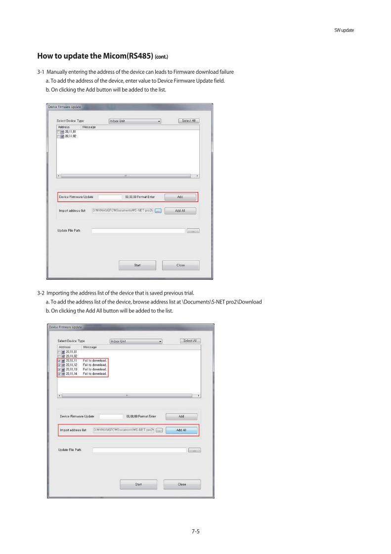
7-5
SW update
How to update the Micom(RS485) (cont.)
3-2 Importing the address list of the device that is saved previous trial.
a. To add the address list of the device, browse address list at \Documents\S-NET pro2\Download
b. On clicking the Add All button will be added to the list.
3-1 Manually entering the address of the device can leads to Firmware download failure
a. To add the address of the device, enter value to Device Firmware Update field.
b. On clicking the Add button will be added to the list.

SW update
7-6
How to update the Micom(RS485) (cont.)
4. Click the Start button for initiating the SW update.
a. The firmware update for the device enters download mode will be displayed.
b. The progress bar at the bottom of the can check the progress of your downloads.
5. Firmware update failure
a. Please update manually if "Firmware Update CRC values are different." error message is displayed.
b. If the firmware update fails, disconnect the S-Net Pro2 communication and re-connect, and re-add the device manually to proceed.

7-7
SW update
7-4. How to update the Micom(UART)
Update SW through RS232(UART) communication.
Step 1Power down the unit and prepare to connect download cable to the PCB
* 20 pin connecter in black color(ODU - 10 pin connecter)
Step 2 Execute S-net pro 2 and go to Add-On tab and click UART Update button
USB to RS232 cable S-Converter
UART update can be used for direct SW update to the hardware.The UART update can be used for SW update of indoor/outdoor/MCU.
We need to connect the S-Net Pro2 to the device board "Download" connector through the download cable.
S-Net Pro2 serial communication should be disconnected. If it is on connection, please disconnect by "Disconnect" button in "Home" ribbon
tool bar. When it is still connected, "UART update" button is disabled.
This feature is applicable in the Disconnected Mode only.
▶ Procedure
1. Connect the indoor/outdoor/MCU board through the download connector.
2. Open S-Net Pro2 and do not click “Connect” button
2. Click on the "UART update".
4. The update window pops up.

SW update
7-8
How to update the Micom(UART) (cont.)
5. Select the download file and Click “Start button” and then Turn On the S-Converter
6. PCB will be updating

7-9
SW update
7-5. How to write the EEPROM
update EEPROM through RS485 communication.
Step 1 Connect S-converter to F1,F2 line
USB to RS232 cable S-Converter
TX+ F1
TX+ F2
Outdoor unit
Main PCB
Step 2 Execute S-net pro 2 and set environment then click connect button
Click Connect

SW update
7-10
How to write the EEPROM (cont.)
Step 3 Go to Add-On tab and click EEPROM Writer
This feature of the outdoor unit is the ability to write data to the outdoor unit EEPROM settings.
(EEPROM firmware, the outdoor unit, FAN version, DBCode to be saved, etc., in fact, write the EEPROM when the outdoor unit are rare.)
▶ Opening "Outdoor EEPROM Write" dialog
Click [Add-On] in ribbon toolbar. Select [Outdoor EEPROM Write] button.
▶ Setting configurations
1. To run EEPROM write operation choose address of the outdoor unit
2. Select All: To Select the entire outdoor unit.
3. 1:1 Direct: It writes data to all the currently connected outdoor Unit EEPROM, when you select the 1:1 Direct checkbox
field then the address checkbox gets disabled.

7-11
SW update
CAUTION
- This is only for Outdoor unit.
- EEPROM writing should be proceeded in case of EEPROM IC replacement by EEPROM IC defect.
Because all the data in the EEPROM IC will be deleted.
* You need to proceed auto trial operation again.
- So when you replace main PCB, keep EEPROM IC and insert it to new PCB without EEPROM writing.
* EEPROM data : eeprom file, S/N, Auto trail operation result, Ref amount check result, etc.
How to write the EEPROM (cont.)
▶ Loading a data file and Establishing connection
1. Click [Open Option File] button to read the source files (. Src). The contents of the file is displayed on the screen and
[Write Option] button is activated
▶ Write Option
Click [Write Option] button and the download status message will be displayed. Progress is to check download progress.

8-1
Reference Sheet
HC H0
H7 H1 HK
HN
H4
HD
HB
HH
HA
Product Type
AM DVM
AJ PMA
AC CAC (USD) / ASD
AE EHS
AN VTL
AKPAK
(Packaged System)
AG CHR
Launch Year
E 2012
F 2013
H 2014
J 2015
K 2016
M 2017
Separator
S General Set (NASA)
N Indoor Unit (NASA)
X Outdoor Unit (NASA)
A General Set (Non-NASA)
B Indoor Unit (Non-NASA)
C Outdoor Unit (Non-NASA)
Grade Classification
F FLAGSHIP
P PREMIUM
D DELUXE ← Basic
S STANDARD
Chassis Classification
1 1 WAY CST
CST 2 2 WAY CST
N MINI 4 WAY CST
4 4 WAY CST
H HSP DUCT
DUCT
M MSP DUCT
L LSP DUCT
E FRESH AIR INTAKE DUCT
G CEILING CONCEILED DUCT
C CEILING
ETCJ CONSOLE
F FLOOR MOUNTING
Rating Voltage
A A(115V, 60hz, 1Ф)
B B(220V, 60Hz, 1Ф)
C C(208~230V, 60Hz)
D D(200~220V, 50Hz)
E E(220~240V, 50Hz)
F F(208~230V, 60Hz, 3Ф)
G G(380~415V, 50Hz, 3Ф)
H H(380V, 60Hz, 3Ф)
J J(460V, 60Hz, 3Ф)
K K(220~240V, 50/60Hz, 1Ф)
M M(127V, 50Hz)
N N (380~415V, 50/60Hz, 3Ф)
Mode
C COOLING ONLY
R410aH HEAT PUMP
R HEAT RECOVERY
D COOLING ONLYR22
E HEAT PUMP
A Cooling onlyR134A
B Heat Pump
H N/A
★Version
★Capacity
8-1-1. Indoor Unit
8. Reference Sheet
8-1. Index for model name
HE
HU
H/
Buyer Name
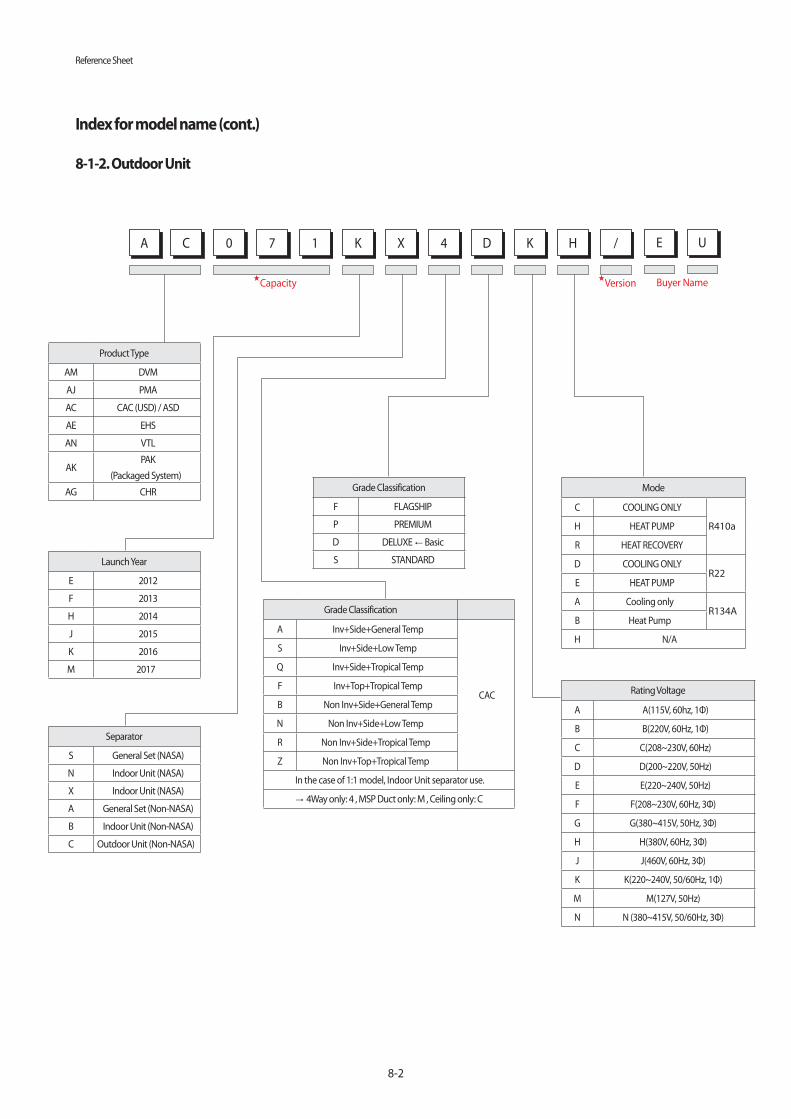
Reference Sheet
8-2
Index for model name (cont.)
HC H0
H7 H1 HK
HX
H4
HD
HK
HH
H/
HA
Product Type
AM DVM
AJ PMA
AC CAC (USD) / ASD
AE EHS
AN VTL
AKPAK
(Packaged System)
AG CHR
Launch Year
E 2012
F 2013
H 2014
J 2015
K 2016
M 2017
Separator
S General Set (NASA)
N Indoor Unit (NASA)
X Indoor Unit (NASA)
A General Set (Non-NASA)
B Indoor Unit (Non-NASA)
C Outdoor Unit (Non-NASA)
Grade Classification
F FLAGSHIP
P PREMIUM
D DELUXE ← Basic
S STANDARD
Grade Classification
A Inv+Side+General Temp
CAC
S Inv+Side+Low Temp
Q Inv+Side+Tropical Temp
F Inv+Top+Tropical Temp
B Non Inv+Side+General Temp
N Non Inv+Side+Low Temp
R Non Inv+Side+Tropical Temp
Z Non Inv+Top+Tropical Temp
In the case of 1:1 model, Indoor Unit separator use.
→ 4Way only: 4 , MSP Duct only: M , Ceiling only: C
Rating Voltage
A A(115V, 60hz, 1Ф)
B B(220V, 60Hz, 1Ф)
C C(208~230V, 60Hz)
D D(200~220V, 50Hz)
E E(220~240V, 50Hz)
F F(208~230V, 60Hz, 3Ф)
G G(380~415V, 50Hz, 3Ф)
H H(380V, 60Hz, 3Ф)
J J(460V, 60Hz, 3Ф)
K K(220~240V, 50/60Hz, 1Ф)
M M(127V, 50Hz)
N N (380~415V, 50/60Hz, 3Ф)
Mode
C COOLING ONLY
R410aH HEAT PUMP
R HEAT RECOVERY
D COOLING ONLYR22
E HEAT PUMP
A Cooling onlyR134A
B Heat Pump
H N/A
★Version
★Capacity
8-1-2. Outdoor Unit
HE
HU
Buyer Name

8-3
Reference Sheet
Index for model name (cont.)
8-1-3. Panel
■ PC4N
※ Only, display the Global 4 Way with Korean/ English K separator.
※ Only, model name for the bundle packaging is “~S”.
★ ※ Only, Global 4 Way Panel version.
HM
HN
HA
HN
HC
HP
H4N
HU
Product Design Classification
P Panel
Product Type
C CST
Product Classification
1N General 1WAY
CST
1B Big 1WAY
2N 2 WAY
4N 4 WAY
4S MINI 4 WAY
4R Round
★ Panel Version
1, 2, .... Domestic
A, B, .... Export
Communication Type
N NASA communication
� Old communication
Color
B Black
E WINE
U White
V Ivory
★Language
K Korean
C Chinese
M 8 languages
E English
TYPE
A Automatic lift / Slide
S STANDARD
H PREMIUM
D 360 General
N 360 Exposed Type
Global
4 Way
Panel
Pattern Waffle Stripe
Domestic 1 5
Export A E

8-4
8-2 Refrigerating Cycle Diagram
■ CONDENSER
High temperature and high pressure gas state coolant discharged from the compressor is converted to a liquid state as it is cooled down
by the heat emission in the outdoor condenser unit, and sent to the evaporator.
■ COMPRESSOR
Low temperature and low pressure coolant is compressed and sent to the cycling system
■ EVAPORATOR
Liquid coolant sucked in through the capillary tubes cools down the room by absorbing the surrounding heat as it evaporates (converting
from liquid to gas). (Absorbing heat required for evaporation)
■ SERVICE VALVE
You can open the valve by turning the need valve counterclockwise using hex wrench, and it is used for vacuum, gas purging, coolant
injection, coolant purging, and indoor-outdoor unit connection.
■ ACCUMULATOR
Accumulator prevents the flow of liquid-state coolant into the compressor. (Liquid-state coolant flowing into the compressor will overload
the compressor.)
Indoor Unit Outdoor Unit
Heat exchangerEvaporator
Liquid pipe
Gas pipe
3-way valve
3-way valve
Electronic expansion valve
Compressor
4-way valve
Cooling
Heating
Leak check points
Aux accumulator
Fan
Heat exchangerEvaporator Fan

This Service Manual is a property of Samsung Electronics Co., Ltd.
Any unauthorized use of Manual can be punished under applicable
International and/or domestic law.
© Samsung Electronics Co., Ltd. December. 2016.
Printed in Korea.
Code No. AC-00171E_1
GSPN (GLOBAL SERVICE PARTNER NETWORK)
Area Web Site