TRACKED M!NIDUMPER MANUAL - Saldatore Distribution Inc.
62
Minidumper TP 500 by Camisa sgE F.II| CAMISA ROBERTO E MASSIMO & C. S.N.C. Loc, Isolo 7 4, 43053 COMPIANO (PR) ITALY Tel, +39 0525 825] 45-+39 0525 825117 Fox +39 0525 825519 Emoil : info@frotellicomiso, it Web site: vwvw,frotellicomiso, it TRACKED M!NIDUMPER TP 5OO USE AND MAINTENANCE INSTRUCTION MANUAL
-
Upload
khangminh22 -
Category
Documents
-
view
0 -
download
0
Transcript of TRACKED M!NIDUMPER MANUAL - Saldatore Distribution Inc.

Minidumper TP 500 by CamisasgE
F.II| CAMISA ROBERTO E MASSIMO & C. S.N.C.Loc, Isolo 7 4, 43053 COMPIANO (PR) ITALY
Tel, +39 0525 825] 45-+39 0525 825117Fox +39 0525 825519
Emoil : info@frotellicomiso, itWeb site: vwvw,frotellicomiso, it
TRACKED M!NIDUMPERTP 5OO
USE AND MAINTENANCE INSTRUCTION
MANUAL

MinidumperTP 500 by Camisa
ATTENTION: Before using the vehicle for the first time, carefully consult the
instruction manual and do not operate or work with this vehicle unless you
have read and understood the instructions and warnings. Failure to follow
the instructions or warnings could result in injury or even death. lf the
Manual is lost or damaged, contact the dealer. lt is the user's responsibility
to adopt all the necessary safety measures.
INTRODUCTIONWe welcome you among the Customers of F.lli CAMISA This vehicle was designed and built to provide
the best performance and special attention was paid to robustness and functionality.We are sure that you will appreciate the high performance, versatility and ease of use of this vehicle.
F.lli CAMISA, is a brand that has been on the market since 1954, and the reliability of the company
represents the best guarantee. You will enjoy using this Tracked minidumper by CAMISA as long as you
use it correctly and carry out the required maintenance operations.
For this purpose, we have written this lnstruction Manual, which will help you to familiarise with the
tracked minidumper, all its components and performance, and will help you carry out the required
maintenance.The Use and maintenance manual of the engine installed on the tracked minidumper is supplied
together with the lnstruction manual of the vehicle.
We recommend that you carefully read both manuals, follow our recommendations, and carry out all
the planned maintenance operations.
WARRANTY CERTIFICATEF.lli CAMISA will take into consideration any request for warranty only if in possession of the annexed
certificate, which shall be duly completed and returned to CAMISA's headquarters no later than 15
days from the date of delivery of the vehicle.
SYMBOLS AND WARNINGSln this Manualthe following symbols are used:
ATTENTION: indicates a potential danger for the operator and/or thepossibility of damaging the vehicle if a certain procedure is no
followed
IMPORTANT: highlights the correct technique or procedure to be
implemented by the operator and informs on what should be done toavoid potential problems to the vehicle, even slight ones, caused by
failure to follow the recommended procedures.

Minidumper TP 500 by Camisa

Minidumper TP 500 by Cqmiso
FIRE HAZARD 32
B|oMECHAN|CAL RISK .'................. 32
9 USING THE VEHICLE START AND STOP ,...,,,,..,,..,32
Tipper- Selfloader - Snow b1ade........... """""" 35
Oleodynamic coupling (optional) """"""""" 37
USING THE TIPPER AND THE LOADING PLATFORM ,,,......'"..37
usrNc THE SELFLOADER (OPTIONAL). ............ ....'..............'. 38
usrNc THE SNOW BLADE (OPTIONAL) .............. 39
CONNECTION TO OTHER EQUIPMENT ,,..,,,,,,,..,42
TRANSPORTING THE VEH|CLE....... ........'............44
MOVTNG A FAULTY VEH|CLE...... ..............'...."... 45
10 MAINTAINANCE AND CHECKS ...,..46
GENERAL WARNINGS "............'..... 45
MATNTENANCE OPERATIONS ............... ............. 47
Fuel supply.. """""' 47
Changing and topping up the engine oil ..............' """""" 48
Replacement of fuel filters.......... """"""""" 48
Changing and topping up the hydraulic oil ............... """" 48
Replacing the hydraulic oil filters """"""""" 50
Compensation tank .""""""""" 50
Adjusting the cables .""""""""' 51
Adjusting the throttle cable ........... .""""""" 53
Adjusting the tension of the tracks """""""' 55
Replacing the tracks """"""""" 55
Greasing points.......... """""""" 55
Precautions for the cold season ."""""""""' 57
Long periods of inactivity """"" 57
When the vehicle is not used for a long time, pour out the fuel from the carburettor and the tank.
if not, the fuel may deteriorate, and this could cause problems to the supply system and make
ignition difficult. ......""""""""" 57
SCHEDULED MAINTENANCE CHART,.,. ,,",,...,'".57
LUBRTCANT CHART ........................ 59
11 PROBLEMS CAUSES SOLUTIONS. ....'.....'."........ 59

MinidumperTP 500 by Comisa

Minidumper TP 500 by Comiso
TECHNICAL SUPPORT
F.lli CAMISA has a Technical Support Service that is available to all its customers to help to solve any
problem on the use and maintenance of its vehicle s.
Customers can send their requests to:F.IIiCAMISA ROBERTO E MASSIMO & C. S.N.C.
Loc. lsola 74 43053 Compiano(Parma) ltalyPhone +39 0525-825145 - +39 0525-8251'17 - Fax +39 0525-825519
Website: www.fratellicamisa. it - Ema il: info@fratellica m isa. it
SPARE PARTS
F.lliCAMtSA distributes its ORIGINAL SPARE PARTS through its Dealers; if there are no dealers in your
area, you may order them directly.When making an order for spare parts, identify the tracked minidumper (model and serial number)
and refer to the Spare Parts Catalogue that can be obtained from the Dealer or directly from F.lli
CAMISA.
IMPORTANT: Failure to use original spare parts or spare parts with
equivalent specifications may cause damage to the vehicle or injury topeople: in this case, F.lli CAMISA declines any and all responsibility'
REPAIRS
For repairs or overhauls that involve complex operations, please contact your local Dealer who
employs specialized staff or F.lli CAMISA directly; in any case, we are at your disposalto ensure prompt
and accurate technicalsupport and for allthat may be usefulto smoothly operate the vehicle'
DOCUMENTATION AND ACCESSORY EqUIPMENT
The following documentation and accessory equipment are available for each vehicle:. USE and MAINTENANCE INSTRUCTION MANUAL for the minidumper. USE and MAINTENANCE INSTRUCTION MANUAL for the engine. WARRANTY CERTIFICATE
,*4./ \)2\-iY
Minidumper TP 500 by Camisa
a
a
a
a
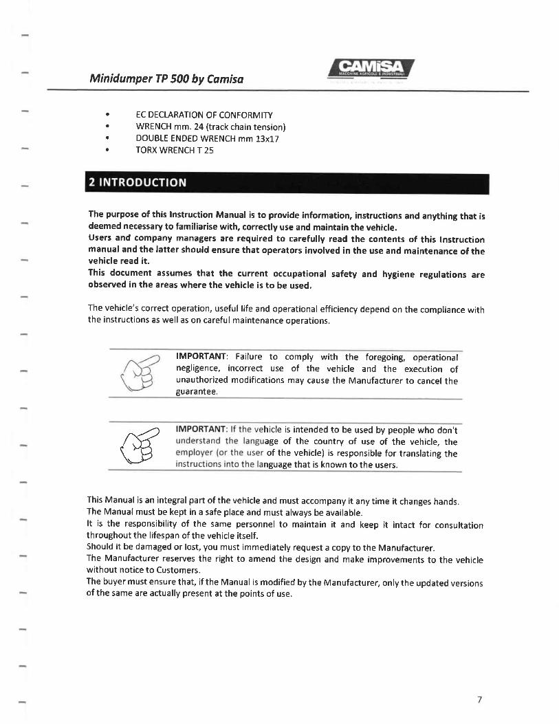
EC DECLARATION OF CONFORMITYWRENCH mm.24 (track chain tension)DOUBLE ENDED WRENCH mm 13x17TORX WRENCH T 25
The purpose of thas lnstruction Manual is to provide information, instructions and anything that isdeemed necessary to familiarise with, correctly use and maintain the vehicte.Users and company managers are required to carefulty read the contents of this lnstructionmanual and the latter should ensure that operators involved in the use and maintenance of thevehicle read it.This document assumes that the current occupational safety and hygiene regutations areobserved in the areas where the vehicle is to be used.
The vehicle's correct operation, useful life and operational efficiency depend on the compliance withthe instructions as well as on careful maintenance operations.
IMPORTANT:negligence,
unauthorizedguarantee.
Failure to comply with the foregoing, operationalincorrect use of the vehicle and the execution ofmodifications may cause the Manufacturer to cancel the
^,-/) hicle is intended to be used by people who don't
/ ,\,f age of the country of use of the vehicle, the\ ^12 of the vehicle) is responsible for translating the\Y nguage that is known to the users.
This Manual is an integral part of the vehicle and must accompany it any time it changes hands.The Manual must be kept in a safe place and must always be available.It is the responsibility of the same personnel to maintain it and keep it intact for consultationthroughout the lifespan of the vehicle itself.Should it be damaged or lost, you must immediately request a copy to the Manufacturer.The Manufacturer reserves the right to amend the design and make improvements to the vehiclewithout notice to Customers.The buyer must ensure that, if the Manual is modified by the Manufacturer, only the updated versionsof the same are actually present at the points of use.

Minidumper TP 50O by Comiso
The Manufacturer is responsible for the descriptions written in ltalian. Any translations may not have
been fully verified, therefore, in case of discrepancies, the ltalian version should be used for reference;
if necessary, contact our technical department that will see to any necessary modifications.
RECIPIENTS
The vehicle is intended for domestic or professional use: forthis reason, it should be used by qualified
operators who meet the following requirements:Are of legal age;
Are physically and psychologically capable of performing particularly difficult technical work;
Have been adequately trained on the use and maintenance of the vehicle;
Are able to understand and interpret the lnstruction Manual and the safety instructions;
Are familiar with the emergency procedures and their implementation;
Have understood the operational procedures defined by the Manufacturer of the vehicle.
ATTENTION: The Manufacturerdamages caused by negligenceinstructions given in this manual.
declines any and all liability forand failure to comply with the
The instructions, drawings and documentation contained in this manual are to be considered strictly
confidential, are the property of the manufacturer and cannot be reproduced in any way, neither in
full nor partially.
OVERVIEW OF THE VEHICTE
The tracked minidumper model TP 5OO is a vehicle designed to transport material and to be connected
to other machines to perform specific operations (for example pest control), that are transported or
operated at fixed point.
The vehicle is intended for both professional and domestic use.
VEHICLE I DENTIFICATION
Each vehicle is equipped with a nameplate for identification located on the top left side of the
dashboard.Fig. 1
Fu rth ermore,

Minidumper TP 500 by Camisa
Fg.
the serial number of the vehicle is punched under the loading platform, onto the chassis, where theloading platform is bolted on the left. Fig. 2.
The engine identification codes were stamped on the crankcase by the engine Manufacturer.
Fratelli Camisa Roberto e Massimo & C. S-n.cLoc lsola 74 - 43053 - Compiano Parma ltayTel +39(0)525.'8251 45 - +39i0)52518251 1 7
www f ratellicamtsa rt
Da515aGFnKw
GLOSSARY
PPE: Personal Protection EquipmentUMIM: Use and Maintenance lnstruction Manuallntended use: Use of the vehicle in compliance with the information given in the instructions for use;Reasonably foreseeable incorrect use: vehicle used for purposes other than the intended ones, butwhich may derive from an easily predictable human behaviour
The vehicle built by F.lli CAMISA is guarantee d for 24 months for domestic use and for 12 consecutivemonths for professional use, from the date of purchase, as long as it is used in accordance with theinstructions illustrated in the UMIM and is used in standard working conditions. Within these terms,F.lli CAMISA undertakes to supply, free of charge, those spare parts that, according to F.lli CAMISA orhis authorized representative, evidence material or manufacturingfaults; the Manufacturer may also,at their sole discretion, perform the repair directly or have it performed by authorized personnel.The warranty becomes void if the vehicle is used without complying with the requirements and thelimits contained in the UMIM, or if the vehicle has been repaired, disassembled or modified byunauthorised workshops. The warranty applies only to those components which, by nature, are notsubject to quick wear-and-tear. Those parts and the accessories supplied with the vehicle, but thatwere not manufactured by F.lli CAMISA, are covered bytheir respective manufacturer's guarantee inso far as such guarantee is available to F.LLI CAMISA.The responsibility of F.lli CAMISA is strictly limited to the supply of spare parts or to the repair ofdefective parts and excludes any responsibility for other costs, damages and direct or indirect lossarising from the use or the impossibility to use the vehicle, both fully or partially.
Fig.2

Minidumper TP 500 by Comisa
IMPORTANT: F.lli CAMISA will take into consideration any request
warranty only in possession of the annexed certificate, which shall
duly completed and returned to CAMISA's headquarters before and
forbe
no
later than 15 days from the date of delivery of the vehicle.
FIRST CHECK
Upon delivery of the vehicle, the buyer is required to:Check the level of all lubricants.
Check the electrolyte level in the battery pack
Check the tension of the tracks.
Check the level of fuel in the tank.Check that all the screens, grilles and safety guards are correctly positioned and in good
conditions.Check that all the labels for safety instructions are in order and in good conditions.
Check that the EC Declaration of Conformity and the tools needed for ordinary maintenance
operations are supplied with the vehicle.
lf the tracked minidumper was delivered by a forwarding agent, ensure that the vehicle is whole
and that no parts are missing; if necessary, place a claim for the fault or missing part.
TP 5OO
E ngine Model Cycle Cyli nder5
Displa cementcm3
Maximum powerKW
Maximum runningspeed revs/min
Sta rt- u p
Subaru EX 21 Petrol 1 21,7 5.15 3600 Manual
Subaru EX 27 Petrol 1 26s 660 3600Man ua I
Electric (ootional)
Honda GX 270 Petrol 1 210 6,30 3600Manual
Electric (optional)
Transm ission Hydrostatic with piston pumps
Hvdraulic motors Orbital
Forwardmovement
1 lever for speed
controls 2 steering control levers
Rol I ers 6 mounted on bearings and with extractable pins
Dr ve Rubber tracks
Tracks tension With tension spnng
Bed for the construction sector, from 0 25 ni mm 1000x700x350 with opening bulkhead
Hydra ulic tr pper
Overalldimensions
mm 1460x700x1180
Weight ks 295
Capacity ke 500
Speed From 0 to 5 Km/h with gradual variation
OPTIONAL ITEMS
Electric start (only for the Subaru EX 27 / Honda GX 390 engines)
Selfl oader
1-0

Minidumper TP 500 by Cdmisa
The pictograms contain critical information/instructions especially as regards safety.
Failure to comply with such provisions may cause:serious safety hazards for operatorsloss of contractual guaranteeexclusion of manufactu rer's responsibility.
I MPORTANT: the pictogramsperiodically clean them withdamaged or no longer legible.
must always be visible anda damp cloth and replace
legible, so it is necessary tothose pictograms that are
SAFETY PICTOGRAMS
The pictograms contained in a triangle indicate a HAZARDThe pictograms contained in a circle indicate a pRoHtBtfloN/oBLtGATIoN
This section describes the location of the hazard and the exact position of the relative warningpictograms.
Before using the vehicle, familiarise with the meaning of the following pictograms.
REF.
NO.
DESCRIPTION
1 General hazard This symbol indicates operationsand points that may put the safety of theoperator at risk. Take extra care to avoid thepotential accident hazard.
2 Before commissioning, always read thelnstruction manual.
3 Remain at a safe distance from the vehicle.
4 Hot surface hazard
5 Poisonous fumes or toxic gases hazard.
5 Stop the engine and remove the spark plugconnector before maintenance.
7 Do not use open flames or smoke.
8 Do not transport people or animals on theloading platform.
9 Do not unload the loading platform while on a
slope.
tl.ril
'ffip
1.L

Minidumper TP 500 by Comisa
h REF. NO. DESCRIPTION
10 Sideways overturn hazard
11 Tie the load to avoid overturning.
L2 Crushing hazard.
13lnsert the support before entering the hazardous
area.
L4 Reverse gear hazard.
15 Crushing hazard when reversing.
REF. NO. DESCRIPTION
15Hot surface hazard: burning danger for fingers
and hands.
REF. NO. DESCRIPTION
L7 Hydraulic oil level cap.
REF. NO. DESCRIPTION
18 Guaranteed acoustic power level Lwa marking.
REF. NO. I OESCRtprtOru
L2

Minidumper TP 500 by Camisa
22
19 | Do not approach the loading floor when thetipper is operating: crushing hazard.
REF. NO. DESCRIPTION
20
General hazardThis symbol indicates operations and points thatmay put the safety of the operator at risk. Takeextra care to avoid the potential accident hazard.
27Before commissioning, always read thelnstruction manual.
Ref. NO. DESCRIPTION
22 Grease where shown.
Ref. NO. DESCRIPTION
23Lifting point ONLY for loading platformreplacement: it is PROHIBITED to use thesepoints to lift the whole vehicle.
Ref. NO. DESCRIPTION
24 Mandatory use of hearing protection.
25 Mandatory use of protective gloves.26 Use safety shoes.
27Do not exceed the permissible sideslope.
H
23
o@HS
13
Minidumper TP 500 by Camiso
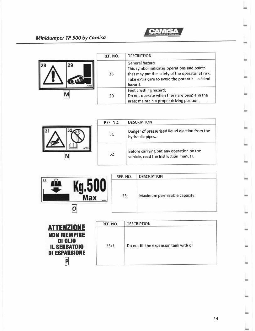
REF. NO. DESCRIPTION
28
General hazard
This symbol indicates operations and points
that may put the safety of the operator at risk.
Take extra care to avoid the potential accident
hazard.
29
Feet crushing hazard;
Do not operate when there are people in thearea; maintain a proper driving position.
REF. NO. DESCRIPTION
31Danger of pressurised liquid ejection from thehydraulic pipes.
32Before carrying out any operation on thevehicle, read the lnstruction manual.
E
REF. NO. DESCRIPTION
33 Maximum permissible caPacitY.
REF. NO. DESCRIPTION
33/t Do not fill the expansion tank with oil
]IOT RIEMPIREDI OLIO
It SERBATOIODt ESPAllSlollE
E
ATTEl{ZIOilE
t4

Minidumper TP 500 by Camiso
REF.
NO.
DESCRIPTION
33/2
Entangling and pulling hazard while the cardan shaft is
rotati ng.
This symbol indicates operations and points that may put thesafety ofthe operator at risk. Take extra care to avoid thepotential accident hazard.
33/3Do not open or remove the protection shields while theengine is running
IDENTIFICATION AND LOCATION OF CONTROTS
Control list
L. Hand throttle lever. 2. Forward speed control lever.3. Direction control levers. 4. Hydraulic tipper control lever.5. Selfloader / snow blade control lever (optional).
Control ldentification Pictograms
GAS g
REF. NO. DESCRIPTION
1
Code 4085
Throttle control lever
2Code A017-C
Forward speed control lever
15

MinidumperTP 500 by Cdmiso
++-
E
- -- -- -E
-- -- -- -I I
-
E
- -- -- -+ +-"""
3Code A016-C
Direction control levers
4
Code A016/8
Hydraulic tipper/snow blade
control lever (optional)
5Code A015/D
Selfloader control lever
(optional)
15

Minidumper TP 500 by Camisa
trtrtrtr
1.7

MinidumperTP 500 by Cqmisq
Etrtrtrtr
trtrtrtrtr
USING CONTROLS
1. HANDTHROTTLE LEVER
To adjust the engine speed, pull the lever to the left (increase RPM) (Fie. 34) or push it to the right
(decrease) (Fie. 35).
Fig. 34 Fig. 35
IMPORTANT: When the vehicle is not moving, set thecontrol lever to the minimum (all the way to the right).
L8

Minidumper TP 500 by Comisa
2. ENGINE ON / OFF knob.
The knob has two positions: ON (Fig. 35) allows igniting and running the engine and OFF (Fig. 37), whichstops the engine and prevents ignition.
3. FORWARD SPEED CONTROL LEVER.
This lever adjusts the fonruard speed of the vehicle and the flow rate of the pump's oil. Push the leverforward to increase the speed and have less power (Fig. 38) and pull the lever backwards to reducethe speed and have more power (Fig. 39).Pulling the lever all the way back sets the Bear to the neutral position and the vehicle will not move.
Fig. 35 Fie.37
ATTENTION: Always maintain a low speed when going downhill.which is appropriate for the type of terrain and slope.
Fig. 38 Fie. 39
19

Minidumper TP 500 by Comisa
4. D!RECTION CONTROL LEVERS.
To move forward, push the levers forward (Fig. 40) or pull the levers backwards to select the reverse
gear (Fig. 4L). Release them to stop the vehicle completely (Fie. a2l-
To steer right forward, push only the left lever (Fig. 43).
To steer left forward, push only the right lever (Fig. 44).
To steer right backward, pull only the left lever (Fig. 45).
To steer left backward, pull only the right lever (Fig. 45).
To rotate the vehicle by 350', push a lever forward and pull the other backward (Fig. a7).
IMPORTANT: This lever is also a safety device. Do not tamper with it and make sure
that it is always in good conditions. lf you are in a critical condition, release it toautomatically stop and brake the vehicle.
Fig.40 Fig.4L
Fig.42 Fig. 43
20

Minidumper TP 500 by Comiso
Fig.44 Fie. 45
s. HYDRAULTC TtPPER/SNOW BLADE CONTROL LEVER (OpTtONAL)
The hydralic tipper control lever allows operating the tipper automatically by means of a hydraulicdistribution unit, or it allows raising or lowering the snow blade, by selecting the oil flow from thedistribution unit positioned under the loading platform. Push the lever forward to tip the loadingplatform (Fig. a8) and pullthe lever towards you to lower the loading platform (Fie. 49).Push the lever forward to lower the snow blade (Fig. 48) and pull the lever towards you to raise thesnow blade (Fig. 49)
Fig.46 Fig.47
Fig.48 Fig.49
21.

MinidumperTP 500 by Camisa
6. SELFLOADER / SNOW BIADE CONTROL LEVER (OPTIONAL)
The selfloader control lever allows operating the selfloader to load the loading platform or move the
material. Push the lever fonarard to lower the selfloader (Fig. 50) and pull the lever towards you to raise
the selfloader and automatically load the loading platform (Fig. 51)'
Fig. 50 Fig.51
ATTENTION: When unloading the loading platform, pull the lever toward you to
bring the selfloader back to allow the correct unloading of the material.
GENERAT PROVISIONS
IMPORTANT: The operator must use the vehicle in accordance with the
-^ instructions contained in this Manual, taking into account the current rules on
f< accident prevention, the use conditions and the technical specifications of the
\ Ya vehicle. Read the instructions contained in this Manual before using the\__)/ vehicle: compliance with such rules during operation will prevent the
occu rrence of accidents.
lf the vehicle has to be stopped for maintenance/repair operations, place a sign to warn against using
the vehicle.
22

Minidumper TP 500 by Camiso
Make sure you do not touch liquid fuels, lubricating oils, acids, solvents, etc. as most of them containsubstances that are potentially harmful.Always use the specific PPE while refuelling, adjusting and maintaining the vehicle; safety shoes shouldbe worn at all times.ln case of welding operations, protect the flexible hoses and rubber sleeves because the sparks of veryhot material could damage them, causing the oils, coolants, etc. to leak. Unplug the battery to avoiddamaging it.
Employees have a duty to actively work with employers to implement prevention measures and mustfollow the instructions given during training.
IMPORTANT: For professional use, the vehicle and any relatedequipment should be used only and exclusively by authorised personnelwho has been adequately trained and is familiar with the safety and useregulations.For domestic use, it is the responsibility of the user to establish whethertheir technical skills and training allow them to use the vehicle in a safemanner.
The vehicle was designed and built to be used as a means of transporting material and to be connectedto or operate specific equipment. Before connecting the vehicle to or using it with another equipment,carefully read the lnstruction manual of the equipment.
IMPORTANT: Before using or allow the vehicle to be used by authorisedand adequately trained operators, ensure that a correct analysis of therisks associated with operations has been duly carried out
^R\{i-t}
0B@
6Brt4as
23

Minidumper TP 500 by Comiso
For professional use, verify that the selection
and training procedures ensure that drivers
and users of the vehicle are able to use it safely.
Users must possess the necessary skills tooperate the vehicle and carry out daily
maintenance operations. An untrained user is
a danger to themselves and others.
Users must be able from a medical point ofview (good mobility, hearing and eyesight).
Driving training is essential and represents a
legal requirement. Untrained drivers are a
danger to themselves and to others.
Employees have a duty to actively work withemployers to implement prevention measures
and must follow the instructions given during
training.
IMPORTANT: lf the vehicle is used for anv ouroose other than that
f< ,.J'*,"0 in this Manual,.J \-l--r.\.--L} resPonsibilities for injur
- property
UNINTENDED USE
The vehicle is intended for use as described in this UMIM; any use that is non-compliant or non-
comparable to what is indicated in the UMIM is to be considered unintended; more specifically:
The vehicle cannot be used on public roads
open to traffic
When transporting equiPment, it is
forbidden to use fastening points that are
not specifically contemplated for use withsuch equipment, and to exceed themaximum weight indicated by theManufactu rer.
Exceeding the capacity established by themanufacturer is dangerous and can cause
serious damage to the structure of thevehicle.
This vehicle is not intended for towingequipment.
The vehicle was designed to be conductedon foot: it is forbidden to drive the vehicle
from the loading platform or when resting
on the chassis.
It is strictly forbidden to modify thestructure of the vehicle.
It is strictly forbidden to transport people
or animals on the vehicle during operationor during the transfer.
The vehicle and any related equipmentshould be used only and exclusively by
authorised personnel who has been
adequately trained and is familiar with thesafety and use regulations.
24

Minidumper TP 500 by Camisa
RECOMMENDATIONS FOR USING THE VEHtCtE CORRECTTY
Before starting the vehicle, check that theload is properly distributed and secured toavoid movements during operation anddangerous imbalances.
Ensure that the load does not reduce thedriver's field of vision.
Ensure that the transported material doesnot hang out from the loading platform.
Do not load or unload the goods while thevehicle is on a slope.
Do not move the vehicle while the loadingplatform is in a vertical position.
Make sure that any transported equipmentdoes not impair the balance of the vehicle.
Before operating the vehicle, check thatthe equipment is correctly connected,referring to this UMtM and to that of theconnected equipment.
Only authorised personnel should bepresent in the work site; if there are otherpeople or animals, stop immediately andmake them move away.
Start the engine and operate only whenthere are no people and children within thevehicle's operation range.
Start slowly and increase the speedgradually.
Slow down before facing a turn; whenturning, always keep in mind the type ofload and the conditions of the terrain.Avoid operating at excessive speeds andavoiding turns on sloping ground.
When transporting heavy loads, proceedwith extreme caution to avoid suddenbraking.
When driving on sloping ground payspecial attention to the adhesion to the
ground and to any obstacles or subsiding ofthe terrain; we recommend to have thevehicle driven by experienced staff with a
sound knowledge of the territory.
When driving downhill, use the samespeed you would use if you were goinguphill on the same slope and drive atmoderate speed.
Choose the operating modes according tothe slope and the state ofthe terrain.
Take special care when driving downhill,especially in rough terrain.
When crossing a slope, keep thetransported equipment raised to the bareminimum so that it does not touch theground
When driving on sloping ground with sideimplements fitted, keep the implementson the upstream side.
Choose the operating modes according tothe slope and the state of the terrain.
Do not jump or bounce the vehicle onuneven ground as you may lose control
ln case of sloping ground, always operatein the lines of maximum slope and drivealong the direction perpendicular to thelevel line on the slopes: never cross themlongitudinally
lf possible, avoid crossing sloping groundor steep slopes. lf you are forced to do so,avoid holes, depressions or protrusions ofthe ground and do not try to drive overtrunks, rocks or raised areas
lf you successfully move over hurdles orsteps, and when the inclination of theterrain changes suddenly, the vehicle mayabruptly change inclination, which maycause the load to displace. We recommend
25

MinidumperTP 500 by Comisa
you deal with these situations at very low
speed to keep the risk to the minimum.
lf it is necessary to cross a steep slope,
avoid abrupt steering: slow down and
make a wide steering
Always keep the gear engaged when
driving downhill. Never allow the vehicle togo down freely with the gear in neutralposition.
Avoid ditches, embankments, earthworks,river banks, canals and fords. Stay away
from the edges as they might collapse.
Do not force the forward lever if resistance
is encountered when engaging.
When using the pressure washer, do not
direct the water jet towards components
and electrical connections, seals, joints,
greasing points, the engine and rubber orplastic parts.
Transport, maintenance, rePair and
lubrication operations must be carried outafter the engine has been stopped and thespark plug wire has been disconnected.
Never connect, disconnect or ground
contacts in the electrical system while theengine is running.
When connecting an additional battery in
case of an emergency start, respect thepolarity, use suitable cables and do notexceed 12 V.
The battery should be recharged in a well-
ventilated room, afterthe battery has been
disconnected from the sYstem and
removed from the vehicle.
The vehicle should never be pulled to make
it start.
Always ensure that the safety devices are
in perfect working order.
It is dangerous to use the vehicle if the
tracks are not fully stretched.
Do not leave the vehicle in motion uphill or
downhill without the operator and withoutthe appropriate wedge.
Do not to refill the tank of the vehicle whilethe engine is running or is very hot, in thepresence of an open flame or in closed
rooms.
Do not leave the engine running indoors:
exhaust gases are toxic.
Work only in daylight, or in the presence ofgood artificial lighting.
Keep the vehicle clean from debris and
plant debris.
Keep away from electrical conductors and
obstacles. Contact with electrical
conductors can cause electric shock and
death.
Operate the controls only after being
properly positioned in the driver's seat.
Do not change the engine's speed that is
set by the manufacturer at their premises.
When the vehicle operates at fixed point,
before running the connected equipment,
secure the work site and prevent any
unauthorized personnel from approachingthe equipment.
26
Minidumper TP 500 by Camisa
WARNINGS FOR THE SAFETY OF OPERATORS
'.6
IMPORTANT:Always keep in mind that if the vehicle is not used correctlyit, can become dangerous and pose a potential risk of serious injury ordeath to oneself and to others that may be in the operating range of thevehicle.It is therefore mandatory that the vehicle be used only by people whoare fully aware of the instructions for use and who have been adequatelytrained, which also allows carrying out a correct risk analysis in anyoperating circu mstance.
General provisions
At work, use hearing protection, safetyshoes and protective gloves and anyother PPE that may be necessary forthe operation to be carried out.
When operating on the vehicle,especially if any component is rotating,make sure that you wear appropriatework garment that is not loose andmay get entangled in the moving parts.
No control should be activated whenstanding on the ground. Allmanoeuvres should be done from thedriver's seat.
Never drive the vehicle if your handsare not free.
Adjust the position of the seataccording to the height of the driver.
lf the engine or the steering wheel donot work, immediately stop the vehicleto prevent any manoeuvring problems.
lf the vehicle is used incorrectly (forexample if the load exceeds themaximum permissible weight), there is
a risk of residual risks due to thedeformation or breakage of somecomponents; the UMIM gives
instructions on the correct use and onthe maximum admissible loads.
Check the efficiency of the safetybrake, especially if the vehicle has notbeen used for a long time.
Replace the safety notices that may bedamaged and keep them clean so thatthey are clearly visible.
Any maintenance or cleaningoperation on the vehicle should becarried out after the engine has beenstopped and the cable ofthe spark plughas been disconnected.
Do not overload the vehicle or use it incombination with equipment that is
not reliable and not intended for thespecific use, or with equipment whichis in a poor state of repair.
Do not park the vehicle on slopingground.
27

Minidumper TP 500 by Camiso
lf the vehicle is started indoors, ensure
that there is sufficient ventilation.
The weight and dimensions of the toolsthat may be transported must be
compatible with the limits set for thevehicle.
Any work on tubes and fittings of thehydraulic system should be carried outafter the engine has been stopped, thepressure has been released and
protective gloves have been worn. Be
careful: the circulating oil can reach
temperatures that exceed 80 " C.
Do not open the oil tank cap when theengine is hot as the system may be hot.
Do not make any changes to thevehicle that may alter its operation.Always consult the dealer if you have
any special requirement.
When refuelling, do not smoke and do
not fillthe tank completely; stay awayfrom any source of flame or sparks,keep the motor turned off and
immediately clean any traces of spilled
diesel fuel.
Do not use flames within the operatingrange of the vehicle.
Do not put yourfeet or hands betweenthe loading platform and the track.
Do not put your hands or feet underthe tracks.
While the tipper is lowering, pay
special attention to any area that maypose a risk of crushing for the hands.
Do not use your hands to locate a
leakage. Use a sheet of paper or a rag
instead.
Check the state of wear of the tracksand replace them if worn out.
Do not allow under 18s to use thevehicle.
Be careful not to come into contactwith hot parts of the engine.
Stop the engine in case of emergencysituations.
Select a flat, stable area when carryingout maintenance operations.
During maintenance, the tracks must
be locked.
Any maintenance or cleaningoperation on the vehicle should be
carried out after the engine has been
stopped; do not open the engine
compartment unless the engine has
been stopped.
Avoid spills while topping up thecooling liquid, the fuel, the lubricatingoil, the brake oil, etc. ln case of spills,
clean the area immediately.
lmmediately repair any fluid leakage.
28

Minidumper TP 500 by Camiso
lmportant considerations of an ecological nature
We have fully understood the importance of maintaing the natural balance in the environment. Soil, air andwater constitute the essential elements for agriculture and human life.
Ask your lubricant, fuel filter, detergent suppliers about the standards to be followed to use, store anddispose of their products.
Deliverthe lubricants to specialcollection points:they must not be dispersed in the soil.
During the design and construction stages F.lli CAMISA checked the points that are considered hazardous forthe operator; however, some residual risks remain that may occur when using the vehicle.
This section highlights some of the most significant risks that may occur; however, this list can never beexhaustive especially when considering any unintended use of the vehicle and the different workingconditions.To limit any residual risks, strictly adhere to the instructions given in the safety chapter.
IMPORTANT: ln all working conditions the person in charge/user of themachine must be certain to operate so that safety is ensured for himselfand for others.Before starting the machine, check that there are no hazardousconditions nearby.During operation, constantly check for the presence of hazards: thisallows timely interventions which reduce any risks to the minimum.
NOSE.UP AND OVERTURNING RISK
There may be a residual risk associated with the tracked minidumper rearing up or overturning. ln eachoperational circumstance, the user must evaluate the level of residual risk and adopt the appropriatebehaviour aimed at eliminating or minimizing the danger, in particular:
Pay special attention whenslope or on uneven terrain.
lf the weight of the loadadmissible one, the trackedmay rear up or overturn.
driving on a
exceeds theminidumper
Take extra care especially as regards theheight and distribution of the load whendriving on uneven ground, especially if youare driving sideways compared to theslope; ensure that the centre of gravity ofthe machine falls within the tracks.
29

Minidumper TP 500 by Comisa
Before fully raising the tipping device,
ensure that the material to be unloaded
slides over the surface of the tipper; if not,
it may dangerously raise the centre ofgravity of the vehicle which may cause thevehicle to overturn.
Pay attention to the load: uneven
distribution of the weight significantly
increases the risk of overturning.
NOISE RISK
There is a residual risk associated with noise as the machine has
than 82 dBA (measured in accordance with ISO 11201:2010 and
values perceived by the driver (L pa) and the sound power levels
in accordance with ISO 3744:2009 and ISO 5395:2008).
a sound pressure level (Lpa) greater
ISO 5395:2008): the sound pressure
are therefore given (Lwa) (measured
hen using the vehicle, we recommend using
rotection devices, such as headsets orover time, help prevent damage to the
IMPORTANT: ln case of overturning or rearing up do not try to hold back
the vehicle but let go of the handlebars and move away.
NOISE DETECTION
MODEL SOUND PRESSURE (Lpa) dB (A) SOUND POWER (Lwa)dB (A)
TP 5OO 85,8 101
VIBRATION RISK
The vehicle is by its very nature a source of vibrations for the human body, the intensity of which
depends on the type of equipment connected and on the type of work performed.
The employer/user must conduct a carefulvibration risk analysis and organise work shifts and activities
so that each worker is not subjected to vibration levels that exceed those established by the current
legislation.
30

Minidumper TP 500 by Camisa
The vehicle vibration levels transmitted to the hand-arm and whole body were measured on the basisof the operating cycle described in the tSO Z63L-I standard.
VIBRATION DETECTION
Vibration levels are influenced by different parameters:Training and behaviour of the operatorOrganization and preparation of the work siteTypes of tracksTo limit the level of exposure to vibrations, it is important to adopt appropriate behaviours, inparticular:
Use a proper forward speed and reduce the revolutions of the engine to the lowest level that iscompatible with the operation being carried out.Adjust the seat according to the size of the driver. To minimize the level of vibrations, adjust thevehicle speed according to the path.
IMPORTANT: The vehicle is not protected from emissions ofdangerous matters and substances: when operating in anenvironment which poses a risk of inhalation, ingestion and contactwith dangerous substances, the operator must wear the specificPPE.
The machine is not protected from the falling objects hazard: a careful risk analysis should beconducted when carrying out operations that may pose this risk. (Example: risk of falling branches inwoodland).
HAND-ARM VIBRATIONMODEL PERCENTILE 75% mls2 AVERAGE t DEV. STANDARD m/s2TP 5OO t4,7 72.7 !2.9
IMPORTANT: The emission values shown describe the vibrationtransmitted and are specific to the indicated conditions of use.
31
Minidumper TP 500 bY Comiso
FIRE HAZARD
All fuels, most of the lubricants and some cooling mixtures are flammable: we recommend checking and
repair any leakage. Always stop the machine before refuelling. Fill the fuel tank outdoors. Do not refuel near
open flames or sparks and do not smoke during this operation. Keep the machine clean by removing all
flammable materials such as fuel, oil, and debris. Don't allow combustible material to accumulate on the
machine. Do not weld or flame-cut pipes or tanks that contain flammable fluids.
Do not bend or hit the high-pressure pipes. Do not install bent or damaged pipes. Check that the pipes and
hoses are not worn-out or damaged.
The batteries give off combustible gases which can explode. Keep the top part of a battery away from direct
flames or sparks. Do not smoke near a battery.
BIOMECHANICAL RISK
lf the minidumper is not used as indicated in the safety chapter, it may pose the risk of biomechanical
overload, especially to the back-lumbar area; the user must therefore follow the instructions for use
illustrated in the safety chapter and must avoid forced movements that may be caused by the uneven
distribution of the transported load.
STARTING PROCEDURE
To start the machine, follow this procedure:
32

Minidumper TP 500 by Comiso
Fig. 54 Set the carburettor choke lever on theengine to the left, "Closed". lf the vehicle is
started when the engine is hot, the choke levermust remain in the open position.
Fig. 55 Slightly accelerate by operating on thethrottle lever located on the handlebar.
Fig.52 Set the fuel cock on the engine to "ON".
33
TP 500 by Comiso
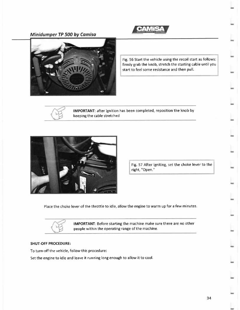
Fig. 55 Start the vehicle using the recoil start as follows:firmly grab the knob, stretch the starting cable until you
start to feel some resistance and then pull.
IMPORTANT: after ignition has been completed, reposition the knob by
keeping the cable stretched
Fig. 57 After igniting,right, "Open."
the choke lever to the
Place the choke lever of the throttle to idle, allow the engine to warm up for a few minutes.
SHUT-OFF PROCEDURE:
To turn-off the vehicle, follow this procedure:
Set the engine to idle and leave it running long enough to allow it to cool.
IMPORTANT: Before starting the machine make sure there are no otherpeople within the operating range of the machine.
34

Minidumper TP 500
Fig. 58 Set the engineuntil the engine stops.
Fig. 59 Then set it back to its original position"ON" to allow the next engine start.
Fig. 50 Set the fuel cock on the engine to "OFF"
!MPORTANT: Before leaving the operator's driving position alwaysfollow this procedure:Check that all commands and equipment are secured and that theforward lever is in neutral.Turn offthe engine.Make sure the automatic parking brake is efficient.
35

Minidumper TP 500 by Comisa
TIPPER- SETFTOADER - S]{OW BTADE
The hydraulic tipper activates the hydraulic jack to use the tipper, and any other connected equipment.
Tipper/snow blade selection lever (optional) (Fig. 61)
Tipper - selfloader selection lever (Fig. 52)
Tracked minidumper (Fig. 53)
Tracked minidumper with overturned loading platform (Fie. 5a)
Tracked minidumper with lowered selfloader (Fig. 55)
Tracked minidumper with raised selfloader (Fig. 65)
Tracked minidumper with lowered snow blade (Fig. 57)
Tracked minidumper with raised snow blade (Fig. 58)
Fig. 51 Fie.52
Fig. 53 Fig.54
36

alrt 1r1 l-r-'{rMinidumper TP 500 by Camisa
66Fg65Fg
Fig.67
Oleodynamic coupling (optional)
Hydraulic connections consist of female half-couplings in the optional single distributor, and of male andfemale in the standard double quick-coupling which can be coupled to half-couplings of the same size. Toensure that the hydraulic system operates smoothly, the oil level in the transmission system should be
checked frequently.
Before connecting any equipment always read the corresponding use and maintenance manual. Ensurethatthe hydraulic cylinders of the equipment that are to be connected contain the same type of oil used for thetransmission system of the tractor to prevent polluting the oil, which may cause the vehicle to malfunction.
USING THE TIPPER AND THE LOADING PTATFORM
Fig. 68
IMPORTANT: To operate the tipper, refer to the "Using the controls"section
r-4\xa\*-}/
37

Minidumper TP 500 by Camisa
ATTENTION: The load must be evenly distributed to avoid that theweight concentrates on the front, rear or side section of the loadingplatform as this would reduce the stability of the vehicle and cause itto overturn.
ATTENTION: The tipper may be operated only from the driver's seat.
It is forbidden to unload the tipper downstream while the vehicle is on sloped ground, as this may cause thevehicle to overturn.
While using the tipper to unload material, only the operator is allowed in the area within the operation range
of the vehicle.
Before completing the operation on the tipper, ensure that the material to be unloaded is sliding over thesurface of the tipper.
ATTENTION: Do not move the vehicle until the tipper hasn't reachedthe rest position.
usrN6 THE SETFLOADER (OPTTONAt'
IMPORTANT: To operate the selfloader, refer to the "Using the Controls"section
ATTENTION: While working with the selfloader, the loading platformmust be resting on the chassis and should not be raised.
ATTENTTON: The selfloader may be operated only from the driver'sseat.
38

Minidumper TP 500 by Camiso
While using the selfloader, only the operator is allowed in the area within the operation range of the vehicle.
ATTENTION: Do notreached the position
move the vehicle until the selfloader hasn'tover the loading platform.
usrNG THE SNOW BrADE (OPTTONATI
IMPORTANT: To operate the snow blade, refer to the "Using theControls" section
ATTENTION: To have a greaterforce on the snow blade, load at least300 kg on the loading platform.
ATTENTION: The tipper may not be operated when the snow blade isinstalled
To use the snow blade, it must first be installed as follows:
i Fig. 69 lnsert the arc with the snow blade on the, outside of the tracks, insert the two bolts on the; right side and tighten them.
39

Minidumper TP 500 by Comisa
Fig. 70 Repeat the same procedure for the left
side, insert the two bolts and tighten them.
, Fig. 71 Place the piston support on the front: chassis of the vehicle, insert the first bolt on the: left, without tightening it
Fig. 72 lnsert the bolt on the right side of thepiston support, without tightening it
*'"*"t
t;* ;;';;;;;; "" the top section or the i
piston support, and tighten everything i
40

Minidumper TP 500 by Cdmiso
Fig. 75 Use the distributor under the loadingplatform to select the operation: pull away fromthe vehicle to select the tipper
Fig. 77 To rotate the snow blade, remove thespring pin inserted under the fixing pin
ii
$Fig. la Connect the hydraulic hoses to the{ distributor located under the loading platformiI
Fig.76 Push the distributor lever inward to selectthe snow blade
4L

TP 5OO Camiso
Reinsert the pin and the spring pin to fasten the blade.
COTTNECTION TO OTI{ER EQUIPMENT
Fig. 79 Rotate the blade until it reaches thedesired position
78 Remove the plug completely
IMPORTANT: Before connecting the vehicle to another equipment,
carefully read the use and maintenance manual of the equipment to be
connected.
The minidumper was designed to be connected to other equipment/machines by means of dedicated
connection and support points located on the loading surface support (Fig. 80-81-82-83-84), or by means of
oleodynamic quick couplings (optional).
6
42

Minidumper TP 500 by Comiso
Fig. 80 Fig. 81
ATTENTION: Verify that the equipment to be installed featuresanchoring and support points that are compatible with the vehicle's.It is forbidden to connect any equipment in points other than thoseforeseen by the Manufacturer
Fig. 82 Fig. 83
Fg 84
43

Minidumper TP 500an equipment
residual risk assessment should be made with regards to the tracked
minidumper-connected equipment assembly and to the operation to be
carried out.
When the size of the equipment exceeds that of the tracked minidumper, the minidumper-connected
equipment assembly may pose residual risks which must be carefully assessed.
When using the dumper-connected equipment assembly, respect the maximum spikes and loads
contemplated by the Manufacturer
TRANSPORTING THE VEHICLE
The vehicle should be transported using a suitable means of transport.
Secure the tracked minidumper on the means of transport by way of straps or chains that are suitable for
fastening to the chassis of the vehicle.
IMPORTANT: Do not hook or connect the chains to the components of
the minidumper as they may be damaged by the chains or by excessive
loads.
The vehicle should not be lifted: it must be driven into the means of
transport.Should any problem prevent moving the minidumper, contact a
specialised com that has the suitable
LOADING AND UNLOADING FROM THE MEANS OF TRANSPORT
When loading/unloading the vehicle onto/from the means of transport, choose a flat and stable area away
from traffic and free from any potentially dangerous objects.
Stop the engine of the vehicle and use the brake to make sure it does not move.
Homologated aluminium ramps suitable for loading/unloading the vehicle should be available; follow the
instructions for the use of such ramps.
44

Minidumper TP 500 by Camisd
Do not load/unload the vehicle when the transport platform is loaded.
During loading / unloading operations, check that there are no people / animals nearby.
Engage the forward gear to load the machine and the reverse gear to unload it and keep the engine speed as
low as possible.
While the vehicle is going into/coming out of the means of transport, it should stay in the middle of the ramp:it is forbidden to steer when driving on the ramps.
ATTENTION: when the centre of gravity of the vehicle goes beyondthe support point of the ramps on the means of transport, the vehiclewill experience a sharp inclination change.
MOVING A FAUTTY VEHICTE
lf there is a problem with the vehicle, stop any work and take it to a servicing centre. lf the minidumper is
blocked by the automatic braking system, it must be transported using a suitable device as follows:
1- Remove any equipment by following the correct procedures
2- Attach the homologated strip that can support the weight of the vehicle without any equipment:the weight is 500 kg.
3- Use a crane to lift the vehicle from the front control arc (Fig. 85) and the two front points on the loadingplatform (Fie.85)
ATTENTION: Move the machine by using the proper precautions as itis a suspended load.
45

Minidumper TP 500 by Camiso
GENERAL WARNINGS
IMPORTANT: Change the oil regularly tocondition.
keep the machine in good
WARNINGS: repair/maintenance works must be performed only by specifically trained personnel.
Before carrying out any maintenance work, carefully read the warnings and the maintenance procedures and
refer to the section Maintenance interuals for the timing.
IMPORTANT: All maintenance/repair works not specifically described inthis manual must be carried out by authorized workshops.
ATTENTION: Always use the PPE suitable for the operation to be
performed, pay attention to the burn hazard, due to the temperature ofthe hot parts ofthe engine and ofthe vehicle.
ATTENTION: Before accessing the area under the tipper, secure it by
inserting the dedicated rod (Fig. 87).
Fig.87
46

Minidumper TP 500 by Comiso
IMPORTANT: lf any protections are removed during maintenance,always remember to reinstall them before operating the machine
Maintenance operations must be performed when the engine is cold and following this procedure: move theforward lever all the way back, stop the engine and remove the spark plug connector, orthe ignition key ifthe engine is fitted with an electric start.Also make sure that there are no people in the vicinity of the machine.
IMPORTANT: ln particular cases it may be necessary to work while theengine is running. ln these cases, pay special attention to moving partsand hot parts, wear specific PPE and operate with the minimum number
required to perform maintenance.
ATTENTION: We advise against smoking or using open flames duringany maintenance and repair work.
IMPORTANT: We recommend compliance with the regulations on thedisposal of the components and/or substances that have been replaced(filters, waste oil, etc.); reference should be made to what is specified bythe manufacturers on the safety data sheets.
!MPORTANT: All the maintenance /repair works not specificallydescribed in this manual must be carried out by authorized workshops
MAINTENANCE OPERATIONS
i Fuel supply!
To ensure that the engine works well, only use unleaded petrol of good quality; it is also strictly forbidden toremove the filter located inside the tank.
47

Minidumper TP 500 by Comisa
ATTENTION: do not refuel while the engine is running or overheated.
Do not smoke during refuelling and keep away any type of flame.
Changing and topping up the engine oil
Refer to the Use and maintenance manual of the engine.
Refer to the Use and maintenance manual of the engine. (See the lubricating fluid table on Pag. 58)
Replacement of fuel filters
Changing and topping up the hydraulic oil
Periodically check the level of the hydraulic oil.
Park the machine on a flat surface while checking, topping up and replacing the oil.
ATTENTION: before changing the oil,loading platform by means of the theand insert the special rod (Fig. 84).
start the machine and lift thehydraulic tipper control lever
REPI.ACING THE OIL
L- Remove the screw located at the front of the tank, which is (Fig. 88) accessible from the front side ofthe vehicle, between the two tracks (Fig 89).
2- Remove the oil plug located on the top of the tank (Fig. 90).
3- Remove the plug with the graduated rod (Fig. 91)
4- Drain the oil into a collection container.5- Once all the oil inside the tank has been drained, put back the drain plue (Fie. 88).
6- Pour 10 I of hydraulic oil (see lubricating table Page 58) from the oil plue (Fie. 90-91).
7- Check the level of the oil by unscrewing the bolt with the measuring rod (Fig. 92).
8- Once the level has been checked, tighten the oil plue (Fie. 93)
48

TP 500 by Camisa
Minimum levelof hydraulic oil
Fig. 90 Fig. 91
Hydraulic oil drain plug
Fig.92 Fig. 93
TOPPING UP THE OlL
1- Unscrew the plug (Fig. 9a-95) to check the level of the hydraulic oil.2- lf the oil is not up to the maximum level (Fig.92l, top it up.3- Checkthe levelagain; if it is correct, tighten the plug (Fig. 93).
IMPORTANT: When changing / topping up the oil, never exceed themaximum permitted level.Always check the oil levels after disconnecting the equipment
49

Minidumper TP 500 by Camiso
eplacrng tne nyoraurtc o
Unscrew the 4 bolts that fasten the oiltank plug (Fie. 9a)
Remove the plug into which the hydraulic oil filter is screwed; replace if neces
L-20-micron piston pump hydraulic oil filter
il,r-(tie. gst
Fig. 94 Fig. 95
Fig. 95
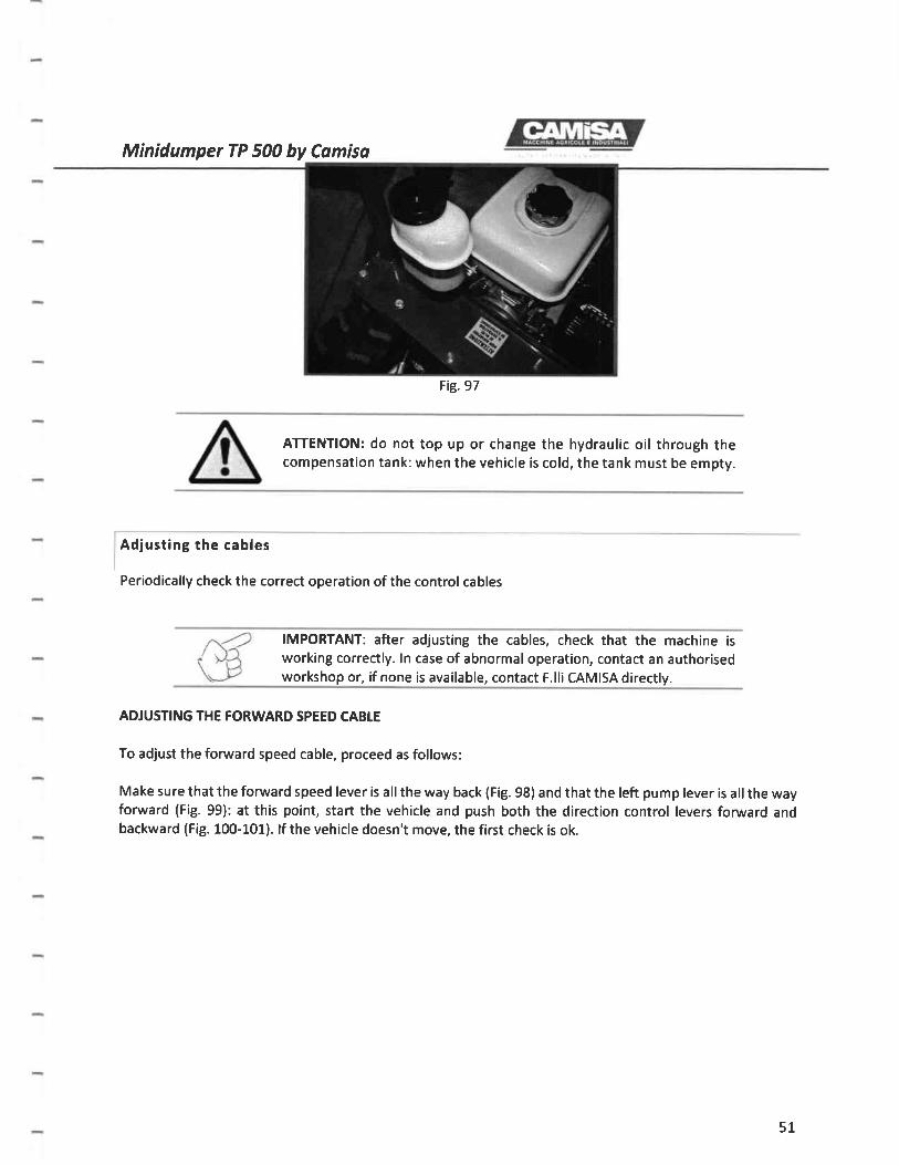
Compensation tank
As the volume of the oil increases as it heats up, the compensation tank located underthe control arc ensures
that the oil does not overflow from the tank. (Fig. 97).
50
Minidumper TP 500 by Comisa
Fig.97
ATTENTION: do not top up or change the hydraulic oil through thecompensation tank: when the vehicle is cold, the tank must be empty.
Adjusting the cables
Periodically check the correct operation of the control cables
IMPORTANT: after adjusting the cables, check that the machine is
working correctly. ln case of abnormal operation, contact an authorisedworkshop or, if none is available, contact F.lli CAMISA directly.
ADJUSTING THE FORWARD SPEED CABLE
To adjust the forward speed cable, proceed as follows:
Make sure that the fonruard speed lever is allthe way back (Fig. 98) and that the left pump lever is allthe wayforward (Fig. 99): at this point, start the vehicle and push both the direction control levers forurrard andbackward (Fig. 100-101). lf the vehicle doesn't move, the first check is ok.
51

Minidumper TP 500
Fig. 98 Fig. 99
Fig. 100 Fig. 101
Make sure that the forward speed lever is pushed forward by 4-5 mm (Fig. 102) and that the left pump lever
moves backward by a few millimiters (Fig. 103): at this point, start the vehicle and push both the direction
control levers fonarard and backward (Fig. 100-101). The machine should make some small movements.
lf not, adjust the cables by means of the adjusters (Fig. 104-105)
Fig. 103Fie. LO2
52

Fig. 104 Fig. 105
Should the machine not stop, despite the forward control lever being backward, screw in the adjustmentdevice located underneath the lever (Fig. 10a) or loosen the adjuster located near the lever of the left pumpand bring the sheath close to the lever (Fig. 105).
lf the machine does not move when moving the forward control lever forward by 4-5 mm, unscrew theadjuster placed under it (Fig. 104) or loosen the adjuster located nearthe pump lever on the left and movethe sheath away from the lever (Fig. 105).
lf the forward control lever does not remain in the desired position, tighten the nut a bit as illustrated in thefigure (Fig. 105-107).
Fig.7O7105Fig
Adjusting the throttle cable
Periodically check the correct operation of the throttle cable; if you experience excessive clearance betweenthe throttle and the acceleration of the engine, adjust as follows
53

Minidumper TP 500 by Camiso
1- Loosen the screw which stops the sheath (Fie. 108); if the engine is too accelerated even though the
control lever is set to the minimum, push the sheath forward (Fig. 109); if the idle is too low, pull
back the sheath (Fie. 109) and tighten the screw.
Fig. 109
lf this adjustment proves to be unsuccessful:
Set the throttle lever to zero to the right (Fie. 110)
Loosen the screw while holding the lower section of the adjuster (Fig. 111)
Pull the cable so that there are is no play
Tighten the screw while holding the lower section of the adjuster (Fig. 111)
Fig. 110 Fig. 111
2-
3-4-5-
""4 IMPORTANT: after adjusting the cables, check that the machine is
"' >)tr working correctly. ln case of abnormal operation, contact an authorised
\J, workshop or, if none is available, contact F.lli CAMISA directly.
Fig. 108
54

Minidumper TP 500 by Comiso
laOlUSrlruG the tension of the tracksi
Periodically check the tension of the tracks.
L- Move the tracked minidumper to a flat and solid surface (Fig. 112).2- Lift the loading platform and insert the dedicated safety bracket (Fig. J.13).3- Place a ruler or a joist on the tracks (Fig. 114).4- Place a bulk of approximately 20 kg in the middle of the track and make sure that between the ruler
and the surface of the track there are approximately 20-25 mm (Fig. 115).5- lf not, operate on the idler guide located inside the chassis. Loosen the lock nut (Fig. 115) and screw
in the bolt (Fig. 117) untilyou have the exact fit, then tighten the lock nut (Fig. 115).
IMPORTANT: after adjusting the tracks, check that the machine is
working correctly. ln case of abnormal operation, contact an authorisedworkshop or, if none is available, contact F.lli CAMISA directly.
772Fig. Fig. 113
Fig. 115Fig. 114
55

Minidumper TP 500 by Comisa
Fig. 115 Fig.lt7
Replacing the tracks
To replace the tracks, contact an authorized dealer or if none is available, contact F.lli CAMISA directly.
There are 2 greasing points on the rear idler wheels (Fig. 1L8) and 2 greasing points on the loading platform
supports (Fig. 1-19); add grease by means of a pump every time you use the minidumper (see lubricant chart
Pag. 57).
lf there is a selfloader, grease allthe points identified by the relative pictogram (Fie. L20).
Greasing points
Fig. 1,18
Fig. 120
Fig. 119
56

Minidumper TP 500 by Camiso
Precautions for
ln the winter season, remove dirt and mud from the vehicle and park it on firm and dry ground. Any dirt lefton the vehicle may freeze and damage the vehicle.lf any component is frozen and blocked, do not force it. Pour hot water over it and wait for it to thaw.(Damage caused by frost or forced manoeuvres is not covered by the warranty).
Long periods of inactivity
When the vehicle is not used for a long time, pour out the fuel from the carburettor and thetank. if not, the fuel may deteriorate, and this could cause problems to the supply system andmake ignition difficult.
Remove dirt and foreign matter from the vehicle and the tracks, making sure you do not wet the enginecomponents.
Replace the engine oil (for replacement please refer to the user manual of the engine).
Store the machine indoors in a dry and well-ventilated place.
Clean allthe parts of the machine, especiallythe starter, the airfilter, the muffler and the carburettor.
Remove any rust and touch-up using rust-prevention varnish.
Resuming vehicle operation without having removed any dirt or grass might overheat the engine and cause fire.
Lubricate all the moving parts and carry out any repair work that might be necessary.
Cover the vehicle with a sheet to protect it from the dust.
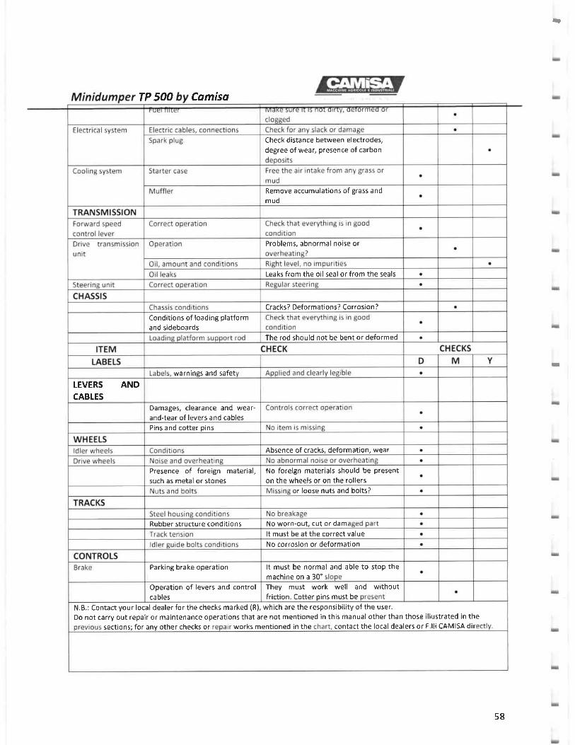
Failure to carry out checks, maintenance or repair works may cause accidents. To ensure thevehicle is efficient and safe to use, comply with the instructions provided here below.Yearly (Y), monthly (M) and daily (D) checks should be regularly carried out before using the vehicle.
ITEM CHECK CHECKS
ENGINE D M YEngine unit Startins. noise level Easv starting, normal noise o
Speed, acceleration Runnins and accelerating normallv a
Muffler. exhaust sasses Normal noise, colour and smell a
Air filter Dirty, loose, or damaged? Filter boxsecurelv fastened and intact?
a
Valve clearance Make sure it is normal (R) a
Compression Make sure it is normal (R) a
Engine crankcase Are there cracks or deformations? a
Lubrication Oil level and condition Sufficient level, no oil or dirtv oil? a
Oil leaks Leaks from the oil seal or from the seals
Fuel suoolv Fuel leaks Check for leaks on a regular basis a
57
TP 5OO Camisa
Check distance between electrodes,degree of wear, presence of carbon
Remove accumulations of grass andmud
Problems, abnormal noise or
Leaks from the oil seal or from the seals
Cracks? Deformations? Corrosion?
Conditions of loading platformand sideboards
The rod should not be bent or deformed
warnings and safel
TEVERS ANDCABTES
Damages, clearance and wear-and-tear of levers and cables
Pins and cotter pins
Absence of cracks, deformation, wear
Presence of foreign material,such as metal or stones
No foreign materials should be present
on the wheels or on the rollers
or loose nuts and bolts?
Rubber structure conditions No worn-out, cut or dam
It must be at the correct value
No corrosion or deformation
It must be normal and able to stop themachine on a 30"
Parking brake operation
Operation of levers and controlcables
They must work well and withoutfriction. Cotter pins must be
N.B.: Contact your local dealer for the checks marked (R), which are the responsibility of the user.
Do not carry out repair or maintenance operations that are not mentioned in this manual other than those illustrated in thesections; for any other checks or works mentioned in the contact the local dealers or F.lli CAMISA dir
-
T
58
Minidumper TP 500 by Comiso
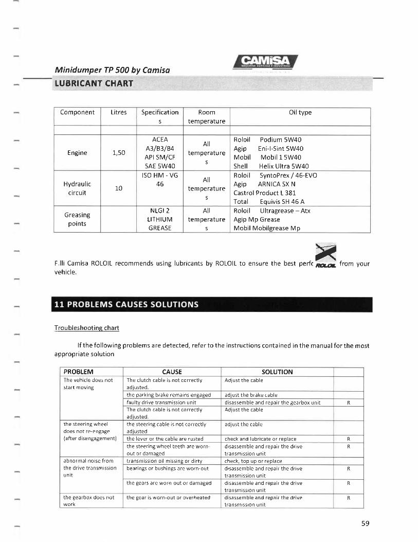
LUBRICANT CHART
F.lli Camisa ROLOIL recommends using lubricants by ROLOIL to ensure the best perfcvehicle.
xdfl. from your
Component Litres Specifications
Room
temperatureOiltype
Engine 1,50
ACEA
A3/83/84APrSM/CF
SAE 5W4O
All
temperatures
Roloil Podium 5W40Agip Eni-l-Sint 5W40Mobil Mobil15W40Shell Helix Ultra 5W40
Hyd ra u lic
circu it10
ISO HM - VG
46All
tem peratu res
Roloil SyntoPrex / 46-EVO
Agip ARNICA SX N
Castrol Product L 381Total Equivis SH 45 A
Greasingpoints
NLGI 2
LITHIUM
GREASE
Alltem peratu re
S
Roloil Ultragrease - AtxAgip Mp Grease
MobilMobilsrease Mp
Troubleshooting chart
lf the following problems are detected, refer to theappropriate solution
instructions contained in the manual for the most
PROBLEM CAUSE SOLUTIONThe vehicle does notstart moving
The clutch cable is not correctlyadiusted.
Adjust the cable
the oarkine brake remains enpased adiust the brake cablefaultv drive transmission unit disassemble and repair the gearbox unit R
The clutch cable is not correctlyadiusted
Adjust the cable
the steering wheeldoes not re-engage(after disengagement)
the steering cable is not correctlya d i rrstpd
adjust the cable
the lever or the cable are rusted check and lubricate or reolace R
the steering wheel teeth are worn-out or damased
disassemble and repair the drivetransmission unit
R
abnormal noise fromthe drive transmissionunit
transmission oil missing or dirty check, top up or replacebearings or bushings are worn-out disassemble and repair the drive
transmission unitR
the gears are worn-out or damaged disassemble and repair the drivetransmission unlt
R
the gearbox does notwork
the Bear is worn-out or overheated disassemble and repair the drivetransmission unit
R
59

TP 500 bv CamisaEJ o,,s , sPq,, r
transmission unittl
the gearbox linkage is crooked repair or replace the parts R
the parking brake is
faultythe parking brake is not correctlyadiusted
adjust the cable
the brake control is rusty check and lubricate or replace the parts
the friction linines are worn-out reolace the brake blocks R
There is water in the brake drum ensase the break reoeatedlv to drv itthe load is excessive reduce the load within the stated limits
the machine does notmove correctly
the load is excessive reduce the load within the stated limitsthe drive wheel is worn-out ordamaeed
replace the drive wheel R
the drive wheels or rollers aredamaped
replace the drive wheels or rollers R
the tracks are loose or worn-out adiust or reolace the tracks R
the vehicle slides offthe tracks
the tracks are loose or worn-out adjust or replace the tracks R
overheating of orintermittent noises
from idler wheels orrollers
the wheel or roller bearings are worn-out or damaged
replace the bearings or the bushings R
the idler wheels or rollers are worn-out or damaged
repair or replace the idler wheels or therollers
R
N.B,: Should vou encounter any problem in identifying the problem, consult your local dealer or F.lli CAMISA directly.
N.B.: Contact your local dealer for checks or repair works marked with (R), which are the responsibility of the user.
Do not carry out repair or maintenance operations that are not mentioned in this manual other than those illustrated in theprevious sections; for any other checks or repair works mentioned in the chart, contact the local dealers or F.lli CAMISA
directly.
50
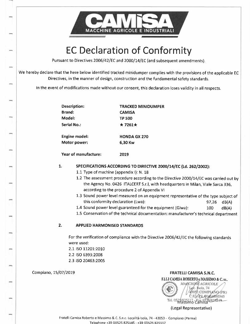
EC Declaration of ConformityPursuant to Directives2006/42lECand2000/74lEC (and subsequent amendments).
We hereby declare that the here below identified tracked minidumper complies with the provisions of the applicable EC
Directives, in the manner of design, construction and the fundamental safety standards.
ln the event of modifications made without our consent, this declaration loses validity in all respects.
Description:
Brand:Model:
SerialNo.:
Engine model:Motor power:
Year of manufacture:
TRACKED MINIDUMPER
CAMISA
TP 5OO
* 726t*
HONDA GX 270
5,30 Kw
20L9
L. sPECr Fr CAT! ONS ACCORDT NG TO Dt R ECTTVE 2OOO I t4 I EC lLd. 262 | 2OO2l:
1.1 Type of machine (appendix l): N. 18
1.2 The assessment procedure according to the Directive 2OOO[4|EC was carried out bythe Agency No. 0426 ITALCERT S.r.l, with headquarters in Milan, Viale Sarca 336,according to the procedure 2 of Appendix Vl
1.3 Sound power level measured on an equipment representative of the type subject ofthis conformity declaration ( Lwa): 97,26 dB(A)
1.4 Sound power level guaranteed for the equipment (Glwa): 100 dB(A)1.5 Conservation of the technical documentation: manufacturer's technical department
2. APPTIED HARMONISED STANDARDS
For the verification of compliance with the Directive 2OOGI 2IEC the following standardswere used:
2.1 ISO L72O1,:2O70
2.2 ISO 5393:2008
2.3 ISO 20453:2005
Compiano, 75/07/2OL9 FRATELTI CAMISA S.N.C.
F.LU CAMISA ROBERIO e MASSMO & C. srr"
(Legal Representative)
Fratelli Camisa Roberto e Massimo & C. S.n.c. Localiti tsola, 74 - 43053 - Compiano (parma)Teleohone +39 (0)525 825145 - +39 (01525 a25777

-
I
-