comprod inc.
196
COMPROD INC. High Quality • Superior Performance • Engineering Design • Excellent Technical Support Trusted by over 1,000 customers worldwide As a market leader in the design and manufacture of RF Antennas, Filtering Systems and In-Building solutions, Comprod puts innovation and customer satisfaction at the core of its business strategy. Over the past 40 years, we have set ourselves apart by adapting our offering to our client needs, while anticipating future industry trends and opportunities. Building on our engineering expertise and experience, we offer a complete range of high-quality, reliable products that are designed for superior performance and operate in the harshest of environments – from the extreme cold of the Arctic to the heat and humidity of the equatorial tropics. Our knowledge of the market, best-in-class technology and high level of customer service have made us a partner of choice for over 1,000 Public Safety, Utility, Telco, Transportation, Defense and Government Agencies worldwide. Our North American manufacturing facilities are certified under ISO 9001:2008 Quality Assurance standards. 1 Comprod’s Headquarter Facilities, Boucherville, QC, Canada
-
Upload
khangminh22 -
Category
Documents
-
view
0 -
download
0
Transcript of comprod inc.

COMPROD INC.
High Quality • Superior Performance • Engineering Design • Excellent Technical Support
Trusted by over 1,000 customers worldwide
As a market leader in the design and manufacture of RF Antennas, Filtering Systems and In-Building solutions, Comprod puts innovation and customer satisfaction at the core of its business strategy. Over the past 40 years, we have set ourselves apart by adapting our offering to our client needs, while anticipating future industry trends and opportunities.
Building on our engineering expertise and experience, we offer a complete range of high-quality, reliable products that are designed for superior performance and operate in the harshest of environments – from the extreme cold of the Arctic to the heat and humidity of the equatorial tropics.
Our knowledge of the market, best-in-class technology and high level of customer service have made us a partner of choice for over 1,000 Public Safety, Utility, Telco, Transportation, Defense and Government Agencies worldwide.
Our North American manufacturing facilities are certified under ISO 9001:2008 Quality Assurance standards.
1
Comprod’s Headquarter Facilities, Boucherville, QC, Canada

2
Our product catalog includes a portfolio of products that operate in the 27 MHz to 3.5 GHz frequency range:
Antennas
• Base Station Antennas
• Antenna Mounting Clamps
• Mobile/Transit Antennas
• Disguised Antennas (Covert Applications)
Filters
• Tx/Rx Combiners (VHF, UHF, 700/800/900MHz)
• Mobile Duplexers
• Isolators
• Receiver Multicoupler Systems
• Multicouplers (VHF, UHF, 700/800/900MHz)
• Duplexers (VHF, UHF, 700/800/900MHz)
• Couplers/Combiners/Dividers
In-Building Systems
• Single/Dual/Tri Band (VHF, UHF, 700/800/900MHz)
• Signal Boosters, including Uni-Directional and Bi-Directional Amplifiers (VHF, UHF, 700/800/900MHz)
This catalog provides detailed electrical and mechanical specifications. These specifications are subject to change without notice.

BASE STATION ANTENNAS
CLAMPS
FILTERS AND COMPONENTS
Pipe-to-Pipe...............................................................................................................76 Pipe-to-Angle............................................................................................................. 80 Side Mounting Assembly Kits....................................................................................... 83 Yagi Holder Kit........................................................................................................... 84
Base Station Antenna Selection Guide......................................................................... 7 Ground Plane Antennas.............................................................................................. 9 Omnidirectional Antennas........................................................................................... 11 Fiberglass Collinear Omni Antenna.............................................................................. 13 Low Band Exposed Dipole Antennas............................................................................ 15 VHF Exposed Dipole Antennas.................................................................................... 19 220MHz Exposed Dipole Antennas............................................................................... 23 UHF Exposed Dipole Antennas.................................................................................... 35 Dual Antenna Arrays.................................................................................................. 39 Enclosed Dipole Antennas........................................................................................... 46 Yagi Antennas............................................................................................................ 50 Reflector Antennas..................................................................................................... 62 Log Periodic Antennas................................................................................................ 70 Data Antennas........................................................................................................... 74
TABLE OF CONTENTS
Filter Naming and Selection Guide............................................................................... 88 Single Cavities (Bandpass, Pass-Reject, Notch)............................................................ 90 Multicouplers............................................................................................................. 93 Duplexers.................................................................................................................. 96 X-Pass Cavities.......................................................................................................... 103 VHF Expandable Systems (X-Pass).............................................................................. 104 UHF Expandable Systems (X-Pass).............................................................................. 112 800MHz Expandable Systems (X-Pass)......................................................................... 114 Receiver Multicouplers................................................................................................ 117 Amplifiers (Tower Top, Receiver)................................................................................ 123 Isolators and RF Loads............................................................................................... 126
3

IN-BUILDING SYSTEMS
DISGUISED ANTENNAS Low-Band Antennas................................................................................................... 175 VHF Antennas............................................................................................................ 176 UHF Antennas............................................................................................................ 177 750-960 MHz Antennas.............................................................................................. 178 Dual Band Antennas................................................................................................... 179 Couplers (FM, Crossband, Tuners)............................................................................... 180
Mobile and Transit Antenna Selection Guide................................................................. 142 Wideband Antennas.................................................................................................. 143 Low band Antennas................................................................................................... 146 VHF Antennas............................................................................................................ 147 UHF Antennas............................................................................................................ 152 750-960 MHz Antennas.............................................................................................. 153 Dual-Band Antennas................................................................................................... 160 Mobile Accessories & Mounts...................................................................................... 164 Transit Antennas (VHF, UHF, 760-960)........................................................................ 170
In-Building Product Selection Guide............................................................................. 185 Single Band Antennas................................................................................................. 186 UHF Antennas............................................................................................................ 188 Multi-Band Antennas.................................................................................................. 189 Tri-Band Antennas..................................................................................................... 190 Signal Boosters (VHF, UHF, 700/800/900)................................................................... 192 Hybrid Couplers......................................................................................................... 196
MOBILE/TRANSIT ANTENNAS
TABLE OF CONTENTS
4
FILTERS AND COMPONENTS
Hybrid Combiners and Couplers.................................................................................. 131 Ceramic Combiners.................................................................................................... 136 Cross Band Couplers.................................................................................................. 138 Combline Filters......................................................................................................... 139 Filter Racks and Mounting.......................................................................................... 140
5
BASE STATION ANTENNAS
Base Station Antennas

6
BASE STATION ANTENNAS
Renowned for their superior performance, quality and reliability, Comprod Inc.’s antennas are designed to excel in the most hostile environments.
Manufactured with the highest quality electrical and mechanical components, built with precision and strength, they feature sealed cable connections, crimped and soldered connectors, moisture-resistant wire harnesses and welded junc-tions which make them ideally suited for Mission-Critical applications.
Our technical sales and support staff will be pleased to help you select the right product for your application from our broad variety of market-proven products. Comprod Inc.’s antennas can also be tailored to fit specific needs, based on unique RF network or product applications (e.g. : increased mast height for higher elevation mounting, customized mast separated into two sections for easier handling inside elevators, etc.).
This catalog summarizes our most popular designs, documenting their electrical and mechanical specifications, images and RF propagation patterns: Data files for these antenna patterns can also be downloaded from our website in pat format, or on demand from our support team in any of the other popular data formats suitable for your network planning software.
KEY FEATURES AND OPTIONS:
1. Heavy Duty – Higher strength, designed to perform in high wind load, or unique situations where stronger designs are warranted.
2. Welded Design – All mechanical junctions are welded where possible to increase loading strength. This is ideal for high winds and winter conditions.
3. Black Anodized – A chemical-conversion coating (“Black Anodization”) that is incorporated throughout the antenna assembly, colored black to absorb the sun’s radiation to promote de-icing of the antenna. The anodization process results in enhanced protection against corrosive elements such as salty air, high humidity, and other corrosive environments (e.g. mining or petrochemical sites). The electrical performance and product life of the antenna is extended with this option.
4. Cable Lengths – Standard length of 2 feet. The feed line length can be adapted to your needs (up to 125 ft.).
5. Connectors – Type N is our standard connector, alternates can be ordered per requirements (e.g. SMA, TNC, DIN 7/16, etc.).
6. Custom Mounting Configurations can be offered depending on the style of antenna.
7. Custom Antennas – different frequency elements on single masts, different patterns (offset, opposing); dual assembly antennas, etc. Our Solutions Specialists can work to adapt a standard design to your unique coverage or installation requirements.
7
BASE STATION ANTENNAS
Model Other 118-138
138-174
406-512
746-960
BW* 1.5:1 Type Pattern Gain
dBd Watts
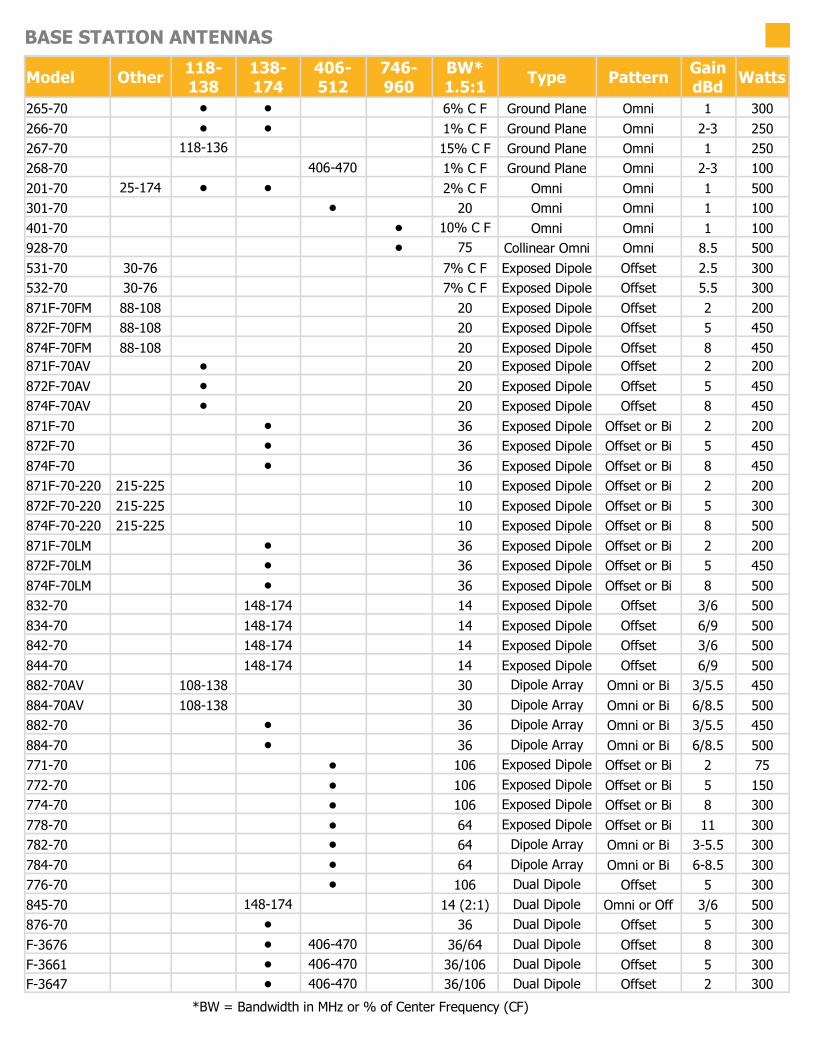
265-70 • • 6% C F Ground Plane Omni 1 300 266-70 • • 1% C F Ground Plane Omni 2-3 250 267-70 118-136 15% C F Ground Plane Omni 1 250 268-70 406-470 1% C F Ground Plane Omni 2-3 100 201-70 25-174 • • 2% C F Omni Omni 1 500 301-70 • 20 Omni Omni 1 100 401-70 • 10% C F Omni Omni 1 100 928-70 • 75 Collinear Omni Omni 8.5 500 531-70 30-76 7% C F Exposed Dipole Offset 2.5 300 532-70 30-76 7% C F Exposed Dipole Offset 5.5 300 871F-70FM 88-108 20 Exposed Dipole Offset 2 200 872F-70FM 88-108 20 Exposed Dipole Offset 5 450 874F-70FM 88-108 20 Exposed Dipole Offset 8 450 871F-70AV • 20 Exposed Dipole Offset 2 200 872F-70AV • 20 Exposed Dipole Offset 5 450 874F-70AV • 20 Exposed Dipole Offset 8 450 871F-70 • 36 Exposed Dipole Offset or Bi 2 200 872F-70 • 36 Exposed Dipole Offset or Bi 5 450 874F-70 • 36 Exposed Dipole Offset or Bi 8 450 871F-70-220 215-225 10 Exposed Dipole Offset or Bi 2 200 872F-70-220 215-225 10 Exposed Dipole Offset or Bi 5 300 874F-70-220 215-225 10 Exposed Dipole Offset or Bi 8 500 871F-70LM • 36 Exposed Dipole Offset or Bi 2 200 872F-70LM • 36 Exposed Dipole Offset or Bi 5 450 874F-70LM • 36 Exposed Dipole Offset or Bi 8 500 832-70 148-174 14 Exposed Dipole Offset 3/6 500 834-70 148-174 14 Exposed Dipole Offset 6/9 500 842-70 148-174 14 Exposed Dipole Offset 3/6 500 844-70 148-174 14 Exposed Dipole Offset 6/9 500 882-70AV 108-138 30 Dipole Array Omni or Bi 3/5.5 450 884-70AV 108-138 30 Dipole Array Omni or Bi 6/8.5 500 882-70 • 36 Dipole Array Omni or Bi 3/5.5 450 884-70 • 36 Dipole Array Omni or Bi 6/8.5 500 771-70 • 106 Exposed Dipole Offset or Bi 2 75 772-70 • 106 Exposed Dipole Offset or Bi 5 150 774-70 • 106 Exposed Dipole Offset or Bi 8 300 778-70 • 64 Exposed Dipole Offset or Bi 11 300 782-70 • 64 Dipole Array Omni or Bi 3-5.5 300 784-70 • 64 Dipole Array Omni or Bi 6-8.5 300 776-70 • 106 Dual Dipole Offset 5 300 845-70 148-174 14 (2:1) Dual Dipole Omni or Off 3/6 500 876-70 • 36 Dual Dipole Offset 5 300 F-3676 • 406-470 36/64 Dual Dipole Offset 8 300 F-3661 • 406-470 36/106 Dual Dipole Offset 5 300 F-3647 • 406-470 36/106 Dual Dipole Offset 2 300
*BW = Bandwidth in MHz or % of Center Frequency (CF)

8
BASE STATION ANTENNAS
Model Other 118-138
138-174
406-512
746-960
BW 1.5:1 Type Pattern Gain Watts
792-70 • 150 Encl. Dipole Offset 5 150 794-70 • 150 Encl. Dipole Offset 8 300 799-70 • 150 Encl. Dipole Offset 10 500 792-70R • 150 Encl. Dipole Directional Up to 8 150 794-70R • 150 Encl. Dipole Directional Up to 13 300 799-70R • 150 Encl. Dipole Directional Up to 15 500 291-70 • 3.75% CF Yagi Directional 3.5 350 295-70 • 4% C F Yagi Directional 6.5 350 290-70 • 4% C F Yagi Directional 9.5 350 250-70 • 36 (2:1) Yagi Directional 7 250 291-70-220 215-225 10 Yagi Directional 3.5 350 295-70-220 215-225 10 Yagi Directional 6.5 350 290-70-220 215-225 10 Yagi Directional 9.5 350 F-3872 • 24 Yagi Directional 3.5 350 433-70 • 24 Yagi Directional 6.5 350 430-70 • 24 Yagi Directional 10 350 480-70 406-470 64 Yagi Directional 10 350
982-70 • 30 Yagi Directional 3.5 200 983-70 • 85 Yagi Directional 6.5 200 980-70 • 85 Yagi Directional 10 200 987-70 • 85 Yagi Directional 12 200 490-70 806-960 85 Yagi Directional 10 200 425-70 • 20 Radome Yagi Directional 10 250 426-70 • 20 Radome Yagi Directional 10 250 490-70R • 72 Radome Yagi Directional 10 150 470-70 132-174 15% C F Corner Refl. Directional 7 250 471-70 132-174 15% C F Corner Refl. Directional 10 250 470-70-220 215-225 10 Corner Refl. Directional 7 250 471-70-220 215-225 10 Corner Refl. Directional 10 250 440-70 • 64 Corner Refl. Directional 9.5 100 442-70 • 64 Corner Refl. Directional 12 100 365-70 406-470 20 Parabolic Refl. Directional 15 250 965-70 764-960 72 Parabolic Refl. Directional 16.5 200 635-70 132-174 42 Log Periodic Directional 6 500 645-70 132-174 42 Log Periodic Directional 6 500 638-70 132-174 36 Log Periodic Directional 8 500 415-70 • 40 Log Periodic Directional 1 250 465-70 • 64 Log Periodic Directional 6 250 590-75BSMO 902-928 26 Data Omni 2 200
F-3766 • 36 Reflector Directional 9 450 F-3713 • 36 Reflector Directional 7 450 F-3729 • 36 Reflector Directional 2.5 200

9
BASE STATION ANTENNAS
GROUND PLANE ANTENNA 108-470 MHz Ground Plane Antenna Series
The Ground Plane Antenna Series are available in VHF and UHF configurations. These omnidirectional antennas are either wide band unity or 2-3 dB gain antennas. They are constructed from high strength, corrosion resistant aluminum alloy and stainless steel. All of our antennas can be completely customized to your particular applications.
• Each antenna has a rugged design to withstand the most extreme environmental conditions.
• Wide frequency band applications.
• The mounting hardware supplied will permit 0.75” to 2.38” O.D. pipe installation.
• DC ground for lightning protection.
• Ideal for mounting on buildings.
Electrical Specifications 265-70 266-70 267-70 268-70
Frequency Range, MHz 118-174 118-174 118-136 406-470
Nominal Gain, dBd Unity 2-3.0 Unity 2-3.0
Bandwidth 1.5:1 VSWR, MHz (% Ctr. Freq.) 6% 1% 15.6% (2:1) 1%
Polarization Vertical Vertical Vertical Vertical
Vertical Beamwidth (Ver. Pol.) 80º 40º 71º 38º
Pattern Omni Omni Omni Omni
Power Rating, Watts 300 250 250 100
Nominal Impedance, Ohms 50 50 50 50
Lightning Protection DC Ground DC Ground DC Ground DC Ground
Standard Termination Type N Male Type N Male Type N Male Type N Male
Tuning Field Adj. Field Adj. Fixed Field Adj.
Mechanical Specifications 265-70 266-70 267-70 268-70
Max. Length, in (mm) 58 (1473) 108 (2743) 67 (1702) 46 (1168)
Width, in (mm) 55 (1397) 46 (1168) 26.5 (673) 20 (508)
Weight, lbs. (kg) 6.8 (3.3) 6.5 (3.0) 6.0 (2.7) 1.5 (0.7)
Rated Wind Velocity, No Ice, mph (km/h) 150 (241) 125 (201) 125 (201) 125 (201)
Rated Wind Velocity, 0.5” (13mm) Ice, mph (km/h) 140(225) 85 (137) 110 (177) 85 (137)
Lateral Thrust @ 100 mph wind, lbs. (kg) 31.8 (14.4) 40 (18.1) 24 (10.7) 7.3 (3.3)
Bending Moment @top clamp: 100 mph, ft*lb (kg*m) 41 (5.7) 94 (13) 28 (3.9) 12 (1.6)
Projected Area, ft² (m²) 1.2 (0.110) 1.57 (0.146) 0.88 (0.082) 0.27 (0.03)
Mounting Information 167-85 Clamp 167-85 Clamp 167-85 Clamp 167-85 Clamp
Order Information 406-430 430-450 450-470
265-70 N/A N/A N/A
266-70 N/A N/A N/A
267-70 N/A N/A N/A
118-136
265-70*1
266-70*1
267-70
136-148
265-70*2
266-70*2
N/A
148-174
265-70*3
266-70*3
N/A
Black Anodized
N/A
N/A
267-70B
268-70 N/A 268-70*1 268-70*2 268-70*3 N/A N/A N/A
267-70

10
BASE STATION ANTENNAS
GROUND PLANE ANTENNA 108-470 MHz
266-70
267-70
268-70
265-70
Horizontal Pattern Vertical Pattern
Horizontal Pattern Vertical Pattern
Horizontal Pattern Vertical Pattern
Horizontal Pattern Vertical Pattern

11
BASE STATION ANTENNAS
OMNIDIRECTIONAL ANTENNA SERIES 25 - 960 MHz Omnidirectional Antenna Series
The Omnidirectional Antenna Series are available in VHF, UHF and 700/800/900 MHz configurations. These omnidirectional antennas are wide-band and unity gain. They are constructed from high strength, corrosion resistant aluminum alloy and stainless steel. All of our antennas can be completely customized to your particular applications.
• Each antenna has a rugged design to withstand the most extreme environmental conditions.
• The mounting hardware supplied will permit 0.75” to 2.3/8” O.D. pipe installation.
• DC ground for lightning protection.
• Because of the very large bandwidth, these are ideal antennas to stock, whether for emergency use or for resale.
Electrical Specifications 201-70 301-70 401-70
Frequency Range, MHz 25-174 MHz 406-512 700-960
Nominal Gain, dBd Unity Unity Unity
Bandwidth 1.5:1 VSWR, MHz 2% 20 10%
Polarization Vertical Vertical Vertical
Vertical Beam width (Ver. Pol.) 78º 75º 75º
Pattern Omni Omni Omni
Power Rating, Watts 500 100 100
Nominal Impedance, Ohms 50 50 50
Lightning Protection Star Gap DC Ground DC Ground
Standard Termination Type N Male Type N Male Type N Male
Mechanical Specifications 201-70 301-70 401-70
Max. Length, in (mm) 229 (5817) 24 (610) 21 (533)
Skirt Diameter, in (mm) 2.625 (67) N/A N/A
Whip Diameter, in (mm) 0.75 (19) N/A N/A
Weight, lbs. (kg) 17 (7.7) 1.4 (0.7) 1 (0.45)
Rated Wind Velocity, no ice, mph (km/h) 115 (185) 150 (241) 150 (241)
Rated Wind Velocity, 0.5” (13mm) ice, mph (km/h) N/A 100 (161) 100 (161)
Lateral Thrust @ 100 mph, ft*lb (kg*m) 67 (30.4) 3.9 (1.8) 3.4 (1.6)
Projected Area, ft² (m²) 2.5 (0.23) 0.15 (0.014) 0.13 (0.019)
Mounting Information Mast O.D. (mm) 1.7" (42) O.D. 167-85 Clamp 167-85 Clamp
Bending Moment @top clamp: 100 mph, ft*lb (kg*m) 308 (42.6) 1.84 (0.25) 1.87 (0.26)
Order Information 406-430 MHz 430-450 MHz 450-470 MHz
201-70 N/A N/A N/A
301-70 301-70*1 301-70*2 301-70*3
401-70 N/A N/A N/A
746-806 MHz
N/A
N/A
401-70*1
806-896 MHz
N/A
N/A
401-70*2
896-960 MHz
N/A
N/A
401-70*3
401-70

12
BASE STATION ANTENNAS
OMNIDIRECTIONAL ANTENNA 25 - 960 MHz
201-70
301-70
401-70
Horizontal Pattern Vertical Pattern
Horizontal Pattern Vertical Pattern
Horizontal Pattern Vertical Pattern

13
BASE STATION ANTENNAS
COLLINEAR OMNIDIRECTIONAL ANTENNA 746-960 MHz
Collinear Omnidirectional Antenna
The 928-70 Collinear Omni Antenna is available in three frequency splits: 746-806; 806-869 or 885-960 within the 746 to 960 MHz range.
The antennas have an 8.5 dBd gain, and offer 6 fixed Electrical Downtilt options, based on customer requirements.
The antenna is constructed with a high quality fiberglass light-grey radome. The aluminum mounting hardware is included with the antenna.
Electrical Specifications 928-70–1; 928-70-2; 928-70-3
Frequency Range, MHz (per Model 928-70-1; 928-70-2; 928-70-3) 746-806; 806-869; 885-960
Nominal Gain, dBd 8.5
Bandwidth 1.4:1 VSWR, MHz 75
Polarization Vertical
Horizontal Beamwidth (°) 360
Vertical Beamwidth (°) 6.5
Electrical Downtilt—Fixed (Options) (°) 0, 1, 2, 3, 4, 5, 6
Pattern Omnidirectional
3rd Order Intermodulation @ 2 X 43 dBm, dBc < -150
Power Rating, Watts 500
Nominal Impedance, Ohms 50
Lightning Protection DC Ground
Standard Termination 7/16 DIN-Female
928-70
Mechanical Specifications 928-70-1/2/3
Max. Length, in (mm) 130 (3310)
Diameter, in (mm) 2 (52)
Weight, lbs. (kg) - with mounting kit 26 (11.8)
Rated Wind Velocity, mph (km/h) 124 (200)
Radome Material Fiberglass, light grey, RAL 7035
Radiating Element Material Brass
Operational Temperature, °C -55 to 70
Mounting Information Pole mount included (U-bolts not included)
Order Information 746-806 MHz 806-869 MHz 885-960 MHz
Model 928-70-1 928-70-2 928-70-3

14
BASE STATION ANTENNAS
COLLINEAR OMNIDIRECTIONAL ANTENNA 746-960 MHz
928-70
Horizontal Pattern Vertical Pattern

15
BASE STATION ANTENNAS
EXPOSED DIPOLE ANTENNA 30-76 MHz
530 Series Low Band Exposed Dipole Antenna
The Low Band Exposed Dipole Antenna Series are available in our standard or heavy duty construction. These exposed dipole antennas come in both single and dual con-figurations, depending on the gain required. They are constructed from high strength, corrosion resistant aluminum alloy, hot galvanized steel mounting hardware, and use unique PVC off-set support arms. Our heavy duty versions have dual support braces and use a superior anti-torque support. All components are oversized.
• Each antenna has a rugged design to withstand the most extreme environmental conditions.
• Supplied with anti-torque supports.
• DC ground for lightning protection.
• Can be black anodized coating for enhanced anti-corrosion and de-icing properties
Electrical Specifications 531-70 531-70HD 532-70 532-70HD
Frequency Range, MHz 30-76 30-76 30-76 30-76
Nominal Gain, dBd 2.5 2.5 5.5 5.5
Bandwidth 1.5:1 VSWR, MHz 7% 7% 7% 7%
Polarization Vertical Vertical Vertical Vertical
Pattern Offset Offset Offset Offset
Power Rating, Watts 300 300 300 300
Nominal Impedance, Ohms 50 50 50 50
Lightning Protection DC Ground DC Ground DC Ground DC Ground
Standard Termination Type N Male Type N Male Type N Male Type N Male
Mechanical Specifications 531-70 531-70HD 532-70 532-70HD
Length @ 30 MHz, in (mm) 189 (4800) 189 (4800) 472 (11989) 472 (11989)
Width, in (mm) 87 (2210) 87 (2210) 87 (2210) 87 (2210)
Weight, lbs. (kg) 37 (17) 43 (19.5) 79 (36) 91 (41)
Rated Wind Velocity, No Ice, mph (km/h) 143 (230) 200 (322) 143 (230) 200 (322)
Rated Wind Velocity, 0.5” (13mm) ice, mph (km/h) 98 (158) 160 (258) 98 (158) 160 (258)
Lateral Thrust @ 100 mph, wind, lbs. (kg) 133 (60.8) 160 (72.3) 266 (121.6) 320 (144.6)
Projected Area, ft² (m²) 4.98 (0.46) 5.94 (0.55) 9.96 (0.92) 11.88 (1.10)
Mounting Information Mast O.D. (mm) (4) 1.25"-2.38" (6) 1.25"-2.38" (8) 1.25"-2.38" (12) 1.25"-2.38"
Order Information 30-32 MHz 32-34 MHz 34-36 MHz
531-70 531-70*1 531-70*2 531-70*3
532-70 532-70*1 532-70*2 532-70*3
531-70HD 531-70HD*1 531-70HD*2 531-70HD*3
36-38 MHz
531-70*4
532-70*4
531-70HD*4
38-41 MHz
531-70*5
532-70*5
531-70HD*5
41-44 MHz
531-70*6
532-70*6
531-70HD*6
532-70HD 532-70HD*1 532-70HD*2 532-70HD*3 532-70HD*4 532-70HD*5 532-70HD*6
44-47 MHz
531-70*7
532-70*7
531-70HD*7
532-70HD*7
47-50 MHz
531-70*8
532-70*8
531-70HD*8
532-70HD*8
531-70HD

16
BASE STATION ANTENNAS
EXPOSED DIPOLE ANTENNA 30-76 MHz
531-70
532-70
532-70HD
Horizontal Pattern Vertical Pattern
Horizontal Pattern Vertical Pattern
Horizontal Pattern Vertical Pattern

17
BASE STATION ANTENNAS
FM EXPOSED DIPOLES 88-108 MHz
870 FM Series Exposed Dipole
The 870 FM Series Exposed Dipoles are available in 1, 2, 4 dipole configu-rations. All of our antennas can be completely customized to your particular applications. Our antennas can be black anodized, adjustable, or fixed, side or top mount, and heavy duty versions are available.
Electrical Specifications 871F-70FM 872F-70FM 874F-70FM
Frequency Range, MHz 88-108 88-108 88-108
Nominal Gain, dBd 2.0-2.5 5.0-5.5 8.0-8.5
Number of Dipoles 1 2 4
Bandwidth 1.5:1 VSWR, MHz 20 20 20
Polarization Vertical Vertical Vertical
Pattern Offset Offset Offset
Power Rating, Watts 200 450 450
Nominal Impedance, Ohms 50 50 50
Lightning Protection DC Ground DC Ground DC Ground
Standard Termination Type N Male Type N Male Type N Male
Mechanical Specifications 871F-70FM 872F-70FM 874F-70FM
Length, in (mm) 114 (2896) 198 (5029) 350 (8890)
Width(3/8 Wave Spacing), in (mm) 47 (1194) 47 (1194) 49 (1245)
Weight, lbs. (kg) 19.1 (8.7) 37 (16.8) 137 (62)
Rated Wind Velocity, No Ice, mph (km/h) 150 (241) 128 (206) 105 (169)
Rated Wind Velocity, 0.5” (13mm) ice, mph (km/h) 118 (190) 100 (161) 84 (135)
Lateral Thrust @ 100 mph, wind, lbs. (kg) 75 (34) 139 (63) 332 (151)
Bending Moment @ top clamp: 100 mph, ft*lb (kg*m) 60 (8.2) 596 (82) 3565 (493)
Projected Area, ft² (m²) 2.8 (0.26) 5.3 (0.49) 12.5 (1.17)
Mounting Information Mast O.D. (mm) 2.4" (61) 2.4" (61) 3.5" (89)
Order Information Adjustable Heavy Duty Side Mount Top Mount Black Anodized
871-70FM 871A-70FM 871F-70FMHD 871F-70FMSM 871F-70FMTM 871F-70FMHDB
872-70FM 872A-70FM 872F-70FMHD 872F-70FMSM 872F-70FMTM 872F-70FMHDB
874-70FM 874A-70FM 874F-70FMHD 874F-70FMSM 874F-70FMTM 874F-70FMHDB
• Each antenna is offered in a 1/4 or 3/8 wave spacing versions.
• The 87XA-70 has external cabling and a field-adjustable pattern.
• The 87XF-70 has internal cabling and fixed dipole-mast spacing.
• Heavy duty versions are available. Please contact a Comprod Inc. Technical support technician for consultation.
872-70FM

18
BASE STATION ANTENNAS
FM EXPOSED DIPOLES 88-108 MHz
871F-70FM Quarter-wave Spacing Horizontal Quarter-wave Spacing Vertical
Quarter-wave Spacing Horizontal Quarter-wave Spacing Vertical 872F-70FM
874F-70FM Quarter-wave Spacing Horizontal Quarter-wave Spacing Vertical

19
BASE STATION ANTENNAS
VHF EXPOSED DIPOLES 118-138 MHz
870 Series VHF Exposed Dipole
The 870 Series AV – Aviation Series VHF Exposed Dipoles are available in 1, 2, 4, 8 and dual dipole configurations. All of our antennas can be completely customized to your particular applications. Our antennas can be black ano-dized, adjustable or fixed, side mount or top mount, and heavy duty versions are available.
Electrical Specifications 871F-70AV 872F-70AV 874F-70AV
Frequency Range, MHz 118-138 118-138 118-138
Nominal Gain, dBd 2.0-2.5 5.0-5.5 8.0-8.5
Number of Dipoles 1 2 4
Bandwidth 1.5:1 VSWR, MHz 20 20 20
Polarization Vertical Vertical Vertical
Pattern Offset Offset Offset
Power Rating, Watts 200 450 450
Nominal Impedance, Ohms 50 50 50
Lightning Protection DC Ground DC Ground DC Ground
Standard Termination Type N Male Type N Male Type N Male
Mechanical Specifications 871F-70AV 872F-70AV 874F-70AV
Length, in (mm) 78 (1981) 162 (4115) 294 (7468)
Width (3/8 Wave Spacing), in (mm) 54 (1372) 54 (1372) 55 (1397)
Weight, lbs. (kg) 16 (7.3) 31 (14.1) 93 (42)
Rated Wind Velocity, No Ice, mph (km/h) 150 (241) 145 (3341) 120 (193)
Rated Wind Velocity, 0.5” (13mm) ice, mph (km/h) 105 (169) 100 (161) 95 (153)
Lateral Thrust @ 100 mph, wind, lbs. (kg) 57 (26) 120 (54.5) 231 (105)
Bending Moment @ top clamp: 100 mph, ft*lb (kg*m) 82 (11) 420 (58) 1437 (199)
Projected Area, ft² (m²) 2.2 (0.2) 4.6 (0.43) 8.8 (0.82)
Mounting Information Mast O.D. (mm) 2.4" (61) 2.4" (61) 2.9" (73)
Order Information Adjustable Heavy Duty Side Mount Top Mount Black Anodized
871-70AV 871A-70AV 871F-70AV-HD 871F-70AV-SM 871F-70AV-TM 871F-70AV-HDB
872-70AV 872A-70AV 872F-70AV-HD 872F-70AV-SM 872F-70AV-TM 872F-70AV-HDB
874-70AV 874A-70AV 874F-70AV-HD 874F-70AV-SM 874F-70AV-TM 874F-70AV-HDB
• Each antenna is offered in a 1/4 or 3/8 wave spacing versions.
• The 87XA-70 has external cabling and a field-adjustable pattern.
• The 87XF-70 has internal cabling and fixed dipole-mast spacing.
• Heavy duty versions are available. Please contact Comprod Inc. Technical support technician for consultation.
872F-70AV

20
BASE STATION ANTENNAS
VHF EXPOSED DIPOLES 118-138 MHz
Quarter-wave Spacing Horizontal Quarter-wave Spacing Vertical 872F-70AV
874F-70AV Quarter-wave Spacing Horizontal Quarter-wave Spacing Horizontal
871F-70AV Quarter-wave Spacing Horizontal Quarter-wave Spacing Vertical

21
BASE STATION ANTENNAS
VHF EXPOSED DIPOLES 138-174 MHz
Electrical Specifications 871F-70 872F-70 874F-70
Frequency Range, MHz 138-174 138-174 138-174
Nominal Gain, dBd 2.0-2.5 5.0-5.5 8.0-8.5
Number of Dipoles 1 2 4
Bandwidth 1.5:1 VSWR, MHz 36 36 36
Polarization Vertical Vertical Vertical
Pattern Offset / bi Offset / bi Offset / bi
Power Rating, Watts 200 450 450
Nominal Impedance, Ohms 50 50 50
Lightning Protection DC Ground DC Ground DC Ground
Standard Termination Type N Male Type N Male Type N Male
Mechanical Specifications 871F-70 872F-70 874F-70
Length, in (mm) 78 (1981) 126 (3200) 246 (6248)
Width(1/2 Wave Spacing), in (mm) 40 (1016) 40 (1016) 40 (1016)
Weight, lbs. (kg) 13 (6) 24 (10.8) 67 (30)
Rated Wind Velocity, No Ice, mph (km/h) 170 (274) 150 (241) 110 (177)
Rated Wind Velocity, 0.5” (13mm) ice, mph (km/h) 145 (217) 135 (217) 85 (137)
Lateral Thrust @ 100 mph, wind, lbs. (N) 45 (199) 92 (407) 206 (914)
Bending Moment @ top clamp: 100 mph, ft*lb (N*m) 18 (24) 205 (278) 1440 (1953)
Projected Area, ft² (m²) 1.7 (0.16) 3.5 (0.33) 7.7 (0.72)
Mounting Information Mast O.D. (mm) 1.9" (48) 2.4" (61) 2.9" (73)
Order Information Adjustable Heavy Duty Side Mount Top Mount Black Anodized
871-70 871A-70 871F-70HD 871F-70SM 871F-70TM 871F-70HDB
872-70 872A-70 872F-70HD 872F-70SM 872F-70TM 872F-70HDB
874-70 874A-70 874F-70HD 874F-70SM 874F-70TM 874F-70HDB
• Each antenna is offered in a 1/4, 3/8, or 1/2 wave spacing versions.
• The 87XA-70 has external cabling and a field-adjustable pattern.
• The 87XF-70 has internal cabling and fixed dipole-mast spacing.
• Heavy duty versions are available. Please contact Comprod Inc. Technical support technician for consultation.
872F-70
870 Series VHF Exposed Dipoles
The 870 Series VHF Exposed Dipoles are available in 1, 2, 4, 8, dipole and dual dipole configurations. All of our antennas can be completely customized to your particular applications. Our antennas can be black anodized, adjustable or fixed, side mount or top mount, and heavy duty versions are available.

22
BASE STATION ANTENNAS
VHF EXPOSED DIPOLES 138-174 MHz
871F-70 Quarter-wave Spacing Horizontal Half-wave Spacing Horizontal Half-wave Spacing Vertical
Quarter-wave Spacing Horizontal Half-wave Spacing Horizontal Half-wave Spacing Vertical 872F-70
874F-70 Quarter-wave Spacing Horizontal Half-wave Spacing Horizontal Half-wave Spacing Vertical

23
BASE STATION ANTENNAS
220MHz EXPOSED DIPOLES 215-225 MHz
Electrical Specifications 871F-70-220 872F-70-220 874F-70-220
Frequency Range, MHz 215-225 215-225 215-225
Nominal Gain, dBd 2.0-2.5 5.0-5.5 8.0-8.5
Number of Dipoles 1 2 4
Bandwidth 1.5:1 VSWR, MHz 10 10 10
Polarization Vertical Vertical Vertical
Pattern Offset / bi Offset / bi Offset / bi
Power Rating, Watts 200 300 500
Nominal Impedance, Ohms 50 50 50
Lightning Protection DC Ground DC Ground DC Ground
Standard Termination Type N Male Type N Male Type N Male
Order Information Heavy Duty Side Mount Top Mount Black Anodized
871-70-220 871F-70-220HD 871F-70-220SM 871F-70-220TM 871F-70-220HDB
872-70-220 872F-70-220HD 872F-70-220SM 872F-70-220TM 872F-70-220HDB
874-70-220 874F-70-220HD 874F-70-220SM 874F-70-220TM 874F-70-220HDB
Mechanical Specifications 871F-70-220 872F-70-220 874F-70-220
Length, in (mm) 66 (1676) 112 (2845) 200 (5080)
Width(1/2 Wave Spacing), in (mm) 31 (787) 31 (787) 32 (813)
Weight, lbs. (kg) 12.5 (5.7) 21 (9.5) 51 (23)
Rated Wind Velocity, No Ice, mph (km/h) 165 (266) 150 (241) 145 (233)
Rated Wind Velocity, 0.5” (13mm) ice, mph (km/h) 140 (225) 130 (209) 105 (177)
Lateral Thrust @ 100 mph, wind, lbs. (kg) 40 (18) 66 (30) 143 (65)
Bending Moment @ top clamp: 100 mph, ft*lb (kg*m) 58 (8) 150 (21) 610 (84)
Projected Area, ft² (m²) 1.5 (0.14) 2.6 (0.24) 5.5 (0.51)
Mounting Information Mast O.D. (mm) 1.9" (48) 1.9" (48) 2.4" (60)
• Each antenna is offered in a 1/4, 3/8 or 1/2 wave spacing versions.
• The 87XA-70 has external cabling and a field-adjustable pattern.
• The 87XF-70 has internal cabling and fixed dipole-mast spacing.
• Heavy duty versions are available. Please contact Comprod Inc. Technical support technician for consultation.
872F-70-220
870 Series 220MHz Exposed Dipoles
The 870 Series 220MHz Exposed Dipoles are available in 1, 2, 4, 8 dipole configurations. All of our antennas can be completely customized to your particular applications. Our antennas can be black anodized, adjustable, or fixed, side mount or top mount, and heavy duty versions are available.

24
BASE STATION ANTENNAS
220MHz EXPOSED DIPOLES 215-225 MHz
871F-70-220 Quarter-wave Spacing Horizontal Half-wave Spacing Horizontal Half-wave Spacing Vertical
Quarter-wave Spacing Horizontal Half-wave Spacing Horizontal Half-wave Spacing Vertical 872F-70-220
874F-70-220 Quarter-wave Spacing Horizontal Half-wave Spacing Horizontal Half-wave Spacing Vertical

25
BASE STATION ANTENNAS
VHF EXPOSED DIPOLES 138-174 MHz
Electrical Specifications 871-70LM 872-70LM 874-70LM
Frequency Range, MHz 138-174 138-174 138-174
Nominal Gain, dBd 2.0-2.5 5.0-5.5 8.0-8.5
Number of Dipoles 1 2 4
Bandwidth 1.5:1 VSWR, MHz 36 36 36
Polarization Vertical Vertical Vertical
Pattern Offset / bi Offset / bi Offset / bi
Power Rating, Watts 200 450 500
Nominal Impedance, Ohms 50 50 50
Lightning Protection DC Ground DC Ground DC Ground
Standard Termination Type N Male Type N Male Type N Male
Mechanical Specifications 871-70LM 872-70LM 874-70LM
Length, in (mm) Mast Not Incl. Mast Not Incl. Mast Not Incl.
Width(1/2 Wave Spacing), in (mm) 40 (1016) 40 (1016) 40 (1016)
Weight, lbs. (kg) 4.5 (2.0) 19 (8.6) 38 (17.2)
Rated Wind Velocity, No Ice, mph (km/h) 150 (241) 150 (241) 150 (241)
Rated Wind Velocity, 0.5” (13mm) ice, mph (km/h) 135 (217) 135 (217) 135 (217)
Lateral Thrust @ 100 mph, wind, lbs. (kg) 20 (9.1) 40 (18.2) 80 (36.5)
Projected Area, ft² (m²) 0.92 (0.08) 1.84 (0.17) 3.64 (0.34)
Mounting Information: Clamp Included 181-85 115R-85 115R-85
Order Information Heavy Duty Black Anodized With Mast
871-70LM 871-70LMHD 871-70LMHDB 871A-70
872-70LM 872-70LMHD 872-70LMHDB 872A-70
874-70LM 874-70LMHD 874-70LMHDB 874A-70
• Each antenna is offered in a 1/4, 3/8 or 1/2 wave spacing versions.
• The 870 LM series has external cabling and is field adjustable pattern
• Heavy-duty versions are available. Please contact a Comprod Inc. Technical support technician for consultation.
870 LM Series VHF Exposed Dipoles
The 870 LM Series VHF Exposed Dipoles are available in 1, 2, 4, 8, dipole configu-rations. The LM stands for “Less Mast”. The product includes the dipole, boom and clamps to mount the dipoles but no mast is supplied. All of our antennas can be completely customized to your particular applications. Our antennas can be black anodized, adjustable-only, side mount or top mount, and heavy duty versions are available.
871F-70LM

26
BASE STATION ANTENNAS
VHF EXPOSED DIPOLES 138-174 MHz
871F-70LM Quarter-wave Spacing Horizontal Half-wave Spacing Horizontal Half-wave Spacing Vertical
Quarter-wave Spacing Horizontal Half-wave Spacing Horizontal Half-wave Spacing Vertical 872F-70LM
874F-70LM Quarter-wave Spacing Horizontal Half-wave Spacing Horizontal Half-wave Spacing Vertical

27
BASE STATION ANTENNAS
VHF EXPOSED DIPOLES 148-174 MHz
830 Series Light Duty VHF Dipoles
The 830 Series Light Duty VHF Exposed Dipoles are available in 2 and 4 dipole configurations. All of our antennas can be completely customized to your applications.
• Low VSWR version with maximum gain over specified frequency.
• The 830 series has external cabling and fixed dipole-mast spacing.
• These antennas have an adjustable pattern for omnidirectional or offset coverage.
• The 834-70 antenna is shipped in two sections to be assembled on site.
Electrical Specifications 832-70 834-70
Frequency Range, MHz 148-174 148-174
Nominal Gain, dBd 3.0/6.0 6.0/9.0
Number of Dipoles 2 4
Bandwidth 1.5:1 VSWR, MHz 14 14
Polarization Vertical Vertical
Pattern Offset Offset
Power Rating, Watts 500 500
Nominal Impedance, Ohms 50 50
Lightning Protection DC Ground DC Ground
Standard Termination Type N Male Type N Male
Mechanical Specifications 832-70 834-70
Length, in (mm) 120 (3048) 244 (6198)
Width(1/2 Wave Spacing), in (mm) 9 (229) 9 (229)
Weight, lbs. (kg) 12 (5.5) 29 (13)
Rated Wind Velocity, No Ice, mph (km/h) 125 (201) 90 (145)
Rated Wind Velocity, 0.5” (13mm) ice, mph (km/h) 90 (145) 65 (105)
Lateral Thrust @ 100 mph, wind, lbs. (kg) 45 (200) 69 (307)
Bending Moment @ top clamp: 100 mph, ft*lb (kg*m) 150 (203) 787 (1067)
Projected Area, ft² (m²) 1.7 (0.16) 4.2 (0.39)
Mounting Information 107-85 clamp set 107-85 clamp set
Order Information 148-162 MHz 160-174 MHz
832-70 832-70*1 832-70*2
834-70 834-70*1 834-70*2
832-70

28
BASE STATION ANTENNAS
VHF EXPOSED DIPOLES 148-174 MHz
832-70 Horizontal Pattern Vertical Pattern
Horizontal Pattern Vertical Pattern
834-70

29
BASE STATION ANTENNAS
VHF EXPOSED DIPOLES 148-174 MHz
840 Series Light Duty VHF Dipoles
The 840 Series Light Duty VHF Exposed Dipoles are available in 2 and 4 dipole configurations. All of our antennas can be completely customized to your applications.
• Low VSWR version with maximum gain over specified frequency.
• The 840 series has internal cabling and fixed dipole-mast spacing.
• These antennas have an adjustable pattern for omnidirectional or offset coverage.
Electrical Specifications 842-70 844-70
Frequency Range, MHz 148-174 148-174
Nominal Gain, dBd 3.0/6.0 6.0/9.0
Number of Dipoles 2 4
Bandwidth 1.5:1 VSWR, MHz 14 14
Polarization Vertical Vertical
Pattern Offset Offset
Power Rating, Watts 500 500
Nominal Impedance, Ohms 50 50
Lightning Protection DC Ground DC Ground
Standard Termination Type N Male Type N Male
Mechanical Specifications 842-70 844-70
Length, in (mm) 138 (3500) 270 (6858)
Width(1/2 Wave Spacing), in (mm) 9 (229) 9 (229)
Weight, lbs. (kg) 22 (10) 40 (18)
Rated Wind Velocity, No Ice, mph (km/h) 150 (241) 110 (177)
Rated Wind Velocity, 0.5” (13mm) ice, mph (km/h) 115 (185) 80 (129)
Lateral Thrust @ 100 mph, wind, lbs. (kg) 70 (31.8) 139 (63)
Bending Moment @ top clamp: 100 mph, ft*lb (kg*m) 167 (23.1) 514 (71)
Projected Area, ft² (m²) 2.6 (0.24) 5.2 (0.48)
Mounting Information 107-85 clamp set 107-85 clamp set
Order Information 148-162 MHz 160-174 MHz
842-70 842-70*1 842-70*2
844-70 844-70*1 844-70*2
842-70
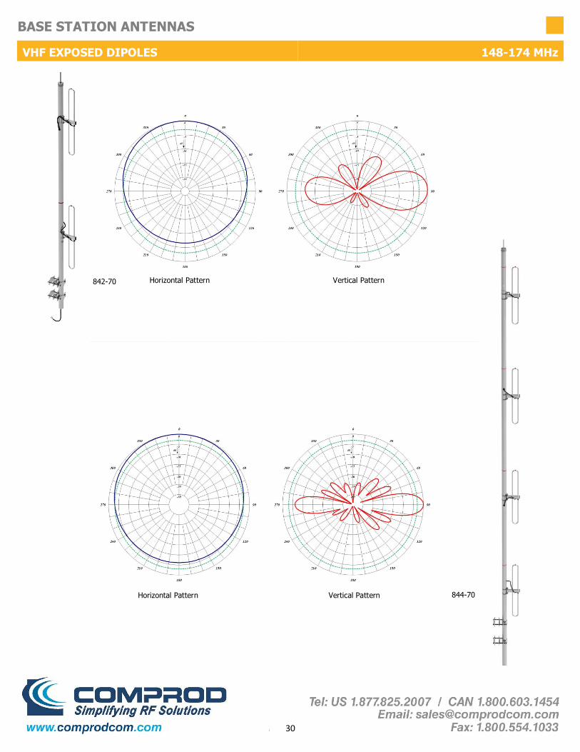
30
BASE STATION ANTENNAS
VHF EXPOSED DIPOLES 148-174 MHz
844-70
842-70
Horizontal Pattern Vertical Pattern
Horizontal Pattern Vertical Pattern

31
BASE STATION ANTENNAS
AVIATION EXPOSED DIPOLE ARRAY 108-138 MHz
880AV Series VHF Exposed Dipole Array
The 880AV Series VHF Exposed Dipole Array are available in 2 and 4 dipole set configurations. All of our antennas can be completely customized to your partic-ular applications. Our antennas can be black anodized, top mount only, and heavy duty versions are available.
• Each antenna is offered in two versions: Omni or bidirectional. (Image shows Omni)
• These antennas have only internal cabling, fixed dipole-mast spacing and adjustable pattern control.
• Heavy-duty versions are available. Please contact a Comprod Inc. Technical support technician for consultation.
Electrical Specifications 882-70AV 884-70AV
Frequency Range, MHz 108-138 108-138
Nominal Gain, dBd 3.0-5.5 6.0-8.5
Number of Dipoles 2 Sets 4 Sets
Bandwidth 1.5:1 VSWR, MHz 30 30
Polarization Vertical Vertical
Pattern Omni or Bi-Dir. Omni or Bi-Dir.
Power Rating, Watts 450 500
Nominal Impedance, Ohms 50 50
Lightning Protection DC Ground DC Ground
Standard Termination Type N Male Type N Male
Mechanical Specifications 882-70AV 884-70AV
Length, in (mm) 157 (3988) 306 (7772)
Width , in (mm) 45 (1143) 46 (1168)
Weight, lbs. (kg) 49 (8.6) 105 (47.6)
Rated Wind Velocity, No Ice, mph (km/h) 140 (225) 100 (162)
Rated Wind Velocity, 0.5” (13mm) ice, mph (km/h) 110 (177) 80 (129)
Lateral Thrust @ 100 mph, wind, lbs. (kg) 154 (70) 307 (139)
Bending Moment @ top clamp: 100 mph, ft*lb (kg*m) 524 (72.5) 2039 (282)
Projected Area, ft² (m²) 5.6 (0.52) 11 (1.04)
Mounting Information: Mast O.D. (mm) 2.9" (73) 3.5" (89)
Order Information Heavy Duty Black Anodized
882-70AV 882-70AVHD 882-70AVHDB
884-70AV 884-70AVHD 884-70AVHDB
882-70AV

32
BASE STATION ANTENNAS
AVIATION EXPOSED DIPOLE ARRAY 108-138 MHz
Bidirectional Horizontal Bidirectional Vertical 882-70AV
882-70AV Omni Horizontal Omni Vertical
884-70AV Omni Horizontal Omni Vertical
Bidirectional Horizontal Bidirectional Vertical 884-70AV

33
BASE STATION ANTENNAS
VHF EXPOSED DIPOLE ARRAY 138-174 MHz
880 Series VHF Exposed Dipole Array
The 880 Series VHF Exposed Dipole Array are available in 2 and 4 dipole set con-figurations. All of our antennas can be completely customized to your particular applications. Our antennas can be black anodized, top mount only, and heavy duty versions are available.
• Each antenna is offered in two versions: Omni or bidirectional. (Image shows Omni)
• These antennas have only internal cabling, fixed dipole-mast spacing, and adjustable pattern control.
• Heavy-duty versions are available. Please contact a Comprod Inc. Technical support technician for consultation.
Electrical Specifications 882-70 884-70
Frequency Range, MHz 138-174 138-174
Nominal Gain, dBd 3.0-5.5 6.0-8.5
Number of Dipoles 2 Sets 4 Sets
Bandwidth 1.5:1 VSWR, MHz 36 36
Polarization Vertical Vertical
Pattern Omni or Bi-Dir. Omni or Bi-Dir.
Power Rating, Watts 450 500
Nominal Impedance, Ohms 50 50
Lightning Protection DC Ground DC Ground
Standard Termination Type N Male Type N Male
Mechanical Specifications 882-70 884-70
Length, in (mm) 138 (3500) 246 (6248)
Width , in (mm) 30 (762) 31 (787)
Weight, lbs. (kg) 36 (16.3) 78 (35)
Rated Wind Velocity, No Ice, mph (km/h) 120 (162) 110 (177)
Rated Wind Velocity, 0.5” (13mm) ice, mph (km/h) 95 (137) 80 (129)
Lateral Thrust @ 100 mph, wind, lbs. (kg) 113 (51) 236 (107)
Bending Moment @ top clamp: 100 mph, ft*lb (kg*m) 351(49) 1264 (175)
Projected Area, ft² (m²) 4.1 (0.38) 8.7 (0.81)
Mounting Information: Mast O.D. (mm) 2.4" (61) 2.9" (73)
Order Information Heavy Duty Black Anodized
882-70 882-70HD 882-70HDB
884-70 884-70HD 884-70HDB
882-70

34
BASE STATION ANTENNAS
VHF EXPOSED DIPOLE ARRAY 138-174 MHz
Bidirectional Horizontal Bidirectional Vertical 884-70
882-70 Omni Horizontal Omni Vertical
Bidirectional Horizontal Bidirectional Vertical 882-70
884-70 Omni Horizontal Omni Vertical

35
BASE STATION ANTENNAS
UHF EXPOSED DIPOLES 406-512 MHz
770 Series UHF Exposed Dipoles
The 770 Series UHF Exposed Dipoles are available in 1, 2, 4, 8 and dual dipole configurations. All of our antennas can be completely customized to your partic-ular applications. Our antennas can be black anodized, adjustable or fixed, side mount or top mount, and heavy duty versions are available.
• Each antenna is offered in a 1/4, 3/8, or 1/2 wave versions.
• The 77X-70 has internal cabling and fixed dipole-mast spacing.
• Heavy-duty Versions are available. Please contact a Comprod Inc. Technical support technician for consultation.
Electrical Specifications 771-70 772-70 774-70 778-70
Frequency Range, MHz 406-512 406-512 406-512 406-512
Nominal Gain, dBd 2.0-2.5 5.0-5.5 8.0-8.5 11.0-11.5
Number of Dipoles 1 2 4 8
Bandwidth 1.5:1 VSWR, MHz 106 106 106 64
Polarization Vertical Vertical Vertical Vertical
Pattern Offset / Bi Offset / Bi Offset / Bi Offset / Bi
Power Rating, Watts 75 150 300 300
Nominal Impedance, Ohms 50 50 50 50
Lightning Protection DC Ground DC Ground DC Ground DC Ground
Standard Termination Type N Male Type N Male Type N Male Type N Male
Mechanical Specifications 771-70 772-70 774-70 778-70
Length, in (mm) 66 (1676) 86 (2184) 126 (3200) 210 (5334)
Width, in (mm) 16 (406) 16 (406) 16 (406) 17 (432)
Weight, lbs. (kg) 8.6 (3.9) 12.6 (5.7) 21 (9.5) 52 (23.6)
Rated Wind Velocity, No Ice, mph (km/h) 170 (274) 160 (257) 150 (241) 140 (225)
Rated Wind Velocity, 0.5” (13mm) ice, mph (km/h) 145 (233) 135 (217) 120 (193) 105 (169)
Lateral Thrust @ 100 mph, wind, lbs. (kg) 27 (12.3) 39 (17.8) 64 (29) 134 (61)
Bending Moment @ top clamp: 100 mph, ft*lb (kg*m) 33.5 (4.6) 72 910) 177 (24.5) 655 (91)
Projected Area, ft² (m²) 1 (0.09) 1.5 (0.14) 2.4 (0.23) 5.1 (0.472)
Mounting Information: Mast O.D. (mm) 1.9" (48) 1.9" (48) 1.9" (48) 2.4" (61)
Order Information Side Mount Top Mount Heavy Duty Welded Black Anodized
771-70 771-70SM 771-70TM 771-70HD 771-70HDW 771-70HDB
772-70 772-70SM 772-70TM 772-70HD 772-70HDW 772-70HDB
774-70 774-70SM 774-70TM 774-70HD 774-70HDW 774-70HDB
778-70 778-70SM 778-70TM 778-70HD 778-70HDW 778-70HDB
772-70

36
BASE STATION ANTENNAS
UHF EXPOSED DIPOLES 406-512 MHz
771-70 Quarter-wave Spacing Horizontal Half-wave Spacing Horizontal Half-wave Spacing Vertical
Quarter-wave Spacing Horizontal Half-wave Spacing Horizontal Half-wave Spacing Vertical 772-70
Quarter-wave Spacing Horizontal Half-wave Spacing Horizontal Half-wave Spacing Vertical 778-70
774-70 Quarter-wave Spacing Horizontal Half-wave Spacing Horizontal Half-wave Spacing Vertical

37
BASE STATION ANTENNAS
UHF EXPOSED DIPOLE ARRAY 406-512 MHz
780 Series UHF Exposed Dipole Array
The 780 Series UHF Exposed Dipole Arrays are available in 2 and 4 dipole set configurations. All of our antennas can be completely customized to your particular applications. Our antennas can be black anodized, top or side mount configuration, and heavy duty versions are available.
• Each antenna is offered in two versions: Omni or bidirectional.
• Antennas have complete internal cabling, fixed dipole-mast spacing, and adjustable pattern control.
• Heavy duty versions are available. Please contact a Comprod Inc. Technical support technician for consultation.
Order Information Heavy Duty Black Anodized 406-470MHz 450-512MHz
782-70 782-70HD 782-70HDB 782-70*1 782-70*2
784-70 784-70HD 784-70HDB 784-70*1 784-70*2
Electrical Specifications 782-70 784-70
Frequency Range, MHz 406-512 406-512
Nominal Gain, dBd 3.0-5.5 6.0-8.5
Number of Dipoles 2 Sets 4 Sets
Bandwidth 1.5:1 VSWR, MHz 64 64
Polarization Vertical Vertical
Pattern Omni or Bi-Dir. Omni or Bi-Dir.
Power Rating, Watts 300 300
Nominal Impedance, Ohms 50 50
Lightning Protection DC Ground DC Ground
Standard Termination Type N Male Type N Male
Mechanical Specifications 782-70 784-70
Length, in (mm) 90 (2286) 126 (3200)
Width, in (mm) 12.75 (324) 12.75 (324)
Weight, lbs. (kg) 25 (11.3) 38 (17)
Rated Wind Velocity, No Ice, mph (km/h) 145 (233) 130 (209)
Rated Wind Velocity, 0.5” (13mm) ice, mph (km/h) 100 (161) 90 (145)
Lateral Thrust @ 100 mph, wind, lbs. (kg) 54 (24.5) 101 (46)
Bending Moment @ top clamp: 100 mph, ft*lb (kg*m) 137 (19) 426 (59)
Projected Area, ft² (m²) 2.0 (0.19) 3.5 (0.33)
Mounting Information: Mast O.D. (mm) 1.9" (48) 2.4" (60)
782-70

38
BASE STATION ANTENNAS
UHF EXPOSED DIPOLE ARRAY 406-512 MHz
Bidirectional Horizontal Bidirectional Vertical 784-70
782-70 Omni Horizontal Omni Vertical
784-70 Omni Horizontal Omni Vertical
Bidirectional Horizontal Bidirectional Vertical 782-70

39
BASE STATION ANTENNAS
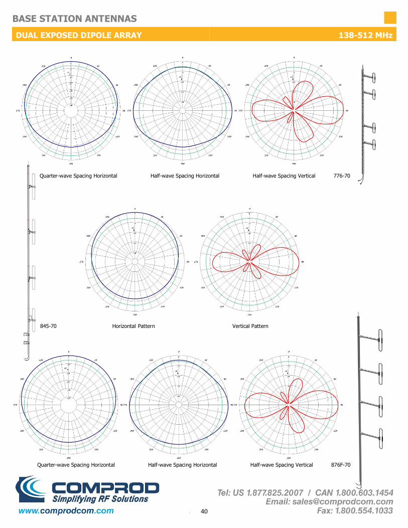
DUAL EXPOSED DIPOLE ARRAY 138-512 MHz
Dual Feed Exposed Dipole Array
The Dual Feed Exposed Dipole Arrays are available in many different configurations. Our VHF, UHF or 700/800/900 MHz antennas can be combined into one mast. These antennas can be mixed and matched with our 840, 870, 880, 770 and 790 series antennas. All of our antennas can be completely customized to your particular applications. Our antennas can be configured for side mount or top mount.
• Low VSWR version with maximum gain over specified frequency.
• Ideal for applications where costs are calculated per antenna.
• Heavy duty versions are available.
• The 845 series has an adjustable pattern for 3 dBd omnidirectional or 6 dBd offset coverage.
• Typical antenna to antenna isolation is 30dB, 40 dB of isolation is also available.
Electrical Specifications 776-70 845-70 876-70
Frequency Range, MHz 406-512 148-174 138-174
Nominal Gain, dBd 5.0-5.5 3.0 or 6.0 5.0-5.5
Number of Dipoles 2 sets of 2 2 sets of 2 2 sets of 2
Bandwidth VSWR, MHz 1.5:1 (106) 2:1 (14) 1.5:1 (36)
Polarization Vertical Vertical Vertical
Pattern Offset Omni or Offset Offset
Power Rating, Watts 300 500 300
Nominal Impedance, Ohms 50 50 50
Lightning Protection DC Ground DC Ground DC Ground
Standard Termination Type N Male Type N Male Type N Male
Mechanical Specifications 776-70 845-70 876-70
Length, in (mm) 126 (3200) 270 (6858) 246 (6248)
Width (1/2 Wave Spacing), in (mm) 16 (406) 9 (229) 40 (1016)
Weight, lbs. (kg) 19 (8.6) 42 (19) 67 (30)
Rated Wind Velocity, No Ice, mph (km/h) 150 (241) 110 (177) 145 (233)
Rated Wind Velocity, 0.5” (13mm) ice, mph (km/h) 150 (241) 80 (129) 95 (153)
Lateral Thrust @ 100 mph, wind, lbs. (kg) 44 (20) 139 (63) 160 (72.6)
Bending Moment @ top clamp: 100 mph, ft*lb (kg*m) 193 (26.7) 514 (71) 1364 (188.7)
Projected Area, ft² (m²) 1.38 (0.128) 5.2 (0.48) 7 (0.65)
Mounting Information Mast O.D. (mm) 1.9" (48) 107-85 clamp 2.9" (61)
Order Info Frequency Equivalent to 40 dB Isolation Side Mount Top Mount Black Anodized
776-70 406-512MHz Dual 772-70 776-70-40dB N/A N/A 776-70HDB
845-70*1 148-162MHz Dual 842-70 N/A N/A N/A N/A
845-70*2 160-174MHz Dual 842-70 N/A N/A N/A N/A
876F-70 138-174MHz Dual 872-70 876F-70-40dB 876F-70SM 876F-70TM 876F-70HDB
776-70-40
40
BASE STATION ANTENNAS
DUAL EXPOSED DIPOLE ARRAY 138-512 MHz
Quarter-wave Spacing Horizontal Half-wave Spacing Horizontal Half-wave Spacing Vertical 876F-70
845-70 Horizontal Pattern Vertical Pattern
Quarter-wave Spacing Horizontal Half-wave Spacing Horizontal Half-wave Spacing Vertical 776-70

41
BASE STATION ANTENNAS
DUAL ANTENNA ARRAY 137-512 MHz Dual Antenna Array
The Dual Antenna Arrays are available in many different configurations. Our VHF, UHF, or 700/800/900 MHz antennas can be combined onto one mast. These antennas can be mixed and matched from our 870, 770 and 790 series antennas. All of our antennas can be completely customized to your particular applications. Our antennas can be configured for top or side mount.
• A low VSWR version, with maximum gain over the specified frequencies.
• Ideal for applications where the costs are calculated per antenna.
• Heavy duty versions are available.
• Multiple combinations are offered and customizable. Please contact a Comprod Inc. Technical support technician for additional details.
Electrical Specifications F-3676 F-3661
Frequency Range, MHz 137-174 406-470 137-174 406-470 137-174 406-470
Nominal Gain, dBd 8.0-8.5 8.0-8.5 5.0-5.5 5.0-5.5 2.0-2.5 2.0-2.5
Number of Dipoles 4 4 2 2 1 1
Bandwidth 1.5:1 VSWR, MHz 36 64 36 106 36 106
Polarization Vertical Vertical Vertical
Pattern Offset Offset Offset
Power Rating, Watts 300 300 300
Nominal Impedance, Ohms 50 50 50
Lightning Protection DC Ground DC Ground DC Ground
Standard Termination Type N Male Type N Male Type N Male
F-3647
Mechanical Specifications F-3676 F-3661 F-3647
Length, in (mm) 354 (8992) 186 (4724) 126 (3200)
Width(1/2 Wave Spacing), in (mm) 41 (1041) 40 (1016) 40 (1016)
Weight, lbs. (kg) 117 (53) 59 (26.8) 26 (11.9)
Rated Wind Velocity, No Ice, mph (km/h) 110 (177) 150 (241) 170 (272)
Rated Wind Velocity, 0.5” (13mm) ice, mph (km/h) 85 (137) 110 (177) 140 (225)
Lateral Thrust @ 100 mph, wind, lbs. (kg) 315 (143) 154 (70) 67 (30.5)
Bending Moment @ top clamp: 100 mph, ft*lb (kg*m) 2469 (341) 720 (100) 110 (15)
Projected Area, ft² (m²) 12 (1.12) 5.7 (0.53) 2.5 (0.23)
Mounting Information Mast O.D. (mm) 3.5" (89) 2.9" (73) 1.9" (48)
Order Information Side Mount Top Mount Heavy Duty Black Anodized
F-3676 F-3676SM F-3676TM F-3676HD F-3676HDB
F-3661 F-3661SM F-3661TM F-3661HD F-3661HDB
F-3647 F-3647SM F-3647TM F-3647HD F-3647HDB
F-3661

42
BASE STATION ANTENNAS
DUAL ANTENNA ARRAY 137-512 MHz
F-3647 Quarter-wave Spacing Horizontal Half-wave Spacing Horizontal Half-wave Spacing Vertical
Quarter-wave Spacing Horizontal Half-wave Spacing Horizontal Half-wave Spacing Vertical F-3661

43
BASE STATION ANTENNAS
DUAL ANTENNA ARRAY 137-512 MHz
F-3676 Quarter-wave Spacing Horizontal Half-wave Spacing Horizontal Half-wave Spacing Vertical

44
BASE STATION ANTENNAS
VHF EXPOSED DIPOLES W/REFLECTORS 138-174 MHz
870 Series VHF Exposed Dipoles with Reflectors
The F-37XX Series antennas are our 870 Series VHF Exposed Dipoles with Reflectors. They are available in 1, 2, 4 dipole configurations. All of our antennas can be com-pletely customized to your applications. Our antennas can be black anodized, fully welded, side mount or top mount, and heavy duty versions are available.
The Reflectors provide a higher degree of directivity. This product is ideal for state or country borders. We have seen great success with being able to shape the RF patterns in the 870 series antenna line.
• Each antenna is configured as a 3/8 wave version.
• The reflectors provide more directivity and greater front-to-back ratios.
• These exposed dipoles have internal cabling and fixed dipole to mast spacing.
• Heavy-duty versions are available. Please contact a Comprod Inc. Technical support technician for consultation.
Electrical Specifications F-3729 F-3713 F-3766
Frequency Range, MHz 138-174 138-174 138-174
Nominal Gain, dBd 2.5-3.0 7.0 9.0-10.0
Number of Dipoles 1 2 4
Number of Reflectors 6 6 6
Bandwidth 1.5:1 VSWR, MHz 36 36 36
Polarization Vertical Vertical Vertical
Pattern Directional Directional Directional
Power Rating, Watts 200 450 450
Nominal Impedance, Ohms 50 50 50
Lightning Protection DC Ground DC Ground DC Ground
Standard Termination Type N Male Type N Male Type N Male
Mechanical Specifications F-3729 F-3713 F-3766
Length, in (mm) 72 (1829) 120 (3048) 240 (6096)
Width(1/2 Wave Spacing), in (mm) 50 (1270) 53 (1346) 53 (1346)
Weight, lbs. (kg) 34.3 (15.6) 57.2 (26) 100.3 (45.5)
Mounting Information Mast O.D. (mm) 2.4" (61) 2.4" (61) 2.9" (73)
Order Information Side Mount Top Mount Black Anodized
F-3729 F-3729SM F-3729TM F-3729SMB
F-3713 F-3713SM F-3713TM F-3713SMB
F-3766 F-3766SM F-33228 (Mid Mount) F-3766SMB
F-3713

45
BASE STATION ANTENNAS
VHF EXPOSED DIPOLES W/REFLECTORS 138-174 MHz
F-3729 3/8 Spacing Horizontal 3/8 wave Spacing Vertical
3/8 Spacing Horizontal 3/8 Spacing Vertical F-3766
F-3713 3/8 Spacing Horizontal 3/8 Spacing Vertical

46
BASE STATION ANTENNAS
790 SERIES ENCLOSED DIPOLE 746-960 MHz
790 Series Enclosed Dipoles
The 790 Series Enclosed Dipoles are available in 2, 4, or 8 dipole configurations. All of our antennas can be completely customized to your particular applications.
Electrical Specifications 792-70 794-70 799-70
Frequency Range, MHz 746-960 746-960 746-960
Nominal Gain, dBd 5.0 8.0 10.0
Number of Dipoles 2 4 8
Bandwidth 1.5:1 VSWR, MHz 150 150 150
Polarization Vertical Vertical Vertical
Pattern Offset Offset Offset
Power Rating, Watts 150 300 500
Nominal Impedance, Ohms 50 50 50
Lightning Protection DC Ground DC Ground DC Ground
Standard Termination Type N Male Type N Male Type N Male
Mechanical Specifications 792-70 794-70 799-70
Length, in (mm) 22 (559) 44.5 (1130) 94 (2388)
Width(1/2 Wave Spacing), in (mm) 2.5 (64) 2.5 (64) 2.5 (64)
Weight, lbs. (kg) 8.8 (4) 14 (6.5) 24 (11)
Rated Wind Velocity, No Ice, mph (km/h) 100 (162) 100 (162) 100 (162)
Rated Wind Velocity, 0.5” (13mm) ice, mph (km/h) 85 (137) 85 (137) 85 (137)
Lateral Thrust @ 100 mph, wind, lbs. (kg) 36.4 (16.5) 73 (33) 153 (59)
Projected Area, ft² (m²) 1.4 (0.13) 2.7 (0.25) 5.7 (0.53)
Mounting Information (Clamps included) 1.5-2.88" O.D. 1.5-2.88" O.D. 1.5-2.88" O.D.
Order Information 746-896MHz 806-960MHz
792-70 792-70*1 792-70*2
794-70 794-70*1 794-70*2
799-70 799-70*1 799-70*2
794-70 • Each antenna is offered in an offset pattern.
• Broadband antennas are ideal for trunking or cellular applications.
• Weatherproof radome to ensure continuous service during severe environmental conditions.
• Versions with 3, 6, and 9 degree downtilt are also available.

47
BASE STATION ANTENNAS
790 SERIES ENCLOSED DIPOLE 746-960 MHz
792-70
799-70
794-70 Horizontal Pattern Vertical Pattern
Horizontal Pattern Vertical Pattern
Horizontal Pattern Vertical Pattern

48
BASE STATION ANTENNAS
790 SERIES ENCLOSED DIPOLE W/REFLECTOR 746-960 MHz
790 Series Enclosed Dipoles with Reflector
The 790 Series Enclosed Dipoles with Reflector are available in 2, 4, or 8 dipole configurations. These antennas can be adjusted from 60º to 160º. All of our antennas can be completely customized to your particular applications.
Electrical Specifications 792-70R 794-70R 799-70R
Frequency Range, MHz 746-960 746-960 746-960
Nominal Gain, dBd Up to 8.0 Up to 13.5 Up to 15.0
Number of Dipoles 2 4 8
Bandwidth 1.5:1 VSWR, MHz 150 150 150
Polarization Vertical Vertical Vertical
Pattern Directional Directional Directional
Power Rating, Watts 150 300 500
Nominal Impedance, Ohms 50 50 50
Lightning Protection DC Ground DC Ground DC Ground
Standard Termination Type N Male Type N Male Type N Male
Mechanical Specifications 792-70R 794-70R 799-70R
Length, in (mm) 22 (559) 44.5 (1130) 94.5 (2395)
Width(1/2 Wave Spacing), in (mm) 25 (635) 25 (635) 25 (635)
Weight, lbs. (kg) 16.5 (7.5) 24 (10.9) 42 (19)
Rated Wind Velocity, No Ice, mph (km/h) 100 (162) 100 (162) 100 (162)
Rated Wind Velocity, 0.5” (13mm) ice, mph (km/h) 85 (137) 85 (137) 85 (137)
Lateral Thrust @ 100 mph, wind, lbs. (kg) 57(26) 115 (52) 243 (110)
Projected Area, ft² (m²) 2.0 (0.19) 4.3 (0.40) 9 (0.84)
Mounting Information (Clamps included) 1.5-2.88" O.D. 1.5-2.88" O.D. 1.5-2.88" O.D.
Order Information 746-896MHz 806-960MHz
792-70R 792-70R*1 792-70R*2
794-70R 794-70R*1 794-70R*2
799-70R 799-70R*1 799-70R*2
794-70R • Broadband antennas are ideal for trunking or cellular applications.
• Reflector is field adjustable and has 5 positions: 60º, 90º, 105º, 130º and 160º.
• Weatherproof radome to ensure continuous service during severe environmental conditions.
• Heavy duty versions are available. Please contact Comprod Inc. Technical support technician for consultation.

49
BASE STATION ANTENNAS
790 SERIES ENCLOSED DIPOLE W/REFLECTOR 746-960 MHz
792-70R90 792-70R130 792-70R160 792-70R
Call for additional patterns
794-70R 794-70R90 794-70R130 794-70R160
799-70R90 799-70R130 799-70R160 799-70R

50
BASE STATION ANTENNAS
VHF YAGI ANTENNA 138-174MHz 290 Series VHF Yagi Antennas The 290 Series VHF Yagi Antenna are available in 2, 3, and 6 element configurations. All of our antennas can be completely customized to your applications. Our antennas can be black anodized, welded, vertically or horizontally polarized, and heavy duty versions are available.
• Each antenna has a rugged design to withstand harsh environmental conditions. • The mounting hardware supplied will permit either vertical or horizontal polarization. • DC ground for lightning protection. • Optionally have the entire antenna welded for added durability. • Heavy-duty versions are available. Please contact Comprod Inc. Technical support.
Electrical Specifications 291-70 295-70 290-70 250-70
Frequency Range, MHz 138-174 138-174 138-174 138-174
Nominal Gain, dBd 3.5 6.5 9.5 7
Number of Elements 2 3 6 7
Bandwidth 1.5:1 VSWR, MHz (Ctr. Freq.%) 3.75% 4% 4% 36 @ 2:1
Polarization Vert. or Horiz. Vert. or Horiz. Vert. or Horiz. Vert. or Horiz.
Horizontal Beamwidth (Horizontal Pol.) 140º 90º 62º 80º
Vertical Beamwidth (Horizontal Pol.) 70º 61º 50º 60º
Front to Back, dB 15 12 17 25
Pattern Directional Directional Directional Directional
Power Rating, Watts 350 350 350 250
Nominal Impedance, Ohms 50 50 50 50
Lightning Protection DC Ground DC Ground DC Ground DC Ground
Standard Termination Type N Male Type N Male Type N Male Type N Male
Mechanical Specifications 291-70 295-70 290-70 250-70
Length, in (mm) 50 (1270) 60 (1524) 108 (2743) 104 (2642)
Width(1/2 Wave Spacing), in (mm) 40 (1016) 43 (1092) 42 (1067) 42 (1067)
Weight, lbs. (kg) 4.8 (2.2) 6.5 (2.9) 12.0 (5.4) 12.0 (5.4)
Rated Wind Velocity, No Ice, mph (km/h) 150 (241) 145 (223) 120 (177) 110 (177)
Rated Wind Velocity, 0.5” (13mm) ice, mph (km/h) 105 (169) 100 (161) 85 (137) 90 (145)
Lateral Thrust @ 100 mph, wind, lbs. (kg) 29 (13) 39 (18) 65 (29) 95 (43)
Projected Area, ft² (m²) 1.1 (0.10) 1.4 (0.13) 2.4 (0.22) 2.6 (0.24)
Mounting Information 181-85 Clamp 181-85 Clamp 115-85 Clamp 115-85 Clamp
Order Information End Mount End Boom Center Mount
291-70 291-70 N/A N/A
295-70 295-70 N/A 295-70CB
250-70 250-70 250-70 N/A
Welded
291-70W
295-70W
250-70W
Heavy Duty
291-70HD
295-70HD
250-70HD
Black Anodized
291-70B
295-70B
250-70B
(2) Stacked
Call
Call
Call
290-70 290-70 290-70EB 290-70CB 290-70W 290-70HD 290-70B 298-70
250-70

51
BASE STATION ANTENNAS
VHF YAGI ANTENNA 138-174 MHz
291-70
290-70
295-70
250-70
Horizontal Polarization
Horizontal Polarization
Horizontal Polarization
Horizontal Polarization
Horizontal Pattern Vertical Pattern
Horizontal Pattern Vertical Pattern
Horizontal Pattern Vertical Pattern
Horizontal Pattern Vertical Pattern
52
BASE STATION ANTENNAS
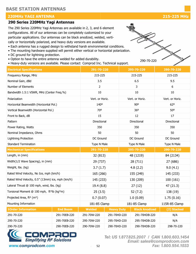
1Order Information End Boom Welded Heavy Duty Black Anodized (2) Stacked
291-70-220 291-70EB-220 291-70W-220 291-70HD-220 291-70HDB-220 N/A
295-70-220 295-70EB-220 295-70W-220 295-70HD-220 295-70HDB-220 N/A
290-70-220 290-70EB-220 290-70W-220 290-70HD-220 290-70HDB-220 298-70-220
Mechanical Specifications 291-70-220 295-70-220 290-70-220
Length, in (mm) 32 (813) 48 (1219) 84 (2134)
Width(1/2 Wave Spacing), in (mm) 29 (737) 28 (711) 27 (686)
Weight, lbs. (kg) 3.7 (1.7) 4.8 (2.2) 9.0 (4.1)
Rated Wind Velocity, No Ice, mph (km/h) 165 (266) 155 (249) 145 (233)
Rated Wind Velocity, 0.5” (13mm) ice, mph (km/h) 145 (233) 130 (209) 100 (161)
Lateral Thrust @ 100 mph, wind, lbs. (kg) 19.4 (8.8) 27 (12) 47 (21.3)
Projected Area, ft² (m²) 0.7 (0.07) 1.0 (0.09) 1.75 (0.16)
Mounting Information 181-85 Clamp 181-85 Clamp 115R-85 Clamp
Torsional Moment @ 100 mph, ft*lb (kg*m) 25 (3.5) 52 (7.2) 138 (19)
220MHz YAGI ANTENNA 215-225 MHz
• Each antenna has a rugged design to withstand harsh environmental conditions. • The mounting hardware supplied will permit either vertical or horizontal polarization. • DC ground for lightning protection. • Option to have the entire antenna welded for added durability. • Heavy-duty versions are available. Please contact Comprod Inc. Technical support.
290 Series 220MHz Yagi Antennas The 290 Series 220MHz Yagi Antennas are available in 2, 3, and 6 element configurations. All of our antennas can be completely customized to your particular applications. Our antennas can be black anodized, welded, verti-cally or horizontally polarized, and heavy duty versions are available.
Electrical Specifications 291-70-220 295-70-220 290-70-220
Frequency Range, MHz 215-225 215-225 215-225
Nominal Gain, dBd 3.5 6.5 9.5
Number of Elements 2 3 6
Bandwidth 1.5:1 VSWR, MHz (Center Freq.%) 10 10 10
Polarization Vert. or Horiz. Vert. or Horiz. Vert. or Horiz.
Horizontal Beamwidth (Horizontal Pol.) 140º 90º 62º
Vertical Beamwidth (Horizontal Pol.) 70º 36º 50º
Front to Back, dB 15 12 17
Pattern Directional Directional Directional
Power Rating, Watts 350 350 350
Nominal Impedance, Ohms 50 50 50
Lightning Protection DC Ground DC Ground DC Ground
Standard Termination Type N Male Type N Male Type N Male
290-70-220

53
BASE STATION ANTENNAS
VHF YAGI ANTENNA 215-225 MHz
295-70-220
290-70-220
Horizontal Polarization
Horizontal Polarization
Horizontal Polarization
291-70-220
Horizontal Pattern Vertical Pattern
Horizontal Pattern Vertical Pattern
Horizontal Pattern Vertical Pattern

54
BASE STATION ANTENNAS
UHF YAGI ANTENNA 406-512 MHz UHF Yagi Antennas Series
The UHF Yagi Antenna Series is available in 2, 3, 7 element and our 70 MHz wideband configurations. All of our antennas can be completely customized to your particular applications. Our antennas can be black anodized, fully welded, vertically or horizontally polarized, and heavy duty versions are available.
480-70
Electrical Specifications F-3872 433-70 430-70 480-70
Frequency Range, MHz 406-512 406-512 406-512 406-470
Nominal Gain, dBd 3.5 6.5 10.0 10.0
Number of Elements 2 3 7 7
Bandwidth 1.5:1 VSWR, MHz (Center Freq.%) 24 24 24 64
Polarization Vert. or Horiz. Vert. or Horiz. Vert. or Horiz. Vert. or Horiz.
Horizontal Beamwidth (Vert. Pol.) 138º 83º 62º 62º
Vertical Beamwidth (Vert. Pol.) 72º 59º 48º 50º
Front to Back, dB 10 12 20 17
Pattern Directional Directional Directional Directional
Power Rating, Watts 350 350 350 350
Nominal Impedance, Ohms 50 50 50 50
Lightning Protection DC Ground DC Ground DC Ground DC Ground
Standard Termination Type N Male Type N Male Type N Male Type N Male
• Each antenna has a rugged, fully welded design to withstand harsh environmental conditions. • The mounting hardware supplied allows either vertical or horizontal polarization. • DC ground for lightning protection. • All UHF Yagi antennas are fully welded. • Heavy-duty versions are available. Please contact Comprod Inc. Technical support.
Mechanical Specifications F-3872 433-70 430-70 480-70
Length, in (mm) 28 (711) 23 (584) 45 (1143) 45 (1143)
Width(1/2 Wave Spacing), in (mm) 14.5 (368) 14 (355) 14.5 (368) 14.4 (366)
Weight, lbs. (kg) 2.8 (1.3) 2.9 (1.3) 3.9 (1.8) 3.9 (1.8)
Rated Wind Velocity, No Ice, mph (km/h) 160 (257) 160 (257) 150 (241) 150 (241)
Rated Wind Velocity, 0.5” (13mm) ice, mph (km/h) 120 (193) 120 (193) 110 (177) 110 (177)
Lateral Thrust @ 100 mph, wind, lbs. (kg) 9 (4.1) 8.7 (4.0) 16 (7.3) 15 (6.8)
Projected Area, ft² (m²) 0.34 (0.03) 0.32 (0.03) 0.61 (0.06) 0.55 (0.05)
Mounting Information 127-85 Clamp 127-85 Clamp 127-85 Clamp 127-85 Clamp
Order Information 406-430 430-450 450-470
F-3872 F-3872*1 F-3872*2 F-3872*3
433-70 433-70*1 433-70*2 433-70*3
480-70 480-70 480-70 480-70
406-470
N/A
N/A
480-70
Black Anodized
F-3872B
433-70B
480-70B
(2) Stacked
N/A
N/A
481-70
(4) Stacked
N/A
N/A
482-70
430-70 430-70*1 430-70*2 430-70*3 N/A 430-70B 431-70 432-70

55
BASE STATION ANTENNAS
UHF YAGI ANTENNA 406-512 MHz
F-3872
430-70
433-70
480-70
Horizontal Polarization
Horizontal Polarization
Horizontal Polarization
Horizontal Polarization
Horizontal Pattern Vertical Pattern
Horizontal Pattern Vertical Pattern
Horizontal Pattern Vertical Pattern
Horizontal Pattern Vertical Pattern

56
BASE STATION ANTENNAS
980 Yagi Antennas Series 746-960 MHz
980 Yagi Antennas Series
The 980 Yagi Antenna Series are available in 2, 3, 7, 12 element configurations. All of our antennas can be completely customized to your particular applica-tions. Our antennas can be black anodized, vertically or horizontally polarized. • Each antenna has a rugged design to withstand harsh environmental conditions.
• The mounting hardware supplied will permit either vertical or horizontal polarization.
• All 980 Series Yagi antennas are fully welded.
• Heavy-duty versions are available. Please Contact a Comprod Inc. Technical support technician for consultation.
Electrical Specifications 982-70 983-70 980-70 987-70
Frequency Range, MHz 746-960 746-960 746-960 746-960
Nominal Gain, dBd 3.5 6.5 10.0 12.0
Number of Elements 2 3 7 12
Bandwidth 1.5:1 VSWR, MHz (Ctr. Freq.%) 30 85 85 85
Polarization Vert. or Horiz. Vert. or Horiz. Vert. or Horiz. Vert. or Horiz.
Horizontal Beamwidth (Horizontal Pol.) 128º 99º 56º 41º
Vertical Beamwidth (Horizontal Pol.) 66º 60º 42º 38º
Front to Back, dB 9 16 20 20
Pattern Directional Directional Directional Directional
Power Rating, Watts 200 200 200 200
Nominal Impedance, Ohms 50 50 50 50
Standard Termination Type N Male Type N Male Type N Male Type N Male
Mechanical Specifications 982-70 983-70 980-70 987-70
Length, in (mm) 11 (280) 13 (330) 27 (686) 41 (1041)
Width(1/2 Wave Spacing), in (mm) 6.5 (165) 8 (203) 8 (203) 8 (203)
Weight, lbs. (kg) 1.7 (0.76) 1.8 (0.82) 2.5 (1.1) 3 (1.4)
Rated Wind Velocity, No Ice, mph (km/h) 160 (257) 160 (257) 150 (241) 140 (225)
Rated Wind Velocity, 0.5” (13mm) ice, mph (km/h) 120 (193) 120 (193) 110 (177) 100 (161)
Lateral Thrust @ 100 mph, wind, lbs. (kg) 2.6 (1.2) 2.8 (1.3) 7 (3.2) 11 (5.0)
Projected Area, ft² (m²) 0.10 (0.009) 0.13 (0.012) 0.26 (0.024) 0.41 (0.038)
Mounting Information 1.0-2.38" O.D. 1.0-2.38" O.D. 1.0-2.38" O.D. 1.0-2.38" O.D.
Included Clamp Model 127-85 127-85 127-85 127-85
983-70
Order Information 746-806MHz 806-869MHz 824-896MHz 896-960MHz Black Anodized (2) Stacked
982-70 N/A
983-70 983-70*1 983-70*2 983-70*3 983-70*4 983-70B N/A
980-70 980-70*1 980-70*2 980-70*3 980-70*4 980-70B (2)980-70
987-70 987-70*1 987-70*2 987-70*3 987-70*4 987-70B (2)987-70
* Call With Frequencies *

57
BASE STATION ANTENNAS
980 YAGI ANTENNA 746-960 MHz
983-70
982-70
980-70
987-70
Horizontal Polarization
Horizontal Polarization
Horizontal Polarization
Horizontal Polarization
Horizontal Pattern Vertical Pattern
Horizontal Pattern Vertical Pattern
Horizontal Pattern Vertical Pattern
Horizontal Pattern Vertical Pattern

58
BASE STATION ANTENNAS
490 SERIES YAGI ANTENNA 806-960 MHz
490 Heavy Duty Yagi Antennas Series
The 490 Heavy Duty Yagi Series is an extremely rugged, 7 element configuration antenna. All of our antennas can be completely customized to your particular applications. Our antennas can be black anodized, vertically or horizontally polarized.
• Each antenna has an extremely rugged design to withstand harsh environmental conditions. • The mounting hardware supplied will permit either vertical or horizontal polarization. • The 490 Series Yagi antennas are fully welded. • DC ground for lightning protection.
Electrical Specifications 490-70
Frequency Range, MHz 806-960
Nominal Gain, dBd 10.0
Number of Elements 7
Bandwidth: 1.5:1 VSWR, MHz 85
Polarization Vert. or Horiz.
Horizontal Beamwidth (Horizontal Pol.) 56º
Vertical Beamwidth (Horizontal Pol.) 42º
Front to Back, dB 20
Pattern Directional
Power Rating, Watts 200
Nominal Impedance, Ohms 50
Standard Termination Type N Male
Mechanical Specifications 490-70
Length, in (mm) 27 (686)
Width(1/2 Wave Spacing), in (mm) 8 (203)
Weight, lbs. (kg) 2.5 (1.1)
Rated Wind Velocity, No Ice, mph (km/h) 150 (241)
Rated Wind Velocity, 0.5” (13mm) ice, mph (km/h) 150 (241)
Lateral Thrust @ 100 mph, wind, lbs. (kg) 38 (17)
Projected Area, ft² (m²) 0.4 (0.04)
Mounting Information 1.0-2.38" O.D.
Bending Moment @ top clamp: 100 mph, ft*lb (kg*m) 13 (1.8)
Order Information 806-869MHz 824-896MHz 896-960MHz Black Anodized (2) Stacked
490-70 490-70*1 490-70*2 490-70*3 490-70B 491-70
490-70

59
BASE STATION ANTENNAS
490 SERIES YAGI ANTENNA 806-960 MHz
490-70
Horizontal Polarization
Horizontal Pattern Vertical Pattern

60
BASE STATION ANTENNAS
RADOME YAGI ANTENNA 406-960 MHz Radome Yagi Antennas Series The Radome Yagi Antenna Series are available in UHF and 700/800/900 MHz configurations. The UHF model is offered with a Fiberglass or PVC Radome. The 700/800/900 MHz model is offered in PVC. All of our antennas can be completely customized to your particular applications.
• Each antenna has a rugged design to withstand extreme environmental conditions. • The mounting hardware supplied supports either vertical or horizontal polarization. • DC ground for lightning protection. • The PVC enclosure is 1/2 inch thick. • These are our Heavy Duty Versions. Please contact a Comprod Inc. Technical support technician for consultation.
Electrical Specifications 425-70 426-70 490-70R
Frequency Range, MHz 406-512 406-512 746-960
Nominal Gain, dBd 10 10 10
Number of Elements Loop Yagi Loop Yagi 7
Bandwidth: 1.5:1 VSWR, MHz 20 20 72
Polarization Vert. or Horiz. Vert. or Horiz. Vert. or Horiz.
Horizontal Beamwidth (Horizontal Pol.) 62º 62º 56º
Vertical Beamwidth (Horizontal Pol.) 48º 48º 42º
Front to Back, dB 20 20 20
Pattern Directional Directional Directional
Power Rating, Watts 250 250 150
Nominal Impedance, Ohms 50 50 50
Lightning Protection DC Ground DC Ground DC Ground
Standard Termination Type N Male Type N Male Type N Male
Mechanical Specifications 425-70 426-70 490-70R
Length, in (mm) 31 (787) 30 (762) 29 (737)
Width(1/2 Wave Spacing), in (mm) 16 (406) 16 (406) 14 (356)
Weight, lbs. (kg) 44 (20) 19 (8.6) 28 (12)
Rated Wind Velocity, No Ice, mph (km/h) 150 (241) 120 (193) 150 (241)
Rated Wind Velocity, 0.5” (13mm) ice, mph (km/h) 105 (169) 110 (177) 115 (185)
Lateral Thrust @ 100 mph, wind, lbs. (kg) 69 (31.3) 61 (27.7) 47.4 (21.5)
Projected Area, ft² (m²) 2.6 (0.24) 2.3 (0.21) 1.8 (0.17)
Mounting Information (clamp included) for pipe size O.D. in (mm)
2.9" O.D. 2.4" O.D. 2.9" O.D.
Radome Material PVC Fiberglass PVC
Order Information (2) Stacked (4) Stacked 406-430 430-450 450-470
425-70 2*425-70 4*425-70 425-70*1 425-70*2 425-70*3
426-70 2*426-70 4*426-70 426-70*1 426-70*2 426-70*3
490-70R 2*490-70R 4*490-70R N/A N/A N/A
490-70R
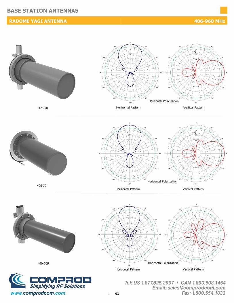
61
BASE STATION ANTENNAS
RADOME YAGI ANTENNA 406-960 MHz
425-70
426-70
490-70R
Horizontal Polarization
Horizontal Polarization
Horizontal Polarization
Horizontal Pattern Vertical Pattern
Horizontal Pattern Vertical Pattern
Horizontal Pattern Vertical Pattern

62
BASE STATION ANTENNAS
VHF CORNER REFLECTOR 132-174 MHz
VHF Corner Reflector Antenna Series
The Corner Reflector Antennas are available in VHF, UHF, 700/800/900 MHz configurations. These antennas have an extremely good front-to-back ratio. They are broadband and are ideal for point-to-point applications. Performance is constant throughout the band.
• Each antenna has a rugged design to withstand harsh environmental conditions.
• Single dipole mounted in the front of a 90º reflector, providing good directivity and a very high front-to-back ratio.
• These antennas have ultra-low VSWR ratings, and will not exceed 2.0:1 VSWR ratio with 0.5” (13 mm) of radial ice.
• The mounting hardware supplied allows either vertical or horizontal polarization.
• DC ground for lightning protection
• Heavy duty versions are available. Please contact a Comprod Inc. Technician for consultation.
Electrical Specifications 470-70 470-70HD 471-70 471-70HD
Frequency Range, MHz 132-174 132-174 132-174 132-174
Nominal Gain, dBd 7.0 7.0 10.0 10.0
Bandwidth: 1.5:1 VSWR, MHz 15% 15% 15% 15%
Polarization Vert. or Horiz. Vert. or Horiz. Vert. or Horiz. Vert. or Horiz.
Horizontal Beamwidth (Vert. Pol.) 67º 67º 50º 50º
Vertical Beamwidth (Vert. Pol.) 75º 75º 66º 66º
Front to Back, dB 30 30 30 30
Pattern Directional Directional Directional Directional
Lightning Protection DC Ground DC Ground DC Ground DC Ground
Standard Termination Type N Male Type N Male Type N Male Type N Male
Power Rating, Watts 250 250 250 250
Nominal Impedance, Ohms 50 50 50 50
Mechanical Specifications 470-70 470-70HD 471-70 471-70HD
Length, in (mm) 48 (1219) 48 (1219) 72 (1829) 72 (1829)
Width, in (mm) 75 (1905) 75 (1905) 120 (3048) 120 (3048)
Weight, lbs. (kg) 39 (17.7) 57 (25.8) 66 (30) 72 (32.7)
Rated Wind Velocity, No Ice, mph (km/h) 100 (61) 140 (225) 100 (61) 140 (225)
Rated Wind Velocity, 0.5” (13mm) ice, mph (km/h) 85 (137) 100 (161) 85 (137) 100 (161)
Lateral Thrust @ 100 mph, wind, lbs. (kg) 144 (65) 236 (107) 320 (145) 398 (181)
Projected Area, ft² (m²) 5.3 (0.5) 8.8 (0.82) 11.9 (1.10) 14.8 (1.38)
Mounting Information: (clamp included) for pipe size O.D. in (mm)
2.9 (73) 2.9 (73) 2.9 (73) 2.9 (73)
470-70HD

63
BASE STATION ANTENNAS
VHF CORNER REFLECTOR 132-174 MHz
470-70
470-70HD
471-70
471-70HD
Vertical Polarization
Vertical Polarization
Vertical Polarization
Horizontal Pattern Vertical Pattern
Horizontal Pattern Vertical Pattern
Horizontal Pattern Vertical Pattern

64
BASE STATION ANTENNAS
220 MHz CORNER REFLECTOR 215-225 MHz 220MHz Corner Reflector Antenna Series The Corner Reflector Antennas are available in VHF, UHF, 700/800/900 MHz configurations. These antennas have an extremely good front-to-back ratio. They are broadband and are ideal for point-to-point applications. Performance is constant throughout the band.
470-70-220HD
• Each antenna has a rugged design to withstand harsh environmental conditions.
• Single or Dual Dipole mounted in the front of a 90º reflector, providing good directivity and a very high front-to-back ratio.
• These antennas have ultra-low VSWR ratings, and will not exceed 2.0:1 VSWR ratio with 0.5” (13 mm) of radial ice.
• The supplied mounting hardware allows either vertical or horizontal polarization.
• DC ground for lightning protection.
• Heavy Duty versions are available. Please contact a Comprod Inc. Technical support technician for consultation.
Electrical Specifications 470-70-220 470-70-220HD 471-70-220
Frequency Range, MHz 215-225 215-225 215-225
Nominal Gain, dBd 7.0 7.0 10.0
Bandwidth: 1.5:1 VSWR, MHz 10 10 10
Polarization Vert. or Horiz. Vert. or Horiz. Vert. or Horiz.
Horizontal Beamwidth (Vert. Pol.) 67º 67º 50º
Vertical Beamwidth (Vert. Pol.) 75º 75º 66º
Front to Back, dB 30 30 30
Pattern Directional Directional Directional
Power Rating, Watts 250 250 250
Nominal Impedance, Ohms 50 50 50
Lightning Protection DC Ground DC Ground DC Ground
Standard Termination Type N Male Type N Male Type N Male
Electrical Specifications 470-70-220 470-70-220HD 471-70-220
Length, in (mm) 48 (1219) 48 (1219) 72 (1829)
Width, in (mm) 75 (1905) 75 (1905) 120 (3048)
Weight, lbs. (kg) 39 (17.7) 57 (25.8) 55 (30)
Rated Wind Velocity, No Ice, mph (km/h) 100 (161) 140 (225) 100 (161)
Rated Wind Velocity, 0.5” (13mm) ice, mph (km/h) 85 (137) 100 (161) 85 (137)
Lateral Thrust @ 100 mph, wind, lbs. (kg) 144 (65) 236 (107) 320 (145)
Projected Area, ft² (m²) 5.3 (0.5) 8.8 (0.82) 11.9 (1.10)
Mounting Information: (clamp included) for pipe size O.D. in (mm)
2.9 (73) 2.9 (73) 2.9 (73)

65
BASE STATION ANTENNAS
220MHz CORNER REFLECTOR 215-225 MHz
470-70-220
470-70-220HD
471-70-220
Vertical Polarization
Vertical Polarization
Vertical Polarization
Horizontal Pattern Vertical Pattern
Horizontal Pattern Vertical Pattern
Horizontal Pattern Vertical Pattern
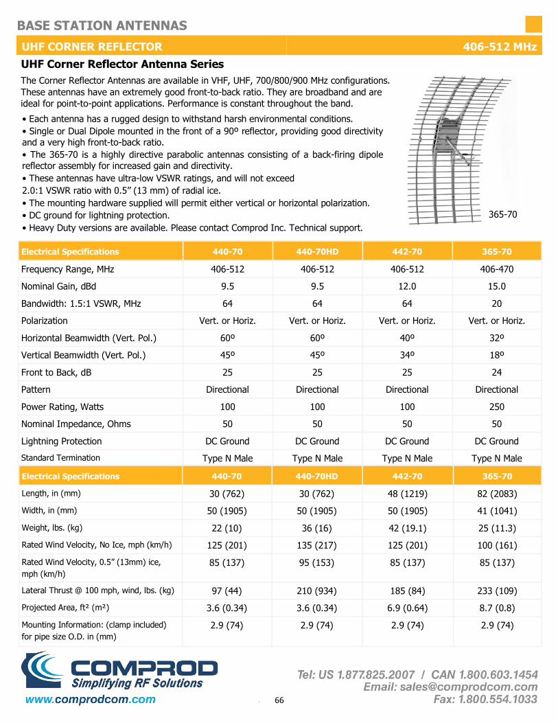
66
BASE STATION ANTENNAS
UHF CORNER REFLECTOR 406-512 MHz
Electrical Specifications 440-70 442-70 365-70
Frequency Range, MHz 406-512 406-512 406-470
Nominal Gain, dBd 9.5 12.0 15.0
Bandwidth: 1.5:1 VSWR, MHz 64 64 20
Polarization Vert. or Horiz. Vert. or Horiz. Vert. or Horiz.
Horizontal Beamwidth (Vert. Pol.) 60º 40º 32º
Vertical Beamwidth (Vert. Pol.) 45º 34º 18º
Front to Back, dB 25 25 24
Pattern Directional Directional Directional
Power Rating, Watts 100 100 250
Nominal Impedance, Ohms 50 50 50
Lightning Protection DC Ground DC Ground DC Ground
Standard Termination Type N Male Type N Male Type N Male
440-70HD
406-512
9.5
64
Vert. or Horiz.
60º
45º
25
Directional
100
50
DC Ground
Type N Male
Electrical Specifications 440-70 442-70 365-70
Length, in (mm) 30 (762) 48 (1219) 82 (2083)
Width, in (mm) 50 (1905) 50 (1905) 41 (1041)
Weight, lbs. (kg) 22 (10) 42 (19.1) 25 (11.3)
Rated Wind Velocity, No Ice, mph (km/h) 125 (201) 125 (201) 100 (161)
Rated Wind Velocity, 0.5” (13mm) ice, mph (km/h)
85 (137) 85 (137) 85 (137)
Lateral Thrust @ 100 mph, wind, lbs. (kg) 97 (44) 185 (84) 233 (109)
Projected Area, ft² (m²) 3.6 (0.34) 6.9 (0.64) 8.7 (0.8)
Mounting Information: (clamp included) for pipe size O.D. in (mm)
2.9 (74) 2.9 (74) 2.9 (74)
440-70HD
30 (762)
50 (1905)
36 (16)
135 (217)
95 (153)
210 (934)
3.6 (0.34)
2.9 (74)
• Each antenna has a rugged design to withstand harsh environmental conditions. • Single or Dual Dipole mounted in the front of a 90º reflector, providing good directivity and a very high front-to-back ratio. • The 365-70 is a highly directive parabolic antennas consisting of a back-firing dipole reflector assembly for increased gain and directivity. • These antennas have ultra-low VSWR ratings, and will not exceed 2.0:1 VSWR ratio with 0.5” (13 mm) of radial ice. • The mounting hardware supplied will permit either vertical or horizontal polarization. • DC ground for lightning protection. • Heavy Duty versions are available. Please contact Comprod Inc. Technical support.
UHF Corner Reflector Antenna Series The Corner Reflector Antennas are available in VHF, UHF, 700/800/900 MHz configurations. These antennas have an extremely good front-to-back ratio. They are broadband and are ideal for point-to-point applications. Performance is constant throughout the band.
365-70

67
BASE STATION ANTENNAS
UHF CORNER REFLECTOR 406-512 MHz
440-70HD
440-70
442-70
Horizontal Pattern Vertical Pattern
Horizontal Polarization
Horizontal Pattern Vertical Pattern
365-70
Horizontal Pattern Vertical Pattern
Vertical Polarization
Vertical Polarization

68
BASE STATION ANTENNAS PARABOLIC DIRECTIONAL ANTENNA 764-960 MHz
Electrical Specifications 965-70 965-70B 965-70BR
Frequency Range, MHz 764-960 764-960 764-960
Nominal Gain, dBd 16.5 16.5 16.5
Bandwidth: 1.5:1 VSWR, MHz 72 72 72
Polarization Vert. or Horiz. Vert. or Horiz. Vert. or Horiz.
Horizontal Beamwidth (Vert. Pol.) 12 12 12
Vertical Beamwidth (Vert. Pol.) 30 30 30
Front to Back, dB 25 25 25
Pattern Directional Directional Directional
Power Rating, Watts 200 200 200
Nominal Impedance, Ohms 50 50 50
Lightning Protection DC Ground DC Ground DC Ground
Standard Termination Type N Male Type N Male Type N Male
Electrical Specifications 965-70 965-70B 965-70BR
Length, in (mm) 68 (1727) 68 (1727) 68 (1727)
Width, in (mm) 36 (914) 36 (914) 36 (914)
Weight, lbs. (kg) 49 (22.3) 49 (22.3) 51 (23.2)
Rated Wind Velocity, No Ice, mph (km/h) 110 (177) 110 (177) 110 (177)
Rated Wind Velocity, 0.5” (13mm) ice, mph (km/h) 85 (137) 85 (137) 85 (137)
Lateral Thrust @ 100 mph, wind, lbs. (kg) 1.9 (0.46) 1.9 (0.46) 1.9 (0.46)
Projected Area, ft² (m²) 4.9 (0.46) 4.9 (0.46) 5 (0.47)
Mounting Information: (clamp included) 112-85 112-85 112-85
965-70
Parabolic Reflector Series Antennas The Reflector antenna is a SRSP-507 Category A compliant antenna. These antennas have an extremely good front-to-back ratio. They are broadband and are ideal for point-to-point applications where restrictions on beam width are present. Perfor-mance is constant throughout the band. • SRSP-507 Category A Compliant. • Mechanical resonance reducing design. • Each antenna has a rugged design to withstand harsh environmental conditions. •The 965-70 is a highly-directive parabolic antenna consisting of a back-firing dipole reflector assembly for increased gain and directivity. • These antennas have ultra-low VSWR ratings, and will not exceed 1.5:1 VSWR ratio with 0.5” (13 mm) of radial ice. • The mounting hardware supplied will permit either vertical or horizontal polarization. • DC ground for lightning protection. • Black Anodized and Dipole Radome protected versions are available. Please Contact a Comprod Inc. Technical support technician for consultation. • 965-70B is Black Anodized and 965-70BR is Black Anodized with a Radome

69
BASE STATION ANTENNAS
PARABOLIC DIRCTIONAL ANTENNA 764-960 MHz
965-70
965-70BR
965-70B
Vertical Polarization
Vertical Polarization
Vertical Polarization
Horizontal Pattern Vertical Pattern
Horizontal Pattern Vertical Pattern
Horizontal Pattern Vertical Pattern

70
BASE STATION ANTENNAS
LOG PERIODIC ANTENNA 132-174 MHz Log Periodic Series Antennas The Log Periodic Antennas are available in VHF and UHF configurations. These antennas have an extremely good front-to-back ratio. They are wideband and are ideal for base station or in-building applications. These antennas are great for providing underground coverage within garages. Performance is constant throughout the band.
Electrical Specifications 635-70 645-70 638-70
Frequency Range, MHz 132-174 132-174 138-174
Nominal Gain, dBd 6.0 6.0 8.0
Bandwidth: 1.5:1 VSWR, MHz 42 42 36
Polarization Vert. or Horiz. Vert. or Horiz. Vert. or Horiz.
Horizontal Beamwidth (Vert. Pol.) 106º 106º 75º
Vertical Beamwidth (Vert. Pol.) 60º 30º 55º
Front to Back, dB 25 25 25
Pattern Directional Directional Directional
Power Rating, Watts 500 500 500
Nominal Impedance, Ohms 50 50 50
Lightning Protection DC Ground DC Ground DC Ground
Standard Termination Type N Male Type N Male Type N Male
Order Information End Mount Center Mount
635-70 635-70 N/A
645-70 N/A 645-70
638-70 638-70 N/A
Electrical Specifications 635-70 645-70 638-70
Length, in (mm) 42 (1067) 42 (1067) 60 (1524)
Width, in (mm) 44 (1118) 44 (1118) 44.5 (1130)
Weight, lbs. (kg) 8 (3.6) 16 (7.2) 16.8 (7.8)
Rated Wind Velocity, No Ice, mph (km/h) 158 (254) 158 (254) 150 (241)
Rated Wind Velocity, 0.5” (13mm) ice, mph (km/h) 108 (173) 108 (173) 108 (173)
Lateral Thrust @ c, wind, lbs. (kg) 31 (14) 31 (14) 47.5 (21.5)
Projected Area, ft² (m²) 0.86 (0.08) 0.86 (0.08) 1.26 (0.120)
Mounting Information: (clamp included) for pipe size O.D. in (mm) 1" to 2.5" (64) 1" to 2.5" (64) 1" to 2.5" (64)
Torsional Moment @ 100 mph, ft*lb (kg*m) 56 (7.8) N/A 121 (16.7)
638-70
• Each antenna has a rugged design to withstand harsh environmental conditions. • The mounting hardware supplied will permit either vertical or horizontal polarization. • DC ground for lightning protection. • Heavy-duty versions are available. Please contact a Comprod Inc. Technical support technician for consultation.

71
BASE STATION ANTENNAS
LOG PERIODIC ANTENNA 132-174 MHz
638-70 Vertical Polarization
Vertical Polarization
635-70
645-70 Vertical Polarization
Horizontal Pattern Vertical Pattern
Horizontal Pattern Vertical Pattern
Horizontal Pattern Vertical Pattern

72
BASE STATION ANTENNAS
LOG PERIODIC ANTENNA 406-512 MHz
Log Periodic Series Antennas The Log Periodic Antennas are available in VHF and UHF configurations. These antennas have an extremely good front-to-back ratio. They are wide-band and are ideal for base station or in-building applications. We have had great success with these antennas providing underground coverage within garages. Performance is constant throughout the band.
• Each antenna has a rugged design to withstand harsh environmental conditions.
• The mounting hardware supplied will permit either vertical or horizontal polarization.
• DC ground for lightning protection.
• Heavy-duty versions are available. Please contact a Comprod Inc. Technical support technician for consultation.
Electrical Specifications 415-70 465-70
Frequency Range, MHz 406-512 406-512
Nominal Gain, dBd Unity 6.0
Bandwidth: 1.5:1 VSWR, MHz 40 64
Polarization Vert. or Horiz. Vert. or Horiz.
Vertical Beamwidth (Vert. Pol.) 84º 60º
Pattern Directional Directional
Power Rating, Watts 250 250
Nominal Impedance, Ohms 50 50
Lightning Protection DC Ground DC Ground
Standard Termination Type N Male Type N Male
Horizontal Beamwidth (Vert. Pol.) N/A 106º
Front to Back, dB N/A 20
Mechanical Specifications 415-70 465-70
Length, in (mm) 18 (457) 15 (381)
Width, in (mm) 14.3 (362) 16 (406)
Weight, lbs. (kg) 2.6 (1.2) 3.3 (1.47)
Rated Wind Velocity, No Ice, mph (km/h) 160 (257) 150 (241)
Rated Wind Velocity, 0.5” (13mm) ice, mph (km/h) 120 (193) 110 (177)
Lateral Thrust @ c, wind, lbs. (kg) 12 (5.4) 14 (6.4)
Torsional Moment @ 100 mph, ft*lb (kg*m) 6.3 (0.88) 6.4 (0.89)
Projected Area, ft² (m²) 0.44 (0.04) 0.50 (0.05)
Mounting Information: Max Pipe Size (mm) 1" to 2.5" (64) 1" to 2.5" (64)
Order Information 406-430MHz 435-470MHz 406-470MHz 450-512MHz
415-70 415-70*1 415-70*2 N/A 415-70*3
465-70 N/A N/A 465-70*1 465-70*2
415-70

73
BASE STATION ANTENNAS
LOG PERIODIC ANTENNA 406-512 MHz
415-70
465-70
Vertical Polarization
Vertical Polarization
Horizontal Pattern Vertical Pattern
Horizontal Pattern Vertical Pattern

74
BASE STATION ANTENNAS
DATA ANTENNA 902-928 MHz
Data Antenna Series
The Data Antenna Series are high quality, high performance, utility grade antennas. We have many different versions of these antennas available.
We have developed antennas for point-to-point data transmissions using PCB surrounding hydro meters. We have modified mobile antennas, in or-der to produce low-cost and effective base station antennas that maximize performance.
• Custom designed.
• Meets your specific needs.
• Designed for any application as required by the customer.
• Heavy-duty versions are available. Please contact a Comprod Inc. Technical support technician for consultation.
Electrical Specifications 590-75BSMO
Frequency Range, MHz 902-928
Nominal Gain, dBd 2.0
Polarization Vertical
Pattern Omnidirectional
Power Rating, Watts 200
Nominal Impedance, Ohms 50
Standard Termination Type N Female*
Mechanical Specifications 590-75BSMO
Length, in (mm) min 14" @ lowest freq.
Diameter, in (mm) N/A
Weight, lbs (kg) N/A
Radiator Stainless Steel
Base ABS, Ultrasonic Brass Insert
Contact Spring Loaded, Gold Plated
Mounting BSMOLC w/N-Female
590-75BSMO
* Other Terminations are available.

75
CLAMPS
Clamps
Our industry-proven clamps will provide strong and reliable mounting for antennas to pipes, masts and flat surfaces. Most of our clamps are fabricated using hot-dipped galvanized high grade steel. They incorporate oversized U-bolts and fastening hardware. We also offer stainless steel versions as an alternative for use in extremely corrosive environments.

76
CLAMPS
90° PIPE-TO-PIPE
185-85
134-85
124-85
181-85
110-85 110R-85 115-85 115R-85
Model 1st Pipe 2nd Pipe
110-85 1.5" to 3.5" dia. 2.25" to 5" dia.
110R-85 1.5" dia. 2.25" to 5" dia.
115-85 1.5" to 3.5" dia. 1.5" to 3.5" dia.
115R-85 1.5" dia. 1.5" to 3.5" dia.
124-85 1" to 2.5" dia. 1" to 2.4" dia.
127-85 1" dia. 1" to 2.4" dia.
132-85 1.9" dia. 1" dia.
134-85 1.5" dia. 0.75" dia.
171-85 1.9" dia. 1.9" dia.
181-85 1.5" dia. 1" to 2.4" dia.
185-85 1.9" dia. 1.5" dia.
Clamp Material
Steel HDG
Steel HDG
Steel HDG
Steel HDG
Aluminum
Aluminum
Aluminum Cast
Aluminum Cast
Aluminum Cast
Aluminum
Aluminum Cast
Screw Material
Steel HDG
Steel HDG
Steel HDG
Steel HDG
Steel HDG
Steel HDG
Stainless Steel
Steel HDG
Steel HDG
Steel HDG
Steel HDG
127-85 132-85 171-85
HDG=Hot Dip Galvanized

77
CLAMPS
PARALLEL PIPE-TO-PIPE
Model 1st Pipe 2nd Pipe
107-85 1.5” to 3.5” dia. 1.5” to 3.5” dia.
108-85 2.5” to 5” dia. 2.5” to 5” dia.
112-85 1.5” to 3.5” dia. 1.5” to 3.5” dia.
112L-85 2.25” to 5” dia. 2.25” to 5” dia.
112M-85 1.5” to 3.5” dia. 2.25” to 5” dia.
121-85 2.375” dia. 2.375” dia.
126-85 1.5” dia. 1.5” to 2” dia.
167-85 1.5” dia. 0.75” to 2.375” dia.
167B-85 0.75” dia. 0.75” to 2.375” dia.
Clamp Material
Steel HDG
Steel HDG
Steel HDG
Steel HDG
Steel HDG
Steel HDG
Aluminum
Steel HDG
Steel HDG
Screw Material
Steel HDG
Steel HDG
Steel HDG
Steel HDG
Steel HDG
Steel HDG
Steel HDG
Steel HDG
Steel HDG
126-85
121-85 112-85 112L-85 112M-85
167-85 167B-85
107-85 HDG=Hot Dip Galvanized

78
CLAMPS
PARALLEL OR 90° PIPE-TO-PIPE
Model 1st Pipe 2nd Pipe
174-85 0.88" to 2.88" dia. 0.88" to 2.88" dia.
1" to 2.4" dia. 1" to 2.4" dia.
189-85 1" to 2.4" dia. 1" to 2.4" dia.
Clamp Material
Aluminum
Steel HDG
Aluminum
188-85
Screw Material
Steel HDG
Steel HDG
Steel HDG
174-85
188-85
189-85
HDG=Hot Dip Galvanized

79
CLAMPS
PIPE-TO-FLAT SURFACE (or wood pole)
Model Pipe O.D.
115P-85 1.5" to 3.5" dia.
115W-85 1.5" to 3.5" dia.
130-85 0.5" to 1.5" dia.
186-85 1.5" to 3.5" dia.
Clamp Material
Steel HDG
Steel HDG
Aluminum
Steel HDG
Screw Material
Steel HDG
Steel HDG
Steel HDG
Steel HDG
186-85
115W-85 115P-85
130-85
HDG=Hot Dip Galvanized

80
CLAMPS
PARALLEL PIPE-TO-ANGLE
Model 1st Pipe Angle
113-85 1.5" to 3.5" dia. 8" x 8" max. 60º
113L-85 2.25" to 5" dia. 8" x 8" max. 60º
116-85 1.5" to 3.5" dia. 8" x 8" max. 90º
116L-85 2.25" to 5" dia. 8" x 8" max. 90º
133-85 1.5" to 3.5" dia. 5" x 5" max. 60º
133L-85 2.25" to 5" dia. 5" x 5" max. 60º
136-85 1.5" to 3.5" dia. 5" x 5" max. 90º
166-85 1.5" to 3.5" dia. 3" x 3" max. 90º
166L-85 2.25" to 5" dia. 3" x 3" max. 90º
163-85 1.5" to 3.5" dia. 3" x 3" max. 60º
163L-85 2.25" to 5" dia. 3" x 3" max. 60º
136L-85 2.25" to 5" dia. 5" x 5" max. 90º
Clamp Material
Steel HDG
Steel HDG
Steel HDG
Steel HDG
Steel HDG
Steel HDG
Steel HDG
Steel HDG
Steel HDG
Steel HDG
Steel HDG
Steel HDG
Screw Material
Steel HDG
Steel HDG
Steel HDG
Steel HDG
Steel HDG
Steel HDG
Steel HDG
Steel HDG
Steel HDG
Steel HDG
Steel HDG
Steel HDG
116-85; 116L-85; 136-85;
136L-85; 166-85; 166L-85
113-85; 113L-85; 133-85;
133L-85;163-85; 163L-85
HDG=Hot Dip Galvanized

81
CLAMPS
90° PIPE-TO-ANGLE
Model 1st Pipe Angle
137-85 1.5" to 3.5" dia. 5" x 5" max. 60º
138-85 1.5" to 3.5" dia. 5" x 5" max. 90º
142-85 1.5" to 3.5" dia. 8" x 8" max. 60º
143-85 1.5" to 3.5" dia. 8" x 8" max. 90º
147-85 1.5" to 3.5" dia. 3" x 3" max. 60º
148-85 1.5" to 3.5" dia. 3" x 3" max. 90º
Clamp Material
Steel HDG
Steel HDG
Steel HDG
Steel HDG
Steel HDG
Steel HDG
Screw Material
Steel HDG
Steel HDG
Steel HDG
Steel HDG
Steel HDG
Steel HDG
137-85; 142-85; 147-85 138-85; 143-85; 148-85
183-85 Pipe Angle
Pipe-to-Angle 1.5" to 3.5" dia. 3.5" x 3.5" max. 60º
Pipe-to-Angle 1.5" to 3.5" dia. 2.75" x 2.75" max. 90º
Pipe-to-Pipe 1.5" to 3.5" dia. 1.5" to 3.5" dia.
Clamp Material
Steel HDG
Steel HDG
Steel HDG
Screw Material
Steel HDG
Steel HDG
Steel HDG
183-85 one clamp three possible arrangements:
HDG=Hot Dip Galvanized

82
CLAMPS
OMNIDIRECTIONAL PIPE-TO-ANGLE
Model Pipe Angle
175-85 1.5" to 3.5" dia. 3" x 3" max. 60º
176-85 1.5" to 3.5" dia. 5" x 5" max. 60º
177-85 1.5" to 3.5" dia. 8" x 8" max. 60º
178-85 1.5" to 3.5" dia. 3" x 3" max. 90º
179-85 1.5" to 3.5" dia. 5" x 5" max. 90º
180-85 1.5" to 3.5" dia. 8" x 8" max. 90º
Clamp Material
Steel HDG
Steel HDG
Steel HDG
Steel HDG
Steel HDG
Steel HDG
Screw Material
Steel HDG
Steel HDG
Steel HDG
Steel HDG
Steel HDG
Steel HDG
OMNIDIRECTIONAL PIPE-TO-PIPE
Model 1st Pipe 2nd Pipe
122-85 0.75” to 2.38 dia. 0.75” to 2.38 dia.
Clamp Material
Aluminum
Screw Material
Steel HDG
PIPE-TO-FLAT SURFACE
Model Pipe
173-85 2.38" dia.
172-85 2.88" dia.
Clamp Material
Aluminum
Aluminum
Screw Material
Steel HDG
Steel HDG
HDG=Hot Dip Galvanized

83
CLAMPS
SIDE-MOUNTING ASSEMBLY
Model Tower Leg Holder Section
153-85 5" x 5" max. 60º 1.5" to 3.5"
155-85 8" x 8" max. 60º 1.5" to 3.5"
157-85 3" x 3" max. 60º 1.5" to 3.5"
Tower
60º and 5"
60º and 8"
60º and 3"
Clamp Material
Steel & Aluminum
Steel & Aluminum
Steel & Aluminum
Screw Material
Steel HDG
Steel HDG
Steel HDG
EACH KIT INCLUDES
153-85 4 Clamps Model 137-85
2 Al. pipe 2" #40 x 10 feet
155-85 4 Clamps Model 142-85
2 Al. pipe 2" #40 x 10 feet
4 Clamps Model 147-85
2 Al. pipe 2" #40 x 10 feet 157-85
EACH KIT INCLUDES
154-85 4 Clamps Model 137-85
2 Al. pipe 2" #40 x 10 feet
156-85 4 Clamps Model 143-85
2 Al. pipe 2" #40 x 10 feet
4 Clamps Model 148-85
2 Al. pipe 2" #40 x 10 feet 158-85
Model Tower Leg Holder Section
154-85 5" x 5" max. 90º 1.5" to 3.5"
156-85 8" x 8" max. 90º 1.5" to 3.5"
158-85 3" x 3" max. 90º 1.5" to 3.5"
Tower
90º and 5"
90º and 8"
90º and 3"
Clamp Material
Steel & Aluminum
Steel & Aluminum
Steel & Aluminum
Screw Material
Steel HDG
Steel HDG
Steel HDG
HDG=Hot Dip Galvanized

84
CLAMPS
SIDE-MOUNTING ASSEMBLY
EACH KIT INCLUDES
150-85 4 Clamps Model 124-85
2 Support pipes 1.5" #40 x 10 feet
151-85 4 Clamps Model 124-85
2 Support pipes 1.5" #40 x 5 feet
4 Clamps Model 124-85
2 Support pipes 2" #40 x 10 feet 152-85
Model Tower Leg Holder Section
150-85 0.875" to 3" Al. pipe 1.9" O.D. x 120"
151-85 0.875" to 3" Al. pipe 1.9" O.D. x 60"
152-85 0.875" to 3" Al. pipe 2.375" O.D. x 120"
Tower
1.5"- 40
1.5"- 40
2.0"- 40
Clamp Material
Steel & Aluminum
Steel & Aluminum
Steel & Aluminum
Screw Material
Steel HDG
Steel HDG
Steel HDG
HDG=Hot Dip Galvanized
Model Tower Leg Holder Section
123-85 1.5" to 3.5" Al. angle 1.5" x 1.5" x 0.1875"
Clamp Material
Steel & Aluminum
Screw Material
Steel HDG
YAGI HOLDER KIT

85
FILTERS AND RF COMPONENTS
Filters and Components

86
FILTERS AND RF COMPONENTS
Bandpass
Loop
Pass/Reject
Loop
Notch
Loop
X-Pass
Loop
Coarse Tuning Rod
Fine Tuning Rod
Loop Assembly with calibration index
1/4” Thick Cavity Top Finish: Gold Iridite
0.12” Thick Cavity Shell Finish: Gold Iridite
Stationary Probe 0.055” Wall Silver Plated
Internal Moveable Probe 0.031” Thick Silver Plated
Aluminum End Cap
Cavity Construction: Mechanical Components
Types of Loops

87
FILTERS AND RF COMPONENTS
CAVITY FILTER D N
Comprod Inc. has one of the most rugged, high quality cavity filter designs in the industry with our proven, temperature-compensated cavities. The flexibility of having four versions of filters, (Bandpass, Notch, Pass-Reject, and X-Pass), availa-ble in 2", 4", 6.625" and 10" cavities, allows for any system to be designed for maximum performance and efficiency. All of the following filters can be achieved by changing the loops, while maintaining the same cavity, when using the 6.625” and 10” cavities.
1. Bandpass Cavity Filter – Passes one narrow band of frequencies and attenuates all others with increasing attenuation above and below the pass frequency. The adjustable selectivity characteristics using rotatable loops allows for a trade-off between insertion loss (0.5 to 3.0 dB) and selectivity. This filter is ideal when the interfering frequencies are not known with any degree of accuracy or when high amounts of broadband filtering are required.
2. Notch Filter – Passes a relatively wide band of required frequencies, while rejecting a very narrow band of undesired frequencies. Notch depth is variable from 15 to 25 dB. Both the pass and notch frequencies must be known. The Notch Filter is recommended when filtering multiple channel transmitters and receivers. This filter is ideal for very close separations (70-200 kHz) in VHF and (200-400 kHz) in UHF.
3. Pass-Reject Filter – Passes a relatively narrow band of required frequencies and rejects a specific undesired frequen-cy. This filter has the greatest notch depth when compared to other types of filters. Notch depth is adjustable, but is dependant on the passband insertion loss (0.3 dB or 0.6 dB typical) and frequency separation. This type of filter is the most efficient for moderately close to wide separations of 200 kHz and greater in VHF and 400 kHz and greater in UHF.
4. X-Pass – A special type of filter for expandable multicoupler/combiner applications. Characteristics are identical to a bandpass filter, but have a third port for coupling to other channels. This filter is ideal for close frequency spacing with extremely low losses, acting similar to a hybrid combiner/multicoupler. The design is extremely flexible and ex-pandable from 1 to 21 cavities per rack with additional channel capabilities.
All of Comprod Inc. 6.625” and 10” filters have two hand-movable tuning rods (a coarse and a fine) for faster tuning. Sil-ver-plated adjustable coupling loops and a calibration index label help to facilitate setting the cavity insertion loss as re-quired for each application.
The combination of a heavy-gauge aluminum outer conductor, thick heliarc-welded cavity top plates, heavy silver-plating on micro-finished tuning assemblies, and Invar-based temperature compensation material results in constant performance levels and long term reliability. Cavity and isolator connectors are type N female, with silver-plated brass bodies and gold- plated center contacts. Thru-line cable assemblies are made with high quality connectors and RG-393B/U Teflon or RG-214/U cable, to provide excellent intermodulation rejection at high system power levels. Gold-plated cable connector center contacts are soldered to the cable, and the dual shield is securely crimped to the connector barrel using pneumatic fixtures and precision dies. All of these attributes contribute to making a superior quality product.
For additional information on Comprod Inc. X-Pass, Combiners, Multicouplers, Duplexers, Pass-Reject, Bandpass, or Notch filters, contact our Technical Support team at [email protected].
.

88
FILTERS AND RF COMPONENTS
PP = Product Category/Family
FF = Frequency Band / Frequency Range
XX = Cavity Size/No. Channels/Load Size/Termination
YY = Mounting Style
FILTER NOMENCLATURE
PP—FF—XX—YY
PP—Product Category / Product Family Codes
11 Mounting Kits 56 2nd Harmonic Filter
13 Cable Kits/Accessories 57 Combline Filters
19 X-Racks 58 Pre-Amp
59 Pre-Selector
21 Low Power Single Junction Isolator 60 Multicoupler (XMF Version – Reject/Pass)
22 Low Power Dual Junction Isolator 61 Bandpass Filter
41 High Power Single Junction Isolator 62 Pass-Reject Filter
42 High Power Dual Junction Isolator 63 Notch Filter
45 RF Loads
46 Signal Sampler 66 Pass-Reject Duplexer
47 Power Divider
48 Hybrid Decouplers VHF/UHF/800/900MHz 68 X-Pass Filter
49 Hybrid Coupler (Single Band) 69 Paging Filter
51 Band pass Conversion Loops HTC Hybrid Transmit Combiner
52 Pass-Reject Conversion Loops XBC X-Band Coupler (Cross Band Couplers)
53 Notch Conversion Loops XRM Expandable Receiver Multicoupler
54 X-Pass Conversion Loops XTC Expandable Transmit Combiner System
55 Variable Attenuator 3-15 dB XTR Expandable Transmit Receiver System

89
FILTERS AND RF COMPONENTS
Model Filter Type Other 118-136 MHz
138-174 MHz
406-512 MHz
746-960 MHz
Cavity/Mounting
Power Watts Connector
61-FF-7X Series Bandpass 30-88 • • • • 6.625 150 N Female 62-FF-7X Series Pass-Reject 30-88 • • • • 6.625 150 N Female 63-FF-7X Series Notch 30-88 • • • • 6.625 150 N Female 60-13-7X Series XMF Multicoupler • 6.625 90-400 N Female 60-40-7X Series XMF Multicoupler • 6.625 80-300 N Female
66-FF-74 Duplexer • • 6.625 350 N Female 66-FF-2P Duplexer • 2 x 2 100 BNC / N F 66-FF-44 Duplexer • • • 4 x 4 350 N Female 66-FF-46 Duplexer • • • 4 x 4 350 N Female 5X4-90 Mobile Duplexer 144-174 406-470 1 x 1 50 BNC / N F 5X6-90 Mobile Duplexer 144-174 406-470 1 x 1 50 BNC / N F
68-XX-7X Series X-Pass 30-88 • • • • 6.625 150 N Female XTC-06-7X Series X-Pass 66-88 6.625 150 N Female XTC-06-0X Series X-Pass 66-88 10 150 N Female XTC-11-7X Series X-Pass 108-136 6.625 150 N Female XTC-11-0X Series X-Pass 108-136 10 150 N Female XTC-13-7X Series X-Pass 132-174 6.625 150 N Female XTC-13-0X Series X-Pass 132-174 10 150 N Female XTC-22-7X Series X-Pass 215-300 6.625 150 N Female XTC-22-0X Series X-Pass 215-300 10 150 N Female XTC-38-7X Series X-Pass 380-512 6.625 150 N Female XTC-38-0X Series X-Pass 380-512 10 150 N Female XTC-74-7X Series X-Pass • 6.625 150 N Female XTC-74-0X Series X-Pass • 10 150 N Female 80-FF-8X Series X-Pass Combiner • • 19" Rack Mt 60/100 N Female
XRM-13-PP Series RX Multicoupler 138-225 • Rack/Cavity RX BNC / N F XRM-38-PP Series RX Multicoupler 300-512 Rack/Cavity RX BNC / N F XRM-80-PP Series RX Multicoupler 806-896 Rack/Cavity RX BNC / N F XRM-90-PP Series RX Multicoupler 896-960 Rack/Cavity RX BNC / N F 90-FF-PP Series RX Multicoupler • • 19" Rack Mt RX N Female
TTA-FF-00 Series TTA Amplifier • • • N/A RX N Female 21-FF-PP Series Single Isolators • • • N/A 100 N Female 22-FF-PP Series Dual Isolators • • • N/A 100 N Female 41-FF-PP Series Single Isolators • • • N/A 150-250 N Female 42-FF-PP Series Dual Isolators • • • N/A 150-250 N Female 45-05-PP Series RF Loads 5-1000 • • • • N/A 5-250 N Male
HTC-13 Combiner Hybrid Combiner • 19" Rack Mt 100 N Female HTC-40 Combiner Hybrid Combiner • 19" Rack Mt 100 N Female HTC-80 Combiner Hybrid Combiner 806-960 19" Rack Mt 100 N Female
49-FF-YY-XX Series Hybrid Coupler • • • N/A N/A N Female Ceramic Combiner Star Junction Com • 19" Rack Mt 125 N Female Ceramic Combiner X-Pass Combiner • 19" Rack Mt 125 N Female XBC-FF-PP Series Crossband Coupler 25-175 • • • • N/A RX-250 N Female 57-FF-XX Series Comblines • • N/A RX N Female Racks, Hardware Filter Racks Racks N/A N/A

90
FILTERS AND RF COMPONENTS
BAND PASS CAVITY 30-1000 MHz
61-XX-7X e e Comprod Inc. Band Pass filters are designed for minimizing interference from adjacent channels and outside systems. They are available in single, double, triple or more units. Selectivity can be determined by the insertion loss of the cavity or by adding additional cavity units as needed. Each cavity is temperature compensated for operation between -40ºC to +60ºC. Each cavity has a gold Alodine finish, silver-plated loops and silver-plated tuning rods. Every cavity is equipped with coarse and fine tuning rods for quick and easy field or lab re-tuning.
• Temperature Compensation - Ensures Frequency Stability • High Attenuation - Minimizes desense and interference from adjacent systems • Adjustable Loops - Each cavity has a calibration index to reference insertion loss
Electrical Specifications 61-03-71 61-06-71 61-11-71 61-13-71 61-40-71 61-74-71
Frequency Range, MHz 30-50 66-88 118-136 136-174 406-512 746-960
Frequency Spacing Min. Please Refer To Typical Curves
Cavity Diameter, in 6.625 6.625 6.625 6.625 6.625 6.625
Continuous Power Input, Watts (Dependent on insertion Loss)
150 150 150 150 150 150
Connectors N Female N Female N Female N Female N Female N Female
Insertion Loss. dB 0.6-1.5
Reject Attenuation
VSWR 1.22:1 1.22:1 1.22:1 1.22:1 1.22:1 1.22:1
Temperature ºC -40 to +60 -40 to +60 -40 to +60 -40 to +60 -40 to +60 -40 to +60
Please Refer To Typical Curves
Order Information Single Dual Triple
4" Cavity 61-XX-41 61-XX-42 61-XX-43
6.625" Cavity 61-XX-71 61-XX-72 61-XX-73
10" Cavity 61-XX-01 61-XX-02 61-XX-03
61-13-71
Mechanical Specifications 61-03-71 61-06-71 61-11-71 61-13-71 61-40-71 61-74-71
Maximum length, in 132 77 31.5 26 11.5 13
Weight, lbs n/a n/a 18 15 10 10

91
FILTERS AND RF COMPONENTS
PASS-REJECT CAVITY 30-1000 MHz
62-XX-7X e e Comprod Inc. Pass-Reject filters are designed to pass a frequency band and reject a narrow band of frequencies. They provide more attenuation than our standard bandpass type cavities. These cavities can reject frequencies on either the high or low side of the pass frequency. Each cavity is temperature compensated for operation between -40ºC to +60ºC. Each cavity has a gold Alodine finish, silver-plated loops and silver-plated tuning rods. Every cavity is equipped with both coarse and fine tuning rods for quick and easy field or lab re-tuning. • Temperature Compensation - Ensures Frequency Stability • High Attenuation - Minimizes desense and interference • Adjustable Loops - Each cavity has a calibration index to reference insertion loss
Electrical Specifications 62-03-71 62-06-71 62-11-71 62-13-71 62-40-71 62-74-71
Frequency Range, MHz 30-50 66-88 118-136 136-174 406-512 746-960
Frequency Spacing Min. Please Refer To Typical Curves
Cavity Diameter, in 6.625 6.625 6.625 6.625 6.625 6.625
Continuous Power Input, Watts (Dependent on insertion Loss)
300 300 300 300 300 300
Connectors N Female N Female N Female N Female N Female N Female
Insertion Loss, dB 0.6-1.5
Reject Attenuation
VSWR 1.22:1 1.22:1 1.22:1 1.22:1 1.22:1 1.22:1
Temperature ºC -40 to +60 -40 to +60 -40 to +60 -40 to +60 -40 to +60 -40 to +60
Please Refer To Typical Curves
Order Information Single Dual Triple
4" Cavity 62-XX-41 62-XX-42 62-XX-43
6.625" Cavity 62-XX-71 62-XX-72 62-XX-73
10" Cavity 62-XX-01 62-XX-02 62-XX-03
62-13-71
Mechanical Specifications 62-03-71 62-06-71 62-11-71 62-13-71 62-40-71 62-74-71
Maximum length, in 132 77 31.5 26 11.5 13
Weight, lbs n/a n/a 18 15 10 10

92
FILTERS AND RF COMPONENTS
NOTCH CAVITY 30-1000 MHz
63-XX-7X e e Comprod Inc. Notch filters are designed to reject one narrow band of frequen-cies, while letting all others pass in the operating band. They provide additional isolation by eliminating close adjacent frequencies. The notch cavities can be cascaded or added to one another in order to sharpen the attenuation of the rejection curve. These cavities can be used individually or in multiples. Each cavity is temperature compensated for operation between -40ºC to +60ºC. Each cavity has a gold Alodine finish, silver-plated loops and silver-plated tuning rods. Every cavity is equipped with both coarse and fine tuning rods for quick and easy field or lab re-tuning.
• Temperature Compensation - Ensures Frequency Stability • High Attenuation - Minimizes desense and interference from adjacent systems • Adjustable Loops - Each cavity has a calibration index
Electrical Specifications 63-03-71 63-06-71 63-11-71 63-13-71 63-40-71 63-74-71
Frequency Range, MHz 30-50 66-88 108-136 136-174 406-512 746-960
Frequency Spacing Min. Please Refer To Typical Curves
Cavity Diameter, in 6.625 6.625 6.625 6.625 6.625 6.625
Continuous Power Input, Watts(Dependent on insertion Loss)
150 150 150 150 150 150
Connectors N Female N Female N Female N Female N Female N Female
Insertion Loss, dB 0.6-1.5
Reject Attenuation
VSWR 1.22:1 1.22:1 1.22:1 1.22:1 1.22:1 1.22:1
Temperature ºC -40 to +60 -40 to +60 -40 to +60 -40 to +60 -40 to +60 -40 to +60
Please Refer To Typical Curves
Order Information Single Dual Triple
4" Cavity 63-XX-41 63-XX-42 63-XX-43
6.625" Cavity 63-XX-71 63-XX-72 63-XX-73
10" Cavity 63-XX-01 63-XX-02 63-XX-03
63-13-71
Mechanical Specifications 63-03-71 63-06-71 63-11-71 63-13-71 63-40-71 63-74-71
Maximum length, in 132 77 31.5 26 11.5 13
Weight, lbs n/a n/a 18 15 10 10
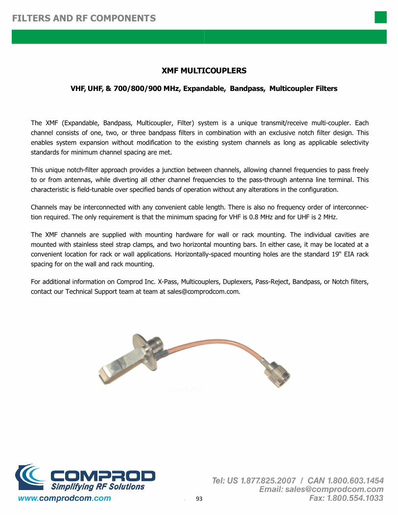
93
FILTERS AND RF COMPONENTS
XMF MU C U ERS
VHF, UHF, & 700/800/900 MHz, Expandable, Bandpass, Multicoupler Filters
The XMF (Expandable, Bandpass, Multicoupler, Filter) system is a unique transmit/receive multi-coupler. Each channel consists of one, two, or three bandpass filters in combination with an exclusive notch filter design. This enables system expansion without modification to the existing system channels as long as applicable selectivity standards for minimum channel spacing are met.
This unique notch-filter approach provides a junction between channels, allowing channel frequencies to pass freely to or from antennas, while diverting all other channel frequencies to the pass-through antenna line terminal. This characteristic is field-tunable over specified bands of operation without any alterations in the configuration.
Channels may be interconnected with any convenient cable length. There is also no frequency order of interconnec-tion required. The only requirement is that the minimum spacing for VHF is 0.8 MHz and for UHF is 2 MHz.
The XMF channels are supplied with mounting hardware for wall or rack mounting. The individual cavities are mounted with stainless steel strap clamps, and two horizontal mounting bars. In either case, it may be located at a convenient location for rack or wall applications. Horizontally-spaced mounting holes are the standard 19“ EIA rack spacing for on the wall and rack mounting.
For additional information on Comprod Inc. X-Pass, Multicouplers, Duplexers, Pass-Reject, Bandpass, or Notch filters, contact our Technical Support team at team at [email protected].

94
FILTERS AND RF COMPONENTS
XMF BAND PASS MULTICOUPLER VHF 138-174MHz 60-13-XP e e Comprod Inc. Bandpass VHF Multicoupler filters are designed for minimizing interference from adjacent channels and outside systems. They are available in single, dual, triple or additional units. Selectivity can be determined by the insertion loss of the cavity or by adding cavity units as required. Each cavity is temperature compensated for operation between -40ºC to +60ºC. Each cavity has a gold Alodine finish, silver-plated loops, and silver-plated tuning rods. Every cavity is equipped with both coarse and fine tuning rods for quick and easy field or lab re-tuning. • Temperature Compensation - Ensures Frequency Stability • High Attenuation - Minimizes desense and interference from adjacent systems • Adjustable Loops - Each cavity has a calibration index
Electrical Specifications 60-13-71 60-13-72 60-13-73
Frequency Range, MHz 138-174 138-174 138-174
Frequency Spacing Min. MHZ 0.8 0.8 0.8
Cavity Diameter, in 6.625 6.625 6.625
Continuous Power Input, Watts (Dependent on Insertion Loss)
90-400 90-400 90-400
Connectors N Female N Female N Female
Insertion Loss, dB 0.6-1.5 1.2-3.2 1.8-5.0
Channel Isolation
VSWR 1.5:1 1.5:1 1.5:1
Temperature ºC -40 to +60 -40 to +60 -40 to +60
See Typical Curves
Mechanical Specifications 60-13-71 60-13-72 60-13-73
Maximum length, in (H x W X D) 34 x 19 x 7 34 x 19 x 16.5 34 x 19 x 16.5
Weight, lbs (kg) 30 (13.6) 36.3 (16.5) 44 (20)
60-13-71
60-13-72
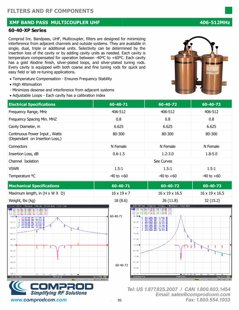
95
FILTERS AND RF COMPONENTS
XMF BAND PASS MULTICOUPLER UHF 406-512MHz
• Temperature Compensation - Ensures Frequency Stability • High Attenuation - Minimizes desense and interference from adjacent systems • Adjustable Loops - Each cavity has a calibration index
60-40-XP e e
Comprod Inc. Bandpass, UHF, Multicoupler, filters are designed for minimizing interference from adjacent channels and outside systems. They are available in single, dual, triple or additional units. Selectivity can be determined by the insertion loss of the cavity or by adding cavity units as needed. Each cavity is temperature compensated for operation between -40ºC to +60ºC. Each cavity has a gold Alodine finish, silver-plated loops, and silver-plated tuning rods. Every cavity is equipped with both coarse and fine tuning rods for quick and easy field or lab re-tuning applications.
Electrical Specifications 60-40-71 60-40-72 60-40-73
Frequency Range, MHz 406-512 406-512 406-512
Frequency Spacing Min. MHZ 0.8 0.8 0.8
Cavity Diameter, in 6.625 6.625 6.625
Continuous Power Input , Watts (Dependant on Insertion Loss,)
80-300 80-300 80-300
Connectors N Female N Female N Female
Insertion Loss, dB 0.6-1.5
Channel Isolation
VSWR 1.5:1 1.5:1 1.5:1
Temperature ºC -40 to +60 -40 to +60 -40 to +60
See Curves
1.2-3.0 1.8-5.0
Mechanical Specifications 60-40-71 60-40-72 60-40-73
Maximum length, in (H x W X D) 16 x 19 x 7 16 x 19 x 16.5 16 x 19 x 16.5
Weight, lbs (kg) 18 (8.6) 26 (11.8) 32 (15.2)
60-40-72
60-40-71

96
FILTERS AND RF COMPONENTS
PSEUDO BAND PASS DUPLEXER
66-FF-74 and 66-FF-76
Comprod Inc. Pseudo Bandpass Duplexer filters are designed for quick and easy installations. These filters are designed for the combination of two frequencies requiring extra isolation or can be used as efficient pre-selectors. They are available in either 4 or 6 cavity configurations if higher levels of isolation are required. Selectivity can be determined by the field adjustable capacitors. Each cavity is temperature compensated for operation between -40ºC to +60ºC. Each cavity has a gold Alodine finish, silver-plated loops, and silver-plated tuning rods. Every cavity is equipped with both coarse and fine tuning rods for quick and easy field or lab re-tuning.
• Temperature Compensation - Ensures Frequency Stability • High Attenuation - Minimizes desense and interference from adjacent systems • Adjustable Loops - Each cavity has a calibration index
Electrical Specifications 66-13-74 66-40-74
Frequency Range, MHz 138-174 406-512
Frequency Spacing Min. 0.5
Cavity Diameter, in 6.625 6.625
Continuous Power Input, Watts 400 350
Connectors N Female N Female
Insertion Loss, dB (maximum) 1.5
Channel Isolation, @ Min. Separation dB 85
VSWR 1.22:1 1.22:1
Temperature ºC -40 to +60 -40 to +60
1.5
1.5
90
66-13-76
138-174
0.3
6.625
400
N Female
2.2
95
1.22:1
-40 to +60
Mechanical Specifications 66-13-74 66-40-74
Maximum length, in (H x W X D) 34 x 19 x 16.5 18.5 x 19 x 16.5
Weight, lbs (kg) 44 (20) 32 (15.2)
66-13-76
34 x 19 x 33
90 (40)
66-13-74

97
FILTERS AND RF COMPONENTS
2-INCH CAVITY DUPLEXERS
66-FF-2P Series 2" Cavity Duplexers Comprod Inc. 2" base station duplexers are ideal for compact high isola-tion installations. These filters are designed for the combination of two frequencies that require extra isolation or they can be used as efficient pre-selectors. Available in either 4 or 6 cavity configurations if higher levels of isolation are required. Selectivity can be determined by the field adjustable capacitors. Each cavity is temperature compensated for operation between -40ºC to +60 ºC. Each cavity has a gold Alodine finish, silver-plated loops, and silver-plated tuning rods.
• Temperature Compensation - Ensures Frequency Stability • High Attenuation - Minimizes desense and interference from adjacent systems
Electrical Specifications 66-13-24 66-14-24 66-13-26 66-14-26
Frequency Range, MHz 132-150 144-174 132-150 144-174
Frequency Spacing Min. 4.5 4.5 3.0 3.0
Cavity Number 4 4 6 6
Cavity Diameter, in 2.0 2.0 2.0 2.0
Continuous Power Inputs, Watts 100 100 100 100
Connectors (Equipment/Antenna) BNC/N BNC/N BNC/N BNC/N
Insertion Loss, dB (maximum) 1.5 1.5 1.5 1.5
Channel Isolation, dB 70 70 80/90 80/90
VSWR 1.3:1
Temperature ºC -40 to +60 -40 to +60 -40 to +60 -40 to +60
1.3:1
Mechanical Specifications 66-13-24 66-14-24 66-13-26 66-14-26
Maximum length, in (H x W X D) 5.25 x 19 x 7.25
Mounting 19" Rack Mount
5.25 x 19 x 7.25
These duplexers are available in other frequencies and configurations. Please call our technical support for additional models..

98
FILTERS AND RF COMPONENTS
4-INCH CAVITY DUPLEXERS
• Temperature Compensation - Ensures Frequency Stability • High Attenuation - Minimizes desense and interference from adjacent systems
Electrical Specifications 66-13-44 66-40-44 66-80-44
Frequency Range, MHz 138-174 406-512 746-960
Frequency Spacing Min. MHZ 0.5 5 9
Cavities, Diameter, in (4) - 4" Square (4) - 4" Square (4) - 4" Square
Continuous Power Input, Watts 350 350 150
Connectors N Female N Female N Female
Insertion Loss, dB (maximum) 1.5 dB
Channel Isolation
VSWR 1.2:1 1.2:1 1.2:1
Temperature ºC -40 to +60 -40 to +60 -40 to +60
70 dB
0.8 dB 0.8 dB
75 dB 90 dB
Mechanical Specifications 66-13-44 66-40-44 66-80-44
Maximum length, in (H x W X D) 31 x 19 x 4 4 x 19 x 15 4 x 19 x 12
Mounting 19" Rack Mount 19" Rack Mount 19" Rack Mount
Weight, lbs (kg) 30 (13.6) 18 (8.2) 16 (7.3)
Order Information Frequency Wall Mount 4 Cavities
66-13-4X 138-174MHz 66-13-44WM 66-13-44
66-40-4X 406-470MHz 66-40-44WM 66-40-44
66-74-4X 746-806MHz 66-74-44WM 66-74-44
66-80-4X 806-896MHz 66-80-44WM 66-80-44
66-90-4X 896-960MHz 66-90-44WM 66-90-44
66-FF-44 Series (4) 4" Cavity Duplexers
These Comprod Inc. 4” base station duplexers are ideal for high power, close frequency separation installations. These filters are designed for combining two frequencies or they can be used as efficient pre-selectors. If higher levels of isolation are required, please consider using 6 cavity configurations. Selectivity can be determined by the field adjustable capacitors. Each cavity is temperature compensated for operation between -40ºC to +60ºC. Each cavity has a gold Alodine finish, silver-plated loops, and silver-plated tuning rods.
66-13-44

99
FILTERS AND RF COMPONENTS
4-INCH CAVITY DUPLEXERS
66-FF-46 Series (6) 4" Cavity Duplexers
These Comprod Inc. 6 cavity 4" base station duplexers are ideal for high power close frequency separation installations. These filters are designed for the combination of 2 frequencies that require extra isolation or they can be used as an efficient pre-selector. If higher levels of isolation are required, please consider using the 8 cavity configuration. Selectivity can be determined by the field adjustable loops. Each cavity is temperature compensated for operation between -40ºC to +60ºC. Each cavity has a gold Alodine finish, silver-plated loops, and silver-plated tuning rods. • Temperature Compensation - Ensures Frequency Stability • High Attenuation - Minimizes desense and interference from adjacent systems
Electrical Specifications 66-13-46 66-40-46 66-80-46
Frequency Range, MHz 138-174 406-512 746-960
Frequency Spacing Min. MHZ 0.5 5.0 3.6
Cavities, Diameter, in (6) - 4" Square (6) - 4" Square (6) - 4" Square
Continuous Power Input, Watts 350 350 350
Connectors N Female N Female N Female
Insertion Loss, dB (maximum) 2.1
Channel Isolation @ Min. Sep. dB
VSWR 1.22:1 1.22:1 1.22:1
Temperature ºC -40 to +60 -40 to +60 -40 to +60
85
1.2 1.2
100 85
Mechanical Specifications 66-13-46 66-40-46 66-80-46
Maximum length, in (H x W X D) 31 x 19 x 8 8 x 19 x 15 8 x 19 x 12
Mounting 19" Rack Mount 19" Rack Mount 19" Rack Mount
Weight, lbs (kg) 45 (20.25) 27 (12.15) 24 (10.8)
Order Information Wall Mount 6 Cavities
66-13-46 66-13-46WM 66-13-46
66-40-46 66-40-46WM 66-40-46
66-80-46 66-80-46WM 66-80-46
Frequency
138-174MHz
406-512MHz
746-960MHz
66-40-44

100
FILTERS AND RF COMPONENTS
4 CAVITY MOBILE DUPLEXERS VHF & UHF
4 Cavity Standard Version
The Comprod Inc. line of mobile duplexers features compact size, low loss and temperature compensation over the range of -40ºC to +60ºC. The use of extruded aluminum cavities and solid- shield copper-jacketed inter-cabling ensures excellent mechanical and electrical stability.
All units are adjustable in the field by qualified personnel and rated at 50 Watts maximum with a maximum VSWR of 1.5: 1 over the entire tuning range.
BNC connectors are standard. Variations on connectors and mountings are available by special order. For N female connectors, add suffix N to model number (Ex. 534-90N).
Electrical Specifications 534-90 504-90
Frequency Range, MHz 144-155/150-165/160-174 406-435/430-470
Frequency Spacing Min. MHz 4.5 5.0 10.0
Continuous Power Rating, Watts 50 50 50
Insertion Loss, dB: TX to Antenna 0.8 1.2 0.8
Insertion Loss, dB: RX to Antenna 0.8 1.2 0.8
Isolation, dB: TX noise suppression at RX frequency 60 50 60
Isolation, dB: TX isolation at TX frequency 60 50 60
Maximum VSWR 1.5:1 1.5:1
Impedance, Ohms 50 50
Connector Type, Female BNC BNC
Temperature ºC -40 to +60 -40 to +60
Mechanical Specifications 534-90 504-90
Dimensions H x W x D, in. (mm)
1-1/4 x 4-1/8 x 7-5/8 (31.8 x 105 x 194)
1-1/4 x 4-1/8 x 8-3/4 (31.8 x 105 x 222)
Weight, lbs (kg) 1.5 (0.7) 2 (0.9)
534-90 Typical Response Curve at 4.5 MHz Spacing
504-90 Typical Response Curve at 5 MHz Spacing
FREQUENCY MHz FREQUENCY MHz

101
FILTERS AND RF COMPONENTS
6 CAVITY MOBILE DUPLEXER VHF & UHF
6 Cavity Standard Version
The Comprod Inc. line of mobile duplexers features compact size, low loss and temperature compensation over the range of -40ºC to +60ºC. The use of extruded aluminum cavities and solid-shield copper-jacketed inter-cabling ensures excellent mechanical and electrical stability.
All units are adjustable in the field by qualified personnel and rated at 50 watts continuous duty with a maximum VSWR of 1.5: 1 over the entire tuning range.
BNC connectors are standard. Variations on connectors and mountings are available by special order. For N female connectors, add suffix N to model number (Ex. 536-90N)
Electrical Specifications 536-90 506-90
Frequency Range, MHz 144-155/150-165/160-174 406-435/430-470
Frequency Spacing Min. MHZ 4.5 5 10
Continuous Power Rating, Watts 50 50 50
Insertion Loss, dB: TX to Antenna 1.2 1.4 1.2
Insertion Loss, dB: RX to Antenna 1.2 1.4 1.2
Isolation, dB: TX noise suppression at RX frequency 80 75 80
Isolation, dB: TX isolation at TX frequency 80 75 80
Maximum VSWR 1.5:1 1.5:1
Impedance, Ohms 50 50
Connector Type, Female BNC BNC
Temperature ºC -40 to +60 -40 to +60
Mechanical Specifications 536-90 506-90
Dimensions H x W x D, in. 1-1/4 X 6-3/16 X 7-5/8 1-1/4 X 6-3/16 X 7-5/8
(mm) (31.8 X 157 X 222) (31.8 X 157 X 222)
Weight, lbs (kg) 2.0 (0.9) 3.5 (1.7)
506-90 Typical Response Curves at 5 MHz Spacing

102
FILTERS AND RF COMPONENTS
-
The X-Pass system is a proven innovative family of filter design technology. Possessing the properties of a combiner, but having the expandability of a multicoupler, our X-Pass filters are one of the most versatile and re-usable filtering systems available on the market.
The X-Pass Transmitter Combiner Receiver Multicoupler has superior expandability compared with the fixed star junction configuration. The X-Pass system can be expanded one channel at a time for up to 21 channels with factory tuned, easy to install expansion channel assemblies. Expansion can be completed easily, without modifying the existing system, as easy as adding one or more channels on top of the existing system (daisy chain).
The X-Pass system is a broadband design allowing the system to span entire frequency ranges by using the properties of the X-Pass combiner for close frequency spacing and the X-Pass multicoupler properties for normally spaced channels. The X-Pass system can span the full 138-174 MHz, 406-512 MHz or 806-960 MHz frequency bands. When using the 6.625” cavities, the TX-TX separation in VHF can be as close as 75 kHz of frequency separation, or 50 kHz of separation when using 10” cavities.
The X-Pass system has the advantage of being extremely flexible to configure. With the ability to combine Bandpass, Pass-Reject, or Notch loops for 6.625” and 10” cavity filters, once-difficult complex operating requirements can be resolved with a customized design. This allows the X-Pass system to have unlimited combinations that can be integrated using multi-cavity configurations while retaining the expandability of the combiner properties for close frequency-spaced channels using 6.625" and 10" cavities. The system can also be a combination of a combiner for close frequency-spaced channels while encompassing the expandability of a standard multicoupler that can be integrated with standard Bandpass, Notch, and Pass-Reject filter combinations. All X-Pass systems come fully assembled, tested and ready for Plug-and-Play installations.
The X-Pass system has one extra beneficial aspect - the optional X-Pass Rack. With this unique rack design, certain systems can take up to 50 % less space than other systems that are in a 19” rack. By being able to mount all of the cavities horizontally, the installer has the ability to expand one channel on top of another in no particular order, and not having the physical obstacles of mounting a star-junction type configuration in a rack. The X-Pass system can save valuable installation space, and make efficient use of the rack space for future expansion projects.
For additional information on Comprod Inc. X-Pass, Multicouplers, Duplexers, Pass-Reject, Bandpass, or Notch filters, contact our Technical Support team: [email protected]

103
FILTERS AND RF COMPONENTS
X-PASS CAVITY 30-1000 MHz
68-XX-7X e e Comprod Inc. X-Pass filters are designed for flexible, close frequency systems. Each cavity has both a Reject and a Pass band curve. These individual cavities are used to add channels to existing systems. Available in single units, they can be combined with Bandpass, Notch, and Pass-Reject cavities for added protection and isolation. Selectivity can be determined by the insertion loss of the cavity or by adding Bandpass cavity units to this expansion channel as required. Each cavity is temperature compensated for operation between -40ºC to +60ºC. Each cavity has a gold Alodine finish, silver-plated loops, and silver-plated tuning rods. Every cavity is equipped with both coarse and fine tuning rods for quick and easy field or lab re-tuning. • Temperature Compensation - Ensures Frequency Stability • High Attenuation - Minimizes desense and interference from adjacent systems • Adjustable Loops - Each cavity has a calibration index
Electrical Specifications 68-03-71 68-06-71 68-11-71 68-13-71 68-40-71 68-74-71
Frequency Range, MHz 30-40 66-88 118-136 136-174 406-512 746-960
Frequency Spacing Min. Please Refer To Typical Curves
Cavity Diameter, in 6.625 6.625 6.625 6.625 6.625 6.625
Continuous Power Input, Watts 150 150 150 150 150 150
Connectors N Female N Female N Female N Female N Female N Female
Insertion Loss, dB 0.6-1.5
Reject Attenuation
VSWR 1.22:1 1.22:1 1.22:1 1.22:1 1.22:1 1.22:1
Temperature ºC -40 to +60 -40 to +60 -40 to +60 -40 to +60 -40 to +60 -40 to +60
Please Refer To Typical Curves
Order Information Single
4" Cavity 68-XX-41
6.625" Cavity 68-XX-71
10" Cavity 68-XX-01
68-13-71
Mechanical Specifications 68-03-71 68-06-71 68-11-71 68-13-71 68-40-71 68-74-71
Maximum length, in 132 77 31.5 26 11.5 13
Weight, lbs n/a n/a 18 15 10 10

104
FILTERS AND RF COMPONENTS
EXPANDABLE TRANSMIT COMBINER 66-88 MHz
XTC-Expandable Transmit Combiner Series Our Expandable Transmit Combiners can combine from 1 to 21 channels. The XTC series of filters incorporates expandability, close frequency spacing and some of the lowest insertion losses in the industry. Using a 6.625” cavity, the XTC can easily support 75 kHz TX-TX spacing or 50 kHz spacing while using 10” cavities. Each cavity is constructed using a gold Alodine finish, silver-plated loops, silver-plated connectors and internal tuning plunger. Additionally, cavities are temperature compensated for operation between -40ºC to +60ºC. Every cavity is equipped with both coarse and fine tuning rods for quick and easy field or lab re-tuning.
• Flexible and expandable design, From 1-21 channel capacity • Expandable: 1 or more additional channels at a time, Re-configurable equipment • 66-88 MHz, 22 MHz of operating bandwidth • Temperature compensation, Ensures frequency stability • High attenuation, Minimizes desense and interference • Ultra-low insertion losses, Low coupling and bridging losses • Continuous high-power handling capability, 150 watts – 24/7
Electrical Specifications XTC-06-72 XTC-06-74 XTC-06-76 XTC-06-78 XTC-06-7-10 XTC-06-7-12
Frequency Range, MHz 66-88 66-88 66-88 66-88 66-88 66-88
Bandwidth, MHz 22
Number of Channels 2 4 6 8 10 12
Cavity Diameter, in 6.625 6.625 6.625 6.625 6.625 6.625
Min. Channel Sep., kHz 50 50 50 50 50 50
Isolation Min., TX-TX, dB 70
Isolation Min., Ant-TX, dB
VSWR 1.22:1 1.22:1 1.22:1 1.22:1 1.22:1 1.22:1
Temperature ºC -40 to +60 -40 to +60 -40 to +60 -40 to +60 -40 to +60 -40 to +60
60
22 22 22 22 22
70 70 70 70 70
60 60 60 60 60
Connectors N Female N Female N Female N Female N Female N Female
Max. Insertion Loss Per Chan., dB 4.7 5.5 6 6.3 6.8 7.3
Continuous Power Input, Watts 150 150 150 150 150 150
Mechanical Specifications XTC-06-72 XTC-06-74 XTC-06-76 XTC-06-78 XTC-06-7-10 XTC-06-7-12
Height, in (H x W X D) (mm) 86.5 x 24 x 40.25 (2197 x 610 x 1022) (In X Rack)
Mounts in 19" Standard Rack Yes Yes Yes Yes Yes Yes
Weight DEPENDS ON SET-UP AND RACK DESIGN
Order Information Single Channel 2 - Channel 3 - Channel 5 - Channel 8 - Channel
4" Cavity XTC-06-41 XTC-06-42 XTC-06-43 XTC-06-45 XTC-06-48
6.625" Cavity XTC-06-71 XTC-06-72 XTC-06-73 XTC-06-75 XTC-06-78
10" Cavity XTC-06-01 XTC-06-02 XTC-06-03 XTC-06-05 XTC-06-08

105
FILTERS AND RF COMPONENTS
EXPANDABLE TRANSMIT COMBINER 66-88 MHz
XTC-Expandable Transmit Combiner Series Our Expandable Transmit Combiners can combine from 1 to 21 channels. The XTC series of filters incorporates expandability, close frequency spacing and some of the lowest insertion losses in the industry. Using a 6.625” cavity, the XTC can easily support 75 kHz TX-TX spacing or 50 kHz spacing when using 10” cavities. Each cavity is constructed using a gold Alodine finish, silver-plated loops, silver-plated connectors and an internal tuning plunger. Additionally, cavities are temperature compensated for operation between -40ºC to +60ºC. Every cavity is equipped with both coarse and fine tuning rods for quick and easy field or lab re-tuning.
• Flexible and expandable design, From 1-21 channel capacity • Expandable: 1 or more additional channels at a time, Re-configurable equipment • 66-88 MHz, 22 MHz of operating bandwidth • Temperature compensation, Ensures frequency stability • High attenuation, Minimizes desense and interference • Ultra-low insertion losses, Low coupling and bridging losses • Continuous high-power handling capability, 150 watts – 24/7
Electrical Specifications XTC-06-02 XTC-06-04 XTC-06-06 XTC-06-08 XTC-06-0-10
Frequency Range, MHz 66-88 66-88 66-88 66-88 66-88
Bandwidth, MHz 22 22 22 22 22
Number of Channels 2 4 6 8 10
Cavity Diameter, in 10 10 10 10 10
Min. Channel Sep., kHz 50 50 50 50 50
Isolation Min., TX-TX, dB 70 70 70 70 70
Isolation Min., Ant-TX, dB 60 60 60 60 60
Max. Insertion Loss Per Chan., dB 3.8 4.9 5.2 5.4 5.6
Continuous Power Input, Watts 150 150 150 150 150
Connectors N Female N Female N Female N Female N Female
VSWR 1.22:1 1.22:1 1.22:1 1.22:1 1.22:1
Temperature ºC -40 to +60 -40 to +60 -40 to +60 -40 to +60 -40 to +60
Mechanical Specifications XTC-06-02 XTC-06-04 XTC-06-06 XTC-06-08 XTC-06-0-10
Height, in (H x W X D) (mm) 86.5 x 24 x 40.25 (2197 x 610 x 1022) (In X Rack)
Mounts in 19" Standard Rack Yes Yes Yes Yes Yes
Weight DEPENDS ON SET-UP AND RACK DESIGN
Order Information Single Channel 2 - Channel 3 - Channel 5 - Channel 8 - Channel
4" Cavity XTC-06-41 XTC-06-42 XTC-06-43 XTC-06-45 XTC-06-48
6.625" Cavity XTC-06-71 XTC-06-72 XTC-06-73 XTC-06-75 XTC-06-78
10" Cavity XTC-06-01 XTC-06-02 XTC-06-03 XTC-06-05 XTC-06-08

106
FILTERS AND RF COMPONENTS
EXPANDABLE TRANSMIT COMBINER 108-136MHz
XTC-Expandable Transmit Combiner Series Our Expandable Transmit Combiners can combine from 1 to 21 channels. The XTC series of filters incorporates expandability, close frequency spacing and some of the lowest insertion losses in the industry. Using a 6.625” cavity, the XTC can easily support 75 kHz TX-TX spacing or 50 kHz spacing while using 10” cavities. Each cavity is constructed using a gold Alodine finish, silver-plated loops, silver-plated connectors and an internal tuning plunger. Additionally, cavities are temperature compensated for operation between -40ºC to +60ºC. Every cavity is equipped with both coarse and fine tuning rods for quick and easy field or lab re-tuning.
Electrical Specifications XTC-11-72 XTC-11-74 XTC-11-76 XTC-11-78 XTC-11-7-10 XTC-11-7-12
Frequency Range, MHz 108-136 108-136 108-136 108-136 108-136 108-136
Bandwidth, MHz 28
Number of Channels 2 4 6 8 10 12
Cavity Diameter, in 6.625 6.625 6.625 6.625 6.625 6.625
Min. Channel Sep., kHz 75 75 75 75 75 75
Isolation Min., TX-TX, dB 70
Isolation Min., Ant-TX, dB
VSWR 1.22:1 1.22:1 1.22:1 1.22:1 1.22:1 1.22:1
Temperature ºC -40 to +60 -40 to +60 -40 to +60 -40 to +60 -40 to +60 -40 to +60
60
28 28 28 28 28
70 70 70 70 70
60 60 60 60 60
Connectors N Female N Female N Female N Female N Female N Female
Max. Insertion Loss Per Chan., dB 3.6 4.5 4.8 5.2 5.4 5.6
Continuous Power Input, Watts 150 150 150 150 150 150
Mechanical Specifications XTC-11-72 XTC-11-74 XTC-11-76 XTC-11-78 XTC-11-7-10 XTC-11-7-12
Height, in (H x W X D) (mm) 86.5 x 24 x 40.25 (2197 x 610 x 1022) (In X Rack)
Mounts in 19" Standard Rack Yes Yes Yes Yes Yes Yes
Weight DEPENDS ON SET-UP AND RACK DESIGN
Order Information Single Channel 2 - Channel 3 - Channel 5 - Channel 8 - Channel
4" Cavity XTC-11-41 XTC-11-42 XTC-11-43 XTC-11-45 XTC-11-48
6.625" Cavity XTC-11-71 XTC-11-72 XTC-11-73 XTC-11-75 XTC-11-78
10" Cavity XTC-11-01 XTC-11-02 XTC-11-03 XTC-11-05 XTC-11-08
• Flexible and expandable design, From 1-21 channel capacity • Expandable: 1 or more additional channels at a time, Re-configurable equipment • 108-136 MHz, 28 MHz of operating bandwidth • Temperature compensation, Ensures frequency stability • High attenuation, Minimizes desense and interference • Ultra-low insertion losses, Low coupling and bridging losses • Continuous high-power handling capability, 150 watts – 24/7

107
FILTERS AND RF COMPONENTS
EXPANDABLE TRANSMIT COMBINER 108-136MHz
XTC-Expandable Transmit Combiner Series Our Expandable Transmit combiners can combine from 1 to 21 channels. The XTC series of filters incorporates expandability, close frequency spacing and some of the lowest insertion losses in the industry. Using a 6.625” cavity, the XTC can easily support 75 kHz TX-TX spacing or 50 kHz spacing while using 10” cavities. Each cavity is constructed using a gold Alodine finish, silver-plated loops, silver-plated connectors and internal tuning plunger. Additionally, cavities are temperature compensated for operation between -40ºC to +60ºC. Every cavity is equipped with both coarse and fine tuning rods for quick and easy field or lab re-tuning.
Electrical Specifications XTC-11-02 XTC-11-04 XTC-11-06 XTC-11-08 XTC-11-0-10 XTC-11-0-12
Frequency Range, MHz 108-136 108-136 108-136 108-136 108-136 108-136
Bandwidth, MHz 28
Number of Channels 2 4 6 8 10 12
Cavity Diameter, in 10 10 10 10 10 10
Min. Channel Sep., kHz 50 50 50 50 50 50
Isolation Min., TX-TX, dB 70
Isolation Min., Ant-TX, dB
VSWR 1.22:1 1.22:1 1.22:1 1.22:1 1.22:1 1.22:1
Temperature ºC -40 to +60 -40 to +60 -40 to +60 -40 to +60 -40 to +60 -40 to +60
60
28 28 28 28 28
70 70 70 70 70
60 60 60 60 60
Connectors N Female N Female N Female N Female N Female N Female
Max. Insertion Loss Per Chan., dB 4.1 4.8 5.1 5.4 5.6 5.7
Continuous Power Input, Watts 150 150 150 150 150 150
Mechanical Specifications XTC-11-02 XTC-11-04 XTC-11-06 XTC-11-08 XTC-11-0-10 XTC-11-0-12
Height, in (H x W X D) (mm) 86.5 x 24 x 40.25 (2197 x 610 x 1022) (In X Rack)
Mounts in 19" Standard Rack Yes Yes Yes Yes Yes Yes
Weight DEPENDS ON SET-UP AND RACK DESIGN
Order Information Single Channel 2 - Channel 3 - Channel 5 - Channel 8 - Channel
4" Cavity XTC-11-41 XTC-11-42 XTC-11-43 XTC-11-45 XTC-11-48
6.625" Cavity XTC-11-71 XTC-11-72 XTC-11-73 XTC-11-75 XTC-11-78
10" Cavity XTC-11-01 XTC-11-02 XTC-11-03 XTC-11-05 XTC-11-08
• Flexible and expandable design, From 1-21 channel capacity • Expandable: 1 or more additional channels at a time, Re-configurable equipment • 108-136 MHz, 28 MHz of operating bandwidth • Temperature compensation, Ensures frequency stability • High attenuation, Minimizes desense and interference • Ultra-low insertion losses, Low coupling and bridging losses • Continuous high-power handling capability, 150 watts – 24/7

108
FILTERS AND RF COMPONENTS
EXPANDABLE TRANSMIT COMBINER 132-174MHz
XTC-Expandable Transmit Combiner Series Our Expandable Transmit Combiners can combine from 1 to 21 channels. The XTC series of filters incorporates expandability, close frequency spacing and some of the lowest insertion losses in the industry. Using a 6.625” cavity, the XTC can easily support 75 kHz TX-TX spacing or 50 kHz spacing while using 10” cavities. Each cavity is constructed using a gold Alodine finish, silver-plated loops, silver-plated connectors and internal tuning plunger. Additionally, cavities are temperature compensated for operation between -40ºC to +60ºC. Every cavity is equipped with both coarse and fine tuning rods for quick and easy field or lab re-tuning.
• Flexible and expandable design, From 1-21 channel capacity • Expandable 1 or more additional channels at a time, Re-configurable equipment • 132-174 MHz, 42 MHz of operating bandwidth • Temperature compensation, Ensures frequency stability • High Attenuation, Minimizes desense and interference • Ultra-low insertion losses, Low coupling and bridging losses • Continuous high power handling capability, 150 watts – 24/7
Electrical Specifications XTC-13-72 XTC-13-74 XTC-13-76 XTC-13-78 XTC-13-7-10 XTC-13-7-12
Frequency Range, MHz 132-174 132-174 132-174 132-174 132-174 132-174
Bandwidth, MHz 42
Number of Channels 2 4 6 8 10 12
Cavity Diameter, in 6.625 6.625 6.625 6.625 6.625 6.625
Min. Channel Sep., kHz 75 75 75 75 75 75
Isolation Min., TX-TX, dB 70
Isolation Min., Ant-TX, dB
VSWR 1.22:1 1.22:1 1.22:1 1.22:1 1.22:1 1.22:1
Temperature ºC -40 to +60 -40 to +60 -40 to +60 -40 to +60 -40 to +60 -40 to +60
60
42 42 42 42 42
70 70 70 70 70
60 60 60 60 60
Connectors N Female N Female N Female N Female N Female N Female
Max. Insertion Loss Per Chan., dB 4.3 5.4 5.8 6.2 6.5 6.7
Continuous Power Input, Watts 150 150 150 150 150 150
Mechanical Specifications XTC-13-72 XTC-13-74 XTC-13-76 XTC-13-78 XTC-13-7-10 XTC-13-7-12
Height, in (H x W X D) (mm) 86.5 x 24 x 40.25 (2197 x 610 x 1022) (In X Rack)
Mounts in 19" Standard Rack Yes Yes Yes Yes Yes Yes
Weight DEPENDS ON SET-UP AND RACK DESIGN
Order Information Single Channel 2 - Channel 3 - Channel 5 - Channel 8 - Channel
4" Cavity XTC-13-41 XTC-13-42 XTC-13-43 XTC-13-45 XTC-13-48
6.625" Cavity XTC-13-71 XTC-13-72 XTC-13-73 XTC-13-75 XTC-13-78
10" Cavity XTC-13-01 XTC-13-02 XTC-13-03 XTC-13-05 XTC-13-08

109
FILTERS AND RF COMPONENTS
EXPANDABLE TRANSMIT COMBINER 132-174MHz
XTC-Expandable Transmit Combiner Series Our Expandable Transmit Combiners can combine from 1 to 21 channels. The XTC series of filters incorporates expandability, close frequency spacing and some of the lowest insertion losses in the industry. Using a 6.625” cavity, the XTC can easily support 75 kHz TX-TX spacing or 50 kHz spacing while using 10” cavities. Each cavity is constructed using a gold Alodine finish, silver-plated loops, silver-plated connectors and internal tuning plunger. Additionally, cavities are temperature compensated for operation between -40ºC to +60ºC. Every cavity is equipped with both coarse and fine tuning rods for quick and easy field or lab re-tuning.
• Flexible and expandable design, From 1-21 channel capacity • Expandable 1 or more additional channels at a time, Re-configurable equipment • 132-174 MHz, 42 MHz of operating bandwidth • Temperature compensation, Ensures frequency stability • High Attenuation, Minimizes desense and interference • Ultra-low insertion losses, Low coupling and bridging losses • Continuous high power handling capability, 150 watts – 24/7
Electrical Specifications XTC-13-02 XTC-13-04 XTC-13-06 XTC-13-08 XTC-13-0-10 XTC-13-0-12
Frequency Range, MHz 132-174 132-174 132-174 132-174 132-174 132-174
Bandwidth, MHz 42
Number of Channels 2 4 6 8 10 12
Cavity Diameter, in 10 10 10 10 10 10
Min. Channel Sep., kHz 50 50 50 50 50 50
Isolation Min., TX-TX, dB 70
Isolation Min., Ant-TX, dB
VSWR 1.22:1 1.22:1 1.22:1 1.22:1 1.22:1 1.22:1
Temperature ºC -40 to +60 -40 to +60 -40 to +60 -40 to +60 -40 to +60 -40 to +60
60
42 42 42 42 42
70 70 70 70 70
60 60 60 60 60
Connectors N Female N Female N Female N Female N Female N Female
Max. Insertion Loss Per Chan., dB 4.1 5.0 5.4 5.7 5.9 6.1
Continuous Power Input, Watts 150 150 150 150 150 150
Mechanical Specifications XTC-13-02 XTC-13-04 XTC-13-06 XTC-13-08 XTC-13-0-10 XTC-13-0-12
Height, in (H x W X D) (mm) 86.5 x 24 x 40.25 (2197 x 610 x 1022) (In X Rack)
Mounts in 19" Standard Rack Yes Yes Yes Yes Yes Yes
Weight DEPENDS ON SET-UP AND RACK DESIGN
Order Information Single Channel 2 - Channel 3 - Channel 5 - Channel 8 - Channel
4" Cavity XTC-13-41 XTC-13-42 XTC-13-43 XTC-13-45 XTC-13-48
6.625" Cavity XTC-13-71 XTC-13-72 XTC-13-73 XTC-13-75 XTC-13-78
10" Cavity XTC-13-01 XTC-13-02 XTC-13-03 XTC-13-05 XTC-13-08

110
FILTERS AND RF COMPONENTS
EXPANDABLE TRANSMIT COMBINER 215-300MHz
XTC-Expandable Transmit Combiner Series Our Expandable Transmit Combiners can combine from 1 to 21 channels. The XTC series of filters incorporates expandability, close frequency spacing and some of the lowest insertion losses in the industry. Using a 6.625” cavity, the XTC can easily support 100 kHz TX-TX spacing or 75 kHz spacing while using 10” cavities. Each cavity is constructed using a gold Alodine finish, silver-plated loops, silver-plated connectors and internal tuning plunger. Additionally, cavities are temperature compensated for operation between -40ºC to +60ºC. Every cavity is equipped with both coarse and fine tuning rods for quick and easy field or lab re-tuning.
• Flexible and expandable design, From 1-21 channel capacity • Expandable 1 or more additional channels at a time, Re-configurable equipment • 215-300MHz, 85 MHz of operating bandwidth • Temperature compensation, Ensures frequency stability • High Attenuation, Minimizes desense and interference • Ultra-low insertion losses, Low coupling and bridging losses • Continuous high power handling capability, 150 watts – 24/7
Electrical Specifications XTC-22-72 XTC-22-74 XTC-22-76 XTC-22-78 XTC-22-7-10 XTC-22-7-12
Frequency Range, MHz 215-300 215-300 215-300 215-300 215-300 215-300
Bandwidth, MHz 85
Number of Channels 2 4 6 8 10 12
Cavity Diameter, in 6.625 6.625 6.625 6.625 6.625 6.625
Min. Channel Sep., kHz 100 100 100 100 100 100
Isolation Min., TX-TX, dB 70
Isolation Min., Ant-TX, dB
VSWR 1.22:1 1.22:1 1.22:1 1.22:1 1.22:1 1.22:1
Temperature ºC -40 to +60 -40 to +60 -40 to +60 -40 to +60 -40 to +60 -40 to +60
60
85 85 85 85 85
70 70 70 70 70
60 60 60 60 60
Connectors N Female N Female N Female N Female N Female N Female
Max. Insertion Loss Per Chan., dB 4.1 4.5 5.1 5.4 5.6 5.8
Continuous Power Input, Watts 150 150 150 150 150 150
Mechanical Specifications XTC-22-72 XTC-22-74 XTC-22-76 XTC-22-78 XTC-22-7-10 XTC-22-7-12
Height, in (H x W X D) (mm) 86.5 x 24 x 26.4 (2197 x 610 x 671) (In X Rack)
Mounts in 19" Standard Rack Yes Yes Yes Yes Yes Yes
Weight DEPENDS ON SET-UP AND RACK DESIGN
Order Information Single Channel 2 - Channel 3 - Channel 5 - Channel 8 - Channel
4" Cavity XTC-22-41 XTC-22-42 XTC-22-43 XTC-22-45 XTC-22-48
6.625" Cavity XTC-22-71 XTC-22-72 XTC-22-73 XTC-22-75 XTC-22-78
10" Cavity XTC-22-01 XTC-22-02 XTC-22-03 XTC-22-05 XTC-22-08

111
FILTERS AND RF COMPONENTS
EXPANDABLE TRANSMIT COMBINER 215-300MHz
XTC-Expandable Transmit Combiner Series Our Expandable Transmit Combiners can combine from 1 to 21 channels. The XTC series of filters incorporates expandability, close frequency spacing and some of the lowest insertion losses in the industry. Using a 6.625” cavity, the XTC can easily support 100 kHz TX-TX spacing or 75 kHz spacing while using 10” cavities. Each cavity is constructed using a gold Alodine finish, silver-plated loops, silver-plated connectors and internal tuning plunger. Additionally, cavities are temperature compensated for operation between -40ºC to +60ºC. Every cavity is equipped with both coarse and fine tuning rods for quick and easy field or lab re-tuning.
• Flexible and expandable design, From 1-21 channel capacity • Expandable 1 or more additional channels at a time, Re-configurable equipment • 215-300MHz, 85 MHz of operating bandwidth • Temperature compensation, Ensures frequency stability • High Attenuation, Minimizes desense and interference • Ultra-low insertion losses, Low coupling and bridging losses • Continuous high power handling capability, 150 watts – 24/7
Electrical Specifications XTC-22-02 XTC-22-04 XTC-22-06 XTC-22-08 XTC-22-0-10 XTC-22-0-12
Frequency Range, MHz 215-300 215-300 215-300 215-300 215-300 215-300
Bandwidth, MHz 85
Number of Channels 2 4 6 8 10 12
Cavity Diameter, in 10 10 10 10 10 10
Min. Channel Sep., kHz 75 75 75 75 75 75
Isolation Min., TX-TX, dB 70
Isolation Min., Ant-TX, dB
VSWR 1.22:1 1.22:1 1.22:1 1.22:1 1.22:1 1.22:1
Temperature ºC -40 to +60 -40 to +60 -40 to +60 -40 to +60 -40 to +60 -40 to +60
60
85 85 85 85 85
70 70 70 70 70
60 60 60 60 60
Connectors N Female N Female N Female N Female N Female N Female
Max. Insertion Loss Per Chan., dB 4.2 5.1 5.5 5.8 6 6.2
Continuous Power Input, Watts 150 150 150 150 150 150
Mechanical Specifications XTC-22-02 XTC-22-04 XTC-22-06 XTC-22-08 XTC-22-0-10 XTC-22-0-12
Height, in (H x W X D) (mm) 79.5 x 24 x 28.4 (2019 x 610 x 721) (In X Rack)
Mounts in 19" Standard Rack Yes Yes Yes Yes Yes Yes
Weight DEPENDS ON SET-UP AND RACK DESIGN
Order Information Single Channel 2 - Channel 3 - Channel 5 - Channel 8 - Channel
4" Cavity XTC-22-41 XTC-22-42 XTC-22-43 XTC-22-45 XTC-22-48
6.625" Cavity XTC-22-71 XTC-22-72 XTC-22-73 XTC-22-75 XTC-22-78
10" Cavity XTC-22-01 XTC-22-02 XTC-22-03 XTC-22-05 XTC-22-08

112
FILTERS AND RF COMPONENTS
EXPANDABLE TRANSMIT COMBINER 380-512MHz
XTC-Expandable Transmit Combiner Series Our Expandable Transmit Combiners can combine from 1 to 21 channels. The XTC series of filters incorporates expandability, close frequency spacing and some of the lowest insertion losses in the industry. Using a 6.625” cavity, the XTC can easily sup-port 125 kHz TX-TX spacing or 75 kHz spacing while using 10” cavities. Each cavity is constructed using a gold Alodine finish, silver-plated loops, silver-plated connectors and internal tuning plunger. Additionally, cavities are temperature compensated for operation between -40ºC to +60ºC. Every cavity is equipped with both coarse and fine tuning rods for quick and easy field or lab re-tuning. • Flexible and expandable design, From 1-21 channel capacity • Expandable 1 or more additional channels at a time, Re-configurable equipment • 380-512MHz, 132MHz of operating bandwidth • Temperature compensation, Ensures frequency stability • High Attenuation, Minimizes desense and interference • Ultra-low insertion losses, Low coupling and bridging losses • Continuous high power handling capability, 150 watts – 24/7
Electrical Specifications XTC-38-72 XTC-38-74 XTC-38-76 XTC-38-78 XTC-38-7-10 XTC-38-7-12
Frequency Range, MHz 380-512 380-512 380-512 380-512 380-512 380-512
Bandwidth, MHz 132
Number of Channels 2 4 6 8 10 12
Cavity Diameter, in 6.625 6.625 6.625 6.625 6.625 6.625
Min. Channel Sep., kHz 125 125 125 125 125 125
Isolation Min., TX-TX, dB 80
Isolation Min., Ant-TX, dB
VSWR 1.22:1 1.22:1 1.22:1 1.22:1 1.22:1 1.22:1
Temperature ºC -40 to +60 -40 to +60 -40 to +60 -40 to +60 -40 to +60 -40 to +60
70
132 132 132 132 132
80 80 80 80 80
70 70 70 70 70
Connectors N Female N Female N Female N Female N Female N Female
Max. Insertion Loss Per Chan., dB 4.1 5.2 5.7 6.0 6.2 6.4
Continuous Power Input, Watts 150 150 150 150 150 150
Mechanical Specifications XTC-38-72 XTC-38-74 XTC-38-76 XTC-38-78 XTC-38-7-10 XTC-38-7-12
Height, in (H x W X D) (mm) 86.5 x 24 x 36 (2197 x 610 x 914) (In X Rack)
Mounts in 19" Standard Rack Yes Yes Yes Yes Yes Yes
Weight DEPENDS ON SET-UP AND RACK DESIGN
Order Information Single Channel 2 - Channel 3 - Channel 5 - Channel 8 - Channel
4" Cavity XTC-38-41 XTC-38-42 XTC-38-43 XTC-38-45 XTC-38-48
6.625" Cavity XTC-38-71 XTC-38-72 XTC-38-73 XTC-38-75 XTC-38-78
10" Cavity XTC-38-01 XTC-38-02 XTC-38-03 XTC-38-05 XTC-38-08

113
FILTERS AND RF COMPONENTS
EXPANDABLE TRANSMIT COMBINER 380-512MHz
XTC-Expandable Transmit Combiner Series Our Expandable Transmit Combiners can combine from 1 to 21 channels. The XTC series of filters incorporates expandability, close frequency spacing and some of the lowest insertion losses in the industry. Using a 6.625” cavity, the XTC can easi-ly support 125 kHz TX-TX spacing or 75 kHz spacing while using 10" cavities. Each cavity is constructed using a gold Alodine finish, silver-plated loops, silver-plated connectors and internal tuning plunger. Additionally, cavities are temperature compensated for operation between -40ºC to +60ºC. Every cavity is equipped with both coarse and fine tuning rods for quick and easy field or lab re-tuning.
• Flexible and expandable design, From 1-21 channel capacity • Expandable 1 or more additional channels at a time, Re-configurable equipment • 380-512MHz, 132MHz of operating bandwidth • Temperature compensation, Ensures frequency stability • High Attenuation, Minimizes desense and interference • Ultra-low insertion losses, Low coupling and bridging losses • Continuous high power handling capability, 150 watts – 24/7
Electrical Specifications XTC-38-02 XTC-38-04 XTC-38-06 XTC-38-08 XTC-38-0-10 XTC-38-0-12
Frequency Range, MHz 380-512 380-512 380-512 380-512 380-512 380-512
Bandwidth, MHz 132
Number of Channels 2 4 6 8 10 12
Cavity Diameter, in 10 10 10 10 10 10
Min. Channel Sep., kHz 75 75 75 75 75 75
Isolation Min., TX-TX, dB 80
Isolation Min., Ant-TX, dB
VSWR 1.22:1 1.22:1 1.22:1 1.22:1 1.22:1 1.22:1
Temperature ºC -40 to +60 -40 to +60 -40 to +60 -40 to +60 -40 to +60 -40 to +60
70
132 132 132 132 132
80 80 80 80 80
70 70 70 70 70
Connectors N Female N Female N Female N Female N Female N Female
Max. Insertion Loss Per Chan., dB 4.3 5.4 6.0 6.6 6.9 7.1
Continuous Power Input, Watts 150 150 150 150 150 150
Mechanical Specifications XTC-38-02 XTC-38-04 XTC-38-06 XTC-38-78 XTC-38-7-10 XTC-38-0-12
Height, in (H x W X D) (mm) 79.5 x 24 x 36 (2019 x 610 x 914) (In X Rack)
Mounts in 19" Standard Rack Yes Yes Yes Yes Yes Yes
Weight DEPENDS ON SET-UP AND RACK DESIGN
Order Information Single Channel 2 - Channel 3 - Channel 5 - Channel 8 - Channel
4" Cavity XTC-38-41 XTC-38-42 XTC-38-43 XTC-38-45 XTC-38-48
6.625" Cavity XTC-38-71 XTC-38-72 XTC-38-73 XTC-38-75 XTC-38-78
10" Cavity XTC-38-01 XTC-38-02 XTC-38-03 XTC-38-05 XTC-38-08

114
FILTERS AND RF COMPONENTS
EXPANDABLE TRANSMIT COMBINER 746-1000MHz
XTC-Expandable Transmit Combiner Series Our Expandable Transmit Combiners can combine from 1 to 21 channels. The XTC series of filters incorporates expandability, close frequency spacing and some of the lowest insertion losses in the industry. Using a 6.625” cavity, the XTC can easi-ly support 250 kHz TX-TX spacing. Each cavity is constructed using a gold Alodine finish, silver-plated loops, silver-plated connectors and internal tuning plunger. Additionally, cavities are temperature compensated for operation between -40ºC to +60ºC. Every cavity is equipped with both coarse and fine tuning rods for quick and easy field or lab re-tuning.
• Flexible and expandable design, From 1-21 channel capacity • Expandable 1 or more additional channels at a time, Re-configurable equipment • 746-1000MHz, 254MHz of operating bandwidth • Temperature compensation, Ensures frequency stability • High Attenuation, Minimizes desense and interference • Ultra-low insertion losses, Low coupling and bridging losses • Continuous high power handling capability, 150 watts – 24/7
Electrical Specifications XTC-74-72 XTC-74-74 XTC-74-76 XTC-74-78 XTC-74-7-10 XTC-74-7-12
Frequency Range, MHz 746-1000 746-1000 746-1000 746-1000 746-1000 746-1000
Bandwidth, MHz 254
Number of Channels 2 4 6 8 10 12
Cavity Diameter, in 6.625 6.625 6.625 6.625 6.625 6.625
Min. Channel Sep., kHz 250 250 250 250 250 250
Isolation Min., TX-TX, dB 80
Isolation Min., Ant-TX, dB
VSWR 1.22:1 1.22:1 1.22:1 1.22:1 1.22:1 1.22:1
Temperature ºC -40 to +60 -40 to +60 -40 to +60 -40 to +60 -40 to +60 -40 to +60
70
254 254 254 254 254
80 80 80 80 80
70 70 70 70 70
Connectors N Female N Female N Female N Female N Female N Female
Max. Insertion Loss Per Chan. 3.1 4.1 4.4 4.9 5.2 5.5
Continuous Power Input, Watts 150 150 150 150 150 150
Mechanical Specifications XTC-74-72 XTC-74-74 XTC-74-76 XTC-74-78 XTC-74-7-10 XTC-74-7-12
Height, in (H x W X D) (mm) 86.5 x 24 x 20.7 (2197 x 610 x 526) (In X Rack)
Mounts in 19" Standard Rack Yes Yes Yes Yes Yes Yes
Weight DEPENDS ON SET-UP AND RACK DESIGN
Order Information Single Channel 2 - Channel 3 - Channel 5 - Channel 8 - Channel
4" Cavity XTC-74-41 XTC-74-42 XTC-74-43 XTC-74-45 XTC-74-48
6.625" Cavity XTC-74-71 XTC-74-72 XTC-74-73 XTC-74-75 XTC-74-78
10" Cavity XTC-74-01 XTC-74-02 XTC-74-03 XTC-74-05 XTC-74-08

115
FILTERS AND RF COMPONENTS
EXPANDABLE TX COMBINER 80 SERIES UHF, 746-960 MHz
X-PASS EXPANDABLE TX COMBINER 80 SERIES
The 80 Series 8” Cavity Transmit Combiner features X-Pass, plug-and-play technology and is fully expandable and reconfigurable. These combiners are designed to offer engineers and technicians many options when designing or upgrading a site.
Electrical Specifications 80-FF-8XILPI Frequency Range, MHz Call for Information Frequency Separation, kHz 200 min Number of Channels 1 to 6+ Isolation, dB TX to TX @ 200k Sep. (S)40 (D)70 ANT to TX @ 600k Sep. (S)30 (D)60 Insertion Loss See Insertion Loss Chart TX input Return Loss, dB 1.25:1 min Power / Channel, Watts Low=60 / High=100
Mechanical Specifications Construction / Finish Aluminum/Gold/Black
Input Connector N-Female Mounting EIA standard 19" Temperature Range, °C -30 to +60
Dimensions Cavity Diameter, in (mm) 8 (203) Width, in (mm) 19 (483)
Depth, in (mm) UHF 16.5 (419)
700-900MHz 21 (534) Height, in (mm) 8.7 (221) Number of Channels (Single cavity per channel) Rack Units | Weight lbs. (kg)
1 5 11 (05) 2 5 22 (10) 3 10 33 (15) 4 10 44 (20) 5 15 55 (25) 6 15 66 (30)
UHF 100 WATT TYPICAL INSERTION LOSS, dB Frequency Separation (kHz) 200 400 600 and +
2 4 3 2.8 3 4.3 3.2 2.85 4 4.6 3.3 2.95 5 4.8 3.4 3 6 5.1 3.5 3.15
Number of Channels
UHF 60 WATT TYPICAL INSERTION LOSS, dB (TX to TX Separations under 400kHz, please use a 100 Watt unit - that spacing requires an external load)
Number of Channels Frequency Separation (kHz) 200 400 600 and +
2 Use 100W 3 2.8 3 3.2 2.85 4 3.3 2.95 5 3.4 3 6 3.5 3.15
700-900MHz 100 WATT TYPICAL INSERTION
Number of Channels Frequency Separation (kHz) 200 500 800 and +
2 3.5 2.5 2.2 3 4.2 3 2.4 4 4.5 3.4 2.5 5 4.8 3.6 2.6 6 5.3 3.7 2.8
8N 1,2 Number of Cavities per TX FF First 2 digits of Freq. 38-94=380-940 MHz 8X 1-6 Number of Channels ILX A=1 B=1.5 C=2 X Pass Insertion Loss
P L/H Power level ILB A=N B=.5 C=1 D=1.5 Band Pass Insertion Loss
I S/D Single or Double Isolator Stages
8N - FF - 8X ILX ILB P I
Example: Model # 81-45-84BAHD
TX Combiner, 1 cavity per channel, UHF 450-470MHz, 4 Channel, Each X-pass cavity set @ 1.5 dB, No BP Cavi-ty, 100 Watt system, Dual Isolators
Ordering Format

116
FILTERS AND RF COMPONENTS
XTR
EXPANDABLE, TRANSMIT-RECEIVE, MULTICOUPLER Our X-Pass technology can combine your TX & RX frequencies onto the same antenna. Our System Design Department can integrate any combination of frequency, and close frequency spacing, minimizing the system’s physical space, and maximizing the efficiency of your system.
Each of our system designs comes with a full intermodulation study that examines the Intermodulation products followed with a customized solution specific to your clients needs. There are no off-the-shelf solutions - each system is custom tai-lored to your exact requirements.
Contact Comprod for a free customized system quotation. TX and RX frequencies will be required.
Here are some design examples:
Filter 1
Filter 2
Filter 3
Filter 4

117
FILTERS AND RF COMPONENTS
RECEIVER MULTICOUPLER 138-225MHz
• Design - Simple and cost effective • Mounting - 19" rack mount (RM) - Cavity mount (CM) - Tray mount (TRM) • Optional 100-240 VAC power supply (PS)
Electrical Specifications XRM-13-02 XRM-13-04 XRM-13-08 XRM-13-16
Frequency Range, MHz 138-225 138-225 138-225 138-225
Pass Band, MHz 3-8 3-8 3-8 3-8
Number of Channels 2 4 8 16
RX/RX Isolation, dB 23+ 23+ 23+ 23+
Amplifier Gain, dB 18 18 18 18
Amplifier Noise Figure, dB 1.9 1.9 1.9 1.9
Amplifier Bias Voltage, VDC +13-28 +13-28 +13-28 +13-28
Amplifier Current Draw, mA 130 130 130 130
Nominal Impedance, Ohms 50 50 50 50
Max VSWR 1.25:1 1.25:1 1.25:1 1.25:1
Temperature ºC -40 to +60 -40 to +60 -40 to +60 -40 to +60
Order Information Rack Mount Cavity Mount Tray Mount
XRM-13-02 XRM-13-02RM XRM-13-02CM XRM-13-02TRM
XRM-13-04 XRM-13-04RM XRM-13-04CM XRM-13-04TRM
XRM-13-16 XRM-13-16RM XRM-13-16CM XRM-13-16TRM
Power Supply
XRM-13-02PS
XRM-13-04PS
XRM-13-16PS
XRM-13-08 XRM-13-08RM XRM-13-08CM XRM-13-08TRM XRM-13-08PS
Mechanical Specifications XRM-13-02 XRM-13-04 XRM-13-08 XRM-13-16
Mounting RM / CM RM / CM RM / CM RM / CM
Weight, lbs 5-12 5-12 5-12 5-12
Connectors (Optional) N (BNC) N (BNC) N (BNC) N (BNC)
XRM-FF-PP Series Comprod Inc. Expandable Receiver Multicouplers are simple and com-pact. They are available in 2, 4, 8, 12 and 16 port configurations. This is an affordable means of combining multiple RX frequencies onto the same antenna. We offer three mounting versions: our standard 19” rack, a tray mounted or a cavity mounted version. Each unit consists of a power splitter and an RF amplifier. Every Expandable Receiver Multicoupler has the optional plug-in power supply.
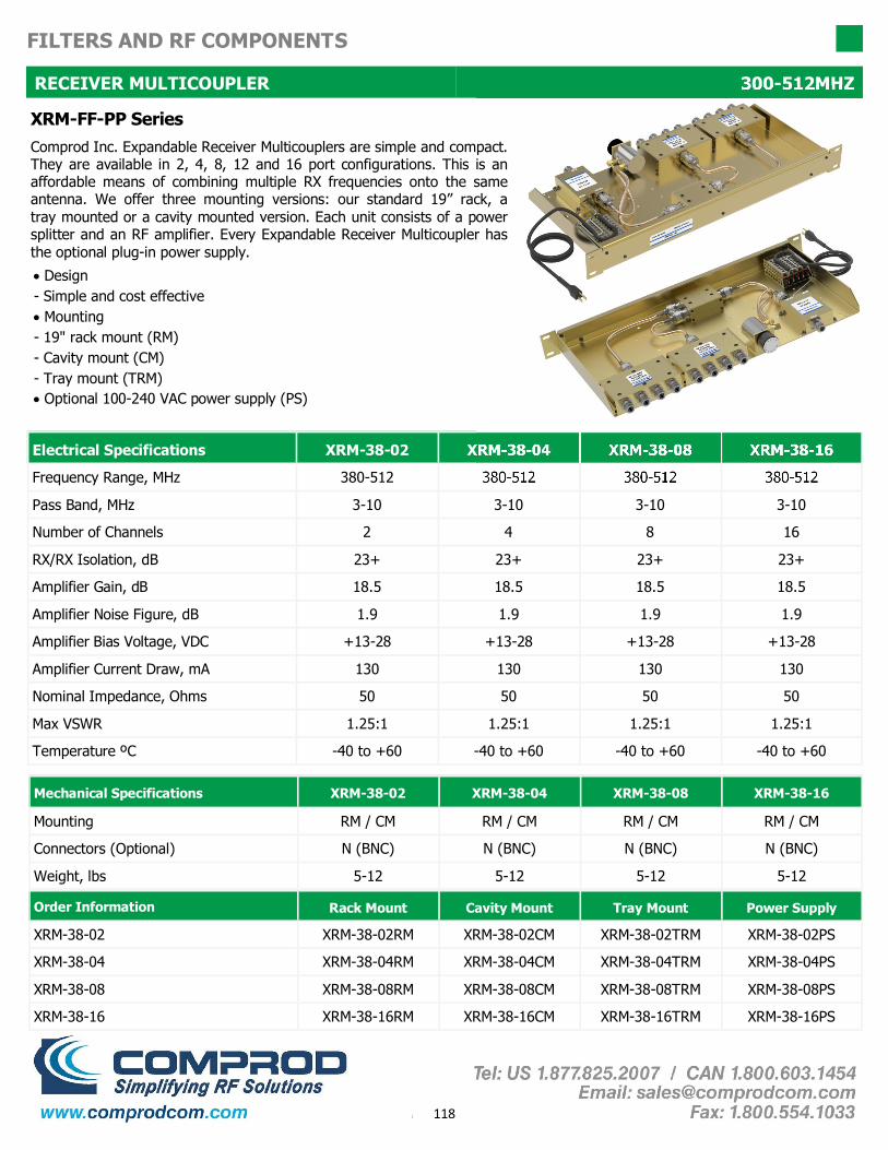
118
FILTERS AND RF COMPONENTS
RECEIVER MULTICOUPLER 300-512MHZ
• Design - Simple and cost effective • Mounting - 19" rack mount (RM) - Cavity mount (CM) - Tray mount (TRM) • Optional 100-240 VAC power supply (PS)
Electrical Specifications XRM-38-02 XRM-38-04 XRM-38-08 XRM-38-16
Frequency Range, MHz 380-512 380-512 380-512 380-512
Pass Band, MHz 3-10 3-10 3-10 3-10
Number of Channels 2 4 8 16
RX/RX Isolation, dB 23+ 23+ 23+ 23+
Amplifier Gain, dB 18.5 18.5 18.5 18.5
Amplifier Noise Figure, dB 1.9 1.9 1.9 1.9
Amplifier Bias Voltage, VDC +13-28 +13-28 +13-28 +13-28
Amplifier Current Draw, mA 130 130 130 130
Nominal Impedance, Ohms 50 50 50 50
Max VSWR 1.25:1 1.25:1 1.25:1 1.25:1
Temperature ºC -40 to +60 -40 to +60 -40 to +60 -40 to +60
Order Information Rack Mount Cavity Mount Tray Mount
XRM-38-02 XRM-38-02RM XRM-38-02CM XRM-38-02TRM
XRM-38-04 XRM-38-04RM XRM-38-04CM XRM-38-04TRM
XRM-38-16 XRM-38-16RM XRM-38-16CM XRM-38-16TRM
Power Supply
XRM-38-02PS
XRM-38-04PS
XRM-38-16PS
XRM-38-08 XRM-38-08RM XRM-38-08CM XRM-38-08TRM XRM-38-08PS
Mechanical Specifications XRM-38-02 XRM-38-04 XRM-38-08 XRM-38-16
Mounting RM / CM RM / CM RM / CM RM / CM
Weight, lbs 5-12 5-12 5-12 5-12
Connectors (Optional) N (BNC) N (BNC) N (BNC) N (BNC)
XRM-FF-PP Series Comprod Inc. Expandable Receiver Multicouplers are simple and compact. They are available in 2, 4, 8, 12 and 16 port configurations. This is an affordable means of combining multiple RX frequencies onto the same antenna. We offer three mounting versions: our standard 19” rack, a tray mounted or a cavity mounted version. Each unit consists of a power splitter and an RF amplifier. Every Expandable Receiver Multicoupler has the optional plug-in power supply.

119
FILTERS AND RF COMPONENTS
RECEIVER MULTICOUPLER 806-896MHZ
• Design - Simple and cost effective • Mounting - 19" rack mount (RM) - Cavity mount (CM) - Tray mount (TRM) • Optional 100-240 VAC power supply (PS)
Electrical Specifications XRM-80-02 XRM-80-04 XRM-80-08 XRM-80-16 XRM-80-32
Frequency Range, MHz 806-896 806-896 806-896 806-896 806-896
Pass Band, MHz 3-18 3-18 3-18 3-18 3-18
Number of Channels 2 4 8 16 32
RX/RX Isolation, dB 23+ 23+ 23+ 23+ 23+
Amplifier Gain, dB 19 19 19 19 19
Amplifier Noise Figure, dB 1.9 1.9 1.9 1.9 1.9
Amplifier Bias Voltage, VDC +13-28 +13-28 +13-28 +13-28 +13-28
Amplifier Current Draw, mA 130 130 130 130 130
Nominal Impedance, Ohms 50 50 50 50 50
Max VSWR 1.25:1 1.25:1 1.25:1 1.25:1 1.25:1
Temperature ºC -40 to +60 -40 to +60 -40 to +60 -40 to +60 -40 to +60
Order Information Rack Mount Cavity Mount Tray Mount
XRM-80-02 XRM-80-02RM XRM-80-02CM XRM-80-02TRM
XRM-80-04 XRM-80-04RM XRM-80-04CM XRM-80-04TRM
XRM-80-16 XRM-80-16RM XRM-80-16CM XRM-80-16TRM
Power Supply
XRM-80-02PS
XRM-80-04PS
XRM-80-16PS
XRM-80-08 XRM-80-08RM XRM-80-08CM XRM-80-08TRM XRM-80-08PS
Mechanical Specifications XRM-80-02 XRM-80-04 XRM-80-08 XRM-80-32
Mounting RM / CM RM / CM RM / CM RM / CM
Weight, lbs 5-12 5-12 5-12 5-12
Connectors (Optional) N (BNC) N (BNC) N (BNC) N (BNC)
XRM-80-16
RM / CM
N (BNC)
5-12
XRM-FF-PP Series Comprod Inc. Expandable Receiver Multicouplers are simple and compact. They are available in 2, 4, 8, 12 and 16 port configurations. This is an affordable means of combining multiple RX frequencies onto the same antenna. We offer three mounting versions: our standard 19” rack, a tray mounted or a cavity mounted version. Each unit consists of a power splitter and an RF amplifier. Every Expandable Receiver Multicoupler has the optional plug-in power supply.

120
FILTERS AND RF COMPONENTS
RECEIVER MULTICOUPLER 896-960MHZ
• Design - Simple and cost effective • Mounting - 19" rack mount (RM) - Cavity mount (CM) - Tray mount (TRM) • Optional power supply (PS)
Electrical Specifications XRM-90-02 XRM-90-04 XRM-90-08 XRM-90-16 XRM-90-32
Frequency Range, MHz 896-960 896-960 896-960 896-960 896-960
Pass Band, MHz 3-15 3-15 3-15 3-15 3-15
Number of Channels 2 4 8 16 32
RX/RX Isolation, dB 23+ 23+ 23+ 23+ 23+
Amplifier Gain, dB 19 19 19 19 19
Amplifier Noise Figure, dB 1.9 1.9 1.9 1.9 1.9
Amplifier Bias Voltage, VDC +13-28 +13-28 +13-28 +13-28 +13-28
Amplifier Current Draw, mA 130 130 130 130 130
Nominal Impedance, Ohms 50 50 50 50 50
Max VSWR 1.25:1 1.25:1 1.25:1 1.25:1 1.25:1
Temperature ºC -40 to +60 -40 to +60 -40 to +60 -40 to +60 -40 to +60
Order Information Rack Mount Cavity Mount Tray Mount
XRM-90-02 XRM-90-02RM XRM-90-02CM XRM-90-02TRM
XRM-90-04 XRM-90-04RM XRM-90-04CM XRM-90-04TRM
XRM-90-16 XRM-90-16RM XRM-90-16CM XRM-90-16TRM
Power Supply
XRM-90-02PS
XRM-90-04PS
XRM-90-16PS
XRM-90-08 XRM-90-08RM XRM-90-08CM XRM-90-08TRM XRM-90-08PS
Mechanical Specifications XRM-90-02 XRM-90-04 XRM-90-08 XRM-90-32
Mounting RM / CM RM / CM RM / CM RM / CM
Weight, lbs 5-12 5-12 5-12 5-12
Connectors (Optional) N (BNC) N (BNC) N (BNC) N (BNC)
XRM-90-16
RM / CM
N (BNC)
5-12
XRM-FF-PP Series Comprod Inc. Expandable Receiver Multicouplers are simple and compact. They are available in 2, 4, 8, 12 and 16 port configurations. This is an affordable means of combining multiple RX frequencies onto the same antenna. We offer three mounting versions: our standard 19” rack, a tray mounted or a cavity mounted version. Each unit consists of a power splitter and an RF amplifier. Every Expandable Receiver Multicoupler has the optional plug-in power supply.

121
FILTERS AND RF COMPONENTS
EXPANDABLE RECEIVER MULTICOUPLER UHF, 794-824 MHz
Expandable Receiver Multicoupler 90 Series Comprod Inc.'s Expandable Receiver Multicoupler provides an af-fordable means of combining multiple Receiver frequencies onto the same antenna. They are available in 2, 4, 8, 12 and 16 port configu-rations. Key features:
• A low noise amplifier provides gain across the frequency band
• Low noise figure and low intermodulation generation
• Features up to 16 ports (24 and 32 port versions are available)
• -30 dB signal sampler port that can also be used to inject a signal
Electrical Specifications
Frequency Band, MHz 794-824
Number of output ports 2 to 16 (24 and 32 port versions available)
Input Preselector Bandwidth Options 794 - 824 MHz, 3/6/12 MHz BW 806 - 821 MHz, 15 MHz BW 806 - 824 MHz, 18 MHz BW 794 - 824 MHz, 30 MHz BW
VSWR 1.5:1
Amplifier Gain, dB 19 typical
Amplifier Output IP3, dB +40 Min
Amplifier Noise Figure, dB 1.9 typical
Manual Attenuation Selection 0 to –10dB in 1 dB steps
RX to RX Isolation, dB >20
TX Band Rejection, dB >80
Connector, Input N (Female)
Connector, Output N (Female)
Connector, Signal Sampler BNC (Female)
Power Input, Standard 110/220 VAC 50/60Hz 10W
AC Power Input Connector Hardwired 3-wire
Mounting EIA Standard 19” 2 RU
Temperature Range C -30 to +60 C
UHF
2 to 16 (24 and 32 port versions available)
2 or 3 MHz Bandwidth 380-512 MHz
1.5:1
18.5 typical
+40 Min
1.9 typical
0 to –10dB in 1 dB steps
>20
>40 at 2MHz TX-RX
N (Female)
N (Female)
BNC (Female)
110/220 VAC 50/60Hz 10W
Hardwired 3-wire
EIA Standard 19” 3 RU
-30 to +60 C
DC Power (optional), VDC +13-28 +13-28

122
FILTERS AND RF COMPONENTS
EXPANDABLE RECEIVER MULTICOUPLER UHF, 794-824 MHz
800 MHz Pass: 806-812MHz (6MHz) 800MHz Pass: 809-821MHz (12MHz)
9 Series 90
W 1,2 Number of Pass Windows
76 794-806 MHz
85 806-824 MHz
First 2 digits of Freq.
38/40/43/45/47
380-512 MHz
PP 2,4,8,16,24 Number of Ports
C N/B N or BNC Connectors
BB 02/03/06/12/15/18/30 Bandwidth in MHz
FF
9 W FF PP C BB - -
800MHz Pass: 794-824MHz (30MHz)
Example: Model # 91-85-8N18
RX Multicoupler, 1 Pass Window, 806MHz, 8 Output Ports, N female, 18 MHz Bandwidth
Ordering Format:
800MHz Pass: 806-824MHz (18MHz)

123
FILTERS AND RF COMPONENTS
TTA, Tower Top Amplifier UHF, 794-824 MHz
Comprod Inc. Tower- Top Amplifier (TTA) systems provide superior receiver system perfor-mance and excellent electrical reliability in a rugged, weather-proof design. The tower unit is housed in a seamless cylindrical aluminum housing with a durable finish to repel both weather and solar energy. The aluminum shell connector plate provide much lower electrical resistance than competing stainless steel housings, enhancing the performance of the internal lightning surge protection. A high permeability internal magnetic shield provides protection against damage from lightning-induced magnetic pulses and is many times more effective than a stainless steel enclosure.
The tower housing has two drain holes to release any water due to condensation build up. RF connections stay weather-resistant longer as a result of the protection provided by a 360° drip- edge. Superior electrical performance starts with a highly selective Combline preselector that provides excellent out-of-band rejection with minimum loss. Our preamplifier uses PHEMT (GaAs FET) device technology to provide low noise performance (1.6dB typical) and high inter-modulation immunity (+39 dBm OIP3).
For greater reliability, the preamplifier uses a pair of hybrid -coupled devices to provide ampli-fier redundancy. This circuit provides useful gain should only one device be operational. The preamp features internal transient suppression that complements lightning surge protection provided on all TTA ports.
In addition to amplifier redundancy, full amplifier bypass capability is provided. A hermetically sealed, high-reliability bypass relay will fully remove the amplifier from the circuit and provide a non-amplified connection from the antenna to keep the system up and running even if the preamplifier totally ceases operation. Bypass mode is activated when DC power to the tower unit is disabled.
The base unit is housed in a 19” rack assembly that includes the power supply and DC injector to send DC (12 V) over the transmission line to operate the tower unit. The base unit has jacks for measurement of tower unit Current using a standard digital multi-meter. Type N connectors provided. Tower unit mounting hardware included.
Building- entry lightning surge suppressor w/DC pass-thru is recommended but not supplied.

124
FILTERS AND RF COMPONENTS
TTA, Tower Top Amplifier UHF, 794-902 MHz
Tower Section Frequency Range, MHz UHF (406-512) 794-806 806-824 896-902
Bandwidth, MHZ 2-3 3, 6, 10, 12 18 6
Gain, dB 16-19 16-19 16-19 16-19
Noise Figure, dB 2-4 2-4 2-4 3-4
3rd Order Intercept Point, dBm
+40 +40 +40 +40
Connectors N Female N Female N Female N Female
Power, VDC +13-28 +13-28 +13-28 +13-28
Housing Diameter, in 16 x 14 x 6 7 7 7
Temperature Range - 40° to +50° C - 40° to +50° C - 40° to +50° C - 40° to +50° C
Weight, lbs 45 with clamps 45 with clamps 45 with clamps 45 with clamps
Housing Length, in N/A 21 21 21
Finish Grey Anodize Grey Anodize Grey Anodize Grey Anodize
792-824
32
16-19
2-4
+40
N Female
+13-28
7
21
Grey Anodize
- 40° to +50° C
45 with clamps
Base Unit Size (H,W,D) in 1.75 x 19 x 6
Finish, Front Black
Connectors Transmission Line, RF Output
Connector Type N Female
Power Input, Standard 110/220 VAC 50/60Hz, 12W
Weight, lbs 5
DC Power (optional), VDC 13-28
Mounting EIA Standard 19” 1 RU
Temperature Range, C -0 to +50
Ordering Information TTA-40-00 TTA-70-00 TTA-79-00 TTA-80-00 TTA-90-00
Frequency, MHz 406-512 794-806 792-824 806-824 896-902

125
FILTERS AND RF COMPONENTS
RECEIVER AMPLIFIERS 138-960MHZ
Models: 58-13-19 (138-174 MHz) 58-40-19 (406-512 MHz) 58-74-19 (740-960 MHz) The Comprod Inc. line of low noise, medium power robust amplifiers are de-signed for unconditionally stable performance in professional communications systems. Featuring rugged construction, internal voltage regulator, hybrid-combined redundant amplifier pairs and low pass filters. The amplifiers will provide higher system dynamic range for fixed receiver systems, tower mounted amplifiers, or Bi-Directional in-building repeaters and boosters.
• High Gain, Low Noise - Maximum performance with minimum noise.
• Filtering on DC Terminals - Greater than 70 dB attenuation from as low as 5 MHz to several GHz
Electrical Specifications 58-13-19 58-40-19 58-74-19
Frequency Range, MHz 100-225 300-520 700-1000
Bandwidth, MHz 125 220 300
Amplifier Type Low Noise/Medium Power Low Noise/Medium Power Low Noise/Medium Power
Typical Gain, dB 18 18.5 19
Amplifier Noise figure, dB 1.9 1.9 1.9
3rd Order Intercept, dBm +41 +41 +41
Output 1 dB Compression Point, dBm 25.0 25.0 25.0
Input/output Return loss, dB -18 Typ. -18 Typ. -18 Typ.
Operating Voltage, VDC 12.5-28 12.5-28 12.5-28
Typical DC Current Draw, mA 130 130 130
Standard Connectors (Optional) N Female (SMA) N Female (SMA) N Female (SMA)
Maximum Input Power, dBm +15 +15 +15
Temperature Range, C -20 to +70 -20 to +70 -20 to +70
Mechanical Specifications
Height, in (mm) 4.375 (111)
Width, in (mm) 2.5 (63.5)
Depth, in (mm) (including Connectors) 0.9375 (23.8)
Weight, lb (kg) 0.42 (0.187)
Finish Alodine (yellow)
Order Information 58-13-19 58-40-19 58-74-19
Frequency MHz 138-174 406-512 740-960
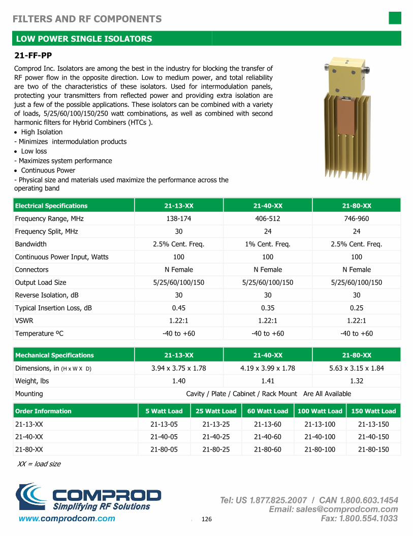
126
FILTERS AND RF COMPONENTS
LOW POWER SINGLE ISOLATORS
21-FF-PP Comprod Inc. Isolators are among the best in the industry for blocking the transfer of RF power flow in the opposite direction. Low to medium power, and total reliability are two of the characteristics of these isolators. Used for intermodulation panels, protecting your transmitters from reflected power and providing extra isolation are just a few of the possible applications. These isolators can be combined with a variety of loads, 5/25/60/100/150/250 watt combinations, as well as combined with second harmonic filters for Hybrid Combiners (HTCs ). • High Isolation - Minimizes intermodulation products • Low loss - Maximizes system performance • Continuous Power - Physical size and materials used maximize the performance across the operating band
Electrical Specifications 21-13-XX 21-40-XX 21-80-XX
Frequency Range, MHz 138-174 406-512 746-960
Frequency Split, MHz 30 24 24
Bandwidth 2.5% Cent. Freq. 1% Cent. Freq. 2.5% Cent. Freq.
Continuous Power Input, Watts 100 100 100
Connectors N Female N Female N Female
Output Load Size 5/25/60/100/150 5/25/60/100/150 5/25/60/100/150
Reverse Isolation, dB 30 30 30
Typical Insertion Loss, dB 0.45 0.35 0.25
VSWR 1.22:1 1.22:1 1.22:1
Temperature ºC -40 to +60 -40 to +60 -40 to +60
Mechanical Specifications 21-13-XX 21-40-XX 21-80-XX
Dimensions, in (H x W X D) 3.94 x 3.75 x 1.78 4.19 x 3.99 x 1.78 5.63 x 3.15 x 1.84
Weight, lbs 1.40 1.41 1.32
Mounting Cavity / Plate / Cabinet / Rack Mount Are All Available
Order Information 5 Watt Load 25 Watt Load 60 Watt Load 150 Watt Load
21-13-XX 21-13-05 21-13-25 21-13-60 21-13-150
21-80-XX 21-80-05 21-80-25 21-80-60 21-80-150
21-40-XX 21-40-05 21-40-25 21-40-60 21-40-150
100 Watt Load
21-13-100
21-40-100
21-80-100
XX = load size

127
FILTERS AND RF COMPONENTS
LOW POWER DUAL ISOLATORS
22-FF-PP Comprod Inc. Isolators are among the best in the industry for blocking the transfer of RF power flow in the opposite direction. Low to medium power and total reliability are two of the characteristics of these isolators. Used for intermodulation panels, protecting your transmitters from reflected power, and providing extra isolation are just a few of the possible applications. These isolators can be combined with a vari-ety of loads, 5/25/60/100/150/250 watt combinations, and combined with second harmonic filters for Hybrid Combiners (HTCs). • High Isolation - Minimizes intermodulation products • Low loss - Maximizes system performance • Continuous Power - Physical size and materials used maximize the performance across the operating band
Electrical Specifications 22-13-XX 22-40-XX 22-80-XX
Frequency Range, MHz 138-174 406-512 746-960
Frequency Split, MHz 30 24 24
Bandwidth 2.5% Cent. Freq. 1% Cent. Freq. 2.5% Cent. Freq.
Continuous Power Input, Watts 100 100 100
Connectors N Female N Female N Female
Output Load Size 5/25/60/100/150 5/25/60/100/150 5/25/60/100/150
Reverse Isolation, dB 50 50 50
Typical Insertion Loss, dB 0.9 0.7 0.5
VSWR 1.22:1 1.22:1 1.22:1
Temperature ºC -40 to +60 -40 to +60 -40 to +60
Mechanical Specifications 22-13-XX 22-40-XX 22-80-XX
Dimensions, in (H x W X D) 3.94 x 6.25 x 1.78 4.19 x 8.75 x 1.78 5.63 x 6.13 x 1.84
Weight, lbs 2.6 2.8 2.75
Mounting Cavity / Plate / Cabinet / Rack Mount Are All Available
Order Information 5 Watt Load 25 Watt Load 60 Watt Load 150 Watt Load
22-13-XX 22-13-05 22-13-25 22-13-60 22-13-150
22-80-XX 22-80-05 22-80-25 22-80-60 22-80-150
22-40-XX 22-40-05 22-40-25 22-40-60 22-40-150
100 Watt Load
22-13-100
22-40-100
22-80-100
XX = load size

128
FILTERS AND RF COMPONENTS
HIGH POWER SINGLE ISOLATORS
41-FF-PP Comprod Inc. Isolators are among the best in the industry for blocking the transfer of RF power flow in the opposite direction. High power and total relia-bility are two of the characteristics of these isolators. Used for intermodulation panels, protecting your transmitters from reflected power, and providing extra isolation are just a few of the possible applications. These isolators can be combined with a variety of loads, 5/25/60/100/150/250 watt combinations, and combined with second harmonic filters for Hybrid Combiners (HTCs).
• High Isolation - Minimizes intermodulation products • Low loss - Maximizes system performance • Continuous Power - Physical size and materials used maximize the performance across the operating band
Electrical Specifications 41-13-XX 41-40-XX 41-80-XX
Frequency Range, MHz 138-174 406-512 746-960
Frequency Split, MHz 30 24 24
Bandwidth 2.5% Cent. Freq. 1% Cent. Freq. 2.5% Cent. Freq.
Continuous Power Input, Watts 150 250 150
Connectors N Female N Female N Female
Output Load Size 5/25/60/100/150 5/25/60/100/150 5/25/60/100/150
Reverse Isolation, dB 30 30 30
Typical Insertion Loss, dB 0.45 0.45 0.25
VSWR 1.22:1 1.22:1 1.22:1
Temperature ºC -40 to +60 -40 to +60 -40 to +60
Mechanical Specifications 41-13-XX 41-40-XX 41-80-XX
Dimensions, in (H x W X D) 3.94 x 3.75 x 1.78 4.19 x 3.99 x 1.78 5.63 x 3.15 x 1.84
Weight, lbs 1,40 1,41 1,32
Mounting Cavity / Plate / Cabinet / Rack Mount Are All Available
Order Information 5 Watt Load 25 Watt Load 60 Watt Load 150 Watt Load
41-13-XX 41-13-05 41-13-25 41-13-60 41-13-150
41-80-XX 41-80-05 41-80-25 41-80-60 41-80-150
41-40-XX 41-40-05 41-40-25 41-40-60 41-40-150
100 Watt Load
41-13-100
41-40-100
41-80-100
XX = load size

129
FILTERS AND RF COMPONENTS
HIGH POWER DUAL ISOLATORS
42-FF-PP Comprod Inc. Isolators are among the best in the industry for blocking the transfer of RF power flow in the opposite direction. High power and total relia-bility are two of the characteristics of these isolators. Used for intermodulation panels, protecting your transmitters from reflected power, and providing extra isolation are just a few of the possible applications. These isolators can be combined with a variety of loads, 5/25/60/100/150/250 watt combinations, and combined with second harmonic filters for Hybrid Combiners (HTCs).
• High Isolation - Minimizes intermodulation products • Low loss - Maximizes system performance • Continuous Power - Physical size and materials used maximize the performance across operating band
Electrical Specifications 42-13-XX 42-40-XX 42-80-XX
Frequency Range, MHz 138-174 406-512 746-960
Frequency Split, MHz 30 24 24
Bandwidth 2.5% Cent. Freq. 1% Cent. Freq. 2.5% Cent. Freq.
Continuous Power Input, Watts 150 250 150
Connectors N Female N Female N Female
Output Load Size 5/25/60/100/150 5/25/60/100/150 5/25/60/100/150
Reverse Isolation, dB 60 60 60
Typical Insertion Loss, dB 0.9 0.7 0.5
VSWR 1.22:1 1.22:1 1.22:1
Temperature ºC -40 to +60 -40 to +60 -40 to +60
Mechanical Specifications 42-13-XX 42-40-XX 42-80-XX
Dimensions, in (H x W X D) 3.94 x 6.25 x 1.78 4.19 x 8.75 x 1.78 5.63 x 6.13 x 1.84
Weight, lbs 2.6 2.8 2.75
Mounting Cavity / Plate / Cabinet / Rack Mount Are All Available
Order Information 5 Watt Load 25 Watt Load 60 Watt Load 150 Watt Load
42-13-XX 42-13-05 42-13-25 42-13-60 42-13-150
42-80-XX 42-80-05 42-80-25 42-80-60 42-80-150
42-40-XX 42-40-05 42-40-25 42-40-60 42-40-150
100 Watt Load
42-13-100
42-40-100
42-80-100
XX = load size
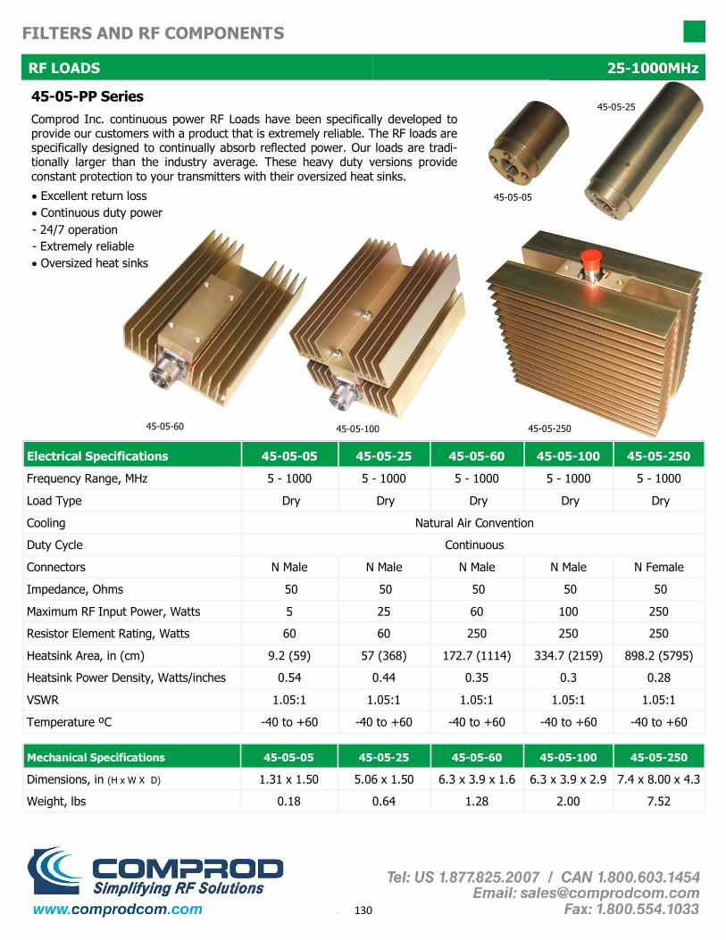
130
FILTERS AND RF COMPONENTS
RF LOADS 25-1000MHz
45-05-PP Series Comprod Inc. continuous power RF Loads have been specifically developed to provide our customers with a product that is extremely reliable. The RF loads are specifically designed to continually absorb reflected power. Our loads are tradi-tionally larger than the industry average. These heavy duty versions provide constant protection to your transmitters with their oversized heat sinks.
• Excellent return loss • Continuous duty power - 24/7 operation - Extremely reliable • Oversized heat sinks
Electrical Specifications 45-05-05 45-05-25 45-05-60 45-05-100 45-05-250
Frequency Range, MHz 5 - 1000 5 - 1000 5 - 1000 5 - 1000 5 - 1000
Load Type Dry
Cooling Natural Air Convention
Duty Cycle Continuous
Connectors N Male N Female
Impedance, Ohms
Maximum RF Input Power, Watts 5 25 60 100 250
Resistor Element Rating, Watts 60 60 250 250 250
Heatsink Area, in (cm) 9.2 (59) 57 (368) 172.7 (1114) 334.7 (2159) 898.2 (5795)
Heatsink Power Density, Watts/inches 0.54 0.44 0.35 0.3 0.28
VSWR 1.05:1
Temperature ºC -40 to +60 -40 to +60 -40 to +60 -40 to +60 -40 to +60
50
Dry Dry Dry Dry
N Male N Male N Male
50 50 50 50
1.05:1 1.05:1 1.05:1 1.05:1
Mechanical Specifications 45-05-05 45-05-25 45-05-60 45-05-100 45-05-250
Dimensions, in (H x W X D) 1.31 x 1.50 5.06 x 1.50 6.3 x 3.9 x 1.6 6.3 x 3.9 x 2.9 7.4 x 8.00 x 4.3
Weight, lbs 0.18 0.64 1.28 2.00 7.52
45-05-60 45-05-250 45-05-100
45-05-05
45-05-25

131
FILTERS AND RF COMPONENTS
HIGH POWER HYBRID COMBINERS 138-174MHz
HTC-13-OX Our Hybrid Transmit Combiners are designed for compact, close frequency installations. Our HTCs are perfect for very closely spaced frequency transmitters These devices are ideal for use when our X-Pass technology does not provide adequate perfor-mance and isolation for very close TX-TX spacing. Hybrid Combin-ers are also ideal for intermodulation panels, providing extra pro-tection with their second harmonic filters, or when physical space is at a premium, and for providing extra isolation between two very close transmitters.
• High Isolation - Minimizes intermodulation products • Low loss - Maximizes system performance • Continuous power - Physical size and materials used maximizes the performance across the operating band
Electrical Specifications HTC-13-04HS HTC-13-04HD
Frequency Range, MHz 138-174 138-174
Frequency Split, MHz 30 24
Bandwidth 2.5% Cent. Freq. 1% Cent. Freq.
Channels 4 4
Continuous Power Input, Watts 100 100
Connectors N Female N Female
Isolator Single Dual
Isolation TX/TX, dB 65 100
Isolation Ant/TX 35+ 70+
Typical Insertion Loss, dB 6.8 7.0
VSWR - Input/output 1.1:1 / 1.3:1 1.1:1 / 1.3:1
Temperature ºC -40 to +60 -40 to +60
HTC-13-02HS
138-174
30
2.5% Cent. Freq.
2
100
N Female
Single
65
35+
3.5
1.1:1 / 1.3:1
-40 to +60
HTC-13-02HD
138-174
24
1% Cent. Freq.
2
100
N Female
Dual
100
70+
3.7
1.1:1 / 1.3:1
-40 to +60
Mechanical Specifications HTC-13-04HS HTC-13-04HD
Dimensions, in (H x W X D) 6.5 x 19 x 18 6.5 x 19 x 18
Weight, lbs 11.8 12.8
Mounting 19" Rack Mount 19" Rack Mount
HTC-13-02HD
6.5 x 19 x 18
9.3-11
19" Rack Mount
HTC-13-02HS
6.5 x 19 x 18
9.3-11
19" Rack Mount

132
FILTERS AND RF COMPONENTS
HIGH POWER HYBRID COMBINERS 406-512MHz
HTC-40-OX Our Hybrid Transmit Combiners are designed for compact, close frequency installations. Our HTCs are perfect for very closely spaced frequency transmitters These devices are ideal for use when our X-Pass technology does not provide adequate perfor-mance and isolation for very close TX-TX spacing. Hybrid Combin-ers are also ideal for intermodulation panels, providing extra pro-tection with their second harmonic filters, or when physical space is at a premium, and for providing extra isolation between two very close transmitters.
• High Isolation - Minimizes intermodulation products • Low loss - Maximizes system performance • Continuous power - Physical size and materials used maximizes the performance across the operating band
Electrical Specifications HTC-40-04HS HTC-40-04HD
Frequency Range, MHz 406-512 406-512
Frequency Split, MHz 30 24
Bandwidth 2.5% Cent. Freq. 1% Cent. Freq.
Channels 4 4
Continuous Power Input, Watts 100 100
Connectors N Female N Female
Isolator Single Dual
Isolation TX/TX, dB 65 100
Isolation Ant/TX 35+ 70+
Typical Insertion Loss, dB 6.8 7.0
VSWR - Input/output 1.1:1 / 1.3:1 1.1:1 / 1.3:1
Temperature ºC -40 to +60 -40 to +60
HTC-40-02HS
406-512
30
2.5% Cent. Freq.
2
100
N Female
Single
65
35+
3.5
1.1:1 / 1.3:1
-40 to +60
HTC-40-02HD
406-512
24
1% Cent. Freq.
2
100
N Female
Dual
100
70+
3.7
1.1:1 / 1.3:1
-40 to +60
Mechanical Specifications HTC-40-04HS HTC-40-04HD
Dimensions, in (H x W X D) 6.5 x 19 x 18 6.5 x 19 x 18
Weight, lbs 11.8 12.8
Mounting 19" Rack Mount 19" Rack Mount
HTC-40-02HD
6.5 x 19 x 18
9.3-11
19" Rack Mount
HTC-40-02HS
6.5 x 19 x 18
9.3-11
19" Rack Mount

133
FILTERS AND RF COMPONENTS
HIGH POWER HYBRID COMBINERS 806-960MHz
HTC-80-OX Our Hybrid Transmit Combiners are designed for compact, close frequency installations. Our HTCs are perfect for very closely spaced frequency transmitters These devices are ideal for use when our X-Pass technology does not provide adequate perfor-mance and isolation for very close TX-TX spacing. Hybrid Combin-ers are also ideal for intermodulation panels, providing extra protec-tion with their second harmonic filters, or when physical space is at a premium, and for providing extra isolation between two very close transmitters.
• High Isolation - Minimizes intermodulation products • Low loss - Maximizes system performance • Continuous power - Physical size and materials used maximizes the performance across the operating band
Electrical Specifications HTC-80-04HS HTC-80-04HD
Frequency Range, MHz 806-960 806-960
Frequency Split, MHz 30 24
Bandwidth 2.5% Cent. Freq. 1% Cent. Freq.
Channels 4 4
Continuous Power Input, Watts 100 100
Connectors N Female N Female
Isolator Single Dual
Isolation TX/TX, dB 65 100
Isolation Ant/TX 35+ 70+
Typical Insertion Loss, dB 6.8 7.0
VSWR - Input/output 1.1:1 / 1.3:1 1.1:1 / 1.3:1
Temperature ºC -40 to +60 -40 to +60
HTC-80-02HS
806-960
30
2.5% Cent. Freq.
2
100
N Female
Single
65
35+
3.5
1.1:1 / 1.3:1
-40 to +60
HTC-80-02HD
806-960
24
1% Cent. Freq.
2
100
N Female
Dual
100
70+
3.7
1.1:1 / 1.3:1
-40 to +60
Mechanical Specifications HTC-80-04HS HTC-80-04HD
Dimensions, in (H x W X D) 6.5 x 19 x 18 6.5 x 19 x 18
Weight, lbs 11.8 12.8
Mounting 19" Rack Mount 19" Rack Mount
HTC-80-02HD
6.5 x 19 x 18
9.3-11
19" Rack Mount
HTC-80-02HS
6.5 x 19 x 18
9.3-11
19" Rack Mount

134
FILTERS AND RF COMPONENTS
HYBRID TRANSMIT COMBINER 806-960MHz
HTC-90-O2DLP Our Hybrid Transmit Combiners are designed for compact, close frequency installations. Our HTCs are perfect for very closely spaced frequency transmitters These devices are ideal for use when our X-Pass technology does not provide adequate performance and isolation for very close TX-TX spacing. Hybrid Combiners are also ideal for intermodulation panels, providing extra protection with their second harmonic filters, or when physical space is at a premium or is constrained, and for providing extra isolation between two very close transmitters.
• High Isolation - Minimizes intermodulation products • Low loss - Maximizes system performance • Continuous power - Physical size and materials used maximizes the performance across the operating band.
Electrical Specifications HTC-90-02DLP
Frequency Range, MHz 896-960
Channels 2
Maximum Power Per Channel, Watts 50
Connectors N Female
Isolator Single
Isolation TX/TX, dB 70
Isolation Ant/TX, dB 50
Typical Insertion Loss, dB 3.7
Maximum Input VSWR 1.22:1
Temperature ºC -40 to +80
Impedance, Ohms 50
Transmit Antenna Return Loss, dB 18
Maximum Output VSWR 1.3:1
Mechanical Specifications
Height, in (mm) 1.75 (44.5)
Weight, lb (kg) 8.8 (4.0)
Mounting Information 19” Rack Mount, 1 Rack Unit
Depth, in (mm) 11.25 (286)
Width, in (mm) 19 (483)

135
FILTERS AND RF COMPONENTS
HYBRID DIRECTIONAL COUPLERS 138-960MHz
49-FF-YY-XX Series Comprod Inc. offers a full line of Hybrid Directional Couplers. The full range of decoupling values allows balanced power division and distribution. These couplers are bidirectional and are well suited for two-way communications systems. A full line of Tri-Band models is available for distribution of VHF, UHF and 800 MHz via a single transmission line. Standard finish is gold Alodine.
• Low Insertion Loss
• High Isolation between ports
• Excellent VSWR
• Tri-Band and other models are available and customizable. Please contact a Comprod Inc. Technical support technician for consultation.
Model With No Load
Model With 5 Watt Load
Model With 25 Watt Load
Frequency Range
Decoupling (dB)
Insertion Loss (dB)
Power Split Ratio (%)
49-13-03-00 49-13-03-05 49-13-03-25 138-174MHz -3.0, ±0.7 -3.0, ±0.3 50 / 50
49-13-48-00 49-13-48-05 49-13-48-25 138-174MHz -4.8, ±0.7 -1.8, ±0.3 67 / 33
49-13-06-00 49-13-06-05 49-13-06-25 138-174MHz -6.0, ±1.0 -1.2, ±0.2 75 / 25
49-13-07-00 49-13-07-05 49-13-07-25 138-174MHz -7.0, ±1.0 -1.0, ±0.2 80 / 20
49-13-10-00 49-13-10-05 49-13-10-25 138-174MHz -10.0, ±1.0 -0.5, ±0.2 90 / 10
49-13-20-00 49-13-20-05 49-13-20-25 138-174MHz -20.0, ±1.0 -0.3 max. 99 / 1
49-38-03-00 49-38-03-05 49-38-03-25 380-512MHz -3.0, ±0.7 -3.0, ±0.3 50 / 50
49-38-48-00 49-38-48-05 49-38-48-25 380-512MHz -4.8, ±0.7 -1.8, ±0.3 67 / 33
49-38-06-00 49-38-06-05 49-38-06-25 380-512MHz -6.0, ±1.0 -1.2, ±0.2 75 / 25
49-38-07-00 49-38-07-05 49-38-07-25 380-512MHz -7.0, ±1.0 -1.0, ±0.2 80 / 20
49-38-10-00 49-38-10-05 49-38-10-25 380-512MHz -10.0, ±1.0 -0.5, ±0.2 90 / 10
49-38-15-00 49-38-15-05 49-38-15-25 380-512MHz -15.0 -0.2 max. 97 / 3
49-38-20-00 49-38-20-05 49-38-20-25 380-512MHz -20.0 -0.2 max. 99 / 1
49-38-30-00 49-38-30-05 49-38-30-25 380-512MHz -30.0 -0.2 max. 99.9 / 0.1
49-74-03-00 49-74-03-05 49-74-03-25 760-960MHz -3.0, ±0.7 -3.0, ±0.3 50 / 50
49-74-48-00 49-74-48-05 49-74-48-25 760-960MHz -4.8, ±0.7 -1.8, ±0.3 67 / 33
49-74-06-00 49-74-06-05 49-74-06-25 760-960MHz -6.0, ±1.0 -1.2, ±0.2 75 / 25
49-74-07-00 49-74-07-05 49-74-07-25 760-960MHz -7.0, ±1.0 -1.0, ±0.2 80 / 20
49-74-10-00 49-74-10-05 49-74-10-25 760-960MHz -10.0, ±1.0 -0.5, ±0.2 90 / 10
49-74-30-00 49-74-30-05 49-74-30-25 760-960MHz -30.0 -0.2 max. 99.9 / 0.1
49-74-15-00 49-74-15-05 49-74-15-25 760-960MHz -15.0 -0.2 max. 97 / 3
49-74-20-00 49-74-20-05 49-74-20-25 760-960MHz -20.0 -0.2 max. 99 / 1

136
FILTERS AND RF COMPONENTS
CERAMIC COMBINER 764-776, 851-869 & 935-941 MHz
Star Junction Ceramic Combiner Comprod Inc.’s Ceramic Combiner uses dielectric resonator technology to offer higher performance than standard RF cavities in a much smaller pack-age. It combines 8 channels in only 8.5” of standard 19” rack space. The resonator allows combining of transmitters at a frequency spacing as close as 150 kHz. Lower insertion loss per channel is another result of the sharper filtering performance. Expandable in individual channel increments. Available in Star or X-Pass (expandable) configuration.
• Available for the 764-776, 851-869 and 935-941 MHz bands
• Designed for tight channel spacing
• Lowest insertion loss, high isolation for maximum coverage and reduced interference
• Star Configuration
• Compact, robust design for rapid installations, increased mobility and ease of maintenance
Frequency Range, MHz 764-776, 851-869 & 935-941
Frequency Spacing, Min. 150 kHz
Temperature Range, °C -35 to +60
TX to TX Isolation at Minimum Frequency Spacing of 150 kHz 65 dB min (double junction isolator)
ANT to TX Isolation 60 dB min (double junction isolator)
Insertion Loss 1.8 dB – 4 Ch. at 500 kHz 2.5 dB – 16 Ch. at 500 kHz 3.8 dB – 24 Ch. at 500 kHz
Power Input / Channel (Watts) 125
Transmitter Input VSWR (max) 1.25:1
Electrical Specifications
Dimensions (HWD), in (mm) 14 x 8.5 x 19 (356 x 216 x 483)
Weight, lb (kg) 8 Channel system 62.17 (28.2)
Mechanical Specifications

137
FILTERS AND RF COMPONENTS
CERAMIC COMBINER 764-776, 851-869 & 935-941 MHz
X-Pass Ceramic Combiner Comprod Inc.’s Ceramic Combiner uses dielectric resonator technology to offer higher performance than standard RF cavities in a much smaller package. It combines 4 channels in only 7.75” of standard 19” rack space. The resonator allows combining of transmitters at a frequency spacing as close as 150 kHz. Lower insertion loss per channel is another result of the sharper filtering performance. Expandable in individual channel incre-ments. Available in Star or X-Pass (expandable) configuration.
• Available for the 764-776, 851-869 and 935-941 MHz bands
• Designed for tight channel spacing
• Lowest insertion loss, high isolation for maximum coverage and reduced interference
• Easy field expandability with X-Pass technology - one channel at a time
• Compact, robust design for rapid installations, increased mobility and ease of maintenance
Frequency Range, MHz 764-776, 851-869 & 935-941
Frequency Spacing, Min. 150 kHz
Temperature Range, °C -35 to +60
TX to TX Isolation at Minimum Frequency Spacing of 150 kHz 65 dB min (double junction isolator)
ANT to TX Isolation 60 dB min (double junction isolator)
Insertion Loss 1.8 dB – 4 Ch. at 500 kHz 2.5 dB – 16 Ch. at 500 kHz 3.8 dB – 24 Ch. at 500 kHz
Power Input / Channel (Watts) 125
Transmitter Input VSWR (max) 1.25:1
Electrical Specifications
Dimensions (HWD), in (mm) 7.75 x 19 x 14 (197 x 483 x 356)
Weight, lb (kg) 4 Channel system 32 (15)
Mechanical Specifications
DRXC Dielectric Resonator X-Pass FF Frequency band:
76=764-776 85=851-869 93=935-940
XX Number of Channels N N Female Connectors
DRXC - FF - XX N
Example: Model # RDXC-85-04N
Ceramic Combiner, 851-869 MHz, 4 Channel N Connectors

138
FILTERS AND RF COMPONENTS
X-BAND COUPLER 25-960MHz
XBC-02-38 XBC-02-38R XBC-38-80 XBC-38-80R XBC-38-80RX
Frequency Range, MHz 1ST 25-175 25-175 380-512 380-512 380-512
2nd 380-960 380-960 806-960 806-960 806-960
Typical Loss, dB 1ST 0.35 0.35 0.20 0.35 0.30
2nd 0.50 0.50 0.20 0.50 0.50
Isolation, dB 40 40 40 40 40
Power Rating, Watts 1ST 250 RX Only 250 RX Only 250
2nd 250 RX Only 250 RX Only RX Only
Connectors N Female
VSWR 1.25:1
Temperature ºC -40 to +60 -40 to +60 -40 to +60 -40 to +60 -40 to +60
Electrical Specifications
Mechanical Specifications XBC-02-38 XBC-02-38R XBC-38-80 XBC-38-80R XBC-38-80RX
Dimensions DEPENDS on Mounting Configuration
Tower Mount DEPENDS on Mounting Configuration
Rack Mount DEPENDS on Mounting Configuration
Order Information 19" Rack Mount Tower Mount Tray Mount Without Bracket
XBC-38-80R XBC-38-80R-RM XBC-38-80R-TM XBC-38-80R-TRM XBC-38-80R-WB
XBC-38-80RX XBC-38-80RX-RM XBC-38-80RX-TM XBC-38-80RXTRM XBC-38-80RX-WB
XBC-02-38 XBC-02-38-RM XBC-02-38-TM XBC-02-38-TRM XBC-02-38-WB
XBC-02-38R XBC-02-38R-RM XBC-02-38R-TM XBC-02-38R-TRM XBC-02-38R-WB
XBC-38-80 XBC-38-80-RM XBC-38-80-TM XBC-38-80-TRM XBC-38-80-WB
Comprod Inc. Cross Band Couplers are designed for easy installation, reducing coaxial runs, and for in-building applications with multi-band antennas. They allow multiple bands to share the same transmission lines. They are available in VHF, UHF and 800/900MHz bands. They can be tower mounted (TM), rack mounted (RM), tray-mounted (TRM) or stand alone.

139
FILTERS AND RF COMPONENTS
COMBLINE FILTERS / PRESELECTORS 30-960MHz
Electrical Specifications 57-45-04 57-80-05 57-80-07 57-80-15 57-80-18
Frequency Range, MHz 450-470 766-960 766-960 766-960 766-960
Type Combline Combline Combline Combline Combline
Insertion Loss Bandwidth, dB 3 1.5 1.5 0.8 0.8
Pass Bandwidth, MHz 4.0 5.0 7.0 15.0 18.0
Return Loss, dB (VSWR) 20 (1.22) 20 (1.22) 20 (1.22) 20 (1.22) 20 (1.22)
Typical Selectivity, dB @ MHz 38 @ 5 80 @ 45 80 @ 45 70 @ 45 70 @ 45
Temperature Range, ºC -30 to +60 -30 to +60 -30 to +60 -30 to +60 -30 to +60
Input Power, Watt RX Only RX Only RX Only RX Only RX Only
Connectors, Antenna/Output N-F/N-F N-F/N-F N-F/N-F N-F/N-F N-F/N-F
Mechanical Specifications 57-45-04 57-80-05 57-80-07 57-80-15 57-80-18
Finish Black Black and gold Alodine
Dimensions H x W x D, in (mm) 5.25 x 19 x 4.5 3.5 x 19 x 6 3.5 x 19 x 6 3.5 x 19 x 6 3.5 x 19 x 6
(133 x 686 x 114) (89 x 483 x 152) (89 x 483 x 152) (89 x 483 x 152) (89 x 483 x 152)
Order information: specify working frequency, bandwidth, power and isolation required.
57-FF-XX Series Comprod Inc. Combline filters are designed for minimizing interference from adjacent channels and outside systems. They are available in a wide range of bandwidths and frequency splits. Used in front of a wideband receiver multicoupler, the preselectors narrow the passband to the desired band-width. Each filter is temperature compensated for operation between -40ºC to +60ºC. Each filter has silver-plated loops, and silver-plated tuning rods. Comprod Inc. preselectors are available in a wide range of frequency splits, bandwidth and cavity sizes. • Temperature Compensation - Ensures Frequency Stability • High Attenuation - Minimizes desense and interference from adjacent systems Several other preselectors are also available. They include comblines and our full line of cavity based preselectors. Sizes range from the very com-pact 1” helical filter to the very selective 6.625” cavity preselector. Please contact a Comprod Inc. Technical support technician for consultation.

140
FILTERS AND RF COMPONENTS
FILTER RACKS AND MOUNTING
Filter Rack Mounting Systems Comprod Inc. filter racks are designed for flexible, space saving filter systems. Each rack has its own benefits, space constraints, ease of installation and cost effectiveness.
19 inch Standard Rack This is a standard 19” rack with mounting holes on either side of the rack for ease of installation. Racks are available in different heights. X–Rack The X-Rack was specifically developed for our X-Series Cavities. This rack sys-tem allows for maximum cavity installation, but minimizes the amount of physi-cal space that is used. All cavities mount horizontally for easy installation and removal. Most X-Rack systems will be supplied turnkey and pre-assembled for quick installation. The maximum capacity per rack is 21 cavities. Racks are available in different heights. Stack Rack The Stack Rack is used when space is at a premium. It must be assembled on-site. Two Stack Racks can hold 40 cavities. All cavities are mounted horizontally, with 4 cavities per row. Wall-Mount and Cabinets We have multiple versions of these cabinets and cavity mounts. Please contact us for additional information. Do not hesitate to ask for custom installations.
We offer four types of racks:
Rack Style Model Number Cavity Size Cavity Length # of Cavity Height Width Depth
X Rack 19-10-26-13 10" 26" 13 79.5" 24" 28.69"
X Rack 19-07-11-20 6.625" 11.5" 21 86.5" 24" 14.19"
X Rack 19-07-26-20 6.625" 26" 21 86.5" 24" 28.69"
X Rack 19-07-13-20 6.625" 13" 21 86.5" 24" 15.81"
X Rack 19-10-26-19 10" 26" 19 108" 24" 28.69"
Stack Rack HRV-85 6.625" 26" 20 42.62" 32.75" 30.25"
Stack Rack HRU-85 6.625" 11.5" 20 42.62" 32.75" 18.25"
19" Standard Rack Call for Available Dimensions
We offer four types of mounting hardware: • Cabinet Mount - (CM) • Wall Mount - (WM) • Rack Mount - (RM) • Tower Mount - (TM) • Tray Mount - (TRM)
We supply mounting hardware manufactured to your specifications. Comprod offers the ability to design, and build your custom concepts.

141
MOBILE/TRANSIT ANTENNAS
Mobile / Transit Antennas
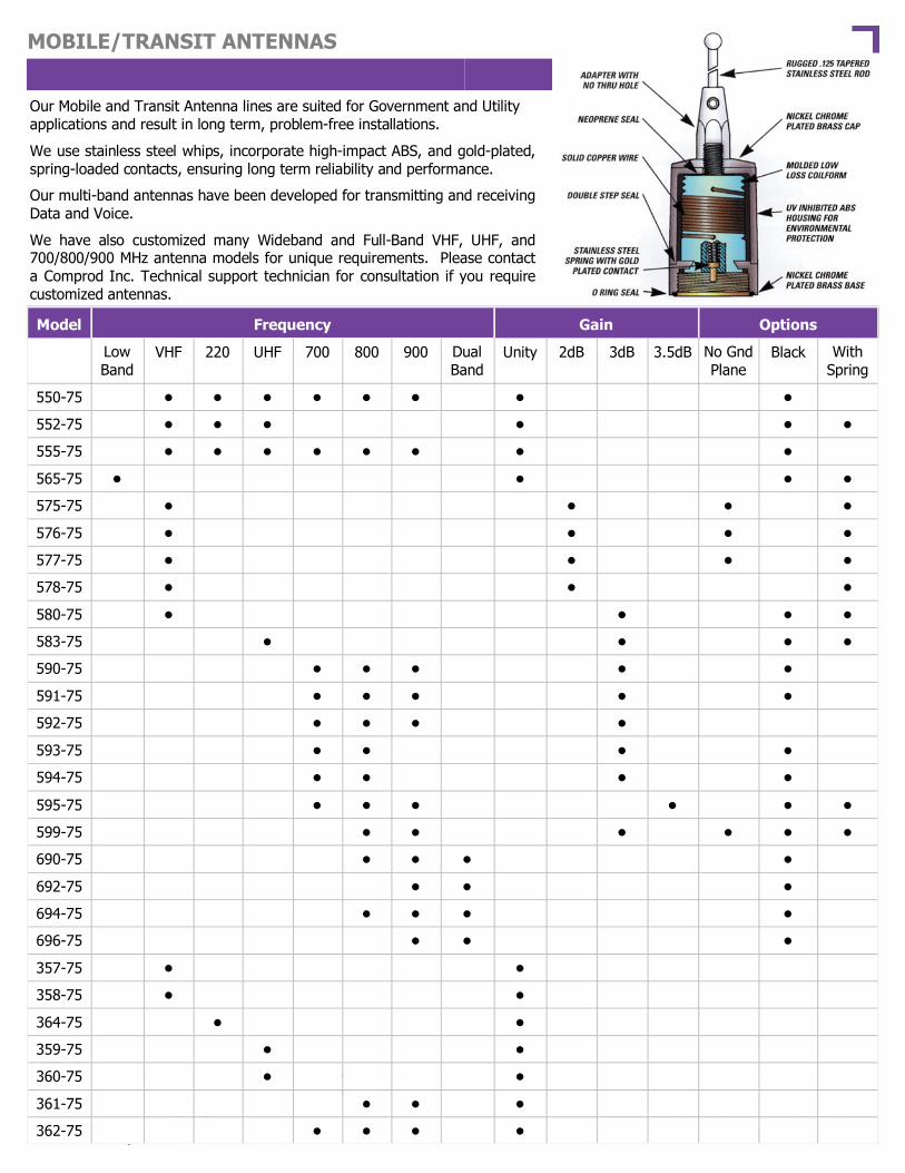
142
MOBILE/TRANSIT ANTENNAS
Our Mobile and Transit Antenna lines are suited for Government and Utility applications and result in long term, problem-free installations.
We use stainless steel whips, incorporate high-impact ABS, and gold-plated, spring-loaded contacts, ensuring long term reliability and performance.
Our multi-band antennas have been developed for transmitting and receiving Data and Voice.
We have also customized many Wideband and Full-Band VHF, UHF, and 700/800/900 MHz antenna models for unique requirements. Please contact a Comprod Inc. Technical support technician for consultation if you require customized antennas.
NGP is “No Ground Plane”
Model Frequency Gain Options
Low Band
VHF 220 UHF 700 800 900 Dual Band
Unity 2dB 3dB 3.5dB No Gnd Plane
Black With Spring
550-75 • • • • • • • •
552-75 • • • • • •
555-75 • • • • • • • •
565-75 • • • •
575-75 • • • •
576-75 • • • •
577-75 • • • •
578-75 • • •
580-75 • • • •
583-75 • • • •
590-75 • • • • •
591-75 • • • • •
592-75 • • • •
593-75 • • • •
594-75 • • • •
595-75 • • • • • •
599-75 • • • • • •
690-75 • • • •
692-75 • • •
694-75 • • • •
696-75 • • •
357-75 • •
358-75 • •
359-75 • •
360-75 • •
361-75 • • •
362-75 • • • •
364-75 • •

143
MOBILE/TRANSIT ANTENNAS
1/4 WAVE BROADBAND 132-512 MHz
Electrical Specifications
Frequency Range, MHz 132-512
Gain, dBd Unity
Impedance, Ohms 50
Power Rating, Watts 150
Bandwidth / VSWR VHF - 24MHz @ 2.0:1, UHF - 100MHz @ 2.0:1
552-75 Series
Performance: These antennas provide unity gain in a broadband design for extra heavy-duty service.
Stylish and Durable: These antennas are manufactured using the best corrosion resistant materials and finishes available. They come with an integrated shock spring and a heavy-duty stainless steel whip that is designed to withstand severe shock.
Reliable: The ABS base has an ultrasonically welded brass insert and a gold-plated spring-loaded contact.
Broadband: This antenna provides 24 MHz of bandwidth using VHF frequencies and 100 MHz of bandwidth at UHF frequencies.
Standard Mounting: All base loaded antennas mate with the standard Motorola C, M type mount .
Ordering Information
Description Model
Chrome finish, triple-plated chrome 552-75A
Black finish 552-75B
Mechanical Specifications
Radiator: Chrome A Tapered S.S. whip., 0.125 dia.
Black B Tapered S.S. whip., 0.10 dia.
Base Ultrasonic brass insert
Contact Spring-loaded, gold-plated
Length, in (mm) 21.5 (55) at 138MHz
Mounting Motorola C, M type

144
MOBILE/TRANSIT ANTENNAS 1/4 WAVE / VHF—UHF—TRUNKING 136-960 MHz
550-75 Series Performance: These antennas provide unity gain in a wideband design for heavy-duty service. Stylish and Durable: These antennas are manufactured using the best corrosion resistant materials and finishes available. Triple-plated chrome or black finishes are available. Reliable: The ABS base has an ultrasonically welded brass insert and a gold-plated spring-loaded contact. Versatile: They are shipped with a 19” whip that can be cut by the customer to any frequency between 136 MHz and 960 MHz according to a cutting chart that is provided. They can also be supplied cut and tested to a specific frequency, at no extra charge. Standard Mounting: These antennas mate with the standard Motorola NMO type mount, providing an excellent moisture seal even when the antenna is removed.
Electrical Specifications
Frequency Range, MHz 136-960
Gain, dBd Unity
Impedance, Ohms 50
Power Rating, Watts 150
Bandwidth/VSWR VHF - 12MHz @ 2.0:1
UHF - 50MHz @ 2.0:1
Ordering Information
Description Model
Chrome finish, triple-plated chrome 550-75A
Black finish 550-75B
Mechanical Specifications
Radiator S.S.
Base ABS, Ultrasonic brass insert
Contact Spring-loaded contact
Length, in 19 maximum
Mounting Std. Motorola C, M type

145
MOBILE/TRANSIT ANTENNAS
ECONOMICAL 132-960 MHz
555-75 Series Performance: These antennas provide unity gain in a wideband design for heavy-duty ser-vice. Stylish and Durable: These antennas are manufactured using the best corrosion resistant materials and finishes available. Triple-plated chrome or black finishes are available. Reliable: The ABS base has an ultrasonically welded brass insert and a gold-plated spring-loaded contact. Versatile: They are shipped with a factory tuned whip cut to size based on the customer specified frequency range between 136 MHz and 960 MHz. Standard Mounting: These antennas mate with the standard Motorola NMO type mount, providing an excellent moisture seal even when the antenna is removed.
Electrical Specifications
Frequency Range, MHz 132-960
Gain, dBd Unity
Impedance, Ohms 50
Power Rating, Watts 200
Bandwidth/VSWR VHF - 12MHz @ 2.0:1
UHF - 50MHz @ 2.0:1
VSWR 1.5:1
Ordering Information
Description Model
Chrome finish, triple-plated chrome 555-75A
Black finish 555-75B
Mechanical Specifications
Radiator: Chrome A Tapered S.S., 0.10 dia.
Black B Tapered S.S., 0.10 dia.
Base ABS
Length, in 20 maximum
Mounting Std. Motorola C, M type

146
MOBILE/TRANSIT ANTENNAS
LOW BAND 27-54 MHz
565-75 Series Performance: Unity gain, base loaded antenna with a power handling ca-pacity of 200 Watts.
Stylish and Durable: These antennas are manufactured using the best corrosion resistant materials and finishes available. The base is triple-plated chrome brass with a large insert, molded low loss coil form and a spring-loaded gold-plated contact.
Broadband: The large diameter coil form used in the construction of the loading coil allows for a wider operational bandwidth and better matching characteristics.
Weatherproof: O-ring seals and overlap construction keeps moisture out of the antenna.
Standard Mounting: These antennas mate with the standard Motorola NMO type mount, providing an excellent moisture seal even when the antenna is removed.
Electrical Specifications
Frequency Range, MHz 27-54
Gain, dBd Unity
Impedance, Ohms 50
Power Rating, Watts 200
VSWR 1.5:1
Bandwidth 2% of center freq.
Ordering Information
Frequency Chrome Black
27-31 MHz 565-75A-1 565-75B-1
30-35 MHz 565-75A-2 565-75B-2
34-40 MHz 565-75A-3 565-75B-3
40-47 MHz 565-75A-4 565-75B-4
47-54 MHz 565-75A-5 565-75B-5
Mechanical Specifications
Radiator: Chrome A Tapered S.S., 0.125 dia.
Black B Tapered S.S., 0.10 dia.
Base ABS, spring-loaded contact
Length, in 52 Maximum
Mounting Std. Motorola C, M type

147
MOBILE/TRANSIT ANTENNAS VHF WIDEBAND / 2 dBd 138-174 MHz
575-75 Series - No Ground Plane A na
This broadband 1/2-wave antenna provides 2.0 dBd of gain over its operating bandwidth. No ground plane is needed for this antenna. Stylish and durable: The antennas are manufactured using the best corrosion resistant mate-rials and finishes available. The base is triple-plated chrome brass with a large insert, molded low loss coil form and a spring-loaded, gold-plated contact. Weatherproof: O-ring seals or Rubber boot option keeps moisture out of the antenna base. Rubber boot avoids scratching/rusting of vehicle if antenna is frequently removed, for maintenance or car wash activities. Standard All base loaded antennas mate with the standard Motorola NMO type mount.
Electrical Specifications
Frequency Range, MHz 138-174
Gain, dBd 2.0
Impedance, Ohms 50
Power Rating, Watts 75
Bandwidth/VSWR VHF - 26MHz @ 2.0:1
Ordering Information
Description Model
Antenna Chrome finish 575-75
With shock spring 575-75S
With shock spring and rubber boot 575-75SR
Antenna with rubber boot 575-75R
Mechanical Specifications
Radiator 17-7 PH S.S.
Base ABS, spring-loaded contact
Length, in 52 maximum
Mounting Standard Motorola type 3/4

148
MOBILE/TRANSIT ANTENNAS VHF WIDEBAND / 2 dBd 148-174 MHz
576-75 Series - No Ground Plane A na
This broadband 1/2-wave antenna provides 2.0 dBd of gain over its operating bandwidth. No ground plane is needed for this antenna. Stylish and durable: The antennas are manufactured using the best corrosion resistant mate-rials and finishes available. The base is triple-plated chrome brass with a large insert, molded low loss coil form and a spring-loaded, gold-plated contact. Weatherproof: O-ring seals or Rubber boot option keeps moisture out of the antenna base. Rubber boot avoids scratching/rusting of vehicle if antenna is frequently removed, for maintenance or car wash activities Standard All base loaded antennas mate with the standard Motorola NMO type mount.
Electrical Specifications
Frequency Range, MHz 148-174
Gain, dBd 2.0
Impedance, Ohms 50
Power Rating, Watts 150
Bandwidth/VSWR VHF - 26MHz @ 1.5:1
Ordering Information
Description Model
Antenna Chrome finish 576-75
Antenna with rubber boot 576-75R
With shock spring 576-75S
With shock spring and rubber boot 576-75SR
Mechanical Specifications
Radiator 17-7 PH S.S.
Base ABS, spring-loaded contact
Length, in 52 maximum
Mounting Standard Motorola NMO type

149
MOBILE/TRANSIT ANTENNAS VHF WIDEBAND / 2 dBd 136-174 MHz
577-75 Series - No Ground Plane A na
This broadband 1/2-wave antenna provides 2.0 dBd of gain over its operating bandwidth. No ground plane is needed for this antenna. Stylish and durable: The antennas are manufactured using the best corrosion resistant ma-terials and finishes available. The base is triple-plated chrome brass with a large insert, molded low loss coil form and a spring-loaded, gold-plated contact. Weatherproof: O-ring seals or Rubber boot option keeps moisture out of the antenna base. Rubber boot avoids scratching/rusting of vehicle if antenna is frequently removed, for maintenance or car wash activities. Standard All base loaded antennas mate with the standard Motorola C, M type mount.
Electrical Specifications
Frequency Range, MHz 136-174
Gain, dBd 2.0
Impedance, Ohms 50
Power Rating, Watts 75
Bandwidth/VSWR VHF - 11MHz @ 1.5:1, 19MHz @ 2.0:1
Ordering Information
Description Standard Model With Spring
Antenna Chrome finish 577-75 577-75S
Antenna with rubber boot 577-75R 577-75SR
Mechanical Specifications
Radiator 17-7 PH S.S.
Base ABS, spring-loaded contact
Length, in 52 maximum
Mounting Standard Motorola C, M type

150
MOBILE/TRANSIT ANTENNAS VHF WIDEBAND / 2 dBd 138-174 MHz
578-75 Performance: This broadband 1/2-wave antenna provides 2.0 dBd of gain over its operating bandwidth. Stylish and Durable: The antennas are manufactured using the best corrosion resistant materials and finishes available. The base is triple-plated chrome brass with a large insert molded low loss coil form and a spring-loaded, gold-plated contact. Weatherproof: O-ring seals or Rubber boot option keeps moisture out of the antenna base. Rubber boot avoids scratching/rusting of vehicle if antenna is frequently removed, for maintenance or car wash activities. Standard Mounting: All base loaded antennas mate with the standard TAD / NMO type mount.
Electrical Specifications
Frequency Range, MHz 138-174
Gain, dBd 2.0
Impedance, Ohms 50
Power Rating, Watts 100
Bandwidth/VSWR 40MHz, 1.8:1
Ordering Information
Description Standard Model
Antenna Chrome finish 578-75
With Spring Mount
578-75S
Antenna with rubber boot 578-75R 578-75SR
Mechanical Specifications
Radiator S.S.
Base ABS, spring-loaded contact
Length, in 36.5
Mounting Standard Motorola NMO

151
MOBILE/TRANSIT ANTENNAS VHF / 3 dBd 132-174 MHz
3 dBd gain is achieved with these premium antennas by featuring a 5/8-wave whip with a base loaded matching coil.
Stylish and durable: The antennas are manufactured using the best corrosion resistant materials and finishes available. The base is triple-plated chrome brass with a large insert molded low loss coil form and a spring-loaded, gold-plated contact.
O-ring seals and overlap construction keeps moisture out of
the antenna.
Standard All base loaded antennas mate with the standard Motorola NMO type mount.
Electrical Specifications
Frequency Range, MHz 132-174
Gain, dBd 3.0
Impedance, Ohms 50
Power Rating, Watts 200
VSWR 1.5:1
Bandwidth, MHz 6
Ordering Information
Description Model With Spring
Chrome finish, triple-plated chrome 580-75A 580-75AS
Black finish 580-75B 580-75BS
Mechanical Specifications
Radiator: Chrome A Tapered S.S. whip., 0.125 dia.
Black B Tapered S.S. whip., 0.10 dia.
Length, in 55 whip
Mounting Standard Motorola NMO type
Base ABS, spring-loaded contact

152
MOBILE/TRANSIT ANTENNAS UHF / 3 dBd 406-512 MHz
Electrical Specifications
Frequency Range, MHz 406-512
Gain, dBd 3.0
Impedance, Ohms 50
Power Rating, Watts 200
Bandwidth at 1.5:1 VSWR, MHz 20
3 dBd gain is achieved with these premium antennas by featuring a 5/8-wave whip with a base loaded matching coil.
Stylish and durable: The antennas are manufactured using the best corrosion resistant materials and finishes available. The base is triple-plated chrome brass with a large insert molded low loss coil form and a spring-loaded, gold-plated con-tact.
Broadband: The large diameter coil form used in the construction of the loading coil allows for a wider operational bandwidth and better matching characteristics.
Weatherproof: O-ring seals or Rubber boot option keeps moisture out of the an-tenna base. Rubber boot avoids scratching/rusting of vehicle if antenna is fre-quently removed, for maintenance or car wash activities.
Standard All base loaded antennas mate with the standard Motorola NMO type mount.
Ordering Information
Frequency Chrome Black
406-430MHz 583-75A-1 583-75B-1
430-450MHz 583-75B-2 583-75A-2
450-470MHz 583-75A-3 583-75B-3
470-490MHz 583-75A-4 583-75B-4
490-512MHz 583-75A-5 583-75B-5
Chrome and Rubber Boot
583-75AR-1
583-75AR-2
583-75AR-3
583-75AR-4
583-75AR-5
Black and Rubber Boot
583-75BR-1
583-75BR-2
583-75BR-3
583-75BR-4
583-75BR-5
Chrome and Spring
583-75AS-1
583-75AS-2
583-75AS-3
583-75AS-4
583-75AS-5
Black and Spring
583-75BS-1
583-75BS-2
583-75BS-3
583-75BS-4
583-75BS-5
Mechanical Specifications
Radiator: Chrome A S.S. whip. 0.10 dia.
Black B S.S. whip. 0.10 dia.
Length, in 21 whip
Mounting Standard Motorola NMO type
Base ABS, spring-loaded contact
583-75 Series
To order with shock spring, and rubber boot add suffix SR to part number. Example: 583-75ASR-3.

153
MOBILE/TRANSIT ANTENNAS CELLULAR—TRUNKING / 3 dBd 760-960 MHz
3 dBd gain is achieved with these premium antennas by featuring a 5/8 wave antenna above a 1/4 wave antenna design.
Stylish and durable: These antennas are manufactured using the best corrosion resistant materials and finishes available. Triple-plated chrome or black finishes available.
The ABS base has an ultrasonically welded brass insert and a leaf spring-loaded contact for long term reliability.
These antennas mate with the standard Motorola NMO type mount, provid-
ing an excellent moisture seal even when the antenna is removed.
Electrical Specifications
Frequency Range, MHz 760-960
Gain, dBd 3.0
Impedance, Ohms 50
Power Rating, Watts 200
Bandwidth at 2.0:1 VSWR, MHz 70
Ordering Information
Frequency Chrome Black
806-866MHz 590-75A-1 590-75B-1
825-896MHz 590-75A-2 590-75B-2
896-960MHz 590-75A-3 590-75B-3
746-806MHz 590-75A-4 590-75B-4
Mechanical Specifications
Radiator: Chrome A S.S.
Black B S.S.
Base ABS, Ultrasonic brass insert
Length, in 14 maximum
Mounting Standard Motorola NMO type
Contact Spring-loaded, gold-plated
590-75 Series

154
MOBILE/TRANSIT ANTENNAS CELLULAR—TRUNKING / LOW COST 760-960 MHz
3 dBd gain is achieved with these premium antennas by featuring a 5/8 wave antenna above a 1/4 wave antenna with an open coil design.
Stylish and durable: These antennas are manufactured using the best corrosion re-sistant materials and finishes available. Triple-plated chrome or black finishes available.
The ABS base has an ultrasonically welded brass insert and a leaf spring-loaded con-tact for long term reliability.
These antennas made with the standard Motorola NMO type mount,
providing an excellent moisture seal even when the antenna is removed.
Electrical Specifications
Frequency Range, MHz 760-960
Gain, dBd 3.0
Impedance, Ohms 50
Power Rating, Watts 200
Bandwidth at 2.0:1 VSWR, MHz 70
Ordering Information
Frequency Chrome Black
806-866MHz 591-75A-1 591-75B-1
825-896MHz 591-75A-2 591-75B-2
896-960MHz 591-75A-3 591-75B-3
746-806MHz 591-75A-4 591-75B-4
Mechanical Specifications
Radiator: Chrome A S.S. whip, 0.10 dia.
Black B S.S. whip, 0.10 dia.
Base Leaf Design
Length, in 15 maximum
Mounting Standard Motorola NMO type
591-75 Series

155
MOBILE/TRANSIT ANTENNAS CELLULAR—TRUNKING / 3 dBd CLOSED COIL 760-960 MHz
3.0 dBd gain is achieved with these premium antennas by featuring a 5/8 wave antenna above a 1/2 wave antenna with a closed coil design.
Stylish and durable: These antennas are manufactured using the best corrosion re-sistant materials and finishes available. Triple-plated chrome or black finishes available.
The ABS base has an ultrasonically welded brass insert and a leaf spring-loaded con-tact for long term reliability.
These antennas mate with the standard Motorola NMO type mount,
providing an excellent moisture seal even when the antenna is removed.
Electrical Specifications
Frequency Range, MHz 760-960
Gain, dBd 3.0
Impedance, Ohms 50
Power Rating, Watts 200
Bandwidth at 2.0:1 VSWR, MHz 70
Ordering Information
Frequency Chrome Black
806-866MHz 592-75A-1 592-75B-1
825-896MHz 592-75A-2 592-75B-2
896-960MHz 592-75A-3 592-75B-3
746-806MHz 592-75A-4 592-75B-4
Mechanical Specifications
Radiator: Chrome A S.S.
Black B S.S.
Base ABS, Ultrasonic brass insert
Length, in 16 maximum
Mounting Standard Motorola NMO type
Contact Spring-loaded, gold-plated
592-75 Series
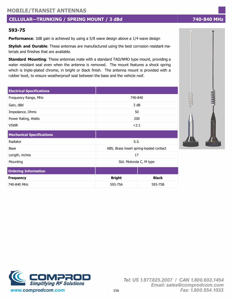
156
MOBILE/TRANSIT ANTENNAS
CELLULAR—TRUNKING / SPRING MOUNT / 3 dBd 740-840 MHz
593-75
Performance: 3dB gain is achieved by using a 5/8 wave design above a 1/4 wave design
Stylish and Durable: These antennas are manufactured using the best corrosion resistant ma-terials and finishes that are available.
Standard Mounting: These antennas mate with a standard TAD/NMO type mount, providing a water resistant seal even when the antenna is removed. The mount features a shock spring which is triple-plated chrome, in bright or black finish. The antenna mount is provided with a rubber boot, to ensure weatherproof seal between the base and the vehicle roof.
Electrical Specifications
Frequency Range, MHz 740-840
Gain, dBd 3 dB
Impedance, Ohms 50
Power Rating, Watts 200
VSWR <2:1
Ordering Information
Frequency Bright Black
740-840 MHz 593-75A 593-75B
Mechanical Specifications
Radiator S.S.
Base ABS, Brass insert spring-loaded contact
Length, inches 17
Mounting Std. Motorola C, M type

157
MOBILE/TRANSIT ANTENNAS
CELLULAR—TRUNKING / MAG MOUNT, 3 dBd Gain 700-850 MHz
594-75
Performance: 3dB gain is achieved by using a 5/8 wave design above a 1/4 wave design
Stylish and Durable: These antennas are manufactured using the best corrosion resistant ma-terials and finishes that are available.
Magnetic Mounting: Features a powerful magnetic base with a protective Mylar to prevent damage to any mounting service. It is supplied with 12 feet of RG58U coax and your choice of connector. Available with Mini-UHF or TNC connector.
Electrical Specifications
Frequency Range, MHz 700-850
Gain, dBd 3 dB
Impedance, Ohms 50
Power Rating, Watts 200
VSWR <2:1
Ordering Information
Frequency Brite Black
700-850 MHz 594-75A 594-75B
Mechanical Specifications
Radiator S.S.
Base ABS, Gold-plated spring-loaded contact
Length, inches 16
Mounting Mini-UHF or TNC connector on 12’ cable,

158
MOBILE/TRANSIT ANTENNAS
CELLULAR—TRUNKING / 3.5 dBd CLOSED COIL 760-970 MHz
3.5 dBd gain is achieved with these premium antennas by featuring a 5/8 wave antenna above a 1/4 wave antenna design.
Stylish and durable: These antennas are manufactured using the best corrosion resistant ma-terials and finishes available. It comes with an integrated shock spring and a heavy-duty stainless steel whip that is designed to withstand severe shock without suffering permanent damage. It is available in triple-plated chrome or black finish.
The ABS base has an ultrasonically welded brass insert and a gold-plated, spring-loaded contact. The silver plated matching coil is fully enclosed to ensure years of dependable service.
O-ring seals and overlap construction keeps moisture out of the antenna.
Standard All base loaded antennas mate with the standard Motorola NMO type connector.
Electrical Specifications
Frequency Range, MHz 760-970
Gain, dBd 3.5
Impedance, Ohms 50
Power Rating, Watts 200
Bandwidth at 2.0:1VSWR, MHz 70
Ordering Information
Frequency Chrome Black
746-806MHz 595-75A-4 595-75B-4
806-866MHz 595-75A-1 595-75B-1
825-896MHz 595-75A-2 595-75B-2
896-970MHz 595-75A-3 595-75B-3
Mechanical Specifications
Radiator: Chrome A S.S.
Black B S.S.
Base ABS, spring-loaded contact
Length, in 18 maximum
Mounting Standard Motorola NMO type
Contact Gold-plated, spring-loaded
Matching coil Silver plated enclosed coil
595-75 Series

159
MOBILE/TRANSIT ANTENNAS
ELEVATED FEED / 3 dBd 806-960 MHz
3 dBd gain is achieved with these premium antennas by featuring a 5/8 wave antenna above a 1/4 wave antenna design with an elevated feed point. This antenna requires no ground plane as a result of its collinear design. The elevated feed design is ideal for the antenna RF signal to clear any nearby obstructions.
The elevated feed-point design keeps the RF signals above and away from the passenger compartment.
This elegant black antenna gives a sleek appearance that blends well with the exterior
treatments of most late model vehicles.
The 599-75 antenna features a built in shock spring and a spring-loaded contact for long term dependability.
Standard These antennas mate with the standard NMO type mount, providing an excellent moisture seal even when the antenna is removed.
Electrical Specifications
Frequency Range, MHz 806-960
Gain, dBd 3.0
Impedance, Ohms 50
Power Rating, Watts 200
Bandwidth at 2.0:1VSWR, MHz 70
Ordering Information
Frequency Black finish
806-866MHz 599-75-1
825-896MHz 599-75-2
896-960MHz 599-75-3
Mechanical Specifications
Radiator Black S.S.
Base Open coil
Contact Solid brass base
Mounting Standard Motorola NMO type
Finish Black
Length, in 23 maximum

160
MOBILE/TRANSIT ANTENNAS
DUAL BAND ANTENNAS 806-1970 MHz
Our premium dual band antennas feature heavy-duty design and excellent performance. Perfect for both voice and data transmission. These antennas are very wide in bandwidth. Stylish and durable: These antennas are manufactured using the best corrosion resistant materials and finishes available. The antenna is low profile, extremely rugged and ideal for commercial applications.
O-ring seals and overlap construction keeps moisture out of
the antenna.
Standard All base loaded antennas mate with the standard Motorola NMO type mount.
Electrical Specifications
Frequency (Full Band) 806-940 / 1710-1970
Gain Unity
Impedance, Ohms 50
Power Rating, Watts 200
Bandwidth at 2.0:1 VSWR, MHz Full Band
Mechanical Specifications
Radiator S.S.
Base ABS, Ultrasonic Brass Insert
Contact Gold-plated spring-loaded
Mounting Standard Motorola NMO type
Finish Black
Length, in 4
Ordering Information 690-75
690-75

161
MOBILE/TRANSIT ANTENNAS
DUAL BAND ANTENNAS 900-2500 MHz
Our premium dual band antennas feature heavy-duty design and excellent performance. Perfect for both voice and data transmission. These antennas are very wide in bandwidth. Stylish and durable: These antennas are manufactured using the best corrosion resistant materials and finishes available. The antenna is low profile, extremely rugged and ideal for commercial applications.
O-ring seals and overlap construction keeps moisture out of the
antenna.
Standard All base loaded antennas mate with the standard Motorola NMO type mount.
Electrical Specifications
Frequency (Full Band) 900-930 / 2400-2500 900-930 / 2400-2500
Gain, dBd 2.0 2.0
Impedance, Ohms 50 50
Power Rating, Watts 250 250
Bandwidth at 2.0:1 VSWR, MHz Full Band Full Band
Mechanical Specifications
Base ABS ABS
Contact Gold-plated spring-loaded Gold-plated spring-loaded
Length, in 3 3
Mounting Standard Motorola NMO type Standard Motorola NMO type
Finish White Black
Ordering Information 692-75W 692-75B
692-75 Series

162
MOBILE/TRANSIT ANTENNAS
DUAL BAND ANTENNAS 806-2000 MHz
Our premium dual band antennas feature heavy-duty design and excellent performance. Perfect for both voice and data transmission. These antennas are very wide in bandwidth. Stylish and durable: These antennas are manufactured using the best corrosion resistant materials and finishes available. The antenna is low profile, extremely rugged and ideal for commercial applications.
O-ring seals and overlap construction keeps moisture out of
the antenna.
Standard All base loaded antennas mate with the standard Motorola NMO type mount.
Electrical Specifications
Frequency (Full Band) 806-960 / 1850-1990
Gain, dBd 2.0
Impedance, Ohms 50
Power Rating, Watts 250
Bandwidth at 2.0:1VSWR, MHz Full Band
Mechanical Specifications
Base ABS
Contact Gold-plated spring-loaded
Length, in 4
Mounting Standard Motorola NMO type
Finish White
Ordering Information 694-75W
ABS
Gold-plated spring-loaded
4
Standard Motorola NMO type
Black
694-75B
694-75 Series

163
MOBILE/TRANSIT ANTENNAS
DUAL BAND ANTENNAS 880-2800 MHz
Our premium dual band antennas feature heavy-duty design and excellent performance. Perfect for both voice and data transmission. These antennas are very wide in bandwidth. Stylish and durable: These antennas are manufactured using the best corrosion resistant materials and finishes available. The antenna is low profile, extremely rugged and ideal for commercial applications.
O-ring seals and overlap construction keeps moisture out of
the antenna.
Standard All base loaded antennas mate with the standard Motorola NMO type mount.
Electrical Specifications
Frequency (Full Band) 880-1200 / 2300-2600 1100-1500 / 2400-2800
Gain Unity Unity
Impedance, Ohms 50 50
Power Rating, Watts 200 200
Bandwidth at 2.0:1VSWR, MHz Full Band Full Band
Mechanical Specifications
Radiator Polyester Coated Brass Polyester Coated Brass
Base ABS, Ultrasonic, Brass insert ABS, Ultrasonic, Brass insert
Contact Gold-plated spring-loaded Gold-plated spring-loaded
Length, in 2.75 2.75
Mounting Standard Motorola NMO type Standard Motorola NMO type
Finish Black Black
Ordering Information 696-75B 696-75-1B
696-75 Series

164
MOBILE/TRANSIT ANTENNAS
MOBILE ANTENNAS / ACCESSORIES
MMM MMNMO BSMN
547-75 MGAS 545-75
Whip Adapter—Chrome
Whip Adapter—Black
TMBM
548-75
Battery Tap A1001A
412-75 Stainless Steel Trunk Groove Mounting Bracket (3/8" hole)
412M-75 Stainless Steel Trunk Groove Mounting Bracket (3/4" hole)
435-75 Rubber Hole Plug / 3/8" Hole Diameter
451-75 Universal Base Mount
453-75 Straight Whip (24" Length) + 5/16 - 24 Thread Adapter
455-75 Unity Gain Whip and Base (451-75 + 453-75)
456-75 Cable Kit / 15ft of RG-58U + PL-259 + UG-175U
545-75 Magnet Mount Kit, Motorola Base, 12 ft. RG58A/U, PL-259
546-75 Magnet Mount Kit, 5/16" Stud Mount, 12 ft. RG58A/U, PL-259
547-75 Trunk Mount Kit, Motorola Base, 17 ft. RG58A/U, PL-259
548-75 Trunk Mount Kit, 5/16" Stud Mount, 17 ft. RG58A/U, PL-259
551-75 C-Mount (3/8"-3/4") c/w 17 ft.RG58A/U, PL-259
634-75 Rubber Hole Plug 7/8" Hole Diameter
MMNMO Mirror Mount Kit, Motorola Base, 12 ft. RG-58A/U, PL-259
BSMN Mirror Mount, Motorola Base, UHF Connector
WAB Whip Adapter, Black
WAC Whip Adapter, Chrome
A1001A Battery Tap (5 Individually packed)
MOBILE ANTENNAS / ACCESSORIES / ADAPTERS
TMBM Trunk Mount Stainless Steel
MGLAS 546-75

165
MOBILE/TRANSIT ANTENNAS
MOBILE ANTENNAS / ACCESSORIES
UTBM
UTBM-UHF
UTBM-NM
UTCR
UNIBKT
BSMO-150
BSMO-450
BSMO-800
Mount Terminates as Mini-UHF.
Mount Terminates as UHF.
Mount Terminates as N Female.
Celling Mounts Terminates as Mini-UHF.
Mobile-to-base adapter only, includes hose clamps.
VHF mobile-to-base adapter w/artificial ground plane, N Female connector.
UHF mobile-to-base adapter w/artificial ground plane, N Female connector.
800-900 mobile-to-base adapter w/artificial ground plane, N Female connector.
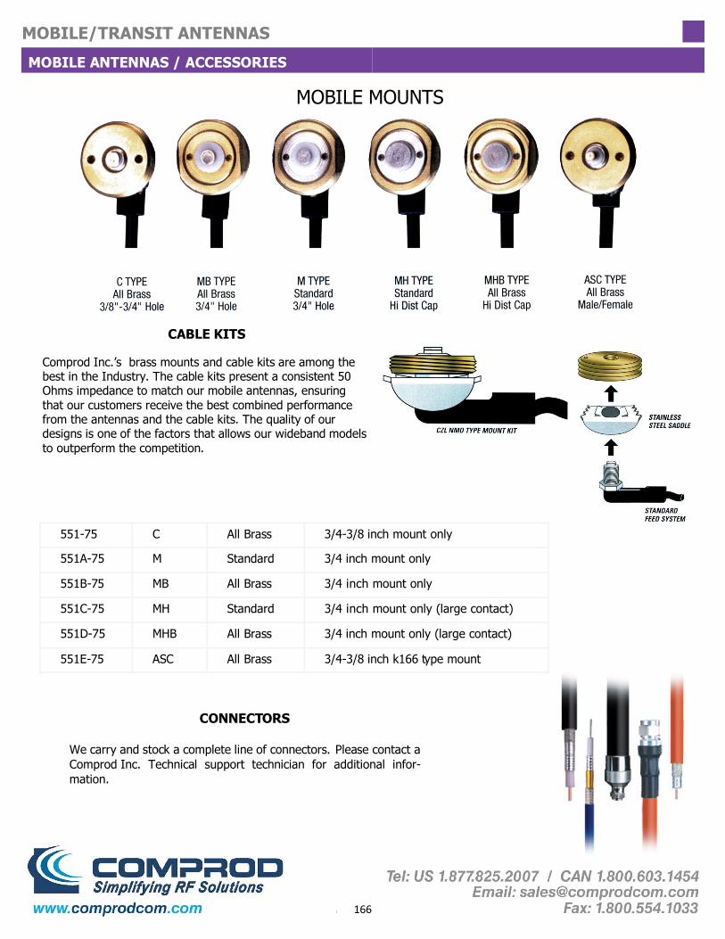
166
MOBILE/TRANSIT ANTENNAS
MOBILE ANTENNAS / ACCESSORIES
MOBILE MOUNTS
CABLE KITS
Comprod Inc.’s brass mounts and cable kits are among the best in the Industry. The cable kits present a consistent 50 Ohms impedance to match our mobile antennas, ensuring that our customers receive the best combined performance from the antennas and the cable kits. The quality of our designs is one of the factors that allows our wideband models to outperform the competition.
551-75 C All Brass 3/4-3/8 inch mount only
551A-75 M Standard 3/4 inch mount only
551B-75 MB All Brass 3/4 inch mount only
551C-75 MH Standard 3/4 inch mount only (large contact)
551D-75 MHB All Brass 3/4 inch mount only (large contact)
551E-75 ASC All Brass 3/4-3/8 inch k166 type mount
CONNECTORS
We carry and stock a complete line of connectors. Please contact a Comprod Inc. Technical support technician for additional infor-mation.
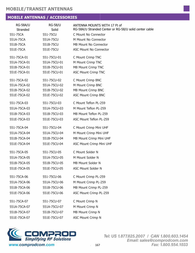
167
MOBILE/TRANSIT ANTENNAS
MOBILE ANTENNAS / ACCESSORIES
RG-58A/U Stranded
RG-58/U Solid
ANTENNA MOUNTS WITH 17 Ft of RG-58A/U Stranded Center or RG-58/U solid center cable
551-75CA 551-75CU C Mount No Connector 551A-75CA 551A-75CU M Mount No Connector 551B-75CA 551B-75CU MB Mount No Connector 551E-75CA 551E-75CU ASC Mount No Connector
551-75CA-01 551-75CU-01 C Mount Crimp TNC 551A-75CA-01 551A-75CU-01 M Mount Crimp TNC 551B-75CA-01 551B-75CU-01 MB Mount Crimp TNC 551E-75CA-01 551E-75CU-01 ASC Mount Crimp TNC
551-75CA-02 551-75CU-02 C Mount Crimp BNC 551A-75CA-02 551A-75CU-02 M Mount Crimp BNC 551B-75CA-02 551B-75CU-02 MB Mount Crimp BNC 551E-75CA-02 551E-75CU-02 ASC Mount Crimp BNC
551-75CA-03 551-75CU-03 C Mount Teflon PL-259
551A-75CA-03 551A-75CU-03 M Mount Teflon PL-259
551B-75CA-03 551B-75CU-03 MB Mount Teflon PL-259
551E-75CA-03 551E-75CU-03 ASC Mount Teflon PL-259
551-75CA-04 551-75CU-04 C Mount Crimp Mini UHF
551A-75CA-04 551A-75CU-04 M Mount Crimp Mini UHF
551B-75CA-04 551B-75CU-04 MB Mount Crimp Mini UHF
551E-75CA-04 551E-75CU-04 ASC Mount Crimp Mini UHF
551-75CA-05 551-75CU-05 C Mount Solder N
551A-75CA-05 551A-75CU-05 M Mount Solder N
551B-75CA-05 551B-75CU-05 MB Mount Solder N
551E-75CA-05 551E-75CU-05 ASC Mount Solder N
551-75CA-06 551-75CU-06 C Mount Crimp PL-259
551A-75CA-06 551A-75CU-06 M Mount Crimp PL-259
551B-75CA-06 551B-75CU-06 MB Mount Crimp PL-259
551E-75CA-06 551E-75CU-06 ASC Mount Crimp PL-259
551-75CA-07 551-75CU-07 C Mount Crimp N
551A-75CA-07 551A-75CU-07 M Mount Crimp N
551B-75CA-07 551B-75CU-07 MB Mount Crimp N
551E-75CA-07 551E-75CU-07 ASC Mount Crimp N
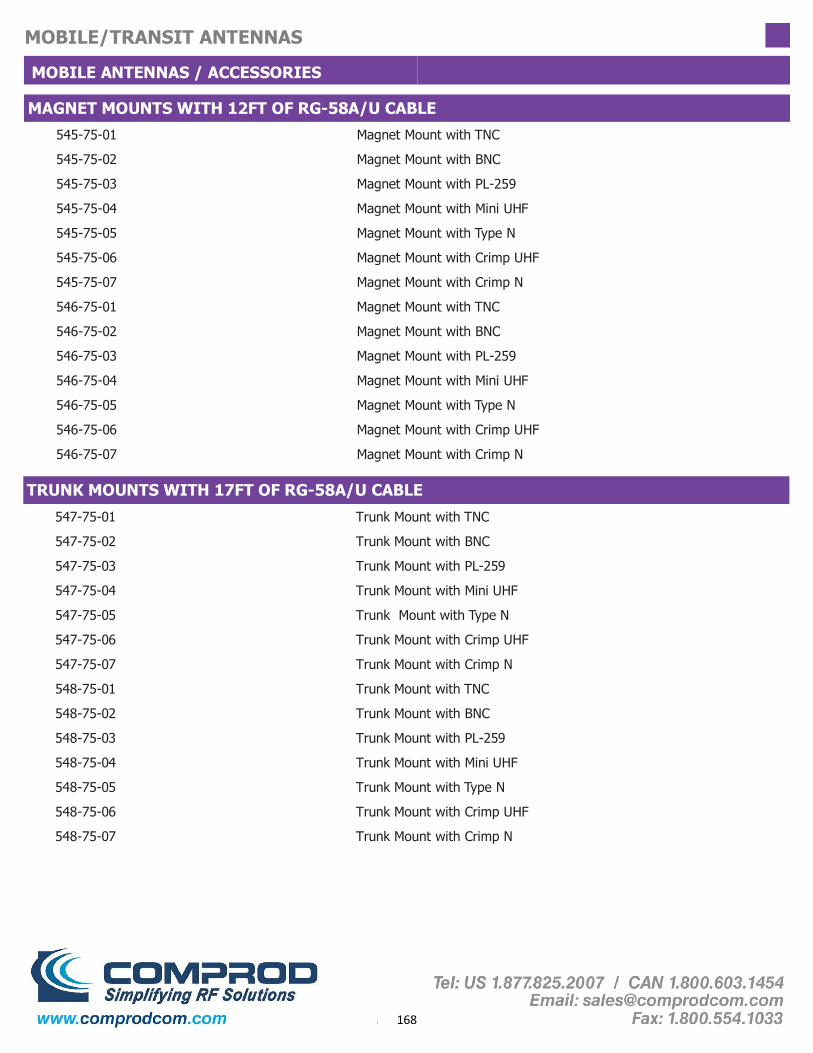
168
MOBILE/TRANSIT ANTENNAS
MOBILE ANTENNAS / ACCESSORIES
545-75-01 Magnet Mount with TNC
545-75-02 Magnet Mount with BNC
545-75-03 Magnet Mount with PL-259
545-75-04 Magnet Mount with Mini UHF
545-75-05 Magnet Mount with Type N
545-75-06 Magnet Mount with Crimp UHF
545-75-07 Magnet Mount with Crimp N
546-75-01 Magnet Mount with TNC
546-75-02 Magnet Mount with BNC
546-75-03 Magnet Mount with PL-259
546-75-04 Magnet Mount with Mini UHF
546-75-05 Magnet Mount with Type N
546-75-06 Magnet Mount with Crimp UHF
546-75-07 Magnet Mount with Crimp N
MAGNET MOUNTS WITH 12FT OF RG-58A/U CABLE
547-75-01 Trunk Mount with TNC
547-75-02 Trunk Mount with BNC
547-75-03 Trunk Mount with PL-259
547-75-04 Trunk Mount with Mini UHF
547-75-05 Trunk Mount with Type N
547-75-06 Trunk Mount with Crimp UHF
547-75-07 Trunk Mount with Crimp N
548-75-01 Trunk Mount with TNC
548-75-02 Trunk Mount with BNC
548-75-03 Trunk Mount with PL-259
548-75-04 Trunk Mount with Mini UHF
548-75-05 Trunk Mount with Type N
548-75-06 Trunk Mount with Crimp UHF
548-75-07 Trunk Mount with Crimp N
TRUNK MOUNTS WITH 17FT OF RG-58A/U CABLE

169
MOBILE/TRANSIT ANTENNAS
MOBILE ANTENNAS / ACCESSORIES
MOBILE ANTENNA PARTS
DBW Dual Band Whip 0.10
DBWB Dual Band Whip 0.10, Black
WPDB33 Dual Band Whip Assembly, 4 dB
WPDB33B Dual Band Whip Assembly, 4 dB, Black
QWP 20 inch Stainless Whip 0.10
QWPB 20 inch Stainless Whip 0.10, Black
WPBL125 52 inch Stainless Taper Whip 0.125
WPBL100 52 inch Stainless Taper Whip 0.10
WPBL100B 52 inch Stainless Taper Whip 0.10, Black
EFW Elevated Feed Whip Assembly
WP85A-X 3.5 dB Whip Assembly 800 MHz
WP85B-X 3.5 dB Whip Assembly 800 MHz, Black
WP855A-X 5 dB Whip Assembly 800 MHz
WP855B-X 5 dB Whip Assembly 800 MHz, Black
WP45A-X 3.5 dB Whip Assembly 450 MHz
WP45B-X 3.5 dB Whip Assembly 450 MHz, Black
WPBL45AX 5 dB Base Load Whip 450 MHz
WPBL45BX 5 dB Base Load Whip 450 MHz, Black
MOUNTING BRACKETS TMBC Stainless Trunk L 3/8 inch Hole (Chrome)
TMBM Stainless Trunk L 3/4 inch Hole (Chrome)
TMBCB Stainless Trunk L 3/8 inch Hole (Black)
TMBMB Stainless Trunk L 3/4 inch Hole (Black)
MMM Mirror Mount Bracket
MMCB Mirror Mount CB with 12 ft. of coax., PL-259
MMCM Mirror Bracket, C-Mount & 12 ft. Coax.
UNIVERSAL THICK BODY MOUNT
UTBM Mount Terminates as Mini-UHF, Maximum Thickness 5/8 inch
Order Cable Kits Separately

170
MOBILE/TRANSIT ANTENNAS
VHF / TRANSIT ANTENNAS 138-174, 215-225 MHz
Electrical Specifications
Nominal Gain Unity Unity
Maximum Power, Watts 150 150
Frequency Range, MHz 148-174 138-174
Bandwidth VSWR: 1.5:1, MHz 3.0 3.0
Bandwidth VSWR: 2.0:1. MHz 4.5 4.5
357-75-ABS 358-75
Nominal Impedance, Ohms 50 50
Radiation Pattern Omni Omni
Polarization Vertical Vertical
Radome Material High Impact ABS N/A
Connector UHF / BNC / N Female UHF / BNC / N Female
Height, in (mm) 4 (102) 4 (102)
Length, in (mm) 21 (533) 23-1/2 (597)
Width, in (mm) 3 (76) 2-1/8 (54)
Weight, lbs (kg) 2.1 (0.945) 6 (2.7)
Minimum Ground Plane Size, in (mm) 36 x 48 (914 x 1219) 36 x 48 (914 x 1219)
364-75
Unity
150
215-225
10
>10
50
Omni
Vertical
N/A
UHF / BNC / N Female
4 (102)
17 (432)
2 (51)
5 (2.27)
36 x 48 (914 x 1219)
Ordering information: Specify exact frequency, Specify connector type, UHF, BNC or N Female
357-75 358 -75
357-75, 358-75 and 364-75 The Comprod Inc.’s line of VHF transit antennas is a low profile rugged alternative to a 1/4 wave whip mobile antenna. When mounted on a horizontal surface, maximum radiation is omnidirectional and vertically polarized.
These antennas are an excellent choice for low clearance applications such as those found on trains, public transit vehicles, construction equipment and police vehicles.
The model 357-75-ABS is a folded 1/4 wavelength section of aluminum tube housed in an impact resistant ABS radome. To ensure a moisture proof installation, the model 357-75-ABS is supplied with a mounting gasket.
The model 358-75 and 364-75 are high strength cast aluminum designs. The antennas can be coated for additional protection against harsh environmental conditions. To ensure a moisture proof installation, the 358-75 and 364-75 are supplied with an O-ring.
358-75
357-75-ABS
364-75

171
MOBILE/TRANSIT ANTENNAS
UHF / TRANSIT ANTENNAS 406-512 MHz
359-75 and 360-75 The Comprod Inc.’s line of UHF transit antennas is a low profile rugged alternative to 1/4 wave whips. When mounted on a horizontal surface, maximum radiation is omnidirectional and vertically polarized.
These antennas are an excellent choice for low clearance applications such as those found on trains, public transit vehicles, construction equip-ment and police vehicles.
The model 359-75 is a high strength cast aluminum design. The antenna can be coated for additional protection against harsh environmental conditions. To ensure a moisture proof installation, the model 359-75 is supplied with an O-ring.
The model 360-75-ABS is a folded 1/4 wavelength section of aluminum tube housed in an impact resistant ABS radome. To ensure a moisture proof installation, the model 360-75-ABS is supplied with a mounting gasket.
Electrical Specifications 359-75 360-75-ABS
Nominal Gain Unity
Maximum Power, Watts 125 125
Frequency Range, MHz 406-512 406-512
Bandwidth VSWR: 1.5:1, MHz 18
Bandwidth VSWR: 2.0:1, MHz 27 40
Nominal Impedance, Ohms 50 50
Radiation Pattern Omnidirectional
Polarization Vertical
Radome Material N/A
Connector UHF / BNC / N Female UHF / BNC / N Female
Height, in (mm) 2-1/2 (64) 3 (76)
Length, in (mm) 8 (203) 11 (279)
Width, in (mm) 2 (51) 3-1/4 (83)
Weight, lbs (kg) 0.75 (0.338) 1 (0.45)
Minimum Ground Plane Size, in (mm) 20 x 16 (508 x 406) 20 x 16 (508 x 406)
Omnidirectional
Vertical
High Impact ABS
20
Unity
359-75
360-75-ABS
Ordering information:
- Specify center frequency - Specify connector type, UHF, BNC or N Female
360-75 359-75

172
MOBILE/TRANSIT ANTENNAS
800 MHz TRANSIT ANTENNAS 760-960 MHz
361-75 and 362-75 The Comprod Inc.’s line of radome transit antennas for operation in the 806-960 MHz band consists of compact, low profile antennas in weatherproof ABS radomes. When mounted on a horizontal surface, maximum radiation is omnidirectional and vertically polarized.
These antennas are an excellent choice for low clearance applications such as those found on trains, mass transit vehicles, construction equipment and po-lice and emergency vehicles.
The 361-75-ABS model is a space diversity design that provides greater com-munication reliability in a poor environment. To ensure a moisture proof instal-lation, the 361-75-ABS model is supplied with an O-ring.
The 362-75-ABS model is a standard, folded radiator housed in a sturdy high-impact ABS radome. To ensure a moisture proof installation, the 362-75-ABS model is supplied with a mounting gasket.
Electrical Specifications 361-75-ABS 362-75-ABS
Nominal Gain Unity
Maximum Power, Watts 50 125
Frequency Range, MHz 806-960
Bandwidth VSWR: 1.5:1, MHz 140 66
Bandwidth VSWR: 2.0:1, MHz N/A 100
Nominal Impedance, Ohms 50
Radiation Pattern Omnidirectional
Polarization Vertical
Radome Material High Impact ABS High Impact ABS
Connector N Female N Female
Height, in (mm) 3.15 (80) 2 (51)
Diameter, in (mm) 9.3 (236) 4.5 (114)
Weight, lbs (kg) 2.5 (1.15) 0.375 (0.169)
Minimum Ground Plane Size, in (mm) 14 x 14 (355 x 355) 10 x 10 (254 x 254)
Unity
760-960
50
Omnidirectional
Vertical
361-75 362-75
361-75-ABS
362-75-ABS

173
DISGUISED ANTENNAS
Disguised Antennas

174
DISGUISED ANTENNAS
Disguised antennas allow a public security organization to use a vehicle’s existing AM/FM antennas for both conventional radio receiver functions as well as allowing a two-way radio to communicate over the same antenna. This allows a covert vehicle to avoid the need for a long mobile antenna, and disguise the fact that it is equipped with a two-way radio communication device. Comprod supplies either the Original Equipment Manufacturers (OEM) antennas, or adjustable universal mounted antennas, based on customer needs. A broadcast coupler is optionally available, to allow the two- way radio transmit and receive frequencies to be shared with the vehicle’s AM/FM radio. The coupler prevents the transmit radio from damaging the AM/FM radio. When multi-band operation is required, Comprod provides the required Cross-band couplers, in order to support multiple frequency band operation on a single antenna.
Comprod has a long experience in supplying disguised antennas and associated couplers to some of the leading Public Safety and private security organizations across North America, for national, state, regional and municipal agencies. Our disguised antennas and filters are reliable and high quality to meet the needs of Mission-Critical communications. The antennas provide high-performance two-way communications in VHF (low and high band), UHF, dual, and 800-900 MHz mobile bands. Once installed, they will be indistinguishable from the original AM/FM broadcast antenna on the covert or undercover vehicle.

175
DISGUISED ANTENNAS
LOW BAND ANTENNA 27-50 MHz Comprod supplies disguised antennas using an OEM antenna combined with a tuning circuit integrated with the coaxial cable. Each antenna assembly is individually calibrated to ensure the best performance in a disguised appearance, which will be completely undetectable from the original’s vehicle’s appearance.
There is an optional broadcast coupler to deliver an antenna that can offer both two-way radio communication in addition to AM/FM receiver functions. The antenna may also be modified to provide multi-band two-way communication.
We are capable of meeting customers' special requirements: • Two or three separate frequency segments in a given mobile band • Cross-channel operation in two mobile bands with one antenna • Alternative antennas to an OEM version will be recommended, where required (e.g. Euro-style, or universal mount traditional whip)
Technical Specifications
Nominal Gain Unity
Bandwidth (1.5 to 1 VSWR), MHz 0.60
Power Rating, Watts 150
Radiator Per OEM antenna
Length, in Per OEM antenna
Feed Line 17 ft. RG58/U
Connector options (customer specified) UHF, Mini-UHF, BNC, TNC
Broadcast Coupler (optional) Model 444-75
If the antenna is not required to provide AM/FM Radio service, the Broadcast Coupler can be omitted.
Typical VSWR vs Frequency curve

176
DISGUISED ANTENNAS
VHF ANTENNA 132-174 MHz Comprod supplies disguised antennas using an OEM antenna combined with a tuning circuit integrated with the coaxial cable. Each antenna assembly is individually calibrated to ensure the best performance in a disguised appearance, which will be completely undetectable from the original’s vehicle’s appearance.
There is an optional broadcast coupler to deliver an antenna that can offer both two-way radio communication in addition to AM/FM receiver functions. The antenna may also be modified to provide multi-band two-way communication.
We are capable of meeting customers' special requirements: • Two or three separate frequency segments in a given mobile band • Cross-channel operation in two mobile bands with one antenna • Alternative antennas to an OEM version will be recommended, where required (e.g. Euro-style, or universal mount traditional whip)
Technical Specifications
Nominal Gain Unity
Bandwidth (1.5 to 1 VSWR), MHz 3.0
Power Rating, Watts 150
Radiator Per OEM antenna
Length, in Per OEM antenna
Feed Line 17 ft. RG58/U
Connector options (customer specified) UHF, Mini-UHF, BNC, TNC
Broadcast Coupler (optional) Model 445-75
If the antenna is not required to provide AM/FM Radio service, the Broadcast Coupler can be omitted.
Typical VSWR vs Frequency curve

177
DISGUISED ANTENNAS
UHF ANTENNA 406-512 MHz Comprod supplies disguised antennas using an OEM antenna combined with a tuning circuit integrated with the coaxial cable. Each antenna assembly is individually calibrated to ensure the best performance in a disguised appearance, which will be completely undetectable from the original’s vehicle’s appearance.
There is an optional broadcast coupler to deliver an antenna that can offer both two-way radio communication in addition to AM/FM receiver functions. The antenna may also be modified to provide multi-band two-way communication.
We are capable of meeting customers' special requirements: • Two or three separate frequency segments in a given mobile band • Cross-channel operation in two mobile bands with one antenna • Alternative antennas to an OEM version will be recommended, where required (e.g. Euro-style, or universal mount traditional whip)
Technical Specifications
Nominal Gain Unity
Bandwidth (1.5 to 1 VSWR), MHz 10-20
Power Rating, Watts 150
Radiator Per OEM antenna
Length, in Per OEM antenna
Feed Line 17 ft. RG-8X
Connector options (customer specified) UHF, Mini-UHF, BNC, TNC
Broadcast Coupler (optional) Model 446-75
If the antenna is not required to provide AM/FM Radio service, the Broadcast Coupler can be omitted.
Typical VSWR vs Frequency curve

178
DISGUISED ANTENNAS
700/800/900 MHZ ANTENNA 764-960 MHz Comprod supplies disguised antennas using an OEM antenna combined with a tuning circuit integrated with the coaxial cable. Each antenna assembly is individually calibrated to ensure the best performance in a disguised appearance, which will be completely undetectable from the original’s vehicle’s appearance.
There is an optional broadcast coupler to deliver an antenna that can offer both two-way radio communication in addition to AM/FM receiver functions. The antenna may also be modified to provide multi-band two-way communication.
We are capable of meeting customers' special requirements: • Two or three separate frequency segments in a given mobile band • Cross-channel operation in two mobile bands with one antenna • Alternative antennas to an OEM version will be recommended, where required (e.g. Euro-style, or universal mount traditional whip)
Technical Specifications
Nominal Gain Unity
Bandwidth (1.5 to 1 VSWR), MHz 62
Power Rating, Watts 75
Radiator Per OEM antenna
Length, in Per OEM antenna
Feed Line 20 ft. LMR-195
Connector options (customer specified) UHF, Mini-UHF, BNC, TNC
Broadcast Coupler (optional) Model 447-75
If the antenna is not required to provide AM/FM Radio service, the Broadcast Coupler can be omitted.
Typical VSWR vs Frequency curve

179
DISGUISED ANTENNAS
DUAL BAND ANTENNAS
We are capable of meeting customers' special requirements: • Two or three separate frequency segments in a given mobile band • Cross-channel operation in two mobile bands with one antenna
For multi-band communications needs, Comprod supplies either the Original Equipment Manufacturers (OEM) antennas, or universal mounted antennas. A broadcast coupler is optionally available, to allow the two way radio transmit and receive frequencies to be shared with the vehicle’s AM/FM radio. The coupler prevents the transmit radio from damaging the AM/FM radio.
For the multi-band operation, Comprod Inc. provides the required Cross-band couplers, in order to support multiple frequency band operation on a single antenna.
Technical Specifications
Frequency Range, MHz 30-50 and 150-174 150-174 and 406-512
Nominal Gain Unity
Bandwidth, MHz 30-50: 0.6, 150-174: 2
VSWR < 1.5:1
Pattern Omnidirectional
Power Rating, Watts 30-512: 150W, 764-960: 75W
Appearance OEM Antenna / Universal
Mounting Front / Rear Fender
Finish Black / Chrome
Height, in 29 to 35
Connector (customer specified) UHF, Mini-UHF, BNC, TNC
Cable VHF - 17' RG-58/U UHF - 17' RG-8X
764-960 - 5' LMR-240
Typical VSWR vs Frequency curves
When ordering, specify Year, Make and Model
of vehicle and both operating frequencies
Euro-style antenna (Option)

180
DISGUISED ANTENNAS
COUPLERS 27-960 MHz
Model Number Frequency Range Insertion Loss
Mobile AM-FM / RX Max Power Minimum Isolation
444-75 27-54 MHz 0.15 dB 1.5 dB 150 Watts 35 dB
446-75 406-512 MHz 0.15 dB 1.5 dB 150 Watts 35 dB
447-75 764-960 MHz 0.20 dB 0.5 dB 50 Watts 40 dB
445-75 138-174 MHz 0.15 dB 1.5 dB 150 Watts 35 dB
Comprod is a leader in the design of RF filtering and coupling devices. The following are the specifications for couplers and tuners required as part of a Disguised Antenna solution.
couplers - allow AM-FM broadcast receiver operation along with normal two-way mobile radio operation.
Crossband couplers - allow mobile radios on two different bands to operate with a single disguised antenna.
Antenna tuners - provide impedance matching and partly retuning the existing antenna to new frequencies
Broadcast Coupler Specifications
Model Number Frequency Range Max Power Impedance
Input 1 Input 2
461-75 144-174 MHz 150 Watts 50 Ohms 10-700 Ohms
462-75 406-512 MHz 150 Watts 50 Ohms 10-700 Ohms
Antenna Tuner Specifications
Model Number
Insertion Loss
Minimum Isolation
485-75 138-174 MHz 406-512 MHz 0.4 dB 40 dB
486-75 30-50 MHz 138-174 MHz 0.3 dB 35 dB
487-75 138-174 MHz 764-960 MHz 0.3 dB 35 dB
Frequency Range Low Pass High Pass
Max Power
100
Connectors
UHF Female
Size (H x W X L) In (mm)
1.6 x 3.5 x 3 (41 x 89 x 76)
Crossband Coupler Specifications
Crossband Coupler

181
IN-BUILDING SYSTEMS
In-Building Systems

182
IN-BUILDING SYSTEMS
Comprod In-building antennas are offered for a variety of RF communication projects for environments that require internal propagation of RF for public safety needs. Our products have been deployed for mission critical projects including subway transit in-tunnel or underground projects, high-rise in-building systems, nuclear power plants, correctional facilities, shopping malls, parking garages, casinos and public sports arenas.
Our line of antenna system solutions incorporates single, dual, and tri-band frequency specifications. These antennas are offered in a wide range of enclosures: radomes, low profile, 6200 Kydex fire-retardant material, ABS high-impact, and polycarbonate.
Comprod can complement antenna systems with other RF components from our portfolio to build out the network: splitters, couplers, taps, cables, connectors, signal boosters (Bi-Directional Amplifiers) required for complete RF needs for In-building public safety requirements.
NOTE: For Donor Yagi Antennas please refer to Yagi Antenna section of our Catalog
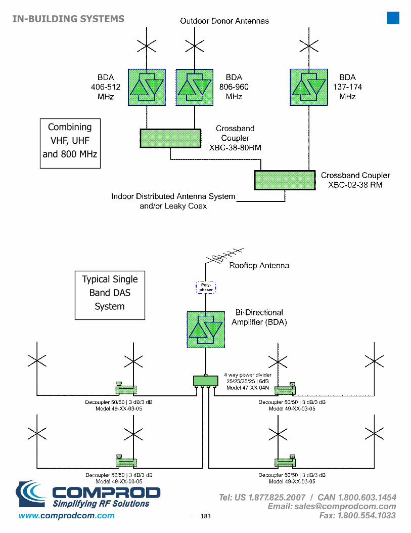
183
IN-BUILDING SYSTEMS
Typical Single Band DAS System
Combining VHF, UHF
and 800 MHz

184
IN-BUILDING SYSTEMS
Typical Multi Story DAS System

185
IN-BUILDING SYSTEMS
Part Number
Frequency Range, MHz
Length, in (mm)
Diameter, in (mm) Pattern Power,
Watts Radome material Color Standard
Connector
357-75 136-174 4 x 21 x 3 Omni 150 ABS/6200 Kydex Grey/White UHF/BNC
360-75 406-512 3.25 x 3 x 11 Omni 50 ABS/6200 Kydex Grey/White UHF/BNC
361-75 806-960 3.15 (80) 9.3 (236) Omni 50 ABS/6200 Kydex Grey/White N Female
362-75 806-960 2.0 (51) 4.5 (114) Omni 100 ABS/6200 Kydex Grey/White N Female
F3987 380-470 6.75 (171) 0.5 (12.75) Omni 150 Aluminum Black or white N Male
F3953 406-512 7.0 (178.5) 0.625 (15.93) Omni 50 Polycar-bonate
Black or white N Male
F33005 806-960 / 1850-1990 2 (51) 4.5 (114) Omni 50 6200 Kydex White N Female
F33048 740-960 2 (51) 4.5 (114) Omni 50 6200 Kydex White N Female
F3749 VHF /UHF/ 806-960 9.78 (249) 7.0 (178.5) Omni 50 6200 Kydex White N Female
F3741 VHF /UHF/ 806-960
11.25 (286.88) 0.65 (16.575) Omni 50 Polycar-
bonate Black N Male
Antennas
Part Number
Frequency Range,
MHz
Size, in (mm) Color Connectors
Max. Gain,
dB
Noise Figure, dB
Max. Out-put Power,
dBm
Input Voltage
Alarm Indicators
UBDA-138225 138-225 MHz
24H x 20W x 14D Grey N Female +100 4 typical DL: +29
UL: +29 AC: 115-220 Power Fail
UBDA-4551 380-512 MHz
24H x 24W x 12D Grey N Female +70 4 typical DL: +29
UL: +29 AC: 115-220 N/A
BDA 764806 DL: 764-776 UL: 794-806
10H x 16W x 8.5D Grey/Red N Female +83.5 2.5 typical DL: +31.5
UL: +31.5 AC: 115-220 DC: 24-27
AGC, S/D, Power Fail
BDA 806870 DL: 851-869 UL: 806-824
10H x 16W x 8.5D Grey/Red N Female +83.5 2.5 typical DL: +31.5
UL: +31.5 AC: 115-220 DC: 24-27
AGC, S/D, Power Fail
BDA 896941 DL: 935-941 UL: 896-901
10H x 16W x 8.5D Grey/Red N Female +83.5 2.5 typical DL: +31.5
UL: +31.5 AC: 115-220 DC: 24-27
AGC, S/D, Power Fail
Amplifiers

186
IN-BUILDING SYSTEMS
MULTI-BAND ANTENNAS SINGLE-BAND ANTENNAS Comprod In-building antennas are designed to provide excellent coverage solu-tions in order for external Public Safety Radio Frequencies to propagate within buildings, tunnels or public use environments. We offer a variety of antennas with Fire Retardant 6200 Kydex radomes. These materials are designed for In-building applications and inside public transport vehicles such as underground trains, vans, buses and trains. They meet the rec-ommended fire safety practices of both the Federal Transit Administration (FTA) and the Federal Rail Administration (FRA) for smoke emission and flammability as tested under ASTM E-662 and ASTM E-162. Our antennas have been installed worldwide and provide RF coverage inside nu-clear power plants, correctional institutions, tunnels, high-rise buildings, sub-ways, shopping malls, parking garages, power plants, high-security office networks and mine shafts. Note: add the material and connector type to the part number when ordering: -ABS is for outdoor use and is grey in color -KYDEX is for indoor use and is white in color
Electrical Specifications 357-75 360-75 361-75 362-75
Frequency Range, MHz 148-174 406-512 806-960 806-960
Nominal Gain, dBd Unity Unity Unity Unity
Bandwidth 1.5:1 VSWR, MHz 3 20 140 66
Bandwidth: 2.0:1 VSWR, MHz 4 40 140 100
Polarization Vertical Vertical Vertical Vertical
Pattern omnidirectional omnidirectional omnidirectional omnidirectional
Power Rating, Watts 150 50 50 100
Nominal Impedance, Ohms 50 50 50 50
Radome ABS / 6200 Kydex ABS / 6200 Kydex ABS / 6200 Kydex ABS / 6200 Kydex
Color Grey / White Grey / White Grey / White Grey / White
Standard Termination UHF / BNC / N UHF / BNC / N N Female N Female
Mechanical Specifications 357-75 360-75 361-75 362-75
Width, in (mm) 4.0 (102) 3.0 (76) 3.15 (80) 2.0 (51)
Length, in (mm) 21.0 (533) 11.0 (279) n/a n/a
Height, in (mm) 3.0 (76) 3.25 (83) n/a n/a
Weight, lbs (kg) 2.1 (0.945) 1.0 (0.45) 2.5 (1.15) 0.375 (0.169)
Required Minimum Ground Plane Size, in (mm) 36 x 48 (914 x 1219)
20 x 16 (508 x 406)
14 x 14 (355 x 355)
10 x 10 (254 x 254)
Diameter, in (mm) n/a n/a 9.3 (236) 4.5 (114)
362-75

187
IN-BUILDING SYSTEMS
MULTI-BAND ANTENNAS SINGLE-BAND ANTENNAS
360-75
361-75
362-75 Top and Underside View
357-75 Top and Underside-view

188
IN-BUILDING SYSTEMS
UHF IN-BUILDING ANTENNAS
Comprod In-building antennas are designed to provide excellent cover-age solutions in order for external Public Safety Radio Frequencies to propagate within buildings, tunnels or public use environments. Our antennas can cover single or multiple frequency bands. We offer a wide variety of antennas with Fire Retardant 6200 Kydex radomes. These materials are designed for In-building applications and inside public transport vehicles such as underground trains, vans, buses and trains. They meet the recommended fire safety practices of both the Federal Transit Administration (FTA) and the Federal Rail Administration (FRA) for smoke emission and flammability as tested under ASTM E-662 and ASTM E-162. Our antennas have been installed worldwide and provide RF coverage inside nuclear power plants, correctional institutions, tunnels, high-rise buildings, subways, shopping malls, parking garages, power plants, high-security office networks and mine shafts. Note: Add “NGP” to part number to order without the ground plane.
Electrical Specifications F-3987 F-3953
Frequency Range, MHz 380-470 406-470 / 450-512
Nominal Gain, dBd Unity Unity
Bandwidth: 2.0:1 VSWR, MHz 90 64
Polarization Vertical Vertical
Pattern omnidirectional omnidirectional
Power Rating, Watts 150 50
Nominal Impedance, Ohms 50 50
Material Aluminium painted Aluminum painted
Color Black or White Black or White
Standard Termination N Male N Male
Mechanical Specifications F-3987 F-3953
Max. Length, in (mm) 6.75 (171) 7.0 (178.5)
Diameter, in (mm) 0.5 (12.75) 0.625 (15.93)
Weight, lbs. (kg) N/A N/A
Required Minimum Ground Plane Size, in (mm) 8 x 8 (203 x 203) 8 x 8 (203 x 203)
Mounting Hardware Included Included
F-3953
F-3987

189
IN-BUILDING SYSTEMS
MULTI-BAND ANTENNAS Comprod In-building antennas are designed to provide excellent coverage solutions in order for external Public Safety Radio Frequencies to propagate within buildings, tunnels or public use environments. Our antennas can cover single or multiple frequency bands. We offer a wide variety of antennas with Fire Retardant 6200 Kydex radomes. These materials are designed for In-building applications and inside public transport vehicles such as underground trains, vans, buses and trains. They meet the recommended fire safety practices of both the Federal Transit Administration (FTA) and the Federal Rail Administration (FRA) for smoke emission and flammability as tested under ASTM E-662 and ASTM E-162. The antennas are installed on ceilings to provide RF coverage inside nuclear power plants, correctional institutions, tunnels, high-rise buildings, subways, shopping malls, parking garages, power plants, high-security office networks and mine shafts.
Electrical Specifications F-33005 F-33048
Frequency Range, MHz 806-960 / 1850-1990 760-960
Nominal Gain, dBd Unity Unity
Bandwidth 1.5:1 VSWR, MHz
138-174 n/a n/a
406-512 n/a n/a
760-960 n/a 200
806-960 72 (Specify Frequencies) n/a
1800-1990 140 n/a
Polarization Vertical Vertical
Pattern omnidirectional omnidirectional
Power Rating, Watts 50 50
Nominal Impedance, Ohms 50 50
Radome 6200 Kydex 6200 Kydex
Standard Termination N Female 32” Jumper - N Female
F-33005
Mechanical Specifications F-33005 F-33048
Max. Length, in (mm) 2 (51) 2 (51)
Diameter, in (mm) 4.5 (114) 4.5 (114)
Weight, lbs. (kg) 0.375 (0.169) 0.375 (0.169)
Required Minimum Ground Plane Size, in (mm) 8 x 8 (203 x 203) 8 x 8 (203 x 203)
Mounting hardware Not Included Not Included
F-33048
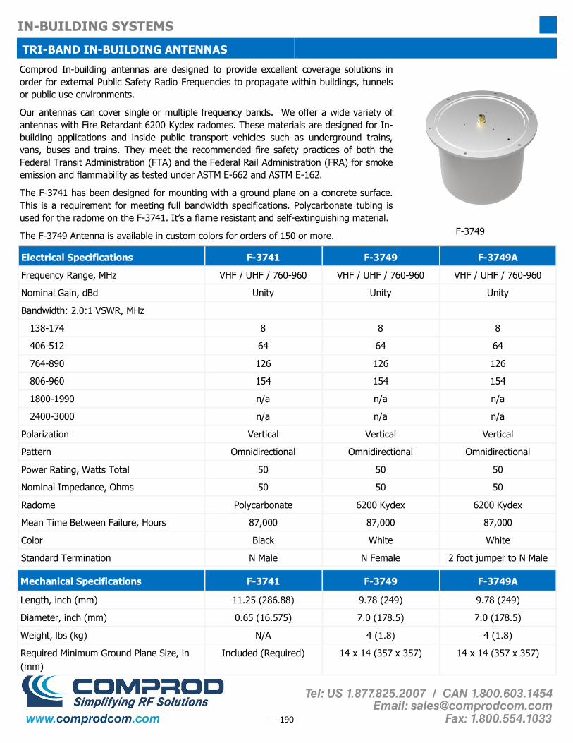
190
IN-BUILDING SYSTEMS
TRI-BAND IN-BUILDING ANTENNAS Comprod In-building antennas are designed to provide excellent coverage solutions in order for external Public Safety Radio Frequencies to propagate within buildings, tunnels or public use environments.
Our antennas can cover single or multiple frequency bands. We offer a wide variety of antennas with Fire Retardant 6200 Kydex radomes. These materials are designed for In-building applications and inside public transport vehicles such as underground trains, vans, buses and trains. They meet the recommended fire safety practices of both the Federal Transit Administration (FTA) and the Federal Rail Administration (FRA) for smoke emission and flammability as tested under ASTM E-662 and ASTM E-162.
The F-3741 has been designed for mounting with a ground plane on a concrete surface. This is a requirement for meeting full bandwidth specifications. Polycarbonate tubing is used for the radome on the F-3741. It’s a flame resistant and self-extinguishing material.
The F-3749 Antenna is available in custom colors for orders of 150 or more.
Electrical Specifications F-3741 F-3749 F-3749A
Frequency Range, MHz VHF / UHF / 760-960 VHF / UHF / 760-960 VHF / UHF / 760-960
Nominal Gain, dBd Unity Unity Unity
Bandwidth: 2.0:1 VSWR, MHz
138-174 8 8 8
406-512 64 64 64
764-890 126 126 126
806-960 154 154 154
1800-1990 n/a n/a n/a
2400-3000 n/a n/a n/a
Polarization Vertical Vertical Vertical
Pattern Omnidirectional Omnidirectional Omnidirectional
Power Rating, Watts Total 50 50 50
Nominal Impedance, Ohms 50 50 50
Radome Polycarbonate 6200 Kydex 6200 Kydex
Color Black White White
Standard Termination N Male N Female 2 foot jumper to N Male
Mean Time Between Failure, Hours 87,000 87,000 87,000
Mechanical Specifications F-3741 F-3749 F-3749A
Length, inch (mm) 11.25 (286.88) 9.78 (249) 9.78 (249)
Diameter, inch (mm) 0.65 (16.575) 7.0 (178.5) 7.0 (178.5)
Weight, lbs (kg) N/A 4 (1.8) 4 (1.8)
Required Minimum Ground Plane Size, in (mm)
Included (Required) 14 x 14 (357 x 357) 14 x 14 (357 x 357)
F-3749

191
IN-BUILDING SYSTEMS
MULTI-BAND ANTENNAS TRI-BAND ANTENNAS
F-3749 Top and Underside View
F-3741
F-33034 Optional Mounting Bracket for F-3749/A F-33220 Optional Mounting Bracket for F-3749 Also available: F-33135 Optional 2’ by 4’ Mounting Bracket F-33203 Optional 2’ by 2’ Mounting Bracket F-33159 Optional 12” by 26” Mounting Bracket
F-3749 A Top and Underside View

192
IN-BUILDING SYSTEMS
VHF BI-DIRECTIONAL AMPLIFIER (BDA) 138-225 MHz
BDA-138225-SERIES
Electrical Specifications
Frequency Range, MHz 138-225 150-225
Automatic Level Control (ALC), dB 35 35
Amplifier Maximum Gain, dB + 100 Typical + 100 Typical
System Nominal Gain at –45 dBm input power + 75 + 75
Input Manual Attenuator Range, dB 0 to 30 in 2 dB steps 0 to 30 in 2 dB steps
Output Level Manual Adjustment range, dB 0 to 15 in 1 dB steps 0 to 15 in 1 dB steps
3rd Order Output Intercept Point, dBm +48 Typical +48 Typical
Noise Figure, Typical (without filters), dB 4 4
Limited Output Composite Power, dBm +31 +31
Nominal Impedance, Ohms 50 50
Input / Output Connectors N Female N Female
AC Power Source Input, Volts 100 to 260 50/60Hz 100 to 260 50/60Hz
Optional DC Power Source Voltages, Volts +24 or +48 +24 or +48
Optional dry contact alarms Power Failure Power Failure
Certification IC: 7755A-UDA138225 FCC: WDM-BDA138225
Canada USA
Mechanical Specifications (Typical)
Dimensions, in H, W, D 24 x 20 x 13.5
Temperature Range, °F (°C) -4 to 131 F (-20 to +55) C
Weight, lbs (Kg) 100 (45)
Comprod Inc.’s BDA138225 is an unidirectional Class B signal booster. It co-vers both the 138-174 MHz and 216-225 MHz bands. The amplifier can be used with input / output filters as an Unidirectional Amplifier or it can be com-bined with input and output duplexers to create a FCC and IC Certified Bi-Directional Amplifier.
Note: The BDA138225 must have adequate input and output filtering to prevent undesired interference. Comprod Technical Solutions Specialists can provide guidance on the required filtering solution for a complete BDA system design.
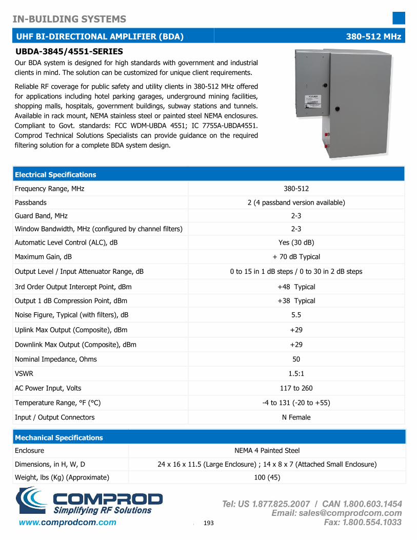
193
IN-BUILDING SYSTEMS
UHF BI-DIRECTIONAL AMPLIFIER (BDA) 380-512 MHz
UBDA-3845/4551-SERIES
Electrical Specifications
Frequency Range, MHz 380-512
Passbands 2 (4 passband version available)
Guard Band, MHz 2-3
Window Bandwidth, MHz (configured by channel filters) 2-3
Automatic Level Control (ALC), dB Yes (30 dB)
Maximum Gain, dB + 70 dB Typical
Output Level / Input Attenuator Range, dB 0 to 15 in 1 dB steps / 0 to 30 in 2 dB steps
3rd Order Output Intercept Point, dBm +48 Typical
Output 1 dB Compression Point, dBm +38 Typical
Noise Figure, Typical (with filters), dB 5.5
Uplink Max Output (Composite), dBm +29
Downlink Max Output (Composite), dBm +29
Nominal Impedance, Ohms 50
VSWR 1.5:1
AC Power Input, Volts 117 to 260
Temperature Range, °F (°C) -4 to 131 (-20 to +55)
Input / Output Connectors N Female
Enclosure NEMA 4 Painted Steel
Dimensions, in H, W, D 24 x 16 x 11.5 (Large Enclosure) ; 14 x 8 x 7 (Attached Small Enclosure)
Weight, lbs (Kg) (Approximate) 100 (45)
Mechanical Specifications
Our BDA system is designed for high standards with government and industrial clients in mind. The solution can be customized for unique client requirements.
Reliable RF coverage for public safety and utility clients in 380-512 MHz offered for applications including hotel parking garages, underground mining facilities, shopping malls, hospitals, government buildings, subway stations and tunnels. Available in rack mount, NEMA stainless steel or painted steel NEMA enclosures. Compliant to Govt. standards: FCC WDM-UBDA 4551; IC 7755A-UBDA4551. Comprod Technical Solutions Specialists can provide guidance on the required filtering solution for a complete BDA system design.
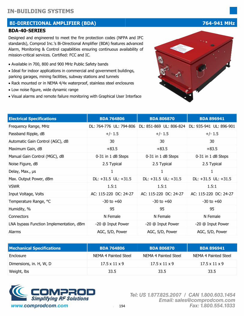
194
IN-BUILDING SYSTEMS
BI-DIRECTIONAL AMPLIFIER (BDA) 764-941 MHz BDA-40-SERIES Designed and engineered to meet the fire protection codes (NFPA and IFC standards), Comprod Inc.’s Bi-Directional Amplifier (BDA) features advanced Alarm, Monitoring & Control capabilities ensuring continuous availability of mission-critical services. Certified: FCC and IC.
• Available in 700, 800 and 900 MHz Public Safety bands
• Ideal for indoor applications in commercial and government buildings, parking garages, mining facilities, subway stations and tunnels
• Rack mounted or in NEMA 4/4x waterproof, stainless steel enclosures
• Low noise figure, wide dynamic range
• Visual alarms and remote failure monitoring with Graphical User Interface
Electrical Specifications BDA 764806 BDA 806870 BDA 896941
Frequency Range, MHz DL: 764-776 UL: 794-806 DL: 851-869 UL: 806-824 DL: 935-941 UL: 896-901
Passband Ripple, dB +/- 1.5 +/- 1.5 +/- 1.5
Automatic Gain Control (AGC), dB 30 30 30
Maximum Gain, dB +83.5 +83.5 +83.5
Manual Gain Control (MGC), dB 0-31 in 1 dB Steps 0-31 in 1 dB Steps 0-31 in 1 dB Steps
Noise Figure, dB 2.5 Typical 2.5 Typical 2.5 Typical
Delay, Max., µs 1 1 1
Max. Output Power, dBm DL: +31.5 UL: +31.5 DL: +31.5 UL: +31.5 DL: +31.5 UL: +31.5
VSWR 1.5:1 1.5:1 1.5:1
Input Voltage, Volts AC: 115-220 DC: 24-27 AC: 115-220 DC: 24-27 AC: 115-220 DC: 24-27
Temperature Range, °C -30 to +60 -30 to +60 -30 to +60
Connectors N Female N Female N Female
LNA bypass Function Implementation, dBm -20 @ Input Power -20 @ Input Power -20 @ Input Power
Alarms AGC, S/D, Power AGC, S/D, Power AGC, S/D, Power
Humidity, % 95 95 95
Mechanical Specifications BDA 764806 BDA 806870 BDA 896941
Enclosure NEMA 4 Painted Steel NEMA 4 Painted Steel NEMA 4 Painted Steel
Dimensions, in. H, W, D 17.5 x 11 x 9 17.5 x 11 x 9 17.5 x 11 x 9
Weight, lbs 33.5 33.5 33.5

195
IN-BUILDING SYSTEMS
BI-DIRECTIONAL AMPLIFIER (BDA) 764-941 MHz
Monitor BDA 764806 BDA 806870 BDA 896941
- TX/RX System Gain - TX/RX Attenuation
- TX Input Power - TX/RX Output Power - DC Voltage/Current - System Temperature
- TX/RX System Gain - TX/RX Attenuation - TX Input Power
- TX/RX Output Power - DC Voltage/Current - System Temperature
- TX/RX System Gain - TX/RX Attenuation
- TX Input Power - TX/RX Output Power - DC Voltage/Current - System Temperature
Alarm BDA 764806 BDA 806870 BDA 896941
- TX Input Over Power - TX/RX Output Over Power
- AGC Range Alarm - TX/RX Shutdown
- PSU Alarm - Over Temperature
- TX Input Over Power - TX/RX Output Over Power
- AGC Range Alarm - TX/RX Shutdown
- PSU Alarm - Over Temperature
- TX Input Over Power - TX/RX Output Over Power
- AGC Range Alarm - TX/RX Shutdown
- PSU Alarm - Over Temperature
Control BDA 764806 BDA 806870 BDA 896941
- HPA On/Off - Gain
- AGC On/Off - Shutdown On/Off
- MCU Reset - Alarm Limit
- HPA On/Off - Gain
- AGC On/Off - Shutdown On/Off
- MCU Reset - Alarm Limit
- HPA On/Off - Gain
- AGC On/Off - Shutdown On/Off
- MCU Reset - Alarm Limit
Visual Alarms and Remote Failure Monitoring with Graphical User Interface
Monitoring & Control Built-in via RS-232 Connector (USB Optional)
Built-in via RS-232 Connector (USB Optional)
Built-in via RS-232 Connector (USB Optional)

196
IN-BUILDING SYSTEMS
HYBRID DIRECTIONAL COUPLERS 138-960MHz
49-FF-YY-XX Series
Comprod Communications Ltd. offers a full line of Hybrid Directional Couplers. The full range of decoupling values allows balanced power division and distribution. These couplers are bidirectional and are well suited for two-way communications systems. A full line of Tri-Band models is available for distribution of VHF, UHF and 800 MHz via a single transmission line. Standard finish is gold Alodine.
• Low Insertion Loss
• High Isolation between ports
• Excellent VSWR
• Tri-Band and other models are available and customizable. Please contact a Comprod Inc. Technical support technician for consultation.
Model With No Load
Model With 5 Watt Load
Model With 25 Watt Load
Frequency Range
Decoupling (dB)
Insertion Loss (dB)
Power Split Ratio (%)
49-13-03-00 49-13-03-05 49-13-03-25 138-174MHz -3.0, ±0.7 -3.0, ±0.3 50 / 50
49-13-48-00 49-13-48-05 49-13-48-25 138-174MHz -4.8, ±0.7 -1.8, ±0.3 67 / 33
49-13-06-00 49-13-06-05 49-13-06-25 138-174MHz -6.0, ±1.0 -1.2, ±0.2 75 / 25
49-13-07-00 49-13-07-05 49-13-07-25 138-174MHz -7.0, ±1.0 -1.0, ±0.2 80 / 20
49-13-10-00 49-13-10-05 49-13-10-25 138-174MHz -10.0, ±1.0 -0.5, ±0.2 90 / 10
49-13-20-00 49-13-20-05 49-13-20-25 138-174MHz -20.0, ±1.0 -0.3 max. 99 / 1
49-38-03-00 49-38-03-05 49-38-03-25 380-512MHz -3.0, ±0.7 -3.0, ±0.3 50 / 50
49-38-48-00 49-38-48-05 49-38-48-25 380-512MHz -4.8, ±0.7 -1.8, ±0.3 67 / 33
49-38-06-00 49-38-06-05 49-38-06-25 380-512MHz -6.0, ±1.0 -1.2, ±0.2 75 / 25
49-38-07-00 49-38-07-05 49-38-07-25 380-512MHz -7.0, ±1.0 -1.0, ±0.2 80 / 20
49-38-10-00 49-38-10-05 49-38-10-25 380-512MHz -10.0, ±1.0 -0.5, ±0.2 90 / 10
49-38-15-00 49-38-15-05 49-38-15-25 380-512MHz -15.0 -0.2 max. 97 / 3
49-38-20-00 49-38-20-05 49-38-20-25 380-512MHz -20.0 -0.2 max. 99 / 1
49-38-30-00 49-38-30-05 49-38-30-25 380-512MHz -30.0 -0.2 max. 99.9 / 0.1
49-74-03-00 49-74-03-05 49-74-03-25 746-960MHz -3.0, ±0.7 -3.0, ±0.3 50 / 50
49-74-48-00 49-74-48-05 49-74-48-25 746-960MHz -4.8, ±0.7 -1.8, ±0.3 67 / 33
49-74-06-00 49-74-06-05 49-74-06-25 746-960MHz -6.0, ±1.0 -1.2, ±0.2 75 / 25
49-74-07-00 49-74-07-05 49-74-07-25 746-960MHz -7.0, ±1.0 -1.0, ±0.2 80 / 20
49-74-10-00 49-74-10-05 49-74-10-25 746-960MHz -10.0, ±1.0 -0.5, ±0.2 90 / 10
49-74-30-00 49-74-30-05 49-74-30-25 746-960MHz -30.0 -0.2 max. 99.9 / 0.1
49-74-15-00 49-74-15-05 49-74-15-25 746-960MHz -15.0 -0.2 max. 97 / 3
49-74-20-00 49-74-20-05 49-74-20-25 746-960MHz -20.0 -0.2 max. 99 / 1