APEX DYNAMICS, INC.
36
APEX DYNAMICS, INC. PLANETARY GEARBOX NEW GENERATION P-SERIES II II II II II II II II PE / PG / PA / PS / PN / PD / PL PN R / PDR PE R / PG R / PA R / PS R / / PLR II II
-
Upload
khangminh22 -
Category
Documents
-
view
0 -
download
0
Transcript of APEX DYNAMICS, INC.

APEX DYNAMICS, INC.
PLANETARY GEARBOX
NEW GENERATION P-SERIES
II II II II
II II II II
PE / PG / PA / PS / PN / PD / PL
PN R / PDRPE R / PG R / PA R / PS R / / PLR
II
II
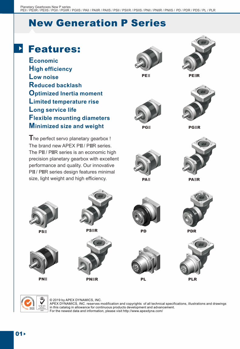
New Generation P Series
01
Economic
High efficiency
Low noise
Reduced backlash
Optimized Inertia moment
Limited temperature rise
Long service life
Flexible mounting diameters
Minimized size and weight
The perfect servo planetary gearbox !
The brand new APEX P / P R series.
The P / P R series is an economic high
precision planetary gearbox with excellent
performance and quality. Our innovative
P / P R series design features minimal
size, light weight and high efficiency.
Features:
IIII
IIII
II II
PS
PE II
II
PE R II
PS RII
PN RIIPNII
PG II
PA II
PG R II
PA R II
PD PDR
PL PLR
© 2019 by APEX DYNAMICS, INC.APEX DYNAMICS, INC. reserves modification and copyrights of all technical specifications, illustrations and drawings in this catalog in allowance for continuous products development and advancement.For the newest data and information, please visit http://www.apexdyna.com/
Planetary Gearboxes New P series PEII / PEIIR / PEIIS / PGII / PGIIR / PGIIS / PAII / PAIIR / PAIIS / PSII / PSII R / PSIIS / P NII / PNIIR / PNIIS / PD / PD R / PDS / PL / PLR

PE 090
The customization detail please contact with APEX sales.
02
APEX DYNAMICS, INC.
(1) (2)PE 090 /-II
/-II
ORDERING CODE
Ordering Example : PE 090 - 010 / SIEMENS 1FT6 041 - 4AF71 PA 090 - 010 - S1 / SIEMENS 1FT6 041 - 4AF71
IIII
Ordering Example : PE R 090 - 010 / SIEMENS 1FT6 041 - 4AF71 PA R 090 - 010 - S1 / SIEMENS 1FT6 041 - 4AF71
IIII
PE R 090
-
-
Gearbox Size:IIPE 050 , IIPE 070, IIPE 090, IIPE 120, IIPE 155 IIPG 040 , IIPG 060 , IIPG 080 , IIPG 120 , IIPG 160
IIPE : PG
PD 053 , PD 064, PD 090, PD 110
PL 070, PL 090, PL 120,
PD : PL :
PA 042, IIPA 060, IIPA 090, IIPA 115, IIPA 142 IIPA : IIPS A, IIPS B, IIPS C, IIPS D, IIPS E IIPS :
Gearbox Size:
IIPE R 050, IIPE R 070, IIPE R 090, IIPE R 120, IIPE R 155
IIPG R 040 , IIPG R 060, IIPG R 080 , IIPG R 120 , IIPG R 160
IIPE R : IIPG R :
PDR 053 , PDR 064, PDR 090, PDR 110
PLR 070, PLR 090, PLR 120
PDR : PL R :
IIPA R 042, IIPA R 060, IIPA R 090, IIPA R 115, IIPA R 142 IIPA R : IIPS R A, IIPS R B, IIPS R C, IIPS R D, IIPS R E IIPS R :
(1)Ratio :
(3)1-stage: 3, 4, 5, 7 ,9 ,10
(5) (3)2-stage: 12 ,15, 16, 20, 25, 30, 35, 40, 50, 70, 81 , 100
(4)3-stage : 120, 160, 200, 280, 350, 500, 700, 1000
IIPN 017 , IIPN 023, IIPN 034, IIPN 042, IIPN 056 IIPN :
IIPN R 017, IIPN R 023, IIPN R 034, IIPN R 042, IIPN R 056 IIPN R :
IIII :
(1) Ratio (i= N / N ) . in out
(2) S1 = Smooth Output Shaft. S1 shaft is only provided for PA / PA R series.
S2 = Output Shaft with Key. This is the standard shaft for P / P R gearbox.
(3) Only provided for PS /PS R and PA / PA R series.
(4) Only provided for PG and PG R series.
(5) Only provided for P L and PLR series.
II IIII II II II
II II
II II
PE IIS 090
(1) (2) 010 ( ) MOTOR
- (1) 010 (6)
(6) P S is the P version with option input ”SHAFT” instead of input “HUB”.
II II
PIIS is the PII version with option input “SHAFT” instead of input “HUB”
Shaft Type
Motor Type
010 ( ) MOTOR

StagesModel No. Type
Nominal Output Torque T2N
3
Nm
4
5
7
10
15
16
20
25
30
35
40
50
70
100
1
All
16
16
15
12
10
15
16
16
15
15
12
16
15
12
10
42
42
40
35
27
40
42
42
40
40
35
43
40
35
27
110
113
118
96
68
109
116
116
123
108
100
117
123
100
70
217
223
220
198
155
213
228
230
228
212
206
232
228
206
162
430
440
435
366
295
424
452
454
450
422
382
459
450
382
308
Nm
Nm
Nm
Emergency Stop Torque T2NOT
Max. Acceleration Torque T2B
(4)No Load Running Torque
3 times T2NAll
All
1,2
1,2
1
2
2
1
3~100
3~100
3~10
15~100
3~10
15~100
0.05
0.05
arcmin(2)Backlash
≦ 8
≦ 12
≦ 10
≦ 14
T = 60% of T2B 2NOT
0.10
0.15
0.15
0.10
0.10
0.40
0.45
0.10 0.30
0.35
0.40
0.45
0.80
0.85
0.80
0.85
2.50
2.55
≦ 7
≦ 11
≦ 9
≦ 13
≦ 6
≦ 10
≦ 8
≦ 12
≦ 6
≦ 10
≦ 8
≦ 12
≦ 6
≦ 10
≦ 8
≦ 12
1,2 3~100Nm/arcminTorsional Rigidity
IIPE
IIPE
0.9 2.2 8 12 16
4,500rpm
8,000rpmNominal Input Speed n1N
Max. Input Speed n1B
1,2
1,2
3~100
3~100
All
All
4,000
6,000
3,600
6,000
3,600
4,800
2,500
3,600
N
N
(3)Max. Radial Load F2rB
(3)Max. Axial Load F2aB
1,2 3~100
1,2 3~100
810
405
1,150
575
1,530
765
3,260
1,630
4,550
2,275
%
º C
Efficiency
Operating Temp
Lubrication
Mounting Position
(4) Running Noise
Degree of Gearbox Protection
1,2 3~100
1,2 3~100
1,2 3~100
1,2 3~100
1,2
1,2
1 3~10
2 15~100
≦ 60
≦ 70
≦ 62
≦ 72
≦ 64
≦ 74
≦ 66
≦ 75
≦ 68
≦ 77
≧ 97%
≧ 93%
≧ 94%
≧ 90%
0º C~ +90º C
Synthetic lubrication grease
All directions
IP65
(1) Ratio
2
All
All
All
All
IIPE
IIPE
IIPE R
IIPE R
IIPE R
IIPE R
All
All
All
IIPE
IIPE
IIPE
IIPE
IIPE R
IIPE R
IIPE R
IIPE R
3~100
3~100
IIPE 050 IIPE 070 IIPE 090 IIPE 120 IIPE 155
IIPE R 050 IIPE R 070 IIPE R 090 IIPE R 120 IIPE R 155
PE / PE R Gearbox PerformanceII II
dB(A)
03
5
3
12
6
22
10
54
19
45
17Nm
Max. bending moment based on (5)the gearbox input flange Mb
0.1 x Mb
motor length (m)
(1) Ratio (i= N / N ) . in out
(2) Backlash is measured at 2% of Nominal Output Torque T .2N
(3) Applied to the output shaft center at 100 rpm .
(4) The dB values are measured by gearbox with ratio 10 (1-stage) or ratio 100 (2-stage), no loading at 3,000 RPM
or at the respective Nominal Input Speed by bigger model size.
By lower ratio and/or higher RPM, the noise level could be 3 to 5 dB higher.
(5) Max. motor weight* (kg) =
*with symmetrically distributed motor weight*with horizontal and stationary mounting
Planetary Gearboxes New P series PEII / PEIIR / PEIIS / PGII / PGIIR / PGIIS / PAII / PAIIR / PAIIS / PSII / PSII R / PSIIS / P NII / PNIIR / PNIIS / PD / PD R / PDS / PL / PLR

0
Perm
itte
d R
ad
ial L
oad
F (
N)
2rB
On
Cen
ter
Po
sit
ion
of
sh
aft
0
500 1000 1500 2000
1000
2000
3000
4000
5000
6000
Output Speed n (rpm)2
Model No.(A)Ø (C3)
8
11
14
19
24
28
32
35
38
42
0.10
0.16
------
------
-------
-------
--
----
--
----
---
-
---
-
----
---
-
0.10
0.16
0.12
0.19
0.10
0.16
2kg.cm
0.200.22 0.36 0.24
1.53 1.70 1.58 2.20 1.73 2.181.51
2.24 2.12 2.74 2.27 2.73
2.68 2.55 3.17 2.70 4.94 3.15
7.77 7.30 9.70 7.91
10.80 10.30 12.80 11.00
14.00 13.50 16.00 14.20
24.50
1-stage 1-stage 1-stage 1-stage 1-stage2-stage 2-stage 2-stage 2-stage 2-stage
IIPE R 050 IIPE R 070 IIPE R 090 IIPE R 120 IIPE R 155 0.18
0.20
0.18
0.20
0.36 0.36
0.39 0.39
0.43 0.43 1.87 1.871.24 1.24 2.67 2.67 6.80 6.80 13.57
2.97 2.97 7.10 7.10 13.8713.87
3.47 3.47 7.59 7.59 14.36 14.36
10.56 17.3310.56 17.33
11.97 18.7411.97 18.74
13.95 20.79 20.7913.95
26.54
Model No.(A)Ø (C3)
8
11
14
19
24
28
32
35
38
42
------
------
-------
-------
--
----
--
----
---
-
---
-
----
---
-
2kg.cm
1-stage 1-stage 1-stage 1-stage 1-stage2-stage 2-stage 2-stage 2-stage 2-stage
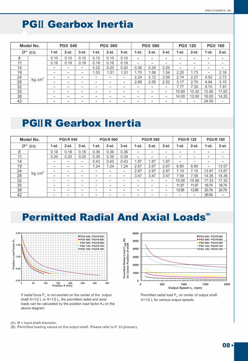
Permitted Radial And Axial Loads
APEX DYNAMICS, INC.
PE Gearbox InertiaII
PE R Gearbox InertiaII
IIPE 050 IIPE 070 IIPE 090 IIPE 120 IIPE 155
(B) Permitted Radial And Axial Loads
If radial force F is not exerted on the center of the output 2r
shaft X<1/2 L or X>1/2 L, the permitted radial and axial loads can be calculated by the position load factor K b on the above diagram.
Permitted radial load F on center of output shaft 2r
X=1/2 L for various output speeds.
(A) Ø = Input shaft diameter.(B) Permitted loading values on the output shaft. Please refer to P. 33 glossary.
PE 050IIPE 070II
PE 090IIPE 120IIPE 155II
IIII
II
IIII
PE R 050IIPE R 070II
PE R 090IIPE R 120IIPE R 155II
II
II
IIII
II//
///
--
--
04
0 50 100 150 200 250 3000.00
Po
sit
ion
Lo
ad
Fa
cto
r K
b
0.50
1.00
1.50
2.00
350Position X (mm)
4.52
PE 050IIPE 070II
PE 090IIPE 120IIPE 155II
IIII
II
IIII
PE R 050IIPE R 070II
PE R 090IIPE R 120IIPE R 155II
II
II
IIII
II//
///

Dimension
PE Series DimensionII
D1
D2
D3 h6
D4 h6
D5
D6
D8
L2
L3
L4
L5
L6
44
M4X9
M4X0.7P
12
35
17
50
24.5
4
2.5
4.5
10
4
13.5
14
2
62
M5X10
M5X0.8P
16
52
22
70
36
4.5
3.5
4.8
12.5
5
18
25
2
80
M6X12
M8X1.25P
22
68
30
90
46
6
4
7.2
19
6
24.5
32
2
108
M8X15
M12X1.75P
32
90
40
120
70
7
5
10
28
10
35
50
4
140
M10X18
M16X2P
40
120
55
155
97
9.5
5.5
12
36
12
43
70
6
L9
L10
H1
B1 h9
IIPE 050 IIPE 070 IIPE 090 IIPE 120 IIPE 155
L3
L2
L4
ØD
4 h
6
ØD
5
ØD
8
ØD1
D2(4x)
B1 h9
D6
ØD3 h6
H1
L6
L9
(1) Dimensions are related to motor interface. Please contact APEX for details.
L5
L10Shaft Detail A
0.2
1
Shaft Detail A
Remark (1)
1-stage 1-stage 1-stage 1-stage 1-stage2-stage 2-stage 2-stage 2-stage 2-stage
ØC
3
05
Planetary Gearboxes New P series PEII / PEIIR / PEIIS / PGII / PGIIR / PGIIS / PAII / PAIIR / PAIIS / PSII / PSII R / PSIIS / P NII / PNIIR / PNIIS / PD / PD R / PDS / PL / PLR
(2) As alternative to input “HUB”, input “SHAFT” is also available, please find in page 32.
Remark (2)

06
APEX DYNAMICS, INC.
PE R Series DimensionII
Dimension
D1
D2
D3 h6
D4 h6
D5
D6
D8
L2
L3
L4
L5
L6
44
M4X9
M4X0.7P
12
35
17
50
24.5
4
2.5
4.5
10
4
13.5
14
2
62
M5X10
M5X0.8P
16
52
22
70
36
4.5
3.5
4.8
12.5
5
18
25
2
80
M6X12
M8X1.25P
22
68
30
90
46
6
4
7.2
19
6
24.5
32
2
108
M8X15
M12X1.75P
32
90
40
120
70
7
5
10
28
10
35
50
4
140
M10X18
M16X2P
40
120
55
155
97
9.5
5.5
12
36
12
43
70
6
L9
L10
L11
L12
H1
B1 h9
IIPE R 050 IIPE R 070 IIPE R 090 IIPE R 120 IIPE R 155
74.5
49.5
89.5
64.5
89.5
60
109.5
80
113
73
139.5
99.5
152
101
188
137
178
121
225.5
168.5
L11L3
L2
L4
L12
Shaft Detail A
ØD
4 h
6
ØD
5
ØD
8
D2(4x)
ØD1
(1) Dimensions are related to motor interface. Please contact APEX for details.
Remark (1)
B1 h9
D6
ØD3 h6
H1
L6
L9
L5
L10Shaft Detail A
0.2
1
1-stage 1-stage 1-stage 1-stage 1-stage2-stage 2-stage 2-stage 2-stage 2-stage
ØC3

07
(6) Stages Model No. Type
Nominal Output Torque T2N
3
Nm
45
7
10
15
16
20
25
30
35
40
50
70
100
120
160
200
280
350
500
700
1000
1
All
16
16
15
1210
15
16
16
15
15
1216
15
1210
19
16
16
12
1215
1210
42
4240
35
2740
42
4240
40
35
43
40
35
2750
43
43
35
35
40
35
27
110
113
118
96
68
109
116
116
123
108
100
117123
100
70
137
118
118
99
99
12299
70
217223
220
198
155
213
228
230
228
212206
232
228
206
162
430
440
435
366
295
424452454
450
422382
459
450
382
308
(1) Ratio
2
IIPG R 040
IIPG 040
IIPG R 060
IIPG 060
IIPG R 080
IIPG 080
IIPG R 120
IIPG 120
IIPG R 160
IIPG 160
Nm
Nm
Nm
Emergency Stop Torque T2NOT
Max. Acceleration Torque T2B
(4)No Load Running Torque
3 times T2NAll
All
1,2,3
1,2,33~1000
3~1000
arcmin(2)Backlash
T = 60% of T2B 2NOT
1,2,3 3~1000Nm/arcminTorsional Rigidity 0.5 2 8 12 164,500rpm
8,000rpmNominal Input Speed n1N
Max. Input Speed n1B
1,2,3
1,2,33~1000
3~1000All
All
4,000
6,000
3,600
6,000
3,600
4,800
2,500
3,600
N
N
520
260
(3)Max. Radial Load F2rB
(3)Max. Axial Load F2aB
1,2,3
1,2,3
1,2,3
1,2,3
3~1000
3~1000
3~1000
3~1000
1,030
515
1,570
785
3,590
1,795
4,690
2,345
%
º C
Efficiency
Operating Temp
LubricationMounting Position
(4) Running Noise
Degree of Gearbox Protection
≦ 60 ≦ 62 ≦ 64 ≦ 66 ≦ 68
≧ 97%
≧ 93%
≧ 94%
≧ 90%
≧ 91%
≧ 87%
0º C~ +90º C
Synthetic lubrication grease
All directions
IP65All
All
All
All
- -- -- ------
-----
3
1
1
2
2
3
3
3~10
3~10
15~100
15~100
120~1000
120~1000
IIPG
IIPG
IIPG
IIPG
IIPG
IIPG
IIPG
IIPG
IIPG R
IIPG R
IIPG R
IIPG R
IIPG R
IIPG R
IIPG R
IIPG R
≦ 8
≦ 12≦ 10
≦ 14
≦ 12≦ 16
≦ 7
≦ 11≦ 9
≦ 13
≦ 11≦ 15
≦ 6
≦ 10
≦ 8
≦ 12≦ 10
≦ 14
≦ 6
≦ 10
≦ 8
≦ 12
≦ 6
≦ 10
≦ 8
≦ 12
1,2,3
1,2,3
1,2,3
1,2,3
3~1000
3~1000
3~1000
3~1000
≦ 70 ≦72 ≦ 74 ≦ 75 ≦ 77
All
All
All
PG / PG R Gearbox PerformanceII II
dB(A)
1
2
3
3~10
15~100
120~1000
IIPG
IIPG
IIPG
IIPG R
IIPG R
IIPG R
--
--
0.10
0.15
0.05 0.40
0.10 0.45 0.85
0.80
2.55
2.50
0.15
0.15
0.10
0.10
0.35
0.45
0.45 0.85
0.10
0.10
0.05
0.05
0.30
0.40
0.40 0.80
--
--
5
3
12
6
22
10
54
19
45
17Nm
Max. bending moment based on (5)the gearbox input flange Mb
0.1 x Mb
motor length (m)
(1) Ratio (i= N / N ) . in out
(2) Backlash is measured at 2% of Nominal Output Torque T .2N
(3) Applied to the output shaft center at 100 rpm .
(4) The dB values are measured by gearbox with ratio 10 (1-stage) or ratio 100 (2-stage), or ratio 1,000 (3-stage) no loading at 3,000 RPM
or at the respective Nominal Input Speed by bigger model size.
By lower ratio and/or higher RPM, the noise level could be 3 to 5 dB higher.
(5) Max. motor weight* (kg) =
*with symmetrically distributed motor weight*with horizontal and stationary mounting
Planetary Gearboxes New P series PEII / PEIIR / PEIIS / PGII / PGIIR / PGIIS / PAII / PAIIR / PAIIS / PSII / PSII R / PSIIS / P NII / PNIIR / PNIIS / PD / PD R / PDS / PL / PLR
08
APEX DYNAMICS, INC.
Model No. IIPG 040 IIPG 060 IIPG 080 IIPG 120 IIPG 160 (A)Ø (C3)
2kg.cm
1-st. 1-st. 1-st. 1-st. 1-st.2-st. 2-st. 2-st. 2-st. 2-st.3-st. 3-st. 3-st.
Model No.(A)Ø (C3)
2kg.cm
1-st. 1-st. 1-st. 1-st. 1-st.2-st. 2-st. 2-st. 2-st. 2-st.3-st. 3-st. 3-st.
PG R Gearbox InertiaII
IIPG R 160 IIPG R 120 IIPG R 080 IIPG R 060 IIPG R 040
PG Gearbox InertiaII
Po
sit
ion
Lo
ad
Facto
r K
b
42 ---- - - - ---- 26.54 -38 ---- - - --- 13.95 13.95 20.79 20.7935 ---- - - --- 11.97 11.97 18.74 18.7432 ---- - - --- 10.56 10.56 17.33 17.3328 ---- -- 3.47 3.47 7.59 7.59 14.36 14.363.4724 ---- -- 2.97 2.97 7.10 7.10 13.87 13.872.9719 -1.24 2.67 2.67 6.80 6.80 13.571.24 2.671.2414 - - - -0.430.43 1.87 1.87 1.870.4311 - - - - - --0.20 0.39 0.39 0.390.20 0.208 - - - - - --0.18 0.36 0.36 0.360.18 0.18
42 ---- - - - - -24.50---38 ---- - - 14.00 13.50 16.00 14.20---35 ---- - - 10.80 10.30 12.80 11.00---32 ---- - - 7.77 7.30 9.70 7.91---28 ---- 2.68 2.55 3.17 2.70 4.94 3.152.52--24 ---- 2.24 2.12 2.74 2.27 4.52 2.732.09--19 -- -1.53 1.70 1.58 2.20 1.73 2.181.51 1.541.51-14 - - - -0.200.22 0.36 0.24 0.200.2011 0.16 - - - - - -0.16 0.19 0.16 -0.160.168 0.10 - - - - - -0.10 0.12 0.10 -0.100.10
Permitted Radial And Axial Loads (B) Permitted Radial And Axial Loads
(A) Ø = Input shaft diameter.(B) Permitted loading values on the output shaft. Please refer to P. 33 glossary.
PG 040IIPG 060II
PG 080IIPG 120IIPG 160II
IIII
II
IIII
PG R 040IIPG R 060II
PG R 080PG R 120IIPG R 160II
II
II
IIII
II//
//
/
0 50 100 150 200 250 300 350Position X (mm) 0
Perm
itte
d R
ad
ial L
oad
F (
N)
2rB
On
Cen
ter
Po
sit
ion
of
sh
aft
0
500 1000 1500 2000
1000
2000
3000
4000
5000
6000
Output Speed n (rpm)2
PG 040IIPG 060II
PG 080IIPG 120IIPG 160II
IIII
II
IIII
PG R 040IIPG R 060II
PG R 080PG R 120IIPG R 160II
II
II
IIII
II//
//
/
0.00
0.50
1.00
1.50
2.00
If radial force F is not exerted on the center of the output 2r
shaft X<1/2 L or X>1/2 L, the permitted radial and axial loads can be calculated by the position load factor K b on the above diagram.
Permitted radial load F on center of output shaft 2r
X=1/2 L for various output speeds.

09
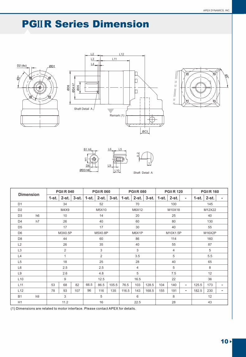
IIPG 040 IIPG 060 IIPG 080 IIPG 120 IIPG 160 Dimension
D1
D2
D3 h6
D4 h7
D5
D6
D8
L2
L3
L4
L5
L6
34
M4X9
M3X0.5P
10
26
17
44
26
2
1
2.6
9
3
11.2
18
2.5
52
M5X10
M5X0.8P
14
40
17
60
35
3
2
4.8
12.5
5
16
25
2.5
70
M6X12
M6X1P
20
60
30
86
40
3
3.5
5
16.5
6
22.5
28
4
100
M10X18
M10X1.5P
25
80
40
114
55
4
5
7.5
22
8
28
40
5
145
M12X22
M16X2P
40
130
55
160
87
5
5.5
12
36
12
43
65
8
L9
L10
H1
B1 h9
Shaft Detail A
ØD
4 h
7
ØD
5
ØD
8
L3
L2
L4
ØD1D2 (4x)
(1) Dimensions are related to motor interface. Please contact APEX for details.
Remark (1)
B1 h9
D6
ØD3 h6
H1
L6
L9
L5
L10Shaft Detail A
0.2
1Ø
C3
PG Series DimensionII
1-st. 1-st. 1-st. 1-st. 1-st.2-st. 2-st. 2-st. 2-st. 2-st.3-st. 3-st. 3-st. --
Planetary Gearboxes New P series PEII / PEIIR / PEIIS / PGII / PGIIR / PGIIS / PAII / PAIIR / PAIIS / PSII / PSII R / PSIIS / P NII / PNIIR / PNIIS / PD / PD R / PDS / PL / PLR
(2) As alternative to input “HUB”, input “SHAFT” is also available, please find in page 32.
Remark (2)
10
APEX DYNAMICS, INC.
PG R Series DimensionII
L11L3
L2
L4
L12
Shaft Detail A
ØD
4 h
7
ØD
5
ØD
8ØD1D2 (4x)
Remark (1)
B1 h9
D6
ØD3 h6
H1
L6
L9
L5
L10Shaft Detail A
0.2
1
ØC3
Dimension
D1
D2
D3 h6
D4 h7
D5
D6
D8
L2
L3
L4
L5
L6
34
M4X9
M3X0.5P
10
26
17
44
26
2
1
2.6
9
3
11.2
18
2.5
52
M5X10
M5X0.8P
14
40
17
60
35
3
2
4.8
12.5
5
16
25
2.5
70
M6X12
M6X1P
20
60
30
86
40
3
3.5
5
16.5
6
22.5
28
4
100
M10X18
M10X1.5P
25
80
40
114
55
4
5
7.5
22
8
28
40
5
145
M12X22
M16X2P
40
130
55
160
87
5
5.5
12
36
12
43
65
8
L9
L10
H1
B1 h9
IIPG R 160 IIPG R 120 IIPG R 080 IIPG R 060 IIPG R 040
L11
L12 78
53
93 107
68 82
96
66.5
116 135
86.5 105.5
116.5
76.5
143 168.5
103 128.5
155
104
191
140
182.5
125.5
230
173
(1) Dimensions are related to motor interface. Please contact APEX for details.
1-st. 1-st. 1-st. 1-st. 1-st.2-st. 2-st. 2-st. 2-st. 2-st.3-st. 3-st. 3-st. -
--
--
-

11
StagesModel No. Type
Nominal Output Torque T2N
3
Nm
4
5
7
10
15
16
20
25
30
35
40
50
70
100
81
9
1
All
16
16
15
12
10
15
16
16
15
15
12
16
15
12
10
8
8
42
42
40
35
27
40
42
42
40
40
35
43
40
35
27
24
24
110
113
118
96
68
109
116
116
123
108
100
117
123
100
70
59
60
217
223
220
198
155
213
228
230
228
212
206
232
228
206
162
131
125
430
440
435
366
295
424
452
454
450
422
382
459
450
382
308
285
273
Nm
Nm
Nm
Emergency Stop Torque T2NOT
Max. Acceleration Torque T2B
(4)No Load Running Torque
3 times T2NAll
All
1,2
1,2
1
2
2
1
3~100
3~100
3~10
15~100
3~10
15~100
0.05
0.05
arcmin(2)Backlash
≦ 8
≦ 12
≦ 10
≦ 14
T = 60% of T2B 2NOT
0.10
0.15
0.15
0.10
0.10
0.40
0.45
0.10 0.30
0.35
0.40
0.45
0.80
0.85
0.80
0.85
2.50
2.55
≦ 7
≦ 11
≦ 9
≦ 13
≦ 6
≦ 10
≦ 8
≦ 12
≦ 6
≦ 10
≦ 8
≦ 12
≦ 6
≦ 10
≦ 8
≦ 12
1,2 3~100Nm/arcminTorsional Rigidity
IIPA
0.9 2.2 8 12 16
4,500rpm
8,000rpmNominal Input Speed n1N
Max. Input Speed n1B
1,2
1,2
3~100
3~100
All
All
4,000
6,000
3,600
6,000
3,600
4,800
2,500
3,600
N
N
(3)Max. Radial Load F2rB
(3)Max. Axial Load F2aB
1,2 3~100
1,2 3~100
810
405
1,150
575
1,530
765
3,470
1,735
4,640
2,320
%
º C
Efficiency
Operating Temp
Lubrication
Mounting Position
(4) Running Noise
Degree of Gearbox Protection
1,2 3~100
1,2 3~100
1,2 3~100
1,2 3~100
1,2
1,2
1 3~10
2 15~100
≦ 60
≦ 70
≦ 62
≦ 72
≦ 64
≦ 74
≦ 66
≦ 75
≦ 68
≦ 77
≧ 97%
≧ 93%
≧ 94%
≧ 90%
0º C~ +90º C
Synthetic lubrication grease
All directions
IP65
(1) Ratio
2
All
All
All
All
PA / PA R Gearbox PerformanceII II
IIPA
IIPA R
IIPA R
All
All
All
3~100
3~100
IIPA R 042 IIPA R 060 IIPA R 090 IIPA R 115 IIPA R 142
IIPA 042 IIPA 060 IIPA 090 IIPA 115 IIPA 142
IIPA
IIPA
IIPA R
IIPA R
IIPA
IIPA R
IIPA
IIPA
IIPA R
IIPA R
dB(A)
IIPA
IIPA R
5
3
12
6
22
10
54
19
45
17Nm
Max. bending moment based on (5)the gearbox input flange Mb
0.1 x Mb
motor length (m)
(1) Ratio (i= N / N ) . in out
(2) Backlash is measured at 2% of Nominal Output Torque T .2N
(3) Applied to the output shaft center at 100 rpm .
(4) The dB values are measured by gearbox with ratio 10 (1-stage) or ratio 100 (2-stage), no loading at 3,000 RPM
or at the respective Nominal Input Speed by bigger model size.
By lower ratio and/or higher RPM, the noise level could be 3 to 5 dB higher.
(5) Max. motor weight* (kg) =
*with symmetrically distributed motor weight*with horizontal and stationary mounting
Planetary Gearboxes New P series PEII / PEIIR / PEIIS / PGII / PGIIR / PGIIS / PAII / PAIIR / PAIIS / PSII / PSII R / PSIIS / P NII / PNIIR / PNIIS / PD / PD R / PDS / PL / PLR

0
Pe
rmit
ted
Ra
dia
l L
oa
d F
(N
)2rB
On
Ce
nte
r P
os
itio
n o
f s
ha
ft
0
500 1000 1500 2000
1000
2000
3000
4000
5000
6000
Output Speed n (rpm)2
Po
sit
ion
Lo
ad
Fa
cto
r K
b
12
APEX DYNAMICS, INC.
PA Gearbox InertiaII
Model No.(A)Ø (C3)
8
11
14
19
24
28
32
35
38
42
0.10
0.16
------
------
------
------
--
----
--
----
---
-
---
-
----
---
-
0.10
0.16
0.12
0.19
0.10
0.16
2kg.cm
0.200.22 0.36 0.24
1.53 1.70 1.58 2.20 1.73 2.181.51
2.24 2.12 2.74 2.27 4.52 2.73
2.68 2.55 3.17 2.70 4.94 3.15
7.77 7.30 9.70 7.91
10.80 10.30 12.80 11.00
14.00 13.50 16.00 14.20
24.50
1-stage 1-stage 1-stage 1-stage 1-stage2-stage 2-stage 2-stage 2-stage 2-stage
0.18
0.20
0.18
0.20
0.36 0.36
0.39 0.39
0.43 0.43 1.87 1.871.24 1.24 2.67 2.67 6.80 6.80 13.57
2.97 2.97 7.10 7.10 13.8713.87
3.47 3.47 7.59 7.59 14.36 14.36
10.56 17.3310.56 17.33
11.97 18.7411.97 18.74
13.95 20.79 20.7913.95
26.54
Model No.(A)Ø (C3)
8
11
14
19
24
28
32
35
38
42
-----
-----
------
------
--
---
--
---
---
---
----
---
2kg.cm
1-stage 1-stage 1-stage 1-stage 1-stage2-stage 2-stage 2-stage 2-stage 2-stage
PA R Gearbox InertiaII
IIPA 042 IIPA 060 IIPA 090 IIPA 115 IIPA 142
IIPA R 042 IIPA R 060 IIPA R 090 IIPA R 115 IIPA R 142
(B) Permitted Radial And Axial Loads
(A) Ø = Input shaft diameter.(B) Permitted loading values on the output shaft. Please refer to P. 33 glossary.
PA 042IIPA 060II
PA 090IIPA 115IIPA 142II
IIII
II
IIII
PA R 042IIPA R 060II
PA R 090PA R 115IIPA R 142II
II
II
IIII
II//
///
PA 042IIPA 060II
PA 090IIPA 115IIPA 142II
IIII
II
IIII
PA R 042IIPA R 060II
PA R 090PA R 115IIPA R 142II
II
II
IIII
II//
///
0 50 100 150 200 250 300 350Position X (mm)
0.00
0.50
1.00
1.50
2.00
If radial force F is not exerted on the center of the output 2r
shaft X<1/2 L or X>1/2 L, the permitted radial and axial loads can be calculated by the position load factor K b on the above diagram.
Permitted radial load F on center of output shaft 2r
X=1/2 L for various output speeds.
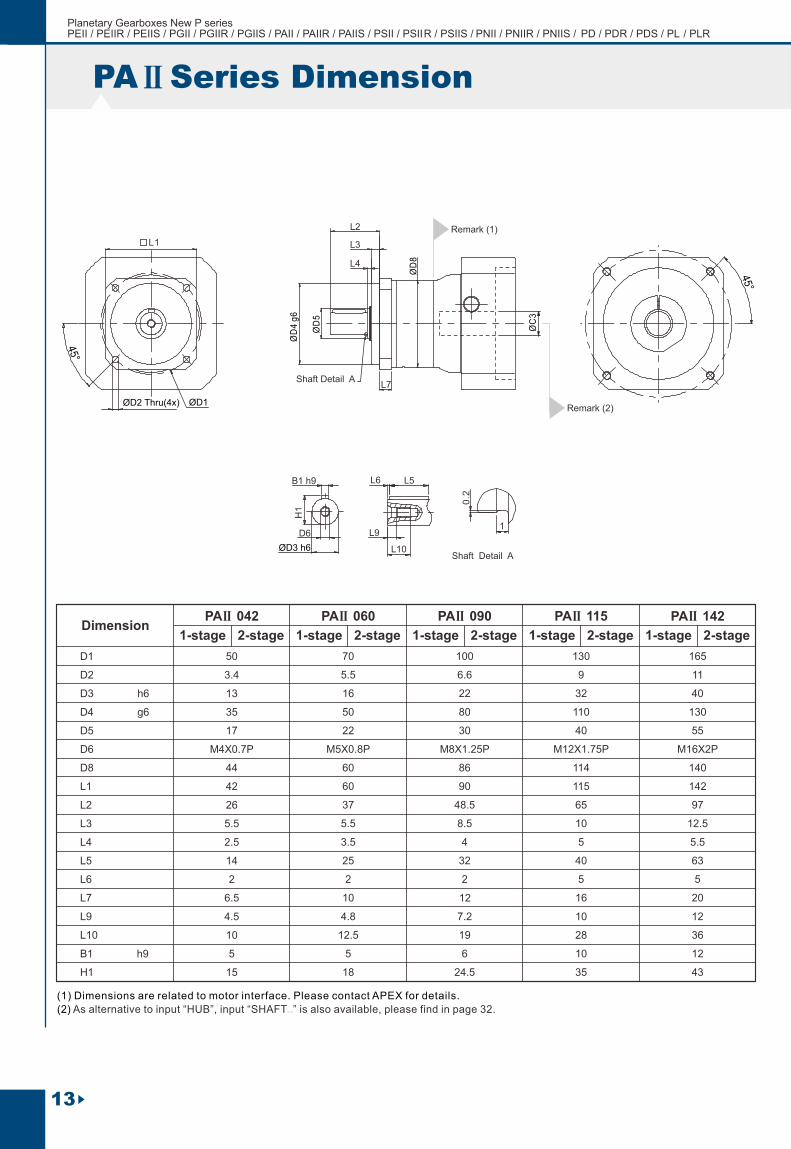
PA Series Dimension
Dimension
D1
D2
D3 h6
D4 g6
D5
D6
D8
L1
L2
L3
L4
L5
L6
L7
50
3.4
M4X0.7P
13
35
17
44
42
26
5.5
2.5
4.5
10
5
15
14
2
6.5
70
5.5
M5X0.8P
16
50
22
60
60
37
5.5
3.5
4.8
12.5
5
18
25
2
10
100
6.6
M8X1.25P
22
80
30
86
90
48.5
8.5
4
7.2
19
6
24.5
32
2
12
130
9
M12X1.75P
32
110
40
114
115
65
10
5
10
28
10
35
40
5
16
165
11
M16X2P
40
130
55
140
142
97
12.5
5.5
12
36
12
43
63
5
20
L9
L10
H1
B1 h9
IIPA 042 IIPA 060 IIPA 090 IIPA 115 IIPA 142
L7 Shaft Detail A
ØD
8
ØD
4 g
6
ØD
5
L3
L2
L4
L1
ØD1ØD2 Thru(4x)
(1) Dimensions are related to motor interface. Please contact APEX for details.
Remark (1)
B1 h9
D6
ØD3 h6
H1
L6
L9
L5
L10Shaft Detail A
0.2
1
1-stage 1-stage 1-stage 1-stage 1-stage2-stage 2-stage 2-stage 2-stage 2-stage
13
ØC
3
II
Planetary Gearboxes New P series PEII / PEIIR / PEIIS / PGII / PGIIR / PGIIS / PAII / PAIIR / PAIIS / PSII / PSII R / PSIIS / P NII / PNIIR / PNIIS / PD / PD R / PDS / PL / PLR
(2) As alternative to input “HUB”, input “SHAFT ” is also available, please find in page 32.
Remark (2)
Remark (2)

14
APEX DYNAMICS, INC.
PA R Series DimensionII
Dimension
D1
D2
D3 h6
D4 g6
D5
D6
D8
L1
L2
L3
L4
L5
L6
L7
50
3.4
M4X0.7P
13
35
17
44
42
26
5.5
2.5
4.5
10
5
15
14
2
6.5
70
5.5
M5X0.8P
16
50
22
60
60
37
5.5
3.5
4.8
12.5
5
18
25
2
10
100
6.6
M8X1.25P
22
80
30
86
90
48.5
8.5
4
7.2
19
6
24.5
32
2
12
130
9
M12X1.75P
32
110
40
114
115
65
10
5
10
28
10
35
40
5
16
165
11
M16X2P
40
130
55
140
142
97
12.5
5.5
12
36
12
43
63
5
20
L9
L10
L11
L12
H1
B1 h9
73
48
88
63
88.5
59
108.5
79
110.5
70.5
137
97
149
98
185
134
175
118
222.5
165.5
L11L3
L2
L4
L12
Shaft Detail A
ØD
4 g
6
ØD
5
L7
ØD
8
ØD2 Thru(4x)
ØD1
(1) Dimensions are related to motor interface. Please contact APEX for details.
L1
Remark (1)
B1 h9
D6
ØD3 h6
H1
L6
L9
L5
L10Shaft Detail A
0.2
1
1-stage 1-stage 1-stage 1-stage 1-stage2-stage 2-stage 2-stage 2-stage 2-stage
IIPA R 042 IIPA R 060 IIPA R 090 IIPA R 115 IIPA R 142
ØC3

StagesModel No. TypeIIPS A IIPS B IIPS C IIPS D IIPS E
Nominal Output Torque T2N
3
Nm
4
5
7
10
15
16
20
25
30
35
40
50
70
100
81
9
1
All
16
16
15
12
10
15
16
16
15
15
12
16
15
12
10
8
8
42
42
40
35
27
40
42
42
40
40
35
43
40
35
27
24
24
110
113
118
96
68
109
116
116
123
108
100
117
123
100
70
59
60
217
223
220
198
155
213
228
230
228
212
206
232
228
206
162
131
125
430
440
435
366
295
424
452
454
450
422
382
459
450
382
308
285
273
Nm
Nm
Nm
Emergency Stop Torque T2NOT
Max. Acceleration Torque T2B
(4)No Load Running Torque
3 times T2NAll
All
1,2
1,2
1
2
2
1
3~100
3~100
3~10
15~100
3~10
15~100
0.05
0.05
arcmin(2)Backlash
≦ 8
≦ 12
≦ 10
≦ 14
T = 60% of T2B 2NOT
0.10
0.15
0.15
0.10
0.10
0.40
0.45
0.10 0.30
0.35
0.40
0.45
0.80
0.85
0.80
0.85
2.50
2.55
≦ 7
≦ 11
≦ 9
≦ 13
≦ 6
≦ 10
≦ 8
≦ 12
≦ 6
≦ 10
≦ 8
≦ 12
≦ 6
≦ 10
≦ 8
≦ 12
1,2 3~100Nm/arcminTorsional Rigidity
IIPS
IIPS
0.6 1.5 6 10.5 18
4,500rpm
8,000rpmNominal Input Speed n1N
Max. Input Speed n1B
1,2
1,2
3~100
3~100
All
All
4,000
6,000
3,600
6,000
3,600
4,800
2,500
3,600
N
N
(3)Max. Radial Load F2rB
(3)Max. Axial Load F2aB
1,2 3~100
1,2 3~100
840
420
1,290
645
1,510
755
3,780
1,890
5,420
2,710
%
º C
Efficiency
Operating Temp
Lubrication
Mounting Position
(4) Running Noise
Degree of Gearbox Protection
1,2 3~100
1,2 3~100
1,2 3~100
1,2 3~100
1,2
1,2
1 3~10
2 15~100
≦ 60
≦ 70
≦ 62
≦ 72
≦ 64
≦ 74
≦ 66
≦ 75
≦ 68
≦ 77
≧ 97%
≧ 93%
≧ 94%
≧ 90%
0º C~ +90º C
Synthetic lubrication grease
All directions
IP65
(1) Ratio
2
All
All
All
All
IIPS R A IIPS R B IIPS R C IIPS R D IIPS R E
IIPS
IIPS
IIPS R
IIPS R
IIPS R
IIPS R
All
All
All
IIPS
IIPS
IIPS
IIPS R
IIPS R
IIPS R
3~100
3~100
PS / PS R Gearbox PerformanceII II
dB(A)
15
IIPS
IIPS R
5
3
12
6
22
10
54
19
45
17Nm
Max. bending moment based on (5)the gearbox input flange Mb
0.1 x Mb
motor length (m)
(1) Ratio (i= N / N ) . in out
(2) Backlash is measured at 2% of Nominal Output Torque T .2N
(3) Applied to the output shaft center at 100 rpm .
(4) The dB values are measured by gearbox with ratio 10 (1-stage) or ratio 100 (2-stage), no loading at 3,000 RPM
or at the respective Nominal Input Speed by bigger model size.
By lower ratio and/or higher RPM, the noise level could be 3 to 5 dB higher.
(5) Max. motor weight* (kg) =
*with symmetrically distributed motor weight*with horizontal and stationary mounting
Planetary Gearboxes New P series PEII / PEIIR / PEIIS / PGII / PGIIR / PGIIS / PAII / PAIIR / PAIIS / PSII / PSII R / PSIIS / P NII / PNIIR / PNIIS / PD / PD R / PDS / PL / PLR

(B) Permitted Radial And Axial Loads
PS AIIPS BII
PS CIIPS DIIPS EII
II
II
IIII
II PS R AIIPS R BII
PS R CIIPS R DIIPS R EII
II
II
IIII
II
PS Gearbox InertiaII
PS R Gearbox InertiaII
Model No. IIPS A IIPS B IIPS C IIPS D IIPS E (A)Ø (C3)
8
11
14
19
24
28
32
35
38
42
0.10
0.16
------
------
------
------
--
----
--
----
---
-
---
-
----
---
-
0.10
0.16
0.12
0.19
0.10
0.16
2kg.cm
0.200.22 0.36 0.24
1.53 1.70 1.58 2.20 1.73 2.181.51
2.24 2.12 2.74 2.27 4.52 2.73
2.68 2.55 3.17 2.70 4.94 3.15
7.77 7.30 9.70 7.91
10.80 10.30 12.80 11.00
14.00 13.50 16.00 14.20
24.50
1-stage 1-stage 1-stage 1-stage 1-stage2-stage 2-stage 2-stage 2-stage 2-stage
IIPS R A IIPS R B IIPS R C IIPS R D IIPS R E 0.18
0.20
0.18
0.20
0.36
(A) Ø = Input shaft diameter.(B) Permitted loading values on the output shaft. Please refer to P. 33 glossary.
0.36
0.39 0.39
0.43 0.43 1.87 1.871.24 1.24 2.67 2.67 6.80 6.80 13.57
2.97 2.97 7.10 7.10 13.8713.87
3.47 3.47 7.59 7.59 14.36 14.36
10.56 17.3310.56 17.33
11.97 18.7411.97 18.74
13.95 20.79 20.7913.95
26.54
Model No.(A)Ø (C3)
8
11
14
19
24
28
32
35
38
42
------
------
------
------
--
----
--
----
---
-
---
-
----
---
-
2kg.cm
1-stage 1-stage 1-stage 1-stage 1-stage2-stage 2-stage 2-stage 2-stage 2-stage
0 50 100 150 200
Position X (mm)
0.00
Po
sit
ion
Lo
ad
Facto
r K
b
0.50
1.00
1.50
2.00
250 300 0
Perm
itte
d R
ad
ial L
oad
F (
N)
2rB
On
Cen
ter
Po
sit
ion
of
sh
aft
Output Speed n (rpm)2
0
500 1000
1000
2000
3000
4000
5000
6000
1500 2000
PS AIIPS BII
PS CIIPS DIIPS EII
II
II
IIII
II PS R AIIPS R BII
PS R CIIPS R DIIPS R EII
II
II
IIII
II
16
APEX DYNAMICS, INC.
If radial force F is not exerted on the center of the output 2r
shaft X<1/2 L or X>1/2 L, the permitted radial and axial loads can be calculated by the position load factor K b on the above diagram.
Permitted radial load F on center of output shaft 2r
X=1/2 L for various output speeds.
17
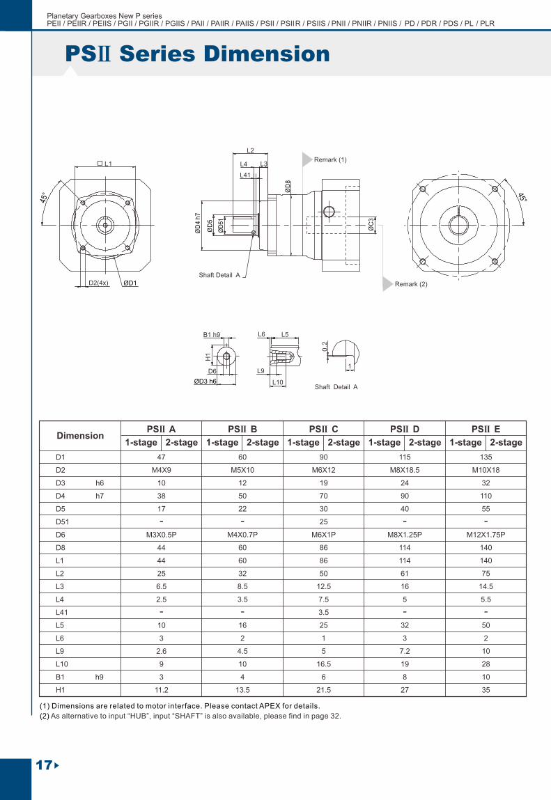
PS Series DimensionII
Shaft Detail A
ØD
8
ØD
4 h
7
ØD
5
ØD
51
L41
L3
L2
L4L1
ØD1D2(4x)
DimensionIIPS A IIPS B IIPS C IIPS D IIPS E
D1
D2
D3 h6
D4 h7
D5
D51
D6
D8
L1
L2
L3
L4
L41
L5
L6
47
M4X9
M3X0.5P
10
38
17
44
44
25
6.5
2.5
2.6
9
3
11.2
10
3
60
M5X10
M4X0.7P
12
50
22
60
60
32
8.5
3.5
4.5
10
4
13.5
16
2
90
M6X12
M6X1P
19
70
30
25
86
86
50
12.5
7.5
5
16.5
6
21.5
3.5
25
1
115
M8X18.5
M8X1.25P
24
90
40
114
114
61
16
5
7.2
19
8
27
32
3
135
M10X18
M12X1.75P
32
110
55
140
140
75
14.5
5.5
10
28
10
35
50
2
-
-
-
-
-
-
-
-
L9
L10
H1
B1 h9
(1) Dimensions are related to motor interface. Please contact APEX for details.
Remark (1)
B1 h9
D6
ØD3 h6
H1
L6
L9
L5
L10Shaft Detail A
0.2
1
1-stage 1-stage 1-stage 1-stage 1-stage2-stage 2-stage 2-stage 2-stage 2-stage
ØC
3
Planetary Gearboxes New P series PEII / PEIIR / PEIIS / PGII / PGIIR / PGIIS / PAII / PAIIR / PAIIS / PSII / PSII R / PSIIS / P NII / PNIIR / PNIIS / PD / PD R / PDS / PL / PLR
(2) As alternative to input “HUB”, input “SHAFT” is also available, please find in page 32.
Remark (2)

18
APEX DYNAMICS, INC.
Dimension
D1
D2
D3 h6
D4 h7
D5
D51
D6
D8
L1
L2
L3
L4
L41
L5
L6
47
M4X9
M3X0.5P
10
38
17
44
44
25
6.5
2.5
2.6
9
47
72
3
11.2
10
3
60
M5X10
M4X0.7P
12
50
22
60
60
32
8.5
3.5
4.5
10
56
85.5
4
13.5
16
2
90
M6X12
M6X1P
19
70
30
25
86
86
50
12.5
7.5
5
16.5
66.5
106.5
6
21.5
3.5
25
1
115
M8X18.5
M8X1.25P
24
90
40
114
114
61
16
5
7.2
19
92
143
8
27
32
3
135
M10X18
M12X1.75P
32
110
55
140
140
75
14.5
5.5
10
28
116
173
10
35
50
2
-
-
-
-
-
-
-
-
L9
L10
L11
L12
H1
B1 h9
PS R Series DimensionII
IIPS R A IIPS R B IIPS R C IIPS R D IIPS R E
62
87
76
105.5
93
133
128
179
163.5
220.5
Shaft Detail A
ØD
8
ØD
4 h
7
ØD
5
ØD
51
L41
L11L3
L2
L4
L12
ØD1
D2(4x)
(1) Dimensions are related to motor interface. Please contact APEX for details.
L1
Remark (1)
B1 h9
D6
ØD3 h6
H1
L6
L9
L5
L10Shaft Detail A
0.2
1
1-stage 1-stage 1-stage 1-stage 1-stage2-stage 2-stage 2-stage 2-stage 2-stage
ØC3

19
StagesModel No. Type
Nominal Output Torque T2N
3
Nm
4
5
7
10
15
16
20
25
30
35
40
50
70
100
1
All
16
16
15
12
10
15
16
16
15
15
12
16
15
12
10
42
42
40
35
27
40
42
42
40
40
35
43
40
35
27
110
113
118
96
68
109
116
116
123
108
100
117
123
100
70
217
223
220
198
155
213
228
230
228
212
206
232
228
206
162
430
440
435
366
295
424
452
454
450
422
382
459
450
382
308
Nm
Nm
Nm
Emergency Stop Torque T2NOT
Max. Acceleration Torque T2B
(4)No Load Running Torque
3 times T2NAll
All
All
1,2
1,2
1
2
2
1
3~100
3~100
3~10
15~100
3~10
15~100
0.05
0.05
arcmin(2)Backlash
≦ 8
≦ 12
≦ 10
≦ 14
T = 60% of T2B 2NOT
0.10
0.15
0.15
0.10
0.10
0.40
0.45
0.10 0.30
0.35
0.40
0.45
0.80
0.85
0.80
0.85
2.50
2.55
≦ 7
≦ 11
≦ 9
≦ 13
≦ 6
≦ 10
≦ 8
≦ 12
≦ 6
≦ 10
≦ 8
≦ 12
≦ 6
≦ 10
≦ 8
≦ 12
1,2 3~100Nm/arcminTorsional Rigidity
IIPN
IIPN
4,500rpm
8,000rpmNominal Input Speed n1N
Max. Input Speed n1B
1,2
1,2
3~100
3~100
All
All
4,000
6,000
3,600
6,000
3,600
4,800
2,500
3,600
N
N
(3)Max. Radial Load F2rB
(3)Max. Axial Load F2aB
1,2 3~100
1,2 3~100 240
480 1,100
550
1,580
790
3,500
1,750
5,420
2,710
%
º C
Efficiency
Operating Temp
Lubrication
Mounting Position
(4) Running Noise
Degree of Gearbox Protection
1,2 3~100
1,2 3~100
1,2 3~100
1,2 3~100
1,2
1,2
1 3~10
2 15~100
≦ 60
≦ 70
≦ 62
≦ 72
≦ 64
≦ 74
≦ 66
≦ 75
≦ 68
≦ 77
≧ 97%
≧ 93%
≧ 94%
≧ 90%
0º C~ +90º C
Synthetic lubrication grease
All directions
IP65
(1) Ratio
2
All
All
All
All
PN / PN R Gearbox PerformanceII II
IIPN
IIPN
IIPN R
IIPN R
IIPN R
IIPN R
IIPN
IIPN
IIPN
IIPN
IIPN R
IIPN R
IIPN R
IIPN R
3~100
3~100
IIPN 017 IIPN 023 IIPN 034 IIPN 042 IIPN 056
IIPN R 017 IIPN R 023 IIPN R 034 IIPN R 042 IIPN R 056
All
All
0.90 1.50 6 12 14
dB(A)
5
3
12
6
22
10
54
19
45
17Nm
Max. bending moment based on (5)the gearbox input flange Mb
0.1 x Mb
motor length (m)
(1) Ratio (i= N / N ) . in out
(2) Backlash is measured at 2% of Nominal Output Torque T .2N
(3) Applied to the output shaft center at 100 rpm .
(4) The dB values are measured by gearbox with ratio 10 (1-stage) or ratio 100 (2-stage), no loading at 3,000 RPM
or at the respective Nominal Input Speed by bigger model size.
By lower ratio and/or higher RPM, the noise level could be 3 to 5 dB higher.
(5) Max. motor weight* (kg) =
*with symmetrically distributed motor weight*with horizontal and stationary mounting
Planetary Gearboxes New P series PEII / PEIIR / PEIIS / PGII / PGIIR / PGIIS / PAII / PAIIR / PAIIS / PSII / PSII R / PSIIS / P NII / PNIIR / PNIIS / PD / PD R / PDS / PL / PLR
APEX DYNAMICS, INC.
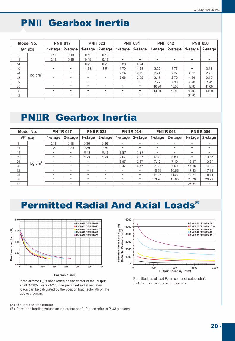
PN Gearbox InertiaII
Model No.(A)Ø (C3)
8
11
14
19
24
28
32
35
38
42
0.10
0.16
------
------
-------
-------
--
----
--
----
---
-
---
-
----
---
-
0.10
0.16
0.12
0.19
0.10
0.16
2kg.cm
0.200.22 0.36 0.24
1.53 1.70 1.58 2.20 1.73 2.181.51
2.24 2.12 2.74 2.27 4.52 2.73
2.68 2.55 3.17 2.70 4.94 3.15
7.77 7.30 9.70 7.91
10.80 10.30 12.80 11.00
14.00 13.50 16.00 14.20
24.50
1-stage 1-stage 1-stage 1-stage 1-stage2-stage 2-stage 2-stage 2-stage 2-stage
0.18
0.20
0.18
0.20
0.36 0.36
0.39 0.39
0.43 0.43 1.87 1.871.24 1.24 2.67 2.67 6.80 6.80 13.57
2.97 2.97 7.10 7.10 13.8713.87
3.47 3.47 7.59 7.59 14.36 14.36
10.56 17.3310.56 17.33
11.97 18.7411.97 18.74
13.95 20.79 20.7913.95
26.54
Model No.(A)Ø (C3)
8
11
14
19
24
28
32
35
38
42
------
------
-------
-------
--
----
--
----
---
-
---
-
----
---
-
2kg.cm
1-stage 1-stage 1-stage 1-stage 1-stage2-stage 2-stage 2-stage 2-stage 2-stage
Position X (mm)
Po
sit
ion
Lo
ad
Facto
r K
b
0
Perm
itte
d R
ad
ial L
oad
F (
N)
2rB
On
Cen
ter
Po
sit
ion
of
sh
aft
Output Speed n (rpm)2
0
500 1000
1000
2000
3000
4000
5000
6000
1500 2000
PN R Gearbox InertiaII
IIPN 017 IIPN 023 IIPN 034 IIPN 042 IIPN 056
IIPN R 017 IIPN R 023 IIPN R 034 IIPN R 042 IIPN R 056
(B) Permitted Radial And Axial Loads
If radial force F is not exerted on the center of the output 2r
shaft X<1/2xL or X>1/2xL, the permitted radial and axial loads can be calculated by the position load factor Kb on the above diagram.
Permitted radial load F on center of output shaft 2r
X=1/2 x L for various output speeds.
(A) Ø = Input shaft diameter.(B) Permitted loading values on the output shaft. Please refer to P. 33 glossary.
20
0 50 100 150 2000.00
0.50
1.00
1.50
2.00
250 300 350
PN 017IIPN 023II
PN 034IIPN 042IIPN 056II
IIII
II
IIII
PN R 017IIPN R 023II
PN R034PN R 042IIPN R 056II
II
II
IIII
II//
///
PN 017IIPN 023II
PN 034IIPN 042IIPN 056II
IIII
II
IIII
PN R 017IIPN R 023II
PN R034PN R 042IIPN R 056II
II
II
IIII
II//
///

Dimension
PN Series DimensionII
D1
D2
D3 h6
D4 h6
D5
D6
L2
L1
L3
L4
L5
L6
L7
43.815
3.4
M4X0.7P
22
17
41.91
31.75
1.6
1
4.5
10
19.05
3.788
6.35
66.675
5.2
38.1
17
57.15
1
4.5
10
3.175
14.125
19.05
9.525
98.425
5.6
M6X1P
73.025
30
82.55
38.1
3.5
5
16.5
4.763
21.163
25.4
9.525
125.73
7.2
M10X1.5P
55.55
35
106.68
50.8
1.5
7.5
22
6.35
28.2
31.75
5.175
12.7
177.8
10.5
M16X2P
114.3
55
146.05
63.5
3.2
5.5
12
36
9.525
42.275
38.1
8.563
19.05
L9
L10
H1
B1 h9
IIPN 017 IIPN 023 IIPN 034 IIPN 042 IIPN 056
(1) Dimensions are related to motor interface. Please contact APEX for details.
1-stage 1-stage 1-stage 1-stage 1-stage2-stage 2-stage 2-stage 2-stage 2-stage
12.7 12.7 19.05 25.4 38.1
M4X0.7P
31.75
1.6 1.6 1.6
3.788 3.807
3.175
14.125
L1
ØD1ØD2 (4x)L7 Shaft Detail A
ØD
4 h
6
ØD
5
L3
L2
L4
ØC
3
B1 h9
D6
ØD3 h6
H1
L6
L9
L5
L10Shaft Detail A
0.2
1
Remark (1)
21
Planetary Gearboxes New P series PEII / PEIIR / PEIIS / PGII / PGIIR / PGIIS / PAII / PAIIR / PAIIS / PSII / PSII R / PSIIS / P NII / PNIIR / PNIIS / PD / PD R / PDS / PL / PLR
(2) As alternative to input “HUB”, input “SHAFT” is also available, please find in page 32.
Remark (2)

Dimension
D1
D2
D3 h6
D4 h6
D5
D6
L1
L2
L3
L4
L5
L6
L7
43.815
3.4
M4X0.7P
12.7
22
17
41.91
31.75
1.6
1
4.5
10
66.675
5.2
M4X0.7P
12.7
38.1
17
57.15
4.5
10
98.425
5.6
M6X1P
19.05
73.025
30
82.55
5
16.5
125.73
7.2
M10X1.5P
25.4
55.55
35
106.68
7.5
22
177.8
10.5
M16X2P
38.1
114.3
55
146.05
12
36
L9
L10
L11
L12
H1
B1 h9
78.4
53.4
93.4
68.4
97.4
67.9
117.4
87.9
117.9
77.9
144.4
104.4
162.4
111.4
198.4
147.4
184.3
127.3
231.8
174.8
(1) Dimensions are related to motor interface. Please contact APEX for details.
1-stage 1-stage 1-stage 1-stage 1-stage2-stage 2-stage 2-stage 2-stage 2-stage
APEX DYNAMICS, INC.
PN R Series DimensionII
IIPN R 017 IIPN R 023 IIPN R 034 IIPN R 042 IIPN R 056
31.75
1.6
1
38.1
3.5
50.8
1.5
63.5
3.2
5.5
1.6 1.6
19.05
3.788
6.35
19.05
9.525
25.4
9.525
31.75
5.715
12.7
38.1
8.563
19.05
3.788 3.807
3.175
14.125
4.763
21.163
6.35
28.2
9.525
42.275
3.175
14.125
B1 h9
D6
ØD3 h6
H1
L6
L9
L5
L10Shaft Detail A
0.2
1
ØD2 (4x) ØD1
L1L11L3
L2
L4
L12
Shaft Detail A
ØD
4 h
6
ØD
5
L7
ØC3
Remark (1)
22

PD / PDR Gearbox Performance
23
StagesModel No. Type
Nominal Output Torque T2N
3
Nm
4
5
7
10
15
16
20
25
30
35
40
50
70
100
1
All
16
16
15
12
10
15
16
16
15
15
12
16
15
12
10
42
42
40
35
27
40
42
42
40
40
35
43
40
35
27
110
113
118
96
68
109
116
116
123
108
100
117
123
100
70
217
223
220
198
155
213
228
230
228
212
206
232
228
206
162
Nm
Nm
Nm
Emergency Stop Torque T2NOT
Max. Acceleration Torque T2B
(4)No Load Running Torque
3 times T2NAll
All
1,2
1,2
1
2
2
1
3~100
3~100
3~10
15~100
3~10
15~100
0.05
0.05
arcmin(2)Backlash
≦ 8
≦ 12
≦ 10
≦ 14
T = 60% of T2B 2NOT
0.10
0.15
0.15
0.10
0.10
0.40
0.45
0.10 0.30
0.35
0.40
0.45
0.80
0.85
≦ 7
≦ 11
≦ 9
≦ 13
≦ 6
≦ 10
≦ 8
≦ 12
≦ 6
≦ 10
≦ 8
≦ 12
1,2 3~100Nm/arcminTorsional Rigidity
PD
PD
4,500rpm
8,000rpmNominal Input Speed n1N
Max. Input Speed n1B
1,2
1,2
3~100
3~100
All
All
4,000
6,000
3,600
6,000
3,600
4,800
N
N
Nm
(3)Max. Radial Load F2rB
(3)Max. Axial Load F2aB
Max. Tilting Moment M2K
1,2 3~100
1,2
1,2
3~100
3~100
1,045 880
440
17
1,615
808
44
3,675
1,838
140
%
º C
Efficiency
Operating Temp
Lubrication
Mounting Position
(4) Running Noise
Degree of Gearbox Protection
1,2 3~100
1,2 3~100
1,2 3~100
1,2 3~100
1,2
1 3~10
2 15~100
≦ 60
≦ 70
≦ 62
≦ 72
≦ 64
≦ 74
≦ 66
≦ 75
≧ 97%
≧ 93%
≧ 94%
≧ 90%
0º C~ +90º C
Synthetic lubrication grease
All directions
IP65
(1) Ratio
2
All
All
All
All
PD
PD
PDR
PDR
PDR
PDR
PD
PD
PD
PD
PDR
PDR
PDR
PDR
3~100
PD 053 PD 064 PD 090 PD 110
PDR 053 PDR 064 PDR 090 PDR 110
523
22
All
All
All
All 31.2 10.8 16.2
dB(A)
1,2 3~1007
4
16
9
56
25
31
16Nm
Max. bending moment based on (5)the gearbox input flange Mb
0.1 x Mb
motor length (m)
(1) Ratio (i= N / N ) . in out
(2) Backlash is measured at 2% of Nominal Output Torque T .2N
(3) Applied to the output flange center at 100 rpm .
(4) The dB values are measured by gearbox with ratio 10 (1-stage) or ratio 100 (2-stage), no loading at 3,000 RPM
or at the respective Nominal Input Speed by bigger model size.
By lower ratio and/or higher RPM, the noise level could be 3 to 5 dB higher.
(5) Max. motor weight* (kg) =
*with symmetrically distributed motor weight*with horizontal and stationary mounting
Planetary Gearboxes New P series PEII / PEIIR / PEIIS / PGII / PGIIR / PGIIS / PAII / PAIIR / PAIIS / PSII / PSII R / PSIIS / P NII / PNIIR / PNIIS / PD / PD R / PDS / PL / PLR

PD
Model No.(A)Ø (C3)
8
11
14
19
24
28
32
35
38
42
0.10
0.16
------
------
-------
-------
--
----
--
----
---
-
---
-
0.10
0.16
0.12
0.19
0.10
0.16
2kg.cm
0.200.22 0.36 0.24
1.53 1.70 1.58 2.20 1.731.51
2.24 2.12 2.74 2.27
2.68 2.55 3.17 2.70
7.77 7.30
10.80 10.30
14.00 13.50
APEX DYNAMICS, INC.
PD Gearbox Inertia
PD 053 PD 064 PD 090 PD 110 1-stage 1-stage 1-stage 1-stage2-stage 2-stage 2-stage 2-stage
24
0.18
0.20
0.18
0.20
0.36 0.36
0.39 0.39
0.43 0.43 1.87 1.87
1.24 1.24 2.67 2.67 6.80 6.80
2.97 2.97 7.10 7.10
3.47 3.47 7.59 7.59
10.56 10.56
11.97 11.97
13.95 13.95
Model No.(A)Ø (C3)
8
11
14
19
24
28
32
35
38
42
------
------
-------
-------
--
----
--
----
---
-
---
-
2kg.cm
PDR Gearbox Inertia
1-stage 1-stage 1-stage 1-stage2-stage 2-stage 2-stage 2-stage
PDR 053 PDR 064 PDR 090 PDR 110
(A) Ø = Input shaft diameter.
PD / PDR
Z2【mm】
M2K =F2a * Y + F2r * (X+Z2)
1000
M2K 【Nm】:
F2a, F2r 【N】:
X, Y, Z2 【mm】:
23.8 21.5 30.1 42.1
Note : Applied to the output flange center at 100 rpm.
053 064 090 110
Max. Tilting Moment M2K
PDR
Z2
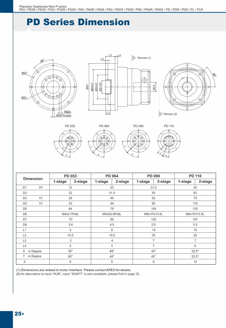
Dimension
D1 H7
D2
D3 h7
D4 h7
D5
D6
D8
D7
L1
L2
L3
L4
X in Degree
Z
12
22
M4x0.7Px8L
28
53
64
3.4
70
4
14.5
3
20
31.5
M5xX0.8Px8L
40
64
79
4.5
88
31.5
50
M6x1Px13.5L
63
90
109
5.5
120
40
63
M6x1Px13.5L
75
110
135
5.5
147
(1) Dimensions are related to motor interface. Please contact APEX for details.
1-stage 1-stage 1-stage 1-stage2-stage 2-stage 2-stage 2-stage
8
19.5
4
15
7
15
7
30 29
5
30°
60°
6
5
45°
45°
8
7 8
22.5°
22.5°
12
PD Series Dimension
PD 053 PD 064 PD 090 PD 110
45°
45°
8
PD 053 PD 064 PD 090 PD 110
Y in Degree
Remark (1)
X
Y
Y
X
Y
XY
X
ØD5
ØD8Thru(8x)
D6(Zx)
ØD2
ØD
4 h
7
ØD
7
L3
L2 L4
ØC
3
L1
ØD
3 h
7
ØD
1 H
7
25
Planetary Gearboxes New P series PEII / PEIIR / PEIIS / PGII / PGIIR / PGIIS / PAII / PAIIR / PAIIS / PSII / PSII R / PSIIS / P NII / PNIIR / PNIIS / PD / PD R / PDS / PL / PLR
(2) As alternative to input “HUB”, input “SHAFT” is also available, please find in page 32.
Remark (2)

APEX DYNAMICS, INC.
PDR Series Dimension
Remark (1)
PDR 053 PDR 064 PDR 090 PDR 110
X
Y
Y
X
Y
XY
X
ØD5
ØD8Thru(8x)
D6(Zx)
ØD2
L11
L3
L2
L4
L12
ØC3
ØD
4 h
7
ØD
7
ØD
3 h
7
ØD
1 H
7
L1
26
X in Degree 30°
60°
45°
45°
22.5°
22.5°
45°
45°Y in Degree
PDR 053 PDR 064 PDR 090 PDR 110 Dimension
D1 H7
D2
D3 h7
D4 h7
D5
D6
D8
D7
L1
L2
L3
L4
L11
L12
Z
12
22
28
53
64
3.4
70
4
14.5
3
20
31.5
M5X0.8Px8L
40
64
79
4.5
88
31.5
50
63
90
109
5.5
120
40
63
M6X1Px13.5L
75
110
135
5.5
147
(1) Dimensions are related to motor interface. Please contact APEX for details.
1-stage 1-stage 1-stage 1-stage2-stage 2-stage 2-stage 2-stage
8
19.5
4
15
7
15
7
30 29
5
42.8
67.8
6
5
39.5
69
8
7 8
128
57.8
82.8
59.5
89
49.6
89.6
76.1
116.1
75.4
126.4
111.4
162.4
M4x0.7Px8L M6x1Px13.5L
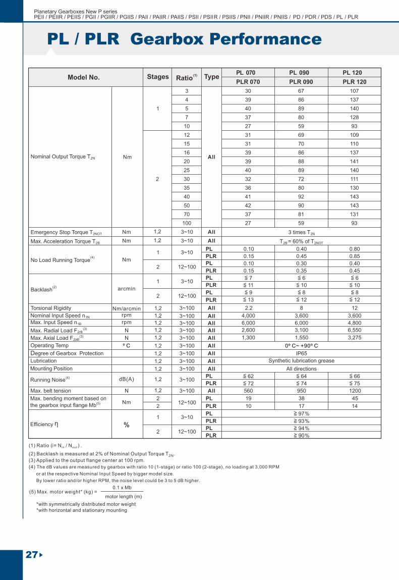
PL / PLR Gearbox Performance
StagesModel No. Type
Nominal Output Torque T2N
3
Nm
4
5
7
10
12
15
16
20
25
30
35
40
50
70
100
1
All
Nm
Nm
Nm
Emergency Stop Torque T2NOT
Max. Acceleration Torque T2B
(4)No Load Running Torque
3 times T2NAll
All
1,2
1,2
1
2
2
1
3~10
3~10
3~10
12~100
3~10
12~100
arcmin(2)Backlash
T = 60% of T2B 2NOT
1,2 3~100Nm/arcminTorsional Rigidity
rpm
rpmNominal Input Speed n1N
Max. Input Speed n1B
1,2
1,2
3~100
3~100
All
All
N
N
N
(3)Max. Radial Load F2rB
(3)Max. Axial Load F2aB
1,2 3~100
1,2 3~100
%
º C
Efficiency
Operating Temp
Lubrication
Mounting Position
(4) Running Noise
Degree of Gearbox Protection
1,2 3~100
1,2 3~100
1,2 3~100
1,2
1,2
3~100
3~100
1,2
1 3~10
2 12~100
≦ 62
≦ 72
≦ 64
≦ 74
≦ 66
≦ 75
≧ 97%
≧ 93%
≧ 94%
≧ 90%
0º C~ +90º C
Synthetic lubrication grease
All directions
IP65
(1) Ratio
2
All
All
All
All
All
3~100
All
All
All
dB(A)
30
39
40
37
27
31
31
39
39
40
32
36
41
42
37
27
67
86
89
80
59
69
70
86
88
89
72
80
92
90
81
59
PL 070 PL 090
PLR 070 PLR 090 PLR 120
107
137
140
128
93
109
110
137
141
140
111
130
143
143
131
93
PL
PL
PLR
PLR
PL
PLR
PL
PLR
≦ 7
≦ 11
≦ 9
≦ 13
0.45
0.30
0.35
8
0.15
0.10
0.15
2.2
0.80
0.85
0.40
0.45
12
≦ 6
≦ 10
≦ 8
≦ 12
≦ 6
≦ 10
≦ 8
≦ 12
4,000
6,000
3,600
6,000
3,600
4,800
2,600 3,100
1,550
6,550
3,2751,300
0.10 0.40
PL
PL
PLR
PLR
PL
PLR
PL
PLR
PL 120
27
19
560
10
38
950
17
45
1200
14Nm
Max. bending moment based on (5)the gearbox input flange Mb
212~100
2
Max. belt tension
0.1 x Mb
motor length (m)
(1) Ratio (i= N / N ) . in out
(2) Backlash is measured at 2% of Nominal Output Torque T .2N
(3) Applied to the output flange center at 100 rpm .
(4) The dB values are measured by gearbox with ratio 10 (1-stage) or ratio 100 (2-stage), no loading at 3,000 RPM
or at the respective Nominal Input Speed by bigger model size.
By lower ratio and/or higher RPM, the noise level could be 3 to 5 dB higher.
(5) Max. motor weight* (kg) =
*with symmetrically distributed motor weight*with horizontal and stationary mounting
Planetary Gearboxes New P series PEII / PEIIR / PEIIS / PGII / PGIIR / PGIIS / PAII / PAIIR / PAIIS / PSII / PSII R / PSIIS / P NII / PNIIR / PNIIS / PD / PD R / PDS / PL / PLR
PL+Pulley PLR+Pulley
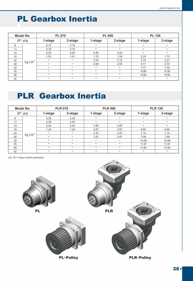
Model No.(A)Ø (C3)
8
11
14
19
24
28
32
35
38
42
- -- -- -- -- -- -
- -- -
- -- -- -- -
- -- -- -
- -
0.12 0.10
0.19 0.16
2kg.cm
0.22 0.20 0.36 0.24
1.53 1.51 1.70 1.58 2.20 1.73
2.24 2.12 2.74 2.27
2.68 2.55 3.17 2.70
7.77 7.30
10.80 10.30
14.00 13.50
0.36 0.36
0.39 0.39
0.43 0.43 1.87 1.871.24 1.24 2.67 2.67 6.80 6.80
2.97 2.97 7.10 7.10
3.47 3.47 7.59 7.59
10.56 10.56
11.97 11.97
13.95 13.95
Model No.(A)Ø (C3)
8
11
14
19
24
28
32
35
38
42
- -- -- -- -- -- -
- -- -
- -- -- -- -
- -- -- -
- -
2kg.cm
APEX DYNAMICS, INC.
PL Gearbox Inertia
PL 070 PL 090 PL 120 1-stage 2-stage 1-stage 2-stage 1-stage 2-stage
PLR Gearbox Inertia
1-stage 2-stage 1-stage 2-stage 1-stage 2-stage
PLR 070 PLR 090 PLR 120
(A) Ø = Input shaft diameter.
PL PLR
28

X in Degree
Y in Degree
PL Series Dimension
Dimension
D1 D2
D3 h7
D4
D5 h7
D6
D8
D9
D7 H7
L1
R
L2
L3
L4
L5
L6
L7
L8
L9
L10
Z
82
6.6
M5X0.8P
M5X0.8P
25
58
68
6
70
12.7
106
9
M6X1P
M6X1P
40
74
88
8
144
13
M6X1P
M8X1.25P
50
100
118
8
(1) Dimensions are related to motor interface. Please contact APEX for details.
1-stage 2-stage 1-stage 2-stage 1-stage 2-stage
92
4
68.3
18.3
122
2
15.7
82.2
3.8
10
8.8
8
10
18.5
12
64°
58°
5
3.7
10.5
14.5
10
15
27
16
45°
45°
7
4.5
12.5
18.5
12
16
28
16
45°
45°
7
PL 070 PL 090 PL 120
18 31 37
-
60.2
Remark (1)D9 (Zx) X
Y
ØD6
ØD2 Thru(4x) ØD1
L1
L6
ØD
4
L3
L2
L4
ØC
3
L10
ØD
3 h
7
ØD
7 H
7(1
x)
ØD
5 h
7
ØD
8(1
x)
A
L5
L9
L8
R
L7
AØ
0.0
5
29
Planetary Gearboxes New P series PEII / PEIIR / PEIIS / PGII / PGIIR / PGIIS / PAII / PAIIR / PAIIS / PSII / PSII R / PSIIS / P NII / PNIIR / PNIIS / PD / PD R / PDS / PL / PLR

X in Degree
Y in Degree
64°
58°
45°
45°
45°
45°
APEX DYNAMICS, INC.
PLR Series Dimension
Dimension
D2
D3 h7
D4
D5 h7
D6
D8
D9
L1
R
L2
L3
L4
L5
L6
L7
L8
L9
L10
L11
L12
Z
82
6.6
M5X0.8P
M5X0.8P
25
58
68
6
70
60.2
12.7
106
9
M6X1P
M6X1P
40
74
88
8
144
13
M6X1P
M8X1.25P
50
100
118
8
(1) Dimensions are related to motor interface. Please contact APEX for details.
92
4
68.3
18.3
122
2
15.7
82.2
3.8
10
8.8
8
10
18.5
16.8 36.8
46.3 66.3
5
3.7
10.5
14.5
10
15
27
22.2 48.9
62.2 88.9
7
4.5
12.5
18.5
12
16
28
34.8 71.1
85.8 122.1
7
PLR 070 PLR 090 PLR 120
18 31 37
-
12 16 16
D9 (Zx) X
Y
ØD6
ØD
2 T
hru
(4x)
ØD1
L1 L6
ØD
4
L3
L2
L4
ØC3
L10
ØD
3 h
7
ØD
7 H
7(1x
)
ØD
5 h
7
ØD
8(1x
)
L5
R
L7
AØ
0.0
5
A
L9
L8
L12
L11
Remark (1)
D1
D7 H7
1-stage 2-stage 1-stage 2-stage 1-stage 2-stage
30

31
Planetary Gearboxes New P series PEII / PEIIR / PEIIS / PGII / PGIIR / PGIIS / PAII / PAIIR / PAIIS / PSII / PSII R / PSIIS / P NII / PNIIR / PNIIS / PD / PD R / PDS / PL / PLR
PL+PULLEY Dimension
Reducer
71
72.9
72.9
91.7
98.4
124.6
43
44
44
28
36
19
0.57
0.65
0.65
1.00
1.18
2.71
mm
D1
Pitch P
98.4 36 1.18
L1 L2 L3Belt Pulley
137
PL 070PLR 070 41.8
41.8
41.8
14.8 51
14.8 51
14.8 51
PL 090PLR 090 51.3
51.3
51.3
24.3 51
24.3 51
24.3 51
PL 120PLR 120 57.7
57.7
17.7 76
17.7 76
AT05-W50-T43
HTD 5M-W50-T44
5GT-W50-T44
AT10-W50-T28
HTD 8M-W50-T36
8YU-W50-T36
AT20-W75-T19
HTD 14M-W75-T28
mm/rotation 2kgcm kg
No.of TeethZ
Circumference Z*P
Interia J
Mass m
3.20
4.68
5.58
5.58
14.07
17.78
69.55
17.78
87.8328
215
220
220
280
288
380
288
392
5
5
5
10
8
20
8
14
ØD
1
L2
L1
L3
PULLEY ORDERING CODE
(1) (2) (3)PUL070 AT05 B -
Ordering Example : PUL 070 - AT05 - B PUL 090 - 8YU - N
Pulley size corresponds to gearbox size:PUL 070: PL 070, PLR 070PUL 090: PL 090, PLR 090PUL 120: PL 120, PLR 120
-
(1) Pulley size.
(2) Pulley specification.
( 3) Pulley appearance. B = Manganese phosphate blackening (Standard) N = Nickel plating

(2) The customization detail please contact with APEX sales.
32
APEX DYNAMICS, INC.
Performance - P S (Input shaft as option)II
Dimension - P S (Input shaft as option)II
Kg cm. 2
N
N
Max. Radial Load F1rB
Max. Axial Load F1aB
Moment of Inertia
(1)
(1)
125 285 565 950 2,000
63 143 283 475 1,000
0.03 0.13 0.62 2.07 10.90
Model NO.
PEIIS 050 PEIIS 070 PEIIS 090 PEIIS 120 PEIIS 155
PGIIS 060 PGIIS 080 PGIIS 120 PGIIS 160PGIIS 040
PAIIS 060 PAIIS 090 PAIIS 115 PAIIS 142PAIIS 042
PSIIS B PSIIS C PSIIS D PSIIS EPSIIS A
PNIIS 023 PNIIS 034 PNIIS 042 PNIIS 056PNIIS 017
PDS 064 PDS 090 PDS 110 -PDS 053
(1) Applied to the input shaft center at 1000 rpm.
D10
Dimension
PEIIS 050 PEIIS 070 PEIIS 090 PEIIS 120 PEIIS 155
PGIIS 060 PGIIS 080 PGIIS 120 PGIIS 160PGIIS 040
PAIIS 060 PAIIS 090 PAIIS 115 PAIIS 142PAIIS 042
PSIIS B PSIIS C PSIIS D PSIIS EPSIIS A
PNIIS 023 PNIIS 034 PNIIS 042 PNIIS 056PNIIS 017
PDS 064 PDS 090 PDS 110 -PDS 053
15 20 30 35 55
26 40 60 80 110
40 60 86 114 143
M4x9 M5x10 M6x10 M10x18
D11
D12
D13
D14
D15
D16
L13
L14
L15
L16
L17
L18
L19
B2
H2
h7
h6
h9
34 52 70 100 130
M3x0.5P M3x0.5P M5x0.8P M6x1P M12x1.75P
8 10 16 20 35
20 28 30 45 65
17 23 26 40 58
2 3 3 4 5
12 18 20 32 45
2.5 3 4 7
2.6 2.6 4.8 5 10
9 9 12.5 16.5 28
2 3 5 6 10
8.8 11.2 18 22.5 38
M10x18
2.5

33
Selection of the optimum gearbox
Selection Start
Continuous OperationCyclic OperationS5 S1
YES NO
Calculate Ratio i
(Eq.1)
(Eq.2)
ED<60%t <20minswork
Calculate the Mean Output
Torque T2m(Eq.3)
Calculate the Mean Output
Torque T2m(Eq.3)
Calculate the Max.Acceleration Torque
T2max(Eq.4)
Select a LargerGearbox
YES
NO NO Select a LargerGearbox
T <T2max 2B
T <T2m 2N
T <T2m 2N
Calculate the Mean Output Speed n and the2m
Nominal Output Speed n of Gearbox2N
(Eq.5)
YES
n <n2m 2N
YES
NOSelect a Smaller Ratio
i in Larger Motor IfNeeded
(Eq.6)
Calculate the Mean Radial F and Axial Loads 2rm
F on Output Shaft of Gearbox2am
Calculate the Permitted Radial F and Axial 2rB
Loads F on Output Shaft of Gearbox2aB
F <F2rm 2rB
F <F2am 2aB
NOSelect a Larger Gearbox
YES
Select the Required Backlash and Shaft Option
Order your APEX Gearbox
Recommended (for S5 Cycle Operation)
The general design is given for
The optimal design is given for
JL
2i
JL Load Inertia
Jm Motor Inertia
4 x Jm
Calculate Ratio i (Eq.2)
Motion Profile
Ou
tpu
t S
pe
ed
Lo
ad
s o
n O
utp
ut
Sh
aft
Ou
tpu
t To
rqu
e
T2a
T2c
T2p
T2d
F2aa
F2ac
F2ap
F2ad
F2ra
F2rc
F2rp
F2rd
n2a
n2c
n2d
n2p
、
、
、
、
Time
ta tc td tp
tcycle
(Eq.1)
(Eq.2)
(Eq.3)
1. ED = x 100%, t = t + t + t work a c d
t + t + ta c d
tcycle
Index : a. Acceleration, c. Constant,
d. Deceleration, p. Pause
~
n Output Speed of the Motorm
n Working Speedwork
nwork
nm2. i
3. T =2m
3 3 3n x t x T + n x t x T +n x t x T2a a 2a 2c c 2c 2d d 2d
、
n x t + n x t +n x t2a a 2c c 2d d
3
4. T = T x i x K x2max mB s
where K iss
Ks No. of Cycles / hr
0 ~ 1,0001.0
1,000 ~ 1,5001.1
1,500 ~ 2,0001.3
2.000 ~ 3,0001.6
3.000 ~ 5,0001.8
T Max. Output Torque of the MotormB
Efficency of the Gearbox (Eq.4)
215. n = n =2a 2d
x n2c
6. F =2rm
3 3 3n x t x F + n x t x F +n x t x F2a a 2ra 2c c 2rc 2d d 2rd
n x t + n x t +n x t2a a 2c c 2d d
3
n =2m
n x t + n x t +n x t2a a 2c c 2d d
t + t + ta c d
n =2N
n1N
i(Eq.5)
F =2am
3 3 3n x t x F + n x t x F +n x t x F2a a 2aa 2c c 2ac 2d d 2ad
n x t + n x t +n x t2a a 2c c 2d d
3
(Eq.6)
JL
2iJm
~=
Planetary Gearboxes New P series PEII / PEIIR / PEIIS / PGII / PGIIR / PGIIS / PAII / PAIIR / PAIIS / PSII / PSII R / PSIIS / P NII / PNIIR / PNIIS / PD / PD R / PDS / PL / PLR

APEX DYNAMICS, INC.
34
Glossary
rpm
rpmMax. Input Speed n1B
Efficiency %
Operating Temperature º C
Lubrication
dB(A)
Nominal Input Speed n1N
Running Noise
Emergency Stop Torque T2NOT
Max. Acceleration Torque T2B
The Emergency Stop Torque is the maximum permitted torque at the output of gearbox. This may happen only occasionally and may not exceed 1,000 times during the whole service life.
Under the Cyclic Operation (S5), the Max. Acceleration Torque is the maximum torque which can be transmitted only briefly to the output of gearbox up to 1,000 cycles/hr.
No Load Running Torque The No Load Running Torque is the min. torque to overcome the internal friction of a gearbox without loading*.
The Nominal Input Speed is the permitted input speed of gearbox by the Continuous Operation (S1) while the housing temperature does not exceed 90°C. This value is measured at environment temperature 25°C.
The Max. Input Speed is the max. permitted input speed of gearbox by the Cyclic operation (S5). Thisvalue is measured at environment temperature 25°C and serves as the absolute limit of the gearbox.
Backlash arcmin
The Backlash is the maximum angular measurement between two teeth of gears when the transverse operation occurs (refer to Diagram 1). The arcmin is the measurement unit for the backlash. One arcmin equals 1/ 60 degree, symbolized as 1'.
Nm/arcminTorsional Rigidity
Moment of Inertia J12kg.cm
The transmission efficiency of the gears inside a gearbox (without friction).
The Operating Temperature indicates the temperature of gearbox housing.
APEX uses synthetic lubrication grease. Alternate greases are available, please contact APEX.
The Running Noise is measured depends on gearbox size, the ratio and the speed*. Higher speed usually induces higher noise level, while higher ratio induces lower noise level.
The Moment of Inertia J1 is a measurement of the effort applied to an object to maintain its momentary condition at rest or rotating.
Breakaway TorqueThe Breakaway Torque is the minimum torque to start the rotation from the input side of gearbox. A smaller size or a higher ratio gearbox requests less Breakaway Torque.Nm
Back Driving TorqueThe Back Driving Torque is the minimum torque to start the rotation from the output side of gearbox. A larger size or a higher ratio gearbox requires greater Back Driving Torque.Nm
Operating pitch circles
(transverse operation)Backlash
Ø(arcmin)
Ø(arcmin)
Test torque
-T(Nm)T(Nm)
50% 100%
T
Ø
* This value is measured at environment temperature 25°C and the input speed 3,000 rpm. If the Nominal Input Speed n of gearbox is 1N
over 3,000 rpm, this value is measured by that specific Nominal Input Speed.
F2 r
F2a
F2 r
F2a
Radial Load
Axial Load
L
X
Radial Load And Axial Load
The permitted radial and axial loads on output shaft of the gearbox depend on the design of the gearbox supporting bearings.
N
Degree of Protection IP code stands for International Protection standard. The IP65 as example: the first IP number stands for protection degree against dust; the second IP number stands for protection against liquid.
Nm
Nm
Nm
Diagram 1
Diagram 2B
ackla
sh(defined)Torsional Rigidity is the quotient (△T / △Ø) between
the applied torque and resulting torsion angle. This value indicates how much torque is needed on the gearbox to rotate the output shaft for 1 arcmin. The Torsional Rigidity can be determined by Hysteresis Curve.
Hysteresis CurveWhen the input shaft is locked, increase torque at the
output slowly up to T in both directions and 2B
then release the torque gradually. According to the measured torque and torsion angle, a closed curve will be acquired as in the Diagram 2.

LIMAN TRADING LIMITED FZC LLCP.O. Box 97 , Postal Code 322, Corporate Parks,Sohar Free Zoon, Oman
APEX DYNAMICS MIDLANDS LTDTEL +44-0121-737-1170Heath House, Cheadle Rd, U?oxeter, ST14 7BY, [email protected]
UAB "APEKSO DINAMIKA"TEL +370 52078165Medaus g. 28A, Medininku k., Vilniaus r. [email protected]
APEX DYNAMICS AUSTRIA GmbHTEL +43 720788416Dr. Hans-Lechner-Strasse 6, 5071 Wals-Siezenheim [email protected]
APEX DYNAMICS JAPANTEL +88-092-45112021-3-46, Hanmichibasi, Hakata-ku, Fukuoka, 812-0897, [email protected]
APEX DYNAMICS DENMARKTEL +45 73121260Grundtvigs Allé 165, 6400Sønderborg, [email protected]
APEX DYNAMICS ISRAEL TEL +972-3-647047117 Hamefalsim St., Kiryat Arye, Petach-Tikva [email protected]
APEX DYNAMICS SLOVAKIA S.R.O.TEL +421919400476Trenčianska cesta 887/52, 957 01 Bánovce nad Bebravou, Slovak republic
APEX DYNAMICS (I) JVTEL +91-9607927142Shop No. 02, S. No. 100/5, Pune-Satara Highway,Ambegaon Khurd, Pune-411046 Maharashtra, [email protected]
APEX DYNAMICS GERMANY GMBHTEL +49-7171 798069-0Marie-Curie-Straße 25 D-73529 Schwäbisch Gmü[email protected]
APEX DYNAMICS SWITZERLAND AGTEL +41-55-4517020Obergasse 40, CH-8854 Galgenen, [email protected]
Ul. Krakowska 50, 32-083 Balice, [email protected]
11 - Burospace - 91570 - Bièvres, [email protected]
APEX DYNAMICSITALY SRLTEL +39 02 36634521VIA E. DE AMICIS, 2-20091 BRESSO (MI)
87 Soi Ladkrabang 30, Ladkrabang, Ladkrabang,Bangkok 10520, [email protected]. th
APEX DYNAMICSK OREA INCTEL +82-31-81799927-5, Aenigol-gil, Ilsandong-gu, Goyang-si, Gyeonggi-do, Republic of Korea [email protected]
APEKS DINAMIK REDUKTOR DISLI SAN TIC ASTEL +90-232-458996010053 SOKAK NO: 9 A.O.S.B. CIGLI – IZMIR– [email protected]
APEX DYNAMICS MOTION (M) SDN BHDTELTEL +60 7237 1055Block A1-2, #35-03, Mercu 1 Jalan Tanjung Puteri 1, R & F Tanjung Puteri, Johor Bahru 80300, Johor. [email protected]
APEX-2021-03-PII/PIIR/PIIS SERIES-TWNPrinted in Taiwan
No10. Keyuan 3rd RD.Situn District, Taichung City 40763, Taiwan (R.O.C)Tel:886-4-24650219 | Fax:886-4-24650118 [email protected] | h�p://www.apexdyna.com
APEX DYNAMICS, INC.