001-057 Alfa GT Q2 GB - AlfaWiki
271
Alfawiki.nl
-
Upload
khangminh22 -
Category
Documents
-
view
1 -
download
0
Transcript of 001-057 Alfa GT Q2 GB - AlfaWiki

Alfawiki.nl

Alfawiki.nl

1
Dear Client,
Thank you for choosing Alfa Romeo.
Your Alfa GT has been designed to guarantee the safety, comfort and driving pleasure typical of Alfa Romeo.
This booklet will help you to get to know the characteristics and operation of your car.
The following pages contain all the indications necessary for you to be able to maintain the high standards of performance, quality, safety andrespect for the environment which characterise this Alfa GT.
The enclosed Warranty Booklet also contains the regulations, the warranty certificate and a guide to the services offered by Alfa Romeo.
Services which are essential and precious because, when you purchase an Alfa Romeo, you are not only acquiring a car, but the tranquillity thatcomes from knowing that an efficient, willing and widespread organisation is at your service for any assistance problems you may have.
Nature benefits in two ways: there’s no pollution from waste disposal and the demand for raw materials is reduced.
Enjoy the reading. And have a good trip.
This booklet describes all the versions of the Alfa GT, so you should only consider the information concerning thetrim level, engine and version purchased by you.
Alfawiki.nl

2
VERY IMPORTANT!
FUEL CAPACITY
Petrol engines: only use unleaded petrol with no less than 95 R.O.N.
Diesel engines: only refuel with diesel fuel conforming to the European specification EN590. The use of other products ormixtures may irreparably damage the engine with invalidation of the warranty due to the damage caused.
STARTING THE ENGINE
Petrol engines with mechanical transmission: make sure that the handbrake is engaged; set the gearshift leverto neutral, fully depress the clutch without pressing the accelerator, then turn the ignition key to AVV and release it as soonas the engine has started.
Petrol engine with Selespeed transmission: keep the brake pedal fully depressed, turn the ignition key to AVV andrelease it as soon as the engine has started; the transmission sets to neutral automatically (the display shows position N).
JTD engines: turn the ignition key to MAR and wait for the Y andm warning lights to go off; turn the ignition keyto AVV and release it as soon as the engine has started.
PARKING ON FLAMMABLE MATERIAL
While working, the catalyst develops a very high temperature. Do not park the car over grass, dry leaves, pine needles orany other inflammable materials: risk of fire.
K
�Alfawiki.nl
3
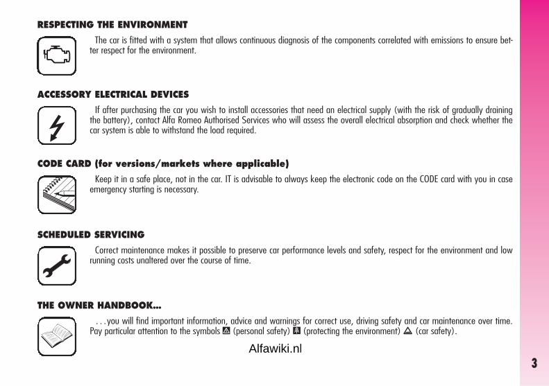
ACCESSORY ELECTRICAL DEVICES
If after purchasing the car you wish to install accessories that need an electrical supply (with the risk of gradually drainingthe battery), contact Alfa Romeo Authorised Services who will assess the overall electrical absorption and check whether thecar system is able to withstand the load required.�
CODE CARD (for versions/markets where applicable)
Keep it in a safe place, not in the car. IT is advisable to always keep the electronic code on the CODE card with you in caseemergency starting is necessary.
SCHEDULED SERVICING
Correct maintenance makes it possible to preserve car performance levels and safety, respect for the environment and lowrunning costs unaltered over the course of time.
THE OWNER HANDBOOK…
…you will find important information, advice and warnings for correct use, driving safety and car maintenance over time.Pay particular attention to the symbols " (personal safety) # (protecting the environment) â (car safety).
RESPECTING THE ENVIRONMENT
The car is fitted with a system that allows continuous diagnosis of the components correlated with emissions to ensure bet-ter respect for the environment.U
Alfawiki.nl

4
Any queries concerning servicing should be forwarded to the showroom from which the car was purchased, the subsidiary company or to ourbranch offices or any point of the Alfa Romeo Network.
Warranty Booklet
The Warranty Booklet is delivered together with every new car and contains the regulations tied to the services given by Alfa Romeo Servicesand to the warranty conditions.
Correctly carrying out the scheduled services specified by the manufacturer is the best way to maintain the performance, safety characteristicsand low running costs of your car. It is also necessary to maintain warranty cover.
“Service” guide
This contains Alfa Romeo Authorised Services. The Services can be recognised by the presence of the Alfa Romeo badge and logo.
The Alfa Romeo organisation in Italy can be found in the telephone directory under the letter “A” Alfa Romeo.
Not all of the models described in this booklet are available in all countries. Only some of the fittings described in this booklet are fitted as stan-dard to the car. The list of available accessories should be requested from the Alfa Romeo Dealers.
Alfawiki.nl
5
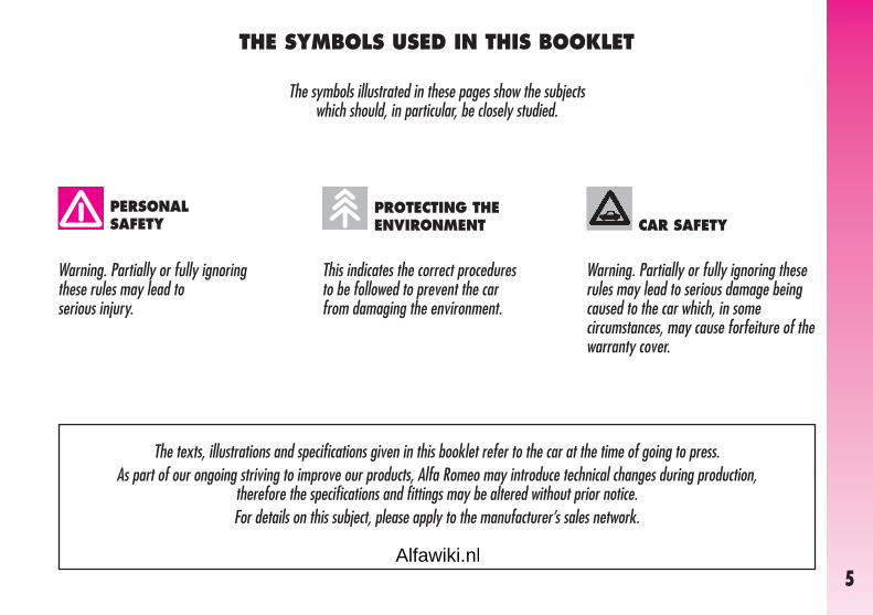
THE SYMBOLS USED IN THIS BOOKLET
The symbols illustrated in these pages show the subjects which should, in particular, be closely studied.
This indicates the correct procedures to be followed to prevent the car from damaging the environment.
Warning. Partially or fully ignoring these rules may lead to serious injury.
Warning. Partially or fully ignoring theserules may lead to serious damage being caused to the car which, in somecircumstances, may cause forfeiture of thewarranty cover.
PERSONALSAFETY
PROTECTING THEENVIRONMENT CAR SAFETY
The texts, illustrations and specifications given in this booklet refer to the car at the time of going to press.As part of our ongoing striving to improve our products, Alfa Romeo may introduce technical changes during production,
therefore the specifications and fittings may be altered without prior notice. For details on this subject, please apply to the manufacturer’s sales network.
Alfawiki.nl

GET
TIN
G T
O K
NO
W Y
OUR C
AR
6
THE ALFA ROMEO CODE SYSTEM
To increase protection against attemptedtheft, the car is fitted with an electronic en-gine lock system (Alfa Romeo CODE) whichis activated automatically when the key isremoved from the ignition. In fact the gripof each key contains an electronic devicewhich modulates the radio frequency signaltransmitted when the engine is started by aspecial aerial incorporated in the ignitionswitch. This modulated signal is the “pass-word” by which the control unit recognisesthe key and only in this condition can theengine be started.
KEYS
The car is delivered with a key with met-al insert (upon request for models/marketswhere required) and a key with remote con-trol. For models/markets where requiredtwo keys with remote control can be pro-vided.
KEY WITHOUT REMOTECONTROL (for versions/markets where applicable)
The fixed metallic insert A-fig. 2 oper-ates:
– the ignition switch;
– the driver’s door lock;
– the passenger’s Air bag deactivation (up-on request for versions/markets where ap-plicable);
– the fuel filler cap lock.
GGEETTTTIINNGG TTOO KKNNOOWW YYOOUURR CCAARR
fig. 2
A0A1118b
fig. 1
A0A00621b
SYMBOLS
On some of the components making upyour Alfa GT, or near to them, specialcoloured labels have been attached. Theselabels bear symbols that remind you of theprecautions to be taken as regards that par-ticular component. A summary list of thesymbols (fig.1) is to be found under thebonnet.
Alfawiki.nl

GET
TIN
G T
O K
NO
W Y
OUR C
AR
7
IMPORTANT To guarantee the perfectefficiency of the electronic devices containedin keys, avoid letting them directly exposedto sunrays.
Together with the keys the CODE card isprovided (for versions/ markets where ap-plicable) (fig. 3), bearing in print the keycodes (both mechanical and electronic foremergency start up).
The code numbers on the CODE card mustbe kept in a safe place , not in the car.
The driver should always keep the elec-tronic CODE card with him/her in the eventof having to carry out emergency starting.
KEY WITH REMOTE CONTROL
The key with remote control (fig. 4) isfitted with:
– a metal insert (A) that can be enclosedin the key grip
– a button (B) for power-assisted open-ing of the metal insert
– a button (C) for remote door unlock-ing and at the same time switching off theelectronic alarm
– a button (D) for remote door lockingand at the same time switching on the elec-tronic alarm
– a button (E) for remote boot unlocking
– removable hook ring (F).
fig. 3
A0A0003b
If the car changes owner,the new owner must begiven all the keys and the
CODE card.
fig. 4
A0A0600b
Alfawiki.nl

GET
TIN
G T
O K
NO
W Y
OUR C
AR
8
The button B should onlybe pressed when the key isaway from the body, in
particular from the eyes, and fromobjects that can be spoilt (clothesfor instance). Make sure the keycan never be touched by others, es-pecially children, who may inad-vertently press the button.
OPENING THE TAILGATE
The tailgate can be opened from outside byremote control pressing button (E), even if theelectronic alarm is on. Opening of the tailgateis accompanied by the direction indicatorsflashing twice; closing is accompanied by asingle flash.
If the electronic alarm is fitted, when thetailgate is opened the alarm system switch-es off volumetric protection and the tailgatecontrol sensor, the system (with the excep-tion of versions for certain markets) “beeps”twice.
Closing the tailgate again, the control func-tions are restored, the system “beeps” twice(with the exception of certain markets).
The metal insert (A) of the key operates:
– the ignition switch
– driver’s door lock and, upon request forversions/markets where applicable, the pas-senger’s door lock
– the passenger’s side Air bag deactiva-tion switch
To bring the metal insert out of the keygrip, press the button (B).
To pull out the hook ring (F) use a finelypointed object (e.g. pen) and work in thedirection of the arrow.
To insert the metal insert in the key grip:
– keep the button (B) pressed
– move the metal insert (A)
– release the button (B) and turn the met-al insert (A) until hearing the click as it locksinto place.
To unlock the doors by remote control pressbutton (C), the doors unlock and the direc-tion indicators flash twice. To lock the doorsby remote control, press button (D), thedoors lock and the direction indicators flashonce. Pressing button (C) the doors are re-leased, if within the next 60 seconds a dooror the tailgate are not opened, the system au-tomatically locks everything again.
On cars fitted with electronic alarm system,pressing button (C) turns it off, pressing but-ton (D) turns it on.
Alfawiki.nl

GET
TIN
G T
O K
NO
W Y
OUR C
AR
9
The codes of any keys notpresented during the mem-orising procedure are
erased. The reason for this is to en-sure that any lost or stolen keyscannot be used to start the engine.
OPERATION
Each time the ignition key is turned to theSTOP position the Alfa Romeo CODE systemdeactivates the functions of the engine elec-tronic control unit.
Each time the car is started turning the ig-nition key to MAR, the Alfa Romeo CODEcontrol unit sends a recognition code to theengine control unit to deactivate the in-hibitor. The code is crypted and variable be-tween over four billion possible combina-tions, and it is sent only if the system con-trol unit has recognised the code transmit-ted from the key which contains an elec-tronic transmitter, through an aerial woundaround the ignition switch.
If the code has not been recognised cor-rectly, the Alfa Romeo CODE warning light(Y) on the cluster turns on.
In this case, the key should be moved tothe STOP position and then back to MAR;if the lock continues, possibly try again withthe other key provided with the car. If it isstill not possible to start the car, follow theinstructions given in the “In an emergency”chapter and then contact Alfa Romeo Au-thorised Services.
IMPORTANT Turning on of the AlfaRomeo CODE warning light (Y) when trav-elling with the ignition key at MAR:
1) If the warning light turns on, this meansthat the system is running a self-test (for ex-ample for a voltage drop). At the first stop,it will be possible to test the system: switchoff the engine turning the ignition key toSTOP; then turn the ignition key to MAR:the warning light turns on and should go offin about one second. If the warning lightstays on, repeat the procedure described pre-viously leaving the key at STOP for over30 seconds. Should the inconvenience per-sists, contact Alfa Romeo Authorised Ser-vices.
2) For versions without the reconfigurablemultifunction display, the flashing of thewarning light means that the car is not pro-tected by the engine inhibitor device. Thiscondition for cars with reconfigurable mul-tifunction display is shown by the turning onof the warning light together with the dis-play of the message: “CODE SYSTEM NOT PRO-GRAMMED”. Contact Alfa Romeo AuthorisedServices immediately to have all the keysmemorised.
IMPORTANT Every key has its owncode, which must be memorised by the sys-tem control unit. To memorise new keys, upto a maximum of eight, apply solely to Al-fa Romeo Authorised Services taking withyou all the keys in your possession, theCODE card, a personal identity documentand the car’s ownership documents.
Alfawiki.nl

GET
TIN
G T
O K
NO
W Y
OUR C
AR
10
If after about 2 secondswith the ignition key atMAR, for versions without
reconfigurable multifunction dis-play, the Alfa Romeo CODE warn-ing light (Y) turns on again flash-ing, or for versions with reconfig-urable multifunction display, thewarning light turns on again to-gether with the message “CODESYSTEM NOT PROGRAMMED”, thismeans that the code of the keyshas not been stored, therefore thecar is not protected by the AlfaRomeo CODE system against at-tempted theft. In this case contactAlfa Romeo Authorised Services tohave the key codes stored.
KEY BATTERY REPLACEMENT
If when pressing button (B or C-fig. 6)on the remote control, nothing happens, thebattery should be replaced by a new oneof the same type to be found c/o normalretailers.
Used batteries are harm-ful to the environment.They should be disposed of
as specified by law in the specialcontainers provided. Avoid expo-sure to naked flames and high tem-peratures. Keep out of reach ofchildren.
fig. 5
A0A0603b
Battery replacement:
– press button (A-fig. 5) and move themetal insert (B) to the open position;
– using a finely-tipped screwdriver, turnthe opening device (C) and pull out the bat-tery holder (D);
– replace the battery (E) making sure thatthe bias is correct;
– re-insert the battery holder in the keyand lock it, turning the device (C).
Alfawiki.nl

GET
TIN
G T
O K
NO
W Y
OUR C
AR
11
ELECTRONIC ALARM
DESCRIPTION
The system comprises: a transmitter, re-ceiver, control unit with siren and volumet-ric sensors. The electronic alarm is controlledby the receiver incorporated in the instru-ment cluster and it is turned on and off bythe remote control in the key which sendsthe crypted and variable code. The electronicalarm controls: the unlawful opening ofdoors, bonnet and boot (perimetral protec-tion), operation of the ignition key, batterycable cutting, the presence of moving bod-ies in the passenger compartment (volu-metric protection), any abnormal rais-ing/sloping of the car (for versions/mar-kets where applicable) and central door lock-ing. It also makes it possible to cut off thevolumetric protection.
IMPORTANT The engine inhibitor func-tion is guaranteed by the Alfa Romeo CODEsystem which is activated automaticallywhen the ignition key is removed.
The remote control is incorporated in thekey and it is fitted with buttons (B-C-D-fig. 6) that activate the corresponding con-trol sending the code to the receiver. Thiscode (rolling code) changes at each trans-mission.
REQUEST FOR ADDITIONALKEYS WITH REMOTE CONTROL
The receiver can recognise up to 5 keyswith incorporated remote control. Should anew key with remote control be necessaryfor any reason during the life of the car, con-tact directly Alfa Romeo Authorised Services,taking with you the CODE card, a personalidentity document and the car’s ownershipdocuments.
HOW TO ACTIVATE THE ALARM
With the doors, bonnet and boot shut andthe ignition key in the STOP or PARK po-sition (key removed), point the key with theremote control in the direction of the car, thenpress and release the button (C-fig. 6).
With the exception of certain markets, thesystem sounds a “beep” and the doors arelocked.
Engagement of the alarm is preceded bya self-diagnostic test indicated by a differentflashing frequency of the deterrent led (A-fig. 7) on the dashboard. If a fault is de-tected the system sounds a further warn-ing “beep”.
fig. 6
A0A0601b
fig. 7
A0A0005b
Alfawiki.nl

GET
TIN
G T
O K
NO
W Y
OUR C
AR
12
– if the led continues flashing, but at dif-ferent intervals than normal, this means thatdifferent attempts to break in have occurred.Through the number of flashes it is possi-ble to identify the type of attempt:
1 flash: one or more doors
2 flashes: tailgate
3 flashes: bonnet
4 flashes: ultrasounds
5 flashes: abnormal car lifting/slop-ing (for versions/marketswhere applicable)
6 flashes: tampering with car startingcables
7 flashes: tampering with battery ca-bles or cutting emergencykey cables
8 flashes: connection line to sensorsand siren
9 flashes: at least three causes ofalarm.
Surveillance
After switching on, the flashing of the de-terrent led (A-fig. 7) on the dashboard in-dicates the system surveillance mode. Theled flashes throughout this period.
IMPORTANT Operation of the electronicalarm is adapted at the origin to the rulesof the different countries.
Self-diagnostic functions and door, bonnet, boot control
If, after engaging the alarm, a second“beep” is sounded, switch off the systempressing the button (B-fig. 6), check thatthe doors, bonnet and tailgate are properlyshut, then switch the system on again press-ing the button (C). Otherwise, the door,bonnet or tailgate that is not shut properlywill be excluded from the alarm system con-trol.
If the doors, bonnet and boot are shut cor-rectly and the control signal is repeated, thesystem self-diagnostic has detected a sys-tem operating fault. It is therefore necessaryto contact Alfa Romeo Authorised Services.
HOW TO DEACTIVATE THE ALARM
To deactivate the alarm press the button (B-fig. 6) of the key with remote control. Thesystem will react as follows (with the ex-ception of certain markets):
– two brief flashes of the direction indi-cators
– two brief “beeps” of the system
– door unlocking.
IMPORTANT If when the system isturned off the deterrent led (A-fig. 7) onthe dashboard stays on (maximum 2 min-utes or until the ignition key is set to MAR)the following should be borne in mind:
Alfawiki.nl

GET
TIN
G T
O K
NO
W Y
OUR C
AR
13
WHEN THE ALARM ISTRIGGERED
When the system is on, the alarm comesinto action in the following cases:
– opening of one of the doors, bonnet ortailgate;
– disconnection of the battery or section-ing of electric cables;
– intrusion in the passenger compartment,for example breakage of windows (volu-metric protection);
– attempt to start the engine (key inMAR position);
– abnormal car lifting/sloping (for ver-sions/markets where applicable).
Depending on the markets, the cutting inof the alarm causes operation of the sirenand hazard warning lights (for about 26 sec-onds). The ways of operating and the num-ber of cycles may vary depending on themarkets.
A maximum number of cycles is howeverenvisaged.
Once the alarm cycle has ended, the sys-tem resumes its normal control function.
VOLUMETRIC PROTECTION
To make sure that the protection systemworks correctly the side windows and sun-roof (if fitted) must be properly shut.
The function can be cut off (if, for exam-ple, leaving animals in the car) carrying outthe following operations in rapid succession:starting from the condition with the igni-tion key at MAR, move the key to STOP,then immediately back to MAR and thento STOP again, then remove the ignitionkey.
The deterrent led (A-fig. 7) on the dash-board lights up for about 2 seconds to con-firm that the function has been cut off.
To restore volumetric protection, move theand keep the ignition key at MAR for over30 seconds.
If, with the volumetric protection functiondeactivated, an electric control controlled bythe ignition key at MAR (e.g. power win-dows) turn the ignition key to MAR, op-erate the control and move the key toSTOP in a maximum time of 30 seconds.This way volumetric protection is not re-stored.
HOW TO CUT OFF THE ALARM SYSTEM
To deactivate the alarm system complete-ly (for instance during prolonged inactivityof the car) simply lock the car turning thekey in the lock.
MINISTERIAL CERTIFICATION
In accordance with the law in force in eachcountry, on the subject of radio frequency,we wish to point out that for the markets inwhich the transmitter needs to be marked,the certification number is given on the com-ponent.
Depending on the versions/markets, thecode may also be given on the transmitterand/or on the receiver.
Alfawiki.nl

GET
TIN
G T
O K
NO
W Y
OUR C
AR
14
IGNITION DEVICE
SWITCH (fig. 8)
The key can be turned to one of four po-sitions:
– STOP: engine switched off, key can beremoved, engine inhibitor engaged, steer-ing lock engaged, services excluded apartfrom those supplied directly (e.g. hazardwarning lights).
– MAR: drive position. The engine lockis deactivated and all electrical devices arepowered.
fig. 8
A0A0016b
When leaving the car al-ways remove the key fromthe ignition to prevent any
occupants of the car from acciden-tally activating the controls. Nev-er leave children in the car unac-companied. Remember to engagethe handbrake and, if the car isparked on an uphill slope, to en-gage the first gear. If the car is fac-ing downhill, engage reverse gear.
If the ignition device istampered with (for exam-ple an attempted theft)
have it checked over by AlfaRomeo Authorised Services beforetravelling again.
IMPORTANT Do not leave the key inthis position when the engine is stopped.
– AVV: unstable position for starting theengine.
IMPORTANT If the engine fails to startmove the key back to STOP and repeat.
The ignition switch has a safety devicewhich prevents passage to AVV when theengine is running.
– PARK: engine switched off, key canbe removed, engine lock engaged, steer-ing lock engaged, sidelights switched on au-tomatically.
IMPORTANT To turn the key to thePARK position, button (A) on the switchmust be pressed first.
Alfawiki.nl

It is absolutely forbiddento carry out whatever af-ter-market operation in-
volving steering system or steer-ing column modifications (e.g.: in-stallation of anti-theft device) thatcould badly affect performance andsafety, cause the lapse of warran-ty and also result in non-compli-ance of the car with homologationrequirements.
GET
TIN
G T
O K
NO
W Y
OUR C
AR
15
STEERING LOCK
Engaging:
– move the key to STOP or PARK, thenremove the key and turn the steering wheelslightly to facilitate the locking action.
Disengaging:
– turn the key to MAR gently rocking thesteering wheel from side to side.
Never remove the ignitionkey with the car on themove. The steering wheel
would lock automatically the firsttime the steering wheel is turned.This also occurs if the car is towed.
DOORS
Before opening a door, al-ways make sure that it canbe done safely.
OPENING/CLOSINGFROM OUTSIDE
Front doors
– To open the door, turn the key (clockwisefor the driver’s door and, upon request for ver-sions/markets where applicable, counter-clockwise for the passenger’s door), then re-move the key and pull the lever (A-fig. 9).
– To close the door, turn the key in thelock in the opposite direction to the one foropening.
fig. 9
A0A0017b
fig. 10
A0A0018b
OPENING/CLOSINGFROM INSIDE
Front doors
– To open the door, pull the handle(A-fig. 10).
– To close the door, pull it; then to preventopening from the outside, press the button(A-fig. 11) on the dashboard, the deter-rent led (B) on the button lights up with ayellow light to confirm that locking has tak-en place.
Alfawiki.nl

Fabric upholstery of yourcar is purpose-made towithstand common wear
resulting from normal use of thecar. It is however absolutely nec-essary to prevent hard and/or pro-longed scratching/scraping causedby clothing accessories like metal-lic buckles, studs, “Velcro” fixings,etc. that stressing locally the fabriccould break yarns and damage theupholstery as a consequence.
GET
TIN
G T
O K
NO
W Y
OUR C
AR
16
FRONT SEATSCENTRAL LOCKING
This allows central locking of the doorlocks.
To engage central locking, the doors mustbe perfectly shut, otherwise locking is de-nied.
IMPORTANT With central locking en-gaged, pulling the inside lever for openingone of the front doors causes the unlock-ing of all the doors.
In the event of a power cut off (blownfuse, battery disconnected, etc.) it is still pos-sible to work the lock by hand.
fig. 11
A0A0019b
Only make adjustmentswhen the car is stationary.
LENGTHWISE ADJUSTMENT (fig. 12)
Raise the lever (A) and push the seatbackwards or forwards; in the driving posi-tion the arms should be slightly flexed andthe hands should rest on the rim of the steer-ing wheel.
fig. 12
A0A0602b
After releasing the ad-justment lever, alwayscheck that the seat is
locked on the runners, trying tomove it to and fro. The lack of thisclamping action could cause theseat to move unexpectedly andcause loss of car control.Alfawiki.nl
GET
TIN
G T
O K
NO
W Y
OUR C
AR
17
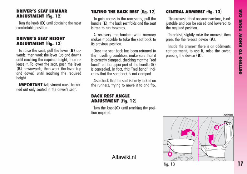
CENTRAL ARMREST (fig. 13)The armrest, fitted on some versions, is ad-
justable and can be raised and lowered tothe required position.
To adjust, slightly raise the armrest, thenpress the the release device (A).
Inside the armrest there is an oddmentscompartment, to use it, raise the cover,pressing the device (B).
TILTING THE BACK REST (fig. 12)To gain access to the rear seats, pull the
handle (E), the back rest folds and the seatis free to run forwards.
A recovery mechanism with memorymakes it possible to take the seat back toits previous position.
Once the seat back has been returned tothe travelling condition, make sure that itis correctly clamped, checking that the “redband” on the upper part of the handle (E)is concealed. In fact, this “red band” indi-cates that the seat back is not clamped.
Also check that the seat is firmly locked onthe runners, trying to move it to and fro.
BACK REST ANGLEADJUSTMENT (fig. 12)
Turn the knob(C) until reaching the posi-tion required.
fig. 13
A0A0023b
DRIVER’S SEAT LUMBARADJUSTMENT (fig. 12)
Turn the knob (D) until obtaining the mostcomfortable position.
DRIVER’S SEAT HEIGHTADJUSTMENT (fig. 12)
To raise the seat, pull the lever (B) up-wards, then work the lever (up and down)until reaching the required height, then re-lease it. To lower the seat, push the lever(B) downwards, then work the lever (upand down) until reaching the requiredheight.
IMPORTANT Adjustment must be car-ried out only seated in the driver’s seat.
Alfawiki.nl

GET
TIN
G T
O K
NO
W Y
OUR C
AR
18
REAR POCKETS (fig. 16)(for versions/markets whereapplicable)
The front seats are fitted with a pocket inthe rear of the back rest.
HEADREST ADJUSTMENT (fig. 15)
To increase passengers’ safety, the head-rests are adjustable in height.
To adjust, press the button (A) and movethe headrest up or down until it clicks intoplace.
IMPORTANT The configuration of theheadrest cushion may vary depending onthe versions and markets. The purpose ofthe illustration is only to show how it is ad-justed.
fig. 15
A0A0604b
Remember that headrestsshould be adjusted so thatthe nape, and not the neck,
rests on them. Only in this positiondo they exert their protective ac-tion in the event of a crash frombehind.
fig. 16
A0A0026b
SEAT WARMING (fig. 14)Seat warming, fitted on certain versions,
is turned on and off through the switch (A)on the outer side of the seat.
Switching on is shown by the lighting upof the led (B) on the switch itself.
fig. 14
A0A0024b
Alfawiki.nl

GET
TIN
G T
O K
NO
W Y
OUR C
AR
19
REAR SEATS
If a particularly heavyload is placed in the boot,when travelling at night, it
is wise to check the height of thehigh beams (see “Headlamps”paragraph).
fig. 18
A0A0605b
Removing the rear parcel shelf
Proceed as follows:
– free the ends of the two rods (A-fig. 18)supporting the parcel shelf (B) pulling theeyelets (C) off the pins (D);
– release the pins (A-fig. 19) at the out-side of the shelf from their housings (B) ob-tained in the side supports, then remove theshelf pulling it outwards.
fig. 19
A0A0255b
EXTENDING THE LUGGAGE COMPARTMENT
The split of rear seat makes it possible toextend the luggage compartment totally orpartially, acting separately on one of the twoparts, thereby offering different possibilitiesof load depending on the number of rearpassengers.
Fabric upholstery of yourcar is purpose-made towithstand common wear
resulting from normal use of thecar. It is however absolutely nec-essary to prevent hard and/or pro-longed scratching/scraping causedby clothing accessories like metal-lic buckles, studs, “Velcro” fixings,etc. that stressing locally the fabriccould break yarns and damage theupholstery as a consequence.
Alfawiki.nl

GET
TIN
G T
O K
NO
W Y
OUR C
AR
20
– raise the headrest to the highest posi-tion, press both buttons (A-fig. 21) at theside of the two supports, then remove theheadrest pulling them upwards;
– move the seat belts to the side extend-ing them correctly without twisting;
– raise the levers (A-fig. 22) retainingthe back rests and tilt them forwards to ob-tain a single loading surface (fig. 23).
fig. 21
A0A0607b
fig. 23
A0A0608 b
Total extension
Proceed as follows:
– check that seat buckles of the side beltsare fitted in the respective pockets on theback rest (A-fig. 20) and the tab (B)of the centre abdominal belt is inserted inthe support (C).
– pull the handles in the centre of the cush-ions, then tilt them forwards;
fig. 20
A0A0623b
fig. 22
A0A0608 b
IMPORTANT For versions/marketswhere applicable, the retainer levers are re-placed by buttons (one for each side). To re-lease the back rests and tilt them, use thebuttons themselves.
Alfawiki.nl

GET
TIN
G T
O K
NO
W Y
OUR C
AR
21
Remember that headrestsshould be adjusted so thatthe nape, and not the neck,
rests on them. Only in this positiondo they exert their protective ac-tion in the event of a crash frombehind.
Partial extension
For partial extension, proceed as follows:
– tilt the cushion required pulling the han-dle at the centre of the cushion, then tilt-ing the actual cushion;
– move the seat belt to one side extend-ing it correctly without twisting;
– raise the lever retaining the back restand tilt it forwards.
To bring the seat back to itsnormal position
Proceed as follows:
– move the seat belts to one side ex-tending them correctly without twisting;
– raise the seat backs, pushing them back-wards until hearing both clamping devicesclick into place;
– set the cushions to the horizontal posi-tion keeping the centre seat belt raised.
HEADREST ADJUSTMENT (fig. 24)
The car may be fitted with two headrestsfor the side seats and, depending on the trimlevel, it may also have a third headrest inthe centre.
To use the headrest, raise it from the (2)“non use position” and reach the (1) “allremoved” position. To restore the “non useposition”, press button (A-fig. 21) andpush the headrest downwards.
All rear headrests can be removed.
fig. 24
A0A0610b
The particular headrest shape interferes in-tentionally with the rear passenger’s correctposition on the back rest; this forces the pas-senger to raise the headrest to use it cor-rectly.
IMPORTANT When using rear seats,the headrests shall be kept in the “all re-moved” position.
Alfawiki.nl

GET
TIN
G T
O K
NO
W Y
OUR C
AR
22
STEERING WHEEL
The driver can adjust the steering wheelposition in rake and height.
To do this, release the lever (A-fig. 27)pulling it towards the steering wheel.
After moving the steering wheel to themost suitable position, lock it pushing thelever fully forwards.
LUGGAGERETAINER NET(where provided)
Present only on certain versions, the re-tainer net (fig. 26) is helpful in correctlyarranging the load and/or suitable for trans-porting light materials.
fig. 27
A0A0706b
Any adjustment of thesteering wheel positionmust be carried out only
with the car stationary.
CENTRAL ARMREST (fig. 25)To use the armrest (A), present only on
certain versions, lower it as illustrated.
fig. 26
A0A0624b
fig. 25
A0A0611b
Alfawiki.nl

GET
TIN
G T
O K
NO
W Y
OUR C
AR
23
REAR-VIEW MIRRORADJUSTMENT
INNER
The mirror, fitted with a safety device thatcauses it to be released in the event of aviolent crash, can be moved using the lever(A-fig. 28) to two different positions, nor-mal or antiglare.
fig. 28
A0A0039b
Folding (fig. 30)– In the event of need (for example when
the mirror causes difficulty in narrow spaces)it is possible to fold the mirror moving it fromposition (A) to position (B).
fig. 30
A0A0041b
When driving the mirrorsshould always be in posi-tion (A).
As the driver’s wing mir-ror is curved, it may slight-ly alter the perception of
distance.
OUTER
Electric adjustment (fig. 29)– use the switch (A) to select the mirror
required (right or left);
– pressing the button (B) in one of thefour directions, move the mirror selected pre-viously;
– position the switch (A) in the interme-diate locking position.
IMPORTANT Adjustment is possible on-ly with the ignition key at MAR.
fig. 29
A0A0040b
Alfawiki.nl

GET
TIN
G T
O K
NO
W Y
OUR C
AR
24 fig. 33
A0A0043b
POWER WINDOWS
IMPORTANT With the ignition key atSTOP or removed, the power windows re-main activated for about 3 minutes and aredeactivated immediately the moment a dooris opened.
Driver’ side (fig. 33)
The driver’s door panel contains the but-tons that control the following windows,with the ignition key at MAR:A - left front windowB - right front window.Press the button to lower the window. Pull
to raise it.
Defrosting/demisting (fig. 31-32)The electric mirrors are fitted with heat-
ing coils which come into operation withrearscreen heating pressing the button (A)thereby defrosting and/or demisting the mir-rors.
IMPORTANT The function is timed andautomatically switched off after a few min-utes.
fig. 32
A0A0612b
fig. 31
A0A0042b
Alfawiki.nl

GET
TIN
G T
O K
NO
W Y
OUR C
AR
25fig. 34
A0A0044b
Passenger’s side (fig. 34)The button (A) controls the passenger’s
side window.
Button and window operation is the sameas that described for driver’s side.
Improper use of the pow-er windows can be danger-ous. Before and during its
operation, always make sure thatpassengers are not exposed to therisk of harm either directly by themoving windows or by personalobjects drawn or knocked by them.
Always remove the igni-tion key when getting outof the car to prevent the
power windows being operated ac-cidentally and constituting a dangerto the passengers in the car.
Do not keep the buttonpressed when the windowis completely raised or
lowered.
IMPORTANT The driver’s power windowis fitted with the “continuous automatic op-eration” device for both lowering and raisingthe window. A brief press on the upper orlower part of the button will cause it to moveand continue automatically: the windowstops in the required position by pressing ei-ther the upper or lower part of the buttonagain. The passenger window is fitted with“automatic continuous operation” device justfor window opening.
Alfawiki.nl

GET
TIN
G T
O K
NO
W Y
OUR C
AR
26
SEAT BELTS
USING THE SEAT BELTS
The belt should be worn keeping the cheststraight and rested against the seat back.
To fasten the seat belts: hold thetongue (A-fig. 35) and insert it into thebuckle (B), until hearing the locking click.At removal, if it jams, let it rewind for a shortstretch, then pull it out again without jerking.
fig. 35
A0A0045b
Proceed as follows with doors closed:
1. open completely the driver’s windowkeeping the button pressed for at least3 seconds after full opening;
2. close completely the driver’s windowkeeping the button pressed for at least3 seconds after full closing;
3. proceed as described in points 1 and2 also for the passenger’s side;
4. check for proper initialisation by oper-ating the windows in automatic.
For all versions, after unlocking the doors,keeping the remote control button pressedfor about 2 seconds will obtain windowopening.
IMPORTANT For versions/marketswhere applicable, after turning off controlunit power (replacing or disconnecting thebattery or replacing the power window con-trol unit protection fuses), window au-tomatism shall be restored.
Alfawiki.nl
GET
TIN
G T
O K
NO
W Y
OUR C
AR
27
After adjustment, alwayscheck that the slider is an-chored in one of the posi-
tions provided. To do this, with thebutton (A) released, exert a fur-ther pressure to allow the anchordevice to catch if release did nottake place at one of the preset po-sitions.
Never press button (C)when travelling.
To unfasten the seat belts: pressbutton (C-fig. 35). Guide the seat beltwith your hand while it is rewinding, to pre-vent it from twisting. Through the reel, thebelt automatically adapts to the body of thepassenger wearing it, allowing freedom ofmovement.
When the car is parked on a steep slopethe reel mechanism may block; this is nor-mal. The reel mechanism prevents the web-bing coming out when it is jerked or if thecar brakes sharply, in a collision or when cor-nering at high speed.
Always adjust the seatbelt height when the car isstationary.
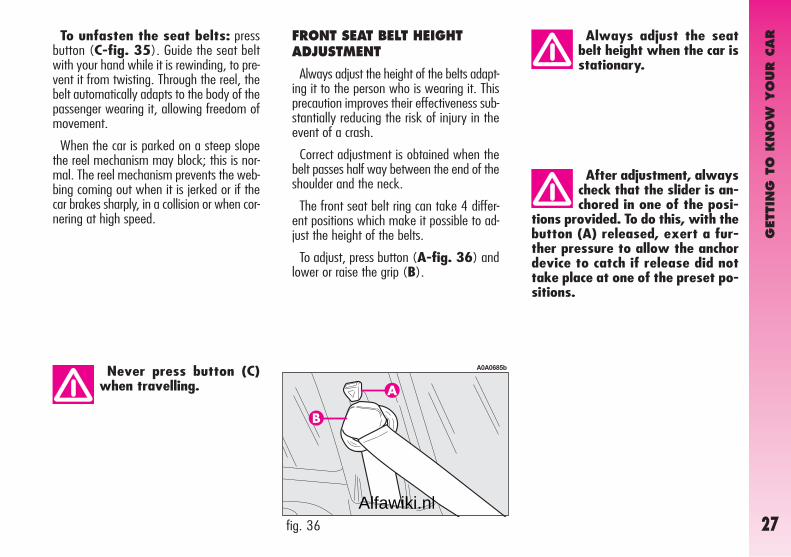
FRONT SEAT BELT HEIGHTADJUSTMENT
Always adjust the height of the belts adapt-ing it to the person who is wearing it. Thisprecaution improves their effectiveness sub-stantially reducing the risk of injury in theevent of a crash.
Correct adjustment is obtained when thebelt passes half way between the end of theshoulder and the neck.
The front seat belt ring can take 4 differ-ent positions which make it possible to ad-just the height of the belts.
To adjust, press button (A-fig. 36) andlower or raise the grip (B).
fig. 36
A0A0685b
Alfawiki.nl

GET
TIN
G T
O K
NO
W Y
OUR C
AR
28
Rear seat belts shall be worn as shown infig. 38. Fig. 39 shows improper belt fas-tening. To tilt the back rest see paragraph“Boot extension”.
IMPORTANT The centre rear seatbelt isinstalled on request only for versions/mar-kets on which it is required.
IMPORTANT Remember that, in theevent of an accident, any passengers occu-pying the rear seats who are not wearinga seat belt not only subject themselves togreat personal risk, but constitute a dangerto the occupants of the front seats.
PRE-TENSIONING DEVICES
To increase the efficiency of the front seatbelts, the car is fitted with pre-tensioning de-vices. These devices “feel” that the car isbeing subject to a violent impact by way ofa sensor and rewind the seat belts a fewcentimetres. In this way they ensure thatthe seat belt adheres to the wearer beforethe restraining action begins.
The seat belt locks to indicate that the de-vice has intervened; the seat belt cannot bedrawn back up even when guiding it man-ually.
IMPORTANT The pretensioner will givemaximum protection when the seat belt ad-heres snugly to wearer’s chest and hips.
fig. 39
A0A0387b
fig. 38
A0A0386b
fig. 37
A0A0686b
REAR BELTS
To fasten the belt: gently pull the belt fromits reel and guide the tape to prevent it fromtwisting, then insert the tongue (A-fig. 37)into the buckle housing (B).
To unfasten the seat belts, press button (E).
Alfawiki.nl

GET
TIN
G T
O K
NO
W Y
OUR C
AR
29
Pre-tensioning devices canonly be used once. Afterthey have been triggered
contact Alfa Romeo Authorised Ser-vices to have them replaced. Thevalidity of the device is 10 yearsfrom the date of production on thesticker; the pretensioners should bechanged at an Alfa Romeo Autho-rised Service as this date ap-proaches.
Operations involving bang-ing, vibrations or heating(above 100°C for a maxi-
mum of 6 hours) in the area of thepretensioners may damage or trig-ger off the device. Vibrations fromrough road surfaces or accidentaljolting caused by mounting pave-ments etc. do not have any effect onthe pretensioner. If, however, youneed assistance, go to Alfa RomeoAuthorised Services.
fig. 40
A0A0675b
LOAD LIMITERS
To increase passengers’ protection in theevent of an accident, the front and rear(where provided) seat belt reels contain aload limiter which allows controlled sag insuch a way as to dose the force acting onthe shoulders and chest during the belt re-straining action in case of a crash.
GENERAL INSTRUCTIONS FOR THE USE OF THE SEATBELTS
All the occupants of the car are obliged torespect the local traffic laws regarding thewearing of seat belts.
Always fasten the seat belts before starting.
Seat belts are also to be worn by expec-tant mothers: the risk of injury in the caseof accident is greatly reduced for them andthe unborn child if they are wearing a seatbelt. Pregnant women must of course posi-tion the lower part of the belt very low downso that it passes under the abdomen (as il-lustrated in fig. 40).
Pretensioner activation may produce asmall amount of smoke. This smoke is in noway toxic and presents no fire hazard.
The emergency tensioning retractor needsno maintenance or lubrication. Any modifi-cation to its original features will nullify theretractor effectiveness. If, due to unusualnatural events (floods, high waves, etc.),the device has been affected by water andmud, it must be replaced.
Alfawiki.nl

GET
TIN
G T
O K
NO
W Y
OUR C
AR
30
Under no circumstancesshould the components ofthe seat belt and preten-
sioner be tampered with or re-moved. Any operation should becarried out by qualified and autho-rised personnel. Always contact anAlfa Romeo Authorised Service.
IMPORTANT The seat belt must not betwisted. The upper part must pass over theshoulder and diagonally across the chest. Thelower part must rest across the pelvis and notacross the (fig. 41) stomach. Do not usedevices (clips, stoppers, etc.) which keep thebelts away from the body.
To ensure the highest de-gree of protection, you arerecommended to keep the
seat backrest in the straightest po-sition possible, and the belt adher-ing well to the chest and pelvis.Seat belts should always be wornin both the front and rear positions!Travelling without seat belt in-creases the risk of serious injury ordeath in the case of accident.
fig. 41
A0A0673b
fig. 42
A0A0051b
IMPORTANT Each seat belt shall be wornonly by one person: do not carry children onyour knee using a single seat belt for both(fig. 42). Do not fasten other objects to thebody.
Alfawiki.nl

GET
TIN
G T
O K
NO
W Y
OUR C
AR
31
HOW TO KEEP THE SEAT BELTSALWAYS IN EFFICIENTCONDITIONS
To keep the seat belts always in efficientconditions, observe the following:
– always use the belts with the tape welltaut and never twisted; make sure that itis free to run without impediments;
– after a serious accident, replace the beltbeing worn at that time, even if it does notappear damaged. Always replace the seatbelts if pretensioners have been activated;
– to clean the belts, wash by hand withneutral soap, rinse and leave to dry in theshade. Never use string detergents, bleachor dyes or any other chemical substance thatmight weaken the fibres;
– prevent the reels from getting wet: theircorrect operation is only guaranteed if wa-ter does not get inside;
– replace the seat belt if it shows signifi-cant wear or cut signs.
If the seat belt has beensubjected to shock, for ex-ample during an accident, it
must be completely replaced to-gether with the attachments andtheir screws, and the pretension-ing devices, even if visible defectsare not detected, as the belt mayhave lost its resilience.
Alfawiki.nl

GET
TIN
G T
O K
NO
W Y
OUR C
AR
32
CARRYING CHILDREN SAFELY
For optimal protection in the event of acrash, all passengers must be seated andwearing adequate restraint systems. This iseven more important for children.
This prescription is compulsory in all ECcountries according to EC Directive2003/20/EC.
Compared with adults, their head is pro-portionally larger and heavier than the restof the body, while the muscles and bonestructure are not completely developed.Therefore, correct restraint systems are nec-essary, other than adult seat belts.
The results of research on the best pro-tection for a child are summarised in Euro-pean Standard ECE- R44, which in additionto making them compulsory, subdivides re-straint systems into five groups:
Group 0 0 - 10 kg in weight
Group 0+ 0 - 13 kg in weight
Group 1 9 - 18 kg in weight
Group 2 15 - 25 kg in weight
Group 3 22 - 36 kg in weight
As it may be noted, the groups overlappartly and in fact, in commerce it is possibleto find devices that cover more than oneweight group. All restraint devices must bearthe certification data, together with the con-trol brand, on a solidly fixed label whichmust absolutely never be removed.
Over 1.50 m in height, from the point ofview of restraint systems, children are con-sidered as adults and wear the seat beltsnormally. Lineaccessori Alfa Romeo offersseats for each weight group, which are therecommended choice, as they have been de-signed and experimented specifically for Al-fa Romeo cars.
Never place cradle child’sseats facing backwards onthe front passenger seat of
cars fitted with passenger’s air bagsince the air bag activation couldcause serious injuries, even mortal.You are advised to carry childrenalways on the rear seat, as this isthe most protected position in thecase of a crash.
SERIOUS DANGERChildren may placedon the front seat of
cars fitted with passenger’s air bagdeactivation. In this case, it is ab-solutely necessary to check thewarning light F on the instru-ment panel to make sure that de-activation has actually took place(see paragraph “Front passengerair bag”). The front passenger’sseat shall be adjusted in the mostbackward position to prevent anycontact between child’s seat anddashboard.
Alfawiki.nl

GET
TIN
G T
O K
NO
W Y
OUR C
AR
33
GROUP 0 AND 0+ (fig. 43)
Babies up to 13 kg must be carried fac-ing behind on a cradle seat which, support-ing the head, does not induce strain on theneck in the event of a sharp deceleration.
The cradle is restrained by the car safetybelts, as illustrated, and it should in turnrestrain the child with the belts incorporat-ed on it.
GROUP 1 (fig. 44)
Starting from 9 to 18 kg in weight, chil-dren may be carried facing forwards withseats fitted with front cushion, throughwhich the car seat belt restrains both childand seat.
The illustration is indica-tive only for assembly. As-semble the seat according
to the compulsory instructions pro-vided with it.
Seats exist which are suit-able for covering weightgroups 0 and 1 with a rear
connection to the car belts and itsown belts to restrain the child. Be-cause of their mass, they can bedangerous if installed incorrectlyfastened to the car belts with acushion. Strictly adhere to the as-sembly instructions provided.
fig. 43
A0A0659b
fig. 44
A0A0660b
Alfawiki.nl

GET
TIN
G T
O K
NO
W Y
OUR C
AR
34
GROUP 2 (fig. 45)
Starting from 15 to 25 kg in weight, chil-dren may be restrained directly by the carseat belts.
Child seats only have the function of po-sitioning the child correctly in relation to thebelts, so that the diagonal part adheres tothe chest and never to the neck and that thehorizontal part adheres to the child’s pelvisand not to the abdomen.
GROUP 3 (fig. 46)
For children from 22 up to 36 kg thechild’s chest is thick enough not to need thespacer back rest anymore.
The figure shows proper child seat posi-tioning on the rear seat.
Over 1.50 m in height, children may wearseat belts like adults.
The illustration is indica-tive only for assembly. As-semble the seat according
to the compulsory instructions pro-vided with it.
fig. 45
A0A0661b
fig. 46
A0A0662b
Alfawiki.nl

GET
TIN
G T
O K
NO
W Y
OUR C
AR
35
PASSENGER SEAT COMPLIANCE WITH REGULATIONS ON CHILD’S SEAT USE
Your car complies with the new European Directive 2000/3/EC regulating child’s seat assembling on the different car seats according tothe following table:
Key:
U = suitable for child restraint systems of the “Universal” category, according to European Standard EEC-R44 for the specified “Groups”.
Range of weight
up to 13 kg
9-18 kg
15-25 kg
22-36 kg
Frontpassenger
U
U
U
U
Rearpassengers
U
U
U
U
Centralpassenger
U
U
U
U
Group
Group 0, 0+
Group 1
Group 2
Group 3
Alfawiki.nl

GET
TIN
G T
O K
NO
W Y
OUR C
AR
36
Below is a summary of the rulesof safety to be followed for car-rying children:
– The recommended position for installinga child’s seat is on the rear seat, as it is themost protected in the event of a crash.
– If the passenger’s air bag is deactivatedalways check warning light F on thecluster to make sure that it has actually beendeactivated.
– Carefully follow the instructions provid-ed with the child’s seat, which the supplieris obliged to attach. Keep them in the cartogether with the documents and this book-let. Do not use used seats without the in-structions for use.
– Always pull the tape to check that beltsare buckled. Never place cradle child’s
seats facing backwards onthe front passenger seat of
cars fitted with passenger’s air bagsince the air bag activation couldcause serious injuries, even mortal.You are advised to carry childrenalways on the rear seat, as this isthe most protected position in thecase of a crash.
– All restraint systems are strictly for onechild only: never use for two children at thesame time.
– Always make sure that the belts do notrest on the child’s neck.
– During the journey, do not allow thechild to stay in abnormal positions or releasethe belts.
– Do not carry children in your arms, noteven small babies. No-one, however strong,can keep hold od them in a crash.
– In the case of accidents, replace thechild’s seat with a new one.
PRESETTING FORMOUNTING“ISOFIX TYPE” CHILDRESTRAINT SYSTEM
The rear seat of your car is preset formounting the Isofix type child restraint sys-tem, a new European standardised systemfor carrying children safely. Isofix type childrestraint system is an additional option thatdoes not prevent from using traditional childrestraint systems. Isofix type child restraintsystem covers three weight groups: 0, 0+and 1.
Due to its different anchoring system, theIsofix child’ seat shall be anchored just us-ing the metal brackets (A-fig. 47) set be-tween rear seat back and cushion.
fig. 47
A0A0671b
Alfawiki.nl

GET
TIN
G T
O K
NO
W Y
OUR C
AR
37
Mount the child restraintsystem only with the carstationary. The Isofix child
restraint system is properly an-chored to the mounting bracketswhen clicks are heard. In any case,keep to the installation instructionsthat must be provided by the childrestraint system Manufacturer.
– push the child restraint system until hear-ing the locking clicks;
– check proper locking by moving thechild’s seat with force: the built-in safetymechanism actually inhibits proper couplingwith only one coupling locked.
It is actually possible to mount both thetraditional restraint system and the Isofixone, e.g. the traditional one on the left andthe Isofix type seat on the right.
Since sizes are different, on the rear seatsit is possible to install just two traditionalchild’s seats, or two Isofix type seats. Onthe front passenger seat it is only possibleto mount traditional child’s seats.
Only Isofix type child restraint systems de-signed and tested for this car must be used.
fig. 48
A0A0663b
MOUNTING THE ISOFIX TYPECHILD’S SEAT
Groups 0 and 0+For children of the 0 and 0+ group (ba-
bies up to 13 Kg), the child’s seat is facingbackwards and the child is restrained by thechild’s seat belts(D-fig. 48).
As the child grows, passing to weight group1, the child’s seat shall be fitted facing for-wards.
For proper mounting proceed as follows:
– check whether the release lever (B) isat rest position (inward);
– find the presetting brackets (A), thenposition the child restraint system with thefastening devices (C) aligned with the brack-ets;
Alfawiki.nl

GET
TIN
G T
O K
NO
W Y
OUR C
AR
38
Group 1
For proper mounting proceed as follows:
– check whether the release lever (B-fig. 49) is at rest position (inward);
– find the presetting brackets (A), thenposition the child restraint system with fas-tening devices (C) aligned with the brack-ets;
– push the child restraint system until hear-ing the locking clicks;
– check proper locking by moving thechild’s seat with force: the built-in safetymechanism actually inhibits improper cou-pling with only one coupling locked.
AIR BAG
The car is fitted with front air bags for thedriver and for the passenger (side bags - win-dow bags).
FRONT AIR BAGS
The front air bag (driver’s and passenger’s)has been designed to protect the occupantsin the event of head-on crashes of medium-high severity by placing the cushion betweenthe occupant and the steering wheel or dash-board.
Front air bags are designed to protect thecar occupants in front crashes and thereforenon-activation in other types of collisions(side collisions, rear-end shunts, roll-overs,etc...) is not a system malfunction.
In the case of a crash, an electronic con-trol unit, when necessary, triggers inflationof the cushion.
The cushion inflates instantaneously, set-ting itself between the body of the front oc-cupants and the structures that could causeinjury. The cushion then deflates immedi-ately afterwards.
With this configuration, the child is securedalso by the car seat belts and by the upperbelts. To apply car seat belts to child’s seatrefer to the child’s seat handbook.
fig. 49
A0A0664b
Alfawiki.nl

GET
TIN
G T
O K
NO
W Y
OUR C
AR
39
Do not apply stickers orother objects on the steer-ing wheel and on the pas-
senger’s air bag cover. Do not putobjects on the dashboard on thepassenger’s side (e.g. cell phones)because they may interfere withthe correct passenger’s air bagopening and seriously injure the oc-cupants of the car.
The driver’s and passenger’s front air baghas been designed to improve the protec-tion of a person wearing a seat belt.
Its volume at maximum inflation fills mostof the space between the steering wheeland the driver and between the dashboardand the passenger.
In the event of minor side crashes (forwhich the restraining action of the seat beltsis sufficient), the air bags are not deployed.Also in this case it is of vital importance towear the seat belts since in case of sidecrash they guarantee proper positioning ofthe occupant.
DRIVER’S FRONT AIR BAG
It consists of an instant-inflating cushioncontained in a special recess in the centre ofthe steering wheel (fig. 50).
The front air bag (driver’s and passenger’s)does not replace but is complementary tothe use of belts, which should always beworn, as specified by law in Europe andmost non-European countries.
In the event of a crash a person that is notwearing the seat belt moves forwards andmay come into contact with the cushionwhile it is still opening. Under these cir-cumstances the protection offered by thecushion is reduced.
Front air bags may not be triggered in thefollowing conditions:
– collisions against highly deformable ob-jects which do not concern the car front sur-face (for example the bumper crashingagainst the guard rail);
– wedging under other cars or protectivebarriers (for example under a lorry or guardrail);
as they do not offer any more protectionthan the seat belts and therefore activationwould be inappropriate. Therefore the fail-ure to be triggered does not mean that thesystem is not working properly.
fig. 50
A0A0613b
Alfawiki.nl

GET
TIN
G T
O K
NO
W Y
OUR C
AR
40
PASSENGER’S FRONT AIRBAG
It consists of an instant-inflating cushioncontained in a special recess in the dash-board; its volume is bigger than the driver’sone (fig. 51).
MANUAL DEACTIVATION OFPASSENGER’S FRONT AIRBAG(fig. 52)(upon request for versions /markets where applicable)
Should it be absolutely necessary to car-ry a child on the front seat, the passenger’sfont air bag can be deactivated.
Deactivation/reactivation takes place withignition key at STOP, and operating it inthe special key switch set in the glovebox.
SERIOUS DANGERChildren may placedon the front seat of
cars fitted with passenger’s air bagdeactivation. In this case, it is ab-solutely necessary to check thewarning light F on the instru-ment panel to make sure that de-activation has actually took place(see paragraph “Front passengerair bag”). The front passenger’sseat shall be adjusted in the mostbackward position to prevent anycontact between child’s seat anddashboard.
fig. 51
A0A0392b
fig. 52
A0A0392b
Never place cradle child’sseats facing backwards onthe front passenger seat of
cars fitted with passenger’s air bagsince the air bag activation couldcause serious injuries, even mortal.You are advised to carry childrenalways on the rear seat, as this isthe most protected position in thecase of a crash.
Alfawiki.nl

GET
TIN
G T
O K
NO
W Y
OUR C
AR
41
The key can be inserted and removed inboth positions.
IMPORTANT Operate the switch onlywhen the engine is not running and the ig-nition key is removed.
The key-operated switch has two positions:
– passenger’s front airbag activated (ONpositionP): warning light F on instru-ment cluster off; it is absolutely prohibitedto carry a child on the front seat.
– passenger’s front airbag deactivated(OFF positionF): warning light F oninstrument cluster on; it is possible to carrya child protected by special restraint systemon the front seat.
The warning light F on the cluster stayson permanently until the passenger’s air bagis reactivated.
Deactivation of the passenger’s front airbag does not inhibit operation of the side airbag.
SIDE AIR BAGS(SIDE BAG - WINDOW BAG)
SIDE BAG (fig. 53)
The side bag is formed of an instanta-neously-inflating cushion housed in the backrest of the front seat and protects the chestof occupants in case of a side crash of medi-um-high severity.
WINDOW BAG (fig. 54)
The window bag is formed of two “cur-tain” cushions housed in the side roof liningcovered by a special trim, which protects thehead of front and rear occupants in the eventof a side crash thanks to the wide cushioninflation surface.
IMPORTANT In the event of side crash,you can obtain the best protection by thesystem keeping a correct position on theseat, thus allowing correct window bag un-folding.
fig. 53
A0A0614b
fig. 54
A0A0615b
Alfawiki.nl

GET
TIN
G T
O K
NO
W Y
OUR C
AR
42
IMPORTANT The front and/or side airbags may be activated if the car is subject-ed to heavy shocks or accidents that involvethe underbody area, such as for example vi-olent bumps against steps, pavements orfixed obstacles on the ground, falling intobig holes or bumpy roads.
IMPORTANT The triggering of air bagsreleases a small amount of powder. Thispowder is not harmful and does not indicatea start of fire; also the surfaces of the de-ployed bag and the car interior may be cov-ered with dusty residue: this may irritate theskin and eyes. In the event of exposure,wash with neutral soap and water.
Life and validity of pyrotechnic charge andcoil contact are indicated on the label setnear the lock of the left front door. As thisdate approaches, contact Alfa Romeo Au-thorized Services to have the device re-placed.
IMPORTANT Should an accident occurin which any of the safety devices is acti-vated, take the car to Alfa Romeo Autho-rized Services to have the devices activatedreplaced and to have the system checked.
All operations involving checking, repair-ing and replacing components concerningthe air bag must be carried out by AlfaRomeo Authorised Services
If the car is to be demolished, Alfa RomeoAuthorised Services should be contacted be-forehand to have the system deactivated. Ifthe car changes ownership, the new own-er must be informed of the instructions foruse and of the above warnings and be giv-en this “Owner’s Manual”.
IMPORTANT The triggering of the pre-tensioners, front air bags and side bags isdecided in a differentiated manner depend-ing on the type of crash. The failure to trig-ger one or more of them does not neces-sarily indicate a system malfunction.
Never rest head, armsand elbows on the door, onthe windows and in the
window bag area to prevent pos-sible injuries during the inflationphase.
Never lean head, armsand elbows out of the win-dow.
Alfawiki.nl

GET
TIN
G T
O K
NO
W Y
OUR C
AR
43
GENERAL CAUTIONS
If when turning the ignitionkey to MAR, the warninglight¬ does not turn on or
if it stays on when travelling therecould be a failure in safety sys-tems; in this event air bags or pre-tensioners could not trigger in caseof impact or, in a minor number ofcases, they could trigger acciden-tally. Contact Alfa Romeo Autho-rized Services immediately to havethe system checked.
Do not cover the backrestof front seats with trims orcovers that are not suitable
to be used with side bags.
Never travel with objectson your lap, in front ofyour chest or with a pipe,
pencil, etc. between your lips; in-jury may result in the event of theair bag being triggered.
Always keep your handson the steering wheel rimwhen driving, so that if the
air bag is triggered, it can inflatewithout meeting any obstacleswhich could cause serious harm toyou. Do not drive with the bodybent forwards, keep the seat backrest in the erect position and leanyour back well against it.
If the car has been stolenor an attempt to steal ithas been made, if it has
been subjected to vandals orfloods, have the air bag systemchecked by Alfa Romeo AuthorizedServices.
Remember that with thekey engaged and at MAR,even if the engine is not
running, the air bags may be trig-gered on a stationary car if it isbumped by another moving car.Therefore, never seat children onthe front seat even when the car isstationary. On the other hand re-member that if the key is at STOP,no safety system (air bags or pre-tensioners) is triggered in theevent of an impact; in this case,failure to come into action cannotbe considered as a sign that thesystem is not working properly.
Alfawiki.nl

GET
TIN
G T
O K
NO
W Y
OUR C
AR
44
STEERING WHEELLEVERS
The devices and services controlled by thelevers on the steering wheel can only be ac-tivated with the ignition key at MAR.
LEFT-HAND LEVER
The left-hand lever controls the outer lightsexcept for the fog lamps and rear fogguards.
When the outer lights are switched on, thevarious controls on the dashboard are illu-minated.
Only with the ignition key at PARK, re-gardless of the position of the knurled ring,the sidelights and number plate lights stay on.
Position (1 or 2-fig. 60) of the levercauses the turning on only of the sidelights(front and rear), on the right or left respec-tively.
Lights switched off (fig. 55)When the pointer in the knurled ring is op-
posite the symbol O, the outer lights areswitched off.
When the ignition key isturned to MAR, the warn-ing light F (with passen-
ger’s front air bag deactivationswitch at ON) turns on and flash-es for few seconds to remind thatpassenger’s air bag will be de-ployed in a crash, after which itshould go off.
The front air bag is trig-gered for shocks greater inmagnitude than the pre-
tensioners. For impacts betweenthese two thresholds, it is there-fore normal that only the preten-sioners are triggered.
Do not hook rigid objectsto the coat hooks and tothe support handles.
The air bag does not sub-stitute the seat belts, butonly increases their effec-
tiveness. Moreover, since the frontair bags do not come into operationin the event of front impact at lowspeed, side collisions, bumps frombehind or overturning, in these cir-cumstances the occupants wouldonly be protected by the seat beltswhich must therefore always befastened.
Never wash seat back-rests with pressurised wa-ter or steam (by hand or at
automatic seat washing stations).
Alfawiki.nl

GET
TIN
G T
O K
NO
W Y
OUR C
AR
45
Sidelights (fig. 56)The sidelights are switched on by turning
the knurled ring from O to6.
The3 warning light on the instrumentcluster will come on at the same time.
Dipped-beam headlights (fig. 57)These are switched on by turning the
knurled ring from 6 to2.
fig. 55
A0A0063b
fig. 56
A0A0064b
Main beams (fig. 58)To turn the main beams on, set the knurled
ring to position 2 and push the lever to-wards the dashboard (stable position);warning light 1 on the instrument panelwill turn on.
To set dipped-beams back pull the lever to-wards the steering wheel.
fig. 57
A0A0065b
fig. 58
A0A0066b
When the dipped beam headlights and thefog lamps are switched on, the outer light con-trol unit (integrated in the Body Computer)works according to the following logics:
– turning on the main beams, the dippedbeams turn off while the fog lamps stay on,when restoring the starting condition atdipped beam setting;
or
– turning on the main beams, the foglamps turn off and then turn on again auto-matically as the main beams are switched off.
Therefore, in the event of Body Comput-er replacement, the outer light operating log-ic may be different.
fig. 59
A0A0067b
Alfawiki.nl

GET
TIN
G T
O K
NO
W Y
OUR C
AR
46
“Follow me home” device (fig. 61)
This function allows the illumination of thespace in front of the car for the length oftime set, and is activated with the ignitionkey at STOP or removed, pulling the left-hand lever towards the steering wheel.
This function is activated pulling the leverwithin 2 minutes from when the engine isturned off. At each single movement of thelever, the staying on of the dipped beamsand sidelights is extended by 30 seconds upto a maximum of 3.5 minutes; the lightsswitch off automatically after the time set.
Each time the lever is operated, the 1warning light on the cluster turns on.
Flashing (fig. 59)The headlights are flashed pulling the lever
towards the steering wheel (instable posi-tion) regardless of the position of theknurled ring. The 1 warning light on thecluster will come on at the same time.
IMPORTANT Only the main-beam lightsare flashed. To avoid penalties follow localregulations.
Direction indicators (fig. 60)
Regardless of the position of the knurledring, moving the lever to the stable positionwill:
up, position (1) - engage the right-handdirection indicators.
down, position (2) - engage the left-handdirection indicators.
One of the warning lights (R or E) willcome on on the instrument cluster at thesame time.
The lever is returned to its position auto-matically and the indicators are switched offwhen the steering wheel is straightened.
IMPORTANT If you wish to signal arapid change of direction involving only aminimal movement of the steering wheel,the lever can be removed up or down with-out it clicking (unstable position). When re-leased, the lever will return to its home po-sition.
fig. 61
A0A0067b
fig. 60
A0A0068b
Alfawiki.nl

GET
TIN
G T
O K
NO
W Y
OUR C
AR
47
This function can be interrupted by keep-ing the lever pulled towards the steeringwheel for more than 2 seconds.
RIGHT-HAND LEVER
The right-hand lever is used to operate thewindscreen wiper-washer and rearscreenwiper-washer. The windscreen washer alsoactivates the headlamp washers, if fitted.
fig. 62
A0A0616b
Windscreen wiper-washer (fig. 62-63)
The lever can be moved to five differentpositions, corresponding to:
A - Windscreen wiper off.
B - Intermittent.
With the lever in position (B), turning thering (F), four possible intermittent speedsare obtained:
■ = intermittent slow.■■ = intermittent medium.■■■ = intermittent medium-fast.■■■■ = intermittent fast.
C - Continuous, slow.
D - Continuous, fast.
E - Fast, temporary (unstable position).
Operation in position (E) is limited to thetime the lever is held in this position. Whenthe lever is released, it returns to position(A) automatically stopping the wiper.
“Intelligent washing” function
Pulling the lever towards the steeringwheel (unstable position) operates the wind-screen washer.
Keeping the lever pulled, with only onemovement it is possible to operate the wash-er jet and the wiper at the same time; in-deed, the latter comes into action auto-matically if the lever is pulled for more thanhalf a second.
The wiper stops working a few strokes af-ter releasing the lever; a further “cleaningstroke” after a few seconds completes thewiping operation.
fig. 63
A0A0617b
Alfawiki.nl

GET
TIN
G T
O K
NO
W Y
OUR C
AR
48
At each start, the rain sensor automaticallystabilises at a temperature of about 40°Cto eliminate any condensation from the con-trol surface and prevent the formation of ice.
The rain sensor is able to detect and au-tomatically adapt to the presence of the fol-lowing particular conditions which requiredifferent sensitivity:
– impurities on the control surface (salt,dirt, etc.);
– streaks of water caused by worn wiperblades;
– difference between day and night (thehuman eye is more disturbed during thenight by the wet glass surface).
Rain sensor (fig. 64)The rain sensor (A), fitted only on cer-
tain versions, is an electronic device com-bined with the windscreen wiper which hasthe purpose of automatically adjusting thenumber of wipes during intermittent opera-tion to the intensity of the rain.
All the other functions controlled by theright-hand lever remain unchanged.
The rain sensor is activated automaticallymoving the right-hand lever to position (B-fig. 62) and it has a range of adjustmentthat gradually varies between wiper sta-tionary (no wiping) when the windscreen isdry, to wiper at first continuous speed (con-tinuous, slow) with heavy rain.
Turning the knurled ring (F-fig. 62) itis possible to increase the sensitivity of therain sensor, obtaining a quicker change fromstationary, when the windscreen is dry, tofirst continuous speed (continuous, slow).
Operating the windscreen washer with therain sensor activated (lever at position B)the normal washing cycle is performed atthe end of which the rain sensor resumes itsnormal automatic function.
Turning the ignition key to STOP the rainsensor is deactivated and the next time theengine is started (MAR position) it will notbe reactivated even if the lever has remainedin position (B). In this case to activate therain sensor, simply move the lever to (A)or (C) and then back to (B).
When the rain sensor is reactivated in thisway, the wiper performs at least one stroke,even if the windscreen is dry, to indicate thatreactivation has occurred.
The rain sensor is located behind the innerrear-view mirror in contact with the wind-screen and inside the area cleaned by thewiper and it controls an electronic controlunit which in turn controls the wiper motor.
fig. 64
A0A0331b
Alfawiki.nl

GET
TIN
G T
O K
NO
W Y
OUR C
AR
49
Headlamp washers (fig. 65)These come into operation when the wind-
screen washer is turned on with thedipped/main beam headlights on.
IMPORTANT On certain versions whenthe headlamp washer is operating, the cli-mate control system automatically engagesinside air re-circulation, to prevent the smellof liquid detergent from entering the pas-senger compartment.
CRUISE CONTROL
GENERAL
The speed regulator (CRUISE CON-TROL), with electronic control, makes itpossible to drive the car at the requiredspeed without pressing the accelerator ped-al. This reduces driving fatigue during longjourneys because the speed memorised isautomatically maintained.
IMPORTANT The device can only be en-gaged at speeds between 30 and 190 km/h.
fig. 65
A0A0704b Cruise Control must be ac-tivated only when theroute and traffic allow a
constant speed for a sufficientlylong distance completely safely.
The device is disengaged automatically inany of the following cases:
– pressing the brake pedal;
– pressing the clutch pedal;
– if the ASR, MSR or ESP system cuts in;
– with Selespeed transmission if a gear ischanged;
– inadvertently moving the Selespeedgear control lever to N.
CONTROLS (fig. 66)Cruise Control is controlled by the
ON/OFF knurled ring (A), by the +/–ring (B) and by the RES button (C).
Ring (A) has two positions:
– OFF in this position the device is deac-tivated;
fig. 66
A0A0077b
Alfawiki.nl

GET
TIN
G T
O K
NO
W Y
OUR C
AR
50
TO MEMORISE THE SPEED
Move the ring (A) to ON and take the carto the required speed normally. Turn the ring(B) to (+) for at least three seconds, thenrelease it. The car speed is memorised andit is therefore possible to release the accel-erator pedal.
The car will continue to travel at the mem-orised constant speed until one of the fol-lowing conditions takes place:
– pressing the brake pedal;
– pressing the clutch pedal;
– if the ASR, MSR or ESP system cuts in;
– with Selespeed transmission if a gear ischanged;
– inadvertent movement of the Selespeedgear control lever to position N.
IMPORTANT In the case of need (whenovertaking for instance) acceleration is pos-sible simply pressing the accelerator pedal;later, releasing the accelerator pedal, the carwill return to the speed memorised previ-ously.
TO RESET THE MEMORISED SPEED
If the device has been disengaged for ex-ample pressing the brake or clutch pedal,the memorised speed can be reset as fol-lows:
– accelerate gradually until reaching aspeed approaching the one memorised;
– engage the gear selected at the timeof speed memorising (4th, 5th or 6thspeed);
– press the RES button (C).
TO INCREASE THE MEMORISED SPEED
The speed memorised can be increasedin two ways:
1) pressing the accelerator and then mem-orising the new speed reached (turning thering to (B) for more than three seconds);
or2) momentaneously turning the ring (B)
to (+): each pulse of the ring will correspondto a slight increase in speed (about 1.5km/h) while pressing continuously will cor-respond to a continuous speed increase. Re-leasing the ring (B) the new speed will bememorised automatically.
– ON is the normal operating position ofthe device. When the ring (A) is in thisposition, the warning light Ü on the in-strument cluster turns on.
Ring (B) serves for memorising and main-taining the car sped or for increasing or low-ering the speed memorised.
Turn the ring (B) to (+) to memorise thespeed reached or increase the speed mem-orised.
Turn the ring (B) to (–) to lower the speedmemorised.
Each time the ring is actuated (B) the speedincreases or lowers by about 1.5 km/h.
Keeping the ring turned the speed changescontinuously. The new speed reached willbe maintained automatically.
The RES button (C) resets the memorisedspeed.
IMPORTANT Turning the ignition key toSTOP or the ring (A) to OFF, the speedmemorised is cleared and the system isswitched off.
Alfawiki.nl
GET
TIN
G T
O K
NO
W Y
OUR C
AR
51
TO REDUCE THE MEMORISED SPEED
The speed memorised can be reduced intwo ways:
1) disengaging the device (for instancepressing the brake pedal) and then memo-rising the new speed (turning the ring (B)to (+) for at least three seconds);
2) keeping the ring pressed (B) at (–)until reaching the new speed which will bememorised automatically.
The device may only be engaged in in 4th,5th or 6th gear, depending on the speedof the car. Travelling downhill with the de-vice engaged the car speed may increasemore than the memorised one, due to thechange in the engine load.
The ring (A) may be left constantly at ONwithout damaging the device. You are, how-ever, advised to switch the device off whennot in use, turning the ring to OFF, to avoidmemorising speeds by accident.
It is advisable to engage the cruise controlonly when the conditions of the traffic orroads so permit under completely safe con-ditions, i.e.: straight and dry roads, dual car-riage ways or motorways, flowing traffic andsmooth road surface. Do not engage the de-vice in town or in heavy traffic conditions.
When travelling with thecruise control on, do notmove the gearshift lever to
neutral and do not move the Sele-speed selector to N.
Cruise control may onlybe engaged at speeds be-tween 30 and 190 km/h.
If the device is faulty ornot working, turn the ring(A) to OFF and contact Al-
fa Romeo Authorised Services af-ter checking that the protectionfuse is intact.
TO RESET THE MEMORISEDSPEED
The memorised speed is automatically re-set turning off the engine or moving the ring(A) to OFF.
Alfawiki.nl

GET
TIN
G T
O K
NO
W Y
OUR C
AR
52
fig. 67
A0A0748b
DASHBOARD(For right-hand drive versions see dashboard and instruments in the dedicated paragraph at the end of the manual)
1. Adjustable side air vents - 2. Fixed side window air vents - 3. External lights control lever - 4. Instrument panel - 5. Tailgate release button - 6. Cards holder(for versions/markets where applicable) - 7. Sound system (for versions/markets where applicable) - 8. Adjustable central air vents - 9. Upper fixed vent - 10.Glass/can holder (for versions/markets where applicable) - 11. Front fog light button - 12. Hazard light switch - 13. Rear fog light button - 14. front passen-ger’s air bag - 15. Glovebox - 16. Door locking button - 17. Heating/ventilation/climate controls - 18. Cigar lighter/ashtray housing lid - 19. Temperature sen-sor - 20. Windscreen wiper stalk - 21. Ignition key and ignition switch - 22. Horn - 23. Steering wheel locking/release lever - 24. Driver’s air bag - 25. Set ofcontrols - 26. Bonnet opening lever.
Alfawiki.nl

GET
TIN
G T
O K
NO
W Y
OUR C
AR
53
A. Fuel level gauge with reserve warninglight - B. Engine coolant fluid temperaturegauge with maximum temperature warninglight - C. Speedometer - D. Odometer dis-play (mileage recorder, trip meter with head-lamp position display) - E. Reconfigurablemultifunction display - F. Rev counter
NOTE On JTDM versions the scale bottomis at 6000 revs.
A. Fuel level gauge with reserve warninglight - B. Engine coolant fluid temperaturegauge with maximum temperature warninglight - C. Speedometer - D. Odometer dis-play (mileage recorder, trip meter with head-lamp position display) - E. Reconfigurablemultifunction display - F. Rev counter
INSTRUMENT PANEL
fig. 68 - petrol versions
fig. 69 - Black Line petrol versions
A0A0760b
A0A0749bAlfawiki.nl

GET
TIN
G T
O K
NO
W Y
OUR C
AR
54
fig. 70 - Q2 diesel version
fig. 71 - 2.0 JTS Selespeed versions
A. Fuel level gauge with reserve warninglight - B. Engine coolant fluid temperaturegauge with maximum temperature warninglight - C. Speedometer - D. Odometer dis-play (mileage recorder, trip meter with head-lamp position display) - E. Reconfigurablemultifunction display - F. Rev counter
A. Fuel level gauge with reserve warninglight - B. Engine coolant fluid temperaturegauge with maximum temperature warninglight - C. Speedometer - D. Odometer dis-play (mileage recorder, trip meter with head-lamp position display) - E. Reconfigurablemultifunction display - F. Rev counter
A0A0761b
A0A0759b
Alfawiki.nl

GET
TIN
G T
O K
NO
W Y
OUR C
AR
55
fig. 71a - 2.0 JTS Selespeed Black Line version
fig. 71b - 3.2 V6 version
A. Fuel level gauge with reserve warninglight - B. Engine coolant fluid temperaturegauge with maximum temperature warninglight - C. Speedometer - D. Odometer dis-play (mileage recorder, trip meter with head-lamp position display) - E. Reconfigurablemultifunction display - F. Rev counter
A. Fuel level gauge with reserve warninglight - B. Engine coolant fluid temperaturegauge with maximum temperature warninglight - C. Speedometer - D. Odometer dis-play (mileage recorder, trip meter with head-lamp position display) - E. Reconfigurablemultifunction display - F. Rev counter
A0A0746b
A0A0752b
Alfawiki.nl

GET
TIN
G T
O K
NO
W Y
OUR C
AR
56
SPEEDOMETER(SPEED INDICATOR)
The gauge (A-fig. 72) indicates the carspeed.
ODOMETER
Odometer display (B-fig. 72) with dou-ble meter (total and trip) and headlamp po-sition display.
The display shows:
– the mileage on the first line (6 figures)
– the trip meter on the second line (4 fig-ures)
– aside the position of the headlight aim-ing device.
To reset the trip meter, keep button (A-fig. 73) on the plate at the side of thesteering column pressed for a few seconds.
IMPORTANT If the battery is discon-nected the trip meter reading is not stored.
REV COUNTER (fig. 74)
The danger zone (red, or white on certainversions) indicates excessive high enginespeed. Do not drive for long periods with thepointer in this area.
IMPORTANT The electronic injection con-trol system gradually shuts off the flow of fu-el when the engine is “over-revving” resultingin a gradual loss of engine power.
When the engine is idling, the rev countermay indicate a gradual or sudden highering ofthe speed, this is normal as it takes place dur-ing normal operation, for example when en-gaging the climate control system or the fan.In particular a slow change in the speed pre-serves the battery charge.
fig. 73
A0A1104b
fig. 74
A0A0757b
fig. 72
A0A0756b
Alfawiki.nl

GET
TIN
G T
O K
NO
W Y
OUR C
AR
57
FUEL LEVEL GAUGE WITHRESERVE INDICATOR
This shows the amount of fuel left in thefuel tank.
0 - tank empty.
1 - tank full (see the indications given inparagraph “At the filling station").
The warning light K (A-fig. 76) turns onto indicate that approx. 7 litres of fuel areleft in the tank.
IMPORTANT The pointer can reach thered area also for a sum of unfavourable con-ditions, i.e.: slow speed, uphill, fully ladenor towing a trailer with hot outside tempera-ture.
IMPORTANT Refuelling shall always beperformed with engine off and ignition key atSTOP. If the engine is off but the key is atMAR, a wrong fuel level could temporarilybe indicated. This is due to the internal sys-tem control logic and cannot be considered asa system malfunctioning.
ENGINE COOLANT FLUIDTEMPERATURE GAUGE WITH MAXIMUM TEMPERATUREWARNING LIGHT
This shows the temperature of the enginecoolant fluid and begins when the fluid tem-perature exceeds approx. 50°C.
Normally the pointer should be towardsthe middle of the scale. If the pointer reach-es the higher temperatures of the scale (redsection, or white on certain versions) the re-quest for car performance should be de-creased.
The turning on of the u (B-fig. 76)warning light (on some versions togetherwith the message shown on the reconfig-urable multifunction display) indicates thatthe coolant fluid temperature is too high;in this case, stop the engine and contactAlfa Romeo Authorised Services.
IMPORTANT The temperature of the en-gine coolant may rise towards the maximumvalues (red section, or white on certain ver-sions) when the car is driven at low speeds,especially when the ambient air tempera-ture is high. In this case it is advisable tostop the car and switch off the engine fora few minutes, after which the journey canbe resumed, preferably at a higher speed.
fig. 76
A0A0758b
Alfawiki.nl

GET
TIN
G T
O K
NO
W Y
OUR C
AR
58
DIGITAL MULTIFUNCTION DISPLAY (where fitted)
The digital multifunction display shows the following: clock, outside temperature, buzzer setting (buzzer on/off), rheostat (light adjustment),condition of the inertial fuel cut-off switch (FPS on).
CONTROL BUTTONS (fig. 75)
To make use of the information the digital display (with the ignition key at MAR) is able to give, you should firstly familiarise with the con-trol buttons on the plate at the side of the steering column, using them as described in the following paragraphs. Before doing anything at all,you are advised to read this chapter in full.
To decrease the value displayed
To decrease the value displayed
Press for less than 1 second (pulse), indicated with Q in the following de-scriptions, to access the various adjustments
Press for more than 2 seconds, indicated with R in the following descriptions,to confirm the choice required and return to the previous display
fig. 75
A0A1105b
Alfawiki.nl

GET
TIN
G T
O K
NO
W Y
OUR C
AR
59
CLOCK (fig. 76)
Adjusting the hours
Press the MODE button in Q, the hourswill flash. Set the hour required using buttons▲ or ▼.
Every press on the button will increase byone unit.
Keeping the button pressed obtains auto-matic fast increase or decrease.
When you are near the value required, re-lease the control and complete adjustmentwith single presses.
Then press the MODE button in R tostore.
fig. 76
Adjusting the minutes
Press the MODE button twice in Q, theminutes will flash. Set the minutes requiredusing buttons ▲ or ▼.
Every press on the button will increase byone unit.
Keeping the button pressed obtains auto-matic fast increase or decrease.
When you are near the value required, re-lease the control and complete adjustmentwith single presses.
Then press the MODE button in R tostore.
OUTSIDE TEMPERATURE (fig. 76)
Outside temperature can be viewed on thedisplay lower side, under the hour indica-tion. When the outside temperature is be-low or 3° C, the indicator starts flashingtogether with the buzzer, to warn the driverabout the possible presence of ice on theroad. The acoustic signal lasts about 2 sec-onds, while the outside temperature indi-cator flashes for about 10 seconds. The sig-nal of possible presence of ice on the roadis repeated only if the outside temperatureis over 6° C and then reaches again 3° C.
A0A0009b
fig. 77
A0A0083b
BUZZER (fig. 77-78)
The buzzer which accompanies the con-trols may be activated (ON) or deactivated(OFF); proceed as follows:
Press the MODE button 3 times in Q,then use buttons ▲ or ▼, to turn the buzzeron or off.
Then press the MODE button in R tostore the condition chosen.
clock and outside temperature display buzzer activated display (ON)
Alfawiki.nl

GET
TIN
G T
O K
NO
W Y
OUR C
AR
60
fig. 79
A0A0012b
fig. 80
A0A0013b
fig. 81
A0A0007b
ing is turned off with the exception of thespeedometer.
Keeping button ▲ pressed (on the plateat the side of the steering column) for morethan 4 seconds the complete instrumentcluster lighting is turned on again.
INERTIAL FUEL CUT-OFF SWITCH ON DISPLAY (fig. 81)
The display shown appears automaticallywhen the inertial fuel cut-off switch cuts in,following a crash of a certain magnitude.
The switch shuts off the supply of fuel.
IMPORTANT See the description in theControls paragraph under the Inertial fuelcut-off switch.
displaywith minimum brightness
displaywith maximum brightness
inertial fuel cut-off switch on display
fig. 78
A0A0014bbuzzer deactivated display (OFF)
LIGHT RHEOSTAT (fig. 79-80)
This function makes it possible to adjustthe lighting (dimming/increasing) of the in-strument cluster, odometer display (totaland trip meter, headlamp aiming device dis-play) of the clock/outside temperature dis-play and of the radio display.
To access the light rheostat, open themenu by pressing button MODE, select “ILLU” (first option displayed) by pressingagain button MODE and then set the re-quired level using buttons ▲/▼.
“ILLU” function is available when at leastthe side/taillights are on.
Partial lighting
Keeping button ▼ pressed (on the plateat the side of the steering column) for morethan 4 seconds the instrument cluster light-
Alfawiki.nl

GET
TIN
G T
O K
NO
W Y
OUR C
AR
61fig. 82
A0A9129g
fig. 83
A0A0022m
INFORMATION ABOUT CAR CONDITION
❒ Trip computer;
❒ Lighting adjustment (rheostat);
❒ Display of failure messages with corre-sponding symbol;
❒ Display of warning messages with cor-responding symbol (e.g.: possible iceon road);
❒ Gear selected (2.0 T.SPARK Selespeedversions only);
❒ Engine oil level (JTDM versions only).
CONTROL BUTTONS fig. 83
MODE
Press the button briefly: to confirmthe selected option and/or to go to nextscreen;
Press the button for long: to con-firm the selected option and to go back toprevious screen;
▲/▼ to scroll the “Setup Menu” up-wards/downwards or to increase/decreasethe value displayed.
The reconfigurable multifunction display isable to display all the useful and necessaryinformation when driving, in particular:
INFORMATION ON STANDARD SCREEN
❒ Time (A-fig. 82);
❒ Outside temperature (B);
❒ Date (C).
RECONFIGURABLE MULTIFUNCTION DISPLAY
Alfawiki.nl

GET
TIN
G T
O K
NO
W Y
OUR C
AR
62
“SETUP MENU”
The “Setup Menu” shall be used to perform the adjustments and/or settings described on the following pages, by pressing button MODEand ▲/▼ (see fig. 83). Press briefly button MODE to display the setup menu. The menu consists of a set of functions arranged in a “cir-cular fashion” fig. 84.
MENU OFF DIMMER
SPEED
TRIP B
TIME
DATE
DST (SUMMER TIME)
MODE 12/24
RADIOTELEPHONE
NAVIGATION
LANGUAGE
UNITS
BUZZER
SERVICE
Day
Year Month
Q
English
Nederlands
Espãnol
Français
Deutsch
Italiano
Q
Press brifely button MODE to open the menu. To surf the menu, press buttons ▲ or ▼. For safety reasons, when the car is running, it ispossible to access only the reduced menu (for setting “DIMMER” and “SPEED” values). When the car is stationary access to the whole menuis enabled.
fig. 84
Alfawiki.nl

GET
TIN
G T
O K
NO
W Y
OUR C
AR
63
Engine oil level check (JTD versions)
Turning the ignition key to MAR the dis-play shows the engine oil level for a few sec-onds. During this phase, to clear the displayand move to next screen, press briefly but-ton MODE.
IMPORTANT To make sure that the en-gine oil level displayed is correct, carry outthe check with the car on level ground.
Fig. 85 refers to the correct engine oillevel display. As the oil level gradually falls,the full bars go off leaving room for the emp-ty ones.
fig. 85
A0A9101g
fig. 86
A0A9102g
fig. 87
A0A9103g
Fig. 86 refers to the display with an oillevel below the preset minimum. In this con-dition the bars are all empty.
IMPORTANT In this case the correct en-gine oil level should be restored as soon aspossible, see “Checking levels” in section“Car maintenance”.
Fig. 87 refers to the display with an oillevel above the preset maximum. In this con-dition the bars are all full.
IMPORTANT In this case, contact AlfaRomeo Authorised Services who will restorethe correct engine oil level.
Alfawiki.nl

GET
TIN
G T
O K
NO
W Y
OUR C
AR
64
SPEED
With this function it is possible to set thecar speed limit (km/h or mph), when thislimit is exceeded the driver is immediatelyalerted (see section “Warning lights and mes-sages”).
To set the speed limit, proceed as follows:
❒ press briefly button MODE: the displaywill show the word ON;
❒ press briefly button MODE then, usebuttons ▲/▼ to set the required speed(during setting the value flashes).
❒ press briefly button MODE to go backto the menu screen or press the buttonfor long to go back to the standardscreen.
IMPORTANT The possible setting is be-tween 30 and 250 km/h or between 20and 150 mph depending on the unit set pre-viously (see paragraph “UNITS” describedlater). Every press of the button ▲/▼ in-creases or decreases by one unit. Keepingbutton ▲/▼ pressed, obtain automatic fastincrease/decrease. When you are near therequired setting release the button and com-plete adjustment with single presses.
To clear setting:
❒ press briefly button MODE: the displaywill show the word OFF;
❒ press button (▼): the display will showthe word OFF;
❒ press briefly button MODE to go backto the menu screen or press the buttonfor long to go back to the standardscreen.
DIMMER
With this function it is possible to adjustthe lighting (dimming/brightening) of theinstrument cluster, mileage recorder (total,trip meter), headlight aiming display, radiodisplay, radio navigator display (where pro-vided) and two-zone climate control (whereprovided).
Proceed as follows:
❒ press briefly button MODE: the displaywill show a graduated scale;
❒ press buttons ▲/▼ to adjust as re-quired.
Partial lighting
Keeping button (▼) pressed for more than 4seconds, the rev counter lighting is turned off.
Keeping button (▲) pressed for more than4 seconds, the complete instrument clusterlighting is turned on again.
IMPORTANT When external lights areswitched on dimming of the brightness canbe perceived. In the event of any faults,lighting adjustment (rheostat) is not possi-ble and the display is shown at its maximumbrightness.
Alfawiki.nl

GET
TIN
G T
O K
NO
W Y
OUR C
AR
65
TIME
This function enables to set the clock(hours - minutes).
Proceed as follows:
❒ press briefly button MODE: the displaywill show the hour;
❒ press buttons ▲/▼ for setting;
❒ press briefly button MODE to set min-utes (pressing the button for long willreturn to standard screen);
❒ press buttons ▲/▼ for setting;
❒ press briefly button MODE to go backto the menu screen or press the buttonfor long to go back to the standardscreen.
IMPORTANT Every press of the button▲/▼ increases or decreases by one unit.Keeping button ▲/▼ pressed, obtain au-tomatic fast increase/decrease. When youare near the required setting release the but-ton and complete adjustment with singlepresses.
DATE
This function enables to update the date(day - month - year).
To correct the date proceed as follows:
❒ press briefly button MODE: the displaywill show the date;
❒ press buttons ▲/▼ for setting the day;
❒ press briefly button MODE for settingthe month (or press the button for longto go back to standard screen);
❒ press buttons ▲/▼ for setting;
❒ press briefly button MODE for settingthe year (or press the button for longto go back to standard screen);
❒ press buttons ▲/▼ for setting;
❒ press briefly button MODE to go backto the menu screen or press the buttonfor long to go back to the standardscreen.
TRIP B
With this option it is possible to turn(ON/OFF) the TRIP B function (partialtrip) which displays the figures relating toAVERAGE CONSUMPTION B, AVERAGESPEED B, TRAVEL TIME B, and TRAVEL DIS-TANCE B during a “partial mission” con-tained in the “general mission” (for furtherinformation see “Trip Computer”).
For activation/deactivation, proceed as fol-lows:
❒ press briefly button MODE: the displaywill show the word ON;
❒ use buttons ▲/▼ to select on or off;
❒ press briefly button MODE to go backto the menu screen or press the buttonfor long to go back to the standardscreen.
Alfawiki.nl

GET
TIN
G T
O K
NO
W Y
OUR C
AR
66
MODE 12/24
This option enables to set the clock in the12h or 24h mode.
To adjust, proceed as follows: ❒ press briefly button MODE: the display
will show 12h;❒ press buttons ▲/▼ for setting (12h
or 24h);❒ press briefly button MODE to go back
to the menu screen or press the buttonfor long to go back to the standardscreen.
RADIO
This option enables to activate/deactivate(ON/OFF) the repetition of the informa-tion displayed by the radio front panel onthe instrument panel display.
For activation/deactivation, proceed as fol-lows:
❒ press briefly button MODE: the displaywill show the word ON;
❒ use buttons ▲/▼ to select on or off; ❒ press briefly button MODE to go back
to the menu screen or press the buttonfor long to go back to the standard screen.
Selecting and activating “RADIO DIS-PLAY ON”, when turning the radio on, thedisplay repeats the information displayed bythe radio front panel.
TELEPHONE
This option enables to activate/deactivate(ON/OFF) displaying of the name (if inthe list) and phone number of the caller onthe instrument panel display.
For activation/deactivation, proceed as fol-lows:
❒ press briefly button MODE: the displaywill show the word ON;
❒ use buttons ▲/▼ to select on or off;
❒ press briefly button MODE to go backto the menu screen or press the buttonfor long to go back to the standardscreen.
Selecting and activating “TELEPHONEDISPLAY ON”, when a phone call arrives,the display shows the name (if in the list)and the phone number of the caller.
DST (SUMMER TIME)
This option enables to turn ON/OFF thesummer time function (which correspondsto + 1 hour in relation to the daylight time).
For activation/deactivation, proceed as fol-lows:
❒ press briefly button MODE: the displaywill show the word ON;
❒ use buttons ▲/▼ to select on or off;
❒ press briefly button MODE to go backto the menu screen or press the buttonfor long to go back to the standardscreen.
Selecting and activating the “DST ON”function, the display switches from daylighttime to summer time and vice versa, withno need to intervene manually on the“TIME” function described previously.
Alfawiki.nl

GET
TIN
G T
O K
NO
W Y
OUR C
AR
67
LANGUAGE
This option enables to select the languagerequired for the texts shown on the display.
To set the required language proceed asfollows:
❒ press briefly button MODE: the displaywill show the previously set “lan-guage”;
❒ press buttons ▲/▼ for setting;
❒ press briefly button MODE to go backto the menu screen or press the buttonfor long to go back to the standardscreen.
UNITS
This option enables to set the units for dis-tance covered (km or mi), fuel consumption(l/100 km, km/l or mpg) and tempera-ture (°C or °F).
To set the required unit proceed as follows:
❒ press briefly button MODE: the displaywill show “km” or “mi” (according toprevious setting);
❒ press buttons ▲/▼ for setting;
❒ press briefly button MODE to selectthe temperature unit (or press the but-ton for long to go back to the standardscreen): the display will show °C or °F(according to previous setting);
❒ press buttons ▲/▼ for setting;
NAVIGATION
This option enables, during use of the ra-dionavigator, to activate/deactivate(ON/OFF) the repetition of the pictogramsdisplayed by the radionavigator on the in-strument panel display.
For activation/deactivation, proceed as fol-lows:
❒ press briefly button MODE: the displaywill show the word ON;
❒ use buttons ▲/▼ to select on or off;
❒ press briefly button MODE to go backto the menu screen or press the buttonfor long to go back to the standardscreen.
Selecting and activating “NAVIGATIONDISPLAY ON”, the instrument panel dis-play shows the information displayed by theradionavigator display.
Alfawiki.nl

GET
TIN
G T
O K
NO
W Y
OUR C
AR
68
BUZZER
This option enables to adjust the volumeof the roger-beep accompanying the acti-vation of the car buttons and any fail-ure/warning indication shown on the dis-play.
To adjust the volume proceed as follows:
❒ press briefly button MODE: the displaywill show the previously set volume“level”;
❒ press buttons ▲/▼ for setting;
❒ press briefly button MODE to go backto the menu screen or press the buttonfor long to go back to the standardscreen.
IMPORTANT In the buzzer OFF con-dition, any buzzer failure warnings are main-tained.
SERVICE
Through this function it is possible to dis-play information connected to proper car ser-vicing.
To consult this function, proceed as follows:
❒ press briefly button MODE: service in“km” or “mi” according to previoussetting, will be displayed (see para-graph “UNITS”);
❒ press buttons ▲/▼ to display the re-quired service info;
❒ press briefly button MODE to go backto the menu screen or press the buttonfor long to go back to the standardscreen.
IMPORTANT The Service Schedule in-cludes car maintenance every 20,000 km;this is shown automatically, with the igni-tion key to MAR, starting from 2,000 km(or mi) from this deadline and it will be dis-played again every 200 km. The display canonly be reset by Alfa Romeo Authorized Ser-vices.
MENU OFF
Selecting this option will bring back to stan-dard screen.
❒ press briefly button MODE to selectthe consumption unit (or press the but-ton for long to go back to the standardscreen);
❒ If the distance unit set is “km”, the dis-play will show “l/100km” or“km/l”: press buttons ▲/▼ for set-ting. If the distance unit set is “mi”, thedisplay will show “mpg”;
❒ press briefly button MODE to go backto the menu screen or press the buttonfor long to go back to the standardscreen.
IMPORTANT The temperature unit (°Cor °F) set on the display is also shown onthe displays of the two-zone climate control(where provided) and radionavigator (whereprovided).
Alfawiki.nl

GET
TIN
G T
O K
NO
W Y
OUR C
AR
69
TRIP COMPUTER
General features
The “Trip computer” displays information relating to the operating status of the car. This function comprises the GENERAL TRIP, concerningthe “complete mission” of the car (journey) and TRIP B, concerning the partial mission of the car; this latter function (as shown in the fol-lowing diagram) is “contained” within the complete mission.
Both functions are resettable (reset - start of new mission).
End of partial mission Start of new partial mission
Reset TRIP B End of partial mission Start of new partial mission
˙Reset TRIP B
˙˙Reset TRIP B
˙ ˙
˙
TRIP B
TRIP B
TRIP B
End of partial mission Start of new partial mission
End of partial mission Start of new partial mission
Reset TRIP B
GENERAL TRIP
End of complete missionStart of new mission
Reset GENERAL TRIP˙
End of complete missionStart of new mission
Reset GENERAL TRIP˙
Alfawiki.nl

GET
TIN
G T
O K
NO
W Y
OUR C
AR
70
Values displayed
Average consumption
This value shows the average consumptionfrom the start of the new mission.
Actual consumption
This value shows instant fuel consumption(this value is updated second by second). Ifparking the car with engine on, the displaywill show “- - - -”.
Average speed
This value shows the car average speed asa function of the overall time elapsed sincethe start of the new mission.
Travel time
This value shows the time elapsed sincethe start of the new mission (driving time).
Range
This value shows the distance in km (ormi) that the car can still cover before need-ing fuel, assuming that driving conditionsare kept unvaried.
The display will show “- - - -“ in the fol-lowing cases:
❒ value lower than 50 km (or 30 mi);
❒ car left parked with engine running forover 5 minutes.
Travel Distance
This value shows the distance covered fromthe start of the new mission.
Each time the battery is connected andeach time a new mission is started (reset),the display will show “0.0”.
IMPORTANT Lacking information, TRIPCOMPUTER values are displayed with “- - - -”.When normal operating condition is reset, cal-culation of different units will restart regular-ly. Values displayed before the failure will notbe reset.
The GENERAL TRIP displays the figures re-lating to:
❒ Average consumption
❒ Actual consumption
❒ Average speed
❒ Travel time
❒ Range
❒ Travel Distance
TRIP B displays information concerning:
❒ Average consumption B
❒ Average speed B
❒ Travel time B
❒ Travel Distance B
Alfawiki.nl

GET
TIN
G T
O K
NO
W Y
OUR C
AR
71
SET BUTTON
This button, set on the right steering col-umn stalk (fig. 86), shall be used (withignition key MAR), to enter the GENERALTRIP and TRIP B functions.
Button SET shall also be used to reset theGENERAL TRIP and TRIP B functions to starta new mission:
- short push: to go to next screen;
- long push: to reset and then start anew mission.
Start of journey procedure (reset)
With ignition key at MAR, press and keepbutton SET pressed for over 2 seconds toreset.
The reset operation (button SET pressedfor over 2 seconds) in the presence of thescreens concerning the GENERAL TRIP makesit possible to reset also the TRIP B.
The reset operation (button SET pressedfor over 2 seconds) in the presence of thescreens concerning only the TRIP B makesit possible to reset only the information as-sociated with this function.
IMPORTANT RANGE and ACTUAL CON-SUMPTION information cannot be reset.
New mission (reset)
Reset can be:
❒ “manual”: reset is performed by the dri-ver by pressing for long button SET;
❒ “automatic”: reset is performed whenthe “travel distance” reaches 9999.9km (or mi), when “travel time” reach-es 99:59 (99 hours and 59 minutes)or after disconnecting and then recon-necting the battery.
fig. 86
A0A0021b
Alfawiki.nl

GET
TIN
G T
O K
NO
W Y
OUR C
AR
72
Handbrake on
The warning light turns on when the hand-brake is on.
HIGH ENGINE COOLANTTEMPERATURE (red)
Turning the ignition key to MAR the warn-ing light turns on, but it should go off afterfew seconds.
The warning light turns on (together withmessage + symbol on the display) when theengine is overheated: if the warning lightcomes on when driving, stop the car leav-ing the engine on and slightly acceleratedto further activate the circulation of thecoolant fluid.
If the warning light does not turn off with-in the next 2 or 3 minutes, stop the engineand contact Alfa Romeo Authorized Services.
WARNING LIGHTS AND MESSAGES
IMPORTANT The presence of warninglights depends on the type of engine andequipment with which the car is fitted.
LOW BRAKE FLUID LEVEL (red)
HANDBRAKEON (red)
Turning the ignition key to MAR the warn-ing light turns on, but it should go off afterfew seconds.
Low brake fluid level
The warning light turns on (together withmessage + symbol on the display) when thelevel of the brake fluid in the reservoir fallsbelow the minimum level, due to possibleleak in the circuit.
x If the warning light turnson when travelling, checkthat the handbrake is not
engaged. If the warning light stayson with handbrake disengaged,stop the car immediately and con-tact Alfa Romeo Authorized Ser-vices.
u
Alfawiki.nl

GET
TIN
G T
O K
NO
W Y
OUR C
AR
73
LOW ENGINE OIL PRESSURE
Message + symbol are displayed when en-gine oil pressure is low.
LOW BATTERY CHARGE
Message + symbol are displayed when thebattery charge is low.
If message + symbol are displayed, con-tact immediately Alfa Romeo Authorized Ser-vices.
AIR BAG FAILURE (red)
Turning the ignition key to MAR the warn-ing light turns on, but it should go off afterfew seconds.
The warning light stays on glowing steadi-ly if there is a failure in the air bag system.
¬ v w
If when turning the igni-tion key to MAR, thewarning light ¬ does not
turn on or if it stays on when trav-elling there could be a failure insafety systems; in this event airbags or pretensioners could nottrigger in case of impact or, in a mi-nor number of cases, they couldtrigger accidentally. Before restart-ing contact Alfa Romeo AuthorizedServices.
The failure of the warninglight ¬ (warning light off)is also indicated by the
flashing for more than the normal4 seconds of the air bag warninglight ¬.
If message + symbol aredisplayed when travellingstop the engine immedi-
ately and contact Alfa Romeo Au-thorized Services.
Alfawiki.nl

GET
TIN
G T
O K
NO
W Y
OUR C
AR
74
BRAKE PAD WEAR
With the brake pedal pressed, the displaywill show message + symbol when frontbrake pads are worn; in this case have themchanged as soon as possible.
IMPORTANT Since the car is fitted withwear sensors for the front brake pads, whenchanging them, check also the rear brakepads.
SELESPEEDTRANSMISSIONFAILURE (2.0 T.SPARK Selespeed versions)
On versions with Selespeed transmission,message + symbol are displayed when thereis a failure in the Selespeed transmission. Inthe event of Selespeed transmission failure,go as soon as possible to the nearest AlfaRomeo Authorized Services and have thesystem checked.
ENGINE CONTROL SYSTEM FAILURE (EOBD) (amber)
(upon request for versions/markets where applicable)
In normal conditions, turning the ignitionkey to MAR, the warning light turns on,but it should go off when the engine hasstarted. The initial turning on indicates thatthe warning light is working properly.
If the warning light stays on or turns onwhen travelling (together with message +symbol on the display):
glowing steadily - means a fault in thesupply/ignition system which could causehigh emissions at the exhaust, possible lackof performance, poor handling and high con-sumption levels. In these conditions it is pos-sible to continue driving without however re-quiring heavy effort or high speed from theengine. Prolonged use of the car with thewarning light on may cause damages. Con-tact Alfa Romeo Authorized Services as soonas possible. The warning light goes off if thefault disappears, but it is however stored bythe system;
SEAT BELTS NOTFASTENED (red)
The warning light turns on glowing steadi-ly with ignition key at MAR, when the dri-ver’s seat belt is not fastened correctly.
INCOMPLETE DOOR LOCKING
Message + symbol are displayed whenone or more doors or the bonnet are notproperly shut.
< d
´
t
U
Alfawiki.nl

GET
TIN
G T
O K
NO
W Y
OUR C
AR
75
ALFA ROMEO CODE SYSTEM
Turning the key to MAR the symbol onthe display shall flash only once and thengo off. If with the ignition key at MAR, thesymbol stays on the display (together witthe message), this indicates a possible fail-ure (see “Alfa Romeo CODE system”).
IMPORTANT The turning on at thesame time of warning light U and sym-bolY indicates a failure of the Alfa RomeoCODE system.
If with the engine running, the displayshows message + symbol, this means thatthe car is not protected by the engine im-mobilising device (see “Alfa Romeo CODEsystem” in this section). Contact Alfa RomeoAuthorized Services to have all the keysmemorised.
GLOW PLUG WARMING (diesel versions)
GLOW PLUG WARMING FAILURE (diesel versions)
Glow plug warming
Turning the ignition key to MAR, the dis-play shows message + symbol. The symbolwill turn off when glow plugs reach the pre-set temperature. Start the engine immedi-ately after the symbol turns off.
IMPORTANT With mild or hot ambienttemperature, warning light stays on for veryshort time.
flashing - indicates the possibility of dam-age to the catalyst (see “EOBD system” inthis section). If the light flashes, it is nec-essary to release the accelerator pedal tolower the speed of the engine until the warn-ing light stops flashing; continue the journeyat moderate speed, trying to avoid drivingconditions that may cause further flashingand contact Alfa Romeo Authorized Servicesas soon as possible.
Y
If, turning the ignition keyto MAR, the warning lightU does not turn on or if it
turns on glowing steadily or flash-ing when travelling, contact AlfaRomeo Authorized Services assoon as possible.
m
Alfawiki.nl

GET
TIN
G T
O K
NO
W Y
OUR C
AR
76
WATER IN DIESELFUEL FILTER (diesel versions)
Message + symbol are displayed whentravelling to indicate that there is water inthe diesel fuel filter.
DIESEL PARTICULATEFILTER CLOGGED(diesel versions)(upon request forversions/marketswhere applicable)
Message + symbol are displayed when thediesel particulate filter is clogged and the dri-ving conditions do not enable to activate au-tomatically the reclaiming procedure.
To enable the cleaning procedure, keep thecar running until the message + symbol turnoff.
Glow plug warming failure
Message + symbol are displayed whenthere is a failure in the glow plug warmingsystem. Contact Alfa Romeo Authorized Ser-vices as soon as possible to have the faulteliminated.
c h
The presence of water inthe fuel circuit may causeserious damage to the en-
tire injection system and cause ir-regular engine operation. If mes-sage + symbol are displayed on thereconfigurable multifunction displaycontact Alfa Romeo AuthorizedServices as soon as possible tohave the system relieved. If theabove indications come on immedi-ately after refuelling, water hasprobably been poured into thetank: turn the engine off immedi-ately and contact Alfa Romeo Au-thorized Services.
Alfawiki.nl

GET
TIN
G T
O K
NO
W Y
OUR C
AR
77
INEFFICIENT ABS SYSTEM (where provided) (amber)
Turning the ignition key to MAR the warn-ing light turns on, but it should go off afterfew seconds.
The warning light turns on (together withmessage + symbol on the display) when thesystem is inefficient. In this case the brak-ing system keeps its effectiveness un-changed, but without the potential offeredby the ABS system.
Caution is advisable, particularly in all cas-es of less than perfect grip. It is necessaryto contact Alfa Romeo Authorized Servicesas soon as possible.
INEFFICIENT EBDELECTRONICBRAKINGDISTRIBUTOR (red)(amber)
The turning on at the sametime of warning lights x and>(togeth-er with message + symbol on the display)with the engine running indicates an EBDsystem failure; in this case heavy brakingmay cause the rear wheels to lock beforetime, with the possibility of skidding.
Drive with the utmost care to the nearestAlfa Romeo Authorized Service to have thesystem checked.
INERTIAL FUEL CUT-OFF SWITCH
Message + symbol are displayed when theinertial fuel cut-off switch is triggered.
s > x>
If after the message yousmell fuel or see leaks fromthe fuel system, do not re-
set the switch to avoid fire risk.
Alfawiki.nl
GET
TIN
G T
O K
NO
W Y
OUR C
AR
78
VDC SYSTEM (where provided) (amber)
Turning the ignition key to MAR the warn-ing light turns on, but it should go off afterfew seconds.
If the warning light does not turn off orstays on when travelling (together with mes-sage + symbol on the display), contact Al-fa Romeo Authorized Services.
The warning light flashes when the VDCsystem cuts in.
ASR (WHEELANTISKID SYSTEM)(where provided)(amber)
Turning the ignition key to MAR, thewarning light turns on, but it should go offafter few seconds.
The warning light turns on when the sys-tem is switched off. The warning light flash-es when the system cuts in, to alert the dri-ver that the system is adapting to the roadsurface grip conditions.
The turning on of the warning light (to-gether with message + symbol on the dis-play) also indicates a failure of the ASR sys-tem. In this case contact Alfa Romeo Au-thorized Services as soon as possible.
FRONTPASSENGER’S AIR BAG DEACTIVATED (amber)
(upon request for versions/markets where applicable)
With passenger’s front air bags ON, turn-ing the ignition key to MAR the warninglight turns on, but it should go off after about4 seconds.
The warning light turns on when the pas-senger’s front Air bag is deactivated.
F á V
Warning light F indi-cates also warning light ¬failures. This is indicated by
intermittent flashing, over 4 sec-onds, of warning light F. In thisevent warning light ¬ could not in-dicate safety system failures. Con-tact Alfa Romeo Authorized Ser-vices to have the system checkedimmediately.
Alfawiki.nl

GET
TIN
G T
O K
NO
W Y
OUR C
AR
79
FUEL RESERVE(amber)
The warning light turns on (on certain ver-sions with the message on the display)when about 7 litres fuel are left in the tankand, on certain versions when the cruisingrange is less than 50 km.
LEFT-HAND DIRECTIONINDICATOR (green)
The warning light turns on when the di-rection indicator stalk is moved downwardsor, together with the right indicator, whenthe hazard warning light button is pressed.
RIGHT-HANDDIRECTIONINDICATOR (green)
The warning light turns on when the di-rection indicator stalk is moved upwards or,together with the left indicator, when thehazard warning light button is pressed.
SIDE/TAILLIGHTS(green)
The warning light turns on when side/tail-lights or low beams are turned on.
CRUISE CONTROL (where provided)(green)
The warning light turns on (on certain ver-sions with message + symbol on the dis-play) when turning the Cruise Controlknurled ring to ON.
MAIN BEAMS (blue)
The warning light turns on when the mainbeams or the “Follow me home” device areturned on (see the relevant paragraph).
EXTERNAL LIGHTSFAILURE (amber)
Turning the ignition key to MAR, thewarning light turns on, but it should go offafter few seconds.
The display will show message + symbolwhen one of the following lights is failing:
❒ side/taillights
❒ brake lights and relevant fuse
❒ rear fog lights
❒ number plate lights.
The failure referring to these lights couldbe: one or more blown bulbs, a blown pro-tection fuse or an electric connection cut-off.
W K
R
E
3
Ü
1
Alfawiki.nl
GET
TIN
G T
O K
NO
W Y
OUR C
AR
80
WARNING LIGHTS FAILURE
The message will be displayed when oneof the following warning lights is failing: ABSwarning light, EBD warning light, ASR warn-ing light, VDC warning light.
ENGINE OIL LEVEL SENSOR
The warning light turns on when a faultis detected to the engine oil level sensor.Contact Alfa Romeo Authorized Services assoon as possible to have the failure elimi-nated.
SPEED LIMIT EXCEEDED
The display will show the dedicated mes-sage + symbol and the buzzer will soundwhen the car exceeds the speed limit setpreviously (see “Reconfigurable multifunc-tion display”).
RANGE (Trip Computer)
The display will show the dedicated mes-sage + symbol when the cruising range isless than 50 km.
SCHEDULED SERVICING
The display will show the dedicated mes-sage starting from 2000 km from the dead-line planned in the Service Schedule. Themessage will be repeated every 200 kmwhen turning the ignition key to MAR.
POSSIBLEPRESENCEOF ICE ON THE ROAD
The display shows message + symbol √and a buzzer will sound when the outsidetemperature reaches or falls below 3°C towarn the driver of the possible presence ofice on the road.
The buzzer will sound for approx. 2 sec-onds whereas the message will stay on thedisplay for aprrox. 10 seconds then, onlythe symbol will stay displayed until tem-perature exceeds 6°C or until the engineis switched off.
If when travelling, next to the indicationof possible ice on road, the temperature willraise above 6° C symbol √ will turn off. Iftemperature falls again below 3° C a newmessage (outside temperature flashing) +symbol √ will be displayed together withthe sound of the buzzer.
√
Alfawiki.nl

GET
TIN
G T
O K
NO
W Y
OUR C
AR
81
1 Upper stationary vent for defrosting or demisting windscreen - 2 Upper centre adjustable vent - 3 Stationary vents for defrosting or demist-ing side windows - 4 Adjustable centre, swivel vents - 5 Side adjustable and swivel outlets - 6 Front feet area fixed vents - 7 Rear feetarea fixed vents - 8 Rear adjustable swivel outlet.
HEATING AND CLIMATE CONTROL SYSTEM
fig. 87
A0A0703b
Alfawiki.nl

GET
TIN
G T
O K
NO
W Y
OUR C
AR
82 fig. 88 fig. 89 fig. 90
UPPER CENTRE VENTADJUSTMENT (fig. 88)
The vent (1) has an opening/closingcontrol (A).
• = Completely closed.
I = Completely open.
CENTRE SWIVEL VENTADJUSTMENT (fig. 88)
Each vent (2) has a lever (B) whichmakes it possible to direct the flow of air(in the 4 directions: up/down, right/left).
To adjust the air flow, use control (C):
• = Completely closed.
I = Completely open.
SIDE SWIVEL OUTLETADJUSTMENT (fig. 89)
To direct the flow of air, turn the knurledring (A) and/or directly use control (B)as required.
To adjust the air flow, use control (C):
• = Completely closed.
I = Partially open.
II = Completely open.
D - fixed vent for defrosting or demistingside windows.
REAR SWIVEL OUTLET ADJUSTMENT(fig. 90)
To direct the flow of air, turn the knurledring (A) and/or directly use control (B)as required.
To adjust the air flow, use control (C):
• = Completely closed.
I = Partially open.
II = Completely open.
A0A0085b A0A0086b A0A0087b
Alfawiki.nl

GET
TIN
G T
O K
NO
W Y
OUR C
AR
83
Below is a brief description of the cli-mate control system functions.
To obtain them, set the pointer on therings of the corresponding knobs as illus-trated.
For more detailed information about thesystem and how to make the best use ofit, read the instructions given in the fol-lowing pages.
MANUAL CLIMATE CONTROL SYSTEM
A0A0730bQUICK DEMISTING/DEFROSTING
A0A0731b
MAXIMUM HEATING POWERfig. 91
fig. 92
Alfawiki.nl

GET
TIN
G T
O K
NO
W Y
OUR C
AR
84
CONTROLS (fig. 93)
1 - Air temperature adjustment knob
2 - Fan speed adjustment knob
3 - Air distribution selector knob
4 - Air recirculation on/off button v5 - Rearscreen heating on/off button (.
fig. 93
A0A0732b
Alfawiki.nl
GET
TIN
G T
O K
NO
W Y
OUR C
AR
85
AIR TEMPERATUREADJUSTMENT KNOB
Turn the ring of knob (1-fig. 93) clock-wise or counter-clockwise respectively tohigher or lower the temperature of the airadmitted to the passenger compartment.
FAN SPEED ADJUSTMENTKNOB
Turning the ring of knob (2-fig. 93) itis possible to select one of the fan speedsto personalise the amount of air admittedto the passenger compartment.
Position 0 turns off the fan and auto-matically engages inside air re-circulation(shown by the lighting up of the led nextto the button 4v) thereby shutting offthe inlet of outside air to the car.
To switch off inside air re-circulation, pressbutton (4)v.
Splitting of air flow between thewindscreen/front side windows
and the lower part of the passenger com-partment.
Air flow towards the windscreenand front side windows for demist-
ing/defrosting.
Flow of air to allow quick demist-ing/defrosting of the windscreen
and front side windows, turning onrearscreen heating for demisting/defrost-ing (function called MAX-DEF).
≤
y
-
AIR DISTRIBUTION KNOB
Turning the knob ring (3-fig. 93), thefollowing positions are selected in sequence:
Air flow towards the upper centre,front centre vents and from the
front and rear outlets with the possibilityof adjustment using the controls on theactual vents.
Splitting of air flow between the pre-vious vents and the lower part of the
passenger compartment.
Air flow to the lower part of the pas-senger compartment (front and rear).
μ
w
¥
Alfawiki.nl

GET
TIN
G T
O K
NO
W Y
OUR C
AR
86
INSIDE AIR RE-CIRCULATIONON/OFF BUTTON
Pressing button (4-fig. 93) v acti-vates inside air re-circulation and the lednext to the button lights up.
In this case the climate control systemdirectly treats the air contained in the pas-senger compartment, the fan is on.
To switch the air re-circulation feature offand withdraw air from outside, press thebutton again.
The inside air recirculationsystem makes it possibleto reach the required
“heating” or “cooling” conditionsfaster. It is however inadvisable touse it on rainy/cold days as itwould considerably increase thepossibility of the windows mistinginside, especially if the manual cli-mate control system is off.
It is advisable to turn onthe inside air recirculationsystem v in queues or
tunnels to avoid admitting pollut-ed air from outside. The prolongeduse of this function should howev-er be avoided, especially with sev-eral persons on board, to avoid thepossibility of the windows mistinginside.
REARSCREEN HEATINGON/OFFBUTTON
Pressing button (5-fig. 93) ( turnson demisting/defrosting of the rearscreen,and if present, the door mirrors heatingcoils; simultaneously the led next to the but-ton turns on. This function is timed andswitches off automatically after 20 minutes.To turn off earlier, press the button again.
IMPORTANT The system automatical-ly turns on rearscreen heating if the tem-perature is below 3°C.
IMPORTANT Do not apply stickers onthe inside of the rearscreen over the heat-ing filaments to avoid damage whichmight cause it to stop working properly.
When cleaning the insideof the rearscreen, takecare not to damage the
heating filaments.
Alfawiki.nl

GET
TIN
G T
O K
NO
W Y
OUR C
AR
87
DEMISTINGAND/OR DEFROSTING THE WINDSCREEN AND FRONT SIDE WINDOWS, REARSCREEN AND WING MIRRORS (MAX-DEF FUNCTION) (fig. 94)
Proceed as follows:
- turn the ring of the air distribution knob(3) to the - symbol.
The climate control activates all the func-tions necessary to quicken demisting/defrosting of the windscreen and side win-dows with timing (switching off automati-cally after 3 minutes), as follows:
- switches off air re-circulation, if engaged;
- sets the maximum air temperature;
- operates the fan at a predefined speed;
- directs the flow of air towards the wind-screen and front side window vents;
- turns on rearscreen heating and, if pre-sent, the wing mirror coils.
When the max demisting/defrosting func-tion is on, the led next to the rearscreenheating button (5)- will turn on.
IMPORTANT If the engine is not hotenough, the function does not immediate-ly engage the pre-established fan speed,to restrict the inlet of air to the passengercompartment that is not warm enough todemist the windows.
After demisting/defrosting, simply usethe controls to maintain the optimum con-ditions of vision and comfort.
IMPORTANT The hotter the enginethe more effective defrosting will be.
IMPORTANT In cases of heavy dampand/or rain and/or big differences in tem-perature between inside the car and out-side, it is advisable to proceed as followsto demist the windows:
- air re-circulation off, led next to button(4)v off;
- pointer of knob (2) at fan second speedat least;
- pointer of knob (3) on symbol ≤ withthe possibility of passing to position y ifmore misting is noted;
To defrost/demist the rearscreen, pressbutton (5)(, led next to button on.
A0A0733b
fig. 94
Alfawiki.nl

GET
TIN
G T
O K
NO
W Y
OUR C
AR
88
HEATING (fig. 95)
To obtain the temperature required, pro-ceed as follows:
- temperature adjustment knob pointer(1) on the red sector as required;
- air quantity adjustment knob pointer(2) on the fan speed required to person-alise the amount of air admitted;
- air distribution knob pointer (3) on therequired position.
To obtain the maximum heating powerproceed as follows:
- knob pointer (1) as far as it will go clock-wise (maximum temperature red sector);
- knob pointer (2) on maximum fanspeed;
- air distribution knob pointer (3) on therequired position (position w) is recom-mended.
IMPORTANT To be able to obtain sat-isfactory passenger compartment warm-ing, the engine should have reached nor-mal operating temperature.
The filter has the specific capability of fil-tering external air, thus admitting to thepassenger compartment purified air, freefrom particles such as dust, pollen, etc.
In addition to the above mentioned func-tions, is also reduces the concentration ofpollutants.
The filtering action is active in all air inletconditions and it is clearly more effectivewith the windows closed.
Have the conditions of the filter checkedat least once a year, preferably at theonset of summer by Alfa RomeoAuthorised Services.
If the car is habitually used in dusty orpolluted areas, the filter should bechecked and replaced at shorter intervalsthan those specified in the ProgrammedMaintenance Schedule.
If the filter is not replacedthe efficiency of the cli-mate control system may
be seriously compromised up toblocking the air flow at the outletsand vents.
POLLEN FILTER (for versions/markets where applicable)
A0A0734b
fig. 95
Alfawiki.nl

GET
TIN
G T
O K
NO
W Y
OUR C
AR
89
AUTOMATIC TWO-ZONE CLIMATE CONTROL SYSTEM (for versions/markets where applicable)
To start the system (fig. 96):
- turn the knob rings to set the requiredtemperatures (driver’s side - passenger’sside).
- press the AUTO button.
IMPORTANT The climate control sys-tem makes it possible to personalise thetemperatures required on the two sidewith a maximum difference of 7°Cbetween the driver’s side and the passen-ger’s side.
IMPORTANT The climate control com-pressor can only work with the engine run-ning and external temperature not verylow.
With low external tem-perature the climate con-trol compressor is unable
to work. It is therefore inadvisableto use the inside air recirculationfunction vwith low outside tem-perature as windows may mistover quickly.
For further details about the system andhow to make the best use of it, read theinstructions given in pages that follow.
A0A0203b
fig. 96
The coolant used for theclimate control system isR134a which meets cur-
rent regulations and does not harmthe environment in the event of ac-cidental spillage. Absolutely avoid the use of oth-
er fluids which are incompatiblewith the system components.Alfawiki.nl

GET
TIN
G T
O K
NO
W Y
OUR C
AR
90
IMPORTANT The demisting procedireis enabled each time the ignition key isturned to MAR or pressing the buttonAUTO. When this procedure is working itcan be turned off pressing one of the fol-lowing buttons : compressor, air recircula-tion, air distribution, air flow. This opera-tion inhibits the incipient misting sensorsignal until the button AUTO is pressedagain or the next time the ignition key isturned to MAR.
On certain versions, the system is inte-grated by an antipollution sensor capableof automatically switching on inside airrecirculation to lessen the harmful effectsof polluted air in cities, queues, tunnelsand operation of the windscreen washer(with the typical smell of spirits).
IMPORTANT The function of theantipollution sensor is subordinate to safe-ty conditions; therefore disabling the cli-mate control compressor or with low exter-nal temperature, the sensor is disabled. Inany case, the sensor can be re-enabledpressing the recirculation button v untiltaking it to the automatic mode.
To ensure correct opera-tion of the incipient mist-ing sensor, stickers must
not be applied (road licence holder,time card etc.). Care should also begiven to cleaning the windscreenand the actual sensor, avoiding theaccumulation of dust and other sub-stances.
GENERAL
The car is fitted with a two-zone climatecontrol system, controlled by an electroniccontrol unit which makes it possible toseparately adjust the air temperature onthe driver’s side and on the passenger’sside. To obtain optimum temperature con-trol in the two areas of the passengercompartment, the system has an outsidesensor, a passenger compartment sensorand a two-zone sun ray sensor.
On some versions the system is integrat-ed with an incipient misting sensorinstalled behind the inside rear-view mir-ror, capable of “controlling” a predefinedarea of the windscreen inner surfacewhich can automatically act on the systemto prevent or reduce misting through aseries of operations such as: opening airre-circulation, enabling the compressor, airflow to the windscreen, fan speed suffi-cient for demisting; in the case of heavymisting, enabling the MAXDEF function.
Alfawiki.nl

GET
TIN
G T
O K
NO
W Y
OUR C
AR
91
The air quality control is also entrusted toa combined particle and activated carbonfilter. The climate control system automat-ically controls and adjusts the followingparameters and functions:
- temperature of the air admitted to thepassenger compartment (for the driver’sand passenger’s side separately)
- fan speed
- air distribution
- inside air re-circulation on/off
- climate control compressor on/off.
The settings of the following functionscan be modified manually:
- fan speed
- air distribution
- inside air re-circulation on/off
- climate control compressor on/off enable.
The control of the functions that havenot been modified manually will alwaysbe automatic and, in any case, the tem-perature of the air flowing into the pas-senger compartment is controlled auto-matically depending on the temperaturesset on the driver’s and passenger’s dis-plays.
IMPORTANT Manual selections pre-vail over automatic ones and remain instorage until the user decides to resumeautomatic control. The settings selectedmanually are stored when the engine isswitched off and resumed the next time itis started.
Alfawiki.nl

GET
TIN
G T
O K
NO
W Y
OUR C
AR
92
CONTROLS (fig. 97)
1 - Inside temperature set display (dri-ver’s side)
2 - Inside temperature adjustment knob(driver’s side)
3 - Fan speed set and system off display(OFF)
4 - Knob for adjusting the fan speed andswitching the system off
5 - Inside temperature set display (pas-senger’s side)
6 - Inside temperature adjustment knob(passenger’s side)
7 - Maximum defrosting/demistingon/off button for windscreen and frontside windows, rearscreen heating andwing mirror coils (MAX-DEF function)
8 - Inside air re-circulation on/off buttonv (manual/automatic)
9 - Rearscreen heating and wing mirrordefrosting on/off button (10 - Air distribution selection buttons
11 - Inside air temperature sensor
12 - Button for aligning the temperatureset on the passenger’s side with that onthe driver’s side MONO
13 - Button for selecting the systemautomatic mode AUTO
14 - Climate control compressor on/offenable button √
fig. 97
A0A0090b
Alfawiki.nl

GET
TIN
G T
O K
NO
W Y
OUR C
AR
93
HOW TO USE THE AUTOMATIC TWO-ZONE CLIMATE CONTROL SYSTEM(fig. 97)
IMPORTANT The knob rings do nothave a mechanical stopper therefore, oncethe maximum or minimum value has beenreached, they are free to turn in bothdirections.
The system can be started in differentways, but it is advisable to set the tem-peratures required on the displays; thenpress the (13) AUTO button.
This way the system will start workingcompletely automatically to reach thetemperatures set as quickly as possibleand then maintain them.
During completely automatic systemoperation, the temperatures set can bechanged at any time; the system will auto-matically change its settings to adjust tothe new requirements.
IMPORTANT To be able to be acceptedby the system, the difference in the tem-perature between the driver’s and passen-ger’s side must be within a range of 7°C.
It is possible to personalise the choicesmade automatically by the system inter-veningmanually on the following controls:
- fan speed adjustment knob (4)
- air distribution selection buttons (10)
- inside air re-circulation on/off button(8)v
- climate control on enable button (14)√.
Manually selecting one or more of thesefunctions turns off the right led on the but-ton (13) AUTO.
With one or more functions engagedmanually, the adjustment of the tempera-ture of the air admitted to the passengercompartment continues to be controlledautomatically by the system (left led onbutton 13 AUTO on) except with the cli-mate control compressor off.
In fact, in this condition the air admittedto the passenger compartment cannothave a lower temperature than the out-side air; this condition is indicated by theturning off of the two leds on button (13)AUTO and flashing on the display (1)and/or (5) related with the temperaturerate that cannot be obtained.
Alfawiki.nl

GET
TIN
G T
O K
NO
W Y
OUR C
AR
94
AIR TEMPERATURE ADJUSTMENT KNOBS (fig. 98)
Turning the rings of knobs (2 or 6),clockwise or counter-clockwise, respective-ly highers or lowers the temperature ofthe air required respectively in the leftzone (knob 2) or right zone (knob 6) ofthe passenger compartment. The temper-atures set are shown on the displays (1)and (5) above the knobs.
Separate operation of the temperaturesset is restored automatically using knob(6).
Turning the knob rings clockwise orcounter-clockwise until they reach theextreme selections HI or LO, the maxi-mum heating or cooling functions arerespectively engaged:
A0A0204b
fig. 98
Alfawiki.nl

GET
TIN
G T
O K
NO
W Y
OUR C
AR
95
HI function (highest heating power - fig. 99)
This is turned on setting on the display atemperature above 32.5°C, and can beactivated independently from the driver’sor passenger’s side or both; this settingbrings the system to the “monozone”mode and is shown on both displays.
This function can be engaged whenrequiring to heat the passenger compart-ment as quickly as possible, exploiting themaximum potential of the system.
This function uses the maximum temper-ature of the coolant fluid, while air distrib-ution and fan speed are controlled accord-ing to the system settings.
This function is unadvisable withthe engine cold to prevent admit-ting air that is not warm enoughto the passenger compartment.
All manual settings are possible with thisfunction on.
To switch the system off, simply turn thering of knob (2) or (6) of the tempera-ture set to a value below 32.5°C; theopposite display will show 32.5°C.
A0A0218b
fig. 99
Pressing key (13) AUTO the display willshow a temperature of 32.5°C and returnsto an operating condition with automatictemperature adjustment.
Alfawiki.nl

GET
TIN
G T
O K
NO
W Y
OUR C
AR
96
LO function (highest cooling power - fig. 100)
This is turned on setting on the display atemperature below 16.5°C; this setting isshown on both displays.
This function can be engaged whenrequiring to cool the passenger compart-ment as quickly as possible, exploiting themaximum potential of the system.
The function cuts off air heating,engages inside air re-circulation (to pre-vent admitting hot air to the passengercompartment) and the climate controlcompressor, takes air distribution to REand the fan speed as set by the system.
All manual settings are possible with thisfunction on.
To switch the function off, simply turnthe ring of knob (2) or (6) of the tem-perature set on a value above 16.5°C;the opposite display will show 16.5°C.
Pressing key (13) AUTO the display willshow a temperature of 16.5°C andreturns to an operating condition withautomatic temperature adjustment.
A0A0219b
fig. 100
Alfawiki.nl

GET
TIN
G T
O K
NO
W Y
OUR C
AR
97
MONO BUTTON FOR ALIGNMENT OF THE TEMPERATURE SET (fig. 101)
Pressing button (12) MONO automati-cally aligns the temperature on the pas-senger’s side with that on the driver’sside, therefore it is possible to set thesame temperature between the two zonessimply turning the ring of knob (2) on thedriver’s side.
This function is provided to simplify tem-perature adjustment of the whole passen-ger compartment when only the driver ison board.
Separate operation of the temperaturesset is automatically restored when thepassenger uses the ring on knob (6) orpresses button (12) MONO.
A0A0207b
fig. 101
Alfawiki.nl

GET
TIN
G T
O K
NO
W Y
OUR C
AR
98
FAN SPEED ADJUSTMENT KNOB (fig. 102-103)
Turning the ring of knob (4), clockwiseor counter-clockwise, increases or decreas-es the speed of the fan, thus the amountof air admitted to the passenger compart-ment; the 16 selectable speeds are shownon a bar (in steps of 3), up to a maximumof 6 bars lit:
- maximum fan speed = all bars lit;
- minimum fan speed = one bar lit.
The fan can be cut off (all bars off) onlyif the climate control compressor has beenswitched off pressing button (14) √. Torestore automatic fan speed control, after amanual adjustment, press button (13)AUTO. Completely turning the ring of knob(4) counter-clockwise switches the systemoff, with the following situation: display(1) off; display (5) off; centre display (3)with litdisplay OFF and left led on inside airre-circulation button (8)v on.
IMPORTANT Pressing the inside airrecirculation button (8)v it is possibleto obtain the inlet of untreated outside airto the passenger compartment. To turn the system on again, simply turn
the ring of knob (4) clockwise, or pressany one button, except the inside air re-cir-culation (8) and rearscreen (9) buttons;this operation restores all the operatingconditions stored previously.
IMPORTANT On leaving the OFF con-dition, inside air re-circulation v returnsto the condition prior to switching off.
A0A0205b
A0A0206bfig. 102
fig. 103
Alfawiki.nl

GET
TIN
G T
O K
NO
W Y
OUR C
AR
99
AIR DISTRIBUTION SELECTION BUTTONS (fig. 104)
Pressing one or more buttons (10) it ispossible to manually choose one of the 5possible air distributions to the passengercompartment:
RE Flow of air to the dashboard centreand side outlets and rear outlet.
RE Splitting of the air flow between theZ vents to the lower part of the pas-
senger compartment (warmest air)and the dashboard centre and side ou-tlets and the rear outlet (coolest air).The air flow distribution is particularlyuseful in spring and autumn, whenthe sun is shining.
Z Air flow towards the front and rearlower parts of the passenger com-partment. Due to the natural ten-dency of heat to spread upwards, thistype of distribution allows heating ofthe passenger compartment in theshortest time, also giving a promptfeeling of warmth to the coldest partsof the body.
A0A0208b
Q Splitting of the air flow between theZ windscreen and side window defro-
sting/demisting vents and the lowerpart the of the car. This type of air di-stribution allows satisfactory heatingof the passenger compartment whilepreventing misting of the windows.
Q Air flow to the windscreen and frontside window vents to demist or de-frost them.
IMPORTANT Pressing one of thesebuttons turns on (led on button itself on)or off (led on button off) the associatedfunctions if the combination chosen isamong the 5 possible ones; if not it onlyactivates the main function of the buttonpressed, without the possibility of turningoff with another press (at least in one dis-tribution the air flow should be spread inthe passenger compartment).
To restore automatic air distribution con-trol after a manual selection, press button(13) AUTO.
fig. 104
Alfawiki.nl
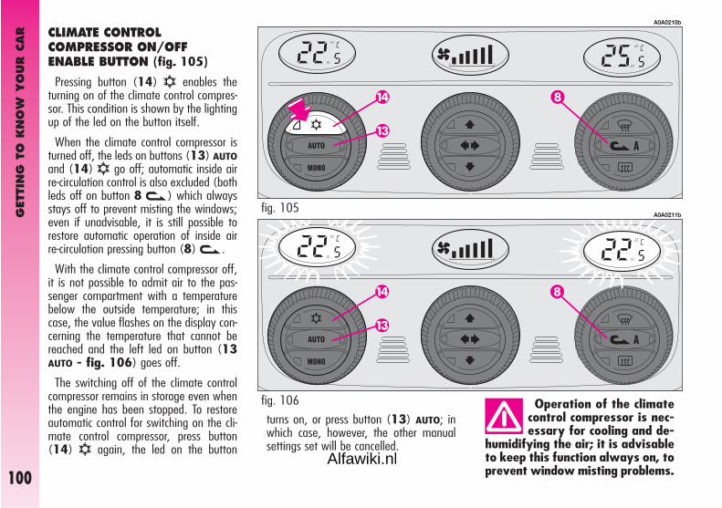
GET
TIN
G T
O K
NO
W Y
OUR C
AR
100
turns on, or press button (13) AUTO; inwhich case, however, the other manualsettings set will be cancelled.
CLIMATE CONTROL COMPRESSOR ON/OFF ENABLE BUTTON (fig. 105)
Pressing button (14) √ enables theturning on of the climate control compres-sor. This condition is shown by the lightingup of the led on the button itself.
When the climate control compressor isturned off, the leds on buttons (13) AUTOand (14) √ go off; automatic inside airre-circulation control is also excluded (bothleds off on button 8 v) which alwaysstays off to prevent misting the windows;even if unadvisable, it is still possible torestore automatic operation of inside airre-circulation pressing button (8)v.
With the climate control compressor off,it is not possible to admit air to the pas-senger compartment with a temperaturebelow the outside temperature; in thiscase, the value flashes on the display con-cerning the temperature that cannot bereached and the left led on button (13AUTO - fig. 106) goes off.
The switching off of the climate controlcompressor remains in storage even whenthe engine has been stopped. To restoreautomatic control for switching on the cli-mate control compressor, press button(14) √ again, the led on the button
Operation of the climatecontrol compressor is nec-essary for cooling and de-
humidifying the air; it is advisableto keep this function always on, toprevent window misting problems.
A0A0210b
A0A0211bfig. 105
fig. 106
Alfawiki.nl

GET
TIN
G T
O K
NO
W Y
OUR C
AR
101
INSIDE AIR RE-CIRCULATION ON/OFF BUTTON (fig. 107)
Inside air re-circulartion is controlledaccording to three operating logics:
- automatic control, indicated by theturning on of the right led on the button;
- forced engagement (inside air re-circu-lation always on), indicated by the turningon of the left led on the button (and bythe right led going off at the same time);
- forced switching off (inside air re-circu-lation always off with air inlet from out-side), indicated by the turning off of bothleds.
These operating conditions are obtainedpressing in sequence the inside air re-cir-culation button (8)v.
When inside air re-circulation is con-trolled automatically by the system, theright led on the air re-circulation button(8)v stays on all the time and the leftled shows the air re-circulation condition:
on = air re-circulation operating;
off = air re-circulation off.
If inside air re-circulation has been turnedon or off manually, the led on button(13) AUTO turns off.
In automatic operation , inside air re-cir-culation is turned automatically when theantipollution sensor detects the presenceof polluted air, for example in cities,queues, tunnels and operation of thewindscreen washer (with the typical smellof spirits).
The inside air- re-circula-tion system makes it pos-sible to reach the required
“heating” or “cooling” conditionsfaster. It is however inadvisable touse it on rainy/cold days as itwould considerably increase thepossibility of the windows mistinginside, especially if the climate con-trol system is off.
A0A0212b
With low external tem-perature the climate con-trol compressor is unable
to work. It is therefore inadvisableto use the inside air recirculationfunctionvwith low outside tem-perature as windows may mistover quickly.
fig. 107
Alfawiki.nl

GET
TIN
G T
O K
NO
W Y
OUR C
AR
102
It is advisable to turn onthe inside air re-circulationsystem in queues or tunnels
to avoid admitting polluted air fromoutside. The prolonged use of thisfunction should however be avoid-ed, especially with several personson board, to avoid the possibility ofthe windows misting inside.
AUTOMATIC OPERATION AUTO BUTTON (fig. 108)
Pressing the (13) AUTO button the sys-tem automatically adjusts the amount anddistribution of the air admitted to the pas-senger compartment, cancelling all theprevious manual adjustments.
This condition is indicated by the lightingup of both leds on the button itself.
When the right led, on button (13) AUTOis off, this means that one or more manualoperations have been carried out and there-fore automatic control is not complete(except temperature control which is alwaysautomatic) indicated by the left led on, orthat the system is in the OFF condition.
In certain weather condi-tions (e.g.: outside tem-perature around 0°C) and
with automatic air re-circulationcontrol on, mist may form on thewindows. In this case press the in-side air re-circulation button (8)v, to switch off re-circulation(leds on button off) and if neces-sary increase the flow of air to thewindscreen.
A0A0209b
fig. 108
Alfawiki.nl

GET
TIN
G T
O K
NO
W Y
OUR C
AR
103
FRONT WINDOWS FAST DEMISTING/DEFROSTING(MAX-DEF) FUNCTION (fig. 109)
Pressing button (7)- the climate con-trol automatically activates timed opera-tion of all the functions needed to quickendemisting/defrosting of the windscreenand front side windows, i.e.:
- it turns on the climate control compres-sor;
- switches off inside air re-circulation, if on(both leds off);
- sets the maximum air temperature (HI)on both displays (1) and (5);
- operates the fan at a predefined speed;
- directs the flow of air towards the wind-screen and front side window vents;
- turns on rearscreen heating and, if pre-sent, the wing mirror coils.
When the maximum demisting/defrostingfeature is on, the led on button (7)-,the led on the rearscreen heating button(9) ( and the led on button (14) √turn on; at the same time the leds on but-ton (8)v.
IMPORTANT If the engine is not hotenough, the function does not immediate-ly engage the pre-established fan speed,to restrict the inlet of air to the passengercompartment that is not warm enough todemist the windows.
When the maximum demisting/defrost-ing function is on, the only manual opera-tion possible are manual adjustment of thefan and switching rearscreen heating off.
Pressing one of the following buttonsagain: (7)-, (8)v, (12) MONO,(13) AUTO or (14) √ the systemswitches off the maximum demisting/defrosting function, restoring the operat-ing conditions of the system prior to turn-ing it on, in addition to activating the lastfunction required, if any.
A0A0213b
fig. 109
Alfawiki.nl

GET
TIN
G T
O K
NO
W Y
OUR C
AR
104
WING MIRROR AND REARSCREENDEFROSTING/DEMISTINGBUTTON (fig. 110)
Pressing button (9) ( turns ondemisting/defrosting of the rearscreenand, if present, the wing mirror coils.
The turning on of this function is shownby the turning on of the led on the button.
This function is timed and switches offautomatically after 20 minutes, or press-ing the button again; the function is alsoswitched off when the engine is stoppedand will not be switched on again the nexttime the engine is started.
IMPORTANT The system automatical-ly turns on rearscreen heating if the tem-perature is below 3°C.
IMPORTANT Do not apply stickers onthe inside of the rearscreen over the heat-ing filaments to avoid damage that mightcause it to stop working properly.
POLLEN FILTER
Have the conditions of the filter checkedby Alfa Romeo Authorised Services at leastonce a year, preferably at the onset ofsummer.
If the car is used mainly in dusty or pol-luted areas it should be checked and, ifnecessary, replaced at shorter intervals.
A0A0214b
The filter has the specific capability of fil-tering external air, thus admitting to thepassenger compartment purified air, freefrom particles such as dust, pollen, etc.
In addition to the above mentioned func-tions, is also reduces the concentration ofpollutants.
The filtering action takes place under allair inlet conditions and it is clearly mosteffective with the windows shut. If the filter is not replaced
the efficiency of the cli-mate control system may
be seriously compromised up toblocking the air flow at the outletsand vents.
fig. 110
Alfawiki.nl

GET
TIN
G T
O K
NO
W Y
OUR C
AR
105
PARKING SENSORS (fig. 111)(upon request for versions/markets where applicable)
Parking sensors are located in the rearbumper and their function is to inform thedriver, through an intermittent buzzer,about the presence of obstacles behindthe car.
ACTIVATION
Sensors are automatically activatedwhen the reverse gear is engaged.
As the distance from the obstacle behindthe car decreases, the acoustic alarmbecomes more frequent.
BUZZER WARNINGS
When the reverse gear is engaged anintermittent acoustic signal is automatical-ly activated.
The acoustic signal:
– becomes louder as the reduction ofdistance between the car and the obstacledecreases;
– becomes continuous when the dis-tance between the car and the obstacle isless that 30 cm and stops immediately ifthe distance raises.
– is constant if the distance is unvaried.If this situation takes place for side sen-sors, the signal is stopped after about 3seconds to prevent sound indicationswhen performing manoeuvres near walls.
OPERATION WITH TRAILER
Parking sensor operationis deactivated automati-cally when the trailer elec-
tric cable plug is fitted into the cartow hook socket.
Sensors are reactivated automaticallywhen removing the trailer cable plug.
fig. 111
A0A0735b
Alfawiki.nl

GET
TIN
G T
O K
NO
W Y
OUR C
AR
106
CONTROLS
TAILGATE OPENING (fig. 112)
Electric tailgate release is only allowed withthe ignition key in the ignition switch atMAR car stationary, at STOP or PARKfor 3 minutes without opening/closing adoor. To release the tailgate, press button(A) on the central console panel.
HAZARD WARNING LIGHTS(fig. 112)
They are switched on by pressing button(C), on the central console panel, regard-less of the position of the ignition key.
When the hazard lights are switched on,the switch itself begins to flash together withthe direction indicators and warning lightson the instrument panel. This function isswitched off by pressing the button again.
Use of the hazard lights isruled by the Highway Codeof the country in which the
car is used. Observe regulations.
FOG LIGHTS (fig. 112)
These are turned on pressing button (B),on the centre console panel, when the out-er lights are already on, at the same timethe led on the button itself turns on.
Press button (B) again to switch off.
IMPORTANT The front foglights shouldbe used in compliance with the local trafficlaws.
fig. 112
A0A0091b
REAR FOG GUARDS (fig. 112)
These are turned on, with the dipped beamheadlights or fog lights on, pressing button(D) on the centre console panel, at thesame time the warning light on the buttonitself turns on.
Turning the ignition key to STOP the fogguards are automatically turned off and theydo not come on the next time the engineis started unless button (D) is pressed. Toturn them off press button (D).
IMPORTANT Always use the rear fogguards in compliance with local regulations.
Alfawiki.nl

GET
TIN
G T
O K
NO
W Y
OUR C
AR
107
If no leaks are found the car can be restart-ed. Press button (A) to activate the fuel sup-ply system again.
fig. 113
A0A0092b
If a smell of fuel is notedfollowing an accident, orthe fuel system is leaking,
to avoid the risk of fire do not re-set the switch.
DOOR LOCKING SYSTEM (fig. 112)
To lock the doors simultaneously, press but-ton (E), on the centre console panel, re-gardless of the position of the ignition key.
The deterrent led turns on as follows:
– with the ignition key at MAR glowingsteadily with a yellow light;
– with the ignition key at STOP flash-ing with a red light (deterrence condition).
INERTIAL FUEL CUT-OFF SWITCH (fig. 113)
This is an automatic safety switch, to befound on the floor next to the driver’s doorpillar, which is triggered in the event of acrash of a certain magnitude to interrupt theflow of fuel.
The cutting in of the inertial switch is shownon the display of the instrument cluster.
Alfawiki.nl

GET
TIN
G T
O K
NO
W Y
OUR C
AR
108
The wheels should belocked after a few clicks ofthe hand brake. If it does
not occur contact Alfa Romeo Au-thorised Services to have the handbrake adjusted.
HAND BRAKE (fig. 115)
The hand brake lever is located betweenthe two front seats.
To operate the brake when the car is sta-tionary, pull lever (A) upwards, until the re-quired braking action is obtained.
When the ignition key is at MAR, thewarning light on the instrument cluster xwill come on.
fig. 115
A0A0620b
Adjust the beams everytime the load carriedchanges.
Correct positions as a function of the load:
– position 0: one or two people occupy-ing the front seats
– position 1: five people;
– position 2: five people + load in theboot;
– position 3: driver + 350 Kg load allstowed in luggage com-partment
fig. 114
A0A1106b
HEADLIGHT AIMING DEVICE (fig. 114)
The headlights should be aimed correctlydepending on the car load.
For the required adjustment (only possiblewith low beams on), press buttons ▲/▼:
– press button ▲, to increase by one po-sition (e.g.: 0 ➟ 1 ➟ 2 ➟ 3);
– press button ▼ to decrease by one po-sition (e.g.: 3 ➟ 2 ➟ 1 ➟ 0);
The display (A), in the tachometer showspositions during adjustment.
Xenon headlights aiming is automatic, ver-sions with this optional are therefore not fit-ted with headlight aiming device.
Alfawiki.nl

GET
TIN
G T
O K
NO
W Y
OUR C
AR
109
To release the hand brake:
– slightly lift the lever (A) and press therelease button (B);
– keeping the button pressed lower thelever, the warning light x on the instru-ment cluster will go out.
To prevent the car from moving acciden-tally, keep the brake pedal pressed whenengaging the hand brake.
IMPORTANT The hand brake lever (A)is fitted with a safety device which preventsthe brake from being released when, withthe lever pulled, button (B) is pressed.Therefore, to release the brake, in additionto pressing button (B), it is also necessaryto pull lever (A) further upwards to releasethe safety device, then lower the lever com-pletely.
IMPORTANT On certain versions abuzzer sounds to alert the driver if the caris moved with the hand brake engaged.
GEARSHIFT LEVER (fig. 116)
The position of the single gears is shownby the pictogram on the gearshift lever knob.
When shifting gear, always fully depressthe clutch pedal. Before engaging reversegear (R) wait for the car to be stationary.
Certain versions are equipped with 6-speedgearbox. For the versions with 6 gears, toengage reverse (R) lift (with the fingersof the same hand holding the lever) the ring(A-fig. 116) positioned under the lever.After engaging the reverse, release the ring.To change from reverse to another gear, itis not necessary to lift the ring on the lever.
IMPORTANT Reverse gear may only beengaged with the car completely at a stand-still. With the engine running, before en-gaging reverse gear it is necessary to waitfor at least 3 seconds with the clutch pedalfully depressed to prevent clashing and thepossibility of damaging the gears.
To change gear smoothly,the clutch pedal must befully depressed. Therefore,
there should be no obstacles on thefloor under the pedal unit: makesure that any mats are well laid anddo not interfere with the pedals.
fig. 116
A0A0684b
Alfawiki.nl

GET
TIN
G T
O K
NO
W Y
OUR C
AR
110 fig. 119
A0A9017i
The gearbox can work according to two op-erating modes:
– the first is semi-automatic (hereinaftercalled MANUAL), in which the driver shiftsgear directly using the lever on the centralconsole or the levers on the steering wheelspokes;
– the second is automatic, called CITY(when selecting CITY with button B-fig.117, the word CITY will be displayed fig.119). In this mode the system decides di-rectly when to shift gear.
SELESPEEDTRANSMISSION(on request for versions/marketswhere applicable)
IMPORTANT To be able to use the Se-lespeed correctly, this chapter should be readin full to understand the correct, permissibleoperations to be carried out right from thestart.
This device comprises a conventional me-chanical transmission, to which an elec-tronically-controlled electrohydraulic devicehas been added, which automatically con-trols the clutch and gear engagement.
The clutch pedal has been eliminated andthe car moves off using only the acceleratorpedal.
Gearshifting takes place through a floatingcontrol lever (A-fig. 117) with “only onestable central position”. Using this lever it ispossible to request increase/decrease of theratio of the gear engaged and/or engage-ment of reverse gear (R) or neutral (N).
There are also two levers on the steeringwheel spokes (fig. 118) through which,only with the car on the move (with speedabove 0,5 km/h), it is possible to in-crease/decrease the gear engaged.
fig. 117
A0A0697b
fig. 118
A0A0669b
Alfawiki.nl

GET
TIN
G T
O K
NO
W Y
OUR C
AR
111
SYSTEM ACTIVATION
IMPORTANT Opening the driver’s door,the Selespeed starts the hydraulic part ofthe system to prepare it for the engine to bestarted.
Turning the ignition key to MAR, all thesegments of the display (fig. 119), thegearbox warning light (fig. 120) and theword CITY turn on. After about one second,the display indicates the gear engaged (N,1, 2, 3, 4, 5, R).
IMPORTANT If after 10 seconds the dis-play segment do not display the gear en-gaged or the warning light stays on, turn theignition key to STOP and wait for the dis-play to go off, then repeat the system acti-vation procedure. If the fault persists, con-tact Alfa Romeo Authorized Services.
With gearshift to CITY gears can be shift-ed manually using both the gearshift leveror the steering wheel controls. Gearshiftstays in CITY.
The gear selected (fig. 119) is alwaysdisplayed regardless of the mode being se-lected selected .
N = neutral;
1 = first gear;
2 = second gear;
3 = third gear;
4 = fourth gear;
5 = fifth gear;
R = reverse.
In CITY or SPORT, the selected mode isalso displayed.
IMPORTANT SPORT mode can onlybe activated after deactivating the CITYmode.
A warning light, a message (fig. 120)and a buzzer draw the attention of the dri-ver in the event of a fault at Selespeed trans-mission.
The Selespeed considerably simplifies useof the car, reducing the fatigue of city dri-ving or when frequent gearshifting is re-quired, at the same time offering brilliantperformance.
fig. 120
A0A9081g
Alfawiki.nl

GET
TIN
G T
O K
NO
W Y
OUR C
AR
112
If the car is on the move, the request isnot accepted; wait for the car to stop andthen request reverse gear engagementagain.
IMPORTANT Once a gear has beenchanged it is necessary to immediately re-lease the gearshift control lever after mak-ing the request. A manoeuvre prolonged(over 10 seconds) makes the system au-tomatically switch to CITY mode; every-thing stops releasing the gearshift lever.
IMPORTANT If wanting to leave the carparked on a sloping road with a gear en-gaged to keep it braked, it is necessary tocheck that the display shows the new gearengaged and then wait for 1 to 2 secondsbefore releasing the brake pedal to allowcomplete clutch engagement.
fig. 123
A0A0700b
OPERATION WITH ENGINE OFF
IMPORTANT Before using the gearshiftcontrol lever, always check the gear en-gaged on the display (N, 1, 2, 3, 4, 5,R).
With the engine off and the car station-ary it is possible to engage all the gears.
With the car stationary and with the brakepedal pressed, requests to shift gears areboth accepted through the control lever onthe central console or through the steeringwheel levers.
To request gearshifting, in addition to keep-ing the brake pedal pressed:
– to shift upwards (+) (fig. 121) pushthe lever “forwards” (if the car is in first gearit shifts to second, if in second it shifts tothird and so on up to fifth). If the systemis in neutral (N) or reverse (R) moving the
lever forwards causes the engagement offirst gear (1).
– to shift downwards (–) (fig. 121)push the lever backwards (if the car is infifth gear it shifts to fourth, if in fourth itshifts to third and so on down to first gear).
To allow setting the transmission to neu-tral (N), starting from the condition withthe car stationary and brake pedal pressed,move the gearshift lever to the right (fig.122).
From any gear (N, 1, 2, 3, 4, 5) andwith the car practically at a standstill, it ispossible to request engagement of reversegear, pushing the lever to the right and thenbackwards (fig. 123).
fig. 121
A0A0698b
fig. 122
A0A0699b
Alfawiki.nl

GET
TIN
G T
O K
NO
W Y
OUR C
AR
113
Never remove the ignitionkey when the car is mov-ing. In addition to the fact
that the Selespeed system wouldnot work properly up to stoppingthe car, the steering wheel wouldlock automatically the first time itis turned.
STARTING THE ENGINE
The engine can be started with the gearengaged or in neutral (N), provided that thebrake pedal is pressed down.
IMPORTANT Keep the pedal fully de-pressed during starting. Since the brake ped-al becomes hard if it is pressed repeatedlywith the engine off, in this situation it is nec-essary to increase the pressure on the ped-al itself to start the engine.
After starting, the gearbox sets to neutralautomatically, the display shows the letter(N) and the system selects the operatingmode memorised before switching off.
If the engine fails to startwith the gear engaged, thedriver is alerted of the po-
tentially dangerous situation dueto the fact that the gearbox hasautomatically set to neutral by thebuzzer and the display.
SWITCHING OFF THE ENGINE AND SYSTEM DEACTIVATION
Turning the ignition key to STOP the en-gine switches off: the gear selected beforeturning the engine off remains engaged.
If the engine stops with the gearbox inneutral (N), the buzzer and the blinkingof (N) draw the attention of the driver sothat the car can be put in safety conditionsengaging the first gear (1) or reverse (R).In this case, it is necessary to turn the igni-tion key to MAR and with the brake ped-al pressed, engage first gear (1) or reverse(R).
NEVER leave the car withthe gears in neutral (N).
It is absolutely necessaryto turn off the engine con-sequently deactivating the
Selespeed system keeping the brakepedal pressed: release the pedalONLY when the display goes off.
Alfawiki.nl

GET
TIN
G T
O K
NO
W Y
OUR C
AR
114
The driver is informed of the reverse gearengaged condition by the intermittent soundof the buzzer as well as by the display.
IMPORTANT If while shifting from re-verse (R)/first gear (1) or neutral (N)/first gear (1) sticking occurs on the firstgear, the system automatically engages sec-ond gear (2).
This should not be considered a failure be-cause it is part of the operating logic. Forthe same reason, if sticking occurs on re-verse gear, the system controls partial clutchclosing so that the gear can be engaged;in this case the engagement of reverse gear(R) will not be as smooth as usual.
After a request to shiftgear with the car station-ary, before pressing the ac-
celerator pedal to make the carstart, the driver must always checkthat the gear engaged shown onthe display is the one required.
MOVING OFF THE CAR
With the engine running and the car sta-tionary, the gears that can be engaged formoving off are only first (1), second (2) orreverse (R).
To engage them it is possible to use thecontrol lever on the centre console, with thebrake pedal pressed, as the steering wheellevers allow gear engagement only over 0.5km/h.
IMPORTANT Reverse gear (R) can beengaged from each of the following otherratios: neutral (N), first gear (1) or secondgear (2). If the car is on the move, the re-quest is not accepted; it is necessary to waitfor the car to be completely stopped andthen request reverse (R) again.
Moving off the car is obtained:
1) releasing the brake pedal;
2) gradually pressing the accelerator ped-al.
The more the accelerator pedal is pressedthe higher the car pick-up torque will be.
Alfawiki.nl

GET
TIN
G T
O K
NO
W Y
OUR C
AR
115
Though strongly inadvisable, if due to un-foreseen circumstances when driving down-hill the car is allowed to travel with the gear-box in neutral (N), when the engagementof a gear is requested, the system auto-matically engages the best gear to allowtransmission of the torque to the wheels inrelation to the speed of the car.
When travelling downhill with a gear en-gaged and the accelerator released (if thecar is moving), beyond a pre-establishedspeed, the system engages the clutch au-tomatically to give the car adequate enginebraking.
For safety reasons the Selespeed systemactivates the buzzer when: clutch over-heating occurs during car starting; in thiscase, it is necessary to “force” moving offavoiding hesitations or to release the accel-erator and use the brake pedal to park thecar if the car is on a slope.
Still due to safety reasons, with the car sta-tionary, the engine running and gear (1),(2) or (R) engaged, the system activatesthe buzzer and automatically shifts to neu-tral (N) when:
– no action is made on the acceleratorand/or brake pedals for at least 3 minutes;
– the brake is pressed for over 10 min-utes;
– the driver’s door is opened and the ac-celerator and brake pedal are not pressedfor at least 1.5 seconds.
IMPORTANT NOTES
– With the car stopped and a gear en-gaged always keep the brake pedal presseduntil deciding to move off;
– during prolonged halts with the enginerunning it is advisable to keep the gearboxin neutral;
– when the car is parked facing uphill, donot use the moving off manoeuvre to keepthe car still; use the brake pedal and pressthe accelerator pedal only when deciding tomove off;
– use second gear only when more con-trol is needed for moving off manoeuvres atlow speed;
– if, with reverse gear engaged, you needto engage first gear or vice versa, shift gearonly when the car is completely stationaryand with the brake pedal pressed.
Alfawiki.nl

GET
TIN
G T
O K
NO
W Y
OUR C
AR
116
STOPPING THE CAR
To stop the car, simply release the accel-erator pedal and, if necessary, press thebrake pedal.
Regardless of the gear engaged and theoperating mode activated (MANUAL orCITY) the system automatically disengagesthe clutch and shifts to a lower gear.
If deciding to move off again without hav-ing stopped the car completely, the mostsuitable ratio will be available for accelera-tor again.
Stopping the car the system automatical-ly engages first gear (1).
OPERATION
The gearbox can work according to two op-erating modes:
– the first one is semi-automatic (MAN-UAL): the decision to change gear is left tothe driver who decides the most appropriatemoment; this mode features the two fol-lowing logics:
1) normal: for comfort driving;
2) sport: (to be activated by button B-fig. 124): for sporty driving.
Sport operating mode is selected by press-ing button SPORT (B-fig. 124) set onthe gearshift lever; when selecting thismode, the display will show SPORT.
– the second one is fully automatic(CITY), in which the system decides di-rectly when to shift gear according to drivingconditions.
To select the CITY mode, press buttonCITY set on the gearshift lever; when se-lecting this mode, the display will showCITY.
Alfawiki.nl

GET
TIN
G T
O K
NO
W Y
OUR C
AR
117
SEMIAUTOMATIC OPERATION (MANUAL)
In the MANUAL operating mode the dis-play shows the gear engaged.
In this operating mode, the decision tochange gear is left to the driver who decidesthe most appropriate moment.
The requests to change gear may takeplace through:
– the control lever on the centre console(A-fig. 124);
– the buttons on the steering wheel (fig.125), which can be operated only whenthe car speed exceeds 0.5 km/h.
The MANUAL operating mode is setwhen, with the CITY mode selected, theCITY button (A-fig. 126) is pressedagain, thereby cutting out the previously se-lected mode.
When changing gear it is not necessaryto release the accelerator pedal because theSelespeed system directly controls the en-gine in such a way as to:
– reduce and then increase engine torque;
– adapt the engine speed to the new gearratio engaged.
When downshifting, the engine is accel-erated automatically to bring it to the speednecessary with the new gear ratio.
Neutral (N) is accepted until the car speedexceeds 40 km/h.
The reverse gear engagement command(R) is accepted only if the car is station-ary.
fig. 125
A0A0669b
fig. 124
A0A0702b
Alfawiki.nl

GET
TIN
G T
O K
NO
W Y
OUR C
AR
118
With the accelerator pedal pressed to over60% of its stroke and an engine speedabove 5000 rpm, gearshifting becomesquicker. In the MANUAL operating modethere are certain automatic/security deviceswhich simplify driving:
– when slowing down, the clutch is dis-engaged and the gear ratio is reduced au-tomatically to be ready for possibly pickingup speed again; if not, stopping the car, firstgear (1) will be engaged automatically;
– request to change gear that could takethe engine above the maximum rpm or be-low the minimum permissible rpm are notaccepted;
AUTOMATIC OPERATION (CITY)
The CITY automatic operating mode is se-lected pressing the button (A-fig. 126)at the base of the gearshift lever.
In addition to the gear, the display willshow the word CITY.
The system decides directly when to shiftgears in relation to the engine rpm and dri-ving conditions.
Releasing the accelerator pedal quickly, thesystem does not engage a higher gear in or-der to maintain an adequate level of enginebrake.
fig. 126
A0A0701b
– if sticking occurs during the engagementof a gear, the system firstly tries to engagethe required gear again and, if it is still notpossible, it automatically engages the im-mediately higher one to avoid leaving thecar in neutral .
IMPORTANT It is advisable to wait forthe end of a gear shifting operation beforerequesting another one, to avoid multiplerequests in rapid succession.
Alfawiki.nl

GET
TIN
G T
O K
NO
W Y
OUR C
AR
119
In the event of whatevertransmission fault, contactAlfa Romeo Authorized Ser-
vices as soon as possible to havethe system checked.
In the event of a fault to the gearshift lever,the system automatically activates the au-tomatic CITY mode to allow the car toreach the nearest Alfa Romeo AuthorizedServices to have the fault detected elimi-nated.
In the event of a fault to the other gear-box components, the system only allows theengagement of certain gears: first gear (1),second gear (2) and reverse (R).
FAILURE INDICATIONS
Failures to the Selespeed gearbox are in-dicated on the display by warning light t(fig. 127), dedicated message andbuzzer.
If the warning light tand the message are dis-played, contact Alfa Romeo
Authorized Services as soon aspossible to have the fault elimi-nated.
fig. 127
A0A9081g
Alfawiki.nl

GET
TIN
G T
O K
NO
W Y
OUR C
AR
120
PARKING THE CAR
To park the car safely it is absolutely nec-essary to engage first gear (1) or reverse(R) and also the handbrake if the road ison a slope.
Turning the engine off with the car facinguphill and a gear engaged, it is absolutelynecessary to wait for the gear display to gooff before releasing the brake pedal, so thatthe clutch is fully disengaged.
If the gearbox is in neutral (N) and want-ing to engage a parking gear, the systemshould be activated and with the foot on thebrake pedal it is necessary to engage (1)or (R).
TOWING THE CAR
IMPORTANT For towing the car, adhereto local regulations. Make sure that the gear-box is in neutral (N) (checking that the carmoves when pushed) and proceed as fortowing a normal car with mechanical gear-box following the instructions given in sec-tion “In an emergency”.
If setting to neutral is not possible, do nottow the car and contact Alfa Romeo Autho-rized Services.
While towing the car donot start the engine.
BUZZER WARNINGS
The buzzer is activated when:
– reverse gear is engaged (R);
– the car is parked with the gearbox inneutral (N); signal that can be noted turn-ing the ignition key to STOP;
– clutch overheating occurs when movingoff;
– the system has shifted automaticallyto neutral (N) when:
there is no action on the acceleratorand/or brake pedal for at least 3 minutes;
or the brake is pressed for over 10 min-utes;
or the driver’s door is opened and no ac-tion is made on the accelerator and brakefor at least 1.5 seconds;
or detection of a gearbox fault;
– gearbox fault.
Alfawiki.nl

GET
TIN
G T
O K
NO
W Y
OUR C
AR
121
INTERIOR FITTINGS
GLOVEBOX
On the dashboard there is a glovebox withlid and light.
To open use handle (A-fig. 128).
When the glovebox is opened with the keyat MAR an inside courtesy light turns on(A-fig. 129).
FRONT ROOF LIGHT (fig. 130)
The roof light comprises two courtesy lightswith corresponding control switch.
IMPORTANT When a door is opened,the roof light turns on and timing of about3 minutes is activated automatically, afterwhich it goes off; closing the doors (withinthe 3 minutes) a second timing of about 7seconds is activated to allow car starting.
fig. 128
A0A0108b
fig. 129
A0A0109b
Never travel with theglovebox open: the lidmight harm the passenger
in the event of an accident.
The fitting is completed by device (B), onthe lid, for inserting a pen or pencil.
IMPORTANT Turning the ignition key toSTOP, opening the glovebox, the light in-side can only be turned on for 15 minutes;after which the system turns it off to avoiddraining the battery.
fig. 130
A0A0111b
Alfawiki.nl

GET
TIN
G T
O K
NO
W Y
OUR C
AR
122 fig. 131
A0A0112b
Unlocking the doors using the remote con-trol, the roof light turns on gradually and tim-ing is activated automatically for about 15seconds. Locking the doors with the remotecontrol the roof light turns off gradually.
The lights are turned off moving the igni-tion key to MAR (with the doors closed).
With switch (A) in the central position(1), both lights are turned on when a dooris opened.
Pressing switch (A) to the left (position0), the lights stay off (OFF position).
Pressing switch (A) to the right (position2) both lights stay on.
Switch (B) turns the lights on individually.
Pressing switch (B) to the left (position 0)the left light is turned on. Pressing the switchto the right (position 2) the right light isturned on.
With switch (B) in the central position (po-sition 1) the lights stay off.
IMPORTANT Turning the ignition key toSTOP, turning the roof light on is only pos-sible for 15 minutes; after which the systemturns it off to avoid draining the battery.
IMPORTANT Before leaving the car,make sure that both switches are in the cen-tral position. By so doing, the roof lights willturn off when the doors are closed. Forget-ting a door open the lights will turn off au-tomatically after a few seconds.
COURTESY LIGHTS (fig. 131)
On the back of the driver’s or passenger’ssun visor, opening the cover (A) the rooflights turn on (B) at the side of the courtesymirror, with the ignition key at MAR. Theselights allow use of the courtesy mirror whenthe light is poor.
IMPORTANT Turning the ignition key toSTOP the lights can be activated only for15 minutes: after which the system turnsthem off to avoid draining the battery.
Alfawiki.nl

GET
TIN
G T
O K
NO
W Y
OUR C
AR
123
REAR ROOF LIGHT (fig. 132)
IMPORTANT When a door is opened,the roof light turns on and timing of about3 minutes is activated automatically, afterwhich it goes off; closing the doors (withinthe 3 minutes) a second timing of about 7seconds is activated to allow car starting.
Unlocking the doors using the remote con-trol, the roof light turns on gradually and tim-ing is activated automatically for about 15seconds. Locking the doors with the remotecontrol the roof light turns off gradually.
The light turns off in any case turning theignition key to MAR (with the doorclosed).
PUDDLE LIGHTS (fig. 133)(for versions/markets whereapplicable)
The light (A) housed in the doors turns onwhen the associated door is opened, re-gardless of the position of the ignition key.
fig. 132
A0A0633b
On the light there is a switch with threepositions.
When switch (A) is in the central posi-tion (0) the light turns on automaticallywhen a door is opened.
Moving the switch to the right (position 1)the light stays off.
Moving the switch to the left (position 2)the light stays on.
IMPORTANT Turning the ignition key toSTOP the roof light can be turned on foronly 15 minutes; after which it is turned offto avoid draining the battery.
IMPORTANT Before leaving the car,make sure that the switch (A) is in the cen-tral position (0), so that the roof light turnsoff when the doors are closed.
fig. 133
A0A0243b
Alfawiki.nl

GET
TIN
G T
O K
NO
W Y
OUR C
AR
124
The cigar lighter gets ex-tremely hot. Handle withcare and prevent its use by
children: danger of fire and/orburning.
Always ensure that thecigar lighter has turned off.
Do not use the ashtray aswaste paper basket: itmight set on fire in contact
with cigarette stubs.
DETERRENT LED (fig. 134)
The led (A) on the instrument clustercomes into operation when the doors arelocked (ignition key at STOP or removed)and it remains in the “deterrence” condi-tion, flashing with a red light until the nexttime the doors are unlocked.
IMPORTANT If a door or the tailgateare not closed perfectly, the deterrent ledflashes at a higher frequency for 4 secondsand then flashes at normal frequency again.
FRONT ASHTRAY AND CIGAR LIGHTER (fig. 135)
To gain access to the ashtray and the cig-ar lighter open the lid (A).
To use the cigar lighter, with the key atMAR, press button (B); after a few sec-onds the button will return automaticallyto its initial position and the cigar lighter isready for use.
Remove the tray to empty and clean theashtray (C).
The position of the cigar lighter in relationto the ashtray and viceversa, may vary de-pending on the trim level.
fig. 134
A0A0005b
fig. 135
A0A0634b
Alfawiki.nl

GET
TIN
G T
O K
NO
W Y
OUR C
AR
125
REAR ASHTRAYS (fig. 136)
For the rear passengers there are two con-cealed ashtrays.
To use or remove pull in the direction ofthe arrow.
CARD HOLDER RECESS AND GLASS HOLDER (fig. 137)(for versions/markets whereapplicable)
The interior fittings are completed by theremovable card holder recess (A) and glassholder (B) located on the centre of the dash-board. To use them, press as shown.
fig. 136
A0A0115b
fig. 137
A0A0116b
ODDMENT POCKETS ON FRONT DOORS (fig. 138)
Each front door has an oddment pocket(A).
fig. 138
A0A0117b
Alfawiki.nl

GET
TIN
G T
O K
NO
W Y
OUR C
AR
126
CELL PHONE PROVISION
The car may be fitted with a provision forinstalling a cell phone.
The mobile phone provision consists of:
– radio + cell phone dual-purpose antenna;
– connection and supply cables with spe-cific connector for connecting hands-free kit.
ODDMENT RECESSES ON CENTRE CONSOLE (fig. 139)
On the centre console, at the side of thehand brake lever, depending on the versions,the following recesses are provided:
– can holder (B);
– magnetic card or toll ticket holder (C);
– pen or pencil holder (D);
– coin holder (E).
SUN VISORS (fig. 140)
The visors can be directed at the front andside.
Behind, the visors have a courtesy mirrorwith a light at the side (A). To use, openthe cover (B).
The lights allow use of the mirrors with dimlight.
The passenger’s sun visor has a symbolconcerning correct use of a child’s seat in thepresence of the passenger’s air bag. For fur-ther details, refer to the passenger’s frontair bag paragraph.
fig. 139
A0A0751b
fig. 140
A0A0121b
For the installation of acell phone and connectionto the provision in the car,
contact only Alfa Romeo Autho-rised Services; this will guaranteefirst-rate results with no possibil-ity of any inconvenience that maycompromise the safety of the car.
The voice kit should bepurchased by the customeras it must be compatible
with the customer’s phone.
Alfawiki.nl

GET
TIN
G T
O K
NO
W Y
OUR C
AR
127
RADIOTRANSMITTERSAND CELLULAR TELEPHONES
Mobile phones and other radio transceiv-er equipment (e.g.: HAM radio systems andthe like) shall not be used inside the car un-less a separate aerial is mounted.
IMPORTANT The use of mobile phones,HAM radio systems or other similar devicesinside the passenger compartment (withoutseparate aerial) may cause electronic sys-tems equipping the car to malfunction. Thiscould compromise safety in addition to con-stituting a potential hazard for the passen-gers.
In addition, transmission and reception ofthese devices may be affected by the shield-ing effect of the car body.
As concerns the use of mobile phones(GSM, GPRS, UMTS) with homologa-tion, keep strictly to the mobile phone man-ufacturer’s specifications.
ACCESSORIESPURCHASED BY THE OWNER
If after buying the car, you decide to installelectrical accessories that require a perma-nent electric supply (alarm, voice feature,radionavigator with satellite antitheft, etc.)or accessories that in any case burden theelectric supply, contact Alfa Romeo Autho-rised Services, whose qualified personnel,besides suggesting the most suitable devicesbelonging to Lineaccessori Alfa Romeo, willalso evaluate the overall electric absorption,checking whether the car electric system isable to withstand the load required, orwhether it needs to be integrated with amore powerful battery.
INSTALLATION OF ELECTRIC/ELECTRONICDEVICES
Electric/electronic devices installed afterbuying the car or in aftermarket shall bearthe and marking:
Fiat Auto S.p.A. authorizes the installationof transceivers provided that installation iscarried out at a specialized shop, work-manlike performed and in compliance withmanufacturer’s specifications.
IMPORTANT Installation of devices re-sulting in modifications of car characteristicsmay cause driving license seizing by trafficagents and also the lapse of the warrantyas concerns defects due to the abovemen-tioned modification or traceable back to itdirectly or indirectly.
Fiat Auto S.p.A. declines all responsibilityfor damages caused by the installation ofnon-genuine accessories or not recom-mended by Fiat Auto S.p.A. and installednot in compliance with the specified re-quirements. Alfawiki.nl

GET
TIN
G T
O K
NO
W Y
OUR C
AR
128
OPENING FROM INSIDE (fig. 141)
Tailgate is released electrically and this canbe performed only when the ignition keyis in position MAR with car at a standstillor in STOP or PARK position for 3 min-utes without unlocking/locking one of thedoors.
To unlock the tailgate, press button (A)on the centre console panel.
Tailgate raising is facilitated by the gasshock springs.
OPENING WITH REMOTE CONTROL (fig. 142)
The tailgate can be opened by remote con-trol from outside pressing the button (A),also when the electronic alarm is engaged.Opening of the tailgate is accompanied bya double flash of the direction indicators;closing is accompanied by a single flash.
If an electronic alarm is fitted, with theopening of the tailgate, the alarm systemswitches off volumetric protection and thetailgate control sensor, the system “beeps”twice (with the exception of certain mar-kets).
fig. 141
A0A0129b
BOOT
The tailgate can be opened:
from the outside of the car - by aremote control impulse;
from the inside of the door - by de-pressing the button (A-fig. 141).
IMPORTANT If the boot is not proper-ly shut, the ´ warning light will come on(on certain versions accompanied by themessage on the reconfigurable multifunctiondisplay).
The gas springs are cali-brated to ensure correcttailgate raising with the
weights foreseen by the manufac-turer. The arbitrary addition ofitems (such spoilers, etc.) maycompromise the correct operationand safety of the actual tailgate.
fig. 142
A0A0636b
Alfawiki.nl

GET
TIN
G T
O K
NO
W Y
OUR C
AR
129fig. 143
A0A0637b
fig. 144
A0A0658b
Closing the tailgate again, the control func-tions are restored, the system “beeps” twice(with the exception of certain markets).
TAILGATE CLOSING
To lock, push in correspondence with theAlfa Romeo badge to lower tailgate, untilyou feel the click of the lock.
BOOT LIGHT (fig. 143)
When the tailgate is opened the light turnson automatically (A) in the right-hand sideof the boot. Closing the tailgate, the lightturns off automatically.
IMPORTANT Turning the ignition key toSTOP, opening the tailgate, turning on thelight will only be possible for 15 minutes;after which the system turns it off to avoiddraining the battery.
EMERGENCY OPENING OF TAILGATE
To succeed in opening the tailgate from theinside, should the car battery be flat, or be-cause of a defect of the electric lock of thetailgate itself, proceed as follows (see “Ex-tending the luggage compartment” in thechapter “Getting to know you car”):
– tilt the rear seat cushions;
– tilt the backrests;
– unlock the lock by pulling the string (A-fig. 144) (the string is located inside theright recess in the tailgate).
Alfawiki.nl

GET
TIN
G T
O K
NO
W Y
OUR C
AR
130
Do not load the bootabove the permitted max-imum (see “Technical spec-
ifications”). Also make sure thatthe objects contained in the bootare well secured to prevent themfrom being thrown forward, caus-ing harm to the passengers.
A heavy load that has notbeen secured may causeserious harm to passen-
gers.
If you want to carry re-serve fuel in a can, followlegal regulations, only us-
ing a certified can, suitably fas-tened to the load securing eyelets.Even in this way the risk of fire isincreased in the case of an accident.
SECURING THE LOAD (fig. 145)
The loads carried may be secured withstraps hooked to the special rings (A) in theboot.
The rings also serve for fastening the lug-gage restrainer, if present (in any case avail-able c/o Alfa Romeo Authorised Services).
CAUTIONS FOR CARRYING LUGGAGE
Travelling at night with a load in the bootit is necessary to adjust the height of the lowbeam headlights (see next paragraph“Headlights” in this chapter). For correct useof the aiming device, also make sure thatthe load does not exceed the values givenin the same paragraph.
fig. 145
A0A0638b
Alfawiki.nl

GET
TIN
G T
O K
NO
W Y
OUR C
AR
131fig. 147
A0A0707b
Carry out this operationonly with the car station-ary.
DANGER-SERIOUS IN-JURY. When carrying outchecks or maintenance op-
erations in the engine compart-ment, take special care not to bumpthe head on the raised bonnet.
If checks need to be car-ried out in the engine com-partment when the engine
is still warm, keep away from thefan as it could start up even whenthe key is removed from the igni-tion. Wait until the engine coolsdown.
BONNET
The bonnet opening lever is under the leftend of the dashboard.
To open:
– pull the lever (A-fig. 146) until thebonnet clicks open.
– press the safety lever (A-fig. 147)upwards.
– raise the bonnet.
IMPORTANT Bonnet raising is aided bytwo gas springs. Do not tamper with thesesprings and accompany the bonnet whileraising it.
fig. 146
A0A0135b
Scarves, ties and looseclothing may be caught inthe moving parts.
For safety reasons thebonnet must be closedproperly to avoid its open-
ing while the car is travelling.Therefore, always check it is prop-erly closed and the catch engaged.Should you notice that the catch isnot perfectly engaged when trav-elling, stop the car immediately andclose the bonnet.
To close:
– lower the bonnet until approx. 20 cmfrom the engine compartment and then letit drop, ensuring it is fully closed and not justheld in position by the safety catch.
If the bonnet does not close properly donot push it down but open it again and re-peat the above procedure.
Alfawiki.nl

GET
TIN
G T
O K
NO
W Y
OUR C
AR
132
HEADLIGHTS
The adjustment of the headlights is vital toyour safety and comfort and to that of oth-er road users.
The adjustment of the headlights is alsogoverned by precise regulations.
Contact Alfa Romeo Authorised Services tohave the headlights correctly adjusted.
IMPORTANT The headlight inner sur-face may get slightly misted: this does notmean it is faulty; it is a natural phenome-non due to low temperature and the air hu-midity level. Misting will disappear as soonas the headlights are turned on. The pres-ence of water drops inside the headlight in-dicates water infiltration: contact Alfa RomeoAuthorised Services.
COMPENSATION FOR TILT (fig. 148)
When the car is loaded, the beam from theheadlights is raised due to the backwardstilt of the car.
In this case the headlights must be ad-justed correctly.
For the required adjustment (only with lowbeams on), use buttons ▲/▼:
– press button ▲, to increase by one po-sition (e.g.: 0 ➟ 1 ➟ 2 ➟ 3);
– press button ▼, to decrease by one po-sition (e.g.: 3 ➟ 2 ➟ 1 ➟ 0);
The display (A), in the tachometer showspositions during adjustment.
fig. 148
A0A1106b
Alfawiki.nl

GET
TIN
G T
O K
NO
W Y
OUR C
AR
133
Check beam aiming everytime the load carriedchanges.
Correct positions as a function of the load:
– position 0: one or two people occupy-ing the front seats
– position 1: five people;
– position 2: five people + load in theboot;
– position 3: driver + 350 Kg load allstowed in luggage com-partment
HEADLIGHT ADJUSTMENT ABROAD (fig. 149-150)
The dipped-beam headlights are adjustedfor circulation in the country in which the caris marketed. In countries with opposite cir-culation, to avoid glaring oncoming vehiclesit is necessary to cover the area of the head-lights as shown below; this is done usingnon-transparent sticker tape.
The illustrations refer to passing from right-hand drive to left-hand drive.
IMPORTANT Xenon headlights aimingis automatic, versions with this optional aretherefore not fitted with headlight aimingdevice.
fig. 149
A0A0199b
fig. 150
A0A0750b
Alfawiki.nl

GET
TIN
G T
O K
NO
W Y
OUR C
AR
134
ABS(on request for versions/marketswhere applicable)
The car is fitted with an ABS braking sys-tem, which prevents the wheels from lock-ing when braking, makes full use of the gripand within the limits of the grip available,keeps the car controllable also in emergencybraking.
When braking a slight pulsing accompa-nied by noise may be felt on the brake ped-al due to the action of the ABS system.
This should not be interpreted as a brak-ing malfunction. It is the signal to the driverthat the ABS has come into action: it is thewarning that the car is travelling at the lim-it of its grip and therefore the speed shouldbe adapted to the type of road.
The ABS system is an additional part of thebase braking system; in the event of a fail-ure it is disabled, leaving the braking sys-tem in the same conditions as a car withoutABS.
In the case of a failure, the anti-lock actionis no longer present, the braking capacity ofthe car is not adversely affected at all.
The ABS better exploitsthe grip available, but can-not increase it; caution is
therefore necessary on slipperysurfaces, without taking unneces-sary risks.
If the ABS cuts in it meansthat the limit of the grip isbeing reached between the
tyre and the road surface: it istherefore necessary to slow downto adapt driving to the grip avail-able.
In the event of a systemfailure, with the turning onof the > warning light on
the instrument cluster, have the carchecked immediately by AlfaRomeo Authorised Services, to beable to have the system restoredto fully efficient conditions.
If you have never previously used cars fit-ted with ABS, it is advisable to practice a lit-tle on a slippery surface, naturally in safe-ty conditions and in accordance with the lo-cal Highway Code; you are also advised toread the following instructions carefully.
The advantage of the ABS over a conven-tional system is that it makes it possible to ob-tain the highest degree of handling also whenbraking completely under limited grip condi-tions, preventing the wheels from locking.
However, with the ABS do not expect thebraking distance to always shorten: for ex-ample, on soft surfaces like gravel or freshsnow or a slippery surface, the space mightincrease.
To better exploit the possibilities of the an-ti-lock system in the case of need, the ad-vice given below should be followed.
Alfawiki.nl

GET
TIN
G T
O K
NO
W Y
OUR C
AR
135
Always take due care when braking onbends, even with the help of the ABS.
The most important advice of all, howev-er, is this:
When the ABS cuts in, andyou feel the pulsing on thepedal, do not lighten the
pressure, but keep the pedal firm-ly pressed with no fear; this wayyou will stop in the least spacepossible, compatibly with the con-ditions of the road surface.
Following these instructions you will bein the best braking condition under all cir-cumstances.
IMPORTANT Cars fitted with ABS mayonly be fitted with the wheel rims, tyres andbrake linings of type and brand approved bythe Manufacturer.
The system is completed by the EBD (Elec-tronic Brake Distributor) which distributesthe braking action through the control unitand the ABS system sensors.
The car is fitted with anelectronic braking distribu-tor (EBD). If the > and x
warning lights turn on simultane-ously with the engine running, thisindicates an EBD system failure; inthis case with sharp braking therear wheels might lock too early,with the possibility of skidding. Dri-ving extremely carefully, go to thenearest Alfa Romeo Authorised Ser-vice to have the system checked.
The turning on of only the> warning light with theengine running normally in-
dicates a fault to the ABS systemonly. In this case the braking sys-tem is still efficient, though with-out the aid of the anti-lock device.Under these conditions perfor-mance of the EBD system may bereduced. In this case too, you areadvised to go immediately to thenearest Alfa Romeo AuthorisedService to have the system checkedover, driving in such a way as toavoid sharp braking.
If the low brake fluid lev-el x warning light turnson, stop the car immedi-
ately and contact the nearest AlfaRomeo Authorised Service. Anyloss of fluid from the hydraulic sys-tem will negatively affect the op-eration of the braking system be itof the conventional type or of thetype with ABS.
If the compact sparewheel is used, operation ofthe ABS system is cut off
and the >warning light on the in-strument cluster turns on.
IMPORTANT If the battery is run downthe> andxwarning lights might turn onwhen starting the engine and go off afterstarting. This should not be considered asa fault but as a warning that during start-ing the ABS is not active. The turning offof the warning lights ensures normal systemoperation.
Alfawiki.nl

GET
TIN
G T
O K
NO
W Y
OUR C
AR
136
VDC SYSTEM (Vehicle Dynamics Control)(on request for versions/markets where applicable)
The VDC is an electronic system that con-trols car stability, intervening on the drivingtorque and braking the wheels in a differ-entiated manner, in the lack of grip, it helpsto bring the car back to the correct direction.
When travelling the car is subjected to lat-eral and longitudinal forces which can becontrolled by the driver as long as the tyresoffer adequate roadholding; when this fallsbelow the minimum level, the car beginsto divert from the course required by the dri-ver.
Especially when travelling on an unevensurface (such as paving, or due to the pres-ence of water, ice or soil), changes in speed(acceleration or braking) and/or course(bends or the need to avoid obstacles) maycause the tyres to lose grip.
When the sensors detect the conditionsthat would lead to skidding, the system in-tervenes on the engine and on the brakesproducing a stabilising torque.
HOW THE VDC SYSTEM WORKS
System is engaged automatically when thecar is started and cannot be switched off.
The basic components of the system are:
– an electronic control unit that process-es the signals received from the various sen-sors and brings about the most appropriatestrategy;
– a sensor that detects the position of thesteering wheels;
– four sensors that detect the turningspeed of each wheel;
– a sensor that detects rotation of the cararound its vertical axis;
– a sensor that detects lateral acceleration(centrifugal force).
The heart of the system is the control unit,which with the data supplied by the sensorsinstalled on the car calculates the centrifugalforces generated when the car is cornering.The yawing sensor, which originates from theaeronautical industry, detects the rotationsof the car around its own vertical axis. Thecentrifugal forces generated when the caris cornering are detected by a highly sensi-tive lateral acceleration sensor.
The performance of thesystem, in terms of activesafety should not induce
the driver to take pointless and un-necessary risks. The style of dri-ving must in any case always beadapted to the conditions of theroad surface, visibility and traffic.The responsibility for road safetyis always and in any case the dri-ver’s.
System helps the driver to keep the car un-der control in the event of a loss of tyre grip.
The forces induced by the system to con-trol the loss of car stability always dependon the grip between the tyre and the roadsurface.
Alfawiki.nl

GET
TIN
G T
O K
NO
W Y
OUR C
AR
137
The stabilising action of the system isbased on the calculations of the system elec-tronic control unit, which processes the sig-nals received from the steering wheel rota-tion sensor, acceleration sensor and rotationspeed sensor of each wheel. These signalsallow the control unit to recognise the ma-noeuvre the driver intends to do when thesteering wheel is turned.
The control unit processes the informationreceived from the sensors and therefore isable to know the position of the car instantby instant and compares it with the coursethe driver would like to follow. In the eventof a discrepancy, in a fraction of a secondthe control unit chooses and commands themost suitable intervention to bring the carimmediately back to the required course:braking one or more wheels at different in-tensity and, if necessary, reducing the pow-er transmitted by the engine.
The corrective actions are modified andcontrolled continuously in seeking the courserequired by the driver.
The action of system considerably en-hances the active safety of the car in verycritical situations and it is particularly help-ful when the grip conditions of the road sur-face change.
For the VDC system towork correctly, the tyresmust be of the same brand
and type on all wheels, in perfectconditions and above all of thespecified type, brand and size.
CUTTING IN OF THE VDC SYSTEM
The cutting in of the system is indicated bythe flashing of the áwarning light on theinstrument cluster, to inform the driver thatthe car is in critical conditions of stability andgrip.
VDC system failure warning
In the event of a failure the system dis-engages automatically and the á warninglight on the instrument cluster turns on glow-ing steadily, together with the message onthe reconfigurable multifunction display.
In the event of an system failure the carbehaves like a car not fitted with this sys-tem: in any case it is advisable to contactAlfa Romeo Authorised Services as soon aspossible.
During use of the compactspare wheel, the VDC sys-tem continues working. It
should be borne in mind that thespare wheel is smaller than a nor-mal tyre, therefore its grip is low-er than that of the other tyres ofthe car.
Alfawiki.nl

GET
TIN
G T
O K
NO
W Y
OUR C
AR
138
SWITCHING ON THE ASR FUNCTION
The ASR function switches on automati-cally each time the engine is started.
When travelling the ASR can be switchedoff and on again pressing switch (A-fig.151).
When the function is turned off, the in-strument panel warning light V turns on.
If the function is switched off when trav-elling, it will turn on again automatically thenext time the engine is started.
fig. 151
A0A1107b
ASR SYSTEM (Antislip Regulation)(on request for versions/markets where applicable)
The ASR function controls the car drive andcuts in automatically every time one or bothdriving wheels slip.
In slipping conditions, tow different controlsystems are activated:
1) if slipping involves both driving wheels,being caused by excessive power transmit-ted, the ASR device cuts in reducing the pow-er transmitted by the engine.
2) if slipping involves only one drivingwheel, the ASR system cuts in automatical-ly braking the wheel that is slipping, withan effect similar to that of a self-locking dif-ferential.
The performance of thesystem in terms of activesafety should not induce
the driver to take pointless and un-necessary risks. The style of dri-ving must in any case be adaptedto the conditions of the road sur-face, visibility and traffic. Roadsurface is always the driver’s re-sponsibility.
The action of the ASR is particularly help-ful in the following circumstances:
– slipping of the inner wheel on a bend,due to the effect of dynamic load changesor excessive acceleration.
– too much power transmitted to thewheels also in relation to the conditions ofthe road safety.
– acceleration on slippery, snowy or frozensurfaces.
– in the case of loss of grip on a wet sur-face (aquaplaning).
Alfawiki.nl

GET
TIN
G T
O K
NO
W Y
OUR C
AR
139
ASR system failure indications
In the event of a fault, the ASR systemswitches off automatically and the Vwarn-ing light on the instrument cluster turns on,together with the message on the reconfig-urable multifunction display.
In the event of an ASR system operatingfailure, the car behaves in the same wayas a car that is not fitted with this system:in any case, it is advisable to contact AlfaRomeo Authorised Services as soon as pos-sible.
MSR SYSTEM (engine braking torque control)
The car is fitted with a special system, in-tegral with the ASR system, that in case ofsudden gear shifting, cuts in providing torqueto the engine thus preventing excessive dri-ving wheel drive that, specially in poor gripconditions, can lead to loss of stability.
During use of the compactspare wheel, the ASR func-tion is cut off and the V
warning light on the instrumentcluster turns on glowing steadilytogether with the message on thereconfigurable multifunction dis-play.
For correct operation ofthe ASR system, the tyresmust absolutely be of the
same brand and type on all wheels,in perfect conditions and, above all,of type, brand and size specified.
IMPORTANT When travelling on snowyroads with snow chains, it may be helpfulto turn the ASR off: in fact, in these condi-tions, slipping of the driving wheels whenmoving off makes it possible to obtain bet-ter drive.
Alfawiki.nl

GET
TIN
G T
O K
NO
W Y
OUR C
AR
140
EOBD SYSTEM(upon request for versions/markets where applicable)
The EOBD system (European On Board Di-agnosis) allows continuous diagnosis of thecomponents of the car correlated with emis-sions.
It also alerts the driver, by turning on thewarning light U on the instrument panel(on certain versions together with message+ symbol on the reconfigurable multifunc-tion display), when these components areno longer in peak conditions.
The objective is:
– to keep the system efficiency under con-trol;
– to warn when a fault causes emissionslevels to increase;
– to warn of the need to replace deterio-rated components.
The system also has a diagnostic connec-tor that can be interfaced with appropriatetools, which makes it possible to read theerror codes stored in the control unit, to-gether with a series of specific parametersfor engine operation and diagnosis. Thischeck can also be carried out by the trafficpolice.
IMPORTANT After eliminating the in-convenience, to check the system com-pletely, Alfa Romeo Authorised Services areobliged to run a bench test and, if necessary,road tests which may also call for a long jour-ney.
If, turning the ignition keyto MAR, the warning lightU does not turn on or if,
while travelling it turns on glow-ing steadily or flashing (on someversions together with the mes-sage + symbol on the reconfig-urable multifunction display), con-tact Alfa Romeo Authorised Ser-vices as soon as possible.
Alfawiki.nl

GET
TIN
G T
O K
NO
W Y
OUR C
AR
141
The radio is installed in a user-friendly po-sition for the driver and passenger and thegraphics on the front panel make locationof the controls quick, facilitating use.
The CD Changer is available at Lineacces-sori Alfa Romeo.
In the following pages you will find theinstructions for use, which you are advisedto read through carefully. The instructions al-so contain the procedure for controlling theCD Changer (if provided) through the radio.For the instructions for use of the CD Chang-er refer to the specific manual.
ADVICE
Road safety
You are advised to learn how to use thevarious radio functions (e.g.: storing sta-tions) before starting to drive.
Reception conditions
Reception conditions change constantlywhen driving. Reception may be disturbedby the presence of mountains, buildings orbridges particularly when far away from thestation being listened to.
IMPORTANT When receiving traffic in-formation, the volume may be higher thannormal.
SOUND SYSTEM
The car sound system, fitted with CD play-er (radio with Compact Disc player) or MP3CD player (radio with MP3 CD player) hasbeen designed in accordance with the spe-cial features of the passenger compartment,with a personalised design that blends withthe style of the dashboard. The sound sys-tem cannot be adapted to other vehicles andfor this reason it cannot be removed.
Alfawiki.nl
GET
TIN
G T
O K
NO
W Y
OUR C
AR
142
Care and maintenance
The radio structure ensures long operationwith no need for particular maintenance.In the event of a fault, contact Alfa RomeoAuthorized Services.
To clean the front panel only use a soft,antistatic cloth. Cleaning and polishing prod-ucts might spoil the surface.
Compact Disc
Remember that dirt, marks or distortion onCompact Disc can cause skipping. To obtainoptimum playing conditions we give the fol-lowing advice:
– Only use Compact Discs which have thefollowing brand:
– Carefully clean all Compact Discs of fin-gerprints and dust using a soft cloth. Sup-port Compact Discs from the outer circum-ference and clean from the centre outwards;
– Never use chemical products for clean-ing (e.g.: spray cans, antistatic or thinners)as they might damage the surface of Com-pact Discs;
– After use, put Compact Discs back intheir container, to avoid marks or scratchesthat may cause skipping when playing;
– Do not expose Compact Discs to directsunlight, high temperatures or damp for pro-longed lengths of time to prevent them frombending;
– Do not stick labels or write on the record-ed surface of Compact Discs.
Too high a volume whendriving can put the driver’slife at risk and that of oth-
er people. Therefore the volumeshould always be adjusted in sucha way that it is always possible tohear the noises of the surroundingenvironment (e.g.: horns, ambu-lance, police sirens, etc.).
Alfawiki.nl

GET
TIN
G T
O K
NO
W Y
OUR C
AR
143
Do not use highly scratched, cracked, ordistorted discs, etc. The use of these discswill involve malfunctioning or damage to theplayer.
For optimal playing use original CDs only.Regular operation is not guaranteed if usingR/RW CDs not properly mastered and/orCDs with max. capacity higher than 650MB.
IMPORTANT Do not use the protectivesheets for CD in commerce or discs with sta-bilisers, etc. as they might get stuck in theinternal mechanism and damage the disc.
IMPORTANT Should copy-protected CDsbe used, then, few seconds may be requiredfor playing them. Moreover, due to the pro-liferation of always new and different pro-tection methods, it is not guaranteed thatthe CD player can play whatever protecteddisc. Copy protection is often indicated onthe CD cover in small letters or hard to readcharacters. Usually it is indicated by writingslike: “COPY CONTROL”, “COPY PROTECT-ED”, “THIS CD CANNOT BE PLAYED ON APC/MAC”, or it is identified by symbols like:
To remove a Compact Disc from its con-tainer, press the centre and raise the disccarefully, holding it by the outer circumfer-ence.
Always hold Compact Discs by the outercircumference. Never touch the surface.
To remove fingerprints and dust, use a softcloth starting from the centre of the Com-pact Disc outwards.
Alfawiki.nl

GET
TIN
G T
O K
NO
W Y
OUR C
AR
144
IMPORTANT The CD player can readmost of the compression systems currentlyon sale (e.g.: LAME, BLADE, XING, FRAUN-HOFER) however, due to the evolution ofthese systems, reading of all compressionformats is not guaranteed.
IMPORTANT When loading a multi-ses-sion CD, only the first session will be played.
TECHNICAL DATA
Radio
Maximum power: 4 x 30W.
Aerial
The aerial is located on the car roof. Youare recommended to slacken and removethe aerial from the roof to avoid damagingit when washing the car in automatic sys-tem.
Speakers
The sound system is formed of a systemcomprising:
– 4 tweeters: 2 front and 2 rear (for ver-sions/markets where applicable) with 30Wpower
– 4 speakers with a diameter of 165 mm(2 front and 2 rear) with 40W power.
Protected discs (and their cover) very of-ten are not marked with the audio CD iden-tification symbol:
Alfawiki.nl
GET
TIN
G T
O K
NO
W Y
OUR C
AR
145
HI-FI BOSE SYSTEM (for versions/markets where applicable)
The HI-FI BOSE system installed on yourcar has been accurately designed to offeroutstanding sound quality and reproduce themusical realism of a live concert, for all theseats in the passenger compartment.
The system’s features include outstandingfaithful reproduction of crystalline trebletones and full, rich basses which among oth-er things, make the Loudness function su-perfluous. In addition, the complete rangeof the sounds is reproduced in the whole pas-senger compartment enveloping the occu-pants with the natural spatial sensation thatis felt when listening to live music.
The components adopted are patented andare the result of the most sophisticated tech-nology, but at the same time they are easyand intuitive to use, so that even less expertpeople can use the system.
Technical information
System comprises:
– 4 high efficiency woofers with diameter165 mm, two at the front and two at theback, each having a coaxial tweeter inside;
– 1 bass box with a volume of 12 dm3
housed on the left-hand side of the boot;
– 1 high power HI-FI amplifier (150W)with 6 channels, analogue equalising in am-plitude signal phase and with 130 mm di-ameter sub-woofer.
Protection fuse
The radio has a 10A fuse located in therear part of the set. To replace the fuse, theradio needs to be pulled out: therefore con-tact Alfa Romeo Authorised Services.
Alfawiki.nl

GET
TIN
G T
O K
NO
W Y
OUR C
AR
146
Radio section – Traffic information reception (TA) – Automatic storage of 6 stations in the
dedicated FM band - FMT (AS – Autostore)
Audio section – Loudness function (excluding versions
with Bose HI-FI system) – Standard equalization (excluding ver-
sions with Bose HI-FI system) – Personal equalization (excluding ver-
sions with Bose HI-FI system) – Automatic volume changing according
to car speed – MUTE function
CD / CD MP3 section – Play / Pause – Previous / next track selection – FF / FR – Previous / next directory selection
CONTROLS ON FRONT PANEL
fig. 152 A0A1113b
Button GENERAL FUNCTIONS Mode
ON
VOL+
VOL
On
Off
Volume up
Volume down
Short push on button
Long push on button
Press button
Press buttonAlfawiki.nl

GET
TIN
G T
O K
NO
W Y
OUR C
AR
147
Button GENERAL FUNCTIONS Mode
FM AS
AM
CD
MUTE
AUD
MENU
Radio band selection FM1, FM2, FM Autostore
Radio band selection MW, LW
Audio source selection (radio/CD/CD-Changer)
Volume on/off (MUTE / PAUSE)
Audio settings: bass (BASS), treble (TREBLE),right/left sound adjustment (BALANCE), front/rear sound adjustment (FADER)
Advanced functions adjustment
Brief cyclic button pressing
Brief cyclic button pressing
Brief cyclic button pressing
Brief button pressing
Menu activation: brief button pressingAdjustment selection: press button ▲ or ▼Value adjustment: press button ÷ or˜Menu activation: brief button pressingAdjustment selection: press button ▲ or ▼Value adjustment: press button ÷ or˜
Button CD FUNCTIONS Mode
˚÷ ˜
▲▼
CD ejection
Previous/next track playback
CD track fast forward/backward
Previous/next CD playback (for CD Changer)
Previous/next directory playback (for MP3 CD)
Brief button pressing
Brief pressing on buttons ÷ or˜Long pressing on buttons ÷ or˜Brief pressing on buttons ▲ or ▼
Brief pressing on buttons ▲ or ▼
Button RADIO FUNCTIONS Mode
1 2 3 4 5 6
Radio station tuning: • Automatic tuning • Manual tuning
Current radio station storage
Stored station recall
Automatic tuning: press button ÷ or˜(long pressing for fast forward) Manual tuning: press button ▲ or ▼(long pressing for fast forward)
Long button pressingrespectively for preset/memories from 1 to 6
Brief button pressingrespectively for preset/memories from 1 to 6
▲
÷ ˜▼
Alfawiki.nl

GET
TIN
G T
O K
NO
W Y
OUR C
AR
148
STEERING WHEEL CONTROLS (where provided)
fig. 153 A0A1114b
Button FUNCTION Mode
z
+–
SRC
ô
ó
Audio Mute on/off (with sound system on)
Volume up
Volume down
Radio frequency (FM1, FM2, FMT, MW, LW) and audio source (Radio - CD - MP3 - CD Changer) selection button
Radio: recall preset stations (1 to 6)MP3: select next directory CD Changer: select next CD in the CD Changer
Radio: recall preset stations (6 to 1)MP3: select previous directoryCD Changer: select previous CD in the CD Changer
Brief button pressing
Press button
Press button
Press button
Press button
Press buttonAlfawiki.nl

GET
TIN
G T
O K
NO
W Y
OUR C
AR
149
Compact Disc section
– Direct disc selection;
– Track selection (forward/backward);
– Fast forward/backward;
– CD Display function: displaying CDname/time elapsed from start of track;
– Playing audio CDs and R/RW CDs.
CD MP3 section
– Directory selection (previous/next);
– Track selection (forward/backward);
– Fast forward/backward;
– MP3 DISP function: directory name, ID3-tag info, time elapsed from start of track,file name);
– Playing audio CDs and R/RW CDs.
Audio section
– Mute/Pause function;
– Soft Mute function;
– Loudness function (excluding versionswith Bose HI-FI system);
– 7 band graphic equalizer (excluding ver-sions with Bose HI-FI system);
– Separate bass/treble adjustment;
– Right/left channel balancing.
GENERAL
The set possesses the following functions:
Radio section
– PLL tuning with FM/AM/MW/LW fre-quency bands;
– RDS (Radio Data System) with TA (traf-fic announcements) - TP (Program Type) -EON (Enhanced Other Network) - REG (Re-gional programmes);
– AF: alternative frequency search selec-tion in RDS mode;
– emergency alarm presetting;
– automatic/manual station tuning;
– FM Multipath detector;
– manual storage of 36 stations: 18 inthe FM band (6 in FM1, 6 in FM2, 6 inFMT), 6 in the MW band and 6 in the LWband;
– automatic storage (Autostore function)of 6 stations in FM band;
– SVC function (excluding versions withBose HI-FI system): automatic volume ad-justment with car speed;
– automatic Stereo/Mono switching.
On multimedia CDs in ad-dition to sound tracks alsodata tracks are recorded.
Playing one of these CDs maycause rustling and such a volumeas to compromise road safety, aswell as causing damage to the fi-nal stages and speakers.
Alfawiki.nl

GET
TIN
G T
O K
NO
W Y
OUR C
AR
150
Selecting CD/CD Changer functions
Pressing briefly and repeatedly button CDit is possible to select the following audiosources in sequence:
– CD (only if the Compact Disc is insert-ed);
– CHANGER (only if the CD Changer is con-nected).
Audio source memory function
If while listening to a CD another functionis selected (e.g.: the radio), playing isstopped and when the CD mode is resumed,it starts again from the point in which it wasstopped.
If while listening to the radio another func-tion is selected, when the Radio mode isresumed, it is tuned to the last station se-lected.
Volume adjustment
Adjust volume through VOL + and VOL -buttons.
If the volume level is changed during thebroadcast of a traffic bulletin, the new set-ting is maintained only until the end of thebulletin.
SVC function (excluding versions with Bose HI-FI system)
The SVC function makes it possible to au-tomatically adapt the volume level to thespeed of the car, increasing it as the speedincreases to maintain the ratio with the noiselevel inside the passenger compartment.
See section MENU for activating/deacti-vating this function.
FUNCTIONS AND ADJUSTMENTS
Turning the sound system on The set isswitched on pressing button ON.
When turning the sound system on, thevolume level will be brought to 20 if it wasset to over.
If the radio is turned on when the key isnot fitted into the ignition device, it will turnoff automatically after about 20 minutes.After automatic switching off, it is howeverpossible to turn the radio on again for oth-er 20 minutes by pressing button ON (seeparagraph “IGN TIME function”).
Turning the sound system off
Keep button ON pressed.
Selecting radio functions
Pressing briefly and repeatedly buttonFMAS it is possible to select the followingfunctions in sequence:
– TUNER (“FM1”, “FM2”, “FMT”);
Pressing briefly and repeatedly button AMit is possible to select the following functionsin sequence:
– TUNER (“MW”, “LW”).
Alfawiki.nl

GET
TIN
G T
O K
NO
W Y
OUR C
AR
151
Audio adjustments
The options proposed by the audio menudiffer according to the audio source select-ed: AM/FM/CD/CDC.
To change Audio functions, press brieflybutton AUD. The display will show “BASS”.
To scroll the Menu options, use buttons ▲or ▼. To change the setting of the optionselected, press buttons ÷ or˜.
The display will show the current statusof the function selected.
The functions controlled by the menu arethe following:
– BASS (bass adjustment);
– TREBLE (treble adjustment);
– BALANCE (right/left balance);
– FADER (excluding versions with Bose HI-FI system) (front/rear balance);
– LD (excluding versions with Bose HI-FIsystem) (Loudness on/off);
– PRESET (excluding versions with BoseHI-FI system) (standard equalization acti-vation and selection);
– XX USER (personal equalization set-ting).
Tone adjustment (bass/treble)
Proceed as follows:
– Use button ▲ or ▼ to select “BASS” or“TREBLE” in the AUDIO menu;
– press button ÷ or ˜ to in-crease/decrease the basses or trebles.
Pressing the buttons briefly the change isgradual by steps. Pressing longer, chang-ing is faster.
Balance adjustment
Proceed as follows:
– Use button ▲ or ▼ to select “BAL-ANCE” in the AUDIO menu;
– press button ÷ to increase the soundfrom the right speakers or button ˜ toincrease the sound from the left speakers.
Pressing the buttons briefly the change isgradual by steps. Pressing longer, chang-ing is faster.
Select “÷ 0˜” to set the same val-ue for both right and left speakers.
Mute /pause function (turning off the volume completely)
To switch on the Mute function, brieflypress the button MUTE. Volume will gradu-ally lower and the display will show the word“MUTE” (when in radio mode) or “PAUSE”(when in CD or CD-Changer mode).
To switch off the Mute function, press thebutton MUTE again. Volume will graduallybecome louder returning to the value set be-fore switching on the Mute function.
Changing volume will deactivate the Mutefunction and the volume will be set to thenew level selected.
With the Mute function on:
– if an emergency alarm or a traffic bul-letin arrives with the TA function on, the mes-sage ignores the Mute function. The Mutefunction will be resumed at the end of thetraffic announcement.
Alfawiki.nl

GET
TIN
G T
O K
NO
W Y
OUR C
AR
152
PRESET/XX EQ SET*/CLASSIC/ ROCK/JAZZ functions (equalizer on/off)
The integrated equalizer can be turned onor off. With the equalizer off, it is possibleto change the sound settings only adjust-ing the bass (“BASS”) and treble tones(“TREBLE”), while activating the functionmakes it possible to adjust the sound curves.
To turn the equalizer off, select “PRESET”by means of button ÷ or˜.
To turn the equalizer on, use button ÷or ˜ to select one of the following op-tions:
– “USER” (adjustment of the 7 equaliz-er bands that can be changed by the user);
– “CLASSIC” (predefined equalizer ad-justment for best playing of classic music);
– “ROCK” (predefined equalizer adjust-ment for best playing of rock and pop mu-sic);
– “JAZZ” (predefined equalizer adjust-ment for best playing of jazz music).
When one of the equalizer settings is on,the display shows “EQ”.
*XX EQ SET function (only if the USER equalizer setting has been selected) (excluding versions with Bose HI-FI system)
To set a personal equalizer adjustment, usebutton ▲ or ▼ to select USER and thenpress button ▼ for long.
The display will show for about 2 seconds“XX EQ SET” and then a graph with 7 bars,where each bar represents a frequency.Choose the bar to be adjusted using button÷ or˜; the bar chosen starts to flashand it is possible to adjust it using button ▲or ▼.
To store the new settings, press buttonAUD again or wait for about 10 seconds.The display will show the word “MEN” to-gether with the graph with 7 bars.
Antitheft protection
Refer to “CD Player” paragraph.
Fader adjustment
Proceed as follows:
– Use button ▲ or ▼ to select “FADER”in the AUDIO menu;
– press button ÷ to increase the soundfrom the rear speakers or button ̃ to in-crease the sound from the front speakers.
Pressing the buttons briefly the change isgradual by steps. Pressing longer, chang-ing is faster.
Select “÷ 0˜” to set the same val-ue for both front and rear speakers.
LD function
The Loudness function improves the soundvolume when listening at low level, in-creasing the basses and trebles.
To switch the function on/off, use button▲ or ▼ to select “LD” in the AUDIO menu.The function condition (on or off) is shownon the display for few seconds by “LD ON”or “LD OFF”.
Alfawiki.nl

GET
TIN
G T
O K
NO
W Y
OUR C
AR
153
Each band is shown by the respectivewording on the display.
The last station selected in the respectivefrequency band will be tuned.
The FM band is divided into sections: FM1,FM2 and FMT. The FMT reception band isreserved to the stations stored automaticallywith the Autostore function.
Presetting buttons
The buttons with symbols from 1 to 6make it possible to set the following pre-settings:
– 18 in the FM band (6 in FM1, 6 inFM2, 6 in FMT);
– 6 in the MW band;
– 6 in the LW band;
To call a preset station, choose the requiredfrequency band and then press briefly thecorresponding preset button (from 1 to 6).
Pressing the respective preset button forlonger than 2 seconds will store the tunedstation. Storing is confirmed by a beep.
Storing the last station heard
The radio automatically keeps in storagethe last station heard for each receptionband, which is then tuned when the radio isturned on or the reception band is changed.
Automatic tuning
Briefly press button ÷ or˜ to startautomatically searching the tuning for thenext station that it is possible to receive inthe direction chosen.
If button ÷ or ˜ is pressed forlonger, quick searching takes place. Whenthe button is released, the tuner stops onthe next receivable station.
If the TA function is on (traffic information),the tuner only searches stations which broad-cast traffic bulletins.
RADIO (TUNER)
Introduction
When the set is turned on the last functionselected before turning off is played (Radio,CD or CD Changer).
To select the Tuner source while listeningto another audio source, press briefly but-tons FMAS or AM, according to the requiredfrequency band.
When Tuner is on, the display will showthe selected station name (RDS stations on-ly) (or frequency), the frequency band (e.g.:FM1) and the preselection button number(e.g.: P1).
Selecting the frequency band
If in the Tuner mode, briefly and repeat-edly press button FMAS or AM to select therequired frequency band.
Every time the button is pressed the fol-lowing bands are selected in sequence:
– Pressing button FMAS: “FM1”, “FM2”,“FMT”;
– Pressing button AM: “MW” and “LW”.
Alfawiki.nl

GET
TIN
G T
O K
NO
W Y
OUR C
AR
154
A-STORE function (automatic station storage)
To switch on the A-STORE function, keepbutton FMAS pressed until receiving the con-firmation beep. With this function the ra-dio automatically stores the six stations withthe strongest signal in decreasing order ofintensity of the FMT frequency band.
IMPORTANT Activating the A-STOREfunction cancels the stations stored previ-ously in the FMT band.
If the TA function is on (traffic information),only the stations that send traffic informa-tion will be stored.
During automatic storage the displayshows “A-STORE”.
To interrupt A-STORE press button FMASagain: the radio will automatically tune tothe station heard before activation of the Au-toSTore function.
At the end of the A-STORE function the ra-dio automatically tunes on the first presetstation in the FMT band stored on preset but-ton 1.
On buttons numbered from 1 to 6, the sta-tions are automatically stored that give astrong signal in that moment in the presentband.
Activating the A-STORE function in MW orLW bands will automatically select the FMTband where the function is then run.
IMPORTANT Sometimes the A-STOREfunction is unable to find 6 stations with astrong signal. In this case the previous sta-tions will be stored on the free preset but-tons.
Manual tuning
This allows manual station searching in thechosen band.
Select the required frequency band andthen press briefly and repeatedly button ▲or ▼ to start searching in the chosen band.Pressing one of the buttons ▲ or ▼ longerobtains fast forward searching, which isstopped when the button is released.
Alfawiki.nl

GET
TIN
G T
O K
NO
W Y
OUR C
AR
155
EON function (Enhanced Other Network)
Certain countries have circuits which grouptogether several stations enabled to broad-cast traffic information. In this case the pro-gramme of the station being heard will beinterrupted temporarily:
– to receive traffic information (only withTA function on);
– to listen to regional programmes everytime these bulletins are given by one of thestations of the same circuits.
Stereophonic stations
If the signal received is weak, the deviceswitches automatically from Stereo to Mono.
MENU
MENU button functions
To activate the menu function, briefly pressbutton MENU. The display shows the word“MENU”.
To scroll the menu functions use button ▲or ▼. To change the setting of the select-ed function use button ÷ or˜.
The display will show the current statusof the function selected.
The functions controlled by the menu arethe following:
– AF (alternative frequency search);
– TA (traffic information);
– REG (regional programmes);
– MP3 DISP (MP3 CD data display);
– SVC (automatic volume control in rela-tion to speed);
– EXT VOL (external audio sources con-trol);
– IGN TIME (System power off mode ra-dio);
– DEFAULT (reset original settings).
To exit the menu function, press buttonMENU again.
Emergency alarm reception
In the RDS mode the radio is set to receiveemergency announcements in the case ofexceptional circumstances or events thatmay cause general danger (earthquakes,floods, etc.), if they are broadcast by thestation tuned.
This function is activated automatically andcannot be deactivated.
During emergency announcement the dis-play will show the message “ALARM”. Dur-ing this announcement the volume willchange as described for traffic announce-ments (see “TA Function”).
Alfawiki.nl

GET
TIN
G T
O K
NO
W Y
OUR C
AR
156
TA function (traffic information)
Certain stations in the FM band (FM1,FM2 and FMT) are enabled to also broad-cast information about traffic conditions. Inthis case the display shows “TP”.
To turn the TA (traffic announcement) func-tion on/off, briefly press button MENU andthen select “TA ON” or “TA OFF”.
IMPORTANT If the TA function (trafficinformation) is on, with CD, CD Changer (ifinstalled), Telephone or Mute/Pause active:automatic station tuning will start.
With the TA function it is possible:
– to search only RDS stations that trans-mit in the FM band, enabled to broadcasttraffic information;
– to receive traffic information althoughCD player or CD Changer are being used;
– to receive traffic information at a pre-defined minimum volume even with the ra-dio volume off.
IMPORTANT In certain countries radiostations exist which, even if the TP functionis on (the display shows “TP”), do not trans-mit traffic information.
If the radio is working in the AM band,when TA is activated, it passes to the FM1band on the last station heard.
The volume with which the traffic bulletinis transmitted varies depending on the lis-tening volume:
– listening volume below 20: traffic bul-letin volume = 20 (fixed value);
– listening volume above 20: traffic bul-letin volume = listening volume +1.
If the volume is changed during a trafficbulletin the value is not shown on the dis-play and the new value is kept only for thebulletin in progress.
The TA function is interrupted by pressingany sound system button.
AF function (alternative frequency search)
Within the RDS system the radio can workin two different modes:
– “AF ON”: alternative frequency searchon (the display shows “AF”);
– “AF OFF”: alternative frequency searchoff.
With “AF ON”, the radio is automaticallytuned to the station with the strongest sig-nal that is broadcasting the same pro-gramme. During the journey it will thus bepossible to continue listening to the stationchosen without having to change the fre-quency when changing area.
Of course, the station being listened tomust be receivable in the area the car iscrossing.
To turn the AF function on/off, press but-ton MENU, and then select “AF ON” or “AFOFF”. If the AF function has been turned onthe display shows “AF”.
If the radio is working in the AM band,when the AF function is activated, it pass-es to the FM1 band on the last station se-lected.
Alfawiki.nl

GET
TIN
G T
O K
NO
W Y
OUR C
AR
157
The display will show the current statusof the function:
– “REG ON”: function on.
– “REG OFF”: function off.
If the function is off and a regional pro-gramme is tuned that works in a determi-nate area and the car enters a different area,the regional station of the new area is re-ceived.
IMPORTANT If AF and REG are both ac-tive, when passing from one region to an-other the radio could not tune properly toa valid alternative frequency.
MP3 DISP function (MP3 CD data display)
With this function it is possible to choosethe information shown on the display, whenlistening to a MP3 CD.
This function can be selected only if a MP3CD is loaded: in this event the display shows“MP3 DISP”.
To change the function use buttons ÷or˜.
The display shows the setting among thesix possible:
– TITLE (track title, if ID3-tag available)
– AUTHOR (track author, if ID3-tag avail-able)
– ALBUM (album title, if ID3-tag available)
– DIR (directory name);
– FILENAME (MP3 file name);
– TIME (time elapsed from start of track).
REG function (regional broadcast reception)
Certain national broadcasters, at determi-nate times of the day, transmit regional pro-grammes which differ from region to region.This function makes it possible to tune in on-ly on local stations (regional) (see para-graph “EON function”).
Activate this function if you want to tuneautomatically to regional stations broad-casting in the selected band.
To turn the function on/off use button÷ or˜.
Alfawiki.nl

GET
TIN
G T
O K
NO
W Y
OUR C
AR
158
EXT function (external audio source control)
With this function it is possible to adjust(setting from 0 to 40) or exclude (OFF) ex-ternal audio sources.
To turn this function on/off, use button÷ or˜.
The display will show the current statusof the function:
– “EXT VOL”: function on.
– “EXT OFF”: function off.
– “EXT 23”: function on with volume lev-el 23.
IGN TIME function (system power on/off mode radio)
This function enables to switch off thesound system according to two differentmodes. To turn the function on use button÷ or˜.
The display will show “IGN TIME” and then:
– “00 MIN”: deactivation dependent onignition key. Sound system will switch offautomatically when turning the ignition keyto STOP;
– “20 MIN”: deactivation independent ofignition key. After having turned the ignitionkey to STOP the sound system will stay onfor 20 minutes max.
IMPORTANT When the sound systemis switched off automatically after turningthe ignition key to STOP (for both immedi-ate or 20-minute delayed power off), it willswitch on automatically turning the ignitionkey to MAR. If the sound system has beenswitched off pressing button ON, when turn-ing the key to MAR it will stay off.
RESTORE function
This function enables to restore default set-tings. Options available are the following:
– NO: no restore;
– YES: restore default settings. During thisoperation the display will show the message“RESTORE”. At the end of this operation,the audio source will not be changed andthe previous situation is displayed.
SVC function (volume changing with speed) (excluding versions with Bose HI-FI system)
This function makes it possible to auto-matically adapt the volume level to thespeed of the car, increasing it as the speedincreases to maintain the ratio with the noiselevel inside the passenger compartment.
To turn the function on/off use button÷ or˜. The display will show the cur-rent status of the function:
– SVC OFF: function off
– SVC LOW: function on (low sensitivity)
– SVC HIGH: function on (high sensitivity).
Alfawiki.nl

GET
TIN
G T
O K
NO
W Y
OUR C
AR
159
Selecting the compact disc player
To turn on the Compact Disc player inte-grated in the set, proceed as follows:
– insert a CD with the set on: the first trackwill be played;
or
– if a CD is already inserted, turn the seton and press briefly button CD to select“CD”: the last heard track will be played.
For optimal playing use only original CDs.When using R/RW CDs, use top quality CDsmastered at the as low as possible speed.
Inserting/ejecting a CD
To insert the CD set it gently in place to ac-tivate the powered loading system, whichwill position it correctly.
Press button ̊ , with the device on, to op-erate the powered CD eject system. Afterejection, the source heard before playing theCD will return.
If CD is not ejected, the device will reloadit automatically after about 20 seconds andthen will set to Tuner (Radio).
CD cannot be ejected if the device is off.
Inserting the ejected CD without fully re-moving it from the slot, the tuner will notchange the source to CD.
COMPACT DISC PLAYER
Introduction
This section only describes CD player op-eration variants: as concerns sound systemoperation, refer “Functions and adjust-ments” paragraph.
Alfawiki.nl

GET
TIN
G T
O K
NO
W Y
OUR C
AR
160
Select track (forward/backward)
Briefly press button ÷ to play the pre-vious track and button ̃ to play the nextone. Tracks are played in sequence: after thelast track, the first one will be played andvice versa.
If playing the track started more than 3seconds ago, pressing briefly button ÷the track is played again from the start. Inthis case if wanting to play the previoustrack, press the button twice consecutively.
Fast forward/backward
Keep button ˜ pressed to move thetrack selected forward at high speed andkeep button ÷ pressed to move it quick-ly backward. Fast forward/backward isstopped once the button is released.
Pause function
To pause the CD player, press buttonMUTE. The display will show “PAUSE”.
To resume playing the track, press buttonMUTE again.
The pause function is deactivated chang-ing the sound source.
Possible error messages
If the CD inserted is illegible (e.g.: CD-ROMinserted, CD not inserted properly or read-ing error), the display will show the mes-sage “CD ERROR” for about 2 seconds.
The CD is then ejected and the previoussource before CD was selected returns.
Display information
When the CD player is working, the dis-play shows the following information whichmeans:
“T05”: shows the number of the track onthe CD;
“03:42”: shows the time elapsed sincethe start of the track (if the correspondingMenu function is on);
Alfawiki.nl

GET
TIN
G T
O K
NO
W Y
OUR C
AR
161
Entering the secret code
When turning the sound system on (in theevent of code request), the display will showthe word “CDC CODE” for about 2 seconds,followed by four dashes “- - - -”.
The secret code comprises four figures from1 to 6, each corresponding to one of thedashes.
To enter the first digit of the code, pressthe corresponding key of the preset stations(from 1 to 6). Enter the other code digits inthe same way.
If the four figures are not entered within20 seconds, the display shows the word“CDC CODE” for 2 seconds and then foursdashes “- - - -”. This is not to be consideredas an incorrect code entry.
After entering the fourth digit (within 20seconds), the radio starts working.
If a wrong code is entered, the radiosounds a beep, the display shows the word“CDC CODE” for 2 seconds and then foursdashes “- - - -” to warn the user that it is nec-essary to enter the correct code.
Every time the user enters a wrong code,the waiting time increases gradually (1 min,2 min, 4 min, 8 min, 16 min, 30 min,1h,2h, 4h, 8h, 16h, 24h) until reaching a max-imum of 24 hours. The waiting time willbe shown on the display with the word “CDCWAIT”. When this goes off it is possible tostart the new code entry procedure.
Code Card
This the document that certifies possessionof the radio. The Code Card contains the ra-dio model, serial number and secret code.
IMPORTANT Keep the Code Card care-fully to be able to give the related data tothe competent authorities in the event oftheft.
Antitheft protection
The radio is fitted with an antitheft pro-tection system based on the exchange of in-formation between the radio and the elec-tronic control unit (Body Computer) installedon the car.
This system warrants the highest level ofsecurity and prevents entry of the secretcode every time the radio supply is discon-nected.
If the result of the check is positive, the setstarts working, whereas if the comparisoncodes are not the same or if the electroniccontrol unit (Body Computer) is replaced,the device informs the user of the need toenter the secret code according to the pro-cedure described in the following paragraph.
Alfawiki.nl

GET
TIN
G T
O K
NO
W Y
OUR C
AR
162
Technical data and operating conditions forMP3 files are as follows:
– adopted CD-ROM shall be mastered ac-cording to ISO9660 Standard;
– music files shall be renamed as “.mp3”otherwise they cannot be played;
– sampling frequencies are: 44.1 kHz,stereo (96 to 320 kbit/s) - 22.05 kHz,mono or stereo (32 to 80 kbit/s);
– it is possible to play variable bit-ratetracks (files).
IMPORTANT Characters: blank, ‘ (apos-trophe), ( and ) (open and closed brackets)are not admitted in MP3 track names. Whensampling MP3 CD you must not use thesecharacters to name files otherwise the soundsystem will not be able to play it.
DISPLAY INFORMATION
ID3-tag info display (track informations)
In addition to time elapsed, directory nameand file name, also ID3-tag info relevant totrack Title, Artist, Author (see section “MP3disp function”) are displayed.
The MP3 directory name shown on the dis-play corresponds to the name with whichthe directory is stored on the CD, followedby an asterisk.
Example of full MP3 directory name: BESTOF *.
If you want to display one ID3-tag info (Ti-tle, Artist, Album) and the track being playedhas no ID3-tag info then, the file name willbe displayed.
MP3 CD PLAYER(where provided)
Introduction
This section only describes MP3 CD play-er operation variants: as concerns sound sys-tem operation, refer to “Functions and Ad-justments” paragraph.
NOTE MPEG Layer-3 audio decoding tech-nology licensed from Fraunhofer IIS andThomson multimedia.
MP3 mode
In addition to standard audio CDs, the soundsystem can also play audio files in MP3 for-mat. Sound system will operate as describedin “Compact Disc player” paragraph when in-serting a conventional audio CD.
For optimal playing use only top qualityCDs mastered at a speed as low as possible.
MP3 CD files are structured by directories,with sequential lists of all directories con-taining MP3 tracks (directories and sub-di-rectories are all brought to the same lev-el), directories not containing MP3 trackscannot be selected.
Alfawiki.nl

GET
TIN
G T
O K
NO
W Y
OUR C
AR
163
CD CHANGER (CDC) Possible error messages
Error messages will be displayed in the fol-lowing cases:
– no CD in the CD Changer: the displaywill show “CD ERROR” until changing thesound source;
– selected CD is illegible (CD not in the se-lected position or CD not inserted properly):the display shows “CD ERROR” after thenumber of the selected CD. The next CD willbe selected; if there are no other CDs or ifthey are also illegible the display will showthe wording “NO CD” until the sound sourceis changed;
– error in CD reading: the display shows“CD ERROR”. The next CD will be selected;if there are no other CDs in the CD Chang-er (after the last CD search will restart fromthe first one) or they are also illegible, if thesound source is not changed, the display willshow the following:
❒ “CHANGER” for about 2.5 seconds;
❒ “CD ERROR” for about 5 seconds;
❒ plays next source for other 5 seconds;
– a CD-ROM is inserted: next CD will beselected.
Select next/previous directory
Press button ▲ to select the next directo-ry or press button ▼ to select the previousone. The name of the new selected direc-tory will be shown on the display.
Directories are selected in cyclic sequence:after the last directory the first one is se-lected and vice versa.
If no other directory/track is selected inthe following 2 seconds, the first track in thenew directory will be played.
If the last track in the currently selected di-rectory is played, the next will then beplayed.
Protection against theft
Refer to “Compact Disc player” paragraph.
Installation and connec-tion of a Lineaccessori CDChanger shall only be per-
formed by Alfa Romeo AuthorizedServices.
Introduction
This section only describes CD Changer(where provided) operation variants: as con-cerns sound system operation, refer to“Functions and adjustments” paragraph.
Selecting the cd changer
Turn on the set, then press briefly and re-peatedly button CD until selecting “CHANG-ER”.
Alfawiki.nl

GET
TIN
G T
O K
NO
W Y
OUR C
AR
164
TROUBLESHOOTING
Overview
Low volume The Fader function shall only be set to “F”
(front), to prevent sound system outputpower reduction and volume muting if theFader level set is = R+9.
Required source cannot beselected
No CD loaded. Load the CD or the MP3 CDyou want to play.
Compact disc player
CD not played Loaded CD is dirty. Clean the CD. Loaded CD is scratched. Try to play another
CD.
Required CD cannot be loaded Another CD is already loaded. Press button˚ and remove the CD.
MP3 file reading
Skipping when reading MP3 files Loaded CD is scratched or dirty. Clean the
CD as described in “CD” voice in “Advise”paragraph.
MP3 track length not displayed correctly
In certain cases (due to recording) MP3track length can be displayed incorrectly.
Selecting the CD
Press button ▲ to select the next CD andbutton ▼ to select the previous CD.
If the loader does not contain a disc in theposition selected, the display briefly showsthe wording “CD ERROR”, and the next CDis played automatically.
Alfawiki.nl

GET
TIN
G T
O K
NO
W Y
OUR C
AR
165
DIESEL ENGINES
If the outside temperature is very low, thediesel thickens due to the formation of paraf-fins and could clog the diesel fuel filter.
In order to avoid these problems, differenttypes of diesel are distributed according tothe season: summer type, winter type arc-tic type (mountains/cold areas).
If refuelling with diesel fuel not suitable forthe current temperature, mix diesel fuel withTUTELA DIESEL ART additive in the pro-portions stated on the can, putting first theantifreeze in the tank and then the dieselfuel.
TUTELA DIESEL ART shall be added todiesel fuel before the due to cold take place.Adding it later will be worthless. If driving orparking the vehicle for a long period in coldareas/mountains, refuel with the diesel fu-el available at local filling stations. In thissituation you are also recommended to havein the tank an amount of fuel 50% higherthan usable capacity.
REFUELLING
PETROL ENGINES
Use only unleaded petrol.
To prevent accidentally filling with leadedpetrol, the diameter of the fuel tank filleris of such a size as not to accept the noz-zle of this type of petrol.
The unleaded petrol octane number(R.O.N.) used shall not be less than 95.
IMPORTANT An inefficient catalystleads to harmful emission at the exhaust,thus environment pollution.
IMPORTANT Under no circumstancesshould conventional leaded petrol be used,as this would irreparably damage the cata-lyst.
Cars with diesel enginesmust only be filled withdiesel fuel for motor vehi-
cles, in compliance with EuropeanSpecification EN590. The use ofother products or mixtures may ir-reparably damage the engine withinvalidation of the warranty due tothe damage caused. In the event ofaccidentally filling with anothertype of fuel, do not start the en-gine and empty the tank. If the en-gine has been run even for only avery short time, in addition to thetank, it is also necessary to drainout the whole fuel circuit.
REFUELLING
To guarantee full tank filling, carry out tworefuelling operations after the first click ofthe fuel delivery gun. Avoid further toppingup operations that could cause damages tothe fuel system.
Alfawiki.nl

GET
TIN
G T
O K
NO
W Y
OUR C
AR
166
IMPORTANT The sealing of the tankmay cause light pressurising in the tank. Alittle breathing off, while slackening the cap,is absolutely normal.
After refuelling, turn the cap clockwise andclose the flap.
IMPORTANT For your safety, make surethat the fuelling pump nozzle is inserted cor-rectly into the housing, before starting theengine.
Should it be not possible to open the fuelflap electrically, use the special cable in theboot (A-fig. 156) to open it manually.
FUEL CAP
The fuel cap (C-fig. 154) is electricallycontrolled. To open it, press button (D-fig.155); the flap can be opened only whenthe engine is off.
The fuel cap (A-fig. 154), accessible af-ter opening the lid (C), is fitted with a catchto prevent losing it (B) which fastens it tothe lid.
When refuelling, hook the cap to the de-vice on the inner flap, as illustrated.
Do not put naked flamesor lighted cigarettes nearthe fuel filler hole as there
is a danger of fire. Do not bend tooclose to the hole either so as not tobreathe in harmful vapours.
If required, replace the fu-el cap only with a genuinenew one to prevent im-
pairing the petrol vapour system.
fig. 154
A0A0644b
fig. 155
A0A1108b
fig. 156
A0A0652b
Alfawiki.nl

GET
TIN
G T
O K
NO
W Y
OUR C
AR
167
The devices used to reduce diesel fuel en-gine emissions are:
– oxidising catalyst;
– exhaust gas recirculation system (E. G. R.);
– diesel particulate filter (DPF).
DPF (Diesel Particulate Filter) (for versions/ markets where applicable)
The Diesel Particulate Filter is a mechani-cal filter, integral with the exhaust system,that physically traps particulates present inthe exhaust gases of Diesel engines.
The diesel particular filter has been adopt-ed to eliminate almost totally particulates incompliance with current / future law regu-lations.
During normal use of the car, the enginecontrol unit records a set of data (e.g.: trav-el time, type of route, temperatures, etc.)and it will then calculate how much partic-ulates has been trapped by the filter.
Since this filter physically traps particulates,it shall be cleaned (reclaimed) at regular in-tervals by burning carbon particles.
ENVIRONMENTAL PROTECTION
The devices used to reduce petrol engineemissions are:
– trivalent catalytic converter (catalytic si-lencer);
– Lambda sensors;
– anti-evaporation system.
If one or more spark plugs are discon-nected, do not run the engine, even for atest.
During normal service thecatalyst and the diesel par-ticulate filter (DPF) reach
high temperatures. Do not there-fore park the car over inflammablematerials (grass, dry leaves, pineneedles, etc.): fire hazard.
Alfawiki.nl

GET
TIN
G T
O K
NO
W Y
OUR C
AR
168
Diesel Particulate Filter clogged
When the diesel particulate filter isclogged, the display shows symbol h+ message. In this event keep the enginerunning until symbol h and messageturn off.
Reclaiming procedure is controlled auto-matically by the engine control unit accord-ing to the filter conditions and the conditionsof use of the car. During reclaiming the fol-lowing phenomena could take place: idlingslight increase, fan activation, slight smokeincrease, high exhaust temperatures.
These situations shall not be considered asfaults and they do not affect car perfor-mance and environment.
Alfawiki.nl
CO
RREC
T USE
OF
THE
CAR
169
STARTING PROCEDUREFOR PETROL VERSIONS
IMPORTANT It is important never topress the accelerator before the engine hasstarted.
1) Make sure the handbrake is engaged.
2) Move the gear lever to neutral.
3) Fully depress the clutch pedal, so thatthe starter motor is not forced to crank thegears.
4) Ensure that the electric systems and de-vices, especially if they absorb high quanti-ties of energy (e.g. heated rearscreen), areswitched off.
5) Turn the ignition key to the AVV po-sition and release it as soon as the enginestarts.
6) If the engine does not start, return thekey to STOP, then repeat the procedure.
IMPORTANT If it is difficult to start theengine do not insist with extended attemptswhich may damage the catalyst, but con-tact Alfa Romeo Authorised Services.
The ignition switch is fitted with a safetydevice which obliges the driver to return thekey to the STOP position before repeat-ing the starting operation if the engine doesnot start immediately.
Similarly, when the engine is running, thedevice prevents the key being moved fromthe MAR to the AVV position.
STARTING THE ENGINE
IMPORTANT The car is fitted with anelectronic engine lock device. If the enginefails to start, see the “Alfa Romeo CODE sys-tem”.
CCOORRRREECCTT UUSSEE OOFF TTHHEE CCAARR
We recommend that dur-ing the initial period you donot drive to full car perfor-
mance (for example excessive ac-celeration, long journeys at topspeed, hard braking etc.).
Running the engine in con-fined areas is extremelydangerous. The engine con-
sumes oxygen and produces carbonmonoxide which is a highly toxicand lethal gas.
When the engine isswitched off never leavethe ignition key in the MAR
position to prevent pointless cur-rent absorption from draining thebattery.
Alfawiki.nl

CO
RREC
T USE
OF
THE
CAR
170
STARTING PROCEDURE FOR JTD VERSIONS
1) Make sure the handbrake is engaged.
2) Set the gearshift lever to neutral.
3) Turn the ignition key to MAR. The re-configurable multifunction display will showthem warning light.
4) Wait for the m to turn off, whichtakes place sooner, the warmer the engine.With the engine very warm the light mightstay on for such a short time as to pass un-noticed.
5) Fully depress the clutch pedal.
6) Turn the ignition key to AVV as soonas the m warning light has gone out.Waiting too long, makes the warming workof the glow plugs useless.
IMPORTANT The electric devices thatabsorb a high amount of energy (climatecontrol, rearscreen heating, etc.) are cut offautomatically during starting.
If the engine does not start at the first at-tempt, move the ignition key to STOP be-fore repeating starting.
If starting is difficult (with the Alfa RomeoCODE system working properly), do not in-sist with prolonged attempts.
Only use an auxiliary battery if the causeis due to low battery charge. Never use abattery charger to start the engine.
WARMING THE ENGINE
– Drive off slowly, at medium revs with-out accelerating abruptly.
– Do not drive at full performance for theinitial kilometres of the journey. Wait untilthe engine coolant temperature reaches 50-60 °C.
Alfawiki.nl

CO
RREC
T USE
OF
THE
CAR
171
Never push, tow or coaststart the car. This couldcause fuel to flow into the
catalyst damaging it irreversibly.
Remember that the en-gine brake and powersteering are not opera-
tional until the engine is started,therefore, much greater effort thanusual is needed on the brake ped-al and steering wheel.
For cars with turbocharg-er in particular, but for allcars in general, sharp ac-
celerating should be avoided beforeswitching the engine off. A “kick” on the accelerator
serves no purpose, consumes fuelpointlessly and may cause seriousdamage to the turbocharger im-peller bearings.
EMERGENCY STARTING
If the Alfa Romeo CODE system does notrecognise the code transmitted by the igni-tion key (warning light Y on the instru-ment cluster glowing on steadily) emer-gency starting may be carried out using thecode of the CODE card.
For the correct procedure see the chapter“In an emergency”.
IMPORTANT If the engine turns off withthe car on the move, the next time it is start-ed, the Alfa Romeo CODE warning light mayturn on(Y). In this case, check that switch-ing off and starting the engine again withthe car stationary, the warning light staysoff. If not, contact Alfa Romeo AuthorisedServices.
ENGINE SWITCHING OFF
– Release the accelerator pedal and waituntil the engine reaches idle speed.
– Turn the ignition key to the STOP po-sition and switch off the engine.
IMPORTANT After a tiring journey it isadvisable to let the engine “get its breathback” allowing it to idle a while to lower thetemperature in the engine compartment.
Alfawiki.nl

CO
RREC
T USE
OF
THE
CAR
172
Never leave children un-attended in the car. Al-ways remove the ignition
key when leaving the car and takeit with you.
To avoid useless con-sumption of power andpossible draining of the
battery, never leave the ignitionkey in the MAR position when theengine is not running.
PARKING
When the car is parked, proceed as fol-lows:
– Switch off the engine.
– Engage the handbrake.
– Engage first gear if the car is faced up-hill or reverse if the car is facing downhill.
– Turn the front wheels so that the car willimmediately come to a halt if the handbrakeslips.
REDUCINGRUNNING COSTS AND ENVIRONMENTPOLLUTION
By following a few simple guidelines, itis possible to save car running costs and re-duce harmful emissions.
GENERAL CONSIDERATIONS
Car maintenance
To take care of the car maintenance havethe checks and adjustments carried out inaccordance with the “Scheduled Mainte-nance Programme”.
Tyres
Check the pressure of the tyres routinelyat an interval of no more than 4 weeks: ifthe pressure is too low consumption levelsincrease as resistance to rolling is higher.
Useless loads
Never travel with an overload in the boot.The weight of the car (especially in urbantraffic), and its geometry heavily affect con-sumption levels and stability.
Electric services
Use electric devices only for the amount oftime needed. Rearscreen heating, addition-al headlights, windscreen wipers and heaterfan need a considerable amount of energy,therefore increasing the requirement of cur-rent increases fuel consumption (up to+25% in the urban cycle).
Climate control system
The climate control system is a further loadbearing heavily on the engine inducing high-er consumption levels(up to +20% on av-erage). Outside temperature permitting,preferably use the air vents.
Aerodynamic items
The use of non-certified aerodynamic itemsmay adversely affect air drag and con-sumption levels.
Alfawiki.nl

CO
RREC
T USE
OF
THE
CAR
173
CONDITIONS OF USE
Cold starting
Short journeys and frequent cold starts donot allow the engine to reach optimum op-erating temperature. This results in a sig-nificant increase in consumption levels (from+15 to +30% on the urban cycle) and emis-sion of harmful substances.
Traffic situations and roadconditions
Rather high consumption levels are tied tosituations with heavy traffic, for examplein queues with frequent use of the lowergears or in cities with many traffic lights. Al-so winding mounting roads and rough roadsurfaces adversely affect consumption.
Stopping in the traffic
During prolonged stops (e.g. level cross-ings) it is advisable to switch the engine off.
DRIVING STYLE
Starting
Do not warm the engine with the car at astandstill or at idle or high speed: underthese conditions the engine warms up muchmore slowly, increasing electrical consump-tion and emissions. It is therefore advisableto move off immediately, slowly, avoidinghigh speeds. This way the engine will warmfaster.
Pointless manoeuvres
Avoid accelerating when waiting at trafficlights or before switching off the engine. Thisand also double declutching is absolutelypointless on modern cars and also increaseconsumption and pollution.
Gearshifting
As soon as the conditions of the traffic androad allow, use a higher gear.
Using a low gear to obtain brilliant per-formance increases consumption.
In the same way improper use of a highgear increases consumption, emissions andengine wear.
Top speed
Fuel consumption considerably increaseswith speed. Maintain an even as possiblespeed, avoiding superfluous braking and ac-celerating, which cost in terms of both fueland emissions.
Acceleration
Accelerating heavily taking the engine toa high speed has a considerably adverse ef-fect on consumption and emission levels;it is wise to accelerate gradually and not ex-ceed the maximum torque.
Alfawiki.nl

CO
RREC
T USE
OF
THE
CAR
174
TOWING TRAILERS
IMPORTANT NOTES
For towing caravans or trailers the car mustbe fitted with a certified tow hook and anadequate electric system. Installation shouldbe carried out by specialised personnel whorelease a special document for circulation onthe road.
Install any specific and/or additionalrearview mirrors as specified by law. Re-member that when towing a trailer, steephills are harder to climb, the braking spacesincrease and overtaking takes longer de-pending on the overall weight.
Engage a lower gear when driving down-hill, rather than constantly using the brake.
The weight the trailer exerts on the car towhook reduces by the same amount the ac-tual car loading capacity.
To make sure the maximum towableweight is not exceeded (given in the logbook) account should be taken of the fullyladen trailer, including accessories and per-sonal belongings.
Drive within the specific speed limit inevery country for car trailers. In any case themaximum speed should never exceed 100km/h.
INSTALLING THE TOW HOOK
The towing device should be fastened tothe body by specialised personnel accordingto the following instructions and any addi-tional and/or integrative information sup-plied by the Manufacturer of the device it-self.
The towing device must meet current reg-ulations with reference to Directive94/20/CEE and subsequent amendments.
For any version the towing device usedmust match the towable weight of the caron which it is to be installed.
For the electric connection a unified con-nector should be used which is generallyplaced on a special bracket normally fas-tened to the towing device itself.
The ABS system withwhich the car may be fitteddoes not control the trailer
braking system. Particular care istherefore necessary on slipperysurfaces.
Under no circumstancesshould the car brake sys-tem be altered to control
the trailer brake. The trailer brak-ing system must be fully indepen-dent of the car’s hydraulic system.
Alfawiki.nl

CO
RREC
T USE
OF
THE
CAR
175
For the electrical connection a 7 or 13 pole12VDC connection must be used (CU-NA/UNI and ISO/DIN standards) followingany reference instructions given by the carManufacturer and/or towing device Manu-facturer.
Any electric brake should be supplied directlyby the battery through a cable with a cross-section of no less than 2.5 mm2. In additionto the electrical branches, the car electric sys-tem can only be connected to the supply ca-ble for an electric brake and to the cable foran internal light, though not above 15W.
INSTALLATION LAYOUT(fig. 1)
The tow hook structure must be fas-tened in the points shown by the sym-bol Ø using 4 M8 screws and 7 M10screws.
The inner plate (2) should have aminimum thickness of 6 mm.
The inner plate (3) should have aminimum thickness of 4 mm.
The inner plate (4) should have aminimum thickness of 5 mm.
The fastening points (1) should be fit-ted with 25 mm x 6 mm spacers.
After fitting, the fasten-ing screw holes shall besealed to prevent exhaust
gas inlet.
IMPORTANT It is compulsory to fastena label (plainly visible) of suitable size andmaterial with the following wording:
MAX LOAD ON BALL 60 kg.
Alfawiki.nl

CO
RREC
T USE
OF
THE
CAR
176 fig. 1
A0A0680b
Existing holes
Existing holes
2 M10 screws3 M10 screws
4 M8 screws
Standard tow ball
2 M10 screws
SECTION A-A
Existing holes
Fully
lade
n ve
hicle
Alfawiki.nl

CO
RREC
T USE
OF
THE
CAR
177
It is necessary therefore to limit their useto the purposes for which they are certified.
IMPORTANT When winter tyres areused with a maximum speed index belowthe one that can be reached by the car (in-creased by 5%), place a notice in the pas-senger’s compartment, plainly in the driver’sview, which states the maximum permissi-ble speed of the winter tyres (as per EC Di-rective).
Fit the same type of tyre on all four wheels(brand and profile) to ensure higher drivingsafety when braking and good handling.
Remember that it is inappropriate tochange the direction of rotation of tyres.
WINTER TYRES
These tyres are specially designed for dri-ving on snow and ice, to be fitted in re-placement of those fitted on the car.
Use winter tyres of the same size as nor-mal tyres provided on the car.
Alfa Romeo Authorised Services will bepleased to advise you on the choice of thetyre most suited to the use the Customer in-tends to make of it.
For the type of tyre to be used, inflationpressures and specifications of winter tyres,follow the instructions given in the “Tech-nical Specifications” chapter.
The winter features of these tyres are re-duced considerably when the tread depthis below 4 mm. In this case, they should bereplaced.
Due to the winter features, under normalconditions of use or long motorway jour-neys, the performance of these tyres is low-er than that of normal tyres.
SNOW CHAINS
Use of snow chains should be in compli-ance with local regulations.
For 1.8 T. SPARK, 2.0 JTS and 1.9JTD versions, tyre 195/60 R15 can befitted with chains (use snow chains with re-duced size with max protrusion beyond thetyre profile of 12 mm). Tyres 205/60 R15- 205/55 R16 - 205/55 ZR16 - 215/45R17 - 215/45 ZR17 - 225/40 ZR18 can-not be fitted with snow chains.
For 3.2 V6 version, only use spider typechains on tyres 215/45 R17” and215/45 ZR 17”. Tyres 225/45 ZR17 -225/40 ZR18 cannot be fitted with snowchains.
Lineaccessori Alfa Romeo provides SPIKESSPIDER COMPACT chains (model: 17003compact) with 9 spikes, 16 mm adjustablelength and 17 inch wheel cap adapter.
Snow chains should only be applied to thedrive wheels (front).
Before purchasing or using snow chains,you are recommended to contact AlfaRomeo Authorised Services.
Check the tensions of the chain after thefirst few metres have been driven.
Alfawiki.nl

CO
RREC
T USE
OF
THE
CAR
178
Keep your speeddown when snowchains are fitted.
Do not exceed 50 km/h. Avoidpotholes, steps and pavements andavoid also to drive for long dis-tances on roads not covered withsnow to prevent damaging the carand the roadbed.
CAR INACTIVITY
If the car is to be left inactive for long pe-riods, the following precautions should benoted:
– House the car under cover in a dry andpossibly ventilated place.
– Engage a gear.
– Check that the handbrake is not en-gaged.
– Clean and protect the paintwork by pro-tective wax.
– Clean and protect the metal polishedparts with marketed products.
– Cover the rubber windscreen andrearscreen wiper blades with talcum powderand raise them off the glass.
– Open the windows slightly.
– Inflate the tyres to a pressure of 0.5 barsabove normal. If possible rest the tyres onwooden planks and periodically check thepressure.
– Do not turn on the electronic alarm sys-tem.
– Disconnect the battery negative termi-nal from the battery and check the batterycharge. This check should be repeated every three months during stowage. Charge the battery if the indicator (whereprovided) shows a dark colour in the centralgreen area.
– Do not empty the engine cooling sys-tem.
– Cover the car with a fabric or perforat-ed plastic cover. Do not use compact plas-tic covers which prevent the humidity on thesurface of the car from evaporating.
Snow chains cannot befitted to the space-saverspare wheel. So, if a front
(drive) wheel is punctured andchains are needed, a rear wheelshould be fitted to the front of thecar (adjust tyre pressure to thespecified value as soon as possi-ble) and the space-saver sparewheel should be fitted to the rear.This way with two normal drivewheels, snow chains can be fittedto them to solve an emergency.
Deactivate the ASR sys-tem when snow chains arefitted. Press the ASR-OFF
button, button led turned on.
Alfawiki.nl

IN A
N E
MER
GEN
CY
179
3) Fully depress the accelerator pedal andkeep it pressed. The U warning light willcome on for eight seconds and then go off,now release the accelerator pedal.
4) The U warning light begins to flash:after it has flashed the same number oftimes as the first digit on the CODE card,press the accelerator pedal and keep itpressed until the U warning light turns on(for four seconds) and then goes off; nowrelease the accelerator pedal.
5) The Uwarning light starts to flash: af-ter the number of flashes corresponding tothe second digit on the CODE card, press theaccelerator pedal and keep it pressed.
6) Repeat this procedure for the remain-ing digits on the CODE card.
7) After entering the last figure, keep theaccelerator pedal pressed. The U warninglight turns on (for four seconds) and thengoes off; now release the accelerator pedal.
8) A quick flash of the U warning light(for about four seconds) confirms that theoperation has been carried out correctly.
9) Start the engine turning the ignition keyfrom MAR to AVV without returning thekey to the STOP position.
Conversely, if the U warning light stayson, turn the key to STOP and repeat theprocedure starting from point 1).
IMPORTANT After emergency startingit is advisable to contact Alfa Romeo Au-thorised Services, because the emergencyprocedure must be repeated each time theengine is started.
EMERGENCYSTARTING
If it is not possible to deactivate the engineinhibitor with the Alfa Romeo CODE system,theY andU warning lights stay on andthe engine will not start. Emergency start-ing is needed to start the engine.
IMPORTANT You are advised to care-fully read the entire procedure before carry-ing it out. If a mistake is made during theemergency procedure, the ignition key shouldbe turned to STOP and the operations mustbe repeated from the start (point 1).
1) Read the 5-figure electronic code on theCODE card.
2) Turn the ignition key to MAR.
IINN AANN EEMMEERRGGEENNCCYYIn an emergency we recommend that you call the freephone number found in the Warranty Booklet.
You can also consult www.alfaromeo.com to find Alfa Romeo Authorised Services your nearest
Alfawiki.nl

IN A
N E
MER
GEN
CY
180
STARTING WITH AN AUXILIARY BATTERY
If the battery is flat (for battery with op-tical hydrometer: dark colour without greenarea in the centre), it is possible to start theengine using an auxiliary battery with thesame capacity or a little higher than the flatone.
Proceed as follows (fig. 1):
1) Remove the protective cover on the pos-itive battery post pressing on the openingcatches (front), then connect the positiveterminals (+ sign next to the terminal) ofthe two batteries using a special cable.
2) Connect the end of the second jumplead to the negative terminal (–) of the aux-iliary battery with an earth point E on theengine or gearbox of the car to be started.
IMPORTANT Do not directly connect thenegative terminals of the two batteries: anysparks may ignite the detonating gas whichcould come out of the battery. If the auxil-iary battery is installed on another car, avoidmetal parts touching accidentally betweenthis car and the one with the flat battery.
3) Start the engine.
4) When the engine has started, removethe cables, reversing the sequence followedfor connection.
If after a few attempts the engine does notstart, do not insist but contact the nearestAlfa Romeo Authorised Service.
fig. 1
A0A0149b
This starting proceduremust be carried out byqualified personnel because
incorrect operations may causeelectrical discharge of considerableintensity. The liquid contained inthe battery is poisonous and cor-rosive. Avoid contact with the skinand the eyes. Keep naked flamesand lighted cigarettes away fromthe battery and do not causesparks.
Never use a batterycharger to start the engineas this could damage the
electronic systems of your car, par-ticularly the ignition and fuel sup-ply control units.
Alfawiki.nl

IN A
N E
MER
GEN
CY
181
STARTING BY INERTIA
If the car is equipped with “Kit for tyre re-pair Fix&Go“, see the instructions containedin the following chapter.
GENERAL INSTRUCTIONS
As an alternative to the FIX & GO, the carcan be provided (upon request) with space-saver spare wheel or standard wheel; wheelchanging and correct use of the jack call forsome precautions as listed below.
IN THE EVENT OF A PUNCTURE
Never push, tow or coaststart the car. This couldcause fuel to flow into the
catalyst damaging it irreversibly.
Remember that the en-gine brake and powersteering are not opera-
tional until the engine is started,therefore, much greater effort thanusual is needed on the brake ped-al and steering wheel.
Signal the presence of thestationary car according tocurrent regulations: hazard
warning lights, reflecting triangleetc.. Any passengers should leavethe car and wait for the wheel to bechanged out of harm of the traffic.If parked on a slope or rough sur-
face, chock the wheels withwedges or other suitable devicesto prevent the car from rolling.
Never start the enginewith the car jacked.When driving with a trail-
er, disconnect the trailer beforeraising the car. The compact sparewheel is specific to your car, do notuse it on other models, or use thespare wheel of other models onyour car. Should the type of wheels used
be changed (alloy rims instead ofsteel), it is also necessary tochange the whole set of fasteningbolts with others of suitable size. The compact spare wheel is nar-
rower than normal wheels, itshould be used only for the dis-tance necessary to reach a servicepoint to have the punctured tyrerepaired and, during its use, the carspeed must not exceed 80 km/h.
Alfawiki.nl

IN A
N E
MER
GEN
CY
182
The spare wheel has asticker that summarisesthe main cautions for use
and limitations. The sticker shouldnever be removed or covered. Thesticker contains the following infour languages: CAUTION! FOR TEMPORARY USE
ONLY! MAX 80 km/h! REPLACE BYNORMAL WHEEL AS SOON ASPOSSIBLE. DO NOT COVER THISLABEL IN USE. Never fit a wheel cap on a com-
pact spare wheel. The car will handle differently
with the spare wheel fitted: avoidheavy braking and accelerating,sharp corners and fast bends.
The life of the sparewheel is approx. 3000 km,after this distance it should
be replaced with another of thesame type. Never attempt to fit a conven-
tional tyre on a rim designed foruse as a compact spare wheel.Have the punctured wheel repairedand refitted as soon as possible. Two or more compact spare
wheels should never be used to-gether. Do not grease the threads of bolts
before installing them; they mightslip out. The jack only serves for chang-
ing wheels on the car with which itis provided or on cars of the samemodel. It must not be used for oth-er purposes such as for instanceraising cars of other models. In nocase should it be used for repairsunder the car. Incorrect positioning of the jack
may cause the jacked car to fall. Do not use the jack for higher ca-
pacities than stated on its label.
Snow chains cannot befitted on the compact sparewheel, so, if a front wheel
is punctured and chains need to beused, the front axle should be fit-ted with normal wheels and thecompact spare wheel fitted to therear. This way, with two normalwheels at the front, snow chainscan be fitted thereby solving theemergency situation.Never tamper with the inflation
valve.Do not insert tools of any kind be-
tween the rim and the tyre. Check, and if necessary, restore
the pressure of the tyres and of thecompact spare wheel to the valuesgiven in the “Technical Specifica-tions” chapter.
Alfawiki.nl

IN A
N E
MER
GEN
CY
183
CHANGING A WHEEL
Please be informed that:
– the jack mass is 2.100 kg.
– the jack requires no adjustment.
– the jack cannot be repaired. In the eventof breakage, it must be replaced by anoth-er original one.
– no tools other than its operating crankcan be fitted to the jack.
To change a wheel, proceed as follows:
– Stop the car in such a position that it isnot dangerous for the traffic, where it is pos-sible to change the wheel safely. Where pos-sible, park on a level, compact surface.
– Switch off the engine and engage thehandbrake.
– Engage first gear or reverse.
– Use handle(A-fig.2) to remove thestiff covering (B).
– Loosen the clamping device (A-fig. 3).
– Take out the tool container (B) and takeit near the wheel to be changed.
– Take the spare wheel (C).
– Remove the wheel cap (A-fig. 4) (on-ly versions with steel rims)
fig. 2
A0A0645b
fig. 3
A0A0151b
fig. 4
A0A0154b
Alfawiki.nl

IN A
N E
MER
GEN
CY
184
– Using the wrench provided (A-fig. 5),loosen the fastening bolts by about one turn.
– Set the jack under the car, near thewheel to be changed taking care not to dam-age the plastic streamlined guard.
– Work the jack crank (A-fig. 6), to ex-tend it until the groove (B) on the upperpart of jack is correctly inserted on the low-er profile of the body (C) approx. 40 cmfrom the profile of the wheelhouse.
– Work the jack and raise the car until thewheel is a few centimetres from the ground.
– Completely unscrew the fastening boltsand remove the wheel.
– Make sure that the contact surfaces ofthe spare wheel with the hub are clean andfree of impurities which may later cause thefastening bolts to slacken.
– Install the spare wheel matching thehole (A-fig. 7) with the corresponding pin(B).
– Using the wrench provided, fasten thefive bolts.
– Lower the car and remove the jack.
– Using the wrench provided, fully tightenthe bolts in the sequence shown in fig. 8.
REFITTINGA NORMAL WHEEL
– Following the procedure described pre-viously, raise the car and remove the sparewheel.
For versions with steel rims:
– Fit the normal wheel matching the hole(A-fig. 7) with the corresponding pin (B).
– Make sure that the contact surfaces ofthe wheel with the hub are clean and freeof impurities which may later cause the fas-tening bolts to slacken.
fig. 5
A0A0694b
fig. 6
A0A0695b
Alfawiki.nl

IN A
N E
MER
GEN
CY
185
– Using the wrench provided, tighten thefastening bolts.
– Lower the car and remove the jack.
– Using the wrench provided, fully tight-en the bolts in the sequence shown previ-ously for the compact spare wheel fig. 8.
– Place the cap near the wheel so that theinflation valve can come through the slotprovided on the cap.
– Press the circumference of the cap, start-ing from the parts nearest to the inflationvalve until it is inserted completely.
IMPORTANT Incorrect fitting may causethe wheel cap to come off when the car istravelling.
For versions with alloy rims:
– Tighten the pin (A-fig. 9) in one ofthe fastening bolt holes on the wheel hub.
– Insert the wheel on the pin and, usingthe wrench provided, tighten the four boltsavailable. This is facilitated by the extensionprovided (B).
– Remove the pin (A-fig. 9) and tight-en the last fastening bolt.
– Lower the car and remove the jack.
– Using the wrench provided, tighten thebolts in the sequence shown previously forthe compact spare wheel fig. 8.
After refitting a wheel:
– stow the spare wheel in the space pro-vided in the boot
– insert the jack in its container forcing itlightly to prevent it from vibrating when trav-elling
– place the tools used in the housings inthe container
– stow the container complete with toolson the spare wheel and secure everythingwith the clamping device (A-fig. 3)
– correctly re-position the stiff cover.
fig. 7
A0A0155b
fig. 8
A0A0156b
fig. 9
A0A0693b
Alfawiki.nl

IN A
N E
MER
GEN
CY
186
QUICK TYRE REPAIR KIT FIX&GO automatic
The car is equipped with a tyre quick re-pairing kit called “FIX&GO automatic”, re-placing the tools and the compact sparewheel usually provided with the car.
The kit fig. 10 is placed in the boot. Inthe kit container you will also find the screw-driver and the tow ring.
The quick tyre repair kit includes:
– bottle A-fig. 10 containing sealer andfitted with:
– filler hose B
– sticker C with caution “max. 80km/h”, to be affixed in a visible positionfor the driver (instrument panel) after re-pairing the tyre;
– compressor D including gauge and con-nections;
– instruction brochure fig. 11, to be usedfor prompt and proper use of the quick re-pair kit and to be then handed to the per-sonnel charged with handling the treatedtyre;
– a pair of protection gloves located in theside space of the compressor;
– adapters for inflating different elements.
fig. 10
A0A1095b
fig. 11
A0A1096b
Alfawiki.nl

IN A
N E
MER
GEN
CY
187
Hand the instructionbrochure to the personnelcharged with treating the
tyre repaired with the kit.
In the event of a puncturecaused by foreign bodies, itis possible to repair tyres
showing damages on the track orshoulder up to max 4 mm diameter.
IT SHOULD BE NOTICED THAT:
The sealing fluid of the quick tyre repair kitis effective with external temperatures be-tween –20°C and +50°C. The sealing flu-id has limited life.
Holes and damages onthe tyre side walls cannotbe repaired. Do not use the
quick tyre repair kit if damagingis due to running with flat tyre.
Repairs are not possiblein case of damages on thewheel rim (bad groove dis-
tortion causing air loss). Do not re-move foreign bodies (screws ornails) from the tyre.
The cylinder contains eth-ylene glycol. The cylindercontains latex: it can cause
allergic reactions. It is harmful if in-gested or inhaled and irritant forthe eyes and in case of contact. Incase of contact rinse immediatelywith water and take off contami-nated clothes. If swallowed, do notinduce vomit, rinse out the mouth,drink a lot of water and call thedoctor immediately. Keep awayfrom children. This product mustnot be used by asthmatics. Do notinhale vapours. Call the doctor im-mediately in case of allergic reac-tions. Keep the cylinder in thespace provided for the purpose andfar from heat. The sealing fluid haslimited life.
Alfawiki.nl

IN A
N E
MER
GEN
CY
188
The compressor shall notbe operated for more than20 minutes. Risk of over-
heating!. Tyres repaired with thequick tyre repair kit shall be usedtemporarily only.
INFLATING PROCEDURE – loosen tyre inflation valve cap, take outthe filler hose A-fig. 14 and screw the ringnut B-fig. 15 on the tyre valve;
fig. 13
A0A1097b
fig. 14
A0A1098b
fig. 15
A0A1099b
Replace the cylinder ifsealer has run out. Do notthrow away the cylinder
and the sealing fluid. Have thesealing fluid and the cylinder dis-posed of in compliance with na-tional and local regulations.
Put on the protectiongloves provided togetherwith quick tyre repair kit.
Proceed as follows:
– place the wheel with the valve A-fig.13 in the position shown in the figure then,pull up the handbrake, take the repairkit and put it on the ground near the in-volved wheel;
Alfawiki.nl

IN A
N E
MER
GEN
CY
189
– make sure the compressor switch A-fig. 16 is set to 0 (off), start the engineand fit plug A-fig. 17 into the cigar lighteroutlet and then turn on the compressor bysetting switch A-fig. 16 to I (on);
fig. 16
A0A1100b
– inflate the tyre to the correct pressurevalue. Check tyre pressure on gauge B-fig.16 with compressor off to obtain precisereading;
– if after 5 minutes it is still impossibleto reach at least 1.5 bar, disengage com-pressor from valve and current outlet, thenmove the car forth for approx. ten metres inorder to distribute the sealing fluid inside thetyre evenly, then repeat the inflation oper-ation;
– if after this operation it is still impossi-ble after 5 minutes to reach at least 1.8 bar,do not start driving since the tyre is exces-sively damaged and the quick tyre repair kitcannot guarantee suitable sealing, contactAlfa Romeo Authorized Services;
– once the correct tyre pressure has beenreached, start driving immediately;
fig. 17
A0A0647b
Apply the sticker in a vis-ible position for the driverto indicate that the tyre
has been treated with the quicktyre repair kit. Drive carefully es-pecially when cornering. Do not ex-ceed 80 km/h. Avoid heavy brak-ing and accelerating.
Alfawiki.nl

IN A
N E
MER
GEN
CY
190
– after driving for about 10 minutes stopand check again the tyre pressure; pull upthe handbrake;
fig. 18
A0A1101b
fig. 19
A0A1102b
If the pressure falls below1.8 bars, do not drive anyfurther: the quick tyre re-
pair kit Fix & Go automatic cannotguarantee proper hold because thetyre is too much damaged. ContactAlfa Romeo Authorized Services.
– drive with the utmost care to the near-est Alfa Romeo Authorized Service.
It is of vital importance tocommunicate that the tyrehas been repaired using the
quick tyre repair kit. Hand the in-struction brochure to the personnelcharged with treating the tyre re-paired with the kit.
FOR CHECKING ANDRESTORING PRESSURE ONLY
The compressor can be also used just forrestoring pressure. Disconnect the quick con-nection A-fig. 18 and connect it directlyto the tyre valve fig. 19; in this way thecylinder is not connected to compressor andthe sealing fluid will not flow into the tyre.
– if at least 1.8 bar pressure is read, re-store proper pressure (with engine runningand handbrake on) and restart;
Alfawiki.nl

IN A
N E
MER
GEN
CY
191fig. 20
A0A01103b
CYLINDER REPLACEMENTPROCEDURE
To replace the cylinder proceed as follows:
– disconnect connection A-fig. 20 andhose B;
– turn counter-clockwise the cylinder to re-place and raise it;
It is of vital importance tocommunicate that the tyrehas been repaired using the
quick tyre repair kit. Hand the in-struction sticker to the personnelcharged with treating the tyre re-paired with the kit.
– fit the new cylinder and turn it clockwise;
– reconnect connection A or hose B intothe proper space.
Alfawiki.nl

Halogen bulbs must behandled touching only themetallic part. If the trans-
parent bulb is touched with the fin-gers, its lighting intensity is re-duced and life of the bulb may becompromised. If touched acciden-tally, rub the bulb with a clothmoistened with alcohol and allowto dry.
IN A
N E
MER
GEN
CY
192
Halogen bulbs containpressurised gas which, ifbroken, may cause small
fragments of glass to be project-ed outwards.
WHEN NEEDING TOCHANGE A BULB
Alterations or repairs tothe electric system not car-ried out correctly and with-
out taking into account the specifi-cations of the system may causemalfunctioning and the risk of fire.
Where possible the bulbsshould be replaced by AlfaRomeo Authorized Ser-
vices. The correct operation and po-sitioning of the external lights arevital to the safety of the car andits passengers and the subject ofspecific laws.
Due to high voltage, thebulb of (Xenon) gas-dis-charge headlights must on-
ly be replaced by experts: dangerof death! Contact Alfa Romeo Au-thorized Services.
Alfawiki.nl

IN A
N E
MER
GEN
CY
193
D.-E. Halogen bulbs
To remove, free it from the clip onits housing.
F. Gas-discharge bulbs (Xenon)
To remove the bulb, slacken the fas-tening ring nut and release the re-taining ring.
GENERAL INSTRUCTIONS
– When a light is not working, check thatthe corresponding fuse is intact beforechanging a bulb.
– For the location of fuses, refer to theparagraph “In the event of a burnt fuse”in this chapter.
– Before changing a bulb check the con-tacts for oxidation.
– Burnt bulbs must be replaced by oth-ers of the same type and power.
– Always check headlight aiming afterchanging a bulb to ensure they are safe.
TYPES OF BULBS (fig. 21)
Various types of bulbs are fitted to your car:
A. All glass bulbs These are pressed on. Pull to remove.
B. Bayonet type bulbs
Press the bulb, turn counter-clockwiseto remove this type of bulb from itsholder.
C. Tubular bulbs
Free them from their contacts to re-move.
fig. 21
A0A0503b
Alfawiki.nl

IN A
N E
MER
GEN
CY
194
BULBS
High beam
Low beam
Gas-discharge low beam headlights
Front sidelights
Foglights
Front direction indicators
Side direction indicators
Rear direction indicators
Rear sidelights - braking lights
Third stop (additional braking lights)
Reversing light
Rear foglights
Number plate light
Puddle lights
Front roof light
Rear roof light
Courtesy mirror light
Glovebox light
Boot light
FIGURE 21
D
D
F
B
E
B
A
B
B
–
B
B
A
C
C
C
A
A
C
POWER
55W
55W
35W
6W
55W
21W
5W
21W
5W/21W
–
21W
21W
5W
5W
10W
10W
1.2W
5W
5W
TYPE
H7
H7
DS2
H6W
H1
PY21W
W5W
P21W
P21/5W
Led
P21W
P21W
W5W
C5W
C10W
C10W
W1.2W
W5W
C5WAlfawiki.nl

IN A
N E
MER
GEN
CY
195
IF AN EXTERIORLIGHT GOES OUT
GAS-DISCHARGE (XENON)HEADLIGHTS
Due to high voltage, thebulb of (Xenon) gas-dis-charge headlights must on-
ly be replaced by experts: dangerof death! Contact Alfa Romeo Au-thorized Services.
HALOGEN HEADLIGHTS The bulbs are arranged inside the light unitas follows (fig. 22):
(A) Fog lights.
(B) Dipped beam headlights.
(C) Sidelights.
(D) Main beam headlights.
To change the bulbs of the sidelights, lowbeams and main beams it is necessary toremove the cover (A-fig. 23) releasingthe catches (B).
To change the fog lights, remove the cov-er (C) turning counter-clockwise.
IMPORTANT For the type of bulb andpower rating, see previous section “Whenneeding to change a bulb”.
The front light units contain the sidelight,dipped beam, main beam and fog lightbulbs.
fig. 22
A0A0159b
fig. 23
A0A0160b
Alfawiki.nl

– Fit a new bulb, making the tab of themetal part coincide with the one on the lampunit, then hook the bulb holder catch (B).
– Re-connect the electric connector (A).
– Refit the protective cover correctly.
Fog lights (fig. 24)
IMPORTANT When needing to changethe left bulb, the side trim next to the lightitself needs to be removed to facilitate ac-cess to the engine compartment.
To change the bulb, proceed as follows:
– Remove the protective cover turningcounter-clockwise.
– Disconnect the electric connector (A).
– Release the bulb catch (B).
– Remove the bulb and replace it.
fig. 24
A0A0161b
After replacement, refitthe covers correctly check-ing that they are properly
secured.
IMPORTANT A slight layer of steam(fogging) can appear on the inside surfaceof the beam transparent cover: this is nota defect. The presence of condensate tracesin beams is a natural phenomenon, due toa low temperature and to the degree of hu-midity in the air. These traces will disappearwhen the beams are turned on. Drops of wa-ter inside the headlight indicate instead wa-ter infiltration: contact Alfa Romeo Autho-rised Services.
IN A
N E
MER
GEN
CY
196Alfawiki.nl

IN A
N E
MER
GEN
CY
197
Dipped beam headlights (fig. 25)
To change the bulb, proceed as follows:
– Remove the protective cover releasingthe catches.
– Disconnect the electric connector (A).
– Release the bulb catch (B).
– Remove the bulb and replace it.
– Fit a new bulb, making the tabs of themetallic part coincide with the grooves onthe reflector, then hook the bulb holder catch(B).
– Re-connect the electric connector (A).
– Refit the protective cover correctly.
fig. 25
A0A0162b
Main beam headlights (fig. 27)
To change the bulb, proceed as follows:
– Remove the protective cover releasingthe catches.
– Disconnect the electric connector (A).
– Release the bulb catch (B).
– Remove the bulb and replace it.
– Fit a new bulb, making the tabs of themetallic part coincide with the grooves on thereflector, then hook the bulb holder catch (B).
– Re-connect the electric connector (A).
– Refit the protective cover correctly.
fig. 27
A0A0164b
Front side lights (fig. 26)
To change the bulb, proceed as follows:
– Remove the protective cover releasingthe catches.
– Using the extension (A), integral withthe bulb holder (B), withdraw the bulb hold-er itself which is snap-fitted.
– Remove the bulb (C), pushing gentlyand turning counter-clockwise.
– Change the bulb and re-insert the bulbholder making sure that it clicks into place;also check that the bulb is in the correct po-sition looking at the lamp from outside.
– Refit the protective cover correctly.
fig. 26
A0A0342b
Alfawiki.nl

IN A
N E
MER
GEN
CY
198
– Replace the bulb;
– Refit the bulb holder turning counter-clockwise and check that it is secured cor-rectly;
– Refit the transparent.
SIDE DIRECTION INDICATORS (fig. 30)
– Push the transparent cover towards therear of the car to compress the catch (A).Release the front part and remove this unit.
– Turn the bulb holder (B) counter-clock-wise and remove it from the cover.
– Remove the snap-fitted bulb and replace it.
– Insert the bulb holder (B) in the trans-parent cover, then position the unit mak-ing sure the catch clicks into place (A).
fig. 29
A0A0626b
fig. 30
A0A0166b
FRONT DIRECTIONINDICATORS (fig. 28-29)
To change the bulb, proceed as follows:
– Using the screwdriver provided, removethe transparent unit operating on the twometal clips as shown in the figure;
– Turn the bulb holder clockwise (A) andremove it;
– Remove the bulb (B) pushing gentlyand turning counter-clockwise;
fig. 28
A0A0625b
Alfawiki.nl

IN A
N E
MER
GEN
CY
199
REVERSING LIGHT AND REAR FOG GUARDS (fig. 31-32)
The reverse light and the rear fog light(both reverse lights for Mexico version) arehoused inside the light unit secured to therear bumper and are located at the bottomside.
fig. 31
A0A0627b
fig. 33
A0A0629b
To change the bulb, proceed as follows:
– from the bumper lower side (fig. 31),operate on the bulb holder (A-fig 32) turn-ing it counter-clockwise and remove it. Takecare not to get burnt if the muffler is still hot;
– Remove the bulb pushing gently andturning counter-clockwise;
– Replace the bulb, then refit the bulbholder.
Anyway, you are advised to have this op-eration carried out by Alfa Romeo AuthorisedServices.
REAR DIRECTION INDICATORSAND REAR SIDELIGHTS-BRAKING LIGHTS (fig. 33-34)
The rear direction indicators and the side-lights-braking lights are in the tail light unitfastened to the body.
To change the bulb, proceed as follows:
– From inside the boot, open the com-partment (A-fig. 33) and then the door(B) through the tab (C);
– Turn the bulb for sidelight and brakinglight counter-clockwise (D-fig.34), or thebulb for the direction indicator (E-fig.34)and remove it;
fig. 32
A0A0628b
Alfawiki.nl

IN A
N E
MER
GEN
CY
200
NUMBER PLATE LIGHTS (fig. 35)
To change the bulbs, proceed as follows:
– Work on the transparent cover frame,in the point shown by the arrow to compressthe catch (B). Free the opposite end and re-move the unit.
– Turn the bulb holder counter-clockwise (A)and remove it from the transparent cover.
– Remove the snap-fitted bulb and replace it.
– Insert the bulb holder (A) in the trans-parent cover then refit the unit checking thatthe catch clicks into place (B).
ADDITIONAL BRAKING LIGHT(THIRD STOP) (fig. 36-37)
To change the led unit, proceed as follows:
– Open the tailgate and use a screwdriv-er to open the two covers (A-fig. 36);
– Slacken the two fastening screws of (B)the led unit;
fig. 35
A0A0171b
fig. 36
A0A0631bA0A0630b
– Withdraw the light (F or G) push it gen-tly and turn counter-clockwise;
– Replace the bulb;
– Refit the bulb holder turning clockwiseand make sure it is secured correctly;
– Refit the door (B) and close the com-partment (A).
fig. 34
Alfawiki.nl

IN A
N E
MER
GEN
CY
201
– disconnect the connector (C-fig. 37),remove the led unit (D) and replace it witha new unit;
– Refit the unit on the tailgate reversingthe above mentioned procedure.
fig. 37
A0A0632b
fig. 39
A0A0175b
PUDDLE LIGHTS (fig. 38)(per versions/market whereprovided)
To change the bulb, proceed as follows:
– Open the door and slacken the screw(A) fastening the transparent covers.
– Remove the unit composed of the twotransparent covers then change the bulb, re-leasing it from the side contacts making surethat the new bulb is correctly clamped be-tween the contacts.
– Realign the two transparent covers andtighten the fastening screw (A).
IF AN INTERIORLIGHT GOES OUT
FRONT ROOF LIGHT (fig. 39-40)
To change the bulbs, proceed as follows:
– Remove the light unit (A) levering inthe points shown by the arrow (in corre-spondence with the retainer catches).
– Open the protective cover (B).
– Replace the bulb concerned releasing itfrom the side contacts making sure that thenew bulb is correctly clamped between thecontacts.
fig. 38
A0A0174b
Alfawiki.nl

IN A
N E
MER
GEN
CY
202
REAR ROOF LIGHT (fig. 41-42)
To change the bulb, proceed as follows:
– Remove the light unit (A) levering inthe point shown by the arrow.
– Replace the bulb releasing it from theside contacts making sure that the new bulbis correctly clamped between the contacts.
– Refit the light unit in the correct positioninserting first the side with the connector,then pressing the other side until the catchclicks into place (B).
fig. 41
A0A0177b
fig. 42
A0A0178b
– Close the protective cover (B).
– Refit the light unit pressing gently in cor-respondence with the retainer catches, un-til hearing the click.
fig. 40
A0A0176b
Alfawiki.nl

IN A
N E
MER
GEN
CY
203
COURTESY MIRROR LIGHT (fig. 43-44)
To change the bulb, proceed as follows:
– Open the mirror cover (A).
– Remove the transparent cover (B) lev-ering in the point shown by the arrow.
– Gently raise the bulb holder (C) from itshousing, remove the snap-fitted bulb andchange it.
– Put the bulb holder correctly (C) backin its housing.
– Refit the transparent cover (B) insert-ing it in its correct position firstly on one endand then on the other until it clicks intoplace.
fig. 43
A0A0179b
fig. 44
A0A0180b
GLOVEBOX LIGHT (fig. 45-46)
To change the bulb, proceed as follows:
– Open the glovebox, then remove thelight unit (A) levering in the point shown bythe arrow.
– Open the protection (B) and change thesnap-fitted bulb.
– Close the protection (B) on the trans-parent cover.
fig. 45
A0A0181b
Alfawiki.nl

IN A
N E
MER
GEN
CY
204
BOOT LIGHT (fig. 47-48)
To change the bulb, proceed as follows:
– Open the tailgate;
– Remove the light unit (A-fig. 47) lev-ering in the point shown by the arrow;
– Refit the light unit inserting it in its cor-rect position firstly on one end and then onthe other until it clicks into place.
– Replace the bulb (B-fig. 48) releas-ing it from the side contacts, making surethat the new bulb is correctly clamped be-tween the contacts;
– Refit the light unit inserting it in its cor-rect position firstly on one end and then onthe other until it clicks into place (C).
fig. 46
A0A0182b
fig. 47
A0A0648b
fig. 48
A0A0649b
Alfawiki.nl

IN A
N E
MER
GEN
CY
205
IN THE EVENT OF A BLOWN FUSE
GENERAL
The fuse is a protective device for the elec-tric system: it comes into action (i.e. it cutsoff) mainly due to a fault or improper actionon the system.
When a device does not work, check theefficiency of its fuse. The conductor ele-ment(A-fig. 49) must be intact; if not, re-place the fuse with one of the same amprating (same colour).
(B) - Undamaged fuse
(C) - Fuse with damaged filament.
Remove the blown fuse using the pincerprovided (D), in the control box.
fig. 49
A0A0185b
Never replace a fuse withmetal wires or anythingelse. Always use an intact
fuse of the same colour.
Never replace a fuse withanother with a higher amprating; DANGER OF FIRE.
If a general fuse (MAXI-FUSE or MEGA-FUSE) cutsin, do not attempt any re-
pair and contact Alfa Romeo Au-thorised Services.
Before replacing a fuse,make sure the ignition keyhas been removed and that
all the other services are switchedoff and/or disengaged.
If a fuse blows again,contact an Alfa Romeo Au-thorised Service.
Alfawiki.nl
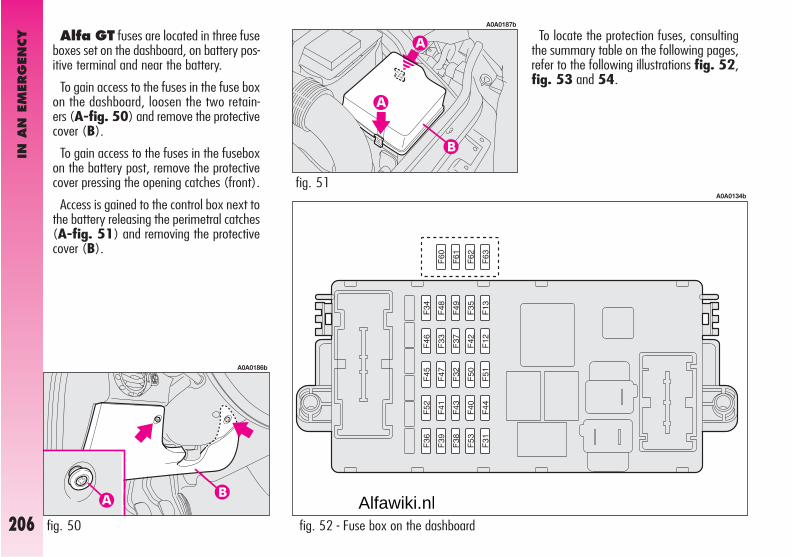
IN A
N E
MER
GEN
CY
206
To locate the protection fuses, consultingthe summary table on the following pages,refer to the following illustrations fig. 52,fig. 53 and 54.
Alfa GT fuses are located in three fuseboxes set on the dashboard, on battery pos-itive terminal and near the battery.
To gain access to the fuses in the fuse boxon the dashboard, loosen the two retain-ers (A-fig. 50) and remove the protectivecover (B).
To gain access to the fuses in the fuseboxon the battery post, remove the protectivecover pressing the opening catches (front).
Access is gained to the control box next tothe battery releasing the perimetral catches(A-fig. 51) and removing the protectivecover (B).
fig. 50
A0A0186b
fig. 51
A0A0187b
fig. 52 - Fuse box on the dashboard
A0A0134b
Alfawiki.nl

IN A
N E
MER
GEN
CY
207
fig. 53 - Fuse box near the battery
A0A0137b
fig. 54 - Fuse box on battery positive terminal
A0A0215b
Alfawiki.nl
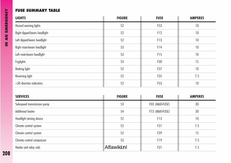
IN A
N E
MER
GEN
CY
208
30
30
10
7.5
15
7.5
7.5
F03 (MAXI-FUSE)
F73 (MAXI-FUSE)
F13
F31
F39
F19
F31
SERVICES FIGURE FUSE AMPERES
Hazard warning lights
Right dipped-beam headlight
Left dipped-beam headlight
Right main-beam headlight
Left main-beam headlight
Foglights
Braking light
Reversing light
+30 direction indicators
10
10
10
10
10
15
10
7.5
10
F53
F12
F13
F14
F15
F30
F37
F35
F53
LIGHTS FIGURE FUSE AMPERES
FUSE SUMMARY TABLE
Selespeed transmission pump
Additional heater
Headlight aiming device
Climate control system
Climate control system
Climate control compressor
Heater unit relay coils
52
52
52
53
53
53
52
52
52
53
54
52
52
52
53
52Alfawiki.nl

IN A
N E
MER
GEN
CY
209
15
15
7.5
15
15
30
30
20
15
7.5
7.5
20
20
15
7.5
15
7.5
F32
F32
F51
F39
F39
F40
F43
F44
F45
F41
F35
F38
F09
F39
F17
F11
F49
SERVICES FIGURE FUSE AMPERES
Key-operated +30
Selespeed transmission
Selespeed transmission
Radio
Navigator
Rearscreen heating
Windscreen - rearscreen washer (pump)
Cigar lighter
Seats with electric heating
Heated wing mirrors – heated nozzles
Cruise control
Central door locking
Headlight washer
Services + 30
Primary services (electronic injection)
Secondary services (electronic injection)
Secondary services
52
52
52
52
52
52
52
52
52
52
52
52
53
52
53
53
52Alfawiki.nl

Volumetric sensors
ESP system sensor
Steering angle sensor
EOBD system diagnosis socket
Cell phone provision
Driver’s door control unit supply
Passenger’s door control unit supply
Control lighting
Climate control system control lighting
Instrument cluster
Instrument cluster
Driver’s door control unit
ABS control unit
ABS control unit
Dashboard control unit
Air - bag control unit
Electronic injection control unit +30
Engine compartment control box (petrol versions)
Dashboard control unit
Trailer control unit
15
7.5
7.5
15
15
20
20
7.5
7.5
10
10
15
7.5
50
50
7.5
7.5
125
70
10
F39
F42
F42
F39
F39
F47
F48
F49
F35
F37
F53
F39
F42
F04 (MAXI-FUSE)
F02 (MAXI-FUSE)
F50
F18
F70 (MEGA-FUSE)
F71 (MAXI-FUSE)
F36
52
52
52
52
52
52
52
52
52
52
52
52
52
53
53
52
53
54
54
52
SERVICES FIGURE FUSE AMPERESIN
AN
EM
ERG
ENCY
210Alfawiki.nl

IN A
N E
MER
GEN
CY
211
40
30
50
15
15
15
15
25
7.5
15
15
30
30
50
20
150
40
60
20
F05 (MAXI-FUSE)
F06 (MAXI-FUSE)
F07 (MAXI-FUSE)
F10
F21
F22
F21
F60 (*)
F16
F61 (*)
F62 (*)
F08
F72 (MAXI-FUSE)
F01 (MAXI-FUSE)
F20
F70 (MEGA-FUSE)
F06 (MAXI-FUSE)
F07 (MAXI-FUSE)
F22
53
53
53
53
53
53
53
52
53
52
52
53
54
53
53
54
53
53
53
SERVICES FIGURE FUSE AMPERES
(*) Fuse behind dashboard control box on an auxiliary bracket.
Climate control fan
Radiator fan (first speed - petrol versions)
Radiator fan (second speed - petrol versions)
Horn
Fuel pump
Injectors (petrol versions)
Ignition coils
Tailgate electric unlocking
Electronic injection system
Bose system
Bose system
Additional heater
Ignition switch
Glow plug warming (JTD versions)
Heated fuel oil filter (JTD versions)
Engine compartment control box (JTD versions)
Radiator fan (first speed – JTD versions)
Radiator fan (second speed – JTD versions)
Injectors (JTD versions)
Alfawiki.nl

IN A
N E
MER
GEN
CY
212
IN THE EVENT OF A FLAT BATTERY
Before anything else, you are advised toread the precautions for preventing the bat-tery from draining and for ensuring long lifein the “car maintenance” chapter.
CHARGING THE BATTERY
IMPORTANT The battery charging pro-cedure is described only for information pur-poses. This operation should be carried outby Alfa Romeo Authorised Services.
Charging should be slow at a low amp rat-ing for 24 hours. Charging for a longer timemay damage the battery.
Charge the battery as follows:
– Disconnect the battery negative termi-nal (–).
– Connect the charger cables to the bat-tery terminal ensuring that the bias is cor-rect.
– Turn on the charger.
– After charging, turn off the charger be-fore disconnecting it from the battery.
– Re-connect the battery negative termi-nal (–).
The liquid contained in thebattery is poisonous andcorrosive. Avoid contact
with the skin or eyes. The batteryshould be charged in a well venti-lated place, away from nakedflames or possible sources ofsparks: danger of explosion andfire.
Do not attempt to chargea frozen battery: it mustfirstly be thawed, other-
wise it may burst. If freezing hasoccurred, the battery should bechecked by skilled personnel tomake sure that the internal ele-ments are not damaged and thatthe body is not cracked, with therisk of leaking poisonous and cor-rosive acid.
Alfawiki.nl

IN A
N E
MER
GEN
CY
213
IF THE CAR IS TO BE TOWED
The tow ring supplied with the car ishoused in the tool box under the boot mat.
To install the tow ring, proceed as follows:
– Take the tow ring from the tool box.
– Remove the cover (A) snap-fitted onthe front (fig. 55) or rear (fig. 56)bumper. To do this, using the flat-bladedscrewdriver provided, protect the tip with asoft cloth to avoid damaging the car.
– Firmly screw the ring in its housing.
fig. 55 - front
A0A0650b
fig. 56 - rear
A0A0670b
Before tightening the ringcarefully clean the thread-ed housing. Before begin-
ning to tow the car, make sure thatthe ring is firmly tightened in itsthreaded housing.
Before starting to tow,turn the ignition key toMAR and back to STOP,
again without removing it. Re-moving the key automatically en-gages the steering lock resulting inthe impossibility to steer thewheels. When towing rememberthat without the help of the enginebrake and power steering greatereffort is required on the pedal andsteering wheel. Do not use flexiblecables for towing and avoid jerks.During towing operations makesure that fastening the joint to thecar does not damage the compo-nents in contact with it. When tow-ing the car, it is compulsory to fol-low specific traffic regulations con-cerning both the towing device andbehaviour on the road.
Alfawiki.nl

IN A
N E
MER
GEN
CY
214
Take care when position-ing the arms of the lift orworkshop lift to avoid dam-
aging the side strips.USING AN ARM LIFT ORWORKSHOP LIFT
The car must only be lifted laterally posi-tioning the ends of the arms or the workshoplift in the areas illustrated, approx. 40 cm fromthe profile of the wheelhouse (fig. 57).
These points are identified by symbol ▼on the bottom of the sidemember.
The car may fall if the jackis not positioned correctly.Never use the jack for
higher capacities than the one stat-ed on the label.
IMPORTANT For versions with Sele-speed transmission, make sure that thegears are in neutral (N) (checking that thecar moves if pushed) and then proceed asfor towing a normal car with mechanicaltransmission, following the instructions giv-en previously.
Should it be impossible to set the gears toneutral, do not tow the car and contact Al-fa Romeo Authorised Services.
Do not start the enginewhen towing the car.
IF THE CAR IS TO BE LIFTED
fig. 57
A0A0672b
Alfawiki.nl

IN A
N E
MER
GEN
CY
215
– In motorways pileups, especially withpoor visibility, the risk of being involved inother crashes is high. Leave the car imme-diately and go beyond the guard-rail.
– If doors are blocked, do not try to getout of the car breaking the windscreen whichis stratified. The windows and rear screenare easier to break.
– Remove the ignition key of the cars in-volved.
– If you note a smell of fuel or other chem-ical products, do not smoke and have a cig-arette stubbed out.
– To put out fires, even small ones, usethe extinguisher, blankets, sand, or earth.
Never use water.
– If use of the lighting system is not nec-essary, disconnect the battery negative ter-minal (–).
IN THE EVENT OF AN ACCIDENT
– It is important to keep calm.
– If you are not directly involved, stop atleast a few dozen metres away from the ac-cident.
– On motorways, stop without blockingthe emergency lane.
– Turn the engine off and the hazard warn-ing lights on.
– At night, illuminate the place of the ac-cident with the headlights.
– Take care, do not risk being run over.
– Signal the accident placing the triangleat regulation distance in a clearly visibleplace.
– Call the emergency organisation, givingthe most accurate information possible. Onmotorways use the special phones provid-ed.
IF PEOPLE ARE INJURED
– An injured person must never be aban-doned. Helping is compulsory also for per-sons not directly involved in the accident.
– Do not crowd around injured people.
– Reassure the injured person that helpis on the way, and stay near to overcomeany panic.
– Release or cut the seat belt restraininginjured persons.
– Do not give injured persons anythingto drink.
– An injured person should never bemoved except in the following circum-stances.
– Remove an injured person from the caronly in danger of fire, sinking or falling.When removing an injured person: do notpull the limbs or bend the head and keepthe body as horizontal as possible.
FIRST AID KIT
In addition to the first-aid kit, it is also wise to keep an extinguisher and a blan-ket in the car.
Alfawiki.nl

CAR M
AIN
TEN
AN
CE
It is however wise to remember that Pro-grammed Maintenance does not complete-ly cover all the car’s requirements: also inthe initial period before the 20,000 km ser-vice coupon and later, between one couponand another, ordinary care is still necessarysuch as for example routinely checking andtopping up the level of fluids, checking thetyre pressure, etc...
IMPORTANT The Programmed Mainte-nance coupons are specified by the Manu-facturer. The failure to have them carried outmay invalidate the warranty.
The Programmed Maintenance service iscarried out by all Alfa Romeo Authorised Ser-vices, at pre-established times.
If during each operation, in addition to theones programmed, the need arises for fur-ther replacements or repairs, these may becarried out only with the explicit agreementof the customer.
IMPORTANT You are advised to contactAlfa Romeo Authorised Services in the eventof any minor operating faults, without wait-ing for the next service coupon.
SCHEDULEDSERVICING
Correct maintenance is determined in en-suring long car life under the best conditions.
This is why Alfa Romeo has programmeda series of checks and maintenance opera-tions every 20,000 km.
IMPORTANT On versions fitted with re-configurable multifunction display, at 2000km from the maintenance deadline, the dis-play will show “REFER TO SERVICE MANU-AL” which is shown again turning the igni-tion key to MAR, every 200 km. For fur-ther details, see “Service” in the “Recon-figurable multifunction display”.
CCAARR MMAAIINNTTEENNAANNCCEE
216Alfawiki.nl
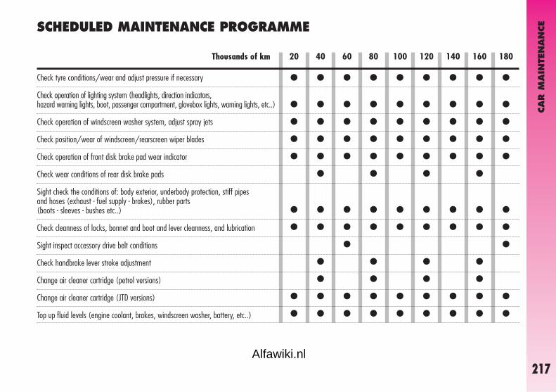
CAR M
AIN
TEN
AN
CE
217
SCHEDULED MAINTENANCE PROGRAMME
20 40 60 80 100 120 140 160 180Thousands of km
Check tyre conditions/wear and adjust pressure if necessary
Check operation of lighting system (headlights, direction indicators, hazard warning lights, boot, passenger compartment, glovebox lights, warning lights, etc..)
Check operation of windscreen washer system, adjust spray jets
Check position/wear of windscreen/rearscreen wiper blades
Check operation of front disk brake pad wear indicator
Check wear conditions of rear disk brake pads
Sight check the conditions of: body exterior, underbody protection, stiff pipes and hoses (exhaust - fuel supply - brakes), rubber parts (boots - sleeves - bushes etc..)
Check cleanness of locks, bonnet and boot and lever cleanness, and lubrication
Sight inspect accessory drive belt conditions
Check handbrake lever stroke adjustment
Change air cleaner cartridge (petrol versions)
Change air cleaner cartridge (JTD versions)
Top up fluid levels (engine coolant, brakes, windscreen washer, battery, etc..)
● ● ● ● ● ● ● ● ●
● ● ● ● ● ● ● ● ●
● ● ● ● ● ● ● ● ●
● ● ● ● ● ● ● ● ●
● ● ● ● ● ● ● ● ●
● ● ● ●
● ● ● ● ● ● ● ● ●
● ● ● ● ● ● ● ● ●
● ●
● ● ● ●
● ● ● ●
● ● ● ● ● ● ● ● ●
● ● ● ● ● ● ● ● ●
Alfawiki.nl

● ● ● ● ● ● ● ● ●
● ●
● ● ● ●
● ● ● ●
● ●
●
● ● ●
●
●
●
● ● ● ● ● ● ● ● ●
● ● ● ● ● ● ● ● ●
● ● ●
● ● ● ● ● ● ● ● ●
● ● ● ● ● ● ● ● ●
CAR M
AIN
TEN
AN
CE
218
20 40 60 80 100 120 140 160 180Thousands of km
Check and if necessary top up the Selespeed automatic transmission oil level (2.0 JTS versions)
Sight check for conditions of timing gear drive toothed belt (3.2 V6 and JTD versions)
Check emissions/smoke at the exhaust (JTD versions)
Check operation of engine control system (through diagnosis socket)
Check mechanical transmission oil level
Change counter-rotating shaft drive belt
Change timing gear drive belt (1.8 T.SPARK and 2.0 JTS versions) (*)
Change timing gear drive belt (3.2 V6 and JTD versions) (*)
Change accessory poly-V drive belt
Change spark plugs (petrol versions)
Change engine oil and oil filter (petrol versions) (or every 24 months)
Change engine oil and oil filter (diesel with DPF versions)(**) (or every 24 months)
Change engine oil and oil filter (diesel without DPF versions)(**) (or every 24 months)
Change brake fluid (or every 24 months)
Change fuel filter (JTD versions)
Change pollen filter (or every year)
(*) Regardless of the km covered, the timing belt shall be replaced every 4 years for particularly demanding use (cold climates, driving in the city, idling for a long time) or in any case every 5 years.(**) Engine oil and oil filter shall actually be changed according to the conditions of use of the car and it is indicated by the relevant warning light or message (where provided) on the instrument panel
(see “Warning lights and messages” paragraph).If the car is used mainly on urban routes or if the yearly kilometres travelled are less than 10,000 km, the engine oil and filter must be changed every 12 months.
Alfawiki.nl

CAR M
AIN
TEN
AN
CE
219
ADDITIONALOPERATIONS
Every 1000 km or before long journeys,check and if necessary top up:
– engine coolant fluid level
– brake/hydraulic clutch control fluid level
– power steering fluid level
– windscreen washer and headlamp wash-er fluid level
– tyre pressure and conditions.
Every 3000 km check and if necessarytop up the engine oil level.
The use of FL Selenia products is rec-ommended which have been designed andmade expressly for Alfa Romeo cars (see“Refuelling” in the “Technical Specifica-tions” chapter).
ANNUAL INSPECTIONPROGRAMME
For cars with an annual mileageof below 20,000 km (for exampleabout 10,000 km) the followingyearly inspection programme is ad-vised:
– Check tyre conditions/wear and if nec-essary adjust the pressure (including sparewheel)
– Check operation of lighting system(headlights, direction indicators, hazardwarning lights, boot, passenger compart-ment, glovebox lights, warning lights, etc.)
– Check operation of windscreen wipersystem, spray jet adjustment
– Check windscreen blade position/wear
– Check front disk brake pad conditionsand wear
– Check cleanness of bonnet and bootlocks, and lever cleanness and lubrication.
– Sight check for conditions of: engine,gearbox, transmission, pipes (exhaust - fu-el supply - brakes), rubber parts (boots -sleeves - bushes etc..), brake and fuel sup-ply system hoses
– Check battery charge
– Sight check for conditions of various dri-ve belts
– Check and if necessary top up fluid lev-els (engine coolant, brakes, windscreenwasher, battery etc. )
– Change engine oil and oil filter
– Change pollen filter.
Alfawiki.nl

CAR M
AIN
TEN
AN
CE
220
IMPORTANT Engine oil
Should prevailing use of the car be underone of the following specially heavy condi-tions:
– trailer or caravan towing
– dusty roads
– short distances (less than 7-8 km) re-peated and with external temperatures be-low zero
– frequently idling engines or long distancelow speed driving or in case of a long terminactivity
replace engine oil more frequently than re-quired on the Scheduled Maintenance Pro-gramme.
IMPORTANT Diesel filter
The variety of the degree of purity of thefuel oil in commerce may make it necessaryto change the fuel oil filter more frequentlythan stated in the Scheduled MaintenanceProgramme. If the engine is “sobbing” itis a sign that the filter needs changing.
IMPORTANT Air cleaner
Using the car on dusty roads change theair cleaner more frequently than specified inthe Schedule Maintenance Programme.
For any doubts concerning the intervals be-tween the engine oil and air cleaner re-placement in relation to how the car is used,contact Alfa Romeo Authorised Services.
Alfawiki.nl

CAR M
AIN
TEN
AN
CE
221
Car maintenance should beentrusted to Alfa RomeoAuthorised Services. For
routine and minor maintenance op-erations you wish to carry outyourself, always make sure youhave the proper equipment, genuineAlfa Romeo spares and the neces-sary fluids; do not however carryout these operations if you have noexperience.
IMPORTANT Pollen filter
If the car is used frequently in dusty orheavily polluted environments it is advisableto replace the filtering element more fre-quently; in particular it should be replaced ifa reduction of the amount of air admitted tothe passenger compartment is noted.
IMPORTANT Battery
It is advisable to check the battery charge,preferably at the onset of winter, to preventthe possibility of the electrolyte freezing.
This check should be carried out more fre-quently if the car is used mainly for shorttrips, or if it is fitted with accessories thatpermanently absorb electricity even with theignition key removed, especially in the caseof after market accessories.
If the car is used in hot climates or partic-ularly harsh conditions it is wise to check thelevel of the battery fluid (electrolyte) morefrequently than specified in the ScheduledMaintenance Programme.
Alfawiki.nl

CAR M
AIN
TEN
AN
CE
222
fig. 1 - 1.8 T. SPARK version
A0A0736b
A0A0681b
CHECKING LEVELS
Never smoke while work-ing in the engine compart-ment; gas and inflammable
vapours may be present, with therisk of fire.
When topping up takecare not to confuse the var-ious types of fluids: they
are incompatible with one anoth-er and could seriously damage thecar.
fig. 2 - 2.0 JTS version
1 Engine oil - 2 Battery - 3 Brake fluid -4 Windscreen/rear window/headlightwasher fluid - 5 Engine coolant - 6 Powersteering fluid - 7 Selespeed transmission oil(2.0 JTS Selespeed versions)
Alfawiki.nl

CAR M
AIN
TEN
AN
CE
223
A0A0396b
fig. 4 - JTD 16V version
1 Engine oil - 2 Battery - 3 Brake fluid -4 Windscreen/rearscreen/headlamp wash-er fluid - 5 Engine coolant fluid - 6 Powersteering fluid
A0A0683b
fig. 3 - 3.2 V6 version
1 Engine oil - 2 Battery - 3 Brake fluid -4 Windscreen/rear window/headlightwasher fluid - 5 Engine coolant - 6 Powersteering fluid
Alfawiki.nl

CAR M
AIN
TEN
AN
CE
224
ENGINE OIL (fig. 5-6-7-8)
The engine oil should be checked with thecar on a level surface a few minutes (about5) after the engine has been switched off.
Remove the dipstick (A), clean it, put itback in completely, remove it and check thatthe level is within the MIN and MAXmarks on the dipstick. The interval betweenthe MIN and MAX marks correspond toabout one litre of oil.
When the engine is hot,take care when workinginside the engine compart-
ment to avoid burns. Rememberthat when the engine is hot, thefan may cut in: danger of injury.
Never add oil with char-acteristics (classification,viscosity) which are differ-
ent from those of the oil already inthe circuit.
fig. 6 - 2.0 JTS version
A0A0682b
fig. 8 - JTD 16V version
A0A0398b
A B
fig. 7 - 3.2 V6 version
A0A0406b
fig. 5 - 1.8 T. SPARK version
A0A0737b
If the oil level is near or even below theMIN mark, add oil through the filter neck(B), until reaching the MAX mark.
IMPORTANT If a routine check revealsthat the level is above the MAX mark, con-tact Alfa Romeo Authorised Services to havethe correct level restored.
IMPORTANT After topping up the oil,before checking the level again, run the en-gine a few seconds and wait for a few min-utes after stopping it.
Alfawiki.nl

CAR M
AIN
TEN
AN
CE
225
Used engine oil and filtercontain harmful substancesfor the environment. Con-
tact Alfa Romeo Authorised Ser-vices to have the oil and the filterchanged, as they are equipped todispose of the waste oil and filtersrespecting nature and the law.
SELESPEED TRANSMISSIONOIL (fig. 9)
The Selespeed transmission oil should bechecked with the car on a level surface andwith the engine stopped and cold.
To check the level, proceed as follows:
– turn the ignition key to MAR;
– disconnect the breather tube and re-move the cap (A) checking that the levelcorresponds with the MAX mark on the dip-stick integrated with the cap;
– if the oil is below the MAX mark, topup to reach the correct level;
Do not add oil with spec-ifications other than thatalready in the gearbox.
fig. 9
A0A0197b
Used gearbox oil containsdangerous substances forthe environment. For chang-
ing the oil we advise contacting Al-fa Romeo Authorised Services whoare equipped for disposing of usedoil respecting nature and the law.
Be very careful workinginside the engine compart-ment if the engine is hot:
danger of burns. Remember thatthe fan may cut in if the engine isvery hot: danger of injury.
Engine oil consumption
Max engine oil consumption is usually 400grams every 1000 km.
During the initial period of use the enginesettles, therefore engine oil consumptionmay be considered stabilised only after thefirst 5000 ÷ 6000 km.
IMPORTANT Engine oil consumption de-pends on the way of driving and the condi-tions of use of the car.
– after refitting the cap, insert thebreather tube firmly on the housing on thecap and turn the ignition key to STOP.
Alfawiki.nl

CAR M
AIN
TEN
AN
CE
226
The cooling system ispressurised. If necessary,replace the cap only with
another genuine one, otherwisesystem efficiency could be compro-mised. Do not remove the reservoircap when the engine is hot: yourisk scalding yourself.
The cooling system usesPARAFLU UP antifreeze.Do not add fluid having dif-
ferent specifications from that al-ready existing. PARAFLU UP can-not be mixed with other types offluids. Should other fluids beadded, do not start the engine andcontact Alfa Romeo AuthorizedServices as soon as possible.
ENGINE COOLANT FLUID (fig. 10)
Do not remove the capwhen the engine is hot:danger of burns.
The level of the coolant in the header tank(reservoir) should be checked with the en-gine cold and the car on a level surface andit should be between the MIN and MAXmarks on the tank.
fig. 10
A0A0240b
If the level is low, loosen the header tankcap (A) and slowly pour a mixture of 50%distilled water and 50% PARAFLU UP FLSelenia through the filler neck until near-ing the MAX mark.
The antifreeze mixture of 50% PARAFLUUP and 50% distilled water guarantees pro-tection down to –35 °C.
Alfawiki.nl
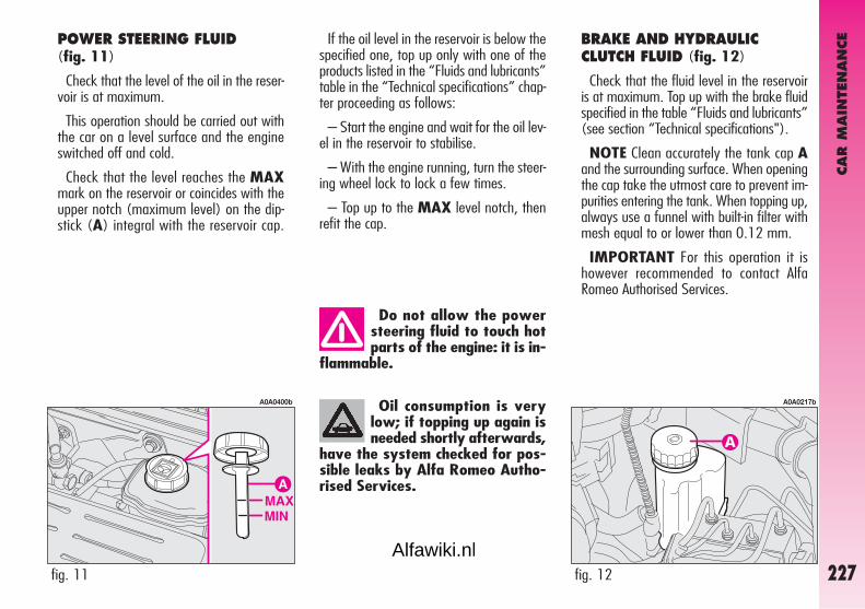
CAR M
AIN
TEN
AN
CE
227
Oil consumption is verylow; if topping up again isneeded shortly afterwards,
have the system checked for pos-sible leaks by Alfa Romeo Autho-rised Services.
Do not allow the powersteering fluid to touch hotparts of the engine: it is in-
flammable.
fig. 12
A0A0217b
fig. 11
A0A0400b
BRAKE AND HYDRAULICCLUTCH FLUID (fig. 12)
Check that the fluid level in the reservoiris at maximum. Top up with the brake fluidspecified in the table “Fluids and lubricants”(see section “Technical specifications").
NOTE Clean accurately the tank cap Aand the surrounding surface. When openingthe cap take the utmost care to prevent im-purities entering the tank. When topping up,always use a funnel with built-in filter withmesh equal to or lower than 0.12 mm.
IMPORTANT For this operation it ishowever recommended to contact AlfaRomeo Authorised Services.
POWER STEERING FLUID (fig. 11)
Check that the level of the oil in the reser-voir is at maximum.
This operation should be carried out withthe car on a level surface and the engineswitched off and cold.
Check that the level reaches the MAXmark on the reservoir or coincides with theupper notch (maximum level) on the dip-stick (A) integral with the reservoir cap.
If the oil level in the reservoir is below thespecified one, top up only with one of theproducts listed in the “Fluids and lubricants”table in the “Technical specifications” chap-ter proceeding as follows:
– Start the engine and wait for the oil lev-el in the reservoir to stabilise.
– With the engine running, turn the steer-ing wheel lock to lock a few times.
– Top up to the MAX level notch, thenrefit the cap.
Alfawiki.nl

CAR M
AIN
TEN
AN
CE
228
Do not travel with thewindscreen washer reser-voir empty: the action of
the windscreen washer is funda-mental for improving vision.
To avoid damaging thepump motor, do not use thewindscreen/rearscreen
washers when the reservoir isempty.
Some commercial addi-tives for windscreen wash-ers are inflammable. The
engine compartment contains hotcomponents which may set it onfire.
IMPORTANT Brake and hydraulic clutchfluid is hygroscopic (i.e. it absorbs moisture).For this reason, if the car is mainly used inareas with a high degree of atmospheric hu-midity, the fluid should be replaced at morefrequent intervals than specified in theScheduled Maintenance Programme.
WINDSCREEN/REARSCREENHEADLIGHT WASHER FLUID(fig. 13)
Open the cap (A) and check the level inthe reservoir.
If necessary top up using a mixture of wa-ter and TUTELA PROFESSIONAL SC35 fluid as follows:
– 30% of TUTELA PROFESSIONALSC 35 and 70% water in summer;
Brake and clutch fluid ispoisonous and highly cor-rosive. In the event of ac-
cidental contact, wash the partsconcerned immediately with neu-tral soap and water, then rinsethoroughly. See a doctor at once ifthe fluid is swallowed.
Theπ symbol on the con-tainer indicates syntheticbrake fluid, distinguishing
it from the mineral kind. Using min-eral fluids irreversibly damages thespecial braking system rubberseals.
fig. 13
A0A0242b
– 50% of TUTELA PROFESSIONALSC 35 and 50% water in winter;
– in the case of temperatures below–20°C use TUTELA PROFESSIONALSC 35 fluid neat.
Make sure that the high-ly corrosive brake fluiddoes not drip onto the
paintwork. If it does, wash it offimmediately with water.
Alfawiki.nl

CAR M
AIN
TEN
AN
CE
229
DIESEL FUEL FILTER(diesel versions)
DRAINING CONDENSATIONWATER
The presence of water inthe supply circuit maycause serious damage to
the entire injection system andcause irregular running of the en-gine. If the warning message +symbol are shown on the recon-figurable multifunction display con-tact Alfa Romeo Authorized Ser-vices as soon as possible to havethe system relieved. If warning in-dications turn on after refuelling,water has probably been pouredinto the tank: turn the engine offimmediately and contact AlfaRomeo Authorized Services.
AIR CLEANER
The air cleaner is connected to the tem-perature and air flow sensors which sendto the control unit the electric signals need-ed for correct operation of the injection andignition system.
It must therefore always be in perfect con-ditions, to ensure correct operation of theengine, low consumption and exhaust emis-sion levels.
If the operations concern-ing cleaner replacement de-scribed below are not car-
ried out correctly and with the dueprecautions, they may compromisethe travelling safety of the car. Youare recommended to have this op-eration carried out by Alfa RomeoAuthorised Services.
If the car is habituallyused in dusty areas, thecleaner should be replaced
at shorter intervals than thosespecified in the Programmed Main-tenance Schedule.
Any attempt to clean thecleaner may damage it,leading to serious engine
damage.
Alfawiki.nl

CAR M
AIN
TEN
AN
CE
230
Incorrect fitting of electri-cal accessories can serious-ly damage the car. If after
buying the car, you wish to installelectric accessories (alarm, soundsystem, radiotelephone, etc.) con-tact Alfa Romeo Authorized Ser-vices who will be able to suggestthe most suitable devices andabove all advise about the need touse a more powerful battery.
BATTERY
The battery is of the “Limited mainte-nance” type: under normal conditions of usethe electrolyte does not need topping upwith distilled water.
Contact Alfa Romeo Authorised Services tohave the battery checked/replaced.
fig. 14
A0A0224b
Batteries contain sub-stances that are very harm-ful for the environment. You
are advised to have the batterychanged at Alfa Romeo AuthorizedServices, which are properlyequipped for disposing of used bat-teries respecting nature and the law.
If the car is to remain sta-tionary for a long time invery cold weather, remove
the battery and take it to a warmplace, otherwise it might freeze.
POLLEN FILTER
Have the dust/pollen filter checked oncea year by Alfa Romeo Authorised Services,preferably at the onset of summer.
If the car is mainly used in dusty or heav-ily polluted areas, the filter should bechanged at more frequent intervals thanspecified in the Scheduled Maintenance Pro-gramme.
IMPORTANT The failure to replace thepollen filter can considerably reduce the ef-fectiveness of the climate control system.
When doing any work onthe battery or near it, al-ways wear special protec-
tive goggles.
The liquid in the battery ispoisonous and corrosive.Avoid contact with eyes
and skin. Do not bring nakedflames or possible sources ofsparks near to the battery: risk offire and explosion.
Alfawiki.nl

CAR M
AIN
TEN
AN
CE
231
– After charging, turn off the charger be-fore disconnecting it from the battery.
– Re-connect the battery negative termi-nal (–).
Never attempt to chargea frozen battery: it mustfirstly be thawed, other-
wise it may burst. If freezing hasoccurred, the battery should bechecked before charging by spe-cialised personnel, to make surethat the internal elements are notdamaged and that the body is notcracked, with the risk of leakingpoisonous and corrosive acid.
CHARGING THE BATTERY
IMPORTANT The battery charging pro-cedure is described only for information pur-poses. This operation should be carried outby Alfa Romeo Authorised Services.
Charging should be slow at a low amp rat-ing for 24 hours. Charging for a longer timemay damage the battery.
Charge the battery as follows:
– Disconnect the battery negative termi-nal (–).
– Connect the charger cables to the bat-tery terminal ensuring that the bias is cor-rect.
– Turn on the charger.
CHECKING THE CHARGE
The battery charge may be checkedthrough the indicator A (where required)set on the battery cover and acting accord-ing to the colour the indicator shows.
Should the battery be not fitted with bat-tery charge inspection device (optical elec-trolyte indicator), inspection operations shallbe carried out by skilled personnel only.
Refer to the table below or to the label(fig. 15) on the battery itself.
Working with a low fluidlevel may damage the bat-tery irreversibly, even
causing it to burst.
Brilliantwhite colour
Dark colourwithout greenarea in the centre
Dark colour with greenarea in the centre
Top up the electrolyte
Low charge level
Sufficient electrolytelevel and charge
Contact Alfa RomeoAuthorised Services
Charge the battery(you are advised to contact
Alfa Romeo Authorised Services)
No action
fig. 15
A0A0393b
Alfawiki.nl

CAR M
AIN
TEN
AN
CE
232
Proceed as follows with doors closed:
1. open completely the driver’s windowkeeping the button pressed for atleast 3 seconds after full opening;
2. close completely the driver’s windowkeeping the button pressed for atleast 3 seconds after full closing;
3. proceed as described in points 1 and2 also for the passenger’s side;
4. check for proper initialisation by oper-ating the windows in automatic.
USEFUL HINTS TO EXTEND THE LIFE OF YOUR BATTERY
To avoid rapidly draining the battery andensure that it continues to work correctly,the following should be noted:
– The terminals must always be firmlytightened.
– As far as possible, avoid keeping ser-vices on for a long time with the enginestopped (radio, hazard lights, parking lights,etc.).
IMPORTANT If the battery is kept witha charge of below 50% it is damaged by sul-phation, its starting capability is reduced andit is also more subject to the possibility offreezing (this may occur already at -10 °C).In the event of a prolonged inactivity, referto the paragraph “car inactivity”, in thechapter “Correct use of the car”.
CHANGINGTHE BATTERY
When changing the battery it should be re-placed with another original one with thesame characteristics. If it is replaced by abattery with different characteristics, themaintenance intervals given in the Sched-uled Maintenance Programme in this chap-ter are no longer valid and for maintenanceit will be necessary to follow the batteryManufacturer’s instructions.
IMPORTANT Lacking power to controlunits (e.g. battery change/disconnectionand replacement of power window controlunit protection fuses), window automatismmust be reset.
– When leaving the car parked in agarage, make sure that the doors, bonnet,boot and interior lids are properly shut toprevent lights from staying on.
– Before carrying out any work on theelectric system, disconnect the negative ca-ble from the battery.
– If after buying the car, you wish to in-stall electric accessories which require a per-manent electric supply (alarm, voice feature,radionavigator with satellite antitheft func-tion etc.) or accessories that burden the elec-tric system, contact Alfa Romeo AuthorisedServices whose qualified personnel, in ad-dition to suggesting the most suitable de-vices belonging to Lineaccessori Alfa Romeo,will evaluate the overall electric absorption,checking whether the car’s electric systemis capable of withstanding the load required,or whether it should be integrated with amore powerful battery. In fact, as some ofthese devices continue absorbing energyeven when the ignition key is off (car sta-tionary, engine off), they gradually drain thebattery.
Alfawiki.nl

CAR M
AIN
TEN
AN
CE
233
Incorrect pressure causes abnormal tyrewear:
(A): normal pressure: tread evenly worn.
(B): low pressure: tread particularly wornat the edges.
(C): high pressure: tread particularly wornin the centre.
Tyres should be changed when the treadthickness is reduced to 1.6 mm.
In any case follow local regulations.
You are also reminded that services withhigh current absorption switched on by theuser, such as for example: baby bottle warm-ers, vacuum cleaner, mobile phone, minifridge, etc., quicken the battery drain-ing process if they are turned on with theengine off or running at idle speed.
IMPORTANT When installing addition-al systems on the car, bear in mind that im-proper branches on connections of the carwiring are dangerous, particularly if safetydevices are involved.
WHEELS AND TYRES
TYRE PRESSURE
Check the tyre pressure of every wheel, in-cluding the spare, every two weeks and be-fore a long journey. The pressure should bechecked with the tyre rested and cold.
It is normal for the pressure to increasewhen the car is in use; for the correct tyreinflation pressure, see “Wheels” in the“Technical Specifications” chapter.
Battery
60 Ah
70 Ah
Maximum permissibleloadless absorption
36 mA
42 mA
The maximum absorption of all the ac-cessories (standard and fitted afterwards)should be 0,6 mA x Ah (of the battery), asshown in the following table:
fig. 16
A0A0225b
Alfawiki.nl
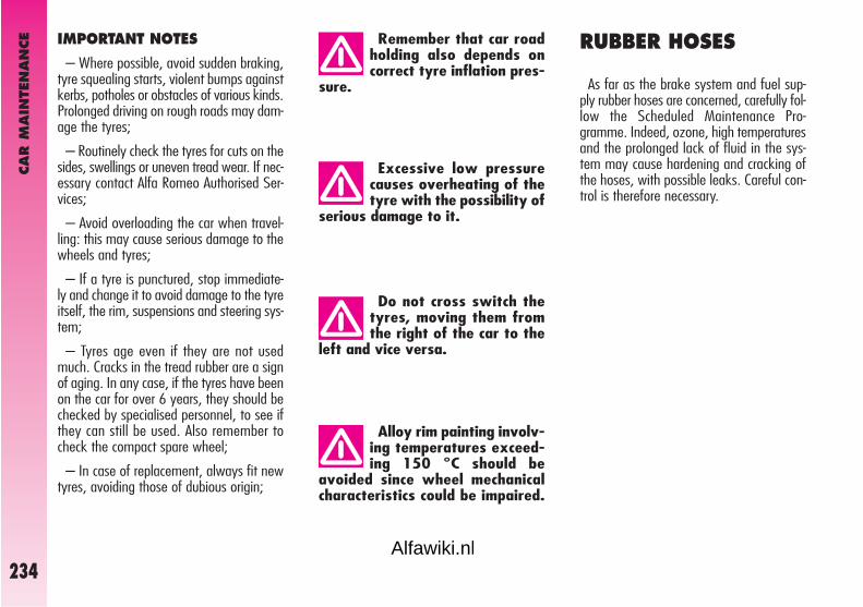
CAR M
AIN
TEN
AN
CE
234
Alloy rim painting involv-ing temperatures exceed-ing 150 °C should be
avoided since wheel mechanicalcharacteristics could be impaired.
Do not cross switch thetyres, moving them fromthe right of the car to the
left and vice versa.
Excessive low pressurecauses overheating of thetyre with the possibility of
serious damage to it.
Remember that car roadholding also depends oncorrect tyre inflation pres-
sure.
RUBBER HOSES
As far as the brake system and fuel sup-ply rubber hoses are concerned, carefully fol-low the Scheduled Maintenance Pro-gramme. Indeed, ozone, high temperaturesand the prolonged lack of fluid in the sys-tem may cause hardening and cracking ofthe hoses, with possible leaks. Careful con-trol is therefore necessary.
IMPORTANT NOTES
– Where possible, avoid sudden braking,tyre squealing starts, violent bumps againstkerbs, potholes or obstacles of various kinds.Prolonged driving on rough roads may dam-age the tyres;
– Routinely check the tyres for cuts on thesides, swellings or uneven tread wear. If nec-essary contact Alfa Romeo Authorised Ser-vices;
– Avoid overloading the car when travel-ling: this may cause serious damage to thewheels and tyres;
– If a tyre is punctured, stop immediate-ly and change it to avoid damage to the tyreitself, the rim, suspensions and steering sys-tem;
– Tyres age even if they are not usedmuch. Cracks in the tread rubber are a signof aging. In any case, if the tyres have beenon the car for over 6 years, they should bechecked by specialised personnel, to see ifthey can still be used. Also remember tocheck the compact spare wheel;
– In case of replacement, always fit newtyres, avoiding those of dubious origin;
Alfawiki.nl

CAR M
AIN
TEN
AN
CE
235
SPRAY NOZZLES (fig. 18)
If the jet of fluid is inadequate, firstly checkthat there is fluid in the reservoir: see“Checking levels” in this chapter.
Then check that the nozzle holes are notclogged, if necessary use a needle.
If necessary, direct the jet of fluid work-ing on the adjustment screw.
fig. 17
A0A0728b
Changing the windscreen wiper blade (fig. 17)
How to remove the blade
Proceed as follows:
– raise the windscreen wiper arm (A);
– turn the blade (B) 90° around the pin(C) set at wiper arm end;
– remove the blade from pin (C).
How to refit the blade
Proceed as follows:
– fit pin (C) into the hole set in the mid-dle of the blade (B);
– refit the wiper arm with the blade onthe windscreen.
Driving with worn wiperblades is a serious hazard,because visibility is re-
duced in bad weather.
WINDSCREEN/REARSCREEN WIPERS
BLADES
Periodically clean the rubber part using spe-cial products; TUTELA PROFESSIONALSC 35 is recommended.
If the rubber blades are bent or worn theyshould be replaced. In any case they shouldbe changed once a year.
A few simple notions can reduce the pos-sibility of damage to the blades:
– If the temperature falls below zero makesure that ice has not frozen the rubberagainst the glass. If necessary, thaw usingan antifreeze product.
– Remove any snow from the glass: in ad-dition to protecting the blades, this preventseffort on the motor and overheating.
– Do not operate the windscreen andrearscreen wipers on dry glass.
fig. 18
A0A0696b
Alfawiki.nl

CAR M
AIN
TEN
AN
CE
236
HEADLIGHT WASHERS(fig. 19)
Regularly check that the spray jets are in-tact and clean.
If it is necessary to direct the jet, contactan Alfa Romeo Authorized Service.
BODYWORK
PROTECTION FROMATMOSPHERIC AGENTS
The main causes of corrosion are:
– atmospheric pollution
– salty air and humidity (coastal areas, orhot humid climates)
– seasonal environment conditions.
Not to be underestimated is also the abra-sive action of wind-borne atmospheric dustand sand and mud and gravel raised by oth-er cars.
On your car, Alfa Romeo has implement-ed the best manufacturing technologies toeffectively protect the bodywork against cor-rosion.
fig. 19
A0A0704b
These include:
– Painting products and systems whichgive the car particular resistance to corrosionand abrasion.
– Use of galvanised (or pretreated) steelsheets, with high resistance to corrosion.
– Spraying of the underbody, engine com-partment, wheel arches and other parts withhighly protective wax products.
– Spraying of plastic parts, with a protec-tive function, in the more exposed points:underdoor, inner wheel arch linings, etc.
– Use of “open” boxed sections to pre-vent condensation and pockets of moisturefrom triggering rust inside.
CAR EXTERIOR ANDUNDERBODY WARRANTY
Your car is covered by warranty againstperforation due to rust of any original ele-ment of the structure or body. For the gen-eral terms of this warranty, refer to AlfaRomeo Warranty booklet.
Alfawiki.nl
CAR M
AIN
TEN
AN
CE
237
Detergents cause waterpollution. Therefore the carshould be washed in areas
equipped for collecting and purify-ing the liquid used in the washingprocess.
Where possible, do not park under trees;the resinous substances many species re-lease give the paint a dull appearance andincrease the possibility of triggering the rustprocesses.
IMPORTANT Bird droppings must bewashed off immediately and thoroughly asthe acid they contain is particularly aggressive.
To correctly wash the car:
1) Remove the aerial from the roof to pre-vent damage to it if the car is washed inan automatic system.
2) Spray the car with a low pressure jet ofwater.
3) Pass a sponge moistened with a lightdetergent solution, rinsing the sponge fre-quently.
4) Rinse well with water and dry with ajet of air or chamois leather.
When drying, take particular care with theless visible parts like door surrounds, bon-net and around the headlights where wa-ter may stagnate. The car should not be tak-en to a closed area immediately, but left inthe open so that residual water can evapo-rate.
Do not wash the car after it has been leftin the sun or with the bonnet hot: this mayalter the shine of the paintwork.
Exterior plastic parts must be cleaned inthe same way as the rest of the car.
ADVICE FOR PRESERVING THE BODYWORK
Paint
The paintwork does not only serve anaestethic purpose but also protects the un-derlying sheet metal.
In the case of deep scrapes or scores, youare advised to have the necessary touch-ing up carried out immediately to avoid theformation of rust.
Only original products should be used fortouching up paint (see “Body paint identi-fication plate” in the “Technical Specifica-tions” chapter).
Normal paint maintenance consists inwashing at intervals depending on the con-ditions and environment of use. For exam-ple, in highly polluted areas, or if the roadsare sprayed with salt, it is wise to wash thecar more frequently.
Alfawiki.nl

CAR M
AIN
TEN
AN
CE
238
Engine compartment
At the end of the winter the engine com-partment should be carefully washed, with-out directing the jet against electronic con-trol units. Contact a specialised workshop tohave this done.
Detergents cause waterpollution. Therefore the en-gine compartment should
be washed in areas equipped forcollecting and purifying the liquidused in the washing process.
IMPORTANT The car should be washedwith the engine cold and the ignition key atSTOP. After washing make sure that thevarious protections (e.g. rubber caps andvarious covers) have not been damaged orremoved.
Windows
Use specific products to clean the windows.Use clean cloths to avoid scratching or al-tering the transparency of the glass.
IMPORTANT The inside of therearscreen should be wiped gently with acloth in the direction of the filaments toavoid damaging the heating device.
Front headlights
IMPORTANT Do not use aromatic sub-stances (e.g. petroleum) or ketones (e.g.acetone) to clean the front headlight plas-tic transparents.
Never use inflammableproducts like fuel oil etheror rectified petrol for clean-
ing inside the car. The electrostat-ic charges generated when rubbingto clean may cause fire.
INTERIOR FITTINGS
Periodically check that water is not trappedunder the mats (due to water dripping offshoes, umbrellas, etc.) which could causeoxidisation on the sheet metal.
CLEANING SEATS AND FABRICAND VELVET PARTS
– Use a soft brush or a vacuum cleaner toremove dust. Velvet is cleaned better if thebrush is moistened.
– Rub the seat with a sponge moistenedwith a solution of water and neutral deter-gent.
Alfawiki.nl

CAR M
AIN
TEN
AN
CE
239
Do not keep aerosol cansin the car. There is the riskthey might explode. Aerosol
cans must never be exposed to atemperature above 50°C. The tem-perature inside the car might go wellbeyond that figure when exposedto the sun’s rays.
INTERIOR PLASTIC PARTS
For routine cleaning of interior plastic partsuse a soft cloth moistened with water andneutral soap. Remove grease or persistingstains using appropriate solvent-free prod-ucts designed to preserve appearance andcolour of plastic components.
IMPORTANT Never use spirit or petro-leum to clean the glass of the instrumentpanel or other plastic components.
STEERING WHEEL/GEAR LEVERKNOB WITH GENUINE LEATHER COVERING
These components shall only be cleanedwith water and neutral soap. Never use spir-it or alcohol-based products.
Before using special products for cleaninginteriors, read carefully label instructions andindications to make sure they are free fromspirit and/or alcohol-based substances. Ifwhen cleaning the windscreen with specialglass products, some drops fall on theleather covering of the steering wheel/gearlever knob remove them immediately andthen clean with water and neutral soap.
IMPORTANT Take the utmost carewhen engaging the steering lock to preventscratching the leather covering.
CLEANING LEATHER SEATS
– Remove dried on dirt with a lightlymoistened chamois leather or cloth with-out pressing too hard.
– Remove liquid and grease stains witha dry absorbent cloth without rubbing. Thenwipe with a soft cloth or chamois leatherwith water and neutral soap. If the stain per-sists, use specific products, carefully follow-ing the instructions for use.
IMPORTANT Never use spirit or alco-holbased products, even in small percentage.
Fabric upholstery of yourcar is purpose-made towithstand common wear
resulting from normal use of thecar. It is however absolutely nec-essary to prevent hard and/or pro-longed scratching/scraping causedby clothing accessories like metal-lic buckles, studs, “Velcro” fixings,etc. that stressing locally the fabriccould break yarns and damage theupholstery as a consequence.
Alfawiki.nl

TECHN
ICAL
SPEC
IFIC
ATI
ON
S
240
IDENTIFICATION LABEL
This (fig. 2) is to be found on the frontcrossmember of the engine compartment.
It contains the following information:(A) Space for details of national ho-
mologation(B) Space for punching the consecutive
chassis number(C) Space available for maximum
weights authorised by various na-tional regulations
(D) Space for version and any supple-mentary indications to those specified
(E) Space for smoke coefficient (JTD ver-sions)
(F) Space for punching manufacturer’sname.
BODYWORK LABEL
This is located in the engine bay, to oneside of the upper right shock absorber (fig.3) and contains:
– Type of vehicle: ZAR 937.000
– Manufacturer’s serial number (chassisnumber).
IDENTIFICATION DATA
You are advised to note the identificationcodes. The identification datastamped andgiven on the labels and their position arethe following (fig. 1):
1 - Identification label
2 - Body label
3 - Bodywork paint identification label
4 - Engine label.
TTEECCHHNNIICCAALL SSPPEECCIIFFIICCAATTIIOONNSS
fig. 1
A0A0654b
fig. 2
A0A0246b
fig. 3
A0A0247b
Alfawiki.nl

TECHN
ICAL
SPEC
IFIC
ATI
ON
S
241
BODYWORK PAINTIDENTIFICATION LABEL
The label (fig. 4) is on the inner left edgeof the tailgate. It contains the following in-formation:
A. Paint manufacturer.
B. Name of colour.
C. Colour code.
D. Indication on the type of product to beused for touching-up.
ENGINE STAMP
Theengine marking is stamped on thegearbox side of the crankcase, in corre-spondence with the exhaust manifold.
ENGINE CODES - BODY VERSIONS
fig. 4
A0A0651b
Engine code Body versions
1.8 T SPARK AR32205 937CXR1A 26
2.0 JTS 937A1000 937CXH1A 22
2.0 JTS 932A2000 937CXT1A 29(for special markets)
2.0 JTS Selespeed 937A1000 937CXH11 23
3.2 V6 936A000 937CXP1B 25
JTD 16V 937A5000 937CXN1B 24D
Alfawiki.nl

2.0 JTS2.0 JTS
Selespeed
937A1000
Otto
4 in line
83 x 91
1970
11.5 : 1
1211656400
20621
3250
NGK PFR6BNGK BKR6EKPA
Unleadedpetrol
95 RON
2.0 JTS (**)
932A2000
Otto
4 in line
83 x 91
1970
11.5 : 1
1191636400
20120
3250
NGK PFR6BNGK BKR6EKPA
Unleadedpetrol
95 RON
JTD 16V
937A5000
Diesel
4 in line
82 x 90.4
1910
17.5 : 1
1101504000
30531
2000
Diesel fuel for motorvehicles
(Specification EN 590)
3.2 V6
936A000
Otto
6 in 60° V
93 x 78
3179
10 : 1
176,52406200
30030.64800
NGK PFR6B
Unleadedpetrol
95 RON
1.8 T. SPARK
AR32205
Otto
4 in line
82.7
1747
11.5 : 1
1031406500
16316.63900
NGK PFR6B+NGK PMR7A
NGK BKR6EKPA+NGK PMR7A
Unleadedpetrol
95 RON
TECHN
ICAL
SPEC
IFIC
ATI
ON
S
242
ENGINE
(*) There are two different spark plugs for each cylinder, one per type (**) For versions/markets where applicable
To change plugs contact Alfa Romeo Authorized Services.
Code type
Cycle
Number and position of cylinders
Piston bore and stroke mm
Total displacement cm3
Compression ratio
Maximum horsepower (EEC):kWHP
at rpm
Maximum torque (EEC):Nm
kgmat rpm
Spark plugs (*)
Fuel
Alfawiki.nl

TECHN
ICAL
SPEC
IFIC
ATI
ON
S
243
FUEL SUPPLY
Alterations or repairs to the fuel supply system carried out incorrectly and without taking account ofthe technical features of the system, may cause operating faults with the risk of fire.
TRANSMISSION
Supply
2.0 JTS
Direct electronic injection
Gearbox
Clutch
Drive
2.0 JTS
Five forward gears plusreverse with
synchronisers for forwardspeeds
Dry single disk withhydraulic control
Front
JTD 16V
Six forward gears plusreverse
all synchronised
Dry single disk withhydraulic control
Front
JTD 16V
Common Rail direct injectionwith supercharging
3.2 V6
Direct electronic injection
3.2 V6
Six forward gears plusreverse all synchronised
Dry single disk withhydraulic control
Front
2.0 JTS Selespeed
Five forward gears andreverse with electronic
control system
Dry single disk withelectrohydraulic control
Front
1.8 T. SPARK
Multipoint electronic injection
1.8 T. SPARK
Five forward gears plusreverse with
synchronisers forforward speeds
Dry single disk withhydraulic control
Front
Alfawiki.nl

TECHN
ICAL
SPEC
IFIC
ATI
ON
S
244
FRONT WHEEL DRIVE WITHSELF-LOCKING DIFFERENTIAL(upon request for versions/markets where applicable)
Alfa Q2 characteristics are such as toguarantee top performance with whateverroad condition.
Alfa Q2 features front wheel drive withfront mechanical self-locking differential LSD(Limited Slip Differential). Torque level be-tween right and left wheel is modulated ac-cording to the TORSEN B front differen-tial grip. Mechanical modulation is continu-ous and gradual thus optimizing drive underwhatever running condition and guarantee-ing smooth drive, high stability and keepingtop comfort conditions.
This type of differential enables to exploitthe tyre-road grip at the best even underpoor grip conditions: the driver is howevercharged with observing common safety rulessince road safety is always the driver's re-sponsibility.
Alfawiki.nl

TECHN
ICAL
SPEC
IFIC
ATI
ON
S
245
Service brakes:– front
– rear
Parking brake
BRAKES
Front
Rear
Type
Turning radius(between pavements) m
1.8 T. SPARK - 2.0 JTS - 3.2 V6 - JTD 16V
rack and pinion with hydraulic power steering
11.5
SUSPENSION
STEERING SYSTEM
1.8 T. SPARK - 2.0 JTS - 3.2 V6 - JTD 16V
Disk
Disk
Controlled by hand lever, acting on the rear brakes
1.8 T. SPARK - 2.0 JTS - 3.2 V6 - JTD 16V
quadrilateral system with stabiliser bar
Mc Pherson type
Alfawiki.nl

WHEELS
RIMS AND TYRES
Pressed steel or alloy rims.
Radial tubeless tyres.
The log book shows all the homologatedtyres.
IMPORTANT In the event of any dis-crepancies between this Handbook and thevehicle Log Book, only the latter should beconsidered.
While the specified dimensions remain thesame, for driving safety, the vehicle must befitted with tyres of the same brand and typeon all wheels.
IMPORTANT Do not use inner tubeswith Tubeless tyres.
COMPACT SPARE WHEEL
Pressed steel rim.
WHEEL GEOMETRY
Front wheel toe-in measured from rim torim: –1 ±0.6
The values refer to the vehicle travelling.
Example:
205/55 R 16 91 W
or
205/55 ZR 16
CORRECT TYRE READING (fig. 5)
Below, please find the instructions need-ed to understand the meaning of the codestamped on the tyre.
The code may be in one of the ways giv-en in the example.
205 = Nominal width (S, distance inmm between sides).
55 = Percentage height/width (H/S)ratio.
R = Radial tyre.
ZR = Radial tyre, with speed over 240km/h.
16 = Rim diameter in inches (Ø).
91 = Load index (capacity), e.g. 91 =615 kg. Not present in ZR tyres.
W, Z = Maximum speed index. In ZRtyres the speed index Z is beforethe R.
fig. 5
A0A0465b
TECHN
ICAL
SPEC
IFIC
ATI
ON
S
246Alfawiki.nl

TECHN
ICAL
SPEC
IFIC
ATI
ON
S
247
Maximum speed index
Q = up to 160 km/h.
R = up to 170 km/h
S = up to 180 km/h.
T = up to 190 km/h.
U = up to 200 km/h.
H = up to 210 km/h.
V = over 210 km/h.
ZR = over 240 km/h.
W = up to 270 km/h.
Y = up to 300 km/h.
Maximum speed index for snow tyres
Q M + S = up to 160 km/h.
T M + S = up to 190 km/h.
H M + S = up to 210 km/h.
Load index (capacity)
60 = 250 kg61 = 257 kg62 = 265 kg63 = 272 kg64 = 280 kg65 = 290 kg66 = 300 kg67 = 307 kg68 = 315 kg69 = 325 kg70 = 335 kg71 = 345 kg72 = 355 kg73 = 365 kg74 = 375 kg75 = 387 kg76 = 400 kg77 = 412 kg78 = 425 kg79 = 437 kg80 = 450 kg81 = 462 kg82 = 475 kg83 = 487 kg84 = 500 kg
85 = 515 kg86 = 530 kg87 = 545 kg88 = 560 kg89 = 580 kg90 = 600 kg91 = 615 kg92 = 630 kg93 = 650 kg94 = 670 kg95 = 690 kg96 = 710 kg97 = 730 kg98 = 750 kg99 = 775 kg100 = 800 kg101 = 825 kg102 = 850 kg103 = 875 kg104 = 900 kg105 = 925 kg106 = 950 kg
CORRECT RIM READING
Below, please find the instructions neededto understand the meaning of the codestamped on the rim, as shown in (fig. 5).
Example:
6,5 J x 15 H2 ET 43
6,5 = rim width in inches (1)
J = rim drop centre outline (side pro-jection where the tyre beadrests) (2)
15 = rim nominal diameter in inches(corresponds to diameter of thetyre to be mounted) (3 = Ø)
H2 = “hump” shape and number (reliefon the circumference holding theTubeless tyre bead on the rim).
ET 43 = camber angle (distance betweendisk/rim line and wheel rim cen-tre line)
Alfawiki.nl

TECHN
ICAL
SPEC
IFIC
ATI
ON
S
248(•) Unchainable tyres (�) For versions/markets where applicable (*) Size certified and admitted only for the specified tyres(**) IMPORTANT Tyres that can be fitted with chains; see paragraph “Snow chains” in section “Correct use of the car”(***) The compact spare wheel cannot be used on this version
2.0 JTS
7 J x 167 J x 17 (�)
7 1/2 J x 17 (�)
205/55 R16 91W (•)205/55 ZR16 (•)
215/45 R17 87W (�)
4J x 15
125/80 R15
6 1/2 J x 15
7 J x 178 J x 18
195/60 R15 88V (**)215/45 R17 87W (•)
215/45 ZR17 87W (Pirelli P7000) (•) (*)
215/45 ZR17 87Y (Good Year Eagle F1) (•)(*)
225/40 ZR18 92Y(Michelin Pilot
Sport 2) (•) (*)225/40 ZR 18 92Y (•)
(Pirelli P Zero Rosso) (*)
195/60 R15 88Q (M+S)205/55 R16 91T (M+S)215/45 R17 87H (M+S)
JTD 16V
6 1/2 J x 157 J x 16
7 J x 17 (�)7 1/2 J x 17 (�)
205/60 R15 91V (•)205/55 R16 91W (•)
205/55 ZR16 (•)215/45 R17 87W (�)
4J x 15
125/80 R15
6 1/2 J x 15
7 J x 178 J x 18
195/60 R15 88V (**)215/45 R17 87W (•)
215/45 ZR17 87W (Pirelli P7000) (•) (*)215/45 ZR17 87Y (Good Year Eagle F1)
(•) (*) 225/40 ZR18 92Y(Michelin Pilot Sport 2)
225/40 ZR 18 92Y (•)(Pirelli P Zero Rosso) (*)(•) (*) 205/60 R15 91V
(Michelin Pilot Primacy) (•) (*)
195/60 R15 88Q (M+S)205/55 R16 91T (M+S)215/45 R17 87H (M+S)
3.2 V6
7 1/2 J x 17
225/45 ZR17 91Y (Pirelli Pzero Rosso) (•)
(*) 225/45 ZR17 (Bridgestone S-02) (•) (*)
(***)
7 1/2 J x 178 J x 18
215/45 R17 87W (**)215/45 R17 87W
(Pirelli P7000) (*) (**)215/45 ZR17 87Y
(Good Year Eagle F1) (*) (**)225/40 ZR18 92Y
(Michelin PilotSport 2) (•) (*)
225/40 ZR 18 92Y (•)(Pirelli P Zero Rosso) (*)
215/45 R17 87H (M+S)225/45 ZR17 91H (M+S)
“Collezione”versions
7J X 17
215/45 R 17 87W (•)
4J x 15
125/80 R15
6 1/2 J x 15
7 J x 168 J x 18
195/60 R15 88V (**)205/55 R16 91V (•)225/40 R18 92Y (•)(Michelin Pilot Sport2) (*)225/40 ZR18 92Y (•)(Pirelli P Zero Rosso) (*)
195/60 R15 88Q (M+S)205/55 R16 91T (M+S)215/45 R17 87H (M+S)
“Black Line”and “Q2”versions
8J X 18
225/40ZR 18 92Y (•)(Michelin Pilot Sport2) (*)225/40 ZR 18 92Y (•)
(Pirelli P Zero Rosso) (*)
4J x 15
125/80 R15
6 1/2 J x 15
7 J x 167 J x 17
195/60 R15 88V (**)205/55 R16 91V (•)215/45 R17 87W (•)
195/60 R15 88Q (M+S)205/55 R16 91T (M+S)215/45 R17 87H (M+S)
StandardfittingsRims
Tyres
Compact spare wheel– Rim
– Tyre
Fittingson requestRims
Tyres
Wintertyres
1.8 T SPARK
6 1/2 J x 157 J x 16
7 J x 17 (�)7 1/2 J x 17 (�)
205/60 R15 91V (•)205/55 R16 91V (•)
205/55 ZR16 (•)215/45 R17 87W (�)
4J x 15
125/80 R15
6 1/2 J x 15
7 J x 178 J x 18
195/60 R15 88V (**)215/45 R17 87W (•)
215/45 ZR17 87W (Pirelli P7000) (•) (*)
215/45 ZR17 87Y (Good Year Eagle F1) (•)(*) 225/40 ZR18 92Y(Michelin Pilot Sport 2)
225/40 ZR 18 92Y (•)(Pirelli P Zero Rosso) (*)(•) (*) 205/60 R15 91V
(Michelin Pilot Primacy) (•) (*)
195/60 R15 88Q (M+S)205/55 R16 91T (M+S)215/45 R17 87H (M+S)
Alfawiki.nl

TECHN
ICAL
SPEC
IFIC
ATI
ON
S
249
COLD TYRE INFLATION PRESSURE
With the tyre hot the inflating pressure should be +0.3 bar compared with the specified ratingWith winter tyres the inflation pressure should be +0,2 bar compared with the specified rating
PERFORMANCE
1.8 T. SPARK 2.0 JTS 2.0JTS 3.2 V6 JTD 16VSelespeed
Maximum speed in km/h 200 216 216 243 209
Tyres
195/60 R15 bar
205/60 R15 bar
205/55 R16 bar
205/55 ZR16 bar
215/45 R17 bar
225/45 ZR17 bar
225/40 ZR18 bar
Compact spare wheel 125/80 R15 bar
reduced loadfront rear
2.2 2.2
2.3 2.3
2.3 2.3
2.3 2.3
2.4 2.3
2.5 2.4
2.5 2.4
4.2
full loadfront rear
2.5 2.5
2.6 2.6
2.6 2.6
2.6 2.6
2.7 2.6
2.8 2.7
2.8 2.7
4.2
Alfawiki.nl

DIMENSIONS
fig. 5
A B C D E F G H
1.8 T. SPARK - 2.0 JTS 4489 967 2596 926 1362 1763 1524 1510
3.2 V6 4489 967 2596 926 1355 1763 1524 1510
JTD 16V 4489 967 2596 926 1366 1763 1524 1510
The sizes are in mm and refer to the car fitted with standard tyres.
Slight changes with optional tyres.
Height with unladen vehicle.
LUGGAGE COMPARTMENTVOLUME
Capacity .................................. 320 dm3
Capacity with rear seat backrest folded ................................ 905 dm3
A0A0653bTE
CHN
ICAL
SPEC
IFIC
ATI
ON
S
250Alfawiki.nl

TECHN
ICAL
SPEC
IFIC
ATI
ON
S
251
Weight empty (including fluids, 90% fuel in the tank and no optional) kg
Payload (*) includingdriver kg
Max permissible weights (**):
– front axle kg– rear axle kg– total kg
Towable weights:– braked trailer kg– trailer without brake kg
Maximum load on ball(braked trailer) kg
WEIGHTS
(*) With special equipment (trailer towing device, etc.) the loadless weight increases, thereby reducing the payload, with regard to the maximum permissi-ble loads.
(**) Loads not to be exceeded. It is the driver’s responsibility to place goods in the boot and/or on the loading surface in accordance with the maximumpermissible loads.
JTD 16V
1320
520
9909801885
1300400
60
3.2 V6
1410
520
10409801930
1400400
60
2.0 JTS
1320
520
9809801840
1300400
60
1.8 T. SPARK
1290
520
9809801810
1300400
60
Alfawiki.nl

REFILLING2.0 JTS
Selespeed
63 (▲)7 (▲)
7,2
4.4 (❍)
2.0
0.6
1.2
0.52
2.54.2
3.2 V6
63 (▲)7 (▲)
7.2
5.9 (❍)
2.0
–
1.2
0.52
2.54.2
1.8 T.SPARK
63 (▲)7 (▲)
7.2
4.4 (❏)
2.0
–
1.2
0.52
2.54.2
2.0JTS
63 (▲)7 (▲)
7.2
4.4 (❍)
2.0
–
1.2
0.52
2.54.2
TECHN
ICAL
SPEC
IFIC
ATI
ON
S
252
JTD 16V
63 (■)7 (■)
7.2
4.5 (●)
2.0
–
1.2
0.52
2.54.2
Fuel tank: litres– including a reserve of litres
Engine cooling system litres
Oil sump and filter litres
Mechanical transmission/differential litres
Selespeed transmission litres
Hydraulic power steering litres
Hydraulic brake circuitwith ABS litres
Windscreen washer and rearscreen washer fluid reservoir litres– with headlamp washer litres
Recommended products and genuine lubricants
(▲) Unleaded petrol with no less than 95 R.O.N
(■) Diesel fuel for motor vehicles(Specification EN590)
Mixture of distilled water and PARAFLU UP at 50%
(❏) SELENIA 20 K for Alfa Romeo(❍) SELENIA RACING(●) SELENIA WR
TUTELA CAR TECHNYX
TUTELA CAR CS SPEED
TUTELA GI/A
TUTELA TOP 4 for Alfa Romeo
Mixture of water and fluidTUTELAPROFESSIONAL SC 35
Alfawiki.nl

TECHN
ICAL
SPEC
IFIC
ATI
ON
S
253
FLUIDS AND LUBRICANTSRECOMMENDED PRODUCTS AND THEIR SPECIFICATIONS
Should non-genuine products be used, lubricants with minimum ACEA A3 properties for petrol engines and ACEA B4 for Diesel engines are tolerated; in thisevent top engine performance is not guaranteed. Using low-quality products, not compliant with ACEA A3 and ACEA B4 properties and specifications could cause engine damages not covered by warranty.
For very cold temperatures, consult Alfa Romeo Authorised Services for the proper Selenia product to use.
SELENIA 20K forALFA ROMEO
SELENIA RACING
SELENIA WR
As per Service Schedule
As per Service Schedule
As per Service Schedule
Use Fluid and lubricant specifications Genuine fluids Changefor correct car operation and lubricants intervals
Lubricants forpetrol engines1.8 T. SPARK
Lubricants forpetrol engines2.0 JTS - 3.2 V6
Lubricants forMultijet engines
Synthetic-based oils, grade SAE 10W-40FIAT 9.55535-G2 qualification
Synthetic-based oil, grade SAE 10W-60FIAT 9.55535-H3 qualification
Synthetic-based oil, grade SAE 5W-40 FIAT 9.55535-N2 qualification.
Alfawiki.nl

TECHN
ICAL
SPEC
IFIC
ATI
ON
S
254
Brake fluid
Protective agent for radiators
Windscreen and rear window washer fluid
Lubricants and greases fortransmissions
Use Fluid and lubricant specificationsfor correct car operation
Synthetic-based oil, grade SAE 75W-85that passes API GL-4 PLUS, FIAT 9.55550
Lubricant for automatic transmissions that passes “ATF DEXRON II D LEV” specification
Specific fluid for gear selector electrohydraulic actuators
Molibdenum disulphide, lithium soap based grease.
Synthetic fluid, F.M.V.S.S. n. 116, DOT 4, ISO 4925, SAE J-1704
Protective with antifreeze action, red colour based on inhibited monoethylenglycol and organic formula, that passes CUNA NC 956-16, ASTM D 3306 specifications
Mixture of alcohol and surfactants CUNA NC 956-11
Genuine fluids and lubricants
TUTELACAR TECHNYX
TUTELA GI/A
TUTELA CAR CS SPEED
TUTELA STAR 500
TUTELA TOP 4 for Alfa Romeo
PARAFLUUP
TUTELAPROFESSIONAL SC 35
Applications
Mechanical gearbox anddifferential
Hydraulic power steering
Selespeedelectrohydraulic actuator
CV joints on wheel side
Brake and clutchhydraulic controls
Cooling circuits.Proportion: 50% down to –35° C. Not to be mixed withproducts having differentformulas.
To be used diluted orundiluted
Alfawiki.nl

TECHN
ICAL
SPEC
IFIC
ATI
ON
S
255
FUEL CONSUMPTION
The fuel consumption figures given in thetable below are determined on the basis ofthe homologation tests set down by specif-ic European directives.
The procedures below are followed formeasuring consumption:
– urban cycle: cold starting followed bydriving that simulates urban use of the car;
– extra-urban cycle: frequent accel-erating in all gears, simulating extraurbanuse of the car; the speed varies between 0and 120 km/h;
– combined consumption: is calcu-lated weighing about 37% of urban cycleconsumption and about 63% of extraurbanconsumption.
3.2 V6
18.6
8.7
12.4
JTD 16V
8.2
4.8
6.1
2.0 JTS
12.2
6.7
8.7
1.8 T. SPARK
12.1
6.4
8.5
2.0 JTSSelespeed
12.2
6.7
8.7
IMPORTANT The type of route,traffic situations, weather conditions,driving style, general conditions ofthe vehicle, trim level/equip-ment/accessories, load, presence ofa roof rack, use of the climate con-trol system, other situations that af-fect air drag may lead to different fu-el consumption levels than thosemeasured (see “Reducing runningcosts and environment pollution” inthe chapter “Correct use of the car”).
Fuel consumption according to directive 2004/3/EC (litres x 100 km)
Urban
Extraurban
Combined
Alfawiki.nl

TECHN
ICAL
SPEC
IFIC
ATI
ON
S
256
CO2 EMISSIONS
CO2 emission levels at the exhaust given in the following table refer to combined consumption.
CO2 EMISSIONS ACCORDING TO 2004/3/EC DIRECTIVE (g/km)
1.8 T. SPARK 2.0 JTS 2.0 JTS Selespeed 3.2 V6 JTD 16V
202 207 207 295 159
Alfawiki.nl

RIG
HT
HAN
D D
RIV
E VER
SIO
N
257
DASHBOARD
fig. 1
A0A0724b
1. Adjustable side air vents - 2. Fixed side window air vents - 3. Front passenger’s air bag - 4. Tailgate release button - 5. Cards holder (for versions/mar-kets where applicable) - 6. Sound system (for versions/markets where applicable) - 7. Adjustable central air vents - 8. Upper fixed vent - 9. Glass/canholder (for versions/markets where applicable) - 10. Front fog light button - 11. Hazard light switch - 12. Rear fog light button - 13. External lights con-trol lever - 14. Instrument panel - 15. Windscreen wiper stalk - 16. Bonnet opening lever - 17. Set of controls - 18. Ignition key and ignition switch - 19.Horn - 20. Steering wheel locking/release lever - 21. Driver’s air bag - 22. Door locking button - 23. Heating/ventilation/climate controls - 24. Cigarlighter/ashtray housing lid - 25. Temperature sensor - 26. Glovebox.
Alfawiki.nl

RIG
HT
HAN
D D
RIV
E VER
SIO
N
258
INSTRUMENTPANEL
A. Fuel level gauge with reserve warninglight - B. Engine coolant fluid temperaturegauge with maximum temperature warninglight - C. Speedometer - D. Odometer dis-play (mileage recorder, trip recorder withheadlamp position display - E. Reconfig-urable multifunction display - F. Rev counter
NOTE On JTDM versions the scale bot-tom is at 6000 revs.
A0A0762b
A0A0754b
fig. 2 - Petrol versions
fig. 3 - Black Line versionsAlfawiki.nl

RIG
HT
HAN
D D
RIV
E VER
SIO
N
259
A0A0763b
A0A0727b
fig. 4 - 2.0 JTS Selespeed versions
fig. 5 - 3.2 V6 version
A. Fuel level gauge with reserve warninglight - B. Engine coolant fluid temperaturegauge with maximum temperature warninglight - C. Speedometer - D. Odometer dis-play (mileage recorder, trip recorder withheadlamp position display - E. Reconfig-urable multifunction display - F. Rev counter
A. Fuel level gauge with reserve warninglight - B. Engine coolant fluid temperaturegauge with maximum temperature warninglight - C. Speedometer - D. Odometer dis-play (mileage recorder, trip recorder withheadlamp position display - E. Reconfig-urable multifunction display - F. Rev counter
Alfawiki.nl

ALP
HABET
ICAL
INDEX
260
IINNDDEEXX
ABS system .............................. 134
Accessories purchased by the user .. 127
Additional stop light (third stop) .... 200
Air bags ..................................... 38
Air cleaner .................................. 229
Alfa Romeo CODE ........................ 6
Armrest
- front ..................................... 17
- rear ...................................... 22
Ashtray
- front ........................................ 124
- rear ......................................... 125
ASR (system) ............................. 138
Battery
- advice for preserving the charge ............................. 232
- checking the charge ........... 212-231
- replacement ........................... 232
Body (maintenance) ................... 236
Body versions ............................. 241
Bonnet ...................................... 131 Boot
- extension .............................. 19 - lighting ................................. 129 - luggage net ........................... 22 - opening from inside ................ 128 - opening with remotecontrol .. 8-128- restraining the load ................. 130 - tailgate closing ....................... 129 - warnings for carrying luggage ... 130
Boot light - changing bulbs ....................... 204
Brakes ....................................... 245 Braking lights (third stop)
- changing bulbs ....................... 199 Bulbs
- general instructions ................. 193 - replacement ........................... 192 - type of bulbs .......................... 193
Card and glass holder ................. 125 Car maintenance .................... 216Cell phones (provision) ................ 126 Changing a wheel .................. 181-183
Changing bulbs
- general instructions ................. 192
- types of bulbs ........................ 193
Checking levels ........................... 222
Cigar lighter ............................... 124
Cleaning and maintenance
- body ..................................... 236
- car interior ............................. 238
- engine compartment ............... 238
- windows ............................... 238
Climate control system ................. 81
Climate control system, automatic two-zone .................. 89
Clock ......................................... 68
Controls ..................................... 106
CO2 emissions ............................ 256
CODE card .................................. 7
Correct use of the car ........... 169
Courtesy light
- changing bulbs ....................... 203
Cruise Control ............................. 49Alfawiki.nl

ALP
HABET
ICAL
INDEX
261
Dashboard ................................ 52 Diesel fuel filter ........................... 229 Diesel particulate filter (DPF) ........ 167 Digital multifunction display .......... 58 Dimensions ................................ 250 Direction indicators
- changing front bulbs ................ 198 - changing rear bulbs ................. 199 - changing side bulbs ................. 198 - switching on .......................... 46
Door locking system .................... 107 Door mirrors ............................... 23 Doors ........................................ 15
Electronic alarm system .............. 11 Emergency starting ...................... 179
- coasting ................................ 181 - starting with an auxiliary battery .................................. 180
Engine codes/body versions ......... 241 Engine
- identification codes ................. 241 - marking ................................ 241 - specifications ......................... 242
Engine compartment
- bonnet .................................. 131 - washing ................................ 238
Engine oil consumption ................ 224 Engine starting ........................... 169 Environmental protection .............. 168 EOBD (system) ........................... 140 External lights (switching on) ....... 44
First-aid kit ................................ 215 Fix &Go Automatic (device) ......... 186 Flashing high beams .................... 45 Fluids and lubricants .................... 253 Follow me home device ............... 46 Foglights
- changing bulbs ....................... 196 - switching on .......................... 106
Front ceiling light ........................ 121 - changing bulbs ....................... 201
Front fog lights - changing bulbs ....................... 196 - switching on .......................... 106
Fuel consumption ........................ 255 Fuel flap .................................... 167 Fuel supply ................................ 243 Fuses ........................................ 205
Getting to know your car ... 6 Glove compartment ..................... 121 Glove compartment light
- changing bulbs ....................... 203
Handbrake ............................... 108 Hazard warning lights
- switching on .......................... 106 Headlamp beam adjustment ......... 108 Headlight washers ................. 49-236 Headlights
- adjustment abroad .................. 133 - compensation for tilt .......... 108-132
Headrests- front ..................................... 18 - rear ...................................... 21
Heating and climate control system ......................... 81
Hoses ........................................ 234
Identification data ...................... 240 Ignition device ............................ 14 Ignition switch and
steering lock ....................... 14-15 In an emergency .................... 179Alfawiki.nl

ALP
HABET
ICAL
INDEX
262
Inertial fuel cut off switch ............. 107 Installation of electric/
electronic devices ..................... 127 Instrument cluster ....................... 53 In the event of an accident ........... 215 Intelligent washing (windscreen) ... 47 Interior fittings (cleaning) ............. 238 Internal fittings .......................... 121
Keys ........................................ 6
Levers (steering wheel) .............. 44 Lights ........................................ 44 Load limiters .............................. 29 Low beam headlights
- changing bulbs ....................... 197 - switching on ..................... 44-45
Luggage restrainer net ................. 22
Main beam headlights - changing bulbs ....................... 197 - switching on .......................... 45
Maintenance- additional operations ............... 229
- annual inspection programme ... 219
- scheduled maintenance ........... 216
- scheduled maintenance programme ............................ 217
Manual heater ............................ 83
Mechanical gearbox ..................... 109
Number plate lights
- changing bulbs ....................... 200
Oddment recesses ..................... 126
Paintwork ................................ 237
Parking ...................................... 172
Parking sensor ............................ 105
Performance ............................... 249
Pockets ..................................... 125
Pollen filter ................................ 230
Power windows .......................... 24
Pretensioners .............................. 28
Puddle lights .............................. 123
- changing bulbs ....................... 201
Radio transmitters and cellulartelephones .............................. 127
Radio ........................................ 141
Rain sensor ................................ 48 Raising the car ............................ 214 Rear ceiling light ......................... 123
- changing bulbs ....................... 202 Rear fog guards
- changing bulbs ....................... 199 - switching on .......................... 106
Rearview mirror .......................... 23 Reconfigurable multifunction
display .................................... 61 Reducing running costs ................ 172 Refuelling ............................. 166-252 Remote control ........................... 7 Rev counter ................................ 56 Reversing light
- changing bulbs ....................... 199 Rims ......................................... 247
Seat belts ................................. 26 - carrying children safety ............ 31 - front belt height adjustment ..... 27 - general instructions ................. 29 - load limiters ........................... 29 - maintenance .......................... 31 - pretensioners ......................... 28Alfawiki.nl

ALP
HABET
ICAL
INDEX
263
- rear centre lap belt .................. 27 - use of belts ............................ 26
Seats- front ..................................... 16 - rear ...................................... 19
Selespeed gearbox ...................... 110 Sidelights
- changing front bulbs ................ 197 - changing rear bulbs ................. 199 - switching on .......................... 45
Snow chains ............................... 177 Speedometer .............................. 56 Steering lock .............................. 15 Steering system .......................... 245 Steering wheel ........................... 22 Sun visors .................................. 126 Suspensions ............................... 245 Symbols .................................... 5-6
Technical specifications ........ 240 Towing the car ............................ 213 Towing trailers ............................ 174 Transmission ............................... 243 Tyres
- correct reading ....................... 246
- Fix&Go automatic ................... 186
- inflating pressure .................... 249
- replacement ........................... 181
- snow chains ........................... 177
- types of tyres and rims ............ 247
- winter ................................... 177
VDC system ............................. 136
Vehicle inactivity ......................... 178
Warning lights and messages ..... 72
Weights ..................................... 251
Wheel geometry ......................... 246
Wheels and tyres ................... 233-246
Windscreen washer
- intelligent washing function ...... 47
- operation ............................... 47
- spray jets .............................. 235
Windscreen wiper
- blade replacement .................. 235
- operation ............................... 47
- rain sensor ............................. 48
- spray jets .............................. 235Alfawiki.nl
PROVISIONS FOR THE PROCESSING OF A VEHICLE AT THE END OF ITS LIFE-CYCLE
For years now Alfa Romeo has been developing its global commitment towards the safeguarding and protection of the Environment throughthe continuous improvement of its production processes and the making of increasingly more “eco friendly” products. With a view to guaran-teeing the best possible service to clients in full observance of environmental standards and in response to the obligations imposed by Euro-pean Directive 2000/53/EC on end-of-life vehicles, Alfa Romeo offers its clients the possibility to hand in their vehicle* at the end of its lifespan without additional costs.
The European Directive, in fact, provides for the take-back of the vehicle without the last holder or owner of the same incurring expenses dueto the fact that the market value of the vehicle is zero or negative. In particular, in almost all of the countries of the European Union, up until 1st January 2007, take-back of the vehicle free of charge only applies to vehicles registered from 1 July 2002 on,while, from 2007 on, take-back will be carried out free of charge, independently of the year of registration, provided that the vehicle still con-tains all its essential component parts (especially engine and body) and is free from additional waste materials.
Our contracted network of authorised treatment facilities has been carefully selected in order to provide a quality service to our customers byde-polluting and recycling “End of Life Vehicles” to approved environmental standards. To find out the location of your nearest authorisedtreatment facility, offering free of charge take-back, simply contact one of our dealers or refer to the Alfa Romeo web site or call the toll freenumber 00800 2532 0000.
* Passenger transportation vehicles to seat a max. of nine persons, having a total admissible weight of 3.5 t
Alfawiki.nl

NNOOTTEESS...............................................................................................................................................................................................
...............................................................................................................................................................................................
...............................................................................................................................................................................................
...............................................................................................................................................................................................
...............................................................................................................................................................................................
...............................................................................................................................................................................................
...............................................................................................................................................................................................
...............................................................................................................................................................................................
...............................................................................................................................................................................................
...............................................................................................................................................................................................
...............................................................................................................................................................................................
...............................................................................................................................................................................................
...............................................................................................................................................................................................
...............................................................................................................................................................................................
...............................................................................................................................................................................................
...............................................................................................................................................................................................Alfawiki.nl

Alfawiki.nl

Alfawiki.nl

COLD TYRE INFLATION PRESSURES
ENGINE OIL REPLACEMENT
Oil sump and filter (1.8 T. SPARK - 2.0 JTS) ........................ litres 4.4
Oil sump and filter (3.2 V6) .............................................. litres 5.9
Oil sump and filter (JTD 16V) ............................................. litres 4.5
Do not discard used oil in the environment.
REFUELLING
Fuel tank capacity............................................................ litres 63Reserve.......................................................................... litres 7
Only refuel petrol engines with unleaded petrol with octane rating (RON)not less than 95.Only refuel diesel engines with diesel fuel for motor vehicles (Specifica-tion EN590).
CUSTOMER SERVICESTECHNICAL SERVICES - SERVICE ENGINEERINGLargo Senatore G. Agnelli, 5 - 10040 Volvera - Torino (Italia)Fiat Group Automobiles S.p.A.Print No. 60431933 - 1st Edition - 05/2008All rights reserved. Reproduction, even in part is prohibited without written permissionfrom Fiat Group Automobiles S.p.A.
S E R V I C E
Tyres
195/60 R15 bar
205/60 R15 bar
205/55 R16 bar
205/55 ZR16 bar
215/45 R17 bar
225/45 ZR17 bar
225/40 ZR18 bar
Compact spare wheel (*)125/80 R15 bar
reduced loadfront rear
2.2 2.2
2.3 2.3
2.3 2.3
2.3 2.3
2.4 2.3
2.5 2.4
2.5 2.4
4.2
full loadfront rear
2.5 2.5
2.6 2.6
2.6 2.6
2.6 2.6
2.7 2.6
2.8 2.7
2.8 2.7
4.2
With the tyre hot the inflating pressure should be +0.3 bar compared with the specified ratingWith winter tyres the inflation pressure should be +0.2 bar compared with the specified rating(*) The compact spare wheel cannot be used on 3.2 V6 version
Alfawiki.nl

Alfawiki.nl