Instruction Manual - Alfa Laval
70
ESE00529-EN11 2020-02 Original manual Instruction Manual Unique Single Seat Valve - Aseptic
-
Upload
khangminh22 -
Category
Documents
-
view
3 -
download
0
Transcript of Instruction Manual - Alfa Laval

ESE00529-EN11 2020-02
Original manual
Instruction ManualUnique Single Seat Valve - Aseptic


Table of contents
The information herein is correct at the time of issue but may be subject to change without prior notice
1. EC Declaration of Conformity .. . . . . . . . . . . . . . . . . . . . . . . . . . . . . . . . . . . . . . . . . . . . . . . . . . . . . . . . . . . . . . . . . . . . . . 4
2. Safety .. . . . . . . . . . . . . . . . . . . . . . . . . . . . . . . . . . . . . . . . . . . . . . . . . . . . . . . . . . . . . . . . . . . . . . . . . . . . . . . . . . . . . . . . . . . . . . . . . . . 52.1. Important information ... . . . . . . . . . . . . . . . . . . . . . . . . . . . . . . . . . . . . . . . . . . . . . . . . . . . . . . . . . . . . . . . . . . . . . . . . . . 52.2. Warning signs ... . . . . . . . . . . . . . . . . . . . . . . . . . . . . . . . . . . . . . . . . . . . . . . . . . . . . . . . . . . . . . . . . . . . . . . . . . . . . . . . . . . 62.3. Safety precautions ... . . . . . . . . . . . . . . . . . . . . . . . . . . . . . . . . . . . . . . . . . . . . . . . . . . . . . . . . . . . . . . . . . . . . . . . . . . . . . 7
3. Installation .. . . . . . . . . . . . . . . . . . . . . . . . . . . . . . . . . . . . . . . . . . . . . . . . . . . . . . . . . . . . . . . . . . . . . . . . . . . . . . . . . . . . . . . . . . . . . 93.1. Unpacking/delivery .. . . . . . . . . . . . . . . . . . . . . . . . . . . . . . . . . . . . . . . . . . . . . . . . . . . . . . . . . . . . . . . . . . . . . . . . . . . . . . 93.2. General installation ... . . . . . . . . . . . . . . . . . . . . . . . . . . . . . . . . . . . . . . . . . . . . . . . . . . . . . . . . . . . . . . . . . . . . . . . . . . . . . 113.3. Welding .. . . . . . . . . . . . . . . . . . . . . . . . . . . . . . . . . . . . . . . . . . . . . . . . . . . . . . . . . . . . . . . . . . . . . . . . . . . . . . . . . . . . . . . . . . . 133.4. Recycling information ... . . . . . . . . . . . . . . . . . . . . . . . . . . . . . . . . . . . . . . . . . . . . . . . . . . . . . . . . . . . . . . . . . . . . . . . . . . 14
4. Operation .. . . . . . . . . . . . . . . . . . . . . . . . . . . . . . . . . . . . . . . . . . . . . . . . . . . . . . . . . . . . . . . . . . . . . . . . . . . . . . . . . . . . . . . . . . . . . . 154.1. Operation .. . . . . . . . . . . . . . . . . . . . . . . . . . . . . . . . . . . . . . . . . . . . . . . . . . . . . . . . . . . . . . . . . . . . . . . . . . . . . . . . . . . . . . . . . 154.2. Troubleshooting .. . . . . . . . . . . . . . . . . . . . . . . . . . . . . . . . . . . . . . . . . . . . . . . . . . . . . . . . . . . . . . . . . . . . . . . . . . . . . . . . . . 174.3. Recommended cleaning .. . . . . . . . . . . . . . . . . . . . . . . . . . . . . . . . . . . . . . . . . . . . . . . . . . . . . . . . . . . . . . . . . . . . . . . . 18
5. Maintenance ... . . . . . . . . . . . . . . . . . . . . . . . . . . . . . . . . . . . . . . . . . . . . . . . . . . . . . . . . . . . . . . . . . . . . . . . . . . . . . . . . . . . . . . . . 205.1. General maintenance ... . . . . . . . . . . . . . . . . . . . . . . . . . . . . . . . . . . . . . . . . . . . . . . . . . . . . . . . . . . . . . . . . . . . . . . . . . . 205.2. Dismantling shut-off valve ... . . . . . . . . . . . . . . . . . . . . . . . . . . . . . . . . . . . . . . . . . . . . . . . . . . . . . . . . . . . . . . . . . . . . . 225.3. Dismantling change-over valve ... . . . . . . . . . . . . . . . . . . . . . . . . . . . . . . . . . . . . . . . . . . . . . . . . . . . . . . . . . . . . . . . 255.4. Plug seal replacement .. . . . . . . . . . . . . . . . . . . . . . . . . . . . . . . . . . . . . . . . . . . . . . . . . . . . . . . . . . . . . . . . . . . . . . . . . . . 325.5. Assembly of shut-off valve .. . . . . . . . . . . . . . . . . . . . . . . . . . . . . . . . . . . . . . . . . . . . . . . . . . . . . . . . . . . . . . . . . . . . . . 355.6. Assembly of change-over valve .. . . . . . . . . . . . . . . . . . . . . . . . . . . . . . . . . . . . . . . . . . . . . . . . . . . . . . . . . . . . . . . . 415.7. Actuator types .. . . . . . . . . . . . . . . . . . . . . . . . . . . . . . . . . . . . . . . . . . . . . . . . . . . . . . . . . . . . . . . . . . . . . . . . . . . . . . . . . . . 525.8. Actuator bushing replacement (non-maintainable actuator) . . . . . . . . . . . . . . . . . . . . . . . . . . . . . . . . . . 535.9. Dismantling of fully maintainable actuator (removable yoke with bolts/2006-June 2016) . 585.10.Dismantling of fully maintainable actuator (yoke without bolts/June 2016 -> ) .. . . . . . . . . . . . 595.11.Mounting of fully maintainable actuator .. . . . . . . . . . . . . . . . . . . . . . . . . . . . . . . . . . . . . . . . . . . . . . . . . . . . . . . . 595.12.Changing pneumatic movement on fully maintainable actuator (NC/NO) .. . . . . . . . . . . . . . . . . . 60
6. Technical data .. . . . . . . . . . . . . . . . . . . . . . . . . . . . . . . . . . . . . . . . . . . . . . . . . . . . . . . . . . . . . . . . . . . . . . . . . . . . . . . . . . . . . . . . 616.1. Technical data ... . . . . . . . . . . . . . . . . . . . . . . . . . . . . . . . . . . . . . . . . . . . . . . . . . . . . . . . . . . . . . . . . . . . . . . . . . . . . . . . . . . 61
7. Parts list and service kits .. . . . . . . . . . . . . . . . . . . . . . . . . . . . . . . . . . . . . . . . . . . . . . . . . . . . . . . . . . . . . . . . . . . . . . . . . . . 627.1. Drawing .. . . . . . . . . . . . . . . . . . . . . . . . . . . . . . . . . . . . . . . . . . . . . . . . . . . . . . . . . . . . . . . . . . . . . . . . . . . . . . . . . . . . . . . . . . . 627.2. Shut-off valve .. . . . . . . . . . . . . . . . . . . . . . . . . . . . . . . . . . . . . . . . . . . . . . . . . . . . . . . . . . . . . . . . . . . . . . . . . . . . . . . . . . . . . 637.3. Change-over valve ... . . . . . . . . . . . . . . . . . . . . . . . . . . . . . . . . . . . . . . . . . . . . . . . . . . . . . . . . . . . . . . . . . . . . . . . . . . . . . 657.4. Maintainable actuator .. . . . . . . . . . . . . . . . . . . . . . . . . . . . . . . . . . . . . . . . . . . . . . . . . . . . . . . . . . . . . . . . . . . . . . . . . . . 67
3

1 EC Declaration of Conformity
Revision of Declaration of Conformity 2018-04-01
The Designated Company
Alfa Laval Kolding A/SCompany Name
Albuen 31, DK-6000 Kolding, DenmarkAddress
+45 79 32 22 00Phone No.
hereby declares that
ValveDesignation
Unique SSV PN10Type
from serial number 1000000 to 70000000000
is in conformity with the following directive with amendments:
- Machinery Directive 2006/42/EC- Pressure Equipment Directive 2014/68/EU category 1 and subjected to assessment procedure Module A. May only be
used for fluids in Group 2
The person authorised to compile the technical file is the signer of this document
Global Product Quality ManagerPumps, Valves, Fittings and Tank Equipment Lars Kruse Andersen
Title Name
Kolding 2018-04-01Place Date Signature
4

2 Safety
Unsafe practices and other important information are emphasised in this manual.Warnings are emphasised by means of special signs
2.1 Important information
Always read the manual before using the valve!
WARNINGIndicates that special procedures must be followed to avoid serious personal injury.
CAUTIONIndicates that special procedures must be followed to avoid damage to the valve.
NOTEIndicates important information to simplify or clarify procedures.
Different actuator types for the SSV valveIn June 2016 the below change was implemented and the “removable yoke with bolts” version is thereby phased out andreplaced by the “yoke without bolts” version.
NOTEIt is important to check for warnings marked on the actuator when servicing an actuator - see below table.
Non-maintainable actuatorSpring under load andCANNOT be opened
Fully maintainable actuatorSpring cage and can beopened
Fully maintainable actuatorSpring cage and can beopened
2200-0098
* DO NOT DISASSEMBLE
kg
!
2200-0096 2200-0097
*) Lock wire opening is lockedwhen warning is marked onactuator
Actuator type
Non-removable yoke “Removable yoke with bolts”.If the yoke with bolts isdamaged it has to be replacedby the “yoke without bolts”
“Yoke without bolts”
Yoke type
Not possible to serviceinternally (it is not possible tochange piston o-rings)
Yes YesService
Yes No NoMarked with warnings
From 2006 From 2006 to June 2016 From June 2016Year of production
5

2 Safety
Unsafe practices and other important information are emphasised in this manual.Warnings are emphasised by means of special signs
2.2 Warning signs
General warning
!
Caustic agents
Danger of injury: (an extra yellow label marked on the actuator from June 2016)Do NOT attempt to cut the actuator open due to spring under load.(The lock wire opening is locked).
SPRING UNDER LOADDo not attempt to cut open
kg
!
Danger of injury (lasermarked on the actuator)Do NOT attempt to disassemble the actuator due to spring under load danger!(The lock wire opening is locked) DO NOT DISASSEMBLE
kg
!
6

2 Safety
All warnings in this manual are summarised on this page.Pay special attention to the instructions below so that severe personal injury and/or damage to the valve are avoided.
2.3 Safety precautions
Actuators
If support air is utilised:
!- Shock in the actuator must NEVER occur- Support air on high pressure actuator versions is NOT allowed
To prevent shock in the actuator and to prevent exceeding 10 bar product pressure, Alfa Laval recommends NOT to exceed3 bar support air on the spring side in all the Unique SSV actuators.
If support air is connected always use the 3 bar air relief fittings = 9611995903.Using the 3 bar air relief fitting also extends the service life of the actuator piston o-ring.
2200-0168_1
Ø26 (Ø1”)
Pos. no. 5For actuators, manufactured year 2005-2018, with serial number from 1000000 - 5999999and from 20000000000 - 59999999999 always use steel adapter (pos 5) = 9614065301Tighten torque = 30 Nm
Ø19 (Ø3/4”)
2200-0169_1
Pos. no. 5For actuators, manufactured year 2019 --> with serial number from 6000000 to 7000000 andfrom 60000000000 to 70000000000 always use steel adapter (pos 5) = 9615374701Tighten torque = 15 Nm
TD 461-990_2
5Alfa Laval recommends max. 3 bar support airAlways use the “3 bar air relief fittings” on support air.Alfa Laval article number = 9611995903
7

2 Safety
All warnings in this manual are summarised on this page.Pay special attention to the instructions below so that severe personal injury and/or damage to the valve are avoided.
Installation
Always read the technical data thoroughly (see section 6 Technical data)Always release compressed air after useNever touch moving parts if the actuator is supplied with compressed airNever touch the valve or the pipelines when processing hot liquids or when sterilisingNever dismantle the valve with valve and pipelines under pressureNever dismantle the valve when it is hot
!
Never cut the actuator open, due to spring under load - if marked with this warning SPRING UNDER LOADDo not attempt to cut open
kg
!
Do NOT attempt to disassemble the actuator due to spring under load danger!
DO NOT DISASSEMBLE
kg
!
Operation
Never dismantle the valve with valve and pipelines under pressureNever dismantle the valve when it is hotAlways read the technical data thoroughly (see section 6 Technical data)Always release compressed air after useNever touch the valve or the pipelines when processing hot liquids or when sterilisingNever touch moving parts if the actuator is supplied with compressed airAlways rinse well with clean water after cleaning
!
Always handle lye and acid with great care
Maintenance
Always read the technical data thoroughly (see section 6 Technical data)Always release compressed air after useNever service the valve when it is hotNever service the valve with valve and pipelines under pressureNever stick your fingers through the valve ports if the actuator is supplied with compressed airNever touch moving parts if the actuator is supplied with compressed airAlways use Alfa Laval genuine spare parts
!
Never cut the actuator open, due to spring under load danger - if marked with this warning SPRING UNDER LOADDo not attempt to cut open
kg
!
Do NOT attempt to disassemble the actuator due to spring under load danger!
DO NOT DISASSEMBLE
kg
!
Transportation
Always ensure that compressed air is releasedAlways ensure that all connections are disconnected before attempting to remove the valve from theinstallationAlways drain liquid out of valves before transportationAlways use predesigned lifting points if definedAlways ensure sufficient fixing of the valve during transportation - if specially designed packaging materialis available, it must be used
8

3 Installation
This instruction manual is part of the delivery. Study the instructions carefully.The items refer to the parts list and service kits section.The valve is supplied as separate parts as standard (for welding).The valve is assembled before delivery if it is supplied with fittings.
3.1 Unpacking/delivery
Step 1CAUTIONAlfa Laval cannot be held responsible for incorrect unpacking.
Check the delivery for:1. Complete valve, shut-off valve or change-over
valve (see steps 3a and 3b.2. Delivery note.
Step 2Actuator version can be ordered either “fully maintainable” (nowarning marked on actuator) or as “non-maintainable” (warningmarked on actuator).
Non-maintainableactuator
Fully maintainableactuator
2200-0095
DO NOT DISASSEMBLE
kg
! *
2200-0097
* = lasermarked warning
Step 3
3aShut-off valve:1. Complete actuator2. Bonnet (20)3. Clamp (19)4. Valve plug (23)5. Valve body (22)6. Diaphragm (29)7. Disc for diaphragm (30)8. Upper spindle (31)
TD 461-676
20
29
30
31
19
22
23
3bChange-over valve:1. Complete actuator2. Bonnet (20)3. 2 x clamps (19)4. Valve plug (27)5. Lower valve body (22)6. Valve seat (28)7. Upper valve body (26)8. Diaphragm (29)9. Disc for diaphragm (30)10. Upper spindle (31)
UP
TD 461-677_1
20
29
30
31
19
22
27
2826
9

3 Installation
This instruction manual is part of the delivery. Study the instructions carefully.The items refer to the parts list and service kits section.The valve is supplied as separate parts as standard (for welding).The valve is assembled before delivery if it is supplied with fittings.
Step 4Remove possible packing material from the valve / valve parts.Inspect the valve / valve parts for visible transport damage.Avoid damaging the valve / valve parts.
10

3 Installation
Study the instructions carefully and pay special attention to the warnings!The valve has welding ends as standard but can also be supplied with fittings.
3.2 General installation
Step 1
!- CAUTION
Alfa Laval cannot be held responsible for incorrect installation.- Always release compressed air after use.- Always read the technical data thoroughly.
See section 6 Technical data.
DO NOT DISASSEMBLE
kg
!
Do NOT attempt to disassemble the actuator due tospring under load danger!
SPRING UNDER LOADDo not attempt to cut open
kg
!
If marked with this warning, do NOT attempt to cutthe actuator open, due to spring under load danger!
Step 2
!Never touch moving parts if the actuator is supplied withcompressed air.
Air
Moving parts!
Air
TD 461-678
Step 3To avoid water hammering, it is recommended to install the valveso that the flow is against the spring closing direction.
Shock in the actuator must never occur.
Avoid waterhammering!
Air
Flow
Flow
2205-0056
11

3 Installation
Study the instructions carefully and pay special attention to the warnings!The valve has welding ends as standard but can also be supplied with fittings.
Step 4Avoid stressing the valve.Pay special attention to:- Vibrations.- Thermal expansion of the pipelines.- Excessive welding.- Overloading of the pipelines.
Risk of damage!
TD 461-680
Step 5
!Always check if the diaphragm is tight - it can be dangerous ifit leaks steam/CIP.Therefore always mount the air fitting included in the box with thevalve on the bonnet and mount hose to the drain accordingly.The hose must be a 4 mm hose for ø25/38 mm and DN25/40and a 6 mm hose for larger typer.
To avoid all danger, thehose must reach thedrain!
TD 461-885
Step 6Make sure that the leak detection hole in the valve body:
1. is visible, when mounting the valve vertically2. always is downwards due to self-draining, when the valve is mounted horizontally.
2200-0172
***
*
* = Leakage detection hole
12

3 Installation
Study the instructions carefully.The valve is supplied as separate parts to facilitate welding.The items refer to the parts list and service kits section.Check the valve for smooth operation after welding.
3.3 Welding
Step 1Always install valves with more than one valve body so that theseals between the valve bodies can be replaced. Do not weldmore than one valve body into the system. It is recommended tofit sufficient clamps/unions to be able to disassemble the valvefor servicing.
Valve size A (mm) B (mm)
DN25/25 mm * 630
DN40/38 mm * 700
DN50/51 mm * 750
DN65/63.5 mm * 740
DN80/76 mm * 800
DN100/101.6 mm * 790
* Depending on body combination and piping solution.
B (incl. top unit)
A*TD 461-015
Step 2Assemble the valve in accordance with the steps on page .Pay special attention to the warnings!
TD 461-681 TD 461-682
Step 3Pre-use check:1. Supply compressed air to the actuator.2. Open and close the valve several times to ensure that it
operates smoothly.Pay special attention to the warnings!
Air
AirOpen/close!
TD 461-683
13

3 Installation
Study the instructions carefully.The valve is supplied as separate parts to facilitate welding.The items refer to the parts list and service kits section.Check the valve for smooth operation after welding.
3.4 Recycling information
• Unpacking
- Packing material consists of wood, plastics, cardboard boxes and in some cases metal straps- Wood and cardboard boxes can be reused, recycled or used for energy recovery- Plastics should be recycled or burnt at a licensed waste incineration plant- Metal straps should be sent for material recycling
• Maintenance
- During maintenance, oil and wearing parts in the machine are replaced- All metal parts should be sent for material recycling- Worn out or defective electronic parts should be sent to a licensed handler for material recycling- Oil and all non-metal wearing parts must be disposed of in accordance with local regulations
• Scrapping
- At end of use, the equipment must be recycled in accordance with the relevant local regulations. Besides the equipmentitself, any hazardous residues from the process liquid must be considered and dealt with in a proper manner. When indoubt, or in the absence of local regulations, please contact your local Alfa Laval sales company. If the actuator is markedwith a danger warning, do not attempt to cut the actuator open.
DO NOT DISASSEMBLE
kg
!
Do NOT attempt to disassemble the actuator due to spring under load danger!
SPRING UNDER LOADDo not attempt to cut open
kg
!
If marked with this warning, do NOT attempt to cut the actuator open, due to spring under load danger!
14
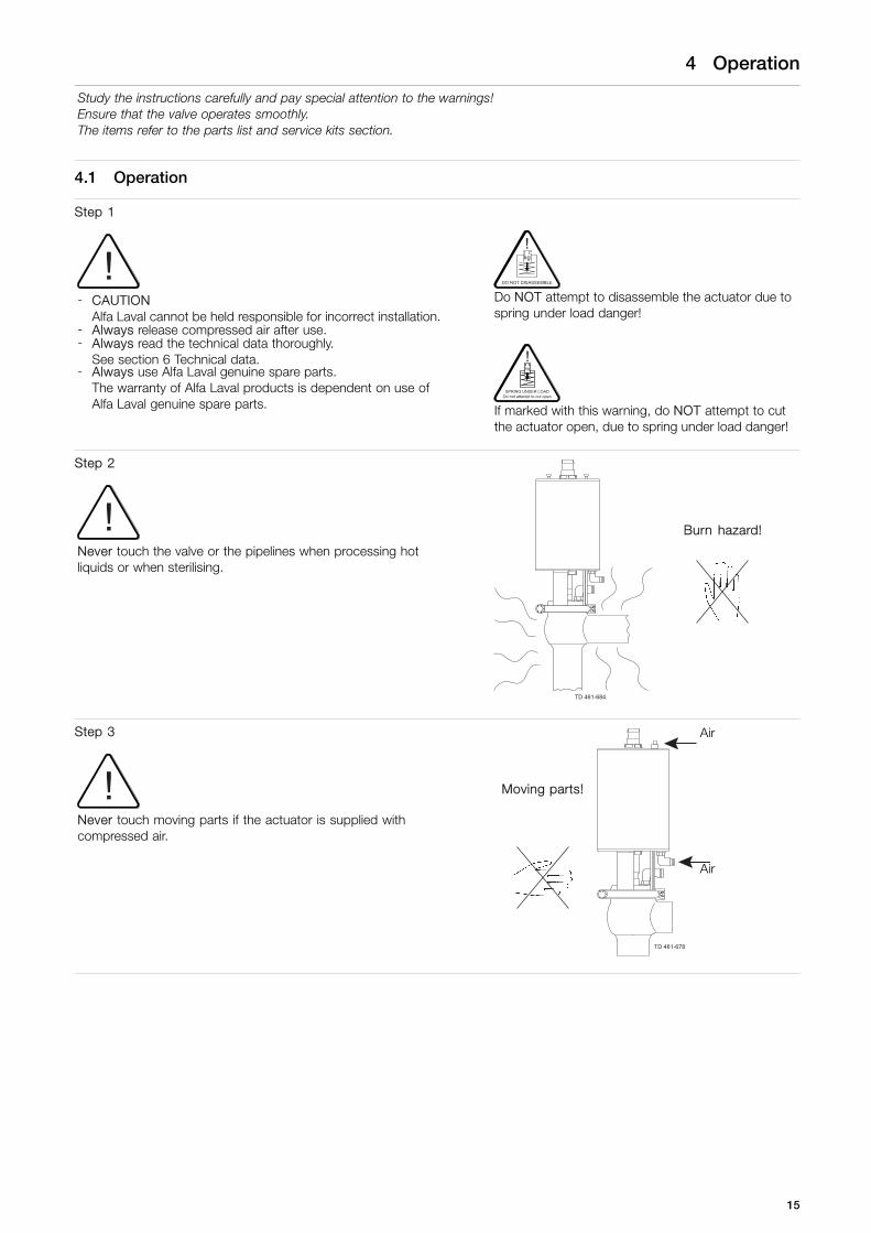
4 Operation
Study the instructions carefully and pay special attention to the warnings!Ensure that the valve operates smoothly.The items refer to the parts list and service kits section.
4.1 Operation
Step 1
!- CAUTION
Alfa Laval cannot be held responsible for incorrect installation.- Always release compressed air after use.- Always read the technical data thoroughly.
See section 6 Technical data.- Always use Alfa Laval genuine spare parts.
The warranty of Alfa Laval products is dependent on use ofAlfa Laval genuine spare parts.
DO NOT DISASSEMBLE
kg
!
Do NOT attempt to disassemble the actuator due tospring under load danger!
SPRING UNDER LOADDo not attempt to cut open
kg
!
If marked with this warning, do NOT attempt to cutthe actuator open, due to spring under load danger!
Step 2
!Never touch the valve or the pipelines when processing hotliquids or when sterilising.
Burn hazard!
TD 461-684
Step 3
!Never touch moving parts if the actuator is supplied withcompressed air.
Air
Moving parts!
Air
TD 461-678
15

4 Operation
Study the instructions carefully and pay special attention to the warnings!Ensure that the valve operates smoothly.The items refer to the parts list and service kits section.
Step 4Lubrication of valves:1. Ensure smooth movement between lip seal (A) and
plug stem (B).2. Lubricate the lip seal with Klüber Paraliq GTE 703 if necessary
(see page 20).
Shut-off valve Change-over valve
TD 461-1008
29
TD 461-1009
29
Step 5Lubrication of actuator:1. Ensure smooth movement of the actuator (the actuator is
lubricated before delivery).2. Lubricate all seals with Molykote Longterm 2 plus if necessary.
TD 461-1010
16

4 Operation
Pay attention to possible faults. Study the instructions carefully.The items refer to the parts list and service kits section.
4.2 Troubleshooting
NOTE!
Study the maintenance instructions carefully before replacing worn parts - see page 20.
Problem Cause/result Repair
External product leakage Worn or damaged lipseal and/or O-ring
- Replace the seals- Replace with seals of a
different rubber grade
Internal product leakage - Worn or product affectedplug seal
- Replace the seal- Replace with a seal of a
different rubber grade- Product deposits on
the seat and/or plug- Frequent cleaning
- Product pressure exceedsactuator specification
- Replace with a high pressure actuator- Use auxiliary air on the spring side
(do not exceed 3 bar). Alfa Lavalarticle number = 9611995903.
- See section 2.3 Safety precautions- Reduce product pressure
Water hammer The flow direction is thesame as the closing direction
- The flow direction should beagainst the closing direction.
- See section 3.2 General installation, .- Throttle air release of solenoid in
top unit
The valve does notopen/close
Product pressure exceedsactuator specification
- Replace with a high pressure actuator- Reduce product pressure- Use auxiliary air on the spring side.
Always use the pressure relief fittings(3 bar) on support side.Alfa Laval article number =9611995903
If marked with a danger warning, do NOT attempt to cut the actuator open, due to spring under load.
DO NOT DISASSEMBLE
kg
!
Do NOT attempt to disassemble the actuator due to spring under load danger!
SPRING UNDER LOADDo not attempt to cut open
kg
!
Do NOT attempt to cut the actuator open due to spring under load danger!
17

4 Operation
The valve is designed for cleaning in place (CIP).Study the instructions carefully and pay special attention to the warnings!NaOH = Caustic soda.HNO3 = Nitric acid.
4.3 Recommended cleaning
Step 1
Always handle lye and acid with great care.
Caustic danger!
Always userubber gloves!
Always useprotective goggles!
Step 2
!Never touch the valve or the pipelines when sterilising.
Burn hazard!
TD 461-684
Step 3Clean the plug and the seats correctly.Pay special attention to the warnings.Lift and lower valve plug momentarily!
Shut-off valve Change-over valve
TD 461-749 TD 461-750
Step 4Examples of cleaning agents:Use clean water, free from chlorides.
1. 1% by weight NaOH at 70o C 2. 0.5% by weight HNO3 at 70o C
1 kgNaOH
+ 100 lwater
= Cleaning agent. 0.7 l53% HNO3
+ 100 lwater
= Cleaning agent.
2.2 l33% NaOH
+ 100 lwater
= Cleaning agent.
18

4 Operation
The valve is designed for cleaning in place (CIP).Study the instructions carefully and pay special attention to the warnings!NaOH = Caustic soda.HNO3 = Nitric acid.
Step 51. Avoid excessive concentration of the cleaning agent.2. Adjust the cleaning flow to the process.3. Always rinse well with clean water after the cleaning.
NOTEThe cleaning agents must be stored/disposed of in accordancewith current regulations/directives.
Always rinse!
Clean water Cleaning agents
19

5 Maintenance
Service the valve regularly.Study the instructions carefully and pay special attention to the warnings!Always use Alfa Laval genuine spare parts. Always keep spare rubber seals and lip seals in stock.Check the valve for smooth operation after servicing.
5.1 General maintenance
Step 1
!- CAUTION
Alfa Laval cannot be held responsible for incorrect installation.- Always release compressed air after use.- Always read the technical data thoroughly.
See section 6 Technical data.- Always use Alfa Laval genuine spare parts.
The warranty of Alfa Laval products is dependent on use ofAlfa Laval genuine spare parts.
DO NOT DISASSEMBLE
kg
!
Do NOT attempt to disassemble the actuator due tospring under load danger!
SPRING UNDER LOADDo not attempt to cut open
kg
!
If marked with this warning, do NOT attempt to cutthe actuator open, due to spring under load danger!
Step 2
!Never service the valve when it is hot.
Never service the valve with valve and pipelines under pressure.
Atmosphericpressurerequired!
Burn hazard!
TD 461-691
Step 3
!Never stick your fingers through the valve ports if the actuator issupplied with compressed air.
Never touch the moving parts if the actuator is supplied withcompressed air.
Air
Moving parts!
Cutting hazard!Air
TD 461-1011
20

5 Maintenance
Service the valve regularly.Study the instructions carefully and pay special attention to the warnings!Always use Alfa Laval genuine spare parts. Always keep spare rubber seals and lip seals in stock.Check the valve for smooth operation after servicing.
Below are some guidelines for maintenance and lubrication intervals. Please note that the guidelines are for normalworking conditions in one shift.
Product wetted seals Actuator bushings complete
Preventivemaintenance
Replace after12 months dependingon working conditions.
Replace after5 years dependingon working conditions.
Maintenance afterleakage (leakagenormally starts slowly)
Replace at theend of the day.
Replace whenpossible.
Plannedmaintenance
- Regular inspectionfor leakage andsmooth operation.
- Keep a record ofthe valve.
- Use the statistics forinspection planning.- Replace after leakage.
- Regular inspectionfor leakage andsmooth operation.
- Keep a record ofthe actuator.
- Use the statistics forinspection planning.- Replace after leakage.
Lubrication
Before fittingKlüber Paraliq GTE 703or similar USDA H1approved oil/grease.
Before fittingMolykote Longterm 2 plus
Pre-use check:Air
1. Supply compressed air to the actuator.2. Open and close the valve several times to
ensure that it operates smoothly.Pay special attention to the warnings!
Open/close!Air
Recommended spare partsService kits (see section 7 Parts list and service kits)
TD 461-683
21

5 Maintenance
Service the valve regularly.Study the instructions carefully and pay special attention to the warnings!Always use Alfa Laval genuine spare parts. Always keep spare rubber seals and lip seals in stock.Check the valve for smooth operation after servicing.
5.2 Dismantling shut-off valve
If the actuator is marked with a danger warning, do NOT attempt to cut the actuator open.
DO NOT DISASSEMBLE
kg
!
SPRING UNDER LOADDo not attempt to cut open
kg
!
Do NOT attempt to disassemble the actuator due to springunder load danger!
Do NOT attempt to cut the actuator open due to springunder load danger!
A = ActuatorB = SpindelC = BonnetD = DiscE = DiaphragmF = Plug
2205-0001
C
B
F
D
E
A
22

5 Maintenance
Service the valve regularly.Study the instructions carefully and pay special attention to the warnings!Always use Alfa Laval genuine spare parts. Always keep spare rubber seals and lip seals in stock.Check the valve for smooth operation after servicing.
Step 1Move the plug in top positionRemove the air drain hoseEnsure pipe is empty and not pressurizedand then loosen the clamp using a 10 mm spanner
Top position
2205-0012_1
Drain hoseconnection
Step 2Loosen the plug from the actuator by usning two 17 spanners
2205-0009
23

5 Maintenance
Service the valve regularly.Study the instructions carefully and pay special attention to the warnings!Always use Alfa Laval genuine spare parts. Always keep spare rubber seals and lip seals in stock.Check the valve for smooth operation after servicing.
Step 3Remove the bonnet
2205-0007
Step 4Loosen the plug from the spindle by using two 17 spannersIf necessary can the bushing (24) in the bonnet be changedClean all parts and replace diaphragm and plug seal
2205-0005
2205-0050
24

5 Maintenance
Service the valve regularly.Study the instructions carefully and pay special attention to the warnings!Always use Alfa Laval genuine spare parts. Always keep spare rubber seals and lip seals in stock.Check the valve for smooth operation after servicing.
5.3 Dismantling change-over valve
A = SpindleB = BonnetC = DiscD = DiaphragmE = ClampF = Upper valve bodyG = SeatH = Change-over plugJ = Lower valve body
D
C
B
E
J
H
G
E
F
A
2205-0018
UP
CORRECT assembling and disassembling to avoid destroying (stretching) diaphragm
IMPORTANT!
Diaphragm
The mechanical stop is in lower body.To adoid overstretching the diaphragm thelower boby clamp must not be loosenedbefore the upper body clamp.
Recommended spare partsService kits (see section 7 Parts list andservice kits) TD 461-1012
29
Mechanical stop
Upper clamp
Place the plug in upper position and loosenthe upper clamp. TD 461-1013
25

5 Maintenance
Service the valve regularly.Study the instructions carefully and pay special attention to the warnings!Always use Alfa Laval genuine spare parts. Always keep spare rubber seals and lip seals in stock.Check the valve for smooth operation after servicing.
INCORRECT assembling and disassembling of Unique SSV Aseptic change-over valve
Upper clamp still mounted,which is wrong
Lower clamp dismounted
TD 461-1014
The plug is overstretching thediaphragm as it moves 10 mm furtherdownwards
Step 1When dismounting always mark the position of actuator, upperand lower valve body,This makes the reassembly much easier, as the valve can bemounted up in the same position in the workshop.
2205-0037
26

5 Maintenance
Service the valve regularly.Study the instructions carefully and pay special attention to the warnings!Always use Alfa Laval genuine spare parts. Always keep spare rubber seals and lip seals in stock.Check the valve for smooth operation after servicing.
Step 2Ensure that the actuator stem Is in upper position before loosingthe upper clamp.Remove the air drain hose.Ensure pipe is empty and not pressurized.ALWAYS start with dismounting the upper clamp to avoiddamaging the diaphragm.IMPORTANTPlease remember NOT to dismount the lower clamp unless plugstays in the upper position (only type NO actuator), as diaphragmthen will be destroyed if plug moves downwards.
Upper position
2205-0057_1
Drain hoseconnection
2205-0058
Step 3
Dismount lower clamp and lower valve body.
!DANGER!Finger cuts at “bonnet” and “seat ring”
!
2205-0059
27

5 Maintenance
Service the valve regularly.Study the instructions carefully and pay special attention to the warnings!Always use Alfa Laval genuine spare parts. Always keep spare rubber seals and lip seals in stock.Check the valve for smooth operation after servicing.
Step 4Loosen the spindle from the actuator. Use 17 mm spanners.Ensure actuator stem is in lower position.Now the plug/seat/upper valve body can be removed from theactuator yoke.
2205-0031
2205-0060
Step 5Loosen the spindle from the plug. Use 17 mm spanners.It is easiest to use a vice.
2205-0028 2205-0029
28

5 Maintenance
Service the valve regularly.Study the instructions carefully and pay special attention to the warnings!Always use Alfa Laval genuine spare parts. Always keep spare rubber seals and lip seals in stock.Check the valve for smooth operation after servicing.
Step 6Dismount spindle from the plug.NOTE:The leakage fitting in the bonnet does not need to be dismounted
2205-0041
Step 7Dismount upper valve body from the plug/seat.
2205-0042
29

5 Maintenance
Service the valve regularly.Study the instructions carefully and pay special attention to the warnings!Always use Alfa Laval genuine spare parts. Always keep spare rubber seals and lip seals in stock.Check the valve for smooth operation after servicing.
Step 8Dismount seat from the plug.Remember to replace o-rings in the seat and the plug.
2205-0043
Step 9Remove bonnet from upper valve body.To do this - use the plug to press the bonnet out of the valve.Remove the seat from the plug. Place the plug in the upper valvebody and press down on upper valve body until bonnet is loose.Be careful not to damage the plug.
2205-0044
Step 10NOTE!It is also possible to use a screw driver between the bonnet andvalve. There is an “opening” marked in the bonnet where thescrew driver can be fitted.
TD 461-752
30

5 Maintenance
Service the valve regularly.Study the instructions carefully and pay special attention to the warnings!Always use Alfa Laval genuine spare parts. Always keep spare rubber seals and lip seals in stock.Check the valve for smooth operation after servicing.
Step 11Dismount bonnet and diaphragm
2205-0045
Step 12Replace the diaphragm.It is important that the flat side of the disc is upwards.The bushing (24) in the bonnet can be changed, if necessary.
2205-0019
�
31

5 Maintenance
Service the valve regularly.Study the instructions carefully and pay special attention to the warnings!Always use Alfa Laval genuine spare parts. Always keep spare rubber seals and lip seals in stock.Check the valve for smooth operation after servicing.
5.4 Plug seal replacement
Step 11. Remove old seal ring using a knife, screwdriver or similar.
Be careful not to damage the plug surface.If using a screwdriver it must be placed underneath the pluggroove (see drawing 1).
2. Grease the new seal ring with Paralique GTE 703, which isincluded in the service kit.Only use a very small amount of grease.
3. Fit the seal ring on the plug without pressing it into the groove.Be careful not to twist the seal ring.Use a screwdriver (two turns) to fit the seal ring properly and toensure it is not twisted (see drawing 2).
4. The seal ring can now be mounted by hand or with the AlfaLaval plug tool.
Drawing 1
It is important to place the screwdriver underneaththe plug.
2200-0122
Drawing 2
2200-0094
32

5 Maintenance
Service the valve regularly.Study the instructions carefully and pay special attention to the warnings!Always use Alfa Laval genuine spare parts. Always keep spare rubber seals and lip seals in stock.Check the valve for smooth operation after servicing.
Step 2Mounting plug seal ring by hand1. Check the seal ring is premounted as described in step 1.
To ensure correct mounting, press with your thumb on theseal ring, which must be done approximately 10 times andalways with opposite pressure points, from A to B, to C andD (see drawing 3).The rest of the seal ring can now be pressed into the grooveso the whole seal ring is mounted. Check that there are NO“bulge” (see drawing 4).If there is a little bulge – then use the screwdriver to eliminatethe bulge.Again press with the thumb on the seal ring and keep thepressure while rotating 360° (see drawing 3).
2. It is important to release compressed air behind the seal ring.This is done with a screwdriver and always underneath theplug as shown.It must be done at one or two different points on thecircumference.Be careful not to make marks on the surface of the plug andseal ring (see drawing 5).
Drawing 3
2200-0142
A
D
B
C
Drawing 4
�
2200-0123
BulgeDrawing 5
2200-0122
33

5 Maintenance
Service the valve regularly.Study the instructions carefully and pay special attention to the warnings!Always use Alfa Laval genuine spare parts. Always keep spare rubber seals and lip seals in stock.Check the valve for smooth operation after servicing.
Step 3Mounting plug seal ring with Alfa Laval plug seal tool
Mounting tool for elastomerplug seals
DN2525 mm
DN4038 mm
DN50 - DN6551 mm - 63.5 mm
DN80 - DN10076.1 mm - 101.6 mm
TD 461-917_1
3
9614060001 9614060002 9614060003 9614060004
Exhaust holesfor screwdriver
Holefor plug spindle
2205-0062
A B
C
D
F
E
1. Part B“Part B” has a small and a large diameter as the tool can beused for two plug sizes – e.g. plug tool = 9614060003 can beused for DN50/ISO51 (small) and DN65/ISO63 (large).“Part B” therefore has to be turned so it matches the plugsize diameter.
2. Part A“Part A” has an upper and lower exhaust hole, as the tool canbe used for two plug sizes – e.g. plug tool = 9614060003.The upper exhaust hole is for the small plug size e.g.DN50/ISO51 (small) and the lower exhaust hole is forDN65/ISO63 (large).When using a “change-over plug” the spindle must also befitted in “part A” and “part B” (see drawing 2).When using a “standard shut-off plug” the spindle is only fittedin “part B” (see drawing 1).
3. Fit the plug spindle in “part B” or “part A”.Place “part A” onto “part B” and then press “hard” down ontop of “part A”.Now fit the screwdriver into the exhaust hole and underneaththe plug groove meanwhile keeping the pressure on “part A”.This should ensure correct removal of air behind the sealring. Normally the sound “Psst” can be heard one time (seedrawing 3).A “drill press” can of course also be used to press down on“part A”.
4. It is important to release compressed air behind the seal ring.This is done with a screwdriver and always underneath theplug as shown (see drawing 4).
A. Part AB. Part BC. PlugsD. O-ringE. Grease Paralique GTE703
from service kitF. Screwdriver (no sharp corner)
34
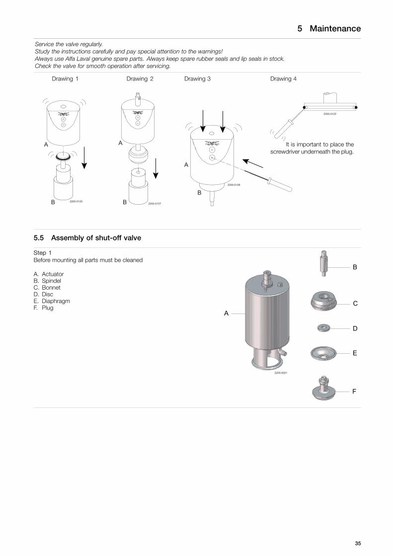
5 Maintenance
Service the valve regularly.Study the instructions carefully and pay special attention to the warnings!Always use Alfa Laval genuine spare parts. Always keep spare rubber seals and lip seals in stock.Check the valve for smooth operation after servicing.
Drawing 1 Drawing 2 Drawing 3 Drawing 4
2200-0122
A
B 2200-0125
A
B 2200-0127
A
B2200-0126
It is important to place thescrewdriver underneath the plug.
5.5 Assembly of shut-off valve
Step 1Before mounting all parts must be cleaned
A. ActuatorB. SpindelC. BonnetD. DiscE. DiaphragmF. Plug
2205-0001
C
B
F
D
E
A
35
5 Maintenance
Service the valve regularly.Study the instructions carefully and pay special attention to the warnings!Always use Alfa Laval genuine spare parts. Always keep spare rubber seals and lip seals in stock.Check the valve for smooth operation after servicing.
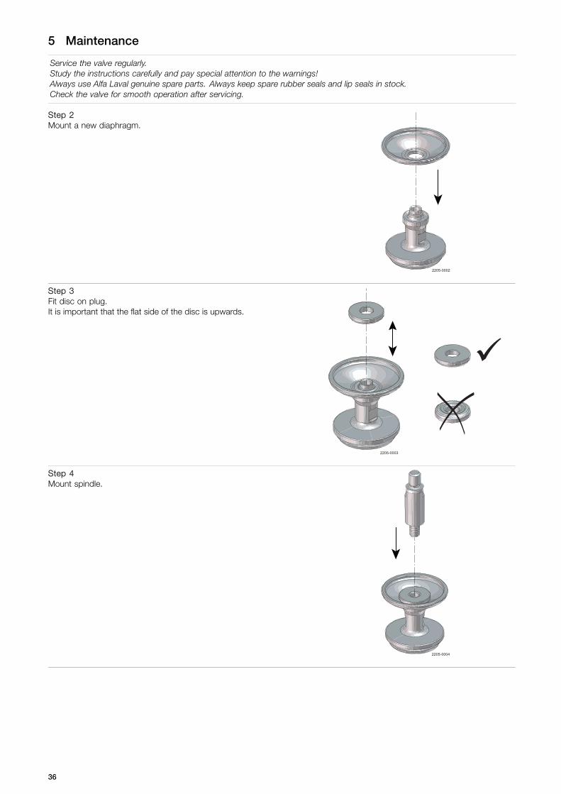
Step 2Mount a new diaphragm.
2205-0002
Step 3Fit disc on plug.It is important that the flat side of the disc is upwards.
2205-0003
�
Step 4Mount spindle.
2205-0004
36

5 Maintenance
Service the valve regularly.Study the instructions carefully and pay special attention to the warnings!Always use Alfa Laval genuine spare parts. Always keep spare rubber seals and lip seals in stock.Check the valve for smooth operation after servicing.
Step 5Tighten spindle and plug with:- 2”/DN50 - 4”/DN100 with Torque = 33 Nm- 1”/DN25 - 1½”/DN40 with Torque = 17 Nm
2205-0005
Step 6We strongly recommend to use some water to “grease” on thebonnets round edge, before mounting the diaphragm. This makesit much easier to mount diaphragm correctly.
2205-0006
Step 7Mount bonnet on spindle and fit diaphragm. Press only with thefingers to avoid scrates on diaphragm. Be sure that diaphragm iscorrectly fitted on the “round edge” on the bonnet.
NOTE!Make sure that the diaphragm issecurely mounted on the bonnetbefore installing the completediaphragm/stem into the valvebody.
TD 461-700
2205-0007
37

5 Maintenance
Service the valve regularly.Study the instructions carefully and pay special attention to the warnings!Always use Alfa Laval genuine spare parts. Always keep spare rubber seals and lip seals in stock.Check the valve for smooth operation after servicing.
Step 8Mount the fitting for leakage in the bonnet. Be sure the actuatorstem is in lower position. Mount the assembled "plug unit" ontothe actuator stem.
2205-0008
Step 9Tighten plug and actuator with:- 2”/DN50 - 4”/DN100 with Torque = 33 Nm- 1”/DN25 - 1½”/DN40 with Torque = 17 Nm
2205-0009
38

5 Maintenance
Service the valve regularly.Study the instructions carefully and pay special attention to the warnings!Always use Alfa Laval genuine spare parts. Always keep spare rubber seals and lip seals in stock.Check the valve for smooth operation after servicing.
Step 10Before mounting bonnet/diaphragm into valve body use grease(Paraliq GTE 703) on sealing surface. This will reduce friction whendiaphragm is pressed into the valve body.Make sure that the actuator stem is in lower position, as thismakes it easiest to fit diaphragm into the valve body.Mount actuator type “NC” without air pressure.Mount actuator type “NO” with air pressure.
2205-0010
Step 11Ensure that the actuator stem is still in lower position.Then press hard on top of the actuator to fit the bonnet/diaphragmin the valve body.There is a “big” gab opening, but diaphragm is now placed intothe valve body.NOTE!There is a “big” gap, but diaphragm is now placed into the valvebody.
* = Big gap
2205-0061
*
Step 12Now move the actuator stem in top position and press HARD ontop of the actuator to reduce the gap to approx. 1 mm.
39

5 Maintenance
Service the valve regularly.Study the instructions carefully and pay special attention to the warnings!Always use Alfa Laval genuine spare parts. Always keep spare rubber seals and lip seals in stock.Check the valve for smooth operation after servicing.
Step 13Mount the clamp (make sure it is located correctly).Tighten with a 10mm spanner. Torque = 10-12 Nm.Grease the thread with Molykote.Place a hose in the fitting in the sealing element (hole for leakagedetection).
2205-0012
40

5 Maintenance
Service the valve regularly.Study the instructions carefully and pay special attention to the warnings!Always use Alfa Laval genuine spare parts. Always keep spare rubber seals and lip seals in stock.Check the valve for smooth operation after servicing.
5.6 Assembly of change-over valve
A = SpindleB = BonnetC = DiscD = DiaphragmE = ClampF = Upper valve bodyG = SeatH = Change-over plug
D
C
B
E
J
H
G
E
F
A
2205-0018
UP
J = Lower valve body
Step 1We recommend to use some water to "grease" on the bonnetsround edge, before mounting the diaphragm. This makes it mucheasier to mount diaphragm correctly.
2205-0006
41

5 Maintenance
Service the valve regularly.Study the instructions carefully and pay special attention to the warnings!Always use Alfa Laval genuine spare parts. Always keep spare rubber seals and lip seals in stock.Check the valve for smooth operation after servicing.
Step 2Mount the disc in the bonnet, with the plane disc side towardsthe bonnet bushing. It is important that the flat side of the discis upwards.
2205-0019
�
Step 3Fit diaphragm to the bonnet. Press only with the fingers so noscratch comes on the diaphragm as this might result in leakage.Be sure that the diaphragm is fitted correctly on the "round edge"on the bonnet.
2205-0020
Step 4We strongly recommend to use grease (Paraliq GTE 703) on theedges of the upper valve body to ensure that the diaphragm ismounted correctly. The sealing surface must be clean to avoidleakage.
2205-0021
UP
42

5 Maintenance
Service the valve regularly.Study the instructions carefully and pay special attention to the warnings!Always use Alfa Laval genuine spare parts. Always keep spare rubber seals and lip seals in stock.Check the valve for smooth operation after servicing.
Step 5Mount bonnet and diaphragm (disc inside) into upper valve body.
2205-0022
UP
Step 6Remember to position valve body with the ø2 hole upwards. Presshard on the bonnet to fit it in the upper valve body.
2205-0023
UP
43

5 Maintenance
Service the valve regularly.Study the instructions carefully and pay special attention to the warnings!Always use Alfa Laval genuine spare parts. Always keep spare rubber seals and lip seals in stock.Check the valve for smooth operation after servicing.
Step 7Place the seat on the plug. Remember to mount new O-rings inthe seat and plug.
2205-0024
Step 8Use a little amount of "Loctite 243" on the plug treat. Be carefulnot to spill a drop outsidethe threaded hole, as this will glue thedisc and plug together. (This can make it difficult to dismount thevalve next time service is carried out.)
2205-0025
44

5 Maintenance
Service the valve regularly.Study the instructions carefully and pay special attention to the warnings!Always use Alfa Laval genuine spare parts. Always keep spare rubber seals and lip seals in stock.Check the valve for smooth operation after servicing.
Step 9Mount upper valve body onto the plug/seat.
2205-0026
UP
Step 10Assemble spindle and plug. Be sure that the disc is placedcorrectly on the plug while screwing spindle and plug together.Remember to mount the leakage fitting in the bonnet!
2205-0027
45

5 Maintenance
Service the valve regularly.Study the instructions carefully and pay special attention to the warnings!Always use Alfa Laval genuine spare parts. Always keep spare rubber seals and lip seals in stock.Check the valve for smooth operation after servicing.
Step 11Tighten the spindle and plug. Use 17 mm spanners.It is easiest to use a vice.Tighten valve size 2"/DN50 - 4"/DN100 with Torque = 33 NmTighten valve size 1"/DN25 - 1½"/DN40 with Torque = 17 Nm
2205-0028 2205-0029
Step 12Ensure that the actuator stem is in lower position.Tighten the valve body/plug together with the actuator.Activate the actuator, if is it a NO version, so the actuator stemmoves downwards to ensure right mounting.
DANGER!Finger cut at “bonnet” and “uper valve body”.
2205-0030_1
46

5 Maintenance
Service the valve regularly.Study the instructions carefully and pay special attention to the warnings!Always use Alfa Laval genuine spare parts. Always keep spare rubber seals and lip seals in stock.Check the valve for smooth operation after servicing.
Step 13Tighten the actuator stem and plug. Use 17 mm spanners.Tighten valve size 2"/DN50 - 4"/DN100 with Torque = 33 Nm.Tighten valve size 1/DN25 - 1½"/DN40 with Torque = 17 Nm.
2205-0031
Step 14Align upper valve body and actuator if necessary. This is done byrotating the valve body only clockwise (only the valve body canrotate as diaphragm is locked).
2205-0032
!
47

5 Maintenance
Service the valve regularly.Study the instructions carefully and pay special attention to the warnings!Always use Alfa Laval genuine spare parts. Always keep spare rubber seals and lip seals in stock.Check the valve for smooth operation after servicing.
Step 15Ensure that the actuator stem is in upper position.DANGER!Finger cut at "bonnet" and "seat ring"
2205-0033 !
48
5 Maintenance
Service the valve regularly.Study the instructions carefully and pay special attention to the warnings!Always use Alfa Laval genuine spare parts. Always keep spare rubber seals and lip seals in stock.Check the valve for smooth operation after servicing.
Step 16
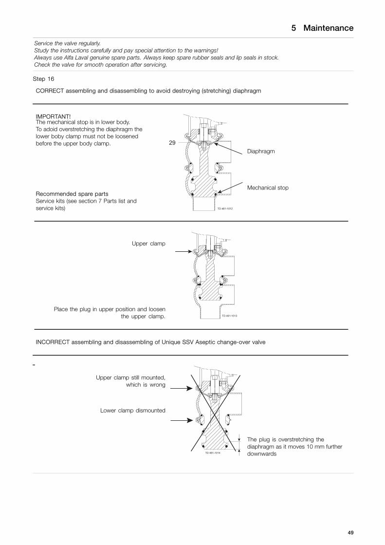
CORRECT assembling and disassembling to avoid destroying (stretching) diaphragm
IMPORTANT!
Diaphragm
The mechanical stop is in lower body.To adoid overstretching the diaphragm thelower boby clamp must not be loosenedbefore the upper body clamp.
Recommended spare partsService kits (see section 7 Parts list andservice kits) TD 461-1012
29
Mechanical stop
Upper clamp
Place the plug in upper position and loosenthe upper clamp. TD 461-1013
INCORRECT assembling and disassembling of Unique SSV Aseptic change-over valve
Upper clamp still mounted,which is wrong
Lower clamp dismounted
TD 461-1014
The plug is overstretching thediaphragm as it moves 10 mm furtherdownwards
49

5 Maintenance
Service the valve regularly.Study the instructions carefully and pay special attention to the warnings!Always use Alfa Laval genuine spare parts. Always keep spare rubber seals and lip seals in stock.Check the valve for smooth operation after servicing.
Step 17Mount lower valve body, but remember to align with upper valvebody, before tightening the lower clamp. Then tighten LOWERclamp with torque M = 10-12 Nm.IMPORTANT:Remember always to fit the LOWER clamp first and the upperclamp as the last one to avoid damaging the diaphragm (alsosee Step 16).
2205-0034
!
Step 18Now mount upper clamp and tighten - Torque = 10-12 Nm.IMPORTANT!Please remember NOT to dismount the lower clamp unless plugstays in the upper position, as diaphragm will be destroyed if plugmoves downwards (also see Step 16).
2205-0035
50

5 Maintenance
Service the valve regularly.Study the instructions carefully and pay special attention to the warnings!Always use Alfa Laval genuine spare parts. Always keep spare rubber seals and lip seals in stock.Check the valve for smooth operation after servicing.
Step 19If the upper valve body has to be rotated remember ALWAYS tostart with dismounting the upper clamp.IMPORTANT!Please remember NOT to dismount the lower clamp unless plugstays in the upper position, as diaphragm will be destroyed if plugmoves downwards. (see also step 16).
2205-0036
51

5 Maintenance
Service the valve regularly.Study the instructions carefully and pay special attention to the warnings!Always use Alfa Laval genuine spare parts. Always keep spare rubber seals and lip seals in stock.Check the valve for smooth operation after servicing.
5.7 Actuator types
Different actuator types for the SSV valveIn June 2016 the below change was implemented and the “removable yoke with bolts” version is thereby phased out andreplaced by the “yoke without bolts” version.
NOTEIt is important to check for warnings marked on the actuator when servicing an actuator - see below table.
Non-maintainable actuatorSpring under load andCANNOT be opened
Fully maintainable actuatorSpring cage and can beopened
Fully maintainable actuatorSpring cage and can beopened
2200-0098
* DO NOT DISASSEMBLE
kg
!
2200-0096 2200-0097
*) Lock wire opening is locked,when warning is marked onactuator
Actuator type
Non-removable yoke “Removable yoke with bolts”.If the yoke with bolts isdamaged it has to be replacedby the “yoke without bolts”
“Yoke without bolts”
Yoke type
Not possible to serviceinternally (it is not possible tochange piston o-rings)
Yes YesService
Yes No NoMarked with warnings
From 2006 From 2006 to June 2016 From June 2016Year of production
52

5 Maintenance
Study the instructions carefully.The items refer to the parts list and service kits section. Handle scrap correctly.A/A = Air/air activated.Service tool: see spare parts.
5.8 Actuator bushing replacement (non-maintainable actuator)
If the actuator is marked with a danger warning, do NOT attempt to cut the actuator open.
DO NOT DISASSEMBLE
kg
!
SPRING UNDER LOADDo not attempt to cut open
kg
!
Do NOT attempt to disassemble the actuator due to springunder load danger!
Do NOT attempt to cut the actuator open due to springunder load danger!
Step 1Introduction- The actuator service kit contains two bushings and four
O-rings.- Mount the thick O-ring inside and the thin O-ring outside the
bushing.- Always lubricate the spindle and O-rings thoroughly with
“Molykote Longterm 2 Plus” before mounting the new bushings.
2200-0099
DO NOT DISASSEMBLE
kg
!
53

5 Maintenance
Study the instructions carefully.The items refer to the parts list and service kits section. Handle scrap correctly.A/A = Air/air activated.Service tool: see spare parts.
Step 2Introduction - Standard socket wrenchUse a 27 mm socket wrench to mount the bushings, as the space in the yoke is limited.A socket wrench 24x27 (length = 185 mm) is a standard tool, which can be purchased from all tool shops.
A = 185 mm
2200-0001
A
Example:Socket wrench - 24x27 mmSupplier: Gedore ToolEAN4010886621264
2200-0002
Step 3Introduction - Aligning spindleThe actuator spindle can in some cases be forced off centre by the internal spring, see drawing below.In these cases, the alignment spindle shown below, together with the socket wrench, is a great help and ensures a reliablemounting of the bushing. The spindle can either be purchased from Alfa Laval together with the socket wrench (9614-1984-01)or it can be manufactured locally using the below dimensions.
Spindle forced off centre by spring inside actuator
2200-0100
DO NOT DISASSEMBLE
kg
!
2200
-000
4
AB
D
C
A = 280 mmB = 16 mmC = Rod ø20 mmD = M12 x 1.5
54

5 Maintenance
Study the instructions carefully.The items refer to the parts list and service kits section. Handle scrap correctly.A/A = Air/air activated.Service tool: see spare parts.
Step 4The actuator must be carefully fixed in a vice if it is dismounted from the valve. Be careful not to press the yoke flange oval whenfixing the actuator in the vice. Only fix carefully on the “yoke leg” as shown below.
2200-0101
DO NOT DISASSEMBLE
kg
!
2200-0006
Step 5Remove adapter screw.(After spindle alignment the adapter screw has to be remounted.)
2200-0102
DO NOT DISASSEMBLE
kg
!
55

5 Maintenance
Study the instructions carefully.The items refer to the parts list and service kits section. Handle scrap correctly.A/A = Air/air activated.Service tool: see spare parts.
Step 61. Lubricate thoroughly both the actuator spindle and O-rings.2. Grease with “Molykote Longterm 2 plus”.3. Fit the bushing on the spindle.
2200-0103
DO NOT DISASSEMBLE
kg
!
Step 7Fit the aligning spindle to the actuator spindle, and then mount the socket wrench.
2200-0104
DO NOT DISASSEMBLE
kg
!
2200-0105
DO NOT DISASSEMBLE
kg
!
Aligning spindle Socket wrench
56
5 Maintenance
Study the instructions carefully.The items refer to the parts list and service kits section. Handle scrap correctly.A/A = Air/air activated.Service tool: see spare parts.
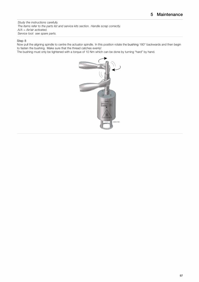
Step 8Now pull the aligning spindle to centre the actuator spindle. In this position rotate the bushing 180° backwards and then beginto fasten the bushing. Make sure that the thread catches evenly!The bushing must only be tightened with a torque of 10 Nm which can be done by turning “hard” by hand.
2200-0106
DO NOT DISASSEMBLE
kg
!
57

5 Maintenance
Study the instructions carefully.The items refer to the parts list and service kits section. Handle scrap correctly.A/A = Air/air activated.Service tool: see spare parts.
5.9 Dismantling of fully maintainable actuator (removable yoke with bolts/2006-June 2016)
If the actuator is marked with a danger warning, do NOT attempt to cut the actuator open.See also section 5.7 Actuator types
DO NOT DISASSEMBLE
kg
!
SPRING UNDER LOADDo not attempt to cut open
kg
!
Do NOT attempt to disassemble the actuator due to springunder load danger!
Do NOT attempt to cut the actuator open due to springunder load danger!
Before dismantling check that the actuator not is marked with a warning.
1. Rotate cylinder.2. Remove lock wire and pull away cylinder.3. Unscrew nuts and remove yoke.4. Top and bottom bushings.5. Remove piston with O-ring and spring assembly.6. Remove O-rings and support disc.
Rotate cylinder withservice tool.
Note! The A/A actuator has no spring assembly.
2200-0107
58
5 Maintenance
Study the instructions carefully.The items refer to the parts list and service kits section. Handle scrap correctly.A/A = Air/air activated.Service tool: see spare parts.
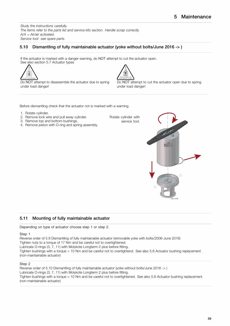
5.10 Dismantling of fully maintainable actuator (yoke without bolts/June 2016 -> )
If the actuator is marked with a danger warning, do NOT attempt to cut the actuator open.See also section 5.7 Actuator types
DO NOT DISASSEMBLE
kg
!
SPRING UNDER LOADDo not attempt to cut open
kg
!
Do NOT attempt to disassemble the actuator due to springunder load danger!
Do NOT attempt to cut the actuator open due to springunder load danger!
Before dismantling check that the actuator not is marked with a warning.
1. Rotate cylinder.2. Remove lock wire and pull away cylinder.3. Remove top and bottom bushings.4. Remove piston with O-ring and spring assembly.
Rotate cylinder withservice tool.
2321-0149
5.11 Mounting of fully maintainable actuator
Depending on type of actuator choose step 1 or step 2.
Step 1Reverse order of 5.9 Dismantling of fully maintainable actuator (removable yoke with bolts/2006-June 2016)Tighten nuts to a torque of 17 Nm and be careful not to overtightened.Lubricate O-rings (3, 7, 11) with Molykote Longterm 2 plus before fitting.Tighten bushings with a torque = 10 Nm and be careful not to overtightend. See also 5.8 Actuator bushing replacement(non-maintainable actuator)
Step 2Reverse order of 5.10 Dismantling of fully maintainable actuator (yoke without bolts/June 2016 -> )Lubricate O-rings (3, 7, 11) with Molykote Longterm 2 plus before fitting.Tighten bushings with a torque = 10 Nm and be careful not to overtightened. See also 5.8 Actuator bushing replacement(non-maintainable actuator)
59

5 Maintenance
Study the instructions carefully.The items refer to the parts list and service kits section. Handle scrap correctly.A/A = Air/air activated.Service tool: see spare parts.
5.12 Changing pneumatic movement on fully maintainable actuator (NC/NO)
If the actuator is marked with a danger warning, do NOT attempt to cut the actuator open.See also section 5.7 Actuator types.
DO NOT DISASSEMBLE
kg
!
SPRING UNDER LOADDo not attempt to cut open
kg
!
Do NOT attempt to disassemble the actuator due to springunder load danger!
Do NOT attempt to cut the actuator open due to springunder load danger!
Before dismantling check that the actuator not is marked with a warning.
1. Rotate cylinder.2. Remove lock wire and pull away cylinder.3. Reverse piston and spring assembly.4. Reverse adapter, air fitting and plug to opposite end.5. Reassemble in reverse order (3 to 1).
A. = Pneumatic movement - upwards (NC)B. = Pneumatic movement - downwards (NO)
2321-0150
A B
60

6 Technical data
It is important to observe the technical data during installation, operation and maintenance.Inform all personnel about the technical data.
6.1 Technical data
The valve is a pneumatic seat valve in a hygienic and modular design remote-controlled by means of compressed air.
It has few and simple moveable parts which results in a very reliable valve and low maintenance cost. An integrated valveplug/diaphragm secures aseptic operation.
Standard Design The Unique SSV Aseptic valve comes in a one or two body configuration. With its module built structure it isdesigned for flexibility and easy customization through the electronic configurator.
Data - valve/actuator
Max. product pressure 800 kPa (8 bar).
Min. product pressure Full vacuum.
Max. sterilisation temperature (steam - short time) 150o C at pressure 380 kPa (3.8 bar)
Temperature range -10o C to + 140o C (standard EPDM seal).
Air pressure, actuator 500 to 700 kPa (5 to 7 bar).
Note: Vacuum is not recommended in aseptic applications.
Materials - valve/actuator
Product wetted steel parts 1.4404 (316L) (internal Ra < 0.8 µm).
Other steel parts 1.4301 (304).
Plug seal EPDM.
Diaphragm EPDM/PTFE.
Other product wetted seals EPDM (standard).
Optional product wetted seals HNBR and FPM.
Other seals NBR.
Weight (kg)
Nominal size DN/OD DIN/DN
Size 25 38 51 63.5 76.1 101.6 25 40 50 65 80 100
Shut-off valve 3.1 3.3 5.6 6.6 11.5 14 3.2 3.4 5.6 6.8 11.9 13.9
Change-over valve 3.9 4.2 7.2 8.7 14.2 18.4 4.1 4.5 7.1 9 15.1 18.3
NoiseOne metre away from and 1.6 metres above the exhaust the noise level of a valve actuator will be approximately 77db (A)without noise damper and approximately 72 db (A) with damper - measured at 7 bar air-pressure.
61
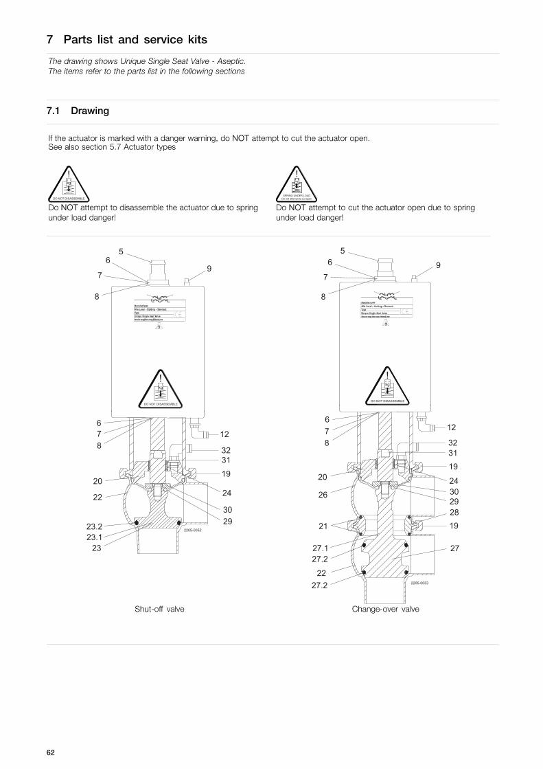
7 Parts list and service kits
The drawing shows Unique Single Seat Valve - Aseptic.The items refer to the parts list in the following sections
7.1 Drawing
If the actuator is marked with a danger warning, do NOT attempt to cut the actuator open.See also section 5.7 Actuator types
DO NOT DISASSEMBLE
kg
!
SPRING UNDER LOADDo not attempt to cut open
kg
!
Do NOT attempt to disassemble the actuator due to springunder load danger!
Do NOT attempt to cut the actuator open due to springunder load danger!
56
7
8
9
876
22
20
2323.123.2
24
32
19
12
2205-0052
DO NOT DISASSEMBLE
kg
!
2930
31
56
7
8
9
876
26
20
21
27.127.2
27.2
24
32
19
12
2205-0053
DO NOT DISASSEMBLE
kg
!
2930
31
22
2819
27
Shut-off valve Change-over valve
62
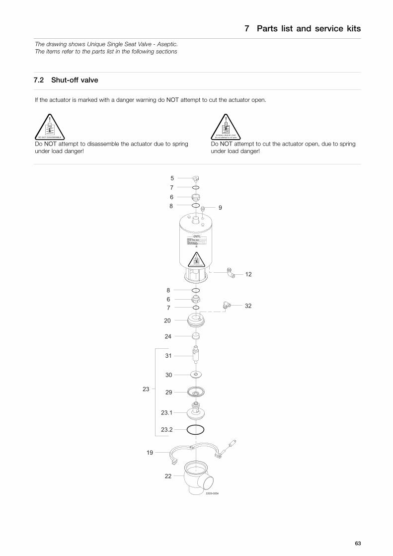
7 Parts list and service kits
The drawing shows Unique Single Seat Valve - Aseptic.The items refer to the parts list in the following sections
7.2 Shut-off valve
If the actuator is marked with a danger warning do NOT attempt to cut the actuator open.
DO NOT DISASSEMBLE
kg
!
SPRING UNDER LOADDo not attempt to cut open
kg
!
Do NOT attempt to disassemble the actuator due to springunder load danger!
Do NOT attempt to cut the actuator open, due to springunder load danger!
5
67
8 9
8
76
24
20
2205-0054
12
32
19
22
DO NOT DISASSEMBLE
kg
!
23
23.1
23.2
29
30
31
63

7 Parts list and service kits
The drawing shows Unique Single Seat Valve - Aseptic.The items refer to the parts list in the following sections
Parts list
Pos. Qty Denomination
5 1 Adapter6 2 Bushing7 2 O-ring8 2 O-ring9 1 Plug12 1(2) Air fitting19 1 Clamp20 1 Bonnet22 1 Valve body23 1 Plug23.1 1 Plug23.2 ♦ 1 Plug seal24 1 Bushing29 ♦ 1 Diaphragm30 1 Disc for diaphragm31 1 Upper spindle32 1 Air fitting
Service kits
DenominationDN 2525 mm
DN 4038 mm
DN 5051 mm
DN 6563.5 mm
DN 8076.1 mm
DN 100101.6 mm
Service kit for actuator Service kit . . . . . . . . . . . . . . . . . . 9611926500 9611926500 9611926500 9611926500 9611926500 9611926500
Service kit for product wetted parts, standard
♦ Service kit, EPDM . . . . . . . . . . 9611926543 9611926544 9611926545 9611926546 9611926547 9611926548♦ Service kit, HNBR . . . . . . . . . . 9611926549 9611926550 9611926551 9611926552 9611926553 9611926554♦ Service kit, FPM . . . . . . . . . . . . 9611926555 9611926556 9611926557 9611926558 9611926559 9611926560
Parts marked with ♦ are included in the service kits.Recommended spare parts: Service kits.
TD 900-354/5
64

7 Parts list and service kits
The drawing shows Unique Single Seat Valve - Aseptic.The items refer to the parts list in the following sections
7.3 Change-over valve
If the actuator is marked with a danger warning do NOT attempt to cut the actuator open.
DO NOT DISASSEMBLE
kg
!
SPRING UNDER LOADDo not attempt to cut open
kg
!
Do NOT attempt to disassemble the actuator due to springunder load danger!
Do NOT attempt to cut the actuator open, due to springunder load danger!
5
67
8 9
8
76
24
20
2205-0055
12
32
19
26
27
27
29
30
31
21
28
21
27.2
27.1
27.2
19
22
27.127.1
25 mm /DN 25 38-51 mm /
DN 40-50
63.5-101.6 mm /DN 65-100
DO NOT DISASSEMBLE
kg
!
65

7 Parts list and service kits
The drawing shows Unique Single Seat Valve - Aseptic.The items refer to the parts list in the following sections
Parts list
Pos. Qty Denomination
5 1 Adapter6 2 Bushing7 2 O-ring8 2 O-ring9 1 Plug12 1(2) Air fitting19 2 Clamp20 1 Bonnet21 ♦ 2 O-ring22 1 Valve body24 1 Bushing26 1 Valve body27 1 Plug27.1 1 Plug27.2 ♦ 2 Plug seal28 1 Seat29 ♦ 1 Diaphragm30 1 Disc for diaphragm31 1 Upper spindle32 1 Air fitting
Service kits
DenominationDN 2525 mm
DN 4038 mm
DN 5051 mm
DN 6563.5 mm
DN 8076.1 mm
DN 100101.6 mm
Service kit for actuator Service kit . . . . . . . . . . . . . . . . . . 9611926500 9611926500 9611926500 9611926500 9611926500 9611926500
Service kit for product wetted parts, standard
♦ Service kit, EPDM . . . . . . . . . . 9611926615 9611926616 9611926617 9611926618 9611926619 9611926620♦ Service kit, HNBR . . . . . . . . . . 9611926621 9611926622 9611926623 9611926624 9611926625 9611926626♦ Service kit, FPM . . . . . . . . . . . . 9611926627 9611926628 9611926629 9611926630 9611926631 9611926632Parts marked with ♦ are included in the service kits. Recommended spare parts: Service kits. TD 900-354/5
66

7 Parts list and service kits
The drawing shows Unique Single Seat Valve - Aseptic.The items refer to the parts list in the following sections
7.4 Maintainable actuator
If the actuator is marked with a danger warning do NOT attempt to cut the actuator open.
DO NOT DISASSEMBLE
kg
!
SPRING UNDER LOADDo not attempt to cut open
kg
!
Do NOT attempt to disassemble the actuator due to springunder load danger!
Do NOT attempt to cut the actuator open, due to springunder load danger!
5
98
6
7
16
10
3
1
2
14
6
8
12
11
71817
13.1
1512
*13
2200-0117
768
*) “Removable yoke with bolts” version, produced from 2006 to June 2016.Replaced by “yoke without bolts” (13)
67

7 Parts list and service kits
The drawing shows Unique Single Seat Valve - Aseptic.The items refer to the parts list in the following sections
Parts list
Pos. Qty Denomination
1 1 Cylinder2 1 Piston3 ♦ 1 O-ring5 1 Adapter6 ♦ 2 Bushing7 ♦ 2 O-ring8 ♦ 2 O-ring9 1 Plug10 1 Lock wire11 ♦ 1 O-ring12 1(2) Air fitting (only 2 for A/A)13 1 Yoke without bolts13.1 1 Yoke (-> 0616)14 1 Spring assembly15 1 Bottom (-> 0616)16 ♦ 1(2) Support disc (only 2 for A/A)17 3 Washer (-> 0616)18 3 Nut (-> 0616)
Service kits
DenominationDN 2525 mm
DN 4038 mm
DN 5051 mm
DN 6563.5 mm
DN 8076.1 mm
DN 100101.6 mm
Service kits Service kit, NO , NC . . . . . . . 9611926497 9611926497 9611926498 9611926498 9611926499 9611926499♦ Service kit, A/A . . . . . . . . . . . . 9611926519 9611926519 9611926520 9611926520 9611926521 9611926521
68

69

How to contact Alfa LavalContact details for all countries arecontinually updated on our website.Please visit www.alfalaval.com to access the information directly.
© Alfa Laval Corporate ABThis document and its contents is owned by Alfa Laval Corporate AB and protected by laws governing intellectual property and thereto related rights. It is the responsibility of the user of thisdocument to comply with all applicable intellectual property laws. Without limiting any rights related to this document, no part of this document may be copied, reproduced or transmitted in anyform or by any means (electronic, mechanical, photocopying, recording, or otherwise), or for any purpose, without the expressed permission of Alfa Laval Corporate AB. Alfa Laval Corporate ABwill enforce its rights related to this document to the fullest extent of the law, including the seeking of criminal prosecution.