ky Alfa Laval ThinkTop V50 and V70
12
. ky Alfa Laval ThinkTop V50 and V70 Automation . Introduction ThinkTop V50 and V70 take valve control to a new level and use all features available on the Alfa Laval diaphragm, butterfly, single-seat and mixproof valves. While helping to increase production performance and secure traceability, ThinkTop V50 and V70 provide real-time information on valve operating status 24/7. Both ThinkTop V50 and V70 are interchangeable with prior ThinkTop versions, and the appropriate variant is selected based on the number of solenoid valves. With only one sensor target and one adapter, ThinkTop V50 and V70 fit onto all actuators equipped with mushrooms. ThinkTop V50 and V70 come fitted with features such as Auto Setup, Live Setup and Flex Setup that streamline the setup process, making it quick and easy. Auto Setup and Live Setup recognise the valve based on its DNA profile and can complete the valve setup without any manual interaction. The burst seat clean function is available on ThinkTop V70. This function controls the optimum open position of the valve, making it possible to achieve up to 90% CIP liquid savings for each seat lift. Application ThinkTop V50 and V70 are designed for use in the dairy, food, beverage, and biopharma industries. Benefits • Automatic setup • Automatic valve recognition • Automatic selection of tolerance band • Fast Auto, Live and Flex Setup • 360-degree LED indication • Burst seat clean • Exchangeable (threaded) air-fittings • Interchangeable with ThinkTop classics . Working principles The control unit offers a single sensor solution for diaphragm, butterfly, single-seat and mixproof valves and it can be fitted with up to three solenoid valves. ThinkTop converts the electrical PLC output signals into mechanical energy to energise, or de-energise, the air-operated valve, using the physical sensor target mounted on the valve stem. Installation with Auto Setup or Live Setup is intuitive and fast. To initiate Auto Setup, simply press the “SELECT” button and then the “ENTER” button to begin the setup sequence. The process is completed in accordance with the number of solenoid valves fitted to the control unit. Alternatively, the ThinkTop can be set up, without dismantling the control head, using the built-in Live Setup feature for remote-configuration www.sks-online.com www.sks-webshop.com
-
Upload
khangminh22 -
Category
Documents
-
view
1 -
download
0
Transcript of ky Alfa Laval ThinkTop V50 and V70

.
ky Alfa Laval ThinkTop V50 and V70Automation
.
IntroductionThinkTop V50 and V70 take valve control to a new level and use allfeatures available on the Alfa Laval diaphragm, butterfly, single-seatand mixproof valves. While helping to increase production performanceand secure traceability, ThinkTop V50 and V70 provide real-timeinformation on valve operating status 24/7.
Both ThinkTop V50 and V70 are interchangeable with prior ThinkTopversions, and the appropriate variant is selected based on the numberof solenoid valves. With only one sensor target and one adapter,ThinkTop V50 and V70 fit onto all actuators equipped with mushrooms.
ThinkTop V50 and V70 come fitted with features such as Auto Setup,Live Setup and Flex Setup that streamline the setup process, makingit quick and easy. Auto Setup and Live Setup recognise the valvebased on its DNA profile and can complete the valve setup withoutany manual interaction.
The burst seat clean function is available on ThinkTop V70. Thisfunction controls the optimum open position of the valve, making itpossible to achieve up to 90% CIP liquid savings for each seat lift.
ApplicationThinkTop V50 and V70 are designed for use in the dairy, food,beverage, and biopharma industries.
Benefits• Automatic setup• Automatic valve recognition• Automatic selection of tolerance band• Fast Auto, Live and Flex Setup• 360-degree LED indication• Burst seat clean• Exchangeable (threaded) air-fittings• Interchangeable with ThinkTop classics
.
Working principlesThe control unit offers a single sensor solution for diaphragm, butterfly,single-seat and mixproof valves and it can be fitted with up to threesolenoid valves. ThinkTop converts the electrical PLC output signalsinto mechanical energy to energise, or de-energise, the air-operatedvalve, using the physical sensor target mounted on the valve stem.
Installation with Auto Setup or Live Setup is intuitive and fast. Toinitiate Auto Setup, simply press the “SELECT” button and thenthe “ENTER” button to begin the setup sequence. The process iscompleted in accordance with the number of solenoid valves fitted tothe control unit. Alternatively, the ThinkTop can be set up, withoutdismantling the control head, using the built-in Live Setup feature forremote-configuration
www.sks-online.com www.sks-webshop.com

Dimensional drawings
ThinkTop V 50 ThinkTop V 70
2066-0094
C
DA
B
C
D
A
B2066-0095
mm Inch mm InchA 123 4.84 A 164 6.45B 105 4.13 B 105 4.13C 200 7.87 C 250 9.84D 150 5.91 D 170 6.69
www.sks-online.com www.sks-webshop.com
Technical data
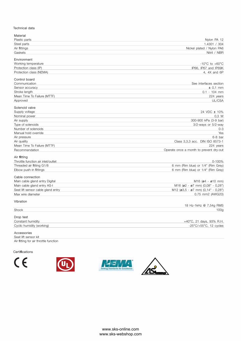
MaterialPlastic parts Nylon PA 12Steel parts 1.4301 / 304Air fittings Nickel plated / Nylon PA6Gaskets Nitril / NBR
EnvironmentWorking temperature -10°C to +60°CProtection class (IP) IP66, IP67 and IP69KProtection class (NEMA) 4, 4X and 6P
Control boardCommunication See interfaces sectionSensor accuracy ± 0,1 mmStroke length 0.1 - 104 mmMean Time To Failure (MTTF) 224 yearsApproved UL/CSA
Solenoid valveSupply voltage 24 VDC ± 10%Nominal power 0,3 WAir supply 300-900 kPa (3-9 bar)Type of solenoids 3/2-ways or 5/2-wayNumber of solenoids 0-3Manual hold override YesAir pressure 6-8 barAir quality Class 3,3,3 acc. DIN ISO 8573-1Mean Time To Failure (MTTF) 224 yearsRecommendation Operate once a month to prevent dry-out
Air fittingThrottle function air inlet/outlet 0-100%Threaded air fitting G1/8 6 mm (Rim blue) or 1/4" (Rim Grey)Elbow push-in fittings 6 mm (Rim blue) or 1/4" (Rim Grey)
Cable connectionMain cable gland entry Digital M16 (ø4 - ø10 mm)Main cable gland entry AS-I M16 (ø2 - ø7 mm) (0,08" - 0,28")Seat lift sensor cable gland entry M12 (ø3,5 - ø7 mm) (0,14" - 0,28")Max wire diameter 0.75 mm2 (AWG20)
Vibration18 Hz-1kHz @ 7,54g RMS
Shock 100g
Drop testConstant humidity +40°C, 21 days, 93% R.H.Cyclic humidity (working) -25°C/+55°C, 12 cycles
AccessoriesSeat lift sensor kitAir fitting for air throttle function
Certifications
www.sks-online.com www.sks-webshop.com

Operational data
LED indicationThinkTop features a 360-degree light guide. When the sensor target is within the respective setup position band, the corresponding colour lights up.
.
2066-0028
.
Valve position
All Main valve open Upper seat lift Lower seat pushActuator
De-energised Energised Energised EnergisedBetween
Not setup
Factory settingGreen flashing White flashing Blue flashing Yellow flashing off
Operation Green White Blue Yellow off
ThinkTop V Mode
Not OK Green / red flashing White / red flashing Blue / red flashing Yellow / red flashing Red lashing
Auto setupAuto Setup is a rule-based function. If one of these rules are not present, Flex Setup must be used.
By default, ThinkTop V50 and V70 uses the de-energised/energised paradigm for valve positions feedback.
3.9.3 Overview of connectors and ports
a Solenoid valve connectorb Indication lampc Main terminals
2066-0092
a b c
a Diagnostic Portb Seat lift sensor terminal
2066-0093
b
a
www.sks-online.com www.sks-webshop.com

Burst clean modeBurst seat clean mode is available for ThinkTop V70 and can be enabled when a ThinkTop V70 with 2 or 3 solenoid valves is setup successfullyusing Auto Setup
The burst seat clean mode is enabled or disabled on the ThinkTop V70 control board. Press "SELECT" (4 times) until LED no 4 flashes, and then press’ENTER" to enable or disable. This option is also available as an IO-Link parameter
The burst seat clean option is from factory disabled by default. However, if it is enabled and there is a manual reset to factory default, the burst seatclean option is disabled.
.
Bust clean mode output diagram
a Input (from PLC)b Positionc Solenoid valve outputd Output (both visual and electrical)e Position reached
a
d
c
b
e e et tt
d2 d2 d2
2066-0032
When the PLC input signal for either upper or lower seat push (Usl, Lsp) goes high, the respective solenoid valve is Energised. As soon as the sensortarget reaches the predefined energised valve position, the solenoid valve is automatically de-energised by the ThinkTop V70.
A two-second electrical and visual feedback (t) is provided as a handshake for successful completion of a burst seat pulse. The PLC input duration mustbe at least 500 ms (d).
If ThinkTop V70 is set up using Auto Setup without the upper seat lift sensor, the function uses the stored setup stroke time for “Lower seat push” plussome extra time for when the solenoid valve is deactivated.
www.sks-online.com www.sks-webshop.com

Water consumption graphThinkTop V70 CIP liquid consumption during Burst seat clean on different Mixproof valves:
Unique Mixproof valve / Unique CP-3 Mixproof valve
2.5” DN 40 and 2” DN50
Nominal liter/Burst clean [1]
00.20.40.60.81.01.21.41.61.8
0 0.5 1 1.5 2 2.5 3
2066-0089
CIP liquid pressure [bar]Lower Seat PushUpper Seat Lift
Unique Mixproof valve / Unique CP-3 Mixproof valve
2.5” DN65 and 3” DN80
Nominal liter/Burst clean [1]
02066-0090
0 0.5 1 1.5 2 2.5 3
0.20.40.60.81.01.21.41.61.8
CIP liquid pressure [bar]Lower Seat PushUpper Seat Lift
Unique Mixproof valve / Unique CP-3 Mixproof valve
4” DN100
Nominal liter/Burst clean [1]
2066-0091
00 0.5 1 1.5 2 2.5 3
0.20.40.60.8
1.0
1.21.4
1.61.8
CIP liquid pressure [bar]Lower Seat PushUpper Seat Lift
www.sks-online.com www.sks-webshop.com

Default bitmappingThe default apply to both Digital and AS-Interface
ThinkTop V50 variants truth signal table: default factory setting
.
DE-EN (I0) MAIN (I2)close open
Status OK
DE-EN (No active SV) 1 0 1
MAIN (SV1 active) 0 1 1
.
ThinkTop V70 truth signal table: default factory setting
.
DE-EN (I0) MAIN (I2) USL (I3) LSP (I3) Status OKall closed open open open (Fail safe signal)
DE-EN (No active SV)Both seats closed.Lower seat in closed position.Upper seat in closed position.
1 0 0 0 1
MAIN (SV1 active)Lower seat in open valve position.Upper seat not closed.
0 1 0 0 1
USL (SV2active)Upper seat not closed.Lower seat in closed position.
0 0 1 0 1
LSP (SV3 active)Lower seat in seat push position.Upper seat in closed position.
0 0 0 1 1
www.sks-online.com www.sks-webshop.com

U.S.A. compliance optionApplies to both Digital Interface and AS-Interface, and ThinkTop V70 variants only. The U.S.A. compliance option refers to a bit mapping interface onlyused in USA on Mixproof valves, fitted with 3 solenoid valves. This U.S.A. bitmapping can be enabled after or before auto setup.
U.S. regulations require independent closed position feedback signals for upper seat lift and lower seat push in a Mixproof valve application
The U.S.A. bitmapping are enabled or disabled on the ThinkTop V70 control board. Press "SELECT" (5 times) until LED no 8 flashes, and then press’ENTER" to enable or disable. This option is also available as an IO-Link parameter.
The U.S.A. compliance option is from factory disabled by default. However, if it is enabled and there is a manual reset to factory default, the U.S.A.compliance option remains enabled.
.
2066-0093
b
a
U.S.A. bitmappingThe information in the table is based on the following setup:
• ThinkTop V70 with 3 solenoid valves• IFT series seat lift sensor of the type NO or NC• Mixproof valve with both seats installed (balanced or unbalanced upper plug)• Any combination of above valve type and sensor type
.
DE-EN (I0) MAIN (I2) USL (I3) LSP (I3) Status OKBoth closed open closed closed (Fail safe signal)
DE-EN (No active SV)Both seats closed.Lower seat in closed position.Upper seat in closed position.
1 0 1 1 1
MAIN (SV1 active)Lower seat in open valve position.Upper seat not closed.
0 1 0 0 1
USL (SV2active)Upper seat not closed.Lower seat in closed position.
0 0 0 1 1
LSP (SV3 active)Lower seat in seat push position.Upper seat in closed position.
0 0 1 0 1
www.sks-online.com www.sks-webshop.com
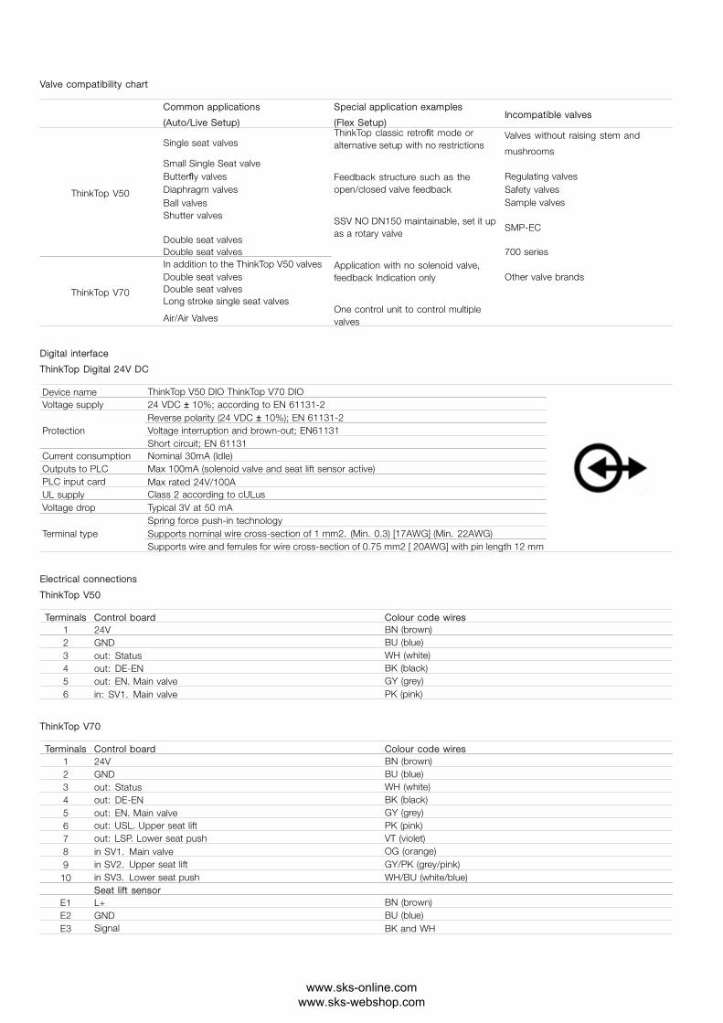
Valve compatibility chart
Common applications
(Auto/Live Setup)
Special application examples
(Flex Setup)Incompatible valves
Single seat valvesValves without raising stem and
mushroomsSmall Single Seat valveButterfly valves Regulating valvesDiaphragm valves Safety valvesBall valves Sample valvesShutter valves
SMP-ECDouble seat valves
ThinkTop V50
Double seat valves 700 seriesIn addition to the ThinkTop V50 valvesDouble seat valves Other valve brandsDouble seat valvesLong stroke single seat valves
ThinkTop V70
Air/Air Valves
ThinkTop classic retrofit mode oralternative setup with no restrictions
Feedback structure such as theopen/closed valve feedback
SSV NO DN150 maintainable, set it upas a rotary valve
Application with no solenoid valve,feedback Indication only
One control unit to control multiplevalves
Digital interface
ThinkTop Digital 24V DC
Device name ThinkTop V50 DIO ThinkTop V70 DIOVoltage supply 24 VDC ± 10%; according to EN 61131-2
Reverse polarity (24 VDC ± 10%); EN 61131-2Voltage interruption and brown-out; EN61131ProtectionShort circuit; EN 61131
Current consumption Nominal 30mA (Idle)Outputs to PLC Max 100mA (solenoid valve and seat lift sensor active)PLC input card Max rated 24V/100AUL supply Class 2 according to cULusVoltage drop Typical 3V at 50 mA
Spring force push-in technologySupports nominal wire cross-section of 1 mm2. (Min. 0.3) [17AWG] (Min. 22AWG)Terminal typeSupports wire and ferrules for wire cross-section of 0.75 mm2 [ 20AWG] with pin length 12 mm
Electrical connections
ThinkTop V50
Terminals Control board Colour code wires1 24V BN (brown)2 GND BU (blue)3 out: Status WH (white)4 out: DE-EN BK (black)5 out: EN. Main valve GY (grey)6 in: SV1. Main valve PK (pink)
ThinkTop V70
Terminals Control board Colour code wires1 24V BN (brown)2 GND BU (blue)3 out: Status WH (white)4 out: DE-EN BK (black)5 out: EN. Main valve GY (grey)6 out: USL. Upper seat lift PK (pink)7 out: LSP. Lower seat push VT (violet)8 in SV1. Main valve OG (orange)9 in SV2. Upper seat lift GY/PK (grey/pink)
10 in SV3. Lower seat push WH/BU (white/blue)Seat lift sensor
E1 L+ BN (brown)E2 GND BU (blue)E3 Signal BK and WH
www.sks-online.com www.sks-webshop.com

ThinkTop V50M12 option (8-pin A-coded plug)Pin numbers and terminal numbers are aligned
.
M12
Chassis
plug connector
Control board
Terminal numbers
Functions
M12 pin numbers with wire colors
per solenoid valve setup
0 x 3/2-way 1 x 3/2-way
1: 24V 1: BN (brown) 1: BN (brown)
2: GND 3: BU (blue) 3: BU (blue)
3: out: Status 2: WH (white) 2: WH (white)
4: out: DE-EN 4: BK (black) 4: BK (black)
5: out: EN. Main valve 5: GY (grey) 5: GY (grey)
6: in SV1. Main valve - 6: PK (pink)
ThinkTop V70M12 option (8-pin A-coded plug)Pin numbers and terminal numbers are aligned
.
M12
Chassis
plug connector
Control board
Terminal numbers
Functions
M12 pin assignment and wire colour
per solenoid valve setup
0 x 3/2-way 1 x 3/2-way 2 x 3/2-way 3 x 3/2-way 1 x 5/2-way
1: 24V 1: BN (brown) 1: BN (brown) 1: BN (brown) 1: BN (brown) 1: BN (brown)
2: GND 3: BU (blue) 3: BU (blue) 3: BU (blue) 3: BU (blue) 3: BU (blue)
3: out: Status 2: WH (white) 2: WH (white) 2: WH (white) 2: WH (white) 2: WH (white)
4: out: DE-EN 4: BK (black) 4: BK (black) 4: BK (black) 4: BK (black) 4: BK (black)
5: out: EN. Main valve 5: GY (grey) 5: GY (grey) 5: GY (grey) 5: GY (grey) 5: GY (grey)
6: out: USL Upper seat lift - 6: PK (pink) 6: PK (pink) - 6: PK (pink)
7: out: LSP. Lower seat push - 7: VT (violet) - - 7: VT (violet)
8: in SV1. Main valve - 8: OG (orange) 8: OG (orange) 8: OG (orange) 8: OG (orange)
9: in SV2. Upper seat lift - - 7: VT (violet) 6: PK (pink) -
10: in SV3. Lower seat push - - - 7: VT (violet) -
.
Cable gland
- Option -
Cable plug
connector
10 wires Length
300 mm
Control board
Terminal numbers
Functions
Cable plug and wire assignment
per solenoid valve setup
0 x 3/2-way 1 x 3/2-way 2 x 3/2-way 3 x 3/2-way 1 x 5/2-way
1: 24V BN (brown) BN (brown) BN (brown) BN (brown) BN (brown)
2: GND BU (blue) BU (blue) BU (blue) BU (blue) BU (blue)
3: out: Status WH (white) WH (white) WH (white) WH (white) WH (white)
4: out: DE-EN BK (black) BK (black) BK (black) BK (black) BK (black)
5: out: EN. Main valve - GY (grey) GY (grey) GY (grey) GY (grey)
6: out: USL Upper seat lift - - PK (pink) PK (pink) -
7: out: LSP. Lower seat push - - - VT (violet) -
8: in SV1. Main valve - OG (orange) OG (orange) OG (orange) OG (orange)
9: in SV2. Upper seat lift - - GY/PK (grey/pink) GY/PK (grey/pink) -
10: in SV3. Lower seat push - - - WH/BU (white/blue) -
www.sks-online.com www.sks-webshop.com
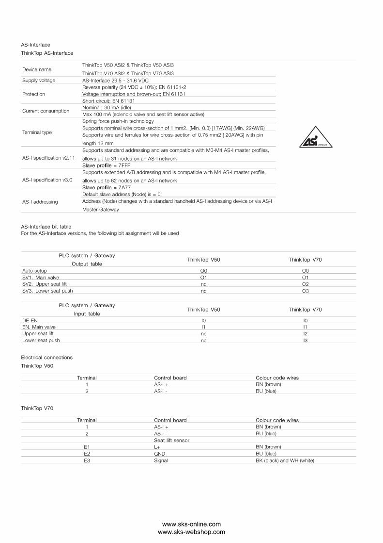
AS-Interface
ThinkTop AS-Interface
Device nameThinkTop V50 ASI2 & ThinkTop V50 ASI3
ThinkTop V70 ASI2 & ThinkTop V70 ASI3Supply voltage AS-Interface 29.5 - 31.6 VDC
Reverse polarity (24 VDC ± 10%); EN 61131-2Voltage interruption and brown-out; EN 61131ProtectionShort circuit; EN 61131Nominal: 30 mA (idle)
Current consumptionMax 100 mA (solenoid valve and seat lift sensor active)Spring force push-in technologySupports nominal wire cross-section of 1 mm2. (Min. 0.3) [17AWG] (Min. 22AWG)
Terminal type Supports wire and ferrules for wire cross-section of 0.75 mm2 [ 20AWG] with pin
length 12 mmSupports standard addressing and are compatible with M0-M4 AS-I master profiles,
allows up to 31 nodes on an AS-I networkAS-I specification v2.11
Slave profile = 7FFFSupports extended A/B addressing and is compatible with M4 AS-I master profile,
allows up to 62 nodes on an AS-I networkAS-I specification v3.0
Slave profile = 7A77Default slave address (Node) is = 0
AS-I addressing Address (Node) changes with a standard handheld AS-I addressing device or via AS-I
Master Gateway
NTERFACE
AS-Interface bit tableFor the AS-Interface versions, the following bit assignment will be used
.
PLC system / Gateway
Output tableThinkTop V50 ThinkTop V70
Auto setup O0 O0SV1. Main valve O1 O1SV2. Upper seat lift nc O2SV3. Lower seat push nc O3
PLC system / Gateway
Input tableThinkTop V50 ThinkTop V70
DE-EN I0 I0EN. Main valve I1 I1Upper seat lift nc I2Lower seat push nc I3
Electrical connections
ThinkTop V50
Terminal Control board Colour code wires1 AS-i + BN (brown)2 AS-i - BU (blue)
ThinkTop V70
Terminal Control board Colour code wires1 AS-i + BN (brown)2 AS-i - BU (blue)
Seat lift sensorE1 L+ BN (brown)E2 GND BU (blue)E3 Signal BK (black) and WH (white)
www.sks-online.com www.sks-webshop.com

ThinkTop V50
M12 option (4-pin A-coded plug)Pin numbers and terminal numbers are aligned
M12
Chassis
plug
connector
Control board
Terminal numbers
Functions
M12 pin assignment and wire colour
per solenoid valve setup
0 x 3/2-way 1 x 3/2-way1: AS-i + 1: BN (brown) 1: BN (brown)2: nc _ _3: AS-i - 3: BU (blue) 3: BU (blue)4: nc _ _
ThinkTop V70
M12 option (4-pin A-coded plug)Pin numbers and terminal numbers are aligned
M12
Chassis
plug
connector
Control board
Terminal numbers
Functions
M12 pin assignment and wire colour
per solenoid valve setup
0 x 3/2-way 1 x 3/2-way 2 x 3/2-way 2 x 3/2-way 1 x 5/2-way1: AS-i + 1: BN (brown) 1: BN (brown) 1: BN (brown) 1: BN (brown) 1: BN (brown)2: nc _ _ _ _ _3: AS-i - 3: BU (blue) 3: BU (blue) 3: BU (blue) 3: BU (blue) 3: BU (blue)4: nc _ _ _ _ _
.
Alfa Laval reserves the right to change specifications without prior notification.
How to contact Alfa LavalContact details for all countriesare continually updated on our website.Please visit www.alfalaval.com toaccess the information direct.
Alfa
Lav
al is
a tr
adem
ark
regi
ster
ed a
nd o
wne
d by
Alfa
Lav
al C
orpo
rate
AB.
en
051
9
www.sks-online.com www.sks-webshop.com