Hkkjr ljdkj jsy ea=ky; - RDSO
26
Page No.1 of 25 Effective from ….02.2020 SPECIFICATION No. TI/SPC/OHE/CW(Cu-Ag)/ 0130 (02/2020) Hkkjr ljdkj jsy ea=ky; GOVERNMENT OF INDIA MINISTRY OF RAILWAYS TECHNICAL SPECIFICATION FOR CONTINUOUS CAST SILVER BEARING COPPER RODS and 107 mm² SILVER BEARING GROOVED COPPER CONTACT WIRE FOR ELECTRIC TRACTION (DRAWN OUT OF CONTINUOUS CAST SILVER BEARING COPPER RODS) February’ 2020 Issued by RESEARCH DESIGNS & STANDARDS ORGANISATION MANAK NAGAR, LUCKNOW (INDIA) -226011 (For official use only)
-
Upload
khangminh22 -
Category
Documents
-
view
0 -
download
0
Transcript of Hkkjr ljdkj jsy ea=ky; - RDSO

Page No.1 of 25 Effective from ….02.2020
SPECIFICATION No. TI/SPC/OHE/CW(Cu-Ag)/ 0130 (02/2020)
Hkkjr ljdkj
jsy ea=ky;
GOVERNMENT OF INDIA MINISTRY OF RAILWAYS
TECHNICAL SPECIFICATION FOR CONTINUOUS CAST SILVER BEARING COPPER RODS and 107 mm²
SILVER BEARING GROOVED COPPER CONTACT WIRE
FOR ELECTRIC TRACTION
(DRAWN OUT OF CONTINUOUS CAST SILVER BEARING COPPER RODS)
February’ 2020
Issued by
RESEARCH DESIGNS & STANDARDS ORGANISATION
MANAK NAGAR, LUCKNOW (INDIA) -226011
(For official use only)

Page No.2 of 25 Effective from ….02.2020
SPECIFICATION No. TI/SPC/OHE/CW(Cu-Ag)/ 0130 (02/2020)
S.N. HEADING PAGE No.
1 SCOPE 4
2 GOVERNING SPECIFICATION 4
3 ENVIRONMENTAL CONDITIONS 5
4 MATERIAL 5-6
5 PHYSICAL CONSTANTS OF SILVER BEARING
COPPER CONTACT WIRE
6-7
6 SIZES, SHAPES, DIMENSIONS, WEIGHTS & OTHER PROPERTIES OF CONTACT WIRE
7 – 8
7 TEST 8 - 9
8 TEST ON CCSB COPPER WIRE ROD 9-12
9 TEST ON CONTACT WIRE 12-13
10 TESTS METHOD 13-16
11 PACKING & MARKING 16-18
12 DISPOSAL OF REJECTED CONTACT WIRE 19
13 MULTIPLIER CONSTANT FOR HARD DRAWN
SILVER BEARING COPPER WIRE
19-20
14 SCHEDULE OF GUARANTEED TECHNICAL
PARTICULARS
21-22
15 Figure 1, CONFIGURATION OF CONTACT WIRE 23
16 Figure 2, SPECIAL CALIPER FOR CHECKING
CONTACT WIRE 24
17 Figure 1, JAWS FOR BENDING TESTS 25

Page No.3 of 25 Effective from ….02.2020
SPECIFICATION No. TI/SPC/OHE/CW(Cu-Ag)/ 0130 (02/2020)
SPECIFICATION NO.TI/SPC/OHE/CW (Cu-Ag)/0130(02/2020)
Amendment Number
Date of Amendment
Total pages including annexure
Amendment/Revision
0 NA 26 First issue
PREPARED BY CHECKED BY APPROVED BY
SIGNATURE
DATE
DESIGNATION SSE Director(TI) EDTI
COPY NUMBER
ISSUED BY ……………. SIGNATURE…….. DATE……………
ISSUED TO ……………………………………………………………… ………………………………………………………………
NOTE: This specification is property of RDSO. No reproduction shall be
done without permission from DG (TI), RDSO. This specification is
not for general use.

Page No.4 of 25 Effective from ….02.2020
SPECIFICATION No. TI/SPC/OHE/CW(Cu-Ag)/ 0130 (02/2020)
SPECIFICATION FOR SILVER BEARING GROOVED COPPER
CONTACT WIRE FOR ELECTRIC TRACTION
(DRAWN OUT OF CCSBC RODS)
1.0 SCOPE
1.1 This Specification covers the requirement of Silver Bearing Copper
Contact Wire manufactured from Continuous Cast Silver Bearing
Copper (CCSBC) Wire Rods for Electric Traction overhead lines.
2.0 GOVERNING SPECIFICATIONS
2.1 In the preparation of this specification assistance has been taken from the following standards and specifications.
2.1.1 IS: 191-2007 Specification for Copper.
2.1.2 IS: 1778-1980 Specification for Reels and drums for bare conductors.
2.1.3 IS: 1885
(Pt.xxxii)-1993
Electro-technical Vocabulary (Electric
cables)
2.1.4 IS: 9713-1983 Specification for Hot Rolled Electrolytic
Copper Wire Rods for Electrical
Conductors.
2.1.5 IS: 440-1964 Methods of chemical analysis of Copper.
2.1.6 IS: 1608-1995 Mechanical Testing of metals
2.1.7 BS EN
50149:2012
Specification for Copper & Copper alloy
grooved Contact Wires.
2.1.8 ASTM B49-09 Standard specification for copper rod
drawing stock for electrical purposes.
2.1.9 ASTM B47-94a
(Re-approved 2007)
Standard specification for copper trolley
wire.
2.1.10 IS: 3476-1986 Specification for trolley & Contact Wire
for Electric Traction.
2.1.11 EN:1977 Copper and Copper Alloys Copper Drawing Stock (Wire Rod)
2.1.12 NEMA WC 26-
2008
Binational Wire and Cable Packaging
Standard.
2.2 In case of any conflict or disparity between the contents of the above
specification and this specification, the latter shall prevail.
2.3 Any deviation from this specification proposed by the manufacturer to
improve upon the performance of Contact Wire shall be considered
only on its merits provided full particulars with justification and
financial implication are furnished by the manufacturer.

Page No.5 of 25 Effective from ….02.2020
SPECIFICATION No. TI/SPC/OHE/CW(Cu-Ag)/ 0130 (02/2020)
3.0 ENVIRONMENTAL CONDITIONS
3.1 The conductor shall be suitable for outdoor use in moist tropical
climate and in areas subject to heavy rainfall, polluted due to industry
and marine atmosphere and severe lightning. The limiting weather
conditions which the conductor has to withstand in service are
indicated in TABLE – 1.
TABLE – 1
ENVIRONMENTAL CONDITIONS
SN Environmental condition Limits
i. Ambient air Temperature. 00 C to +500 C
ii. Maximum temperature of metallic object under sun.
700 C
iii. Minimum temperature. -100 C
iv. Maximum relative humidity 100%
v. Annual Rainfall 1750 mm to 6250 mm.
vi. Maximum number of thunder storm days per annum.
85
vii. Maximum number of dust
storm days per annum.
35
viii. Number of rainy days per annum
120
ix. Basic wind pressure 200 kgf/m2
x. Altitude Altitude: 1000 m above mean sea
level. Altitude: 2000m in J& K area.
4.0 MATERIAL
4.1 The Silver Bearing Copper Contact Wire shall be drawn out of indigenous or imported CCSBC Rods manufactured by any of the
following processes:
(a) Continuous Cast & Rolled (CCR) Process
(b) Vertical upward continuous casting process
Diameter of the rod so obtained, shall be as given in Table-3.
Copper used, should be Electrolytic grade Copper cathodes conforming to the requirement of LME Grade `A’ copper as listed in the London
Metal Exchange.
The chemical composition of the Continuous Cast Sliver Bearing Copper (CCSBC) Rod shall be as given in Table-2.
The manufacturer of CCSBC Wire Rod which is used in the manufacture of prototype Contact Wire will be treated as approved
vendor for CCSBC Wire Rod once the prototype Contact Wire
manufactured by this CCSBC Wire Rod is approved.

Page No.6 of 25 Effective from ….02.2020
SPECIFICATION No. TI/SPC/OHE/CW(Cu-Ag)/ 0130 (02/2020)
TABLE – 2
CHEMICAL COMPOSITION OF CCSBC ROD
Element %ppm
Cu Rest
Ag 0.08 to 0.12%
Bi < 5 ppm
Oxygen < 400 ppm
Other elements 0.03%
5.0 PHYSICAL CONSTANTS OF SILVER BEARING COPPER CONTACT WIRE
5.1 SILVER BEARING COPPER
5.1.1 VOLUME RESISTIVITY
The resistivity of Silver Bearing Copper Contact Wire is a function of the tensile strength. Within a range of 30 – 50 kg/mm2 tensile
strength, the following formula has been found to express sufficiently
closely the results obtained in practice and been adopted in calculating the resistance specified in IS : 3476-1986
P= T/16
Where P= Percentage increase in resistivity of the hard drawn
copper over its resistivity when annealed and
T = Tensile strength of the hard drawn silver bearing copper in kg/mm2.
5.1.1.1 The resistances given in the TABLE–3 are based on standard resistivity of annealed Silver Bearing Copper at 20°C modified in
accordance with the above formula.
5.1.1.2 At a temperature of 20°C the volume resistivity of standard annealed Silver Bearing Copper is 1/58 = 0.017241 ohm mm2/m.
5.1.1.3 Silver Bearing Copper which has a resistivity at 20°C of 1/58 =
0.017241 ohm mm2/m is said to have a conductivity of 100%.
5.1.2 DENSITY
At a temperature of 20°C the density of Silver Bearing Copper has
been taken as 8.89 g/cm3.
Page No.7 of 25 Effective from ….02.2020
SPECIFICATION No. TI/SPC/OHE/CW(Cu-Ag)/ 0130 (02/2020)
5.1.3 CO-EFFICIENT OF LINEAR EXPANSION
At a temperature of 20°C the co-efficient of linear expansion of Silver
Bearing Copper has been taken as 0.000017/ °C. This co-efficient may
be used over a temperature range from 0°C to 150°C.
5.1.4 CONSTANT MASS TEMPERATURE CO-EFFICIENT OF RESISTANCE
At a temperature of 20°C, the co-efficient of variation of the
resistance with temperature of Silver Bearing Copper, measured
between two potential points rigidly fixed to the wire, the metal being
allowed to expand freely, has been taken as 0.00381/k as per BS EN-50149:2012.
6.0 SIZES, SHAPES, DIMENSIONS, WEIGHTS AND OTHER PROPERTIES OF CONTACT WIRE
6.1 The size, shape and dimension for the Contact Wire shall be as indicated in Figure – 1 & 2.
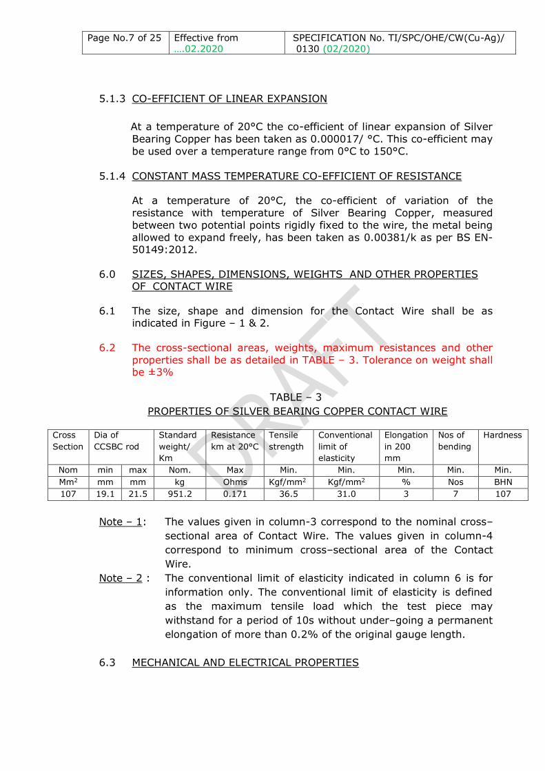
6.2 The cross-sectional areas, weights, maximum resistances and other
properties shall be as detailed in TABLE – 3. Tolerance on weight shall be ±3%
TABLE – 3
PROPERTIES OF SILVER BEARING COPPER CONTACT WIRE
Cross
Section
Dia of
CCSBC rod
Standard
weight/
Km
Resistance
km at 20°C
Tensile
strength
Conventional
limit of
elasticity
Elongation
in 200
mm
Nos of
bending
Hardness
Nom min max Nom. Max Min. Min. Min. Min. Min.
Mm2 mm mm kg Ohms Kgf/mm2 Kgf/mm2 % Nos BHN
107 19.1 21.5 951.2 0.171 36.5 31.0 3 7 107
Note – 1: The values given in column-3 correspond to the nominal cross–
sectional area of Contact Wire. The values given in column-4
correspond to minimum cross–sectional area of the Contact
Wire.
Note – 2 : The conventional limit of elasticity indicated in column 6 is for
information only. The conventional limit of elasticity is defined
as the maximum tensile load which the test piece may
withstand for a period of 10s without under–going a permanent
elongation of more than 0.2% of the original gauge length.
6.3 MECHANICAL AND ELECTRICAL PROPERTIES

Page No.8 of 25 Effective from ….02.2020
SPECIFICATION No. TI/SPC/OHE/CW(Cu-Ag)/ 0130 (02/2020)
6.3.1 The tensile strength, elongation and hardness when tested in
accordance with Clauses 10.7,10.8 & 10.10 respectively, shall not be
less than the appropriate values given in TABLE-3. The Contact Wire shall also comply with the requirements of the bending test specified
in Clause 10.9.
6.3.2 The Electrical Resistance per Kilo meter of the sample, multiplied by
the appropriate constant in TABLE-5 and corrected for the cross-
sectional area, shall not exceed the values given in TABLE-3.
6.4 JOINTS
There shall be no joints in Contact Wire made out of CCSBC Rods.
6.5 FREEDOM FROM DEFECTS
6.5.1 The Contact Wire shall be clean, smooth and free from harmful
defects, such as scales, peelings, sharp edges and defects in the
groove.
6.5.2 The groove shall be uniform and free from twists. Any defect in the
groove noticed at the time of or subsequent to erection of the Contact
Wire shall entail heavy penalty on the manufacturer. To check on this, suitable means shall be employed by the manufacturer by way of
provision of a mirror or other suitable means and monitor during the
drawing out of the Contact Wire.
6.6 The wire drawing of Contact Wire shall be done by 5 or 6 stage wire
drawing machine.
7.0 TESTS
7.1 After a purchase order is placed for supply of wire for overhead Railway Traction, the internal test results for all the tests specified in
clauses-8.1 & 9.1 shall be furnished by the successful manufacturer to
the Director General (TI)/RDSO within the period stipulated for prototype approval in the order
7.2 Any changes required to be done in the prototype as required by the Director General (TI)/RDSO shall be carried out expeditiously by the
manufacturer.
7.3 Type-Testing Schedule:- Prior to giving a call to the Director General (TI)/RDSO for inspection and testing of the prototype, the
manufacturer shall submit a detailed test schedule consisting of
schematic circuit diagrams/layout for each of the tests and the number of days required to complete all the tests at one stretch. Once
the schedule is approved, the test shall invariably be done
accordingly. However during the process of type testing or even later, the purchaser reserves the right to conduct any additional test(s)
besides those specified herein, on Wire Rod/Contact Wire so as to test

Page No.9 of 25 Effective from ….02.2020
SPECIFICATION No. TI/SPC/OHE/CW(Cu-Ag)/ 0130 (02/2020)
Wire Rod/Contact Wire to his satisfaction or for gaining additional
information and knowledge. In case any dispute or disagreement
arises between the manufacturer and representative of the Director General (TI)/RDSO during the process of testing as regards the
procedure for type tests and/or the interpretation and acceptability of
the results of type test, it shall be brought to the notice of the Director General (TI)/RDSO, whose decision shall be final and binding.
7.4 All the tests specified, unless otherwise mentioned elsewhere, in the
specification shall be carried out at the manufacturer works. The manufacturer shall arrange all the necessary machinery, apparatus,
labour and assistance required for conducting the tests without any
extra cost.
7.5 In the event of the tests not being carried through to completion at
one stretch for any reasons attributable to the manufacturer and it is required for the representative of the Director General (TI)/RDSO to
go again or more number of times to the works of the manufacturer or
other place(s) for continuing and/or completing the tests on the
prototype(s) of the conductor, the manufacturer shall reimburse to the Director General (TI)/RDSO the cost for the representative’s visits to
works or other place(s) for the tests more than once. The costs as
claimed by the Director General (Traction Installation), Research Designs & Standards Organisation, Lucknow shall be paid through a
demand draft as advised to the manufacturer.
7.6 BULK MANUFACTURE
Only after clear written approval of the results of the tests on the prototype is communicated by the Director General (TI)/RDSO to the
manufacturer, manufacturer shall take up bulk manufacture of the
Contact Wire which shall be strictly with the same material and
process as adopted for the prototype.
7.7 TECHNICAL DATA
The manufacturer shall furnish along with the offer the guaranteed
performance data and other technical particulars of the Contact Wire
as per para 13.0 of the specification. The guaranteed values shall have to be proved by test.
8.0 TESTS ON CCSBC RODS
8.1 TYPE TESTS
8.1.1 The following type tests shall be carried out on three samples of the CCSBC rods taken in accordance with IS : 191-2007 or latest.
i) Visual Examination ii) Measurement of dimensions
iii) Compression Test

Page No.10 of 25
Effective from ….02.2020
SPECIFICATION No. TI/SPC/OHE/CW(Cu-Ag)/ 0130 (02/2020)
iv) Tensile strength/elongation Test
v) Chemical composition
vi) Micro-structure examination vii) Ultrasonic testing at the time of wire drawing
viii) Electrical Resistivity Test
8.2 ACCEPTANCE TESTS
8.2.1 “CUSTOMER HOLD POINT(CHP)”
The manufacturer shall include in his quality assurance plan (QAP) a
CHP stage beyond which the manufacturing process shall proceed only
after CCSBC rods pass the acceptance test duly verified by the Designated Authority in accordance with Clause No.8.2.2.
The QAP shall have the approval of the Director General (TI), RDSO before taking up the manufacture.
8.2.2 The following tests shall be carried out on the samples of CCSBC rods
drawn in accordance with IS: 9713-1983 (for the purpose of sampling only).
i) Visual Examination ii) Measurement of dimensions
iii) Compression Test
iv) Tensile strength/elongation Test
v) Chemical Composition vi) Micro-structure Examination
vii) Electrical resistivity test
8.3 MANUFACTURER’S TESTS
8.3.1 The manufacturer shall test all the CCSBC rods for visual examination and measurement of dimensions. All the wire rods shall be free from
any piping, crow feet, indentation, foreign particles or inclusions,
surface defects, twists and entanglements.
8.3.2 The manufacturer shall test every lot of CCSBC rods for
tensile/elongation and compression. These tests shall be carried out
on the samples of wire rods drawn in accordance with IS : 9713-1983. A lot shall be as stipulated in IS : 9713-1983.
8.3.3 The manufacturer shall test every lot of CCSBC rods for chemical composition and micro-structure examination. The samples will be
drawn in accordance with IS :191-2007.
8.3.4 Records of the results of the tests shall be maintained by the manufacturer and checked by the Inspector.
8.4 CRITERIA FOR ACCEPTANCE

Page No.11 of 25
Effective from ….02.2020
SPECIFICATION No. TI/SPC/OHE/CW(Cu-Ag)/ 0130 (02/2020)
8.4.1 Criteria for acceptance of the lot shall be in accordance with Clause-9
of IS : 9713-1983.
8.5 METHODS OF TESTS
8.5.1 VISUAL EXAMINATION
The surface of CCSBC Rod shall be fairly smooth, free from inclusions
or foreign particles, indentation, surface defects, scales, twists,
entanglements etc.
8.5.2 MEASUREMENT OF DIMENSIONS
Discard approximately 2.5 meter length from the end of the coil.
Three measurements at 60° angular displacement shall be made
around the circumference at two places 4 meter apart. An average of six readings shall be considered as the diameter of the CCC wire rod.
The diameter shall be as specified in table-3.
8.5.3 COMPRESSION TEST
A sample of length twice the diameter of the CCSBC rod shall be cut
from the coil and then compressed till its length becomes half the original length. Curved surface, after test, shall not show any crack or
defect on visual check.
8.5.4 TENSILE STRENGTH/ELONGATION TEST
When tested in accordance with IS: 1608–1995 or latest “Mechanical
Testing of Metals” for tensile strength and elongation, the material shall have a tensile strength of 20.4 kgf/mm2 (min.) and a minimum
of 46% elongation. But the gauge length of the sample for this test
shall be of 250 mm.
8.5.5 CHEMICAL COMPOSITION
The material shall have the chemical composition as given in Table-2. The trace elements shall be determined by Spectrometric method. The
copper shall be determined in accordance with IS: 440-1964 or
Spectrometer. Oxygen content, may be determined by oxygen analyzer or Spectrometer. However, Inspection authority may send
the samples to Government Approved Laboratory for verification of
oxygen content.
8.5.6 MICRO-STRUCTURE EXAMINATION
The sample of CCSBC Rod cut along transverse section polished and etched shall show equiaxed re-crystallised fine grains having grain
size finer than ASTM-5. The presence of cast columnar grains in the
micro-structure shall not be permitted.

Page No.12 of 25
Effective from ….02.2020
SPECIFICATION No. TI/SPC/OHE/CW(Cu-Ag)/ 0130 (02/2020)
8.5.7 ELECTRICAL RESISTIVITY TEST
Electrical Resistivity of CCSBC rod shall be determined in accordance
with IS 613-2000 or latest. Resistivity shall not be greater than 0.01737 ohm mm2/m at 200C.
8.5.8 ULTRASONIC TEST
The CCSBC Rod shall be ultrasonically tested by the manufacturer
continuously during production of Contact Wire for the entire length.
The defect if any, observed shall require that complete rod to be discarded. Records shall be maintained for the purpose and produced
before the inspector on demand. The Contact Wire drawing machine
should stop automatically if any defect is observed during ultrasonic testing
8.5.9 PROOF OF PURCHASE OF CCSBC ROD
Supplier shall be required to submit following documents at the time
of Routine Inspection which shall be part of Inspection Certificate.
8.5.9.1 Proof of purchase(Invoice) of CCSBC Rod from the approved
Vender.
8.5.9.2 For imported CCSBC Rod the Supplier shall submit proof of import i.e.
i) Bill of Entry.
ii) Bill of Lading/Air way bill.
iii) Payment details to overseas CCSBC Rod manufacturer. iv) Declaration that he has and will not use these Documents for
any other consignment or purpose.
8.5.9.3 Procurement of CCSBC rod from indigenous manufacturer is
preferable.
8.5.9.4 Procurement of CCSBC rod from any distributor/trader/channel partner of manufacturer is not permitted to ensure quality of
material.
9.0 TESTS ON CONTACT WIRE
9.1 TYPE TESTS
The CCSBC rods shall be drawn into the prototype Contact Wire in
presence of the Inspector. The following tests shall be carried out on the samples cut at random from the Contact Wire coil produced. Each
test shall be conducted on three samples.
9.1.1 Visual examination.
9.1.2 Verification of dimensions.
9.1.3 Measurement of weight.
9.1.4 Electrical resistance test.

Page No.13 of 25
Effective from ….02.2020
SPECIFICATION No. TI/SPC/OHE/CW(Cu-Ag)/ 0130 (02/2020)
9.1.5 Hardness test.
9.1.6 Tensile test.
9.1.7 Elongation test.
9.1.8 Bending test.
9.1.9 Chemical analysis.
9.1.10 Micro-structure examination.
9.1.11 Ultrasonic testing of Contact wire
9.2 ACCEPTANCE TESTS
Same as type tests except that indicated in Clause 9.1.11. In addition weighment of 3 or 1/5th of offered Contact Wire drums for acceptance
tests, whichever is higher, for gross weight. The Inspector shall verify
the results of manufacturer’s tests.
9.3 ROUTINE TESTS
9.3.1 Visual examination. 9.3.2 Verification of dimensions.
9.3.3 Measurement of weight.
9.3.4 Tensile test. 9.3.5 Elongation test.
9.3.6 Bending test.
9.3.7 Oxygen Content
9.4 MANUFACTURER’S TESTS
9.4.1 The manufacturer shall test every lot of CCSBC rod for chemical composition. A lot shall be as stipulated in IS : 9713-1983. The results
shall be checked by the Inspector.
9.4.2 Every CCSBC Rod shall be thoroughly inspected for blow holes, pipes, oxide-inclusions and other defects before drawing. In case of defects
Contact Wire shall be rejected.
9.4.3 The manufacture shall weigh every drum of the Contact Wires for tare
weight and gross weight. Records of the results of weighment shall be
checked by the Inspector at the time of Acceptance Tests.
10.0 TEST METHODS
10.1 MICRO-STRUCTURE EXAMINATION OF CONTACT WIRE
A sample of the finished Contact Wire shall be transversely sectioned,
polished and etched and it shall show equiaxed re-crystallised fine grain structure to ASTM No.7 or finer. Presence of cast columnar
grains or dentritic structure representing improper breakdown of the
original structure will not be permitted.

Page No.14 of 25
Effective from ….02.2020
SPECIFICATION No. TI/SPC/OHE/CW(Cu-Ag)/ 0130 (02/2020)
10.2 CHEMICAL ANALYSIS
The samples taken from the Contact Wire shall be tested for chemical composition in accordance with Clause 8.5.5 of this specification.
10.3 VISUAL EXAMINATION
The surface finish of the grooved Contact Wire shall be checked for
defects, such as chips, scales, sharp edges, bubbles, peelings,
scratches, pin holes. The Contact Wire shall have no twists or kinks.
10.4 VERIFICATION OF DIMENSIONS
10.4.1 The diameter of the grooved Contact Wire shall be measured by
means of a ratchet micrometer or a dial micrometer between two
circular flat studs having a diameter of not less than 5 mm. The value of the diameter shall be the mean of two readings made in two
directions perpendicular to each other and situated approximately at
the same cross section.
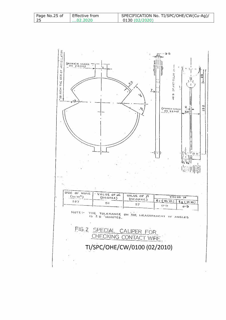
10.4.2 CHECKING OF DIMENSIONS AT THE BOTTOM OF THE GROOVE
The dimensions at the bottom of the groove in the Contact Wire shall be measured by means of either a special caliper made in accordance
with Fig.2 or by shadowgraph projection of not less than 10X. The
method shall be subject to agreement between the purchaser and the
manufacturer.
10.5 MEASUREMENT OF WEIGHT
The weight of the Contact Wire, per km shall be calculated by
weighing a piece of 50 cm length by a balance of accuracy of ±1gm,
by a digital balance.
10.6 TENSILE TEST
A sample of Contact Wire which is straight and of length such that when it is held in the jaws of the Tensile Testing Machine the distance
between the jaws is not less than 250mm shall be taken. A gauge
length of 200mm shall be marked on the test piece for the purpose of measuring the elongation. The load shall be applied gradually until the
test piece breaks. The tensile strength of the Contact Wire shall be not
less than values specified in TABLE-3.
10.7 ELONGATION TEST
The elongation shall be measured on the same test piece which was subjected to tensile test upto its fracture as specified in Clause- 10.7.
The elongation of the sample after tensile test shall be measured with
reference to the gauge length after the fractured ends have been fitted together provided fracture occurs within the gauge length. The

Page No.15 of 25
Effective from ….02.2020
SPECIFICATION No. TI/SPC/OHE/CW(Cu-Ag)/ 0130 (02/2020)
values of percent elongation measured shall be not less than the
values specified in TABLE-3. If the fracture occurs out side the gauge
length and the required elongation is not achieved, another sample shall be tested. If this sample also fails, the lot shall be rejected.
10.8 BENDING TEST
The test consists of bending by hand/machine, a straight length of
200 mm long Contact Wire through 90° and back, alternately on
either side of the vertical with the axis of the straight and bent portions of the Contact Wire remaining in the same plane. The test
piece shall be held in blocks of the type shown in Fig.3 having a radius
of 30 mm. A tube whose inside diameter is slightly higher than the diameter of the Contact Wire and one end of which is closed shall be
put over the contact wire, the lower end of the tube being about 20
mm above the surface of the blocks. The first bending operation shall be carried out in a direction such that the top lobe of the wire is in
tension. One bend shall be construed as including all operation
between two consecutive passages of the test piece through the
vertical position. During each bending operations the entire length of the Contact Wire and in particular the length adjacent to the clamping
plane shall touch the face of the block on the side to which the
Contact Wire is bent. There shall not be any twisting of the wire during bending. There shall not be more than one bending operation
per second. The test piece shall withstand the appropriate number of
bends indicated in TABLE-3 without fracture.
10.9 HARDNESS TEST
Hardness of sample of Contact Wire shall be determined on Brinell Scale with 2.5 mm dia. balls and load of 62.5 kg. in accordance with
IS: 1500 –1983. The hardness shall be measured at mid radius of the
cross section of Contact Wire and average of 3 such values shall be considered for qualifying purpose.
10.10 ELECTRICAL RESISTANCE TEST
The electrical resistance of three samples shall be measured by means
of a double Kelvin Bridge. The current terminals shall be sufficiently
away from the voltage terminals. The electrical resistance of test
sample multiplied by W x C/K shall not exceed the appropriate values
indicated in TABLE-3.
Where
W = weight per km of test sample in kg
K = standard weight of Contact Wire per km in kg
C = multiplying constant for temperature variation indicated in
TABLE-5.

Page No.16 of 25
Effective from ….02.2020
SPECIFICATION No. TI/SPC/OHE/CW(Cu-Ag)/ 0130 (02/2020)
Note : The Inspector shall check the accuracy and calibration of the
measuring equipment by resistance of known value.
10.11 The contact wire shall be shall be ultrasonically tested by the
manufacturer continuously during production for the entire length. The
defect if any, observed shall require that entire tension length of Contact wire to be discarded. Records shall be maintained for the
purpose and produced before the inspector on demand. The Contact
Wire drawing machine should stop automatically if any defect is
observed during ultrasonic testing
10.12 SELECTION OF SAMPLE FOR TESTS & CRITERIA OF APPROVAL
10.13.1 BATCHES
10.13.2 The Contact Wire shall be offered for inspection in a batch of 6
drums at a time.
10.13.3 One sample of Contact Wire shall be cut from each drum in the presence of the Inspector for the tests. No treatment shall be given
to any sample before tests except that it may be straightened, if
necessary.
10.13.4 Three samples of Contact Wire shall be subjected to acceptance
tests as given below :
10.12.4.1 Visual examination.
10.12.4.2 Verification of dimensions.
10.12.4.3 Measurement of weight 10.12.4.4 Electrical resistance test.
10.12.4.5 Hardness test.
Thereafter one sample from each drum shall be subjected to the
following tests:
10.12.4.6 Tensile and Elongation Tests. 10.12.4.7 Bending Test.
10.12.4.8 After destruction one of the sample shall be subjected to
the chemical composition test. 10.12.4.9 Acceptance of records maintained for tests in accordance
with 8.5.8 & 10.12 will form a part of the acceptance
tests for the Contact Wire.
10.13.5 Should a sample of Contact Wire fail in any one of the test, a
second sample of the Contact Wire shall be taken from the same
drum from which the sample which had failed was taken. This sample shall be subject to the same test in which the first sample
had failed. If the second sample passes the test the batch shall be
deemed to have complied with the requirement of this clause.

Page No.17 of 25
Effective from ….02.2020
SPECIFICATION No. TI/SPC/OHE/CW(Cu-Ag)/ 0130 (02/2020)
Should failure occur in more than one test, the batch shall be
deemed to be rejected.
11.0 PACKING AND MARKING
11.1 PACKING OF CCSBC RODS
The material shall be supplied in coils strapped with loops or as
required by the Purchaser.
11.2 MARKING OF CCSBC ROD COILS
On the coil suitable tags with markings made on them shall be provided with each coil and shall carry the following information.
i Name and trade mark of manufacturer ii Size of wire rod, weight and length of coil
iii Lot number
iv Date of manufacture
v Purchase order number and name of consignee: vi Date of inspection and inspecting authority
vii Written submission of declaration from the manufacturer
regarding use of CCSBC Rod with proof of purchase along with relevant documents
viii Any other information required by the purchaser.
11.3 PACKING AND MARKING OF CONTACT WIRE
11.3.1 Type of Drums
11.3.1.1 The contact wire shall be supplied properly wound on either
wooden drums or corrugated steel drums (type of drum required
whether wooden or steel to be specified by the purchaser in his purchase order) in specified weights as required by the purchaser,
the turns of the wire being close and continuous without any
overriding except on the first and last turns of each layer.
11.3.1.2 A drum shall carry only one continuous length of contact wire. 11.3.1.3 In order to avoid any damage to Contact Wire, corrugated paper
sheet of min. 3.00 mm thickness shall be provided on the outer
diameter of barrel & at the top layer of Contact wire, after winding of entire length has been completed.
11.3.1.4 Inner side of flanges shall also be provided with corrugated paper
sheet of Min. 3.00 mm thickness pasted/tied to flange. 11.3.1.5 Top surface of finished drum shall also be provided with plastic
sheet for additional protection. On top of plastic sheet, additional
corrugated paper sheet to be provided for enhanced protection to
Copper Conductor before final packing. 11.3.1.6 Any damage in the Contact Wire shall be to supplier’s account.
11.3.2 The Contact Wire shall be so wound on the drum that the top (smaller) lobe of the Contact Wire is on the top. The manufacturer

Page No.18 of 25
Effective from ….02.2020
SPECIFICATION No. TI/SPC/OHE/CW(Cu-Ag)/ 0130 (02/2020)
shall ensure that the top and the bottom lobes of the Contact Wire
are not disturbed during winding on the drum and the Contact Wire
is not twisted to change the orientation of the top lobe on the drum.
11.3.3 The length of the Contact Wire for each drum shall be specified by
the purchaser. The specified length shall not be more than 2000m.
11.3.4 The length of the Contact Wire in a drum, after the test pieces
required for the various tests have been cut and taken out shall be
not less than values specified by the purchaser.
11.3.5 The wooden drum shall comply with IS: 1778-1980 “Specification for
Reels and Drums for bare conductors” and shall have the dimensions as indicated in TABLE-4.
TABLE – 4
DRUM DIMENSION FOR DIFFERENT SIZE OF CONTACT WIRE
Size of Contact Wire (mm2)
Length of* Contact Wire (m)
Flange** dia(mm)
Barrel dia (mm)
Traverse (mm)
Remarks
107 1600 1530 1200 600
107 2000 1575 1200 600
*These are higher limits which may not exceed by more than 50m.
** Flange diameter subject to a maximum of 1900mm.
11.3.6 Corrugated Steel drums shall be of maximum capacity 3570 Kg as
per Table 2.2 type RM of NEMA WC 26-2008. Size of the selected drum for 107 mm2 (HDGSBC) Contact Wire is as per table below:
Flange Barrel Dia Traverse
72 inch 48 inch 36 inch
1828.8 mm 1219.2 mm 914.4 mm
11.3.7 Gross Wight of Steel Drum specified in Para 11.3.6 above, after
winding contact wire shall be limited to 2800 kg.
11.3.8 Each drum of Contact Wire shall be provided with two colour bands
alternatively each of red and yellow paint of approximately 75mm
width each, at the top layer of Contact Wire for identification. Top
end of the Contact Wire shall also be provided with lead seal by
inspection authority by making hole from top lobe to bottom in the
Contact Wire, in addition to punch mark provided by the
manufacturer for identification of end. On receipt of Contact Wire

Page No.19 of 25
Effective from ….02.2020
SPECIFICATION No. TI/SPC/OHE/CW(Cu-Ag)/ 0130 (02/2020)
drums the colour bands, sealing at the end of Contact Wire and
punch mark shall be verified by the consignee to ascertain correct
receipt of length of Contact Wire.
11.3.9 The emblem/identification mark of the Contact wire manufacturer
and CCSBC Rod manufacturer with year of manufacture in 3 mm
letter size shall be provided on the top lobe of the Contact Wire on
regular intervals – not less than 40m and not exceeding 50m so as
to facilitate identification. The marking shall be provided in the
format mentioned in Clause 11.3.10 below and shall be such that it
is not detrimental to the strength of the Contact Wire.
11.3.10 The identification mark in format CCC/MMM/YY shall be provided as
mentioned in Clause 11.3.9 above.
Where, First abbreviation i.e CCC shall indicate identification for
manufacture of CCSBC rod Followed by slash
Second abbreviation i.e ‘MMM’ shall indicate identification for
manufacture of Contact wire followed by slash
Third abbreviation i.e ‘YY’ shall indicate year of manufacture for
example 80 for 1980 and 10 for 2010. The abbreviation for
manufacturer shuld be first three alphabets of Vendor name as
indicated in Vendor Directory against each firm.
11.3.11 The following particulars shall be marked in indelible paint on each
drum:
i Purchaser’s order number.
ii Size of Contact Wire.
iii Length of Contact Wire.
iv Gross and net weights.
v Drum number and vi Consignee and other particulars as required by the purchaser.
vii Make, batch no. and month & year of procurement of CCSBC rod.
11.4 DISPOSAL OF REJECTED CONTACT WIRE
Contact Wire which is rejected shall be cut into pieces of length not
greater than 300 m or drawn again into thinner wire. This shall be
done in the presence of the Inspector.
12.0 MULTIPLIER CONSTANT FOR HARD DRAWN SILVER BEARING
COPPER WIRE
TABLE – 5

Page No.20 of 25
Effective from ….02.2020
SPECIFICATION No. TI/SPC/OHE/CW(Cu-Ag)/ 0130 (02/2020)
Multiplying constant and its reciprocal for converting resistance of
copper Contact Wire various temperatures to that at standard
temperature of 20° C and to that and for converting resistance at
20°C to that at any other temperature respectively:
Temperature 0C Multiplier Constant Reciprocal of constant
5.0 1.0606 0.9429
5.5 1.0585 0.9448
6.0 1.0563 0.9467
6.5 1.0542 0.9486
7.0 1.0521 0.9505
7.5 1.0500 0.9524
8.0 1.0479 0.9543
8.5 1.0458 0.9562
9.0 1.0437 0.9581
9.5 1.0417 0.9600
10.0 1.0396 0.9524
10.5 1.0376 0.9638
11.0 1.0355 0.9657
11.5 1.0335 0.9676
12.0 1.0314 0.9695
12.5 1.0294 0.9714
13.0 1.0274 0.9733
13.5 1.0254 0.9752
14.0 1.0234 0.9771
14.5 1.0214 0.9790
15.0 1.0194 0.9810
15.5 1.0174 0.9829
16.0 1.0155 0.9848
16.5 1.0135 0.9867
17.0 1.0116 0.9886
17.5 1.0096 0.9905
18.0 1.0077 0.9924
18.5 1.0057 0.9943
19.0 1.0038 0.9962
19.5 1.0019 0.9981
20.0 1.0000 1.0000
20.5 0.9981 1.0019
21.0 0.9962 1.0038
21.5 0.9943 1.0057
22.0 0.9924 1.0076
22.5 0.9906 1.0095
23.0 0.9887 1.0114
23.5 0.9868 1.0133
24.0 0.9850 1.0152
24.5 0.9831 1.0171
25.0 0.9813 1.0191
25.5 0.9795 1.0210

Page No.21 of 25
Effective from ….02.2020
SPECIFICATION No. TI/SPC/OHE/CW(Cu-Ag)/ 0130 (02/2020)
26.0 0.9777 1.0229
26.5 0.9758 1.0248
27.0 0.9740 1.0267
27.5 0.9722 1.0286
28.0 0.9704 1.0305
28.5 0.9686 1.0324
29.0 0.9668 1.0343
29.5 0.9651 1.0362
30.0 0.9633 1.0381
NOTE – 1: If the resistance of Contact Wire at T°C is measured, the
resistance at 20°C is obtained by multiplying the resistance at
T°C by the multiplying constant against the value of T°C given
in column 2. If the resistance at 20°C is known, the resistance
at T°C is obtained by multiplying the resistance at 20°C by
reciprocal indicated against T°C given in column 3.
NOTE – 2: The temperature co-efficient of resistance of copper varies
slightly from sample to sample according to its conductivity.
The figures given above are based on a co-efficient of 0.00381
per °C at 20° C which is an average value for copper of 97%
conductivity. The error in using this for copper in the range of
conductivity of 96% to 98% will not exceed 0.06%.

Page No.22 of 25
Effective from ….02.2020
SPECIFICATION No. TI/SPC/OHE/CW(Cu-Ag)/ 0130 (02/2020)
13.0 SCHEDULE OF GUARANTED TECHNICAL PARTICULARS
The Schedule of guaranteed technical particulars (SOGP) for Hard Drawn Grooved Silver Bearing Copper Contact Wire for overhead
electric traction drawn out of CCSBC rods.
S.N. Item description Unit of
measurement
Value as per
RDSO’s
specification
Offered
value by
tenderer
1 Chemical composition (a) CCSBC Rod & Contact
Wire
i) Cu ii) Ag
iii) Bi
iv) Oxygen v) Other elements
%/ppm
% %
ppm
ppm %
Rest 0.08 to 0.12
<5
400 max 0.03
2 Maximum resistivity of
CCSBC rod at 20oC
ohm mm²/mm
0.017241
3 Minimum tensile strength of CCSBC rod
kgf/mm²
20.4
4 Minimum elongation on
gauge length of 250mm
% 46
5 Min. & max. dia of CCSBC rod for manufacturing of
107 mm² HDGSBC Contact
Wire.
mm
19.1 to 21.5
6 Grain size micro structure of
CCSBC rod.
ACTM Finer than
ASTM-5
7 Standard weight/ km of 107 sq.mm HDGSBC Contact
Wire
Kg
951.2 ±3.0%
8 Resistance /km of 107 mm2 HDGSBC Contact Wire at 20⁰C
Ohm
0.171 (max.)
9 Minimum tensile strength of
107 mm² HDGSBC Contact
Wire
Kgf/mm²
36.5
10 Minimum elongation of HDGSBC Contact Wire in
200 mm
% 3
11 Min. conventional limit of elasticity
(theoretical value for
information only)
Kgf/mm²
31.0
12 Min. No. of bends of 107 mm2 HDGSBC Contact wire
to withstand with
Nos
7

Page No.23 of 25
Effective from ….02.2020
SPECIFICATION No. TI/SPC/OHE/CW(Cu-Ag)/ 0130 (02/2020)
13 Minimum hardness of 107
mm² HDGSBC Contact Wire
BHN
107
14 Grain size of micro-
structured 107 mm2 Contact Wire
ASTM
Finer than
ASTM-7
15 Diameter of 107 mm2
HDGSBC Contact Wire:
mm
12.24+0.16
16 Thickness of 107 mm²
HDGSBC Contact Wire at
groove.
mm 6.92+0.15
17 Angle of groove of 107 mm²
HDGSBC Contact Wire
Degree 78+2
-0
NOTE: This is a draft Specification and the Specification shall be freezed after
successful prototype testing on different samples of silver bearing
Copper Contact Wires made with either continuous cast and rolled
process or vertical upward continuous casting process.
14.0 All the provisions contained in RDSO’s ISO procedure laid down in
document no. QO-D-8.1-11 dated 08.05.2019 (Title “Vendor-change
in approved status”) and subsequent versions/amendments thereof,
shall be binding and applicable on the successful vendor/ vendors in
the contracts floated by Railways to maintain quality of the products
supplied to Railways.

Page No.24 of 25
Effective from ….02.2020
SPECIFICATION No. TI/SPC/OHE/CW(Cu-Ag)/ 0130 (02/2020)
Page No.25 of 25
Effective from ….02.2020
SPECIFICATION No. TI/SPC/OHE/CW(Cu-Ag)/ 0130 (02/2020)

Page No.26 of 25
Effective from ….02.2020
SPECIFICATION No. TI/SPC/OHE/CW(Cu-Ag)/ 0130 (02/2020)