STC-GS-1 Train Lighting.pdf - RDSO
821
-
Upload
khangminh22 -
Category
Documents
-
view
2 -
download
0
Transcript of STC-GS-1 Train Lighting.pdf - RDSO

Phase II - Module No. STC-GS-1


General Services - Coaching deals with
Maintenance of TrainLighting Coaches (Non AC)
Maintenance of AC coaches
Carriage Repair Works
(Electrical side) in POH shops
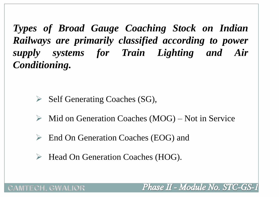
Types of Broad Gauge Coaching Stock on Indian
Railways are primarily classified according to power
supply systems for Train Lighting and Air
Conditioning.
Self Generating Coaches (SG),
Mid on Generation Coaches (MOG) – Not in Service
End On Generation Coaches (EOG) and
Head On Generation Coaches (HOG).
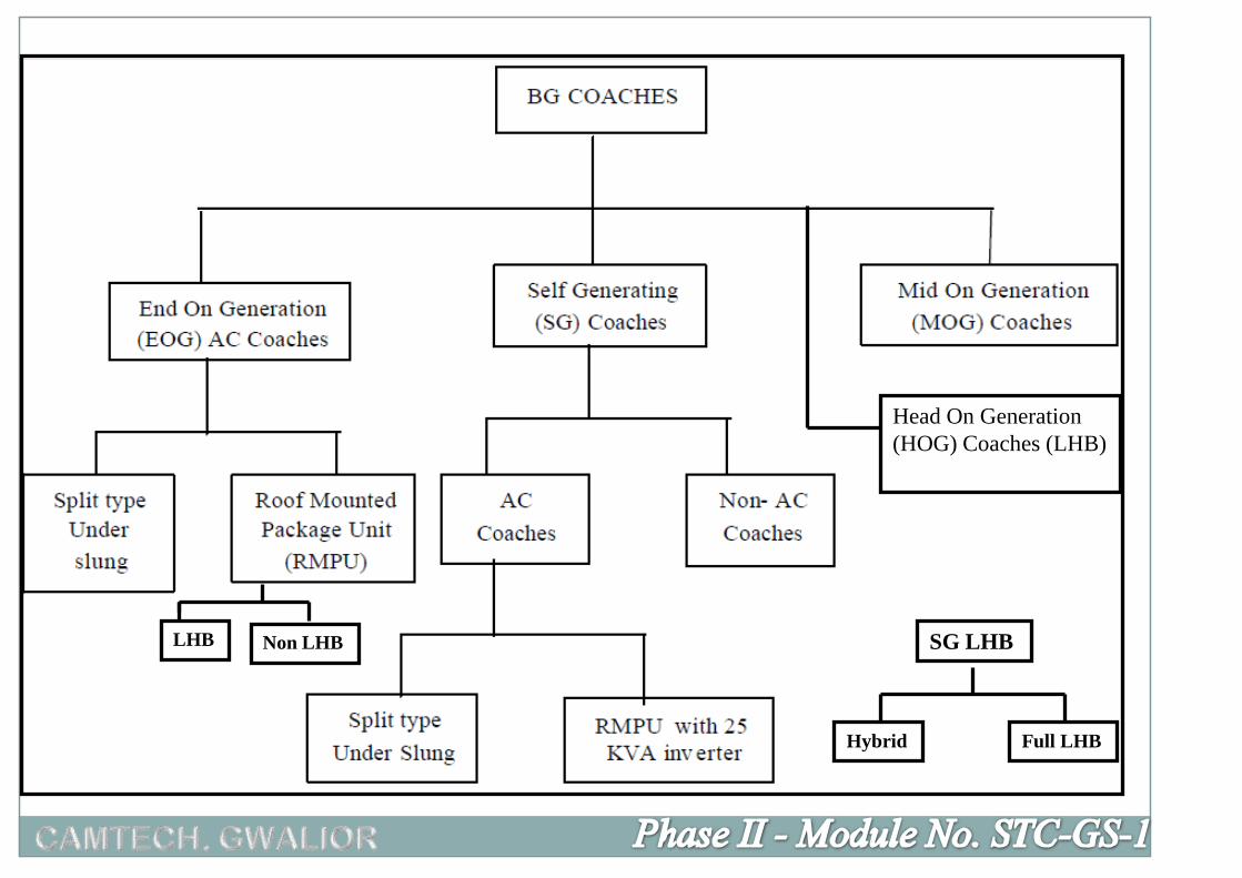
Head On Generation
(HOG) Coaches (LHB)
LHB Non LHB SG LHB
Hybrid Full LHB

Non AC coach AC coaches (both SG & EOG)
SLR (guard van) Power car
General Second (GS) Ist AC
Sleeper (SCN) 2nd AC
Chair car 3rd AC
Pantry Chair car
Double decker (chair car) Composite coach (any of two
accommodations in one coach)
Double decker (chair car)
Garibrath coaches
Pantry car

Train Lighting (NON AC) ICF Design Coach

Air Conditioned ICF Design Coach

Air Conditioned LHB Design Coach

Train Lighting (Non AC) LHB Design Coach
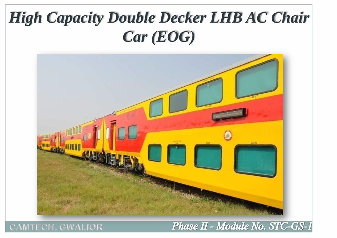
High Capacity Double Decker LHB AC Chair
Car (EOG)


(from day 1 as per „Cheap Trains Act‟ 1844)
On IR train services commenced in 1853.
Side wall bracket (general coaches) and ceiling (saloon
& Ist class) mounted Oil (vegetable or mineral) lamps.
One lamp per coach
To be fixed before sun set and removed after sun rise.

Used by East Indian Railway in last decade of 19th
Century in 400 carriages.
Improved quality of lighting
Gas storage at high pressure.
High initial cost but reduced maintenance cost.
Subsequent improvement by
o Using lamps with more than one burner
o Use of acetylene mixed gas
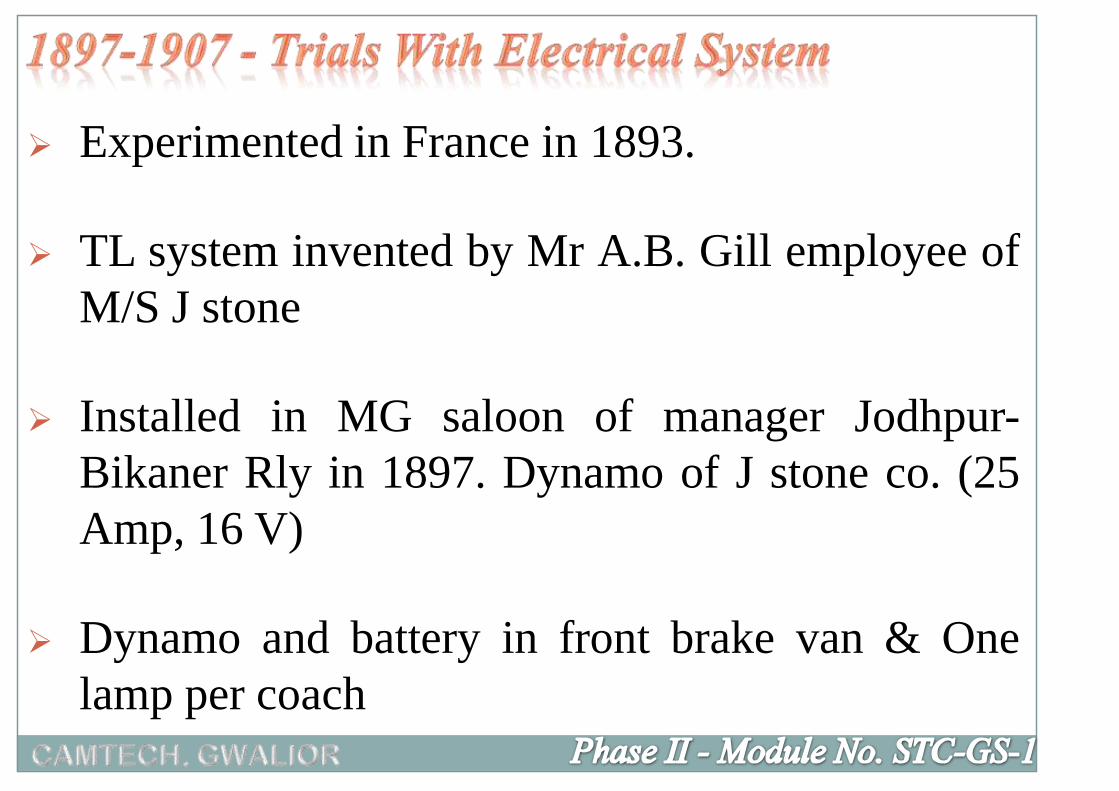
Experimented in France in 1893.
TL system invented by Mr A.B. Gill employee of
M/S J stone
Installed in MG saloon of manager Jodhpur-
Bikaner Rly in 1897. Dynamo of J stone co. (25
Amp, 16 V)
Dynamo and battery in front brake van & One
lamp per coach

South Indian Railways also installed a set of
equipment in 1897.
In 1901 by Rajputana-Malwa Railway 16 V
Battery adopted. Charging done with dynamo
installed in Ajmer W/S.

Both brake vans provided with battery and
dynamo.
Belts were being tightened by Guard on run.
Auto (centrifugal type ) cut out for dynamo (to
battery ) at 5 kmph

Locomotive, C&W Superintendents committee
was set up in 1889 in 9th meeting in 1907
reviewed progress of trials and adopted this
system.
In 1913 Railway Board issued orders for
adoption of electric lighting.
Initially up to 1907 no fans.

Started provision of fans especially in Ist class
coaches. Fans provided in Ist & 2nd class from
1907, in inter class from 1937 and in Third class
from 1950.
From 1955, 1 fan for each sleeping berth.
Double Battery Parallel Block (DBPB) system
Rake introduced in 1930 and Upper class coaches
also fitted with dynamo and battery (9th CWSC
meeting decision)

ESC recommended for double battery system in
1949 but not approved by Board due to
circulating currents.
Uncontrolled theft of copper from electrical
equipment.

RDSO report on evaluation and performance of
DBPB 24 V DC TL system in 1967
recommended;
o Silicon blockers in place of auto cut switches.
o Manually operated switch in place of magnetic switch.
o Aluminum wiring in place of Copper wiring.
o Bogie mounted Dynamo/Alternator with V belts.
22nd ESC discussed the need to go for 110 V DC
system.

RB accepted RDSO recommendation for 110 V
DC in 1968.
Used Ist time during 1950 with first lot of fully
AC coaches. (axle driven 18 kW, 130 V dc
generator provided with carbon pile voltage
regulator).
ICF built 6 rakes with 110 V dc system in
1976.

In 1987 M/S Best & Crompton developed brush
less alternator.
These coaches used 3 & 4.5 kW Alternator and
regulator.
Battery 90 Ah , 11V, 5 cells monoblocks.
Light and Fan circuits controlled by MCBs.

During 1988, Railway Board appointed special
committee of CEEs to work out modalities of
extending this system to all coaches.
After acceptance of this committee’s report in
early nineties, all newly built SG coaches now
work on 110 V dc system.
All 24 V dc coaches have also been converted in
110 V dc system.

V dc trial rakes were fitted with FL fittings. AC
coaches had FL fittings since beginning.
From 90s onward, all coaches are provided with
FL fittings.
In 1992, CFLs introduced in ACCN coaches.
LED lights are being provided in new coaches.

Insulated dc system offers following advantages:
i. System in healthy condition will not offer any
dangerous shock by touching any of the 2 dc
wires.
ii. Short circuit level will be adequate for proper
discrimination.

ISC = 0
Earth Fault
iii. In an emergency, train lighting can be continued with
an earth fault on one of the 2 wires as the battery is on
floating circuit and there will be zero current with
single earth fault.

During 1900-1935
• By providing Khus-Khus mats
• By providing ice containers
First air-conditioned coach
Manufactured in the year 1936 at Matunga Workshop,
Mumbai
Introduction of AC coach in regular service
Manufactured by ICF, Chennai in 1965

Low Medium High
• I AC Cooling 22 C 24 C 26 C
Heating 17 C 19 C 21 C
• II AC Cooling 24 C 26 C
Heating 19 C 21 C
RMPU type AC coaches with Electronic
thermostats have fixed settings of 23 C -25 C


Gas leakage
Accumulated Dust reduces heat transfer.
Under slung Eqpt. gets hit by ballast, Cattle
run over etc.
Coach weight increase.

RMPU of 5.2 TR each was introduced in the year
1992 with 25 KW alternator.
Now a days two high capacity packaged air-conditioning
units of 7.0 TR for AC II tier & AC III tier coaches and
10.0 TR for LHB Double Decker coaches are being
used.
For first AC - one unit of 7 TR is being used
Mounted above the toilets on both ends supplying
conditioned air in the tapered duct to serve the coach end
to end.

Condensor Fans Air Intake For
The Condensor
Fans
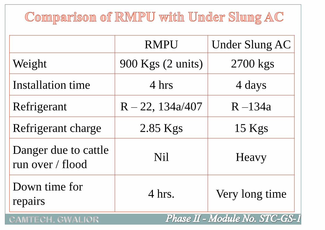
RMPU Under Slung AC
Weight 900 Kgs (2 units) 2700 kgs
Installation time 4 hrs 4 days
Refrigerant R – 22, 134a/407 R –134a
Refrigerant charge 2.85 Kgs 15 Kgs
Danger due to cattle
run over / floodNil Heavy
Down time for
repairs4 hrs. Very long time

Generation is AC which after AC-DC
rectification becomes 110 V DC.
Volt DC (with battery back up) for lights &
fans. For AC (RMPU)
It gets converted into 415 V, 3 ph through
Inverters.

750 Volt Generation from DG sets placed in
power cars at the ends.
Power Supply from OHE through LOCO
Transformer.

Salient features
Axle driven under slung Alternator with V – belts.
110 V dc regulated at different speeds through
RRU/ERRU.
Battery back up during standing/slow movement of
train.
2X25 kVA, 110 V dc/415 V inverters for AC load.
110 V DC supply for lights and fans.


It gives better flexibility in rake formation; majority of
SG type coach is more.
The system is independent of mode of traction.
As each coach has battery, so no additional source is
required. No separate power car required
The problem / defect in any particular coach do not
affect the others.
Feed extension is possible in emergency from adjacent
coach
Advantages of SG System

Load restricted to 2X25 kW per coach at present.
Bulky 1100 Ah (AC)/ 120 Ah (Non-AC) coach battery
required as power is not generated during standby /
slow movement .
No standby alternator /battery in non-AC coaches so
system became poor reliability.
Extensive maintenance due to under-slung alternator, v-
belt, axle pulleys, tensioning device, inverter, battery
etc.
Poor system efficiency around 57%.
Disadvantages of SG System
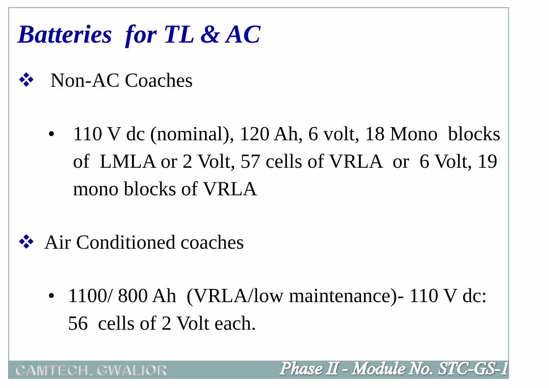
Non-AC Coaches
• 110 V dc (nominal), 120 Ah, 6 volt, 18 Mono blocks
of LMLA or 2 Volt, 57 cells of VRLA or 6 Volt, 19
mono blocks of VRLA
Air Conditioned coaches
• 1100/ 800 Ah (VRLA/low maintenance)- 110 V dc:
56 cells of 2 Volt each.
Batteries for TL & AC
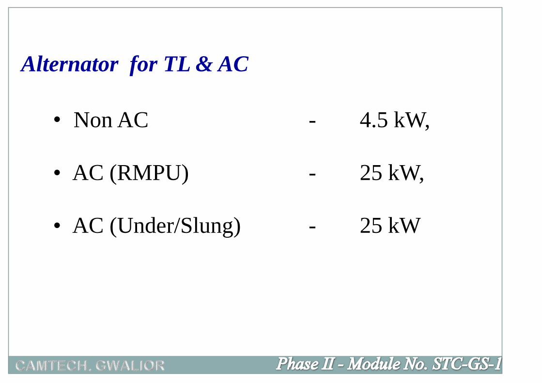
• Non AC - 4.5 kW,
• AC (RMPU) - 25 kW,
• AC (Under/Slung) - 25 kW
Alternator for TL & AC
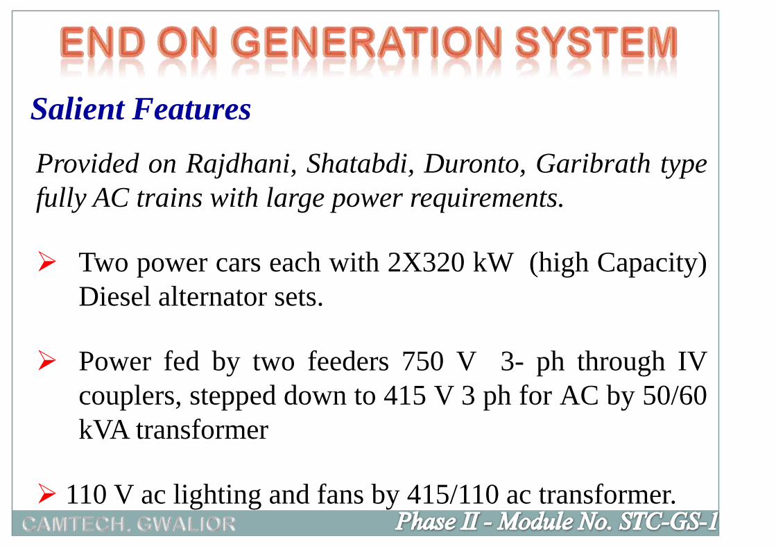
Provided on Rajdhani, Shatabdi, Duronto, Garibrath type
fully AC trains with large power requirements.
Two power cars each with 2X320 kW (high Capacity)
Diesel alternator sets.
Power fed by two feeders 750 V 3- ph through IV
couplers, stepped down to 415 V 3 ph for AC by 50/60
kVA transformer
110 V ac lighting and fans by 415/110 ac transformer.
Salient Features

750 V, 3 Ø FEEDER
415 V, 3 Ø
50/60kVA TRANSFORMER 415 V, 3 Ø LIGHTING TRANSFORMER
110 V, 3 Ø
LIGHTING LOAD
ACLOAD
COACH SUPPLY
ALT. ALT. ALT. ALT.
GENERATOR CAR
GENERATOR
CAR
FEEDER - I
FEEDER - IICOACHESCOACHES


No restriction of Load due to high capacity power cars.
Does not require bulky batteries, alternators.
Standby DA sets.
Independent of mode of traction.
Less maintenance required due to elimination of under
slung alternator, battery, axle pulley, V-belts etc.
Higher system efficiency than SG system.
Advantages of EOG System
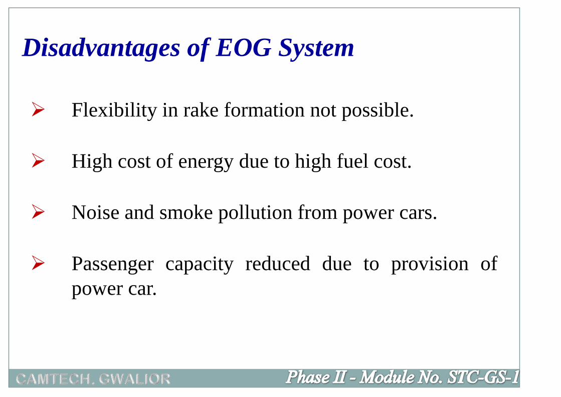
Flexibility in rake formation not possible.
High cost of energy due to high fuel cost.
Noise and smoke pollution from power cars.
Passenger capacity reduced due to provision of
power car.
Disadvantages of EOG System

Single phase power supply received from OHE
through loco or tapped from OHE in power
car through separate pantograph.
Cost effective, reliable and energy efficient.
Salient Features

Elimination of heavy under slung equipment viz
alternator, battery, Inverter etc. in SG coaches
and DA sets in EOG power car avoiding noise
and smoke pollution.
Inverter (single phase to 3 phase) can be
mounted on/ under loco or power car or
individual coach.


Operating Formation of rakes, Placement of rakes, planning of
new coaching depots, Planning of new trains,
Timetabling, Rake rationalization, planning of POH
of coaches, Co-ordination for sick marking.
Commercial Introduction of new trains, Extra coaches and trains
for seasonal rush, Special trains, Refund in case of
Non AC, passenger complaints
MechanicalCo-ordination for coach maintenance, placement of
rakes, integrated coach maintenance, Sick line
maintenance.
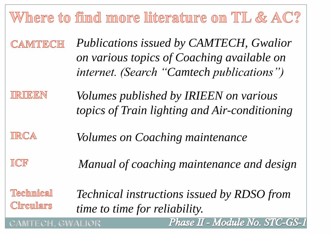
Volumes published by IRIEEN on various
topics of Train lighting and Air-conditioning
Technical instructions issued by RDSO from
time to time for reliability.
Volumes on Coaching maintenance
Manual of coaching maintenance and design
Publications issued by CAMTECH, Gwalior
on various topics of Coaching available on
internet. (Search “Camtech publications”)


Phase II - Module No. STC-GS-1

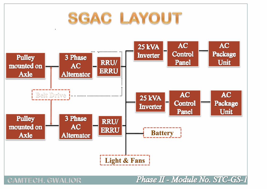
Self Generating System (SG),
End On Generation System (EOG) and
Head On Generation System (HOG) - trials are under
progress
Based on the type of generation, there are three systems
adopted over IR. These are -

In this system, power supply is generated in individual
coach through alternators propelled by axles.
Power generated during run supplies coach supply and
also charges the battery bank provided in each coach,
which in turn supplies power to the coach while the coach
is stationary.
The alternators are fitted in the under frame driven by the
axle through V-belts.
These alternators generate 110V, AC, 3Ø, which is
rectified and regulated by Rectifier cum Regulator Units
(RRU/ERRU).

The RRU further passes 110V DC for coach supply and
battery charging.
This system is used for Air Conditioned coaches and Non
AC coaches of Mail/Express/Passenger trains.
ALT.
RRU/ ERRU
FIELDWINDING
BATTERY BOX
+-
TO COACH LOAD

Non AC coaches (TL Coaches)
Roof Mounted Package Unit
(RMPU) type AC coaches
Under slung type AC coaches
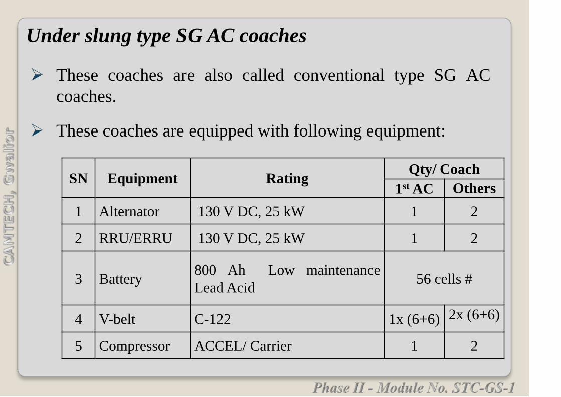
These coaches are also called conventional type SG AC
coaches.
These coaches are equipped with following equipment:
Under slung type SG AC coaches
SN Equipment RatingQty/ Coach
1st AC Others
1 Alternator 130 V DC, 25 kW 1 2
2 RRU/ERRU 130 V DC, 25 kW 1 2
3 Battery800 Ah Low maintenance
Lead Acid56 cells #
4 V-belt C-122 1x (6+6) 2x (6+6)
5 Compressor ACCEL/ Carrier 1 2

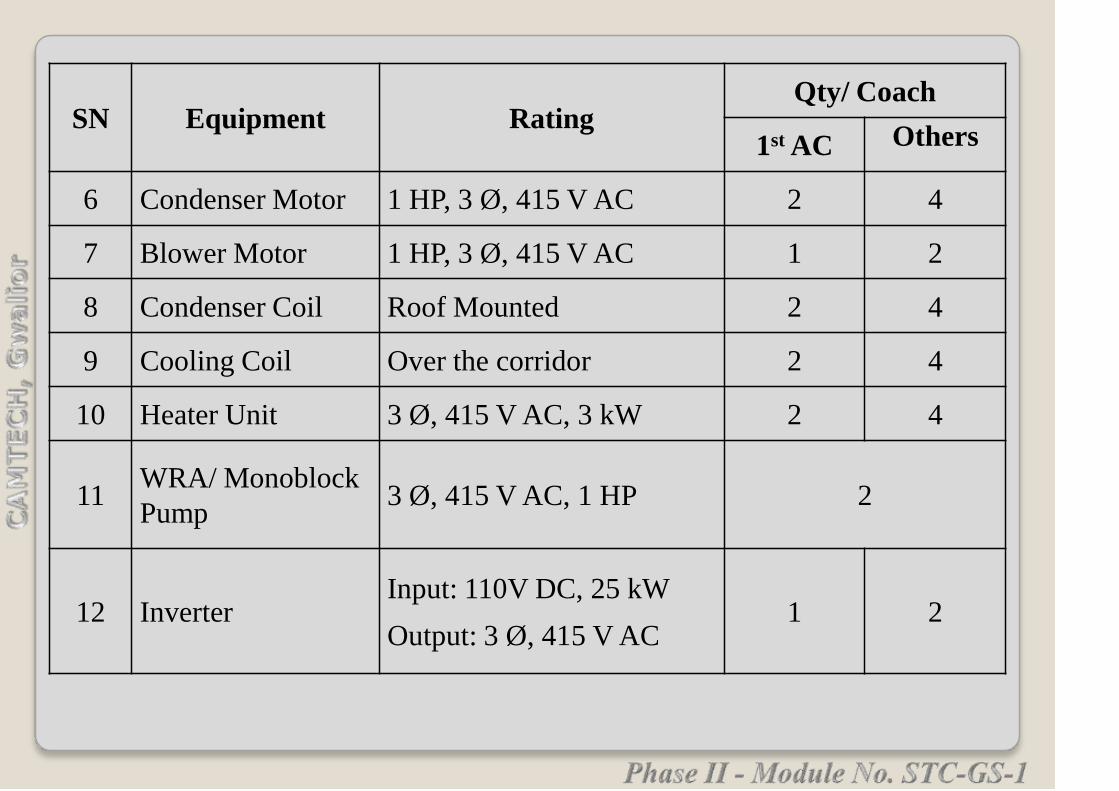
SN Equipment RatingQty/ Coach
1st ACOthers
6 Compressor Motor 8.5/10 HP, 110 VDC 1 2
7 Condenser Motor 1.5 HP, 110V DC 2 4
8 Blower Motor 1 HP, 110V DC 1 2
9 Condenser Coil Under slung 1 2
10 Cooling Coil Over the corridor 1 2
11 Heater Unit 110V DC, 6 kW 1 2
12 WRA 1 motor 2
# Now for better reliability 1100 Ah VRLA batteries are being
retrofitted.

These coaches are also called RMPU type SGAC coaches.
These coaches are equipped with following equipment:
SN Equipment RatingQty/ Coach
1st AC Others
1 Alternator 130V, 193A DC, 25kW 1 2
2 RRU/ERRU 130V,193A DC, 25 kW 1 2
3 Battery 1100 Ah, VRLA 56 cells
4 V-belt C-122 1 x (6+6) 2 x (6+6)
5 Sealed Compressor 3 Ø, 415 V AC 2 4
Roof Mounted Package Unit (RMPU) type SGAC coaches
SN Equipment RatingQty/ Coach
1st AC Others
6 Condenser Motor 1 HP, 3 Ø, 415 V AC 2 4
7 Blower Motor 1 HP, 3 Ø, 415 V AC 1 2
8 Condenser Coil Roof Mounted 2 4
9 Cooling Coil Over the corridor 2 4
10 Heater Unit 3 Ø, 415 V AC, 3 kW 2 4
11WRA/ Monoblock
Pump3 Ø, 415 V AC, 1 HP 2
12 InverterInput: 110V DC, 25 kW
Output: 3 Ø, 415 V AC1 2

These coaches are equipped with following equipment:
SN Equipment Rating Qty/ Coach
1 Alternator 120 V, 37.5A DC, 4.5 kW 1
2RRU/
ERRU120 V, 37.5 A DC, 4.5 kW 1
3 Battery
120 Ah, 6V VRLA or 120
Ah, 6 V Monoblock
LMLA
2 V, 57 cells or 19 Mono
blocks VRLA/ 54 cells or
18 mono-block LMLA
4 V-belt C-122 4
Non AC coaches

Description of Power Circuit
The 3- phase, 415 VAC, 50Hz power supply is used to
operate two hermetically sealed compressors, one double
shaft blower motor, two condenser motors and one set of
heaters through six contactors.
All the equipment are protected by over load relays and
MCBs.
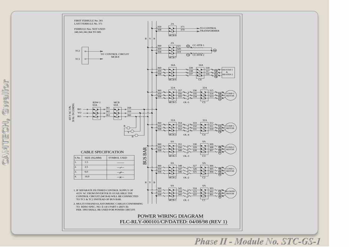
RSW-1
RO
YO
BO
63A
415
V A
C 3
Ph.
50 H
z I
N C
OM
ING
363
362
361
MCB63A
360
359
358
R
Y
B
MCB-1
6A
345
344
343
324
323
322
OL-1 C1
6A
303
302
301
BLOWER
MOTOR
R Y B
MCB-2
6A
348
347
346
327
326
325
OL-2 C2
6A
306
305
304
COND-1
MOTOR
360
359
358
360
359
358
MCB-3
6A
351
350
349
330
329
328
OL-3 C3
6A
309
308
307
COND-2
MOTOR
360
359
358
MCB-4
32A
354
353
352
333
332
331
OL-4 C4
32A
312
311
310
COMP-1
MOTOR
360
359
358
MCB-5
32A
357
356
355
336
335
334
OL-5 C5
32A
315
314
313
COMP-2
MOTOR
360
359
358
MCB-6
16A
339
338
337
C6
16A
318
317
316
360
359
358
HEATER-1
&
HEATER-2
MCB-7
2A
360
359
358
CC-HTR 1
CC-HTR 2
MCB-8
359
358
2A
TRANSFORMERTO CONTROL
R Y B
CABLE SPECIFICATION
S.No. SIZE (SQ.MM) SYMBOL USED
1. 1.5
2. 2.5
3. 6.0
4. 16.0
371
370
FIRST FERRULE No. 301
LAST FERRULE No. 371
FERRULE Nos. NOT USED
340,341,342,364 TO 369.
TC2
TC1
TO CONTROL CIRCUIT
MCB-8
1. IF SEPARATE FILTERED CONTROL SUPPLY OF
415V AC FROM INVERTER IS AVAILABLE THE
CONTROL CIRCUIT (MCB-8) WILL BE CONNECTED
TO TC1 & TC2 INSTEAD OF BUS BAR.
2. MULTI STRAND ELASTOMERIC CABLES CONFIRMING
TO RDSO SPEC. NO. E-14/1 PART-1 (REV.II)
FEB. 1993 SHALL BE USED FOR POWER CIRCUIT.
POWER WIRING DIAGRAM
FLC-RLY-000101/CP/DATED: 04/08/98 (REV 1)
BU
S B
AR
321
320
319

Description of Control Circuit
A step down transformer of 415V/110V is used to provide
110V AC, single phase to control circuit.
The thermostats, PCBs, OLPs, HP cut out, LP cut out,
timers, etc. operate at this control voltage.
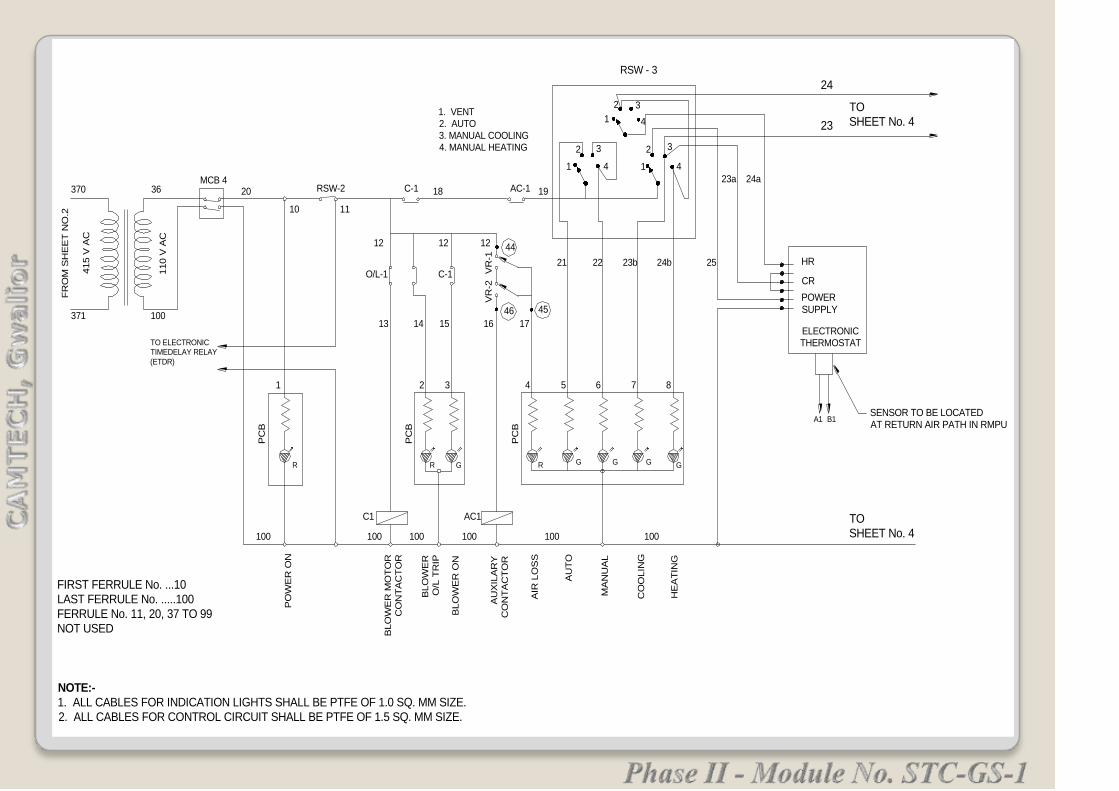
AU
TO
1
1212 4412
110 V
AC
FR
OM
SH
EE
T N
O.2
415 V
AC
NOTE:-
1. ALL CABLES FOR INDICATION LIGHTS SHALL BE PTFE OF 1.0 SQ. MM SIZE.
2. ALL CABLES FOR CONTROL CIRCUIT SHALL BE PTFE OF 1.5 SQ. MM SIZE.
FIRST FERRULE No. ...10
LAST FERRULE No. .....100
FERRULE No. 11, 20, 37 TO 99
NOT USED
100371
AIR
LO
SS
BLO
WE
R O
N
BLO
WE
R
O/L
TR
IP
AU
XIL
AR
Y
CO
NT
AC
TO
R
BLO
WE
R M
OT
OR
CO
NT
AC
TO
R
PO
WE
R O
N
100 100
C1
PC
B
R
13
1
O/L-1
100 100
AC1
R
PC
B
G
100
PC
B
R
1514
2 3
C-1
1716
4 5
VR
-2
46
VR
-1
45
21
36370MCB 4
20 RSW-2
1. VENT2. AUTO
3. MANUAL COOLING4. MANUAL HEATING
C-1 AC-1
HE
AT
ING
CO
OLIN
G
MA
NU
AL
100
G G G G
6 7
22 23b
8
24b 25
TO
SHEET No. 4
ELECTRONIC THERMOSTAT
RSW - 3
14
1
2 3
4
2
2 3
4
3
24
23
24a23a
TO
SHEET No. 4
HR
CR
TO ELECTRONICTIMEDELAY RELAY
(ETDR)
POWER
SUPPLY
SENSOR TO BE LOCATEDAT RETURN AIR PATH IN RMPU
10 11
18 19
A1 B1

CO
ND
.1
CO
NT
AC
TO
R
CO
ND
.1 O
/L
CO
ND
.2
CO
NT
AC
TO
R
CO
ND
.2 O
/L
CO
ND
.1 O
N
CO
MP
.1
CO
NT
AC
TO
R
CO
MP
.1 O
/L
LP
1
HP
1
CO
MP
.1
BY
PA
SS
CO
MP
.2
CO
NT
AC
TO
R
CO
MP
.2 O
/L
LP
2
HP
2
CO
MP
.2
BY
PA
SS
CO
MP
.1 O
N
CO
MP
.2 O
N
CO
ND
.2 O
N
HE
AT
ER
CO
NT
AC
TO
R
OH
P 2
TR
IP
OH
P 1
TR
IP
HE
AT
ER
ON
FR
OM
SH
EE
T N
O. 3
24
23
C2 C3
C6
C3
C2
O/L-2 O/L-3 C-2 C-3
40 40 40 40
41 43 45 4642 44
9 10 11 12
PC
B
PC
B
RGR G
C2 C3
PC
B
100 100 100 100
N N N N N
48
49
T26
T27
T29
T31
T28
T30
51
5257
54
55
13 14 15 16 17 18 19 20
21 22
23 24 25
PC
B
PC
B
PC
B
R R R R R R R R R R
G G
G
1
2
3 1
2
3
a b
48
T38
T39
T41
T42
T40
T4362
61
63
65
65
66
70
68
69
71
4848
C4 C5
72 73
8282
82
C6
84
85
C6C5C4
NOTE :1. FIRST FERRULE No. 40 & LAST FERRULE No. 100.
2. FERRULE No. NOT USED - 47, 50, 53, 56, 64, 67, 74 TO 81, 85, 88 TO 99.
3. R-RED LED INDICATOR & G-GREEN LED INDICATOR4. CABLE SIZE FOR ALL INDICATION LIGHTS SHALL BE PTFE OF 1 SQ.MM.5. CABLE SIZE FOR CONTROL CIRCUIT SHALL BE PTFE OF SIZE 1.5 SQ.MM.
1. BOTH COMPRESSOR ON.2. COMPRESSOR-1 BYPASS
3. COMPRESSOR-2 BYPASS
RSW-5
ETDR
N1 Ph1
PhN
N1 Ph1
HP1
LP1
O/L-4
54
5960
58
T32 T34
T33
T35
T37
T36
HP2
LP2
O/L-5
66
N
OHP-1
83
OHP-1
86
87
ETDRFROM
SHEET
NO.3{
FROM
SHEET
NO.3{

FROM
TB 7 RS W3
R1, Y1, B1
R2, Y2, B2TB2
MPCB
MCB
4151, 4152
RSW7
4157,4158
4159
PUMP1
U,V,W
PUMP2
U1,V1,W1
TO
TB 8
XR
4154,4155
4156
221,222
223
191,192
193,N
TO
TB 1
FROM
TB 1191,192193, N
MCB
RSW4
194,195196
197,198199
MCB
MCB
MCB
FR1
FY1
FB1
TO
TB 1
N
VOLT
METER
1814
FROMTB 3
263 262
FROMTB 4
BATT
AMMETER
FROM 500A SHUNT
19
201
TO
TB 4
700
TB 4
FROM
RC
L1
706
RC
L2
707
1 &
3701
702
FS
L
2 &
4F
SL
TO CL2
RSW-1
500A
17
117
19
26 RSW-2
300A
261
400A
26
250A
2614
250A
2613
TO
IN
V2 +
(DP
)
TO
IN
V1 +
(DP
)
TOTB4
19
1911717
17
TO ALT-1
AMMETR
201
FR
OM
U/F
16
16
TO ALT-2
AMMETR
TO
TB 5
FR
OM
U/F
116
FR
OM
U/F
19
FR
OM
U/F
201
250A
181
250A
181
TO
IN
V2 +
(DP
)
TO
IN
V1 +
(DP
)
250A
18
TO
40A
MC
BF
RO
M U
/F
- VeT
OVR
ALT-1
16
17
ALT-2
116
117
262,
1814
3,4
,4a,
5
FROM TB6
16,17,116,117
FROM SHUNT
RSW-6(FL)
300
330
TO
6A MCB
FROM 40A
MCB
26
RSW-6
(IC, L)
26
500
700
TO MCB (+10A)
2611
2612
1814 / VM18 0 2.5A
702.5A
SP5A
18115A
11825A
180310A
180410A
1840A
2640A
70010A
50010A
3305A
3005A
SP5A
72.5A
FROM TB 42.5A
18
TO RSW 5
PAIL
VM 262
TO TB 4
SP
L1
L2
IC1
IC2
TO
TB
3F
RO
M
RS
W 6
FROM TB 4
FR
OM
RS
W 5
TO
T
B 4
4153
N
SCHEMATIC DIAGRAM FOR POWER PANEL

Capacity : 25 kW
Voltage : 130 V +/- 5% on DC side (97V, 3phase AC)
193 A Max on DC side.
Cut in Speed : 380 RPM (30 Kmph )
MFO : 700 RPM (51 kmph approx for 135 A at 135V)
Max. Speed : 2500 RPM (156 Kmph approx)
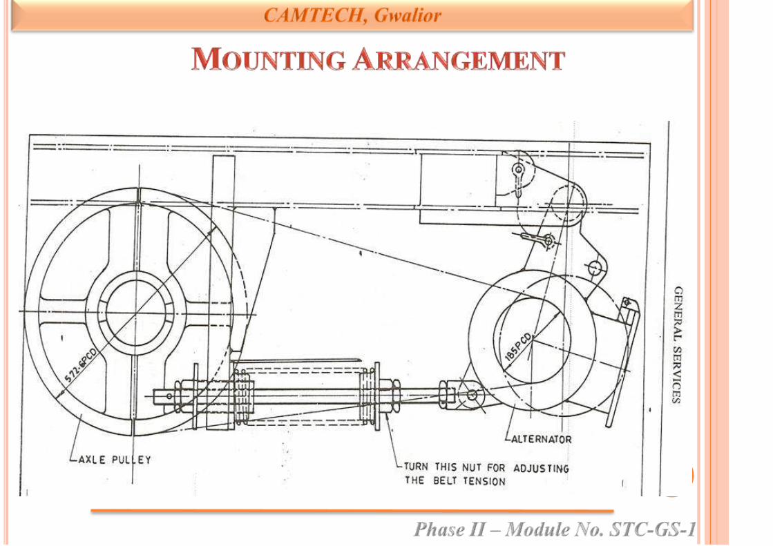
Mounting : Transom mounting
Belts : V-belts (C-122)
• Alternator

Insulation : H- class
Resistance between field terminals : 7.3 ohms
Resistance between phase terminals : 0.08 ohms
Alternator Pulley : 200 mm PCD 6 groove
pulley
RRU/ERRU
Capacity : 25kW
Voltage : 130V+/-5 % V DC
Current : 25kW – 193A DC Max
Battery
Voltage : 2V
Capacity : 1100 Ah
Type : VRLA
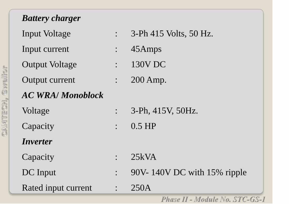
Battery charger
Input Voltage : 3-Ph 415 Volts, 50 Hz.
Input current : 45Amps
Output Voltage : 130V DC
Output current : 200 Amp.
AC WRA/ Monoblock
Voltage : 3-Ph, 415V, 50Hz.
Capacity : 0.5 HP
Inverter
Capacity : 25kVA
DC Input : 90V- 140V DC with 15% ripple
Rated input current : 250A

AC Output : 3- Ph. 3-wire, 415V+/- 5%
PWM sine wave
Output frequency : 50 Hz+/- 3%
Output power factor : 0.8
Rated Output current : 35A
Power Panel Equipment
Voltmeter : 0-200V DC
Center-Zero-Ammeter : 500-0-500 DC
Ammeter for Alternator-I & II : 0-300A DC
RSW1 (Alternator supply selector rotary switch) : 400/500Amps
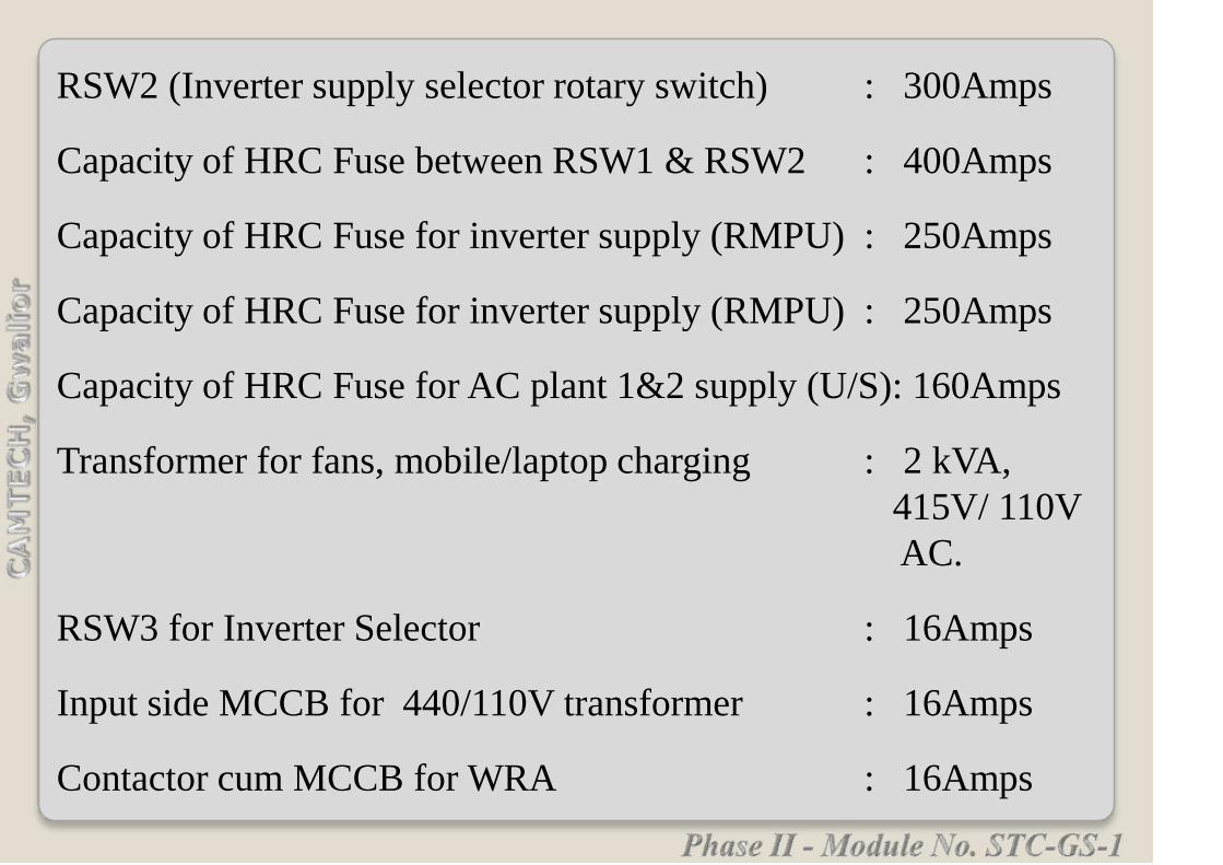
RSW2 (Inverter supply selector rotary switch) : 300Amps
Capacity of HRC Fuse between RSW1 & RSW2 : 400Amps
Capacity of HRC Fuse for inverter supply (RMPU) : 250Amps
Capacity of HRC Fuse for inverter supply (RMPU) : 250Amps
Capacity of HRC Fuse for AC plant 1&2 supply (U/S): 160Amps
Transformer for fans, mobile/laptop charging : 2 kVA,
415V/ 110V
AC.
RSW3 for Inverter Selector : 16Amps
Input side MCCB for 440/110V transformer : 16Amps
Contactor cum MCCB for WRA : 16Amps

RSW4 for fans : 16Amps
RSW5 for Lights : 16Amps
RSW6 for night lights : 16Amps
RSW7 for WRA selector : 16Amps
MCBs for +ve, -ve circuits of FTLs/ CFL Night : 6Amps
Lamps, fans, Mobile charging inverter.
AC Control Panel Equipment (RMPU)
RSW1 : 63Amps
MCB TP : 63 Amps.
MCB TP for blower, condensers : 6 Amps

MCB TP for compressors : 32 Amps.
MCB TP for heaters : 16 Amps
MCB DP for Control T/F : 4Amps
Contactors for blower, condensers : 6 Amps
Contactors for compressors : 32Amps
Contactor for heater : 16Amps.
Control Transformer : 415/110V AC

Make : Maneurop/ Compelend
scroll
Maneurop/ Compelend
scroll
Power
consumption
: 5250 W +/- 20 %
depending on ambient
temperature
5250 W +/- 20 %
depending on ambient
temperature
Current : 8.5A+/- 25% at
415VAC 3-phase 50Hz
depending on Ambient
temperature
8.5A+/- 25% at
415VAC 3-phase 50Hz
depending on Ambient
temperature
Compressor

Power factor : 0.85 0.85
C.F.M.(Displacement) : 12.033 C.F.M, R-
22 Vapour
12.033 C.F.M, R-
22 Vapour
Volume : 117.65
CC/Revolution
117.65
CC/Revolution
Evaporator Motor
Type : Centrifugal type Centrifugal type
Diameter : 10” (250mm) 11” (280mm)
Air flow (CFM) : 4200 Cu.Mtr/Hr+/-
10% at 20 mm water
guage
4000 Cu.Mtr/Hr at 20
mm water guage
Pressure (External Static) : 25 mm Minimum
water guage
25 mm Minimum
water guage

Speed : 1415+/- 10% RPM 1400+/- 10% RPM
Capacity : 1.5 HP 1.5 HP
Current : 2.6A +/-10% at 415 VAC 3-
Ph, 50Hz.
2.6A +/-10% at 415
VAC 3-Ph, 50Hz.
Condenser Fans
Diameter : 24” 21”
Air flow : 4000 x 2 (6800 Cu.Mtr/Hr x 2)
at 7mm static.
3825 x 2 (13000
Cu.Mtr/Hr minimum)
Speed : 910 +/- 10% RPM. 1400 +/- 10% RPM
Motor capacity : 1 HP x 2 1 HP x 2
Current : 2.1A+/- 10% x2 at 415V.AC 3
Ph 50Hz.
2.2A+/- 10% x2 at
415V.AC 3 phase 50Hz

Evaporator Coil
Face area : 0.254 sq.mtr x 2 0.265 sq.mtr x 2
Material of Tube : Copper Copper
Tube O.D. : 9.525 mm(3/8”) 9.62 mm(3/8”)
Fin material : Copper Copper
Fin thickness : 0.127 mm 0.14 mm
No. of fins/25mm : 15 12+/-1

Condenser Coil
Face area : 0.7376 sq.mtr x 2 0.67 sq.mtr x 2
Material of Tube : Copper Copper
Tube O.D. : 9.525 mm(3/8”) 9.62 mm(3/8”)
Fin material : Copper Copper
Fin thickness : 0.127mm 0.14 mm
No. of fins/25mm : 15 12+/-1
Refrigerant : R-22 less than 2.5 kg each
circuit
R-22 less than 3.0 kg each
circuit
LP : 35+/- 2 PSI 35+/- 2 PSI
HP : 415+/- 2 PSI 415+/- 2 PSI


(Self Generating TL Coaches)
Phase II - Module No. STC-GS-1
Most of the conventional non-air conditioned BG
coaches (ie. TL coaches) running on Indian
Railways are Self Generation (SG) type coaches
fitted with 4.5 kW alternators.
These coaches have 110 V DC systems for fan &
lights.
Each coach is provided with bogie mounted axle
driven one brush less alternator of 4.5 kW with
static rectifier-cum-regulator unit (RRU)/ Electronic
rectifier-cum-regulator unit (ERRU), giving an
output at 124 volts D.C.
The lights are arranged in two circuits (L-I, L-II) and fans in
one circuit-F, each controlled by a rotary switch.
Each circuit of lights and fans is protected by HRC fuse which
acts as back up protection in case of any short circuit fault,
isolating the faulty circuit only.
The circuit L-1 have essential/ emergency lighting circuit
which also include all Lavatory lights, 50% of compartment
lights, doorway lights, Night lights in all types of IInd Class
coaches.
(Ref: Specification No. EL/TL/48 (Rev.1) –2005)
The L-II light circuit feeds all the balance lights in
the coach.
The size of HRC fuse will be as per the type of
coach and the coach load, which will be governed
by the particular specification of the coach.
Re-wirable tinned copper fuses protect the branch
circuits for lights and fans.
Contd.......
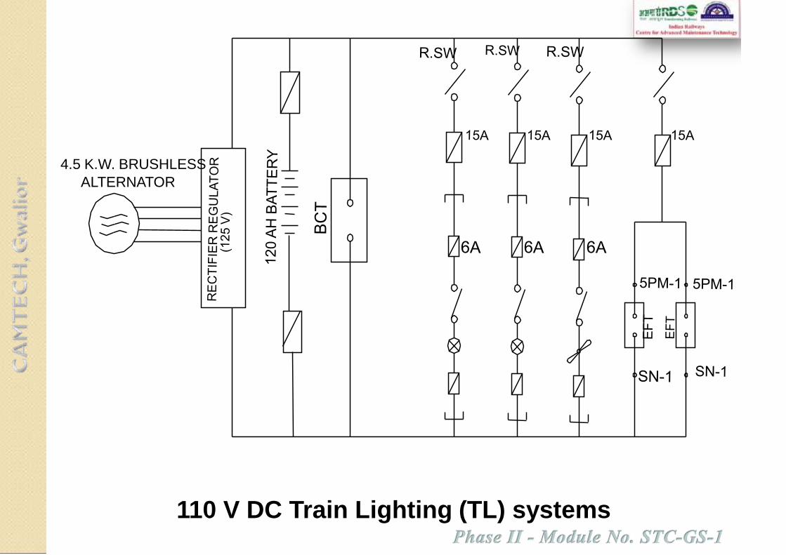
110 V DC Train Lighting (TL) systems
4.5 K.W. BRUSHLESS
ALTERNATOR
These re-wirable fuses are located on a distribution fuse
board.
All branch circuits are protected by the fuses, both on
negative and positive sides.
Ordinarily one fuse protects upto a maximum of 3 light
points or 2 fans points.
The grouping of negative wires is done in such a manner
that the group load is within the capacity of the distribution
fuse board and arrangements are identical on positive and
negative sides.
Contd.......

MAIN RECTIFIER BRIDGE
FIELD RECTIFIER BRIDGE
VOLTAGE & CURRENTSENSOR
OVER VOLTAGE PROTECTION
FIELD CONTROL CIRCUIT
A1A2 A3
FIELD
REGULATOR
F +
F-
B-
B+
The general schematic wiring diagram is illustrated in RDSO
Drawing No. SKEL-3928 Alt. 2 which is to be followed.
Alternator – Regulator block diagram

Colour Code:
For easy identification of the cables, the various circuits have
colour code as indicated below:
Paralleling main and fan positive cables ……….… Red
Light positive cables. …………..… ………………Yellow
Fan negative cables ………………..……………….Black
All other negative cables except fan negatives ….…Blue
The positive & negative cable is segregated by running them
in two separate conduits. The phase & field cables from
alternator to terminal box and from terminal box to rectifier
cum regulator should be run in flexible PVC conduits.
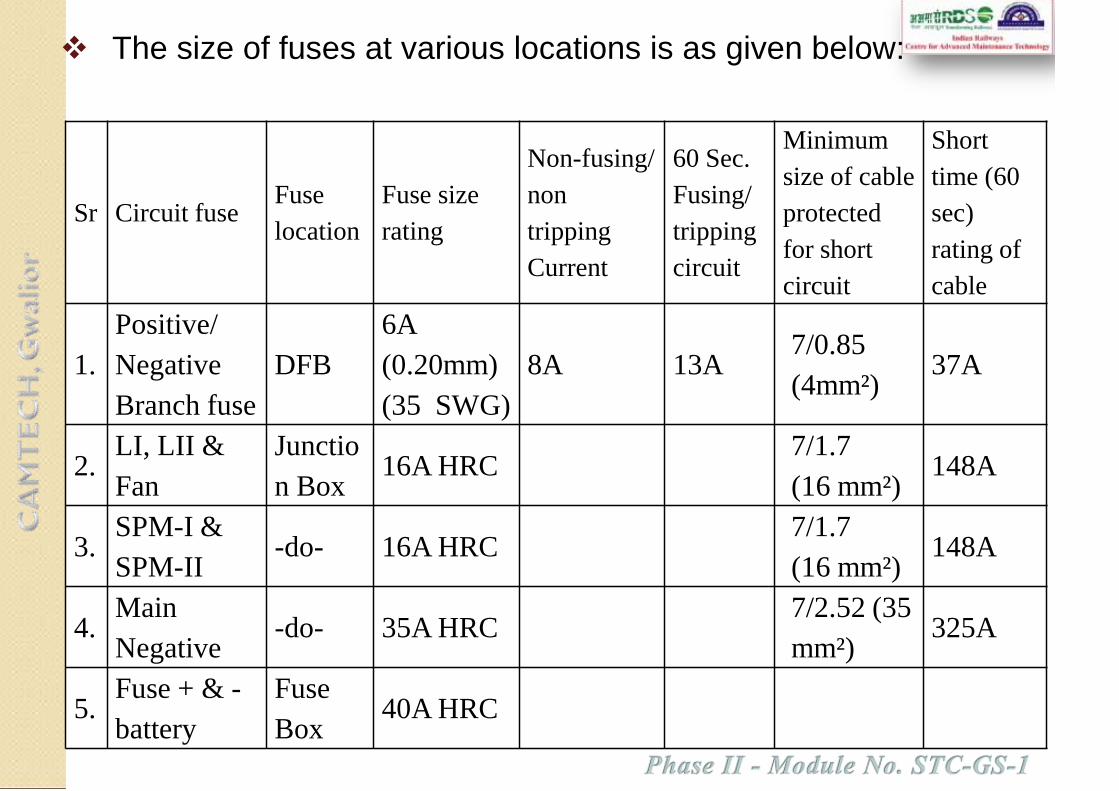
The size of fuses at various locations is as given below:
Sr Circuit fuseFuse
location
Fuse size
rating
Non-fusing/
non
tripping
Current
60 Sec.
Fusing/
tripping
circuit
Minimum
size of cable
protected
for short
circuit
Short
time (60
sec)
rating of
cable
1.
Positive/
Negative
Branch fuse
DFB
6A
(0.20mm)
(35 SWG)
8A 13A7/0.85
(4mm²)37A
2.LI, LII &
Fan
Junctio
n Box16A HRC
7/1.7
(16 mm²)148A
3.SPM-I &
SPM-II-do- 16A HRC
7/1.7
(16 mm²)148A
4.Main
Negative-do- 35A HRC
7/2.52 (35
mm²)325A
5.Fuse + & -
battery
Fuse
Box40A HRC

The standard ratings at the dc output terminals of the
rectifying and regulating equipment are 4.5 kW, 37.5A,
120 Volts.
It is driven by 4 Nos. ‘V’ belt coupled between the axle
and the alternator pulley.
These are designed as per
spec. no. RDSO/PE/SPEC/
TL/0054-2003 (Rev‘0’) with
amndt.1 &2.
The inductor type
Brushless alternator is an
axle driven, power-
generating machine with
‘V’ belt drive, mounted on
the bogies of the coaches.

The alternator is suspended on bogie on suspension boss fitted with
alternator pin.
The suspension boss fitted with a renewable bush having bore dia of
32.5 mm + 0.20 mm and alternator pin of diameter 31.75 mm + 0.0
mm / -0.10 mm.
The alternator is secured with safety chains (as per RDSO Drg.
SKEL 3934) to avoid dropping of it on track in case of any
breakage during run.
The alternator is secured with safety chains (as per RDSO Drg.
SKEL 3934) to avoid dropping of it on track in case of any
breakage during run.
i. Charging the coach batteries
ii. To meet electrical load i.e. fans, lights, mobile charging points
etc. in the coach.
The Alternator with the help of static/electronic rectifier
cum regulator unit regulates and rectifies the voltage
which is used for:

Alternator pulley A pulley fitted on alternator and driven by
axle pulley through ‘V’ belt. The pitch circle diameter
(PCD) is 200 ± 0.3 mm.
Belts are kept under tension by a spring-loaded belt-
tensioning device.
‘V’ belts used are of ‘C’ section size C-122 conforming to
RDSO Specification No. RDSO/PE/SPEC/0059-2004
(Rev.’0’)/ latest.
Axle pulley - A pulley fitted
on the axle of the coach to
drive the alternator by ‘V’
belt. The pitch circle
diameter (PCD) is 572.6 ±
0.4 mm.

The rectifier cum regulator unit has mainly following functions:
i To rectify the 3 phase AC output of the alternator to DC output.
ii Regulating the voltage generated by the alternator at the set
value.
iii Regulating the output current.

The static Rectifier cum Regulator (RRU) consists
components
Power rectifier,
Magnetic Amplifier (MA),
Excitation transformer (ET),
Voltage detector (DT) and
Over volt protection relay (OVPR)
The Electronic Rectifier regulator unit (ERRU) employs
IGBT with driver circuit for the control of field excitation.
It employs Micro controller for the control of output DC
voltage, out put current, Battery charging current and field
current.
Electronic Rectifier cum Regulator (ERRU) is as per RDSO
specification No. RDSO/ PE/ SPEC/ D/AC/0013 (Rev.0).
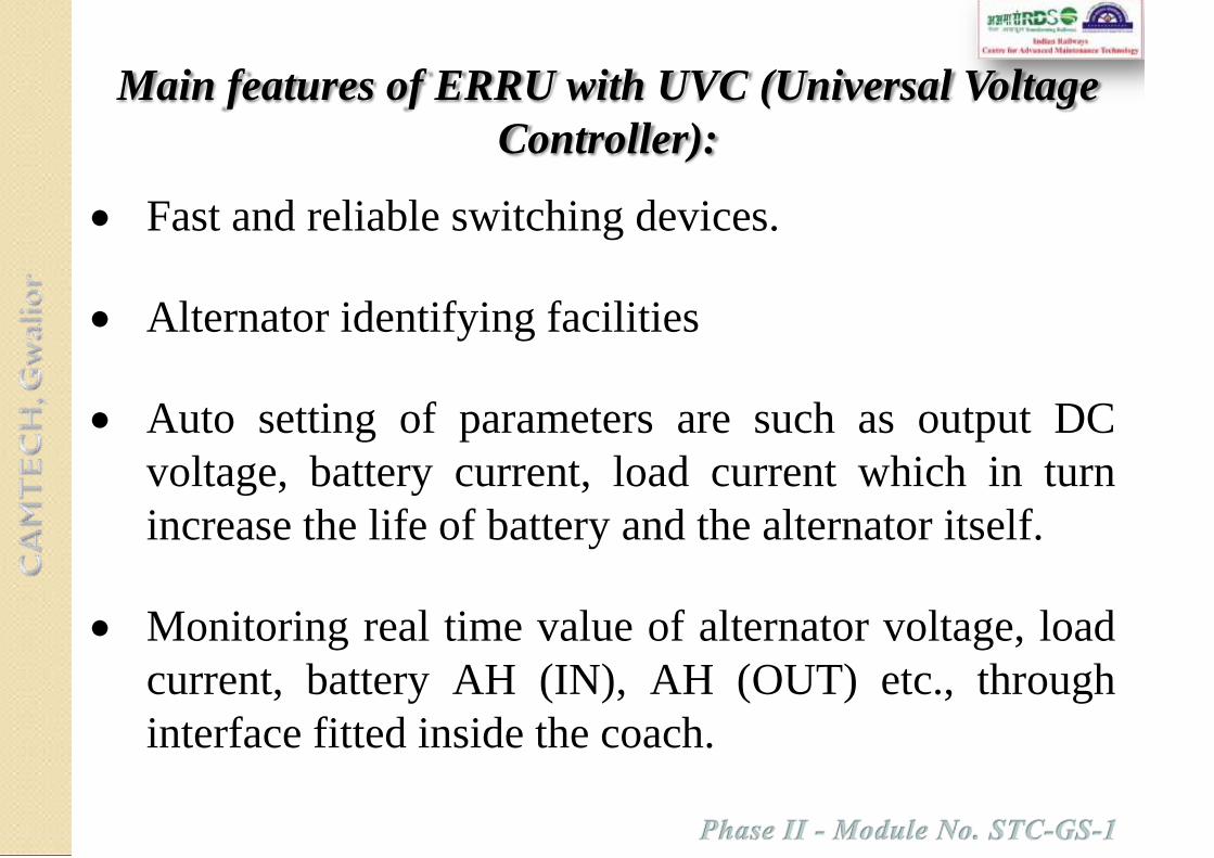
Fast and reliable switching devices.
Alternator identifying facilities
Auto setting of parameters are such as output DC
voltage, battery current, load current which in turn
increase the life of battery and the alternator itself.
Monitoring real time value of alternator voltage, load
current, battery AH (IN), AH (OUT) etc., through
interface fitted inside the coach.
Main features of ERRU with UVC (Universal Voltage
Controller):

Control circuit is Modular type design.
Auto identification of alternator is ratings and
indications.
Auto setting of parameters are of voltage, load
current, Battery current, over voltage, over current
and current limiting for all the regulator of 4.5 kW,
18 kW and 25 kW.
UVC is interchangeable with all types of Electronic
Regulators from 4.5 kW to 25 kW.
Main advantages of ERRU:

Close regulation of voltage +/- 2 V over the entire range
of load and speed to have uniform charging of batteries.
Less voltage and current ripple are on Battery Charging
current.
Controlled Battery charging current to have longer life of
batteries.
Moulded Hall sensors for current sensing and setting
current limit.
Static over voltage protection and latching without
battery.
Isopack Power diodes directly mounted on the heat sinks
to have better heat dissipation.

Moulded PCBs to avoid dust and vibration problems.
Separate interface unit for monitoring the parameters like
DC Voltage, DC current, Battery charging and discharging
currents, Amp, Hours etc. and it can be downloaded.
This interface has facilities to store AH.IN and AH.OUT,
generation and non-generation time, total distance traveled
by coach and faults occurred in the regulators.
This interface also has Emergency unit. In case of failure of
one control unit, the other control unit will take care of both
regulators.
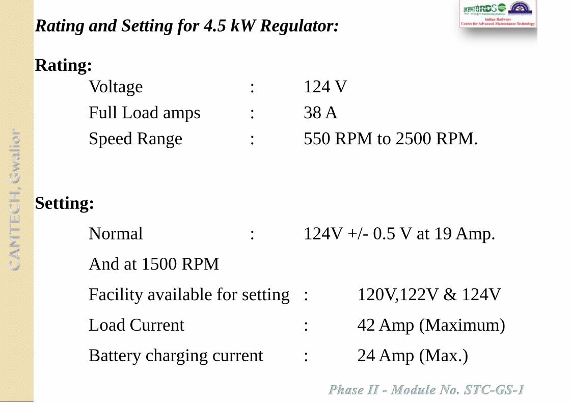
Rating:
Voltage : 124 V
Full Load amps : 38 A
Speed Range : 550 RPM to 2500 RPM.
Setting:
Normal : 124V +/- 0.5 V at 19 Amp.
And at 1500 RPM
Facility available for setting : 120V,122V & 124V
Load Current : 42 Amp (Maximum)
Battery charging current : 24 Amp (Max.)
Rating and Setting for 4.5 kW Regulator:

In 110V, train lighting system, 6V, 120 Ah capacity mono
block batteries are used in all types of conventional non air-
conditioned BG coaches.
There are two types of batteries ie. Low maintenance lead
acid (LMLA) and valve regulated lead acid (VRLA).

Eighteen (18) Nos. mono-blocks (each consisting of 3 cell
used in series) of battery constituting one set, are arranged in
two battery boxes. In each battery box the mono-blocks are
arranged in one row of 9 mono-blocks and each mono-block
is kept perpendicular to the track.
These are used in conjunction with brushless alternators with
suitable rectifier cum regulator of 4.5 kW capacity with a
nominal setting of 126 V, 37.5 Amp at full load and 1500
rev./ min.
Water :
• The water used for topping up and preparing
electrolyte shall conform to IS 1069 – 1993.
Electrolyte:
• It shall be prepared from battery grade sulphuric acid
conforming to IS 266-1993 with latest amendment.
• The level of electrolyte shall be at least 50 mm above the top
of separator protector in fully topped up condition (up to the
green level of float indicator).
• The specific gravity of electrolyte when the battery is in fully
charged condition at 27 degree centigrade shall be between
1.210 to 1.220 for 120Ah. The specific gravity shall be
corrected to 27 degree centigrade using the formula given
under C1.3.2.2 of IS 8320-1982.
Manufacturing & commissioning date of Battery:
• The year and month of manufacturer shall be punched on
positive terminal lug base with letter size not less than 6 mm
height and on Negative terminal side commissioning of
cells/batteries, month/year shall be marked by Railways.
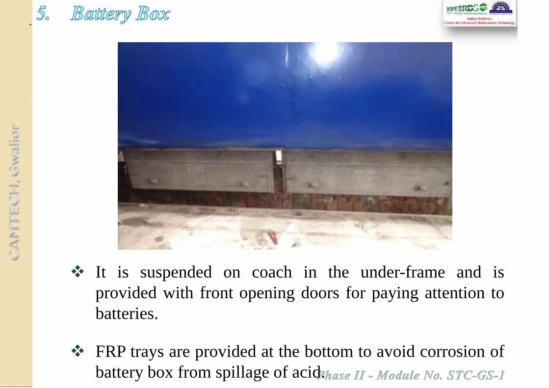
It is suspended on coach in the under-frame and is
provided with front opening doors for paying attention to
batteries.
FRP trays are provided at the bottom to avoid corrosion of
battery box from spillage of acid.

The interior of the battery box is painted with anti-corrosive
paint. The box is provided with ventilating grills to permit
flow of outside air over the cells.
A drain pipe is provided at the bottom of the box to allow
spilled acid or water to drain out.
Mild steel rods threaded at both ends are fixed to the battery
boxes after loading the cells.
While mounting the battery box in under-frame of the
coaches, special care is taken to provide locking nuts and split
pins to avoid any accidental falling of batteries while running.

BCT is provided centrally at the both sides of the
under-frame of the coaches for external charging
of the batteries at stations or maintenance lines.
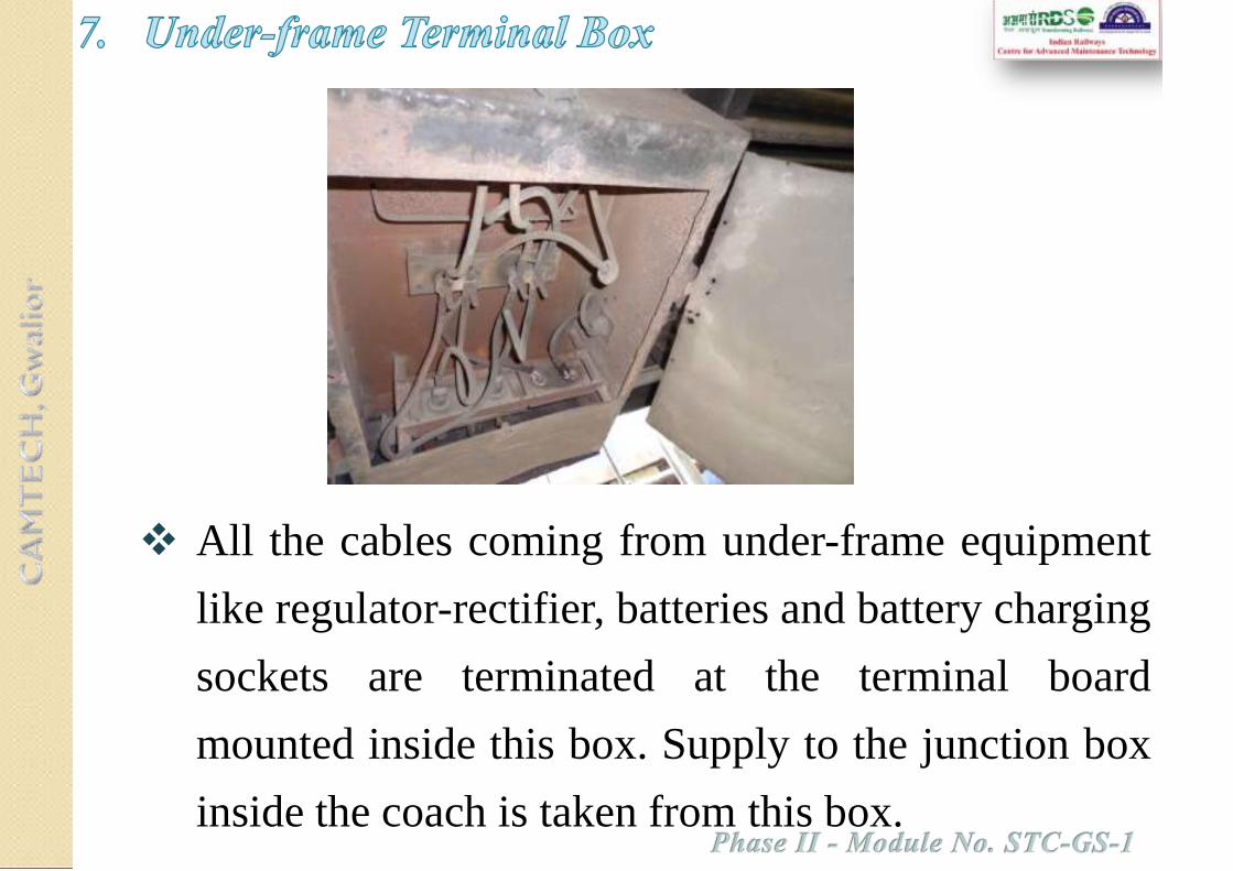
All the cables coming from under-frame equipment
like regulator-rectifier, batteries and battery charging
sockets are terminated at the terminal board
mounted inside this box. Supply to the junction box
inside the coach is taken from this box.

Rotary Junction Box is
provided inside the coach. It
is used to arrange and
control the power supply to
various circuits of the coach
(e.g. light, fan etc.) with the
help of rotary switches and
HRC fuses.

Each coach is provided with four emergency feed
terminal boards on end panels, one each at the four
corners of the coach at lower level to enable emergency
connection to be made between adjacent coaches. On
these terminal boards, the outer terminal shall be
connected to the positive and the inner terminal shall be
connected to negative.
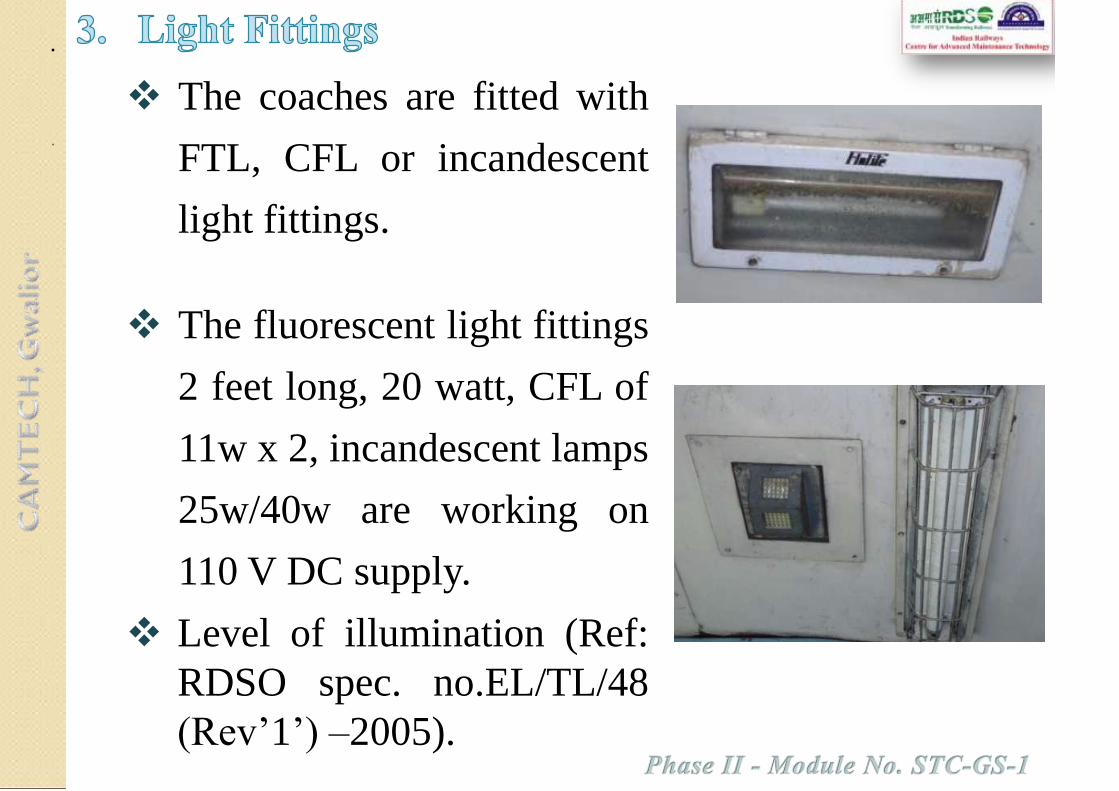
The coaches are fitted with
FTL, CFL or incandescent
light fittings.
The fluorescent light fittings
2 feet long, 20 watt, CFL of
11w x 2, incandescent lamps
25w/40w are working on
110 V DC supply.
Level of illumination (Ref:
RDSO spec. no.EL/TL/48
(Rev’1’) –2005).

Class of coach Min. illumination level
Ist class compartments 30 lux
2nd class compartments 30 lux
Postal compartments 40 lux
Pantry compartments 30 lux
Lavatories and corridor 16 lux
Luggage compartment of SLR coaches 20 lux
The level of illumination to be attained in various types
of coaches shall be as given below

On non AC BG coaches 400 mm
sweep carriage fans are used where
system voltage is 110 DC. These fans
are fixed type with voltage range is
90- 140V DC.
These fans are being replaced with
Brushless DC (BLDC) fans for 110
Volt dc, 400 mm and 450 mm sweep
fixed type.
The blades are made of fire retardant
plastic material.

Fuse distribution boards are
provided for each compartment/
bay of the coach.
The covers of Fuse distribution
boards are modified to restrict
the entry of waste/rubbish
material inside the FDB through
its cover and thus reduce the
possibility of fires incidences in
the cables in the vicinity of
FDB.


Phase II – Module No. STC-GS-1

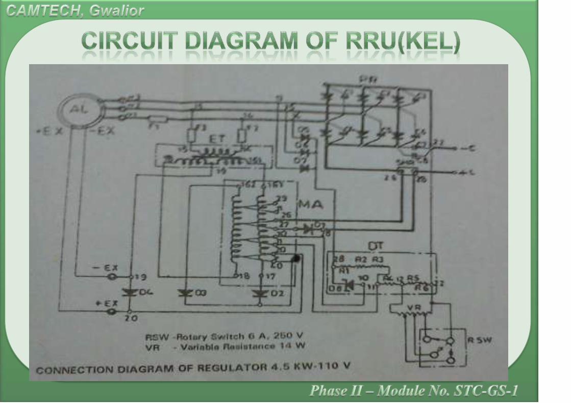
Power Rectifier
Field Diode
Blocking Diodes
Free wheeling diode
Magnetic Amplifier
Excitation Transformer/Field Transformer
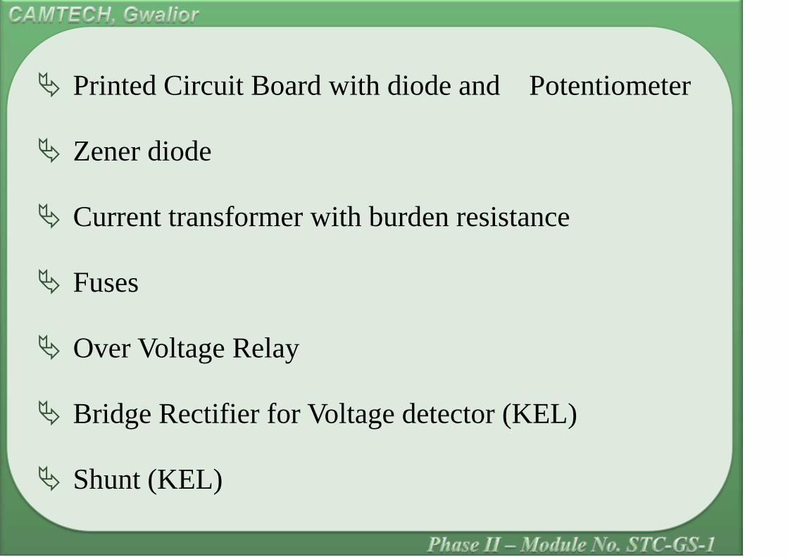
Printed Circuit Board with diode and Potentiometer
Zener diode
Current transformer with burden resistance
Fuses
Over Voltage Relay
Bridge Rectifier for Voltage detector (KEL)
Shunt (KEL)

Voltage detector (KEL)
Capacitor assembly (KEL)
Filter Circuit
Terminal Block.


Brushless alternator is totally enclosed
construction capable of developing a constant
voltage and used for Charging the coach battery
Operation of light, fans, Air Conditioner in the
coach.

A.C. Winding and field winding, both accommodated
in the stator.
The A.C. winding is distributed in the small slots &
field winding is concentrated in two slots .
Each field coil spans half the total number of slots.
The Rotor, consists of stacked stamping, resembles a
cogged wheel having teeth and slots, uniformly
distributed on rotor surface skewing the rotor axis.
The alternator consists of two sets of windings
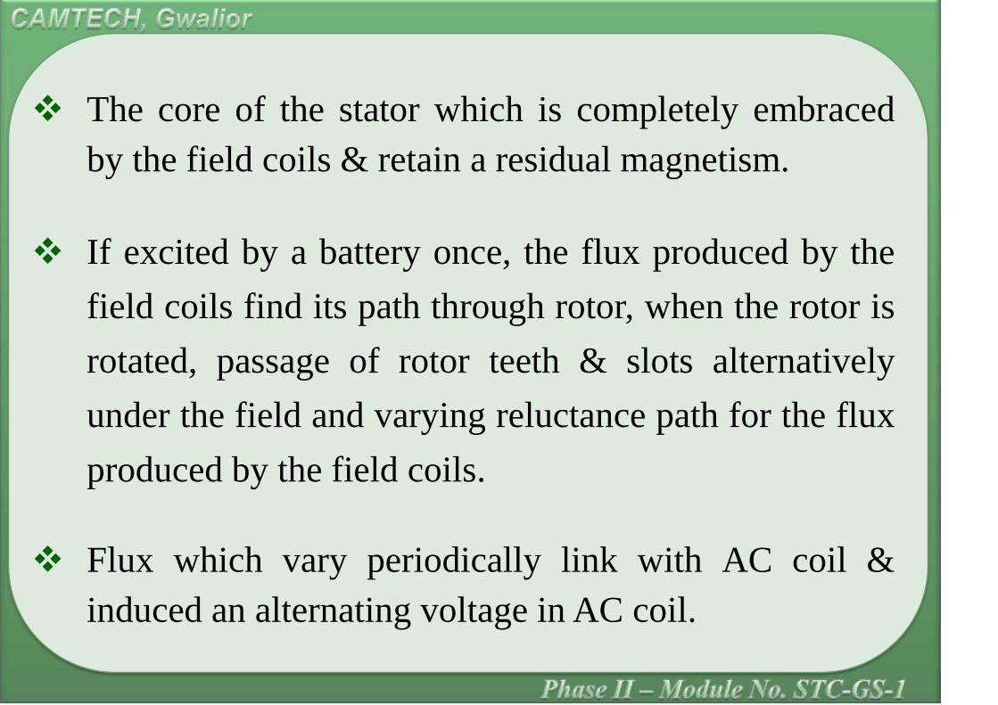
The core of the stator which is completely embraced
by the field coils & retain a residual magnetism.
If excited by a battery once, the flux produced by the
field coils find its path through rotor, when the rotor is
rotated, passage of rotor teeth & slots alternatively
under the field and varying reluctance path for the flux
produced by the field coils.
Flux which vary periodically link with AC coil &
induced an alternating voltage in AC coil.

The frequency of induced voltage depends on the
speed of rotor.
The field is controlled through regulator to attain
desired output voltage.
The 3 phase output from the alternator is rectified by
the bridge connected silicon diodes.
The DC excitation to the field is obtained by full wave
rectification of alternating current provided through
the field transformer and the load winding of the
magnetic amplifier.

The voltage induced in the alternator winding is
dependent on the speed of revolution of rotor and on the
excitation current.
In the absence of voltage detector and magnetic
amplifier, the generated voltage of the alternator is
controlled by only saturation of stator, which is not
regulated.
The necessity of magnetic amplifier is come into
picture.

As soon as, the pre-set value of voltage reached, the
Zener diode in voltage detector starts conducting and
sends a “control current” through magnetic amplifier
winding.
The flux produced by the control current is in such a
way that it opposes the flux produced by the load
winding, thereby increasing the impedance of the field
circuit.
The increase in field impedance value reduces the field
current and brings down the voltage output to the
normal value.

The current limiting is also achieved in similar manner.
When the alternate current increases by pre-determined
load current, the voltage of the CT after rectification by
bridge will provide the necessary “error signal” for
magnetic amplifier.
In this case, voltage drop across the resistance “R-1” will
cause the Zener diode to conduct.
The control current also passes through same control
winding.

The effect of this control current is to retain the current
at the limited value and to reduce the voltage and hence
the output current
Static over voltage protection (OVP) circuit is provided
to stop the generation is case of any fault of the
components and cause over generation.
As the voltage goes beyond the setting limit for more
than 3 seconds the OVP circuit immediately reduces the
field current and latches the output voltage at less than
90 volts, the latching remains even without battery.


• Semiconductors having studs (main diodes, field
diodes) should not be over tightened. Recommended
torques for these are given below:-
a) Main diodes- 4.5 N-m.
b) Field diodes- 2 N-m.
As per RDSO/PE/SMI/TC/0003-99 (Rev. 0)
• Solder (60/40,18 SWG) with 35 W soldering iron

Use silicon grease/ heat sinking compound between
mating surface of semiconductors with heat sink.
Use fuse link as per manufacture recommendations.


Phase II – Module No. STC-GS-1


Electricity is required in a coach for operating lights
and fans as part of the minimum amenities to be
provided to the passengers traveling in a train.

One of the conventional methods is to generate the
requisite energy through the use of alternators driven by
the axle of the coaches.
The obvious problem with such arrangement was frequent
interruption and variation of frequency and voltage
generated with varying speed from stationary condition to
its maximum.
A battery of sufficient Ampere-Hour capacity was thus put
in parallel to feed the power to the coach during such low
voltage conditions. The battery was getting charged when
the generation was good.

Magnetic Amplifier based control was successfully
introduced at this stage to regulate and control the
DC voltage generated through the regulation of the
field current of the alternator.
This DC power is used to operate the various
electrical equipment and accessories inside the
coach.

This design of RRU is having its inherent limitations.
Poor voltage regulation.
No battery-charging feature of charging the coach
battery with current limit at constant voltage.

The voltage and current ripple in the 110V DC output
are varying substantially depending upon the type of
load and speed which may affect life of batteries.
Hence, it is felt necessary to go for an alternative
better design having fast response, better regulation
(within ± 2%) using fast switching devices with its
control circuitry to achieve higher reliability and fail
safe feature of the equipment.

The objective of the project ERRU is primarily to regulate
the alternator generation at the desired setting considering
the load condition and to maintain a constant charging
current for the battery and to reduce voltage as well as
current ripple.
In addition the system is intended to have fast response and
fail safe protection.
The Electronic Rectifying cum Regulator Unit also have
some additional feature, viz., over voltage protection,
overload protection with fast corrective response together
with various annunciations for indicating the system status.
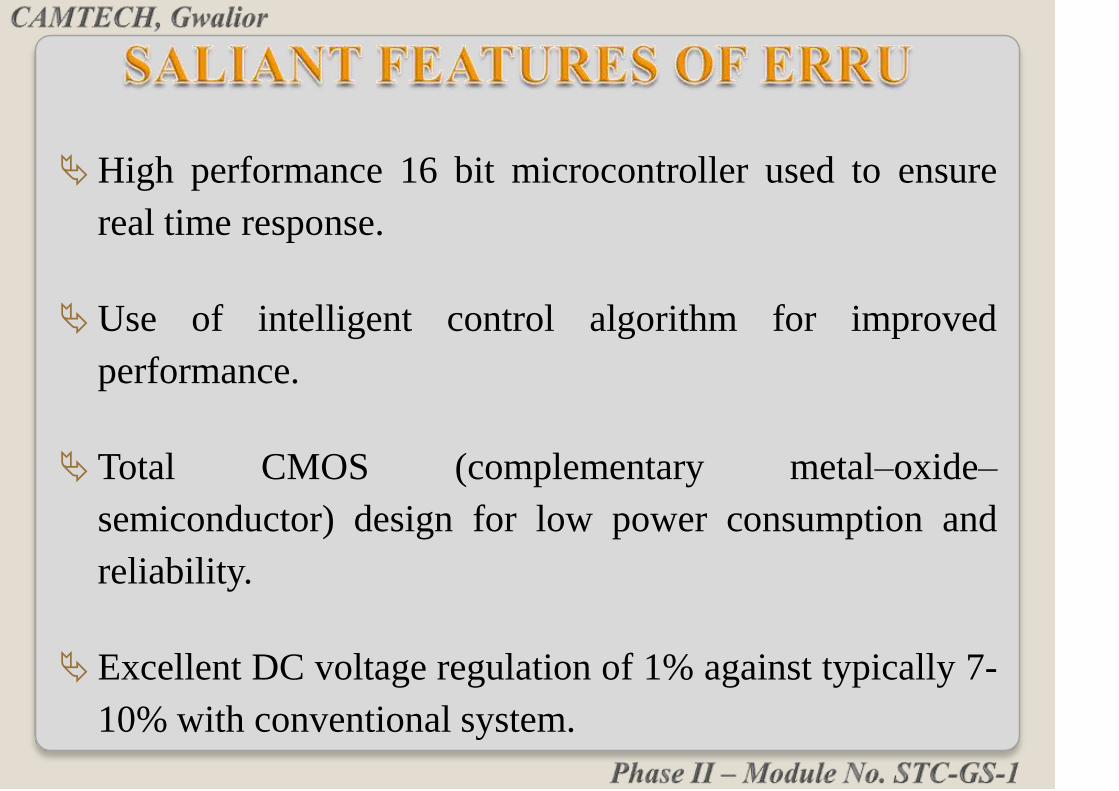
High performance 16 bit microcontroller used to ensure
real time response.
Use of intelligent control algorithm for improved
performance.
Total CMOS (complementary metal–oxide–
semiconductor) design for low power consumption and
reliability.
Excellent DC voltage regulation of 1% against typically 7-
10% with conventional system.

Reduction of the ripple content in the controlled DC
output (less than 1% ripple content as compared to the
15% in conventional system).
Better Current Regulation and current ripple (less than
10% compared to typically 25% in conventional system).
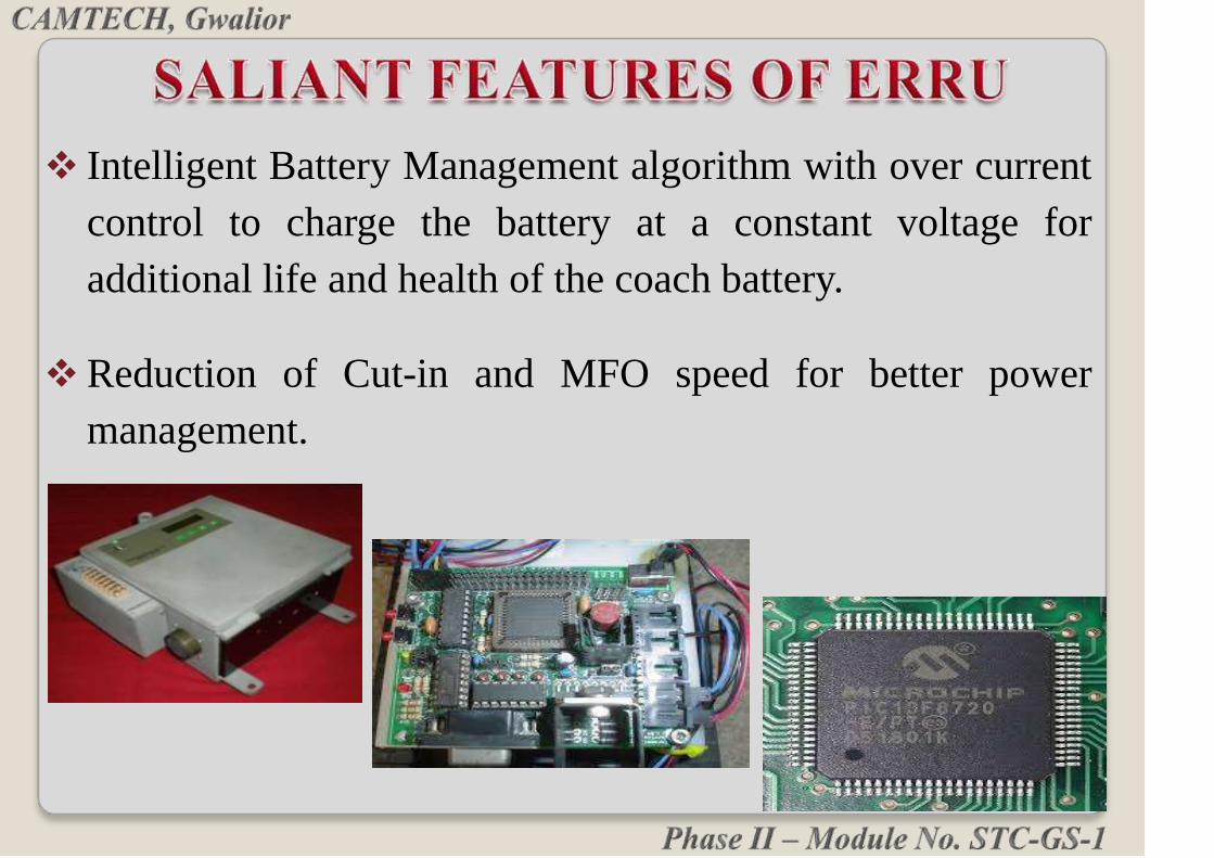
Intelligent Battery Management algorithm with over current
control to charge the battery at a constant voltage for
additional life and health of the coach battery.
Reduction of Cut-in and MFO speed for better power
management.

RDSO specification No. RDSO/PE/SPEC/
AC/0013-2011 (REV-2) For Electronic
Rectifier cum Regulator Unit (ERRU) FOR 25
kW & 4.5 kW Alternator fitted on AC & TL
Coaches issued in December, 2011.
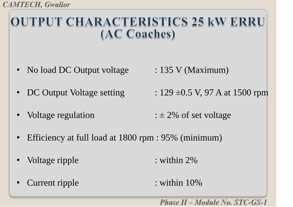
• No load DC Output voltage : 135 V (Maximum)
• DC Output Voltage setting : 129 ±0.5 V, 97 A at 1500 rpm
• Voltage regulation : ± 2% of set voltage
• Efficiency at full load at 1800 rpm : 95% (minimum)
• Voltage ripple : within 2%
• Current ripple : within 10%
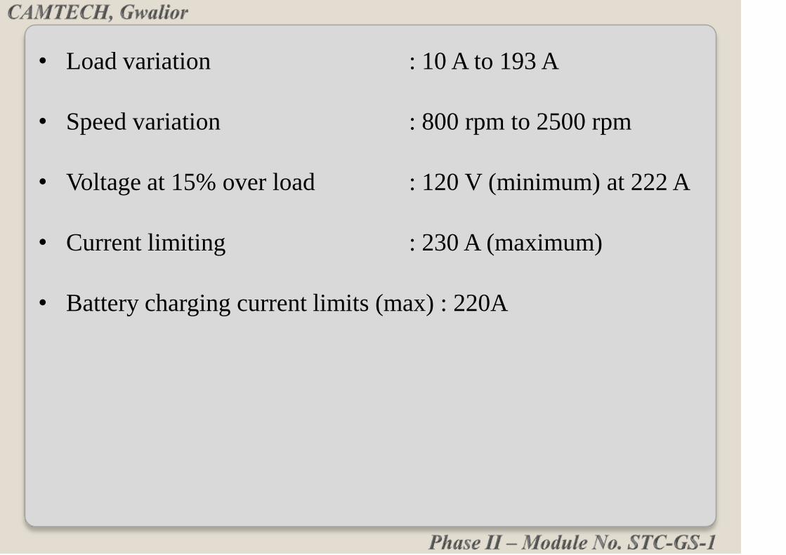
• Load variation : 10 A to 193 A
• Speed variation : 800 rpm to 2500 rpm
• Voltage at 15% over load : 120 V (minimum) at 222 A
• Current limiting : 230 A (maximum)
• Battery charging current limits (max) : 220A


No load DC Output voltage : 130 V (Maximum)
DC output voltage setting : 128.5 ± 0.5 V at 19 A at 1500 rpm
Voltage regulation : ±2% of set voltage
Efficiency at full load at 1800 rpm : 95% (minimum)
Voltage ripple : within 2%
Current ripple : within 10%
Load variation : 1 A to 37.5 A

Speed variation : 600 rpm to 2500 rpm
Voltage at over load of 40 A : 115 V (minimum)
Current limiting : 43 A (maximum)
Battery charging current limits(max.) : 24 A


Alternator
L
O
A
D
Micro Controller
DC/DC Switching
Power Supply
IGBT Based Field
Power Switching
Module
Analog Signal
Conditioning
Coach Indication
Panel
Keyboard/Display
Field
HALL Sensor
UVC
NOTE:-
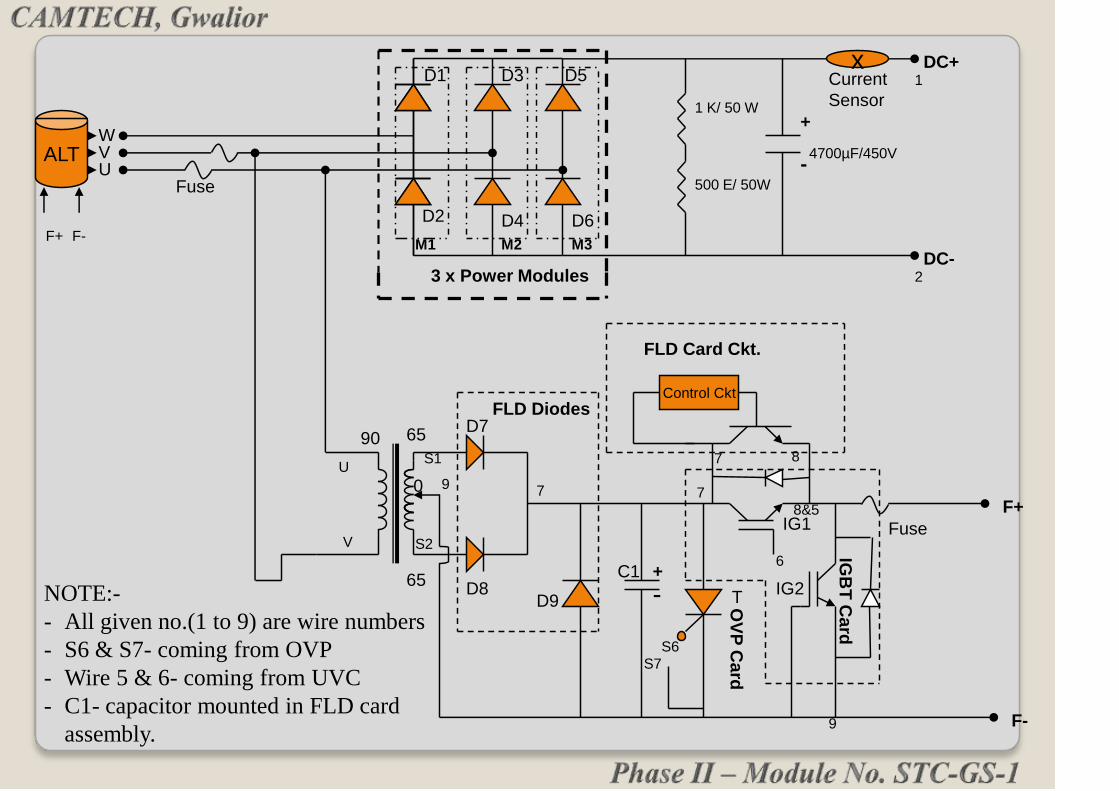
- All given no.(1 to 9) are wire numbers
- S6 & S7- coming from OVP
- Wire 5 & 6- coming from UVC
- C1- capacitor mounted in FLD card
assembly.
FLD Card Ckt.
1 K/ 50 W
500 E/ 50W
4700µF/450VUVW
90 65
0
65
DC+
DC-3 x Power Modules
+
-
F+
F-
D1
D2
D3
D4
D5
D6
D7
D8D9
M1 M2 M3
C1
T
FLD Diodes
Fuse
Fuse
IG1
IG2
IGB
T C
ard
+
-
ALT
F+ F-
xCurrent
Sensor
1
2
U
V
S1
S2
9 7 7
6
7 8
8&5
9
S6
S7
Control CktO
VP
Card

For easy understand the ERRU circuit is divided into
five parts:
1. Power circuit
2. Field circuit
3. Voltage control circuit
4. Current sensing circuit
5. OVP circuit

3 phase supply from alternator is converted into DC by
power rectifier consists of Isopack power diodes.
Filtered dc output current is sensed by load hall sensor and
battery current is sensed by battery all sensor.
DC output voltage is available at DC+ and DC- terminals
for roof load and B+ and DC-for battery charging
1. Power circuit:
Alternator 3 phase bridge Filter circuit Hall sensors(2)
rectifier
Coach load Battery
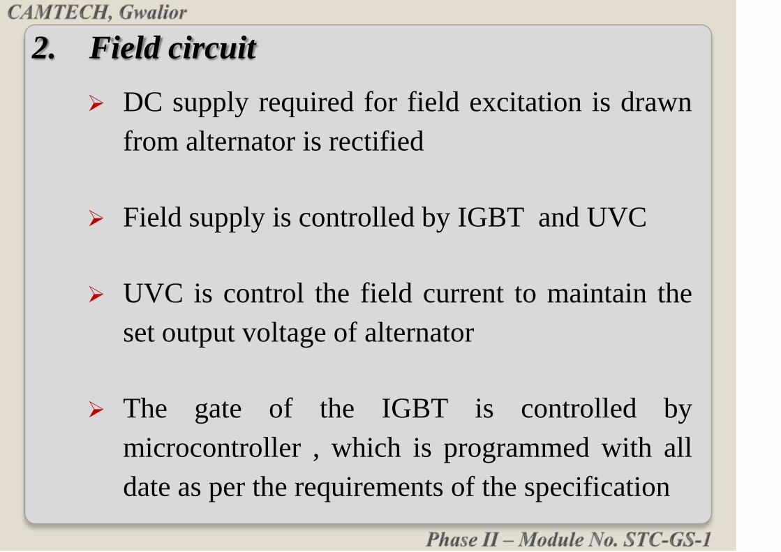
DC supply required for field excitation is drawn
from alternator is rectified
Field supply is controlled by IGBT and UVC
UVC is control the field current to maintain the
set output voltage of alternator
The gate of the IGBT is controlled by
microcontroller , which is programmed with all
date as per the requirements of the specification
2. Field circuit

3. Voltage Control Circuit
The circuit consists of SMPS unit, micro
controller.
If the voltage exceeds preset value the micro
controller gives signal to gate of IGBT
IGBT is fast switching device controls output
voltage and maintain with in limits

4. Current sensing circuit:
When ever current exceeds preset value the
microcontroller gives signal to gate of IGBT
IGBT controls output current and maintain with in
limits
Hall sensor used to sense the current flowing in the
alternator is fed into main circuit to limit the output
current and protect the equipment from over current

It is provided to stop the generation incase of
any fault of the components and cause over
voltage.
When over voltage exceeds 145V OVP
equipment disconnects the field circuit
5. Over voltage protection circuit:

FIELD
CARD
UVC
DISPLAY,
WITH UVC
CARD
TRANSISTOR
BLEEDER
RESISTOR
IGBT ET
POWER
MODULES
CAPACITOR
DATA
DOWNLOADING
UNIT

• These diode modules contain two diodes in a single
pack and have a base plate.
• They can be mounted directly on the heat sinks
needed no insulation in between. This results in
effective heat transfer to the heat sink and thereby
reducing temperature of the device.
• These isopack power diode used as 3 –phase bridge
rectifier.
ISOPACK POWER DIODES

• Rating of diode modules are as:-
• D1-D6 (25 kW) Power Diode 350A/ 1200V
• D1-D6 (4.5kW) Power Diode:- 50A/1200V

Universal application with a common design to
achieve inter changeability among the same make.
Electronic controller unit having microcontroller
can identify the rating of alternator and
automatically adjust parameters.
It can control the field current.
Ensures load sharing between two alternators.
UVC CARD AND UVC DISPLAY UNIT

UVC CARD & UVC DISPLAY UNIT

IGBT (INSULATED GATE BIPOLAR
TRANSISTOR)
Switching device to control DC input signal to the
field for regulating DC output.
It provide faster speed, better drive than power BJTs.
It is a semiconductor device combines high voltage
and high current BJT with low power and fast
switching MOSFET.


OVER VOLTAGE PROTECTGION(OVP)
Static over voltage protection circuit is provided to
stop the generation is case of any fault of the
components and causing over generation.
As the voltage goes beyond the setting limit for more
than 3 seconds the OVP circuit immediately reduces
the field current and Latches the output voltage at
less than 90 volts the Latching remains even without
battery.

It is tripping under no load or over load conditions
and reset by itself automatically within 2 sec.
The tripping voltage of the relay is set at 138+/- 1 V
for 4.5KW and 141+/- 1V for 25KW ERRUs.
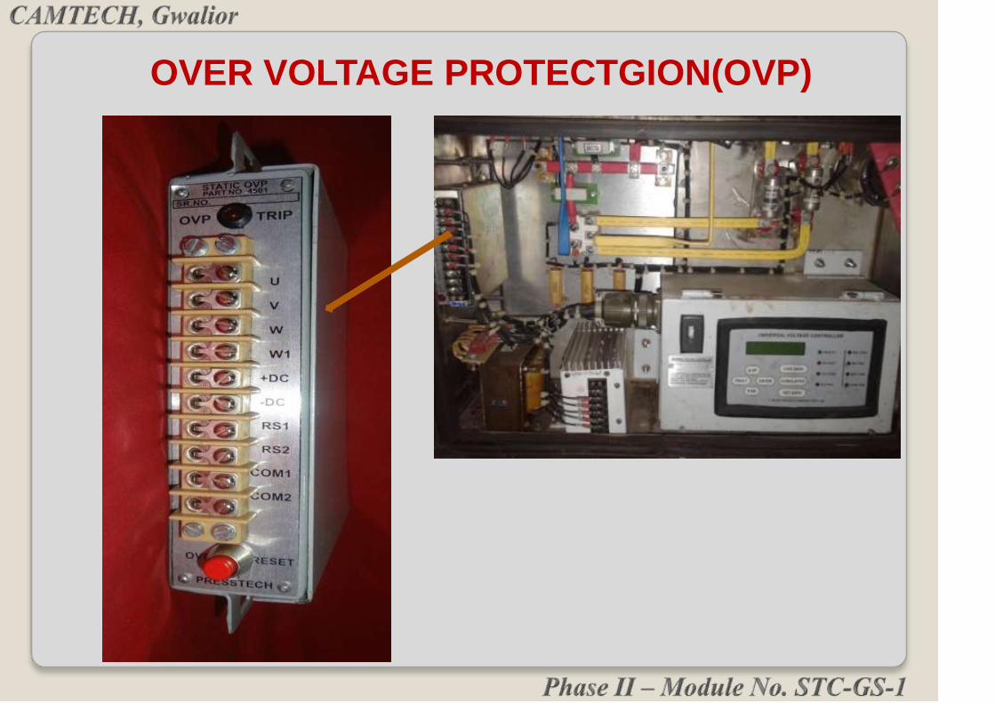
OVER VOLTAGE PROTECTGION(OVP)

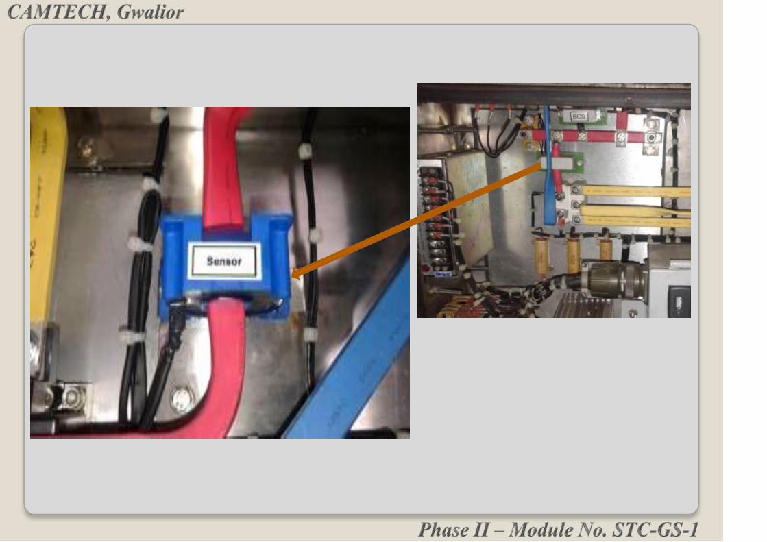
The Hall Sensor is a transformer operating with a
balanced magnetic flux principle to measure DC -
AC pulsating current with galvanic insulation
between primary and secondary circuit.
Hall Effect Sensors are used for sensing the output
load current and battery charging current. The
battery charging current is set to limit the charging
current as per the battery capacity.
These sensors are able to measure currents from 250
mA to approximately 1000A.

BLEEDER RESISTORS

Excitation (Field) transformer
is used for step down the
alternator output voltage for
field circuit.
Field transformer output
voltage rectified by 1-phase
Bridge Rectifier & Rectified
voltage controlled by
switching device as per speed
& load to maintain the D.C.
output constant.
ET (EXCITATION TRANSFORMER)
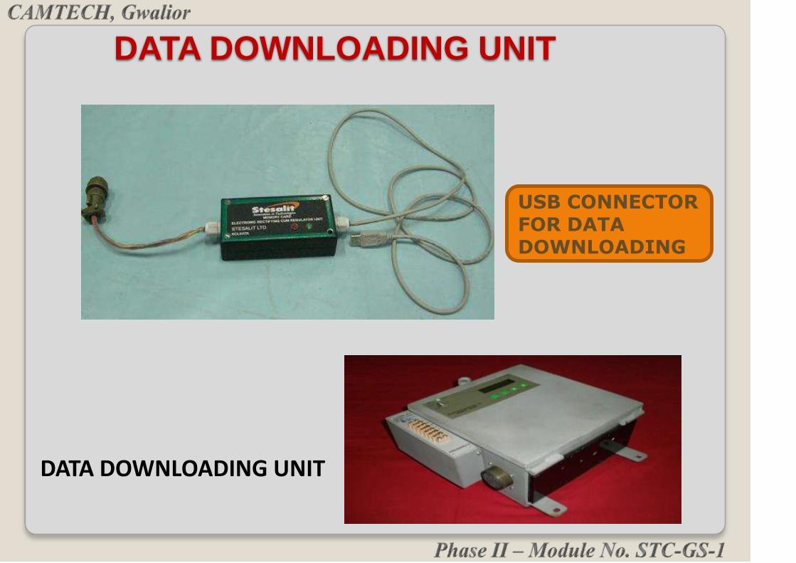
USB CONNECTORFOR DATA DOWNLOADING
DATA DOWNLOADING UNIT
DATA DOWNLOADING UNIT

DATA DOWNLOADING START WAIT FOR SEVERAL MINUTES (5-8)
PRESS ENTER
PRESS ENTER
PRESS SET PERA
FIRST CONNECT DATA LOGER TO UVC BOX
DATA DOWNLOADING PROCESS
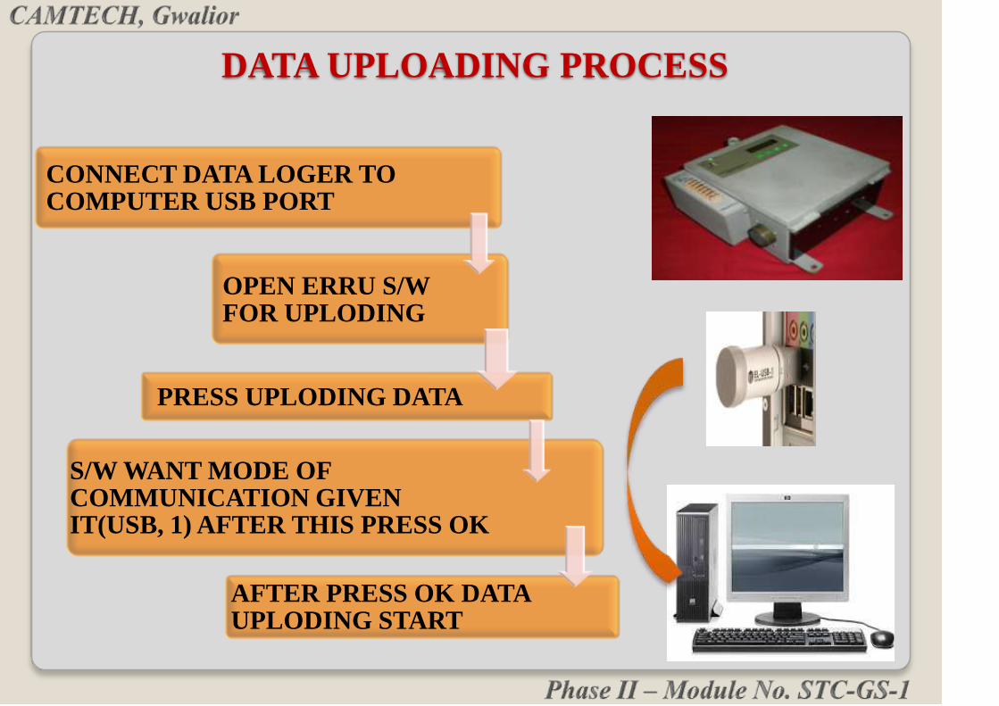
CONNECT DATA LOGER TO COMPUTER USB PORT
OPEN ERRU S/W FOR UPLODING
PRESS UPLODING DATA
S/W WANT MODE OF COMMUNICATION GIVEN IT(USB, 1) AFTER THIS PRESS OK
AFTER PRESS OK DATA UPLODING START
DATA UPLOADING PROCESS

COMPUTER INTERFACE

Data can be logged through USB port by using a
commercially available pen drive.
Step 1: Insert the pen drive in the USB port
provided on CIP and wait for
approximately 40 seconds after which
the display on the LCD screen changes
to “DOWNLOADING ERRU NPP
DATA”.
Thereafter the display changes to
“DOWNLOADING ERRU PP DATA”.

Step2: After the downloading is over the display comes
back to show the default screen. Plug out the Pen
drive from the USB port. The entire operation
does not require any command from the user in
the form of key pressing to download the Data.
Step3: Insert the pen drive in the USB slot of the
Laptop/Desktop. Run the Software provided for
the analysis of data.

Step4: The name of the file present on pen drive will be
in the form of “serialnumber.EFD” where serial
number specifies the serial number of the ERRU
for which the data has been logged from CIP.
Select the respective file through the “open file”
command on the software. After the selection of
the file the data can be analyzed in Minute
Format, Hourly Format, Overall Cumulative data
analysis and Fault Analysis.

AFTER DATA UPLODING PRESS LIVE DATA/ FAULT
PRESS LIVE DATA FOR DATA CHECKING
PRESS FAULT FOR FAULT FINDING
DATA CHECKING PROCESS

Power & Control Connectivity Of
Alternator With ERRU

U
V
W
F- F+
From the Alternator,
connect U, V, W and Field
connections as F+ & F-
DC-
DC+
Coach Load
DC+ & DC-
Terminals
B+
Battery +ve
Terminal
CIP Connector

KEYBOARD

The Keyboard consists of four function keys and three
other keys for parameter setting.
Live Data:
Pressing this key displays the information of on line non-
cumulative data.
Cumulative:
Pressing this key displays the information of on line
cumulative data.
Fault:
Pressing this key displays the information of the faults
which have occurred in the system.

Set Data:
Pressing this key displays the information of the setting
parameters for the Electronic Regulator.
The other three keys are UP, DN & ENTER are
used for incrementing, decrementing of different
parameter set limits and to store them in a
nonvolatile memory.

There are 8 LED annunciations to alert the user about
the system status on line
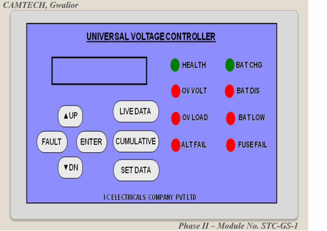
LED NOMENCLATURE
Health: This green LED gives the health of Universal
Voltage Controller of the Electronic Regulator cum
Rectifier Unit. It is off whenever there is any problem in
the UVC.

OV Volt:
As soon as the terminal voltage goes beyond 142 Volts
by anyhow, this RED led gives an indication that over
voltage occurred. Once this LED glows it will remain
latched unless and until the system is reset.
LED NOMENCLATURE
Health:
This green LED gives the health of Universal Voltage
Controller of the Electronic Regulator cum Rectifier
Unit. It is off whenever there is any problem in the
UVC.
Alt Fail:
When the Alternator is moving above 600 RPM, but
the Alternator generated voltage is less than 110 Volts,
in such a condition it is assumed that the Alternator has
some problems, as it is not able to generate the
sufficient voltage.
This condition is considered to be the Failure of the
alternator and the RED LED glows to indicate
Alternator failure.
Bat Dis:
This red LED glows when the Battery is in the
discharging mode. Alternatively, it remains OFF during
the charge condition of the battery. In addition the normal
display gets automatically changes in accordance of
battery charging or discharging mode.
BAT CHG:
This GREEN LED glows only when the Battery is in the
charging mode. Alternatively, it remains OFF during the
discharge condition of the battery. In addition the normal
display gets automatically changes in accordance of
battery charging or discharging mode.

OV LOAD:
Over Load or Short Circuit condition is indicated by the
OL / SC FAULT LED.
Fuse Fail:
If any one or both the main fuses in the U & V phase
line fails due to any abnormal condition or the Field
Fuse is blown off, the FUSE
Fail Red Led glows to indicate the fuse failure. This
though does not affect the performance of UVC; what
for UVC health remains unchanged.

Bat Low:
As soon as the terminal voltage goes below 102V this
RED Led glows to give an indication that battery
voltage has dropped below 102V.

The ERRU is ‘maintenance free’ equipment. Visual check
for mounting and external damages.
Weekly Maintenance:
During maintenance, check the various fuses for two
phases from alternator and the field fuse.
Check the power cable connections with load, battery
as well as with the alternator on the control-wiring box
of ERRU box.
Check the 12-core 1:1 cable continuity between
ERRUs and CIP.
MAINTAINENCE
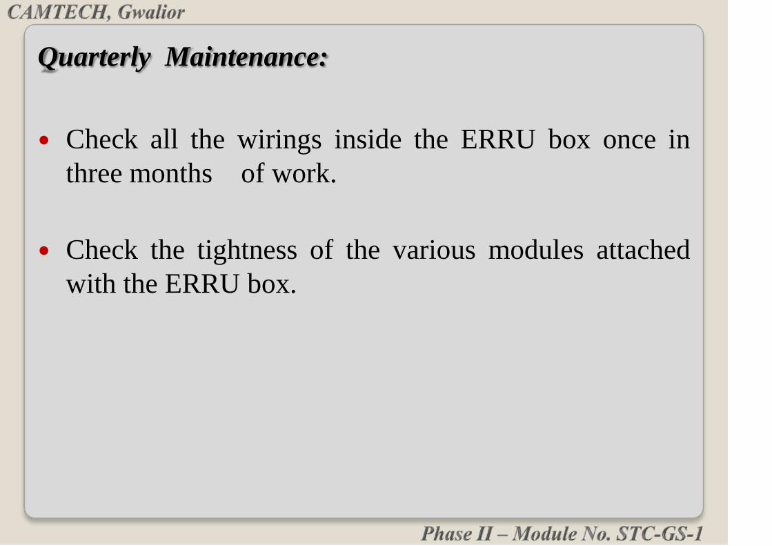
Quarterly Maintenance:
Check all the wirings inside the ERRU box once in
three months of work.
Check the tightness of the various modules attached
with the ERRU box.
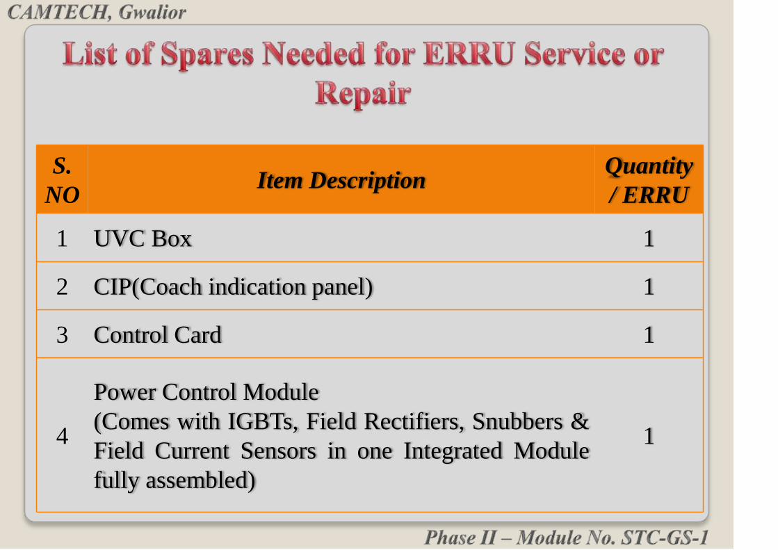
S.
NOItem Description
Quantity
/ ERRU
1 UVC Box 1
2 CIP(Coach indication panel) 1
3 Control Card 1
4
Power Control Module
(Comes with IGBTs, Field Rectifiers, Snubbers &
Field Current Sensors in one Integrated Module
fully assembled)
1

S.
NOItem Description
Quantity
/ ERRU
5 Power Diode Module 3
6Current Sensors
( or Load Current)2
7Communication Couplers with 17 meters for NPP
side & 14 Meters for PP side 12-core wire fully
assembled
2
S.
NO
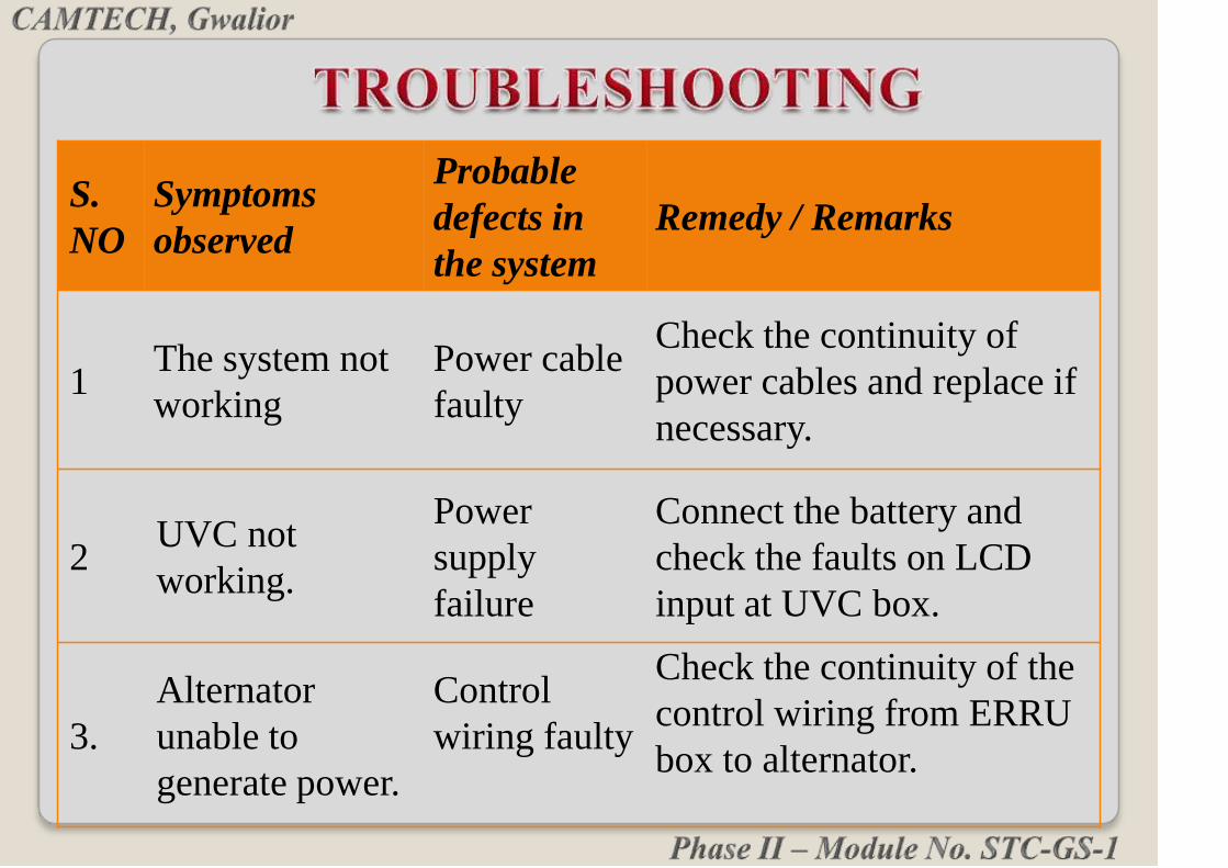
Symptoms
observed
Probable
defects in
the system
Remedy / Remarks
1The system not
working
Power cable
faulty
Check the continuity of
power cables and replace if
necessary.
2UVC not
working.
Power
supply
failure
Connect the battery and
check the faults on LCD
input at UVC box.
3.
Alternator
unable to
generate power.
Control
wiring faulty
Check the continuity of the
control wiring from ERRU
box to alternator.

S.
NOSymptoms
observed
Probable
defects in
the system
Remedy / Remarks
3 Alternator
unable to
generate
power.
Main fuse
failure
Check and replace (if blown) the
ac phase fuses.
Field fuse
fail
Check and replace (if blown) the
field fuse.
4 Reduced
alternator
generation
Voltage
setting
changed.
Check the actual set voltage using
the keyboard in the SETTINGS
menu.
System in
current
control
mode.
Check the current limit settings
(total & battery charging current
limits) and the actual loads from
the display to ensure whether the
system is in current limiting mode.
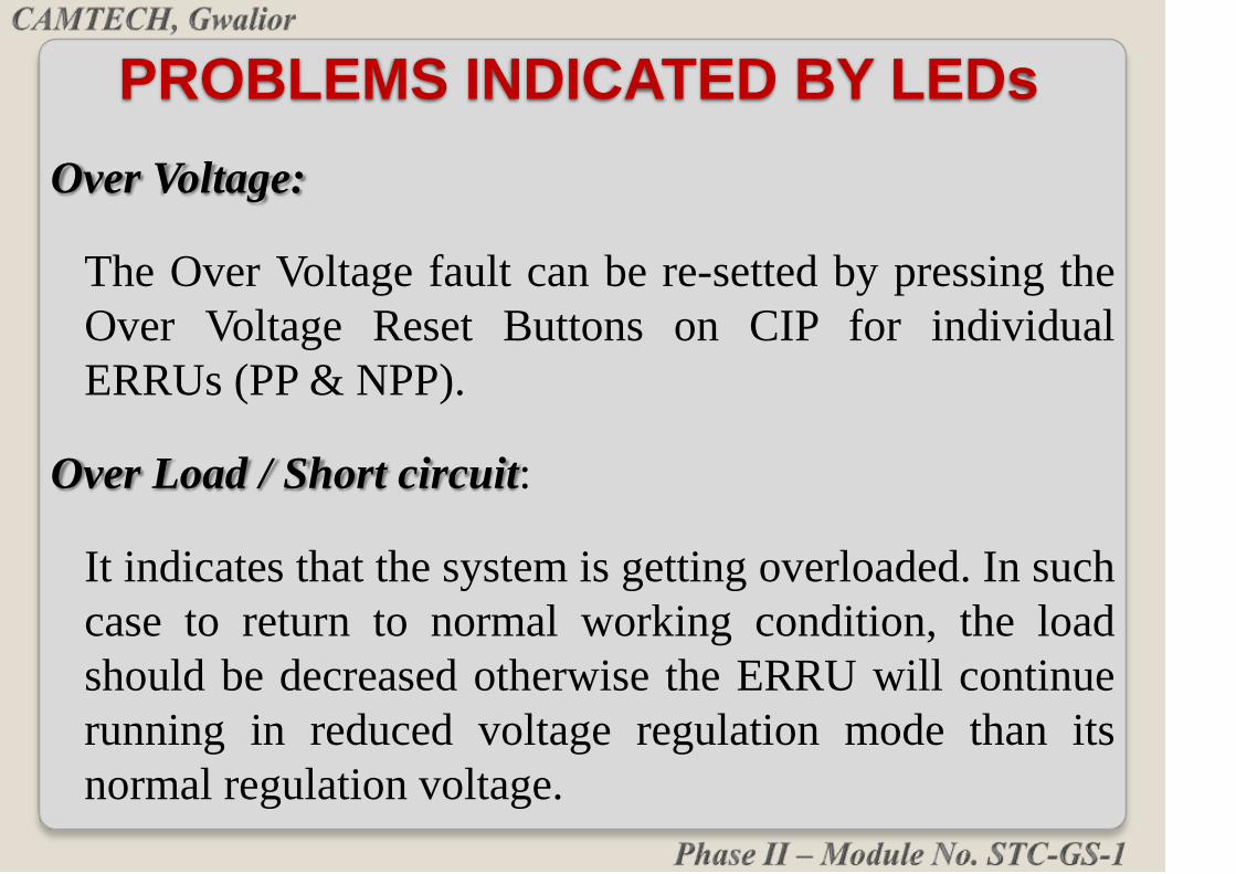
Over Voltage:
The Over Voltage fault can be re-setted by pressing the
Over Voltage Reset Buttons on CIP for individual
ERRUs (PP & NPP).
Over Load / Short circuit:
It indicates that the system is getting overloaded. In such
case to return to normal working condition, the load
should be decreased otherwise the ERRU will continue
running in reduced voltage regulation mode than its
normal regulation voltage.
PROBLEMS INDICATED BY LEDs

Fuse Fail:
In case of Main Fuse (any of two) or Field Fuse failure
the LCD of CIP and ERRU gives the message. Replace
the blown fuses.
Alternator Failure:
In some cases of alternator failure (other than
mechanical) the ERRU shows the fault message.
Recharge the alternator or replace.
UVC health: Replace UVC in case of this LED glows.

Connect all the terminals strictly as directed in the
OEM’s manual.
Connect Battery before starting test and see the
healthiness of UVC on keyboard display and LED.
Check the setting parameters before starting the test.
Parameters are loaded by default. If required these
can be changed as desired within certain predefined
limits.
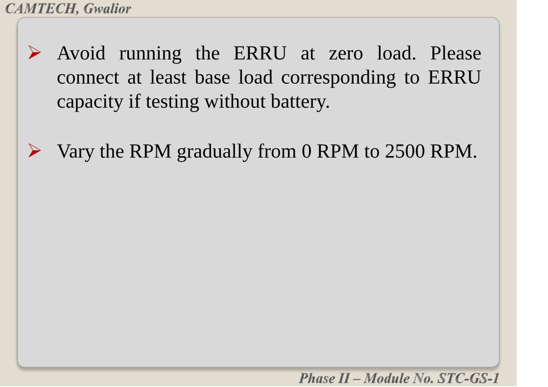
Avoid running the ERRU at zero load. Please
connect at least base load corresponding to ERRU
capacity if testing without battery.
Vary the RPM gradually from 0 RPM to 2500 RPM.

Do not test the 25 KW ERRU without connecting the
battery while installed in the coach.
Always switch on the battery first, verify the
communication with CIP. Ensure the proper parameter
settings through the display panel and the proper load
connections before starting the test.
Never apply the field fuse when alternator is running
at a speed more than 400 RPM.
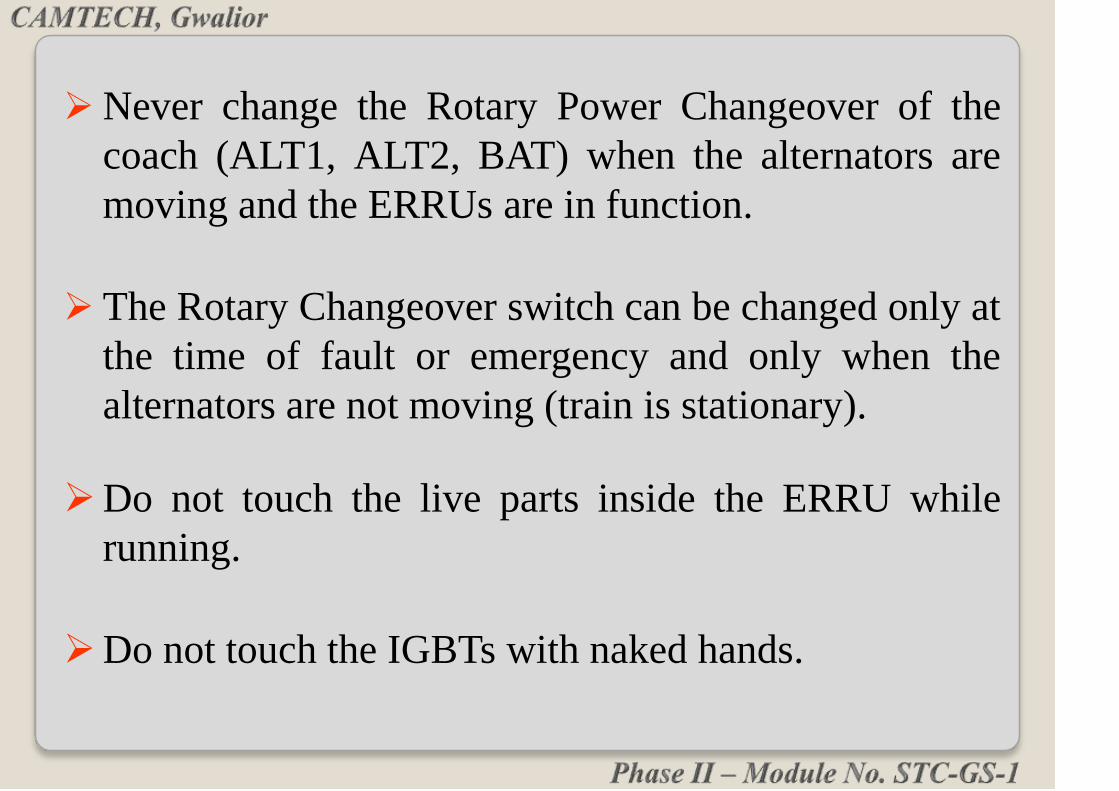
Never change the Rotary Power Changeover of the
coach (ALT1, ALT2, BAT) when the alternators are
moving and the ERRUs are in function.
The Rotary Changeover switch can be changed only at
the time of fault or emergency and only when the
alternators are not moving (train is stationary).
Do not touch the live parts inside the ERRU while
running.
Do not touch the IGBTs with naked hands.

Do not start the alternator through prime mover if
ERRU is not connected with battery.
Do not charge the battery by any external source if its
voltage is more than 140 Volts. This will trip the
ERRU in over voltage latched condition.

Phase II – Module No. STC-GS-1
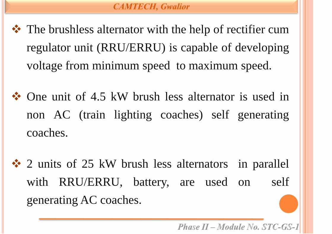
The brushless alternator with the help of rectifier cum
regulator unit (RRU/ERRU) is capable of developing
voltage from minimum speed to maximum speed.
One unit of 4.5 kW brush less alternator is used in
non AC (train lighting coaches) self generating
coaches.
2 units of 25 kW brush less alternators in parallel
with RRU/ERRU, battery, are used on self
generating AC coaches.

Ratings in use (at dc output terminals)
3 kW for MG TL coaches.
4.5 kW, 110/120 V DC, 38 A for TL coaches.
12 kW, 110/130 V DC for MG AC coaches and Jan
shatabdi.
25 kW, 110/130 V, 193 A for under slung and
RMPU type AC coaches
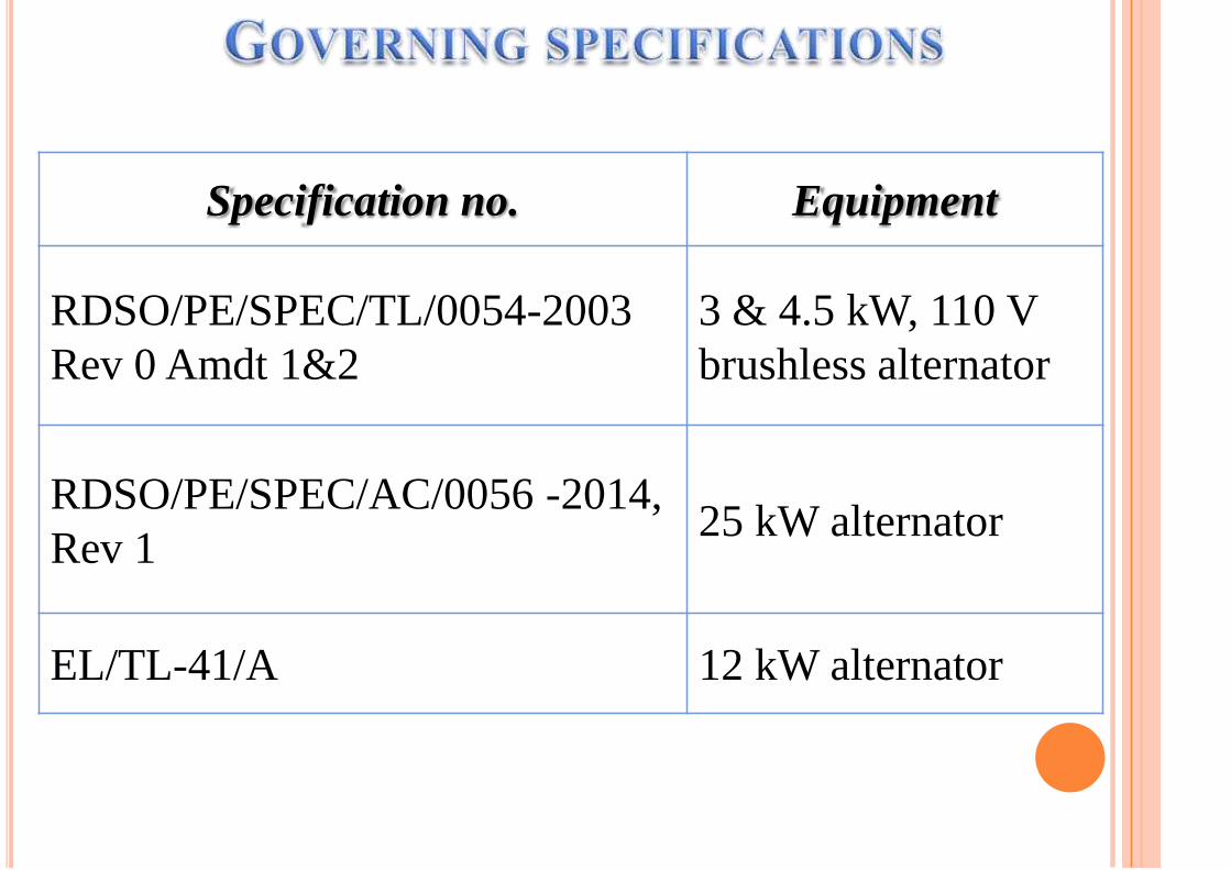
Specification no. Equipment
RDSO/PE/SPEC/TL/0054-2003
Rev 0 Amdt 1&2
3 & 4.5 kW, 110 V
brushless alternator
RDSO/PE/SPEC/AC/0056 -2014,
Rev 125 kW alternator
EL/TL-41/A 12 kW alternator

Quantity
• TL coaches - 1 set/coach
• All AC coaches except FAC - 2 sets/coach
• FAC - 1 set/coach (being increased to 2 sets/coach)
Used for charging battery set of coach at nominal 110
V and catering AC and TL load of the coach.
RRU/ERRU used for
• Rectify ac output of alternator
• Regulate output of alternator
• Prevent reverse flow of current from battery

Alternator Part I Part II
4.5 kW KEL Kundra Star Electric Company
SIL PD Steel
HMTD Kapsons
Presstech
Best & Crompton
IC Electrical
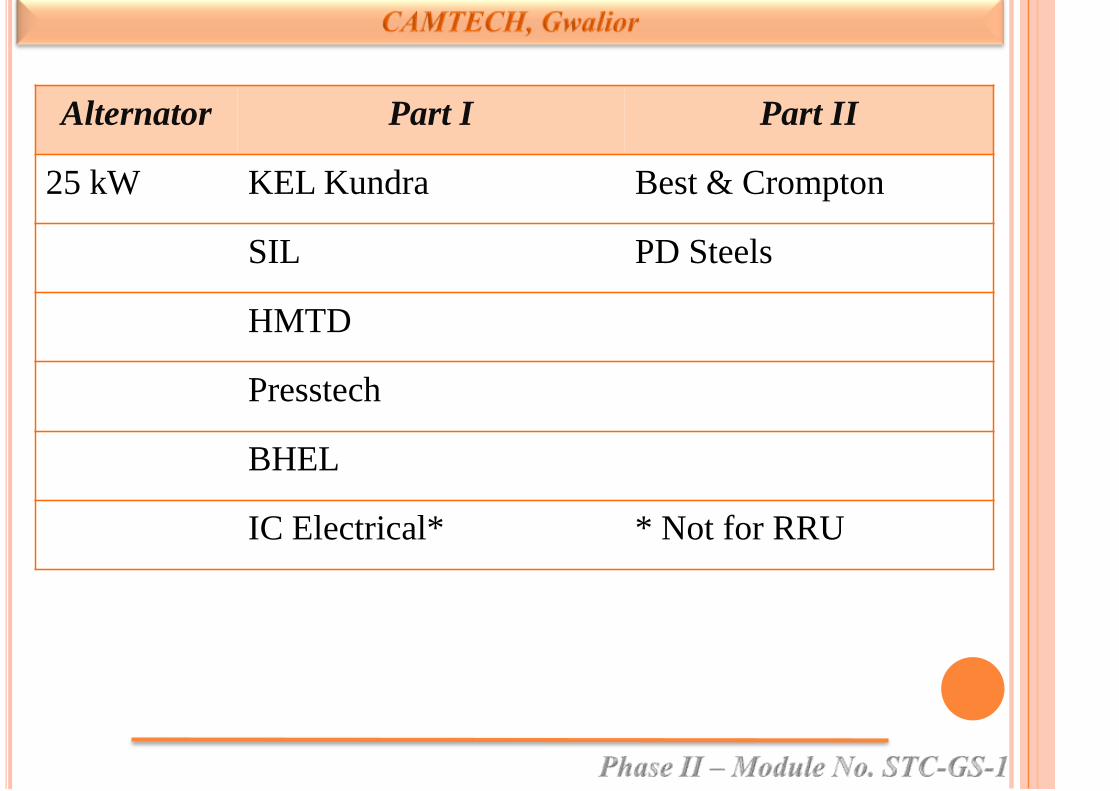
Alternator Part I Part II
25 kW KEL Kundra Best & Crompton
SIL PD Steels
HMTD
Presstech
BHEL
IC Electrical* * Not for RRU
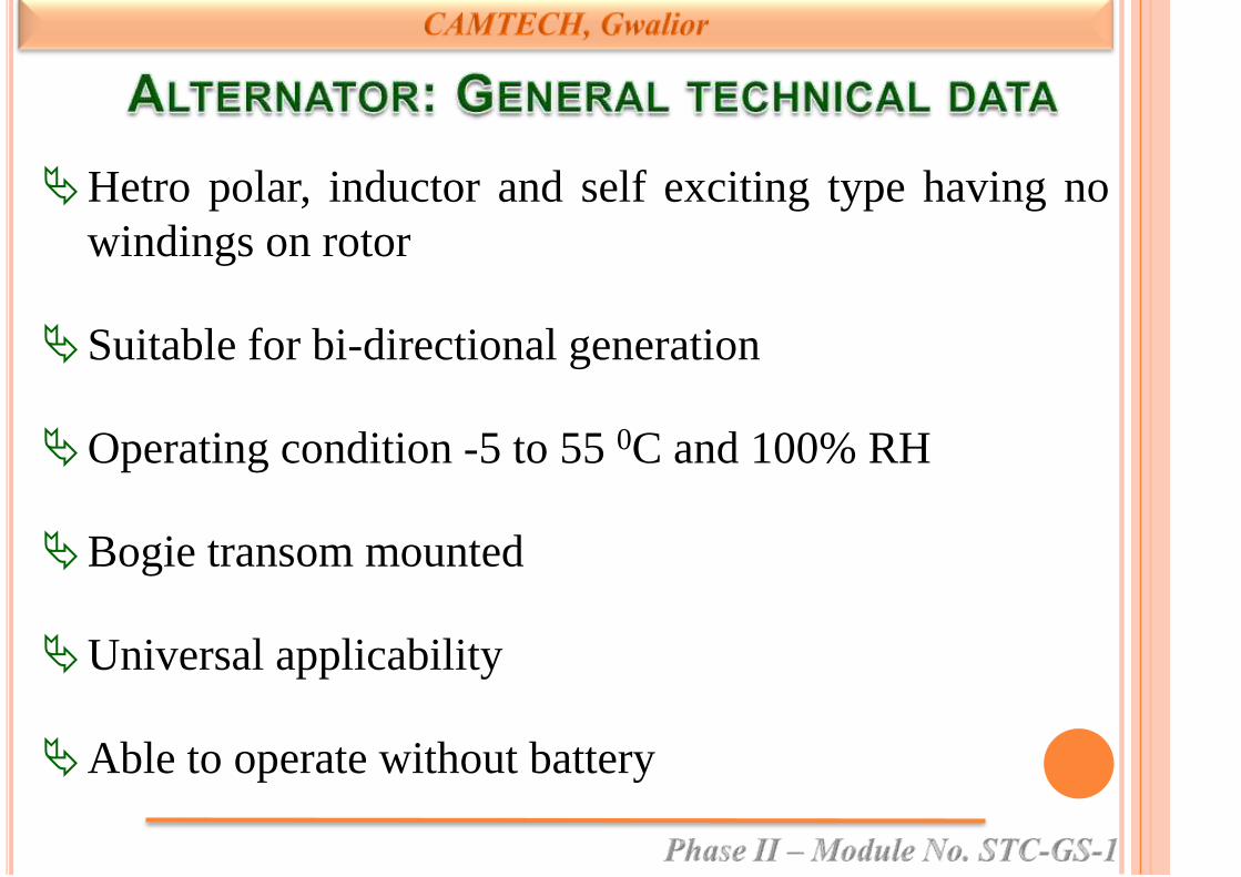
Hetro polar, inductor and self exciting type having no
windings on rotor
Suitable for bi-directional generation
Operating condition -5 to 55 0C and 100% RH
Bogie transom mounted
Universal applicability
Able to operate without battery

Rotor shaft made of EN 24 (hardened and tempered)
Coach wheel Dia: New/fully worn -915/813 mm
Rotor and Alternator pulleys dynamically balanced
Finished shafts to be 100% ultra sonic tested
I/P & O/P sockets terminated on separate terminal
posts.
RRU is magnetic amplifier type field excitation control.
Insulated cleat provided on frame to support cables
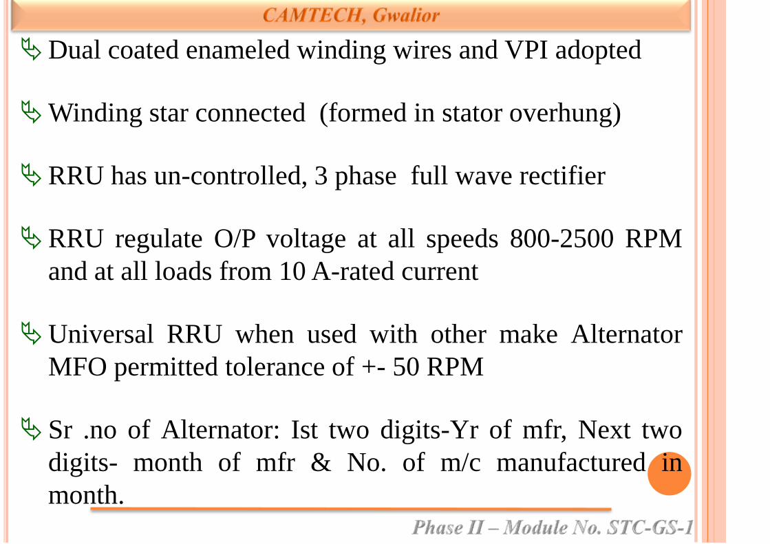
Dual coated enameled winding wires and VPI adopted
Winding star connected (formed in stator overhung)
RRU has un-controlled, 3 phase full wave rectifier
RRU regulate O/P voltage at all speeds 800-2500 RPM
and at all loads from 10 A-rated current
Universal RRU when used with other make Alternator
MFO permitted tolerance of +- 50 RPM
Sr .no of Alternator: Ist two digits-Yr of mfr, Next two
digits- month of mfr & No. of m/c manufactured in
month.

Each alternator set comprises of
• 1 TL/AC alternator with 1/2 V grooved pulleys
• Safety chains 2 for 4.5 kW/ 3 for 25 kW
• 1 RRU/ERRU
• Belt tensioning device complete
• Axle pulley complete with rubber pad and
hardware

• Suspension pin complete with hardware
• Crimping type sockets for Alternator and
RRU/ERRU
• Maintenance manual
Items procured separately
• V belts 4 (TL), 6+6 (AC)
• Nylon suspension bushes 2/set

Cut-in speed:
Alternator speed in RPM at which rectified output is
110 V at no load.
Min speed for full output (MFO):
Min Alternator speed in RPM at which it gives rated
O/P current at rated V.
Voltage and Current detector:
Device to limit voltage and current of alternator to pre-
set values.

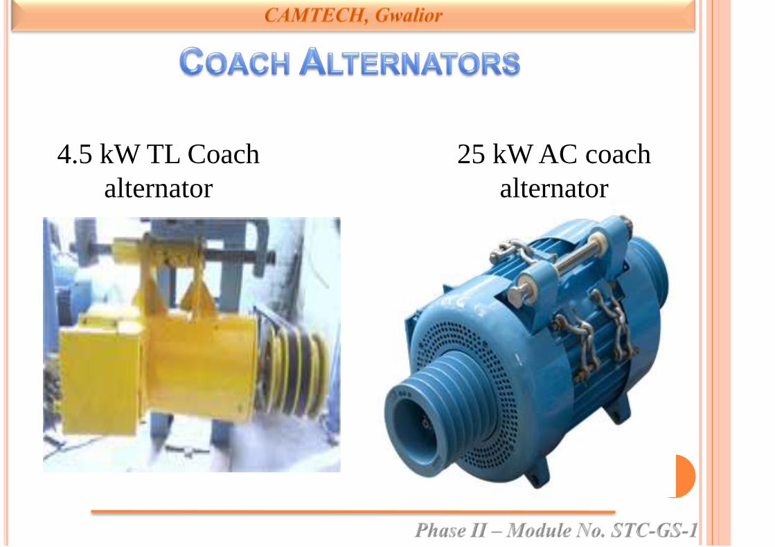
25 kW AC coach
alternator
4.5 kW TL Coach
alternator


Wound stator with field coil
Rotor shaft with lamination
End shield (Driving End)
End shield (Non Driving End)
Bearing (NU311,Driving End)
Bearing (6309, Non Driving End)
Safety Chains
Lock nut
Lock Washer
Alternator Pulley 4 – V groove
Cast Nylon bush
Bearing cover
Shaft key
Castle nut
Split pin
Suspension pin
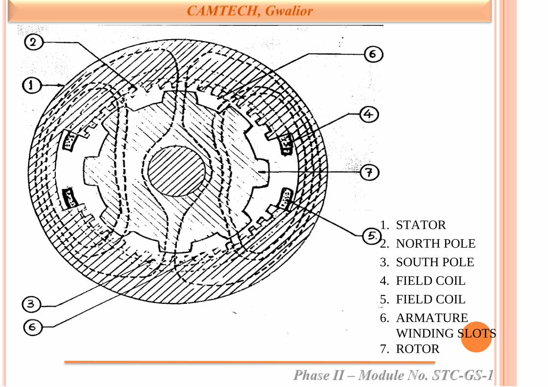
1. STATOR
2. NORTH POLE
3. SOUTH POLE
4. FIELD COIL
5. FIELD COIL
6. ARMATURE
WINDING SLOTS
7. ROTOR

Cut in Speed – 350 ± 50 r.p.m.
MFO (Min. speed for Full output) - 550 ± 50 r.p.m.
Working Speed – 2500 r.p.m.
Voltage setting at 1500 r.p.m at 19 Amps – 128.5 ± 0.5
Volt DC
Over Voltage Protection Setting – 145 ± 1 Volt DC
Current Setting – 37.5 Amps
Current limiting – 37.5 + 15% of rated load (amps)

Modified Nylon bush arrangement issued vide RDSO
letter no EL/1.6.9.15 Dt. 28.12.2012
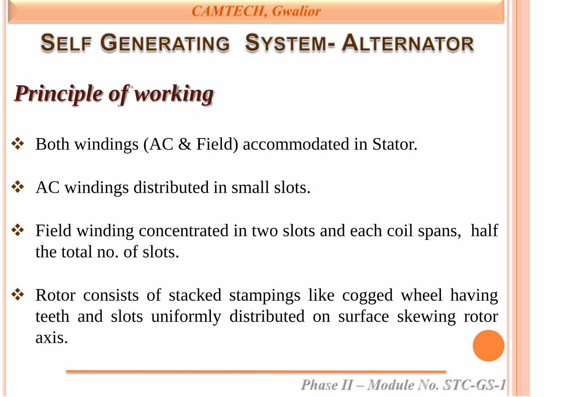
Both windings (AC & Field) accommodated in Stator.
AC windings distributed in small slots.
Field winding concentrated in two slots and each coil spans, half
the total no. of slots.
Rotor consists of stacked stampings like cogged wheel having
teeth and slots uniformly distributed on surface skewing rotor
axis.
Principle of working

Core of stator (completely embraced by field coils) retain
residual magnetism, if excited once by battery.
Flux produced by field coils find its path through rotor.
On rotation, rotor offers varying reluctance path for the field
flux.
Varying field flux induces alternating voltage in AC coils.
Frequency depend on speed and magnitude on speed and level of
excitation.


Circuit diagram

Functions
Rectification of 3 phase AC output of alternator
using full wave rectifier bridge.
Regulation of voltage at set value.
Regulating output current at set value.

Components
3 ph full wave rectifier (Diode D1 to D6) with heat
sinks.
1 ph full wave rectifier (Diode D16 & D17) on heat
sink along with free wheeling diode D18.
Sensing diodes (D19 & D20) for current/voltage
setting with zener diode Z1.

Full wave rectifier

DE- NU-311
NDE 6309
4.5 kW
• Drive end: NU-311 (Cylindrical)
• Non drive end: 6309 (Deep groove ball)
25 kW
• Terminal end NU-312 (cylindrical)
• Other end 7312 (angular contact ball)
L 10 life 16 million km at 1500 RPM
Make : SKF/FAG

Feature 4.5 kW 25 kW
Rating 120 V, 37.5 Amp 130 V, 193 Amp
Factory set at (1500 RPM) 128.5V at 1/2 load 128 V at 1/2 load
Efficiency 70% at full load
and 1800 RPM
80 % at full load
and 1800 RPM
Min. RPM for 2V ac r.m.s. 300 NM
Field winding resistance 4.5+/- 0.5 Ω 8.5+/-1.5 Ω
Stator winding resistance
(phase to phase)
0.4+/- 0.05 Ω 0.045+/-0.01 Ω
Suspension pin dia 31.75+0/-0.10 mm 35.0 +0.2/-0.3 mm
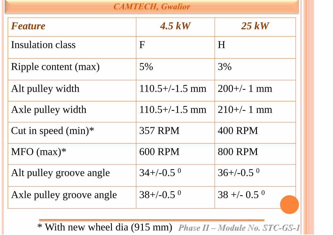
Feature 4.5 kW 25 kW
Insulation class F H
Ripple content (max) 5% 3%
Alt pulley width 110.5+/-1.5 mm 200+/- 1 mm
Axle pulley width 110.5+/-1.5 mm 210+/- 1 mm
Cut in speed (min)* 357 RPM 400 RPM
MFO (max)* 600 RPM 800 RPM
Alt pulley groove angle 34+/-0.5 0 36+/-0.5 0
Axle pulley groove angle 38+/-0.5 0 38 +/- 0.5 0
* With new wheel dia (915 mm)
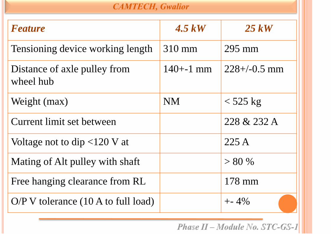
Feature 4.5 kW 25 kW
Tensioning device working length 310 mm 295 mm
Distance of axle pulley from
wheel hub
140+-1 mm 228+/-0.5 mm
Weight (max) NM < 525 kg
Current limit set between 228 & 232 A
Voltage not to dip <120 V at 225 A
Mating of Alt pulley with shaft > 80 %
Free hanging clearance from RL 178 mm
O/P V tolerance (10 A to full load) +- 4%

Feature 4.5 kW 25 kW
I limiting by potentiometer 228-232 A
Voltage not to dip below 120 V at 225 A
Max V set through potentiometer 140 V at 800 rpm on
10 A load
Max I set through potentiometer 232 A
Bearing L10 life > 16 million km at
1500 RPM
Bearing re-greasing interval >30 M or 6 lac km
OVR set at 145+- 1 V
Size of rotor (D * L)
No of teeth (slot) on rotor 8 12
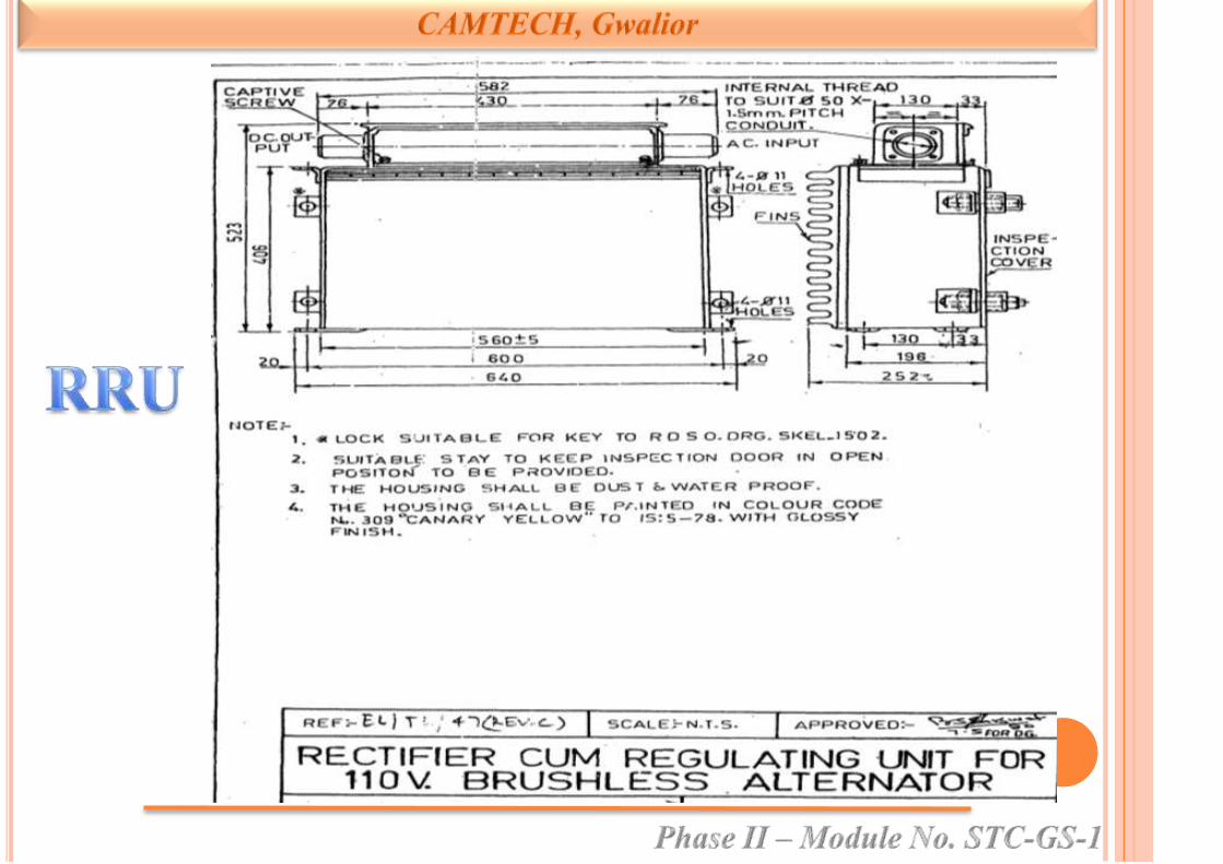
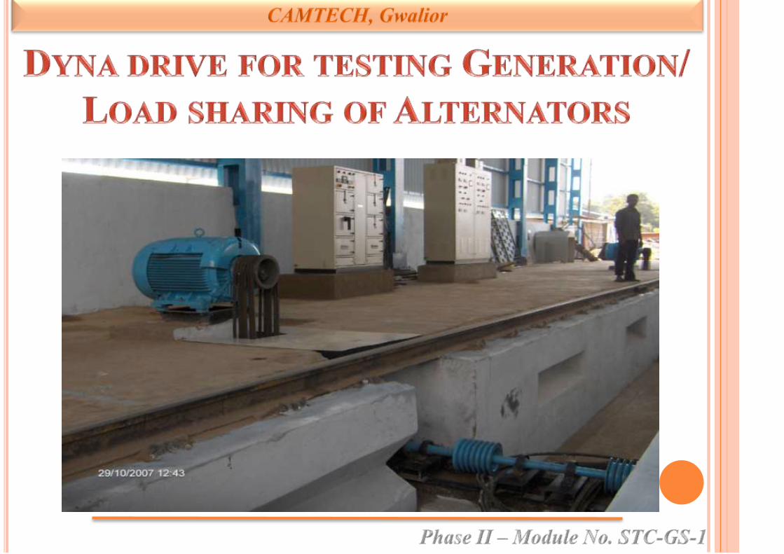
Sr SMI/MS N0 Description Reference
1 AC/SMI/9
Instruction for re-assembly of
NH type bearing of 18 kW
KEL make alternator during
POH
EL/7.1.21/K
Dt. 03.7.1991
2
RDSO/PE/SMI/
AC/ALT/0002
98(Rev.0)
Fits and limits on bearings of
alternators and motors used on
AC coaches.
EL/7.1.38/1
Dt. 20.01.99
3
RDSO/PE/SMI/
AC/ALT/0003,
98(Rev.0)
Procedure for measuring
bearing clearance of a free
bearing.
EL/7.1.38/1
Dt. 20.01.99

Sr SMI/MS N0 Description Reference
4 RDSO/PE/SM/
AC/ALT/0004
–98(Rev.0)
Condition monitoring of
bearings.
EL/7.1.38/1
Dt. 20.01.99
5 RDSO/PE/SMI/
AC/ALT/0005–
98(Rev.0)
Fitment of outer race of
bearings in the housing.
EL/7.1.38/1
Dt. 20.01.99
6 RDSO/PE/SM/
AC/ALT/0006–
98(Rev.0)
Testing and checking of new
bearings for alternators and
motors of AC coaches.
EL/7.1.38/1
Dt. 20.01.99
7 RDSO/PE/SM/
AC/ALT/0007–
98(Rev.0)
Guidelines to identify genuine
and spurious/reconditioned
bearings.
EL/7.1.38/1
Dt. 20.01.99
Sr SMI/MS N0 Description Reference
8
RDSO/PE/SM/
TL/ /0003-99
(REV.`0’)
Proper mounting ,maintenance
and handling of power and
field diodes provided in RRU
April 1999
9
RDSO/PE/SMI/
AC/0018–99
(Rev.0)
Proper load sharing in AC
coaches.
EL/7.1.38/1
05.02.1999
10
RDSO/PE/SMI/
AC/0019 –2002
(Rev. '0')
Testing procedure for proper
working of OV protection
provided in 25 kW alternator.
EL/7.1.38/1
11
RDSO/PE/SMI/
TL/026 2003
(REV.`0’)
SMI for checking shaft of TL
alternatorOct. 2003
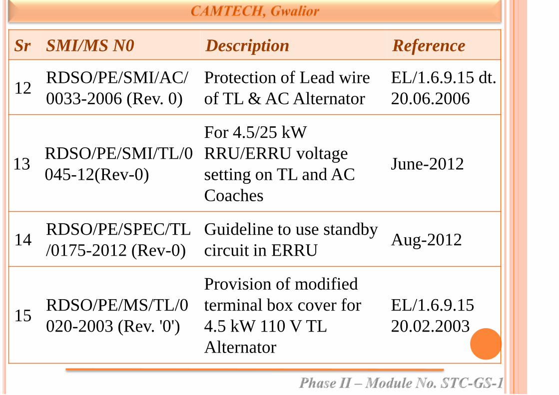
Sr SMI/MS N0 Description Reference
12RDSO/PE/SMI/AC/
0033-2006 (Rev. 0)
Protection of Lead wire
of TL & AC Alternator
EL/1.6.9.15 dt.
20.06.2006
13RDSO/PE/SMI/TL/0
045-12(Rev-0)
For 4.5/25 kW
RRU/ERRU voltage
setting on TL and AC
Coaches
June-2012
14RDSO/PE/SPEC/TL
/0175-2012 (Rev-0)
Guideline to use standby
circuit in ERRUAug-2012
15RDSO/PE/MS/TL/0
020-2003 (Rev. '0')
Provision of modified
terminal box cover for
4.5 kW 110 V TL
Alternator
EL/1.6.9.15
20.02.2003
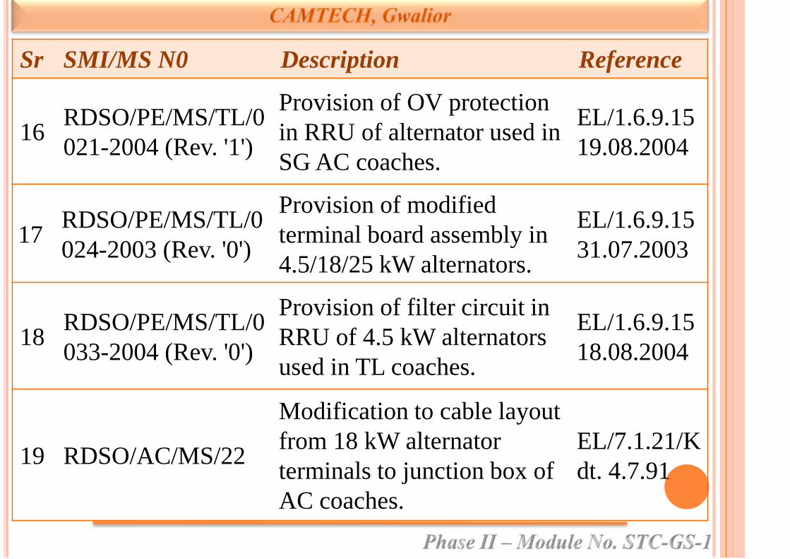
Sr SMI/MS N0 Description Reference
16RDSO/PE/MS/TL/0
021-2004 (Rev. '1')
Provision of OV protection
in RRU of alternator used in
SG AC coaches.
EL/1.6.9.15
19.08.2004
17RDSO/PE/MS/TL/0
024-2003 (Rev. '0')
Provision of modified
terminal board assembly in
4.5/18/25 kW alternators.
EL/1.6.9.15
31.07.2003
18RDSO/PE/MS/TL/0
033-2004 (Rev. '0')
Provision of filter circuit in
RRU of 4.5 kW alternators
used in TL coaches.
EL/1.6.9.15
18.08.2004
19 RDSO/AC/MS/22
Modification to cable layout
from 18 kW alternator
terminals to junction box of
AC coaches.
EL/7.1.21/K
dt. 4.7.91
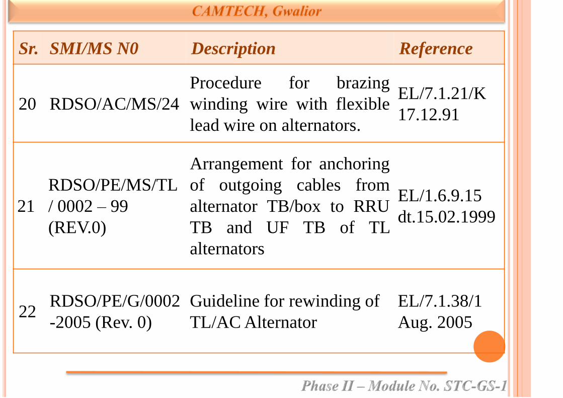
Sr. SMI/MS N0 Description Reference
20 RDSO/AC/MS/24
Procedure for brazing
winding wire with flexible
lead wire on alternators.
EL/7.1.21/K
17.12.91
21
RDSO/PE/MS/TL
/ 0002 – 99
(REV.0)
Arrangement for anchoring
of outgoing cables from
alternator TB/box to RRU
TB and UF TB of TL
alternators
EL/1.6.9.15
dt.15.02.1999
22RDSO/PE/G/0002
-2005 (Rev. 0)
Guideline for rewinding of
TL/AC Alternator
EL/7.1.38/1
Aug. 2005

Sr. SMI/MS N0 Description Reference
23
RDSO/PE/MS/A
C/ 0034-2005
(Rev. 0)
For protection of lead wire
in 4.5 /25 kW Alternator
EL/7.1.38/1
23.08.2005
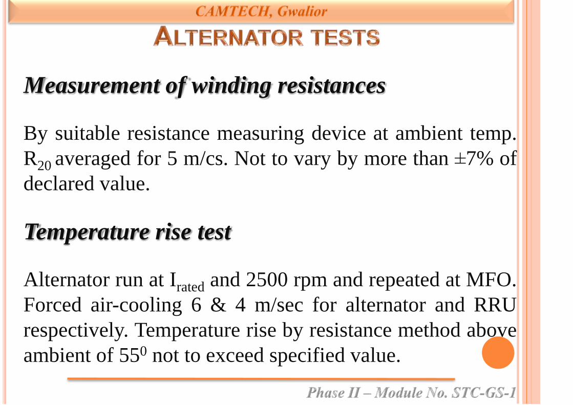
Measurement of winding resistances
By suitable resistance measuring device at ambient temp.
R20 averaged for 5 m/cs. Not to vary by more than ±7% of
declared value.
Temperature rise test
Alternator run at Irated and 2500 rpm and repeated at MFO.
Forced air-cooling 6 & 4 m/sec for alternator and RRU
respectively. Temperature rise by resistance method above
ambient of 550 not to exceed specified value.

IR Test
Measured before and after HV test between all terminals
shorted together and body with 500 V dc megger. Value
to be > 20 Mῼ.
HV Test
Immediately after temp rise test 1500 ac rms 50 hz
(gradually increased from 500 V) applied all shorted
external terminals and frame for 1 min. For acceptance
duration 5 sec and without temp rise test. ILeakage < 30 mA.
Open Circuit Test
Alternator run at minimum 5 speeds
(500,900,1500,1800, 2500) with field separately excited.
O/P voltage vs field excitation curves are plotted.
Load test
Conducted with resistance load and or with battery.
All characteristic tests done at 129 V, 96.5 A at 1500
rpm. (for 25 kW) Test consists of , No load test,
speed vs O/P, and Current vs V test.

No load test
Conducted at base load of 10 A. DC O/P voltage recorded
at MFO,1500,1800 and 2500 rpm and variation not to
exceed 4% of pre set voltage.
Speed vs O/P voltage
Done at full rated and half rated current at speeds from
MFO to max speed. V not to vary ±4% of pre set value.
Current vs voltage
Done at 1800 rpm. I varied from 10 to 193 A, keeping
speed constant. V not to vary ± 4%.

Current limiting characteristic test
Done after I vs V test. Point when , current doesn't
increase even with load increase. Not to exceed 230 A.
Mechanical over speed and induced voltage test
Done just after temp rise or load test. Alternator run for 2
minutes in each direction with Open Circuit stator
winding and separate excitation at cut-in speed level at
speed of 3035 rpm.

Short circuit test
Done on cold m/c. O/P terminals short circuited with an
ammeter and excitation adjusted to achieve 25, 50, 75 and
100% full load. Curves plotted for various speeds.
Parallel operation
Done at 800,1800 and 2500 at 25,50 and 100% load.
Difference not to exceed 30 A.
OV protection:
Time delay of 3 seconds. Set at specified voltage for
different make.
Surge protection test:
At 1800 rpm, full thrown off and O/P voltage rise recorded.
Again full load leaving 10 A resistive load thrown off and V
not to rise > 400 V and should drop to normal in 5 seconds.
Efficiency test:
Efficiency at 1800 rpm to be >80%. Speed vs efficiency curves
at rated load.
Environmental tests:
Done on RRU only. Temp rise (dry and damp heat), in
corrosive atmosphere, combined dust humidity and heat and
vibration and shock test.
Hose proof test:
For RRU, IP 55S of IS 4691-85
Special tests
• Ripple content not to exceed 3%. (Vmax-
Vmin)/(Vmax-Vmin)*100 %
• Mating of pulley with shaft: Done using plug and ring
gauges and prussian blue and media
• Shorting of power diode: At 1800 rpm and full load
for 2”.

• OC power diode
• Junction temp of semi conductors
• Dynamic balancing of rotor and pulleys
• MFO at cold and hot condition
• MHO measurement
Fire retardant test for terminal board

Tightening of alternating pulley with 30 kg-m torque
by torque wrench.
Heat the bearing by the induction heater during
fitment.
Use proper grade of grease as per manufacture
recommendations.
Quantity of grease to be used:
Ball Bearing 6309 -13 gms (approx)
Roller Bearing NU 311-20 gms (approx)

Fuse wire instead of fuse link.
Over tightening of diodes.
Less size of lead wire.
Hammer on pulley during removal.
Over tight the alternator pulley.
Heat the bearing more than 100oC.

Put extra grease in bearing.
Use less than 80% mating surface alternator pulley.
Use alternator pulley if V groove shine/0.5mm wall
are worn out.

Locking of alternator suspension hanger pin.
Alignment of alternator pulley with axle pulley.
Use same grade of V belts.
Check belt tension as per RDSO recommendation-4
kg weight, sag-14 mm. (max)

Tightening axle pulley with 30 kg-m torque and gap
between hub 3mm.±0.5mm.
Check any damage or worn out part.
Check fitment of safety chain with alternator & bogie.


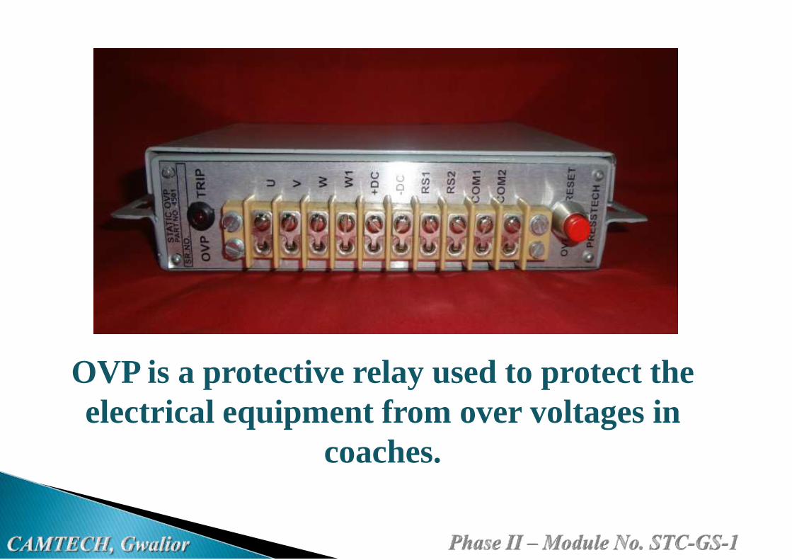
OVP is a protective relay used to protect the
electrical equipment from over voltages in
coaches.

Over voltages are voltages that exceed the normal values.
These normal values determine the insulation, which is
designed and tested according to the appropriate
regulations.
The degree of insulation varies depending on the type of
electrical equipment.
Over voltage generation may cause failure of lights & fans
and may lead to smoke emission in some cases.
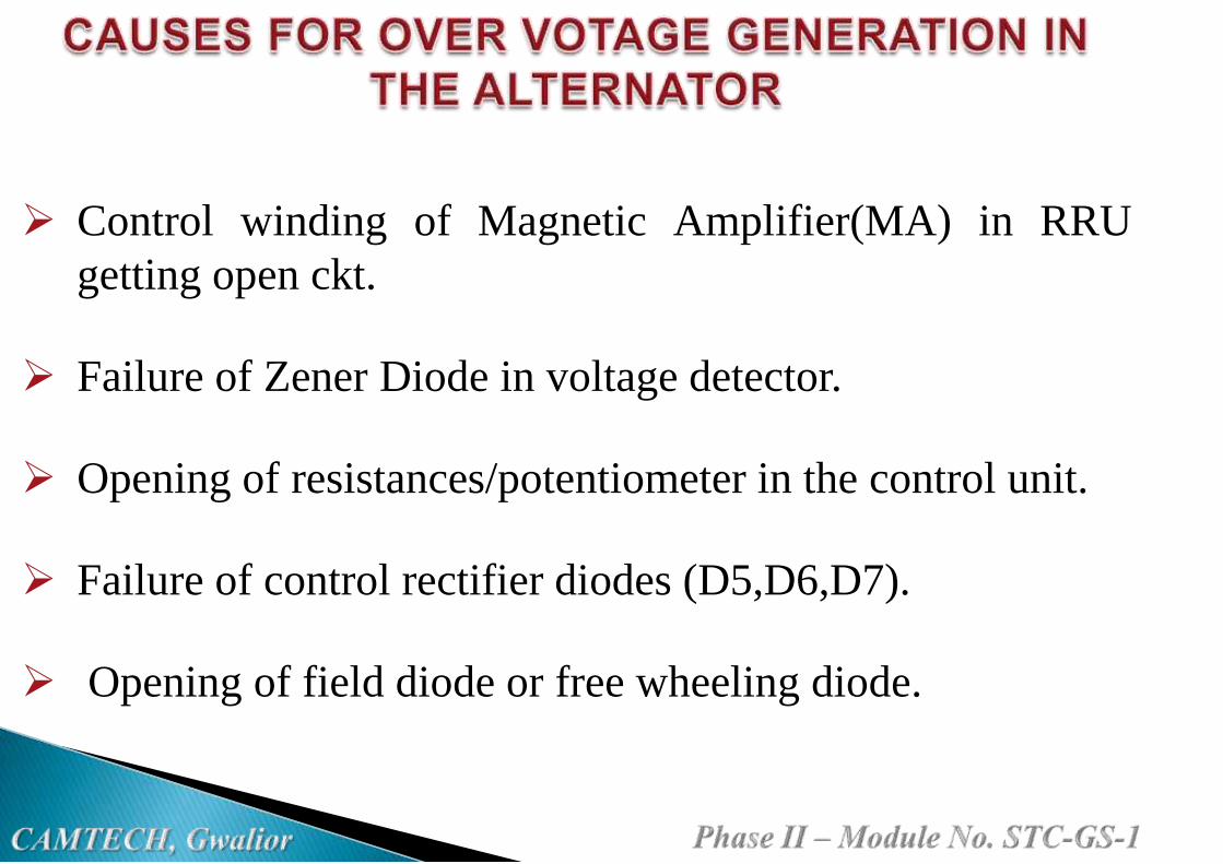
Control winding of Magnetic Amplifier(MA) in RRU
getting open ckt.
Failure of Zener Diode in voltage detector.
Opening of resistances/potentiometer in the control unit.
Failure of control rectifier diodes (D5,D6,D7).
Opening of field diode or free wheeling diode.
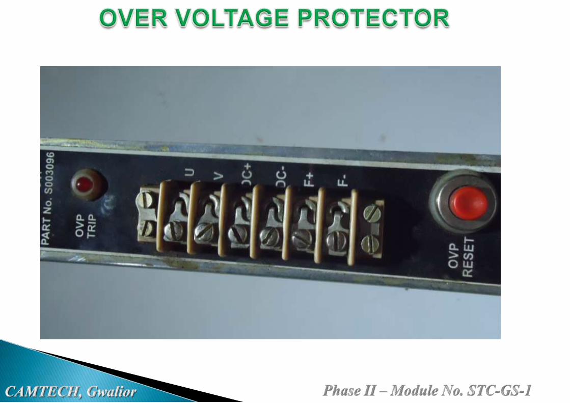

It is a safety device.
It protects the coach from over voltage generation if
control circuit failed in RRU/ERRU.
It is of two types:
1)series type
2) shunt type

OVP

OVP

It stops the generation incase of any fault in the voltage
control ckt of RRU/ERRU
If the voltage goes beyond 142volts dc for more than 3
seconds the OVP circuit immediately reduces the field
current and latches the output voltage at less than 90
volts.(in shunt type OVP)
The latching remains even without battery
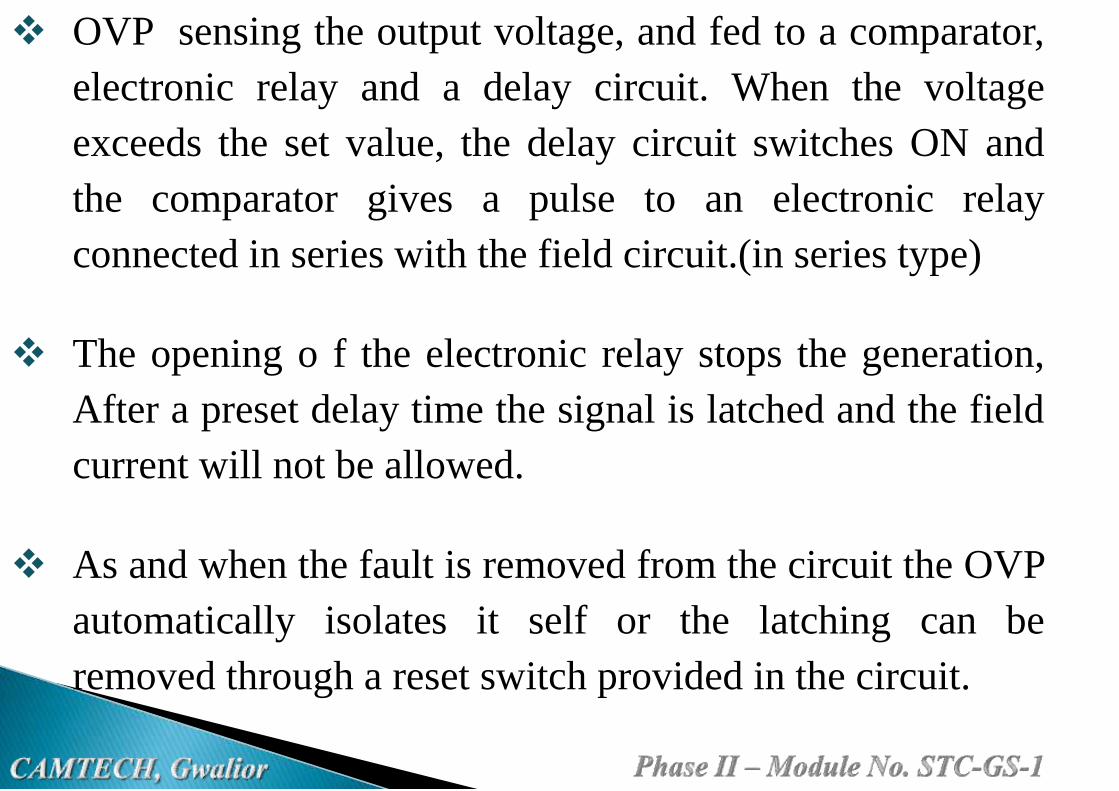
OVP sensing the output voltage, and fed to a comparator,
electronic relay and a delay circuit. When the voltage
exceeds the set value, the delay circuit switches ON and
the comparator gives a pulse to an electronic relay
connected in series with the field circuit.(in series type)
The opening o f the electronic relay stops the generation,
After a preset delay time the signal is latched and the field
current will not be allowed.
As and when the fault is removed from the circuit the OVP
automatically isolates it self or the latching can be
removed through a reset switch provided in the circuit.
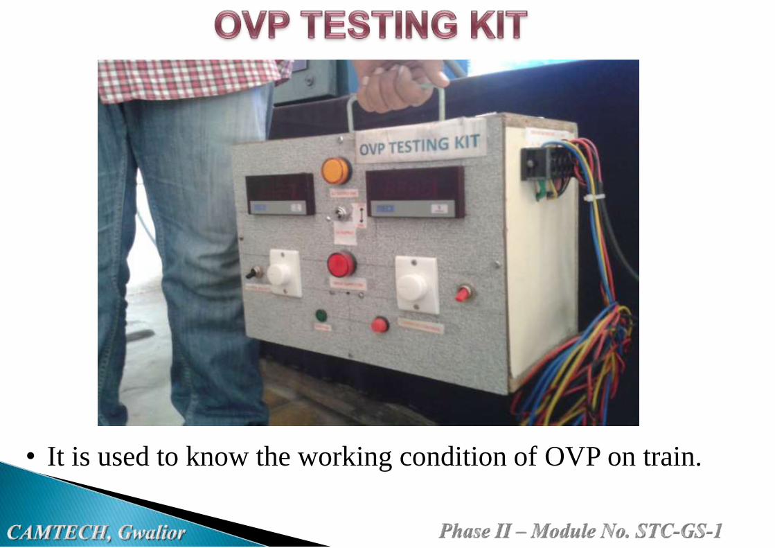
• It is used to know the working condition of OVP on train.

OVP
MAKEDC+ DC- F+ F- U V
Tripping
VoltageRemarks
KEL 7 8 19 20 - - 150V DC
Connect loop
wire between 8
& 13 of OVP
SIL,STS&
ICECPLDC+ DC- F+ F- - -
116/119V
AC
Connect loop
between
DC +ve to U
Best&
CromptonB+ B- F+ F- AC1 AC2
140±1V
DC-
KAPSON DC+ DC- F+ F- U V143-144V
DC-
HMTD B+ B- 2 F2 - -150V
DC
Connect loop
between
DC + ve to 10
PRESSTE
CHDC+ DC- F+ F- U V
146 V
DC-

OVP
MAKEDC+ DC- F+ F- U V
Tripping
VoltageRemarks
KEL 7 8 15B 15R 13 14 150V DC
Connect loop wire
between 8 & 13 of
OVP
SIL DC+ DC- F+ F- - - 150V DC
Connect loop
between
DC +ve to V+
STESALIT DC+ DC- F+ F- - - 123V AC
Connect loop
between
DC +ve to U
ICECPL DC+ DC- F+ F- - -116-
119V AC
Connect loop
between
DC +ve to U
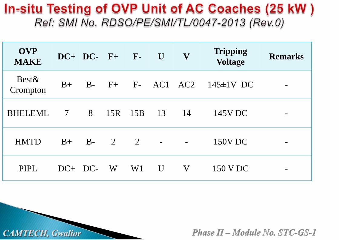
OVP
MAKEDC+ DC- F+ F- U V
Tripping
VoltageRemarks
Best&
CromptonB+ B- F+ F- AC1 AC2 145±1V DC -
BHELEML 7 8 15R 15B 13 14 145V DC -
HMTD B+ B- 2 2 - - 150V DC -
PIPL DC+ DC- W W1 U V 150 V DC -

1. Disconnect all terminal
wires at OVP.
2. Connect the OVP Test Kit
wires to corresponding
OVP terminals as per
SMI-0047-2013 (Rev.0).

3. Connect 110V DC
supply to Testing Kit.
4. Switch “ON” the input
supply ( Keep the Variac
position at minimum).
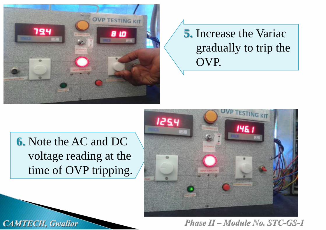
5. Increase the Variac
gradually to trip the
OVP.
6. Note the AC and DC
voltage reading at the
time of OVP tripping.

7. Finally decrease the
voltage with Variac and
switch “off” the supply
of testing kit.
8. Reset the OVP by
pressing the Reset button.
9. Reconnect the wires of
OVP by disconnecting the
Test kit wires.
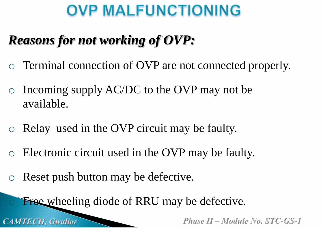
Reasons for not working of OVP:
o Terminal connection of OVP are not connected properly.
o Incoming supply AC/DC to the OVP may not be
available.
o Relay used in the OVP circuit may be faulty.
o Electronic circuit used in the OVP may be faulty.
o Reset push button may be defective.
o Free wheeling diode of RRU may be defective.

It leads to over generation/low generation (80-90volts).
Causing lights and fans may burnt/dim.
Cells may over charge causing cell burst/internal short
ckt/under charge due to low generation.
Insulation damage, joints may lead to earth leakage.
There is a chance to broke fire.
Note: Check the OVP once in every 3 months on train.

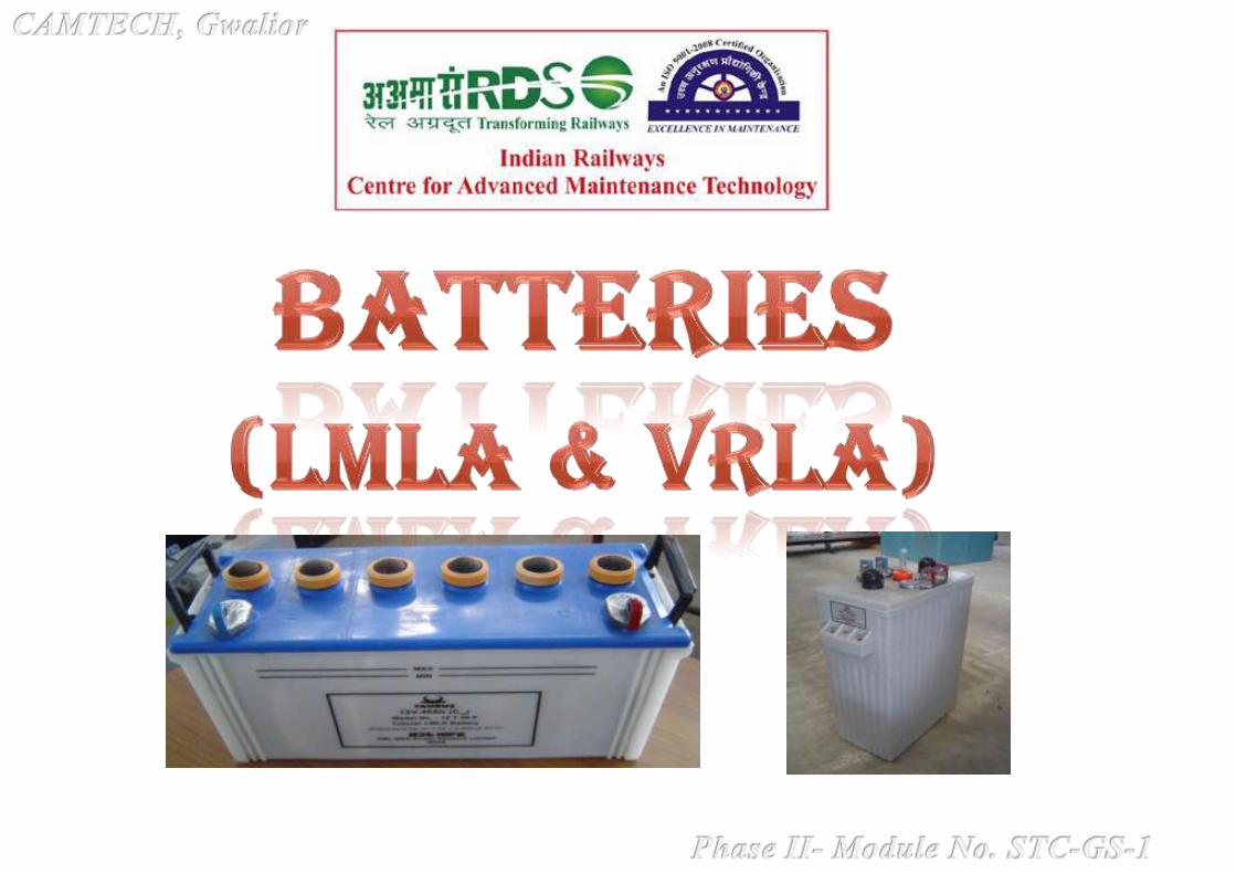


Battery consists of two or more
cells electrically connected.
Cell is a device that converts the
Chemical energy into electrical
energy by means of an
electrochemical reaction.
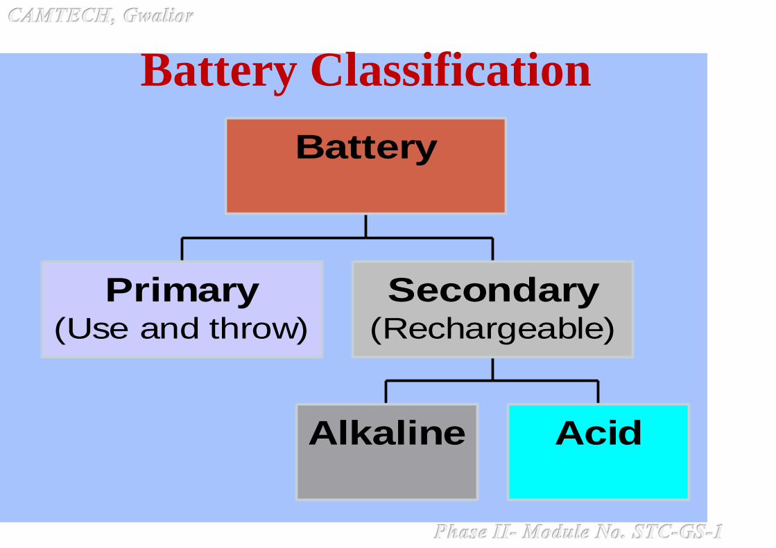
Battery Classification
Primary(Use and throw)
Alkaline Acid
Secondary(Rechargeable)
Battery
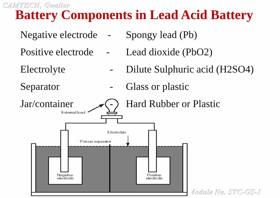
Negative electrode - Spongy lead (Pb)
Positive electrode - Lead dioxide (PbO2)
Electrolyte - Dilute Sulphuric acid (H2SO4)
Separator - Glass or plastic
Jar/container - Hard Rubber or Plastic
Battery Components in Lead Acid Battery

1. Series Connection
• Positive terminal of one cell is connected to the negative
terminal of another cell
• Increasing the overall voltage but the overall capacity remains
the same.
2 . Parallel Connections
• Like terminals of all cells connected together
• The overall voltage remains same but capacity will be increased
Battery Connections

Battery Capacity
Amount of charge available when battery is discharged at a
specific rate specified in Ampere-hours (Ah).
Measurement…
Battery terminal voltage under discharge under standard
conditions of 27ºC
Example:
A 2.0V Lead-acid battery rated for 200 Ah (for a 10-
hour rate) will deliver 20 amperes of current for 10 hours
under standard temperature before its terminal voltage
reaches specified value (for example 1.75V for VRLA or
1.85Vfor LMLA)
Battery capacity varies with the discharge rate.

Specific gravity of acid is the measure of its concentration
Indicates the state of charge of flooded cell but not the capacity
Specific gravity is measured by Hydro Meter
Cell open circuit voltage = Specific gravity + 0.845
Specific gravity varies with temperature
Higher Specific Gravity – More capacity but shorter life
Lower Specific Gravity - Less capacity but longer life

Where is this 2.0V coming from?
At the negative electrode
Discharge
Pb + H2SO4 PbSO4 +2H+ + 2e- E° = 0.356V
Charge
At the positive electrode
Discharge
PbO2 + 2H+ + H2SO4 +2e- PbSO4 + 2 H2O E° = 1.685V
Charge
Overall Reaction:
Discharge
PbO2 + Pb + 2 H2SO4 PbSO4 (+ve Plate) + PbSO4 (-ve Plate) + 2 H2O
Charge
E° = 2.041V

Flooded Lead-Acid Batteries
• Electrodes/plates are immersed in electrolyte
• Vented for gas escape
• Distilled water must be added occasionally
Sealed Lead-Acid Batteries
• No free electrolyte
• Oxygen recombination and hence water is retained
• Regulated vent to allow gases to escape at particular pressure
Flooded Vs Sealed Batteries
Recombination Reaction
At Positive Plate
H2O 2H+ + ½ O2 + 2e-
At Negative Plate
½ O2 + Pb PbO
PbO + H2SO4 + 2e- + 2H+ 2PbSO4 + 2H2O + Heat

Different types of Plates
Plante Flat grid Tubular

AGM (Absorbent Glass Mat)
SEPARATOR in VRLA CELLS

Conceptual View - Oxygen Recombination Process
Advantages:• No water Topping
• Office Friendly (No separate battery room required)
• Small Size
Disadvantage:• Sensitive to Operating temperature
ELECTROCHEMISTRY OF LEAD-ACID BATTERIES
PbO2 + 2H2SO4 + Pb >
2PbSO4 + 2H2O
2PbSO4 + 2H2O >
PbO2 + Pb + 2H2SO4
Discharge Charging
+Loading
PbSO4
PbO2
PbSO4
Pb
H2O
PbO2
PbSO4
H+
SO4
SO4
e - e
Charging
-
+ -
H 02
H+
-
H+
H2SO4
H2SO4
Pb
PbSO4
--
--

- SULPHURIC ACID
- WATER
-LEAD DIOXIDE ON +
-LEAD SULPHATE ON +
-SPONGE LEAD ON --LEAD SULPHATE ON-
Load
_+
MAX. H 2SO4
MIN. H2O
MAX. PbO2
MIN. PbSO4
MAX. Pb
MIN. PbSO4
LEAD - ACID BATTERY DISCHARGE
CHARGED DISCHARGEDDISCHARGING
Load
_+
MIN. H 2SO4
MAX. H2O
MIN. PbO2
MAX. PbSO4
MIN. Pb
MAX. PbSO4
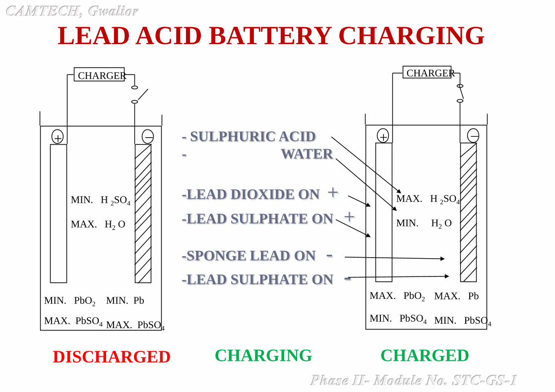
- SULPHURIC ACID
- WATER
-LEAD DIOXIDE ON +
-LEAD SULPHATE ON +
-SPONGE LEAD ON -
-LEAD SULPHATE ON -
CHARGER
_+
MIN. H 2SO4
MAX. H2 O
MIN. PbO2
MAX. PbSO4
MIN. Pb
MAX. PbSO4
LEAD ACID BATTERY CHARGING
DISCHARGED CHARGEDCHARGING
CHARGER
_+
MAX. H 2SO4
MIN. H2 O
MAX. PbO2
MIN. PbSO4
MAX. Pb
MIN. PbSO4
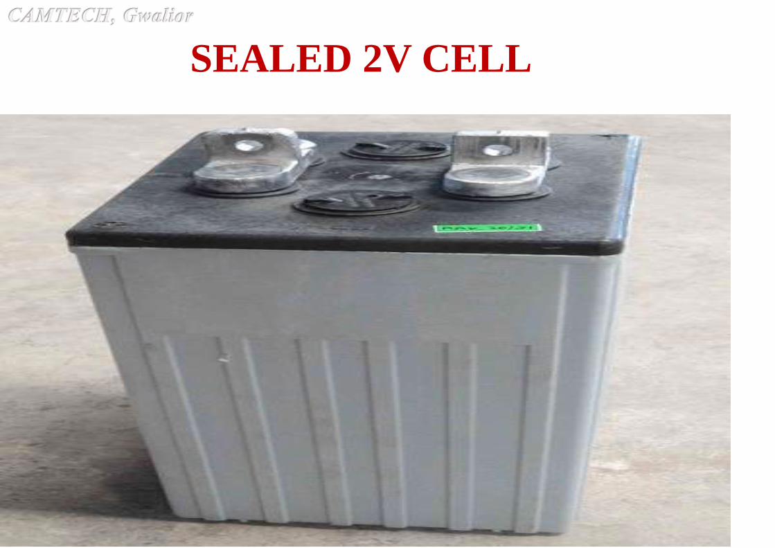
SEALED 2V CELL

SEALED 12V BATTERY

INITIAL CHARGING

INITIAL FILLING AND CHARGING
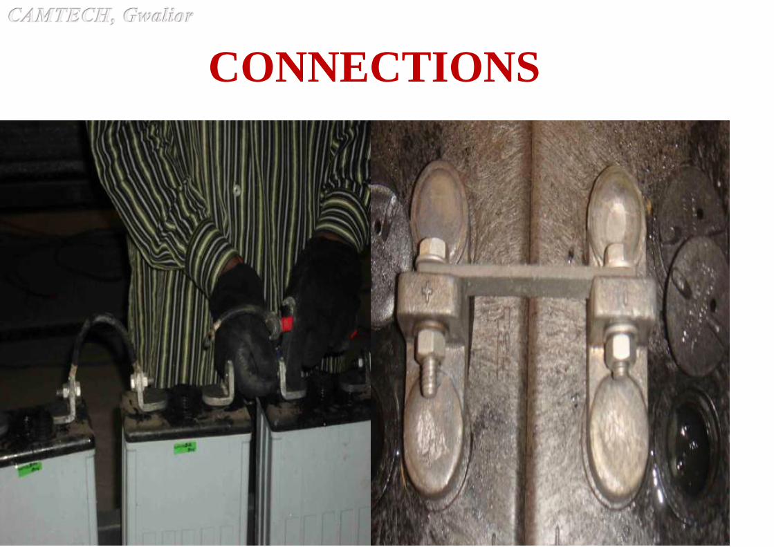
CONNECTIONS

ACID FILLING AND LEVELLING
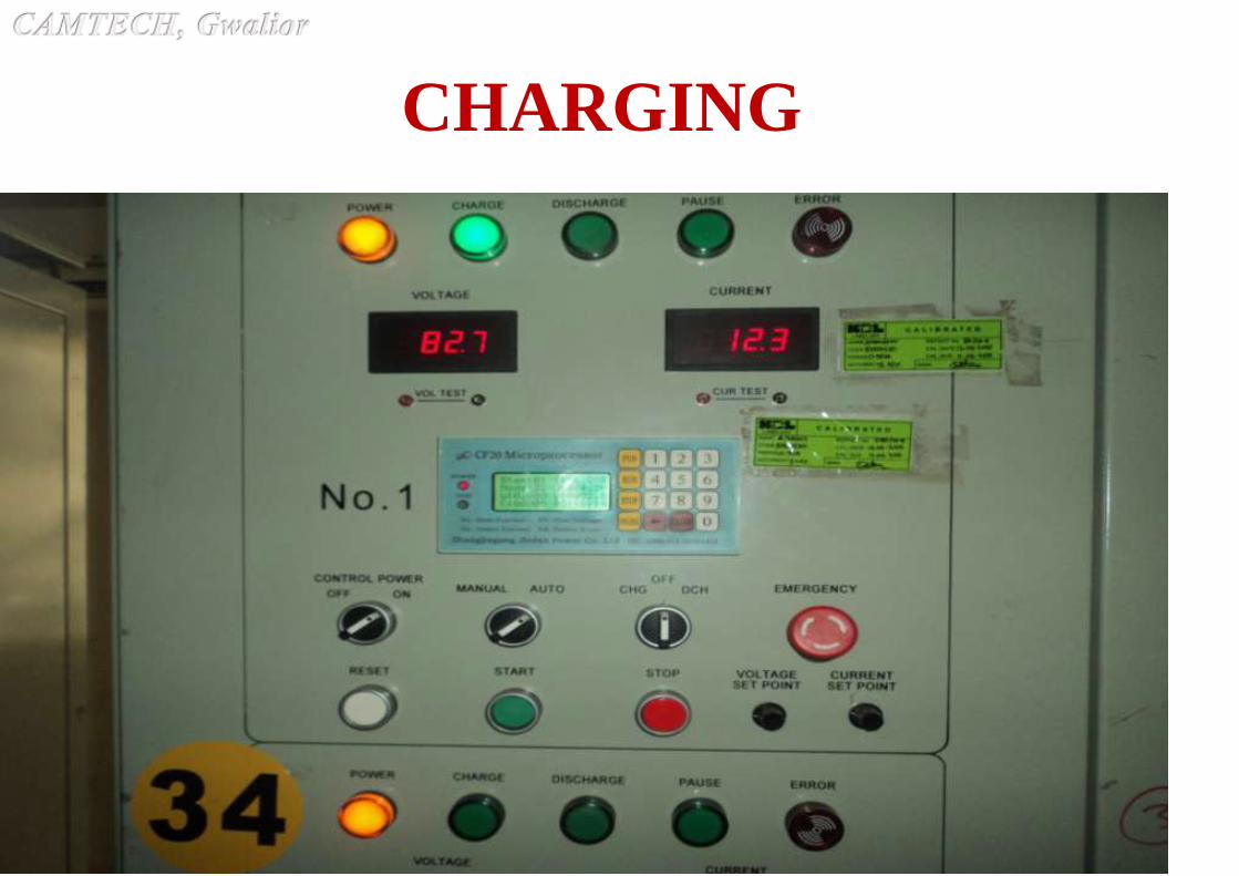
CHARGING
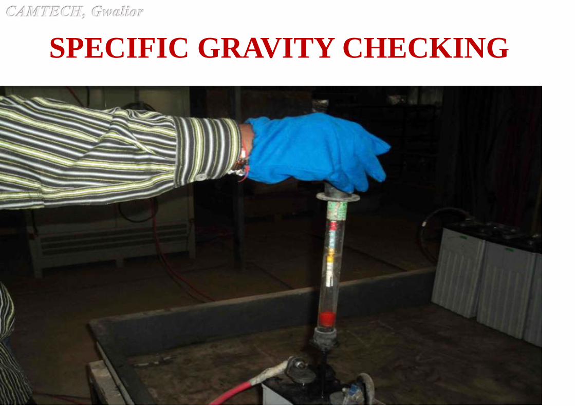
SPECIFIC GRAVITY CHECKING
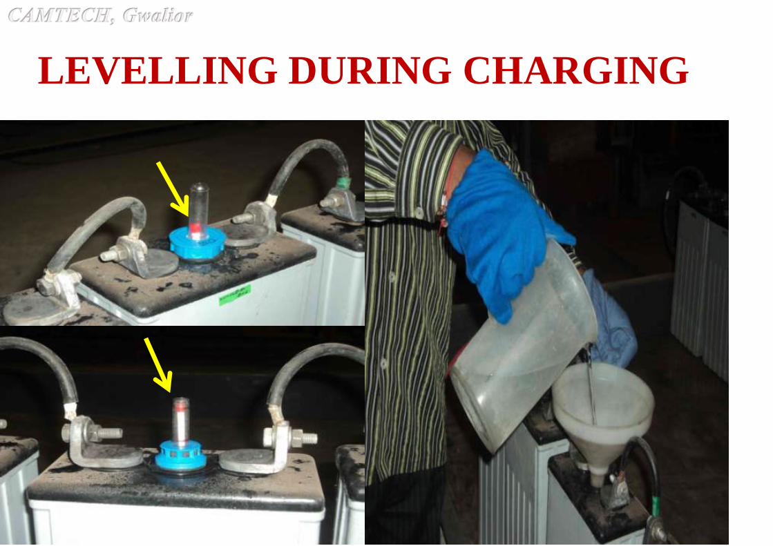
LEVELLING DURING CHARGING
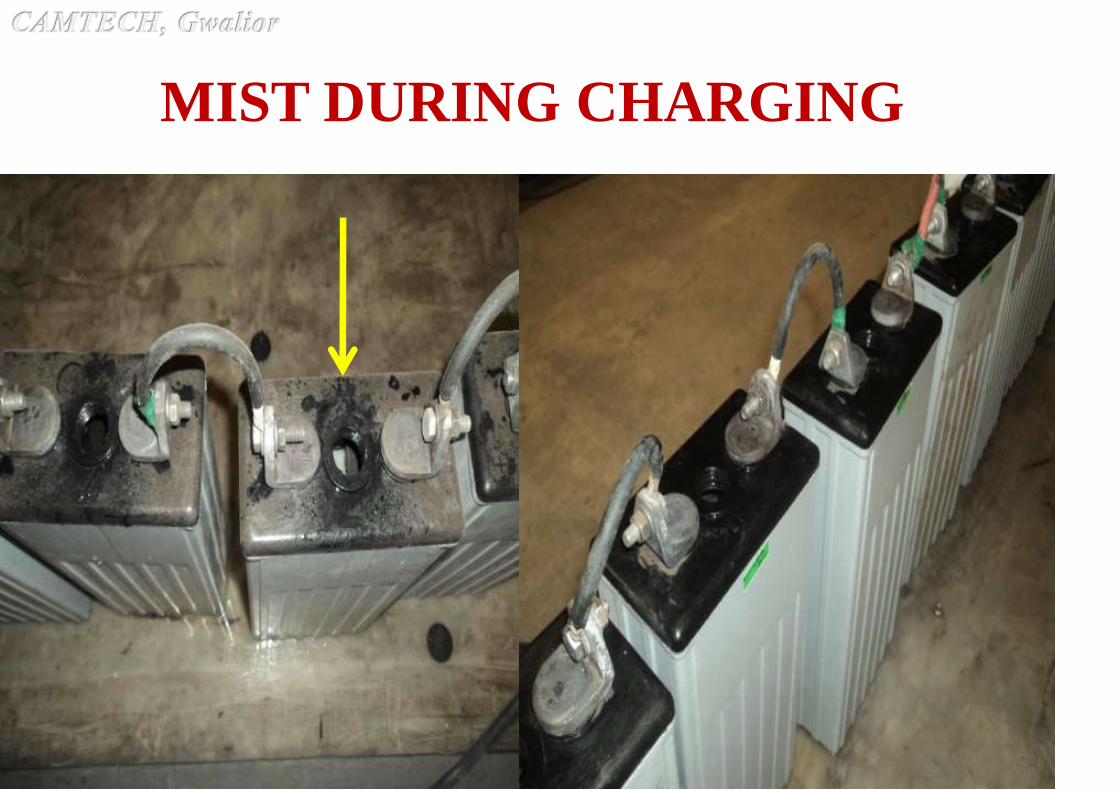
MIST DURING CHARGING

DRY CELL
WITHOUT ACIDAFTER REST
PERIOD
END OF
CHARGING
VOLTAGE BEFORE & AFTER

LMLA Battery ChargingWhen Charging Current (Amps) ECV at the
end of
100%
discharge
Specific Gravity
Initial % Final % Charging Full
Discharge
Initial Filling and charging
10% of rated Ah capacity tillvoltage reaches 2.4V
5% of rated Ah capacity from 2.4V till end of charge (2.6 to 2.7V)
1.85V Filling
1.22 ± 0.005
Fully charged
1.24 ± 0.005
1.17 ±0.02
Reading to be taken every 4 hours. Allow rest period during charging ifElectrolyte temperature exceeds 50ºC. Add electrolyte with initial fillingspecific gravity for topping up during initial charging only. Total mandatoryminimum charge input in Ah is 550% of rated battery Ah for cells with unformedplates (300% for partially formed plates)
Freshening charge:-
If cells are not commissioned after initial charging, the battery has to becharged for 6 hours at 5% of rated Ah capacity charging current.
If it is constant voltage charger, battery has to be charged @ 2.4V per cell for 24hours with 10% of rated Ah capacity charging current.
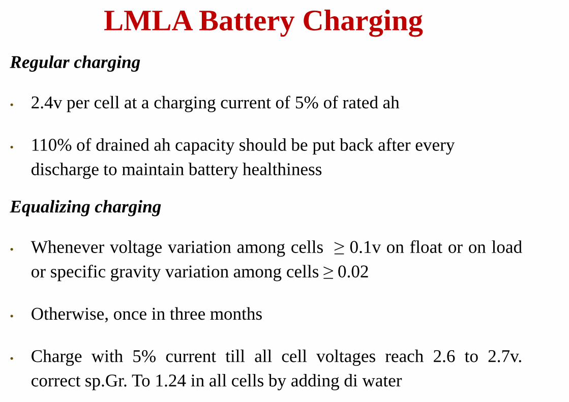
LMLA Battery Charging
Regular charging
• 2.4v per cell at a charging current of 5% of rated ah
• 110% of drained ah capacity should be put back after every
discharge to maintain battery healthiness
Equalizing charging
• Whenever voltage variation among cells ≥ 0.1v on float or on load
or specific gravity variation among cells ≥ 0.02
• Otherwise, once in three months
• Charge with 5% current till all cell voltages reach 2.6 to 2.7v.
correct sp.Gr. To 1.24 in all cells by adding di water

LMLA Battery Charging
Equalizing Charging (contd…)
• Minimum charge input (ah) during equalizing should be 50% of the
rated ah capacity
• If it is a constant voltage charger, increase the voltage to 2.55V per
cell, charge for 16 hours at a current setting of 10% of rated ah
capacity
Recommendation
• If voltage variation or specific gravity variation beyond specified
limits persist even after equalizing, replace particular cells.
• They need to be tested and revived separately.
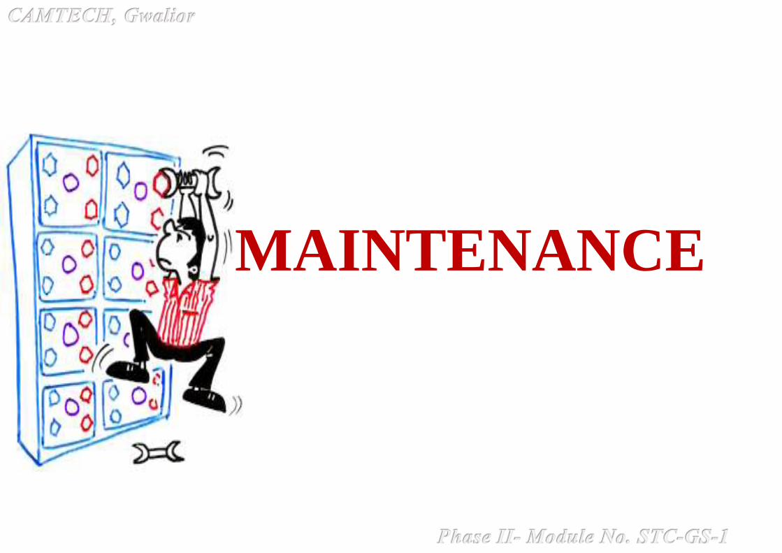
MAINTENANCE

• LMLA batteries are widely preferred as
maximum life can be obtained from the battery
with little maintenance.
• At the same time, they can suffer from premature
death if not given proper attention for periodic
maintenance.
• Proper initial charging, correct specific gravity and
correct quantity of acid are very important for little
maintenance later.
• Records of initial load test is very important to verify the
performance of batteries later and will help in identifying
reasons for failure later, if any.
Recommendations

• Contaminated acid
• Wrong specific gravity of acid
• Insufficient acid quantity
• Reverse connections while charging
• Incomplete charging
• Loose terminal connections or over tightening.
• Cells left with dummy vent plugs.
• Damaged cells installed leading to electrolyte leak.
What can go wrong during Initial
Charging?

• Wrong cable size between charger and battery
• Improper connector sizes between cells
• Wrong charger voltage settings
• Insufficient acid quantity
• Adding acid instead of DI water
• Leaving vent hole and level indicator hole open
• Insufficient or overcharging
• High room temperature
• Wrong calibration of measuring instruments
What can go wrong in operation?

Routine Maintenance - Monthly
Check for dust accumulation around all connections – from input
cable till the last cell in the battery bank – and clean the dust
Check for any corroded bolts / cable lugs / connectors – Clean /
replace them – apply petroleum jelly
Check and clean dusted vent plugs and refit properly
Check and replace any broken cell as any acid leak will damage the
battery stand
Identify one pilot cell for every six cells in the battery
Check and record Float Voltage of pilot cells and verify if it is as per
recommendations given in manual
Apply site load and measure on load voltages of pilot cells after 15
minutes on load
Routine Maintenance – Half yearly
• Verify monthly maintenance records and ensure all
mandatory checks are carried out and are in order
• Check the level of electrolyte in each cell and top up with
distilled water to maintain level within the marks
• Check for proper functioning of measuring instruments –
multimeter / ammeter / voltmeter – recalibrate if necessary
• Check float voltage and electrolyte specific gravity of each
cell and verify the State of Charge(SOC) of each cell
• Give equalizing charge as recommended in the manual
• Replace any broken vent plug or float guide

Routine Maintenance - Annually
• Clean all cells for dust and acid mist
• Clean all vent plugs for removing accumulated dust
• Clean / replace corroded connecting parts
• Ensure full state of charge of battery
• Conduct load test up to 80% depth of discharge of battery
• Level the electrolyte and conduct equalizing charge as given
in the manual
• Check charger settings for correctness of voltage and
current as recommended in the manual

&

Improper terminal tightening X
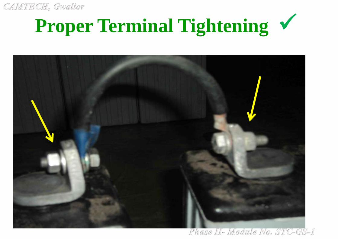
Proper Terminal Tightening
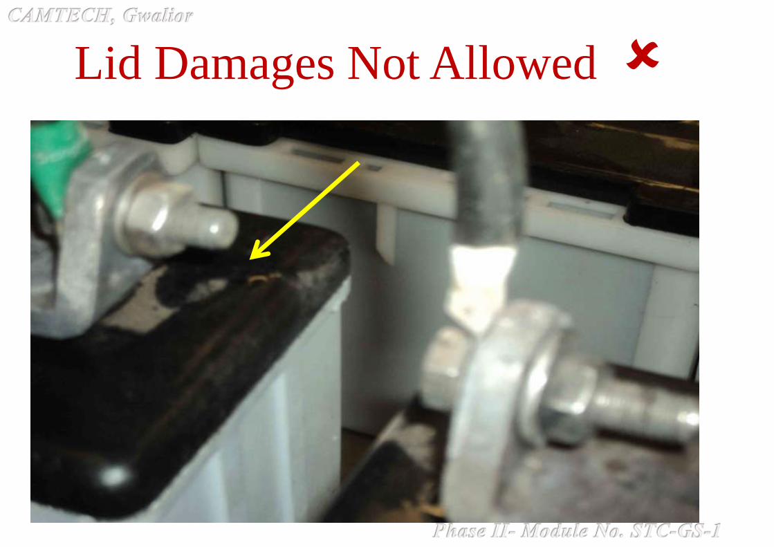
Lid Damages Not Allowed

ADDING ACID DURING CHARGING

DAMAGED VENT PLUGS
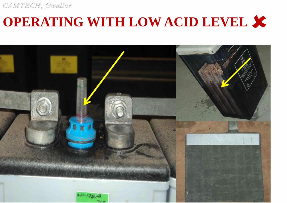
OPERATING WITH LOW ACID LEVEL

OPERATING WITH CORRECT ACID LEVEL

Varying Acid Levels in Same Battery
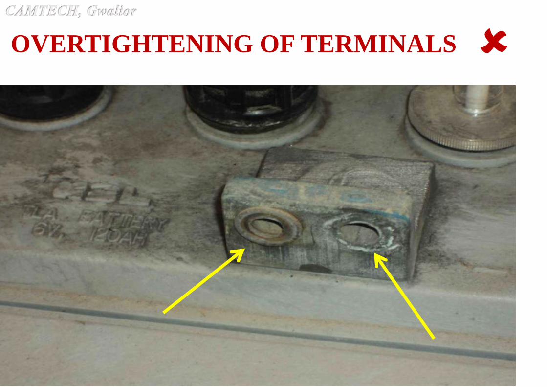
OVERTIGHTENING OF TERMINALS

This video can also be viewed on Youtube CAMTECH
Gwalior videos or following link:
https://www.youtube.com/watch?v=leUkuod-v0s
CAMTECH, Gwalior has prepared a video film on
“Maintenance of LMLA batteries used in TL
Coaches”
This video is available on internet at RDSO
Directorates CAMTECH Publications for
download Electrical 2015-16

Endless V-belts (multiple drive) are used for transmission of
mechanical power from the coach axle to the alternator which
supplies power to the train-lighting and air conditioning loads
in Railway coaches.
The reliability of the V-belt is essential to ensure that there is
no breakdown in the passenger amenities, viz. lighting, air
conditioning and air circulation devices i.e. fans in the
railway coaches.
Railways are using C-122/3155 Lp V-belts.
RDSO has also issued specification no.
RDSO/PE/SPEC/AC/00160-2014 (Rev. 1) for long life V
belts with ‘Aramid’ cord which are under trial.

A drive which consists of one or more V-belts
mounted on grooved pulleys.
The profiles of the belts and the pulley grooves are
such that the belts come into contact with the sides of the pulley grooves only and not with the
base of the grooves.
a. V-belt Drive

A belt, the cross section of which is shaped roughly like
a trapezium. The latter is usually isosceles. On the cross-section the trapezium is outlined by the
base, sides and top of the belt.
b. V-Belt
Cross Section of V-Belt
W = Nominal top width of a V-belt
A = Angle of V-Belt
T = Nominal Height of a V-belt
Wp = Pitch width of a V-belt

c. Angle of V-Belt (A) The included angle obtained by extending the sides of the
belt.
d. Nominal Inside Length The approximate length along the inside of belt while is an
untensioned condition.
e. Nominal Height of a V-belt (T)
Height of the trapezium outlined on a cross section.
f. Nominal top width of a V-belt (W)
Top width of the trapezium outlined on a cross-section.

g. Pitch width of a V-belt (Wp)
The width of the belt at its pitch zone. The width remains
unchanged when the belt is bent perpendicularly to its
base. This is a basic dimension of standardization for the
belt and for the corresponding pulley groove, considered
as a whole.
h. Effective belt length (under specified tension)
The sum of the effective circumference of one of the
measuring pulleys and twice the distance between pulley
centres.

j. Pulley pitch diameter (dp)
The diameter of the pulley measured at the groove pitch
width and represents the effective diameter of the pulley.
k. Matched Set
A set of selected number of belts, the lengths of which are
within the specified limits enabling them to be used
together on a multiple V-belt drive.
i. Pulley groove pitch width (Wp)
That width of the pulley groove which is dimensionally
the same as the pitch width of the belt associated with
the pulley.

The C-122/3155 Lp endless V-belts of isosceles trapezoidal
cross section consist of a combination of elastomeric compound(s) with polyster cord reinforcement and outside polycot fabric coated with polychloroprene, the whole is
moulded together in a uniform manner and shaped in accordance
with the belt manufacturing practice.
Constructional cross sectional view of C-122 V-Belt

V-belt base material has the following properties:
Parameters Requirement
Hardness, IRHD 82 ± 4
Tensile strenth, Kg/sq cm 100 min.
Elongation at break, % 150.min.
The finished belting has the following physical properties:
Elongation on a length of 200mm between reference lines.
Maximum percentage elongation
at load of 300kgf shall be 3% and
upto break 15%
Breaking strength 1150 Kgs (Min.)
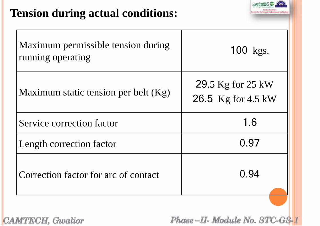
Tension during actual conditions:
Maximum permissible tension during
running operating100 kgs.
Maximum static tension per belt (Kg)29.5 Kg for 25 kW
26.5 Kg for 4.5 kW
Service correction factor 1.6
Length correction factor 0.97
Correction factor for arc of contact 0.94

Cross section of the endless V-belt in ‘C’ section is as shown
below with the nominal top, width and thickness in mm for C-
122/3155 Lp as indicated.
Nominal top width W = 22 0.5mm
Nominal thickness T = 14 0.5 mm
Angle = 40 degrees
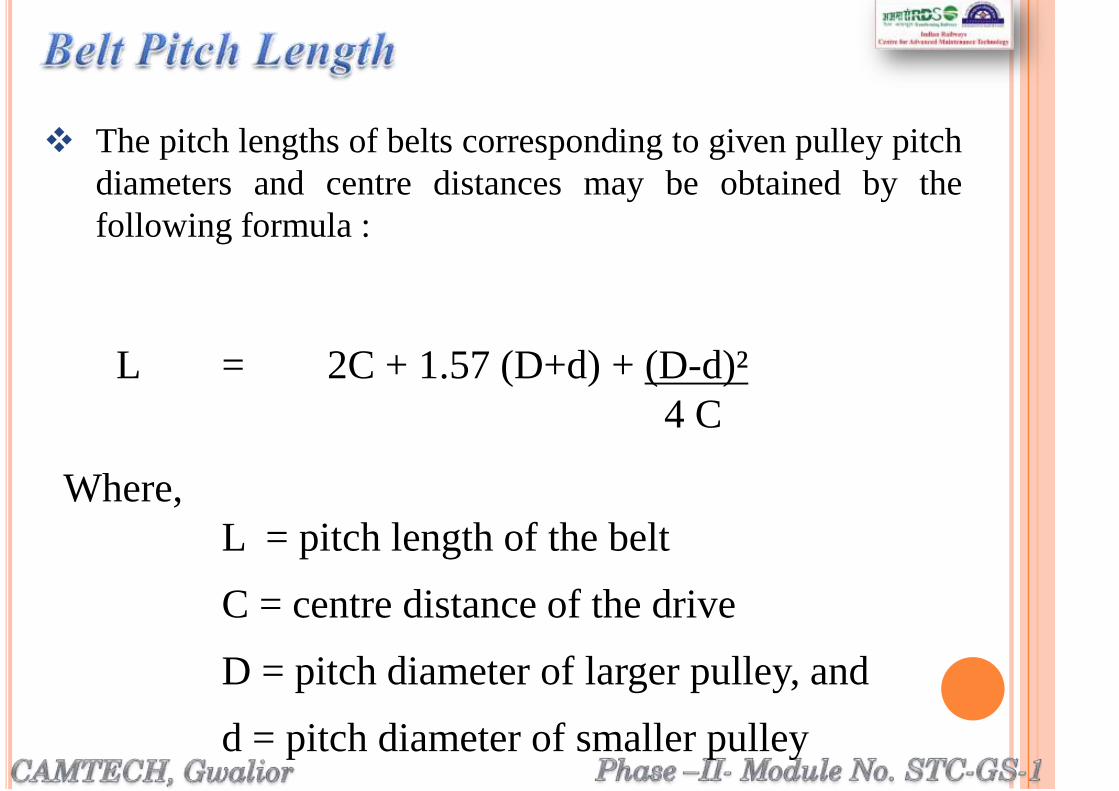
L = 2C + 1.57 (D+d) + (D-d)²
4 C
Where,
L = pitch length of the belt
C = centre distance of the drive
D = pitch diameter of larger pulley, and
d = pitch diameter of smaller pulley
The pitch lengths of belts corresponding to given pulley pitch
diameters and centre distances may be obtained by the
following formula :

If the actual pitch length of the belt is equal to
nominal pitch length ± 1.0 mm, the belt is given
the code number as 50.
A deviation of 2.0 mm in length is represented by
one unit and the code number increases or
decreases as the length is more or less.
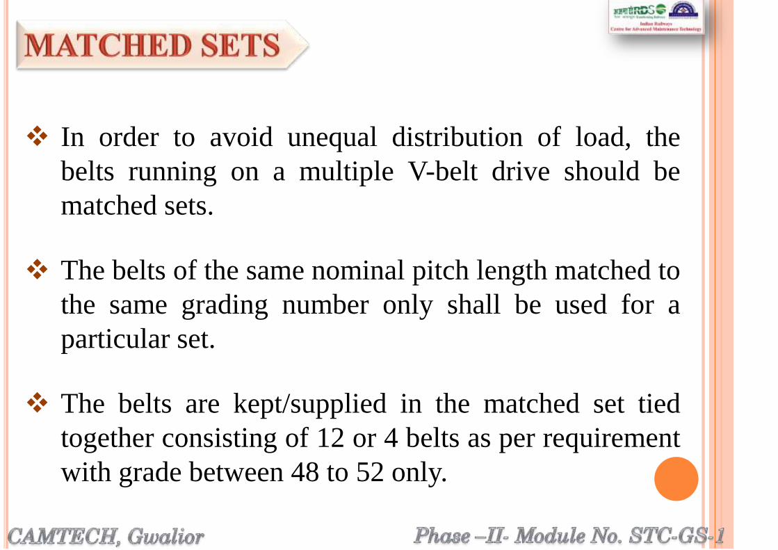
In order to avoid unequal distribution of load, the
belts running on a multiple V-belt drive should be
matched sets.
The belts of the same nominal pitch length matched to
the same grading number only shall be used for a
particular set.
The belts are kept/supplied in the matched set tied
together consisting of 12 or 4 belts as per requirement
with grade between 48 to 52 only.

The v-belts confirming are marked legibly and
durably on the top surface with the symbol indicating
the belt cross-section, the nominal pitch length in mm,
grading number (length-code), year of manufacture
and manufacturer’s name or trade mark.
Belt shall be checked for any deformity, bulging,
waviness, cracks blemishes, unevenness etc..

The pitch length of the belts shall be checked as
mentioned earlier.
The angle of V-Belt shall be checked with Profile
projector.

Along a straight portion of the
belt in an un-tensioned state, the
cross-section of the belt shall be
such that when placed in a gauge
as shown in given figure, it shall
not touch the bottom of the
gauge, the edges of the top width
‘s’ and ‘t’ shall not be higher
than the points ‘u’ and ‘v’ at the
top of the template and the
guiding mark ‘mn’ on the
template shall cut the whole
width of the belt in its upper half.
Note: The pitch width of the belt 19
mm, is the width of the gauge
at the level of this guiding mark
mn drawn on the gauge.

The V belts should be stored in a cool, dry and well
ventilated stock room away from direct sunlight, steam
pipes, oil & corrosive fumes, high voltage apparatus.
The ambient room temperature shall be preferably
below 30 degree C.
Belts should not be stored on the floor or near
windows, radiators or airflow from heaters.
Unfavorable storage conditions can lead to reduced belt
life and to variations in belt length. Following are the
important criteria for good storage.
Some fibres used in strength members of belts are
subject to shrinkage in storage, the amount depending
on the temperature, relative humidity, and storage time.
During storage avoid excess weight on and distortion
of belts.
The ideal means of storage is hanging on saddle type
pegs. When the longer belts hung on pegs should be
coiled so that the loops are not greater than
approximately 2500 mm in circumference.

Pegs should be crescent (semi-circular) shaped and
large enough to avoid compression set from corners or
from acute bends of the belt.
It should preferably, not be stored for more than one
year after the date of manufacture.
Ensure that issue of V belts is being done according to
FIFO (First in First out) policy.
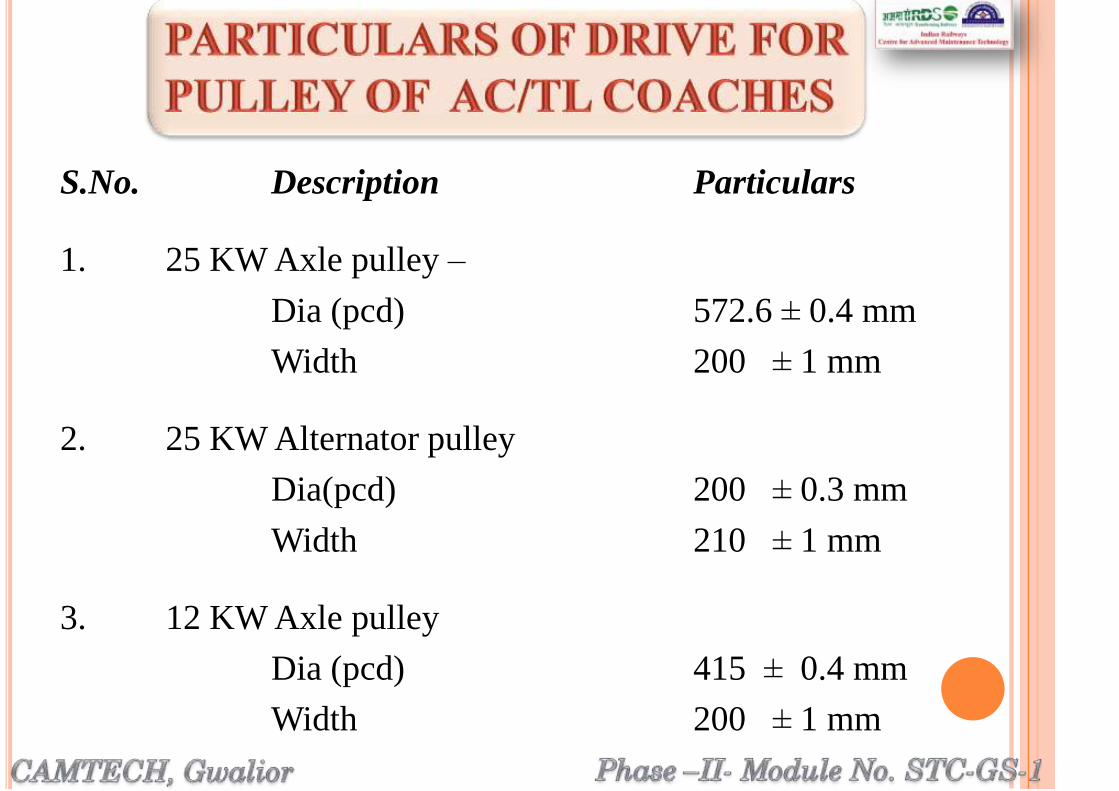
S.No. Description Particulars
1. 25 KW Axle pulley –
Dia (pcd) 572.6 ± 0.4 mm
Width 200 ± 1 mm
2. 25 KW Alternator pulley
Dia(pcd) 200 ± 0.3 mm
Width 210 ± 1 mm
3. 12 KW Axle pulley
Dia (pcd) 415 ± 0.4 mm
Width 200 ± 1 mm
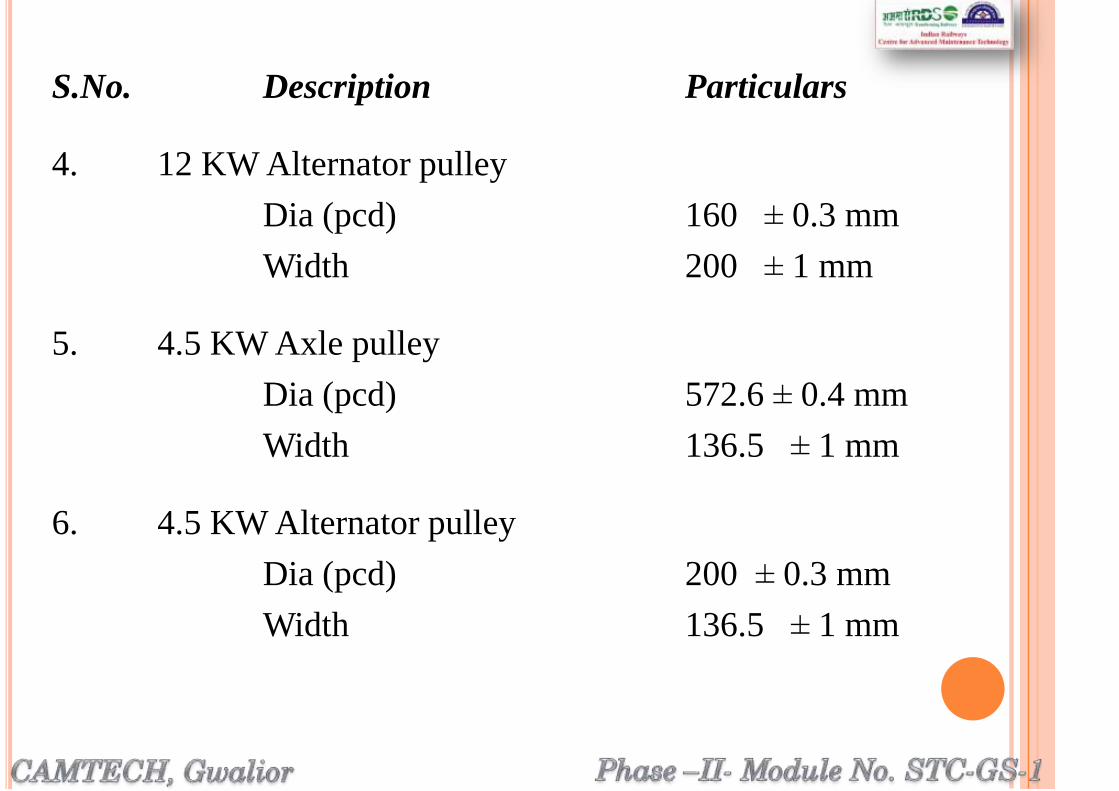
S.No. Description Particulars
4. 12 KW Alternator pulley
Dia (pcd) 160 ± 0.3 mm
Width 200 ± 1 mm
5. 4.5 KW Axle pulley
Dia (pcd) 572.6 ± 0.4 mm
Width 136.5 ± 1 mm
6. 4.5 KW Alternator pulley
Dia (pcd) 200 ± 0.3 mm
Width 136.5 ± 1 mm
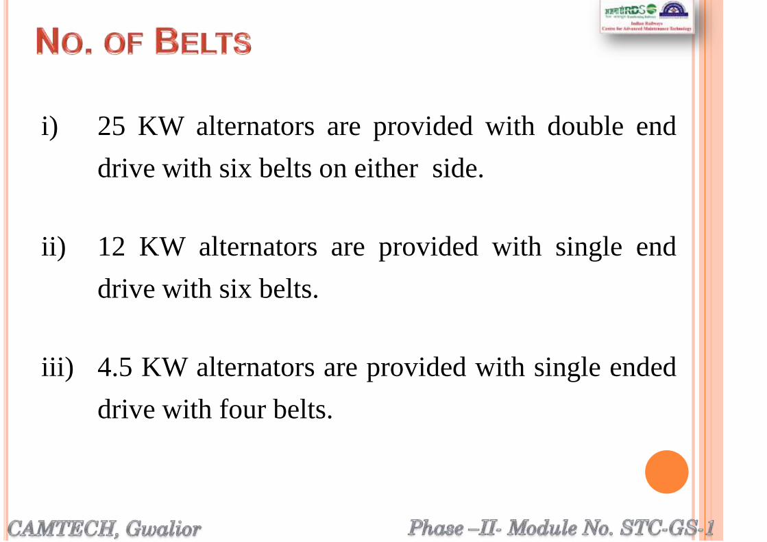
i) 25 KW alternators are provided with double end
drive with six belts on either side.
ii) 12 KW alternators are provided with single end
drive with six belts.
iii) 4.5 KW alternators are provided with single ended
drive with four belts.


Phase –II- Module No. STC-GS-1
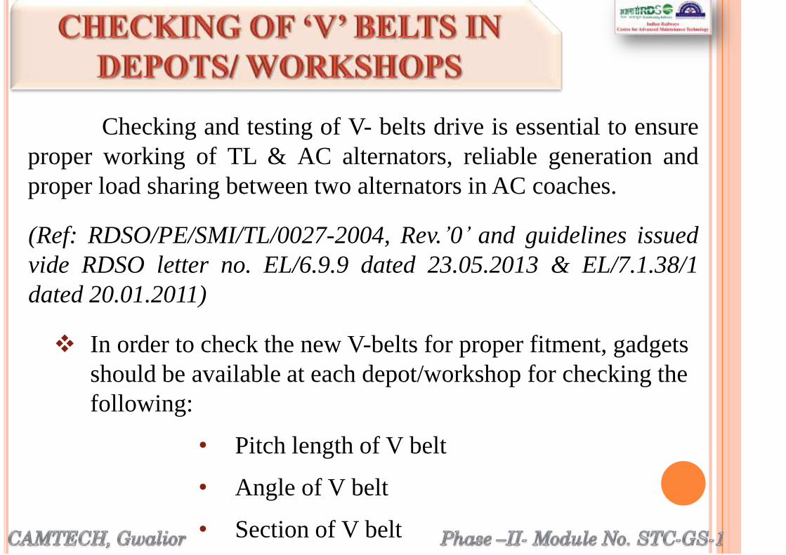
In order to check the new V-belts for proper fitment, gadgets
should be available at each depot/workshop for checking the
following:
• Pitch length of V belt
• Angle of V belt
• Section of V belt
Checking and testing of V- belts drive is essential to ensure
proper working of TL & AC alternators, reliable generation and
proper load sharing between two alternators in AC coaches.
(Ref: RDSO/PE/SMI/TL/0027-2004, Rev.’0’ and guidelines issued
vide RDSO letter no. EL/6.9.9 dated 23.05.2013 & EL/7.1.38/1
dated 20.01.2011)

Pitch length of all the belts shall be measured by pitch length
testing machine before providing the belts in the coaches.
Two or more makes of belts should not be used in a set.
Re-tension of newly fitted belts shall be done after 1st trip or 500
km run, whichever is convenient.
It should be ensured
that in case of 25 kW
alternator all the 12
belts and in case of 4.5
kW alternator all the 4
belts shall be of same
pitch length/Grade.
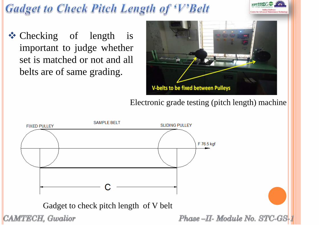
Checking of length is
important to judge whether
set is matched or not and all
belts are of same grading.
Gadget to check pitch length of V belt
Electronic grade testing (pitch length) machine

Nominal circumference of the pulley at pitch dia is 700 mm
Nominal pitch length of the belt is = 2C+700 mm
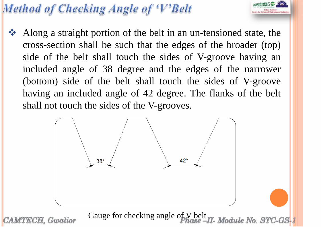
Along a straight portion of the belt in an un-tensioned state, the
cross-section shall be such that the edges of the broader (top)
side of the belt shall touch the sides of V-groove having an
included angle of 38 degree and the edges of the narrower
(bottom) side of the belt shall touch the sides of V-groove
having an included angle of 42 degree. The flanks of the belt
shall not touch the sides of the V-grooves.
Gauge for checking angle of V belt

Along a straight portion of the belt in an un-tensioned state, the
cross-section of the belt shall be such that when placed in a
gauge as shown in above figure , it shall not touch the bottom
of the gauge, the edges of the top width „s‟ and „t‟ shall not be
higher than the points „u‟ and „v‟ at the top of the template and
the guiding mark „mn‟ on the template shall cut the whole
width of the belt in its upper half.
Note: The pitch width of the
belt 19 mm, is the
width of the gauge at
the level of this
guiding mark mn
drawn on the gauge.

For effective power transmission from axle to alternator, health
of pulleys should be good.
Following Instructions to be followed during POH/IOH, “C”
schedule and maintenance at Workshops and coaching depots.
If bottom of the groove is
observed shining throughout
uniformly, the pulley should be
replaced.

The pulley groove walls should be examined for ovality with
the help of a steel scale. If the walls are worn out by more than
0.5 mm the pulley should be replaced.
Surface matching between pulley bore and shaft should not be
less than 80%.
The key in shaft should be fitted properly.
Worn key must be replaced by spare EN8 key. If matching of
80% is ensured then the chances of key failure are very less.

The angle of grooves should be checked by gauges.
If angle has increased, the pulley should be replaced. There are
different gauges for axle pulley and alternator pulley.
Gauge for checking
groove angle of
Alternator and Axle
pulley

Ensure gap between two halves
of axle pulley to 3.0 ± 0.5 mm
and tightening torque should be
upto 30 kg - mtr (maximum)
Checking of gap
between two halves
of Axle pulley
Replace rubber pads of axle
pulley 100%. Check rubber
quality in each lot from M&C lab.
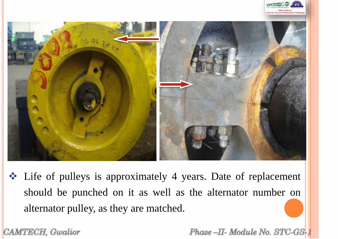
Life of pulleys is approximately 4 years. Date of replacement
should be punched on it as well as the alternator number on
alternator pulley, as they are matched.

After removal of alternator for POH, gap between bogie
suspension brackets should be checked.
Excess gap between bogie bracket and alternator suspension
bracket will lead to misalignment of alternator.

After fitment of alternator in the bogie suspension bracket,
alignment of alternator and axle pulley should be checked.
It can be checked by cord which should touch 4 edges of both
pulleys simultaneously.

It can be checked by laser beam also. Beam from
alternator pulley groove center should fall in the
center of corresponding axle pulley groove.
Do not paint the pulleys after cleaning. It will affect
heat dissipation.
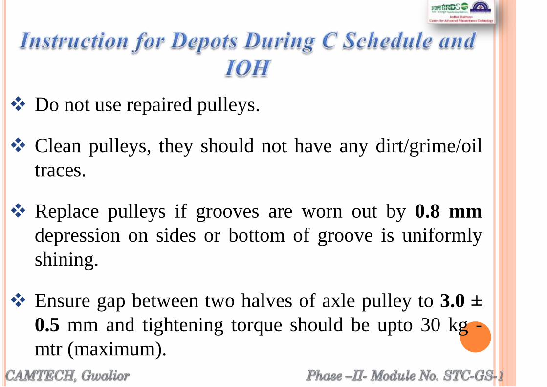
Do not use repaired pulleys.
Clean pulleys, they should not have any dirt/grime/oil
traces.
Replace pulleys if grooves are worn out by 0.8 mm
depression on sides or bottom of groove is uniformly
shining.
Ensure gap between two halves of axle pulley to 3.0 ±
0.5 mm and tightening torque should be upto 30 kg -
mtr (maximum).
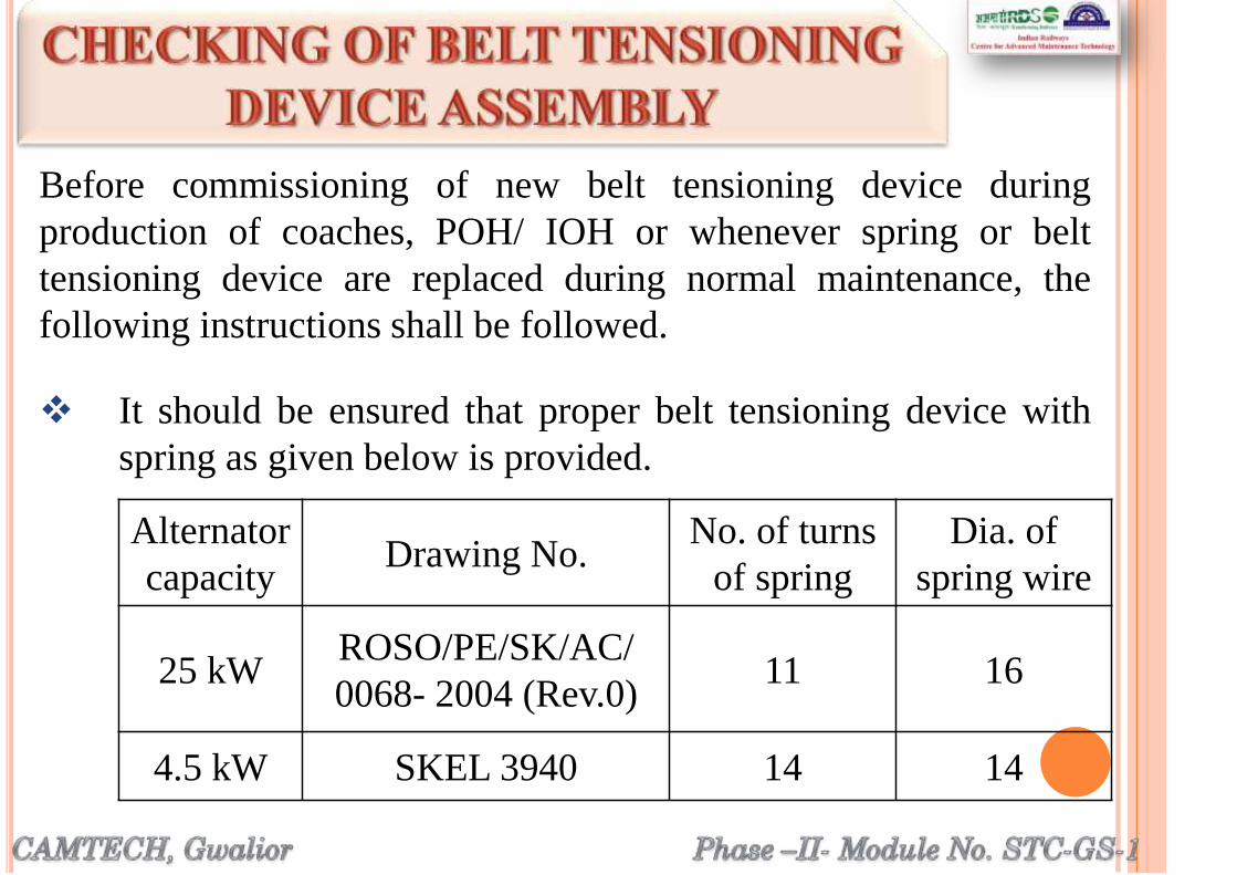
Before commissioning of new belt tensioning device during
production of coaches, POH/ IOH or whenever spring or belt
tensioning device are replaced during normal maintenance, the
following instructions shall be followed.
It should be ensured that proper belt tensioning device with
spring as given below is provided.
Alternator
capacityDrawing No.
No. of turns
of spring
Dia. of
spring wire
25 kWROSO/PE/SK/AC/
0068- 2004 (Rev.0)11 16
4.5 kW SKEL 3940 14 14

Indication plate of belt tensioning device is cut to 250mm
irrespective of the kW rating of the alternator.
It is only to indicate that spring has to be changed if proper
tension with 4 kg weight test is not achieved.
Belt should be tightened to the maximum extent possible and
measurement of proper tension is to be done as under:
A weight of 4 kg should be hanged from the centre of the belt
span and see that the top surface of this belt does not go below
bottom surface of remaining belts.
Checking of V belt tension with 4 kg weight

For this following may be followed:
a. Insert steel scale of size 30cm as
shown and check that it is
passing easily between the V-
belts.
b. In case desired V-belt tension is
not achieved up to 250mm of
spring length, then tension rod
should be replaced.
Belt to be tightened till it reaches red mark
which may be confirmed by a 30cm steel scale.
Checking of „V‟ belt tension with
4 kg weight and steel scale

c. Ensure 35/50 mm barrel bush gap in the bogie
bracket of TL/AC coaches respectively.

Ensure testing of springs before fitment by
conducting, compression test. Compression test shall
be conducted on compression testing machine or
fabricated system in depot/ workshop.
Spring compression in step of 10mm and weight
applied shall be recorded in the format given on next
slide and deflection in mm per kg of load shall be
calculated.
(Ref: RDSO/PE/SMI/AC/0042-2009, Rev’0’)
• Spring testing

Sr. Spring
length in mm
Wt. in
kg.
Spring rate
derived
Remarks
1. 345 0 (Zero) Value of kg/
mm should be
calculated.
Obtained value of spring
stiffness should be verified for
4.5kW as per RDSO‟s drg. No.
SKEL-3040 sheet 2 as well as
modified springs for 25kW
alternator as per RDSO‟s drg.
no. RDSO/PE/SK/AC/0068-
2004 (Rev.0).
Average value of old spring as
per RDSO‟s drg. no. SKEL -
3040 sheet 2 should be within
2.8-3.2kg/mm for 4.5kW and
4.8-5.5kg/mm for modified
springs for 25 kW alternator as
per RDSO drg. No.RDSO/
PE/SK/ AC/ 0068-2004 (Rev.0)
2. 335 Weight
should be
recorded
3. 325
4. 315
5. 305
6. 295
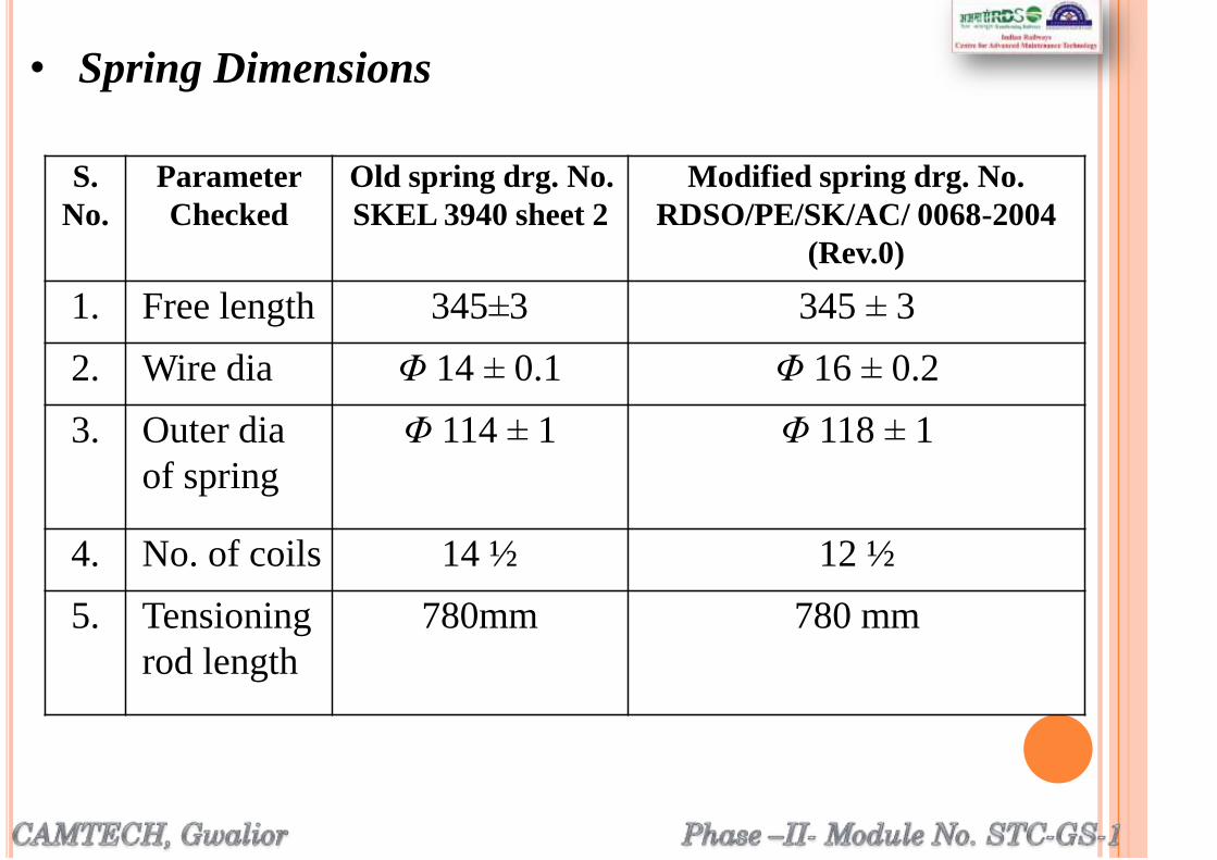
• Spring Dimensions
S.
No.
Parameter
Checked
Old spring drg. No.
SKEL 3940 sheet 2
Modified spring drg. No.
RDSO/PE/SK/AC/ 0068-2004
(Rev.0)
1. Free length 345±3 345 ± 3
2. Wire dia Φ 14 ± 0.1 Φ 16 ± 0.2
3. Outer dia
of spring
Φ 114 ± 1 Φ 118 ± 1
4. No. of coils 14 ½ 12 ½
5. Tensioning
rod length
780mm 780 mm

Following shall be checked in belt tensioning device:
Tensioning rod thread for any damage
Deformity in spring sheet
Deformity in rotary spring sheet
Damage of threads in special nut
Cut/ rubbing mark in spring coil
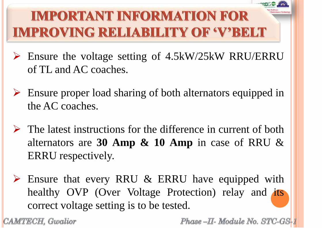
Ensure the voltage setting of 4.5kW/25kW RRU/ERRU
of TL and AC coaches.
Ensure proper load sharing of both alternators equipped in
the AC coaches.
The latest instructions for the difference in current of both
alternators are 30 Amp & 10 Amp in case of RRU &
ERRU respectively.
Ensure that every RRU & ERRU have equipped with
healthy OVP (Over Voltage Protection) relay and its
correct voltage setting is to be tested.

Ensure proper battery charging / pre-cooling during
maintenance before train departure to avoid sudden
loading of alternators. This will reduce the cases of belt
dropping.
Ampere setting of RRU/ERRU shall be ensured as per
specified limits.


Phase –II- Module No. STC-GS-1
1. Belt slippage
• Alternator/ axle pulley worn out
• Improper tension of V beltsProbable Causes :
2. Belt turn over and face twisted
Probable Causes : • Misalignment of alternator/ axle
pulley
• Particular V belt loose
3. Excessive stretch
Probable Causes : • Improper spring tension of belt
tensioning device

4. Rapid wear
Probable Causes : • Excess tension on V belts
• Improper spring tension of belt
tensioning device
• Pulley groove pitted
• Misalignment of alternator/ axle pulley
• Poor material quality of V belts
5. Belt bottom cracks wear
Probable Causes : • Alternator/ axle pulley groove worn out
• Poor material quality of V belts
6. Belt top cracks
Probable Causes : • Pulley groove angle small
• Poor material quality of V belts
7. Belt dropping
Probable Causes : • Sudden loading on alternators
• Improper load sharing between alternators
• Current controlling of RRU/ERRU not
proper
• Shifting of axle pulley
• Misalignment of alternator/ axle pulley
• Lateral play in alternator
• Shifting of alternator shaft resulting in
shifting of alternator pulley and
misalignment.8. Smoking of belts
Probable Causes : • Alternator/ axle pulley groove worn out
• Sudden loading on alternators
• Unequal tension among the V belts

During maintenance/after fitment of alternator in the bogie
suspension bracket, alignment of alternator and axle pulley
should be checked.
It can be checked by cotton cord which should touch all the
four edges of the both pulleys simultaneously.
If misalignment is found, locate the cause of misalignment and
rectify it.
It can be checked by laser
beam also.
Beam from alternator pulley
groove center should fall in
the center of corresponding
axle pulley groove.
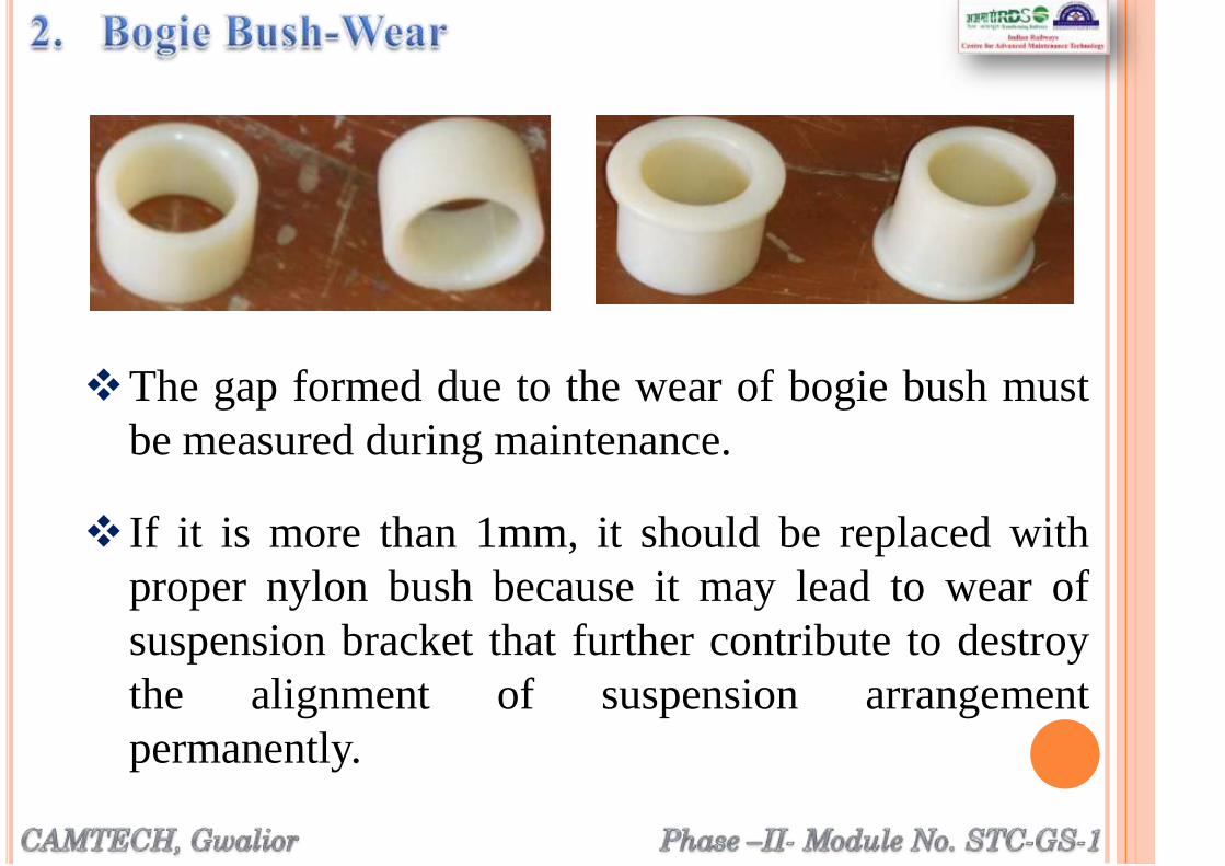
The gap formed due to the wear of bogie bush must
be measured during maintenance.
If it is more than 1mm, it should be replaced with
proper nylon bush because it may lead to wear of
suspension bracket that further contribute to destroy
the alignment of suspension arrangement
permanently.

The clearance between suspension brackets found more due to
improper workmanship/ measurement during the manufacturing
process of bogies.
Gap between bogie suspension brackets should be checked.
Excess gap between bogie bracket and alternator suspension
bracket will lead to misalignment of alternator (400+4mm max.
for AC and 268+4mm max. for Non AC coaches)
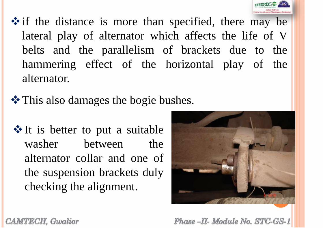
It is better to put a suitable
washer between the
alternator collar and one of
the suspension brackets duly
checking the alignment.
if the distance is more than specified, there may be
lateral play of alternator which affects the life of V
belts and the parallelism of brackets due to the
hammering effect of the horizontal play of the
alternator.
This also damages the bogie bushes.

The alternator may get stuck up due to the seizure
of bearing that may in turn results the belt
dropping.
To avoid this type of failures, the following
practices shall be followed:
Bearings should be cleaned and greased properly
during POH.
End shield of alternator should be properly
tightened to avoid entry of abrasive particles.
Vibration checking and clearance checking for
bearing should be done during POH.

Groove of alternator pulley and axle pulley should be
checked during POH and at the time of replacement
of V belt for worn out and groove base shining and
ovality.

The pulley is to be replaced if pulley groove width is
increase by 0.5mm at workshop level and 0.8mm at
depot level or the groove base of the pulley is shining or
mechanically damaged.
The standard groove angle is 36 degree for alternator
pulley and it is 40 degree for axle pulley. If the groove
angle is more, excessive wear at the base section or belt
bottom crack may happen and if the groove angle is
small, crushing and wear of belt at top or belt top crack
may happen.

Both the alternator pulley and axle pulley shall be
replaced during alternate POH or when ever
mechanical damage of pulley occurs.
Replace the old axle pulley fixing rubber pads with
new rubber pads during POH and whenever
replacement of axle pulley is required.
The number embossed in both halves of the axle
pulleys must be same.

It is to be ensured that diameters of the pulleys are same as
specified.
Ensure gap between two halves of axle pulley to 3.0 ±
0.5 mm with the tightening torque of 30 kg-m
(maximum).
The gap between axle
pulley halves should be
checked with feeler gauge
during maintenance.
After fixing of axle pulley,
verticality of the pulley
should be checked with
plumb or spirit level.
The reinforcement cords are broken if the belts are
forced over pulleys during fitment.
Change the belt set and install them in grooves only
after loosening the tension spring of belt tensioning
device.
During replacement, do not ride the wheel over belts
that definitely damage the reinforcement cord of V belt.
If belts are replacing, replace all the belts as set with
same grade, same make and of same batch.
Special care should be given during the provision of V belts
since it is one of the root causes of premature failures:

Tensioning of the final recommended value after
every first trip or 500 kms immediately after
provision of V belts at workshop or depots &
thereafter as per standard maintenance practices
mentioned in schedules.
In absence of proper tension in V-belts, they may get
failed due to belt slippage that increases the screeching
noise and heat.
Thus smoking may start from the belts that result in V-
belt drop.
The following actions shall be ensured to maintain
proper tension.
Tensioning of the final recommended value after every
first trip or 500 kms immediately after provision of V
belts at workshop or depots & thereafter as per standard
maintenance practices mentioned in schedules.
It shall also ensure that correct type of belt tensioning
device spring as prescribed by RDSO equipped in
coaches during POH as well as at depot level.
Check the tightness of belts by 4 kg weight.
Excessive stretch may arise due to overloading
and internal breaks.
Overloading may be due to bad design, failed
bearings of the alternator, failure of output control
of the regulator of the alternator, or internal breaks
during manufacture or due to forcing the belts
over top of the grooves.

The temperature of the axle pulley groove may
approach to 27 ºC above from the ambient
temperature.
However in hot summer, ambient temperature
reaches as above as 49 ºC.
This increases the belt temperature more than that
of the design temperature.
This is also one of the causes of smoke emission
from V belts and belt drop.

Anti-rotating lug welding shall be done precisely in-butt
with suspension pin.
Suspension pin head thickness and anti rotating ‘U’
thickness must match perfectly to avoid rotation of S/pin &
therefore damage to Trans-mounting bush.
Standard tool kit for AC Escorting staff
Feeler gauge sets (0.05 mm to 1.00 mm)
Measurement of belt tensioning device
Free length of spring 345 mm
Length of indicator 250 mm
GO/NOGO gauges for checking the grooves of alternator
pulley and axle pulley.
Gadget of 4 kg weight for checking the tension of V-belts
V- Belts pitch length testing machine
Test bench for checking of RRU/ERRU & alternator 4.5 kW
Test bench for checking of RRU/ERRU & alternator 25 kW
BTD spring testing machine
VVVF type machine for load sharing in AC coaches
In-Situ testing kit of OVP
Gauges for measurement of cross section of V-belt

Phase –II- Module No. STC-GS-1
(Conventional Self Generating
NON AC Coaches)

Attention on Maintenance Lines
Check the plate-form attention report and concentrate first on
attending the defects in these coaches by adapting systematic
trouble shooting procedures.
Proceed as follows in respect of other equipment.
First attend alternators in coaches for generation, which
have arrived "cold" and coach dark condition as per
platform report. Proceed as follows:
Check field fuse, replace if found blown, with proper rating
and approved make.
(Primary & Secondary Maintenance)

Check the continuity of field and phase winding with the
help of test lamp/ multi-meter to ensure that windings
are not open circuited.
Check for loss of residual magnetism with the help of
voltmeter across the field terminals. In case of loss of
magnetism, give 12 V DC flashing to the field terminals
for few seconds to regain lost residual magnetism.
Check that the regulator feedback loop is O.K.
Check connections for tightness in alternator and
rectifier regulator. If this is all right, remove belt from
alternator.
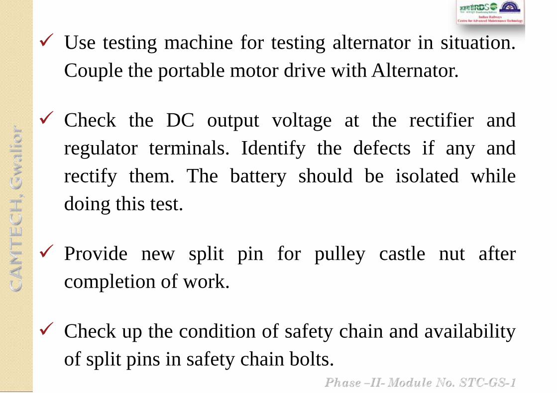
Use testing machine for testing alternator in situation.
Couple the portable motor drive with Alternator.
Check the DC output voltage at the rectifier and
regulator terminals. Identify the defects if any and
rectify them. The battery should be isolated while
doing this test.
Provide new split pin for pulley castle nut after
completion of work.
Check up the condition of safety chain and availability
of split pins in safety chain bolts.
Check up alternator suspension bracket and tension
gear for any damage and replace, if necessary.
Check up and tighten loose bolts in terminals box
covers.
Check availability of split pin for alternator castle nut.
Never energize field from battery in case of failure of
field circuit diode in regulator. Apart from non
regulation, this may cause permanent damage to field
windings.
If there is no generation, ensure that there is no
breakage in the cable termination.

Examine the indicating white mark on the pulley
axle and ensure that the pulley has not slipped. If
pulley has slipped, take necessary corrective
action.
Tap the pulley with hammer and judge the
tightness or crack by sound. If it gives clean
metallic sound the pulley is tight. Dull sound
indicates that it is loose. Bolt should be tightened
with torque wrench to 30 kgm.
Check the lock nuts and split pins for availability
and tightness.
Check the belt tension after every round trip of the coach.
For new V-belt fitted, the belt should be re-tightened after
completing the first trip.
Check condition of belt for fraying of edges, etc.,
Check the belts for overturn and correct it, if necessary.
Check the number of belts which should be 4 nos. for 4.5
kW alternators.
Tension should be felt by hand by striking it slightly. Belt
in correct tension will respond `alive' and `spring-back'. If
required re-tensioning, the same shall be re-tensioned.
Check that all the sets of belts provided should be of same
make & grade.

Whenever belts are replaced, to get optimum performance
following precautions should be exercised:
a) The belts of same nominal length i.e. same grading should be
used as a set.
b) Two or more makes of belts should not be used in a set.
c) Check tension of V belt after fitment by tension gauge.
d) Re-tension newly fitted belts after 1st trip or 500 km run,
whichever is convenient.
e) Check alignment of pulleys whenever alternator is replaced.
f) Replace pulleys if grooves are worn out. Check by GO/NO-
GO gauges.
Commissioning and checking of new ‘V’ belts
To check the new „V‟ belts for proper fitment,
following gadgets should be available at each depot:
• Pitch length of „V‟ belt
• Angle of „V‟ belt
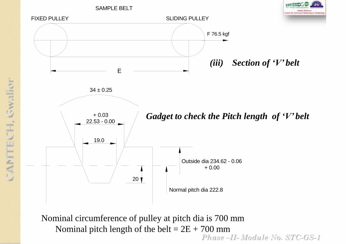
19.0
+ 0.0322.53 - 0.00
34 ± 0.25
20
Outside dia 234.62 - 0.06 + 0.00
Normal pitch dia 222.8
E
FIXED PULLEY SLIDING PULLEY
F 76.5 kgf
SAMPLE BELT
E
FIXED PULLEY SLIDING PULLEY
F 76.5 kgf
SAMPLE BELT
(iii) Section of ‘V’ belt
Gadget to check the Pitch length of ‘V’ belt
Nominal circumference of pulley at pitch dia is 700 mm
Nominal pitch length of the belt = 2E + 700 mm

Method of checking Angle of ‘V’ Belt
38°42°
Along a straight portion of the belt in an un-tensioned state, the
cross-section shall be such that the edges of the broader (top)
side of the belt shall touch the sides of V-groove having an
included angle of 38 degree and the edges of the narrower
(bottom) side of the belt shall touch the sides of V-groove
having an included angle of 42 degree.
The flanks of the belt shall not touch the sides of the V-
grooves.
Gauge for checking angle of v-belts

Clean regulator externally.
Open regulator terminal cover and check for
signs of overheating in all the terminals/bus
bars/etc.
Check up for loose connections and tighten the
same. If the terminal board is found affected due
to heat, replace terminal board with new one.
Check for any damage to the phase and field
wires /cables inter connecting regulator and
alternator and its anchoring arrangement.

Check and secure properly the terminal cover and
regulator cover.
Check the cable termination of the regulator
visually for any abnormality.
If the alternator arrived without generation, then
open the regulator and check for any abnormality
and ensure the fuses are intact.
Check the cable for any abnormality from the
alternator to the regulator by using test lamp, if
found open/short, attend the same.
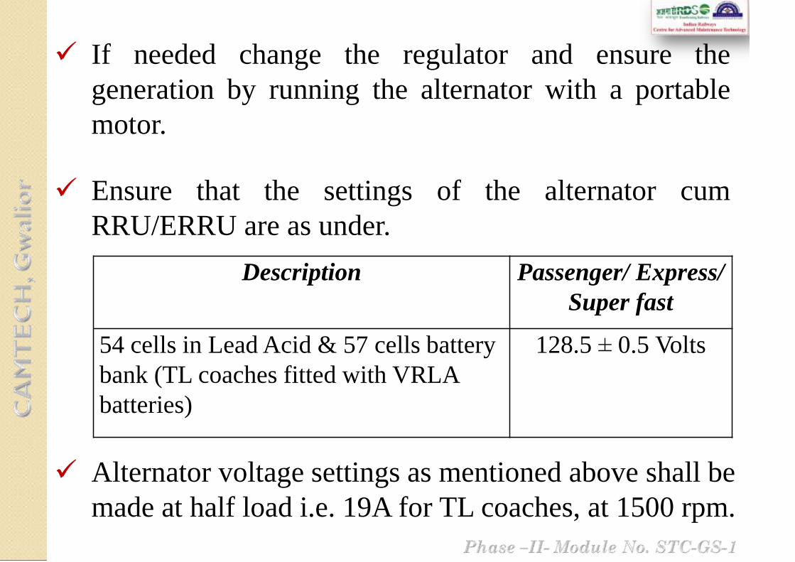
Description Passenger/ Express/
Super fast
54 cells in Lead Acid & 57 cells battery
bank (TL coaches fitted with VRLA
batteries)
128.5 ± 0.5 Volts
Alternator voltage settings as mentioned above shall be
made at half load i.e. 19A for TL coaches, at 1500 rpm.
If needed change the regulator and ensure the
generation by running the alternator with a portable
motor.
Ensure that the settings of the alternator cum
RRU/ERRU are as under.

To know the condition of cells during `Trip
Examination' some cells in a battery are treated as
`pilot' cells.
On arrival of train in the maintenance line,
disconnect all inter vehicle connections.
Record the specific gravity of `pilot' cells in each
battery.
Different cells should be identified as pilot cells
every month. The idea of identifying different
cells as pilot cells every month is to ensure that
true condition of the battery is reflected.
i. Conventional Lead Acid Batteries

Marking of these cells to indicate pilot cells shall be
done as follows and repeat cycle further
1 2 3 4 5 6 7 8 9
10 11 12 13 14 15 16 17 18
Month Pilot Cells
1st Month 1, 12, 13
2nd Month 2, 11, 14
3rd Month 3, 10, 15
4th Month 4, 9, 16
5th Month 5, 8, 17
6th Month 6, 7, 18
Check the floats of each cell and check for correct
electrolyte level as indicated in the float stem.

Replace missing/defective floats.
In case of low level, replenish with distill water.
If any cell needs too much water for replenishing,
watch for crack in the cells and also check the voltage
on load which should not be less than 1.80V.
In case of any defect, remove the mono-block and
replace by a spare one preferably of the same make
and lug date or a lug date as close to the one already
in the coach.

Coaches with discharged batteries which shows less
than 100 V on load should be put on charge at double
the normal rate of charge and the charging reduced to
half the rate of charge as soon as the gassing starts
and continued till the specific gravity rises to the fully
charged value which should be between 1210 and
1220.
Use the battery charging terminals provided in
coaches for charging purpose.
Check up correct polarity and connect the charging
cables.

Use a clip on D.C. ammeter of 0-25 A range to check
up the battery charging current. Note down the rate
of charging and the number of hours of charge.
Check specific gravity of pilot cells and the total
voltage of battery on load at the end of charge and
record.
Keep micro porous vent plug tight.
Ensure that washer is available in micro porous vent
plugs.
Check all the battery box members for any cracks in
the fabricated battery box/cradle and take corrective
action.
Check for proper fitment of mono block in the battery
box ensuring wooden packing pieces.
The person in charge of battery maintenance should
record all the readings mentioned above in his diary
and this information should be transferred to the
register maintained for various trains.
Check anti-theft rods and provision of nuts both inside
and outside the battery box on either side. Secure
battery box cover finally after all works are
completed.
Ensure that the fitment of the battery box is in order
with all the bolts, nuts, lock nuts, split pins etc.

Ensure the bottom plate of the box is well secured.
Ensure the cells are properly cleaned.
Ensure all micro porous vent plugs and sealed floats
guide are properly closed.
Check the terminations in the fuse and the condition
of the fuse.
Check the termination of cable in the under frame link
box, for proper condition and attend if needed.

Check for by-passing of the failed cells. If the
cells are found by-passed, replace these failed
cells immediately with the healthy ones.
Dust accumulation, if observed, clean with dry
cotton cloth.
Cell cover/ container cracked or bursts, if noted,
replace the cell with a healthy cell immediately.
ii. VRLA Batteries
(Ref. RDSO/PE/ SMI / TL /0024-2012/Rev.2 dated
17.08.2012)

In case of battery terminal/ cable over heating sign,
check for loose connection at the cell terminal post/
cable end. If required, replace the cable immediately.
Protective lid on safety valve if missing provide new
one immediately.
Charge the batteries, preferably for 6-8 hrs. after
arrival as cells may be partially discharged.
Do not boost charge the cells for more than 12 hours.
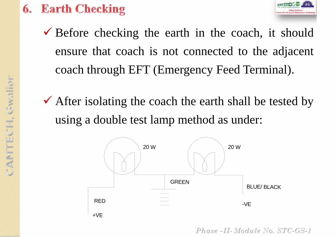
Before checking the earth in the coach, it should
ensure that coach is not connected to the adjacent
coach through EFT (Emergency Feed Terminal).
After isolating the coach the earth shall be tested by
using a double test lamp method as under:
20 W 20 W
GREENBLUE/ BLACK
-VERED
+VE
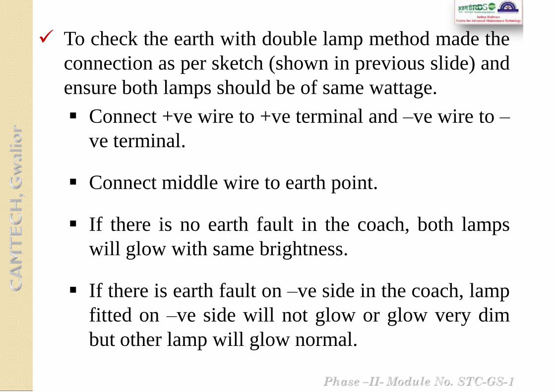
To check the earth with double lamp method made the
connection as per sketch (shown in previous slide) and
ensure both lamps should be of same wattage.
Connect +ve wire to +ve terminal and –ve wire to –
ve terminal.
Connect middle wire to earth point.
If there is no earth fault in the coach, both lamps
will glow with same brightness.
If there is earth fault on –ve side in the coach, lamp
fitted on –ve side will not glow or glow very dim
but other lamp will glow normal.

If there is earth fault on +ve side in the coach, lamp
fitted on +ve side will not glow or glow very dim
but other lamp will glow normal.
If any earth is noticed the required corrective
measures should be taken to remove the earth before
inducting the coach in the service.

Following scheme is prescribed for all trains during primary
or secondary maintenance at a depot:
Switch on each fan individually and check its working.
If the fan does not start, short the switch terminals with a
small piece of wire temporarily.
If the fan starts it will indicate that the controlling switch
is defective. Replace defective switch.
If the fan does not start when the switch terminals are
shorted, proceed as follows for fans:
• Test for supply at the 2-way connector terminals near
the fan with the switch on. If there is no supply, the
wiring is defective and has to be attended.
• If fan is defective, repair or replace.
If the fan is noisy, check for loose blades/fan guards and tighten
them.
If the noise is due to bearings, replace the fan.
Check the fuse for fans and ensure that it is of correct size (35
SWG) tinned copper.
Clean guard and body of fan externally.
In swiveling and bracket fans ensure that the fan dust cover is
promptly replaced after attention and also that the nylon cord
provided to prevent loss of fan dust cover, is available in
position.
The MCB/fuse controlling the fan circuit shall be checked for
correct rating (16A), proper functioning and replace if found
defective.
Switch on each lamp/tube light/CFL. If the lamp/tube
light/CFL does not glow, check lamp/tube light /CFL and
replace, if fused.
If the lamp/tube light/CFL is all right, check control fuse
and replace, if found blown.
If the fuse is all right, check control switch and replace, if
necessary.
If the switch is all right, check up lamp holder for any
defect or loose connection and rectify.
If there is no defect in the lamp holder, check up for supply
at the holder terminals and if the wiring is found defective,
rectify.
Provide switch covers and fuse covers promptly, if they are
missing.

If any dome cover is open or not secured properly, rectify
defect, if any and secure.
Replace broken glass domes/acrylic covers of tube
lights/CFLs.
Check MCBs/fuses for light circuits in junction box for
proper operation and replace defective MCBs. Check for
loose connections between MCB and bus bars and rectify.
Ensure that MCBs/fuses are intact for protection of each
circuit.
Check tightness of terminal connections of HRC fuse for
negative circuit in junction box.
Never by-pass or use incorrect fuses as this may result in
serious failures.
Earthing of wiring in the coach shall be checked both on the
positive and negative wire separately in each coach by the earth
testing device.
A coach with negative earth fault in case of 110 V DC systems,
which could not be attended in time, can be given in service in
case of emergency. The coach shall be taken for attention by the
primary maintenance station during the next trip.
Testing shall be done only at cable terminations.
Poor crimping of cable lugs and loose connections in terminals
may result in excessive heating and discoloration of lugs, tapes
and cables. Check for this during inspection and take prompt
action to locate and rectify the defects.
Replace incorrect size of HRC fuses by correct rating.

Check all fuses and ensure that they are secured tightly to their
terminals. Replace defective MCBs/fuses in junction box by
MCBs/fuses of correct rating.
Remember that fuses are provided for protecting circuits in case of
faults. Try to find out the cause of fault.
Loose and exposed/hanging wires should be secured and properly
covered.
In case wiring is found mechanically damaged or tampered with or
needs replacement, the coach should be marked electrically “sick”.
If the work is of a minor nature, this may be done in maintenance
lines.
Coaches which are suspected to have wiring defect either in the
under-frame or roof shall be subjected to insulation test with 500 V
megger.
Record all the attention given in the under frame and roof, the
Specific Gravity, the condition of generation, lamps, fans and
fuses, availability of belts etc. with coach and other details.

Check FDB‟s cover for any gap and entry for waste/
rubbish material.
Check and ensure supply and functioning of each
Mobile/ Laptop charging point, replace if found
defective.

Clean the interior of battery box.
Clean the cell tops and deposit of sulphation, if any in inter
cell and end cell connections.
Remove sulphated inter cell connections, clean the
connecting surface with a piece of cloth.
Use fresh fasteners.
Sulphated internal connections and fasteners should be
soaked in kerosene oil, cleaned with warm water and kept
ready for use.
In addition to the instructions contained under "Trip
examination" the following works shall be carried out:

Inter cell connections should be provided with both small and
large strips and four fasteners each with one hexagonal nut, one
spring washer to IS:3063 and two steel punched washers to
IS:2016.
Remove end cell connectors, clean the connecting surface both in
cell and connector thoroughly and provide back.
Check for proper crimping of terminal.
In case strands of connecting cable are found cut at the crimping
end, cut wire at the crimping end and re-crimp with a new inter
cell connector.
End cell connector confirming to IS:6848 should only be
provided.
Tinned copper crimping sockets with a single hole, if any,
provided as a stop gap measure should be replaced by standard
end cell connector.

Provide end cell connectors with both the fasteners each with
one spring washer to IS: 3063 and one punched steel washer to
IS:2016.
Tap sealed float guides and check for free movement.
Look for elongated holes in sealed float guides and replace such
guides. Replace deficient floats promptly.
Check whether vent plugs are of the anti-splash type and replace
if required.
Check the make of cells and the lug date.
Different "makes" of cells mono block if found mixed together
should be replaced by a single "make" of cells.
If it is not possible to do this during one fortnightly examination
this should be noted down and attempts made to replace the
same during the next fortnightly examination.

Check whether cell/ mono block packing is tight and provide
additional packing, if necessary.
Use only hard wood coated with acid resistant paint for cell
packing.
Check for provision of anti-theft rods and provision of nuts,
both inside and outside the battery box on either side. Replace
deficient rod and nuts.
Apply petroleum jelly on inter cell connection and end cell
connections.
Check battery fuses and replace overheated/incorrect size fuses
by correct size.
Check battery box fixing nuts for tightness.

Check for tightness of terminal connections of alternators
and rectifier regulators.
Thoroughly clean externally the alternator and regulator.
Open inspection cover of regulator. Blow dust with a
portable blower. Secure covers tightly after inspection.
Check locking of current setting of regulator, if disturbed it
should be reset/locked as prescribed.
Check the alternator pulley for proper fixture and the
availability of castle nut and split pin.
In addition to the works mentioned in Trip &
fortnightly examination, carry out the following:

Reset the correct position of pulley, if found shifted and
tighten the loose nuts with torque wrench with
recommended torque.
Check tightness of nuts and also availability of chuck
nuts and split pins in all fixing bolts.
Conventional Lead Acid Batteries
Record specific gravity of individual cells/mono block.
"Switch on" full load of the coach and record individual
voltage of cells and total voltage.

"Switch off" load. If the specific gravity is less than that
painted on the battery box, charge the cells as specified under
"Trip Examination" after topping up with DM water, if
required.
Use battery charging terminals provided on coaches for
charging purposes.
Charging should be continued till the specific gravity rises to
the value of mentioned in battery box, on "Pilot" cells.
In case pilot cells show no appreciable improvement, check
specific gravity of adjacent cells.
If the specific gravity does not improve in spite of charging,
replace the battery by another set.
Cells should be handled with due care while unloading and in
transit to avoid breakage.
On completion of charging, record the specific gravity of
individual cells. If there is any wide variation in the specific
gravity/ voltage of cells, disconnect and replace those cells
showing low specific gravity/voltage by spare ones.
In case there are more than 1/3 of total cells with low specific
gravity, the entire set should be replaced.
Cells showing reverse voltage, zero volts should be withdrawn
and replaced by charged cells immediately.
Record individual voltage of cells and the total voltage on full
load of the coach.
Change the marking of the pilot cell as given in trip schedule.

Open front door. Check all connections in MCB-cum-fuse panel
for tightness any for heating sign, fuses etc.
Check availability of terminal lugs for all cables in junction box
and replace if necessary by terminal lugs of correct size.
Check rotary switches / MCBs provided for lights, fans circuits
for correct condition and rotary switch and EFTs for proper
operation.
Replace/ repair defective MCBs.
Check up negative fuse and replace, if necessary by correct
ratings of HRC fuse.
If rotary switches are provided instead of MCBs, Check for
proper operation.
Check up HRC fuses provided with rotary switches for correct
rating and replace, if necessary.
Close front door and secure properly by the locking key, If
found defective, the same may be attended/replaced.
Superstructure wiring and under-frame wiring shall be
tested separately for which the main negative fuse in shall
be opened and controlling MCBs for all circuits kept off.
All other fuses shall remain in circuit.
Insulation resistance shall be measured with all fittings and
equipment connected both on under-frame and
superstructure.
The under-frame wiring shall be tested with battery fuse
open.
The IR value should be minimum 2 Mega-Ohm in fair
weather condition and minimum 1 Mega-Ohm under
adverse weather condition.
Availability of inspection cover of DFBs should be ensured.

The fan body, guards and blade shall be thoroughly
cleaned with cloth.
All fans shall be opened and condition of commutator,
brushes and brush gear shall be thoroughly checked.
Studs used for fixing the fan to coach body, shall be
checked and tightened, wherever necessary.
Availability of all the three fixing studs should be
ensured.
All the switches controlling the fans shall be checked for
its smooth operation and correct working and replaced,
where necessary.
Fan blades shall be replaced if found bent, or if there is no
proper air discharge.

Open each fitting with the dome key and remove the dust
of the fitting both from inside and outside.
Ensure free operation of locking mechanism and replace
defective fitting.
Clean first glass domes with wet cloth and then with a
clean dry cloth.
Replace rusted fittings and fittings with damaged surface.
Check up wattage of lamps and replace with that of
correct wattage.
Check up whether toggle switches are marked to indicate
lighting control "L", night light control `NL', side lamps
in guards compartment as `SL', tail lamps as `TL-Rear',
`TL-Front', luggage room as `LRL'.If not, stencil legends
with fluorescent paint.

Check up all lighting circuit fuses in each coach for correct
size and replace if necessary.
Stencil the size of fuses near the locations, if not already
done.
Mark inspection covers of distribution fuse boards as `DFB'
if not done already.
Thoroughly clean metal guards for roof light fittings in
luggage rooms and paint, if necessary.
Check each switch of lights and fans for proper fixing
and operation. Replace defective switches.
Switches should be provided in the locations intended for
them and provided with covers with their knobs exposed
for operation by passengers.

Check distribution fuse boards and fuse cut outs of light
and fan circuits, for over heating and tightness of
connections and provisions of correct size of fuses in the
fuse terminals.
Check up supply and marking of polarity of EFTs.
Replace missing EFTs and those without wiring nuts.
`Switch off‟ load. Charge the cells at 50% of normal rate
of charge, i.e., at 1/10th of the rated capacity of cells.
Record hourly cell voltage and specific gravity reading
of every cell.
Terminate charging when 3 successive readings are
constant.
In addition to the instructions contained under "Monthly
Examination" following activities should be done:
i. Conventional Lead Acid Batteries

Record specific gravity and no load voltage of each cell 10
minutes after terminating charge.
Specific gravity should be between 1.210 and 1.220 for cells
upto 120 Ah capacity. The voltage should not be less than 2.1
V.
If there is a wide variation in the specific gravity and voltage
readings, such cells should be replaced.
Check the cell voltage on full load.
Cells showing reverse and low voltage are to be replaced with
healthy cells of the same make/type.

13 Nm tightening torque of terminal bolt with torque
wrench for four terminal design cell (all makes
except Exide).
22Nm tightening torque of terminal bolt with torque
wrench for four terminal design cell (Exide).
Do not over tight.
Terminal post corrosion, if observed remove the
cable and clean the terminal post and cable lug with
brass brush or fine emery paper and apply petroleum
jelly.
ii. VRLA Batteries
(Ref. RDSO/PE/SMI/TL/0024-2012/Rev.2 dated 17.08.2012)
The following steps shall be followed:
(i) Discharge the battery bank with full coach load for
15 minutes (based on coach arrival battery SOC).
(ii) Note down the individual cell readings after 15
minutes while the coach is still connected during the
discharge.
(iii) If all the cell voltages are 1.98 Volts and above then
the cells are in healthy condition. Charge the cells
same to be put back into service.
(iv) If some of the cell voltages are less than 1.98 Volts
then give boost charging with 2.30 VPC for 12 hrs.
by charging them separately with current limited to
20% of battery rated capacity
a. If the total battery bank open circuit voltage for TL
coaches is 117.0 Volts or above for 57 Cells.

(v) The weak cells, which are charged separately, must be
checked through a discharge at C-10 rate for 30 minutes,
the end of discharge voltage should be above 2.0 V. If
such a re-charged cell fails to qualify the above test, it
should not be put back in the coach.
(vi) After performing the discharge test on the revived cells,
the cells need to be charged at least for 4 hours, prior to
fitment in the coach.
b. If the total battery bank, open circuit voltage for TL
coaches is less than 117.0 Volts for 57 Cells.
Charge the cells for 12 hrs with 2.30 VPC and then carry
out the discharge test as per item no. i to iii of (a) above.
Carry out visual inspection of terminal box for signs of
overheating, fumes and presence of water etc., clean it.
Check the connections for any defect, if required re-
crimping and taping should be done. Replace spring
washers, if overlapping.
Disconnect the regulator and measure the insulation by
500 V megger; if found less than 10 M-ohm, remove
alternator and heat its winding in the oven at 80 degree C
for 1 hour.
In addition to the instructions contained under "Quarterly
Examination“ following activities should be done:

Check the condition of outgoing cables and its cleating
arrangement. Replace the grommet, if necessary. Ensure that
flexible pipe carrying the cables is connected properly to the
grommet to prevent damage to insulation.
Check the suspension pin, main suspension lugs of alternator
and bogie brackets for any signs of crack. Provide new nylon
bushes and secure nuts and bolts, with new split pins. Play
between alternator lugs and bogie bracket should not be more
than 4.0 mm.
Check profile of „V‟ groove for worn out pulley as per SMI
No. RDSO/PE/SMI/TL/0030-2005 (Rev.0) dtd. 12.08.2005.
Check the pulley fixing, concentrating on lock nut and locking
collar pin. If lock nut is damaged, replace it.

Check safety chains and chain fixing nuts, bolts and split pins.
Replace tension rod sleeve.
Fit tension rod fixing pin of alternator with new washer and
split pin. Replace spring, if belts loose upon coach arrival.
Lubricate the threads of the tension rod and adjusting nut.
Check the lock nuts and split pins for availability and tightness.
Appropriate open jaw type torque wrench to be used for uniform
tightness of all studs, value of torque depends on the gap required
between two pulley halves.
Check distance between wheel hub and axle pulley with gauge
plate.
Check the condition of pulleys and its „V‟ grooves profile. Replace
the pulley, if required.
Tap with hammer and judge the tightness by sound.
Ensure gap between the two halves of the axle pulley is 3.0 ±
0.5mm.
Examine the indicating white mark on the axle pulley and ensure
that the pulley has not shifted. If pulley found shifted, remove the
pulley and re-tighten it after replacing rubber pads and provide
indicating white mark.

Replace all existing “V” belts with new “V” belts having
same grade/make.
Follow the instruction given in SMI No.
RDSO/PE/SMI/TL/0027-2004 (Rev.0) dtd. 05.03.2004 for
checking new “V” belts.
The old “V” belts removed from service to be destroyed.
Check tension of “V” belts.
For the exact measurement of tension, a weight of 4 kg.
shall be hanged from the centre of belt span and see that the
top surface of this belt does not go below bottom surface of
remaining belts.

Clean regulator box externally and remove all the dust
with dry compressed air.
Open cover and change sealing sponge rubber gasket.
Clean all dust with soft brush and vacuum cleaner from
inside, particularly from heat sink of electronic
components and terminal board.
Check voltage and current setting.
Ensure that they have not been disturbed and are in locked
position.

Following tests shall be done to ensure proper working of
RRU/ ERRU with alternator:
Set specified voltage 128.5 +/- 0.5 at half load 19 A &
1500 rpm.
Check OVP set voltage and working. Check the proper
suspension of the unit and provide new split pin in its
suspension bolt.
Tighten all the electrical connections and check whether
power connections are provided with locking washers.
Check field and phase HRC fuses for their proper rating
and fitment.
Clean the battery box externally and remove all dust
with dry compressed air.
Open battery box covers. Remove inter-cell
connections and take out the cells.
Clean the cells, inter-cell and end cell connectors
thoroughly. Replace spring washers, if each are
overlapping.
Check for crack in cell containers leading to leakage.
If needed, replace the defective cell with healthy cell
of similar capacity, make and lug date.
Check for heating signs on the positive and negative
terminals and discolouring of the cells container/ top
lid. Clean the sulphation of terminals.
(i) Lead Acid Batteries

Check the level of electrolyte in all the cells and top up with
distilled water, if necessary.
Check the specific gravity and voltage of all cells with cell
tester.
Check all vent plugs and float guides conditions and replace
defective ones.
Check the conditions of connecting strips/ leads and replace if
required.
Check all suspension bolts of battery box suspension/ cradle
for signs of any crack, corrosion, rusting and take corrective
action.
Clean and examine condition of battery boxes.
Examine condition of FRP tray and replace if necessary.

Paint all battery boxes. Battery box will be applied with
Grey colour high build epoxy paint to RDSO Spec. No.
M & C/ PCN/111 to a thickness of 100 – 120 micron.
Provide all cells in battery boxes with proper packing.
Connect all inter-cell connections and end cell
connectors. Provide petroleum jelly on all connections.
Charge the battery bank at the rate I = 0.1 x C10 fully till
3 constant hourly readings of voltage found, indicating
the condition of a fully charged cell.
Fit the battery box covers and secure them properly.
Refer Quarterly Schedule for the maintenance of VRLA
batteries.
(ii) VRLA Batteries

Open each fitting and clean properly from inside and
outside. Ensure free operation of locking mechanism and
replace defective fitting.
Replace rusted fittings and fittings with damaged
surface.
Check all the lights for proper working. Rectify or
replace if necessary.
Check up all lighting circuit fuses for correct rating and
replace if necessary.
Check and clean plastic fan blade and ensure that there is
no crack on the blade or hub.
Ensure proper fixing of fans and locking arrangement.
Check for abnormal sound, rectify or replace, if needed.

Ensure that the correct polarity of field winding i.e. positive
connected to F+ while measuring the continuity of the field
winding, otherwise the alternator will not self excite.
Check the proper compression force on the tensioning
spring with indicator plate by tightening the special nut.
Keep the terminal box tightly closed.
Use the cable grommets or cable gland of correct size for
reducing the vibration of terminal connections.
It is preferable to anchor the cables externally to avoid
shocks and vibrations on the terminals.
i. Do’s
Don‟t use improper tools to handle the alternator; it
may damage parts of the alternator.
Don‟t re-grease the bearing frequently. Re-greasing
should be done after thoroughly cleaning the bearing
with white spirit. It is preferable to re-grease the
bearing only during POH.
Don‟t keep the belts in over tension as this may
reduce life of the belt.
ii. Don’ts

Short all seven terminals of the terminal box before
measuring the insulation resistance.
Ensure that DC „+‟ and DC „-‟ are connected to
battery positive and battery negative respectively.
Wrong connection will damage main diodes.
i. Do’s

Don‟t disturb the settings of the regulator shunt and
potentiometer.
In any circumstances the burden resistance setting should
not be disturbed.
Don‟t open the regulator box unless there is a defect.
Don‟t use a megger to test the components. Use
multimeter.
Don‟t reverse the field terminals on regulator and
alternator.
Never use a fuse wire for field fuse. Always use HRC
fuse of specified value.
ii. Don’ts
Use belt of the same lengths for a set.
Belts should be stocked in lots as per date of receipt
and use in the principle of first in first out basis. The
belts shall be stored in a well ventilated room free
from direct sunlight and moisture.
Re-tension newly fitted belts after first trip.
Maintain a gap of approx. 55 mm between
supporting plate and fixing nut on the free end of
tension rod or upto the split pin for the 4.5 kW
alternators.
Maintain proper alignment between axle pulley and
alternator pulley.
i. Do’s
Do not allow loose belts.
Do not disturb the nut and check-nut on free end of
tension rod if proper gap is available between supporting
plate and fixing nut i.e. 55 mm for TL alternator.
Do not use repaired pulleys.
Do not use old and new mixed belts in sets.
Belt should not have any oil or grease traces, if persist
clean it by soap and water.
The matched set should have belts of one manufacturer
only. Do not use belt of same grade of different
manufacturer in a set.
ii. Don’ts


Phase II - Module No. STC-GS-1
(9 Months)
Phase II - Module No. STC-GS-1
The schedule ‘IOH’ shall be carried out on sick line
at nominated primary depot.
Different SMIs issued by RDSO time to time for the
maintenance of TL & AC equipment are to be
followed.

Phase II - Module No. STC-GS-1
S.No.
Particulars IOH
Frequency of Examination
9 months
+ 30 days
– 0 days
TL & AC EQUIPMENT
1.0 Alternators
1.1
Carry out visual inspection of terminal box for signs
of overheating, fumes and presence of water etc.,
clean it.
1.2
Check the connections for any defect, if required re-
crimping and taping should be done. Replace spring
washers, if overlapping.

Phase II - Module No. STC-GS-1
S.No.
Particulars IOH
Frequency of Examination
9 months
+ 30 days
– 0 days
1.3
Disconnect the regulator and measure the insulation by
500 V megger; if found less than 10 M-ohm, remove
alternator and heat its winding in the oven at 80 degree
C for 1 hour.
1.4
Check the condition of outgoing cables and its cleating
arrangement. Replace the grommet, if necessary.
Ensure that flexible pipe carrying the cables is
connected properly to the grommet to prevent damage
to insulation.

Phase II - Module No. STC-GS-1
S.No.
Particulars IOH
Frequency of Examination9 months
+ 30 days
– 0 days
1.5
Check the suspension pin, main suspension lugs of
alternator and bogie brackets for any signs of crack.
Provide new nylon bushes and secure nuts and bolts,
with new split pins. Play between alternator lugs and
bogie bracket should not be more than 4.0 mm.
1.6
Check profile of „V‟ groove for worn out pulley as per
SMI No. RDSO/PE/SMI/TL/0030-2005 (Rev.0) dtd.
12.08.2005.

Phase II - Module No. STC-GS-1
S.No.
Particulars IOH
Frequency of Examination9 months
+ 30 days
– 0 days
1.7Check the pulley fixing, concentrating on lock nut and
locking collar pin. If lock nut is damaged, replace it.
1.8Check safety chains and chain fixing nuts, bolts and
split pins.
1.9
Replace tension rod sleeve. Fit tension rod fixing pin
of alternator with new washer and split pin. Replace
spring, if belts loose upon coach arrival.

Phase II - Module No. STC-GS-1
S.No.
Particulars IOH
Frequency of Examination9 months
+ 30 days
– 0 days
1.10Lubricate the threads of the tension rod and adjusting
nut.
1.11
Check the logbook for abnormal/ unequal load sharing
and ensure that the difference is within the range of 30
A with RRU and 10 A with ERRU. Follow the
instructions given in SMI No.
RDSO/PE/SMI/AC/0018-99 (Rev.0) dtd. 05.02.1999.

Phase II - Module No. STC-GS-1
S.No
Particulars IOH
Frequency of Examination9 months
+ 30 days
– 0 days
2.0 Axle Pulley & Alternator Pulley
2.1
Check the lock nuts and split pins for availability and
tightness. Appropriate open jaw type torque wrench to
be used for uniform tightness of all studs, value of
torque depends on the gap required between two pulley
halves.
2.2Check distance between wheel hub and axle pulley with
gauge plate.
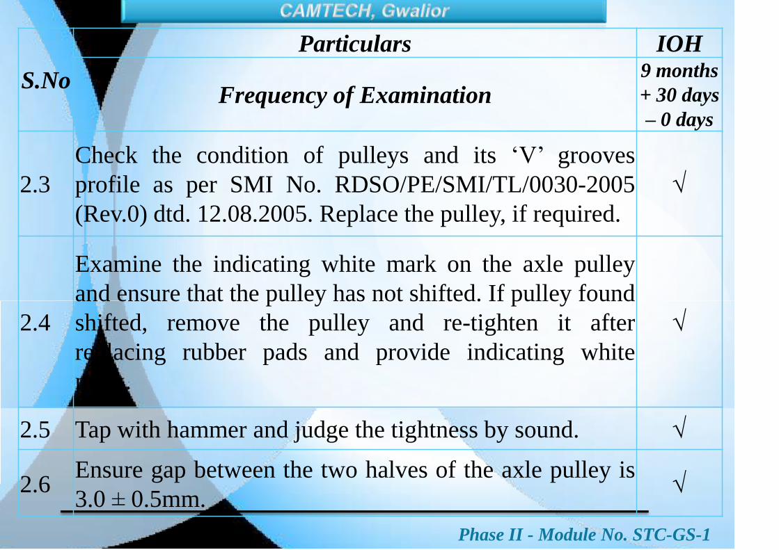
Phase II - Module No. STC-GS-1
S.No
Particulars IOH
Frequency of Examination9 months
+ 30 days
– 0 days
2.3
Check the condition of pulleys and its „V‟ grooves
profile as per SMI No. RDSO/PE/SMI/TL/0030-2005
(Rev.0) dtd. 12.08.2005. Replace the pulley, if required.
2.4
Examine the indicating white mark on the axle pulley
and ensure that the pulley has not shifted. If pulley found
shifted, remove the pulley and re-tighten it after
replacing rubber pads and provide indicating white
mark.
2.5 Tap with hammer and judge the tightness by sound.
2.6Ensure gap between the two halves of the axle pulley is
3.0 ± 0.5mm.

Phase II - Module No. STC-GS-1
S.No
Particulars IOH
Frequency of Examination9 months
+ 30 days
– 0 days
3.0 ‘V’ Belts
3.1
Replace all existing “V” belts with new “V” belts having same
grade/make. Follow the instruction given in SMI No.
RDSO/PE/SMI/TL/0027-2004 (Rev.0) dtd. 05.03.2004 for
checking new “V” belts. The old “V” belts removed from
service to be destroyed.
3.2
Check tension of “V” belts. For the exact measurement of
static tension, apply force `P‟ with a spring balance at the
centre of span in direction perpendicular to the span until the
belt is deflected from the normal to the extent of 16 mm per
meter of span. The force `P‟ should be between 31.4 to 47.0 kg.

Phase II - Module No. STC-GS-1
S.No
Particulars IOH
Frequency of Examination9 months
+ 30 days
– 0 days
4.0 Rectifier Cum Regulator Unit (RRU/ ERRU)
4.1Clean regulator box externally and remove all the
dust with dry compressed air.
4.2Open cover and change sealing sponge rubber
gasket.
4.3
Clean all dust with soft brush and vacuum cleaner
from inside, particularly from heat sink of electronic
components and terminal board.
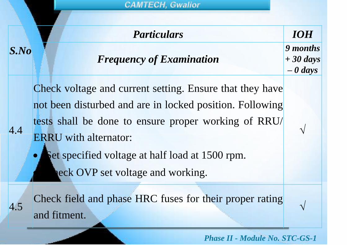
Phase II - Module No. STC-GS-1
S.No
Particulars IOH
Frequency of Examination9 months
+ 30 days
– 0 days
4.4
Check voltage and current setting. Ensure that they have
not been disturbed and are in locked position. Following
tests shall be done to ensure proper working of RRU/
ERRU with alternator:
Set specified voltage at half load at 1500 rpm.
Check OVP set voltage and working.
4.5Check field and phase HRC fuses for their proper rating
and fitment.
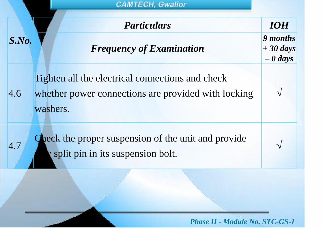
Phase II - Module No. STC-GS-1
S.No.
Particulars IOH
Frequency of Examination9 months
+ 30 days
– 0 days
4.6
Tighten all the electrical connections and check
whether power connections are provided with locking
washers.
4.7Check the proper suspension of the unit and provide
new split pin in its suspension bolt.

Phase II - Module No. STC-GS-1
S.No.
Particulars IOH
Frequency of Examination9 months
+ 30 days
– 0 days
5.0 Battery Charger
5.1Clean battery charger externally and remove all the
dust.
5.2 Clean all dust with soft brush and vacuum cleaner from
inside, particularly from heat sink of electronic
components and terminal board.
5.3 Ensure that the coarse and fine control switch is in
position No.1.
5.4 Check and clean all connections and contacts and
tighten all electrical connections.

Phase II - Module No. STC-GS-1
S.No.
Particulars IOH
Frequency of Examination9 months
+ 30 days
– 0 days
6.0 Battery & Battery Box
6.1 Lead Acid Batteries
6.1.1Clean the battery box externally and remove all dust with
dry compressed air.
6.1.2Open battery box covers. Remove inter-cell connections
and take out the cells.
6.1.3
Clean the cells, inter-cell and end cell connectors
thoroughly. Replace spring washers, if each are
overlapping.

Phase II - Module No. STC-GS-1
S.No.
Particulars IOH
Frequency of Examination9 months
+ 30 days
– 0 days
6.1.4
Check for crack in cell containers leading to leakage. If
needed, replace the defective cell with healthy cell of
similar capacity, make and lug date.
6.1.5
Check for heating signs on the positive and negative
terminals and discolouring of the cells container/ top lid.
Clean the sulphation of terminals.
6.1.6Check the level of electrolyte in all the cells and top up
with distilled water, if necessary.

Phase II - Module No. STC-GS-1
S.No.
Particulars IOH
Frequency of Examination9 months
+ 30 days
– 0 days
6.1.7Check the specific gravity and voltage of all cells with
cell tester.
6.1.8Check all vent plugs and float guides conditions and
replace defective ones.
6.1.9Check the conditions of connecting strips/ leads and
replace if required.
6.1.10
Check all suspension bolts of battery box suspension/
cradle for signs of any crack, corrosion, rusting and take
corrective action.

Phase II - Module No. STC-GS-1
S.No.
Particulars IOH
Frequency of Examination9 months
+ 30 days
– 0 days
6.1.11 Clean and examine condition of battery boxes.
6.1.12 Examine condition of FRP tray and replace if necessary.
6.1.13
Paint all battery boxes. Battery box will be applied with
Grey colour high build epoxy paint to RDSO Spec. No.
M & C/ PCN/111 to a thickness of 100 – 120 micron.
6.1.14 Provide all cells in battery boxes with proper packing.
6.1.15Connect all inter-cell connections and end cell
connectors. Provide petroleum jelly on all connections.

Phase II - Module No. STC-GS-1
S.No.
Particulars IOH
Frequency of Examination
9 months
+ 30 days
– 0 days
6.1.16
Charge the battery bank at the rate I = 0.1 x C10 fully till
3 constant hourly readings of voltage found, indicating
the condition of a fully charged cell.
6.1.17 Fit the battery box covers and secure them properly.
6.2.
For the maintenance of VRLA batteries follow the
instructions given in SMI No. RDSO/PE/SMI/TL/
0024-2004 (Rev.2) dt. 17.08.2012

Phase II - Module No. STC-GS-1
S.No.
Particulars IOH
Frequency of Examination9 months
+ 30 days
– 0 days
6.3 LMLA Batteries
6.3.1
For the maintenance of LMLA batteries follow
the instructions given in SMI No. RDSO/ PE/
SMI/ AC/ 0032-2006 (Rev.0) dt. 31.05.2006. For
TL batteries follow RDSO/ PE/ SMI/ TL/ 0025
and RDSO/ PE/ SMI/ TL/ 0028.

Phase II - Module No. STC-GS-1
S.No.
Particulars IOH
Frequency of Examination9 months
+ 30 days
– 0 days
UNDERSLUNG AIR CONDITIONING EQUIPMENT
7.0 Compressor ACCEL
7.1Clean the compressor externally with dry compressed
air.
7.2Clean the oil strainer with petrol or CTC (Carbon
Tetrachloride).
7.3 Replace filter bag for BG 34 BR

Phase II - Module No. STC-GS-1
S.No.
Particulars IOH
Frequency of Examination9 months
+ 30 days
– 0 days
7.4
Check oil level and observe any signs of leakage, which
will be indicated by presence of oil at the point of
leakage.
7.5Check for signs of leakage at joints & shaft seal and
rectify.
7.6
Replace the compressor oil with new oil. Follow the
instructions given in SMI No. RDSO/ AC /SMI/ 6 dtd.
08.09.1981 and correction slip issued vide L.No. EL/
7.1.75 dtd. May 1982.
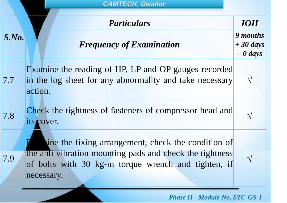
Phase II - Module No. STC-GS-1
S.No.
Particulars IOH
Frequency of Examination9 months
+ 30 days
– 0 days
7.7
Examine the reading of HP, LP and OP gauges recorded
in the log sheet for any abnormality and take necessary
action.
7.8Check the tightness of fasteners of compressor head and
its cover.
7.9
Examine the fixing arrangement, check the condition of
the anti vibration mounting pads and check the tightness
of bolts with 30 kg-m torque wrench and tighten, if
necessary.
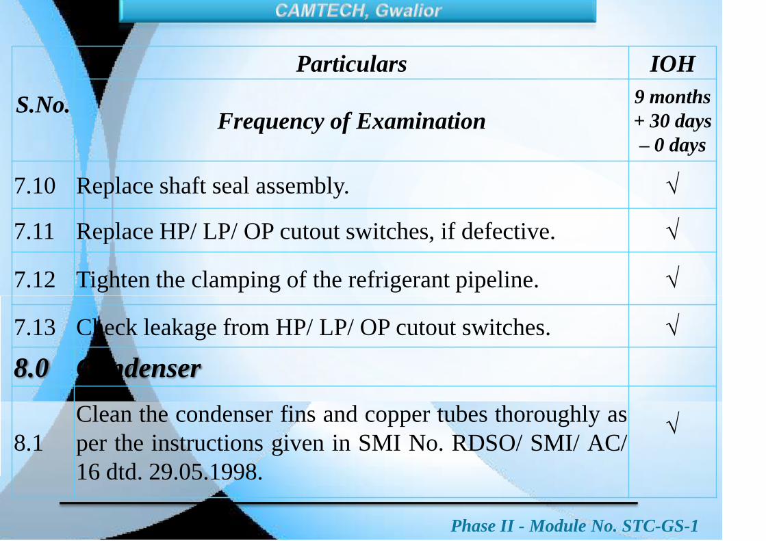
Phase II - Module No. STC-GS-1
S.No.
Particulars IOH
Frequency of Examination9 months
+ 30 days
– 0 days
7.10 Replace shaft seal assembly.
7.11 Replace HP/ LP/ OP cutout switches, if defective.
7.12 Tighten the clamping of the refrigerant pipeline.
7.13 Check leakage from HP/ LP/ OP cutout switches.
8.0 Condenser
8.1
Clean the condenser fins and copper tubes thoroughly as
per the instructions given in SMI No. RDSO/ SMI/ AC/
16 dtd. 29.05.1998.

Phase II - Module No. STC-GS-1
S.No.
Particulars IOH
Frequency of Examination9 months
+ 30 days
– 0 days
8.2 Examine the fins for external damage due to flying
ballast and take corrective action if necessary.
8.3 Replace catch all filter.
8.4 Check the condition of body frame and replace the
condenser, if necessary.
8.5 Check and ensure that the protection plates and grills are
provided on the three sides of the frame.
8.6 Ensure minimum airflow of 4 meters per second through
condenser.
8.7 Check the leakage and rectify, if required.
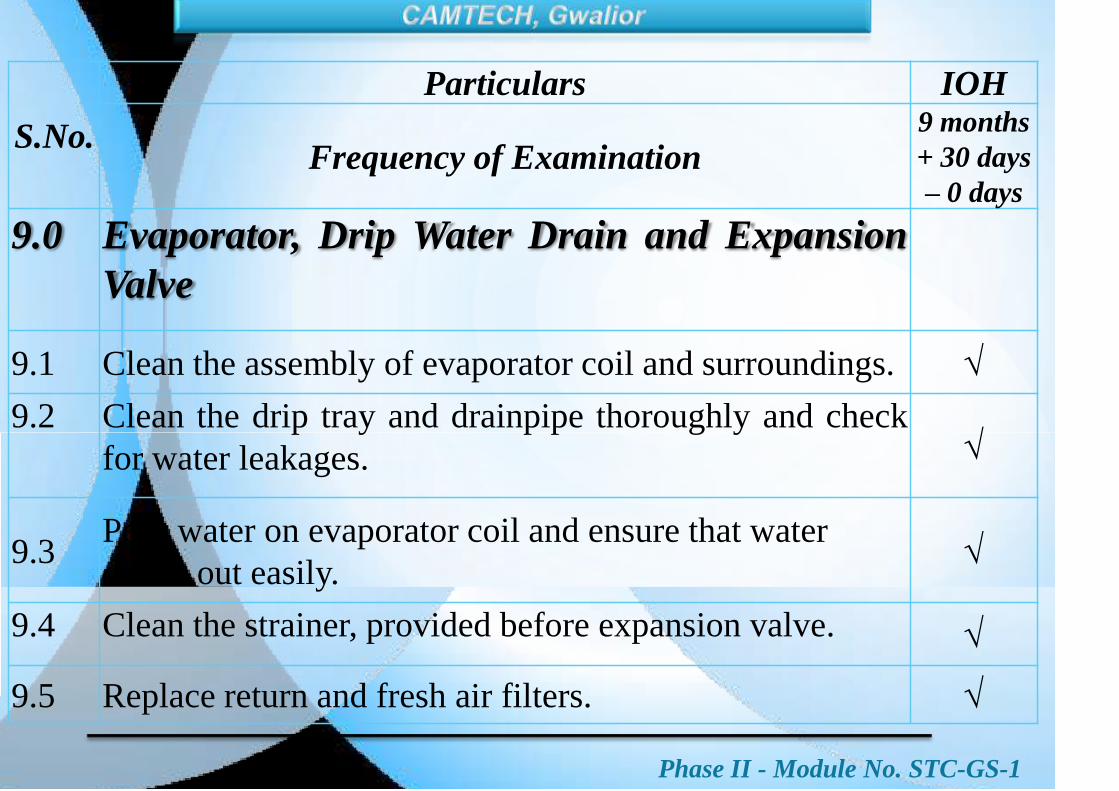
Phase II - Module No. STC-GS-1
S.No.
Particulars IOH
Frequency of Examination9 months
+ 30 days
– 0 days
9.0 Evaporator, Drip Water Drain and Expansion
Valve
9.1 Clean the assembly of evaporator coil and surroundings.
9.2 Clean the drip tray and drainpipe thoroughly and check
for water leakages.
9.3Pour water on evaporator coil and ensure that water
drains out easily.
9.4 Clean the strainer, provided before expansion valve.
9.5 Replace return and fresh air filters.

Phase II - Module No. STC-GS-1
S.No Particulars IOH
Frequency of Examination9 months
+ 30 days
– 0 days
9.7 Replace canvas duct, if required.
9.8 Check the condition of heater bank.
10.0 Compressor, Condenser & Evaporator Motors
10.1 Clean the motors externally with dry compressed air.
10.2Check mounting of all motors for any signs of crack,
corrosion and rusting. Take remedial action if required.
10.3
Check the condition of the anti vibration mounting pads
and check the tightness of bolts with 30 kg-m torque
wrench and tighten, if necessary.
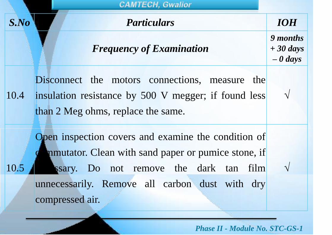
Phase II - Module No. STC-GS-1
S.No Particulars IOH
Frequency of Examination9 months
+ 30 days
– 0 days
10.4
Disconnect the motors connections, measure the
insulation resistance by 500 V megger; if found less
than 2 Meg ohms, replace the same.
10.5
Open inspection covers and examine the condition of
commutator. Clean with sand paper or pumice stone, if
necessary. Do not remove the dark tan film
unnecessarily. Remove all carbon dust with dry
compressed air.
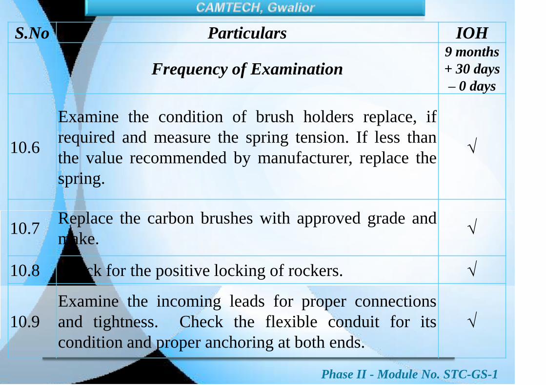
Phase II - Module No. STC-GS-1
S.No Particulars IOH
Frequency of Examination9 months
+ 30 days
– 0 days
10.6
Examine the condition of brush holders replace, if
required and measure the spring tension. If less than
the value recommended by manufacturer, replace the
spring.
10.7Replace the carbon brushes with approved grade and
make.
10.8 Check for the positive locking of rockers.
10.9
Examine the incoming leads for proper connections
and tightness. Check the flexible conduit for its
condition and proper anchoring at both ends.

Phase II - Module No. STC-GS-1
S.No Particulars IOH
Frequency of Examination9 months
+ 30 days
– 0 days
10.10
Check the bearings for noise by shock pulse meter and
replace, if required. Lubricate bearings with
appropriate quantity of recommended grease.
10.11Examine flexible tyre coupling of compressor and
replace, if found defective.
10.12 Check the alignment of the compressor and its motor.
10.13 Check the starting resistance connectors for tightness.

Phase II - Module No. STC-GS-1
S.No Particulars IOH
Frequency of Examination9 months
+ 30 days
– 0 days
10.14Connect the motor connection and tighten the terminal
connections in the terminal box.
10.15Check the direction of rotation of motor for
correctness.
10.16 Clean the condenser fan blades and tighten, if loose.
10.17Clean the blower drum and check it‟s fixing for
tightness.

Phase II - Module No. STC-GS-1
S.No Particulars IOH
Frequency of Examination9 months
+ 30 days
– 0 days
11.0 Dehydrator and Liquid Receiver
11.1 Check the sight glass for leakage, rectify if necessary.
11.2 Clean the strainer in the dehydrator-cum-filter unit.
11.3
After 10 minutes of starting the compressor, check the
level of liquid refrigerant. It should be at the bottom of
the lower glass of the liquid receiver.
11.4
After 15 minutes of starting the plant, feel the outlet and
inlet to dehydrator by hand for temperature difference.
The outlet should not be colder than inlet.

Phase II - Module No. STC-GS-1
S.No Particulars IOH
Frequency of Examination9 months
+ 30 days
– 0 days
12.0 Thermostats
12.1 Clean thermostat bulb with cotton.
12.2
Check for any breakage in mercury column or body of the
thermostat and replace it with new one if required. Do not heat
the bulb to join the the broken pieces of mercury column.
12.3
Check the condition of thermostat holder and its fixing
arrangement. Replace it with new one if found broken or
contacts defective.
12.4Ensure working of plants in auto mode for all temperature
setting.
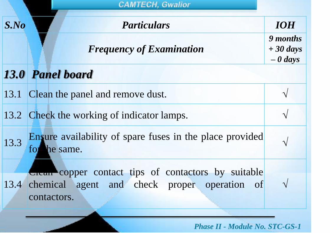
Phase II - Module No. STC-GS-1
S.No Particulars IOH
Frequency of Examination9 months
+ 30 days
– 0 days
13.0 Panel board
13.1 Clean the panel and remove dust.
13.2 Check the working of indicator lamps.
13.3Ensure availability of spare fuses in the place provided
for the same.
13.4
Clean copper contact tips of contactors by suitable
chemical agent and check proper operation of
contactors.

Phase II - Module No. STC-GS-1
S.No Particulars IOH
Frequency of Examination9 months
+ 30 days
– 0 days
13.5 Provide arc chutes properly.
13.6 Check and tighten all electrical connections.
13.7 Check the relays and their connections.
13.8Check the PCB in the thermostat circuits for their
proper functioning
13.9 Check all diodes and their connections.
13.10 Check all rotary switches and their connections.
13.11
Check the operation of cooling pilot relay (by short
circuiting terminals of C.T.). Remove short after the
completion of check.

Phase II - Module No. STC-GS-1
S.No Particulars IOH
Frequency of Examination9 months
+ 30 days
– 0 days
14.0 Coach Wiring
14.1
Revised check the earth leakage in the wiring with a
double test lamp method as explained in the RDSO
code of practice and prevention of fire as per EL/ TL
56.
14.2Revised check for loose connection in all the junction
box/ terminal boards & tighten if necessary

Phase II - Module No. STC-GS-1
S.No Particulars IOH
Frequency of Examination9 months
+ 30 days
– 0 days
14.3
Carry out coach insulation test as per item no. 5.8 of
code of practice for prevention of fire. (RDSO/ PE/ O/
0008-205, Rev. „0‟ dt. Oct. 2006).
14.4Clean the electrical control/ cubicle and terminal boxes/
terminal boards, remove dust.
14.5
Check the locking and securing arrangement for the
door and covers of control/ power cubicle and terminal
boxes/ terminal boards/ fuse distribution boards.
Rectify or replace if necessary.
14.6 Check supply to laptop/ mobile charging points.

Phase II - Module No. STC-GS-1
S.No Particulars IOH
Frequency of Examination9 months
+ 30 days
– 0 days
15.0 Lights
15.1
Open each fitting and clean properly from inside and outside.
Ensure free operation of locking mechanism and replace
defective fitting.
15.2 Replace rusted fittings and fittings with damaged surface.
15.3Check all the lights for proper working. Rectify or replace if
necessary.
15.4Check all light switches for their condition and proper
working. Replace defective switches.
15.5Check up all lighting circuit fuses for correct rating and
replace if necessary.

Phase II - Module No. STC-GS-1
S.No Particulars IOH
Frequency of Examination9 months
+ 30 days
– 0 days
16.0 Fans
16.1Check and clean plastic fan blade and ensure that there
is no crack on the blade or hub.
16.2Check the leakage current, if greater than 300 micro
Amps. Then replace capacitor in AC fan.
16.3 Ensure proper fixing of fans and locking arrangement.
16.4Check for abnormal sound, rectify or replace, if
needed.
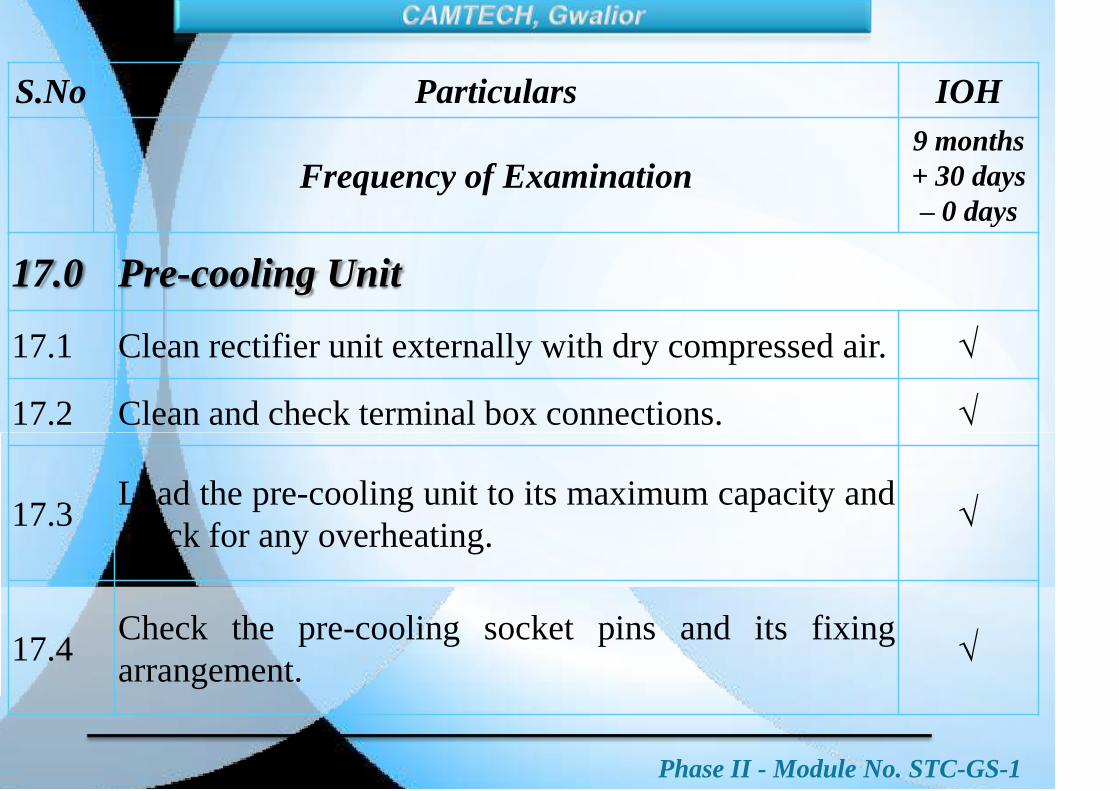
Phase II - Module No. STC-GS-1
S.No Particulars IOH
Frequency of Examination9 months
+ 30 days
– 0 days
17.0 Pre-cooling Unit
17.1 Clean rectifier unit externally with dry compressed air.
17.2 Clean and check terminal box connections.
17.3Load the pre-cooling unit to its maximum capacity and
check for any overheating.
17.4Check the pre-cooling socket pins and its fixing
arrangement.
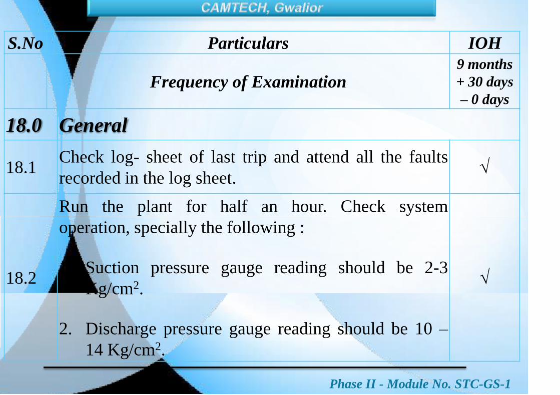
Phase II - Module No. STC-GS-1
S.No Particulars IOH
Frequency of Examination9 months
+ 30 days
– 0 days
18.0 General
18.1Check log- sheet of last trip and attend all the faults
recorded in the log sheet.
18.2
Run the plant for half an hour. Check system
operation, specially the following :
1. Suction pressure gauge reading should be 2-3
Kg/cm2.
2. Discharge pressure gauge reading should be 10 –
14 Kg/cm2.
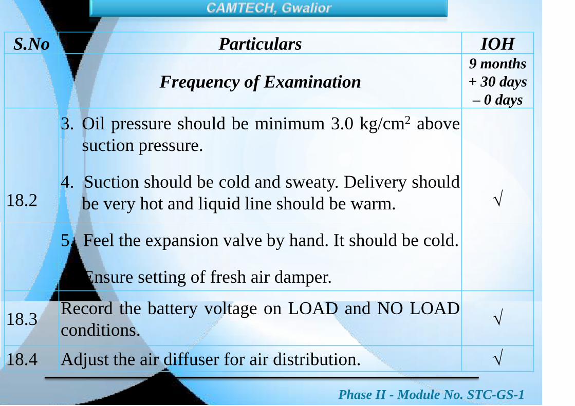
Phase II - Module No. STC-GS-1
S.No Particulars IOH
Frequency of Examination9 months
+ 30 days
– 0 days
18.2
3. Oil pressure should be minimum 3.0 kg/cm2 above
suction pressure.
4. Suction should be cold and sweaty. Delivery should
be very hot and liquid line should be warm.
5. Feel the expansion valve by hand. It should be cold.
6. Ensure setting of fresh air damper.
18.3Record the battery voltage on LOAD and NO LOAD
conditions.
18.4 Adjust the air diffuser for air distribution.

Phase II - Module No. STC-GS-1
S.No Particulars IOH
Frequency of Examination9 months
+ 30 days
– 0 days
ROOF MOUNTED AC PACKAGE UNIT
19.0 Control Panel
19.1Check the log sheet and attend the defects noticed
during run as reported by escorting staff.
19.2
Clean the panel with vacuum cleaner or compressed air
and check for any loose connections. All cable entry
holes to be provided with grommets.
19.3 Check that all legend plates inside the control are intact.

Phase II - Module No. STC-GS-1
S.No Particulars IOH
Frequency of Examination9 months
+ 30 days
– 0 days
19.4 Check that glass cover over indication PCB is intact.
19.5
Check and clean the power and control contractors and
clean copper contact tips of contactors by suitable
chemical agent.
19.6Check the connection of switchgear terminal blocks for
overheating and tightness.
19.7 Check rotary switches for proper working.
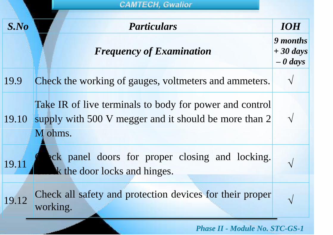
Phase II - Module No. STC-GS-1
S.No Particulars IOH
Frequency of Examination9 months
+ 30 days
– 0 days
19.9 Check the working of gauges, voltmeters and ammeters.
19.10
Take IR of live terminals to body for power and control
supply with 500 V megger and it should be more than 2
M ohms.
19.11Check panel doors for proper closing and locking.
Check the door locks and hinges.
19.12Check all safety and protection devices for their proper
working.

Phase II - Module No. STC-GS-1
S.No Particulars IOH
Frequency of Examination9 months
+ 30 days
– 0 days
19.13Replace defective/ by passed components including
indicator LEDs and lamps, if any.
19.14 Check proper working of electronic thermostat.
19.15
Remove the out going wires from MCB 7, in case of
scroll compressor. (There is no provision of crank case
heater in scroll compressor)
19.16Clean accumulated dust over sensor of electronic
thermostat.

Phase II - Module No. STC-GS-1
S.No Particulars IOH
Frequency of Examination9 months
+ 30 days
– 0 days
19.17 Electronic thermostat
a. Clean the dust on the temperature sensor.
b. Calibrate the temperature sensor by digital contact
type calibrated temperature meter having probe
sensor.
c. Ensure the functional working of Display unit.
d. Check the cut in the cable of sensor and replace
damaged/ cut cable by new cable.

Phase II - Module No. STC-GS-1
S.No Particulars IOH
Frequency of Examination9 months
+ 30 days
– 0 days
19.17 Electronic thermostat
e. Ensure the connector for sensor i.e. Amphenol make
no. MIL – C – 5015 type 4 pin connector with
model no. MS 3106 R – 14S – 2S – 3202 & MS
3106 F – 14S – 2S – 3202 series for controller box
and sensor both. If not matched, replace by
Amphenol make series connector. Ensure the
interchangeability of one make sensor with other
make sensor.

Phase II - Module No. STC-GS-1
S.No Particulars IOH
Frequency of Examination9 months
+ 30 days
– 0 days
f. Correct the by pass connection for manual operation
and ensure the auto mode operation of electronic
thermostat.
g. Ensure the single setting of temperature i.e. cut in 25
degree C – cut off 23 degree C in summer and 19 cut
in 21 cut off in winter.
h. Ensure that the insulation resistance is more than 20
Mega ohms. If less, take corrective action.

Phase II - Module No. STC-GS-1
S.No Particulars IOH
Frequency of Examination9 months
+ 30 days
– 0 days
20.0 RMPU
20.1 Replace all fresh air and return air filters
20.2 Clean all air bellows and ducts.
20.3 Check the condition of cables and conduits.
20.4
Check the working of all motors and take their IR values
with 500V megger and record the same. IR should be
more than 2 M ohms. If found less, take corrective action.
20.5Check all the motors for abnormal sound by shock pulse
meter and replace the bearings, if necessary.
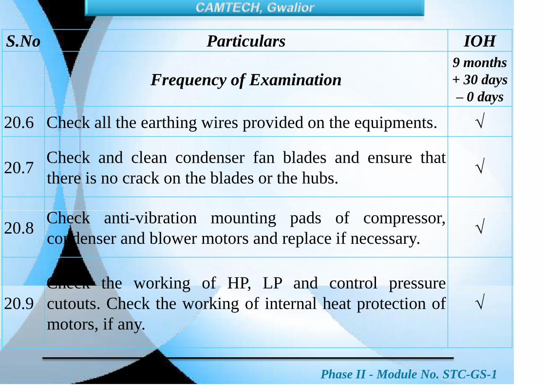
Phase II - Module No. STC-GS-1
S.No Particulars IOH
Frequency of Examination9 months
+ 30 days
– 0 days
20.6 Check all the earthing wires provided on the equipments.
20.7Check and clean condenser fan blades and ensure that
there is no crack on the blades or the hubs.
20.8Check anti-vibration mounting pads of compressor,
condenser and blower motors and replace if necessary.
20.9
Check the working of HP, LP and control pressure
cutouts. Check the working of internal heat protection of
motors, if any.

Phase II - Module No. STC-GS-1
S.No Particulars IOH
Frequency of Examination9 months
+ 30 days
– 0 days
20.10Check the condition of latch for securing the evaporator
compartment cover.
20.11 Ensure proper clamping of all the refrigerant pipelines.
20.12 Check the condition of drainpipes and clean it.
20.13
Check heater tripping when blower MCB is off. (Shall be
read as below)
Check heater tripping through VANE Relay, OHP 1 & 2.
20.14 Check the working of RMPU.
Phase II - Module No. STC-GS-1
S.No. Particulars IOH
Frequency of Examination
9 months
+ 30 days
– 0 days
20.15
Run the plant for half an hour and check the current
drawn by various equipments with the help of
clamp tester. Normal currents for various
equipment and mode of operation shall be as
under:-
Package in cooling mode : 20 – 23 Amp.
Package in heating mode : 11 – 13 Amp.
Compressor motors : 7 – 10 Amp.
Condenser motors : 1.5 – 2 Amp.
Blower Motor : 1.5 – 2.5 Amp.

Phase II - Module No. STC-GS-1
S.No. Particulars IOH
Frequency of Examination
9 months
+ 30 days
– 0 days
20.16 Check working of all over load relays.
20.17
Check for proper operation of time delay relays
provided in compressor circuit. As soon as power
supply is switched `ON‟ first compressor should
come in circuit after 2 minutes and the second one
after 2.5 minutes.
20.18
Check working of both Roof Mounted Package
Units (RMPUs) with either of the inverter on the
Self Generating (SG) AC coaches provided with
two package units.

Phase II - Module No. STC-GS-1
S.No. Particulars IOH
Frequency of Examination
9 months
+ 30 days
– 0 days
21.0 Inverter
The maintenance of coach inverter should only be
done through respective OEMs.

Phase II - Module No. STC-GS-1
S.No. Particulars IOH
Frequency of Examination
9 months
+ 30 days
– 0 days
22.0 Drip Tray
22.1 Clean the sludge inside the pipe walls and tray.
22.2Pour water into drip tray and ensure that the poured
water is drained through the outlet pipe.
22.3Check the normal flow of water in drip tray by
running the AC plant continuously for 2 to 3 hours.

Phase II - Module No. STC-GS-1
S.No. Particulars IOH
Frequency of Examination
9 months
+ 30 days
– 0 days
23.0 WRA ( Mono Block Type)
23.1
Clean and check complete assembly for any
defect or abnormality. Take corrective action,
if required.
23.2 Replace drain plug rubber washer.
23.3 Check proper operation of pump.
Phase II - Module No. STC-GS-1
S.No. Particulars IOH
Frequency of Examination
9 months
+ 30 days
– 0 days
24.0 Microprocessor Controller for RMPU
24.1Check the insulation resistance. If less, take corrective
action.
24.2Check on/ off switch for proper working. Replace
defective switch.
24.3Check LED for proper working. Rectify or replace, if
necessary.
24.4Clean the dust on the temperature sensor and humidity
sensor.

Phase II - Module No. STC-GS-1
S.No. Particulars IOH
Frequency of Examination
9 months
+ 30 days
– 0 days
24.5Calibrate the temperature sensor by digital contact
type calibrated temperature meter having probe sensor.
24.6Calibrate the humidity sensor by digital contact type
calibrated humidity meter.
24.7Check the cut in the cable of sensor and replace
damaged/ cut cable by new cable.
Phase II - Module No. STC-GS-1
S.No. Particulars IOH
Frequency of Examination
9 months
+ 30 days
– 0 days
24.8
Correct the by-pass connection for manual operation
and ensure the auto mode operation of micro-processor
controller.
24.9
Ensure the set temperature and night start hours and
night end hours for sleep mode operation. The data
should be in memory after once switch off and switch
on again.

Phase II - Module No. STC-GS-1
S.No. Particulars IOH
Frequency of Examination
9 months
+ 30 days
– 0 days
25. Testing
25.1
Generation testing should be conducted on SGAC
coaches by running both alternators through dyna
drive on full coach load.
26.0Load sharing testing of alternators in SGAC
coaches shall be done.
27.0Generation testing in TL coaches shall be
done.
Phase II - Module No. STC-GS-1
SMI and MS issued time to time by RDSO will
be followed and maintenance schedule shall be
up dated accordingly.

Phase II - Module No. STC-GS-1
S.
No.Items
Every IOH
(12
Months)
Remarks
1. „V‟Belt Y
RDSO letter No.
EL/7.2.1 dtd.
24.03.2014
2. Suspension Bush Y
3. Air Filters of RMPU Y
4.Alternator tension
rod sleeveY

Phase II - Module No. STC-GS-1

Phase II – Module No. STC-GS-1
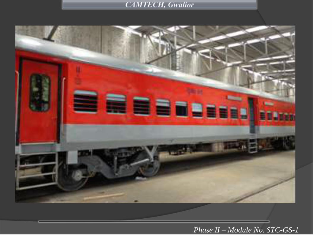
Phase II – Module No. STC-GS-1

Phase II – Module No. STC-GS-1
These LHB variant new generation non ac passenger
coaches are being manufactured with stainless steel shells
to increase the life span of coaches.
These coaches have better parameters of passenger
comfort, safety and reliability in comparison to
conventional ICF design coaches.
These coaches are fitted with FIAT bogies and supplied by
power cars as in EOG system.
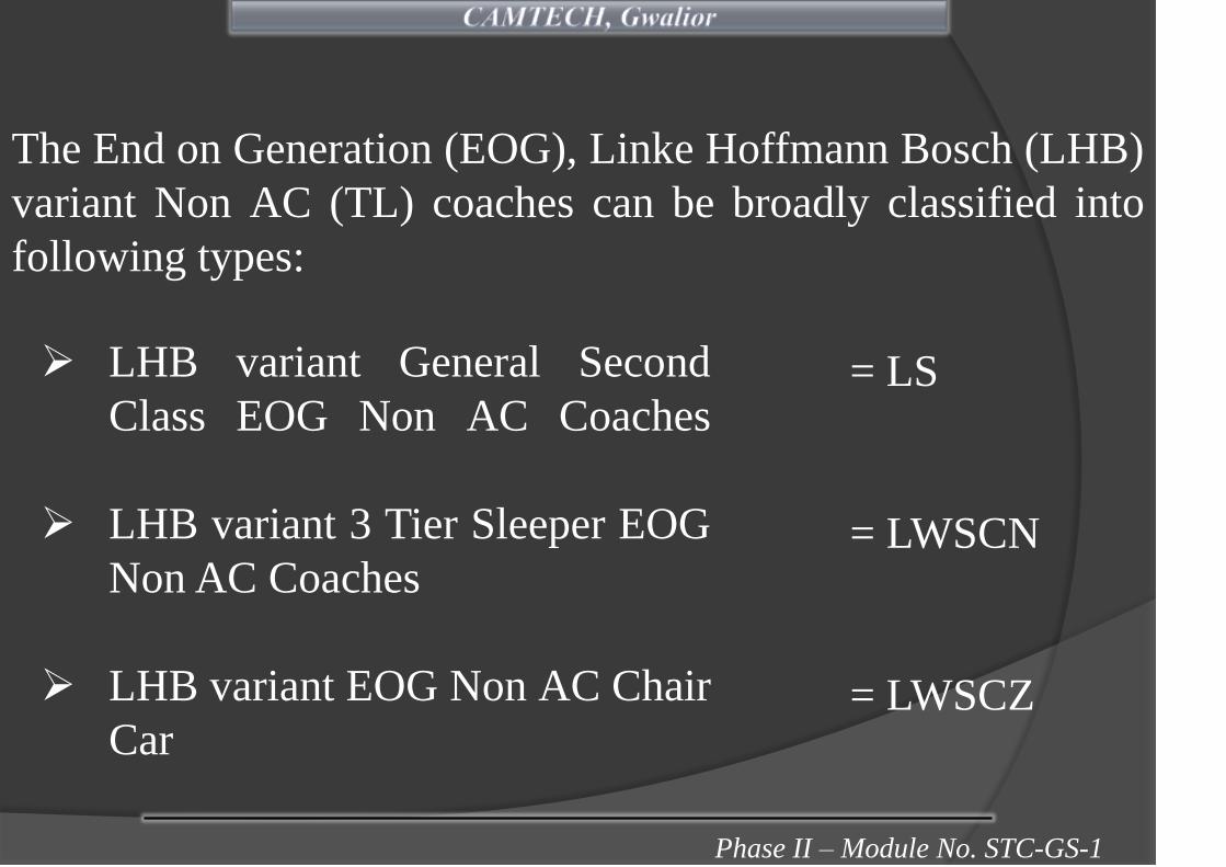
Phase II – Module No. STC-GS-1
The End on Generation (EOG), Linke Hoffmann Bosch (LHB)
variant Non AC (TL) coaches can be broadly classified into
following types:
LHB variant General Second
Class EOG Non AC Coaches
LHB variant 3 Tier Sleeper EOG
Non AC Coaches
LHB variant EOG Non AC Chair
Car
= LS
= LWSCN
= LWSCZ

Phase II – Module No. STC-GS-1
Exteriors and Interiors views of LHB EOG NON
AC GS Coaches
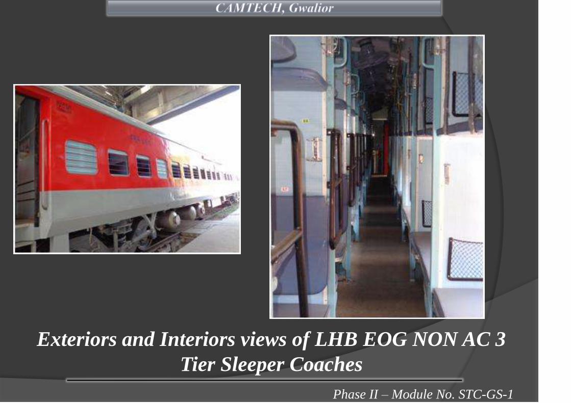
Phase II – Module No. STC-GS-1
Exteriors and Interiors views of LHB EOG NON AC 3
Tier Sleeper Coaches

Phase II – Module No. STC-GS-1
Exteriors and Interiors views of LHB EOG NON AC
Chair Car

Phase II – Module No. STC-GS-1
LHB variant non AC EOG coaches are equipped with 9/15
kVA step down transformers for stepping down 750 V, 3 Φ AC,
4 wire, 50 Hz supply to 415 V/ 190V, 3 Φ AC, 4 wire, 50 Hz
supply.
Power cars at both ends take entire load of whole rake, which
includes air conditioning (if AC coaches in rake), light and fan
circuit, and regulated battery charger circuit and mini pantry
equipment (if chair cars in rake).
Each power car has two DG sets (normally out of which one
DG set is standby).

Phase II – Module No. STC-GS-1
End ON Generation System
• The neutral point of the 3 phase winding of the generator is
solidly earthed in the power cars.
• The neutral conductor of the 750 volts, 3 phase, 4 wire
system shall not be earthed at any other point in the rake
composition.
ALT. ALT. ALT. ALT.
GENERATOR
CAR
GENERATOR
CAR
FEEDER - I
FEEDER - IICOACHESCOACHES

Phase II – Module No. STC-GS-1
Constant voltage regulated battery charger.
Onboard Switch Board panel with controls of lighting and
fan and their fuses.
Under slung panel for 750 volt and 415/ 190 volt supply.
Onboard supply only 110 volt dc and 190/110 V ac for
mobile charging sockets.

Phase II – Module No. STC-GS-1
Provision of Dry type Transformer without encapsulation.
Elegant interior light fittings.
Integrated modular mini pantry unit in Chair cars.
Provision of Measuring and Monitoring relays in Feeder
circuit.
Wheel set earthing equipment for high life of axle bearings.
Provision of under slung mounted earthing and
disconnecting device.

Phase II – Module No. STC-GS-1
Provision of under slung mounted water raising mono
block pump with pump controller (in 3 tier sleeper
coaches only). As per Railway board L. no.
2010(M)(PU)/1/28 dtd. 06.03.2012, overhead water tanks
are to be provided and water raising mono block pump
are to be eliminated.
Cable protection system with IP-67 protection and UL-94
V0 fire retardancy.
Phase II – Module No. STC-GS-1
Provision of Emergency Feed Terminal (EFT) in future
coaches and the same is to be implemented during POH in
existing coaches.
Provision of Battery Charging Terminal (BCT) in future
coaches and the same is to be implemented during POH in
existing coaches.

Phase II – Module No. STC-GS-1
S.No ITEM
Reference
Specification/
Drawing
Second
class
(LS)
3 Tier
Sleeper
(LWSCN)
Chair
Car
(LWSCZ)
1. Set of panelRCF EDTS-
355,REV-1,AM-2
2.
Transformer,9KV
A/15kva,750/415
/ 190V AC
RDSO/PE/SPEC/
TL/0158-
2010,REV-0,
Type-Ist
(9 kVA)
(9 kVA)
(15 kVA)

Phase II – Module No. STC-GS-1
S.No ITEM
Reference
Specification/
Drawing
Second
class
(LS)
3 Tier
Sleeper
(LWSCN)
Chair
Car
(LWSCZ)
3.VRLA battery,
110v, 70 Ah
RDSO/PE/SPEC/
AC/0009-
2008,REV-1,AM-
1,ANNX-A
4.
Constant voltage
regulated battery
charger
RDSO/PE/SPEC/
AC/129-2009,
REV-1
5. fuse box (+ve)RCF LW71001
Alt. f
6. fuse box (-ve)RCF LW71002
Alt. f

Phase II – Module No. STC-GS-1
S.No ITEM
Reference
Specification/
Drawing
Second
class
(LS)
3 Tier
Sleeper
(LWSCN)
Chair
Car
(LWSCZ)
7.Charging
Terminal (BCT)
RDSO/PE/SK/TL/
0179-2014 Rev.
‘0’
8.Emergency feed
terminal (EFT)
RDSO/PE/SK/TL/
0179-2014 Rev.
‘0’
9.
100 VA
Transformer
750/110 V for
Feeder contactor
control

Phase II – Module No. STC-GS-1
S.No TEM
Reference
Specification/
Drawing
Second
class
(LS)
3 Tier
Sleeper
(LWSCN)
Chair
Car
(LWSCZ)
10.
Zs coupling, 400
Amp, 750v,3-ph,
50hz
RCF EDTS-
105,REV-E,AM-
1,2 & 3, CORE-
1,TYPE-Ist
11.Feeder junction
box
RCF EDML-
020,REV-I
12.
Wheel set
earthing
equipment
RCF EDTS-
101,REV-C,AM-1

Phase II – Module No. STC-GS-1
S.No TEM
Reference
Specification/
Drawing
Second
class
(LS)
3 Tier
Sleeper
(LWSCN)
Chair
Car
(LWSCZ)
13.
Self priming
mono- block
pump- (To be
eliminated as per
Railway Board
Directives)
RCF EDTS-186,
REV-A, AM-1 & 2 --- ----
14. BLDC Fan
RDSO/PE/SPEC/T
L/ 0021-2005,
REV-2,COR-1,
BLDC

Phase II – Module No. STC-GS-1
S.No TEM
Reference
Specification/
Drawing
Second
class
(LS)
3 Tier
Sleeper
(LWSCN)
Chair
Car
(LWSCZ)
15.Exhaust Fan for
Lavatory
16.Fluorescent
lamp(FL)RCF CC76213 --
17. FL, CFL double RCF LW76055 -- --
18.
Emergency
Lighting Unit
(ELU)
RCF EDTS-
151,REV-C,AM-1
& 2

Phase II – Module No. STC-GS-1
S.
No.ITEM
Reference
Specification/
Drawing
Second
class
(LS)
3 Tier
Sleeper
(LWSCN)
Chair
Car
(LWSCZ)
19.
Passenger alarm
coach indication light
(PACIL)
RCF LW76005 --- ---
20.
Passenger alarm
reservation chart
indication light
(PARCIL)
RCF CC76238 ---
21.Door way light (DL)
/ gangway light (GL)RCF CC76216

Phase II – Module No. STC-GS-1
S.
No.ITEM
Reference
Specification/
Drawing
Second
class
(LS)
3 Tier
Sleeper
(LWSCN)
Chair
Car
(LWSCZ)
22. Lavatory light (LL) RCF LW76033
23. Night lamp (NL) RCF CC76289 -- --
24.Switch plate
assembly
RCF EDML-
127,REV-0, -- ---
25.Switch plate
assembly
RCF EDML-
086,REV-4,-- ---
26.Switch plate
assembly
RCF EDML-
125,REV-0,-- --

Phase II – Module No. STC-GS-1
S.
No.ITEM
Reference
Specification/
Drawing
Second
class
(LS)
3 Tier
Sleeper
(LWSCN)
Chair
Car
(LWSCZ)
27. Set of cage clampRCF CC72069/
CC72070
28.
Distribution panel
for pantry
equipments
RCF CC72172 -- --
29.Material list for
compartment light
RCF EDML-126,
REV-1-- --
30.Mini pantry (LHB
EOG type)
RCF EDTS-339,
REV-B-- --
Phase II – Module No. STC-GS-1
The set of panels comprises of the various cubicles
consisting of power and control switchgear as mentioned
below:
i. High Voltage Cubicle (under-slung mounted)
ii. Battery Charger Box (under-slung mounted)
iii. Low voltage panel (onboard)

Phase II – Module No. STC-GS-1
(i) High Voltage Cubicle (under-slung mounted)
This fabricated stainless steel cubicle is mounted
in under-slung in the coach.
UNDER SLUNG HV PANEL

Phase II – Module No. STC-GS-1
This panel houses the disconnecting and earthing device,
switchgear and fuses for 750 V, 415 V, 190 V, 110 V,
Pump controller, Anti skid device, MMR, RCBO
(Residual Circuit Breaker with Overload), rotary switches
for feeder selection etc.
From the front of the panel all the equipment can be
access for.
For maintenance front covers are provided with hinges
and locking arrangement. The box is earthed with two
earthing terminals on top and bottom.

Phase II – Module No. STC-GS-1
o Disconnecting and Earthing Device
A disconnecting and
earthing device along-with
high voltage fuses is
mounted inside the panel.
It is an OFF load device
rated for 63 amps at 750
volts fed from Generator
Car through ZS couplings.
It has two positions ON &
EARTH.

Phase II – Module No. STC-GS-1
Contactor K01
Fuses net1
Contactor K 02
Contactor K24, K25
Fuses net2
The main function of this device is to separate the two feeders
(input supply) and simultaneously earthing 750 volts ac network
of the coach in case of emergency like contactor jamming or
maintenance of coach even during running of coaches.
HV 750V Panel

Phase II – Module No. STC-GS-1
Low voltage fuses for transformer secondary and other
415/190 volt circuit fuses and RCBO (Residual Circuit
Breaker with Overload)
415/ 190 V Panel
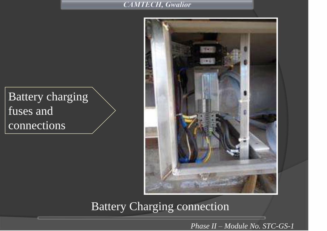
Phase II – Module No. STC-GS-1
Battery Charging connection
Battery charging
fuses and
connections

Phase II – Module No. STC-GS-1
Rotary switch for selecting net-1, OFF, net-2.
Rotary switch for selecting remote and local control of
supply.
Rotary switch for local/
remote selectionRotary switch for
feeder selection
Rotary Switch Control with Remote

Phase II – Module No. STC-GS-1
(mono block pump and pump controller to be discontinued in
future production by PUs)
Anti Skid Device
Pump Controller
Pump controller and Anti Skid Device
Phase II – Module No. STC-GS-1
Constant Voltage Regulated Battery Charger is
provided for rectifying ac supply into dc for
providing power supply in the coach at 110 V dc
and at the same time to charge the VRLA batteries
provided in the coach.
The under-slung mounted totally enclosed, IP 53
ingress protection cubicle houses the regulated
battery charger along-with connectors.
(ii) Regulated battery Charger

Phase II – Module No. STC-GS-1
The battery charger is forced air cooled, IGBT based and
DSP (digital signal processor) controlled working on a
nominal input supply of 415 V, 3 phase, 50 Hz fed from
750/415 V transformer.
Phase II – Module No. STC-GS-1
This is a 3 phase dry type distribution transformer designed
for LHB type NON AC EOG coaches for providing power to
coaches from 750 V supply of power cars.
There are two types of transformer i.e. type I- 9 kVA for
general IInd class and 3 tier sleeper coaches (train lighting
load 6.5 kVA-415V + 2.5 kVA -190V AC) and
Type II 15 kVA for chair cars (pantry load and train lighting
load 12.5 kVA- 415V+ 2.5 kVA 190V AC).
Both types of the transformers are star- star-star connected,
dry type and air cooled.

Phase II – Module No. STC-GS-1
The class of insulation of winding is
class ‘H’.
Transformer is fitted under slung
with 4 nos. anti vibration mountings.
Following protection fuses are
provided in transformer:
• For 9 kVA transformer-
HT HRC fuse 3.3 kV, 20 Amps. – 3 nos.
LT HRC fuse 500 V, 16 Amps – 6 nos.
• For 15 kVA transformer-
HT HRC fuse 3.3 kV, 32 Amps. – 3 nos.
LT HRC fuse 500 V, 32 Amps – 6 nos.

Phase II – Module No. STC-GS-1
Transformer is housed in stainless steel housing with IP 67
protection and over all dimensions, construction and
mounting of the transformer is same as in 60 kVA
transformer of LHB AC coaches.

Phase II – Module No. STC-GS-1
VRLA battery requires no topping up under normal
working conditions and minimal maintenance during
lifetime of battery.
It has self sealing safety valve, which normally does not
open out during service.
These coaches are provided with 9 modules of 12 volt
70Ah, VRLA battery in series in one battery box mounted
in under-slung.Battery Box & Batteries

Phase II – Module No. STC-GS-1
The auxiliary power required for charging is supplied by a
regulated battery charger at constant voltage based as
required by the battery.
Current limit for battery charging is 20 Amp at constant
voltage with the voltage setting at 122.0 ± 1.0 volt.

Phase II – Module No. STC-GS-1
Battery Module Salient Features
• Capacity : 12 V, 70 Ah (at 27° C) battery module
• Container : PP-CP (Poly Propylene Co-Polymer)
V2 grade/ ABS (Acrylonitrile
Butadiene Styerene) FR V2 grade
• Rate of Discharge : 10 hr
• Handle is provided on container instead of lid.
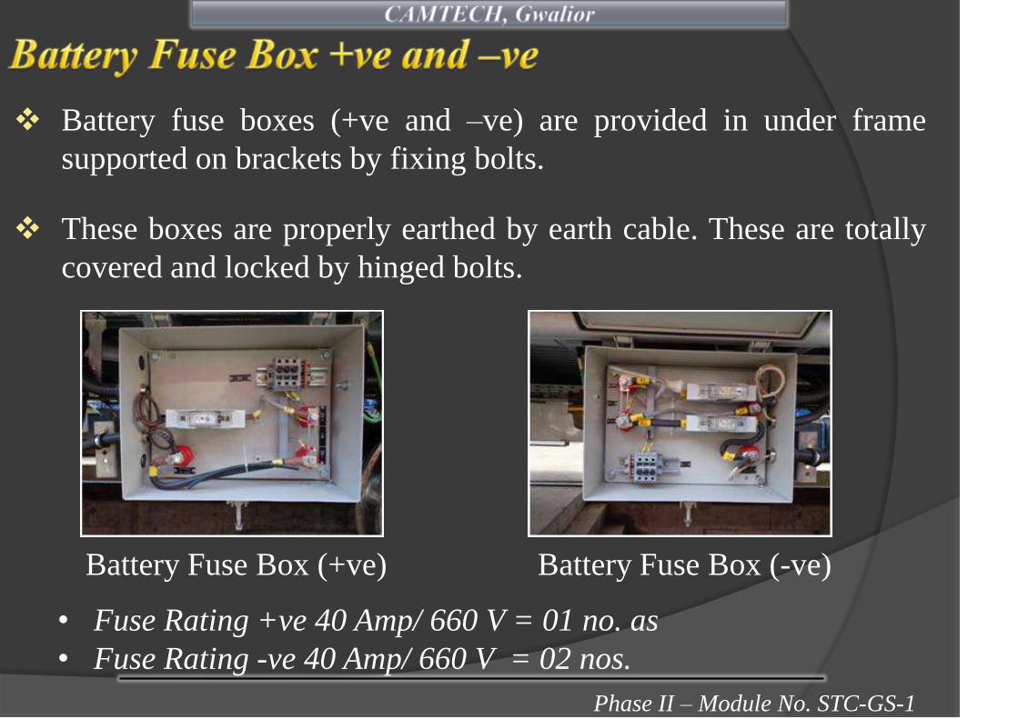
Phase II – Module No. STC-GS-1
Battery fuse boxes (+ve and –ve) are provided in under frame
supported on brackets by fixing bolts.
These boxes are properly earthed by earth cable. These are totally
covered and locked by hinged bolts.
Battery Fuse Box (+ve) Battery Fuse Box (-ve)
• Fuse Rating +ve 40 Amp/ 660 V = 01 no. as
• Fuse Rating -ve 40 Amp/ 660 V = 02 nos.

Phase II – Module No. STC-GS-1
Under-frame mounted Inter-vehicular coupler unit are
used for transmission of 3 phase, 5 wire, 750 V, 50 Hz
power supply from power cars to rake/ coaches (LHB
type) working on End On Generation (EOG) system.
Various sub assemblies of IVC are given as under:
• Jumper Plug Assembly – 2 nos.
• Coupling Socket Assembly– 2 nos.

Phase II – Module No. STC-GS-1
Jumper Plug
AssemblyBlind Socket
Assembly– 2 nos.
Ratchet Assembly
Coupling
Socket
Assembly
ZS Coupling
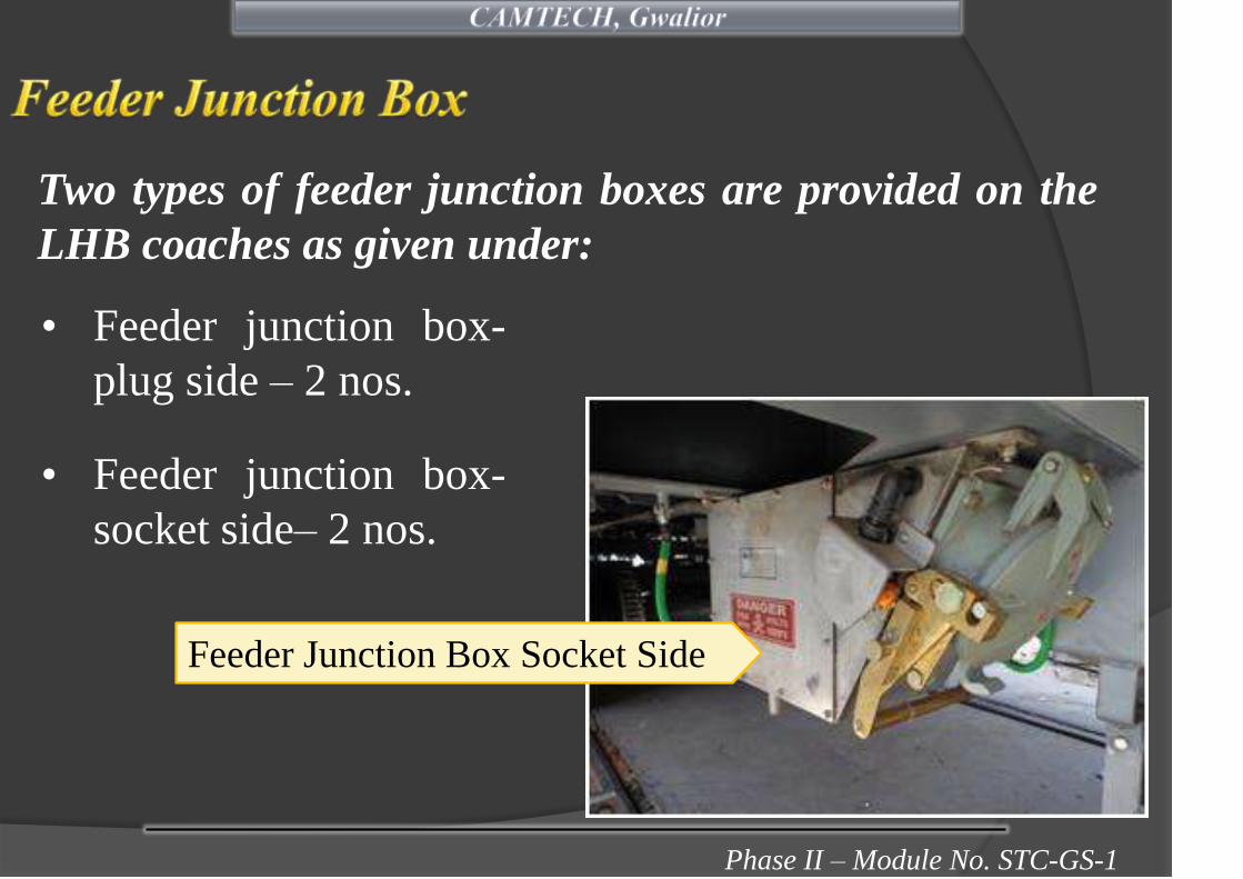
Phase II – Module No. STC-GS-1
Two types of feeder junction boxes are provided on the
LHB coaches as given under:
Feeder Junction Box Socket Side
• Feeder junction box-
plug side – 2 nos.
• Feeder junction box-
socket side– 2 nos.
Phase II – Module No. STC-GS-1
Wheel set earthing equipment for the wheel set is provided
to prevent return current flow through the axle bearings
and likely damage.
Thus the earthing contact system acts as a current bridge
that creates a connection by means of wiper contact
(brush) from the stationary bogie frame to the rotating
wheel set.

Phase II – Module No. STC-GS-1
i. Wheel set earthing equipment with stainless steel braided
earthing cable.
ii. Earthing resistor assembly 0.1 Ohm with mounting bracket
and grounding cable – 3 sets
This set comprises following subassemblies per bogie:
Wheel set and earthing equipment Earthing resistor assembly

Phase II – Module No. STC-GS-1
Resistances are provided to restrict the return current from
certain bogie parts and providing return current path
through pre-determined low resistance path.
Phase II – Module No. STC-GS-1
Mono-block pump set are used on non AC 3 tier sleeper
coaches for lifting water from main tanks mounted on the
under-frame to auxiliary tanks.
The water raising 3 phase horizontal centrifugal self-
priming mono-block pump with thermal switch as
protection device embedded in the motor.
{To be discontinued in future production as per Railway
Board L. No. 2010/M (PU)/1/28 dtd. 06.03.2012}
Phase II – Module No. STC-GS-1
The pumps are mounted on the under-frame on a cradle
arrangement with interconnecting stainless steel piping
arrangement.
Microprocessor based pump controller is programmed for
alternate loading of pumps during operation, isolation of
faulty pump, overload protection, running time etc.
The pump controller is located in 750 V HV panel in under
frame.
• The nominal input voltage to controller is 110 V AC/DC.

Phase II – Module No. STC-GS-1
• The controller is preset to run one of the pumps for a
period of 4 hrs. (adjustable) continuously and then
automatically switch over to the other pump for same
duration to enable equal loading of the pumps.
• In the event of failure of any one of the pumps, the
controller automatically switches over to the other
pump.
• It is also possible to run the pumps in manual mode by
selection through a rocker switch provided on the
controller.

Phase II – Module No. STC-GS-1
Pump controller Mono-block pump set

Phase II – Module No. STC-GS-1
The on-board panel houses the rotary switch panel as
used in conventional coaches for distribution of light and
fan.
This also houses rotary switch for feeder selection to
select the feeders as provided in the under-slung HV
cubicle and rotary switch for mobile charging socket
along-with connectors, push button for testing AEL is
also provided in this box.
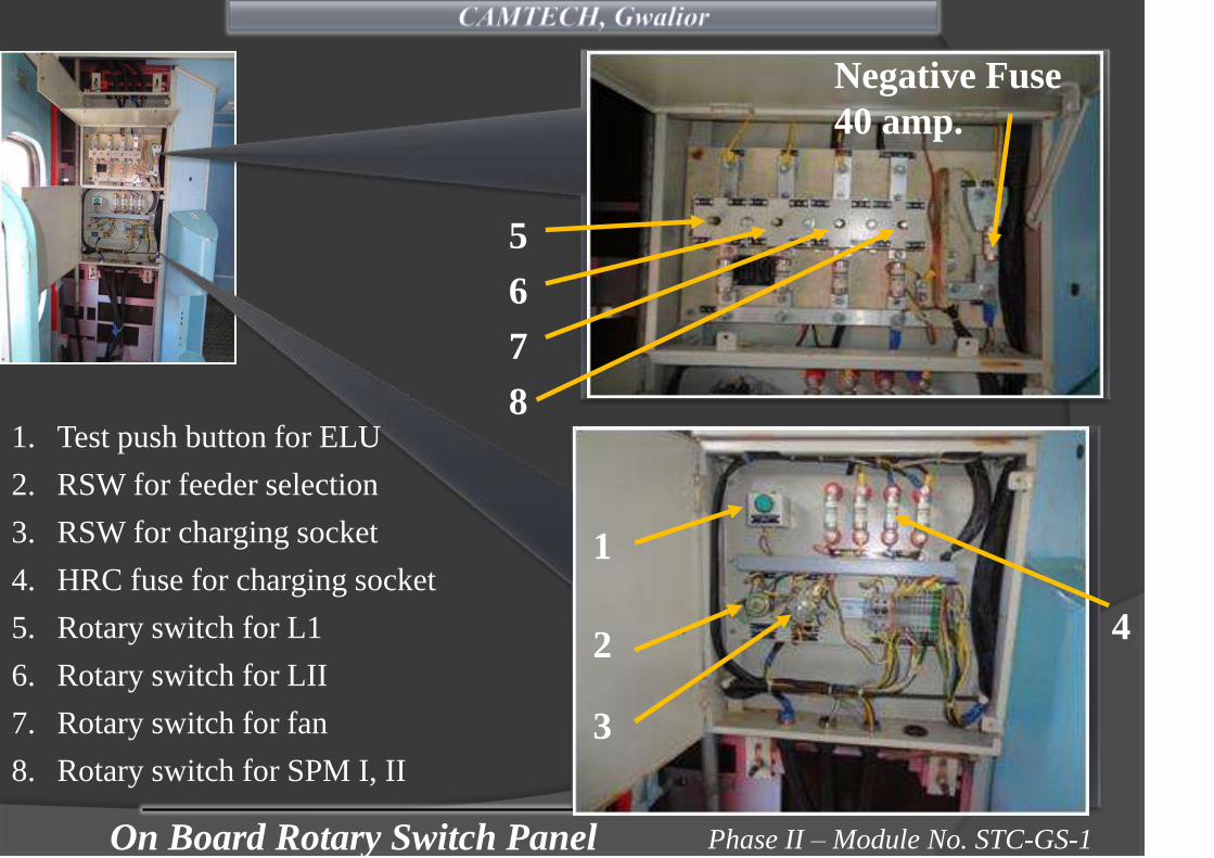
Phase II – Module No. STC-GS-1
5
6
7
8
4
On Board Rotary Switch Panel
1
2
3
1. Test push button for ELU
2. RSW for feeder selection
3. RSW for charging socket
4. HRC fuse for charging socket
5. Rotary switch for L1
6. Rotary switch for LII
7. Rotary switch for fan
8. Rotary switch for SPM I, II
Negative Fuse
40 amp.

Phase II – Module No. STC-GS-1
Brushless DC carriage fans of sweep 400 mm, working on
110 V DC supply are being provided in railway coaches
which requires minimum maintenance.
BLDC Fan

Phase II – Module No. STC-GS-1
• Dark Green : BLDC fan without hall sensor
• Dark yellow : BLDC fan with hall sensor
A band of colour of about 20 mm wide over the
periphery of the fan body approximately at its middle
portion is applied as a colour code for the following:

Phase II – Module No. STC-GS-1
Fluorescent light (FL) fitting works at 110V AC/DC
ballast and is provided with poly carbonate diffusers.
These fittings are provided in general IInd class coaches
and in 3 tier sleeper coaches.
Flotescent Light Fitting
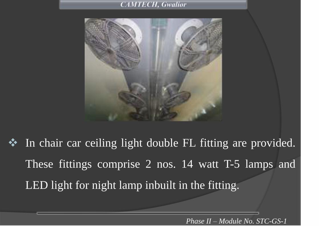
Phase II – Module No. STC-GS-1
In chair car ceiling light double FL fitting are provided.
These fittings comprise 2 nos. 14 watt T-5 lamps and
LED light for night lamp inbuilt in the fitting.
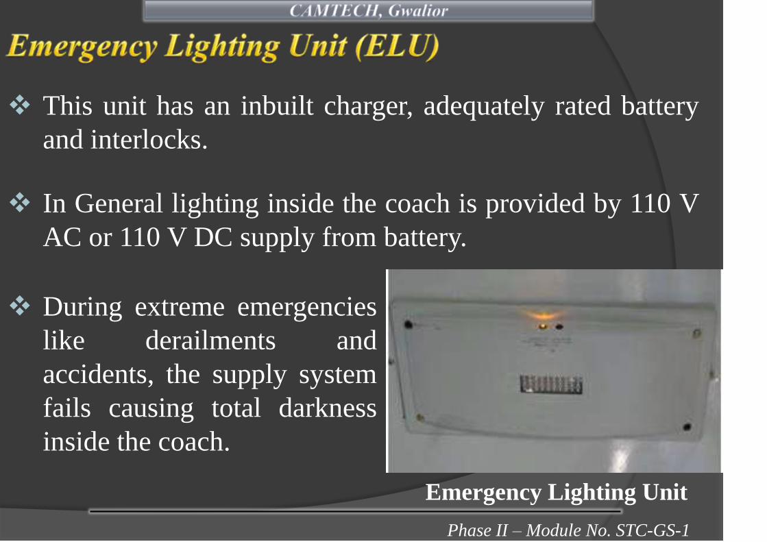
Phase II – Module No. STC-GS-1
This unit has an inbuilt charger, adequately rated battery
and interlocks.
In General lighting inside the coach is provided by 110 V
AC or 110 V DC supply from battery.
During extreme emergencies
like derailments and
accidents, the supply system
fails causing total darkness
inside the coach.
Emergency Lighting Unit

Phase II – Module No. STC-GS-1
To facilitate easy exit of passengers and their immediate
rescue during such emergencies, these emergency lights are
provided.
These lights are provided in doorways and inside the coach
(4 nos. in each coach) which will illuminate automatically
on failure of normal power supply or dropping of supply
voltage to a certain value inside the coach simulating
accident conditions.
These light fitting can work up to 6 hrs continuous
illumination.

Phase II – Module No. STC-GS-1
Each emergency light unit consists VRLA battery of 6 AH
capacity fixed inside the unit and LED cluster type lamp unit.
Healthiness of battery voltage is indicated by one AMBER
colour LED and if battery is discharged, a RED colour LED
glows.
Phase II – Module No. STC-GS-1
In each coach 2 nos. gangway/ doorway lights are
provided each consisting 2 nos. 11 watt CFL with
individual electronic ballast. Ballast is suitable for 110
V AC/DC supply.

Phase II – Module No. STC-GS-1
Lavatory light fitting with 11 watt CFL and electronic
ballast for individual lamp is provided. Ballast is suitable
for 110 V AC/DC supply.

Phase II – Module No. STC-GS-1
These lamps are provided in 3 tier Sleeper coaches. Night
light fitting (LED based) are provided with bright white
high intensity LEDs and acrylic milky diffuser.
Sticker indicating berth
number are pasted on
night light lamp.
Night Light – LED Type
Phase II – Module No. STC-GS-1
Passenger Alarm Coach Indication Light

Phase II – Module No. STC-GS-1
For LS/GS coaches
• In 2nd general coaches 2 nos. fan
switches and 1no. switch and 1 no. 5
pin mobile charging socket on each
switch boards are mounted and total
20 nos. (10 nos. cabin side + 10 nos.
corridor side) are provided in coaches.
• 1 no. 500 mA glass fuse is provided in
phase wire in mobile charging socket
with fuse holder.

Phase II – Module No. STC-GS-1
For 3 tier sleeper coaches
• In 3 tier sleeper coaches switch
plate assembly complete with
polycarbonate cover frame and
powder coated steel plate with 4
nos. ON-OFF switches (2 nos. fan
switches and 1no. light switch and
1 no. mobile charging switch) and
1 no. mobile charging socket with
2 nos. 500 mA glass fuses (one
each in phase & neutral wire)
with fuse holders are provided on
either side of each cabin.

Phase II – Module No. STC-GS-1
For Chair Car
• In chair car switch plate assembly
complete with polycarbonate cover frame
and powder coated steel plate with 3 nos.
ON-OFF switches (2 nos. fan switches
and 1 no. mobile charging switch) and 1
no. mobile charging socket are provided.
(16 nos. in a car)
• 1 no. 500 mA glass fuse is provided in
phase wire in mobile charging socket with
fuse holder.

Phase II – Module No. STC-GS-1
No MCBs are provided.
High voltage panel with regulated battery charger are
provided under slung.
Only 190/110V AC and 110 V DC provided in On-
board panel.
These coaches are HOG compatible.
Phase II – Module No. STC-GS-1
Provision of stainless steel cubicles for under slung
panels.
In the original design coaches, the feeder contactors
(K01, K02) are with 110 volts DC control, however it is
modified and these have been changed to 110 volts AC
control by providing 2 nos. 100 VA transformer
750/110V.
Provision of 500 mA glass fuse for individual mobile
charging socket.

Phase II – Module No. STC-GS-1
• The lights are arranged in two circuits (L-I, L-II) and fans
in one circuit-F, each controlled by a rotary switch. Each
circuit of lights and fans is protected by HRC fuse which
acts as back up protection in case of any short circuit fault,
isolating the faulty circuit only.
(Ref: RDSO Specification No. EL/TL/48 (Rev.1) –2005)

Phase II – Module No. STC-GS-1
Rotary
Junction Box
• The circuit L-1 have essential/emergency lighting circuit
which also include all Lavatory lights, 50% of
compartment lights, doorway lights, Night lights in all
types of IInd Class coaches. The L-II light circuit feeds all
the balance lights in the coach.

Phase II – Module No. STC-GS-1
• Glass fuses of proper rating protect
the branch circuits for lights and
fans. These glass fuses are located
on a distribution fuse board.
Fuse Distribution Boards
• All branch circuits are protected by the fuses, both on
negative and positive sides. The grouping of negative wires
is done in such a manner that the group load is within the
capacity of the distribution fuse board and arrangements are
identical on positive and negative sides.
Phase II – Module No. STC-GS-1
Colour Code:
• For easy identification of the cables, the various circuits
have colour code as indicated below:
Paralleling main and fan positive cables …….… Red
Light positive cables. …………………..… ……Yellow
Fan negative cables ………………………..…… Black
All other negative cables except fan negatives … Blue
• Positive and negative wires run in separate conduits on
opposite side wall of the coach.

Phase II – Module No. STC-GS-1
a. Hot case 01 no.
b. Refrigerating unit (Bottle cooler) 01 no.
c. Storage compartment with sink 01 no.
d. Water boiler 01 no.
e. Bottle cooler/ deep freezer 01 no.
f. Cup board 01 no.
Mini pantry equipment for LHB EOG Non AC chair car
comprises following equipment made of stainless steel:

Phase II – Module No. STC-GS-1
The hot case is meant to keep
warm and warm up
respectively precooked
dishes in casseroles. Hot case
is divided into 2 separate
parts. The temperature of
these divisions is separately
controllable by thermostat
switches.
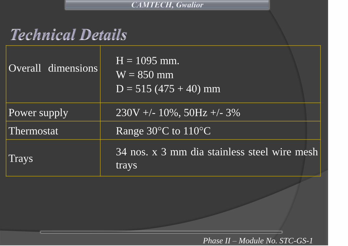
Phase II – Module No. STC-GS-1
Overall dimensionsH = 1095 mm.
W = 850 mm
D = 515 (475 + 40) mm
Power supply 230V +/- 10%, 50Hz +/- 3%
Thermostat Range 30°C to 110°C
Trays34 nos. x 3 mm dia stainless steel wire mesh
trays

Phase II – Module No. STC-GS-1
The hot case is provided with a circulating air system
(blower) to maintain evenly warm up.
In order to maintain uniform temperature inside the
compartments, thermostatic control is provided and
initially set at 80°C.
A safety thermostat at factory preset is provided to avoid
excessive heating of the cabinet in case of blower motor
failure.
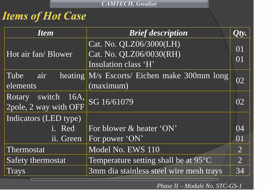
Phase II – Module No. STC-GS-1
Item Brief description Qty.
Hot air fan/ Blower
Cat. No. QLZ06/3000(LH)
Cat. No. QLZ06/0030(RH)
Insulation class ‘H’
01
01
Tube air heating
elements
M/s Escorts/ Eichen make 300mm long
(maximum)02
Rotary switch 16A,
2pole, 2 way with OFFSG 16/61079 02
Indicators (LED type)
i. Red
ii. Green
For blower & heater ‘ON’
For power ‘ON’
04
01
Thermostat Model No. EWS 110 2
Safety thermostat Temperature setting shall be at 95°C 2
Trays 3mm dia stainless steel wire mesh trays 34

Phase II – Module No. STC-GS-1
To keep the 120 nos., 1 litre
bottles of drinking mineral water
bottles at a temperature level of
3°C to 5°C refrigeration unit is
provided.
A circulating fan is provided at
the top of the unit for air
circulation and uniform cooling.

Phase II – Module No. STC-GS-1
a. Overall dimensions
H = 1750 mm
W = 550 mm
D = 515 mm (including door)
b. Power supply 230V +/- 10%, 50Hz +/- 3%
c. Thermal insulationFoamed polystyrene (Styrofoam) or
polyurethane foam
d. ThermostatDanfoss KP-61/ALCO/Honeywell
make
e. Compressor R134a charged compressors
f. Condenser and evaporator coilscomprise of copper tubes and
aluminium fins
g. Condenser and evaporator fans impeller 230mm dia type-A
h. Shut off valve indfoss/ danfoss make.

Phase II – Module No. STC-GS-1
To keep the food/ drinks in cold storage, a refrigeration
unit is provided for different cooling temperatures. The
refrigeration unit consists of the following compartments:
Deep freezer compartment
The deep freezer is to freeze and preserve ice cream. The
permanent temperature setting shall be at least -18°C. The
temperature setting range is from -18°C to -25°C.
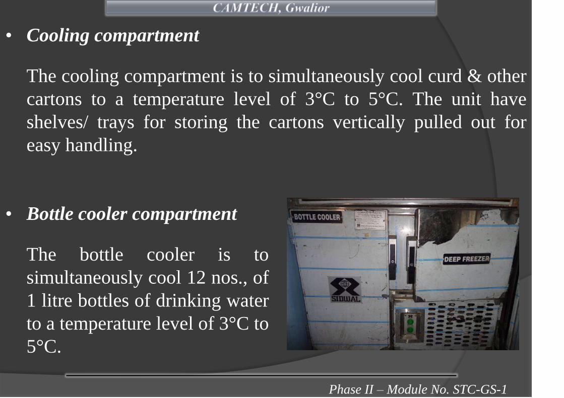
Phase II – Module No. STC-GS-1
• Cooling compartment
The cooling compartment is to simultaneously cool curd & other
cartons to a temperature level of 3°C to 5°C. The unit have
shelves/ trays for storing the cartons vertically pulled out for
easy handling.
• Bottle cooler compartment
The bottle cooler is to
simultaneously cool 12 nos., of
1 litre bottles of drinking water
to a temperature level of 3°C to
5°C.

Phase II – Module No. STC-GS-1
a. Overall dimensions
Height = 775mm
Depth = 520 mm
Width = 850mm
b. Max. Power 400 Watts
c. Operating voltage 230V +/- 10%, 50Hz +/- 3%
d. Thermostat make/Range
Dan Foss KP-61/Alco/Honeywell make
i. Deep freezer:- 18°C to -25°C
ii. Bottle cooler: 0 to + 10°C
iii.Cooling compartment : 0 to +10°C
e. Thermal insulationFoamed polystyrene (Styrofoam) or
polyurethane foam

Phase II – Module No. STC-GS-1
f. Compressors R134a charged compressors
g. Condenser and evaporator fans Impeller 230mm dia type-A
h. Condenser and evaporator coilsComprising of copper tubes and
aluminium fins
i. Shut OFF valve Indfoss/ Danfoss make

Phase II – Module No. STC-GS-1
• The water boiler is rectangular
type design. Indications are
provided on the terminal box
for power ‘ON’ and heater
‘ON’

Phase II – Module No. STC-GS-1
a. Capacity of water boiler 25 liters (approx.)
b. Power supply 230V AC ±10% 50Hz±3%
c. Heating element2 x 1500 Watt tube type emersion heating
element
d. Thermostat Range 40-110°C to IS:3017 (latest)
e. Overall dimensions
Height = 675mm (max.) (600 + 75mm)
Width = 275mm (max.)
Depth = 380mm (max.)
f. Thermal insulationRock wool plate/ bonded mineral wool
having bulk density of 40-50 Kg/Cu.m
g. Water Inlet 15mm bore stainless steel pipe
h. Water outlet 15mm bore stainless steel pipe
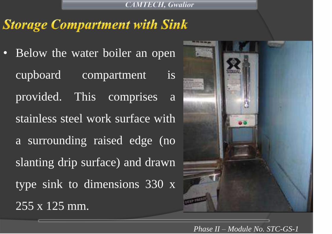
Phase II – Module No. STC-GS-1
• Below the water boiler an open
cupboard compartment is
provided. This comprises a
stainless steel work surface with
a surrounding raised edge (no
slanting drip surface) and drawn
type sink to dimensions 330 x
255 x 125 mm.

Phase II – Module No. STC-GS-1
• A wall mounted cupboard
without door (2 shelves) is
provided for storage of vacuum
flask and cups. It is provided
with aluminium bar to prevent
the vacuum flask and cups
falling out. Unit is fabricated
form 1.0mm thick high grade
stainless steel sheet.
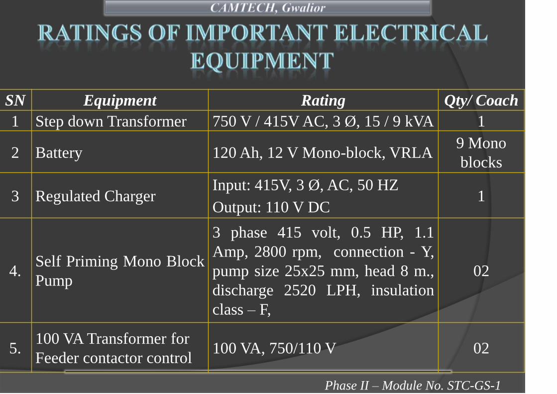
Phase II – Module No. STC-GS-1
SN Equipment Rating Qty/ Coach
1 Step down Transformer 750 V / 415V AC, 3 Ø, 15 / 9 kVA 1
2 Battery 120 Ah, 12 V Mono-block, VRLA9 Mono
blocks
3 Regulated ChargerInput: 415V, 3 Ø, AC, 50 HZ
Output: 110 V DC1
4.Self Priming Mono Block
Pump
3 phase 415 volt, 0.5 HP, 1.1
Amp, 2800 rpm, connection - Y,
pump size 25x25 mm, head 8 m.,
discharge 2520 LPH, insulation
class – F,
02
5.100 VA Transformer for
Feeder contactor control100 VA, 750/110 V 02

Phase II – Module No. STC-GS-1
LHB EOG TYPE NON-AC GS (LS) COACHES
Item Code Description WattageQty Per
CoachLoad In
FL Fluorescent Light 20 20 400
DL Door Way Light 20 6 120
GL Gangway Light 26 2 52
LL Lavat0ry Light 13 4 52
AEL Accidental Emergency Light 10 4 40
PACIL Passenger,alarm, Light 10 2 20
F Fan 38 30 1140
Total Load 1824
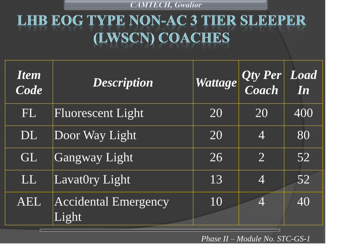
Phase II – Module No. STC-GS-1
Item
CodeDescription Wattage
Qty Per
Coach
Load
In
FL Fluorescent Light 20 20 400
DL Door Way Light 20 4 80
GL Gangway Light 26 2 52
LL Lavat0ry Light 13 4 52
AEL Accidental Emergency
Light
10 4 40
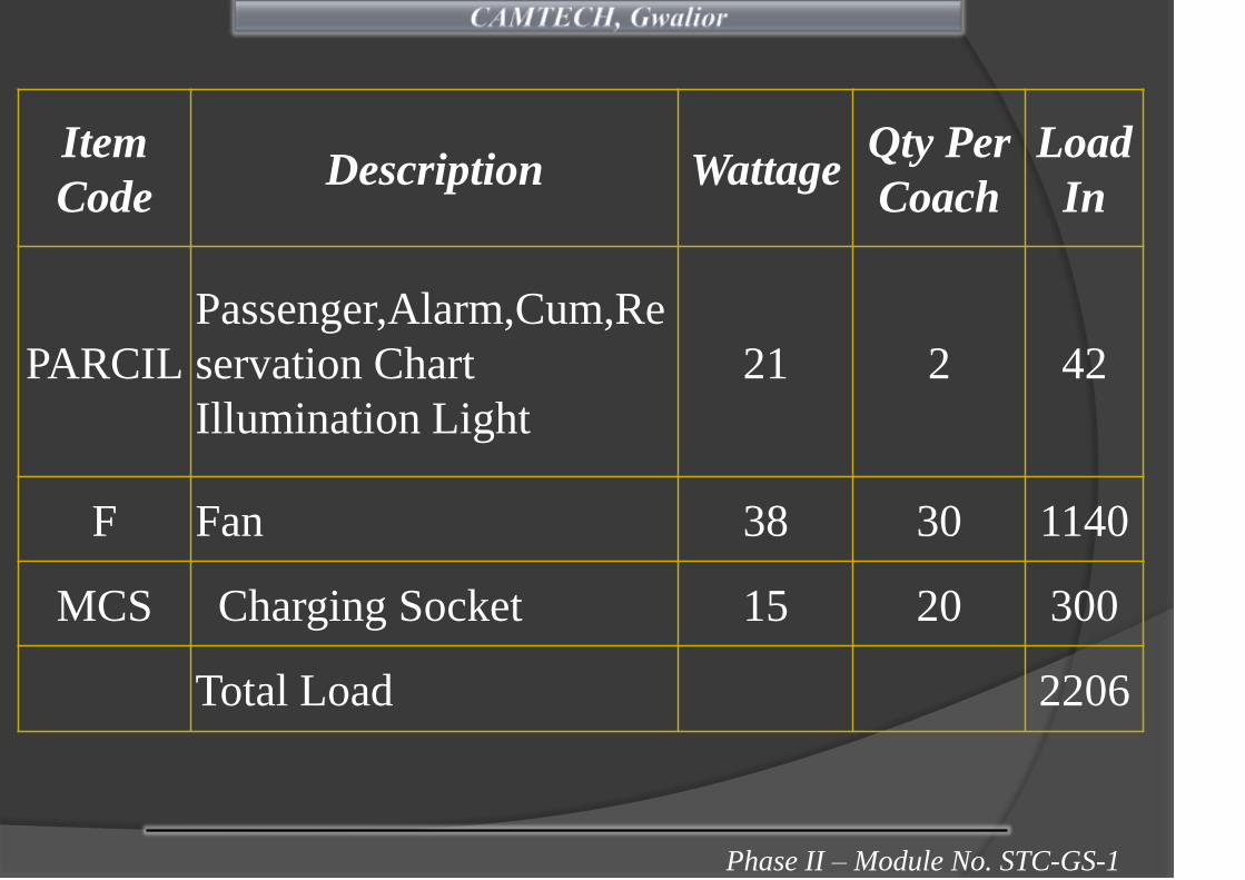
Phase II – Module No. STC-GS-1
Item
CodeDescription Wattage
Qty Per
Coach
Load
In
PARCIL
Passenger,Alarm,Cum,Re
servation Chart
Illumination Light
21 2 42
F Fan 38 30 1140
MCS Charging Socket 15 20 300
Total Load 2206
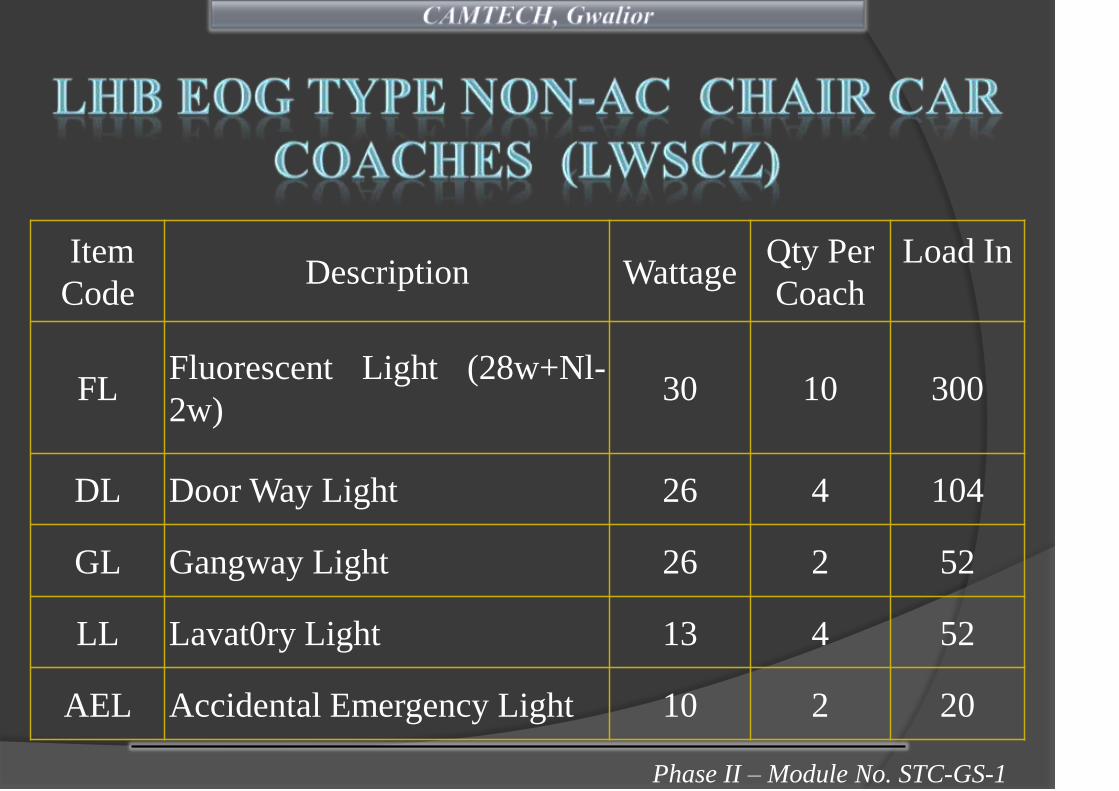
Phase II – Module No. STC-GS-1
Item
CodeDescription Wattage
Qty Per
Coach
Load In
FLFluorescent Light (28w+Nl-
2w)30 10 300
DL Door Way Light 26 4 104
GL Gangway Light 26 2 52
LL Lavat0ry Light 13 4 52
AEL Accidental Emergency Light 10 2 20

Phase II – Module No. STC-GS-1
Item
CodeDescription Wattage
Qty Per
Coach
Load In
PARCILPassenger,Alarm,Cum,Reserva
tion Chart Illumination Light21 2 42
F Fan 38 36 1368
MCS Charging Socket 15 17 255
Total Load 2193

Phase II – Module No. STC-GS-1

Phase II - Module No. STC-GS-1

Phase II - Module No. STC-GS-1Phase II - Module No. STC-GS-1
One of the methods to reduce the down time of the
coaching stock is to provide the proper tools with
modern design.
Availability of proper tools with artisan staff is essential
to enhance the productivity and quality of work.
Performance record of tools is required to be kept to
review their performance.

Phase II - Module No. STC-GS-1
1. Always use the right size and type of tool for the job being
done.
2. Keep tools in proper working condition.
3. Never alter a tool from its original condition.
4. Always wear safety goggles when using punches, chiesels,
hammers and cutting tools.
5. Never use a tool as a hammer unless manufactured for that
purpose.

Phase II - Module No. STC-GS-1
6. Never use a pipe extension to increase the leverage of any
wrench.
7. Adjustable wrenches should be tightly adjusted to the nut
and pulled so that the force is on the side of the fixed jaw.
8. Never use a pipe wrench to bend, raise or lift a pipe.
9. Ratchet mechanisms should be cleaned and lubricated
periodically with light grade oil.
10. Keep hammer heads tight on the handle. Never use a
hammer with a loose or damaged handle.

Phase II - Module No. STC-GS-1
11. Metal cutting chisels are intended for cutting, shaping and
removing metal softer than the cutting edge itself.
12. Always strike the struck base of a chisel or punch. The
striking face of the hammer should have a dia.
approximately 10 mm larger than the struck face of the
punch or chisel.
13. Never use screw drivers with rounded tips.
14. Never use a screwdriver as a chisel, punch, scraper or pry
bar. Use screw driver for screw driving only.

Phase II - Module No. STC-GS-1
(In Proper Tool Bag)
S.No. Description Qty
1.
Tool box of size 325x440x120 mm (Approx.) with fixing
arrangement for tools and locking arrangement with 2
no. keys
1 set
2.Neon bulb tester cum Screw driver set with 8 nos of
blade.1 set

Phase II - Module No. STC-GS-1
S.No Description Qty
3.Combination plier insulated with thick CA sleeve with
joint cutter length 205 mm1
4. Digital multi-meter 1
5. T spanner of sizes 10, 13, 15, 17 1
6.Panel key square type ¼ size suitable for opening of
control panel of AC coaches1
7. Key for opening fittings of AC coaches 1
8.Test lamp holder (brass) fitted with two mtrs. of 2 core
flexible copper wire1
9. Torch with cells (+2 cell spare) 1

Phase II - Module No. STC-GS-1
S.No Description Qty
10.DE spanner set 8 pcs of sizes 6/7, 8/9, 10/11, 12/13,
14/15, 16/17, 18/19, 20/221 set
11. Allen key size 4 mm, 3/16, 7/32 1
12.Heavy duty cable cutting knife adjustable in aluminium
casing over all size 140 mm1
13. Adjustable spanner length 255 mm 1
14. Infrared Digital Thermometer (Temperature gun) 1
15. Insulated Nose plier 6” 1
16. Tongue tester A.C. (0-100 A) 1
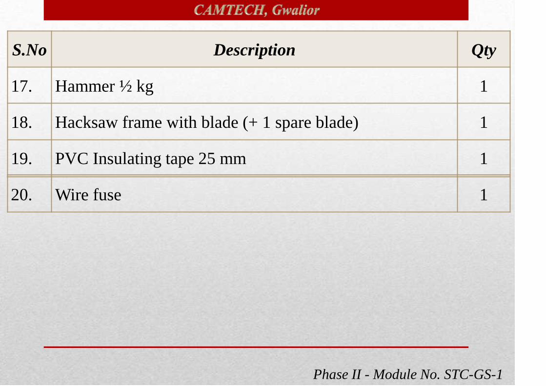
Phase II - Module No. STC-GS-1
S.No Description Qty
17. Hammer ½ kg 1
18. Hacksaw frame with blade (+ 1 spare blade) 1
19. PVC Insulating tape 25 mm 1
20. Wire fuse 1

Phase II - Module No. STC-GS-1
S.No. Name of Tools Qty.
1.Combination plier insulated with thick CA sleeve with
joint cutter length 205 mm1 no.
2. Insulated Wire Stripper & Cutter 16 sq.mm 1 no.
3. Insulated Long Nose Pliers 6” 1 no.
4.Neon bulb tester cum Screw driver set with 8 nos of
blade similar1 no.
(In proper tool bag)

Phase II - Module No. STC-GS-1
S.No. Name of Tools Qty.
5. Fitting Opening Key (FDB/CFL/Tube light/RRU) 1 no.
6.DE spanner set 8 pcs of sizes 6/7. 8/9, 10/11, 12/13,
14/15, 16/17, 18/19, 20/221 set
7. Adjustable spanner length 255 mm 1 no.
8.Test lamp holder (brass) fitted with two mtrs. of 2
core flexible copper wire1 no.
9. Hacksaw frame with blade (12") + One extra blade 1 no.
10. Flat file 150 mm 1 no.
11. Ball pen Hammer 300 gms 1 no.
12. Torch with cell, LED 1 no.
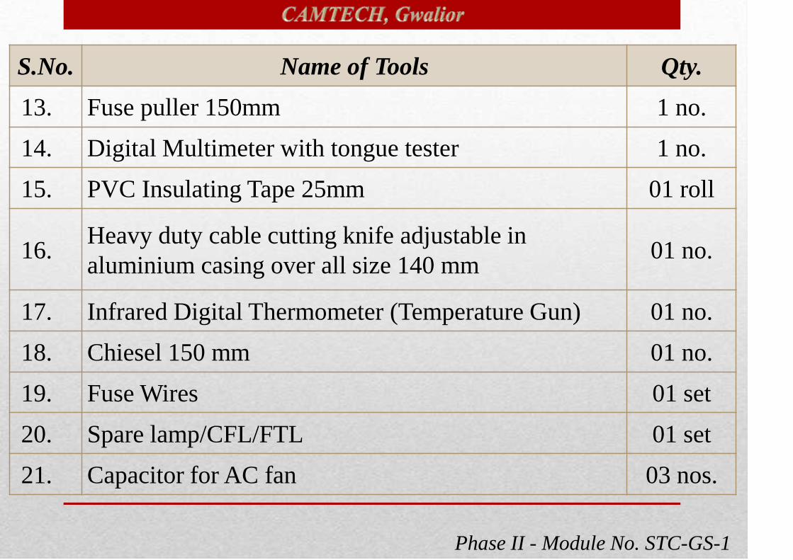
Phase II - Module No. STC-GS-1
S.No. Name of Tools Qty.
13. Fuse puller 150mm 1 no.
14. Digital Multimeter with tongue tester 1 no.
15. PVC Insulating Tape 25mm 01 roll
16.Heavy duty cable cutting knife adjustable in
aluminium casing over all size 140 mm01 no.
17. Infrared Digital Thermometer (Temperature Gun) 01 no.
18. Chiesel 150 mm 01 no.
19. Fuse Wires 01 set
20. Spare lamp/CFL/FTL 01 set
21. Capacitor for AC fan 03 nos.

Phase II - Module No. STC-GS-1
Tools Kit for TL Fitter (In Proper Tool Bag)
S.No. Name of Tools Qty.
1.Combination plier insulated with thick CA sleeve with
joint cutter length 205 mm1 no.
2. Insulated Wire Stripper & Cutter 16 sqmm 1 no.
3. Insulated Long Nose Pliers 6” 1 no.
4.Neon bulb tester cum Screw driver set with 8 nos of
blade similar 1 each
5. Fitting Opening Key (FDB/CFL/Tube light/RRU) 1 no.

Phase II - Module No. STC-GS-1
S.No. Name of Tools Qty.
6.DE spanner set 8 pcs of sizes 6/7. 8/9, 10/11, 12/13,
14/15, 16/17, 18/19, 20/221 set
7. Ring Spanner Set 1 set
8. Adjustable spanner length 255 mm 1 no.
9.Test lamp holder (brass) fitted with two mtrs. of 2 core
flexible copper wire1 no.
10 Flat file 150mm 1 no.
11. Ball pen Hammer (300 gm) 1 no.
12. Torch, 4 cell (LED) 1 no.
13. Fuse puller 6” 1 no.
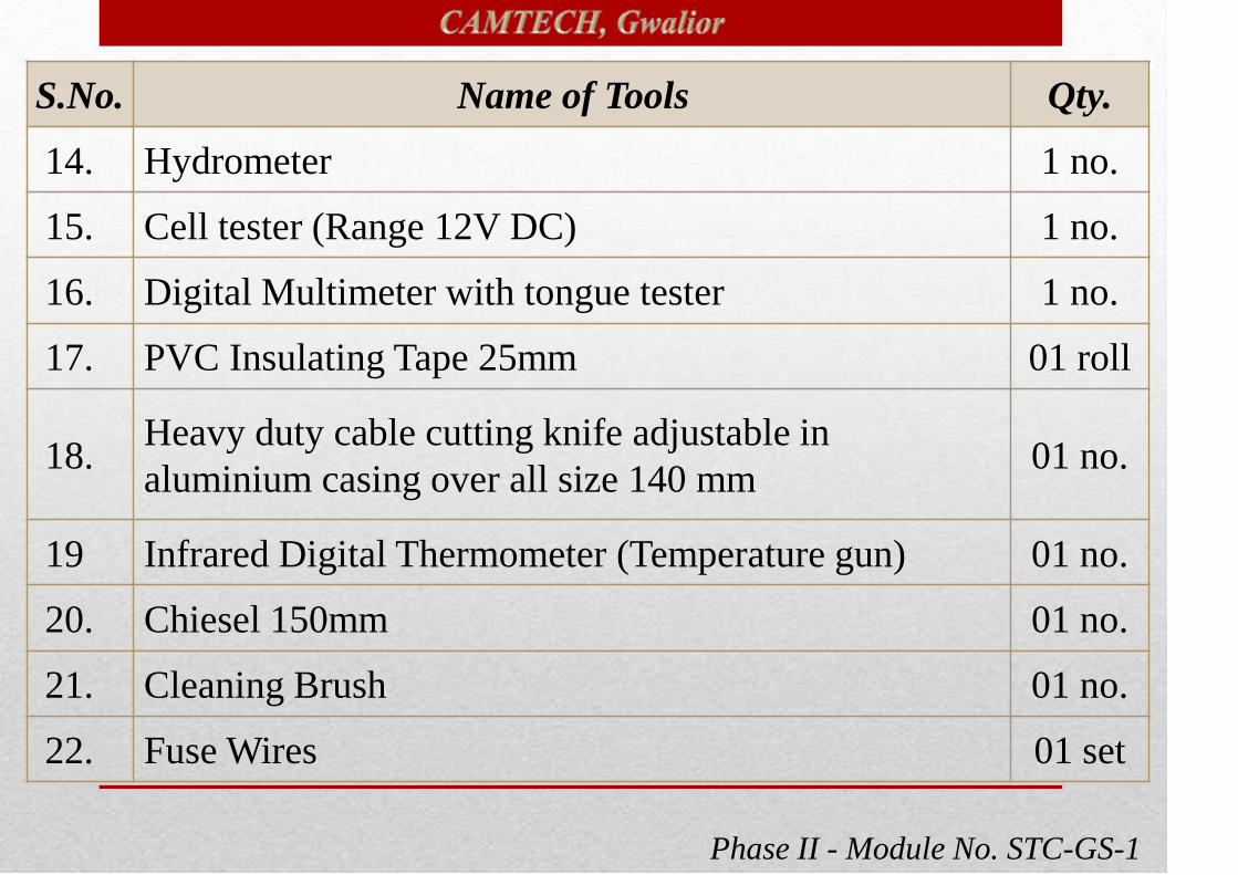
Phase II - Module No. STC-GS-1
S.No. Name of Tools Qty.
14. Hydrometer 1 no.
15. Cell tester (Range 12V DC) 1 no.
16. Digital Multimeter with tongue tester 1 no.
17. PVC Insulating Tape 25mm 01 roll
18.Heavy duty cable cutting knife adjustable in
aluminium casing over all size 140 mm01 no.
19 Infrared Digital Thermometer (Temperature gun) 01 no.
20. Chiesel 150mm 01 no.
21. Cleaning Brush 01 no.
22. Fuse Wires 01 set

Phase II - Module No. STC-GS-1
S.No. Name of Tool
1.Combination plier insulated with thick CA sleeve with joint
cutter length 205 mm
2 Insulated Wire Stripper & Cutter 16 sqmm
3 Insulated Long Nose Pliers 6”
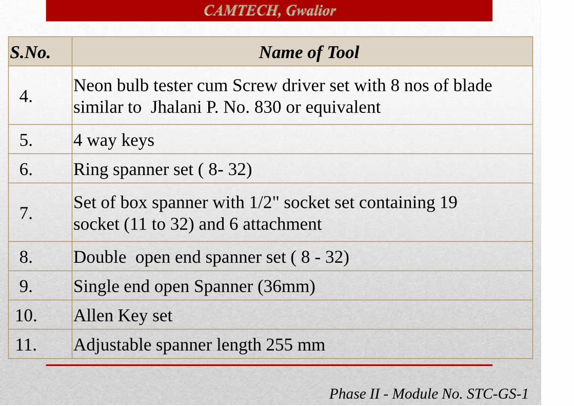
Phase II - Module No. STC-GS-1
S.No. Name of Tool
4.Neon bulb tester cum Screw driver set with 8 nos of blade
similar to Jhalani P. No. 830 or equivalent
5. 4 way keys
6. Ring spanner set ( 8- 32)
7.Set of box spanner with 1/2" socket set containing 19
socket (11 to 32) and 6 attachment
8. Double open end spanner set ( 8 - 32)
9. Single end open Spanner (36mm)
10. Allen Key set
11. Adjustable spanner length 255 mm

Phase II - Module No. STC-GS-1
S.No. Name of Tool
12.Test lamp holder (brass) fitted with two mtrs. of 2 core
flexible copper wire
13. Hacksaw frame with blade (12") + Extra Blades
14. Flat, round, triangular files
15. Ball pein Hammer ( 200gm, 300gm, 500gm, 800 gm, 1kg)
16. Nylon hammer
17. Chiesel flat 150mm
18. Infrared Digital Thermometer (Temperature gun)
19. Torch, 4 cell, LED for each staff

Phase II - Module No. STC-GS-1
S.No. Name of Tool
20. Fuse puller 6”
21. Crimping tool ( 0.5 - 1.6 mm2 )
22. Crimping tool (1.5 - 16 mm2 )
23. Hydraulic crimping machine (upto 300 mm)
24.Heavy duty cable cutting knife adjustable in aluminium
casing over all size 140 mm
25. Multipurpose Portable power drill machine
26. Auto ranging Digital Multimeter
27. Hydrometer

Phase II - Module No. STC-GS-1
S.No. Name of Tool
28. Digital clamp meter
29 Bearing/ Pulley Puller
30. Pulley V groove “GO” , “NO GO” gauge
31. Portable electric straight grinder
32. Digital lux meter
33. Cell tester (0-12) V DC
34. Digital Tachometer
35. Digital Vernier caliper

Phase II - Module No. STC-GS-1
S.No. Name of Tool
36. Digital Micrometer
37. Digital Meggar (500 V to 5000 V )
38. Heavy duty Pipe wrench
39. Soldering iron
40. De-soldering gun
41. Hot air gun / Hot air blower
42. Portable Blower / Dust extractor
43.1/2" socket set containing 19 socket (11 to 32) with 6
attachment

Phase II - Module No. STC-GS-1
S.No. Name of Tool
44. Torque wrench 0-5kg-m
45. Shock pulse meter (SPM)
46. All purpose saw
47. Infrared Digital Thermometer
48. Cable cutter 150mm
49. Insulating Tapes 25mm
50. Safety helmet for each staff
51. Gum boot for each staff
52. Tool bag for each technician
Phase II - Module No. STC-GS-1
(In Proper Tool Bag)
S.No. Name of Tools Qty.
1.Combination plier insulated with thick CA sleeve with
joint cutter length 205 mm1 no.
2. Insulated Nose plier 6” 1 no.
3. Neon bulb tester Screw driver set with 8 nos of blade 1 set

Phase II - Module No. STC-GS-1
S.No. Name of Tools Qty.
4.Panel key square type ¼ size suitable for opening of
control panel of AC coaches1 no.
5.4 way key & fitting opening key
(FDB/CFL/tubelight/RRU)1 no.
6.DE spanner set 8 pcs of sizes 6/7. 8/9, 10/11, 12/13,
14/15, 16/17, 18/19, 20/221 set
7. T spanner of sizes 10, 13, 15, 17 1
8.Test lamp holder (brass) fitted with two mtrs. of 2 core
flexible copper wire1 no
9.Heavy duty cable cutting knife adjustable in
aluminium casing over all size 140 mm1 no.

Phase II - Module No. STC-GS-1
S.No. Name of Tools Qty.
10. Allen key ( 3- 15m) 1 no
11. Flat file 150mm 1 no
12. Hammer 200 g 1 no
13. Torch, cells (+2 cell spare) 1 no
14. Auto ranging Digital Multimeter 1 no.
15. Tongue tester A.C. (0-100 A)
16. Adjustable spanner length 255 mm 1 no.
17. Infrared Digital Thermometer (Temperature gun) 1
18. PVC Insulating tape 25mm 1
19. Wire fuse 1

Phase II - Module No. STC-GS-1
S.No. Name of Tools
1.Combination plier insulated with thick CA sleeve with joint
cutter length 205 mm
2. Insulated Wire Stripper & Cutter 16 sqmm
3. Insulated Nose plier 6”
4.Neon bulb tester cum Screw driver set with 8 nos of blade
equivalent

Phase II - Module No. STC-GS-1
S.No. Name of Tools
5. 4 way key
6. Ring spanner set ( 8- 32)
7.Set of box spanner with 1/2" socket set containing 19 socket (11
to 32) and 6 attachment
8. Double open end spanner set ( 8 - 32)
9. Single end open Spanner (36mm)
10. T spanner set
11. Allen Key set
12. Adjustable spanner length 255 mm
13. Test lamp/ Hand lamp

Phase II - Module No. STC-GS-1
S.No. Name of Tools
14. Hacksaw frame with blade (12") + extra blades
15. Flat round, file
16. Ball pein Hammer 200 gm, 500gm, 1kg.
17. Nylon hammer 100gm
18. Chiesel (Flat) - 8"
19. C Clamp
20. Crimping tool (0.5 - 6 mm)
21. Crimping tool (1.5 -1 6 mm)

Phase II - Module No. STC-GS-1
S.No. Name of Tools
22. Pinching tool
23. Tube bender (3/8", 5/8", 7/8")
24. Flare tool
25. Tube cutter
26. Torch (4 cell) + extra cells for each staff
27. Digital Tachometer
28. Digital Clamp meter
29. Hydrometer
Phase II - Module No. STC-GS-1
S.No. Name of Tools
30. Auto ranging Digital Multimeter
31. Cell tester (0-12) volt DC
32. Battery analyzer
33. Digital meggar ( 500 V, 1000 V, 2500V, 5000V)
34. Digital Micrometer
35. Digital Vernier calipers
36. Blower / Dust extractor
37. Portable electric straight grinder
38. Torque wrenches
39. Pipe wrench

Phase II - Module No. STC-GS-1
S.No. Name of Tools
40. Multipurpose Portable Power drill machine
41. Soldering iron
42 De-soldering Gun
43 Hot air gun / Hot air blower
44 Shock pulse meter (SPM)
45 All purpose saw
46 Pulley V groove “GO” , “NO GO” gauge
47 Pulley/ Bearing puller
48 Digital Anemometer

Phase II - Module No. STC-GS-1
S.No. Name of Tools
49. Infrared Digital thermometer (Temperautre gun)
50. Digital lux meter
51. Winding insulation Resistance meter
52. Cable cutter/ wire cutter
53. Gum boot for each staff
54. Infrared thermal imaging camera
55. Power quality analyzer
56. Leakage current tester
57. Fuse puller
Phase II - Module No. STC-GS-1
S.No. Name of Tools
59. PVC tape
60. Bunching tie
61. Amery paper
62. Amery cloth
63. Digital spirit level
64. Digital thermometer
65. Duster cloth
66. Automatic self adjusting small spanner
67. Spanner multi wrench 10 in one
Phase II - Module No. STC-GS-1
S.No. Name of Tools
68 Multi wrench/ Spanner
69 Ratchet wrench – Ratchet type spanner
70 Angular grinder
71 Cord less drill machine
72 Cord less screw driver
73 Knife set
74 Wire brush
75 Nylon brush
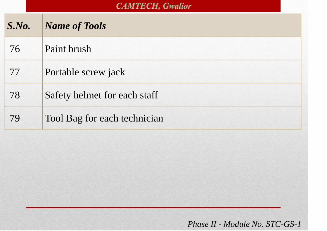
Phase II - Module No. STC-GS-1
S.No. Name of Tools
76 Paint brush
77 Portable screw jack
78 Safety helmet for each staff
79 Tool Bag for each technician

Phase II - Module No. STC-GS-1

Phase II - Module No. STC-GS-1Phase II - Module No. STC-GS-1

Phase II - Module No. STC-GS-1
150mm , 200mm, 250mm.
STEEL.
Cutting, twisting of small
wires and holding round
and flat objects.

Phase II - Module No. STC-GS-1
Don’t use as a hammer.
Don’t cut steel wires.
Don’t hold hot substances.
Don’t spoil the handle insulation.
Keep the plier safe from rust.
Lubricate moving part.

Phase II - Module No. STC-GS-1
150mm , 200mm.
STEEL.
Cutting wires at narrow places,
for removing insulation, and
instrument works.

Phase II - Module No. STC-GS-1
Don’t cut steel wires.
Don’t spoil the handle insulation.
Keep the cutter safe from rust.
Lubricate moving part.
Don’t cut hot substances.

Phase II - Module No. STC-GS-1
100mm,150mm , 200mm.
STEEL.
For connecting and disconnecting
small wires and tightening and
loosening of small nuts in narrow
places and also for cutting the thin
wires.
Phase II - Module No. STC-GS-1
Don’t use as a hammer.
Don’t cut steel wires.
Don’t spoil the handle insulation.
Keep the plier safe from rust.
Lubricate moving part.

Phase II - Module No. STC-GS-1
75mm, 100mm,150mm ,
200mm, 250mm,300mm.
Blade in steel, Handle in
wood or celluloid.
For tightening and loosening
screws. and wiring accessories
like switches, holders etc.

Phase II - Module No. STC-GS-1
Don’t use with loose handle.
Don’t hammer the handle.
Don’t use it as chisel.
Correctly fit the blade edge in the
screw slots.
Avoid greasy or oily handle.

Phase II - Module No. STC-GS-1
It is used to open and close
the RJB cover, Pannel
boards, FTL/CFL fittings
etc.

Phase II - Module No. STC-GS-1
8 to 36
Steel
For tightening and loosening
of nuts and bolts.

Phase II - Module No. STC-GS-1
Use correct size spanner .
Don’t use as a hammer.
Don’t strike with hammer while
tightening or loosening.
Don’t apply grease/oil on its jaws.

Phase II - Module No. STC-GS-1
300mm Cast iron
For tightening and loosening nut &
bolt of different sizes with single
spanner thus saving time.
Don’t use as a hammer.
Don’t strike with hammer while
tightening or loosening.
Don’t apply grease/oil on its jaws.
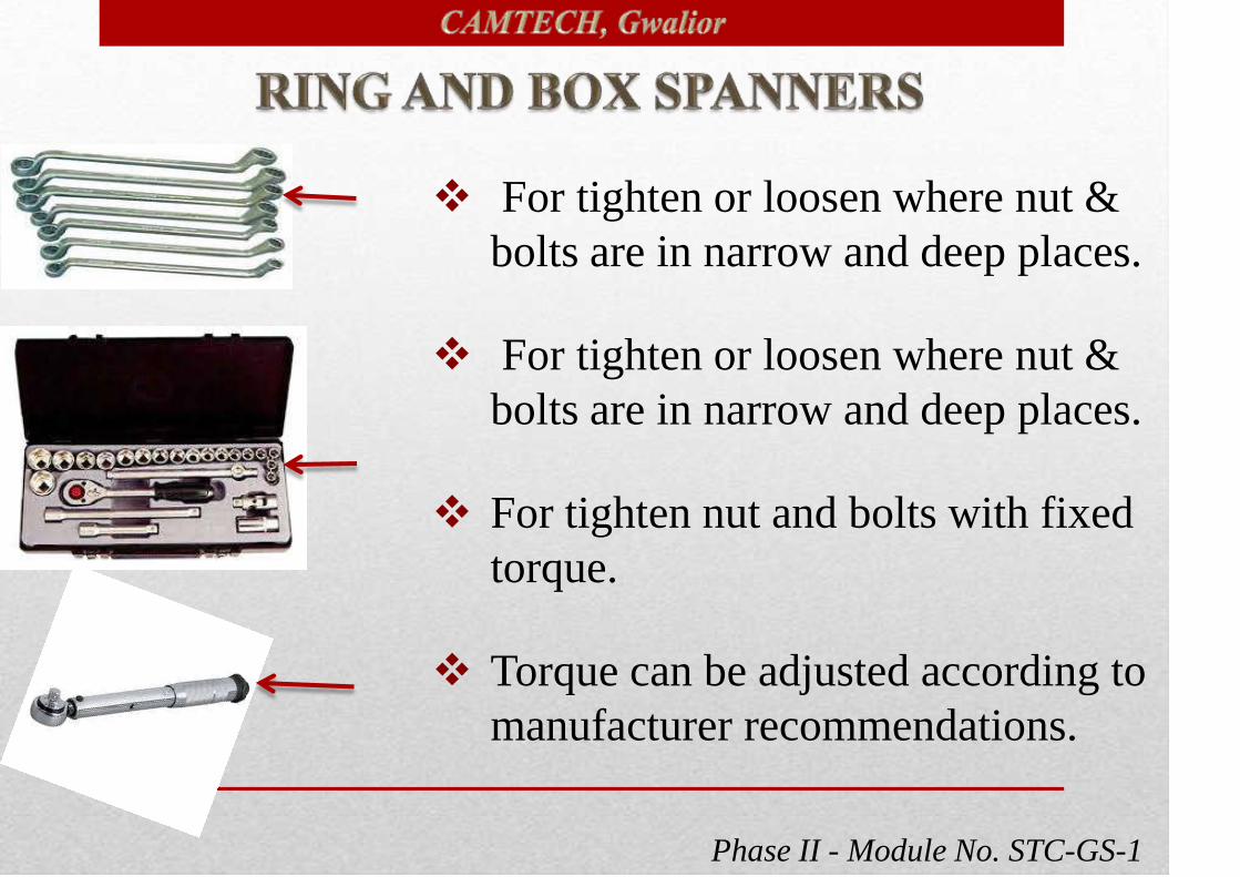
Phase II - Module No. STC-GS-1
For tighten or loosen where nut &
bolts are in narrow and deep places.
For tighten or loosen where nut &
bolts are in narrow and deep places.
For tighten nut and bolts with fixed
torque.
Torque can be adjusted according to
manufacturer recommendations.
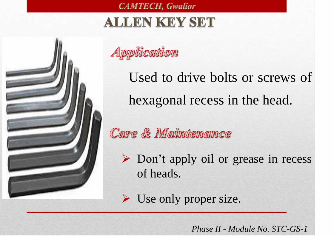
Phase II - Module No. STC-GS-1
Used to drive bolts or screws of
hexagonal recess in the head.
Don’t apply oil or grease in recess
of heads.
Use only proper size.

Phase II - Module No. STC-GS-1
5m,10m,20m
Used to measure length, width
and heights where ever required.
Don’t bend reverse side or twist.
See that paint should not scratched.
Avoid from rust.

Phase II - Module No. STC-GS-1
Two lamps of same wattage and
same voltage must be connected
in series.(+ve red, -ve blue and
earth green or white).
With this arrangement we can
check the coach earth.
Handle the test lamp with care
otherwise it may broken.

Phase II - Module No. STC-GS-1
12”
For cutting conduit pipes, G.I.pipes
and small iron pieces etc.
Blade should be fixed tight enough.
Use coolant while cutting.
Teeth of the blade should be away from the handle.
Hold the frame straightly while cutting.
Lift the saw slightly on return stroke.

Phase II - Module No. STC-GS-1
Used to cut the cable of
aluminum or copper up to 240
sqmm.
Don’t cut metal pipes or rods.
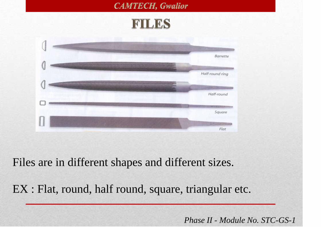
Phase II - Module No. STC-GS-1
Files are in different shapes and different sizes.
EX : Flat, round, half round, square, triangular etc.

Phase II - Module No. STC-GS-1
For smoothen surfaces and finishing works.
For different places suitable shape of the file will be used.
Handle should not be loose.
Don’t apply oil or grease while filing.
Clean the file with wire brush after completion of work.

Phase II - Module No. STC-GS-1
300 gm
For bending, straightening small iron sheets.
For driving nails on wood or walls.
For tap the pulley to know the condition by
observing sound.
Handle should not be loose.
Don’t apply oil or grease on bottom surface .

Phase II - Module No. STC-GS-1
500 Volts
For testing availability
of supply.
Don’t use on higher voltage than specified.
Don’t tight or loose the screws (heavy).
Stand on earth while testing.
Touch the metal clip while testing.

Phase II - Module No. STC-GS-1
4 Cells (each 1.5v)
To observe objects when there
is no lights.
To focus light on narrow and
dark places. Don’t drop the torch.
Don’t dip into the water.
Switch ‘off’ light and remove the cells out after completion
of work.

Phase II - Module No. STC-GS-1
Available in different sizes depends up
on size of the fuse.
For pulling the fuse safely.
Don’t drop on hard ground.
Don’t apply oil or grease.
Hold the fuse in correct position.

Phase II - Module No. STC-GS-1
Used to check specific gravity of
electrolyte in flooded type cells.
Handle with care.
Take the electrolyte slowly.
Keep it clean.

Phase II - Module No. STC-GS-1
3-0-3Volts DC
For test the voltage of individual
cell and polarity.
Don’t use more than one cell.
Don’t dip into the water.
Handle with care.

Phase II - Module No. STC-GS-1
Used to measure ac/dc voltages of
different range.
Used to measure ac/dc low currents.
Used to check continuity of the circuit
and to measure resistance.etc.
Phase II - Module No. STC-GS-1
First select the range and units to be
measured.
Disconnect the supply while checking
continuity or while measuring resistance.
Handle with care.
Check the condition of prods.
Keep the meter clean and observe the
error.

Phase II - Module No. STC-GS-1
: Used to skin the insulation of wires.
Don’t cut the conductor.
Keep the knife sharp.
Close the safety cap after completion of
work.
Don’t spoil the insulation.

Phase II - Module No. STC-GS-1
: Used to tightening or loosening of belt
tension.
Don’t use as a hammer.
Don’t apply oil or grease.

Phase II - Module No. STC-GS-1
: Used to check the pulley worn out
condition.
Don’t bend the leaves.
Keep it clean.

Phase II - Module No. STC-GS-1
: Used to crimp the small lugs on
wires/cables.
Use proper jaw for suitable size of the lug.
Apply oil on moving part.

Phase II - Module No. STC-GS-1
Used to solder wire joints, commutator
segments and electronic components on PCB.
Iron must be connected to earth.
Flexible wire should be used.
Keep the iron on holder.
25W, 65W, 125W, 250W.etc.

Phase II - Module No. STC-GS-1
Used to measure illumination level
in coaches or where ever required.
Handle with care.
Cover the sensor with cap after
completion of work.

Phase II - Module No. STC-GS-1
To measure the temperature on hot
spot by non touching the hot spot .
Don’t drop the meter.
Don’t dip into the water.
Don’t take the meter very near to hot
spot.

Phase II - Module No. STC-GS-1
To measure the high currents in the cable (ac/dc). And
also can used as multimeter.
First select the correct range then measure.
Keep the meter clean.

Phase II - Module No. STC-GS-1
Used to pull the pulley or bearing of the
alternator or any rotating machine.
Fix the puller in correct position while
using.
Don’t apply grease on claws while
using.
Apply oil or grease on moving parts.

Phase II - Module No. STC-GS-1
Used to blow or suck the dust from
RJB,FDB, Electrical equipments,
dc fan carbon dust etc.
Check the carbon brush of the
blower.
Use nose mask to protect ourselves
from dust.

Phase II - Module No. STC-GS-1
To make small holes on iron or wood.
Use lubricant while making hole on
metals.
Don’t fix the drill bit loosely.
Don’t put too much pressure on
machine.
Check the connection of cable
connected to machine.

Phase II - Module No. STC-GS-1
To measure speed of the rotating
machine in RPM.
Touch the spindle to pulley
straightly.
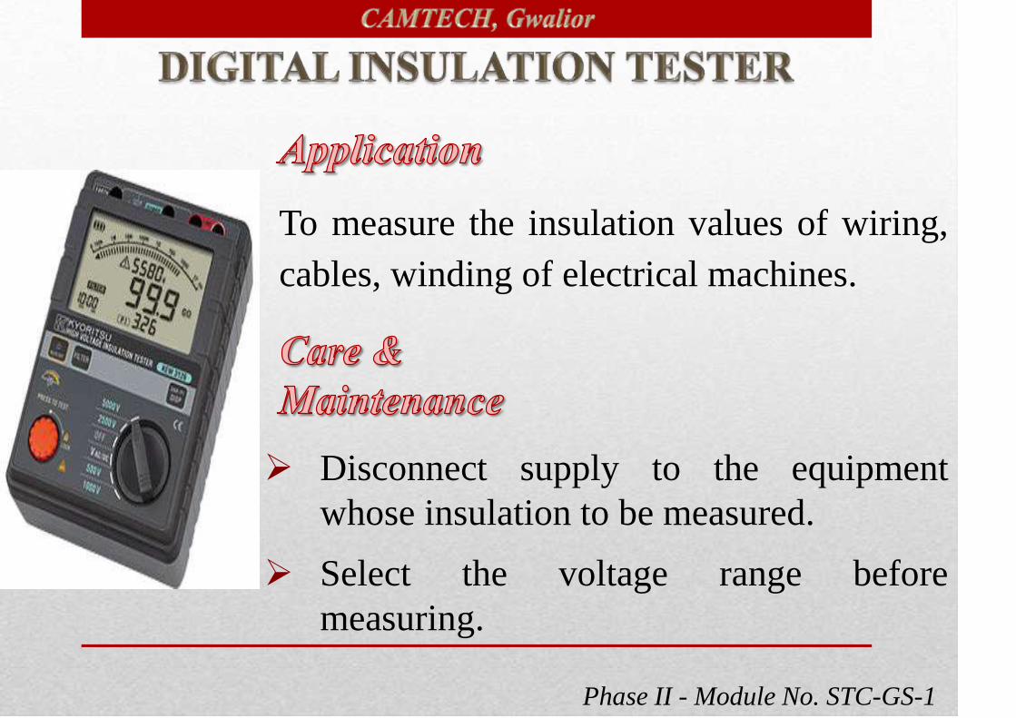
Phase II - Module No. STC-GS-1
To measure the insulation values of wiring,
cables, winding of electrical machines.
Disconnect supply to the equipment
whose insulation to be measured.
Select the voltage range before
measuring.

Phase II - Module No. STC-GS-1
Used to monitor the condition
of bearing of rotating machines.
Fix the sensor in correct place.
Observe the reading keenly.

Phase II - Module No. STC-GS-1
Used to measure inner/outer dia of the object
accurately.
Observe the reading keenly.
Handle with care.
Clean the vernier after completion the work.

Phase II - Module No. STC-GS-1
To find out the dia of very thin wire.
Adjust the thimble gently.
Clean the spindle .
Handle with care.

Phase II - Module No. STC-GS-1
Standard wire gauge (SWG) is a system
of numbering used to measure the
diameters of wire and thickness of sheet
metal. The measurements are represented
in dimensions of inches and millimeters.
• Don’t put in tool bag.
• Keep it clean

Phase II - Module No. STC-GS-1

Phase II - Module No. STC-GS-1

Phase II - Module No. STC-GS-1
Technical Specifications :
Test voltage 500 V to 5000 V DC
IR Range 0 – 5 T
Display Digital
Short circuit current < 2mA
● To measure Insulation Resistance
of all voltage components like
transformer winding, CTs, PTs,
bushings, cables, motor and
Alternator windings etc.

Phase II - Module No. STC-GS-1
Healthiness of winding insulation can be checked.
LED based visual indication for discharge condition of
meter ensures safety.
This LED glows after the HT is switch OFF, till the voltage
on test object/ HV terminal is below 50 V approximate.
Equipment have HV, LV & Guard and Internal discharge of
object after test, memory for measurement results, ability to
transfer the data to a PC, polarization index and dielectric
absorption ratio.
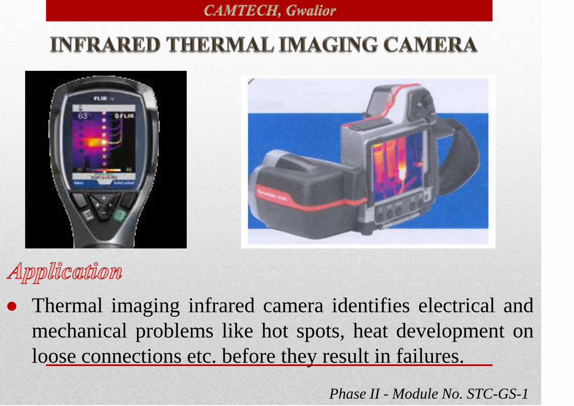
Phase II - Module No. STC-GS-1
● Thermal imaging infrared camera identifies electrical and
mechanical problems like hot spots, heat development on
loose connections etc. before they result in failures.

Phase II - Module No. STC-GS-1
● It is a non-contact device which detects infrared radiations
and converts it into electronic signals. These signals are
then processed to produce thermal image of the object.
Technical Details:(For more details refer RDSO Spec. No. TI/SPC/OHE/TIPS/1031, December, 2013)
Sr. Features Present Specification
1. Detector Un-cooled focal plane array (FPA) of
320 x 240 pixels or more
2. Temperature measurement
Range
0 to 500 degree centigrade or Higher

Phase II - Module No. STC-GS-1
Sr. Features Present Specification
3.Minimum
focus distance
Minimum focus distance less than or equal to 40
cm to infinity.
4. AccuracyWith ± 2°/o of display or ± 2°c whichever is
greater.
5. Focus Auto or Manual
6. DisplayNot less than 75 mm diagonally active matrix
colour LCD with high luminance or better.

Phase II - Module No. STC-GS-1
It helps to find out electrical hot spots and faulty
equipment in incipient conditions.
It is an ideal means for maintenance people looking for
safety and reliability when conducting routine surveys of
electrical systems, switchgear and electrical components.
It is non contacting and can be done in live condition
without affecting the operation, production or traffic.
Phase II - Module No. STC-GS-1
It is applicable to most types of electrical, mechanical
equipment and power lines.
It has the storage memory and images are saved with
details. The same can be downloaded with USB port and
detail analysis can be done with the help of software.

Phase II - Module No. STC-GS-1
● Electro chemical battery
analyser accurately measures
health of lead acid battery
(chemical and electrical) in
terms of sulfation, dry out,
voltage and impedance.
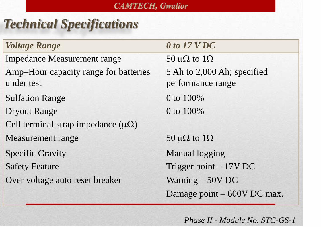
Phase II - Module No. STC-GS-1
Voltage Range 0 to 17 V DC
Impedance Measurement range 50 to 1
Amp–Hour capacity range for batteries
under test
5 Ah to 2,000 Ah; specified
performance range
Sulfation Range 0 to 100%
Dryout Range 0 to 100%
Cell terminal strap impedance ()
Measurement range 50 to 1
Specific Gravity Manual logging
Safety Feature
Over voltage auto reset breaker
Trigger point – 17V DC
Warning – 50V DC
Damage point – 600V DC max.
Technical Specifications

Phase II - Module No. STC-GS-1
It can store large amount of data and auto hold and
auto-data storage facility also available.
It has ability to measure AC voltage and low
resistance.
It can memorize the value on the spot.
It can enhance resistance against noise.

Phase II - Module No. STC-GS-1
● Power Quality analyzer helps to
locate, predict, prevent, and
troubleshoot power quality
problem in three & single phase
power distribution system.
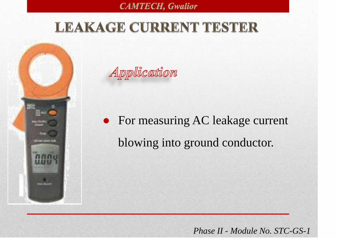
Phase II - Module No. STC-GS-1
● For measuring AC leakage current
blowing into ground conductor.

Phase II - Module No. STC-GS-1
Conductor size 30mm. max. (approx.)
Battery Type Two 1.5V SUM-3
Display 3¼ LCD with 40 segment bargraph
Range Selection Manual
Overload Indication OL
Power Consumption 15mA (approx.)
Dimensions 210 (H) x 72(w) x 36(D) mm
Weight 210 gm (battery included)
Technical Specifications
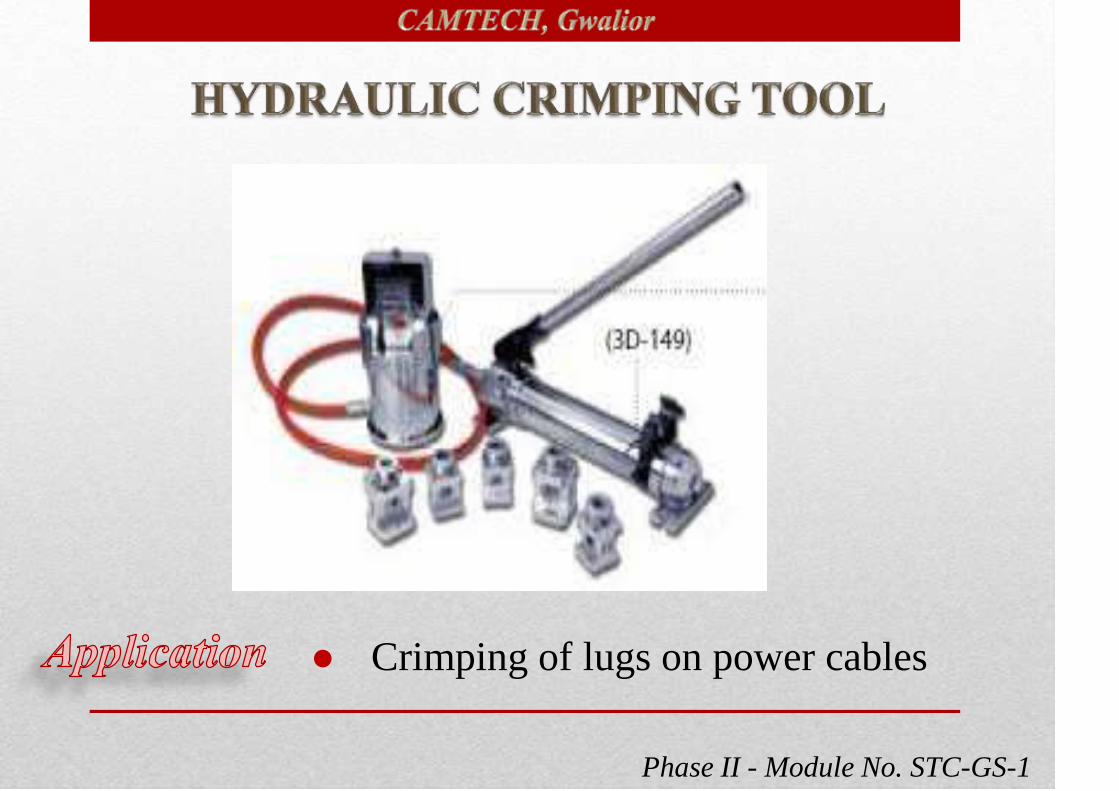
Phase II - Module No. STC-GS-1
● Crimping of lugs on power cables
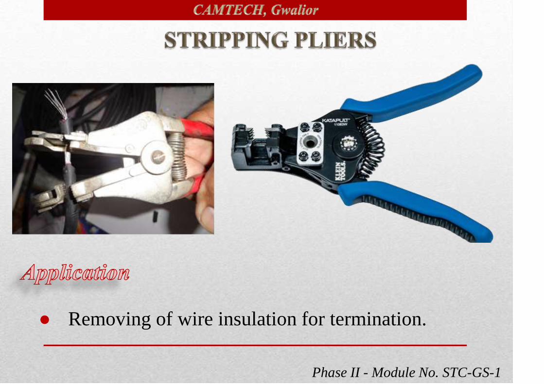
Phase II - Module No. STC-GS-1
● Removing of wire insulation for termination.
Phase II - Module No. STC-GS-1
Strips wire up to 7/8" or 4mm2
Automatic feature holds jaws open to remove wire
without crushing ends. Practically eliminates all
nicking, cutting, or fraying. Strips teflon, silicon and
PVC wire. Made of aluminium with plastic molded
handles.

Phase II - Module No. STC-GS-1
● Cutting of cables, wires (solid / stranded)
upto 10mm2 length 160mm approx.
● Cut round cable and wire cutter to multi
- conductor cable Up to 10 mm2

Phase II - Module No. STC-GS-1

Phase II - Module No. STC-GS-1

Phase II - Module No. STC-GS-1

Phase II - Module No. STC-GS-1

Phase II - Module No. STC-GS-1

Phase II - Module No. STC-GS-1
● Cutting work of sheet metal, nut/bolts, iron angles,
pipes etc.

Phase II - Module No. STC-GS-1
Saw in wood 130 MM
Saw in steel 20 MM
Power input 600 W
No load stroke rate 2600 stroke/min.
Saw stroke length 28 MM
Weight 3.1 Kg.
Technical Specifications

Phase II - Module No. STC-GS-1
● For grinding, sanding, rust removing etc.

Phase II - Module No. STC-GS-1
GRINDING POINTS MAX. 25 MM DIA
NO LOAD SPEED 27000 RPM
POWER INPUT 500 W
TOOL HOLDER COLLET-CAP MAX.8 MM DIA
SPINDLE COLLER
DIA43 MM
WEIGHT 1.3 KGS.
Technical Specifications

Phase II - Module No. STC-GS-1
● For bending copper tubes used in air conditioning.

Phase II - Module No. STC-GS-1
● Calibrated angle marking from 10° to 180° for left,
right or offset bends. Made of tie cast alloy .
● 3/8", 5/8", 7/8".

Phase II - Module No. STC-GS-1
● Checking of alignment of foundations of pumps,
transformers, DG sets etc. and other applications
which require accurate level.
Phase II - Module No. STC-GS-1
Length 600mm
Measuring Accuracy at 0/ 90 max. 0, 05
Measuring Accuracy at 1to 89 max. 0, 2
Battery 9V DC6 LR 61
Technical Specifications

Phase II - Module No. STC-GS-1
● To cut copper tubes used
in air-conditioning.
●1/8" to 7/8"
● Larger knob for greater torque, harden flare
grooved roller

Phase II - Module No. STC-GS-1
● For measuring the temperature and
relative humidity.

Phase II - Module No. STC-GS-1
● Simultaneous readout of °C or °F (switchable) and %
RH. Minimum/ Maximum memory functions for both
temperature and humidity
Range 30 to 90% RH, 0-50 °C Temp.
Resolution 1% RH, 0.1°F or °C

Phase II - Module No. STC-GS-1
● For squeezing the copper tube used in
air-conditioning.
● Product based on IS: 10372
● 1/4"

Phase II - Module No. STC-GS-1
● Removal of solder joint
● Rugged, manual loading tool for
volume de-soldering. High vacuum
heavy-duty plastic, fully enclosed
shaft for safety. Plunger locks for
compact storage.

Phase II - Module No. STC-GS-1
● For making flare shape for copper pipes used in
air-conditioning.

Phase II - Module No. STC-GS-1
Length In mm Cutting Edge in mm
150 16
200 25
250 30
300 32
● Octagonal Chiesel made from high grade steel,
forged and ground. Differential heat treatment for
cutting edge and striking end to ensure long life.
Phase II - Module No. STC-GS-1
Length In mm Cutting Edge in mm
150 25
200 25
250 25
Half round file Bastard 300
Half round file Smooth 200
Half round file Smooth 300
Round file Bastard 200
Round file Bastard 250
Round file Smooth 150
Round file Smooth 250

Phase II - Module No. STC-GS-1

Phase II - Module No. STC-GS-1
● Conforming to IS 4003-1978 (Part-I), Heavy
duty housing with integral I-beam handle
made of SG Iron for maximum strength.
Suitably proportioned handle for comfortable
grip (powder coated).
Size mm Capacity mm
250 35
300 44
350 48
450 60
600 76

Phase II - Module No. STC-GS-1
● High Grade Chrome Vanadium Steel. As
per IS 6131-1980 & 7381-1986
● Bi-hexagonal & Hexagonal One Set

Phase II - Module No. STC-GS-1
Product Item Sockets (mm)
22 Sockets10,11,12,13,14,15,16,17,18,19,21,22,23,24,2
6,27,28,29,30,32,33,34
5 AccessoriesExtension bar 125mm,255mm, Universal
joint T Handle , Ratchet Handle

Phase II - Module No. STC-GS-1
Length in mm
105
205

Phase II - Module No. STC-GS-1
● Khadi cloth
● Dusting work,panel,
window glass etc
cleaning work.

Phase II - Module No. STC-GS-1
Automatic self- adjusting small spanner having functional capacity
A/F 6 mm to 22 mm or SAE A/F 1/4" to 7/8"
Alloy steel duly hardened jaw, nylon 6 moulded upon steel strip &
insulated up to -1000 volts and stainless steel rivet.

Phase II - Module No. STC-GS-1
● Spanner multi-wrench (ratchet type) -16 effective sizes in one
wrench having functional capacity A/F 10,12,16,17,19 mm &
BS 1/4", 4/16, 3/8", 7/16", 1/2" 1/2".
● Alloy steel duly hardened jaw; nylon 6 moulded on steel strip
handle.

Phase II - Module No. STC-GS-1
● Multi-wrench/ Spanner ( 22 sizes of METRIC and SAE in
two wrenches) having functional capacity A/F MM
5,7,8,10,12,13 & MM 14,15,17,18,21.
● Alloy steel duly hardened jaw; nylon 6 moulded on steel strip
handle

Phase II - Module No. STC-GS-1
● Ratchet wrench- ratchet type spanner (12 sizes of MM & 5
sizes of SAE in three wrenches). The three spanners cover
12 sizes in MM – 8,10,11,12,13,15,16,17,18,19,21,22.
● Alloy steel duly hardened.
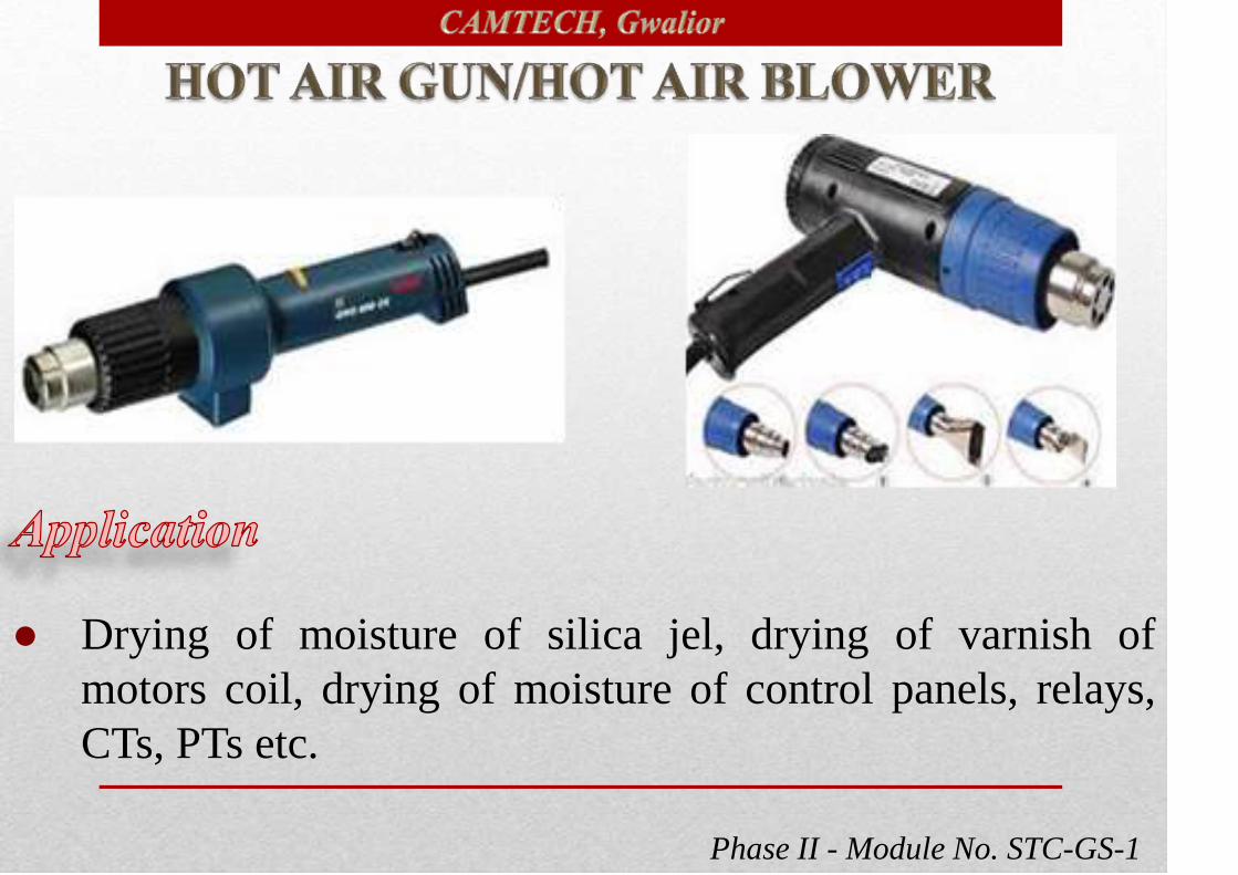
Phase II - Module No. STC-GS-1
● Drying of moisture of silica jel, drying of varnish of
motors coil, drying of moisture of control panels, relays,
CTs, PTs etc.

Phase II - Module No. STC-GS-1
RATED POWER CONSUMPTION 2000 W
TEMPERATURE RANGE 100-6000 C
AIR FLOW RATE 350-550 LIT/MIN
STEPLESS TEMP. CONTROL YES
AIRFLOW REGULATION 2 STAGE
WEIGHT 0.7 KGS.
Technical Specifications

Phase II - Module No. STC-GS-1
● To measure the air flow velocity of
blowers.

Phase II - Module No. STC-GS-1
Range Resolution Accuracy
Air Flow 80 - 4000 ft/min.
0.4 - 20 m/sec
1
0.01 m/s
+/- 3% FS
+/- 3% FS
Battery Life 100 Hours
Display Size 37mm x 42mm
Display Type LCD
Temp. -10°C to 50° C
+14°F to 122°F
0.1
0.1
+/- 1.0°C
+/- 2.0 °F
Range
Max. Reading 9999
Fan Diameter 70mm ( 2 7/8")
Technical Specifications

Phase II - Module No. STC-GS-1

Phase II - Module No. STC-GS-1

Phase II - Module No. STC-GS-1
● For grinding welding spots/
joints back gouging, sanding
and rust removing.
Grinding & cutting discs 100 MM DIA
Rubber packing pad 100 MM DIA
Cup brushes 60 MM DIA
No load speed 11000 RPM
Power input 670 W
Weight 1.4 Kgs.

Phase II - Module No. STC-GS-1
Item Parameter
No-load Speed 0-350r/min,0-1350r/min
Keyless Chuck 0.8~10 mm
Max Troque 30 N.m
Battery: Lithium-ion 12V~1400Amh
Charger 60mins fast charger
Technical Specifications

Phase II - Module No. STC-GS-1
Type: Electronic screwdriver
• Dimensions: 27X21X7 cm
• Material: PVC & metal
• A cordless screwdriver that includes
4 bits, slotted 4.5 mm
• Helps illuminate dark work areas
• Features LED battery level indicator
• Charging time : 3 to 5 hours, one full
charge will last 20 minutes

Phase II - Module No. STC-GS-1

Phase II - Module No. STC-GS-1
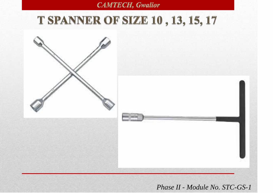
Phase II - Module No. STC-GS-1

Phase II - Module No. STC-GS-1

Phase II - Module No. STC-GS-1
Phase II - Module No. STC-GS-1

Phase II - Module No. STC-GS-1
Floor mounted 4.5 kW AC
test drive complete set for
alternator and regulator
testing.
Floor mounted 25 kW AC test
drive complete set with
regenerative load testing for
alternator and regulator testing.

Phase II - Module No. STC-GS-1
1kW portable motor drive set for
testing alternator and regulator.
Power supply analyzer,
oscilloscope dual
channel, storage type

Phase II - Module No. STC-GS-1
Surge comparison tester for testing windings of motor
Test benches for testing OVP
relays & contactors with
contacts testing with chart .

Phase II - Module No. STC-GS-1
Alternator pulley gap
checking facility Filler
guage.
Alternator pulley
adjusting guage
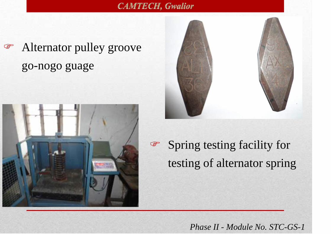
Phase II - Module No. STC-GS-1
Alternator pulley groove
go-nogo guage
Spring testing facility for
testing of alternator spring

Phase II - Module No. STC-GS-1
‘V’ belt pre stretching machine (Grading machine)

Phase II - Module No. STC-GS-1
S.No. Item Reference IS
1.
Open end Spanner
(Single & Double ended open jaw
spanners)
IS 2028 – 2004 (Rev.V)
2. Ring spanners IS 2029 (Rev.IV)- 1998
3.Combination wrenches with equal
openingsIS 6389 – 1998 (Rev. II)

Phase II - Module No. STC-GS-1
S.No. Item Reference IS
4.Ring slugging wrenches
(Spanner)IS 4509 – 1992 (Rev. I)
5.Open ended slugging wrenches
(Spanners)
IS 4508 – 1992 (Rev.I)
with amendment 2 – Jan. 2003
6.Single ended open jaw
adjustable wrenchesIS 6149 - 1971
7.
Insulated pliers, pincers and
nippers – Technical supply
conditions
IS 2615 – 1989 (Rev.2)
8.Combination side cutting pliers
- specificationIS 3650 1981 (Rev.2)
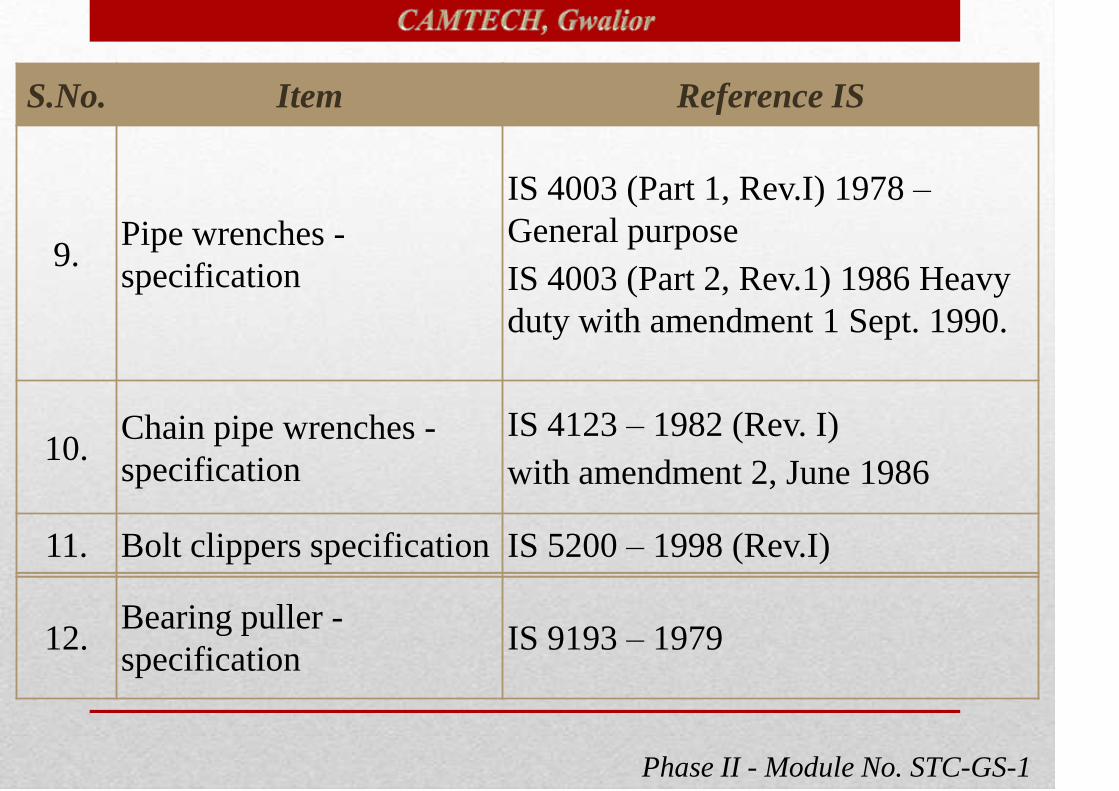
Phase II - Module No. STC-GS-1
S.No. Item Reference IS
9.Pipe wrenches -
specification
IS 4003 (Part 1, Rev.I) 1978 –
General purpose
IS 4003 (Part 2, Rev.1) 1986 Heavy
duty with amendment 1 Sept. 1990.
10.Chain pipe wrenches -
specification
IS 4123 – 1982 (Rev. I)
with amendment 2, June 1986
11. Bolt clippers specification IS 5200 – 1998 (Rev.I)
12.Bearing puller -
specificationIS 9193 – 1979

Phase II - Module No. STC-GS-1
S.No. Item Reference IS
13.Steel hammers –
Specification
IS 841 – 1983 (Rev.2)
Amendment no.1 – July 1984
Amendment no.2 – Jan 1987
14.Screw drivers –
Specification
IS 844 (Part I, Rev.I) – 1972 – Technical supply
condition
IS 844 (Part II, Rev.I) – 1972 – Dimensions
IS 844 (Part II, Rev.2) – 1979 - Dimensions, –
Reaffirmed – 1984.
IS 844 (Rev.I) Part III -1974- Dimensions for
Screw drivers for recessed head screws.

Phase II - Module No. STC-GS-1

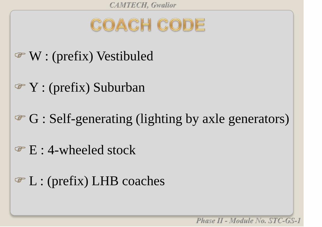
W : (prefix) Vestibuled
Y : (prefix) Suburban
G : Self-generating (lighting by axle generators)
E : 4-wheeled stock
L : (prefix) LHB coaches

F : First Class
S : Second Class
M : Military

CN : 3-tier sleeper coach
CW : 2-tier sleeper coach
CZ : Chair car
CD : Dining Car
CB : Pantry/kitchen car/buffet car
CL : Kitchen car
CR : State saloon

CT : Tourist car (first class) (includes
bathrooms, kitchen, and sitting and
sleeping compartments)
CTS : Tourist car (second class) (includes
bathrooms, kitchen, and sitting and
sleeping compartments)
C : (except as above) With Coupe
D : Double-decker

Y : (not as prefix) With Ladies'
compartment (usually 6-berth
compartment with locking door)
AC : Air-conditioned

GS - Second class self-generating.
SLR - IInd Class with Brake & Luggage.
GLR - IInd Class with Brake.
DSLR - Disabled IInd Class with Brake &
Luggage.

WGSCN : IInd Class 3-tier Sleeper Vestibuled .
FACC : Air conditioning Coach with First
Class with coupe.
WGFSCWAC : First A.C. cum Second A.C.
WGACCW : Air conditioning Two tier Sleeper
(Vestibuled).
WGACCN : Air conditioning Three tier Sleeper
(Vestibuled).
WSCZAC : Air conditioning II-nd Class Chair Car.

VP : Bogie Parcel Van.
EVP : Four wheeler Parcel Van.
WLLRMEN : Luggage & Brake with Generator.
ER : Inspection Carriage.
RA : Officer Saloon.
RH : Bogie Medical Van.

LGS = Second class self-generating
LSCN = Second class 3-tier sleeper
LWACCW = AC2 tier sleeping Car (52 berths)
LWACCN = AC3 tier sleeping car (72 berths)
LWCBAC = Air-conditioned pantry/kitchen/buffet car
LWFAC = AC1 Air-conditioned first class

LWFCZAC = AC Executive chair car (56 seats)
LWLRRM = Luggage/generator/brake van
LWSCZAC = Air-conditioned chair car (78 seats)
LWSCZ = Non AC Chair car

The basic requirements for rail transportation
system are:
Railway track,
Signalling and telecommunications,
Rolling stock which contains locomotives, coaches
and wagons,
Maintenance and operating personnel of these assets.

Railway track and signals are fixed assets and these are
must for running of trains irrespective of the number
of trains run.
The rolling stock and crew requirement are based on
quantum of traffic to be handled.
Careful planning is required in acquisition and
utilisation of the coaches, especially the A.C. coaches,
since they are costly assets.
Minimum turn-round time will increase the number of
trips & more earning.

To ensure optimum utilisation of coaches with
minimum lie-over period at destination.
Availability of coach for trip.
Schedule inspection on due date so that the same is
maintained in good fettle for reliable service.
Rake links indicate the sequence in which coaches
have to operate.

Rake links give all the information about the movement of
coaches at a glance and can be used as a ready reckoner by
operating staff.
To achieve maximum utilisation of the rakes.
Rake-links are prepared in such a manner that the coaches
are kept on run for the maximum number of hours each
day.
Minimum detention at the terminal stations.
Ideal rake-link is one in which lie-over of coaches at
destination is minimum, utilisation (km earning per coach
per day) is maximum.
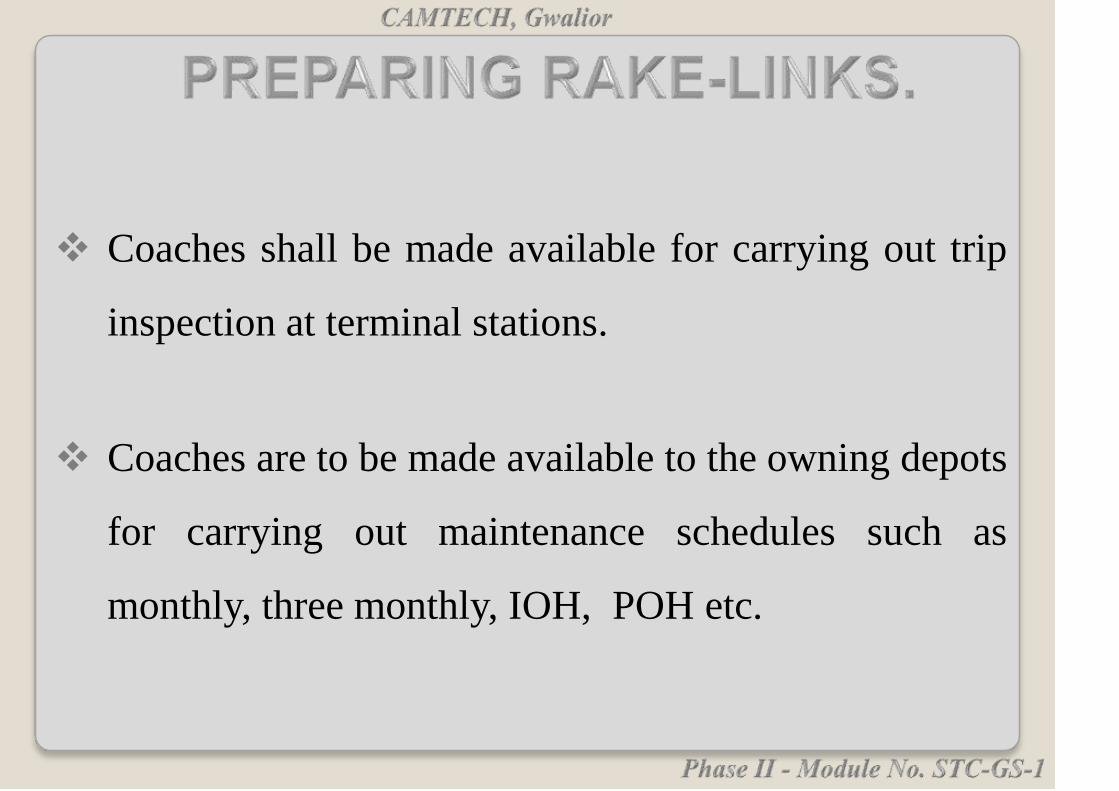
Coaches shall be made available for carrying out trip
inspection at terminal stations.
Coaches are to be made available to the owning depots
for carrying out maintenance schedules such as
monthly, three monthly, IOH, POH etc.
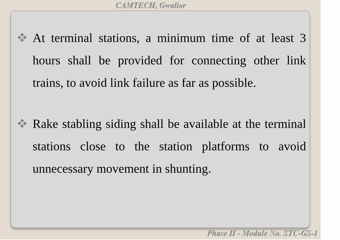
At terminal stations, a minimum time of at least 3
hours shall be provided for connecting other link
trains, to avoid link failure as far as possible.
Rake stabling siding shall be available at the terminal
stations close to the station platforms to avoid
unnecessary movement in shunting.