
ELRS_SPEC_SPM_0002 Rev_4 170718.pdf - RDSO
86
l--p"ge r or ?TI{f, TT{q'_R iG Tildq GOVERNMENT OF INDIA MINISTRY OF RAILWAYS SPECIFICATION FOR MICROPROCESSOR BASED ELECTRONIC SPEED CUM ENERGY MONITORING SYSTEM F'OR ELECTRIC LOCOMOTIVES spEcrFrcArroNsf;"r""i?1#.?3/spM/ooo2(REv.4) Approved by Signature PEDSE tu 7a.7.19 fuq"d frtqnm-q sqqena Grfqf,fl eil-q qr;ro rrqd{ qt{f,ilT(, dEI;lS - 226011 trLtrCTRICAL DITtrCTORATE RESEARCH DESIGNS AND STANDARDS ORGANISATION MANAK NAGAR, LUCKNOW _ 22607I Prepared by Checked by Issued bv w SSE/Svstem '\-i*9 sstr/ svsrem '*="ill- BnsBEEEil,s
-
Upload
khangminh22 -
Category
Documents
-
view
0 -
download
0
Transcript of ELRS_SPEC_SPM_0002 Rev_4 170718.pdf - RDSO
l--p"ge r or
?TI{f, TT{q'_R
iG Tildq
GOVERNMENT OF INDIAMINISTRY OF RAILWAYS
SPECIFICATION FOR
MICROPROCESSOR BASED ELECTRONIC SPEED CUM
ENERGY MONITORING SYSTEM
F'OR
ELECTRIC LOCOMOTIVES
spEcrFrcArroNsf;"r""i?1#.?3/spM/ooo2(REv.4)
Approved by Signature
PEDSE tu7a.7.19
fuq"d frtqnm-qsqqena Grfqf,fl eil-q qr;ro rrqd{
qt{f,ilT(, dEI;lS - 226011
trLtrCTRICAL DITtrCTORATERESEARCH DESIGNS AND STANDARDS ORGANISATION
MANAK NAGAR, LUCKNOW _ 22607I
Prepared by Checked by Issued bvwSSE/Svstem
'\-i*9sstr/ svsrem
'*="ill-BnsBEEEil,s
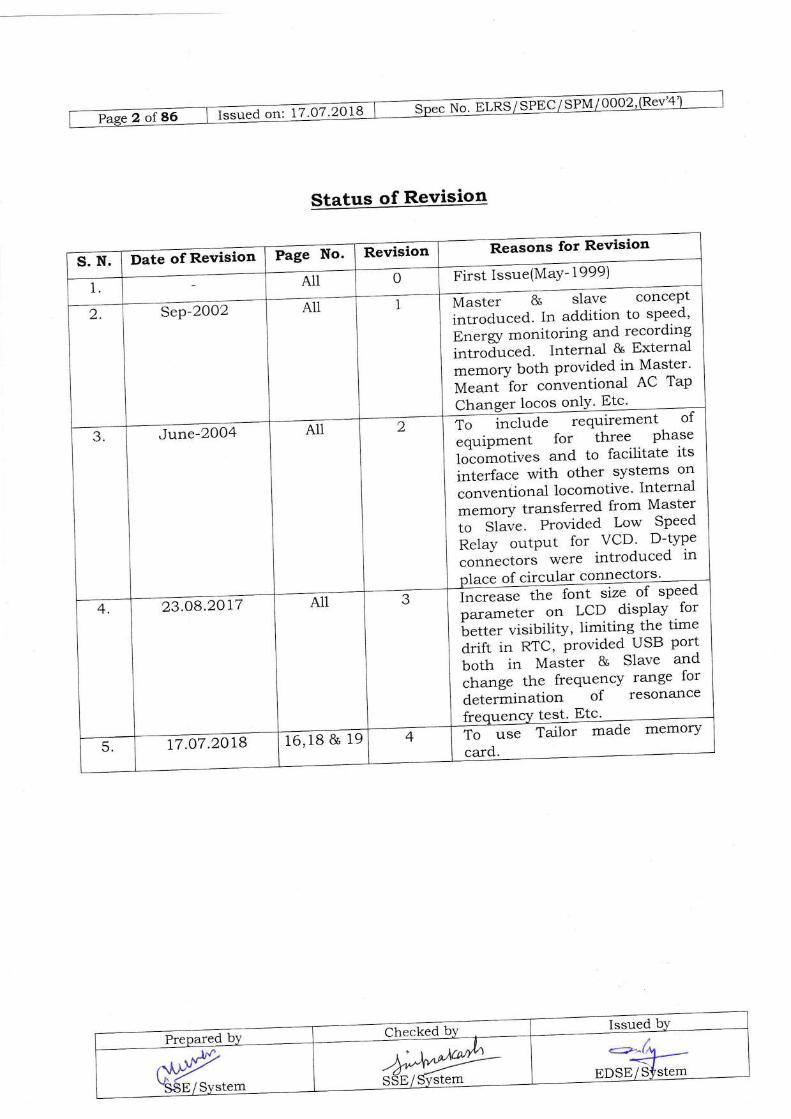
Status of Revision
Pi^t f -""qMaY- 1999)
Changer locos onlY' Etc'
nr""t". g slave concept
lrliroar."d. In addition to sPeed'
err.tg, monitoring and recording
introf,uc"d. Internal & External
memory both Provided in Master'
Meant for conventional AC TaP
T, t""l,rd. t"qa-em"tt of
.quip*"nt for- th:tt, . tlt::i"l"ir.,i"es and to facilitate itsinterface with other sYstems on
.o.,r".rtlona1 locomotive' Internalmemory transferred from Master
i"- Sf"".' Provid'ed Low SPeed
Relay outPut for VCD' D-tYPe
connectors were introduced in
.ce of circular connectors'
June-2004
ffif speed
p*.-"r.. on lCD . dt*1,'"'-,|::
fli,". visibilitv, limiting the time
drift in RTC, Provided USB Portboth in Master & Slave and
.tr.trg. the frequency range for
determination of resonance
23.O8.2017
to -r*e: tdto. made memory
card.16,18 & 1977.07.2018

CONTENTS
SL NO. DESCRIPTION PAGE NO
1. GENERAL 4-92. TECHNICAL SPtrCIFICATION 10-34J. SCOPE OF SUPPLY 35
4. CLIMATIC & ENVIORNMENTAL CONDITION 36-375. iNSPECTION 3B
6, TBSTS 39-487. TEST CERTIFICATES & MARKINGS 49
B. ORDtrRING INFORMATION 50
9. PIN ALLOCATION DETAILS 51 - 54
10. CONNECTION DIAGRAM 55- 56
11. REPORTING FORMAT FOR PRINTING 57 -6612. SURGE TEST WAVEFORM DETAILS 67
13. SCHEMATIC DIAGRAM 6B
14. SUMMARY OFAPPLICABILITY
ACCESSORIES AND THEIR69 72
15. DRAWINGS 73-86
Prepared b_v Checked by Issued by
M9@-SSE/Svstem ffi,,t*r
gYS'SE/System

N".trL@@ts
1.O
1.1
t.2
1.3
CHAPTER 1
GENERAL
SCOPE & OBJECT:
ThisspecificationCoversrequirementsofMlcRoPRocEssoRBASEDELECTRONTc spppp RECORDIN;;-^INDICAJITG ao BNpncv MONITORING
sysTEM for application on converli""rl A.c. Tap changer Locomotives and
spEED RECoRDir.rC- w6H ixnrciiixc sysTEM REQ"UIRED oN THREE
'HASE LoCoMoTIVE (Eners, M"J;;lrg sv"1.," a'lreadv provid'ed through Loco
Microprocessor C""t'i t" Tilee Phase Locomotives)'
ThespecificationCoversbasicfeaturesofequipments.Itistheresponsibilityofthe manufacturerfsupptigr !o #fr,;
-Ji..iritla"t-f design to meet the
requirements of this specttlcatlon'
DEFINITIONS:
Forthepurposeofthisspecification,thefollowingdefinitionsshallapply:
1.3.1 Tenderer /Supplier/ Manufacturer
The Firm/company wh-o submits the offer for supply 9f MicrSgrocessor based
Electronic Speed Recording, i#;;i;; and Energr Monitoring system'
1.3.2 Purchaser
Indian RailwaYs
1.3.3 RDSO
ResearchDesignsan{-Qtandardsorganizatton,MinistryofRailway,ManakN.g*, Lucknow - 226011
1.3.4 InsPecting Officer
Apersonnominatedbythepurchaser'.toinspecttheequipmentonhisbeha-1fortherepres;;i;ii;;"rttretns!;;*'sof{icersonominated'
1.3.5 Contractor
AnyFirmorCompany'.,jhwhomtheorderforsupplyoftheequipmenthasbeen placeJor intendi to be placed'
1.3.6 Master
nr/4-BPsFvJtem

5 of 86 | Issued on: 17 .07 .2018 No. ELRS/ SPtrC/ SPM/ 0002,(Rev'4
Recorder cum Indicator Unit, which will record the journey data.
1.3.7 Slave
Indicator unit, which shall follow the Master.
1.3.8 Signal Conditioning Unit (SCU)
Equipment to convert CT/PT output to lowmicroprocessor.
1.3.9 Speed Sensor
voltage signal that can be fed to
Fulse generating unit mounted on Locomotive axle to generate the pulses perrevolution of Loco Wheel.
1.3.10 SENSCON
32 Shell 14 Pin circular connector that shall be used to connect Speed Sensorunit to MASTER Unit.
L.4 CONTRACTOR'SRESPONSIBILITY:
The contractor's responsibility will extend to the following:
L.4.L Supply of detailed instruction for insta-llation of the equipment on thelocomotive. For this purpose the supplier sha1l also depute his representativeduring instaliation of the first two equipments in the locomotive at each location(CLW/Shed/WorkshoP).
L.4.2 Commissioning, testing & field tria-ls of the prototype equipment in service. Thesupplier shall arrange to carry out detailed test & field trial jointly with RDSO'
1.4.3 The supplier shal1 supply suitable software for eva-luation of data downloadedfrom the systern.
L.4.4 The design shall be developed as per requirement given in this specification. The
detailed design shall be submitted to RDSO for scrutiny and approval beforecommencing of the manufacturing. Here "approval" means the "approvaL ofdesign features" only. The suppliers sha,Ll be responsible for performance ofcomplete system.
1.4.5 MODIFICATIONS
The supplier shatl be responsible for carrying out all the modifications at hisown cost on any part of the equipment during the period of warranty requiredfor satisfactory operation of the equipment as per technical specification. For
Prepared by Checked by. Issued by
'.ar\YCV'SSE/System
4'4'@'SStr / Svstem
nur'lu^1T!-*lrs
EDStr/ Sl'stem
G*u.a =-o"'.
IZrq72O.Y1
anytechnicalmatterthefinalauthorityis-ofRDSO.Modification,ifanyrequired o.r-irr.
*ur"i* of -the experience .gr,;;i' a'ring the
. field trials of
prototype "ori;;;, shal1 t""i"."Ip*:o by^iit" suppliers wi-thout any extra
cost. Such ,ir"iir*",ion shall a"'irlarz"d in consuitation with RDSO'
I.4.6 INSTALLATION INSTRUCTIONS:
lnstallationinstructionshallbeprovidedinacceptableforrne.g.instruction^card.Theseinstructionssha-llincludethemethodofinterco-nnection'typeolcable and grade of cable, ;;;;* .""i"t#JJ LJ *r'"trter the cable is
screened. Tf,e maximum "uf" tru',"mitter *p#a'-"r'Jibe indicated' Details of
any special precaution t'"t"""try sha1l also be stated'
I.4.7 INSTRUCTION MANUAL:
The manufact ttrer f supplier sha]l supply . sufficient tor.',t.-* of instruction
manual. This shalt inctude" "rJ;. J"Jt'rliitn and operating' maintenance'
calibration and card Trouble shooting tuJlt'J' List of spares with part no'/
tech, specification "1,,1| also i" i.,.t,a"a N,*?9, olqol"*:be supplied shal1
be 10% of the number .f "q;;;;;;;;J"t'"d, subject to a minimum of 2 copres
Per order'
1.4.8 TRAINING OF INDIAN RAILWAYS PERSONNEL:
Thesuppliershallalrangeforfreeofcost!1alfnsl"1i1iT.R1r1u,'ay,spersonneiin operation, maint".,T?" ";;;;t*
lnstallatiot'Jco"'*issioning' Maintenance^
and trouble shooting of th^e "i*i"--i"tt'dl"g^iat" Jo*t'ro"ding & eva-luation ol
Data through Evaluation Software'
1.5 PROVEN DESIGN AND TECHNICAL COLABORATION:
The system offered sha1l be of proven^design. T1r..,"'nl1l"t sha1l furnish
documeniary evidence "r ilL*g-*'o3r"9"t"7"J similar system/sub-system
".r.".""fffi rn case "f-"ff";;;;;t
]o,"ig" b;;;"; thev must indicate the plan
for inaigeni'sation in . pfr-"""i **rr", an-d must enclose a copy of MOU with an
Indian fi; ;; R"*t'-vt Bank of lndia's clearance'
L.6 INFRINGEMENT OF PATENT RIGHTES:
Ind'ianRailwaysshalln.otberesponsib]eforinfringementofpatentrightsarising due to similarity i. a."ig", 'mrrrufacturing process,. use of components'
used in d.esign, a"r"top*Ji,^-..a *.";;;i;;"*g J Microorocessor based
Electronic Speed "r- e.r..-g, Monitoring sy*i.* i.o "]
other factors which
may cause such ai"prt"li?.'";;^*;;;i;iil-f to settle anv issue lies with the
manufacturer'
L.7 DOCUMENTATION:

Is"u"d o.,, 17.07)018 No.ELRSzS@
The tenderer must submit the following information with the offer in printedf:?#i:::Xfi:[piled in a uoorur"t ri.- -oii".'i-*,
incomplete inrormation
a) Deta,ed specification of the offered purse Generator, majorequipments like CT, pT, Master rrJ SfaVB
b) Details of semiconductor devices used, their specification and datasheet.
c) Mechanical drawings of co.mnr9t9 system w-ith details of dimensions,mounting arrangement and weight Jfrufi6. provided.
d) System description, Block circuit Diagram, deta,s of majorcomponents/ equipments, circuit descriptiin, working principre andsalient features' The details of -i..op.o..""o. / micro controllerused, functionar bl0ck description, ircg" used, control systemhierarchy, protocol used for inteifacing
e) Mou (Memorandum of und.erstanding) with the coilaborator,wherever applicable.
QAM (Quality assurance martual)
Test protocol with procedure including schematic of test set up oftesting.
h) Latest ISO 9001 certification.
{)
s)
i) Details of infrastructure, manufacturing and testing activities in linewith guidelines issued vide RDSO spec no. _ ELRS/spEC/sI/0015'Reliability of Electronics used in Roiling stock ippiifrtio.r.,,1.8 RAILWAYS' RESPONSIBILITY:
Railway will be responsible for followings:
1'8'1 The cabiing required in locomotive i. e. for connecting cr and pr in Tapchanger Locomotive and from SENSCON to MASTER for Three phaseLocomotive.
1'8'2 The cabie -fot :g"lecting potential free contacts to microprocessor basedElectronic Speed Indicatin"g & Recordi"g u"ii *i,i"t"".;*;:;"li"ring sysrem.1'8'3
f3'#lJ"H;Ti3;".?.and electrical eners, required for erection, testing &
1'8'4 The wages and allowa-nces as well as the cost of the travel to and from the place

rfi.a ""; tfPUqf-q
1.9
of training for railway personnel'
REFERENCE TO VARIOUS SPECIFICATIONS:
Assistance has-been t'k"l-1':i::I?lt'".-l:5.iil:""ffi1iona1' British and Indian
stance has Deerr LiaKLrr is specification.A;;il;if,cation in formation of thstan
DescriPtionAmendmentNo. & Year -
MonthSPec. no
BS-3403
IS:3202
Year &Month
Soecification tor lncllud'Lrr16
Ii.r,o-.."t and sPeedometer
=;;;;" for industrial'ri^rr.,,^.,o ,r"rd marine use.
i990
[\ar-IIwqJ u *'- --: --- --- of e
1 (1eeO) Code of Practlce lol u,r'qLv
itr"n"g '- fo' electrical
^^,'ihffcnt
-.
1965
-Current Trartslormer6pecification Part 2 :
Measuring Currentt964 2"d Rev. 199 z
IS 2705(Patt 2)
I rafVoltage 'I'rartstoru
1965 2"d Rev. l9vzIS 3156(Part 1) Soeci{ication I'arr z
" ,t--^ ^. , *l - - \/n1ta se TransformellVIeaSLrlrrrE,,' "^"*o-: - ----:-;;f
Rules for electrofllc cqurY--^^r ^n.oi1 rrehicles
-tpc,oosz
I
IEC77Rules for electronrc^ --,i.^mant
968-U r e9ulPr^,""'' ; :_^.I^-^+-.1Identification caros - lrrLClir auvu
.i..""t"f cards with contact -.-r^-.^i ^^1 ^L aracteristics'
1987-O7ISO: 7816 -1
-ISO: ?816 - 2
IJtIyDtL@ vl'* -- -
; j:-IM' ^+adldentification caros - rrrLtrBraLvu
.it."trt*l cards urith contacts -i*,-^-\l' - dimensions andr - ^^r.i^-c ^f fhe contaCtS
1988-12
l0Uir-Lrurro v' -'^- - -
il;;iiliio,' "'d* - integrated
;l;;;it cards with contact' Part
iii --"r...ronic signals and
, ---^ ^*,i-ainn nrotOCOl.
rqsg - oq 2, \1994- r',z)isoTtoc -78)-6 - 3
lriiJlsrrrroo'"'- t^ - -
I"formatL"n technoloS'
1dr";ti;;iion cards - integrated
;;il cards with contact. Part
iv i",". industry commands for
1995-09ISO/lEC-7816-+
1II LUI urrarrbr .
N""rU"ttU sYstem and
resistration Procedure for" r: ^^.l^- iAenlifler.
lEC 7816-5 994 1 (1ee6)
ttc - zsto-o
applluiaLrvrr rs"^-"^:-- -----------
Identification caros - lrrLUlir auvu
circuit(s) cards with contacts -1996
-=',rfihn-PnsB/IvsJem
c9lllEli:::'::---- ^ -
Issued on; iini 2otl No.Blns/S@
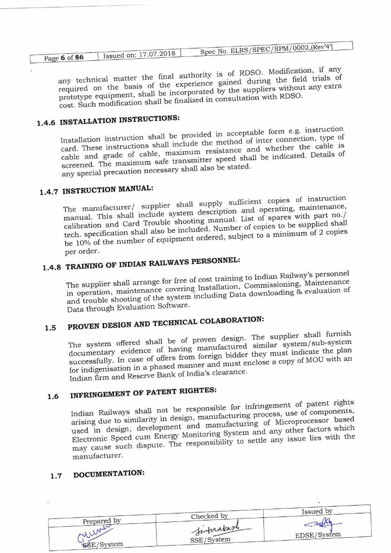
Part VI inter Gdu.rrl, d.rt,elements.rEC/TR3 61000_1_1 Electromagrr.ti. compaUUrtity(EMC) Part I general iection iapplication & interpretation offundamental definition andterms
rEC-61000-4_6 Testing and measurementtechniques - Section VI,immunity to conductdisturbance, induced by radio
Specification for speedor.rete.ald odometer system for road
ELRS/SPEC/Sr/001s Reliability of Electronics usedin rolling stock

G"""a orl 17.O72W
CHAPTER 2
2.1 BASIC DESIGN AND CONSTRUCTION:
The construction sha1l be mechanically robust so as to assure permanence in all
mechanical, electrical, "r"",.o[i."li -.gnetic adjustments when used in
accordanc. *';h ;;uiacturer's recommendations'
The equipment being a safety item sha-11 be designed for high degree of reliability'
2.2 The system sha-ll be capabie of indicating and recording in both (forward and
reverse) ai'"Jtitt-of travel of the Locomotive'
2.S|nviewoflimitedSpaceavailableintheLocomotive,theequipmentshallbe-'- J."ig.red as compact as possible'
2.4 INPUT/ OUTPUT TO SPEED CUM ENERGY MONITORING SYSTEM:
2.4.I INPUT
f'--rn-grtterY/Batterycharger of locomotive'110 v(DC)
(Variation from7OY to t25
P-6="0-"tta ''a 1
termina-l of Mail
Transformer
41sfs8o- v Ac(variation 29O Y loAC InPu
for EneMonitoring Ri.rg TYPe
provided a]terminal oiTransformer
OHn currentthrough CT
CABi of Locomotive'
FYoffiF-and GRo
Terminals at SB ir1-NCI f"rSrnamicBraking1 No: for Coasting
ffi-m-om outPut of SCU'1 No: for Voltagefunction1 No: for Current
AnalogInputs-2 Nos.
REMARKLEVELSN
T
z
SIGNAL TO
DC PowerSupplY
Recorder/IndicatorunitSCU
3 DigitalInputs- 3 Nos.(Minimum)
Recorderunit
Recorderunit
4

2.4.2 OUTPUT:
Relay Outputs5 nos.
(Minimum)
Recorder 1 No. for the Live sign of thespeedometer.
2 Nos (Doubte Throw type) - one forthe 105 % of the maximum speed andother for ll} % of the maximumspeed.
1 I\o for vigilance control device cutout at low speed i.e. below 2 Kmph.
1 No spare.
Spare Ports for tapping Speed SrdA fo.other Systems i.e. TCAS/TPWS
2.5 EQUIPMENTDESCRTPTTON:
2.5.L SPEED SENSOR:
opto - Electronic Speed Sensor shall be used to generate pulses with numbersdirectly proportional to distance covered and fiequency proportional to thespeed of locomotive.
Two such sensors with hot redundancy will be provided for high reliability. Thesystem shall be so designed that changeover from faulty "p.Ja sensor to goodone shall be done automatically and an Error shall be iogged in Error"Log
Memory to indicate failure of one sensor.
The Speed Sensor shall be designed so as to prevent the ingress of water, dustetc. and lubricalt from axle box. It shall withstand Weatler proof Test andWater Tightness Test as per Clause 6.5 and 6.6.
The size of Pulse Generator used as speed sensor shall be as per CLW,s DrgNo. CLW/ES/SK-6/SpM.
2.5,2 RECORDER.CUM-INDICATOR:
The Speed cum Energr Recorder cum Indicator is the intelligent unit calledMASTER. It is a composite unit consisting of Record.. rrrj Indicator Unitmounted in the CAB of Locomotive. Recorde.lfral have central control of the
Prepared by Checked by Issued byc\y-SBE/system
,h4'@SSE/ System
--'-^6)5'-rtr6+ltsEDSE/Svstem
Remarks

t="--=_=_==-,"a orr'. tz rz?l]q
equipmentconsistingofmicropro-Cessor'1.:"dCPUandaportableflashmemory .*J & FLASH EtrPROt{ based tnternal Memory to record the data
listed in Ctause 2'9 and'power supply card'
Itshallprovideanalogindicationforspeedwith?igltalDisplayforIndication oi e.r!.5, and otherop*.*.,.. as listl',J in clause 2'7 'L'LO'
2.5.9 INDICATOR:
AnlndicatorUnit(SLAVEIconnectedtoMASTERforrepeatingitsdisplayshallbe provideiir'iir"'otfr", Cai'"i r.".o,,,oti""' I;;;i f'""t *Jogue tvpe Speed
lndication having Digital Di";; f* ite':lt:"f oi et"t5' and other parameter
as listed in Clarise 2.,.L,d"rria f'r,nSff EEfirOM bas6d lnternal Memory for
recording ti'"-iJ"t""y Jata listed in Clause 2'9'
2.5.4 VOLTAGE & CURRENT SENSORS:
ForprocessingtheenerSlrelatedparameter:,s,VoltagesignalCorrespondingto22.5 kVOUp i,oftage shall ;;"kJ t o* +rSVlgSOV"'""Ji*v winding of main
transformer using duat voit;;"-;;""ti,r r"i"rtrmer 1+t-s7sso: 110) and
current signal can be taken ,"i?,g a ring typ" .;;;;nt Transformer (300: 5) from
PrimarY of main translormer'
RatingofPTandCTs.lra]lbe10VAwrthaccuracyclass0.5asperIS3156(Part2): 1992"'i fS* ZZOS(Part 2): t992 respectively'
2.5.5 SIGNAL CONDITIONING UNIT (SCU):
ThisshalldothefunctionofconvertingVoltageandCurrentsigna-ltakenfromdual voltage potentia f.ut"=forrn". "'t[ ti"g ?"o" Current Translormer to low
voltage signal that can o" i"a to uittoftoti="ot of Recorder for EnerSr
monitoring'
2.5.6 CONNECTOR FOR COUPLING:
MasterUnitShallbeconnectedtoSpe.eclsensor(PulseGenerator)throughcircular connector prorla.i^-t-t"ir" "ta of Pulse Generator to ensure modularity
and easy replacement-oilitner pulse generator or Master itself' connector
provided r,ilir" "..a oi e*r=rc"r..'..,ot "r'"riu"*-i+
pin 32 shell female Sichem
Connector (SENSCONI oilfi"a make o"i5i-ft" ma1e counterpart of this
"o.r,,"tto' "ftJfUt of Eibow type and Allied make only'
SENSCON(maleElbowtype)shallbesuppliedloosealongwithcabies.
A suitable support plate as per clw's Drg No. clw/ES/s-[-5/sPM/0002(Rev2)
sha-1l be provided by the LLufacturer to 'io'nt SENSCON below locomotrve
under frame'
.:-Lr\*EDSE/SYStem
14^
E

2.5.7 CONNECTING CABLES WITH CONNECTORS:
The connecting cables shall be provided with protective sheaths towithstand arduous service conditions and electrical noises and shallend with polxized connectors to eliminate chances of inadvertentwrong connections. Sufficient length of cable connecting variousequipments shall be supplied. In case of electric locomotives thedistance between two cabs, where equipments may be mounted is ofthe order of 20 meters (Approx).
supplier will submit a wiring diagram a]ong with his offer. cables,which are covered in scope of suppiy, shall be indicated with lugs. Thetentative block/schematic diagram of the system is shown in Annexurexv.
Terminals for Railway cables shall be of M5 standards.
All the cables used sha1l be Multi core copper cables having conductorcross section 0.5 mm2, P|FE insulated, FRLS jacketed along withshielding. To ensure maximum noise immunity of the transmittedsignal, only screened cable shall be used. The braid should have anoptical coverage of > 807o.
Master and Slave Units will employ D - Type connector. 50 Pin (Male)connector provided for Master and Slave and 9 Pin (Female)connector provided for Master shall be of MIL Grade only and ofeither ITT Cannon/Aliied/Tyco or Essen make. Allconnectors/contacts provided should be Solderable/Crimped.
On the back side of Master and Slave Cable Fixing Clamps shall beprovided to hold cable for 50 Pin and 9 Pin connectors.
vi) Pin Allocation details for D type connectors to be used is enclosed inAnnexure L
2.5.8 JUNCTION BOX:
A Junction Box conforming to CLW's drawing no. CLW/ES/SK-7/SPM IOOO2(Rev. 2) sha1l be provided in the Machine Room (behind TK- 1 Panel where SCUis mounted) of Conventional Electric Locomotive and in CAB 2 of Three PhaseElectric Locomotive to tap speed signal coming from SENSCON for sharing thesarne with TCAS/TPWS. Cable carrying speed signal from SENSCON coming toMaster (RCI) unit sha,ll be terminated into the Junction Box. From this junctionbox further cable connection to Master (RCI) unit and TCAS/TPWS will betaken. In order to avoid overloading of pulse generator due to TCAS/TPWS aswell as to protect the PG in case of fault occurring in the TCAS/TPWS interfacea fuse of suitable rating sha-ll be provided inside Junction Box before tappingpoint of the speed signal to TCAS/TPWS to protect the pulse generator.
ii)
iii)
irr)
v)
Prepared by Checked by Issued by
cryYstr/svstem
,r:A^*gYSSE/Svstem ,;ffi=#H,r
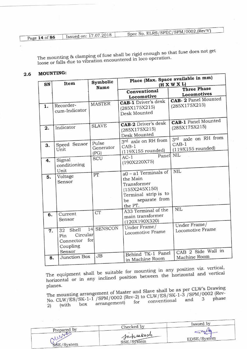
MOUNTING:le in mm)
Place (Max. SPaclHXwxL)
-ilPan"ttvtounted(28sx17sx21s)ileg-l Drrt=r's cicsk
(2Bsx175X21s)Desk Mounted
EesJFe;i Mou"t"a(285X175X21s)
CAB2 Drt"er's desk(285X17sx215)Desk Mounted
3ta-3ra1g on RH from
119X155 rou3ta ur.1e on RH from
119X155 roundAc- 1 I',ane
lr9OX22OX7 5\
a0 - a1 Termrna-ls ot
the MainTransformer(1s5X245Xls0)Termina.l striP is tobe seParate from
VoltageSensor
eS3 Termt"al of themain transformer120x190x32 ilna.r Frasrcl
Locomotive Frameilt-d.t P.tm./Locomotive FramegZ Snen 1
Pin Ci-rculConnectorCouplingSensor eABZ-tdt wall in
eeh,"a-TK- 1 Panelin Machine Room
2.6
Themounting&clamping.offusll]ra]lberigidenoughsothatfusedoesnotgetlooseorfallsaueto-vit'.Iiot'encounteredinlocooperatron'
Theequipmentshallbesuitableformountingin.anvpositloflvlz.horizonta-1 or in any inciinta po*itio;';;;;" |ne iirtzontal and
planes. ^r rrr,^
ThemountingarrangementofMasterandSlave_-"L{lbeasperCLW,sDrawrngN o c,.w / ES / sK- r-i"7r'roo I oooz B;";)-t;Er-w I n9) ir<- r - s / sPM / 0002 (Rev-
2) (with bo"' 'f;;;..ti -"
r"i conventional and 3 phase
vertical,vertical
-_",fyEDSE/SYstem
Issued on: 17.07 .2OlB No. trLRS/ SPEC/ SpM/ 0OO2
locomotive' In conventional locos mounting of these boxes will be done onmounting table with the help of 4 screws urrl i., the case of 5 phase locomotivemounting shall be done by riveting these boxes on cable cover assembly atcentre pillar of locomotive.'lhe nr-"""upprvi"g smaller size of Master and Slavewill provide adopter plate to match the Master and slave box as per abovedrawings.
In existing AC Tap Changer Locomotives already in field, the mountingarrangement sharl be pro'ided as per cLW,s D.g xo:cLW/trs/SHED/spM I ooo2 1Revzl to ensure interchangeability.
For interchangeability of PT and cr the mounting dimensions and terminalposition sequence should be sarne and it will 6. as p.. - cLw's Drg no.cLw lESlsK-2/spM and cLW/ES/sK-3/spM to suit M5 studs.
For signal *conditioning Box ]lounling holes and terminal positions shall be asper CLW's Drg no. CLW/ES/SK_4/SpilI.
Summar5r of accessories and their- applicability in AC Tap Changer Locomotiveald Three Phase Locomotive for Micioprocessor based ^Electronic
Speed cumEnergz Monitoring System is given in An'nexure XVI.
2.7 TECHNICAL DETAILS
2.7.L INDICATING SYSTEM:
2.7.1.lThe Recorder cum Indicator (MASTER) and Indicator (SLAVE) shallcontinuou s1y indicate :
i. speed in Kmph, continuously in analog form with graduations of 2.0Kmph.
ii. ReaJ time, continuously in hrs, minutes and seconds on digital disptay.
iii. Cumulati'n e Energz in KWH continuously on digltal display.
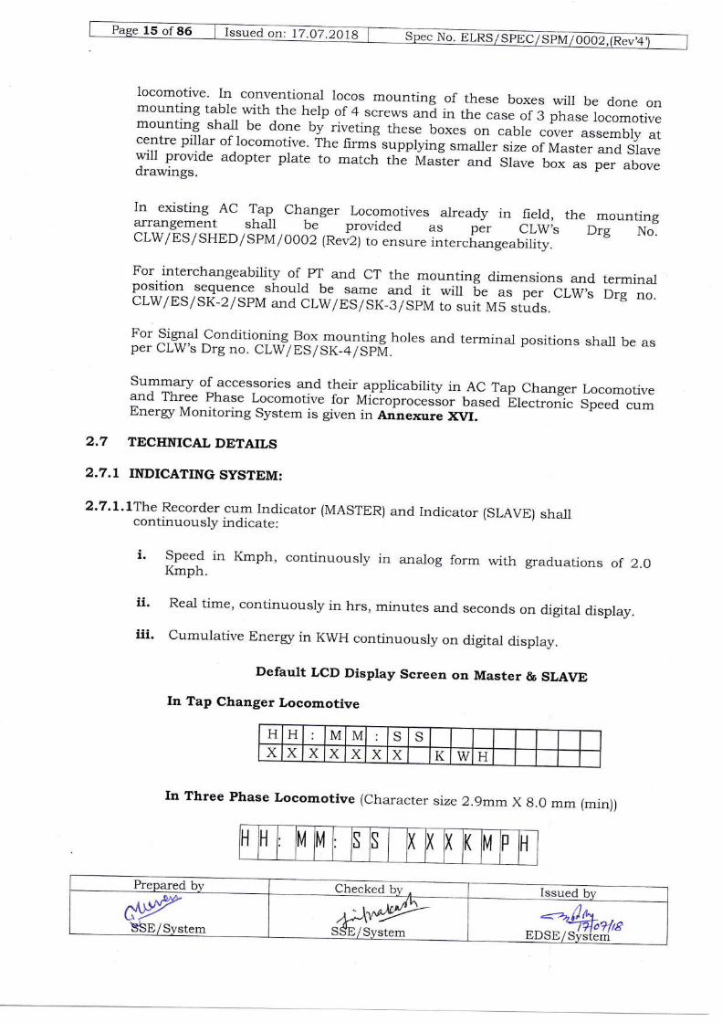
Default LCD Display Screen on Master & SLAVE
In Tap Changer Locomotive
In Three Phase Locomotive (character size 2.9m.,-x B.o mm (min))
H H M M S SX x x X X X X K w H
H H M M S S I ( ( K [4 DH
N".E
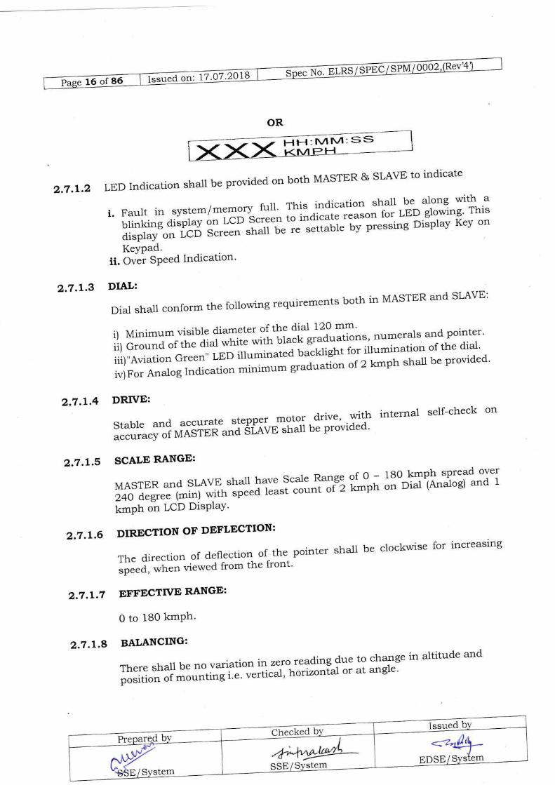
OR
2.7.L.2
2.7.1.3
LEDlndicationshallbeprovidedonbothMASTER&SLAVEtoindicate
i.Faultinsystem/memoryfuil.ThisindicationshallbealongwithablinkingdisplayonLCDgtl:":toindicatereasonforLEDglowing'Thisdisplay on lcB s;.;; sha1l be r" "".t.ut"
by presslng Display Key on
KeYPad.ii. Over SPeed Indication'
DIAL:
Dial sha_1l conform the following requirements both in MASTER and sLAvE:
i) Minimum visible d'iameter of the dial 120 mm'
ii) Ground or ilrJa]J;;ii" *itr, uia.k graduationsl-numerals and pointer'
iii),,Aviation Green" LED illumi.r.,"Jt.".klight for illumination of the dial'
iv)For Analog Indication minimum;;;"; n of 2 kmph shall be provided'
2.7.L.4 DRTVE:
Stablearrdaccuratesteppermoto-l.d.rive,withinternalself-checkon,"""""fr :; 1CIGiilil"'"J"StiiE shall be provided'
2.7.L.5 SCALE RANGE:
MASTERandSLAVEsha-ilhaveScaleRangeofO_lB0kmphspreadover240 degree (min) *rtn "f,..J
t"u.", count #) it*pn on Dial (Analog) and 1
kmPh on LCD DisPIaY'
2.7.L.6 DIRECTION OF DEFLECTION:
The direction of defl-ection of the pointer shal1 be clockwise for increasing
*Ptta, *f'"n viewed from the front'
2.7.I.7 EFFECTIVE RANGE:
0 to 180 kmPh'
2.7.L.8 BALANCING:
Thereshallbenovariationinzeroteadtngduetochangeinaltitudeandpo"iti#'o"i'i""tl,,gi't:;il;'r"horizontaloratangle'
SStr
Hl-{: IVlIM- SS

2.7.L.9 REAL TIME CLOCK:
A Clock Chip sha1l be provided to maintain the time base in the system. Theoperating temperature of RTC chip shall be in the range of 0 oC to 70 0C withtemperature compensation circuit. The maximum permissible drift in timesetting shall be up to + l-2 minlyear. Alternatively, a GPS receiver modulemay be provided to set the time automatically.
2.7.L.10 PARAMETERS TO BE DISPLAYED:
The equipment (MASTER & SLAVE) sha1l display following parameters on a16X2 LCD Screen by pressing Display Key on Keypad except speed whichshall be displayed with character size as 2.9mrn X 8.0 mm(min.).
a. SPEED AND RELATED FUNCTIONS:
i) Speed in kmph.ii) Over Speed Limit Settingiii) Distance traveled in Km. (Odometer)ir) Distance Traveled by Present Driver in Km.v) Distance coasted by Present Driver in Km(up to two decima-l
points)vi) Coasting Duration by Present Driver. (HH : MM : SS)vii) Dynamic brakes Duration (HH : MM : SS)viii) Wheel diameter settingix) Real time in HH:MM:SS in 24 hours scalex) Date in DD: MM: YYxi) Memory Status (used %)xii) System Faultsxiii) Driver IDxirr) Train No.xv) Train loadxvi) Loco number.
b. ENERGY FUNCTIONS:
i) Energr consumed during run.ii) Energu consumed during ha1t.iii) Tota-l Energz consumed.iv) OHE voltage.v) OHE current.vi) Power Factor
2.7.2 RECORDING SYSTEM:
The recording system shall consist of:
Prepared by Checked by I Issued by
-=-ilh"tf,7+/rsEDSE/Svd{em'
n{Dd'".1S$E/System h^4r4>SSb/Svstem

Gil"d on.t7.9J29]8'
2.7 .2.L INTERNAL MEMORY:
AnlnternalFLASHEEPROMmemoryofsufficientcapacitytocontainthefollowingsub-memo.i"".t.t.,''ul."*oryshallbeprovidedinbothMasterand Slave'
a.SHoRTTERMMEMoRY:Tostorethemostrecentdataoftheminimumlast 3 hours of travel ;;i"dj"g loco halt time, in loop (circular) form' in
respectofparamet.....,tio.'""di.,Clause2.gwithresolutionofonesecond.
b.FAULTANDCoNFIGURATIoNSMEMoRIES:Torecordtheequipmentstatus and interna r""ltr-i., toop ro.--*J contain customer specific
configuration param.t.r" io be used for processing the stored data'
2.7 .2.2 EXTERNAL MEMORY:
ThememorycardshallwithstandtemperatureuptoT00Candshallbeaccessible to only authorized person' The external memorv card sha-ll be
procured from OEMs or auth irized' dealer ;'i"OEM" oniy' The firmware of
system shall be able to read & write on Memory card of capacity upto 64GB'
Supplierwillensurethe",,it,t,itl.yorspa'e,,,"-o,ycardsforaperiodofl0Y"*" from the date of suPPlY'
TheMemorycardsha]lhavesufficientcapacitytocontainthefollowingsub-memories:
a.sHoRTTERMMEMoRY:Aminimum3hoursSHORT.TERMmemory with resoiution of one second as in the Internal Memory'
b.LoNGTERMMEMoRIES:Tostorethemostrecentdataofthelastg0 days of halt *J*r, or 62,000kms of distance travelled, in loop
form, with resolution of 30 ""J'd* in respect of parameters
mentioned in Clause 2'9'c.FAULTANDcoNT.IcuRATIoNsMEMORIES:Asinthelnterna]
Memory.
2.7.2.gTo avoid the problems of not recording of_data, formatting of card etc' in case
of changing the external ;.-;t.*i* from one system to another system'
followin! ft"a.t"t" shalt be provided'
i)WhenacardistakenoutfromanEsMoNandprovidedbackinthesalne ESMON or-oiif'" same make ESMON' the iystem shall not ask
foranyformattingetc.butsha-llcontinuetorecordthefuturedatainloop form.
ii)lfrecord,erSeesnewmemorycard.thesystemshouldpromptforusing of memory card but shouli-"o, format the card immediately'
The system "irlff--!*t tt'o'gft ti*" (60 seconds) to disable thg
formatting. Memory card stralr fe formatted only aJter lapse of
specified time.
cbeg_1.e$-!YD-o-arcd hvTssued bv
<4+-EDSE/SY*emw"-sSElJy$g*

iii) Situations of 'card not available', 'Defective card' and 'data being notrecording on card' shall be treated as faulty state and LED indicitionalong with display on LCD shall be provided.
2.8 TRANSFERRING THE JOURNEY DATA:
Normally, the data stored in the portable memory card shall be transferred tothe PC through Memory Card Reader Unit. The transfer of data from InternalMemory sha-ll be only in exceptional cases when the portable memory has beendamaged/ lost or cannot be salvaged.The data from the portable memory card shall be down loaded when itsreserved capacity (85%) is used up, to prevent the recorded data being overwritten. To down load the data the portable memory card shall be removed fromthe locked cassette compartment of Master unit and inserted into the "MemoryCard Reader" interfaced with PC equipped with evaluation software. After thedata is down loaded, the memory card sha-ll be erased for reuse. The memoryreader shall be so designed that it does not require to be disconnected from thePC for normal use of the printer. It sha-Il be possible to download the data ofSHORT TERM MEMORY/LONG TERM MEMORY with suitable commands.The Master and Slave units shall be separately equipped with USB host port fordirect downloading of data to USB Mass Storage Devices from External orInternal Memory as the case may be. This should be possible by executingcertain commands from the Keypad and LCD display of Master and Slave units.User should be able to select either short term or long term data or both ofexternal memory ald short term data of internal memory as the case may be.The user interface protocol for Data Downloading is given in Clause 2.16.9(d).The provision shall be made for retaining the data in the memory of Systemeven after downloading to USB Mass Storage Device.USB host port under lock & key arrangement shall be provided both in recorderand indicator.
2.9 PARAMETERS TO BE RECORDED:
The equipment; Recorder cum Indicator (Master) Unit shal1 continuously record.the following parameters in the memory (both Internal and External):
a. SPEED AND RELATED PARAMETERS:
i) Speed in km/h.ii) over speed \Mith rime and Duration (Driver wise/Train wise)iii) Distance traveled in Km. (Odometer)
Prepared by Checked bv A Issued by#SSE/System
,\.r\*.!9'SSd/ Svstem
o.ltrlohrrcEDSE/Svstbm'

I="r"d o., 17.O7.2018
iv) Distance coasted in Km' (up to two decima-l points')
v) Coasting Duration (HH : MM :-SS)
vi) Real timle in HH:MM:SS in 24 hours scale
vii) Date in DD: MM: YY'
viiil Oynamic brakes duration (HH : MM : SS)
ix) SYstem Faultx) Train loadxi) Driver IDxii) Train No'xiii) Loco numberxiv) Events like Memory Fteeze' Power ON/OFF
b. ENERGY PARAMETERS:
i) Energz consumed during run 1.n fwlii) EnerSr consumed il;iG halt in lnvh(In Long Term Memory only)
ilil Total Energz consumedi r) Specific Bnerry Consumption (Driver Wise/Train Wise)
v) Average OHE voltage ln t<V' (Up to one decimal points')
vi) Average OHE current in amP'
vii) Po*er"Fattor(In Long Term Memory Only)
z.LO REPORTING FORMAT:
2.lo.lPrinting of data of long-term and short-term memories sha-l1 be in continuous
printing f"r;;l;instea[ of screen-by-screen printing, to cut down printing time'
Normalty, the disptay ,ra prirrli,,*t J1," sha11 be Jlectable and shall print out
events like violation of p..-;;;;;ined speed, voltage, starts, stops and speed
data between specified time or distance intervals. se'iection mode may either be
one or a combination of 2 or 3 conditions'
2.LO.zThe printing/plotting of the d'ata of short-term memory shall be in detail' with
resolution of one second i" ;i;;J ";-rrr"tog
(grapfricai) format, as desired'
a:Theanalog(graphical)plottingofthedatashailbepossibleinfollowingconfigurations:
Checked bY lssued b)'
,r'-'zrJh.BPsEls:s{S!q--
Pr"pary4!Y-g*SE/SYstem
second for qk slt lgrm me
desired constant
iir*-irr"t"*rt=, the smallest intervals being
;;" as sampling rate of recording i'e' 1
(i) Speed Vs time atconstant time interval
e smallest
ir,.*J of distance will be as per sampling Iate'(rr) Sp."a Vs Distance
constant timePlotting of enerSz '
i;,;;J-, t6ii1 n.r".5, Vs Time

) Energz Vs DistancePlotting of energz data at desired constaltdistance interva-ls, the smallest intervalof distqnce wili be as per sampling rate.
It shall also be possible to have above analog (graphical) print outs for desiredtime or distance intervars, on enlarged/amplif# ".'d., ro.^u.ltliil,1,
Parameters on "X" and "y" axis shali be clearly marked on the GraphicalPrintouts with Major gridlines whatever the .asi be i... 1 second in case ofShort Term Recording Printouts and 30 seconds in case of Long Term RecordingPrintouts.(For more details see formats enclosed)
b: The Tabular plotting of the data shall be possible in following configurations:
(i) Driver wiseConsumption &Brake Data
Specific EnerryCoasting/Dynamic
(iii) Specific Energz Consumption &Coasting/ Dynamic Brake Data fordesired Time Period
19"^:1*are shall also provide for printing of the data in the following selectiveIOrmats:
1. Only the page desired to be viewed.2. Continuous print out of all pages.3. Between desired time/distance intervals.4- Data above/or below an specified speed threshord.5. Data for a particular driver/train number.
Iot Reporting formats see Annexure enclosed. In case of Three phaseLocomotive Reporting Formats sha,rl be same excruding Energr parameters,Coasting and Dynamic Brake Data.
Note:1' The information like File Name, Starting Date, and Ending Date etc.shall be printed on only first page.2' T..e summary of data shall be pii.,t.d on rast page only.3. In case print out is of one page, both,, 1,,and,,2,,sha_[ be printed onsatne page.
2.1! MEMORY FREEZE:
A memory freeze facility shall be provided to allow the locomotive to be moved
Prepared by Checked hv Issued by#S:SE/System
4;".W-SSb/S1'stem
(ii) Specific Energr Consumption &Coasting /Dynamic Brake Data fordesired Distance

No,@02'(Rev'4@t_s
afteranincident,w.ithoutoverwritingthedatastoredduringlast3hoursoftravel. A Memory Freeze swit;L
"rru]l ior*ally be provided to freeze short term
memory recording unaffectin;il9 il;,r"""iatg tt'er long term memory' The
switch for freeztng the a^t, =frrtit".lrrrd"t " :-"-Jiq glass t:::1o" the MASTER
unit. The giass "trdt u" broken, when req-uired, f; operating the switch' An
LtrD indication with messrg. - LCD displ"y;;; ,,,",,,ory freeze shall also be
Provided'
2.L2 MEMORY FULL INDICATION:
AmessageonLCDdisplayshallbeprovided.ontheMASTERtogiveadvancewarning f.r;;;; loading if..'a"i" ftom portabit^tt*oty card when 85% of the
memorycapacityhas-beenutrlized.Amemo,yfullmessageshallalsoberecorded inbrroi Log Memory only once'
Under this condition display shal1 be as given below:-
2.L3 OVER SPEED ALARM:
provision sha11 be made to give audio-visual warning- af nreset over speed
setting. The over speed.".ttin!*stJt Ut Aot'" ifttot'jf' f,tyboutd but the 105%
and 110% of speed setting shJuld be programm"d u."* a percentage value of the
over sPeed setting'
It should not be possible for the locomotive crew to interfere vr'ith this setting'
2.L4 PERIOD OF MEASUREMENT:
The average speed of locomotive is the ratio of the d'istance travelled to the time
required t" .J*, that distance. Thus, determining the average speed involves
measuring of a distan.. ,rrJI tl-. p..ioa. irr. ?r,orter the time period' the
closer i= tnl average speed to the instantan-"" =p""d' .with a view to have
average speed indicated ,." *Jl ," ,..o.a"a '..v tro"" 1o instantaneous speed'
measuring time period shall b"e oirrt. order of 0.4 seconds or less'
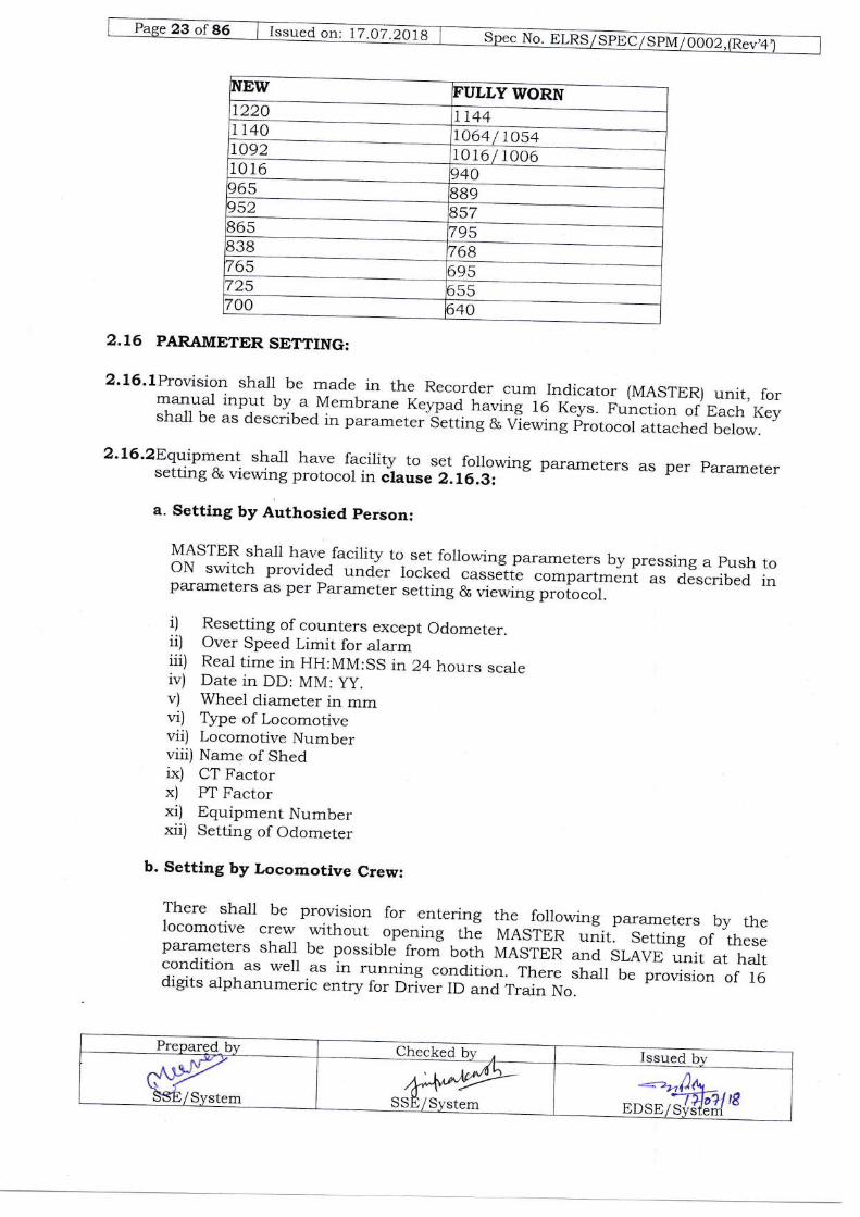
2.LS WHEEL WEAR ADJUSTMENT:
Wheelwearadjustmentbetweenthenewandfullywornwheeldiameterinstepof 1 mm shall be provided i1l,rr. H,resTER. T}'Js',sr'a1r not be accessible to the
locomotive crew'
Thewheeldiameters(mm)normallyinuseonthelndianRailwaysare:
OR
i4?a?if
DStr/Sys1-tr
Issued on: 17.OT 2OlB No. ELRS/ SpEc/EFMt oOoz JRev a
1064 I 10541Ot6 / too6
2.16 PARAMETER SETTING:
2'16'lProvision shall be made in the Recorder cum fndicator (MASTER) unit, formanua'l input by a Membrane Keypad having 16 Keys. Function of Each Keyshall be as described in parameter Setting & viewing protocol attached below.
2'16'2Equipment shall have facility to set following parameters as per parametersetting & viewing protocol in clause 2.L6.A: '
a. Setting by Authosied person:
MASTER sha-Il ha'e facility to set following parameters by pressing a push tooN switch provided undlr locked ."""&iL compartment as described inparameters as per parameter setting & viewing protocol.
i) Resetting of counters except Odometer.ii) Over Speed Limit for alarmiii) Real time in HH:MM:SS in 24 hours scaleiv) Date in DD: MM: yy.v) Wheel diameter in mmvi) Type of Locomotivevii) Locomotive Numberviii) Name of Shedix) CT Factorx) PT Factorxi) Equipment Numberxii) Setting of Odometer
b. Setting by Locomotive Crew:
There shall be provision for entering the _following parameters by thelocomotive crew without opening th; MASTER .rrrit. setting of theseparameters shall be possible from both MASTER and SLAVE unit at ha_ltcondition as well as in running condition. There shdl b1 provision of 16digits alphanumeric entry for Driver ID and rrain No.

G-"u"aorr111q7.:10|9
i) Driver IDii) Train Numberiii) Train load'
-j Dial lllumination
2.L6.|PARAMETER SETTING AND VIEWING PROTOCOL:
TheSpeed,Ti.meDistancecumEnerSlRecorderandlndicatorisorovidedwithan anarog iriuminated airr^ poinier*display io indicate. :p":9
in kmph' In
addition . i6 .h*acter " 2 l;;';r.f,iu"iEn'i" pi"tiaed t-o view and set the
pararneter"' ir"^a'i"1t di"pi;; 'lJC-"*Pi"pr^i 5;;; on both MASTER and
SLAVE -nJf U" "* p"t Clause 2'7'1'1 (ffi)'
Incaseanalogdisplayfails,aprovision*",,lP"madeinsuchawavthatabovedefault dispiiy sha1l auto*.,iiutty change i";S#;J"1Cf'*ttter size 2'9mmX
B.0mm)aspr'inTapCh";;;;comot"ivesasgivenbelow:
Thefollowingistheprotoc-91|orv1-:u,lngandsettingthevariousparametersonthe MASTER and ir'ivp Units '"i;;?"yp"at
r1t'a"ta shal1 be viewed or set
with a 16 key -;;;;" [;tp*^f;;;#;10 Alphanumeric Kevs contalnlng
Numeric digrts o j;;;arpr'"utti"a1 Letters A to Z
DistributionoflettersofAlphabetonnumerickeysshallbeasgivenbelow:
'0' KeY shall have Provisionfor "SPace"
'1'KeY shall be as
'2'Key shaLl have letters A' B' C
tr:trm*s*tr=af$ill2 Ei
11 asC ti
lu***'*.:mw.ry'
{1sii!l psr
1l
lL-.-"----* **t'
;iE
'3'Key shall have letters D' E' F
ffi-tvttvl:SS
Issued on: 17.O7.2018 No. ELRS/ SPEC/SpM/OOO2 JRev4
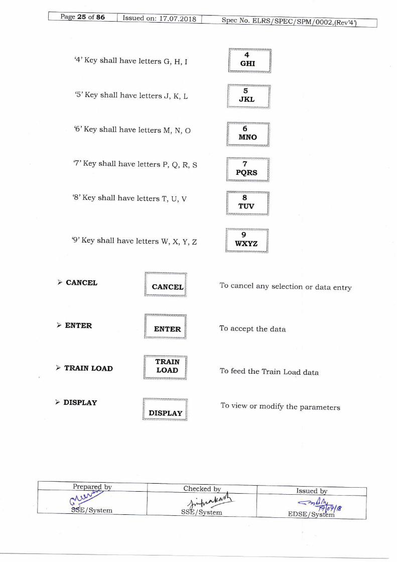
'4'Key shall have letters G, H, I
'5'Key shall have letters J, K, L
'6'Key shall have letters M, N, O
'7'Key shall have letters p, e, R, S
'B'Key shall have letters T, U, V
'9' Key shall have letters W, X, y , Z
> CANCEL
> ENTER
> TRAIN LOAD
> DISPLAY
To calcel any selection or data entry
To accept the data
To feed the Train Load data
To view or modify the parameters

> DRWER ID
> TRAIN NO.
To feed the Driver ID
To feed. the Train Number
On pressing of Key '2'first time Numeric 't*1:^?,:na11
bre entered' On pressing Key
t2t 2ndtime Letter 'A' shali be entered. On pressi";?t; '2' 3td' time Letter 'B' sha1l
be entered. On pressing Key '2' 4li t *e Leiter 'C' shali be entered and on presslng
Key,2,5thtimex,*.,l"dtgil2shallbeenteredagain&abovewillrepeat'
Thesameprocedureforenteringotherlettersshallbefollowedwithotherkeyasstandard.
a. VIEWING OF THE PARAMETERS USING DISPLAY KEY:
ItshallbePossiblefromboth.MASTERandSLAVEUnittoviewparametersusingdisplay r"v *ii"i^i;;;"i-" i';;;"iil^* well as in running condition'
displayed in successron with every p.""I-J the 'DiSPiRVt tt"5',' At this
mode current v.lues "", .r, only te ;. It shall not be possible to
mod'ifv any value t*"tiitf"-Dia1 Iliumination Level'
anY time'
snatiUe made in *rch ,,r^y that preffiPNfBn'Key in-display mode
when that param",", L ;'-p1"y9a .*huil-ft""ze t...,e display to desired
parameter on screen instead of defauit'
b. SETTING OF DIAL ILLUMINATION:
i.e. Loco moving ur at^:lurra stru 5y pr."-"ir-rgihe Numeric Keys 1 to 9'
shal1 be minimum
.--%{\EDSE/SYstlm
10% when key 1 was pressed.
lOoh when key 2 was pressed.
shal1 be maximum loooh.
c. SETTING OF THE PARAMETERS:
There are two kinds of parameters, which can be set by using keypad:
1. Parameters, which are to be entered by Locomotive crew.
2. Paran'eter, which are to be set by Authorised person.
1. PARAMETERS TO BE ENTERED BY LOCOMOTIVE CREW:
A provision shall be made to set parameters given in Clause 2.16.2 b from boththe MASTER & the SLAVE unit in .lr.rrrlg as well as halt condition ofLocomotive.
SETTING OF TRAIN LOAD:
shall be shown on Display.
'ENTER' Key th-e display shall return to default display -mode
afterdisplaying "New Data Recorded,,for 3 seconds.
entered and to retain the earlier stored data. After pressing ,CANCEL,Key,Display shall return to earlier stored data afte; dispr{ring "Data NotRecorded" message for 3 seconds.
There shall also be prorrision fo,. displaying "INVALID VALUE, messagewhenever any wrong entry is made.
SETTING OF DRTVER ID:
@ISSE/System
11.

,ltshallbepossibletoentertheAlphanumericdiverlDbypressing.DRIVER1n; r"y on the KeYPad'
, After pressing 'DRIVER ID'Key existing Driver ID (stored in memory) sha11
be shbwn on DisPlaY'
> The new Driver ID (Alphanumeric) shall be entered using Keypad'
-Pressing.ENTER,Keyshail'doacceptanceofthisentry.Afterpressing'ENTER' t<.v tr'" displav .*Lf,1";#;;';; I"i""rt
displav mode after
displaying "N"*'o"'tt n'""otd"d" for 3 seconds'
Kev a,,d ," ';;J; the "arliet "tl;;'"d;;'
After pressing 'GANCEL' Kev'
Diiplay "frrff 'r?ir-..rr-,o
"*fi".'"*ii.J*i^,t afte; displaying "Data Not
R."o.d"d" message for 3 seconds'
Number bY Pressingiii. SETTING OF TRAIN NUMBER:
> It sha11 be possible to -enter the Alphanumeric Train
"IRAIN NO'']<"V on the KeYPad'
}AfterpressingTRAINNo',KeyexistingTrainno'(storedinmemory)shallbeshown on DisPlaY'
>ThenewTrainNumber(Alphanumeric)shallbeenteredusingkeypad.
iPressing,ENTER,Keyshalldoacceptanceofthisentry.Afterpressing,ENTER,Key the display -frlif i""trr"-io a"tt'tiai"pl"V "'od"
after displaying
"New P^tt fr"torded' for 3 seconds'
>Itshallbepossibletodiscardanynew.dataenteredbypressing.CANCEL,Key and 1o'- retain the eaiier
-"tt."A datl'' ;ft;; pressing 'CANCEL' Key'
Display shail return to .*ii", " -...a aata^^ Jlei disptaying "Data Not
Recordedi message for 3 seconds'
2.PARAMETERSSETTINGBYAUTHoRISEDPERSoN(configurationmode):
(i)TheseparametersshallbeenteredfromMASTERUnitonlywhenLocomotiveisstand,still r.e. speed is 0 kmph. ,r;i;;;;i t'octea-cassette
-compartment is open'
If Locomotive siarts moving, af'r"- J"r" "ntry, 'f i" p'&ttss' sha1l be made to abort
with a -.""u.g" ,,Loco Moving" ";;;;
ni"pr.v ro' us
":;;;"-;d then display sha11
return to default disPlaY'
(ii}Parametersthosewillbesetinthismodeale.giveninClause2.I6,2a.However.some more parameters to be -",;;;;-.aa"aL"-tgitta between Purchaser and
SuPPlier'

(iii) SETTTNG OF PARAMETERS:
shall be reset separately, for which provision sharl ti maae.
Switch shall be provided inside the Lock-ed Cassette compartment ofMASTER.
for 3 seconds the system should autornatically chang.o".r from bisplayMode to Configuration Mode.
Display to indicate readiness of system for configuration.
to be set consecutively.
Key the display shall show the "NEW VALUE BNtBnoo;, and vaLue toconfirm proper entry.
'DISPLAY' Key shall retain the curient setting ..rJ al"ptry the nextparameter.
SETTING OF TYPE OF LOCOMOTIVE:
There shall be provision for selection of rype of Locomotive (Tap changerLoco/Three Phase Loco). when Three Phase Lo"o is selected the parametersrelated to Energr, Dl.namic Brake and coasting should not bedisplayed / recorded / printed.
' As LCD Display shows Type of Locomotive in first line and Earlier Loco typeSetting (Tap changer Locof Three phase Lo.oj-in second rine.' To change the loco type press th.e "cANCEL,,, Key. At this time Type of Loco tobe setected (Tap changeir.oco/Three phase il.;;i "h;il;ii"pj#a.' Pressing "ENTER" key after this display shall change the setting lo desired LocoType.

(iv|Whenallparametersalesetpressing.EMER,keyafterlastparameterwillreturn the system in dispiay ;;; t.; a"i..rrt display. Now ciose the Locked
Cassette ComPartment door'
(v}Thereshallalsobeprovisionfordisplaying"INVALIDVALUE"messagewheneverany wrong entry is made'
lnCaSeauthorizedpersonforget-.topress"ENTER"k.yforexitingfromContrguration Mode, ,. p.o,ri"ion Jfrrff U. -rai t;;t;;;" to default dispiay mode
from Config;t"tiot' Mode automatically' .-r^-^A.r^ra hrr nressins cancel key
Thereshallbeprovisionofd,iscardingthenewentereddatabypressingcancelkey.
d. Data downloading to USB Mass Storage Device:
ThereshallbeprovisionofdownloadingthedataofExternalandlnternalMemorywith the help of suitable .";;;; o.,-r,co dffi;;;{9;+ kev pad as described
below. This ihould be po"*iur"'i" iocomotive halt condition only:
tofiff"u*BMassst-o11?"^?:l:',',-t:"t1?':f ,1;,iJ;,""r:-';::?:tHJu*:"
proceed"'promptingfoiaccept"tg'"T""i;lttgll-l:-downioadingmodesha1lbedisplayedo"i"Cp5t"'"'ofMasterUnitofESMON'
ii). pressing "Enter" t<"y-*rtl start downloading mode' ;hould prompt f
iii).Afterenteringin-todownloadingmode,systemshouldpromptfordownloading from External Memory, a1iJ"i1lt"rnal Memory by displaying
message ,.PreSS 1 f".;;;;",r* z r"i r"*t.I.'J o,.tu' and 3 for both,,.
iv)' Afte r p r" " "in
g th e. appropriate T" ::,5*'"?l rii;It:};'r;trX"'-'ffi:: i;:ao*TrtJaAittg If'" short term and lonp
"Press l for short t"'* & 2 for long teim Data and 3 for both"'
v).Bypressi.,.*.o,,o*iu.."KeyonKeyPad,Correspondingdatashallbed"#i""dta-itt i'ti UdB mu'== storage device'
vi)'lncasetherg.is.losufficientmemoryinUSBMassStorageDevice,the"y"tttshouldit'att]ttiIvii"pr"vi"g;tioEnoughMemory"'vii). After finishing ao*r.ro.i sy9tel "r'o'iJi"Jittr"
to*pletion of download by
d&1;;;;1o o*to' d comPlete"'
In SALVE uniti).WhenUSBMass,.StorageDeviceis.inserted,amessage..PressENTERto
proceed,,, prompting foI accept*.."oi"Lt'*it'g in lo"downloading mode
shallbedisplavediii6"o;;;hvofSlaveUnitofESMON'
*; ",f:[: rur;{e--'ff#:i #fi*'ii us? Yi: s'iorage Device' the
svstemshouldi^di";;;;-ii"pr'vittgliloEt'ottghMemory"'iv1. efter {inishlng aoJoad"system shouid indicate completion of download by
dili;;;; "o5'",,to'd comPlete"'
2.L6.4 LCD DATA DISPLAY FORMAT:
a.ThedetailshowtheaboveparametersshallbedisplayedonLCDDisplayformatisgiven below:
-; z,1iXo, -PoSEi-sYg!dm--
SSE/SYstem

1. OHE Voltage
2. Speed
3. Speed limit for over speed a_larm
4. Current Date
5. Total Distance Travelled(Odometer)
6. Energz Consumed During Run
7. Ener5, Consumed During Halt
8. Energr Consumed by presentdriver
9. Distance Traveled by presentdriver
10. Dynamic Braking ApplicationDuration by present driver
1 1. Distance Coasted by presentdriver
12. Duration of Coasting by presentdriver
13. OHE Current
14. Memory Card capacity status
15. System fauit Indication, if anyoccurred during operation
o H E V o L T A \.I EX X K V
S tlE E D X X ( K M E H
OR
o V E R S P tr E D L I M I TX X K M P H
D A T ED D M M Y Y
K ItrLVl T R A V E L L E D
x X X X K M
E N E R G Y A T R U NX X )a X X x K w H
E N E R G Y A T H A L TX 2! X X x X X K w H
tr N R G Y C o N S U M E DX X x X X X K w H
K M B Y C U R D R I V E RX X X X X x x K M
D B A P P L D U R A T I o NH LI M M S S H o U R S
D I S T A N C E C o A S T E DX X X X x X K M
C o A S T I N G T I M EH H M M S S IJ o U R S
o H E U U R R E N TX X X A M P
M E M C A R D S T A T U SX o/-/o F U L L
X X X X X X X X X X X x X x X XY X X x X x X X X X X X X X
Preparp( by Checked bv Issued by{ySSE/System AA'PP
SSE/System "#,%:tr

Giued on-ry.Q1'29)9
16. Wheel Diameter
17. Driver ID
18. Train No'
19. Train Load
20 Loco No'
b. Parameters to be entered by Driver
1. Driver ID(AlPhanumeric Entry)
2. Train No'
3. Train Load
c. Parameters to be set by authorised
1. Reset Counters
2. Max SPeed for Over SPeed Alarm
3. Current time Setting
4. Current date setting
5. Wheel Diameter Setting
- At halt as well as in running condition:
D R I E R I D
x x x x x X x X x x x x x x x x
T R A I N N o
x x x x x x x x x x x x x X x x
T R A I N L o A D
x x x X x T o N S
DD R I E R I
x x x x x x x x x x x x x x x x
T R A i N N ox x x x X x x x
x x x x x X X x
T R A I N L o A D
T o N Sx x x x X x
person (Shed Staff) - At halt onIY:
N T E R SR E s tr T C o U
T T I N GT I M E S E
SH H M l\ iI S
T T I N UD A T E S E
D D M M Y Y
D A s E T T I N Gw H B E L iX x x x M M
.=.=-,Jrb--*
oosoiilst{m
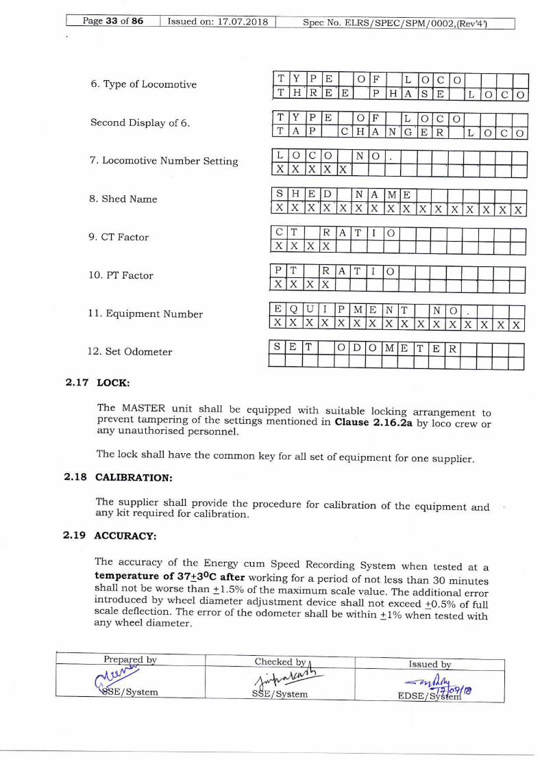
6. Type of Locomotirre
Second Display of 6.
7. Locomotive Number Setting
B. Shed Name
9. CT Factor
10. Pl Factor
1 1. Bquipment Number
12. Set Odometer
2.L7 LOCK:
The MASTER unit shall be equipped with suitable locking arrangement toprevent tampering of the settings mentioned in Clause 2.L6.d,a by lolo crew orany unauthorised personnel.
The lock shall have the common key for all set of equipment for one supplier.
2.18 CALIBRATION:
The supplier shall provide the procedure for calibration of the equipment andany kit required for calibration.
2.I9 ACCURACY:
The accuracy of the trnerry cum Speed Recording System when tested at atemperature of 37+3og after working for a period of not less than 30 minutesshall not be worse than +1 .5o/o of the maximum scaLe value. The additiona,l errorintroduced by wheel diameter adjustment device shall not exceed +O.Soh of fullsca-le deflection. The error of the odometer shall tre within t1% when,.",.a *1,f.any wheel diarneter.
T Y P E o F L o C oT H R E E P H A S E L o C o
T Y P E o F L o C oT A P C H A N G tr R L o C o
L o C o N oX X X X X
S H E D N A M EX x X X X x X X X X X X x X X
C T R A T I oX X X X
P T R A T I oX X X X
E o U I P M tr N T ox ,( X X X X X X X X X X x X X
S E T o D o M E T E R
Prepare-d by Checked by,r Issued by
C:\YqgsE/System ,k4*M5-SSp/System
**-'nf)4'EDStr/s€JTE
C"""4 "* lZ .07 '2018
2.2O INTERFACING EQUIPMENT AND SOFTWARE:
2.2O.L MEMORY CARD READER UNIT:
To facilitate the transfer (downloading) of data from Externa] Memory card to
pC, the tenderer will quote =.p*"itfy'an lnterface unit (Memorv Card Reader
Unit) compatibie with differ.r]i u"i"io.rs of Wi;;;;"; pC' rne plrchaser sha1l
decide the quantity to be supplied'
2.2O.2EVALUATION SOFTWARE TO ANALYSE THE DATA:
Necessarysoftwareford'ataretrieva],analys-rs",,ap".i',jlli,intheabovemanner sha11 be developed;J-"rppti"d uf trr" manufacturer of the Energr
cum Speed Monitoring SystJJ ir',"'"ort*are shall be menu-d'riven and MS
windows XX compatible and shall not require knowledge of any programmlng
tanguage ,rra =frif be suita;."^r;;;perai-ed with minimum computer literacy'
software should be same f";';i;;.sions of ESMON of same make and upward
revision .f;;il;e should retain backward compatibility'
The software sha1l have file management system for retaining the data in the file
narle assigned, by the user. Tle file m,.nagement shall not require any
knowledge of DOS'
2.2o.gPersonal Computer/Laptop with printer:
This shal1 be installed by Indian Railways'
2.2L COLOUR SCHEME:
Thecolouroftheequipmentsshallbeasperls-5Grayasfollows:
Recorder cum Indicator (Master)' Indicator
i;;Gt, Sig.,u'l conditioning Unit and
Junction Box
Speed Sensor (Pulse Generator)
: Shade Code 631
: Shade Code 632
- --/4d)q *trDsElil+!q-

35 of 86 | Issued on'. t7.07.2018 ] Spec No. ELRS/SPtrC/SPM/0002,(Rev'4
CHAPTER 3
SCOPE OF SUPPLY
PART OF THE SYSTEM COI{VENTIONALTAP CHANGERLOCOMOTTVE
3 PHASE ACLOCOMOTTVE
Recorder cum Indicator (MASTER) 1 1
Indicator (SLAVE) 1 1
Speed Sensor Unit 1 1
Junction Box 1 1
Signal Conditioning Unit (SCU) 1
Voltage Sensor (PT) 1
Current Sensor (CT) 1
32 She11 14 Pin Connector
(SENSCON)
1 1
Support Plate for SENSCOI{ 1 1
Cover Assembly 1
Cables 1 Set 1 Set
Memory Card Reader Unit To be indicated by purchaser
Eva-luation Software To be indicated by purchaser
Prepared by Checked byn Issued by
--ila,''-iT[oq{&EDSE/Svdterh
dy€8E/Svstem
M4*SSE / Svstem

No. -Br--nV SPscTBPrt / oooz._^-^^
f "i".a on. 17 .O7 '2O18
CHAPTER 4
4.I TEMPERATURE:
TheMicroprocessorbasedElectronicspeedRecording&IndicatingSystemwillbe fitted i"'i;;;;;tive where the tempeiature will be
a)Maximumtemperature}Stabledl,ocomotiveundersun:700C) On board "otL"'g
loco under Shed : 55 oC
b) Ambient temperature ioperating i3:: I I::3) Storage:
4.2 RELATTVE HUMIDITY:
UPto i00% during rainY season'
4.9 ALTITUDE:
UPto 2500 m above mean sea 1eve1'
4.4 RAINFALL:
Veryhear,yincertainTheequip*..,,tshould.bedesignedinsuchawayas to withitand its runnin* i" ii;;-;;t;i f"tJi"Jloz-*t t5o'" Rail Level'
4.5 ATMOSPHERE DURING HOT WEATHER:
Extremelydustyartddesertterrarnincertainareas.Thedustconcentrationinair may reach a high va-lue of 1'6 mg/cm3'
4.6 COASTAL AREA:
Theequipmentshallbedesignedtl'workincoastalareain^humidityandsaltiaden and corrosive atmi;;i;;; rn" ma-*i;;*";;"s of the some of the
Parameters shall be as follows:
: 8.5.:7 mg /litre.
: 6 rng lbtre.:130 Licro siemens /cm
a) Maximum PH value
bi SulPhateconcentration.j Max' concentration
of chlorined) MaximumconductivitY

4.7 VIBRATION:
The System shall be designed to withstand the vibrations and shock
encountered in service satisfactorily as specified in IEC l2B7 (1995 -07) and
605Z1 (1998 - 02) publication for the Electronic Equipments used on Rail
vehicle and reievant IECs as applicable to other equipment.
4.8 ELECTROMAGNETICPOLLUTION:
High degree of electromagnetic pollution is anticipated in locomotive machine
.oJ-, *-h"r. the equip-"rrt witf be mounted. Necessary precaution should be
taken in this regard.
The system sha,ll be interference free from the communication system between
the Guard-Driver-Control and Public Address System. The sarne should be
tested as per IEC 61000 for Electro Magnetic Compatibility. Details given inClause 6.7.
4.9 SPIKES & SURGES:
provision shall be made for suppression of transients (spikes & surges). Theequipment sha-ll withstand, without damage, the surge test mentioned inClause 6.10.
Prepared by Checked by 'l Issued by
^Jirc\p-SStr/Svstem
wy*SStr/System
:=arrilfnBrsuIJ,TSI{/8
ilnslsppclsPrrrloooz,B""cG-"u"4o4,12111;zora
CHAPTER 5
INSPECTION
S.lThewholeofthematerialorfittingsused-intheconstructionoftheequipmentshall be subjected to irl"p..iio, 6y the Inspe.l'"g officer and sha11 be to his
entire satisfaction'
5.2 The inspecting officer sha11 have the power to:
S.z.LAdoptanymeanshemay-considernecessarytosatisfyhimthatallthematerials or fittings specified #.'".,",riy used*tirrighout ihe construction'
5.2.2Visit at any reasonable time and without previous notice, either contractor,s
works o, rrl sub-contractors works to inspecf the manufacture and the quality
of the work at anY stage'
S.2.gTorejectanymaterialsorfittingsthatdoesnotconformtotherelevantstandards/specifications or have iot been *u't''r"tured in accordalce with
the approved practices. The ,qL","J -u-t.ri^i" * ii'tit'g" sha1l be marked in a
distinguishable manner ,.ra "nai be dispolta uif iri such- ma,ner as the
Inspecting officer -ry air".i to avoid lt" i.r,J"tttent use in the product order
,.* P"t this sPeci{ication'
S.2.4Testingofequipmentandfittingsshall,^lsfaraspossiblebecarriedoutattheworks of the manufactr-...r.-iJ*,ing of bought out components may also be
carried out at contractor/sub-contru..tor.''f..*i".", ^if
3o required' The
contractor shali provide free of charge, "r.r' "titrials
or fittings as may be
requiredfortestrngwhetherathisownorhissubcontractor,spremises'ThetestforwhichfacilitiesarenotavailablemaYbecarriedoutatRDSOoranyother approved laboratory r". -rri.r, the testilg "r'*gt"
sha11 be payable by the
suPPlier'
5.2.5 The Inspecting of{icer shal1 select a-11 the equipments and the fittings required
for testing"andott"i" "f'af be carried out in his presence'
s.2.6 No material shajl be packed or dispatched until jl: i":p,t-ctins officer has
passed it. The contru",oiJl"Iir"""rrr:r,,for its efficiency in every way shall
remain the same as if the .qrii*.". h;d ;t;; manufaclured and tested by
him.
S,2,Tshouldanypartrequire.aiterationoranydefectappearsduringthetestortrialthe contract-or shall. *itf,ori ,1r...1t" if,*gl"' T"k" such alteration or rectrly
the defects to the satisfaction ofihe Inspecting Officer'
S.2.SCopiesofMaker,stestcertificate,guarS''l..theperformanceoftheequipmentshall be supplied m aupri.ai.'J"itE *r,r' tr'" Jlri"ity of each set of equipment'
f "",r.a on: 17.O7.2018
CHAPTER 6
TESTS
6.1 CATEGORIES OF TEST
6.1.1 TYPE TEST:
Type test sha1l be carried out on equipment of the approved design' Type test
sha-llbe.g.i,.'carriedoutiftherei"^nychangeindesignorSourceofsupplyofanyComponents/sub.components7,"".-uty/validityoftypetesthasexpiredorpurchaserSodesires.ThesetestsshallbewitnessedbyRePresentative of RDSO'
6.L.2 ROUTINE TEST:
Routine test shall be carried out on all the pieces of equipment of each order'
whichshaj]bewitnesseduy"tn.-.o.,"ig.'".T.,ominatedrepresentativeoftheConsignee/lnspecting Officer as per Purchase Order'
6. 1.3 ACCEIPTENCE TEST:
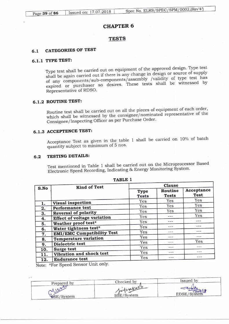
Acceptance Test as given in the table 1 shall be carried on 10% of batch
q..^.rtity subject to minimum of 5 nos'
6.2 TESTING DETAILS:
Test mentioned in Table 1 sha-l1 be carried out on the Microprocessor Based
Electronictspl.a n.cording, Indicating & Energr Monitoring system'
*o,., *Ror SPeed Sensor Unit onlY'
TABLE 1
Kind of Test ClauseS.No
TypeTests
RoutineTests
AcceptanceTest
Yes Yes Yes1. Tiarral inenaafi
Yes Yes Yes2.' tDarfarmqnae test
Yes Yes Yes3. Reversal of Polarity4. Pffect of voltage vaqelieg Yes Yes
Yes5. Weather ProoJleE!'6. Water tightness test* Yes
7. Pnnr/ PnnC ComPatrbillly Tes! Yes
8. Temperature variation Yes
9. Dielectric test Yes Yes
10. Surge test Yes
11. Vibratid;nd shock test Yes
t2. Endurance test Yes
Issued
trDSE/ SyStefi't'9Str/ SYstem

6.2.L VISUAL INSPECTION:
Visual inspection shall be carried out to ensure that the equipment under test
is of acceptable workmanship and in conformity with manufacturers design
specification accepted by hrrchaser. The foiiowing parameters sha11 be
checked during insPection:
' Fitment of 'Speed sensor'Unit on the axle box'
. Dia] Illumination, Diameter of Dia1, scale Range and Dia-l Spread over
SYstem.
' Provisions for locking of 'MASTER & 'SLAVE'Unit'
' Provision of USB Port on Master and Slave unit'. Cable sockets and terminals'
' Pin Allocation Details. Indication for'Memory Fuli',, over Speed Alarm, Equipment Fault'
. "Wheel Wear Adjustment" arrangement'
. Display arrangement for parameters to be displayed as per clause
2.7.1.10' MemorY Freeze Switch'' Mountingarrangement'. Identification markings'
6.2,2 PERFORMANCE TEST:
These tests are carried out to check and ensure that the performance of the
equipment is in order and meets the specification requirements' These tests
sha1l be carried out at temferature 3i+3 deg' c, relative humidity between
4*oh and. g0% and magnetic- {ield not srgnificantly different.from that of the
earth. The operating voltage sha1l be nominal voltage specified in clause 2'4'
6.2.2.1GENERAL WORKING:
Run the complete system on a test bench with a variable; constant speeds
drive at mean wheel diameter and nominal operatinq Yo]!age' Connect the
speed sensor, via SENSCON, to the MASTPR ;d SLAVE Unit' Input voltage
and current signal .o,..*po,,ai',g to 4l5l3}a volt auxiliary winding a-nd
current signa-l from secondary o-f .rrrr..tt sensor unit sha1l be given to
MASTER unit.
Length and type of connecting cable/terminals etc' sha11 be the salne as to be
supplied. Run the system for"30 minutes over the full scale range' check for
working of the sYstem'
After this period MASTER unit sha1l be connected to PC for down loading the
data from internal & external memory to check that the recording are being
carried out as required. gott tkt. Exiernal & Internal Memory data shall be
downloaded & checked'
Issued b],Prepared b1''
Checked brr-+"*uSSE/ Svstem
- ,o,44 *eose/E.t*-
6.2.2.2 ACCURACY TEST:
The accuracy of the system shall be measured for the mean wheel diameter at
a temperature of 37+3 deg c after a warming period of not less than 30
minute. One of the following means shall be adopted for this test.
a. A Stroboscope' control by a master tuning forkmonitoring the same shaJt as that under test'
b. A digita-l frequency meter, operated in parallel towheel or other mealls of obtaining a successionsensor unit.
c. A standard system of known accuracy driven from the same shaft as thatunder test. The standard speedometer sha-ll have an accuracy of + 0.15%.
Idea1ly, accuracy shall be checked by setting the pointer of the
speedometei system under test to the appropriate scale mark and reading the
correct speed from the standard source. In case of method (a) above, the
correct speed sha-ll be set on the stroboscope and reading of the system undertest shall be taken.
Each system shall be tested at a minimum of 5 approximately equidistant-setting over the fu11 scale range, both in ascending and descending order ofthe speed. A variable speed drive with constant angular velocity at any chosen
setting shall be used for this purpose'
For checking the ener5/ function, voltage and current signals sha1l be given insteps. The minimum itep of voltage signal shall correspond to 19 KV OHE &minimum step in current signal shall be lOoh of current sensor rating.
The accuracy of the system shal1 confirm to the requirements of Clause 2.I9.
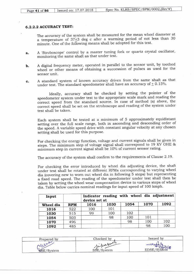
For checking the error introduced by wheel dia adjusting device, the sha,ft
under test stall be rotated at different RPMs corresponding to varying wheeldia (covering new to worn out wheel dia in following 5 steps) but representinga fixed road speed. The reading of the speedometer under test sha-ll then be
taken by setting the wheel wear compensation device to various steps of wheeldia. Table below carries nominal readings for input speed of 100 kmph.
Input Indicator reading with wheel dia adjustmentdevice set at
Wheel dia RPM 10 16 1030 1054 1070 L09210 16 522 100 1011030 515 99 100 1.02
1054 503 98 100 101
1070 496 9B 100 t02LA92 485 9B 100
or quartz crysta1 oscillator,
the sensor unit, by toothedof pulses as used for the
Prepared bv Checked by Issued by*y€EE/Svstem
Mte!|;-SStr/System #fur
No,o-yns7seoq/qlNalleqzG=u"a otr, 17.07 '2OlB
Thedifferencebetweenthespeedobservedfgraparticr-rlarsettingofwheeldiameter and input speed to'sensor sha1l not
"xceed +o'Soh of the full scale
deflection'
6.2.2.3BALANCE:
There shall be no variation in the readin g at zeto given by the indicating
instrument vis a vis the crriu..tio" due to th''-'gt" in altitude or its mounting
fosition i.e.ltotrzontal' vertical or at angle'
6.2.2.4 POINTER OSCILLATION:
Whentestedasfollowsthepointeroscillation,peaktopeak,shallbewithintoh ofthe maximum scale value'
Thespeedometersystemshallbearrangedsothatitisdrivenatasteadyspeed, *hi.^h;; be varied o.rer the effective range' The system shall be tested
for oscillation at five appro;;;i;ly equidistit" points, of which the lowest
shal1 not be less than 10% "f;;i;"m'scaie 'alue, over the effective range'
6.2,2.5 POINTER STABILITY:
when tested as fo110ws the-additional variation in indication of speedometer
system "f ifJ "ot
t-*"tta O'25% of the maximum sca-1e value'
ThespeedometersvstemshallbearrangedSothatwhenfirstputintooperation-rr^irrai..,io. oi".pproximately"Zi"t" of the fu11 scale reading is
obtained. The system shal1 d# t; ieft running for 3-0 minutes' The difference
between the indication. ;;i be within the tolerance specified in the
Preceding ParagraPh'
6.2.2.6 DAMPING TEST:
Theamountofoverswingshallnotexcee+,,"ofsteadyreadingandthereadingshallbetothelimitsofaccuracyafterreconnectionwhentestedasfollows:Thespeedindicatorshallbeadjuste-dtozero.Thespeedometersystemshallthen be operated at 75ok""r id. full scale ieading' The indicator or input
source *rrat then be mechanrca-lly "r ^;;;;Icdly
disconne-cT1,-::
reconnectedaftertheindexhas,etu.n.atozero,T]heamountofoverSwlngonreconnectionshallnotexceed,thefigurestatedintheprecedingparagraph,
6.2.2.7 CHECK FOR OVER SPEED ALARM:
Runthesystemtothemaximumspeedtowhichtheoverspeedalarmrssetand checkif the a-larm is operatrng'
Relayoutputatl05%and110%ofMaximumspeedSettingshallalsobechecked'
6.2.2.8 RELAY OUTPUT TEST:
a. Live Sign Test:
Put on the supplv and check for the tl"::ti:-L*{."Ho',}i;,lJ: :l?:.Ti?nPut on the supply arld cnecK rur LrrL in working order with
;;ip;i "tl"l,i ^r. available as long as the svstem 1s
Power Supply ON. A--.---] ,rraaf .
1O5% and 1 LOoh ofMax Speed Relay Output Test:b.
*.y-SSE/SYstem
ffiv ------ Cl,"ct<ea UV
+^*'"t'SSE / SYste\!-
.-.ao),hI
EDSE/Qtjtelq
-
Run the system and increase the speed to 105% of Max Speed Setting, thecorresponding relay output should get closed. In the sarne way also test forllo% of Max Speed Setting RelaY.
c. Low Speed RelaY OutPut Test:
Put ON the supply of the system ald check that Low Speed Relay Outputis available. Start the system and gradually increase the speed as speedbecomes 2 Krnph, the corresponding relay should get opened and outputsignal disappear/ diminishes.
6.3 REVERSE POLARITY TEST:
Where reversed polarity protection is provided the effectiveness of this sha1l
be tested over a period of not less than 1 minute within the specified voltagerange. After this test the system sha-ll be connected correctly and theaccuracy sha-ll comply with the requirements of clause 2.L9.
6.4 VOLTAGE VARIATION TEST:
The complete system sha-ll be operated for mean rn'heel diameter at threeequally spaced speeds covering the full range. At each setting of the speed theoperating voltage shall be varied between the limit specilied in Clause 2.4.The variation in the voltage shall not affect the speed indication.
6.5 WEATHER PROOF TEST:
The weather proofed parts of the system (sub assembly which are outside thelocomotives) sha1l be placed in a simulated installed position in chamber at atemperature of 55 + 5 deg C for a period of 30 minutes, and then subjected toa fine air borne spray of ordinary tap water for 15 minutes. The temperaturesha-ll then be allowed to recover up to 37 + 5 deg C after which the watershall be found not to have penetrated the system. The system sha1l operatecorrectly throughout this test.
6.6 WATER TIGHTNESS TEST:
The water proofed parts of the system (the speed sensor unit) shall be placedin a simulated installed position and immersed for one hour under water at apressure of 0.13 bar (1.5 m head of water) at 37 + 5 deg c, after which theyshall be examined to see that there has been no penetration of water.
6.7 EMC/EMI COMPATIBILITY TEST:
6.7.L RFI RADIATED TEST:
This test shall be conducted as per ItrC 61000 - 4 - 3. The complete systemin simulated insta-lled condition shall be put in to the Radiation Chamber &desired Radiation as defined below shall be applied:
Freq. Range B0 MHz to 1000 MHz
Field Strength 10V/m
Amplitude Modulation: 80% at lkHz Sinusoida-l
During test the equipment shall be watched for malfunctioning or any erraticbehavior. Data recorded in the memory of the system during test sha1l also be
Prepare"d by Checked bv Issued by*Ys"SE/System
/y4**4L-SSE/Svstem
*^gharcEDSE / Svdtenl

tssued on: 17.O7.2OlB
downloaded & eva-iuated through Evalu'atio Software for the performalce of
thesystem."*"ttaSDataRecording&DownloadingSystem.
No degradation of the system & malfunctioning should be aliowed during or
after the test.
6.7.2 RFI CONDUCTED TEST:
ThistestshallbeconductedaSperlEC-6.1000-4_6.Thecompletesystemin simulated installed .orraitio.n shall be put for the test' The desired
Radiation as defined below^"f.Jf Le applied o" DC power- lfut lines of
Recorder cum Indicator and "*"rog
& digital input lines of Recorder cum
Indicator unit:0.15 MHz to B0 MHz
10V/m
B0% AmPlitude Modulation
Freq. Range
Amplitude
Modulation
6.7.3
During test the equipment sha1l be watched for malfunctioning or any erratic
behavior. Data recorded in the memory of the system during test shali also be
downloaded & evaluated througtr Et'iuation S-oftware for the performance of
;;; ;r;i;; t" ,r.tit= Data RecJrding & Downloading svstem'
Nod'egrad,ationofthesystem&malfunctioningshouldbeallowedduringorafter the test.
ELECTRICAL FAST TRANSIENTS TEST:
ThistestshallbeconductedaSperlEC61000-4_4.Thecompletesysteminsimulated installed conJitio.r .n"[ u" put for th_e test' The recommended test
severity leve1 is f"*i+ *ith Direct Couptl,,g for Power Lines & \Mith Capacitive
Coupling for communication & Si;;;l tL": The EFT of defined severitv
shal1 be applied'o.r- co--unicatio-n 1ine, Analog ang Slgld '"lll lines'
sp e e d s e n s o r *i g. ir' ii,i."" ;i R;;.'4;:f. 1: i: f 1: Y:ii:.r"P "
p owe r in lin e s
:ffi:H;:?:"#ra"".or unit a,,d indicator unit as fo110ws:
SeveritY for Level 4 P"1"" Sh"Pe : 5/5O n seconds
ffisignal
2KVCapacitive CouPling bothpo"itir" & negative side for60 seconds each sides
4Kv
Direct CouPling bothpositive & negative side
for 60 seconds eachsides
Coupling & PulseAmplitude
after the test.
Preoared bY€ .M -ntl\Y,r'trsSq!y$e!q--
Checked bY
S
a-1,v*--j--=a-E/ SYsTem
Issued bY
.;rnyfu-EDSE/ si.1'At"!q
45 of 86 I Issued on 17.O7.2018 No. ELRS/ SPEC/ SPM/0002,(Rev'4
6.7.4 POWER FREQUENCY MAGNETIC FrELD:
This test shall be conducted as per ItrC 61000 - 4 - B.The complete system insimulated insta-lled condition shall be put for the test. The recommended testseverity levei is level 5. The Power Frequency Magnetic Field of definedseverity shaLl be applied on system in all X, Y, & Z planes.
Frequency:SOHz
Amplitude: 100 A/m Continuous Level 5 for 6O seconds in each planes.
During test the equipment shall be watched for malfunctioning or any erraticbehavior. Data recorded in the memory of the system during test shall also bedownloaded & evaluated through Evaluation Software for the performance ofthe system as well aS Data Recording & Downloading system.
No degradation of the system & malfunctioning should be allowed during orafter the test.
6.8 TEMPERATURE VARIATION TES?:
6.8.1 COOLING TESTS:Complete system shall be piaced, without any voltage applied, in a chamberwhere the temperature is progressively lowered from ambient to the lowestagreed temperature (at least upto O deg C) over a period of time not less than30 minutes. The assembly shall be kept for 2 hours, at the loweredtemperature with a tolerance of + 3 deg C (this period starting from thethermal enclosure is uniform throughout)
At the end of this period the accuracy test (Clause 6.2.2.2) shall be carriedout keeping the equipment at low temperature.
6.8.2 TEMPERATURE RISE TEST:
6.8.2.lDRY HEAT TEST:
The complete system or the individua,l sub assembly as the case may benormally energized sha-ll be placed in a chamber where the temperature isprogressively raised from the ambient temperature to 70 deg C or to highestagreed temperature, with tolerance of + 2 deg C, over a period of time not lessthan 30 minutes.
The assembly sha-ll then be kept for 3 hours at this temperature. (this periodstarting from the time when the temperature throughout the chamber isuniform).
At the end of this period, accuracy test (Clause 6.2.2.21 shall be carried out.The accuracy of this system under the above tests conditions shall be asunder:
Prepated by Checked by r Issued by
:\,YS,SE/Svstem
.,=r-AutrDSE/s;m-#r8

f "or"a on: 17.O7.2OlB
AccuracY "h of MaximumScale Value
Temperature range - deg C
6.8.2.2 DAMP HEAT TEST:
Place the equipment in the humidity test chamber' Raise the oven temp' to
+OoC + 2oClra fr.r*ldity of 100% over a period of 2 hrs'
Note the reading of time, humidity and temperature of oven after every hour'
Stop the t"*i uti., the chamier hls attained steady state reading for last ten
hours. Now lower the temperature to room temperatute (25_a^ 100c) over a
period of 3 hours, keeping the relative humidiiy between B0% and loo%'
AfterthiscycleCalryouttheAccuracytestasperClause6.2.2.2anddielectric t""t ,-" ptt il'o"e 6'9 of this test procedure'
6.9 DIELECTRIC TEST:
The aim of dielectric test is to prevent the rnounting of components too close
to the surrounding meta-l parts' The test sha-ll be carried out with the circuit
board connected in its place of operation' The test voltage of a nominal
frequency of 50 Hz sha1l ne .ppriea ior 1 min. between all the terminals of the
circuit board short circuitei'& metal rack of the electronic assembly' For
circuit board with a meta-llic supporting frame, the test voltage shali also be
applied bet*een all short-circuiteb connections of the plug connector and the
metallic s.,pfo.tirrg frame. ryr. ..rrr.". value of the test voltage sha1l be:
1000 V for rated supply voltages between 72 and 725 V '
The tests sha]l be considered as satisfactory if neither a disruptive discharge
nor a flashover occurs'
The test shall be carried out at the norma-l temperature of the test site'
The test voltage at frequency of 50 Hz or
sinusoidal form'
Tests on single pieces of apparatus:
60 Hz shall be aPProximatelY
Forapparatusincircuitswithratedvoltagesbelow300VDCorl00VACdielectric tests of "pp*"*.
and .ompo.t"ri" part shall be made to earth at a
voltage of 1000 V rms.
However,forapparatusincircuitofratedvoltagelessthan30V,thetestshall be carried out at 750 V'
6.10 SURGE TEST:

47 of 86 | Issued on: 17.07.2018 ] Spec No. ELRS/SPtrC/SPM/00O2,(B9{1
The surge voltage shall be applied at the point of connection betweenexternal circuit and the electronic equipment likely to produce surges, inform of wave shou'n diagrammatically in figure-I.
The duration D corresponds to the time value laid down for the surgevoltages.
The enerry of the surge will be defined by the impedance of the generator,which shall not erceed 50O O.
If no other values are agreed between the user and the manufacturer, theva-lues to be considered for the test are as follow.
A=1.5KV, D=45ps Impedance = 500 O (fig II)
It is a-lso possible to appiy the waveform defined in Iig II; the test may then becarried out in accordance with the diagram in figure IV.
The values corresponding to the test with 1.5 KV are given in fig.IlThe test shall be considered as satisfactory if it does not give rise to anydeterioration or abnorma-l operation.Permitted transient surges (non-repetitive i.e. with an interval greater from5000 times the duration of the surge). Transient non-repetitive surges withrespect to the zero potential of the supply, which are to be withstand by theelectronic equipment, without disturbances at the connections between thelater and externa-l circuit, sha-Il have the following maximum amplitudes:
7 KV for a time D = 0.1 ps4KVforatimeD=1us3KVforatimeD=5us1.5 KV for a time D = 45 ,usBOOVforatimeD= 100ps
Time D being that defined as above
6.11 THE VIBRATION AND SHOCKS:
The complete assembly or a sub-assembly together with its auxiliaries andmounting a-rrangements (including shock absorbing devices, if used) sha-ll besubjected to the following tests under the prevailing ambient conditions ofthe testing area in three mutually perpendicular planes. For these tests, theequipment shall be secured in a suitable position, to a machine producingvibrations of sinusoidal form, with adjustable amplitude and frequency.
6.1 I.IDETERMINATION OF RESONANCE FREQUENCy:
In order to determine the possible existence of critical frequency producingreson€rnce, the frequency shal1 be varied progressively over the range 5 Hz -50 Hz within a tirne not less than four minutes and the amplitude of
thethe
Prepared by Checked by ^
Issued bvM'SStr/Svstem 44*,,y1)--SSE/Svstem
:," /JattrDSE/S;TJiIIIS
G=r.d or' 11.O7.29)B
oscillation(a)expressedinmi]limetersshouldbevariedasafunctionoffrequency (f) according to the relatton'
a = 25lt for values of 'f from 5 Hz to 70 Hz'
a = 25O I P for values of 'f exceeding 10 Hz & up to 50 Hz'
If resonalce is produced, the corresponding frequency shall be maintained for
ten minutes in each case with"t"h"""ip*"t'1" alive' A Lheck shall be made that
no ill effects result on the operation of the apparatus'
6.1L.2 TEST WITH SUSTAINED VIBRATIONS:
Theequipmentinoperationshallbethensubjectedtosustainedvibrationfora period of 2 hours either at the critical frequency, if any detected during the
above test, or
alternatively at a frequency of 25 Hz' The amplitude of the vibration sha1l be
the va-iue ;;";";;ilg io'the frequencv concerned'
6.11.3 TESTS TO SIMULATE THE EFFECT OF SHUNTING SHOCK:
The equipment, in operation'. shall !" ::b1ttted for 2 minutes to 50 Hz
vibration of such nature that the maximum acceleration is equal to 30 m/sq
sec (amplitra., = 0.3 mm).-Ai the end of th" ,-bove tests, the assembly sha1l
be subjected to performan..'i"** (clause 6,2.21and di-electric test (clause
6.e).
6.L2 ENDURANCE TESTS:
Theequipmentshallbecontinuouslyworkedforl00,00Okmsatascalereading of approximately Zi"t"-of t"11 staie' These tests shal1 be carried out at
thenominaloperatingvoltagearrdfor-.Twheeid.iameter.Thetestsshallbeacceptable if the equipmeni';;;"^""ilf".iori1y throughout the tests and
also after the test'
6.13 FIELD TRTALS:
After successful completion of prototype .tests' the equ^lpments sha1l be
subjectedtoiield/servicetrials|o,,minimumperiodof"i*months.Thenumber of trial equipments and venue shall bL .as "g'-",1d
between the
prr.hu.""i- ;J- the suppri".. iir" installation and commissioning of the
.qrripme.rt, fo, field trials *nJf U" carried out by the supplier at his own cost'
EDSE/S

CHAPTER 7
TEST CERTIFICATES AND MARKINGS
7.L TEST CERTIFICATE:
The manufacturer shall provide test certificate of the system/parts procuredfrom outside and used in the equipment supplied to the purchaser.
The Semiconductor devices, PCBs used do not come under scope of thisclause. However the supplier shall ensure quality and performance report ofabove components by enclosing in Internal Test Report of the System andsubmitting it to RDSO before Prototype Test.
7.2 IDENTIFICATIONMARKING:
The following particulars shall be clearly and indelibly marked on theappropriate location of the equipment.
a. Manufacturer's/Supplier's identification or trademark.
b. Manufacturer's/supplier's designation (type, symbol or code etc).
c. Manufacturer's seria-l no/Batch no and year of manufacturer.
d. Speed scale range.
e. Name of the equipment e.g. 'Speed cum Energr Recorder/Indicator'.
7.3 MARKING OF TERMINALS:
The correct operation of the equipment depends upon the specific connectionsof the terminals on system, As such termina-ls shall be marked appropriately.
Prepared. by Checked by Issued Lry
CYS8E/Svstem
/,fu**'"'4r-SSE/System ,ffdk1,B

ORDERING INFORMATION
RDSO Specification No.
Class of vehicle(Conventional TaP - ChangerLocomotives, Three Phase Locomotives)
Wheel diameter
Ade Box and axle box cover details(for mounting of sPeed sensor)
System scale range
1.
2.
ao.
4.
5.
New: mm
Fu1ly worn: mm
Drg. No(Enclose coPY)
O - 1BO KMPH
Table mountedPanel Mounted
Nos
--Nos_-Nos
--NosNos
6. Mounting
7. Nos of memory reader required
8. Copies of software required
g. Nos of calibration kits required
10. Nos of PT required
1 1. Nos. of CT required
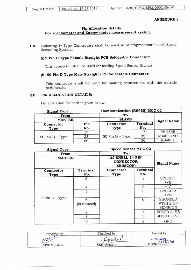
ANNEXURE I
Pin Allocation detailsFor speedometer and Energy meter measurement system
1.O Following D Type Connectors shall be used in Microprocessor based Speed
Recording SYstem:
(i)9 Pin D Type Female straight PCB Solderable connector:
This connector shall be used for feeding Speed sensor Signals.
(ii) 50 Pin D Type Male Straight PCB Solderable connector:
This connector sha-ll be used for making connections with the outsideperipherals.
2.O PIN ALLOCATION DEIAILS:
. Pin allocation for both is given below:-
MCC 01
d Sensor MCC 02
Prepalefl by Checked bv Issued by
.4*lr^*,Lr'o l,- | <a--
SStr/ System
*'4t*tnEDSE / Systerri
Communication (RS485From To
Signal NameMASTER SLAVEConnector
TvpePinNo.
ConnectorType
TerminalNo.
50PinD-TypeL7
50PinD-Typel7 RS 4858
JJ J.) RS4B5GND50 50 RS485A
From To
Signal NameMASTER 32 SHELL 14 PIN
CONNECTQRISENSCONI
ConnectorTvpe
TerminalNo.
ConnectorTVpe
TerminalNo.
9PinD-Type
a.) 1 SPEED 1
+Vtr4 2 +V5 5 SPEED 2
+VE
6(is unused)
6 SHORTEDWITH 2 OFSENSCON
7 7 SPEED 2 -VEB c SPEED 1 -VE9 B GND
gS6E/System
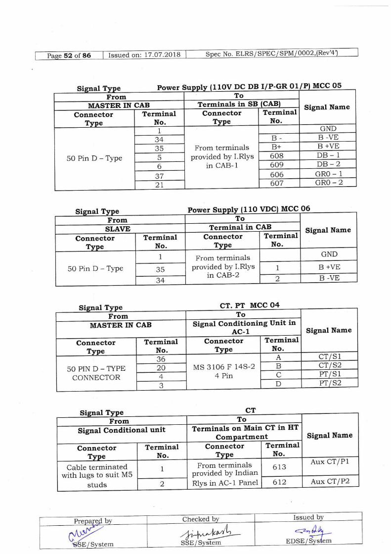
Power 11OV DC DB I/P-GR O1/P) MCt !qFrom To
Signal NameMASTER IN CAB Terminals in SB (CAB)
ConnectorTVoe
TerminalNo.
ConnectorTVpe
TerminalNo.
50PinD-Type
1
From terminarlsprovided by I.Rlys
in CAB- 1
GND.A.)a B- B -VE
35 B+ g +VE
5 608 DB_ 1
6 609 DB_2J/ 606 GRO_ 1
27 607 GRO-2
Power Su 110 MCC
From To
Signal NameSLAVE Terminal in CAB
ConnectorTVpe
TerminalNo.
ConnectorTvpe
TerminalNo.
50PinD-Type1 From terminals
provided by I.Rlysin CAB-2
GND
35 1g +VE
34 2 B -VE
o6
CT. T,-T MCC 04From To
Signal NameMASTER IN CAB Signal Conditioning Unit in
AC-1
ConnectorTVoe
TerminalNo.
ConnectorTvpe
TerminalNo.
50PIND-TYPtrCONNECTOR
36MS 3106 F l4S-2
4 Pin
A CTlS1
20 B CTIS24 C Pr/s1a.) D w ls2
Signal NameTerminals on Main CT in HTSignal Conditional unit
TerminalNo.
Aux CTIP1From termina-lsprovided by IndianRlys in AC- 1 Panel
Cable terminatedwith lugs to suit M5
studs
,r:'n )"1'n<*f"-
EDSE/System

DIGITAL AND ANALOG INPUT SIGNALS:
There shall be 3 Digital Input Signals and 2 Anatog Input Signals; Pins allocated are
as below:
Pin No. Abbreviation Name of theSignal
Position
6 DIG 1 +ve Digita-l Input 1 Recorder
5 DIG 1 -ve21. DIG 2 +ve Digital Input 2 Recorder
J/ DIG 2 -veB DIG 3 +ve Digital Input
3(Spare)Recorder
7 DIG 3 -ve36 ANLG 1 Analog Input 1 Recorder
20 ANILG 1
4 ANLG 2 Anaiog Input 2 Recorder
3 ANLG 2
Auxiliary Winding ofMain Transformer
Cable terminatedwith lugs.
Cable terminatedwith lugs.
Secondary Winding of Main PfConnector
TYPe
Aux CT/PICable terminated withAux CT/P2
Prepared by Checked by Issued bv
;^rg"€.5E7system
-]'r+r*-'1"/L,1 ,{SSE/System
<z-ild^ur.rEtF#8
FT
From To
SignalName
I{f UnitConnector
TVneTerminal
No.Connector
TvpeTerminal
No.
96s 1MainPI/P1
966 2Main
YI /P2
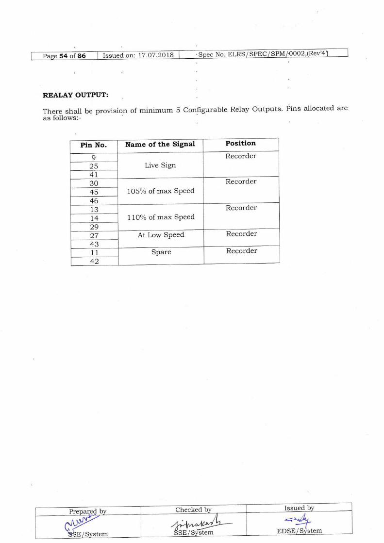
REALAY.OUTPUT:
There shall be provision of minimum 5 Coniigurable Relay Outputs' Pins allocated are
as followS:-
Pin No. Name of the Signal Position
ILive Sign
Recorder254130
105% of max SpeedRecorder
454613
l,loo/o of max SPeedRecorder
142927 At Low Speed Recorder4311 Spare Recorder42
PrepareQ b1' Checked by Issued by
IYSSE/Svstem ^*^"*+*Sstr / sr;astem
..*LBnseil'stem
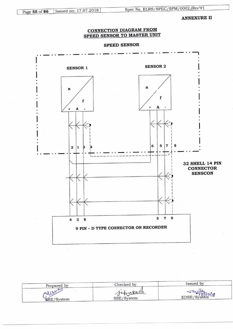
No. PLns / SPEC / SP-A4I lqezI*".d "* 17.O7.2018
ANNEXURE II
CONNECTION DIAGRAM FROMsippp sPusoR to uestPn unrt
SPEED SENSOR
SENSOR 1 SENSOR 2
-),/l
32 SHELL 14 PINCONNECTOR
SENSCON
+A
9 PIN _ D TYPE CONNECTOR ON RECORDER
Prepared by Checked br. Issued by
-<=^o)oveospr tF.JE?/r8-
-l^4NYSfB/sv"t"*
/N,*/LSStr/System _
I
I
l
I
:
I
I
I
','lI
I
+A

)ao
I o-)
.sf %-1, >ql'cn
ii lJlIa1, arE]
O
OC)
O
=-*i\l.\ t-
t\n+q'Sr,l\-\ CD
Vcn
.O
OSrcd
C)!t!
rE\a:1\ ra2 \-V)
b0
tra4'lOzErEAtrhEE;8ootrrl,z
t(?to(')
ot)F
cl)(,)
H
Fla2oiloFoH2zoorilAF.a
I
zAoIo
of;olE ( I\r_
n
EHBE F p*EuFl
o
nol u)ool o+l tal aillx
2oTEo \./
EBEiloo
lI)o+ail
('c)urnI:
t{Fa
=zroO\otEF, b..O<,lg.o73UNrrl +
!cotio.tf,l(r)
?u)AC,)orO
orO?2* '.IZI *t5I Y!trU (AH'-zilotoo
El 'ra6=<oo
n+,2trraO
EFn3pailn202F
oEZoz
aHt{a
eNF]aHooHilzoHoF.ofrf22oofr]A>.({A
I
oroNoHE&o
o2o(.ofrl22oo
=aooHzIr.HI
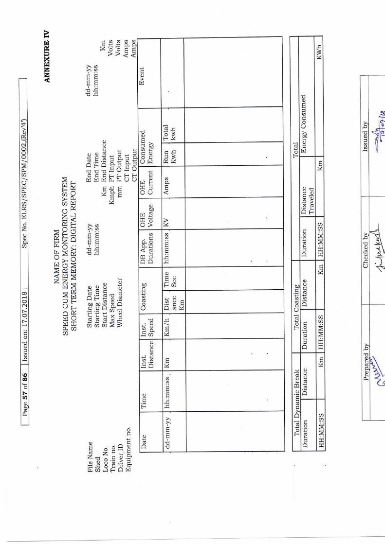
Cd
oF
O
E
a
Oa,lliO
V
dCJad
t-1 F
odli
aa:i
bI
!
doOdI
F
OO
Cd
ae
o!dt
n
a
>
+F
dC)timO
(dH
F
UO
a
E
o(gti
o
aa>
tiF
a
F
(,
0)t-lhlU)'co,Oft]
Lr/
li +i
o
q')
0!frf .EF]iOo>
a
<c6Li
qJ
a
F
F
;
aCd
O
0.)
t-i ().= o)?a
-Oboeo av
d
axE6 E
C)O
.cdaa
-H
OE
aF
q)pcd
a
I
EE'dr-l
-aaal-iePO-VEE T>>i
EHil,
Xfrlzz
>a>a
t.'
O(.)/
or9S-i-t'tr'a;qrA;=X 5-ts a---:r-!EE;--- - t. . L
r-r F4i./---LE4--
at) x =Eafr i -
zaH<*X?, r'e<r (J rl ? !'.4?-Y i E(Y-^*H
=ZA tr Ff! h .. i -
V!d-*>'/, t={l {)
>0zEl<td>rn> oqU 6A,PC--EAltHZG) X:.;CgE I'-r- !-;o.:il- Moo'Xko
ll *i-rh-rtt ='E -v) o,
EC h H K [:t# aaa>5a
U-#I .^ Ft- : O!:HU:-!6 Z L u'XZ.d n C tr.:f
or or 5'A .f ZEASiAfi
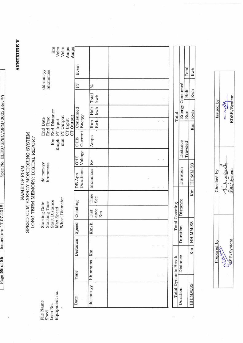
p(.)
aa
,H
<l aT.l cn
1[il\tA
-o
O0)
(-)
I
I\-f.-,tl$ q,
\\E5a
-lEl+ [/)\ -'cD
-o
Oticd
c)
H
H
,gi\#s{\ l!.2 ")6I --7
dp
F
O
o
bIliO
lr.l
F
V
O*
d{ q.)
rj>o6a1 i-
H
M
odLF(
t-.,t
aa<aaa#
c(
a
(-)
!oF
O
C6
a
\,/
o!!
H
aa>EJi!r
mC)
d
eLU
F
0)O
6a
!
!
!)t-.,t
aa>Erri
H
!
(-)
E -oo\
of
okl
(!S(-v
dl>-_: PIJ(
r.t
Or,r li o
Obo
H!{oc>
<6L
H!
a
E;
h0
aC6
o(-)
O
.TO?a+!?aQ-/1 :v
0)Op.aq)O
Cd
aa
O
EtI
C)!do
I
tr
daaa!!!^&^^d>>i
HfrxHzz
>(,>aI .,
l.'
FO
OO-
. a\ Lu *
fEEE-si^:F^OlU--H\)4TdEEIC'I- (a d/ r Lf;riAEEti
s'o
NoOO
a(JfrluiaaMr-l
oz
td-HAH
\-/*dHv/
Aa>o
ti.,D
AJOS :TUH!X:; c'J'd !! ts ! ., LU
hco0! 9-!!-za-
!!Pvlilili|1CJ( 6 6 aSaaazS
r.l (-Fo(a-afiauZJa,i^!
-Bis=z ajh5:E>b(1 2
Hfi9>il,*<H=zz,4
ft] 5>xFr E{orr-zl-r.l a14 l
a
co
C\t-f-
;
(.)-a
oco
oorO
ot
Ia.: EeoUA:(U Fz t-iz.- 14'9
^'-qy?,-.i*Uvf& CD -] frl

frlg,
xfrlzz
aaa
Mo
r(
aa
oo.
ol
dt>IrlollolcalE,Ioldlot
>l
C,L
dlFIal
L-rl*Ipt
^lFI
ciFo
F
olottrl(!I
atol
aa.;
;
o
FEri
a
0)otdao€frl
odoEa
I
F
zf,l Ft-Ua->o-a i-;
Z)a, {./1 :-
;Eg=zatri - ..
k=kY>ollJ rt n.>0zrn<riDlZZr-t
na>E?u"klo>afrrnx0i t-'la
orrSo o Y ..TEHEd*irE FPX Y B. :HHx-a'5 s 5 v)+) ol ^E E E x.F EI -6 d cd idE H, .ii ti d Ei 5 'x
a
H
i
t'
I
I
oF
6rlol
dl+rlotnl
0rlOI
slal.il
^l;t!lolFI
F
aaaa!H
li Lrb- 9-o!B.
Hotr
\,/FOO
trEoo.i .l+JPa&ElolB; E$Eirtr 6()Hi o qE o
OA (,HQ
aaaa
Fts
/dLr-Ptu
/- a- lV '1'u*H\
E,oo*a()
o
aAaAaaAa)aaI:UdtHHctrtrEdHt-!:HHn.. ! t-d!!Ad- n^Fol .:v al ,vF trl Ht F r- cl
ol '.rl ol'- Fr(ot 6rLI LI
aElaanl9"1 ?.?.*lEEI E E qI
E-6I E E FI'. Fi r-rd-!nal-
dHBFuvvLt-!tr- i. fr.
otr'E .9l.i +JddE!A€--tdd.u 0i)orFtr
BBBMVVaaaa);!FddHH;;4l
oll a -)--HF r-t<l
dHtr'EuO'dd
e -d E i6.E*,7X.g ; E '3' .EEtE S ir fi' EEE

Hilxfrl22
.o
CJ
a
-o
O]4(.)o(J
aahlaa
-o
OI'i
gOt<p.
q)
\?L\6AE?>a
---2aaalV:'VY:I
\,/ \./ \r' \./ vFFFFF
- r\ .i ti /t /txu v v v vOO O O O O+r)< = x = xorL, (, (J lJ u
.9rEl - - - frH Eit-c r -c -c -c6 iD tr,j 3 3 "t :'/ortr O--: - --: --: -AHO : : : : :
o
Etrhi
LOotrtrotdo
dd-
^^^nddtsFFv/ \./ w
Eq,0)gao
o
6'
(gktr.ec g 3 g 3H.g E Ei E E-Ylld tr tr t trH|r>r5 -C -c -C -CA'i, -c -c -c -c
iN::O-1 ^,adI
tr,6iliic.lktititrtioccoo
dH
V
>a>,at..--
Fts
-r< );>iw :=:,4 H v +FCt<np66u,*lZ, I. U
-:_-UN|; C
=5X !.i9.84AQ A Y, AM>.. A;:X-Z.c-Eniiy r.dE-vH--/X>V &lrrlri\, . IJrr-r i kl-vLtz M ._d r-r El229
td>2uD r,lO>AMfrl nH-rlJr 't
U)4-tv**E
\,/
iFFFFvvvVV
b, €,tro.ntrE(8.EOQ
cliO
LL.]
p
a0)
I
O
v
Y
*
F
aliO
H
>a>raI ..
HF
E .l-
bpn+
-.P-. ", v? alvv9. P C, -v)
oo or.! Intt\*v)
t !!X(trCCG11PPs;:aaaz
t-Itsl()#fi E
E]
cod
oit-t-;
U
oa

aa!!oo
l{
HilXazz
traoaa6
dt!-HFL-HH'V\,/;(V
ol
dl>lEIololola1
'dlol
ot>l
0rlOICI61al5l
PlotFI
F
aE
F
a
V
olol
dlolal
OIOI
HI9la1.i1ot-t(!l!lolFI
oF
a
l"ig
ciF
ololEll6tl
alat
a;
;j
ots
hE,
rt
HI
I
Folift.
aa;
"H
ol ^rliFI
aa;
;
olin
ocE.idddk
&Efil (U+t 0)Or.F,m
aaaaoa;
tstsF4 H!HHFddd4dd
Ol ^A.:alHt L ! rtLt !t.tl Alt-l nl
cdlr.l5l!t
:1:"IFETIFFOI
!!nd
//HFUUli lih. 9.
aaaaHHdaitrtr;;dd
ol o oEIF FF.l
aa
o.iFtrIolpt(dl
JIA^l:1 IF?I7 .11
.c
oLl
q
9uHqr._r ()tsabo|r')H.l+r=H TEA
=Fl
6)ocq, .EH.2ao
t,E,frl H
AH
l:fi:
q)oo9CASbD .9na(ddaa
zfil ,r--lnM>' L/i^ O-,^ F..l
z*1M</'1 l)
/V ii l,
E6nxzFu. derac>01 t<ktpzz*
Hkl-A3EO7o=kldf'l F0.a
trF(.+U
U.
I(+!
a
bo
Folitro.
FOO
CHoo.i .i+, +JegEOEBt E Feotr oqtr
El O &tr ohl1'; ofrle
E,oc)Eao
o
dHtr'E+ro; E e .5sil'tE*.n^.E e e '? E EE
E 3 ir B E sE
aaaaFF
Hts
tdtsH-*tuP P 3Cd:
r-t-NlL
o0
*Ei6 ;;
q, Ftr)a{l* >'?aN\\l lrl't a
t-lrn

,.o-alO
aa
t0Jl€-J-A{i a-t* -I\Hil cn
H
-o
O
(-)
O
O
t?aHaa
,UOtr
Otr
H
\EH
XE]g,pxrdzz
I<
vxl(L)a-FF!--HO C O C O>,a oo o o o oi9 50 a e ? ?e C g.U (, u e uE E <r H* # # #FF EhEit } } it }Ef 
HEF
iaaaatr++6-1*UU!ts>>ii
xHg,
xH2z
>,a>,aFF
PP
OU!,!
..a,(E = ={i:pu-P'n
=tr/,--qr+3ie+=77'o:ut!!-) a t. . Lt-
rn?^ts+FAE E 3E>Z .rrrA A ;'i
tr.l)az>&a >,a
H-r-t >)o>vHn(-EItiF
;.Zk E E-(r-d-IJ" i<, r- : 7
-,\l 9*u. o(.r ) u.\
U-.1 /h Vad6<inP
L
ftlt orqU E
=d !,=E='=- r-* j.!d H P'PX aE^( E'E:t,)6,)i,)LLLX0)fil- d (d d ki -cri \' 66r,>>p.a
dt
I
9 .^ fiH ,{ Oi:i9i-FNZ*rX
21.,*4.71 ^ L !r.::V.H>dn, U .r a .- J
.i*uH:_:fi. [D -] F t-.] Ir.l
oArrlQQ tZ XEP.E
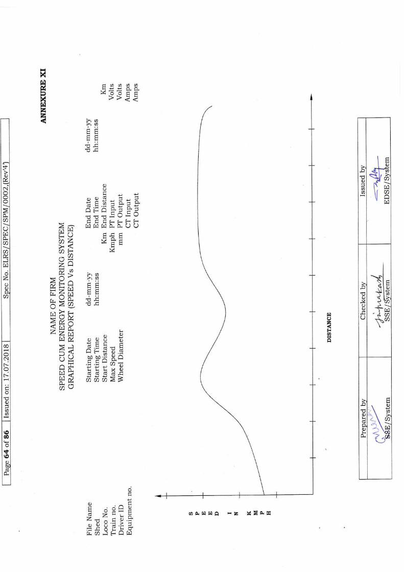
0)
aa
lctt;lq)jffi
r+'1, >-sl c/f^6" :1\ rit,l a
E,l
.o
O
O
O
Ixl-(lH\i l;1la5tra\-i rrl'"{ (ntcn
O!dpOlio.
. (-)\€\t/'
..\ a,. \ r,l<Y8{Ja
f.lozFaA
c,aaaoL<JAA,)--**
+u9!ts>>tt
t{xHfiXfElzz >a>ot..
OA
-door:_1u)^=F,r;o-r-^:-^^-g-Ji-J=)-=
-d-..LLZ.
- [! LIJ LI,J LJ- L \J \J
r-\ Lr.lH,\r-U FEE?n4 E 3EA? X.*AZA*> >aal)^v)ZZa .!)
dL-L!L a . \ L !tr,VA E F-lr^d-5>e €=,-. ). r-s\rUZM.an i; v\EJNzza . bftTM OqU Z. ;8tr tr
=? dtr,iEs
5 9 s sx &onE E::cD6io_r-r-LX0.)lr) j (! (U 6 (U-tr
P il 666>>u1 \-)
U-pq .^ FL.A!VL^v-d
\9ZL:2 -:.
g
-4^Lv.:qrUUatzI:-LJ - L ! UCa,,7+or,l
oAfirrln rZ S=*E
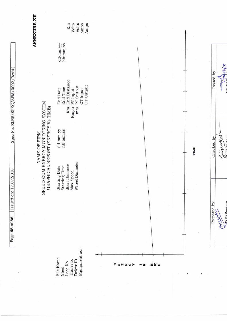
tdaF
c,aaaa!!!^-r.ootrl>>ti
t{XH&Xrdzz >,a>a
!..
OOn
o9s*E -ztra.ii-gdE5-"2?1E'c'u: C: ----..LL
r-\-.\tj= s 3EE?^ t- \./vt ItaA
zni.]>*A ?,a<LJnl 2)AoZ=r.l EE=ZZ F FHAr-\l'::-lJH-dIr.<{- 9--\a(-9!
XrX2il,Q.< i-i G)Z> V, L-ft1 ,,8 *:d XEr nA (\ X:- (E E 5!F!a1 lUJ-aY.-c E v 9x E_o
LLi--ri-{l'tt 5'.5-"'o)Ed hhHt.3/-l .hPPPr.:H-r\r aaa>>LLa
o-Ig .^ FL.^!Uq o:;i c(u?*.ts HA4'dni9'f
-e9IFitiiaiaariaEHtrO> rZ XIE
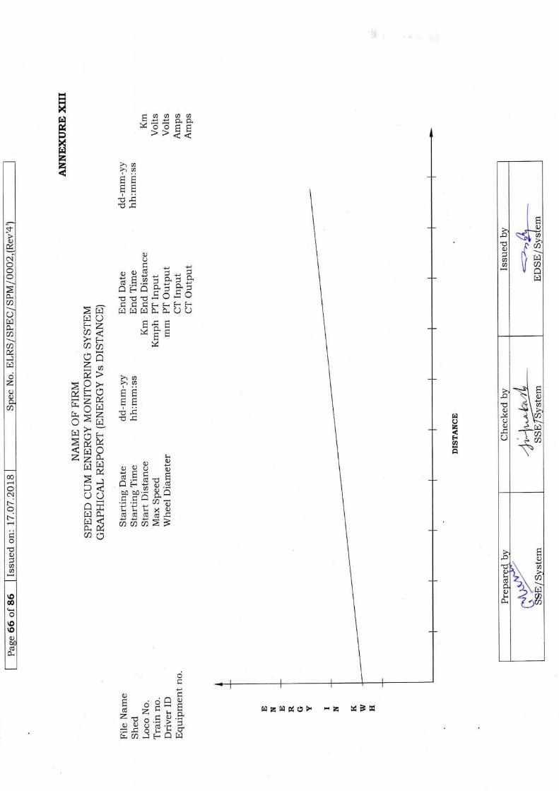
O
aa
i:d
I()
i<l i^
f6D.{\ir lJ..l\t a\]al
rn
.ot0)i4Oo
O
l
I.'.--{ F-\ ilJI P>to-+\ >{ \cnJ i--. r.r\U].+CD
O
doq)lr
l!
HH
;*
ao2F{ao
taoaa\\HHr' r' <<
xfrlilXHzz >,a>)A
I .,
!iF
I "
OOdFg*
i H g r 3: iA;-A O-- tr'-1J:r!=Jr<
'cEElOiQa
- -. . LL>a 6f;dEfuuklo/_> !.L FiLa< v=EB/2aih vY t--]z.^v,> >i,
-4.\/^>Y.f, 'L'tO'Lj\I H EiZX E E--tElk Y2 qEclli u*lL] / h (r
>Y'N,<6022* " bril5 oeU 6tJa€C-HdL2, \ ji:;(E! !--J-#.'(!i X M'b,! I5v\-/--ft*
F r
-
,i
-
^ ;- 'a'E * "' aJ
-:5'LLLxoIrlO- cdddcrj .CFr E 6h6>>I\ LLac
npq .^ fu.^!v
d 2 !-HY U.; > io9ocdi,a
.**UHI'Yb.a)FLll!
nzrrlflot, ta tsBE

ANNEXURE XTV
SURGE TEST
U
A
0.9A
o.5AA
A=1.8kv D>451
a=O.9kv d<O.1 p
d2 < o.lD
CHARGINGIMPEDENCE Zc
FIGURE II
PULSE FORMINGNETWORK
(IMPEDENCE Zu)Uc CHRGING
VOLTAGESWITCH
FIGURE III
F'IGURE TV
I
|Hlt
< o.1DFIGURE I
Prepared by Checked by Issued bv
ffi*", 4*yyySSE / System
'-=*lrq,otrDStr/Sr)stem-
67 of86 on 17.O7.2018 No.
U
C = O. 1 trF
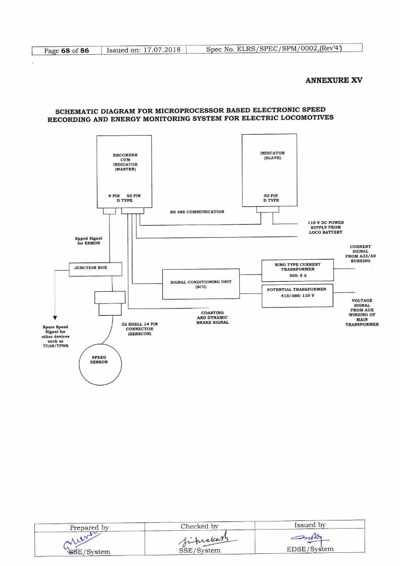
ANNEXURE XV
SCHEMATIC DIAGRAM FOR MICROPROCESSOR BASED ELECTRONIC SPEED
RECORDING AND ENERGY MONITORTNG SYSTEM FOR ELECTRIC LOCOMOTTVES
RS 445 COMMUNICATION
Spped Signalfor ESMON
CURRENTSIGNAL
FROM A33/AOBUSHING
VOLTAGESlGNAL
FROM AUXWINDING OF
MAINTRANSFORMERSpare Speed
Siglal forother devices
such asTCAS/TPWS
RECORDERCUM
INDICATOR(MASTER}
9 PIN 50 PIND TYPE
RING TYPE CURRENTTRANSFORMER
3OO: 5 A
Prepared b-v Checked bv Issued bv
^r,q\dB / sv"te-.+'-\"^:@-SStr / System
-r--rfl6,EDSEEJ;;

ANNEXURE XVI
Summary of accessories and their applicability in AC Tap ChangerLocomotive and Three Phase Locomotive for Microprocessor based
Electronic Speed bum Energy Monitoring System.
Prepared b1, Checked b1. Issued by
,&q*!4-SSE/System ur 'r
SN Description Type & Make Equipment Location Remarks
AC Tap ChangerLocomotive
Three PhaseLocomotives
1. Master CAB.1 CAB- 2 Firm's Supplyas per DrgNo.cLW/ES/SK-1-1to3/SPM/0002(Rev2)
2. Slave CAB-2 CAB- 1
3. PulseGenerator(PG)
3rd axle(R.H.side)
4tn axle(R.H.side)
Firm's Supplyas per Drg No.cl,w/ES/SK-6/SPM
4. SENSCON(32 Shell 14PinConnector)
Allied make,Sichem Type,Female on PGside & ma,leElbow typefor MasterCable
Below UnderFrame
Below UnderFrame
Firm's Supply
5. SupportPlate forSENSCON
BelowUnder frame
Below Underframe
Firm's Supplyas per Drg No.cl.w/ES/SK-s/sPM/0002(Rev2)
6. PotentialTransformer(Pr)
At aux windingof mainTransformer
Nil Firm's Supplyas per Drg No.cI.w/ES/SK-2/SPM
7. CurrentSensor (CT)
At 33 Termina-lof the maintransformer
Nil Firm's Supplyas per DrgNo.cl.w/ES/SK-3/SPM
8. SignaJconditioningUnit (SCU)
AC- 1 Panel Nil Firm's Supplyas per DrgNo.clwi ES/sK-4/SPM
69 Issued on: 17.O7.2Ol No.
c9P}'3SE/System

N- ELRS / SPEC / SIIvII eq92G"u"a o.t: 1,7.O7 -2018
Firm's SuPPIYas per DrgNo.cI.w/ES/ SPM
looo2ls-35A
Centre Pillarin Both CABCover
Assembly
Firm's SuPPIYas per Drg No.cl,w/ES/ SK-7 lsPMlooo2
CAB2 SideWall inMachineRoom
Behind TK-1Panel inMachine Room
JunctionBox
M"lti C*" C"ble-screened(shielded)Cable Length & No.
PC to SENSCON(Female)
Junction Boxwith fusesuitablerating andCable shall besupplied bY
ESMONmanufacturer
13Meters(6 Core)
13Meters(6Core)
SONSCON(Male) to JB
JB to 9 PinD-Type(Female)connectorfor Master
9 Meters(6 Core)
50 Pin D-Type (Female)connector atboth ends
27Meters(3 Core)
27 Meters(3 Core)
Master to Slave
50 PinType(Female
to M5 socketfor SB/CAB
5 Meters(2 Coreas DBR&Coastingnot inuse)
5 Meters(6 Core)
Master toCAB(Battery, DBR,GR-O,CTF)
S1r.rr" to CAB(For Battery) 50 Pin DType (Female
) connectoto M5 socketfor SB/CAB
Master to SCU MeCore)\4
Ni1 50 Pin D-Type(Female) connectorto 4 Pinconnector (Fe
male) atSCU end
SCU to F"I 3 rnm2Railway'sstandardcable(2 No.)
Nil M5 Socketat both ends
SCU to CT 3 rnrn2Railway'sstandardcable(2 No.)
Nil M5 Socketat both ends
Master to SB in MachineRoom
Nil Existing 50 Pin D-Type(Female) connectorat Master toSB inMachineRoom
Slave to SB in MachineRoom
Ni1 Existing 50 Pin D-Type(FemaIe) connectorat Slave tcSB inMachineRoom
JB to TCAS/TPWS EMI/EMC shielded Cables from Junction Box toTCAS/TPWS interface shal1 tre provided by
TCAS /TPWS manufacturer.L2. D-TVpe Connectors
Description Type & Make(Only MILGradel
Location RemarksAC Tap ChangerLocomotive
Three PhaseLocomotives
50 Pin(Male) ITTCannon/Allied/Essen/Tycomake
Both for Masterand Slave (2 No.)
Both forMaster andSlave (2 No.)
Firm'sSupplyfitted bothon Masterand SlaveUnits
9 Pin(Female) ITTCannon/Allied/Essen/Tycomake
Onforwith
Master Onlyconnection
PG
On MasterOnly forconnectionwith PG
Firm'sSupplyfitted onMasterUnit
Prepared by Checked by Issued by
*y-\SStr/System
*4;+ftgEDSE/Syslem
M*@-SSE / Svstem

9 Pin(Male) ITTCannon/Allied/Essen/Tyco
nake
To be fitted oncable towardsMaster end forconnection withPG
towardsMaster endforconnectionwith PG
be fittedcable
To
To be mfg.atCLW(Connectors/Pins/ SocketsandLockingScrews tobesuppliedloosea-long withequipment)
50Pin(Female)
ITTCannon/Allied/Essen/Tycomake
To be {itted oncable towardsMaster and Slaveends forconnection of SBCAB (For BatteryGR,CTF andEnergr (CT,P|)signals)
To be fittedon cabletowardsMaster andSlave endsforconnection ofSB2 ofMachineRoom
Prepared bv Checked by Issued by
@"S6E/System*a*1'
SSE/System
:==:1fi0\ s*-*1'*trDSE/Systbm

Issued on: 17.07.2018 No. trLRS/ SPEC/ SPM / 0002.(Rev'4
riiiii,r
Prepared by Checked bv Issued bv*t\SSE/System*M"+t,*
EDSE/Svstem/b+ra9L
SSE / Svitem

S,..... .N .,'-s-1 ,ffi
#,u,..,.:
* -." 'i
+, "il'J,* 'I
,": t *rI
Prepared by Checked by Issued by
**"s'dE/svstem++Y"j*-
SStr/Sy5tem-=4-
EDSE/System
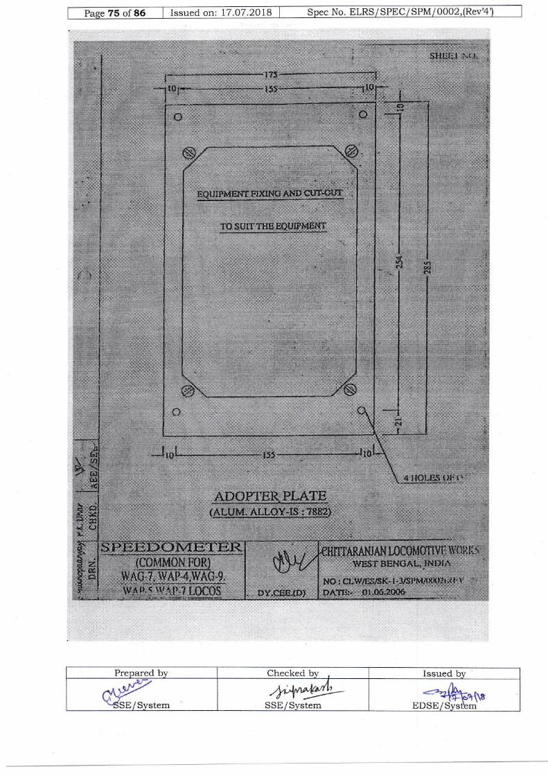
Pase 75 "f
36 I Issued on: 17.07.2018 I Spec No. ELRS/SPEC/SPM/0002,(Rev'4
::.: | :f;.', :
Prepared bv Checked bv Issued bv
cqHSE/System
ryy,y/LSSE/System
-==={knt*EDSE/Svstem

Paee 76 of 86 I issued on: 17.O7.2018 I Spe. No, ELRS/SPEC/SPM/0002,(Rev'4
la''t:it
t:),r;
$i!;
*Y;:;r,l iL
ntlt}i{r}{i-vix
t:,:- lBlr f:.lllrfiI -k*-
Ltr.
ilrtrrrur*xrAN t ossl!{0'rlY}I, tBSf USH€'d{- tt{l}l^
.!i ;i, ' ::::::-a:==.i::: 11..:: ' ,:i;,1 1:1:,.'
N$. ctlf/EtrrSK*slsrutttrJ-:' lr-s$*aoCIa
Prepared bt' Checked b1, Issued by
@SSE/SyStem
.1
=firr(1,.{
EDStr/Svstem
ffijrf: 1

:.Y,.;l::,,:"i
Prepared by Checked bv Issued bygrSSE/System
b$*v!-SStr / Sr,'stem
"<?"b11^T+Efll8
EDStr/Systdm
i: - "- - :. :ii.*x' - 1 ..-rr :- *&d, -

ffi.: tz.oz.zots-- Sp.c No. trLRS/SPEC/sPVllqq2.,1Eqv 1
:$rli
l',I;
Prepared by Checked by Issued by
.l|l-
^$yuSSE/svstem++eYL-
SSE/Sfstem EDSE/Slstem
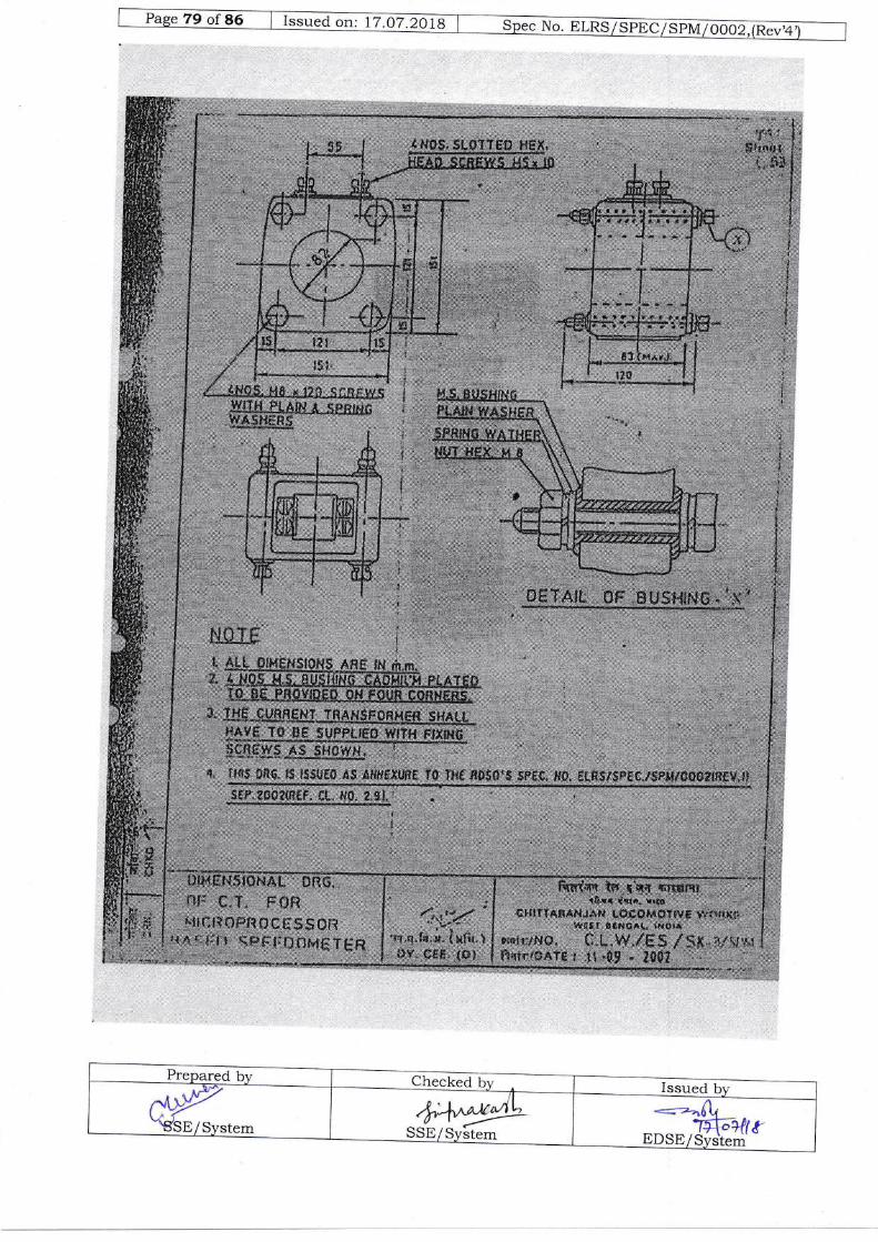
Issued
&y"'"BSE/System bA*yY
SStr/Svltem*=-*.frq
1_a{;q-ilstrDSE/System
4r::]a l:! l i/]*j4:!sF:,i+]
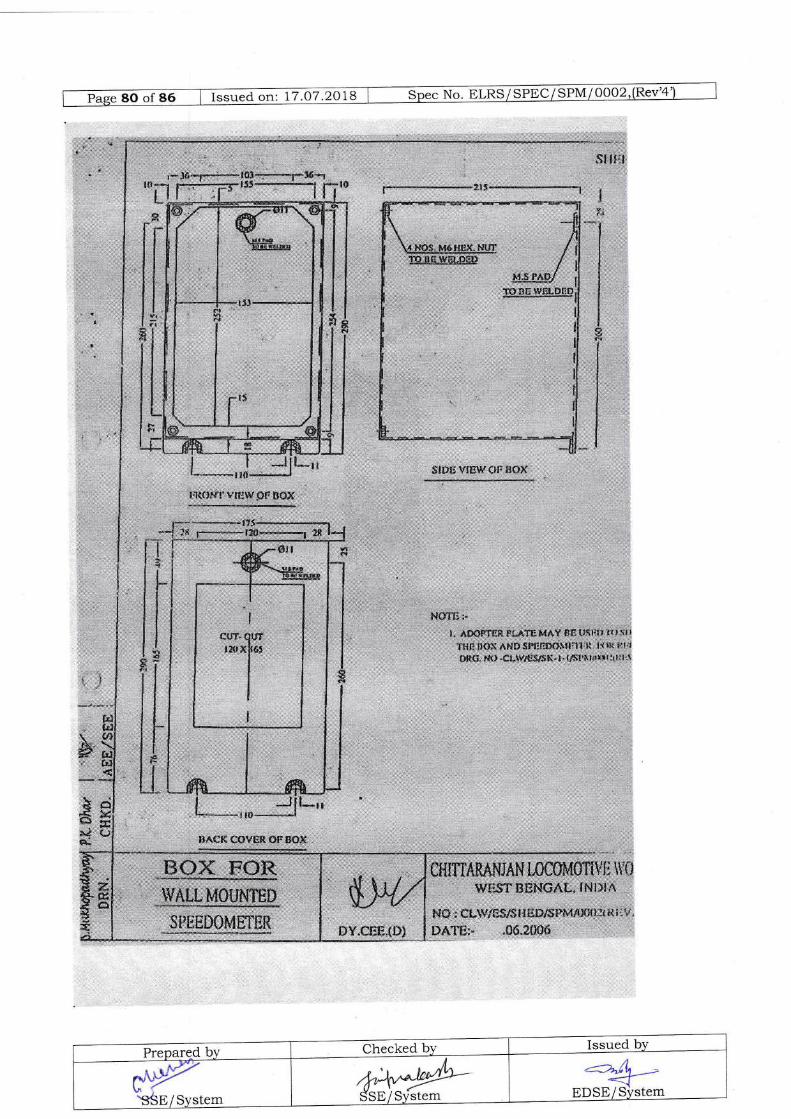
#{l
+.*
".r6*J.*l'
*$i';$UlS Vr6\*{rtr }}t}t{
NSTE..l. A$sFTgfi FiJTTE M'tY &e ttqlti! r' l s' I
mtfi l]a]i A$s$lq:rf}iiltl:1|'li ttRt pr+
$*&i!*{}.e ti*{$X.}-,l$t'&l$iriit:{tii.it
m.S.,wxr*rctlu
: : ...$pmD$Mtr[-mR
,,.,,.',,,.,,, H{ffi X,$N€i,$![u,lNl,]t ",,.
, &B,r *l3sJs${$l{Srys&'lslfl{$ ** tl l'-
f)-{TE:" .06"2006
I;Rtl&tli t,iliw,$$ E*x
Jfl**t116,,.. , ,,,,*,1
Preparqd by Checked by Issued blz
<=);L ->{_fEDSE/Slstem*r
'S6E/System
,h+"y1'-SSE/System
lIirjl
IU nC lSF.l.pn[
I,l
*p1gg1:gg${}}d
:;s. $ffi a*1*sN
i';
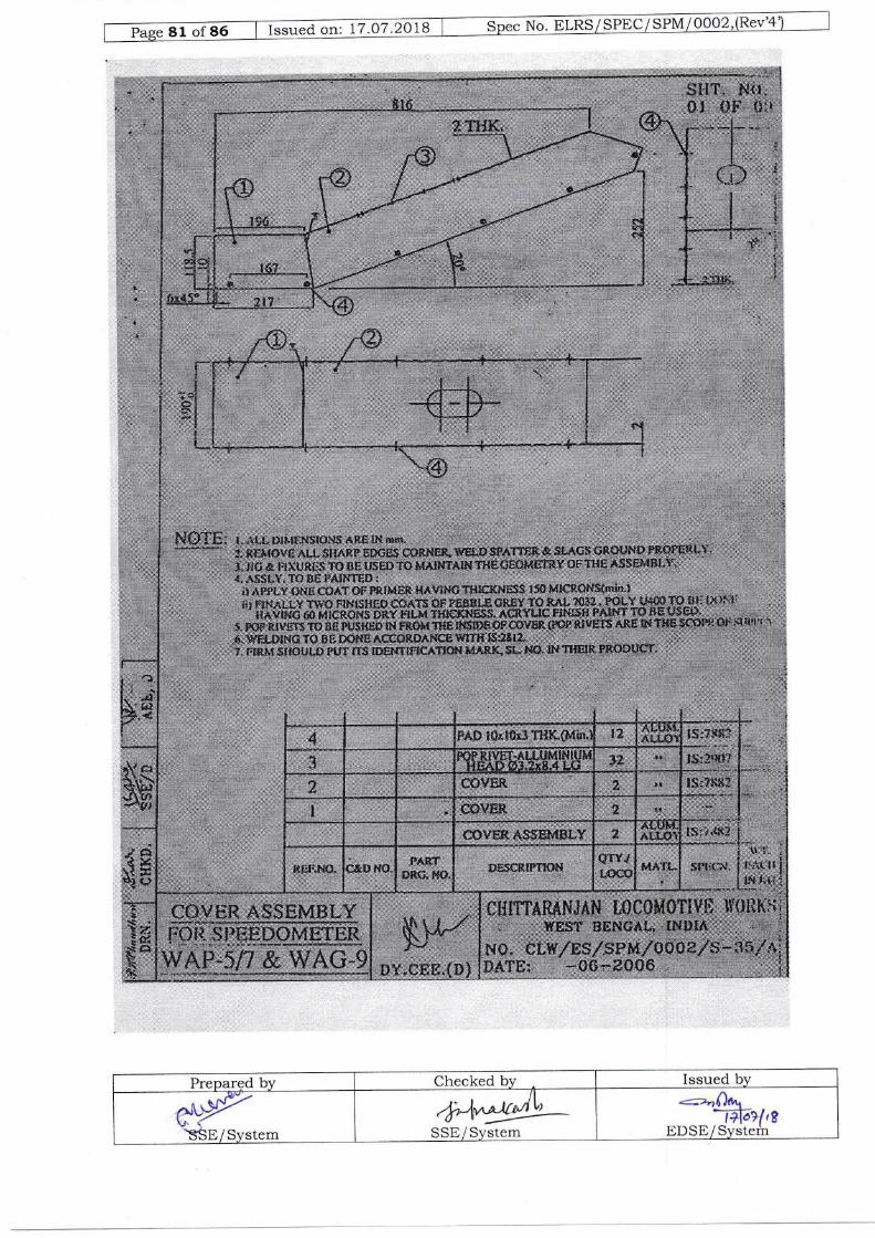
Issued on: 17.O7.2018
,"1 . t',r,t- ;t"
,t.ur'" '. *.
: 'li
o,l, i
'l,r,#i#*
.;_, I
."r.1 .
:':trNl li":a::ii
,' ':* ':
.-,'1|!tLi=i@ii,,:,,;
luffi
' r_, '\i,
b *t,.i|,,
larr r,illiiriii!:1111i, i ir:!J
-:..Ji
$Eit:::i!, tl il;
;ti;:.i,. 11!llllri4: iri::::;:::isr
li::;ii?.?b.! Ittnil;'::,#lwlt:itwa*,
Prepargd by Checked bv Issued by
'SSE/System.["b:,t /L'---
SStr / St stem
<=aQ6*1iloil,t
EDSE/System

iz .ot.zola I spec No. ELRS/SPEC/Silvll!9q2J89" 1
Prepared by Checked by Issued by
'SSE/System 4-+4bSStr / System
<*&--EDSE/Svttem
.t:t:i:itl x i I |xti!].=irrS(S:;:,;;;?.S'w.1

83 of 86 I Issued on: 17.07.2Q18 I Spec No
;:.-}ii=, ,'#';rtr#*!'ti, ',,,,,18.111', N{i:
1' ; --. , ..; ,,'i.i-. ,,'
Prepargfl by Checked by Issued by- ^,vv7SSE/System +a@-
SSE/Sydtem 4*t,sEDSE/Svbtem
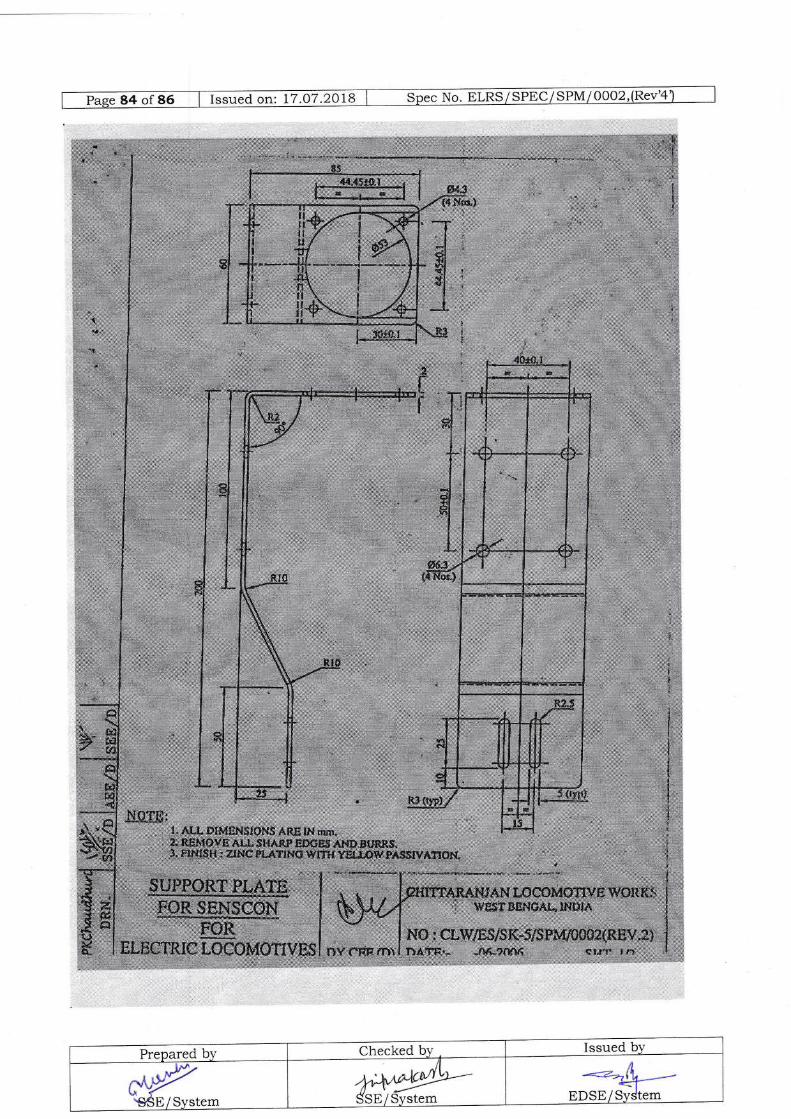
Prepared by Checked bv Issued bv
-r-y.S'SE/ System
M'4ry)SSE/System
4e /Ao>rt lr ,g{EDStr/Sydtem
t:**-#
i*
J- '*
#$**.*ffilrnffirue*resueR& , ,. ', * ".,.
ffilffiEg$fH -;, .,".= "f "
""';, . utt&s*=*.*;n: =a,u***r,+*;*
:*:$*nI
fl'*f. ;,, "-,1- n, . _, lMffi$rcssx;,smra*B., tp*t*ffiftlgA;3,.."" 4esryH,,,j,;
q '

85 of 86 | Issued on: 17.07.2018 I spec No. ELRS/SPEC/spM/o0oi,(Rev'+
;ri+!l#triii:i!!!ti,!
Wi:iiii
Wffi iirii#,i?ffiff'j$i+ffi
;li,,1. 11,2
:.1 {, t t',,i i|,rtllll;:)*i J"l!4',: ;:!'tl,, l ; |,'jilf;
il;ig1;= *
Prepared by Checked by Issued bv
CigP-SSE/System
)"J /\^A*r'/Y\.(). v --SSE/Svs6m 'ah;+trs
EDSE/SyStem
*il,fillti;*iit;i;:!lli,' u.'"*,,'r,r ."ru,. "1.- _,'i .{- ' rt:-}iFr,,;i,
%*:::!'il a *, .,*F:f,$* _,,,*.,#rr**:'.ft
t'l::-|.!.. 1
", ,, a ,.i, ,
il*,.##r,f, lir:,,,;i: ii:iiiiiii:fif.f,iiij i,."^",,::,#.i[iilili:t::-:::i !iitltfi!;t:*;,;411gif lilii*iiil"\lu"|!;:l];1t,!i1iffilttlii1i.iLr'S jr, ,
!i:#;i:li, jUii;i:;ii:i,;;j;ji!!;i,,ii:ili;:::;:::i:r:l lii
!,i{Jlft=,,'' #ii:ir,,.t,:4[ni ,,1.: litr":t-],,##ir iirll i;irii1i,, .,,.:ilr irli! ' ,..*,)t$"1lil:,-),:.rii:#ifrii;.:?...,;
*it;rti. iiiil:t.:::| 1.,, 9J1l.,iititiji,#,t;,::, :t,
:::l-tttti:iit:ljiiji1tlitLi!i:i::j:iii"f",ifi,,1}
.,:, r1.?:4'i-.Hrr ! ii : :'i1..',tl I llliWAtiWSLS*:W'W'8:.":.-!n,!,
;tll[l'tiii*
i.a'u\ tfifrtr:tr2)-r.tr::?:,7ar,fitFr?.,,wi*mt**.i;rnEigriri:grt*LlQ<:,.,:)]t .... . " I
tii.i;iitll;iitW,tfi,.,i;illlllit-|,,;::AtrtrEi,i:i,,ry.
rfi ilf !:::;i?tffi:i1ll1iL.1,V::;:,i*1.1?/tt-t:.i,{;,l,llllitt)!r',riW.l4:!":':t!:tti',ri*,ii,,,,':ii L*zlr.lr ,,;ir ,liif.i# l
,1/iii;;;it;)tt4-t!1,11,fuii.1.'i1ii:a:lry/B|rtt u:4..'. t a+v,..:It:.. r :: ! | .ry,wr:1;':ai!!ffi*:a ti tril
i:.4:illltltt_n::::r.t:,:-Wj.:.:,:.t .iE?..".- }il,rjl:i*$1i$4+;i#
t
li
'lil.ll!i:tt: j!:trjfi /t"*"*:.,.+Liiiiii*i:;:: jrrlliiri w-_t.,
I firii;!i::.!.!:lrl; i"! :11+**l.
r:.4.j$iil:':'L:Nt,rrliii;);!iirxi,.'#rliii,ii:i**",,.,r,. i,,,]6:1,ti':li ;i t ; il.ii,#*;::::,.:#
,,tiiii,;.fi,y:ii,i;,iitM,r,wWi
r!!it,!{ii;i;,Hi![ t/xlliii:.iitiltj.Lliii::+
{lliii:ji :rlitlltl' #+l l,,i:*'li.=r:;ii# ir. ilii,tli}l:..=;.* ;'.tiii-.lr;.;?:ii titiij,:::i?:r.,i:,:rl,,t:iirt L.rl.liil iil i,ly:1;,jffi;fi:itlli#i'i.:: il#;
i:1.1[$ffit'r-r76l'lfilfi".;::.,.1Jrxiif:.ijg(ii.;:i:iiilil]liri:llti r,'tufai:;ffiilii,, r:iirir[i::i,$iit:-,Htii:til
i::::r.:,i lrj i1..,,,,1 l, i,,; i tl*t*t?2 )ii{:,iwi:irlitlttiltt;t; i ti:E!:..i:;
;::Ei{ffi::-t*: ' ,.\a..1."t; y:nfil {-.*}. _,*i:r- "*

lliiffi,Ei]illfiil?r:#l,L,r;;aii,l
ii;...:i ili;,:i,ii(s..1.;.r}
:pti;;iI
ru;i,*:,
x:ilill l::i:,iu:t-,j
,+i
3;.,t. 1.,',
:,"'
t',:.. "
'i.i-;:
L
i,:".
i . ljlj
=:lillit:li, , rqil
:lirllll"'Eili*: i ., :
:fu i,i"*l
, - I,,"ffi':-r
I iit:tr'i;:li i=:X,t.
_i
i::::. l ii:
ili r;rri..n.
1:..i6liiitk. ..'i. al$i'.:t ltii:lrr,
i:::;:\ltFr:-j
rr;r:as =!r iili ril,i
r:,.;;t iiiiii ijii.?l,.":. !
i=liiii..l1:{15.t :,: :|
:::{,'-,ri::::,
l;tri'i't',;.t,.ji+iiiri
,.'#i:r:l'+ tf,iiiiidtt::.r:$l
",".'";...
Li {i irriE
-r:.:!r .il :r=^.1'i":,.,
--::l
: : ,- . :.''l' ':.i; l;a
*r$ffi.*::*H:1
;-
, : \"wy,
t,ti. j|I,,
;- l$-:'"*ll ""
ffi#: :l'
.r. .,..1', .:"' ,' ,.,:,,:-.jit'r' i*TlilT$$$l,,utr*ffimr*qvtR$s,f
" I
I-*, 1*.JffiffiH*,Iilsi: ,
**,.,*-",. ;"
";:; ,'*'";,':;j
,...:l.r:,,.. ti :lrl
,.". qN
:ft;fi;:'T.
ffiN,S-: Swr+i$sss
*-.* -'1.:*{*'l::l' ,ll'ir: -'lrr,: )
'l,. :'',,i ,
:,'. ti:, 1 ii 'r:'rl'r;r,'.
*' ,
Gw_- "'t",,r
;-*li;*<-.*;&;-\
'.1r.,- _,,"-,i
-:.4 ^-
P.: 'S', tS r$;1
:"1;lj,riilft* *--;B*Hi 'mQmi..i1:i,,fl .l
et't$iffiJ.:rr:-*-1"i'lT::Y,r,,..1l i ,.
l;,it,:l+,.
". '"o' ' * ''r" , .ti
.: !+:)
'r;;= iiit,
" .'r ,
:-l :
," *".1:".i:::'r,:,":l:,iLili:1
iii,l ;i,,',, : )i::i:i
Wffiai -, ;l
l=
$ffiN:. rtu$
I i..!+itti:
I L .rili::l.illY i:l:1--]:i.ut"li; i lI ii:::::?u" .,]-:
{i,irF,...:..#
ffi$$*
Prepared bY Checked by. Issued by
*_="{L_EDSE/SylstemN"q
"'BB/System.J.-Y*ril)-SStr/ System