
Guideline on Construction of RRI Room / Control Room with ... - RDSO
45
GOVERNMENT OF INDIA “kjrljdkj MINISTRY OF RAILWAYS jsyea=ky; Guideline on Construction of RRI Room / Control Room with firefighting provision No. RDSO/WKS/2018/2 November, 2018 Works Directorate dk;Z funs’kky; Research Designs & Standards Organisation Lucknow-226011 vuqla/kkuvfHkdYi ,oaekudlaxBu y[kuÅ& 226011
-
Upload
khangminh22 -
Category
Documents
-
view
9 -
download
0
Transcript of Guideline on Construction of RRI Room / Control Room with ... - RDSO

GOVERNMENT OF INDIA
“kjrljdkj
MINISTRY OF RAILWAYS j sye a=ky;
Guideline on Construction of
RRI Room / Control Room with firefighting provision
No. RDSO/WKS/2018/2 November, 2018
Works Directorate dk;Z funs’kky;
Research Designs & Standards Organisation Lucknow-226011
vuql a/kkuvfHkdYi ,oaekudlaxBu y[kuÅ& 226011

INDEX S.
No. Items Page
No. 1. Introduction 1
2. General Arrangement of RRI Installation 1
3. General Precautions as per IS 15493 (Gaseous Fire Extinguishing Systems)
6
4. Most common causes of fire incidences 7
5. Losses due to fire incidence at Relay room / control room 7 6. Fireproofing provisions required in construction of new RRI/ Control Room 7 7. Fire Fighting arrangements 23
8. Automatic Fire Detection & Alarm System (AFDAS) 26
9. Inspection & Maintenance of Fire Extinguishers 35
10. First Aid Box 36
11. Tentative Fire Safety Audit check List 36
12. Reference 43

Page 1 of 43
1.0 Introduction: Fires can be devastating if not controlled in time. On Indian Railways also a lot ofdamages take place due to fires. Therefore, it becomes imperative that all required steps aretaken to prevent and control fires. This is possible when Railway men are acquainted withcauses of fires, types of fires, types of fire extinguishing equipments and materials and kind of equipments to be used for different kind of fires etc. Relay room / control room are places where the system used in large and busy stations that have to handle high volumes of train movements. In this, an entire route through the station can be selected and all the associated points and signals along the route can be set at once by a switch for receiving, holding, blocking, or dispatching trains.
2.0 General Arrangement of RRI Installation: The General Arrangement of RRI Installation is as follows:
A. Central Building: B. Gumpty:
A. Central Building: The Central Building houses the following rooms which is the back bone of RRI. The vital rooms are generally named as Panel Room, Relay Interlocking Room, Power Supply Room, Battery Room, Cable Termination Room and Diesel Generator Room. Diesel Oil Storage Room, FOIS room, Operating Store room, On Duty Signal Maintainer Room and Signal Inspector Room are part of non-vital rooms. i. Panel Room:
It consists of signal operating panel, Yard Occupancy Indication panel, Paging
and talk back system, several control telephones for deciding the train movements.
It is air-conditioned. False ceiling is generally available in this room. 5/15A sockets and its wiring are one of major source of fire.
It is continuously manned round the clock.

Page 2 of 43
PANEL ROOM
ii. Relay/Interlocking Room:
RELAY/INTERLOCKING ROOM
Page 3 of 43
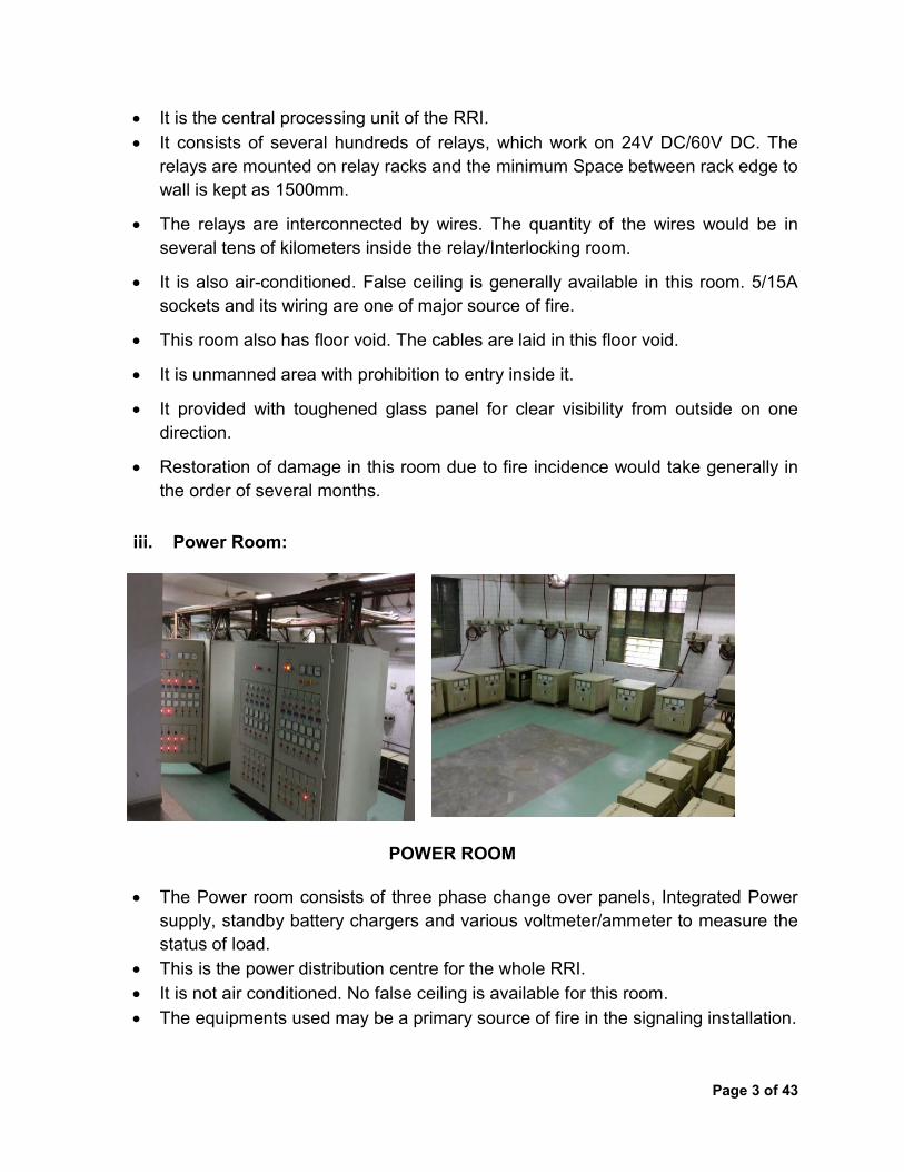
It is the central processing unit of the RRI. It consists of several hundreds of relays, which work on 24V DC/60V DC. The
relays are mounted on relay racks and the minimum Space between rack edge to wall is kept as 1500mm. The relays are interconnected by wires. The quantity of the wires would be in several tens of kilometers inside the relay/Interlocking room. It is also air-conditioned. False ceiling is generally available in this room. 5/15A sockets and its wiring are one of major source of fire. This room also has floor void. The cables are laid in this floor void. It is unmanned area with prohibition to entry inside it. It provided with toughened glass panel for clear visibility from outside on one direction. Restoration of damage in this room due to fire incidence would take generally in the order of several months.
iii. Power Room:
POWER ROOM
The Power room consists of three phase change over panels, Integrated Power supply, standby battery chargers and various voltmeter/ammeter to measure the status of load.
This is the power distribution centre for the whole RRI. It is not air conditioned. No false ceiling is available for this room. The equipments used may be a primary source of fire in the signaling installation.

Page 4 of 43
iv. Battery Room:
Battery room
Low maintenance secondary cells with rating in several hundreds of Ampere-Hour are provided as backup to the electric supply.
It is not air conditioned. No false ceiling is available for this room.
v. Cable Termination Room:
Cable Termination room
Page 5 of 43
Several hundreds of cable coming from outside is terminated on this room. The output of the cable termination rack is connected to Relay/Interlocking room. It is not air conditioned. No false ceiling is available for this room.
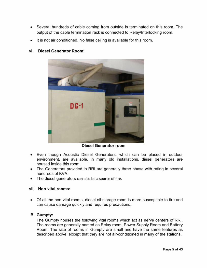
vi. Diesel Generator Room:
Diesel Generator room Even though Acoustic Diesel Generators, which can be placed in outdoor
environment, are available, in many old installations, diesel generators are housed inside this room. The Generators provided in RRI are generally three phase with rating in several hundreds of KVA. The diesel generators can also be a source of fire.
vii. Non-vital rooms:
Of all the non-vital rooms, diesel oil storage room is more susceptible to fire and
can cause damage quickly and requires precautions. B. Gumpty:
The Gumpty houses the following vital rooms which act as nerve centers of RRI. The rooms are generally named as Relay room, Power Supply Room and Battery Room. The size of rooms in Gumpty are small and have the same features as described above, except that they are not air-conditioned in many of the stations.

Page 6 of 43
3.0 General Precautions as per IS 15493 (Gaseous Fire Extinguishing Systems): 3.1 Plan shall contain sufficient details to enable an evaluation of the protected
enclosures(s) or local protection(s) vis-à-vis the effectiveness of the system. Plans for submission to the authorities shall be drawn up in accordance with the following requirements:
a. Plans for integrity of fittings shall be clear, contain all required details including scale and point of compass and shall be clearly dated;
b. Name of the enterprise, location and detailed postal address; c. Location and construction of the protected enclosures, walls and partitions; d. Cross and longitudinal sectional elevations of the protection enclosures showing
the full height, schematic diagram, ceilings, false floors, etc; e. Location of ducts and similar devices, dampers, air handling systems, venting
arrangements and their details with supporting calculations, etc.
3.2 Safety interlocks and lock-off valve shall be provided wherever required. 3.3 Exit routes which shall be kept clear at all times and the provision of emergency
lighting and adequate direction signs to minimize travel distances. 3.4 Outward swinging self-closing doors which can be opened from inside including
when locked from the outside. 3.5 Warning and instruction signs shall be arranged. 3.6 Pre discharge alarms within such areas that are distinctive from all other alarm
signals and that will operate immediately upon detection of fire. 3.7 Means of prompt ventilation of such areas after any discharge of agent. Forced
draft ventilation will often be necessary. Care shall be taken to completely dissipate hazardous atmospheres and not just move them to other locations, as agents are generally heavier than air.
3.8 Self contained breathing apparatus and personnel trained for its use (Recommended).
3.9 Means to detect a hazardous atmosphere in or around the protected area (Recommended).
3.10 Requirements for the Protected enclosures:
a. The protected enclosure shall have sufficient structural strength and integrity to contain the agent discharge;
b. The area of the un-closable openings such as ventilator openings within the enclosure shall be kept to as least as possible to avoid ingress of the agent through the leakages to the adjoining areas. Where confinement of the agent within the enclosure is not practicable, protection shall be extended to include the adjacent connected hazards or work areas;

Page 7 of 43
c. Particular attention should be given to openings around cable, duct and pipelines (similar utility services) penetrating through the wall(s) and floor(s); the openings should be effectively sealed or preferably fire studded;
d. In case of unavoidable openings, such openings should be restricted to as minimum as possible. In such cases, quantity of agent needs to be suitably increased in consultation with the authorities concerned for maintaining the desired concentration within the enclosure.
4.0 Most common causes of fire incidences:
Short circuit in electrical wiring due to overloaded / outdated or wornout wiring. Carelessly thrown lighted matches or cigarette butts. Careless use of heating appliances such as electric heater. Careless storage and handling of highly inflammable material. Overheating, sparking or arching due to electrical failures,loose connections or
faulty equipment. Absence of adequate firefighting equipments. Continuation of equipments in service which are overdue for replacement. Availability of excess waste paper, trash and other items at working place that can easily catch fire. Ignorance of maintenance or safety instructions. Non-availability of any fire escape plan. Lack of knowledge or training about fire fighting to staff. Any other cause.
5.0 Losses due to fire incidence at Relay room / control room: Damage to costly installation like Relay Room, Operating panel & Power Supply
system. Paralyzing complete signaling system Disruption in automatic train operation Severe detention to trains lasting several days Loss in terms of man hours due to deputation of additional task force to restore or
install a new system. Loss of life may also take. Heavy financial loss to Railways due to above.
6.0 Fireproofing provisions required in construction of new RRI/ Control Room: This section specifies the requirements of buildings specifically provided for the housing of equipment.
Equipment installed trackside shall be housed in buildings or location cases.
Page 8 of 43
Where the floor area requirements exceed 10.0 square metres, a building will be constructed of preferably: • cavity brick or • waterproof cavity concrete blocks or • prefabricated sandwich panel type construction. Where the floor area requirements do not exceed 10.0 square metres, the equipment housing preferably may be a: • prefabricated sandwich panel (e.g. Level crossing location); or • pre-cast concrete construction; or • location case type of housing.
All buildings for the housing of equipment shall be suitable for the climate of the area. They shall be weatherproof, with particular attention given in the design to the provision of features, which reduce degradation due to environmental factors, and overall ensure that it remains fit for purpose over its full life with minimal maintenance.
The floor level of buildings shall be 600 mm above the adjacent ground level or 150 mm above rail level whichever is the lower or as decided by Engineer-in-charge. However, where flooding occurs this floor level will be set higher at least 500mm above highest recorded flood level at the site.
Wire and cable entrances to all housings shall be sealed to prevent the ingress of moisture, rodents, termites and insects. The seal shall be easily removed for additions and modifications.
Relay and equipment racks in buildings shall be free standing and securely fixed to
the floor.
Bollard poles shall be located on all corners of the building or a minimum of four (4) installed in such a manner as to afford an appropriate level of protection for the building from damage by vehicles. These bollards shall be typically constructed of scrap rail section or similar, be 1500 mm above ground level, 400mm in ground and painted with high gloss “white” paint.
Doors, door jambs and windows shall have a minimum fire rating of 2 hours.
External doors shall be of all steel construction. Door jambs shall be formed from 3 mm steel (preferably) and sized to match the door thickness and wall thickness which is dependent on the type of building construction. The type of construction and installation has to maintain the fire rating of the door system. They shall be fitted with
Page 9 of 43
a 50 mm wide awning over the doorway. Corrosion protection of steel door and door jambs shall be carried out. Unless otherwise nominated in the Particular Specification, windows are not required in buildings.
Generally, all electrical services wiring shall be concealed or placed in ducted
skirting. Eaves lining shall be 6mm fibrous cement sheeting e.g. Versilux or equivalent. Ceilings shall be minimum two (2) hours fire resistant plaster board. All joints shall be taped and plastered.
In case of prefabricated sandwich panel buildings walls shall be constructed of 75
mm (minimum) thick sandwich panels, using 0.6 mm metal sheeting inside and outside, with fire resistant insulating material between.
The roof shall be constructed of 100 mm (minimum) thick sandwich panels, using
0.6 mm metal sheeting inside and outside, with fire resistant insulating material between.
All internal and external joints shall be neatly trimmed and sealed with silicone.
Stainless steel rivets, sealed with silicone shall be used throughout. All vents shall be waterproof, covered with metallic fly screen mesh to prevent insect
entry, and shall be filtered to minimize dust entry. Each vent shall have a minimum size of 0.03 square metres and shall be distributed to achieve maximum airflow through the location case.
Building Characteristics. Building characteristics include the following:
Configuration (area; ceiling height; ceiling configuration, such as flat, sloped beams;
windows and doors; and thermodynamic properties) Environment (ambient temperature, humidity, background noise, and so forth) Equipment (heat-producing equipment, HVAC, manufacturing equipment, and so forth) Functioning characteristics (occupied, during times, days, and so forth) Target locations Potential ignition sources Aesthetic or historic preservation considerations

Page 10 of 43
6.1 In Construction: Following fire retardant building materials may be used in construction of structure-
a. Bricks– Bricks generally have a very low thermal conductivity and nearly approach fire proof stage if all stones and foreign materials are removed from them. At the time of construction, if mortar is used with fire resistant compounds, fire resistance increases. Fly ash bricks / blocks, aerated concrete blocks are fire resistant which can withstand temperature upto 15000C. Fire Resistant mortar compounds are available in market in brand name such as ASTRO FM COMPOUND, ASTRO HS FM Compound, Silver seal fire mortar etc.
b. Concrete - The actual behavior of concrete in case of fire depends upon the
quality of cement and aggregates used. In case of reinforced concrete and pre-stressed concrete, fire resistance of component depends upon the position of steel. As per IS:456 the concrete cover for fire resistance of the member is as Table 1 below. There is no loss in strength in concrete when it is heated up to 250°C. The reduction in strength starts, if the temperature goes beyond 250°C. Normally, reinforced concrete structures can resist fire for about one hour at a temperature of 1000°C.
Table 1 Nominal Cover to meet specified period of Fire Resistance
Fire Resistance h
Nominal Cover Beams Slabs Ribs Column
s
mm
Simply supported
mm
Continuous
mm
Simply supported
mm
Continuous
mm
Simply supported
mm
Continuous
mm 0.5 20 20 20 20 20 20 40 1 20 20 20 20 20 20 40 1.5 20 20 25 20 35 20 40 2 40 30 35 25 45 35 40 3 60 40 45 35 55 45 40 4 70 50 55 45 65 55 40
c. Steel: Steel has a thermal conductivity and a thermal diffusivity over 1000 times higher than that of concrete and wood. This becomes the biggest drawback of steel when it is exposed to fire, as it results in warping and distortion. This may lead to the collapse of the structure as the steel cools.

Page 11 of 43
The creep of steel also increases at a rapid rate as the temperature of fire rises above 5500C. The extent of deformation can ultimately cause the failure of the structures. Cold-rolled steel used in steel structures loses strength rapidly when exposed to 4000C, as the fire increases the temperature. Cold-drawn wire used in pre-stressed concrete loses strength at a much faster rate. The yield strength decreases to about half as the temperature of fire rises above 6000C.
Poly steel forms used in buildings are better fire resistant, moisture proof and energy efficient. The method of construction consists of placing hollow polystyrene forms over steel rods, stacking them on top of one another and then sealing the space with cement. Thus steel gets surrounded by the polystyrene as insulating material to fire.
In fire prone places, steel columns are usually protected with brick works or by encasing in concrete. Reinforcement in concrete are protected by concrete cover. Fire resistant paints can be applied on steel grills, steel column and beams.
d. Glass & glass panel– Glass conducts heat faster than metal and when heated, tends to crack easily
because of its low thermal conductivity and uneven expansion. The cracks can be minimised by the use of glass reinforced with steel wire netting. Reinforced glass with steel wire is more resistant to fire and during cooling process, even if it breaks, fractured glasses are in their original position.
The reinforced glass has a higher melting point than the ordinary glass, and as such it is commonly used for fire resisting doors, windows, sky-lights, partitions etc. These panels are made with two or more sheets of tempered glass with an interlayer of a gel of polymer salt, which crystallizes to a solid when heated. These glass panels can delay the spread of fire by 30 to 90 minutes.
e. Aluminium– It is good conductor of heat. Melting point of aluminium is much lower than steel i.e. 6550C. It does not burn, does not give off smoke when exposed to fire and does not emit sparks on impact. It is used in door, window & ventilator frame and partition panel.
Some of the Manufactures – i. Jindal Aluminium limited ii.Hindalco, Aditya Birla Group
Page 12 of 43
f. Fire Retardant Coatings – The application of fire retardant paints on combustible wood structures reduces the flammability as it forms an insulating layer on the surface. Paints based on poly vinyl acetate or other synthetic resins in which fire retarding components like ammonium phosphate (a nitrogen compound) or a carbon-forming agent are incorporated, have properties to delay ignition by at least 10 minutes in case of fire. Calcium carbonate and calcium oxalate are used in formulations of organic coatings against fire. Heat is dissipated both in decomposition of inorganic compounds and in the intumescent fragmented particles detached from the surface by sudden gel formation. The interiors, therefore, could be treated by carbonates and oxalate containing paints which swell and decompose, and form foams, non-flammable gases, or form fragmented particles which, while leaving the surface, take the heat away, and thus cool the surface. Fireproof paint products include intumescent paint for steel, water based fire retardants, kits to upgrade wooden doors and interior wall, exterior wall, roof ceiling & floor. Fire-resistant paints are developed to meet certain levels of fire protection. Fire retardant epoxy floor coating may be provided such as ShaliFloor® SL 3E FR, Thermoguard Flame Retardant Floor Paint etc.
Some of the Manufactures of fire proof paints – i. Macromol Products, Chennai
ii. Gangotri Hi-Tech Coatings, Nagpur iii. SatyaFirotech India Private Limited, New Delhi
iv. Noble Paints Pvt. Ltd.,Mumbai. v. Shalimar Interiors, New Delhi
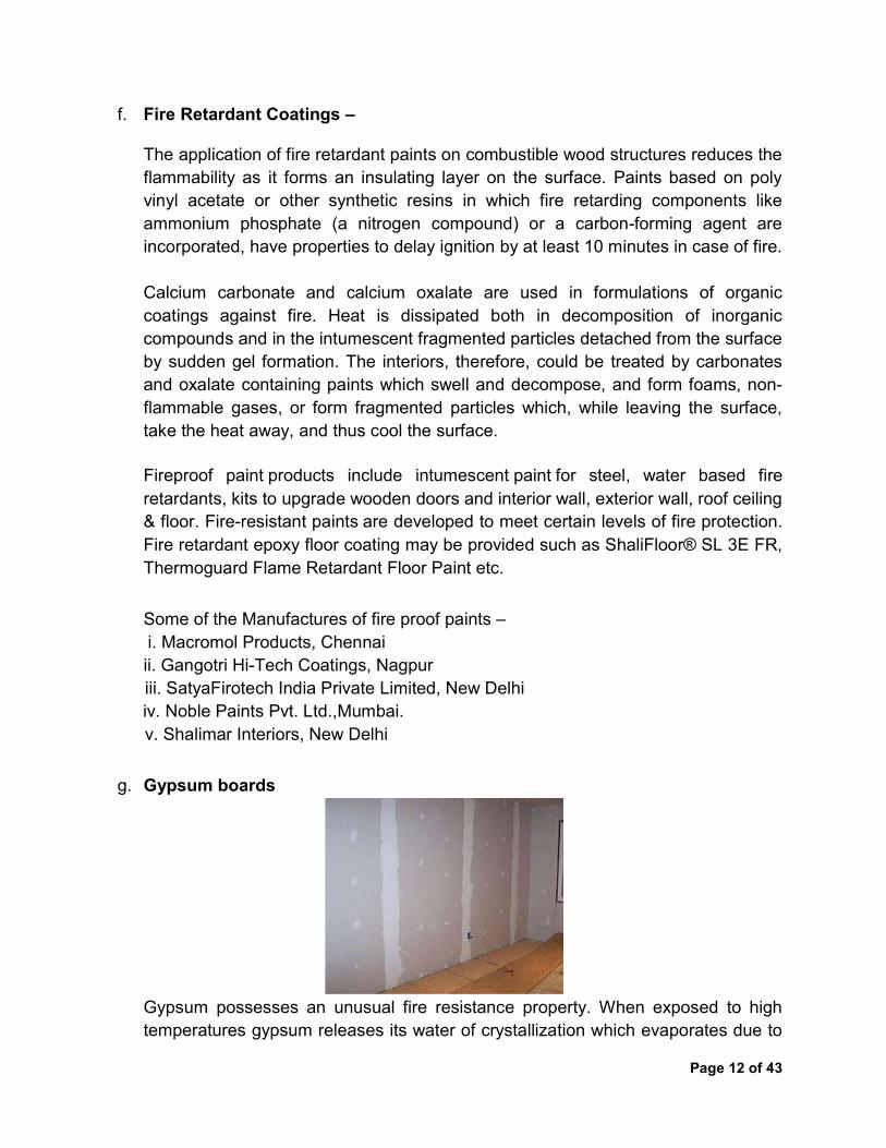
g. Gypsum boards
Gypsum possesses an unusual fire resistance property. When exposed to high temperatures gypsum releases its water of crystallization which evaporates due to

Page 13 of 43
heat from the fire. As long as the side of the gypsum plasters board facing the fire does not get completely decomposed the other face remains cool. It also absorbs heat on dehydration at high temperatures reached by the fire. Gypsum boards are used in partition and ceilings. Some of the Manufactures – i.Vans Gypsum Board, Navi Mumbai, Maharashtra
ii.Sherlock Industries, Near Narmada Rest House, G.I.D.C., Ankleshwar (GUJ) –393002.
iii. Sai India Gypsum Products Pvt. Ltd., Near Jangid Complex, Mira Road Thane – 401107.
iv. India Gypsum Pvt. Ltd., Mumbai ([email protected]) v. Gyproc, Saint Gobain, India.
h. Perlite Boards
Perlite is an amorphous volcanic glass that has relatively high water content, typically formed by the hydration of obsidian. It occurs naturally and has the unusual property of greatly expanding when heated sufficiently. It softens when it reaches temperatures of 850–900°C. Water trapped in the structure of the material vaporizes and escapes, and this causes the expansion of the material to 7–16 times its original volume. The expanded material is a brilliant white, due to the reflectivity of the trapped bubbles. In the construction and manufacturing fields, it is used in lightweight plasters and mortars, insulation and ceiling tiles. Small quantities of perlite are also used in foundries, cryogenic insulation, as a lightweight aggregate in mortar (firestop) and in ceramics as a clay additive. Expanded vermiculite and perlite, the lightweight materials used in boards or plaster possess thermal qualities which increase fire-resistance properties. Some of the Manufacturers – i. Amol Dicalite Limited, Navrangpura, Ahmedabad
ii. Perl Tech- Perlite Technology, Laxmi Chamber, Navjeevan Press Road, Ahmedabad.
iii. Santosh Chemical Co., Sola, Ahmedabad. i. Magnesium Oxychloride Cement
Magnesium oxychloride cement, a combination of magnesium oxide and magnesium chloride with inert fillers, is used in coatings, flooring, and in wood-wool boards as binder. Wood-wool boards are widely used to partitions and ceilings.

Page 14 of 43
Some of the Manufactures: i. Phulad Mines & Minerals Private Limited, Maharashtra
ii. Mantra Minerals Pvt. Ltd., Rajasthan iii. Rahul Magnesia Pvt. Ltd., Sarkhej-Gandhinagar Highway, Ahmedabad.
j. Calcium silicate boards:
Calcium silicate is one of the mostly used materials in fireproofing, which is a safe alternative to asbestos for high temperature insulation materials. Industrial grade piping and equipment insulation is often fabricated from calcium silicate.
High performance calcium silicate boards retain their excellent dimensional stability even in damp and humid conditions and can be installed at an early stage in the construction program, before wet trades are completed and the building is weather-tight. Calcium silicate boards and tiles are also available in market which can be used in partition wall as well as false ceiling, if required. Some of the Manufactures:
i. Shalimar Interiors, New Delhi ii. Ramco Industries Limited, Mylapore, Chennai. iii. Metroc, Noida iv. Supra Associates, Maharashtra v. Surani Interior Products LLP, Mumbai vi. Galaxy Interior & Exteriors, Chennai vii. M/s Aerolite Ceiling System, Hyderabad
k. Treated timber
It is not possible to make timber fully fire-resistant, however by using chemicals and paints only retard the action of fire. Timber can be rendered non-inflammable, which will not flame or glow but merely char, and will not, therefore, assist in the propagation of fire.

Page 15 of 43
Chemical methods:These include the impregnation of timber with effective chemicals, or by coating the surface of timber with a layer of noncombustible paint.
Impregnation with chemicals:The treated wood utilizes a fire retardant chemical that remains stable in high temperature environments. The treatment is done by pressure impregnation of the timber with large quantities of chemicals. The most common of which are aluminium di-phosphate and sulphate, borax and boric acid, zinc chloride and sodium tetra-borate. The treatment provides a physical barrier to flame spread. The treated wood chars but does not oxidize. Effectively, this creates a convective layer that transfers flame heat to the wood in a uniform way which significantly slows the progress of fire to the material.
As chemicals are water soluble, they are leached out due to rain when applied on exposed structures. Therefore, a second shallow impregnation with a fire-retardant, water-repellent sealer or paints like flamex and bitulac fire-retardant paint is applied, which substantially retards leaching. Paints of asbestos, magnesium sulphate, ferrous oxide etc. also have been found to be very much effective. Fire retardant salts are impregnated by pressure process. White washing is effective to some extent in retarding the action of fire.
Surface coating:The most commonly used flame retardant coatings are cement grouts, clay-sulphate paste; paints such as silicate, chloride, phosphate paints and; emulsions like chloro paraffin. Some fire retardants (chemicals) form a film on the surface of wood and decompose under heat yielding non-inflammable gases that dilute the inflammable gases and consequently retard the ignition of the latter. Some of the other fire retardants have low melting points. These melt under heat and form a barrier to the supply of oxygen to the inside.
l. Fire Retardant Coatings
A fire retardant coating can be worth hundreds of times its cost in minimizing premise damage in the event of fire and the value cannot be calculated when the “intumescent paint” contains or delays fire spread long enough to save human life. The application of fire retardant paints on combustible wood structures reduces the flammability as it forms an insulating layer on the surface. Paints based on polyvinyl acetate or other synthetic resins in which fire retarding components like ammonium phosphate (a nitrogen compound) or acarbon-forming agent are incorporated, have properties to delay ignition by at least 10 minutes in case of fire.

Page 16 of 43
Calcium carbonate and calcium oxalate are used in formulations of organic coatings against fire. Heat is dissipated both in decomposition of inorganic compounds and in the intumescent fragmented particles detached from the surface by sudden gel formation. The interiors, therefore, could be treated by carbonates and oxalate containing paints which swell and decompose, and form foams, non-flammable gases, or form fragmented particles which, while leaving the surface, take the heat away, and thus cool the surface.
m. Intumescent Coating
An intumescent coating or paint is the mixture of organic resins, binders, pigments, ceramics and refractory fillers that swell and char when exposed to fire. Intumescent coatings are sprayed on steel surfaces, and when temperature increases to a threshold point these coatings expand in the cellular form. The expansion is many times their original thickness thereby forming a protective barrier that protects the surface from heat. Substances that actually produce expansion and char formation are known as blowing agents. The blowing agents are usually dicyandiamide, melamine, guanidine, glycine, urea, chlorinated paraffin etc. Epoxy or vinyl based intumescent paints are also available but they have limited interior applications due to their toxicity. A clear intumescent paint is based on polyurethane with halophosphateeaster, asbestos, silica, fluorspar, dolomite, etc., or magnesia, fibre glass and foamed glass. These coatings are either water based with ammonium polyphosphate or oil based containing melamine phosphate with fibrous materials to increase toughness.
An intumescent paint applied at the manufacturer’s recommended rate can make it possible to comply with a flame spread rating lower than what exists on an already-installed wall, ceiling or other surface. These paints can give an extra measure of fire protection to property and people. Architects, developers, building

Page 17 of 43
superintendents and home owners can use this simple safeguard in a number of strategic ways:
As a fire retarding coating on roof timbers, floor rafters and support members. To protect corridors, stair wells between stories, and exits from buildings. On dividing walls around space heaters, furnaces, or heating plants in basements or compartmented in living areas. In working areas of a factory or process plant exposed to gas or oil-fired heaters, welding or brazing operations, handling of combustible materials. When fire breaks out, whatever the source, in an area with surfaces properly coated with intumescent paint – here are the benefits it delivers that a conventional paint cannot: Upon first encroachment of the source flame, the film foams up as much as 200 times its thickness to make continuous insulating foam composed of tiny closed cells. The greatly expanded cellular foam delays the lateral spread of fire and helps to protect the substrate beneath it. Occupant escape time is prolonged; destruction of property is delayed, reduced or avoided; restoration costs are minimized. On properly coated surfaces, the generation of combustible gasses and high temperatures that lead to flashover and the creation of lethal atmospheres is delayed or prevented. The thick, tightly-adhered foam coating thermally insulates the substrate walls, ceiling, or support member from excessive heat, thus postponing ignition. The insulation maintains the protection of the substrate for as long as hours, often long enough to prevent actual ignition. Even in severe fires that have been brought under control in reasonable time, the substrate wall, ceiling, support timber may often be scraped clean and found to be still in serviceable condition. Intumescent paints are not designed to prevent fires. They are designed to keep damage to a minimum and to “buy time” until help can arrive.

Page 18 of 43
6.2 Provision in Electrical installation–Causes and prevention of Electrical Fire- Overloading: It is the common practice that most of the people connect additional
load to the installation, without checking whether existing installation is capable of withstanding the additional load or not. Undersize cables may initially with stand additional load, but gradually due to overheating of cables, the insulation gets deteriorated and fails leading to fire.
Temporary electrical connections: Many times temporary electrical connections
are made. These are basically planned on short term basis. The quality of work involved in it is normally of sub-standard nature. Temporary electrical connections give rise to faults such as loose connections, insufficient or naked points, unstable supports, inadequate insulation etc. All these shortcomings give rise to overheating, insulation failure, spark-over and ultimately damage due to fire.
Bad contacts and loose connections: Contact surfaces contain microscopic air
gaps, dirt etc. which result in higher contact resistance, subsequent rise in temperature and continuous dissipation of heat. After continuous use, erosion in switch contacts increases so much, that even a small change in the load causes sparking at contacts. This may result in the rise of the temperature of the surroundings. In electrical circuits loose connections also cause resistive heating. The insulation of cables, wooden material, terminal boards, all constitute combustible materials. Under such circumstances when temperature of the surrounding air is high, a small spark is sufficient to ignite and cause a fire.
In addition to above following are also some common causes for electrical fires:
i. Short circuits at joints and terminations due to bare wires loosening out of the
terminals or the wires fraying out and touching other terminals. ii. Arcing at improper joints, loose connections and terminations resulting in high
temperature build-up. iii. Earth faults in wires with deteriorated insulation. iv. Short circuit due to mechanical damage to insulation. v. Heat from other sources. vi. Sub-standard installation processes.
6.2.1 Fire safety measures for electrical wiring
Following safe practices in respect of electrical wiring would help to reduce fireincidents:
Selection: 1. Prefer copper wiring/ cables. 2. Use only ISI marked wiring/ cables and related accessories.

Page 19 of 43
3. Use 10 sq mm. cable for main connection between the electricity supply meter and the main switch on the distribution board in the house/ flat and 6 mm. cable for connection between distribution board and sub-distribution board in each room.
4. Use 4 sq mm. cable for supplies to geysers, heaters and air-conditioners and such heavy loads.
5. Please refer BS 6387 regarding test method for resistance to fire of cables required to maintain circuit integrity under fire conditions.
Installation 1. Don’t install electrical power circuits and communication circuits in the same
conduit/casing. 2. Ensure that the wiring for high power consuming devices like air
conditioners,geysers, etc. run separately. 3. Seal cable passes and other openings effectively, using suitable fire protection
methods such as fire stops and fire breaks. 4. Take extra safety precautions such as reliable termination, use of continuous
wires without joints. 5. Derate the current rating of the wires to ensure that the temperature remains
safely within the prescribed limits when a number of wires are laid together in casing or conduit. Avoid temporary wiring and connections.
6. Install a master control switch outside office occupancies to enable switching off power after office hours.
7. Have a spare galvanized steel wire in the conduit for pulling a cable in future for additional circuiting or for replacing a defective cable.
8. Don’t use flexible conduits for general wiring. Protective Accessories:
1. Don’t increase the fuse capacity for preventing or eliminating frequent fuse blow-up. Prefer HRC (High Rupturing Capacity) fuses.
2. Use MCBs (Miniature Circuit Breakers) for protecting higher capacity loads like geysers, air-conditioners, etc.
3. Use separate MCB distribution boards for circuit supplying to devices/ appliances which can be switched off with the master switch and for other circuits which are not to be switched off by the master switch.
4. Use RCCBs (Residual Current - Operated circuit Breakers). Don’t depend on fuses, MCBs, etc. for protection against leakage current.

Page 20 of 43
Plug and Socket: 1. Use 3-pin (or wherever so made by 2-pin) plugs to make connections to the
socket.Never insert loose wires. 2. Provide 3-pin plug for all electrical appliances and ensure that earthing is
connected to the pin meant for earthing. 3. Don’t use 3-pin plug with earthing terminal missing or sawed-off. 4. Ensure that plug and socket fit each other smoothly and provide adequate
contact for carrying rated full load current. 5. Don’t try to force a 2-pin plug in a 3-pin socket. 6. Avoid connecting multiple appliances or circuits to a single socket.
6.2.2 Do’s and Don’ts
DO’S • Use ISI marked or Quality Control certified electrical material and appliances. • Use Earth Leakage Circuit Breakers (ELCBs) to avoid accidents from earth
leakage current. • Use good quality fuses, miniature circuit breakers and earth leakage circuit
breakers of correct ratings. • Use one socket for one appliance. • Switch off the electric supply of fire affected areas. • Use dry chemical powder type extinguishers on electric fires. • Fuses and switches should be mounted on metallic cubicles for greater safety
against fire. • Replace broken plugs and switches immediately. • Keep the electrical wires away from hot and wet surfaces. • Switch off appliances after use and remove plugs from the socket. • Switch off the Main switch when leaving the premises, home for a long duration. • Use electrical wires, cables and materials of proper capacity and insulation. • The relevant Code of practice for prevention of fire should be followed. • Ensure easy access to put off the supply. • Use switches which clearly indicate “ON” & “OFF”. • Crimping should be done with the proper size/ type of cable lug & terminal or
ferrulewith the use of proper crimping tool. • Keep the electrical switch room neat, clean and ventilated. • Use insulated wire for neutral and independent wire for earthing. • Check sockets/plugs/wirings thoroughly if any overheating marks are seen.

Page 21 of 43
DON’Ts
• Don’t use substandard fixtures, appliances. • Never have temporary or naked joints on wiring. • Don’t lay wires under carpets, mats or doorways. They get crushed, resulting in
short circuiting. • Don’t allow appliances cords to swing. • Don’t place bare wire ends in a socket, use a three pin plug top. • Do not remove plugs by pulling the wires. • Do not smoke in electrical zone. • Do not connect fuse in the neutral circuits. • Do not replace fuse unless fault is detected. • Do not plug in lamp or appliance with the switch ON. • Do not overload any electrical circuit. • Do not use water to extinguish electric fires. • Do not construct any house or structure below the overhead electric lines and
maintain the specified horizontal distance from the lines. • Do not use wires and cables with joints. • Do not dry clothes like tea towels etc. over the electrical heater, cooking pan etc. • Do not leave ovens in “ON” condition after use. • Do not sit too close to the heater to keep warm. You could easily set light to your
clothes or your chair, particularly if you fall asleep. 6.3 Firefighting precautions at Signal interlocking, RRI (Route Relay
Interlocking) /PI (Panel Interlocking) / EI (Electronic Interlocking) installations A signal interlocking installation whether PI, RRI or EI may consist of one or more of the following sections: Relay Room, Operating panel room, Power equipment room, Battery room, S&T staff duty room, SSE/JE in-charge office, DG set room, cable termination room and store room.
6.3.1 Precautions for PI/RRI/EI installations - Provisions to be made in the building before commissioning: Window air-conditioners installed in Relay room are causes of failure of power supply during summer. Excessive load in summer due to continuous use may lead to fire in relay room. Centralized cooling of Relay Room is recommended in place of window air-conditioners.
The entry of outdoor Signalling & Telecom cables in the building should be in a fully secured manner.

Page 22 of 43
There should be a provision of cable pit at the entry point outside the building/cabin in which the coils of outdoor cables to be buried with sand.
A small pond filled with water nearby should be constructed near the cable pit. Apart from emergencies like fire incidences, the water from the pond can be used in AC plant also in routine working.
Provision of openings in the wall for cable entry from one room to another should be done. The tendency of breaking wall or roof for cable entry or any other purpose after commissioning should be discouraged.
There should be provision of permanent duct for cables on each floor of the building.
Electrical layout plan and new cables should be got approved by electrical department.
From the past experiences, false ceilings are prone to catch fire therefore no false ceiling should be provided in the relay room or panel room.
6.3.2 Wiring and cabling
Signaling cables & Signaling Power Cables should not run in same path. They should be laid in separate channels orducts.
Colour coding of wires as per zonal railway instructions should be strictly followed for easy identification of different types of power supplies such as 60 V DC, 24V DC, 110 V AC etc. as well as positive and negative paths such as B60, N60, BX110 and NX110 etc.
All electrical department cables and S&T cable should also run in different paths. Where a wiring system passes through elements of building construction such as
floors, walls, roofs, ceilings, partitions or cavity barriers, the openings remaining after passage of the wiring system shall be sealed according to the degree of fire resistance required of the element concerned, if any (As per clause 4.12.1 of SP 30:2011).
Except for fire resistance over one hour, this requirement is satisfied if the sealing of the wiring system concerned has been type tested by the method specified in the relevant Indian standard. Each sealing arrangement used shall comply with the following requirements: It shall be compatible with the material of the wiring system with which it is in
contact. It shall permit thermal movement of the wiring system without reduction of the
sealing quality It shall be removable without damage to existing cable where space permits
future extension to be made.

Page 23 of 43
It shall resist relevant external influences to the same degree as the wiring system with which it is used.
Fire alarm and emergency lighting circuits shall be segregated from all other cables and from each other (As per clause 4.13.1.14 of SP 30:2011)
7.0 Fire Fighting arrangements:
Fire extinguishers should be provided both for protecting building structure as well
as occupancy hazard contained therein. The number and size of fire extinguishers required shall be determined to minimize
the hazards by the appropriate authority taking into consideration the severity of incipient fire anticipated behaviour characteristics of different materials and structure elements of buildings, rapidity with which a fire may spread, intensity of heat that may be developed, accessibility to fire, type of extinguisher, the smoke contributed by the burning material, special features of building construction and nature of occupancy (single or mixed) and electrical fitting, equipment, etc, installed therein.
Adequate number of firefighting equipments should be available inside Relay room, Power equipment room, battery room and Operating Panel room or as per zonal railway instructions at such locations from where equipment is clearly visible and easily approachable from working place.
The required number of fire extinguishers may be determined by considering any single extinguisher of suitable type or a combination of two or more types.
Always use the correct type of fire extinguisher. Only Carbon dioxide (Co2) type fire extinguishers to be used in S&T installations which are suitable for liquid and electrical fire.
7.1 Selection of Location: The extinguishers should be placed in conspicuous positions and shall be readily
accessible for immediate use in all parts of the occupancy. It should always be borne in mind while selecting locations that fire extinguisher are intended only for the use on incipient fire and they will be of little value if the fire is not extinguished or brought under control, in the early stages.
Generally, fire extinguishers should be placed as near as possible to exits or stair lands without hindering the escape routes. Wherever possible, advantage should be taken of normal routes of escape by placing these in positions where these shall readily be seen by persons following the natural impulse to get out of danger.

Page 24 of 43
The extinguishers should be available for immediate use at all times. Extinguishers should be sited in such a way that the user may not have to travel more than 15 m from the site of the fire to reach the extinguishers.
The extinguisher should be placed properly i.e. either in a trolley or mounted on wall firmly. The extinguisher should not be placed in a position where it is likely to gain heat from the surrounding equipment or process
A framed plan showing the location of fire extinguishers, means of access and other useful information should be displayed at suitable places, but should be available near to the entrance to the premises preferably.
7.2 Selection of Fire Extinguishers: Fire related to RRI /Control room may be grouped in following two classes:
i) Class B fires — Fires involving flammable liquids or liquefiable solids or the like where a blanketing effect is essential.
ii) Class C fires — Fires involving flammable gases under pressure including liquefied gases, where it is necessary to inhibit the burning gas at fast rate with an inert gas, powder or vaporizing liquid for extinguishment.
7.3 Suitability of portable fire extinguishers:
i) Class B fires — Foam, dry powder, clean agent and carbon dioxide extinguishers. This type fire extinguishers shall be used in generator room or outside the RRI/Control room. ii) Class C fires — Dry powder, clean agent and carbon dioxide extinguishers. Where energized electrical equipment is involved in a fire, non-conductivity of the extinguishing media is of utmost importance, and only extinguishers expelling dry powder, carbon dioxide (without metal horn) or clean agent should be used. Once the electrical equipment is de-energized, extinguishers suitable for the class of the fire risk involved can be used safely. This type fire extinguisher shall be used in RRI / Control room.
7.4 Fire Fighting Arrangements:
7.4.1 Fire buckets filled with water or sand - A low-technology method of fighting
small fires. Buckets have a convex, protruding bottom, rendering them useless for other purposes, thus reducing the potential for theft or misuse.
Main advantages: Cheap, reliable, and easy to use and can be quickly refilled and reinstated.Small fires can be effectively extinguished.

Page 25 of 43
7.4.2 Dry Powder fire Extinguisher
Main chemical ingredients: (Mono Ammonia Phosphate) Pressurized with N2 Gas Mono-ammonium phosphate, ABC Dry Chemical, ABE Powder, tri-class, or multi-purpose dry chemical is a dry chemical extinguishing agent used on class A, Class B, and class C fires.
7.4.3 Dry Carbon dioxide Extinguisher (CO2 type) – This type of extinguisher is highly pressurized with carbon dioxide, which is a non-flammable inert gas . If applied correctly, it reduces the oxygen content in the air around the fuel to below that required for combustion to take place. It is non-conductor of electricity. It means that carbon dioxide is suitable for use on fires where electrical systems may still be under power.
7.4.4 Clean Agent Extinguishers Like Co2, Clean Agent fire suppressant is stored as a liquid under pressure that turns to gas on discharge to air. Clean agent extinguishers were developed as an environmentally acceptable alternative to Halon. Clean Agent is effective on Class B and C fires. Clean agent extinguishers act to extinguish a fire by smothering it without damaging delicate electronic equipment external to the fire or leaving a residue. The Clean Agent does not conduct electricity back to the user making them also effective on electrical fires. For installation of clean agent fire suppression system IS 15493 and NFPA 2001 may be followed in addition with RDSO/SPN/218/2016 version 1.0-d2.
7.4.5 Foam Type Extinguisher - Main chemical ingredients: A solution of sodium Bicarbonate mixed with Turkey red oil. This can be placed at diesel generator room & fuel storage room.

Page 26 of 43
8.0 Automatic Fire Detection & Alarm System (AFDAS):
{Specification for Automatic Fire Detection & Alarm System for Signalling Installations; Document No.: RDSO/SPN/217/2016 Version No.: -2.0-d0}
Automatic Fire Detection & Alarm System (AFDAS) shall consist of all or any of the following: i) Probe type Bimetallic Heat detectors for Diesel Generator enclosure. ii) UV & IR flame detectors for Diesel Oil Storage room. iii) Heat and Smoke multi sensors for Diesel Generator room, Power Supply Room,
non-air conditioned Relay Rooms, ASM Room, and other rooms connected withsignaling Installations.
iv) Linear Heat Sensing (LHS) cable along with its interface module (for cable trays, cable troughs& cable bunch etc.)
or Linear Heat Detection System with its interface module (for cable trays, cable
troughs, & cable bunch etc.) v) Aspirating (air sampling) type smoke detectorfor air conditioned RelayRooms vi) Control Panel - For reading the signals from sensors/detectors,
givingaudio/visual alarms. vii) Other Items (OI) - like Manual Call Points at the entry and exit of
variousrooms,connecting cables, relays, Audio Visual alarms etc. necessary for commissioning & reliable operationof the AFDAS.
The AFDAS shall be self-checking & diagnostic type. It shall continuously monitor the health of the sensors/ detectors & the complete system including battery. The data regarding health & event shall be logged in the system with date & time stamp, which can be downloaded to a PC/ Laptop at later stage. The system should have capacity to store data for up to a minimum of 512 fire events and other events. The Control Panel shall be networkable to the Zonal / Divisional Railway headquarters preferably over TCP/IP and shall have clock synchronization facility.

Page 27 of 43
The detectors shall be suitable for installation in electrical cabinets, transformers, invertors, cable trays, electronic equipments, power equipment rooms, relay rooms, or any other enclosed areas, which are vulnerable for fire as deemed fit by Indian Railways.
The system shall be suitable to detect fire/ fire like situation in relay room, power equipment room, Diesel generator room, Oil Storage room, ASM room (inside Operating/Maintainer panel and change over panel) and other rooms pertaining to Signalling installation, electronic equipment, electrical wiring etc., and generate audio visual alarms.
The AFDAS shall work satisfactorily & reliably over the entire range of following environmental parameters: Temperature range shall be as per the limits specified in the concerned para. Humidity: 0 to 85 % (This is as per Para No. A26.1 of NFPA 72). In dusty, sandy, and desert conditions, the OEMs shall specify the frequency
for cleaning of the detectors, after installation to avoid false alarms. Loop controllers shall have built in interference nullifier so that separate EMI
control circuit is not required. The loop distance may be a minimum of 1.2 KM or as per the recommendation of the manufacturer recommendation of the manufacture.
or Radio frequency /electromagnetic interference and electromagnetic compatibility must be available. The limits for EMI shall be 2KV (±10%), 5 KHz (±20%) for Power supply ports and 1KV (±10%), 5 KHz (±20%) for input/output signal, data and control ports (IEC 61000 4-4).
In case it is felt necessary by the railways to add more or additional sensors to the
existing Fire Alarm System, the sensors/ detectors covered in this specification shall be backward and forward compatible for future expansions.
The Automatic Fire Detection and Alarm System covered in this specification shall also be able to generate requisite commands to activate ‘Automatic Fire Suppression System’, where provided.
It shall be possible to extend the alarm to remote location.
The working of the equipment shall not cause interference to other
electrical/electronic circuits/systems.
In case of low battery, the system shall give alarm and indication on the control panel. The AFDAS shall have provision to provide sufficient sets of Programmable

Page 28 of 43
Potential Free NO/NC contacts (minimum 3 NO and 3 NC for each room where AFSS is installed); to trigger the Automatic Fire suppression system through logical function as per RDSO/SPN/218/2016 or latest pertaining to Signalling Installations, if provided, switching off the power supply to power equipment /relay room (if required) and for interfacing with the existing Data Logger system. The Current carrying capacity of NO and NC contacts shall be at least 500mA.
The system shall not degrade the performance of relays, power equipment, wiring, cables etc. when subjected to Fire Detection & Alarm process.
The system shall be capable of working in non-air conditioned environment in the installation except for Aspirating (air sampling) type smoke detector. It shall be suitable for installation on AC/ DC electrified and non-electrified sections. It shall be suitable in all areas including where locomotives having thyristor controlled single phase or 3-phase induction motors haul passenger or freight trains and where chopper controlled EMU stocks are operated.
The general principles of the Automatic Fire Detection & Alarm System (AFDAS) shall be as follows: The response time for alarm generation from the time of detection by
sensors/detectors shall not exceed ten seconds (NFPA 72 Edition 2016 Para 10.11.1). It shall reliably transmit the detected signal to the Control Panel, so that it can translate this detected signal into suitable alarm signal and warn the railway personal for taking corrective action.
It shall monitor the health of the system. It shall Indicate or display the location of fire, status of detectors with all stages of
alarms. It shall be possible to expand the system by minimum 20% in future in terms of
various types of sensors subject to minimum of two sensors in each category. Power Supply Arrangements for AFDAS: The primary source of supply shall be
110V/230V AC to be given by Railways. In case, failure of primary power supply the system shall work on Secondary power source (battery backup) as part of the system. The minimum cut off voltage for primary shall be specified by OEM. Whenever the primary power supply fails to provide minimum voltage required for operation, the secondary source of power supply shall automatically provide power within 10 seconds (Clause 10.6.6.1 of NFPA 72 Edition 2016).
The System design shall not incorporate use of any radioactive material. A declaration shall be submitted by the supplier in this regard at the time of product approval.

Page 29 of 43
8.1 GENERAL ARRANGEMENT OF AUTOMATIC FIRE DETECTION & ALARM SYSTEM (AFDAS)
8.2 Components of Fire Alarm System - The main components of a Fire Alarm System are:
(a) Fire Alarm Control Panel (b) Detectors (Smoke, Heat or Multi-sensor) (c) Manual Call points (d) Alarm Sounders
8.2.1 Fire Alarm Control Panel A Fire Alarm Control Panel (FACP) is the system's brain, and it's capable of making rapid decisions. The detection devices detect the presence of smoke or particles of combustion and then alert the FACP about a problem; the FACP then gives information by activating visual and audible alarm signals to take appropriate action. These outputs are typically for the purpose of warning occupants on a fire alarm signal, notify the fire brigade, control the spread of heat, smoke or fire; or used for a wide variety of other purposes. From this location, the alarm system can be tested, silenced, reset, or programmed as needed. If the system uses digital addressable initiating devices, the panel will not only tell us which part of the building has the fire alarm, it will also tell us which smoke detector, heat detector or flame detector activated the alarm and where in the building it is located.
Control Panel
Smoke & Heat Multi Sensor
LHS/LHD Interface
Audio Visual Alarms
Existing Fire Alarm System
Aspirating type Smoke Detector (For Air-Conditioned Relay Rooms Preferably) Probe type Bimetallic
Heat Detector
UV & IR Flame detector

Page 30 of 43
There are four basic types of panels: coded panels, conventional panels, addressable panels, and multiplex systems. The fire alarm control panel normally contains following indicator lights and buttons that control the operation of the alarm system: Visual and audible alarm indications may be present for power, system, signal circuits, detection of fire and other functions. There shall be an “Acknowledge” button:
“System ON” indicates that the Fire Alarm System is functioning properly. “Mains ON” indicates that the main power supply is functioning. If there is a
power failure, the fire alarm system is operating on stand-by power, usually batteries.
“Battery low” indicates that battery is not charged. “Charging ON” indicates that battery charging is in progress. “Silence” indicates that alarm is to be acknowledged. “Common Fire” indicates that there is fire in any one or more zones. “Fire Alarm” or “Fire” indication of a zone indicates that there is fire in that zone
and the alarm horns, bells, or strobes have been activated. Pressing the “Acknowledge” button will turn off the alarm horns, bells, or strobes; leave the system in an alarm condition so that the initiating device in that
particular that sets off the alarm can be located. “Reset” or “System Reset” will turn off the alarm horns, bells, or strobes and
return the panel and any alarminitiating devices to their normal non-alarm condition.
Page 31 of 43
Note: On activation of fire alarm systems, the first response of on duty staff should be to press “acknowledge” button to “silence” the alarm keeping visual indications of Fire alarm in ON condition. The alarm system should not be “reset” until after the building has been evacuated, the location of the alarm has been investigated, and any problem has been corrected.
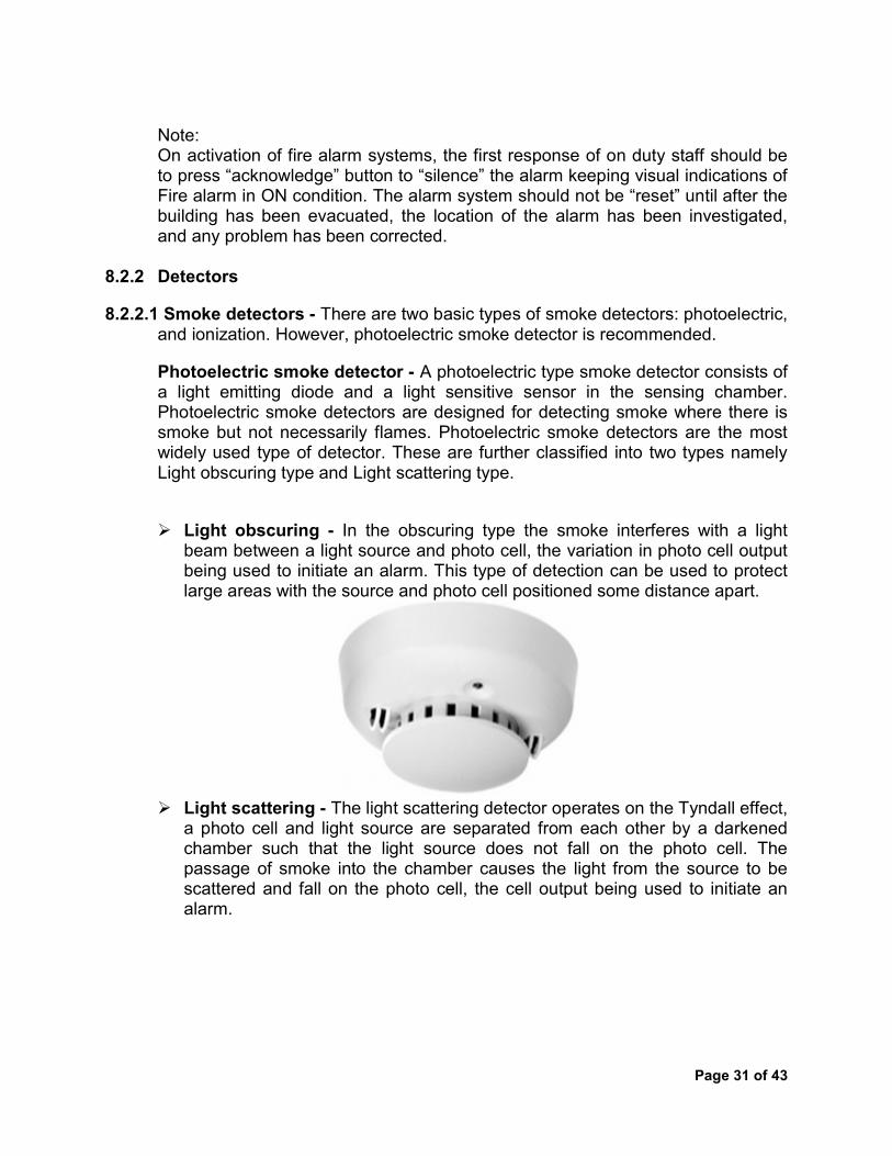
8.2.2 Detectors 8.2.2.1 Smoke detectors - There are two basic types of smoke detectors: photoelectric,
and ionization. However, photoelectric smoke detector is recommended. Photoelectric smoke detector - A photoelectric type smoke detector consists of a light emitting diode and a light sensitive sensor in the sensing chamber. Photoelectric smoke detectors are designed for detecting smoke where there is smoke but not necessarily flames. Photoelectric smoke detectors are the most widely used type of detector. These are further classified into two types namely Light obscuring type and Light scattering type. Light obscuring - In the obscuring type the smoke interferes with a light
beam between a light source and photo cell, the variation in photo cell output being used to initiate an alarm. This type of detection can be used to protect large areas with the source and photo cell positioned some distance apart.
Light scattering - The light scattering detector operates on the Tyndall effect, a photo cell and light source are separated from each other by a darkened chamber such that the light source does not fall on the photo cell. The passage of smoke into the chamber causes the light from the source to be scattered and fall on the photo cell, the cell output being used to initiate an alarm.

Page 32 of 43
It is recommended that a combination of both Ionisation and Photoelectric smoke alarms should be installed in an installation as per requirement.
8.2.2.2 Heat detector - A heat detector is a fire alarm device designed to respond when the convected thermal energy of a fire increases the temperature of a heat sensitive element. The thermal mass and conductivity of the element regulate the rate flow of heat into the element. All heat detectors have this thermal lag. Heat detectors have two main classifications of operation, "rate-of-rise" and "fixed temperature". The Heat detector is used to help in the reduction of damaged property. It is triggered when temperature increases.
i) Fixed temperature heat detector - This is the most common type of heat
detector. A fixed-temperature device will reach its operating temperature sometime after the surrounding air temperature exceeds that temperature.
ii) Rate-of-Rise (ROR) heat detector - Rate-of-Rise (ROR) heat detectors operate on a rapid rise in element temperature of 12° to 15°F (6.7° to 8.3°C) increase per minute, irrespective of the starting temperature. This type of heat detector can operate at a lower temperature fire condition than would be possible if the threshold were fixed
8.2.2.3 Heat cum Smoke Multi-sensor detector - Heat cum Smoke detectors provide fast and reliable response to photoelectric smoke and heat detection. While the smoke and heat detection circuits operate independently, their output being "OR" connected. The detector provides the fire detection performance by acting as a smoke sensor and/or a heat detector at the same location.

Page 33 of 43
This detector combines inputs from optical and heat sensors and processes them using a sophisticated algorithm. When polled by the control panel it returns an analogue count which is determined by combined responses from both optical and heat sensors. They are designed to be sensitive to a wide range of fires and may be used in place of an ionization detector in many instances.
Operating principle - Signals from the optical smoke chamber and temperature sensor are independent, and represent the smoke level and air temperature respectively in the vicinity of the detector; the detector’s micro controller processes both signals. The temperature signal processing extracts only rate of rise information for combination with the smoke signal. The detector will not respond to slow increases in temperature but a large sudden change can cause an alarm without presence of smoke, if sustained for 20 seconds.
Note: As per normal practice, the sensors are installed on the ceiling. Some of the equipments or wiring is placed at a lower height for example operating panel and its wiring. If such installation catches fire then by the time smoke reaches the sensor, it might fully burn. Hence it is recommended that the heat/smoke detectors should be installed near the likely source of fire e.g. inside the operating panel or near the wiring.
8.2.2.4 UV & IR Flame Detector - UV Flame detector makes use of ultraviolet sensitive photocathode for detecting flame. It has a narrow spectral sensitivity of 185 to 260 urn which is insensitive to visible light. Single or multiple wavelength infra-red flame detector sense wavelength in the infra-red spectrum. Almost all the materials that participate in the flaming combustion emit ultraviolet radiation to some degree during flaming combustion, whereas only carbon containing fuels emit significant radiation at the 4.35 micron (carbon dioxide) band used by many detector types to detect a flame.
8.2.2.5 Manual Call Points - A Break Glass Call Point is a device which enables personnel to raise the alarm by breaking the frangible element (Front glass) on the fascia with hammer. Manual Call Points should be mounted on all escape routes, and at all exit points from the floors of a building and to clear air. It

Page 34 of 43
should not be possible to leave the floor of a building without passing a manual call point, nor should it be necessary to deviate from any escape route in order to operate a manual call point. In order to provide easy access, call points should be mounted between 1.2m and 1.6m from the floor, and should be clearly visible and identifiable. The maximum distance that anyone should have to travel in order to activate a manual call point is 45 metres, unless the building is occupied by people with limited mobility, or a rapid fire development is likely, in which case the maximum travel distance should be reduced to 20 metres. Flameproof call points are available, also handle operated points for use in areas where broken glass may cause a hazard.
8.2.3 Alarm Sounders
i. Audio alarm sounder - This is an electronic alarm sounder used within the
control of fire alarm system, which provides an audible warning on detection of fire in any zone of the building.
ii. Sounder cum strobe - The Sounder cum strobe is designed to give the audio
& visual indication in case of emergency & fire.

Page 35 of 43
9.0 Inspection & Maintenance of Fire Extinguishers:
The owner or designated agent or occupant of a property in which fire extinguishers are located shall be responsible for such inspection, maintenance, and recharging.
Maintenance, servicing, and recharging shall be performed by trained persons having available the appropriate servicing manual(s), the proper types of tools, recharge materials and manufacturer’s recommended replacement parts or parts specifically listed for use in the fire extinguisher.
Labels indicating fire extinguisher use or classification or both shall be placed on the front of the fire extinguisher.
Periodic inspection of fire extinguishers shall include a check of at least the following items: a) Location in designated place; b) No obstruction to access or visibility; c) Operating instructions on nameplate legible and facing outward; d) Safety seals and tamper indicators not broken or missing; e) Fullness determined by weighing or lifting; f) Examination for obvious physical damage, corrosion, leakage, or clogged
nozzle; g) Pressure gauge reading or indicator in the operable range or position; and h) Condition of tyres, wheels, carriage, hose, and nozzle checked (for wheeled
units). 9.1 Inspection of Co2 type Fire Extinguisher:
Make sure the extinguisher is mounted in a location where it is visible and easy to locate during an emergency. Check the tamper-seal to verify it is not broken or missing. Ensure the pull-pin is not missing. Check the extinguisher for obvious physical damage, corrosion, leakage, or a clogged nozzle, and report if any to the concerned agency. Ensure that the extinguisher is not over due for recharging.

Page 36 of 43
Note: Carbon Dioxide extinguishers do not have a gauge. The only method for verifying a carbon dioxide extinguisher is fully-charged is to weigh the unit and verify with the weight written on the equipment.
10.0 First Aid Box: Ensure availability of First aid box in duty room. Ensure that all essential medicines and bandages are available in the first aid box.
11.0 Tentative Fire Safety Audit check List: Name of Station Division Zonal Railway Date of audit Audit undertaken by (print name) Fire Safety Management Yes No N/A Comments Has the fire risk assessment been carried out? Is the fire risk assessment record available?

Page 37 of 43
Have the identified means to reduce or remove the significant hazards been carried out? Insulated cover for Lugs of battery
terminals. Air Conditioner Fire detection and suppression device that also helps in preventing the spread of fire. Fire preventive provision for the conduits from where cables enter. Fire Granules for prevention in cable trays. Self-Contained Breathing Apparatus as per IS 10245-Part-IV and Protective dress at least two sets for each signalling installation provided with AFSS. Any rearrangement of electrical gadgets required for installation of AFSS shall be done by the purchaser. Exit routes shall be kept clear at all times and provision of emergency lighting and adequate direction signs to minimize travel distances shall be provided. All the doors shall have facility to open from inside even though they are locked from outside to allow any person to come out of the hazard area. This arrangement is to be done by the purchaser.
Have the means to control the risk and protection of people in the event of fire been carried out?
Have staffs been suitably trained for these measures? Senior Supervisors Technicians Helpers
Is there suitable monitoring of fire safety measures in place? (AFDAS/ Other fire alarm and monitoring system, Fire extinguisher/AFSS)
Can it be demonstrated that monitoring is regularly carried out?
Fire Prevention — General Yes No N/A Comments

Page 38 of 43
Is there an effective system for ensuring that the quantities and storage of all types of flammable materials are reasonable and properly controlled?
Are all areas clean and tidy with no inappropriate storage and all combustible waste properly placed in designated containers?
Is all waste regularly collected and placed in a safe place ready for collection?
Are smoking areas properly marked and used? Are all employees in high risk areas properly informed of the particular risks and the means to control these risks?
Prior to leaving the premises, are all areas inspected for potential fire and unnecessary equipment turned off?
Are there suitable means to control the risk of arson?
Has all staff received basic fire prevention instruction?
Do staffs understand the need to report any potential fire hazards?
Do staffs understand the role of self-closing and other fire-resisting doors — the need to keep them closed and free of obstruction to ensure that they will control the spread of fire and smoke?
Are all fire-resisting and smoke-stop doors, especially those on hold-open devices, closed at night?
If any permit-to-work systems are in place, are they operated correctly at all times?
Fire Prevention — Electrical Safety Yes No N/A Comments Is the entire electrical installation in order?
Has all remedial work been carried out or the

Page 39 of 43
items withdrawn? Are records regarding regular testing of installation, equipment and portable appliances up to date?
Is the use of flexible electrical cable and extension leads kept to a minimum and only short lengths used?
Is electrical equipment (eg light bulbs/fittings and any electrical heating appliances) kept well away from combustible materials?
Are staffs aware that only trained personnel authorised by management can make repairs or alterations to electrical systems and equipment?
Fire Prevention — Buildings, Plant and Machinery Yes No N/A Comments Are all fire or smoke barriers in good condition with any openings for pipes ducts, etc properly protected by provision of fire-resisting materials or fire dampers?
Are fire dampers tested regularly for correct operation and results recorded?
Are regular checks undertaken and recorded of the condition of all fire safety measures within the premises?
Fire Prevention — Means of Escape Yes No N/A Comments Are fire exits of a sufficient number and of sufficient width to enable the people present in any and all areas to evacuate safely?
Do all final exits lead to a place of total safety? Are all fire exits readily available? Are all final exits and intermediate doors easily operable from the inside without the use of a key?
Are all corridors, gangways and stairways forming part of escape routes free from obstruction and not used for storage?

Page 40 of 43
Are floor and stairway surfaces in good condition and free from tripping and slipping hazards, particularly including any external stairs and paths?
Are fire-resisting and smoke-stop doors in good condition, with fully operating self-closing devices and the doors closing fully onto rebates?
Do all doors on escape routes open in the direction of travel?
Are all escape routes clearly and properly signed throughout their lengths, with internal doors not forming part of a route clearly labelled as such?
Are all escaping routes provided with adequate lighting at all times of the day and night?
Is adequate emergency lighting provided and is it fully serviceable?
Have appropriate provisions been made for the safety of persons with special needs, such as the young, old or disabled?
Fire Prevention — Actions in the Event of Fire Yes No N/A Comments Are there clearly defined written fire action and emergency evacuation procedures, including provision for ensuring that everyone is out of the building?
Are all employees fully aware of these procedures and their own particular duties and responsibilities in the event of an evacuation?
Are suitable "Fire Action" notices prominently displayed around the premises?
Have appropriate staffs been appointed to take control in the event of a fire (Fire Marshal) and to summon the fire brigade for all fires, no matter how small?
Have appropriate arrangements been made for dealing with those who are not normally on the
Page 41 of 43
premises such as members of the public, visitors and contractors? Are the fire evacuation assembly areas in safe locations, clear of the building and away from fire brigade vehicle access and parking?
Are there alternative evacuation areas available in the event that the nominated ones are not available?
Are emergency evacuation routes and procedures checked by carrying out drills at least once per year?
Fire Prevention — Fire Detection and Alarm Systems Yes No N/A Comments Can a fire alarm be raised without placing anyone in danger?
Is the fire alarm system in full working order? Are there sufficient fire alarm call points located near to every exit from each floor and from each building?
Are all alarm call points unobstructed and clearly visible?
Are the audible signals from the fire alarm operated weekly and clearly audible throughout the premises?
Fire Prevention — Portable Fire-fighting Equipment Yes No N/A Comments Is there adequate provision of portable fire extinguishers which are suitable types for the fire risks where they are positioned (Cl. 5.1 of RDSO/SPN/217/2016)?
Are all portable fire extinguishers and fire blankets suitably located, positioned on brackets securely fixed to the wall and available for immediate use— not obstructed or hidden?
Are the locations of all portable fire extinguishers and fire blankets clearly identifiable even without the provision of

Page 42 of 43
appropriate signs? Fire Prevention — Notices and Fire Safety Signs Yes No N/A Comments Are sufficient appropriate fire safety notices and signs used throughout the premises?
Are all fire safety signs throughout the premises present, undamaged and clearly visible?
Do all "panic bar" fire exit doors have suitably positioned "Push Bar to Open" signs?
Fire Prevention — Fire Service Facilities and Liaison Yes No N/A Comments Is there adequate access to the site and all buildings to enable fire brigade vehicles to get close enough for fire-fighting and rescue purposes?
Are all fire hydrants in the vicinity clearly indicated and accessible?
Is the fire brigade familiar with the premises and any particular special hazards relating to the premises or the activities within it?
Fire Prevention — Testing, Maintenance and Records Yes No N/A Comments Are the fire detection and alarm system tests carried out and recorded?
Are the emergency escape lighting systems properly tested, maintained and these recorded?
Are the portable fire extinguishers and fire hoses properly tested, maintained and these recorded?
Is the automatic fire suppression system properly tested, maintained and these recorded?
Are any other fixed fire suppression systems properly tested, maintained and these recorded?
Page 43 of 43
Are any smoke or heat control systems properly tested maintained and these recorded?
Are all automatically closing doors or shutters and similar properly tested, maintained and these recorded?
Are any emergency generators properly tested, maintained and these recorded?
Are their suitable records of the regular fire safety maintenance tests?
Are there suitable records of fire evacuation drills?
Audit Results If all answers to the questions above are "yes" or "n/a", your fire safety procedures are currently adequate. No further action is required at this time. Simply sign and date the form in the spaces provided below. If one or more answers to the questions above are "no", your fire safety procedures are currently inadequate. Sign and date the form in the spaces provided below, and record deficiencies and remedial actions in the “Action required following fire safety audit” form. Audit undertaken by(print name) Audit undertaken by(print name)
12.0 Reference –
1. National Building Code – 2016. 2. Engineering (Signalling) specification ESC-07-03 small buildings, location cases,
terminal cases and general purpose cases of Australian Rail Track Corporation Limited.
3. Gaseous Fire Extinguishing System _ General Requirements (IS: 15493:2004). 4. Selection, Installation and Maintenance of First – Aid Fire Extinguishers – Code of
Practice (IS:2190:2010). 5. National Fire Alarm and Signaling Code 72 Handbook : 2016. 6. National Electrical Code 2011 (SP30:2011). 7. Specification for Automatic Fire Detection & Alarm System for Signalling
Installations; Document No.: RDSO/SPN/217/2018 Version No.: -2.0.
*****