STC-TRS-Conventional-05 - RDSO
179
-
Upload
khangminh22 -
Category
Documents
-
view
0 -
download
0
Transcript of STC-TRS-Conventional-05 - RDSO


Phase II - Module No. STC-TRS-Conv-05
These presentation slides are only for
training purpose. It is clarified that these
slides does not supersede any existing
provisions laid down by RDSO or Railway
Board/ Zonal Railways.
Phase II - Module No. STC-TRS-Conv-05

Phase II - Module No. STC-TRS-Conv-05
3) Trip VCB and ensure LSDJ
glowing.
4) Lower panto and ensure
both pantos are in lower
condition.
1) Apply SA9 and ensure physically that loco brakes are
applied.
2) Close BLCPD & create 10.5 Kg.cm2 pressure.

Phase II - Module No. STC-TRS-Conv-05
5) Remove ZPT from “0” position.
6) Insert ZPT in 5o clock position in HOM box and rotate it to
70 clock position in clock wise direction and observe …..
b) Existing pressure from
PANTO pipeline will
be exhausted through
HOM.
c) Grounding handle of
HOM will be released.
a) RS pressure to PANTO pipeline will be cut off.

Phase II - Module No. STC-TRS-Conv-05
7) For grounding, raise the grounding handle to upwards &
observe…..
a) Roof equipment and main transformer are connected to
ground.
b) ZPT key is locked.
c) 4 fitchet keys will be released.
d) BV interlocks will be closed in VCB control circuit.

Phase II - Module No. STC-TRS-Conv-05
8) Take 4 fitchet keys. The 4 key are provided for……
a) One for personal custody.
b) One for opening of HT-1 door.
c) One for opening of HT-2 door.
d) One for remove the locking of ladder.
Note: If HT compartment doors and ladder are not
having lock then take only one key for personal
custody.
9) Enter inside HT compartment and after completion of
work un-ground the loco in reverse procedure.

Phase II - Module No. STC-TRS-Conv-05
Sr. Test Standard Values
1All programme switches position should be
on 1OK
2Check the operation of all BL switches
& BL BoxFree

Phase II - Module No. STC-TRS-Conv-05
Sr. Test Standard Values
3Check battery voltage by keeping HBA position
"ON"95 to 105 V
4Check lighting circuit (All cab, corridoor LM, LC,
Marker light, Flasher light (Cab1+2) both positionWorking
5Q-118 Relay checking through C-105, C-106, C-
107, Q-118 drops after 5 Sec.)- ARNO locoRelay drop out
6HOM ground through ZPT key, check both arms
position.Normal
7Check the proper working of all H.T.
Compartment locks and ladder locks
Working
properly

Phase II - Module No. STC-TRS-Conv-05
Sr. Test Standard Values
81) MCPA pressure build up time for 8 Kg/cm²
2) CPA safety valve blows at
8 Minutes max.
8.5 Kg/cm²
9Close VCB through (BLIDJ ON)
BLRDJ/BP2DJ (LSDJ extinguish)Normal
10 VCB open through BLDJ/BPIDJ VCB open

Phase II - Module No. STC-TRS-Conv-05
Sr. Test Standard Values
11 QOA dropTarget dropped,
VCB open
12 QOP-1+2 dropTarget dropped,
VCB open
13
Negative bonding -
1) Test Lamp.
2) Through QOA
No bonding
No bonding
14Q100 closing time
after C118 openingQ100 pick up after 5 Sec.

Phase II - Module No. STC-TRS-Conv-05
Sr. Test Standard Values
15 Q100 closing time after C118 openingQ100 pick up after 5
Sec.
16QPDJ for VCB - Cut out
Cut in
3.5 Kg/cm²
4.6 Kg/cm²
17BLCP & BLCPD 'ON' C-101, C-102, C-
103 CloseClosed
18 BLVMT 'ON' C-105, C-106, C-107 close Closed
19One by one through QTD-105, 106 one
after another with a time delay of 5seconds
5 seconds each.
(In SIV locos all
closes at a time).

Phase II - Module No. STC-TRS-Conv-05
Sr. Test Standard Values
20MCP pressure building up for
pressure LT 09.5 Kg/cm²
21
Check ZSMGR pressure.
Check SMGR pressure drop per
notch progression/regression.
3.5 Kg/cm²
Less than
0.5 Kg/cm²
22Check reverser 'J' operation through
MPJ, LSB extinguish.
Reverser operating
properly
23 Take one notch through MP Ok.
24Check line contactors L1, L2, L3, L4,
L5, L6.Normal

Phase II - Module No. STC-TRS-Conv-05
Sr. Test Standard Values
25 Check opening & closing of line
contactors.
i) Through HVSI-1 & HMCS-1/ L1, L2,
L3
ii) Through HVSI-2 & HMCS-2/L4,L5,L6
Closing & opening properly.
Closing & opening properly.
26 Shunting contactor operation after 20th
notch.
a) Operate MPJ, S/Cont. position 1,2,3.
(Total 18 contactors)
b) If 6 S/Cont. existing on loco press
ZQWC & operate MP from 0-15 notch
(S/Cont. 1,2,4, Close & other side 3,5,6
close)
Operating properly
Operating properly

Phase II - Module No. STC-TRS-Conv-05
Sr. Test Standard Values
27EEC through progression &
regression time (0-32 notch)9 - 11 Sec.
28Function of MOM by manually (0
to 32 notch)Normal
29Take 4 to 5 notch & short Q-20. Regression coming &
SON sounding LSOV glowing (Ref: RDSO MS 211)OK
30Take 4 to 5 notch & short QD-1+2 inter lock. Regression
coming through Q-48 LSP glowing. Sander valve operated.OK

Phase II - Module No. STC-TRS-Conv-05
Sr. Test Standard Values
31
PHGR working after 5th notch &
check its stroke. Check oil flow
indicator of PHGR.
Working
properly
32
Take one notch & operate A9-
emergency/ RS auto regression
coming.
Notches
regretted.

Phase II - Module No. STC-TRS-Conv-05
Sr. Test Standard Values
33Take notch through MP
& EEC 0 to 32 notches
Notches progression
& regression properly
34
Keep MP on braking
side, check CTFs
operate & C-145 closes
(Ref : RDSO MS 383)
LSC145 glows
C145 closes
35
Take a notch in
braking, LSDBR
glowing continuously
1) Regression coming on 6th notch in
DBR with MVRF
2) Regression coming on 16th notch in
Roof mounted DBR

Phase II - Module No. STC-TRS-Conv-05
Sr. Test Standard Values
36Apply SA9, regression coming
through SWC, LSB glows.
Regression OK & C145
maintained.
37Sanding circuit in Forward/Reverse
directionWorking properly
38Wiper Servo Motor (Cab 1+2)
operation.
Operating
properly
39 Horn (LT, HT) soundingSounding
properly

Phase II - Module No. STC-TRS-Conv-05
Sr. Test Standard Values
40
Check brake releasing
through VEF on all
position of A9.
1) Brake should get released on all position
of A9 except on
emergency position
of A9.
2) On emergency position
of A9 the brake should
not get released.
41
Checking of Un-loader
modification with
contactor (CP-1+2 &
after 5 sec. CP-3)
Closing & opening properly.
42Checking of air
leakage.No leakage

Phase II - Module No. STC-TRS-Conv-05
Sr. Test Standard Values
43 Check the function of FDCS unit. Normal
44 Check the function of BPEMS.VCB open, BP drops through
IP valve notches regretted.
45
Check the function of
VCD unit by operating
A9/SA9, horn switches,
PVSA, VCD Push
button closing
(Ref: RDSO MS 382)
VCD cycle
resetted on
displays. IP valve
pick up after
penalty brake
Phase II - Module No. STC-TRS-Conv-05
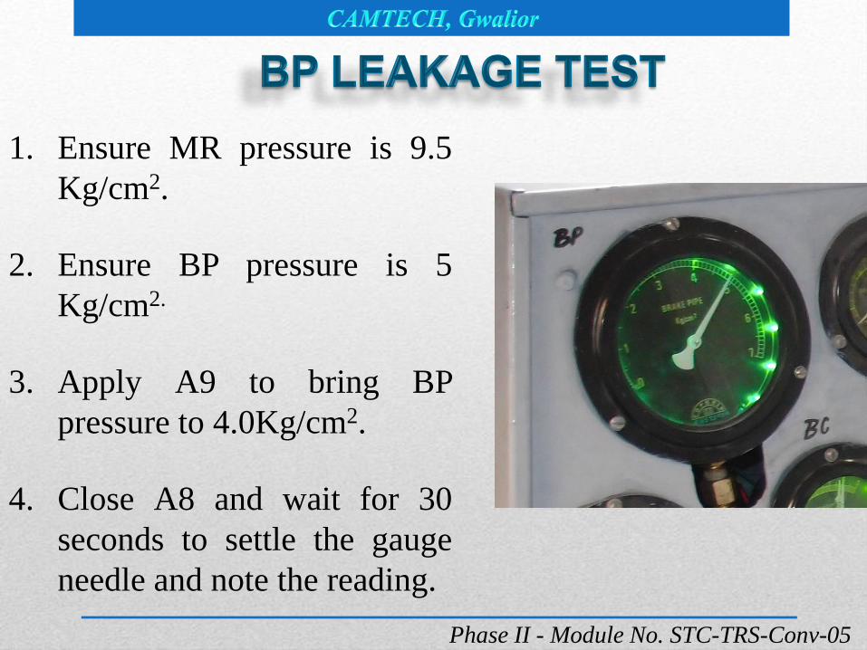
1. Ensure MR pressure is 9.5
Kg/cm2.
2. Ensure BP pressure is 5
Kg/cm2.
3. Apply A9 to bring BP
pressure to 4.0Kg/cm2.
4. Close A8 and wait for 30
seconds to settle the gauge
needle and note the reading.

Phase II - Module No. STC-TRS-Conv-05
5. Wait for another five minutes and note down the BP
pressure reading , difference of pressure should not be
more than
6. For loco : 0.7Kg/cm2 within 5 minutes (0.2Kg/cm2 for one
minute)
7. For MU formation : 1.25Kg/cm2 for 5 min (0.25Kg/cm2
for 1 minute)

Phase II - Module No. STC-TRS-Conv-05
1. Ensure MR pressure is 9.5
Kg/cm2.
2. FP pressure is 6 Kg/cm2.
3. Open FP angle cock slightly to
reach FP pressure to 5 Kg/cm2.
4. Close feed valve COC, FP
angular cock and wait for one
minute to note down the FP
pressure reading.

Phase II - Module No. STC-TRS-Conv-05
5. Wait for another 5 minutes, note down the reading.
difference of pressure should not be more than
6. For loco : 0.7Kg/cm2 within 5 minutes (0.2Kg/cm2 for one
minute)
7. For MU formation : 1.25Kg/cm2 for 5 min (0.25Kg/cm2
for 1 minute)

Phase II - Module No. STC-TRS-Conv-05
1. Keep A9 handle in Emergency
position.
2. Create MR pressure to 9.5
Kg/cm2.
3. Couple 7.5mm leak hole test
kit to BP pipe palm end.
4. Keep A9 to release position,
ensure BP pressure is charged
to 5 Kg/cm2.

Phase II - Module No. STC-TRS-Conv-05
5. Open BP angle cock.
6. When BPSW is pressed, BP pressure should not drop
below 4.4 Kg/cm2 in BP gauge after 60 seconds.
7. When BPSW is not pressed, the BP drop should be
between 2.5 Kg/cm2 to 3.5 Kg/cm2 after 60 seconds
Note: Keep number of CPs in service according to trailing
load.

Phase II - Module No. STC-TRS-Conv.-05

Phase II - Module No. STC-TRS-Conv.-05
Sr. Test Remark
1
Put all programme switches on
proper position & check the
operation
OK
2 Check the operation of HOM Free

Phase II - Module No. STC-TRS-Conv.-05
Sr. Test Remark
3 Switch on the battery &
check battery voltage.
85 Volts min
4 Raising & lowering
time of Panto 1 & 2
6 to 10 sec
5 Raising & lowering steps of Panto 1 & 2 3 steps
Phase II - Module No. STC-TRS-Conv.-05
Sr. Test Remark
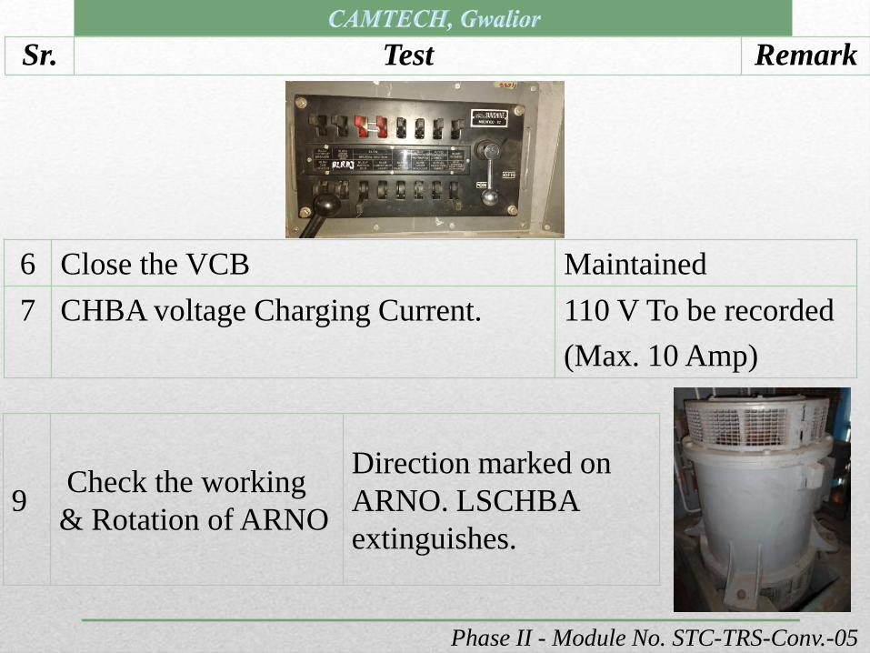
6 Close the VCB Maintained
7 CHBA voltage Charging Current. 110 V To be recorded
(Max. 10 Amp)
9Check the working
& Rotation of ARNO
Direction marked on
ARNO. LSCHBA
extinguishes.

Phase II - Module No. STC-TRS-Conv.-05
Sr. Test Remark
10Check the working of SI
Unit
Working properly on
display status "Working
OK“. LSCHBA
extinguishes.
11
See the aux. voltage
a. For ARNO.
b. For SI unit
c. Check the direction
of all auxiliary
motors working.
380 +22.5%V.
415 V
OK

Phase II - Module No. STC-TRS-Conv.-05
Sr. Test Remark
12
Stop auxiliary compressor (CPA). Leakage
from emergency reservoir & its circuit only
commencing from 8 Kg/cm² in 5 min.
0.2 Kg/ Cm² in 5
min.
13 Time taken by 1 CP (Main Comp.) to charge the system :
Ato charge the system from
0 to 9.5 Kg/cm²
a) 13 Min
(If air dryer not in circuit)
b) 17 Min
(If air dryer in circuit)
Bto charge the system from
8.0 to 9.5 Kg/cm²
a) 90 sec.
(If air dryer not in circuit)
b) 120 Sec.
(If air dryer in circuit)

Phase II - Module No. STC-TRS-Conv.-05
Sr. Test Remark
14
Pressure Governor
RGCP (C-31)
Cut in at -
Cut out at –
8.0 kg/cm²
9.5 kg/Cm²
15Check the working of VEAD
through auto drain valve
9.5 Kg/cm²
VEAD functioning MR 1+2
pressure drains for 2 sec.
16Main Reservoir safety valves
blows at -10.5 kg/cm²
Phase II - Module No. STC-TRS-Conv.-05
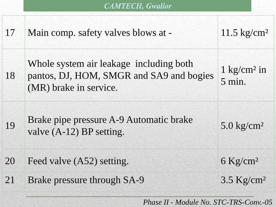
17 Main comp. safety valves blows at - 11.5 kg/cm²
18
Whole system air leakage including both
pantos, DJ, HOM, SMGR and SA9 and bogies
(MR) brake in service.
1 kg/cm² in
5 min.
19Brake pipe pressure A-9 Automatic brake
valve (A-12) BP setting. 5.0 kg/cm²
20 Feed valve (A52) setting. 6 Kg/cm²
21 Brake pressure through SA-9 3.5 Kg/cm²

Phase II - Module No. STC-TRS-Conv.-05
22 Time taken for full application of brakes
through SA-9
6 to 9 sec.
23 Time taken for brake release through SA-9
upto 0.4 Kg/cm²
6 to 10 sec.
24 Brake pressure through A-9 1.8 Kg/cm²

Phase II - Module No. STC-TRS-Conv.-05
25Brake pipe pressure drop with both cab
rubber hose pipe in service (in 5 min.)0.7 Kg/cm²
26Feed pipe pressure drop with both cab
rubber hose pipe in service (in 5 min.)0.7 Kg/cm²
27Brake drop by isolating SA-9 out put cock
in 5 minutes. 0.7 Kg/cm²
28
Operate (D-1) air emergency brake valve
(RS-1 & RS-2) and note that BP pressure
drop at a very fast rate to 0. This will result
in regression through RGEB.
Regression
OK.
Notches
regretted.
Phase II - Module No. STC-TRS-Conv.-05
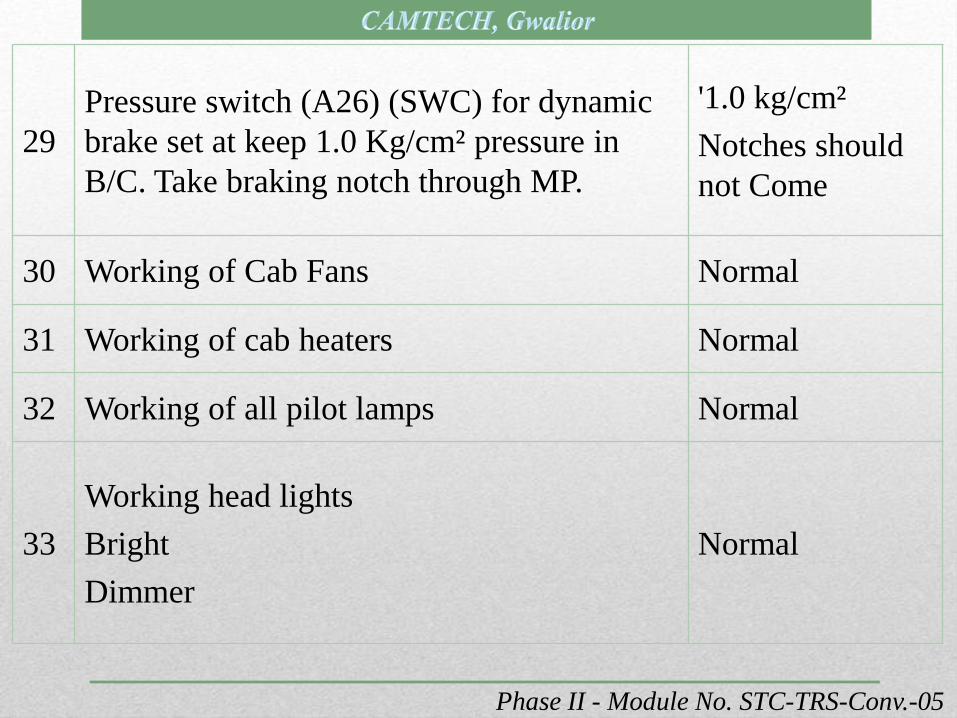
29
Pressure switch (A26) (SWC) for dynamic
brake set at keep 1.0 Kg/cm² pressure in
B/C. Take braking notch through MP.
'1.0 kg/cm²
Notches should
not Come
30 Working of Cab Fans Normal
31 Working of cab heaters Normal
32 Working of all pilot lamps Normal
33
Working head lights
Bright
Dimmer
Normal

Phase II - Module No. STC-TRS-Conv.-05
35 Desk light Normal
36 Gauge light Normal
37 NR light Normal
38 Corridor light Normal
39 H.T. Compartment light Normal
40 Flasher light Normal
41 LSGRT light Normal
34
Marker light with monitoring
box
Red
White
Normal

Phase II - Module No. STC-TRS-Conv.-05
42 Working of NR Normal
43 Working of SPM Normal
44 Check the function of QSIT relay.VCB
tripped.
45Also check the function of HSIV switch. (QSIT
bypass for 45 minutes)Ok

Phase II - Module No. STC-TRS-Conv.-05
46Function of pressure relay at various position of
programme switchesNormal
QVSI-1 Normal
QVSI-2 Normal
QVRH Normal
QPH Normal
QVSL-1 Normal
QVSL-2 Normal
QVMT-1 Normal
QVMT-2 Normal
Phase II - Module No. STC-TRS-Conv.-05
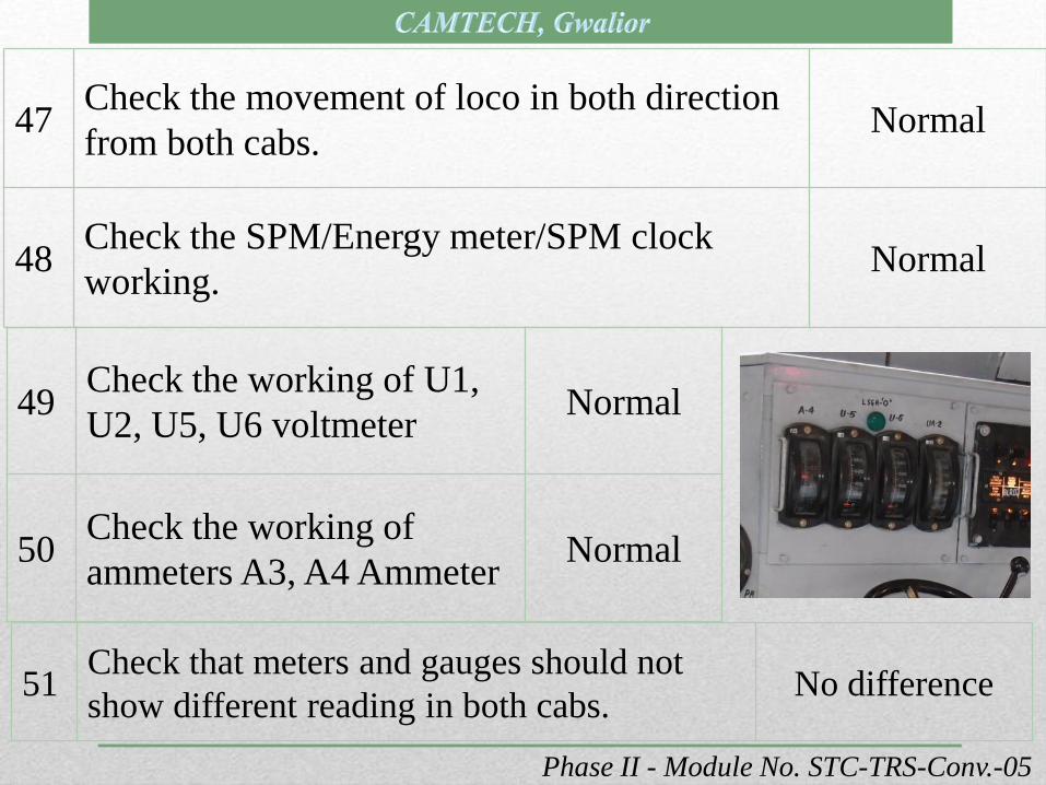
47Check the movement of loco in both direction
from both cabs.Normal
48Check the SPM/Energy meter/SPM clock
working.Normal
49Check the working of U1,
U2, U5, U6 voltmeterNormal
50Check the working of
ammeters A3, A4 AmmeterNormal
51Check that meters and gauges should not
show different reading in both cabs. No difference

Phase II - Module No. STC-TRS-Conv.-05
52Check the isolation of each TM one by
one through HMCS-1, HMCS-2.
Checked and found
normal
53
First notch tripping by HVSI putting on
2. Full notch tripping by Q46 pick up.
Half notch tripping by manually rotating
GR 1/2 notch.
VCB tripped
54Check AFL circuit with 4 mm & 7.9 mm
leak hole.
Notches regretted
LED/Buzzer sounds,
flasher light flashing
55Brake application time for passenger
service through A-9
7 to 10 Sec for 95%
of Max Pr. Build up

Phase II - Module No. STC-TRS-Conv.-05
56Check the function QD1
and QD2
Auto regression and LSP
glowing and sanding.
57Check the function Q20.
Auto regression and SON
sounding and LSOV glowing.
58Brake release time for
passenger service
10-15 sec for brake cylinder
pressure up to 0.4 kg/cm²
59Brake application for goods
service
15-25 Sec for 95% of Max. Pr.
Build up.
60Brake release time of goods
service
25-40 Sec for Br. Cylinder upto
0.4 Kg/cm²

Phase II - Module No. STC-TRS-Conv.-05
61Individual TM testing from
both cab in both direction
Respective TM working in F/R
OK. Respective meter
indicating
62 Check BP pressure at different position of A9
A Release 5 Kg/cm²
B Minimum reduction 4.5 - 4.8 Kg/cm²
C Full Service 3.4 - 3.6 Kg/cm²
D Over Reduction 2.4 – 2.5 Kg/cm²
E Emergency 0 Kg/cm²

Phase II - Module No. STC-TRS-Conv.-05
63
Take MP in braking mode & open
the DJ. Emergency brakes should be
applied through IP valve.
Brake applied
64 Check the function of VCD Check found normal
65
Check Brake Power:
Apply brake with SA-9 as per SMI-
197 Rev.01
Check found normal
66
Feed Pipe Testing:
Ensure working of Duplex Check
valve (5 kg/cm² + 0.1) in FP circuit.
Niddle of FP gauge
show deflection as
soon as MR reaches
to 5 Kg/cm²

(Ref: ACTM Vol. III Para 30514)


1. All TMs to be checked for proper
fitment of inspection covers. A cyclic
check to be conducted on all
locomotives for ensuring proper
pressure in commutator chamber of all
TMs.
2. A cyclic check should be done
on all locomotives for ensuring
proper cleaning of side body
filters.
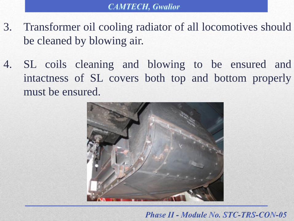
3. Transformer oil cooling radiator of all locomotives should
be cleaned by blowing air.
4. SL coils cleaning and blowing to be ensured and
intactness of SL covers both top and bottom properly
must be ensured.

5. All relays must be provided with covers along with
proper gasket to ensure dust free environment for relay
operation.
6. All blowers must be checked for delivery of rated air
output.

7. Proper working of all blower relays in the locomotive
must be ensured
8. RSI block elemex and SBs
at different locations must
be checked for dust
freeness to avoid any
chances of tracking.

9. Working of cab fans
must be ensured in all
locomotives.
10. All types of rubber
hoses must be closely
examined for their
physical condition.
11. Re-greasing of MVMT
bearing during IC to be
ensured.

12. Loco interior to be thoroughly cleaned of accumulated oil
and dust.
13. Loco pilots must be alerted to feel the axle boxes as often
as possible and their temperature should be monitored at
various out pits / sheds on return.

14. There should be no leakage of grease from axle box
front cover and rear dust guard.
15. Earthing shunts should be intact.
16. Gear case half ring and half ring felt should be properly
fitted.
17. Sun visors in both cabs should be secured.

18. Roof insulators should be cleaned thoroughly.
19. Clean oil bath filters of CP & ensure proper fittings.
20. Fuses with covers should be secured.

21. Apply petroleum jelly on reverser
contacts.
22. Cab heaters to be disconnected by
providing insulating plate in fuse
box.
23. Inspection covers, terminal covers
and bellows of traction motors
should be checked for proper
fitting and tightened by providing
necessary gasket.

25. Transformer sealing gasket should be checked and
replace if need be to avoid dust ingress.
26. No leakage of transformer oil from transformer, GR,
MPH circuit and other accessories and proper cleaning
in its vicinity.
24. Secure and properly clean
traction motor expanded
metal protective screens.

28. Battery boxes should be cleaned.
29. Top up batteries with distilled
water.
27. Ensure transformer oil in
gauge glass and oil level
in tap changer not more
than 200C. Ensure
healthy condition of
silica gel

30. Petroleum jelly to be applied on
battery connections.
31. There should be no leakage of
compound from gear case & half
ring.
32. There should be no oil leakage in
the loco from CP.

33. Ensure cyclic check of cables, dressing, bunching,
provision of gromets by March.
34. Check battery charger and adjust voltage / current.
35. RSI blocks should be checked & there should be no dust
accumulation.
36. Secure dust proof transparent covering of auxiliary
interlock assembly, RS assembly.
37. Ensure proper greasing of all TMs in IC schedule.
38. TM leads should be checked for proper cleating.

39. Proper greasing of bearings of all auxiliary motors to be
done during inspection schedules.
40. Ensure that all the auxiliary terminal covers are intact.
41. Ensure no over-aged battery in service.
42. Ensure availability of fire extinguishers in locos.


1) Test the water-tightness of loco body including roof by
means of a high pressure water jet and seal all leakage
points. (It must be ensured that the loco is well away
from live OHE to prevent the water jet coming into
contact with live wires)

a) Loco body joints and hood
joints.
b) Joints of the mounting bases
of roof equipment.
c) Head light gaskets
2) Special attention should be given to the following points
and gasket for water leakage:

d) Joints of look out glasses and corridor side glasses.
e) Door gaskets.
f) Sand box gasket and covers.
g) Joints of marker light.

i) VCB cover joints.
j) Side body filter joints with super structure.
k) Glass shutters.
l) Roof gasket.
h) Cover of multiple operation / coupler sockets.

3) Cleanliness of roof gutters and drain pipes and accumulation
of water on the roof.
5) Check the Cab floor above sand boxes for any water leakage
into the sand boxes.
4) Roof bus bars clamps should be greased to prevent
accumulation of water.

6) Roof joints with super-structure-roof gasket should be in
good fettle (condition).
7) Proper functioning of all eight
sanders by providing sand of size
between 2 microns to 20 microns
should be ensured.
8) Ensure arrangements for filling good quality of sand on
all crew changing points.
9) Ensure availability of register where acknowledgement
of drivers is taken after filling up sand.

8) Ensure entry in log book regarding functioning of
sanders and availability of sand.
9) Ensure working of sand drying plant and build up
adequate stock of dry screened sand at sanding points.
10) One cyclic overhauling of additional C-2 relay valve.
11) Proper working of wipers should be ensured.

12) Provision of head light dome and protection cap over
horns and sand boxes.
13) Replacement of Silica gel of transformer and GR
breather.
14) Overhauling and Reconditioning of air drier in VCB
locomotive on the basis of silica gel colour of desiccant.
15) Paraffin/ petroleum jelly should be applied to the
terminals of lead acid battery.
16) Check TM inspection covers and terminal blocks cover
gasket and replace them, if necessary.
17) Check the bottom covers of the smoothing reactor for
any damage, replace, if any cracking are observed.

18) Ensure proper functioning of
water separation and drain cock of
the pneumatic pipe system. During
monsoon, the pneumatic system
should be drained more often to
discharge the accumulated water.
19) Provision of RTV compound on MCP terminal box at
cable entry point to restrict water entry. Ensure gasket on
Terminal box cover or provide RTV.
20) Provision of RTV compound on axle box to restrict water
entry in axle box. Ensure gasket on Terminal box cover or
provide RTV.

23) The transformer oil and tap changer oil should be tested
for dielectric strength in a cycle before the outset of
monsoon, and filtered if BDV is less than 40 kV.
21) Provision of RTV compound
on SPM pulse generator (PG)
to restrict water entry.
22) High flood marks 9” should
be painted on the cattle guard
to give the indications to the
drivers of water levels over
the rails.
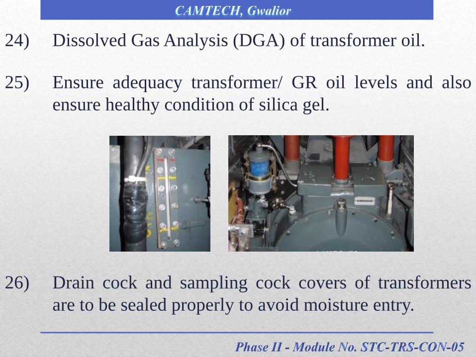
24) Dissolved Gas Analysis (DGA) of transformer oil.
25) Ensure adequacy transformer/ GR oil levels and also
ensure healthy condition of silica gel.
26) Drain cock and sampling cock covers of transformers
are to be sealed properly to avoid moisture entry.

27) Drain the compressed air pipe line
manually where the automatic drain
valves are removed and cocks are
provided.
28) Apply a coat of anti-corrosive paint on the roof bolts
while the loco comes to shed.
29) Ensure opening /closing of side window
shutters.

30) Insulation resistance of vital equipment like TM, SL
lying on shop floor to be improved by baking in oven,
varnishing and proper covering.
31) All air dryers to be in proper working order.
32) All EMU type after-cooler to be regularly drained by
drivers as well as at out pits.
33) One cycle calibration of QD relay
setting for proper pickup and dropout
current.


1 Working of heaters/ blowers in both cabs.
2 Air tightness of cab main doors,
window shutters, and sealing of
ventilator covers.
3 Cab doors and corridor doors locking handles are in
working order. Door sealing gasket should be in tight
position.
4 Main compressors oil bath should be checked and oil
replaced if necessary. Ensure that un-loaders are in
service.

Sr. Seasonal Precautions
5 Ensuring 100% working of sanders. Availability of dry
sands in all sand boxes and all covers must be air tight.
6 Proper level of oil to be maintained in TFP, GR. Silica
gel must be in good condition.
7 TM inspection covers sealing gasket should be checked
to ensure that there is no air gap and locked properly.
8 The servo motor of pantographs should be drained off
and re-greasing to be done to avoid jamming.
9 Ensure proper cleaning of roof line and pantograph
insulators.

Sr. Seasonal Precautions
10SMGR servo motor cylinders to be cleaned and re-
greased.
11
Battery terminals should be checked for sulphation,
cleaned and petroleum jelly to be applied on the
terminals.
12
Brake cylinder adjustment should be carried out and re-
greasing done. Free movement brake cylinders are to be
ensured.
13Ensuring 100% provision of gasket and glasses for TK
panel doors.

14.Restoring proper functioning of head light & Flasher
light.
15.Ensuring 100% replacement & cleaning of gasket of
body side filter & measurement of pressure drop.
16. Ensuring 100% functioning of Marker light.
17. Air dryer must be in working order.
18.Ensure draining of moisture from all MR and free
movement of drain cocks.

Reference
RDSO letter no. EL/0.2.2 dated 06.12.2016, 27.07.2010 and
RDSO’S REPORT NO:ELRS/PR/0113(Rev- ‘0’), August 2006
NOTE: For complete details please refer above letters and
reports and latest instructions issued by Railway
Board, RDSO. This is only for training purpose.

The fire in electric locomotives, even at a very small
scale is a very serious incident. The fire or smoke
emission cases generally lead to disruption of traffic
and makes the troubleshooting of locomotive more
cumbersome as there is a panic among the crew,
invariably. In some of the cases, the fire leads to
complete damage to the electric locomotive. Therefore,
there is a need for complete elimination of the origin of
fire even at a very low level.

The fire, as an effect, its control and elimination can be
categorized in 3 parts –
(A) The originating point of the fire.
(B) Need of immediate curbing the further
propagation of fire by using fire retardant
materials and components.
(C) Use of fire fighting arrangement, in case the
fire has taken place.


Transformer:
1. DGA of transformer and GR oil should be carried out as
per RDSO SMI No. 138 during every IC schedule. DGA
plants should be covered by an AMC and calibration
should be done on daily basis with standard gases as
recommended by OEM.
Special watch should be kept
on the transformers who have
completed more than 12 years
in service.
2. Break down value of the transformer oil and GR oil should
be checked as per IS:6792/1992 during every IC. All the
sheds and workshops should have minimum two BDV
testing machine which should be calibrated every 6 months.
3. The centrifuging of transformer oil and GR oil should be
done during every AOH besides during changing of
transformer and GR .
4. The centrifuging of the transformer oil should done as per
RDSO's guidelines and IS - 1866-2000. The cold
centrifuging for minimum 4 hours must be done, before
switching on the heaters of the centrifuging plant.

5. During POH of locomotives, core of the transformer
should be lifted for cleaning, checking, tightness of
pressure bolts, gasket changing etc.Also, the
transformers who has completed 18 years or likely to be
completing 18 years of life in service should be
thoroughly checked during POH by the workshops and
their rehabilitation should be planned as per the
recommendations of the committee on codal life of the
equipment.

6.1 The working of PHGR
should be ensured during
inspection, trip inspection
or testing of locomotive.
The same should be
recorded in log book if it
stops working. All the
operating staff should be
counseled.
6. PHGR:
All the PHGR should be modified so as to avoid sticking
up of the PHGR during service.

6.2 If the locomotive is to be attended after PHGR has
stopped working for sometime or PHGR is not
found working, in this case the oil accumulated in
the pipe line of PHGR should be flushed and
cleaned with new oil that accumulated dirt and
other impurities do not enter into the GR oil.

The maintenance of GR should be done as per RDSO's
guidelines which are as under-
1. Materials are procured from RDSO’s approved sources
only.
Tap Changer (GR):

2. Replacement of material should strictly be in terms of
AOH/IOH kits by sheds and POH kits by the workshops
during POH, this will be in addition to other parts required
to be replaced as and when required.
3. The items of one GR
components should not be
intermixed with other GR.
4. There should not be any
piecemeal replacement of
items.

5. GR should be opened for thorough checking, flushing
with oil after every 6months.
6. Checking of transformer and GR safety valves should be
done whenever GR cover is opened or transformer is
taken out for maintenance.
7. The filling up and topping up of the oil in GR should
invariably be done directly from centrifuging plant (not
manually by carrying in container).
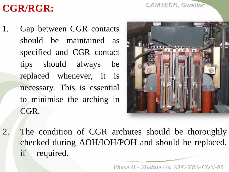
1. Gap between CGR contacts
should be maintained as
specified and CGR contact
tips should always be
replaced whenever, it is
necessary. This is essential
to minimise the arching in
CGR.
2. The condition of CGR archutes should be thoroughly
checked during AOH/IOH/POH and should be replaced,
if required.
CGR/RGR:

1. Re-cabling of locomotive
having Elastomeric cables
should be done after 18 years
i.e. during Mid Rehabilitation
of locomotive or second POH
in freight locomotives, third
POH of coaching locomotive.

2. Use of electrometric cable and thin walled cables should
strictly be as per RDSO's specifications only.
3. While laying out or replacing the power, auxiliary and
control cables sharp bends are to be avoided.
3.1 Use of neoprene base rubber insulated sheets should
be extensively used for protection of cables against
mechanical damage at bends or at the critical
locations where there are chances of cables coming
into contact with sharp edges of locomotive metallic
part.

4. All the cable cleats should be of SRBGF(IS:1 0192 UP1
grade) and procured from CLW approved sources only. In
no case use of wooden cleats, wooden supports or any
other wooden or bakelite material should be used in the
vicinity of the power/auxiliary/control cables.

5. All cable cleats must be checked for presence of positive
gap in full tight condition.
6. All the cable lugs and ferrules must be of the sizes, which
is suitable for a particular size of cable only. Availability
of all the sizes of cable lugs and ferrules must be ensured
by the sheds and workshops so as to eliminate the use of
wrong size of cable lugs, even by mistake or otherwise.
7. Lying out of the cables should be such that power,
auxiliary and control cables should not get mixed. This is
to be ensured by CLW and POH shops during
MTR/POH.
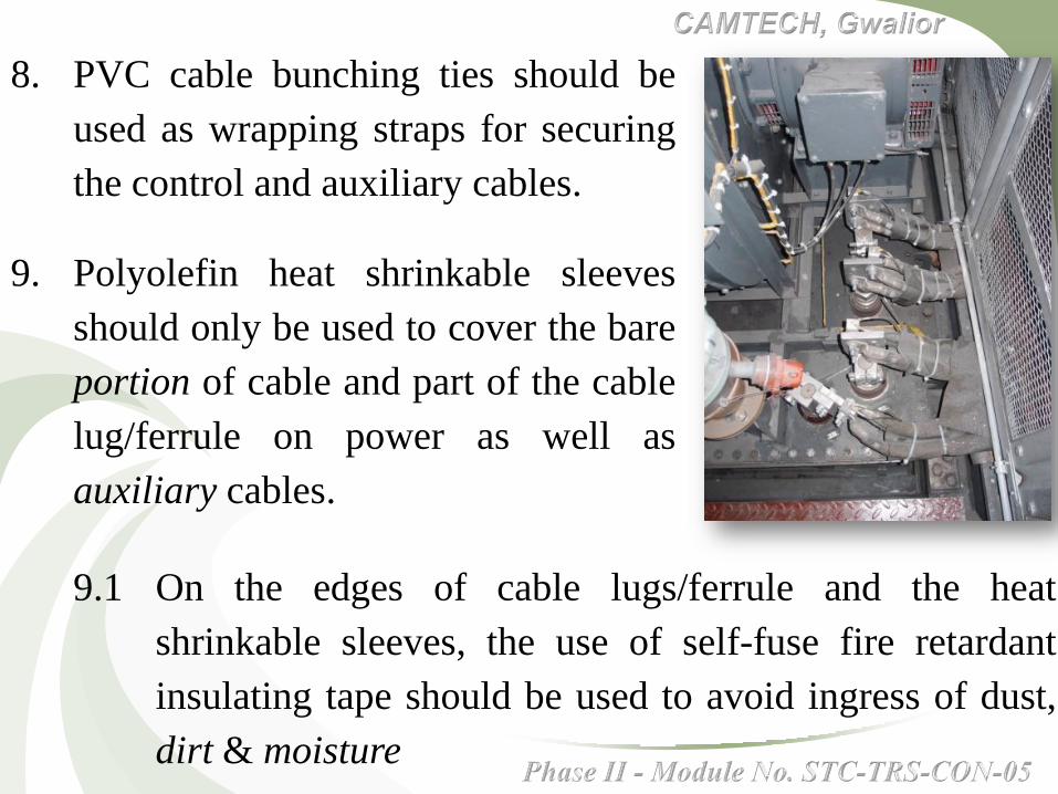
8. PVC cable bunching ties should be
used as wrapping straps for securing
the control and auxiliary cables.
9. Polyolefin heat shrinkable sleeves
should only be used to cover the bare
portion of cable and part of the cable
lug/ferrule on power as well as
auxiliary cables.
9.1 On the edges of cable lugs/ferrule and the heat
shrinkable sleeves, the use of self-fuse fire retardant
insulating tape should be used to avoid ingress of dust,
dirt & moisture
10. During the major schedules i.e. AOH/IOH/POH, all the
holes through which the cables passes, should be checked
for sharp edges, burrs and availability of proper size of
grommets should be ensured in proper condition.
11. In no case the joining of the cables should be permitted
even for emergency operations for short duration. The cable
layout should be in one piece and with end to end having
proper lugs.
12. The ferrule of traction motor connection cables should be
checked during every disconnection of traction motor in
locomotive i.e. during every lifting. The replacement of
ferrules should be strictly as per the size of cables.

12.1 The traction motor cable ferrules size is also to
match with size of cable connectors (PG clamps)
so as to avoid any looseness of the connection in
junction box or flash over. Also, to avoid cables
coming out of the clamp.
13. Proper care should be given so
that traction motor cable is
not under tension. Proper
supporting cleats with chain
arrangement with the body
must be ensured during
maintenance of locomotives.

14. Use of 10 sq.mm cables from HBA to HOBA in place
of 3 sq.mm cable.
15. Sharing of current among the
cables going from transformer
secondary bushing (a3 & a4 as
well as a6 & a5) to rectifier
ie. 4 nos. each is not equal.
Out of these four cables, one
cable is drawing nearly 40% of
the total current. Thus, over
loaded and prone to pre-
mature failure.

Hence, these 8 cables going from transformer to rectifier
should be checked for their condition. If the condition is
found to be bad i.e. over heating mark or insulation
getting brittle or otherwise should be changed as and
when noticed.
16. The cable cleats which are not to be opened or loosened
during routine maintenance should be opened for
cleaning and replaced with SRBGF (Synthetic Resin
Bonded Glass Fabric) with the provision of additional
neoprene rubber sheet during IOH & POH of the
locomotive.

1. Repair and maintenance of the smoothing reactors
should be carried out as per RDSO’S Modification
Sheet No. WAG5/15. As per the modification sheet
the gaps between core and inner coil and gap
between outer- coil and inner coil should be
maintained, besides the other routine maintenance
practices.
2. Use of the materials specially SRBGF wedges,
sheets, stainless steel cross channels and pressing
bolts should be used.

3. SL cover should be opened during every IC and blowing
of SL should be done for removal of dust and dirt.
4. During IOH/POH of locomotive SL should be taken out
for cleaning, baking and varnishing and check the
condition of insulation specially at the corners.

5. All the SL30 should be checked for gaps between inner
coil and core and outer coil and inner coil. If gaps are not
within the permissible limit specially between core and
inner coil, the SL should be taken out for repairs. This is
very much essential for proper cooling of SL.
6. All the cable connections of
SL should be thoroughly
checked during IC
inspection and during AOH
of locomotive by sheds.

1. QLM:
1.1. All the QLM relays having mechanical locking
arrangement should only be used.
1.2. QLM relays should
be taken out from
locomotive during
AOH for testing and
setting on test bench.

As per practice in vogue, the sealing of QLM relay has to
be ensured during every inspection & trip checking of
locomotive. The breakage of seal is to be reported by the
drivers.
2. Thorough investigation of locomotive should be done for
the cases having QLM dropped without any apparent
reason. No locomotive should be allowed without proper
trouble shooting and fact finding.
3. The continuity of the QLM circuits from TFILM to QLM
should be checked during every inspection ie. lA, IB & IC
or whenever center hood is disconnected for maintenance
purposes.

4. The CT ratio of TFILM
should be checked on
proper test bench during
IOH of locomotive.
However, sheds are advised
to have a drive for one
round of this checking and
keep the record of the same
immediately. CT's with
more than 5% of error
should be discarded.
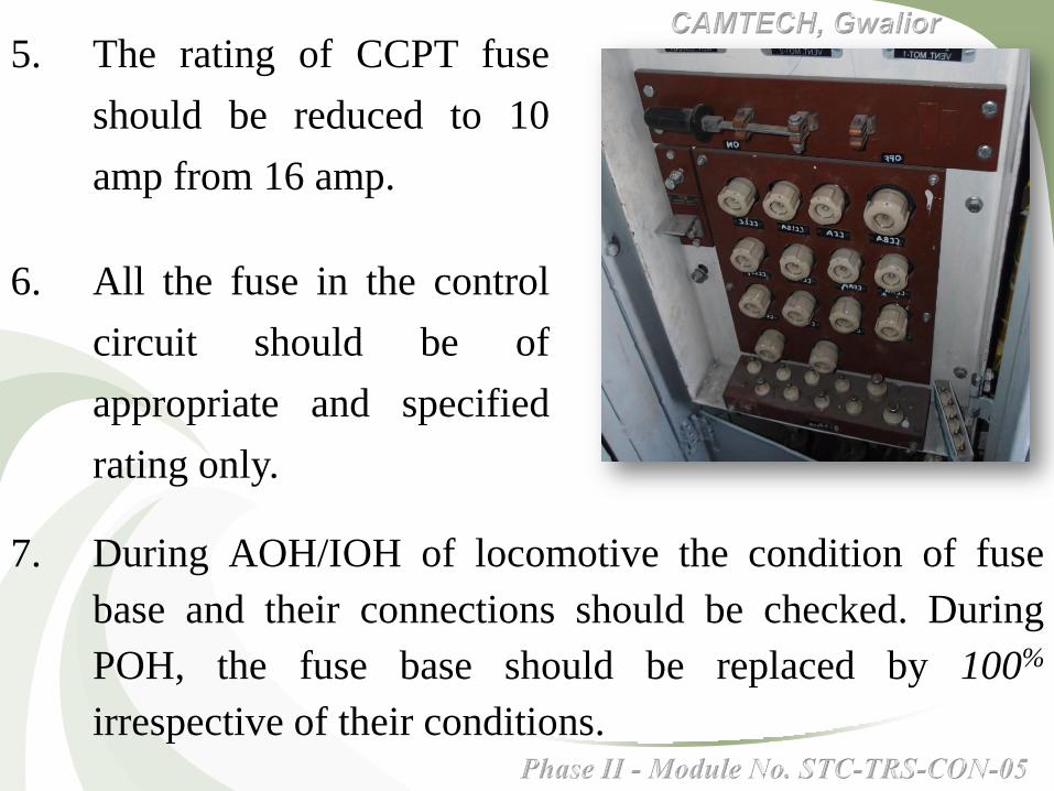
5. The rating of CCPT fuse
should be reduced to 10
amp from 16 amp.
6. All the fuse in the control
circuit should be of
appropriate and specified
rating only.
7. During AOH/IOH of locomotive the condition of fuse
base and their connections should be checked. During
POH, the fuse base should be replaced by 100%
irrespective of their conditions.

8. The condition of air flow relays must be ensued during
every inspection including the trip inspection. No
locomotive should be allowed in service with air flow relay
isolated except for a very short run and with a continuous
watch by the crew on the associated machine.
9. Use of flap type air flow relays
should be discontinued and
ROSO instructions and
approved sources for air flow
relays should be used.

10. Transformer earthing
connection (A0) with the
locomotive body must be
ensured whenever
transformer is lifted and
fitted back. Even sheds
may ensure this
connection during every
inspection of locomotive
visually.

11. The separation of Q20 terminals on BA3 panel should be
done by a thin glass- fibre separator. This is to avoid
shorting of terminals due to creepage since there is a
potential difference of 750 V between these two
terminals.

12. All relays should be provided
with proper relay covers
having sealing gasket to
avoid ingress of dist/dirt and
moisture.
13. All relay foundation should
be thoroughly checked
during every inspection of
locomotive by the sheds.

1.0 During multiple unit (MU)
operation LSOL circuit should
be maintained in proper
functional order. In all the
locomotives it should be
commissioned.
1.1 During multiple loco
operation, it should be ensured
that LSGR glowing for leading
and trailing locomotives
should be made independent.

1. The separation of phases in TK panel with a provision of
glass fibre separators should be ensured.
2. The maintenance and replacement of
contact tips, testing of magnetic coils
should be done as per maintenance
schedule. The contact pressure should
be measured and maintained during
every inspection of locomotives.
As far as possible, the replacement of
tips should be in pairs only.
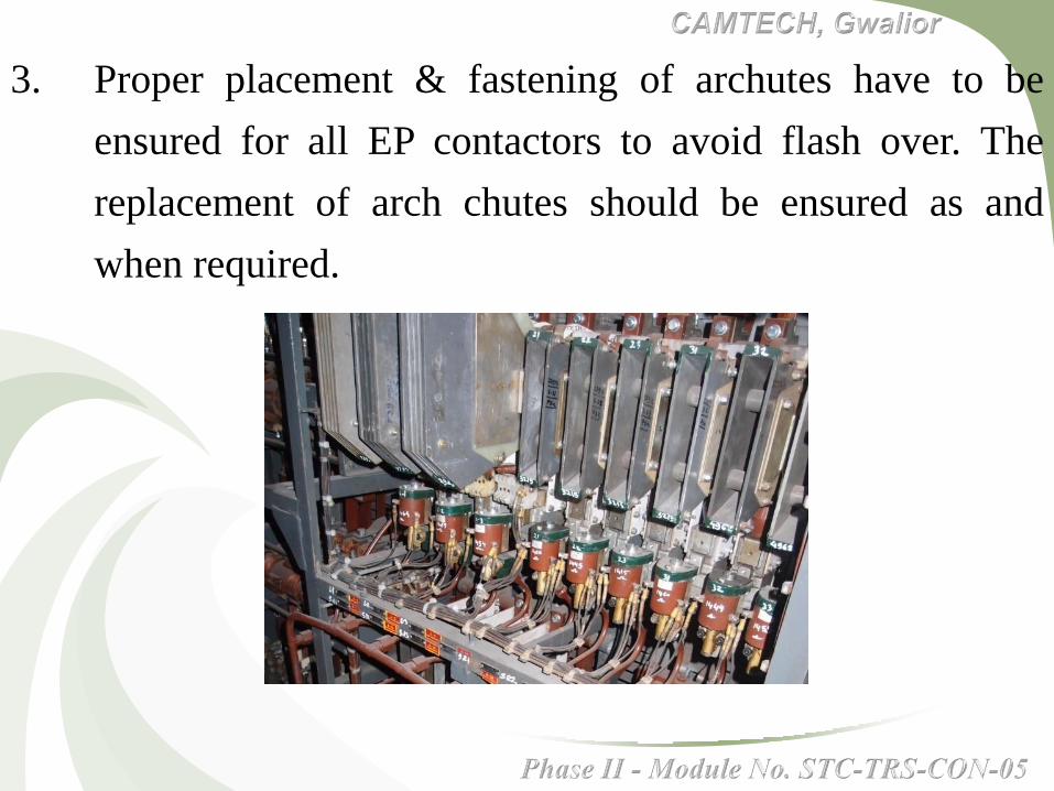
3. Proper placement & fastening of archutes have to be
ensured for all EP contactors to avoid flash over. The
replacement of arch chutes should be ensured as and
when required.

4. All the scheduled maintenance practices for EP
contactors i.e. contact pressure contact gap, proper
condition of fixed and moving contact tips should be
ensured during every inspection of locomotive. The
traction motor line contactors tips should be replaced
during AOH/IOH/POH of the locomotive by sheds and
workshops.
5. The condition of reverser drum, fixed and mobile
contacts pressure and matching of contacts must be
ensured during every inspection of locomotive.

6. The condition of flexible shunt should be checked for
EP/EM contactors and reverser during every inspection
of locomotives and they should be replaced immediately
as and when required to avoid flashovers.

1.0 Locomotive body:
1.1 Cleaning of side body filter
with pressurized water jet and
air blowing must be done
during every inspection of
locomotives.
1.2 The condition of side body
filters should be maintained
and replacement should be
planned as and when required.

1.3 100% replacement of side body filter should be
done during POH of locomotive by the
workshops.
2.0 All locomotives opening at the cable entry points or
otherwise must be blocked by suitable rubber materials.
3.0 All-the drain pipes meant for draining out of excess
compressor oil, transformer oil should be maintained in
proper condition and checked during every inspection of
locomotives.

4.0 Water leakage:
4.1 All roof gaskets must be changed during POH& IOH
of the locomotives. Condition must be checked
during AOH of the locomotive also and same should
be replaced, if found necessary.
4.2 The rubber gasket for central hood should be checked
thoroughly with respect to its condition as well as
proper placement during removal of central hood
along with VCB.

4.3 All sheds and workshops should have water leakage
testing facilities minimum at two locations i.e. on each
sides of Electric Loco Sheds for water leakage testing.
4.4 All pre-monsoon/rainy season precautions must be taken
by loco sheds and workshops by two months prior to the
monsoon season so that all locomotives attended before
the monsoon.
5.0 All apertures and opening from doors, sky light glasses
should be blocked by proper fitment of rubber gasket and
sealing compound by the sheds and workshops.

6.0 All traction motor should be checked for any ingress of
CP oil during every inspection. Immediate attention
should be given.

7.0 Proper securing of footplates in
corridors and HT compartment
area must be ensured with all
fasteners intact lest there would
be physical damage to control
or other cables coming into
contact with the loose metallic
footplates.
This should be ensured by loco sheds after each and
every opening of footplates during routine inspection,
checking or otherwise.

1. The condition of capacitors, specially at the terminals
should be closely checked during every inspection of
locomotive against any symptom of loose connection or
terminal is loose. The capacitors should be replaced
immediately, if it develops sign of bulging, flashing etc.

2. Proper indicating fuses of rectifiers
should be used. In no case shorting
by wires in lieu of fuse should be
allowed.
3. The failed device of the rectifiers
must be immediately changed.
4. The working of locomotive by
passing the QVSI must be
prohibited.

1. All auxiliary motors
should be provided with
epoxy glass terminal
boards as per RDSO’s
guidelines.
2. All auxiliary motors
must be provided with
proper terminal covers
with proper fastening
and sealing with rubber
gaskets.

3. The condition of cable lugs and cables must be checked
against cutting of strands or lug getting loose during every
inspection as well as changing of auxiliary machine.
4. The rotation of MPH, MVSL, MVRH & MVSI should be
carefully checked and ensured whenever the auxiliary
machines are changed or disconnected.

5. Even a slight oil leakage from MPH should not be
permitted for long in service.
6. Extra care should be given for cleaning of MPH area
during all the inspection of locomotive and whenever,
MPH is changed.
7. All auxiliary machines should be closely watched by
maintenance and running staff against any abnormal
sound which may lead to generation of heat, sparking or
smoke emission.

1. Compressors are to be maintained as per OEMs
recommendations.
2. The replacement of spares
during overhauling or
otherwise should be in the
form of kit, specially for HP&
LP valves to avoid throwing of
excess oil and leakage.

3. During every inspection of locomotive accumulation of
oil should be watched under SA panel and suitable
remedial measure must be taken.
4. The filling up/ topping up of the oil should be done with
the help of proper funnel by the shed and outstation staff
too.

1. The flash over in traction motors can be minimized by
taking care of, the following important schedules/
attention of items during overhauling as well as in routine
maintenance –
(a) V-cone cleaning of the armature should be done
strictly in every IC schedule.
(b) The condition of arching studs/horns should be
closely monitored for their gaps and proper shape.

2. During overhauling of traction
motor ovality checking during
commutator turning, proper
mica under cutting and proper
champheuring of commutator
should be done.
(c) As per practice in vogue, the use of anti tracking
varnish, cleaning of BHRR, proper spring tension of
carbon brushes, proper use of carbon brushes etc.
should not only be continued but needs close
monitoring and keep proper records.

3. The condition of inter-connecting leads, terminal board
and insulators should be thoroughly checked for flash
marks or any other abnormality during overhauling or
during lifting of locomotive, before reconnection.
4. All the insulating materials, insulators and other such
items should only be procured from approved sources.

1. The under frame brake rigging items should be kept in
cleaned condition, specially, in the vicinity of brake blocks
and wheels. There should not be accumulation of
polythene items, paper and animal dung to avoid smoke
emission due to likely sparks from brake blocks or
otherwise.

2. Traction motor body,
junction boxes also should
be kept in cleaned condition
in every inspection.
3. The removal of muck and
foreign materials from the
cable carrying ducts, junction
box in the under frame of
locomotive should be ensured
during AOH, IOH and during
lifting of locomotive.

4. Checking of roof bars, its fixation arrangement of
pantograph shunts should be checked during every
inspection and replacement should be done, if required,
immediately.

5. Cleaning of panto foot insulators, roof line insulators,
insulators of VCB, lightening arrestor, bushing portion on
the roof of the locomotive should be kept in cleaned
condition during every inspection of locomotive. The
accumulation or presence of any form of foreign material
should be immediately attended.

a) Presently, the fire
extinguisher of 05 kgs.
capacity DCP type are
being used in each
locomotives with two nos.
in each cab i.e. four nos.
in each locomotive.

b) The maintenance and periodic checks on DCP type fire
extinguishers should be as per IS: 2190 of 1992 ( Code
of Practice for selection installation & maintenance of
portable fire extinguishers ). The salient features of this is
as per clause 10. 8 which deals with the quarterly
checking , replacement of powder and its quality,
checking of gas cartridge by weighment, checking of end
fittings, life of fire extinguishers' and sample checking.
The fire detection and automatic fire fighting arrangement in
Locomotives would also be tried with state of art technology
and reliability.


Switch off OHE supply by opening the controlling
isolator and provide pad lock in OHE isolated
condition in supervision of maintenance in-charge

Earth OHE by providing earth discharge rods on both
ends
The sequence of fixing discharge rod should be first
by connecting clamp to earth and then connect to
OHE
Earthing pole
Earthing clamp

Provide “MAN AT
WORK” board at
both side of the loco
Always use ladder provided in
loco for accessing to the roof
of the loco.

Put battery switch HBA on “OFF” position and
remove battery fuse CCBA before doing and work
on loco.
Ground the locomotive by operating earthing switch
HOM

Do not leave any tool,
cotton waste or any other
foreign material on the loco
Always use helmets and boots
while working on locomotive.

Use 110 V hand lamp/torch
wherever required
Regularly check the
condition of hand lamp lead
Drain pressure/
water from CDC’s
and reservoirs

Always discharge the meggered circuit to ground
with the help of flexible insulated wire after
meggering.

Ensure that loco is in de-energised condition and
ground the locomotive with earthing switch HOM
Provide proper wheel skids on both sides of the loco
before working in under frame.

Do not drop oil/grease on the
pits as staff may slip and get
injured
Do not leave released brake
blocks and other hardware
inside the pits.
Close BC cut-out-cocks before
working on brake rigging

Keep fire extinguishers
and sand buckets with
full of sand.
Do not energise the loco
without permission of the
in-charge concerned.

Before energising loco,
lock all the doors of the
HT compartment.
Switch “ON” earthing
switch HOM
Before energising the loco,
give “HT ON” warning
loudly at the corridors.

Ensure working of A9
and SA9 brakes and
Only authorised person
should drive loco for any
purpose.
Ensure availability of fire
extinguishers and buckets
filled with sand at fire
sensitive places.

Follow safety norms and speed restrictions during
traction testing and shunting in the shed.

First aid box shall be available at proper place
All the pits/lines having dead ends should be
provided with proper buffer stoppers

Check safety slings
regularly for turn out
strands
Carry DP test ultra sonic
testing for lifting assets like
tackles, hooks, anchors &
pins etc. periodically.

Use goggles while doing
chipping or grinding works
Use hand gloves, welding
goggles / screen, proper shoes
while doing welding works

Do not leave any material on the path ways and do not
drop oil or grease

Do not use
earth wire as
neutral wire.
Provide safe guards all around rotating machines, or high
voltage/current equipments under testing

Use nose masks and goggles while doing blowing or
while working in dust prone areas


Electric shock treatment instructions shall be
displayed at various locations.
Only authorised person should do arc/gas welding.
Check the cutting torch, cylinder regulators, and hose
pipes for their proper condition before starting the gas
welding work.
Use spark lighters to light the torch of gas welding.
Use proper spindle keys for opening and closing the
valves of gas cylinders.

Protect the torch nozzle from dust, dirt, oil, grease
etc. to avoid back fire.
Keep the gas cylinder away from inflammable
substances.
Do not use petrol and kerosene near by welding
works.
Use correct size welding cable without any joints.
Only authorised and & trained person should use over
head crane.

Crane drivers should frequently use crane horn to alert
people of floor.
Earth all electrical fittings, electrical machines and
plants.
Before renew a blown fuse, find the cause.
Display clearly the switch layout of the electric
supply, so that staff should be aware of the switch to
be isolated in case of emergency.
All lifting of heavy equipment with EOT cranes
should be carried out under proper supervision.
Secure all the locking bolts of the top cover of the VPI
plant
Ensure proper working and regularly calibration of
thermostats / temperature controllers provided on the
ovens.
Safety related slogans should be displayed at various
places.
Follow the local safety instructions issued time to
time for your and others safety.

Conventional Electric Locomotives
Phase II - Module No. STC-TRS-Conv-05

Phase II - Module No. STC-TRS-Conv-05
CAMTECH, Gwalior
Energy conservation means making an effort to
ensure the use of energy in most efficient way
by using high energy efficient equipment/
appliance with help of energy conservation tools
and energy audit.

Drivers/motormen are expected to be well –
conversant with the road to make the best use of
down gradients to effect maximum possible saving
in energy consumption.
In level sections and particularly in suburban
sections, coasting should be resorted to as much as
possible and brake applied only when essential to
control the speed or stop the train.
To help drivers and motormen “Coasting Boards” are
fixed at appropriate points on suburban sections.
This feature should receive special emphasis during
learning the road period.
Speed may be allowed to drop down when going up a
short up-gradient.
After passing over the crest, the train will automatically
pickup the speed with power off when going downhill,
so that it attains maximum permissible speed on the
section when it arrives at the foot of the next up gradient.

Training of drivers on simulator can help drivers
in running of trains with optimum consumption of
energy.
Drivers should use regenerative braking where
provision exists on locomotives.
By de-energizing locomotives in yards in case of
delayed start of trains.
By allowing sufficient time for releasing the brake
before notching up.

By de-energizing rear loco in an empty load.
Avoid excessive application of brakes.
Switching off blower motors when train waits for
signal.
Switching off locomotives idling in yards loco
sheds/ trip sheds.