Variations & Delay: Nothing ever stays the same - Fenwick Elliott
Upload
khangminh22Category
view
1download
0
Elliott A
viatio
n STC ST04
272C
H is ap
prove
d for
use o
n Tex
tron A
viatio
n 560
XL S/N
560-5
116 O
nly

Elliott A
viatio
n STC ST04
272C
H is ap
prove
d for
use o
n Tex
tron A
viatio
n 560
XL S/N
560-5
116 O
nly

Elliott A
viatio
n STC ST04
272C
H is ap
prove
d for
use o
n Tex
tron A
viatio
n 560
XL S/N
560-5
116 O
nly
Elliott A
viatio
n STC ST04
272C
H is ap
prove
d for
use o
n Tex
tron A
viatio
n 560
XL S/N
560-5
116 O
nly
Elliott A
viatio
n STC ST04
272C
H is ap
prove
d for
use o
n Tex
tron A
viatio
n 560
XL S/N
560-5
116 O
nly
Elliott A
viatio
n STC ST04
272C
H is ap
prove
d for
use o
n Tex
tron A
viatio
n 560
XL S/N
560-5
116 O
nly

B/
Elliott A
viatio
n STC ST04
272C
H is ap
prove
d for
use o
n Tex
tron A
viatio
n 560
XL S/N
560-5
116 O
nly
IR/
Elliott A
viatio
n STC ST04
272C
H is ap
prove
d for
use o
n Tex
tron A
viatio
n 560
XL S/N
560-5
116 O
nly

Elliott Aviation Technical Products Development, Inc. Report No.: GTP-3832-560-1 6601 74th Ave Building A Revision: B Milan, IL 61264 Dated 09/28/2018 1 of 18
Ground Test Plan For Garmin ADS-B System Installation
Ground Test Plan
For
Garmin ADS-B Out System Installation
(Type Certificate A22CE)
© 2017 ELLIOTT AVIATION TECHNICAL PRODUCTS DEVELOPMENT, INC.
Elliott Aviation Technical Products Development, Inc. reserves the copyright of all information and illustrations in this publication which is provided in confidence and which may not be used for any purpose other than for which it was originally supplied. The publication may not be reproduced in part or in whole without the consent in writing of Elliott Aviation Technical Products Development, Inc.
Elliott A
viatio
n STC ST04
272C
H is ap
prove
d for
use o
n Tex
tron A
viatio
n 560
XL S/N
560-5
116 O
nly
Elliott Aviation Technical Products Development, Inc. Report No.: GTP-3832-560-1 6601 74th Ave Building A Revision: B Milan, IL 61264 Dated 09/28/2018 2 of 18
Ground Test Plan For Garmin ADS-B System Installation
REVISIONS PAGE
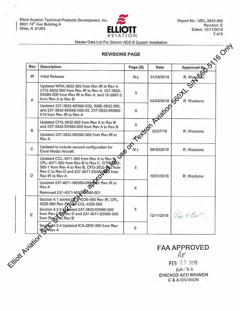
Rev Description Page (S) Date Approved By
IR Initial Release ALL 11/15/2017 R. Woolums
A Added Section 3.7 11
07/31/2018 R. Woolums
Added Section 5.3 13
B Revised Section 3.7 11
09/28/18 Revised Section 5.3 13
Elliott A
viatio
n STC ST04
272C
H is ap
prove
d for
use o
n Tex
tron A
viatio
n 560
XL S/N
560-5
116 O
nly
Elliott Aviation Technical Products Development, Inc. Report No.: GTP-3832-560-1 6601 74th Ave Building A Revision: B Milan, IL 61264 Dated 09/28/2018 3 of 18
Ground Test Plan For Garmin ADS-B System Installation
TABLE OF CONTENTS
COVER PAGE .......................................................................................................... 1 REVISIONS PAGE.................................................................................................... 2 TABLE OF CONTENTS ............................................................................................ 3 1 General: .............................................................................................................. 4
2 Preparation – Configuration Verification ............................................................. 8
3 ATC # 1 Mode S / Diversity ............................................................................... 10
4 Preparation – ATC # 2 ...................................................................................... 12
5 ATC # 2 Mode S / Diversity ............................................................................... 12
6 ADS-B Annunciators (RS-232 bus and GTX annunciator discrete) ................. 14
7 Preparation – ADS-B Out ATC # 2 ................................................................... 14
8 ATC # 2 ADS-B OUT / GDL 88 GPS / In Air ..................................................... 15
9 Preparation - ADS-B Out ATC # 1 .................................................................... 15
10 ATC # 1 ADS-B OUT / GDL 88 GPS / In Air ..................................................... 15
11 Preparation - UAT FIS-B IN / Bluetooth ............................................................ 16
12 UAT FIS-B IN / Bluetooth in air (If Flight Stream 110 is installed) .................... 16
13 Reversionary Modes ......................................................................................... 17
14 Circuit Breakers ................................................................................................. 17
15 Radio Altimeter .................................................................................................. 17 Test Conclusion ...................................................................................................... 18
Elliott A
viatio
n STC ST04
272C
H is ap
prove
d for
use o
n Tex
tron A
viatio
n 560
XL S/N
560-5
116 O
nly

Elliott Aviation Technical Products Development, Inc. Report No.: GTP-3832-560-1 6601 74th Ave Building A Revision: B Milan, IL 61264 Dated 09/28/2018 4 of 18
Ground Test Plan For Garmin ADS-B System Installation
1 General: This Elliott Aviation Ground Test Plan (GTP) is intended for Model 560XL ADS-B Out transponder with FIS-B In installations modified in accordance with Elliott Aviation Master Data List MDL-3832-560.
14.CFR 91.215 Mode S Transponder and 91.227 ADS-B related functions and operations are evaluated.
EMC is evaluated.
14 CFR Part 43: 43.3 requires appropriately rated personnel and 43.9 require maintenance records.
Safe access to the top fuselage antennas is required. Mode S diversity isolation requires antenna blocking.
This GTP does not address RVSM aspects and assumes that the pitot / static system was not opened or modified in any way.
The ADS-B aspects of this test plan may be conducted in a hangar but clear view of the GPS constellation is required. Local airport Lat/Lon information is also required. Use either the Airport Reference Point (ARP) or the coordinates for the control tower.
No EMI/EMC included in this document. Use Repair Station procedures.
Information in (parenthesis) indicates aspect of installed system being evaluated, references to other document steps or variables for aircraft equipage. IFR 6000 Operators manual references are included.
1.1 Testing Prerequisites:
This GTP requires compliance with modifications described in the above Master Data List.
Notable specifics:
The previously installed and approved transponder antennas, coaxes and connectors are unmodified except where specifically indicated.
The GDL-88 to GTX3000 wiring connections must be is as indicated without deviation.
The GTX 3000 transponders and GDL 88 GPS must be configured in accordance with Elliott Aviation Configuration Instructions document CFG-3832-560.
Determine if the aircraft has Dynamic Flight ID. Refert to Honeywell RMU; ATC page.
Elliott A
viatio
n STC ST04
272C
H is ap
prove
d for
use o
n Tex
tron A
viatio
n 560
XL S/N
560-5
116 O
nly
Elliott Aviation Technical Products Development, Inc. Report No.: GTP-3832-560-1 6601 74th Ave Building A Revision: B Milan, IL 61264 Dated 09/28/2018 5 of 18
Ground Test Plan For Garmin ADS-B System Installation
1.2 Required Test Equipment:
Equipment Description Comments
Cobham / Aeroflex ATC Tester with Standard accessories. (see manual for complete list)
IFR 6000 Used for Mode S and ADS-B testing. Ensure calibration covers options 2 (TCAS), 3 (ADS-B) and 5 (UAT). Operation Manual Issue 12 2014 or later required.
Apple I PAD or equivalent Blue Tooth PED
With Garmin Pilot or Foreflight app loaded. Used to verify the Flight Stream 110.
1.3 Required Air Traffic Control / Tower Coordination
Contact the local FAA to have a transponder code assigned for the duration of any testing.
1.4 Required Reference Documents
1) Elliott Aviation Configuration Instructions document CFG-3832-560.
2) FAA Advisory Circular AC43-6C dated 07/15/14 (or later revision).
3) Local tower Latitude / Longitude. Digital - Terminal Procedures Publication (d-TPP)/Airport Diagrams: https://www.faa.gov/air_traffic/flight_info/aeronav/digital_products/dtpp/
The GTX 3000 will not function properly until software setup and configuration is accomplished.
The GDL-88 will not function properly until software setup and configuration is accomplished.
Elliott A
viatio
n STC ST04
272C
H is ap
prove
d for
use o
n Tex
tron A
viatio
n 560
XL S/N
560-5
116 O
nly
Elliott Aviation Technical Products Development, Inc. Report No.: GTP-3832-560-1 6601 74th Ave Building A Revision: B Milan, IL 61264 Dated 09/28/2018 6 of 18
Ground Test Plan For Garmin ADS-B System Installation
1.5 IFR 6000 setup an position notes:
1) The IFR 6000 installed options can be witnessed by pressing the “SETUP” hard-key repeatedly until the “SETUP-CONFIG INFO” screen appears.
2) Continue pressing the “SETUP” hard-key until “SETUP-GENERAL” appears. Set units to FEET and ERP to dBW.
3) When positioning and setting up the IFR 6000 Test Set, reasonably accurate values are to be used for “ANT RANGE” and “ANT HEIGHT”.
4) These values may be used as a starting point and must be addressed if the IFR 6000 needs to be repositioned. Note: Height is relative to the IFR 6000 ANTENNA, not ground.
NOTE: Do not exceed 50 ft from any ATC antenna when establishing test set position.
Multi-path reflections from other aircraft as well as hangar surfaces may severely impact this testing. Test set
position trial and error may be necessary.
5) The ideal testing condition is outside on the ramp away from other aircraft, vehicles and hangars. The most challenging transponder radio frequency testing environment in inside a closed cluttered hangar.
6) Keeping in mind the depiction above, the IFR 6000 test set may be hand held at different heights above the floor as well as moved along the arc representing the distances configured at set-up.
7) The above range settings are only a starting point for testing and may be changed to accommodate large deviations from the guide values. The IFR 6000 Ops Manual is recommended reading prior to testing.
Elliott A
viatio
n STC ST04
272C
H is ap
prove
d for
use o
n Tex
tron A
viatio
n 560
XL S/N
560-5
116 O
nly
Elliott Aviation Technical Products Development, Inc. Report No.: GTP-3832-560-1 6601 74th Ave Building A Revision: B Milan, IL 61264 Dated 09/28/2018 7 of 18
Ground Test Plan For Garmin ADS-B System Installation
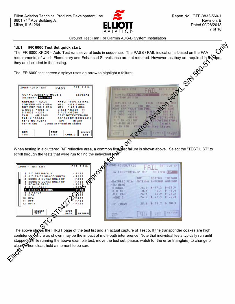
1.5.1 IFR 6000 Test Set quick start: The IFR 6000 XPDR – Auto Test runs several tests in sequence. The PASS / FAIL indication is based on the FAA requirements, of which Elementary and Enhanced Surveillance are not required. However, as they are required in Europe, they are included in the testing. The IFR 6000 test screen displays uses an arrow to highlight a failure:
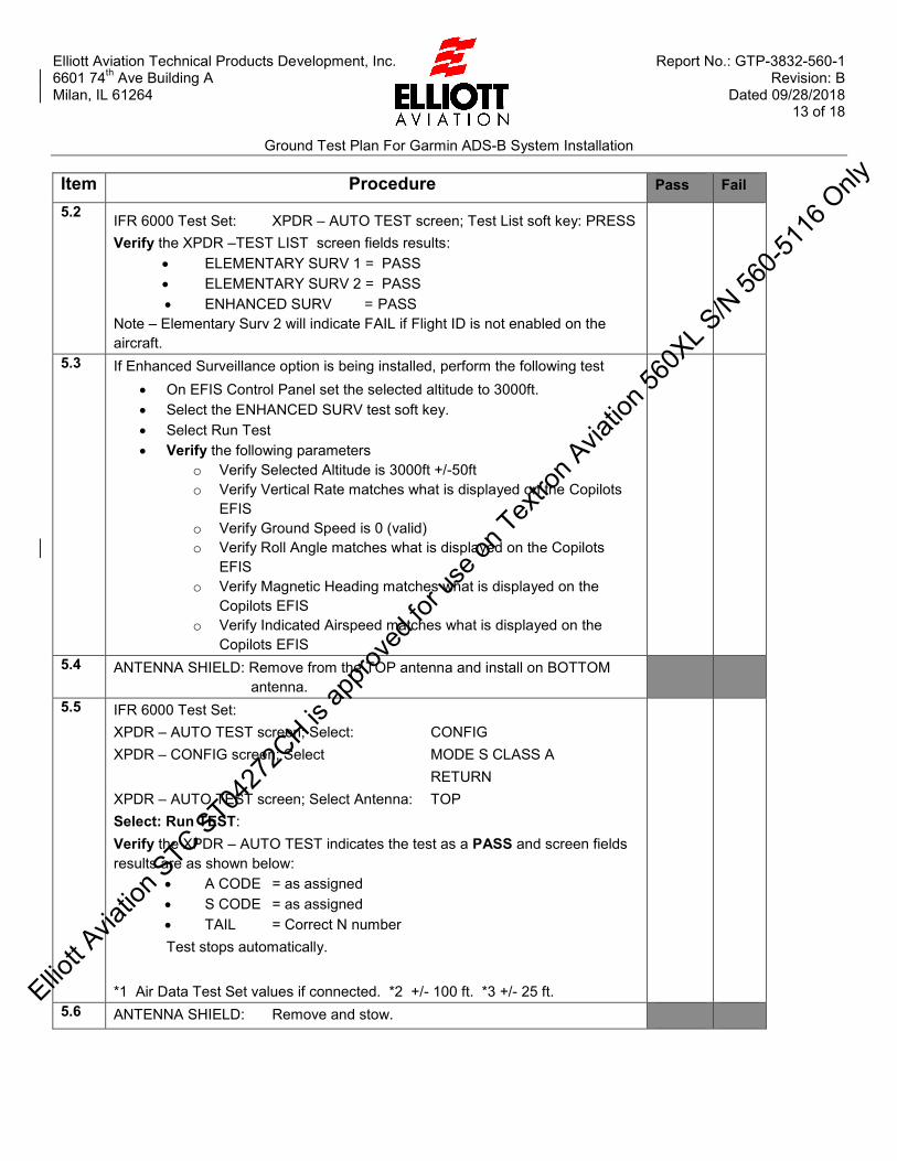
When testing in a cluttered R/F reflective area, a common first-test failure is shown above. Select the “TEST LIST” to scroll through the tests that were run to find the individual test:
The above shows the FIRST page of the test list and an actual capture of Test 5. If the transponder coaxes are high confidence, failure as shown may be the impact of multi-path interference. Note that individual tests typically run until stopped. While running the above example test, move the test set, pause, watch for the error triangle(s) to change or clear. When clear, hold a moment to be sure.
Elliott A
viatio
n STC ST04
272C
H is ap
prove
d for
use o
n Tex
tron A
viatio
n 560
XL S/N
560-5
116 O
nly

Elliott Aviation Technical Products Development, Inc. Report No.: GTP-3832-560-1 6601 74th Ave Building A Revision: B Milan, IL 61264 Dated 09/28/2018 8 of 18
Ground Test Plan For Garmin ADS-B System Installation
Item Procedure Pass Fail
2 Preparation – Configuration Verification
2.1 1) Aircraft may be positioned in a hangar or outdoors. 2) Ensure that the aircraft is properly grounded in accordance with AMM
procedures. 3) For the # 1 GTX 3000 Transponder, conduct Elliott Aviation
Configuration Instructions document CFG-3761-560; steps 4 through 4.1, check “NORMAL” box, then select the “Regions” tab to access the software part number and version number.
2.2 Verify # 1 GTX 3000 Transponder Software part number and Version is as indicated in document CFG-3832-560, paragraph 3.0.
2.3 Verify # 1 GTX 3000 Transponder configuration is as indicated in document CFG-3832-560, paragraph 4.4 through 4.6.2.
2.3.1 Select ATC # 1 Active. Verify that the GTX 3000 Install Tool “STATUS” XPDR State – Ident Active box indicates a check when either remote Ident switch is pressed.
2.3.2 Verify that the GTX 3000 Install Tool Diagnostics Tab / DAP Tab / Heading Data pane indicates Mag Heading value referenced to pilot display.
2.4 1) Confirm that the GTX 3000 Install Tool shows Normal and not CONFIG before disconnect.
2) Close Install Tool and disconnect from PC / Laptop. Properly stow cable. 3) For the # 2 GTX 3000 Transponder, conduct Elliott Aviation
Configuration Instructions document CFG-3832-560; steps 4 through 4.1, check “NORMAL” box, then select the “Product Data” tab to access the software part number and version number.
2.5 Verify # 2 GTX 3000 Transponder Software part number and Version is as indicated in document CFG-3832-560, paragraph 3.0.
2.6 Verify # 2 GTX 3000 Transponder configuration is as indicated in document CFG-3832-560, paragraph 4.4 through 4.6.2.
2.6.1 Select ATC # 2 Active Verify that the GTX 3000 Install Tool “STATUS” XPNDR State – Ident Active box indicates a check when either remote Ident switch is pressed.
2.6.2 Verify that the GTX 3000 Install Tool Diagnostics Tab / DAP Tab / Heading Data pane indicates Mag Heading referenced to co-pilot display.
2.7 1) Confirm that the GTX 3000 Install Tool shows Normal and not CONFIG before disconnect.
2) Close Install Tool and disconnect from PC / Laptop. Properly stow cable.
2.8 For the GDL 88 UAT/GPS, conduct Elliott Aviation Configuration Instructions document CFG-3832-560; step 5.1, then step 5.3.1 to gain access to the software part number and version number.
Elliott A
viatio
n STC ST04
272C
H is ap
prove
d for
use o
n Tex
tron A
viatio
n 560
XL S/N
560-5
116 O
nly

Elliott Aviation Technical Products Development, Inc. Report No.: GTP-3832-560-1 6601 74th Ave Building A Revision: B Milan, IL 61264 Dated 09/28/2018 9 of 18
Ground Test Plan For Garmin ADS-B System Installation
Item Procedure Pass Fail
2.9 Verify GDL 88 UAT/GPS System Software Version and System Software Part Number is as indicated in document CFG-3832-560, paragraph 3.0.
2.10 Verify GDL 88 UAT/GPS configuration is as indicated in document CFG-3832-560 paragraph 5.4 through 5.4.6.
2.11 1) Close Install Tool and disconnect from PC / Laptop. Properly stow cable. 2) Power down the aircraft in accordance with the AMM.
2.12 1) Aircraft may be positioned in a hangar or outdoors. GPS position is required. Be aware of hazards associated with transmitting RF signals inside an enclosed structure.
2) Ensure that the aircraft is properly grounded in accordance with AMM procedures.
3) Apply ground power and power up the avionics in accordance with the AMM.
4) Ensure that “Weight on Wheels”, (WOW) is in the ON GROUND state.
5) On the IFR 6000 Test Set configure the height and range for the ATC antenna per Operators Manual and set DIV TEST = ON. Refer to Section 1.5 of this document for initial height and range values.
6) Obtain the IFR 6000 Test Set antenna cover accessory.
7) Request a transponder code from ATC. ATC should be advised that the aircraft will be “squawking” on this code for the duration of the test. Advise ATC of the planned Flight ID if the aircraft is Flight ID capable. Testing inside a structure may block the aircraft transponder from ATC view but a code should be coordinated in any event.
8) Select ATC #1 Active, ALT, and set the transponder code as assigned by ATC. Set Flight ID to TEST 1 (if aircraft is elementary surveillance capable).
2.13 On the Honeywell RMU; select Test and confirm PASS. 2.14 Select EGPWS / TAWS test. Confirm PASS. 2.15 Using a properly equipped PED, configure for WiFi off and pair with Flight
Stream 110 (If installed). Start “Garmin Pilot” app (preferred) and monitor app for GPS position.
Elliott A
viatio
n STC ST04
272C
H is ap
prove
d for
use o
n Tex
tron A
viatio
n 560
XL S/N
560-5
116 O
nly

Elliott Aviation Technical Products Development, Inc. Report No.: GTP-3832-560-1 6601 74th Ave Building A Revision: B Milan, IL 61264 Dated 09/28/2018 10 of 18
Ground Test Plan For Garmin ADS-B System Installation
Item Procedure Pass Fail
3 ATC # 1 Mode S / Diversity 3.1 Locate the “ADS-B 1 / 2” Annunciators on the pilot’s instrument panel and press
master annunciator press to test. Verify that all segments illuminate.
3.2 Disable the #2 transponder by pulling the ATC 2 circuit breaker located in the pilots breaker panel.
3.3 Place the aircraft in AIR MODE, weight OFF wheels in accordance with AMM. 3.4 Install ATC antenna cover on BOTTOM ATC antenna.
3.5 IFR 6000 Test Set: XPDR – AUTO TEST screen; Select: CONFIG XPDR – CONFIG screen; Select MODE S CLASS A RETURN XPDR – AUTO TEST screen; Select Antenna: TOP Select: Run TEST: Verify the XPDR – AUTO TEST indicates the test as a PASS and screen fields results are as shown below:
A CODE = as assigned S CODE = as assigned TAIL = Correct N number Flight ID = TEST 1
Note for aircraft that do not have Elementary Surveillance, the Flight ID will match the aircraft N-number (US Aircraft only)
FS = 0, NO ALERT – NO SPI – IN AIR VS = IN AIR C ALT = QFE at QNE (*1, *2) S ALT = QFE at QNE (*1, *3)
Test stops automatically. *1 Air Data Test Set values if connected. *2 +/- 100 ft. *3 +/- 25 ft.
3.6 IFR 6000 Test Set: XPDR – AUTO TEST screen; Test List soft key: PRESS Verify the XPDR –TEST LIST screen fields results:
ELEMENTARY SURV 1 = PASS ELEMENTARY SURV 2 = PASS ENHANCED SURV = PASS
Note – Elementary Surv 2 will indicate FAIL if Flight ID is not enabled on the aircraft.
Ellio
tt Avia
tion S
TC ST0427
2CH is
appro
ved f
or us
e on T
extro
n Avia
tion 5
60XL S
/N 56
0-511
6 Only

Elliott Aviation Technical Products Development, Inc. Report No.: GTP-3832-560-1 6601 74th Ave Building A Revision: B Milan, IL 61264 Dated 09/28/2018 11 of 18
Ground Test Plan For Garmin ADS-B System Installation
Item Procedure Pass Fail
3.7 If Enhanced Surveillance option is being installed, perform the following test On EFIS Control Panel set the selected altitude to 3000ft. Select the ENHANCED SURV test soft key. Select Run Test Verify the following parameters
o Verify Selected Altitude is 3000ft +/-50ft o Verify Vertical Rate matches what is displayed on the Pilots
EFIS o Verify Ground Speed is 0 (valid) o Verify Roll Angle matches what is displayed on the Pilots EFIS o Verify Magnetic Heading matches what is displayed on the
Pilots EFIS o Verify Indicated Airspeed matches what is displayed on the
Pilots EFIS
3.8 ANTENNA SHIELD: Remove from BOTTOM Antenna and install on TOP antenna. (Operators Manual app J, fig 2)
3.9 IFR 6000 Test Set: XPDR – AUTO TEST screen; Select: CONFIG XPDR – CONFIG screen; Select MODE S CLASS A RETURN XPDR – AUTO TEST screen; Select Antenna: BOTTOM Select: Run TEST: Verify the XPDR – AUTO TEST indicates the test as a PASS and screen fields results are as shown below:
A CODE = XXXX (ATC assigned) S CODE = XXXX (ATC assigned) TAIL = Correct N number
Test stops automatically.
Elliott A
viatio
n STC ST04
272C
H is ap
prove
d for
use o
n Tex
tron A
viatio
n 560
XL S/N
560-5
116 O
nly

Elliott Aviation Technical Products Development, Inc. Report No.: GTP-3832-560-1 6601 74th Ave Building A Revision: B Milan, IL 61264 Dated 09/28/2018 12 of 18
Ground Test Plan For Garmin ADS-B System Installation
Item Procedure Pass Fail
4 Preparation – ATC # 2 4.1 1) Maintain "Weight on Wheels", (WOW) in the IN AIR state.
2) On the IFR 6000 Test Set configure the height and range for the ATC antennas and maintain DIV TEST = ON. Refer to Section 1.5 of this document for initial height and range values.
3) Relocate the IFR 6000 Test Set antenna cover accessory the TOP ATC antenna.
4) Select ATC #2 Active, ALT, and set transponder code as assigned by ATC and Flight ID to 2 TEST (if aircraft is elementary surveillance capable).
5) Disable the # 1 transponder by pulling the ATC 1 circuit breaker and enable the #2 transponder by resetting the ATC 2 circuit breaker both are located in pilot circuit breaker panel.
5 ATC # 2 Mode S / Diversity
5.1 IFR 6000 Test Set: XPDR – AUTO TEST screen; Select: CONFIG XPDR – CONFIG screen; Select MODE S CLASS A RETURN XPDR – AUTO TEST screen; Select Antenna: BOTTOM Select: Run TEST: Verify the XPDR – AUTO TEST indicates the test as a PASS and screen fields results are as shown below:
A CODE = as assigned S CODE = as assigned TAIL = Correct N number Flight ID = 2 TEST
Note for aircraft that do not have Elementary Surveillance, the Flight ID will match the aircraft N-number (US Aircraft only)
FS = 0, NO ALERT – NO SPI – IN AIR VS = IN AIR C ALT = QFE at QNE (*1, *2) S ALT = QFE at QNE (*1, *3)
Test stops automatically. *1 Air Data Test Set values if connected. *2 +/- 100 ft. *3 +/- 25 ft.
Ellio
tt Avia
tion S
TC ST0427
2CH is
appro
ved f
or us
e on T
extro
n Avia
tion 5
60XL S
/N 56
0-511
6 Only
Elliott Aviation Technical Products Development, Inc. Report No.: GTP-3832-560-1 6601 74th Ave Building A Revision: B Milan, IL 61264 Dated 09/28/2018 13 of 18
Ground Test Plan For Garmin ADS-B System Installation
Item Procedure Pass Fail
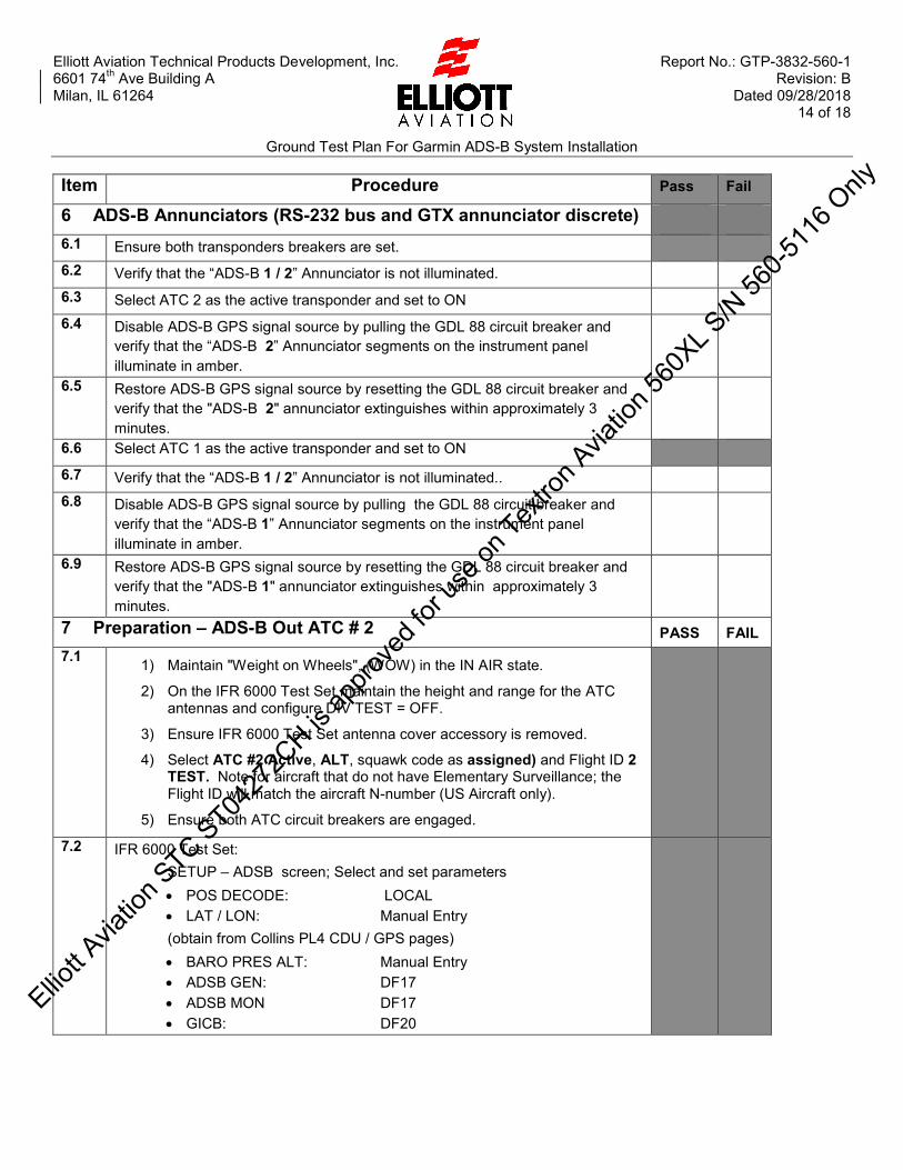
5.2 IFR 6000 Test Set: XPDR – AUTO TEST screen; Test List soft key: PRESS Verify the XPDR –TEST LIST screen fields results:
ELEMENTARY SURV 1 = PASS ELEMENTARY SURV 2 = PASS ENHANCED SURV = PASS
Note – Elementary Surv 2 will indicate FAIL if Flight ID is not enabled on the aircraft.
5.3
If Enhanced Surveillance option is being installed, perform the following test
On EFIS Control Panel set the selected altitude to 3000ft. Select the ENHANCED SURV test soft key. Select Run Test Verify the following parameters
o Verify Selected Altitude is 3000ft +/-50ft o Verify Vertical Rate matches what is displayed on the Copilots
EFIS o Verify Ground Speed is 0 (valid) o Verify Roll Angle matches what is displayed on the Copilots
EFIS o Verify Magnetic Heading matches what is displayed on the
Copilots EFIS o Verify Indicated Airspeed matches what is displayed on the
Copilots EFIS
5.4 ANTENNA SHIELD: Remove from the TOP antenna and install on BOTTOM antenna.
5.5 IFR 6000 Test Set: XPDR – AUTO TEST screen; Select: CONFIG XPDR – CONFIG screen; Select MODE S CLASS A RETURN XPDR – AUTO TEST screen; Select Antenna: TOP Select: Run TEST: Verify the XPDR – AUTO TEST indicates the test as a PASS and screen fields results are as shown below:
A CODE = as assigned S CODE = as assigned TAIL = Correct N number
Test stops automatically. *1 Air Data Test Set values if connected. *2 +/- 100 ft. *3 +/- 25 ft.
5.6 ANTENNA SHIELD: Remove and stow.
Elliott A
viatio
n STC ST04
272C
H is ap
prove
d for
use o
n Tex
tron A
viatio
n 560
XL S/N
560-5
116 O
nly
Elliott Aviation Technical Products Development, Inc. Report No.: GTP-3832-560-1 6601 74th Ave Building A Revision: B Milan, IL 61264 Dated 09/28/2018 14 of 18
Ground Test Plan For Garmin ADS-B System Installation
Item Procedure Pass Fail
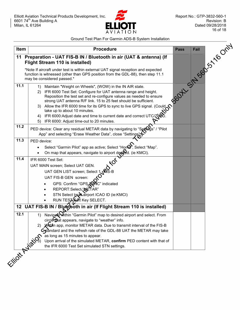
6 ADS-B Annunciators (RS-232 bus and GTX annunciator discrete) 6.1 Ensure both transponders breakers are set. 6.2 Verify that the “ADS-B 1 / 2” Annunciator is not illuminated. 6.3 Select ATC 2 as the active transponder and set to ON 6.4 Disable ADS-B GPS signal source by pulling the GDL 88 circuit breaker and
verify that the “ADS-B 2” Annunciator segments on the instrument panel illuminate in amber.
6.5 Restore ADS-B GPS signal source by resetting the GDL 88 circuit breaker and verify that the "ADS-B 2" annunciator extinguishes within approximately 3 minutes.
6.6 Select ATC 1 as the active transponder and set to ON 6.7 Verify that the “ADS-B 1 / 2” Annunciator is not illuminated.. 6.8 Disable ADS-B GPS signal source by pulling the GDL 88 circuit breaker and
verify that the “ADS-B 1” Annunciator segments on the instrument panel illuminate in amber.
6.9 Restore ADS-B GPS signal source by resetting the GDL 88 circuit breaker and verify that the "ADS-B 1" annunciator extinguishes within approximately 3 minutes.
7 Preparation – ADS-B Out ATC # 2 PASS FAIL 7.1 1) Maintain "Weight on Wheels", (WOW) in the IN AIR state.
2) On the IFR 6000 Test Set maintain the height and range for the ATC antennas and configure DIV TEST = OFF.
3) Ensure IFR 6000 Test Set antenna cover accessory is removed.
4) Select ATC #2 Active, ALT, squawk code as assigned) and Flight ID 2 TEST. Note for aircraft that do not have Elementary Surveillance; the Flight ID will match the aircraft N-number (US Aircraft only).
5) Ensure both ATC circuit breakers are engaged.
7.2 IFR 6000 Test Set: SETUP – ADSB screen; Select and set parameters
POS DECODE: LOCAL LAT / LON: Manual Entry
(obtain from Collins PL4 CDU / GPS pages) BARO PRES ALT: Manual Entry ADSB GEN: DF17 ADSB MON DF17 GICB: DF20
Elliott A
viatio
n STC ST04
272C
H is ap
prove
d for
use o
n Tex
tron A
viatio
n 560
XL S/N
560-5
116 O
nly

Elliott Aviation Technical Products Development, Inc. Report No.: GTP-3832-560-1 6601 74th Ave Building A Revision: B Milan, IL 61264 Dated 09/28/2018 15 of 18
Ground Test Plan For Garmin ADS-B System Installation
Item Procedure Pass Fail
8 ATC # 2 ADS-B OUT / GDL 88 GPS / In Air 8.1 IFR 6000 Test Set:
ADVISORY CIRCULARS MAIN: Select AC20-165 AIR. ADV CIRC 20-165 AIR screen; select RUN. Verify the ADV CIRC 20-165 AIR test screen indicates the test as a PASS and screen fields results are as shown below:
NIC record: ADV CIRC 20-165 AIR screen; select NEXT PAGE:.
SDA = 2
9 Preparation - ADS-B Out ATC # 1
9.1 Maintain "Weight on Wheels", (WOW) in the IN AIR state.
On the IFR 6000 Test Set configure the height and range for the ATC antennas and maintain DIV TEST = OFF. Refer to section 1.5 of this document for initial height and range values.
Ensure IFR 6000 Test Set antenna cover accessory is removed.
Select ATC # 1 Active, ALT, squawk code as assigned and Flight ID TEST 1. Note for aircraft that do not have Elementary Surveillance, the Flight ID will match the aircraft N-number (US Aircraft only)
Ensure both ATC circuit breakers are engaged.
10 ATC # 1 ADS-B OUT / GDL 88 GPS / In Air PASS FAIL 10.1 IFR 6000 Test Set:
ADVISORY CIRCULARS MAIN: Select AC20-165 AIR. ADV CIRC 20-165 AIR screen; select RUN. Verify the ADV CIRC 20-165 AIR test screen indicates the test as a PASS and screen fields results are as shown below:
NIC record: ADV CIRC 20-165 AIR screen; select NEXT PAGE.
SDA = 2
Elliott A
viatio
n STC ST04
272C
H is ap
prove
d for
use o
n Tex
tron A
viatio
n 560
XL S/N
560-5
116 O
nly
Elliott Aviation Technical Products Development, Inc. Report No.: GTP-3832-560-1 6601 74th Ave Building A Revision: B Milan, IL 61264 Dated 09/28/2018 16 of 18
Ground Test Plan For Garmin ADS-B System Installation
Item Procedure Pass Fail
11 Preparation - UAT FIS-B IN / Bluetooth in air (UAT & antenna) (If Flight Stream 110 is installed) *Note If aircraft under test is within external UAT signal reception and expected function is witnessed (other than GPS position from the GDL-88), then step 11.1 may be considered passed.*
11.1 1) Maintain "Weight on Wheels", (WOW) in the IN AIR state. 2) IFR 6000 Test Set: Configure for UAT antenna range and height.
Reposition the test set and re-configure values as needed to ensure strong UAT antenna R/F link. 15 to 25 feet should be sufficient.
3) Allow the IFR 6000 time for its GPS to sync to live GPS signal. (Could take up to about 10 minutes.
4) IFR 6000:Adjust date and time to current date and correct UTC/ZULU. 5) IFR 6000: Adjust time-out to 20 minutes.
11.2 PED device: Clear any residual METAR data by navigating to “Settings” / “Pilot App” and selecting “Erase Weather Data”, close “Settings”.
11.3 PED device: Select “Garmin Pilot” app as active; Select “Home”, Select “Map”. On map that appears, navigate to airport desired. (ie KMCI).
11.4 IFR 6000 Test Set: UAT MAIN screen; Select UAT GEN. UAT GEN LIST screen; Select 1. FIS-B UAT FIS-B GEN screen:
GPS: Confirm “GPS SYNC” indicated REPORT:Select “METAR” STN Select local airport ICAO ID (ie:KMCI) RUN TEST Soft Key SELECT.
12 UAT FIS-B IN / Bluetooth in air (If Flight Stream 110 is installed)
12.1 1) Navigate within “Garmin Pilot” map to desired airport and select. From circle that appears, navigate to “weather” info.
2) Within app, monitor METAR data. Due to transmit interval of the FIS-B standard and the refresh rate of the GDL-88 UAT the METAR may take as long as 15 minutes to appear.
3) Upon arrival of the simulated METAR, confirm PED content with that of the IFR 6000 Test Set simulated STN settings.
Elliott A
viatio
n STC ST04
272C
H is ap
prove
d for
use o
n Tex
tron A
viatio
n 560
XL S/N
560-5
116 O
nly

Elliott Aviation Technical Products Development, Inc. Report No.: GTP-3832-560-1 6601 74th Ave Building A Revision: B Milan, IL 61264 Dated 09/28/2018 17 of 18
Ground Test Plan For Garmin ADS-B System Installation
Item Procedure Pass Fail
13 Reversionary Modes
13.1 Aircraft: Set to weight ON wheels; ON GROUND state.
IFR 6000 test set may stand down at this stage.
Ensure both ATC circuit breakers are still engaged
13.2 Comm # 2 circuit breaker: PULL RMU # 2: Verify OFF (blank screen)
13.3 RMU #1 press the ATC LSK and then press the TEST key. Verify NO FAULTS 13.4 Select ATC # 2 Active, ALT, and set squawk code to 2121. 13.5 Verify 2121 remains active on the #1 RMU 13.6 Comm # 2 circuit breaker: Press (reset)
RMU # 2: Verify ON (normal condition)
13.7 Comm # 1 circuit breakers: PULL RMU # 1: Verify OFF (blank screen)
13.8 RMU #2 press the ATC LSK and then press the TEST key. Verify NO FAULTS 13.9 Select ATC # 1 Active, ALT, and set squawk code to 4343 13.10 Verify 4343 remains active on the #2 RMU 13.11 Comm # 1 circuit breaker: Press (reset)
RMU # 1: Verify ON (normal condition)
14 Circuit Breakers
14.1 GDL 88 circuit breaker: Verify label: ADS-B (over) GPS 14.2 Flight Stream circuit breaker: Verify label: FIS-B (over) BL TH
15 Radio Altimeter
15.1 Perform Radio Altimeter test in accordance with Citation 560 AMM 34-12-02.
Elliott A
viatio
n STC ST04
272C
H is ap
prove
d for
use o
n Tex
tron A
viatio
n 560
XL S/N
560-5
116 O
nly

Elliott Aviation Technical Products Development, Inc. Report No.: GTP-3832-560-1 6601 74th Ave Building A Revision: B Milan, IL 61264 Dated 09/28/2018 18 of 18
Ground Test Plan For Garmin ADS-B System Installation
Aircraft “N” number: Serial Number CFR Part 43.3 Test Personnel: Date Location: (ICAO Airport ID and General location) Test equipment make and model Calibration date Aircraft Hobbs Time: Notes:
Elliott A
viatio
n STC ST04
272C
H is ap
prove
d for
use o
n Tex
tron A
viatio
n 560
XL S/N
560-5
116 O
nly
Elliott Aviation Technical Products Development, Inc. Report No.: CFG-3832-560 6601 74th Ave Building A Revision: D Milan, IL 61264 Dated: 10/01/2018 1 of 14
Configuration Instruction For Garmin ADS-B System Installation
Configuration Instructions
For
Garmin ADS-B Out System Installation
(Type Certificate A22CE)
© 2017 ELLIOTT AVIATION TECHNICAL PRODUCTS DEVELOPMENT, INC.
Elliott Aviation Technical Products Development, Inc. reserves the copyright of all information and illustrations in this publication which is provided in confidence and which may not be used for any purpose other than for which it was originally supplied. The publication may not be reproduced in part or in whole without the consent in writing of Elliott Aviation Technical Products Development, Inc.
Elliott A
viatio
n STC ST04
272C
H is ap
prove
d for
use o
n Tex
tron A
viatio
n 560
XL S/N
560-5
116 O
nly

Elliott Aviation Technical Products Development, Inc. Report No.: CFG-3832-560 6601 74th Ave Building A Revision: D Milan, IL 61264 Dated: 10/01/2018 2 of 14
Configuration Instruction For Garmin ADS-B System Installation
REVISIONS PAGE
Rev Description Page (S) Date Approved By
IR Initial Release ALL 01/08/2018 R. Woolums
A
Section 3.0 updated GDL 88 software level and corrected wording of note 2 3
01/12/2018 R. Woolums Section 4.5.2 corrected 429 input assignments and antenna loss readings. 8
Section 5.4.1 corrected antenna orientation from right to left 12
B Section 4.5.2 corrected ADC speed to LOW 8 02/27/2018 R. Woolums
C Section 4.5.2 added RX 6 for EFIS, Change RX2 for Off and RX4 to AHRS 8 07/31/2018 R. Woolums
D
Section 3 corrected software p/n typo 5
10/01/2018
Section 4.4.1 Removed AHRS QTY 6
Removed Section 4.6.2 10
Elliott A
viatio
n STC ST04
272C
H is ap
prove
d for
use o
n Tex
tron A
viatio
n 560
XL S/N
560-5
116 O
nly
Elliott Aviation Technical Products Development, Inc. Report No.: CFG-3832-560 6601 74th Ave Building A Revision: D Milan, IL 61264 Dated: 10/01/2018 3 of 14
Configuration Instruction For Garmin ADS-B System Installation
Table of Contents COVER PAGE ............................................................................................................ 1 LOG OF REVISIONS .................................................................................................. 2 TABLE OF CONTENTS .............................................................................................. 3 1 Introduction: ............................................................................................................. 4 2 Preliminary Operations: ........................................................................................... 4
3 Effectivity .................................................................................................................. 5 4 GTX 3000 Configuration .......................................................................................... 5 5 GDL 88 Configuration ............................................................................................ 12 6 Conclusion ............................................................................................................. 14
Elliott A
viatio
n STC ST04
272C
H is ap
prove
d for
use o
n Tex
tron A
viatio
n 560
XL S/N
560-5
116 O
nly

Elliott Aviation Technical Products Development, Inc. Report No.: CFG-3832-560 6601 74th Ave Building A Revision: D Milan, IL 61264 Dated: 10/01/2018 4 of 14
Configuration Instruction For Garmin ADS-B System Installation
1 Introduction: 1.1 Read and understand these instructions prior to beginning these procedures.
1.2 Required equipment:
Serial port equipped PC laptop computer; Win 7 is preferred. HyperTerminal and current familiarity of basic RS232 operations is advised. Quality serial cable not to exceed 15 feet. USB “A” to “B” cable for the GDL 88.
1.3 Garmin supplied “Install Tool” software for access to the GTX 3000 and GDL 88 is required. Details found in paragraph 3.0 of this document.
1.4 GPS activity can be witnessed during these procedures. GPS/WAAS signal access may be beneficial for configuration troubleshooting and testing.
1.5 Qualified personnel familiar with Citation 560 Excel/XLS weight on wheels manipulation, with current PC/laptop configuration software activities and with the Honeywell SPZ 8000 cockpit.
1.6 Have available Garmin Transponder Installation Manual 190-00926-01 rev P for reference.
2 Preliminary Operations: 2.1 Establish PC laptop operations and familiarity with Garmin programming procedures:
2.1.1 Address the PC computer serial port functionality first, a baud rate of 19,200 is proven. Then address the Garmin “Install Tool”. (pgph 3.0) installations. Both the GTX 3000 Install Tool and GDL 88 Install Tool can be extracted and installed on the PC computer and operated without interface to the LRU’s. If either Install Tool ultimately fails to load, try another, newer computer. Due to the high number of variables, Install Tool operation cannot be guaranteed across all operating systems / update status / hardware platform combinations.
Also note that the GTX 3000 Install Tool, when not connected to a LRU, allows some configuration settings manipulation. An off-line configuration CANNOT be compiled for uploading later. However a previously SAVED configuration may be uploaded.
2.1.2 Take the off-line time to become familiar with each Install Tool. The GTX 3000 Install Tool has a lower “STATUS” window with real-time status information. Take particular note of the lower left area: OPERATING MODE; Normal and Config. Ensure that the Config box is checked prior to making configuration changes. Also the Install Tool Info tab opens windows that show real time data from other sources feeding into the GTX 3000.
For the GDL 88 install tool, note there is a Demo Mode available. Similar the GTX 3000 Install Tool, real time data is displayed, simple config changes can be made, etc.
Elliott A
viatio
n STC ST04
272C
H is ap
prove
d for
use o
n Tex
tron A
viatio
n 560
XL S/N
560-5
116 O
nly

Elliott Aviation Technical Products Development, Inc. Report No.: CFG-3832-560 6601 74th Ave Building A Revision: D Milan, IL 61264 Dated: 10/01/2018 5 of 14
Configuration Instruction For Garmin ADS-B System Installation
3 Effectivity GTX 3000 Transponder
L.R.U. P/N (1) Catalog P/N Software P/N Version Install Tool
011-01997-00 010-00736-00 006-B0912-16 3.30 006-a0271-23.zip GDL 88
L.R.U. P/N (1) Catalog P/N Software P/N Version Install Tool
011-02370-00 010-0000860-30 006-B0684-16 3.34 (2) 006-a0248-12.zip (1) Located on L.R.U. data plate. (2) Software P/N 006-B0684-12 Version 3.20 or later is REQUIRED for use with GTX3000 systems. Refer to Service Bulletin 1501 rev A for information on updating software. Later approved software Part Number (P/N), Version and Install Tool may be used only if supported by Garmin Service Bulletin release that specifically includes Garmin GTX3000 transponders.
4 GTX 3000 Configuration Once the aircraft is properly secured, take the following steps:
Confirm that the GTX 3000 transponders and the GDL 88 are properly installed Before applying power to the units, confirm that the antenna coaxes are connected and providing loads to the
transmitters De-energize the GTX 3000 transponders by pulling the associated circuit breakers. Connect the RS 232 config
cable between the GTX 3000 involved and PC. Conduct normal aircraft power turn-on including avionics. On the PC, start the GTX 3000 Install Tool, then apply
power to the GTX 3000 in use. In the very lower left corner “GTX CONNECTED” should be displayed highlighted in green. Confirm that the OPERATING MODE Config box is checked. Configuration can now begin.
4.1 First Configuration (This step is not applicable to subsequent configuration or ICA activities.)
4.1.1 Confirm config module status: Observe Install Tool: STATUS tab; Status OK panel:
4.1.1.1 Confirm that “Info: Config Module Absent” box is UN-checked.
4.1.1.2 Confirm that “Warn: No Config Module Data” box is UN-checked
4.1.2 If the previous step shows a checked box:
4.1.2.1 Install Tool; Regions tab: SELECT.
4.1.2.2 Status pane; Operating Mode. Check Config.
4.1.2.3 Large button “Initialize Configuration Module”: Press. (Resets to factory defaults)
4.1.2.4 Status pane; Operating Mode. Check Normal.
Elliott A
viatio
n STC ST04
272C
H is ap
prove
d for
use o
n Tex
tron A
viatio
n 560
XL S/N
560-5
116 O
nly
Elliott Aviation Technical Products Development, Inc. Report No.: CFG-3832-560 6601 74th Ave Building A Revision: D Milan, IL 61264 Dated: 10/01/2018 6 of 14
Configuration Instruction For Garmin ADS-B System Installation
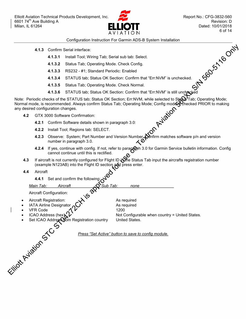
4.1.3 Confirm Serial interface:
4.1.3.1 Install Tool; Wiring Tab; Serial sub tab: Select.
4.1.3.2 Status Tab; Operating Mode. Check Config.
4.1.3.3 RS232 - #1; Standard Periodic: Enabled
4.1.3.4 STATUS tab; Status OK Section: Confirm that “Err:NVM” is unchecked.
4.1.3.5 Status Tab; Operating Mode. Check Normal.
4.1.3.6 STATUS tab; Status OK Section: Confirm that “Err:NVM” is still unchecked
Note: Periodic checks of the STATUS tab; Status OK Section; Err:NVM, while selected to Status Tab; Operating Mode; Normal mode, is recommended. Always confirm Status Tab; Operating Mode; Config mode is checked PRIOR to making any desired configuration changes.
4.2 GTX 3000 Software Confirmation:
4.2.1 Confirm Software details shown in paragraph 3.0:
4.2.2 Install Tool; Regions tab: SELECT.
4.2.3 Observe: System; Part Number and Version Number. Confirm matches software p/n and version number in paragraph 3.0.
4.2.4 If yes, continue with config. If not, refer to paragraph 3.0 for Garmin Service bulletin information. Config cannot continue until this is rectified.
4.3 If aircraft is not currently configured for Flight ID in the Status Tab input the aircrafts registration number (example N123AB) into the Flight ID section and press enter.
4.4 Aircraft
4.4.1 Set and confirm the following:
Main Tab: Aircraft Sub Tab: none
Aircraft Configuration:
Aircraft Registration: As required IATA Airline Designator As required VFR Code 1200 ICAO Address (hex) Not Configurable when country = United States. Set ICAO Address from Registration country United States.
Press “Set Active” button to save to config module.
Elliott A
viatio
n STC ST04
272C
H is ap
prove
d for
use o
n Tex
tron A
viatio
n 560
XL S/N
560-5
116 O
nly
Elliott Aviation Technical Products Development, Inc. Report No.: CFG-3832-560 6601 74th Ave Building A Revision: D Milan, IL 61264 Dated: 10/01/2018 7 of 14
Configuration Instruction For Garmin ADS-B System Installation
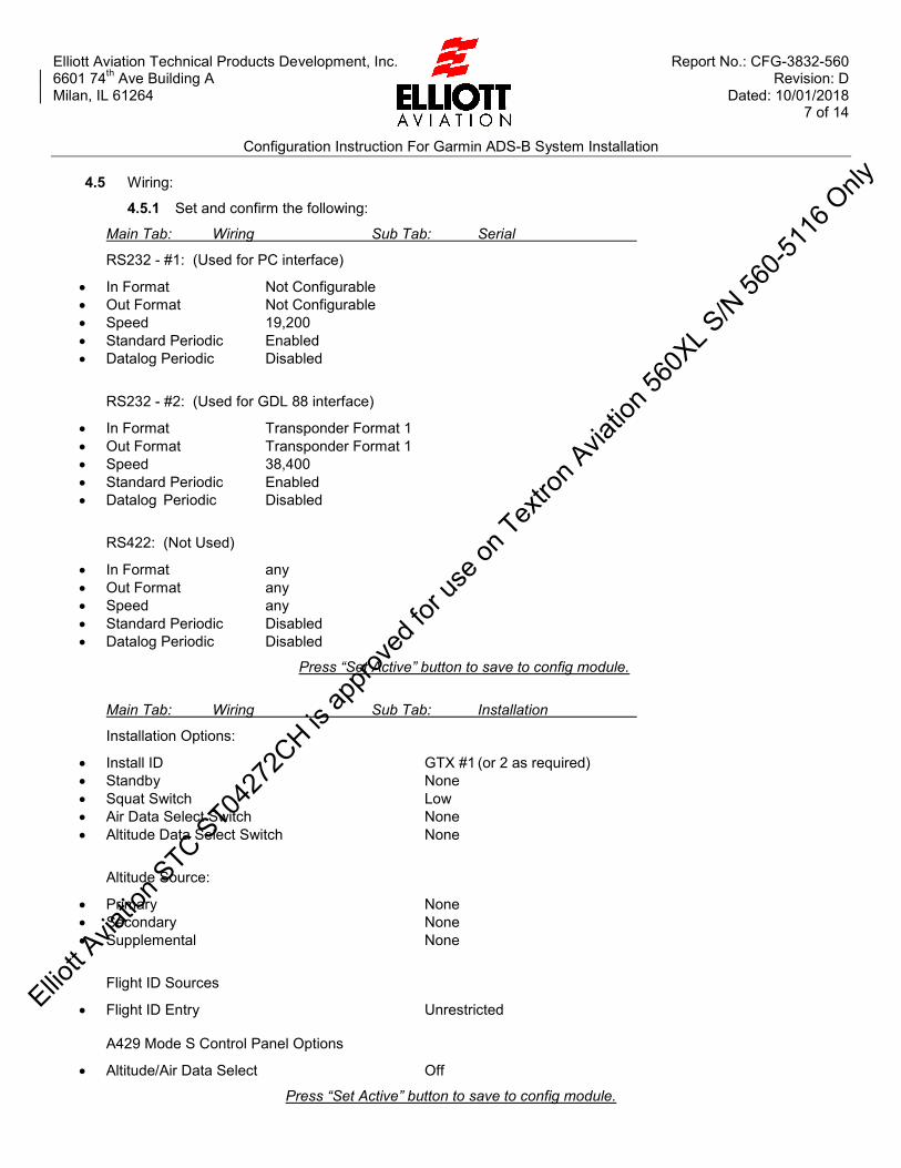
4.5 Wiring:
4.5.1 Set and confirm the following:
Main Tab: Wiring Sub Tab: Serial
RS232 - #1: (Used for PC interface)
In Format Not Configurable Out Format Not Configurable Speed 19,200 Standard Periodic Enabled Datalog Periodic Disabled
RS232 - #2: (Used for GDL 88 interface)
In Format Transponder Format 1 Out Format Transponder Format 1 Speed 38,400 Standard Periodic Enabled Datalog Periodic Disabled
RS422: (Not Used)
In Format any Out Format any Speed any Standard Periodic Disabled Datalog Periodic Disabled
Press “Set Active” button to save to config module.
Main Tab: Wiring Sub Tab: Installation
Installation Options:
Install ID GTX #1 (or 2 as required) Standby None Squat Switch Low Air Data Select Switch None Altitude Data Select Switch None
Altitude Source:
Primary None Secondary None Supplemental None
Flight ID Sources
Flight ID Entry Unrestricted A429 Mode S Control Panel Options
Altitude/Air Data Select Off
Press “Set Active” button to save to config module.
Elliott A
viatio
n STC ST04
272C
H is ap
prove
d for
use o
n Tex
tron A
viatio
n 560
XL S/N
560-5
116 O
nly

Elliott Aviation Technical Products Development, Inc. Report No.: CFG-3832-560 6601 74th Ave Building A Revision: D Milan, IL 61264 Dated: 10/01/2018 8 of 14
Configuration Instruction For Garmin ADS-B System Installation
4.5.2 Set and confirm the following:
Main Tab: Wiring Sub Tab: A429
Input:
Channel 1 Speed: High Format: Mode S Control Panel Channel 2 Speed: Low Format: Off Channel 3 Speed: High Format: AHRS Channel 4 Speed: High Format: AHRS Channel 5 Speed: Low Format: ADC Channel 6 Speed: Low Format: EFIS Channel 7 Speed: Low Format: Off Channel 8 Speed: High Format: ARINC 735 TCAS Format 1
Output:
Channel 1 Speed: High Format: Mode S Control Panel Channel 2 Speed: Low Format: Off Channel 3 Speed: Low Format: Off Channel 4 Speed: High Format: ARINC 735 TCAS Format 1
Press “Set Active” button to save to config module.
Main Tab: Wiring Sub Tab: Antenna
Cable Specifications:
Top Antenna Loss (dB) 2.50 dB Top Antenna Delay (ns) 50 ns Bottom Antenna Loss (dB) 1.50 dB Bottom Antenna Delay (ns) 25 ns Antenna Switch None
Note: These values are general and may vary depending on model. Refer to Garmin Transponder Installation Manual 190-00926-01 rev P or later approved revision section 2.4 for information on coax cable lengths. Set delays to closest increment.
GPS Antenna Offset:
Position Offset Applied No Lateral Offset From Center (M) 0 Towards Field disappears when 0 entered above. Longitudinal Offset From Nose (M) 2
Press “Set Active” button to save to config module.
Elliott A
viatio
n STC ST04
272C
H is ap
prove
d for
use o
n Tex
tron A
viatio
n 560
XL S/N
560-5
116 O
nly

Elliott Aviation Technical Products Development, Inc. Report No.: CFG-3832-560 6601 74th Ave Building A Revision: D Milan, IL 61264 Dated: 10/01/2018 9 of 14
Configuration Instruction For Garmin ADS-B System Installation
Main Tab: Wiring Sub Tab: Discretes
Discrete Inputs:
Gillham Altitude Disabled Ident Unassigned Standby Unassigned Squat Switch J1-17 / J5-40 ADSB 1090 Out Disable Unassigned UAT ADSB Out Disable J1-47 / J5-22 Control Panel Select S0 J2-54 / J5-09 Air Data Select Unassigned Transponder Active J1-46 / J5-32 Altitude Data Select Unassigned
Discrete Outputs:
Fail 1 J1-61 / J5-06 Fail 2 J2-20 / J5-05 Reply Indicator Unassigned ADS-B Fail J1-19 / J5-07 XPDR Active Unassigned Antenna Select Unassigned Altitude Valid Unassigned
Press “Set Active” button to save to config module.
Elliott A
viatio
n STC ST04
272C
H is ap
prove
d for
use o
n Tex
tron A
viatio
n 560
XL S/N
560-5
116 O
nly

Elliott Aviation Technical Products Development, Inc. Report No.: CFG-3832-560 6601 74th Ave Building A Revision: D Milan, IL 61264 Dated: 10/01/2018 10 of 14
Configuration Instruction For Garmin ADS-B System Installation
4.6 Airframe:
4.6.1 Set and confirm the following:
Main Tab: Airframe Sub Tab: Airframe Configuration
ICAO Model C56X ICAO Aircraft Type Landplane ICAO Engine Type Jet ICAO Wake Medium (15,500lbs - 300,000lbs) Aircraft Length <=25 M Aircraft Width <=23 M Engine Quantity 2 Max Airspeed <=600 knots Aircraft Type A: Small (15,500 – 75,000 lbs)
Press “Set Active” button to save to config module.
Elliott A
viatio
n STC ST04
272C
H is ap
prove
d for
use o
n Tex
tron A
viatio
n 560
XL S/N
560-5
116 O
nly

Elliott Aviation Technical Products Development, Inc. Report No.: CFG-3832-560 6601 74th Ave Building A Revision: D Milan, IL 61264 Dated: 10/01/2018 11 of 14
Configuration Instruction For Garmin ADS-B System Installation
4.6.2 Set and confirm the following:
Main Tab: Airframe Sub Tab: Operational Options
Enhanced Surveillance Enabled ADS-B Transmit Always Enabled UAT In Disabled 1090 In Disabled Source Integrity Level (3)10˄-7th (AC20-165B; 3.3.3.3) SIL Data Measured Per Hour System Design Assurance (2)Level C (AC20-165B; App A, 3.1.2.1.1 Table A-6) Auto Moding Disabled Gillham Cross-Compare Failure Disabled
Press “Set Active” button to save to config module.
4.7 Configuration related aspects of interface settings may be checked:
4.7.1 GTX 3000 unit being configured; Install Tool; Status pane; Operating Mode. Check Normal.
4.7.2 Aircraft cockpit; Honeywell RMU: Confirm NO FAULTS.
4.7.3 Honeywell RMU and Yoke IDENT: Operate ATC functions ON/ALT/STDBY, change Mode “C” code, Select Reversionary Mode: Confirm normal operations.
4.7.4 GTX 3000 Install Tool: Monitor Status pane for correlation of ATC operations listed in previous step. .
4.8 Upon satisfactory configuration:
4.8.1 Confirm that each GTX 3000 units show Normal and not CONFIG before disconnecting.
4.8.2 Install Tool; Regions tab: SELECT
4.8.3 Install Tool; Regions Pane; “View Configuration” button: SELECT.
4.8.4 Close Install Tool and disconnect from PC / Laptop.
Elliott A
viatio
n STC ST04
272C
H is ap
prove
d for
use o
n Tex
tron A
viatio
n 560
XL S/N
560-5
116 O
nly

Elliott Aviation Technical Products Development, Inc. Report No.: CFG-3832-560 6601 74th Ave Building A Revision: D Milan, IL 61264 Dated: 10/01/2018 12 of 14
Configuration Instruction For Garmin ADS-B System Installation
5 GDL 88 Configuration 5.1 Once the aircraft is properly secured, ground power available, take the following steps:
When the GDL 88 is to be configured, pull the GDL 88 circuit breaker, connect using USB the GDL 88 to the PC. Apply power to the GDL 88 then start the GDL 88 install tool.
The USB drivers may take a moment, then the GDL 88 install tool lower left hand corner should indicate GDL 88 CONNECTED highlighted in green. Configuration can now begin. Note that upon making changes to a setting, a pop-up along the bottom of the tool page will appear. This allows either the change to be saved or cancelled.
5.2 Confirm Config module status:
5.2.1 Review Introduction 1.3 and Preliminary Operations 2.2.4 and 2.2.5.
5.2.2 Install Tool; Diagnostics; Faults: Select.
5.2.3 Confirm that Configuration Module Fault is green / inactive.
5.3 Confirm Software status:
5.3.1 Install Tool; Diagnostics; Unit Information: Select
5.3.2 Observe: System Software Version and System Software Part Number matches software p/n and version number in paragraph 3.0.
5.3.3 If yes, continue with config. If not, refer to paragraph 3.0 for Garmin Service bulletin information. Config cannot continue until this is rectified.
5.3.4 When accomplishing GDL 88 software update per the service bulletin, take particular note that the upload must be accomplished twice in order to satisfy the CRC Fault.
5.4 Configuration
(Note that the UAT transmit function is NOT used, however use of accurate data is required)
5.4.1 Antenna:
Top Antenna Not Present Top Antenna Self Test Not Present Bottom Antenna Self Test Enable for self test, disable prior to release. Internal GPS Antenna Lon. Offset 10 (Feet from nose) Internal GPS Antenna Lateral Offset 1 (Feet) Left External GPS/SBAS Source Antenna 0 (Not Applicable)
5.4.2 ARINC 429
Not used, set all to Disabled.
Elliott A
viatio
n STC ST04
272C
H is ap
prove
d for
use o
n Tex
tron A
viatio
n 560
XL S/N
560-5
116 O
nly

Elliott Aviation Technical Products Development, Inc. Report No.: CFG-3832-560 6601 74th Ave Building A Revision: D Milan, IL 61264 Dated: 10/01/2018 13 of 14
Configuration Instruction For Garmin ADS-B System Installation
5.4.3 Aircraft:
Aircraft ICAO Address (Octal) Manual entry. Aircraft Call Sign As required Mode 3/A VFR Code 1200 Aircraft Category Small Aircraft Length 52 feet Aircraft Width 56 Feet Stall Speed 95 Knots ADS-D Transmit Disable FIS-B Processing Enable Internal GPS/SBAS Enable Transponder Interrogation Disable UAT Call Sign ID Logic Enable Equipment Status Annunciators Dual Air/Ground Discrete Not Installed Pressure Alt Broadcast Inhib Switch Not Installed UAT Anonymous Mode Unavailable
5.4.4 Audio
Not used, take defaults.
5.4.5 Ethernet
Not used, set all to Not Present / None.
5.4.6 RS-232/RS-422
RS-232 In Out
Port 1 Disabled Disabled
Port 2 Disabled Disabled
Port 3 GTX 3000 Format 1 #1 GTX 3000 Format 1 #1
Port 4 Disabled Disabled
Port 5 GTX 3000 Format 1 #2 GTX 3000 Format 1 #2
RS-422
Port 1 Connext Format 1 Connext Format 1
Port 2 Disabled Disabled
5.5 Upon satisfactory configuration:
5.5.1 GDL 84/88 Install Tool: Confirm that the GDL 88 has no settings to save by observing the Install Tool lower edge.
5.5.2 Close Install Tool and disconnect from PC / Laptop
Elliott A
viatio
n STC ST04
272C
H is ap
prove
d for
use o
n Tex
tron A
viatio
n 560
XL S/N
560-5
116 O
nly

Elliott Aviation Technical Products Development, Inc. Report No.: CFG-3832-560 6601 74th Ave Building A Revision: D Milan, IL 61264 Dated: 10/01/2018 14 of 14
Configuration Instruction For Garmin ADS-B System Installation
6 Conclusion 6.1 Properly secure all connectors and cables.
6.2 Confirm normal Weight On Wheels status.
6.3 Conduct normal aircraft power down sequence.
6.4 Accomplish maintenance record in accordance with 14 CFR Part 43.9 for both the GTX 3000 transponders as well as the GDL 88 UAT. Be sure to include: Software part number and Version number visually confirmed within the Install Tool applications.
Signature:
Completed date:
Elliott A
viatio
n STC ST04
272C
H is ap
prove
d for
use o
n Tex
tron A
viatio
n 560
XL S/N
560-5
116 O
nly

SINGLE WIRE M22759 / 16-XX-9 (XX = WIRE GAUGE)
SINGLE SHIELDED WIRE M27500-XXTG1T14 (XX = WIRE GAUGE)
2-WIRE SHIELDED M27500-XXTG2T14 (XX = WIRE GAUGE)
3-WIRE SHIELDED M27500-XXTG3T14 (XX = WIRE GAUGE)
WIRE SPLICE
DIODE
CIRCUIT BREAKER
CAP & STOW WIRE
XX PARTS LIST PARTS BUBBLE
COAX
AMPS
NAMENAME
(REW) = REMOVE EXISTING WIRE
XXX -XXX X XX N451 -100 A 22 N (EXAMPLE ONLY)
REFERENCE DESIGNATOR
EXISTING
NEW WIRE
SYSTEMWIRE GAUGE
SEGMENT
GROUND
PARALLEL CONNECTIONP.C.
LEGEND:
B
W
O
W
B
SPLICE TO EXISTING SHIELDS
NOTES:
1. REFERENCE THE FOLLOWING GARMIN INTERNATIONAL MANUALS:GTX 3000 TRANSPONDER INSTALLATION MANUAL; 190-00926-01, REV L, OCT 2015GDL 84/88 TSO INSTALLATION MANUAL; 190-01122-00; REV H, DEC 2014.FLIGHT STREAM 110/210 TSO INSTALLATION MANUAL; 190-01700-00; REV E; DEC2015.
2. EXISTING TRANSPONDER MODULE INTERNAL TO THE RCZ IS DISABLED. THEEXISTING SOURCES TO THE TRANSPONDER ARE REWIRED.
3. NOT USED
4. ALL WIRING AND COMPONENT ASSEMBLY, INSTALLATION, ROUTING, SLEEVINGAND SECURING SHALL COMPLY WITH CESSNA CITATION 560XL - CHAPTER 20STANDARD PRACTICES - AIRFRAME
5. ALL TERMINAL AND SPLICE CRIMPING ARE TO BE IN ACCORDANCE WITHVENDOR SPECIFICATIONS AND PROCEDURES.
6. ASTERISK (*) NEXT TO A LETTER INDICATES A LOWER CASE LETTER.
7. IF OPTIONAL FLIGHT STREAM 110 IS NOT INSTALLED CAP AND STOW ALL WIRESINDIVIDUALLY NEAR COPILOTS JEP CHART HOLDER. ADDITIONALLY CAP ANDSTOW CIRCUIT BREAKER WIRE AND DO NOT INSTALL CIRCUIT BREAKER.
8. LABEL MARKER BAND (PARTS LIST ITEM 21) WITH INDELIBLE INK. LABEL SHALLCONTAIN THE CONNECTOR NUMBER AND UNIT OR CONNECTOR IT MATES WITH.
9. INSTALL ENOUGH TAPE TILL THE STRAIN RELIEF CLAMPS ONTO THE TAPE.
10. USE PAGE 8 TO ASSEMBLE CONNECTOR.
11. REFERENCE ECS/CARLISLE DRAWING NUMBER 322402 REV F DATED JUNE 10,2005.
12. SPECIAL RSB WIRING NOTES: IMPORTANT!
* USE 125OHM TWISTED-PAIR SHIELDED CABLE PER NOTE #11
* THE WIRE LENGTH BETWEEN UNITS AND TO THE TERMINATOR (RESISTOR 120+- 10% OHMS ) MUST BE GREATER THAN 23IN (>23IN)
* THE SHIELD CONNECTION AT EACH STUB MUST BE DONE WITH A SPLICETHAT PROVIDES A MAXIMUM SHIELD-TO-SHIELD CONNECTION OF 0.3IN (PG #8RSB WIRING EXAMPLE)
* ALL STUB WIRING SHOULD CONSIST OF WIRE, PER NOTE #11, WITH THEMAXIMUM LENGTH OF THE STUB WIRES 10IN OR LESS. THE UNSHIELDEDSTUB SECTION SHOULD BE TWISTED TOGETHER (PG #8 RSB WIRINGEXAMPLE)
* BUS SHIELDS SHOULD BE KEPT TO MINIMUM LENGTH. PERMISSIBLE TOSUBSTITUTE SHIELDED BRAID WITH 22 AWG WIRE.
* WHEN SPLICING RSB WIRING USE RED SPLICE TO SPLICE THE WIRESTOGETHER AND THE YELLOW ENVIRONMENTAL COVER.
WIRE CODE:
UNSHIELDED STUB WIRE TWISTED TOGETHER
DESCRIPTIONREV DATE APPROVED BY
REVISIONS
IR INITIAL RELEASE 01/08/18 R. WOOLUMS
.0 ± .1.00 ± .03
.000 ± .005
TOLERANCES IN INCHESUNLESS OTHERWISESPECIFIED
PAGE NUMBERDRAWING NUMBERDRAWING DESCRIPTIONA/C MAKE, MODEL
INITIAL RELEASE DATE A/C S/N
SCALEDRAWN BY
CHECKED BY
THIS DRAWING INCLUDING THE DESIGN AND PRINCIPLES OF CONSTRUCTION DISCLOSED IS THE PROPERTY OFELLIOTT AVIATION AND IS SUBMITTED WITH THE UNDERSTANDING THAT IT IS NOT TO BE REPRODUCED NORCOPIED IN WHOLE OR IN PART NOR LOANED OR OTHERWISE COMMUNICATED TO ANY THIRD PARTY NOR USEDIN ANY MANNER DETRIMENTAL TO THE INTEREST OF ELLIOTT AVIATION WITHOUT ITS EXPRESS CONSENT.ACCEPTANCE OF THIS DRAWING WILL BE CONSTRUED AS AN AGREEMENT TO THE ABOVE.
ELLIOTTMOLINE, IL 61266TECH PRODUCTS
SIZE
Bof 8237-3832-E0560-000GARMIN ADS-B OUT SYSTEMELECTRICAL INSTALLATION560-5501 THRU 560-600001/08/18TB
CITATION 560XLRLW1
NTS
A CHANGED GDL 88 COAX CONNECTOR TO 90°CORRECTED VARIOUS TYPOS 01/15/18 R. WOOLUMS
B ADDED NOTE 12 TO CLARIFY RSB WIRING 02/12/18 R. WOOLUMS
C 07/31/18 R. WOOLUMSCORRECTED VARIOUS TYPOS & ADDED EHS
D 12/11/18 R. WOOLUMSCHANGED SHADIN CONV P/N TO 833520-01
1/3/2019 8:53:33 AM
Elliott A
viatio
n STC ST04
272C
H is ap
prove
d for
use o
n Tex
tron A
viatio
n 560
XL S/N
560-5
116 O
nly
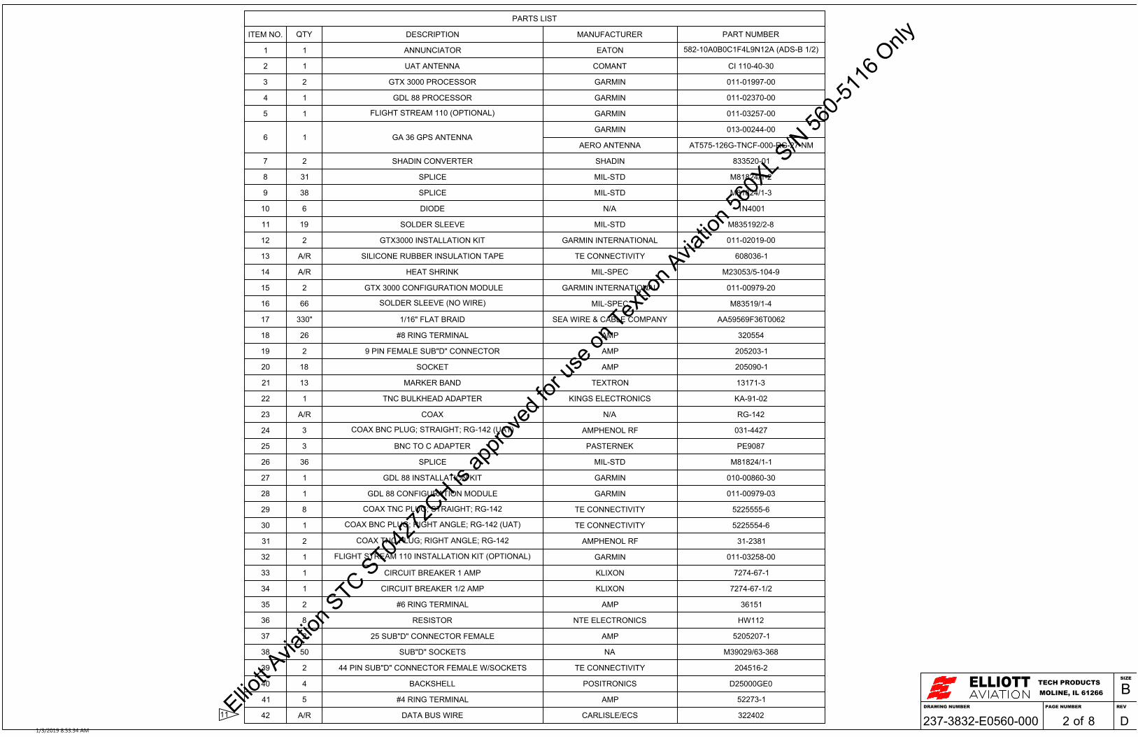
PARTS LIST
ITEM NO. QTY DESCRIPTION MANUFACTURER PART NUMBER
1 1 ANNUNCIATOR EATON 582-10A0B0C1F4L9N12A (ADS-B 1/2)
2 1 UAT ANTENNA COMANT CI 110-40-30
3 2 GTX 3000 PROCESSOR GARMIN 011-01997-00
4 1 GDL 88 PROCESSOR GARMIN 011-02370-00
5 1 FLIGHT STREAM 110 (OPTIONAL) GARMIN 011-03257-00
6 1 GA 36 GPS ANTENNAGARMIN 013-00244-00
AERO ANTENNA AT575-126G-TNCF-000-RG-27-NM
7 2 SHADIN CONVERTER SHADIN 833520-01
8 31 SPLICE MIL-STD M81824/1-2
9 38 SPLICE MIL-STD M81824/1-3
10 6 DIODE N/A 1N4001
11 19 SOLDER SLEEVE MIL-STD M835192/2-8
12 2 GTX3000 INSTALLATION KIT GARMIN INTERNATIONAL 011-02019-00
13 A/R SILICONE RUBBER INSULATION TAPE TE CONNECTIVITY 608036-1
14 A/R HEAT SHRINK MIL-SPEC M23053/5-104-9
15 2 GTX 3000 CONFIGURATION MODULE GARMIN INTERNATIONAL 011-00979-20
16 66 SOLDER SLEEVE (NO WIRE) MIL-SPEC M83519/1-4
17 330" 1/16" FLAT BRAID SEA WIRE & CABLE COMPANY AA59569F36T0062
18 26 #8 RING TERMINAL AMP 320554
19 2 9 PIN FEMALE SUB"D" CONNECTOR AMP 205203-1
20 18 SOCKET AMP 205090-1
21 13 MARKER BAND TEXTRON 13171-3
22 1 TNC BULKHEAD ADAPTER KINGS ELECTRONICS KA-91-02
23 A/R COAX N/A RG-142
24 3 COAX BNC PLUG; STRAIGHT; RG-142 (UAT) AMPHENOL RF 031-4427
25 3 BNC TO C ADAPTER PASTERNEK PE9087
26 36 SPLICE MIL-STD M81824/1-1
27 1 GDL 88 INSTALLATION KIT GARMIN 010-00860-30
28 1 GDL 88 CONFIGURATION MODULE GARMIN 011-00979-03
29 8 COAX TNC PLUG; STRAIGHT; RG-142 TE CONNECTIVITY 5225555-6
30 1 COAX BNC PLUG; RIGHT ANGLE; RG-142 (UAT) TE CONNECTIVITY 5225554-6
31 2 COAX TNC PLUG; RIGHT ANGLE; RG-142 AMPHENOL RF 31-2381
32 1 FLIGHT STREAM 110 INSTALLATION KIT (OPTIONAL) GARMIN 011-03258-00
33 1 CIRCUIT BREAKER 1 AMP KLIXON 7274-67-1
34 1 CIRCUIT BREAKER 1/2 AMP KLIXON 7274-67-1/2
35 2 #6 RING TERMINAL AMP 36151
36 8 RESISTOR NTE ELECTRONICS HW112
37 2 25 SUB"D" CONNECTOR FEMALE AMP 5205207-1
38 50 SUB"D" SOCKETS NA M39029/63-368
39 2 44 PIN SUB"D" CONNECTOR FEMALE W/SOCKETS TE CONNECTIVITY 204516-2
40 4 BACKSHELL POSITRONICS D25000GE0
41 5 #4 RING TERMINAL AMP 52273-1
42 A/R DATA BUS WIRE CARLISLE/ECS 32240211DRAWING NUMBER
ELLIOTTMOLINE, IL 61266TECH PRODUCTS
PAGE NUMBER REV
SIZE
B
of237-3832-E0560-000 8 D21/3/2019 8:53:34 AM
Elliott A
viatio
n STC ST04
272C
H is ap
prove
d for
use o
n Tex
tron A
viatio
n 560
XL S/N
560-5
116 O
nly

# 1 TRANSPONDER1J3301GTX3000
-28VDC POWER INPUT-28VDC POWER INPUT-POWER GROUND-POWER GROUND
GROUND 50
1J3302
53
4244-
51GROUND58GROUND
--
37ARINC 429 TX 1 (A)34ARINC 429 TX 1 (B)
32ARINC 429 RX 1 (A)35ARINC 429 RX 1 (B)
-(ADC) ARINC 429 RX 5 (A) 30-(ADC) ARINC 429 RX 5 (B) 31
--
2629
-
(TCAS) ARINC 429 RX 8 H/S (A) 36
-
37-
14
-
15
(#1 AHRS) ARINC 429 RX 3 (A)(#1 AHRS) ARINC 429 RX 3 (B)
(TCAS) ARINC 429 RX 8 H/S (B)
(TCAS) ARINC 429 TX 4 H/S (A)(TCAS) ARINC 429 TX 4 H/S (B)
B
W
B
W
B
W
B
W
B
W
B
W
31 -SUPPRESSION
17 -(GND = GND) WEIGHT ON WHEELS
LEFT NOSE AVIONICS BAY
560-104A22
560-110A22
560-105A22
560-106A22
560-108A22
560-100A20
560-101A20N
560-102A20N
A
FWD B/H
C
CB PANEL DISCPF920
20
HNDC11 GND BLOCK
R
-REMOTE ON 58
B
W
19ADS-B ANNUN -
1112
23
1269
1132 ADS-B
1 2
560-113A22
J560-302
RS-232 #2 RXRS-232 #2 TX
-24-25
RS-232 #2 GND -43O
W
B
560-109A22O
W
B
6J881 GDL88 (PG 5)25
44
47CONFIG DISCRETE INPUT -
B
W
B
W 23
6
-- B
W
B
W
B
W560-114A22
560-115A22-- B
W
40
1J1 #1 SHADIN AMC CONVERTER (PG 6)41
2510
(22AWG)
(22AWG)
560-107ACX
B
W 2848
12 O
W
B
O
W
B 3
560-109B22
560-107BCX
11TYPICAL
J1 #1 SHADIN AMC CONVERTER (PG 6)2560-100B20P.C.
46 -EXTERNAL STBY (GND=STBY)
PI601 #1 RMU 850*KB
PB831 JB831
NOSE CTR WEBPN525 JN525
PN381 NOSE AVIONICS J-BOX6360
PN384 NOSE J-BOX27
1718
1516
147
B
W
B
W
PN819 RMP TCAS 200014J14H
B
W
B
W
14B14A (REF CESSNA W/D 8608138 PG 2)
1231 2J3301 #2 GTX 3000 (PG 4)
42 PN611 #1 NAV UNIT
560-107CCX
NOSE CTR WEBPN702 JN702
N
FWD B/HPB526 JB526
4
PN900 NOSE AVIONICS J-BOX
2012
PG 4 859283242
M
PT
(REF CESSNA W/D 8600202 PG 6)
560-103A22
560-120A22560-121A22
560-119A22560-118A22
560-120B22560-121B22
560-119B22560-118B22
28VDC LEFT HAND
RH CB PANEL
AVIONICS BUS
A
(22AWG)
(22AWG)
(22AWG)
(22AWG)
(22AWG)
(22AWG)
(22AWG)
4849
-B
W560-116A22
(#2 AHRS) ARINC 429 RX 4 (A)(#2 AHRS) ARINC 429 RX 4 (B) B
W
3 8 10
18
-
PN311 AHRS(REF CESSNA W/D 8617119 PG 1)
P.C.
3351 PN330 NOSE CTR WEB
(REF CESSNA W/D 8616184 PG 1)
P.C.
- 1GROUND 1- 21POWER 4- 40DATA 3- 60CLOCK 2
CONFIG MODULE
22 -RS-232 #1 RX 323 -RS-232 #1 TX 227 -RS-232 #1 GND 5
O
W
B
O
W
B
LOC: BACKSHELL
560-117A22 CONFIG PORTCOVER AND STOWWHEN NOT IN USE.
PB843A
EXISTING #1 LOWER XPDR ANT
TOP ANTENNA
BOTTOM ANTENNA
(LOC: TIED IN HARNESS BEHIND GTX 3000 CONNECTORS)
15
1XPDR
5
8 TYPICAL
9
12
16 TYPICAL17
18 TYPICAL
19 20
10
29
29
23
23 25 24
29
18
J560-3039
(REF CESSNA W/D 8603113)
PN818 RMP TCAS 2000(REF CESSNA W/D 8608138 PG 2)
(REF CESSNA W/D 8600202 PG 8)
(REF CESSNA W/D 8600202 PG 3)
LOC: CENTER INSTRUMENT PANEL
PB843BFWD B/H
EXISTING #1 UPPER XPDR ANT
(REF CESSNA W/D 8608131 PG 1)
(REF CESSNA W/D 8608131 PG 2)
(REF CESSNA W/D 8618103)
(REW)
(REW)
(REW)
(REW)
(REW)
(REW)
(REW)
(REW)
(REW)
(REW)
560-113B22
560-123A22B
W 3952 PN367 J2A IC-615
P.C.--
32B
W(EFIS) ARINC 429 RX 6 (A)(EFIS) ARINC 429 RX 6 (B) 33 (REF CESSNA W/D 8612159 PG 2)
DRAWING NUMBER
ELLIOTTMOLINE, IL 61266TECH PRODUCTS
PAGE NUMBER REV
SIZE
B
of237-3832-E0560-000 8 D31/3/2019 8:53:34 AM
Elliott A
viatio
n STC ST04
272C
H is ap
prove
d for
use o
n Tex
tron A
viatio
n 560
XL S/N
560-5
116 O
nly
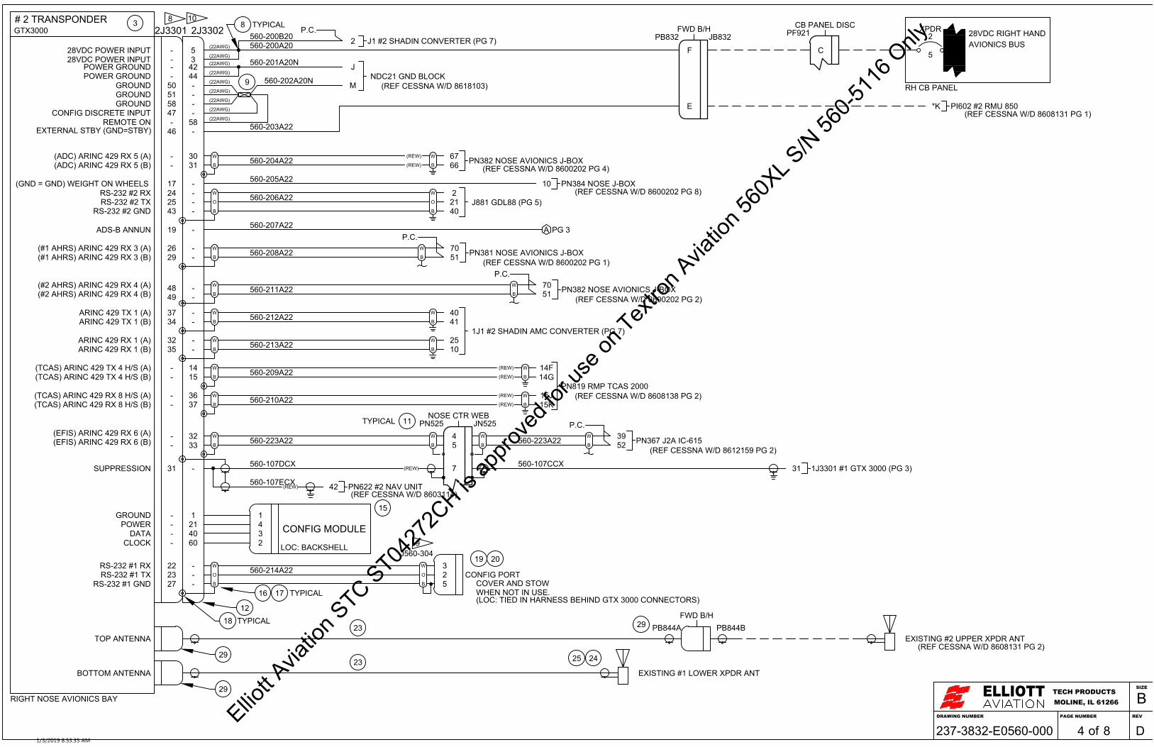
# 2 TRANSPONDER2J3301GTX3000
-28VDC POWER INPUT-28VDC POWER INPUT-POWER GROUND-POWER GROUND
GROUND 50
2J3302
53
4244-
51GROUND58GROUND
--
37ARINC 429 TX 1 (A)34ARINC 429 TX 1 (B)
32ARINC 429 RX 1 (A)35ARINC 429 RX 1 (B)
-(ADC) ARINC 429 RX 5 (A) 30-(ADC) ARINC 429 RX 5 (B) 31
--
2629
-
(TCAS) ARINC 429 RX 8 H/S (A) 36
-
37-
14
-
15
(#1 AHRS) ARINC 429 RX 3 (A)(#1 AHRS) ARINC 429 RX 3 (B)
(TCAS) ARINC 429 RX 8 H/S (B)
(TCAS) ARINC 429 TX 4 H/S (A)(TCAS) ARINC 429 TX 4 H/S (B)
B
W
B
W
B
W
B
W
2XPDR
5
31 -SUPPRESSION
17 -(GND = GND) WEIGHT ON WHEELS
RIGHT NOSE AVIONICS BAY
560-204A22
560-208A22
560-209A22
560-210A22
560-205A22
560-200A20
560-201A20N
560-202A20N
28VDC RIGHT HAND
RH CB PANEL
F
FWD B/H
C
CB PANEL DISCPF921
JNDC21 GND BLOCK
M
-REMOTE ON 58
B
W
19ADS-B ANNUN - 560-207A22
RS-232 #2 RXRS-232 #2 TX
-24-25
RS-232 #2 GND -43O
W
B
560-206A22O
W
B
2J881 GDL88 (PG 5)21
40
47CONFIG DISCRETE INPUT -
AVIONICS BUS
-- B
W
B
W
B
W560-212A22
560-213A22-- B
W
40
1J1 #2 SHADIN AMC CONVERTER (PG 7)41
2510
(22AWG)
(22AWG)
560-107DCX
560-107ECX
11TYPICAL
J1 #2 SHADIN CONVERTER (PG 7)2560-200B20P.C.
46 -EXTERNAL STBY (GND=STBY)
PI602 #2 RMU 850*KE
PB832 JB832
NOSE CTR WEBPN525 JN525
PN382 NOSE AVIONICS J-BOX6667
PN384 NOSE J-BOX10
A
B
W
14G14F
B
W
15K15J
B
WPN381 NOSE AVIONICS J-BOX51
70
(REF CESSNA W/D 8600202 PG 1)
31 1J3301 #1 GTX 3000 (PG 3)
42 PN622 #2 NAV UNIT
560-107CCX
560-203A22
PG 3
7
P.C.
4849
-- B
W560-211A22(#2 AHRS) ARINC 429 RX 4 (A)
(#2 AHRS) ARINC 429 RX 4 (B)
(22AWG)
(22AWG)
B
WPN382 NOSE AVIONICS J-BOX51
70
(REF CESSNA W/D 8600202 PG 2)
P.C.
- 1GROUND 1- 21POWER 4- 40DATA 3- 60CLOCK 2
CONFIG MODULE
22 -RS-232 #1 RX 323 -RS-232 #1 TX 227 -RS-232 #1 GND 5
O
W
B
O
W
B
LOC: BACKSHELL
560-214A22 CONFIG PORTCOVER AND STOWWHEN NOT IN USE.(LOC: TIED IN HARNESS BEHIND GTX 3000 CONNECTORS)
PB844A
EXISTING #1 LOWER XPDR ANT
TOP ANTENNA
BOTTOM ANTENNA
(22AWG)
(22AWG)
(22AWG)
(22AWG)
(22AWG)
3 8 TYPICAL
9
15
12
16 TYPICAL17
18 TYPICAL
19 20
29
29
23
23 25 24
29
J560-3049
8 10
PN819 RMP TCAS 2000(REF CESSNA W/D 8608138 PG 2)
PB844BFWD B/H
EXISTING #2 UPPER XPDR ANT
(REF CESSNA W/D 8600202 PG 4)
(REF CESSNA W/D 8600202 PG 8)
(REF CESSNA W/D 8608131 PG 1)
(REF CESSNA W/D 8608131 PG 2)
(REF CESSNA W/D 8603114)
(REF CESSNA W/D 8618103)
(REW)
(REW)
(REW)
(REW)
(REW)
(REW)
(REW)
(REW)
560-223A22B
W 3952 PN367 J2A IC-615
P.C.--
32B
W(EFIS) ARINC 429 RX 6 (A)(EFIS) ARINC 429 RX 6 (B) 33 B
W
B
W45 560-223A22
(REF CESSNA W/D 8612159 PG 2)
DRAWING NUMBER
ELLIOTTMOLINE, IL 61266TECH PRODUCTS
PAGE NUMBER REV
SIZE
B
of237-3832-E0560-000 8 D41/3/2019 8:53:35 AM
Elliott A
viatio
n STC ST04
272C
H is ap
prove
d for
use o
n Tex
tron A
viatio
n 560
XL S/N
560-5
116 O
nly

64GROUND65POWER62DATA63CLOCK
CONFIG
USB +USB -
USB POWERUSB JACK (PART OF CONNECTOR KIT)
USB GND
62544
O
W
B
RS-232 # 3 TXRS-232 # 3 RX
RS-232 # 3 GND
MODULE
1432
3214
61604241
GPS ANTENNA23
COVER AND STOWWHEN NOT IN USE.
UAT/WAAS RECIEVER
J881GDL88
RIGHT NOSE AVIONICS BAY
POWER GROUNDPOWER GROUND
REMOTE ONREMOTE ON
77781718
22140
O
W
B
RS-232 # 5 TXRS-232 # 5 RX
RS-232 # 5 GND
501231
FAN GROUNDFAN SPEED
FAN POWER
RACK FAN
RACK FAN PIGTAIL
BLUETOOTH J301 FLIGHTSTREAM 11016
5 28VDC POWER INPUT15 POWER GROUND
B
W
B
W
13 ARINC 422 TX 1 (A)14 ARINC 422 TX 1 (B)
4 ARINC 422 RX 1 (A)10 ARINC 422 RX 1 (B)
28 VDC POWER IN28 VDC POWER IN
1920
GPSADS-B
1
BL THFIS-B
1/2
B
W
B
W
5776
5675
ARINC 422 TX 1 (A)ARINC 422 TX 1 (B)
ARINC 422 RX 1 (A)ARINC 422 RX 1 (B)
J884
GREENWHITEREDBLACKGRAY
BLACKREDYELLOWWHITE
O
W
B
560-300A22
560-301A22N560-302A22N
560-109B22
560-206A22
560-303A22
560-304A22
242543
2P3301 #2 GTX 3000 (PG 4)
24
UAT ANTENNA
UAT ANTENNA23J882
NDC21 GND BLOCKPN
560-305A22560-306A22N
GPS ANTENNA
33
34
7
BLACKYELLOWRED
123
BLACKYELLOWRED
35
35
8
4
5
6
2
RH CB PANEL
28
P/O 27
27
F
FWD B/H
E
CB PANEL DISCPF921PB525 JB525
G
B
W
B
W
GH
JK
B
W
B
W
O
W
B
242543
1P3301 #1 GTX 3000 (PG 3)192223
NOSE CTR WEBJN305 PN305
O
W
B
O
W
B
28VDC RIGHT HANDAVIONICS BUS
8 TYPICAL
16 TYPICAL17
18 TYPICAL
11TYPICAL 18
31
30
8
8 25
31
8
171832
10 8
8 10
22
LOC: BEHIND COPILOT JEP CHART CABINET
P560-30329 J560-303FWD B/H
29
LOC: BOTTOM AIRCRAFT, NOSE
LOC: UPPER FUSELAGE
(REF CESSNA W/D 8618103)
23
560-109A22
560-300B22
560-303B22
560-304B22
560-300C22
560-305B22
DRAWING NUMBER
ELLIOTTMOLINE, IL 61266TECH PRODUCTS
PAGE NUMBER REV
SIZE
B
of237-3832-E0560-000 8 D51/3/2019 8:53:35 AM
Elliott A
viatio
n STC ST04
272C
H is ap
prove
d for
use o
n Tex
tron A
viatio
n 560
XL S/N
560-5
116 O
nly

#1 SHADIN CONVERTER1J1#1 RSB CONVERTER
228VDC POWER INPUT
1POWER GROUND
25#1 GTX 3000 429 TX (A)10#1 GTX 3000 429 TX (B)
B
W
B
W
B
W
B
W
B
W
B
W560-402A24
37CHASSIS GROUND
21#1 PRIM RCZ (P)8#1 PRIM RCZ (N)
B
W560-403A24
B
W
1728VDC POWER INPUT
16POWER GROUND
40#1 GTX 3000 429 RX (A)41#1 GTX 3000 429 RX (B)
#1 RCZPN521 COM UNIT
RSB PRIMARY (P)11 RSB PRIMARY (N)B
W
B
W
B
W
B
W
25#1 PRIM RSB P12#1 PRIM RSB N
B
W560-403B24
B
WX
XX
XX
10
XX
XX
XX
X
XXXXXXXXXXXX
XXXXXXXXXXXXX
7
B
W
B
W 36B
W
B
W36
37 38 40
39 408
560-402B24 560-402C24
42
42
42
42
LEFT NOSE AVIONICS BAY
12 12
12
12
12
12
12
1J2
12
B
W
B
W
B
W
B
W
B
W
B
W
B
W
B
W
B
W
B
W
XX
XX
X
XX
XX
XX
X
XXXXXXXXXXXX
XXXXXXXXXXXXX
B
W
B
W 36B
W
B
W36
42
42
42
42
12 12
12
12
12
12
12
12
17#1 SEC RSB (P)4#1 SEC RSB (N)
14#1 SEC RCZ (P)1#1 SEC RCZ (N) 560-404A24
560-405A24
RSB SECONDARY (P)61 RSB SECONDARY (N)
560-405B24
74
560-404B24 560-404C24
16 TYPICAL41
8 TYPICAL
P.C.1J3302 #1 GTX3000 (PG 3)5560-100B20
560-400A20N
NDC11 GND BLOCKM
J
560-401A22N
560-406A16
(REF CESSNA W/D 8618103)
1J3301 #1 GTX3000 (PG 3)
3235
560-114A22
560-115A22
3734
71(8615173 PG 1) PN612 #1 RNZ 81
1(86151173 PG 1) PN523 RESISTOR MODULE 34
88(8615173 PG 2) PN611 #1 RNZ 102
53(8615173 PG 2) PN369 #1 IC-600 54
P.C.PB526 FWD B/HW
(REF CESSNA W/D 8601176 PG 1)
26
17
23SDI #1
10
DRAWING NUMBER
ELLIOTTMOLINE, IL 61266TECH PRODUCTS
PAGE NUMBER REV
SIZE
B
of237-3832-E0560-000 8 D61/3/2019 8:53:35 AM
Elliott A
viatio
n STC ST04
272C
H is ap
prove
d for
use o
n Tex
tron A
viatio
n 560
XL S/N
560-5
116 O
nly

#2 SHADIN CONVERTER2J1#2 RSB CONVERTER
228VDC POWER INPUTP.C.
2J3302 #2 GTX3000 (PG 4)5
1POWER GROUND
2J3301 #2 GTX3000 (PG 4)
25#2 GTX 3000 429 TX (A)10#2 GTX 3000 429 TX (B)
B
W
B
W 3235
B
W
B
W
B
W
B
W
560-200B20
560-502A24
560-500A20N
560-212A22
560-213A22
37CHASSIS GROUND
21#2 PRIM RCZ (P)8#2 PRIM RCZ (N)
B
W560-503A24
B
W
NDC21 GND BLOCKR
P1728VDC POWER INPUT
16POWER GROUND 560-501A22N
40#2 GTX 3000 429 RX (A)41#2 GTX 3000 429 RX (B)
3734
#2 RCZPN518 COM UNIT
RSB PRIMARY (P)11 RSB PRIMARY (N)B
W
B
W
B
W
B
W
19(8615173 PG 1) PN368 #2 IC-600 20
25#2 PRIM RSB P12#2 PRIM RSB N
B
W560-503B24
B
W
XX
XX
X
10
XX
XX
XX
X
XXXXXXXXXXXX
XXXXXXXXXXXXX
71(8615173 PG 1) PN623 #2 RNZ 81
7
B
W
B
W 36B
W
B
W36
37 38 40
39 408
560-506A16P.C.
PB525 FWD B/HW(REF CESSNA W/D 8601177 PG 1)
560-502B24 560-502C24
42
42
42
42
RIGHT NOSE AVIONICS BAY
(REF CESSNA W/D 8618103)
12 12
12
12
12
12
12
2J2
12
B
W
B
W
B
W
B
W
B
W
B
W
B
W
B
W
B
W
B
W
XX
XX
X
XX
XX
XX
X
XXXXXXXXXXXX
XXXXXXXXXXXXX
B
W
B
W 36B
W
B
W36
42
42
42
42
12 12
12
12
12
12
12
12
17#2 SEC RSB (P)4#2 SEC RSB (N)
14#2 SEC RCZ (P)1#2 SEC RCZ (N) 560-504A24
560-505A24
RSB SECONDARY (P)61 RSB SECONDARY (N)
560-505B24
7453(8615173 PG 2) PN370 #2 IC-600 54
88(8615173 PG 2) PN622 #2 RNZ 102
560-504B24 560-504C24
8 TYPICAL26
16 TYPICAL4117
10
DRAWING NUMBER
ELLIOTTMOLINE, IL 61266TECH PRODUCTS
PAGE NUMBER REV
SIZE
B
of237-3832-E0560-000 8 D71/3/2019 8:53:36 AM
Elliott A
viatio
n STC ST04
272C
H is ap
prove
d for
use o
n Tex
tron A
viatio
n 560
XL S/N
560-5
116 O
nly

14
16
17
13
18
GARMIN D-SUB CONNECTOR ASSEMBLY (TYPICAL)
9
ALL OTHER CONNECTOR PARTS ARE PART OF APPLICABLE INSTALLATION KIT
DRAWING NUMBER
ELLIOTTMOLINE, IL 61266TECH PRODUCTS
PAGE NUMBER REV
SIZE
B
of237-3832-E0560-000 8 D81/3/2019 8:53:36 AM
Elliott A
viatio
n STC ST04
272C
H is ap
prove
d for
use o
n Tex
tron A
viatio
n 560
XL S/N
560-5
116 O
nly

SINGLE WIRE M22759 / 16-XX-9 (XX = WIRE GAUGE)
SINGLE SHIELDED WIRE M27500-XXTG1T14 (XX = WIRE GAUGE)
2-WIRE SHIELDED M27500-XXTG2T14 (XX = WIRE GAUGE)
3-WIRE SHIELDED M27500-XXTG3T14 (XX = WIRE GAUGE)
WIRE SPLICE
DIODE
CIRCUIT BREAKER
CAP & STOW WIRE
XX PARTS LIST PARTS BUBBLE
COAX
B.O.M. PARTS CALL OUTXX
AMPS
NAMENAME
(REW) = REMOVE EXISTING WIRE
XXX -XXX X XX N451 -100 A 22 N (EXAMPLE ONLY)
REFERENCE DESIGNATOR
EXISTING
NEW WIRE
SYSTEMWIRE GAUGE
SEGMENT
GROUND
PARALLEL CONNECTIONP.C.
WIRE CODE:
LEGEND:
B
W
O
W
B
SPLICE TO EXISTING SHIELDS
UNSHIELDED STUB WIRE TWISTED TOGETHER
NOTES:
1. REFERENCE THE FOLLOWING GARMIN INTERNATIONAL MANUALS:GTX 3000 TRANSPONDER INSTALLATION MANUAL; 190-00926-01, REV L, OCT 2015GDL 84/88 TSO INSTALLATION MANUAL; 190-01122-00; REV H, DEC 2014.FLIGHT STREAM 110/210 TSO INSTALLATION MANUAL; 190-01700-00; REV E; DEC2015.
2. EXISTING TRANSPONDER MODULE INTERNAL TO THE RCZ IS DISABLED. THEEXISTING SOURCES TO THE TRANSPONDER ARE REWIRED.
3. NOT USED
4. ALL WIRING AND COMPONENT ASSEMBLY, INSTALLATION, ROUTING, SLEEVINGAND SECURING SHALL COMPLY WITH CESSNA CITATION 560XL - CHAPTER 20STANDARD PRACTICES - AIRFRAME
5. ALL TERMINAL AND SPLICE CRIMPING ARE TO BE IN ACCORDANCE WITHVENDOR SPECIFICATIONS AND PROCEDURES.
6. ASTERISK (*) NEXT TO A LETTER INDICATES A LOWER CASE LETTER.
7. IF OPTIONAL FLIGHT STREAM 110 IS NOT INSTALLED CAP AND STOW ALL WIRESINDIVIDUALLY NEAR COPILOTS JEP CHART HOLDER. ADDITIONALLY CAP ANDSTOW CIRCUIT BREAKER WIRE AND DO NOT INSTALL CIRCUIT BREAKER.
8. LABEL MARKER BAND (PARTS LIST ITEM 21) WITH INDELIBLE INK. LABEL SHALLCONTAIN THE CONNECTOR NUMBER AND UNIT OR CONNECTOR IT MATES WITH.
9. INSTALL ENOUGH TAPE TILL THE STRAIN RELIEF CLAMPS ONTO THE TAPE.
10. USE PAGE 8 TO ASSEMBLE CONNECTOR.
11. REFERENCE ECS/CARLISLE DRAWING NUMBER 322402 REV F DATED JUNE 10,2005.
12. SPECIAL RSB WIRING NOTES: IMPORTANT!
* USE 125OHM TWISTED-PAIR SHIELDED CABLE PER NOTE #11
* THE WIRE LENGTH BETWEEN UNITS AND TO THE TERMINATOR (RESISTOR 120+- 10% OHMS ) MUST BE GREATER THAN 23IN (>23IN)
* THE SHIELD CONNECTION AT EACH STUB MUST BE DONE WITH A SPLICETHAT PROVIDES A MAXIMUM SHIELD-TO-SHIELD CONNECTION OF 0.3IN (PG #8RSB WIRING EXAMPLE)
* ALL STUB WIRING SHOULD CONSIST OF WIRE, PER NOTE #11, WITH THEMAXIMUM LENGTH OF THE STUB WIRES 10IN OR LESS. THE UNSHIELDEDSTUB SECTION SHOULD BE TWISTED TOGETHER (PG #8 RSB WIRINGEXAMPLE)
* BUS SHIELDS SHOULD BE KEPT TO MINIMUM LENGTH. PERMISSIBLE TOSUBSTITUTE SHIELDED BRAID WITH 22 AWG WIRE.
* WHEN SPLICING RSB WIRING USE RED SPLICE TO SPLICE THE WIRESTOGETHER AND THE YELLOW ENVIRONMENTAL COVER.
13. EXISTING SOURCES AND INTERFACE TO TRANSPONDER UNCHANGED. FULLDETAILS OMITTED FOR CLARITY. REFERENCE AIRCRAFT WIRING DIAGRAMMANUAL FOR COMPLETE DETAILS.
DESCRIPTIONREV DATE APPROVED BY
REVISIONS
IR INITIAL RELEASE 07/31/18 R. WOOLUMS
A CORRECTED TYPOS AND FEEDTHU PINOUTS 06/26/18 R. WOOLUMS
B CHANGED SHADIN CONV P/N TO 833520-01 12/11/18 R. WOOLUMS
.0 ± .1.00 ± .03
.000 ± .005
TOLERANCES IN INCHESUNLESS OTHERWISESPECIFIED
PAGE NUMBERDRAWING NUMBERDRAWING DESCRIPTIONA/C MAKE, MODEL
INITIAL RELEASE DATE A/C S/N
SCALEDRAWN BY
CHECKED BY
THIS DRAWING INCLUDING THE DESIGN AND PRINCIPLES OF CONSTRUCTION DISCLOSED IS THE PROPERTY OFELLIOTT AVIATION AND IS SUBMITTED WITH THE UNDERSTANDING THAT IT IS NOT TO BE REPRODUCED NORCOPIED IN WHOLE OR IN PART NOR LOANED OR OTHERWISE COMMUNICATED TO ANY THIRD PARTY NOR USEDIN ANY MANNER DETRIMENTAL TO THE INTEREST OF ELLIOTT AVIATION WITHOUT ITS EXPRESS CONSENT.ACCEPTANCE OF THIS DRAWING WILL BE CONSTRUED AS AN AGREEMENT TO THE ABOVE.
ELLIOTTMOLINE, IL 61266TECH PRODUCTS
SIZE
Bof 8237-4071-E0560-000GARMIN GTX 3000 SYSTEMELECTRICAL INSTALLATION560-5001 THRU 560-550007/31/18TB
CITATION 560XLRLW1
NTS
1/3/2019 8:52:20 AM
Elliott A
viatio
n STC ST04
272C
H is ap
prove
d for
use o
n Tex
tron A
viatio
n 560
XL S/N
560-5
116 O
nly

PARTS LIST
ITEM NO. QTY DESCRIPTION MANUFACTURER PART NUMBER
1 1 ANNUNCIATOR EATON 582-10A0B0C1F4L9N12A (ADS-B 1/2)
2 1 UAT ANTENNA COMANT CI 110-40-30
3 2 GTX 3000 PROCESSOR GARMIN 011-01997-00
4 1 GDL 88 PROCESSOR GARMIN 011-02370-00
5 1 FLIGHT STREAM 110 (OPTIONAL) GARMIN 011-03257-00
6 1 GA 36 GPS ANTENNAGARMIN 013-00244-00
AERO ANTENNA AT575-126G-TNCF-000-RG-27-NM
7 2 SHADIN CONVERTER SHADIN 833520-01
8 67 SPLICE MIL-STD M81824/1-2
9 2 SPLICE MIL-STD M81824/1-3
10 6 DIODE N/A 1N4001
11 59 SOLDER SLEEVE MIL-STD M835192/2-8
12 2 GTX3000 INSTALLATION KIT GARMIN INTERNATIONAL 011-02019-00
13 A/R SILICONE RUBBER INSULATION TAPE TE CONNECTIVITY 608036-1
14 A/R HEAT SHRINK MIL-SPEC M23053/5-104-9
15 2 GTX 3000 CONFIGURATION MODULE GARMIN INTERNATIONAL 011-00979-20
16 26 SOLDER SLEEVE (NO WIRE) MIL-SPEC M83519/1-4
17 130" 1/16" FLAT BRAID SEA WIRE & CABLE COMPANY AA59569F36T0062
18 26 #8 RING TERMINAL AMP 320554
19 2 9 PIN FEMALE SUB"D" CONNECTOR AMP 205203-1
20 18 SOCKET AMP 205090-1
21 13 MARKER BAND TEXTRON 131741-3
22 1 TNC BULKHEAD ADAPTER KINGS ELECTRONICS KA-91-02
23 A/R COAX N/A RG-142
24 3 COAX BNC PLUG; STRAIGHT; RG-142 (UAT) AMPHENOL RF 031-4427
25 3 BNC TO C ADAPTER PASTERNEK PE9087
26 - NOT USED - -
27 1 GDL 88 INSTALLATION KIT GARMIN 010-00860-30
28 1 GDL 88 CONFIGURATION MODULE GARMIN 011-00979-03
29 9 COAX TNC PLUG; STRAIGHT; RG-142 TE CONNECTIVITY 5225555-6
30 1 COAX BNC PLUG; STRAIGHT; RG-142 (UAT) AMPHENOL RF 031-4427
31 1 COAX TNC PLUG; RIGHT ANGLE; RG-142 AMPHENOL RF 31-2381
32 1 FLIGHT STREAM 110 INSTALLATION KIT (OPTIONAL) GARMIN 011-03258-00
33 1 CIRCUIT BREAKER 1 AMP KLIXON 7277-2-1
34 1 CIRCUIT BREAKER 1/2 AMP KLIXON 7277-2-1/2
35 2 #6 RING TERMINAL AMP 36151
36 8 RESISTOR NTE ELECTRONICS HW112
37 2 25 SUB"D" CONNECTOR FEMALE AMP 5205207-1
38 50 SUB"D" SOCKETS NA M39029/63-368
39 2 44 PIN SUB"D" CONNECTOR FEMALE W/SOCKETS TE CONNECTIVITY 204516-2
40 4 BACKSHELL POSITRONICS D25000GEO
41 5 #4 RING TERMINAL AMP 52273-1
42 A/R DATA BUS WIRE CARLISLE/ECS 32240211DRAWING NUMBER
ELLIOTTMOLINE, IL 61266TECH PRODUCTS
PAGE NUMBER REV
SIZE
B
of237-4071-E0560-000 8 B21/3/2019 8:52:20 AM
Elliott A
viatio
n STC ST04
272C
H is ap
prove
d for
use o
n Tex
tron A
viatio
n 560
XL S/N
560-5
116 O
nly

# 1 TRANSPONDER1J3301GTX3000
-28VDC POWER INPUT-28VDC POWER INPUT-POWER GROUND-POWER GROUND
GROUND 50
1J3302
53
4244-
51GROUND58GROUND
--
37ARINC 429 TX 1 (A)34ARINC 429 TX 1 (B)
32ARINC 429 RX 1 (A)35ARINC 429 RX 1 (B)
-(ADC) ARINC 429 RX 5 (A) 30-(ADC) ARINC 429 RX 5 (B) 31
--
2629
-
(TCAS) ARINC 429 RX 8 H/S (A) 36
-
37-
14
-
15
(#1 AHRS) ARINC 429 RX 3 (A)(#1 AHRS) ARINC 429 RX 3 (B)
(TCAS) ARINC 429 RX 8 H/S (B)
(TCAS) ARINC 429 TX 4 H/S (A)(TCAS) ARINC 429 TX 4 H/S (B)
B
W
B
W
B
W
B
W
B
W
B
W
31 -SUPPRESSION
17 -(GND = GND) WEIGHT ON WHEELS
LEFT NOSE AVIONICS BAY
560-104A22
560-110A22
560-105A22
560-106A22
560-108A22
560-100A20
560-101A20N
560-102A20N
A
FWD B/H
C
CB PANEL DISCPF908
20
MNDC11 GND BLOCK
R
-REMOTE ON 58
B
W
19ADS-B ANNUN -
1112
23
1269
1132 ADS-B
1 2
560-113A22
J560-302
RS-232 #2 RXRS-232 #2 TX
-24-25
RS-232 #2 GND -43O
W
B
560-109A22O
W
B
6J881 GDL88 (PG 5)25
44
47CONFIG DISCRETE INPUT -
B
W
B
W 23
6
-- B
W
B
W
B
W560-114A22
560-115A22-- B
W
40
1J1 #1 SHADIN AMC CONVERTER (PG 6)41
2510
(22AWG)
(22AWG)
560-107ACX
B
W 2848
560-109B22
560-107BCX
11TYPICAL
J1 #1 SHADIN AMC CONVERTER (PG 6)2560-100B20P.C.
46 -EXTERNAL STBY (GND=STBY)
PI627 #1 RMU 850*KB
PB829 JB829
NOSE CTR WEBPN505 JN505
PN381 NOSE AVIONICS J-BOX6360
PN384 NOSE J-BOX27
1718
1516
147
B
W
B
W
PT809 LBP CAS 678180
B
W
B
W
6867
1331 2J3301 #2 GTX 3000 (PG 4)560-107CCX
M
FWD B/HPB512 JB512
PN900 NOSE AVIONICS J-BOX
2012
PG 4 1359333242
L
NP
560-103A22
560-120A22560-121A22
560-119A22560-118A22
560-120B22560-121B22
560-119B22560-118B22
28VDC LEFT HAND
RH CB PANEL
AVIONICS BUS
A
(22AWG)
(22AWG)
(22AWG)
(22AWG)
(22AWG)
(22AWG)
(22AWG)
4849
-B
W560-116A22
(#2 AHRS) ARINC 429 RX 4 (A)(#2 AHRS) ARINC 429 RX 4 (B) B
W
3 8 10
18
-
PN311 AHRS
P.C.
7051 PN382 J-BOX
P.C.
- 1GROUND 1- 21POWER 4- 40DATA 3- 60CLOCK 2
CONFIG MODULE
22 -RS-232 #1 RX 323 -RS-232 #1 TX 227 -RS-232 #1 GND 5
O
W
B
O
W
B
LOC: BACKSHELL
560-117A22 CONFIG PORTCOVER AND STOWWHEN NOT IN USE.
PB1004A
EXISTING #1 LOWER XPDR ANT
TOP ANTENNA
BOTTOM ANTENNA
(LOC: TIED IN HARNESS BEHIND GTX 3000 CONNECTORS)
15
1XPDR
5
8 TYPICAL
9
12
16 TYPICAL17
18 TYPICAL
19 20
10
29
29
23
23 25 24
29
18
J560-3039
PT808 RBP CAS 67
LOC: CENTER INSTRUMENT PANEL
PB1004BFWD B/H
EXISTING #1 UPPER XPDR ANT
BLKREDYELLOWWHITE
(REW)
(REW)
(REW)
(REW)
(REW)
(REW)
(REW)
(REW)
(REW)
13
45 B
W
13
42 PN611 #1 NAV UNIT
O
W
B
O
W
B
192021
22
B
W
(REW)
(REW)
560-116B22
560-123A22B
W 3952 PN367 J2A IC-600
P.C.--
32B
W(EFIS) ARINC 429 RX 6 (A)(EFIS) ARINC 429 RX 6 (B) 33
560-113B22
(REF CESSNA W/D 8618103)
(REF CESSNA W/D 8603101)
(REF CESSNA W/D 8617101 PG 1)
(REF CESSNA W/D 8600200 PG 5)
(REF CESSNA W/D 8600200 PG 4)
(REF CESSNA W/D 8608103)
(REF CESSNA W/D 8608109 PG 2)
(REF CESSNA W/D 8608109 PG 2)
(REF CESSNA W/D 8600200 PG 10)
(REF CESSNA W/D 8600200 PG 8)
(REF CESSNA W/D 8623143 PG 1)
DRAWING NUMBER
ELLIOTTMOLINE, IL 61266TECH PRODUCTS
PAGE NUMBER REV
SIZE
B
of237-4071-E0560-000 8 B31/3/2019 8:52:21 AM
Elliott A
viatio
n STC ST04
272C
H is ap
prove
d for
use o
n Tex
tron A
viatio
n 560
XL S/N
560-5
116 O
nly

# 2 TRANSPONDER2J3301GTX3000
-28VDC POWER INPUT-28VDC POWER INPUT-POWER GROUND-POWER GROUND
GROUND 50
2J3302
53
4244-
51GROUND58GROUND
--
37ARINC 429 TX 1 (A)34ARINC 429 TX 1 (B)
32ARINC 429 RX 1 (A)35ARINC 429 RX 1 (B)
-(ADC) ARINC 429 RX 5 (A) 30-(ADC) ARINC 429 RX 5 (B) 31
--
2629
-
(TCAS) ARINC 429 RX 8 H/S (A) 36
-
37-
14
-
15
(#1 AHRS) ARINC 429 RX 3 (A)(#1 AHRS) ARINC 429 RX 3 (B)
(TCAS) ARINC 429 RX 8 H/S (B)
(TCAS) ARINC 429 TX 4 H/S (A)(TCAS) ARINC 429 TX 4 H/S (B)
B
W
B
W
B
W
B
W
2XPDR
5
31 -SUPPRESSION
17 -(GND = GND) WEIGHT ON WHEELS
RIGHT NOSE AVIONICS BAY
560-204A22
560-208A22
560-209A22
560-210A22
560-205A22
560-200A20
560-201A20N
560-202A20N
28VDC RIGHT HAND
RH CB PANEL
F
FWD B/H
C
CB PANEL DISCPF909
RNDC20 GND BLOCK
P
-REMOTE ON 58
B
W
19ADS-B ANNUN - 560-207A22
RS-232 #2 RXRS-232 #2 TX
-24-25
RS-232 #2 GND -43O
W
B
560-214B22O
W
B
2J881 GDL88 (PG 5)21
40
47CONFIG DISCRETE INPUT -
AVIONICS BUS
-- B
W
B
W
B
W560-212A22
560-213A22-- B
W
40
1J1 #2 SHADIN AMC CONVERTER (PG 7)41
2510
(22AWG)
(22AWG)
560-107DCX
560-107ECX
11TYPICAL
J1 #2 SHADIN CONVERTER (PG 7)2560-200B20P.C.
46 -EXTERNAL STBY (GND=STBY)
PI628 #2 RMU 850*KE
PB830 JB830
NOSE CTR WEBPN305 JN305
PN382 NOSE AVIONICS J-BOX6667
PN384 NOSE J-BOX10
A
B
W
8382
B
W
5654
B
WPN381 NOSE AVIONICS J-BOX51
70
31 1J3301 #1 GTX 3000 (PG 3)
42 PN622 #2 NAV UNIT
560-107CCX
560-203A22
PG 3
7
P.C.
4849
-- B
W560-211A22(#2 AHRS) ARINC 429 RX 4 (A)
(#2 AHRS) ARINC 429 RX 4 (B)
(22AWG)
(22AWG)
B
WPN382 NOSE AVIONICS J-BOX51
70P.C.
- 1GROUND 1- 21POWER 4- 40DATA 3- 60CLOCK 2
CONFIG MODULE
22 -RS-232 #1 RX 323 -RS-232 #1 TX 227 -RS-232 #1 GND 5
O
W
B
O
W
B
LOC: BACKSHELL
560-214A22 CONFIG PORTCOVER AND STOWWHEN NOT IN USE.(LOC: TIED IN HARNESS BEHIND GTX 3000 CONNECTORS)
PB1014A
EXISTING #1 LOWER XPDR ANT
TOP ANTENNA
BOTTOM ANTENNA
(22AWG)
(22AWG)
(22AWG)
(22AWG)
(22AWG)
3 8 TYPICAL
9
15
12
16 TYPICAL17
18 TYPICAL
19 20
29
29
23
23 25 24
29
J560-3049
8 10
PN809 LBP CAS 67
PB1014BFWD B/H
EXISTING #2 UPPER XPDR ANT
BLKREDYELLOWWHITE
(REW)
(REW)
(REW)
(REW)
B
W
B
W
FWD PRESS BHDPB822 JB822
B
W
B
W
1415
1213
(REW)
(REW)
(REW)
(REW)
(REW)
(REW)
(REW)
13
(REF CESSNA W/D 8618103)
(REF CESSNA W/D 8600200 PG 5)
(REF CESSNA W/D 8608103)
(REF CESSNA W/D 8600200 PG 10)
(REF CESSNA W/D 8600200 PG 4)
(REF CESSNA W/D 8600200 PG 5)
(REF CESSNA W/D 8603102)
560-223A22B
W 3952 PN367 J2A IC-600
P.C.--
32B
W(EFIS) ARINC 429 RX 6 (A)(EFIS) ARINC 429 RX 6 (B) 33 B
W
B
W2223 560-223A22
(REF CESSNA W/D 8623143 PG 1)
(REF CESSNA W/D 8608109 PG 2)
11TYPICALNOSE CTR WEB
PN505 JN505
DRAWING NUMBER
ELLIOTTMOLINE, IL 61266TECH PRODUCTS
PAGE NUMBER REV
SIZE
B
of237-4071-E0560-000 8 B41/3/2019 8:52:21 AM
Elliott A
viatio
n STC ST04
272C
H is ap
prove
d for
use o
n Tex
tron A
viatio
n 560
XL S/N
560-5
116 O
nly

64GROUND65POWER62DATA63CLOCK
CONFIG
USB +USB -
USB POWERUSB JACK (PART OF CONNECTOR KIT)
USB GND
62544
O
W
B
RS-232 # 3 TXRS-232 # 3 RX
RS-232 # 3 GND
MODULE
1432
3214
61604241
GPS ANTENNA23
COVER AND STOWWHEN NOT IN USE.
UAT/WAAS RECIEVER
J881GDL88
RIGHT NOSE AVIONICS BAY
POWER GROUNDPOWER GROUND
REMOTE ONREMOTE ON
77781718
22140
O
W
B
RS-232 # 5 TXRS-232 # 5 RX
RS-232 # 5 GND
501231
FAN GROUNDFAN SPEED
FAN POWER
RACK FAN
RACK FAN PIGTAIL
BLUETOOTH J301 FLIGHTSTREAM 11016
5 28VDC POWER INPUT15 POWER GROUND
B
W
B
W
13 ARINC 422 TX 1 (A)14 ARINC 422 TX 1 (B)
4 ARINC 422 RX 1 (A)10 ARINC 422 RX 1 (B)
28 VDC POWER IN28 VDC POWER IN
1920
GPSADS-B
1
BL THFIS-B
1/2
B
W
B
W
5776
5675
ARINC 422 TX 1 (A)ARINC 422 TX 1 (B)
ARINC 422 RX 1 (A)ARINC 422 RX 1 (B)
J884
GREENWHITEREDBLACKGRAY
BLACKREDYELLOWWHITE
O
W
B
560-300A22
560-301A22N560-302A22N
560-109B22
560-214B22
560-303A22
560-304A22
242543
2P3301 #2 GTX 3000 (PG 4)
24
UAT ANTENNA
UAT ANTENNA23J882
NDC21 GND BLOCKNM
560-305A22560-306A22N
GPS ANTENNA
33
34
7
BLACKYELLOWRED
123
BLACKYELLOWRED
35
35
8
4
5
6
2
RH CB PANEL
28
P/O 27
27
F
FWD B/H
H
CB PANEL DISCPF909PB512 JB512
L
B
W
B
W
GH
JK
B
W
B
W
O
W
B
242543
1P3301 #1 GTX 3000 (PG 3)192021
NOSE CTR WEBJN505 PN505
O
W
B
O
W
B
28VDC RIGHT HANDAVIONICS BUS
8 TYPICAL
16 TYPICAL17
18 TYPICAL
11TYPICAL 18
29
30
8
8 25
31
8
171832
10 8
8 10
22
LOC: BEHIND COPILOT JEP CHART CABINET
P560-30329 J560-303FWD B/H 29
LOC: BOTTOM AIRCRAFT, NOSE
LOC: UPPER FUSELAGE
560-109A22
560-300B22
560-303B22
560-304B22
560-300C22
560-305B22(REF CESSNA W/D 8618103)
DRAWING NUMBER
ELLIOTTMOLINE, IL 61266TECH PRODUCTS
PAGE NUMBER REV
SIZE
B
of237-4071-E0560-000 8 B51/3/2019 8:52:22 AM
Elliott A
viatio
n STC ST04
272C
H is ap
prove
d for
use o
n Tex
tron A
viatio
n 560
XL S/N
560-5
116 O
nly
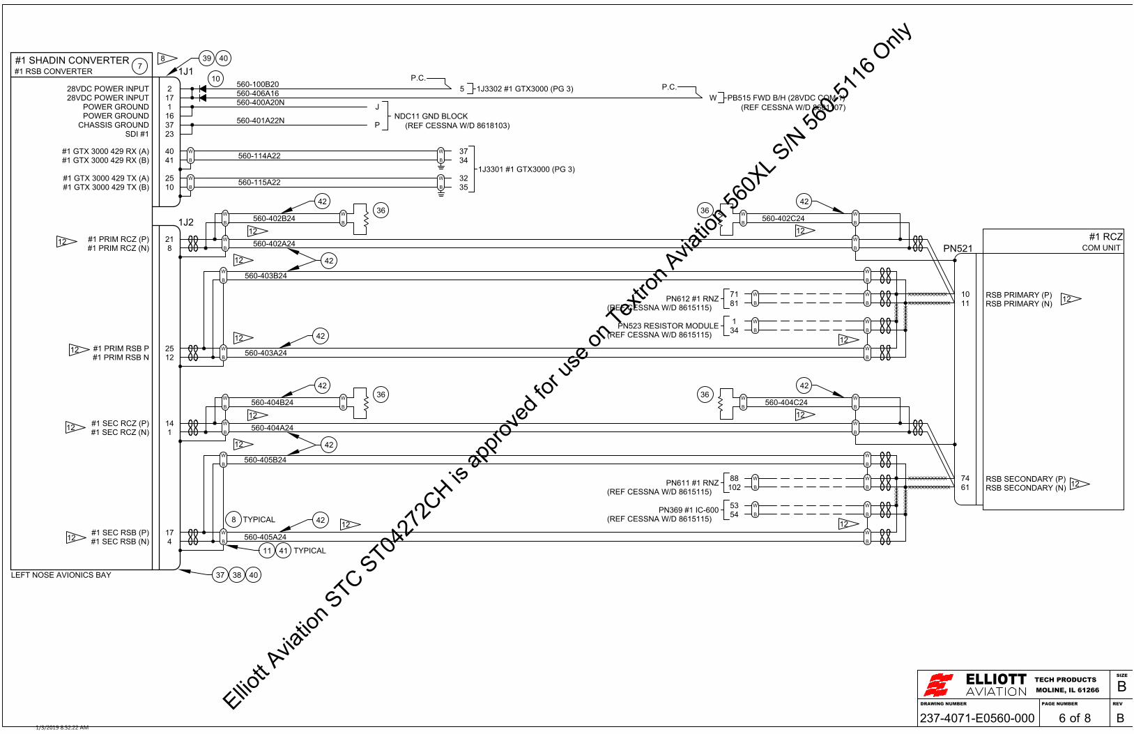
#1 SHADIN CONVERTER1J1#1 RSB CONVERTER
228VDC POWER INPUT
1POWER GROUND
25#1 GTX 3000 429 TX (A)10#1 GTX 3000 429 TX (B)
B
W
B
W
B
W
B
W
B
W
B
W560-402A24
37CHASSIS GROUND
21#1 PRIM RCZ (P)8#1 PRIM RCZ (N)
B
W560-403A24
B
W
1728VDC POWER INPUT
16POWER GROUND
40#1 GTX 3000 429 RX (A)41#1 GTX 3000 429 RX (B)
#1 RCZPN521 COM UNIT
RSB PRIMARY (P)11 RSB PRIMARY (N)B
W
B
W
B
W
B
W
25#1 PRIM RSB P12#1 PRIM RSB N
B
W560-403B24
B
W
XX
XX
X
10
XX
XX
XX
X
XXXXXXXXXXXX
XXXXXXXXXXXXX
7
B
W
B
W 36B
W
B
W36
37 38 40
39 408
560-402B24 560-402C24
42
42
42
42
LEFT NOSE AVIONICS BAY
12 12
12
12
12
12
12
1J2
12
B
W
B
W
B
W
B
W
B
W
B
W
B
W
B
W
B
W
B
W
XX
XX
X
XX
XX
XX
X
XXXXXXXXXXXX
XXXXXXXXXXXXX
B
W
B
W 36B
W
B
W36
42
42
42
42
12 12
12
12
12
12
12
#1 SEC RSB (N)
1
560-405B24
RSB SECONDARY (N)
12
8
41
1J3302 #1 GTX3000 (PG 3)560-100B20
560-400A20N
17#1 SEC RSB (P)
14
4
#1 SEC RCZ (N)#1 SEC RCZ (P)
RSB SECONDARY (P)
560-404A24
560-405A24
560-401A22N
61
11
74
560-404B24 560-404C24
TYPICAL
560-114A22
TYPICAL
P.C.5
34
71
NDC11 GND BLOCKP
PN612 #1 RNZ
J
560-406A16
81
34
321J3301 #1 GTX3000 (PG 3)
35560-115A22
37
102 PN611 #1 RNZ
5354
1
88
P.C.
PN523 RESISTOR MODULE
W
PN369 #1 IC-600
PB515 FWD B/H (28VDC COM 1)
23SDI #1
10
(REF CESSNA W/D 8618103)
(REF CESSNA W/D 8601107)
(REF CESSNA W/D 8615115)
(REF CESSNA W/D 8615115)
(REF CESSNA W/D 8615115)
(REF CESSNA W/D 8615115)
DRAWING NUMBER
ELLIOTTMOLINE, IL 61266TECH PRODUCTS
PAGE NUMBER REV
SIZE
B
of237-4071-E0560-000 8 B61/3/2019 8:52:22 AM
Elliott A
viatio
n STC ST04
272C
H is ap
prove
d for
use o
n Tex
tron A
viatio
n 560
XL S/N
560-5
116 O
nly
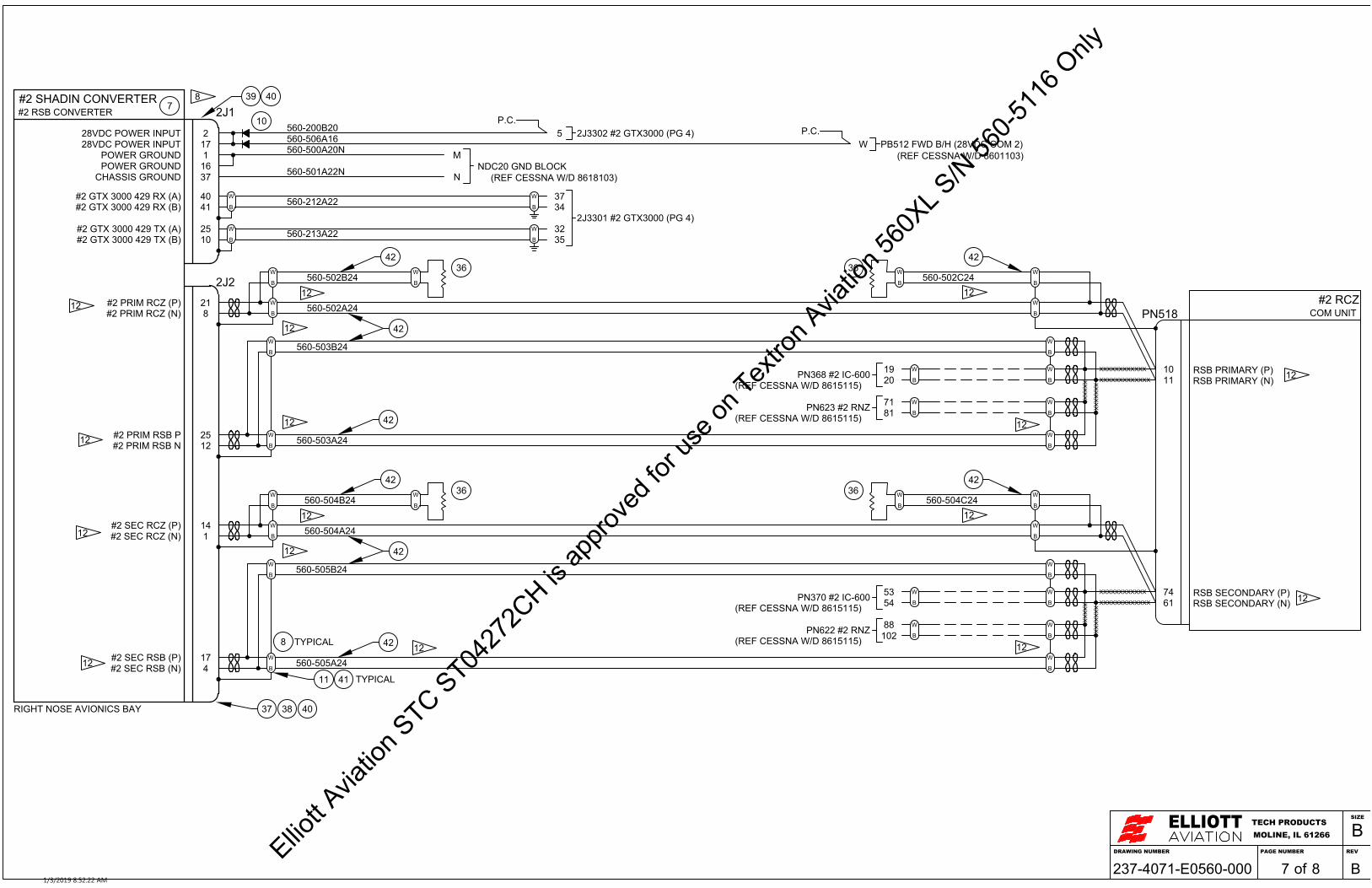
#2 SHADIN CONVERTER2J1#2 RSB CONVERTER
228VDC POWER INPUTP.C.
2J3302 #2 GTX3000 (PG 4)5
1POWER GROUND
2J3301 #2 GTX3000 (PG 4)25#2 GTX 3000 429 TX (A)10#2 GTX 3000 429 TX (B)
B
W
B
W 3235
B
W
B
W
B
W
B
W
560-200B20
560-502A24
560-500A20N
560-212A22
560-213A22
37CHASSIS GROUND
21#2 PRIM RCZ (P)8#2 PRIM RCZ (N)
B
W560-503A24
B
W
NDC20 GND BLOCKN
M1728VDC POWER INPUT
16POWER GROUND 560-501A22N
40#2 GTX 3000 429 RX (A)41#2 GTX 3000 429 RX (B)
3734
#2 RCZPN518 COM UNIT
RSB PRIMARY (P)11 RSB PRIMARY (N)B
W
B
W
B
W
B
W
19PN368 #2 IC-600 20
25#2 PRIM RSB P12#2 PRIM RSB N
B
W560-503B24
B
W
XX
XX
X
10
XX
XX
XX
X
XXXXXXXXXXXX
XXXXXXXXXXXXX
71PN623 #2 RNZ 81
7
B
W
B
W 36B
W
B
W36
37 38 40
39 408
560-506A16P.C.
PB512 FWD B/H (28VDC COM 2)W(REF CESSNA W/D 8601103)
560-502B24 560-502C24
42
42
42
42
RIGHT NOSE AVIONICS BAY
12 12
12
12
12
12
12
2J2
12
B
W
B
W
B
W
B
W
B
W
B
W
B
W
B
W
B
W
B
W
XX
XX
X
XX
XX
XX
X
XXXXXXXXXXXX
XXXXXXXXXXXXX
B
W
B
W 36B
W
B
W36
42
42
42
42
12 12
12
12
12
12
12
12
17#2 SEC RSB (P)4#2 SEC RSB (N)
14#2 SEC RCZ (P)1#2 SEC RCZ (N) 560-504A24
560-505A24
RSB SECONDARY (P)61 RSB SECONDARY (N)
560-505B24
7453PN370 #2 IC-600 54
88PN622 #2 RNZ 102
560-504B24 560-504C24
11 TYPICAL41
8 TYPICAL
10
(REF CESSNA W/D 8618103)
(REF CESSNA W/D 8615115)
(REF CESSNA W/D 8615115)
(REF CESSNA W/D 8615115)
(REF CESSNA W/D 8615115)
DRAWING NUMBER
ELLIOTTMOLINE, IL 61266TECH PRODUCTS
PAGE NUMBER REV
SIZE
B
of237-4071-E0560-000 8 B71/3/2019 8:52:22 AM
Elliott A
viatio
n STC ST04
272C
H is ap
prove
d for
use o
n Tex
tron A
viatio
n 560
XL S/N
560-5
116 O
nly

14
16
17
13
18
GARMIN D-SUB CONNECTOR ASSEMBLY (TYPICAL)
9
ALL OTHER CONNECTOR PARTS ARE PART OF APPLICABLE INSTALLATION KIT
DRAWING NUMBER
ELLIOTTMOLINE, IL 61266TECH PRODUCTS
PAGE NUMBER REV
SIZE
B
of237-4071-E0560-000 8 B81/3/2019 8:52:23 AM
Elliott A
viatio
n STC ST04
272C
H is ap
prove
d for
use o
n Tex
tron A
viatio
n 560
XL S/N
560-5
116 O
nly

DESCRIPTIONREV DATE APPROVED BY
REVISIONS
IR INITIAL RELEASE 08/17/17 S. MCCORD
A UPDATED AIRCRAFT SKIN LAYUP 01/19/18 S. MCCORD
B ADDED OPTION FOR GPS ON RH OR LH 05/08/18 S. MCCORD
.0 ± .1.00 ± .03
.000 ± .005
TOLERANCES IN INCHESUNLESS OTHERWISESPECIFIED
PAGE NUMBERDRAWING NUMBERDRAWING DESCRIPTIONA/C MAKE, MODEL
INITIAL RELEASE DATE A/C S/N
SCALEDRAWN BY
CHECKED BY
THIS DRAWING INCLUDING THE DESIGN AND PRINCIPLES OF CONSTRUCTION DISCLOSED IS THE PROPERTYOF ELLIOTT AVIATION AND IS SUBMITTED WITH THE UNDERSTANDING THAT IT IS NOT TO BE REPRODUCEDNOR COPIED IN WHOLE OR IN PART NOR LOANED OR OTHERWISE COMMUNICATED TO ANY THIRD PARTY NORUSED IN ANY MANNER DETRIMENTAL TO THE INTEREST OF ELLIOTT AVIATION WITHOUT ITS EXPRESSCONSENT. ACCEPTANCE OF THIS DRAWING WILL BE CONSTRUED AS AN AGREEMENT TO THE ABOVE.
ELLIOTTMOLINE, IL 61266TECH PRODUCTS
SIZE
Bof 3237-3832-M0560-010ANTENNAINSTALLATIONSN/A08/17/17GS
CESSNA 560XLSM1
NTS
FWD
UP
-501 P/N DESCRIPTION SIZE / WT SPECIFICATION ITEM
PARTS LISTQTY
. 1234567891011121314
. .. .... .
.. .
.#10 NUTPLATE MIL-STD
.. .
.UAT ANTENNA INSTL .
..
.RIVET
.RIVET
.#10-32 FH SCREW MIL-STD
.#10-32 FH SCREW MIL-STD
.UAT ANTENNA DOUBLER ELLIOTT AVIATION
.GPS ANTENNA DOUBLER ELLIOTT AVIATION
..
NOT USED.
NAS1473A34
NOT USED.
-503.
..NAS1097AD4-425MS20426AD3-38MS24694S-574
MS24694S-51.
.121-3761-M0560-010-511
-501 GPS ANTENNA INSTL .
MIL-STDMIL-STD
.
237-3832-M0560-010-53
-503
.
.
.
4
.
.288.
4
1.
1. REFERENCE ELLIOTT AVIATION DWG. # 237-3832-E0560-000 OR 237-4071-E0560-000FOR ANTENNA PART NUMBERS.
2. ALL DIMENSIONS GIVEN IN INCHES.
3. CONTOUR PARTS TO MATCH AIRCRAFT CONTOUR.
4. VERIFY ANTENNA CLEARS NOSE LANDING GEAR DOOR.
5. REMOVE PAINT FROM AIRCRAFT SKIN AND PREP FOR PROPER BONDING INACCORDANCE WITH MAINTENANCE MANUAL 20-21-02. THE ELECTRICAL BONDSHALL ACHIEVE A DC RESISTANCE OF 2.5 MILLIOHMS OR LESS BETWEEN THEANTENNA METAL BASE AND AIRCRAFT STRUCTURE (WITH THE COAXDISCONNECTED). COMPLIANCE SHALL BE VERIFIED USING A CALIBRATEDMILLIOHMMETER.
6. MATCH DRILL FUSELAGE TO DOUBLERS.
7. BREAK ALL EDGES AND REMOVE ALL BURRS.
8. ATTACH NUTPLATES TO DOUBLERS ONLY.
9. APPLY FAYING SURFACE SEALANT OF PS890B1/2 TO DOUBLERS.
10. APPLY A FILLET SEAL OF P/S 890 B 1/2 AROUND PERIMETER OF ANTENNA ANDCONNECTOR HOLE AND COVER ALL NUTPLATES.
11. CONNECT ANTENNA TO HARNESS PER ELLIOTT AVIATION DWG. #237-3832-E0560-000.
NOTES:
5/18/2018 10:44:58 AM
Elliott A
viatio
n STC ST04
272C
H is ap
prove
d for
use o
n Tex
tron A
viatio
n 560
XL S/N
560-5
116 O
nly

CONNECTOR
1.1± 0.5
0.13
1.1± 0.5
0.13
DRAWING NUMBER
ELLIOTTMOLINE, IL 61266TECH PRODUCTS
PAGE NUMBER REV
SIZE
B
of237-3832-M0560-010 3 B2
FWD
UP
39
4X
84X
AIRCRAFT SKIN0.040" THK. 2024T3
FWD
LH
(GPS ANTENNA) 1
(SKIN SPLICE)
EXISTING DOUBLER0.016" THK. 2024T3
OR
5/18/2018 10:44:59 AM
Elliott A
viatio
n STC ST04
272C
H is ap
prove
d for
use o
n Tex
tron A
viatio
n 560
XL S/N
560-5
116 O
nly

2.4±0.2
CONNECTOR
DRAWING NUMBER
ELLIOTTMOLINE, IL 61266TECH PRODUCTS
PAGE NUMBER REV
SIZE
B
of237-3832-M0560-010 3 B3
FWD
UP
4
7
4X
8
4X
AIRCRAFT SKIN0.050" THK. 2024 T42
FWD
RH
(UAT ANTENNA)
4
1
5/18/2018 10:44:59 AM
Elliott A
viatio
n STC ST04
272C
H is ap
prove
d for
use o
n Tex
tron A
viatio
n 560
XL S/N
560-5
116 O
nly

DESCRIPTIONREV DATE APPROVED BY
REVISIONS
IR INITIAL RELEASE 08/17/17 S. MCCORD
.0 ± .1.00 ± .03
.000 ± .005
TOLERANCES IN INCHESUNLESS OTHERWISESPECIFIED
PAGE NUMBERDRAWING NUMBERDRAWING DESCRIPTIONA/C MAKE, MODEL
INITIAL RELEASE DATE A/C S/N
SCALEDRAWN BY
CHECKED BY
THIS DRAWING INCLUDING THE DESIGN AND PRINCIPLES OF CONSTRUCTION DISCLOSED IS THE PROPERTYOF ELLIOTT AVIATION AND IS SUBMITTED WITH THE UNDERSTANDING THAT IT IS NOT TO BE REPRODUCEDNOR COPIED IN WHOLE OR IN PART NOR LOANED OR OTHERWISE COMMUNICATED TO ANY THIRD PARTY NORUSED IN ANY MANNER DETRIMENTAL TO THE INTEREST OF ELLIOTT AVIATION WITHOUT ITS EXPRESSCONSENT. ACCEPTANCE OF THIS DRAWING WILL BE CONSTRUED AS AN AGREEMENT TO THE ABOVE.
ELLIOTTMOLINE, IL 61266TECH PRODUCTS
SIZE
Bof 2237-3832-M0560-020ANNUNCIATORINSTALLATIONN/A08/17/17GS
CESSNA 560XLSM1
NTS
FWD
UP
1. REFERENCE ELLIOTT AVIATION DWG. # 237-3832-E0560-000 FORANNUNCIATOR PART NUMBER.
2. ALL DIMENSIONS GIVEN IN INCHES.
3. LOCATE ANNUNCIATOR WITHIN REGION SHOWN. ENSUREANNUNCIATOR CLEARS PANEL STRUCTURE AND IS ALIGNED WITHEXISTING ANNUNCIATORS.
4. CONNECT ANNUNCIATOR TO HARNESS PER APPLICABLE WIRINGDIAGRAM OR PER MFG INSTRUCTIONS.
NOTES:
DESCRIPTION SIZE / WT SPECIFICATION ITEM
PARTS LIST
. 1234
789
10........ .
.. .
.. .ANNUNCIATOR INSTALLATION .
.
.
.
-501 P/N
QTY
..
..
..
..
.....
-501.
.
.
.
.
.
.
.
.
.
.
.
.5.
. .....
6.. ..
... . ..
8/17/2017 3:32:13 PM
Elliott A
viatio
n STC ST04
272C
H is ap
prove
d for
use o
n Tex
tron A
viatio
n 560
XL S/N
560-5
116 O
nly

0.70
0.70
PULL LENS CAPSULEFROM ANNUNCIATORBODY
MOUNTING SLEEVE
LOCKING PAW
INSTRUMENT PANEL
ONCE LENS CAPSULE IS REMOVED.USE SCREW DRIVER TO TIGHTENSCREWS INSIDE ANNUNCIATORBODY TO TIGHTEN LOCKING PAWINTO THE MOUNTING SLEEVE.
5.2
2.9
DRAWING NUMBER
ELLIOTTMOLINE, IL 61266TECH PRODUCTS
PAGE NUMBER REV
SIZE
B
of237-3832-M0560-020 2 IR2
LH
UP 1(ANNUNCIATOR)
8/17/2017 3:32:13 PM
Elliott A
viatio
n STC ST04
272C
H is ap
prove
d for
use o
n Tex
tron A
viatio
n 560
XL S/N
560-5
116 O
nly
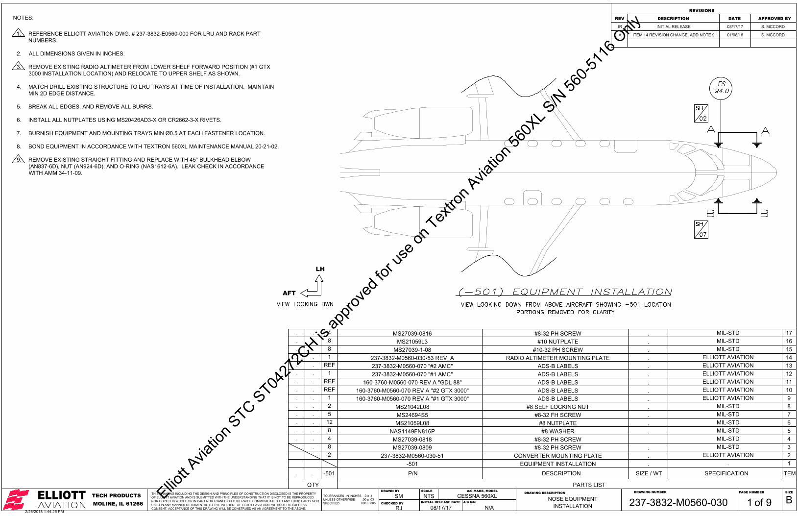
DESCRIPTIONREV DATE APPROVED BY
REVISIONS
IR INITIAL RELEASE 08/17/17 S. MCCORD
A ITEM 14 REVISION CHANGE, ADD NOTE 9 01/08/18 S. MCCORD
.0 ± .1.00 ± .03
.000 ± .005
TOLERANCES IN INCHESUNLESS OTHERWISESPECIFIED
PAGE NUMBERDRAWING NUMBERDRAWING DESCRIPTIONA/C MAKE, MODEL
INITIAL RELEASE DATE A/C S/N
SCALEDRAWN BY
CHECKED BY
THIS DRAWING INCLUDING THE DESIGN AND PRINCIPLES OF CONSTRUCTION DISCLOSED IS THE PROPERTYOF ELLIOTT AVIATION AND IS SUBMITTED WITH THE UNDERSTANDING THAT IT IS NOT TO BE REPRODUCEDNOR COPIED IN WHOLE OR IN PART NOR LOANED OR OTHERWISE COMMUNICATED TO ANY THIRD PARTY NORUSED IN ANY MANNER DETRIMENTAL TO THE INTEREST OF ELLIOTT AVIATION WITHOUT ITS EXPRESSCONSENT. ACCEPTANCE OF THIS DRAWING WILL BE CONSTRUED AS AN AGREEMENT TO THE ABOVE.
ELLIOTTMOLINE, IL 61266TECH PRODUCTS
SIZE
Bof 9237-3832-M0560-030NOSE EQUIPMENTINSTALLATIONN/A08/17/17RJ
CESSNA 560XLSM1
NTS
AFT
LH
1. REFERENCE ELLIOTT AVIATION DWG. # 237-3832-E0560-000 FOR LRU AND RACK PARTNUMBERS.
2. ALL DIMENSIONS GIVEN IN INCHES.
3. REMOVE EXISTING RADIO ALTIMETER FROM LOWER SHELF FORWARD POSITION (#1 GTX3000 INSTALLATION LOCATION) AND RELOCATE TO UPPER SHELF AS SHOWN.
4. MATCH DRILL EXISTING STRUCTURE TO LRU TRAYS AT TIME OF INSTALLATION. MAINTAINMIN 2D EDGE DISTANCE.
5. BREAK ALL EDGES, AND REMOVE ALL BURRS.
6. INSTALL ALL NUTPLATES USING MS20426AD3-X OR CR2662-3-X RIVETS.
7. BURNISH EQUIPMENT AND MOUNTING TRAYS MIN Ø0.5 AT EACH FASTENER LOCATION.
8. BOND EQUIPMENT IN ACCORDANCE WITH TEXTRON 560XL MAINTENANCE MANUAL 20-21-02.
9. REMOVE EXISTING STRAIGHT FITTING AND REPLACE WITH 45° BULKHEAD ELBOW(AN837-6D), NUT (AN924-6D), AND O-RING (NAS1612-6A). LEAK CHECK IN ACCORDANCEWITH AMM 34-11-09.
NOTES:
DESCRIPTION SIZE / WT SPECIFICATION ITEM
PARTS LIST
. 1234
789
10.ADS-B LABELS.ADS-B LABELS.#8 SELF LOCKING NUT.#8-32 FH SCREW MIL-STD
.#8-32 PH SCREW MIL-STD
.CONVERTER MOUNTING PLATE ELLIOTT AVIATIONEQUIPMENT INSTALLATION .
MIL-STDELLIOTT AVIATIONELLIOTT AVIATION
-501 P/N
QTY
160-3760-M0560-070 REV A "#2 GTX 3000"REF160-3760-M0560-070 REV A "#1 GTX 3000"1
MS21042L082MS24694S55
4MS27039-08098
237-3832-M0560-030-512-501
.
.
.
.
.
.
.
.
.
.
.
.
.5.
#8-32 PH SCREW MIL-STDMS27039-08188..
6.#8 WASHER MIL-STDNAS1149FN816P
12..
. 11ADS-B LABELS ELLIOTT AVIATION160-3760-M0560-070 REV A "GDL 88"REF..
#8 NUTPLATE MIL-STDMS21059L08
. 12ADS-B LABELS ELLIOTT AVIATION237-3832-M0560-070 "#1 AMC"1..
. 13ADS-B LABELS ELLIOTT AVIATION237-3832-M0560-070 "#2 AMC"REF..
. 14RADIO ALTIMETER MOUNTING PLATE ELLIOTT AVIATION237-3832-M0560-030-53 REV_A1..
. 15#10-32 PH SCREW MIL-STDMS27039-1-088..
. 16#10 NUTPLATE MIL-STDMS21059L38..
. 17#8-32 PH SCREW MIL-STDMS27039-08164..
2/26/2018 1:44:25 PM
Elliott A
viatio
n STC ST04
272C
H is ap
prove
d for
use o
n Tex
tron A
viatio
n 560
XL S/N
560-5
116 O
nly
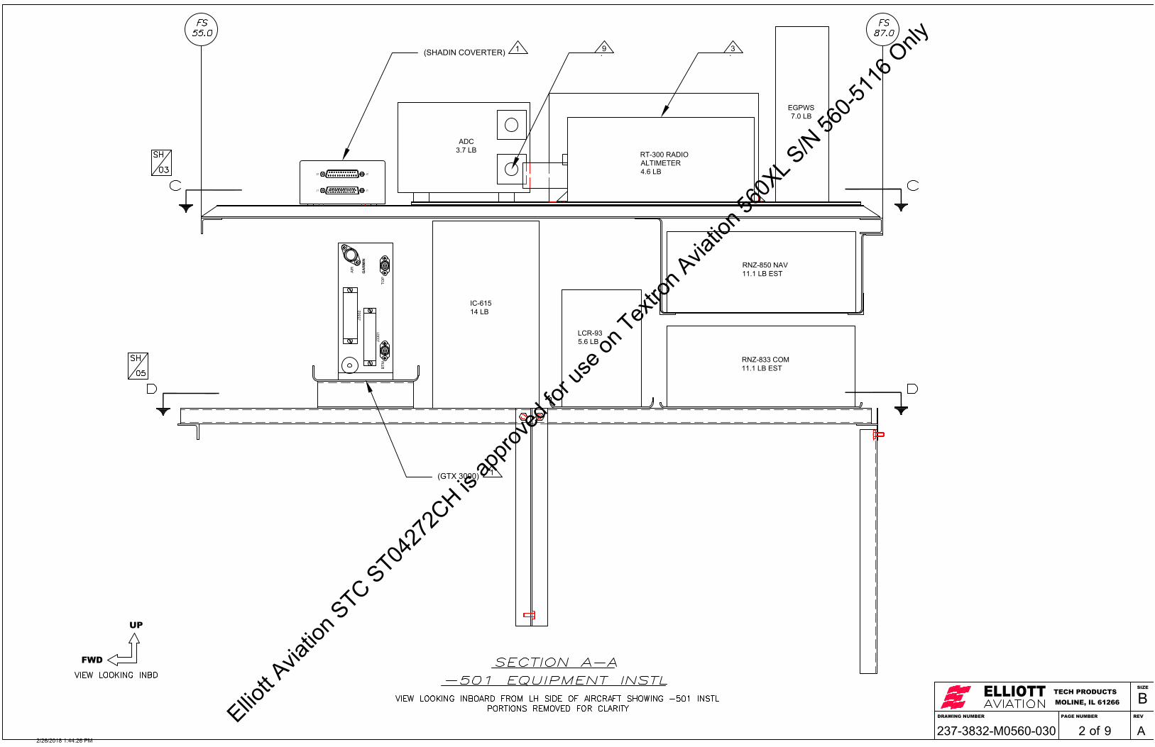
RNZ-850 NAV11.1 LB EST
RNZ-833 COM11.1 LB EST
LCR-935.6 LB
IC-61514 LB
J1J1
J2J2
BTM
J330
1
J330
2
AIR
TOP
GA
RM
IN
ADC3.7 LB RT-300 RADIO
ALTIMETER4.6 LB
EGPWS7.0 LB
DRAWING NUMBER
ELLIOTTMOLINE, IL 61266TECH PRODUCTS
PAGE NUMBER REV
SIZE
B
of237-3832-M0560-030 9 A2
FWD
UP
(GTX 3000) 1
(SHADIN COVERTER) 1 .3.9
2/26/2018 1:44:26 PM
Elliott A
viatio
n STC ST04
272C
H is ap
prove
d for
use o
n Tex
tron A
viatio
n 560
XL S/N
560-5
116 O
nly

CL
1.25± 0.5
ELECTRONICMODULEENCLOSURE ASSY7 LB EST
ADC3.7 LB
EGPWS7.0 LB
0.2
0.35
#1 AMC
DRAWING NUMBER
ELLIOTTMOLINE, IL 61266TECH PRODUCTS
PAGE NUMBER REV
SIZE
B
of237-3832-M0560-030 9 A3
FWD
INBD
(0.14" THK ALUMINUM HONEYCOMB SHELF0.030" THK UPPER AND LOWER SKINS)
(SHADIN CONVERTER)1
12.3
2/26/2018 1:44:26 PM
Elliott A
viatio
n STC ST04
272C
H is ap
prove
d for
use o
n Tex
tron A
viatio
n 560
XL S/N
560-5
116 O
nly
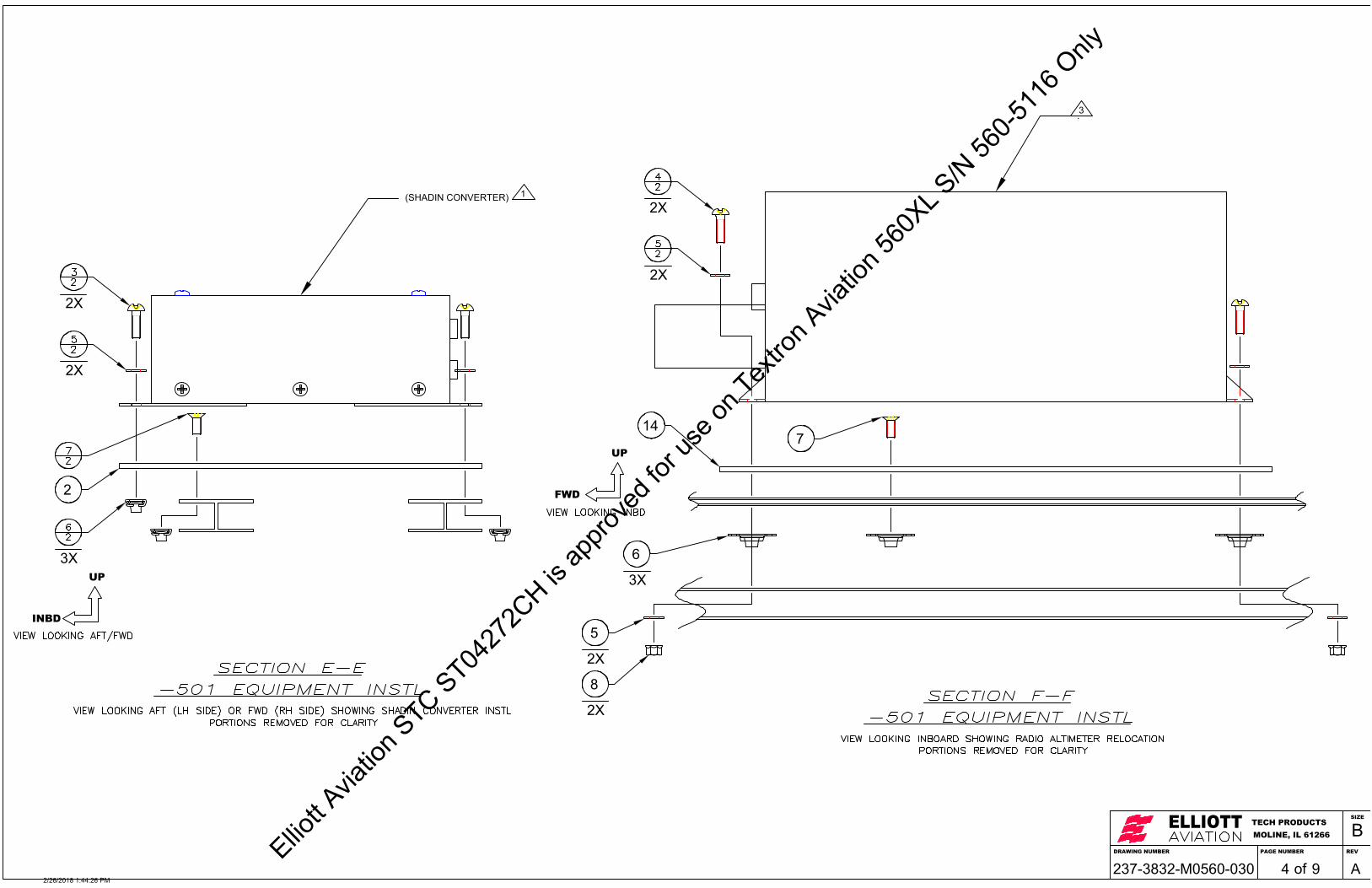
DRAWING NUMBER
ELLIOTTMOLINE, IL 61266TECH PRODUCTS
PAGE NUMBER REV
SIZE
B
of237-3832-M0560-030 9 A4
INBD
UP
(SHADIN CONVERTER) 1
.3
FWD
UP
3X
2X
2X
2X
2X
3X
6
2X
5
2X
8
7
2
14
2/26/2018 1:44:26 PM
Elliott A
viatio
n STC ST04
272C
H is ap
prove
d for
use o
n Tex
tron A
viatio
n 560
XL S/N
560-5
116 O
nly

#1 GTX 3000
IC-61514 LB
LCR-935.6 LB
RNZ-833 COM11.1 LB EST
3.2
1.6
DRAWING NUMBER
ELLIOTTMOLINE, IL 61266TECH PRODUCTS
PAGE NUMBER REV
SIZE
B
of237-3832-M0560-030 9 A5
FWD
INBD 9
(GTX 3000) 1
2/26/2018 1:44:27 PM
Elliott A
viatio
n STC ST04
272C
H is ap
prove
d for
use o
n Tex
tron A
viatio
n 560
XL S/N
560-5
116 O
nly

DRAWING NUMBER
ELLIOTTMOLINE, IL 61266TECH PRODUCTS
PAGE NUMBER REV
SIZE
B
of237-3832-M0560-030 9 A6
RH
UP
RH
UP
(GTX 3000) 1
EXISTING EQUIPMENTTRAY
(GTX 3000 TRAY)1
(GTX 3000) 1
2X
2X
2X
2X
EXISTING EQUIPMENTSHELF
2/26/2018 1:44:27 PM
Elliott A
viatio
n STC ST04
272C
H is ap
prove
d for
use o
n Tex
tron A
viatio
n 560
XL S/N
560-5
116 O
nly

RNZ-850 NAV11.1 LB EST
RCZ-833 COM11.1 LB EST
LCR-935.6 LB
IC-61514 LB
J1 J1
J2 J2
TCAS14.2 #
ADC3.7 LB
AOASTALL
WARNINGCOMP3.0 LB
PWR SUPPLY14 LB
BTM
J330
1
J330
2
AIR
TOP
GA
RM
IN
DRAWING NUMBER
ELLIOTTMOLINE, IL 61266TECH PRODUCTS
PAGE NUMBER REV
SIZE
B
of237-3832-M0560-030 9 A7
AFT
UP
(GTX 3000) 1
(SHADIN CONVERTER) 1
(GDL 88) 1
2/26/2018 1:44:28 PM
Elliott A
viatio
n STC ST04
272C
H is ap
prove
d for
use o
n Tex
tron A
viatio
n 560
XL S/N
560-5
116 O
nly

1.25± 0.5
4.5
0.9
4.0
5.8
#2 GTX 3000 GDL 88
TCAS14.2 #
AOASTALL
WARNINGCOMP3.0 LB
ADC3.7 LB
#2 AMC
DRAWING NUMBER
ELLIOTTMOLINE, IL 61266TECH PRODUCTS
PAGE NUMBER REV
SIZE
B
of237-3832-M0560-030 9 A8
AFT
INBD
(0.14" THK ALUMINUM HONEYCOMB SHELF0.030" THK UPPER AND LOWER SKINS)
(SHADIN CONVERTER)
1
(GTX 3000) 1
(GDL 88) 1
10 11
13
2/26/2018 1:44:28 PM
Elliott A
viatio
n STC ST04
272C
H is ap
prove
d for
use o
n Tex
tron A
viatio
n 560
XL S/N
560-5
116 O
nly

FAN
DRAWING NUMBER
ELLIOTTMOLINE, IL 61266TECH PRODUCTS
PAGE NUMBER REV
SIZE
B
of237-3832-M0560-030 9 A9
LH
UP
(GDL 88) 1
EXISTING SHELF
(GDL 88 TRAY)1
2X
2X
2X
2/26/2018 1:44:29 PM
Elliott A
viatio
n STC ST04
272C
H is ap
prove
d for
use o
n Tex
tron A
viatio
n 560
XL S/N
560-5
116 O
nly

DESCRIPTIONREV DATE APPROVED BY
REVISIONS
IR INITIAL RELEASE 08/17/17 S. MCCORD
.0 ± .1.00 ± .03
.000 ± .005
TOLERANCES IN INCHESUNLESS OTHERWISESPECIFIED
PAGE NUMBERDRAWING NUMBERDRAWING DESCRIPTIONA/C MAKE, MODEL
INITIAL RELEASE DATE A/C S/N
SCALEDRAWN BY
CHECKED BY
THIS DRAWING INCLUDING THE DESIGN AND PRINCIPLES OF CONSTRUCTION DISCLOSED IS THE PROPERTYOF ELLIOTT AVIATION AND IS SUBMITTED WITH THE UNDERSTANDING THAT IT IS NOT TO BE REPRODUCEDNOR COPIED IN WHOLE OR IN PART NOR LOANED OR OTHERWISE COMMUNICATED TO ANY THIRD PARTY NORUSED IN ANY MANNER DETRIMENTAL TO THE INTEREST OF ELLIOTT AVIATION WITHOUT ITS EXPRESSCONSENT. ACCEPTANCE OF THIS DRAWING WILL BE CONSTRUED AS AN AGREEMENT TO THE ABOVE.
ELLIOTTMOLINE, IL 61266TECH PRODUCTS
SIZE
Bof 2237-3832-M0560-040FLIGHT STREAM 110INSTALLATION (OPTIONAL)N/A08/17/17GS
CESSNA 560XLSM1
NTS
FWD
UP
1. REFERENCE ELLIOTT AVIATION DWG. # 237-3832-E0560-000 FORFLIGHTSTREAM PART NUMBER.
2. ALL DIMENSIONS GIVEN IN INCHES.
3. LOCATE FLIGHT STREAM 110 ON OUTBOARD SIDE OF COPILOTJEPPS CABINET. MATCH DRILL CABINET TO FLIGHT STREAM 110.
4. BOND ALL INSERTS IN PLACE USING 3M DP420, MAGNOLIA 121-146A/B, ATR 360, OR ATR 525 A/B EPOXY. DRILL INSTALLATION HOLE.RAKE OUT CORE 0.25 AROUND ENTIRE PERIMETER OFINSTALLATION HOLE. INSTALL TAB/INSERT ASSY IN INSTALLATIONHOLE AND INJECT EPOXY UNTIL IT APPEARS IN VENT HOLE. LETSET ACCORDING TO MANUFACTURER'S INSTRUCTIONS.
5. CONNECT LRU TO HARNESS PER ELLIOTT AVIATION DWG. #237-3832-E0560-000.
NOTES:
DESCRIPTION SIZE / WT SPECIFICATION ITEM
PARTS LIST
. 1234
789
10...ADS-B LABELS...#6 INSERT MIL-STD
.. .
.. .EQUIPMENT INSTALLATION .
.ELLIOTT AVIATION
.
-501 P/N
QTY
..160-3760-M0560-070 "FLIGHTSTREAM 110"1
NOT USED.NAS1836-06-74
.NOT USED.NOT USED.
-501.
.
.
.
.
.
.
.
.
.
.
.
.5.
. .NOT USED4..
6.#6-32 PH SCREW MIL-STDMS35206-228
4.. #6 WASHER MIL-STDNAS1149FN632P
2/26/2018 1:46:35 PM
Elliott A
viatio
n STC ST04
272C
H is ap
prove
d for
use o
n Tex
tron A
viatio
n 560
XL S/N
560-5
116 O
nly

5.11.0
FLIGHTSTREAM 110
DRAWING NUMBER
ELLIOTTMOLINE, IL 61266TECH PRODUCTS
PAGE NUMBER REV
SIZE
B
of237-3832-M0560-040 2 IR2
RH
UP 9
(FLIGHTSTREAM 110)1
1 (FLIGHTSTREAM 110)
(EXISTING JEPPS CABINET)
RH
UP
2/26/2018 1:46:35 PM
Elliott A
viatio
n STC ST04
272C
H is ap
prove
d for
use o
n Tex
tron A
viatio
n 560
XL S/N
560-5
116 O
nly

RNZ-850 NAV11.1 LB EST
RCZ-833 COM11.1 LB EST
LCR-935.6 LB
IC-61514 LB
J1 J1
J2 J2
TCAS14.2 #
ADC3.7 LB
AOASTALL
WARNINGCOMP3.0 LB
PWR SUPPLY14 LB
BTM
J330
1
J330
2
AIR
TOP
GA
RM
IN
NOSEJ-BOX
NOSE WEB DISC
DESCRIPTIONREV DATE APPROVED BY
REVISIONS
IR INITIAL RELEASE 01/08/18 S. MCCORD
.0 ± .1.00 ± .03
.000 ± .005
TOLERANCES IN INCHESUNLESS OTHERWISESPECIFIED
PAGE NUMBERDRAWING NUMBERDRAWING DESCRIPTIONA/C MAKE, MODEL
INITIAL RELEASE DATE A/C S/N
SCALEDRAWN BY
CHECKED BY
THIS DRAWING INCLUDING THE DESIGN AND PRINCIPLES OF CONSTRUCTION DISCLOSED IS THE PROPERTYOF ELLIOTT AVIATION AND IS SUBMITTED WITH THE UNDERSTANDING THAT IT IS NOT TO BE REPRODUCEDNOR COPIED IN WHOLE OR IN PART NOR LOANED OR OTHERWISE COMMUNICATED TO ANY THIRD PARTY NORUSED IN ANY MANNER DETRIMENTAL TO THE INTEREST OF ELLIOTT AVIATION WITHOUT ITS EXPRESSCONSENT. ACCEPTANCE OF THIS DRAWING WILL BE CONSTRUED AS AN AGREEMENT TO THE ABOVE.
ELLIOTTMOLINE, IL 61266TECH PRODUCTS
SIZE
Bof 4237-3832-M0560-050WIRE ROUTINGINSTALLATIONN/A01/08/18TB
CESSNA 560XLSM1
NTS
AFT
UP
NOTES
1. REFERENCE ELLIOTT ELECTRICAL WIRING DIAGRAMS237-3932-E0560-000 FOR REQUIRED PARTS.
2. MAINTAIN A MINIMUM BEND RADIUS OF 10 TIMES THE WIRE DIAMETERDURING HANDLING AND ROUTING. SEE SAMPLE "A" LAST PAGE.
3. TAKE CARE TO NOT CRUSH COAX. IF COAX GETS KINKED OR CRUSHEDDURING INSTALLATION, REPLACE WITH NEW. PERMISSIBLE TO ROUTENEW WIRING GROUP INCLUDING COAX OUTSIDE CLAMP IF PROPERLYSECURED WITHIN 2 INCHES ON EITHER SIDE OF CLAMP. DO NOTOVERTIGHTEN TIE WRAPS ON COAX.
4. ROUTE NEW WIRING WITH EXISTING WHERE POSSIBLE. SECURE ATREGULAR INTERVALS NOT TO EXCEED 12 INCHES. EXCEPT WIRING ATTHE ANNUNCIATOR WHERE IT IS IN CLOSE PROXIMITY TO THE ENGINEINDICATORS THESE WIRES MUST BE SECURED TO THE EXISTINGANNUNCIATOR WIRING AT A 2" INTERVAL.
5. HYDRAULIC, FUEL AND OXYGEN LINES: MAKE SURE A MINIMUM OF 0.4INCHES POSITIVE CONTROL SEPARATION EXIST BETWEEN NEW WIRES /COAXES. AND THESE LINES. ANY NEW WIRING / COAXES WITHIN 2.0INCHES OF THESE LINES MUST BE CLAMPED TO MAINTAIN SEPARATION.
6. SEE PAGE 3 FOR DETAILED WRITTEN WIRE ROUTING INSTRUCTIONS.
7. IDENTIFY NEW WIRES NOT TO EXCEED 24 INCHES BETWEEN TAGS.MARK AS FOLLOWS USING SUPPLIED (PARTS LIST ITEM #3) MARKERBANDS:
(GPS ANTENNA)
(#2 TRANSPONDER)
(ANNUNCIATOR)
(FWD PRESSURE BULKHEAD)
(GDL 88)
(FLIGHT STREAM 110 OPTIONAL)
-501WIRE ROUTING INSTL
P/N DESCRIPTION SIZE / WT SPECIFICATION ITEM
PARTS LISTQTY
.
.12345
.-501
TEXTRONMARKER BANDS13171-3
.
.30A/R
A/R
HELITUBESPIRAL WRAPHT1/4N
.
(#2 AMC)
(CIRCUIT BREAKER PANEL)
(EXISTING #2 XPDR ANT)
AR 4" CABLE TIEBT1M-M PANDUIT
(NOSE WEB DISC)
(NOSE J-BOX)
(TCAS PROCESSOR)
(#2 RCZ)
ADS-B
6.A/R7.A/R
PANDUITPANDUITAVERY
6.125" CABLE TIEBT1.5I-M8" CABLE TIEBT2S-M15" CABLE TIE10036
1/30/2018 12:23:17 PM
Elliott A
viatio
n STC ST04
272C
H is ap
prove
d for
use o
n Tex
tron A
viatio
n 560
XL S/N
560-5
116 O
nly

RNZ-850 NAV11.1 LB EST
RNZ-833 COM11.1 LB EST
LCR-935.6 LB
IC-61514 LB
J1J1
J2J2
BTM
J330
1
J330
2
AIR
TOP
GA
RM
IN
ADC3.7 LB RT-300 RADIO
ALTIMETER4.6 LB
EGPWS7.0 LB
NOSE WEB DISC
DRAWING NUMBER
ELLIOTTMOLINE, IL 61266TECH PRODUCTS
PAGE NUMBER REV
SIZE
B
of237-3832-M0560-050 4 IR3
AFT
UP
(#1 AMC)
(EXISTING #1 XPDR ANT)(UAT ANT)
(#1 TRANSPONDER) (#1 RCZ)
(#1 NOSE WEB DISC)
1/30/2018 12:23:18 PM
Elliott A
viatio
n STC ST04
272C
H is ap
prove
d for
use o
n Tex
tron A
viatio
n 560
XL S/N
560-5
116 O
nly

3X
BULKHEAD- 7.5
CL
#2 GTX 3000 GDL 88
#2 SHADIN CONVERTER
3X
BULKHEAD- 7.5
CL
#1 SHADIN CONVERTER
DRAWING NUMBER
ELLIOTTMOLINE, IL 61266TECH PRODUCTS
PAGE NUMBER REV
SIZE
B
of237-3832-M0560-050 4 IR2
AFT
LH
(GDL 88)
(ANNUNCIATOR)
(FLIGHT STREAM 110 OPTIONAL)
(FWD PRESSURE BULKHEAD)
(UAT ANTENNA)
(GPS ANTENNA)
(#1 TRANSPONDER)(#1 AMC)
(#2 TRANSPONDER)
(#2 AMC)
(EXISTING #1 XPDR ANT)
(EXISTING #2 XPDR ANT)
(CIRCUIT BREAKER PANEL)
2
1/30/2018 12:23:18 PM
Elliott A
viatio
n STC ST04
272C
H is ap
prove
d for
use o
n Tex
tron A
viatio
n 560
XL S/N
560-5
116 O
nly

(TYPICAL INSTALLATION)
SAMPLE A
TIE WRAPNYLON
MINIMUM BEND RADIUS: MUST NOT BE LESS THAN 10 TIMESTHE OUTSIDE DIAMETER OF THE LARGEST WIRE OR CABLE,EXCEPT WHERE WIRES BREAK OUT AT TERMINATIONS.WHERE WIRE IS SUITABLY SUPPORTED, THE RADIUS MAY BE6 TIMES THE DIAMETER OF THE WIRE. COAX BEND RADIUSSHOULD NEVER EXCEED 10 TIMES IT'S DIAMETER.
USED FOR ALL BENDS UNLESS OTHERWISE SHOWN
DRAWING NUMBER
ELLIOTTMOLINE, IL 61266TECH PRODUCTS
PAGE NUMBER REV
SIZE
B
of237-3832-M0560-050 4 IR4
Wire Routing Instructions
1. Wiring from the #1 GTX 3000 and #1 AMC is is routed from the forward side of the left nose avionics bay. The #1 GTX3000 is on the lower shelf and the AMCis located on the upper shelf. The wiring follows the existing aircraft wire some wires go to the nose center web disconnects while the remaing cable bundle isrouted aft towards the forward bulkhead. At that point some of the wiring follows the existing AHRS wiring bundle to the AHRS connector, and some of otherfollows the existing wiring bundle to the #1 RCZ connector. The rest of the wiring is routed aft to the forward bulkhead. At this point the wiring keeps followingthe existing avionics wiring outboard to the forward pressure bulkhead connectors. The existing avionics wiring bundles also contain the same type of low level28vdc and discrete wiring along with ARINC 429 and RSB databus wiring. All wiring is secured using tie straps in accordance with Textron Aviation 560XLstandard wiring practices as shown in Chapter 20, Section 21.
2. Wiring from the #2 GTX3000 and GDL 88 are in the middle of the upper shelf and the #2 AMC is located forward on the upper shelf. The wiring follows theexisting aircraft wire bundles along the lower avionics bay center wall to the nose center web disconnects. From there it follows along the center web afttowards the forward bulkhead and at that point some wiring follows the existing wiring bundle to the #2 RCZ connector. The rest of the wiring is routed aft tothe forward bulkhead. At this point the wiring keeps following the existing avionics wiring outboard to existing forward pressure bulkhead connectors. Somewiring breaks out and follows the existing wiring the Nose J-box the remaining wiring goes to existing forward pressure bulkhead connectors. The existingavionics wiring bundles in the nose also contain the same type of low level 28 VDC and discrete wiring along with ARINC 429 and RSB databus wiring. Allwiring is secured using tie straps in accordance with Textron Aviation 560XL standard wiring practices as shown in Chapter 20, Section 21.
3. Wiring from the existing forward bulkhead connectors is routed from the existing forward bulkhead connectors following existing like avionics wiring bundles.The annunciator wiring breaks out and follows like avionics bundles to behind the center instruments panel. FQIS wiring is present behind the centerinstrument panel. It is likely that a six (6) inch separation margin between the FQIS wiring and new cable cannot be ensured. Therefore, the new annunciatorwiring will be zip tied to the existing aircraft annunciator wiring. The zip ties in this area only will be spaced at no greater than every 2” in order to maintainrequired separation from the FQIS wiring such that a broken wire plus a broken zip tie will not result in any physical contact with adjacent FQIS wiring. Theremaining wires follow along the right cockpit side wall to the circuit breaker panel. If the Flight Stream 110 is installed the remaining wires continue aft to thechart holder to the Flight Stream 110 location. Except where noted for the annunciator wiring, the existing avionics wiring bundles in the cockpit also containthe same type of low level 28 VDC and discrete wiring along with databus wiring. All wiring is secured using tie straps in accordance with Textron Aviation560XL standard wiring practices as shown in Chapter 20, Section 21.
4. The UAT antenna cable is routed from the GDL 88 located in the middle of the upper right avionics shelf in nose following and tie wrapped to existing coaxes.The new cable is routed inboard to the nose center web, then aft to the forward pressure bulkhead where it routes to the left side of the aircraft. It then routesdown to the bottom of the nose avionics bay to the UAT antenna. All wiring is secured using tie straps in accordance with Textron Aviation 560XL standardwiring practices as shown in Chapter 20, Section 21.
5. The GPS antenna cable is routed from the GDL 88 located in the middle of the upper right avionics shelf in the following the existing TCAS cables to a newlyinstalled forward bulkhead TNC connector. On the cabin side of the forward bulkhead it continues to follow the TCAS antenna coaxes down the RH cockpitsidewall to the middle of the right hand side circuit breaker panel. At this point the GPS coax remains in its own wire bundle down the right hand sidewall, it issecured using tie wraps to existing tie down blocks to the aircraft frame. At the right forward cockpit partition, the coax goes up the aircraft sidewall to the topof the aircraft. The coax is also wrapped with spiral wrap from this point to the antenna. Once at the top of the aircraft it follows the #2 GPS coax through ahole in the frame. The coax then goes through an existing lightning hole in the aircraft to the left bay where the GPS antenna is located. All wiring is securedusing tie straps in accordance with Textron Aviation 560XL standard wiring practices as shown in Chapter 20, Section 21.
6. The lower #1 lower transponder antenna cable is routed from the #2 GTX 3000 located on the lower left avionics shelf following and tie wrapped to existingcoax. The new cable is routed inboard to the nose center web, then aft following existing com and nav coaxes to the forward pressure bulkhead. At this pointthe coax routes outboard and then down to the bottom of the nose avionics bay to the existing #1 lower transponder antenna. All wiring is secured using tiestraps in accordance with Textron Aviation 560XL standard wiring practices as shown in Chapter 20, Section 21.
7. The #2 lower transponder antenna cable is routed from the #2 GTX 3000 located in the middle of the upper right avionics shelf in nose following and tiewrapped to existing coaxes. The new cable is routed inboard to the nose center web, then aft following the existing TCAS antenna coaxes to the forwardpressure bulkhead where it routes to the left side of the aircraft. It then routes down to the bottom of the nose avionics bay to the lower transponder antenna.All wiring is secured using tie straps in accordance with Textron Aviation 560XL standard wiring practices as shown in Chapter 20, Section 21.
4 5 6 7
1/30/2018 12:23:19 PM
Elliott A
viatio
n STC ST04
272C
H is ap
prove
d for
use o
n Tex
tron A
viatio
n 560
XL S/N
560-5
116 O
nly
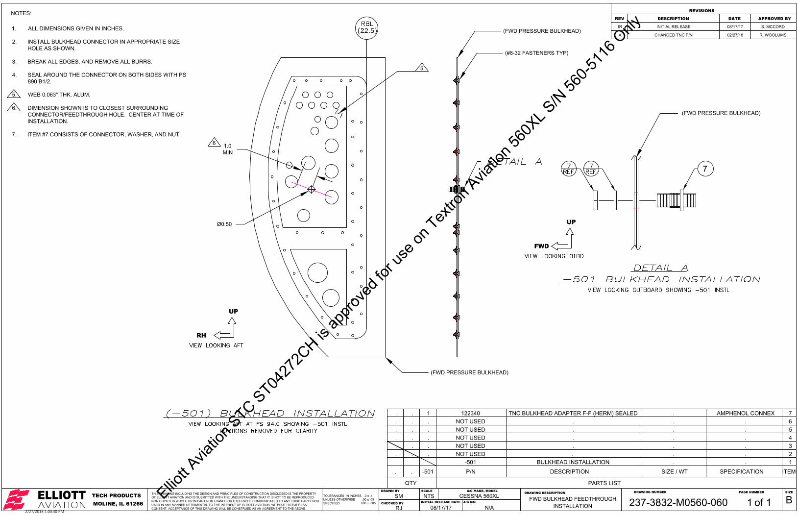
(FWD PRESSURE BULKHEAD)
(FWD PRESSURE BULKHEAD)
1.0MIN
(#8-32 FASTENERS TYP)
Ø0.50
DESCRIPTIONREV DATE APPROVED BY
REVISIONS
IR INITIAL RELEASE 08/17/17 S. MCCORD
A CHANGED TNC P/N 02/27/18 R. WOOLUMS
.0 ± .1.00 ± .03
.000 ± .005
TOLERANCES IN INCHESUNLESS OTHERWISESPECIFIED
PAGE NUMBERDRAWING NUMBERDRAWING DESCRIPTIONA/C MAKE, MODEL
INITIAL RELEASE DATE A/C S/N
SCALEDRAWN BY
CHECKED BY
THIS DRAWING INCLUDING THE DESIGN AND PRINCIPLES OF CONSTRUCTION DISCLOSED IS THE PROPERTYOF ELLIOTT AVIATION AND IS SUBMITTED WITH THE UNDERSTANDING THAT IT IS NOT TO BE REPRODUCEDNOR COPIED IN WHOLE OR IN PART NOR LOANED OR OTHERWISE COMMUNICATED TO ANY THIRD PARTY NORUSED IN ANY MANNER DETRIMENTAL TO THE INTEREST OF ELLIOTT AVIATION WITHOUT ITS EXPRESSCONSENT. ACCEPTANCE OF THIS DRAWING WILL BE CONSTRUED AS AN AGREEMENT TO THE ABOVE.
ELLIOTTMOLINE, IL 61266TECH PRODUCTS
SIZE
Bof 1237-3832-M0560-060FWD BULKHEAD FEEDTHROUGHINSTALLATIONN/A08/17/17RJ
CESSNA 560XLSM1
NTS
-501BULKHEAD INSTALLATION
P/N DESCRIPTION SIZE / WT SPECIFICATION.
.
ITEM
PARTS LISTQTY
.
.
.
12345
.
..-501
NOT USED.
.
.
6.
.
.
.. . .NOT USED .
122340 TNC BULKHEAD ADAPTER F-F (HERM) SEALED AMPHENOL CONNEX1 7
RH
UP
1. ALL DIMENSIONS GIVEN IN INCHES.
2. INSTALL BULKHEAD CONNECTOR IN APPROPRIATE SIZEHOLE AS SHOWN.
3. BREAK ALL EDGES, AND REMOVE ALL BURRS.
4. SEAL AROUND THE CONNECTOR ON BOTH SIDES WITH PS890 B1/2.
5. WEB 0.063" THK. ALUM.
6. DIMENSION SHOWN IS TO CLOSEST SURROUNDINGCONNECTOR/FEEDTHROUGH HOLE. CENTER AT TIME OFINSTALLATION.
7. ITEM #7 CONSISTS OF CONNECTOR, WASHER, AND NUT.
NOTES:
.. NOT USED ... .
.. NOT USED ... .
.. NOT USED ... .
5
FWD
UP
(FWD PRESSURE BULKHEAD)
6
7
2/27/2018 1:00:30 PM
Elliott A
viatio
n STC ST04
272C
H is ap
prove
d for
use o
n Tex
tron A
viatio
n 560
XL S/N
560-5
116 O
nly

DESCRIPTIONREV DATE APPROVED BY
REVISIONS
IR INITIAL RELEASE 05/08/18 S. MCCORD
A UPDATED NOTE 3 FOR ALTERNATE P/N, 09/24/18 S. MCCORD
ADDED NOTE 4 (PG 6)
.0 ± .1.00 ± .03
.000 ± .005
TOLERANCES IN INCHESUNLESS OTHERWISESPECIFIED
PAGE NUMBERDRAWING NUMBERDRAWING DESCRIPTIONA/C MAKE, MODEL
INITIAL RELEASE DATE A/C S/N
SCALEDRAWN BY
CHECKED BY
THIS DRAWING INCLUDING THE DESIGN AND PRINCIPLES OF CONSTRUCTION DISCLOSED IS THE PROPERTYOF ELLIOTT AVIATION AND IS SUBMITTED WITH THE UNDERSTANDING THAT IT IS NOT TO BE REPRODUCEDNOR COPIED IN WHOLE OR IN PART NOR LOANED OR OTHERWISE COMMUNICATED TO ANY THIRD PARTY NORUSED IN ANY MANNER DETRIMENTAL TO THE INTEREST OF ELLIOTT AVIATION WITHOUT ITS EXPRESSCONSENT. ACCEPTANCE OF THIS DRAWING WILL BE CONSTRUED AS AN AGREEMENT TO THE ABOVE.
ELLIOTTMOLINE, IL 61266TECH PRODUCTS
SIZE
Bof 10237-4071-M0560-080NOSE EQUIPMENTINSTALLATIONN/A05/08/18GS
CESSNA 560XLSM1
NTS
AFT
LH
1. REFERENCE ELLIOTT AVIATION DWG. # 237-4071-E0560-000 FOR LRU AND RACK PARTNUMBERS.
2. RELOCATE #2 RNZ-850 FROM TOP OF SHELF TO BOTTOM OF SHELF USING BRACKETRY ASSHOWN.
3. REMOVE EXISTING STATIC LINE AND REPLACE WITH NEW STATIC LINE SHOWN. CLAMPSECURELY AS REQUIRED AND ENSURE ADEQUATE CHAFE PROTECTION. PERMISSIBLE TOSUBSTITUTE TEXTRON P/N 6614130-10 IN LIEU OF HOSE AND FITTINGS. LEAK CHECK INACCORDANCE WITH AMM 34-11-09.
4. MAINTAIN MIN SPACING AS SHOWN.
5. ALL DIMENSIONS GIVEN IN INCHES.
6. MATCH DRILL EXISTING STRUCTURE TO LRU TRAYS AT TIME OF INSTALLATION. MAINTAINMIN 2D EDGE DISTANCE.
7. BREAK ALL EDGES, AND REMOVE ALL BURRS.
8. INSTALL ALL NUTPLATES USING MS20426AD3-X OR CR2662-3-X RIVETS.
9. BURNISH EQUIPMENT SHELVES AND MATING SURFACE OF -001 SHELF ASSY MIN Ø0.5 ATEACH FASTENER LOCATION. BOND EQUIPMENT IN ACCORDANCE WITH TEXTRON 560XLMAINTENANCE MANUAL 20-21-02. TREAT PER MIL-C-5541, CLASS 1A.
NOTES:
94.0FS
DESCRIPTION SIZE / WT SPECIFICATION ITEM
PARTS LIST
. 1234
789
10
.ADS-B LABELS
.ADS-B LABELS
.#8 NUTPLATE
.#8-32 FH SCREW MIL-STD
.#8-32 PH SCREW MIL-STDCONVERTER MOUNTING PLATE ELLIOTT AVIATION
EQUIPMENT INSTALLATION .
MIL-STDELLIOTT AVIATIONELLIOTT AVIATION
-501 P/N
QTY
160-3760-M0560-070 REV A "#2 GTS 3000"REF160-3760-M0560-070 REV A "#1 GTS 3000"1
MS21061L08.MS24694S512
18MS27039-08098
237-3832-M0560-030-512
-501-001
.
.4.
.
.
.
.
.
.
.
.
5
.RIVET MIL-STDMS20470AD4-4
11..
6
.#8 WASHER MIL-STDNAS1149FN816P
13..
.
11
ADS-B LABELS ELLIOTT AVIATION160-3760-M0560-070 REV A "GDL 88"REF..
#8 NUTPLATE MIL-STDMS21059L08
.
12
ADS-B LABELS ELLIOTT AVIATION237-3832-M0560-070 "#1 AMC"1...
13
ADS-B LABELS ELLIOTT AVIATION237-3832-M0560-070 "#2 AMC"REF...
14
TUBE ASSY PITOT STATIC TEXTRON6614130-101...
15
#10-32 PH SCREW MIL-STDMS27039-1-088...
16
#10 NUTPLATE MIL-STDMS21059L38...
17
#8-32 PH SCREW MIL-STDMS27039-08154..
.
1819202122232425
....
.RIVET MIL-STDNAS1097AD4-428..
.#8-32 PH SCREW MIL-STDMS27039-08075..
.MOUNTING PLATE ELLIOTT AVIATION237-4071-M0560-080-591..
.STIFFENER ELLIOTT AVIATION237-4071-M0560-080-57.2.
.FWD SUPPORT ELLIOTT AVIATION237-4071-M0560-080-55.1.
.AFT SUPPORT ELLIOTT AVIATION237-4071-M0560-080-53.1.
.SHELF ELLIOTT AVIATION237-4071-M0560-080-51.11 .SHELF ASSY .-001
16.0" ± 0.5"STRATOFLEX HOSE AIRCRAFT SPRUCE193-6 (LP-MIL-H-5593-6)1.. 26.HOSE FITTING AIRCRAFT SPRUCE311-6D2.. 27.. ..... 28
9/27/2018 1:17:18 PM
Elliott A
viatio
n STC ST04
272C
H is ap
prove
d for
use o
n Tex
tron A
viatio
n 560
XL S/N
560-5
116 O
nly

RNZ-850 NAV11.9 LB
RNZ-833 COM11.1 LB
LCR-935.6 LB
IC-61514 LB
J1J1
J2J2 BTM
J330
1
J330
2
AIR
TOP
GA
RM
IN
ADC3.7 LB
PWR SUPPLY14 LB
DRAWING NUMBER
ELLIOTTMOLINE, IL 61266TECH PRODUCTS
PAGE NUMBER REV
SIZE
B
of237-4071-M0560-080 10 A2
FWD
UP
87.0FS
55.0FS (GTX 3000) 1
(SHADIN CONVERTER) 1
9/27/2018 1:17:19 PM
Elliott A
viatio
n STC ST04
272C
H is ap
prove
d for
use o
n Tex
tron A
viatio
n 560
XL S/N
560-5
116 O
nly

3X
BULKHEAD- 7.5
CL
1.75± 0.5
ADC3.7 LB
#1 AMC
RNZ-850 NAV11.9 LB
#1 GTX 3000
DRAWING NUMBER
ELLIOTTMOLINE, IL 61266TECH PRODUCTS
PAGE NUMBER REV
SIZE
B
of237-4071-M0560-080 10 A3
FWD
INBD
(0.14" THK ALUMINUM HONEYCOMB SHELF0.030" THK UPPER AND LOWER SKINS)
0.0BL
87.0FS
(SHADIN CONVERTER)1
2017
9/27/2018 1:17:19 PM
Elliott A
viatio
n STC ST04
272C
H is ap
prove
d for
use o
n Tex
tron A
viatio
n 560
XL S/N
560-5
116 O
nly
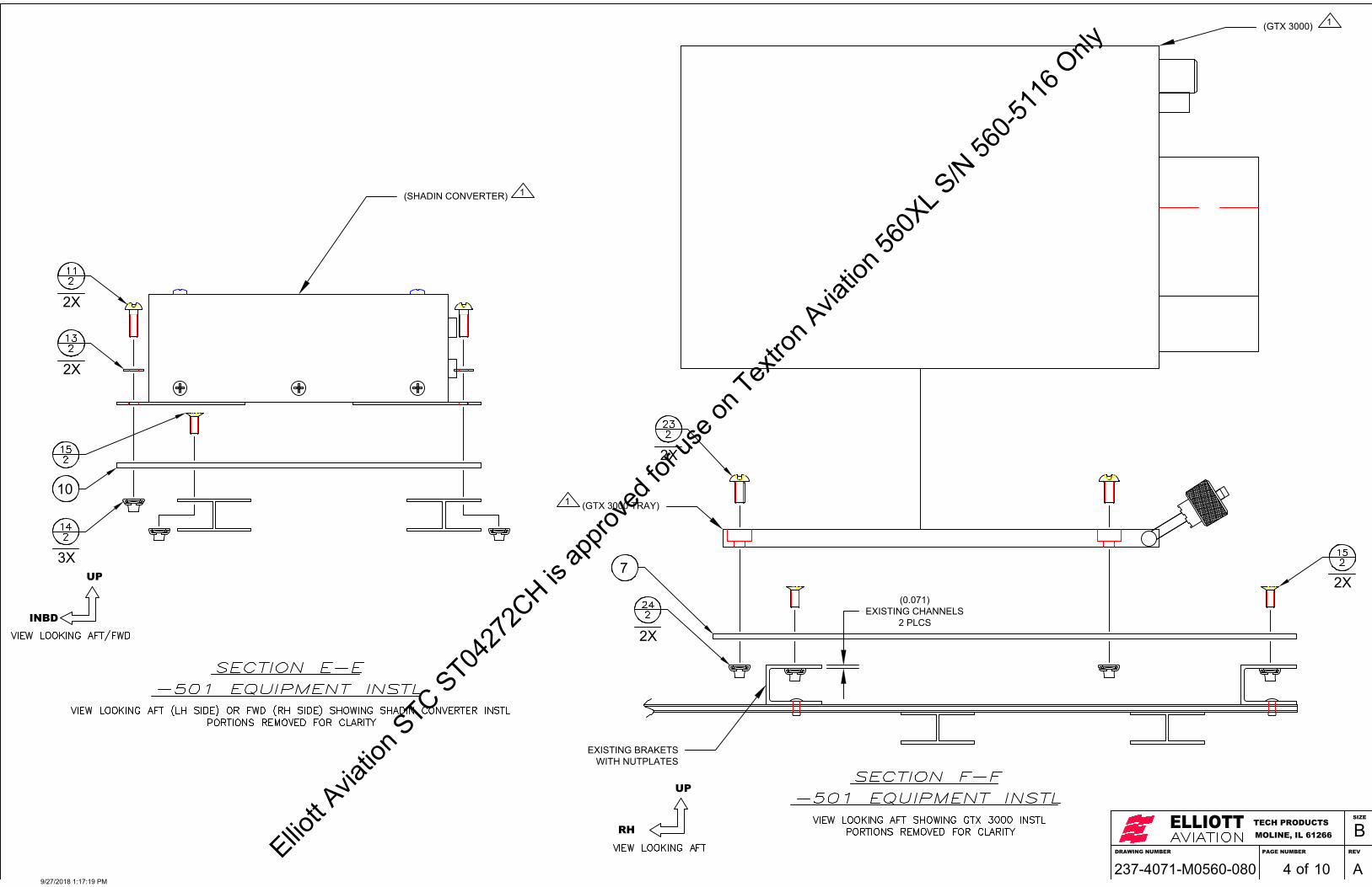
(0.071)EXISTING CHANNELS
2 PLCS
DRAWING NUMBER
ELLIOTTMOLINE, IL 61266TECH PRODUCTS
PAGE NUMBER REV
SIZE
B
of237-4071-M0560-080 10 A4
INBD
UP
(SHADIN CONVERTER) 1
RH
UP
3X
2X
2X
10
(GTX 3000) 1
(GTX 3000 TRAY)1
2X
2X
72X
EXISTING BRAKETSWITH NUTPLATES
9/27/2018 1:17:19 PM
Elliott A
viatio
n STC ST04
272C
H is ap
prove
d for
use o
n Tex
tron A
viatio
n 560
XL S/N
560-5
116 O
nly
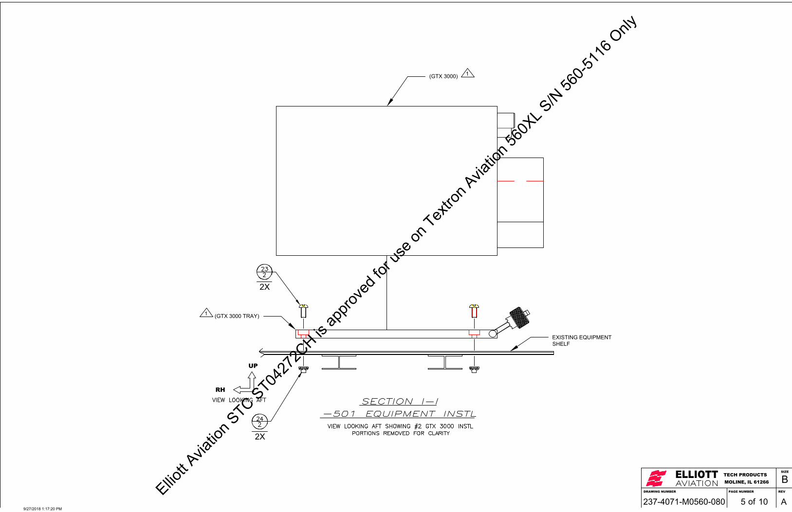
DRAWING NUMBER
ELLIOTTMOLINE, IL 61266TECH PRODUCTS
PAGE NUMBER REV
SIZE
B
of237-4071-M0560-080 10 A5
RH
UP
(GTX 3000) 1
2X
2X
EXISTING EQUIPMENTSHELF
(GTX 3000 TRAY)1
9/27/2018 1:17:20 PM
Elliott A
viatio
n STC ST04
272C
H is ap
prove
d for
use o
n Tex
tron A
viatio
n 560
XL S/N
560-5
116 O
nly

RCZ-833 COM11.1 LB
LCR-935.6 LB
IC-61514 LB
J1 J1
J2 J2
ADC3.7 LB
AOASTALL
WARNINGCOMP3.0 LB
PWR SUPPLY14 LB
BTM
J330
1
J330
2
AIR
TOP
GA
RM
IN
RNZ-850 NAV11.9 LB 0.25
MIN
DRAWING NUMBER
ELLIOTTMOLINE, IL 61266TECH PRODUCTS
PAGE NUMBER REV
SIZE
B
of237-4071-M0560-080 10 A6
AFT
UP
87.0FS
55.0FS
(GTX 3000) 1
(SHADIN CONVERTER) 1
(GDL 88) 1
2
4
9/27/2018 1:17:20 PM
Elliott A
viatio
n STC ST04
272C
H is ap
prove
d for
use o
n Tex
tron A
viatio
n 560
XL S/N
560-5
116 O
nly

3X
BULKHEAD- 7.5
CL
1.75± 0.5
3.8
6.2± 0.5
0.5
4.0
#2 GTX 3000
AOASTALL
WARNINGCOMP3.0 LB
ADC3.7 LB
#2 AMC
1.50GDL 88
DRAWING NUMBER
ELLIOTTMOLINE, IL 61266TECH PRODUCTS
PAGE NUMBER REV
SIZE
B
of237-4071-M0560-080 10 A7
AFT
INBD
(0.14" THK ALUMINUM HONEYCOMB SHELF0.030" THK UPPER AND LOWER SKINS)
0.0BL
87.0FS
(SHADIN CONVERTER)
1
(GTX 3000) 1
(GDL 88) 1
1819
21
22
26
27
27
3
3
9/27/2018 1:17:20 PM
Elliott A
viatio
n STC ST04
272C
H is ap
prove
d for
use o
n Tex
tron A
viatio
n 560
XL S/N
560-5
116 O
nly

DRAWING NUMBER
ELLIOTTMOLINE, IL 61266TECH PRODUCTS
PAGE NUMBER REV
SIZE
B
of237-4071-M0560-080 10 A8
LH
UP
(EXISTING NUTPLATE- MATCH DRILL)EXISTING RNZ-850 NAV
EXISTING RNZ-850 NAVMOUNTING TRAY
2X
9/27/2018 1:17:20 PM
Elliott A
viatio
n STC ST04
272C
H is ap
prove
d for
use o
n Tex
tron A
viatio
n 560
XL S/N
560-5
116 O
nly
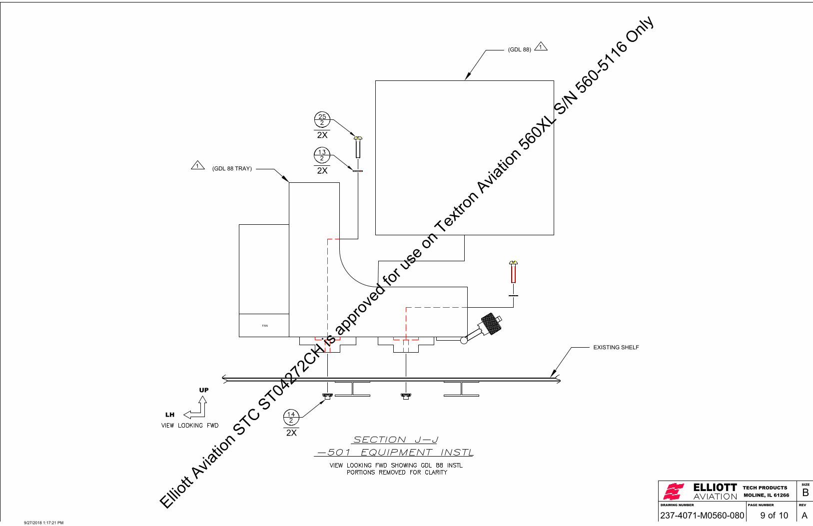
FAN
DRAWING NUMBER
ELLIOTTMOLINE, IL 61266TECH PRODUCTS
PAGE NUMBER REV
SIZE
B
of237-4071-M0560-080 10 A9
LH
UP
(GDL 88) 1
EXISTING SHELF
(GDL 88 TRAY)1
2X
2X
2X
9/27/2018 1:17:21 PM
Elliott A
viatio
n STC ST04
272C
H is ap
prove
d for
use o
n Tex
tron A
viatio
n 560
XL S/N
560-5
116 O
nly

0.302 PLCS 1.0
DRAWING NUMBER
ELLIOTTMOLINE, IL 61266TECH PRODUCTS
PAGE NUMBER REV
SIZE
B
of237-4071-M0560-080 10 A10
3
4
5
66 2X
9/27/2018 1:17:21 PM
Elliott A
viatio
n STC ST04
272C
H is ap
prove
d for
use o
n Tex
tron A
viatio
n 560
XL S/N
560-5
116 O
nly

Elliott Aviation Technical Products Development, Inc. Report No.: ICA-3832-560 6601 74th Ave Building A Revision: A Milan, IL 61264 Dated 12/11/2018 1 of 21
Instructions for Continued Airworthiness For Garmin ADS-B System Installation
Instructions for Continued Airworthiness
For
Garmin ADS-B Out System Installation
(Type Certificate A22CE)
© 2017 ELLIOTT AVIATION TECHNICAL PRODUCTS DEVELOPMENT, INC.
Elliott Aviation Technical Products Development, Inc. reserves the copyright of all information and illustrations in this publication which is provided in confidence and which may not be used for any purpose other than for which it was originally supplied. The publication may not be reproduced in part or in whole without the consent in writing of Elliott Aviation Technical Products Development, Inc.
Elliott A
viatio
n STC ST04
272C
H is ap
prove
d for
use o
n Tex
tron A
viatio
n 560
XL S/N
560-5
116 O
nly

Elliott Aviation Technical Products Development, Inc. Report No.: ICA-3832-560 6601 74th Ave Building A Revision: A Milan, IL 61264 Dated 12/11/2018 2 of 21
Instructions for Continued Airworthiness For Garmin ADS-B System Installation
REVISIONS PAGE
Rev Description Page (S) Date Approved By
IR Initial Release ALL 01/23/2018 R. Woolums
A Updated Appendix A A1 12/11/2018
Elliott A
viatio
n STC ST04
272C
H is ap
prove
d for
use o
n Tex
tron A
viatio
n 560
XL S/N
560-5
116 O
nly

Elliott Aviation Technical Products Development, Inc. Report No.: ICA-3832-560 6601 74th Ave Building A Revision: A Milan, IL 61264 Dated 12/11/2018 3 of 21
Instructions for Continued Airworthiness For Garmin ADS-B System Installation
TABLE OF CONTENTS COVER PAGE .......................................................................................................... 1 REVISIONS PAGE.................................................................................................... 2 TABLE OF CONTENTS ............................................................................................ 3 Chapter 1 Introduction .............................................................................................. 4 Chapter 2 Maintenance Instructions and Shedules .................................................. 6 Chapter 3 Access .................................................................................................... 13 Chapter 4 Lifting and Shoring ................................................................................. 14
Chapter 5 Leving and Weighing .............................................................................. 14 Chapter 6 Towing and Taxing ................................................................................. 15 Chapter 7 Parking and Moring ................................................................................ 15 Chapter 8 Placards and Markings ........................................................................... 15 Chapter 9 Servicing................................................................................................. 15 Chapter 10 Airworthiness Limitations ..................................................................... 16 Appendix A .............................................................................................................. A1
Elliott A
viatio
n STC ST04
272C
H is ap
prove
d for
use o
n Tex
tron A
viatio
n 560
XL S/N
560-5
116 O
nly

Elliott Aviation Technical Products Development, Inc. Report No.: ICA-3832-560 6601 74th Ave Building A Revision: A Milan, IL 61264 Dated 12/11/2018 4 of 21
Instructions for Continued Airworthiness For Garmin ADS-B System Installation
Chapter 1 INTRODUCTION
1.1 Scope/Purpose/Applicability/Distribution
The Instructions for Continued Airworthiness (ICA) described herein are applicable only to those aircraft modified by FAA STC . These ICA describe the recommended and required maintenance procedures for the installation of Garmin ADS-B System.
The maintenance information provided by this document must be included in the operator’s Aircraft Maintenance Manual and the operator’s Aircraft Scheduled Maintenance Program. All documents listed in the required documents section must be maintained with this document. FAA accepted revisions to this document will be distributed by mail to the applicable certifying authorities and operators of legally modified aircraft.
1.2 System Description
The features of this modification include the installation of Garmin GTX 3000 transponders, reusing existing aircraft wiring, and two installed Shadin AMC Converters connecting the transponders to the RCZ Com units and the remaining RSB bus. This modification also includes a Garmin GDL 88 GPS / UAT and optional Flight Stream 110 Bluetooth FIS-B installation. A GPS and UAT-SBS antenna is installed. Annunciation is added for ADS-B status. New circuit breakers are installed in the copilot’s circuit breaker panel. New wiring is added to supply the GTX 3000 transponders with GPS position for the GDL 88. The Flight Stream 110 (if installed) supports properly equipped FIS-B capable Bluetooth devices
1.3 Required Data
All requited data is located in Appendix A of this document.
1.4 Referenced Garmin/Shadin documents:
Nomenclature Drawing Number Rev Date
GTX 3000 Transponder Installation Manual 190-00926-01 P Apr 2017
GDL 84/88 TSO Installation Manual 190-01122-00 L Nov 2017
Flight Stream 110/210 TSO Installation Manual 190-01700-00 F Aug 2017
ARINC to Manchester Converter M833520-00 A Dec 2017 1.5 Systems Control:
1.5.1 The GTX 3000 transponders replace the Honeywell transponder modules. All control is via the existing Honeywell RMU. No changes to operational control are imposed by this STC.
1.5.2 The Shadin AMC Converters convert RSB databus into ARINC 429. The AMC has no external control.
1.5.3 The GDL 88 is a GPS sensor and FIS-B UAT receiver. The GDL 88 has no external control.
1.5.4 The Flight Stream 110 is a Bluetooth repeater for the GDL 88 FIS-B products and has no external control.
1.6 Document administration:
1.6.1 This document will be revised by Elliott Aviation Engineering when revisions to descriptive or approval data warrant.
1.6.2 When this document is revised, all pages will be revised to indicate the current level. Chapter 10 will have its own revision status embedded. FAA approved revisions to the document will be distributed by mail to the applicable certifying authorities and operations of legally modified aircraft.
Elliott A
viatio
n STC ST04
272C
H is ap
prove
d for
use o
n Tex
tron A
viatio
n 560
XL S/N
560-5
116 O
nly

Elliott Aviation Technical Products Development, Inc. Report No.: ICA-3832-560 6601 74th Ave Building A Revision: A Milan, IL 61264 Dated 12/11/2018 5 of 21
Instructions for Continued Airworthiness For Garmin ADS-B System Installation
1.7 Abbreviations and Definitions:
1090ES A transponder distinction. 1090 is the classic frequency of Secondary Surveillance Radar (SSR) transponders. The addition of “ES” at the end signifies that the transponder is equipped with Extended Squitter used by the ADS-B aircraft segment. Note that this class of transponder supports Class “A” airspace (altitudes above 18,000 feet) operations. Typically, no FIS-B or TIS-B functionality is included, compared to UAT.
AMM Aircraft Maintenance Manual DAH Design Approval Holder. The FAA term that includes STC holders such as Elliott Aviation. FIS-B Flight Information System broadcast. A radio frequency service that transmits weather and
aeronautical products, either by satellite or ground based systems. Refer to FAA Advisory Circular 20-149A for thorough explanation.
Latency The total time between when the position is measured and when the position is transmitted by the aircraft. A 14 CFR §91.227 performance requirement for ADS-B broadcast systems. The collection of specific equipment, interface and testing represented by this STC comprises an approved Latency
OEM Original Equipment Manufacturer. SBS Surveillance and Broadcast Service. Provided by the FAA. Ground based transmission at a
frequency of 978 MHz. SDA System Design Assurance. A 14 CFR §91.227 performance requirement for ADS-B broadcast
systems. The collection of specific equipment, interface and testing represented by this STC comprises an approved SDA.
UAT Universal Access Transceiver. A new device that supports the ADS-B aircraft segment at lower altitudes (below 18,000 feet) Allows smaller aircraft that operate below Class “A” airspace a more
AMC ARINC to Manchester Converter. Converts RSB databus to ARINC 429 and vice versa. 1.8 Precautions
Typical precautions are to be taken when accessing, removing, replacing, testing or inspecting these STC modifications. Specific precautions will be addressed in context throughout this document.
1.9 Units of measurement:
Non- metric. English units including Inches, feet, etc..
Elliott A
viatio
n STC ST04
272C
H is ap
prove
d for
use o
n Tex
tron A
viatio
n 560
XL S/N
560-5
116 O
nly

Elliott Aviation Technical Products Development, Inc. Report No.: ICA-3832-560 6601 74th Ave Building A Revision: A Milan, IL 61264 Dated 12/11/2018 6 of 21
Instructions for Continued Airworthiness For Garmin ADS-B System Installation
Chapter 2 MAINTENANCE INSTRUCTIONS AND SCHEDULES:
2.1 Mandatory Replacements:
The GTX 3000 1090ES Transponder, GDL 88 GPS / UAT and optional Flight Stream 110 systems’ electrical components and installation is "On Condition" as determined by routine surveillance and there is no mandatory replacement time for any aspect of this system.
Refer to 560XL OEM WDM, Wiring – Maintenance Practices - chapter 20-10-01, for comprehensive wiring harness surveillance concerns.
See Chapter 10 Airworthiness Limitations for antenna installation inspections.
2.2 Recurring Maintenance:
2.2.1 Antenna Installations
Antenna installations require special inspection requirements and shall be maintained using Chapter 10 of this document.
2.2.2 Bulkhead Connector Installation
The bulkhead connector installation requires no special inspections requirements and shall be maintained using normal OEM maintenance manual procedures
2.2.3 Basic Mode S Transponder functions:
The installation of the GTX 3000 transponders must continue to meet the operational requirements of 14 CFR §§ 91.413, 91.215, and 91.217 and comply with the transponder system tests and inspections called out in 14 CFR § 43, appendix F.
The Honeywell SPZ 8000 altitude reporting equipment connected to the Garmin ADS-B transponders must comply with all applicable 14 CFR §§ 91.217, 91.411, and part 43 appendix E test and inspection requirements. If the altimetry system is compliant with the Reduced Vertical Separation Minimum (RVSM) standards, the requirements and tolerances stated in the approved RVSM maintenance program must be met. ADS-B installation does not alter these requirements.
2.2.4 ADS-B functions:
Compliance with aircraft equipage requirements imposed by the operational requirements of 14 CFR §§ 91.225 and 91.227 is achieved by these STC modifications. ADS-B Maintenance is "On Condition" as determined by routine surveillance during Mode S maintenance, by the flight crew as well the FAA Air Traffic Control system.
2.2.5 FIS-B functions:
This modification has an optional installation that supports ground based SBS FIS-B reception. UAT/FIS-B Maintenance is "On Condition”.
2.3 Setup and Configuration in Service
Note: There is NO Shadin AMC Converter Setup or Configuration required.
2.3.1 Garmin GDL 88 (Removal & Installation Only)
2.3.1.1 Confirm Garmin GDL 88 line replaceable unit part number from the Elliott Aviation wiring diagram 121-3832-E0560-000 located in Appendix A.
2.3.1.2 Obtain Elliott Configuration Instructions located in Appendix A. Read Section 5 of Configuration Instructions before proceeding with reconfiguration of the GDL 88. Take special note of the specific instructions for laptop computer interface, software effectivity and maintenance record details.
The GDL-88 will not function properly until software setup and configuration is accomplished.
Elliott A
viatio
n STC ST04
272C
H is ap
prove
d for
use o
n Tex
tron A
viatio
n 560
XL S/N
560-5
116 O
nly

Elliott Aviation Technical Products Development, Inc. Report No.: ICA-3832-560 6601 74th Ave Building A Revision: A Milan, IL 61264 Dated 12/11/2018 7 of 21
Instructions for Continued Airworthiness For Garmin ADS-B System Installation
PRECAUTION:
Part number, configuration and electrical interface has been evaluated and approved for ADS-B Latency and SDA requirements. Any deviations
will require additional approval.
2.3.1.3 While using the Elliott Configuration Instructions Section 5, access to the GDL 88 Diagnostics
section is available. Real time GPS information is presented.
2.3.1.4 For setup and configuration, GPS reception must be confirmed using the diagnostic page. Use known GPS position to validate the GDL 88 diagnostic position readout such as the aircrafts navigation GPS. This information is presented on the Pro Line 4 cockpit control display unit under the IDX pages. Sample page below show typical GDL 88 GPS data.
2.3.1.5 After GPS reception is verified aircraft maybe returned to service.
2.3.1.6 For troubleshooting an in-service system, GPS activity may be confirmed using this diagnostic page. Lack of GPS position may be due to disconnect antenna coax, faulty antenna or faulty GDL 88. Neither the GDL 88 nor GPS antenna is field serviceable. If faulty, the GDL 88 line replaceable unit may only be repaired by Garmin. Replace a faulty GPS antenna with new.
Sample page:
Elliott A
viatio
n STC ST04
272C
H is ap
prove
d for
use o
n Tex
tron A
viatio
n 560
XL S/N
560-5
116 O
nly

Elliott Aviation Technical Products Development, Inc. Report No.: ICA-3832-560 6601 74th Ave Building A Revision: A Milan, IL 61264 Dated 12/11/2018 8 of 21
Instructions for Continued Airworthiness For Garmin ADS-B System Installation
2.3.2 GTX 3000 Transponder (Removal & Installation Only)
2.3.2.1 Confirm Garmin GTX 3000 line replaceable unit part number from the Elliott Aviation wiring diagram 237-3832-E0560-000 located in Appendix A.
2.3.2.2 Obtain Elliott Configuration Instructions located in Appendix A. Read sections 2 and 4 of this document before proceeding with reconfiguring of the GTX 3000. Take special note of the requirements for laptop computer interface and software effectivity details.
The GTX 3000 will not function properly until software setup and configuration is accomplished.
PRECAUTION:
Part number, configuration and electrical interface has been evaluated and approved for ADS-B Latency and SDA requirements. Any deviations
will require additional approval.
2.3.2.3 While using the Elliott Configuration Instructions, access to the GTX 3000 status is available. Real
time information is presented.
2.3.2.4 For setup and configuration, the following items must be verified:
GPS Position Magnetic Weight on wheels is operating correctly. ADS-B mode indicated. 4096 code agrees with RMU ATC settings. Flight ID agrees with RMU ATC settings.(note: Dynamic (pilot set) Flight ID not available
on aircraft all.) TCAS status correct for aircraft. Most aircraft will have TCAS installed.
2.3.2.5 GPS position is confirmed using the “Info / ADS-B Out” page. Confirm GPS position from the GDL 88. Sample page follows to show typical GTX 3000 GPS source information.
2.3.2.6 Heading is confirmed using “Info / EHS” page. Confirm heading from the Pro Line 4 system. Sample page follows to show typical GTX 3000 Heading source information.
2.3.2.7 WOW, ADS-B mode, 4096 Code, Flight ID, and TCAS status is confirmed using the “Status” page in the GTX 3000 configuration tool. Sample page follows to show typical GTX 3000 “Status” page information.
2.3.2.8 After these have been verified perform 14 CFR 43 App F ¶ A-J.
2.3.2.9 The aircraft may now be returned to service.
Elliott A
viatio
n STC ST04
272C
H is ap
prove
d for
use o
n Tex
tron A
viatio
n 560
XL S/N
560-5
116 O
nly
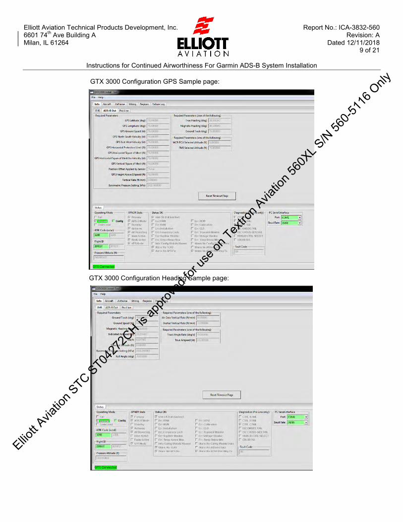
Elliott Aviation Technical Products Development, Inc. Report No.: ICA-3832-560 6601 74th Ave Building A Revision: A Milan, IL 61264 Dated 12/11/2018 9 of 21
Instructions for Continued Airworthiness For Garmin ADS-B System Installation
GTX 3000 Configuration GPS Sample page:
GTX 3000 Configuration Heading Sample page:
Elliott A
viatio
n STC ST04
272C
H is ap
prove
d for
use o
n Tex
tron A
viatio
n 560
XL S/N
560-5
116 O
nly

Elliott Aviation Technical Products Development, Inc. Report No.: ICA-3832-560 6601 74th Ave Building A Revision: A Milan, IL 61264 Dated 12/11/2018 10 of 21
Instructions for Continued Airworthiness For Garmin ADS-B System Installation
GTX 3000 Configuration Status Sample Page:
2.3.2.10 For troubleshooting an in-service system, GPS activity may be confirmed using this “Info / ADS-B
Out” page. Lack of GPS position may be due to GDL 88 issues such as disconnect antenna coax, faulty antenna or faulty GDL 88. See 2.5 above. If the GDL 88 is not suspect, suspect RS 232 interface, configuration or GTX 3000 transponder. The GTX 3000 is not field serviceable. If faulty, the GTX 3000 line replaceable unit may only be repaired by Garmin.
2.3.2.11 For troubleshooting an in-service system, heading activity may be confirmed using this “Info / EHS” page. Lack of heading may be due to suspect 429 interface or configuration. The GTX 3000 heading source is the same as is used for the Flight Crew presentations The GTX 3000 is not field serviceable. If faulty, the GTX 3000 line replaceable unit may only be repaired by Garmin.
2.3.2.12 For troubleshooting an in-service system, the above may be confirmed using this “Status” page:
Weight on wheels is operating correctly. (squat switch, wiring and config). ADS-B mode indicated. (GDL 88, valid 429 data, wiring and config). 4096 code agrees with RMU ATC settings. Access the Pro Line control display unit and
exercise the squawk codes, the GTX 3000 should indicate correctly almost immediately. (wiring and config).
Flight ID agrees with RMU ATC settings. Select reversionary mode on the associated instrument panel to enable off-side control display unit GTX 3000 control. (RMU, wiring and config).
TCAS status correct for aircraft. Most aircraft will have TCAS installed. Confirm TCAS by visual observation of directional antennas and / or Pro Line control display unit TCAS page. Confirm no faults if TCAS installed and the ADS-B system is interfaced properly. (wiring and config).
2.3.2.13 The GTX 3000 is not field serviceable. If faulty, the GTX 3000 line replaceable unit may only be repaired by Garmin.
Elliott A
viatio
n STC ST04
272C
H is ap
prove
d for
use o
n Tex
tron A
viatio
n 560
XL S/N
560-5
116 O
nly

Elliott Aviation Technical Products Development, Inc. Report No.: ICA-3832-560 6601 74th Ave Building A Revision: A Milan, IL 61264 Dated 12/11/2018 11 of 21
Instructions for Continued Airworthiness For Garmin ADS-B System Installation
2.3.3 GTX 3000 “N” number Registration change.
2.3.3.1 Obtain Elliott Configuration Instructions located in Appendix A. Using sections 2 and 4 of the Configuration Instructions Access the “Aircraft” tab on the GTX 3000 configuration tool. Modify the registration as needed and press enter to set the configuration. Shutdown the configuration tool and verify registration number change using IFR 6000 or similar transponder test set.
Sample page:
Elliott A
viatio
n STC ST04
272C
H is ap
prove
d for
use o
n Tex
tron A
viatio
n 560
XL S/N
560-5
116 O
nly

Elliott Aviation Technical Products Development, Inc. Report No.: ICA-3832-560 6601 74th Ave Building A Revision: A Milan, IL 61264 Dated 12/11/2018 12 of 21
Instructions for Continued Airworthiness For Garmin ADS-B System Installation
2.4 GTX 3000 / GDL 88 / Shadin AMC Troubleshooting
Reported Issue Steps Transponder reporting:
Altitude
Observe or determine Honeywell flight displays for air data indications.
If present and correct, GTX 3000 suspect wiring or configuration.
Transponder reporting:
Heading
Observe or determine Honeywell flight displays for heading indications.
If present and correct, GTX 3000 suspect wiring or configuration.
Transponder reporting:
ADS-B - Air
Observe or determine the ADS-B annunciator status.
If ADS-B annunciation OFF, suspect GTX 3000 in use.
If ADS-B annunciation ON, suspect GDL 88 LRU, wiring or configuration.
Transponder reporting:
ADS-B - Surface
Not seen by flight crew, report will come from ATC Ground.
Same as above for ADS-B annunciation status.
Transponder reporting:
Mode C
Observe or determine the Honeywell RMU annunciations.
If alternate GTX 3000 can be controlled using Honeywell RMU, suspect the GTX 3000 LRU.
TCAS Honeywell MFD: Observe status. Use the Test button on the front of the TCAS processor and verify errors displayed on the LED lights.
RMU display is dashed, in COMM & Transponder Segments
Swap #1 & #2 AMC IF fault follows LRU swap, replace AMC Unit. If fault does not follow check Wiring.
Commercial Off The Shelf ADS-B receiver devices are suitable for GO / NO GO confirmation that the GTX 3000 transponders are transmitting GPS position. HOWEVER, only approved calibrated test devices, such as the IFR 6000, may be used to confirm transponder output power and minimum trigger levels as well as diversity isolation.
To conduct an in-depth as-installed complete functional check including UAT, qualified test equipment such as the IFR 6000 will be required. Refer to specific test set instructions for operation and testing.
Elliott A
viatio
n STC ST04
272C
H is ap
prove
d for
use o
n Tex
tron A
viatio
n 560
XL S/N
560-5
116 O
nly

Elliott Aviation Technical Products Development, Inc. Report No.: ICA-3832-560 6601 74th Ave Building A Revision: A Milan, IL 61264 Dated 12/11/2018 13 of 21
Instructions for Continued Airworthiness For Garmin ADS-B System Installation
Chapter 3 ACCESS:
3.1 Overview:
The information contained herein supplements the basic Maintenance Manuals only in those areas listed, when the aircraft is modified in accordance with Elliott Aviation drawings and diagrams specified in Section 1.3 of this document.
3.1.1 GTX 3000s are located in the forward right avionics bay upper equipment shelf. A configuration module is also located inside the J3302 connectors.
3.1.2 GDL 88 is located in the forward right avionics bay upper equipment shelf. A configuration module is also located inside the J811 connector.
3.1.3 AMCs are located in the forward right and left avionics bays upper equipment shelf.
3.1.4 Flight Stream 110 (if installed) is located on the outboard side of the Co-Pilot’s chart holder cabinet.
3.1.5 ADS-B 1/2 annunciator is located in the cockpit panel
3.1.6 GA 36 GPS Antenna is located on top of the aircraft fuselage above the cabin headliner FS 172.00-187.00 left of center line
3.1.7 UAT Antenna is located on the belly of the aircraft fuselage below the left forward avionics bay FS 67.10-75.80
3.1.8 Wiring follows existing aircraft wire routes in the nose and cockpit area.
3.2 Equipment and wiring access:
No new access is required from the installation of this modification. Access to all equipment and wiring is gained using existing aircraft maintenance manual techniques.
Elliott A
viatio
n STC ST04
272C
H is ap
prove
d for
use o
n Tex
tron A
viatio
n 560
XL S/N
560-5
116 O
nly
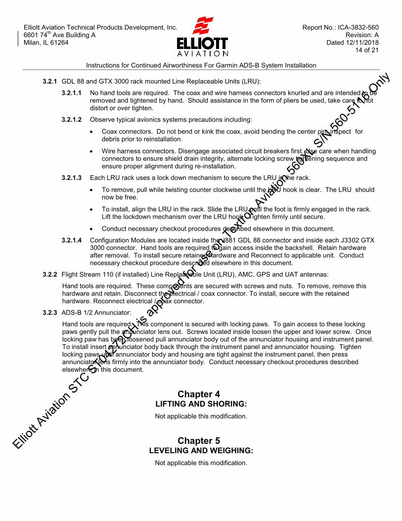
Elliott Aviation Technical Products Development, Inc. Report No.: ICA-3832-560 6601 74th Ave Building A Revision: A Milan, IL 61264 Dated 12/11/2018 14 of 21
Instructions for Continued Airworthiness For Garmin ADS-B System Installation
3.2.1 GDL 88 and GTX 3000 rack mounted Line Replaceable Units (LRU):
3.2.1.1 No hand tools are required. The coax and wire harness connectors knurled and are intended to be removed and tightened by hand. Should assistance in the form of pliers be used, take care to not distort or over tighten.
3.2.1.2 Observe typical avionics systems precautions including:
Coax connectors. Do not bend or kink the coax, avoid bending the center pin, inspect for debris prior to reinstallation.
Wire harness connectors. Disengage associated circuit breakers first. Use care when handling connectors to ensure shield drain integrity, alternate locking screw tightening sequence and ensure proper alignment during re-installation.
3.2.1.3 Each LRU rack uses a lock down mechanism to secure the LRU in the rack.
To remove, pull while twisting counter clockwise until the LRU hook is clear. The LRU should now be free.
To install, align the LRU in the rack. Slide the LRU until the foot is firmly engaged in the rack. Lift the lockdown mechanism over the LRU hook. Tighten firmly until secure.
Conduct necessary checkout procedures described elsewhere in this document.
3.2.1.4 Configuration Modules are located inside the J881 GDL 88 connector and inside each J3302 GTX 3000 connector. Hand tools are required to gain access inside the backshell. Retain hardware after removal. To install secure retained hardware and Reconnect to applicable unit. Conduct necessary checkout procedure described elsewhere in this document.
3.2.2 Flight Stream 110 (if installed) Line Replaceable Unit (LRU), AMC, GPS and UAT antennas:
Hand tools are required. These components are secured with screws and nuts. To remove, remove this hardware and retain. Disconnect the electrical / coax connector. To install, secure with the retained hardware. Reconnect electrical / coax connector.
3.2.3 ADS-B 1/2 Annunciator:
Hand tools are required. This component is secured with locking paws. To gain access to these locking paws gently pull the annunciator lens out. Screws located inside loosen the upper and lower screw. Once locking paw has been loosened pull annunciator body out of the annunciator housing and instrument panel. To install insert annunciator body back through the instrument panel and annunciator housing. Tighten locking paws until annunciator body and housing are tight against the instrument panel, then press annunciator lens firmly into the annunciator body. Conduct necessary checkout procedures described elsewhere in this document.
Chapter 4 LIFTING AND SHORING: Not applicable this modification.
Chapter 5 LEVELING AND WEIGHING:
Not applicable this modification.
Elliott A
viatio
n STC ST04
272C
H is ap
prove
d for
use o
n Tex
tron A
viatio
n 560
XL S/N
560-5
116 O
nly

Elliott Aviation Technical Products Development, Inc. Report No.: ICA-3832-560 6601 74th Ave Building A Revision: A Milan, IL 61264 Dated 12/11/2018 15 of 21
Instructions for Continued Airworthiness For Garmin ADS-B System Installation
Chapter 6 TOWING AND TAXIING:
Not applicable this modification.
Chapter 7 PARKING AND MOORING: Not applicable this modification.
Chapter 8 PLACARDS AND MARKINGS:
Not applicable this modification.
Chapter 9 SERVICING:
Not applicable this modification.
Elliott A
viatio
n STC ST04
272C
H is ap
prove
d for
use o
n Tex
tron A
viatio
n 560
XL S/N
560-5
116 O
nly

Elliott A
viatio
n STC ST04
272C
H is ap
prove
d for
use o
n Tex
tron A
viatio
n 560
XL S/N
560-5
116 O
nly

Elliott A
viatio
n STC ST04
272C
H is ap
prove
d for
use o
n Tex
tron A
viatio
n 560
XL S/N
560-5
116 O
nly

Elliott A
viatio
n STC ST04
272C
H is ap
prove
d for
use o
n Tex
tron A
viatio
n 560
XL S/N
560-5
116 O
nly

Elliott A
viatio
n STC ST04
272C
H is ap
prove
d for
use o
n Tex
tron A
viatio
n 560
XL S/N
560-5
116 O
nly

Elliott A
viatio
n STC ST04
272C
H is ap
prove
d for
use o
n Tex
tron A
viatio
n 560
XL S/N
560-5
116 O
nly

Elliott A
viatio
n STC ST04
272C
H is ap
prove
d for
use o
n Tex
tron A
viatio
n 560
XL S/N
560-5
116 O
nly
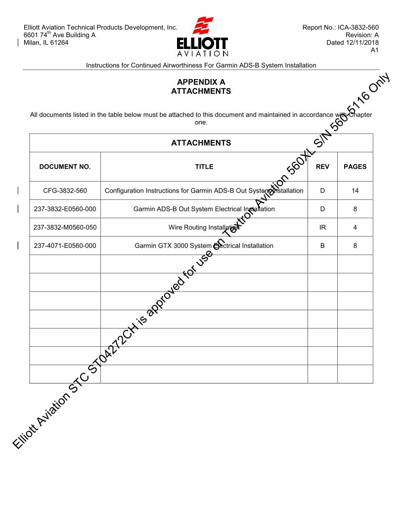
Elliott Aviation Technical Products Development, Inc. Report No.: ICA-3832-560 6601 74th Ave Building A Revision: A Milan, IL 61264 Dated 12/11/2018 A1
Instructions for Continued Airworthiness For Garmin ADS-B System Installation
APPENDIX A ATTACHMENTS
All documents listed in the table below must be attached to this document and maintained in accordance with Chapter one.
ATTACHMENTS
DOCUMENT NO. TITLE REV PAGES
CFG-3832-560 Configuration Instructions for Garmin ADS-B Out System Installation D 14
237-3832-E0560-000 Garmin ADS-B Out System Electrical Installation D 8
237-3832-M0560-050 Wire Routing Installation IR 4
237-4071-E0560-000 Garmin GTX 3000 System Electrical Installation B 8
Elliott A
viatio
n STC ST04
272C
H is ap
prove
d for
use o
n Tex
tron A
viatio
n 560
XL S/N
560-5
116 O
nly

Elliott A
viatio
n STC ST04
272C
H is ap
prove
d for
use o
n Tex
tron A
viatio
n 560
XL S/N
560-5
116 O
nly
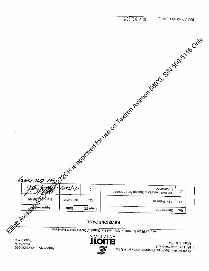
Elliott A
viatio
n STC ST04
272C
H is ap
prove
d for
use o
n Tex
tron A
viatio
n 560
XL S/N
560-5
116 O
nly

Elliott A
viatio
n STC ST04
272C
H is ap
prove
d for
use o
n Tex
tron A
viatio
n 560
XL S/N
560-5
116 O
nly

Elliott A
viatio
n STC ST04
272C
H is ap
prove
d for
use o
n Tex
tron A
viatio
n 560
XL S/N
560-5
116 O
nly
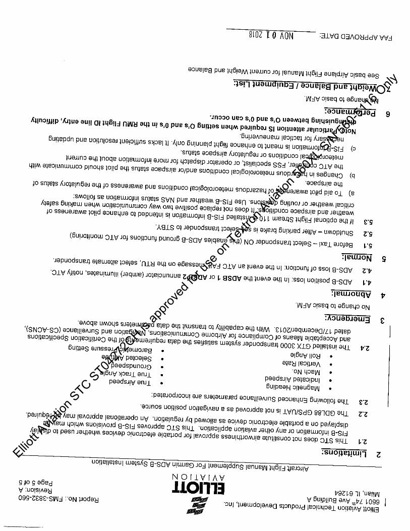
Elliott A
viatio
n STC ST04
272C
H is ap
prove
d for
use o
n Tex
tron A
viatio
n 560
XL S/N
560-5
116 O
nly
Elliott Aviation Technical Products Development, Inc. Report No.: WBE-3832-560 6601 74
th Ave Building A Revision: A
Milan, IL 61264 Dated 01/15/2018 1 of 4
Weight and Balance Effects For Garmin ADS-B System Installation
Weight and Balance Effects
For
Garmin ADS-B Out System Installation
(Type Certificate A22CE)
© 2017 ELLIOTT AVIATION TECHNICAL PRODUCTS DEVELOPMENT, INC.
Elliott Aviation Technical Products Development, Inc. reserves the copyright of all information and illustrations in this publication which is
provided in confidence and which may not be used for any purpose other than for which it was originally supplied. The publication may not
be reproduced in part or in whole without the consent in writing of Elliott Aviation Technical Products Development, Inc.
Elliott A
viatio
n STC ST04
272C
H is ap
prove
d for
use o
n Tex
tron A
viatio
n 560
XL S/N
560-5
116 O
nly

Elliott Aviation Technical Products Development, Inc. Report No.: WBE-3832-560 6601 74
th Ave Building A Revision: A
Milan, IL 61264 Dated 01/15/2018 2 of 4
Weight and Balance Effects For Garmin ADS-B System Installation
REVISIONS PAGE
Rev Description Page (S) Date Approved By
IR Initial Release ALL 11/15/2017 R. Woolums
A Incorporated ODA comments 2, 4 01/15/2018
Elliott A
viatio
n STC ST04
272C
H is ap
prove
d for
use o
n Tex
tron A
viatio
n 560
XL S/N
560-5
116 O
nly

Elliott Aviation Technical Products Development, Inc. Report No.: WBE-3832-560 6601 74
th Ave Building A Revision: A
Milan, IL 61264 Dated 01/15/2018 3 of 4
Weight and Balance Effects For Garmin ADS-B System Installation
TABLE OF CONTENTS
COVER PAGE ....................................................................................................... 1
REVISIONS PAGE ................................................................................................ 2
TABLE OF CONTENTS ......................................................................................... 3
1 Purpose .......................................................................................................... 4
2 Removed Equipment ....................................................................................... 4
3 Added Equipment ............................................................................................ 4
4 Optional Added Equipment .............................................................................. 4
5 Weight and Balance Effects ............................................................................. 4
Elliott A
viatio
n STC ST04
272C
H is ap
prove
d for
use o
n Tex
tron A
viatio
n 560
XL S/N
560-5
116 O
nly

Elliott Aviation Technical Products Development, Inc. Report No.: WBE-3832-560 6601 74
th Ave Building A Revision: A
Milan, IL 61264 Dated 01/15/2018 4 of 4
Weight and Balance Effects For Garmin ADS-B System Installation
1 Purpose
The purpose of this document is to illustrate the changes in the weight and balance after modification installing Garmin ADS-B system. This data is supplied to support updating the aircraft’s actual weight and balance records.
2 Removed Equipment
QTY Part Number Description Unit Weight
(lbs) Total Weight
(lbs) Arm (in) Moment
1 7001840-936 RT-300 Radalt 4.6 -4.6 68 -312.8 Total -4.6 -312.8
None
3 Installed/Relocated Equipment
QTY Part Number Description Unit Weight
(lbs) Total Weight
(lbs) Arm (in) Moment
1 011-01997-00 #1 GTX3000 6 6 68 408 1 7001840-936 RT-300 Radalt 4.6 4.6 81.89 376.7 1 011-01997-00 #2 GTX3000 6 6 84.26 505.56 1 011-02370-00 GDL88 4.1 4.1 81.83 201.72 1 833520-00 #1 AMC .9 .9 66.9 60.21 1 833520-00 #2 AMC .9 .9 67.17 60.54 1 013-00244-00 GA36 GPS Antenna .47 .47 177.57 83.46 1 CI 110-40-30 UAT Antenna .25 .25 78.61 19.65
Total 23.22 1715.84
4 Optional Added Equipment
QTY Part Number Description Unit Weight
(lbs) Total Weight
(lbs) Arm (in) Moment
1 011-03257-00 Flight Stream 110 .27 .27 177.68 47.97 Total .27 47.97
5 Weight and Balance Effects
Part numbers of removed equipment to be verified with actual aircraft equipment list during modification.
Weight (lbs)
Moment
Removed Equipment -4.6 -312.8
Added / Relocated Equipment without options
23.22 1715.84
Added / Relocated Equipment
with options 23.49 1763.81
Total without options 18.62 1403.04
Total with options 18.89 1451.01
Elliott A
viatio
n STC ST04
272C
H is ap
prove
d for
use o
n Tex
tron A
viatio
n 560
XL S/N
560-5
116 O
nly

Elliott Aviation Technical Products Development, Inc. Report No.: ELA-3832-560 6601 74th Ave Building A Revision: IR Milan, IL 61264 Dated 01/08/2018 1 of 6
Electrical Load Analysis For Garmin ADS-B System Installation
Electrical Load Analysis
For
Garmin ADS-B Out System Installation
(Type Certificate A22CE)
© 2017 ELLIOTT AVIATION TECHNICAL PRODUCTS DEVELOPMENT, INC.
Elliott Aviation Technical Products Development, Inc. reserves the copyright of all information and illustrations in this publication which is provided in confidence and which may not be used for any purpose other than for which it was originally supplied. The publication may not be reproduced in part or in whole without the consent in writing of Elliott Aviation Technical Products Development, Inc.
Elliott A
viatio
n STC ST04
272C
H is ap
prove
d for
use o
n Tex
tron A
viatio
n 560
XL S/N
560-5
116 O
nly

Elliott Aviation Technical Products Development, Inc. Report No.: ELA-3832-560 6601 74th Ave Building A Revision: IR Milan, IL 61264 Dated 01/08/2018 2 of 6
Electrical Load Analysis For Garmin ADS-B System Installation
REVISIONS PAGE
Rev Description Page (S) Date Approved By
IR Initial Release ALL 01/08/2018
Elliott A
viatio
n STC ST04
272C
H is ap
prove
d for
use o
n Tex
tron A
viatio
n 560
XL S/N
560-5
116 O
nly
Elliott Aviation Technical Products Development, Inc. Report No.: ELA-3832-560 6601 74th Ave Building A Revision: IR Milan, IL 61264 Dated 01/08/2018 3 of 6
Electrical Load Analysis For Garmin ADS-B System Installation
TABLE OF CONTENTS COVER PAGE .......................................................................................................... 1 REVISIONS PAGE.................................................................................................... 2 TABLE OF CONTENTS ............................................................................................ 3 1 Purpose and scope: ............................................................................................. 4
2 Electrical System Capacity Analysis: ................................................................... 4
3 Conclusion:........................................................................................................... 6
A1 Textron AMM 560XL ELA .................................................................................. A1
Elliott A
viatio
n STC ST04
272C
H is ap
prove
d for
use o
n Tex
tron A
viatio
n 560
XL S/N
560-5
116 O
nly

Elliott Aviation Technical Products Development, Inc. Report No.: ELA-3832-560 6601 74th Ave Building A Revision: IR Milan, IL 61264 Dated 01/08/2018 4 of 6
Electrical Load Analysis For Garmin ADS-B System Installation
1 Purpose and scope: This document will provide the electrical load change of all the removed equipment and all the installed equipment associated with the Garmin ADS-B System installation in support of MDL-3832-560 for Textron Aviation Model 560XL. This is based off the Textron Aviation AMM ELA and made current for 560-5628.
Due to the nature of ADS-B, all phases of flight as well surface operations are assumed. Since the ADS-B requirements involve use of the transponder during surface operations, no idle (quiescent) values are used.
The GTX 3000 switched output DC is not used in this installation.
2 Electrical System Capacity Analysis: 2.1 Equipment details:
Avionics Emergency Bus Load Change (amps)
Circuit Breaker Size
Removed Equipment
None Installed Equipment:
Shadin #1 AMC [+] .2 A NA*
Total Avionics Emergency Bus Change [+] .2 A
*When powered by the Avionics Emergency Bus, Shadin #1 AMC is protected by the existing #1 COMM 1 circuit breaker (10A).
Left Avionics Bus Load Change (amps)
Circuit Breaker Size
Removed Equipment
Honeywell #1 XPDR [-] .95 A 5A* Installed Equipment:
Garmin GTX 3000 # 1 [+] 1.6 A 5A*
Shadin #1 AMC [+] .2 A NA**
Total Left Avionics Bus Change [+] 0.4 A
*The existing Honeywell #1 XPDR circuit breaker (5A) is retained and re-purposed for the Garmin GTX 3000 #1 circuit breaker (5A).
**When powered by the Left Avionics Bus, Shadin #1 AMC wiring is protected by the Garmin GTX 3000 #1 circuit breaker (5A).
Ellio
tt Avia
tion S
TC ST0427
2CH is
appro
ved f
or us
e on T
extro
n Avia
tion 5
60XL S
/N 56
0-511
6 Only

Elliott Aviation Technical Products Development, Inc. Report No.: ELA-3832-560 6601 74th Ave Building A Revision: IR Milan, IL 61264 Dated 01/08/2018 5 of 6
Electrical Load Analysis For Garmin ADS-B System Installation
Right Avionics Bus Load Change (amps)
Circuit Breaker Size
Removed Equipment
Honeywell #2 XPDR [-] .95 A 5A Installed Equipment:
Garmin GTX 3000 # 2 [+] 1.6 A 5A*
Garmin GDL 88 [+] 0.71 A 1A
Shadin #2 AMC [+] 0.2 A NA**
Garmin Flight Stream 110 (optional) [+] 0.06 A 1/2A
Total Right Avionics Bus Change (w/ Flight Stream 110 installed) [+] 1.17 A
Total Aircraft Load Change (w/ Flight Stream 110 installed) [+] 2.67 A
Total Right Avionics Bus Change (w/o Flight Stream 110 installed) [+] 1.11 A
Total Aircraft Load Change (w/o Flight Stream 110 installed) [+] 2.61 A
*The existing Honeywell #1 XPDR circuit breaker (5A) is retained and re-purposed for the Garmin GTX 3000 #1 circuit breaker (5A).
**When powered by the Left Avionics Bus, Shadin #1 AMC wiring is protected by the Garmin GTX 3000 #1 circuit breaker (5A).
Elliott A
viatio
n STC ST04
272C
H is ap
prove
d for
use o
n Tex
tron A
viatio
n 560
XL S/N
560-5
116 O
nly

Elliott Aviation Technical Products Development, Inc. Report No.: ELA-3832-560 6601 74th Ave Building A Revision: IR Milan, IL 61264 Dated 01/08/2018 6 of 6
Electrical Load Analysis For Garmin ADS-B System Installation
3 Conclusion: The result of the Garmin ADS-B System installation is a total net gain of 2.67 Amp to the aircraft generation system. In accordance with the Textron Aviation 560XL AMM the worst case amperage draw is 567.88 amps which occurs during night takeoff in non-icing conditions. The new total aircraft load is 570.55 amps during a night takeoff in non-icing conditions. This total is still less than the total rated maximum load capacity of 600 amps the aircraft is capable of and within electrical load safety margins. During single generator icing operation the new total maximum load went from 356.92 amps to 359.59 amps. This has no effect on the existing aircraft procedure during single generator operation, to turn the interiors master switch off. This shed 135.19 amps and brings the aircraft total to 224.4 amps which is below the 300 amp aircraft single generator capacity and within the electrical load safety margin.
The result of the Garmin ADS-B system installation is a total net gain of .2 Amps to the Emergency bus. In accordance with the Textron Aviation 560XL AMM the original Emergency Bus total is 29.94 amps. The new total Emergency Bus load is 30.14 amps. Using the calculations below the total Emergency Bus Operating time is now 51.30 minutes which is above the required 30 minutes.
40 Amp / hour Battery Capacity
Average Demand ................................ =Battery total load ............................ (29.94)
Amp Minutes in 30 Minutes ................. =Average demand x 30 minutes ...... (29.94 x 30=898.2)
Amp Hour Required ............................. =Amp Minutes in 30 Minutes ÷ 60 .... (898.2÷60=14.97)
Battery Rated Capacity ....................... =Amp Hour Required÷0.8................. (14.97÷0.8=18.71)
Time on Emergency Bus Operation .... =Battery Capacity ÷Battery Rated Capacity x 30 51.30
(40 amp-hr x 0.8 ÷18.71) x 30=51.30 minutes.
Elliott A
viatio
n STC ST04
272C
H is ap
prove
d for
use o
n Tex
tron A
viatio
n 560
XL S/N
560-5
116 O
nly

Elliott Aviation Technical Products Development, Inc. Report No.: ELA-3832-560 6601 74th Ave Building A Revision: IR Milan, IL 61264 Dated 01/08/2018 A1 of A14
Electrical Load Analysis For Garmin ADS-B System Installation
Textron Aviation
Aircraft Maintenance Manual
Electrical Load Analysis
Elliott A
viatio
n STC ST04
272C
H is ap
prove
d for
use o
n Tex
tron A
viatio
n 560
XL S/N
560-5
116 O
nly
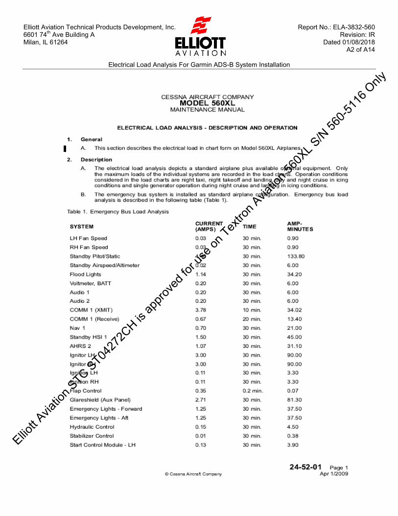
Elliott Aviation Technical Products Development, Inc. Report No.: ELA-3832-560 6601 74th Ave Building A Revision: IR Milan, IL 61264 Dated 01/08/2018 A2 of A14
Electrical Load Analysis For Garmin ADS-B System Installation
Elliott A
viatio
n STC ST04
272C
H is ap
prove
d for
use o
n Tex
tron A
viatio
n 560
XL S/N
560-5
116 O
nly

Elliott Aviation Technical Products Development, Inc. Report No.: ELA-3832-560 6601 74th Ave Building A Revision: IR Milan, IL 61264 Dated 01/08/2018 A3 of A14
Electrical Load Analysis For Garmin ADS-B System Installation
Elliott A
viatio
n STC ST04
272C
H is ap
prove
d for
use o
n Tex
tron A
viatio
n 560
XL S/N
560-5
116 O
nly
Elliott Aviation Technical Products Development, Inc. Report No.: ELA-3832-560 6601 74th Ave Building A Revision: IR Milan, IL 61264 Dated 01/08/2018 A4 of A14
Electrical Load Analysis For Garmin ADS-B System Installation
Elliott A
viatio
n STC ST04
272C
H is ap
prove
d for
use o
n Tex
tron A
viatio
n 560
XL S/N
560-5
116 O
nly

Elliott Aviation Technical Products Development, Inc. Report No.: ELA-3832-560 6601 74th Ave Building A Revision: IR Milan, IL 61264 Dated 01/08/2018 A5 of A14
Electrical Load Analysis For Garmin ADS-B System Installation
Elliott A
viatio
n STC ST04
272C
H is ap
prove
d for
use o
n Tex
tron A
viatio
n 560
XL S/N
560-5
116 O
nly
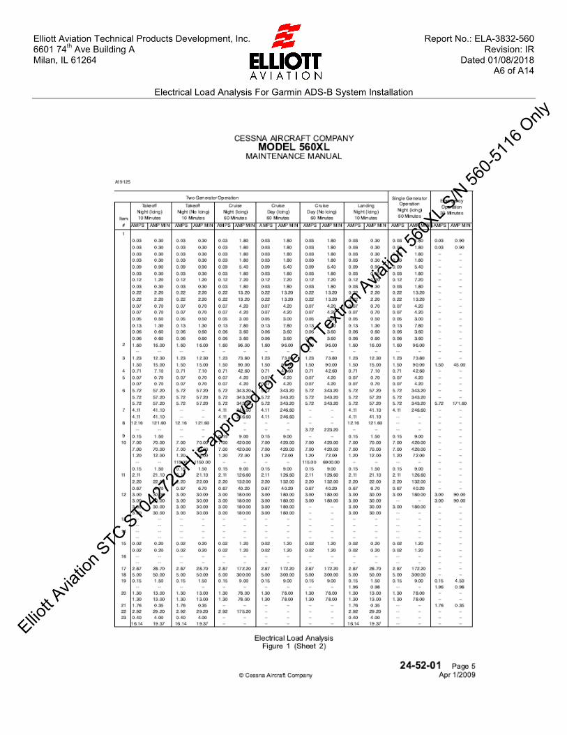
Elliott Aviation Technical Products Development, Inc. Report No.: ELA-3832-560 6601 74th Ave Building A Revision: IR Milan, IL 61264 Dated 01/08/2018 A6 of A14
Electrical Load Analysis For Garmin ADS-B System Installation
Elliott A
viatio
n STC ST04
272C
H is ap
prove
d for
use o
n Tex
tron A
viatio
n 560
XL S/N
560-5
116 O
nly

Elliott Aviation Technical Products Development, Inc. Report No.: ELA-3832-560 6601 74th Ave Building A Revision: IR Milan, IL 61264 Dated 01/08/2018 A7 of A14
Electrical Load Analysis For Garmin ADS-B System Installation
Elliott A
viatio
n STC ST04
272C
H is ap
prove
d for
use o
n Tex
tron A
viatio
n 560
XL S/N
560-5
116 O
nly

Elliott Aviation Technical Products Development, Inc. Report No.: ELA-3832-560 6601 74th Ave Building A Revision: IR Milan, IL 61264 Dated 01/08/2018 A8 of A14
Electrical Load Analysis For Garmin ADS-B System Installation
Elliott A
viatio
n STC ST04
272C
H is ap
prove
d for
use o
n Tex
tron A
viatio
n 560
XL S/N
560-5
116 O
nly

Elliott Aviation Technical Products Development, Inc. Report No.: ELA-3832-560 6601 74th Ave Building A Revision: IR Milan, IL 61264 Dated 01/08/2018 A9 of A14
Electrical Load Analysis For Garmin ADS-B System Installation
Elliott A
viatio
n STC ST04
272C
H is ap
prove
d for
use o
n Tex
tron A
viatio
n 560
XL S/N
560-5
116 O
nly
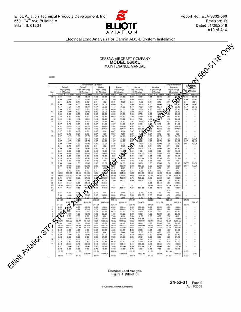
Elliott Aviation Technical Products Development, Inc. Report No.: ELA-3832-560 6601 74th Ave Building A Revision: IR Milan, IL 61264 Dated 01/08/2018 A10 of A14
Electrical Load Analysis For Garmin ADS-B System Installation
Elliott A
viatio
n STC ST04
272C
H is ap
prove
d for
use o
n Tex
tron A
viatio
n 560
XL S/N
560-5
116 O
nly

Elliott Aviation Technical Products Development, Inc. Report No.: ELA-3832-560 6601 74th Ave Building A Revision: IR Milan, IL 61264 Dated 01/08/2018 A11 of A14
Electrical Load Analysis For Garmin ADS-B System Installation
Elliott A
viatio
n STC ST04
272C
H is ap
prove
d for
use o
n Tex
tron A
viatio
n 560
XL S/N
560-5
116 O
nly

Elliott Aviation Technical Products Development, Inc. Report No.: ELA-3832-560 6601 74th Ave Building A Revision: IR Milan, IL 61264 Dated 01/08/2018 A12 of A14
Electrical Load Analysis For Garmin ADS-B System Installation
Elliott A
viatio
n STC ST04
272C
H is ap
prove
d for
use o
n Tex
tron A
viatio
n 560
XL S/N
560-5
116 O
nly

Elliott Aviation Technical Products Development, Inc. Report No.: ELA-3832-560 6601 74th Ave Building A Revision: IR Milan, IL 61264 Dated 01/08/2018 A13 of A14
Electrical Load Analysis For Garmin ADS-B System Installation
Elliott A
viatio
n STC ST04
272C
H is ap
prove
d for
use o
n Tex
tron A
viatio
n 560
XL S/N
560-5
116 O
nly

Elliott Aviation Technical Products Development, Inc. Report No.: ELA-3832-560 6601 74th Ave Building A Revision: IR Milan, IL 61264 Dated 01/08/2018 A14 of A14
Electrical Load Analysis For Garmin ADS-B System Installation
Elliott A
viatio
n STC ST04
272C
H is ap
prove
d for
use o
n Tex
tron A
viatio
n 560
XL S/N
560-5
116 O
nly
Copyright © 2022 FDOKUMEN