User Manual - TRS Motorcycles
48
User Manual 125 - 250 - 280 - 300 User Manual - 300,280,250,125cc - (August 2020)
-
Upload
khangminh22 -
Category
Documents
-
view
0 -
download
0
Transcript of User Manual - TRS Motorcycles

User Manual
125 - 250 - 280 - 300
User Manual - 300,280,250,125cc - (August 2020)

2

3
Dear customer,
Thank you for your confidence in us, and congratu-lations on the purchase of your new TRS One.
Because of our experience, professionalism and pas-sion for trial bikes we are able to offer you an innova-tive, reliable and up-to-date motorcycle. It has a com-prehensively checked technical performance that has been tried and tested both by our technicians and our high-level drivers worldwide.
The solutions we have used give the motorcycle an unmistakable character, combining simplicity, re-liability and design. We pay attention to every last detail to give you a unique bike.
At the same time, this manual gives you all the in-formation you need to use the motorcycle appro-priately and safely. We recommend that you read it carefully before you use the motorcycle.
In addition, you will find tips and useful information for the maintenance and upkeep your new TRS One.
Yours faithfully,
Welcome to TRS

4
Picture shows homologated version with regard to regulation (EU) Nº168/2013 Picture shows competition version only and is not manufactured for, nor should it be used on
public streets, roads or highways. The use of this kit should be limited to participation in sanc-
tionet competition events upon a closed course.

5
Please read this user manual thoroughly before using your motorcycle. It details all the instructions for the correct handling of the motorcycle and for your safety, as well as helping towards the best possible maintenance ¬and upkeep from day one.
Please pay special attention to the notes flagged up with the following symbols:
ATTENTION! This symbol refers to points which, if ignored, could lead to some kind of damage to your motorcycle. Non-observance of these warnings could render your motorcycle warranty void.
CAUTION! This symbol refers to points which, if ignored, could lead to physical danger for the user.
TRS advises you:
In addition to these specific warnings, the manual gives advice on the best use of your motorcycle, as well as better adjustment and control of its important features.
TRS reserves the right to make changes to this manual.

6
If you have any doubts about adjustments to your motorcycle, refer to the manual and/or contact an authorised TRS dealer.
Please carefully read through the information in the user manual to familiarise yourself with the features of your motorcycle before driving it using the maxi-mum power settings.
• A running-in period of at least 8-10 hours without driving at high speeds or full throttle is advised, in order to allow the engine to bed in. In these first hours, drive at a moderate speed only.
• Fuel is a highly inflammable liquid. Use caution when refuelling and always¬ turn off the engine first.• Before running the engine at high speed, it is im-portant to let it reach an optimum operating tempe-rature, especially when starting up the motorcycle or in low temperature conditions.
• This motorcycle uses two-stroke synthetic oil mixed with 1% 98 octane fuel. Do not use any other kind of lubrication without previously checking with an authorised TRS mechanic.
• This motorcycle is designed to carry just one per-son, and it is not permitted to carry a passenger.
• For a long life of service, keep the motorcycle maintained as recommended¬ in this manual.
• This bike is designed to be safe when driving, pro-vided that the driver is equipped with the appro-priate safety equipment (helmet, protective clo-thing, etc.). Be careful and drive sensibly.
TRS recommends:

7
71 - Description of parts 82 - Technical specifications TRS One - Engine 123 - Technical specifications TRS One - Frame 134 - Manufacturer’s plate (under the fuel tank) 145 - Unboxing, set up 156 - Starting and stopping the engine 167 - Choke 168 - Gearshift 18 9 - Fuel tap 1810 - Fuel tank 2011 - Tyres 2112 - Braking system 2213 - Steering lock 2314 - Side stand 2315 - Handlebar and Instrument panel 2416 - Adjustment of the levers and the handlebar 2617 - Changing the transmission oil 2618 - Spark plug 2819 - Air Filter 2820 - Cooling system 2921 - Draining of coolant 29
Index
22 - Temperature switch 2923 - Filling with coolant 3024 - Bleeding air in the cooling system 3025 - Carburettor 3126 - Carburetion of the mixture 3127 - Carburator adjustment of the idle speed 3128 - Front suspension 3329 - Rear suspension 3330 - Drive chain 3431 - Reed valve 3532 - Swing arm 3533 - Rear brake pedal 3534 - Footrest 3635 - Exhaust muffler 3636 - Tank clutch pump 36 37 - Motorcycle maintenance 3738 - Pares de Apriete 3739 - Storage 3840 - Maintenance operations 3941 - Approval 4142 - Xtrack Kit 4243 - Troubleshooting and Frequently Asked Questions 4344 - Recommended products 47
8
01
02
12
08 27
151325
14
28
03
17
04
07
19
18
11
20
2122
05
24
3233
09
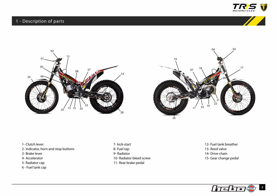
1- Clutch lever2- Indicator, horn and stop buttons3- Brake lever4- Accelerator5- Radiator cap6 - Fuel tank cap
7- kick-start8- Fuel tap9- Radiator10- Radiator bleed screw11- Rear brake pedal
12- Fuel tank breather13- Reed valve14- Drive chain15- Gear change pedal
1 - Description of parts
1033
09

9
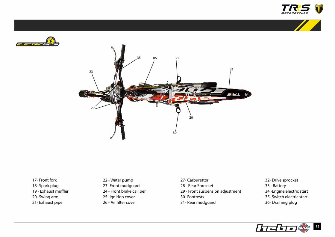
17- Front fork18- Spark plug19 - Exhaust muffler20- Swing arm21- Exhaust pipe
22- Water pump 23- Front mudguard24 - Front brake calliper25- Ignition cover26 - Air filter cover
27- Carburettor 28 - Rear Sprocket29 - Front suspension adjustment30- Footrests31- Rear mudguard
06
26
30
30
3122
29
32- Drive sprocket33 - Drain plug oil engine

10
1- Clutch lever2- Indicator, horn and stop buttons3- Brake lever4- Accelerator5- Radiator cap6 - Fuel tank cap
7- kick-start8- Fuel tank9- Radiator10- Radiator bleed screw11- Rear brake pedal
12- Fuel tank breather13- Fuel tap14- Reed valve15- Drive chain16- Gear change pedal
1 - Description of parts
01
02
12
08
13
27
161425
15
28
03
17
04
07
19
18
11
20
2122
0524
3432
33
36
09
10
09
36
11
17- Front fork18- Spark plug19 - Exhaust muffler20- Swing arm21- Exhaust pipe
22 - Water pump 23- Front mudguard24 - Front brake calliper25- Ignition cover26 - Air filter cover
27- Carburettor 28 - Rear Sprocket29 - Front suspension adjustment30- Footrests31- Rear mudguard
06
26
30
30
3123
29
35
32- Drive sprocket 33 - Battery34 -Engine electric start 35- Switch electric start 36- Draining plug

12
2 - Technical specifications TRS One - Engine
Technical Specifications TRS One - Engine
ENGINE: Single cylinder 2 stroke. Displacement: 294,1cc - 272,2 cc - 247,7 ccCooling system: Liquid cooled.Bore x stroke: 79x60 mm (300 cc) - 76x60 mm (280 cc) - 72,5x60 mm (250 cc).Ignition: HIDRIA CDI (double spark).Clutch: 3 disks diaphragm TRS hydraulic system.Gearbox: 5 speeds.Engine oil capacity: Standard Engine 350cc /Electric Start Engine 450ccTransmission: Chain.Fuel: Petrol 2.3L 98 2T oil 1.0%.Carburettor: Dellorto PHBL26 reed valve admission / Keihin pwk 28 Starting: Kick to primary transmission (kick-start) / Kick-start & Electric Start Air filter: Foam.Spark: NGK-R BPMR6A.
13
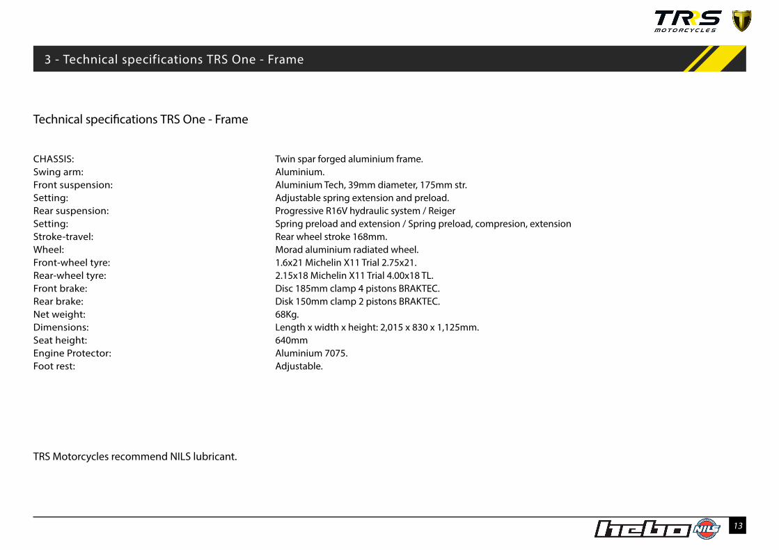
TRS Motorcycles recommend NILS lubricant.
CHASSIS: Twin spar forged aluminium frame.Swing arm: Aluminium.Front suspension: Aluminium Tech, 39mm diameter, 175mm str.Setting: Adjustable spring extension and preload.Rear suspension: Progressive R16V hydraulic system / Reiger Setting: Spring preload and extension / Spring preload, compresion, extensionStroke-travel: Rear wheel stroke 168mm.Wheel: Morad aluminium radiated wheel.Front-wheel tyre: 1.6x21 Michelin X11 Trial 2.75x21.Rear-wheel tyre: 2.15x18 Michelin X11 Trial 4.00x18 TL.Front brake: Disc 185mm clamp 4 pistons BRAKTEC.Rear brake: Disk 150mm clamp 2 pistons BRAKTEC.Net weight: 68Kg.Dimensions: Length x width x height: 2,015 x 830 x 1,125mm.Seat height: 640mmEngine Protector: Aluminium 7075.Foot rest: Adjustable.
3 - Technical specifications TRS One - Frame
Technical specifications TRS One - Frame

14
All motorcycles manufactured by TRS have an identification number stamped on the frame which also appears in the technical sheet of the documentation that will be supplied to the user. This number cannot be replaced or changed. It is stamped on the tube on the right hand side of the frame and may be required in any technical inspection.
SERIAL NUMBER AND KEY CODE These numbers are the ones that identify your motorcycle and the steering lock. Keep a note of them in your manual (e.g. to obtain a copy of the keys if they are lost).
4 - Manufacturer’s plate (under the fuel tank)
a) The position of the identifi-
cation number, located on the
tube on the right hand side of the
frame.
b)) The engine identification num-
ber, located under the reed valve
of the carburettor.
We recommend that you keep a note of the serial number and the identification details for your motorcycle to use in the event of theft or to order spare parts.
a
b

15
SETUP BEFORE USING
For safety reasons, motorcycles TRRS with Electric Start are delivered without fuel and oil (only when the transport is air and maritime transport) , and with the ground connector disconnected to prevent ocurrance during transport. Follow the instructions below for seeting up the motorcycle.
1. Location of the groundconnector, protected with electrical tape. Then proceed to connect the ground connector to the chassis.
2. Using a 4mm allen wrench, unscrew the two screws on top of the fuel tank
3. Using a 10 mm wrench unscrew the upper nut of the fuel tank.
4. Leave the fuel tank resting on the right side on the motorcycle chassis.
5. Unscrew the screw of the ground connector.
6. Take off the tape of the ground connector.
7. Insert the ground connector with the screw togheter and screw with an 8 mm wrench.
8. Repeat the same procedure in reverse to set up the tank.
NOTE: Oil level engine electric start 450cc
2 1
3 4
5 6
7
5 - Unboxing , set up

16
STARTING AND STOPPING THE ENGINE
KICK-START CHOKE
The Stop button is positioned on the left-hand side of the handlebar, close to your thumb for easy use.
Use the choke when the engine is cold to help star-ting without damaging the engine. This device, used correctly, will prevent wear and mechanical damage by starting the motorcycle in adverse tem-peratures. It is operated by a black lever located in the carburettor.
6 - Starting and stopping the engine 7 - Choke
a) Start lever, on the right side of the TRS One
b) Stop button, to the left of the handlebar
c) Kill switch, to the right of the handlebar
f ) Choke, in the carburettor
a
b
/
d
It is a safety element, so that , in the event of the pilot falling, the motorcycle is disconnected. Make sure that the rider puts the elastic band on the left wrist and is firmly secured, before starting the motorcycle.
f

17
6 - Starting and stopping the engine 7 - Choke/
STARTING AND STOPPING THE ENGINE
SWITCH ELECTRIC START CHOKE
The Stop button is positioned on the left-hand side of the handlebar, close to your thumb for easy use.
Use the choke when the engine is cold to help star-ting without damaging the engine. This device, used correctly, will prevent wear and mechanical damage by starting the motorcycle in adverse temperatures. It is operated by a black lever located in the carburettor.
b) Stop button, to the left of the handlebar
c) Kill switch, to the right of the handlebar
f ) Choke, in the carburettor
d
It is a safety element, so that , in the event of the pilot falling, the motorcycle is disconnected. Make sure that the rider puts the elastic band on the left wrist and is firmly secured, before starting the motorcycle.
a) Electric start switch button, on the right side handlebar
NOTE:
1) Before starting the motorcycle, fold the side stand.2) Hold the lever clutch3) Make sure that the gear shift is in neutral.4) Choke - unlock black lever when engine is hot5) Press the Electric start switch button until the engine starts. Do not hold the button down for longer than 10 ‘‘.If the engine does not start, check the troubleshooting at the end of this document.
b
f
a

18
GEARSHIFT FUEL TAP
The gearshift is controlled by a pedal on the left-hand side of the vehicle. The sequence of gears is as shown in the diagram. You must hold down the clutch lever on the left while changing gear. The position of the gears is illustrated in the diagram.
On the left side of the frame, you can see the diagram for using of the fuel tap.The small operating lever is located above the carburettor. We advise turning off the fuel tap when transporting the motorcycle in a vehicle as well as when it is not in use for a long period.
8 - Gearshift 9 - Fuel tap
You can find the first gear by pushing the lever downwards. For the other gears, push the lever upwards, moving up a gear each time you push it.
Positions Res, On and Off in the
fuel tap. There is a sticker on the
frame showing the position.a) Gear shift lever
/
5432N1
a
b

19
GEARSHIFT FUEL TAP
The gearshift is controlled by a pedal on the left-hand side of the vehicle. The sequence of gears is as shown in the diagram. You must hold down the clutch lever on the left while changing gear. The position of the gears is illustrated in the diagram.
On the left side of the frame, you can see the diagram for using of the fuel tap.The small operating lever is located above the carburettor. We advise turning off the fuel tap when transporting the motorcycle in a vehicle as well as when it is not in use for a long period.
You can find the first gear by pushing the lever downwards. For the other gears, push the lever upwards, moving up a gear each time you push it.
b) Fuel Tap.
a) Gear shift lever
5432N1
a
b
8 - Gearshift 9 - Fuel tap/
20
10 - Fuel tank
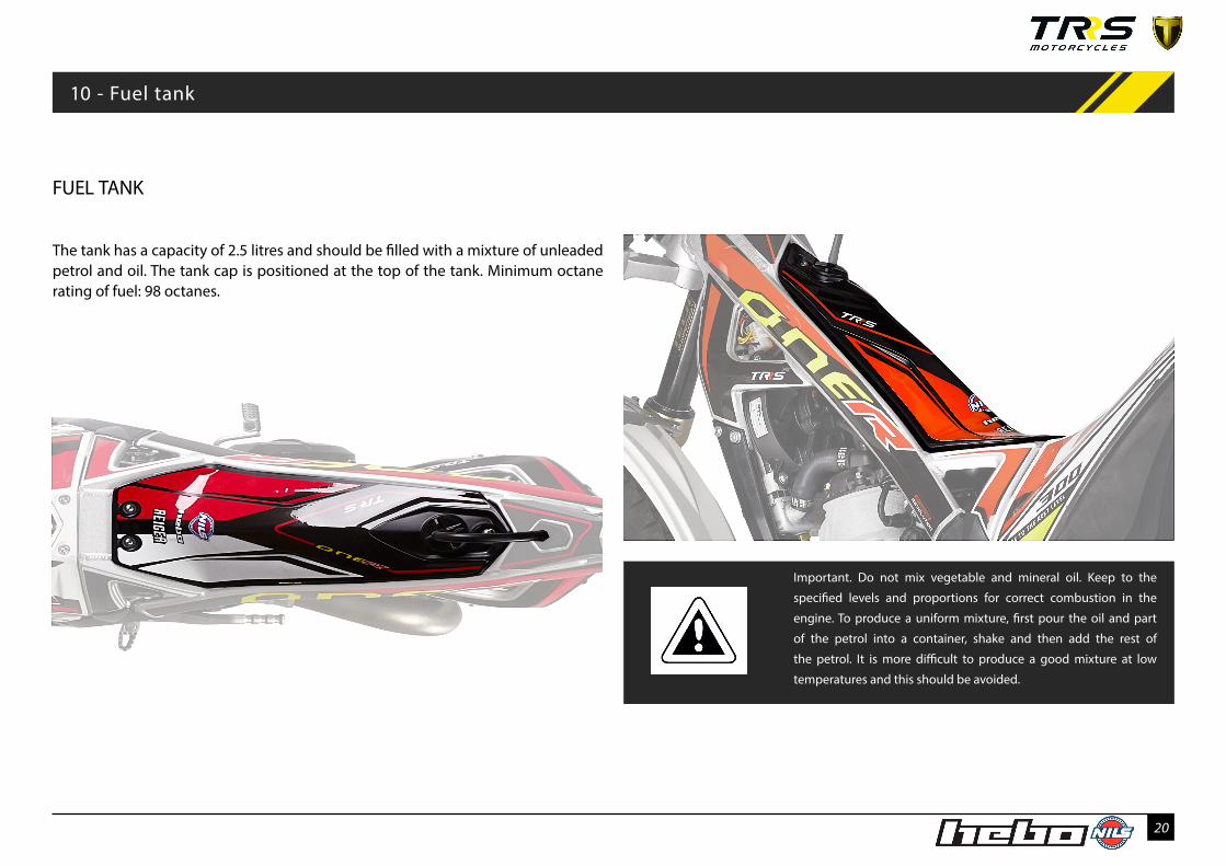
The tank has a capacity of 2.5 litres and should be filled with a mixture of unleaded petrol and oil. The tank cap is positioned at the top of the tank. Minimum octane rating of fuel: 98 octanes.
Important. Do not mix vegetable and mineral oil. Keep to the
specified levels and proportions for correct combustion in the
engine. To produce a uniform mixture, first pour the oil and part
of the petrol into a container, shake and then add the rest of
the petrol. It is more difficult to produce a good mixture at low
temperatures and this should be avoided.
FUEL TANK

21
TYRES
The condition of the tyres is a key factor in safety and guarantees better driving. Make sure your tyre pressure is always correct and check for wear. The pressure must be checked when the tyre is cold.
On low-grip terrain you can reduce the tyre pressu-re slightly to increase the grip and vice versa.TYRES
Front wheel:2,75x21” TRIALRear wheel:4,00x18” TRIAL
RECOMMENDED TYRE PRESSURE:
Front wheel:0,45bar (0,42bar for competition)
Rear wheel:0,35bar (0,3bar for competition)
11 - Tyres
Image of the rear wheel of the TRS

22
BRAKE PADS LEVEL OF REAR BRAKE FLUID LEVEL OF FRONT BRAKE FLUID
12 - Braking system
To ensure optimal braking you need to check the condition of the brake pads. Initially the pad indi-cator groove is normally around 3mm. If after use you find this has been reduced to below 2mm, they need to be replaced.
To replace them you need to remove the brake ca-lliper from the fork tube, taking out the bolts and the wire clip that you can remove from underneath. For reassembly you will need to lever the pistons back with a screwdriver. Then make sure the bolts and the wire pin clip are tight.
To check the rear brake fluid level, you can view it through the triangle of the frame on the left side of the motorcycle. The level needs to be kept be-tween the minimum and the maximum. You can access the oil reservoir by removing the pe-trol tank and loosening the cap on the tank. Brake fluid is highly corrosive so avoid spillage.
At the rear of the front brake pump you can check the fluid level, and replenish it to the correct level with brake fluid NILS DOT-4.
c) Level of fluid in the front brake pump.
b) Rear brake reservoir
a) Brake pads
a
b
MaxMin
c

23
STEERING LOCK SYSTEM SIDE STAND
13 - Steering lock 14 - Side stand
The anti-theft system located at the front of the motorcycle allows you to immobilise the steering. Turn the handlebars as far as they will go to the ri-ght and press the anti-theft system, turning the key until you feel it lock.
The side stand is located on the right side of the vehicle, secured to the frame by a spring. Move the side stand out as far as it will go to rest the motorcycle on it when stationary.
At the base of the side stand there are two holes that you may use to change the way it folds up.If you put the spring in the forward setting in the direction of travel, the side stand will always stay open until you raise it.If you use this position, it is important to remember to manually lift it before starting off.Whereas if you put the spring into the rear setting, the stand will automatically fold up into position in order for you to drive.
/
b) Side stand located on the right of the motorcycle c) Adjustment holes in the side stand
a) The steering lock system is located under the headlight
ab
c

24
On the left side of the handlebar are:
a) - Clutch lever.b) - Horn.c) - Engine stop button.d) - Main/dip beam switch, and indicator switch - (Mo-torcycle approval)
The instrument panel is in the centre of the handlebar (e). (More information and instructions for use are gi-ven in later sections of this manual).
On the right-hand side of the handlebar you can find:
g - Brake lever.h - Throttle.
HANDLEBAR AND INSTRUMENT PANEL STANDARD
15 - Handlebar and Instrument panel
f) At the back of the headlight
is the CDI map switch. Here,
you can choose between the
positions:
I: Wet or 0: Dry.
Note: Only in competition mo-
del
Left-hand side of the handlebar. Central part of the handlebar. Right-hand side of the handlebar.
a
b
c
d
e
f
g
h

25
On the left side of the handlebar are:
a) - Clutch lever.b) - Horn.c) - Engine stop button.d) - Main/dip beam switch, and indicator switch - (Motorcycle approval)
The instrument panel is in the centre of the hand-lebar (e). (More information and instructions for use are given in later sections of this manual).
On the right-hand side of the handlebar you can find:
g - Brake lever.h - Throttle. i- Electric stratrt button
HANDLEBAR AND INSTRUMENT PANEL WITH ELECTRIC START
15 - Handlebar and Instrument panel with electric start
f ) At the back of the headlight
is the CDI map switch. Here,
you can choose between the
positions:
I: Wet or 0: Dry.
Left-hand side of the handlebar. Central part of the handlebar. Right-hand side of the handlebar.
a
b
c
d
e
f
g
hi

26
ADJUSTMENT OF THE LEVERS
Both the clutch lever and the brake lever must have a maximum initial free play of 3mm. It is important that this free play exists and you should not disable it. To adjust, use the adjustment nuts on the levers.
To adapt the handlebar to different types of driving, you can change the angle by loosening the clamps that secure it to the fork. Once you have adjusted it as desired, tighten the bolts again, starting with those closest to the seat and moving on to those closest to the speedometer.
The engine has a capacity of 350 cc of transmission oil.
Do not mix different types of oil. Always top up using the same type. We recommend using oil such as NILS CLUTCH TRIAL.
16 - Adjustment of the levers and the handlebar / 17 - Changing the transmission oil
CHANGING THE TRANSMISSION OIL
There is a plug on the bottom of the sump for drai-ning the oil Fig(b) and another in the upper part for filling Fig(a). To change the oil, start the motorcycle with a cold engine and let it run at idle speed for 5 minutes. This will warm up the oil to the right tem-perature for changing. Then place the motorcycle in driving position with a container below and remove the drain plug. Let all of the oil drain out, and then clean the plug, re-moving any metal shavings. Once it is clean, repla-ce it and refill the engine through the opening on the top, until reaching the desired level in the sight level glass.
TRS Motorcycles recomends NILS CLUTCH TRIAL.
Fig (b):Oil drain plug at the bottom of the sumpa) Oil filler cap, in the upper part of the sump.Maximum initial free play of both levers of the handlebar.
a
b
recommends lubricant

27
CHANGING THE TRANSMISSION OIL WITH ELECTRIC START
17 - Changing the transmission oil
a
Fig (b): Oil drain plug, at the bottom of the crankcase
a): Oil filler cap, in the upper part of the crankcase.
b
The engine has a capacity of 450 cc of transmission oil.
Do not mix different types of oil. Always top up using the same type. We recommend using oil such as NILS CLUTCH TRIAL.
The electric start system is lubricated with the same oil engine. To change the oil, if the engine is cold, we recommend start the motorcycle and let it run at idle speed for 5 minutes. This will warm up the oil to the right temperature for changing. There are two plugs on the lower part of the engine. Then place the motor-cycle on the side stand unfold. Put a container below the right drain plug and remove. Let all of the oil drain out, and then clean the plug, removing any metal shavings fixed on the magnet provide. Once it is clean, check the cooper washer and replace if it is necessary and tight the drain plug.
On the electric start engines, is necessary drain out the remaining oil placed on the electric start cover. To carry out, lie down the motorcycle up to 5º on the left side and put a container below the arrow indicator. Remove the M5 allen bolt. (picture). check the cooper washer and replace if it is necessary and tight the drain plug.
Refill the engine through the oil filler cap, with capaci-ty of 450cc on the electric start engine.
On the standard engine, without electric start, the
c
It is recommended to change the engine oil, at least once a year.
recommends lubricant
BATTERY
The battery gives the power to start the engine. It is placed behind the front light lamp. Maintenance is not required. The battery auto charges it selves when the engine is running. It is not necessary charge the battery from the outside by charger.
Fig (c): Oil drain plug, remaining oil placed on the electric strat cover.

28
19 - Air Filter
It is very important check it after every use. Remove the cover filter box and check if it is necessary to clean and lubricate or it is better replace the air filter foam.
To insert it, slide through the center of the spring to make sure it is placed correctly.
Make this revision periodically ensure the engine func-tion correctly and obtain the best performance without reducing its reliability.
c) By removing the hatch you can easily reach the air filter to clean
or replace it; d) Foam air filter.
SPARK PLUG AIR FILTER
It is important to maintain the gap stipulated by TRS of 1mm between the electrode and the arc to ensure optimum engine performance.Its colour tells you whether you are using¬ the ri-ght fuel: Very white colour: very poor mixture. Very black colour: too greasy a mixture.
a) The plug that is factory-ins-
talled is defined in the techni-
cal specifications. Tighten to
11Nm.
18 - Spark plug
1mmb) Top view of the cover of air filter case.
d
b
ca
/
The air filter is easily reached removing the top hatch of the air filter case.Move the spring back in order to remove the filter for cleaning or replacement.

29
COOLING SYSTEM
20 - Cooling system
DRAINING OF COOLANT TEMPERATURE SWITCH
21 - Draining of coolant 22 - Temperature switch
Do not forget that the radiator can get very hot. When handling, be cautious and wait for it to cool down after stopping the engine. Always use coolant (-30°C) for light alloy engines for topping up the radiator.
The tubes into and out of the radiator should be regularly checked for dents, cracks or leaks that could impair the cooling system. For correct maintenance of the engine, make sure it has the right level of coolant. To do this, you can top up the radiator tank through the cap at the top (preferably with the recommended coolant).
By loosening the coolant drain bolt at the bottom of the water pump you can drain the coolant circuit of the engine. Before remove the radiator cap.
It is important to wait until the engine is at ambient temperature to drain the radiator, to avoid any danger of burns or scald.
The temperature switch controls the start and stop of the fan to ensure the engine has the co-rrect operating temp¬e-rature. It is important to be aware if the motorcycle is overheating and the fan is not working. In this case, it needs to be replaced.
b) Coolant drain bolt located on the lid of the water pump.
c) Temperature switch located
at the bottom of the radiator.
a
a) Radiator
/ /
b
c

30
In order to ensure that the cooling circuit is fully bled, when you are filling it with coolant, loosen the screw located at the top of the cylinder head until the air has been released, and retighten it. Then fill the radia¬tor up to the correct level, not quite full, so that the air acts as an expansion vessel.
Remove the cap on the top of the radiator to fill it up with coolant, making sure you remove the air using the bleed screw on the cylinder head. For optimum functioning, do not fill the radiator right up to the top. We recommend using a suitable filling recep-tacle for greater control.
Avoid fill up at the top . It is recommend left a chamber of air 8mm aproximately.
The factory-supplied coolant is a permanent-type anti-freeze of ethylene glycol, diluted in 50% distilled water and containing anticorrosive additives.
We recommend periodically bleeding the system and changing the coolant. Watch out for abnormal colour of the coolant: white stains (corroded alu-minium), brown stains (corroded steel). To respect the environment, dispose of the used coolant in the designated places.
FILLING WITH COOLANT
23 - Filling with coolant 24 - Bleeding air in the cooling system
BLEEDING AIR IN THE COOLING SYSTEM
a
a) Filler cap located on the top of the radiator.
b) Bleed screw for the coolant, located in the cylinder head.
/
Radiator section detail, cover fins with 8mm of water. There
should be an air chamber at the top. b

31
CARBURETTOR
a) Carburettor. When handling the carburettor and adjacent parts there may be traces of
fuel that need to be drained first.
Be cautious: fuel is highly flammable and toxic.
It is advisable to periodically check the carburettor, washing and drying it with compressed air to improve its performance.Check the height of the float that marks the level of fuel in the carburettor and adjust it so it is at 17mm within the specified margins.
CARBURETION OF THE MIXTURE
A good way to find out the quality of the mixture that is going into the engine is to inspect¬ the spark plug. If the plug is light brown in colour, the mixture is good, whereas if it is black (excess of petrol), or white (ex¬cess of air), the mixture reaching the engine is wrong.
To control the amount of fuel reaching the engine you can adjust the position of the main jet, which has a graduated scale, where the higher the number indicates the greater the flow of fuel. You can also control the mixture by adjusting the air screw, unscrewing it to enrich the mixture and vice versa.
25 - Carburettor 26 - Carburetion of the mixture/
a
An optimum petrol-air mixture will enable you to obtain maximum performance from your engine. To do this, you need to adjust the amounts of fuel and air entering the carburettor. b) Ralentí c) Aire
b
c
CARBURATOR ADJUSTMENT OF THE IDLE SPEED (DELLORTO)
The carburetor has two adjustment screws: the air and the idle speed, which will allow you to vary their operating point if necessary.
b) Idle speed adjusting screw.Turning clockwise increases idle.Turning counterclockwise reduces idling.
c) Mix adjustment screw:Factory default settings:5 turns (counter clockwise). Uns-crewing it to enrich itand screw to lean the air / gasoline mixture. "
/ 27 - Carburator adjustment of the idle speed

32
CARBURATOR ADJUSTMENT OF THE IDLE SPEED (KEIHIN)
Idle mixture adjusting screw c) is used to adjustment richness of fuel/air intake engine. The adjustment could be necessary when the elevation (meters from level sea) or the weather temperature changes enough to feel variations on the performance on engine. If variation is needed, first counting the position of the screw the bike uses and write it down on a sheet the current. In order to avoid damage the cone screw, don’t thigh strong on the closed position. For example, the standard setting from factory is 1 ½ anticlockwise from the closed position (full clockwise).
If the factory setting is not adequate and you need to adjust it, follow these steps:
Get the bike warmed up. With the engine runs turn the screw slightly (no more than 5 minutes) each time in the direction required:
Direction:
• Clockwise: Less turns out = less air into the pilot circuit = richening it.• Anticlockwise: More turns out = More air = leaning it.
Allowing 15-20 seconds between turns for the engine to "catch up" to each new fuel/air setting. Few rotation make high difference.
b) Throttle valve adjusting screw.When the idle mixture adjusting is in correct point, then is time to adjust the idle engine.
• Clockwise: Increase the engine rpm.• Anticlockwise: Decrease the engine rpm.
c) The idle mixture adjusting
27 - Carburator adjustment of the idle speed
b
c

33
Factory default settings:
Clicks are from the closed position. Open anticlockwi-se direction.
Screws at top:
a) Spring preload: Left side (Allen key 6mm): 10.5 turns. b) Compression: Right side (Flat screwdriver): 30 Clicks.
Screws on the bottom:• Extension: Left and right side (Allen key 6mm) Both sides: 1 turn.
Oil capacity:
a) Spring fork (Left side): From the upper side of the tube, distance of level oil 110mm without spring.
b) Compression fork (Right side): From the upper side of the tube, distance of level oil 55mm compressed. Oil type: SAE 5 (suspension).
SHOCK ABSORBER:REIGER 2 WAYS (ONE RR & XTRACK RR):
• Compression (Special spanner): Located on the top of the shock absorber: 15 clicks.
• Extension (Flat screwdriver): Located on the bottom of the shock absorber: 39 Clicks.
FRONT SUSPENSION REAR SUSPENSION
a) Spring preload; b) Compression adjustment
The front fork can be adjusted with the screws at the top. To adjust the preload, turn the screw on the left-hand fork tube, and to set the compression, turn the screw on the right-hand tube.
b) On the left-hand side of the
suspension you can set preload
c) The hydraulic brake of the shock absorber can be ad-justed using the screw located on the bottom.
Important! It is essential to maintain and lubricate the bearings, ball joint and seals.
For correct functioning of the motorcycle, it is very important to fit the suspension wishbone arm in its original position. Its asymmetric triangle shape allows you to make sure that it is correctly positio-ned. Once it is in place it should be tilted¬ slightly upwards.
The maintenance and lubrication of the bearings, seals and ball joints of the system is essential to guarantee smooth operation, in addition to ensu-ring that the screws are correctly tightened.
28 - Front suspension 29 - Rear suspension/
a b
a) On the right-hand side of the
suspension you can set com-
pression adjustment.
c
34
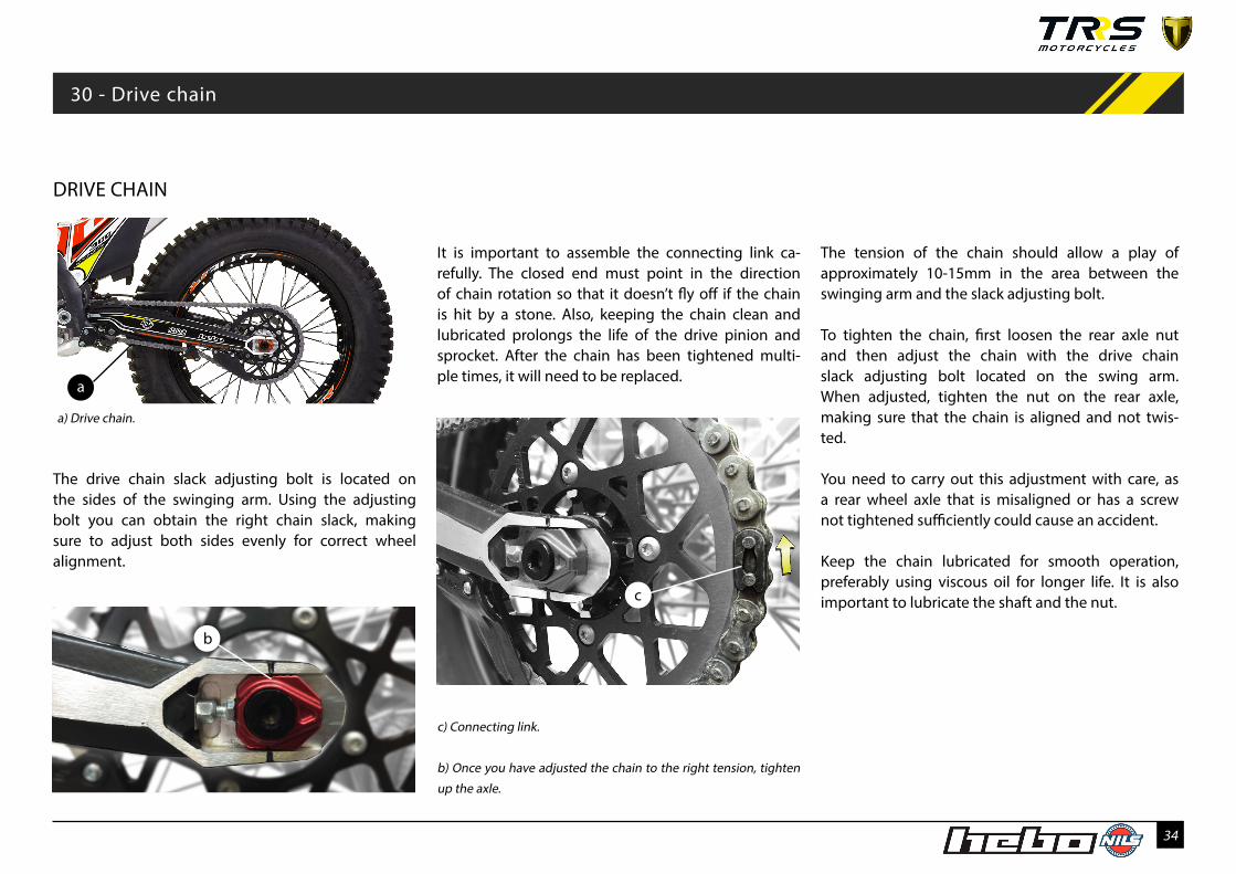
The tension of the chain should allow a play of approximately 10-15mm in the area between the swinging arm and the slack adjusting bolt.
To tighten the chain, first loosen the rear axle nut and then adjust the chain with the drive chain slack adjusting bolt located on the swing arm. When adjusted, tighten the nut on the rear axle, making sure that the chain is aligned and not twis-ted.
You need to carry out this adjustment with care, as a rear wheel axle that is misaligned or has a screw not tightened sufficiently could cause an accident.
Keep the chain lubricated for smooth operation, preferably using viscous oil for longer life. It is also important to lubricate the shaft and the nut.
DRIVE CHAIN
The drive chain slack adjusting bolt is located on the sides of the swinging arm. Using the adjusting bolt you can obtain the right chain slack, making sure to adjust both sides evenly for correct wheel alignment.
b) Once you have adjusted the chain to the right tension, tighten
up the axle.
c) Connecting link.
It is important to assemble the connecting link ca-refully. The closed end must point in the direction of chain rotation so that it doesn’t fly off if the chain is hit by a stone. Also, keeping the chain clean and lubricated prolongs the life of the drive pinion and sprocket. After the chain has been tightened multi-ple times, it will need to be replaced.
b
30 - Drive chain
a
a) Drive chain.
c

35
REED VALVE REAR BRAKE PEDAL SWING ARM
The inlet is through a reed valve and its condition has a significant influence on the performance of the engine. Whenever the carburettor is removed for cleaning, make sure the reed valves are not worn or broken and if so, replace the valve with a new one.
The screw for adjusting the brake pedal height in relation to the footrest is at the front of the lever.
At the rear there is a rod and lock nut that allow you to adjust the rear brake. It is very important that when it has been tightened there is 2mm clearance gap at the front to ensure smooth operation.
For correct maintenance of the rear suspension system and swing arm, it needs to be regularly dis-mantled for cleaning, checking and lubricating the internal bearings, plus adjusting and lubricating of the chain. Make sure that all the parts are in perfect condition and replace any worn components as re-quired.
c) Tensioning rod rear brake pedal; (d) Screw for height adjustment
of the brake pedal. For correct performance, you need to leave a
small clearance gap.
b) Important! The swing arm and the rear suspension need to be
regularly maintained.
a) Reed valve, located between the carburettor and the engine.
c
d2mm
31 - Reed valve 32 - Swing arm 33 - Rear brake pedal/ /
a b

36
FOOTRESTS EXHAUST MUFFLER CLUTCH PUMP TANK
The footrests are adjustable. By swapping the was-hers you can move them forward or backwards from 2.5mm to 5.00mm.This allows you to customise the motorcycle for greater efficiency and comfort, depending on your height or driving style.
The end of the muffler is detachable and allows you to easily replace the exhaust packing fibreglass in order to improve the performance of the motorcycle.
It is necessary to periodically check the oil level in the clutch pump tank. As is indicated on the lid, only mineral oil may be used, in order not to dama-ge the o-rings. We recommend NILS mineral oil. If you need to bleed the circuit, push down the lever repeatedly until you note it has been bled, and then fill with oil up to 2mm from the top.
a) The footrests are adjustable, so that you can move them forwards
or backwards by moving the washers 2.5mm to 5.00mm in either
direction.
b) ) Important! Remember that when the motorcycle is turned on,
the exhaust get very hot.
c) Clutch pump tank. Only mineral oil may be used, in order not to
damage the o-rings
34 - Footrest 35 - Exhaust muffler 36 - Tank clutch pump/ /
c
ab

37
The greater the care given to the motorcycle, the longer its service life will be and the better it will perform. Check all the elements listed below and keep them clean and lubricated for optimum ser-vice:
·LEVER ARTICULATIONS
·REAR BRAKE PEDAL
·GEAR LEVER
·FOOTRESTS AND SIDE STAND
·STARTER PEDAL
·THROTTLE
·STEERING COLUMN
·DRIVE CHAIN AND SWING ARM ARTICULATIONS
·CHAIN TENSIONER
MOTORCYCLE MAINTENANCE
TORQUE NmSwinging arm-Chassis 40-50Upper shock absorber fastener 40-50Lower shock absorber fastener 40-50Front wheel axle 40-50Connecting rods 40-50Handlebar 25-30Front mudguard bridge 7-10Muffler 10-15Rear wheel axle 40-50Front brake calliper fasteners 25-30Exhaust pipe fasteners 10-15Engine fasteners 30-35Rear brake master cylinder fasteners 7-10Spark plug 11Footrest screw 25-30
TORQUE NmIgnition fasteners 7-8Clutch fasteners 20-25Cylinder stud fasteners 25Reed valve fasteners 7-8Clutch spring fasteners 3-4Sump fasteners 7-8Water pump cover fastener 7-8Clutch cover fasteners 7-8Flywheel fasteners 40Ignition cover 7-8Sump drain plug 12Starter pedal bolt 12-13Tornillo del pedal de cambio 7-8Gear change pedal bolt 12-13
TIGHTENING TORQUES
37 - Motorcycle maintenance / 38 - Pares de Apriete

38
STORAGE
If it is necessary to store the motorcycle for a long period of time, the following operations are recommen-ded before storage:
•Clean the whole vehicle. •Lubricate or grease the components that need it. •Empty the fuel tank. (Take care with the fuel, which is inflammable and toxic) •Empty the sump, removing the old transmission oil and refilling with new oil (If the engine is cold, it is recommended to start up and leave running for a few minutes to warm up the oil and assist draining). •Cover the exhaust with a plastic bag, protecting it from the elements. •Any unpainted metal parts that could get rusty should be coated with oil. •Avoid the tyres touching the ground by placing a piece of cardboard or similar material under them. •Protect the motorcycle as much as possible form dust and dirt by covering it with a plastic or canvas sheet.
When putting the motorcycle back into service, first:
•Remove the plastic covers used. •Check the oil and lubrication of components. •Check the spark plug. •Adjust tyre pressure as recommended. •Fill the petrol tank.
39 - Storage

39
MAINTENANCE WORK
(Note: Note that cleaning your motorcycle prior to maintenance will aid you in detecting any faults and wear in the vehicle)
COMPONENT CHECK ADJUST REPLACE CLEAN LUBRICATERear shock absorber Annually Every 2 yearsFront fork suspension oil 60 hoursTransmission oil 2 hours 10 hoursBrake adjustment After every use Whenever necessarySpark plug 10 hours 30 hours 60 hours 15 hoursSwinging arm and connecting rods After every use If damaged After every use After each washTransmission chain After every use Whenever necessary If damaged After every use After each washThrottle cable and twist grip After every use Whenever necessary If damaged Whenever necessary After each washReed valve box 30 hours If damaged After every useCarburettor Whenever necessary If damaged After every useChassis If damaged After every useCarburettor jet Whenever necessary If damaged 10 hoursSteering bearing If damagedPiston bearing If damagedWheel bearing If damagedEngine bearings If damagedRear sprocket 30 hours First 5 hours If damaged After each washCylinder head and cylinder 60 hours AnnuallyBrakes After every use Whenever necessary If damagedBrake discs After every use First 5 hours If damaged Each two usesClutch plates If damagedClutch If damagedWheel-muffler clearance After every use If there are any fallExhaust 500 hoursMuffler exhaust packing fibreglass 100 hours
40 - Maintenance operations

40
COMPONENT CHECK ADJUST REPLACE CLEAN LUBRICATEAir Filter After every use If damaged After every use After each wash
Steering play After every use Whenever necessary
Brake hoses Whenever necessary Every 2 years After each wash
Coolant Whenever necessary Annually
General lubrication After every use After every use After each wash
Front and rear wheel If damaged After every use
Tyres After every use If damaged After every use
Brake fluid level Whenever necessary
Chain guide slipper If damaged
Starter pedal and gear change pedal If damaged After each wash
Brake master cylinder piston and
dust cover
If damaged
Brake piston and dust cover In the event of a fall
Piston and rings 60 hours Annually
Front and rear wheels 20 hours If damaged After every use
Fuel system After every use If damaged
Front suspension Whenever necessary If damaged
Exhaust seal If damaged
Nuts, bolts and other fasteners Whenever necessary If damaged
Petrol tube After every use Whenever necessary If damaged
Radiator tube and joints After every use Whenever necessary If damaged
Chassis protective adhesive elements If damaged
Sump protector If damaged

41
APPROVAL
All the components fitted in this vehicle comply with legal approval require-ments, including the identification marks on parts that require them. In particular, note that the following items are compulsory for using the motor-cycle on public roads and must be present on the vehicle in order to pass the Vehicle Technical Inspection Test:
- Registration plate holder - Speedometer - Lighting system and reflectors - Indicators - Horn - Rear view mirrors - Steering lock - Manufacturer’s identification plate - Air filter restrictor - Exhaust system with catalyser - Exhaust muffler - Carburettor jets - Side stand
IMPORTANT NOTE: The vehicle is also supplied with a RACING KIT contai-ning additional components. Bear in mind that the modifications provided by this kit are NOT covered by the vehicle approval.
41 - Approval

42
42 - Xtrack Kit
XTRACK KIT
This kit is a competition accessory only and is not manufacturated for, nor should it be used on public streets, roads or highways. The use of this kit should be limited to participation in sanctioned competition events upon a closed course.
43
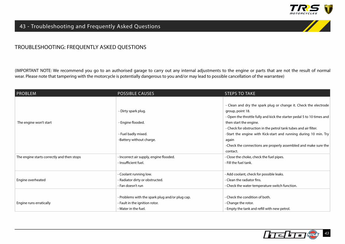
TROUBLESHOOTING: FREQUENTLY ASKED QUESTIONS
(IMPORTANT NOTE: We recommend you go to an authorised garage to carry out any internal adjustments to the engine or parts that are not the result of normal wear. Please note that tampering with the motorcycle is potentially dangerous to you and/or may lead to possible cancellation of the warrantee)
PROBLEM POSSIBLE CAUSES STEPS TO TAKE
The engine won’t start
- Dirty spark plug.
- Engine flooded.
- Fuel badly mixed.
-Battery without charge.
- Clean and dry the spark plug or change it. Check the electrode
group, point 18.
- Open the throttle fully and kick the starter pedal 5 to 10 times and
then start the engine.
- Check for obstruction in the petrol tank tubes and air filter.
-Start the engine with Kick-start and running during 10 min. Try
again
-Check the connections are properly assembled and make sure the
contact.
The engine starts correctly and then stops - Incorrect air supply, engine flooded.
- Insufficient fuel.
- Close the choke, check the fuel pipes.
- Fill the fuel tank.
Engine overheated
- Coolant running low.
- Radiator dirty or obstructed.
- Fan doesn’t run
- Add coolant, check for possible leaks.
- Clean the radiator fins.
- Check the water temperature switch function.
Engine runs erratically
- Problems with the spark plug and/or plug cap.
- Fault in the ignition rotor.
- Water in the fuel.
- Check the condition of both.
- Change the rotor.
- Empty the tank and refill with new petrol.
43 - Troubleshooting and Frequently Asked Questions

44
PROBLEM POSSIBLE CAUSES STEPS TO TAKE
Engine makes strange noises - Ignition problems.
- Overheated engine.
- Take the motorcycle to an authorised workshop.
- Stop the engine and check the state of the cooling and exhaust
systems.
Engine lacks power
- Intake problems.
- Exhaust system problems.
- Carburettor jets dirty.
- Damaged crankshaft bearings.
- Clutch slipping.
- Clean the fuel admission system and air filter.
- Check for leaks in the system and clean or replace the exhaust
packing fiberglass.
- Remove the carburettor and clean it.
- Replace the bearings.
- Check its adjustments. Take bike to a specialist garage.
Exhaust gives off white smoke
- Water is getting into the cylinder.
- Accelerator cable incorrectly adjusted.
- Change the cylinder head O-ring.
- Check accelerator adjustment.
Exhaust gives off brown smoke
- Insufficient air in the mixture.
- Main jet too high.
-Weak of seal
- Clean or change the air filter.
- Check the main jet
-Check or cange the seals of crank-shaft
Explosions in the exhaust
- Carbon deposits in the combustion chamber.
- Incorrect type of fuel.
- Spark plug in bad condition or wrong type.
- Exhaust system gaskets damaged.
- Clean the combustion chamber.
- Empty fuel tank and refill with correct type of fuel.
- Replace spark plug with correct type.
- Check condition of gaskets and replace if necessary.
Clutch not working correctly
- No play in the clutch lever.
- Clutch worn.
- Clutch springs broken or weak.
- Take bike to a specialist work shop.

45
PROBLEM POSSIBLE CAUSES STEPS TO TAKE
Gears engage badly - Problems in forks, gears or additional gearbox systems.
-Clutch not working correctly.
- Take bike to a specialist garage.
Abnormal noises
- Worn or badly adjusted chain
- Rear sprocket teeth worn.
- Chain needs lubrication.
- Badly aligned rear wheel.
- Lack of oil in the front fork.
- Problems with the front fork springs.
- Worn brake disc.
- Brake pads glazed or badly fitted.
-Exhaust system problems
-Shock absorber linkage wear or damage
- Adjust or change chain.
- Change rear sprocket.
- Apply appropriate chain lubricant.
- Take bike to a specialist garage.
- Add fork oil to the specified level.
- Replace front fork spring.
- Replace brake disc.
- Refit or replace pads.
- Check and replace gaskets and seals on the exhaust if is necessary
-Replace seals and bearing linkage and lubricate
Unstable ride
- Steering shaft nut too tight.
- Steering bearings worn or damaged.
- Bent steering shaft.
- Loosen the steering nut a little.
- Replace bearings.
- Take bike to a specialist garage.
Suspension too hard
- Too much oil in fork.
- Oil in fork too dense.
- Twisted or bent fork.
- Excessive tyre pressure.
- Rear shock absorber badly adjusted.
- Remove excess oil.
- Replace oil with correct density.
- Take bike to a specialist garage.
- Adjust tyre pressure.
- Adjust rear shock absorber.

46
PROBLEM POSSIBLE CAUSES STEPS TO TAKE
Suspension too soft
- Low oil level in fork.
- Oil with excessively low density.
- Rear shock absorber badly adjusted.
- Add the right oil to the specified level.
- Replace oil with correct density.
- Adjust rear shock absorber.
Handlebar vibration
- Worn tyre, swinging arm or bearings worn.
- Rim off-centre.
- Badly aligned wheel.
- Steering shafts, handlebar supports or fasteners with play.
- Take bike to a specialist garage.
- Take bike to a specialist garage.
- Take bike to a specialist garage.
- Tighten nuts and fasteners to specified torque.
Brakes working badly
- Pads worn
- Discs worn.
- Loss of brake fluid.
- Brake fluid in bad condition.
- Master cylinder piston worn.
- System incorrectly adjusted.
- Change pads
- Change discs.
- Check circuits. Replace leaking parts and top up fluid to the
correct level.
- Remove brake fluid circuit and replace with fresh fluid of the
right type.
- Replace master cylinder piston.
- Adjust brakes.
Fusing bulbs - Voltage regulator problems. - Check connections. Check voltage regulator and fuses.

47
44 - Recommended products
RECOMMENDED PRODUCTS
TRS Motorcycles recommends the use of NILS lubricants and maintenance products.

48
SAFETY/ATTENTIONThis symbol refers to points which, if ignored, could lead to physical danger for the user.
VEHICLE PROPER ASSEMBLY This symbol refers to points which, if ignored, could lead to some kind of damage to your motorcycle. Non-observance of these warnings could render your mo-torcycle warranty void.
DANGER DUE TO THE PRESENCE OF FLAMMABLE LIQUIDCarefully read the use and maintenance manual.
OBLIGATION TO USE PROTECTIVE CLOTHING AND ACCESSORIES The use of the vehicle is subordinate to the employment of clothing and accessories of protection (safety shoes).To use the vehicle it is mandatory to wear protective clothing and accessories.
PROTECTIVE GLOVES MUST BE USEDTo take the action described, the use of protective gloves is obligatory.
THE USE OF OPEN FIRES OR FORMS OF UNCONTROLLED SOURCES OF IGNITION IS PROHIBITED
SMOKING IS PROHIBITED
THE USE OF MOBILE PHONES IS PROHIBITED
DANGER DUE TO THE PRESENCE OF CORROSIVE SUBSTANCESThe liquids marked with this symbol are very corrosive: Handle with extreme care.
DANGER OF POISONING
Warning Symbols