
Sheltering the Self From the Storm: Self-Construal Abstractness and the Stability of Self-Esteem
Upload
khangminh22Category
view
2download
0
SARITOR Self PropelledOperator Instruction Manual
67000304- 201HAU - 09.2009
www.hardi.com.au
We congratulate you for choosing a HARDI plant protection product. The reliability and efficiency of this product depends upon your care. The first step is to carefully read and pay attention to this instruction book. It contains essential information for the efficient use and long life of this product.
As this instruction book covers all versions of the equipment, including all hydraulic boom versions, and all operating units, please pay attention to the paragraphs dealing precisely with your model.
This book is not designed to be a maintenance manual, its main purpose is to supply operational information and is to be read in conjunction with the “Spray Technique” book and any other manuals supplied with your sprayer.
Illustrations, technical information and data in this book are to the best of our belief correct at the time of printing. As it is HARDI Australia policy to improve our products, we reserve the right to make changes in design, features, accessories, specifications and maintenance instructions at any time and without notice.
HARDI Australia is without any obligation in relation to implements purchased before or after such changes.
HARDI Australia cannot undertake any responsibility for possible omissions or inaccuracies in this publication, although everything possible has been done to make it complete and correct.
As this instruction book covers more models and features or equipment, which are available in certain countries only, please pay attention to paragraphs dealing with precisely your model.
Published by HARDI Australia
Table of Contents
TOC. 1
Welcome Section 1
Welcome Message 2
Safety Section 2
Operator Safety1Introduction
Safety Alert Icons
Spray Drift
Mechanical Safety
Disposal of Chemical Containers
Chemical SafetySafety Equipment
Contaminated Clothing and Equipment
Australian Safety Standards
Chemical Information
Sprayer SafetyOperations
Service and Maintenance
Engine SafetyEngine Operation
Electrical SafetyDuring Sprayer Use
Operation of Electrical Components
Table of Contents
TOC. 2
DescriptionSection 3
Introduction 1General Info
View 1
View 2
Identification Plates
Roadworthiness
Chassis
Tanks
Further documents
In-Cab Controls and Features 5Electronic Control Units
AgLeader Insight Display
AgLeader DirectCommand Application
Saritor Section Control Grip
Right Side Controls
The Cantrak Engine Monitor
The Tri Display
The Tri display (Fuel Computer Modes)
The Quad Display
“A” Pillar Monitors/Gauges
Fuel Gauge
Digital Display
Ancillary EquipmentAuxiliary Power Outlet
Power Strip Outlets
Cabin Access Ladder
Night Spraying Lights
External Features
Main Tank Level Indicator
Safety Locker
Liquid SystemPump
Standard
Pump Drive
Control Box
Filters
2 inch and 3 inch Quick Couplers
Turbofill
Section valves
Table of Contents
TOC. 3
BoomBoom configurations
Boom Terminology
Boom Operators Manual
Boom Lock-In Mechanism
Boom Lift Accumulators
Norac Boom Auto Height Control
Sprayer Set-UpSection 4
Introduction 1Safety
Before operating the sprayer
Start Up
SARITOR 4800 AgLeader Setup Process 3Home Icon
Tool IconGrower Field Management
Create Grower
Input Season details
Input Field data
Input Operator data
Application SetupConfiguration
Vehicle
Implement
Controller
Product
Console Setup
GPS Guidance
Field NotesNotes Icon
Run Icon
Driver Accessory Adjustments 5Seat Suspension and Adjustment
Adjusting Armrest
Adjust Left Hand Armrest
Steering Column Tilt
Telescopic Steering Wheel
Radio/Cassette/CD
Table of Contents
TOC. 4
Sprayer Operation Section 5
Transporting 1General
Transporting Sprayer On Equipment Trailer
Towing
Track Width
Cabin Switches and Controls 2Vehicle Lighting Switches
Hazard Lights (Switch A)
Road Lights (Switch B)
Field Lights (Switch C) - 2 position switch
Work Lights (Switch D)
Turn Signals
Heater and Air Conditioner Controls
Storage Compartments
Cabin Ingress / EgressCab door lock and handle
Interior door handle
Emergency Exit
Seat Belts
Overhead ConsoleTurn Signals On
Low Fuel
Park Brake
Wait To Start
Transmission Temperature
Hydraulic Oil Temperature
Voltage
Check Transmission
Low Brake Pressure
Stop Engine
Windshield Wiper/Washer Switch
Cab Interior Light
Track Width Alteration - Leg Widening
Horn Button
Brake Pedal
Engine Speed Accelerator Pedal
Differential Lock Pedal
Ignition Switch
Console Panel Controls 9Transmission Speed and Direction Selector
Park Brake Control Knob
Table of Contents
TOC. 5
Product Pump ON/OFF Switch
Agitation ON/OFF Switch
Rinse Mode Selector Knob
AgLeader Insight Display
Saritor Section Grip Controller
Engine Speed Control handle
Common Operations 14Re-Fuelling
FTZ FORCE Boom controlUnfolding procedure
Folding procedure
Alternative boom width
Boom support wheels (Optional)
Adjustment of EFC operating unit 16To check the EFC operating unit
Liquid system 17Filling of water
Filling - Main Tank
Filling - Rinse Tank
Filling the clean water tank
Chemical induction by HARDI TurboFiller 19Turbo Filler Manifold Controls
Chemical container cleaning lever
TurboDeflector valve
TurboFiller suction valve
Turbo Filler - PH6 Scienco Pump
Agitation 21Variable Agitation control
Agitating Product Tank
Agitation before re-starting spraying
Table of Contents
TOC. 6
Filters 22Cyclone Filter
Return Valve
Position A
Position B
Position C
Multi Section Filter
Cleaning of filters
In-Field Spraying Operation 23Cleaning
IntroductionCleaning Guidelines
Rinse SystemSpray Mode
Tank Rinse ModeTank Empty ModeBoom Rinse Mode
Rinsing boom and fluid system
Rinsing the pump and spray lines
Rinsing the entire liquid system
De-contamination27Introduction
De-contamination agents
Decontamination
Tank rinsing
Using the drain valve
Maintenance Section 6
Introduction1Maintenance procedures
Before you get started
Spare parts
Lubrication
General info
Table of Contents
TOC. 7
Recommended lubricants 3BALL BEARINGS
SLIDE BEARINGS
OIL LUB. POINTS
“O” Ring Seals
Boom lubrication plan
Regular Interval Servicing 410 & 50 Hourly Servicing
- Nozzle filters
- Cyclone & MultiSection filtersTo service the Cyclone filter
To reassemble
Occasional Maintenance 6General info
Level Indicator Cord Replacement
Boom Tube Fittings
Shock Absorbers
Wear bushing replacement
Tyre & Wheel Fitting
Tyre Fitting
Wheel Fitting
EFC distribution valve service
Section valves removal procedure
To remove the EFC valves proceed as follows
Section valves service procedure
EFC Dis-assembly procedure
Cone check/renewal for Pressure Regulation
Boom adjustment and service
Changing bulbs (conventional work lights)
Off-season storage 11Off-season storage program
Preparing the sprayer for use after storage
Table of Contents
TOC. 8
Checks & Adjustments 12General info
Boom Adjustments
Level indicator adjustment
Front Brake Caliper - If Fitted
Removal
Reassembly
Bleeding The Brakes
Rear Differential Brake Caliper
Removal
Reassembly
Bleeding The Brakes
Steering Cylinder Phasing
Steering Toe-In Adjustment
Transmission Fluid Level
Rear Differential
Oil Level Check
Change Differential Oil
Rear Drop Box (48" Clearance Machines)
Oil Level Check
Change Drop Box Oil
Differential Output Shaft Nuts
Steering Cylinder Ball Joints
Changing Hydraulic Reservoir Oil
Hydraulic Oil filter
Check Hydraulic Hose and Fitting Condition
Check Hydraulic Cylinders
Air Compressor
Air Tank & Air compressor inspection
Raising and Lowering Hood
To Raise Hood
To Lower Hood
Heat Exchangers
Cooling Package Cleaning
Engine Coolant
Coolant Level Check
Add Coolant
13 Spline Cooling Coupler
Hydraulic System Maintenance 25General Information
Hydraulic System Cleanliness

Table of Contents
TOC. 9
Engine Maintenance 26General Information
Engine Oil and Filter
Fuel Filters
Primary Fuel Filter (Water Separator)
Secondary Fuel Filter
Drive Shaft Universal Joints
Front and Rear Axle Wear Pads
Front Axle King Pins
Front Wheel Hub Bearings
Engine Air Cleaner Filters (Oval)
Storage Tray / Recirculation Filter
Engine Data Link Connector
Maintenance Schedule 30
Fault Finding Section 7
Operational Problems 1Introduction
Prevention
Sensors 4Introduction
Sensor types
Pressure Transducer and Flow Sensor
Flow Sensor Inspection
Engine Trouble Shooting 5Engine Fault Codes
DirectCommand TroubleShooting Guide 17
Table of Contents
TOC. 10
Technical Specifications Section 8
General A75 Specifications 1Dimensions
Overall Dimensions
Weight
Conversion factors: Metric to Imperial units
Filter mesh specifications
Recommended Tyre Pressures
Recommended Lubricants & Filters
Recommended Coolant
Electrical connections for InSight 4
EFC 5EFC - Fluid PCB
Sprayer hydraulics 7Hydraulic Oil Recommendations
Typical Characteristics
AutoSteer Hose Connections 8
AgLeader System Connections Overview 9
Joystick Interface Connections 15
Tightening Hydraulic Fittings 16Tightening O-Ring Fittings
Tightening Flare Type Fittings
Torque Specifications 17
Spare part information 18HARDI spare parts pages
Materials and recycling 18Disposal of the sprayer

Table of Contents
TOC. 11
Warranty Section 9
Warranty policy & conditions 1
Risk Assessment Section 10
Entanglement 1
Cutting, Stabbing, Puncturing or Striking 1
Shearing 1
Crushing 2
Electrical 3
Explosion 3
Friction 3
Pressure 4
Slips, Trips & Falls 4
Ergonomics 5
Suffocation 5
High Temperature or Fire 5
Other Hazards 6
Condition / Stability 6
Environment 7
Abnormal Situations 7
Systems of Work 8

Table of Contents
TOC. 12
1 - Welcome
1. 1
SARITOROperator Instruction Manual67000304- 201HAU - 09.2009
HARDI Australia
Cross Keys Road CavanSouth Australia

1 - Welcome
1. 2
Welcome Message
To our valued customer:
Congratulations on your purchase and thank you for choosing the HARDI “SARITOR” Self Propelled Sprayer. This “Operator Instruction Manual” covers the Safety, Operation and Maintenance procedures for the 4800 Litre model, and is to be read in conjunction with the “Boom”and “Spray Controller” manuals supplied with your sprayer.
This book is not designed to be a maintenance manual, its main purpose is to supply operational information and is to be read in conjunction with the “Spray Technique” book and any other manuals supplied with your sprayer.
± WARNING: Any persons intending to use this equipment, or any of it’s parts or systems must read and understand these publications, in addition to any related material, paying close attention to the safety warnings prior to operation.
In addition, all operators must be of a suitable age, have undergone appropriate training and hold correct licenses where applicable, as required by state and federal law. The safety sections and warnings in this publication and all related material must be thoroughly read and understood before attempting to operate this equipment.
€ DANGER: Failure to comply with the above may result in personal injury, death or damage to the equipment,property, crops or the environment.
μ Attention: The technical data contained herein is to the best knowledge of HARDI Australia Pty Ltd correct at the time of publishing. HARDI Australia Pty Ltd reserves the right to make changes in design, features, accessories, specifications and instructions at any time without prior notice and is without obligation in relation to products purchased before or after such changes and assumes no responsibility for any errors, inaccuracies or omissions.
Please visit our web site at: www.hardi.com.au for more information about research and development, our product range, spraying techniques and crop protection. For sales, service and spare parts information contact your local HARDI dealer.
Copyright: Design, text, illustrations and layout in this manual are produced and published by HARDI Australia Pty Ltd and are protected by copyright law. Copyright © June 2009 HARDI Australia Pty Ltd.
2 - Safety
2. 1
Operator Safety
IntroductionThis manual contains safety information which could prevent crop damage, personal injury or death. It is compulsory that all operators intending to use this equipment read and understand this manual and related literature. Safety information in each section must be read carefully, and if any doubt contact your HARDI dealer for further information.
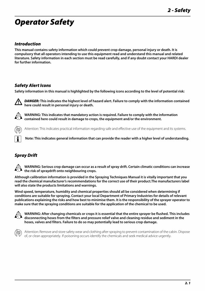
Safety Alert IconsSafety information in this manual is highlighted by the following icons according to the level of potential risk:
€ DANGER: This indicates the highest level of hazard alert. Failure to comply with the information contained here could result in personal injury or death.
± WARNING: This indicates that mandatory action is required. Failure to comply with the information contained here could result in damage to crops, the equipment and/or the environment.
μ Attention: This indicates practical information regarding safe and effective use of the equipment and its systems.
÷ Note: This indicates general information that can provide the reader with a higher level of understanding.
Spray Drift
± WARNING: Serious crop damage can occur as a result of spray drift. Certain climatic conditions can increase the risk of spraydrift onto neighbouring crops.
Although calibration information is provided in the Spraying Techniques Manual it is vitally important that you read the chemical manufacturer’s recommendations for the correct use of their product.The manufacturers label will also state the products limitations and warnings.
Wind speed, temperature, humidity and chemical properties should all be considered when determining if conditions are suitable for spraying. Contact your local Department of Primary Industries for details of relevant publications explaining the risks and how best to minimise them. It is the responsibility of the sprayer operator to make sure that the spraying conditions are suitable for the application of the chemical to be used.
± WARNING: After changing chemicals or crops it is essential that the entire sprayer be flushed. This includes disconnecting hoses from the filters and pressure relief valve and cleaning residue and sediment in the hoses, valves and filters. Failure to do so may potentially lead to serious crop damage.
μ Attention: Remove and store safety wear and clothing after spraying to prevent contamination of the cabin. Dispose of, or clean appropriately. If poisoning occurs identify the chemicals and seek medical advice urgently.
2 - Safety
2. 2
Mechanical Safety
€ DANGER: Never operate any part of the equipment if any of it’s components or safety shields are damaged. Never service or repair the equipment while it’s operating and replace all safety devices and shields after service procedures.
€ DANGER: Always de-pressurise the equipment and disconnect the power after each use and before servicing. make sure all hydraulics are in the recommended position. Do not walk under any part of the sprayer or the boom unless it is properly secured.
€ DANGER: Never attempt to enter a tank or allow some one else to do so for any reason.
€ DANGER: No persons are allowed in the operations area of the sprayer. Keep unauthorised persons and children away from the equipment at all times. Do not allow any one to ride on the equipment while it is operating.
€ DANGER: Do not exceed the max. recommended RPM for any part of this equipment.
€ DANGER: Local laws may require operators to be certified before using spray equipment and some chemicals. Consult your local authorities before commencing operation.
± WARNING: When using an arc welder disconnect any power leads to the sprayer prior to welding and remove any flammable or explosive material from the area.
± WARNING: Although every effort has been made to include as much safety information as practical, it is impossible to anticipate every hazardous scenario. It is therefore the responsibility of the operator to exercise safe operating practices.
± WARNING: This equipment is intended for the application of crop protection chemicals and liquid fertilisers only. HARDI Australia does not authorise or endorse it’s use for any other purpose.
μ Attention: The drivers seat is the only intended working place during operation. One passenger may ride in the ‘dicky seat’ under supervision of the driver.
Disposal of Chemical ContainersPlease note that in addition to normal safe operating practices, and in the interests of a cleaner and safer environment HARDI Australia supports the “drumMUSTER” chemical drum recycling program:
• Rinse empty drums immediately after use.
• Remove lids to allow drums to dry completely.
• Recycle with “drumMUSTER”
± WARNING: Used chemical containers pose a severe threat to persons, animals and the environment. Before disposal, contact the Environmental Protection Authority or the Department of Primary Industries in your area for more information.
2 - Safety
2. 3
Chemical Safety
€ DANGER: Avoid risk of chemical contamination. Always read chemical labels and pressure test the equipment with clean water prior to filling. Never eat, drink or smoke when spraying or working with contaminated equipment.
€ DANGER: Never drink water from any of the sprayer's tanks.
€ DANGER: Never assume that the contents of the ‘clean water’tank is safe to drink
€ DANGER: Chemical contamination poses a serious health risk. It is the responsibility of the operator to make sure safe work practices are observed and correct safety equipment and clothing is used.
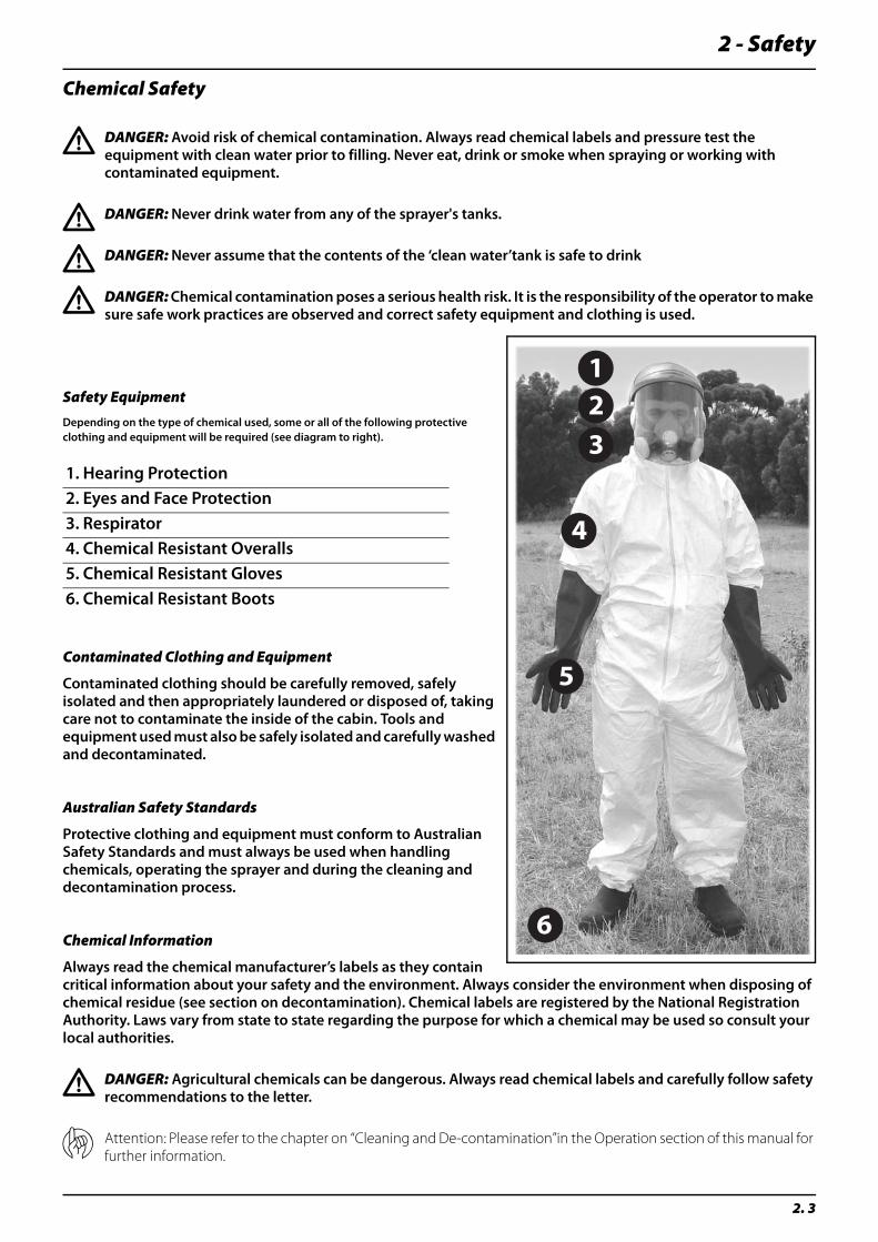
Safety EquipmentDepending on the type of chemical used, some or all of the following protective clothing and equipment will be required (see diagram to right).
Contaminated Clothing and Equipment
Contaminated clothing should be carefully removed, safely isolated and then appropriately laundered or disposed of, taking care not to contaminate the inside of the cabin. Tools and equipment used must also be safely isolated and carefully washed and decontaminated.
Australian Safety Standards
Protective clothing and equipment must conform to Australian Safety Standards and must always be used when handling chemicals, operating the sprayer and during the cleaning and decontamination process.
Chemical Information
Always read the chemical manufacturer’s labels as they contain critical information about your safety and the environment. Always consider the environment when disposing of chemical residue (see section on decontamination). Chemical labels are registered by the National Registration Authority. Laws vary from state to state regarding the purpose for which a chemical may be used so consult your local authorities.
€ DANGER: Agricultural chemicals can be dangerous. Always read chemical labels and carefully follow safety recommendations to the letter.
μ Attention: Please refer to the chapter on “Cleaning and De-contamination”in the Operation section of this manual for further information.
1. Hearing Protection2. Eyes and Face Protection3. Respirator4. Chemical Resistant Overalls5. Chemical Resistant Gloves6. Chemical Resistant Boots
123
4
5
6
2 - Safety
2. 4
Sprayer Safety
Operations
For your safety:
€ DANGER: Secure the discharge lines before starting the pump. An insecure line may whip causing personal injury and/or property damage.
€ DANGER: Never operate this vehicle on public roads at high speeds with product in the product tank. Driving at high speeds with product in the tank will overload the tyres, causing tyre failure leading to loss of control. Losing control will result in death or serious injury.
€ DANGER: Do not use these pumps for pumping water or other liquids for human or animal consumption.
± WARNING: Do not pump at pressures higher than the maximum recommended pressure.
± WARNING: Empty all product from the product tank before leaving the field. Do not attempt to drive this vehicle at high speeds with product in the tank. Fill product tank once you have reached the area of operation.
± WARNING: Turn on the hazard lights and the road lights before entering onto a public road. Keep them on while travelling on the road.
± WARNING: Check hoses for wear or worn condition before each use. Make certain that all connections are tightly secured.
μ Attention: Periodically inspect the product pump and the system components. Perform routine maintenance as required.
μ Attention: Clean off all hazard and road lights when going from the field to the road.
Service and Maintenance
For your safety:
€ DANGER: Release all pressure within the system before servicing any component.
€ DANGER: Drain all fluids from the system before servicing any component. Flush with water.
± WARNING: Disconnect power before servicing.
± WARNING: Use only pipe, hose and fittings rated for the maximum psi rating of the pump.
2 - Safety
2. 5
Engine Safety
Engine Operation
For Your Safety:
€ DANGER: If an engine has been operating and the coolant is hot, allow the engine to cool before you slowly loosen the filler cap and relieve the pressure from the cooling system.
€ DANGER: Relieve all pressure in the air, oil and cooling systems before any lines, fittings or related items are removed or disconnected. Be alert for possible pressure when disconnecting any device from a system that utilizes pressure. Do not check for pressure leaks with your hand. High pressure oil or fuel can cause personal injury.
€ DANGER: To prevent suffocation and frostbite, wear protective clothing and ONLY disconnect liquid refrigerant (freon) lines in a well ventilated area. To protect the environment, liquid refrigerant systems must be properly emptied and filled using equipment that prevents the release of refrigerant gas (fluorocarbons) into the atmosphere. Federal law requires capture and recycling of refrigerant gases.
€ DANGER: Corrosion inhibitor contains alkali. Do not get the substance in your eyes. Avoid prolonged or repeated contact with skin. Do not swallow internally. In case of contact, immediately wash skin with soap and water. In case of contact, immediately flood eyes with large amounts of water for a minimum of 15 minutes. IMMEDIATELY CALL A PHYSICIAN - KEEP OUT OF REACH OF CHILDREN.
€ DANGER: Naphtha and Methyl Ethyl Ketone (MEK) are flammable materials and must be used with caution. Follow the manufacturer’s instructions to provide complete safety when using these materials. KEEP OUT OF REACH OF CHILDREN.
± WARNING: Improper practices or carelessness can cause burns, cuts, mutilation, asphyxiation or other bodily injury or death.
± WARNING: Disconnect the battery (negative [-] cable first, then the positive [+] cable) and discharge any capacitors before beginning any repair work. Put a “Do Not Operate” tag in the operator’s compartment or on the controls.
± WARNING: Use ONLY the proper engine barring techniques for manually rotating the engine.
2 - Safety
2. 6
Electrical Safety
During Sprayer Use
Beware of overhead power lines!
€ DANGER: Operating agricultural machinery near power-lines presents a potentially fatal hazard. It is the responsibility of the operator to make sure that minimum safe clearances are strictly observed, in particular when transporting the implement,spraying, raising, tilting or lowering the boom. Also be aware that during hot or windy weather sagging or swaying of power lines can reduce safe working clearances.
Operation of Electrical Components
For Your Safety:
€ DANGER: Never operate this machine with a damaged electrical cord. Disconnect from electrical supply if machine is not working properly or cord is damaged.
€ DANGER: Do not attempt to bypass a fuse. If a fuse is no longer serviceable, a shock or short hazard may exist.
€ DANGER: All electrical components generate heat. To avoid serious burns, never touch internal components immediately after use.
€ DANGER: Disassembly or attempted repairs, if accomplished incorrectly can create electrical shock and/or short hazards. Only qualified personnel should perform repair service.
€ DANGER: Some electrical components can store energy after the unit is shut down. Be sure to completely de-energize all electrical components, discharging all stored energy before beginning any service work.
± WARNING: Never replace original fuses/breakers with a higher amperage fuses/breakers.
± WARNING: Never attempt to replace electrical wires and cables with smaller gauge wire and cable.
μ Attention: Do not attempt to operate this machine without the appropriate fuses and breakers in place.
μ Attention: Inspect all components for damage after any electrical problem.There are additional hazards associated with the service and maintenance of electrical components
÷ Note: This machine and its systems are designed to operate off of a 12 volt DC power supply only.
DANGER
BEWARE OF OVERHEAD ELECTRICAL LINES
ELECTROCUTION
SERIOUS INJURY OR DEATH
3 - Description
3. 1
Description
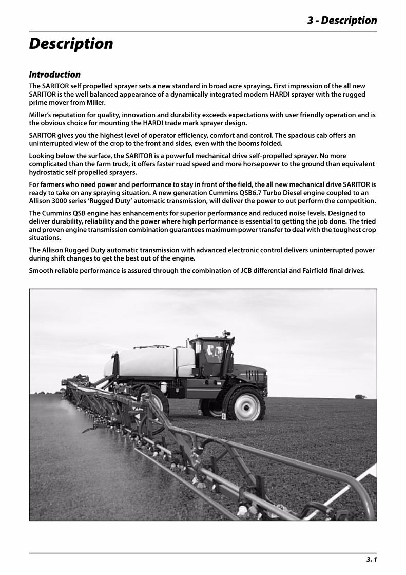
IntroductionThe SARITOR self propelled sprayer sets a new standard in broad acre spraying. First impression of the all new SARITOR is the well balanced appearance of a dynamically integrated modern HARDI sprayer with the rugged prime mover from Miller.
Miller’s reputation for quality, innovation and durability exceeds expectations with user friendly operation and is the obvious choice for mounting the HARDI trade mark sprayer design.
SARITOR gives you the highest level of operator efficiency, comfort and control. The spacious cab offers an uninterrupted view of the crop to the front and sides, even with the booms folded.
Looking below the surface, the SARITOR is a powerful mechanical drive self-propelled sprayer. No more complicated than the farm truck, it offers faster road speed and more horsepower to the ground than equivalent hydrostatic self propelled sprayers.
For farmers who need power and performance to stay in front of the field, the all new mechanical drive SARITOR is ready to take on any spraying situation. A new generation Cummins QSB6.7 Turbo Diesel engine coupled to an Allison 3000 series ‘Rugged Duty’ automatic transmission, will deliver the power to out perform the competition.
The Cummins QSB engine has enhancements for superior performance and reduced noise levels. Designed to deliver durability, reliability and the power where high performance is essential to getting the job done. The tried and proven engine transmission combination guarantees maximum power transfer to deal with the toughest crop situations.
The Allison Rugged Duty automatic transmission with advanced electronic control delivers uninterrupted power during shift changes to get the best out of the engine.
Smooth reliable performance is assured through the combination of JCB differential and Fairfield final drives.
3 - Description
3. 2
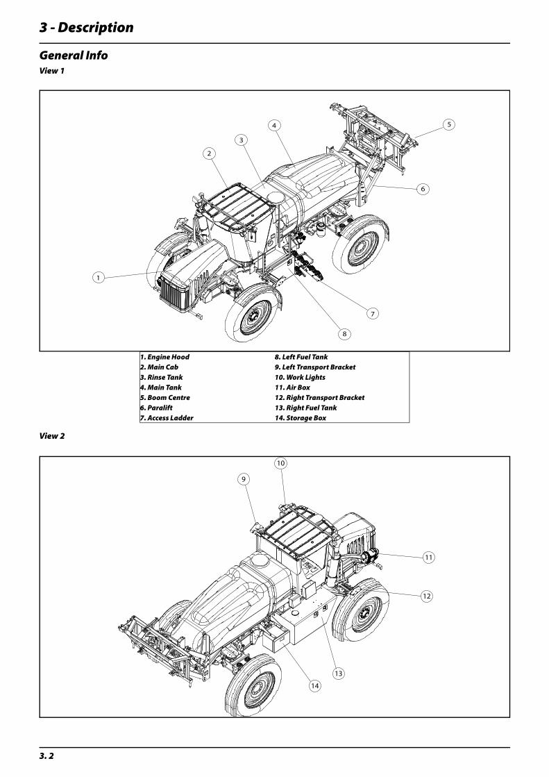
General InfoView 1
View 2
1. Engine Hood 8. Left Fuel Tank2. Main Cab 9. Left Transport Bracket3. Rinse Tank 10. Work Lights4. Main Tank 11. Air Box5. Boom Centre 12. Right Transport Bracket6. Paralift 13. Right Fuel Tank7. Access Ladder 14. Storage Box
1
2
3
4 5
6
7
8
11
12
13
14
9
10
3 - Description
3. 3
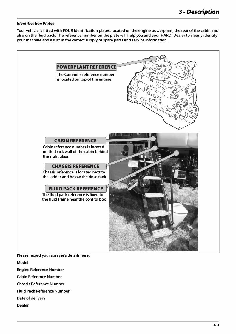
Identification Plates
Your vehicle is fitted with FOUR identification plates, located on the engine powerplant, the rear of the cabin and also on the fluid pack. The reference number on the plate will help you and your HARDI Dealer to clearly identify your machine and assist in the correct supply of spare parts and service information.
Please record your sprayer’s details here:
Model
Engine Reference Number
Cabin Reference Number
Chassis Reference Number
Fluid Pack Reference Number
Date of delivery
Dealer
POWERPLANT REFERENCE
CABIN REFERENCE
CHASSIS REFERENCE
FLUID PACK REFERENCE
The Cummins reference numberis located on top of the engine
Chassis reference is located next tothe ladder and below the rinse tank
The fluid pack reference is fixed tothe fluid frame near the control box
Cabin reference number is locatedon the back wall of the cabin behindthe sight glass
3 - Description
3. 4
Roadworthiness
When driving on public roads and other areas where the highway code applies, or areas where there are special rules and regulations for marking and lights on implements, you should observe these and equip implements accordingly.
Chassis
Strong and compact chassis with chemical and weather resistant powder coat finish. Screws, nuts and bolts (etc) are Stainless Steel or DELTA-MAGNI treated to resist corrosion.
Tanks
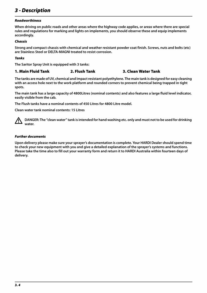
The Saritor Spray Unit is equipped with 3 tanks:
The tanks are made of UV, chemical and Impact resistant polyethylene. The main tank is designed for easy cleaning with an access hole next to the work platform and rounded corners to prevent chemical being trapped in tight spots.
The main tank has a large capacity of 4800Litres (nominal contents) and also features a large fluid level indicator, easily visible from the cab.
The Flush tanks have a nominal contents of 450 Litres for 4800 Litre model.
Clean water tank nominal contents: 15 Litres
€ DANGER: The “clean water” tank is intended for hand washing etc. only and must not to be used for drinking water.
Further documents
Upon delivery please make sure your sprayer’s documentation is complete. Your HARDI Dealer should spend time to check your new equipment with you and give a detailed explanation of the sprayer’s systems and functions. Please take the time also to fill out your warranty form and return it to HARDI Australia within fourteen days of delivery.
1. Main Fluid Tank 2. Flush Tank 3. Clean Water Tank
3 - Description
3. 5
In-Cab Controls and Features
Electronic Control Units
AgLeader Insight Display
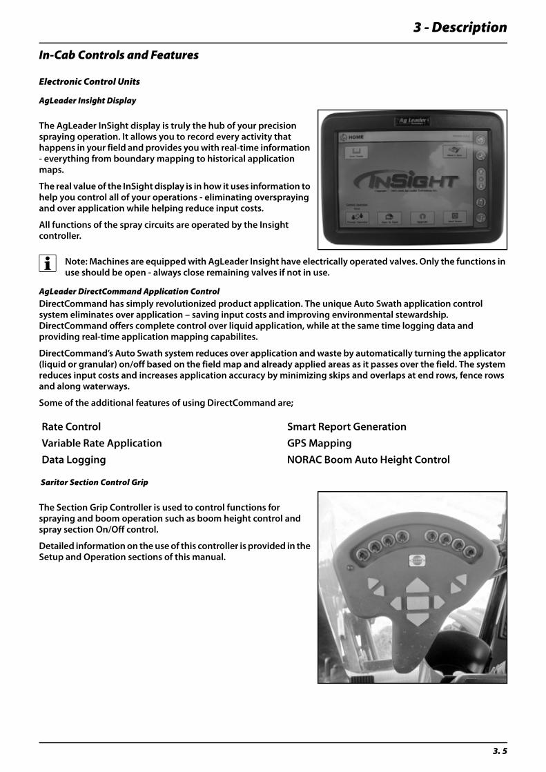
The AgLeader InSight display is truly the hub of your precision spraying operation. It allows you to record every activity that happens in your field and provides you with real-time information - everything from boundary mapping to historical application maps.
The real value of the InSight display is in how it uses information to help you control all of your operations - eliminating overspraying and over application while helping reduce input costs.
All functions of the spray circuits are operated by the Insight controller.
÷ Note: Machines are equipped with AgLeader Insight have electrically operated valves. Only the functions in use should be open - always close remaining valves if not in use.
AgLeader DirectCommand Application ControlDirectCommand has simply revolutionized product application. The unique Auto Swath application control system eliminates over application – saving input costs and improving environmental stewardship. DirectCommand offers complete control over liquid application, while at the same time logging data and providing real-time application mapping capabilites.
DirectCommand’s Auto Swath system reduces over application and waste by automatically turning the applicator (liquid or granular) on/off based on the field map and already applied areas as it passes over the field. The system reduces input costs and increases application accuracy by minimizing skips and overlaps at end rows, fence rows and along waterways.
Some of the additional features of using DirectCommand are;
Saritor Section Control Grip
The Section Grip Controller is used to control functions for spraying and boom operation such as boom height control and spray section On/Off control.
Detailed information on the use of this controller is provided in the Setup and Operation sections of this manual.
Rate Control Smart Report GenerationVariable Rate Application GPS MappingData Logging NORAC Boom Auto Height Control
3 - Description
3. 6
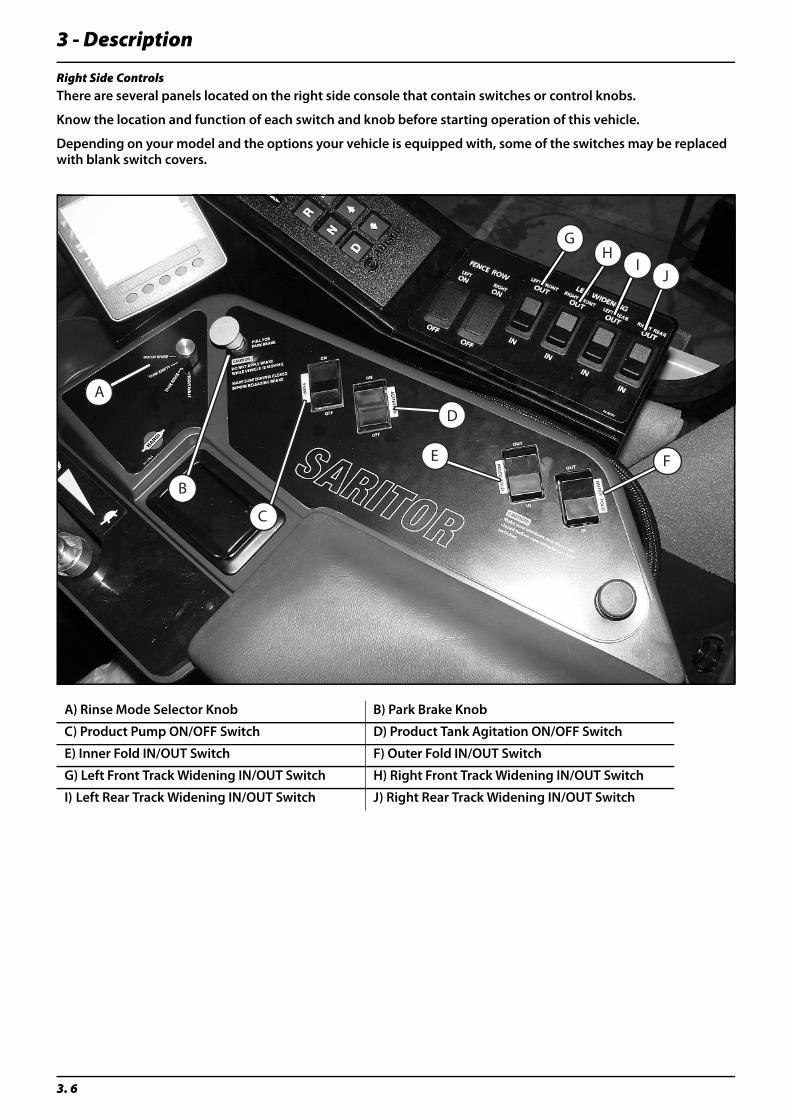
Right Side ControlsThere are several panels located on the right side console that contain switches or control knobs.
Know the location and function of each switch and knob before starting operation of this vehicle.
Depending on your model and the options your vehicle is equipped with, some of the switches may be replaced with blank switch covers.
A) Rinse Mode Selector Knob B) Park Brake Knob
C) Product Pump ON/OFF Switch D) Product Tank Agitation ON/OFF Switch
E) Inner Fold IN/OUT Switch F) Outer Fold IN/OUT Switch
G) Left Front Track Widening IN/OUT Switch H) Right Front Track Widening IN/OUT Switch
I) Left Rear Track Widening IN/OUT Switch J) Right Rear Track Widening IN/OUT Switch
A
B
C
D
E F
GH
IJ
3 - Description
3. 7
The Cantrak Engine Monitor
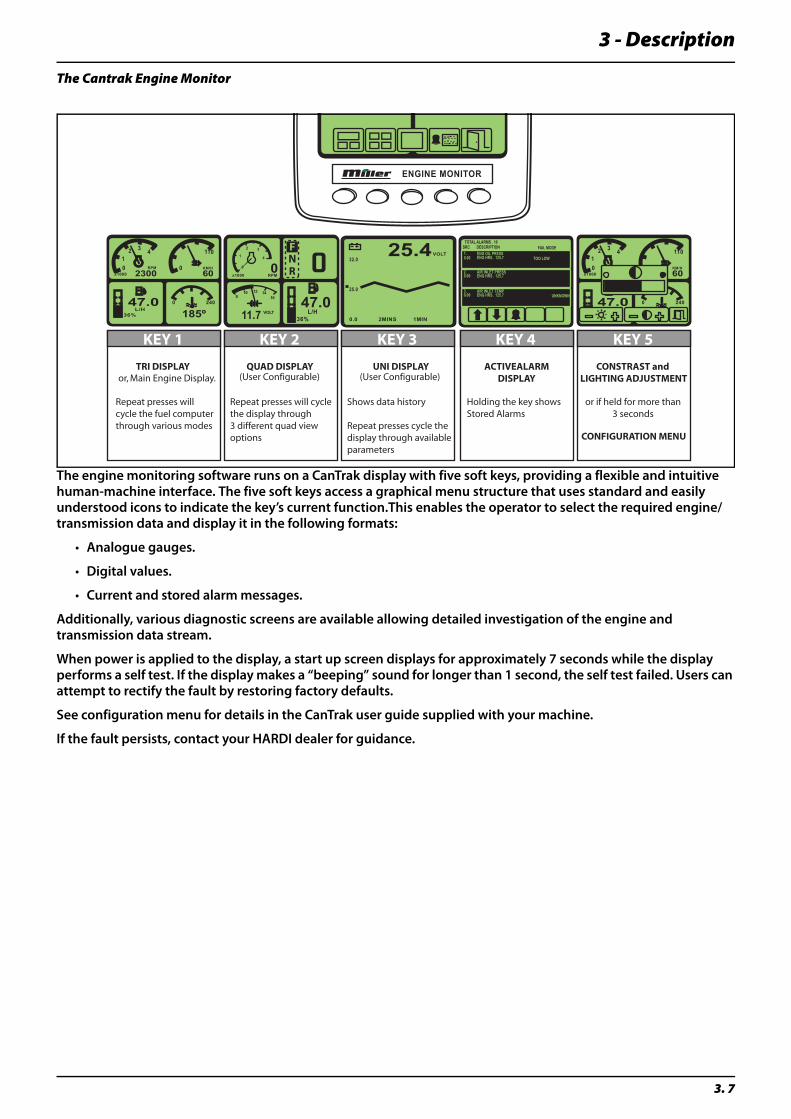
The engine monitoring software runs on a CanTrak display with five soft keys, providing a flexible and intuitive human-machine interface. The five soft keys access a graphical menu structure that uses standard and easily understood icons to indicate the key’s current function.This enables the operator to select the required engine/transmission data and display it in the following formats:
• Analogue gauges.
• Digital values.
• Current and stored alarm messages.
Additionally, various diagnostic screens are available allowing detailed investigation of the engine and transmission data stream.
When power is applied to the display, a start up screen displays for approximately 7 seconds while the display performs a self test. If the display makes a “beeping” sound for longer than 1 second, the self test failed. Users can attempt to rectify the fault by restoring factory defaults.
See configuration menu for details in the CanTrak user guide supplied with your machine.
If the fault persists, contact your HARDI dealer for guidance.
47.0L/H
36%
10
2 3 4
RPM
x1000 23000
110
KM/H
60
2400
185º47.0
10
2 3 4
RPM
x1000 23000
110
KM/H
60
2400
ENGINE MONITOR
47.0L/H
36%
0
1
2 3
4
RPMx10000
11.7 VOLT
810 12 14
16
RN
VOLT
0.0 2MINS 1MIN
25.0
32.025.4 FAIL MODE
TOO LOW
UNKNOWN
ENG OIL PRESSENG HRS . 125.7
AIR INLET PRESSENG HRS . 125.7
AIR INLET TEMPENG HRS . 125.7
1.
2.
3.
0.00
0.00
0.00
TOTAL ALARMS . 10SRC DESCRIPTION
KEY 1 KEY 2 KEY 3 KEY 4 KEY 5
TRI DISPLAY QUAD DISPLAY UNI DISPLAY ACTIVEALARMDISPLAY
CONSTRAST and LIGHTING ADJUSTMENT
CONFIGURATION MENU
Repeat presses willcycle the fuel computerthrough various modes
Repeat presses will cyclethe display through3 different quad viewoptions
Shows data history
Repeat presses cycle the display through availableparameters
Holding the key showsStored Alarms
or if held for more than3 seconds
or, Main Engine Display. (User Configurable) (User Configurable)
3 - Description
3. 8
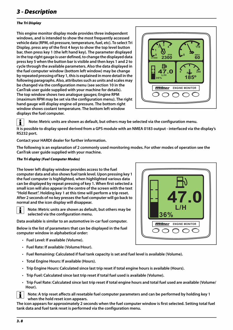
The Tri Display
This engine monitor display mode provides three independent windows, and is intended to show the most frequently accessed vehicle data (RPM, oil pressure, temperature, fuel, etc). To select Tri Display, press any of the first 4 keys to show the top level button bar, then press key 1 (the left hand key). The parameter displayed in the top right gauge is user defined, to change the displayed data press key 5 when the button bar is visible and then keys 1 and 2 to cycle through the available parameters. Also the data displayed in the fuel computer window (bottom left window) may be change by repeated pressing of key 1, this is explained in more detail in the following paragraphs. Also, attributes such as units and scales may be changed via the configuration menu (see section 10 in the CanTrak user guide supplied with your machine for details).The top window shows two analogue gauges; Engine RPM (maximum RPM may be set via the configuration menu). The right hand gauge will display engine oil pressure. The bottom right window shows coolant temperature. The bottom left window displays the fuel computer.
÷ Note: Metric units are shown as default, but others may be selected via the configuration menu.
It is possible to display speed derived from a GPS module with an NMEA 0183 output - interfaced via the display’s RS232 port.
Contact your HARDI dealer for further information.
The following is an explanation of 2 commonly used monitoring modes. For other modes of operation see the CanTrak user guide supplied with your machine.
The Tri display (Fuel Computer Modes)
The lower left display window provides access to the fuel computer data and also shows fuel tank level. Upon pressing key 1 the fuel computer is highlighted, when highlighted various data can be displayed by repeat pressing of key 1. When first selected a small icon will also appear in the centre of the screen with the text “Hold Reset”. Holding key 1 at this time will perform a trip reset. After 2 seconds of no key presses the fuel computer will go back to normal and the icon display will disappear.
÷ Note: Metric units are shown as default, but others may be selected via the configuration menu.
Data available is similar to an automotive in-car fuel computer.
Below is the list of parameters that can be displayed in the fuel computer window in alphabetical order:
• Fuel Level: If available (Volume).
• Fuel Rate: If available (Volume/Hour).
• Fuel Remaining: Calculated if fuel tank capacity is set and fuel level is available (Volume).
• Total Engine Hours: If available (Hours).
• Trip Engine Hours: Calculated since last trip reset if total engine hours is available (Hours).
• Trip Fuel: Calculated since last trip reset if total fuel used is available (Volume).
• Trip Fuel Rate: Calculated since last trip reset if total engine hours and total fuel used are available (Volume/Hour).
÷ Note: A trip reset affects all resetable fuel computer parameters and can be performed by holding key 1 when the hold reset icon appears.
The icon appears for approximately 2 seconds when the fuel computer window is first selected. Setting total fuel tank data and fuel tank reset is performed via the configuration menu.
ENGINE MONITOR
47.0L/H
36%
10
2 3 4
RPM
x1000 23000
110
KM/H
60
2400
185º
ENGINE MONITOR
47.0L/H
36%
3 - Description
3. 9
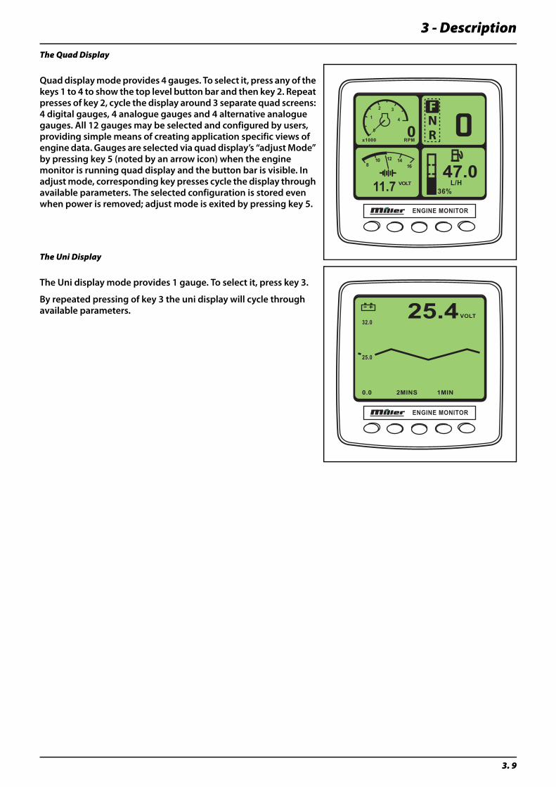
The Quad Display
Quad display mode provides 4 gauges. To select it, press any of the keys 1 to 4 to show the top level button bar and then key 2. Repeat presses of key 2, cycle the display around 3 separate quad screens: 4 digital gauges, 4 analogue gauges and 4 alternative analogue gauges. All 12 gauges may be selected and configured by users, providing simple means of creating application specific views of engine data. Gauges are selected via quad display’s “adjust Mode” by pressing key 5 (noted by an arrow icon) when the engine monitor is running quad display and the button bar is visible. In adjust mode, corresponding key presses cycle the display through available parameters. The selected configuration is stored even when power is removed; adjust mode is exited by pressing key 5.
The Uni Display
The Uni display mode provides 1 gauge. To select it, press key 3.
By repeated pressing of key 3 the uni display will cycle through available parameters.
ENGINE MONITOR
47.0L/H
36%
0
1
2 3
4
RPMx10000
11.7 VOLT
810 12 14
16
RN
ENGINE MONITOR
VOLT
0.0 2MINS 1MIN
25.0
32.025.4
3 - Description
3. 10
“A” Pillar Monitors/Gauges
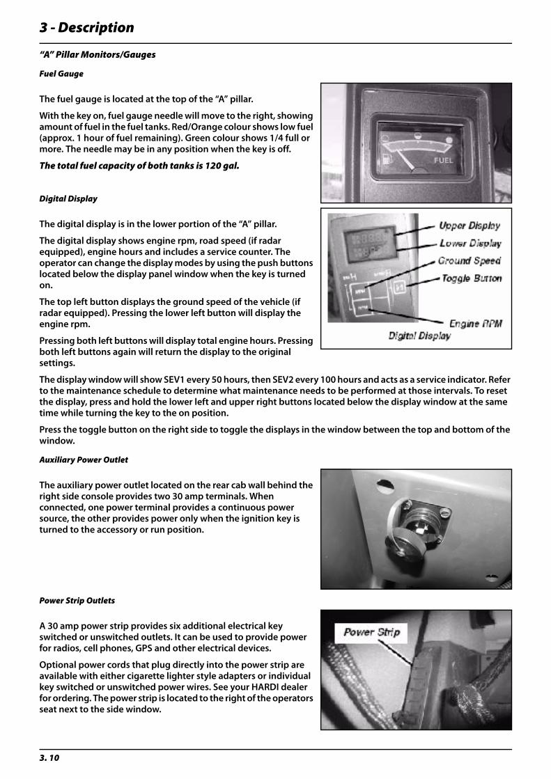
Fuel Gauge
The fuel gauge is located at the top of the “A” pillar.
With the key on, fuel gauge needle will move to the right, showing amount of fuel in the fuel tanks. Red/Orange colour shows low fuel (approx. 1 hour of fuel remaining). Green colour shows 1/4 full or more. The needle may be in any position when the key is off.
The total fuel capacity of both tanks is 120 gal.
Digital Display
The digital display is in the lower portion of the “A” pillar.
The digital display shows engine rpm, road speed (if radar equipped), engine hours and includes a service counter. The operator can change the display modes by using the push buttons located below the display panel window when the key is turned on.
The top left button displays the ground speed of the vehicle (if radar equipped). Pressing the lower left button will display the engine rpm.
Pressing both left buttons will display total engine hours. Pressing both left buttons again will return the display to the original settings.
The display window will show SEV1 every 50 hours, then SEV2 every 100 hours and acts as a service indicator. Refer to the maintenance schedule to determine what maintenance needs to be performed at those intervals. To reset the display, press and hold the lower left and upper right buttons located below the display window at the same time while turning the key to the on position.
Press the toggle button on the right side to toggle the displays in the window between the top and bottom of the window.
Auxiliary Power Outlet
The auxiliary power outlet located on the rear cab wall behind the right side console provides two 30 amp terminals. When connected, one power terminal provides a continuous power source, the other provides power only when the ignition key is turned to the accessory or run position.
Power Strip Outlets
A 30 amp power strip provides six additional electrical key switched or unswitched outlets. It can be used to provide power for radios, cell phones, GPS and other electrical devices.
Optional power cords that plug directly into the power strip are available with either cigarette lighter style adapters or individual key switched or unswitched power wires. See your HARDI dealer for ordering. The power strip is located to the right of the operators seat next to the side window.
3 - Description
3. 11
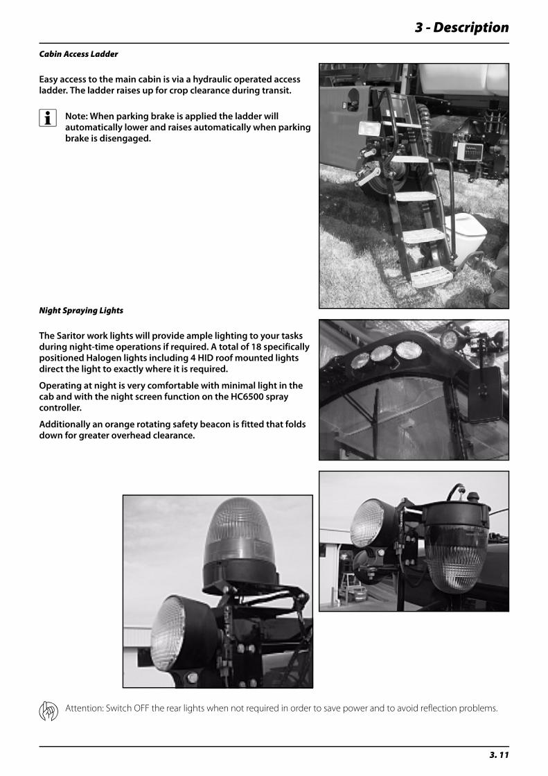
Cabin Access Ladder
Easy access to the main cabin is via a hydraulic operated access ladder. The ladder raises up for crop clearance during transit.
÷ Note: When parking brake is applied the ladder will automatically lower and raises automatically when parking brake is disengaged.
Night Spraying Lights
The Saritor work lights will provide ample lighting to your tasks during night-time operations if required. A total of 18 specifically positioned Halogen lights including 4 HID roof mounted lights direct the light to exactly where it is required.
Operating at night is very comfortable with minimal light in the cab and with the night screen function on the HC6500 spray controller.
Additionally an orange rotating safety beacon is fitted that folds down for greater overhead clearance.
μ Attention: Switch OFF the rear lights when not required in order to save power and to avoid reflection problems.
3 - Description
3. 12
External Features
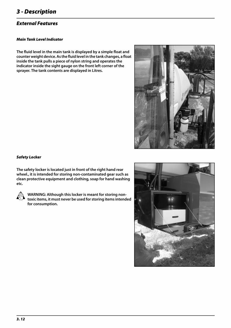
Main Tank Level Indicator
The fluid level in the main tank is displayed by a simple float and counter weight device. As the fluid level in the tank changes, a float inside the tank pulls a piece of nylon string and operates the indicator inside the sight gauge on the front left corner of the sprayer. The tank contents are displayed in Litres.
Safety Locker
The safety locker is located just in front of the right hand rear wheel., it is intended for storing non-contaminated gear such as clean protective equipment and clothing, soap for hand washing etc.
± WARNING: Although this locker is meant for storing non-toxic items, it must never be used for storing items intended for consumption.
3 - Description
3. 13
Liquid System
Pump
A Hypro 9306 centrifugal pump is fitted, with easy access to service parts.
Standard= Hypro 9306
Pump DriveThe sprayer’s main fluid pump is powered by a conventional hydraulic powered drive motor.
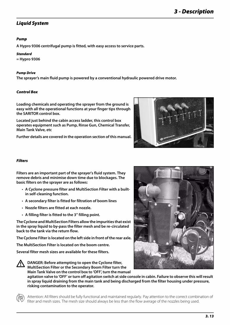
Control Box
Loading chemicals and operating the sprayer from the ground is easy with all the operational functions at your finger tips through the SARITOR control box.
Located just behind the cabin access ladder, this control box operates equipment such as Pump, Rinse Gun, Chemical Transfer, Main Tank Valve, etc
Further details are covered in the operation section of this manual.
Filters
Filters are an important part of the sprayer's fluid system. They remove debris and minimise down time due to blockages. The basic filters on the sprayer are as follows:
• A Cyclone pressure filter and MultiSection Filter with a built-in self-cleaning function.
• A secondary filter is fitted for filtration of boom lines
• Nozzle filters are fitted at each nozzle.
• A filling filter is fitted to the 3” filling point.
The Cyclone and MultiSection Filters allow the impurities that exist in the spray liquid to by-pass the filter mesh and be re-circulated back to the tank via the return flow.
The Cyclone Filter is located on the left side in front of the rear axle.
The MultiSection Filter is located on the boom centre.
Several filter mesh sizes are available for these filters.
€ DANGER: Before attempting to open the Cyclone filter, MultiSection Filter or the Secondary Boom Filter turn the Main Tank Valve on the control box to ‘OFF’, turn the manual agitation valve to ‘OFF’ or turn off agitation switch at side console in cabin. Failure to observe this will result in spray liquid draining from the main tank and being discharged from the filter housing under pressure, risking contamination to the operator.
μ Attention: All filters should be fully functional and maintained regularly. Pay attention to the correct combination of filter and mesh sizes. The mesh size should always be less than the flow average of the nozzles being used.
3 - Description
3. 14
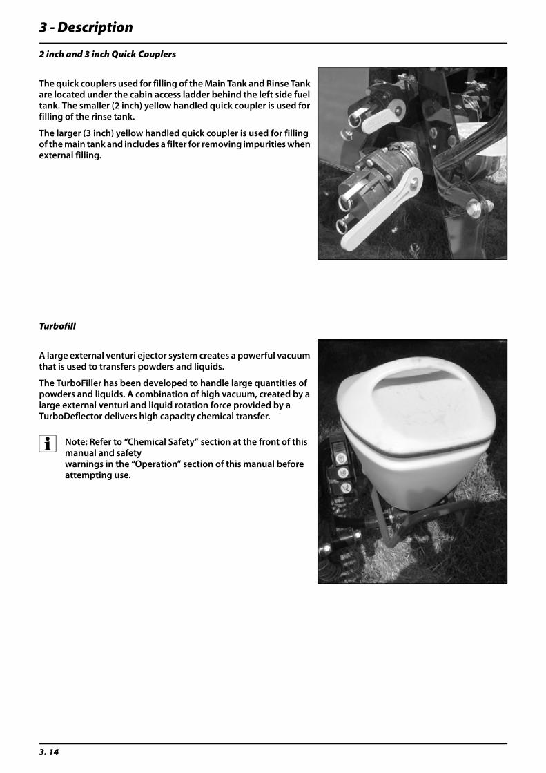
2 inch and 3 inch Quick Couplers
The quick couplers used for filling of the Main Tank and Rinse Tank are located under the cabin access ladder behind the left side fuel tank. The smaller (2 inch) yellow handled quick coupler is used for filling of the rinse tank.
The larger (3 inch) yellow handled quick coupler is used for filling of the main tank and includes a filter for removing impurities when external filling.
Turbofill
A large external venturi ejector system creates a powerful vacuum that is used to transfers powders and liquids.
The TurboFiller has been developed to handle large quantities of powders and liquids. A combination of high vacuum, created by a large external venturi and liquid rotation force provided by a TurboDeflector delivers high capacity chemical transfer.
÷ Note: Refer to “Chemical Safety” section at the front of this manual and safety warnings in the “Operation” section of this manual before attempting use.
3 - Description
3. 15
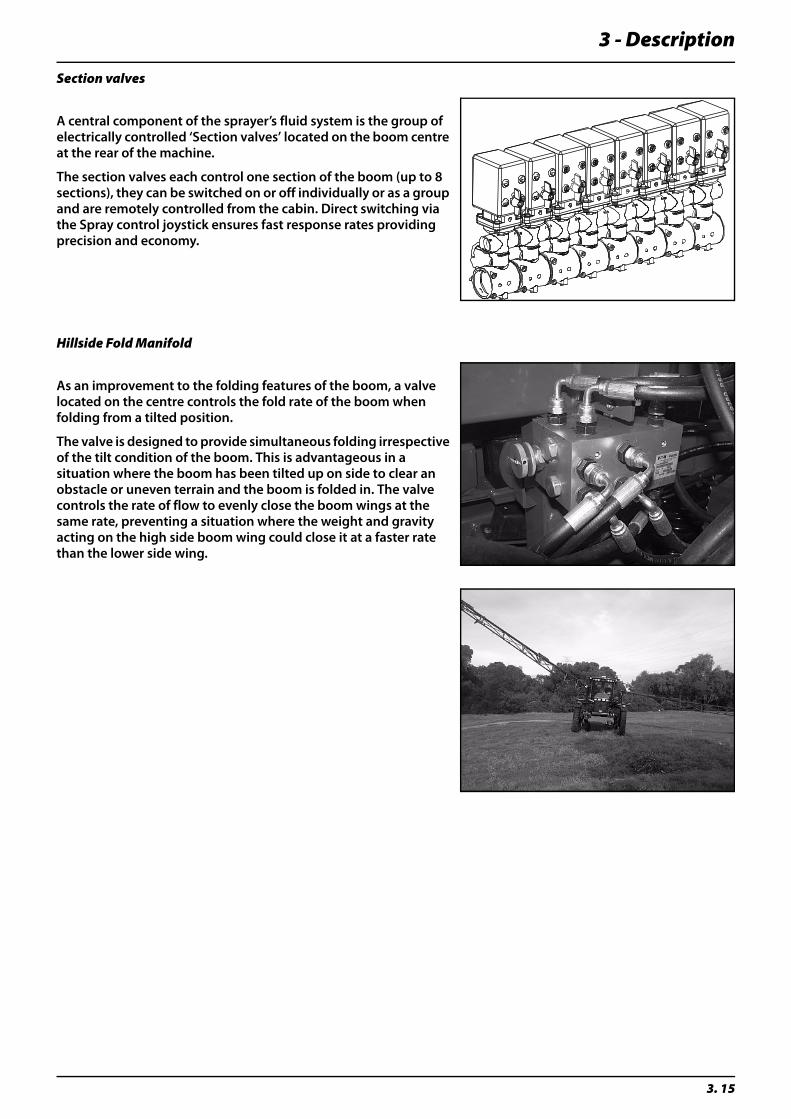
Section valves
A central component of the sprayer’s fluid system is the group of electrically controlled ‘Section valves’ located on the boom centre at the rear of the machine.
The section valves each control one section of the boom (up to 8 sections), they can be switched on or off individually or as a group and are remotely controlled from the cabin. Direct switching via the Spray control joystick ensures fast response rates providing precision and economy.
Hillside Fold Manifold
As an improvement to the folding features of the boom, a valve located on the centre controls the fold rate of the boom when folding from a tilted position.
The valve is designed to provide simultaneous folding irrespective of the tilt condition of the boom. This is advantageous in a situation where the boom has been tilted up on side to clear an obstacle or uneven terrain and the boom is folded in. The valve controls the rate of flow to evenly close the boom wings at the same rate, preventing a situation where the weight and gravity acting on the high side boom wing could close it at a faster rate than the lower side wing.
3 - Description
3. 16
Boom
μ Attention: Important information on Safety, Operation and Maintenance specific to your boom configuration is detailed in the “Boom Operators Manual” supplied with your sprayer’s documentation. It must be read and fully understood by anyone intending to operate this equipment. Failure to do so could result in serious personal injury or death.
Boom configurations
The Saritor FTZ boom is available in the following sizes;
• 24m Two Fold
• 28m Two Fold
• 30m Three Fold
• 32m Three Fold
• 36m Three Fold
Boom Terminology
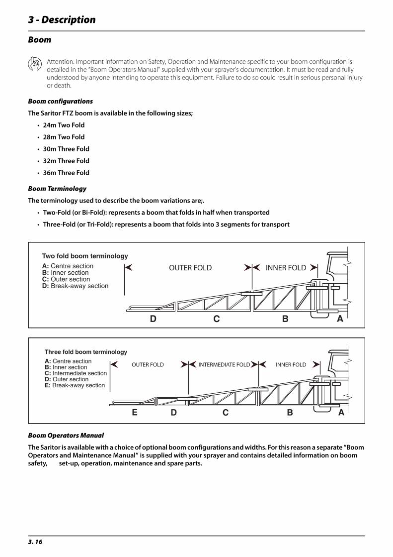
The terminology used to describe the boom variations are;.
• Two-Fold (or Bi-Fold): represents a boom that folds in half when transported
• Three-Fold (or Tri-Fold): represents a boom that folds into 3 segments for transport
Boom Operators Manual
The Saritor is available with a choice of optional boom configurations and widths. For this reason a separate “Boom Operators and Maintenance Manual” is supplied with your sprayer and contains detailed information on boom safety, set-up, operation, maintenance and spare parts.
OUTER FOLD INNER FOLD
OUTER FOLD INNER FOLDINTERMEDIATE FOLD
3 - Description
3. 17
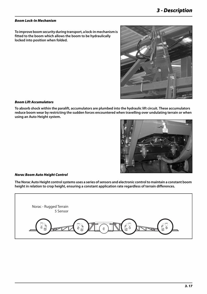
Boom Lock-In Mechanism
To improve boom security during transport, a lock-in mechanism is fitted to the boom which allows the boom to be hydraulically locked into position when folded.
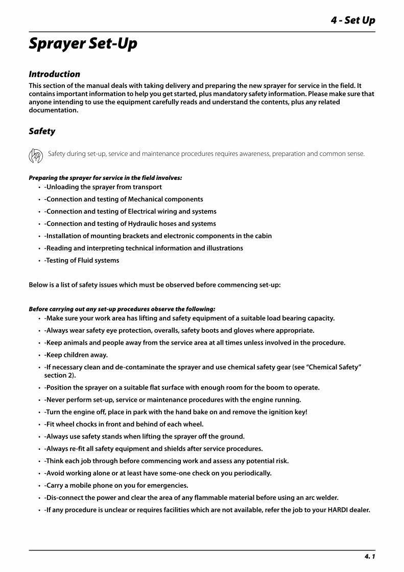
Boom Lift Accumulators
To absorb shock within the paralift, accumulators are plumbed into the hydraulic lift circuit. These accumulators reduce boom wear by restricting the sudden forces encountered when travelling over undulating terrain or when using an Auto Height system.
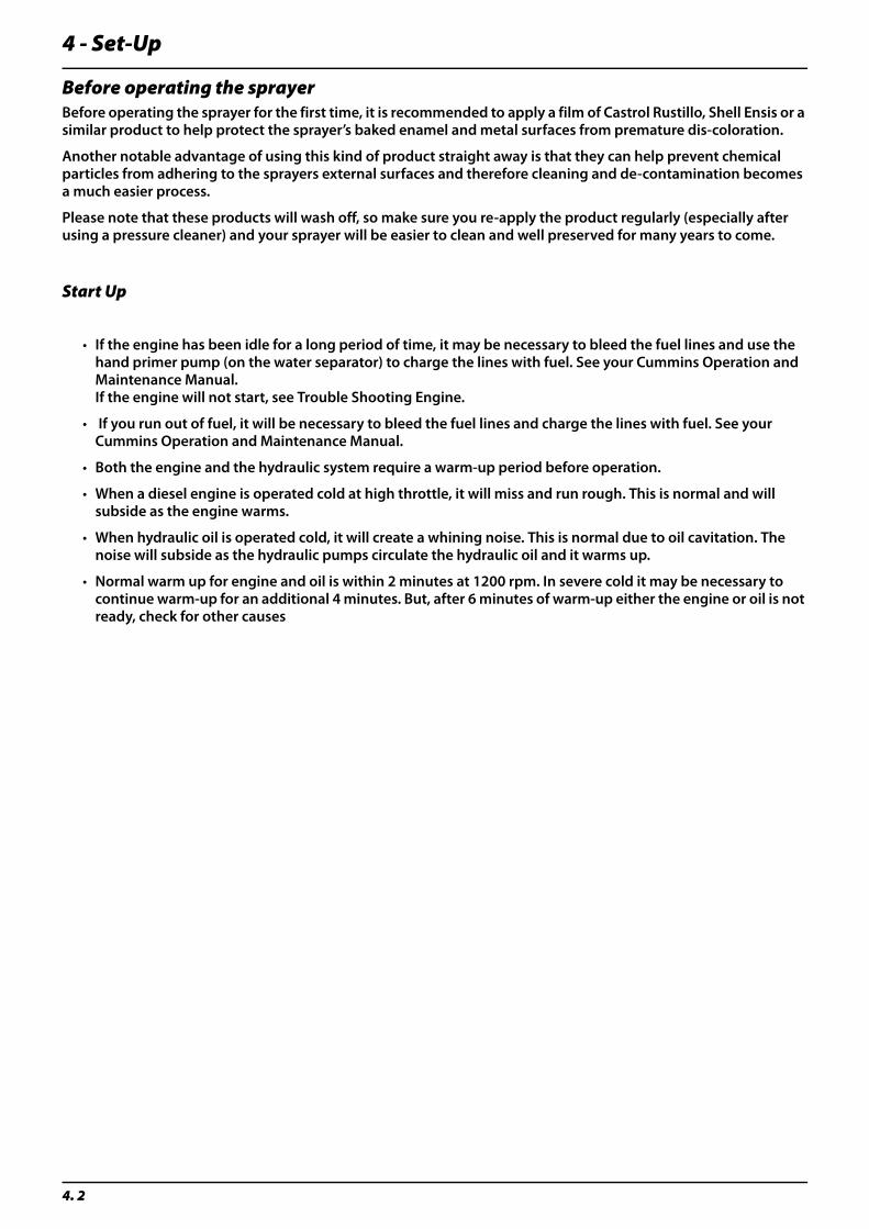
Norac Boom Auto Height Control
The Norac Auto Height control systems uses a series of sensors and electronic control to maintain a constant boom height in relation to crop height, ensuring a constant application rate regardless of terrain differences.
Norac - Rugged Terrain5 Sensor

3 - Description
3. 18
4 - Set Up
4. 1
Sprayer Set-Up
IntroductionThis section of the manual deals with taking delivery and preparing the new sprayer for service in the field. It contains important information to help you get started, plus mandatory safety information. Please make sure that anyone intending to use the equipment carefully reads and understand the contents, plus any related documentation.
Safety
μ Safety during set-up, service and maintenance procedures requires awareness, preparation and common sense.
Preparing the sprayer for service in the field involves:• -Unloading the sprayer from transport
• -Connection and testing of Mechanical components
• -Connection and testing of Electrical wiring and systems
• -Connection and testing of Hydraulic hoses and systems
• -Installation of mounting brackets and electronic components in the cabin
• -Reading and interpreting technical information and illustrations
• -Testing of Fluid systems
Below is a list of safety issues which must be observed before commencing set-up:
Before carrying out any set-up procedures observe the following:• -Make sure your work area has lifting and safety equipment of a suitable load bearing capacity.
• -Always wear safety eye protection, overalls, safety boots and gloves where appropriate.
• -Keep animals and people away from the service area at all times unless involved in the procedure.
• -Keep children away.
• -If necessary clean and de-contaminate the sprayer and use chemical safety gear (see “Chemical Safety” section 2).
• -Position the sprayer on a suitable flat surface with enough room for the boom to operate.
• -Never perform set-up, service or maintenance procedures with the engine running.
• -Turn the engine off, place in park with the hand bake on and remove the ignition key!
• -Fit wheel chocks in front and behind of each wheel.
• -Always use safety stands when lifting the sprayer off the ground.
• -Always re-fit all safety equipment and shields after service procedures.
• -Think each job through before commencing work and assess any potential risk.
• -Avoid working alone or at least have some-one check on you periodically.
• -Carry a mobile phone on you for emergencies.
• -Dis-connect the power and clear the area of any flammable material before using an arc welder.
• -If any procedure is unclear or requires facilities which are not available, refer the job to your HARDI dealer.
4 - Set-Up
4. 2
Before operating the sprayerBefore operating the sprayer for the first time, it is recommended to apply a film of Castrol Rustillo, Shell Ensis or a similar product to help protect the sprayer’s baked enamel and metal surfaces from premature dis-coloration.
Another notable advantage of using this kind of product straight away is that they can help prevent chemical particles from adhering to the sprayers external surfaces and therefore cleaning and de-contamination becomes a much easier process.
Please note that these products will wash off, so make sure you re-apply the product regularly (especially after using a pressure cleaner) and your sprayer will be easier to clean and well preserved for many years to come.
Start Up
• If the engine has been idle for a long period of time, it may be necessary to bleed the fuel lines and use the hand primer pump (on the water separator) to charge the lines with fuel. See your Cummins Operation and Maintenance Manual. If the engine will not start, see Trouble Shooting Engine.
• If you run out of fuel, it will be necessary to bleed the fuel lines and charge the lines with fuel. See your Cummins Operation and Maintenance Manual.
• Both the engine and the hydraulic system require a warm-up period before operation.
• When a diesel engine is operated cold at high throttle, it will miss and run rough. This is normal and will subside as the engine warms.
• When hydraulic oil is operated cold, it will create a whining noise. This is normal due to oil cavitation. The noise will subside as the hydraulic pumps circulate the hydraulic oil and it warms up.
• Normal warm up for engine and oil is within 2 minutes at 1200 rpm. In severe cold it may be necessary to continue warm-up for an additional 4 minutes. But, after 6 minutes of warm-up either the engine or oil is not ready, check for other causes

4 - Set Up
4. 3
SARITOR 4800 AgLeader Setup Process
÷ The information given in this manual for the setup of the AgLeader system is based on general HARDI specific setup requirements. Should users require further information or troubleshooting information, please refer the InSight User Manual (P/No. 2002877)
- Home IconThe Home Screen is displayed when the unit is first turned on. To return to the home screen from any other area press the home icon.
The icons panel on the right hand side of the screen control the following;
Navigation Button Button Description
1 Press to access the Home screen on the InSight display. Options available at the Home screen are, Copy to Card, Upgrade System, User Guide, Change Operator and Shut Down
2 Press to access the menus and wizards used for system configuration. General setup item groups include, Grower-Field Management, Field Notes, Console, and GPS configurations. Use specific setup item groups include, Planting, Product Application, Tillage, and Harvest configurations.
3 Press the Brightness Control to set display back light intensity to fit current operating conditions.
4 Press to display a summary screen showing totals for the current field operation you are performing.
5 Press to launch the Run Screen. The Run Screen provides control of all field operations and the data logging associated with, Harvest, Planting, Tillage, and Product Application.
1. HOME
2. MENU
3. BRIGHTNESS
4. SUMMARY
5. RUN

4 - Set-Up
4. 4
Tool IconThe set-up menu provides several areas of setup, the main areas of concern with the HARDI Saritor are;
• Grower Field Management
• Application Setup
• Console
• GPS Guidance
• Field Notes
Grower Field ManagementIt is necessary to setup parameters for the grower field and season details, this is carried out under grower field management.
To setup grower details the following areas must be completed;
Create Grower•For information on creating a new grower refer to the InSight User Manual page 23
Input Season details•For information on Season Setup refer to the InSight User Manual page 21
Input Field data•For information on Field Setup refer to the InSight User Manual page 27
Input Operator data•For information on Operator Setup refer to the InSight User Manual page 32
Full details on how to setup the InSight for Grower Field Management are contained in the AgLeader InSight User Manual
Application Setup The Application Setup allows the operator to setup parameters for the following;
Configuration•For information on Configuration Setup refer to the InSight User Manual page 298
Vehicle•For information on Vehicle Setup refer to the InSight User Manual page 307
Implement•For information on Implement Setup refer to the InSight User Manual page 311
Controller•For information on Controller Setup refer to the InSight User Manual page 316
Product•For information on Product Setup refer to the InSight User Manual page 324
Console SetupThe console setup allows the operator to change data relating to items such as current time, location, units of measure, etc.
Refer to InSight User Manual on page 39
GPS GuidanceFull details of the setting up GPS through the InSight are contained in the manual on page 46
4 - Set Up
4. 5
Field NotesField notes allows the operator to setup symbols / markers that allow obstacles (trees, rocks, etc) to be mapped into the field. For further information on Field Notes Setup refer to the InSight User Manual page 35
Notes IconThis icon allows viewing of reports for Grower, Field or Product
Run IconThis icon allows operator into the active screen for operation monitoring. Full details are available in the InSight User Manual on page 79.
Driver Accessory Adjustments
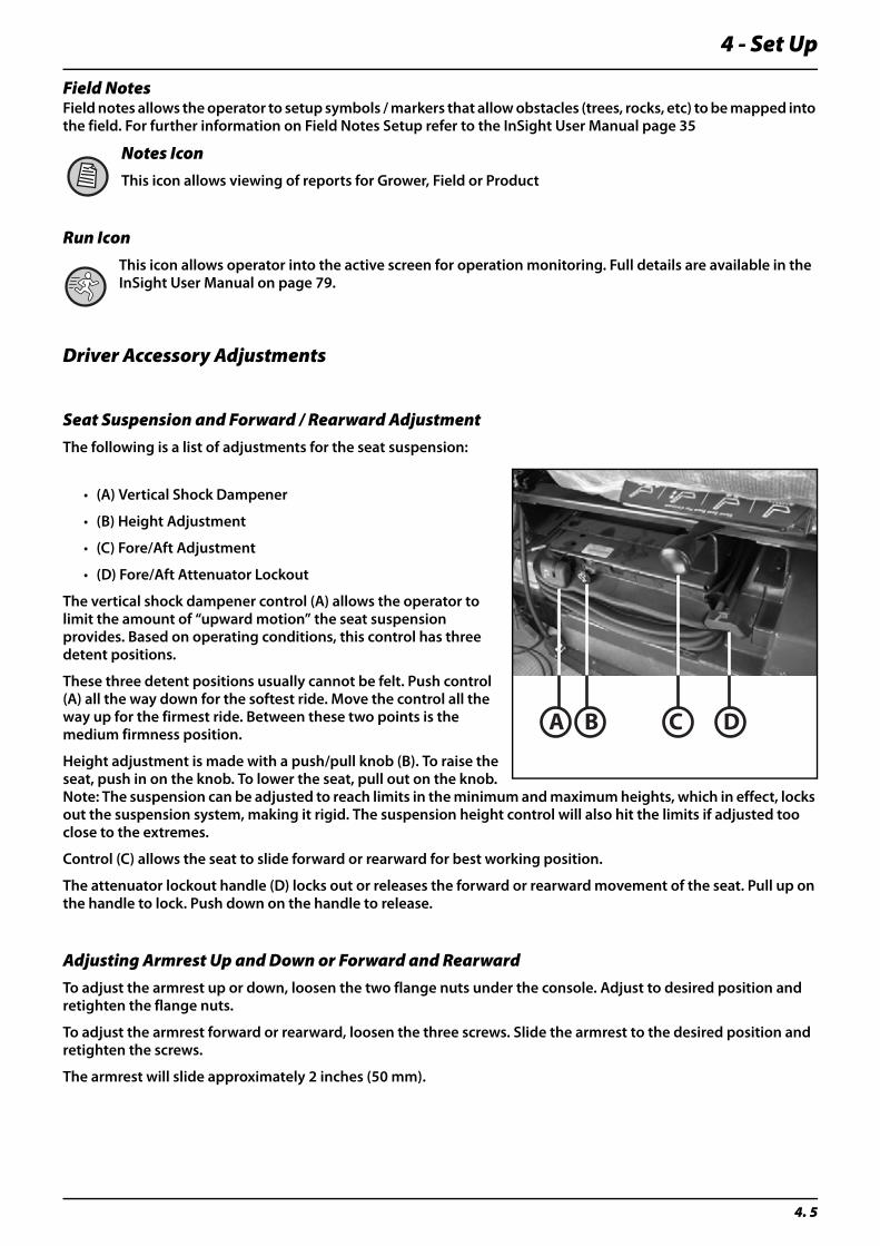
Seat Suspension and Forward / Rearward AdjustmentThe following is a list of adjustments for the seat suspension:
• (A) Vertical Shock Dampener
• (B) Height Adjustment
• (C) Fore/Aft Adjustment
• (D) Fore/Aft Attenuator Lockout
The vertical shock dampener control (A) allows the operator to limit the amount of “upward motion” the seat suspension provides. Based on operating conditions, this control has three detent positions.
These three detent positions usually cannot be felt. Push control (A) all the way down for the softest ride. Move the control all the way up for the firmest ride. Between these two points is the medium firmness position.
Height adjustment is made with a push/pull knob (B). To raise the seat, push in on the knob. To lower the seat, pull out on the knob. Note: The suspension can be adjusted to reach limits in the minimum and maximum heights, which in effect, locks out the suspension system, making it rigid. The suspension height control will also hit the limits if adjusted too close to the extremes.
Control (C) allows the seat to slide forward or rearward for best working position.
The attenuator lockout handle (D) locks out or releases the forward or rearward movement of the seat. Pull up on the handle to lock. Push down on the handle to release.
Adjusting Armrest Up and Down or Forward and RearwardTo adjust the armrest up or down, loosen the two flange nuts under the console. Adjust to desired position and retighten the flange nuts.
To adjust the armrest forward or rearward, loosen the three screws. Slide the armrest to the desired position and retighten the screws.
The armrest will slide approximately 2 inches (50 mm).
A B C D
4 - Set-Up
4. 6
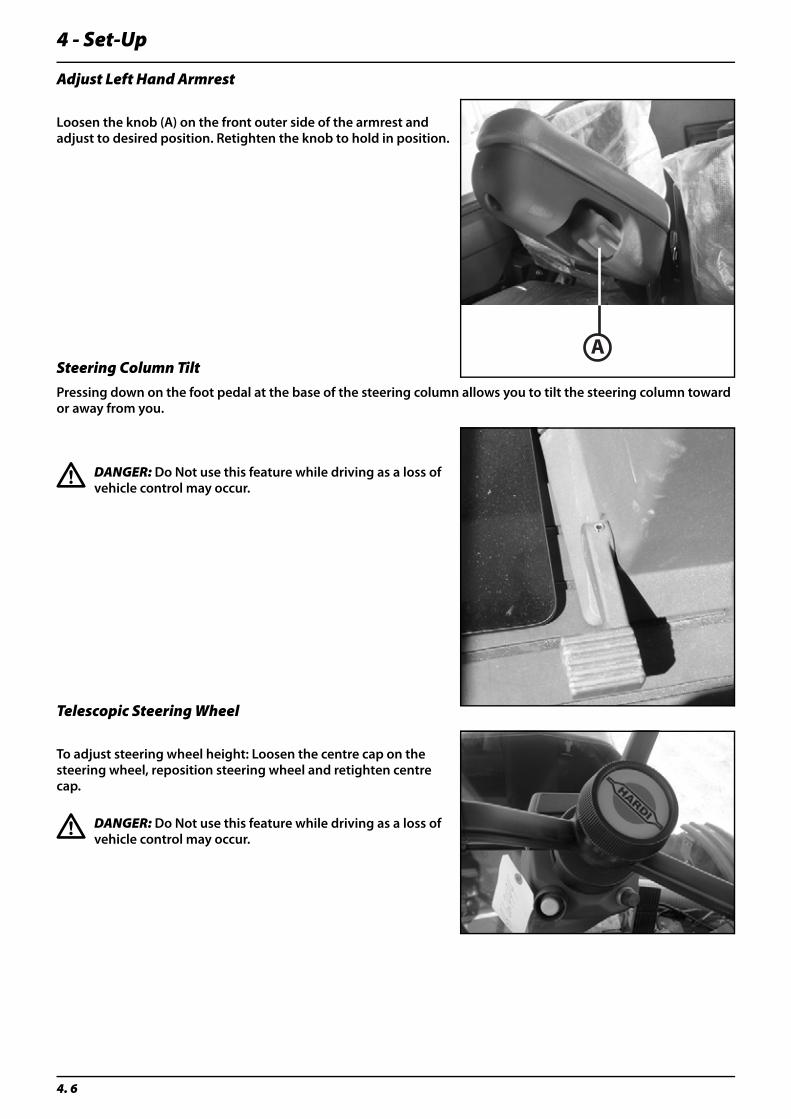
Adjust Left Hand Armrest
Loosen the knob (A) on the front outer side of the armrest and adjust to desired position. Retighten the knob to hold in position.
Steering Column TiltPressing down on the foot pedal at the base of the steering column allows you to tilt the steering column toward or away from you.
€ DANGER: Do Not use this feature while driving as a loss of vehicle control may occur.
Telescopic Steering Wheel
To adjust steering wheel height: Loosen the centre cap on the steering wheel, reposition steering wheel and retighten centre cap.
€ DANGER: Do Not use this feature while driving as a loss of vehicle control may occur.
A
4 - Set Up
4. 7
Radio/Cassette/CD
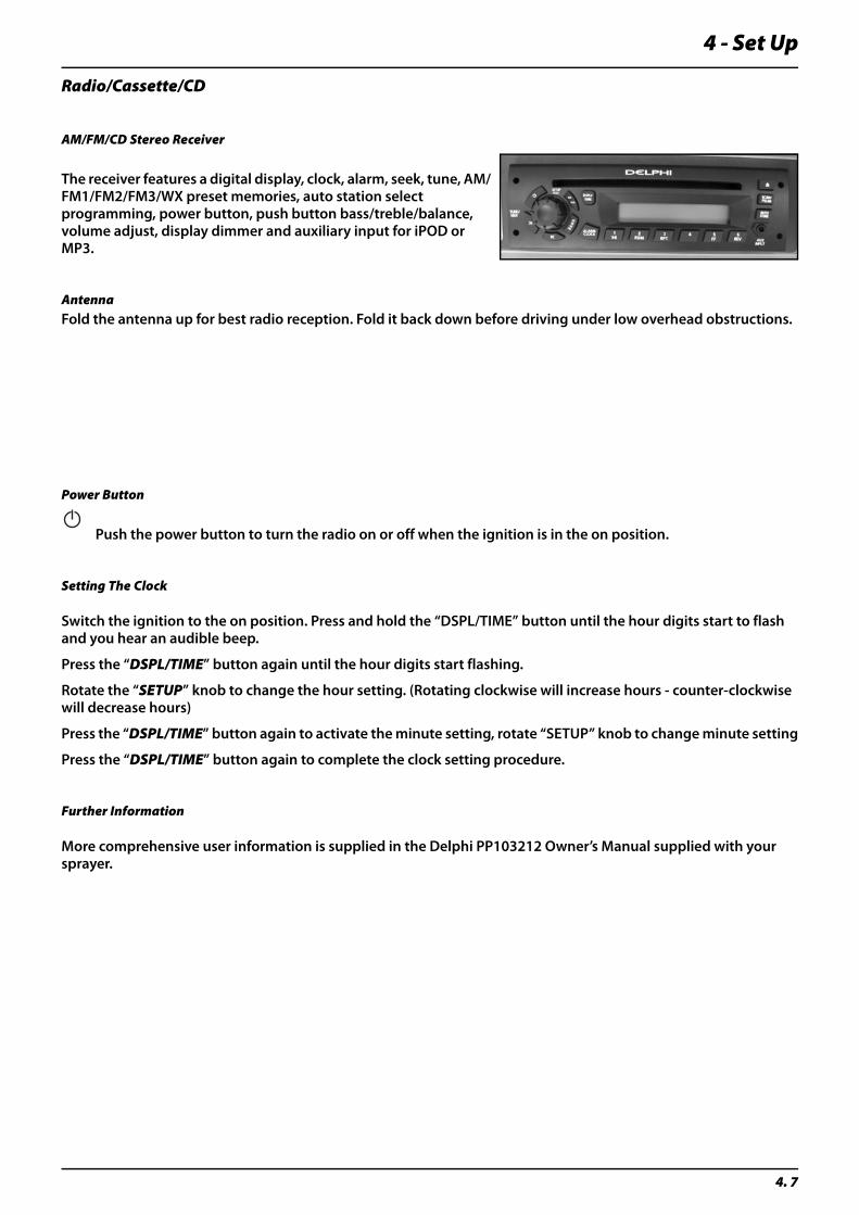
AM/FM/CD Stereo Receiver
The receiver features a digital display, clock, alarm, seek, tune, AM/FM1/FM2/FM3/WX preset memories, auto station select programming, power button, push button bass/treble/balance, volume adjust, display dimmer and auxiliary input for iPOD or MP3.
AntennaFold the antenna up for best radio reception. Fold it back down before driving under low overhead obstructions.
Power Button
Push the power button to turn the radio on or off when the ignition is in the on position.
Setting The Clock
Switch the ignition to the on position. Press and hold the “DSPL/TIME” button until the hour digits start to flash and you hear an audible beep.
Press the “DSPL/TIME” button again until the hour digits start flashing.
Rotate the “SETUP” knob to change the hour setting. (Rotating clockwise will increase hours - counter-clockwise will decrease hours)
Press the “DSPL/TIME” button again to activate the minute setting, rotate “SETUP” knob to change minute setting
Press the “DSPL/TIME” button again to complete the clock setting procedure.
Further Information
More comprehensive user information is supplied in the Delphi PP103212 Owner’s Manual supplied with your sprayer.

4 - Set-Up
4. 8
5 - Operation
5. 1
Sprayer OperationTransportingGeneral
Fold and store the booms in the storage cradles. Be sure to hold the boom lower switch in the lower position to relieve all the pressure in the lift cylinders. This will allow the booms to rest completely on the storage cradles and eliminate any boom bounce during transport.
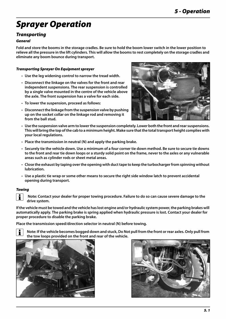
Transporting Sprayer On Equipment sprayer
• Use the leg widening control to narrow the tread width.
• Disconnect the linkage on the valves for the front and rear independent suspensions. The rear suspension is controlled by a single valve mounted in the centre of the vehicle above the axle. The front suspension has a valve for each side.
• To lower the suspension, proceed as follows:
• Disconnect the linkage from the suspension valve by pushing up on the socket collar on the linkage rod and removing it from the ball stud.
• Use the suspension valve arm to lower the suspension completely. Lower both the front and rear suspensions. This will bring the top of the cab to a minimum height. Make sure that the total transport height complies with your local regulations.
• Place the transmission in neutral (N) and apply the parking brake.
• Securely tie the vehicle down. Use a minimum of a four corner tie down method. Be sure to secure tie downs to the front and rear tie down loops or a sturdy solid point on the frame, never to the axles or any vulnerable areas such as cylinder rods or sheet metal areas.
• Close the exhaust by taping over the opening with duct tape to keep the turbocharger from spinning without lubrication.
• Use a plastic tie wrap or some other means to secure the right side window latch to prevent accidental opening during transport.
Towing
÷ Note: Contact your dealer for proper towing procedure. Failure to do so can cause severe damage to the drive system.
If the vehicle must be towed and the vehicle has lost engine and/or hydraulic system power, the parking brakes will automatically apply. The parking brake is spring applied when hydraulic pressure is lost. Contact your dealer for proper procedure to disable the parking brake.
Place the transmission speed/direction selector in neutral (N) before towing.
÷ Note: If the vehicle becomes bogged down and stuck, Do Not pull from the front or rear axles. Only pull from the tow loops provided on the front and rear of the vehicle.

5 - Operation
5. 2
Track WidthYour vehicle is equipped with the leg widening option, use the leg widening switches on the right side console to adjust the wheel width to the minimum width. Be sure to drive the vehicle forward or backward when adjusting the tread width.
Adjust the wheels all the way in for loading on a trailer.
÷ Note: You must obey all applicable highway safety laws and rules when transporting this vehicle or driving it on public highways.
Cabin Switches and Controls
Vehicle Lighting Switches
The lights on the vehicle are controlled by four separate switches in the overhead console of the cab. These switches are:
Hazard Lights (Switch A)• Push the top of the switch in to turn the two front and two rear hazard lights on. Push the bottom of the switch in to turn the hazard lights off. Always use the hazard lights when travelling on public roadways. If your vehicle has an optional strobe light, it will also be controlled by this switch.
Road Lights (Switch B)• Push the top of the switch in to turn the road lights on. The road lights consist of the centre two lights on the hood, the inner two and outer two lights on the cab as well as the red tail lights. Push the bottom of the switch in to turn the road lights off. Always use the road lights when travelling on public roadways.
Field Lights (Switch C) - 2 position switch• Push the top of the switch to the middle position to turn the field lights on. The field lights consist of the outer two lights on the hood and the middle light in each set of lights on the front of the cab. Push the top of the switch to the top position to turn on the HID roof lights. Push the switch to the bottom position to turn the field lights off.
Work Lights (Switch D)• Push the top of the switch in to turn the work lights on. The work lights consist of the side light mounted on the right side of the vehicle above the fuel tank and the side light on the left side of the vehicle mounted next to the ladder. Push the bottom of the switch in to turn the work lights off.
Turn Signals
÷ Note: The turn signals are NOT self cancelling so the lever must be moved back to neutral after a turn has been made.
÷ Note: When operating this sprayer on roads or highways, always use the turn signals.
5 - Operation
5. 3
Heater and Air Conditioner Controls
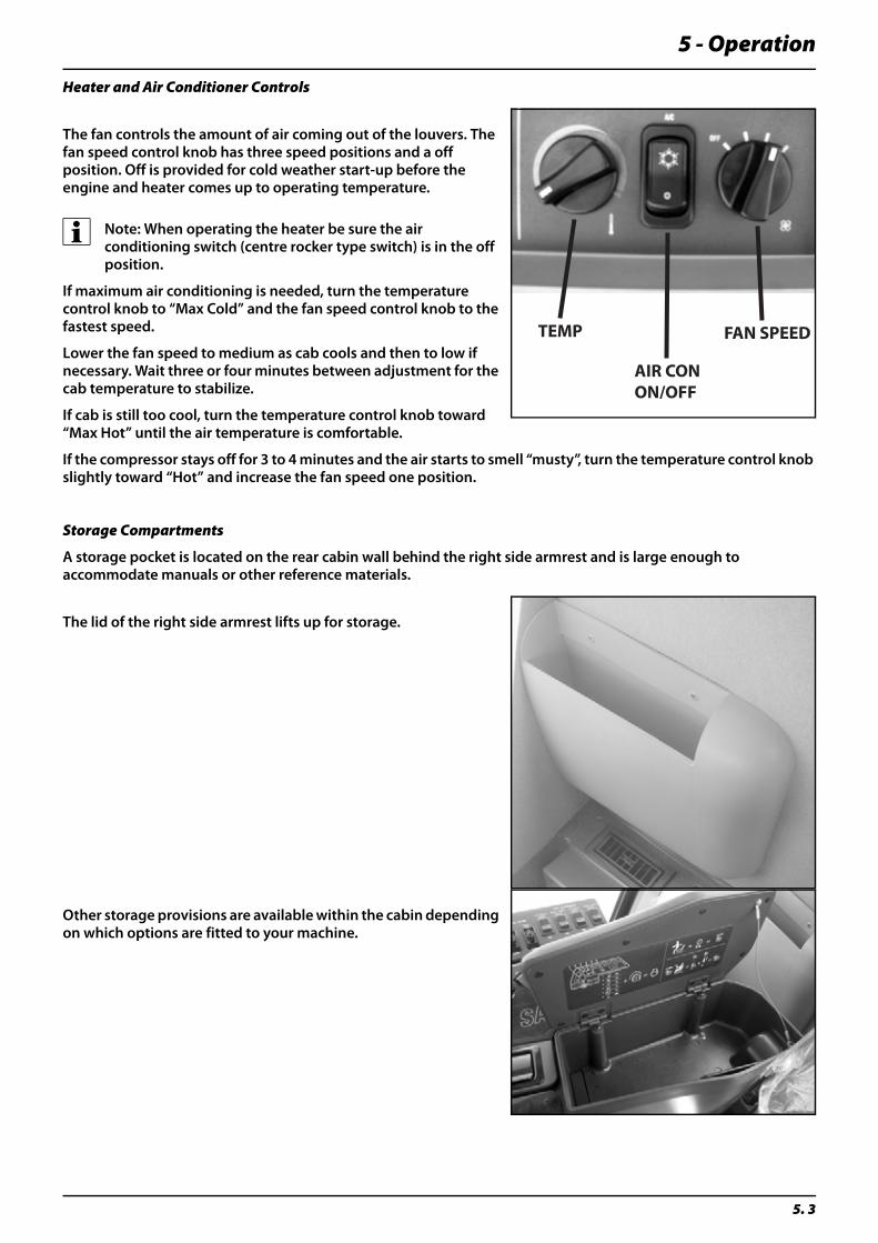
The fan controls the amount of air coming out of the louvers. The fan speed control knob has three speed positions and a off position. Off is provided for cold weather start-up before the engine and heater comes up to operating temperature.
÷ Note: When operating the heater be sure the air conditioning switch (centre rocker type switch) is in the off position.
If maximum air conditioning is needed, turn the temperature control knob to “Max Cold” and the fan speed control knob to the fastest speed.
Lower the fan speed to medium as cab cools and then to low if necessary. Wait three or four minutes between adjustment for the cab temperature to stabilize.
If cab is still too cool, turn the temperature control knob toward “Max Hot” until the air temperature is comfortable.
If the compressor stays off for 3 to 4 minutes and the air starts to smell “musty”, turn the temperature control knob slightly toward “Hot” and increase the fan speed one position.
Storage Compartments
A storage pocket is located on the rear cabin wall behind the right side armrest and is large enough to accommodate manuals or other reference materials.
The lid of the right side armrest lifts up for storage.
Other storage provisions are available within the cabin depending on which options are fitted to your machine.
FAN SPEED
AIR CONON/OFF
TEMP
5 - Operation
5. 4
Cabin Ingress / Egress
Cab door lock and handle
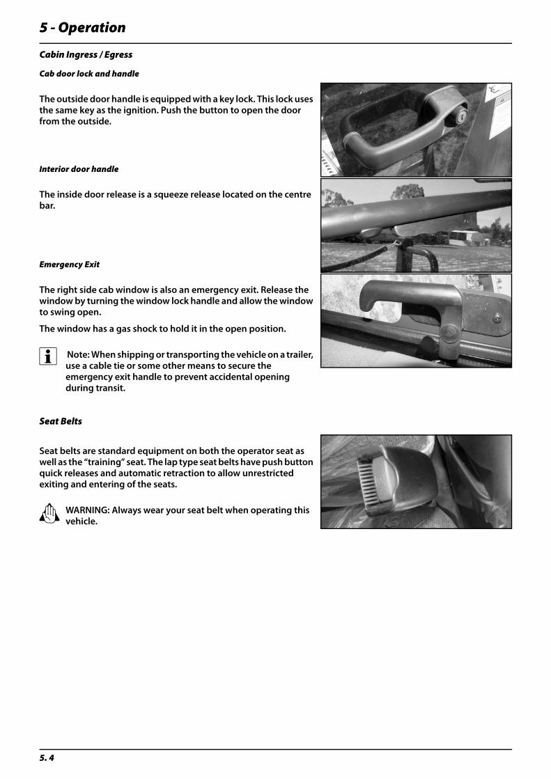
The outside door handle is equipped with a key lock. This lock uses the same key as the ignition. Push the button to open the door from the outside.
Interior door handle
The inside door release is a squeeze release located on the centre bar.
Emergency Exit
The right side cab window is also an emergency exit. Release the window by turning the window lock handle and allow the window to swing open.
The window has a gas shock to hold it in the open position.
÷ Note: When shipping or transporting the vehicle on a trailer, use a cable tie or some other means to secure the emergency exit handle to prevent accidental opening during transit.
Seat Belts
Seat belts are standard equipment on both the operator seat as well as the “training” seat. The lap type seat belts have push button quick releases and automatic retraction to allow unrestricted exiting and entering of the seats.
± WARNING: Always wear your seat belt when operating this vehicle.

5 - Operation
5. 5
Overhead Console (Engine and Hydraulic System Monitor)
Several engine and hydraulic functions are continually monitored by the system. This display shows both red and amber lights and sounds a buzzer. The buzzers have “priorities.” A continuous buzzer is a problem which needs immediate attention.
When the ignition key is in the start position, all the lights on the panel will come on.
These warning lights dim at night when the field or road lights are on.
In the event that an abnormal condition is detected, the result is communicated to you on the overhead console. The warnings are as follows:
Turn Signals On: The amber light will come on and an audible alarm will sound reminding the operator that the turn signals have been activated. They will remain on as long as the turn signal system is activated.
Low Fuel: The amber light will come on continuously and an audible alarm will sound every 5 minutes indicating that there is approximately 10 to 15 gallons (38-57 litres) of fuel left.
Park Brake: The light will come on when the parking brake is applied as a reminder. If the operator puts the transmission in gear with the parking brake applied an audible alarm will also sound.
Wait To Start: The amber light will come on and remain on when the engine air induction manifold heater is active. The light will go out when the engine is ready to be started.
Transmission Temperature:
μ Attention: The red light will come on and an audible alarm will sound when the transmission oil temperature is too high.
Place the transmission in neutral, with engine at low idle and allow temperature to cool. The light will go out when temperature is below the specified range. If the temperature does not cool down by idling, shut the vehicle off and clean the transmission oil cooler fins. The transmission cooler is integrated in the cooling package.
Hydraulic Oil Temperature: The red light will come on and an audible alarm will sound when the hydraulic oil temperature is too high. The light will remain on and the alarm will sound as long as the temperature is above the normal operating range. Shut the vehicle off and check for the cause as soon as safely possible. Clean the hydraulic oil cooler fins. The hydraulic oil cooler is integrated in the cooling package.
Voltage: The amber light will come on and an audible alarm will sound every 5 minutes when the battery is discharging (voltage drops below 10.5 volts). Turn off any unneeded electrical features. Check the battery and alternator for a possible problem.
Check Transmission: The amber light will come on indicating one of the following conditions: low oil level, low oil pressure or over heating. The light will remain on until either the fault is satisfied in the case of low oil pressure or until the CANtrak monitor is reset. These faults should be stored in memory.
Low Brake Pressure: The amber light will come on and remain on when the brake system pressure drops below the normal operating range. Check brake system and fluid level.
Stop Engine: The red light will come on and an audible alarm will sound continuously. This indicates a major engine problem and the vehicle should be stopped as soon as safely possible.

5 - Operation
5. 6
In addition to alerting the operator to system faults, this light is used in diagnostic operation. The light flashes the various 3 digit fault code sequence when used in the onboard diagnostic mode.
Windshield Wiper/Washer Switch
The windshield wiper can be stopped on either side of the windshield, depending on when the switch is returned to the off position.
The ignition switch must be in the on position for the windshield wiper to work.
To activate the windshield washer, press and hold the top of the wiper switch in. The washer will be activated as long as the switch is held in position. When the switch is released it will return to the wiper position.
÷ Note: Keep the windshield washer reservoir full with windshield washer fluid only. The windshield washer reservoir is located below the right side cab window.
Cab Interior Light
The cab interior light is controlled by a single ON/OFF switch located next to the light.

5 - Operation
5. 7
Track Width Alteration - Leg Widening Controls (Optional Equipment)
With this option the axle track width is adjustable from approx. 3050mm to 3800mm depending on crop spacing requirements or transport requirements.
There are four separate switches, one to control each axle (FRONT - REAR - LEFT - RIGHT).
In order to either widen or reduce the axle width, the vehicle must be slowly driven either forward or backward while moving the axles. The switches are spring loaded to return to centre (OFF) position when released. The switches must be held in either IN or OUT position to activate track adjustments.
Two switches can be activated at the same time if desired.
Horn Button
The horn button is located on the right rear corner of the steering column.
Ignition Switch
The ignition switch is located on the right side of the steering column.
The switch position are OFF - ACCESSORY - PREHEAT/RUN - START
Once the engine starts and the key is released the switch will return to the RUN position.
Whenever the ignition switch is turned to ON and the engine temperature is too cold, the “Wait to Start” light on the overhead control panel will illuminate, it will remain on until the preheat temperature has been satisfied. Once the light goes out it is safe to turn the key to the START position and crank the engine.
Remove the key from the ignition switch when the vehicle is unattended.
The ACCESSORY position enables use of any switched accessories such as radios, etc. without having the engine running.
HORN
IGNITION SWITCH
5 - Operation
5. 8
Brake Pedal
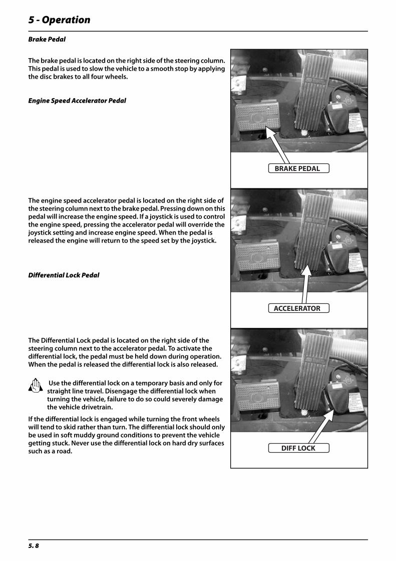
The brake pedal is located on the right side of the steering column. This pedal is used to slow the vehicle to a smooth stop by applying the disc brakes to all four wheels.
Engine Speed Accelerator Pedal
The engine speed accelerator pedal is located on the right side of the steering column next to the brake pedal. Pressing down on this pedal will increase the engine speed. If a joystick is used to control the engine speed, pressing the accelerator pedal will override the joystick setting and increase engine speed. When the pedal is released the engine will return to the speed set by the joystick.
Differential Lock Pedal
The Differential Lock pedal is located on the right side of the steering column next to the accelerator pedal. To activate the differential lock, the pedal must be held down during operation. When the pedal is released the differential lock is also released.
± Use the differential lock on a temporary basis and only for straight line travel. Disengage the differential lock when turning the vehicle, failure to do so could severely damage the vehicle drivetrain.
If the differential lock is engaged while turning the front wheels will tend to skid rather than turn. The differential lock should only be used in soft muddy ground conditions to prevent the vehicle getting stuck. Never use the differential lock on hard dry surfaces such as a road.
BRAKE PEDAL
ACCELERATOR
DIFF LOCK
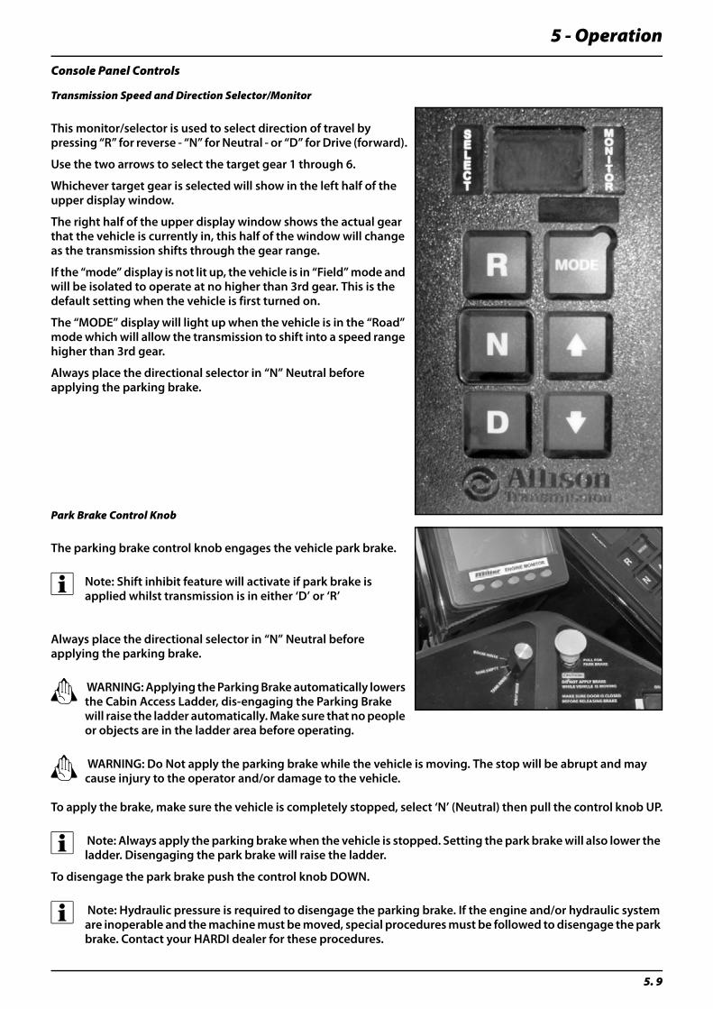
5 - Operation
5. 9
Console Panel Controls
Transmission Speed and Direction Selector/Monitor
This monitor/selector is used to select direction of travel by pressing “R” for reverse - “N” for Neutral - or “D” for Drive (forward).
Use the two arrows to select the target gear 1 through 6.
Whichever target gear is selected will show in the left half of the upper display window.
The right half of the upper display window shows the actual gear that the vehicle is currently in, this half of the window will change as the transmission shifts through the gear range.
If the “mode” display is not lit up, the vehicle is in “Field” mode and will be isolated to operate at no higher than 3rd gear. This is the default setting when the vehicle is first turned on.
The “MODE” display will light up when the vehicle is in the “Road” mode which will allow the transmission to shift into a speed range higher than 3rd gear.
Always place the directional selector in “N” Neutral before applying the parking brake.
Park Brake Control Knob
The parking brake control knob engages the vehicle park brake.
÷ Note: Shift inhibit feature will activate if park brake is applied whilst transmission is in either ‘D’ or ‘R’
Always place the directional selector in “N” Neutral before applying the parking brake.
± WARNING: Applying the Parking Brake automatically lowers the Cabin Access Ladder, dis-engaging the Parking Brake will raise the ladder automatically. Make sure that no people or objects are in the ladder area before operating.
± WARNING: Do Not apply the parking brake while the vehicle is moving. The stop will be abrupt and may cause injury to the operator and/or damage to the vehicle.
To apply the brake, make sure the vehicle is completely stopped, select ‘N’ (Neutral) then pull the control knob UP.
÷ Note: Always apply the parking brake when the vehicle is stopped. Setting the park brake will also lower the ladder. Disengaging the park brake will raise the ladder.
To disengage the park brake push the control knob DOWN.
÷ Note: Hydraulic pressure is required to disengage the parking brake. If the engine and/or hydraulic system are inoperable and the machine must be moved, special procedures must be followed to disengage the park brake. Contact your HARDI dealer for these procedures.

5 - Operation
5. 10
Product Pump ON/OFF Switch
The Product Pump ON/OFF Switch is a two position rocker switch.
Push the top of the switch to turn the pump ON.
Push the bottom of the switch to turn the pump OFF.
Agitation ON/OFF Switch
The Agitation ON/OFF Switch is a two position rocker switch.
Push the top of the switch to turn agitation ON.
Push the bottom of the switch to turn agitation OFF.
÷ Note: The Product Pump switch has to be ON before agitation will operate and the Agitation Valve must also be in the OPEN position.
Fold Switches
A detailed procedure for folding the booms is shown under the heading ‘FTZ Force Boom Control’ later in this section.
The inner fold switch controls the inner fold cylinders located closest to the boom centre. They will activate when opening and closing the boom from the transport position.
The outer fold switch controls the outer wing folding.
INN
ER FOLD
OU
TER FOLD
AG
ITATION
PUM
P
PULL FOR
PARK BRAKE
89110904
ON
OFF
OUT
IN
OUT
IN
ON
OFF
Make sure windows and doors are closed before operating boom fold switches
SARITORDO NOT APPLY BRAKE
WHILE VEHICLE IS MOVING
MAKE SURE DOOR IS CLOSED
BEFORE RELEASING BRAKE
CAUTION:
CAUTION:
PU
MP
ON
OFF
INN
ER FOLD
OU
TER FOLD
AG
ITATION
PUM
P
PULL FOR
PARK BRAKE
89110904
ON
OFF
OUT
IN
OUT
IN
ON
OFF
Make sure windows and doors are closed before operating boom fold switches
SARITORDO NOT APPLY BRAKE
WHILE VEHICLE IS MOVING
MAKE SURE DOOR IS CLOSED
BEFORE RELEASING BRAKE
CAUTION:
CAUTION:
AG
ITAT
ION
ON
OFF
INN
ER FOLD
OU
TER FOLD
AG
ITATION
PUM
P
PULL FOR
PARK BRAKE
89110904
ON
OFF
OUT
IN
OUT
IN
ON
OFF
Make sure windows and doors are closed before operating boom fold switches
SARITORDO NOT APPLY BRAKE
WHILE VEHICLE IS MOVING
MAKE SURE DOOR IS CLOSED
BEFORE RELEASING BRAKE
CAUTION:
CAUTION:
INN
ER FO
LD
OUT
IN
INN
ER FOLD
OU
TER FOLD
AG
ITATION
PUM
P
PULL FOR
PARK BRAKE
89110904
ON
OFF
OUT
IN
OUT
IN
ON
OFF
Make sure windows and doors are closed before operating boom fold switches
SARITORDO NOT APPLY BRAKE
WHILE VEHICLE IS MOVING
MAKE SURE DOOR IS CLOSED
BEFORE RELEASING BRAKE
CAUTION:
CAUTION:
OU
TE
R FO
LD
OUT
IN
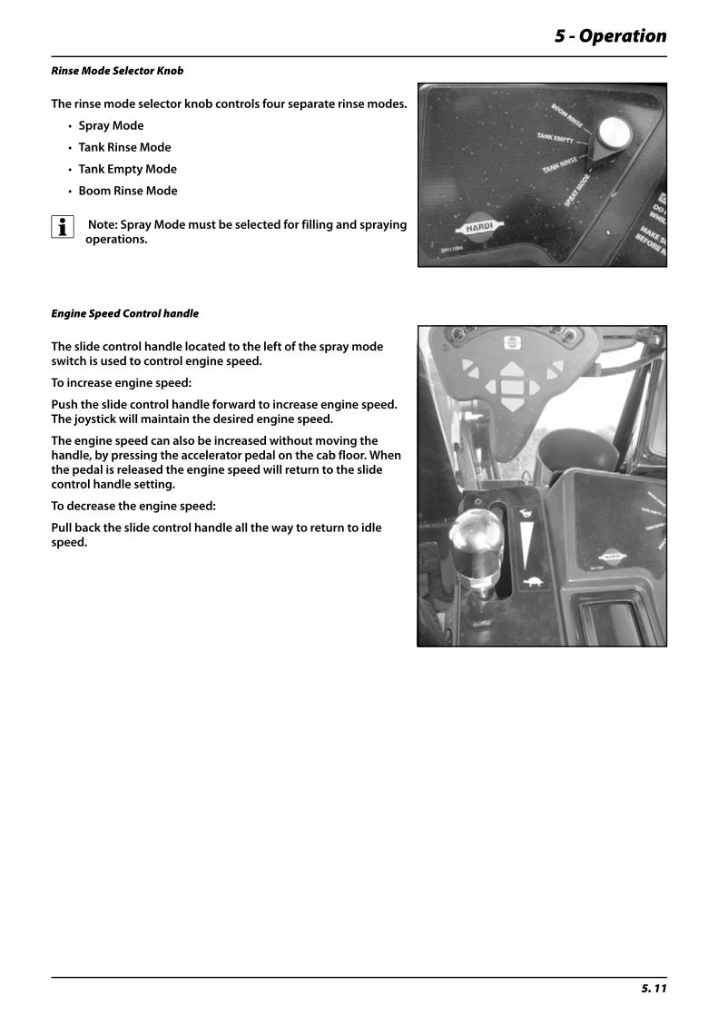
5 - Operation
5. 11
Rinse Mode Selector Knob
The rinse mode selector knob controls four separate rinse modes.
• Spray Mode
• Tank Rinse Mode
• Tank Empty Mode
• Boom Rinse Mode
÷ Note: Spray Mode must be selected for filling and spraying operations.
Engine Speed Control handle
The slide control handle located to the left of the spray mode switch is used to control engine speed.
To increase engine speed:
Push the slide control handle forward to increase engine speed. The joystick will maintain the desired engine speed.
The engine speed can also be increased without moving the handle, by pressing the accelerator pedal on the cab floor. When the pedal is released the engine speed will return to the slide control handle setting.
To decrease the engine speed:
Pull back the slide control handle all the way to return to idle speed.

5 - Operation
5. 12
AgLeader Insight Display
The AgLeader InSight display is truly the hub of your precision spraying operation. It allows you to record every activity that happens in your field and provides you with real-time information - everything from boundary mapping to historical application maps.
The real value of the InSight display is in how it uses information to help you control all of your operations - eliminating overspraying and over application while helping reduce input costs.
÷ Note: Consult the InSight User Manual supplied with your machine for full description of sprayer operations available when using the AgLeader DirectCommand system.
Navigation Button Button Description
1 Press to access the Home screen on the InSight display. Options availableat the Home screen are, Copy to Card, Upgrade System, User Guide,Change Operator and Shut Down
2 Press to access the menus and wizards used for system configuration.General setup item groups include, Grower-Field Management, FieldNotes, Console, and GPS configurations. Use specific setup item groupsinclude, Planting, Product Application, Tillage, and Harvest configura-tions.
3 Press the Brightness Control to set display back light intensity to fit cur-rent operating conditions.
4 Press to display a summary screen showing totals for the current field op-eration you are performing.
5 Press to launch the Run Screen. The Run Screen provides control of allfield operations and the data logging associated with, Harvest, Planting,Tillage, and Product Application.
1. HOME
2. MENU
3. BRIGHTNESS
4. SUMMARY
5. RUN
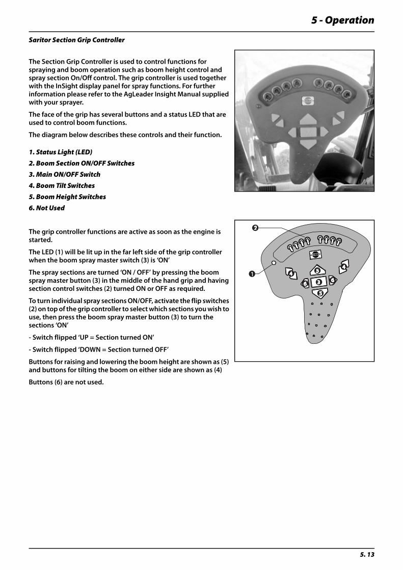
5 - Operation
5. 13
Saritor Section Grip Controller
The Section Grip Controller is used to control functions for spraying and boom operation such as boom height control and spray section On/Off control. The grip controller is used together with the InSight display panel for spray functions. For further information please refer to the AgLeader Insight Manual supplied with your sprayer.
The face of the grip has several buttons and a status LED that are used to control boom functions.
The diagram below describes these controls and their function.
The grip controller functions are active as soon as the engine is started.
The LED (1) will be lit up in the far left side of the grip controller when the boom spray master switch (3) is ‘ON’
The spray sections are turned ‘ON / OFF’ by pressing the boom spray master button (3) in the middle of the hand grip and having section control switches (2) turned ON or OFF as required.
To turn individual spray sections ON/OFF, activate the flip switches (2) on top of the grip controller to select which sections you wish to use, then press the boom spray master button (3) to turn the sections ‘ON’
- Switch flipped ‘UP = Section turned ON’
- Switch flipped ‘DOWN = Section turned OFF’
Buttons for raising and lowering the boom height are shown as (5) and buttons for tilting the boom on either side are shown as (4)
Buttons (6) are not used.
1. Status Light (LED)
2. Boom Section ON/OFF Switches
3. Main ON/OFF Switch
4. Boom Tilt Switches
5. Boom Height Switches
6. Not Used
5
5
663
44
2
1
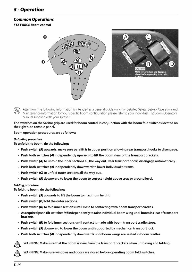
5 - Operation
5. 14
Common OperationsFTZ FORCE Boom control
μ Attention: The following information is intended as a general guide only. For detailed Safety, Set-up, Operation and Maintenance information for your specific boom configuration please refer to your individual FTZ Boom Operators Manual supplied with your sprayer.
The switches on the Saritor grip are used for boom control in conjunction with the boom fold switches located on the right side console panel.
Boom operation procedures are as follows;
Unfolding procedureTo unfold the boom, do the following:
• Push switch (5) upwards, make sure paralift is in upper position allowing rear transport hooks to disengage.
• Push both switches (4) independently upwards to lift the boom clear of the transport brackets.
• Push switch (A) to unfold the inner sections all the way out. Rear transport hooks disengage automatically.
• Push both switches (4) independently downward to lower individual tilt rams.
• Push switch (C) to unfold outer sections all the way out.
• Push switch (5) downward to lower the boom to correct height above crop or ground level.
Folding procedureTo fold the boom, do the following:
• Push switch (5) upwards to lift the boom to maximum height.
• Push switch (D) fold the outer sections.
• Push switch (B) to fold inner sections until close to contacting with boom transport cradles.
• As required push tilt switches (4) independently to raise individual boom wing until boom is clear of transport brackets.
• Push switch (B) to fold inner sections until contact is made with boom transport cradle stops.
• Push switch (5) downward to lower the boom until supported by mechanical transport lock.
• Push both switches (4) independently downwards until boom wings are seated in boom cradles.
± WARNING: Make sure that the boom is clear from the transport brackets when unfolding and folding.
± WARNING: Make sure windows and doors are closed before operating boom fold switches.
CA
DB5
5
663
44
2
1
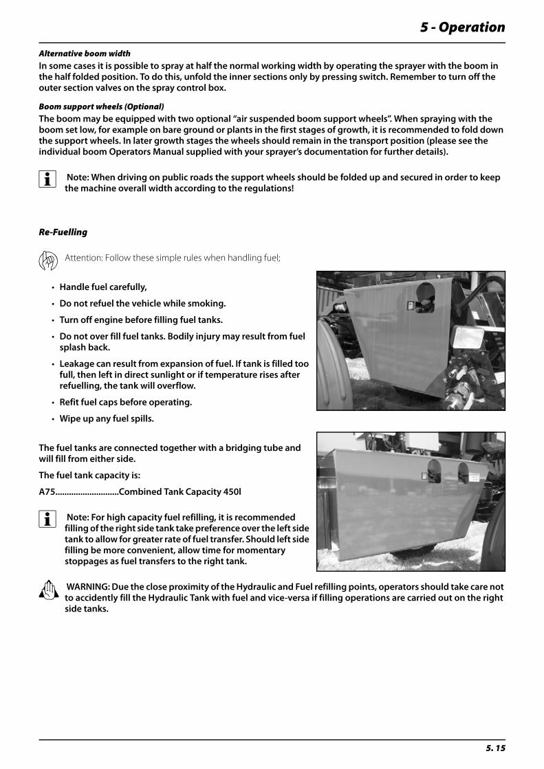
5 - Operation
5. 15
Alternative boom widthIn some cases it is possible to spray at half the normal working width by operating the sprayer with the boom in the half folded position. To do this, unfold the inner sections only by pressing switch. Remember to turn off the outer section valves on the spray control box.
Boom support wheels (Optional)The boom may be equipped with two optional “air suspended boom support wheels”. When spraying with the boom set low, for example on bare ground or plants in the first stages of growth, it is recommended to fold down the support wheels. In later growth stages the wheels should remain in the transport position (please see the individual boom Operators Manual supplied with your sprayer’s documentation for further details).
÷ Note: When driving on public roads the support wheels should be folded up and secured in order to keep the machine overall width according to the regulations!
Re-Fuelling
μ Attention: Follow these simple rules when handling fuel;
• Handle fuel carefully,
• Do not refuel the vehicle while smoking.
• Turn off engine before filling fuel tanks.
• Do not over fill fuel tanks. Bodily injury may result from fuel splash back.
• Leakage can result from expansion of fuel. If tank is filled too full, then left in direct sunlight or if temperature rises after refuelling, the tank will overflow.
• Refit fuel caps before operating.
• Wipe up any fuel spills.
The fuel tanks are connected together with a bridging tube and will fill from either side.
The fuel tank capacity is:
A75............................Combined Tank Capacity 450l
÷ Note: For high capacity fuel refilling, it is recommended filling of the right side tank take preference over the left side tank to allow for greater rate of fuel transfer. Should left side filling be more convenient, allow time for momentary stoppages as fuel transfers to the right tank.
± WARNING: Due the close proximity of the Hydraulic and Fuel refilling points, operators should take care not to accidently fill the Hydraulic Tank with fuel and vice-versa if filling operations are carried out on the right side tanks.
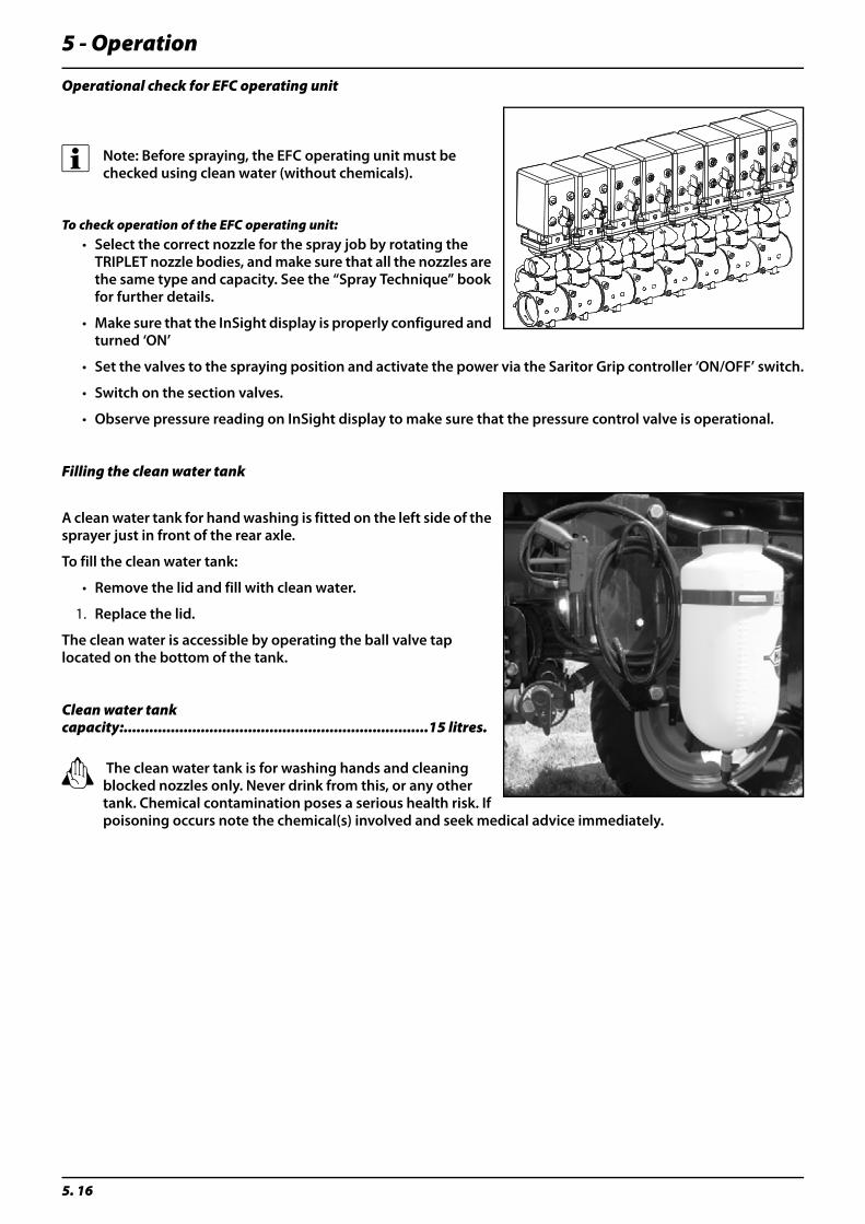
5 - Operation
5. 16
Operational check for EFC operating unit
÷ Note: Before spraying, the EFC operating unit must be checked using clean water (without chemicals).
To check operation of the EFC operating unit:• Select the correct nozzle for the spray job by rotating the
TRIPLET nozzle bodies, and make sure that all the nozzles are the same type and capacity. See the “Spray Technique” book for further details.
• Make sure that the InSight display is properly configured and turned ‘ON’
• Set the valves to the spraying position and activate the power via the Saritor Grip controller ‘ON/OFF’ switch.
• Switch on the section valves.
• Observe pressure reading on InSight display to make sure that the pressure control valve is operational.
Filling the clean water tank
A clean water tank for hand washing is fitted on the left side of the sprayer just in front of the rear axle.
To fill the clean water tank:
• Remove the lid and fill with clean water.
1. Replace the lid.
The clean water is accessible by operating the ball valve tap located on the bottom of the tank.
Clean water tank capacity:.......................................................................15 litres.
± The clean water tank is for washing hands and cleaning blocked nozzles only. Never drink from this, or any other tank. Chemical contamination poses a serious health risk. If poisoning occurs note the chemical(s) involved and seek medical advice immediately.
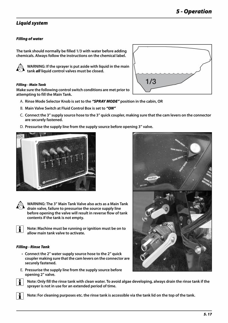
5 - Operation
5. 17
Liquid system
Filling of water
The tank should normally be filled 1/3 with water before adding chemicals. Always follow the instructions on the chemical label.
± WARNING: If the sprayer is put aside with liquid in the main tank all liquid control valves must be closed.
Filling - Main TankMake sure the following control switch conditions are met prior to attempting to fill the Main Tank.
A. Rinse Mode Selector Knob is set to the “SPRAY MODE” position in the cabin, OR
B. Main Valve Switch at Fluid Control Box is set to “ON”
C. Connect the 3” supply source hose to the 3” quick coupler, making sure that the cam levers on the connector are securely fastened.
D. Pressurise the supply line from the supply source before opening 3” valve.
± WARNING: The 3” Main Tank Valve also acts as a Main Tank drain valve, failure to pressurise the source supply line before opening the valve will result in reverse flow of tank contents if the tank is not empty.
÷ Note: Machine must be running or ignition must be on to allow main tank valve to activate.
Filling - Rinse Tank
• Connect the 2” water supply source hose to the 2” quick coupler making sure that the cam levers on the connector are securely fastened.
E. Pressurise the supply line from the supply source before opening 2” valve.
÷ Note: Only fill the rinse tank with clean water. To avoid algae developing, always drain the rinse tank if the sprayer is not in use for an extended period of time.
÷ Note: For cleaning purposes etc. the rinse tank is accessible via the tank lid on the top of the tank.
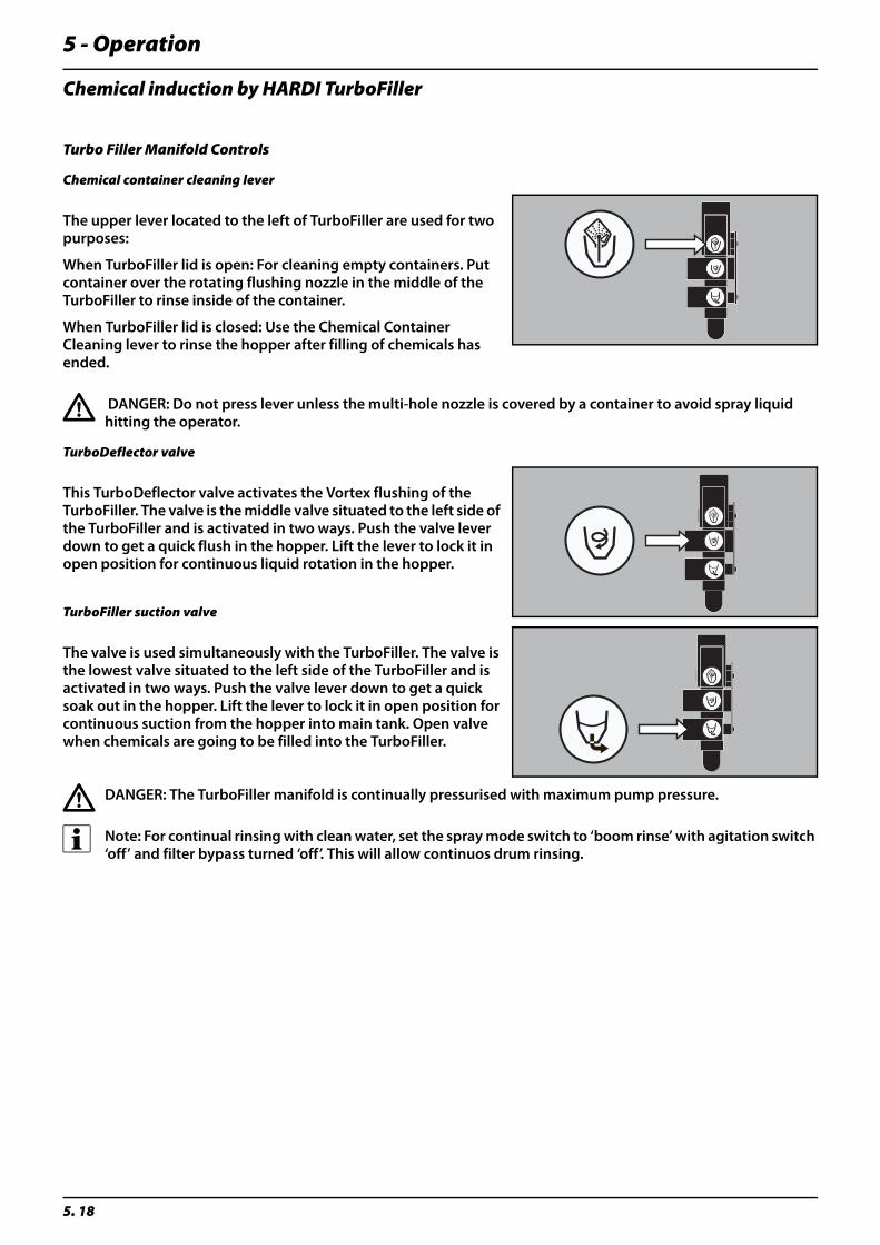
5 - Operation
5. 18
Chemical induction by HARDI TurboFiller
Turbo Filler Manifold Controls
Chemical container cleaning lever
The upper lever located to the left of TurboFiller are used for two purposes:
When TurboFiller lid is open: For cleaning empty containers. Put container over the rotating flushing nozzle in the middle of the TurboFiller to rinse inside of the container.
When TurboFiller lid is closed: Use the Chemical Container Cleaning lever to rinse the hopper after filling of chemicals has ended.
€ DANGER: Do not press lever unless the multi-hole nozzle is covered by a container to avoid spray liquid hitting the operator.
TurboDeflector valve
This TurboDeflector valve activates the Vortex flushing of the TurboFiller. The valve is the middle valve situated to the left side of the TurboFiller and is activated in two ways. Push the valve lever down to get a quick flush in the hopper. Lift the lever to lock it in open position for continuous liquid rotation in the hopper.
TurboFiller suction valve
The valve is used simultaneously with the TurboFiller. The valve is the lowest valve situated to the left side of the TurboFiller and is activated in two ways. Push the valve lever down to get a quick soak out in the hopper. Lift the lever to lock it in open position for continuous suction from the hopper into main tank. Open valve when chemicals are going to be filled into the TurboFiller.
€ DANGER: The TurboFiller manifold is continually pressurised with maximum pump pressure.
÷ Note: For continual rinsing with clean water, set the spray mode switch to ‘boom rinse’ with agitation switch ‘off’ and filter bypass turned ‘off’. This will allow continuos drum rinsing.
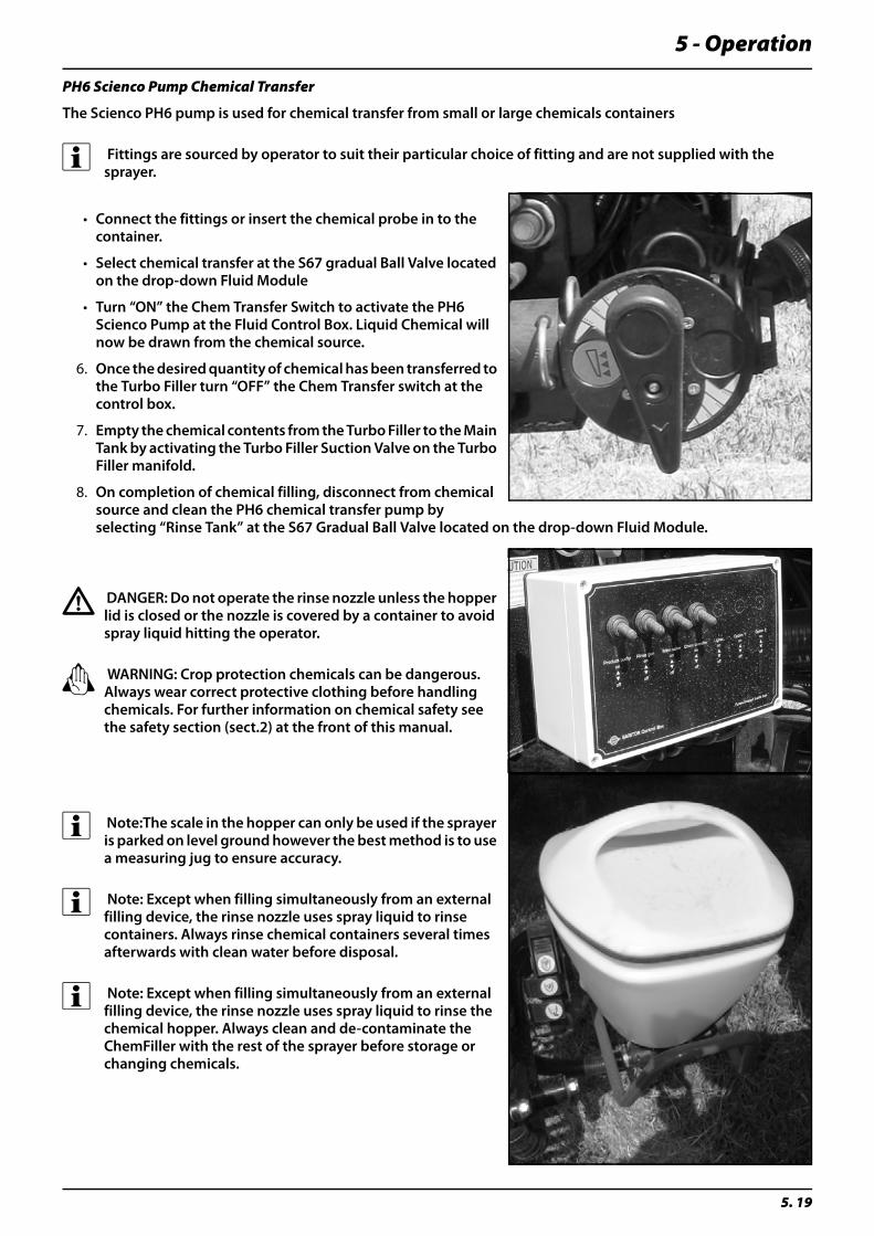
5 - Operation
5. 19
PH6 Scienco Pump Chemical Transfer
The Scienco PH6 pump is used for chemical transfer from small or large chemicals containers
÷ Fittings are sourced by operator to suit their particular choice of fitting and are not supplied with the sprayer.
• Connect the fittings or insert the chemical probe in to the container.
• Select chemical transfer at the S67 gradual Ball Valve located on the drop-down Fluid Module
• Turn “ON” the Chem Transfer Switch to activate the PH6 Scienco Pump at the Fluid Control Box. Liquid Chemical will now be drawn from the chemical source.
6. Once the desired quantity of chemical has been transferred to the Turbo Filler turn “OFF” the Chem Transfer switch at the control box.
7. Empty the chemical contents from the Turbo Filler to the Main Tank by activating the Turbo Filler Suction Valve on the Turbo Filler manifold.
8. On completion of chemical filling, disconnect from chemical source and clean the PH6 chemical transfer pump by selecting “Rinse Tank” at the S67 Gradual Ball Valve located on the drop-down Fluid Module.
€ DANGER: Do not operate the rinse nozzle unless the hopper lid is closed or the nozzle is covered by a container to avoid spray liquid hitting the operator.
± WARNING: Crop protection chemicals can be dangerous. Always wear correct protective clothing before handling chemicals. For further information on chemical safety see the safety section (sect.2) at the front of this manual.
÷ Note:The scale in the hopper can only be used if the sprayer is parked on level ground however the best method is to use a measuring jug to ensure accuracy.
÷ Note: Except when filling simultaneously from an external filling device, the rinse nozzle uses spray liquid to rinse containers. Always rinse chemical containers several times afterwards with clean water before disposal.
÷ Note: Except when filling simultaneously from an external filling device, the rinse nozzle uses spray liquid to rinse the chemical hopper. Always clean and de-contaminate the ChemFiller with the rest of the sprayer before storage or changing chemicals.
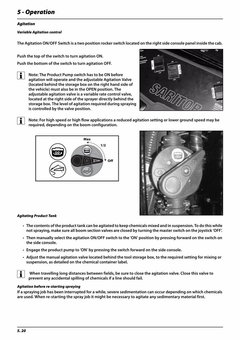
5 - Operation
5. 20
Agitation
Variable Agitation control
The Agitation ON/OFF Switch is a two position rocker switch located on the right side console panel inside the cab.
Push the top of the switch to turn agitation ON.
Push the bottom of the switch to turn agitation OFF.
÷ Note: The Product Pump switch has to be ON before agitation will operate and the adjustable Agitation Valve (located behind the storage box on the right hand side of the vehicle) must also be in the OPEN position. The adjustable agitation valve is a variable rate control valve, located at the right side of the sprayer directly behind the storage box. The level of agitation required during spraying is controlled by the valve position.
÷ Note: For high speed or high flow applications a reduced agitation setting or lower ground speed may be required, depending on the boom configuration.
Agitating Product Tank
• The contents of the product tank can be agitated to keep chemicals mixed and in suspension. To do this while not spraying, make sure all boom section valves are closed by turning the master switch on the joystick ‘OFF’.
• Then manually select the agitation ON/OFF switch to the ‘ON’ position by pressing forward on the switch on the side console.
• Engage the product pump to ‘ON’ by pressing the switch forward on the side console.
• Adjust the manual agitation valve located behind the tool storage box, to the required setting for mixing or suspension, as detailed on the chemical container label.
÷ When travelling long distances between fields, be sure to close the agitation valve. Close this valve to prevent any accidental spilling of chemicals if a line should fail.
Agitation before re-starting sprayingIf a spraying job has been interrupted for a while, severe sedimentation can occur depending on which chemicals are used. When re-starting the spray job it might be necessary to agitate any sedimentary material first.
���
���
��

5 - Operation
5. 21
FiltersCyclone FilterThe Cyclone Filter and Multi Section Filter allow the impurities in the spray liquid to by-pass the filter mesh and be re-circulated back to the tank via the return flow. In the event of unplanned fluid system maintenance whilst spraying, the operator can close the main electrically operated suction valve at the fluid control box and the agitation control switch in the cabin to ‘OFF’, isolating the main tank for safety. A one-way check valve prevents return flow from the distribution valves when checking the Cyclone and Multi Section Filters making these tasks safer and cleaner.
Function diagram:
Return ValveThe Return valve (see inset) has three positions marked with small dots on the lever:
Position A(Marked with 1 dot): This position prevents return flow and is used for rinsing the boom when spray liquid remains in the main tank. It is also used when high spraying volume is required.
Position B(Marked with 2 dots): Normal spraying position with return flow to prevent filter from being clogged during spraying. This position is also used when rinsing the boom if the main tank is empty.
Position C(Marked with 3 dots): Flushing position for use if filter is clogged. Lift and hold the lever to increase return flow and clean the filter.
Multi Section FilterThe Multi Section Filter is mounted on the rear of the sprayer centre where the section distribution valves are located.
The Multi Section filter does not require continuous return to tank as most contaminants are trapped in the Cyclone filter.
The filter can be flushed out in the same manner as the Cyclone filter by operating the Return valve at the bottom of the filter.
It is recommended that the flush liquid is trapped in a suitable container and disposed of in a safe manner or returned into the tank via the Turbofiller.
€ DANGER: To stop contaminated products from splashing the operator or draining from Main Tank whilst cleaning the Cyclone Filter or Multi-Section Filter, the main 3” Ball Valve must be “closed” and the agitation valve switch must be ‘OFF’. Set the S67 ball valve located near the Cyclone Pressure Filter to the ‘OFF’ position to prevent flow of either Main Tank or Boom line contents.
÷ Note: For ease of operation, always lubricates o-rings after cleaning filter.
Cleaning of filters
Clean filters help to:
• Reduce damage to sprayer components such as valves, seals and operating units during operation.
• Prevent nozzle blockages occurring whilst spraying.
• Prolong life of the pump. The main filter protecting the sprayers internal components is the suction filter. A blocked suction filter will result in pump cavitation. Check it regularly.
1. Filter lid 2. Flow from pump 3. To boom
4. Return to tank 5. Return valve 6. Check valve

5 - Operation
5. 22
In-Field Spraying Operation
• Make sure that the rotary fluid dial is selected to the ‘Spray Mode’ position.
• Check the manual agitation valve (located behind the storage box on the right hand side of the vehicle) is positioned correctly, according to the chemical container label, re-agitation level required.
• Position the cyclone filter boost valve to position ‘B’.
• Enter required litres/per hectare into InSight terminal
• Engage Product Pump at side console switch, make sure that the pressure is seen on pump pressure gauge at bottom left of cabin windscreen.
• Engage agitation switch at side console to ‘ON’ position
• Switch boom ‘ON’ at Saritor Grip controller ON/OFF product switch.
• For manual or auto pressure regulation control, please refer to InSight User manual.
• For boom pressure readout, activate the pressure transducer readout on the InSight Display terminal.
5 - Operation
5. 23
Cleaning
Introduction
The best performance and service life can be expected when the sprayer is properly cleaned and maintained. Clean sprayers are safe and ready for action. Clean sprayers are less likely to be damaged by pesticides and their solvents.
€ DANGER: Agricultural chemicals can be dangerous. Read chemical labels and carefully follow safety recommendations to the letter. Always use appropriate safety clothing and equipment (see section 2 of this manual for further information).
÷ Note: Read instructions for cleaning carefully before starting on the job. This includes the instructions on the chemical label which must be observed. Further information such as local restrictions on the disposal of chemical washings and licensing for operators specific to your area can be obtained from the Department of Primary Industries and the Environmental Protection Agency.
Cleaning Guidelines
• Read the whole chemical label. Take note of any particular instructions regarding recommended protective clothing, deactivating agents, etc. Read the detergent and deactivating agent labels. If cleaning procedures are given, follow them closely.
• Be familiar with local legislation regarding the disposal of chemical washings, mandatory decontamination methods, etc. Contact the appropriate department, e.g. Department of Primary Industries / Environmental Protection Agency.
• Legislation demands that you prevent seepage or run off of residue into streams, water courses, ditches, wells, springs, etc. The washings from the cleaning area must not enter sewers. Drainage must be confined to an approved catchment.
• Cleaning starts with accurate calibration. A well calibrated sprayer will ensure the minimum amount of spray solution remains in the tank once the spray job is completed.
• It is good practice to clean and decontaminate the sprayer immediately after use, rendering the sprayer safe and ready for the next spray job. This also prolongs the life of the components. Be aware that if chemicals are left to dry out on the sprayers surfaces, they become much more difficult to remove.
• It is sometimes necessary to leave spray liquid in the tank for short periods, e.g. overnight, or until the weather improves. Animals and unauthorised persons must not have access to the sprayer under these circumstances.
• If the product to be used is corrosive (ie: liquid fertiliser) apply a coat of a suitable rust inhibitor before and after the job.
5 - Operation
5. 24
Rinse SystemThe Saritor offers a simple yet effective rinse system. It allows for all essential components of the fluid system to be cleaned by choosing one or more rinse modes on the rinse mode selector knob.
The rinse mode selector knob controls four separate rinse modes;
Observe the following conditions when using the rinse functions;
Turn agitation OFF
Turn product pump OFF. Do Not run the pump dry!
Spray ModeWith the rinse mode selector switch in the “Spray Mode” position.
• The sump valve is open
• The fresh water valve is closed
• The tank rinse valve is closed
• The agitation valve is closed (Unless activated ON with the console switch)
• The product pump is ON or OFF depending on the console switch
Tank Rinse ModeWith the rinse mode selector switch in the “Tank Rinse” position.
• The sump valve is closed
• The fresh water valve is open
• The tank rinse valve is open
• The agitation valve is open
• The product pump is ON regardless of the console switch position
The chemical inductor valve can be opened during this cycle
Tank Empty ModeWith the rinse mode selector switch in the “Tank Empty” position.
• The sump valve is open
• The fresh water valve is closed
• The tank rinse valve is closed
• The agitation valve is closed
• The product pump is ON regardless of the console switch position
Boom Rinse ModeWith the rinse mode selector switch in the “Boom Rinse” position.
• The sump valve is closed
• The fresh water valve is open
• The tank rinse valve is closed
• The agitation valve is closed
• The product pump is ON regardless of the console switch position
1. Spray Mode 2. Tank Rinse Mode 3. Tank Empty Mode 4. Boom Rinse Mode
5 - Operation
5. 25
Rinsing boom and fluid system
± WARNING: In the following scenarios the 3” fill line, filter and ball valve will entrap residue.
± WARNING: In field rinsing can never take the place of a thorough decontamination. Always refer to Chemical suppliers decontamination instructions in combination with “Decontamination” section in this book.
The rinse tank is used in two main scenarios:
In Scenario A residue will not be cleaned out, but in Scenario B, residue will be cleaned out.
SCENARIO A:Rinsing the pump, operating unit and spray lines etc in the event of an interruption to spraying before the main tank is empty (for example when poor weather prevents further spraying or night falls). To flush the system proceed as follows:
Rinsing the pump, operating unit and spray lines• Turn the cyclone filter valve to off position A (marked with one dot) to prevent return flow from diluting the
contents of the main tank (see CycloneFilter operating instructions earlier this section). Turn ‘OFF’ the agitation valve to reduce return flow of product to tank.
• Turn the Rinse Selector Knob to “Boom Rinse” mode.
• Spray water from the rinse tank onto an area of the field not yet sprayed until air comes out of all the nozzles.
• Return Rinse selector knob to “Spray Mode” position.
SCENARIO B:In-field dilution and expulsion of “Technical Residue” (ie: the residual spray liquid remaining in the tank and spray circuit after the first clear pressure drop is seen on the pressure gauge).
Rinsing the entire liquid system• Turn the cyclone filter valve to off position A (marked with one dot) to prevent return flow from diluting the
contents of the main tank (see CycloneFilter operating instructions earlier this section).
• Empty the sprayer as much as possible by turning the Rinse selector knob to “Tank Empty” mode (Position 2) and spray onto an area of the field not yet sprayed until air comes out of all the nozzles.
• Turn the Rinse selector knob to “Tank rinse” mode. Transfer 1/3 of rinse tank content to main tank and return Rinse selector knob to “Spray Mode” mode position.
• Clean out the 3” fill line. The solution can be collected in a suitable container and poured into the Turbo filler.
• Briefly operate all functions of the Turbofiller and transfer the contents to the main tank.
• Empty the sprayer again by turning the Rinse selector knob to “Tank Empty” mode and spray onto an area of the field not yet sprayed until air comes out of all the nozzles.
• Repeat section 3-6 until all rinse water is consumed.
± WARNING: To avoid over-dosing the crop, spray out diluted residues over as large an area as possible by increasing your forward speed (to double if possible) and halve your working pressure to somewhere around 1.5 bar (20 psi).
5 - Operation
5. 26
De-contamination
IntroductionA complete cleaning and storage procedure consists of six steps:
In addition to the cleaning information previously described, complete sprayer cleaning includes “De-contamination” which is essential to reduce risk to other crops sprayed and makes sure the sprayer is safe and ready for the next spray job. It is especially critical after using herbicides where even tiny traces of chemicals left in machinery can damage later sprayed crops. Always remember, if it’s not clean, it’s not safe!
It is therefore necessary to neutralise any chemical residues left within the sprayer’s fluid system, before changing crops, chemicals or off-season storage. This includes the main tank, flush tank, chemical induction system, all hoses, valves, spray lines, nozzles and the external surfaces of the sprayer.
± WARNING: Always use personal safety equipment and clothing, and make sure contaminated equipment and clothing is stored, cleaned, or disposed of in an appropriate manner (See “Chemical Safety” in section 2 of this manual).
De-contamination agentsSome chemicals require particular neutralising agents and stringent decontamination procedures to make sure particles that may have adhered to sprayer system surfaces are rendered neutral before spraying a new crop or changing chemicals.
Chemical labels contain important information regarding safety, cleaning, neutralising agents and decontamination procedures. Read them and take note of recommended de-activating agents and follow their instructions to the letter.
± WARNING: Local laws may vary from state to state regarding the use and disposal of certain agricultural chemicals. Contact your local authorities for details. Information can also be obtained from the Department of Agriculture, the Department of Primary Industries or the Environmental Protection Authority.
± WARNING: Contamination of one chemical to another can adversely affect chemical properties and damage or destroy your next crop. The sprayer must be cleaned and decontaminated when changing chemicals or crops.
Decontamination:After your sprayer has been flushed/rinsed and drained, it's time to clean and decontaminate it. Using the recommended decontamination agent and dose listed on the product label (personal protective equipment is essential). Be sure to decontaminate both the interior and exterior of the machine, running the de-contaminating solution right through the fluid system and boom structure and out the nozzles.
As most chemicals used have a tendency to block nozzles and filters, remove and clean in the appropriate decontamination solution with a soft brush. Check also for sediment on the pressure side of the safety valve.
Tank rinsing:If tank rinse nozzles are fitted add clean water to the spray tank until it is approximately a quarter (25%) full. Then mix in a cleaning agent recommended for sprayer decontamination at the correct dilution rate for the volume of liquid in the spray tank. No further water needs to be added at this stage. Use the tank rinsing nozzles, re-circulate and discharge via the boom nozzles.
÷ Note: The tank rinse nozzle cannot guarantee a 100% effective cleaning job. It is recommended to clean the tank manually with a long handled brush or high pressure cleaner.
÷ Note: For further information on cleaning and de-contamination please contact your HARDI Dealer or visit our web site at www.hardi.com
1. Read Labels 2. Flush 3. Drain 4. Decontamination 5. Inspect 6. Store
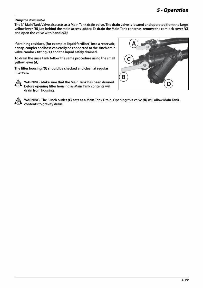
5 - Operation
5. 27
Using the drain valveThe 3” Main Tank Valve also acts as a Main Tank drain valve. The drain valve is located and operated from the large yellow lever (B) just behind the main access ladder. To drain the Main Tank contents, remove the camlock cover (C) and open the valve with handle(B)
If draining residues, (for example: liquid fertiliser) into a reservoir, a snap-coupler and hose can easily be connected to the 3inch drain valve camlock fitting (C) and the liquid safely drained.
To drain the rinse tank follow the same procedure using the small yellow lever (A)
The filter housing (D) should be checked and clean at regular intervals.
± WARNING: Make sure that the Main Tank has been drained before opening filter housing as Main Tank contents will drain from housing.
± WARNING: The 3 inch outlet (C) acts as a Main Tank Drain. Opening this valve (B) will allow Main Tank contents to gravity drain.
A
B
C
D

5 - Operation
5. 28
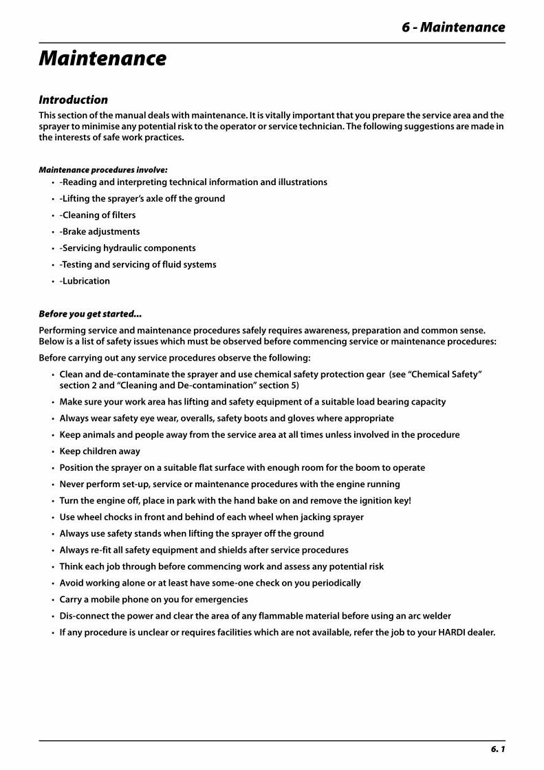
6 - Maintenance
6. 1
Maintenance
IntroductionThis section of the manual deals with maintenance. It is vitally important that you prepare the service area and the sprayer to minimise any potential risk to the operator or service technician. The following suggestions are made in the interests of safe work practices.
Maintenance procedures involve:• -Reading and interpreting technical information and illustrations
• -Lifting the sprayer’s axle off the ground
• -Cleaning of filters
• -Brake adjustments
• -Servicing hydraulic components
• -Testing and servicing of fluid systems
• -Lubrication
Before you get started...
Performing service and maintenance procedures safely requires awareness, preparation and common sense. Below is a list of safety issues which must be observed before commencing service or maintenance procedures:
Before carrying out any service procedures observe the following:
• Clean and de-contaminate the sprayer and use chemical safety protection gear (see “Chemical Safety” section 2 and “Cleaning and De-contamination” section 5)
• Make sure your work area has lifting and safety equipment of a suitable load bearing capacity
• Always wear safety eye wear, overalls, safety boots and gloves where appropriate
• Keep animals and people away from the service area at all times unless involved in the procedure
• Keep children away
• Position the sprayer on a suitable flat surface with enough room for the boom to operate
• Never perform set-up, service or maintenance procedures with the engine running
• Turn the engine off, place in park with the hand bake on and remove the ignition key!
• Use wheel chocks in front and behind of each wheel when jacking sprayer
• Always use safety stands when lifting the sprayer off the ground
• Always re-fit all safety equipment and shields after service procedures
• Think each job through before commencing work and assess any potential risk
• Avoid working alone or at least have some-one check on you periodically
• Carry a mobile phone on you for emergencies
• Dis-connect the power and clear the area of any flammable material before using an arc welder
• If any procedure is unclear or requires facilities which are not available, refer the job to your HARDI dealer.

6 - Maintenance
6. 2
Spare parts
For spare parts diagrams, please see the section at the back of this manual, visit the web site at www.agroparts.com and register for free, or contact your HARDI dealer.
÷ Note: Due to on-going development the parts information at www.agroparts.com may not currently contain all the spare parts drawings specific to your product.
Please contact your HARDI dealer for further information and updates.
LubricationGeneral info
To avoid contamination from dirt and condensed water, always keep lubricants clean, dry and cool - preferably at a constant temperature.
Keep oil filling jugs, hoppers and grease guns clean, and clean the lubricating points thoroughly before applying lubricant.
Avoid skin contact with mineral oil products for long periods.
Always follow the directions concerning recommended quantity. If no recommended quantity is given, feed the lubricator until new grease becomes visible.
Pictogram in lubrication & oiling plans indicate the following:
• Lubricant to be used
• Operating hours before next lubrication
÷ If the sprayer is cleaned with a high pressure cleaner lubrication of the entire machine is recommended.
Boom lubrication plan
÷ Note: For complete Boom and boom centre service information please refer to your FTZ Boom Operators Manual supplied with your sprayer’s documentation.
Recommended lubricants
BALL BEARINGS
Castrol EPL2 Grease or equivalent.
SLIDE BEARINGS
Castrol Molybdenum-disulphide grease or equivalent
OIL LUBE POINTS
Castrol EPX 80W/90 or equivalent
“O” RING SEALS
Castrol Non-mineral based Rubber grease or equivalent
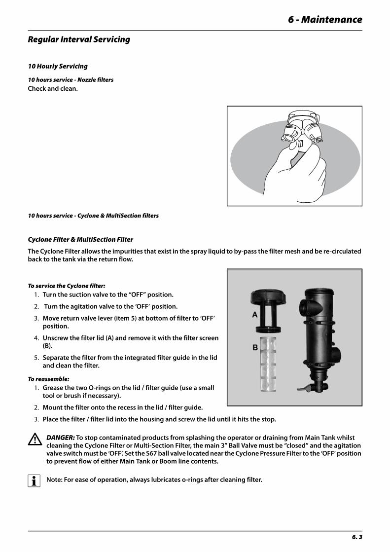
6 - Maintenance
6. 3
Regular Interval Servicing
10 Hourly Servicing
10 hours service - Nozzle filtersCheck and clean.
10 hours service - Cyclone & MultiSection filters
Cyclone Filter & MultiSection Filter
The Cyclone Filter allows the impurities that exist in the spray liquid to by-pass the filter mesh and be re-circulated back to the tank via the return flow.
To service the Cyclone filter:1. Turn the suction valve to the “OFF” position.
2. Turn the agitation valve to the ‘OFF’ position.
3. Move return valve lever (item 5) at bottom of filter to ‘OFF’ position.
4. Unscrew the filter lid (A) and remove it with the filter screen (B).
5. Separate the filter from the integrated filter guide in the lid and clean the filter.
To reassemble:1. Grease the two O-rings on the lid / filter guide (use a small
tool or brush if necessary).
2. Mount the filter onto the recess in the lid / filter guide.
3. Place the filter / filter lid into the housing and screw the lid until it hits the stop.
€ DANGER: To stop contaminated products from splashing the operator or draining from Main Tank whilst cleaning the Cyclone Filter or Multi-Section Filter, the main 3” Ball Valve must be “closed” and the agitation valve switch must be ‘OFF’. Set the S67 ball valve located near the Cyclone Pressure Filter to the ‘OFF’ position to prevent flow of either Main Tank or Boom line contents.
÷ Note: For ease of operation, always lubricates o-rings after cleaning filter.
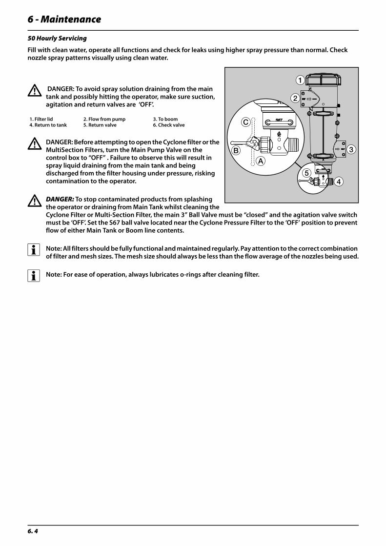
6 - Maintenance
6. 4
50 Hourly Servicing
Fill with clean water, operate all functions and check for leaks using higher spray pressure than normal. Check nozzle spray patterns visually using clean water.
€ DANGER: To avoid spray solution draining from the main tank and possibly hitting the operator, make sure suction, agitation and return valves are ‘OFF’.
€ DANGER: Before attempting to open the Cyclone filter or the MultiSection Filters, turn the Main Pump Valve on the control box to “OFF” . Failure to observe this will result in spray liquid draining from the main tank and being discharged from the filter housing under pressure, risking contamination to the operator.
€ DANGER: To stop contaminated products from splashing the operator or draining from Main Tank whilst cleaning the Cyclone Filter or Multi-Section Filter, the main 3” Ball Valve must be “closed” and the agitation valve switch must be ‘OFF’. Set the S67 ball valve located near the Cyclone Pressure Filter to the ‘OFF’ position to prevent flow of either Main Tank or Boom line contents.
÷ Note: All filters should be fully functional and maintained regularly. Pay attention to the correct combination of filter and mesh sizes. The mesh size should always be less than the flow average of the nozzles being used.
÷ Note: For ease of operation, always lubricates o-rings after cleaning filter.
1. Filter lid 2. Flow from pump 3. To boom4. Return to tank 5. Return valve 6. Check valve
6 - Maintenance
6. 5
Occasional maintenance
General info
The maintenance and renewal intervals for the following will depend very much on the conditions under which the sprayer will be operated and are therefore impossible to specify.
Level Indicator Cord Replacement
If the cord on the level indicator has to be changed, the float guide pole is removed:
1. Remove the tank drain valve (see paragraph “Drain valve seal replacement”) and loosen the fitting holding the pole in position.
2. Pull the pole down through the drain valve hole till it is free in the top of the tank.
3. The pole can now be taken out of the tank through the filling hole.
€ DANGER: Do not enter the inside of the tank - the parts can be changed from the outside of the tank!
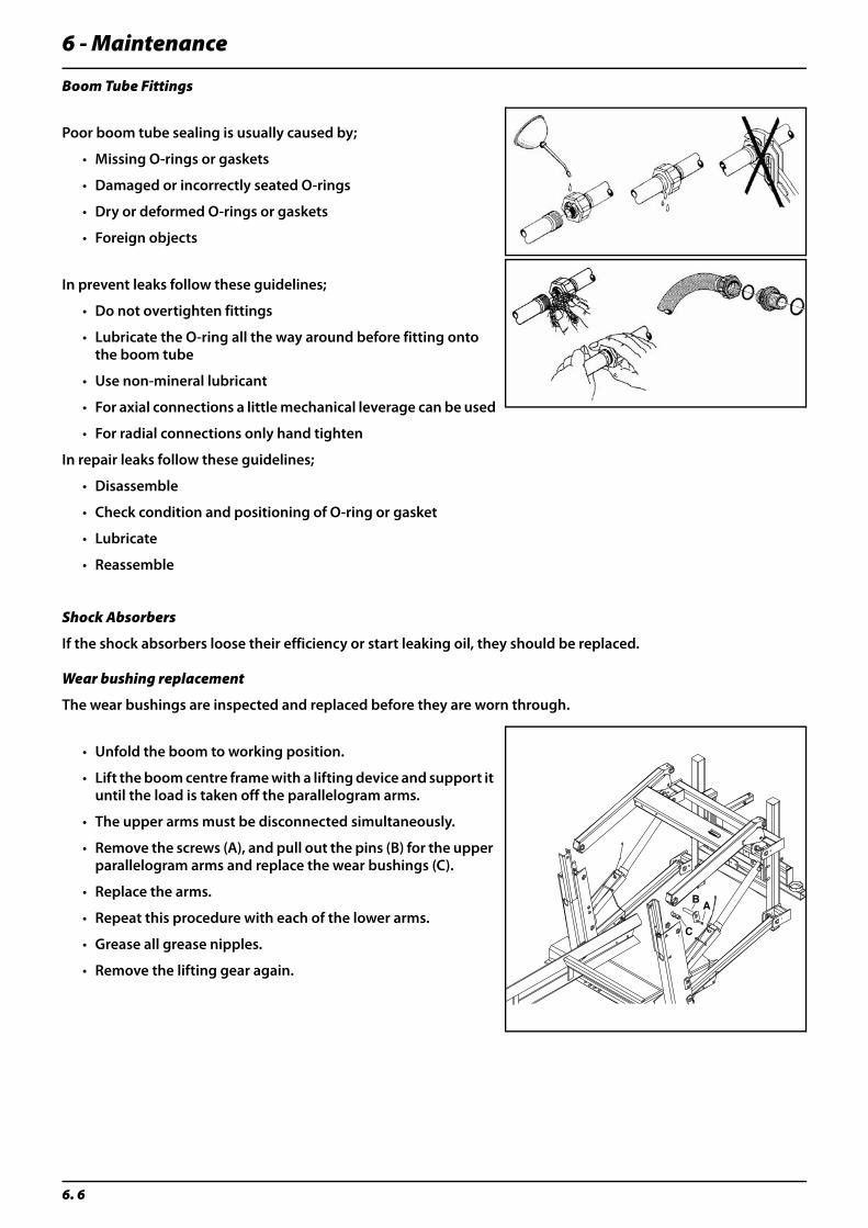
6 - Maintenance
6. 6
Boom Tube Fittings
Poor boom tube sealing is usually caused by;
• Missing O-rings or gaskets
• Damaged or incorrectly seated O-rings
• Dry or deformed O-rings or gaskets
• Foreign objects
In prevent leaks follow these guidelines;
• Do not overtighten fittings
• Lubricate the O-ring all the way around before fitting onto the boom tube
• Use non-mineral lubricant
• For axial connections a little mechanical leverage can be used
• For radial connections only hand tighten
In repair leaks follow these guidelines;
• Disassemble
• Check condition and positioning of O-ring or gasket
• Lubricate
• Reassemble
Shock Absorbers
If the shock absorbers loose their efficiency or start leaking oil, they should be replaced.
Wear bushing replacement
The wear bushings are inspected and replaced before they are worn through.
• Unfold the boom to working position.
• Lift the boom centre frame with a lifting device and support it until the load is taken off the parallelogram arms.
• The upper arms must be disconnected simultaneously.
• Remove the screws (A), and pull out the pins (B) for the upper parallelogram arms and replace the wear bushings (C).
• Replace the arms.
• Repeat this procedure with each of the lower arms.
• Grease all grease nipples.
• Remove the lifting gear again.
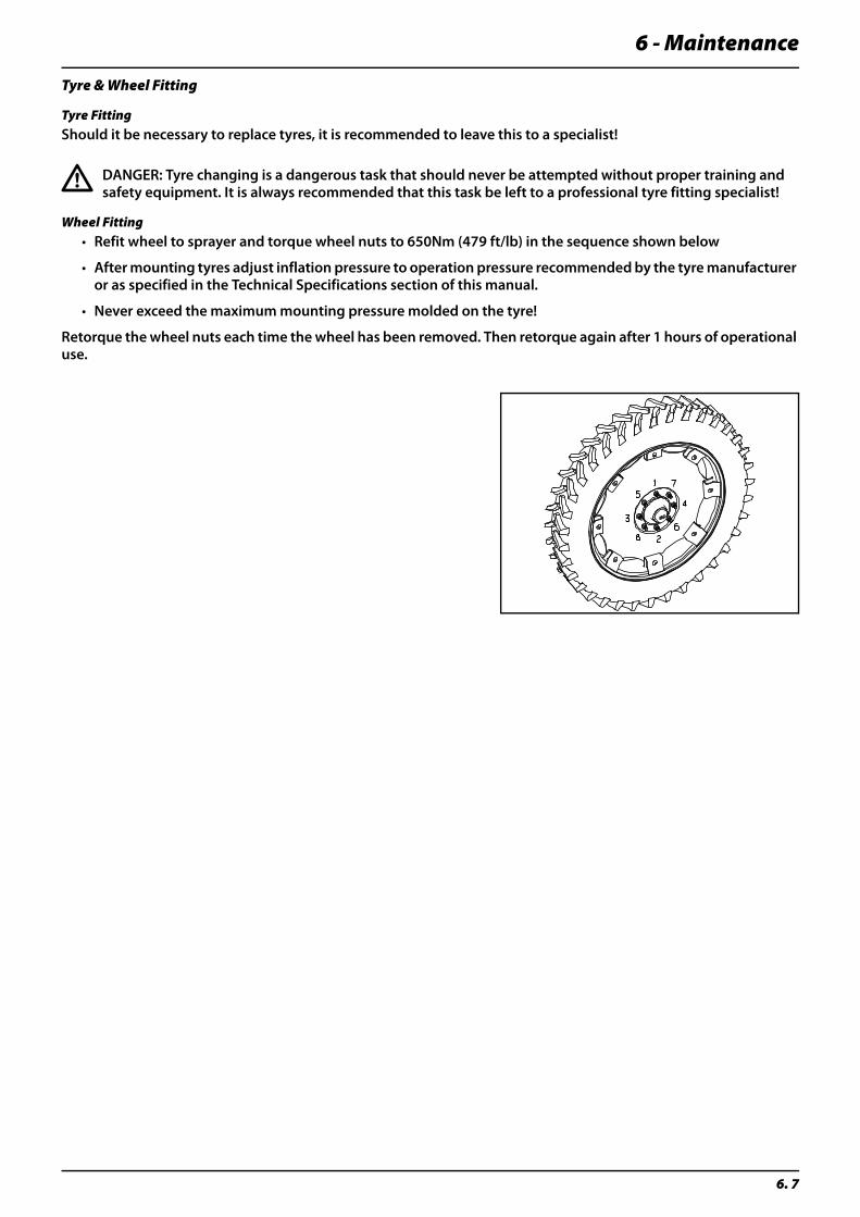
6 - Maintenance
6. 7
Tyre & Wheel Fitting
Tyre FittingShould it be necessary to replace tyres, it is recommended to leave this to a specialist!
€ DANGER: Tyre changing is a dangerous task that should never be attempted without proper training and safety equipment. It is always recommended that this task be left to a professional tyre fitting specialist!
Wheel Fitting• Refit wheel to sprayer and torque wheel nuts to 650Nm (479 ft/lb) in the sequence shown below
• After mounting tyres adjust inflation pressure to operation pressure recommended by the tyre manufacturer or as specified in the Technical Specifications section of this manual.
• Never exceed the maximum mounting pressure molded on the tyre!
Retorque the wheel nuts each time the wheel has been removed. Then retorque again after 1 hours of operational use.
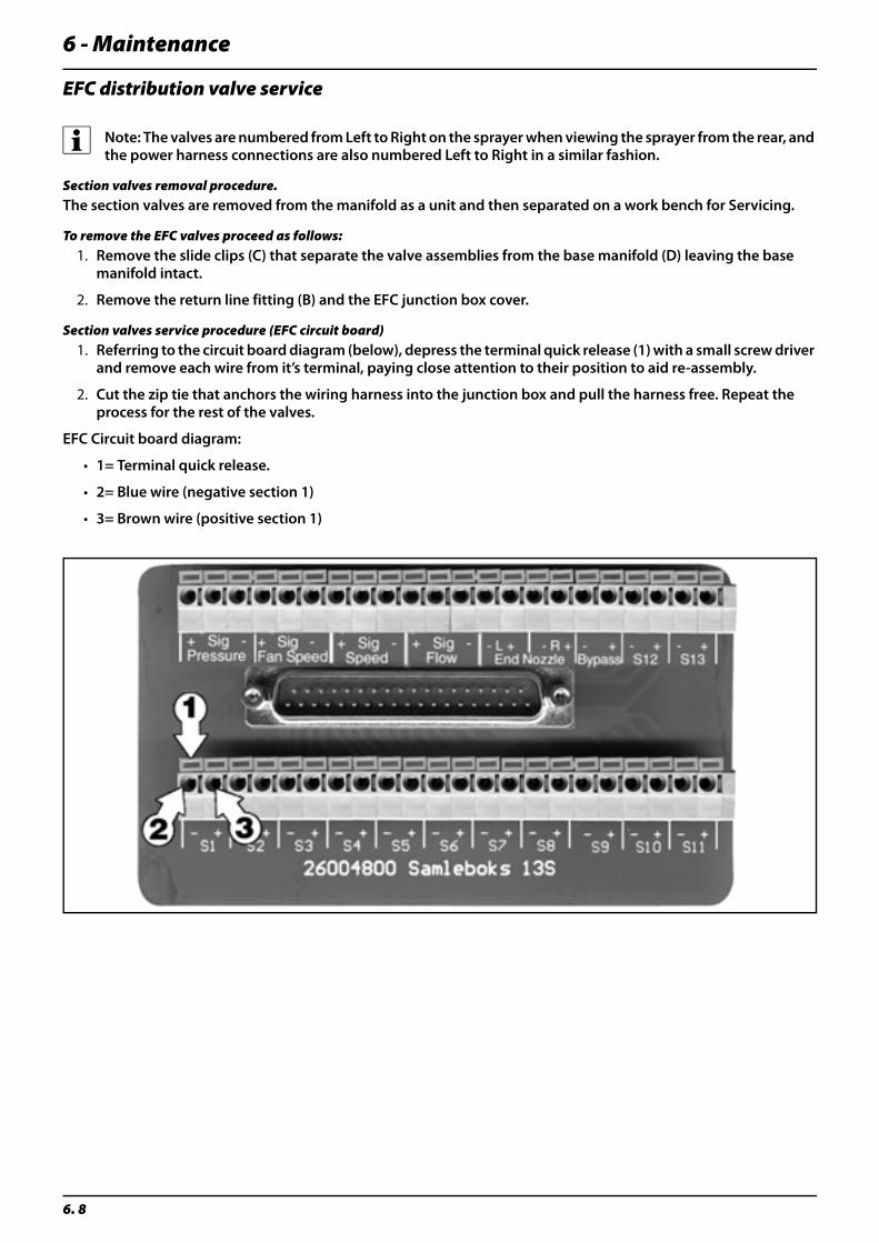
6 - Maintenance
6. 8
EFC distribution valve service
÷ Note: The valves are numbered from Left to Right on the sprayer when viewing the sprayer from the rear, and the power harness connections are also numbered Left to Right in a similar fashion.
Section valves removal procedure.The section valves are removed from the manifold as a unit and then separated on a work bench for Servicing.
To remove the EFC valves proceed as follows: 1. Remove the slide clips (C) that separate the valve assemblies from the base manifold (D) leaving the base
manifold intact.
2. Remove the return line fitting (B) and the EFC junction box cover.
Section valves service procedure (EFC circuit board)1. Referring to the circuit board diagram (below), depress the terminal quick release (1) with a small screw driver
and remove each wire from it’s terminal, paying close attention to their position to aid re-assembly.
2. Cut the zip tie that anchors the wiring harness into the junction box and pull the harness free. Repeat the process for the rest of the valves.
EFC Circuit board diagram:
• 1= Terminal quick release.
• 2= Blue wire (negative section 1)
• 3= Brown wire (positive section 1)
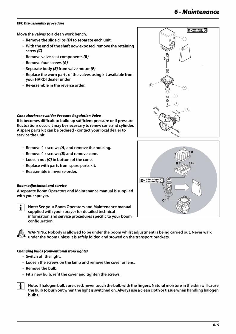
6 - Maintenance
6. 9
EFC Dis-assembly procedure
Move the valves to a clean work bench,• Remove the slide clips (D) to separate each unit. • With the end of the shaft now exposed, remove the retaining
screw (C)• Remove valve seat components (B)• Remove four screws (A)• Separate body (E) from valve motor (F)• Replace the worn parts of the valves using kit available from
your HARDI dealer under • Re-assemble in the reverse order.
Cone check/renewal for Pressure Regulation ValveIf it becomes difficult to build up sufficient pressure or if pressure fluctuations occur, it may be necessary to renew cone and cylinder. A spare parts kit can be ordered - contact your local dealer to service the unit.
• Remove 4 x screws (A) and remove the housing.• Remove 4 x screws (B) and remove cone.• Loosen nut (C) in bottom of the cone.• Replace with parts from spare parts kit.• Reassemble in reverse order.
Boom adjustment and serviceA separate Boom Operators and Maintenance manual is supplied with your sprayer.
÷ Note: See your Boom Operators and Maintenance manual supplied with your sprayer for detailed technical information and service procedures specific to your boom configuration.
± WARNING: Nobody is allowed to be under the boom whilst adjustment is being carried out. Never walk under the boom unless it is safely folded and stowed on the transport brackets.
Changing bulbs (conventional work lights)• Switch off the light.• Loosen the screws on the lamp and remove the cover or lens.• Remove the bulb.• Fit a new bulb, refit the cover and tighten the screws.
÷ Note: If halogen bulbs are used, never touch the bulb with the fingers. Natural moisture in the skin will cause the bulb to burn out when the light is switched on. Always use a clean cloth or tissue when handling halogen bulbs.
A
D
B
C
E
F
6 - Maintenance
6. 10
Off-season storage
Off-season storage programWhen the spraying season is over, you should devote some extra time to the sprayer. If chemical residue is left over in the sprayer for longer periods, it can reduce the life of the individual components. To preserve the sprayer intact and to protect the components, carry out following off-season storage program.
• Clean the sprayer completely - inside and outside - as described under “Cleaning of the sprayer”. Make sure that all valves, hoses and auxiliary equipment have been cleaned with detergent and flushed with clean water afterwards, so no chemical residue is left in the sprayer.
• Renew possible damaged seals and repair visible leaks.
• Empty the sprayer completely and let the pump work for a few minutes. Operate all valves and handles to drain as much water off the spraying circuit as possible. Let the pump run until air is coming out of all nozzles. Remember to drain the rinsing tank also.
• Engage the pump and operate all valves and functions on the MANIFOLD, operating unit, chemical inductor etc. allowing the anti-freeze mixture to be distributed around the entire circuit. Open the operating unit main on/off valve and distribution valves so the anti-freeze is sprayed through the nozzles as well. The anti-freeze will also prevent O-rings, seals, diaphragms etc. from drying out.
• Lubricate all lubricating points according to the lubricating scheme - regardless of intervals stated.
• When the sprayer is dry, remove rust from possible scratches or damages in the paint and touch up the paint.
• Remove the glycerine-filled pressure gauges and store them frost free in vertical position.
• Apply a thin layer of anti-corrosion oil (e.g. SHELL ENSIS FLUID, CASTROL RUSTILLO or similar) on all metal parts. Avoid oil on rubber parts, hoses and tyres.
• Fold the boom in transport position and relieve pressure from all hydraulic functions.
• Apply grease on all hydraulic ram piston rods which are not fully retracted in the barrel to protect against corrosion.
• Chock up the wheels, to prevent moisture damage and deformation of the tyres. Tyre blacking can be applied to the tyre walls to preserve the rubber.
• To protect against dust the sprayer can be covered by a tarpaulin. Make sure of ventilation to prevent condensation.
Preparing the sprayer for use after storageAfter a storage period the sprayer should be prepared for the next season the following way:
• Remove the cover.
• Remove the support from the wheel axle and adjust the tyre pressure.
• Wipe off the grease from hydraulic ram piston rods.
• Fit the pressure gauges again. Seal with Teflon tape.
• Check all hydraulic and electric functions.
• Rinse the entire liquid circuit on the sprayer with clean water.
• Fill with clean water and check all functions.
• Check function of brakes. Please note that brake power will be reduced until the rust are worn off the drums. Always brake lightly until the disks are clean.

6 - Maintenance
6. 11
Checks & Adjustments
General info
The maintenance and renewal intervals for the following will depend very much on the conditions under which the sprayer will be operated and are therefore impossible to specify.
Boom Adjustments
Please refer to the Force (FTZ) Boom Operator Manual for all boom adjustment procedures.
Prior to making boom adjustments, make sure the following tasks have been carried out;
• Lubricate all parts of the sprayer
• Place sprayer on level ground (horizontal surface)
• Unfold boom
Level indicator adjustment
The level indicator reading should be checked regularly. When the tank is empty, the float should lie on the stop pin, of the rod, and the O-ring on the indicator should be positioned at the top position line (A).
If any deviation is found, pull out the plug (B), loosen screws (C), and adjust the length of the cord.
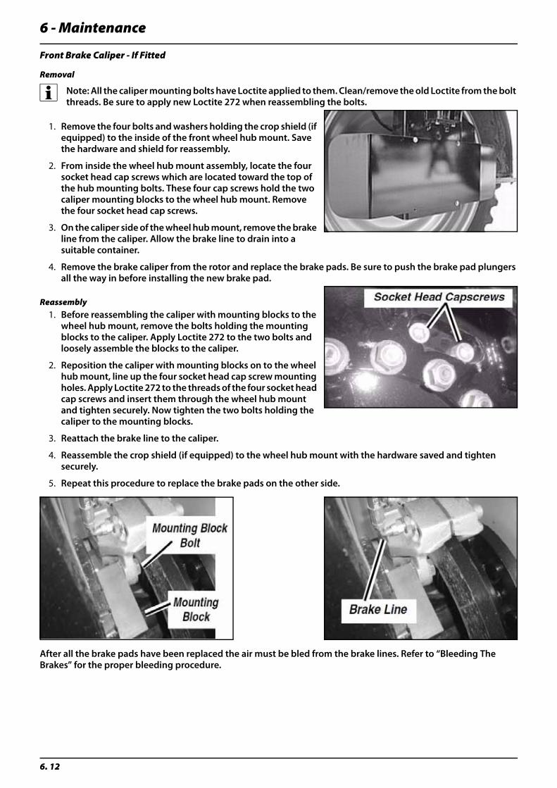
6 - Maintenance
6. 12
Front Brake Caliper - If Fitted
Removal
÷ Note: All the caliper mounting bolts have Loctite applied to them. Clean/remove the old Loctite from the bolt threads. Be sure to apply new Loctite 272 when reassembling the bolts.
1. Remove the four bolts and washers holding the crop shield (if equipped) to the inside of the front wheel hub mount. Save the hardware and shield for reassembly.
2. From inside the wheel hub mount assembly, locate the four socket head cap screws which are located toward the top of the hub mounting bolts. These four cap screws hold the two caliper mounting blocks to the wheel hub mount. Remove the four socket head cap screws.
3. On the caliper side of the wheel hub mount, remove the brake line from the caliper. Allow the brake line to drain into a suitable container.
4. Remove the brake caliper from the rotor and replace the brake pads. Be sure to push the brake pad plungers all the way in before installing the new brake pad.
Reassembly1. Before reassembling the caliper with mounting blocks to the
wheel hub mount, remove the bolts holding the mounting blocks to the caliper. Apply Loctite 272 to the two bolts and loosely assemble the blocks to the caliper.
2. Reposition the caliper with mounting blocks on to the wheel hub mount, line up the four socket head cap screw mounting holes. Apply Loctite 272 to the threads of the four socket head cap screws and insert them through the wheel hub mount and tighten securely. Now tighten the two bolts holding the caliper to the mounting blocks.
3. Reattach the brake line to the caliper.
4. Reassemble the crop shield (if equipped) to the wheel hub mount with the hardware saved and tighten securely.
5. Repeat this procedure to replace the brake pads on the other side.
After all the brake pads have been replaced the air must be bled from the brake lines. Refer to “Bleeding The Brakes” for the proper bleeding procedure.
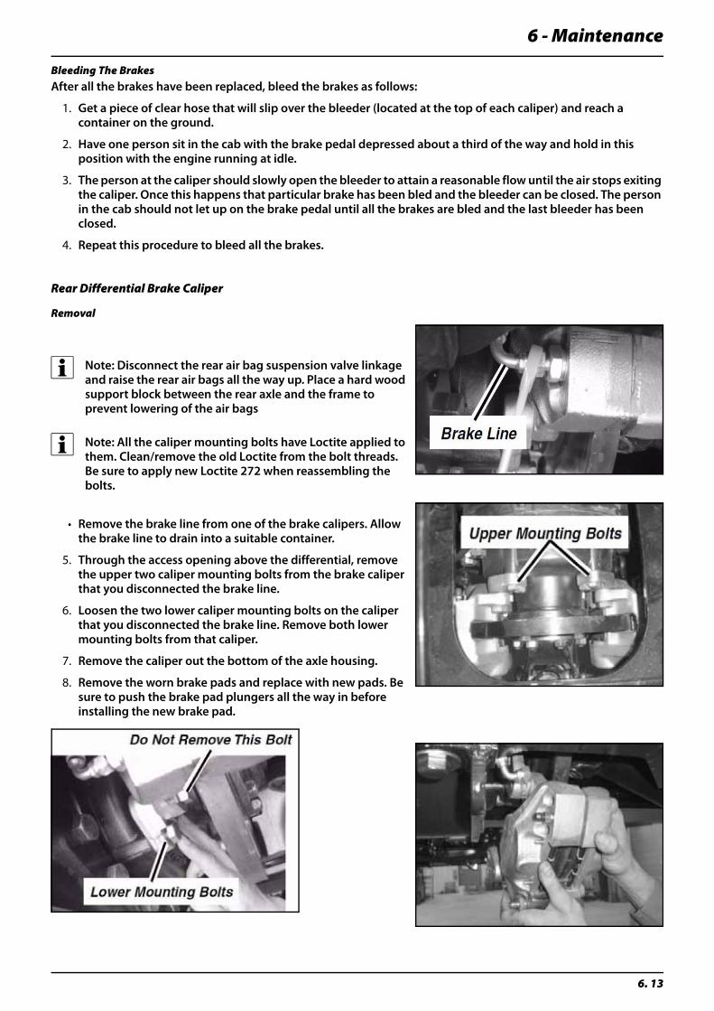
6 - Maintenance
6. 13
Bleeding The BrakesAfter all the brakes have been replaced, bleed the brakes as follows:
1. Get a piece of clear hose that will slip over the bleeder (located at the top of each caliper) and reach a container on the ground.
2. Have one person sit in the cab with the brake pedal depressed about a third of the way and hold in this position with the engine running at idle.
3. The person at the caliper should slowly open the bleeder to attain a reasonable flow until the air stops exiting the caliper. Once this happens that particular brake has been bled and the bleeder can be closed. The person in the cab should not let up on the brake pedal until all the brakes are bled and the last bleeder has been closed.
4. Repeat this procedure to bleed all the brakes.
Rear Differential Brake Caliper
Removal
÷ Note: Disconnect the rear air bag suspension valve linkage and raise the rear air bags all the way up. Place a hard wood support block between the rear axle and the frame to prevent lowering of the air bags
÷ Note: All the caliper mounting bolts have Loctite applied to them. Clean/remove the old Loctite from the bolt threads. Be sure to apply new Loctite 272 when reassembling the bolts.
• Remove the brake line from one of the brake calipers. Allow the brake line to drain into a suitable container.
5. Through the access opening above the differential, remove the upper two caliper mounting bolts from the brake caliper that you disconnected the brake line.
6. Loosen the two lower caliper mounting bolts on the caliper that you disconnected the brake line. Remove both lower mounting bolts from that caliper.
7. Remove the caliper out the bottom of the axle housing.
8. Remove the worn brake pads and replace with new pads. Be sure to push the brake pad plungers all the way in before installing the new brake pad.
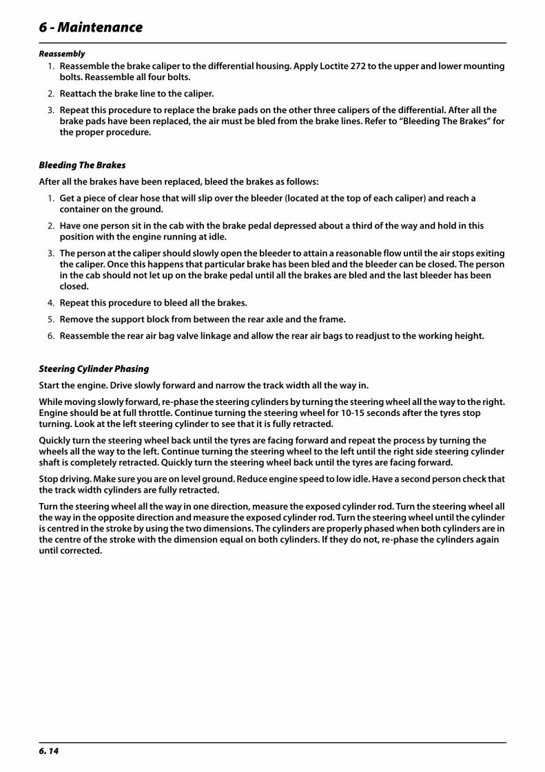
6 - Maintenance
6. 14
Reassembly1. Reassemble the brake caliper to the differential housing. Apply Loctite 272 to the upper and lower mounting
bolts. Reassemble all four bolts.
2. Reattach the brake line to the caliper.
3. Repeat this procedure to replace the brake pads on the other three calipers of the differential. After all the brake pads have been replaced, the air must be bled from the brake lines. Refer to “Bleeding The Brakes” for the proper procedure.
Bleeding The Brakes
After all the brakes have been replaced, bleed the brakes as follows:
1. Get a piece of clear hose that will slip over the bleeder (located at the top of each caliper) and reach a container on the ground.
2. Have one person sit in the cab with the brake pedal depressed about a third of the way and hold in this position with the engine running at idle.
3. The person at the caliper should slowly open the bleeder to attain a reasonable flow until the air stops exiting the caliper. Once this happens that particular brake has been bled and the bleeder can be closed. The person in the cab should not let up on the brake pedal until all the brakes are bled and the last bleeder has been closed.
4. Repeat this procedure to bleed all the brakes.
5. Remove the support block from between the rear axle and the frame.
6. Reassemble the rear air bag valve linkage and allow the rear air bags to readjust to the working height.
Steering Cylinder Phasing
Start the engine. Drive slowly forward and narrow the track width all the way in.
While moving slowly forward, re-phase the steering cylinders by turning the steering wheel all the way to the right. Engine should be at full throttle. Continue turning the steering wheel for 10-15 seconds after the tyres stop turning. Look at the left steering cylinder to see that it is fully retracted.
Quickly turn the steering wheel back until the tyres are facing forward and repeat the process by turning the wheels all the way to the left. Continue turning the steering wheel to the left until the right side steering cylinder shaft is completely retracted. Quickly turn the steering wheel back until the tyres are facing forward.
Stop driving. Make sure you are on level ground. Reduce engine speed to low idle. Have a second person check that the track width cylinders are fully retracted.
Turn the steering wheel all the way in one direction, measure the exposed cylinder rod. Turn the steering wheel all the way in the opposite direction and measure the exposed cylinder rod. Turn the steering wheel until the cylinder is centred in the stroke by using the two dimensions. The cylinders are properly phased when both cylinders are in the centre of the stroke with the dimension equal on both cylinders. If they do not, re-phase the cylinders again until corrected.
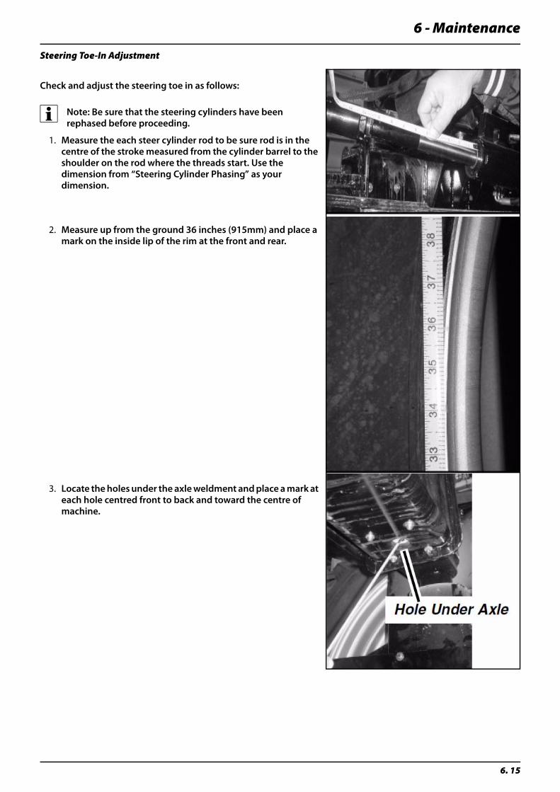
6 - Maintenance
6. 15
Steering Toe-In Adjustment
Check and adjust the steering toe in as follows:
÷ Note: Be sure that the steering cylinders have been rephased before proceeding.
1. Measure the each steer cylinder rod to be sure rod is in the centre of the stroke measured from the cylinder barrel to the shoulder on the rod where the threads start. Use the dimension from “Steering Cylinder Phasing” as your dimension.
2. Measure up from the ground 36 inches (915mm) and place a mark on the inside lip of the rim at the front and rear.
3. Locate the holes under the axle weldment and place a mark at each hole centred front to back and toward the centre of machine.
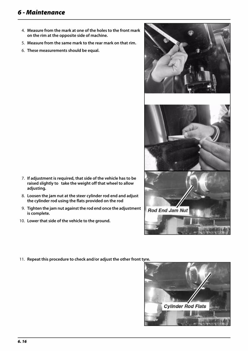
6 - Maintenance
6. 16
4. Measure from the mark at one of the holes to the front mark on the rim at the opposite side of machine.
5. Measure from the same mark to the rear mark on that rim.
6. These measurements should be equal.
7. If adjustment is required, that side of the vehicle has to be raised slightly to take the weight off that wheel to allow adjusting.
8. Loosen the jam nut at the steer cylinder rod end and adjust the cylinder rod using the flats provided on the rod
9. Tighten the jam nut against the rod end once the adjustment is complete.
10. Lower that side of the vehicle to the ground.
11. Repeat this procedure to check and/or adjust the other front tyre.
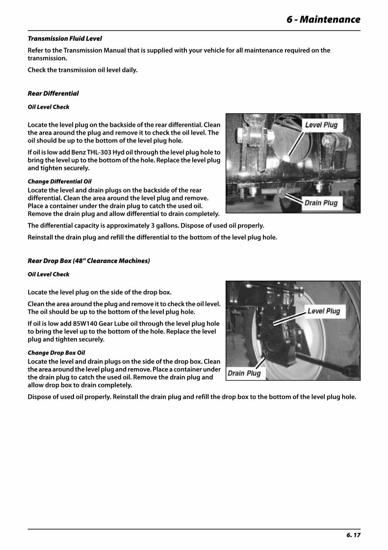
6 - Maintenance
6. 17
Transmission Fluid Level
Refer to the Transmission Manual that is supplied with your vehicle for all maintenance required on the transmission.
Check the transmission oil level daily.
Rear Differential
Oil Level Check
Locate the level plug on the backside of the rear differential. Clean the area around the plug and remove it to check the oil level. The oil should be up to the bottom of the level plug hole.
If oil is low add Benz THL-303 Hyd oil through the level plug hole to bring the level up to the bottom of the hole. Replace the level plug and tighten securely.
Change Differential OilLocate the level and drain plugs on the backside of the rear differential. Clean the area around the level plug and remove. Place a container under the drain plug to catch the used oil. Remove the drain plug and allow differential to drain completely.
The differential capacity is approximately 3 gallons. Dispose of used oil properly.
Reinstall the drain plug and refill the differential to the bottom of the level plug hole.
Rear Drop Box (48" Clearance Machines)
Oil Level Check
Locate the level plug on the side of the drop box.
Clean the area around the plug and remove it to check the oil level. The oil should be up to the bottom of the level plug hole.
If oil is low add 85W140 Gear Lube oil through the level plug hole to bring the level up to the bottom of the hole. Replace the level plug and tighten securely.
Change Drop Box OilLocate the level and drain plugs on the side of the drop box. Clean the area around the level plug and remove. Place a container under the drain plug to catch the used oil. Remove the drain plug and allow drop box to drain completely.
Dispose of used oil properly. Reinstall the drain plug and refill the drop box to the bottom of the level plug hole.
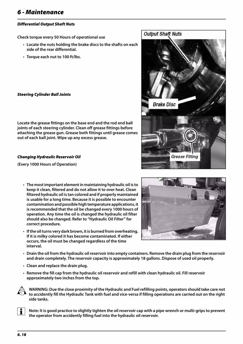
6 - Maintenance
6. 18
Differential Output Shaft Nuts
Check torque every 50 Hours of operational use
• Locate the nuts holding the brake discs to the shafts on each side of the rear differential.
• Torque each nut to 100 ft/lbs.
Steering Cylinder Ball Joints
Locate the grease fittings on the base end and the rod end ball joints of each steering cylinder. Clean off grease fittings before attaching the grease gun. Grease both fittings until grease comes out of each ball joint. Wipe up any excess grease.
Changing Hydraulic Reservoir Oil
(Every 1000 Hours of Operation)
• The most important element in maintaining hydraulic oil is to keep it clean, filtered and do not allow it to over heat. Clean filtered hydraulic oil is tan colored and if properly maintained is usable for a long time. Because it is possible to encounter contamination and possible high temperature applications, it is recommended that the oil be changed every 1000 hours of operation. Any time the oil is changed the hydraulic oil filter should also be changed. Refer to “Hydraulic Oil Filter” for correct procedure.
• If the oil turns very dark brown, it is burned from overheating. If it is milky colored it has become contaminated. If either occurs, the oil must be changed regardless of the time interval.
• Drain the oil from the hydraulic oil reservoir into empty containers. Remove the drain plug from the reservoir and drain completely. The reservoir capacity is approximately 18 gallons. Dispose of used oil properly.
• Clean and replace the drain plug.
• Remove the fill cap from the hydraulic oil reservoir and refill with clean hydraulic oil. Fill reservoir approximately two inches from the top.
± WARNING: Due the close proximity of the Hydraulic and Fuel refilling points, operators should take care not to accidently fill the Hydraulic Tank with fuel and vice-versa if filling operations are carried out on the right side tanks.
÷ Note: It is good practice to slightly tighten the oil reservoir cap with a pipe wrench or multi-grips to prevent the operator from accidently filling fuel into the hydraulic oil reservoir.
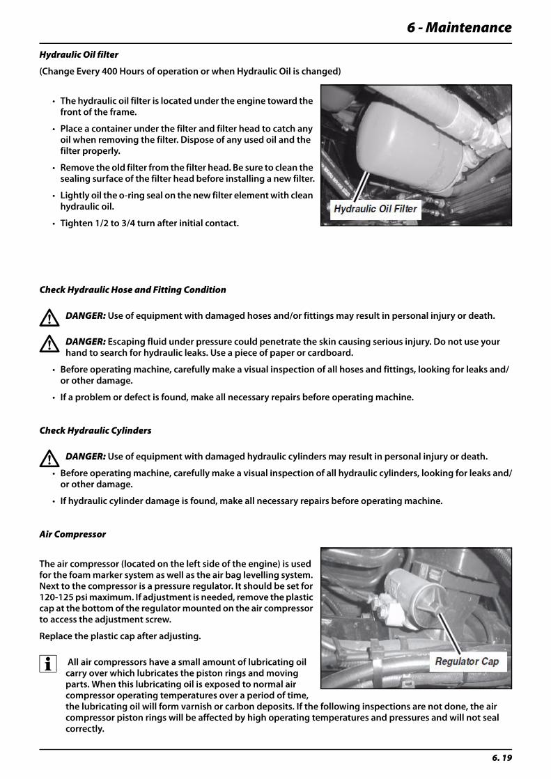
6 - Maintenance
6. 19
Hydraulic Oil filter
(Change Every 400 Hours of operation or when Hydraulic Oil is changed)
• The hydraulic oil filter is located under the engine toward the front of the frame.
• Place a container under the filter and filter head to catch any oil when removing the filter. Dispose of any used oil and the filter properly.
• Remove the old filter from the filter head. Be sure to clean the sealing surface of the filter head before installing a new filter.
• Lightly oil the o-ring seal on the new filter element with clean hydraulic oil.
• Tighten 1/2 to 3/4 turn after initial contact.
Check Hydraulic Hose and Fitting Condition
€ DANGER: Use of equipment with damaged hoses and/or fittings may result in personal injury or death.
€ DANGER: Escaping fluid under pressure could penetrate the skin causing serious injury. Do not use your hand to search for hydraulic leaks. Use a piece of paper or cardboard.
• Before operating machine, carefully make a visual inspection of all hoses and fittings, looking for leaks and/or other damage.
• If a problem or defect is found, make all necessary repairs before operating machine.
Check Hydraulic Cylinders
€ DANGER: Use of equipment with damaged hydraulic cylinders may result in personal injury or death.
• Before operating machine, carefully make a visual inspection of all hydraulic cylinders, looking for leaks and/or other damage.
• If hydraulic cylinder damage is found, make all necessary repairs before operating machine.
Air Compressor
The air compressor (located on the left side of the engine) is used for the foam marker system as well as the air bag levelling system. Next to the compressor is a pressure regulator. It should be set for 120-125 psi maximum. If adjustment is needed, remove the plastic cap at the bottom of the regulator mounted on the air compressor to access the adjustment screw.
Replace the plastic cap after adjusting.
÷ All air compressors have a small amount of lubricating oil carry over which lubricates the piston rings and moving parts. When this lubricating oil is exposed to normal air compressor operating temperatures over a period of time, the lubricating oil will form varnish or carbon deposits. If the following inspections are not done, the air compressor piston rings will be affected by high operating temperatures and pressures and will not seal correctly.
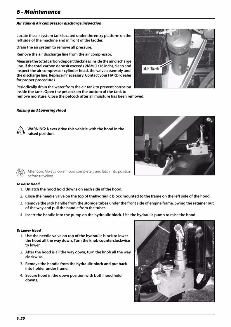
6 - Maintenance
6. 20
Air Tank & Air compressor discharge inspection
Locate the air system tank located under the entry platform on the left side of the machine and in front of the ladder.
Drain the air system to remove all pressure.
Remove the air discharge line from the air compressor.
Measure the total carbon deposit thickness inside the air discharge line. If the total carbon deposit exceeds 2MM (1/16 inch), clean and inspect the air compressor cylinder head, the valve assembly and the discharge line. Replace if necessary. Contact your HARDI dealer for proper procedures
Periodically drain the water from the air tank to prevent corrosion inside the tank. Open the petcock on the bottom of the tank to remove moisture. Close the petcock after all moisture has been removed.
Raising and Lowering Hood
± WARNING: Never drive this vehicle with the hood in the raised position.
μ Attention: Always lower hood completely and latch into position before traveling.
To Raise Hood1. Unlatch the hood hold downs on each side of the hood.
2. Close the needle valve on the top of thehydraulic block mounted to the frame on the left side of the hood.
3. Remove the jack handle from the storage tubes under the front side of engine frame. Swing the retainer out of the way and pull the handle from the tubes.
4. Insert the handle into the pump on the hydraulic block. Use the hydraulic pump to raise the hood.
To Lower Hood1. Use the needle valve on top of the hydraulic block to lower
the hood all the way down. Turn the knob counterclockwise to lower.
2. After the hood is all the way down, turn the knob all the way clockwise.
3. Remove the handle from the hydraulic block and put back into holder under frame.
4. Secure hood in the down position with both hood hold downs.
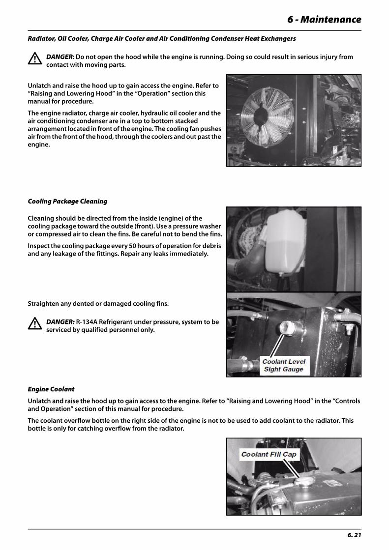
6 - Maintenance
6. 21
Radiator, Oil Cooler, Charge Air Cooler and Air Conditioning Condenser Heat Exchangers
€ DANGER: Do not open the hood while the engine is running. Doing so could result in serious injury from contact with moving parts.
Unlatch and raise the hood up to gain access the engine. Refer to “Raising and Lowering Hood” in the “Operation” section this manual for procedure.
The engine radiator, charge air cooler, hydraulic oil cooler and the air conditioning condenser are in a top to bottom stacked arrangement located in front of the engine. The cooling fan pushes air from the front of the hood, through the coolers and out past the engine.
Cooling Package Cleaning
Cleaning should be directed from the inside (engine) of the cooling package toward the outside (front). Use a pressure washer or compressed air to clean the fins. Be careful not to bend the fins.
Inspect the cooling package every 50 hours of operation for debris and any leakage of the fittings. Repair any leaks immediately.
Straighten any dented or damaged cooling fins.
€ DANGER: R-134A Refrigerant under pressure, system to be serviced by qualified personnel only.
Engine Coolant
Unlatch and raise the hood up to gain access to the engine. Refer to “Raising and Lowering Hood” in the “Controls and Operation” section of this manual for procedure.
The coolant overflow bottle on the right side of the engine is not to be used to add coolant to the radiator. This bottle is only for catching overflow from the radiator.
6 - Maintenance
6. 22
Coolant Level Check
The level of coolant in the radiator can be checked at the sight gauge located in the top tank on the rear (engine) side of the radiator. Coolant should be visible in the sight gauge.
Add Coolant
If the coolant level is low, allow the engine and radiator to cool before attempting to open the radiator cap on the tank. Add coolant as needed to bring the level up into the sight gauge.
€ DANGER: Open radiator cap slowly to relieve pressure before opening. Hot liquids under pressure can cause serious burns.
13 Spline Cooling Coupler
On earlier Saritor models a 13 spline coupler was fitted between the engine and hydraulic motor. If fitted, it requires daily lubrication to prevent coupler fatigue.
± WARNING: Lubricate 13 spline coupler daily.
Hydraulic System Maintenance
€ DANGER: Avoid high pressure fluids. Avoid the hazard by relieving all hydraulic pressure from the system before disconnecting any lines or fittings. Tighten all connections before applying any pressure. Search for hydraulic oil leaks with a piece of cardboard. Protect your hands and body from high pressure fluids.
General Information
The hydraulic system is divided into three separate systems. Each system has its own pump.
The three systems are:
• Main hydraulic system is a pressure compensated closed centre system. This system operates the main product pump circuit as well as the boom hydraulic system and the vehicle parking brake release circuit.
• The fan drive for the cooling system is operated by a separate hydraulic pump and only operates the cooling fan.
• The vehicle steering is operated by its own hydraulic pump.
Hydraulic System Cleanliness
μ Attention: The greatest contributor to hydraulic component failure is contamination of the oil with dirt and other debris. Keep all hydraulic access areas completely clean, such as around the hydraulic filter and filler cap. Immediately repair any fittings, hoses or other components where leakage is observed.
÷ Note: Wipe up any leakage.
If the hydraulic system should be disconnected for service, protect the ends of hoses, tubing and ports of components from contamination with clean lint free towels or clean plastic bags, plugs or caps.
Before installing any replacement hose, flush the inside of the hose with clean diesel fuel or unused commercial petroleum cleaning solvent for ten seconds minimum. Do not use water, water soluble cleaners or compressed air.
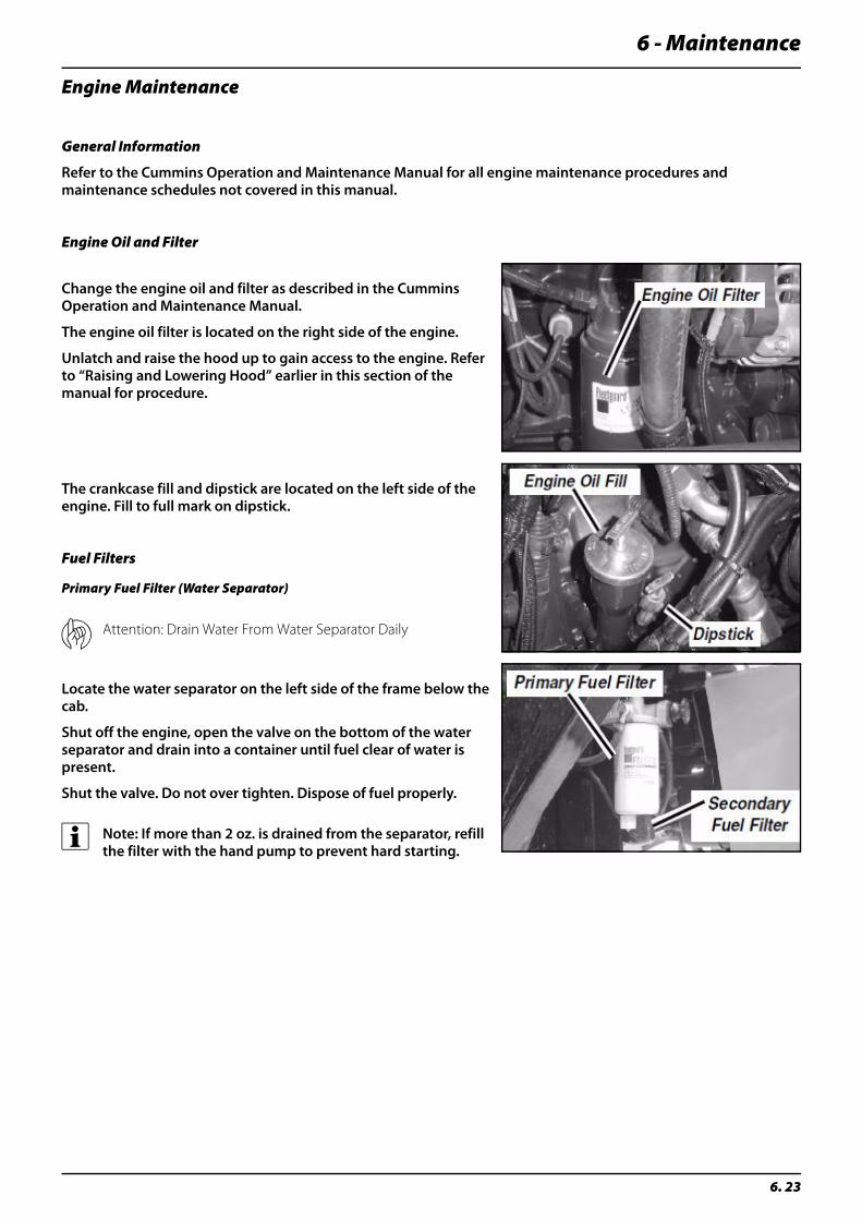
6 - Maintenance
6. 23
Engine Maintenance
General Information
Refer to the Cummins Operation and Maintenance Manual for all engine maintenance procedures and maintenance schedules not covered in this manual.
Engine Oil and Filter
Change the engine oil and filter as described in the Cummins Operation and Maintenance Manual.
The engine oil filter is located on the right side of the engine.
Unlatch and raise the hood up to gain access to the engine. Refer to “Raising and Lowering Hood” earlier in this section of the manual for procedure.
The crankcase fill and dipstick are located on the left side of the engine. Fill to full mark on dipstick.
Fuel Filters
Primary Fuel Filter (Water Separator)
μ Attention: Drain Water From Water Separator Daily
Locate the water separator on the left side of the frame below the cab.
Shut off the engine, open the valve on the bottom of the water separator and drain into a container until fuel clear of water is present.
Shut the valve. Do not over tighten. Dispose of fuel properly.
÷ Note: If more than 2 oz. is drained from the separator, refill the filter with the hand pump to prevent hard starting.

6 - Maintenance
6. 24
Secondary Fuel FilterChange the secondary filter as required. The secondary fuel filter is located directly to the rear of the water separator.
Drive Shaft Universal Joints
Locate the grease fittings on each end of the drive shaft between the transmission and the rear differential. Clean off the grease fittings before attaching grease gun. Do Not over grease, Wipe clean any excess grease.
Front and Rear Axle Wear Pads
Locate the grease fittings on each wear pad adjuster on the front and rear axles. Clean off the grease fittings before attaching the grease gun. Grease until grease is visible on the wear pads inside each axle tube.
Front Axle King Pins
Locate the two grease fittings on each of the front king pins. Clean off grease fittings before attaching grease gun. Grease both fittings until grease comes out of the king pin tube.
Wipe away excess grease.
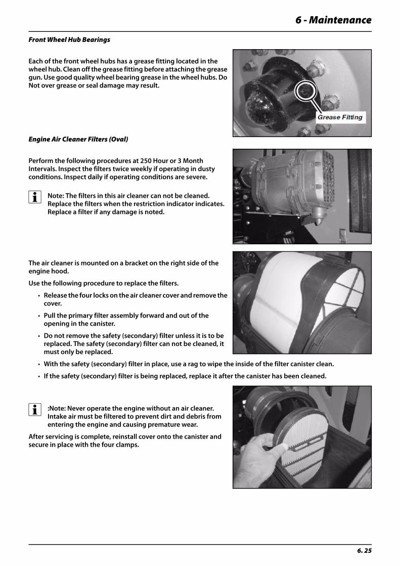
6 - Maintenance
6. 25
Front Wheel Hub Bearings
Each of the front wheel hubs has a grease fitting located in the wheel hub. Clean off the grease fitting before attaching the grease gun. Use good quality wheel bearing grease in the wheel hubs. Do Not over grease or seal damage may result.
Engine Air Cleaner Filters (Oval)
Perform the following procedures at 250 Hour or 3 Month Intervals. Inspect the filters twice weekly if operating in dusty conditions. Inspect daily if operating conditions are severe.
÷ Note: The filters in this air cleaner can not be cleaned. Replace the filters when the restriction indicator indicates. Replace a filter if any damage is noted.
The air cleaner is mounted on a bracket on the right side of the engine hood.
Use the following procedure to replace the filters.
• Release the four locks on the air cleaner cover and remove the cover.
• Pull the primary filter assembly forward and out of the opening in the canister.
• Do not remove the safety (secondary) filter unless it is to be replaced. The safety (secondary) filter can not be cleaned, it must only be replaced.
• With the safety (secondary) filter in place, use a rag to wipe the inside of the filter canister clean.
• If the safety (secondary) filter is being replaced, replace it after the canister has been cleaned.
÷ :Note: Never operate the engine without an air cleaner. Intake air must be filtered to prevent dirt and debris from entering the engine and causing premature wear.
After servicing is complete, reinstall cover onto the canister and secure in place with the four clamps.

6 - Maintenance
6. 26
Periodically check the evacuator valve on the front of the air cleaner cover to make sure it is closing and sealing when the engine is running.
If the evacuator valve does not close and seal properly it must be replaced.
Storage Tray / Recirculation Filter
Behind the “Training” seat is a removable storage tray. Remove this storage tray to access the recirculation filter. Pull the recirculation filter out to service it. Be sure to replace the recirculation filter and storage tray before operating.
Engine Data Link Connector
This connector is provided to allow a Cummins Service Technician to connect to the engine computer. It allows the technician to diagnose engine related problems from inside the cab. An additional connector is located on the left side of the engine in the wire harness.
The cab connector is located in front of the right side armrest below the engine monitor. It has a jumper plug in it that should remain plugged in during normal vehicle operation.
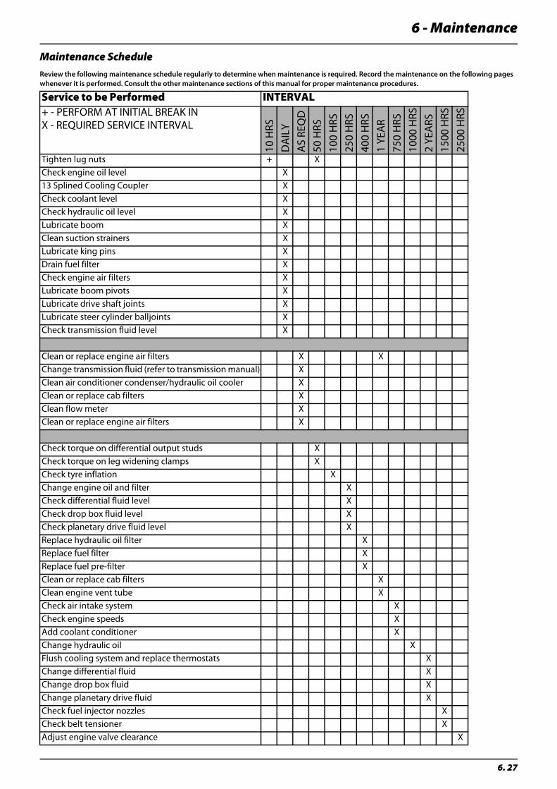
6 - Maintenance
6. 27
Maintenance ScheduleReview the following maintenance schedule regularly to determine when maintenance is required. Record the maintenance on the following pages whenever it is performed. Consult the other maintenance sections of this manual for proper maintenance procedures.
Service to be Performed INTERVAL+ - PERFORM AT INITIAL BREAK INX - REQUIRED SERVICE INTERVAL
10 H
RSD
AIL
YA
S RE
QD
50 H
RS10
0 H
RS25
0 H
RS40
0 H
RS1
YEA
R75
0 H
RS10
00 H
RS2
YEA
RS15
00 H
RS25
00 H
RS
Tighten lug nuts + XCheck engine oil level X13 Splined Cooling Coupler XCheck coolant level XCheck hydraulic oil level XLubricate boom XClean suction strainers XLubricate king pins XDrain fuel filter XCheck engine air filters XLubricate boom pivots XLubricate drive shaft joints XLubricate steer cylinder balljoints XCheck transmission fluid level X
Clean or replace engine air filters X XChange transmission fluid (refer to transmission manual) XClean air conditioner condenser/hydraulic oil cooler XClean or replace cab filters XClean flow meter XClean or replace engine air filters X
Check torque on differential output studs XCheck torque on leg widening clamps XCheck tyre inflation XChange engine oil and filter XCheck differential fluid level XCheck drop box fluid level XCheck planetary drive fluid level XReplace hydraulic oil filter XReplace fuel filter XReplace fuel pre-filter XClean or replace cab filters XClean engine vent tube XCheck air intake system XCheck engine speeds XAdd coolant conditioner XChange hydraulic oil XFlush cooling system and replace thermostats XChange differential fluid XChange drop box fluid XChange planetary drive fluid XCheck fuel injector nozzles XCheck belt tensioner XAdjust engine valve clearance X

6 - Maintenance
6. 28
Maintenance Record
Date Service Performed

6 - Maintenance
6. 29
Maintenance Record
Date Service Performed

6 - Maintenance
6. 30

7 - Fault Finding
7. 1
Fault Finding
Operational ProblemsIntroduction
In most cases where faults are experienced the most commonly accepted diagnostic approach is to rule out possible causes systematically by a process of elimination. As a rule this process can begin by investigating the following factors which have previously been found responsible:
• Minor leaks on the suction side of the pump will reduce the pump capacity or stop the suction completely.
• Pressure filters becoming blocked will result in rising pressure at the pressure gauge but falling pressure at the nozzles.
• Foreign material which has found it’s way to the pump valves will reduce pump efficiency.
• Poorly re-assembled pumps, will allow the pump to suck air resulting in reduced or no fluid capacity (investigate this if the pump was recently overhauled / serviced).
• Contamination of the hydraulic system will result in rapid wear to hydraulic components.
It is good practice to start by checking these basics:
• Filling, pressure and nozzle filters are clean.
• Check hoses for leaks and cracks, paying particular attention to suction hoses.
• Check gaskets and O-ring seals are present and in good condition.
• Check that the pressure gauge is in good working order (accurate calibration and chemical dosage depends on it).
• Check the operating unit functions properly (always use clean water for testing)
• Flow meter and speed sensor are functioning correctly (further information is given on this at the end of this section).
Prevention
Naturally prevention is the best policy. Regular maintenance protects your investment, maximises sprayer efficiency, minimises expensive down time and risk of personal injury.
To achieve the best possible service from your HARDI sprayer always make sure that:
• Hydraulic system components are maintained and kept clean (keep hose couplings up out of the dirt and covered when not in use to prevent moisture contamination).
• Proper cleaning and de-contamination is carried out after each spray job and before changing chemicals or crops. Never put off cleaning until later (crop protection chemicals are much harder to remove once they’ve dried out).
• Regular and thorough maintenance is carried out on time (see maintenance section of this manual for schedule).
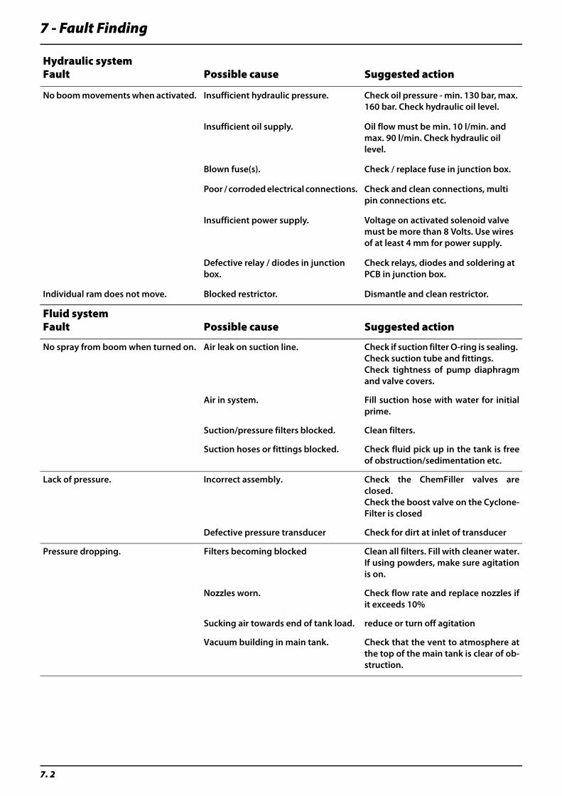
7 - Fault Finding
7. 2
Hydraulic systemFault Possible cause Suggested action
No boom movements when activated. Insufficient hydraulic pressure. Check oil pressure - min. 130 bar, max. 160 bar. Check hydraulic oil level.
Insufficient oil supply. Oil flow must be min. 10 l/min. and max. 90 l/min. Check hydraulic oil level.
Blown fuse(s). Check / replace fuse in junction box.
Poor / corroded electrical connections. Check and clean connections, multi pin connections etc.
Insufficient power supply. Voltage on activated solenoid valve must be more than 8 Volts. Use wires of at least 4 mm for power supply.
Defective relay / diodes in junction box.
Check relays, diodes and soldering at PCB in junction box.
Individual ram does not move. Blocked restrictor. Dismantle and clean restrictor.
Fluid system Fault Possible cause Suggested action
No spray from boom when turned on. Air leak on suction line. Check if suction filter O-ring is sealing. Check suction tube and fittings.Check tightness of pump diaphragmand valve covers.
Air in system. Fill suction hose with water for initialprime.
Suction/pressure filters blocked. Clean filters.
Suction hoses or fittings blocked. Check fluid pick up in the tank is freeof obstruction/sedimentation etc.
Lack of pressure. Incorrect assembly. Check the ChemFiller valves areclosed.Check the boost valve on the Cyclone-Filter is closed
Defective pressure transducer Check for dirt at inlet of transducer
Pressure dropping. Filters becoming blocked Clean all filters. Fill with cleaner water.If using powders, make sure agitationis on.
Nozzles worn. Check flow rate and replace nozzles ifit exceeds 10%
Sucking air towards end of tank load. reduce or turn off agitation
Vacuum building in main tank. Check that the vent to atmosphere atthe top of the main tank is clear of ob-struction.
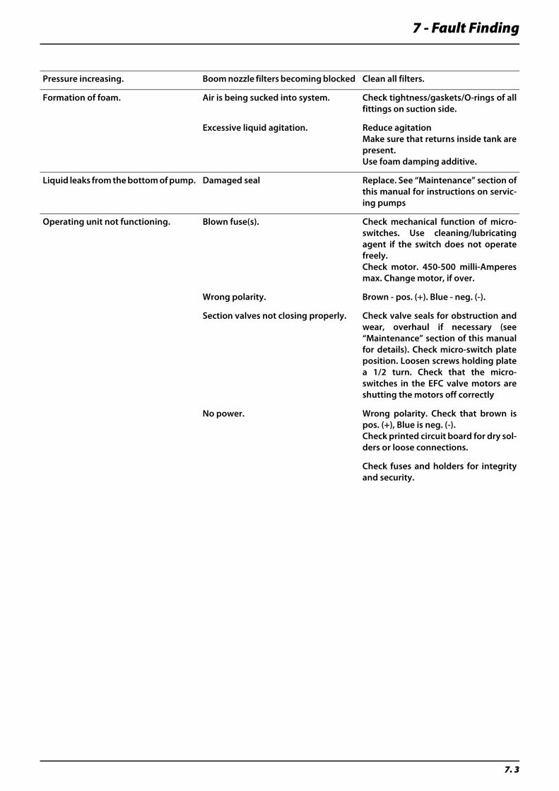
7 - Fault Finding
7. 3
Pressure increasing. Boom nozzle filters becoming blocked Clean all filters.
Formation of foam. Air is being sucked into system. Check tightness/gaskets/O-rings of allfittings on suction side.
Excessive liquid agitation. Reduce agitation Make sure that returns inside tank arepresent. Use foam damping additive.
Liquid leaks from the bottom of pump. Damaged seal Replace. See “Maintenance” section ofthis manual for instructions on servic-ing pumps
Operating unit not functioning. Blown fuse(s). Check mechanical function of micro-switches. Use cleaning/lubricatingagent if the switch does not operatefreely. Check motor. 450-500 milli-Amperesmax. Change motor, if over.
Wrong polarity. Brown - pos. (+). Blue - neg. (-).
Section valves not closing properly. Check valve seals for obstruction andwear, overhaul if necessary (see“Maintenance” section of this manualfor details). Check micro-switch plateposition. Loosen screws holding platea 1/2 turn. Check that the micro-switches in the EFC valve motors areshutting the motors off correctly
No power. Wrong polarity. Check that brown ispos. (+), Blue is neg. (-). Check printed circuit board for dry sol-ders or loose connections.
Check fuses and holders for integrityand security.
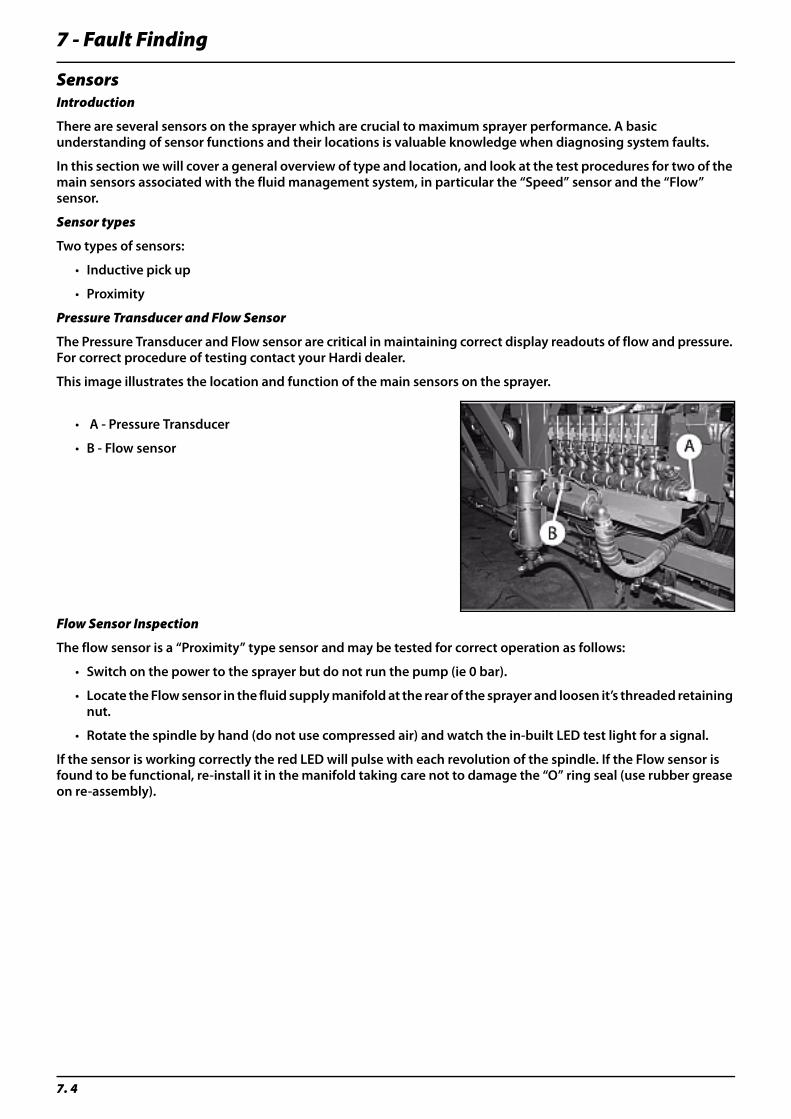
7 - Fault Finding
7. 4
SensorsIntroduction
There are several sensors on the sprayer which are crucial to maximum sprayer performance. A basic understanding of sensor functions and their locations is valuable knowledge when diagnosing system faults.
In this section we will cover a general overview of type and location, and look at the test procedures for two of the main sensors associated with the fluid management system, in particular the “Speed” sensor and the “Flow” sensor.
Sensor types
Two types of sensors:
• Inductive pick up
• Proximity
Pressure Transducer and Flow Sensor
The Pressure Transducer and Flow sensor are critical in maintaining correct display readouts of flow and pressure. For correct procedure of testing contact your Hardi dealer.
This image illustrates the location and function of the main sensors on the sprayer.
• A - Pressure Transducer
• B - Flow sensor
Flow Sensor Inspection
The flow sensor is a “Proximity” type sensor and may be tested for correct operation as follows:
• Switch on the power to the sprayer but do not run the pump (ie 0 bar).
• Locate the Flow sensor in the fluid supply manifold at the rear of the sprayer and loosen it’s threaded retaining nut.
• Rotate the spindle by hand (do not use compressed air) and watch the in-built LED test light for a signal.
If the sensor is working correctly the red LED will pulse with each revolution of the spindle. If the Flow sensor is found to be functional, re-install it in the manifold taking care not to damage the “O” ring seal (use rubber grease on re-assembly).

7 - Fault Finding
7. 5
Engine Trouble Shooting
Engine Fault Codes
The Cummins QSB engine has onboard diagnostic capabilities built into it to troubleshoot the engine fault codes.
FAULT DETECTION:
Engine fault codes can be detected while the engine is running. If a fault occurs, the engine computer takes a snapshot of engine operating parameters and logs the fault code into memory. If the fault is active (currently being detected) while the engine is running, one of the engine warning lamps will light up in the cab overhead panel and will stay on and a buzzer will sound. The lamp color will indicate the severity of the fault.
The CANtrak Display will display active fault codes as they occur. The display can also be used to view inactive fault codes. Follow the directions in the CANtrak Operators Manual to view inactive fault codes.
Engine will not crank Check that the drive control lever is in Neutral.
Check that Neutral start switch is working properly.
Check that Starter Relay in fuse box is working prop-erly.
Coolant temperature too high Clean air inlet screens.
Clean debris out of radiator, oil cooler and AC con-denser fins.
Check coolant level.
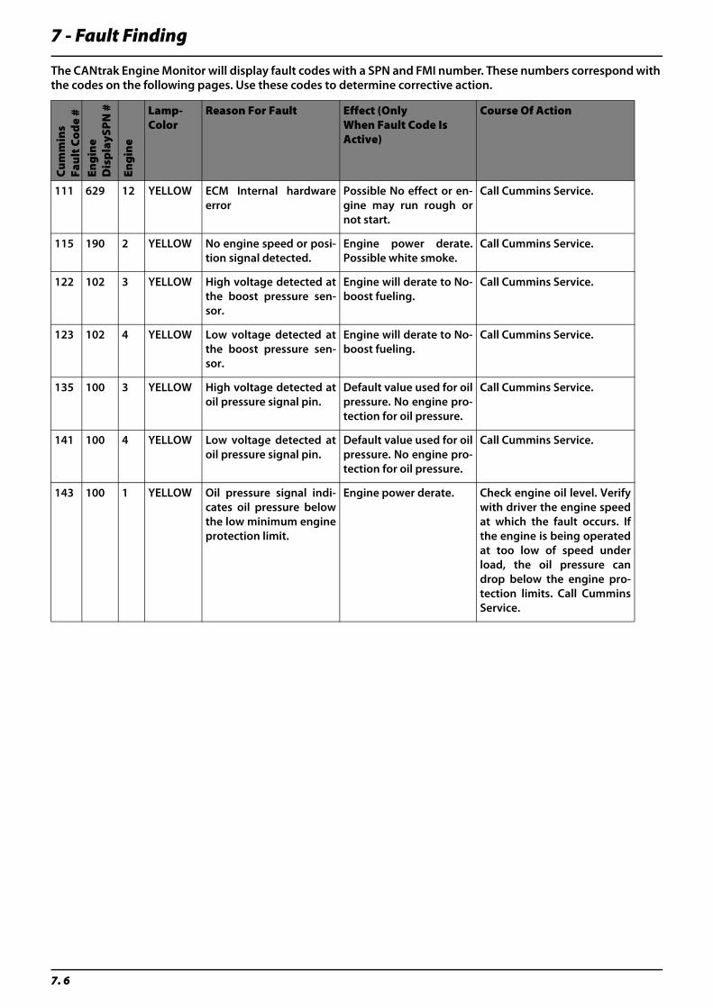
7 - Fault Finding
7. 6
The CANtrak Engine Monitor will display fault codes with a SPN and FMI number. These numbers correspond with the codes on the following pages. Use these codes to determine corrective action.
Cu
mm
ins
Fau
lt C
od
e #
Eng
ine
Dis
pla
ySP
N #
Eng
ine
Lamp-Color
Reason For Fault Effect (Only When Fault Code Is Active)
Course Of Action
111 629 12 YELLOW ECM Internal hardwareerror
Possible No effect or en-gine may run rough ornot start.
Call Cummins Service.
115 190 2 YELLOW No engine speed or posi-tion signal detected.
Engine power derate.Possible white smoke.
Call Cummins Service.
122 102 3 YELLOW High voltage detected atthe boost pressure sen-sor.
Engine will derate to No-boost fueling.
Call Cummins Service.
123 102 4 YELLOW Low voltage detected atthe boost pressure sen-sor.
Engine will derate to No-boost fueling.
Call Cummins Service.
135 100 3 YELLOW High voltage detected atoil pressure signal pin.
Default value used for oilpressure. No engine pro-tection for oil pressure.
Call Cummins Service.
141 100 4 YELLOW Low voltage detected atoil pressure signal pin.
Default value used for oilpressure. No engine pro-tection for oil pressure.
Call Cummins Service.
143 100 1 YELLOW Oil pressure signal indi-cates oil pressure belowthe low minimum engineprotection limit.
Engine power derate. Check engine oil level. Verifywith driver the engine speedat which the fault occurs. Ifthe engine is being operatedat too low of speed underload, the oil pressure candrop below the engine pro-tection limits. Call CumminsService.
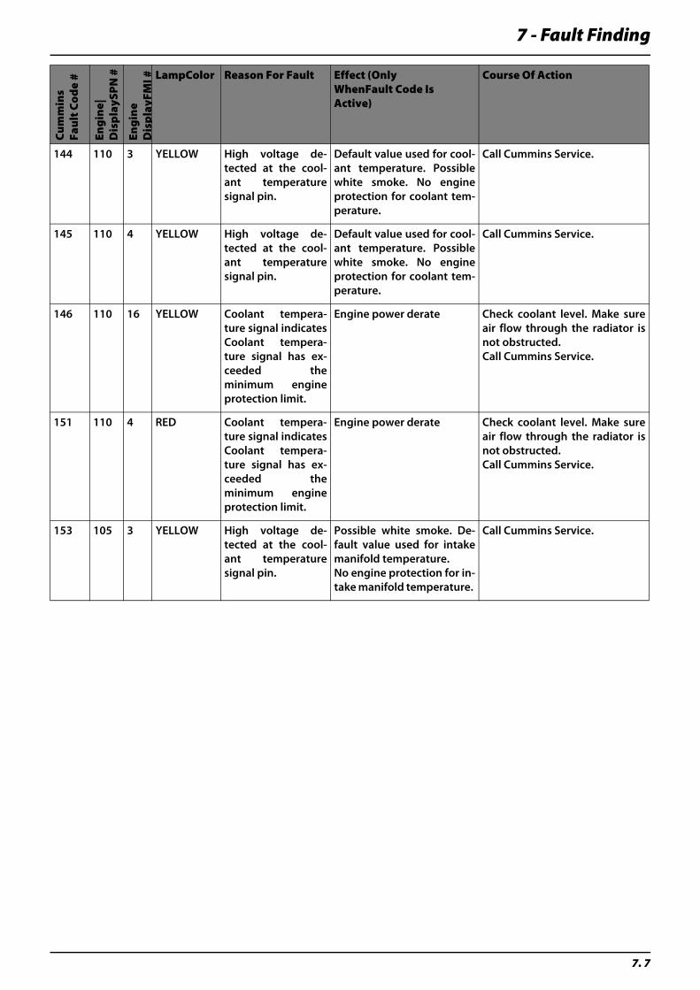
7 - Fault Finding
7. 7
Cu
mm
ins
Fau
lt C
od
e #
Eng
ine|
Dis
pla
ySP
N #
Eng
ine
Dis
pla
yFM
I # LampColor Reason For Fault Effect (Only WhenFault Code Is Active)
Course Of Action
144 110 3 YELLOW High voltage de-tected at the cool-ant temperaturesignal pin.
Default value used for cool-ant temperature. Possiblewhite smoke. No engineprotection for coolant tem-perature.
Call Cummins Service.
145 110 4 YELLOW High voltage de-tected at the cool-ant temperaturesignal pin.
Default value used for cool-ant temperature. Possiblewhite smoke. No engineprotection for coolant tem-perature.
Call Cummins Service.
146 110 16 YELLOW Coolant tempera-ture signal indicatesCoolant tempera-ture signal has ex-ceeded theminimum engineprotection limit.
Engine power derate Check coolant level. Make sureair flow through the radiator isnot obstructed. Call Cummins Service.
151 110 4 RED Coolant tempera-ture signal indicatesCoolant tempera-ture signal has ex-ceeded theminimum engineprotection limit.
Engine power derate Check coolant level. Make sureair flow through the radiator isnot obstructed.Call Cummins Service.
153 105 3 YELLOW High voltage de-tected at the cool-ant temperaturesignal pin.
Possible white smoke. De-fault value used for intakemanifold temperature.No engine protection for in-take manifold temperature.
Call Cummins Service.
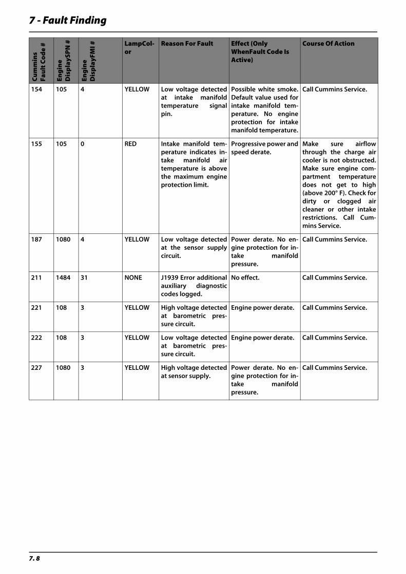
7 - Fault Finding
7. 8
Cu
mm
ins
Fau
lt C
od
e #
Eng
ine
Dis
pla
ySP
N #
Eng
ine
Dis
pla
yFM
I # LampCol-or
Reason For Fault Effect (Only WhenFault Code Is Active)
Course Of Action
154 105 4 YELLOW Low voltage detectedat intake manifoldtemperature signalpin.
Possible white smoke.Default value used forintake manifold tem-perature. No engineprotection for intakemanifold temperature.
Call Cummins Service.
155 105 0 RED Intake manifold tem-perature indicates in-take manifold airtemperature is abovethe maximum engineprotection limit.
Progressive power andspeed derate.
Make sure airflowthrough the charge aircooler is not obstructed.Make sure engine com-partment temperaturedoes not get to high(above 200° F). Check fordirty or clogged aircleaner or other intakerestrictions. Call Cum-mins Service.
187 1080 4 YELLOW Low voltage detectedat the sensor supplycircuit.
Power derate. No en-gine protection for in-take manifoldpressure.
Call Cummins Service.
211 1484 31 NONE J1939 Error additionalauxiliary diagnosticcodes logged.
No effect. Call Cummins Service.
221 108 3 YELLOW High voltage detectedat barometric pres-sure circuit.
Engine power derate. Call Cummins Service.
222 108 3 YELLOW Low voltage detectedat barometric pres-sure circuit.
Engine power derate. Call Cummins Service.
227 1080 3 YELLOW High voltage detectedat sensor supply.
Power derate. No en-gine protection for in-take manifoldpressure.
Call Cummins Service.
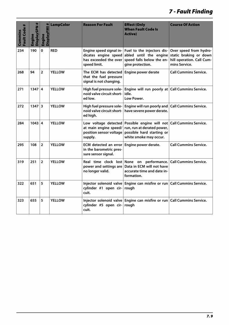
7 - Fault Finding
7. 9
Cu
mm
ins
Fau
lt C
od
e #
Eng
ine
Dis
pla
ySP
N #
Eng
ine
Dis
pla
yFM
I # LampColor Reason For Fault Effect (Only When Fault Code Is Active)
Course Of Action
234 190 0 RED Engine speed signal in-dicates engine speedhas exceeded the overspeed limit.
Fuel to the injectors dis-abled until the enginespeed falls below the en-gine protection.
Over speed from hydro-static braking or downhill operation. Call Cum-mins Service.
268 94 2 YELLOW The ECM has detectedthat the fuel pressuresignal is not changing.
Engine power derate Call Cummins Service.
271 1347 4 YELLOW High fuel pressure sole-noid valve circuit short-ed low.
Engine will run poorly atidle.Low Power.
Call Cummins Service.
272 1347 3 YELLOW High fuel pressure sole-noid valve circuit short-ed high.
Engine will run poorly andhave severe power derate.
Call Cummins Service.
284 1043 4 YELLOW Low voltage detectedat main engine speed/position sensor voltagesupply.
Possible engine will notrun, run at derated power,possible hard starting orwhite smoke may occur.
Call Cummins Service.
295 108 2 YELLOW ECM detected an errorin the barometric pres-sure sensor signal.
Engine power derate. Call Cummins Service.
319 251 2 YELLOW Real time clock lostpower and settings areno longer valid.
None on performance.Data in ECM will not haveaccurate time and date in-formation.
Call Cummins Service.
322 651 5 YELLOW Injector solenoid valvecylinder #1 open cir-cuit.
Engine can misfire or runrough
Call Cummins Service.
323 655 5 YELLOW Injector solenoid valvecylinder #5 open cir-cuit.
Engine can misfire or runrough
Call Cummins Service.
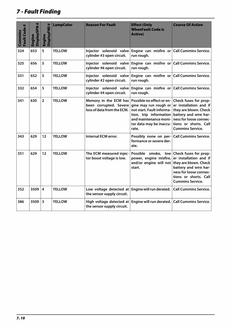
7 - Fault Finding
7. 10
Cu
mm
ins
Fau
lt C
od
e #
Eng
ine
Dis
pla
ySP
N #
Eng
ine
Dis
pla
yFM
I # LampColor Reason For Fault Effect (Only WhenFault Code Is Active)
Course Of Action
324 653 5 YELLOW Injector solenoid valvecylinder #3 open circuit.
Engine can misfire orrun rough.
Call Cummins Service.
325 656 5 YELLOW Injector solenoid valvecylinder #6 open circuit.
Engine can misfire orrun rough.
Call Cummins Service.
331 652 5 YELLOW Injector solenoid valvecylinder #2 open circuit.
Engine can misfire orrun rough.
Call Cummins Service.
332 654 5 YELLOW Injector solenoid valvecylinder #4 open circuit.
Engine can misfire orrun rough.
Call Cummins Service.
341 630 2 YELLOW Memory in the ECM hasbeen corrupted. Severeloss of data from the ECM.
Possible no effect or en-gine may run rough ornot start. Fault informa-tion, trip informationand maintenance moni-tor data may be inaccu-rate.
Check fuses for prop-er installation and ifthey are blown. Checkbattery and wire har-ness for loose connec-tions or shorts. CallCummins Service.
343 629 12 YELLOW Internal ECM error. Possibly none on per-formance or severe der-ate.
Call Cummins Service.
351 629 12 YELLOW The ECM measured injec-tor boost voltage is low.
Possible smoke, lowpower, engine misfire,and/or engine will notstart.
Check fuses for prop-er installation and ifthey are blown. Checkbattery and wire har-ness for loose connec-tions or shorts. CallCummins Service.
352 3509 4 YELLOW Low voltage detected atthe sensor supply circuit.
Engine will run derated. Call Cummins Service.
386 3509 3 YELLOW High voltage detected atthe sensor supply circuit.
Engine will run derated. Call Cummins Service.
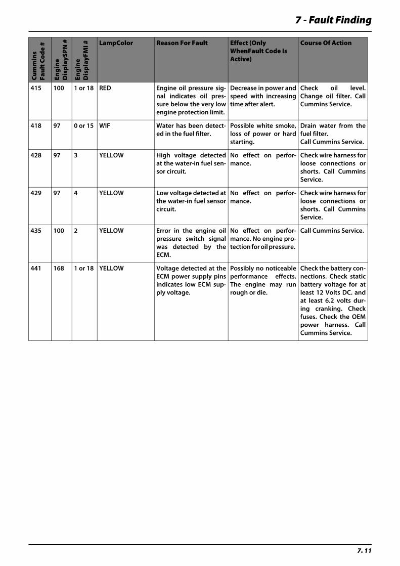
7 - Fault Finding
7. 11
Cu
mm
ins
Fau
lt C
od
e #
Eng
ine
Dis
pla
ySP
N #
Eng
ine
Dis
pla
yFM
I # LampColor Reason For Fault Effect (Only WhenFault Code Is Active)
Course Of Action
415 100 1 or 18 RED Engine oil pressure sig-nal indicates oil pres-sure below the very lowengine protection limit.
Decrease in power andspeed with increasingtime after alert.
Check oil level.Change oil filter. CallCummins Service.
418 97 0 or 15 WIF Water has been detect-ed in the fuel filter.
Possible white smoke,loss of power or hardstarting.
Drain water from thefuel filter.Call Cummins Service.
428 97 3 YELLOW High voltage detectedat the water-in fuel sen-sor circuit.
No effect on perfor-mance.
Check wire harness forloose connections orshorts. Call CumminsService.
429 97 4 YELLOW Low voltage detected atthe water-in fuel sensorcircuit.
No effect on perfor-mance.
Check wire harness forloose connections orshorts. Call CumminsService.
435 100 2 YELLOW Error in the engine oilpressure switch signalwas detected by theECM.
No effect on perfor-mance. No engine pro-tection for oil pressure.
Call Cummins Service.
441 168 1 or 18 YELLOW Voltage detected at theECM power supply pinsindicates low ECM sup-ply voltage.
Possibly no noticeableperformance effects.The engine may runrough or die.
Check the battery con-nections. Check staticbattery voltage for atleast 12 Volts DC. andat least 6.2 volts dur-ing cranking. Checkfuses. Check the OEMpower harness. CallCummins Service.
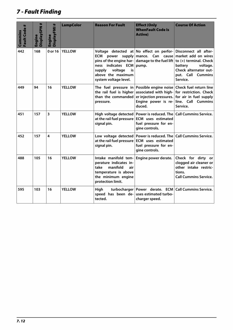
7 - Fault Finding
7. 12
Cu
mm
ins
Fau
lt C
od
e #
Eng
ine
Dis
pla
ySP
N #
Eng
ine
Dis
pla
yFM
I # LampColor Reason For Fault Effect (Only WhenFault Code Is Active)
Course Of Action
442 168 0 or 16 YELLOW Voltage detected atECM power supplypins of the engine har-ness indicates ECMsupply voltage isabove the maximumsystem voltage level.
No effect on perfor-mance. Can causedamage to the fuel liftpump.
Disconnect all after-market add on wiresto (+) terminal. Checkbattery voltage.Check alternator out-put. Call CumminsService.
449 94 16 YELLOW The fuel pressure inthe rail fuel is higherthan the commandedpressure.
Possible engine noiseassociated with high-er injection pressures.Engine power is re-duced.
Check fuel return linefor restriction. Checkfor air in fuel supplyline. Call CumminsService.
451 157 3 YELLOW High voltage detectedat the rail fuel pressuresignal pin.
Power is reduced. TheECM uses estimatedfuel pressure for en-gine controls.
Call Cummins Service.
452 157 4 YELLOW Low voltage detectedat the rail fuel pressuresignal pin.
Power is reduced. TheECM uses estimatedfuel pressure for en-gine controls.
Call Cummins Service.
488 105 16 YELLOW Intake manifold tem-perature indicates in-take manifold airtemperature is abovethe minimum engineprotection limit.
Engine power derate. Check for dirty orclogged air cleaner orother intake restric-tions.Call Cummins Service.
595 103 16 YELLOW High turbochargerspeed has been de-tected.
Power derate. ECMuses estimated turbo-charger speed.
Call Cummins Service.
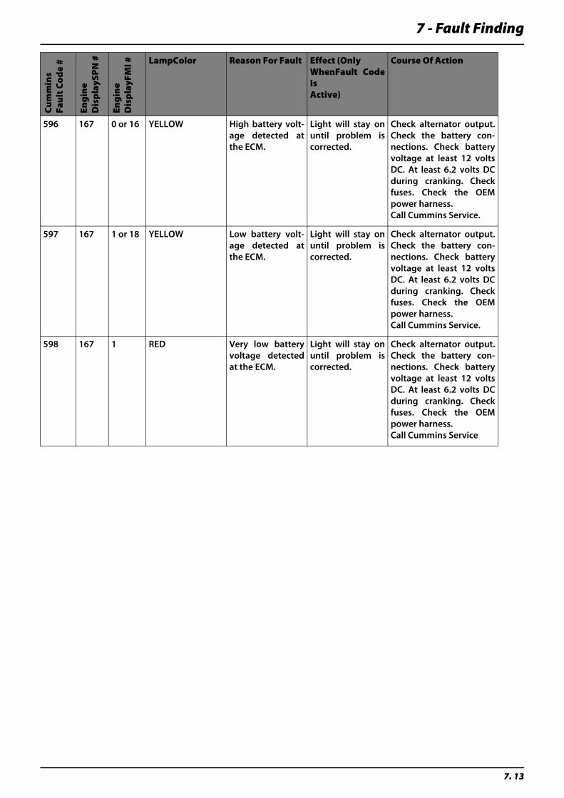
7 - Fault Finding
7. 13
Cu
mm
ins
Fau
lt C
od
e #
Eng
ine
Dis
pla
ySP
N #
Eng
ine
Dis
pla
yFM
I # LampColor Reason For Fault Effect (Only WhenFault CodeIs Active)
Course Of Action
596 167 0 or 16 YELLOW High battery volt-age detected atthe ECM.
Light will stay onuntil problem iscorrected.
Check alternator output.Check the battery con-nections. Check batteryvoltage at least 12 voltsDC. At least 6.2 volts DCduring cranking. Checkfuses. Check the OEMpower harness. Call Cummins Service.
597 167 1 or 18 YELLOW Low battery volt-age detected atthe ECM.
Light will stay onuntil problem iscorrected.
Check alternator output.Check the battery con-nections. Check batteryvoltage at least 12 voltsDC. At least 6.2 volts DCduring cranking. Checkfuses. Check the OEMpower harness. Call Cummins Service.
598 167 1 RED Very low batteryvoltage detectedat the ECM.
Light will stay onuntil problem iscorrected.
Check alternator output.Check the battery con-nections. Check batteryvoltage at least 12 voltsDC. At least 6.2 volts DCduring cranking. Checkfuses. Check the OEMpower harness.Call Cummins Service
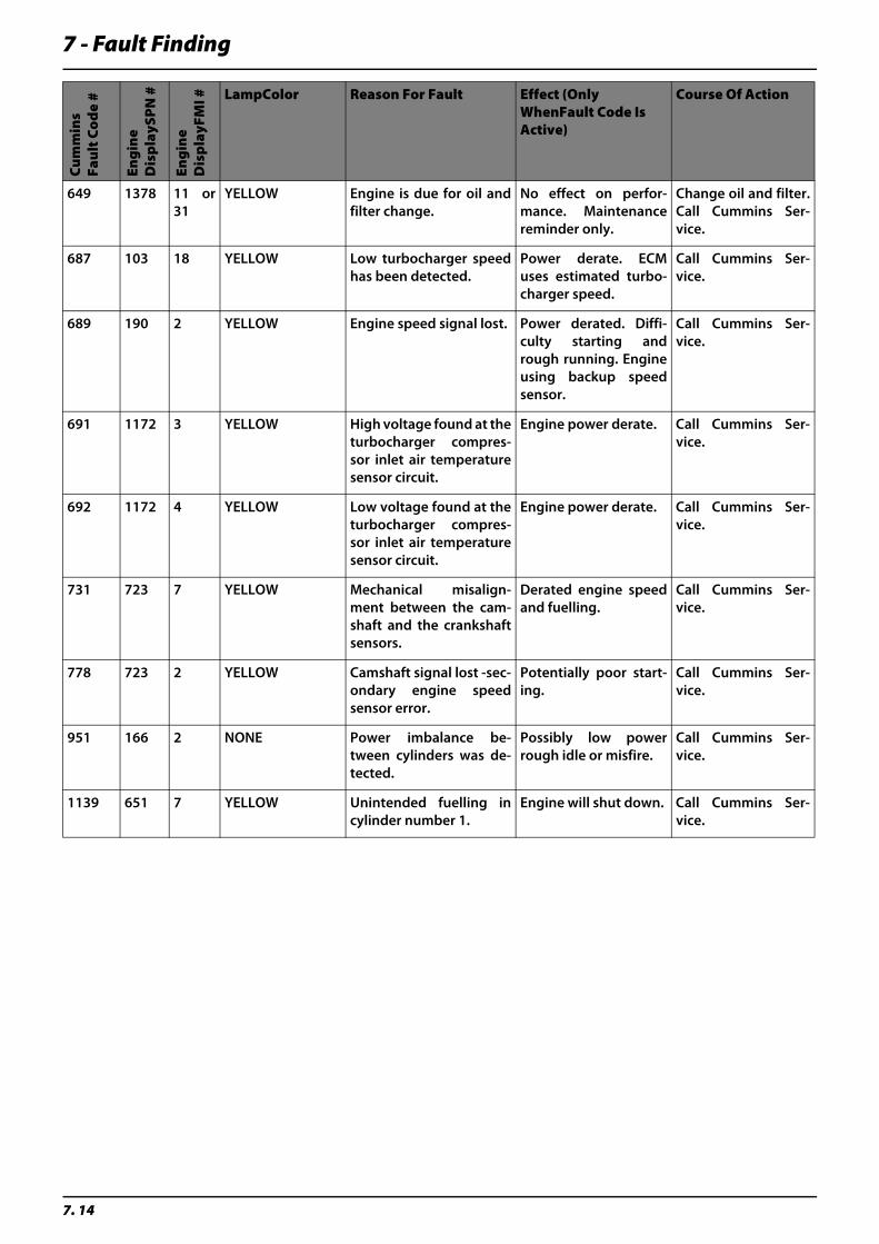
7 - Fault Finding
7. 14
Cu
mm
ins
Fau
lt C
od
e #
Eng
ine
Dis
pla
ySP
N #
Eng
ine
Dis
pla
yFM
I # LampColor Reason For Fault Effect (Only WhenFault Code Is Active)
Course Of Action
649 1378 11 or31
YELLOW Engine is due for oil andfilter change.
No effect on perfor-mance. Maintenancereminder only.
Change oil and filter.Call Cummins Ser-vice.
687 103 18 YELLOW Low turbocharger speedhas been detected.
Power derate. ECMuses estimated turbo-charger speed.
Call Cummins Ser-vice.
689 190 2 YELLOW Engine speed signal lost. Power derated. Diffi-culty starting andrough running. Engineusing backup speedsensor.
Call Cummins Ser-vice.
691 1172 3 YELLOW High voltage found at theturbocharger compres-sor inlet air temperaturesensor circuit.
Engine power derate. Call Cummins Ser-vice.
692 1172 4 YELLOW Low voltage found at theturbocharger compres-sor inlet air temperaturesensor circuit.
Engine power derate. Call Cummins Ser-vice.
731 723 7 YELLOW Mechanical misalign-ment between the cam-shaft and the crankshaftsensors.
Derated engine speedand fuelling.
Call Cummins Ser-vice.
778 723 2 YELLOW Camshaft signal lost -sec-ondary engine speedsensor error.
Potentially poor start-ing.
Call Cummins Ser-vice.
951 166 2 NONE Power imbalance be-tween cylinders was de-tected.
Possibly low powerrough idle or misfire.
Call Cummins Ser-vice.
1139 651 7 YELLOW Unintended fuelling incylinder number 1.
Engine will shut down. Call Cummins Ser-vice.
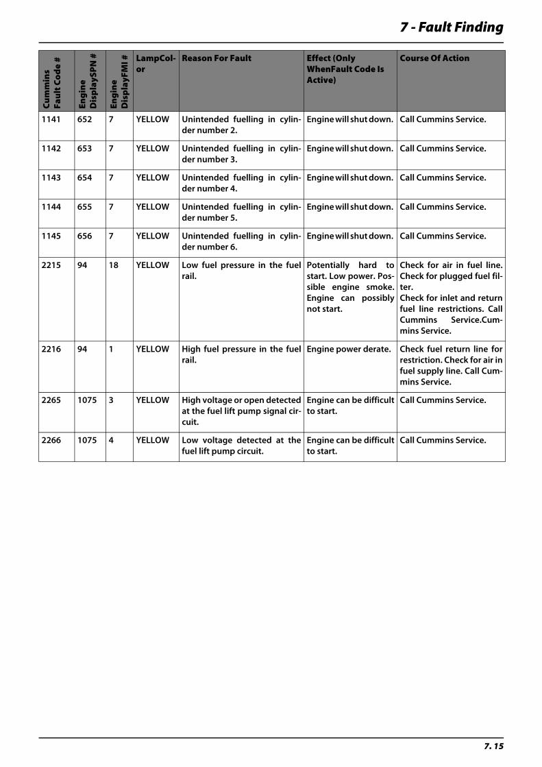
7 - Fault Finding
7. 15
Cu
mm
ins
Fau
lt C
od
e #
Eng
ine
Dis
pla
ySP
N #
Eng
ine
Dis
pla
yFM
I # LampCol-or
Reason For Fault Effect (Only WhenFault Code Is Active)
Course Of Action
1141 652 7 YELLOW Unintended fuelling in cylin-der number 2.
Engine will shut down. Call Cummins Service.
1142 653 7 YELLOW Unintended fuelling in cylin-der number 3.
Engine will shut down. Call Cummins Service.
1143 654 7 YELLOW Unintended fuelling in cylin-der number 4.
Engine will shut down. Call Cummins Service.
1144 655 7 YELLOW Unintended fuelling in cylin-der number 5.
Engine will shut down. Call Cummins Service.
1145 656 7 YELLOW Unintended fuelling in cylin-der number 6.
Engine will shut down. Call Cummins Service.
2215 94 18 YELLOW Low fuel pressure in the fuelrail.
Potentially hard tostart. Low power. Pos-sible engine smoke.Engine can possiblynot start.
Check for air in fuel line.Check for plugged fuel fil-ter.Check for inlet and returnfuel line restrictions. CallCummins Service.Cum-mins Service.
2216 94 1 YELLOW High fuel pressure in the fuelrail.
Engine power derate. Check fuel return line forrestriction. Check for air infuel supply line. Call Cum-mins Service.
2265 1075 3 YELLOW High voltage or open detectedat the fuel lift pump signal cir-cuit.
Engine can be difficultto start.
Call Cummins Service.
2266 1075 4 YELLOW Low voltage detected at thefuel lift pump circuit.
Engine can be difficultto start.
Call Cummins Service.
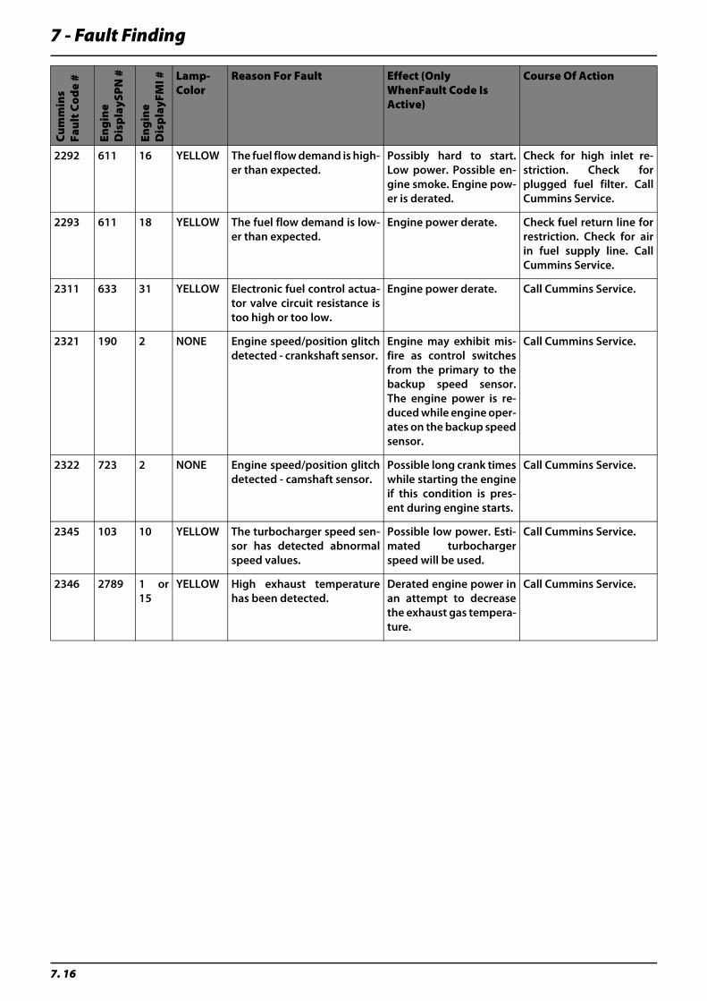
7 - Fault Finding
7. 16
Cu
mm
ins
Fau
lt C
od
e #
Eng
ine
Dis
pla
ySP
N #
Eng
ine
Dis
pla
yFM
I # Lamp-Color
Reason For Fault Effect (Only WhenFault Code Is Active)
Course Of Action
2292 611 16 YELLOW The fuel flow demand is high-er than expected.
Possibly hard to start.Low power. Possible en-gine smoke. Engine pow-er is derated.
Check for high inlet re-striction. Check forplugged fuel filter. CallCummins Service.
2293 611 18 YELLOW The fuel flow demand is low-er than expected.
Engine power derate. Check fuel return line forrestriction. Check for airin fuel supply line. CallCummins Service.
2311 633 31 YELLOW Electronic fuel control actua-tor valve circuit resistance istoo high or too low.
Engine power derate. Call Cummins Service.
2321 190 2 NONE Engine speed/position glitchdetected - crankshaft sensor.
Engine may exhibit mis-fire as control switchesfrom the primary to thebackup speed sensor.The engine power is re-duced while engine oper-ates on the backup speedsensor.
Call Cummins Service.
2322 723 2 NONE Engine speed/position glitchdetected - camshaft sensor.
Possible long crank timeswhile starting the engineif this condition is pres-ent during engine starts.
Call Cummins Service.
2345 103 10 YELLOW The turbocharger speed sen-sor has detected abnormalspeed values.
Possible low power. Esti-mated turbochargerspeed will be used.
Call Cummins Service.
2346 2789 1 or15
YELLOW High exhaust temperaturehas been detected.
Derated engine power inan attempt to decreasethe exhaust gas tempera-ture.
Call Cummins Service.
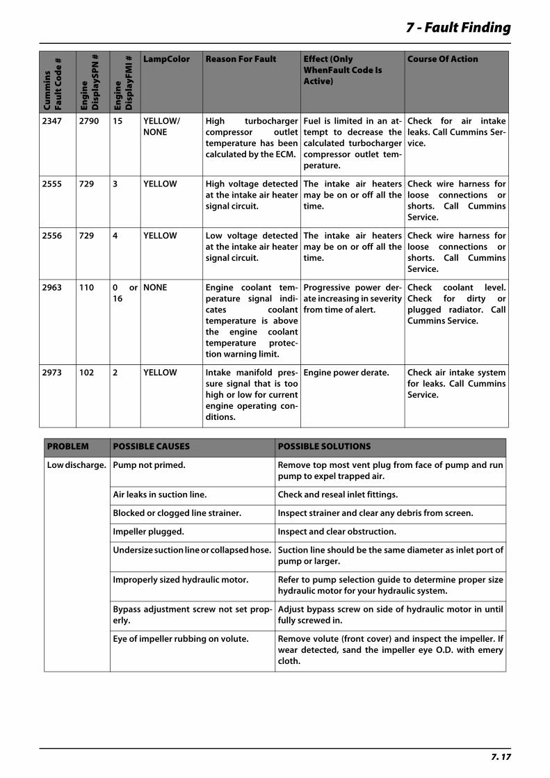
7 - Fault Finding
7. 17
Cu
mm
ins
Fau
lt C
od
e #
Eng
ine
Dis
pla
ySP
N #
Eng
ine
Dis
pla
yFM
I # LampColor Reason For Fault Effect (Only WhenFault Code Is Active)
Course Of Action
2347 2790 15 YELLOW/NONE
High turbochargercompressor outlettemperature has beencalculated by the ECM.
Fuel is limited in an at-tempt to decrease thecalculated turbochargercompressor outlet tem-perature.
Check for air intakeleaks. Call Cummins Ser-vice.
2555 729 3 YELLOW High voltage detectedat the intake air heatersignal circuit.
The intake air heatersmay be on or off all thetime.
Check wire harness forloose connections orshorts. Call CumminsService.
2556 729 4 YELLOW Low voltage detectedat the intake air heatersignal circuit.
The intake air heatersmay be on or off all thetime.
Check wire harness forloose connections orshorts. Call CumminsService.
2963 110 0 or16
NONE Engine coolant tem-perature signal indi-cates coolanttemperature is abovethe engine coolanttemperature protec-tion warning limit.
Progressive power der-ate increasing in severityfrom time of alert.
Check coolant level.Check for dirty orplugged radiator. CallCummins Service.
2973 102 2 YELLOW Intake manifold pres-sure signal that is toohigh or low for currentengine operating con-ditions.
Engine power derate. Check air intake systemfor leaks. Call CumminsService.
PROBLEM POSSIBLE CAUSES POSSIBLE SOLUTIONS
Low discharge. Pump not primed. Remove top most vent plug from face of pump and runpump to expel trapped air.
Air leaks in suction line. Check and reseal inlet fittings.
Blocked or clogged line strainer. Inspect strainer and clear any debris from screen.
Impeller plugged. Inspect and clear obstruction.
Undersize suction line or collapsed hose. Suction line should be the same diameter as inlet port ofpump or larger.
Improperly sized hydraulic motor. Refer to pump selection guide to determine proper sizehydraulic motor for your hydraulic system.
Bypass adjustment screw not set prop-erly.
Adjust bypass screw on side of hydraulic motor in untilfully screwed in.
Eye of impeller rubbing on volute. Remove volute (front cover) and inspect the impeller. Ifwear detected, sand the impeller eye O.D. with emerycloth.

7 - Fault Finding
7. 18
DirectCommand TroubleShooting Guide
Pre-Liquid Application Checklist
If actual rate is consistent, Direct-Command system should apply
correctly. If not, see ‘Rate is Erratic’ on page 8
Is the firmware on the monitor and modules current?
Will configuration load on Run Screen?
Do the boom indicators on the Run Screen turn blue?
Do the booms turn on?
Does product come out of boom?
Does the Insight register flow?
YES
YES
YES
YES
YES
YES
NO
NO
NO
NO
NO
NO
Upgrade monitor and module firmware
See Configuration will not load - Page 3
See Boom Indicators on Run Screen do not turn blue - Page 4
See Booms do not turn on - Page 5
See Product not applying - Page 6
See Insight does not register flow - Page 7
DirectCommand Liquid TroubleShooting Guide
Page 1/10
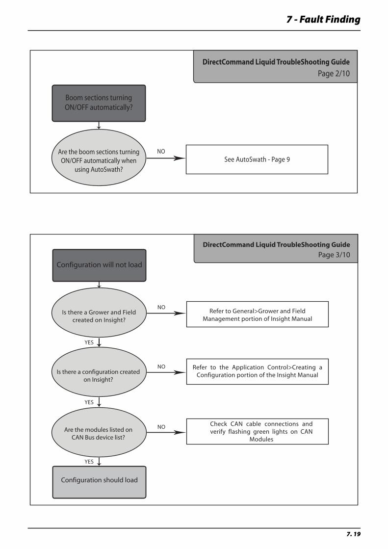
7 - Fault Finding
7. 19
Boom sections turning ON/OFF automatically?
NOSee AutoSwath - Page 9
Are the boom sections turning ON/OFF automatically when
using AutoSwath?
DirectCommand Liquid TroubleShooting Guide
Page 2/10
Configuration will not load
Configuration should load
Is there a Grower and Field created on Insight?
Is there a configuration created on Insight?
Are the modules listed onCAN Bus device list?
YES
YES
YES
NO
NO
NO
Refer to General>Grower and Field Management portion of Insight Manual
Refer to the Application Control>Creating a Configuration portion of the Insight Manual
Check CAN cable connections and verify flashing green lights on CAN
Modules
DirectCommand Liquid TroubleShooting Guide
Page 3/10
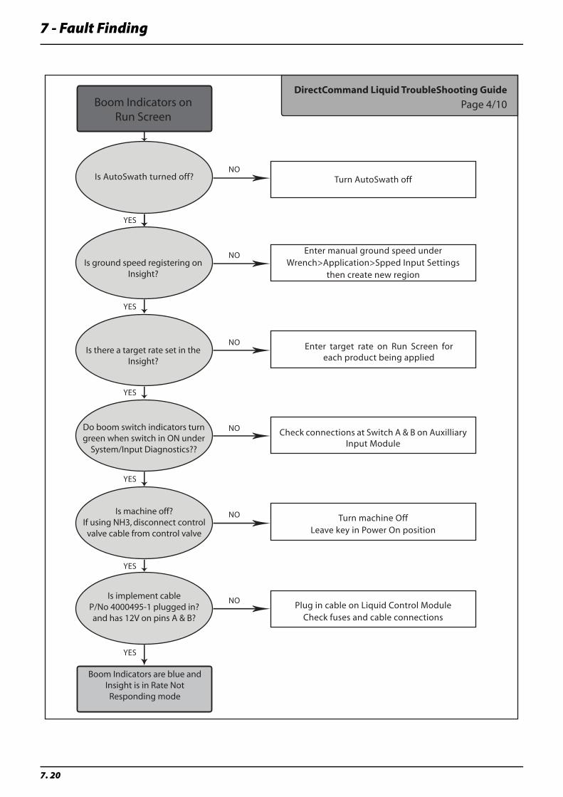
7 - Fault Finding
7. 20
Boom Indicators on Run Screen
Boom Indicators are blue and Insight is in Rate Not Responding mode
Is AutoSwath turned off?
Is ground speed registering on Insight?
Is there a target rate set in the Insight?
Do boom switch indicators turn green when switch in ON under
System/Input Diagnostics??
Is machine off?If using NH3, disconnect control valve cable from control valve
Is implement cable P/No 4000495-1 plugged in? and has 12V on pins A & B?
YES
YES
YES
YES
YES
YES
NO
NO
NO
NO
NO
NO
Turn AutoSwath off
Enter manual ground speed underWrench>Application>Spped Input Settings
then create new region
Enter target rate on Run Screen for each product being applied
Check connections at Switch A & B on Auxilliary Input Module
Turn machine OffLeave key in Power On position
Plug in cable on Liquid Control ModuleCheck fuses and cable connections
DirectCommand Liquid TroubleShooting Guide
Page 4/10
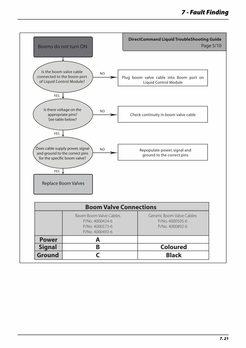
7 - Fault Finding
7. 21
Booms do not turn ON
Replace Boom Valves
Is the boom valve cable connected to the boom port
of Liquid Control Module?
Is there voltage on the appropriate pins?See table below?
Does cable supply power, signal and ground to the correct pins
for the specific boom valve?
YES
YES
YES
NO
NO
NO
Plug boom valve cable into Boom port on Liquid Control Module
Check continuity in boom valve cable
Repopulate power, signal and ground to the correct pins
Boom Valve Connections
Power AB Coloured
BlackCSignal
Ground
Raven Boom Valve Cables
P/No. 4000424-6
P/No. 4000573-6
P/No. 4000493-6
Generic Boom Valve Cables
P/No. 4000505-6
P/No. 4000892-6
DirectCommand Liquid TroubleShooting Guide
Page 5/10
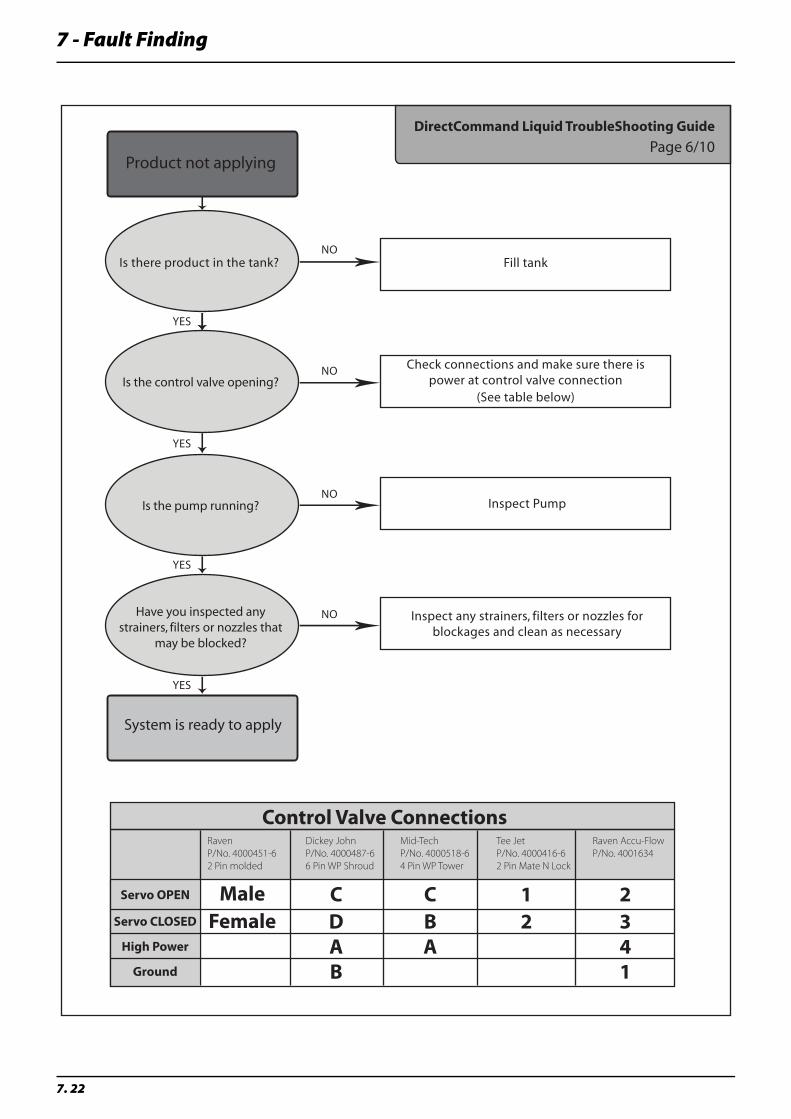
7 - Fault Finding
7. 22
Product not applying
System is ready to apply
Is there product in the tank?
Is the control valve opening?
Is the pump running?
YES
YES
YES
NO
NO
NO
Fill tank
Check connections and make sure there is power at control valve connection
(See table below)
Inspect Pump
Have you inspected any strainers, filters or nozzles that
may be blocked?
YES
NO Inspect any strainers, filters or nozzles for blockages and clean as necessary
Control Valve Connections
Servo OPEN
Servo CLOSED
High Power
Ground
DC
AB
BC
A21
32
41
MaleFemale
Raven
P/No. 4000451-6
2 Pin molded
Dickey John
P/No. 4000487-6
6 Pin WP Shroud
Mid-Tech
P/No. 4000518-6
4 Pin WP Tower
Tee Jet
P/No. 4000416-6
2 Pin Mate N Lock
Raven Accu-Flow
P/No. 4001634
DirectCommand Liquid TroubleShooting Guide
Page 6/10
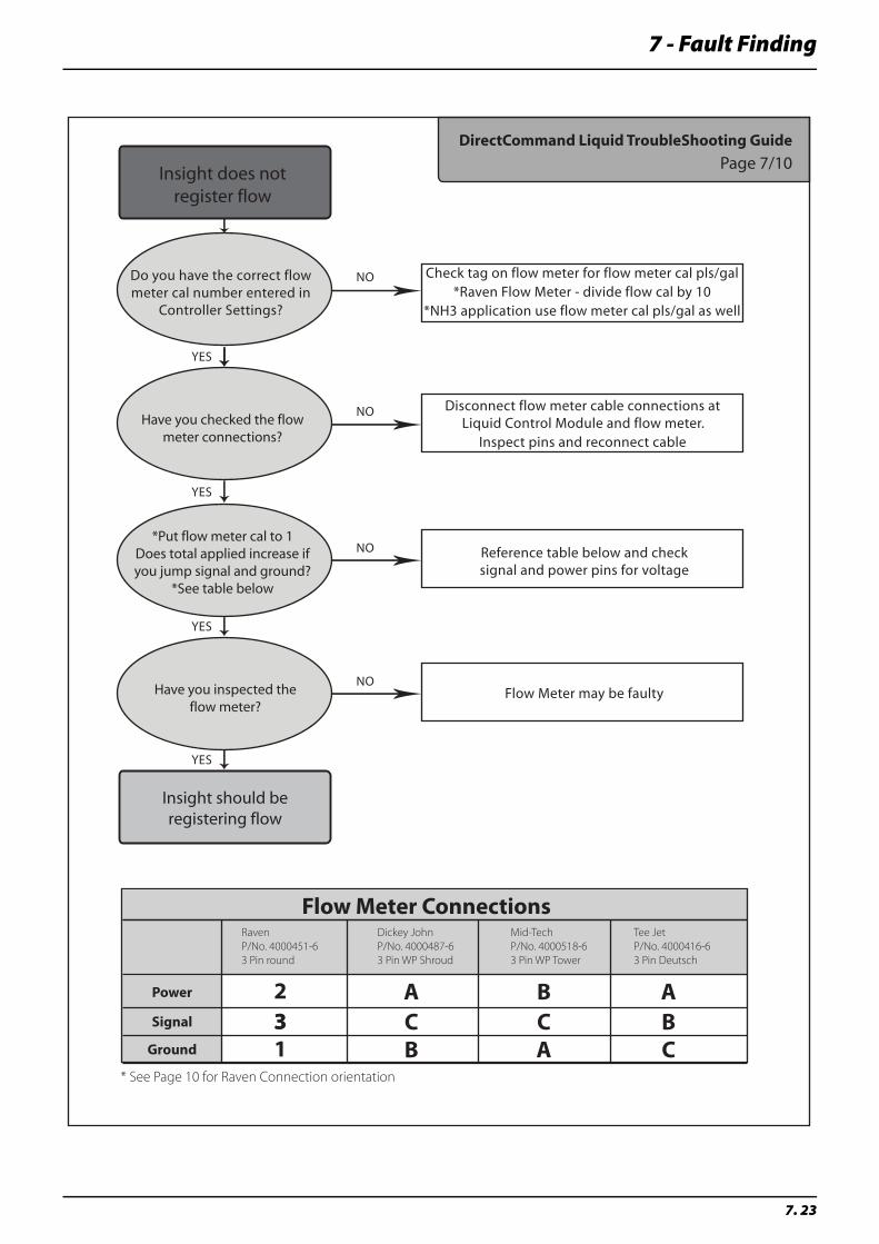
7 - Fault Finding
7. 23
Insight does not register flow
Insight should be registering flow
Do you have the correct flow meter cal number entered in
Controller Settings?
Have you checked the flow meter connections?
*Put flow meter cal to 1Does total applied increase if you jump signal and ground?
*See table below
YES
YES
YES
NO
NO
NO
Check tag on flow meter for flow meter cal pls/gal*Raven Flow Meter - divide flow cal by 10
*NH3 application use flow meter cal pls/gal as well
Disconnect flow meter cable connections at Liquid Control Module and flow meter.
Inspect pins and reconnect cable
Reference table below and check signal and power pins for voltage
Have you inspected the flow meter?
YES
NOFlow Meter may be faulty
Flow Meter Connections
Power
Signal
Ground
CA
BCB
ABA
C
2331
Raven
P/No. 4000451-6
3 Pin round
Dickey John
P/No. 4000487-6
3 Pin WP Shroud
Mid-Tech
P/No. 4000518-6
3 Pin WP Tower
Tee Jet
P/No. 4000416-6
3 Pin Deutsch
* See Page 10 for Raven Connection orientation
DirectCommand Liquid TroubleShooting Guide
Page 7/10
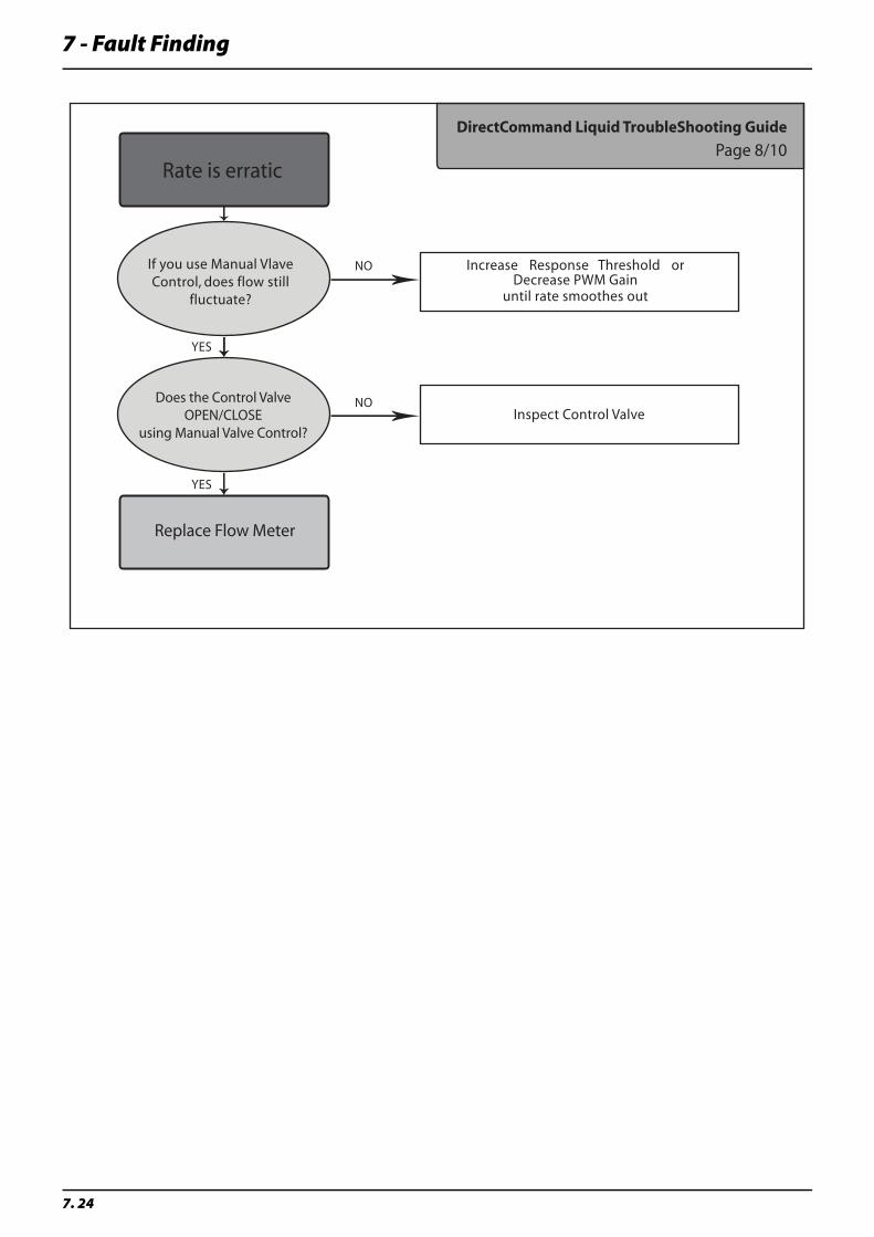
7 - Fault Finding
7. 24
Rate is erratic
Replace Flow Meter
If you use Manual Vlave Control, does flow still
fluctuate?
Does the Control Valve OPEN/CLOSE
using Manual Valve Control?
YES
YES
NO
NO
Increase Response Threshold or Decrease PWM Gain
until rate smoothes out
Inspect Control Valve
DirectCommand Liquid TroubleShooting Guide
Page 8/10
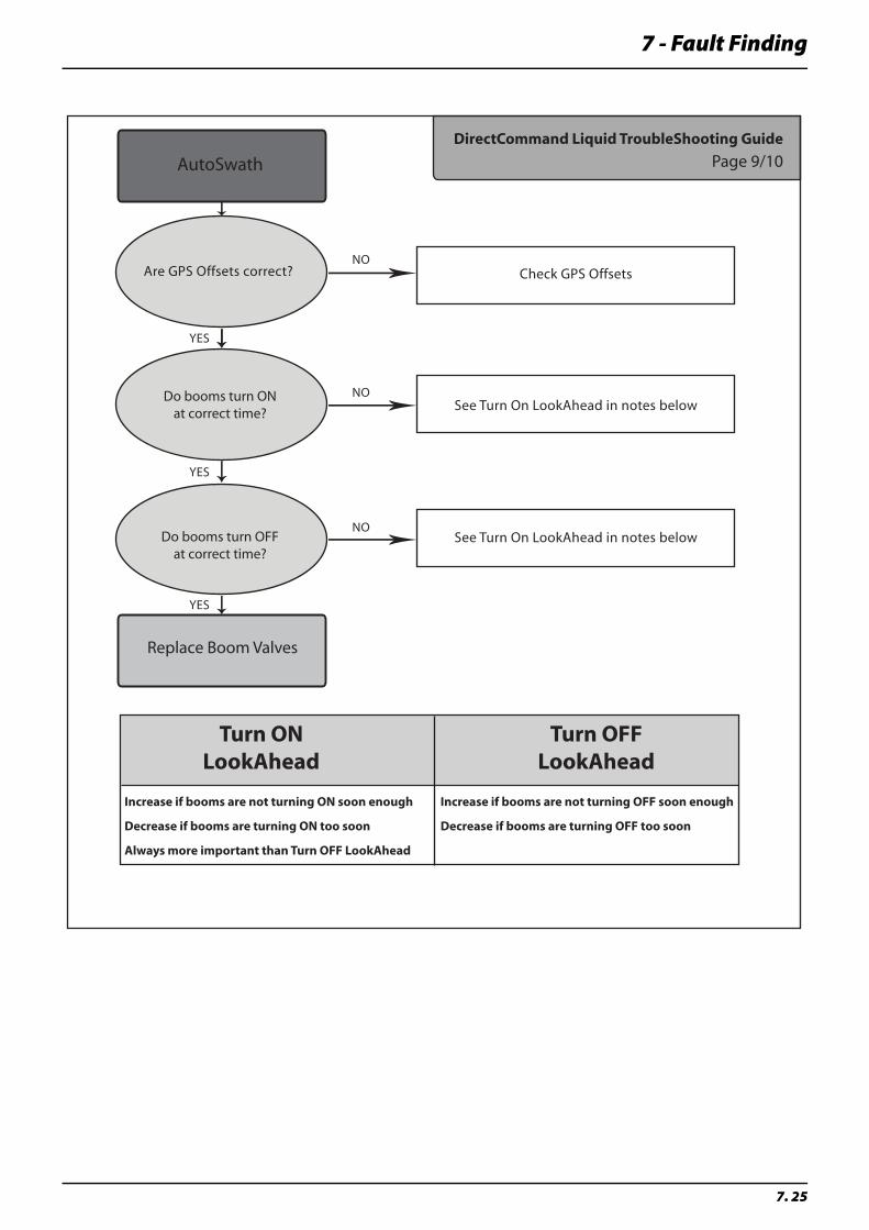
7 - Fault Finding
7. 25
AutoSwath
Replace Boom Valves
Are GPS Offsets correct?
Do booms turn ON at correct time?
Do booms turn OFF at correct time?
YES
YES
YES
NO
NO
NO
Check GPS Offsets
See Turn On LookAhead in notes below
See Turn On LookAhead in notes below
Turn ONLookAhead
Turn OFFLookAhead
Increase if booms are not turning ON soon enough
Decrease if booms are turning ON too soon
Always more important than Turn OFF LookAhead
Increase if booms are not turning OFF soon enough
Decrease if booms are turning OFF too soon
DirectCommand Liquid TroubleShooting Guide
Page 9/10
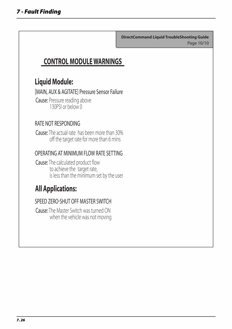
7 - Fault Finding
7. 26
DirectCommand Liquid TroubleShooting Guide
Page 10/10
Liquid Module:
All Applications:
CONTROL MODULE WARNINGS
[MAIN, AUX & AGITATE] Pressure Sensor Failure
RATE NOT RESPONDING
Cause: Pressure reading above 130PSI or below 0
Cause: The actual rate has been more than 30% off the target rate for more than 6 mins
OPERATING AT MINIMUM FLOW RATE SETTINGCause: The calculated product flow to achieve the target rate, is less than the minimum set by the user
SPEED ZERO-SHUT OFF MASTER SWITCHCause: The Master Switch was turned ON when the vehicle was not moving

8 - Technical Specifications
8. 1
General A75 Specifications
Dimensions
Overall Dimensions
All measurements are in millimetres
ENGINE Cummins QSB 6.7 litre CAB 90 Series - ERV
TRANSMISSION Allison 6 Speed Horse Power 275
DIFFERENTIAL JCB w/On The Go Differential Lock FINAL DRIVE Drop Box
PRODUCT TANK 4800 litres Polyethylene Tank RINSE TANK 454 litre Polyethylene
SUSPENSION Automatic Adjust Air Bag w/Sway Control AXLE WIDTH Adjustable 3050mm to 3810mm
GROUND SPEED 0 - 68 km/h FUEL CAPACITY 450 litres
WHEEL BASE 4270mm TURNING RADIUS 4500mm
TYRES 380/90R46 Field or Highway Lug BRAKES Heavy Duty Front & Rear WheelDisc Brakes
BOOM OPTIONS 36m FTZ PRODUCT PUMP Hypro 9306 Stainless Steel
BOOM HEIGHT Adjustable 500mm to 2000mm CROP CLEARANCE 1200mm
HYDRAULIC SYS-TEM
Pressure Compensated HYDRAULIC CA-PACITY
95 litres
LADDER Wide Cast Steps w/Hydraulic Fold PARKING BRAKE Spring Applied - Hydraulic Release
A B C D E F G H3900 3500 9100 4240 3100 630 1145 580
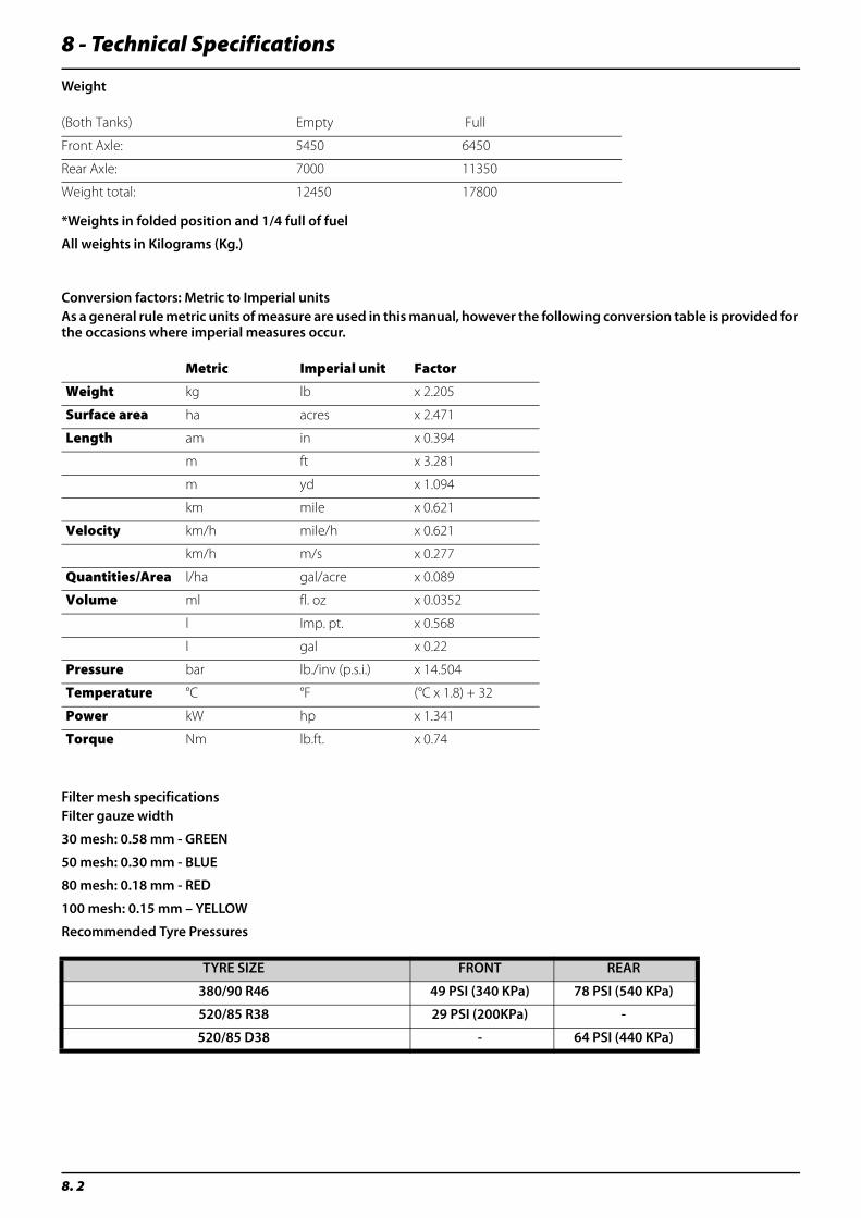
8 - Technical Specifications
8. 2
Weight
*Weights in folded position and 1/4 full of fuel
All weights in Kilograms (Kg.)
Conversion factors: Metric to Imperial unitsAs a general rule metric units of measure are used in this manual, however the following conversion table is provided for the occasions where imperial measures occur.
Filter mesh specificationsFilter gauze width
30 mesh: 0.58 mm - GREEN
50 mesh: 0.30 mm - BLUE
80 mesh: 0.18 mm - RED
100 mesh: 0.15 mm – YELLOW
Recommended Tyre Pressures
(Both Tanks) Empty Full
Front Axle: 5450 6450
Rear Axle: 7000 11350
Weight total: 12450 17800
Metric Imperial unit Factor
Weight kg lb x 2.205
Surface area ha acres x 2.471
Length am in x 0.394
m ft x 3.281
m yd x 1.094
km mile x 0.621
Velocity km/h mile/h x 0.621
km/h m/s x 0.277
Quantities/Area l/ha gal/acre x 0.089
Volume ml fl. oz x 0.0352
l Imp. pt. x 0.568
l gal x 0.22
Pressure bar lb./inv (p.s.i.) x 14.504
Temperature °C °F (°C x 1.8) + 32
Power kW hp x 1.341
Torque Nm lb.ft. x 0.74
TYRE SIZE FRONT REAR
380/90 R46 49 PSI (340 KPa) 78 PSI (540 KPa)
520/85 R38 29 PSI (200KPa) -
520/85 D38 - 64 PSI (440 KPa)
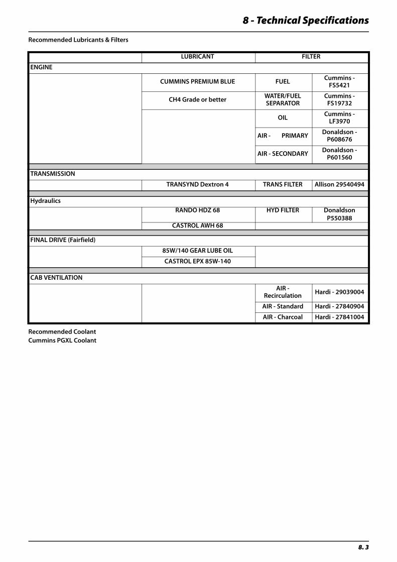
8 - Technical Specifications
8. 3
Recommended Lubricants & Filters
Recommended CoolantCummins PGXL Coolant
LUBRICANT FILTER
ENGINE
CUMMINS PREMIUM BLUE FUEL Cummins - FS5421
CH4 Grade or better WATER/FUEL SEPARATOR
Cummins - FS19732
OIL Cummins - LF3970
AIR - PRIMARY Donaldson -P608676
AIR - SECONDARY Donaldson - P601560
TRANSMISSION
TRANSYND Dextron 4 TRANS FILTER Allison 29540494
HydraulicsRANDO HDZ 68 HYD FILTER Donaldson
P550388CASTROL AWH 68
FINAL DRIVE (Fairfield)
85W/140 GEAR LUBE OIL
CASTROL EPX 85W-140
CAB VENTILATION
AIR - Recirculation Hardi - 29039004
AIR - Standard Hardi - 27840904
AIR - Charcoal Hardi - 27841004

8 - Technical Specifications
8. 4
Electrical connections for InSight
Liquid Control Box 37 Pin Male Pin # Boom Junction Box
37 Pin Female Function
Yellow / Grey 1 Green / Black Section 13 positive
Pink / Blue 2 Pink / Blue Section 11 positive
Grey / Blue 3 Grey / Blue Section 11 negative
Red / Blue 4 Red / Blue Section 10 positive
White 5 White Section 10 negative
White / Black 6 Brown Section 9 positive
Brown / Black 7 Yellow Section 9 negative
Brown / Blue 8 Grey Section 8 positive
White / Red 9 Blue Section 8 negative
White / Pink 10 Red Section 7 positive
Pink / Brown 11 Purple Section 7 negative
Yellow / Brown 12 Grey / Pink Section 6 positive
White / Grey 13 Grey / Brown Section 6 negative
White / Green 14 White / Green Section 5 positive
Brown / Green 15 Brown / Green Section 5 negative
Grey / Pink 16 Brown / Yellow Section 4 positive
Grey / Brown 17 Grey / White Section 4 negative
Red 18 White / Pink Section 3 positive
Purple 19 Brown / Pink Section 3 negative
Pink / Green 20 Yellow / Red Section 13 negative
Green / Blue 21 Yellow / Grey Section 12 positive
Yellow / Blue 22 Pink / Green Section 12 negative
Green / Black 23 Green / Blue Bypass positive
Yellow / Red 24 Yellow / Blue Bypass negative
Pink 25 Pink Right Nozzle positive
Green 26 Green Left Nozzle positive
White / Yellow 27 White / Yellow Common Nozzle negative
Green / Red 28 Green / Red Flow Signal
Grey / Red 29 Black Common Signal negative
Black 30 Grey / Red Common Signal positive
Yellow / Black 31 Yellow / Black Speed Signal
Brown / Red 32 Brown / Red Boom Centre Lock
White / Blue 33 White / Blue Pressure Signal
Yellow 34 Brown / Black Section 1 negative
Brown 35 White / Black Section 1 positive
Blue 36 White / Red Section 2 negative
Grey 37 Brown / Blue Section 2 positive
Grey / PinkNot Connected at either end
Yellow / Pink

8 - Technical Specifications
8. 5
EFCWhen connecting an optional function into the EFC distribution box be aware that the maximum current for every connection is 2 Amp. The total current draw allowed for the whole connector box may not exceed 10 Amp.
Remember that as a rule the sprayers internal wiring is colour coded:
Blue....................................................= + Positive
Brown...............................................= - Negative
μ Attention: For more information on EFC circuit board service, see EFC service procedure in the “Maintenance section” of this manual
EFC - Fluid PCB
Pin Function Pos Sig. Neg
Opt 1 Pressure sensor Brn Blu -
Opt 2 RPM sensor or anemometer Brn Blu Blk
Speed Brn Blu Blk
Flow Brn Blu Blk
L end nozzle Pendulum lock at HAY/LPY Brn Blu
R end nozzle Pendulum lock at HAY/LPY Brn Blu
Reg (Yellow) Brn Blu
Bypass EC on/off Brn Blu
Sec 9 User defined A&B 2 x x
Sec 8 User defined A&B 1 x x
Sec 7 Twin speed Brn Whi
Sec 6 Twin angle Yel Gre
Sec 5 Brn Blu
Sec 4 Brn Blu
Sec 3 Brn Blu
Sec 2 Brn Blu
Sec 1 Brn Blu
Gnd L R - +
Foam marker No. 4 Not used 2 6 5 1 3

8 - Technical Specifications
8. 6
Boom hydraulics
Hillside Fold Manifold Schematic
A1 B1 A2 B2 A3 B3 A4 B4
2A 2B 2C 2D
4A 4B
3B3A
3A
1 2 3 4

8 - Technical Specifications
8. 7
Hydraulic Oil RecommendationsIt is important that a quality oil be used to insure proper longevity of hydraulic components.
Following is the minimum specifications for hydraulic oil to be used on this sprayer.
Typical Characteristics
Some US mineral oil brands that meet these specifications are:
• Benz Flowmite 68
• Mobil DTE 16M
• Amoco Rykon 68
• Shell Tellus T68
• Chevron AW68MV
• Texaco Rando HDZ68
• Exxon Univis N68
ISO Classification HV-68
Viscosity, cSt @ 40° C 69.0
Viscosity, cSt @ 100° C 11.0
Viscosity, SUS @ 38° C 352
Viscosity, SUS @ 99° C 63.4
Viscosity, cPs @ -20° C 4940
Viscosity, cPs @ 30° C 28700
Viscosity Index, Typical 150
Viscosity Loss, Sonis Shear Method <7%
Pour Point, °C, Typical 38.8
Flash Point, °C, Typical 221
API Gravity 30.8
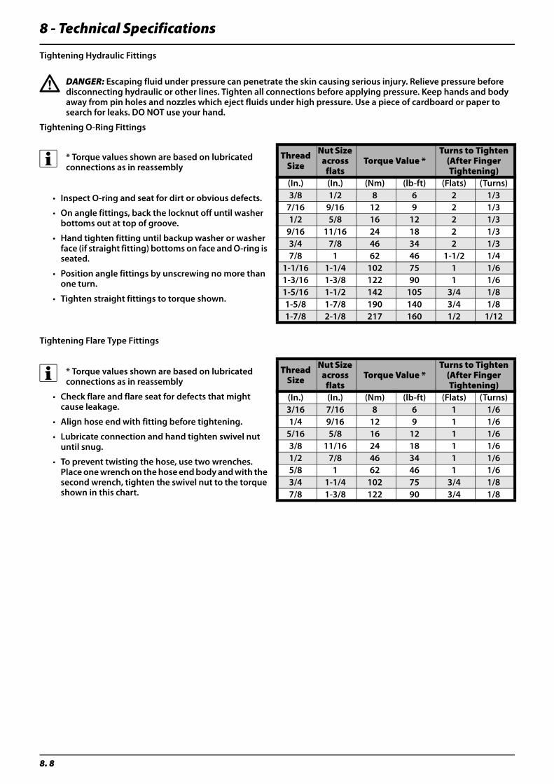
8 - Technical Specifications
8. 8
Tightening Hydraulic Fittings
€ DANGER: Escaping fluid under pressure can penetrate the skin causing serious injury. Relieve pressure before disconnecting hydraulic or other lines. Tighten all connections before applying pressure. Keep hands and body away from pin holes and nozzles which eject fluids under high pressure. Use a piece of cardboard or paper to search for leaks. DO NOT use your hand.
Tightening O-Ring Fittings
Tightening Flare Type Fittings
÷ * Torque values shown are based on lubricated connections as in reassembly
• Inspect O-ring and seat for dirt or obvious defects.
• On angle fittings, back the locknut off until washer bottoms out at top of groove.
• Hand tighten fitting until backup washer or washer face (if straight fitting) bottoms on face and O-ring is seated.
• Position angle fittings by unscrewing no more than one turn.
• Tighten straight fittings to torque shown.
Thread Size
Nut Size across
flatsTorque Value *
Turns to Tighten (After Finger Tightening)
(In.) (In.) (Nm) (lb-ft) (Flats) (Turns)3/8 1/2 8 6 2 1/3
7/16 9/16 12 9 2 1/31/2 5/8 16 12 2 1/3
9/16 11/16 24 18 2 1/33/4 7/8 46 34 2 1/37/8 1 62 46 1-1/2 1/4
1-1/16 1-1/4 102 75 1 1/61-3/16 1-3/8 122 90 1 1/61-5/16 1-1/2 142 105 3/4 1/81-5/8 1-7/8 190 140 3/4 1/81-7/8 2-1/8 217 160 1/2 1/12
÷ * Torque values shown are based on lubricated connections as in reassembly
• Check flare and flare seat for defects that might cause leakage.
• Align hose end with fitting before tightening.
• Lubricate connection and hand tighten swivel nut until snug.
• To prevent twisting the hose, use two wrenches. Place one wrench on the hose end body and with the second wrench, tighten the swivel nut to the torque shown in this chart.
Thread Size
Nut Size across
flatsTorque Value *
Turns to Tighten (After Finger Tightening)
(In.) (In.) (Nm) (lb-ft) (Flats) (Turns)3/16 7/16 8 6 1 1/61/4 9/16 12 9 1 1/6
5/16 5/8 16 12 1 1/63/8 11/16 24 18 1 1/61/2 7/8 46 34 1 1/65/8 1 62 46 1 1/63/4 1-1/4 102 75 3/4 1/87/8 1-3/8 122 90 3/4 1/8
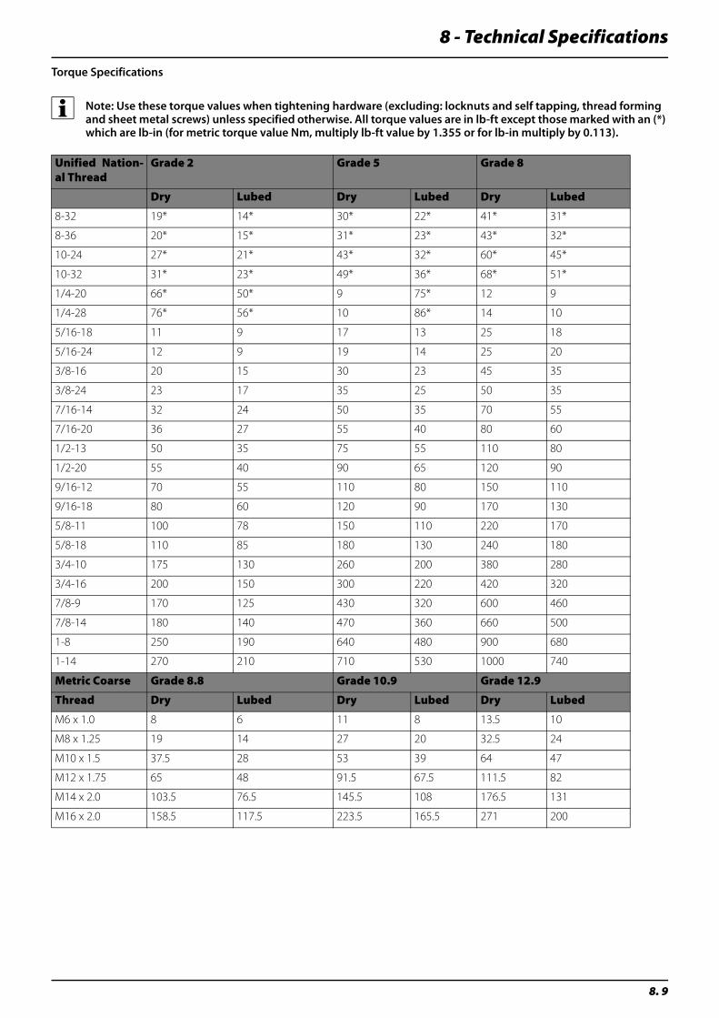
8 - Technical Specifications
8. 9
Torque Specifications
÷ Note: Use these torque values when tightening hardware (excluding: locknuts and self tapping, thread forming and sheet metal screws) unless specified otherwise. All torque values are in lb-ft except those marked with an (*) which are lb-in (for metric torque value Nm, multiply lb-ft value by 1.355 or for lb-in multiply by 0.113).
Unified Nation-al Thread
Grade 2 Grade 5 Grade 8
Dry Lubed Dry Lubed Dry Lubed
8-32 19* 14* 30* 22* 41* 31*
8-36 20* 15* 31* 23* 43* 32*
10-24 27* 21* 43* 32* 60* 45*
10-32 31* 23* 49* 36* 68* 51*
1/4-20 66* 50* 9 75* 12 9
1/4-28 76* 56* 10 86* 14 10
5/16-18 11 9 17 13 25 18
5/16-24 12 9 19 14 25 20
3/8-16 20 15 30 23 45 35
3/8-24 23 17 35 25 50 35
7/16-14 32 24 50 35 70 55
7/16-20 36 27 55 40 80 60
1/2-13 50 35 75 55 110 80
1/2-20 55 40 90 65 120 90
9/16-12 70 55 110 80 150 110
9/16-18 80 60 120 90 170 130
5/8-11 100 78 150 110 220 170
5/8-18 110 85 180 130 240 180
3/4-10 175 130 260 200 380 280
3/4-16 200 150 300 220 420 320
7/8-9 170 125 430 320 600 460
7/8-14 180 140 470 360 660 500
1-8 250 190 640 480 900 680
1-14 270 210 710 530 1000 740
Metric Coarse Grade 8.8 Grade 10.9 Grade 12.9
Thread Dry Lubed Dry Lubed Dry Lubed
M6 x 1.0 8 6 11 8 13.5 10
M8 x 1.25 19 14 27 20 32.5 24
M10 x 1.5 37.5 28 53 39 64 47
M12 x 1.75 65 48 91.5 67.5 111.5 82
M14 x 2.0 103.5 76.5 145.5 108 176.5 131
M16 x 2.0 158.5 117.5 223.5 165.5 271 200
8 - Technical Specifications
8. 10
Spare part information
HARDI spare parts pages
For Spare Parts requirements, either contact your HARDI dealer, log onto www.agroparts.com (register for free and click on the HARDI International Spare parts and service link) or visit our web site at: www.hardi.com.au
We apologise for any inconvenience.
Further information
HARDI spare part and technical support
HARDI Australia continues to invest heavily in research and development of sprayer technology to bring the best and most innovative spray products to the Australian market.
In addition our spare parts and field support staff are working closely with our regional dealer network to provide you the best after sales service and technical advice available.
Further information about spraying, our organisation and it’s product range is available through your HARDI dealer or visit our web site at: www.hardi.com.au
Materials and recycling
Disposal of the sprayer
When the equipment has completed its working life, it must be thoroughly cleaned and de-contaminated before disposal. The tank, hoses and synthetic fittings can be incinerated at an authorised disposal depot. The metallic parts can be scrapped. Contact your local Authorities for information regarding safe disposal of the following materials:
• Tank: HDPE
• Hoses: PVC
• Valves: mainly glass-filled PA.
• Fittings: PA
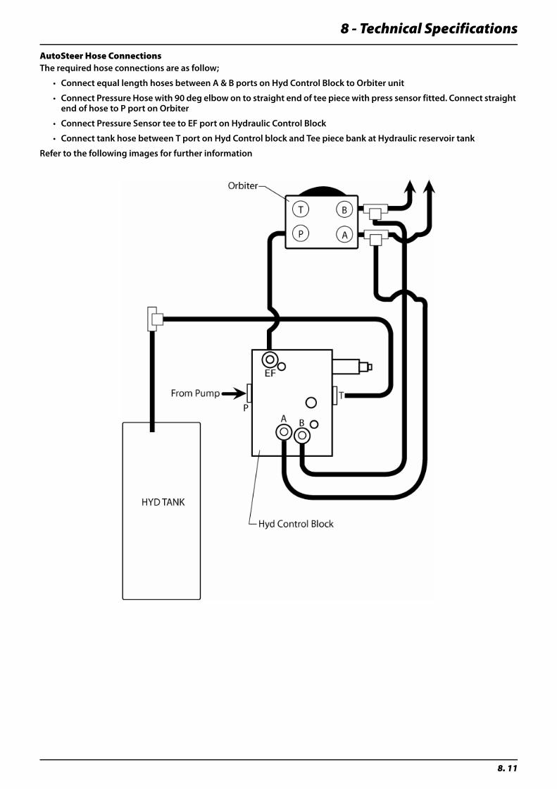
8 - Technical Specifications
8. 11
AutoSteer Hose ConnectionsThe required hose connections are as follow;
• Connect equal length hoses between A & B ports on Hyd Control Block to Orbiter unit
• Connect Pressure Hose with 90 deg elbow on to straight end of tee piece with press sensor fitted. Connect straight end of hose to P port on Orbiter
• Connect Pressure Sensor tee to EF port on Hydraulic Control Block
• Connect tank hose between T port on Hyd Control block and Tee piece bank at Hydraulic reservoir tank
Refer to the following images for further information
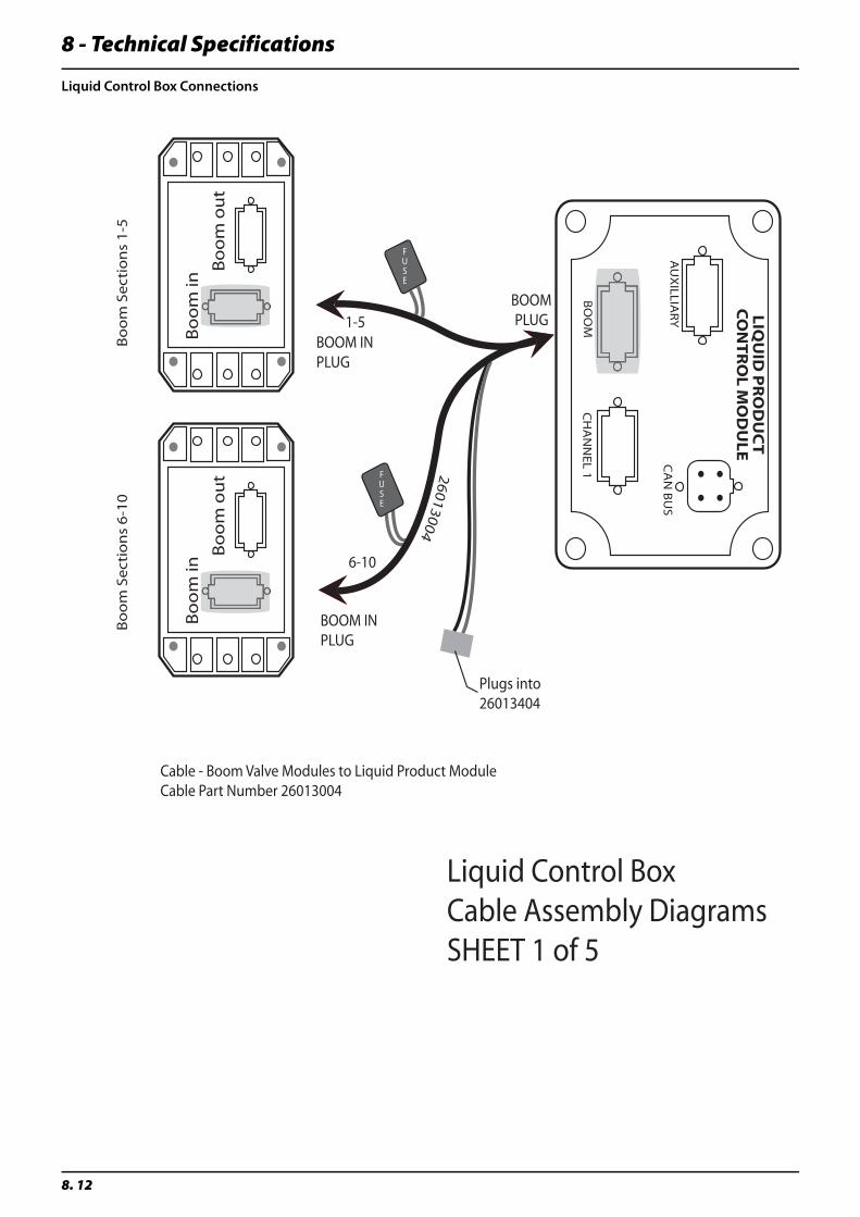
8 - Technical Specifications
8. 12
Liquid Control Box Connections
CA
N B
US
CH
AN
NE
L 1B
OO
M
AU
XILLIA
RY LIQ
UID
PR
OD
UC
T C
ON
TRO
L MO
DU
LE
Bo
om
in
Bo
om
ou
t
Bo
om
in
Bo
om
ou
t
Bo
om
Se
ctio
ns
1-5
Bo
om
Se
ctio
ns
6-1
0
26
013004
1-5
6-10
BOOM IN PLUG
BOOM IN PLUG
BOOMPLUG
Cable - Boom Valve Modules to Liquid Product ModuleCable Part Number 26013004
Plugs into 26013404
Liquid Control Box Cable Assembly Diagrams SHEET 1 of 5
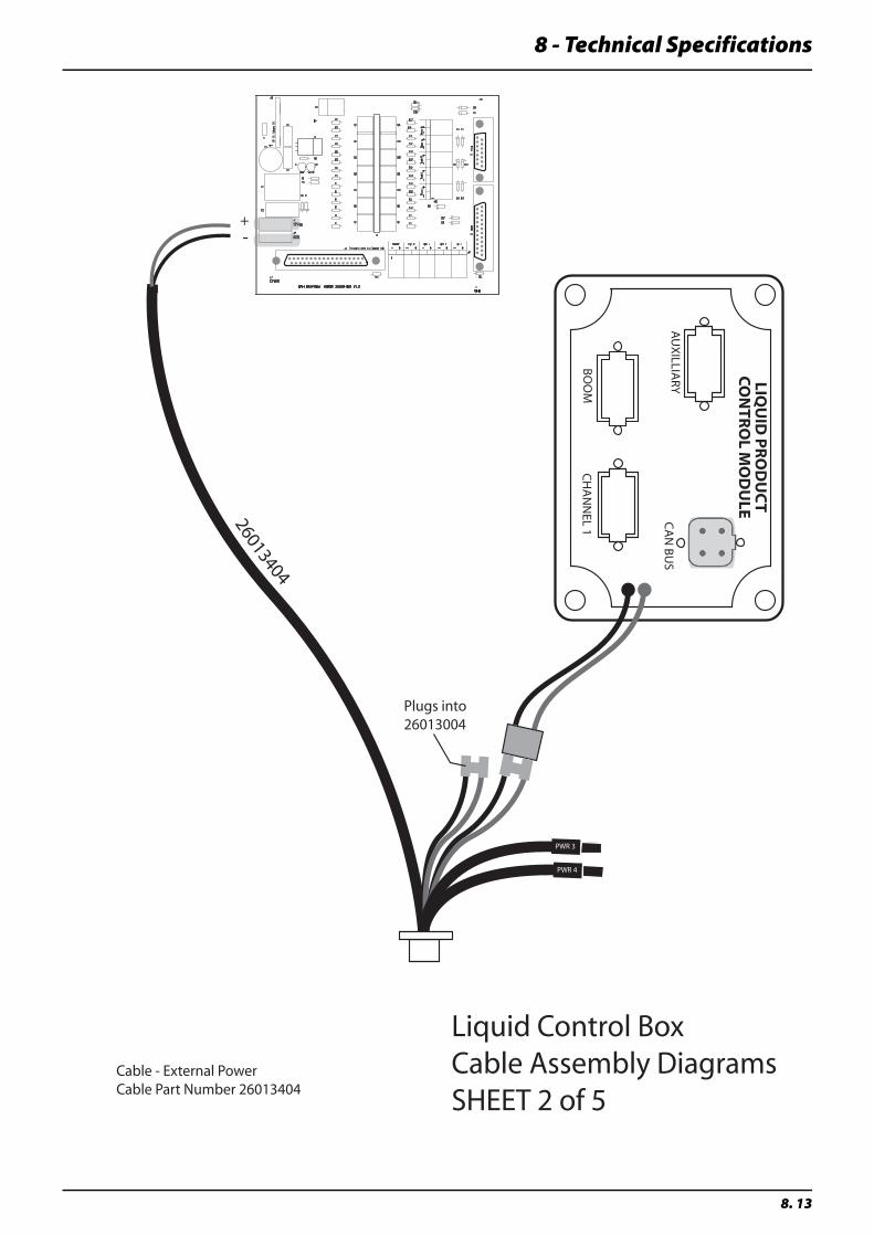
8 - Technical Specifications
8. 13
Cable - External PowerCable Part Number 26013404
26013404
CA
N B
US
CH
AN
NEL 1
BO
OM
AU
XILLIA
RY LIQU
ID PRO
DU
CT
CON
TROL M
OD
ULE
+-
PWR 3
PWR 4
Plugs into 26013004
Liquid Control Box Cable Assembly Diagrams SHEET 2 of 5
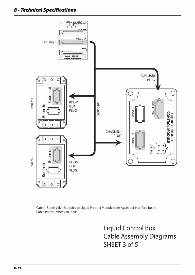
8 - Technical Specifications
8. 14
CA
N B
US
CH
AN
NEL 1
BO
OM
AU
XILLIA
RY LIQU
ID PRO
DU
CT
CON
TROL M
OD
ULE
Bo
om
in
Bo
om
ou
t
Bo
om
in
Bo
om
ou
t
BV
R M
2B
VR
M1
BOOM OUT PLUG
BOOM OUT PLUG
AUXILIARYPLUG
CHANNEL 1PLUG
Cable - Boom Valve Modules to Liquid Product Module from AgLeader Interface BoardCable Part Number 26013204
J2 Plug
Liquid Control Box Cable Assembly Diagrams SHEET 3 of 5
2601
3204
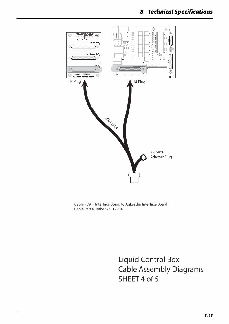
8 - Technical Specifications
8. 15
Cable - DAH Interface Board to AgLeader Interface BoardCable Part Number 26012904
26012904
J3 Plug J4 Plug
Y-Splice Adapter Plug
Liquid Control Box Cable Assembly Diagrams SHEET 4 of 5
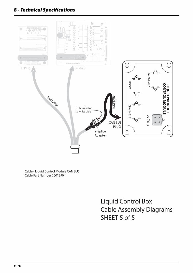
8 - Technical Specifications
8. 16
Cable - Liquid Control Module CAN BUS Cable Part Number 26013904
26012904
J3 Plu g
Y-Splice Adapter
CA
N B
US
CH
AN
NEL 1
BO
OM
AU
XILLIA
RY LIQU
ID PRO
DU
CT
CON
TROL M
OD
ULE
CAN BUSPLUG
26013904Fit Terminator to white plug
Liquid Control Box Cable Assembly Diagrams SHEET 5 of 5
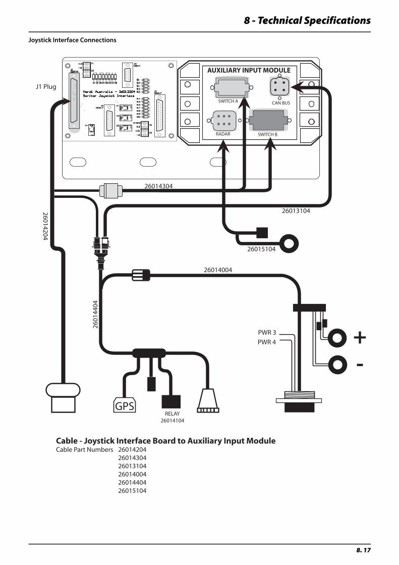
8 - Technical Specifications
8. 17
Joystick Interface Connections
Cable - Joystick Interface Board to Auxiliary Input ModuleCable Part Numbers 26014204 26014304 26013104 26014004 26014404 26015104
J1 Plug
AUXILIARY INPUT MODULE
CAN BUSSWITCH A
SWITCH BRADAR
26014204
26014304
26013104
GPSRELAY
26014104
26014004
2601
4404
PWR 3
PWR 4 +-
26015104
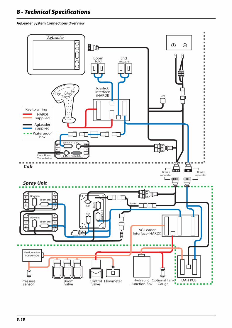
8 - Technical Specifications
8. 18
AgLeader System Connections Overview
Pressuresensor
Boomvalve
Boom in
Boom
Chan
nel 1
Aux
Can
Can
Speed Switch B
Switch A
From AlisonTransmission
GPS
Power
Boom out
40-wayconnector
12-wayconnector
Boom out
Boom in
Fluid JunctionPCB (HARDI)
Boomfold
End nozzle
Controlvalve
Flowmeter Hydraulic Junction Box
Optional TankGauge
DAH PCB
AG LeaderInterface (HARDI)
Spray Unit
Cab
Joystick Interface(HARDI)
Key to wiring
HARDIsupplied
AgLeadersupplied
Waterproofbox
AgLeader
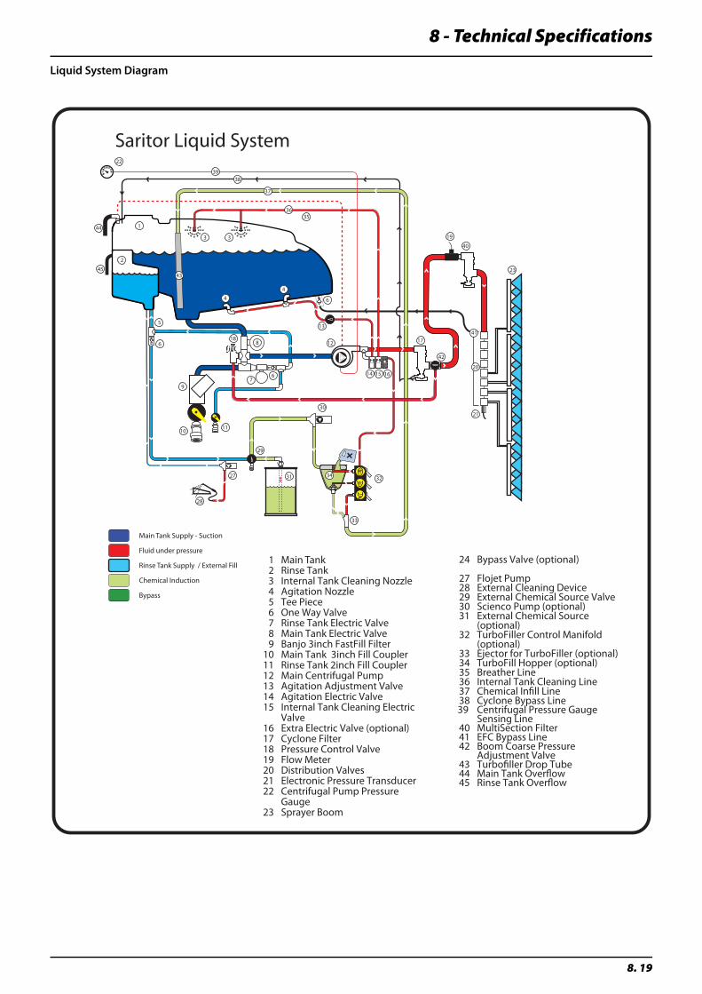
8 - Technical Specifications
8. 19
Liquid System Diagram
Saritor Liquid System
37
3 3
5
27
28
29
30
33
32
23
21
20
19
18 17
97
10
6 8
15
31
11
12
13
14
4
16
1
2
22
4
6
6
3635
1 Main Tank 2 Rinse Tank 3 Internal Tank Cleaning Nozzle 4 Agitation Nozzle 5 Tee Piece 6 One Way Valve 7 Rinse Tank Electric Valve 8 Main Tank Electric Valve 9 Banjo 3inch FastFill Filter 10 Main Tank 3inch Fill Coupler 11 Rinse Tank 2inch Fill Coupler 12 Main Centrifugal Pump 13 Agitation Adjustment Valve 14 Agitation Electric Valve 15 Internal Tank Cleaning Electric
Valve 16 Extra Electric Valve (optional) 17 Cyclone Filter 18 Pressure Control Valve 19 Flow Meter 20 Distribution Valves 21 Electronic Pressure Transducer 22 Centrifugal Pump Pressure
Gauge 23 Sprayer Boom
24 Bypass Valve (optional) 27 Flojet Pump 28 External Cleaning Device 29 External Chemical Source Valve 30 Scienco Pump (optional) 31 External Chemical Source
(optional) 32 TurboFiller Control Manifold
(optional) 33 Ejector for TurboFiller (optional) 34 TurboFill Hopper (optional) 35 Breather Line 36 Internal Tank Cleaning Line 37 Chemical Infill Line 38 Cyclone Bypass Line 39 Centrifugal Pressure Gauge
Sensing Line 40 MultiSection Filter 41 EFC Bypass Line 42 Boom Coarse Pressure
Adjustment Valve 43 Turbofiller Drop Tube 44 Main Tank Overflow 45 Rinse Tank Overflow
34
3839
40
41
42
43
44
45
Main Tank Supply - Suction
Fluid under pressure
Rinse Tank Supply / External Fill
Chemical Induction
Bypass

8 - Technical Specifications
8. 20
9 - Warranty
9. 1
Warranty policy & conditionsHARDI® Australia P/L hereinafter called “HARDI®”, offers the following limited warranty in accordance with the provisions below to each original retail purchaser of HARDI® new equipment of its own manufacturer, from an authorized HARDI® dealer, that such equipment is at the time of delivery to such purchaser, free from defects in material and workmanship and that such equipment will be warranted for a period of 12 months from the date of delivery to the end user providing the machine is used and serviced in accordance with the recommendations in the Operator’s Manual and is operated under normal farm conditions. Use of these products for contracting purposes will limit the warranty to a period of 90 days.
• This limited warranty is subject to the following exceptions:
• Parts of the machine not manufactured by HARDI®, (i.e. engines, tyres, tubes, electronic controls, and other components or trade accessories, etc.) are not covered by this warranty but are subject to the warranty of the original manufacturer. Any claim falling into this category will be taken up with the manufacturer concerned.
• This warranty will be withdrawn if any equipment has been used for purposes other than for which it was intended or if it has been misused, neglected, modified or damaged by accident or ‘act of God’, let out on hire or furnished by a rental agency. Nor can claims be accepted if parts other than those manufactured by HARDI® have been incorporated in any of our equipment. Further, HARDI® shall not be responsible for damage in transit or handling by any common carrier and under no circumstances within or without the warranty period will HARDI® be liable for damages of loss of use, or damages resulting from delay, or any other consequential damage including loss of profit.
• We cannot be held responsible for loss of livestock, loss of crops, loss because of delays in harvesting or any expense or loss incurred for labour, supplies, substitute machinery, rental for any other reason, or for injuries either to the owner or to a third party, nor can we be called upon to be responsible for labour charges, other than originally agreed, incurred in the removal or replacement of components.
• The customer will be responsible for and bear the costs of:
• Normal maintenance such as greasing, maintenance of oil levels, minor adjustments, etc.
• Decontamination and Transportation of any HARDI® product to and from where the warranty work is performed. Failure to properly clean/decontaminate the unit clear of ALL chemical traces prior to delivery for maintenance, may incur additional servicing fees at the discretion of HARDI®.
• Dealer travel time to and from the machine or to deliver and return the machine from the service workshop for repair.
• Dealer travelling costs.
• This warranty is limited to the replacement, free of cost to the original purchaser, of any part/parts of the unit that in HARDI’s judgement, show evidence of defects in material and/or workmanship, provided the said part/parts is/are returned to HARDI®, FREIGHT PRE PAID through an authorised HARDI® dealer. Parts defined as fast wearing items, i.e. tyres, diaphragms and V-belts, etc (which could be subject to mis-use or abuse from high solvent content chemicals, lack of cleaning, etc) is at the discretion of HARDI® AUSTRALIA P/L.
• This warranty will not apply to any product which is altered or modified without the express written permission of HARDI® and/or repaired by anyone other than an Authorized Service Dealer
• Warranty is dependent upon the strict observance by the purchaser of the following provisions:
• That this warranty may not be assigned or transferred to anyone.
• That the Warranty Registration Certificate has been correctly completed by dealer and purchaser with their names and addresses, dated, signed and returned to the appropriate address as given on the Warranty Registration Certificate.
• That unit has been operated in accordance with the Operators Manual/s, and that all safety, maintenance and cleaning instructions in the operator’s manual shall be followed and all safety guards regularly inspected and replaced where necessary.
• No warranty is given on second-hand products and none is to be implied
• HARDI® reserves the right to incorporate any change in design in its products without obligation to make such changes on units previously manufactured.
• The judgement of HARDI® in all cases of claims under this warranty shall be final and conclusive and the purchaser agrees to accept its decisions on all questions as to defect and to the exchange of any part or parts.

9 - Warranty
9. 2
• No employee or representative is authorized to change this warranty in any way or grant any other warranty unless such change is made in writing and signed by an officer of HARDI® at it’s head office.
• Any pump replacement must be approved in advance by the Service Manager.
• Claims under this policy must be filed with HARDI® within thirty (30) days of work performed or warranty shall be void.
• Parts requested must be returned prepaid within thirty (30) days for warranty settlement.
• Warranty claims must be COMPLETELY filled out properly or will be returned.
DISCLAIMER OF FURTHER WARRANTY
THERE ARE NO WARRANTIES, EXPRESSED OR IMPLIED, EXCEPT AS SET FORTH ABOVE. THERE ARE NO WARRANTIES WHICH EXTEND BEYOND THE DESCRIPTION OF THE PRODUCT CONTAINED HEREIN. IN NO EVENT SHALL THE COMPANY BE LIABLE FOR INDIRECT, SPECIAL OR CONSEQUENTIAL DAMAGES (SUCH AS LOSS OF ANTICIPATED PROFITS) IN CONNECTION WITH THE RETAIL PURCHASER’S USE OF THE PRODUCT.
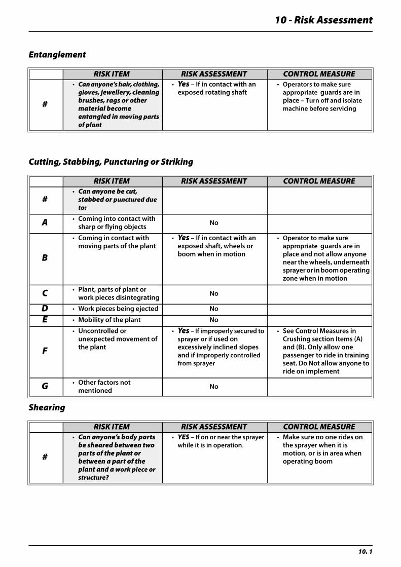
10 - Risk Assessment
10. 1
Entanglement
Cutting, Stabbing, Puncturing or Striking
Shearing
RISK ITEM RISK ASSESSMENT CONTROL MEASURE
#
• Can anyone’s hair, clothing, gloves, jewellery, cleaning brushes, rags or other material become entangled in moving parts of plant
• Yes – If in contact with an exposed rotating shaft
• Operators to make sure appropriate guards are in place – Turn off and isolate machine before servicing
RISK ITEM RISK ASSESSMENT CONTROL MEASURE
#• Can anyone be cut,
stabbed or punctured due to:
A • Coming into contact with sharp or flying objects No
B
• Coming in contact with moving parts of the plant
• Yes – If in contact with an exposed shaft, wheels or boom when in motion
• Operator to make sure appropriate guards are in place and not allow anyone near the wheels, underneath sprayer or in boom operating zone when in motion
C • Plant, parts of plant or work pieces disintegrating No
D • Work pieces being ejected No
E • Mobility of the plant No
F
• Uncontrolled or unexpected movement of the plant
• Yes – If improperly secured to sprayer or if used on excessively inclined slopes and if improperly controlled from sprayer
• See Control Measures in Crushing section Items (A) and (B). Only allow one passenger to ride in training seat. Do Not allow anyone to ride on implement
G • Other factors not mentioned No
RISK ITEM RISK ASSESSMENT CONTROL MEASURE
#
• Can anyone’s body parts be sheared between two parts of the plant or between a part of the plant and a work piece or structure?
• YES – If on or near the sprayer while it is in operation.
• Make sure no one rides on the sprayer when it is motion, or is in area when operating boom
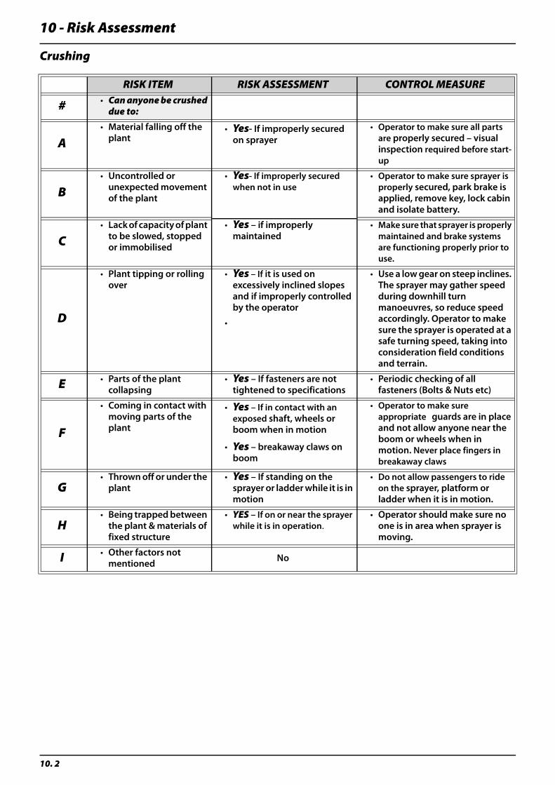
10 - Risk Assessment
10. 2
Crushing
RISK ITEM RISK ASSESSMENT CONTROL MEASURE
# • Can anyone be crushed due to:
A• Material falling off the
plant• Yes- If improperly secured
on sprayer• Operator to make sure all parts
are properly secured – visual inspection required before start-up
B• Uncontrolled or
unexpected movement of the plant
• Yes- If improperly secured when not in use
• Operator to make sure sprayer is properly secured, park brake is applied, remove key, lock cabin and isolate battery.
C• Lack of capacity of plant
to be slowed, stopped or immobilised
• Yes – if improperly maintained
• Make sure that sprayer is properly maintained and brake systems are functioning properly prior to use.
D
• Plant tipping or rolling over
• Yes – If it is used on excessively inclined slopes and if improperly controlled by the operator
• Use a low gear on steep inclines. The sprayer may gather speed during downhill turn manoeuvres, so reduce speed accordingly. Operator to make sure the sprayer is operated at a safe turning speed, taking into consideration field conditions and terrain.
•
E • Parts of the plant collapsing
• Yes – If fasteners are not tightened to specifications
• Periodic checking of all fasteners (Bolts & Nuts etc)
F
• Coming in contact with moving parts of the plant
• Yes – If in contact with an exposed shaft, wheels or boom when in motion
• Operator to make sure appropriate guards are in place and not allow anyone near the boom or wheels when in motion. Never place fingers in breakaway claws
• Yes – breakaway claws on boom
G• Thrown off or under the
plant• Yes – If standing on the
sprayer or ladder while it is in motion
• Do not allow passengers to ride on the sprayer, platform or ladder when it is in motion.
H• Being trapped between
the plant & materials of fixed structure
• YES – If on or near the sprayer while it is in operation.
• Operator should make sure no one is in area when sprayer is moving.
I • Other factors not mentioned No
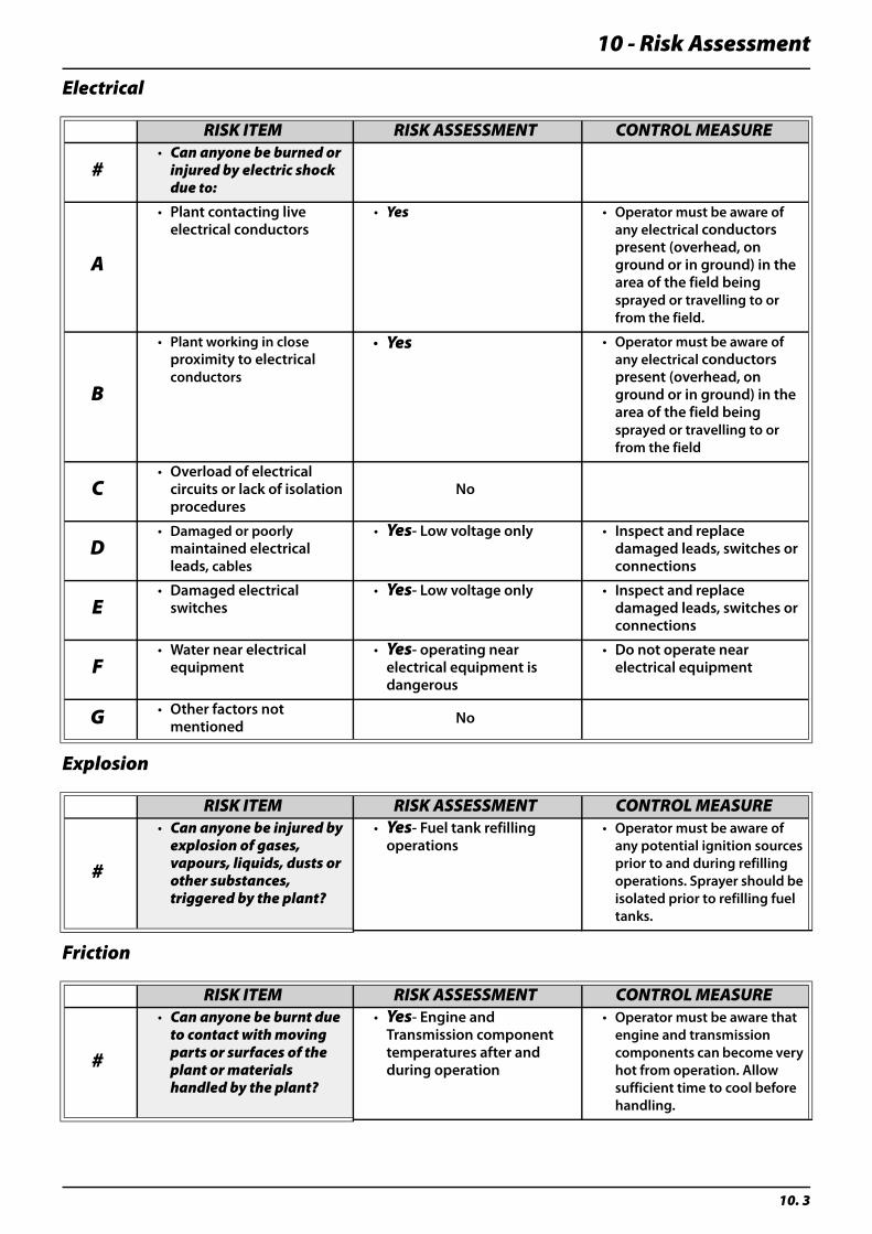
10 - Risk Assessment
10. 3
Electrical
Explosion
Friction
RISK ITEM RISK ASSESSMENT CONTROL MEASURE
#• Can anyone be burned or
injured by electric shock due to:
A
• Plant contacting live electrical conductors
• Yes • Operator must be aware of any electrical conductors present (overhead, on ground or in ground) in the area of the field being sprayed or travelling to or from the field.
B
• Plant working in close proximity to electrical conductors
• Yes • Operator must be aware of any electrical conductors present (overhead, on ground or in ground) in the area of the field being sprayed or travelling to or from the field
C• Overload of electrical
circuits or lack of isolation procedures
No
D• Damaged or poorly
maintained electrical leads, cables
• Yes- Low voltage only • Inspect and replace damaged leads, switches or connections
E• Damaged electrical
switches• Yes- Low voltage only • Inspect and replace
damaged leads, switches or connections
F• Water near electrical
equipment• Yes- operating near
electrical equipment is dangerous
• Do not operate near electrical equipment
G • Other factors not mentioned No
RISK ITEM RISK ASSESSMENT CONTROL MEASURE
#
• Can anyone be injured by explosion of gases, vapours, liquids, dusts or other substances, triggered by the plant?
• Yes- Fuel tank refilling operations
• Operator must be aware of any potential ignition sources prior to and during refilling operations. Sprayer should be isolated prior to refilling fuel tanks.
RISK ITEM RISK ASSESSMENT CONTROL MEASURE
#
• Can anyone be burnt due to contact with moving parts or surfaces of the plant or materials handled by the plant?
• Yes- Engine and Transmission component temperatures after and during operation
• Operator must be aware that engine and transmission components can become very hot from operation. Allow sufficient time to cool before handling.
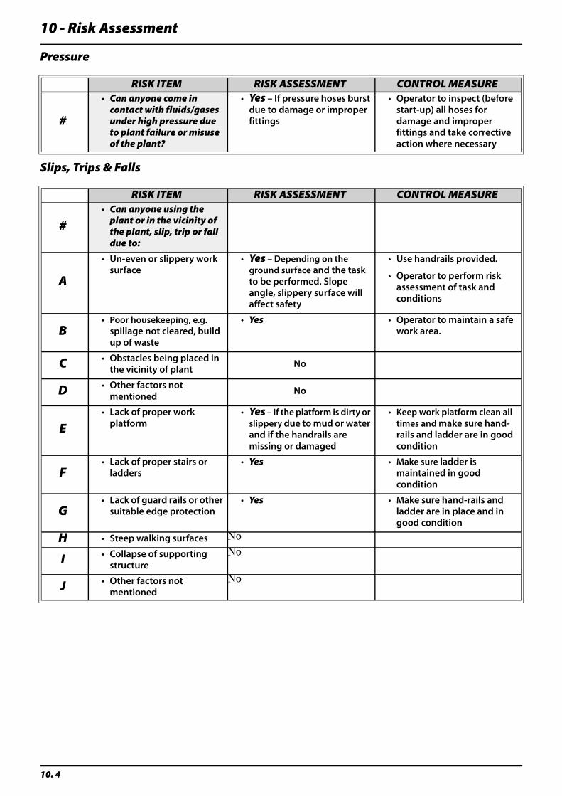
10 - Risk Assessment
10. 4
Pressure
Slips, Trips & Falls
RISK ITEM RISK ASSESSMENT CONTROL MEASURE
#
• Can anyone come in contact with fluids/gases under high pressure due to plant failure or misuse of the plant?
• Yes – If pressure hoses burst due to damage or improper fittings
• Operator to inspect (before start-up) all hoses for damage and improper fittings and take corrective action where necessary
RISK ITEM RISK ASSESSMENT CONTROL MEASURE
#• Can anyone using the
plant or in the vicinity of the plant, slip, trip or fall due to:
A
• Un-even or slippery work surface
• Yes – Depending on the ground surface and the task to be performed. Slope angle, slippery surface will affect safety
• Use handrails provided.
• Operator to perform risk assessment of task and conditions
B• Poor housekeeping, e.g.
spillage not cleared, build up of waste
• Yes • Operator to maintain a safe work area.
C • Obstacles being placed in the vicinity of plant No
D • Other factors not mentioned No
E• Lack of proper work
platform• Yes – If the platform is dirty or
slippery due to mud or water and if the handrails are missing or damaged
• Keep work platform clean all times and make sure hand-rails and ladder are in good condition
F• Lack of proper stairs or
ladders• Yes • Make sure ladder is
maintained in good condition
G• Lack of guard rails or other
suitable edge protection• Yes • Make sure hand-rails and
ladder are in place and in good condition
H • Steep walking surfaces No
I • Collapse of supporting structure
No
J • Other factors not mentioned
No
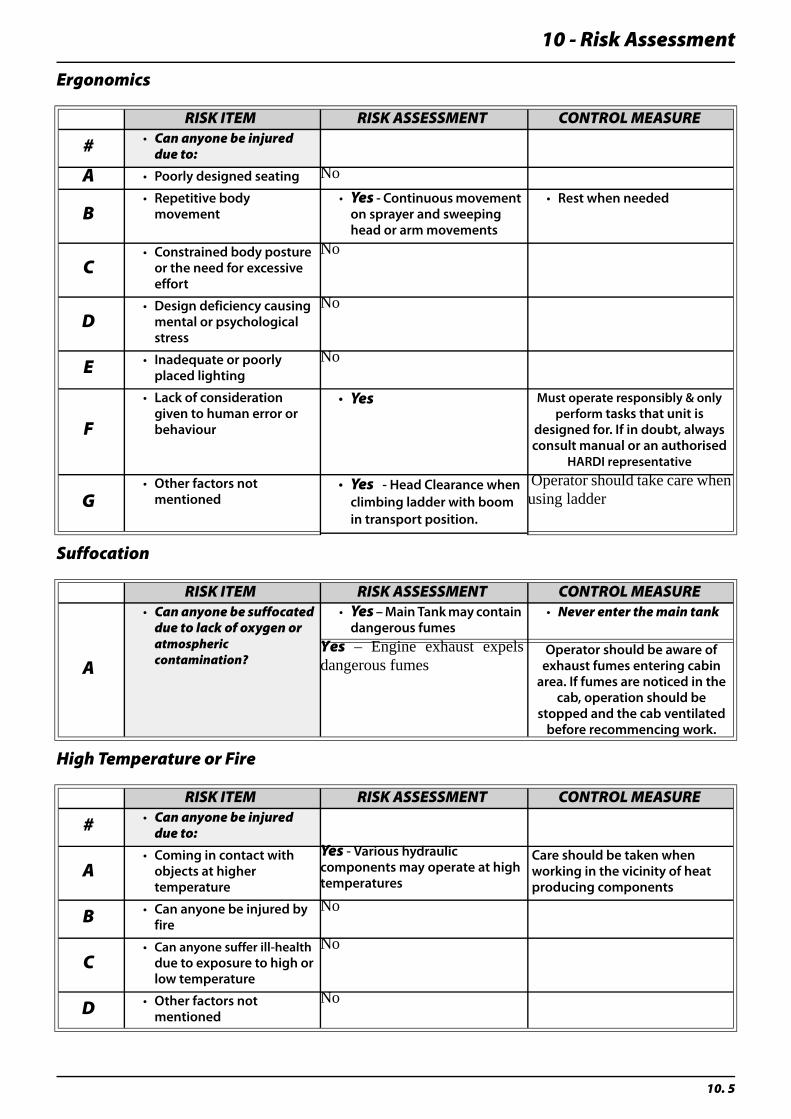
10 - Risk Assessment
10. 5
Ergonomics
Suffocation
High Temperature or Fire
RISK ITEM RISK ASSESSMENT CONTROL MEASURE
# • Can anyone be injured due to:
A • Poorly designed seating No
B• Repetitive body
movement• Yes - Continuous movement
on sprayer and sweeping head or arm movements
• Rest when needed
C• Constrained body posture
or the need for excessive effort
No
D• Design deficiency causing
mental or psychological stress
No
E • Inadequate or poorly placed lighting
No
F
• Lack of consideration given to human error or behaviour
• Yes Must operate responsibly & only perform tasks that unit is
designed for. If in doubt, always consult manual or an authorised
HARDI representative
G• Other factors not
mentioned• Yes - Head Clearance when
climbing ladder with boom in transport position.
Operator should take care whenusing ladder
RISK ITEM RISK ASSESSMENT CONTROL MEASURE
A
• Can anyone be suffocated due to lack of oxygen or atmospheric contamination?
• Yes – Main Tank may contain dangerous fumes
• Never enter the main tank
Yes – Engine exhaust expelsdangerous fumes
Operator should be aware of exhaust fumes entering cabin
area. If fumes are noticed in the cab, operation should be
stopped and the cab ventilated before recommencing work.
RISK ITEM RISK ASSESSMENT CONTROL MEASURE
# • Can anyone be injured due to:
A• Coming in contact with
objects at higher temperature
Yes - Various hydraulic components may operate at high temperatures
Care should be taken when working in the vicinity of heat producing components
B • Can anyone be injured by fire
No
C• Can anyone suffer ill-health
due to exposure to high or low temperature
No
D • Other factors not mentioned
No
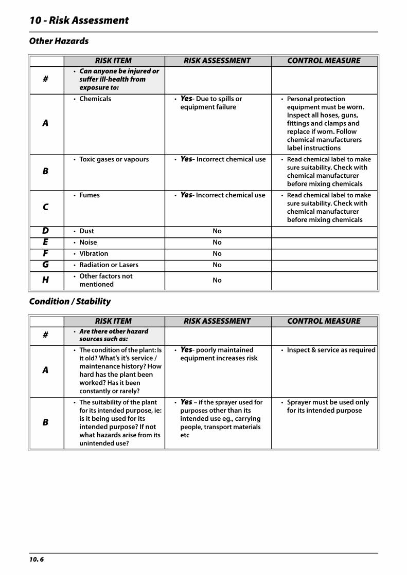
10 - Risk Assessment
10. 6
Other Hazards
Condition / Stability
RISK ITEM RISK ASSESSMENT CONTROL MEASURE
#• Can anyone be injured or
suffer ill-health from exposure to:
A
• Chemicals • Yes- Due to spills or equipment failure
• Personal protection equipment must be worn. Inspect all hoses, guns, fittings and clamps and replace if worn. Follow chemical manufacturers label instructions
B• Toxic gases or vapours • Yes- Incorrect chemical use • Read chemical label to make
sure suitability. Check with chemical manufacturer before mixing chemicals
C• Fumes • Yes- Incorrect chemical use • Read chemical label to make
sure suitability. Check with chemical manufacturer before mixing chemicals
D • Dust No
E • Noise No
F • Vibration No
G • Radiation or Lasers No
H • Other factors not mentioned No
RISK ITEM RISK ASSESSMENT CONTROL MEASURE
# • Are there other hazard sources such as:
A
• The condition of the plant: Is it old? What’s it’s service / maintenance history? How hard has the plant been worked? Has it been constantly or rarely?
• Yes- poorly maintained equipment increases risk
• Inspect & service as required
B
• The suitability of the plant for its intended purpose, ie: is it being used for its intended purpose? If not what hazards arise from its unintended use?
• Yes – if the sprayer used for purposes other than its intended use eg., carrying people, transport materials etc
• Sprayer must be used only for its intended purpose
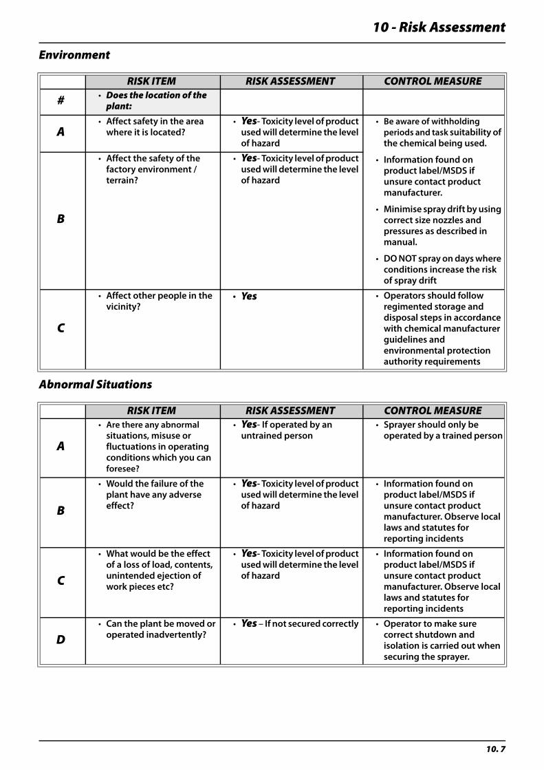
10 - Risk Assessment
10. 7
Environment
Abnormal Situations
RISK ITEM RISK ASSESSMENT CONTROL MEASURE
# • Does the location of the plant:
A• Affect safety in the area
where it is located?• Yes- Toxicity level of product
used will determine the level of hazard
• Be aware of withholding periods and task suitability of the chemical being used.
• Information found on product label/MSDS if unsure contact product manufacturer.
• Minimise spray drift by using correct size nozzles and pressures as described in manual.
• DO NOT spray on days where conditions increase the risk of spray drift
B
• Affect the safety of the factory environment / terrain?
• Yes- Toxicity level of product used will determine the level of hazard
C
• Affect other people in the vicinity?
• Yes • Operators should follow regimented storage and disposal steps in accordance with chemical manufacturer guidelines and environmental protection authority requirements
RISK ITEM RISK ASSESSMENT CONTROL MEASURE
A
• Are there any abnormal situations, misuse or fluctuations in operating conditions which you can foresee?
• Yes- If operated by an untrained person
• Sprayer should only be operated by a trained person
B
• Would the failure of the plant have any adverse effect?
• Yes- Toxicity level of product used will determine the level of hazard
• Information found on product label/MSDS if unsure contact product manufacturer. Observe local laws and statutes for reporting incidents
C
• What would be the effect of a loss of load, contents, unintended ejection of work pieces etc?
• Yes- Toxicity level of product used will determine the level of hazard
• Information found on product label/MSDS if unsure contact product manufacturer. Observe local laws and statutes for reporting incidents
D• Can the plant be moved or
operated inadvertently?• Yes – If not secured correctly • Operator to make sure
correct shutdown and isolation is carried out when securing the sprayer.
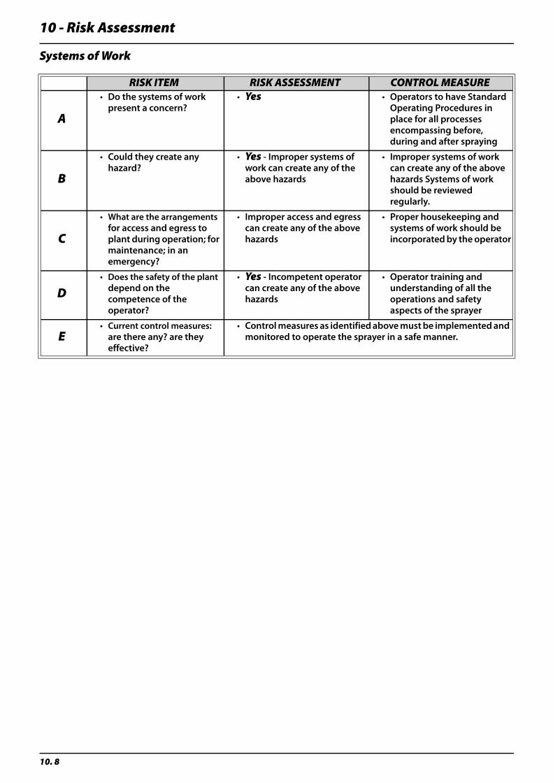
10 - Risk Assessment
10. 8
Systems of Work
RISK ITEM RISK ASSESSMENT CONTROL MEASURE
A
• Do the systems of work present a concern?
• Yes • Operators to have Standard Operating Procedures in place for all processes encompassing before, during and after spraying
B
• Could they create any hazard?
• Yes - Improper systems of work can create any of the above hazards
• Improper systems of work can create any of the above hazards Systems of work should be reviewed regularly.
C
• What are the arrangements for access and egress to plant during operation; for maintenance; in an emergency?
• Improper access and egress can create any of the above hazards
• Proper housekeeping and systems of work should be incorporated by the operator
D• Does the safety of the plant
depend on the competence of the operator?
• Yes - Incompetent operator can create any of the above hazards
• Operator training and understanding of all the operations and safety aspects of the sprayer
E• Current control measures:
are there any? are they effective?
• Control measures as identified above must be implemented and monitored to operate the sprayer in a safe manner.
Copyright © 2022 FDOKUMEN