Environmental and Cost Assessment of a Polypropylene Nanocomposite
Upload
independentCategory
view
0download
0
CERAMICSINTERNATIONAL
Available online at www.sciencedirect.com
0272-8842/$ - sehttp://dx.doi.org/
nCorrespondinfax: þ91 33 247
E-mail addreprobalkdas@red
Ceramics International 40 (2014) 2723–2729www.elsevier.com/locate/ceramint
Role of interface on electrical conductivity of carbonnanotube/alumina nanocomposite
Soumya Sarkara, Probal Kr. Dasa,n
aNon-oxide Ceramics & Composites Division, CSIR-Central Glass & Ceramic Research Institute (CSIR-CG&CRI), Kolkata 700032, India
Received 12 August 2013; received in revised form 10 October 2013; accepted 11 October 2013Available online 21 October 2013
Abstract
Interface of multiwalled carbon nanotube (MWCNT)/alumina (Al2O3) nanocomposites have been studied using TEM. At low sinteringtemperature (Tsin¼1500 1C), a 3–5 nm thick amorphous interface region was noticed. Nanocomposite sintered at 1700 1C possessed a well-defined graphene layer coating on matrix grains as the interface between CNT and Al2O3. A mechanism of such layered interface formation hasbeen proposed. No traceable chemical reaction product was observed at the interface even after sintering at 1700 1C. It was noticed that while DCelectrical conductivity (sDC) of 1500 1C sintered 2.4 vol% MWCNT/Al2O3 nanocomposite was only�0.02 S/m, it raised to �21 S/m whensintering was done at 1700 1C. Such 103 times increase in sDC of present nanocomposite at a constant CNT loading was not only resulted fromthe exceptionally high electron mobility of CNT but the well-crystallized graphene interface on insulating type Al2O3 grains also significantlycontributed in the overall increase of electrical performance of the nanocomposite, especially, when sintering was done at 1700 1C.& 2013 Elsevier Ltd and Techna Group S.r.l. All rights reserved.
Keywords: B. Electron microscopy; B. Interfaces; B. Nanocomposites; C. Electrical conductivity
1. Introduction
In composites, optimum interface performance is essential sinceit decides how effectively applied load (mechanical), electron(electrical/electronic) and phonon (thermal) transfer occurs amongits constituents [1]. Therefore, interface characterization is indis-pensable to establish the exact structure-property relationship incomposites. CNT reinforced ceramic matrix nanocomposites viz.CNT/Al2O3, CNT/Si3N4, CNT/ZrO2, CNT/SiC, CNT/SiO2-ZnOare not exception in this regard [2–6]. Although, many reports areavailable on property evaluation of the most ancient, economic andversatile ceramic i.e. Al2O3 reinforced with CNT [7–13], limitedwork has been performed on CNT/Al2O3 interface characterization[7–8,13–14]. Further, most of these reports dealt with structuralintegrity of CNT in sintered nanocomposites and position ofnanotubes in matrix phase (i.e. within, outside or at grain boundary
e front matter & 2013 Elsevier Ltd and Techna Group S.r.l. All ri10.1016/j.ceramint.2013.10.049
g author. Tel.: þ91 33 2473 3469/76/77/96;3 0957.sses: [email protected],iffmail.com (P.Kr. Das).
position). The primary aim of present work was to study theinterface/interaction region of pressureless sintered CNT/Al2O3
nanocomposites and changes in interface nature with increasingTsin using TEM. Finally, correlation between observed CNT/Al2O3
interface and sDC of present nanocomposites was analyzed.
2. Experimental procedures
2.1. Raw material and sample preparation
Multiwalled CNT (MWCNT: Shenzhen NTP, China,495wt% pure) and Al2O3 powder (Almatis, ACC Ltd., India,99.8 wt% pure) were used as raw materials [12]. The nano-composite fabrication procedure can be found elsewhere [12].In brief, nanocomposite powder mixtures were prepared bywet-mixing of as-received dispersed raw materials followed bydrying and sieving. Sintering was done in a graphite resistanceheating furnace (1000-4560-FP20; Thermal Technology Inc.U.S.A.) under static Argon (Ar: 35–70 kPa) (Table 1).
ghts reserved.
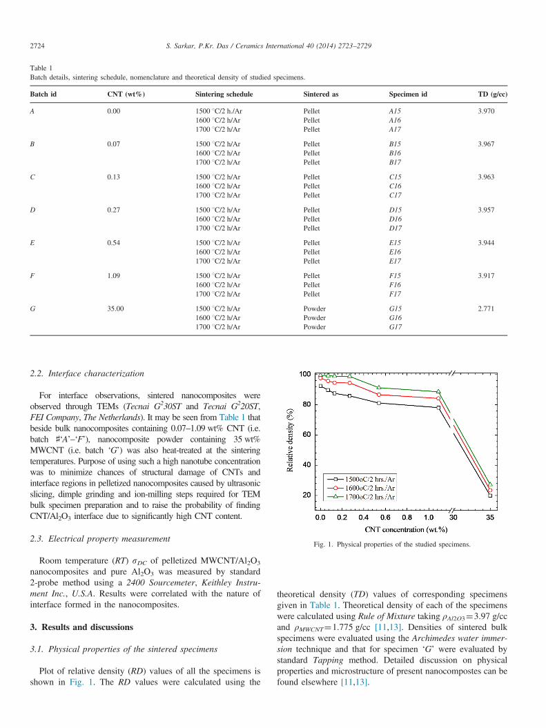
Table 1Batch details, sintering schedule, nomenclature and theoretical density of studied specimens.
Batch id CNT (wt%) Sintering schedule Sintered as Specimen id TD (g/cc)
A 0.00 1500 1C/2 h./Ar Pellet A15 3.9701600 1C/2 h/Ar Pellet A161700 1C/2 h/Ar Pellet A17
B 0.07 1500 1C/2 h/Ar Pellet B15 3.9671600 1C/2 h/Ar Pellet B161700 1C/2 h/Ar Pellet B17
C 0.13 1500 1C/2 h/Ar Pellet C15 3.9631600 1C/2 h/Ar Pellet C161700 1C/2 h/Ar Pellet C17
D 0.27 1500 1C/2 h/Ar Pellet D15 3.9571600 1C/2 h/Ar Pellet D161700 1C/2 h/Ar Pellet D17
E 0.54 1500 1C/2 h/Ar Pellet E15 3.9441600 1C/2 h/Ar Pellet E161700 1C/2 h/Ar Pellet E17
F 1.09 1500 1C/2 h/Ar Pellet F15 3.9171600 1C/2 h/Ar Pellet F161700 1C/2 h/Ar Pellet F17
G 35.00 1500 1C/2 h/Ar Powder G15 2.7711600 1C/2 h/Ar Powder G161700 1C/2 h/Ar Powder G17
Fig. 1. Physical properties of the studied specimens.
S. Sarkar, P.Kr. Das / Ceramics International 40 (2014) 2723–27292724
2.2. Interface characterization
For interface observations, sintered nanocomposites wereobserved through TEMs (Tecnai G230ST and Tecnai G220ST,FEI Company, The Netherlands). It may be seen from Table 1 thatbeside bulk nanocomposites containing 0.07–1.09 wt% CNT (i.e.batch ♯‘A’–‘F’), nanocomposite powder containing 35 wt%MWCNT (i.e. batch ‘G’) was also heat-treated at the sinteringtemperatures. Purpose of using such a high nanotube concentrationwas to minimize chances of structural damage of CNTs andinterface regions in pelletized nanocomposites caused by ultrasonicslicing, dimple grinding and ion-milling steps required for TEMbulk specimen preparation and to raise the probability of findingCNT/Al2O3 interface due to significantly high CNT content.
2.3. Electrical property measurement
Room temperature (RT) sDC of pelletized MWCNT/Al2O3
nanocomposites and pure Al2O3 was measured by standard2-probe method using a 2400 Sourcemeter, Keithley Instru-ment Inc., U.S.A. Results were correlated with the nature ofinterface formed in the nanocomposites.
3. Results and discussions
3.1. Physical properties of the sintered specimens
Plot of relative density (RD) values of all the specimens isshown in Fig. 1. The RD values were calculated using the
theoretical density (TD) values of corresponding specimensgiven in Table 1. Theoretical density of each of the specimenswere calculated using Rule of Mixture taking ρAl2O3¼3.97 g/ccand ρMWCNT¼1.775 g/cc [11,13]. Densities of sintered bulkspecimens were evaluated using the Archimedes water immer-sion technique and that for specimen ‘G’ were evaluated bystandard Tapping method. Detailed discussion on physicalproperties and microstructure of present nanocompostes can befound elsewhere [11,13].
S. Sarkar, P.Kr. Das / Ceramics International 40 (2014) 2723–2729 2725
3.2. Interface analyses of the sintered specimens
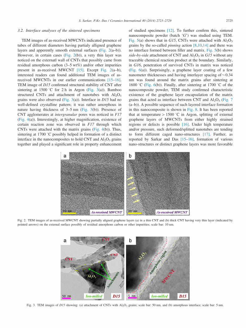
TEM images of as-received MWCNTs indicated presence oftubes of different diameters having partialy alligned graphenelayers and apperently smooth external surfaces (Fig. 2(a–b)).However, in certain cases (Fig. 2(b)), a very thin layer wasnoticed on the externatl wall of CNTs that possibly came fromresidual amorphous carbon (3–5 wt%) and/or other impuritiespresent in as-received MWCNT [15]. Except Fig. 2(a–b),interested readers can found additional TEM images of as-received MWCNTs in our earlier communications [15–16].TEM image of D15 confirmed structural stability of CNT aftersintering at 1500 1C for 2 h in Argon (Fig. 3(a)). Bamboostructured CNTs and attachment of nanotubes with Al2O3
grains were also observed (Fig. 3(a)). Interface in D15 had nowell-defined crystalline pattern; it was rather amorphous innature having thickness of 3–5 nm (Fig. 3(b)). Presence ofCNT agglomerates at intergranular pores was noticed in F17(Fig. 4(a)). Interestingly, at higher magnification, existence ofcertain reaction zone was observed in F17 through whichCNTs were attached with the matrix grains (Fig. 4(b)). Thus,sintering at 1700 1C possibly helped in formation of a distinctinterface in the nanocomposites to hold CNT and Al2O3 grainstogether and played a significant role in property enhancement
Fig. 2. TEM images of as-received MWCNT showing partially aligned graphene lapointed arrows) on the external surface possibly of residual amorphous carbon or
Fig. 3. TEM images of D15 showing: (a) attachment of CNTs with Al2O3
of studied specimens [12]. To further confirm this, sinterednanocomposite powder (batch ‘G’) was studied using TEM.Fig. 5(a) shows that in G15, CNTs were attached with Al2O3
grains by the so-called pinning action [8,10,14] and there wasno interface formed between filler and matrix. Fig. 5(b) showsside-by-side attachment of CNT and Al2O3 in G15 without anytraceable chemical reaction product at the boundary. Similarly,in G16, penetration of survived CNTs in matrix was noticed(Fig. 6(a)). Surprisingly, a graphene layer coating of a fewnanometer thicknesses and having interlayer spacing of�0.34nm was found around the matrix grains after sintering at1600 1C (Fig. 6(b)). Finally, after sintering at 1700 1C of thenanocomposite powder, TEM study confirmed characteristicexistence of the graphene layer encapsulation of the matrixgrains that acted as interface between CNT and Al2O3 (Fig. 7(a–b)). A possible sequence of such layered interface formationin this nanocomposite is shown in Fig. 8. It has been reportedthat at temperature41500 1C in Argon, splitting of externalgraphene layers of MWCNTs from either highly strainedregions or defects is possible [16]. Under high temperatureand/or pressure, such deformed/splitted nanotubes are tendingto form different caged nano-structures [17]. Further, asreported by Sarkar and Das [15–16], formation of variousnano-structures or distinct graphene layers was more favorable
yers (a) in a thin CNT and (b) thick CNT having very thin layer (indicated byother impurities; scale bar: 10 nm.
grains; scale bar: 50 nm, and (b) amorphous interface; scale bar: 5 nm.
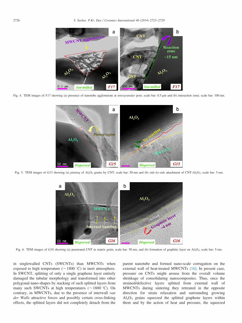
Fig. 4. TEM images of F17 showing (a) presence of nanotube agglomerate at intergranular pore; scale bar: 0.5 μm and (b) interaction zone; scale bar: 100 nm.
Fig. 5. TEM images of G15 showing (a) pinning of Al2O3 grains by CNT; scale bar: 50 nm and (b) side-by-side attachment of CNT-Al2O3; scale bar: 5 nm.
Fig. 6. TEM images of G16 showing (a) penetrated CNT in matrix grain; scale bar: 50 nm, and (b) formation of graphitic layer on Al2O3; scale bar: 5 nm.
S. Sarkar, P.Kr. Das / Ceramics International 40 (2014) 2723–27292726
in singlewalled CNTs (SWCNTs) than MWCNTs whenexposed to high temperature (�1800 1C) in inert atmosphere.In SWCNT, splitting of only a single graphene layer entirelydamaged the tubular morphology and transformed into otherpolygonal nano-shapes by stacking of such splitted layers frommany such SWCNTs at high temperatures (�1800 1C). Oncontrary, in MWCNTs, due to the presence of interwall vander Walls attractive forces and possibly certain cross-linkingeffects, the splitted layers did not completely detach from the
parent nanotube and formed nano-scale corrugation on theexternal wall of heat-treated MWCNTs [16]. In present case,pressure on CNTs might arouse from the overall volumeshrinkage of consolidating nanocomposites. Thus, once thestrained/defective layers splitted from external wall ofMWCNTs during sintering they retreated in the oppositedirection for strain relaxation and surrounding growingAl2O3 grains squeezed the splitted graphene layers withinthem and by the action of heat and pressure, the squeezed
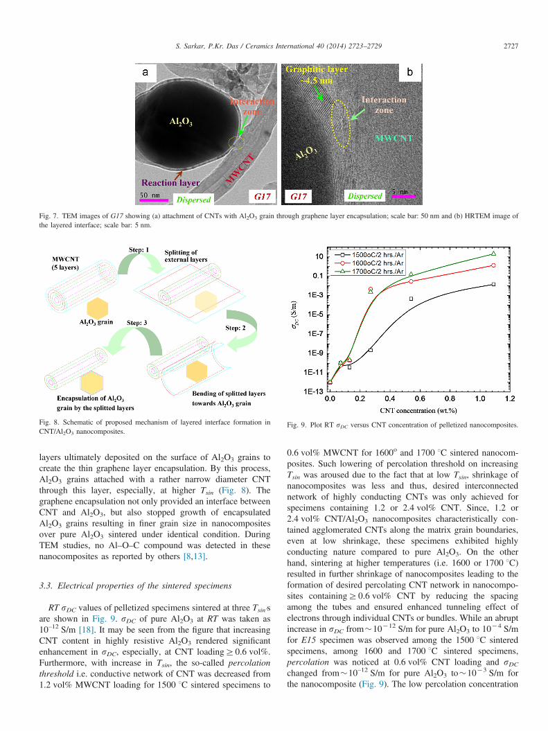
Fig. 7. TEM images of G17 showing (a) attachment of CNTs with Al2O3 grain through graphene layer encapsulation; scale bar: 50 nm and (b) HRTEM image ofthe layered interface; scale bar: 5 nm.
Fig. 8. Schematic of proposed mechanism of layered interface formation inCNT/Al2O3 nanocomposites.
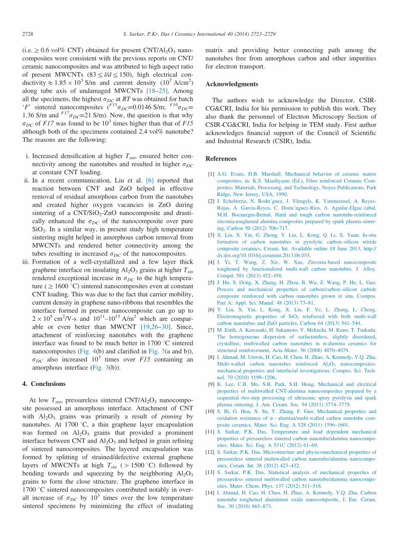
Fig. 9. Plot RT sDC versus CNT concentration of pelletized nanocomposites.
S. Sarkar, P.Kr. Das / Ceramics International 40 (2014) 2723–2729 2727
layers ultimately deposited on the surface of Al2O3 grains tocreate the thin graphene layer encapsulation. By this process,Al2O3 grains attached with a rather narrow diameter CNTthrough this layer, especially, at higher Tsin (Fig. 8). Thegraphene encapsulation not only provided an interface betweenCNT and Al2O3, but also stopped growth of encapsulatedAl2O3 grains resulting in finer grain size in nanocompositesover pure Al2O3 sintered under identical condition. DuringTEM studies, no Al–O–C compound was detected in thesenanocomposites as reported by others [8,13].
3.3. Electrical properties of the sintered specimens
RT sDC values of pelletized specimens sintered at three Tsin'sare shown in Fig. 9. sDC of pure Al2O3 at RT was taken as10–12 S/m [18]. It may be seen from the figure that increasingCNT content in highly resistive Al2O3 rendered significantenhancement in sDC, especially, at CNT loadingZ0.6 vol%.Furthermore, with increase in Tsin, the so-called percolationthreshold i.e. conductive network of CNT was decreased from1.2 vol% MWCNT loading for 1500 1C sintered specimens to
0.6 vol% MWCNT for 1600o and 1700 1C sintered nanocom-posites. Such lowering of percolation threshold on increasingTsin was aroused due to the fact that at low Tsin, shrinkage ofnanocomposites was less and thus, desired interconnectednetwork of highly conducting CNTs was only achieved forspecimens containing 1.2 or 2.4 vol% CNT. Since, 1.2 or2.4 vol% CNT/Al2O3 nanocomposites characteristically con-tained agglomerated CNTs along the matrix grain boundaries,even at low shrinkage, these specimens exhibited highlyconducting nature compared to pure Al2O3. On the otherhand, sintering at higher temperatures (i.e. 1600 or 1700 1C)resulted in further shrinkage of nanocomposites leading to theformation of desired percolating CNT network in nanocompo-sites containingZ0.6 vol% CNT by reducing the spacingamong the tubes and ensured enhanced tunneling effect ofelectrons through individual CNTs or bundles. While an abruptincrease in sDC from�10�12 S/m for pure Al2O3 to 10�4 S/mfor E15 specimen was observed among the 1500 1C sinteredspecimens, among 1600 and 1700 1C sintered specimens,percolation was noticed at 0.6 vol% CNT loading and sDCchanged from�10–12 S/m for pure Al2O3 to�10�3 S/m forthe nanocomposite (Fig. 9). The low percolation concentration
S. Sarkar, P.Kr. Das / Ceramics International 40 (2014) 2723–27292728
(i.e.Z0.6 vol% CNT) obtained for present CNT/Al2O3 nano-composites were consistent with the previous reports on CNT/ceramic nanocomposites and was attributed to high aspect ratioof present MWCNTs (83r l/dr150), high electrical con-ductivityE1.85� 103 S/m and current density (107 A/cm2)along tube axis of undamaged MWCNTs [18–25]. Amongall the specimens, the highest sDC at RT was obtained for batch‘F’ sintered nanocomposites (F15sDC=0.0146 S/m; F16sDC=1.36 S/m and F17sDC=21 S/m). Now, the question is that whysDC of F17 was found to be 103 times higher than that of F15although both of the specimens contained 2.4 vol% nanotube?The reasons are the following:
i.
Increased densification at higher Tsin, ensured better con-nectivity among the nanotubes and resulted in higher sDCat constant CNT loading.ii.
In a recent communication, Liu et al. [6] reported thatreaction between CNT and ZnO helped in effectiveremoval of residual amorphous carbon from the nanotubesand created higher oxygen vacancies in ZnO duringsintering of a CNT/SiO2-ZnO nanocomposite and drasti-cally enhanced the sDC of the nanocomposite over pureSiO2. In a similar way, in present study high temperaturesintering might helped in amorphous carbon removal fromMWCNTs and rendered better connectivity among thetubes resulting in increased sDC of the nanocomposites.iii.
Formation of a well-crystallized and a few layer thickgraphene interface on insulating Al2O3 grains at higher Tsinrendered exceptional increase in sDC to the high tempera-ture (Z1600 1C) sintered nanocomposites even at constantCNT loading. This was due to the fact that carrier mobility,current density in graphene nano-ribbons that resembles theinterface formed in present nanocomposite can go up to2� 105 cm2/V-s and 1011–1013 A/m2 which are compar-able or even better than MWCNT [19,26–30]. Since,attachment of reinforcing nanotubes with the grapheneinterface was found to be much better in 1700 1C sinterednanocomposites (Fig. 4(b) and clarified in Fig. 7(a and b)),sDC also increased 103 times over F15 containing anamorphous interface (Fig. 3(b)).4. Conclusions
At low Tsin, pressureless sintered CNT/Al2O3 nanocompo-site possessed an amorphous interface. Attachment of CNTwith Al2O3 grains was primarily a result of pinning bynanotubes. At 1700 1C, a thin graphene layer encapsulationwas formed on Al2O3 grains that provided a prominentinterface between CNT and Al2O3 and helped in grain refiningof sintered nanocomposites. The layered encapsulation wasformed by splitting of strained/defective external graphenelayers of MWCNTs at high Tsin (41500 1C) followed bybending towards and squeezing by the neighboring Al2O3
grains to form the close structure. The graphene interface in1700 1C sintered nanocomposites contributed notably in over-all increase of sDC by 103 times over the low temperaturesintered specimens by minimizing the effect of insulating
matrix and providing better connecting path among thenanotubes free from amorphous carbon and other impuritiesfor electron transport.
Acknowledgments
The authors wish to acknowledge the Director, CSIR-CG&CRI, India for his permission to publish this work. Theyalso thank the personnel of Electron Microscopy Section ofCSIR-CG&CRI, India for helping in TEM study. First authoracknowledges financial support of the Council of Scientificand Industrial Research (CSIR), India.
References
[1] A.G. Evans, D.B. Marshall, Mechanical behavior of ceramic matrixcomposites, in: K.S. Mazdiyasni (Ed.), Fiber reinforced Ceramic Com-posites: Materials, Processing, and Technology, Noyes Publications, ParkRidge, New Jersey, USA, 1990.
[2] J. Echeberria, N. Rodrı´guez, J. Vleugels, K. Vanmeensel, A. Reyes-Rojas, A. Garcia-Reyes, C. Domı´nguez-Rios, A. Aguilar-Elgue´zabal,M.H. Bocanegra-Bernal, Hard and tough carbon nanotube-reinforcedzirconia-toughened alumina composites prepared by spark plasma sinter-ing, Carbon 50 (2012) 706–717.
[3] X. Liu, X. Yin, G. Zheng, Y. Liu, L. Kong, Q. Li, X. Yuan, In-situformation of carbon nanotubes in pyrolytic carbon–silicon nitridecomposite ceramics, Ceram. Int. Available online 18 June 2013, http://dx.doi.org/10.1016/j.ceramint.2013.06.035.
[4] J. Yi, T. Wang, Z. Xie, W. Xue, Zirconia-based nanocompositetoughened by functionalized multi-wall carbon nanotubes, J. Alloy.Compd. 581 (2013) 452–458.
[5] J. Hu, S. Dong, X. Zhang, H. Zhou, B. Wu, Z. Wang, P. He, L. Gao,Process and mechanical properties of carbon/carbon–silicon carbidecomposite reinforced with carbon nanotubes grown in situ, Compos.Part A: Appl. Sci. Manuf. 48 (2013) 73–81.
[6] Y. Liu, X. Yin, L. Kong, X. Liu, F. Ye, L. Zhang, L. Cheng,Electromagnetic properties of SiO2 reinforced with both multi-wallcarbon nanotubes and ZnO particles, Carbon 64 (2013) 541–544.
[7] M. Estili, A. Kawasaki, H. Sakamoto, Y. Mekuchi, M. Kuno, T. Tsukada,The homogeneous dispersion of surfactantless, slightly disordered,crystalline, multiwalled carbon nanotubes in α-alumina ceramics forstructural reinforcement, Acta Mater. 56 (2008) 4070–4079.
[8] I. Ahmad, M. Unwin, H. Cao, H. Chen, H. Zhao, A. Kennedy, Y.Q. Zhu,Multi-walled carbon nanotubes reinforced Al2O3 nanocomposites:mechanical properties and interfacial investigations, Compos. Sci. Tech-nol. 70 (2010) 1199–1206.
[9] K. Lee, C.B. Mo, S.B. Park, S.H. Hong, Mechanical and electricalproperties of multiwalled CNT-alumina nanocomposites prepared by asequential two-step processing of ultrasonic spray pyrolysis and sparkplasma sintering, J. Am. Ceram. Soc. 94 (2011) 3774–3779.
[10] S. Bi, G. Hou, X. Su, Y. Zhang, F. Guo, Mechanical properties andoxidation resistance of α�alumina/multi-walled carbon nanotube com-posite ceramics, Mater. Sci. Eng. A 528 (2011) 1596–1601.
[11] S. Sarkar, P.K. Das, Temperature and load dependent mechanicalproperties of pressureless sintered carbon nanotube/alumina nanocompo-sites, Mater. Sci. Eng. A 531C (2012) 61–69.
[12] S. Sarkar, P.K. Das, Microstructure and physicomechanical properties ofpressureless sintered multiwalled carbon nanotube/alumina nanocompo-sites, Ceram. Int. 38 (2012) 423–432.
[13] S. Sarkar, P.K. Das, Statistical analysis of mechanical properties ofpressureless sintered multiwalled carbon nanotube/alumina nanocompo-sites, Mater. Chem. Phys. 137 (2012) 511–518.
[14] I. Ahmad, H. Cao, H. Chen, H. Zhao, A. Kennedy, Y.Q. Zhu, Carbonnanotube toughened aluminium oxide nanocomposite, J. Eur. Ceram.Soc. 30 (2010) 865–873.
S. Sarkar, P.Kr. Das / Ceramics International 40 (2014) 2723–2729 2729
[15] S. Sarkar, P.K. Das, Thermal and structural stability of single- and multi-walled carbon nanotubes up to 1800 1C in Argon studied by Ramanspectroscopy and transmission electron microscopy, Mater. Res. Bull. 48(2013) 41–47.
[16] S. Sarkar, P.K. Das, S. Bysakh, Effect of heat treatment on morphologyand thermal decomposition kinetics of multiwalled carbon nanotubes,Mater. Chem. Phys. 125 (2011) 161–167.
[17] M. Zhang, D.W. He, L. Ji, B.Q. Wei, D.H. Wu, X.Y. Zhang, Y.F. Xu, W.K. Wang, Microstructural changes in carbon nanotubes induced byannealing at high pressure, Carbon 37 (1999) 657–662.
[18] G.-D. Zhan, A.K. Mukherjee, Carbon nanotube reinforced alumina-basedceramics with novel mechanical, electrical and thermal properties, Int. J.Appl. Ceram. Technol. 1 (2) (2004) 161–171.
[19] Y. Ando, X. Zhao, H. Shimoyama, G. Sakai, K. Kaneto, Physicalproperties of multiwalled carbon nanotubes, Int. J. Inorganic Mater.1 (1999) 77–82.
[20] K. Ahmad, W. Pan, Dramatic effect of multiwalled carbon nanotubes onthe electrical properties of alumina based ceramic nanocomposites,Compos. Sci. Technol. 69 (2009) 1016–1021.
[21] K. Ahmad, W. Pan, S.-L. Shi, Electrical conductivity and dielectricproperties of multiwalled carbon nanotube and alumina composites, Appl.Phys. Lett. 89 (2006) 133122.
[22] F. Inam, H. Yan, D.D. Jayaseelan, T. Peijs, M.J. Reece, Electricallyconductive alumina-carbon nanocomposites prepared by spark plasmasintering, J. Eur. Ceram. Soc. 30 (2010) 153–157.
[23] K. Lee, C.B. Mo, S.B. Park, S.H. Hong, Mechanical and electricalproperties of multiwalled CNT-alumina nanocomposites prepared by a
sequential two-step processing of ultrasonic spray pyrolysis and sparkplasma sintering, J. Am. Cream. Soc. 94 (11) (2012) 3774–3779.
[24] L. Kumari, T. Zhang, G.H. Du, W.Z. Li, Q.W. Wang, A. Datye, K.H. Wu, Synthesis, microstructure and electrical conductivity of carbonnanotube-alumina nanocomposites, Ceram. Int. 35 (2009) 1775–1781.
[25] M. Poorteman, M. Traianidis, G. Bister, F. Cambier, Colloidal proces-sing, hot pressing and characterisation of electroconductive MWCNT-alumina composites with compositions near the percolation threshold, J.Eur. Ceram. Soc. 29 (2009) 669–675.
[26] W.Y. Jang, N.N. Kulkarni, C.K. Shih, Z. Yao, Electrical characterizationof individual carbon nanotubes grown in nanoporous anodic aluminatemplates, Appl. Phys. Lett. 84 (7) (2004) 1177–1179.
[27] L. Zeng, X.Y. Liu, G. Du, J.F. Kang, R.Q. Han, Evaluation of mobility ingraphene nanoribbons including line edge roughness scattering, In:SISPAD 2009, San Diego, CA, 2009, pp. 1–4.
[28] A. Behnam, A.S. Lyons, M.-H. Bae, E.K. Chow, S. Islam, C.M. Neumann, E. Pop, Transport in nanoribbon interconnects obtainedfrom graphene grown by chemical vapor deposition, Nano Lett. 12 (2012)4424–4430.
[29] K.-J. Lee, A.P. Chandrakasan, J. Kong, Breakdown current density ofCVD-grown multilayer graphene interconnects, IEEE Electron. DeviceLett. 32 (2011) 557–559.
[30] K.S. Novoselov, V.I. Falko, L. Colombo, P.R. Gellert, M.G. Schwab,K. Kim, A roadmap for graphene, Nature 490 (2012) 192–200.
Copyright © 2022 FDOKUMEN