Clay nanotube encapsulation for functional biocomposites
11
This article appeared in a journal published by Elsevier. The attached copy is furnished to the author for internal non-commercial research and education use, including for instruction at the authors institution and sharing with colleagues. Other uses, including reproduction and distribution, or selling or licensing copies, or posting to personal, institutional or third party websites are prohibited. In most cases authors are permitted to post their version of the article (e.g. in Word or Tex form) to their personal website or institutional repository. Authors requiring further information regarding Elsevier’s archiving and manuscript policies are encouraged to visit: http://www.elsevier.com/authorsrights
-
Upload
independent -
Category
Documents
-
view
6 -
download
0
Transcript of Clay nanotube encapsulation for functional biocomposites
This article appeared in a journal published by Elsevier. The attachedcopy is furnished to the author for internal non-commercial researchand education use, including for instruction at the authors institution
and sharing with colleagues.
Other uses, including reproduction and distribution, or selling orlicensing copies, or posting to personal, institutional or third party
websites are prohibited.
In most cases authors are permitted to post their version of thearticle (e.g. in Word or Tex form) to their personal website orinstitutional repository. Authors requiring further information
regarding Elsevier’s archiving and manuscript policies areencouraged to visit:
http://www.elsevier.com/authorsrights
Author's personal copy
Clay nanotube encapsulation for functional biocomposites
Yuri Lvov a,⁎, Artem Aerov b,c, Rawil Fakhrullin d
a Institute for Micromanufacturing, Louisiana Tech University, Ruston, LA, USAb Institute for Theoretical Physics IV, University of Stuttgart, Stuttgart, Germanyc Max Planck Institute for Intelligent Systems, Stuttgart, Germanyd Institute of Fundamental Medicine and Biology, Kazan Federal University, Republic of Tatarstan, Russian Federation
a b s t r a c ta r t i c l e i n f o
Available online 16 October 2013
Keywords:Halloysite clay nanotubesNanosafetySustained releaseDrugsEnzymesMicrobial shells
Natural halloysite clay nanotubes with 50 nm outer- and 15 nm inner- diameters are described as miniaturevehicles for sustained release of drugs and proteins. The release time may be adjusted from 10 to 200 h withthe tube surface polymeric coating. An explanation of sustained release through locking electrical potential atthe nanotube ends is suggested. These biocompatible ceramic tubes may be also used for architecturalconstruction of nanoshells onmicrobes through alternation with polycations to enhance the intrinsic propertiesof biological cells. Halloysite nanotubes (pristine or drug-loaded) are well mixable with polar and low-polarpolymers allowing for functional biocompositeswith enhancedmechanical strength, adhesivity and slow releaseof drugs or other chemical agents. Halloysite is nontoxic abundantly available from natural deposit materialwhich does not require exfoliation or other complicated energy consuming processing.
© 2013 Elsevier B.V. All rights reserved.
Contents
1. Introduction . . . . . . . . . . . . . . . . . . . . . . . . . . . . . . . . . . . . . . . . . . . . . . . . . . . . . . . . . . . . . 1892. Clay tubes as nano-containers . . . . . . . . . . . . . . . . . . . . . . . . . . . . . . . . . . . . . . . . . . . . . . . . . . . . . 1903. Extended function of loaded drugs and biocides . . . . . . . . . . . . . . . . . . . . . . . . . . . . . . . . . . . . . . . . . . . . . 1914. Loading and slow release of proteins; enzymatic nanoreactor . . . . . . . . . . . . . . . . . . . . . . . . . . . . . . . . . . . . . . . 192
4.1. Tube-end electrical lock . . . . . . . . . . . . . . . . . . . . . . . . . . . . . . . . . . . . . . . . . . . . . . . . . . . . . 1935. Composite biomaterials based on halloysite nanotubes . . . . . . . . . . . . . . . . . . . . . . . . . . . . . . . . . . . . . . . . . . 1956. Toxicity of halloysite nanotubes . . . . . . . . . . . . . . . . . . . . . . . . . . . . . . . . . . . . . . . . . . . . . . . . . . . . . 1977. Conclusions . . . . . . . . . . . . . . . . . . . . . . . . . . . . . . . . . . . . . . . . . . . . . . . . . . . . . . . . . . . . . . 197Acknowledgments . . . . . . . . . . . . . . . . . . . . . . . . . . . . . . . . . . . . . . . . . . . . . . . . . . . . . . . . . . . . . 197Appendix A. Supplementary data . . . . . . . . . . . . . . . . . . . . . . . . . . . . . . . . . . . . . . . . . . . . . . . . . . . . . 197References . . . . . . . . . . . . . . . . . . . . . . . . . . . . . . . . . . . . . . . . . . . . . . . . . . . . . . . . . . . . . . . . . 197
1. Introduction
Halloysite clay is a natural tubule material formed by rolled kaolinsheets. Halloysite is alumosilicate and is chemically identical to kaolinalthough usually contains minor amount of metal ions replacingin some positions aluminum. Typically 10–15 alumosilicate layersroll into the cylinder and its wall packing may be controlled with(001) X-ray reflection of 0.72 nm for dry halloysite [1–4]. Surfaceof halloysite tubes is silica and its innermost is alumina, providingstrong negative zeta-potential of ca. −30mV on the tube surface and
+25mV in the tube innermost in aqueous dispersions at normal pH.Halloysite tubes' diameter is of 40–70 nm with inner lumen diameterof 10–15nm and length of 1500±500nm (Fig. 1) [4–6]. It is interestingthat sonication over a long time period of kaolin aqueous dispersionresults in formation of halloysite-like tubes, though the productconcentration is very low and the tube shape is rather poor [7]. Animportant advantage of halloysite as compared with platy clays likemontmorillonite, kaolin and laponite stacked in larger crystallites isthat these nanotubes do not need exfoliation and can be easily dispersedin water or polar polymers. Halloysite dispersion in water is stable forfew hours and can be re-dispersed again with simple shaking or shortsonication.
The size of halloysite tubes varies in different deposits, but smallertubes providing slowest release kinetics are of the most interest and
Advances in Colloid and Interface Science 207 (2014) 189–198
⁎ Corresponding author at: Institute forMicromanufacturing, Louisiana TechUniversity,Ruston, USA. Tel.: +1 318 257 5144.
E-mail address: [email protected] (Y. Lvov).
198
0001-8686/$ – see front matter © 2013 Elsevier B.V. All rights reserved.http://dx.doi.org/10.1016/j.cis.2013.10.006
Contents lists available at ScienceDirect
Advances in Colloid and Interface Science
j ourna l homepage: www.e lsev ie r .com/ locate /c i s

Author's personal copy
wewill discuss these ca. 50nm diameter clay tubes. Halloysite is minedfrom natural deposits as raw materials (white or brownish stonesresembling chalk), then milled and heated to ca. 120 °C to removehydrated water (providing tighter wall packing with layer periodicityshifting from 1.0 to 0.72nm) (Fig. 1). Some deposits, like Dragon Minein Utah, USA contain up to 98% pure halloysite with few percentageadmixtures like quartz which are removed during processing. Halloysiteis available in thousand tons at low price from a number of companies inUSA, New Zealand, China and Turkey.
Different outside/inside chemistry of halloysite tubes (SiO2/Al2O3)allows for selective chemical modification of these surfaces [8–10].First, selective etching of inner tube alumina with strong acid or basewas demonstrated allowing an increase of the tube inner diameterfrom 15 to 25 nm preserving outermost diameter of 50 nm. This alsoincreased surface area of halloysite from typical 60–70m2/g for pristinesamples to 200–300 m2/g for the processed ones. Second, selectivecoating of the halloysite inner lumen with octadecyl phosphonic acidor dopamine derivativeswas demonstrated [9–11].Wehave tomentionthat silanization of clay silica outermost with octadecyl trimethoxysilaneis a standard chemical procedure. Therefore, one can prepare threetypes of clay nanotubes 1) pristine hydrophilic halloysite nanotubeswith surface contact angle of 10° [4]; 2) halloysite with hydrophobiccore containing aliphatic alkyl chains, kind of solid state tubulemicelles, or 3) make these nanotube overall coated with aliphaticchains through silanization [9]. This allows for adjusting claynanotube surface for dispersing in polymers of different polarities,from low polar polyolefins and elastomers to highly polar nylon,and loading halloysite both with hydrophilic or hydrophobicchemical agents [3,4,11].
Halloysite, natural clay with SiO2 surface and ca. 1μm tube-length, isconsidered as safe biocompatible material allowing for its efficientremoval from an organism with macrophages [12,13]. It was shownthat for many biological cells and tissues halloysite is safe up toconcentration of 0.2 mg/mL which is very high safe concentrationfor inorganic inclusions. The toxicity of halloysite was tested after 48-hour incubation with fibroblast and human breast cells. It was observedthat halloysite is non-toxic and is much less harmful than ordinarytable salt (NaCl) though may penetrate into the cell interior [13].To investigate the effect of halloysite on in vitro model of the largeintestine, Caco-2/HT29-MTX cells were exposed to nanotubes fortoxicity proteomic analysis. Results indicate that halloysite exhibitsa high degree of biocompatibility characterized by an absence ofcytotoxicity, despite elevated pro-inflammatory cytokine release. Bio-informatics analysis of differentially expressed protein profiles sug-gest that halloysite stimulates processes related to cell growth andproliferation, subtle responses to cell infection, irritation and injury,enhanced antioxidant capability, and an overall adaptive response to
exposure [12]. Our preliminary experiments with micro-warms andfeedingmice and rats also support halloysite's safety for bio-organisms.
All these properties reinforce using halloysite as natural nano-containers for loading and sustained release of chemical and biologicalagents (drugs, proteins, DNA, antibacterials, marine biocide and anti-fouling agents, anticorrosion, flame-retardant and polymer self-healingchemicals). Using halloysite for drug loading and slow release was firstsuggested by Price et al. [14] followed by papers by Lewis and Deasyand Kelly et al. [15,16] and many other publications [17–24]. Drug,proteins or other chemicals may be loaded into the clay tube at 10–25 wt.%, kept for a long time in dry conditions, and then released inaqueous or other liquid media during 10–20 h controlled by lumenopening diameter, diffusion coefficient and concentration gradient.
In this paper, we discuss halloysite loading and slow releasemechanisms and provide a qualitative theoretical explanation basedon the idea of locking electrical potential at the tube ends. These drug/protein nanotube formulations are suggested for direct biomedicalapplications or may be admixed to different polymers (from polarpolysaccharides, polyamides and epoxy resins to low polar plasticssuch as polyethylene or polypropylene) producing smart compositeswith antimicrobial and self-healing properties [3,25–28]. Loading claynanotubes with enzymes and DNA and coating them onto micro-organisms are other aspects of the work.
2. Clay tubes as nano-containers
An empty lumen of the clay tubes is an excellentminiature containerfor encasing chemical agents. For loading, halloysite is mixed with asaturated (highly-concentrated) solution of the selected chemicals(melted compounds could be also used). Solvents have to be of lowviscosity, provide high solubility for the agents and wet halloysitewalls (e.g., water, acetone and ethanol). Then suspension is stirredand transferred to an evacuated jar. Suspension is kept under vacuumfor 3–5 min resulting in light fizzling which indicates that air beingremoved from the tubes. Then the vacuum is broken, solution entersinto lumen and loaded compound condensates within the tube. Thishas to be repeated 2–3 times to increase the loading efficiency (Fig. 2).After loading, tubes are briefly washed to remove a substance fromthe external walls, dried at 70 °C and may be kept for a long time(protein-halloysites are dried using a desiccator to minimize thermaldenaturation). Using polar solvent enhances loading due to largecapillary forces of 200 atm pushing solution into the lumen (asestimated with Laplace formula) [4]. One can assume that for loadingnon-wetting liquids like oil or mercury, in contrary, one has to applyan external pressure of hundreds of atmospheres.
To evaluate the tube loading efficiency, we used UV absorbencyassuring complete release with 1 h sample ultrasonication (usually,
Fig. 1. Scheme of tightening halloysite tube walls during heating dehydration (a). Aqueous dispersion TEM and dry powder SEM images of halloysite from Dragon Mine, Utah, AppliedMinerals Inc. (b–c). Scale bar is 1 μm.
190 Y. Lvov et al. / Advances in Colloid and Interface Science 207 (2014) 189–198

Author's personal copy
thiswas thefinal control stage aftermonitoring drug or protein release).Thermo gravimetrical analysis (TGA)was also used to estimate proteinsand polyelectrolyte loading, and it has shown that minor amount ofthe load was never released. Besides, loading of the nanotube lumenswas visualized with TEM for electron-dense materials like silveracetate or ammonium molybdate tetrahydrate, Fig. 2b [4,29].Typically, 6–10 wt.% loading was reached for untreated halloysitewhich is close to theoretical estimation for a 15-nm diametertube lumen volume. With acid etched lumens halloysite loadingreached 20–30% [8].
3. Extended function of loaded drugs and biocides
For many loaded drugs, release from halloysite nanotubes takes10–20 h (Fig. 3). In the first work on halloysite drug loading, thefollowing compounds were used: khellin, oxytetracycline (a watersoluble antibiotic), and nicotinamide adenine dinucleotide (NAD),an important enzymatic co-factor [14]. Release of oxytetracyclinewas completed in 20 h; NAD was released in 5 h. For khellin loadedfrom melt the release extended over 200 h which is associated withits low solubility in water. All these release rates obtained insink conditions are much longer than direct water dissolution ofthese compounds' microcrystals (usually few minutes) indicatingnanopore controlled diffusion from halloysite tubes [4,17]. Powder
drugs furosemide, nifedipine and dexamethasone may be dissolvedin water within 10–15 min but loading into halloysite extendstheir release to 10–15 h (Fig. 3a) [17]. Therefore, encapsulation inhalloysite increased this drug release time more than 50 times:only 60% of dexamethasone, 50% of furosemide and 40% of nifedipinewere released in the first six hours. Drug release profiles weredescribed with formula: Mt = K ∗ tn, where both K and n are theexperimental constants (e.g. in the case of furosemide, 10-foldreduction of Kwas observed as comparedwith unformulated powderdrug). Longer released furosemide probably has stronger interactionwith halloysite lumen as compared to dexamethasone and nifedipine.Release mechanism of the furosemide and dexamethasone fits to themodel with exponential constant of 0.7 which is close to the zeroorder kinetics. Optimization of the acidity of the solution and usageof alcohol solvent to increase drug concentration is allowed for largerloading efficiency [17].
Some of the cosmetic applications of halloysite are encapsulationof skin moisturizing agent glycerol, vitamin C (ascorbic acid) andantiseptics for their extended functionality. Glycerol-halloysite loadingefficiency was 15 wt.%. Glycerol release from clay nanotube followedPeppas' low and was much slower than its bulk dissolution: only 30%of the glycerol was released within 10h [30].
Halloysite encapsulated drugs may be admixed into plastics tomake them biofunctional through slow medicine release. Tetracycline
Fig. 2. Halloysite tube loading scheme (a), and TEM prove of the efficient lumen loading with electron contrast silver acetate (b).
Fig. 3. Furosemide, dexamethasone and nifedipine sustained release from halloysite nanotubes in water; almost vertical curves close to Y-axis are drugs powder dissolution(a). Normal (initial) and stress induced (jump) antibiotic gentamicin release from halloysite doped into PMMA bone cement, total sample loading was 1.8 mg (b), and SEMimage of this composite cut (c).
191Y. Lvov et al. / Advances in Colloid and Interface Science 207 (2014) 189–198
Author's personal copy
encapsulated halloysite in complexwith cationic chitosanwas proposedfor dog teeth fillings with sustained antimicrobial properties [16].Halloysite tubes loaded with drugs and doped into polymers havevery low leakage and allowed for triggered slow release when thetube ends are open to environment (e.g., in polymer defects,microcracks or under external stress). In Fig. 3b–c, we demonstratethe antibiotic gentamicin being released from halloysite nanotubesdoped into polymethylmethacrylate (PMMA) bone cement withantibacterial activity. Release in this case was 250–300 h, muchlonger than release from “free” halloysite or direct admixing gentamicinin PMMA. This time corresponds to standard orthopedic medicinepractice demanding two weeks antibacterial protection of the bonesurgery zone [27]. One can see a good dispersion of clay nanotubeswithin bulk polymer; under external stress, the sample cracked whichresulted in additional burst-release of antibiotics from the sampleinternal layers (Fig. 3b–c).
Halloysite mixes well with the most of polar or low polaritypolymers and even with wax, thus, opening a perspective forhalloysite-antiseptics containing materials (for example, to preventspread of infections in hospitals). As we mentioned, an application ofmechanical stress to drug-halloysite composites provides additionalrelease of antibiotic allowing for simplemethod enhancing thematerial'santimicrobial efficiency.
Halloysite based polymeric composites provide also a significantenhancement in mechanical properties. 5–10 wt.% halloysite dopinggives increase of tensile strength of ethylene propylene from 1.3 to12 MPa and for styrene–butadiene rubber — from 16 to 40 MPa [4].Besides, it doubles polymer coating adhesivity, and the tube's emptylumen allows for the loading with bioactive substances. This enablesdesign of smart composite materials with synergistically improvedstrength and adhesivity accomplished with controlled release of anti-microbial, flame-retardant, self-healing, and other agents [4]. Halloysiteclay is environmentally friendly inexpensive natural nanomaterialwhich makes it perspective for scalable production of functionalpolymer composites. The loading capacity (10–25 wt.%), temperature(tubule shape preserved up to 950 °C), chemical and mechanicalstability of halloysite are higher than for other nanoparticles usedas containers, like porous silica, amphiphile vesicles and liposomes.As compared to other clays, halloysite has significantly less surfacehydroxyl groups capable of forming intra-particle hydrogen bonds,which makes it easily dispersible.
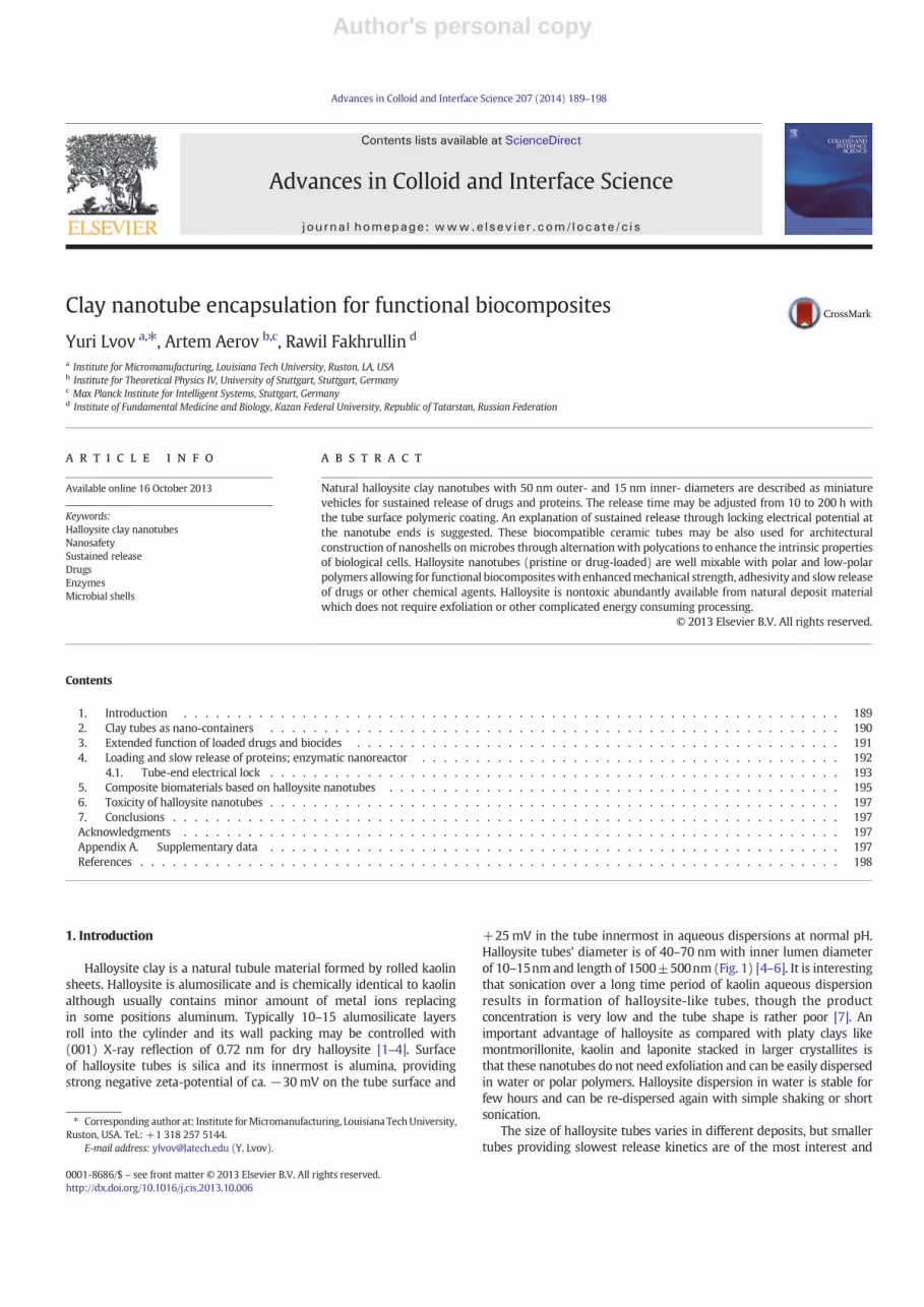
Another way to extend the halloysite formulation release time isbased on its additional encapsulation through formation of surfacecomplex with benzotriazole (BTA) and copper ions or with layer-by-layer (LbL) polyelectrolyte coating, Scheme1 [4,24,28]. The firstmethodemerged from research on anticorrosion agent benzotriazole loadinginto halloysite and was used for prolongation of release time of loaded
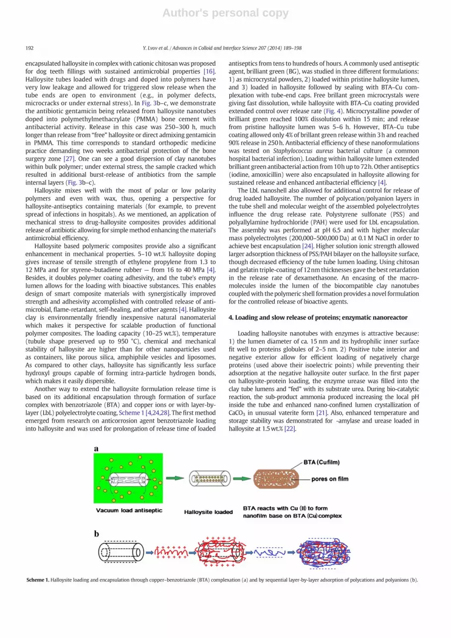
antiseptics from tens to hundreds of hours. A commonly used antisepticagent, brilliant green (BG), was studied in three different formulations:1) as microcrystal powders, 2) loaded within pristine halloysite lumen,and 3) loaded in halloysite followed by sealing with BTA–Cu com-plexation with tube-end caps. Free brillant green microcrystals weregiving fast dissolution, while halloysite with BTA–Cu coating providedextended control over release rate (Fig. 4). Microcrystalline powder ofbrilliant green reached 100% dissolution within 15 min; and releasefrom pristine halloysite lumen was 5–6 h. However, BTA–Cu tubecoating allowed only 4% of brillant green release within 3h and reached90% release in 250h. Antibacterial efficiency of these nanoformulationswas tested on Staphylococcus aureus bacterial culture (a commonhospital bacterial infection). Loading within halloysite lumen extendedbrilliant green antibacterial action from10hup to 72h.Other antiseptics(iodine, amoxicillin) were also encapsulated in halloysite allowing forsustained release and enhanced antibacterial efficiency [4].
The LbL nanoshell also allowed for additional control for release ofdrug loaded halloysite. The number of polycation/polyanion layers inthe tube shell and molecular weight of the assembled polyelectrolytesinfluence the drug release rate. Polystyrene sulfonate (PSS) andpolyallylamine hydrochloride (PAH) were used for LbL encapsulation.The assembly was performed at pH 6.5 and with higher molecularmass polyelectrolytes (200,000–500,000 Da) at 0.1M NaCl in order toachieve best encapsulation [24]. Higher solution ionic strength allowedlarger adsorption thickness of PSS/PAH bilayer on the halloysite surface,though decreased efficiency of the tube lumen loading. Using chitosanand gelatin triple-coating of 12nmthicknesses gave the best retardationin the release rate of dexamethasone. An encasing of the macro-molecules inside the lumen of the biocompatible clay nanotubescoupledwith thepolymeric shell formation provides a novel formulationfor the controlled release of bioactive agents.
4. Loading and slow release of proteins; enzymatic nanoreactor
Loading halloysite nanotubes with enzymes is attractive because:1) the lumen diameter of ca. 15 nm and its hydrophilic inner surfacefit well to proteins globules of 2–5 nm. 2) Positive tube interior andnegative exterior allow for efficient loading of negatively chargeproteins (used above their isoelectric points) while preventing theiradsorption at the negative halloysite outer surface. In the first paperon halloysite-protein loading, the enzyme urease was filled into theclay tube lumens and “fed” with its substrate urea. During bio-catalyticreaction, the sub-product ammonia produced increasing the local pHinside the tube and enhanced nano-confined lumen crystallization ofCaCO3 in unusual vaterite form [21]. Also, enhanced temperature andstorage stability was demonstrated for -amylase and urease loaded inhalloysite at 1.5wt.% [22].
Scheme 1. Halloysite loading and encapsulation through copper–benzotriazole (BTA) complexation (a) and by sequential layer-by-layer adsorption of polycations and polyanions (b).
192 Y. Lvov et al. / Advances in Colloid and Interface Science 207 (2014) 189–198
Author's personal copy
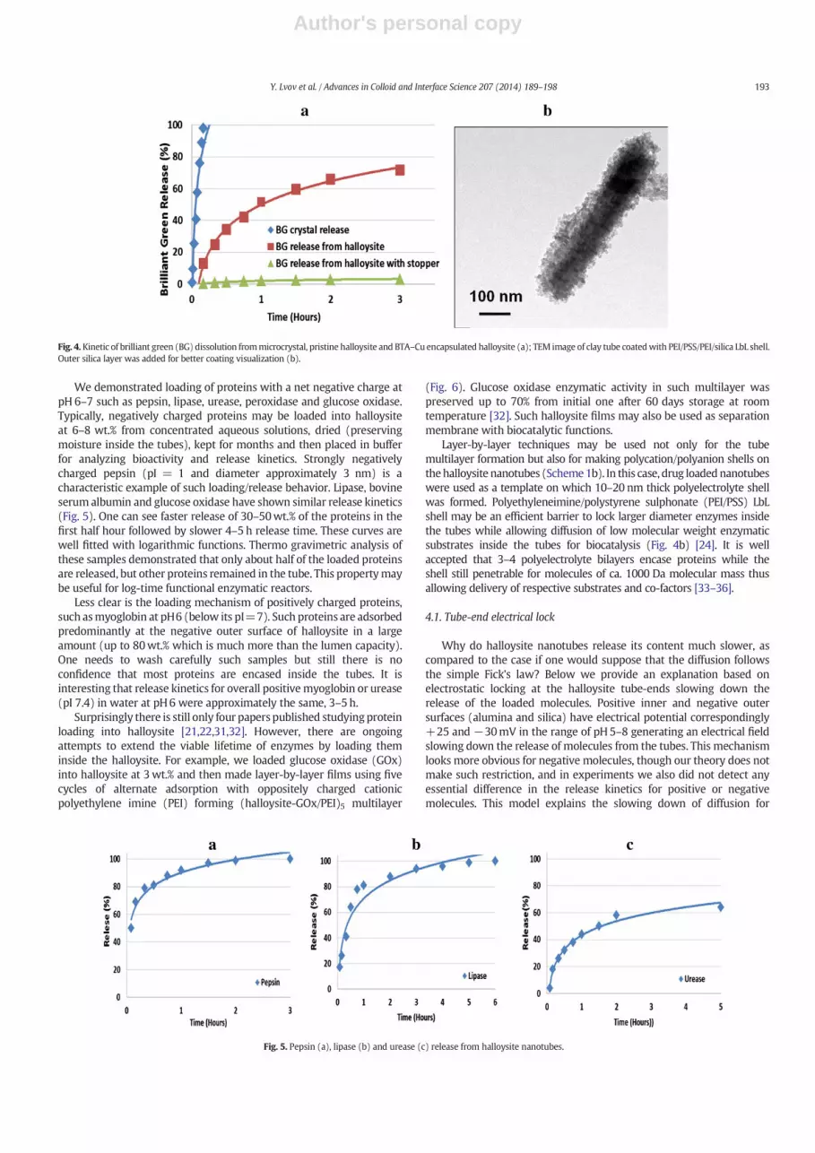
We demonstrated loading of proteins with a net negative charge atpH 6–7 such as pepsin, lipase, urease, peroxidase and glucose oxidase.Typically, negatively charged proteins may be loaded into halloysiteat 6–8 wt.% from concentrated aqueous solutions, dried (preservingmoisture inside the tubes), kept for months and then placed in bufferfor analyzing bioactivity and release kinetics. Strongly negativelycharged pepsin (pI = 1 and diameter approximately 3 nm) is acharacteristic example of such loading/release behavior. Lipase, bovineserum albumin and glucose oxidase have shown similar release kinetics(Fig. 5). One can see faster release of 30–50wt.% of the proteins in thefirst half hour followed by slower 4–5 h release time. These curves arewell fitted with logarithmic functions. Thermo gravimetric analysis ofthese samples demonstrated that only about half of the loaded proteinsare released, but other proteins remained in the tube. This propertymaybe useful for log-time functional enzymatic reactors.
Less clear is the loading mechanism of positively charged proteins,such asmyoglobin at pH6 (below its pI=7). Such proteins are adsorbedpredominantly at the negative outer surface of halloysite in a largeamount (up to 80wt.% which is much more than the lumen capacity).One needs to wash carefully such samples but still there is noconfidence that most proteins are encased inside the tubes. It isinteresting that release kinetics for overall positivemyoglobin or urease(pI 7.4) in water at pH6 were approximately the same, 3–5h.
Surprisingly there is still only four papers published studyingproteinloading into halloysite [21,22,31,32]. However, there are ongoingattempts to extend the viable lifetime of enzymes by loading theminside the halloysite. For example, we loaded glucose oxidase (GOx)into halloysite at 3wt.% and then made layer-by-layer films using fivecycles of alternate adsorption with oppositely charged cationicpolyethylene imine (PEI) forming (halloysite-GOx/PEI)5 multilayer
(Fig. 6). Glucose oxidase enzymatic activity in such multilayer waspreserved up to 70% from initial one after 60 days storage at roomtemperature [32]. Such halloysite films may also be used as separationmembrane with biocatalytic functions.
Layer-by-layer techniques may be used not only for the tubemultilayer formation but also for making polycation/polyanion shells onthehalloysite nanotubes (Scheme1b). In this case, drug loadednanotubeswere used as a template on which 10–20 nm thick polyelectrolyte shellwas formed. Polyethyleneimine/polystyrene sulphonate (PEI/PSS) LbLshell may be an efficient barrier to lock larger diameter enzymes insidethe tubes while allowing diffusion of low molecular weight enzymaticsubstrates inside the tubes for biocatalysis (Fig. 4b) [24]. It is wellaccepted that 3–4 polyelectrolyte bilayers encase proteins while theshell still penetrable for molecules of ca. 1000 Da molecular mass thusallowing delivery of respective substrates and co-factors [33–36].
4.1. Tube-end electrical lock
Why do halloysite nanotubes release its content much slower, ascompared to the case if one would suppose that the diffusion followsthe simple Fick's law? Below we provide an explanation based onelectrostatic locking at the halloysite tube-ends slowing down therelease of the loaded molecules. Positive inner and negative outersurfaces (alumina and silica) have electrical potential correspondingly+25 and −30mV in the range of pH5–8 generating an electrical fieldslowing down the release of molecules from the tubes. This mechanismlooks more obvious for negative molecules, though our theory does notmake such restriction, and in experiments we also did not detect anyessential difference in the release kinetics for positive or negativemolecules. This model explains the slowing down of diffusion for
Fig. 4. Kinetic of brilliant green (BG) dissolution frommicrocrystal, pristine halloysite and BTA–Cu encapsulated halloysite (a); TEM image of clay tube coatedwith PEI/PSS/PEI/silica LbL shell.Outer silica layer was added for better coating visualization (b).
Fig. 5. Pepsin (a), lipase (b) and urease (c) release from halloysite nanotubes.
193Y. Lvov et al. / Advances in Colloid and Interface Science 207 (2014) 189–198

Author's personal copy
dielectric water molecules through the inlet of the tube. It is only ourhypothesis which may initiate deeper theoretical analysis on the stillunclear nature of slowing release from hydrophilic nanotubes. Theelectrostatic field which is present at the ends of the clay tubes slowsdown the diffusion in dielectric liquids. Water has very large dielectricconstant of around 80 at room temperature. It is known that the forcef per unit volume of dielectric liquid exerted by electrostatic field E isequal to [37]:
f!¼ ρ
8πgrad E2
dεdρ
� �ð1Þ
where ρ is thedensity of the liquid, and ε is its dielectric constant. So, thedielectric molecules are pulled inside the regions where electrostaticfield is present. It is intuitive that these “absorbing” regions entrap thechaotically moving molecules for longer periods than other regionshaving no electrostatic field; hence diffusion is slowed down therein.It follows from Eq. (1) that the force field acting on water molecules isa potential field. This explains why the effect of slow release is morepronounced for a narrow halloysite nanotube, Fig. 7: the chargespresent on the inner and outer surfaces of the tube produce electrostaticfield, which is stronger at the ends of the tube (at the edge). If the lumenis large (a), the inlet of the tube is mostly not occupied by electrostaticfield, so the release of the tube content by diffusion is not slowed
down. If the lumen diameter is small (b), the inlet of the tube is totallyclosed by the field, which can lead to a significant slowing down ofthe release. More detailed theoretical description is given in theSupplementary materials. The electrostatic field at the inlet of the tubeis roughly equal to the one near a charged surface carrying the samecharge density as the inner lumen surface which is ca. 1 electron per10 nm2 and dε
dρ≅0:114m3
kg . Putting this into Supplementary materialEq. 9, we obtain u ~ 2.3 KT, and, hence, a 10 times decrease of thediffusion coefficient at the inlet of the tube. This qualitatively describesthe observed sustained release from charged halloysite nanotubes.
Experimentswith the tube internal charge neutralization underlinedthe importance of the electrical dipole formed through the halloysitewall. Very interesting results were obtained with loading DNA intohalloysite. It has to be easy because DNA is anionic polymer readilyadsorbed on positive surfaces like halloysite interior-alumina. In [23],adsorption of DNA on halloysite was studied and drastic increase ofcolloidal stability of halloysite–DNA complexes was detected. Theauthors explained this by external DNA adsorption on the alreadynegative tube surface enhancing the total complex negativity. However,such negative–negative interaction looks not favorable. Lazzara et al.[38,39] suggested a differentmechanismof enhancing the tube externalelectrical potential: negative molecules are adsorbed inside halloysitetubes and compensate the inner positive charges which, in turn,increase overall halloysite negativity. At nano-scale, when oppositelycharged inner and outer tube surfaces are separated by fewnanometers,this mutual neutralization looks quite possible. To prove this, anionicsodium dodecyl sulphate (amphiphile) was adsorbed inside thehalloysite neutralizing the tube inner positive charges and enhancedtubes' zeta-potential to −62 (±2) mV (also colloidal stability of thesample was increased) [39]. We made experiments with anionicsodium polystyrene sulphonate (PSS) loading into halloysite which aswell increased negativity of halloysite to−70 (±2) mV and essentiallyenhanced the dispersion stability (Fig. 8). PSS of 70,000 Da allowedbetter loading into the halloysite tubes as compared with highermolecular mass PSS of 500,000 Da which is connected with its smallerhydrodynamic radius [40]. In 5 h after preparation plain halloysiteprecipitated but PSS-treated halloysite preserved its colloidal stability.
A similar tube's zeta-potential enhancement was observed foradsorption of both anionic amphiphile molecules and linear polyanionswhich proves the importance of the internal positive charge com-pensation for better colloidal stability. Manipulations with DNA loadinginto halloysite nanotubes are very interesting because it may provide avehicle for the delivery into biological cells.
Halloysite nanotubes offer a great and yet not fully realizedpotential as components in bio-inspired functional materials. Onemay envisage a number of biologically-relevant applications arising
Fig. 6. SEM cross-section of the LbL film assembled of halloysite tubes loadedwith glucoseoxidase alternated with cationic polyethyleneimine (six bilayers deposited on siliconwafer).
Fig. 7. Scheme of blocking electrical potential preventing release of molecules from tubes of small diameter.
194 Y. Lvov et al. / Advances in Colloid and Interface Science 207 (2014) 189–198
Author's personal copy
from the hollow structure of halloysite loaded with a cargo (such asDNA, enzymes, drugs, and co-factors) and then either delivered intobiological cells/tissues or providing an extended release into thebiological environment. Contrary to many other nanotubes, such ascarbon, metal or metal oxide tubes, halloysite is a biocompatiblenatural material. Apart from the cargo-carrier functionality, halloysitetubes can also be employed as structural (skeleton) components indental and tissue engineering scaffolds. Belowwe give several examplesof cell-halloysite composites.
5. Composite biomaterials based on halloysite nanotubes
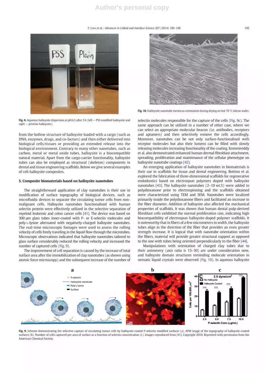
The straightforward application of clay nanotubes is their use inmodification of surface topography of biological devices, such asmicrofluidic devices to separate the circulating tumor cells from non-malignant cells. Halloysite nanotubes functionalised with humanselectin protein were effectively utilized in the selective separation ofmyeloid leukemic and colon cancer cells [41]. The device was based on300 μm glass tubes inner-coated with P- or E-selectin molecules andpoly-L-lysine alternated with negatively-charged halloysite nanotubes.The real-time microscopic footages were used to assess the rollingvelocity of cells freely traveling in the liquid flow through themicrotubes.Microscopic observations indicated that halloysite nanotubes tailored toglass surface considerably reduced the rolling velocity and increased thenumber of captured cells (Fig. 9).
The improvement of cell separation is caused by the increase of totalsurface area after the immobilization of clay nanotubes (as shown usingatomic forcemicroscopy) and the subsequent increase of the number of
selectin molecules responsible for the capture of the cells (Fig. 9c). Thesame approach can be utilized in a number of other case, where wecan select an appropriate molecular beacon (i.e. antibodies, receptorsand aptamers) and then selectively remove the cells accordingly.Moreover, nanotubes can be not only surface-functionalised withreceptor molecules but also their lumens can be filled with slowlyreleasingmolecules increasing functionality of the coating. Kommireddyet al. also demonstrated enhanced human dermal fibroblast attachment,spreading, proliferation and maintenance of the cellular phenotype onhalloysite nanotube coatings [42].
An emerging application of halloysite nanotubes in biomaterials istheir use in scaffolds for tissue and dental engineering. Bottino et al.explored the fabrication of three-dimensional scaffolds for regenerativeendodontics based on electrospun polymers doped with halloysitenanotubes [43]. The halloysite nanotubes (2–10 wt.%) were added topolydioxanone prior to electrospinning and the scaffolds obtainedwere characterized using TEM and SEM. Nanotubes were localizedprimarily inside the polydioxanone fibers and facilitated an increase inthe fiber diameter. Addition of halloysite also affected the mechanicalproperties of scaffolds. It was shown that human dental pulp-derivedfibroblast cells exhibited the normal proliferation rate, indicating highbiocompatibility of electrospun halloysite-doped polymer scaffolds. Itis noteworthy that infibers of a fewmicrometers inwidth, the halloysitetubes align in the direction of the fiber that provides an even greaterstrength increase. It is logical that with nanotube orientation withinthe fibers, material will provide greater structural support as opposedto the one with tubes being oriented perpendicularly to the fiber [44].
Manipulations with orientation of charged clay tubes due totheir anisomery (axis ratio is 15–30) are under consideration now,and halloysite domain structures reminding molecule orientation innematic liquid crystals were observed (Fig. 10). In aqueous halloysite
Fig. 8.Aqueous halloysite dispersion at pH6.5 after 5h (left— PSSmodified halloysite andright — pristine halloysite).
Fig. 9. Scheme demonstrating the selective capture of circulating tumor cells by halloysite-coated P-selectin modified surfaces (a). AFM image of the topography of halloysite-coatedsurfaces (b). Number of cells captured per area of surface as a function of selectin concentration (c). Images reproduced from [41], Copyright 2010. Reprinted with permission from theAmerican Chemical Society.
Fig. 10.Halloysite nanotubemeniscus orientation during drying on hot 70°C siliconwafer.
195Y. Lvov et al. / Advances in Colloid and Interface Science 207 (2014) 189–198
Author's personal copy
droplet on hot substrate, convective flow associated with the solventevaporation carries the tubes from the bulk solution towards the liquid–solid–air boundary and makes the solution sufficiently concentrated toinitiate transition from the isotropic to the liquid crystalline state. Thisphenomenon may be important for halloysite doped polymers withanisotropy of mechanical strength. Nematic behavior of 25–35wt.%aqueous halloysite presenting mosaic of small micro-domains withspontaneously oriented tubes was also observed [45].
The concept of using halloysite nanotubes as dopants was alsoemployed by Liu et al. in fabrication of chitosan-based scaffolds fortissue engineering [46]. Nanocomposite halloysite-doped scaffoldsdemonstrated the enhanced mechanical and thermal properties,namely the significant enhancement in compressive strength,compressive modulus, and temperature stability as compared withthe pure chitosan scaffolds. These scaffolds were effectively colonizedby human fibroblasts.
Another intriguing area of research is tailoring nanomaterials to cellsurfaces which allows rendering new functionalities to living microbialcells. LbL encapsulation of biological cells was suggested byMax PlanckInstitute team led by Helmuth Möhwald and for the first time wasdemonstrated for surface modification of Escherichia coli bacteria anderythrocytes (red blood cells) [47,48]. These so-called “cyborg cells”
have recently become a popular and promising composite biomaterial[49–54]. For example, living cells may be anchored through micro-capsules with surface-attached magnetic nanoparticles that allowin vitro manipulation via a magnetic field [53,54]. Halloysite nanotubeswere also immobilized on the cell walls of microbial cells via the LbLdeposition with oppositely-charged polymers (Fig. 11).
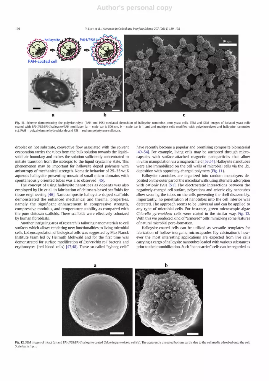
Halloysite nanotubes are organized into random monolayers de-posited on the outer part of themicrobialwalls using alternate adsorptionwith cationic PAH [51]. The electrostatic interactions between thenegatively-charged cell surface, polycations and anionic clay nanotubesallow securing the tubes on the cells preventing the shell disassembly.Importantly, no penetration of nanotubes into the cell interior wasdetected. The approach seems to be universal and can be applied toany type of microbial cells. For instance, green microscopic algaeChlorella pyrenoidosa cells were coated in the similar way, Fig. 12.With this we produced kind of “armored” cells mimicking some featuresof natural microbial pore-formation.
Halloysite-coated cells can be utilized as versatile templates forfabrication of hollow inorganic microcapsules (by calcination); how-ever the most interesting applications are expected from live cellscarrying a cargo of halloysite nanotubes loadedwith various substancesprior to the immobilization. Such “nanocarrier” cells can be regarded as
Fig. 11. Scheme demonstrating the polyelectrolyte (PAH and PSS)-mediated deposition of halloysite nanotubes onto yeast cells. TEM and SEM images of isolated yeast cellscoated with PAH/PSS/PAH/halloysite/PAH multilayer (a — scale bar is 500 nm, b — scale bar is 1 μm) and multiple cells modified with polyelectrolytes and halloysite nanotubes(c). PAH— polyallylamine hydrochloride and PSS — sodium polystyrene sulfonate.
Fig. 12. SEM images of intact (a) and PAH/PSS/PAH/halloysite coated Chlorella pyrenoidosa cell (b). The apparently uncoated bottom part is due to the cell media adsorbed onto the cell.Scale bar is 1 μm.
196 Y. Lvov et al. / Advances in Colloid and Interface Science 207 (2014) 189–198

Author's personal copy
a composite living material providing the cells with a load of nutrients,protective antibodies or biocides, DNA and enzymes. For instance, as aproof of principle, the extended release of glucose loaded into halloysitenanotubes immobilized onto yeast cells was demonstrated [51].
6. Toxicity of halloysite nanotubes
Any nanomaterial envisaged to be used as intracellular deliveryvehicle or as a structural modifier of cells is regarded as a potentiallytoxic. The toxicity of halloysite nanotubes was investigated in severalstudies, generally indicating its very low toxicity levels [12,13]. However,further research is required to investigate the possible long-term toxiceffects of halloysite nanotubes in vivo and in vitro. Here we highlightseveral studies reporting the interaction of halloysite nanotubes withliving cells. Toxicity of aqueous halloysite nanotubes dispersionswas tested using epithelial adenocarcinoma cells (HeLa) and humanbreast cancer cells (MCF-7) [13]. The dose-dependent toxicity at highhalloysite concentrationswas observed, however at lower concentrations( 0.5 mg/mL) up to 70% of cells were viable. Increased halloysiteconcentrations (N1mg/mL) induced a clear decrease in cell viabilityin bothMCF-7 andHeLa cells. The uptake of FITC-labelednanotubes intocells was detected; however, the mechanism of the high concentrationtoxicity remains unclear and can be caused by themechanical impact ofnanotubes on cells. As long as pure halloysite does not induce the acutetoxicity in human cells at lower concentrations, one can anticipate thatthe addition of halloysite to other materials as a surface or structuralmodifier should not reduce their biocompatibility. Human myeloid andcolon cancer cells were found to tolerate the exposure to surface-immobilized halloysite nanotubes [42]. Dental fibroblasts were able tocolonize halloysite-doped polymer scaffolds as well as the pure ones[46], and chitosan-halloysite nanocomposites were found to be non-toxic to human fibroblasts [55].
The toxicity of halloysite nanotubes towards microbial cells wasfound to be negligible. This can be explained by a sufficient protectionprovided to microbial cells by carbohydrate cell walls, whichcannot be penetrated by clay nanotubes. Pure halloysite nanotubesdemonstrated no toxicity towards E. coli bacteria [56]. We haveshown that halloysite nanotubes tailored to yeast cell walls viapolyelectrolyte multilayers did not create an increased mortalityrate in cells, however, a delay in cell growth curves was detected(Fig. 13). The delay is caused by polyelectrolyte shells rather thanhalloysite itself. Budding cells (Fig. 13b) require additional timeto pierce the multi-layered shell, which results in a 3-hour delayin biomass real time growth. The exposition of cells into pure halloysitedid not induce any delay in growth rate. The experimental data availabletoday suggest that the halloysite nanotubes are non-toxic towards livingcells, which, however, needs to be verified on a large number of modelcells and living organisms.
7. Conclusions
Halloysite clay tubes of 50 nm diameter and 1–2 μm length arediscussed as natural nanocontainers for loading and sustained releaseof bioactive molecules. Halloysite inner lumen can store and releasemolecules in a controllable manner making these tiny containersattractive for applications in drug delivery, antimicrobial materials, self-healing polymeric composites and regenerative medicine. Halloysitehas no cell toxicity which allows its usage for drug delivery systemscapable of releasing bioactive agents in a sustained manner from tensof hours to months. It may be useful for oral drug formulations, skincare, medical implants and dentistry, though halloysite cannot beused for intravenous injection because it is not biodegradable.
Halloysite tubes can encase enzymes for longer storage, extendedhigher temperature functionality while the tube's opening allows fordelivery of small substrate molecules into the tube interior for bio-catalysis. Loading DNA into halloysite is another perspective researchdirection. As functional nano-block halloysite tubes may be used forbuilding on biological cells, like formation of spore-like microbial shellsproviding microorganisms with additional functions.
These clay nanotubes have strong surface interaction with bio-polymers (e.g., polysaccharides, polyamides) and with high, mediumor low polarity polymers (e.g., polyacrylates, epoxy, polyvinylchloride,polyethylene) and can be doped into plastics providing good dispersions.These ceramic nanotubes form a kind of a “skeleton” in the bulkpolymers enhancing the composite strength and adhesivity. Besides,these “skeleton bones” may be loaded with bioactive compounds likereal bones are loaded with marrow providing additional functionality.Halloysite is biocompatible “green” material and its simple processingcombined with low cost make it a perspective for nano-architecturalpolymeric composites.
Acknowledgments
Authors are thankful to E. Abdullayev, Applied Minerals Inc., USAfor useful critics and providing halloysite. Thanks to J. Tully for dataon protein loading, Y. Zhao for the images of oriented halloysitetubes and Y. Osin for help with SEM. This study was supportedby RFBR 12-03-93939-G8 grant (RF). AA acknowledges DFG grantKR3844/2-1, Germany. NSF-1029147 and NSF-EPS1003897 grants areacknowledged for their support. Any opinions,findings, and conclusionsor recommendations expressed in this report are those of authors anddo not necessarily reflect the view of National Science Foundation.
Appendix A. Supplementary data
Supplementary data to this article can be found online at http://dx.doi.org/10.1016/j.cis.2013.10.006.
Fig. 13.Growth curves of yeast cells subjected to pure halloysite nanotubes or halloysite/polyelectrolytes composite coatings (a) Reprintedwith permission from [51]. Copyright 2013 TheRoyal Society of Chemistry; SEM image of budding yeast cell, where the halloysite/polyelectrolyte coating is shown in pink andmother and daughter cells in greed (simulated colors) (b).
197Y. Lvov et al. / Advances in Colloid and Interface Science 207 (2014) 189–198

Author's personal copy
References
[1] Joussein E, Petit S, Churchman J, Theng B, Righi D, Delvaux B. Clay Miner 2005;40:383.[2] Lvov Y, Shchukin D, Möhwald H, Price R. ACS Nano 2008;2:814.[3] Du M, Guo B, Jia D. Polym Int 2010;59:574.[4] Lvov Y, Abdullayev E. Prog Polym Sci 2013;38:1690.[5] Abdullayev E, Abbasov V, Tursunbayeva A, Portnov S, Lvov Y. ACS Appl Mater
Interfaces 2013;5:4464.[6] Abdullayev E, Lvov Y. J Mater Chem B 2013;1:2894.[7] Kuroda K, Ito K, Itabashi K, Kuroda K. Langmuir 2011;27:2028.[8] Abdullayev E, Joshi A, Wei W, Zhao Y, Lvov Y. ACS Nano 2012;6:7216.[9] YahW-O, Xu H, SoejimaH,MaW, Takahara A, Lvov Y. J AmChem Soc 2012;134:12134.
[10] Yah W-O, Takahara A, Lvov Y. J Am Chem Soc 2012;134:1853.[11] Jing H, Yah W-O, Higaki Y, Otsuka H, Lvov Y, Takahara A. Chem Lett 2013;42:121.[12] Lai X, Agarwal M, Lvov Y, Pachpande C, Varahramyan K, Witzmann F. J Appl Toxic
2014:34. http://dx.doi.org/10.1002/jat.2858 [web published].[13] Vergaro V, Abdullayev E, Cingolani R, Lvov Y, Leporatti S. Biomacromolecules
2010;11:820.[14] Price R, Gaber B, Lvov Y. J Microencapsul 2001;18:713.[15] Levis S, Deasy P. Int J Pharm 2002;243:125.[16] Kelly H, Deasy P, Ziaka E, Claffey N. Int J Pharm 2004;274:167.[17] Veerabadran N, Price R, Lvov Y. Nano 2007;2:215.[18] Ward C, Song S, Davis E. J Nanosci Nanotechnol 2010;10:6641.[19] Forsgren J, Jämstorp E, Bredenberg S, Engqvist H, StrømmeM. J Pharm Sci 2010;99:219.[20] GuoM,Wang A, Nuhammad F, QiW, Ren H, Guo Y, et al. Chin J Chem 2012;30:2115.[21] Shchukin D, Price R, Lvov Y. Small 2005;1:510.[22] Zhai R, Zhang B, Liu L, Xie Y, Zhang H, Liu J. Catal Commun 2010;12:259.[23] Shami M, Geckeler K. Nanotechnology 2008;19:075604.[24] Veerabadran N, Mongayt D, Torchilin V, Price R, Lvov Y. Macromol Rapid Commun
2009;24:99.[25] Liu M, Guo B, Du M, Cai X, Jia D. Nanotechnology 2007;18:455703.[26] Du M, Gao B, Jia D. Eur Polym J 2006;42:1362.[27] Wei W, Abdullayev E, Hollister A, Lvov Y, Mills D. Macromol Mater Eng 2012;297:645.[28] Joshi A, Abdullayev E, Vasiliev A, Volkova O, Lvov Y. Langmuir 2013;29:7439.[29] Abdullayev E, Sakakibara K, Okamoto K, Wei W, Ariga K, Lvov Y. ACS Appl Mater
Interfaces 2011;3:4040.[30] Suh Y, Kil D, Chung K, Abdullayev E, Lvov Y, Mongayt D. J Nanosci Nanotechnol
2011;11:661.
[31] Lvov Y, Price R, Gaber B, Ichinose I. Colloids Surf Eng 2002;198–200:375.[32] Abdullayev E, Joshi A, Wei W, Lvov Y. Proceedings of the ASME-2012 International
Mechanical Engineering Congress. Houston, USA: R. Becker; 2012. p. 324.[33] De Geest M, Sukhorukov G, Möhwald H. Expert Opin Drug Deliv 2009;6:613.[34] Ariga K, Vinu A, Yamauchi Y, Ji Q, Hill J. Bull Chem Soc Jpn 2012;85:1.[35] Ji Q, Miyahara M, Hill JP, Acharya S, Vinu A, Yoon SB, et al. J Am Chem Soc 2008;130:
2376.[36] Kong J, Lu Z, Lvov Y, Desamero R, Frank H, Rusling J. J Am Chem Soc 1998;120:7371.[37] Becker R, Sauter F. Electromagnetic Fields and Interactions. London: Blakie Publ;
1964. p. 248.[38] Cavallaro G, Lazzara G, Milioto S. Langmuir 2011;27:1158.[39] Cavallaro G, Lazzara G, Milioto S. J Phys Chem 2012;116:21932.[40] Dobrynin A, Rubinstein M. Prog Polym Sci 2005;30:1049.[41] Hughes A, King M. Langmuir 2010;26:12155.[42] Kommireddy D, Ichinose I, Lvov Y, Mills D. J Biomed Nanotechnol 2005;1:286.[43] Bottino M, Yassen G, Platt J, Labban N, Windsor L, Spolnik K, et al. J Tissue Eng Regen
Med 2013. http://dx.doi.org/10.1002/term.1712 [web published].[44] Liao R, Guo B, Zhao J, ZhouW-Y. Proceeding 2nd International Conference Advanced
Textile Materials & Technology, Hangzhou, China; 2010. p. 63.[45] Luo Z, Song H, Feng X, Run M, Cui H, Wu L, et al. Langmuir 2013:29. http://dx.doi.org/
10.1021/la402836d [web published].[46] Liu M, Wu C, Jiao Y, Xiong S, Zhou C. J Mater Chem B 2013;1:2078.[47] Donath E, Moya S, Neu B, Sukhorukov G, Georgieva R, Voigt A, et al. Chem Eur J
2002;8:5481.[48] Neu B, Voigt A, Mitlohner R, Leporatti S, Gao C, Donath E, et al. J Microencapsul
2001;18:385.[49] Fakhrullin R, Lvov Y. ACS Nano 2012;6:4557.[50] Fakhrullin R, Zamaleeva A, Minullina R, Konnova S, Paunov V. Chem Soc Rev
2012;41:4189.[51] Konnova S, Sharipova I, Demina T, Osin Y, Yarullina D, Zelenikhin P, et al. Chem
Commun 2013;49:4208.[52] Kommireddy D, Sriram S, Lvov Y, Mill M. Biomaterials 2006;27:4296.[53] Dzamukova M, Zamaleeva A, Ishmuchametova D, Osin Y, Nurgaliev D, Kiyasov A,
et al. Langmuir 2011;27:14386.[54] Pavlov A, De Geest B, Louage B, Lybaert L, De Koker S, Koudelka Z, et al. Adv Mater
2013. http://dx.doi.org/10.1002/adma.201303287 [web published].[55] Liu M, Zhang Y, Wu C, Xiong S, Zhou C. Int J Biol Macromol 2012;51:566.[56] Zhang Y, Chen Y, Zhang H, Zhang B, Liu J. J Inorg Biochem 2013;118:59.
198 Y. Lvov et al. / Advances in Colloid and Interface Science 207 (2014) 189–198