Micromechanics and macromechanics of carbon nanotube-enhanced elastomers
28
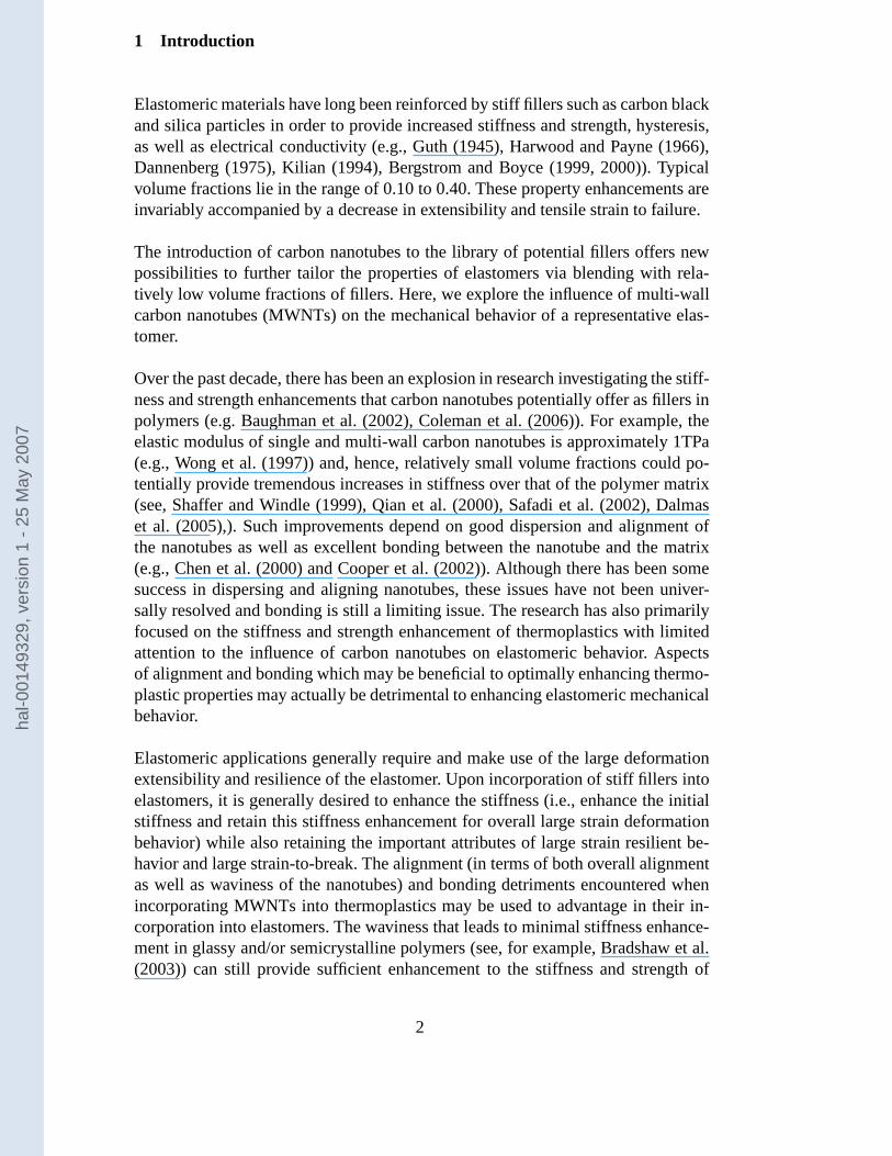
Micromechanics and Macromechanics of Carbon Nanotube Enhanced Elastomers S. Cantournet M. C. Boyce , A. H. Tsou . Ecoles des Mines de Paris/CNRS, Centre des mat´ eriaux/UMR 7633, BP 87, 91003 Evry, France Departement of Mechanical Engineering, Massachusetts Institute of Technology, Cambridge, MA, 02139 USA ExxonMobil Chemical Company, 52000 Baytown drive, Baytown, TX 77520, USA Abstract The effects of carbon nanotubes on the mechanical behavior of elastomeric materials is investigated. The large deformation uniaxial tension and uniaxial compression stress-strain behaviors of a representative elastomer are first presented. This elastomer is then rein- forced with multi-wall carbon nanotubes (MWNTs) and the influence of weight fraction of MWNTs on the large deformation behavior of the resulting composite is quantified. The initial stiffness and subsequent strain-induced stiffening at large strains are both found to increase with MWNT content. The MWNTs are also found to increase both the tensile strength and the tensile stretch at break. A systematic approach for reducing the experi- mental data to isolate the MWNT contribution to the strain energy of the composite is pre- sented. A constitutive model for the large strain deformation behavior of MWNT-elastomer composites is then developed. The effects of carbon nanotubes are modeled via a consti- tutive element which tracks the stretching and rotation of a distribution of wavy carbon nanotubes. The MWNT strain energy contribution is due to the bending/unbending of the initial waviness and provides the increase in initial stiffness as well as the retention and further enhancement of the increase in stiffness with large strains. The model is shown to track the stretching and rotation of the CNTs with macroscopic strain as well as predict the dependence of the macroscopic stress-strain behavior on the MWNT content for both uniaxial tension and uniaxial compression. Key words: Elastomers, nanotubes, anisotropic, nonlinear behavior PACS: Corresponding author. Tel: +33-160-76-30-52; Fax: +33-160-76-31-50 Email address: [email protected] (S. Cantournet). Preprint submitted to Elsevier Science 27 June 2006 hal-00149329, version 1 - 25 May 2007 Author manuscript, published in "Journal of the Mechanics and Physics of Solids 55, 6 (2007) 1321-1339" DOI : 10.1016/j.jmps.2006.07.010
Transcript of Micromechanics and macromechanics of carbon nanotube-enhanced elastomers
Micromechanics and Macromechanics of CarbonNanotube Enhanced Elastomers
S. Cantournet��� �����
M. C. Boyce�, A. H. Tsou
�.
�Ecoles des Mines de Paris/CNRS, Centre des materiaux/UMR 7633, BP 87, 91003 Evry,
FranceDepartement of Mechanical Engineering, Massachusetts Institute of Technology,
Cambridge, MA, 02139 USAExxonMobil Chemical Company, 52000 Baytown drive, Baytown, TX 77520, USA
Abstract
The effects of carbon nanotubes on the mechanical behavior of elastomeric materials isinvestigated. The large deformation uniaxial tension and uniaxial compression stress-strainbehaviors of a representative elastomer are first presented. This elastomer is then rein-forced with multi-wall carbon nanotubes (MWNTs) and the influence of weight fraction ofMWNTs on the large deformation behavior of the resulting composite is quantified. Theinitial stiffness and subsequent strain-induced stiffening at large strains are both found toincrease with MWNT content. The MWNTs are also found to increase both the tensilestrength and the tensile stretch at break. A systematic approach for reducing the experi-mental data to isolate the MWNT contribution to the strain energy of the composite is pre-sented. A constitutive model for the large strain deformation behavior of MWNT-elastomercomposites is then developed. The effects of carbon nanotubes are modeled via a consti-tutive element which tracks the stretching and rotation of a distribution of wavy carbonnanotubes. The MWNT strain energy contribution is due to the bending/unbending of theinitial waviness and provides the increase in initial stiffness as well as the retention andfurther enhancement of the increase in stiffness with large strains. The model is shown totrack the stretching and rotation of the CNTs with macroscopic strain as well as predictthe dependence of the macroscopic stress-strain behavior on the MWNT content for bothuniaxial tension and uniaxial compression.
Key words: Elastomers, nanotubes, anisotropic, nonlinear behaviorPACS:
�Corresponding author. Tel: +33-160-76-30-52; Fax: +33-160-76-31-50Email address: [email protected] (S. Cantournet).
Preprint submitted to Elsevier Science 27 June 2006
hal-0
0149
329,
ver
sion
1 -
25 M
ay 2
007
Author manuscript, published in "Journal of the Mechanics and Physics of Solids 55, 6 (2007) 1321-1339" DOI : 10.1016/j.jmps.2006.07.010
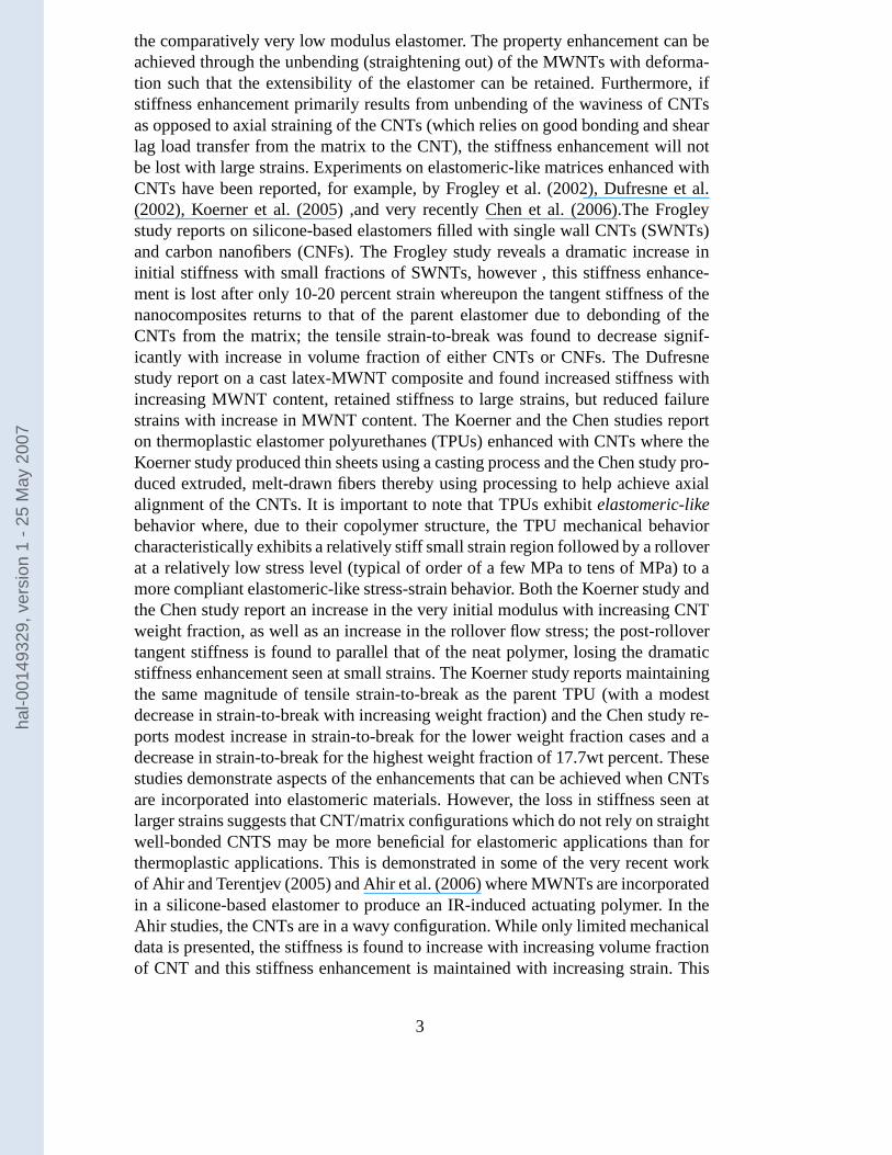
1 Introduction
Elastomeric materials have long been reinforced by stiff fillers such as carbon blackand silica particles in order to provide increased stiffness and strength, hysteresis,as well as electrical conductivity (e.g., Guth (1945), Harwood and Payne (1966),Dannenberg (1975), Kilian (1994), Bergstrom and Boyce (1999, 2000)). Typicalvolume fractions lie in the range of 0.10 to 0.40. These property enhancements areinvariably accompanied by a decrease in extensibility and tensile strain to failure.
The introduction of carbon nanotubes to the library of potential fillers offers newpossibilities to further tailor the properties of elastomers via blending with rela-tively low volume fractions of fillers. Here, we explore the influence of multi-wallcarbon nanotubes (MWNTs) on the mechanical behavior of a representative elas-tomer.
Over the past decade, there has been an explosion in research investigating the stiff-ness and strength enhancements that carbon nanotubes potentially offer as fillers inpolymers (e.g. Baughman et al. (2002), Coleman et al. (2006)). For example, theelastic modulus of single and multi-wall carbon nanotubes is approximately 1TPa(e.g., Wong et al. (1997)) and, hence, relatively small volume fractions could po-tentially provide tremendous increases in stiffness over that of the polymer matrix(see, Shaffer and Windle (1999), Qian et al. (2000), Safadi et al. (2002), Dalmaset al. (2005),). Such improvements depend on good dispersion and alignment ofthe nanotubes as well as excellent bonding between the nanotube and the matrix(e.g., Chen et al. (2000) and Cooper et al. (2002)). Although there has been somesuccess in dispersing and aligning nanotubes, these issues have not been univer-sally resolved and bonding is still a limiting issue. The research has also primarilyfocused on the stiffness and strength enhancement of thermoplastics with limitedattention to the influence of carbon nanotubes on elastomeric behavior. Aspectsof alignment and bonding which may be beneficial to optimally enhancing thermo-plastic properties may actually be detrimental to enhancing elastomeric mechanicalbehavior.
Elastomeric applications generally require and make use of the large deformationextensibility and resilience of the elastomer. Upon incorporation of stiff fillers intoelastomers, it is generally desired to enhance the stiffness (i.e., enhance the initialstiffness and retain this stiffness enhancement for overall large strain deformationbehavior) while also retaining the important attributes of large strain resilient be-havior and large strain-to-break. The alignment (in terms of both overall alignmentas well as waviness of the nanotubes) and bonding detriments encountered whenincorporating MWNTs into thermoplastics may be used to advantage in their in-corporation into elastomers. The waviness that leads to minimal stiffness enhance-ment in glassy and/or semicrystalline polymers (see, for example, Bradshaw et al.(2003)) can still provide sufficient enhancement to the stiffness and strength of
2
hal-0
0149
329,
ver
sion
1 -
25 M
ay 2
007
the comparatively very low modulus elastomer. The property enhancement can beachieved through the unbending (straightening out) of the MWNTs with deforma-tion such that the extensibility of the elastomer can be retained. Furthermore, ifstiffness enhancement primarily results from unbending of the waviness of CNTsas opposed to axial straining of the CNTs (which relies on good bonding and shearlag load transfer from the matrix to the CNT), the stiffness enhancement will notbe lost with large strains. Experiments on elastomeric-like matrices enhanced withCNTs have been reported, for example, by Frogley et al. (2002), Dufresne et al.(2002), Koerner et al. (2005) ,and very recently Chen et al. (2006).The Frogleystudy reports on silicone-based elastomers filled with single wall CNTs (SWNTs)and carbon nanofibers (CNFs). The Frogley study reveals a dramatic increase ininitial stiffness with small fractions of SWNTs, however , this stiffness enhance-ment is lost after only 10-20 percent strain whereupon the tangent stiffness of thenanocomposites returns to that of the parent elastomer due to debonding of theCNTs from the matrix; the tensile strain-to-break was found to decrease signif-icantly with increase in volume fraction of either CNTs or CNFs. The Dufresnestudy report on a cast latex-MWNT composite and found increased stiffness withincreasing MWNT content, retained stiffness to large strains, but reduced failurestrains with increase in MWNT content. The Koerner and the Chen studies reporton thermoplastic elastomer polyurethanes (TPUs) enhanced with CNTs where theKoerner study produced thin sheets using a casting process and the Chen study pro-duced extruded, melt-drawn fibers thereby using processing to help achieve axialalignment of the CNTs. It is important to note that TPUs exhibit elastomeric-likebehavior where, due to their copolymer structure, the TPU mechanical behaviorcharacteristically exhibits a relatively stiff small strain region followed by a rolloverat a relatively low stress level (typical of order of a few MPa to tens of MPa) to amore compliant elastomeric-like stress-strain behavior. Both the Koerner study andthe Chen study report an increase in the very initial modulus with increasing CNTweight fraction, as well as an increase in the rollover flow stress; the post-rollovertangent stiffness is found to parallel that of the neat polymer, losing the dramaticstiffness enhancement seen at small strains. The Koerner study reports maintainingthe same magnitude of tensile strain-to-break as the parent TPU (with a modestdecrease in strain-to-break with increasing weight fraction) and the Chen study re-ports modest increase in strain-to-break for the lower weight fraction cases and adecrease in strain-to-break for the highest weight fraction of 17.7wt percent. Thesestudies demonstrate aspects of the enhancements that can be achieved when CNTsare incorporated into elastomeric materials. However, the loss in stiffness seen atlarger strains suggests that CNT/matrix configurations which do not rely on straightwell-bonded CNTS may be more beneficial for elastomeric applications than forthermoplastic applications. This is demonstrated in some of the very recent workof Ahir and Terentjev (2005) and Ahir et al. (2006) where MWNTs are incorporatedin a silicone-based elastomer to produce an IR-induced actuating polymer. In theAhir studies, the CNTs are in a wavy configuration. While only limited mechanicaldata is presented, the stiffness is found to increase with increasing volume fractionof CNT and this stiffness enhancement is maintained with increasing strain. This
3
hal-0
0149
329,
ver
sion
1 -
25 M
ay 2
007

aspect of the mechanical behavior thus contributes to the resilient and reversiblebehavior needed for actuation mechanisms. There is great potential for enhancingthe mechanical performance of elastomers via incorporation of small weight frac-tions of CNTs; the multifunctional possibilities of further using such enhancementsto produce actuators is enormous (note the Koerner study was directed at creat-ing CNT-TPU actuating materials). Hence the need for quantifying and predictingthe large strain multiaxial stress-strain behavior of CNT-enhanced elastomers withmicrostructurally-informed constitutive models will provide a tool for further de-signing and optimizing materials for a wide range of applications (mechanical andotherwise).
In this paper, we study the mechanics of MWNT-elastomer composites. A series ofmaterial compositions with a range in weight fraction of MWNTs are produced andevaluated in large deformation uniaxial tension and compression testing. The con-tribution of the MWNTs to the deformation is then evaluated in a systematic reduc-tion of the strain energy contributions of the elastomer matrix and the MWNTs tothe overall composite strain energy. A three-dimensional constitutive model is thendeveloped and shown to capture the dependence of the large deformation stress-strain behavior of the elastomer nanocomposites subjected to different types ofdeformation (uniaxial tension and uniaxial compression).
2 Experimental Program
2.1 Materials
The elastomer is a brominated polymer derived from a copolymer of isobutyleneand paramethylstyrene (PMS) with a trademark name of EXXPRO (or BIMSM inaccordance to ASTM) (Powers et al. (1992)). Specifically, EXXPRO 3745 fromExxonMobil Chemical Company with 1.2 mole % bromine was the BIMSM elas-tomer used. This BIMSM elastomer has a specific density of 0.92 and is knownto possess a good combination of properties including temperature resistance, heatstability, low permeability, high damping and ozone/weathering resistance (Kresgeand Wang (1993)), Multi-wall carbon nanotubes (MWNTs) of type PR19-PS MWNTwere obtained from Applied Science. The MWNTs had a diameter range of approx-imately ������� to �������� as estimated from SEM and TEM micrographs.
Blends of BIMSM and MWNTs were prepared using a Banbury internal mixerdirectly operating at 100 RPM under �� ����� RAM pressure. The polymer was addedfirst whereas MWNTs were added ����� later. All mixes were removed from theinternal mixer at a dump temperature of ��������� or lower with a total mix time of3 to 5 minutes. Curatives of 1 phr (parts per hundred of polymer) zinc oxide and1.5 phr stearic acid were subsequently added using a roller mill operating at �������
4
hal-0
0149
329,
ver
sion
1 -
25 M
ay 2
007
to ����� � � . These blends were then compression molded and cured to form 2 � �thick plaques in a curing press. The cure temperature was set at ���� � � and curetime applied was t90 + 5 (5 minutes plus the time required to reach 90 % cure asmeasured by an oscillating disk cure meter).
BIMSM/MWNT nanocomposites with a range in weight fraction of MWNT wereproduced. Thermogravimetric analysis (TGA) was conducted on all samples to ver-ify the final material composition and found the prepared samples to possess aweight fraction close to that blended. Table 1 summarizes the compositions.
Scanning electron microscopy on freeze-fractured surfaces as well as transmissionelectron microscopy (TEM) (Figure 1) revealed good dispersion with random dis-tribution and orientation of MWNTs within the elastomeric matrix.
2.2 Mechanical Testing
Uniaxial tension and uniaxial compression tests were conducted on all materialcompositions. Tests were conducted to large strains at constant engineering strainrate (displacement rate divided by specimen gage length) on a Zwick/Roell Z010single axis screw machine. Specimens were cut from the
� � � thick molded plaques.Tensile specimens were rectangular of dimension ���� � * ��� � . Two types of gripswere used. For moderate strains (strains less than 0.70) tensile grips with surfacesdesigned to test relatively thin compliant polymers were used; one surface is alu-minum and the mating surface is a polyurethane. For larger strains (to final failure),Zwick grip 8122 with a spring-loaded grip action was used to avoid any slidingat very large deformation. The transverse displacement was monitored opticallyduring extension and the axial strain was determined assuming incompressibility.Load-unload-reload tests were conducted to quantify any hysteresis and/or strain-induced softening of the materials. Tests were also conducted at different engineer-ing strain rates to quantify any rate dependence. Some samples were also extendeduntil failure to examine the effect of MWNTs on the tensile stress and strain atbreak. Compression specimens were cylinders of nominally ��� � in diameter and�� � in height (accomplished by stacking three
� � � thick cylinders). Thin Teflonsheets were placed between the specimens and the compression platens to reducefriction; additionally, a powder composed of PTFE and PE was placed between thespecimens and the Teflon sheets. Load-unload-reload tests were conducted. Testswere also performed at different engineering strain rates. Tensile and compressiondata are reported in terms of true stress (load divided by current deformed cross-sectional area) and true strain (the natural logarithm of the current axial gage lengthdivided by the initial gage length). Since the bulk modulus of rubber is substan-tially (i.e. 2-3 orders of magnitude greater) than the shear modulus of rubber, thedeformed cross-sectional area during uniaxial tension and compression can be es-timated from the measured axial strain assuming incompressibility. A minimum of
5
hal-0
0149
329,
ver
sion
1 -
25 M
ay 2
007
at least three tests were conducted for each loading situation; stress-strain curveswere repeatable in all cases and , in the case of uniaxial tension, strain-to-breakmeasurements were also repeatable for all data sets.
3 Experimental results
3.1 Uniaxial tension
Uniaxial tension true stress-strain data are shown in Figure 2. Figure 2a reveals theelastomer matrix material to exhibit a small level of hysteresis (tests at differentstrain rates, not shown, revealed negligible strain rate sensitivity); the stiffness andthe hysteresis are both observed to increase with an increase in MWNT content.The hysteresis was further quantified through cyclic load-unload-reload tests (rep-resentative data are provided in Appendix A) and was found to be a Mullins effect(see, Mullins (1947, 1969), Mullins and Tobin (1954, 1965)) whereby the hystere-sis was nearly absent after the first cycle. Figure 2b depicts the uniaxial tensile datato large strain up to final failure where the stiffening with strain is observed to in-crease with increase in MWNT content and the strain to failure was also found toincrease with increase in MWNT content (failure occurred in the gage length of thespecimen and was not a grip-induced failure). The inset of Figure 2b shows the ini-tial modulus as a function of wt% MWNT where the 12.2wt% MWNT-elastomercomposite has a modulus 2.5 times that of the neat elastomer.Comparatively, a sim-ilar weight fraction of carbon black filler would provide a modulus 1.3 times that ofthe neat elastomer (e.g., Bergstrom and Boyce (1999)). These data show an abilityto substantially increase the tensile stiffness and retain the stiffness enhancementduring large strain deformation as well as the ability to increase the tensile strengthand the tensile strain-to-break.
3.2 Uniaxial Compression Results
Uniaxial compressive true stress-true strain data are shown in Figure 3a revealingthe same basic trends as observed in the tensile data. The overall stiffness and thestiffening with strain are seen to increase with MWNT content. The neat elastomerexhibits a low level of hysteresis; the nanocomposite hysteresis increases with anincrease in MWNT content. The compressive stress-strain behavior is comparedto the tensile stress-strain behavior in Figure 3b for the neat elastomer and for the6.1wt% and 12.2wt% MWNT-elastomers. These data show the classic differencesseen in elastomer compression vs tension stress-strain data. In an elastomer, thisdifference is attributable to the evolution in alignment of the underlying molecularnetwork with different states of strain. The network aligns in a biaxial orientation
6
hal-0
0149
329,
ver
sion
1 -
25 M
ay 2
007

when subjected to uniaxial compression and aligns in a uniaxial orientation whensubjected to uniaxial tension. Here, the MWNTs do not alter this compression vstension dependence of the stress-strain behavior and, indeed, must also orient withdeformation as discussed further in the modeling section.
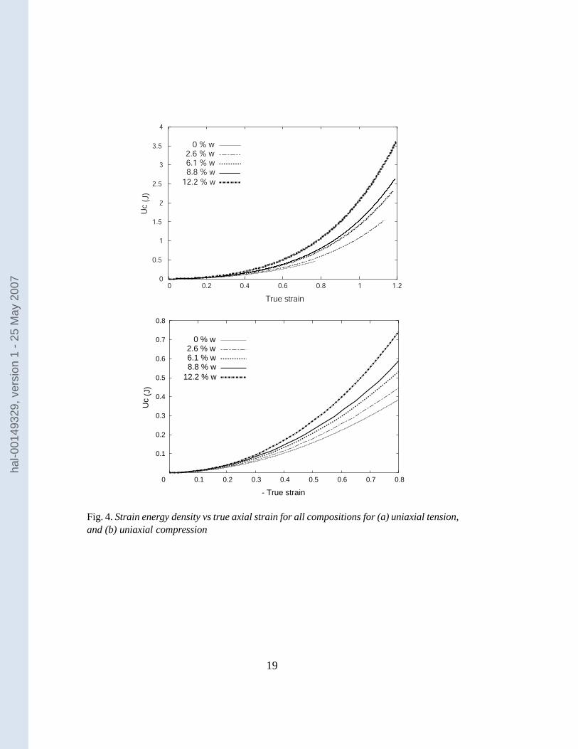
3.3 Strain Energy
The tensile and compression stress vs strain data were further reduced to plotsof strain energy density vs axial strain. Figure 4 shows the strain energy densityresults for all material compositions for uniaxial tension (Figure 4a) and uniaxialcompression (Figure 4b). This data is then once again reduced to provide a plot ofthe strain energy contribution of the MWNTs, ��������� , to the composite behavior.Here, we assume a simple rule of mixtures approach giving:
���� ������������� ���� ������ (1)
or,
��������������� �!� �"�� #�$���%�'&(�) #� (2)
where �� is the strain energy density of the composite, ��� is the strain energy den-sity of the elastomer, and is the volume fraction of the MWNTs. Figure 5 depicts�������� vs. axial strain for uniaxial tension (Figure 5a) and for uniaxial compres-sion (Figure 5b) as obtained by reducing the data for all compositions. Note thatthe curves obtained from each composition are nearly coincident for the tensiledata as well as for the compression data and thus reflect the unit contribution ofthe MWNTs to the deformation behavior of the composite. The coincidence ofthese data supports the use of equation 2 as a surprisingly good first approxima-tion to assess and model the contribution of MWNTs to the composite behavior.This form of the reduced data will be shown to be instrumental in constructing themicrostructurally-informed constitutive model for these nanocomposites * .
* The loading curves were used to construct the strain energy density curves and, hence,contain the hysteresis contibutions seen in the elastomer compositions which were foundto increase with an increase in MWNT content. As a first-order approach we are neglectinghysteresis effects.
7
hal-0
0149
329,
ver
sion
1 -
25 M
ay 2
007

4 Constitutive model
4.1 Model Development
Our experimental results indicate that the strain energy density, � , of the MWNT-elastomer composites under consideration can be decomposed into a contributionfrom the elastomer, ��� , and a contribution from the MWNTs, ��������� , using thesimple rule of mixtures approach given earlier in equation (1). This representationis physically realistic for this case of a low to modest volume fraction of wavy(bent) fibers distributed within a compliant elastomeric matrix, where the fiberswill essentially deform with the matrix, unbending and rotating with the imposeddeformation. The wavy fibers offer little disturbance to the basic deformation fieldof the elastomer (in other words, there is not a significant amplification of strain inthe matrix) and hence the elastomer deformation can be directly described by themacroscopic deformation gradient.
Here, the elastomer matrix contribution will be modeled using the Arruda-Boyce(A-B) eight-chain network model of rubber elasticity (Arruda and Boyce (1993))and the MWNT contribution will be captured using the framework for anisotropichyperelastic materials as originally developed by Spencer (1984). The strain energycontributions will be described below and each will be a function of properties ofthe constituent material and the imposed deformation. The macroscopic deforma-tion is described by the deformation gradient,
� ����� &���� , with polar decompo-sitiom
� ��� �� � , � denotes the position of a material point in the initial,reference configuration and � denotes the the position vector of that same materialpoint in current, deformed configuration. The corresponding right Cauchy-Greentensor is given by � � ����� ����� and the left Cauchy-Green tensor is given by� � ��� � �� � . The invariants of � and
�are given by:
�* ���������! � � ��� "$#�%
* �#�%% � #&%')(� % � �
�+* � %* �,���-���. � � % �0/"� #�%*#&%% � #�% * #&%' � #�%% #&%'� ' �213 4� � � ��� # %
*# %% # %' (3)
where#�5
are the principal stretches.
4.1.1 Elastomer Matrix Representation
The BIMSM elastomer is a crosslinked molecular network and was found to ex-hibit little time-dependence. The Mullins effect (quantified in the data presented inAppendix A) is small and can be modelled using the Qi and Boyce (2004) model,
8
hal-0
0149
329,
ver
sion
1 -
25 M
ay 2
007

but this effect is neglected in this paper in order to more clearly focus on the pri-mary contributions of the MWNTs to the mechanical behavior. Hence, the matrixis approximated as hyperelastic and modeled using the A-B eight-chain networkmodel of rubber elasticity. The A-B model represents a random isotropic molecularnetwork as eight chains emanating from a central junction point to the corners of acube; the cube is taken to be aligned with the principal axes of stretch. In this rep-resentation, each chain stretches by the root mean square of the imposed stretch,#���� 5 � �
��# %* �
# %% � # %' �%&�� �� �
* &�� and also rotates towards the axis(es) ofmaximum principal stretch(es) (Figure 6). Thus, the eight-chain model captures theessence of the physics of deformation of an isotropic random network as verified byits ability to predict the stress-strain behavior of an elastomer under different statesof strain. The strain energy function for a compressible version of the eight-chainmodel (see, Bischoff et al. (2001)) is given by:
��� ����� � � #���� 5 ��� ����� � �������� � � � � � �
� � ����� � ��� "! �#� � � �
%(4)
where � �%$'& *' # ���� 5 �� � � ;#���� 5 � � � �
* &�� ; � � �%$(& * " *) � ( ; where $'& * is the
inverse Langevin function with $�� � � �+*-,/. � � � � � � & � , � � � � ' and 0! is thebulk modulus.
The Cauchy stress is then obtained by differentiating ��� , giving:
1 � � �
� ����� � *� � ������32 (5)
or 1 � � �4��5� � �6 �#
���� 5 � � � � � 2 � � 0! �7� � � � 2The material properties were fit to the BIMSM tensile data, giving ��� � �58 ���:9<; �and � � � ��� ; the bulk modulus was taken to be �>=?; � . The model fit is shown tocapture the tensile behavior in Figure 7. As is well known, elastomeric stress-strainbehavior is strongly dependent on the state of imposed deformation (see, for exam-ple, Treloar (1975), Arruda and Boyce (1993)), where the greatest contrast is seen incomparisons of uniaxial tension to uniaxial compression (or, alternatively, uniaxialtension and equibiaxial tension). The model prediction of the uniaxial compressionbehavior based on its fit to the tensile data is also shown in Figure 7 , demonstrat-ing the ability of the model to capture the matrix behavior. The small discrepancybetween model prediction and experiment is most likely due to our neglecting thesmall amount of hysteresis and Mullins effect (see Appendix A) exhibited by thismaterial. However, for purposes of examining the effect of CNTs on the uniaxialtension and compression behavior , this discrepancy is small.
9
hal-0
0149
329,
ver
sion
1 -
25 M
ay 2
007
4.1.2 MWNT Representation
The contribution to the composite strain energy emanating from the deformationof the constituent MWNTs is modeled by first building from the basic frameworkpresented in Spencer (1984) for anisotropic fiber-reinforced hyperelastic materials.This framework has been followed and/or built upon in recent years by a numberof investigators including, for example, Bischoff et al. (2002b,a) who establishedan anisotropic molecular network model for skin tissue; Holzapfel (2003, 2000) indevelopments of models of arterial wall tissue, and Reese et al. (2001) in modelsof fabric reinforced elastomers and Horgan and Saccomandi (2005) in a model ofan incompressible elastomer reinforced with a single family of fibers. The frame-work begins with the recognition of fiber direction, � , as a building block of neededinvariants for constructing the anisotropic strain energy function. Using a notation��� as representing the direction of the ith family of fibers, several additional invari-ants (beyond
�* ,� % , and
� 'introduced previously) become relevant. The primary
invariants of interest being: ����� ��� 5 8 �"8�� 5��� ��� 5 8 � % 8�� 5 (6)
where additional invariants which capture coupling between fiber families consti-tute the remaining invariants (for an overview, see, for example, Holzapfel (2000)).
In our representation, based on the experimental data, we first take the simplestapproach and capture the influence of the wavy MWNTs (i.e., the MWNTs are notstraight nor are they aligned, instead they are randomly dispersed and in an undu-lated or bent configuration within the matrix) by simply building a strain enregyfunction based on the
����, where
�����physically represents the square of the stretch
of the fiber family in the ith direction:# %������� � � �����
. The MWNT strain energycontribution can then be expressed as:
���������� � 5 5 ���������� #&% ������� � � (7)
where 5
is the volume fraction of MWNTs whose end-to-end vector is aligned inthe ith direction and the sum is over all MWNT end-to-end directions present in thematerial; the ”fiber stretch” here refers to the extension of the end-to-end distanceof this wavy MWNT where this extension results in the unbending or straighteningout of the MWNT waviness.
For the material under consideration, we note that the orientation distribution isisotropic and we thus take a leap similar to that of the eight-chain network modelof rubber elasticity: we represent the contribution of the random distribution ofnanotubes by the average initial orientation direction. The average orientation is ap-proximately given by the azimuthal angle of 55 degrees (see, for example, Bergstromand Boyce (2001)) corresponding to the fibers associated with the ����� ������� family
10
hal-0
0149
329,
ver
sion
1 -
25 M
ay 2
007
(i.e. (1,1,1), (1,1,-1), (-1,1,1),(1,-1,1)... ). This isotropic distribution is more op-timally captured by considering the average orientation given with respect to theprincipal stretch directions, i.e. taking the azimuthal angle of ����� with respect tothe maximum principal stretch direction. This is thus the “8-chain” network ap-proach and gives:
#������� �
� �* &�� . We thus have “isotropized” the anisotropic
strain energy function for a random isotropic distribution of MWNTs which givesthe MWNT contribution to be:
������������ ����������� # % ������� � � (8)
where# %������� � � * &�� .
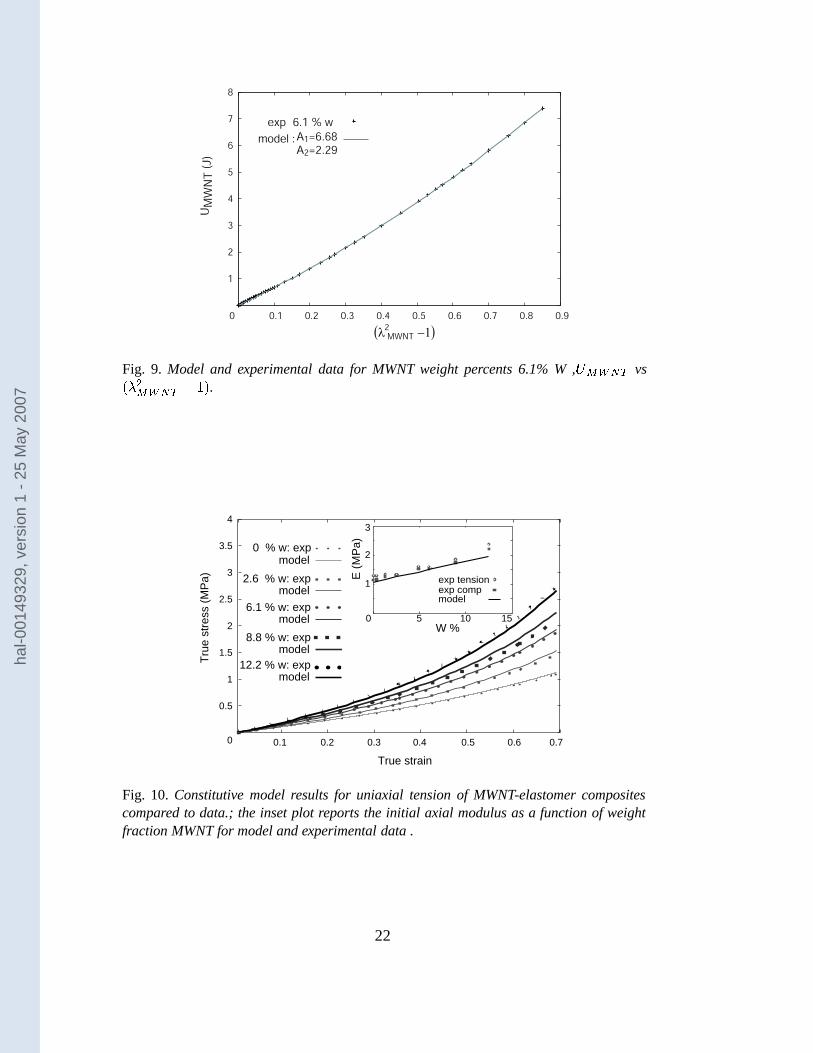
This isotropized contribution also provides a framework for further reduction of ourexperimental data of Figures 5a and 5b which we can now represent as � ������� vs�# %������� � � � as shown in Figure 8. Fitting the data as represented in Figure 8
provides the MWNT strain energy function:
�������� � �* �#�������
%� � ��� � % � # ����� � % � � �
%�
� �*
�� � � (9)
or,
������������*� � � * � � ���
� %� � � * � � �
%�
� �*
�� � �
where the model curve fit, with�* � �8 � 9<; � and
� % � � 8 � �>9<; � , is shown inFigure 9. The model for the more general case of a distribution in MWNT orienta-tions is given in Appendix B. We further emphasize that the strain energy contribu-tion from the MWNTs is a result of the energy from bending and/or unbending ofundulations in the MWNTs during the imposed macroscopic deformation, wherethe MWNTs stretch (extending their end-to-end distance via unbending) and rotatewith the imposed deformation such that they deform with the matrix.
4.1.3 Composite Constitutive Model
The composite strain energy function is simply the sum of the contributions fromthe elastomer and from the MWNT as given earlier in equation 1 and now usingequations 4 and 9 for the elastomer and MWNT contributions, respectively. Differ-entiation of the strain energy function gives the Cauchy stress:
1 � � � �� #� �4��5� � �6 �#���� 5 � � � � � 2 �
��
� � �* �
�� %� � � * � � ��� B �
� � *� 1 � 0! �#� � � � 2
(10)
11
hal-0
0149
329,
ver
sion
1 -
25 M
ay 2
007
4.2 Comparison of model and experimental results
The constitutive model results are compared to data in Figures 10 and 11. Fig-ure 10 shows the model results for uniaxial tension of the neat elastomer and theMWNT-elastomer composites plotted together with the data. The model is found toquantitatively capture the features of the uniaxial tension stress-strain behavior andits dependence on MWNT content. The inset of Figure 10 shows the model resultsfor initial modulus as a function of wt% MWNT. The model results for uniaxialtension and compression to strains of 1.0 and -1.0, respectively, together with thecorresponding data are shown in Figure 11. The model is also found to be in goodagreement with experimental data for uniaxial compression. The model is found tocapture the data to large strain and to quantitatively predict the uniaxial compres-sion behavior showing the distinct differences in tension and compression data aswell as the dependence of the curves on MWNT content.
5 Conclusions
The influence of multi-wall carbon nanotubes on the mechanical behavior of elas-tomeric materials was investigated. The BIMSM elastomer was blended with mul-tiwall carbon nanotubes (MWNTs) and the influence of weight fraction of MWNTson the large deformation tensile and compressive behavior was quantifed. The ini-tial stiffness and subsequent stretch-induced stiffening at large strains were bothfound to increase with MWNT content. The MWNTs were also found to increasethe tensile strength and the tensile strain-to-break. The strain energy density ofthe composite materials as obtained experimentally was reduced into two contribu-tions: a matrix contribution and a MWNT contribution. The ability to decomposethe experimentally obtained strain energy guided the development of a hyperelasticconstitutive model for the composite materials based on the volume fraction of ma-trix and MWNT. The model was found to predict the effects of MWNT content onthe large deformation stress strain behavior of the composite materials in tensionand compression, showing excellent agreement with the experimental data.
Acknowledgements
This research was sponsored, in part, by USAFOSR through the DURINT Poly-mer Nanocomposites, Grant No. F49620-01-1-0447, and, in part, by ExxonMobilChemical Company.
12
hal-0
0149
329,
ver
sion
1 -
25 M
ay 2
007

References
Ahir, S., Squires, A., Rajbakhsh, A., Terentjev, E., 2006. Infrared actuation inaligned polymer-nanotube composites. Phys. Rev. B 73, 1–12.
Ahir, S., Terentjev, E., 2005. Photomechanical actuation in polymer nanotube com-posites. Nature Mater. 4, 491–495.
Arruda, E. M., Boyce, M. C., 1993. A three-dimensional constitutive model forthe large stretch behavior of rubber elastic materials. Jnl. of the Mechanics andPhysics of Solids 41, 389–412.
Baughman, R., Zakhidov, A., de Heer, W., 2002. Carbon nanotubes the route towardapplications. Science 297 (5582), 787–792.
Bergstrom, J., Boyce, M., 1999. Mechanical behavior of particle filled elastomers.Rubber Chemistry and Technology 72, 633–656.
Bergstrom, J., Boyce, M., 2000. Large strain time-dependent behavior of filled elas-tomers. Mechanics of Materials 32, 627–644.
Bergstrom, J. S., Boyce, M. C., 2001. Deformation of elastomeric networks: re-lation between molecular level deformation and classical statistical mechanicsmodels of rubber elasticity. Macromolecules 34, 614–626.
Bischoff, J. E., Arruda, E. M., Grosh, K., 2001. A new constitutive model for thecompressibility of elastomers at finite deformation. Rubber Chemistry and Tech-nology 74, 541–559.
Bischoff, J. E., Arruda, E. M., Grosh, K., 2002a. A microstructurally based or-thotropic hyperelastic constitutive law. Jnl. Appl. Mech. 69, 570–579.
Bischoff, J. E., Arruda, E. M., Grosh, K., 2002b. Orthotropic hyperelasticity interms of an arbitrary molecular chain model. Jnl. Appl. Mech. 69, 198–201.
Bradshaw, R., Fisher, F., Brinson, L., 2003. Fiber waviness in nanotube-reinforcedpolymer compositesii modeling via numerical approximation of the dilute strainconcentration tensor. Comp. Sci. Technol. 63, 1705–1722.
Chen, W., Tao, X., Liu, Y., 2006. Carbon nanotube-reinforced polyurethane com-posite fibers. Comp. Sci. Technol.In press, available on line June 2006.
Chen, Y., Shaw, D., Guo, L., 2000. Field emission of different oriented carbonnanotubes. Applied Physics Letters 76 (17), 2469–2471.
Coleman, J. N., Khan U., B. W. J., Gunko, Y. K., 2006. Small but strong: A reviewof the mechanical properties of carbon nanotube polymer composites. Carbon44, 1624–1652.
Cooper, C., Ravich, D., Lips, D., Mayer, J., Wagner, H., 2002. Distribution andalignment of carbon nanotubes and nanofibrils in a polymer matrix. Comp SciTechnol 62, 1105–1102.
Dalmas, F., Chazeau, L., Gauthier, C., Masenelli-Varlot, K., Dendievel, R.,Cavaille, J., 2005. Multiwalled carbon nanotube/polymer nanocomposites: pro-cessing and properties. J. Polym. Sci. Part B: Polym Phys 43 (10), 1187–1197.
Dannenberg, E. M., 1975. The effet of surface chemical interactions on the proper-ties of filler reinforced rubbers. Rubber Chemistry and Technology 44, 440–478.
Dufresne, A., Paillet, M., Putaux, J., Canet, R., Carmona, F., Delhaes, P., 2002.Processing and characterization of carbon nanotube/poly(styren-co-butyl acry-
13
hal-0
0149
329,
ver
sion
1 -
25 M
ay 2
007

late) nanocomposites. Jnl. Mater. sci. 37, 3915–3923.Frogley, M., D., R., H.D., W., 2002. Mechanical properties of carbon nanoparticle-
reinforced elastomers. Comp Sci Technol 63, 1647–1654.Guth, E., 1945. Theory of filler reinforcement. Jnl. Appl. Phys. 16 (1), 20–25.Harwood, J., Payne, A., 1966. Stress-softening in natural rubber vulcanizates. part
iii: Carbon black-filled vulcanizates. J. Appl. Polym. Sci. 10, 315–324.Holzapfel, G. A., 2000. Nonlinear solid mechanics, a continuum approach for en-
gineering. John Wiley and Sons, Chichester.Holzapfel, G. A., 2003. Structural and numerical models for the viscoelastic re-
sponse of arterial walls with residual stresses. Springer-Verlag, Wien, chapter(pages 109-184) in Biomechanics of Soft Tissue in Cardivascular Systems, ed.Holzapfel, G.A., Ogden, R.W., CISM Lectures No. 441.
Horgan, C. O., Saccomandi, G., 2005. A new consititutive theory for fiber-reinforced incompressible nonlinearly elastic solids. Jnl. of the Mechanics andPhysics of Solids 53, 1985–2015.
Kilian, H. G. a., 1994. Universal properties in filler loaded rubbers. Rubber Chem-istry and Technology 67.
Koerner, H., Liu, W., Alexander, M., Mirau, P., Dowty, H., Vaia, R.,2005. Deformation-morphology correlations in electrically conductive carbonnanotube–thermoplastic polyurethane nanocomposites. Polymer 46, 4405–4420.
Kresge, E. N., Wang, H. C., 1993. Butyl Rubbers. John Wiley and Sons, New york,v. 8 p 934 in Kirk-Ohmer Encyclopedia of Chemical Technology.
Mullins, L., 1947. Effect of stretching on the properties of rubber. Journal of RubberResearch 16, 275–289.
Mullins, L., 1969. Softening of rubber by deformation. Rubber Chem. Technol. 42,339–362.
Mullins, L., Tobin, N. R., 1954. Theoretical model for the elastic behavior of filler-reinforced vulcanized rubbers. Proc. 3rd Rubber Technol. Con., W. Heffer andSons Ltd., 397–412.
Mullins, L., Tobin, N. R., 1965. Stress softening in ruber vulcanizates. parti. useof a strain amplification factor describe the elastic behavior of filler-reinforcedvulcanized rubber. Jnl. of Applied Polymer Science 9, 2993–3009.
Powers, K. W., Wang, H. C., Chung, T. C., Dias, A. J., Olkusz, J. A., November 101992. Patent : Para-alkylstyrene/isolefin copolymers and functionalized copoly-mer thereof. Number : US 5,162,445.
Qi, H. J., Boyce, M. C., 2004. Constitutive model for stretch-induced softening ofthe stress-stretch behavior of elastomeric materials. Jnl. of the Mechanics andPhysics of Solids 52, 2187–2205.
Qian, D., Dickey, E., Andrews, R.and Rantell, T., 2000. Load transfer and de-formation mechanisms in carbon nanotubepolystyrene composites. Adv. Mater.76 (20), 2868–2870.
Reese, S., Raible, T., Wriggers, P., 2001. Finite element modelling of orthotropicmaterial behavior in pneumatic membranes. Int. Jnl. of Solids and Structures 38,9525–9544.
Safadi, B., Andrews, R., Grulke, E., 2002. Multiwalled carbon nanotube polymer
14
hal-0
0149
329,
ver
sion
1 -
25 M
ay 2
007
composites: synthesis and characterization of thin films. Jnl. of Applied PolymerScience 84 (14), 2660–2669.
Shaffer, M., Windle, A., 1999. Fabrication and characterization of carbon nan-otube/poly(vinyl alcohol) composites. Adv. Mater. 11, 937–941.
Spencer, A. J. M., 1984. Constitutive Theory for strongly Anisotropic Solids.Springer-Verlag, Wien, chapter (pages 1-32) in Continuum theory of the me-chanics of fiber-reinforced composites, ed. Spencer, A. J. M., CISM Courses andLectures No. 282.
Treloar, L., 1975. The Physics of Rubber Elasticity. 3rd ed., Clarendon Press, Ox-ford.
Wong, E., Sheehan, P., C.M., L., 1997. Nanobeam mechanics: elasticity, strength,and toughness of nanorods and nanotubes. Science 277, 1971–1975.
15
hal-0
0149
329,
ver
sion
1 -
25 M
ay 2
007

Table 1: Material Compositions
Nanocomposite No. 1 2 3 4
Elastomer (phr) 100 100 100 100
MWNT (phr) 2.5 7.5 10 15
Formulation ( ����� ) 2.43/.0113 6.97/.0372 9.09/.049 13.04/.0718
TGA ( ����� ) 2.60/.0136 6.07/.0323 8.8/.0474 12.16/.0667
� =weight percent; � =volume fraction
Fig. 1. (a) Low magnification Scanning Electron micrographs of a freeze fractured sur-face and (b) TEM of MWCNT/elastomer nanocomposite of 15 wt � , showing uniformity ofMWCNT dispersion
16
hal-0
0149
329,
ver
sion
1 -
25 M
ay 2
007

0.2
0.4
0.6
0.8
1
1.2
1.4
1.6
0 0.05 0.1 0.15 0.2 0.25 0.3 0.35 0.4
True stress (MPa)
True strain
t
0.4
εtrue
0
0 % w2.6 % w6.1 % w
12.2 % w
8.8 % w
0 % w2.6 % w6.1 % w
12.2 % w
8.8 % w
0
2
4
6
8
10
0.2 0.4 0.6 0.8 1 1.2
3
0 5 10 15
E (MPa)
W %
1
2
True stress (MPa)
True strain
Fig. 2. (a) Uniaxial tension load-unload true stress vs. true strain at an engineering strainrate of 0.01 /s to a strain of 0.4 for the elastomer and the elastomer-MWNT nanocompos-ites; (b)Uniaxial tension true stress vs. true strain at a strain rate of 0.01/s taken to failure;the inset plot reports the initial axial modulus as a function of weight fraction MWNT.
17
hal-0
0149
329,
ver
sion
1 -
25 M
ay 2
007

0
0.5
1
1.5
2
2.5
3
0.1 0.2 0.3 0.4 0.5 0.6 0.7 0.8 0.9 1
t
1
− εtrue
0
0 % w2.6 % w6.1 % w
12.2 % w8.8 % w
-Tru
e st
ress
(M
Pa)
-True strain
comp. tension
0 % w
6.1 % w
12.é2 % w
0
2
4
6
0.2 0.4 0.6 0.8 1
1
3
5
+/-
True stress
(MPa)
+/- True strain
3
0 5 10
E (MPa)
1
2
comp.
tension
W %
Fig. 3. (a) Uniaxial compression load-unload true stress vs. true strain at an engineeringstrain rate of 0.01/s to a strain of -1.0 for the elastomer and the elastomer-MWNT nanocom-posites; (b) Comparison of uniaxial tension and uniaxial compression true stress-truestrain for 0phr, 5phr (6.07 � wt) and 15phr (12.16 � wt) compositions; the inset plot re-ports the comparison of uniaxial tension and uniaxial compression initial modulus as afunction of weight fraction MWNT.
18
hal-0
0149
329,
ver
sion
1 -
25 M
ay 2
007
0
0.5
1
1.5
2
2.5
3
3.5
4
0 0.2 0.4 0.6 0.8 1 1.2
True strain
0 % w2.6 % w6.1 % w
12.2 % w
8.8 % w
Uc (J)
0.1
0.2
0.3
0.4
0.5
0.6
0.7
0.8
0 0.1 0.2 0.3 0.5 0.6 0.7 0.8
0 % w2.6 % w6.1 % w
12.2 % w8.8 % w
Uc
(J)
0.4
- True strain
Fig. 4. Strain energy density vs true axial strain for all compositions for (a) uniaxial tension,and (b) uniaxial compression
19
hal-0
0149
329,
ver
sion
1 -
25 M
ay 2
007

0
1
2
3
4
5
6
7
8
9
0.1 0.2 0.3 0.4 0.5 0.6 0.7 0.8
Um
wnt
(J)
True strain
2.6 % w6.1 % w
12.2 % w8.8 % w
2
4
6
8
10
0 0.2 0.4 0.6 0.8 1
-True strain
2.6 % w6.1 % w
12.2 % w8.8 % w
UM
WN
T (
J)
Fig. 5. Strain energy density of the MWNTs vs true axial strain for all compositions for (a)uniaxial tension and (b) uniaxial compression.
Fig. 6. Eight-chain network model is (a) undeformed, (b) uniaxial tension, and (c) uniaxialcompression, Arruda and Boyce (1993)
20
hal-0
0149
329,
ver
sion
1 -
25 M
ay 2
007

0
0.2
0.4
0.6
0.8
1
1.2
1.4
1.6
0.1 0.2 0.3 0.4 0.5 0.6 0.7 0.8
+/-
Tru
e st
ress
(M
Pa)
+/- True strain
exp tensionmodel tension
exp compressionmodel compression
Fig. 7. Arruda Boyce model and experimental data for BIMSM in uniaxial tension anduniaxial compression. Model fit to tensile data; compression is a prediction.
2
4
6
8
10
0 0.1 0.2 0.3 0.4 0.5 0.6 0.7 0.8
2.6 % w6.1 % w
12.2 % w8.8 % w
comptension
UM
WN
T (
J)
MWNT(λ −1)2
Fig. 8. � ������� vs ���%������������ for uniaxial tension and for uniaxial compression.
21
hal-0
0149
329,
ver
sion
1 -
25 M
ay 2
007
1
2
3
4
5
6
7
8
0 0.1 0.2 0.3 0.4 0.5 0.6 0.7 0.8 0.9
A1=6.68A2=2.29
exp
model :
f2
6.1 % w
λ
UMWNT
(J)
(λ −1)MWNT2
Fig. 9. Model and experimental data for MWNT weight percents 6.1% W , � ������� vs���%��������� �� .
0
0.5
1
1.5
2
2.5
3
3.5
4
0.1 0.2 0.3 0.4 0.5 0.6 0.7
Tru
e st
ress
(M
Pa)
True strain
2.6 % w: expmodel
6.1 % w: expmodel
8.8 % w: expmodel
12.2 % w: expmodel
0 % w: expmodel
3
0 5 10 15
E (
MP
a)
W %
1
2
modelexp compexp tension
Fig. 10. Constitutive model results for uniaxial tension of MWNT-elastomer compositescompared to data.; the inset plot reports the initial axial modulus as a function of weightfraction MWNT for model and experimental data .
22
hal-0
0149
329,
ver
sion
1 -
25 M
ay 2
007

0
2
4
6
8
10
0.2 0.4 0.6 0.8 1
+/-
Tru
e st
ress
(M
Pa)
+/- True strain
comp tension exp
model
MWCNT 12.2 % w
0
1
2
3
4
0.2 0.4 0.6 0.8 1
comp tension
exp
model
+/-
True stress
(MPa)
+/- True strain
MWCNT 2.6 % w
Fig. 11. Constitutive model results for uniaxial tension and uniaxial compression comparedto data for MWNT weight percents (a) 12.2% and (b) 2.6%.
23
hal-0
0149
329,
ver
sion
1 -
25 M
ay 2
007

A Mullins effect
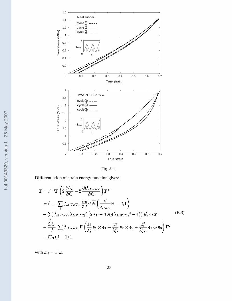
The elastomer and MWNT-elastomer composites of this study were found to ex-hibit a Mullins effect (a stretch-induced softening of the stress-strain behavior com-monly observed in elastomeric material, see, for example, Mullins (1947, 1969),Mullins and Tobin (1954, 1965), Harwood and Payne (1966)) as evidenced by amore compliant response on reloading of the material after having been subjectedto a prior load-unload cycle. For completeness, Figures A.1 and A.2 show load-unload-reload data for uniaxial tension (A.1) and compression (A.2) of the neatelastomer and MWNT-elastomers. Figure (A.1) shows the uniaxial tensile load-unload-reload behavior to/from strains of 0.40 and 0.69 for the neat elastomer andthe 15phr MWNT-elastomer composite. Figure A.2 shows the load-unload-reloadbehavior of the neat elastomer and the 15phr MWNT-elastomer nanocomposite incompression to/from a strain of -1.0.
B Anisotropic Strain Energy for Composite Containing Initial PreferentialOrientation of MWNTs
The materials under consideration were found to contain a randomly oriented dis-tribution of MWNTs. However, the modeling presented is also applicable to thecase of an initially preferentially oriented distribution of MWNTs as is presentedin this appendix for purposes of both completeness and comparison. The fibers di-rection are given by unit vectors � 5 � � 5��
* ���5�� % ���
5�� 'in the initial configuration
and#�
� � � * 8 �"8 � * , #�� � � � % 8 �08 � % , #��� � � � ' 8 �"8 � ' represent the stretchesalong the principales fiber axes. We take the MWNT contribution to be given by:
�������� � 5 ������� � ���������� #�% ������� � � (B.1)
where#������� � % � � � 5 � � 5 � � 5 giving the composite strain energy function:
�������� � �* �#������� � % � � � � � % � # ������� � % � � �
%� � �
*� � � #��� �� #��� ��� #��� ����� � (B.2)
24
hal-0
0149
329,
ver
sion
1 -
25 M
ay 2
007
0
0.2
0.4
0.6
0.8
1
1.2
1.4
1.6
0.1 0.2 0.3 0.4 0.5 0.6 0.7
Tru
e st
ress
(M
Pa)
True strain
cycle 1 cycle 2 cycle 3
Neat rubber
t
1
εtrue
01 2 3
0
0.5
1
1.5
2
2.5
3
3.5
4
0.1 0.2 0.3 0.4 0.5 0.6 0.7
Tru
e st
ress
(M
Pa)
True strain
cycle 1 cycle 2 cycle 3
MWCNT 12.2 % w
t
1
εtrue
01 2 3
Fig. A.1.
Differentiation of strain energy function gives:
1 ��� & * � � �#���� � � � �#��������� � � � �� � � � 5 ������� � � �4��5� � �6 �#
��� 5 � � � � � 2 �� 5 ������� � # ������� � % " � �
* � � � % � # ������� � % � � �( ��� 5�� ��� 5
�� �
*� 5 ������� �-� � %5# %� � * � �* �
�%5# %�� � % � � % � �
%5# %���� � ' � � ' � � �� 0! �#� � � � 2
(B.3)
with � � 5 � � 8�� 525
hal-0
0149
329,
ver
sion
1 -
25 M
ay 2
007

0
0.5
1
1.5
2
2.5
3
0.1 0.2 0.3 0.4 0.5 0.6 0.7 0.8 0.9 1
t
1
− εtrue
0
0 % w
12.2 % w
- T
rue
stre
ss (
MP
a)
- True strain
load reloadunload
Fig. A.2.
Table B.1: Orientation Distribution for Each Case
case No. � �5 �-5
1 40 0.01667 (1,1,1.685), (-1,1,1.685), (1,-1,1.685), (-1,-1,1.685)
2 55 0.01667 (1,1,1), (-1,1,1), (1,-1,1), (-1,-1,1)
3 70 0.01667 (1,1,0.53), (-1,1,0.53), (1,-1,0.53), (-1,-1,0.53)
4 40,70 0.008335 (1,1,1.685), (-1,1,1.685), (1,-1,1.685), (-1,-1,1.685)
0.008335 (1,1,0.53), (-1,1,0.53), (1,-1,0.53), (-1,-1,0.53)
As an example, we compare four cases, each with a total volume fraction of MWNTsof � �58 �� � . The orientation distributions are represented as “cones” of fiber fami-lies (Figure B.1a) to the axial loading direction. Furthermore, to adequately captureeach azimuthal angle family, four particular directions from each cone are taken asindicated in the figure. The four cases that we compare are listed in Table B.1. Re-sults are presented for uniaxial tension and uniaxial compression of the four caseswhere Figure B.1a shows the uniaxial tensile behavior and Figure B.1b shows theuniaxial compression behavior. In tension and compression, the initial stiffness de-pends strongly on the initial alignment of the fibers (Figure B.2) . In tension simu-lations, the nanocomposite is observed to stiffen with strain and the strain stiffeningis observed to increase with the initial fiber alignment, where nanocomposites withfibers initially more axially oriented stiffen more with strain. In compression sim-ulations, the strain stiffening is also found to depend upon initial fiber orientation,where initial alignments with the fibers more biaxially oriented (in the plane withnormal coinciding with the compression axis) are observed to strain stiffen morewith strain as the fibers become more biaxially aligned in the plane normal to thecompression axis thus resisting the compression.
26
hal-0
0149
329,
ver
sion
1 -
25 M
ay 2
007

2
4
6
8
10
12
14
16
0 0.2 0.4 0.6 0.8 1
Tru
e st
ress
(M
Pa)
True strain
θ = 40°θ = 55°θ = 70°
0 0.2 0.6 1True strain
θ
20
40
60
θ = 40°, θ = 70°
θ
e1
e2
e3
0.5
1
1.5
2
2.5
3
0 0.2 0.4 0.6 0.8 1
- T
rue
stre
ss (
MP
a)
- True strain
θ = 40°θ = 55°θ = 70°
θ = 40°, θ = 70°
10
30
50
70
90
0 0.2 0.6 1-True strain
θ
Fig. B.1. Constitutive model results for composite containing initial preferential orientationof MWNTs for uniaxial tension (a) and uniaxial compression (b). The initial orientation ofMWNTs are given by the table B.1 and represented by a ”cone” (a).
27
hal-0
0149
329,
ver
sion
1 -
25 M
ay 2
007

0.02
0.04
0.06
0.08
0.1
0.12
0 0.01 0.02 0.03 0.04 0.05
+/-
Tru
e st
ress
(M
Pa)
+/- True strain
θ = 40°θ = 55°θ = 70°
comptension
Fig. B.2. Small strain behavior as a function of the initial alignment of the fibers for uniaxialtension and uniaxial compression.
28
hal-0
0149
329,
ver
sion
1 -
25 M
ay 2
007