Superconducting Characteristics of 4-Å Carbon Nanotube-Zeolite Composite
Upload
khangminh22Category
view
1download
0
HAL Id: tel-01261535https://tel.archives-ouvertes.fr/tel-01261535
Submitted on 25 Jan 2016
HAL is a multi-disciplinary open accessarchive for the deposit and dissemination of sci-entific research documents, whether they are pub-lished or not. The documents may come fromteaching and research institutions in France orabroad, or from public or private research centers.
L’archive ouverte pluridisciplinaire HAL, estdestinée au dépôt et à la diffusion de documentsscientifiques de niveau recherche, publiés ou non,émanant des établissements d’enseignement et derecherche français ou étrangers, des laboratoirespublics ou privés.
Dielectric properties of carbon nanotube-BaTiO� hybridsreinforced PVDF composites
Benhui Fan
To cite this version:Benhui Fan. Dielectric properties of carbon nanotube-BaTiO� hybrids reinforced PVDF composites.Materials. Université Paris-Saclay, 2015. English. �NNT : 2015SACLC005�. �tel-01261535�

NNT : 2015SACLC005
THESE DE DOCTORAT DE
L’UNIVERSITE PARIS-SACLAY
PREPAREE A
“CentraleSupélec”
ECOLE DOCTORALE N° 579
Sciences mécaniques et énergétiques, matériaux et géosciences
Spécialité de doctorat : génie mécanique
Par
Mlle. Benhui, Fan
Propriétés diélectriques des composites à matrice PVDF comportant des
renforts hybrides nano/micro-échelles (nanotubes de carbone et BaTiO3)
Thèse présentée et soutenue à Châtenay-Malabry, 16 Novembre 2015:
Composition du Jury :
M., Lubineau, Gilles Professeur, KAUST Président
M., Sylvestre, Alain Professeur, G2Elab Rapporteur
M., Jestin, Jacques Chargé de recherche, HDR, CEA Rapporteur
M., Bedoui, Fahmi Maître de conférence, HDR, UTC Examinateur
Mme. Barrau, Sophie Maître de conférence, Univ. Lille 1 Examinatrice
M. Pruvost, Sébastien Maître de conférence, INSA Lyon Examinateur
M. Bai, Jinbo Directeur de Recherche, CentraleSupeléc Directeur de thèse

Université Paris-Saclay Espace Technologique / Immeuble Discovery Route de l’Orme aux Merisiers RD 128 / 91190 Saint-Aubin, France
Titre : Propriétés diélectriques des composites à matrice PVDF comportant des renforts hybrides nano/micro-échelles (nanotubes de carbone et BaTiO3)
Mots clés : propriétés diélectriques, dispersion, structure, le traitement thermique
Résumé : La dispersion des nanotubes de carbone (NTC) dans le polyfluorure de vinylidène
(PVDF) est un grand défi pour avoir de meilleures propriétés diélectriques. Les hybrides,
titanate de baryum (BT)-NTC, ayant une structure particulière sont révélés être efficaces
pour l'amélioration de la dispersion de NTC dans la matrice de polymère et la réduction du
seuil de percolation du matériau composite. Cette thèse vise à atteindre une haute
performance diélectrique du composite via la conception de charges ayant une structure
favorable ainsi que l'étude exhaustive de l'interaction entre les NTC et la matrice de
polymère semi-cristallin.
Dans le chapitre 1, un bref revu de l’état de l’art sur le contexte général des matériaux
diélectrique est introduite ainsi les progrès récents dans ce domaine sont présentés pour
mieux comprendre les composites et leurs application.
Dans le chapitre 2, nous préparons deux types d’hybrides avec deux structures différentes. Les premiers hybrides sont préparés par un dépôt chimique en phase vapeur
(CVD). Les BT forment le noyau de ces hybrides et les NTC croient dessus (H-NTC-BT).
Les deuxième hybrides sont préparées par réaction hydrothermale où NTC sont revêtus par
les BT (H-BT-NTC). Par la suite, nous préparons des composites avec une matrice de
PVDF renforcés par les deux types d’hybrides déjà synthétisés cela en coulant la solution
puis par extrusion-injection. En outre, les méthodes de caractérisation de la morphologie,
des propriétés thermiques, diélectriques et la cristallisation sont également introduites dans
ce chapitre.
Dans le chapitre 3, les comportements diélectriques de H-NTC-BT/PVDF sont étudiés
en détails. Une augmentation dramatique de la permittivité diélectrique est observée après
le traitement thermique. Ce changement peut être dû à la réorganisation du réseau
conducteur de NTC et la recristallisation de PVDF. Par la modélisation et la caractérisation
expérimentale, Nous déduisons que cette augmentation significative de la permittivité
diélectrique après le traitement thermique est dû au rétrécissement de la distance de NTC
dans des couches amorphes voisine de PVDF d’un côte et au polymorphe β à l'interface NTC-PVDF d’un autre.
Dans le chapitre 4, la dispersion des NTC dans la matrice du composite PVDF est
étudiée par la conception de différentes structures. Tout d'abord, une comparaison du seuil
de percolation de H-NTC-BT/PVDF calculé et celui déterminé expérimentalement est
menée pour mieux comprendre la morphologie de H-NTC-BT. Ensuite, deux comparaisons
sont menées:
- La première compare les facteurs de transformation de la dispersion des NTC dans
les composites H-NTC-BT/PVDF et NTC/PVDF cela en mesurant de la conductivité AC
dans les différentes couches de ces composites.
- La deuxième compare trois types de composites de PVDF renforcés par des hybrides
ayant la même fraction volumique de NTC et BT mais des structures différentes. L'effet de
ces différentes structures de ces hybrides est étudié en comparant leurs propriétés
diélectriques.
Pour finir conclusions générales sont présentées dans le chapitre 5 ainsi les
perspectives prévues pour les travaux futurs.

Université Paris-Saclay Espace Technologique / Immeuble Discovery Route de l’Orme aux Merisiers RD 128 / 91190 Saint-Aubin, France
Title : Dielectric properties of carbon nanotube-BaTiO3 hybrids reinforced PVDF composites
Keywords : Dielectric properties, dispersion, structure, thermal treatment
Abstract: The dispersion of carbon nanotube (CNT) in polyvinylidene fluoride (PVDF) is
always a big challenge for the high dielectric property. CNT-barium titanate (BT) hybrids
with the special structure are proved to be effective for improving the dispersion of CNT in
polymer matrix and reduce the percolation threshold of composite. This thesis aims to
achieve high dielectric performance of composites via designing fillers with the favorable
structure as well as comprehensively study interactions between CNT and semi-crystalline
polymer matrix.
In chapter 1, we provide a general introduction about dielectric material’s background
knowledge. Meanwhile the development including recent breakthroughs and their
applications for dielectric field are also provided in this chapter.
In chapter 2, we prepare two hybrids with different structures. The first hybrids are
prepared by chemical vapor deposition (CVD) method. It is with the structure of BT as a core
and CNTs growing outsides (H-CNT-BT). The second hybrids are prepared by hydrothermal
reaction where BT particles are coated outside CNT (H-BT-CNT). Meanwhile, we fabricate
hybrids reinforced PVDF matrix composites by solution casting plus extrusion-injection way.
Additionally, methods for characterization involving morphology, thermal and dielectric
properties as well as crystallization are also introduced in this chapter.
In chapter 3, dielectric behaviors of H-CNT-BT/PVDF are studied concretely. A
dramatic increment on dielectric permittivity is observed after thermal treatment. This
change may result from the change of CNT’s conductive network and the behavior of
PVDF’s re-crystallization. By calculating work and experimental characterization, the
shrinkage of neighboring CNT’s distance in PVDF’s amorphous layers and the induced β
polymorph at CNT-PVDF interface may cause the significant increment in dielectric
permittivity after thermal treatment.
In chapter 4, CNT’s dispersion in PVDF matrix composites is studied by designing
different structures. Firstly, a comparison between calculated and experimental percolation
threshold of H-CNT-BT/PVDF is conducted for studying morphology parameters of H-CNT-
BT. Afterwards, two comparisons are conducted: one is between H-CNT-BT/PVDF and
CNT/PVDF. Processing factors for CNT’s dispersion are discussed via measuring different
depth’s AC conductivity from out layer to core. The other is among three hybrids reinforced
PVDF composites. Hybrids structure’s effect on CNT’s dispersion is discussed via
comparing dielectric properties of composites with same volume fractions of CNT and BT
but different structures.
In chapter 5, general conclusions are formed according to works and perspectives are
provided for the improvement of the future work.

Acknowledgement
Acknowledgement
Firstly, I would like to express my sincere gratitude to my supervisor Mr. Jinbo
Bai for continuous support on my Ph.D study and related research works, for his
patience and motivation. Otherwise, I could not finish my thesis. Meanwhile, I would
also like to take this opportunity to express my gratitude to the financial support from
China Scholarship Council (CSC).
Besides my supervisor, I would like to thank the rest of my thesis committees:
Prof. Alain Sylvestre, Prof. Jacques Jestin, Prof. Gilles Lubineau, Dr. Fahmi Bedoui,
Dr. Sébastien Pruvost and Dr. Sophie Barrau, for their insightful comments which
help me to improve the quality of my thesis.
Then I would like to thank my master’s supervisor Prof. Zhimin Dang for
recommending me to do Ph.D studying in Jinbo’s group. My sincere thanks also go to
Prof. Guohua Hu for his helpful suggestions on polymer processing as well as
continuous encouragement and care for my life in France.
I also thank engineers of laboratory who have helped me to do measurements:
Françoise Garnier for SEM, Paul Haghi-Ashtiani for STEM and EDS, Pascale
Gemeiner for Raman and Nicolas Guiblin for XRD. Meanwhile, I also thank Farida
Djebbari, Sokona Konate, Ecri Perrin, Gilbert Le Gal and Thomas Reiss.
Additionally, I am also grateful to labmates for their help on my research work:
Hang Zhao, Ahlem Raies, Yang Ma, Lu Liu, Xiaoxin Lu, Wang Chow, Xue Bai,
Wenlong Wang, etc. In particular, I am grateful to Dr. Diana Salem, Dr. Lynda Belkadi,
Dr. Delong He and my former colleague, Dr. Tao Zhou, for their careful correction on
my thesis as well as my university classmate, Wanghui Chen, for the discussion and
support to my study.
Last but not the least, I would like to thank my parents for their accompaniments
and comforts especially when I am in low mood. Their smile and sweet words are so
magic for me to face difficulties bravely in my life.

Content
i
Content
Acknowledgement ____________________________________________________ 4
Acronyms and symbols_________________________________________________ 1
Chapter 1 General Introduction _________________________________________ 5
1.1 Dielectric property _____________________________________________________ 6
1.1.1 Dielectric permittivity and polarization __________________________________________ 6
1.1.2 Frequency dependence ______________________________________________________ 12
1.1.3 Dielectric materials ________________________________________________________ 14
1.2 Composites for high dielectric permittivity _________________________________ 17
1.2.1 Simulations for dielectric-dielectric composites __________________________________ 17
1.2.2 Simulations for conductor-dielectric composites _________________________________ 19
1.2.3 Interface between fillers and matrix ___________________________________________ 21
1.2.4 Gouy-Chapman diffusion layer and multi-layer core model ________________________ 23
1.3 Nanoparticles used for composites ________________________________________ 26
1.3.1 Nanoparticles for dielectric-dielectric composites ________________________________ 26
1.3.2 Nanoparticles for conductor-dielectric composites ________________________________ 28
1.4 Carbon nanotube and its polymer matrix composites __________________________ 29
1.4.1 Synthesis of CNT by chemical vapor deposition _________________________________ 29
1.4.2 Improving the dispersibility of carbon nanotubes in composites _____________________ 32
1.4.3 Processing for CNT/polymer matrix composites _________________________________ 34
1.5 Property of polyvinylidene fluoride _______________________________________ 38
1.5.1 Crystalline polymorphs of polyvinylidene fluoride _______________________________ 39
1.5.β Inducing crystalline polymorph _____________________________________________ 41
1.6 Conclusion __________________________________________________________ 45
Chapter 2 Synthesis of hybrids with different structures and polyvinylidene fluoride matrix composites ____________________________________________________ 47
2.1 Materials for the experiments ____________________________________________ 48
β.β Characterization’s methods ______________________________________________ 49
2.3 Synthesis of carbon nanotube-BaTiO3 hybrids _______________________________ 50
2.3.1 Method of synthesis ________________________________________________________ 50
2.3.2 Effect of the weight ratio between BaTiO3 and Fe(NO3)3•9H2O _____________________ 51
2.3.3 Effect of the reaction temperature _____________________________________________ 56
2.3.4 Effect of hydrogen flow rate _________________________________________________ 61
2.4 Synthesis of BaTiO3-carbon nanotube hybrids _______________________________ 64
2.4.1 Method of synthesis ________________________________________________________ 64
2.4.2 Coating TiO2 on the modified carbon nanotubes _________________________________ 65
2.4.3 Crystallization of BaTiO3 by hydrothermal reaction _______________________________ 69
2.5 Fabrication of polyvinylidene fluoride matrix composites ______________________ 74

Content
ii
2.6 Partial conclusion _____________________________________________________ 75
Chapter 3 Dielectric property of carbon nanotube-BaTiO3 hybrids/polyvinylidene fluoride ____________________________________________________________ 77
3.1 Dielectric property of composites before thermal treatment ____________________ 78
3.1.1 Morphology analysis _______________________________________________________ 78
3.1.2 Thermal analysis __________________________________________________________ 80
3.1.3 Dielectric property of composites with different volume fractions ___________________ 81
3.2 Dielectric property of composites after thermal treatment ______________________ 83
3.2.2 Effect of volume fractions of carbon nanotube-BaTiO3 hybrids _____________________ 83
3.2.2 Effect of annealing temperature _______________________________________________ 86
γ.β.γ The change of neighboring CNTs’ distance after thermal treatment __________________ 87
3.2.4 Effect of annealing duration __________________________________________________ 92
3.2.5 Effect of multi-cycle annealing _______________________________________________ 95
3.2.6 Effect of cooling rates ______________________________________________________ 96
3.3 In-situ simultaneous synchrotron X-ray characterization _______________________ 99
3.3.1 Wide-angle X-ray diffraction for polyvinylidene fluoride _________________________ 100
3.3.2 Wide-angle X-ray diffraction for the composite _________________________________ 103
3.4.3 Small-angle X-ray scattering for the composite _________________________________ 107
3.4 Partial conclusion ____________________________________________________ 112
Chapter 4 Comparison of the composites’ dielectric property with different fillers——modeling and experimental investigation _______________________ 114
4.1 Calculation for the percolation threshold of carbon nanotube-BaTiO3
hybrids/polyvinylidene fluoride ____________________________________________ 115
4.1.1 The excluded volume and percolation threshold _________________________________ 115
4.1.2 The parameters and method involved in the calculation ___________________________ 117
4.1.3 Results and discussion _____________________________________________________ 123
4.1.4 Comparison of the calculated percolation threshold with the experimental results ______ 129
4.β Influences of hybrids’ structures on carbon nanotubes’ dispersion in polyvinylidene fluoride matrix _________________________________________________________ 132
4.2.1 Comparison between carbon nanotube/polyvinylidene fluoride and carbon nanotube-BaTiO3
hybrids/polyvinylidene fluoride __________________________________________________ 132
4.2.2 Comparison of dielectric properties for hybrids/polyvinylidene fluoride composites with
different structures _____________________________________________________________ 139
4.3 Partial conclusion ____________________________________________________ 144
Chapter 5 General conclusions and perspectives __________________________ 146
5.1 General conclusions __________________________________________________ 146
5.2 Perspectives ________________________________________________________ 149
Reference _________________________________________________________ 150

Acronyms and symbols
1
Acronyms and symbols
Acronyms
AC Alternating current
BT Barium titanate
CNT Carbon nanotube
CTE Coefficient of thermal expansion
CVD Chemical vapor deposition
DC Direct Current
DFT Density functional theory
DMAc Dimethyl acetamide
DMF Dimethyl formamide
DSC Differential scanning calorimetry
EDS Energy-dispersive X-ray spectroscopy
FTIR Fourier transform infrared spectrometer
H-BT-CNT Hybrids barium titanate-carbon nanotube
H-CNT-BT Hybrids carbon nanotube-barium titanate
LBL Layer-by-layer
M- CNT/BT Mechanical mixing of carbon nanotube/barium titanate
MWNT Multi-wall carbon nanotube
MD Molecular dynamics
PA Polyamide
PANI Polyaniline
PC Polycarbonate
PET Polyester
PMMA Poly(methyl methacrylate)
PPS Polyphenylene sulfide
PVDF Polyvinylidene fluoride
PVP Polyvinyl pyrrolidone
PVT Pressure-volume-temperature
SEM Scanning electron microscope
STEM Scanning transmission electron microscope
SAXS Small-angle X-ray scattering
TEM Transmission electron microscope

Acronyms and symbols
2
Tg Glass transition temperature
TGA Thermal gravimetric analysis
TrFE Trifluoroethylene
WAXD Wide-angle X-ray diffraction
XRD X-ray diffraction
Symbols
Chapter 1
C Capacitor
A Area of plate for a parallel plate capacitor
d Distance between two plates of parallel plate capacitor
0 Absolute permittivity
Q Charge on the electrode
r Relative dielectric permittivity
p Electric dipole moment
a Vector from the negative charge to the positive charge
E Strength of electric field
r' Real part of dielectric permittivity
r” Imaginary part of dielectric permittivity
tan Dielectric loss tangent
Eb Dielectric strength
eff Dielectric permittivity for the composite
m Dielectric permittivity for the matrix
f Dielectric permittivity for the filler
φ Volume fraction of the filler
q Critical exponent in percolation threshold
f Volume fraction of conductive filler
fc Percolation threshold
d Diameter of the filler
t Thickness of interface
Chapter 2
ΔfG⁰ Gibbs function of reaction
K Equilibrium constant
R Ideal gas constant
Q Reaction quotient
T Temperature

Acronyms and symbols
3
Chapter 3
fH-CNT-BT Volume fraction of H-CNT-BT
fCNT Volume fraction of CNT
fBT Volume fraction of BT
' Relative dielectric permittivity
tan Dielectric loss
Rt Tunneling resistance
σt Tunneling conductivity
e The elementary charge
h Planck’s constant
A Cross-section area of the junction
Tunneling energy barrier height
Z Impedance
R Resistance
C Capacitor
s Parameter of frequency
σ Conductivity
φ Ratio of CNT’s resistance and tunneling resistance
ρ Resistivity
d Distance between neighboring CNTs
Ic Intensity of crystalline diffraction
Ia Intensity of amorphous halo
Xc% Crystallinity
q Momentum transfer or scattering vector
β% Content of polymorph in the PVDF crystallinity
La Thickness of amorphous layer
Lc Thickness of crystalline lamellae
Lp Thickness of long period
Chapter 4
Vex Excluded volume
Vcore Volume of core
Vtotal BT Total BT volume in H-CNT-BT
Vtotal CNT Total CNT volume in H-CNT-BT
Vsingle BT Single BT volume in H-CNT-BT
Vsingle CNT Single BT volume in H-CNT-BT
i Thickness of the interface outside the particle
rp Radius of BT particle

Acronyms and symbols
4
rc Radius of CNT
rc+i Radius of CNT with a polymer interface
t Ratio of CNT with a hard core and a soft shell
l Length of CNT
a Aspect ratio
wt Weight fraction of CNT in H-CNT-BT
n Number of CNTs on a single BT particle
NA Avogadro constant
Ntotal BT Whole number of BT
Ntotal CNT Whole number of CNT
MBT Molar mass of BT
ρCNT Density of CNT
ρBT Density of BT
qp Inversely proportional
s Effective length of CNT in H-CNT-BT
m Modified factor

Chapter 1
5
Chapter 1 General Introduction
___________________________________________________________
Introduction
In this chapter, we review basic knowledge of dielectric theory and materials
with high dielectric performance applied for nanocomposites. Theoretical models for
calculating composite’s dielectric permittivity, percolative behavior and interface
property are also introduced for better understanding dielectric property of
nanocomposites. Meanwhile, we also provide recent developments on dispersing
carbon nanotubes and processing polymer matrix composites in order to provide a
background for progresses as well as problems existing in this field. Additionally, the
nature of polyvinylidene fluoride including molecular chains, crystallization and the
crystalline transition are also illustrated comprehensively in the last part of this
chapter.

Chapter 1
6
1.1 Dielectric property
1.1.1 Dielectric permittivity and polarization
The parallel plate capacitor equation with free space as an insulator is given by
where 0 is the absolute permittivity (8.854×10⁻¹²F/m), A is the plate area and d is the
separation between two plates. The structure is shown in Figure 1.1. If there is a
material medium between two plates, then the capacitance (the charge storage ability
per unit voltage) will increase by the factor of r, where r is called the dielectric
constant of medium or its relative permittivity.
Figure 1.1 The common structure of the plate capacitor
Consider what happens when a dielectric slab (a slab of any non-conductive
material) is inserted into a parallel plate capacitor, as shown in Figure 1.2. During the
insertion of dielectric slab, there is an external current flow which indicates that an
addition charge is stored on both plates. The charge on electrodes increases from Q0 to
Q. The relative permittivity r is also defined to reflect this increase in the capacitance
due to a dielectric medium.

Chapter 1
7
Figure.1.2 (a) As a slab of insulating material is inserted between two plates, there is
an external current flow indicating that more charge is stored on the plates. (b) The
capacitance has been increased due to the insertion of a medium between the plates. [1]
The increment in the stored charge is due to the polarization of medium where
positive and negative charges are displaced from their equilibrium positions. Usually,
the polarization can be divided into four kinds:
(1) Electric polarization
An electric dipole moment p is a simply separation between a negative and a
positive charge with equal magnitude Q. If a is the vector from the negative charge to
the positive one, the electric dipole moment is defined as a vector by
For a neutral atom, the net charge is zero. However, on the average, a neutral atom is
rarely found and the atom usually has net dipole moment. When the atom is in an
external electric field, an induced dipole moment will be developed. The electrons
become easily displaced by the field because they are much lighter than the positive
nucleus. Thus, as shown in Figure 1.3, the separation of negative charge center from
positive one results in an induced dipole moment termed as the electric polarization.

Chapter 1
8
Figure 1.3 (a) is the definition of electric dipole moment, (b) and (c) are the origin of
electronic polarization [1]
Meanwhile, for a solid with the covalent bonds, the electronic polarization from
an atom is quite small. The main polarization comes from valence electrons. Valence
electrons live not only in covalent bonds between ionic cores, but also in the whole
crystal because they may tunnel from bond to bond and exchange places mutually.
Valence electrons’ wave function is delocalized instead of localized to any particular
atom. Thus, as shown in Figure 1.4, when an electric field is applied, electrons in
covalent bonds are much more flexible than those individual ionic cores. This type of
electronic polarization, aroused by the displacement of electrons in covalent bonds, is
responsible for the large dielectric permittivity of covalent types’ materials.

Chapter 1
9
Figure 1.4 (a) Valence electrons in covalent bonds in the absence of an applied field.
(b) When an electric field is applied to a covalent solid, valence electrons in covalent
bonds shift very easily with respect to positive ionic cores. The whole solid becomes
polarized due to the collective shift in the negative charge distribution of valence
electrons. [1]
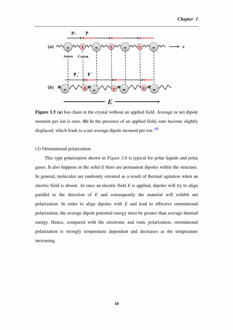
(2) Ionic polarization
Ionic polarization occurs in ionic crystals as shown in Figure 1.5. When an
applied field is absent, the solid has no net polarization because dipole’s moments of
equal magnitude are lined up head to head and tail to tail so that net dipole’s moment
is zero. However, in the presence of a field E along the x direction, negative ions are
pushed in the –x direction and positive ions in the +x direction about their equilibrium
positions. Consequently, the dipole’s moment p+ in the +x direction increases to p’+
while the dipole’s moment p- decreases to p’-. At this time, the net dipole moment
(average dipole moment) per ion pair is now p’+-p’- which depends on the electric
field E. Additionally, each ion also has a core of electro that becomes displaced in the
presence of an applied field with respect to the positive nuclei as we mentioned before.
Hence, this part of dipole’s moment caused by electrons also contributes to the
polarization of a solid with the ionic polarization, although its magnitude is much
smaller than ionic contribution in these solids.
Chapter 1
10
Figure 1.5 (a) Ion chain in the crystal without an applied field. Average or net dipole
moment per ion is zero. (b) In the presence of an applied field, ions become slightly
displaced, which leads to a net average dipole moment per ion. [1]
(3) Orientational polarization
This type polarization shown in Figure 1.6 is typical for polar liquids and polar
gases. It also happens in the solid if there are permanent dipoles within the structure.
In general, molecules are randomly oriented as a result of thermal agitation when an
electric field is absent. At once an electric field E is applied, dipoles will try to align
parallel to the direction of E and consequently the material will exhibit net
polarization. In order to align dipoles with E and lead to effective orientational
polarization, the average dipole potential energy must be greater than average thermal
energy. Hence, compared with the electronic and ionic polarization, orientational
polarization is strongly temperature dependent and decreases as the temperature
increasing.

Chapter 1
11
Figure 1.6 (a) A polar molecule possesses a permanent dipole moment p0. (b) In
absence of a field, thermal agitation of molecules results in zero net average dipole
moment per molecule. (c) A dipole placed in a field experiences a torque that tries a
rotate it to align p0 with the field E. (d) In the presence of an applied field, dipoles try
to rotate to align with the field against thermal agitation. There is now a net average
dipole moment per molecule along the field. [1]
In the presence of electronic, ionic and orientational polarization mechanisms,
the average induced dipole moment per molecule will be the sum of all contributions
in terms of the local field. [1, 2]
However, there is an essential polarization which is
unavoidable for materials especially for composites: interfacial polarization. It cannot
be simply added into the sum of the three polarization mechanisms since it occurs at
interfaces where the field is not well defined.
(4) Interfacial polarization
Interfacial polarization appears because positive charges accumulate at the
interface and remaining negative charges in the bulk together constitute dipoles
moments that appear in the polarization vector. It occurs whenever there is an
accumulation of charges at an interface between two regions especially for
heterogeneous dielectric materials as shown in Figure 1.7. For a material, however
perfect, it contains more or less defects, impurities and various mobile carries such as
electrons, holes or ionized host or impurity ions. Under the presence of an applied

Chapter 1
12
field, these positive ions migrate to the negative electrode and simply pile up at
interfaces which raise positive space charge near the electrode. This additional charge
on the interface appears as an increase in the dielectric permittivity.
Figure 1.7 (a) A crystal with equal number of mobile positive ions and fixed negative
ions. In the absence of a field, there is no net separation between all the positive
charges and all the negative charges. (b) In the presence of an applied field, the
mobile positive ions migrate toward the negative electrode and accumulate there.
There is now an overall separation between the negative charges and positive charges
in the dielectric. The dielectric therefore exhibits interfacial polarization. (c) Grain
boundaries and interfaces between different materials frequently give rise to
interfacial polarization. [1]
1.1.2 Frequency dependence
What we have already introduced is the static dielectric permittivity which is an
effect of polarization under direct current (DC) conditions. While the voltage across a
parallel plate capacitor is under a sinusoidal signal (alternating current (AC) field),
then the polarization of the medium leads to an AC dielectric permittivity that is really
different from the DC’s case. Commonly, there are two factors against the immediate
alignment of dipoles with the field. The first one is caused by thermal agitation which

Chapter 1
13
randomizes the dipole orientations. The other one is attributed to interactions with
neighbors in a viscous medium. This part will be particularly strong in the liquid or
polymer where dipoles cannot response instantaneously to the applied field’s change.
Hence the dielectric permittivity of an insulating material depends on the frequency
which can be described as a complex physical quantity:
where r’ is the real part and r” is the imaginary part. r’ represents the relative
permittivity that can be used in calculating the capacitance. The imaginary part r”
represents the energy lost in the dielectric medium as dipoles are oriented against
random collision by the field. When the energy storage and transformation occur at
the same rate, the energy will be transferred to heat most efficiently. The peak of r” is
called a relaxation peak which is at the frequency when dipole’s relaxations are the
right rate for maximum power dissipation. This process is known as dielectric
resonance.
We define the relative magnitude of r” with respect to r’ through a quantity,
tan , called the loss tangent (or loss factor), as
The power dissipates per unit volume in the polarization mechanism is the energy loss
per unit time to random molecular collisions as heat. Obviously, the dielectric loss is
associated by three factors: frequency, electric field and tan .

Chapter 1
14
Figure 1.8 The frequency dependence of the real and imaginary parts of the dielectric
permittivity in the presence of interfacial, orientational, ionic and electronic
polarization mechanisms [1]
We can represent general features of the frequency dependence of the real and
imaginary parts of the dielectric permittivity in Figure 1.8. Although the distinctive
peaks in r” and transition features in r’ appear in certain frequency range, in real
case these peaks and various features are broader with overlapping various peaks
which exhibits a broad peak. Furthermore, at low frequencies, interfacial
polarization’s peak is even broader because there are numbers of mechanisms (various
species of charge carriers) for the charges to accumulate at interfaces with individual
speeds. Orientational polarization, although typically happens from radio to
microwave frequencies, in some polymer materials, it involves a limited rotation of
dipolar side groups attached to the polymer chain which can occur at lower
frequencies depending on the temperature.
1.1.3 Dielectric materials
The property of a dielectric material can be described by several essential
parameters depending on various application fields: polarization-electric field P-E
relationship and breakdown field (dielectric strength, Eb) are for the high electric field
Chapter 1
15
while the dielectric permittivity and dielectric loss tan are used for the weak
electric field. [3-5]
If we view the weak electric field application more concretely, for
the application of integrated circuit insulation, a low dielectric permittivity is
preferred. On the contrary, for the energy conversion and storage systems’ application,
a high dielectric permittivity is highly desirable. [4]
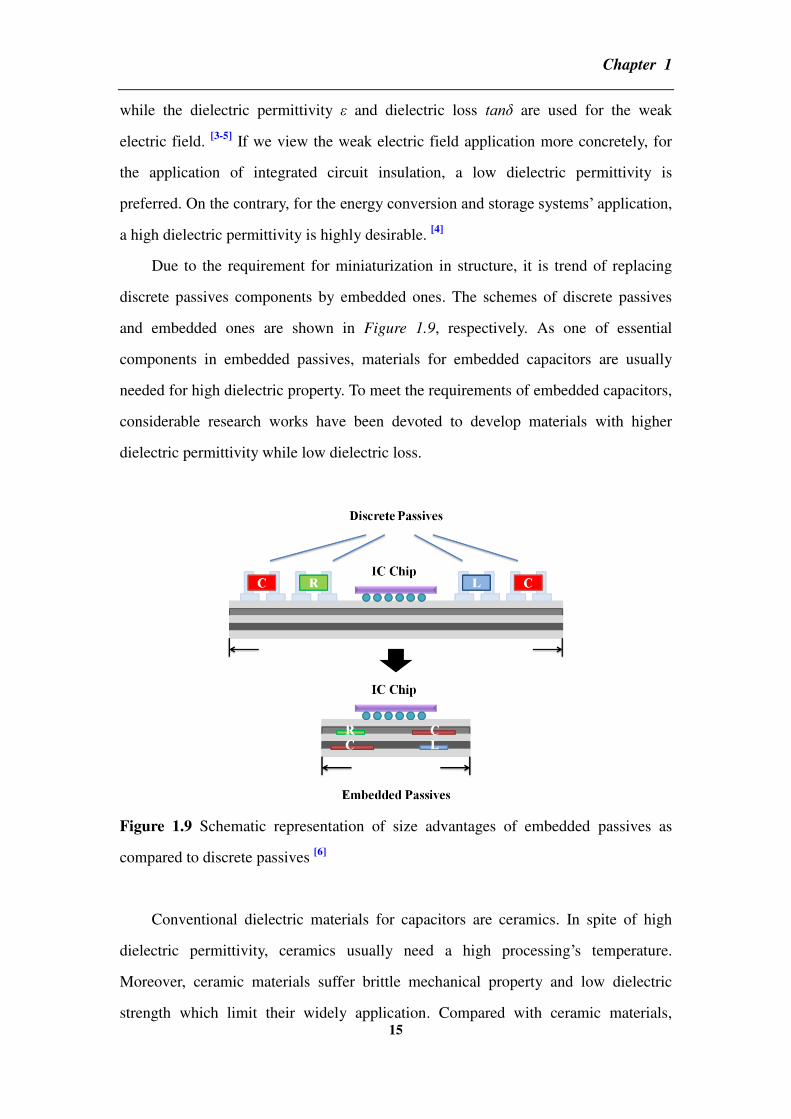
Due to the requirement for miniaturization in structure, it is trend of replacing
discrete passives components by embedded ones. The schemes of discrete passives
and embedded ones are shown in Figure 1.9, respectively. As one of essential
components in embedded passives, materials for embedded capacitors are usually
needed for high dielectric property. To meet the requirements of embedded capacitors,
considerable research works have been devoted to develop materials with higher
dielectric permittivity while low dielectric loss.
Figure 1.9 Schematic representation of size advantages of embedded passives as
compared to discrete passives [6]
Conventional dielectric materials for capacitors are ceramics. In spite of high
dielectric permittivity, ceramics usually need a high processing’s temperature.
Moreover, ceramic materials suffer brittle mechanical property and low dielectric
strength which limit their widely application. Compared with ceramic materials,

Chapter 1
16
advantages of common polymers are relatively high dielectric strength and
mechanical flexibility. We list main index of common dielectric polymer films for
recent capacitor’s applications in table 1. However, due to instinct low dielectric
permittivity, most polymers fail to meet the requirement for embedded capacitors
which need materials with the dielectric permittivity in the range from 25 to 170. [7]
Hence, the addition of inorganic fillers, especially nanoparticles, into polymer matrix
to fabricate dielectric composites represents one of the most promising approaches for
further improvement on dielectric property.
Table 1 Common polymer films for capacitors with their dielectric property [8]
Polymer film r Maximum
Temperature
(oC)
Breakdown
strength
(MW/m)
Energy
Density
(J/cm3)
Tan %
@1kHz
Polypropylene (PP) 2.2 105 640 1-1.2 <0.02
Polyester (PET) 3.3 125 570 1-1.5 <0.5
Polycarbonate (PC) 2.8 125 528 0.5-1 <0.15
Polyphenylene
sulfide (PPS)
3 200 550 1-1.5 <0.03
Polyvinylidene
fluoride (PVDF)
12 125 590 2.4 <1.8
According to the definition, nanoparticles are those particles with diameters
below to micron dimension (<0.1 m). A more stringent definition considers
nanoparticles as particles with properties depending on their sizes directly. In the
latter case, restricted nanoparticles are those with sizes below 20nm. [7]
Furthermore,
the smaller the particles are, the more obvious surface properties will be which will
strongly affect their interfacial properties, agglomeration and the physical property.

Chapter 1
17
1.2 Composites for high dielectric permittivity
Based on the nanoparticles used, the polymer matrix composite can be classified
into two types: one is the dielectric-dielectric composite where nanoparticles used are
dielectrics; while the other is the conductor-dielectric composite where nanoparticles
used are conductors. [4]
1.2.1 Simulations for dielectric-dielectric composites
Various formulas have been proposed to simulate the dielectric permittivity of
dielectric-dielectric composite by analytical models. There are two well-known
simplified models calculating the effective dielectric permittivity eff for a composite:
parallel and series models and they are shown in the Figure 1.10 (a) and (b),
respectively.
Figure 1.10 Schematic of structural patterns for parallel (a) and series (b) models. (c)
Schematic of effective dielectric permittivity of a composite versus the composition:
1-parallel connection; 2-series connection; 3-real composite (Lictenecker’s
logarithmic mixing law) [4]
The formula can be simply written as:
Chapter 1
18
where φ is the volume fraction of fillers, m and f are the dielectric permittivities of
matrix and fillers and n is either +1 for parallel case or -1 for series case. Compared
with the experimental data obtained in Figure 1.10 (c), we can find that eff for the
parallel model is always higher than that of series one while experimental one is
usually between the two. [9]
Besides series and parallel models, other models are provided as follows:
(1) Lichtenecker formula
As n approaching to 0, the equation can be equivalent to a logarithmic mixture
rule which is known as the Lichtenecker formula (1926): Despite lacking enough scientific evidences, it has shown remarkable applicability to
various heterogeneous media because it is a kind of compromise between the two
extreme limits of series and parallel mixtures. [1, 10]
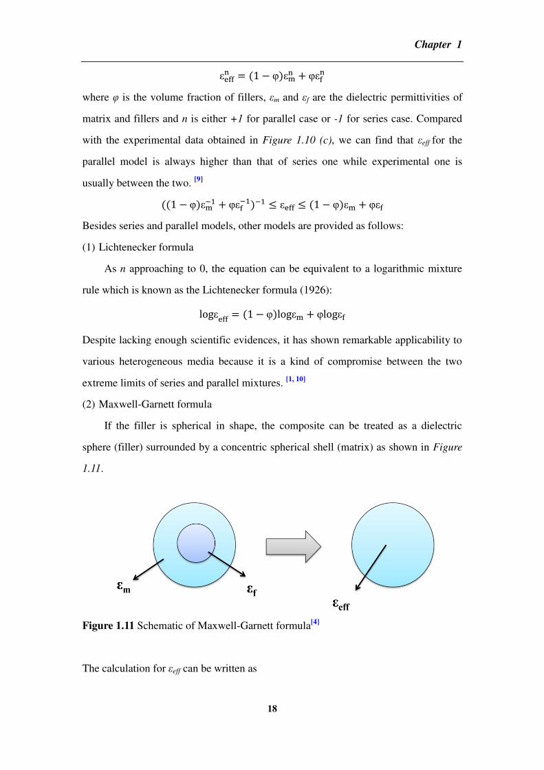
(2) Maxwell-Garnett formula
If the filler is spherical in shape, the composite can be treated as a dielectric
sphere (filler) surrounded by a concentric spherical shell (matrix) as shown in Figure
1.11.
Figure 1.11 Schematic of Maxwell-Garnett formula[4]
The calculation for eff can be written as

Chapter 1
19
This is Maxwell-Garnett (also named as Maxwell-Wagner) mixing rule effective for
calculating infinite dilution of dispersed phase (spherical particles are well separated
by distances greater than their characteristic size). It is also argued that this mixing
rule is an approximation of the Lichtenecker’s logarithmic law. [12]
However, not all fillers are spherical shapes. When dispersed particles are not
spherical in shape, it needs to be modified. A common way is to introduce a
depolarization factor, which is related to their deviation from sphericity. Thus,
Maxwell-Garnett is changed into a more general form:
where A is the parameter of depolarization. When A=1/3, it is back to fillers with
spherical shape. The value of A can be calculated or found in the reference. [12]
1.2.2 Simulations for conductor-dielectric composites
For conductor-dielectric composites, their properties are based on the percolation
theory. In order to account for physical properties of heterogeneous materials, the
percolation transition in properties is considered. This percolation transition lies in a
fact that particles of minor phase (i.e. fillers) come into contact with each other and a
continuous cluster extends throughout the system when the volume fraction of minor
phase approaches the critical value fc (percolation threshold). [13]
In the case of
dielectric property, as filler’s content approaches to fc, a dramatic change of
composites’ dielectric property will happen as indicated in Figure 1.12.

Chapter 1
20
Figure 1.12 Schematic of eff and volume fraction of fillers. The insets show the
geometric phase transition of fillers (denoted by dark spots) in composite’s
microstructure near percolation threshold fc. [4]
When fc is approached from below, eff diverges as follows:
for f < fc
where m is the dielectric permittivity of the insulator matrix and q is a critical
exponent which controls the variation of physical quantities near fc. It varies from 0.8
to 1 in light of different interactions between matrix and fillers. [3]
Moreover, q also
depends on the spatial dimension of composites. As pointed out by Efros and
Shklovski, [14]
this formula infers the maximum value of dielectric permittivity
achieved at fc.
The dielectric behavior near fc can be explained by micro-capacitor networks. [3,
13] Namely, each micro-capacitor is formed by neighboring conductive fillers and a
very thin layer of dielectric in between. With a significant increase in the intensity of
local electric field, each micro-capacitor contributes an abnormally large capacitance
when fillers are close to fc. This promotes the migration and accumulation of charge
carries at the interfaces between fillers and matrix. The charges generated either by
surface plasma resonance or by charge injection from the external electrodes are
accumulated at the interfaces due to different relaxation times between fillers and

Chapter 1
21
polymer matrix. This charges’ accumulation may cause the Coulomb blockade by the
insulating matrix until adjacent conductive fillers approach each other and the charges
are tunneling (when the distance between the two neighboring particles is within
tunneling range) or by Ohmic conduction (in the case of direct contact of neighboring
particles).[13]
This polarization caused by trapped or accumulated electric-charge
carriers at interface is called interfacial polarization, also known as the
Maxwell-Wagner effect. The interfacial polarization is responsible for the increment
of dielectric permittivity especially at low frequency as it needs time for responding.
If observed at high frequencies, the frequency response is the matrix dominant rather
than the interface.
1.2.3 Interface between fillers and matrix
The interface sets up between two otherwise uniform phases A and B. Each atom
or molecule in two-phase system equilibrates with its surrounding via short and
long-range forces. Thus, the range which mutual forces are different from the ‘bulk’ is
defined an interface AB as illustrated in Figure 1.13 (a). As long as across interface
AB, the intensity I of any property will change. Furthermore, the distances of
property’s change between A-B (t1) and B-A (t2) are usually different up to the
property of interest.

Chapter 1
22
Figure 1.13 (a) The interface between two phases A and B defined by the intensities
I1 and I2 of properties 1 and 2 as they vary over effective distances t1 and t2 between A
and B. t1 and t2 will be of nanometric dimension. (b) Scheme of particle A with AB
interface in the matrix B. (c) Particle size dependence of interface properties.[15]
Meanwhile, the interface also has another interesting phenomenon. Given a
situation that A is the particle of finite size and surrounded by a polymer B with AB
interface as shown in Figure 1.13 (b), interface’s effect will become increasingly
significant as the particle’s diameter reducing especially for nanoparticles. A
following formula can describe the relationship among volume fraction of interface,
thickness of shell and diameter of particle:
where f is the volume fraction of interface, d is the diameter of particle and t is the
thickness of interface, respectively. [3, 15]
According to this formula, the volume
fraction of interface increases as the ratio of interface’s thickness and particle’s
diameter increasing.
Additionally, the third important feature in nanometric system is also shown in

Chapter 1
23
Figure 1.13 (c): a typical property of bulk A will be lost gradually as the particle’s
diameter shrinks and more elements of the particle come to reside in interface state
which strengthens the influence of interface forces more than that of bulk forces. For
the dielectric property of polymer matrix composite, as the diameter of particles
reducing to the nanometric, the high dielectric property of nanoparticles usually acts
as electrical defect centers in polymer matrix. Such a defect center effectively distorts
the distribution of electric field and increases the local electrical field around the
particles in the matrix where is much higher than the average field. Thus, the places
with nanoparticles usually produce much leakage current and suffer low dielectric
strength. However, given that nanoparticles are coated by a layer to barrier electron
tunneling across the interface, the leakage current will be effectively controlled and
the dielectric strength will be improved. Therefore, an ideal composite is supposed to
comprise nanoparticles with grading dielectric permittivities from the center to the
border by the bridge of interfaces.[13]
1.2.4 Gouy-Chapman diffusion layer and multi-layer core model
The morphology and property of interfaces have been widely investigated in
many studies and generally they are affected by two parts. One is electrical interaction
and the other is the surface characteristics of nanoparticles. On the one hand, in the
case of electrical interaction, there is a model known as Gouy-Chapman diffusion
layer shown in Figure 1.14 (a) which can illustrate the interfacial region between
nanoparticles and polymer matrix. [15]
If the nanoparticle is charged, an equalization
of chemical potential will be established due to the ionization of surface groups and
the adsorption of ions from the polymer matrix. According to colloid chemistry, a
stern layer is usually formed attributed to the difference between inorganic
nanoparticles and polymer matrix where a portion of counter ions is absorbed around
nanoparticles by electrostatic Coulomb force and other forces. Two important
interactions will be evoked in this layer. One is associated with the polarization from
polymers involving dipole and molecular motion. The other is associated with a
diffuse electrical double layer composed by positive and negative ions if the polymer

Chapter 1
24
is solid electrolyte and contains mobile charges. According to Lewis et al’s view, [15]
the Debye length of the Gouy-Chapman diffusion layer can be calculated as several
tens to one hundred nanometers. This indicates that nanoparticles are possibly to
affect mutually and the electrically collaborative effect may be formed with the
closest neighbors. Hence, as nanoparticle’s volume fraction increasing, it can be
anticipated that this interfacial overlapping phenomenon causes some collaborative
effects which intensify interface’s influence on the dielectric property.
On the other hand, in the case of interfaces’ morphology and property, a
comprehensive model has been proposed by Tanaka et al. [16, 17]
This hypothetical
multi-layered core model for the interface is based on a spherical inorganic particle
embedded in a polymer matrix.
Figure 1.14 (a) The interface region of Gouy-Chapman formed in the positive
charged nanoparticles. (b) Multi-layer core model for interfaces between inorganic
nanoparticles and polymer matrix in a polymer nanocomposite. [3]
It consists of a
bonded layer, a bound layer and a loose layer. As the nanoparticle is positively
charged, a diffuse electrical double layer would form in the interfacial region and
overlap the three layers above.
As shown in Figure 1.14 (b), the multi-layer core structure involves a bonded

Chapter 1
25
layer, a bound layer and a loose layer gradually. The bonded layer is with the
thickness around 1nm where the main interaction is consisted with short-range force
such as ionic, covalent, hydrogen bonds, or van der waals force. Due to abundant
unsaturated bonds like hydrogen and organic groups on the surfaces, nanoparticles are
easy to be connected with polymer matrix. Thus, this layer is tightly bonded on both
inorganic and organic substances and its strength largely depends on the polarity of
particles and matrix. Usually the bigger the dielectric permittivity is, the stronger the
force will be. Hence, bonded layer has an essential influence on the interfacial
polarization.
The second layer is bound layer. It is consist of polymer chains which are bound
or interacted to the bonded layer. It is associated with the polymer chains involving
conformation, mobility, the degree of chain folding and stereographic structures. Its
thickness is usually from 2 to 9nm. Its morphology and strength are strongly
influenced by the interfacial interaction strength of the bonded layer. It is postulated
that tight binding such as ionic or covalent bonding will form a thick bound layer with
a highly ordered structure. Besides the bonded layer’s influence, the property of the
bound layer also depends on surface property of nanoparticles and cohesive energy
density of the polymer.
The third layer is loose layer which is a region loosely coupling to the bound
layer. In this layer, polymer chains’ conformation and mobility, and even free volume
or crystallinity are all different from polymer matrix. But compared with inner two
layers mentioned, the difference between the loose layer and polymer matrix is
smaller. The thickness of this layer is about several tens of nanometers and they are
randomly around the nanoparticle.
It is summarized that the binding strength in the bonded layer not only affects the
thickness of interfacial region but also the local morphology and crystalline structure
of the inner bound layer and even the loose layer. Therefore, the mutual effect of
nanoparticles and polymer matrix in the interfacial region, especially in the bonded
layer is crucial to the property of interface.

Chapter 1
26
1.3 Nanoparticles used for composites
1.3.1 Nanoparticles for dielectric-dielectric composites
The key factor for improving dielectric permittivity in dielectric-dielectric
composite is using nanoparticles with high dielectric permittivity. Researches in past
few years have succeeded in promoting composites’ dielectric performances by
incorporating ferroelectric ceramic nanoparticles such as TiO2, [18]
ZrO2, [19]
BaTiO3
(BT), [20-22]
CaCu3Ti4O12 [23]
and Pb(Zr,Ti)O3 [24]
. Taking BT as an example, BT is a
typical perovskite ceramic and its nanoparticles can be produced by micro-emulsion,
sol-gel, and hydrothermal and so on. The high dielectric permittivity of BT results
from its ferroelectric. This crystal is permanently polarized even in the absence of an
applied field and it already possesses a finite polarization vector due to the separation
of positive and negative charges. Moreover, BT’s dielectric permittivity shows a clear
size dependent which reduces dramatically from 5000 to hundreds as grain’s size
reducing from 1 m to 30nm due to crystalline phase’s transition from tetragonal to
cubic. But it does not mean that BT nanoparticles are inferior compared with
microparticles. Dang et al. have studied BT’s size dependency of dielectric
permittivity for both BT/PVDF and BT/PI nanocomposites at low frequency. [20-22, 25]
Although BT’s ferroelectric property loses, the dielectric permittivity of composites
with BT nanoparticles of smaller size is still much higher than that those of bigger
size due to the strong interfacial polarization. Meanwhile, besides size’s effect,
temperature also influences greatly on BT’s crystalline phase transition. A critical
temperature of BT’s crystalline phase transition from tetragonal to cubic phase,
known as the Curie temperature, is around 437K. Namely, BT exhibits neither
permanent polarization nor ferroelectric above 437K. On the contrary, it will come
back to tetragonal phase with spontaneously polarized statement below 473K. [26, 27]
The effect of size and temperature on BT’s crystalline phase’s transition is shown in
Figure 1.15.

Chapter 1
27
Figure 1.15 Size and temperature effects on two kinds crystal phases’ mutual
transition of BT particles
Lots of researches about BT reinforced polymer matrix composites have been
reported in recent years. Kim et al. have studied the effect of various BT volume
fractions on the dielectric permittivity and breakdown strength of poly(vinylidene
fluoride-co-hexafluoro propylene) composites. The dielectric permittivity of
composite achieves to γ5 when BT’s volume fraction is around 60%. Similar cases
have also been found in BT/epoxy composites. [28]
Kuo et al. have formed BT/epoxy
with the dielectric permittivity of 50 which is almost ten times larger than epoxy’s
original dielectric permittivity. [29]
Additionally, the effective surface modification of
BT particles has also been proved to be effective for improving the dielectric property
of composites. Zhou et al have reported that H2O2 modified BT can largely improve
the dielectric strength of PVDF matrix composite due to the formation of hydrogen
bond between electronphilic atoms on PVDF and –OH groups on the surface of BT.
[30] Huang and Jiang have successful prepared core-shell structured BT/poly(methyl
methacrylate) (PMMA) nanocomposite via in situ atom transfer radical
polymerization (ATRP) of methyl methacrylate (MMA). The core-shell structure
achieves its composite to extremely low dielectric loss. [31]
However, as mentioned before, dielectric properties of BT reinforced polymer
matrix composites are temperature dependent which limits their further applications.
[4] Moreover, in order to achieve higher dielectric permittivity, large amounts of BT

Chapter 1
28
(more than 50%) is usually needed for the composite which reduces the mechanical
flexibility of composites and makes them extremely brittle.[28]
Hence, more works and
studies in dielectric-dielectric composites are still needed for achieving high dielectric
property of composites.
1.3.2 Nanoparticles for conductor-dielectric composites
Compared with the dielectric-dielectric composite, the addition of conductive
nanoparticles has a stronger impact on composite’s dielectric property. By replacing
dielectric nanoparticles with conductive ones, percolative behavior will increase the
dielectric permittivity dramatically (several tens times higher than the polymer matrix)
in the vicinity of percolation threshold. Thus, it provides a potential alternative in
virtual of extremely high dielectric permittivity with much lower fillers incorporating,
as long as that they can also meet the requirement of the dielectric breakdown strength
and low loss tangent. [3]
Among various conductive fillers, carbon nanotube (CNT) doubtlessly has
attracted the most attention. CNT has a hollow structure with the walls formed by
one-atom-thick sheets of carbon called graphene which are rolled at specific and
discrete (“chiral”) angles. CNT generally is categorized as single-walled nanotubes
(SWNT) and multi-walled nanotubes (MWNT). [32]
SWNT has a single seamless
cylindrical wall with fullerene caps while MWNT has several graphite sheets which
are concentrically rolled up around each other. Due to the unique structure, CNT has
many advantages over other conductive fillers which can be included at least three
points as follows:
1. The superior intrinsic conductivity (105~10
8S/m) and excellent electric current
carrying capacity which is 1000 times higher than copper wire.
2. The high compatibility with the polymer matrix which does not deteriorate the
flexibility of polymer matrices.
3. A large and tunable aspect ratios which significantly reduces fc in its composite. [13,
33]

Chapter 1
29
1.4 Carbon nanotube and its polymer matrix composites
1.4.1 Synthesis of CNT by chemical vapor deposition
Chemical vapor deposition (CVD) is one of the most popular methods used to
produce CNTs. In this process, thermal decomposition of a hydrocarbon vapor is
conducted in the presence of metallic catalyst. Differently with high temperature
electric arc discharge technique, a medium temperature range can meet for the
synthesis which makes CVD popular for CNT’s synthesis. The temperature used for
CVD is usually less than 1000oC and hydrocarbon compounds are decomposed on the
substrate by inducing catalysts. The common procedures can be divided into the
following four steps and the experimental set-up CVD used for CNT growth in its
simplest form is shown in Figure 1.16. [34, 35]
1. Metallic nanoparticles are required to be well prepared on a substrate.
2. A substrate is placed in the furnace and a reduction treatment is carried out for
nanoparticles upon heating under carries gases of Ar, H2 or NH3.
3. The hydrocarbon gas or the liquid carbon resources selected are introduced into the
furnace.
4. CVD growth occurs at a suitable temperature by catalytic decomposition of the
hydrocarbon molecules on the metallic nanoparticles.
Figure 1.16 Schematic diagram of a CVD setup in its simplest form [34]

Chapter 1
30
The transition metals such as iron, cobalt and nickel are suitable catalysts for the
growth of CNT. Their advantages can be summarized as follows: (1) high solubility of
carbon at high temperatures, (2) high carbon diffusion rate and (3) a wide CVD’s
temperature window for more choices of carbon sources due to high melting point and
low equilibrium-vapor pressure of these metals. However, a bulk metal itself is not
able to catalyze the decomposition of hydrocarbon vapor to form carbon filaments.
Instead, it has to be dispersed into nanoparticle’s forms before CVD which is
indispensable for the CNT growth. According to the literatures there are several ways
to prepare catalyst nanoparticles such as sol-gel, [36, 37]
impregnation, [38, 39]
and
thermal deposition of solid organometallocenes (for example, ferrocene, cobaltocene
and nickelocene) [34, 40, 41]
.
Meanwhile, the growth of CNT greatly depends on the nature of substrate
despite the same catalyst used. In order to achieve an efficient CNT growth, substrates
should be chemically inert to metallic particles because metal-substrate reactions
(chemical bond formation) will block the catalyst activity. Furthermore, the surface
morphology and textural properties of the substrate will also greatly affect both yield
and quality of CNTs. According to relative researches, nanopores on the surface of
substrate will not only increase the yield of CNT but also provide the narrow
distribution of CNT’s diameter. Additionally, substrate’s thickness and shape are also
important for CNT’s growth. Commonly, the substrate for hybrids in our group
involves alumina (Al2O3), [42, 43]
graphene nano-sheet (GNP), [44, 45]
and silicon carbide
(SiC) [46, 47]
etc.
Hydrocarbons are easy to break at high temperature and this thermal
decomposition is called “pyrolysis”. The growth of CNT will be achieved only when
the pyrolysis occurs in the presence of catalyst nanoparticle. The mechanism of
CNT’s growth has been debatable for a long term and there are two general models
which are widely accepted: tip-growth model and base-growth model [48, 49]
,
respectively. The mechanism for practical growth cases usually depends on the
interaction between catalyst and substrate.
In the case of tip-growth model which is illustrated in Figure 1.17, when the

Chapter 1
31
catalyst-substrate interaction is weak (the metallic particle has an acute contact angle
with the substrate), the hydrocarbon will decompose on the top surface of the metallic
particles while the carbon will diffuse down through metallic particle’s bottom which
will push the whole metallic particle off the substrate. As long as the metallic
particle’s top is open for fresh hydrocarbon decomposition (a concentration gradient
exists in the metallic particle which results in the carbon diffusion), CNT continues to
grow longer and longer. Once the metallic particle is fully covered with excess carbon,
its catalyst activity stops and CNT’s growth is ceased.
(a)
(b)
Figure 1.17 (a) for tip-growth model and (b) for base-growth model [34]
In the case of base-growth model which is shown in Figure 1.17 (b), it is for the

Chapter 1
32
strong interaction between metallic particle and substrate where an obtuse contact
angle is formed between the two. The initial hydrocarbon decomposition and carbon
diffusion occur which is as similar as the case of tip-growth model, but differently,
CNT does not push the catalyst up from the substrate. The growth is compelled to
emerge out from the top of metallic particle (farthest from the substrate that has
minimum interaction with the substrate). At the beginning, carbon crystallizes out as a
hemispherical dome (the most favorable closed-carbon network on a spherical
nanoparticle) and then extends up in the form of seamless graphitic cylinder.
Subsequent the hydrocarbon deposition happens on the lower peripheral surface of
metallic particle and then as-dissolved carbon diffuses upwards. Thus CNT grows up
with the metallic particle rooted on its bases.
Additionally, besides the interaction between catalyst and substrate, CNT’s
growth is also governed by the size of catalyst particle. Generally speaking, smaller
particles (a few nanometers) favor SWNT’s formation while bigger particles (tens
nanometers) favor MWNT’s formation. Furthermore, higher temperature (900-1200oC)
yields SWNT which needs higher energy while lower temperature (600-900oC) favors
MWNT’s growth. [34]
1.4.2 Improving the dispersibility of carbon nanotubes in composites
Due to the substantial van de waals attraction, a homogeneous dispersion of CNT
is really hard to realize which usually causes composites’ properties far away from the
expectation. Thus, a good dispersion of CNT in the polymer matrix is essential for
achieving high property. Moreover, the interface between CNT and polymer should
also be well and carefully designed. Otherwise, interfacial slippage by poor adhesion
and less interaction may happen which influences the property negatively.
In order to improve the dispersibility of CNT, lots of efforts have been invested
which can be roughly divided into four strategies: (1) Surface modification of CNT;
(2) Functionalization of polymer matrix; (3) Adding compatibilizers and (4) Preparing
polymer composites via suitable process ways. We will introduce recent studies on the
surface modification of CNT and the processing ways for composites in this part.

Chapter 1
33
There are two main approaches for CNT’s functionalization: the covalent
functionalization and the non-covalent one. For the part of covalent functionalization,
it is achieved by either direct addition reactions to CNT’s sidewalls or modifications
of some surface bound functional groups such as carboxylic acid on the CNT. The
functionalized CNT can be much more stable in polar solvents. Furthermore, they can
reinforce the strength of interfacial bonding between CNT and polymer matrix by
functional groups. However, functionalization will damage sp2 conformation of
carbon atoms and influence electrical and mechanical properties negatively. Some
brief functionalized ways of CNT are shown in Figure 1.18.
Figure 1.18 Surface functionalization of CNT [50]
For the part of CNT’s non-covalent functionalization, it depends on van der
waals force, π-π, CH-π and electrostatic interactions. The advantage of non-covalent
functionalization is remaining the original structure of CNT as well as its excellent
electrical and mechanical properties. But the interaction between CNT and wrapping
molecules is much weaker than the covalent one. Generally, polymers with
conjugated and aromatic groups are widely used for polymer wrapping though π-π

Chapter 1
34
stacking and van der waals interactions (e.g. polyvinyl pyrrolidone (PVP) [51]
,
poly(phenylenevinylene), pyrene-poly(ethylene glycol)). However, the efficiency of
load transfer might decrease since forces between wrapping molecules and CNT
surface might be relative weak. [33]
For a semicrystalline polymer matrix, interfacial crystallization offers another
possible method to enhance CNT/polymer interfacial interaction. This interaction
between polymer and CNT is attributed to the crystallization at the interface where
CNT acts as nuclei that induces the polymer lamellae growing on its surfaces. These
as-formed crystalline structures are generally denoted as hybrid crystalline structure,
in contrast to conventional crystalline structures consisting of only polymer species.
Generally, there are two factors resulting in the interfacial crystallization: (1).
Electrostatic and van der waals’s interactions. (2) Mismatch in the coefficient of
thermal expansion (CTE) between CNT and polymer. [52]
For the former one, an
interfacial crystalline layer yielded on the graphite surface of CNT can enhance the
electrostatic matching between graphite crystallites and segments in a special
crystalline-chain conformation. For example, the interfacial crystalline layer of PVDF
coating on CNT is polymorph with the zigzag all-trans conformation.
For the difference in CTE, polymer crystalline polymorph’s CTE is smaller than
its amorphous counterpart, the mismatch in CTEs between CNT and polymer may be
increased with the appearance of crystalline interface layer. This may lead to higher
compressive thermal residual stress and a stronger mechanical interlocking effect,
compared with the case of amorphous polymer on the CNT surface. Hence, it
probably causes the property change after thermal treatment.
1.4.3 Processing for CNT/polymer matrix composites
All the processing routes normally aim at dispersing CNT in the polymers
matrices with a desired manner. Common traditional approaches for fabricating CNT
reinforced polymer composites include: solution casting, melt processing, in situ
polymerization, processing of composites based on thermosets, and electro
/coagulation spinning for composite fibers or yarn production. [5, 53, 54]
These methods

Chapter 1
35
have been well discussed and included in recent reviews. Figure 1.19 provides a
scheme of the general processing procedures for CNT/polymer matrices composites.
In the following paragraphs, we introduce some common routes as well as novel
approaches for CNT reinforced polymer composites.
Figure 1.19 Processing routes for CNT reinforced polymer matrix composites
(1) Solution casting
In this route, a dispersion of CNT and polymer matrix in a suitable solvent is
required in the first step. And then the composite film is formed by precipitating or
evaporating the solvent. The solvent can be either polar or non polar in light of the
polymer’s chemical property. An advantage of this route is the possibility to achieve
debundling and good dispersion of CNT in composite. Many polymers can be solved
in common solvents such as toluene, chloroform, tetrahydrofurance (THF),
dimethylacetamide (DMAc) or dimethylformamide (DMF). [55-57]
For example, DMF
is a good solvent for efficiently dissolving PVDF and disposing CNT. [21, 58]
Ultrasonic wave is the most efficient tool to release the aggregation of CNT because it
reinforces the interaction between CNT and polymer which may cause the crystalline
transformation of PVDF. [59]
Yu et al. have reported that both α and polymorphs of
PVDF are found in ultrasonicated MWNT/PVDF mixtures while only α polymorph of
PVDF is existed in the mixture without ultrasonicated processing.[60]
However, there
is an unavoidable requirement is that polymer matrix must be soluble in certain
solvent. This is one of limitations for its widely application in industry. Furthermore,

Chapter 1
36
it is less environmental friendly and economical due to the consuming of the solvents.
(2) Melt processing
Compared with the solution casting, melt processing is a more common and
simpler route from the perspective of commercial applications, particularly for
thermoplastic polymers which are stable under their process temperature, e.g.
polypropylene/CNT, [61]
high density PE/CNT, [62]
polycarbonate/CNT, [63]
PMMA/CNT, [64]
polyoxymethylene/CNT, [65]
polyamide 6 (PA6)/CNT, [66]
etc. Melt
processing usually mixes CNT with the molten polymer by shear of screws and
afterward shaping by compression molding, extrusion or injection molding.
Advantages of this route are its high speed, simplicity and easy integration into
standard industrial facilities. But the disadvantage is still on the dispersion of CNT in
polymer. A high increment of viscosity is observed even at low amount of CNT due to
a high interfacial surface energy between entanglement of CNT and polymer chains.
Consequently, the bubbles introduced during the process are extremely hard to
remove which is even worse in the case of CNT with long aspect ratio. These defects
in the composites usually lead to a poor quality. Thus, some additives are introduced
(e.g. processing acids and plasticizers) into system or much stronger mechanical
shearing has to be applied which may destroy the structure of CNT. [53, 54]
Another
disadvantage of the melt processing is the migration and orientation of CNT under
flow especially during injection molding procedure. [67, 68]
T. Villmow et al have
studied CNT reinforced PC composites by extrusion-injection route. The morphology
of the sample in different thickness has been carefully observed by transmission
electron microscopy. [69]
They have found that the more closes to the core part, the
more random of CNT’s dispersion will be in the composite.
(3) In-situ polymerization
CNT are disposed in the monomer followed by polymerization via this route. A
higher percentage of CNT may be facially dispersed by a strong mechanical stirring
during the reaction. It is suitable for preparing a composite whose polymer matrix
fails to be processed by neither the solution casting (insoluble ones) nor the melt
processing (thermally unstable polymers or those with low melt flow index). [23, 70-71]

Chapter 1
37
Cochet et al have reported the improved electrical properties of MWNT/polyaniline
(PANI) composite by in situ polymerization due to the site-selective interaction
between the quinoid ring of PANI and MWNT. [73]
Cho and co-workers have reported
a simple approach to synthesizing MWNT/polypyrrole composite with high
conductivity by in situ polymerization of pyrrole on CNT with the addition of ferric
chloride as an oxidant. [74]
(4) Layer-by-layer (LBL) technique
The LBL route involves fabricating a layered structural composite by alternate
dipping of a substrate into CNT/polyelectrolyte dispersions. [75-77]
Meanwhile, in order
to enhance the film’s structural integrity, the crosslink is usually introduced to
reinforce the adhesions of films. As a versatile and relatively low-costly route, it
provides multifunctional molecular assemblies of tailed structures so that various
properties of the composite will be achieved in order to meet different requirements of
materials with nanometer thickness. Moreover, large-scale and reproducible
production of membrane-based, highly integrated microsensors will also be achieved
due to the simple processing of LBL. [78]
(5) Buckypaper
Buckypaper is a thin porous assembly of CNT and in the last few years, its
electrical mechanical properties have attracted much attention. The common
preparation of buckypaper usually requires CNT being well-dispersed in a certain
solvent such as DMF or N-Methyl-2-pyrrolidone and then removing the solvent by
Buchner filtration. [79, 80]
Recently, a novel preparation without the dispersion and
filtration process has been formed by Ding and his co-workers. [81]
CNT arrays have
been used, rather than the mixture of CNT and solvent, for achieving the “domino
pushing effect” so that most of CNT are well aligned tightly in the buckypaper. Thus,
better properties have been achieved in thermal or electrical conductivity due to the
regularity in structure.
In summary, with these different processing techniques, numbers of polymers
can be processed to CNT reinforced composites no matter thermoplastic or thermoset,
and amorphous or semi-crystalline. An optimized process is the priori of good CNT’s

Chapter 1
38
dispersion in the polymers matrices. Meanwhile, a careful investigation on the state of
CNT’s aggregation and the orientation in the composite is also necessary and crucial
for the final property.
1.5 Property of polyvinylidene fluoride
PVDF is synthesized by addition polymerization of CH2=CF2 monomers. The
polymer chains are composed by an alternating CH2 and CF2 groups as shown in
Figure 1.20 (a). [82] Due to highly regular chain structure, PVDF is semi-crystalline
polymer with the typical crystallinity of 50%. Meanwhile, its glass transition
temperature (Tg) and melting point are around -40oC and 170
oC, respectively. As a
thermoplastic polymer, a reasonable melting viscosity lets PVDF have good
processing ability without adding stabilizers. [83, 84]
The pressure-volume-temperature
(PVT) curve of PVDF is also provided in Figure 1.20 (b), the volume expansion of
PVDF occurs at the melting point since crystalline part gradually changes into
amorphous part at this stage.
A high dielectric property makes PVDF distinguished from other polymers in the
application of dielectric materials. [86]
PVDF’s high dielectric property is attributed to
its piezoelectricity and the polarization. As a semi-crystalline polymer, PVDF has at
least five crystalline polymorphs. [87-90]
However, not all crystalline polymorphs have
high piezoelectric property because piezoelectricity depends on polar crystal structure.
Although piezoelectricity of PVDF is still low compared to piezoelectric ceramic
materials such as BT and lead zirconate titanate, easy processing makes PVDF
becomes very popular for piezoelectric materials. [91]

Chapter 1
39
(a)
(b)
Figure 1.20 Scheme of PVDF chains (a) [81]
and its PVT curves (b) [85]
1.5.1 Crystalline polymorphs of polyvinylidene fluoride
Concretely, five distinct crystalline polymorphs of PVDF are α, , , δ and ,
respectively which can be characterized by X-ray diffraction (XRD) and fourier
transform infrared spectrometer (FTIR). The most common crystalline polymorph is α
crystallized from melt or solution. [88, 92-94]
It consists of chains with
trans-gauche-trans-gauche’ (TGTG’) torsion conformations arranging in an
anti-parallel form. In TGTG’ conformation, dipoles are inclined relative to the normal
axis so that the average dipole moment for each monomer is largely reduced.
Meanwhile, the unit cell of α phase lattice has two chains in a TGTG’ conformation
and dipoles normal to the chain axis are anti-parallel, thus neutralizing each other.
Thus, this conformation results in non-polarity which causes limited piezoelectricity
and low dielectric property.
The second crystalline polymorph is whose polymer chains have an all-trans

Chapter 1
40
distribution (TTTT) in a distorted, planar zigzag conformation. This all-trans
conformation has all of its dipoles aligned to the chain axis. Its unit cell has two
all-trans chains packed with their dipoles pointing in the same direction. [88, 91, 93, 94]
Molecular dipoles in the polymorph are thus entirely aligned in one direction which
have spontaneous polarization and substantial piezoelectricity. The structures of α and
polymorphs are shown in Figure 1.21 (a), (b), respectively
(a)
(b)
Figure 1.21 The structural schemes of PVDF’s crystal phases: (a) for α and (b) for
phases, respectively [92]

Chapter 1
41
Table 2 provides the crystalline parameters of α and polymorphs.
Table 2 Parameters for two crystalline polymorphs of PVDF [95]
Crystalline polymorph a (Å) b (Å) c (Å)
α 4.96 9.64 4.62
8.58 4.91 2.56
polymorph has chains with T3GT3G’ torsion distributions and its conformation
of chains are similar with α polymorph. δ and polymorphs are the polar and
anti-polar of α and polymorphs, respectively. For δ polymorph, chains are arranged
in a parallel fashion which is also able to yield a polar structure, but due to smaller
dipole moment of each chain, δ polymorph is less polar than phase. [88, 91]
1.5.2 Inducing β crystalline polymorph
Due to its high dielectric property, researches of inducing polymorph in PVDF
and its composites have been very attractive. However, it is not easy to obtain the
entirely polymorph PVDF by common processing ways. In all-trans PVDF,
neighboring fluorine (F) atoms has to overlap because the diameter of F atom (0.27nm)
is slightly larger than the space provided by all-trans carbon chain (0.256nm). This
process needs more energy to achieve, but in order to diminish the overlapping CF2
groups are tilted to the right and left to their original conformation. This deflection of
CF2 groups converts from TTTT ( polymorph) conformation into TGTG’ (α
polymorph) or TTTG’ ( polymorph). [91]
Hence, it is much easier to obtain α
polymorph than polymorph in normal circumstances. Nevertheless, there are still
some methods to induce polymorph which can be divided into four points: (1)
drawing-poling of PVDF films and fibers [93, 96-99]
(2) optimization processing
conditions [96, 100, 101]
(3) copolymerization with trifluoroethylene [102-107]
and (4)
addition of CNT. [60, 108-110]
(1) Drawing-poling
Drawing generally orientates molecular chains (even for some crystallites)

Chapter 1
42
towards the drawing direction which will promote the transition from α to
polymorph especially during the crystallization process. It can be explained from the
structural difference between the two polymorphs. As the parameters shown in the
table 2, the unit cell of polymorph is longer in the chain direction while shorter in
other two directions than α polymorph. Thus, drawing in the chain direction may
provide the possibility for the transition from α to polymorph. However, drawing’s
temperature is a key factor. Sajkiewicz et al. have showed that PVDF film or fiber
must be drawn at temperature below the range from 130 to 140oC so that the
transition from α to polymorph could be induced. Afterwards, the maximum of
transition may happen from 70 to 87oC.
[111] If the temperature is too low, the viscosity
of PVDF is too high for chains’ mobility under the stress. Reversely, if the
temperature is too high, the low viscosity may decrease the strength of crystalline
which causes a deformation under stress. [91]
However, obtained all-trans conformation by merely drawing still cannot achieve
high dielectric property since simply drawing just yields the orientation of crystallites.
Dipoles are still in an irregular alignment in these crystalline grains and thus
permanent dipoles’ polarization is absent. The experimental works by Nilsson et al.
[112] and molecular dynamics (MD) simulation by Satyanarayana and Bolton
[113] have
proved that merely drawing cannot achieve the piezoelectricity. A strong external
electric field (at least 80MV/m) is necessary for the alignment of dipoles and this
process is called poling. Poling is divided into two kinds: contact poling and
non-contact poling. Both of them are shown in Figure 1.22. In the case of contact
poling, electrodes are required for contacting PVDF film or fiber directly. While in the
case of non-contact poling, poling can be realized by a corona discharge which
provides a higher electric field before PVDF’s electrical breakdown occurs.
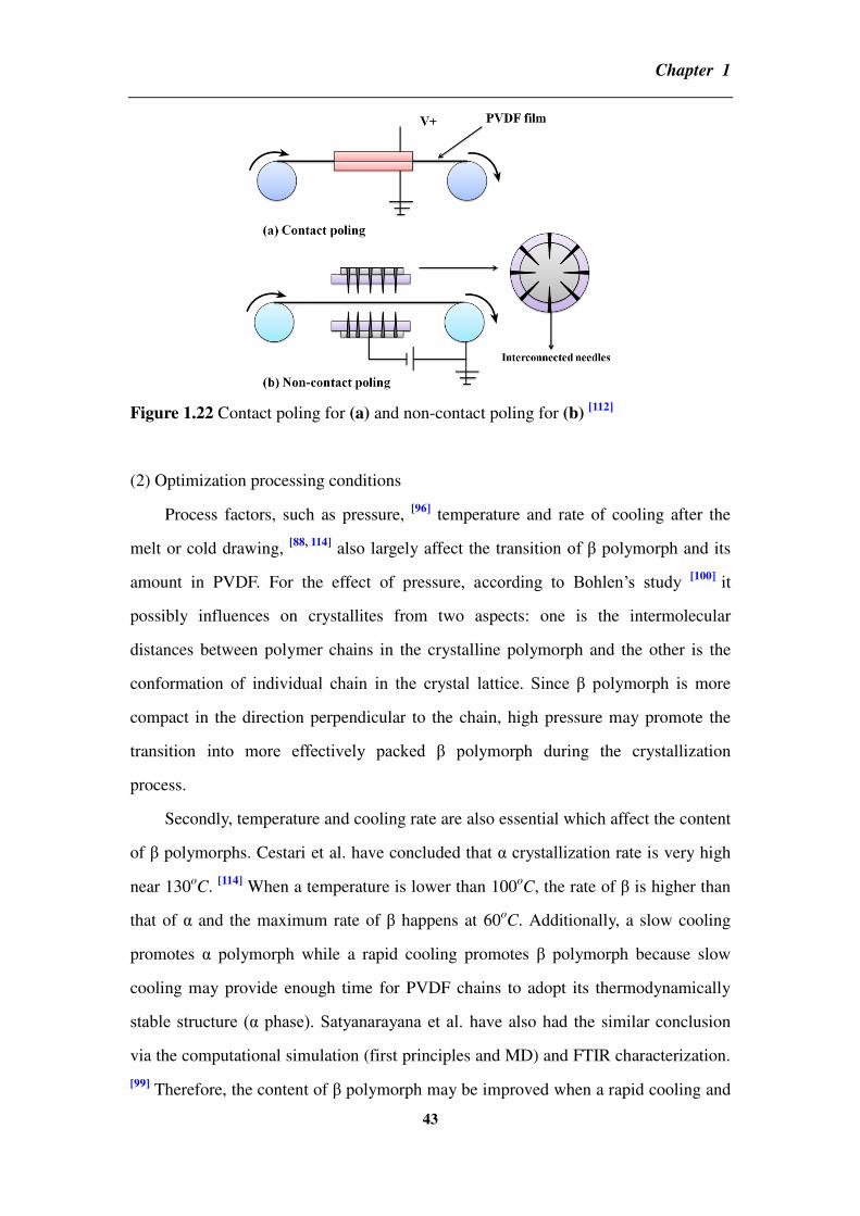
Chapter 1
43
Figure 1.22 Contact poling for (a) and non-contact poling for (b) [112]
(2) Optimization processing conditions
Process factors, such as pressure, [96]
temperature and rate of cooling after the
melt or cold drawing, [88, 114]
also largely affect the transition of polymorph and its
amount in PVDF. For the effect of pressure, according to Bohlen’s study [100]
it
possibly influences on crystallites from two aspects: one is the intermolecular
distances between polymer chains in the crystalline polymorph and the other is the
conformation of individual chain in the crystal lattice. Since polymorph is more
compact in the direction perpendicular to the chain, high pressure may promote the
transition into more effectively packed polymorph during the crystallization
process.
Secondly, temperature and cooling rate are also essential which affect the content
of polymorphs. Cestari et al. have concluded that α crystallization rate is very high
near 130oC.
[114] When a temperature is lower than 100
oC, the rate of is higher than
that of α and the maximum rate of happens at 60oC. Additionally, a slow cooling
promotes α polymorph while a rapid cooling promotes polymorph because slow
cooling may provide enough time for PVDF chains to adopt its thermodynamically
stable structure (α phase). Satyanarayana et al. have also had the similar conclusion
via the computational simulation (first principles and MD) and FTIR characterization.
[99] Therefore, the content of polymorph may be improved when a rapid cooling and

Chapter 1
44
high pressure are conducted under crystallization.
(3) Copolymerization with trifluoroethylene
The addition of trifluoroethylene (TrFE) units to PVDF chains induces a
structure which is similar as polymorph and yields high piezoelectric effect.
According to MD simulations by Holman et al. [106]
, in the case of pure PVDF the
gauche character increases if cooling from a high temperature. While in the case of
PVDF-TrFE the all-trans character increases. It infers that activation’s barrier of
crystallization into is hard for pure PVDF to overcome but easy for PVDF-TrFE.
Thus PVDF-TrFE may obtain all-trans conformation without drawing or poling.
Density functional theory (DFT) and MD calculation carried out by Su et al. also
gives similar results that inclusion of TrFE units (50%) has stabilized some all-trans
structures. [94]
(4) Addition of CNT
The addition of CNT will also help to induce polymorph. In the case of CNT
reinforced PVDF composites processed by blending, the interactions between CNT
and PVDF will promote the amount of polymorph. Guo et al. have proposed that the
fluorine atoms in PVDF chains are attracted to the delocalized π electrons of CNT
which makes PVDF chains wrapped around CNT during the melting. [115]
A strong π-π
interaction at interface of CNT-PVDF may hinder the transition from polymorph to
α phase during crystallization.
The discussions about inducing polymorph in PVDF by adding CNT can be
divided into two scenarios from the view of thermodynamics: [91]
1. The interactions between PVDF and CNT may yield in the interfaces where Gibbs
free energy might be lower if PVDF is in polymorph. In other word, polymorph
may be thermodynamically stable polymorph based on the presence of CNT.
2. α polymorph is still thermodynamically, but polymorph may appear in the
melting or solution stable in the presence of CNT. The interaction of PVDF-CNT
might increase barrier of transition from to α polymorph.
Thus, the difference between these two scenarios is that in the first one,
polymorph is thermodynamically stable while in the second one, polymorph is

Chapter 1
45
kinetically stable. If the second scenario is valid, the transition from α to must occur
in the melting or solution because the energy barrier of transition from α to may be
overcome if PVDF chains obtain enough energy. In fact, many experimential results
have provided the evidence that long term sonication for CNT/PVDF composite
promotes polymorph. Yu et al. have reported that both α and polymorphs are
found in sonicated MWNT/PVDF mixture while only α polymorph exists in
unsonication mixtures. [60]
Levi et al. have reported that the function of CNT (no
matter SWNT or MWNT) may be viewed as the nuclei for rapid crystallization which
yields much more polymorph.[116]
Meanwhile, increasing amount of MWNT will
also enhance the amount of polymorph. Moreover, the increment of polymorph
depends on CNT’s exfoliating and dispersing in the composite. [91]
Other studies have reported that for MWNT/PVDF composite, if MWNT is
modified by ester functionalization [117]
or grafted by PVP [118]
, more amounts of
polymorph may be induced compared with MWNT without surface modification.
About the interactions between CNT and PVDF, there is a disagreement between
the experimental results and computational modeling. [91]
For experimental results,
authors propose that the epitaxial matching between polymorph of PVDF and
hexagonal carbon network of CNT’s wall is really important. [115, 117]
The strong
interactions result from the fluorine atoms of all-trans PVDF chain and π electrons of
CNT. Namely, F-π interaction is the key factor for increment of polymorph. In
contrast, computational modeling results by Yu et al. conclude that it is the positively
charged hydrogen atoms of polymorph that interact more strongly with π electrons
of CNT (H-π interaction) instead of fluorine atoms. [60]
It is hard to judge whether the
interaction is F-π or H-π, but the interaction happening on the interface of CNT and
PVDF will largely affect dielectric property of the composite which is important for
practical application of CNT reinforced PVDF composites.
1.6 Conclusion
In this chapter, we have reviewed basic knowledge of dielectric theory and recent
Chapter 1
46
researches on polymer matrix composites with high dielectric performance. Compared
with properties of ceramics and commercial polymers, nanocomposites are widely
accepted to be one of the most promising materials for embedded capacitors. Large
numbers of researches have shown that nanofiller’s dispersibility, interfacial
interaction between nanofillers and matrix, suitable processing for nanocomposites
and applied polymer matrix’s nature are the four key factors for achieving high
dielectric property and these four factors always affect mutually with each other.
Firstly, the dispersion of nanofillers will largely determine composite’s property.
A good dispersion not only reinforces the adhesion between nanofillers and matrix,
but also lowers fc and consequently enhances the dielectric strength of composite.
Secondly, interactions between nanofillers and matrix are various including the
chemical bonding, van der waals force, π-π interaction and interfacial crystallization,
etc. They will largely influence nanofillers’ dispersion in polymer matrix which needs
to be well studied. Thirdly, processing’s method is the base of nanocomposite with
high dielectric property. Defects in nanocomposites and the inhomogeneous
dispersion of nanofillers need to be avoided as much as possible. Fourthly, the nature
of polymer matrix influences dielectric property directly. The original dielectric
property, polarity, crystallinity and processing property of polymer matrix are
doubtlessly crucial for its nanocomposite’s dielectric property.
Hence, in the following parts, we will attempt to prepare nanofillers with novel
structures in order to achieve high dielectric property. Meanwhile, the dispersion of
nanofillers and the effect of interfaces will also be well analyzed via designing and
comparing properties of samples with same two-phase nanofillers but different
structures. Additionally, besides experimental works, calculating works will also be
conducted to understand further about fc and conductive network’s formation. In this
thesis, we aim at achieving composites with high dielectric property by optimizing
nanofiller’s dispersion and strengthening their interfacial interaction with polymer
matrix.

Chapter 2
47
Chapter 2 Synthesis of hybrids with different structures and
polyvinylidene fluoride matrix composites
___________________________________________________________
Introduction
In this chapter, we introduce works for experiments and methods for
characterizations. The detail information of BT and CNT hybrids with different
structures are provided in this chapter. One is BT particles as cores and CNT growing
outside as shells by CVD. The other is BT particles coating on the CNT surface by
hydrothermal reaction. Meanwhile, these hybrids’ properties including morphology,
crystalline phases and component’s content are all characterized and discussed in the
related parts. Additionally, processing way for PVDF matrix composites is also
mentioned in this chapter.

Chapter 2
48
2.1 Materials for the experiments
All the information of materials used for experiments is listed in table 2.1
including their names, molecular formula, physical states, purity and providers.
Table 2.1 Materials for the experiments
Materials Molecular
formula
Physical
states
Purity Notes
Iron (III) nitrate
nonahydrate
Fe(NO3)3•9H2O s* 98% Sigma Aldrich
Barium titanate BaTiO3 s, (<2 m) 99.9% Sigma Aldrich
Barium hydroxide
octahydrate
Ba(OH)2•8H2O s 99.9% Sigma Aldrich
Titanium (IV) butoxide TiC4H9O4 l* 97.0% Sigma Aldrich
Ethanol C2H5OH l 96%
Dimethylformamide HCON(CH3)2 l 99.8% Sigma Aldrich
Argon Ar g* Carrier gas
Hydrogen H2 g Carrier gas
Acetylene C2H2 g Carbon source
* s, l and g stand for solid, liquid and gas, respectively
PVDF powder is provided from Arkema Group and main physical properties are
listed in table 2.2.
Table 2.2 The specification of Arkema Group Kynar 720 PVDF
Physical property Index Physical property Index
Density (g/cm3) 1.78 Volume resistivity (ohm.cm) 1.5×10
14
Melting point (oC) 171 Thermal conductivity (W/(mK)) 0.19
Thermal decomposition (oC) 375
Heat capacity (J/(goC)) 1.17-1.51

Chapter 2
49
2.2 Characterization’s methods
The as-prepared samples are characterized by following techniques:
Morphology characterization for hybrids and fractures surfaces of composites is
conducted by scanning electron microscope (SEM) (LEO Gemini 530). Composites
are broken by impregnated in the liquid nitrogen for five minutes. The
energy-dispersive X-ray spectroscopy (EDS) and scanning transmission electron
microscope (STEM) are conducted by Titan3 G2.
Thermal gravimetric analysis (TGA) is conducted by thermo gravimetric
analysis (NETZSCH STA 449F3).
Differential scanning calorimetry (DSC) is conducted by thermo gravimetric
analysis (NETZSCH STA 449F3). The temperature range is from 25 to 200oC with
the rate of 10oC/min. The DSC program includes two heating–cooling cycles. Melting
and crystallization temperatures are determined from the second heating–cooling
cycle.
X-ray diffraction (XRD) of hybrids is measured by the D2 Phaser X-ray Powder
Diffraction, Bruker.
Dielectric properties of composites are characterized as a function of frequency
by the impedance analyzer (Solatron 1260). Before measurement, silver layer is
applied on the sample’s two sides for increasing contacting. The measurement of
dielectric property after thermal treatment is as follows: The sample is annealed at a
set temperature for 30min and then cooled down to room temperature. The dielectric
property is measured after the sample is cooled down to room temperature.
The synchrotron X-ray measurements are conducted under synchrotron sources
at Advanced Photon Source at Argonne national laboratory (USA) on 5-ID-D
beam-line. Medium angle detector is used with range of 0.12⩽q⩽0.70Å−1. The
sample is put in the Al2O3 crucible and well packed by the press tablet machine. The
measurement procedure is corresponding to thermal treatment. Namely, the sample is

Chapter 2
50
firstly heated from 30 to 150oC with the rate of 10
oC/min. And then the temperature
maintains at 150oC for 30min and afterward it is cooled down to 30
oC with the same
rate. One thing should be mentioned is that although in the X-ray measurement, the
temperature is set at 150oC for the measurement but actually it is at 143
oC. This
difference between set annealing temperature and actually tested temperature for
thermal treatment is also existed in the dielectric measurement. The heater is set at
150oC but the measured temperature is at 138
oC by the thermocouple. The exposure
time of beam is 0.1s which depends on sample’s properties. The time between each
frame is 6s. Generally the smaller value is used, the more scanning information will
be detected but more time is needed too. In our case, we use normal mode for the
measurement. The number of frames is largely dependent on the procedure of DSC
thermal process and it needs a simple calculation.
2.3 Synthesis of carbon nanotube-BaTiO3 hybrids
2.3.1 Method of synthesis
Carbon nanotube-BaTiO3 hybrids (H-CNT-BT) are produced via the floating
catalytic CVD process. Acetylene (C2H2) is used as carbon source and iron (III)
nitrate nonahydrate (Fe(NO3)3•9H2O) as the catalyst precursor. The preparation
procedure can be divided into two steps: (1) preparation of catalyst nanoparticles on
BT by the impregnation way and (2) CVD reaction. The procedure is described as
follows:
Firstly, for impregnation: BT with Fe(NO3)3•9H2O are dissolved in ethanol by
magnetic stirring for 1h at room temperature and heated at 70oC to evaporate the
solvent. Afterward, the mixture is calcined at 450°C in a tube furnace for 1h in order
to oxidize Fe(NO3)3 to Fe2O3.
Secondly, for CVD, the prepared BT-Fe2O3 mixture is homogeneously dispersed
on the surface of a quartz plate (3×50cm2). Afterwards the quartz with powders is put
into the middle of a furnace for the reaction (60cm in length). The temperature of
CVD is between 600 to 800oC under argon and hydrogen atmosphere. Herein, gas

Chapter 2
51
flows are accurately controlled by electronic mass flow meters (Bronkhorst, France).
After heating to the set temperature and becoming stably, acetylene as the carbon
source is introduced into the reactor. After 30min, the furnace is cooled down
naturally under the argon atmosphere.
In the process of synthesizing H-CNT-BT, there are two main aspects involved:
one is the impregnation of BT particles in Fe(NO3)3•9H2O solvent and the other is the
growth of CNT on BT particles. Both of them are greatly affected by experimental
conditions (e.g., chemical agencies’ ratio, gas flow rate and reaction temperatures, etc.)
as well as the nature of substrate particles (e.g., size, shape and surface chemical
properties, etc.). Hence, in this part, we focus on three experimental parameters: the
weight ratio between BT and Fe(NO3)3•9H2O, the reaction temperature, and the flow
rate of H2, respectively, in order to study their effects on CNT’s morphology and
quantity in H-CNT-BT hybrids.
2.3.2 Effect of the weight ratio between BaTiO3 and Fe(NO3)3•9H2O
(a)
(b)
Figure 2.1 SEM images of the pure BaTiO3 (BT) observed under different
magnifications. (a) is the 10k and (b) is 50k, respectively.
Before impregnated in Fe(NO3)3•9H2O solvent, pure BT particles are
characterized by SEM in order to have a comparison in morphology with ones after
impregnated Fe2O3. As shown in Figure 2.1, pure BT particles are not homogeneous

Chapter 2
52
in diameter and their size range is from 100nm to 1 m. Shapes of particles are not
regular and most of them are mixed with sphere and cubic. Meanwhile, observing the
enlarged image in Figure 2.1 (b), we find that some particles’ surfaces are smooth and
others are covered by fragments of particles with the size around 100nm. Most
particles are agglomerated with each other which increase the average size of clusters
and consequently may provide more surface area for CNT’s growth.
(a)
(b)
Figure 2.2 SEM images of BT-Fe2O3 mixture with weight ratio of 85:15. (a) is 20k
and (b) is 100k, respectively.
After the impregnation, in Figure 2.2 we find that there are some small and
round nanoparticles (Fe2O3) with the size from 15 to 30nm dispersed on the surface of
BT. These Fe2O3 particles trend to stick on BT particles with larger size and coarser
surface. A possible reason may be attributed to the impregnation of BT/Fe2O3. Due to
the poor solubility of BT in ethanol, a few BT particles can be impregnated by
Fe(NO3)3 solution while others sink in the bottom and have less incubation.
Furthermore, during ethanol’s evaporation process, BT particles are also unavoidably
precipitated in the bottom owning to its high density that intensifies the
inhomogeneous impregnation of the whole BT particles in Fe(NO3)3•9H2O solvent.
Additionally, during calcinations, the agglomeration of Fe2O3 may be caused by
thermal movement agitated at high temperature. Although the inhomogeneous
dispersion of catalyst on BT particles, impregnation way is still applied for catalyst’s

Chapter 2
53
preparation because of its easy process and efficiency for the afterwards CVD
reaction.
After describing BT and BT/Fe2O3’s morphologies, we start the discussion on
CNT’s growth by CVD. The weight ratio between BT and Fe(NO3)3 is investigated
and we choose four weight ratios (80:20, 85:15, 90:10 and 95:5, respectively) for the
study. CVD conditions for the four samples are the same: before CVD’s reaction, the
mixture of BT/Fe2O3 is under H2 reduction for 10min in advance for reducing Fe2O3
into Fe nanoparticles. And then CVD reaction is conducted at 750oC for 30min with a
mixture of gas flows: Ar=1l/min, H2=0.1l/min and C2H2=0.05l/min, respectively.
Comparing with SEM images shown in Figure 2.3, we find that the weight ratio
of BT and Fe(NO3)3•9H2O has largely influences the growth of CNT. Firstly,
comparing with the morphology of CNT in Figure 2.3 (a) and (b), we find that the
diameter of CNT in (a) is less homogeneous than that in (b). In Figure 2.3 (b), the
diameter of CNT is around 25nm and the length is longer than 2 m. Whereas, in
Figure 2.3 (a) marked by white circles, we can find that some CNTs grow very gross
(the diameter is larger than 40nm) while others grow slim (the diameter is less than
15nm). A possible reason is the over dose of Fe2O3 incubated on BT particles may
intensify the agglomerations of iron nanoparticles in the reduction process. According
to the reference [34]
, a general experience shows that the catalyst particles size dictates
the diameter of CNT. Although, the growth of CNTs in H-CNT-BT by CVD runs in a
not well-defined mechanism, it is mostly assumed to involve three procedures: (1) the
adsorption and decomposition of the acetylene on active points of the iron catalyst, (2)
the formation of iron-carbon intermediate species, and (3) finally the growth of CNTs.
This mechanism infers the importance of metallic particle’s size for the morphology
of obtained CNT. Given that the catalyst impregnated on BT surface is over dosed, the
size of catalyst is prone to be inhomogeneous. This difference in the size of catalytic
nanoparticles probably leads to various diameters in CNT. Moreover, a negative result
which even influences the quality of CNT is that when the size of metallic particles
increase, the formation of nonselective forms of carbon (carbon nanofibers,
amorphous carbon, etc.) are favored rather than CNT. This can also be found and

Chapter 2
54
marked in white cycles of Figure 2.3 (a). Hence, if the weight ratio of Fe(NO3)3 and
BT is over dosed and the agglomeration of catalyst nanoparticles on BT is obvious
which affects negatively not only on CNT’s morphology but also on its quality and
property.
(a)
(b)
(c)

Chapter 2
55
(d)
Figure 2.3 SEM images of H-CNT-BT
with different weight ratios of BT and
Fe(NO3)3•9H2O: (a): 80:20, (b): 85:15,
(c): 90:10 and (d): 95:5, respectively. The
left ones are with small magnitude and
the right ones are with large magnitude.
On the contrary, if the ratio of Fe(NO3)3 and BT is not enough, there will be less
CNT grown on the BT as shown in Figure 2.3 (c). Moreover, if the ratio is smaller, as
shown in (d), nearly no CNT will grow on BT due to lacking catalyst. It is known that
the key factor for CNT’s growth is to achieve acetylene decomposition on the iron
catalyst surface rather than aerial pyrolysis. The smaller amount of catalyst has on BT,
the less possibility of contact between hydrocarbon and catalyst will be so that CNT
growth will be limited. This infers that a very small amount of catalyst in hybrids is
not able to induce the growth of CNT. Similar result has also concluded by
Perez-Cabero et.al’s studies on the synthesis of MWNT by CVD. [119]
These SEM
images in Figure 2.3 show us that the property of CNT strongly depends on the iron
content. If the ratio of BT and Fe(NO3)3 is too small, less or even no CNT will grow
on BT. Conversely, if the ratio is excessive, the amorphous carbon will be formed
around CNT which is harmful for the quality of CNT and moreover the morphology is
also negatively influenced.
Therefore, the ratio of 85:15 is chosen for the rest of experiments due to the
relatively homogeneous morphology of CNT. However, there is still a problem shown
in Figure 2.3 (b): not all BT particles have been covered by CNT. Besides the
inhomogeneous disposal of iron catalyst on BT’s surfaces mentioned before, another
possible reason may be caused by the procedure of H2 reduction before CVD.
Because there is no chemical bonding between BT and Fe2O3, the interaction between
Fe2O3 and BT particles is weak. According to the reference, [34]
it is known that the

Chapter 2
56
physical state of catalyst may change during CVD process: in the case of acetylene
decomposition on nickel catalyst supported on silica and graphite substrates at 600oC,
metallic particles change the shape and move up with a trail of carbon deposit. In our
case, the temperature used for H-CVD-BT is 750oC. It is highly possible that the
movement and agglomeration of the iron nanoparticles may occur in the process of
pre-reduction before CVD, and finally result in the partial growth of CNTs on BT. In
order to reduce this negative effect, a shorter induced reaction time may be better for
the homogeneous growth on BT. Thus, the step of pre-reduction of H2 will be deleted
in the following experiments and CVD will start directly as soon as the temperature is
stabilized to the set value.
2.3.3 Effect of the reaction temperature
The CVD conditions for this part are as follows: the mixture of BT/Fe2O3 (85:15)
is used for the reaction without H2 reduction in advanced. Different temperatures (600,
650,700, 750 and 800oC) are set and the reaction time is 30min. The gas flows are:
Ar=1l/min, H2=0.1l/min and C2H2=0.05l/min. The morphologies of H-CNT-BT at five
reaction temperatures are shown in Figure 2.4 from (a) to (e), respectively.

Chapter 2
57
(a)
(b)
(c)

Chapter 2
58
(d)
(e)
Figure 2.4 SEM images of H-CNT-BT at different temperatures: (a) 600oC, (b)
650oC, (c) 700
oC, (d) 750oC and (e) 800
oC, respectively. The right images are the
enlarged ones for the left.
Firstly, comparing with five series of SEM images in Figure 2.4, we find that the
general shape of CNT obtained is a bit straight without too many curves. It is because
the acetylene is used for hydrocarbon source. In general, the molecular structure of
precursor has the detrimental effect on the morphology of CNT’s growth. Linear
hydrocarbons usually decompose thermally into atomic carbon or
linear/dimmers/trimers of carbon which promote to the straight and hollow CNT’s
production. [120,121]
Acetylene is a kind of linear hydrocarbons and thus CNTs in
H-CNT-BT is nearly straight without many curves. Secondly, we can find that as the
temperature increasing, the amount of CNTs grown on BT reduces and moreover, the
diameter becomes inhomogeneous. From SEM images, we find that morphologies of

Chapter 2
59
CNT in H-CNT-BT are more uniform at lower temperatures (600 and 650oC). When
the temperature increases to 750 or 800oC, more amorphous carbon appears in the
system which is marked in Figure 2.4 (d) and (e) by white cycles. Two reasons may
cause this negative effect from higher temperature. On the one hand, CNT nucleation
and growth are usually dominated by two factors. One is the diffusion of catalyst
nanoparticles on BT’s surfaces and the other is carbon pyrolytic reactions in the gas
phase. Considering Oswald ripening mechanism [122]
, a high temperature usually
causes small particles coalescing into big ones and thus reduced iron nanoparticles are
easy to move and agglomerate which affects the homogeneous morphology of the
CNT on BT particles.
On the other hand, the carbon resource used for H-CNT-BT is acetylene, a kind
of hydrocarbons whose pyrolysis temperature is ranging from 450 to 600oC. Except
for methane and other light paraffins, most hydrocarbons (CnHm) usually have a
positive value of Gibbs function of formation ΔfGo (variation of the Gibbs free energy
of the system that occurs during the formation reaction from graphite and hydrogen)
at all temperatures under standard state conditions. This is a criterion of how far the
standard-state is from equilibrium according to the following reaction:
The relationship between Gibbs function of reaction at any moment on time (ΔrG)
and the standard-state Gibbs function of reaction (ΔrGo) is described by the following
equation:
where R is the ideal gas constant and Q is the reaction quotient at that moment in time.
At the equilibrium, ΔrG=0 and Q=K, where K is the equilibrium constant. Partial
pressures of H2 and of CnHm, PH2 and PCnHm (in bars), verify K=PH2m/2/ PCnHm and
RTlnK=-ΔrGo=ΔfG
o(CnHm). K and ΔfGo
CnHm both are determined by the reaction
temperature. [122]
Thus, in the case of acetylene used in H-CNT-BT system,
ΔfGoC2H2=225.31-0.054T (kJ/mol) and K=PH2/PC2H2=exp(27098/T-6.5) are reducing

Chapter 2
60
when the temperature increases from 600 to 800oC. The calculation results for five
temperatures are available in table 2.3 as follows.
Table 2.3 Gibbs function of formation and equilibrium constant for the decomposition
reaction of acetylene
T (oC) 600 650 700 750 800
ΔfGo
C2H2 (kJ/mol) 178.2 175.5 172.8 170.1 167.4
K 4.55×10¹⁰
8.46×10⁹ 1.87×10
9 4.8×10
9 1.4×10
8
From the calculation in table 2.3, we can find that the decomposition of
acetylene is thermodynamically and controlled by kinetics. The equilibrium constant
of reaction, K, is much higher at lower reaction temperature which demonstrates that
lower reaction temperature (from 600 to 700oC) promotes the CVD reaction to the
equilibrium state. Furthermore, if reaction’s temperature is high, the movement of gas
molecules are intensified which may cause the amorphous carbon appearing on BT
surface so that affects the quality of CNTs. Hence, a higher temperature (over 700oC)
is not favor to CNT’s growth in H-CNT-BT system. In addition, if comparing with
these enlarged SEM images in the right columns of Figure 2.4 from (a) to (e), we
observe that some small catalyst nanoparticles are not only remained on BT surfaces
but also in the inner of CNTs or on the top of them. This phenomenon may suggest
that CNT in H-CNT-BT grows via base-growth coexisting with tip-growth model.
In Figure 2.5, the pink region of mass loss from 500 to 600oC is CNT’s thermal
decomposition temperature range. We find the amount of CNT in H-CNT-BT also
depends on the reaction temperature. When the reaction temperature increases from
600 to 650oC, the amount of CNTs will increase from 7.88% to 9.36%. Meanwhile,
the maximum appears at 650oC. Afterward, as the reaction temperature further
increases, CNT’s content decreases gradually. This is also observed in the SEM
images of Figure 2.4. Therefore, the amount of CNT measured by TGA also supports
that 650oC is the suitable temperature for CNTs growth on BT particles.

Chapter 2
61
Figure 2.5 TGA for H-CNT-BT synthesized at different temperatures
2.3.4 Effect of hydrogen flow rate
The CVD conditions for this part are as follows: the mixture of BT/Fe2O3 (85:15)
is used for CVD reaction without H2 reduction in advanced. The reaction is conducted
at 650oC for 30min under the gas flows: Ar=1l/min and C2H2=0.05l/min, respectively.
We choose three flow values of H2: 0.05, 0.1 and 0.2l/min, respectively, for
experiments.
By calculating the mass loss values from 500 to 600oC in the pink region of
Figure 2.6, we find that when H2=0.1l/min, the amount of CNTs will reach the
maximum. Usually, there are two different influences brought by H2 during CVD
reaction: the positive one for CNT’s growth is to reduce Fe2O3 into Fe nanoparticles
effectively which is able to catalyze CNT growth. While the negative one is to slow
down dehydrogenation’s rate of acetylene and impede the formation of sp2-like
carbon structures. [123]
These two points affect mutually and an optimized value is
needed by balancing both of them. Thus, we will also investigate the effect of
hydrogen flow rate on CNT’s morphology in H-CNT-BT.

Chapter 2
62
Figure 2.6 TGA for H-CNT-BT synthesized with different H2 flow rates
Compared with SEM images of different H2 flow rates shown in Figure 2.7 from
(a) to (c), we find that increasing H2 flow rate affects not only the amount but also the
diameter of CNT. Meanwhile as H2 rate increasing, the distribution of CNT’s diameter
is also les homogeneous. It is still attributed to the agglomeration of Fe nanoparticles
since more Fe2O3 are reduced under more H2, the possibility of inhomogeneous
distribution of iron catalysts on BT particles also increases which affects negatively
on CNTs’ morphology. That less amount of CNTs on BT particles shown in Figure 2.7
(c) proves again the negative role of hydrogen in the dehydrogenization of acetylene
on catalyst particles. Thus H2 flow ratio in the carrier gases plays an essential role on
CNTs’ growth in H-CNT-BT. In our system, the H2 flow rate of 0.1l/min will be the
appropriate one according to the result of TGA and SEM images of obtained CNT.

Chapter 2
63
(a)
(b)
(c)
Figure 2.7 SEM images of H-CNT-BT synthesized with different H2 flow rates: (a):
0.05l/min, (b): 0.1l/min and (c): 0.2l/min, respectively. The right images are the
enlarged ones for the left.
Therefore, for the summary of experimental data, we conclude that conditions
for the synthesis of H-CNT-BT in following experiments are: the weight fraction of
BT and Fe(NO3)3•9H2O is 85:15. The reaction temperature is 650oC and the H2 flow

Chapter 2
64
rate is 0.1l/min.
2.4 Synthesis of BaTiO3-carbon nanotube hybrids
2.4.1 Method of synthesis
BaTiO3-carbon nanotube hybrids (H-BT-CNT) with BT coating CNT are
synthesized by two steps. The first step is coating titanium dioxide (TiO2) on the
surface of modified CNT. The second step is crystallizing BT by means of the
hydrothermal reaction between TiO2 (coated on the surface of CNT in the first step)
and Ba(OH)2•8H2O. The whole experimental procedures can be divided into seven
steps:
(1) CNT is modified by concentrated nitric acid (65%) at 110oC for 2h with water
refluxing. Afterward, the modified CNT is washed by pure water and dried in oven.
(2) Surface modified CNTs (0.05g), certain content of ammonia solution (25%) and
absolute ethanol are mixed in a single flask by ultrasonic dispersion in ice bath for
30min.
(3) The solution of tetrabutyl titanate (TBOT) and ethanol is droplet into the single
flask with fiercely magnetic stirring.
(4) After the hydrolysis reaction, the product is heated at 70°C for removing solvent.
(5) Ba(OH)2•8H2O and obtained mixture (precursor of CNT-TiO2) with certain ratio
are magnetically stirred in a hydrothermal reactor for 1h.
(6) Hydrothermal reaction is conducted in the oven at the set temperature.
(7) After the reactor cooled down, the product is washed by pure water and ethanol
for three times and finally drying in the oven at 100oC.

Chapter 2
65
2.4.2 Coating TiO2 on the modified carbon nanotubes
Figure 2.8 The chemical reactions for the hydrolysis of coating TiO2 on CNT
Coating TiO2 on modified CNT is the first step for synthesis. The main reaction
in this step is TBOT’s hydrolysis which is illustrated in Figure 2.8. The process is a
dynamic equilibrium of condensation and dissolution which is greatly influenced by
the reaction duration and content of ammonia solution. [124-126]
A study of TiO2
conversion on CNT will help us to find a suitable chemical reaction condition for
hydrolysis. As illustrated in the chemical reaction of TBOT’s hydrolysis in Figure 2.8,
the addition of ammonia solution catalyses the TiO2 precursor coating on the surface
of CNT. Since the modified CNT and the product of TBOT hydrolysis are both with
negative zeta potentials, they need positive zeta potential ions to bridge them. NH4+ in
ammonia solution enables to provide the positive zeta potential and associate the
modified CNT with the production of TBOT’s hydrolysis. However, TBOT is really
sensitive to water, even to water vapor in the air. The ammonia solution is a kind of an
aquarium solution (25%) which affects TBOT’s hydrolysis reaction negatively. Hence,
the content of ammonia solution is a key factor for the conversation. By the

Chapter 2
66
investigation for three contents of ammonia solution by TG analysis, we find that
when the content is 0.2ml, the whole reaction is not stable with the time. When the
content is 0.4ml, the conversation of TiO2 becomes less. Thus, combining with the
reaction’s stability and TiO2’s conversation, 0.3ml is a suitable content for the coating.
The measurement of TGA is shown in Figure 2.9.
Figure 2.9 Influence of different NH3H2O contents on TiO2 conversion measured by
TGA
Meanwhile, we investigate the effect of reaction duration on the morphology of
TiO2 coating on CNT. The results of STEM and EDS are shown in Figure 2.10.

Chapter 2
67
(a)
(b)
(c)
(d)

Chapter 2
68
(e)
Figure 2.10 Influence of different reaction durations with NH3H20 (0.3ml) on
morphology. The STEM images (left) and EDS for Ti (right) are shown in (a) for
15min, (b) for 30min, (c) for 2h and (d) for 5h, respectively. (e) is the TiO2
conversion at different reaction duration tested by TGA.
From Figure 2.10, we find that at the beginning of the hydrolysis, the precursors
of TiO2 start to accumulate on surfaces of modified CNTs. The agglomeration and
inhomogeneous disposal of TiO2 are obvious in the STEM of 15min. As the reaction
duration prolonging, in the STEM of 30min and 2h, the agglomeration becomes less
than before due to fiercely magnetic stirring. Especially for 2h, we can see TiO2
almost coats on the whole surface of CNT. However, when the duration reaches 5h,
the content of TiO2 precursor decreases which can not only be seen on the
morphology but also in the TGA of Figure 2.10 (e). It results from the equilibrium
between condensation and dissolution of TBOT’s hydrolysis which we mentioned
before.[127]
Therefore, according to the results of characterization for TiO2 content and
morphology, a chosen condition of coating TiO2 on surfaces of modified CNTs are
0.3ml ammonia solution and the reaction duration of 2h.

Chapter 2
69
2.4.3 Crystallization of BaTiO3 by hydrothermal reaction
The crystallization process of solid phases under hydrothermal conditions are
usually conducted at autogenously pressure, achieved via particular saturated vapor
pressure of the solution at specified temperature and the composition of hydrothermal
solution. In this case, temperature, duration and pressure for hydrothermal reaction are
three important factors which influence the crystallization process. Hence, for
preparation of H-BT-CNT, we will also focus on these three factors and try to find a
suitable experimental condition.
At first, we use two temperatures, 180 and 200oC, respectively as reaction
temperatures and XRD is used for the analysis of BT’s crystallization which is
illustrated in Figure 2.11. It can be found that higher temperature helps to form better
crystallization since crystallization of BT is endothermic. Relative references indicate
that the activation energy for BT crystallization under hydrothermal condition varies
in the range from 21 to 105kJ/mol for the chemical reaction that proceeds on the
liquid stage. Temperature’s range from 120 to 250oC is widely used for the
preparation. [128-132]
Generally, higher temperature provides enough energy to
stimulate the reaction. However, considering safety, temperatures over 200oC will not
be tested in the experiments. Comparing the data with BT’s standard pattern, we find
that there are some little peaks which do not belong to BT but BaCO3. BaCO3 comes
from some CO2 dissolved in the water which also crystallizes with Ba(OH)2. Luckily,
the amount of BaCO3 is tiny. Meanwhile, in the inset figure, curves for both
temperatures have only one peak in the range from 40 to 50 degree, it means that the
crystal phase of BT we obtained in this condition is cubic rather than tetragonal which
has two peaks in this range. Hence, according to the XRD pattern, 200oC will be used
for the followed experiments.

Chapter 2
70
Figure 2.11 XRD of two temperatures for H-BT-CNT
Secondly, we will discuss the effect of reaction pressure. XRD results of three
reaction pressures are shown in Figure 2.12. Hydrothermal reaction happens at 200oC
that is higher than water’s boiling point under ambient condition (100oC). Thus,
water’s volume in the reactors determines the pressure of reaction. It is easy to
understand that when the volume of water is high, the large pressure will be achieved.
Comparing three volumes of water in the XRD pattern shown in Figure 2.11, we find
that in this system reaction pressure does not influence much on the crystallization
and BT’s crystal phase. The intensities of peaks are similar for three curves and all of
them just have one peak in the inset graph. However, the volume of water is still
important because more CO2 will be brought in the system which influences
negatively on BT’s purity. Hence, 80% water content will be used for the following
experiments.

Chapter 2
71
Figure 2.12 XRD for three water contents in hydrothermal reactor
Figure 2.13 XRD of three reacting durations
Thirdly, reaction duration is also studied and we choose 2h, 5h and 10h for
comparison. As XRD patterns illustrated in Figure 2.13, we find that reaction duration
does not affect crystallization of BT much. As reaction duration prolonging,
intensities of peaks in three curves do not change a lot. This means the process of
BT’s crystallization does not largely depend on reaction duration. Therefore, we will
take BT’s morphology at different reaction duration into consideration.

Chapter 2
72
Before the discussion, it is necessary to study the chemical process of
hydrothermal reaction. The crystallization via hydrothermal reaction obeys to
dissolving-precipitation mechanism and it is mainly controlled by dissolving rate of
reactant TiO2. The presence of OH- irons of Ba-OH bond is responsible for TiO2’s
hydrolysis which acts as catalysts to accelerate the crystallization of BT via
precipitation. [133]
Figure 2.14 Schematic sketch of the dissolution/precipitation mechanism that
conduces to the hydrothermal crystallization of BT coating on CNT
The whole crystallization process is illustrated in Figure 2.14. Firstly the solution
is supersaturated due to dissolution of precursors. BT spontaneously starts to
precipitate in this stage which yields an abundant numbers of nuclei for the
crystallization. Thus, the dissolution of TiO2 controls BT nucleation and growth in the
early stage. The process of nucleation can be divided into homogeneous one and
heterogeneous one. For the homogeneous nucleation shown in the upper part of
scheme, Ti-O bonds of anhydrous TiO2 precursor must be broken via hydrolytic
attacking to hydroxyl-titanium complexes (Ti(OH)x4-x
). Afterward, they are able to
dissolute and react with barium ions or complexes (Ba2+
or BaOH+) in the solution to
precipitate BT. For the heterogeneous nucleation as shown in the beneath part of
scheme, it often happens in the intermediate or final stage of reaction and largely

Chapter 2
73
depends on the dissociation of remaining reactants. Differently with the homogeneous
nucleation, in heterogeneous nucleation, TiO2 particles act as precipitation sites of BT
nuclei during their dissolving process. The aggregation and coarsening of BT usually
happens in hydrothermal reaction due to Ostwald re-crystallization mechanism. Thus,
both homogeneous and heterogeneous nucleations show that the reaction duration is
responsible for BT’s morphology. This process can be studied by STEM and EDS.
Results of different reaction durations are shown in Figure 2.15 (a), (b), (c)
respectively.
As illustrated in Figure 2.15 (a), it is found that in the first 2h, BT particles have
already formed and started to accumulate on CNT’s surfaces. As reaction duration
increasing, the accumulation of BT particles keeps increasing shown in Figure 2.15
(b). Meanwhile, intensities of Ba and Ti’s peaks of EDS in the right are sharper and
higher compared with those for 2h. Furthermore, from STEM images of Figure 2.15
(b), we find that BT particles not only accumulate on CNT’s surface, but also
agglomerate individually which means coarsening of BT particles has already started
in the this stage. When reaction duration reaches 10h as the image shown in Figure
2.15 (c), we observe agglomeration of BT particles is much more obvious. Thus, in
order to have homogeneous BT’s coating on CNT, coarsening process should be
avoided as much as possible and 5h will be chosen for the experimental condition.

Chapter 2
74
(a)
(b)
(c)
Figure 2.15 STEM and EDS for H-BT-CNT with different reaction times. (a) for 2h,
(b) for 5h and (c) for 10h, respectively
2.5 Fabrication of polyvinylidene fluoride matrix composites
Composites are all fabricated by the combination of solution casting and
extrusion-injection processing. Firstly, pre-calculated amount of fillers is disposed
into DMF solvent by 30min’s ultrasonic dispersion. And then PVDF powder is added

Chapter 2
75
into the mixture and stirring magnetically for 2h at 70oC. The mixed fillers/PVDF
solution is coated on a glass substrate by thermally treating at 70oC for 2h in order to
evaporate DMF. Afterwards, for further processing, the film of filler/PVDF is put into
a co-rotating, conical, two-screw micro-extruder/compounder (Micro 5cc Twin Screw
Compounder, DSM) and blends at 230oC for 1h with the speed of 60rpm in Ar
protection atmosphere. Slabs with the thickness of 1.45mm are fabricated via
extrusion-injection (Micro 5cc Injection Molder, DSM, at 1.3MPa for 1min). The
temperatures of injection nozzle and mould holder are set at 240oC and 60
oC,
respectively. The scheme of extrusion-injection process is shown in Figure 2.16.
Figure 2.16 Scheme of the process for the H-CNT-BT/PVDF nanocomposite by
extrusion-injection way
2.6 Partial conclusion
This chapter contains experimental and characterization works for the thesis.
Firstly, H-CNT-BT has been produced with in situ grafting CNTs on the surface of BT
by CVD. It is found that CNT’s weight fraction and morphology are strongly

Chapter 2
76
influenced by experimental conditions. According to the study, the weight ratio
between BT particles and Fe(NO3)3•9H2O are dominant to the growth of CNTs on BT
particles and the ratio of 85:15 is the effective for synthesis. Then CVD reaction
temperature also plays an important role on the morphology of H-CNT-BT. Over high
temperature may impede CNT’s growth due to thermal decomposition’s property of
acetylene. By comparing with morphologies of H-CNT-BT synthesized at different
temperatures, we find 650oC is a suitable temperature for CVD reaction in
H-CNT-BT’s system. Additionally, hydrogen flow rate in carrier gas is also studied
for further improvement of CNT’s quantity and we find that hydrogen flow rate of
0.1l/min is favorite for CNT’s growth in this system.
Secondly, H-BT-CNT is prepared by two steps. In the case of coating TiO2 on
CNT by TBOT’s hydrolysis, ammonia solution content and reaction duration affect
TiO2’s conversion and morphology. A proper ammonia solution increases the
conversion of TiO2. Reasonable reaction duration is the key factor for controlling
coating morphology in this step. We find that ammonia solution content of 0.3ml and
reaction duration of 2h are favorable for TiO2 coating. In the case of BT hydrothermal
reaction, we find temperature is the key factor for BT’s crystallization. Meanwhile,
reaction duration is also important for final morphology of BT coating on CNT’s
surface. By the analysis of obtained experimental data, 200oC and 5h are suitable for
the hydrothermal reaction’s condition. Additionally, obtained BT particles are cubic
phase in H-BT-CNT system.
The processing of PVDF matrix composites and relative characterizations are
also provided in this chapter. About dielectric property of composites, we will discuss
in the next two chapters.

Chapter 3
77
Chapter 3 Dielectric property of carbon nanotube-BaTiO3
hybrids/polyvinylidene fluoride
___________________________________________________________
Introduction
In this chapter, we study performances of H-CNT-BT/PVDF composites with
different volume fractions including morphology, thermal, dielectric and
crystallization property. Meanwhile, a thermal treatment is conducted for comparing
the change of dielectric behaviors. A significant increment in dielectric permittivity is
observed after thermal treatment. Moreover, we find that the increment of dielectric
permittivity after thermal treatment depends on filler’s volume fraction and thermal
treatment’s parameters including annealing temperature, annealing duration,
multi-cycle annealing and cooling rate. In order to study thermal treatment’s effect on
the dielectric property and understand comprehensively for the interfacial interaction
between CNT in H-CNT-BT and PVDF, in-situ synchrotron X-ray is applied to detect
the re-crystallization behavior of PVDF including crystalline polymorphs’ transition
and thickness’s change of long period.

Chapter 3
78
3.1 Dielectric property of composites before thermal treatment
3.1.1 Morphology analysis
(a) (b)
(c) (d)
Figure 3.1 (a) SEM image of the fracture surface of H-CNT-BT/PVDF-10% (vol%)
composite, (b) is an enlarging part of white circle shown in (a). (c) and (d) are
morphologies of H-CNT-BT before incorporated into PVDF
The SEM images of H-BT-CNT/PVDF-10%’s fracture surface (10% means the
volume fraction of H-CNT-BT) is presented in Figure 3.1(a) and (b) is an enlarge one.
We find that original structures of H-CNT-BT are partly destroyed compared with the
images shown in Figure 3.1 (c) and (d), respectively, but fortunately, there are still

Chapter 3
79
some remained structures. Meanwhile, CNT and BT are dispersed in a relative
homogeneous mode. This good dispersion may be attributed to H-CNT-BT’s structure
which arrays CNT in a special way before incorporated into PVDF rather than in an
initial entangled state. The scheme in Figure 3.2 helps us to understand this double
dispersion of CNT in PVDF matrix.
Figure 3.2 Scheme of double dispersion of H-CNT-BT in PVDF
Although original H-CNT-BT hybrid’s structure is partly destroyed due to
blending, the linkage between BT and CNT is not totally absent. Observing in Figure
3.1 (b), we find that BTs and CNTs do not depart from each other by their individual
agglomerations. Instead, they stay with each other in a compatible state. This
compatible dispersal in PVDF provides more possibilities for potential collaborative
effects between H-CNT-BT and PVDF. Furthermore, the addition of H-CNT-BT does
not destroy PVDF matrix because no obvious voids and defects are observed in
Figure 3.1 (a) and (b). If comparing CNT’s diameter in Figure 3.1 (b), with Figure
3.1 (c) and (d), it is easy to find that CNT’s diameter of composite in Figure 3.1 (b)
marked by white arrow is a bit bigger than that of H-CNT-BT in Figure 3.1 (c) and
(d). This indicates that blending way is able to create a PVDF interfacial layer
wrapping around CNT. This polymer adhesion on CNT’s surface provides the support
for existence of micro-capacitor. The formation of micro-capacitor in the composite
may induce a strong interfacial polarization under the applied field and consequently

Chapter 3
80
greatly influences the dielectric property. This part we will discuss further in the
following study.
3.1.2 Thermal analysis
Figure 3.3 DSC for pure PVDF and H-CNT-BT/PVDF-9%
In order to study thermal properties of PVDF and H-CNT-BT/PVDF composite,
DSC is conducted for them and results are shown in Figure 3.3. Firstly during the
heating stage, melting points of PVDF and H-CNT-BT/PVDF-9% are 170.2oC and
170.7oC, respectively. During the cooling stage, crystallization’s temperatures of
PVDF and H-CNT-BT/PVDF-9% are 143oC and 145
oC, respectively. It can be found
that crystallization’s temperature for H-CNT-BT/PVDF-9% is a bit higher than pure
PVDF. It is caused by the addition of CNT that acts as nuclei for the rapid
crystallization and promotes PVDF’s crystallization. According to the reference, [116]
it
is generally believed that CNT in semi-crystalline polymers leads to a heterogeneous
nucleation which is typically much faster than pure polymers. This effect on polymer
crystallization will increase crystallization’s temperature and nucleation’s density
while decrease crystallization’s time. Therefore, crystallization’s temperature of
H-CNT-BT/PVDF-9% is a bit higher than pure PVDF due to the presence of CNT.

Chapter 3
81
3.1.3 Dielectric property of composites with different volume fractions
Before analyzing dielectric properties of H-CNT-BT/PVDF composites, we
provide concrete concentrations of each component including weight fractions and
volume fractions for H-CNT-BT, CNT and BT, respectively in composites. They are
shown in table 3.1. Herein, densities for BT, CNTs and PVDF used in the calculation
are 6.02, 2.00 and 1.79g/cm3, respectively.
Table 3.1 Concentrations of each component for H-BT-CNT/PVDF composite
H-CNT-BT (wt%) fH-CNT-BT (vol%) fBT (vol%) fCNT (vol%) 2.69 1 0.724 0.276
5.29 2 1.45 0.551
7.81 3 2.17 0.827
10.2 4 2.90 1.10
12.6 5 3.62 1.38
14.9 6 4.35 1.65
17.1 7 5.07 1.93
19.2 8 5.80 2.20
21.3 9 6.52 2.48
21.8 9.25 6.70 2.55
22.3 9.5 6.88 2.62
22.8 9.75 7.06 2.69
23.3 10 7.24 2.76

Chapter 3
82
Figure 3.4 Dielectric permittivity (the large one) and dielectric loss (the insert one) of
H-CNT-BT/PVDF composites as a function of fH-CNT-BT, measured at 100, 1k, and
1MHz at room temperature.
The change of dielectric permittivity in H-CNT-BT/PVDF composites can be
divided into two stages shown in Figure 3.4. Initially, in the first stage, when fH-CNT-BT
is small (fH-CNT-BT<8%, fCNT<2.2%) and far away from percolative behavior, the
conductive network is less effective to arouse the strong interfacial polarization. Thus,
dielectric permittivity for H-CNT-BT/PVDF increases slightly compared with one of
pure PVDF (10→ββ at 100Hz). Meanwhile dielectric loss remains at a low lever
(below 0.1 at 100Hz). Dielectric properties in this stage is as similar as most CNT
reinforced PVDF composites with low fCNT.
However, as fH-BT-CNT further increasing to the vicinity of percolation threshold fc
(9%<fH-CNT-BT<10%, 2.2%<fCNT<2.76%) where we view it as the second stage,
dielectric permittivity of H-CNT-BT/PVDF has a significant increment (for example:
dielectric permittivity of H-CNT-BT/PVDF-9.25% is 304 at 100Hz). It is possibly
attributed to the further shrinkage of inter distances between two CNTs as fH-CNT-BT
increasing and the appearance of micro-capacitor near percolated behavior. But
dielectric loss in this stage is still lower. This is owing to the existence of BT particles
in H-CNT-BT and the thin PVDF layer at the interface of CNT we mentioned in SEM

Chapter 3
83
images. The leakage current caused by percolative behavior is possibly blocked by
both of them which leads to high dielectric permittivity but low loss tangent (<0.24).
According to dielectric theory, Debye-type relaxation and leakage current are two
factors for dielectric loss [3, 13]
. In H-CNT-BT/PVDF, interfacial components of
micro-capacitors are not only PVDF/CNT, but also BT/PVDF and BT/CNT. Even
though the original structure of H-CNT-BT is partly lost during the procedure of
processing, BTs and CNTs still have collaborative effects with each other, rather than
separated in two individual agglomerations in PVDF. Although from the view of
external-field effect, PVDF interfacial layer between neighboring CNTs may not
strong enough to withstand the increasing local field, the existence of BTs may
behave as a buffer to reduce short circuits occurring so that partial leakage current
may be avoided. Therefore, high dielectric permittivity with low dielectric loss can be
achieved via a special structure of H-CNT-BT.
Still in the second stage, when fH-CNT-BT is 9.5% (fCNT=2.62%), a small decrement
in dielectric permittivity appears compared with the case of fH-CNT-BT=9.25%. This is
typically percolative behavior and when fH-CNT-BT=9.75%, dielectric permittivity
increases dramatically again as well as dielectric loss. The maximum of dielectric
permittivity and dielectric loss for the composite are as 1777 and 6 at 100Hz,
respectively when fH-CNT-BT is 10%. It is worthy to mention that this high dielectric
permittivity while low dielectric loss near percolated behavior is rarely seen compared
with most CNT/PVDF composites. It is because an extremely low fCNT (2.76%) of
H-CNT-BT/PVDF is used near percolative behavior while in the case of CNT/PVDF,
CNT’s volume fraction is usually over than 9% for percolation threshold.
3.2 Dielectric property of composites after thermal treatment
3.2.2 Effect of volume fractions of carbon nanotube-BaTiO3 hybrids
We compare dielectric permittivity for H-CNT-BT/PVDF composites from 0% to
10% between before and after thermal treatment. Herein, the annealing temperature is
150oC and the duration is 30min. The values of dielectric permittivity at 100Hz and

Chapter 3
84
1MHz are shown in table 3.2.
Table 3.2 Dielectric permittivity’s change of composites with different fH-CNT-BT
between before and after annealing-cooling treatment
'@100Hz '@1MHz
fH-CNT-BT % Before After Before After
0 14.8 12.7 12.4 10.7
1% 13.7 12.5 11.0 10.5
2% 15.5 14.3 11.1 10.5
3% 17.9 16.9 12.6 12.2
4% 16.3 15.6 12.1 11.9
5% 19.3 17.4 13.5 13.3
6% 20.6 19.4 14.6 14.6
7% 24.2 23.0 17.2 17.0
8% 24.2 22.5 16.6 17.3
9% 56.4 123.8 31.9 67.4
9.25% 304.2 1040.1 84.7 202.9
9.5% 250.1 851.5 85.5 209.9
9.75% 279.4 1111.5 70.2 140.7
10% 3732.4 7600.6 101.7 470.4
If we pay attention to the data of two frequencies’ dielectric permittivity at the
same volume fraction, we find that data in table 3.2 can also be divided into two
stages. The first stage is lower fH-CNT-BT (from 0 to 8%) and in this stage, neither at
100Hz nor at 1MHz, dielectric permittivity increases after thermal treatment. On the
contrary, it decreases a little. But as fH-CNT-BT increasing gradually, this difference
gradually becomes small. It is known that the composite processed by
extrusion-injection way usually suffers the inhomogeneous dispersal of fillers in
composites especially for composites incorporated with fibers with large aspect ratios
like CNT. [134-136]
During the injection procedure, the sample is pushed into a mold by
large pressure and fast speed from higher temperature (240oC) to lower temperature
(60oC). Both PVDF and CNT may be oriented toward the machine direction due to
the shear of mold’s surface which arrays dipoles regularly and promotes polarization.
However, a thermal treatment will partly destroy dipoles’ orientation so that causes a
slight decrement in dielectric permittivity. Moreover, thought thermal treatment may

Chapter 3
85
change CNT’s network but it is not effective enough for inducing tunneling effect
since in this stage, fH-CNT-BT is far away from the percolated threshold. Hence, even
thought the change of conductive network may cause the shrinkage of neighboring
CNTs’ distances, original low fH-CNT-BT still fails to improve the dielectric property
after thermal treatment.
However, in the second stage, when fH-CNT-BT is over than 9%, dielectric
permittivity after thermal treatment has a significant increment. Meanwhile, this
increment has been remained after the sample cooling down to the room temperature
which means that the change of conductive network is irreversible. The thermal
treatment promotes a further connection of conductive network especially near
percolated behavior which may arouse strong interfacial polarization and then
increase dielectric permittivity. Hence, this volume fractions’ dependence shows that
the increment of dielectric permittivity after thermal treatment is highly associated
with percolative behavior. In order to study more about the effect of thermal treatment
on sample’s dielectric property near percolation threshold, different parameters
including annealing temperatures, annealing durations, multi-cycle’s annealing and
cooling rates are investigated and discussed in the following parts.

Chapter 3
86
3.2.2 Effect of annealing temperature
(a)
(b)
Figure 3.5 Frequency dependence of dielectric properties for
H-CNT-BT/PVDF-9.25% of before and after anneal at different temperatures (a) for
dielectric permittivity and (b) for loss tangent, respectively
H-CNT-BT/PVDF-9.25% is conducted at three annealing temperatures: 50, 100
and 150oC, respectively and results are shown in Figure 3.5. Firstly, in Figure 3.5 (a),

Chapter 3
87
we find that dielectric permittivity increases as annealing temperature increasing.
Especially after annealed at 150oC, dielectric permittivity displays a notable
enhancement (three times larger than that of before). Generally in the case of
conductive-dielectric composite, its dielectric property mainly depends on conductive
network. Thus it is possible that CNT network’s change and consequently the
shrinkage of distance between neighboring CNTs after thermal treatment results in the
increment of dielectric permittivity. Meanwhile, we notice that if temperature is lower
than 150oC, the increment in dielectric permittivity is not very obvious. This
phenomenon makes us to consider the thermal property of H-CNT-BT/PVDF
composite. The result in DSC shows that 150oC is similar to crystallization’s
temperature of the composite. Thus, annealing at this temperature for 30min may
induce some PVDF’s crystalline melting. The change of CNT’s network may happen
in this re-crystallization of PVDF procedure. Additionally, if we observe frequency
dependence of dielectric loss in Figure 3.5 (b), after thermal treatment, the loss
tangent increases a little but still remains at a low level (<1.5 at 100Hz). This infers
that annealing at 150oC does not change CNT’s network thoroughly since low
dielectric loss is still from Debye-type relaxation.
3.2.3 The change of neighboring CNTs’ distance after thermal treatment
The electrical conduction of a CNT/PVDF composite is primarily governed by
the tunneling of electrons through gaps between neighboring CNTs, instead of
conduction through intimate CNTs contacting. [13]
The dielectric permittivity’s
increment caused by thermal treatment is probably due to the change of neighboring
CNTs’ distance. Hence, we will use the theory of tunneling effect and models
including series and parallel to estimate distance’s change between neighboring CNTs
after thermal treatment.

Chapter 3
88
Figure 3.6 A CNT’s pair with a tunneling gap between them
The scheme in Figure 3.6 shows a typical two-dimensional sample space with
two randomly generated CNTs. Since the tunneling effect of H-CNT-BT/PVDF is
mainly caused by CNT, we will analog the model of CNT/PVDF composite for
calculation. [137-143]
The resistance of H-CNT-BT/PVDF composite can be roughly
considered as CNT-PVDF’s resistance since PVDF interface is effective
micro-capacitor layer wrapped outside CNT which is observed by SEM. BT particles
favor to promote a good dispersion of CNT in PVDF matrix, but they affect less for
the tunneling effect. The tunneling resistance and tunneling conductivity between
neighboring CNTs can be approximated by
where m is the mass of an electron, e is the elementary charge, h is Planck’s constant,
d is the distance between CNTs, A is the cross-sectional area of the junction and is
the tunneling energy barrier height (PVDF is 0.3eV), [145]
respectively. If we use
conductivity (σt) to estimate, the equation will change into:
Usually DC conductivity is used for the calculation, but what we have tested by
solartron is the AC impedance. According to related theory, the impedance can be
expressed as:
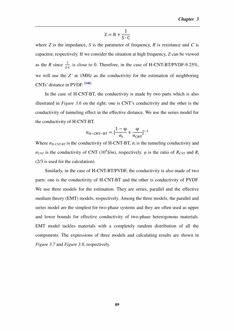
Chapter 3
89
where Z is the impedance, S is the parameter of frequency, R is resistance and C is
capacitor, respectively. If we consider the situation at high frequency, Z can be viewed
as the R since is close to 0. Therefore, in the case of H-CNT-BT/PVDF-9.25%,
we will use the Z’ at 1MHz as the conductivity for the estimation of neighboring
CNTs’ distance in PVDF. [146]
In the case of H-CNT-BT, the conductivity is made by two parts which is also
illustrated in Figure 3.6 on the right: one is CNT’s conductivity and the other is the
conductivity of tunneling effect in the effective distance. We use the series model for
the conductivity of H-CNT-BT.
Where σH-CNT-BT is the conductivity of H-CNT-BT, σt is the tunneling conductivity and
σCNT is the conductivity of CNT (104S/m), respectively. φ is the ratio of RCNT and Rt
(2/3 is used for the calculation).
Similarly, in the case of H-CNT-BT/PVDF, the conductivity is also made of two
parts: one is the conductivity of H-CNT-BT and the other is conductivity of PVDF.
We use three models for the estimation. They are series, parallel and the effective
medium theory (EMT) models, respectively. Among the three models, the parallel and
series model are the simplest for two-phase systems and they are often used as upper
and lower bounds for effective conductivity of two-phase heterogonous materials.
EMT model tackles materials with a completely random distribution of all the
components. The expressions of three models and calculating results are shown in
Figure 3.7 and Figure 3.8, respectively.

Chapter 3
90
Figure 3.7 Assuming the electric field conducting in a vertical direction. Where σ1 is
the conductivity of PVDF, σ2 is the conductivity of H-CNT-BT and σe is the
conductivity of the composite. φ is the volume fraction of CNT, respectively.[9]
Figure 3.8 Calculations for distances between neighboring CNTs by three models
As shown in Figure 3.8, we can find neither series model nor EMT is suitable for
the calculation since both of then fail to show the distance dependence of conductivity
in the range of measurement. On the contrary, parallel model is able to show the
distance dependence in this range. Therefore, we use parallel model for composite’s
conductivity.
2.4 2.45 2.5 2.55 2.6 2.65 2.7
x 10-9
4
6
8
10
12
14
x 10-4
Distance between CNTs [m]
Con
du
ctiv
ity [
S/m
]
Series model
EMT model
Parallel model

Chapter 3
91
Table 3.3 Impedance (Z), resistivity (ρ) and conductivity (σ) of before and after
annealing at 50, 100 and 150oC for 30min, and then cooling naturally.
T(°C) Z'@1MHz ρ σ d(Å)
25 1.31×10⁴ 2.01×10² 4.99×10⁻³ 22.3
50 1.23×10⁴ 1.89×10² 5.30×10⁻³ 22.2
100 1.13×10⁴ 1.73×10² 5.77×10⁻³ 22.0
150 5.19×10³ 79.7 1.25×10⁻² 20.6
Figure 3.9 Results of calculation by parallel model
The results of calculation are listed in table 3.3 and Figure 3.9, respectively. We
find that after annealing at 50 and 100oC, a decrement in the distance between
neighboring CNTs happens but the value is too small to induce the large increment of
dielectric permittivity. After annealing at 150oC, the value decreases from 22.6 to
20.7Å that induces tunneling effect and consequently causes a significant increment in
dielectric permittivity. If we compare data before and after thermal treatment at 150oC,
we can find that the decrement in distances is around 2Å. This decrement is an
average value since we do not consider complicated situations including overlapping
area at the CNT-CNT junction, CNT’s diameter, the thickness of PVDF layer between
adjacent CNTs and BT’s influence. This is just the simplest estimation according to

Chapter 3
92
measurement results. Thus, as we mention before, only the distance between
neighboring CNTs is close enough, the effective change of conductive network will
induce tunneling effect and then improve dielectric permittivity after thermal
treatment. In order to study more comprehensively about the effect of thermal
treatment on dielectric property, we will come back to experimental works and
consider more factors involving annealing duration, multi-cycle annealing and cooling
rates.
3.2.4 Effect of annealing duration
In order to study the effect of annealing duration, we choose
H-CNT-BT/PVDF-9.5% as the sample which is closed to fc. The condition of the
thermal treatment is annealing at 150oC for 15, 30, 60, 90 and 120min, respectively,
and then cooling naturally to the room temperature. The results are shown in table 3.4,
Figure 3.10 (a) and (b), respectively.
Table 3.4 Dielectric property’s contrast of H-CNT-BT/PVDF-9.5% of before and after
five annealing durations
H-CNT-BT/PVDF-9.5% tan @100Hz ’ @100Hz tan @1MHz ’ @1MHz
Before 0.21 258 0.32 71
After 15min 0.32 776 0.48 144
After 30min 0.42 1015 0.45 180
After 60min 0.49 1117 0.46 192
After 90min 0.51 1140 0.46 197
After 120min 0.55 1172 0.47 199

Chapter 3
93
(a)
(b)
Figure 3.10 Dielectric property’s comparison in different annealing durations for
H-CNT-BT/PVDF-9.5%: (a) for dielectric permittivity, (b) for loss tangent,
respectively.
As shown in Figure 3.10 and table 3.4, we find that after 15min’s annealing,
dielectric permittivity of H-CNT-BT/PVDF-9.5% at 100Hz has increased around three
times than the before one (258.4→776.1). Moreover, as annealing duration increasing
further, dielectric permittivity will reach over 1000. Afterwards, when the duration is

Chapter 3
94
over 60min, dielectric permittivity becomes stable and increases just a little as
duration prolonging to 120min. But during the whole process, dielectric loss always
keeps at a low level (less than 0.6 at 100Hz). This property is really rare in the
conductor-dielectric composites. There are some reasons for the significant
improvement in dielectric performance after thermal treatment. Firstly, in the case of
the dielectric permittivity’s increment, the change of CNT’s conductive network is
forming better as annealing duration prolonging so that more interfacial polarization
may be aroused at low frequency. However, this change of CNT’s network is a kind of
dynamic equilibrium and finally, it will become stable as the annealing duration is
enough long. Thus, the change of CNT’s conductive network is a kinetic and
time-consuming process.
Secondly, in the case of dielectric loss, the low loss tangent shown in Figure 3.10
(b) infers that CNT clusters are dispersed in PVDF and they are still isolated to each
other by the PVDF interfacial layer which infers that dielectric loss still partly stems
from the Debye-relaxation after thermal treatment. According to Debye model
description, it assumes that the identical reorienting dipoles are non-interacting and
the distribution of relaxation times is affected by independently reorienting dipoles
instead of thoroughly interfacial polarization between hybrids and matrix. [147]
Low
loss tangent near the percolation threshold is possibly attributed to the special
structure of H-CNT-BT hybrids and the interaction between CNT and BT in PVDF’s
matrix. The special structure promotes the dispersion of CNT and releases high
dielectric loss caused by interfacial polarization after thermal treatment. Hence, the
results of annealing duration infer that the change of conductive network is a dynamic
process and thermal treatment will promote the conductive network to become stable
finally. But the factor that judges whether composites finally reaching the percolative
behavior or not mainly depends on the original volume fraction of CNT. A thermal
treatment may only promotes and stabilizes formed conductive network instead of
directly reducing percolation threshold or changing the conductive network in a
thorough mode.
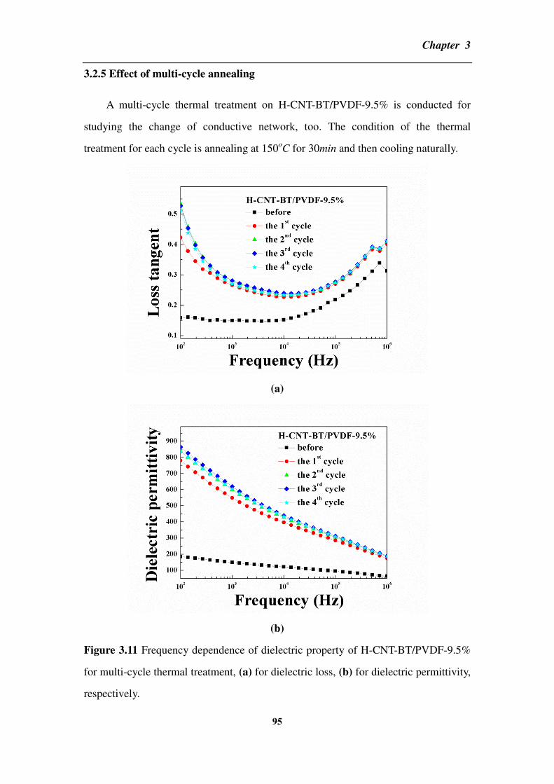
Chapter 3
95
3.2.5 Effect of multi-cycle annealing
A multi-cycle thermal treatment on H-CNT-BT/PVDF-9.5% is conducted for
studying the change of conductive network, too. The condition of the thermal
treatment for each cycle is annealing at 150oC for 30min and then cooling naturally.
(a)
(b)
Figure 3.11 Frequency dependence of dielectric property of H-CNT-BT/PVDF-9.5%
for multi-cycle thermal treatment, (a) for dielectric loss, (b) for dielectric permittivity,
respectively.

Chapter 3
96
Table 3.5 Dielectric property for H-CNT-BT/PVDF-9.5% of before and after
multi-cycle annealing
H-CNT-BT/PVDF-9.5% tan @100Hz ’@100Hz tan @1MHz ’@1MHz
Before 0.16 184.9 0.31 63.9
The 1st cycle 0.42 780.2 0.40 174.7
The 2nd
cycle 0.53 837.4 0.41 185.5
The 3rd
cycle 0.53 863.1 0.41 189.2
The 4th
cycle 0.51 835.4 0.41 187.3
As shown in Figure 3.11 and table 3.5, we find that similarly as the case of
increasing annealing duration, dielectric permittivity increases a lot after the first
cycle annealing (185→780 at 100Hz, and 64→175 at 1MHz). Afterwards, after
multi-cycle annealing, dielectric property is gradually stable and does not change too
much (around 840 at 100Hz and 188 at 1MHz). Dielectric loss in the whole process
keeps at a low level which is less than 0.53 at 100Hz and 0.42 at 1MHz. These results
also prove that CNT network’s change needs time and it can be viewed as a kinetic
process. Actually, the effect of multi-cycle annealing for the conductive network can
be analogized with prolonging annealing duration. As mentioned before, an
inhomogeneous dispersion of H-CNT-BT in composites affects the change of
conductive network. Meanwhile, CNT conductive network is really sensitive near the
percolation threshold. Thus, a thermal treatment is able to release the conductive
network’s sensitivity to external stimulations. After a favorite thermal treatment, the
dielectric property of composites will become more stable and higher.
3.2.6 Effect of cooling rates
The effect of thermal treatment’s cooling rates on the dielectric property is also
studied in this part. We compare two cooling rates for H-CNT-BT/PVDF-9.25% after
annealing at 150oC for 30min: one is cooling naturally (to room temperature) as we
used before and the other is quenching into the ice water.

Chapter 3
97
(a)
(b)
Figure 3.12 Dielectric properties of H-CNT-BT/PVDF-9.25% between before and
after thermal treatment by two cooling rates. The large graph is frequency dependence
of dielectric permittivity and the inset one is frequency dependence of loss tangent.
(a) for the natural cooling, (b) for the quenching, respectively.
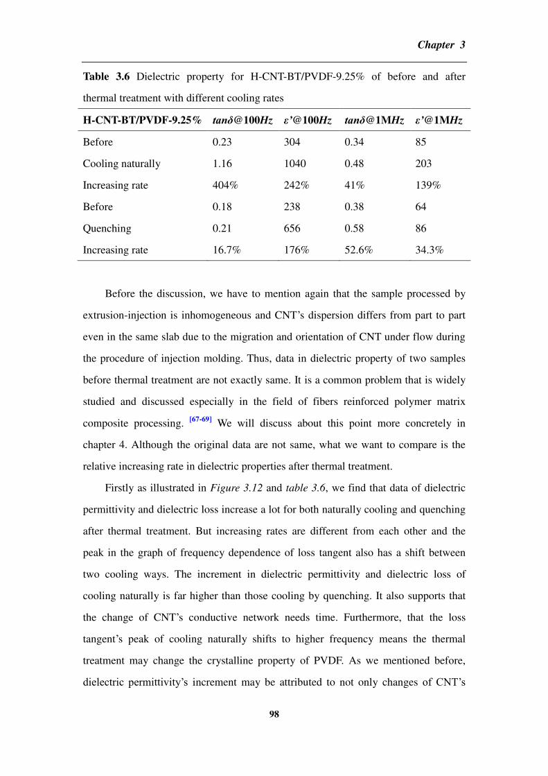
Chapter 3
98
Table 3.6 Dielectric property for H-CNT-BT/PVDF-9.25% of before and after
thermal treatment with different cooling rates
H-CNT-BT/PVDF-9.25% tan @100Hz ’@100Hz tan @1MHz ’@1MHz
Before 0.23 304 0.34 85
Cooling naturally 1.16 1040 0.48 203
Increasing rate 404% 242% 41% 139%
Before 0.18 238 0.38 64
Quenching 0.21 656 0.58 86
Increasing rate 16.7% 176% 52.6% 34.3%
Before the discussion, we have to mention again that the sample processed by
extrusion-injection is inhomogeneous and CNT’s dispersion differs from part to part
even in the same slab due to the migration and orientation of CNT under flow during
the procedure of injection molding. Thus, data in dielectric property of two samples
before thermal treatment are not exactly same. It is a common problem that is widely
studied and discussed especially in the field of fibers reinforced polymer matrix
composite processing. [67-69]
We will discuss about this point more concretely in
chapter 4. Although the original data are not same, what we want to compare is the
relative increasing rate in dielectric properties after thermal treatment.
Firstly as illustrated in Figure 3.12 and table 3.6, we find that data of dielectric
permittivity and dielectric loss increase a lot for both naturally cooling and quenching
after thermal treatment. But increasing rates are different from each other and the
peak in the graph of frequency dependence of loss tangent also has a shift between
two cooling ways. The increment in dielectric permittivity and dielectric loss of
cooling naturally is far higher than those cooling by quenching. It also supports that
the change of CNT’s conductive network needs time. Furthermore, that the loss
tangent’s peak of cooling naturally shifts to higher frequency means the thermal
treatment may change the crystalline property of PVDF. As we mentioned before,
dielectric permittivity’s increment may be attributed to not only changes of CNT’s
Chapter 3
99
network but also PVDF’s re-crystallization behavior. Since annealing temperature is
very close to the crystallization temperature, some changes may occur in the process
of re-crystallization of PVDF after the thermal treatment which may contribute to the
increment of dielectric property.
3.3 In-situ simultaneous synchrotron X-ray characterization
In-situ simultaneous synchrotron wide-angle X-ray diffraction (WAXD) and
small-angle X-ray scattering (SAXS) measurements are conducted to investigate the
transition of crystalline polymorphs and the thickness change of PVDF’s long period.
The three categories that describe most synchrotron X-ray experiments are: X-ray
scattering, X-ray spectroscopy and X-ray imaging. [148]
By analysis obtained data,
crystalline behavior of PVDF will be well studied which provides more information to
understand thermal treatment’s influence on H-CNT-BT/PVDF’s dielectric property.

Chapter 3
100
3.3.1 Wide-angle X-ray diffraction for polyvinylidene fluoride
(a)
(b)
(c)
Figure 3.13 (a) WAXD for PVDF measured at different temperatures; (b) and (c) are
profile analysis of diffractometer scans for before and after thermal treatment,
respectively.

Chapter 3
101
Table 3.7 Xc% and β% at different temperatures for PVDF calculated by the results of
temperature dependence of WAXD
Temperature (oC) Xc% β%
30 51.5% 0.92%
40 50.1% 0.64%
50 48.3% 0.33%
60 46.8% 0.29%
80 46.1% 0.11%
100 40.5%
120 37.3%
150 35.2%
Annealing at 150oC for 30min
150 31.6%
120 40.7%
100 43.1%
80 46.5% 0.25%
60 44.9% 0.27%
50 48.0% 0.32%
40 47.2% 0.51%
30 52.5% 0.49%
Temperature resolving WAXD experiments are conducted for PVDF. Results are
shown in Figure 3.13 (a), the fitting results of before and after thermal treatment are
shown in Figure 3.13 (b) and (c), respectively. In order to derive quantitative
information related to material’s microstructure such as the crystalline fraction or
different crystalline polymorphs within the material, peak fitting procedure is
followed. [149]
Gaussian peak is assigned for the amorphous hallow, while Lorentz
peak is assigned for crystalline polymorph by Origin’s fitting routines. The calculation
of the crystalline (Xc) and polymorph fraction are determined according to Murthy’s
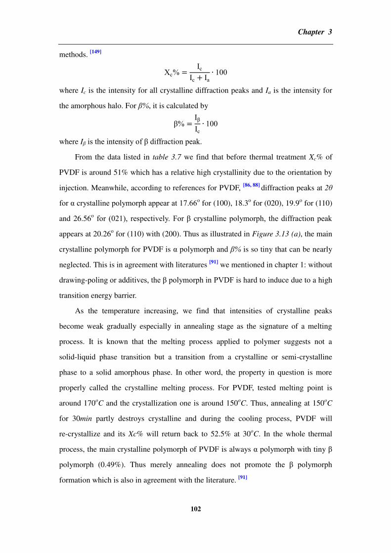
Chapter 3
102
methods. [149]
c Ic
Ic Ia 100
where Ic is the intensity for all crystalline diffraction peaks and Ia is the intensity for
the amorphous halo. For β%, it is calculated by
IIc
100
where Iβ is the intensity of diffraction peak.
From the data listed in table 3.7 we find that before thermal treatment Xc% of
PVDF is around 51% which has a relative high crystallinity due to the orientation by
injection. Meanwhile, according to references for PVDF, [86, 88]
diffraction peaks at 2θ
for α crystalline polymorph appear at 17.66o for (100), 18.3
o for (020), 19.9
o for (110)
and 26.56o for (0β1), respectively. For crystalline polymorph, the diffraction peak
appears at 20.26o for (110) with (200). Thus as illustrated in Figure 3.13 (a), the main
crystalline polymorph for PVDF is α polymorph and β% is so tiny that can be nearly
neglected. This is in agreement with literatures [91]
we mentioned in chapter 1: without
drawing-poling or additives, the polymorph in PVDF is hard to induce due to a high
transition energy barrier.
As the temperature increasing, we find that intensities of crystalline peaks
become weak gradually especially in annealing stage as the signature of a melting
process. It is known that the melting process applied to polymer suggests not a
solid-liquid phase transition but a transition from a crystalline or semi-crystalline
phase to a solid amorphous phase. In other word, the property in question is more
properly called the crystalline melting process. For PVDF, tested melting point is
around 170oC and the crystallization one is around 150
oC. Thus, annealing at 150oC
for 30min partly destroys crystalline and during the cooling process, PVDF will
re-crystallize and its Xc% will return back to 52.5% at 30oC. In the whole thermal
process, the main crystalline polymorph of PVDF is always α polymorph with tiny
polymorph (0.49%). Thus merely annealing does not promote the polymorph
formation which is also in agreement with the literature. [91]

Chapter 3
103
3.3.2 Wide-angle X-ray diffraction for the composite
(a)
(b)
(c)
Figure 3.14 (a) WAXD of H-CNT-BT/PVDF-9.25% at different temperatures; (b)
and (c) are profile analysis of diffractometer scans for before and after thermal
treatment, respectively.
Table 3.8 Xc% and β% at different temperatures for H-CNT-BT/PVDF-9.25%

Chapter 3
104
calculated by the results of temperature dependence of WAXD
Temperature (oC) Xc% β%
30 58.6% 13.0%
40 58.0% 14.6%
50 56.6% 15.5%
60 56.1% 15.9%
80 54.5% 17.4%
100 52.9% 18.3%
120 51.2% 19.7%
150 49.0% 21.5%
Annealing at 150oC for 30min
150 52.3% 23.9%
120 55.9% 24.6%
100 59.2% 25.2%
80 60.8% 22.9%
60 62.5% 23.9%
50 63.5% 25.1%
40 64.7% 25.3%
30 65.7% 25.1%
Comparing with data in table 3.8, we find three interesting phenomena. Firstly,
Xc% of H-CNT-BT/PVDF-9.25% is higher than that of PVDF since CNT in
H-CNT-BT is as the nuclei which promotes PVDF’s crystallization. Meanwhile, there
is some polymorph appearing in the crystalline which is marked by a black arrow in
Figure 3.15(a). Secondly, during the heating stage, Xc% of H-CNT-BT/PVDF-9.25%
decreases as temperature increasing which is as similarly as pure PVDF. But β% of
H-CNT-BT/PVDF-9.25% is increasing gradually according to fitting results. Thirdly,
β% is further increasing during the cooling stage. When the sample comes back to the
room temperature, β% of H-CNT-BT/PVDF-9.25% reaches 25%. It is almost twice as
Chapter 3
105
much as that of before thermal treatment (1γ →β5 ). These phenomena mean that
CNT may not only induce but also stabilize the polymorph in
H-CNT-BT/PVDF-9.25% which effectively prevents crystalline transition from to α.
According to the report, [91]
the interaction between CNT and PVDF will induce
polymorphs in CNT reinforced PVDF composite by means of decreasing the energy
barrier of crystalline transition from α to . Our results happen to provide the evidence
for this statement and it also infers that a thermal treatment possibly provides more
energy to overcome the transition barrier from α to and even back to the room
temperature, β% does not decrease but increases more.
It is known that interfacial interaction between CNT and PVDF promotes
interfacial crystallization process. Hence, well dispersion of CNT in PVDF matrix
should induce higher crystalline fraction as a result of high surface interfaces. The
high crystalline fraction for the reinforced PVDF is most probably the results of the
surface interface increasing between CNT and PVDF matrix. Meanwhile, interfaces
are the places that have stronger interaction caused by PVDF’s polarity and CNT’s π
delocalized electrons compared with other part of PVDF. Thus, increasing amounts of
polymorph are probable to be formed on CNT-PVDF interfaces. Furthermore, CNTs
in H-CNT-BT by CVD have different diameter’s distribution, bundling
characterizations and lengths. This various morphologies cause different surface
energies and affects PVDF’s volumetric exclusion. These nano-inclusion factors all
affect PVDF’s crystallization and amount of polymorph.
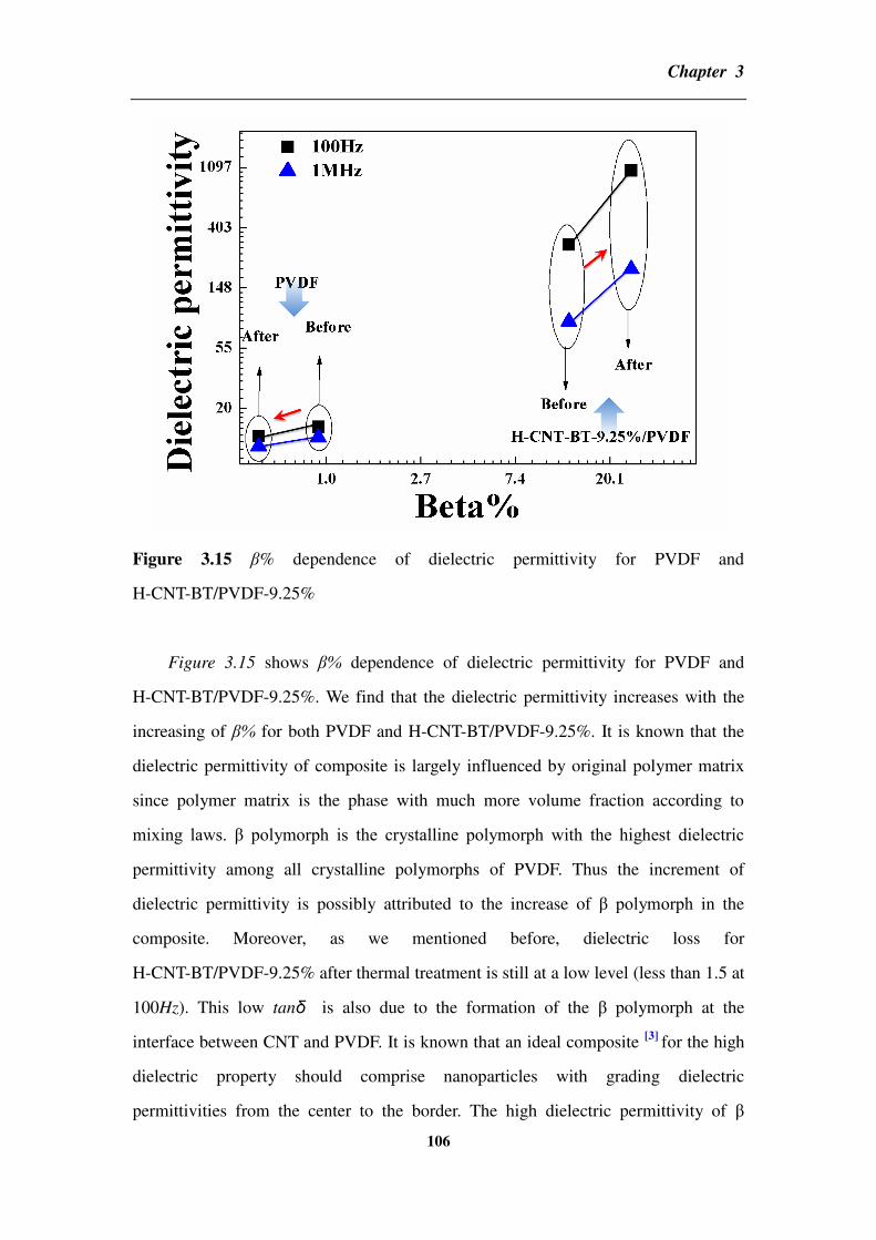
Chapter 3
106
Figure 3.15 β% dependence of dielectric permittivity for PVDF and
H-CNT-BT/PVDF-9.25%
Figure 3.15 shows β% dependence of dielectric permittivity for PVDF and
H-CNT-BT/PVDF-9.25%. We find that the dielectric permittivity increases with the
increasing of β% for both PVDF and H-CNT-BT/PVDF-9.25%. It is known that the
dielectric permittivity of composite is largely influenced by original polymer matrix
since polymer matrix is the phase with much more volume fraction according to
mixing laws. polymorph is the crystalline polymorph with the highest dielectric
permittivity among all crystalline polymorphs of PVDF. Thus the increment of
dielectric permittivity is possibly attributed to the increase of polymorph in the
composite. Moreover, as we mentioned before, dielectric loss for
H-CNT-BT/PVDF-9.25% after thermal treatment is still at a low level (less than 1.5 at
100Hz). This low tanδ is also due to the formation of the polymorph at the
interface between CNT and PVDF. It is known that an ideal composite [3]
for the high
dielectric property should comprise nanoparticles with grading dielectric
permittivities from the center to the border. The high dielectric permittivity of

Chapter 3
107
polymorph will be as the bridge for better combining CNT and α polymorph of PVDF
in the composite which reduces dielectric loss. Due to establishing a buffer layer with
medium dielectric permittivity between CNT and α polymorph in PVDF, the field
intensification aroused by CNT’s percolative behavior may be effectively reduced
which favors to keep a low dielectric loss.
3.4.3 Small-angle X-ray scattering for the composite
Figure 3.16 SAXS for H-CNT-BT/PVDF-9.25% at different temperatures
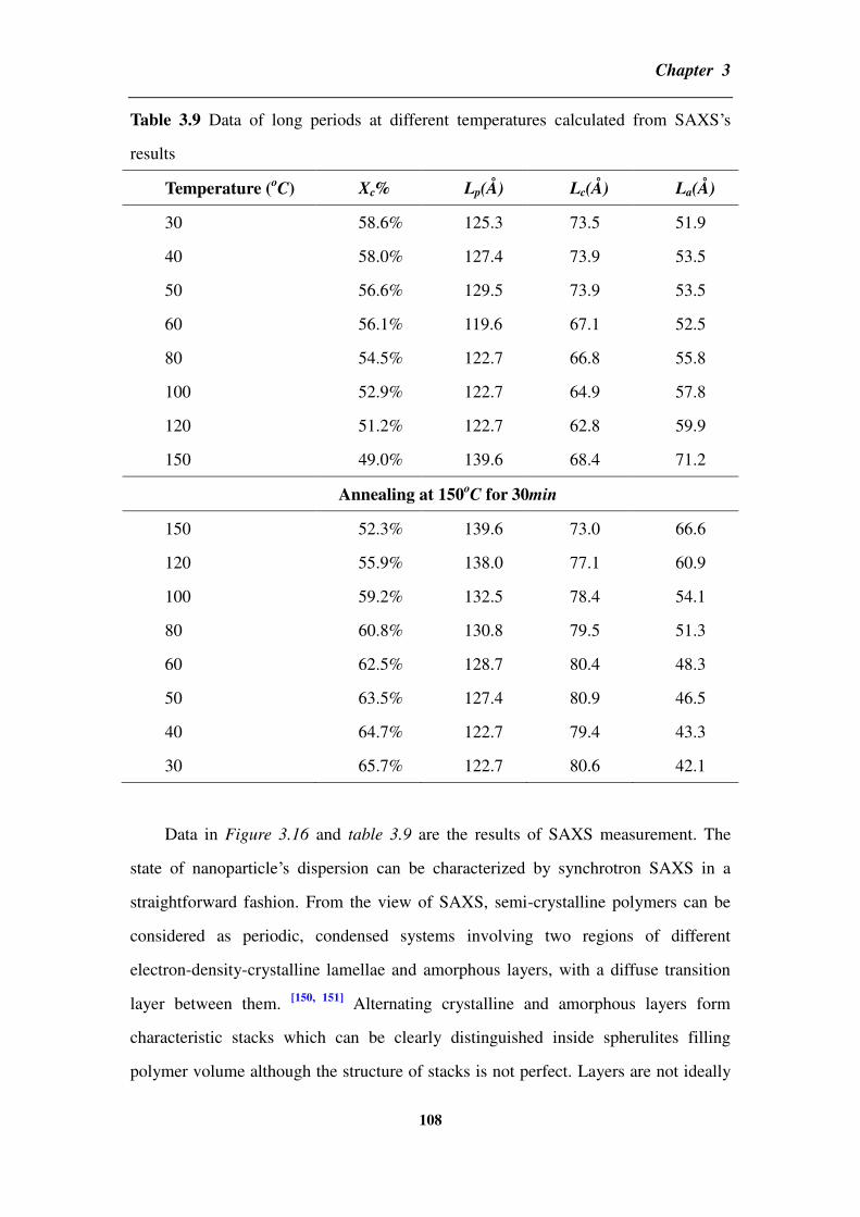
Chapter 3
108
Table 3.9 Data of long periods at different temperatures calculated from SAXS’s
results
Temperature (oC) Xc% Lp(Å) Lc(Å) La(Å)
30 58.6% 125.3 73.5 51.9
40 58.0% 127.4 73.9 53.5
50 56.6% 129.5 73.9 53.5
60 56.1% 119.6 67.1 52.5
80 54.5% 122.7 66.8 55.8
100 52.9% 122.7 64.9 57.8
120 51.2% 122.7 62.8 59.9
150 49.0% 139.6 68.4 71.2
Annealing at 150oC for 30min
150 52.3% 139.6 73.0 66.6
120 55.9% 138.0 77.1 60.9
100 59.2% 132.5 78.4 54.1
80 60.8% 130.8 79.5 51.3
60 62.5% 128.7 80.4 48.3
50 63.5% 127.4 80.9 46.5
40 64.7% 122.7 79.4 43.3
30 65.7% 122.7 80.6 42.1
Data in Figure 3.16 and table 3.9 are the results of SAXS measurement. The
state of nanoparticle’s dispersion can be characterized by synchrotron SAXS in a
straightforward fashion. From the view of SAXS, semi-crystalline polymers can be
considered as periodic, condensed systems involving two regions of different
electron-density-crystalline lamellae and amorphous layers, with a diffuse transition
layer between them. [150, 151]
Alternating crystalline and amorphous layers form
characteristic stacks which can be clearly distinguished inside spherulites filling
polymer volume although the structure of stacks is not perfect. Layers are not ideally

Chapter 3
109
parallel and they may be curved in space changes continuously. However, since lateral
dimensions of stacks are much bigger than the wavelength of X-rays, by scattering
from such specific layered structures can be described by the scattered intensity which
is completely determined by the electron density variation occurring in only one
direction perpendicularly to layers. Thus, the analysis of SAXS curves makes possible
determination of several important parameters of stacks, such as the thickness of
amorphous layers and crystalline lamellae.
For a simple estimation for the thickness of long period, amorphous layers and
crystalline lamellae, we use equations as follows:
Lp βπ
Lc Lp c
La Lp Lc
where Lp, Lc and La are the thickness of long period, crystalline lamellae and
amorphous layers, respectively. q is the momentum transfer or scattering vector.
Herein, we choose its value of the peak in the curve of q-Iq2 plotted in Figure 3.16.
Firstly, in Figure 3.16 as the temperature increasing, peaks of curves shift to
smaller q during the heat stage while in the cooling stage, q shifts to bigger value
again. Meanwhile, the intensity of peak is much stronger than that of before thermal
treatment. Generally, the larger the inhomogeneity size in a system is, the smaller the
q value will be needed in order to determine the structure. [152]
The peak shifting to
smaller q means Lp of PVDF and H-CNT-BT’s dispersion have some change during
the thermal treatment. If comparing with the calculated Lp, La and Lc, in table 3.8, we
find that as the temperature increasing, data of La does not change so much at first
(from 30 to 120oC) but data of Lc decreases. However, as the temperature reaching
150oC, data of La has increased from 51.9 to 71.2Å. After annealing for 30min, La
begins to shrink gradually and until the sample cooling to the room temperature. This
gradually decrease of La demonstrates that the shrinkage of neighboring CNTs’
distance and the change of conductive network possibly happens in this process.
It is know that CNT’s dispersion largely depends on processing ways and usually

Chapter 3
110
the discussion of thermal treatment’s effect focuses on the annealing temperature
which is a bit above the melting point. [153-159]
In other word, if the composite is
annealed above polymer matrix’s melting point, the secondary agglomeration of CNT
possibly occurs in the melting stage which easily causes the reformation of conductive
network. However, in this study we find that not only during the melting stage but
also in the re-crystallization stage influences the change of CNT’s conductive network.
Thus, the conductive network in a composite is affected not only by CNT’s volume
fraction, but also by the nature of polymer matrix and their processing ways,
especially for semi-crystalline polymer matrix. If the sample is conducted by a
thermal treatment, the system will be in a thermodynamic equilibrium state, the
CNT’s conductive network will become very sensitive especially approaching to the
percolation threshold. Moreover, the difference in the interfacial energy between the
CNT and PVDF including coefficient of thermal expansion (CTE) is usually high
which will make the conductive network increase sensitivity to the thermal treatment.
[160] Hence, the change in the thickness of Lp, Lc and La detected by SAXS suggests
that distance’s change between neighboring CNT after thermal treatment is mainly
attributed to PVDF’s amorphous layers.
By a comparison of data in table 3.10, we find that both at 100Hz and 1MHz,
dielectric permittivity after thermal treatment has a significant increment but the
thickness of crystalline lamellae increase while the thickness of amorphous layers
decrease. This is associated with collaborative effects of two kinds’ polarizations on
dielectric property. On the one hand, the crystalline PVDF usually has more regular
structure which will promote dipoles orientational polarization. This kind of
polarization usually happens at high frequency which has shown in chapter one. The
increment of dielectric permittivity at 1MHz can be associated with the change of Lc.
Moreover, considering the increment of β% after thermal treatment, it can be inferred
that the increment of dielectric permittivity at 1MHz is possibly caused by the
crystalline polymorph transition and the increment of Lc. On the other hand, as we
have already mentioned before, the increment in dielectric permittivity at 100Hz is
attributed to strong interfacial polarization. The shrinkage of amorphous layers after

Chapter 3
111
thermal treatment provides more possibility for reducing the distance between
neighboring CNTs. Furthermore, if we compare with the calculation results of
tunneling effect, the shrinkage of around 10Å in La will provide enough possibility for
neighboring CNTs’ distance change and arousing the tunneling effect.
Table 3.10 The comparison of changes in the dielectric permittivity and the long
period before and after thermal treatment
H-CNT-BT/PVDF-9.25% '@100Hz '@1MHz Lc(Å) La(Å)
Before 304 85 73.5 51.9
After 1040 203 80.6 42.1
Figure 3.17 Scheme of changes of PVDF’s long period and CNT’s dispersion
between before and after annealing treatment
After the analysis of WAXD and SAXS, a brief summary of thermal treatment’s
effect is illustrated in Figure 3.17 from two aspects. On the one hand, in the case of
conductive network’s reformation, the thermal treatment may change the orientation
of PVDF and CNT which makes CNT to disperse in more random mode in the

Chapter 3
112
composites. This effect for the dielectric property largely depends on fH-CNT-BT and
percolative behavior. If fH-CNT-BT is far away from fc, the dielectric permittivity will
decrease a bit due the less regularity of the dipole after the thermal treatment. If
fH-CNT-BT is approaching to fc, as the case of H-CNT-BT/PVDF-9.25% shown in the
scheme, the effective conductive network’s change will lead to tunneling effect and
consequently improve the dielectric permittivity by strong interfacial polarization.
This process mainly happens in the PVDF’s amorphous part via the shrinkage in the
thickness of La after thermal treatment. On the other hand, in the case of PVDF’s
crystalline part which is expressed by spherulities, the thermal treatment will increase
crystallinity and promote the polymorph at the interface of CNT and PVDF. This
interfacial crystalline layer composed by polymorph forms an ideal dielectric
structure with grading dielectric permittivities from the center to the border, namely
CNT→PVDF’s polymorph→PVDF’s α polymorph. Combined with this ideal
dielectric structure and BT particles’ buffer of the leakage current caused by
percolative behavior, the dielectric permittivity of H-CNT-BT/PVDF-9.25% increases
a lot while dielectric loss remains at a low level after thermal treatment. Therefore, the
change of CNT’s network in the amorphous layer and polymorph increment after
thermal treatment are mainly attributed to the high dielectric performance.
3.4 Partial conclusion
H-CNT-BT/PVDF composite processed by solution casting plus
extrusion-injection way has high dielectric permittivity and low dielectric loss. This
high dielectric property is attributed to a good dispersion of CNT in composites. It is
due to H-CNT-BT’s special structure achieving an extremely low CNT’s percolation
threshold (fCNT=2.77%) for H-CNT-BT/PVDF composites. Furthermore, this good
dispersion of CNT favors to induce polymorph of PVDF and improves the dielectric
property in a wide range of frequency.
After thermal treatment, the dielectric property of the composite is further
increased even the sample is cooling to the room temperature. This increment of

Chapter 3
113
composite’s dielectric permittivity depends on hybrid’s volume fraction and
parameters of the thermal treatment involving annealing temperature, annealing
duration and multi-cycle annealing, and cooling rates. Concretely, firstly, the volume
fraction of hybrids should be close to the percolation threshold so that the effective
decrement of neighboring CNT’s distance can induce the tunneling effect. Secondly,
the annealing temperature should be high enough to cause partly melting in the
crystalline of PVDF and arouse the effective shrinkage of amorphous layers. Thirdly,
the reformation of CNT’s conductive network is the kinetic process which needs
enough time to complete contacting of CNTs. Prolonging annealing duration and
multi-cycle annealing will reduce the sensitivity of CNT’s conductive network which
stabilizes and enhances dielectric performance of composites. Fourthly, cooling rate
also affects the final increment of dielectric permittivity since it influence PVDF
re-crystallization behavior.
According to the results of in-situ synchrotron X-ray measurement, the
increment in dielectric permittivity of H-CNT-BT/PVDF after thermal treatment is
attributed to two points: one is the reformation of CNT’s conductive network happens
in the amorphous layer of PVDF. Thermal treatment reduces the thickness of La and
consequently shrinks neighboring CNTs’ distance. The other is more polymorph
induced at the interface of CNT-PVDF. By analysis of the re-crystallization of PVDF,
we know more comprehensively about the interaction between CNT and PVDF as
well as CNT’s percolative behavior in a semi-crystalline polymer. It provides us
useful information for achieving high dielectric property. Meanwhile, we have to
consider more factors including the processing way of composites, the structure of
fillers and the original property of polymer matrix.
Chapter 4
114
Chapter 4 Comparison of the composites’ dielectric property with
different fillers——modeling and experimental investigation
___________________________________________________________
Introduction
In this chapter, we will investigate the dispersion of CNT in PVDF composites
from three aspects. Firstly, we use the theory of excluded volume to calculate the
possible percolation threshold of H-CNT-BT/PVDF composites and make comparison
with the experimental one in order to discuss the structure’s effect of H-CNT-BT on
the dispersion of CNT. Secondly, AC conductivity of H-CNT-BT/PVDF-9.5% and
CNT/PVDF-8% is compared at different depth of sample vertical to injection
direction in order to study CNT’s dispersion processed by extrusion-injection way.
Thirdly, we incorporate hybrids with different structures but with the same volume
fraction of BT and CNT into PVDF for preparation composites. Via analysis of
dielectric property, we will discuss the structure of hybrid’s effect on CNT’s
dispersion and the percolative behavior for PVDF composite.

Chapter 4
115
4.1 Calculation for the percolation threshold of carbon
nanotube-BaTiO3 hybrids/polyvinylidene fluoride
4.1.1 The excluded volume and percolation threshold
The percolation threshold fc is a critical value of composite at which conductive
particles form channels through composite. It strongly depends on the size and shape
of conductive fillers. In order to estimate the fc for composite, the theory of excluded
volume is widely applied in many researches. The excluded volume is the volume
around an object into which the center point of an identical object is prohibited, if the
two are not overlap. [161]
We take a sphere as an example:
Figure 4.1 Scheme of the excluded volume of a sphere
As shown in Figure 4.1, radiuses of both spheres are r and if there is no mutual
contacting, the distance between two centers of them should be larger than double
times of their radius. Thus the excluded volume of a sphere can be written as: π π
In a CNT reinforced polymer system, in order to calculate fc by the theory of excluded
volume, most of works have consistently modeled CNT as a penetrable, straight,
capped cylinder. As pointed out by L. Berhan and A.M. Sastry’s hard-core model, [162]

Chapter 4
116
if treating CNT as a spherocylinder of the length L and the radius R, the excluded
volume is given by
π π
where is the average value for two sticks with the angle θ between them. For
a random distribution: π
The core volume of a single spherocylinder can be written as π π
By Monte Carlo simulations, fc is found to be inversely proportional to the excluded
volume. The analytical solution for the volume fraction near percolation threshold is
often expressed as
where c is a modified factor associated with the aspect ratio of CNT. The modeling
work usually focuses on how to revise fc combining theoretical models and actually
shapes by adding more modified factors into consideration.
In the classic percolation theory, the conductive network is considered to be
formed through the intimate connection between adjacent conducting fillers. However,
in some practical cases, it usually obeys to another mechanism. Conductive particles
are connected not geometrically but electrically via tunneling. In this case, the
percolation network has already been formed even thought a geometrically connected
network is still absent. Therefore, simulation works can also provide a good tool to
investigate the effect of parameters on the tunneling distance including CNT types,
surface functionalization and molecular weight of the polymer matrix in the
composite which cannot easily be carried out by experiments.
In our system, H-CNT-BT is not a simple mixture of CNT and BT particles in
PVDF. Instead, it has an initial structure that BT is as core and CNT grows on its
surface. Thus, by calculating fc we can understand better the function of parameters of
H-CNT-BT involving the size of BT, the aspect ratio of CNT and the thickness of

Chapter 4
117
interface, etc. After the discussion about H-CNT-BT’s role on fc of H-CNT-BT/PVDF,
we will have a comprehensive view of H-CNT-BT and their contribution for the
improvement of dielectric property. Hence, in this part, we are based on modeling
works of high-aspect-ratio fiber system and the theory of excluded volume in order to
estimate fc for H-CNT-BT/PVDF’s system.
4.1.2 The parameters and method involved in the calculation
Before starting the calculation, some parameters used are defined at first in
Figure 4.2. We assume the radius and the length of CNT per BT particle is rc and l,
respectively while the radius of BT particle is rp. These three parameters’ ranges can
be observed by SEM. The SEM image for the morphology of H-CNT-BT is provided
in Figure 4.3.
Parameters:
i: the thickness of interface outside a single
particle, herein, we set it as 0.5nm
rp: the radius of a BT particle observed by
SEM
rc: the radius of a CNT observed by SEM
rc+i: the radius of CNT with polymer
interface
t: the ratio of hard core and the soft shell
l: the length of CNT
a = l / rc+i : the aspect ratio of the CNT
observed by SEM
wt: the weight fraction of CNT in H-CNT-BT
n: the number of CNTs on a single particle
Figure 4.2 Parameters of H-CNT-BT used in the assumption

Chapter 4
118
Figure 4.3 The SEM image of the morphology of H-CNT-BT
From Figure 4.3, we can estimate some parameters for H-CNT-BT. rc is from 10
to 25nm, l is from 1to10 m and rp is from 200nm to 2 m. Meanwhile, an aspect ratio,
a, is also defined as the ratio of rc+i and l of CNT.
When H-CNT-BT is incorporated into PVDF matrix, there is an interface
wrapped around not only BT but also CNT which is so important for properties that
cannot be ignored. The reason why the interface should be taken into consideration is
attributed to tunneling effect in conductive behavior. As we mentioned before for
electrical percolation, as the volume fraction of CNT in composite increasing, the
inter-tube distance reduces and thereby increases the possibility of percolation. When
the minimum distance between neighboring CNTs reduces to the maximum allowed
tunneling gap, then electrons can tunnel between two CNTs. The tunneling resistance
is not only associated with the polymer thickness between two adjacent CNTs but also
with the chemical property of polymer matrix. Hence, the polymer interfacial region
between neighboring CNT cannot be ignored for the calculation of percolation
threshold. We employ i and t to describe the interface of BT-PVDF and CNT-PVDF,
respectively. Additionally, the number of CNT on an individual BT particle can be
marked as n which can be estimated by CNT’s weight fraction (wt) measured by TGA
shown in the Figure 4.4.

Chapter 4
119
Figure 4.4 TGA for H-CNT-BT
As shown in Figure 4.4 we can find that the weight fraction of CNT in
H-CNT-BT is around 0.11. Thus, if we want to estimate the number of CNT per BT
particle, we firstly suppose the mass of total CNT in H-CNT-BT as wt while BT
particles as 1-wt. The whole number of BT particles can be written as
where NA is the Avogadro constant, NA=6.022 141 79(30)×1023
/mol and MBT is the
molar mass of BT which is 233.192g/mol. Meanwhile, the volume of total BT
particles can be written as
where ρBT is the density of BT which is 6.02g/cm3. Similarly, total CNT’s volume can
be written as
where ρCNT is the density of CNT and we use 2g/cm3. Thus, a volume’s ratio between
total BT and total CNT can be expressed as

Chapter 4
120
The average number of CNT per BT particle, n, can be written as
where Vsingle BT and V single CNT are the volume for a single BT particle and a single CNT,
respectively. They can be written as π π π
Consequently, the core volume of a single H-CNT-BT is
Herein, it is essential to point out that the radius of a BT particle should be large
enough to allow CNT to grow. Thus, the boundary condition of H-CNT-CNT among
rp, n and rc+i is π π
According to the way used in literatures, [163,164]
the percolation is defined as the
formation of a connected cluster that spans a representative volume element. Herein,
we return to a semi-empirical, analytical result pointed out by Balberg et al. We
assume CNT to be a straight cylinder of length l and radius r, with hemispheric end
caps to allow comparison of results in the l/r→0 limit with the assumption that the
number of objects per unit volume at percolation qp is inversely proportional to the
excluded volume Vex of one of the objects, i.e.,
where Vex is the excluded volume we have mentioned (the volume around the object
into which the center point of an identical object is prohibited, if the two are not
overlap).
In the case of H-CNT-BT, we also treat it as a sphere which is shown in the
Figure 4.5.

Chapter 4
121
Figure 4.5 Sphere model used in H-CNT-BT for calculating its excluded volume
We consider H-CNT-BT is a sphere whose radius is composed of two parts: one
is BT’s radius which is marked as rp+i while the other is the effective length of CNT
which is marked as s as shown in Figure 4.5. A suitable approach to modeling
percolation in the fiber reinforced polymer matrix composite is “hard-core model”
where each conductive inclusion is modeled as an impenetrable hard core surrounded
by a soft shell and the hard core stands for the actual inclusion and the thickness of
surrounding penetrable soft shell is related to tunneling distance. Although the
interface effect is considered into “hard-core model”, it is still not enough for our
system since treatments for the hard-core approach to model percolation of fibrous
systems are limited for lower aspect ratio fillers. However, CNT in H-CNT-BT is with
large aspect ratio as illustrated in the SEM image of Figure 4.5. Hence, “hard-core
model” cannot be simply employed in our system and some modification is needed to
fit H-CNT-BT’s system in order to let the calculated result get closer to the
experimental one.
Another popular approach in modeling percolative behaviors of composites
reinforced by high aspect ratio fibers is “soft-core model” which considers the fiber as
a soft core (i.e., fully permeable) rod and assumes that the onset of both geometric and
electrical percolation occur simultaneously. In spite of differences between a soft-core
fiber network model and an actual CNT loaded composite, “soft-core model” has
been proved to predict the percolation threshold in high agreement with experimental
data. Therefore, in the case of H-CNT-BT/PVDF system, we will take the way of
references [162, 144]
and combine two models together by means of defining a parameter,

Chapter 4
122
t, as the ratio of CNT’s core radius, rc, and outer radius with a soft shell for CNT, rc+i. The soft-core limit can be expressed as t=0 while the hard-core limit is given by t=1.
Moreover, considering that CNT in H-CNT-BT as illustrated in Figure 4.5, they are
helical, wavy and entangled with others rather than straight like sticks. Directly using
the length of CNT as an effective length will bring much discrepancy for the
calculation. Thus, a modified factor, m, is used to consider shape’s factor. According
to the research of Berhan and Sastry, they have investigated the effect of CNT’s
waviness on percolation threshold and the validity of excluded volume rule for
systems of wavy fibers. According to their method and several tests in the calculation,
for H-CNT-BT’s system, the effective length of CNT, s, will be given by where m=0.499. Hence, the excluded volume for hybrids can be denoted as π
In light of the relationship between Vex and fc as well as the high aspect ratio of CNT,
the approach to predict fc for the composite can be expressed as:
The process of estimation for fc of H-CNT-BT/PVDF is shown in Figure 4.6. We
will discuss about the relationship among fc and some H-CNT-BT’s parameters
including: the number of CNT on single BT particle, n, the radius of BT, rp, the radius
of CNT, rc, the length of CNT, l and the ratio of hard-core to the outer radius of soft
shell, t, respectively.

Chapter 4
123
Figure 4.6 Scheme of the calculation for H-CNT-BT/PVDF
4.1.3 Results and discussion
Firstly, before calculating fc, we firstly discuss the relationship between wt and n.
Herein, t is set at 0.85 for CNT and i at 0.5nm for BT, respectively according to the
multi-core model we have mentioned in chapter one where the thickness of bonded
layer is around 1nm. Meanwhile, we fix other three factors as constants for each graph
and their values are shown in Figure 4.7.

Chapter 4
124
(a) l=7.5 m, t=0.85, rc=15nm
(b) rp=500nm, t=0.85, rc=15nm
(c) rp=500nm, t=0.85, l=7.5 m
Figure 4.7 Calculated results of the relationship between wt and fc changing with rp,
rc, l and t. (a) rp-fc, (b) l-fc and (c) rc-fc, respectively
0.05 0.1 0.15 0.2
100
101
102
103
Weight fraction of CNT in hybrid
Nu
mb
er o
f C
NT
s on
sig
nle
parti
cle
wt vs n
rp = 0.2um
rp = 0.5um
rp = 0.8um
rp = 1.1um
rp = 1.4um
rp = 1.7um
rp = 2um
0.05 0.1 0.15 0.2
101
102
Weight fraction of CNT in hybrid
Nu
mb
er o
f C
NT
s o
n s
ign
le p
arti
cle
wt vs l
l=3um
l=7.5um
l=12um
l=16.5um
l=21um
l=25.5um
l=30um
0.05 0.1 0.15 0.2
101
102
103
104
Weight fraction of CNT in hybrid
Nu
mb
er o
f C
NT
s o
n s
ign
le p
arti
cle
wt vs n
rc = 2nm
rc = 5nm
rc = 8nm
rc = 11nm
rc = 14nm
rc = 17nm
rc = 20nm

Chapter 4
125
Three pictures illustrated in Figure 4.7 provide the information that n is
dependent on not only wt but also rp, l and rc. It is easy to understand that n increases
as wt increasing due to more amount of CNT in H-CNT-BT. Furthermore, as shown in
Figure 4.7, we find that three shape factors of H-CNT-BT (rp, l and rc) influence n in
various ways. Concretely, as shown in Figure 4.7 (a), n increases with rp’s increasing
while decreases with l and rc’s increasing as shown in Figure 4.7 (b) and (c),
respectively. It is because a BT particle can provide more space with larger radius
which promotes more CNTs growing outside. Meanwhile, CNT with smaller radius
and shorter length may decrease initial volume which also helps to enhance CNT’s
numbers on the surface of per BT particle. Therefore, these graphs infer that the
number of CNT on a single BT particle depends on not only the weight fraction but
also on morphology parameters of BT and CNT.
Secondly, we compare the relationship of calculated fc, rp, l, rc and t. According
to “soft-core model”, t is the ratio of CNT’s original radius and the radius of CNT
with polymer’s interface. Thus, an increasing of t means that the thickness of interface
reduces. As defined, until t=1 means that there is no interface outside CNT.

Chapter 4
126
(a) rc=15nm, wt=0.11, a=500
(b) rp=500nm, rc=15nm, wt=0.11
(c) rp=500nm, wt=0.11, a=500
Figure 4.8 Calculated results for three factors’ effects on fc with different t. (a) rp-fc,
(b) l-fc and (c) rc-fc, respectively

Chapter 4
127
From three figures shown in Figure 4.8, we find that the estimated fc for
H-CNT-BT is less than 0.16 no matter how much change of rp, rc and l. This is in
agreement with Zallen’s study. [165]
The theoretical value of fc is approximately 0.16
for a homogeneously dispersed system which contains randomly oriented fillers of
spherical shape with similar dimensions. Furthermore, if compared with experimental
data reported in references, [3]
for most spherical conductive fillers, the experimental
fc is often distributed in a broad range from 0.013 to 0.17 and fc are usually lower than
0.16. A commonly accepted explanation for this discrepancy between theory and
experiment is that the real statement of fillers in polymer matrix is a kind clusters
formed by the randomly distributed conductive fillers with a complex shape and
larger aspect ratio than that of each filler itself. The dimension of clusters plays a
crucial role on determining fc in percolative composites of spherical conductive fillers.
Hence, we plot three parameters dependence of fc with different t in Figure 4.8 (a), (b)
and (c), respectively, in order to view morphologies’ and interface’s effects on fc.
Firstly, we start by Figure 4.8 (a). We set rc at 15nm and the aspect ratio, a at 500,
respective. We plot rp dependence of fc with different t. We find that fc increases as rp
increasing. It is because during the calculation procedure, fc is the ratio of
H-CNT-BT’s core volume and its excluded one. Thus, both volumes increase as rp
increasing, but the volume of core increases faster than excluded volume. This
difference between two volumes’ changing rates leads to fc increasing with rp. This
shows that for a percolative system, simply increasing size of conductive fillers will
not probably cause low fc. In experimental cases, it is also a common phenomenon
since the factor usually influences fc is the dispersion of fillers rather than their real
sizes.
Secondly in Figure 4.8 (b), we set rp at 500nm and rc at 15nm, respective. We
plot l dependence of fc with different t. As l increasing fc reduces which means that the
longer the CNT on a BT particle is, the lower fc of the composite will be achieved.
Because CNT with longer length is easier to contact with others even though in a
lower volume fraction the percolative behavior in the composite will also be easy to
form in this case. This is proved by experimental data. Li et.al have used Al2O3-CNT

Chapter 4
128
hybrids with different aspect ratios in the epoxy composite. They have found that the
composite reinforced by Al2O3-CNT hybrids with higher aspect ratio has a lower fc
compared with those of lower aspect ratio. Lin et.al have also found similar result in
the system of Al2O3-CNT/ poly(dimethylsiloxane) (PDMS) composites.
Thirdly, we set rp at 500nm and a at 500, respective. We plot rc dependence of fc
with different t in Figure 4.8 (c). We find that fc also decreases as rc increasing as
similar as the case of rp’s effect on fc. As we mentioned the number of CNT reduces
per BT particle due to the increasing of rc. But on the contrary, the excluded volume
will increase which causes the decreasing of fc. Moreover, given that CNT’s radius
increases, the possibility of inter-contacting will also increase. In addition, three
graphs provide a decreasing trend of fc with t reducing. We list the data of t, rc and the
thickness of shell, rc+i-rc, respectively in table 4.1 to illustrate this point.
Table 4.1 The relationship among t, rc+i and rc+i-ri
t 0.65 0.7 0.75 0.8 0.85 0.9 0.95
rc+i (nm) 23 21 20 19 18 17 16
rc+i-ri (nm) 8 6 5 4 3 2 1
In the calculation procedure, the interface thickness is considered as a part into
the radius of CNT, thus a smaller t means a thicker interface, namely, a bigger radius
of CNT. As mentioned in the analysis of CNT radius’s effect, we have known that
CNT with a large radius favors to reduce fc. It can be analogized to the case of t
dependence of fc. Meanwhile, as we have mentioned before, t is used as a parameter
to describe the ratio of core’s radius and outer soft shell’s radius. The larger the t is,
the more it approaches to the limit of hard-core model based on the theory. We
employ this shell to describe polymer’s interface wrapped around CNT. In a CNT
reinforced polymer matrix composite, the tunneling distance depends not only on the
distance of neighboring CNTs’ distance, but also on polymer’s type since the
tunneling energy barrier height varies widely up to polymer’s physical and chemical

Chapter 4
129
property. For instance, some of polymers have low (e.g. for PMMA, =0.17eV,
PVDF, =0.3eV), [145]
whereas others have relatively high (e.g. for epoxy, =1.5eV).
Hence, choosing of t depends on the type of polymer matrix and after several tests we
set t at 0.85 for H-CNT-BT/PVDF composite in the followed calculation.
4.1.4 Comparison of the calculated percolation threshold with the experimental
results
Table 4.2 Dielectric permittivity at three frequencies for H-CNT-BT/PVDF composite
fH-CNT-BT 100Hz 1kHz 1MHz
1% 12 12 9
2% 13 13 10
3% 15 14 11
4% 14 14 10
5% 16 16 12
6% 17 16 12
7% 21 20 16
8% 20 18 14
9% 41 37 23
9.25% 304 231 85
9.5% 250 193 85
9.75% 279 196 70
10% 1776 773 80
Figure 4.9 (a) shows the liner fit for H-CNT-BT/PVDF composite’s dielectric
permittivity measured at 100Hz. Figure 4.9 (b) illustrates a comparison between
experimental and calculated fc for H-CNT-BT/PVDF’s system. Herein, aspect ratio, a,
is employed to describe CNT’s morphology. Dielectric permittivity at three
frequencies for H-CNT-BT/PVDF composites with different volume fractions is listed
in table 4.2. Firstly, it can be found that when fH-CNT-BT is around 9.25%, dielectric
permittivity has a sudden increment (41→304@100Hz). As we have mentioned in

Chapter 4
130
chapter 3, this dramatic increment means that fH-CNT-BT is approaching to fc. After a
slight decrease in dielectric permittivity, when fH-CNT-BT reaches 10%, dielectric
permittivity increases significantly again (279→1776).
(a)
(b) t=0.85
Figure 4.9 (a) Best linear fit for the dielectric permittivity of H-CNT-BT/PVDF
composites at 100Hz. (b) A comparison between experimental and calculated fc for
H-CNT-BT/PVDF system

Chapter 4
131
This is a typical percolative phenomenon. The physical reason for the critical
behavior of dielectric permittivity near percolation is the existence of micro-capacitor
network which we have discussed in chapter 3. In order to estimate fc from
experimental data, we fit experimental permittivity data at 100Hz according to the
equation
For f < fc
Where eff is the dielectric permittivity of composite, m is the dielectric permittivity of
matrix, f is filler’s volume fraction, respectively. The best linear fit to data at 100Hz to
the log-log plot of the power law gives q=0.982 which agrees with the universal one
(q is in the range from 0.8 to 1). Meanwhile, we find fc=0.1004 in the law for the
experimental result of H-CNT-BT/PVDF system. The fitting result is shown in Figure
4.9 (a).
In the case of calculation, we mesh fc changing with a and rp, respectively in
Figure 4.9 (b) and herein, we set t at 0.85. Meanwhile, we set a from 200 to1000 and
rp from 500nm to 2 m. In the graph, it can be found that with a increasing and rp
decreasing, fc reduces which is in agreement with results discussed before. The
experimental result (fc=0.1004) happens to be in the range of fc by calculation which
means the treatment of CNT for H-CNT-BT is valid for H-CNT-BT/PVDF’s system.
Furthermore, the combination of “hard-core” and “soft-core model” by the parameter
t (0.85) also works for PVDF matrix.
Via calculation work, we find that low fc in H-CNT-BT/PVDF is possibly
attributed to the unique structure of H-CNT-BT. The existence of BT particles
increases the excluded volume compared with the case of merely considering the
excluded volume of CNT as a spherocylinder. Meanwhile, we consider the core
volume depends on the radius of BT and CNT as well as the number of CNT which
also differs with the case of CNT reinforced polymer case. Thus, for
H-CNT-BT/PVDF’s system, the special structure is essential for a lower fc. From the
experimental view, differently from CNT reinforced polymer matrix composites, CNT
in H-CNT-BT has already been dispersed by BT particles before being incorporated
into PVDF and the dispersion of them by blending is the second time. Although the

Chapter 4
132
blending processing partly destroys H-CNT-BT’s original structure, it is still better
than CNT reinforced polymer which lacks the first dispersion. Numbers of
experimental results in our group can provide evidences that the dispersion of CNT by
particles’ carriers is better than that of merely CNT in the polymer matrix. [43, 45, 46, 47]
Besides H-CNT-BT, other hybrids such as H-CNT-Al2O3 and H-CNT-SiC are
incorporated into different polymer matrix like epoxy and PDMS to prepare
composites. All composites have lower fc than the same matrix composite reinforced
only by MWNT. It is known that a good dispersion of CNT reduces fc and finally
enhances dielectric property. Hence, the application of hybrids can provide a
promising way for composites with good CNT’s dispersion and low percolation
threshold.
4.2 Influences of hybrids’ structures on carbon nanotubes’ dispersion
in polyvinylidene fluoride matrix
4.2.1 Comparison between carbon nanotube/polyvinylidene fluoride and carbon
nanotube-BaTiO3 hybrids/polyvinylidene fluoride
As we mentioned before, due to the migration and orientation of CNT under flow
especially during injection process, the dispersion of CNT in PVDF is largely affected
by the shear of mold’s surfaces. In order to study BT’s role for the composite, we
compare AC conductivity in different thickness of two composites from surface to
core. Herein, the reason why AC conductivity is chosen for comparison rather than
dielectric permittivity is that the material in core part may become conductive which
makes dielectric permittivity meaningless.
We choose two CNT/PVDF-8% samples in one slab: one is for the measurement
before thermal treatment and the other is for after thermal treatment. We use an
abrasive paper to polish both sides of samples simultaneously and each time the
thickness is controlled by 0.1mm. In order to compare the property in a similar level,
two counterparts have similar AC conductivity before thermal treatment. We plot

Chapter 4
133
them together in Figure 4.10 for the reference.
Figure 4.10 Frequency dependence of AC conductivity for CNT/PVDF-8% before
thermal treatment.
Firstly we discuss AC conductivity for CNT/PVDF-8% before thermal treatment.
Frequency dependence of AC conductivity is illustrated in Figure 4.11. We find that
as the thickness decreasing, AC conductivity increases gradually until polishing to the
core part where the value is several magnitudes larger than that of out layer part.
Meanwhile, AC conductivity for each layer is strong frequency dependent but this
dependence reduces as the thickness reducing. On the one hand, an obvious increment
in AC conductivity in core part infers that CNT’s dispersion is inhomogeneous from
the surface to core. Namely, in out layer part, the dispersion of CNT is affected by
molds’ shearing and partly orientated. But in core part, this orientation by mold is
released. The dispersion of CNT in core part is more random than that of surface part
which improves the AC conductivity. On the other hand, frequency dependence of AC
conductivity means that CNT/PVDF-8% is still dielectric rather than conductive even
thought in core part where the dispersion of CNT is more random. Thus the dispersion
of CNT may affect percolative behavior but fc is still mainly dominant by the original
volume fraction of CNT in PVDF. This is as similar as the result discussed in chapter

Chapter 4
134
3. Therefore, comparing of AC conductivity in different depth of CNT/PVDF-8%, we
find that in the case of CNT/PVDF processed by extrusion-injection way, CNT’s
dispersion largely depends on the depth vertical to the injection direction and it is
more random in the core part than that of the surface part.
Figure 4.11 Frequency dependence of AC conductivity for CNT/PVDF-8% before
thermal treatment.
Figure 4.12 Frequency dependence of AC conductivity for CNT/PVDF-8% after
thermal treatment.

Chapter 4
135
After thermal treatment (annealing at 150oC for 30min and cooling naturally) for
the counterpart, we find that AC conductivity of each layer which is shown in Figure
4.12 has been increased near ten times than that of before. Meanwhile, each layer is
still frequency dependent. We compare the increment of AC conductivity at 100Hz for
each layer after thermal treatment and find that the increment in AC conductivity also
depends on layers as illustrated in Figure 4.13. In the core part where CNT’s
dispersion is more random, the tunneling effect induced by neighboring CNTs is easy
to occur due to the stimulation of thermal treatment. Therefore, for CNT/PVDF-8%,
AC conductivity measured at different depth shows that CNT’s dispersion is depth
dependent and the more approaches to the core, the more sensitive of the conductive
network will be to a thermal treatment.
Figure 4.13 The comparison of AC conductivity at 100Hz of before and after thermal
treatment for CNT/PVDF-8%.
We also do same measurements for H-CNT-BT/PVDF-9.5%. Similarly, at first,
we choose two counterparts in one slab with similar original AC conductivity which is
shown in Figure 4.14 for the reference.

Chapter 4
136
Figure 4.14 Frequency dependence of AC conductivity for H-CNT-BT/PVDF-9.5%
before thermal treatment.
AC conductivity measured at 100Hz of before and after thermal treatment as well
as their comparison are shown in Figure 4.15 (a), (b) and (c), respectively. As shown
in Figure 4.15 for H-CNT-BT/PVDF-9.5% (fCNT=2.6%), comparing with
CNT/PVDF-8%, we find that the dispersion of CNT in H-CNT-BT/PVDF-9.5% is
less depth dependent and more random in each thickness than CNT/PVDF-8%.
Although inhomogeneous dispersion of CNT by extrusion-injection processing still
exists for H-CNT-BT/PVDF-9.5%, carried by BT particles, this negative effect
become less since when the thickness decreases to 1.2mm, AC conductiviy starts to be
stable and as the thickness reducing further, the value does not change in large scale.
Furthermore, thermal treatment’s influence for the dynamic percolative behavior also
less depends on the depth for H-CNT-BT/PVDF-9.5% as shown in Figure 4.15 (c).
This means also that dynamic percolative behavior is more associated with the
original percolation. If CNT’s dispension is random and its original percolation is less
sensitive with the thickness, the effect by thermal treatment will be less.

Chapter 4
137
(a)
(b)

Chapter 4
138
(c)
Figure 4.15 AC conductivity at 100Hz for H-CNT-BT/PVDF-9.5% in different
thickness parts. (a) before thermal treatment, (b) after thermal treatment and (c) a
comparison between two, respectively
Figure 4.16 The comparsion of AC conductivity at 100Hz for two samples of before
and after thermal treatment
We compare two samples’ AC conductivity at 100Hz in Figure 4.16. We find that
CNT’s conductive network in H-CNT-BT/PVDF-9.5% is less sensitive to thermal

Chapter 4
139
treatment than CNT/PVDF-8%. As we analysing before, CNT’s dispersion largely
affects the sensitivity of conductive network. The unique structrue of H-CNT-BT
favors the dispersion of CNT in PVDF matrix. With the help of BT’s carriers, it may
be much easier to disperse CNT by traditional blending process and largely avoids
CNT’s aggregation. Meanwhile, CNT grown on BT may effectively prevent the
restacking of BT particles and improve interfaces’ amounts in the composite which
may enhance synergistic effects of BT and CNT. Additionally, the surfacial growth of
CNT on BT serves as bridges to connect neighboring CNTs in more easier mode than
that of CNT/PVDF. These are all favorable to form more homogenerous dispersion
and more stable conductive network in the composite. Therefore, H-CNT-BT not only
reduces the percolation threshold for the PVDF matrix composite but also stablizes
CNT’s conductive network and releases negative effects by extrusion-injection
process.
4.2.2 Comparison of dielectric properties for hybrids/polyvinylidene fluoride
composites with different structures
Figure 4.17 TGA for H-CNT-BT and H-BT-CNT used in composites
Figure 4.17 shows results of TGA for H-CNT-BT and H-BT-CNT used in the
Chapter 4
140
preparation for PVDF matrix composites. The mass loss of the thermal decomposition
from 400 to 600oC shows that CNT and BT’s contents in two hybrids are similar and
both of them have around 10% (weight fraction) of CNT. Meanwhile, it can be found
that there is a bit difference in thermal stability of CNT between two samples. The
CNT in H-CNT-BT is more stable than that of H-BT-CNT which may be caused by
different sources. The CNT used in H-CNT-BT is prepared by CVD in our lab while
the CNT in H-BT-CNT is bought from Shenzhen nanotech Port Company (China).
Thus, thermal and chemical properties have a little difference. Additionally, we use
this mass ratio of CNT and BT (1:9) as reference to calculate BT and CNT’s contents
in the case of mechanical mixing CNT/BT (M-CNT/BT) in order to have a
comparison for dielectric properties. This comparison is about via fabricating three
PVDF matrix composites incorporated by BT-CNT hybrids with same BT and CNT’s
volume fractions, 3% for CNT and 7% for BT, but with different structures.
Morphologies of three composites’ fractures surfaces are shown in Figure 4.18
(a), (b) and (c), respectively. Compared with SEM images of three fractures’ surfaces,
we find that two designed structures are all partly destroyed due to the process of
blending with PVDF. However, some linkage between CNT and BT has been
remained. Besides the situation of H-CNT-BT/PVDF-10% we mentioned in chapter 3,
in the case of H-BT-CNT/PVDF-10% shown in Figure 4.18 (b), we still can find
some evidences of CNTs wrapped by BT particles. Moreover, in Figure 4.18 (b),
similarly as the case of H-CNT-BT/PVDF-10%, CNTs and BT do not agglomerate
individually and their dispersion in PVDF matrix is more homogeneous than that of
M-CNT/BT/PVDF-10% shown in Figure 4.18 (c).

Chapter 4
141
(a)
(b)
(c)
Figure 4.18 The morphology of fractures’ surfaces for three hybrids reinforced PVDF
composites. (a) H-CNT-BT/PVDF-10%, (b) H-BT-CNT/PVDF-10% and (c)
M-CNT/BT/PVDF-10%, respectively.

Chapter 4
142
(a)
(b)
Figure 4.19 Frequency dependence of dielectric properties for three composites with
hybrids of 10% volume fraction (a) for dielectric permittivity and (b) for loss tangent,
respectively
Figure 4.19 (a) and (b) show frequency dependence of dielectric permittivity and
loss tangent for three composites with hybrids of 10% volume fraction. As shown in
the two figures, it is easy to figure out that there is large difference among three
composites in dielectric behaviors in spite of sharing same BT and CNT volume

Chapter 4
143
fractions. Comparing with both dielectric permittivity and loss tangent,
H-CNT-BT/PVDF is the highest; H-BT-CNT/PVDF is moderate while
M-CNT/BT/PVDF is the lowest. Meanwhile, we find that for H-CNT-BT/PVDF,
dielectric permittivity and loss tangent is largely dependent on the frequency while the
cases for other two are far less frequency dependent. This diversity in dielectric
properties is possibly attributed to different structures of hybrids in PVDF matrix.
As we discussed before, H-CNT-BT has the structure that BT is as a core and
CNT growing outside as a shell. This hybrid can be viewed as conductive filler since
CNT can easily connect with each other without blocks of BT. They will have
percolative phenomenon which we have discussed before. Thus, this high dielectric
permittivity and loss tangent for H-CNT-BT/PVDF is attributed to percolative
behavior which is explained by micro-capacitors model and interfacial polarization.
Furthermore, although the original core-shell structure of H-CNT-BT is partly
destroyed during the processing, BT and CNT still have the interaction with each
other instead of separated and agglomerated individually in PVDF matrix. Thus, more
interface area is possibly created for promoting interfacial polarization which benefits
high dielectric property. Meanwhile, as we have analyzed before, this structure
improves CNTs’ dispersion in PVDF matrix. Hence, even though fCNT is 3%, the bulk
composite still approaches to the percolation threshold.
However, in cases of H-BT-CNT/PVDF and M-CNT/BT/PVDF, despite
incorporated the same volume fraction of BT and CNT as that of H-CNT-BT/PVDF,
neither of them achieves high dielectric permittivity. 3% CNT is too low to approach
to the percolation threshold for either of them. Moreover, if comparing carefully, we
still find the difference in dielectric properties between H-BT-CNT/PVDF and
M-CNT/BT/PVDF. In the case of H-BT-CNT/PVDF, H-BT-CNT in PVDF matrix has
the structure that BT coating outside of CNT. Thus, BT particles serve as blocks to
reduce CNTs’ mutual contacting which hinders the formation of conductive network.
However, due to the coating structure, BT particles can disperse in a better mode
which favors to form micro-capacitors of BT-PVDF. Meanwhile, it can reduce the
possible particles’ agglomeration which remains the dielectric loss at a low level

Chapter 4
144
comparing with the case of M-CNT/BT/PVDF. Although, H-BT-CNT/PVDF-10%
does not show percolative behivor in a low CNT volume fraction, there is the
interfacial overlapping between BT and CNT due to the coating. This interfacial
overlapping will possibly cause some collaborative effect among neighboring
particles (far-field effect) which intensifies the effect of interfaces on the macroscopic
properties of the composite and arouses strong interfacial polarization.
In the case of M-CNT/BT/PVDF, dielectric permittivity is the lowest among
three samples. This illustrates that simply mechanical mixing of BT and CNT cannot
have a good dielectric property. In M-CNT/BT/PVDF composite, BT particles
become obstacles due to a random dispersal without any special structure which may
impede CNTs and PVDF forming micro-capacitors and consequently weakens
interfacial polarization. Moreover, no matter for BT particles or for CNT, neither of
them has enough interfaces with this low volume fraction to achieve percolative
behavior. These two reasons may cause the lowest dielectric permittivity of
M-CNT/BT/PVDF among three hybrids reinforced composites. Therefore, it is the
different structure of BT-CNT hybrids in the composites that causes the large variety
of dielectric properties for three composites.
4.3 Partial conclusion
In this chapter, we study CNT’s dispersion in PVDF matrix composite. Firstly,
the theory of excluded volume has been employed to calculate fc for
H-CNT-BT/PVDF composite. A range of calculated fc is obtained and the
experimental fc happens in the calculated range. By means of analyzing and
investigating morphology parameters of H-CNT-BT including CNT’s radius and
length, BT’s radius and the interfacial thickness, we understand better about the
function of H-CNT-BT’s unique structure for CNT’s dispersion in PVDF which is an
essential factor for achieving low percolation threshold in H-CNT-BT/PVDF
composite.
Secondly, dielectric behaviors of PVDF matrix composites incorporated with

Chapter 4
145
different fillers are compared with H-CNT-BT/PVDF to study structure’s effect on
CNT’s dispersion. CNT/PVDF is the first counterpart for the comparison. By
measuring AC conductivity at different depth vertical to the injection direction in the
sample, we find that CNT’s migration and orientation under flow especially during
the injection process causes inhomogeneous dispersion in the inner composite. But
H-CNT-BT/PVDF partly overcomes this negative processing effect due to the
existence of BT and the unique structure. Compared with CNT/PVDF, the dispersion
of CNT is more homogeneous in different depth of the composite and its conductive
network is also less sensitive to thermal treatment.
Additionally, other two hybrids are incorporated into PVDF matrix and their
dielectric properties are also compared with H-CNT-BT/PVDF to further demonstrate
structure’s effect on CNT’s dispersion. It is based on the same volume fractions of
CNT and BT, the structure of BT-CNT hybrids greatly affects CNT’s percolative
behavior in PVDF matrix and consequently differs the dielectric property from each
other. Among three composites, H-CNT-BT/PVDF has the highest dielectric property
due to its extremely low percolation threshold while M-CNT/BT/PVDF has the
lowest dielectric property due to lacking effective interaction. Therefore, the structure
of BT-CNT hybrids is crucial for achieving a good dispersion of CNT and a low
percolation threshold in PVDF matrix. Carefully designing of structure can not only
improve the interfacial interaction between fillers and matrix but also partly overcome
inhomogeneous dispersion of CNT caused by processing which benefits for achieving
a higher dielectric property.

Chapter 5
146
Chapter 5 General conclusions and perspectives
___________________________________________________________
5.1 General conclusions
This thesis focuses on the dielectric property of BT-CNT hybrids reinforced
PVDF composites via designing hybrid’s structure and optimizing dispersion of CNT
in PVDF matrix composite. The main results are concluded as follows:
1. The synthesis of BT-CNT hybrids
H-CNT-BT has been produced via in situ grafting CNTs on the surface of BT by
CVD. CNT’s weight fraction and the morphology strongly depend on experimental
conditions. Firstly, the weight ratio between BT particles and catalyst Fe(NO3)3•9H2O
are crucial to CNT’s growth and the ratio of 85:15 is studied to be effective for the
synthesis. Secondly, CVD temperature also greatly influences H-CNT-BT’s synthesis.
An over high temperature may negatively affect obtained CNT not only in
morphology but also in quality due to thermal deposition’s property of acetylene.
After a series of characterization and comparison by SEM and TGA, 650oC is
eventually the appropriate temperature for H-CNT-BT’s preparation. Thirdly,
hydrogen flow rate in the whole carrier gas is also studied for further improving the
growth of CNT in H-CNT-BT and we find that 0.1l/min is the favorite flow rate for
H-CNT-BT’s synthesis.
H-BT-CNT is prepared by two steps. In the case of TBOT’s hydrolysis, coating
TiO2 on the modified CNT is largely influenced by ammonia solution’s content and
reaction duration. A proper content of ammonia solution promotes the conversion of
TiO2 and catalyses hydrolysis reaction. Suitable reaction duration is key factor for the

Chapter 5
147
morphology of TiO2’s coating. We find that 0.3ml of ammonia solution’s content and
2h of reaction duration are fitting for the first step. In the case of hydrothermal
reaction for BT’s crystallization, we find reaction temperature is essential for BT’s
crystallization. Meanwhile, hydrothermal reaction’s duration is also important for
BT’s morphology deposited on the surface of CNT. By analysis of obtained
experimental data, 200oC and 5h are appropriate for BT’s hydrothermal condition.
The obtained BT particles in the H-BT-CNT are cubic crystal phase.
2. The dielectric property of H-CNT-BT/PVDF
H-CNT-BT/PVDF composites processed by solution casting plus
extrusion-injection way have high dielectric permittivity while low dielectric loss.
Due to the special structure of H-CNT-BT, a much lower percolation threshold
(fCNT=2.77%) has been achieved compared with CNT reinforce PVDF composites by
same processing way (fCNT=10.4%). Furthermore, the good dispersion of CNT
consequently induces polymorph of PVDF at the interface of CNT-PVDF which
further improves the dielectric property in a wide frequency range.
After thermal treatment, dielectric property of the composite is further improved
even the sample are cooled to the room temperature. This dramatic increment of
dielectric permittivity strongly depends on fH-CNT-BT and conditions of the thermal
treatment including temperature, duration, multi-cycle, and cooling rate. Concretely,
(1) fH-CNT-BT should be close to the percolation threshold so that the effective shrinkage
of neighboring CNT’s distance can induce the tunneling effect after thermal treatment.
(2) the annealing temperature should be high enough to partly melt the crystalline part
of PVDF and change amorphous layers. (3) the change of CNT’s conductive network
is the kinetic process which needs enough time to stabilize formed connective
network. Prolonging annealing duration and multi-cycle annealing will similarly
ameliorate CNT’s conductive network. (4) the cooling rate also affects the final
increment of dielectric permittivity due to its influences on PVDF’s re-crystallization
behavior.
By in-situ synchrotron X-ray characterization and modeling calculation, the
increment of dielectric permittivity after thermal treatment possibly results from two

Chapter 5
148
points: one possibility is the change of CNT’s conductive network after thermal
treatment which is probably attributed to the shrinkage of amorphous layers’ thickness.
The other is more amount of polymorph is induced at the interface of CNT-PVDF
due to the strong interaction of PVDF’s polarity and CNT’s π electrons.
3. Comparison of composites’ dielectric property with different fillers
The effect of fillers’ structure on CNT’s dispersion is studied in chapter 4. Firstly,
the theory of excluded volume has been employed to investigate the percolation
threshold for H-CNT-BT/PVDF composites. The calculated percolation threshold is in
agreement with the experimental data fitted by the law of percolation theory which
makes the application of excluded volume valid for the modeling work. By analyzing
morphology parameters of H-CNT-BT including CNT’s radius and length, BT’s
radius and the interfacial thickness, it shows that the unique structure of H-CNT-BT
improves CNT’s dispersion in PVDF matrix and consequently reduces the percolation
threshold.
In order to further study CNT’s dispersion in the sample, H-CNT-BT/PVDF-9.5%
and CNT/PVDF-8% are compared by measuring different depth’s dielectric property
vertical to injection direction. It is found that the core-shell structure of H-CNT-BT
favors to dispense CNT in more homogeneous mode and release the negative effect
by injection process. Moreover, the conductive network of H-CNT-BT/PVDF is more
stable to the thermal treatment than that of CNT/PVDF composite.
Additionally, other two kinds of hybrids with different structures, namely
H-BT-CNT and M-CNT/BT, are also incorporated into PVDF matrix as the references
to compare the dielectric property and CNT’s dispersion with H-CNT-BT/PVDF
composite. The experimental results show that not all hybrids have positive effect on
CNT’s dispersion in PVDF. Dielectric property highly depends on hybrid’s structure
because the percolation threshold is largely affected by the way of BT particle’s
existence. By the comparison and analysis for three composites prepared by the same
processing way and with the same BT and CNT’s volume fraction but different
BT-CNT structures, we find H-CNT-BT/PVDF has the highest dielectric property due
to the unique structure of H-CNT-BT which effectively reduces the percolation

Chapter 5
149
threshold. H-BT-CNT/PVDF is moderate while M-CNT-BT/PVDF is the lowest.
Hence, designing an appropriate structure is the key factor for CNT’s dispersion in
PVDF matrix composite and achieving high dielectric property.
5.2 Perspectives
As we have mentioned in the thesis, an inhomogeneous structure in composite
caused by injection process still needs to be modified. As the filler with large aspect
ratio, CNT’s migration and flow in the polymer matrix is largely influenced by the
injection parameters. In order to achieve more homogeneous CNT’s dispersion in
composites, processing parameters need to be well studied including injection rate,
injection pressure and difference in temperature between mold and nozzle.
H-CNT-BT’s core-shell structure is partly destroyed during the blending process.
The study of the morphology at different stages’ blending including SEM and TEM
will provide useful information about the structure’s evolution and deformation during
the whole processing procedure. This work is essential for optimizing the blending
parameters involving the force, rotating rate and blending duration which benefits for
remaining the H-CNT-BT’s structure as much as possible in PVDF matrix.
In light of the calculation’s result, the percolation threshold of H-CNT-BT/PVDF
is associated with the aspect ratio of CNT on BT particles. It may be achieved by
adjusting CVD parameters which can provide experimental results for the effect of
CNT’s aspect ratio on percolation threshold.
Temperature dependence of dielectric property will be recommended to conduct
since it may provide more details about PVDF chains’ movement during the thermal
treatment, especially in the cooling stage. Temperature dependence of dielectric
property will provide us more information about the polarization in PVDF’s
re-crystallization stage.
The difference of the thermal property between CNT and PVDF may affect the
interfacial crystallization. The thermal property can be studied and the result may
infer more information to understand better about the polymorph’s inducing.

Reference
150
Reference
[1] S.O. Kasap. Principles of electronic materials and devices. Chapter 7
Dielectric materials and insulation. Mc Graw Hill Education. 2007. P583-609
[2] Charles Kittel. Introduction to solid state physics. Chapter 6 Dielectric
properties. John Wiley & Sons, Inc. 1953. P96-111
[3] Z.M. Dang, J.K. Yuan, S.H. Yao and R.J. Liao, Flexible nanodielectric
materials with high permittivity for power energy storage. Advanced.
Materials. 2013. 25
[4] L. Zhang and Z.Y. Cheng, Development of polymer-based 0-3 composites
with high dielectric constant, Journal of Advanced Dielectrics, 2011, 1, 4, 389
[5] Z.M. Dang, J.K. Yuan, J.W. Zha, T. Zhou, S.T. Li, G.H. Hu, Fundamentals,
processes and applications of high-permittivity polymer-matrix composites,
Progress in Materials Science 2012. 74
[6] D. Lu, C.P. Wong (eds.), Materials for Advanced Packaging, Chapter 14
Embedded Passives. Springer SciencetBusiness Media. 2009. P460
[7] Thomas Hanemann and Dorothee Vinga Szabo. Polymer-nanoparticle
composites: from synthesis to modern applications. Materials 2010. 3
[8] L.J. Qi, L. Petersson and T.L. Liu, Review of Recent Activities on Dielectric
Films for Capacitor Applications. Journal of International Council on
Electrical Engineering. 2014. 4
[9] M. Wang and N. Pan, Predictions of effective physical properties of complex
multiphase materials. Materials Science and Engineering R. 2008. 63
[10] T. Zakri, J.P. Lanrent, M. Vauclin, Theoretical evidence for “Lichtenecker’s
mixture formulae’s based on the effective medium theory. Journal of Physics
D-Applied Physics. 1998. 31
[11] K. Wagner. The after effect in dielectrics. Arch Electrontech. 1914. 378
[12] C.W. Nan, Physics of inhomogeneous inorganic materials. Progress in
Materials Science. 1993. 37
[13] C.W. Nan, Y. Shen, and J. Ma, Physical properties of composites near
percolation. The Annual Review of materials Research. 2010. 40
[14] A.L. Efros, B.I. Shklovskii. Physica Status Solidi (B). 1976. 76
[15] T J Lewis, Interfaces are the dominant feature of dielectrics at the nanometric
level. IEEE Transaction on dielectric and electrical insulation. 2004. 11
[16] T. Tanaka, M. Kozako, N. Fuse, Y. Ohki, Proposal of a multi-core model for
polymer nanocomposite dielectrics. IEEE Transaction on dielectric and
electrical insulation. 2005. 12
[17] S.T. Li, G.L.Yin, G.Chen, J.Y.Li, S.N. Bai, L.S. Zhong, Y.X. Zhang and

Reference
151
Q.Q.Lei, Short-term breakdown and long-term failure in nanodielectrics: A
review, IEEE Transaction on dielectric and electrical insulation. 2010. 17
[18] B.Balasubramanian, K.L.Kraemer, N.A.Reding, R.Skomski,S.Ducharme and
D.J. Sellmyer, Synthesis of Monodisperse TiO2−Paraffin Core−Shell Nanoparticles for Improved Dielectric Properties. ACS Nano. 2010. 4
[19] C. Zou, D. Kushner, S. Zhang, Wide temperature polyimide/ZrO2
nanodielectric capacitor film with excellent electrical performance. Applied
Physics Letters. 2011. 98
[20] B.H. Fan, J.W. Zha, D.R. Wang, J. Zhao, Z.F. Zhang, Z.M. Dang, Preparation
and dielectric behaviors of thermoplastic and thermosetting polymer
nanocomposite films containing BaTiO3 nanoparticles with different
diameters. Composites Science and Technology. 2013. 80
[21] B.H. Fan, J.W. Zha, D.R. Wang, J. Zhao, Z.M. Dang, Size-dependent
low-frequency dielectric properties in the BaTiO3/poly(vinylidene fluoride)
nanocomposite films. Applied Physics Letter. 2012. 100
[22] B.H. Fan, J.W. Zha, D.R. Wang, J. Zhao, Z.M. Dang, Experimental study and
theory prediction of dielectric permittivity in BaTiO3/Polyimide
nanocomposite films. Applied Physics Letter. 2012.100
[23] Z.M. Dang, T. Zhou, S.H. Yao, J.K. Yuan, J.W. Zha, H.T. Song, J.Y. Li, Q.
Chen, W.T. Yang, J. Bai, Advanced calcium copper titanate/polyimide
functional hybrid films with high dielectric permittivity. Advanced Materials.
2009. 21
[24] H. Tang, Y. Lin, H.A. Sodano, Enhanced energy storage in nanocomposite
capacitors through aligned PZT nanowires by uniaxial strain assembly.
Advanced Energy Materials. 2012. 2
[25] Z.M. Dang, H.P. Xu, H.Y. Wang, Significantly enhanced low-frequency
dielectric permittivity in the BaTiO3/poly(vinylidenefluoride) nanocomposite.
Applied Physics Letter. 2007. 90
[26] S.O. Kasap. Principles of electronic materials and devices. Chapter 7
Dielectric materials and insulation. Mc Graw Hill Education. 2007. P647-653
[27] Charles Kittel. Introduction to solid state physics. Chapter 7 Ferroelectric
crystals. John Wiley & Sons, Inc. 1953. P116-117
[28] P. Kim, N.M. Doss, J.P. Tillotson, P.J. Hotchkiss, M.J. Pan, S.R. Marder, J.Y.
Li, J.P. Calame and J.W. Perry, High energy density nanocomposites based on
surface-modified BaTiO3 and a ferroelectric polymer. ACS Nano. 2009. 3
[29] D.H. Kuo, C.C. Chang, T.Y. Su, W.K. Wang, B.Y. Lin, Dielectric properties
of three ceramic/epoxy composites. Materials Chemistry and Physics. 2004.
85
[30] T. Zhou, J.W. Zha, R.Y. Cui, B.H. Fan, J.K. Yuan and Z.M. Dang, Improving
dielectric properties of BaTiO3/ferroelectric polymer composites by
employing surface hydroxylated BaTiO3 nanoparticles. ACS Applied
Materials and Interfaces. 2011. 3
[31] L. Xie, X. Huang, C. Wu, P. Jiang, Core-shell structured poly (methyl
methacrylate)/BaTiO3 nanocomposites prepared by in situ atom transfer

Reference
152
radical polymerization: a route to high dielectric constant. Journal of
Materials Chemistry. 2011. 21
[32] Iijima S. Helical microtubules of graphitic carbon. Nature. 1991. 354
[33] M.T. Byrne and Y.K. Gun’ko, Recent advances in research on carbon
nanotube-polymer composites. Advanced Materials. 2010. 22
[34] M. Kumar and Y. Ando, Chemical vapor deposition of carbon nanotubes: a
review on growth mechanism and mass production. Journal of Nanoscience
and nanotechnology. 2010. 10
[35] A.C. Dupuis, The catalyst in the CCVD of carbon nanotubes—a review.
Progress in Materials Science. 2005. 50
[36] M.A. Ermakova, D.Y. Ermakov, A.L. Chuvilin, G.G. Kuvshinov.
Decomposition of methane over iron catalysts at the range of moderate
temperatures: the influence of structure of the catalytic systems and the
reaction conditions on the yield of carbon and morphology of carbon
filaments. Journal of catalysis.2001. 201
[37] S.S. Pan, Z.W. Xie, B.H. Chang, L.F. Sun, W.Y. Zhou, G. Wang. Direct
growth of aligned open carbon nanotubes by chemical vapor deposition.
Chemical Physics Letters. 1999. 299
[38] R.R. Bacsa, C. Laurent, A. Peigney, W.S. Bacsa, T. Vaugien, A. Rousset.
High specific surface area carbon nanotubes from catalytic chemical vapor
deposition process. Chemical Physics Letters. 2000. 323
[39] J.P. Pinheiro, M.C. Schouler, P. Gadelle. Nanotubes and nanofilaments from
carbon monoxide disproportionation over Co/MgO catalysts I. Growth versus
catalyst state. Carbon. 2003. 41
[40] Y. Li, J. Liu, Y. Wang, Z.L. Wang. Preparation of monodispersed Fe-Mo
nanoparticles as the catalyst for CVD synthesis of carbon nanotubes.
Chemistry of Materials. 2001.13
[41] C.L. Cheung, A. Kurtz, H. Park, C.M. Lieber. Diameter-controlled synthesis
of carbon nanotubes. Journal of Physical Chemistry B. 2002.106
[42] A. Dichiara, Y. Lin, D. He and J. Bai, Bio-inspired method to improve the
carbon nanotube adhesion strength onto substrates. Science of Advanced
materials. 2014. 6
[43] W.K. Li, D.L. He, Z.M. Dang and J.B. Bai, In situ damage sensing in the
glass fabric reinforced epoxy composites containing CNT-Al2O3 hybrids.
Composites Sciences and Technology. 2014. 99
[44] Y.Q. Lin, A. Dichiara, D.L. He, P. Haghi-Ashtiani, J.B. Bai, Uniform
diameter multi-walled carbon nanotubes with a controlled wall number
obtained by a simple chemical vapor deposition method. Chemical Physics
Letters. 2012. 554
[45] W.K. Li, A. Dichiara, J.B. Bai, Carbon nanotube-graphene nanoplatelet
hybrids as high-performance multifunctional reinforcements in epoxy
composites. Composites Science and Technology. 2013. 74
[46] W.L. Li, J.K. Yuan, Y.L. Lin, S.H. Yao, Z.Y. Ren, H. Wang, M.Q. Wang, J.B.
Bai, The controlled formation of hybrids structures of multi-walled carbon

Reference
153
nanotubes on SiC plate-like particles and their synergetic effects as a fillers in
poly(vinglidene fluoride) based composites. Carbon. 2013. 51
[47] W.K. Li, J.K. Yuan, A. Dichiara, Y.Q. Lin, J.B. Bai, The use of vertically
aligned carbon nanotubes grown on SiC for in situ sensing of elastic and
plastic deformation in electrically percolative epoxy composites. Carbon.
2012. 50
[48] R.T.K. Baker, Catalytic growth of carbon filaments. Carbon 1989. 27
[49] S.B. Sinnott, R. Andrews, D. Qian, A.M. Rao, Z. Mao, E.C. Dickey, F.
Derbyshire, Model of carbon nanotube growth through chemical vapor
deposition. Chemical Physics Letters. 1999. 315
[50] H.C. Wu, X.L. Chang, L. Liu, F. Zhao and Y.L. Zhao, Chemistry of carbon
nanotubes in biomedical applications. Journal of Materials Chemistry. 2010.
20
[51] H. Kitano, K. Tachimoto, M. Gemmei-Ide, N. Tsubaki, Interaction between
polymer chains covalently fixed to single-walled carbon nanotubes.
Macromolecular Chemistry and Physics. 2006. 207
[52] Eric D. Laird and Christopher Y. Li, Structure and morphology control in
crystalline polymer − carbon nanotube nanocomposites. Macromolecules.
2013. 46
[53] N.G. Sahoo, S. Rana, J.W. Cho, L. Li, S.H. Chan, Polymer nanocomposites
based on functionalized carbon nanotubes. Progress Polymer Science. 2010.
35
[54] F. Husszin, M. Hojjati, Polymer-matrix nanocomposites, processing,
manufacturing, and application: An overview, Journal of composite materials.
2006. 40
[55] S.W. Kim, T. Kim, Y.S. Kim, H.S. Choi, H.J. Lim, S.J. Yang, C.R. Park,
Surface modifications for the effective dispersion of carbon nanotubes in
solvents and polymers. Carbon. 2012. 50
[56] Y.Y. Huang and E. M. Terentjev, Dispersion of carbon nanotubes: Mixing,
sonication, stabilization, and composite properties. Polymers. 2012. 4
[57] L.D. Tijinga, C.H.Parkb, W.L.Choia, M.T.G. Rueloa, A. Amarjargal, H.R.
Pant, I.T.Im, C.S. Kim, Characterization and mechanical performance
comparison of multiwalled carbon nanotube/polyurethane composites
fabricated by electrospinning and solution casting. Composites Part B:
Engineering. 2013. 44
[58] Z.M. Dang, S.H. Yao, J.K. Yuan, J.B. Bai, Tailored dielectric properties based
on mictrostructure change in BaTiO3-carbon nanotube/polyvinylidene
fluoride three-phase nanocomposites. Journal of physical chemistry C. 2010,
114
[59] H. Xia, Q. Wang, G. Qiu, Polymer-encapsulated carbon nanotubes prepared
through ultrasonically initiated in situ emulsion polymerization. Chemistry of
materials. 2003. 15
[60] S. Yu, W. Zheng, W. Yu, Y. Zhang, Q. Jiang, and Z. Zhao, Formation
mechanism of -Phase in PVDF/CNT composite prepared by the sonication

Reference
154
method. Macromolecules. 2009. 42
[61] H. Zhang, Z. Zhang, Impact behavior of polypropylene filled with
multi-walled carbon nanotubes. European Polymer Journal. 2007. 43
[62] W. Tang, M.H. Santare, S.G. Advani. Melt processing and mechanical
property characterization of multi-walled carbon nanotube/high density
polyethylene (MWNT/HDPE) composite films. Carbon. 2003. 41
[63] P. Potschke, A.R. Bhattacharyya, A. Janke, Melt mixing of polycarbonate
with multiwalled carbon nanotubes: microscopic studies on the state of
dispersion. European Polymer Journal. 2004. 40
[64] R.E. Gorga, R.E. Cohen, Toughness enhancements in
poly(methylmethacrylate) by addition of oriented multiwall carbon
nanotubes. Journal of Polymer Science Part B: Polymer Physics. 2004. 42
[65] Y. Zeng, Z. Ying, J. Du, H.M. Cheng, Effects of carbon nanotubes on
processing stability of polyoxymethylene in melt-mixing process. The journal
of physical chemistry. 2007. 111
[66] O. Meincke, D. Kaempfer, H. Weickmann, C. Friedrich, M. Vathauer, H.
Warth, Mechanical properties and electrical conductivity of carbon-nanotube
filled polyamide-6 and its blends with acrylonitrile/butadiene/styrene.
Polymer. 2004. 45
[67] S. Pegel, P. Po¨tschke, G. Petzold, I. Alig, S. M. Dudkin, D. Lellinger,
Dispersion, agglomeration, and network formation of multiwalled carbon
nanotubes in polycarbonate melts. Polymer. 2008. 49
[68] S.N. Li, B. Li, Z.M. Li, Q. Fu, K.Z. Shen, Morphological manipulation of
carbon nanotube/polycarbonate/polyethylene composites by dynamic
injection packing molding. Polymer. 2006. 47
[69] T. Villmow, S. Pegel, P. Potschke, U.Wagenknecht, Influence of injection
molding parameters on the electrical resistivity of polycarbonate filled with
multi-walled carbon nanotubes. Composites Science and Technology. 2008.
68
[70] J.W. Zha, B.H. Fan, Z.M. Dang, S.T. Li, and G. Chen, Microstructure and
electrical properties in three-component (Al2O3–TiO2)/polyimide
nanocomposite films. Journal of Materials Research. 2010. 25
[71] Z.M. Dang, Y.Q. Lin, H.P. Xu, C.Y. Shi, S.T. Li, J.B. Bai, Fabrication and
dielectric characterization of advanced BaTiO3/polyimide nanocomposite
films with high thermal stability. Advanced Functional Materials. 2008. 18
[72] N. Hu, H. Zhou, G. Dang, X. Rao, C. Chen, W. Zhang, Efficient dispersion of
multi-walled carbon nanotubes by in situ polymerization. Polymer
international. 2007. 56
[73] M. Cochet, W.K. Maser, A.M. Benito, M.A. Callejas, M.T. Martinez, J.M.
Benoit, J. Schreiber and O. Chauvet, Synthesis of a new polyaniline/nanotube
composites: “in-situ” polymerization and charge transfer through
site-selective interaction. Chemical Communciations. 2001. 21
[74] N.G. Sahoo, Y.C. Jung, H.H. So, J.W. Cho, Polypyrrole coated carbon
nanotubes: synthesis, characterization, and enhanced electrical properties.
Reference
155
Synthetic Metals. 2007. 157
[75] T.J. Kang, M. Cha, E.Y. Jang, J. Shin, H.U. Im, Y. Kim, J. Lee, Y.H. Kim,
Ultra-thin and Conductive Nanomembrane Arrays for Nanomechanical
Transducers. Advanced Materials. 2008. 20
[76] B. S. Shim, P. Podsiadlo, D. G. Lilly, A. Agarwal, J. Leet, Z. Tang, S. Ho, P.
Ingle, D. Paterson, W. Lu, N. A. Kotov, Nanostructured Thin Films Made by
Dewetting Method of Layer-By-Layer Assembly. Nano Letters. 2007. 7
[77] S. Srivastava, N. A. Kotov, Composite Layer-by-Layer (LBL) Assembly with
Inorganic Nanoparticles and Nanowires, Accounts of chemical research.
2008. 41
[78] B. S. Shim, W. Chen, C. Doty, C. L. Xu, N. A. Kotov, Smart Electronic Yarns
and Wearable Fabrics for Human Biomonitoring made by Carbon Nanotube
Coating with Polyelectrolytes. Nano Letters. 2008. 8
[79] M. Endo, H. Muramatsu, T. Hayashi, Y. A. Kim, M. Terrones, N. S.
Dresselhaus, Nanotechnology: 'Buckypaper' from coaxial nanotubes.
Nature. 2005. 433
[80] S. D. Bergin, V. Nicolosi, P. V. Streich, S. Giordani, Z. Y. Sun, A. H. Windle,
P. Ryan, N. P. P. Niraj, Z. T. T. Wang, L. Carpenter, W. J. Blau, J. J. Boland, J.
P. Hamilton, J. N. Coleman, Towards Solutions of Single-Walled Carbon
Nanotubes in Common Solvents. Advanced Materials. 2008. 20
[81] W. Ding, S. Pengcheng, L. Changhong, W. Wei, F. Shoushan, Highly oriented
carbon nanotube papers made of aligned carbon nanotubes. Nanotechnology.
2008. 7
[82] E. Fukada, S. Tasaka, H. Nalwa, Ferroelectric Polymers. Nalwa, H., Ed.
Marcel Dekker: New York. 1995. p 353
[83] Seiler DA. In: Scheirs J, ed. Modern Fluoropolymers. Chichester: John Wiley
& Sons, 1997. p 487.
[84] R.E. Cais, J.M. Kometani, New isomers of poly(vinyl fluoride) with
controlled regiosequence microstructure. Polymer. 1988. 29
[85] H. Nakano, K. Shimizu, S. Takahashi, A. Kono, T. Ougizawa, H. Horibe,
Resistivity-temperature characteristics of filler-dispersed polymer
composites. Polymer. 2012. 53
[86] R. G. Jr. E. M. UENO, Effect of crystalline phase, orientation and
temperature on the dielectric properties of poly (vinylidene fluoride) (PVDF).
Journal of materials science. 1999. 34
[87] C.H. Du, B.K. Zhu, Y.Y. Xu, Effects of stretching on crystalline phase
structure and morphology of hard elastic PVDF fibers. Journal of Applied
Polymer Science. 2007. 24
[88] R. G. Jr. Determination of the α, , and crystalline phases of
poly(vinylidene fluoride) films prepared at different conditions. Journal of
Applied Polymer Science. 2006. 100
[89] C. Marega, A. Marigo, Influence of annealing and chain defects on the
melting behaviour of poly(vinylidene fluoride). European Polymer Journal.
2003. 39

Reference
156
[90] B.S. Ince-Gunduz, R.t Alpern, D. Amare, J. Crawford, B. Dolan, S. Jones, R.
Kobylarz, M. Reveley, P. Cebe, Impact of nanosilicates on poly(vinylidene
fluoride) crystal polymorphism: Part 1. Melt-crystallization at high
supercooling. Polymer. 2010. 51
[91] M. Bohlen and K. Bolton. Inducing the -phase of poly(vinylidene fluoride)
– a review. Annual review of nanoscience and nanotechnology. 2015. 1
150110
[92] A. Hartono1, S. Satira, M. Djamal, R. Ramli, H. Bahar, E. Sanjaya, Effect of
mechanical treatment temperature on electrical properties and crystallite size
of PVDF film. Advances in Materials Physics and Chemistry. 2013. 3
[93] A. Lund, and B. Hagström, Melt spinning of poly(vinylidene fluoride) fibers
and the influence of spinning parameters on -phase crystallinity.
Journal of Applied Polymer Science. 2010. 116
[94] H. Su, A. Starchan, and W. A. Goddard III, Density functional theory and
molecular dynamics studies of the energetics and kinetics of electroactive
polymers: PVDF and P(VDF-TrFE). Physical Review B. 2004. 70
[95] KP Pramoda, A. Mohamed, I.Y. Phang and T.X. Liu, Crystal transformation
and thermomechanical properties of poly(vinylidene fluoride)/clay
nanocomposites. Polymer International. 2005. 54
[96] B.E. El Mohajir, and N. Heymans, Changes in structural and mechanical
behaviour of PVDF with processing and thermo-mechanical treatments. 1.
Change in structure. Polymer. 2001. 42
[97] A. Salimi, and A. A. Yousefi, FTIR studies of -phase crystal formation in
stretched PVDF films. Polymer Testing. 2003. 22
[98] M. M. D. Ramos, H. M. G. Correia, and S. Lanceros-Méndez, Atomistic
modelling of processes involved in poling of PVDF. Computational
Materials Science. 2005. 33
[99] K. C. Satyanarayana, and K. Bolton, Molecular dynamics simulations of α- to
-poly(vinylidene fluoride) phase change by stretching and poling. Polymer.
2012. 53
[100] M. Bohlen, and K. Bolton, Effect of single wall carbon nano-tubes on the
conformation of Poly(vinylidene fluoride). Quantum Matter. 2014. 3
[101] E. Erdtman, K. C. Satyanarayana, and K. Bolton, Simulation of α- and
-PVDF melting mechanisms. Polymer. 2012. 53
[102] B.J. Chu, X. Zhou, K.L. Ren, B. Neese, M.R. Lin, Q. Wang, F. Bauer, Q. M.
Zhang, A dielectric polymer with high electric energy density and fast
discharge speed. Science. 2006. 313
[103] B. Ploss, B. Ploss, Dielectric nonlinearity of PVDF–TrFE copolymer.
Polymer. 2000. 41
[104] L. Zhu and Q. Wang, Novel ferroelectric polymers for high energy density
and low loss dielectrics. Macromolecules. 2012. 45
[105] L. Zhu, Exploring strategies for high dielectric constant and low loss polymer
dielectrics. Journal of Physical Chemistry Letters. 2014. 5
[106] R. W. Holman, and G. J. Kavarnos, A molecular dynamics investigation of

Reference
157
the structural characteristics of amorphous and annealed poly(vinylidene
fluoride) and vinylidene fluoride-trifluoroethylene copolymers. Polymer.
1996. 37
[107] S. S. Je, T. Sharma, Y. Lee, B. Gill, and J. X. Zhang, A thin-film piezoelectric
PVDF-TrFE based implantable pressure sensor using lithographic patterning,
in Proceedings of IEEE Conference on Micro Electro Mechanical Systems
(IEEE, 2011). P644-647
[108] P. Costa, J. Silva, V. Sencadas, C.M. Costa, F.W.J. van Hattum, J.G. Rocha, S.
Lanceros-Mendez, The effect of fiber concentration on the α to -phase
transformation, degree of crystallinity and electrical properties of vapour
grown carbon nanofiber/poly(vinylidenefluoride) composites. Carboon. 2009.
47
[109] G.H. Kim, S.M. Hong and Y. Seo, Piezoelectric properties of poly(vinylidene
fluoride) and carbon nanotube blends: -phase development. Physical
Chemistry Chemical Physics. 2009. 11
[110] N. Levi, R. Czerw, S. Xing, P. Iyer, and D.L. Carroll, Properties of
polyvinylidene difluoride-carbon nanotube blends, Nano Letters. 2004. 4
[111] P. Sajkiewicz, A. Wasiak, and Z. Gocłowski, Phase transitions during stretching of poly(vinylidene fluoride). European Polymer Journal. 1999. 35
[112] E. Nilsson, A. Lund, C. Jonasson, C. Johansson, and B. Hagstom, Poling and
characterization of piezoelectric polymer fibers for use in textile sensors.
Sensors and Actuators A. 2013. 201
[113] K. C. Satyanarayana, and K. Bolton, Molecular dynamics simulations of α- to
-poly(vinylidene fluoride) phase change by stretching and poling. Polymer.
2012. 53
[114] R.G. Jr., and M. Cestari, Effect of Crystallization Tem-perature on the
Crystalline Phase Content and Morphology of Poly(vinylidene Fluoride).
Journal of Polymer Science Part B: Polymer Physics. 1994. 32
[115] Z. Guo, E. Nilsson, M. Rigdahl, and B. Hagström, Melt spinning of PVDF
fibers with enhanced phase structure. Journal of Polymer Science. 2013.
130
[116] N. Levi, R. Czerw, S. Xing, P. Iyer, and D. L. Carroll, Properties of
polyvinylidene difluoride-carbon nanotube blends. Nano letters. 2004. 4
[117] S. Manna, and A. K. Nandi, Piezoelectric polymorph in poly(vinylidene
fluoride)-functionalized multiwalled carbon nanotube nanocomposite films.
Journal of Physical Chemistry C. 2007. 111
[118] M. El Achaby, F.E. Arrakhiz, S. Vaudreuil, E.M. Essassi, A. Qaiss, and M.
Bousmina, Nanocomposite films of poly(vinylidene fluoride) filled with
polyvinylpyrrolidone-coated multiwalled carbon nanotubes: enhancement of
-polymorph formation and tensile properties. Polymer Engineering and
Science. 2013. 53
[119] M. Pérez-Cabero, I. Rodr guez-Ramos, A. Guerrero-Ru z, Characterization of
carbon nanotubes and carbon nanofibers prepared by catalytic decomposition
of acetylene in a fluidized bed reactor. Journal of Catalysis. 2003. 215

Reference
158
[120] O.A. Nerushev, S. Dittmar, R.E. Morjan, F. Rohmund and E.E.B. Campbell,
Particle size dependence and model for iron-catalyzed growth of carbon
nanotubes by thermal chemical vapor deposition. Journal of Applied Physics.
2003. 93
[121] R.E. Morjan, O.A. Nerushev, M. Sveningsson, F. Rohmund, L.K.L.
Falk, E.E.B. Campbell, Growth of carbon nanotubes from C60. Applied
Physics A. 2004. 78
[122] A. Loiseau, P. Launois, P. Petit, S. Roche, J.P. Salvetat. Understanding carbon
nanotubes from basics to application. Springer. Chapter 2 Synthesis methods
and growth mechanisms. P64-65
[123] D.L. He, M. Bozlar, M. Genestoux, J. Bai. Diameter- and length-dependent
self-organizations of multi-walled carbon nanotubes on spherical alumina
microparticles. Carbon. 2010. 48
[124] P. Wang, D. Chen and F.Q. Tang, Preparation of Titania-Coated Polystyrene
Particles in Mixed Solvents by Ammonia Catalysis. Langmuir. 2006. 22
[125] Q.M. Cao, Q.M. Yu, D.W. Connell, G. Yu, Titania/carbon nanotube
composite (TiO2/CNT) and its application for removal of organic pollutants.
Clean Technologies and Environmental Policy. 2013. 15
[126] X.C. Jiang, T. Herricks and Y.N. Xia, Monodispersed spherical colloids of
titania: synthesis, characterization and crystallization. Advanced Materials.
2003. 15
[127] W. Li, J.P. Yang, Z.X. Wu, J.X. Wang, B. Li, S.S. Feng, Y.H. Deng, F. Zhang,
and D.Y. Zhao, A versatile kinetics-controlled coating method to construct
uniform porous TiO2 shells for multifunctional core−shell structures. Journal
of the American Chemical Society. 2012. 134
[128] C. Bi, M.F. Zhu, Q.H. Zhang, Y.G. Li, H.Z. Wang, Electromagnetic wave
absorption properties of multi-walled carbon nanotubes decorated with
La-doped BaTiO3 nanocrystals synthesized by a solvothermal method.
Materials Chemistry and Physics. 2011. 126
[129] Q. Huang and L. Gao, Manufacture and electrical properties of multiwalled
carbon nanotube/BaTiO3 nanocomposite ceramics. Journal of Materials
Chemistry. 2004. 14
[130] Q. Huang, L. Gao, Y.Q. Liu and J. Sun, Sintering and thermal properties of
multiwalled carbon nanotube–BaTiO3 Composites. Journal of Materials
Chemistry. 2005. 15
[131] X. Huang, Z.J. Pu, M.N. Feng, L.F. Tong and X.B. Liu, BaTiO3@MWCNT
score/shell nanotubes embedded PEN nanocomposite films with high thermal
stability and high permittivity. Materials Letters. 2013. 96
[132] X. Huang, M.N. Feng, X.B. Liu, Synergistic enhancement of dielectric
constant of novel core/shell BaTiO3@MWCNTs/PEN nanocomposites with
high thermal stability. Journal of Materials Science: Materials in Electronics.
2014. 25
[133] J.C. Rendón-Angeles, Z. Matamoros-Veloza and K. Yanagisawa,
Crystallization – Science and Technology. Chapter 8 Preparation of selected

Reference
159
ceramic compounds by controlled crystallization under hydrothermal
conditions. P215-219
[134] S.N. Li, B. Li, Z.M. Li, Q. Fu, K.Z. Shen, Morphological manipulation of
carbon nanotube/polycarbonate/polyethylene composites by dynamic
injection packing molding. Polymer. 2006. 47
[135] R.J. Crowson, M.J. Folkes, and P. F. Bright, Rheology of short glass
fiber-reinforced thermoplastics and its application to injection molding 1.
Fiber motion and viscosity measurement. Polymer Engineer and Science.
1980. 20
[136] S.S. Katti and J.M. Schultz, The microstructure of injection-molded
semicrystalline polymers: A review. Polymer Engineer and Science. 1982. 22
[137] N. Hu, Z. Masuda, C. Yan, H. Fukunaga and T. Hashida. The electrical
properties of polymernanocomposites with carbon nanotube fillers.
Nanotechnology. 2008. 19
[138] Y.B. Yi and E. Tawerghi, Geometric percolation thresholds of interpenetrating
plates in three-dimensional space. Physical Review E. 2009. 79
[139] N. Hu, Y. Karube, M. Arai, T. Watanabe, C. Yan,Y. Li, Y.L. Liu, H.
Fukunaga, Investigation on sensitivity of a polymer/carbon nanotube
composite strain sensor. Carbon. 2010. 48
[140] F. Dalmas, R. Dendievel, L. Chazeau, J.Y. Cavaille, C. Gauthier, Carbon
nanotube-filled polymer composites: Numerical simulation of electrical
conductivity in three-dimensional entangled fibrous networks. Acta
Materialia. 2006. 54
[141] N. Hu, Y. Karube, C. Yan, Z. Masuda, H. Fukunaga, Tunneling effect in a
polymer/carbon nanotube nanocomposite strain sensor. Acta Materialia.
2008. 56
[142] A.V. Kyrylyuk and Paul van der Schoot, Continuum percolation of carbon
nanotubes in polymeric and colloidal media. PNAS. 2008. 105
[143] A.B. Oskouyi, P. Mertiny, Monte Carlo model for the study of
percolation thresholds in composites filled with circular conductive
nano-disks. Procedia Engineering. 2010. 10
[144] Y. Kinoshita, M. Kawachi, T. Matsuura, N. Ohno, Axial buckling behavior of
wavy carbon nanotubes: A molecular mechanics study. Physica E. 2013. 54
[145] R. Rahman and P. Servati, Effects of inter-tube distance and alignment on
tunneling resistance an strain sensitivity of nanotube/polymer composite
films. Nanotechnology. 2012. 23
[146] Andrzej Lasia, Electrochemical Impedance Spectroscopy and its
Applications. Springer, 2014. P145
[147] M. Gałązka, E. Juszyńska-Gałązka, N. Osiecka, M. Massalska-Arodź, and A.
Bąk, On new scaling of dielectric response. Journal Of Applied Physics.
2015. 118
[148] Argonne National Laboratory, The advanced photon source, a national
synchrotron radiation research facility. ANL/APS/TB-25-Rev. 1997
[149] N.S. Murthy and H. Minor, General procedure for evaluating amorphous

Reference
160
scattering and crystallinity from X-ray diffraction scans of semi-crystalline
polymers. Polymer. 1990. 31
[150] S. Rabiej and M. Rabiej, Determination of the parameters of lamellar
structure of semi-crystalline polymers using a computer program SASDAT.
Polymer. 2011. 56
[151] A. Wurm, D. Lellinger, A.A. Minakov, T. Skipa, P. Pötschke, R. Nicula, I.
Alig, C. Schick, Crystallization of poly( -caprolactone)/MWCNT
composites: A combined SAXS/WAXS, electrical and thermal conductivity
study. Polymer. 2014. 55
[152] B. Chu and B. S. Hsiao, Small-angle X-ray scattering of polymers, Chemical
Reviews. 2001. 101
[153] I. Alig, T. Skipa, D. Lellinger, M. Bierdel and H. Meyer, Dynamic percolation
of carbon nanotube agglomerates in a polymer matrix: comparison of
different model approaches. Basic Solid State Physics. 2008. 254
[154] C. Zhang, P. Wang, C.A. Ma, G.A. Wu, M. Sumita, Temperature and time
dependence of conductive network formation: Dynamic percolation and
percolation time. Polymer.2006. 47
[155] F.M. Du, R.C. Scogna, W. Zhou, S. Brand, J.E. Fischer and K.I. Winey,
Nanotube networks in polymer nanocomposites: rheology and electrical
conductivity. Macromolecules 2004, 37
[156] C. Su, L.H. Xu, C. Zhang and J. Zhu, Selective location and conductivity
network formation of multiwalled carbon nanotubes in
polycarbonate/poly(vinylidene fluoride) blends. Composites Sciences and
Technology. 2011. 71
[157] H. Deng, L. Lin, M.Z. Ji, S.M. Zhang, M.B. Yang and Q. Fu, Progress on the
morphological control of conductive network in conductive polymer
composites and the use as electroactive multifunctional materials. Progress in
Polymer Science. 2014. 39
[158] I. Alig, P. Potschke, D. Lellinger. T. Skipa, S. Pegel, G.R. Kasaliwal and T.
Villmow, Establishment, morphology and properties of carbon nanotube
networks in polymer melts. Polymer. 2012. 53
[159] H. Deng, T. Skipa, E. Bilotti, R. Zhang, D. Lellinger, L. Mezzo, Q. Fu, I.
Alig, and T. Peijs, Preparation of high-performance conductive polymer
fibers through morphological control of networks formed by nanofillers.
Advanced Functional materials. 2010. 20
[160] N.Y. Ning, S.R. Fu, W. Zhang, F. Chen, K. Wang, H. Deng, Q. Zhang and Q.
Fu, Realizing the enhancement of interfacial interaction in semicrystalline
polymer/filler composites via interfacial crystallization. Progress in Polymer
Science. 2012. 37
[161] I. Balberg, C. H. Anderson, S. Alexander and N. Wagner, Excluded volume
and its relation to the onset of percolation. Physical Review B. 1984. 30
[162] L. Berhan and A.M. Sastry, Modeling percolation in high-aspect-ratio fiber
systems. Physical Review E. 2007. 75
[163] N. Hu, Z. Masuda, C. Yan, G. Yamamoto, H. Fukunaga1 and T. Hashida, The

Reference
161
electrical properties of polymer nanocomposites with carbon nanotube fillers.
Nanotechnology. 2008. 19
[164] Y. B. Yi and E. Tawerghi, Geometric percolation thresholds of
interpenetrating plates in three-dimensional space. Physical Review E. 2009.
79
[165] R. Zallen, The physics of amorphous solids. Wiley. New York. 1983
Copyright © 2022 FDOKUMEN