Air-assisted growth of ultra-long carbon nanotube bundles
7
IOP PUBLISHING NANOTECHNOLOGY Nanotechnology 19 (2008) 455609 (7pp) doi:10.1088/0957-4484/19/45/455609 Air-assisted growth of ultra-long carbon nanotube bundles Xuesong Li 1,3 , Xianfeng Zhang 2 , Lijie Ci 1 , Rakesh Shah 2 , Christopher Wolfe 2 , Swastik Kar 1 , Saikat Talapatra 2,3 and Pulickel M Ajayan 1 1 Department of Materials Science and Engineering, Rensselaer Polytechnic Institute, Troy, NY 12180, USA 2 Department of Physics, Southern Illinois University Carbondale, IL 62901, USA E-mail: [email protected] (X Li) and [email protected] Received 11 July 2008, in final form 25 August 2008 Published 9 October 2008 Online at stacks.iop.org/Nano/19/455609 Abstract We report an air-assisted chemical vapor deposition (CVD) method for the synthesis of super-long carbon nanotube (CNT) bundles. By mixing a small amount of air in the vapor phase catalyst CVD process, the catalyst lifetime can be dramatically increased, and extremely long dense and aligned CNT bundles up to 1.5 cm can be achieved. Electron microscopy characterization shows that the injection of air does not damage the CNT structures. Further, we have estimated that individual ultra-long CNTs can carry moderate current densities ∼10 5 A cm −2 , indicating their possible use in nanoelectronic devices. (Some figures in this article are in colour only in the electronic version) 1. Introduction Carbon nanotubes (CNTs), because of their extremely appeal- ing physical properties, show promise for various applications ranging from vacuum microelectronics to biological sensors. It is also envisioned that there are technologies [1–4] which will need macro-architectures fabricated using CNTs as building blocks. Since these architectures (for example thick CNT films and fibers) possess superb properties, such as high strength, low density, high specific surface area, and excellent thermal and electrical conductivity, they are considered as potential engineering materials for developing applications in a variety of fields, such as composites, field emission display devices, electrochemical sensing and electrochemical energy storage devices. Recently it was also reported that metallic CNTs or long dense CNT bundles (∼1 mm) are expected to outperform copper in terms of failure current density, power dissipation, and on-chip signal transfer delays as far as their use as nanoscale interconnects are concerned [5]. Further advantages of growing long vertically aligned CNTs are that small bundles of requisite diameters can then be easily separated from the parent CNT forest, which then forms microscopic multi- filament wires for electronic applications. Thus, the past few 3 Authors to whom any correspondence should be addressed. years have seen tremendous progress in synthesizing bulk CNT architectures [6–18]. Currently, the most popular method used for CNT growth is chemical vapor deposition (CVD) [19–21] since this approach provides enough flexibility for controlling two main aspects of CNT growth: growth rate and growth duration. Using this method, individual single-walled carbon nanotubes (SWNTs) can grow up to 4 cm at a high growth rate of 11 μms −1 [13] and multi-walled carbon nanotubes (MWNTs) up to ∼10 cm within 10 h [14]. However, for growing dense aligned CNTs (ACNTs), the growth rates are much lower, typically between several microns to tens of microns per minute [7, 10–12, 16–18, 22]. Typically, the growth rates of CNTs decrease with reaction time increase and consequently ACNT growth terminates after a certain time. Some researchers attributed the growth termination of ACNTs to the lack of diffusion of carbon—the carbon source is increasingly blocked by the ACNT film height increase [7, 23, 24]. However, in some other cases it has been shown that vapor can freely diffuse through the as-grown CNT forest to the substrate surface to initiate the growth of a new ACNT layer [25–27]. In these cases ACNT growth termination is attributed to catalyst deactivation, due to the graphitic encapsulation of the catalyst particle with amorphous carbon [28–31]. This graphitic encapsulation detrimentally 0957-4484/08/455609+07$30.00 © 2008 IOP Publishing Ltd Printed in the UK 1
-
Upload
independent -
Category
Documents
-
view
1 -
download
0
Transcript of Air-assisted growth of ultra-long carbon nanotube bundles

IOP PUBLISHING NANOTECHNOLOGY
Nanotechnology 19 (2008) 455609 (7pp) doi:10.1088/0957-4484/19/45/455609
Air-assisted growth of ultra-long carbonnanotube bundlesXuesong Li1,3, Xianfeng Zhang2, Lijie Ci1, Rakesh Shah2,Christopher Wolfe2, Swastik Kar1, Saikat Talapatra2,3 andPulickel M Ajayan1
1 Department of Materials Science and Engineering, Rensselaer Polytechnic Institute, Troy,NY 12180, USA2 Department of Physics, Southern Illinois University Carbondale, IL 62901, USA
E-mail: [email protected] (X Li) and [email protected]
Received 11 July 2008, in final form 25 August 2008Published 9 October 2008Online at stacks.iop.org/Nano/19/455609
AbstractWe report an air-assisted chemical vapor deposition (CVD) method for the synthesis ofsuper-long carbon nanotube (CNT) bundles. By mixing a small amount of air in the vapor phasecatalyst CVD process, the catalyst lifetime can be dramatically increased, and extremely longdense and aligned CNT bundles up to 1.5 cm can be achieved. Electron microscopycharacterization shows that the injection of air does not damage the CNT structures. Further, wehave estimated that individual ultra-long CNTs can carry moderate current densities∼105 A cm−2, indicating their possible use in nanoelectronic devices.
(Some figures in this article are in colour only in the electronic version)
1. Introduction
Carbon nanotubes (CNTs), because of their extremely appeal-ing physical properties, show promise for various applicationsranging from vacuum microelectronics to biological sensors. Itis also envisioned that there are technologies [1–4] which willneed macro-architectures fabricated using CNTs as buildingblocks. Since these architectures (for example thick CNT filmsand fibers) possess superb properties, such as high strength,low density, high specific surface area, and excellent thermaland electrical conductivity, they are considered as potentialengineering materials for developing applications in a varietyof fields, such as composites, field emission display devices,electrochemical sensing and electrochemical energy storagedevices. Recently it was also reported that metallic CNTs orlong dense CNT bundles (∼1 mm) are expected to outperformcopper in terms of failure current density, power dissipation,and on-chip signal transfer delays as far as their use asnanoscale interconnects are concerned [5]. Further advantagesof growing long vertically aligned CNTs are that small bundlesof requisite diameters can then be easily separated from theparent CNT forest, which then forms microscopic multi-filament wires for electronic applications. Thus, the past few
3 Authors to whom any correspondence should be addressed.
years have seen tremendous progress in synthesizing bulk CNTarchitectures [6–18].
Currently, the most popular method used for CNTgrowth is chemical vapor deposition (CVD) [19–21] sincethis approach provides enough flexibility for controlling twomain aspects of CNT growth: growth rate and growthduration. Using this method, individual single-walled carbonnanotubes (SWNTs) can grow up to 4 cm at a high growthrate of 11 μm s−1 [13] and multi-walled carbon nanotubes(MWNTs) up to ∼10 cm within 10 h [14]. However, forgrowing dense aligned CNTs (ACNTs), the growth rates aremuch lower, typically between several microns to tens ofmicrons per minute [7, 10–12, 16–18, 22]. Typically, thegrowth rates of CNTs decrease with reaction time increaseand consequently ACNT growth terminates after a certaintime. Some researchers attributed the growth terminationof ACNTs to the lack of diffusion of carbon—the carbonsource is increasingly blocked by the ACNT film heightincrease [7, 23, 24]. However, in some other cases it hasbeen shown that vapor can freely diffuse through the as-grownCNT forest to the substrate surface to initiate the growth ofa new ACNT layer [25–27]. In these cases ACNT growthtermination is attributed to catalyst deactivation, due to thegraphitic encapsulation of the catalyst particle with amorphouscarbon [28–31]. This graphitic encapsulation detrimentally
0957-4484/08/455609+07$30.00 © 2008 IOP Publishing Ltd Printed in the UK1
Nanotechnology 19 (2008) 455609 X Li et al
Figure 1. (a) Photograph of the 1.5 cm long densely aligned CNTs (growth parameters: g0 = 200 sccm, gair = 5 sccm,CFerrocene = 0.02 g ml−1, v = 0.12 ml min−1, T1 = 250 ◦C, T2 = 800 ◦C, t = 15 h) and SEM images of different parts of the film: (b) bottom,(c) middle, and (d) top, respectively. Scale bars: 1 μm.
affects the availability of its surface to hydrocarbon precursorsand subsequently deters CNT formation. When the catalystparticle is completely encapsulated, CNT growth terminates.Adding an optimal amount of oxidizer such as water [12] oroxygen [15] has been proven to effectively increase catalystlifetime to keep CNT growing. In this way densely alignedSWNTs can grow up to 2.5 mm [12] and MWNTs up to7 mm [16] by catalytic deposition of ethylene on pre-depositedcatalyst. In the present work we show that the growth ofaligned MWNTs by vapor phase catalyst CVD can be greatlyenhanced by mixing a small amount of air during the growthprocess. By optimizing the growth parameters, 1.5 cm longdensely aligned MWNTs can be produced. The oxygen in airserves as the oxidizer that can maintain catalyst activity for avery long time. We also tested the failure current densities ofsmall bundles of these long ACNTs in ambient conditions.
2. Experimental details
A typical xylene–ferrocene injection CVD system was usedhere for CNT growth [21] (horizontal tube furnace with glasstube 4 feet in length and 1.8 inch in inner diameter). Thegrowth process was similar to that reported previously [22].A mixture of Ar/H2 (85%/15%) was fed into the systemat a flow rate of 300 sccm for ∼20 min to purge out thesystem. In the mean time, the evaporator (for catalyst andcarbon source solution evaporation) and the tube furnace(for CNT growth) were heated to the desired temperatures(T1 and T2, respectively). Then the solution of ferrocene
(catalyst precursor) and xylene (carbon source) at a determinedconcentration (CFerrocene) was injected into the evaporator bya syringe pump at a constant rate (v). The ferrocene/xylenevapor was carried by Ar/H2 at an optimal rate (g0) into thefurnace tube. In this particular work a small amount of air (gair)was mixed in the reaction environment to help maintain thecatalyst activity. The reaction time was controlled by adjustingthe feeding time of the ferrocene/xylene solution. Denselyaligned MWNTs were grown on SiO2 substrates.
The as-grown samples were characterized by scanningelectron microscopy (SEM), transmission electron microscopy(TEM), and Raman spectroscopy. Electrical measurement wasperformed by the two-terminal current–voltage method.
3. Results and discussion
3.1. Characterization of the as-grown long aligned MWNTs
Figure 1(a) shows a photograph of the extremely long alignedMWNT block up to 1.5 cm grown at 800 ◦C for 15 h. Differentparts (bottom, middle, and top) of the nanotube block wereexamined by SEM (figures 1(b)–(d)) and TEM (figures 2(a)and (b)). Compared to the uniformly pyrolyzed carbon coatedCNTs grown by normal CVD (without air) we previouslyreported [22], here the coatings vary along CNTs: the CNTsclose to the substrate (bottom part) are very clean and theupper portions are coated with more and more pyrolyzedcarbon. CNT diameter distribution was analyzed based onTEM images by counting more than 100 tubes (figure 2(c)).The average outer diameter of the bottom CNTs is 35 nm,
2
Nanotechnology 19 (2008) 455609 X Li et al
0
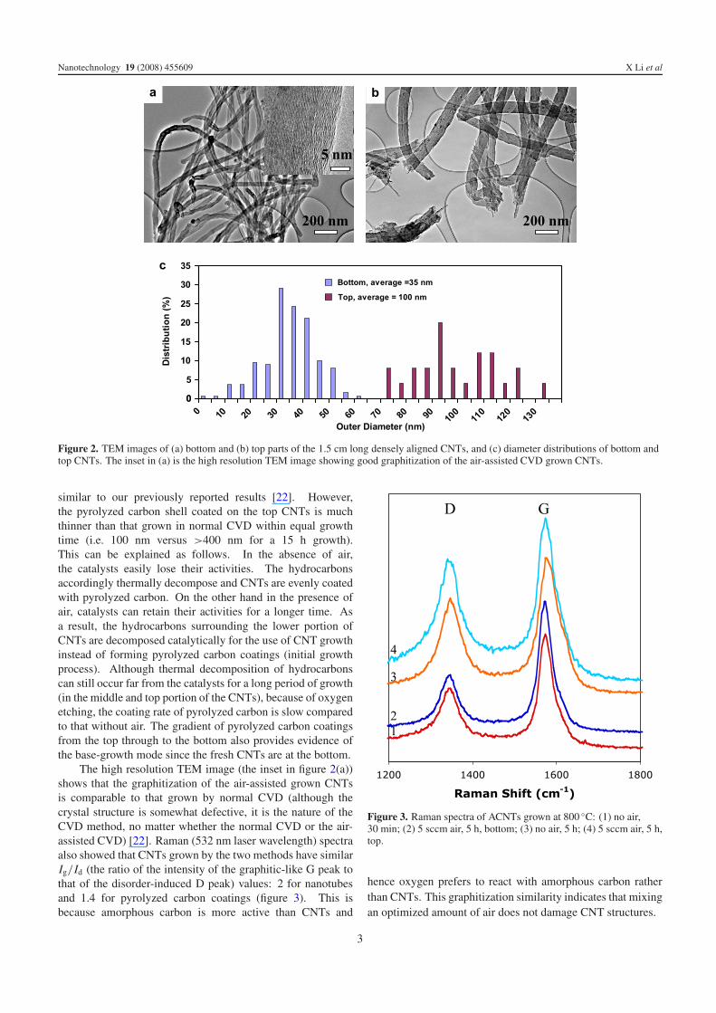
Figure 2. TEM images of (a) bottom and (b) top parts of the 1.5 cm long densely aligned CNTs, and (c) diameter distributions of bottom andtop CNTs. The inset in (a) is the high resolution TEM image showing good graphitization of the air-assisted CVD grown CNTs.
similar to our previously reported results [22]. However,the pyrolyzed carbon shell coated on the top CNTs is muchthinner than that grown in normal CVD within equal growthtime (i.e. 100 nm versus >400 nm for a 15 h growth).This can be explained as follows. In the absence of air,the catalysts easily lose their activities. The hydrocarbonsaccordingly thermally decompose and CNTs are evenly coatedwith pyrolyzed carbon. On the other hand in the presence ofair, catalysts can retain their activities for a longer time. Asa result, the hydrocarbons surrounding the lower portion ofCNTs are decomposed catalytically for the use of CNT growthinstead of forming pyrolyzed carbon coatings (initial growthprocess). Although thermal decomposition of hydrocarbonscan still occur far from the catalysts for a long period of growth(in the middle and top portion of the CNTs), because of oxygenetching, the coating rate of pyrolyzed carbon is slow comparedto that without air. The gradient of pyrolyzed carbon coatingsfrom the top through to the bottom also provides evidence ofthe base-growth mode since the fresh CNTs are at the bottom.
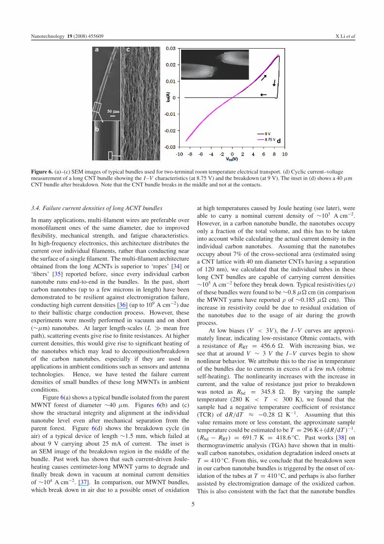
The high resolution TEM image (the inset in figure 2(a))shows that the graphitization of the air-assisted grown CNTsis comparable to that grown by normal CVD (although thecrystal structure is somewhat defective, it is the nature of theCVD method, no matter whether the normal CVD or the air-assisted CVD) [22]. Raman (532 nm laser wavelength) spectraalso showed that CNTs grown by the two methods have similarIg/Id (the ratio of the intensity of the graphitic-like G peak tothat of the disorder-induced D peak) values: 2 for nanotubesand 1.4 for pyrolyzed carbon coatings (figure 3). This isbecause amorphous carbon is more active than CNTs and
Figure 3. Raman spectra of ACNTs grown at 800 ◦C: (1) no air,30 min; (2) 5 sccm air, 5 h, bottom; (3) no air, 5 h; (4) 5 sccm air, 5 h,top.
hence oxygen prefers to react with amorphous carbon ratherthan CNTs. This graphitization similarity indicates that mixingan optimized amount of air does not damage CNT structures.
3

Nanotechnology 19 (2008) 455609 X Li et al
Figure 4. (a) Air flow effects on ACNT growth kinetics. (b) Air floweffects on average outer diameters of CNTs. Growth parameters:g0 = 200 sccm, CFerrocene = 0.01 g ml−1, v = 0.11 ml min−1,T1 = 250 ◦C, T2 = 770 ◦C.
3.2. Air flow effects
Figure 4(a) shows the effects of air flow rate on the growthkinetics of the aligned MWNTs. When no air is injected, CNTgrowth shows an obvious lengthening–thickening process. Inthe lengthening process, catalysts are active and CNTs grow ata constant rate. In the thickening process, CNTs stop growingin length and their diameters are increased by being coated withpyrolyzed carbon. When an optimal amount of air is injected,catalyst lifetime is dramatically increased, and hence the CNTlengthening process can extend to a very long time. Thelongest experiment we carried out is for 15 h, and there wasstill no obvious decrease in CNT growth rate. The amount ofair also affects the thickness of the pyrolyzed carbon coatingson CNTs, as shown in figure 3(b). When there is no air, theCNTs are uniformly coated. In the presence of air, the bottomCNTs are always fresh without coatings no matter how muchair (since the plots are similar for the case of air = 1 sccmand 2 sccm, only one is shown in figure 4(b)). However, thethickness of pyrolyzed carbon coated on upper CNTs decreaseswith the increase of the air amount.
It should be noted that with the introduction of air theoptimum growth parameters become wider than that withoutair. For example, the optimized values for T2 = 770 ◦Care: g0 = 100–400 sccm, gair = 2–10 sccm, CFerrocene =
Figure 5. (a) Temperature effects on ACNT growth kinetics.(b) Arrhenius plot of CNT growth rate.
0.01–0.05 g ml−1, v = 0.11 ± 0.005 ml min−1, T1 =170–300 ◦C. For other temperatures the values shift slightlybut keep wide ranges. This wide growth window makes iteasier to achieve super-long aligned MWNTs.
3.3. Growth temperature effects
Figure 5(a) shows the data for the best CNT growth resultsobtained at different temperatures. With growth temperatureincreasing, more air was required to maintain the catalystactivity. The lengthening–thickening process appears again at830 ◦C, though 10 sccm air has been injected. This could bedue to the fact that hydrocarbons tend to be easily pyrolyzedat higher temperatures, and the pyrolyzed carbon encapsulatesthe catalyst particles and terminates CNT growth.
The CNT growth rate can be determined from the slopesof the plots in figure 5(a). The activation energy can beestimated from the Arrhenius plot similarly to the reportedmethod [32]. The growth rate of CNTs is expressed by v =A[C]sat exp(−Eact/RT ), where A is a constant independent oftemperature, [C]sat is the saturated concentration of carbon inγ -Fe, and Eact is the activation energy. The Arrhenius plot ofln(v/[C]sat) versus 1/T is shown in figure 5(b). The linearfit gives a value of Eact, 145 ± 2 kJ mol−1, which is close tothe data reported by other groups [31–33], suggesting that thediffusion of C atoms in metal catalyst particles would be a rate-determining step for CNT growth in the present system.
4
Nanotechnology 19 (2008) 455609 X Li et al
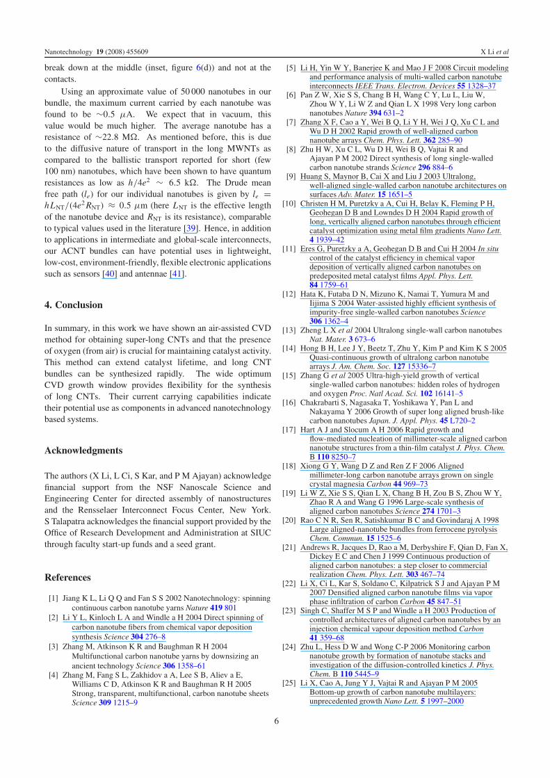
Figure 6. (a)–(c) SEM images of typical bundles used for two-terminal room temperature electrical transport. (d) Cyclic current–voltagemeasurement of a long CNT bundle showing the I–V characteristics (at 8.75 V) and the breakdown (at 9 V). The inset in (d) shows a 40 μmCNT bundle after breakdown. Note that the CNT bundle breaks in the middle and not at the contacts.
3.4. Failure current densities of long ACNT bundles
In many applications, multi-filament wires are preferable overmonofilament ones of the same diameter, due to improvedflexibility, mechanical strength, and fatigue characteristics.In high-frequency electronics, this architecture distributes thecurrent over individual filaments, rather than conducting nearthe surface of a single filament. The multi-filament architectureobtained from the long ACNTs is superior to ‘ropes’ [34] or‘fibers’ [35] reported before, since every individual carbonnanotube runs end-to-end in the bundles. In the past, shortcarbon nanotubes (up to a few microns in length) have beendemonstrated to be resilient against electromigration failure,conducting high current densities [36] (up to 109 A cm−2) dueto their ballistic charge conduction process. However, theseexperiments were mostly performed in vacuum and on short(∼μm) nanotubes. At larger length-scales (L � mean freepath), scattering events give rise to finite resistances. At highercurrent densities, this would give rise to significant heating ofthe nanotubes which may lead to decomposition/breakdownof the carbon nanotubes, especially if they are used inapplications in ambient conditions such as sensors and antennatechnologies. Hence, we have tested the failure currentdensities of small bundles of these long MWNTs in ambientconditions.
Figure 6(a) shows a typical bundle isolated from the parentMWNT forest of diameter ∼40 μm. Figures 6(b) and (c)show the structural integrity and alignment at the individualnanotube level even after mechanical separation from theparent forest. Figure 6(d) shows the breakdown cycle (inair) of a typical device of length ∼1.5 mm, which failed atabout 9 V carrying about 25 mA of current. The inset isan SEM image of the breakdown region in the middle of thebundle. Past work has shown that such current-driven Joule-heating causes centimeter-long MWNT yarns to degrade andfinally break down in vacuum at nominal current densitiesof ∼104 A cm−2. [37]. In comparison, our MWNT bundles,which break down in air due to a possible onset of oxidation
at high temperatures caused by Joule heating (see later), wereable to carry a nominal current density of ∼103 A cm−2.However, in a carbon nanotube bundle, the nanotubes occupyonly a fraction of the total volume, and this has to be takeninto account while calculating the actual current density in theindividual carbon nanotubes. Assuming that the nanotubesoccupy about 7% of the cross-sectional area (estimated usinga CNT lattice with 40 nm diameter CNTs having a separationof 120 nm), we calculated that the individual tubes in theselong CNT bundles are capable of carrying current densities∼105 A cm−2 before they break down. Typical resistivities (ρ)of these bundles were found to be ∼0.8 μ� cm (in comparisonthe MWNT yarns have reported ρ of ∼0.185 μ� cm). Thisincrease in resistivity could be due to residual oxidation ofthe nanotubes due to the usage of air during the growthprocess.
At low biases (V < 3V ), the I –V curves are approxi-mately linear, indicating low-resistance Ohmic contacts, witha resistance of RRT = 456.6 �. With increasing bias, wesee that at around V ∼ 3 V the I –V curves begin to shownonlinear behavior. We attribute this to the rise in temperatureof the bundles due to currents in excess of a few mA (ohmicself-heating). The nonlinearity increases with the increase incurrent, and the value of resistance just prior to breakdownwas noted as Rbd = 345.8 �. By varying the sampletemperature (280 K < T < 300 K), we found that thesample had a negative temperature coefficient of resistance(TCR) of dR/dT ≈ −0.28 � K−1. Assuming that thisvalue remains more or less constant, the approximate sampletemperature could be estimated to be T = 296 K+(dR/dT )−1.(Rbd − RRT) = 691.7 K = 418.6 ◦C. Past works [38] onthermogravimetric analysis (TGA) have shown that in multi-wall carbon nanotubes, oxidation degradation indeed onsets atT = 410 ◦C. From this, we conclude that the breakdown seenin our carbon nanotube bundles is triggered by the onset of ox-idation of the tubes at T = 410 ◦C, and perhaps is also furtherassisted by electromigration damage of the oxidized carbon.This is also consistent with the fact that the nanotube bundles
5
Nanotechnology 19 (2008) 455609 X Li et al
break down at the middle (inset, figure 6(d)) and not at thecontacts.
Using an approximate value of 50 000 nanotubes in ourbundle, the maximum current carried by each nanotube wasfound to be ∼0.5 μA. We expect that in vacuum, thisvalue would be much higher. The average nanotube has aresistance of ∼22.8 M�. As mentioned before, this is dueto the diffusive nature of transport in the long MWNTs ascompared to the ballistic transport reported for short (few100 nm) nanotubes, which have been shown to have quantumresistances as low as h/4e2 ∼ 6.5 k�. The Drude meanfree path (le) for our individual nanotubes is given by le =hLNT/(4e2 RNT) ≈ 0.5 μm (here LNT is the effective lengthof the nanotube device and RNT is its resistance), comparableto typical values used in the literature [39]. Hence, in additionto applications in intermediate and global-scale interconnects,our ACNT bundles can have potential uses in lightweight,low-cost, environment-friendly, flexible electronic applicationssuch as sensors [40] and antennae [41].
4. Conclusion
In summary, in this work we have shown an air-assisted CVDmethod for obtaining super-long CNTs and that the presenceof oxygen (from air) is crucial for maintaining catalyst activity.This method can extend catalyst lifetime, and long CNTbundles can be synthesized rapidly. The wide optimumCVD growth window provides flexibility for the synthesisof long CNTs. Their current carrying capabilities indicatetheir potential use as components in advanced nanotechnologybased systems.
Acknowledgments
The authors (X Li, L Ci, S Kar, and P M Ajayan) acknowledgefinancial support from the NSF Nanoscale Science andEngineering Center for directed assembly of nanostructuresand the Rensselaer Interconnect Focus Center, New York.S Talapatra acknowledges the financial support provided by theOffice of Research Development and Administration at SIUCthrough faculty start-up funds and a seed grant.
References
[1] Jiang K L, Li Q Q and Fan S S 2002 Nanotechnology: spinningcontinuous carbon nanotube yarns Nature 419 801
[2] Li Y L, Kinloch L A and Windle a H 2004 Direct spinning ofcarbon nanotube fibers from chemical vapor depositionsynthesis Science 304 276–8
[3] Zhang M, Atkinson K R and Baughman R H 2004Multifunctional carbon nanotube yarns by downsizing anancient technology Science 306 1358–61
[4] Zhang M, Fang S L, Zakhidov a A, Lee S B, Aliev a E,Williams C D, Atkinson K R and Baughman R H 2005Strong, transparent, multifunctional, carbon nanotube sheetsScience 309 1215–9
[5] Li H, Yin W Y, Banerjee K and Mao J F 2008 Circuit modelingand performance analysis of multi-walled carbon nanotubeinterconnects IEEE Trans. Electron. Devices 55 1328–37
[6] Pan Z W, Xie S S, Chang B H, Wang C Y, Lu L, Liu W,Zhou W Y, Li W Z and Qian L X 1998 Very long carbonnanotubes Nature 394 631–2
[7] Zhang X F, Cao a Y, Wei B Q, Li Y H, Wei J Q, Xu C L andWu D H 2002 Rapid growth of well-aligned carbonnanotube arrays Chem. Phys. Lett. 362 285–90
[8] Zhu H W, Xu C L, Wu D H, Wei B Q, Vajtai R andAjayan P M 2002 Direct synthesis of long single-walledcarbon nanotube strands Science 296 884–6
[9] Huang S, Maynor B, Cai X and Liu J 2003 Ultralong,well-aligned single-walled carbon nanotube architectures onsurfaces Adv. Mater. 15 1651–5
[10] Christen H M, Puretzky a A, Cui H, Belay K, Fleming P H,Geohegan D B and Lowndes D H 2004 Rapid growth oflong, vertically aligned carbon nanotubes through efficientcatalyst optimization using metal film gradients Nano Lett.4 1939–42
[11] Eres G, Puretzky a A, Geohegan D B and Cui H 2004 In situcontrol of the catalyst efficiency in chemical vapordeposition of vertically aligned carbon nanotubes onpredeposited metal catalyst films Appl. Phys. Lett.84 1759–61
[12] Hata K, Futaba D N, Mizuno K, Namai T, Yumura M andIijima S 2004 Water-assisted highly efficient synthesis ofimpurity-free single-walled carbon nanotubes Science306 1362–4
[13] Zheng L X et al 2004 Ultralong single-wall carbon nanotubesNat. Mater. 3 673–6
[14] Hong B H, Lee J Y, Beetz T, Zhu Y, Kim P and Kim K S 2005Quasi-continuous growth of ultralong carbon nanotubearrays J. Am. Chem. Soc. 127 15336–7
[15] Zhang G et al 2005 Ultra-high-yield growth of verticalsingle-walled carbon nanotubes: hidden roles of hydrogenand oxygen Proc. Natl Acad. Sci. 102 16141–5
[16] Chakrabarti S, Nagasaka T, Yoshikawa Y, Pan L andNakayama Y 2006 Growth of super long aligned brush-likecarbon nanotubes Japan. J. Appl. Phys. 45 L720–2
[17] Hart A J and Slocum A H 2006 Rapid growth andflow-mediated nucleation of millimeter-scale aligned carbonnanotube structures from a thin-film catalyst J. Phys. Chem.B 110 8250–7
[18] Xiong G Y, Wang D Z and Ren Z F 2006 Alignedmillimeter-long carbon nanotube arrays grown on singlecrystal magnesia Carbon 44 969–73
[19] Li W Z, Xie S S, Qian L X, Chang B H, Zou B S, Zhou W Y,Zhao R A and Wang G 1996 Large-scale synthesis ofaligned carbon nanotubes Science 274 1701–3
[20] Rao C N R, Sen R, Satishkumar B C and Govindaraj A 1998Large aligned-nanotube bundles from ferrocene pyrolysisChem. Commun. 15 1525–6
[21] Andrews R, Jacques D, Rao a M, Derbyshire F, Qian D, Fan X,Dickey E C and Chen J 1999 Continuous production ofaligned carbon nanotubes: a step closer to commercialrealization Chem. Phys. Lett. 303 467–74
[22] Li X, Ci L, Kar S, Soldano C, Kilpatrick S J and Ajayan P M2007 Densified aligned carbon nanotube films via vaporphase infiltration of carbon Carbon 45 847–51
[23] Singh C, Shaffer M S P and Windle a H 2003 Production ofcontrolled architectures of aligned carbon nanotubes by aninjection chemical vapour deposition method Carbon41 359–68
[24] Zhu L, Hess D W and Wong C-P 2006 Monitoring carbonnanotube growth by formation of nanotube stacks andinvestigation of the diffusion-controlled kinetics J. Phys.Chem. B 110 5445–9
[25] Li X, Cao A, Jung Y J, Vajtai R and Ajayan P M 2005Bottom-up growth of carbon nanotube multilayers:unprecedented growth Nano Lett. 5 1997–2000
6
Nanotechnology 19 (2008) 455609 X Li et al
[26] Pinault M, Pichot V, Khodja H, Launois P, Reynaud C andMayne-L’hermite M 2005 Evidence of sequential lift ingrowth of aligned multiwalled carbon nanotube multilayersNano Lett. 5 2394–8
[27] Zhu L, Xiu Y, Hess D W and Wong C-P 2005 Aligned carbonnanotube stacks by water-assisted selective etching NanoLett.5 2641–5
[28] Baker R T K 1989 Catalytic growth of carbon filaments Carbon27 315–23
[29] Bower C, Zhou O, Zhu W, Zhu W, Werder D J, Jin S andJin S 2000 Nucleation and growth of carbon nanotubes bymicrowave plasma chemical vapor deposition Appl. Phys.Lett. 77 2767–9
[30] Li Y M, Kim W, Zhang Y G, Rolandi M, Wang D W andDai H J 2001 Growth of single-walled carbon nanotubesfrom discrete catalytic nanoparticles of various sizes J. Phys.Chem. B 105 11424–31
[31] Helveg S, Lopez-Cartes C, Sehested J, Hansen P L,Clausen B S, Rostrup-Nielsen J R, Abild-Pedersen F andNorskov J K 2004 Atomic-scale imaging of carbon nanofibregrowth Nature 427 426–9
[32] Kim K E, Kim K J, Jung W S, Bae S Y, Park J, Choi J andChoo J 2005 Investigation on the temperature-dependentgrowth rate of carbon nanotubes using chemical vapordeposition of ferrocene and acetylene Chem. Phys. Lett.401 459–64
[33] Baker R T K, Barber M A, Harris P S, Feates F S andWaite R J 1972 Nucleation and growth of carbon depositsfrom the nickel catalyzed decomposition of acetyleneJ. Catal. 26 51–62
[34] Baughman R H, Zakhidov A A and Deheer W A 2002 Carbonnanotubes–the route toward applications Science297 787–92
[35] Harris P J F 2004 Carbon nanotube composites Int. Mater.49 31–43
[36] Wei B Q, Vajtai R and Ajayan P M 2001 Reliability and currentcarrying capacity of carbon nanotubes Appl. Phys. Lett.79 1172–4
[37] Wei Y, Jiang K L, Liu L, Chen Z and Fan S S 2007Vacuum-breakdown-induced needle-shaped ends ofmultiwalled carbon nanotube yarns and their field emissionapplications Nano Lett. 7 3792–7
[38] Chena C-M, Chenb M, Leub F-C, Hsub S-Y, Wangb S-C,Shia S-C and Chena C-F 2004 Purification of multi-walledcarbon nanotubes by microwave digestion method DiamondRelat. Mater. 13 1182–6
[39] Cho H, Koo K-H, Kapur P and Saraswat K C 2008Performance comparisons between Cu/low-κ ,carbon-nanotube, and optics for future on-chip interconnectsIEEE Electron Device Lett. 29 122
[40] Zhao L, Choi M, Kim H S and Hong S H 2007 The effect ofmultiwalled carbon nanotube doping on the CO gassensitivity of SnO2-based nanomaterials Nanotechnology18 445501
[41] Wang Y, Kempa K, Kimball B, Carlson J B, Benham G, Li WZ, Kempa T, Rybczynski J, Herczynski A and Ren Z F 2004Receiving and transmitting light-like radio waves: Antennaeffect in arrays of aligned carbon nanotubes Appl. Phys. Lett.85 2607–9
7