Using CTP Bundles to Create Logical Configurations for ...
210
Using CTP Bundles to Create Logical Configurations for Physical Interfaces Modified: 2016-02-23 Copyright © 2016, Juniper Networks, Inc.
-
Upload
khangminh22 -
Category
Documents
-
view
1 -
download
0
Transcript of Using CTP Bundles to Create Logical Configurations for ...

Using CTP Bundles to Create LogicalConfigurations for Physical Interfaces
Modified: 2016-02-23
Copyright © 2016, Juniper Networks, Inc.

Juniper Networks, Inc.1133 Innovation WaySunnyvale, California 94089USA408-745-2000www.juniper.net
Copyright © 2016, Juniper Networks, Inc. All rights reserved.
Juniper Networks, Junos, Steel-Belted Radius, NetScreen, and ScreenOS are registered trademarks of Juniper Networks, Inc. in the UnitedStates and other countries. The Juniper Networks Logo, the Junos logo, and JunosE are trademarks of Juniper Networks, Inc. All othertrademarks, service marks, registered trademarks, or registered service marks are the property of their respective owners.
Juniper Networks assumes no responsibility for any inaccuracies in this document. Juniper Networks reserves the right to change, modify,transfer, or otherwise revise this publication without notice.
Using CTP Bundles to Create Logical Configurations for Physical InterfacesCopyright © 2016, Juniper Networks, Inc.All rights reserved.
The information in this document is current as of the date on the title page.
YEAR 2000 NOTICE
Juniper Networks hardware and software products are Year 2000 compliant. Junos OS has no known time-related limitations through theyear 2038. However, the NTP application is known to have some difficulty in the year 2036.
ENDUSER LICENSE AGREEMENT
The Juniper Networks product that is the subject of this technical documentation consists of (or is intended for use with) Juniper Networkssoftware. Use of such software is subject to the terms and conditions of the End User License Agreement (“EULA”) posted athttp://www.juniper.net/support/eula.html. By downloading, installing or using such software, you agree to the terms and conditions ofthat EULA.
Copyright © 2016, Juniper Networks, Inc.ii

Table of Contents
About the Documentation . . . . . . . . . . . . . . . . . . . . . . . . . . . . . . . . . . . . . . . . . . . . xv
Documentation and Release Notes . . . . . . . . . . . . . . . . . . . . . . . . . . . . . . . . . xv
Documentation Conventions . . . . . . . . . . . . . . . . . . . . . . . . . . . . . . . . . . . . . . xv
Documentation Feedback . . . . . . . . . . . . . . . . . . . . . . . . . . . . . . . . . . . . . . . . xvii
Requesting Technical Support . . . . . . . . . . . . . . . . . . . . . . . . . . . . . . . . . . . . xviii
Self-Help Online Tools and Resources . . . . . . . . . . . . . . . . . . . . . . . . . . xviii
Opening a Case with JTAC . . . . . . . . . . . . . . . . . . . . . . . . . . . . . . . . . . . . xviii
Part 1 Overview
Chapter 1 Using Bundles to Create Logical Configurations for Physical InterfacesOverview . . . . . . . . . . . . . . . . . . . . . . . . . . . . . . . . . . . . . . . . . . . . . . . . . . . . . . . . . . 3
Types of Bundles Overview . . . . . . . . . . . . . . . . . . . . . . . . . . . . . . . . . . . . . . . . . . . . 3
Interface Naming Conventions for the CTP Series . . . . . . . . . . . . . . . . . . . . . . . . . . 4
Chapter 2 CTP Bundle Overview . . . . . . . . . . . . . . . . . . . . . . . . . . . . . . . . . . . . . . . . . . . . . . . 7
Adaptive Clocking Overview for CTP Bundles . . . . . . . . . . . . . . . . . . . . . . . . . . . . . . 7
Determining Optimal Packet Size for CTP Bundles Overview . . . . . . . . . . . . . . . . . 8
Bandwidth for Transporting Serial Data . . . . . . . . . . . . . . . . . . . . . . . . . . . . . . 8
Packet Creation Delay . . . . . . . . . . . . . . . . . . . . . . . . . . . . . . . . . . . . . . . . . . . . . 8
Performance of the IP Network . . . . . . . . . . . . . . . . . . . . . . . . . . . . . . . . . . . . . 9
Providing QoS for CTP Bundles by Using Service Type Overview . . . . . . . . . . . . . . 10
Circuit Startup Process Overview . . . . . . . . . . . . . . . . . . . . . . . . . . . . . . . . . . . . . . . 11
Network Node Reference Overview . . . . . . . . . . . . . . . . . . . . . . . . . . . . . . . . . . . . . 12
Guidelines for Configuring NetRef . . . . . . . . . . . . . . . . . . . . . . . . . . . . . . . . . . . 12
Support for Multiple Master Nodes to Associate With a Single Slave Node in
NetRef . . . . . . . . . . . . . . . . . . . . . . . . . . . . . . . . . . . . . . . . . . . . . . . . . . . . . . . . 13
Loss of Signal Detection Capability on CTP Bundles and SAToP Bundles . . . . . . . 15
Detection of LOS on Serial Interfaces . . . . . . . . . . . . . . . . . . . . . . . . . . . . . . . . 16
Detection of LOS on T1/E1 Interfaces . . . . . . . . . . . . . . . . . . . . . . . . . . . . . . . . 17
Guidelines for Configuring LOS Detection . . . . . . . . . . . . . . . . . . . . . . . . . . . . . . . . 17
Chapter 3 Transparent Encoding Overview . . . . . . . . . . . . . . . . . . . . . . . . . . . . . . . . . . . . . 19
Transparent Encoding Applications and Support Overview . . . . . . . . . . . . . . . . . . 19
How Basic Transparent Encoding Works . . . . . . . . . . . . . . . . . . . . . . . . . . . . . . . . 20
Using Phase-Correction FIFO Buffer with Transparent Encoding . . . . . . . . . . . . . . 21
Using Send Timing (ST) Clocking for Higher Speed Circuits with Transparent
Encoding . . . . . . . . . . . . . . . . . . . . . . . . . . . . . . . . . . . . . . . . . . . . . . . . . . . . . . 23
iiiCopyright © 2016, Juniper Networks, Inc.

Chapter 4 TDM/TDC Encoding Overview . . . . . . . . . . . . . . . . . . . . . . . . . . . . . . . . . . . . . . 25
TDM/TDC Encoding Overview . . . . . . . . . . . . . . . . . . . . . . . . . . . . . . . . . . . . . . . . . 25
How TDM Interleaving Works . . . . . . . . . . . . . . . . . . . . . . . . . . . . . . . . . . . . . . 25
How the CTP Implementation of TDM/TDC Works . . . . . . . . . . . . . . . . . . . . 26
TDM Rates . . . . . . . . . . . . . . . . . . . . . . . . . . . . . . . . . . . . . . . . . . . . . . . . . . . . . 26
TDM High-Speed and Low-Speed Ports . . . . . . . . . . . . . . . . . . . . . . . . . . . . . 27
Chapter 5 Ethernet Media Configuration Overview . . . . . . . . . . . . . . . . . . . . . . . . . . . . . . 29
Ethernet Media Configuration Overview . . . . . . . . . . . . . . . . . . . . . . . . . . . . . . . . . 29
Support for Full-Duplex Mode Only on NIC Ports Connected to CTP
Devices . . . . . . . . . . . . . . . . . . . . . . . . . . . . . . . . . . . . . . . . . . . . . . . . . . . . 29
Part 2 Configuration
Chapter 6 Configuring CTP Bundles (CTP Menu) . . . . . . . . . . . . . . . . . . . . . . . . . . . . . . . 33
Adding a Bundle (CTP Menu) . . . . . . . . . . . . . . . . . . . . . . . . . . . . . . . . . . . . . . . . . 34
Configuring IP Parameters for CTP Bundles (CTP Menu) . . . . . . . . . . . . . . . . . . . 34
Configuring Circuit Startup Parameters for CTP Bundles (CTP Menu) . . . . . . . . . 36
Configuring the Direction of the Circuit (CTP Menu) . . . . . . . . . . . . . . . . . . . . . . . 37
Configuring Virtual IP Parameters for CTP Bundles (CTP Menu) . . . . . . . . . . . . . 38
Configuring IP Forwarding for CTP Bundles (CTP Menu) . . . . . . . . . . . . . . . . . . . . 39
Configuring the Missing Packet Fill Pattern for CTP Bundles (CTP Menu) . . . . . . 40
Configuring Signaling for CTP Bundles (CTP Menu) . . . . . . . . . . . . . . . . . . . . . . . 42
Configuring Multiservice Port Parameters for CTP Bundles (CTPView) . . . . . . . . 46
Configuring Multiservice Audio Mode Port Parameters for CTP Bundles
(CTPView) . . . . . . . . . . . . . . . . . . . . . . . . . . . . . . . . . . . . . . . . . . . . . . . . . 46
Configuring Multiservice IRIG-B Mode Port Parameters for CTP Bundles
(CTPView) . . . . . . . . . . . . . . . . . . . . . . . . . . . . . . . . . . . . . . . . . . . . . . . . . 48
Configuring Multiservice TDC Mode Parameters for CTP Bundles
(CTPView) . . . . . . . . . . . . . . . . . . . . . . . . . . . . . . . . . . . . . . . . . . . . . . . . . 49
Configuring Multiservice 4WTO Mode Port Parameters for CTP Bundles
(CTPView) . . . . . . . . . . . . . . . . . . . . . . . . . . . . . . . . . . . . . . . . . . . . . . . . . 50
Configuring Serial Port Parameters for CTP Bundles (CTP Menu) . . . . . . . . . . . . 52
Configuring Transparent Encoding for CTP Bundles (CTP Menu) . . . . . . . . . . . . . 55
Configuring Bundle Pairs for TDM/TDC Operation (CTP Menu) . . . . . . . . . . . . . . 56
Configuring the High-Speed CTP Bundle for TDM/TDC Operation (CTP
Menu) . . . . . . . . . . . . . . . . . . . . . . . . . . . . . . . . . . . . . . . . . . . . . . . . . . . . . 57
Configuring the Low-Speed CTP Bundle for TDM/TDC Operation (CTP
Menu) . . . . . . . . . . . . . . . . . . . . . . . . . . . . . . . . . . . . . . . . . . . . . . . . . . . . . 58
Configuring T1 and E1 Port Parameters for CTP Bundles (CTP Menu) . . . . . . . . . 59
Configuring Multiservice Port Parameters for CTP Bundles (CTP Menu) . . . . . . . 62
Configuring Multiservice Audio Mode Port Parameters for CTP Bundles (CTP
Menu) . . . . . . . . . . . . . . . . . . . . . . . . . . . . . . . . . . . . . . . . . . . . . . . . . . . . . 62
Configuring Multiservice IRIG-B Mode Port Parameters for CTP Bundles
(CTP Menu) . . . . . . . . . . . . . . . . . . . . . . . . . . . . . . . . . . . . . . . . . . . . . . . . 64
Configuring Multiservice TDC Mode Parameters for CTP Bundles (CTP
Menu) . . . . . . . . . . . . . . . . . . . . . . . . . . . . . . . . . . . . . . . . . . . . . . . . . . . . 66
Configuring Multiservice 4WTO Mode Port Parameters for CTP Bundles
(CTP Menu) . . . . . . . . . . . . . . . . . . . . . . . . . . . . . . . . . . . . . . . . . . . . . . . . 67
Copyright © 2016, Juniper Networks, Inc.iv
Using CTP Bundles to Create Logical Configurations for Physical Interfaces

Configuring 4WTO Port Parameters for CTP Bundles (CTP Menu) . . . . . . . . . . . 69
Configuring IRIG-B Port Parameters for CTP Bundles (CTP Menu) . . . . . . . . . . . . 72
Configuring Advanced Port Options for CTP Bundles (CTP Menu) . . . . . . . . . . . . 74
Selecting the Type of Clocking on Serial Ports for CTP Bundles (CTP Menu) . . . . 75
Configuring Custom Clocking for CTP Bundles (CTP Menu) . . . . . . . . . . . . . . . . . 78
Configuring Adaptive Clocking for CTP Bundles (CTP Menu) . . . . . . . . . . . . . . . . 81
Configuring Ethernet Media (CTP Menu) . . . . . . . . . . . . . . . . . . . . . . . . . . . . . . . . 83
Displaying Ethernet Media Information (CTP Menu) . . . . . . . . . . . . . . . . . . . . . . . 84
Configuring PBS and Bridge Ports (CTP Menu) . . . . . . . . . . . . . . . . . . . . . . . . . . . 85
Configuring Port Mirroring for CTP Bundles (CTP Menu) . . . . . . . . . . . . . . . . . . . . 87
Configuring NetRef for Adaptive Bundle Operation . . . . . . . . . . . . . . . . . . . . . . . . 89
Configuring NetRef for Primary or Backup Operation . . . . . . . . . . . . . . . . . . . . . . 90
Configuring NetRef Multiple Master Nodes (CTP Menu) . . . . . . . . . . . . . . . . . . . . 90
Configuring NetRef Settings (CTPView) . . . . . . . . . . . . . . . . . . . . . . . . . . . . . . . . . 94
Configuring LOS Detection on CTP and SAToP Bundles (CTP Menu) . . . . . . . . . . 96
Configuring Cryptographic Resynchronization (Crypto Resync) . . . . . . . . . . . . . . 97
Chapter 7 Configuring CTP Bundles (CTPView) . . . . . . . . . . . . . . . . . . . . . . . . . . . . . . . . 101
Adding a Bundle (CTPView) . . . . . . . . . . . . . . . . . . . . . . . . . . . . . . . . . . . . . . . . . . 101
Configuring IP Parameters for CTP Bundles (CTPView) . . . . . . . . . . . . . . . . . . . . 102
Configuring Circuit Startup Parameters for CTP Bundles (CTPView) . . . . . . . . . 104
Configuring the Direction of the Circuit (CTPView) . . . . . . . . . . . . . . . . . . . . . . . 105
Configuring Virtual IP Parameters for CTP Bundles (CTPView) . . . . . . . . . . . . . . 106
Configuring IP Forwarding for CTP Bundles (CTPView) . . . . . . . . . . . . . . . . . . . . 107
Configuring the Missing Packet Fill Pattern for CTP Bundles (CTPView) . . . . . . 108
Configuring Signaling for CTP Bundles (CTPView) . . . . . . . . . . . . . . . . . . . . . . . . 110
Configuring Multiservice Port Parameters for CTP Bundles (CTP Menu) . . . . . . . 113
Configuring Multiservice Audio Mode Port Parameters for CTP Bundles (CTP
Menu) . . . . . . . . . . . . . . . . . . . . . . . . . . . . . . . . . . . . . . . . . . . . . . . . . . . . . 113
Configuring Multiservice IRIG-B Mode Port Parameters for CTP Bundles
(CTP Menu) . . . . . . . . . . . . . . . . . . . . . . . . . . . . . . . . . . . . . . . . . . . . . . . . 115
Configuring Multiservice TDC Mode Parameters for CTP Bundles (CTP
Menu) . . . . . . . . . . . . . . . . . . . . . . . . . . . . . . . . . . . . . . . . . . . . . . . . . . . . . 117
Configuring Multiservice 4WTO Mode Port Parameters for CTP Bundles
(CTP Menu) . . . . . . . . . . . . . . . . . . . . . . . . . . . . . . . . . . . . . . . . . . . . . . . . 118
Configuring Serial Port Parameters for CTP Bundles (CTPView) . . . . . . . . . . . . . 119
Configuring Transparent Encoding for CTP Bundles (CTPView) . . . . . . . . . . . . . 122
Configuring Bundle Pairs for TDM/TDC Operation (CTPView) . . . . . . . . . . . . . . . 124
Configuring the High-Speed CTP Bundle for TDM/TDC Operation
(CTPView) . . . . . . . . . . . . . . . . . . . . . . . . . . . . . . . . . . . . . . . . . . . . . . . . 124
Configuring the Low-Speed CTP Bundle for TDM/TDC Operation
(CTPView) . . . . . . . . . . . . . . . . . . . . . . . . . . . . . . . . . . . . . . . . . . . . . . . . 125
Configuring T1 and E1 Port Parameters for CTP Bundles (CTPView) . . . . . . . . . . 126
Configuring Multiservice Port Parameters for CTP Bundles (CTPView) . . . . . . . . 128
Configuring Multiservice Audio Mode Port Parameters for CTP Bundles
(CTPView) . . . . . . . . . . . . . . . . . . . . . . . . . . . . . . . . . . . . . . . . . . . . . . . . 128
Configuring Multiservice IRIG-B Mode Port Parameters for CTP Bundles
(CTPView) . . . . . . . . . . . . . . . . . . . . . . . . . . . . . . . . . . . . . . . . . . . . . . . . 130
vCopyright © 2016, Juniper Networks, Inc.
Table of Contents

Configuring Multiservice TDC Mode Parameters for CTP Bundles
(CTPView) . . . . . . . . . . . . . . . . . . . . . . . . . . . . . . . . . . . . . . . . . . . . . . . . 132
Configuring Multiservice 4WTO Mode Port Parameters for CTP Bundles
(CTPView) . . . . . . . . . . . . . . . . . . . . . . . . . . . . . . . . . . . . . . . . . . . . . . . . 132
Configuring 4WTO Port Parameters for CTP Bundles (CTPView) . . . . . . . . . . . . 134
Configuring IRIG-B Port Parameters for CTP Bundles (CTPView) . . . . . . . . . . . . 137
Configuring Advanced Port Options for CTP Bundles (CTPView) . . . . . . . . . . . . 139
Selecting the Type of Clocking on Serial Ports for CTP Bundles (CTPView) . . . . 140
Configuring Custom Clocking for CTP Bundles (CTPView) . . . . . . . . . . . . . . . . . 142
Configuring Adaptive Clocking for CTP Bundles (CTPView) . . . . . . . . . . . . . . . . 145
Configuring PBS and Bridge Ports (CTPView) . . . . . . . . . . . . . . . . . . . . . . . . . . . 146
Configuring Port Mirroring for CTP Bundles (CTPView) . . . . . . . . . . . . . . . . . . . . 148
Configuring NetRef Settings (CTPView) . . . . . . . . . . . . . . . . . . . . . . . . . . . . . . . . 149
Part 3 Administration
Chapter 8 Activating, Disabling, Deleting, or Recentering CTP Bundles . . . . . . . . . . . 153
Activating, Disabling, Deleting, or Recentering CTP Bundles (CTPView) . . . . . . . 153
Activating, Disabling, Deleting, or Recentering for CTP Bundles (CTP Menu) . . . 153
Chapter 9 Querying CTP Bundles . . . . . . . . . . . . . . . . . . . . . . . . . . . . . . . . . . . . . . . . . . . . 155
Displaying the Running CTP Bundle Configuration, State, and Counters (CTP
Menu) . . . . . . . . . . . . . . . . . . . . . . . . . . . . . . . . . . . . . . . . . . . . . . . . . . . . . . . . 155
Displaying the NetRef Node Synchronization Information (CTP Menu) . . . . . . . . 161
Displaying Running CTP Bundle Configuration, State, and Counters
(CTPView) . . . . . . . . . . . . . . . . . . . . . . . . . . . . . . . . . . . . . . . . . . . . . . . . . . . . 163
Chapter 10 Monitoring Packet Creation and Reception and Packet Delay . . . . . . . . . . 169
Using SCC Counts to Monitor Packet Creation and Reception for CTP Bundles
(CTP Menu) . . . . . . . . . . . . . . . . . . . . . . . . . . . . . . . . . . . . . . . . . . . . . . . . . . . 169
Using Buffer Sampling to Monitor Packet Delay for CTP Bundles (CTP
Menu) . . . . . . . . . . . . . . . . . . . . . . . . . . . . . . . . . . . . . . . . . . . . . . . . . . . . . . . . 170
Searching for Bundles Based on Bundle Description from CTPView . . . . . . . . . . . 171
Chapter 11 Diagnostic Testing for CTP Bundles Overview . . . . . . . . . . . . . . . . . . . . . . . . 173
Serial Loops for CTP Bundles Overview . . . . . . . . . . . . . . . . . . . . . . . . . . . . . . . . . 173
Normal Data Flow in the CTP Network . . . . . . . . . . . . . . . . . . . . . . . . . . . . . . 173
Serial Loop to the Serial Interface . . . . . . . . . . . . . . . . . . . . . . . . . . . . . . . . . . 173
Serial Loop to the Network . . . . . . . . . . . . . . . . . . . . . . . . . . . . . . . . . . . . . . . 174
BERT Testing for CTP Bundles Overview . . . . . . . . . . . . . . . . . . . . . . . . . . . . . . . . 174
End-to-End BERT for CTP Bundles Overview . . . . . . . . . . . . . . . . . . . . . . . . . . . . 175
Chapter 12 Configuring and Displaying Diagnostic Testing for CTP Bundles . . . . . . . . 177
Configuring Serial Loops for CTP Bundles (CTP Menu) . . . . . . . . . . . . . . . . . . . . . 177
Configuring Serial Loops for CTP Bundles (CTPView) . . . . . . . . . . . . . . . . . . . . . 178
Configuring BERT Testing for CTP Bundles (CTP Menu) . . . . . . . . . . . . . . . . . . . 179
Configuring BERT Testing for CTP Bundles (CTPView) . . . . . . . . . . . . . . . . . . . . 180
Displaying BERT Status and Counters for CTP Bundles (CTP Menu) . . . . . . . . . . 181
Displaying BERT Status and Counters for CTP Bundles (CTPView) . . . . . . . . . . 182
Copyright © 2016, Juniper Networks, Inc.vi
Using CTP Bundles to Create Logical Configurations for Physical Interfaces

Chapter 13 Reducing the Number of SNMP Traps Generated for Late andMissingPackets . . . . . . . . . . . . . . . . . . . . . . . . . . . . . . . . . . . . . . . . . . . . . . . . . . . . . . . . . 185
Reducing the Number of SNMP Traps Generated for Late and Missing Packets
(CTP Menu) . . . . . . . . . . . . . . . . . . . . . . . . . . . . . . . . . . . . . . . . . . . . . . . . . . . 185
Part 4 Index
Index . . . . . . . . . . . . . . . . . . . . . . . . . . . . . . . . . . . . . . . . . . . . . . . . . . . . . . . . 189
viiCopyright © 2016, Juniper Networks, Inc.
Table of Contents

Copyright © 2016, Juniper Networks, Inc.viii
Using CTP Bundles to Create Logical Configurations for Physical Interfaces

List of Figures
Part 1 Overview
Chapter 3 Transparent Encoding Overview . . . . . . . . . . . . . . . . . . . . . . . . . . . . . . . . . . . . . 19
Figure 1: Simplified Model of a Transparent Encoded Circuit . . . . . . . . . . . . . . . . . 20
Figure 2: Transparent Encoding with Phase-Correction FIFO Buffers . . . . . . . . . . . 21
Figure 3: Clock and Data Paths with Transparent Phase-Correction FIFO
Buffers . . . . . . . . . . . . . . . . . . . . . . . . . . . . . . . . . . . . . . . . . . . . . . . . . . . . . . . . 22
Figure 4: High-Speed and Low-Speed Paths with Transparent Encoding . . . . . . . 23
Figure 5: Transparent Encoding Using ST Clocking . . . . . . . . . . . . . . . . . . . . . . . . . 24
Chapter 4 TDM/TDC Encoding Overview . . . . . . . . . . . . . . . . . . . . . . . . . . . . . . . . . . . . . . 25
Figure 6: Serial Port Bit Allocation Without TDM . . . . . . . . . . . . . . . . . . . . . . . . . . 25
Figure 7: Serial Port Bit Allocation With 16 Bits Allocated to TDM . . . . . . . . . . . . . 25
Figure 8: Bit Allocation for TDM Rates of 2, 4, and 8 . . . . . . . . . . . . . . . . . . . . . . . 26
Figure 9: TDC Application Over TDM Using 16-in-32 TDM Rate . . . . . . . . . . . . . . . 26
Figure 10: High-Speed and Low-Speed Ratio at the Maximum TDM Rate of
16 . . . . . . . . . . . . . . . . . . . . . . . . . . . . . . . . . . . . . . . . . . . . . . . . . . . . . . . . . . . . 27
Figure 11: TDM Rates as Applied to TDC . . . . . . . . . . . . . . . . . . . . . . . . . . . . . . . . . . 27
Figure 12: TDM/TDC High-Speed and Low-Speed Ports . . . . . . . . . . . . . . . . . . . . 28
Part 3 Administration
Chapter 11 Diagnostic Testing for CTP Bundles Overview . . . . . . . . . . . . . . . . . . . . . . . . 173
Figure 13: Normal Data Flow . . . . . . . . . . . . . . . . . . . . . . . . . . . . . . . . . . . . . . . . . . 173
Figure 14: Serial Loop to the Interface . . . . . . . . . . . . . . . . . . . . . . . . . . . . . . . . . . 174
Figure 15: Serial Loop to the Network . . . . . . . . . . . . . . . . . . . . . . . . . . . . . . . . . . . 174
Figure 16: Normal Data Flow . . . . . . . . . . . . . . . . . . . . . . . . . . . . . . . . . . . . . . . . . . 175
Figure 17: BERT Transmission to the Network . . . . . . . . . . . . . . . . . . . . . . . . . . . . 175
Figure 18: End-to-End BERT Reception . . . . . . . . . . . . . . . . . . . . . . . . . . . . . . . . . 175
Figure 19: End-to-End BERT Transmission and Reception . . . . . . . . . . . . . . . . . . 176
ixCopyright © 2016, Juniper Networks, Inc.

Copyright © 2016, Juniper Networks, Inc.x
Using CTP Bundles to Create Logical Configurations for Physical Interfaces

List of Tables
About the Documentation . . . . . . . . . . . . . . . . . . . . . . . . . . . . . . . . . . . . . . . . . . xv
Table 1: Notice Icons . . . . . . . . . . . . . . . . . . . . . . . . . . . . . . . . . . . . . . . . . . . . . . . . . xvi
Table 2: Text and Syntax Conventions . . . . . . . . . . . . . . . . . . . . . . . . . . . . . . . . . . xvi
Part 1 Overview
Chapter 1 Using Bundles to Create Logical Configurations for Physical InterfacesOverview . . . . . . . . . . . . . . . . . . . . . . . . . . . . . . . . . . . . . . . . . . . . . . . . . . . . . . . . . . 3
Table 3: Bundle Types and Supported Interfaces . . . . . . . . . . . . . . . . . . . . . . . . . . . 3
Table 4: Interface Type Specifiers . . . . . . . . . . . . . . . . . . . . . . . . . . . . . . . . . . . . . . . 4
Chapter 2 CTP Bundle Overview . . . . . . . . . . . . . . . . . . . . . . . . . . . . . . . . . . . . . . . . . . . . . . . 7
Table 5: Packet Creation Delay for Serial Interfaces . . . . . . . . . . . . . . . . . . . . . . . . . 9
Table 6: Packet Rate for Various Packet Size and Serial Interface Rate
Settings . . . . . . . . . . . . . . . . . . . . . . . . . . . . . . . . . . . . . . . . . . . . . . . . . . . . . . . . 9
Table 7: DSCP Classes and Service Type . . . . . . . . . . . . . . . . . . . . . . . . . . . . . . . . . 10
Chapter 5 Ethernet Media Configuration Overview . . . . . . . . . . . . . . . . . . . . . . . . . . . . . . 29
Table 8: Valid Ethernet Media Configuration Settings for CTP . . . . . . . . . . . . . . . . 29
Part 2 Configuration
Chapter 6 Configuring CTP Bundles (CTP Menu) . . . . . . . . . . . . . . . . . . . . . . . . . . . . . . . 33
Table 9: CTP Bundle IP Parameter Settings in the CTP Menu . . . . . . . . . . . . . . . . 34
Table 10: CTP Bundle Advanced Options Parameter Settings for Circuit Startup
in the CTP Menu . . . . . . . . . . . . . . . . . . . . . . . . . . . . . . . . . . . . . . . . . . . . . . . . 36
Table 11: CTP Bundle Circuit Direction Setting in the CTP Menu . . . . . . . . . . . . . . . 37
Table 12: CTP Bundle Virtual IP Parameter Settings in the CTP Menu . . . . . . . . . . 38
Table 13: CTP Bundle IP Forwarding Settings in the CTP Menu . . . . . . . . . . . . . . . 40
Table 14: CTP Bundle Missing Packet Fill Pattern Parameter Setting in the CTP
Menu . . . . . . . . . . . . . . . . . . . . . . . . . . . . . . . . . . . . . . . . . . . . . . . . . . . . . . . . . 41
Table 15: CTP Bundle Signaling Parameter Settings in the CTP Menu . . . . . . . . . 43
Table 16: CTP Bundle Multiservice Audio Port Parameter Settings in
CTPView . . . . . . . . . . . . . . . . . . . . . . . . . . . . . . . . . . . . . . . . . . . . . . . . . . . . . . 46
Table 17: CTP Bundle Multiservice IRIG-B Port Parameter Settings in
CTPView . . . . . . . . . . . . . . . . . . . . . . . . . . . . . . . . . . . . . . . . . . . . . . . . . . . . . . 48
Table 18: CTP Bundle Multiservice TDC Port Parameter Settings in CTPView . . . 50
Table 19: CTP Bundle Multiservice 4WTO Mode Port Parameter Settings in
CTPView . . . . . . . . . . . . . . . . . . . . . . . . . . . . . . . . . . . . . . . . . . . . . . . . . . . . . . . 51
Table 20: CTP Bundle Serial Port Parameter Settings in the CTP Menu . . . . . . . . 52
Table 21: Transparent Mode Parameter Settings in the CTP Menu . . . . . . . . . . . . 55
xiCopyright © 2016, Juniper Networks, Inc.

Table 22: High-Speed CTP Bundle Parameters for TDM/TDC Operation in the
CTP Menu . . . . . . . . . . . . . . . . . . . . . . . . . . . . . . . . . . . . . . . . . . . . . . . . . . . . . 57
Table 23: CTP Bundle T1/E1 Port Parameter Settings in the CTP Menu . . . . . . . . 60
Table 24: CTP Bundle Multiservice Audio Mode Port Parameter Settings in the
CTP Menu . . . . . . . . . . . . . . . . . . . . . . . . . . . . . . . . . . . . . . . . . . . . . . . . . . . . . 63
Table 25: CTP Bundle Multiservice IRIG-B Port Parameter Settings in the CTP
Menu . . . . . . . . . . . . . . . . . . . . . . . . . . . . . . . . . . . . . . . . . . . . . . . . . . . . . . . . . 65
Table 26: CTP Bundle Multiservice TDC Port Parameter Settings in the CTP
Menu . . . . . . . . . . . . . . . . . . . . . . . . . . . . . . . . . . . . . . . . . . . . . . . . . . . . . . . . . 67
Table 27: CTP Bundle Multiservice 4WTO Port Parameter Settings in the CTP
Menu . . . . . . . . . . . . . . . . . . . . . . . . . . . . . . . . . . . . . . . . . . . . . . . . . . . . . . . . . 68
Table 28: CTP Bundle 4WTO Port Parameter Settings in the CTP Menu . . . . . . . 70
Table 29: CTP Bundle IRIG-B Port Parameter Settings in the CTP Menu . . . . . . . . 73
Table 30: CTP Bundle Advanced Port Option Settings in the CTP Menu . . . . . . . 74
Table 31: Clocking Type Supported for Each Encoding Type as Displayed in the
CTP Menu . . . . . . . . . . . . . . . . . . . . . . . . . . . . . . . . . . . . . . . . . . . . . . . . . . . . . 76
Table 32: CTP Bundle Custom Clocking Settings in the CTP Menu . . . . . . . . . . . . 78
Table 33: CTP Bundle Adaptive Clocking Settings in the CTP Menu . . . . . . . . . . . 82
Table 34: Configuration Options for a PBS Port . . . . . . . . . . . . . . . . . . . . . . . . . . . 85
Table 35: Unidirectional and Bidirectional Circuit Options . . . . . . . . . . . . . . . . . . . 87
Table 36: CTP Bundle Source Port Mirroring Settings in CTP Menu . . . . . . . . . . . 88
Table 37: Configuring Multiple NetRef Master Node IP Addresses . . . . . . . . . . . . . 94
Table 38: Node Configuration Settings Page in CTPView . . . . . . . . . . . . . . . . . . . 95
Table 39: LOS Settings in the CTP Menu . . . . . . . . . . . . . . . . . . . . . . . . . . . . . . . . . 97
Table 40: Cryptographic Resynchronization Options . . . . . . . . . . . . . . . . . . . . . . . 98
Chapter 7 Configuring CTP Bundles (CTPView) . . . . . . . . . . . . . . . . . . . . . . . . . . . . . . . . 101
Table 41: CTP Bundle IP Parameter Settings in CTPView . . . . . . . . . . . . . . . . . . . 102
Table 42: CTP Bundle Advanced Options Parameter Settings for Circuit Startup
in CTPView . . . . . . . . . . . . . . . . . . . . . . . . . . . . . . . . . . . . . . . . . . . . . . . . . . . 104
Table 43: CTP Bundle Circuit Direction Setting in CTPView . . . . . . . . . . . . . . . . . 105
Table 44: CTP Bundle Virtual IP Parameter Settings in CTPView . . . . . . . . . . . . 106
Table 45: CTP Bundle IP Forwarding Parameter Settings in CTPView . . . . . . . . 108
Table 46: CTP Bundle Missing Packet Fill Pattern Parameter Setting in
CTPView . . . . . . . . . . . . . . . . . . . . . . . . . . . . . . . . . . . . . . . . . . . . . . . . . . . . . 109
Table 47: CTP Bundle Signaling Settings in CTPView . . . . . . . . . . . . . . . . . . . . . . . 111
Table 48: CTP Bundle Multiservice Audio Mode Port Parameter Settings in the
CTP Menu . . . . . . . . . . . . . . . . . . . . . . . . . . . . . . . . . . . . . . . . . . . . . . . . . . . . . 114
Table 49: CTP Bundle Multiservice IRIG-B Port Parameter Settings in the CTP
Menu . . . . . . . . . . . . . . . . . . . . . . . . . . . . . . . . . . . . . . . . . . . . . . . . . . . . . . . . . 115
Table 50: CTP Bundle Multiservice TDC Port Parameter Settings in the CTP
Menu . . . . . . . . . . . . . . . . . . . . . . . . . . . . . . . . . . . . . . . . . . . . . . . . . . . . . . . . . 117
Table 51: CTP Bundle Multiservice 4WTO Port Parameter Settings in the CTP
Menu . . . . . . . . . . . . . . . . . . . . . . . . . . . . . . . . . . . . . . . . . . . . . . . . . . . . . . . . . 118
Table 52: CTP Bundle Serial Port Parameter Settings in CTPView . . . . . . . . . . . . 120
Table 53: CTP Bundle Transparent Encoding Parameter Settings in CTPView . . 122
Table 54: High-Speed CTP Bundle Parameters for TDM/TDC Operation in
CTPView . . . . . . . . . . . . . . . . . . . . . . . . . . . . . . . . . . . . . . . . . . . . . . . . . . . . . . 125
Table 55: CTP Bundle T1 and E1 Port Parameter Settings in CTPView . . . . . . . . . 126
Copyright © 2016, Juniper Networks, Inc.xii
Using CTP Bundles to Create Logical Configurations for Physical Interfaces

Table 56: CTP Bundle Multiservice Audio Port Parameter Settings in
CTPView . . . . . . . . . . . . . . . . . . . . . . . . . . . . . . . . . . . . . . . . . . . . . . . . . . . . . 129
Table 57: CTP Bundle Multiservice IRIG-B Port Parameter Settings in
CTPView . . . . . . . . . . . . . . . . . . . . . . . . . . . . . . . . . . . . . . . . . . . . . . . . . . . . . . 131
Table 58: CTP Bundle Multiservice TDC Port Parameter Settings in CTPView . . 132
Table 59: CTP Bundle Multiservice 4WTO Mode Port Parameter Settings in
CTPView . . . . . . . . . . . . . . . . . . . . . . . . . . . . . . . . . . . . . . . . . . . . . . . . . . . . . . 133
Table 60: CTP Bundle 4WTO Port Parameter Settings in CTPView . . . . . . . . . . . 135
Table 61: CTP Bundle IRIG-B Port Parameter Settings in CTPView . . . . . . . . . . . 137
Table 62: CTP Bundle Advanced Port Options Settings in CTPView . . . . . . . . . . 139
Table 63: Clocking Type Supported for Each Encoding Type as Displayed in
CTPView . . . . . . . . . . . . . . . . . . . . . . . . . . . . . . . . . . . . . . . . . . . . . . . . . . . . . . 141
Table 64: CTP Bundle Custom Clocking Settings in CTPView . . . . . . . . . . . . . . . 143
Table 65: CTP Bundle Adaptive Clocking Settings in CTPView . . . . . . . . . . . . . . 145
Table 66: Configuration Options for a PBS Port . . . . . . . . . . . . . . . . . . . . . . . . . . 147
Table 67: Unidirectional and Bidirectional Circuit Options . . . . . . . . . . . . . . . . . . 149
Table 68: CTP Bundle Source Port Mirroring Settings in CTPView . . . . . . . . . . . . 149
Table 69: Node Configuration Settings Page in CTPView . . . . . . . . . . . . . . . . . . . 150
Part 3 Administration
Chapter 9 Querying CTP Bundles . . . . . . . . . . . . . . . . . . . . . . . . . . . . . . . . . . . . . . . . . . . . 155
Table 70: CTP Bundle Runtime State and Counters in the CTP Menu . . . . . . . . . 156
Table 71: Display of Node Synchronization Details for NetRef in the CTP
Menu . . . . . . . . . . . . . . . . . . . . . . . . . . . . . . . . . . . . . . . . . . . . . . . . . . . . . . . . 162
Table 72: CTP Bundle Runtime State and Counters in CTPView . . . . . . . . . . . . . 164
Chapter 10 Monitoring Packet Creation and Reception and Packet Delay . . . . . . . . . . 169
Table 73: Statistics for Packet Creation and Reception for CTP Bundles in the
CTP Menu . . . . . . . . . . . . . . . . . . . . . . . . . . . . . . . . . . . . . . . . . . . . . . . . . . . . 169
Table 74: Buffer Counts for CTP Bundles in the CTP Menu . . . . . . . . . . . . . . . . . . 171
Chapter 12 Configuring and Displaying Diagnostic Testing for CTP Bundles . . . . . . . . 177
Table 75: Serial Loop Parameter Settings in the CTP Menu . . . . . . . . . . . . . . . . . 178
Table 76: Serial Loop Parameter Settings in CTPView . . . . . . . . . . . . . . . . . . . . . 178
Table 77: BERT Parameter Settings in the CTP Menu . . . . . . . . . . . . . . . . . . . . . . 179
Table 78: BERT Parameter Settings in CTPView . . . . . . . . . . . . . . . . . . . . . . . . . . 180
Table 79: BERT Status and Counters in the CTP Menu . . . . . . . . . . . . . . . . . . . . . 181
Table 80: BERT Status and Counters in CTPView . . . . . . . . . . . . . . . . . . . . . . . . . 182
Chapter 13 Reducing the Number of SNMP Traps Generated for Late andMissingPackets . . . . . . . . . . . . . . . . . . . . . . . . . . . . . . . . . . . . . . . . . . . . . . . . . . . . . . . . . 185
Table 81: SNMP Trap Parameter Settings in the CTP Menu . . . . . . . . . . . . . . . . . 185
xiiiCopyright © 2016, Juniper Networks, Inc.
List of Tables

Copyright © 2016, Juniper Networks, Inc.xiv
Using CTP Bundles to Create Logical Configurations for Physical Interfaces

About the Documentation
• Documentation and Release Notes on page xv
• Documentation Conventions on page xv
• Documentation Feedback on page xvii
• Requesting Technical Support on page xviii
Documentation and Release Notes
To obtain the most current version of all Juniper Networks®
technical documentation,
see the product documentation page on the Juniper Networks website at
http://www.juniper.net/techpubs/.
If the information in the latest release notes differs from the information in the
documentation, follow the product Release Notes.
Juniper Networks Books publishes books by Juniper Networks engineers and subject
matter experts. These books go beyond the technical documentation to explore the
nuances of network architecture, deployment, and administration. The current list can
be viewed at http://www.juniper.net/books.
Documentation Conventions
Table 1 on page xvi defines notice icons used in this guide.
xvCopyright © 2016, Juniper Networks, Inc.

Table 1: Notice Icons
DescriptionMeaningIcon
Indicates important features or instructions.Informational note
Indicates a situation that might result in loss of data or hardware damage.Caution
Alerts you to the risk of personal injury or death.Warning
Alerts you to the risk of personal injury from a laser.Laser warning
Indicates helpful information.Tip
Alerts you to a recommended use or implementation.Best practice
Table 2 on page xvi defines the text and syntax conventions used in this guide.
Table 2: Text and Syntax Conventions
ExamplesDescriptionConvention
To enter configuration mode, type theconfigure command:
user@host> configure
Represents text that you type.Bold text like this
user@host> show chassis alarms
No alarms currently active
Represents output that appears on theterminal screen.
Fixed-width text like this
• A policy term is a named structurethat defines match conditions andactions.
• Junos OS CLI User Guide
• RFC 1997,BGPCommunities Attribute
• Introduces or emphasizes importantnew terms.
• Identifies guide names.
• Identifies RFC and Internet draft titles.
Italic text like this
Configure the machine’s domain name:
[edit]root@# set system domain-namedomain-name
Represents variables (options for whichyou substitute a value) in commands orconfiguration statements.
Italic text like this
Copyright © 2016, Juniper Networks, Inc.xvi
Using CTP Bundles to Create Logical Configurations for Physical Interfaces

Table 2: Text and Syntax Conventions (continued)
ExamplesDescriptionConvention
• To configure a stub area, include thestub statement at the [edit protocolsospf area area-id] hierarchy level.
• The console port is labeledCONSOLE.
Represents names of configurationstatements, commands, files, anddirectories; configuration hierarchy levels;or labels on routing platformcomponents.
Text like this
stub <default-metricmetric>;Encloses optional keywords or variables.< > (angle brackets)
broadcast | multicast
(string1 | string2 | string3)
Indicates a choice between the mutuallyexclusive keywords or variables on eitherside of the symbol. The set of choices isoften enclosed in parentheses for clarity.
| (pipe symbol)
rsvp { # Required for dynamicMPLS onlyIndicates a comment specified on thesame line as the configuration statementto which it applies.
# (pound sign)
community namemembers [community-ids ]
Encloses a variable for which you cansubstitute one or more values.
[ ] (square brackets)
[edit]routing-options {static {route default {nexthop address;retain;
}}
}
Identifies a level in the configurationhierarchy.
Indention and braces ( { } )
Identifies a leaf statement at aconfiguration hierarchy level.
; (semicolon)
GUI Conventions
• In the Logical Interfaces box, selectAll Interfaces.
• To cancel the configuration, clickCancel.
Represents graphical user interface (GUI)items you click or select.
Bold text like this
In the configuration editor hierarchy,select Protocols>Ospf.
Separates levels in a hierarchy of menuselections.
> (bold right angle bracket)
Documentation Feedback
We encourage you to provide feedback, comments, and suggestions so that we can
improve the documentation. You can provide feedback by using either of the following
methods:
• Online feedback rating system—On any page at the Juniper Networks Technical
Documentation site at http://www.juniper.net/techpubs/index.html, simply click the
stars to rate the content, and use the pop-up form to provide us with information about
your experience. Alternately, you can use the online feedback form at
http://www.juniper.net/techpubs/feedback/.
xviiCopyright © 2016, Juniper Networks, Inc.
About the Documentation

• E-mail—Send your comments to [email protected]. Include the document
or topic name, URL or page number, and software version (if applicable).
Requesting Technical Support
Technical product support is available through the Juniper Networks Technical Assistance
Center (JTAC). If you are a customer with an active J-Care or Partner Support Service
support contract, or are covered under warranty, and need post-sales technical support,
you can access our tools and resources online or open a case with JTAC.
• JTAC policies—For a complete understanding of our JTAC procedures and policies,
review the JTAC User Guide located at
http://www.juniper.net/us/en/local/pdf/resource-guides/7100059-en.pdf.
• Product warranties—For product warranty information, visit
http://www.juniper.net/support/warranty/.
• JTAC hours of operation—The JTAC centers have resources available 24 hours a day,
7 days a week, 365 days a year.
Self-Help Online Tools and Resources
For quick and easy problem resolution, Juniper Networks has designed an online
self-service portal called the Customer Support Center (CSC) that provides you with the
following features:
• Find CSC offerings: http://www.juniper.net/customers/support/
• Search for known bugs: http://www2.juniper.net/kb/
• Find product documentation: http://www.juniper.net/techpubs/
• Find solutions and answer questions using our Knowledge Base: http://kb.juniper.net/
• Download the latest versions of software and review release notes:
http://www.juniper.net/customers/csc/software/
• Search technical bulletins for relevant hardware and software notifications:
http://kb.juniper.net/InfoCenter/
• Join and participate in the Juniper Networks Community Forum:
http://www.juniper.net/company/communities/
• Open a case online in the CSC Case Management tool: http://www.juniper.net/cm/
To verify service entitlement by product serial number, use our Serial Number Entitlement
(SNE) Tool: https://tools.juniper.net/SerialNumberEntitlementSearch/
Opening a Casewith JTAC
You can open a case with JTAC on the Web or by telephone.
• Use the Case Management tool in the CSC at http://www.juniper.net/cm/.
• Call 1-888-314-JTAC (1-888-314-5822 toll-free in the USA, Canada, and Mexico).
Copyright © 2016, Juniper Networks, Inc.xviii
Using CTP Bundles to Create Logical Configurations for Physical Interfaces

For international or direct-dial options in countries without toll-free numbers, see
http://www.juniper.net/support/requesting-support.html.
xixCopyright © 2016, Juniper Networks, Inc.
About the Documentation

Copyright © 2016, Juniper Networks, Inc.xx
Using CTP Bundles to Create Logical Configurations for Physical Interfaces

PART 1
Overview
• Using Bundles to Create Logical Configurations for Physical Interfaces
Overview on page 3
• CTP Bundle Overview on page 7
• Transparent Encoding Overview on page 19
• TDM/TDC Encoding Overview on page 25
• Ethernet Media Configuration Overview on page 29
1Copyright © 2016, Juniper Networks, Inc.

Copyright © 2016, Juniper Networks, Inc.2
Using CTP Bundles to Create Logical Configurations for Physical Interfaces

CHAPTER 1
Using Bundles to Create LogicalConfigurations for Physical InterfacesOverview
• Types of Bundles Overview on page 3
• Interface Naming Conventions for the CTP Series on page 4
Types of Bundles Overview
Table 3 on page 3 shows the typical application for each bundle type, and lists the
interfaces that each type of bundle supports.
Table 3: Bundle Types and Supported Interfaces
Interface Types SupportedGenerally Used ForBundle Type
• CTP150
• Serial interface
• Multiservices interface
• T1/E1 interface
• CTP2000
• Multiservices interface
• Serial interface
• Serial interface with T1/E1 daughtercard
• Serial interface with 4WTOdaughter card
• Serial interface with IRIG-Bdaughter card
• T1/E1 interface
Connecting legacy serial interfaces tothe IP network
CTP (circuit-to-packet)
• CTP150
• T1/E1 interface
• CTP2000
• Serial interface with T1/E1 daughtercard
• T1/E1 interface
Connecting single T1 or E1 interfaces toan IP network
SAToP (structure-agnostic TDM over IP)
3Copyright © 2016, Juniper Networks, Inc.

Table 3: Bundle Types and Supported Interfaces (continued)
Interface Types SupportedGenerally Used ForBundle Type
• CTP2000
• T1/E1 interface with unused DS0s
• FXS interface
• FXO interface
• 4W-E&M interface
• CTP150
• T1/E1 interface with unused DS0s
• Serial interface
An unused DS0 is a DS0 not assigned toanother bundle. When a CESoPSNbundle is attached to a port, by defaultall unused DS0s are assigned to thebundle.
Grouping multiple DS0s to one IP circuitCESoPSN (circuit emulation servicesover a packet-switched network)
• CTP2000
• T1/E1 interface
• 4W-E&M interface
• Voice compression module
• FXS interface
• FXO interface
Grouping multiple analog circuits(channels) into one IP circuit
VComp (voice compression)
Interface Naming Conventions for the CTP Series
In the CTP software, interfaces are specified in the format:
type-slot/port
where
type—Type of interface. A two-character abbreviation.
slot—Slot number on the CTP device.
port—Port number on the CTP device.
If the interface module has a daughter card installed, the interface format is as follows:
type-slot/portw/daughter-card
Table 4: Interface Type Specifiers
Type SpecifierInterface Type
4w4WE&M
4w4WTO
e1E1
Copyright © 2016, Juniper Networks, Inc.4
Using CTP Bundles to Create Logical Configurations for Physical Interfaces

Table 4: Interface Type Specifiers (continued)
Type SpecifierInterface Type
fo2W-FXO
fs2W-FSX
irigIRIG
seSerial
t1T1
t1e1T1E1
5Copyright © 2016, Juniper Networks, Inc.
Chapter 1: Using Bundles to Create Logical Configurations for Physical Interfaces Overview

Copyright © 2016, Juniper Networks, Inc.6
Using CTP Bundles to Create Logical Configurations for Physical Interfaces

CHAPTER 2
CTP Bundle Overview
• Adaptive Clocking Overview for CTP Bundles on page 7
• Determining Optimal Packet Size for CTP Bundles Overview on page 8
• Providing QoS for CTP Bundles by Using Service Type Overview on page 10
• Circuit Startup Process Overview on page 11
• Network Node Reference Overview on page 12
• Support for Multiple Master Nodes to Associate With a Single Slave Node in
NetRef on page 13
• Loss of Signal Detection Capability on CTP Bundles and SAToP Bundles on page 15
• Guidelines for Configuring LOS Detection on page 17
Adaptive Clocking Overview for CTP Bundles
The goal of adaptive clocking is to prevent buffer anomalies by adjusting the clocks so
that they are the same at each end of the network. If the clocks are not the same at each
end of the network, the data rate entering and exiting buffers will not be the same, which
causes a buffer underflow or overflow.
Adaptive clocking works by gathering information about packets arriving from the IP
network and using that information to determine whether adjustments need to be made
to the local clock to maintain frequency lock with the remote end. This process is called
adaptive time domain processing (ATDP). ATDP provides rapid convergence to the
correct clock, and does not vary due to changes in the average jitter buffer fill. As a result,
a circuit continuously operates without a buffer recenter, even when clock references
are not used.
There are two types of adaptive clocking:
• Adaptive clocking with internal clock—Recovers the clock from the user equipment
connected to the remote CTP device and uses it to generate both transmit and receive
timing. All clocking is performed by the DDS, which is initially configured to be locked
to the local system clock. When packets begin to flow between the CTP devices, the
adaptive clock begins time domain analysis of the packets that arrive from the remote
CTP device. Based on this analysis, adjustments are made to the DDS clock to
approximate the frequency of the clock used to create network-bound packets on the
7Copyright © 2016, Juniper Networks, Inc.

remote CTP. In this way, the local CTP port can maintain long-term frequency lock
with the remote CTP and pass this clock to the locally connected user equipment.
• Adaptive clocking with external TX clock—Data received from the local user equipment
that is bound to the IP network is clocked using the CTP external user clock (the transmit
timing clock). Data received from the remote CTP device and bound for the interface
is adaptively clocked with the recovered clock from the user equipment connected to
the remote CTP device. This configuration allows for independent adaptive configuration
in each direction. With this method, the user equipment can send packets into the
network with their local clock, and the remote end CTP devices adaptively recover this
clock. This clocking method is useful when the port speed is high or the cable length
between the user equipment and CTP device is large.
RelatedDocumentation
Configuring Adaptive Clocking for CTP Bundles (CTP Menu) on page 81•
• Configuring Adaptive Clocking for CTP Bundles (CTPView) on page 145
Determining Optimal Packet Size for CTP Bundles Overview
You can specify the size of IP packets that are created from data received at the serial
port. The CTP device uses packet size along with the serial interface rate to calculate
the packet rate; that is, the rate that packets are created. The maximum packet rate is
1500 packets per second.
To determine the optimal packet size, consider the following:
• Bandwidth for transporting serial data
• Packet creation delay
• Performance of the IP network
For example, larger packet sizes are more bandwidth-efficient, but introduce more delay
during packet creation.
Bandwidth for Transporting Serial Data
When considering bandwidth in relation to deciding packet size, add overhead for both
the Layer 2 encapsulation and the IP header. The IP header comprises 20 bytes; and the
encapsulation overhead varies, but is typically either 6 or 8 bytes on serial links. This
overhead causes smaller packets to be less efficient and result in serial data requiring
more bandwidth.
Calculate the bandwidth required for a serial bit stream as follows:
IP Bandwidth = [Packet Size (bytes) + 20 (bytes) + 2 (bytes) + EncapsulationOverhead(bytes) x [Packet Rate (pps)] x 8
Packet Creation Delay
Serial data received at the CTP interface must be buffered long enough to allow a packet
to be created. The delay to create the packet increases as either the size of the packet
increases or as the rate of the serial interface decreases. Generally, this delay is minimal
Copyright © 2016, Juniper Networks, Inc.8
Using CTP Bundles to Create Logical Configurations for Physical Interfaces

except when the rate of the serial interface is low and the packet size is large. We
recommend that you set the packet size to a smaller value for lower-speed serial
interfaces. Table 5 on page 9 provides examples of serial interface packet creation delay
in milliseconds.
Table 5: Packet Creation Delay for Serial Interfaces
Serial Interface Delay (msec)
Packet Size (bytes)
14001024768512256128Interface Rate(Kbps)
175.0128.096.064.032.016.064
87/564.048.032.016.08.0128
43.832.024.016.08.04.0256
10.98.06.04.02.01.01024
7.35.34.02.71.30.71544
5.54.03.02.01.0.52048
Performance of the IP Network
The number of packets created (packet rate) is inversely related to the packet size
configured. For example, smaller packets result in a greater packet rate. When you
configure the packet size, consider the packet-forwarding performance of the attached
router and network. Table 6 on page 9 provides examples of packet rates for various
packet sizes and serial interface rates.
Table 6: Packet Rate for Various Packet Size and Serial Interface Rate Settings
Packet Rate (Packets per Second)
Packet Size (Bytes)
14001024768512256128Interface Rate(Kbps)
5.77.810.415.631.362.564
11.415.620.831.362.5125.0128
22.931.341.762.5125.020.0256
91.4125.0166.7250.0500.01000.01024
137.9188.5251.3277.0753.91507.81544
182.9250.0333.3500.01000.02000.02048
9Copyright © 2016, Juniper Networks, Inc.
Chapter 2: CTP Bundle Overview

RelatedDocumentation
Configuring IP Parameters for CTP Bundles (CTP Menu) on page 34•
• Configuring IP Parameters for CTP Bundles (CTPView) on page 102
Providing QoS for CTP Bundles by Using Service Type Overview
In IP networks, the IP flow is typically classified based on the Differentiated Services
Code Point (DSCP) setting in the type of service (TOS) byte of the IP header. DSCP is a
scalable solution for classifying flows in a large IP network based on the class of service
desired on specific IP traffic flows.
With the CTP device, you can configure DSCP settings for each circuit’s IP flow. For
example, some circuits could be configured for the expedited forwarding (EF) class.
When the network routers receive this EF-marked flow from the CTP device, they place
the marked traffic into a high-priority queue, enabling this traffic to be serviced before
lower priority traffic. As an EF-marked flow traverses the IP network, routers can use its
classification to provide the flow a more predictable level of performance across the
network
When you configure the service type of a bundle, you specify the ToS byte to be used in
IP headers of packets sent from the CTP device to the IP network. The ToS setting is
applied to circuits created by the bundle for which the service type is configured.
Table 7 on page 10 shows the mapping for each DSCP class and setting to the ToS setting
that you configure as the service type for a bundle. The EF class (ToS setting 184) is
commonly used for circuit traffic.
Table 7: DSCP Classes and Service Type
ToS SettingDSCP SettingDSCP Class
22456CS7
19248CS6
18446EF
16040CS5
15238AF43
14436AF42
13634AF41
12832CS4
12030AF33
11228AF32
Copyright © 2016, Juniper Networks, Inc.10
Using CTP Bundles to Create Logical Configurations for Physical Interfaces

Table 7: DSCP Classes and Service Type (continued)
ToS SettingDSCP SettingDSCP Class
10426AF31
9624CS3
8822AF23
8020AF22
7218AF21
6416CS2
5213AF13
4812AF12
4010AF11
328CS1
RelatedDocumentation
Configuring IP Parameters for CTP Bundles (CTPView) on page 102•
• Configuring IP Parameters for CTP Bundles (CTP Menu) on page 34
Circuit Startup Process Overview
CTP devices use UDP operational and maintenance (OAM) packets to initially discover
the circuit on the remote CTP device, and to verify continued connectivity with the remote
device. When a bundle is activated, the CTP device sends OAM packets to the remote
circuit until the required number of packets is received. The circuit then changes its state
to in-sync, and begins sending data packets.
Circuits continue to send OAM packets to the remote device at a configured rate. If the
number of OAM packets that the CTP devices misses reaches a configured number, the
state of the circuit changes from in synchronization to no synchronization.
You can also specify how many consecutive packets the IP network must drop before
the CTP device restarts the circuit. After the circuit restarts, the CTP device must receive
a specified number of in-sequence packets before it transitions the circuit from in-sync
to running.
RelatedDocumentation
Configuring Circuit Startup Parameters for CTP Bundles (CTPView) on page 104•
• Configuring Circuit Startup Parameters for CTP Bundles (CTP Menu) on page 36
11Copyright © 2016, Juniper Networks, Inc.
Chapter 2: CTP Bundle Overview
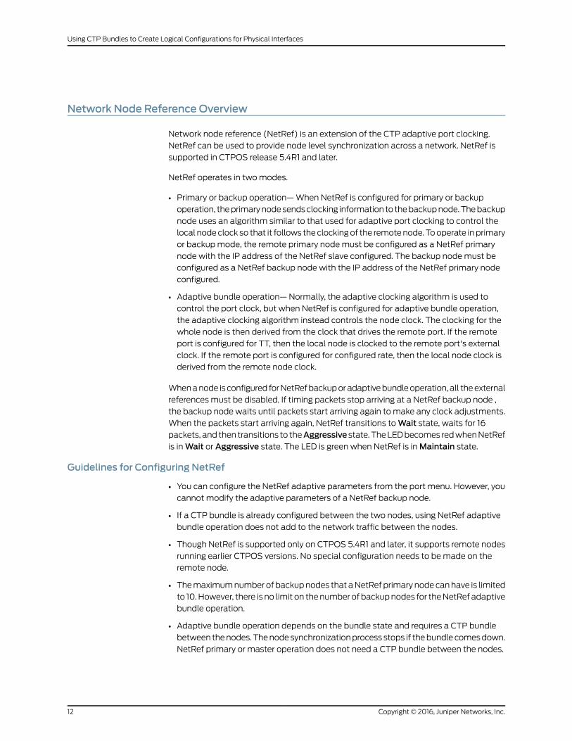
Network Node Reference Overview
Network node reference (NetRef) is an extension of the CTP adaptive port clocking.
NetRef can be used to provide node level synchronization across a network. NetRef is
supported in CTPOS release 5.4R1 and later.
NetRef operates in two modes.
• Primary or backup operation— When NetRef is configured for primary or backup
operation, the primary node sends clocking information to the backup node. The backup
node uses an algorithm similar to that used for adaptive port clocking to control the
local node clock so that it follows the clocking of the remote node. To operate in primary
or backup mode, the remote primary node must be configured as a NetRef primary
node with the IP address of the NetRef slave configured. The backup node must be
configured as a NetRef backup node with the IP address of the NetRef primary node
configured.
• Adaptive bundle operation— Normally, the adaptive clocking algorithm is used to
control the port clock, but when NetRef is configured for adaptive bundle operation,
the adaptive clocking algorithm instead controls the node clock. The clocking for the
whole node is then derived from the clock that drives the remote port. If the remote
port is configured for TT, then the local node is clocked to the remote port's external
clock. If the remote port is configured for configured rate, then the local node clock is
derived from the remote node clock.
When a node is configured for NetRef backup or adaptive bundle operation, all the external
references must be disabled. If timing packets stop arriving at a NetRef backup node ,
the backup node waits until packets start arriving again to make any clock adjustments.
When the packets start arriving again, NetRef transitions to Wait state, waits for 16
packets, and then transitions to theAggressivestate. The LED becomes red when NetRef
is in Wait or Aggressive state. The LED is green when NetRef is in Maintain state.
Guidelines for Configuring NetRef
• You can configure the NetRef adaptive parameters from the port menu. However, you
cannot modify the adaptive parameters of a NetRef backup node.
• If a CTP bundle is already configured between the two nodes, using NetRef adaptive
bundle operation does not add to the network traffic between the nodes.
• Though NetRef is supported only on CTPOS 5.4R1 and later, it supports remote nodes
running earlier CTPOS versions. No special configuration needs to be made on the
remote node.
• The maximum number of backup nodes that a NetRef primary node can have is limited
to 10. However, there is no limit on the number of backup nodes for the NetRef adaptive
bundle operation.
• Adaptive bundle operation depends on the bundle state and requires a CTP bundle
between the nodes. The node synchronization process stops if the bundle comes down.
NetRef primary or master operation does not need a CTP bundle between the nodes.
Copyright © 2016, Juniper Networks, Inc.12
Using CTP Bundles to Create Logical Configurations for Physical Interfaces

RelatedDocumentation
Configuring NetRef for Adaptive Bundle Operation on page 89•
• Configuring NetRef for Primary or Backup Operation on page 90
Support for Multiple Master Nodes to AssociateWith a Single Slave Node in NetRef
Network node reference (NetRef) is an extension of the CTP adaptive port clocking.
NetRef can be used to provide node level synchronization across a network. When NetRef
is configured for primary or backup operation, the primary node sends clocking information
to the backup node. The backup node uses an algorithm similar to that used for adaptive
port clocking to control the local node clock so that it follows the clocking of the remote
node. To operate in primary or backup mode, the remote primary node must be configured
as a NetRef primary node with the IP address of the NetRef slave configured. The backup
node must be configured as a NetRef backup node with the IP address of the NetRef
primary node configured. You can configure up to four master modes, each of which can
send their clocking information to a maximum of 10 slaves and the slave node can receive
clocking information from the configured master nodes.
You can configure the four master nodes using CTP Menu or the CTPView web server
during Netref slave configuration. As a result, a single slave node can use the IP address
of up to four master nodes while you configure Netref slave node settings.
Each master node is assigned a priority during Netref slave configuration. The master
node with the highest priority is assigned Priority 1, the second highest priority for the
master node is Priority 2, and so on. You cannot configure the priority of the master nodes.
The priorities assigned are unique for each masters while configuring Netref slave nodes.
The slave nodes synchronize their local clock with the clock of the highest priority master
node (Priority 1 master node). After the highest priority master goes down or when a
problem occurs during the clock synchronization phase, the CTP device switches to its
next highest priority master (Priority 2 master node). The slave nodes synchronize their
clock with the clock of Priority 2 master node. The priorities of the master nodes are also
switched in the backend, after switching of the master nodes takes place. In the case of
flapping between the masters, the primary master (high priority) is retained or binding
with the master that contains a good clock quality is maintained.
When switching of the masters takes place, an event of mastership change is logged
into the syslog messages. The slave node synchronization query provides the details of
the master node to which the slave is locked and the details of the configured master
nodes along with their assigned priorities. You cannot configure the lowest priority masters
until its higher priority masters are configured. Similarly, you cannot disable the highest
priority masters until its lower priority masters are disabled.
When a node is configured as NetRef Master, it starts generating the NetRef packets and
send them to the slave nodes. The slave node accepts the packets from the highest
priority master node and the NetRef state of the slave node is changed to wait state. If
16 sequenced packets are received by the slave nodes, the NetRef state is changed from
Wait state to Aggressive state. At this stage, if 8 packets are missed continuously, the
NetRef state again moves back to the Wait state. These NetRef packets are processed
and slope is calculated. Based on the slope, the clock of the slave node is in
13Copyright © 2016, Juniper Networks, Inc.
Chapter 2: CTP Bundle Overview

synchronization with the master node and the state changes to the Maintain state. The
state changes from Maintain or Aggressive to Starvation when no NetRef packet is
received in last 20 seconds. As soon as the node goes to Starvation state, switching of
the master takes place. The packets are processed by the slave nodes to synchronize
their clock with the next highest priority master node. Flapping of the masters occurs if
you continuously “round robin” to each master and wait for 20 seconds for an incoming
NetRef packet.
The LED becomes red when NetRef is inWait orAggressive state. The LED is green when
NetRef is in Maintain state. The switching of the masters occurs as described in the
following table:
Assigned PriorityAfter FourthFailure
Assigned PriorityAfter Third Failure
Assigned PriorityAfter SecondFailure
Assigned PriorityAfter First Failure
AssignedPrioritySlave Nodes
1 (primary)2341 (primary)Master 1
2341 (primary)2Master 2
341 (primary)23Master 3
41 (primary)34Master 4
If all the four master nodes goes down, the NetRef state remains in Starvation state and
no switching will take place. When the NetRef state of the slave node is Maintain and
the primary master goes down, the slave node is unable to receive the packets within
the last 20 seconds. Therefore, the NetRef state of the slave node moves from Maintainstate to Starvation state and switching takes place. When the NetRef state of the slave
node isAggressiveand the primary master goes down, the slave node is unable to receive
the packets within the last 20 seconds. Therefore, the NetRef state of the slave node
transitions from Aggressive state to Starvation state and switching will take place.
When the NetRef state of the slave node is in Wait state (waiting for NetRef packets
from the primary master node) and the primary master node is disabled but the secondary
master nodes are sending NetRef packets to the slave node, switching will take place.
Revert option is not supported; when the primary node comes up, the slave node remains
locked to the secondary master node and does not become locked to the primary master
node.
Without multiple master nodes support, when a node is configured as slave, the node
www_db string is
“23;1;0;0;0;0;0;0;0;0;0;5;1;5;1;5;1;5;1;5;1;;2|64|127.0.0.1/127.0.0.1/127.0.0.1/127.0.0.1/127.0.0.1/127.0.0.1/127.0.0.1/127.0.0.1/127.0.0.1/|0|255|;0;”
This www_db string is not different when multiple master nodes are configured for a
backup node. The first IP address in the www_db string contains a priority of 1, the second
contains a priority of 2, and so on, as shown as follows:
Copyright © 2016, Juniper Networks, Inc.14
Using CTP Bundles to Create Logical Configurations for Physical Interfaces

“23;1;0;0;0;0;0;0;0;0;0;5;1;5;1;5;1;5;1;5;1;;2|64|10.216.118.73/10.216.118.86/10.216.118.90/10.216.118.88/127.0.0.1/127.0.0.1/127.0.0.1/127.0.0.1/127.0.0.1/|0|255|;0;”
When node is configured asmaster, the nodewww_db stringwill remain same as it is there
in the earlier releases.
Loss of Signal Detection Capability on CTP Bundles and SAToP Bundles
A loss of signal (LOS) alarm indicates that there is a physical link problem with the
connection to the router receive port from the neighboring SONET equipment transmit
port. An LOS alarm occurs when the port on the card is in service but no signal is being
received. The cabling is not correctly connected to the ports, or no signal exists on the
line. Possible causes for a loss of signal include upstream equipment failure or a fiber
cut.
The CTP devices support a both-ended redundancy mechanism, in which two identical
CTP circuit bundles are combined using Y cables at each end, enabling one bundle to
act as a backup for the other. One of the bundles is in use (online), while the other is in
the standby state (offline). Only the online bundle is allowed to drive the Y cable towards
the user equipment, while the offline bundle is tristate. A communications channel (such
as redundancy by using a hardware link that uses a special Y cable or redundancy based
on a software link that does not depend on a signaling hardware like the Y cable) between
ports at each end determines which of the two ports on the Y cable is currently online.
When one bundle fails, the failed bundle transitions to the offline and places the other
bundle in the online state.
Consider a sample configuration scenario in which two CTP bundles (four CTP ports)
are used in a Y-cable redundancy format. Software-based redundancy is enabled. In this
type of configuration, 172.25.62.51:te-0/0(B0) is the left primary link and
172.25.62.51:te-0/1(B1) is the left secondary link. 172.25.62.52:te-0/0(B0) is the right
primary link and 172.25.62.52:te-0/1(B1) is the right secondary link. In this redundant
configuration, the circuit is very robust, protecting against many types of failures, such
network failures, power failures, and equipment failures. However, one type of failure is
not detected, which is when a cable is pulled out.
Starting with CTPOS Release 7.2R1, CTP devices support the detection of a loss of signal,
which denotes a physical link problem. The following conditions are supported:
• In a serial both-ended Y-cable redundancy configuration (software-based Y cable link
protocol), removal of Y cable leg from the CTP port of the online bundle must be able
to force a switch to the standby bundle.
• In a T1/E1 both-ended Y cable configuration (software-based Y cable link protocol),
removal of Y cable leg from the CTP port of the online bundle must be able to force a
switch to the standby bundle.
The T1/E1, CTP, and SAToP bundles support LOS detection and based on this signal, the
run state of the bundles switches to TfFail, which initiates a software-based Y cable
switchover to a redundant port. Also, for T1/E1 both-ended Y-cable redundancy
configuration, only software-based Y cable link protocol is supported and hardware-based
redundancy is not supported.
15Copyright © 2016, Juniper Networks, Inc.
Chapter 2: CTP Bundle Overview

The way in which CTP redundancy works is by using the bundle state to make decisions.
When a bundle is in the RUNNING state, the following processes occur:
1. The remote CTP is operational and is able to generate and send packets into the IP
network (towards us).
2. The network is able to transport bundle OAM and payload packets from the remote
CTP to the local CTP.
3. A sufficient percentage of the bundle payload packets fills packet delay variation
(PDV buffers) and maintain circuit data transport towards the locally connected user
equipment.
Therefore, when a bundle is in the RUNNING state, it is “usable” and can be online in a
redundant configuration.
Consider a network topology in which a failure occurs in the circuit path that does not
cause the circuit to exit the RUNNING state. This phenomenon can be the case when the
cable is pulled from the CTP port of a redundant online bundle. Although this condition
might not typically be considered an actual failure, and instead more of a configuration
error, this symptom can nevertheless be classified in the failure category. Therefore, a
mechanism to be able to detect this condition in redundant setups and provide an online
circuit switch to offline when the cable is removed is beneficial. CTP devices support the
evaluation of LOS conditions on serial interfaces and T1E1 interfaces in CTP bundles and
SAToP bundles.
• Detection of LOS on Serial Interfaces on page 16
• Detection of LOS on T1/E1 Interfaces on page 17
Detection of LOS on Serial Interfaces
For serial interfaces, the determination of LOS condition is already performed in CTPOS
releases earlier than Release 7.2R1. When a serial circuit is configured to use the TT input
(on a data communication equipment [DCE] interface) for at least one of its five
configured port clocks (for example, “Cfg Rate - Ext Clk), the external clock frequency is
examined by the CTP device before the local bundle can go to the running state. If there
is no external clock present or it is not the correct frequency, then the bundle transitions
to the TtFAIL state and never go to RUNNING. Also, if the bundle is already in the RUNNING
state, the external clock is verified every second to ensure that its frequency is still present
and within range. If not, the bundle transitions from RUNNING to TtFAIL.
In the TtFAIL state, the bundle periodically transitions back to the EVAL state, where the
external clock is checked again. If the clock fails or a bad frequency occurs, the bundle
returns to the TtFAIL state. If the clock is properly functional, then the bundle transitions
to the various states that eventually end in the RUNNING state. Such a method of change
of states enable a graceful (if not instantaneous) recovery of a circuit where a cable is
disconnected, but subsequently reconnected. Because removal of the cable on a serial
port that is using an external clock can cause the bundle to exit the RUNNING state, that
bundle switches offline, if currently online in a Y-cable redundancy setup.
Copyright © 2016, Juniper Networks, Inc.16
Using CTP Bundles to Create Logical Configurations for Physical Interfaces

Detection of LOS on T1/E1 Interfaces
The clock and data signals are embedded together on a T1/E1 interface in a single AMI
(alternate mark inversion) electrical signal. The hardware line interface unit (LIU) that
recovers the composite AMI signal into its component clock and data signals recovers a
clock from the incoming AMI signal, even when none is present because it is based on a
free running phase-locked loop (PLL) that generates a clock, even when it is not locked
to an incoming signal. As a result, the CTP port interface receives an incoming external
clock from the LIU, whether a valid T1/E1 signal is connected to the CTP or not. The LIU,
however, cannot determine when it has a valid incoming T1/E1 signal, and in such a
condition, the LIU indicates as a LOS status bit. This indication serves as the basis for
detecting a cable disconnect in a Y-cable redundant configuration.
To use LOS as a way to take down a RUNNING bundle, the effective method implemented
is to treat a T1/E1 LOS condition exactly the same as a serial port with a bad or missing
external clock. When the CTP device performs its “check external clock” function, instead
of returning an automatic success on T1/E1 ports, the LOS status bit is analyzed to
determine whether it is a T1/E1 port. If the LIU LOS status indicates that there is no
incoming signal, then the function returns a failure, which causes the bundle to move to
the TtFAIL state. This state is the same as a missing external clock processing for a serial
port. In this manner, the T1/E1 ports behave exactly the same way as serial ports.
Guidelines for Configuring LOS Detection
Keep the following points in mind when you configure the capability to detect LOS
conditions on T1E1 interfaces:
• A cable disconnection of a serial port cannot be detected when no external clock is
being used by the port. The following clock configurations use an external clock:
• DCE/DTE: Cfg Rate – Ext Clk
• DCE/DTE: All Clock – Ext Clk
• DCE/DTE: Adap Rate – Ext Clk
• DCE/DTE: Auto Rate – Ext Clk
• DTE: All clocked by Ext Clk (ST/RT)
• DTE: All clocked by User Clk (RT)
• Any custom clock config that uses “TT”
• For any other serial clock configuration, a cable removal on the online port does not
cause it to exit the running state.
• For T1/E1 ports, the recovered clock (which is equivalent to the external clock of a serial
port) from the incoming T1/E1 AMI signal is used in all available T1/E1 preconfigured or
canned clock configurations.
• The T1 LOS checking technique was primarily intended for CTP bundles. Because the
T1/E1 SAToP bundle state machine also supports the bundle EVAL state as part of its
bundle state machine, it can also benefit from the LOS checking functionality provided
17Copyright © 2016, Juniper Networks, Inc.
Chapter 2: CTP Bundle Overview

by this feature. However, the LOS detection feature on SAToP bundles is not useful
for both ended redundancy, since both-ended Y-cable redundancy configurations only
supports CTP bundles.
• CESoPSN and VCOMP bundles are not supported for detecting LOS conditions because
their bundle state machines do not support an EVAL state.
• You can configure the LOS detection mechanism for T1/E1 ports in the same function
that checks the external input clock. In addition, this T1/E1 LOS detection capability is
processed under the control of a separate port configuration flag so that this LOS
checking occurs only when this flag is active. Although this menu option to enable or
disable the LOS detection functionality is shown regardless of the port type, such as
serial interfaces or T1E1 interfaces, this setting becomes effective on a T1/E1 port only
when it is connected to a CTP or SAToP bundle. If the LOS detection functionality is
enabled on a serial port or other bundle types, the setting is not processed.
• Also, when you run the bundle query for CTP bundles and SAToP bundles, the T1E1
port type displays port configuration flags that are relevant to a T1E1 port. In the
PortConfigFlags field displayed in the output of the bundle query, T1LoSCheck denotes
that LOS detection is specified on a T1 port connected to a CTP bundle or a SAToP
bundle, E1LoSCheck denotes that LOS detection is specified on a E1 port connected
to a CTP bundle or a SAToP bundle, and the NoRdReclk flag signifies that the
redundancy receiving (RX) clock is disabled. The NoRdReclk flag is also displayed
because this flag is default enabled for a T1/E1 port, whereas it is usually not enabled
for a serial port.
Copyright © 2016, Juniper Networks, Inc.18
Using CTP Bundles to Create Logical Configurations for Physical Interfaces

CHAPTER 3
Transparent Encoding Overview
• Transparent Encoding Applications and Support Overview on page 19
• How Basic Transparent Encoding Works on page 20
• Using Phase-Correction FIFO Buffer with Transparent Encoding on page 21
• Using Send Timing (ST) Clocking for Higher Speed Circuits with Transparent
Encoding on page 23
Transparent Encoding Applications and Support Overview
Transparent mode is for unique applications that require the data and clock signals to
be sampled at one end of a circuit and replicated at the far end. For example, applications
in which:
• Data rates are low (32 Kbps or less) and rates can vary over time. The sampling jitter
prevents use of higher data rates.
• Data rates are low and fixed and/or low network latency is required.
• Clocks must disappear (transitions stop) periodically during circuit operation.
The transparent encoding scheme is supported only when you have worked with the
Juniper Networks Technical Assistance Center (JTAC) to verify that your application
requires this encoding scheme. You may need to use special adapters on the cable to
properly map the data and clock signals to the connector pins that the application uses.
We recommend that you do not use transparent encoding in WAN environments because
of its large consumption of bandwidth.
RelatedDocumentation
How Basic Transparent Encoding Works on page 20•
• Using Phase-Correction FIFO Buffer with Transparent Encoding on page 21
• Using Send Timing (ST) Clocking for Higher Speed Circuits with Transparent Encoding
on page 23
• Configuring Transparent Encoding for CTP Bundles (CTP Menu) on page 55
• Configuring Transparent Encoding for CTP Bundles (CTPView) on page 122
19Copyright © 2016, Juniper Networks, Inc.

HowBasic Transparent EncodingWorks
There are two modes of transparent encoding. They are Transparent 4 mode (TRANS)
and Transparent 8 mode (TRANS8). Transparent 8 mode is supported only on CTPOS
release 6.4 and later.
Transparent encoding mode 4 samples incoming data on four input signals (SD, TT, RTS,
and DTR), transports these signals across the IP network to the remote end of the circuit,
and sends the signals on four output signals (RD, RT, CTS, and DSR). Figure 1 on page 20
shows a simplified model of a transparent encoded circuit.
Figure 1: SimplifiedModel of a Transparent Encoded Circuit
IP Network
g015
401
RD
RT
CTS
DSR
2
24
4
20
SD
TT
RTS
DTR
3
17
5
6
2
24
4
20
SD
TT
RTS
DTR
3
17
5
6
RD
RT
CTS
DSR
Transparent CircuitTransparent Circuit
Pin Pin
The signal sampling rate is based on the configured port rate. For example, if the port
rate is 128 Kbps, then the four signals are sampled at 128 KHz, which generates a packet
flow through the IP network of 512 Kbps (4 x 128 KHz). The smallest sampling rate
available is 5.3 μsec (approximately 192 KHz).
To prevent errors in transport, both ends of the circuit must be synchronized with each
other. You can achieve synchronization either by locking each CTP node to a common
reference or by enabling adaptive clocking on one end of the circuit.
Transparent 8 encoding is an extension of Transparent 4 encoding. Compared with
Transparent 4 encoding, which sends four signals in each direction, Transparent 8
encoding doubles the bandwidth and allows eight signals to be sampled and transported.
This allows signals to be sent from additional interfaces that were not supported in
Transparent 4 encoding, although the bandwidth usage will be higher.
RelatedDocumentation
Transparent Encoding Applications and Support Overview on page 19•
• Using Phase-Correction FIFO Buffer with Transparent Encoding on page 21
• Using Send Timing (ST) Clocking for Higher Speed Circuits with Transparent Encoding
on page 23
• Configuring Transparent Encoding for CTP Bundles (CTP Menu) on page 55
Copyright © 2016, Juniper Networks, Inc.20
Using CTP Bundles to Create Logical Configurations for Physical Interfaces

• Configuring Transparent Encoding for CTP Bundles (CTPView) on page 122
Using Phase-Correction FIFO Buffer with Transparent Encoding
The transparent encoding feature provides a phase-correction FIFO buffer. This FIFO
buffer aligns the clock and data phase relationship on a transparent encoded circuit in
which the clock travels in one direction through the network, and the data travels in the
opposite direction. The transparent FIFO buffer is needed because of the latency of signal
transport over the IP network.
Figure 2 on page 21 shows the phase-correction FIFO buffers. You can enable the
phase-correction FIFO buffer at either end of the circuit. You would not enable the FIFO
buffer at both ends of the circuit.
Figure 2: Transparent Encoding with Phase-Correction FIFO Buffers
Transparent CircuitTransparent Circuit
DTE DCE
g015
406
RD
RT
CTS
DSR
2
24
4
20
SD
TT
RTS
DTR
3
17
5
6
2
24
4
20
SD
TT
RTS
DTR
3
17
5
6
RD
RT
CTS
DSR
Pin Pin
FIFO FIFO
Figure 3 on page 22 shows the paths of the clock and data through the phase-correction
FIFO buffer that is enabled on the transparent circuit on the right.
• The clock enters the network from the DCE, goes to the DTE, and then clocks data into
the network on the DTE. The clock is also looped back on the DTE to enter the network
in phase with the data as it travels from the DTE to the DCE.
• The data enters the FIFO buffer in phase with the clock passing through the network
from the DTE to the DCE, while data is clocked out of the FIFO buffer with the clock
that entered the network from the DCE, which is in phase with the user clock.
21Copyright © 2016, Juniper Networks, Inc.
Chapter 3: Transparent Encoding Overview

Figure 3: Clock and Data Paths with Transparent Phase-Correction FIFOBuffers
Transparent CircuitTransparent Circuit
DTE DCE
g015
402
RD
RT
CTS
DSR
2
24
4
20
SD
TT
RTS
DTR
3
17
5
6
2
24
4
20
SD
TT
RTS
DTR
3
17
5
6
RD
RT
CTS
DSR
Red = clockBlue = data
Pin Pin
FIFO FIFO
Like in TRANS encoding, you can use the 16 bit phase correction FIFO in TRANS 8 encoding
to accommodate the problems that can be caused by the high latency in the circuit
whether or not the remote DCE device can accept TT input or not.
When the customer DCE device can support the TT signal returned by the DTE, the phase
correction FIFO is not needed. The DCE transmit clock (ST) is sampled and carried
downstream to the DTE, where it is used to generate the upstream data that is sent back
to the customer DCE. This clock data is also sent as the DTE transmit clock (TT) to travel
along with the data in phase. When these signals get back to the customer DCE device,
they are still in phase (same delay through the network), so the customer DCE can use
the TT signal to recover the transmit data on the SD lead.
Consider a scenario in which the customer's upstream DCE does not use the TT signal
for capturing upstream data, and instead uses the ST clock. Here, due to the latency of
the ST clock traveling downstream and the time taken for the return trip of the data, it
is difficult to ensure error-free data transport. In such a scenario, you can use phase
correction FIFO to ensure error-free data transport.
The SD or TT clock and data signals get back to the upstream CTP device, where the
data is clocked into the FIFO using the TT clock, which is in phase. This data is clocked
out of the FIFO using the upstream ST clock, and the data is realigned to be in phase with
the ST clock.
RelatedDocumentation
Transparent Encoding Applications and Support Overview on page 19•
• How Basic Transparent Encoding Works on page 20
• Using Send Timing (ST) Clocking for Higher Speed Circuits with Transparent Encoding
on page 23
• Configuring Transparent Encoding for CTP Bundles (CTP Menu) on page 55
• Configuring Transparent Encoding for CTP Bundles (CTPView) on page 122
Copyright © 2016, Juniper Networks, Inc.22
Using CTP Bundles to Create Logical Configurations for Physical Interfaces

UsingSendTiming (ST)Clocking forHigherSpeedCircuitswithTransparent Encoding
When the relationship between the clock and the data signals is critical, you can use ST
clocking with transparent encoding to prevent delay and jitter in CTP2000 series devices,
making it possible to carry higher speed circuits in transparent mode.
Figure 4 on page 23 shows the issue of delay and jitter where a transparent encoded
circuit connects a DCE to a DTE. The circuit is set up as follows:
• The high-speed clock and data lines (shown in red) are aligned by a FIFO buffer at the
DCE.
• The signaling leads (shown in blue) are passed end-to-end without going through the
FIFO buffer. The signaling paths that carry non-timing-critical signals are subject to
delay and jitter.
The problem is that when a FIFO buffer is used at one end of the circuit, an additional
clock path from the DCE to the DTE is needed to carry a clock to the DTE so that it can
return a DTE-to-DCE clock that is in phase with the data. This DTE-to-DCE clock is needed
to clock the FIFO input. Normally, one of the signal lead paths carries this transmit clock.
However, when the circuit is running at speeds above 32k, the delay and jitter on these
paths make these signal choices nonoptimal.
Figure 4: High-Speed and Low-Speed Paths with Transparent Encodingg0
1540
3
Red = High-speed clock and data linesBlue = Signaling lead
DCE
RTS
CTS
DTR
DSR
DTE
DTR
DSR
RTS
CTS
Transparent Circuit
FIFO
Delay/Jitter
Delay/Jitter
Delay/Jitter
Delay/Jitter
Transparent Circuit
23Copyright © 2016, Juniper Networks, Inc.
Chapter 3: Transparent Encoding Overview

To solve the issue of delay and jitter associated with the signaling leads, you can use the
ST interface signal to feed or sink the RTS-to-CTS signal path. By using the ST interface
signal instead of the RTS-to-CTS signal path, delay and jitter are removed from that
signal path. Figure 5 on page 24 shows a transparent-encoded circuit with the additional
ST functionality:
• At the DCE, the RTS-to-CTS signal path is configured to use ST (as an input from the
DCE) to feed that signal path through the network.
• At the DTE, that signal is placed onto the ST lead, which is configured as an output.
Figure 5: Transparent Encoding Using ST Clocking
IP Network
g015
404
Red = Send timing (ST) pathBlue = Send data (SD path
3
17
4
5
7
3
17
4
6
6
20
7
1 1
20
2
24
5
20
7
3
17
4
5
6
20
7
1 1
6
3
17
4
5
6
20 DTR
RTS
RD
DSR
RT
CTS
2
24
17
4
5
6
20
SD
DTR
TT
RTS
DSR
RT
CTS
Transparent Circuit
10d/
5j
10d/
5j
DTE
3
17
4
5
6
20DTR
DSR
RTS
CTS
DCE
3
17
4
5
6
20
RTS
CTS
DTR
DSR
Adapter Adapter
2
24
15
2
15
3 2
1515
2
24
SD 3RD
1515
2
15
2
15FIFO
FIFO
ST ST
TT
Transparent Circuit
When you configure transparent encoding to use the ST lead instead of RTS/CTS, you
can specify whether or not ST is an input lead.
RelatedDocumentation
• Transparent Encoding Applications and Support Overview on page 19
• How Basic Transparent Encoding Works on page 20
• Using Phase-Correction FIFO Buffer with Transparent Encoding on page 21
• Configuring Transparent Encoding for CTP Bundles (CTP Menu) on page 55
• Configuring Transparent Encoding for CTP Bundles (CTPView) on page 122
Copyright © 2016, Juniper Networks, Inc.24
Using CTP Bundles to Create Logical Configurations for Physical Interfaces

CHAPTER 4
TDM/TDC Encoding Overview
• TDM/TDC Encoding Overview on page 25
TDM/TDC Encoding Overview
The time domain correlation (TDC) feature uses time division multiplexing (TDM) to
interleave multiple data types on serial ports so that the CTP device can bond two circuits
into a single data stream. Doing so allows the CTP device to carry two independent data
streams on the same path through the IP network . Out of each set of 32 bits in the IP
data stream, you can designate a certain number of bits for TDM functions.
The TDM/TDC feature is commonly used for telemetry applications, and is supported
on CTP2000 serial interfaces.
HowTDM InterleavingWorks
When TDM is not being used, all 32 bits in the IP data stream transport serial data on a
port. For example, Figure 6 on page 25 shows all 32 bits being allocated to local serial
port data as indicated with the D.
Figure 6: Serial Port Bit AllocationWithout TDM
g015
394
012345678911 1013 1215 1417 1619 1821 2023 2225 2427 2629 2830D D D D D D D D D D D D D D D D D D D D D D D D D D D D D DD
31DNo TDM
When you enable TDM, a specific number of the 32 data bits are allocated for another
function. That is, another function is interleaved with the serial data. For example, in
Figure 7 on page 25 half of the bits (16 bits in 32) are allocated to serial port data (as
indicated by D), and half of the bits are allocated to TDM (as indicated by T).
Figure 7: Serial Port Bit AllocationWith 16 Bits Allocated to TDM
g015
395
D D D D D D D D D D D D D D D D
TDM Rate 16 (1:1)
012345678911 1013 1215 14TTTTTTTTTTTTTTTT
The number of bits out of 32 that are allocated to TDM is called the TDM rate.
Figure 7 on page 25 showed a TDM rate of 16. Figure 8 on page 26 shows the bit allocation
for TDM rates of 2, 4, and 8.
25Copyright © 2016, Juniper Networks, Inc.

Figure 8: Bit Allocation for TDMRates of 2, 4, and 8
g015
396
D D D D D D D D D D D D D D D D D D D D D D D D D D D D D D
D D D D D D D D D D D D D D D D D D D D D D D D D D D D
D D D D D D D D D D D D D D D D D D D D D D D D
012345678911 1013 1215 1417 1619 1821 2023 2225 2427 2629 28
012345678911 1013 1215 1417 1619 1821 2023 2225 2427 26
012345678911 1013 1215 1417 1619 1821 2023 22
TTTTTTTT
TTTT
TT
TDM Rate 2 (15:1)
TDM Rate 4 (7:1)
TDM Rate 8 (3:1)
How the CTP Implementation of TDM/TDCWorks
To use this feature, you configure two bundles on each CTP device:
• A high-speed bundle that carries all traffic by interleaving multiple data sources into
a single stream.
• A low-speed bundle that routes clock and data signals.
The high-speed bundle oversamples the incoming clock (TT) and data (SD) from the
low-speed bundle. At the remote end of the network, the embedded circuit data is
recovered and exits the node on the low-speed bundle as RT and RD outputs. The direct
interleaving of two bundles’ data allows TDC to be maintained between the two bundles
with an accuracy of one bit time at the bundle’s data rate.
The low-speed bundle receives network-bound clock and data signals from the user
equipment and inserts it into the bundle. It also transmits interface-bound clock and
data from the bundle to the user equipment.
Figure 9: TDC Application Over TDMUsing 16-in-32 TDMRate
g015
397
D D CD D D D D D D D D D D D D D DD C D C D C D C D C D C D C012345678911 1013 1215 14
TDM Rate 16
In Figure 4:
• The blue D bits synchronously carry the higher-speed circuit.
• The red D bits asynchronously oversample and transport the lower-speed circuit data.
• The green C bits asynchronously oversample and transport the lower-speed circuit
clock.
TDMRates
At the maximum TDM rate of 16, the CTP device can transport four low-speed bits for
every eight high-speed bits as shown in Figure 10 on page 27.
Copyright © 2016, Juniper Networks, Inc.26
Using CTP Bundles to Create Logical Configurations for Physical Interfaces

Figure 10: High-Speed and Low-Speed Ratio at theMaximumTDMRateof 16
g015
398
D D CD D D D D D D D D D D D D D DD C D C D C D C D C D C D C012345678911 1013 1215 14
HIGH SPEED CLK
LOW SPEED CLK
TDM Rate 16
If the ratio of circuit speeds is higher than 8:1, then you can use lower TDM rates, which
allocates fewer bits for the TDM function and therefore uses less network bandwidth.
Figure 11 on page 27 shows other supported TDM rates as applied to TDC.
Figure 11: TDMRates as Applied to TDC
D D CD D D D D D D D D D D D D D D D D D D D D D D D D D D D D
D D CD D D D D D D D D D D D D D D D D D D D D D D D D D D
TDM Rate 2
D C
D D CD D D D D D D D D D D D D D D D D D D D D D DD C D C D C
012345678911 1013 1215 1417 1619 1821 2023 2225 2427 2629 28
012345678911 1013 1215 1417 1619 1821 2023 2225 2427 26
012345678911 1013 1215 1417 1619 1821 2023 22
g015
399
TDM Rate 4
TDM Rate 8
TDMHigh-Speed and Low-Speed Ports
To use the TDM/TDC feature, you configure a high-speed bundle and a low-speed bundle
as follows:
• The high-speed bundle is configured on an even-numbered port, and it is configured
for TDM encoding because it interleaves multiple data sources into a single stream.
• The low-speed bundle is configured on an odd-numbered port that is one port number
higher (N+1) than the high-speed port. It is configured for TDM/TDC clocking because
it routes clock and data signals.
Figure 12 on page 28 shows a high-speed port and low-speed port.
27Copyright © 2016, Juniper Networks, Inc.
Chapter 4: TDM/TDC Encoding Overview

Figure 12: TDM/TDCHigh-Speed and Low-Speed Ports
g015
400
Low-speed port
High-speed port
RT
RD
SD
TT
FIFOx1
PKT
RXTT
ST
RT
RD
SD
TT
RFTT
STDDS
X:1 interleave
X:1 interleave
TDM data in
TDM data out
Network-bound TDC dataNetwork-bound TDC clockInterface-bound TDC dataInterface-bound TDC clock
IP Network
TXDIV
RTDIV
PKT
SIG_IN
SIG_OUT
FIFOx8
ST
STDDS
PKT
PKT
RTDIV
TXDIV
RFTT
RXTT
FIFO
As shown in the figure:
• The red path shows the network-bound path for the low-speed TDC data and clock.
The low-speed port receives the clock and data signals from the user equipment, and
transmits it to the transmit data jitter FIFO on the high-speed port. Once out of the
FIFO, the CTP device interleaves the TDC data streams into a single packet flow for
the TDM/TDC bundle.
• The blue path shows the interface-bound path for the TDC data and clock. The
low-speed port transmits the interface-bound clock and data from the TDM/TDC
bundle to the user equipment.
RelatedDocumentation
• Configuring Bundle Pairs for TDM/TDC Operation (CTP Menu) on page 56
• Configuring Bundle Pairs for TDM/TDC Operation (CTPView) on page 124
Copyright © 2016, Juniper Networks, Inc.28
Using CTP Bundles to Create Logical Configurations for Physical Interfaces

CHAPTER 5
Ethernet Media Configuration Overview
• Ethernet Media Configuration Overview on page 29
Ethernet Media Configuration Overview
You can configure the CTP Ethernet media to autonegotiate and set the speed to either
100 or 10 Mbps. By default, autonegotiation is enabled and the speed is to 1000 Mbps.
If you choose to disable autonegotiation, the system prompts you to configure the desired
speed.
The Ethernet configurations on CTP must match the configuration of the connected
router or switch. Mismatched configurations, such as setting the CTP system to
autonegotiate and the router to full duplex, will result in a misconfiguration and dropped
packets. You must disable Cisco Discovery Protocol on the Fast Ethernet port connected
to the CTP system.
Table 8 on page 29 lists the valid Ethernet media configuration settings that CTP Series
supports.
Table 8: Valid Ethernet Media Configuration Settings for CTP
MTU (up to 1500)Mode (Duplex)Autoneg StatusSpeed
anyFullON1000
anyFullOFF100
anyFullOFF10
NOTE: The CTP system supports only full duplexmode.
Support for Full-DuplexMode Only on NIC Ports Connected to CTP Devices
If the autonegotiation setting of the CTP Ethernet media and the far-end switch or router
do not match, it is possible for the CTP Ethernet ports to be in a half-duplex state, although
the duplex setting is not configurable and always assumed to be full-duplex on the CTP
device. Starting with CTPOS and CTPView Release 7.2, only full-duplex mode is supported
29Copyright © 2016, Juniper Networks, Inc.

on the network interface card (NIC) ports of the far-end switch or router connected to
the CTP devices and if you do not configure full-duplex on NIC ports during the
autonegotiation process, then the interfaces are considered to be down and a log message
is recorded in both the /var/log/messages directory and the syslog file stating that the
interface is down due to a non-full duplex condition. You are prompted to verify the cable
connection, speed, and duplex settings because the NIC link might be down.
The default speed for autonegotiation is 100 Mbps. To configure Ethernet interfaces on
a CTP device using the CTP Menu, from the Main Menu, select 5) Node Operations.
Display the current Ethernet configuration by selecting 12) Config ethernetmedia. You
can configure autonegotiation to be enabled, which sets the speed as 1000 Mbps.
Mismatched configurations, such as setting the CTP system to autonegotiate and the
router to full duplex, may result in a misconfiguration and dropped packets. You must
disable Cisco Discovery Protocol on the Fast Ethernet port connected to the CTP system.
RelatedDocumentation
• Configuring Ethernet Media (CTP Menu) on page 83
• Displaying Ethernet Media Information (CTP Menu) on page 84
Copyright © 2016, Juniper Networks, Inc.30
Using CTP Bundles to Create Logical Configurations for Physical Interfaces

PART 2
Configuration
• Configuring CTP Bundles (CTP Menu) on page 33
• Configuring CTP Bundles (CTPView) on page 101
31Copyright © 2016, Juniper Networks, Inc.

Copyright © 2016, Juniper Networks, Inc.32
Using CTP Bundles to Create Logical Configurations for Physical Interfaces

CHAPTER 6
Configuring CTP Bundles (CTP Menu)
• Adding a Bundle (CTP Menu) on page 34
• Configuring IP Parameters for CTP Bundles (CTP Menu) on page 34
• Configuring Circuit Startup Parameters for CTP Bundles (CTP Menu) on page 36
• Configuring the Direction of the Circuit (CTP Menu) on page 37
• Configuring Virtual IP Parameters for CTP Bundles (CTP Menu) on page 38
• Configuring IP Forwarding for CTP Bundles (CTP Menu) on page 39
• Configuring the Missing Packet Fill Pattern for CTP Bundles (CTP Menu) on page 40
• Configuring Signaling for CTP Bundles (CTP Menu) on page 42
• Configuring Multiservice Port Parameters for CTP Bundles (CTPView) on page 46
• Configuring Serial Port Parameters for CTP Bundles (CTP Menu) on page 52
• Configuring Transparent Encoding for CTP Bundles (CTP Menu) on page 55
• Configuring Bundle Pairs for TDM/TDC Operation (CTP Menu) on page 56
• Configuring T1 and E1 Port Parameters for CTP Bundles (CTP Menu) on page 59
• Configuring Multiservice Port Parameters for CTP Bundles (CTP Menu) on page 62
• Configuring 4WTO Port Parameters for CTP Bundles (CTP Menu) on page 69
• Configuring IRIG-B Port Parameters for CTP Bundles (CTP Menu) on page 72
• Configuring Advanced Port Options for CTP Bundles (CTP Menu) on page 74
• Selecting the Type of Clocking on Serial Ports for CTP Bundles (CTP Menu) on page 75
• Configuring Custom Clocking for CTP Bundles (CTP Menu) on page 78
• Configuring Adaptive Clocking for CTP Bundles (CTP Menu) on page 81
• Configuring Ethernet Media (CTP Menu) on page 83
• Displaying Ethernet Media Information (CTP Menu) on page 84
• Configuring PBS and Bridge Ports (CTP Menu) on page 85
• Configuring Port Mirroring for CTP Bundles (CTP Menu) on page 87
• Configuring NetRef for Adaptive Bundle Operation on page 89
• Configuring NetRef for Primary or Backup Operation on page 90
• Configuring NetRef Multiple Master Nodes (CTP Menu) on page 90
• Configuring NetRef Settings (CTPView) on page 94
33Copyright © 2016, Juniper Networks, Inc.

• Configuring LOS Detection on CTP and SAToP Bundles (CTP Menu) on page 96
• Configuring Cryptographic Resynchronization (Crypto Resync) on page 97
Adding a Bundle (CTPMenu)
To add a bundle using the CTP Menu:
1. From the CTP Main Menu, select 1) Bundle Operations.
2. Select the type of bundle that you want to configure.
Before you create a VComp bundle, you must ensure that the CTP system has a
VComp card installed. The CTP system displays a warning message if no VComp card
is installed. If you create a VComp bundle on a CTP system that does not have a
VComp card installed and try to activate it, the CTP system displays the following
warning message:
There is not enough system DSP resource for the bundle.
The bundle remains disabled until you install a VComp card and activate the bundle
again. If you remove the VComp card from a CTP system that has an active VComp
bundle, the Run state of the VComp bundle changes to MisCfg.
3. Enter add to add a new bundle.
4. Select the port you want to attach the bundle to.
Configuring IP Parameters for CTP Bundles (CTPMenu)
The CTP software uses the IP parameters to create IP packets.
Before you begin:
• Disable the bundle before you modify the bundle options.
To configure IP parameters for CTP bundles using the CTP Menu:
1. From the CTP Main Menu, select 1) Bundle Operations.
2. Select 1) CTP.
3. Select a bundle from the list.
If you select an active bundle, you are prompted to disable the bundle before
configuring it.
4. Select 2) Config to configure the bundle.
5. Configure options 1 through 9 as described in Table 9 on page 34.
Table 9: CTP Bundle IP Parameter Settings in the CTPMenu
Your ActionFunctionField
Enter the address of the remoteCTP device.
Specifies the name and IP address of the remote CTP device.RemoteAddress
Copyright © 2016, Juniper Networks, Inc.34
Using CTP Bundles to Create Logical Configurations for Physical Interfaces

Table 9: CTP Bundle IP Parameter Settings in the CTPMenu (continued)
Your ActionFunctionField
Enter a number from 0 through249.
Specifies the bundle to connect to on the remote CTP device.Remote CircuitID
Enter a number from 0 through249.
Specifies the bundle on the local CTP device.Local Circuit ID
For CTP150 devices, enter anumber from 8 through 1456.
For CTP2000 devices, enter anumber from 4 through 1456.
Specifies the size of IP packets that are created from data received atthe serial port.
The CTP device makes sure that the combination of packet size and datarate does not result in a packet rate that exceeds 1200 packets persecond.
Packet Size
Enter a number from 0.001through 9999.000 milliseconds.
Specifies the minimum average buffer size. Use a value that is greaterthan the expected jitter and less than the Pkt Buffer Set parameter.
The minimum buffer ensures that the buffer does not become too smallbecause of timing variances between the local and remote serialinterfaces.
The entire buffer is available for accommodating and smoothing packetdelay jitter, regardless of the minimum buffer setting.
Min Buffer
Enter a number from 0.001through 9999.000 milliseconds.
Specifies the buffer size when the circuit enters a running state. This valuemust be large enough to accommodate the anticipated packet delay,and it must be set to a value greater than the minimum buffer size andlower than the maximum buffer size.
Pkt Buffer Set
Enter a number from 0.001through 9999.000 milliseconds.
Specifies the maximum buffer size. The maximum buffer ensures thatthe buffer does not become too large due to timing variances betweenthe local and remote serial interfaces. If the buffer size exceeds themaximum buffer size, the buffer is recentered to the Pkt Buffer Set value.
Periodic buffer recenters are not expected. If you notice recenters, werecommend that you verify the reference to the CTP (if used) or that youconfigure one port with adaptive clocking.
Max Buffer
Enter a number from 0 through255.
Specifies the ToS byte to be used in the IP headers of packets sent fromthe CTP device to the IP network.
For a mapping of ToS byte values to DSCP classes and settings, see“Providing QoS for CTP Bundles by Using Service Type Overview” onpage 10.
You do not need to set the ToS value to the same value on local andremote bundles.
Service Type
Enter a number from 0 through255.
Specifies the maximum number of router hops that a packet can traverse.The CTP device sets the TTL value in IP packets that it sends to the IPnetwork. The IP network does not alter or optimize the packet routingbased on the TTL setting. You do not need to set the same TTL value onlocal and remote ports.
Time to Live
35Copyright © 2016, Juniper Networks, Inc.
Chapter 6: Configuring CTP Bundles (CTP Menu)

Table 9: CTP Bundle IP Parameter Settings in the CTPMenu (continued)
Your ActionFunctionField
Type a description for the bundle.Specifies identifying information about the bundle.
You can use the bundle description as the search criteria when you searchfor bundles from the network monitoring page.
BundleDescription
RelatedDocumentation
Providing QoS for CTP Bundles by Using Service Type Overview on page 10•
Configuring Circuit Startup Parameters for CTP Bundles (CTPMenu)
This topic describes how to configure advanced options that are related to circuit startup.
Set these parameters to the same values on the local and remote CTP devices.
Before you begin:
• Disable the bundle before you modify the bundle options.
To configure circuit startup parameters using the CTP Menu:
1. From the CTP Main Menu, select 1) Bundle Operations.
2. Select 1) CTP.
3. Select a bundle from the list.
If you select an active bundle, you are prompted to disable the bundle before
configuring it.
4. Select 2) Config.
5. Select 10) Advanced Options.
6. Configure options 4, 5, 6, 7, and 8 as described in Table 10 on page 36.
Table 10: CTP Bundle Advanced Options Parameter Settings for Circuit Startup in the CTPMenu
Your ActionFunctionField
Enter a number from 1 through64.
Specifies how many consecutive circuit packets the IP network mustdrop before the CTP device restarts the circuit.
We recommend that you set the parameter to a larger value whenthe IP network uses packet-encrypting devices. These devices causemomentary interruption in packet flows when encryption keys areupdated.
Consecutive pkts loss tostarve
Enter a number from 1 through64.
Specifies the number of in-sequence packets the CTP device mustreceive after a starvation before the circuit transitions from in-syncto running.
In sequence pkts afterstarve
Enter a number from 1 through255.
Specifies the number of OAM packets per second that the circuitsends to the remote CTP device.
OAM Chan Rate(pkt/sec)
Copyright © 2016, Juniper Networks, Inc.36
Using CTP Bundles to Create Logical Configurations for Physical Interfaces

Table 10: CTP Bundle Advanced Options Parameter Settings for Circuit Startup in the CTPMenu (continued)
Your ActionFunctionField
Enter a number from 1 through255.
Specifies the number of OAM packets that the circuit must receivebefore the state moves from no synchronization to insynchronization.
OAM pkts for Sync
Enter a number from 1 through255.
Specifies the number of received OAM packets that the CTP devicemisses before the state of the circuit moves from in synchronizationto no synchronization.
OAM pkts for Sync Loss
RelatedDocumentation
Circuit Startup Process Overview on page 11•
Configuring the Direction of the Circuit (CTPMenu)
This topic describes how to configure the direction of the circuit.
Before you begin:
• Disable the bundle before you modify the bundle options.
To configure the direction of circuits created with the CTP bundle using the CTP Menu:
1. From the CTP Main Menu, select 1) Bundle Operations.
2. Select 1) CTP.
3. Select a bundle from the list.
If you select an active bundle, you are prompted to disable the bundle before
configuring it.
4. Select 2) Config.
5. Select 10) Advanced Options.
6. Configure option 10 as described in Table 11 on page 37.
Table 11: CTP Bundle Circuit Direction Setting in the CTPMenu
Your ActionFunctionField
Select one:
• Bidirectional circuit—Circuit is bidirectional.
• Unidirectional circuit source—Circuit is unidirectional, andthis end of the circuit is the source.
• Unidirectional circuit destination—Circuit is unidirectional,and this end of the circuit is the destination.
Specifies whether the circuit is unidirectionalor bidirectional. If unidirectional, specify thedirection of the circuit—source or destination.
Unidirectionalcircuit
37Copyright © 2016, Juniper Networks, Inc.
Chapter 6: Configuring CTP Bundles (CTP Menu)

Configuring Virtual IP Parameters for CTP Bundles (CTPMenu)
The virtual IP parameters allow you to use a separate IP address for each bundle and to
use an address that is different from the IP address for the CTP device. If you configure
the IP address on the:
• Same subnet as the CTP IP address, you do not need a static route on the router.
• Different subnet as the CTP IP address, you need a static route on the router.
Before you begin:
• Create a list of the virtual IP addresses that will be associated with the CTP device. To
do so, From the CTP Main Menu, selectNodeOperations>Configurenetworksettings> Virtual IP addresses and follow the onscreen instructions.
When you submit your new configuration, the CTP device reboots.
• Disable the bundle before you modify the bundle options.
To configure virtual IP parameters for CTP bundles using the CTP Menu:
1. From the CTP Main Menu, select 1) Bundle Operations.
2. Select 1) CTP.
3. Select a bundle from the list.
If you select an active bundle, you are prompted to disable the bundle before
configuring it.
4. Select 2) Config.
5. Select 10) Advanced Options.
6. Configure options 1 and 2 as described in Table 12 on page 38.
Table 12: CTP Bundle Virtual IP Parameter Settings in the CTPMenu
Your ActionFunctionField
Select one:
• n (no)—Circuits created by this bundle use the IPaddress of the CTP device.
• y (yes)—Circuits created by this bundle use anaddress that is different from the CTP device.
Specifies whether or not the bundle uses anaddress that is different from the IP address of theCTP device.
The virtual IP address is used in the IP packet’sOrigination Address field, and is used for the circuit’sdata and OAM flow.
Use virtual ip forport
Select an IP address from the list displayed.
At the remote end of the bundle, specify this IPaddress as the Remote Address of the bundle.
Specifies the virtual IP address for circuits createdby this bundle.
Virtual ip for port
Copyright © 2016, Juniper Networks, Inc.38
Using CTP Bundles to Create Logical Configurations for Physical Interfaces

Configuring IP Forwarding for CTP Bundles (CTPMenu)
There are two ways to set up CTP bundles for IP forwarding:
• Direct drive—Packets are forwarded directly between drivers on the local and remote
CTP device. Use this method for simple port-to-port configurations. We recommend
that you use this method with supervision from JTAC.
• Direct drive disabled—Packets are forwarded based on information in the kernel’s IP
stack.
Before you begin:
• Disable the bundle before you modify the bundle options.
To configure IP forwarding for CTP bundles using the CTP Menu:
1. From the CTP Main Menu, select 1) Bundle Operations.
2. Select 1) CTP.
3. Select a bundle from the list.
If you select an active bundle, you are prompted to disable the bundle before
configuring it.
4. Select 2) Config.
5. Select 10) Advanced Options.
6. Configure option 13 as described in Table 13 on page 40.
39Copyright © 2016, Juniper Networks, Inc.
Chapter 6: Configuring CTP Bundles (CTP Menu)

Table 13: CTP Bundle IP Forwarding Settings in the CTPMenu
Your ActionFunctionField
Select one:
• YES—CTP uses thekernel’s IP stack toforward packets.
• NO—CTP usesdirect drive toforward packets.
Specifies whether the CTP bundle uses direct drive or IP tables to forward packets.
If you are using route redundancy, port mirroring, or VLANs, you must disable direct driveand use IP tables.
If any port on the CTP node is configured for a PBS or bridged port, then the Direct Driveoption is automatically set to Disabled on all existing and future bundles on that node.
If a port is configured as a PBS or Bridged port, then the bundles on that port is deleted. Ifa bundle is created on a different port, then it disables Direct Drive on that port when otherports are configured as a PBS or bridged port.
Until CTPView Release 7.1R1, the direct drive feature is enabled by default and thisfunctionality configuration is not displayed in the output of the bundle query. If you explicitlyenabled the direct drive capability (using IP tables instead of direct drive forpacket-forwarding), the bundle query displayed "NotDirDrv" when you run the bundlequery from the Main Menu of CTP Menu by selecting 1) Query. Starting with CTPOS andCTPView Release 7.2, the default behaviour is direct-drive disabled (IP table is turned onfor forwarding of packets). With default configuration, the bundle query output does notdisplay the direct drive settings. Only if you explicitly enable the direct-drive capability, thebundle query output displays "Bndl Config Flags: DirDrv" in bundle query. CTP bundlecircuits that use route redundancy and port forwarding must have direct drive disabled toallow for asymmetric routing. When direct drive is disabled, packets are forwarded basedon information in the kernel’s IP stack. When direct drive is enabled, packets are forwardeddirectly between drivers on the local and remote CTP device.
Disabledirectdrive
Configuring theMissing Packet Fill Pattern for CTP Bundles (CTPMenu)
This topic describes how to specify the fill pattern that the CTP device inserts when IP
packets are dropped.
Before you begin:
• Disable the bundle before you modify the bundle options.
To configure the missing packet fill pattern for CTP bundles using the CTP Menu:
1. From the CTP Main Menu, select 1) Bundle Operations.
2. Select 1) CTP.
3. Select a bundle from the list.
If you select an active bundle, you are prompted to disable the bundle before
configuring it.
4. Select 2) Config.
5. Select 10) Advanced Options.
6. Configure option 3)Missing pkt fill pattern as described in Table 14 on page 41.
Copyright © 2016, Juniper Networks, Inc.40
Using CTP Bundles to Create Logical Configurations for Physical Interfaces

Table 14: CTP Bundle Missing Packet Fill Pattern Parameter Setting in the CTPMenu
Your ActionFunctionField
Enter two hexadecimal digits. Youmust enter a value other than ff. Thisfield does not require the 0xcharacters.
Specifies the data that the CTP device inserts into the circuit bitstream when an IP packet is dropped. The number of bits inserted isequal to the number of bits in the missed packet.
When the bundle is down, the port sends the value of the leastsignificant bit (LSB) of the missing fill pattern.
This data insertion method prevents a loss of bit count integrity toattached circuit devices and encryptors.
Missing pkt fillpattern
41Copyright © 2016, Juniper Networks, Inc.
Chapter 6: Configuring CTP Bundles (CTP Menu)

Configuring Signaling for CTP Bundles (CTPMenu)
You can set input and output signals for the CTP device. Your settings should be based
on the settings of the user equipment.
• Output signals—You can set output signals to a fixed value, or you can set them to
inband so that the output signal state is based on the state of the input signal at the
user equipment. Output signals that you can set vary depending on whether the bundle
is configured as the DTE or the DCE:
• DTE output signals:
• DTR (data set ready)
• RTS (request to send)
• LL (local loopback)
• RL (remote loopback)
• DCE output signals:
• DSR (data set ready)
• CTS (clear to send)
• DCD (data carrier detect)
• TM (test mode)
• Input signals—You can set the input signals to either unused (ignored) or used to create
a demand circuit. When configured for demand, packets created from the circuit are
transferred across the IP network only when the signal lead is in the specified state for
the circuit to be Demand Call – Active. When two or more leads are configured for
demand, all configured leads must be in the Demand Call – Active state for the circuit
to transfer packets across the IP network.
Input signals that you can set vary depending on whether the bundle is configured as
the DTE or the DCE:
• DTE—Input signals are TM, CTS, DSR, DCD.
• DCE—Input signals are RL, RTS, DTR, LL.
The input state of each signal lead is encoded once in every transmitted IP packet.
Thus the granularity of the transitions (frequency or changes) that can be transferred
across the network is equal to the packet rate of the circuit.
Before you begin:
• Disable the bundle before you modify the bundle options.
To configure signaling for CTP bundles using the CTP Menu:
1. From the CTP Main Menu, select 1) Bundle Operations.
Copyright © 2016, Juniper Networks, Inc.42
Using CTP Bundles to Create Logical Configurations for Physical Interfaces

2. Select 1) CTP.
3. Select a bundle from the list.
If you select an active bundle, you are prompted to disable the bundle before
configuring it.
4. Select 2) Config.
5. Select 10) Advanced Options.
6. Select 11) Signaling Config.
7. Configure the options as described in Table 15 on page 43.
Table 15: CTP Bundle Signaling Parameter Settings in the CTPMenu
Your ActionFunctionField
Select one:
• 0) Fixed
• 1) In-Band
If you chose Fixed, select:
• 0=Space=Low=On—Signal is turned on.
• 1=Mark=High=Off—Signal is turned off.
If you chose In-Band, select a remote signal source:
• 0) RL from rem DCE, TM from rem DTE—Output signalis based on the state of the RL input signal from theDCE or the TM signal from the DTE.
• 1) RTS from rem DCE, CTS from rem DTE—Output signalis based on the state of the RTS input signal from theDCE or the CTS signal from the DTE.
• 2) DTR from rem DCE, DSR from rem DTE—Outputsignal is based on the state of the DTR input signal fromthe DCE or the DSR signal from the DTE.
• 3) LL from rem DCE, DCD from rem DTE—Output signalis based on the state of the LL input signal from the DCEor the DCD signal from the DTE.
Specifies the output signal depending onwhether the bundle is configured as the DCEor the DTE:
• DCE—DSR output signal.
• DTE—DTR output signal.
DSR (output)
or
DTR (output)
43Copyright © 2016, Juniper Networks, Inc.
Chapter 6: Configuring CTP Bundles (CTP Menu)
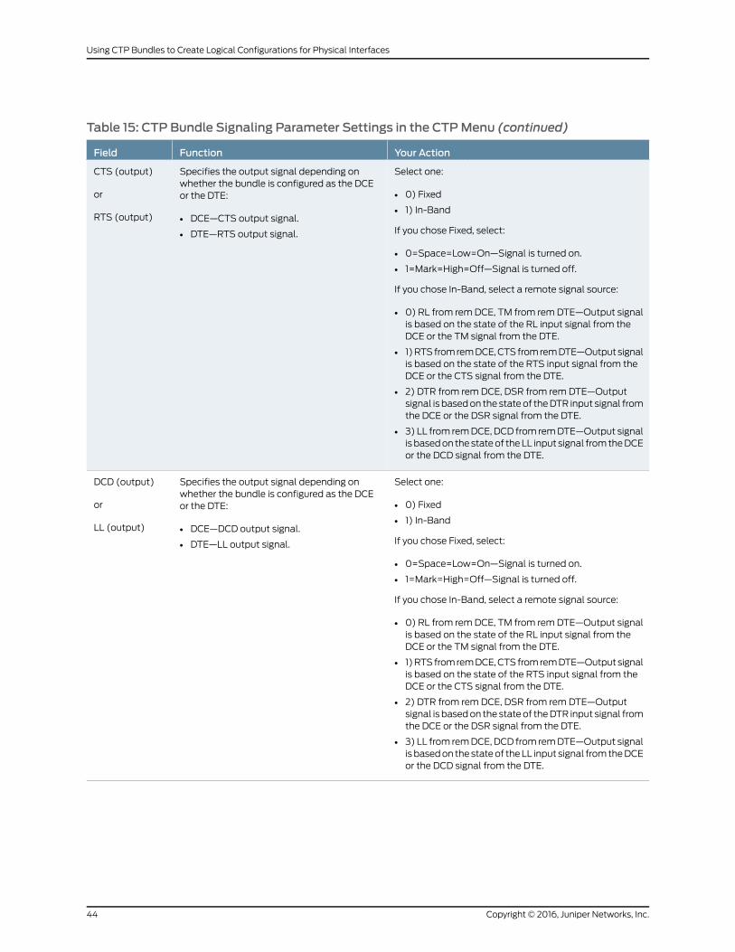
Table 15: CTP Bundle Signaling Parameter Settings in the CTPMenu (continued)
Your ActionFunctionField
Select one:
• 0) Fixed
• 1) In-Band
If you chose Fixed, select:
• 0=Space=Low=On—Signal is turned on.
• 1=Mark=High=Off—Signal is turned off.
If you chose In-Band, select a remote signal source:
• 0) RL from rem DCE, TM from rem DTE—Output signalis based on the state of the RL input signal from theDCE or the TM signal from the DTE.
• 1) RTS from rem DCE, CTS from rem DTE—Output signalis based on the state of the RTS input signal from theDCE or the CTS signal from the DTE.
• 2) DTR from rem DCE, DSR from rem DTE—Outputsignal is based on the state of the DTR input signal fromthe DCE or the DSR signal from the DTE.
• 3) LL from rem DCE, DCD from rem DTE—Output signalis based on the state of the LL input signal from the DCEor the DCD signal from the DTE.
Specifies the output signal depending onwhether the bundle is configured as the DCEor the DTE:
• DCE—CTS output signal.
• DTE—RTS output signal.
CTS (output)
or
RTS (output)
Select one:
• 0) Fixed
• 1) In-Band
If you chose Fixed, select:
• 0=Space=Low=On—Signal is turned on.
• 1=Mark=High=Off—Signal is turned off.
If you chose In-Band, select a remote signal source:
• 0) RL from rem DCE, TM from rem DTE—Output signalis based on the state of the RL input signal from theDCE or the TM signal from the DTE.
• 1) RTS from rem DCE, CTS from rem DTE—Output signalis based on the state of the RTS input signal from theDCE or the CTS signal from the DTE.
• 2) DTR from rem DCE, DSR from rem DTE—Outputsignal is based on the state of the DTR input signal fromthe DCE or the DSR signal from the DTE.
• 3) LL from rem DCE, DCD from rem DTE—Output signalis based on the state of the LL input signal from the DCEor the DCD signal from the DTE.
Specifies the output signal depending onwhether the bundle is configured as the DCEor the DTE:
• DCE—DCD output signal.
• DTE—LL output signal.
DCD (output)
or
LL (output)
Copyright © 2016, Juniper Networks, Inc.44
Using CTP Bundles to Create Logical Configurations for Physical Interfaces

Table 15: CTP Bundle Signaling Parameter Settings in the CTPMenu (continued)
Your ActionFunctionField
Select one:
• 0) Fixed
• 1) In-Band
If you chose Fixed, select:
• 0=Space=Low=On—Signal is turned on.
• 1=Mark=High=Off—Signal is turned off.
If you chose In-Band, select a remote signal source:
• 0) RL from rem DCE, TM from rem DTE—Output signalis based on the state of the RL input signal from theDCE or the TM signal from the DTE.
• 1) RTS from rem DCE, CTS from rem DTE—Output signalis based on the state of the RTS input signal from theDCE or the CTS signal from the DTE.
• 2) DTR from rem DCE, DSR from rem DTE—Outputsignal is based on the state of the DTR input signal fromthe DCE or the DSR signal from the DTE.
• 3) LL from rem DCE, DCD from rem DTE—Output signalis based on the state of the LL input signal from the DCEor the DCD signal from the DTE.
Specifies the output signal depending onwhether the bundle is configured as the DCEor the DTE:
• DCE—TM output signal.
• DTE—RL output signal.
TM (output)
or
RL (output)
Select one:
• 0) Unused—Input signals are ignored.
• 1) Demand call.
If you chose Demand call, select an input signal value:
• 0=Space=Low=On—Signal is turned on.
• 1=Mark=High=Off—Signal is turned off.
Specifies the input signal depending on whetherthe bundle is configured as the DCE or the DTE:
• DCE—RL input signal.
• DTE—TM input signal.
RL (input)
or
TM (input)
Select one:
• 0) Unused—Input signals are ignored.
• 1) Demand call.
If you chose Demand call, select an input signal value:
• 0=Space=Low=On—Signal is turned on.
• 1=Mark=High=Off—Signal is turned off.
Specifies the input signal depending on whetherthe bundle is configured as the DCE or the DTE:
• DCE—RTS input signal.
• DTE—CTS input signal.
RTS (input)
or
CTS (input)
Select one:
• 0) Unused—Input signals are ignored.
• 1) Demand call.
If you chose Demand call, select an input signal value:
• 0=Space=Low=On—Signal is turned on.
• 1=Mark=High=Off—Signal is turned off.
Specifies the input signal depending on whetherthe bundle is configured as the DCE or the DTE:
• DCE—DTR input signal.
• DTE—DSR input signal.
DTR (input)
or
DSR (input)
45Copyright © 2016, Juniper Networks, Inc.
Chapter 6: Configuring CTP Bundles (CTP Menu)

Table 15: CTP Bundle Signaling Parameter Settings in the CTPMenu (continued)
Your ActionFunctionField
Select one:
• 0) Unused—Input signals are ignored.
• 1) Demand call.
If you chose Demand call, select an input signal value:
• 0=Space=Low=On—Signal is turned on.
• 1=Mark=High=Off—Signal is turned off.
Specifies the input signal depending on whetherthe bundle is configured as the DCE or the DTE:
• DCE—LL input signal.
• DTE—DCD input signal.
LL (input)
or
DCD (input)
Enter a number from 0 through 3.Specifies the output signaling delay in packets.Output delay(pkts)
ConfiguringMultiservice Port Parameters for CTP Bundles (CTPView)
• Configuring Multiservice Audio Mode Port Parameters for CTP Bundles
(CTPView) on page 46
• Configuring Multiservice IRIG-B Mode Port Parameters for CTP Bundles
(CTPView) on page 48
• Configuring Multiservice TDC Mode Parameters for CTP Bundles (CTPView) on page 49
• Configuring Multiservice 4WTO Mode Port Parameters for CTP Bundles
(CTPView) on page 50
ConfiguringMultiservice Audio Mode Port Parameters for CTP Bundles (CTPView)
Before you begin:
• Log in to the CTPView software at least at the Net_Admin level.
• Connect the CTPView server to the CTP device for which you want to configure bundles.
To configure Multiservice audio mode port parameters using CTPView:
1. In the side pane, select Bundle > Configuration.
2. Run your mouse over the Display and Select an Existing Bundle bar.
3. In the table of bundles, select the bundle that you want to modify.
4. UnderBundleOptions, configure the parameters as described in Table 16 on page 46
and click Click to Submit Bundle AND Port Changes.
Table 16: CTP Bundle Multiservice Audio Port Parameter Settings in CTPView
Your ActionFunctionField
Enter a description of up to 64 alphanumericcharacters. Do not use the followingcharacters:
( ; ' " ) ]
Specifies a description for the port.Port Description
Copyright © 2016, Juniper Networks, Inc.46
Using CTP Bundles to Create Logical Configurations for Physical Interfaces

Table 16: CTP Bundle Multiservice Audio Port Parameter Settings in CTPView (continued)
Your ActionFunctionField
Select DCARD.Specifies the daughter card as the interface type.I/F Type
Select Audio.Specifies that the bundle will run in audio mode.Multi-Service Mode
Select one:
• Master—This end of the circuit providesclocking.
• Slave—This end of the circuit usesadaptive clocking.
Specifies whether this end of the circuit provides clockingor uses adaptive clocking.
If the CTP devices at both ends of the circuit aresynchronized, you can configure both ends as Master.
Audio Mode
Select one:
• Channel 0—Enables only channel 0.
• Dual Channel—Enables both channel 0and channel 1.
Specifies the channel or channels to enable.Audio Channel
Select one:
• 8
• 12
• 16
• 24
• 32
• 48
Specifies the sample rate for audio circuits in kilohertz. Thesample rate determines the audio quality and the networkbandwidth needed. Higher sample rates create an IP dataflow that requires higher bandwidth.
8 KHz corresponds to standard toll quality voice.
48 KHz corresponds to CD quality audio.
Audio Sample Rate[ KHz ]
Select one:
• DISABLED (16 bit samples)—Generates16-bit audio samples.
• ENABLED (8 bit samples)—Generates8-bit audio samples.
Enables or disables μ-law encoding. Standard audio codesamples are 16 bits. If you enable μ-law encoding, the 16-bitsamples are converted to 8 bits, consuming half of thebandwidth without significant audio degradation.
Audio μ-lawEncoding
Select one:
• DISABLED—Disables the active squelchfunction on the circuit (audio output isalways enabled).
• ENABLED/ACTIVE—Squelch input isgrounded and analog output is disabled.
• ENABLED/INACTIVE—No signal is appliedto the squelch input. Input is open andanalog output is possible.
Enables or disables the active squelch function on thecircuit.
If enabled, specifies whether the squelch is active orinactive.
The squelch function gates local audio output when DSR-A(channel 0) or RTS-A (channel 1) inputs are active orinactive.
Audio Squelch
Enter a number from 0 through 255.Specifies the output level for channel 0.
Note the following information about the values:
• 0—There is no output.
• 128—Unity gain, which means there is no attenuation orgain.
• 255—Gain is 2:1.
Audio Channel 0Output Level
47Copyright © 2016, Juniper Networks, Inc.
Chapter 6: Configuring CTP Bundles (CTP Menu)

Table 16: CTP Bundle Multiservice Audio Port Parameter Settings in CTPView (continued)
Your ActionFunctionField
Enter a number from 0 through 255.Specifies the output level for channel 1.
Note the following information about the values:
• 0—There is no output.
• 128—Unity gain, which means there is no attenuation orgain.
• 255—Gain is 2:1.
Audio Channel 1Output Level
ConfiguringMultiservice IRIG-BMode Port Parameters for CTP Bundles (CTPView)
Before you begin:
• Log in to the CTPView software at least at the Net_Admin level.
• Connect the CTPView server to the CTP device for which you want to configure bundles.
To configure Multiservice IRIG-B mode port parameters using CTPView:
1. In the side pane, select Bundle > Configuration.
2. Run your mouse over the Display and Select an Existing Bundle bar.
3. In the table of bundles, select the bundle that you want to modify.
4. Under Bundle Options, configure the parameters as described in Table 17 on page 48
and click Click to Submit Bundle AND Port Changes.
Table 17: CTP Bundle Multiservice IRIG-B Port Parameter Settings in CTPView
Your ActionFunctionField
Enter a description of up to 64alphanumeric characters. Do not usethe following characters:
( ; ' " ) ]
Specifies a description for the port.PortDescription
Select DCARD.Specifies the daughter card as the interface type.I/F Type
Select IRIG-B.Specifies that the bundle will run in IRIG-B mode.Multi-ServiceMode
Copyright © 2016, Juniper Networks, Inc.48
Using CTP Bundles to Create Logical Configurations for Physical Interfaces

Table 17: CTP Bundle Multiservice IRIG-B Port Parameter Settings in CTPView (continued)
Your ActionFunctionField
Select one:
• TX (signal enters CTP)—The endof the circuit that accepts IPpackets, extracts the IRIG-B datacodes, and transmits IRIG-Bsignaling output onto the cable.
• RX (signal exits CTP)—The end ofthe circuit that recovers IRIG-Bfrom the attached cable andgenerates IP packets toward thenetwork.
Specifies the direction of the circuit. Although the IP circuit connectionthrough the network is full duplex, an IRIG-B circuit is a simplexapplication, and the interface can operate only in Rx or Tx mode andnot both at the same time.
(Although the bundle is by default a full duplex IP connection, youcan configure it for simplex to save network bandwidth.)
If the autonegotiation setting of the CTP Ethernet media and thefar-end switch or router do not match, it is possible for the CTPEthernet ports to be in a half-duplex state, although the duplex settingis not configurable and always assumed to be full-duplex on the CTPdevice. Starting with CTPOS Release 7.2, the half-duplex state at CTPnetwork interface card (NIC) ports are acquired, regardless of theduplex setting configured on the far-end node. After theautonegotiation process is completed, if the CTP NIC cannot acquirefull-duplex mode, then the interfaces are considered to be down anda log message is recorded in both the /var/log/messages directoryand the syslog file stating that the interface is down due to a non-fullduplex condition. You are prompted to verify the cable connection,speed, and duplex settings because the NIC link might be down.
IRIG-B Source
Enter a number from 1000 through25,500 bps. The port speed must bea multiple of 100 bps.
Specifies the data rate on the IP connection.
Note the following about setting the IRIG rate:
• Unless network bandwidth is at a premium, we do not recommendthat you change this value from the default of 16,000 bps.
• Although the IRIG information can be transported through thenetwork at the minimum configured rate (1000 bps), a CTP bundlerunning at this rate is subject to high latency.
IRIG-B DataRate
Enter a number from 0.00 through7.85 volts peak-to-peak.
This option appears only if you set the direction of the port to Tx.
Specifies the high output level, which is measured in peak-to-peakvoltage. This setting is based on a 50-ohm termination
Output HighVolts Level
Enter a number from 0.00 through7.85 volts peak-to-peak.
This option appears only if you set the direction of the port to Tx.
Specifies the low output level, which is measured in peak-to-peakvoltage. This setting is based on a 50-ohm termination.
Output LowVolts Level
ConfiguringMultiservice TDCMode Parameters for CTP Bundles (CTPView)
Before you begin:
• Log in to the CTPView software at least at the Net_Admin level.
• Connect the CTPView server to the CTP device for which you want to configure bundles.
To configure Multiservice TDC mode port parameters using CTPView:
1. In the side pane, select Bundle > Configuration.
2. Run your mouse over the Display and Select an Existing Bundle bar.
49Copyright © 2016, Juniper Networks, Inc.
Chapter 6: Configuring CTP Bundles (CTP Menu)

3. In the table of bundles, select the bundle that you want to modify.
4. UnderBundleOptions, configure the parameters as described in Table 18 on page 50
and click Click to Submit Bundle AND Port Changes.
Table 18: CTP Bundle Multiservice TDC Port Parameter Settings in CTPView
Your ActionFunctionField
Enter a description of up to 64 alphanumericcharacters. Do not use the following characters:
( ; ' " ) ]
Specifies a description for the port.Port Description
Select DCARD.Specifies the daughter card as the interface type.I/F Type
Select TDC.Specifies that the bundle will run in TDC mode.Multi-Service Mode
Select one:
• Source (signal enters CTP)—End of the circuitthat receives NRZ/IRIG data.
• Destination (signal exits CTP)—End of the circuitthat sends NRZ/IRIG data toward the network.
Specifies the direction of the circuit.TDC Source
Enter a number from 500 through 5,000,000 bpsin multiples of 500.
Specifies the NRZ data rate on the IP connection.TDC NRZ Rate
Enter a number from 0 through 255.Specifies the output level.
Note the following information about the values:
• 0—There is no output.
• 128—Unity gain, which means there is noattenuation or gain.
• 255—Gain is 2:1.
TDC IRIG Output Level
ConfiguringMultiservice 4WTOMode Port Parameters for CTP Bundles (CTPView)
Before you begin:
• Log in to the CTPView software at least at the Net_Admin level.
• Connect the CTPView server to the CTP device for which you want to configure bundles.
To configure Multiservice 4WTO mode port parameters using CTPView:
1. In the side pane, select Bundle > Configuration.
2. Run your mouse over the Display and Select an Existing Bundle bar.
3. In the table of bundles, select the bundle that you want to modify.
4. Under BundleOptions, configure the parameters as described in Table 19 on page 51.
5. Click Click to Submit Bundle AND Port Changes.
Copyright © 2016, Juniper Networks, Inc.50
Using CTP Bundles to Create Logical Configurations for Physical Interfaces

Table 19: CTP Bundle Multiservice 4WTOMode Port Parameter Settings in CTPView
Your ActionFunctionField
Enter a description of up to 64alphanumeric characters. Do not use thefollowing characters:
( ; ' " ) ]
Specifies a description for the port.Port Description
Select DCARD.Specifies the daughter card as theinterface type.
I/F Type
Select 4WTOSpecifies that the bundle will run in4WTO mode.
Multi-Service Mode
Select one:
• Master—This end of the circuitprovides clocking.
• Slave—This end of the circuit usesadaptive clocking.
Specifies whether this end of the circuitprovides clocking or uses adaptiveclocking.
If the CTP devices at both ends of thecircuit are synchronized, you canconfigure both ends as Master.
4WTO Mode
Select one:
• Channel 0—Enables only channel 0.
• Dual Channel—Enables both channel0 and channel 1.
Specifies the channel or channels toenable.
Each CTP bundle can support either oneor two channels.
4WTO Channel
Sample rate is fixed at 8 KHz, whichcorresponds to standard toll qualityvoice.
Sample rate for audio circuits in kilohertz.The sample rate determines the audioquality and the network bandwidthneeded.
4WTO Sample Rate [ KHz ]
4WTO μ-law encoding is fixed atDISABLED.
4WTO μ-law encoding is notconfigurable.
4WTO μ-law Encoding
Select one:
• DISABLED—Disables the activesquelch function on the circuit
• ENABLED/ACTIVE—Squelch input isgrounded and analog output isdisabled.
• ENABLED/INACTIVE—No signal isapplied to the squelch input. Input isopen and analog output is possible.
Enables or disables the active squelchfunction on the circuit.
If enabled, specifies whether the squelchis active or inactive.
The squelch function gates local audiooutput when DSR-A (channel 0) orRTS-A (channel 1) inputs are active orinactive.
4WTO Squelch
Enter a number from 0 through 255.Specifies the output level for channel 0.
Note the following information about thevalues:
• 0—There is no output.
• 128—Unity gain, which means there isno attenuation or gain.
• 255—Gain is 2:1.
4WTO Channel 0 Output Level
51Copyright © 2016, Juniper Networks, Inc.
Chapter 6: Configuring CTP Bundles (CTP Menu)

Table 19:CTPBundleMultiservice4WTOModePortParameterSettings inCTPView (continued)
Your ActionFunctionField
Enter a number from 0 through 255.Specifies the output level for channel 1.
Note the following information about thevalues:
• 0—There is no output.
• 128—Unity gain, which means there isno attenuation or gain.
• 255—Gain is 2:1.
4WTO Channel 1 Output Level
Configuring Serial Port Parameters for CTP Bundles (CTPMenu)
This topic describes how to configure port parameters for serial interfaces.
Before you begin:
• Disable the bundle before you modify the bundle options.
To configure serial port parameters for CTP bundles using the CTP Menu:
1. From the CTP Main Menu, select 1) Bundle Operations.
2. Select 1) CTP.
3. Select a bundle from the list.
If you select an active bundle, you are prompted to disable the bundle before
configuring it.
4. Select 3) Port Config.
5. Configure the options as described in Table 20 on page 52.
Table 20: CTP Bundle Serial Port Parameter Settings in the CTPMenu
Your ActionFunctionField
Enter a description of up to 64alphanumeric characters. Do not usethe following characters:
( ; ' " ) ]
Specifies a description for the port.Port descriptor text
Select 2) Interface.Displays the menu used to configure theinterface type, mode, and encoding.
Interface
Copyright © 2016, Juniper Networks, Inc.52
Using CTP Bundles to Create Logical Configurations for Physical Interfaces

Table 20: CTP Bundle Serial Port Parameter Settings in the CTPMenu (continued)
Your ActionFunctionField
Select one:
• OFF—Do not set the interface type toOFF.
• EIA-530
• EIA-530A
• RS-232
• V.35
• Optional Interface
Specifies the electrical standard used onthe serial interface.
You can install the following optionaldaughter cards on a serial interface:
• T1/E1 (CTP1000 and CTP2000 series)
• 4WTO (CTP1000 and CTP2000series)
• IRIG-B (CTP2000 series only)
• Multiservice Daughter Cards (CTP2000 and CTP150 series)
Type
Select one:
• DCE—The interface is connected toa DCE device.
• DTE—The interface is connected toa DTE device.
Specifies that the interface is connectedto a data communication equipment(DCE) device or to a data terminalequipment (DTE) device.
Mode
Select one:
• NRZ—Nonreturn to zero (NRZ) lineencoding.
• ISOCH—Isochronous encoding.Isochronous encoding does notprovide or embed the clock in thedata.
• CDI—Conditioned diphase.Conditioned diphase encodingrecovers and embeds the clock in thedata signal. CDI encoding provides aspeed of up to 4608 KBps.
• TRANS—Transparent encoding. See“Configuring Transparent Encodingfor CTP Bundles (CTP Menu)” onpage 55.
• TDM—Additional data is interleavedwith the port’s serial data. This optionis used on TDM/TDC high-speedports and is available only oneven-numbered ports on a CTP 2000serial module. See “ConfiguringBundle Pairs for TDM/TDC Operation(CTP Menu)” on page 56.
• TRANS8—Extension of the TRANSencoding. Compared with TRANSencoding, which sends four signals ineach direction, with TRANS8encoding, bandwidth is doubled andeight signals can be sampled andtransported. This allows signals to besent from additional interfaces thatwere not supported in TRANS 4.
Specifies the serial encoding methodused on this bundle.
When you change the encoding method,the clocking configuration changes to thedefault configuration for the encodingmethod that you select.
Encoding
53Copyright © 2016, Juniper Networks, Inc.
Chapter 6: Configuring CTP Bundles (CTP Menu)

Table 20: CTP Bundle Serial Port Parameter Settings in the CTPMenu (continued)
Your ActionFunctionField
Enter a number from 0.00100 through12880.00000 KHz.
Specifies the speed of the port. Innetworks without bandwidth constraints,we recommend a multiple of 10.
The port speed recommendations varyaccording to encoding type:
• For transparent mode circuits, the portspeed is the sample rate for user data.Therefore, the port rate should be amultiple of the user data rate.
• For CDI circuits, the maximum portspeed is limited to 4608 KBps.
The port speed also varies depending onhardware:
• CTP2000 devices cannot have anaggregate port rate greater than114.688 Mbps.
Enter Synthesized port rate (KHz)
Specify y (yes) or n (no).Specifies whether adaptive clocking isenabled for this circuit.
If both end nodes are not locked to aclock reference, we recommend that youenable one end (not both) for adaptiveclocking
Appears only if you select ISOCH, CDI,TRANS, or TDM encoding.
Enable adaptive clocking?
Specify y (yes) or n (no).If you enabled adaptive clocking,specifies whether or not to initializeadaptive clocking parameters to theirdefault values, which depend on portspeed, packet size, and bufferingparameters set on the bundle.
We recommend the following settings:
• If you are configuring the bundle foradaptive clocking for the first time,enter y.
• If you have previously configured thebundle to optimize adaptive clockingfor this network, enter n.
Initialize adaptive clocking parameters?y[n]: y
This option is used for TDM/TDCoperation. See “Configuring theHigh-Speed CTP Bundle for TDM/TDCOperation (CTP Menu)” on page 57.
TDC Clk/Data on port N+1
This option is used for TDM/TDCoperation. See “Configuring theHigh-Speed CTP Bundle for TDM/TDCOperation (CTP Menu)” on page 57.
TDM rates
Copyright © 2016, Juniper Networks, Inc.54
Using CTP Bundles to Create Logical Configurations for Physical Interfaces

Configuring Transparent Encoding for CTP Bundles (CTPMenu)
This topic describes how to configure transparent encoding for CTP bundles. You must
configure transparent encoding on each end of the circuit.
To reduce transport latency, we recommend that you use the smallest buffer values
possible for networks.
NOTE: There are twomodes of transparent encoding. They are Transparent4mode (TRANS) and Transparent 8mode (TRANS8). Transparent 8modeis only supported on CTPOS release 6.4 and later. This topic describes howto configure the TRANS encoding.
Before you begin:
• Disable the bundle before you modify the bundle options.
To configure transparent encoding using the CTP Menu:
1. From the CTP Main Menu, select 1) Bundle Operations.
2. Select 1) CTP.
3. Select a bundle from the list.
If you select an active bundle, you are prompted to disable the bundle before
configuring it.
4. Select 3) Port Config.
5. Select 2) Interface.
6. Set Mode to DCE and set Encoding to TRANS.
7. Follow the onscreen instructions to configure the options as described in
Table 21 on page 55.
Table 21: Transparent Mode Parameter Settings in the CTPMenu
Your ActionFunctionField
Enter a number from0.00100 through1024.000000 KHz.
Specifies the speed of the port. For transparent mode circuits, the portspeed is the sample rate for user data. Therefore, the port rate should bea multiple of the user data rate. In networks without bandwidth constraints,we recommend a multiple of 10.
Enter Synthesized portrate (KHz)
Specify y (yes) or n (no).Specifies whether adaptive clocking is enabled for this circuit.
If both end nodes are not locked to a clock reference, we recommend thatyou enable one end (not both) for adaptive clocking
Enable adaptiveclocking?
55Copyright © 2016, Juniper Networks, Inc.
Chapter 6: Configuring CTP Bundles (CTP Menu)

Table 21: Transparent Mode Parameter Settings in the CTPMenu (continued)
Your ActionFunctionField
Specify y (yes) or n (no).If you enabled adaptive clocking, specifies whether or not to initializeadaptive clocking parameters to their default values, which depend onport speed, packet size, and buffering parameters set on the bundle.
We recommend the following settings:
• If you are configuring the bundle for adaptive clocking for the first time,enter y.
• If you have previously configured the bundle to optimize adaptiveclocking for this network, enter n.
Initialize adaptiveclocking parameters?y[n]: y
Specify y (yes) or n (no).Enables or disables the phase-correction FIFO buffer. This FIFO bufferaligns the clock and data phase relationship on a TRANS encoded circuitin which the clock travels in one direction and the data travels in theopposite direction.
Enable this FIFO buffer at one end of the circuit, but not at both ends.
Enable 16 bit FIFO?
Specify y (yes) or n (no).Specifies whether or not to invert the FIFO write clock.Invert FIFO Write clock?
Specify y (yes) or n (no).Specifies whether or not to invert the FIFO read clock.Invert FIFO Read clock?
Specify y (yes) or n (no).Specifies that the circuit uses the ST lead instead of the RTS and CTSleads to sample local SD/TT/RTS/DTR signals and forward them to theremote RD/RT/CTS/DSR signals.
The RTS and DTR leads are subject to additional delay and jitter becausethey are signaling leads. On higher-speed circuits, the delay and jitter onthese paths make the signal choices nonoptimal. Therefore, you canspecify that the circuit uses the ST lead instead of the RTS and CTS leads,which will not have this delay and jitter.
Use ST lead (instead ofRTS/CTS)?
Specify y (yes) or n (no).If you specify that the circuit uses the ST lead instead of the RTS and CTSleads, you can specify whether the ST lead is an input lead.
Is ST an input?
RelatedDocumentation
Transparent Encoding Applications and Support Overview on page 19•
• How Basic Transparent Encoding Works on page 20
• Configuring Transparent Encoding for CTP Bundles (CTPView) on page 122
• Using Phase-Correction FIFO Buffer with Transparent Encoding on page 21
• Using Send Timing (ST) Clocking for Higher Speed Circuits with Transparent Encoding
on page 23
Configuring Bundle Pairs for TDM/TDCOperation (CTPMenu)
The TDM/TDC feature is supported on CTP2000 serial interfaces. TDM/TDC operation
requires both a low-speed bundle and a high-speed bundle. This topic describes how to
Copyright © 2016, Juniper Networks, Inc.56
Using CTP Bundles to Create Logical Configurations for Physical Interfaces

configure the high-speed and low-speed bundle port options when used for TDM/TDC
bundles using CTP Menu.
1. Configuring the High-Speed CTP Bundle for TDM/TDC Operation (CTP
Menu) on page 57
2. Configuring the Low-Speed CTP Bundle for TDM/TDC Operation (CTP
Menu) on page 58
Configuring the High-Speed CTP Bundle for TDM/TDCOperation (CTPMenu)
Configure the high-speed bundle on an even-numbered port.
Before you begin:
• Disable the bundle before you modify the bundle options.
To configure a high-speed CTP bundle for TDM/TDC operation using the CTP Menu:
1. From the CTP Main Menu, select 1) Bundle Operations.
2. Select 1) CTP.
3. Select a bundle from the list. You must configure the bundle on an even-numbered
port.
If you select an active bundle, you are prompted to disable the bundle before
configuring it.
4. Select 3) Port Config.
5. Select 2) Interface.
6. Select 3) Encoding.
7. Select 5) TDM.
8. Follow the onscreen instructions to configure the parameters as described in
Table 22 on page 57.
9. Configure the rest of the bundle as you normally would.
Table 22: High-Speed CTP Bundle Parameters for TDM/TDCOperation in the CTPMenu
Your ActionFunctionField
Press Enter.Specifies that the TDM function is TDC Clk/Data on port N+1.
This option is available only on even-numbered ports on a CTP2000 serial module, andwhen the serial encoding parameter is set to TDM.
TDC Clk/Data on port N+1 oversamples the incoming clock (TT) and data (SD) from theadjacent port above this one (N+1) at this port’s clock rate, and embeds it in its data. At theremote end of the network, the embedded circuit data is recovered and exits the node onport N+1 as RT and RD outputs.
Because of the direct interleaving of two ports’ data, TDC is maintained between these twoports with an accuracy of one bit time at this port’s data rate.
TDC Clk/Dataon port N+1
57Copyright © 2016, Juniper Networks, Inc.
Chapter 6: Configuring CTP Bundles (CTP Menu)

Table 22: High-Speed CTP Bundle Parameters for TDM/TDCOperation in the CTPMenu (continued)
Your ActionFunctionField
Select one:
• 16
• 8
• 4
• 2
Specifies the number of bits out of 32 that are used for the TDM function (and not for localserial port data).
Appears only if you selected TDM encoding.
Keep in mind the following when you configure the TDM rate:
• If the rate is too low, the bundle may not carry the low-speed data because of insufficientoversampling.
• If the rate is too high, the low-speed circuit will still run, but will likely use more bandwidththan necessary.
• You may want to configure a higher rate to increase the TDM rate to reduce jitter on thelow-speed clock and data signals.
TDM rates
Configuring the Low-Speed CTP Bundle for TDM/TDCOperation (CTPMenu)
Configure the low-speed bundle on an odd-numbered port that is one higher than the
corresponding high-speed bundle.
Before you begin:
• Disable the bundle before you modify the bundle options.
To configure the low-speed CTP bundle using CTP Menu:
1. From the CTP Main Menu, select 1) Bundle Operations.
2. Select 1) CTP.
3. Select a bundle from the list. The bundle must be configured on an even-numbered
port.
If you select an active bundle, you are prompted to disable the bundle before
configuring it.
4. Select 3) Port Config.
5. Select 3) Clock Config.
6. Select 1) Port Clock Config.
7. Select 8) TDM/TDC - Interleaved Slow Port.
NOTE: Do not configure any other bundle parameters.
RelatedDocumentation
TDM/TDC Encoding Overview on page 25•
Copyright © 2016, Juniper Networks, Inc.58
Using CTP Bundles to Create Logical Configurations for Physical Interfaces

Configuring T1 and E1 Port Parameters for CTP Bundles (CTPMenu)
This topic describes how to configure port parameters for T1/E1 interfaces.
Before you begin:
• Disable the bundle before you modify the bundle options.
To configure port parameters for T1/E1 daughter cards for CTP bundles using the CTP
Menu:
1. From the CTP Main Menu, select 1) Bundle Operations.
2. Select 1) CTP.
3. Select a bundle from the list. The bundle port must have a T1/E1 daughter card
installed.
If you select an active bundle, you are prompted to disable the bundle before
configuring it.
4. Select 3) Port Config.
5. Select 2) Interface.
6. Select 1) Type and set the type to Optional Interface: T1/E1.
7. Follow the onscreen instructions and configure the options as described in
Table 23 on page 60.
The options vary depending on whether the bundle is T1 or E1 and whether fractional
T1 or E1 is configured.
8. To configure clocking for the port, select 3) Clock Config and configure the Clock
Config option as described in Table 23 on page 60.
59Copyright © 2016, Juniper Networks, Inc.
Chapter 6: Configuring CTP Bundles (CTP Menu)

NOTE: BITS input isaT1/E1 line interfaceunit (LIU),withAMI (alternatemarkinversion) encoding enabled and B8ZS/HDB3 (Zero Suppression) disabled.Theequalization is set fora0-133 feetcable.An internal 100ohmterminationis present, although it might need to be externally augmented based on thetypeofcablingused.AnyvalidAMIsignalworksproperlyand it isnot restrictedtoonly the"all 1"BITSsignalbut theonesdensitymustbesufficient topreventLOS (according to the ITUG.775 recommendation). TheTTL input has a slicepointof3.3V/2= 1.65V relative tochassis ground(GND).Therefore, anysignalon thecoaxial center conductor that transitions through that voltage registersa transition. There aremany signals, besides TTL, that satisfy this criteria. Anexternal terminationmust be provided that matches the impedance of thecable that goes to the BNC connector.
If you can configure the rate in CTPmenu, then theTTL supports a frequencyof2048KHz for theTTLclock input,provided thesignal isgoodandnoise-free(terminated properly). TTL is rate-agile, while BITS is restricted to T1/E1frequencies.
TheTTL input ishigh-impedance(noon-boardterminationprovided)becausea variety of cable typesmight exist that you can use to drive signal to thisconnector, such as RG-58 coax (50 ohm), RG-59 coax (75 ohm), or twistedpair (100-120 ohm). Instead of applying a particular impedance terminationon the board and have it incorrectly done, we recommend that you configurethe impedanceterminationbasedonyournetworkenvironment.Forexample,a 50 ohm termination is needed if you are using RG-58/U coax cable, whichhas 50 ohm impedance.
Table 23: CTP Bundle T1/E1 Port Parameter Settings in the CTPMenu
Your ActionFunctionField
Enter a description of up to 64alphanumeric characters. Do not use thefollowing characters:
( ; ' " ) ]
Specifies a description for the port.Port descriptor
Select one:
• T1
• E1
• Fractional T1
• Fractional E1
Specifies the type of interface.Type
Select one:
• B8ZS
• AMI
Specifies the T1 encoding method usedon this bundle.
Option (for T1)
Copyright © 2016, Juniper Networks, Inc.60
Using CTP Bundles to Create Logical Configurations for Physical Interfaces

Table 23: CTP Bundle T1/E1 Port Parameter Settings in the CTPMenu (continued)
Your ActionFunctionField
Select one:
• RJ48
• COAX
For E1 interfaces, configure thetermination to work with either coaxialor RJ-48.
Option (for E1)
The following clock synthesizer settingsare set by the software, and you cannotchange them:
• For T1, the clock synthesizer is set to1544 KHz.
• For E1 the clock synthesizer is set to2048 KHz.
Clock synthesizer
For T1, select a number from 1 through24.
For E1, select a number from 1 through31.
Specifies the number of fractional T1 orE1 channels to transport.
Fractional channels
Select one:
• y (yes)—Frame Transport—Framingbit is transported along with data,which results in data alignment withthe frame.
• n (no)t—Framing bit is nottransported.
For fractional T1, enables or disablesfractional frame transport.
Fractional Frame Transport
Select one:
• n (no)—Common channel signaling(CSS) is used. The common channelcarries data messages that conveysignaling for the circuits between twodevices.
• y (yes)—Channel associated signaling(CAS) is used. Each traffic channel hasa dedicated signaling channel(channel 16).
Specifies the signaling method used forfractional E1.
CAS support
61Copyright © 2016, Juniper Networks, Inc.
Chapter 6: Configuring CTP Bundles (CTP Menu)

Table 23: CTP Bundle T1/E1 Port Parameter Settings in the CTPMenu (continued)
Your ActionFunctionField
Select one:
• CTP is Clock Source—The PBX eitherreturns the clock received from theCTP device, or it returns a clock thatis traceable to the same source as theCTP node clock reference. Youtypically use this configuration whenyou configure the CTP device with aclock reference input.
• CTP is Loop Timed—The PBX providesthe clock, and the CTP device returnsthe same clock to the PBX. Youtypically use this configuration whenthe PBX has the more accurate clocksource. You can configure the far endof the circuit with adaptive clocking torecover this clock if necessary.
• CTP is Clock Source (AdaptiveEnd)—The PBX returns the clockreceived from the CTP device, and theCTP device uses the adaptiverecovered clock. You typically use thisconfiguration when the CTP devicedoes not have a reference input andthe PBX typically requires a clock fromthe distant PBX.
Specifies the type of clocking for the port.The default value for Clock Config isCTPis Loop Timed.
Clock Config
ConfiguringMultiservice Port Parameters for CTP Bundles (CTPMenu)
• Configuring Multiservice Audio Mode Port Parameters for CTP Bundles (CTP
Menu) on page 62
• Configuring Multiservice IRIG-B Mode Port Parameters for CTP Bundles (CTP
Menu) on page 64
• Configuring Multiservice TDC Mode Parameters for CTP Bundles (CTP Menu) on page 66
• Configuring Multiservice 4WTO Mode Port Parameters for CTP Bundles (CTP
Menu) on page 67
ConfiguringMultiservice Audio Mode Port Parameters for CTP Bundles (CTPMenu)
Before you begin:
• Disable the bundle before you modify the bundle options.
To configure Multiservice audio mode port parameters using the CTP Menu:
1. From the CTP Main Menu, select 1) Bundle Operations.
2. Select 1) CTP.
3. Select a bundle from the list.
Copyright © 2016, Juniper Networks, Inc.62
Using CTP Bundles to Create Logical Configurations for Physical Interfaces

If you select an active bundle, you are prompted to disable the bundle before
configuring it.
4. Select 3) Port Config.
5. Select 2) Interface.
6. Select 1) Type, and set the type to Optional Interface: MultiSvc.
7. Follow the onscreen instructions and configure the options as described in
Table 24 on page 63.
Table 24: CTP Bundle Multiservice Audio Mode Port Parameter Settings in the CTPMenu
Your ActionFunctionField
Select AUDIO.Specifies that the bundle will run in audiomode.
Mode
Select one:
• Master—This end of the circuit providesclocking.
• Slave—This end of the circuit usesadaptive clocking.
Specifies whether this end of the circuitprovides clocking or uses adaptiveclocking.
If the CTP devices at both ends of thecircuit are synchronized, you canconfigure both ends as Master.
Master/Slave
Select one:
• Disable—Channel 0 is the only activechannel.
• Enable—Both channel 0 and channel1 are active.
Two channels are supported—channel0 and channel 1.
Enables or disables the use of bothchannels.
Dual Channel
Select one:
• 8
• 12
• 16
• 24
• 32
• 48
Specifies the sample rate for audiocircuits in kilohertz. The sample ratedetermines the audio quality and thenetwork bandwidth needed. Highersample rates create an IP data flow thatrequires higher bandwidth.
8 KHz corresponds to standard tollquality voice.
48 KHz corresponds to CD quality audio.
Audio Sample Rate
Select one:
• Disable—Generates 16-bit audiosamples.
• Enable—Generates 8-bit audiosamples.
Enables or disables μ-law encoding.Standard audio code samples are 16 bits.If you enable μ-law encoding, the 16-bitsamples are converted to 8 bits,consuming half of the bandwidthwithout significant audio degradation.
μ-law Encoding:
63Copyright © 2016, Juniper Networks, Inc.
Chapter 6: Configuring CTP Bundles (CTP Menu)

Table 24: CTP Bundle Multiservice Audio Mode Port Parameter Settings in the CTPMenu (continued)
Your ActionFunctionField
Select one:
• Disable—Disables the active squelchfunction on the circuit (audio output isalways enabled).
• Enable and active—Squelch input isgrounded and analog output isdisabled.
• Enable and inactive—No signal isapplied to the squelch input. Input isopen and analog output is possible.
Enables or disables the active squelchfunction on the circuit.
If enabled, specifies whether the squelchis active or inactive.
The squelch function gates local audiooutput when DSR-A (channel 0) orRTS-A (channel 1) inputs are active orinactive.
Talk Squelch
Enter a number from 0 through 255.Specifies the output level for channel 0.
Note the following information about thevalues:
• 0—There is no output.
• 128—Unity gain, which means there isno attenuation or gain.
• 255—Gain is 2:1.
Ch 0 Output Level: 1.00x (decimal 128)
Enter a number from 0 through 255.Specifies the output level for channel 1.
Note the following information about thevalues:
• 0—There is no output.
• 128—Unity gain, which means there isno attenuation or gain.
• 255—Gain is 2:1.
Ch 1 Output Level: 1.00x (decimal 128)
ConfiguringMultiservice IRIG-BMode Port Parameters for CTP Bundles (CTPMenu)
Before you begin:
• Disable the bundle before you modify the bundle options.
To configure Multiservice IRIG-B mode port parameters using the CTP Menu:
1. From the CTP Main Menu, select 1) Bundle Operations.
2. Select 1) CTP.
3. Select a bundle from the list.
If you select an active bundle, you are prompted to disable the bundle before
configuring it.
4. Select 3) Port Config.
5. Select 2) Interface.
Copyright © 2016, Juniper Networks, Inc.64
Using CTP Bundles to Create Logical Configurations for Physical Interfaces

6. Select 1) Type and set the type to Optional Interface: MultiSvc.
7. Follow the onscreen instructions and configure the options as described in
Table 25 on page 65.
Table 25: CTP Bundle Multiservice IRIG-B Port Parameter Settings in the CTPMenu
Your ActionFunctionField
Select IRIG.Specifies that the bundle will run inIRIG-B mode.
Mode
Specify yes or no to the question: Is thisan IRIG-B source end (IRIG-B signalenters CTP)?
• Yes (y)—Sets direction to Rx. This endof the circuit recovers IRIG-B from theattached cable and generates IPpackets toward the network.
• No (n)—Sets the direction to Tx. Thisend of the circuit accepts IP packets,extracts the IRIG-B data codes, andtransmits IRIG-B signaling output ontothe cable.
If the autonegotiation setting of the CTPEthernet media and the far-end switchor router do not match, it is possible forthe CTP Ethernet ports to be in ahalf-duplex state, although the duplexsetting is not configurable and alwaysassumed to be full-duplex on the CTPdevice. Starting with CTPOS Release 7.2,the half-duplex state at CTP networkinterface card (NIC) ports are acquired,regardless of the duplex settingconfigured on the far-end node. After theautonegotiation process is completed, ifthe CTP NIC cannot acquire full-duplexmode, then the interfaces are consideredto be down and a log message isrecorded in both the/var/log/messages directory and thesyslog file stating that the interface isdown due to a non-full duplex condition.You are prompted to verify the cableconnection, speed, and duplex settingsbecause the NIC link might be down.
Specifies the direction of the circuit.Although the IP circuit connectionthrough the network is full duplex, anIRIG-B circuit is a simplex application,and the interface can operate only in Rxor Tx mode and not both at the sametime.
(Although the bundle is by default a fullduplex IP connection, you can configureit for simplex to save networkbandwidth.)
Src/Dest
65Copyright © 2016, Juniper Networks, Inc.
Chapter 6: Configuring CTP Bundles (CTP Menu)

Table25:CTPBundleMultiservice IRIG-BPortParameterSettings in theCTPMenu (continued)
Your ActionFunctionField
Enter a number from 1000 through25,500 bps. The port speed must be amultiple of 100 bps.
Specifies the data rate on the IPconnection.
Note the following about setting the IRIGrate:
• Unless network bandwidth is at apremium, we do not recommend thatyou change this value from the defaultof 16,000 bps.
• Although the IRIG information can betransported through the network atthe minimum configured rate (1000bps), a CTP bundle running at this rateis subject to high latency.
IRIG Rate
Enter a number from 0.00 through 7.85volts peak-to-peak.
This setting applies only if you set thedirection of the port to Tx.
Specifies the high output level, which ismeasured in peak-to-peak voltage. Thissetting is based on a 50-ohmtermination.
Output High Level
Enter a number from 0.00 through 7.85volts peak-to-peak.
This setting applies only if you set thedirection of the port to Tx.
Specifies the low output level, which ismeasured in peak-to-peak voltage. Thissetting is based on a 50-ohmtermination.
Output Low Level
ConfiguringMultiservice TDCMode Parameters for CTP Bundles (CTPMenu)
Before you begin:
• Disable the bundle before you modify the bundle options.
To configure Multiservice TDC mode port parameters using the CTP Menu:
1. From the CTP Main Menu, select 1) Bundle Operations.
2. Select 1) CTP.
3. Select a bundle from the list.
If you select an active bundle, you are prompted to disable the bundle before
configuring it.
4. Select 3) Port Config.
5. Select 2) Interface.
Copyright © 2016, Juniper Networks, Inc.66
Using CTP Bundles to Create Logical Configurations for Physical Interfaces

6. Select 1) Typeand set the type to Optional Interface: MultiSvc.
7. Follow the onscreen instructions and configure the options as described in
Table 26 on page 67.
Table 26: CTP Bundle Multiservice TDC Port Parameter Settings in the CTPMenu
Your ActionFunctionField
Select TDC/IRIG.Specifies that the bundle will run in TDCmode.
Mode
Select one:
• Src (signal enters CTP)—End of thecircuit that receives NRZ/IRIG data.
• Dst (signal exits CTP)—End of thecircuit that sends NRZ/IRIG datatoward the network.
Specifies the direction of the circuit.Src/Dest
Enter a number from 500 through5,000,000 bps. The port speed must bea multiple of 500 bps.
Specifies the data rate on the IPconnection.
NRZ/Rate
Enter a number from 0 through 255.Specifies the output level.
Note the following information about thevalues:
• 0—There is no output.
• 128—Unity gain, which means there isno attenuation or gain.
• 255—Gain is 2:1.
IRIG Output Level
ConfiguringMultiservice 4WTOMode Port Parameters for CTP Bundles (CTPMenu)
Before you begin:
• Disable the bundle before you modify the bundle options.
To configure Multiservice 4WTO mode port parameters using the CTP Menu:
1. From the CTP Main Menu, select 1) Bundle Operations.
2. Select 1) CTP.
3. Select a bundle from the list. The bundle port must have a 4WTO daughter card
installed.
If you select an active bundle, you are prompted to disable the bundle before
configuring it.
4. Select 3) Port Config.
5. Select 2) Interface.
67Copyright © 2016, Juniper Networks, Inc.
Chapter 6: Configuring CTP Bundles (CTP Menu)

6. Select 1) Type and set the type to Optional Interface: MultiSvc.
7. Configure the options as described in Table 27 on page 68.
Table 27: CTP Bundle Multiservice 4WTOPort Parameter Settings in the CTPMenu
Your ActionFunctionField
Select 4WTO-Em.Specifies that the bundle will run in4WTO mode.
Mode
Select one:
• Master—This end of the circuitprovides clocking.
• Slave—This end of the circuit usesadaptive clocking.
Specifies whether this end of the circuitprovides clocking or uses adaptiveclocking.
If the CTP devices at both ends of thecircuit are synchronized, you canconfigure both ends as Master.
Master/Slave
Select one:
• Disable—Channel 0 is the only activechannel.
• Enable—Both channel 0 and channel1 are active.
Two channels are supported—channel0 and channel 1.
Enables or disables the use of bothchannels.
Dual Channel
Select one:
• Disable—Disables the active squelchfunction on the circuit.
• Enable and active—Squelch input isgrounded and analog output isdisabled.
• Enable and inactive—No signal isapplied to the squelch input. Input isopen and analog output is possible.
Enables or disables the active squelchfunction on the circuit.
If enabled, specifies whether the squelchis active or inactive.
The squelch function gates local audiooutput when DSR-A (channel 0) orRTS-A (channel 1) inputs are active orinactive.
Talk Squelch
Enter a number from 0 through 255.Specifies the output level for channel 0.
Note the following information about thevalues:
• 0—There is no output.
• 128—Unity gain, which means there isno attenuation or gain.
• 255—Gain is 2:1.
Ch 0 Output Level: 1.00x (decimal 128)
Enter a number from 0 through 255.Specifies the output level for channel 1.
Note the following information about thevalues:
• 0—There is no output.
• 128—Unity gain, which means there isno attenuation or gain.
• 255—Gain is 2:1.
Ch 1 Output Level: 1.00x (decimal 128)
Copyright © 2016, Juniper Networks, Inc.68
Using CTP Bundles to Create Logical Configurations for Physical Interfaces

Configuring 4WTOPort Parameters for CTP Bundles (CTPMenu)
For CTP bundles, you can configure a 4WTO daughter card installed on a serial interface
module.
You do not need to configure port speed and clocking for the analog 4WTO interface.
Selecting this interface causes the port speed and clocking to be automatically configured.
You can set up 4WTO daughter cards to interoperate with Multiservice Interface modules.
Interoperability of Multiservice Interface modules with 4WTO daughter cards requires
the following:
• Firmware revision 4 or later on the 4WTO daughter card.
• CTPView releases 3.4R4 or later or releases 4.x or later.
• CTPOS release 6.0 or later.
• Channel 1 cannot be the enabled channel.
Before you begin:
• Disable the bundle before you modify the bundle options.
To configure port parameters for 4WTO daughter cards for CTP bundles using the CTP
Menu:
1. From the CTP Main Menu, select 1) Bundle Operations.
2. Select 1) CTP.
3. Select a bundle from the list. The bundle port must have a 4WTO daughter card
installed.
If you select an active bundle, you are prompted to disable the bundle before
configuring it.
4. Select 3) Port Config.
5. Select 2) Interface.
6. Select 1) Type and set the type to Optional Interface: Voice 4W/TO.
7. Follow the onscreen instructions.
To prevent voice channels from generating occasional noise bursts caused by
unsynchronized nodes, we recommend that you either enable adaptive clocking on
one end of the voice port (not both) or lock both ends of the voice port to clock
references.
8. Configure the options as described in Table 28 on page 70.
69Copyright © 2016, Juniper Networks, Inc.
Chapter 6: Configuring CTP Bundles (CTP Menu)

Table 28: CTP Bundle 4WTOPort Parameter Settings in the CTPMenu
Your ActionFunctionField
Select one:
• Disabled—Only one channel can beenabled.
• Enabled—Channels 1 and 2 areenabled.
Each CTP port with the daughter cardinstalled can support either one or twochannels.
Enables or disables the use of bothchannels.
Dual Channel
Enter either 0 or 1.If Dual Channel is disabled, specifieswhich voice channel you want to enableon the 4WTO daughter card.
Enabled Channel
Enter a number from 0 through 255.Specifies the input level for the 4WTOdaughter card.
Note the following information about thevalues:
• 0—Gain is 2:3 (signal is attenuated33% or 1.8 dB).
• 25—Unity gain, which means there isno attenuation or gain.
• 255—Gain is 4:1 (signal is amplified400% or 6 dB).
Intermediate values are derived withlinear interpolation. The actual gaindepends on the impedance of theattached device.
Input Level
Enter a number from 0 through 255.Specifies the output level for the 4WTOdaughter card.
Note the following information about thevalues:
• 0—Gain is 2:3 (signal is attenuated33% or 1.8 dB).
• 25—Unity gain, which means there isno attenuation or gain.
• 255—Gain is 4:1 (signal is amplified400% or 6 dB).
Intermediate values are derived withlinear interpolation. The actual gaindepends on the impedance of theattached device.
Output Level
Copyright © 2016, Juniper Networks, Inc.70
Using CTP Bundles to Create Logical Configurations for Physical Interfaces

Table 28: CTP Bundle 4WTOPort Parameter Settings in the CTPMenu (continued)
Your ActionFunctionField
Select one:
• DISABLED—Disables the activesquelch function on the circuit
• ENABLED/ACTIVE—Squelch input isgrounded and analog output isdisabled.
• ENABLED/INACTIVE—No signal isapplied to the squelch input. Input isopen and analog output is possible.
Enables or disables the active squelchfunction on the circuit.
If enabled, specifies whether the squelchis active or inactive.
The squelch function gates local audiooutput when DSR-A (channel 1) orRTS-A (channel 0) inputs are active orinactive.
Talk Squelch
• Enabled—Interoperability with theMultiservice Interface module isenabled.
• Disabled—Interoperability with theMultiservice Interface module isdisabled.
Enables or disables interoperability ofthe 4WTO daughter card withMultiservice Interface modules.
When you enable interoperability of the4WTO daughter card with MultiserviceInterface modules, the port speed for thebundle is set as follows:
• 64 when only channel 0 is enabled.
• 128 when dual channel is enabled.
Ms interwork
Select one:
• 4WTO/IRIG - Master End—This end ofthe circuit generates a clock signal andsends it to the remote end.
• 4WTO/IRIG - Adaptive End—This endof the circuit receives the clock signalfrom the remote end. The clock slaveuses its period to determine when tosample data and how to transmit dataacross the link.
• Custom—The custom clockingconfiguration is used.
Specifies the type of clocking for the port.
To prevent voice channels fromgenerating occasional noise burstscaused by unsynchronized nodes, werecommend that you configure one endof the voice port (not both) for adaptiveclocking or lock both ends to clockreferences.
Clock Config
RelatedDocumentation
Configuring Multiservice 4WTO Mode Port Parameters for CTP Bundles (CTP Menu)
on page 67
•
71Copyright © 2016, Juniper Networks, Inc.
Chapter 6: Configuring CTP Bundles (CTP Menu)

Configuring IRIG-B Port Parameters for CTP Bundles (CTPMenu)
This topic describes how to configure port parameters for IRIG-B daughter cards.
Adaptive clocking is configured by default on IRIG-B bundles, and the packet size is set
to 64 bytes. The packet size combined with the default data rate of 16 Kbps produces a
packet rate of 32 pps, which is a good packet rate for adaptive clocking.
Before you begin:
• Disable the bundle before you modify the bundle options.
To configure IRIG-B port parameters using the CTP Menu:
1. From the CTP Main Menu, select 1) Bundle Operations.
2. Select 1) CTP.
3. Select a bundle from the list. The bundle port must have an IRIG-B daughter card
installed.
If you select an active bundle, you are prompted to disable the bundle before
configuring it.
4. Select 3) Port Config.
5. Select 2) Interface.
6. Select 1) Type and set the type to Optional Interface: IRIG-B.
7. Follow the onscreen instructions and configure the options as described in
Table 29 on page 73.
The options vary depending on whether the bundle is T1 or E1 and whether fractional
T1 or E1 is configured.
8. To configure clocking for the port, select 3) Clock Config and configure the Clock
Config option as described in Table 29 on page 73.
Copyright © 2016, Juniper Networks, Inc.72
Using CTP Bundles to Create Logical Configurations for Physical Interfaces

Table 29: CTP Bundle IRIG-B Port Parameter Settings in the CTPMenu
Your ActionFunctionField
Specify yes or no to the question: Is thisan IRIG-B source end (IRIB-B signalenters CTP)?
• Yes (y)—Sets direction to Rx. This endof the circuit recovers IRIG-B from theattached cable and generates IPpackets toward the network
• No (n)—Sets the direction to Tx. Thisend of the circuit accepts IP packets,extracts the IRIG-B data codes, andtransmits IRIG-B signaling output ontothe cable.
Specifies the direction of the circuit.Although the IP circuit connectionthrough the network is full duplex, anIRIG-B circuit is actually a simplexapplication, and the daughter card canoperate only in Rx or Tx mode and notboth at the same time.
If the autonegotiation setting of the CTPEthernet media and the far-end switchor router do not match, it is possible forthe CTP Ethernet ports to be in ahalf-duplex state, although the duplexsetting is not configurable and alwaysassumed to be full-duplex on the CTPdevice. Starting with CTPOS Release 7.2,the half-duplex state at CTP networkinterface card (NIC) ports are acquired,regardless of the duplex settingconfigured on the far-end node. After theautonegotiation process is completed, ifthe CTP NIC cannot acquire full-duplexmode, then the interfaces are consideredto be down and a log message isrecorded in both the/var/log/messages directory and thesyslog file stating that the interface isdown due to a non-full duplex condition.You are prompted to verify the cableconnection, speed, and duplex settingsbecause the NIC link might be down.
Direction
Enter a number from 0.00 through 7.85volts peak-to-peak.
This setting appears only if you set thedirection of the port to Tx.
Specifies the high output level, which ismeasured in peak-to-peak voltage. Thissetting is based on a 50-ohm termination
Output High Level
Enter a number from 0.00 through 7.85volts peak-to-peak.
This setting appears only if you set thedirection of the port to Tx.
Specifies the low output level, which ismeasured in peak-to-peak voltage. Thissetting is based on a 50-ohmtermination.
Output Low Volts Level
Enter a number from 1000 through25,500 bps. The port speed must be amultiple of 100 bps.
Specifies the data rate on the IPconnection.
Unless network bandwidth is at apremium, we do not recommend that youchange this value from the default of 16Kbps.
Port Speed (kbps)
73Copyright © 2016, Juniper Networks, Inc.
Chapter 6: Configuring CTP Bundles (CTP Menu)

Table 29: CTP Bundle IRIG-B Port Parameter Settings in the CTPMenu (continued)
Your ActionFunctionField
Select one:
• 4WTO/IRIG - Master End—This endof the circuit generates a clock signaland sends it to the remote end.
• 4WTO/IRIG - Adaptive End—This endof the circuit receives the clock signalfrom the remote end. The clock slaveuses its period to determine when tosample data and how to transmit dataacross the link.
• Custom—The custom clockingconfiguration is used.
Specifies the type of clocking for thebundle.
Clock Config
Configuring Advanced Port Options for CTP Bundles (CTPMenu)
Before you begin:
• Disable the bundle before you modify the bundle options.
To configure advanced port options for CTP bundles using the CTP Menu:
1. From the CTP Main Menu, select 1) Bundle Operations.
2. Select 1) CTP.
3. Select a bundle from the list.
If you select an active bundle, you are prompted to disable the bundle before
configuring it.
4. Select 3) Port Config.
5. Select 4) Advanced Options.
6. Configure the options as described in Table 30 on page 74.
Table 30: CTP Bundle Advanced Port Option Settings in the CTPMenu
Your ActionFunctionField
Select y or n.Do not change this value withoutconsulting JTAC.
Specifies whether or not the CTP devicedrives received data (RD) onto data setready (DSR) and real-time (RT) dataonto test mode (TM).
Single ended data/clock outputs
Select y or n.Do not change this value withoutconsulting JTAC.
Specifies whether or not to reclock RDwith the RT clock to align the data andthe clock.
Reclock RD to align RD/RT
Copyright © 2016, Juniper Networks, Inc.74
Using CTP Bundles to Create Logical Configurations for Physical Interfaces

Table 30: CTP Bundle Advanced Port Option Settings in the CTPMenu (continued)
Your ActionFunctionField
Select y or n.Specifies that the CTP device disqualifiestransmit timing (TT) only when it is higherthan the port speed.
When enabled, this setting keeps the portfrom going to the TtFail state when theincoming user clock fluctuates between0 and the configured port rate. If the TTrate goes above the configured port rate,the CTP device sends the port to theTtFail state to protect the system froman overspeed TT, which would causeproblems for the port, CTP device, ornetwork.
Only high TT checking
Select y or n.When request to send (RTS) is inactive,specifies whether or not the CTP devicefeeds TT with the internally createdclock.
TT Clock Gated by RTS
Select y or n.When clock gating is enabled, specifieswhether or not to use the inverted RTSsignal.
RTS Clock Gate Invert
Select y or n.Specifies whether or not to invert databound for the interface with data boundfor the IP network.
Input/Output Data Invert
Select y or n.Helps maintain the low-speed port on aTDM/TDC CTP serial circuit at up whenthe high-speed circuit goes down.
Substitute DDS when TT gone
Selecting the Type of Clocking on Serial Ports for CTP Bundles (CTPMenu)
This topic describes how to select the type of clocking that you want to use on serial
ports. The type of clocking supported depends on the type of encoding you are using.
Before you begin:
• Disable the bundle before you modify the bundle options.
CTP Menu gives you the option of selecting the clocking type when you change the
interface encoding for a circuit. You can also specify the clocking type for CTP bundles
using the CTP Menu as follows:
1. From the CTP Main Menu, select 1) Bundle Operations.
2. Select 1) CTP.
3. Select a bundle from the list.
If you select an active bundle, you are prompted to disable the bundle before
configuring it.
75Copyright © 2016, Juniper Networks, Inc.
Chapter 6: Configuring CTP Bundles (CTP Menu)

4. Select 3) Port Config.
5. Select 3) Clock Config.
6. Select 1) Port Clock Config.
7. Configure the options as described in Table 31 on page 76.
Table 31: Clocking Type Supported for Each Encoding Type as Displayed in the CTPMenu
Clocking Type SupportedEncoding Type
You can specify the following clocking methods for NRZ and TDM circuits with DCEmode specified:
• Custom—The custom clocking configuration is used.
• Configured Rate, w/o Ext Tx Clk (TT)—Configured rate without external TX clock(TT). The CTP device synthesizes the rate that is used on the ST and RT outputs tothe attached device. The ST is used to sample Send Data from the attached DTE.The clock is created by the CTP DDS circuitry and logic. This option is commonlyused on circuits that are less than 1 Mbps.
• Configured Rate, Ext Tx Clk (TT—Configured rate with external TX clock (TT). TheCTP device synthesizes the rate that is used on the ST and RT outputs to the attacheddevice. The clock is created by the DDS circuitry and logic. This option is used tosample Send Data from the attached device. It assumes that the attached device isusing ST or clock reference that is traceable to CTP reference. It is typically used forhigher data rates (>1 Mbps) and long cables.
• All Clocked by Ext Tx Clk (TT)—All clocked with external TX clock (TT). The CTPdevice uses the external TT timing from the DTE for all clocking. Ext TT is used tosample Send Data from the attached device, to generate the RT clock, and to clockdata into the IP network.
• Adaptive Rate, Ext Tx Clk (TT)—Adaptive clocking with external TX clock (TT).
• Adaptive Rate, w/o Ext Tx Clk (TT)—Adaptive clocking with internal clock.
• Autobaud Rate, Ext Tx Clk (TT)—Autobaud rate with internal clock.
• Autobaud Rate, w/o Ext Tx Clk (TT)—Autobaud rate with external clock.
• TDM/TDC Interleaved Slow Port—Available only on odd-numbered ports. Use thisoption for the low-speed port of a time domain correlation (TDC) circuit.
NRZ and TDM with interface modeset to DCE
You can specify the following clocking methods for NRZ and TDM circuits with DTEmode specified:
• Adaptive Rate, Ext Tx Clk (TT)—Adaptive clocking with external TX clock (TT).
• Adaptive Rate, w/o Ext Tx Clk (TT)—Adaptive clocking with internal clock.
• Autobaud Rate, Ext Tx Clk (TT)—Autobaud rate with internal clock.
• Autobaud Rate, w/o Ext Tx Clk (TT)—Autobaud rate with external clock.
• DTE, All Clocked by Ext Clk (ST/RT)—The DCE equipment provides all clocks. TheST input clock is used to clock out the external transmit clock (TT) and the senddata (SD). The RT input clock is used to clock in the receive data (RD).
• TDM/TDC Interleaved Slow Port—Available only on even-numbered bundles. Usethis option for the slower port of the time domain correlation (TDC) circuit.
• DTE, All Clocked by User Clk(RT)—The DCE equipment provides all clocks. The RTinput clock is used to clock out the external transmit clock (TT) and the send data(SD) and to clock in the receive data (RD).
• Custom—The custom clocking configuration is used.
NRZ and TDM with interface modeset to DTE
Copyright © 2016, Juniper Networks, Inc.76
Using CTP Bundles to Create Logical Configurations for Physical Interfaces

Table 31: Clocking Type Supported for Each Encoding Type as Displayed in the CTPMenu (continued)
Clocking Type SupportedEncoding Type
You can specify the following clocking methods for ISOCH circuits:
• Adaptive Rate, Ext Tx Clk (TT)—Adaptive clocking with external TX clock (TT).
• Adaptive Rate, w/o Ext Tx Clk (TT)—Adaptive clocking with internal clock.
• Autobaud Rate, Ext Tx Clk (TT)—Autobaud rate with internal clock.
• Autobaud Rate, w/o Ext Tx Clk (TT)—Autobaud rate with external clock.
• ISOCH - Master End—This end of the circuit generates a clock signal and sends it tothe remote end. Configure ISOCH - Adaptive End at the remote end.
• ISOCH - Adaptive End—This end of the circuit uses adaptive clocking to receive theclock signal from the remote end. The clock slave uses its period to determine whento sample data and how to transmit data across the link.
• Custom—The custom clocking configuration is used.
ISOCH
You can specify the following clocking methods for CDI circuits:
• Adaptive Rate, Ext Tx Clk (TT)—Adaptive clocking with external TX clock (TT).
• Adaptive Rate, w/o Ext Tx Clk (TT)—Adaptive clocking with internal clock.
• Autobaud Rate, Ext Tx Clk (TT)—Autobaud rate with internal clock.
• Autobaud Rate, w/o Ext Tx Clk (TT)—Autobaud rate with external clock.
• CDI - Master End—This end of the circuit generates a clock signal and sends it to theremote end. Configure CDI - Adaptive End at the remote end.
• CDI - Adaptive End—This end of the circuit uses adaptive clocking to receive the clocksignal from the remote end. The clock slave uses its period to determine when tosample data and how to transmit data across the link.
• Custom—The custom clocking configuration is used.
CDI
You can specify the following clocking methods for TRANS circuits:
• Adaptive Rate, Ext Tx Clk (TT)—Adaptive clocking with external TX clock (TT).
• Adaptive Rate, w/o Ext Tx Clk (TT)—Adaptive clocking with internal clock.
• Autobaud Rate, Ext Tx Clk (TT)—Autobaud rate with internal clock.
• Autobaud Rate, w/o Ext Tx Clk (TT)—Autobaud rate with external clock.
• TRANS - Master End—This end of the circuit generates a clock signal and sends it tothe remote end. Configure TRANS - Adaptive End at the remote end.
• TRANS - Adaptive End—This end of the circuit uses adaptive clocking to receive theclock signal from the remote end. The clock slave uses its period to determine whento sample data and how to transmit data across the link.
• Custom—The custom clocking configuration is used.
TRANS
77Copyright © 2016, Juniper Networks, Inc.
Chapter 6: Configuring CTP Bundles (CTP Menu)

Configuring CustomClocking for CTP Bundles (CTPMenu)
The custom clocking configuration allows you to configure the source for all clocks and
specify which clocks are used to sample and transmit data. The configuration provides
complete control over how clocks are used, and we recommend that you have a good
understanding of circuit and system clocking before you use this configuration.
You can use custom clocking to:
• Configure the interface to use nonstandard clock configurations that meet the timing
needs of your application.
• Configure asymmetric clocks.
• Create special configurations for devices such as tactical radios.
Before you begin:
• Disable the bundle before you modify the bundle options.
To configure custom clocking for CTP bundles using the CTP Menu:
1. From the CTP Main Menu, select 1) Bundle Operations.
2. Select 1) CTP.
3. Select a bundle from the list.
If you select an active bundle, you are prompted to disable the bundle before
configuring it.
4. Select 3) Port Config.
5. Select 3) Clock Config.
6. Select 1) Port Clock Config.
7. Select Custom.
8. Configure the options as described in Table 32 on page 78.
Table 32: CTP Bundle CustomClocking Settings in the CTPMenu
Your ActionFunctionField
Select:
• User (OI)—The clock is recovered fromthe user equipment.
• Adaptive—The DDS uses adaptiveclocking to recover the clock signalfrom the remote CTP device.
• Autobaud—This setting enables themonitoring of OAM packets for theterminal timing (TT) frequency at theother end and processing toaccommodate frequency changesthat are detected.
Specifies the clock source for the DDS.DDS Synthesizer Source
Copyright © 2016, Juniper Networks, Inc.78
Using CTP Bundles to Create Logical Configurations for Physical Interfaces

Table 32: CTP Bundle CustomClocking Settings in the CTPMenu (continued)
Your ActionFunctionField
Select:
• DDS Output—Direct digital synthesizerclock generator.
• Oscillator—Oscillator system clock.
Specifies the source for the divider clock.The DIV clock is an alternative clockgenerator for the bundle, and its outputclock is an even integer divider of itssource clock.
The divider is used to configureasymmetric circuits.
For example, if the source clock is 512KHz, the output of the DIV clock can be256 KHz, 128 KHz, 85.333 KHz, so on.
DIV (clk divider) Source
Enter an even number from 2 through64,000.
Specifies the divider clock value. Theclock value of the DIV source is dividedby this value to obtain the output clockvalue of the DIV clock.
DIV (clk divider) Value
Select one (the values that appeardepend on whether the bundle isconfigured as the DCE or as the DTE):
• OFF—No clock is used.
• ST (ext clk)—Send timing clock. Theinterface clock signal from the DCE tothe DTE (CTP device).
• DDS (synth)—Direct digital synthesizerclock
• TT (ext clk)—Transmit timing clock.The interface clock signal from theDTE to the DCE (CTP device).
• RT (ext clk)—Receive timing clock.Interface clock signal from the DCE tothe DTE (CTP device).
• DIV (synth)—Divider clock generator.
Specifies the clock used for Send Timingon the network bound interface.
ST (net bound i/f) clk sel
Select one (the values that appeardepend on whether the bundle isconfigured as the DCE or as the DTE):
• OFF—No clock is used.
• ST (ext clk)—Send timing clock. Theinterface clock signal from the DCE tothe DTE (CTP device).
• DDS (synth)—Direct digital synthesizerclock
• TT (ext clk)—Transmit timing clock.The interface clock signal from theDTE to the DCE (CTP device).
• RT (ext clk)—Receive timing clock.Interface clock signal from the DCE tothe DTE (CTP device).
• DIV (synth)—Divider clock generator.
Specifies the clock used for ReceiveFrequency on the network boundinterface.
RF (net bound fifo) clk sel
79Copyright © 2016, Juniper Networks, Inc.
Chapter 6: Configuring CTP Bundles (CTP Menu)

Table 32: CTP Bundle CustomClocking Settings in the CTPMenu (continued)
Your ActionFunctionField
Select one (the values that appeardepend on whether the bundle isconfigured as the DCE or as the DTE):
• OFF—No clock is used.
• ST (ext clk)—Send timing clock. Theinterface clock signal from the DCE tothe DTE (CTP device).
• DDS (synth)—Direct digital synthesizerclock
• TT (ext clk)—Transmit timing clock.The interface clock signal from theDTE to the DCE (CTP device).
• RT (ext clk)—Receive timing clock.Interface clock signal from the DCE tothe DTE (CTP device).
• DIV (synth)—Divider clock generator.
Specifies the clock used for the ReceiveData path on the network bound serialcommunications controller (SCC).
RX (net bound scc) clk sel
Select one:
• OFF—No clock is used.
• DDS (synth)—Direct digital synthesizerclock
• TT (ext clk)—Transmit timing clock.The interface clock signal from theDTE to the DCE (CTP device).
• DIV (synth)—Divider clock generator.
Specifies the clock used for ReceiveTiming on the interface bound interface.
This parameter appears only if you haveconfigured the bundle as the DCE.
RT (i/f bound i/f) clk sel
Select one:
• ST (ext clk)—Send timing clock. Theinterface clock signal from the DCE tothe DTE (CTP device).
• DDS (synth)—Direct digital synthesizerclock
• RT (ext clk)—Receive timing clock.Interface clock signal from the DCE tothe DTE (CTP device).
• DIV (synth)—Divider clock generator.
Specifies the Transmit Timing clock onthe interface bound interface.
This parameter appears only if you haveconfigured the bundle as the DTE.
TT (i/f bound i/f) clk sel
Copyright © 2016, Juniper Networks, Inc.80
Using CTP Bundles to Create Logical Configurations for Physical Interfaces

Table 32: CTP Bundle CustomClocking Settings in the CTPMenu (continued)
Your ActionFunctionField
Select one (the values that appeardepend on whether the bundle isconfigured as the DCE or as the DTE):
• OFF—No clock is used.
• ST (ext clk)—Send timing clock. Theinterface clock signal from the DCE tothe DTE (CTP device).
• DDS (synth)—Direct digital synthesizerclock
• TT (ext clk)—Transmit timing clock.The interface clock signal from theDTE to the DCE (CTP device).
• RT (ext clk)—Receive timing clock.Interface clock signal from the DCE tothe DTE (CTP device).
• DIV (synth)—Divider clock generator.
Specifies the clock used for the TransmitData path on the interface bound serialcommunications controller (SCC).
TX (i/f bound scc) clk sel
Configuring Adaptive Clocking for CTP Bundles (CTPMenu)
The adaptive clocking configuration allows you to modify attributes that affect the
adaptive clocking algorithm. The default settings are acceptable for most applications.
We recommend that you change these settings only with the assistance of JTAC.
Before you begin:
• Disable the bundle before you modify the bundle options.
To configure adaptive clocking for CTP bundles using the CTP Menu:
1. From the CTP Main Menu, select 1) Bundle Operations.
2. Select 1) CTP.
3. Select a bundle from the list.
If you select an active bundle, you are prompted to disable the bundle before
configuring it.
4. Select 3) Port Config.
5. Select 3) Clock Config.
6. Select 1) Port Clock Config.
7. Select Set Adaptive Parameters.
8. Configure the options as described in Table 33 on page 82.
81Copyright © 2016, Juniper Networks, Inc.
Chapter 6: Configuring CTP Bundles (CTP Menu)

Table 33: CTP Bundle Adaptive Clocking Settings in the CTPMenu
Your ActionFunctionField
Select Set to Defaults.Sets the adaptive clocking configurationto the default settings.
Set to Defaults
Enter a number from 3 through 200seconds.
Specifies the time period during initialstart of adaptive clocking during whichpacket samples that are experiencing theleast delay through the network arecollected. These samples are used foraggressive state calculations.
AGGR Seconds/Calc
Enter a number from 3 through 300seconds.
Specifies the time period during normaladaptive clocking during which packetsamples that are experiencing the leastdelay through the network are collected.These samples are used for maintenancestate calculations.
MNTN Seconds/Calc
Enter a number from 1 through 100packets per minute.
Specifies the number of packets perminute, which when reached, causes theadaptive clocking algorithm to changefrom aggressive state to maintenancestate. Lower values result in longerswitchover times with a clock valuecloser to the remote clock.
Slope for MNTN in ppm
Enter a number from 2 through 120seconds.
Specifies how quickly the clockingcorrects to the buffer set point while inmaintenance state.
Maintenance Decay in calcs
Enter a number from 1 through 1000parts per billion.
Specifies a cap for frequencyacceleration, which constrains thefrequency adjustments to the adaptiveclock.
Max Clock Adjust in ppb
Enter a number from 1 through 400packets per minute.
Specifies a cap for frequency velocity,which constrains the frequency velocityof the adaptive clock.
Max Clock Offset in ppm
Enter a number from 100 through1,000,000 seconds.
Specifies the buffer error rate required tochange the adaptive clocking algorithmstate from maintenance to aggressive.
Max Buffer Error in usec
RelatedDocumentation
Adaptive Clocking Overview for CTP Bundles on page 7•
Copyright © 2016, Juniper Networks, Inc.82
Using CTP Bundles to Create Logical Configurations for Physical Interfaces

Configuring Ethernet Media (CTPMenu)
You can configure the CTP Ethernet media to autonegotiate the duplex mode and speed
and to set the speed to either 100 or 10 Mbps. The Ethernet configurations on the CTP
device must match the configuration of the connected router or switch. Mismatched
configurations, such as setting the CTP system to autonegotiate and the router to full
duplex, may result in a misconfiguration and dropped packets. You must disable Cisco
Discovery Protocol on the Fast Ethernet port connected to the CTP system.
To configure Ethernet interfaces on a CTP device using the CTP Menu:
1. From the Main Menu, select 5) Node Operations.
2. Display the current Ethernet configuration by selecting 12) Config ethernetmedia.
****** You are about to modify a system parameter that will require*** a system reboot when complete.****** If you decide to continue, the system will automatically*** reboot upon leaving these menus.****** Note: If these parameters are changed incorrectly,*** system may not be reachable via the network*** after the system reboots.*** Are you sure? y[n]: yHere is a list of the available ethernet devices and their descriptions: eth0: 10/100/1000 Copper (right) eth1: 10/100/1000 Copper (left)Please input the device to configure the media for: eth0
Configure eth0 (e1000) for autonegotiation? [y] n
Configure eth0 for 100 Mbps [y] nOK, setting speed to 10 Mbps.
Autonegotiation is enabled by default and the speed is set to 1000 Mbps
Your ActionFunctionField
Specify an Ethernet port from the list.Specifies the Ethernet portPlease input the device toconfigure the media for
Specify y or n.
If you specify y, autonegotiation is enabled and thespeed is set to 1000 Mbps.
If you specify n, the system prompts you to set thespeed to 100 Mbps.
Specifies whether autonegotiation isenabled. The default speed forautonegotiation is 1000 Mbps.
Configure eth0 (e1000) forautonegotiation
Specify y or n. If you specify y, the system sets thespeed to 100 Mbps.
If you specify n, the speed is set to 10 Mbps.
Specifies the speed. This field is notdisplayed if autonegotiation is enabled.
Configure eth0 for 100 Mbps
83Copyright © 2016, Juniper Networks, Inc.
Chapter 6: Configuring CTP Bundles (CTP Menu)

3. Specify the Ethernet device you want to configure, and follow the onscreen instructions.
If the autonegotiation setting of the CTP Ethernet media and the far-end switch or router
do not match, it is possible for the CTP Ethernet ports to be in a half-duplex state, although
the duplex setting is not configurable and always assumed to be full-duplex on the CTP
device. Starting with CTPOS and CTPView Release 7.2, the half-duplex state at CTP
network interface card (NIC) ports are acquired, regardless of the duplex setting
configured on the far-end node. After the autonegotiation process is completed, if the
CTP NIC cannot acquire full-duplex mode, then the interfaces are considered to be down
and a log message is recorded in both the /var/log/messages directory and the syslog
file stating that the interface is down due to a non-full duplex condition. You are prompted
to verify the cable connection, speed, and duplex settings because the NIC link might be
down.
RelatedDocumentation
Ethernet Media Configuration Overview on page 29•
• Displaying Ethernet Media Information (CTP Menu) on page 84
Displaying Ethernet Media Information (CTPMenu)
This topic describes how to display the supported link modes (speed and duplex) and
the configuration of the Ethernet media on CTP devices.
To display Ethernet interface information on a CTP device using the CTP Menu:
1. From the Main Menu, select 5) Node Operations.
2. Display the current Ethernet configuration by selecting 11) Display ethernetmedia.
A list a of available Ethernet devices and is displayed.
3. Specify the Ethernet device whose details are to be displayed.
The CTP system displays the details of the Ethernet device that you selected.
If the autonegotiation setting of the CTP Ethernet media and the far-end switch or router
do not match, it is possible for the CTP Ethernet ports to be in a half-duplex state, although
the duplex setting is not configurable and always assumed to be full-duplex on the CTP
device. Starting with CTPOS Release 7.2, the half-duplex state at CTP network interface
card (NIC) ports are acquired, regardless of the duplex setting configured on the far-end
node. After the autonegotiation process is completed, if the CTP NIC cannot acquire
full-duplex mode, then the interfaces are considered to be down and a log message is
recorded in both the /var/log/messages directory and the syslog file stating that the
interface is down due to a non-full duplex condition. You are prompted to verify the cable
connection, speed, and duplex settings because the NIC link might be down.
RelatedDocumentation
Ethernet Media Configuration Overview on page 29•
• Configuring Ethernet Media (CTP Menu) on page 83
Copyright © 2016, Juniper Networks, Inc.84
Using CTP Bundles to Create Logical Configurations for Physical Interfaces

Configuring PBS and Bridge Ports (CTPMenu)
Configuring a packet-bearing serial (PBS) interface allows you to connect a CTP device
to an IP network through a serial interface. A port configured as a PBS interface uses
static routes and does not participate in any routed protocol sessions, such as OSPF and
RIP.
A port must be configured as either a circuit emulation port or a PBS interface or as a
bridge port. The default is the circuit emulation port. You can change the port between
circuit emulation and PBS modes from the Node Operations menu. You can configure
PBS interface or bridge ports from the CTPView web interface or from the CTP menu.
This section describes how to configure PBS from the CTP Menu.
If any port on a CTP node is configured as a PBS or bridge port, then the Direct Drive
option is automatically set to Disabled on all bundles on that node. If a port is configured
as a PBS or bridge port, then all the bundles on that port is deleted. If a bundle is created
on a different port, the Direct Drive option is disabled on that port when other ports are
configured as a PBS or bridge port.
NOTE: Only users with administrative privileges can configure PBS.
To configure a PBS interface from CTP menu:
1. From the Main Menu, select 5) Node Operations.
2. Select 3) Configure network settings > 11) Config port operational mode(CE/PBS/bridge).
3. Select the port that you want to configure for PBS.
4. Select 1) Routed (PBS)
The CTP system restarts after you select the port.
5. Select 5) Node Operations > 10) Port operations (PBS/bridge).
6. When prompted, specify the port that you want to configure as a PBS interface.
Please choose from the following PBS/bridge ports:se-2/7Enter Port [se-2/7 ]:
7. Select 2) Config.
8. Specify the options as described in Table 34 on page 85.
Table 34: Configuration Options for a PBS Port
Your ActionFunctionField
Enter a description of up to 64 alphanumeric characters.Use only the following special characters:
_ + @ : , . -
Specifies a description for the port.Port description
85Copyright © 2016, Juniper Networks, Inc.
Chapter 6: Configuring CTP Bundles (CTP Menu)

Table 34: Configuration Options for a PBS Port (continued)
Your ActionFunctionField
Select one:
• CHDLC
• PPP
PPP and HDLC encapsulation are supported byPBS interfaces. Select the encapsulation fromthe CLI or from the CTPView drop-down menu.
Encapsulation
Enter the IP address of the local IP interface.The PBS interface requires that the IP addressof the local IP interfaces be specified.
Local Address ofP2P Link
Enter the IP address of the remote IP interface.The PBS interface requires that the IP addressof the remote IP interfaces be specified.
Both the local and the remote IP interfaces mustbe on the same network.
Remote ip ofp2p link
Select one:
• Cfg Rate - Int Clk—Configured rate without externalTX clock (TT). The CTP device synthesizes the ratethat is used on the ST and RT outputs to the attacheddevice. The ST output is used to sample Send Datafrom the attached DTE. The clock is created by theCTP DDS circuitry and logic. This option is commonlyused on circuits that are less than 1 Mbps.
• Cfg Rate - Ext Clk—Configured rate with external TXclock (TT). The CTP device synthesizes the rate thatis used on the ST and RT outputs to the attacheddevice. The clock is created by the DDS circuitry andlogic. This option is used to sample Send Data fromthe attached device. It assumes that the attacheddevice is using an ST or a clock reference that istraceable to CTP reference. It is typically used for higherdata rates (>1 Mbps) and long cables.
• All Clock - Ext Clk—All clocked with external TX clock(TT). The CTP clock uses the external TT timing fromthe DTE for all clocking. Ext TT is used to sample SendData from the attached device, to generate the RTclock, and to clock data into the IP network.
• Custom—The custom clocking configuration is used.
The clock configuration submenu lets youconfigure port speed and clock configuration.The clocking options include configured ratewith and without external TT, all clocked byexternal TT, and custom clocking.
CTPView allows you to configure the rate usingan input field and to specify the clocking from adrop-down menu of valid options.
Clock Config
Select one:
• EIA530
• EIA530A
• RS232
• V.35
• T1/E1
The Interface is configurable to be either EIA530,EIA530A, RS232, V.35, or T1/E1 (optional whenhardware is installed). The encoding is limitedto NRZ.
Interface
Enter the MTU in bytes. The default value is 1500.The MTU can be configured to a value up to1500 bytes. MTU fragmentation is notsupported.
MTU
Copyright © 2016, Juniper Networks, Inc.86
Using CTP Bundles to Create Logical Configurations for Physical Interfaces

Table 34: Configuration Options for a PBS Port (continued)
Your ActionFunctionField
Enter up to three static routes.You can configure up to three active static routesthat use the PBS interface. The static routesmust not conflict with the static routesconfigured on any other PBS Interfaces.
First static route
Second staticroute
Third static route
9. Select 3) Activate to activate the port that you configured as PBS.
RelatedDocumentation
Configuring PBS and Bridge Ports (CTPView) on page 146•
• Monitoring PBS and Bridge Ports Configuration from CTPView
Configuring Port Mirroring for CTP Bundles (CTPMenu)
Port mirroring enables you to mirror traffic to a third port. The packet generated from the
source is sent to an assigned destination and to another port whether it is on the local
node or remote node.
Bundles using port mirroring must have the direct drive disabled. When a bundle
configuration that has a port mirroring component is submitted, the CTPView software
enforces the direct drive rule when the node is configured to the new settings.
NOTE: To view and configure port mirroring parameters, youmust login asan administrator.
You can configure source and destination port mirroring for a CTP device from CTPView.
To configure source and destination port mirroring for CTP bundles from the CTP Menu:
1. From the Main Menu, select 1) Bundle Operations > 1) CTP.
2. Select a bundle from the list.
3. Select 2) Config> 11) Advanced Options> 10) Unidirectional circuit and configure
the parameters as described in Table 35 on page 87.
Table 35: Unidirectional and Bidirectional Circuit Options
DescriptionField
Select one:
• Bidirectional circuit—Select to configure both source ad destination port mirroring.
• Unidirectional circuit source—Select to configure only source port mirroring.
• Unidirectional circuit destination—Select to configure only destination port mirroring.
Unidirectional Circuit
4. Select 12) Port mirror Config.
87Copyright © 2016, Juniper Networks, Inc.
Chapter 6: Configuring CTP Bundles (CTP Menu)

Current port mirror configuration: NoneOptions(0-quit, 1-add, 2-delete, 3-show): (0-3)[3]: 1
5. Enter 1 to configure port mirroring.
6. Follow the onscreen instructions and configure the parameters as described in
Table 36 on page 88.
Table 36: CTP Bundle Source Port Mirroring Settings in CTPMenu
Your ActionField
Select one:
• yes
• no
Add Source mirroring
Enter the remote IP address.Enter remote ip address
Enter the remote circuit ID in the range 0-249.Enter remote cid
Select one:
• yes
• no
Add Destination mirroring
Enter the remote IP address for the destination port.Enter remote ip address
Enter the remote circuit ID in the range 0-249.Enter remote cid
7. From the Operations Menu, select 4) Activate to activate the bundle.
RelatedDocumentation
Configuring Port Mirroring for CTP Bundles (CTPView) on page 148•
Copyright © 2016, Juniper Networks, Inc.88
Using CTP Bundles to Create Logical Configurations for Physical Interfaces

Configuring NetRef for Adaptive Bundle Operation
For NetRef adaptive bundle operation, the adaptive calculations are used to manage the
node clock instead of the port clock as is done for a standard adaptive bundle. When the
port is activated, the CTP device verifies whether:
• The port configured for adaptive clocking.
• NetRef is configured for adaptive port operation.
• The bundle number matches the bundle number that is configured in NetRef.
If the above requirements are met, a flag is set to indicate that the adaptive calculation
for the port should manage the node clock instead of the port clock. The adjustment
range in the adaptive calculation is limited to 0–4095 and is not set by the adaptive
parametermaxppboffset. The port adaptive calculation continues to manage the node
clock until the bundle is disabled.
To configure network node reference for adaptive bundle operation:
1. From the MainMenu, select 2) Node Synchronization
2. Select 6) NetRef.
3. From the NetRef Menu, select 1) NetRef.
Enable NetRef (0=Off, 1=Master, 2=Slave, 3=Adaptive Bundle)? (0-3)[2]:
4. Enter 3 to select Adaptive Bundle.
5. Select 2) Adaptive Bundle and specify the bundle number.
When you configure a node for NetRef adaptive bundle operation, you must specify
the bundle number in the NetRef menu.
For adaptive bundle operation, the bundle must be configured for adaptive clocking and
must be activated after you configure NetRef. NetRef adaptive bundle operation starts
only after the bundle that is configured is activated. NetRef is disabled when you disable
the bundle. To use the bundle without the NetRef feature, you must first disable the
bundle, turn off NetRef adaptive bundle operation, and then re-enable the bundle.
RelatedDocumentation
Network Node Reference Overview on page 12•
• Configuring NetRef for Primary or Backup Operation on page 90
89Copyright © 2016, Juniper Networks, Inc.
Chapter 6: Configuring CTP Bundles (CTP Menu)

Configuring NetRef for Primary or Backup Operation
NetRef primary backup operation involves a new packet flow from the primary node to
all the backup nodes. These timing packets are sent at a rate of approximately 4.5 packets
per second.
NOTE: In this topic, the terms Primary and Backup refer tomaster and slaveoperations or nodes, respectively.
To configure network node reference for primary or backup operation:
1. From the Main Menu, select 2) Node Synchronization
2. Select 6) NetRef
3. From the NetRef Menu, 1) NetRef.
Enable NetRef (0=Off, 1=Master, 2=Slave, 3=Adaptive Bundle)? (0-3)[2]:
4. Enter 1 to select Master mode or 2 to select Slave mode.
5. Select 2) Remote Address and specify the IP address of the NetRef slave.
NOTE: When a node is configured for NetRef backup operation, the remoteaddressmust be configured to that of theprimary node. Likewise, theNetRefprimary nodemust be configured with the IP address of the NetRef backupnode. A NetRef primary node can be configured to send data packets to upto 10 NetRef backup nodes.
RelatedDocumentation
Configuring NetRef for Adaptive Bundle Operation on page 89•
• Network Node Reference Overview on page 12
Configuring NetRef Multiple Master Nodes (CTPMenu)
NetRef primary backup operation involves a new packet flow from the primary node to
all the backup nodes. These timing packets are sent at a rate of approximately 4.5 packets
per second.
NOTE: In this topic, the terms Primary and Backup refer tomaster and slaveoperations or nodes, respectively.
To configure network node reference with multiple master nodes:
1. From the Main Menu, select 2) Node Synchronization
2. Select 6) NetRef to configure NetRef configuration parameters.
Copyright © 2016, Juniper Networks, Inc.90
Using CTP Bundles to Create Logical Configurations for Physical Interfaces

NOTE: Youcanselect 1) 1stPriority,Reference0,2)2ndPriority,Reference1, 3) 3rd Priority, Reference 2, 4) 4th Priority, Reference 3, and 5) 5thPriority, Reference to specify the prioritized node clock references. Anexternal reference input and any of the serial interfacesmay be used forthe node reference clock. Reference frequencies must be 32 KHz, n x 64KHz, or 1,544 KHz up to amaximum of 4096 KHz (2048 KHzmaximumon the CTP1002).
3. From the NetRef Menu, 1) NetRef to enable NetRef on the CTP device..
Enable NetRef (0=Off, 1=Master, 2=Slave, 3=Adaptive Bundle)? (0-3)[2]:
4. Enter 2 to select Slave mode.
5. From the NetRef Menu, select 2) NetRef Master IP (Priority 1). and specify the IP
address of the NetRef master node, which is assigned a priority of 1.
6. From the NetRef Menu, select 3) NetRef Master IP (Priority 1). and specify the IP
address of the NetRef master node, which is assigned a priority of 2.
7. From the NetRef Menu, select 4) NetRef Master IP (Priority 1). and specify the IP
address of the NetRef master node, which is assigned a priority of 3.
8. From the NetRef Menu, select 5) NetRef Master IP (Priority 1). and specify the IP
address of the NetRef master node, which is assigned a priority of 4.
Please select a number from the following list:------------------------------------- 0) Exit to Shell 1) Bundle Operations 2) Node Synchronization 3) Node Summary 4) Node Diagnostics 5) Node Operations 6) Save Running Database to Flash------------ Your choice [3]: 2
=========================================================================== (ctp_74 06/24/15 19:25:18 UTC) | Node Synchronization Menu==========================================================================
Please select a number from the following list:------------------------------------- 0) Back to Previous Menu 1) 1st Priority, Reference 0: Disabled 2) 2nd Priority, Reference 1: Disabled 3) 3rd Priority, Reference 2: Disabled 4) 4th Priority, Reference 3: Disabled 5) 5th Priority, Reference 4: Disabled 6) NetRef: Disabled 7) 32 kHz Ref Output: NO 8) Query Node Sync Status 9) Measure Ref Inputs10) Calibrate Node to Current Reference------------ Your choice [6]: 6
==========================================================================
91Copyright © 2016, Juniper Networks, Inc.
Chapter 6: Configuring CTP Bundles (CTP Menu)

= (ctp_74 06/24/15 19:25:38 UTC) | NetRef Menu==========================================================================
Please select a number from the following list:------------------------------------- 0) Back to Previous Menu 1) NetRef: Disabled------------ Your choice [1]: 1Enable NetRef (0=Off, 1=Master, 2=Slave, 3=Adaptive Bundle)? (0-3)[0]: 2
=========================================================================== (ctp_74 06/24/15 19:25:42 UTC) | NetRef Menu==========================================================================
Please select a number from the following list:------------------------------------- 0) Back to Previous Menu 1) NetRef: Slave 2) NetRef Master IP (Priority 1): 127.0.0.1 3) NetRef Master IP (Priority 2): 127.0.0.1 4) NetRef Master IP (Priority 3): 127.0.0.1 5) NetRef Master IP (Priority 4): 127.0.0.1------------ Your choice [2]: 2
Configure a NetRef Master? n[y]: y
Enter remote node IP address for NetRef:(rtn for 127.0.0.1)? 10.216.118.73
=========================================================================== (ctp_74 10/30/15 12:22:08 UTC) | NetRef Menu==========================================================================
Please select a number from the following list:------------------------------------- 0) Back to Previous Menu 1) NetRef: Slave 2) NetRef Master IP (Priority 1): 10.216.118.73 3) NetRef Master IP (Priority 2): 127.0.0.1 4) NetRef Master IP (Priority 3): 127.0.0.1 5) NetRef Master IP (Priority 4): 127.0.0.1------------ Your choice [2]: 3
Configure a NetRef Master? n[y]: y
Enter remote node IP address for NetRef:(rtn for 127.0.0.1)? 10.216.118.86
=========================================================================== (ctp_74 10/30/15 12:48:56 UTC) | NetRef Menu==========================================================================
Please select a number from the following list:------------------------------------- 0) Back to Previous Menu 1) NetRef: Slave 2) NetRef Master IP (Priority 1): 10.216.118.73 3) NetRef Master IP (Priority 2): 10.216.118.86 4) NetRef Master IP (Priority 3): 127.0.0.1 5) NetRef Master IP (Priority 4): 127.0.0.1
Copyright © 2016, Juniper Networks, Inc.92
Using CTP Bundles to Create Logical Configurations for Physical Interfaces

------------ Your choice [3]: 4
Configure a NetRef Master? n[y]: y
Enter remote node IP address for NetRef:(rtn for 127.0.0.1)? 10.216.118.90
=========================================================================== (ctp_74 10/30/15 12:49:04 UTC) | NetRef Menu==========================================================================
Please select a number from the following list:------------------------------------- 0) Back to Previous Menu 1) NetRef: Slave 2) NetRef Master IP (Priority 1): 10.216.118.73 3) NetRef Master IP (Priority 2): 10.216.118.86 4) NetRef Master IP (Priority 3): 10.216.118.90 5) NetRef Master IP (Priority 4): 127.0.0.1------------ Your choice [4]: 5
Configure a NetRef Master? n[y]: y
Enter remote node IP address for NetRef:(rtn for 127.0.0.1)? 10.216.118.88
=========================================================================== (ctp_74 10/30/15 12:49:12 UTC) | NetRef Menu==========================================================================
Please select a number from the following list:------------------------------------- 0) Back to Previous Menu 1) NetRef: Slave 2) NetRef Master IP (Priority 1): 10.216.118.73 3) NetRef Master IP (Priority 2): 10.216.118.86 4) NetRef Master IP (Priority 3): 10.216.118.90 5) NetRef Master IP (Priority 4): 10.216.118.88------------ Your choice [5]:
NOTE: When a node is configured for NetRef backup operation, the remoteaddressmust be configured to that of theprimary node. Likewise, theNetRefprimary nodemust be configured with the IP address of the NetRef backupnode. A NetRef primary node can be configured to send data packets to upto 10 NetRef backup nodes.
Rate selection and clock configuration allow the serial interface rate to beconfigured through the software. Rates supported range from less than 300bps to 12.288Mbps (in subhertz increments). You can configure the CTPsystems by using themenu interface to providemultiple prioritized nodeclock references. An external reference input and any of the serial interfacesmay be used for the node reference clock. Reference frequenciesmust be 32KHz, n x 64 KHz, or 1,544 KHz up to amaximum of 4096 KHz (2048 KHzmaximum on the CTP1002).
93Copyright © 2016, Juniper Networks, Inc.
Chapter 6: Configuring CTP Bundles (CTP Menu)

Follow the onscreen instructions and configure the options as described
inTable 37 on page 94.
Table 37: ConfiguringMultiple NetRef Master Node IP Addresses
Your ActionFunctionField
Enter 2, 3, 4, and 5 to configure NetRef master nodeswith priorities 1, 2, 3, and 4, respectively.
Specifies whether you want to configuremultiple master nodes with priorities,which can be used to transmit clockinginformation to the backup nodes in NetRef.
NetRef Master IP(Priority)
Specify y or n.Specifies whether you want to configure aNetRef master node.
Configure a NetRefMaster? n[y]
Specify IP address of the NetRef master node assignedwith different priorities.
Specify rtn to set the IP address of 127.0.0.1 interfacethat is prompted by the system to be specified as thedefault IPv4 address of the master node. For example,if the prompt displays (rtn for 127.0.0.1), and if youspecify rtn, 127.0.0.1 is set as the default IP address.
Specifies the IP address of the NetRefmaster node..
Enter remote node IPaddress for NetRef
RelatedDocumentation
Configuring NetRef for Adaptive Bundle Operation on page 89•
• Network Node Reference Overview on page 12
Configuring NetRef Settings (CTPView)
NetRef primary backup operation involves a new packet flow from the primary node to
all the backup nodes. These timing packets are sent at a rate of approximately 4.5 packets
per second.
NOTE: In this topic, the terms Primary and Backup refer tomaster and slaveoperations or nodes, respectively.
To configure network node reference with primary and backup operation using the Node
Configuration page of CTPView:
1. In the side pane, select Node > Node Config.
2. Configure the parameters described in Table 38 on page 95 and click SubmitConfiguration.
3. (Optional) Click Node > Node Query to verify the NetRef master and backup node
configuration details.
Copyright © 2016, Juniper Networks, Inc.94
Using CTP Bundles to Create Logical Configurations for Physical Interfaces
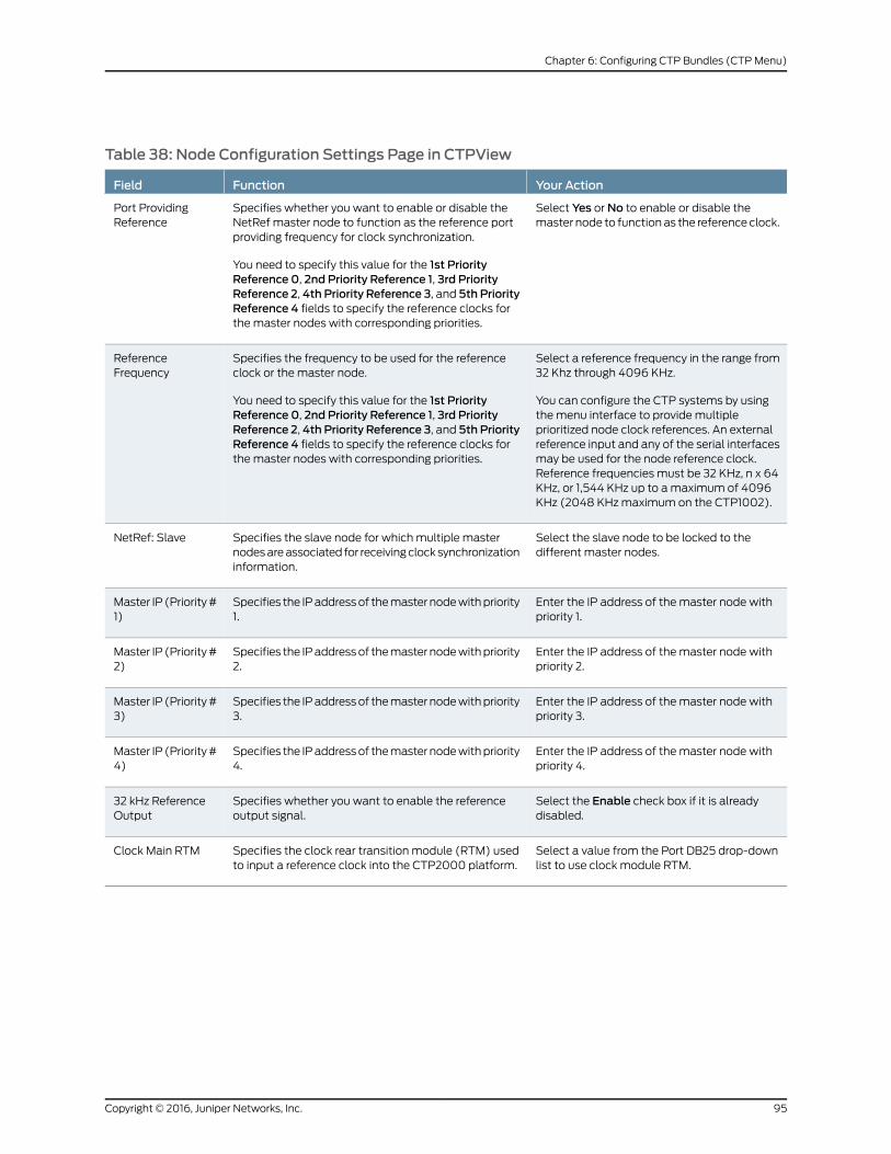
Table 38: Node Configuration Settings Page in CTPView
Your ActionFunctionField
Select Yes or No to enable or disable themaster node to function as the reference clock.
Specifies whether you want to enable or disable theNetRef master node to function as the reference portproviding frequency for clock synchronization.
You need to specify this value for the 1st PriorityReference 0, 2nd Priority Reference 1, 3rd PriorityReference 2, 4th Priority Reference 3, and 5th PriorityReference 4 fields to specify the reference clocks forthe master nodes with corresponding priorities.
Port ProvidingReference
Select a reference frequency in the range from32 Khz through 4096 KHz.
You can configure the CTP systems by usingthe menu interface to provide multipleprioritized node clock references. An externalreference input and any of the serial interfacesmay be used for the node reference clock.Reference frequencies must be 32 KHz, n x 64KHz, or 1,544 KHz up to a maximum of 4096KHz (2048 KHz maximum on the CTP1002).
Specifies the frequency to be used for the referenceclock or the master node.
You need to specify this value for the 1st PriorityReference 0, 2nd Priority Reference 1, 3rd PriorityReference 2, 4th Priority Reference 3, and 5th PriorityReference 4 fields to specify the reference clocks forthe master nodes with corresponding priorities.
ReferenceFrequency
Select the slave node to be locked to thedifferent master nodes.
Specifies the slave node for which multiple masternodes are associated for receiving clock synchronizationinformation.
NetRef: Slave
Enter the IP address of the master node withpriority 1.
Specifies the IP address of the master node with priority1.
Master IP (Priority #1)
Enter the IP address of the master node withpriority 2.
Specifies the IP address of the master node with priority2.
Master IP (Priority #2)
Enter the IP address of the master node withpriority 3.
Specifies the IP address of the master node with priority3.
Master IP (Priority #3)
Enter the IP address of the master node withpriority 4.
Specifies the IP address of the master node with priority4.
Master IP (Priority #4)
Select the Enable check box if it is alreadydisabled.
Specifies whether you want to enable the referenceoutput signal.
32 kHz ReferenceOutput
Select a value from the Port DB25 drop-downlist to use clock module RTM.
Specifies the clock rear transition module (RTM) usedto input a reference clock into the CTP2000 platform.
Clock Main RTM
95Copyright © 2016, Juniper Networks, Inc.
Chapter 6: Configuring CTP Bundles (CTP Menu)

Configuring LOS Detection on CTP and SAToP Bundles (CTPMenu)
Starting with CTPOS Release 7.2R1, CTP devices support the detection of a loss of signal,
which denotes a physical link problem. The following conditions are supported:
• In a serial both-ended Y-cable redundancy configuration (hardware-based redundancy
or software-based Y cable link protocol), removal of Y cable leg from the CTP port of
the online bundle must be able to force a switch to the standby bundle.
• In a T1/E1 both-ended Y cable configuration (hardware-based redundancy or
software-based Y cable link protocol), removal of Y cable leg from the CTP port of the
online bundle must be able to force a switch to the standby bundle.
A CTP series device provides two types of Y-cable redundancy.
• Redundancy by using a hardware link that uses a special Y cable
• Redundancy by using a software link that does not depend on a signaling hardware
like the Y cable
The CTP devices support a both-ended redundancy mechanism, in which two identical
CTP circuit bundles are combined using Y cables at each end, enabling one bundle to
act as a backup for the other. One of the bundles is in use (online), while the other is in
the standby state (offline). Only the online bundle is allowed to drive the Y cable towards
the user equipment, while the offline bundle is tristate. A communications channel (such
as redundancy by using a hardware link that uses a special Y cable or redundancy based
on a software link that does not depend on a signaling hardware like the Y cable) between
ports at each end determines which of the two ports on the Y cable is currently online.
When one bundle fails, the failed bundle transitions to the offline and places the other
bundle in the online state.
Before you begin:
• Disable the bundle before you modify the bundle options.
To configure the capability to detect LOS alarms in a Y-cable redundancy configuration
for CTP and SAToP bundles by using the CTP Menu:
1. From the Main Menu, select 1) Bundle Operations.
2. Select 1) CTP.
3. Select a bundle from the list.
If you select an active bundle, you are prompted to disable the bundle before
configuring it.
4. Select 3) Port Config.
5. Select 4) Advanced Options to configure advanced attributed for the CTP bundle.
Copyright © 2016, Juniper Networks, Inc.96
Using CTP Bundles to Create Logical Configurations for Physical Interfaces

6. Select 20) LOS checking (T1E1 only) to configure the functionality to detect LOS for
the T1E! interfaces in a CTP bundle or SAToP bundle.
7. Follow the onscreen instructions and configure the options as described
Table 39 on page 97.
Table 39: LOS Settings in the CTPMenu
Your ActionFunctionField
Enter y or n to enable or disable the LOSdetection capability.
NOTE: Although this menu option toenable or disable the LOS detectionfunctionality is shown regardless of theport type, such as serial interfaces or T1E1interfaces, this setting becomes effectiveon a T1/E1 port only when it is connectedto a CTP or SAToP bundle. If the LOSdetection functionality is enabled on aserial port or other bundle types, thesetting is not processed.
Specifies that the capability to identifyLOS alarms on T1E1 interfaces in SAToPor CTP bundles needs to be enabled.
A loss of signal (LOS) alarm indicatesthat there is a physical link problem withthe connection to the router receive portfrom the neighboring SONET equipmenttransmit port. An LOS alarm occurs whenthe port on the card is in service but nosignal is being received. The cabling is notcorrectly connected to the ports, or nosignal exists on the line. Possible causesfor a loss of signal include upstreamequipment failure or a fiber cut.
Check LOS on T1/E1 ports forCTP/SAToP bundles? y[n]
Configuring Cryptographic Resynchronization (Crypto Resync)
You can use the CTP chassis with cryptographic devices. You can configure synchronized
(in-sync) and pulse cryptographic resynchronized (resync) options for use with these
devices.
If an error occurs on a secure link, the cryptographic devices can get out of sync. When
the CTP software detects that a cryptographic device is out of sync or that keepalives
or LMI has been lost, it signals to the cryptographic device to resync by pulsing DSR and/or
CTS.
The NRZ port has a configuration parameter for cryptographic resynchronization where
you need to specify a port that is on the same node and is monitored. The port has to be
a Fractional T1/E1 port that has Frame transport Enabled. When the bundle that includes
these ports is up and running, the cryptographic resynchronization function monitors the
frame synchronization bit of the framer in the east bound direction, and if the framer
indicates loss of frame, then the cryptographic function is activated.
You can configure how long the CTP software waits before requesting a resynchronization,
set the pulse width, and set the pulse period of the resynchronization request. You can
also configure the direction of the pulse (0 to 1 or 1 to 0). To disable the pulse, set the
in-sync and pulse value to the same value.
To configure cryptographic resynchronization:
1. From the CTP Main Menu, select 1) Bundle Operations >
2. Select 1) CTP.
97Copyright © 2016, Juniper Networks, Inc.
Chapter 6: Configuring CTP Bundles (CTP Menu)

3. Select a bundle from the list.
4. Select 3) Port Config > 4) Advanced Options > 11) Remote Port T1E1 crypto
This option allows this port to output a crypto resyncpulse based on the T1/E1 frame status (i/f bound) of another port.The port must be a T1/E1 port or Serial port with T1E1 DCARD.The port must be configured for fractional T1/E1 w/ frame transportThe port must be on this node.
Would you like to enable this feature? y[n]:Enter T1/E1 Port [se-0/0]:
5. Enter y and select a T1E1 port when prompted..
6. 12) Crypto Options
0) Back to Previous Menu 1) Crypto resync wait time: 4 sec 2) Crypto resync pulse width: 1 sec 3) Crypto resync pulse period: 8 sec 4) Crypto resync DSR in-sync value: 1 (mark/high/off) 5) Crypto resync DSR pulse value: 0 (space/low/on) 6) Crypto resync CTS in-sync value: 1 (mark/high/off) 7) Crypto resync CTS pulse value: 0 (space/low/on)
7. Configure the cryptographic resynchronization options as described in
Table 40 on page 98
Table 40: Cryptographic Resynchronization Options
Field DescriptionField Name
Number of seconds to wait between loss of sync on the port and the firstresynchronization pulse.
Enter a value in the range 1 – 60. The default value is 4 seconds
Crypto resync wait time
Pulse width in seconds. This is the number of seconds the resynchronization pulse willbe asserted.
Enter a value in the range 1 -15. the default value is 1 second
Crypto resync pulse width
Number of seconds between the beginning of each pulse. This value minus the pulsewidth equals the time between the end of one pulse and the beginning of the next pulse.
Enter a value in the range 1-1000. The default value is 8 seconds.
Crypto resync pulse period
State of DSR or DTR when the port is in sync.
Enter a value in the range 0-1. The default value is 1.
Crypto resync DSR in-sync value
State of DSR or DTR to be sent between the resynchronization pulses when the port isout of sync.
Enter a value in the range 0-1. The default value is 0.
Crypto resync DSR pulse value
State of CTS or RTS when the port is in sync.
Enter a value in the range 0-1. The default value is 1.
Crypto resync CTS in-sync value
Copyright © 2016, Juniper Networks, Inc.98
Using CTP Bundles to Create Logical Configurations for Physical Interfaces

Table 40: Cryptographic Resynchronization Options (continued)
Field DescriptionField Name
State for CTS or RTS to be sent between the resynchronization pulses when the portis out of sync.
Enter a value in the range 0-1. The default value is 0.
Crypto resync CTS pulse value
99Copyright © 2016, Juniper Networks, Inc.
Chapter 6: Configuring CTP Bundles (CTP Menu)

Copyright © 2016, Juniper Networks, Inc.100
Using CTP Bundles to Create Logical Configurations for Physical Interfaces

CHAPTER 7
Configuring CTP Bundles (CTPView)
• Adding a Bundle (CTPView) on page 101
• Configuring IP Parameters for CTP Bundles (CTPView) on page 102
• Configuring Circuit Startup Parameters for CTP Bundles (CTPView) on page 104
• Configuring the Direction of the Circuit (CTPView) on page 105
• Configuring Virtual IP Parameters for CTP Bundles (CTPView) on page 106
• Configuring IP Forwarding for CTP Bundles (CTPView) on page 107
• Configuring the Missing Packet Fill Pattern for CTP Bundles (CTPView) on page 108
• Configuring Signaling for CTP Bundles (CTPView) on page 110
• Configuring Multiservice Port Parameters for CTP Bundles (CTP Menu) on page 113
• Configuring Serial Port Parameters for CTP Bundles (CTPView) on page 119
• Configuring Transparent Encoding for CTP Bundles (CTPView) on page 122
• Configuring Bundle Pairs for TDM/TDC Operation (CTPView) on page 124
• Configuring T1 and E1 Port Parameters for CTP Bundles (CTPView) on page 126
• Configuring Multiservice Port Parameters for CTP Bundles (CTPView) on page 128
• Configuring 4WTO Port Parameters for CTP Bundles (CTPView) on page 134
• Configuring IRIG-B Port Parameters for CTP Bundles (CTPView) on page 137
• Configuring Advanced Port Options for CTP Bundles (CTPView) on page 139
• Selecting the Type of Clocking on Serial Ports for CTP Bundles (CTPView) on page 140
• Configuring Custom Clocking for CTP Bundles (CTPView) on page 142
• Configuring Adaptive Clocking for CTP Bundles (CTPView) on page 145
• Configuring PBS and Bridge Ports (CTPView) on page 146
• Configuring Port Mirroring for CTP Bundles (CTPView) on page 148
• Configuring NetRef Settings (CTPView) on page 149
Adding a Bundle (CTPView)
Before you begin:
• Log in to the CTPView software at least at the Net_Admin level.
101Copyright © 2016, Juniper Networks, Inc.

• Connect the CTPView server to the CTP device for which you want to configure bundles.
To add a bundle using CTPView:
1. In the side pane, select Bundle > Configuration.
2. Run your mouse over the Open Add Bundles Display bar.
3. Under NewBndl Number, select a bundle number.
4. Under the type of bundle you want to add, select a source port and click the button
for the type of bundle.
Before you create a VComp bundle, you must ensure that the CTP system has a
VComp card installed. The CTP system displays a warning message if no VComp card
is installed. If you create a VComp bundle on a CTP system that does not have a
VComp card installed and try to activate it, the CTP system displays the following
warning message:
There is not enough system DSP resource for the bundle.
The bundle remains disabled until you install a VComp card and activate the bundle
again. If you remove the VComp card from a CTP system that has an active VComp
bundle, the Run state of the VComp bundle changes to MisCfg.
5. Enter the parameters and click Click to Submit Bundle AND Port Changes.
Configuring IP Parameters for CTP Bundles (CTPView)
The CTP software uses the IP parameters to create IP packets.
Before you begin:
• Log in to the CTPView software at least at the Net_Admin level.
• Connect the CTPView server to the CTP device for which you want to configure bundles.
To configure IP parameters for CTP bundles using CTPView:
1. In the side pane, select Bundle > Configuration.
2. Run your mouse over the Display and Select an Existing Bundle bar.
3. In the table of bundles, select the bundle that you want to modify.
4. UnderBundleOptions, configure the parameters as described in Table 41 on page 102
and click Click to Submit Bundle AND Port Changes.
Table 41: CTP Bundle IP Parameter Settings in CTPView
Your ActionFunctionField
Type a description for the bundle.Specifies identifying information about the bundle.
You can use the bundle description as the search criteria when yousearch for bundles from the network monitoring page.
BundleDescription
Select DISABLED or ACTIVE.Specifies whether the bundle is active or disabled.State
Copyright © 2016, Juniper Networks, Inc.102
Using CTP Bundles to Create Logical Configurations for Physical Interfaces

Table 41: CTP Bundle IP Parameter Settings in CTPView (continued)
Your ActionFunctionField
In the first field, select the CTPdevice.
In the second field, select aninterface on the CTP device.
Specifies the name and IP address of the remote CTP device.RemoteAddress
Enter a number from 0 through 249.Specifies the bundle to connect to on the remote CTP device.Remote CircuitID
Enter a number from 0 through 249.Specifies the bundle on the local CTP device.Local Circuit ID
Select a packet size.
For CTP150 devices, the availablepacket size is 8 through 1456.
For CTP2000 devices, the availablepacket size is 4 through 1456.
Specifies the size of IP packets that are created from data received atthe serial port.
The CTP device makes sure that the combination of packet size anddata rate does not result in a packet rate that exceeds 1200 packetsper second.
Packet Size
Enter a number from 0.001 through9999.000 milliseconds.
Specifies the minimum average buffer size. Use a value that is greaterthan the expected jitter and less than the Buffer Set parameter.
The minimum buffer ensures that the buffer does not become too smallbecause of timing variances between the local and remote serialinterfaces.
The entire buffer is available for accommodating and smoothing packetdelay jitter, regardless of the minimum buffer setting.
Min Buffer
Enter a number from 0.001 through9999.000 milliseconds.
Specifies the buffer size when the circuit enters a running state. Thisvalue must be large enough to accommodate the anticipated packetdelay, and it must be set to a value greater than the minimum buffersize and lower than the maximum buffer size.
Buffer Set
Enter a number from 0.001 through9999.000 milliseconds.
Specifies the maximum buffer size. The maximum buffer ensures thatthe buffer does not become too large due to timing variances betweenthe local and remote serial interfaces. If the buffer size exceeds themaximum buffer size, the buffer is recentered to the Buffer Set value.
Periodic buffer recenters are not expected. If you notice recenters, werecommend that you verify the reference to the CTP (if used) or thatyou configure one port with adaptive clocking.
Max Buffer
Enter a number from 0 through 255.Specifies the ToS byte to be used in the IP headers of packets sentfrom the CTP device to the IP network.
For a mapping of ToS byte values to DSCP classes and settings, see“Providing QoS for CTP Bundles by Using Service Type Overview” onpage 10.
You do not need to set the ToS value to the same value on local andremote bundles.
Service Type
103Copyright © 2016, Juniper Networks, Inc.
Chapter 7: Configuring CTP Bundles (CTPView)

Table 41: CTP Bundle IP Parameter Settings in CTPView (continued)
Your ActionFunctionField
Enter a number from 0 through 255.Specifies the maximum number of router hops that a packet cantraverse. The CTP device sets the TTL value in IP packets that it sendsto the IP network. The IP network does not alter or optimize the packetrouting based on the TTL setting. You do not need to set the same TTLvalue on local and remote ports.
Time to Live
RelatedDocumentation
Determining Optimal Packet Size for CTP Bundles Overview on page 8•
• Providing QoS for CTP Bundles by Using Service Type Overview on page 10
Configuring Circuit Startup Parameters for CTP Bundles (CTPView)
This topic describes how to configure advanced options that are related to circuit startup.
Set these parameters to the same values on the local and remote CTP devices.
Before you begin:
• Log in to the CTPView software at least at the Net_Admin level.
• Connect the CTPView server to the CTP device for which you want to configure bundles.
To configure circuit startup parameters for CTP bundles using CTPView:
1. In the side pane, select Bundle > Configuration.
2. Run your mouse over the Display and Select an Existing Bundle bar.
3. In the table of bundles, select the bundle that you want to modify.
4. Under Bundle Options, select Advanced Options Show to display advanced
parameters and configure the parameters as described in Table 42 on page 104.
5. Click Click to Submit Bundle AND Port Changes.
Table 42: CTP Bundle Advanced Options Parameter Settings for Circuit Startup in CTPView
Your ActionFunctionField
Enter a number from 1through 255.
Specifies the number of OAM packets per second that the circuitsends to the remote CTP device.
OAM Packet Spacing
Enter a number from 1through 255.
Specifies the number of OAM packets that the circuit must receivebefore the state moves from no synchronization to insynchronization.
OAM Packets for Sync
Enter a number from 1through 255.
Specifies the number of received OAM packets that the CTP devicemisses before the state of the circuit moves from in synchronizationto no synchronization.
OAM Packets for SyncLoss
Copyright © 2016, Juniper Networks, Inc.104
Using CTP Bundles to Create Logical Configurations for Physical Interfaces

Table 42: CTP Bundle Advanced Options Parameter Settings for Circuit Startup inCTPView (continued)
Your ActionFunctionField
Enter a number from 1through 64.
Specifies how many consecutive circuit packets the IP networkmust drop before the CTP device restarts the circuit.
We recommend that you set the parameter to a larger value whenthe IP network uses packet-encrypting devices. These devices causemomentary interruption in packet flows when encryption keys areupdated.
Consecutive Pkt Loss ToStarvation
Enter a number from 1through 64.
Specifies the number of in-sequence packets the CTP device mustreceive after a starvation before the circuit transitions from in-syncto running.
InSync Pkts AfterStarvation
RelatedDocumentation
Circuit Startup Process Overview on page 11•
Configuring the Direction of the Circuit (CTPView)
This topic describes how to configure the direction of the circuit.
Before you begin:
• Log in to the CTPView software at least at the Net_Admin level.
• Connect the CTPView server to the CTP device for which you want to configure bundles.
To configure the direction of circuits created with the CTP bundle using CTPView:
1. In the side pane, select Bundle > Configuration.
2. Run your mouse over the Display and Select an Existing Bundle bar.
3. In the table of bundles, select the bundle that you want to modify.
4. UnderBundleOptions, configure the parameters as described in Table 43 on page 105
and click Click to Submit Bundle AND Port Changes.
Table 43: CTP Bundle Circuit Direction Setting in CTPView
Your ActionFunctionField
Select one:
• BI-DIRECTIONAL—Circuit is bidirectional.
• SOURCE—Circuit is unidirectional, and this end of thecircuit is the source.
• DESTINATION—Circuit is unidirectional, and this end ofthe circuit is the destination.
Specifies whether the circuit is unidirectionalor bidirectional. If unidirectional, specify thedirection of the circuit—source or destination.
UnidirectionalCircuit
105Copyright © 2016, Juniper Networks, Inc.
Chapter 7: Configuring CTP Bundles (CTPView)

Configuring Virtual IP Parameters for CTP Bundles (CTPView)
The virtual IP parameters allow you to use a separate IP address for each bundle and to
use an address that is different from the IP address for the CTP device. If you configure
the IP address on the:
• Same subnet as the CTP IP address, you do not need a static route on the router.
• Different subnet as the CTP IP address, you need a static route on the router.
Before you begin:
• Log in to the CTPView software at least at the Net_Admin level.
• Create a list of the virtual IP addresses that will be associated with the CTP device. To
do so, select Node >Maintenance > ConfigureCTPDeviceVirtual IPs, and follow the
instructions on the pane. You can create up to 56 virtual IP addresses.
When you submit your new configuration, the CTP device reboots.
• Connect the CTPView server to the CTP device for which you want to configure bundles.
To configure virtual IP parameters for CTP bundles using CTPView:
1. In the side pane, select Bundle > Configuration.
2. Run your mouse over the Display and Select an Existing Bundle bar.
3. In the table of bundles, select the bundle that you want to modify.
4. Under Bundle Options, select Advanced Options Show to display advanced
parameters and configure the parameters as described in Table 44 on page 106.
5. Click Click to Submit Bundle AND Port Changes.
Table 44: CTP Bundle Virtual IP Parameter Settings in CTPView
Your ActionFunctionField
Select one:
• DISABLED—Circuits created by this bundle use theIP address of the CTP device.
• ENABLED—Circuits created by this bundle use anaddress that is different from the CTP device.
Specifies whether or not the bundle uses an addressthat is different from the IP address of the CTPdevice.
The virtual IP address is used in the IP packet’sOrigination Address field, and is used for the circuit’sdata and OAM flow.
Use Virtual IP
Enter the virtual IP address.
At the remote end of the bundle, specify this IPaddress as the Remote Address of the bundle.
Specifies the virtual IP address for circuits createdby this bundle.
Virtual IP [ IPv4only ]
Copyright © 2016, Juniper Networks, Inc.106
Using CTP Bundles to Create Logical Configurations for Physical Interfaces

Configuring IP Forwarding for CTP Bundles (CTPView)
There are two ways to set up CTP bundles for IP forwarding:
• Direct drive—Packets are forwarded directly between drivers on the local and remote
CTP device. Use this method for simple port-to-port configurations. We recommend
that you use this method with supervision from JTAC.
• Direct drive disabled—Packets are forwarded based on information in the kernel’s IP
stack.
Before you begin:
• Log in to the CTPView software at least at the Net_Admin level.
• Connect the CTPView server to the CTP device for which you want to configure bundles.
To configure IP forwarding for CTP bundles using CTPView:
1. In the side pane, select Bundle > Configuration.
2. Run your mouse over the Display and Select an Existing Bundle bar.
3. In the table of bundles, select the bundle that you want to modify.
4. Under Bundle Options, select Advanced Options Show to display advanced
parameters and configure the parameters as described in Table 45 on page 108.
5. Click Click to Submit Bundle AND Port Changes.
107Copyright © 2016, Juniper Networks, Inc.
Chapter 7: Configuring CTP Bundles (CTPView)

Table 45: CTP Bundle IP Forwarding Parameter Settings in CTPView
Your ActionFunctionField
Select one:
• DISABLED—CTPuses the kernel’s IPstack to forwardpackets.
• ENABLED—CTPusesdirect drive toforward packets.
Specifies whether the CTP bundle uses direct drive or IP tables to forward packets.
If you are using route redundancy, port mirroring, or VLANs, you must disable direct drive anduse IP tables.
If any port on the CTP node is configured for a PBS or bridged port, then the Direct Driveoption is automatically set to Disabled on all existing and future bundles on that node.
If a port is configured as a PBS or bridged port, then the bundles on that port is deleted. If abundle is created on a different port, then it disables Direct Drive on that port when otherports are configured as a PBS or bridged port.
Until CTPView Release 7.1R1, the direct drive feature is enabled by default and thisfunctionality configuration is not displayed in the output of the bundle query. If you explicitlyenabled the direct drive capability (using IP tables instead of direct drive forpacket-forwarding) by using the selectingNo for theDisabledirectdrive field in theAdvancedOptions screen of the Configuration window under Bundle Operations of the CTP Main Menu,bundle query displayed "NotDirDrv" when you run the bundle query from the Main Menu ofCTP Menu by selecting 1) Query. Starting with CTPOS and CTPView Release 7.2, the defaultbehavior is direct-drive disabled (IP table is turned on for forwarding of packets). With defaultconfiguration, the bundle query output does not display the direct drive settings. Only if youexplicitly enable the direct-drive capability, the bundle query output displays "Bndl ConfigFlags: DirDrv" in bundle query. CTP bundle circuits that use route redundancy and portforwarding must have direct drive disabled to allow for asymmetric routing. When directdrive is disabled, packets are forwarded based on information in the kernel’s IP stack. Whendirect drive is enabled, packets are forwarded directly between drivers on the local andremote CTP device.
DirectDrive
Configuring theMissing Packet Fill Pattern for CTP Bundles (CTPView)
This topic describes how to specify the fill pattern that the CTP device inserts when IP
packets are dropped.
Before you begin:
• Log in to the CTPView software at least at the Net_Admin level.
• Connect the CTPView server to the CTP device for which you want to configure bundles.
To configure the missing packet fill pattern for CTP bundles using CTPView:
1. In the side pane, select Bundle > Configuration.
2. Run your mouse over the Display and Select an Existing Bundle bar.
3. In the table of bundles, select the bundle that you want to modify.
4. Under Bundle Options, select Advanced Options Show to display advanced
parameters and configure the parameters as described in Table 46 on page 109.
5. Click Click to Submit Bundle AND Port Changes.
Copyright © 2016, Juniper Networks, Inc.108
Using CTP Bundles to Create Logical Configurations for Physical Interfaces

Table 46: CTP Bundle Missing Packet Fill Pattern Parameter Setting in CTPView
Your ActionFunctionField
Enter two hexadecimal digits. Youmust enter a value other than ff. Thisfield does not require the 0xcharacters.
Specifies the data that the CTP device inserts into the circuit bitstream when an IP packet is dropped. The number of bits insertedis equal to the number of bits in the missed packet.
When the bundle is down, the port sends the value of the leastsignificant bit (LSB) of the missing fill pattern.
This data insertion method prevents a loss of bit count integrity toattached circuit devices and encryptors.
Missing PacketFill Pattern
109Copyright © 2016, Juniper Networks, Inc.
Chapter 7: Configuring CTP Bundles (CTPView)

Configuring Signaling for CTP Bundles (CTPView)
You can set input and output signals for the CTP device. Your settings should be based
on the settings of the user equipment.
• Output signals—You can set output signals to a fixed value, or you can set them to
inband so that the output signal state is based on the state of the input signal at the
user equipment. Output signals that you can set vary depending on whether the bundle
is configured as the DTE or the DCE:
• DTE output signals:
• DTR (data set ready)
• RTS (request to send)
• LL (local loopback)
• RL (remote loopback)
• DCE output signals:
• DSR (data set ready)
• CTS (clear to send)
• DCD (data carrier detect)
• TM (test mode)
• Input signals—You can set the input signals to either unused (ignored) or used to create
a demand circuit. When configured for demand, packets created from the circuit are
transferred across the IP network only when the signal lead is in the specified state for
the circuit to be Demand Call – Active. When two or more leads are configured for
demand, all configured leads must be in theDemandCall –Active state for the circuit
to transfer packets across the IP network.
Input signals that you can set vary depending on whether the bundle is configured as
the DTE or the DCE:
• DTE—Input signals are TM, CTS, DSR, DCD.
• DCE—Input signals are RL, RTS, DTR, LL.
The input state of each signal lead is encoded once in every transmitted IP packet.
Thus the granularity of the transitions (frequency or changes) that can be transferred
across the network is equal to the packet rate of the circuit.
Before you begin:
• Log in to the CTPView software at least at the Net_Admin level.
• Connect the CTPView server to the CTP device for which you want to configure bundles.
Copyright © 2016, Juniper Networks, Inc.110
Using CTP Bundles to Create Logical Configurations for Physical Interfaces

To configure signaling for CTP bundles using CTPView:
1. In the side pane, select Bundle > Configuration.
2. Run your mouse over the Display and Select an Existing Bundle bar.
3. In the table of bundles, select the bundle that you want to modify.
4. Under Bundle Options, select Advanced Options Show to display advanced
parameters and configure the parameters as described in Table 47 on page 111.
5. Click Click to Submit Bundle AND Port Changes.
Table 47: CTP Bundle Signaling Settings in CTPView
Your ActionFunctionField
Select the number of packets:
• 0
• 1
• 2
• 3
Specifies the output signaling delay inpackets.
Signal Out -Output Delay
Select one:
• Fixed - ON/0/Space/Low—Signal is turned on.
• Fixed - OFF/1/Mark/High—Signal is turned off.
• InBand - From Remote RL—Output signal is based on the stateof the RL input signal from the DCE or the TM signal from theDTE.
• InBand - From Remote RTS—Output signal is based on the stateof the RTS input signal from the DCE or the CTS signal from theDTE.
• InBand - From Remote DTR—Output signal is based on the stateof the DTR input signal from the DCE or the DSR signal from theDTE.
• InBand - From Remote LL—Output signal is based on the stateof the LL input signal from the DCE or the DCD signal from theDTE.
Specifies the output signal dependingon whether the bundle is configured asthe DCE or the DTE:
• DCE—DSR output signal.
• DTE—DTR output signal.
Signal Out -DSR/DTR
Select one:
• Fixed - ON/0/Space/Low—Signal is turned on.
• Fixed - OFF/1/Mark/High—Signal is turned off.
• InBand - From Remote RL—Output signal is based on the stateof the RL input signal from the DCE or the TM signal from theDTE.
• InBand - From Remote RTS—Output signal is based on the stateof the RTS input signal from the DCE or the CTS signal from theDTE.
• InBand - From Remote DTR—Output signal is based on the stateof the DTR input signal from the DCE or the DSR signal from theDTE.
• InBand - From Remote LL—Output signal is based on the stateof the LL input signal from the DCE or the DCD signal from theDTE.
Specifies the output signal dependingon whether the bundle is configured asthe DCE or the DTE:
• DCE—CTS output signal.
• DTE—RTS output signal.
Signal Out -CTS/RTS
111Copyright © 2016, Juniper Networks, Inc.
Chapter 7: Configuring CTP Bundles (CTPView)

Table 47: CTP Bundle Signaling Settings in CTPView (continued)
Your ActionFunctionField
Select one:
• Fixed - ON/0/Space/Low—Signal is turned on.
• Fixed - OFF/1/Mark/High—Signal is turned off.
• InBand - From Remote RL—Output signal is based on the stateof the RL input signal from the DCE or the TM signal from theDTE.
• InBand - From Remote RTS—Output signal is based on the stateof the RTS input signal from the DCE or the CTS signal from theDTE.
• InBand - From Remote DTR—Output signal is based on the stateof the DTR input signal from the DCE or the DSR signal from theDTE.
• InBand - From Remote LL—Output signal is based on the stateof the LL input signal from the DCE or the DCD signal from theDTE.
Specifies the output signal dependingon whether the bundle is configured asthe DCE or the DTE:
• DCE—DCD output signal.
• DTE—LL output signal.
Signal Out -DCD/LL
Select one:
• Fixed - ON/0/Space/Low—Signal is turned on.
• Fixed - OFF/1/Mark/High—Signal is turned off.
• InBand - From Remote RL—Output signal is based on the stateof the RL input signal from the DCE or the TM signal from theDTE.
• InBand - From Remote RTS—Output signal is based on the stateof the RTS input signal from the DCE or the CTS signal from theDTE.
• InBand - From Remote DTR—Output signal is based on the stateof the DTR input signal from the DCE or the DSR signal from theDTE.
• InBand - From Remote LL—Output signal is based on the stateof the LL input signal from the DCE or the DCD signal from theDTE.
Specifies the output signal dependingon whether the bundle is configured asthe DCE or the DTE:
• DCE—TM output signal.
• DTE—RL output signal.
Signal Out -TM/RL
Select one:
• Unused—Input signals are ignored.
• Demand Call - Active High—Signal is turned off.
• Demand Call - Active Low—Signal is turned on.
Specifies the input signal depending onwhether the bundle is configured as theDCE or the DTE:
• DCE—RL input signal.
• DTE—TM input signal.
Signal In -RL/TM
Select one:
• Unused—Input signals are ignored.
• Demand Call - Active High—Signal is turned off.
• Demand Call - Active Low—Signal is turned on.
Specifies the input signal depending onwhether the bundle is configured as theDCE or the DTE:
• DCE—RTS input signal.
• DTE—CTS input signal.
Signal In -RTS/CTS
Copyright © 2016, Juniper Networks, Inc.112
Using CTP Bundles to Create Logical Configurations for Physical Interfaces

Table 47: CTP Bundle Signaling Settings in CTPView (continued)
Your ActionFunctionField
Select one:
• Unused—Input signals are ignored.
• Demand Call - Active High—Signal is turned off.
• Demand Call - Active Low—Signal is turned on.
Specifies the input signal depending onwhether the bundle is configured as theDCE or the DTE:
• DCE—DTR input signal.
• DTE—DSR input signal.
Signal In -DTR/DSR
Select one:
• Unused—Input signals are ignored.
• Demand Call - Active High—Signal is turned off.
• Demand Call - Active Low—Signal is turned on.
Specifies the input signal depending onwhether the bundle is configured as theDCE or the DTE:
• DCE—LL input signal.
• DTE—DCD input signal.
Signal In -LL/DCD
ConfiguringMultiservice Port Parameters for CTP Bundles (CTPMenu)
• Configuring Multiservice Audio Mode Port Parameters for CTP Bundles (CTP
Menu) on page 113
• Configuring Multiservice IRIG-B Mode Port Parameters for CTP Bundles (CTP
Menu) on page 115
• Configuring Multiservice TDC Mode Parameters for CTP Bundles (CTP Menu) on page 117
• Configuring Multiservice 4WTO Mode Port Parameters for CTP Bundles (CTP
Menu) on page 118
ConfiguringMultiservice Audio Mode Port Parameters for CTP Bundles (CTPMenu)
Before you begin:
• Disable the bundle before you modify the bundle options.
To configure Multiservice audio mode port parameters using the CTP Menu:
1. From the CTP Main Menu, select 1) Bundle Operations.
2. Select 1) CTP.
3. Select a bundle from the list.
If you select an active bundle, you are prompted to disable the bundle before
configuring it.
4. Select 3) Port Config.
5. Select 2) Interface.
6. Select 1) Type, and set the type to Optional Interface: MultiSvc.
7. Follow the onscreen instructions and configure the options as described in
Table 24 on page 63.
113Copyright © 2016, Juniper Networks, Inc.
Chapter 7: Configuring CTP Bundles (CTPView)

Table 48: CTP Bundle Multiservice Audio Mode Port Parameter Settings in the CTPMenu
Your ActionFunctionField
Select AUDIO.Specifies that the bundle will run in audiomode.
Mode
Select one:
• Master—This end of the circuit providesclocking.
• Slave—This end of the circuit usesadaptive clocking.
Specifies whether this end of the circuitprovides clocking or uses adaptiveclocking.
If the CTP devices at both ends of thecircuit are synchronized, you canconfigure both ends as Master.
Master/Slave
Select one:
• Disable—Channel 0 is the only activechannel.
• Enable—Both channel 0 and channel1 are active.
Two channels are supported—channel0 and channel 1.
Enables or disables the use of bothchannels.
Dual Channel
Select one:
• 8
• 12
• 16
• 24
• 32
• 48
Specifies the sample rate for audiocircuits in kilohertz. The sample ratedetermines the audio quality and thenetwork bandwidth needed. Highersample rates create an IP data flow thatrequires higher bandwidth.
8 KHz corresponds to standard tollquality voice.
48 KHz corresponds to CD quality audio.
Audio Sample Rate
Select one:
• Disable—Generates 16-bit audiosamples.
• Enable—Generates 8-bit audiosamples.
Enables or disables μ-law encoding.Standard audio code samples are 16 bits.If you enable μ-law encoding, the 16-bitsamples are converted to 8 bits,consuming half of the bandwidthwithout significant audio degradation.
μ-law Encoding:
Select one:
• Disable—Disables the active squelchfunction on the circuit (audio output isalways enabled).
• Enable and active—Squelch input isgrounded and analog output isdisabled.
• Enable and inactive—No signal isapplied to the squelch input. Input isopen and analog output is possible.
Enables or disables the active squelchfunction on the circuit.
If enabled, specifies whether the squelchis active or inactive.
The squelch function gates local audiooutput when DSR-A (channel 0) orRTS-A (channel 1) inputs are active orinactive.
Talk Squelch
Copyright © 2016, Juniper Networks, Inc.114
Using CTP Bundles to Create Logical Configurations for Physical Interfaces

Table 48: CTP Bundle Multiservice Audio Mode Port Parameter Settings in the CTPMenu (continued)
Your ActionFunctionField
Enter a number from 0 through 255.Specifies the output level for channel 0.
Note the following information about thevalues:
• 0—There is no output.
• 128—Unity gain, which means there isno attenuation or gain.
• 255—Gain is 2:1.
Ch 0 Output Level: 1.00x (decimal 128)
Enter a number from 0 through 255.Specifies the output level for channel 1.
Note the following information about thevalues:
• 0—There is no output.
• 128—Unity gain, which means there isno attenuation or gain.
• 255—Gain is 2:1.
Ch 1 Output Level: 1.00x (decimal 128)
ConfiguringMultiservice IRIG-BMode Port Parameters for CTP Bundles (CTPMenu)
Before you begin:
• Disable the bundle before you modify the bundle options.
To configure Multiservice IRIG-B mode port parameters using the CTP Menu:
1. From the CTP Main Menu, select 1) Bundle Operations.
2. Select 1) CTP.
3. Select a bundle from the list.
If you select an active bundle, you are prompted to disable the bundle before
configuring it.
4. Select 3) Port Config.
5. Select 2) Interface.
6. Select 1) Type and set the type to Optional Interface: MultiSvc.
7. Follow the onscreen instructions and configure the options as described in
Table 25 on page 65.
Table 49: CTP Bundle Multiservice IRIG-B Port Parameter Settings in the CTPMenu
Your ActionFunctionField
Select IRIG.Specifies that the bundle will run inIRIG-B mode.
Mode
115Copyright © 2016, Juniper Networks, Inc.
Chapter 7: Configuring CTP Bundles (CTPView)

Table49:CTPBundleMultiservice IRIG-BPortParameterSettings in theCTPMenu (continued)
Your ActionFunctionField
Specify yes or no to the question: Is thisan IRIG-B source end (IRIG-B signalenters CTP)?
• Yes (y)—Sets direction to Rx. This endof the circuit recovers IRIG-B from theattached cable and generates IPpackets toward the network.
• No (n)—Sets the direction to Tx. Thisend of the circuit accepts IP packets,extracts the IRIG-B data codes, andtransmits IRIG-B signaling output ontothe cable.
If the autonegotiation setting of the CTPEthernet media and the far-end switchor router do not match, it is possible forthe CTP Ethernet ports to be in ahalf-duplex state, although the duplexsetting is not configurable and alwaysassumed to be full-duplex on the CTPdevice. Starting with CTPOS Release 7.2,the half-duplex state at CTP networkinterface card (NIC) ports are acquired,regardless of the duplex settingconfigured on the far-end node. After theautonegotiation process is completed, ifthe CTP NIC cannot acquire full-duplexmode, then the interfaces are consideredto be down and a log message isrecorded in both the/var/log/messages directory and thesyslog file stating that the interface isdown due to a non-full duplex condition.You are prompted to verify the cableconnection, speed, and duplex settingsbecause the NIC link might be down.
Specifies the direction of the circuit.Although the IP circuit connectionthrough the network is full duplex, anIRIG-B circuit is a simplex application,and the interface can operate only in Rxor Tx mode and not both at the sametime.
(Although the bundle is by default a fullduplex IP connection, you can configureit for simplex to save networkbandwidth.)
Src/Dest
Enter a number from 1000 through25,500 bps. The port speed must be amultiple of 100 bps.
Specifies the data rate on the IPconnection.
Note the following about setting the IRIGrate:
• Unless network bandwidth is at apremium, we do not recommend thatyou change this value from the defaultof 16,000 bps.
• Although the IRIG information can betransported through the network atthe minimum configured rate (1000bps), a CTP bundle running at this rateis subject to high latency.
IRIG Rate
Copyright © 2016, Juniper Networks, Inc.116
Using CTP Bundles to Create Logical Configurations for Physical Interfaces

Table49:CTPBundleMultiservice IRIG-BPortParameterSettings in theCTPMenu (continued)
Your ActionFunctionField
Enter a number from 0.00 through 7.85volts peak-to-peak.
This setting applies only if you set thedirection of the port to Tx.
Specifies the high output level, which ismeasured in peak-to-peak voltage. Thissetting is based on a 50-ohmtermination.
Output High Level
Enter a number from 0.00 through 7.85volts peak-to-peak.
This setting applies only if you set thedirection of the port to Tx.
Specifies the low output level, which ismeasured in peak-to-peak voltage. Thissetting is based on a 50-ohmtermination.
Output Low Level
ConfiguringMultiservice TDCMode Parameters for CTP Bundles (CTPMenu)
Before you begin:
• Disable the bundle before you modify the bundle options.
To configure Multiservice TDC mode port parameters using the CTP Menu:
1. From the CTP Main Menu, select 1) Bundle Operations.
2. Select 1) CTP.
3. Select a bundle from the list.
If you select an active bundle, you are prompted to disable the bundle before
configuring it.
4. Select 3) Port Config.
5. Select 2) Interface.
6. Select 1) Typeand set the type to Optional Interface: MultiSvc.
7. Follow the onscreen instructions and configure the options as described in
Table 26 on page 67.
Table 50: CTP Bundle Multiservice TDC Port Parameter Settings in the CTPMenu
Your ActionFunctionField
Select TDC/IRIG.Specifies that the bundle will run in TDCmode.
Mode
117Copyright © 2016, Juniper Networks, Inc.
Chapter 7: Configuring CTP Bundles (CTPView)

Table 50: CTP Bundle Multiservice TDC Port Parameter Settings in the CTPMenu (continued)
Your ActionFunctionField
Select one:
• Src (signal enters CTP)—End of thecircuit that receives NRZ/IRIG data.
• Dst (signal exits CTP)—End of thecircuit that sends NRZ/IRIG datatoward the network.
Specifies the direction of the circuit.Src/Dest
Enter a number from 500 through5,000,000 bps. The port speed must bea multiple of 500 bps.
Specifies the data rate on the IPconnection.
NRZ/Rate
Enter a number from 0 through 255.Specifies the output level.
Note the following information about thevalues:
• 0—There is no output.
• 128—Unity gain, which means there isno attenuation or gain.
• 255—Gain is 2:1.
IRIG Output Level
ConfiguringMultiservice 4WTOMode Port Parameters for CTP Bundles (CTPMenu)
Before you begin:
• Disable the bundle before you modify the bundle options.
To configure Multiservice 4WTO mode port parameters using the CTP Menu:
1. From the CTP Main Menu, select 1) Bundle Operations.
2. Select 1) CTP.
3. Select a bundle from the list. The bundle port must have a 4WTO daughter card
installed.
If you select an active bundle, you are prompted to disable the bundle before
configuring it.
4. Select 3) Port Config.
5. Select 2) Interface.
6. Select 1) Type and set the type to Optional Interface: MultiSvc.
7. Configure the options as described in Table 27 on page 68.
Table 51: CTP Bundle Multiservice 4WTOPort Parameter Settings in the CTPMenu
Your ActionFunctionField
Select 4WTO-Em.Specifies that the bundle will run in4WTO mode.
Mode
Copyright © 2016, Juniper Networks, Inc.118
Using CTP Bundles to Create Logical Configurations for Physical Interfaces

Table 51: CTPBundleMultiservice4WTOPortParameter Settings in theCTPMenu (continued)
Your ActionFunctionField
Select one:
• Master—This end of the circuitprovides clocking.
• Slave—This end of the circuit usesadaptive clocking.
Specifies whether this end of the circuitprovides clocking or uses adaptiveclocking.
If the CTP devices at both ends of thecircuit are synchronized, you canconfigure both ends as Master.
Master/Slave
Select one:
• Disable—Channel 0 is the only activechannel.
• Enable—Both channel 0 and channel1 are active.
Two channels are supported—channel0 and channel 1.
Enables or disables the use of bothchannels.
Dual Channel
Select one:
• Disable—Disables the active squelchfunction on the circuit.
• Enable and active—Squelch input isgrounded and analog output isdisabled.
• Enable and inactive—No signal isapplied to the squelch input. Input isopen and analog output is possible.
Enables or disables the active squelchfunction on the circuit.
If enabled, specifies whether the squelchis active or inactive.
The squelch function gates local audiooutput when DSR-A (channel 0) orRTS-A (channel 1) inputs are active orinactive.
Talk Squelch
Enter a number from 0 through 255.Specifies the output level for channel 0.
Note the following information about thevalues:
• 0—There is no output.
• 128—Unity gain, which means there isno attenuation or gain.
• 255—Gain is 2:1.
Ch 0 Output Level: 1.00x (decimal 128)
Enter a number from 0 through 255.Specifies the output level for channel 1.
Note the following information about thevalues:
• 0—There is no output.
• 128—Unity gain, which means there isno attenuation or gain.
• 255—Gain is 2:1.
Ch 1 Output Level: 1.00x (decimal 128)
Configuring Serial Port Parameters for CTP Bundles (CTPView)
This topic describes how to configure port parameters for serial interfaces.
Before you begin:
• Log in to the CTPView software at least at the Net_Admin level.
119Copyright © 2016, Juniper Networks, Inc.
Chapter 7: Configuring CTP Bundles (CTPView)

• Connect the CTPView server to the CTP device for which you want to configure bundles.
To configure serial port parameters for CTP bundles using CTPView:
1. In the side pane, select Bundle > Configuration.
2. Run your mouse over the Display and Select an Existing Bundle bar.
3. In the table of bundles, select the bundle that you want to modify.
4. Under Port Options configure the parameters as described in Table 52 on page 120.
5. Click Click to Submit Bundle AND Port Changes.
Table 52: CTP Bundle Serial Port Parameter Settings in CTPView
Your ActionFunctionField
Enter a description of up to 64alphanumeric characters. Do not use thefollowing characters:
( ; ' " ) ]
Specifies a description for the port.Port Description
Select one:
• DCE—The interface is connected to aDCE device.
• DTE—The interface is connected to aDTE device.
Specifies that the interface is connectedto a data communication equipment(DCE) device or to a data terminalequipment (DTE) device.
I/F Mode
Select one:
• NRZ—Nonreturn to zero (NRZ) lineencoding.
• ISOCH—Isochronous encoding.Isochronous encoding does not provideor embed the clock in the data.
• CDI—Conditioned diphase. Conditioneddiphase encoding recovers and embedsthe clock in the data signal. CDIencoding provides a speed of up to4608 KBps.
• TDM—Additional data is interleavedwith the port’s serial data. This optionis used on TDM/TDC high-speed portsand is available only oneven-numbered ports on a CTP 2000serial module. See “Configuring theHigh-Speed CTP Bundle for TDM/TDCOperation (CTPView)” on page 124.
• TRANS8—Extension of the TRANSencoding. Compared with TRANSencoding, which sends four signals ineach direction, with TRANS8 encoding,bandwidth is doubled and eight signalscan be sampled and transported. Thisallows signals to be sent fromadditional interfaces that were notsupported in TRANS encoding. </para>
Specifies the serial encoding methodused on this bundle.
When you change the encoding method,the clocking configuration changes tothe default configuration for theencoding method that you select.
Serial Encoding
Copyright © 2016, Juniper Networks, Inc.120
Using CTP Bundles to Create Logical Configurations for Physical Interfaces
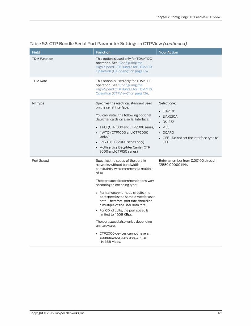
Table 52: CTP Bundle Serial Port Parameter Settings in CTPView (continued)
Your ActionFunctionField
This option is used only for TDM/TDCoperation. See “Configuring theHigh-Speed CTP Bundle for TDM/TDCOperation (CTPView)” on page 124.
TDM Function
This option is used only for TDM/TDCoperation. See “Configuring theHigh-Speed CTP Bundle for TDM/TDCOperation (CTPView)” on page 124.
TDM Rate
Select one:
• EIA-530
• EIA-530A
• RS-232
• V.35
• DCARD
• OFF—Do not set the interface type toOFF.
Specifies the electrical standard usedon the serial interface.
You can install the following optionaldaughter cards on a serial interface:
• T1/E1 (CTP1000 and CTP2000 series)
• 4WTO (CTP1000 and CTP2000series)
• IRIG-B (CTP2000 series only)
• Multiservice Daughter Cards (CTP2000 and CTP150 series)
I/F Type
Enter a number from 0.00100 through12880.00000 KHz.
Specifies the speed of the port. Innetworks without bandwidthconstraints, we recommend a multipleof 10.
The port speed recommendations varyaccording to encoding type:
• For transparent mode circuits, theport speed is the sample rate for userdata. Therefore, port rate should bea multiple of the user data rate.
• For CDI circuits, the port speed islimited to 4608 KBps.
The port speed also varies dependingon hardware:
• CTP2000 devices cannot have anaggregate port rate greater than114.688 Mbps.
Port Speed
121Copyright © 2016, Juniper Networks, Inc.
Chapter 7: Configuring CTP Bundles (CTPView)

Configuring Transparent Encoding for CTP Bundles (CTPView)
This topic describes how to configure transparent encoding for CTP bundles. You must
configure transparent encoding on each end of the circuit.
To reduce transport latency, we recommend that you use the smallest buffer values
possible for networks.
There are two modes of transparent encoding. They are Transparent 4 mode (TRANS)
and Transparent 8 mode (TRANS8). TRANS8 mode is supported only on CTPOS Release
6.4 and later. It is not supported on CTPView. After you configure TRANS8 from CTPOS,
you cannot reconfigure the bundle from CTPView.
This topic describes how to configure the TRANS encoding.
Before you begin:
• Log in to the CTPView software at least at the Net_Admin level.
• Connect the CTPView server to the CTP device for which you want to configure bundles.
To configure transparent encoding parameters for CTP bundles using CTPView:
1. In the side pane, select Bundle > Configuration.
2. Run your mouse over the Display and Select an Existing Bundle bar.
3. In the table of bundles, select the bundle that you want to modify.
4. Under Port Options, set Serial Encoding to TRANS.
5. Configure the Port Speed and Clock Cfg as described in Table 53 on page 122.
6. UnderPortOptions, selectAdvancedOptionsShow to display advanced parameters
and configure the parameters as described in Table 53 on page 122.
7. Click Click to Submit Bundle AND Port Changes.
Table 53: CTP Bundle Transparent Encoding Parameter Settings in CTPView
Your ActionFunctionField
Enter a number from 0.00100 through12880.00000 KHz.
Specifies the sample rate for user data.The port rate should be a multiple of theuser data rate.
Port Speed
Copyright © 2016, Juniper Networks, Inc.122
Using CTP Bundles to Create Logical Configurations for Physical Interfaces

Table 53: CTP Bundle Transparent Encoding Parameter Settings in CTPView (continued)
Your ActionFunctionField
Select one:
• TRANS - Master End—This end of thecircuit generates a clock signal andsends it to the remote end. ConfigureTRANS - Slave End at the remote end.
• TRANS - Slave End—This end of thecircuit uses adaptive clocking to receivethe clock signal from the remote end.The clock slave uses its period todetermine when to sample data andhow to transmit data across the link. Ifyou specify TRANS - Slave End, theadaptive clocking configurationappears. See “Configuring AdaptiveClocking for CTP Bundles (CTPView)”on page 145.
• Custom—The custom clockingconfiguration is used. See “ConfiguringCustom Clocking for CTP Bundles(CTPView)” on page 142.
Specifies the clocking method used forthe transparent circuit.
To prevent errors in transport, both endsof a circuit must be synchronized witheach other. You can accomplish this byeither locking each end of the circuit toa common reference or by enablingadaptive clocking at one end of a circuit.
Clock Cfg
Select one:
• DISABLED
• ENABLED
Enables or disables the phase correctionFIFO buffer. This FIFO buffer aligns theclock and data phase relationship on aTRANS encoded circuit in which theclock travels in one direction and thedata travels in the opposite direction.
Enable this FIFO buffer at one end of thecircuit, but not at both ends.
16-Bit Jitter Absorption FIFO
Select one:
• DISABLED
• ENABLED
Specifies whether or not to invert theFIFO buffer write clock.
Invert FIFO Write Clock
Select one:
• DISABLED
• ENABLED
Specifies whether or not to invert theFIFO read clock.
Invert FIFO Read Clock
123Copyright © 2016, Juniper Networks, Inc.
Chapter 7: Configuring CTP Bundles (CTPView)

Table 53: CTP Bundle Transparent Encoding Parameter Settings in CTPView (continued)
Your ActionFunctionField
Select one:
• DISABLED
• INPUT—Enables the ST lead andspecifies that the ST lead is an inputlead.
• OUTPUT—Enables the ST lead andspecifies that the ST lead is an outputlead.
Specifies that the circuit uses the STlead instead of the RTS and CTS leadsto sample local SD/TT/RTS/DTRsignals and forward them to the remoteRD/RT/CTS/DSR signals.
The RTS and DTR signals are subject toadditional delay and jitter because theyare signaling leads. On higher-speedcircuits, the delay and jitter on thesepaths make the signal choicesnonoptimal. Therefore, you can specifythat the circuit uses the ST lead insteadof the RTS and CTS leads, which will nothave this delay and jitter.
Use ST Lead (instead of RTS/CTS)
RelatedDocumentation
Transparent Encoding Applications and Support Overview on page 19•
• How Basic Transparent Encoding Works on page 20
• Using Phase-Correction FIFO Buffer with Transparent Encoding on page 21
• Using Send Timing (ST) Clocking for Higher Speed Circuits with Transparent Encoding
on page 23
Configuring Bundle Pairs for TDM/TDCOperation (CTPView)
The TDM/TDC feature is supported on CTP2000 serial interfaces. TDM/TDC operation
requires both a low-speed bundle and a high-speed bundle. This topic describes how to
configure the high-speed and low-speed bundle port options when used for TDM/TDC
bundles using CTPView.
1. Configuring the High-Speed CTP Bundle for TDM/TDC Operation
(CTPView) on page 124
2. Configuring the Low-Speed CTP Bundle for TDM/TDC Operation (CTPView) on page 125
Configuring the High-Speed CTP Bundle for TDM/TDCOperation (CTPView)
Configure the high-speed bundle on an even-numbered port.
Before you begin:
• Log in to the CTPView software at least at the Net_Admin level.
• Connect the CTPView server to the CTP device for which you want to configure bundles.
To configure a high-speed CTP bundle for TDM/TDC operation using CTPView:
1. In the side pane, select Bundle > Configuration.
2. Run your mouse over the Display and Select an Existing Bundle bar.
Copyright © 2016, Juniper Networks, Inc.124
Using CTP Bundles to Create Logical Configurations for Physical Interfaces

3. In the table of bundles, select the bundle that you want to modify. You must configure
the bundle on an even-numbered port.
4. Under Port Options, configure the parameters as described in Table 54 on page 125
and click Click to Submit Bundle AND Port Changes.
5. Configure the rest of the bundle as you normally would.
Table 54: High-Speed CTP Bundle Parameters for TDM/TDCOperation in CTPView
Your ActionFunctionField
Specify TDM as the encoding method.Specifies the serial encoding method used on this bundle.SerialEncoding
Select the following:
TDC Clk/Data on port N+1—Oversamples theincoming clock (TT) and data (SD) from theadjacent port above this one (N+1) at this port’sclock rate, and embeds it in its data. At the remoteend of the network, the embedded circuit data isrecovered and exits the node on port N+1 as RTand RD outputs.
Because of the direct interleaving of two ports’data, TDC is maintained between these two portswith an accuracy of one bit time at this port’s datarate.
Specifies the TDM function. Currently, only one TDM functionis supported.
This option is available only on even-numbered ports on aCTP2000 serial module, and when the serial encodingparameter is set to TDM.
TDMFunction
Select one:
• 16
• 8
• 4
• 2
Specifies the number of bits out of 32 that are used for theTDM function (and not for local serial port data).
Keep in mind the following when you configure the TDMrate:
• If the rate is too low, the bundle may not carry thelow-speed data because of insufficient oversampling.
• If the rate is too high, the low-speed circuit will still run,but will likely use more bandwidth than necessary.
• You may want to configure a higher rate to increase theTDM rate to reduce jitter on the low-speed clock and datasignals.
TDM Rate
Configuring the Low-Speed CTP Bundle for TDM/TDCOperation (CTPView)
Configure the low-speed bundle on an odd-numbered port that is one port higher than
the corresponding high-speed bundle.
Before you begin:
• Log in to the CTPView software at least at the Net_Admin level.
• Connect the CTPView server to the CTP device for which you want to configure bundles.
125Copyright © 2016, Juniper Networks, Inc.
Chapter 7: Configuring CTP Bundles (CTPView)

To configure the low-speed CTP bundle using CTPView:
1. In the side pane, select Bundle > Configuration.
2. Run your mouse over the Display and Select an Existing Bundle bar.
3. In the table of bundles, select the bundle that you want to modify.
4. Set the Clock Cfg to TDM/TDC Interleaved Slow Port.
NOTE: Do not configure any other bundle parameters.
RelatedDocumentation
TDM/TDC Encoding Overview on page 25•
Configuring T1 and E1 Port Parameters for CTP Bundles (CTPView)
This topic describes how to configure port parameters for T1/E1 interfaces.
Before you begin:
• Log in to the CTPView software at least at the Net_Admin level.
• Connect the CTPView server to the CTP device for which you want to configure bundles.
To configure T1 and E1 port parameters for CTP bundles using CTPView:
1. In the side pane, select Bundle > Configuration.
2. Run your mouse over the Display and Select an Existing Bundle bar.
3. In the table of bundles, select the bundle that you want to modify.
4. Under Port Options, configure the parameters as described in Table 55 on page 126.
The options vary depending on whether the bundle is T1 or E1 and whether fractional
T1 or E1 is configured.
5. Click Click to Submit Bundle AND Port Changes.
Table 55: CTP Bundle T1 and E1 Port Parameter Settings in CTPView
Your ActionFunctionField
Enter a description of up to 64alphanumeric characters. Do not use thefollowing characters:
( ; ' " ) ]
Specifies a description for the port.Port Description
Select DCARD.Specifies the daughter card as theinterface type.
I/F Type
Copyright © 2016, Juniper Networks, Inc.126
Using CTP Bundles to Create Logical Configurations for Physical Interfaces

Table 55: CTP Bundle T1 and E1 Port Parameter Settings in CTPView (continued)
Your ActionFunctionField
Select one:
• T1
• E1
Specifies the type of interface.T1/E1 Choice
Select one:
• DISABLED—Card is not fractional.
• ENABLED—Card is fractional.
Specifies whether the card is fractional.Fractional
Select one:
• B8ZS
• AMI
For T1 interfaces, specifies the T1encoding method used on this bundle.
T1 Line Coding
For fractional T1, ESF is the only optionsupported.
With ESF framing, the framesynchronization, data link, and CRCframing bits are passed across the IPnetwork untouched.
Framing Mode
Select one:
• Frame Transport—Framing bit istransported along with data, whichresults in data alignment with theframe.
• No Frame Transport—Framing bit is nottransported.
For fractional T1, enable or disablefractional frame transport.
Fractional Frame Transport
Select one:
• RJ48
• COAX
For E1 interfaces, configure thetermination to work with either coaxialor RJ-48.
E1 Connector Type
For T1, select a number from 1 through 24.
For E1, select a number from 1 through 31.
Specifies the number of fractional T1 orE1 channels to transport.
Number of Channels
Select one:
• CSS—Common Channel Signaling. Thecommon channel carries datamessages that convey signaling for thecircuits between two devices.
• CAS—Channel associated signaling.Each traffic channel has a dedicatedsignaling channel (channel 16).
Specifies the signaling method used forfractional E1.
Signaling
127Copyright © 2016, Juniper Networks, Inc.
Chapter 7: Configuring CTP Bundles (CTPView)

Table 55: CTP Bundle T1 and E1 Port Parameter Settings in CTPView (continued)
Your ActionFunctionField
Select one:
• CTP is Clock Source—The PBX eitherreturns the clock received from the CTPdevice, or it returns a clock that istraceable to the same source as theCTP node clock reference. You typicallyuse this configuration when youconfigure the CTP device with a clockreference input.
• CTP is Loop Timed—The PBX providesthe clock, and the CTP device returnsthe same clock to the PBX. Youtypically use this configuration whenthe PBX has the more accurate clocksource. You can configure the far endof the circuit with adaptive clocking torecover this clock if necessary.
• CTP is Clock Source – Adap—The PBXreturns the clock received from the CTPdevice, and the CTP device uses theadaptive recovered clock. You typicallyuse this configuration when the CTPdevice does not have a reference inputand the PBX typically requires a clockfrom the distant PBX.
Specifies the type of clocking for theport. The default value for Clock Cfg isCTP is Loop Timed.
Clock Cfg
ConfiguringMultiservice Port Parameters for CTP Bundles (CTPView)
• Configuring Multiservice Audio Mode Port Parameters for CTP Bundles
(CTPView) on page 128
• Configuring Multiservice IRIG-B Mode Port Parameters for CTP Bundles
(CTPView) on page 130
• Configuring Multiservice TDC Mode Parameters for CTP Bundles (CTPView) on page 132
• Configuring Multiservice 4WTO Mode Port Parameters for CTP Bundles
(CTPView) on page 132
ConfiguringMultiservice Audio Mode Port Parameters for CTP Bundles (CTPView)
Before you begin:
• Log in to the CTPView software at least at the Net_Admin level.
• Connect the CTPView server to the CTP device for which you want to configure bundles.
To configure Multiservice audio mode port parameters using CTPView:
1. In the side pane, select Bundle > Configuration.
2. Run your mouse over the Display and Select an Existing Bundle bar.
Copyright © 2016, Juniper Networks, Inc.128
Using CTP Bundles to Create Logical Configurations for Physical Interfaces

3. In the table of bundles, select the bundle that you want to modify.
4. UnderBundleOptions, configure the parameters as described in Table 16 on page 46
and click Click to Submit Bundle AND Port Changes.
Table 56: CTP Bundle Multiservice Audio Port Parameter Settings in CTPView
Your ActionFunctionField
Enter a description of up to 64 alphanumericcharacters. Do not use the followingcharacters:
( ; ' " ) ]
Specifies a description for the port.Port Description
Select DCARD.Specifies the daughter card as the interface type.I/F Type
Select Audio.Specifies that the bundle will run in audio mode.Multi-Service Mode
Select one:
• Master—This end of the circuit providesclocking.
• Slave—This end of the circuit usesadaptive clocking.
Specifies whether this end of the circuit provides clockingor uses adaptive clocking.
If the CTP devices at both ends of the circuit aresynchronized, you can configure both ends as Master.
Audio Mode
Select one:
• Channel 0—Enables only channel 0.
• Dual Channel—Enables both channel 0and channel 1.
Specifies the channel or channels to enable.Audio Channel
Select one:
• 8
• 12
• 16
• 24
• 32
• 48
Specifies the sample rate for audio circuits in kilohertz. Thesample rate determines the audio quality and the networkbandwidth needed. Higher sample rates create an IP dataflow that requires higher bandwidth.
8 KHz corresponds to standard toll quality voice.
48 KHz corresponds to CD quality audio.
Audio Sample Rate[ KHz ]
Select one:
• DISABLED (16 bit samples)—Generates16-bit audio samples.
• ENABLED (8 bit samples)—Generates8-bit audio samples.
Enables or disables μ-law encoding. Standard audio codesamples are 16 bits. If you enable μ-law encoding, the 16-bitsamples are converted to 8 bits, consuming half of thebandwidth without significant audio degradation.
Audio μ-lawEncoding
129Copyright © 2016, Juniper Networks, Inc.
Chapter 7: Configuring CTP Bundles (CTPView)

Table 56: CTP Bundle Multiservice Audio Port Parameter Settings in CTPView (continued)
Your ActionFunctionField
Select one:
• DISABLED—Disables the active squelchfunction on the circuit (audio output isalways enabled).
• ENABLED/ACTIVE—Squelch input isgrounded and analog output is disabled.
• ENABLED/INACTIVE—No signal is appliedto the squelch input. Input is open andanalog output is possible.
Enables or disables the active squelch function on thecircuit.
If enabled, specifies whether the squelch is active orinactive.
The squelch function gates local audio output when DSR-A(channel 0) or RTS-A (channel 1) inputs are active orinactive.
Audio Squelch
Enter a number from 0 through 255.Specifies the output level for channel 0.
Note the following information about the values:
• 0—There is no output.
• 128—Unity gain, which means there is no attenuation orgain.
• 255—Gain is 2:1.
Audio Channel 0Output Level
Enter a number from 0 through 255.Specifies the output level for channel 1.
Note the following information about the values:
• 0—There is no output.
• 128—Unity gain, which means there is no attenuation orgain.
• 255—Gain is 2:1.
Audio Channel 1Output Level
ConfiguringMultiservice IRIG-BMode Port Parameters for CTP Bundles (CTPView)
Before you begin:
• Log in to the CTPView software at least at the Net_Admin level.
• Connect the CTPView server to the CTP device for which you want to configure bundles.
To configure Multiservice IRIG-B mode port parameters using CTPView:
1. In the side pane, select Bundle > Configuration.
2. Run your mouse over the Display and Select an Existing Bundle bar.
3. In the table of bundles, select the bundle that you want to modify.
4. Under Bundle Options, configure the parameters as described in Table 17 on page 48
and click Click to Submit Bundle AND Port Changes.
Copyright © 2016, Juniper Networks, Inc.130
Using CTP Bundles to Create Logical Configurations for Physical Interfaces

Table 57: CTP Bundle Multiservice IRIG-B Port Parameter Settings in CTPView
Your ActionFunctionField
Enter a description of up to 64alphanumeric characters. Do not usethe following characters:
( ; ' " ) ]
Specifies a description for the port.PortDescription
Select DCARD.Specifies the daughter card as the interface type.I/F Type
Select IRIG-B.Specifies that the bundle will run in IRIG-B mode.Multi-ServiceMode
Select one:
• TX (signal enters CTP)—The endof the circuit that accepts IPpackets, extracts the IRIG-B datacodes, and transmits IRIG-Bsignaling output onto the cable.
• RX (signal exits CTP)—The end ofthe circuit that recovers IRIG-Bfrom the attached cable andgenerates IP packets toward thenetwork.
Specifies the direction of the circuit. Although the IP circuit connectionthrough the network is full duplex, an IRIG-B circuit is a simplexapplication, and the interface can operate only in Rx or Tx mode andnot both at the same time.
(Although the bundle is by default a full duplex IP connection, youcan configure it for simplex to save network bandwidth.)
If the autonegotiation setting of the CTP Ethernet media and thefar-end switch or router do not match, it is possible for the CTPEthernet ports to be in a half-duplex state, although the duplex settingis not configurable and always assumed to be full-duplex on the CTPdevice. Starting with CTPOS Release 7.2, the half-duplex state at CTPnetwork interface card (NIC) ports are acquired, regardless of theduplex setting configured on the far-end node. After theautonegotiation process is completed, if the CTP NIC cannot acquirefull-duplex mode, then the interfaces are considered to be down anda log message is recorded in both the /var/log/messages directoryand the syslog file stating that the interface is down due to a non-fullduplex condition. You are prompted to verify the cable connection,speed, and duplex settings because the NIC link might be down.
IRIG-B Source
Enter a number from 1000 through25,500 bps. The port speed must bea multiple of 100 bps.
Specifies the data rate on the IP connection.
Note the following about setting the IRIG rate:
• Unless network bandwidth is at a premium, we do not recommendthat you change this value from the default of 16,000 bps.
• Although the IRIG information can be transported through thenetwork at the minimum configured rate (1000 bps), a CTP bundlerunning at this rate is subject to high latency.
IRIG-B DataRate
Enter a number from 0.00 through7.85 volts peak-to-peak.
This option appears only if you set the direction of the port to Tx.
Specifies the high output level, which is measured in peak-to-peakvoltage. This setting is based on a 50-ohm termination
Output HighVolts Level
Enter a number from 0.00 through7.85 volts peak-to-peak.
This option appears only if you set the direction of the port to Tx.
Specifies the low output level, which is measured in peak-to-peakvoltage. This setting is based on a 50-ohm termination.
Output LowVolts Level
131Copyright © 2016, Juniper Networks, Inc.
Chapter 7: Configuring CTP Bundles (CTPView)

ConfiguringMultiservice TDCMode Parameters for CTP Bundles (CTPView)
Before you begin:
• Log in to the CTPView software at least at the Net_Admin level.
• Connect the CTPView server to the CTP device for which you want to configure bundles.
To configure Multiservice TDC mode port parameters using CTPView:
1. In the side pane, select Bundle > Configuration.
2. Run your mouse over the Display and Select an Existing Bundle bar.
3. In the table of bundles, select the bundle that you want to modify.
4. UnderBundleOptions, configure the parameters as described in Table 18 on page 50
and click Click to Submit Bundle AND Port Changes.
Table 58: CTP Bundle Multiservice TDC Port Parameter Settings in CTPView
Your ActionFunctionField
Enter a description of up to 64 alphanumericcharacters. Do not use the following characters:
( ; ' " ) ]
Specifies a description for the port.Port Description
Select DCARD.Specifies the daughter card as the interface type.I/F Type
Select TDC.Specifies that the bundle will run in TDC mode.Multi-Service Mode
Select one:
• Source (signal enters CTP)—End of the circuitthat receives NRZ/IRIG data.
• Destination (signal exits CTP)—End of the circuitthat sends NRZ/IRIG data toward the network.
Specifies the direction of the circuit.TDC Source
Enter a number from 500 through 5,000,000 bpsin multiples of 500.
Specifies the NRZ data rate on the IP connection.TDC NRZ Rate
Enter a number from 0 through 255.Specifies the output level.
Note the following information about the values:
• 0—There is no output.
• 128—Unity gain, which means there is noattenuation or gain.
• 255—Gain is 2:1.
TDC IRIG Output Level
ConfiguringMultiservice 4WTOMode Port Parameters for CTP Bundles (CTPView)
Before you begin:
• Log in to the CTPView software at least at the Net_Admin level.
Copyright © 2016, Juniper Networks, Inc.132
Using CTP Bundles to Create Logical Configurations for Physical Interfaces

• Connect the CTPView server to the CTP device for which you want to configure bundles.
To configure Multiservice 4WTO mode port parameters using CTPView:
1. In the side pane, select Bundle > Configuration.
2. Run your mouse over the Display and Select an Existing Bundle bar.
3. In the table of bundles, select the bundle that you want to modify.
4. Under BundleOptions, configure the parameters as described in Table 19 on page 51.
5. Click Click to Submit Bundle AND Port Changes.
Table 59: CTP Bundle Multiservice 4WTOMode Port Parameter Settings in CTPView
Your ActionFunctionField
Enter a description of up to 64alphanumeric characters. Do not use thefollowing characters:
( ; ' " ) ]
Specifies a description for the port.Port Description
Select DCARD.Specifies the daughter card as theinterface type.
I/F Type
Select 4WTOSpecifies that the bundle will run in4WTO mode.
Multi-Service Mode
Select one:
• Master—This end of the circuitprovides clocking.
• Slave—This end of the circuit usesadaptive clocking.
Specifies whether this end of the circuitprovides clocking or uses adaptiveclocking.
If the CTP devices at both ends of thecircuit are synchronized, you canconfigure both ends as Master.
4WTO Mode
Select one:
• Channel 0—Enables only channel 0.
• Dual Channel—Enables both channel0 and channel 1.
Specifies the channel or channels toenable.
Each CTP bundle can support either oneor two channels.
4WTO Channel
Sample rate is fixed at 8 KHz, whichcorresponds to standard toll qualityvoice.
Sample rate for audio circuits in kilohertz.The sample rate determines the audioquality and the network bandwidthneeded.
4WTO Sample Rate [ KHz ]
4WTO μ-law encoding is fixed atDISABLED.
4WTO μ-law encoding is notconfigurable.
4WTO μ-law Encoding
133Copyright © 2016, Juniper Networks, Inc.
Chapter 7: Configuring CTP Bundles (CTPView)

Table59:CTPBundleMultiservice4WTOModePortParameterSettings inCTPView(continued)
Your ActionFunctionField
Select one:
• DISABLED—Disables the activesquelch function on the circuit
• ENABLED/ACTIVE—Squelch input isgrounded and analog output isdisabled.
• ENABLED/INACTIVE—No signal isapplied to the squelch input. Input isopen and analog output is possible.
Enables or disables the active squelchfunction on the circuit.
If enabled, specifies whether the squelchis active or inactive.
The squelch function gates local audiooutput when DSR-A (channel 0) orRTS-A (channel 1) inputs are active orinactive.
4WTO Squelch
Enter a number from 0 through 255.Specifies the output level for channel 0.
Note the following information about thevalues:
• 0—There is no output.
• 128—Unity gain, which means there isno attenuation or gain.
• 255—Gain is 2:1.
4WTO Channel 0 Output Level
Enter a number from 0 through 255.Specifies the output level for channel 1.
Note the following information about thevalues:
• 0—There is no output.
• 128—Unity gain, which means there isno attenuation or gain.
• 255—Gain is 2:1.
4WTO Channel 1 Output Level
Configuring 4WTOPort Parameters for CTP Bundles (CTPView)
For CTP bundles, you can configure a 4WTO daughter card installed on a serial interface
module.
You can set up 4WTO daughter cards to interoperate with Multiservice Interface modules.
Interoperability of Multiservice Interface modules with 4WTO daughter cards requires
the following:
• Firmware revision 4 or later on the 4WTO daughter card.
• CTPView releases 3.4R4 or 4.x.
• CTPOS release 6.0 or later.
• Channel 1 cannot be configured as the channel option.
Before you begin:
• Log in to the CTPView software at least at the Net_Admin level.
• Connect the CTPView server to the CTP device for which you want to configure bundles.
Copyright © 2016, Juniper Networks, Inc.134
Using CTP Bundles to Create Logical Configurations for Physical Interfaces

To configure port parameters for 4WTO daughter cards for CTP bundles using CTPView:
1. In the side pane, select Bundle > Configuration.
2. Run your mouse over the Display and Select an Existing Bundle bar.
3. In the table of bundles, select the bundle that you want to modify.
4. Under Port Options, configure the parameters as described in Table 60 on page 135.
5. Click Click to Submit Bundle AND Port Changes.
Table 60: CTP Bundle 4WTOPort Parameter Settings in CTPView
Your ActionFunctionField
Enter a description of up to 64alphanumeric characters. Do not use thefollowing characters:
( ; ' " ) ]
Specifies a description for the port.Port Description
Select DCE.Specifies that the interface is connectedto a data communication equipment(DCE) device.
I/F Mode
Select DCARD.Specifies the daughter card as theinterface type.
I/F Type
Select one:
• Channel 0—Enables only channel 0.
• Channel 1—Enables only channel 1.
• Dual Channel—Enables both channel0 and channel 1.
Specifies the voice channel or channelsto enable on the 4WTO daughter card.
Each CTP port with the daughter cardinstalled can support either one or twochannels.
Channel Options
Enter a number from 0 through 255.Specifies the output level for the 4WTOdaughter card.
Note the following information about thevalues:
• 0—Gain is 2:3 (signal is attenuated33% or 1.8 dB).
• 25—Unity gain, which means there isno attenuation or gain.
• 255—Gain is 4:1 (signal is amplified400% or 6 dB).
Intermediate values are derived withlinear interpolation. The actual gaindepends on the impedance of theattached device.
Output Level
135Copyright © 2016, Juniper Networks, Inc.
Chapter 7: Configuring CTP Bundles (CTPView)

Table 60: CTP Bundle 4WTOPort Parameter Settings in CTPView (continued)
Your ActionFunctionField
Enter a number from 0 through 255.Specifies the input level for the 4WTOdaughter card.
Note the following information about thevalues:
• 0—Setting the value to 0 attenuatesthe signal 33% (1.8 dB).
• 25—This is the default and the unityvalue (no attenuation or gain).
• 255—Setting the value to 255amplifies the signal 400% (6 dB).
Note the following information about thevalues:
• 0—Gain is 2:3 (signal is attenuated33% or 1.8 dB).
• 25—Unity gain, which means there isno attenuation or gain.
• 255—Gain is 4:1 (signal is amplified400% or 6 dB).
Intermediate values are derived withlinear interpolation. The actual gaindepends on the impedance of theattached device.
Input Level
Enter a number from 0.00100 through12880.00000 KHz.
Port Speed
Select one:
• DISABLED—Disables the activesquelch function on the circuit
• ENABLED/ACTIVE—Squelch input isgrounded and analog output isdisabled.
• ENABLED/INACTIVE—No signal isapplied to the squelch input. Input isopen and analog output is possible.
Enables or disables the active squelchfunction on the circuit.
If enabled, specifies whether the squelchis active or inactive.
The squelch function gates local audiooutput when DSR-A (channel 1) orRTS-A (channel 0) inputs are active orinactive.
Talk Squelch
• ENABLED—Interoperability with theMultiservice Interface module isenabled.
• DISABLED—Interoperability with theMultiservice Interface module isdisabled.
Enables or disables interoperability ofthe 4WTO daughter card withMultiservice Interface modules.
When you enable interoperability of the4WTO daughter card with MultiserviceInterface modules, the port speed for thebundle is set as follows:
• 64 when only channel 0 is enabled.
• 128 when dual channel is enabled.
MS Interwork
Copyright © 2016, Juniper Networks, Inc.136
Using CTP Bundles to Create Logical Configurations for Physical Interfaces

Table 60: CTP Bundle 4WTOPort Parameter Settings in CTPView (continued)
Your ActionFunctionField
Select one:
• Custom—Custom clockingconfiguration is used.
• Voice/IRIG-B Master End—This end ofthe circuit generates a clock signal andsends it to the remote end.
• Voice/IRIG-B Slave End—This end ofthe circuit receives the clock signalfrom the remote end. The clock slaveuses its period to determine when tosample data and how to transmit dataacross the link.
Specifies the type of clocking for the port.
To prevent voice channels fromgenerating occasional noise burstscaused by unsynchronized nodes, werecommend that you configure one endof the voice port (not both) for adaptiveclocking or lock both ends to clockreferences.
Clock Cfg
RelatedDocumentation
Configuring Multiservice 4WTO Mode Port Parameters for CTP Bundles (CTPView)
on page 50
•
Configuring IRIG-B Port Parameters for CTP Bundles (CTPView)
This topic describes how to configure port parameters for IRIG-B daughter cards.
Adaptive clocking is configured by default on IRIG-B bundles, and the packet size is set
to 64 bytes. The packet size combined with the default data rate of 16 Kbps produces a
packet rate of 32 pps, which is a good packet rate for adaptive clocking.
Before you begin:
• Log in to the CTPView software at least at the Net_Admin level.
• Connect the CTPView server to the CTP device for which you want to configure bundles.
To configure IRIG-B port parameters using CTPView:
1. In the side pane, select Bundle > Configuration.
2. Run your mouse over the Display and Select an Existing Bundle bar.
3. In the table of bundles, select the bundle that you want to modify.
4. UnderBundleOptions, configure the parameters as described in Table 61 on page 137
and click Click to Submit Bundle AND Port Changes.
Table 61: CTP Bundle IRIG-B Port Parameter Settings in CTPView
Your ActionFunctionField
Enter a description of up to 64 alphanumericcharacters. Do not use the followingcharacters:
( ; ' " ) ]
Specifies a description for the port.PortDescription
Select DCARD.Specifies the daughter card as the interface type.I/F Type
137Copyright © 2016, Juniper Networks, Inc.
Chapter 7: Configuring CTP Bundles (CTPView)

Table 61: CTP Bundle IRIG-B Port Parameter Settings in CTPView (continued)
Your ActionFunctionField
Enter a number from 1.000 through 25.500KHz. The port speed must be a multiple of 100bps.
Specifies the data rate on the IP connection.
Unless network bandwidth is at a premium, we do notrecommend that you change this value from the default of16,000 bps.
Port Speed
Select one:
• RX—The end of the circuit that recoversIRIG-B from the attached cable andgenerates IP packets toward the network.
• TX—The end of the circuit that accepts IPpackets, extracts the IRIG-B data codes,and transmits IRIG-B signaling output ontothe cable.
Specifies the direction of the circuit. Although the IP circuitconnection through the network is full duplex, an IRIG-B circuitis actually a simplex application, and the daughter card canoperate only in Rx or Tx mode and not both at the same time.
If the autonegotiation setting of the CTP Ethernet media andthe far-end switch or router do not match, it is possible for theCTP Ethernet ports to be in a half-duplex state, although theduplex setting is not configurable and always assumed to befull-duplex on the CTP device. Starting with CTPOS Release7.2, the half-duplex state at CTP network interface card (NIC)ports are acquired, regardless of the duplex setting configuredon the far-end node. After the autonegotiation process iscompleted, if the CTP NIC cannot acquire full-duplex mode,then the interfaces are considered to be down and a logmessage is recorded in both the/var/log/messagesdirectoryand the syslog file stating that the interface is down due to anon-full duplex condition. You are prompted to verify the cableconnection, speed, and duplex settings because the NIC linkmight be down.
Direction
Enter a number from 0.00 through 7.85 voltspeak-to-peak.
This option appears only if you set the direction of the port toTx.
Specifies the high output level, which is measured inpeak-to-peak voltage. This setting is based on a 50-ohmtermination
Output HighVolts Level
Enter a number from 0.00 through 7.85 voltspeak-to-peak.
This option appears only if you set the direction of the port toTx.
Specifies the low output level, which is measured inpeak-to-peak voltage. This setting is based on a 50-ohmtermination.
Output LowVolts Level
Select one:
• Custom—The custom clockingconfiguration is used.
• Voice/IRIG-B Master End—This end of thecircuit generates a clock signal and sendsit to the remote end.
• Voice/IRIG-B Slave End—This end of thecircuit receives the clock signal from theremote end. The clock slave uses its periodto determine when to sample data and howto transmit data across the link.
Specifies the type of clocking for the bundle.Clock Cfg
Copyright © 2016, Juniper Networks, Inc.138
Using CTP Bundles to Create Logical Configurations for Physical Interfaces

Configuring Advanced Port Options for CTP Bundles (CTPView)
Before you begin:
• Log in to the CTPView software at least at the Net_Admin level.
• Connect the CTPView server to the CTP device for which you want to configure bundles.
To configure advanced port options for CTP bundles using CTPView:
1. In the side pane, select Bundle > Configuration.
2. Run your mouse over the Display and Select an Existing Bundle bar.
3. In the table of bundles, select the bundle that you want to modify.
4. Under Port Options, select the Advanced Options Show to display advanced
parameters and configure the parameters as described in Table 62 on page 139.
5. Click Click to Submit Bundle AND Port Changes.
Table 62: CTP Bundle Advanced Port Options Settings in CTPView
Your ActionFunctionField
Select ENABLED orDISABLED.
Do not change this value without consulting JTAC.
Specifies whether or not the CTP device drives received data (RD)onto data set ready (DSR) and real-time (RT) data onto test mode(TM).
Single Ended Data/ClockOutput
Select ENABLED orDISABLED.
Do not change this value without consulting JTAC.
Specifies whether or not to reclock RD with the RT clock to align thedata and the clock.
Reclock to Align Clockand Data
Select ENABLED orDISABLED.
Specifies that the CTP device disqualifies transmit timing (TT) onlywhen it is higher than the port speed.
When enabled, this setting keeps the port from going to the TtFailstate when the incoming user clock fluctuates between 0 and theconfigured port rate. If the TT rate goes above the configured portrate, the CTP device sends the port to the TtFail state to protect thesystem from an overspeed TT, which would cause problems for theport, CTP device, or network.
Only High TT Checking
Select ENABLED orDISABLED.
When request to send (RTS) is inactive, specifies whether or not theCTP device feeds TT with the internally created clock.
TT Clock Gated by RTS
Select ENABLED orDISABLED.
When clock gating is enabled, specifies whether or not to use theinverted RTS signal.
RTS Clock Gated Invert
Select ENABLED orDISABLED.
Specifies whether or not to invert data bound for the interface withdata bound for the IP network.
Input/Output DataInversion
Select ENABLED orDISABLED.
Helps maintain the low-speed port on a TDM/TDC CTP serial circuitat up when the high-speed circuit goes down.
Substitute DDS when TTgone
139Copyright © 2016, Juniper Networks, Inc.
Chapter 7: Configuring CTP Bundles (CTPView)

Table 62: CTP Bundle Advanced Port Options Settings in CTPView (continued)
Your ActionFunctionField
Select Yes or No.Specifies whether you want to enable or disable loss of signal (LOS)detection for CTP bundles in a T1/E1 both-ended Y cable configuration(hardware-based redundancy or software-based Y cable linkprotocol).
LOS checking (T1E1 only)
Selecting the Type of Clocking on Serial Ports for CTP Bundles (CTPView)
This topic describes how to select the type of clocking that you want to use on serial
ports. The type of clocking supported depends on the type of encoding you are using.
Before you begin:
• Log in to the CTPView software at least at the Net_Admin level.
• Connect the CTPView server to the CTP device for which you want to configure bundles.
To specify the clocking type for CTP bundles using CTPView:
1. In the side pane, select Bundle > Configuration.
2. Run your mouse over the Display and Select an Existing Bundle bar.
3. In the table of bundles, select the bundle that you want to modify.
4. UnderPortOptions, select a clocking type in theClockCfg field. Table 63 on page 141
describes the clocking types that are supported for each encoding type.
5. Click Click to Submit Bundle AND Port Changes.
Copyright © 2016, Juniper Networks, Inc.140
Using CTP Bundles to Create Logical Configurations for Physical Interfaces

Table 63: Clocking Type Supported for Each Encoding Type as Displayed in CTPView
Clocking Type SupportedEncoding Type
You can specify the following clocking methods for NRZ and TDM circuits with DCEmode specified:
• Cfg Rate - Int Clk—Configured rate without external TX clock (TT). The CTP devicesynthesizes the rate that is used on the ST and RT outputs to the attached device.The ST is used to sample Send Data from the attached DTE. The clock is created bythe CTP DDS circuitry and logic. This option is commonly used on circuits that areless than 1 Mbps.
• Cfg Rate - Ext Clk—Configured rate with external TX clock (TT). The CTP devicesynthesizes the rate that is used on the ST and RT outputs to the attached device.The clock is created by the DDS circuitry and logic. This option is used to sampleSend Data from the attached device. It assumes that the attached device is usingST or clock reference that is traceable to CTP reference. It is typically used for higherdata rates (>1 Mbps) and long cables.
• All Clock - Ext Clk—All clocked with external TX clock (TT). The CTP clock uses theexternal TT timing from the DTE for all clocking. Ext TT is used to sample Send Datafrom the attached device, to generate the RT clock, and to clock data into the IPnetwork.
• Adap Rate - Ext Clk—Adaptive clocking with external TX clock (TT).
• Adap Rate - Int Clk—Adaptive clocking with internal clock.
• Auto Rate - Int Clk—Autobaud rate with internal clock.
• Auto Rate - Ext Clk—Autobaud rate with external clock.
• TDM/TDC Interleaved Slow Port—Available only on odd-numbered ports. Use thisoption for the low-speed port of a time domain correlation (TDC) circuit.
• Custom—The custom clocking configuration is used.
NRZ and TDM with interface modeset to DCE.
You can specify the following clocking methods for NRZ and TDM circuits with DTEmode specified:
• Custom—The custom clocking configuration is used.
• DTE, All Clocked by Ext Clk (ST/RT)—The DCE equipment provides all clocks. TheST input clock is used to clock out the external transmit clock (TT) and the senddata (SD). The RT input clock is used to clock in the receive data (RD).
• DTE, All Clocked by User Clk(RT)—The DCE equipment provides all clocks. The RTinput clock is used to clock out the external transmit clock (TT) and the send data(SD) and to clock in the receive data (RD).
NRZ and TDM with interface modeset to DTE
You can specify the following clocking methods for ISOCH circuits:
• ISOCH - Master End—This end of the circuit generates a clock signal and sends it tothe remote end. Configure ISOCH - Slave End at the remote end.
• ISOCH - Slave End—This end of the circuit uses adaptive clocking to receive the clocksignal from the remote end. The clock slave uses its period to determine when tosample data and how to transmit data across the link.
If you specify slave end, the adaptive clocking configuration appears.
• Custom—The custom clocking configuration is used.
ISOCH
141Copyright © 2016, Juniper Networks, Inc.
Chapter 7: Configuring CTP Bundles (CTPView)

Table63:ClockingTypeSupportedforEachEncodingTypeasDisplayed inCTPView(continued)
Clocking Type SupportedEncoding Type
You can specify the following clocking methods for CDI circuits:
• CDI - Master End—This end of the circuit generates a clock signal and sends it to theremote end. Configure CDI - Slave End at the remote end.
• CDI - Slave End—This end of the circuit uses adaptive clocking to receive the clocksignal from the remote end. The clock slave uses its period to determine when tosample data and how to transmit data across the link.
If you specify CDI-Slave End, the adaptive clocking configuration appears.
• Custom—The custom clocking configuration is used.
CDI
You can specify the following clocking methods for TRANS circuits:
• TRANS - Master End—This end of the circuit generates a clock signal and sends it tothe remote end. Configure TRANS - Slave End at the remote end.
• TRANS - Slave End—This end of the circuit uses adaptive clocking to receive theclock signal from the remote end. The clock slave uses its period to determine whento sample data and how to transmit data across the link.
If you specify TRANS - Slave End, the adaptive clocking configuration appears.
• Custom—The custom clocking configuration is used.
TRANS
Configuring CustomClocking for CTP Bundles (CTPView)
The custom clocking configuration allows you to configure the source for all clocks and
specify which clocks are used to sample and transmit data. The configuration provides
complete control over how clocks are used, and we recommend that you have a good
understanding of circuit and system clocking before you use this configuration.
You can use custom clocking to:
• Configure the interface to use nonstandard clock configurations that meet the timing
needs of your application.
• Configure asymmetric clocks.
• Create special configurations for devices such as tactical radios.
Before you begin:
• Log in to the CTPView software at least at the Net_Admin level.
• Connect the CTPView server to the CTP device for which you want to configure bundles.
To configure custom clocking for CTP bundles using CTPView:
1. In the side pane, select Bundle > Configuration.
2. Run your mouse over the Display and Select an Existing Bundle bar.
3. In the table of bundles, select the bundle that you want to modify.
4. Under Port Options in the Clock Cfg field, select Custom.
Copyright © 2016, Juniper Networks, Inc.142
Using CTP Bundles to Create Logical Configurations for Physical Interfaces

5. Select CustomClocking Options Show to display custom clocking parameters and
configure the parameters as described in Table 64 on page 143.
The options vary depending on the I/F Type selected.
6. Click Click to Submit Bundle AND Port Changes.
Table 64: CTP Bundle CustomClocking Settings in CTPView
Your ActionFunctionField
Enter a number from 1 through 2,147,483,647 Hz.Specifies a fixed frequency for the DirectDigital Synthesizer (DDS).
DDS Frequency
Enter a number from 0 through 4.Specifies the divider for the DDS.DDS PostDivider
Select one:
• USER—The clock is recovered from the user equipment.
• ADAP—DDS uses adaptive clocking to recover the clock signalfrom the remote CTP device.
• AUTO—Use for the autobaud feature. This setting enablesthe monitoring of OAM packets for the terminal timing (TT)frequency at the other end and processing to accommodatefrequency changes that are detected.
Specifies the clock source for the DDS.DDS Source
Select one:
• DDS—Direct digital synthesizer clock generator.
• OSC—Oscillator system clock.
Specifies the source for the divider clock.The DIV clock is an alternative clockgenerator for the bundle, and its outputclock is an even integer divider of itssource clock.
The divider is used to configureasymmetric circuits.
For example, if the source clock is 512 KHz,the output of the DIV clock can be 256KHz, 128 KHz, 85.333 KHz, and so on.
DIV Source
Enter an even number from 2 through 64,000.Specifies the divider clock value. The clockvalue of the DIV source is divided by thisvalue to obtain the output clock value ofthe DIV clock.
DIV Clk Divider
Select one:
• OFF—No clock is used.
• DDS—Direct digital synthesizer clock generator.
• TT—Transmit timing clock. The interface clock signal fromthe DTE to the DCE (CTP device). The TT clock is used onlyif the bundle is configured as the DCE.
• DIV—Divider clock generator.
• ST—Send timing clock. The interface clock signal from theDCE to the DTE (CTP device). The ST clock is used only if thebundle is configured as the DTE.
Specifies the clock used for Send Timingon the network bound interface.
ST Net BoundI/F Clock
143Copyright © 2016, Juniper Networks, Inc.
Chapter 7: Configuring CTP Bundles (CTPView)

Table 64: CTP Bundle CustomClocking Settings in CTPView (continued)
Your ActionFunctionField
Select one:
• OFF—No clock is used.
• DDS—Direct digital synthesizer clock generator.
• TT—Transmit timing clock. The interface clock signal fromthe DTE to the DCE (CTP device). The TT clock is used onlyif the bundle is configured as the DCE.
• DIV—Divider clock generator.
• ST—Send timing clock. The interface clock signal from theDCE to the DTE (CTP device). The ST clock is used only if thebundle is configured as the DTE.
Specifies the clock used for ReceiveFrequency on the network boundinterface.
RF Net BoundI/F Clock
Select one:
• OFF—No clock is used.
• DDS—Direct digital synthesizer clock generator.
• TT—Transmit timing clock. The external transmit clock usedto provide clocking from the CTP device to the user equipment.
• DIV—Divider clock generator.
• ST—Send timing clock. The interface clock signal from theuser equipment to the CTP device.
Specifies the clock used for the ReceiveData path on the network bound serialcommunications controller (SCC).
RX Net BoundSCC Clock
Select one:
• OFF—No clock is used.
• DDS—Direct digital synthesizer clock generator.
• TT—Transmit timing clock. The external transmit clock usedto provide clocking from the CTP device to the user equipment.
• DIV—Divider clock generator.
• ST—Send timing clock. The interface clock signal from theuser equipment to the CTP device.
Specifies the clock used for ReceiveTiming on the interface bound interface.
RT I/F BoundI/F Clock
Select one:
• OFF—No clock is used.
• DDS—Direct digital synthesizer clock generator.
• TT—Transmit timing clock. The external transmit clock usedto provide clocking from the CTP device to the user equipment.
• DIV—Divider clock generator.
• ST—Send timing clock. The interface clock signal from theuser equipment to the CTP device.
Specifies the clock used for the TransmitData path on the interface bound serialcommunications controller (SCC).
TX I/F BoundSCC Clock
Copyright © 2016, Juniper Networks, Inc.144
Using CTP Bundles to Create Logical Configurations for Physical Interfaces

Configuring Adaptive Clocking for CTP Bundles (CTPView)
The adaptive clocking configuration allows you to modify attributes that affect the
adaptive clocking algorithm. The default settings are acceptable for most applications.
We recommend that you change these settings only with the assistance of JTAC.
Before you begin:
• Log in to the CTPView software at least at the Net_Admin level.
• Connect the CTPView server to the CTP device for which you want to configure bundles.
To configure adaptive clocking for CTP bundles using CTPView:
1. In the side pane, select Bundle > Configuration.
2. Run your mouse over the Display and Select an Existing Bundle bar.
3. In the table of bundles, select the bundle that you want to modify.
4. Under Port Options in the Clock Cfg field, select Adap Rate - Ext Clk or Adap Rate -Int Clk.
5. Select Adaptive Clocking Options Show to display adaptive clocking parameters
and configure the parameters as described in Table 65 on page 145.
6. Click Click to Submit Bundle AND Port Changes.
Table 65: CTP Bundle Adaptive Clocking Settings in CTPView
Your ActionFunctionField
Select Yes.Sets the adaptive clocking configurationto the default settings.
Initialize Adaptive Settings
Enter a number from 3 through 200seconds.
Specifies the time period during initialstart of adaptive clocking during whichpacket samples that are experiencingthe least delay through the network arecollected. These samples are used foraggressive state calculations.
Aggressive Calc Period
Enter a number from 3 through 300seconds.
Specifies the time period during normaladaptive clocking during which packetsamples that are experiencing the leastdelay through the network are collected.These samples are used for maintenancestate calculations.
Maintenance Calc Period
Enter a number from 1 through 100packets per minute.
Specifies the number of packets perminute, which, when reached, causes theadaptive clocking algorithm to changefrom aggressive state to maintenancestate. Lower values result in longerswitchover times with a clock valuecloser to the remote clock.
Slope for Maintenance
145Copyright © 2016, Juniper Networks, Inc.
Chapter 7: Configuring CTP Bundles (CTPView)

Table 65: CTP Bundle Adaptive Clocking Settings in CTPView (continued)
Your ActionFunctionField
Enter a number from 2 through 120seconds.
Specifies how quickly the clockingcorrects to the buffer set point while inmaintenance state.
Maintenance Decay
Enter a number from 1 through 200 partsper billion.
Specifies a cap for frequencyacceleration, which constrains thefrequency adjustments to the adaptiveclock.
Max Clock Adjustment Value
Enter a number from 1 through 400packets per minute.
Specifies a cap for frequency velocity,which constrains the frequency velocityof the adaptive clock.
Max Clock Offset
Enter a number from 100 through1,000,000 microseconds.
Specifies the buffer error rate requiredto change the adaptive clockingalgorithm state from maintenance toaggressive.
Max Buffer Error
RelatedDocumentation
Adaptive Clocking Overview for CTP Bundles on page 7•
Configuring PBS and Bridge Ports (CTPView)
Configuring a packet-bearing serial (PBS) interface allows you to connect a CTP device
to an IP network through a serial interface. A port configured as a PBS interface uses
static routes and does not participate in any routed protocol sessions, such as OSPF and
RIP.
A port must be configured as either a circuit emulation port or a PBS interface or as a
bridge port. The default is the circuit emulation port. You can configure a PBS interface
or bridged ports from the CTPView web interface or from the CTP menu. This section
describes how to configure PBS from CTPView.
If any port on a CTP node is configured as a PBS or bridge port, then the Direct Drive
option is automatically set to Disabled on all bundles on that node. If a port is configured
as a PBS or bridge port, then all the bundles on that port is deleted. If a bundle is created
on a different port, the Direct Drive option is disabled on that port when other ports are
configured as a PBS or bridge port.
To configure PBS or bridge port from CTPView:
1. In the side pane, select Node > PBS/Bridge Config.
The PBS/Bridge Port Configuration pane is displayed.
2. Click Add or Delete PBS/Bridged Ports.
The PBS/Bridge Port Mode Selection page is displayed.
3. From the PBS/Bridge Mode Ports page, select the port that you want to configure as
a PBS or bridge port, and click Submit Mode Selections.
Copyright © 2016, Juniper Networks, Inc.146
Using CTP Bundles to Create Logical Configurations for Physical Interfaces

4. Run your mouse over theMouseOver toDisplay andSelect anExistingPBS&BridgePort bar.
5. From the table of ports, select the port that you want to configure as a PBS port.
6. Specify the options as described in Table 66 on page 147, and click Click to SubmitPort Changes.
Table 66: Configuration Options for a PBS Port
Your ActionFunctionField
Enter a description of up to 64 alphanumeric characters.Use only the following special characters:
_ + @ : , . -
Specifies a description for the port.Port description
Select one:
• CHDLC
• PPP
PBS interfaces support PPP and HDLCencapsulation.
Encapsulation
Enter the IP address of the local IP interface.The PBS interface requires that the IP addressof the local IP interfaces be specified.
Local Address ofP2P Link
Enter the IP address of the remote IP interface.The PBS interface requires that the IP addressof the remote IP interfaces be specified.
Both the local and the remote IP interfacesmust be on the same network.
Remote ip of p2plink
Select one:
• Cfg Rate - Int Clk—Configured rate without external TXclock (TT). The CTP device synthesizes the rate that isused on the ST and RT outputs to the attached device.The ST is used to sample Send Data from the attachedDTE. The clock is created by the CTP DDS circuitry andlogic. This option is commonly used on circuits that areless than 1 Mbps.
• Cfg Rate - Ext Clk—Configured rate with external TXclock (TT). The CTP device synthesizes the rate that isused on the ST and RT outputs to the attached device.The clock is created by the DDS circuitry and logic. Thisoption is used to sample Send Data from the attacheddevice. It assumes that the attached device is using anST or a clock reference that is traceable to CTPreference. It is typically used for higher data rates (>1Mbps) and long cables.
• All Clock - Ext Clk—All clocked with external TX clock(TT). The CTP clock uses the external TT timing fromthe DTE for all clocking. Ext TT is used to sample SendData from the attached device, to generate the RT clock,and to clock data into the IP network.
• Custom—The custom clocking configuration is used.
The clock configuration submenu lets youconfigure port speed and clock configuration.The clocking options include configured ratewith and without external TT, all clocked byexternal TT, and custom clocking.
CTPView allows you to configure the rate usingan input field and to specify the clocking froma drop-down menu of valid options.
Clock Config
147Copyright © 2016, Juniper Networks, Inc.
Chapter 7: Configuring CTP Bundles (CTPView)

Table 66: Configuration Options for a PBS Port (continued)
Your ActionFunctionField
Select one:
• EIA530
• EIA530A
• RS232
• V.35
• T1/E1
The Interface is configurable to be eitherEIA530, EIA530A, RS232, V.35, or T1/E1(optional when hardware is installed). Theencoding is limited to NRZ.
Interface
Enter the MTU in bytes. The default value is 1500.The MTU can be configured to a value up to1500 bytes. MTU fragmentation is notsupported.
MTU
Enter up to three static routes.You can configure up to three active staticroutes that use the PBS interface. The staticroutes must not conflict with the static routesconfigured on any other PBS Interfaces.
First static route
Second staticroute
Third static route
RelatedDocumentation
Configuring PBS and Bridge Ports (CTP Menu) on page 85•
• Monitoring PBS and Bridge Ports Configuration from CTPView
Configuring Port Mirroring for CTP Bundles (CTPView)
Port mirroring enables you to mirror traffic to a third port. The packet generated from the
source is sent to an assigned destination and to another port whether it is on the local
node or remote node.
Bundles that use port mirroring must have the direct drive disabled. When a bundle
configuration that has a port mirroring component is submitted, the CTPView software
enforces the direct drive rule when the node is configured to the new settings.
NOTE: To view and configure port mirroring parameters, youmust login asan administrator.
You can configure source and destination port mirroring for a CTP device from CTPView.
To configure source and destination port mirroring for CTP bundles from CTPView:
1. In the side pane, select Bundle > Configuration.
2. Run your mouse over the Display and Select an Existing Bundle bar.
3. In the table of bundles, select the bundle that you want to configure.
Copyright © 2016, Juniper Networks, Inc.148
Using CTP Bundles to Create Logical Configurations for Physical Interfaces

4. UnderBundleOptions, selectAdvancedOptionsShowand configure the parameters
as described in Table 67 on page 149.
Table 67: Unidirectional and Bidirectional Circuit Options
DescriptionField
Select one:
• Bi-directional—Select to configure both source ad destination port mirroring.
• Source—Select to configure only source port mirroring.
• Destination—Select to configure only destination port mirroring.
Unidirectional Circuit
5. Under BundleOptions, select Source PortMirroring Show and the Destination PortMirroring Show and configure the parameters as described in Table 68 on page 149.
Table 68: CTP Bundle Source Port Mirroring Settings in CTPView
Your ActionField
Enter the remote IP address.Remote IP [ IPv4 only ]
Click to select the remote IP address from the list.
Select theRemoveTailcheck box to remove the port mirroring tail from the bundle.The check box will be visible only if port mirroring is configured.
Remote Address [ IPv4 only ]
Enter the remote circuit ID in the range 0-249.Remote CID [ 0 -249 ]
6. Click Click to Submit Bundle AND Port Changes.
RelatedDocumentation
Configuring Port Mirroring for CTP Bundles (CTP Menu) on page 87•
Configuring NetRef Settings (CTPView)
NetRef primary backup operation involves a new packet flow from the primary node to
all the backup nodes. These timing packets are sent at a rate of approximately 4.5 packets
per second.
NOTE: In this topic, the terms Primary and Backup refer tomaster and slaveoperations or nodes, respectively.
To configure network node reference with primary and backup operation using the Node
Configuration page of CTPView:
1. In the side pane, select Node > Node Config.
2. Configure the parameters described in Table 38 on page 95 and click SubmitConfiguration.
149Copyright © 2016, Juniper Networks, Inc.
Chapter 7: Configuring CTP Bundles (CTPView)

3. (Optional) Click Node > Node Query to verify the NetRef master and backup node
configuration details.
Table 69: Node Configuration Settings Page in CTPView
Your ActionFunctionField
Select Yes or No to enable or disable themaster node to function as the reference clock.
Specifies whether you want to enable or disable theNetRef master node to function as the reference portproviding frequency for clock synchronization.
You need to specify this value for the 1st PriorityReference 0, 2nd Priority Reference 1, 3rd PriorityReference 2, 4th Priority Reference 3, and 5th PriorityReference 4 fields to specify the reference clocks forthe master nodes with corresponding priorities.
Port ProvidingReference
Select a reference frequency in the range from32 Khz through 4096 KHz.
You can configure the CTP systems by usingthe menu interface to provide multipleprioritized node clock references. An externalreference input and any of the serial interfacesmay be used for the node reference clock.Reference frequencies must be 32 KHz, n x 64KHz, or 1,544 KHz up to a maximum of 4096KHz (2048 KHz maximum on the CTP1002).
Specifies the frequency to be used for the referenceclock or the master node.
You need to specify this value for the 1st PriorityReference 0, 2nd Priority Reference 1, 3rd PriorityReference 2, 4th Priority Reference 3, and 5th PriorityReference 4 fields to specify the reference clocks forthe master nodes with corresponding priorities.
ReferenceFrequency
Select the slave node to be locked to thedifferent master nodes.
Specifies the slave node for which multiple masternodes are associated for receiving clock synchronizationinformation.
NetRef: Slave
Enter the IP address of the master node withpriority 1.
Specifies the IP address of the master node with priority1.
Master IP (Priority #1)
Enter the IP address of the master node withpriority 2.
Specifies the IP address of the master node with priority2.
Master IP (Priority #2)
Enter the IP address of the master node withpriority 3.
Specifies the IP address of the master node with priority3.
Master IP (Priority #3)
Enter the IP address of the master node withpriority 4.
Specifies the IP address of the master node with priority4.
Master IP (Priority #4)
Select the Enable check box if it is alreadydisabled.
Specifies whether you want to enable the referenceoutput signal.
32 kHz ReferenceOutput
Select a value from the Port DB25 drop-downlist to use clock module RTM.
Specifies the clock rear transition module (RTM) usedto input a reference clock into the CTP2000 platform.
Clock Main RTM
Copyright © 2016, Juniper Networks, Inc.150
Using CTP Bundles to Create Logical Configurations for Physical Interfaces

PART 3
Administration
• Activating, Disabling, Deleting, or Recentering CTP Bundles on page 153
• Querying CTP Bundles on page 155
• Monitoring Packet Creation and Reception and Packet Delay on page 169
• Diagnostic Testing for CTP Bundles Overview on page 173
• Configuring and Displaying Diagnostic Testing for CTP Bundles on page 177
• Reducing the Number of SNMP Traps Generated for Late and Missing
Packets on page 185
151Copyright © 2016, Juniper Networks, Inc.

Copyright © 2016, Juniper Networks, Inc.152
Using CTP Bundles to Create Logical Configurations for Physical Interfaces

CHAPTER 8
Activating, Disabling, Deleting, orRecentering CTP Bundles
• Activating, Disabling, Deleting, or Recentering CTP Bundles (CTPView) on page 153
• Activating, Disabling, Deleting, or Recentering for CTP Bundles (CTP Menu) on page 153
Activating, Disabling, Deleting, or Recentering CTP Bundles (CTPView)
This topic describes how to change the status of bundles. You can recenter only active
CTP and SAToP bundles.
Before you begin:
• Log in to the CTPView software at least at the Net_Admin level.
• Connect the CTPView server to the CTP device for which you want to change the status
of the bundles.
To change the status of bundles:
1. In the side pane, select Bundle > Change Status.
2. Select the appropriate boxes and click Submit.
Activating, Disabling, Deleting, or Recentering for CTP Bundles (CTPMenu)
You can recenter only active CTP bundles.
To activate, disable, delete, or recenter bundles using the CTP Menu:
1. From the CTP Main Menu, select 1) Bundle Operations.
2. Select the type of bundle.
3. Select a bundle from the list.
4. From the menu, select the option that you want to perform on the bundle:
• 4) Activate
• 5) Disable
153Copyright © 2016, Juniper Networks, Inc.

• 6) Recenter
Copyright © 2016, Juniper Networks, Inc.154
Using CTP Bundles to Create Logical Configurations for Physical Interfaces

CHAPTER 9
Querying CTP Bundles
• Displaying the Running CTP Bundle Configuration, State, and Counters (CTP
Menu) on page 155
• Displaying the NetRef Node Synchronization Information (CTP Menu) on page 161
• Displaying Running CTP Bundle Configuration, State, and Counters
(CTPView) on page 163
Displaying the Running CTP Bundle Configuration, State, and Counters (CTPMenu)
To display a bundle using the CTP Menu:
1. From the CTP Main Menu, select 1) Bundle Operations.
2. Select the type of bundle.
3. Select a bundle from the list.
4. From the menu, select 1) Query. The configuration of the bundle appears followed by
the runtime state and counters.
Table 70 on page 156 describes the fields in the state and counters sections of the
display.
The signaling configuration appears only if you changed the signaling configuration
from the default configuration.
155Copyright © 2016, Juniper Networks, Inc.

Table 70: CTP Bundle Runtime State and Counters in the CTPMenu
Field DescriptionField Name
Displays the current state of the bundle:
• N/A—Bundle is disabled.
• No Sync—The local CTP device is not able to communicate with the remote CTP device.
• In Sync—The local CTP device is communicating properly with the remote device (OAM packets), butdata is not flowing.
The bundle will remain In Sync when network bandwidth is insufficient to transmit the data packets.If the bundle is configured as demand on RTS high, and RTS is currently low, then also the bundleremains in the InSync state until RTS rises.
• Running—The local CTP device is communicating and is synchronized with the remote CTP device.The circuit is established between the bundles.
• Eval—The bundle is in the transition state between No Sync and In Sync. The bundle is configured touse an external (TT) clock, and this clock is being measured to see if it is the proper frequency.
• TooSlow—The CTP bundle configuration is not possible because it consumes too little resources. Forexample, the configured port parameters yield a data rate, which is less than or equal to 0.
• TooFast—The CTP bundle configuration is not possible because it consumes too much resources. Forexample, the configured port speed and packet size gives a bundle packet rate that exceeds themaximum of 1000 packets per second.
• TtFAIL—The CTP bundle reaches the TtFAIL state from the Eval state when the measured TT is morethan 6.25% of the configured (expected) TT frequency
• MisCfg—A misconfiguration of the bundles between the local and remote devices prevents the circuitfrom being brought up. For example, incorrectly configured IP addresses and mismatched speeds.
• CfgFail—The configuration of the bundle cannot be supported. If you encounter this error, delete thebundle and create a new bundle.
• AutoWait—The bundle is configured for AutoBaud clocking and the user clock (TT) has recentlychanged. The state machine is waiting for the TT to stabilize before bringing the circuit up.
• DirDrv—The direct drive capability is enabled for the bundle. If the direct drive functionality is disabled,the “NotDirDrv” flag is displayed.
Until CTPView Release 7.1R1, the direct drive feature is enabled by default and this functionalityconfiguration is not displayed in the output of the bundle query. If you explicitly enabled the directdrive capability (using IP tables instead of direct drive for packet-forwarding) by using the selectingNo for the Disable direct drive field in the Advanced Options screen of the Configuration windowunder Bundle Operations of the CTP Main Menu, bundle query displayed "NoDirDrv" when you run thebundle query from the Main Menu of CTP Menu by selecting 1) Query. Starting with CTPOS andCTPView Release 7.2, the default behavior is direct-drive disabled (IP table is turned on for forwardingof packets). With default configuration, the bundle query output does not display the direct drivesettings. Only if you explicitly enable the direct-drive capability, the bundle query output displays "BndlConfig Flags: DirDrv" in bundle query. CTP bundle circuits that use route redundancy and port forwardingmust have direct drive disabled to allow for asymmetric routing. When direct drive is disabled, packetsare forwarded based on information in the kernel’s IP stack. When direct drive is enabled, packets areforwarded directly between drivers on the local and remote CTP device.
Run State
Copyright © 2016, Juniper Networks, Inc.156
Using CTP Bundles to Create Logical Configurations for Physical Interfaces

Table 70: CTP Bundle Runtime State and Counters in the CTPMenu (continued)
Field DescriptionField Name
Displays the current configuration of BERTs and serial loops.
• SdInactive—No activity is detected on the serial input. The activity detector checks the serial inputline every 500 milliseconds for any transitions on the line. Port Run Time flag of the serial CTP bundleshows the status as Inactive if no activity is detected on the serial input line. This flag is displayed onlywhen the serial input line is inactive, which is an abnormal condition. No such flag is displayed if theserial input line is active.
This flag applies only to a serial port that has a T1E1 DCARD installed and is in use. It does not applyto ports on a T1E1 card.
• BertFrmNet—Receive BERT for this port is active and is monitoring the interface bound data. ReceiveBERT is only a monitoring function and does not affect the interface bound data.
• BertFromIf—Receive BERT for this port is active and is monitoring the network bound data. ReceiveBERT is only a monitoring function and does not affect the network bound data.
• BertToNet—Transmit BERT for this port is active and is sending the network bound data, therebyinterrupting the normal data path from the interface.
• BertToIf—Transmit BERT for this port is active and is sending the interface bound data, therebyinterrupting the normal data path from the IP network.
• LoopToNet—Interface bound data is looped back towards the IP network, thereby interrupting thenormal network bound data. Interface bound data is not interrupted.
• LoopToIf—Network bound data is looped back towards the interface, thereby interrupting the interfacebound data. Network bound data is not interrupted.
Port Runtime Flags
Displays the current status of the IRIG-B runtime
• TxIpSync—Transmit mode is in sync with the remote CTP device. The local IRIG module is able torecover the framed IRIG signal from the data arriving from the remote IRIG module through the IPnetwork.
• TxSyncLost—Transmit mode is not in sync with the remote CTP device. This flag is set whenever theTxIpSync flag is active after issuing the last port counter clear command. When activated, it remainsactive until you issue the next port counter clear command.
• RxIrigSync—Receive mode is in sync with the remote CTP device. The local IRIG module is able torecover the IRIG signal from the data arriving from the IRIG signal arriving at the interface.
• RxSyncLost—Receive mode is not in sync with the remote CTP device. This flag is set when theRxIrigSync flag is active after issuing the last port counter clear command. When activated, it remainsactive until you issue the next port counter clear command.
IRIG-B Run Flags
Bundle Config
Displays whether the bundle is active or disabled.DBase State
Displays the remote IP address.Remote Addr
Displays the remote circuit ID in the range 0-249.Remote CID
Displays the local circuit ID in the range 0-249.Local CID
Displays the size of IP packets that are created from data received at the T1/E1 interface. The CTPsoftware calculates a default packet size based on the number of time slots configured, the type ofinterface (T1 or E1), and the type of signaling (CCS or CAS).
Packet size
157Copyright © 2016, Juniper Networks, Inc.
Chapter 9: Querying CTP Bundles

Table 70: CTP Bundle Runtime State and Counters in the CTPMenu (continued)
Field DescriptionField Name
Displays the maximum, running state, and minimum buffer sizes, in terms of milliseconds. The numberthat you entered varies depending on the type of interface and signaling. The set buffer size denotes thebuffer size when the circuit enters a running state.
BufMax/Set/Min(ms)
Displays the ToS byte to be used in IP headers of packets sent from the CTP device to the IP network.The ToS setting is applied to circuits created by the bundle for which the service type is configured.
IP Hdr TOS
Displays the port configured for IP protocol and OAM applications.IP Proto/OAM Port
Displays the interfaces that are part of the configured bundle.Port(s) in bundle
Displays the description of the bundle, which enables easy identification.Bndl Desc
Port Config
Displays the type of interface.
The type of interface that you select affects the default packet size and buffer sizes for the bundle.
Interface type
Displays the current configuration of the port:
• T1LoSCheck—Denotes that LOS detection is specified on a T1 port connected to a CTP bundle or aSAToP bundle
• E1LoSCheck—Denotes that LOS detection is specified on a E1 port connected to a CTP bundle or aSAToP bundle
• NoRdReclk flag—Signifies that the redundancy receiving (RX) clock is disabled. The NoRdReclk flagis also displayed because this flag is default enabled for a T1/E1 port, whereas it is usually not enabledfor a serial port.
When you run the bundle query for CTP bundles and SAToP bundles, the T1E1 port type displays portconfiguration flags that are relevant to a T1E1 port.
Port Config Flags
Displays the framing type for T1 interfaces.
• ESF
• D4
Framing type
Displays the configured redundancy mode.
• Disable—Y-cable redundancy is not enabled on this port.
• eXclusive OR (XOR)—Redundancy is enabled. In this mode the Y cable is active only if the port is inRUNNING state and the serial port on the Y-cable link is not in RUNNING state. If both bundles areRUNNING, the Y cable remains inactive on both the ports.
• ReVeRT (RVRT)—When you select this mode, a primary and a secondary path is enabled. The primarypath drives the cable when its bundle is in RUNNING state, independent of the state of the secondarypath. The secondary path is activated when the primary path is offline. Whenever the primary pathcomes back online, the path is switched back to the primary path.
• NOnReVert (NORV)—When you select this mode, the circuit is not switched back to primary whenthe primary path comes back online after switching to secondary path. The circuit is switched to theprimary path only when the secondary path fails.
• Signal (SIG)—The primary path is activated only if the secondary CTS output is inactive. When CTSis active, secondary drives cable.
Redundancy Config
Copyright © 2016, Juniper Networks, Inc.158
Using CTP Bundles to Create Logical Configurations for Physical Interfaces

Table 70: CTP Bundle Runtime State and Counters in the CTPMenu (continued)
Field DescriptionField Name
Specifies whether it is a primary and a backup bundle. When the software link is enabled and link partnersare specified, the software verifies that there is a matched primary and backup pair.
Primary/Secondary
Specifies the link types for primary and back up bundle.
• H/W link—When enabled, the Y-cable redundancy is supported only on serial ports, and the linkbetween ports is a hardware signaling connection over a special Y cable that uses the output tocable(TM) and the input from cable(RL) to communicate redundancy state between port pairs, byusing keepalive pulses. Its operation is similar to the default operation of the redundancy feature inCTPOS Release 6.5 and earlier.
• S/W link—Allows Y-cable port pairs to maintain contact with each other by means of OAM packetsinstead of using a hardware signaling path. The software link has the following advantages:
• The software link does not require a special signaling hardware, which means that Y-cableredundancy is supported on T1E1 ports as well as serial ports with a special Y cable. Serial ports canget TM/RL signals for user applications.
• Software or OAM link packets can check link partners and identify configuration errors. They canalso differentiate between dead and alive states.
Pri/Sec Link Type
Specifies an IP address for the other port of the redundant primary and backup pair.IP Address
Displays the line buildout for T1 interfaces.
• 0) ~133 ft
• 1) ~266 ft
• 2) ~399 ft
• 3) ~533 ft
• 4) ~655 ft
• 5) -7.5dB CSU
• 6) -15dB CSU
• 7) -22.5dB CSU
Line Buildout
Displays the type of clocking for the port.
• CTP is Clock Source—The PBX either returns the clock received from the CTP or it returns a clock thatis traceable to the same source as the CTP node clock reference. You typically use this configurationwhen you configure the CTP device with a clock reference input.
• CTP is Loop Timed—The PBX provides the clock and the CTP returns the same clock to the PBX. Youtypically use this configuration when the PBX has the more accurate clock source. You can configurethe far end of the circuit with adaptive clocking to recover this clock if necessary.
• CTP is Clock Source (Adaptive End)—The PBX returns the clock received from the CTP, and the CTPuses the adaptive recovered clock. You typically use this configuration when the CTP does not havea reference input and the PBX typically requires clock from the distant PBX.
On CTP150 devices, If you set clocking toCTP isClockSource(AdaptiveEnd), the first bundle activatedon the interface is assigned as the adaptive master bundle on which the transmit clock is adjusted.This bundle is also the last bundle to be deactivated on the interface.
Clock Source
159Copyright © 2016, Juniper Networks, Inc.
Chapter 9: Querying CTP Bundles

Table 70: CTP Bundle Runtime State and Counters in the CTPMenu (continued)
Field DescriptionField Name
Appears for bundles on T1/E1 interfaces.
• LOS—Loss of signal. This could mean that the cable is not attached. When LOS is detected, the CTPdevice puts the bundle into a loop so that the TX and RX clock are looped to each other.
• LOF—Loss of frame.
• AIS—Alarm indication signal.
• RAI—Remote alarm indication (yellow alarm).
• LOF_NB—Fractional T1 only. FPGA framer loss of frame network bound.
• LOF_IB – Fractional T1 only. FPGA framer loss of frame interface bound.
T1E1 flags
Displays the current speed of the transmit timing (TT) clock.
The TT measurement is displayed only for a CTP bundle or a SAToP bundle that is attached to a T1E1port on a T1E1 Daughter Card or a CTP bundle attached to a serial port with clock configuration set toConfiguredwith TT, All Clocked by TT, Adaptive Rate, w/ User Clk (TT), or Autobaud Rate, w/ UserClk (TT).
TT (Ext Clock)
Displays the current speed of the receive timing (RT) clock.
Appears if the bundle is configured as the DTE, and clocking is set toDTE,AllClockedbyExtClk (ST/RT).
RT (Ext Clock)
For bundles that are configured as the adaptive end for adaptive clocking, displays the current state ofthe adaptive clock:
• Aggressive—Bundle is running, and adaptive clocking is in training mode.
• Maintain (20 us)—Bundle is running, and adaptive clocking is in steady state. The value specifiedparentheses is the current offset from the optimal buffer level. When adaptive clocking is functioningproperly, it should hover around 0.
• N/A (Port Not RUNNING)—Bundle is disabled.
Adaptive State
For bundles that are configured as the adaptive end for adaptive clocking, displays the frequency currentlybeing recovered from the master end.
Adap RecoveredFreq
Displays the running configuration of input signals.Input Signals
Displays the running configuration of output signals.Output Signals
Displays packets per second (PPS) for the current bundle, for all running bundles on the CTP device,and the maximum PPS for the CTP device.
NOTE: For CESoPSN bundle, this field is available only in CTPOS release 7.0 and later.
Checked out PPS
Counters
Packets received from the IP network destined for the bundle.I/F bound packets
Packets created by the bundle and sent to the IP network.NET bound packets
Packets that were delivered to the CTP device, but arrived too late to be processed. Significant numbersof late packets indicate that the size of the buffer needs to be increased.
Late pkts
Copyright © 2016, Juniper Networks, Inc.160
Using CTP Bundles to Create Logical Configurations for Physical Interfaces

Table 70: CTP Bundle Runtime State and Counters in the CTPMenu (continued)
Field DescriptionField Name
Packets that were not delivered to the CTP in time to process out the serial interface because they wereeither late or dropped by the IP network.
Each time a packet is missed, the data fill pattern specified in the advanced port options is substitutedfor data in the missed packet. The substitution maintains the bit count integrity of the data sent to theDTE or encryptor, but results in what appears to be a burst of errors with a duration equal to the size ofthe packet.
Missing pkts
Packets that were delivered to the CTP device, but arrived too late to be processed. Significant numbersof late packets indicate that the size of the buffer needs to be increased.
Late pkts
Packets that were not delivered to the CTP in time to process out the serial interface because they wereeither late or dropped by the IP network.
Each time a packet is missed, the data fill pattern specified in the advanced port options is substitutedfor data in the missed packet. The substitution maintains the bit count integrity of the data sent to theDTE or encryptor, but results in what appears to be a burst of errors with a duration equal to the size ofthe packet.
Missing pkts
Number of times the buffer was restarted.Buffer restarts
Number of times the buffer state was less than the minimum buffer setting.Buffer underflows
Number of times the buffer reached the maximum set threshold.Buffer overflows
Indicates an exceeded threshold. The CTP device is designed to tolerate strings of consecutive missingpackets without the loss of bit count integrity. The number of packets is configurable; the default is five.Exceeding this threshold is called a starvation, and a counter is incremented each time this event occurs.
Buffer starves
Largest buffer sample observed.Buffer max samples
Maximum, average, and minimum buffer sizes observed.Buff Max/Avg/Min
Maximum, average, and minimum buffer sizes observed in the last minute.Buff Last Minute
Indicates the last time that the system counters were reset.
This feature is supported on CTPOS release 6.6R3 and later for CESoPSN bundles created on CTP2000series.
Last counter clear
Displaying the NetRef Node Synchronization Information (CTPMenu)
To display the configured NetRef node synchronization details using the CTP Menu:
1. From the Main Menu, select 2) Node Synchronization
2. Select 8) Query Node Sync Status to view NetRef node details.
The Slave Node Sync query displays the IP address of that master node to which it is
locked. The query output also displays the IP addresses of all the configured masters
along with their priorities. When a switchover of the master nodes occurs, the slave
161Copyright © 2016, Juniper Networks, Inc.
Chapter 9: Querying CTP Bundles

node sync query displays the IP address of the switched master node. In the following
example, the slave node is locked to the primary master (10.216.118.73).
Node Synchronization Info=========================Reference in use: Slave of 10.216.118.86NetRef State: Maintain (last adj -0.217 ppm)
NetRef Masters: 10.216.118.73 Priority 1 10.216.118.86 Priority 2 10.216.118.90 Priority 3 10.216.118.88 Priority 4
When the primary master (10.216.118.73) goes down, the slave node locks to the next
highest priority master (10.216.118.86) as illustrated in the following example:
Please select a number from the following list:------------------------------------- 0) Back to Previous Menu 1) 1st Priority, Reference 0: Disabled 2) 2nd Priority, Reference 1: Disabled 3) 3rd Priority, Reference 2: Disabled 4) 4th Priority, Reference 3: Disabled 5) 5th Priority, Reference 4: Disabled 6) NetRef: Slave 7) 32 kHz Ref Output: NO 8) Query Node Sync Status 9) Measure Ref Inputs10) Calibrate Node to Current Reference------------ Your choice [6]: 8
Node Synchronization Info=========================Reference in use: Slave of 10.216.118.86NetRef State: Maintain (last adj -0.217 ppm)
NetRef Masters: 10.216.118.73 Priority 1 10.216.118.86 Priority 2 10.216.118.90 Priority 3 10.216.118.88 Priority 4
Table 71 on page 162 describes the fields corresponding to the configured NetRef nodes
and synchronization details displayed in the output.
Table 71: Display of Node Synchronization Details for NetRef in the CTPMenu
Field DescriptionField Name
Displays the IP address of the NetRef master node that is being referenced and used by the slave orbackup node.
Reference in use
Copyright © 2016, Juniper Networks, Inc.162
Using CTP Bundles to Create Logical Configurations for Physical Interfaces

Table 71: Display of Node Synchronization Details for NetRef in the CTPMenu (continued)
Field DescriptionField Name
Displays the NetRef state, such as Maintain, Aggressive, Starvation, or Wait. Also, this field displaysthe number of packets per minute, which when reached, causes the clocking algorithm to change,and which constrains the frequency adjustments to the adaptive clock.
If all the four master nodes goes down, the NetRef state remains inStarvation state and no switchingwill take place. When the NetRef state of the slave node is Maintain and the primary master goesdown, the slave node is unable to receive the packets within the last 20 seconds. Therefore, the NetRefstate of the slave node moves from Maintain state to Starvation state and switching takes place.When the NetRef state of the slave node is Aggressive and the primary master goes down, the slavenode is unable to receive the packets within the last 20 seconds. Therefore, the NetRef state of theslave node transitions from Aggressive state to Starvation state and switching will take place.
NetRef State
NetRef Masters
Displays the IP address of the NetRef master node assigned with priority 1.Priority 1
Displays the IP address of the NetRef master node assigned with priority 2.Priority 2
Displays the IP address of the NetRef master node assigned with priority 3.Priority 3
Displays the IP address of the NetRef master node assigned with priority 4.Priority 4
Displaying Running CTP Bundle Configuration, State, and Counters (CTPView)
This topic describes how to display the running configuration of your bundle, along with
the state and various counters.
Before you begin:
• Log in to the CTPView software at least at the Net_Admin level.
• Connect the CTPView server to the CTP device for which you want to change the status
of the bundles.
To view information about the bundle:
1. In the side pane, select Bundle > RuntimeQuery.
2. Run your mouse over the MouseOver to Display and Select Bundles to Display bar.
3. In the table of bundles, select the bundles that you want to view, and click DisplaySelected Bundles. To select multiple bundles, hold down the CTRL key.
The configuration of the bundle or bundles appears followed by the runtime state
and counters.
Table 72 on page 164 describes the fields in the state and counters sections of the
display.
The signaling configuration appears only if you changed the signaling configuration
from the default configuration.
163Copyright © 2016, Juniper Networks, Inc.
Chapter 9: Querying CTP Bundles

Table 72: CTP Bundle Runtime State and Counters in CTPView
Field DescriptionField Name
Displays the current state of the bundle:
• N/A—Bundle is disabled.
• No Sync—The local CTP device is not able to communicate with the remote CTP device.
• In Sync—The local CTP device is communicating properly with the remote device, but data is notflowing to the interface.
• Running—The local CTP device is communicating and is synchronized with the remote CTP device.The circuit is established between the bundles.
• Eval—The bundle is in the transition state between No Sync and In Sync.
• TooSlow—Encountered when the bundle is configured for all clocking to be done by the externaltransmit timer (TT) clock. The error occurs when either no clock is provided by the external deviceor the rate is different from the configured rate.
• TooFast—Encountered when the bundle is configured for all clocking to be done by the external TTclock. The error occurs when either no clock is provided by the external device or the rate is differentfrom the configured rate.
• TtFAIL—The TT differs from the configured value by more than 1/16.
• MisCfg—A misconfiguration of the bundles between the local and remote devices prevents thecircuit from being brought up. For example, incorrectly configured IP addresses and mismatchedspeeds.
• CfgFail—The configuration of the bundle cannot be supported. If you encounter this error, deletethe bundle and create a new bundle.
• AutoWait—The bundle is waiting for the TT to stabilize.
• DirDrv—The direct drive capability is enabled for the bundle. If the direct drive functionality is disabled,the “NotDirDrv” flag is displayed.
Until CTPView Release 7.1R1, the direct drive feature is enabled by default and this functionalityconfiguration is not displayed in the output of the bundle query. If you explicitly enabled the directdrive capability (using IP tables instead of direct drive for packet-forwarding) by using the selectingNo for the Disable direct drive field in the Advanced Options screen of the Configuration windowunder Bundle Operations of the CTP Main Menu, bundle query displayed "NoDirDrv" when you runthe bundle query from the Main Menu of CTP Menu by selecting 1) Query. Starting with CTPOS andCTPView Release 7.2, the default behavior is direct-drive disabled (IP table is turned on for forwardingof packets). With default configuration, the bundle query output does not display the direct drivesettings. Only if you explicitly enable the direct-drive capability, the bundle query output displays"Bndl Config Flags: DirDrv" in bundle query. CTP bundle circuits that use route redundancy and portforwarding must have direct drive disabled to allow for asymmetric routing. When direct drive isdisabled, packets are forwarded based on information in the kernel’s IP stack. When direct drive isenabled, packets are forwarded directly between drivers on the local and remote CTP device.
Run State
Copyright © 2016, Juniper Networks, Inc.164
Using CTP Bundles to Create Logical Configurations for Physical Interfaces

Table 72: CTP Bundle Runtime State and Counters in CTPView (continued)
Field DescriptionField Name
Displays the current configuration of BERTs and serial loops.
• Inactive—No activity is detected on the serial input. The activity detector checks the serial input lineevery 500 milliseconds for any transitions on the line. Port Run Time flag of the serial CTP bundleshows the status as Inactive if no activity is detected on the serial input line. This flag is displayedonly when the serial input line is inactive, which is an abnormal condition. No such flag is displayedif the serial input line is active.
This flag applies only to a serial port that has a T1E1 DCARD installed and is in use. It does not applyto ports on a T1E1 card.
• BertFrmNet—Used to receive the BERT from the network
• BertFromIf—Used to receive the BERT from the interface
• BertToNet—
• BertToIf—
• LoopToNet—Used to loop back the BERT to the network
• LoopToIf—Used to loop back the BERT to interface
Port Runtime Flags
Displays the current status of the IRIG-B runtime
• TxIpSync—Transmit mode is in sync with the remote CTP device.
• TxSyncLost—Transmit mode is not in sync with the remote CTP device.
• RxIpSync—Receive mode is in sync with the remote CTP device.
• RxSyncLost—Receive mode is not in sync with the remote CTP device.
IRIG-B Run Flags
Appears for bundles on T1/E1 interfaces.
• LOS—Loss of signal. This could mean that the cable is not attached. When LOS is detected, theCTP device puts the bundle into a loop so that the TX and RX clock are looped to each other.
• LOF—Loss of frame.
• AIS—Alarm indication signal.
• RAI—Remote alarm indication (yellow alarm).
• LOF_NB—Fractional T1 only. FPGA framer loss of frame network bound.
• LOF_IB – Fractional T1 only. FPGA framer loss of frame interface bound.
T1E1 flags
Displays the current speed of the transmit timing (TT) clock.
The TT measurement is displayed only for a CTP bundle or a SAToP bundle that is attached to a T1E1port on a T1E1 Daughter Card or a CTP bundle attached to a serial port with clock configuration set toConfiguredwith TT, All Clocked by TT, Adaptive Rate, w/ User Clk (TT), or Autobaud Rate, w/ UserClk (TT).
TT (Ext Clock)
Displays the current speed of the receive timing (RT) clock.
Appears if the bundle is configured as the DTE, and clocking is set to DTE, All Clocked by Ext Clk(ST/RT) .
RT (Ext Clock)
For bundles that are configured as the adaptive end for adaptive clocking, displays the current stateof the adaptive clock:
• Maintain (20 us)
• Maintain (968 us)
• N/A (Port Not RUNNING)
Adaptive State
165Copyright © 2016, Juniper Networks, Inc.
Chapter 9: Querying CTP Bundles

Table 72: CTP Bundle Runtime State and Counters in CTPView (continued)
Field DescriptionField Name
For bundles that are configured as the adaptive end for adaptive clocking, displays the frequencycurrently being recovered from the master end.
Adap Recovered Freq
Displays the running configuration of input signals.Input Signals
Displays the running configuration of output signals.Output Signals
Displays packets per second (PPS) for the current bundle, for all running bundles on the CTP device,and the maximum PPS for the CTP device.
NOTE: For CESoPSN bundle, this field is available only in CTPOS release 7.0 and later.
Checked out PPS
Counters
Packets received from the IP network destined for the bundle.I/F bound packets
Packets created by the bundle and sent to the IP network.NET bound packets
Packets that were delivered to the CTP device, but arrived too late to be processed. Significant numbersof late packets indicate that the size of the buffer needs to be increased.
Late pkts
Packets that were not delivered to the CTP in time to process out the serial interface because theywere either late or dropped by the IP network.
Each time a packet is missed, the data fill pattern specified in the advanced port options is substitutedfor data in the missed packet. The substitution maintains the bit count integrity of the data sent to theDTE or encryptor, but results in what appears to be a burst of errors with a duration equal to the sizeof the packet.
Missing pkts
Number of times the buffer was restarted.Buffer restarts
Number of times that the average buffer state was less than the minimum buffer setting.Buffer underflows
Number of times that the buffer state exceeded the maximum buffer setting.Buffer overflows
Indicates an exceeded threshold. The CTP device is designed to tolerate strings of consecutive missingpackets without the loss of bit count integrity. The number of packets is configurable; the default isfive. Exceeding this threshold is called a starvation, and a counter is incremented each time this eventoccurs.
Buffer starves
Largest buffer sample observed.Buffer max samples
Maximum, average, and minimum buffer sizes observed.Buff Max/Avg/Min
Maximum, average, and minimum buffer sizes observed in the last minute.Buff Last Minute
Number of seconds the current update has been running.BERT running sec
Number of seconds that the local CTP device has been in sync with the remote CTP device.BERT sync sec
Copyright © 2016, Juniper Networks, Inc.166
Using CTP Bundles to Create Logical Configurations for Physical Interfaces

Table 72: CTP Bundle Runtime State and Counters in CTPView (continued)
Field DescriptionField Name
Number of seconds during which there were errors.BERT error sec
Shows whether the CTP device is currently in sync with the remote CTP deviceBERT in sync
Indicates the last time that the system counters were reset.
This feature is supported on CTPOS release 6.6R3 and later for CESoPSN bundles created on CTP2000series.
Last counter clear
167Copyright © 2016, Juniper Networks, Inc.
Chapter 9: Querying CTP Bundles

Copyright © 2016, Juniper Networks, Inc.168
Using CTP Bundles to Create Logical Configurations for Physical Interfaces

CHAPTER 10
MonitoringPacketCreationandReceptionand Packet Delay
• Using SCC Counts to Monitor Packet Creation and Reception for CTP Bundles (CTP
Menu) on page 169
• Using Buffer Sampling to Monitor Packet Delay for CTP Bundles (CTP Menu) on page 170
• Searching for Bundles Based on Bundle Description from CTPView on page 171
Using SCC Counts toMonitor Packet Creation and Reception for CTP Bundles (CTPMenu)
Serial Communications Controller (SCC) counts provide detail about packet creation
and reception for a CTP bundle.
You cannot display SCC counts in CTPView.
To display SCC counts using the CTP Menu:
1. From the CTP Main Menu, select 1) Bundle Operations.
2. Select the type of bundle.
3. Select a bundle from the list.
4. Select 8) Runtime Diags.
5. Select 7) SCC Counts.
A list of packet counters appears. Table 73 on page 169 describes the counters.
Table 73: Statistics for Packet Creation and Reception for CTP Bundles in the CTPMenu
DescriptionField Name
Packets to network from interface. Number of packets that were sent to the IP network from theinterface.
Pkts to NET from I/F
Packets to network interrupts. Number of packets destined for the IP network that were processedby the software.
Pkts to NET ints
Packets to interface from network. Number of packets that were sent to the interface from theIP network.
Pkts to I/F from NET
169Copyright © 2016, Juniper Networks, Inc.

Table 73: Statistics for Packet Creation and Reception for CTP Bundles in the CTPMenu (continued)
DescriptionField Name
Packets to interface interrupts. Number of packets destined for the interface that were processedby the software driver.
Pkts to I/F ints
Packets to interface missing. Number of packets destined for the interface that were not availablewhen the data was needed. Unavailability can be caused by a dropped packet in the IP networkor a delayed packet considered late by the CTP device according to the current buffer settingsand state.
Pkts to I/F missing
Packets to interface late. Number of packets destined for the serial interface that were not availablewhen the data was needed. Unavailability can be caused by a dropped packet in the IP networkor a delayed packet considered late by the CTP device according to the current buffer settingsand state.
Pkts to I/F late
Packets to interface recenter count. Number of buffer recenters since the last time statistics werecleared. Recenters are caused by either buffer underflow (buffer depleted) or the buffer exceedingthe maximum delay configured for the bundle.
Under normal operations, the buffer recenter count should not increment. If the count isincrementing, check both the clocking configuration and the reference clocks being used by theCTP device. For example, if the local and remote ends of the bundle are configure with slightlydifferent rates, buffer recenters will result. If the accuracy or stability of the references is inaccurate,recenters may also occur.
Pkts to I/F recenter cnt
Packets to interface underflow count. Number of times the minimum threshold was reached sincethe counter was last reset.
Pkts to I/F underflow cnt
Packets to interface overflow count. Number of times the minimum threshold was reached sincethe counter was last reset.
Pkts to I/F overflow cnt
Packets to interface starvation count. Number of times the CTP device considered the bundle tobe in a starvation condition. The CTP receive processor considers a starvation condition to bewhen a fixed consecutive number of packets are missing from the IP network. During this state,the buffer is recentered. Starvation can occur because of a failure in the IP network or because ofa cabling or Ethernet interface problem.
Pkts to I/F starve cnt
Using Buffer Sampling toMonitor Packet Delay for CTP Bundles (CTPMenu)
The CTP device uses buffer sampling to monitor packet delay. Buffer samples are based
on the amount of time that packets are in the buffer. The time is measured from when
a packet arrives from the Ethernet interface to when it is transmitted out the serial
interface.
You cannot display buffer sampling in CTPView.
To display buffer for a CTP bundle using the CTP Menu:
1. From the CTP Main Menu, select 1) Bundle Operations.
2. Select the type of bundle.
3. Select a bundle from the list.
Copyright © 2016, Juniper Networks, Inc.170
Using CTP Bundles to Create Logical Configurations for Physical Interfaces

4. Select 8) Runtime Diags.
5. Select 8) Buffer Query.
A list of buffer counts appears. Table 74 on page 171 describes the fields in the buffer
counts.
Table 74: Buffer Counts for CTP Bundles in the CTPMenu
DescriptionField Name
Number of packets measured since the last time the count was cleared.Total Samples
Within the total number of samples, the smallest sample measured in milliseconds.Packets in this sample experienced the most delay.
Smallest Sample
Within the total number of samples, the average buffer fill, in milliseconds.Average Sample
Within the total number of samples, the largest sample measured in milliseconds. Packetsin this sample experienced the least delay.
Largest Sample
Difference between the largest sample measured and the smallest sample measured, inmilliseconds. This number corresponds to system packet delay jitter.
Largest Buffer Jitter
Searching for Bundles Based on Bundle Description fromCTPView
You can search for a bundle from the CTPView network monitoring page by using the
bundle description as the search criteria.
To search for bundles from the CTPView network monitoring page:
1. In the side pane, select Network >Monitoring.
The Network Monitoring pane is displayed.
2. Run your mouse over the MouseOver to Search bundles using Bundle descriptionbar.
3. Enter the search criteria in the search field and click Search.
A list of bundles matching the search criteria is displayed.
RelatedDocumentation
• Adding a Bundle (CTP Menu) on page 34
• Adding a Bundle (CTPView) on page 101
171Copyright © 2016, Juniper Networks, Inc.
Chapter 10: Monitoring Packet Creation and Reception and Packet Delay

Copyright © 2016, Juniper Networks, Inc.172
Using CTP Bundles to Create Logical Configurations for Physical Interfaces

CHAPTER 11
Diagnostic Testing for CTP BundlesOverview
• Serial Loops for CTP Bundles Overview on page 173
• BERT Testing for CTP Bundles Overview on page 174
• End-to-End BERT for CTP Bundles Overview on page 175
Serial Loops for CTP Bundles Overview
You can use serial loops to diagnose issues in your network. You set up serial loops in the
following directions:
• Toward the serial interface and the attached customer device.
• Toward the IP network and the remote customer device.
Serial loops may not run on transparent circuits. The serial loop function connects the
SD and RD signals of the interface (in the direction specified), and will work only if a
transparent circuit uses the SD and RD signals to transport data.
Normal Data Flow in the CTPNetwork
Figure 13 on page 173 shows the normal data flow through the network.
Figure 13: Normal Data Flow
IP network
g015
431
CTP deviceCTP deviceCustomerEquipment
CustomerEquipment
Serial Loop to the Serial Interface
Figure 14 on page 174 shows the data flow for a serial loop to the interface and the local
customer device.
The serial loop toward the interface loops data arriving from the serial interface that is
destined for the IP network back to the serial interface. The data is still transmitted from
173Copyright © 2016, Juniper Networks, Inc.

the serial interface to the IP network, but data from the IP network to the serial interface
is blocked.
Figure 14: Serial Loop to the Interface
IP networkCustomerEquipment
g015
433
CTP deviceCTP deviceCustomerEquipment
Serial Loop to the Network
Figure 15 on page 174 shows the data flow for a serial loop toward the network.
Serial loops toward the IP network loops data arriving from the IP network that is destined
for the serial interface back to the IP network and the remote customer device. The data
is still transmitted from the IP network to the serial interface, but data from the serial
interface to the IP network and the remote customer device is blocked.
Figure 15: Serial Loop to the Network
IP network
g015
432
CTP deviceCTP deviceCustomerEquipment
CustomerEquipment
RelatedDocumentation
Configuring Serial Loops for CTP Bundles (CTP Menu) on page 177•
• Configuring Serial Loops for CTP Bundles (CTPView) on page 178
BERT Testing for CTP Bundles Overview
The CTP series provides Bit Error Rate Tests (BERT) for bundles. Each bundle can have
a BERT transmitter and receiver that can transmit and receive a pseudorandom sequence
of data using a pattern that you specify. You can set up the BERT to transmit the data
sequence toward the serial interface or toward the IP network. User data is replaced with
the data sequence in the direction that you select.
You can set up BERTs in the following directions:
• Toward the serial interface and the attached customer device.
• Toward the IP network and the remote customer device. This configuration is called
end-to-end BERT.
BERTs do not run on bundles that use transparent encoding or on fractional T1/E1 bundles.
Copyright © 2016, Juniper Networks, Inc.174
Using CTP Bundles to Create Logical Configurations for Physical Interfaces

RelatedDocumentation
Configuring BERT Testing for CTP Bundles (CTPView) on page 180•
• Configuring BERT Testing for CTP Bundles (CTP Menu) on page 179
• Displaying BERT Status and Counters for CTP Bundles (CTPView) on page 182
• Displaying BERT Status and Counters for CTP Bundles (CTP Menu) on page 181
End-to-End BERT for CTP Bundles Overview
This topic provides an overview of how to set up end-to-end BERT for CTP bundles.
Figure 16 on page 175 shows the normal data flow through the network. BERT is disabled.
Figure 16: Normal Data Flow
IP network
g015
431
CTP deviceCTP deviceCustomerEquipment
CustomerEquipment
To set up end-to-end BERTS for CTP bundles:
1. To send BERT transmissions to the network, start BERT injection on each CTP bundle
toward the IP network as shown in Figure 17 on page 175.
Figure 17: BERT Transmission to the Network
IP networkCustomerEquipment
CustomerEquipment
g015
434
BERT TX
CTP device
BERT TX
CTP device
2. To receive BERT reception from the network, start BERT reception on each bundle
from the IP network as shown in Figure 18 on page 175.
Figure 18: End-to-End BERT Reception
IP networkCustomerEquipment
CustomerEquipment
g015
435
BERT RX
CTP device
BERT RX
CTP device
The result is that end-to-end BERT transmission and reception are running as shown in
Figure 19 on page 176.
175Copyright © 2016, Juniper Networks, Inc.
Chapter 11: Diagnostic Testing for CTP Bundles Overview

Figure 19: End-to-End BERT Transmission and Reception
IP networkCustomerEquipment
CustomerEquipment
g015
436
BERT TX
BERT RX
CTP device
BERT RX
BERT TX
CTP device
Copyright © 2016, Juniper Networks, Inc.176
Using CTP Bundles to Create Logical Configurations for Physical Interfaces

CHAPTER 12
Configuring and Displaying DiagnosticTesting for CTP Bundles
• Configuring Serial Loops for CTP Bundles (CTP Menu) on page 177
• Configuring Serial Loops for CTP Bundles (CTPView) on page 178
• Configuring BERT Testing for CTP Bundles (CTP Menu) on page 179
• Configuring BERT Testing for CTP Bundles (CTPView) on page 180
• Displaying BERT Status and Counters for CTP Bundles (CTP Menu) on page 181
• Displaying BERT Status and Counters for CTP Bundles (CTPView) on page 182
Configuring Serial Loops for CTP Bundles (CTPMenu)
Serial loops will run on transparent circuits only if the transparent circuits use the SD and
RD signals to transport data.
To configure serial loops with the CTP Menu:
1. From the CTP Main Menu, select 1) Bundle Operations.
2. Select 1) CTP.
3. Select a bundle from the list.
4. Select 8) Runtime Diags.
5. Select 1) Serial Loop.
6. Configure the Serial Loop option as described in Table 75 on page 178.
177Copyright © 2016, Juniper Networks, Inc.

Table 75: Serial Loop Parameter Settings in the CTPMenu
Your ActionFunctionField
Select one:
• None—Removes the serial loop.
• To NET—Creates a loop toward the network. Data arriving from the IP networkdestined for the serial interface is looped back to the IP network and remotecustomer device. The data is still transmitted from the IP network to the serialinterface, but data from the serial interface to the IP network and remote deviceis blocked.
• To I/F—Creates a loop toward the customer device attached to the serial interface.Data arriving from the serial interface that is destined for the IP network is loopedback to the serial interface. The data is still transmitted from the serial interfaceto the IP network, but data from the IP network to the serial interface is blocked.
Specifies the direction ofthe serial loop or removesthe serial loop.
SerialLoop
RelatedDocumentation
Serial Loops for CTP Bundles Overview on page 173•
Configuring Serial Loops for CTP Bundles (CTPView)
Serial loops will run on transparent circuits only if the transparent circuits use the SD and
RD signals to transport data.
To configure serial loops using CTPView:
1. In the side pane, select Bundle > Diagnostics.
2. Click Bit Error Rate Tester.
3. Run your mouse over the MouseOver to Select a Port to Display bar.
A list of bundles configured on the CTP device appears.
4. In the table of bundles, select the bundle for which you want to configure a serial loop.
5. Configure the serial loop as described in Table 76 on page 178.
Table 76: Serial Loop Parameter Settings in CTPView
Your ActionFunctionField
Select one:
• None—Removes the serial loop.
• To Net—Creates a loop toward the network. Data arriving from the IP networkdestined for the serial interface is looped back to the IP network and remotecustomer device. The data is still transmitted from the IP network to the serialinterface, but data from the serial interface to the IP network and remote deviceis blocked.
• To I/F—Creates a loop toward the customer device attached to the serial interface.Data arriving from the serial interface that is destined for the IP network is loopedback to the serial interface. The data is still transmitted from the serial interfaceto the IP network, but data from the IP network to the serial interface is blocked.
Specifies the direction ofthe serial loop or removesthe serial loop.
SerialLoop
Copyright © 2016, Juniper Networks, Inc.178
Using CTP Bundles to Create Logical Configurations for Physical Interfaces

RelatedDocumentation
Serial Loops for CTP Bundles Overview on page 173•
Configuring BERT Testing for CTP Bundles (CTPMenu)
BERTs do not run on bundles that use transparent encoding or on fractional T1/E1 bundles.
To configure BERTs with the CTP Menu:
1. From the CTP Main Menu, select 1) Bundle Operations.
2. Select 1) CTP.
3. Select a bundle from the list.
4. Select 8) Runtime Diags.
5. Configure the BERT options as described in Table 77 on page 179.
Table 77: BERT Parameter Settings in the CTPMenu
Your ActionFunctionField
Select one:
• Disabled—Disables BERT transmission on thisbundle.
• Tx to NET—BERT pattern is injected toward theIP network. User data transmitted in the directionof the IP network is replaced with the BERTpattern.
• Tx to I/F—BERT pattern is injected toward theserial interface. User data transmitted toward theserial interface is replaced with the BERT pattern.
Specifies whether this bundle acts as the BERTtransmitter. If the bundle is the BERT transmitter,specifies the direction in which it transmits test data.
BERTInjection
Select one:
• Disabled—Disables BERT reception on this bundle.
• Rx from NET—BERT pattern is received from thenetwork.
• Rx from I/F—BERT pattern is received from theinterface.
Specifies whether this bundle acts as the BERT receiver.If the bundle is the BERT receiver, specifies the directionfrom which it receives test data.
The BERT receiver does not disrupt the existing dataflow in either direction.
BERTReception
Select one:
• MARK
• ALT
• 511
• 2047
• 2^15-1
• 2^20-1
• 2^23-1
• 2^29-1
• 2^31-1
• 2^4-1
Specifies the type of BERT pattern.
BERT patterns are compatible with the external BERTequipment that you are using. All patterns except 2^31-1are compatible with the Fireberd 6000.
When you set up a bidirectional end-to-end BERT, youmust configure the same pattern on both bundles.
BERT Pattern
179Copyright © 2016, Juniper Networks, Inc.
Chapter 12: Configuring and Displaying Diagnostic Testing for CTP Bundles

Table 77: BERT Parameter Settings in the CTPMenu (continued)
Your ActionFunctionField
Enter 5) BERT Error Inject to inject an error into thepattern.
The BERT transmitter injects an error into the patternto verify that an end-to-end BERT has been established.
BERT ErrorInject
RelatedDocumentation
BERT Testing for CTP Bundles Overview on page 174•
• Displaying BERT Status and Counters for CTP Bundles (CTP Menu) on page 181
Configuring BERT Testing for CTP Bundles (CTPView)
BERTs do not run on bundles that use transparent encoding or on fractional T1/E1 bundles.
To configure BERTs with CTPView:
1. In the side pane, select Bundle > Diagnostics.
2. Click Bit Error Rate Tester.
3. Run your mouse over the MouseOver to Select a Port to Display bar.
A list of bundles configured on the CTP device appears.
4. In the table of bundles, select the bundle for which you want to configure BERTs.
5. Configure the BERT parameters as described in Table 78 on page 180.
Table 78: BERT Parameter Settings in CTPView
Your ActionFunctionField
Select one:
• Disabled—Disables BERT transmission on thisbundle.
• Tx to Net—BERT pattern is injected toward theIP network. User data transmitted in the directionof the IP network is replaced with the BERTpattern.
• Tx to I/F—BERT pattern is injected toward theserial interface. User data transmitted in thedirection of the IP network is replaced with theBERT pattern.
Specifies whether this bundle acts as the BERTtransmitter. If the bundle is the BERT transmitter,specifies the direction in which it transmits test data.
BERTInjection
Select one:
• Disabled—Disables BERT reception on thisbundle.
• Rx from Net—BERT pattern is received from thenetwork.
• Rx from I/F—BERT pattern is received from theinterface.
Specifies whether this bundle acts as the BERT receiver.If the bundle is the BERT receiver, specifies the directionfrom which it receives test data.
The BERT receiver does not disrupt the existing data flowin either direction.
BERTReception
Copyright © 2016, Juniper Networks, Inc.180
Using CTP Bundles to Create Logical Configurations for Physical Interfaces

Table 78: BERT Parameter Settings in CTPView (continued)
Your ActionFunctionField
Select one:
• MARK
• ALT
• 511
• 2047
• 2^15-1
• 2^20-1
• 2^23-1
• 2^29-1
• 2^31-1
• 2^4-1
Specifies the type of BERT pattern.
BERT patterns are compatible with the external BERTequipment that you are using. All patterns except 2^31-1are compatible with the Fireberd 6000.
When you set up a bidirectional end-to-end BERT, youmust configure the same pattern on both bundles.
Patterns
Select the number of seconds.Specifies the rate at which CTPView checks the statusof the BERT and updates the synchronization status andcounters.
Update Rate
Click the button to inject an error into the pattern.The Error Cnt should increment by one.
The BERT transmitter injects an error into the pattern toverify that an end-to-end BERT has been established.
Inject Error
RelatedDocumentation
BERT Testing for CTP Bundles Overview on page 174•
• Displaying BERT Status and Counters for CTP Bundles (CTPView) on page 182
Displaying BERT Status and Counters for CTP Bundles (CTPMenu)
To display BERT status and counters with the CTP Menu:
1. From the CTP Main Menu, select 1) Bundle Operations.
2. Select the type of bundle.
3. Select a bundle from the list.
4. Select 8) Runtime Diags.
5. Select 6) BERT counts.
6. Table 79 on page 181 describes the BERT status and counters.
Table 79: BERT Status and Counters in the CTPMenu
DescriptionField Name
Number of seconds the test has been running since BERT statistics were cleared.BERT Running time
Number of seconds that the local CTP device has been in sync with the remote CTPdevice.
Sync Seconds
Number of seconds during which there were errors.Errored Seconds
181Copyright © 2016, Juniper Networks, Inc.
Chapter 12: Configuring and Displaying Diagnostic Testing for CTP Bundles

Table 79: BERT Status and Counters in the CTPMenu (continued)
DescriptionField Name
Number of errors found since BERT statistics were cleared.Error Count
Number of times synchronization was lost.Sync Loss Count
Shows whether the local CTP device is currently in sync with the remote device.
• YES—The local CTP device is in sync with the remote device.
• NO—The local CTP device is not in sync with the remote device.
Currently in SYNC
RelatedDocumentation
BERT Testing for CTP Bundles Overview on page 174•
• Configuring BERT Testing for CTP Bundles (CTP Menu) on page 179
Displaying BERT Status and Counters for CTP Bundles (CTPView)
This topic describes how to display BERT status and counters.
Before you begin:
• Log in to the CTPView software at least at the Net_Admin level.
• Connect the CTPView server to the CTP device for which you want to change the status
of the bundles.
To view BERT status and counters:
1. In the side pane, select Bundle > Diagnostics.
2. Click Bit Error Rate Tester.
3. Run your mouse over the MouseOver to Select a Port to Display bar.
A list of bundles configured on the CTP device appears.
4. In the table of bundles, select the bundle that you want to view.
The BERT configuration and counters page appears. Table 80 on page 182 describes
the status and the counter fields.
Table 80: BERT Status and Counters in CTPView
Field DescriptionField Name
Shows whether the local CTP device is currently in sync with the remote device.
• If the Sync indicator is green, the local CTP device is in sync with the remote device.
• If the Lost indicator is red, the local CTP device is not in sync with the remote device.
Sync or Lost
Percentage of time since BERT statistics were cleared that there were no errors.Error Free %
Number of errors found since BERT statistics were cleared.Error Cnt
Copyright © 2016, Juniper Networks, Inc.182
Using CTP Bundles to Create Logical Configurations for Physical Interfaces

Table 80: BERT Status and Counters in CTPView (continued)
Field DescriptionField Name
Number of seconds during which there were errors.Error Sec
Number of seconds that the local CTP device has been in sync with the remote CTP device.Sync Sec
Percentage of time since BERT statistics were cleared that the circuit has been available.Availability%
Number of seconds the current update has been running.Run Sec
Number of times synchronization was lost.SLoss Cnt:
Time since the BERT counters were cleared.Last Clr
RelatedDocumentation
• BERT Testing for CTP Bundles Overview on page 174
• Configuring BERT Testing for CTP Bundles (CTPView) on page 180
183Copyright © 2016, Juniper Networks, Inc.
Chapter 12: Configuring and Displaying Diagnostic Testing for CTP Bundles

Copyright © 2016, Juniper Networks, Inc.184
Using CTP Bundles to Create Logical Configurations for Physical Interfaces

CHAPTER 13
Reducing the Number of SNMP TrapsGenerated for Late and Missing Packets
• Reducing the Number of SNMP Traps Generated for Late and Missing Packets (CTP
Menu) on page 185
Reducing the Number of SNMP Traps Generated for Late andMissing Packets (CTPMenu)
This feature is supported on SAToP and CTP bundles.
To reduce the number of SNMP traps generated for late and missing packets with the
CTP Menu:
1. From the CTP Main Menu, select 1) Bundle Operations.
2. Select 1) CTP or 2) SAToP.
3. Select a bundle from the list.
4. Select 12)MissingPktsgeneratesnmptrapand configure the parameter as described
in Table 81 on page 185.
5. Select 13) Late Pkts generate snmp trap and configure the parameter as described
in Table 81 on page 185.
Table 81: SNMP Trap Parameter Settings in the CTPMenu
Your ActionFunctionField
Enter a number from 0 through 255.
A setting of 0 means that no SNMP trap isgenerated for missing packets.
Number of missing packets that must be within onesecond of generating a trap before the trap is actuallygenerated.
Missing Pkts generatesnmp trap
Enter a number from 0 through 255.
A setting of 0 means that no SNMP trap isgenerated for late packets.
Number of late packets that must be within one secondof generating a trap before the trap is actuallygenerated. Late packets are packets that arrived toolate at the CTP device to be processed out theinterface.
Late Pkts generatesnmp trap
185Copyright © 2016, Juniper Networks, Inc.

Copyright © 2016, Juniper Networks, Inc.186
Using CTP Bundles to Create Logical Configurations for Physical Interfaces

PART 4
Index
• Index on page 189
187Copyright © 2016, Juniper Networks, Inc.

Copyright © 2016, Juniper Networks, Inc.188
Using CTP Bundles to Create Logical Configurations for Physical Interfaces

Index
Symbols#, comments in configuration statements..................xvii
( ), in syntax descriptions...................................................xvii
< >, in syntax descriptions..................................................xvii
[ ], in configuration statements........................................xvii
{ }, in configuration statements.......................................xvii
| (pipe), in syntax descriptions.........................................xvii
Bbraces, in configuration statements...............................xvii
brackets
angle, in syntax descriptions....................................xvii
square, in configuration statements......................xvii
bundle description..................................................................171
Ccomments, in configuration statements......................xvii
conventions
text and syntax...............................................................xvi
CTP bundles
loss of signal checking..................................................15
loss of signal checking, configuring........................96
loss of signal checking, guidelines............................17
curly braces, in configuration statements....................xvii
customer support.................................................................xviii
contacting JTAC............................................................xviii
Ddocumentation
comments on.................................................................xvii
Ffont conventions.....................................................................xvi
Lloss of signal checking
CTP and SAToP bundles..............................................15
loss of signal checking, guidelines for
CTP and SAToP bundles.......................................17, 96
Mmanuals
comments on.................................................................xvii
Nnetwork node reference
adaptive bundle.............................................................89
NetRef adaptive bundle................................................12
NetRef master..........................................................12, 90
NetRef multiple master nodes...................................13
NetRef slave..............................................................12, 90
NetRef slave and master node priorities................13
NetRef slave node with multiple master
nodes...............................................................................13
Pparentheses, in syntax descriptions...............................xvii
port mirroring
configuring port mirroring from CTPMenu...........87
configuring port mirroring from CTPView...........148
SSAToP bundles
loss of signal checking, configuring........................96
loss of signal checking, guidelines............................17
searching for a bundle..........................................................171
support, technical See technical support
syntax conventions................................................................xvi
Ttechnical support
contacting JTAC............................................................xviii
189Copyright © 2016, Juniper Networks, Inc.

Copyright © 2016, Juniper Networks, Inc.190
Using CTP Bundles to Create Logical Configurations for Physical Interfaces