Review of Fatigue Assessment Approaches for Welded ... - MDPI
32
Citation: Corigliano, P.; Crupi, V. Review of Fatigue Assessment Approaches for Welded Marine Joints and Structures. Metals 2022, 12, 1010. https://doi.org/10.3390/ met12061010 Academic Editor: António Bastos Pereira Received: 15 May 2022 Accepted: 11 June 2022 Published: 14 June 2022 Publisher’s Note: MDPI stays neutral with regard to jurisdictional claims in published maps and institutional affil- iations. Copyright: © 2022 by the authors. Licensee MDPI, Basel, Switzerland. This article is an open access article distributed under the terms and conditions of the Creative Commons Attribution (CC BY) license (https:// creativecommons.org/licenses/by/ 4.0/). metals Review Review of Fatigue Assessment Approaches for Welded Marine Joints and Structures Pasqualino Corigliano * and Vincenzo Crupi Department of Engineering, University of Messina, 98166 Messina, Italy; [email protected] * Correspondence: [email protected] Abstract: Welded joints are widely used in many sectors and represent the main joining technique also in the marine industry. The welded joints are sites of high stress concentrations and are subject to severe conditions for the marine environment. The design of marine welded joints has to consider the effects from wave loads, ship motions and loading/unloading operations and corrosion effects. The aim of this scientific work is to discuss about the state of the art of the standards and the approaches for predicting the fatigue life of welded joints used for the marine industry. Several approaches are examined in order to provide an overview and highlight the advantages and limitations of each method. Furthermore, recent advances in welding of dissimilar metals and autonomous welding are considered. Keywords: welded joints; marine structures; fatigue life; local approaches 1. Introduction Fatigue is one of the most significant failure modes for ship and offshore structures [1]. The ship structures are exposed to harsh environmental cyclic loading from wave pres- sure, ship motions and loading/unloading procedures that cause fatigue failure [1,2] The fractures in ship structures are frequently due to fatigue (Figure 1). Figure 1. Fatigue cracks in ship structures. Ship structures are mainly made of longitudinal and transverse details connected by welded joints. Figure 2 illustrates some typical applications of weld types in shipbuilding and the related welding processes. The welding processes, which are most commonly used in shipbuilding, are flux-cored arc welding (FCAWs), submerged arc welding (SAW), Gas Metals 2022, 12, 1010. https://doi.org/10.3390/met12061010 https://www.mdpi.com/journal/metals
-
Upload
khangminh22 -
Category
Documents
-
view
1 -
download
0
Transcript of Review of Fatigue Assessment Approaches for Welded ... - MDPI
Citation: Corigliano, P.; Crupi, V.
Review of Fatigue Assessment
Approaches for Welded Marine Joints
and Structures. Metals 2022, 12, 1010.
https://doi.org/10.3390/
met12061010
Academic Editor: António
Bastos Pereira
Received: 15 May 2022
Accepted: 11 June 2022
Published: 14 June 2022
Publisher’s Note: MDPI stays neutral
with regard to jurisdictional claims in
published maps and institutional affil-
iations.
Copyright: © 2022 by the authors.
Licensee MDPI, Basel, Switzerland.
This article is an open access article
distributed under the terms and
conditions of the Creative Commons
Attribution (CC BY) license (https://
creativecommons.org/licenses/by/
4.0/).
metals
Review
Review of Fatigue Assessment Approaches for Welded MarineJoints and StructuresPasqualino Corigliano * and Vincenzo Crupi
Department of Engineering, University of Messina, 98166 Messina, Italy; [email protected]* Correspondence: [email protected]
Abstract: Welded joints are widely used in many sectors and represent the main joining techniquealso in the marine industry. The welded joints are sites of high stress concentrations and are subject tosevere conditions for the marine environment. The design of marine welded joints has to consider theeffects from wave loads, ship motions and loading/unloading operations and corrosion effects. Theaim of this scientific work is to discuss about the state of the art of the standards and the approachesfor predicting the fatigue life of welded joints used for the marine industry. Several approaches areexamined in order to provide an overview and highlight the advantages and limitations of eachmethod. Furthermore, recent advances in welding of dissimilar metals and autonomous weldingare considered.
Keywords: welded joints; marine structures; fatigue life; local approaches
1. Introduction
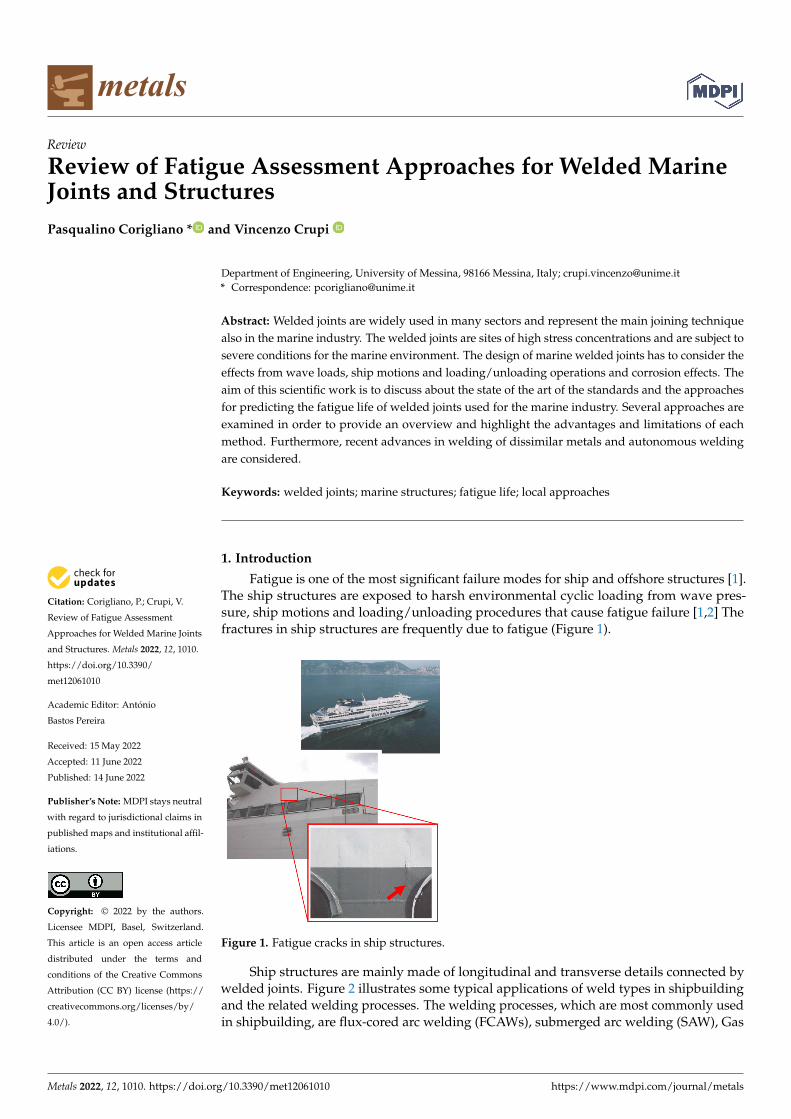
Fatigue is one of the most significant failure modes for ship and offshore structures [1].The ship structures are exposed to harsh environmental cyclic loading from wave pres-sure, ship motions and loading/unloading procedures that cause fatigue failure [1,2] Thefractures in ship structures are frequently due to fatigue (Figure 1).
Metals 2022, 12, x. https://doi.org/10.3390/xxxxx www.mdpi.com/journal/metals
Review
Review of Fatigue Assessment Approaches for Welded Marine
Joints and Structures
Pasqualino Corigliano * and Vincenzo Crupi
Department of Engineering, University of Messina, 98166 Messina, Italy; [email protected]
* Correspondence: [email protected]
Abstract: Welded joints are widely used in many sectors and represent the main joining technique
also in the marine industry. The welded joints are sites of high stress concentrations and are subject
to severe conditions for the marine environment. The design of marine welded joints has to consider
the effects from wave loads, ship motions and loading/unloading operations and corrosion effects.
The aim of this scientific work is to discuss about the state of the art of the standards and the ap-
proaches for predicting the fatigue life of welded joints used for the marine industry. Several ap-
proaches are examined in order to provide an overview and highlight the advantages and limita-
tions of each method. Furthermore, recent advances in welding of dissimilar metals and autono-
mous welding are considered.
Keywords: welded joints; marine structures; fatigue life; local approaches
1. Introduction
Fatigue is one of the most significant failure modes for ship and offshore structures
[1]. The ship structures are exposed to harsh environmental cyclic loading from wave
pressure, ship motions and loading/unloading procedures that cause fatigue failure [1,2]
The fractures in ship structures are frequently due to fatigue (Figure 1).
Figure 1. Fatigue cracks in ship structures.
Ship structures are mainly made of longitudinal and transverse details connected by
welded joints. Figure 2 illustrates some typical applications of weld types in shipbuilding
and the related welding processes. The welding processes, which are most commonly
used in shipbuilding, are flux-cored arc welding (FCAWs), submerged arc welding
Citation: Corigliano, P.; Crupi, V.
Review of Fatigue Assessment
Approaches for Welded Marine
Joints and Structures. Metals 2022,
12, x. https://doi.org/10.3390/xxxxx
Academic Editor: António Bastos
Pereira
Received: 15 May 2022
Accepted: 11 June 2022
Published: 14 June 2022
Publisher’s Note: MDPI stays neu-
tral with regard to jurisdictional
claims in published maps and institu-
tional affiliations.
Copyright: © 2022 by the authors.
Submitted for possible open access
publication under the terms and con-
ditions of the Creative Commons At-
tribution (CC BY) license (https://cre-
ativecommons.org/licenses/by/4.0/).
Figure 1. Fatigue cracks in ship structures.
Ship structures are mainly made of longitudinal and transverse details connected bywelded joints. Figure 2 illustrates some typical applications of weld types in shipbuildingand the related welding processes. The welding processes, which are most commonly usedin shipbuilding, are flux-cored arc welding (FCAWs), submerged arc welding (SAW), Gas
Metals 2022, 12, 1010. https://doi.org/10.3390/met12061010 https://www.mdpi.com/journal/metals
Metals 2022, 12, 1010 2 of 32
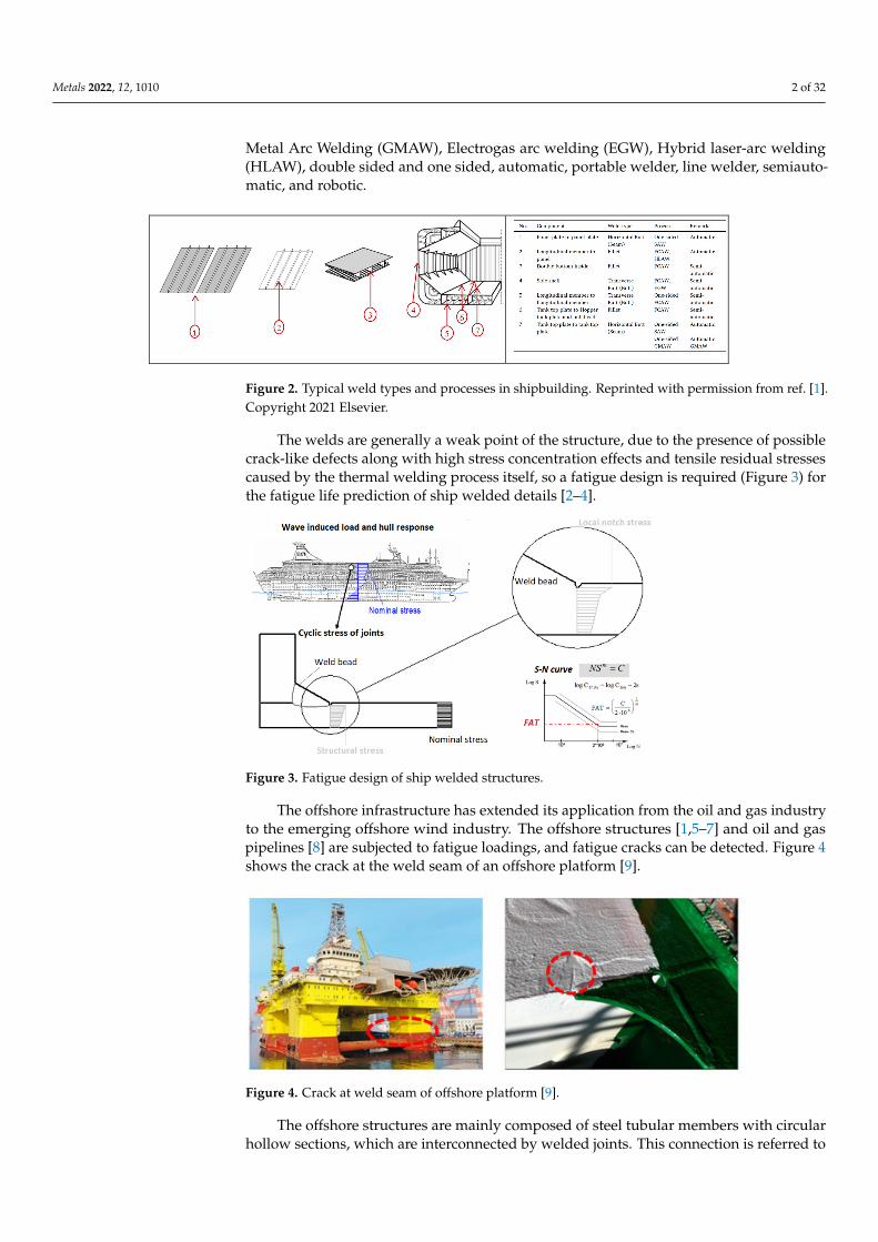
Metal Arc Welding (GMAW), Electrogas arc welding (EGW), Hybrid laser-arc welding(HLAW), double sided and one sided, automatic, portable welder, line welder, semiauto-matic, and robotic.
Metals 2022, 12, x FOR PEER REVIEW 2 of 33
(SAW), Gas Metal Arc Welding (GMAW), Electrogas arc welding (EGW), Hybrid laser-
arc welding (HLAW), double sided and one sided, automatic, portable welder, line
welder, semiautomatic, and robotic.
Figure 2. Typical weld types and processes in shipbuilding. Reprinted with permission from ref.
[1].Copyright 2021 Elsevier.
The welds are generally a weak point of the structure, due to the presence of possible
crack-like defects along with high stress concentration effects and tensile residual stresses
caused by the thermal welding process itself, so a fatigue design is required (Figure 3) for
the fatigue life prediction of ship welded details [2–4].
Figure 3. Fatigue design of ship welded structures.
The offshore infrastructure has extended its application from the oil and gas industry
to the emerging offshore wind industry. The offshore structures [1,5–7] and oil and gas
pipelines [8] are subjected to fatigue loadings, and fatigue cracks can be detected. Figure
4 shows the crack at the weld seam of an offshore platform [9].
Figure 4. Crack at weld seam of offshore platform [9].
Figure 2. Typical weld types and processes in shipbuilding. Reprinted with permission from ref. [1].Copyright 2021 Elsevier.
The welds are generally a weak point of the structure, due to the presence of possiblecrack-like defects along with high stress concentration effects and tensile residual stressescaused by the thermal welding process itself, so a fatigue design is required (Figure 3) forthe fatigue life prediction of ship welded details [2–4].
Metals 2022, 12, x FOR PEER REVIEW 2 of 33
(SAW), Gas Metal Arc Welding (GMAW), Electrogas arc welding (EGW), Hybrid laser-
arc welding (HLAW), double sided and one sided, automatic, portable welder, line
welder, semiautomatic, and robotic.
Figure 2. Typical weld types and processes in shipbuilding. Reprinted with permission from ref.
[1].Copyright 2021 Elsevier.
The welds are generally a weak point of the structure, due to the presence of possible
crack-like defects along with high stress concentration effects and tensile residual stresses
caused by the thermal welding process itself, so a fatigue design is required (Figure 3) for
the fatigue life prediction of ship welded details [2–4].
Figure 3. Fatigue design of ship welded structures.
The offshore infrastructure has extended its application from the oil and gas industry
to the emerging offshore wind industry. The offshore structures [1,5–7] and oil and gas
pipelines [8] are subjected to fatigue loadings, and fatigue cracks can be detected. Figure
4 shows the crack at the weld seam of an offshore platform [9].
Figure 4. Crack at weld seam of offshore platform [9].
Figure 3. Fatigue design of ship welded structures.
The offshore infrastructure has extended its application from the oil and gas industryto the emerging offshore wind industry. The offshore structures [1,5–7] and oil and gaspipelines [8] are subjected to fatigue loadings, and fatigue cracks can be detected. Figure 4shows the crack at the weld seam of an offshore platform [9].
Metals 2022, 12, x FOR PEER REVIEW 2 of 33
(SAW), Gas Metal Arc Welding (GMAW), Electrogas arc welding (EGW), Hybrid laser-
arc welding (HLAW), double sided and one sided, automatic, portable welder, line
welder, semiautomatic, and robotic.
Figure 2. Typical weld types and processes in shipbuilding. Reprinted with permission from ref.
[1].Copyright 2021 Elsevier.
The welds are generally a weak point of the structure, due to the presence of possible
crack-like defects along with high stress concentration effects and tensile residual stresses
caused by the thermal welding process itself, so a fatigue design is required (Figure 3) for
the fatigue life prediction of ship welded details [2–4].
Figure 3. Fatigue design of ship welded structures.
The offshore infrastructure has extended its application from the oil and gas industry
to the emerging offshore wind industry. The offshore structures [1,5–7] and oil and gas
pipelines [8] are subjected to fatigue loadings, and fatigue cracks can be detected. Figure
4 shows the crack at the weld seam of an offshore platform [9].
Figure 4. Crack at weld seam of offshore platform [9]. Figure 4. Crack at weld seam of offshore platform [9].
The offshore structures are mainly composed of steel tubular members with circularhollow sections, which are interconnected by welded joints. This connection is referred to

Metals 2022, 12, 1010 3 of 32
as the tubular joint. If the tubular joint consists of two pipes with different diameters, thelarger diameter pipe is called the chord, and the smaller one is known as the brace. Figure 5shows tubular joints, which are most commonly used in offshore structures.
Metals 2022, 12, x FOR PEER REVIEW 3 of 33
The offshore structures are mainly composed of steel tubular members with circular
hollow sections, which are interconnected by welded joints. This connection is referred to
as the tubular joint. If the tubular joint consists of two pipes with different diameters, the
larger diameter pipe is called the chord, and the smaller one is known as the brace. Figure
5 shows tubular joints, which are most commonly used in offshore structures.
Figure 5. Types of tubular joints along with their nomenclature [10].
A review of corrosion fatigue in offshore structures is reported in [11], and its results
show that the corrosion fatigue crack growth behavior of steel welded joints in marine
environments depends on several parameters (material, environment, loading conditions,
microstructure, welding procedure and residual stresses).
Static and fatigue tests were recently performed on a large-scale detail of hybrid tub-
ular joints (Figure 6) for an offshore wind turbine in [12]. The tests demonstrated that these
kinds of hybrid joints, made by combining adhesives together with welding, can be suc-
cessfully used in offshore structures, as the fatigue strength is improved.
Figure 6. Large-scale detail of hybrid tubular joints for offshore wind turbine investigated in [12].
Reprinted with permission from ref. [12]. Copyright 2022 Elsevier.
Figure 5. Types of tubular joints along with their nomenclature [10].
A review of corrosion fatigue in offshore structures is reported in [11], and its resultsshow that the corrosion fatigue crack growth behavior of steel welded joints in marineenvironments depends on several parameters (material, environment, loading conditions,microstructure, welding procedure and residual stresses).
Static and fatigue tests were recently performed on a large-scale detail of hybridtubular joints (Figure 6) for an offshore wind turbine in [12]. The tests demonstrated thatthese kinds of hybrid joints, made by combining adhesives together with welding, can besuccessfully used in offshore structures, as the fatigue strength is improved.
Metals 2022, 12, x FOR PEER REVIEW 3 of 33
The offshore structures are mainly composed of steel tubular members with circular
hollow sections, which are interconnected by welded joints. This connection is referred to
as the tubular joint. If the tubular joint consists of two pipes with different diameters, the
larger diameter pipe is called the chord, and the smaller one is known as the brace. Figure
5 shows tubular joints, which are most commonly used in offshore structures.
Figure 5. Types of tubular joints along with their nomenclature [10].
A review of corrosion fatigue in offshore structures is reported in [11], and its results
show that the corrosion fatigue crack growth behavior of steel welded joints in marine
environments depends on several parameters (material, environment, loading conditions,
microstructure, welding procedure and residual stresses).
Static and fatigue tests were recently performed on a large-scale detail of hybrid tub-
ular joints (Figure 6) for an offshore wind turbine in [12]. The tests demonstrated that these
kinds of hybrid joints, made by combining adhesives together with welding, can be suc-
cessfully used in offshore structures, as the fatigue strength is improved.
Figure 6. Large-scale detail of hybrid tubular joints for offshore wind turbine investigated in [12].
Reprinted with permission from ref. [12]. Copyright 2022 Elsevier. Figure 6. Large-scale detail of hybrid tubular joints for offshore wind turbine investigated in [12].Reprinted with permission from ref. [12]. Copyright 2022 Elsevier.

Metals 2022, 12, 1010 4 of 32
The fatigue strength and durability of welded structures are strongly related to severalparameters: the local geometrical discontinuity (weld toe radius, flank angle and weldsize), the service loadings, the environmental conditions, the thickness plate, the manu-facturing process, the residual stresses initiated during the welding process, the defects,and the material properties. Thus, this produces a great scatter in the fatigue life of thewelded joints.
The local mechanical properties are expected to change from the weld metal (WM) tothe heat-affected zone (HAZ), and generally they will be different from the base material(BM). In a previous study of the authors [13], they developed a new procedure, which isbased on the following steps: the hardness measurements using the UCI (ultrasonic contactimpedance) method for the identification of the different zones (BM, HAZ, and WM), theassessment of their cyclic stress–strain curves depending on the hardness values, and therealization of a nonlinear FEA, considering the different material properties. Figure 7 showsthe different material zones derived from the UCI method.
Metals 2022, 12, x FOR PEER REVIEW 4 of 33
The fatigue strength and durability of welded structures are strongly related to sev-
eral parameters: the local geometrical discontinuity (weld toe radius, flank angle and weld
size), the service loadings, the environmental conditions, the thickness plate, the manu-
facturing process, the residual stresses initiated during the welding process, the defects,
and the material properties. Thus, this produces a great scatter in the fatigue life of the
welded joints.
The local mechanical properties are expected to change from the weld metal (WM)
to the heat-affected zone (HAZ), and generally they will be different from the base mate-
rial (BM). In a previous study of the authors [13], they developed a new procedure, which
is based on the following steps: the hardness measurements using the UCI (ultrasonic
contact impedance) method for the identification of the different zones (BM, HAZ, and
WM), the assessment of their cyclic stress–strain curves depending on the hardness val-
ues, and the realization of a nonlinear FEA, considering the different material properties.
Figure 7 shows the different material zones derived from the UCI method.
Figure 7. Hardness measurement results and identification of the three zones (WM, HAZ, BM)
[13].
Nowadays, the shipbuilding industry is engaged in the construction of ships with
structures significantly thinner than those of the traditional ships. Thus, the influence of
the plate thickness on the fatigue response of the welded joint is an important parameter.
It is well known that there is a reduction in the fatigue strength when the size of the struc-
tural element increases. This is due mainly to the presence of higher tensile residual
stresses in the way of welds and to higher notch stresses caused by the through-thickness
stress gradient that arise at geometrical discontinuities. The thickness effect is mainly ex-
plained by the geometrical size effect, shown in Figure 8: when a crack with the same
length is considered for two welded joints with different thicknesses and subjected to the
same nominal stress, the local stress at the tip turns out to be lower in the thinner joint as
a consequence of its steeper stress gradient [14].
Figure 8. Through-thickness stress gradient in the welded joint [15].
Figure 7. Hardness measurement results and identification of the three zones (WM, HAZ, BM) [13].
Nowadays, the shipbuilding industry is engaged in the construction of ships withstructures significantly thinner than those of the traditional ships. Thus, the influence of theplate thickness on the fatigue response of the welded joint is an important parameter. It iswell known that there is a reduction in the fatigue strength when the size of the structuralelement increases. This is due mainly to the presence of higher tensile residual stressesin the way of welds and to higher notch stresses caused by the through-thickness stressgradient that arise at geometrical discontinuities. The thickness effect is mainly explainedby the geometrical size effect, shown in Figure 8: when a crack with the same length isconsidered for two welded joints with different thicknesses and subjected to the samenominal stress, the local stress at the tip turns out to be lower in the thinner joint as aconsequence of its steeper stress gradient [14].
Metals 2022, 12, x FOR PEER REVIEW 4 of 33
The fatigue strength and durability of welded structures are strongly related to sev-
eral parameters: the local geometrical discontinuity (weld toe radius, flank angle and weld
size), the service loadings, the environmental conditions, the thickness plate, the manu-
facturing process, the residual stresses initiated during the welding process, the defects,
and the material properties. Thus, this produces a great scatter in the fatigue life of the
welded joints.
The local mechanical properties are expected to change from the weld metal (WM)
to the heat-affected zone (HAZ), and generally they will be different from the base mate-
rial (BM). In a previous study of the authors [13], they developed a new procedure, which
is based on the following steps: the hardness measurements using the UCI (ultrasonic
contact impedance) method for the identification of the different zones (BM, HAZ, and
WM), the assessment of their cyclic stress–strain curves depending on the hardness val-
ues, and the realization of a nonlinear FEA, considering the different material properties.
Figure 7 shows the different material zones derived from the UCI method.
Figure 7. Hardness measurement results and identification of the three zones (WM, HAZ, BM)
[13].
Nowadays, the shipbuilding industry is engaged in the construction of ships with
structures significantly thinner than those of the traditional ships. Thus, the influence of
the plate thickness on the fatigue response of the welded joint is an important parameter.
It is well known that there is a reduction in the fatigue strength when the size of the struc-
tural element increases. This is due mainly to the presence of higher tensile residual
stresses in the way of welds and to higher notch stresses caused by the through-thickness
stress gradient that arise at geometrical discontinuities. The thickness effect is mainly ex-
plained by the geometrical size effect, shown in Figure 8: when a crack with the same
length is considered for two welded joints with different thicknesses and subjected to the
same nominal stress, the local stress at the tip turns out to be lower in the thinner joint as
a consequence of its steeper stress gradient [14].
Figure 8. Through-thickness stress gradient in the welded joint [15]. Figure 8. Through-thickness stress gradient in the welded joint [15].
Metals 2022, 12, 1010 5 of 32
Moreover, the thickness effect is also due to the increment of the probability of defectswhen the size of the structural element increases.
Ship hull and offshore structures, generally, consist of steel components connected bywelded joints and, unfortunately, the formation of defects is inherent to the welding tech-nology. These defects can grow into propagating fatigue cracks under repeated applicationof the dynamic loads during the service life.
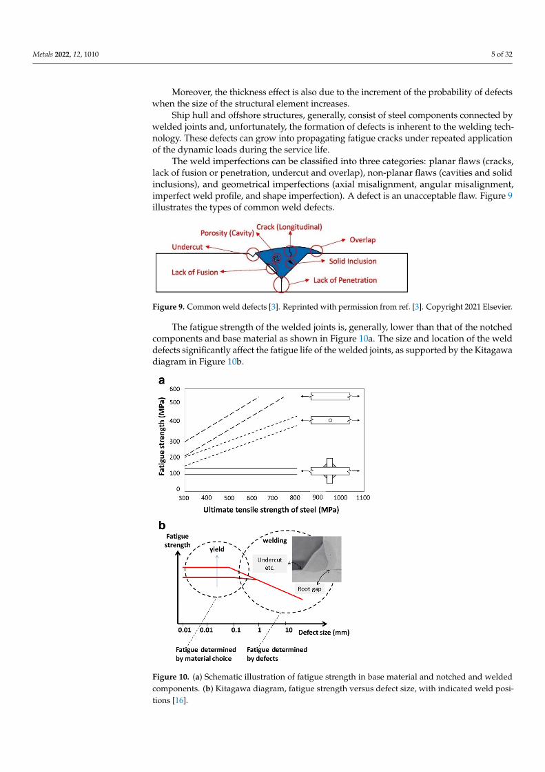
The weld imperfections can be classified into three categories: planar flaws (cracks,lack of fusion or penetration, undercut and overlap), non-planar flaws (cavities and solidinclusions), and geometrical imperfections (axial misalignment, angular misalignment,imperfect weld profile, and shape imperfection). A defect is an unacceptable flaw. Figure 9illustrates the types of common weld defects.
Metals 2022, 12, x FOR PEER REVIEW 5 of 33
Moreover, the thickness effect is also due to the increment of the probability of de-
fects when the size of the structural element increases.
Ship hull and offshore structures, generally, consist of steel components connected
by welded joints and, unfortunately, the formation of defects is inherent to the welding
technology. These defects can grow into propagating fatigue cracks under repeated appli-
cation of the dynamic loads during the service life.
The weld imperfections can be classified into three categories: planar flaws (cracks,
lack of fusion or penetration, undercut and overlap), non-planar flaws (cavities and solid
inclusions), and geometrical imperfections (axial misalignment, angular misalignment,
imperfect weld profile, and shape imperfection). A defect is an unacceptable flaw. Figure
9 illustrates the types of common weld defects.
Figure 9. Common weld defects [3]. Reprinted with permission from ref. [3]. Copyright 2021 Else-
vier.
The fatigue strength of the welded joints is, generally, lower than that of the notched
components and base material as shown in Figure 10a. The size and location of the weld
defects significantly affect the fatigue life of the welded joints, as supported by the Kita-
gawa diagram in Figure 10b.
Figure 10. (a) Schematic illustration of fatigue strength in base material and notched and welded
components. (b) Kitagawa diagram, fatigue strength versus defect size, with indicated weld posi-
tions [16].
Figure 9. Common weld defects [3]. Reprinted with permission from ref. [3]. Copyright 2021 Elsevier.
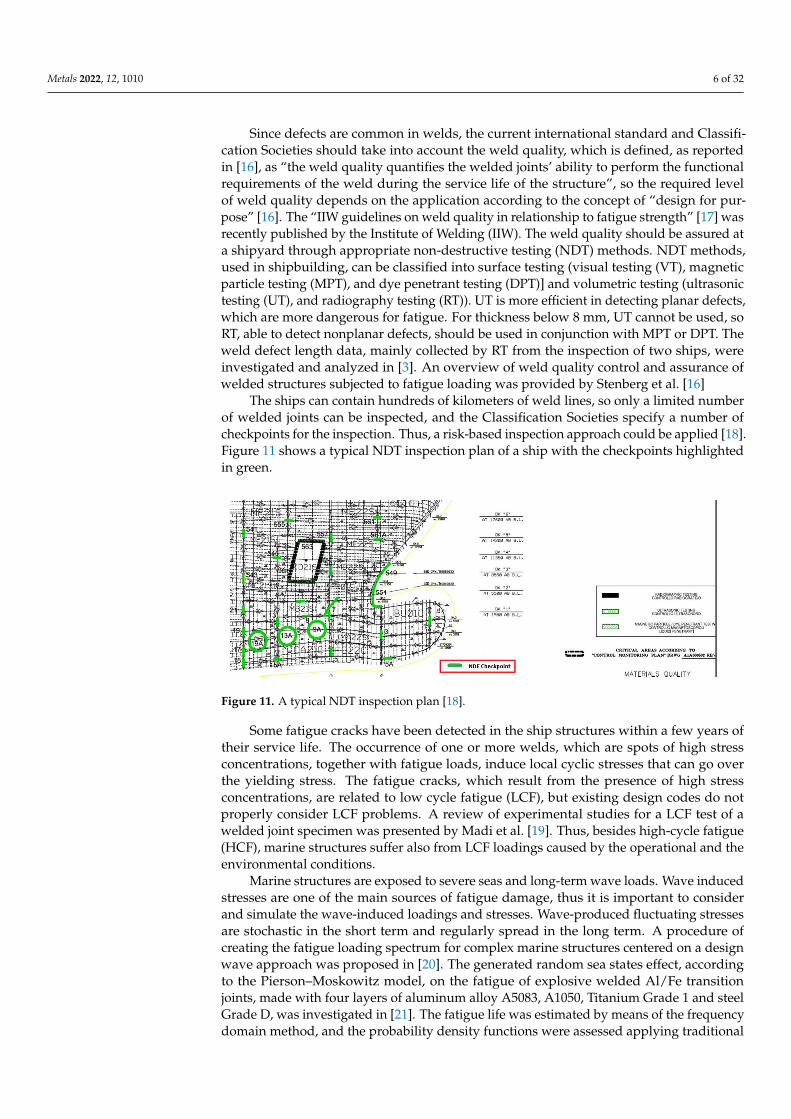
The fatigue strength of the welded joints is, generally, lower than that of the notchedcomponents and base material as shown in Figure 10a. The size and location of the welddefects significantly affect the fatigue life of the welded joints, as supported by the Kitagawadiagram in Figure 10b.
Metals 2022, 12, x FOR PEER REVIEW 5 of 33
Moreover, the thickness effect is also due to the increment of the probability of de-
fects when the size of the structural element increases.
Ship hull and offshore structures, generally, consist of steel components connected
by welded joints and, unfortunately, the formation of defects is inherent to the welding
technology. These defects can grow into propagating fatigue cracks under repeated appli-
cation of the dynamic loads during the service life.
The weld imperfections can be classified into three categories: planar flaws (cracks,
lack of fusion or penetration, undercut and overlap), non-planar flaws (cavities and solid
inclusions), and geometrical imperfections (axial misalignment, angular misalignment,
imperfect weld profile, and shape imperfection). A defect is an unacceptable flaw. Figure
9 illustrates the types of common weld defects.
Figure 9. Common weld defects [3]. Reprinted with permission from ref. [3]. Copyright 2021 Else-
vier.
The fatigue strength of the welded joints is, generally, lower than that of the notched
components and base material as shown in Figure 10a. The size and location of the weld
defects significantly affect the fatigue life of the welded joints, as supported by the Kita-
gawa diagram in Figure 10b.
Figure 10. (a) Schematic illustration of fatigue strength in base material and notched and welded
components. (b) Kitagawa diagram, fatigue strength versus defect size, with indicated weld posi-
tions [16].
Figure 10. (a) Schematic illustration of fatigue strength in base material and notched and weldedcomponents. (b) Kitagawa diagram, fatigue strength versus defect size, with indicated weld posi-tions [16].
Metals 2022, 12, 1010 6 of 32
Since defects are common in welds, the current international standard and Classifi-cation Societies should take into account the weld quality, which is defined, as reportedin [16], as “the weld quality quantifies the welded joints’ ability to perform the functionalrequirements of the weld during the service life of the structure”, so the required levelof weld quality depends on the application according to the concept of “design for pur-pose” [16]. The “IIW guidelines on weld quality in relationship to fatigue strength” [17] wasrecently published by the Institute of Welding (IIW). The weld quality should be assured ata shipyard through appropriate non-destructive testing (NDT) methods. NDT methods,used in shipbuilding, can be classified into surface testing (visual testing (VT), magneticparticle testing (MPT), and dye penetrant testing (DPT)] and volumetric testing (ultrasonictesting (UT), and radiography testing (RT)). UT is more efficient in detecting planar defects,which are more dangerous for fatigue. For thickness below 8 mm, UT cannot be used, soRT, able to detect nonplanar defects, should be used in conjunction with MPT or DPT. Theweld defect length data, mainly collected by RT from the inspection of two ships, wereinvestigated and analyzed in [3]. An overview of weld quality control and assurance ofwelded structures subjected to fatigue loading was provided by Stenberg et al. [16]
The ships can contain hundreds of kilometers of weld lines, so only a limited numberof welded joints can be inspected, and the Classification Societies specify a number ofcheckpoints for the inspection. Thus, a risk-based inspection approach could be applied [18].Figure 11 shows a typical NDT inspection plan of a ship with the checkpoints highlightedin green.
Metals 2022, 12, x FOR PEER REVIEW 6 of 33
Since defects are common in welds, the current international standard and Classifi-
cation Societies should take into account the weld quality, which is defined, as reported
in [16], as “the weld quality quantifies the welded joints’ ability to perform the functional
requirements of the weld during the service life of the structure”, so the required level of
weld quality depends on the application according to the concept of “design for purpose”
[16]. The “IIW guidelines on weld quality in relationship to fatigue strength” [17] was
recently published by the Institute of Welding (IIW). The weld quality should be assured
at a shipyard through appropriate non-destructive testing (NDT) methods. NDT methods,
used in shipbuilding, can be classified into surface testing (visual testing (VT), magnetic
particle testing (MPT), and dye penetrant testing (DPT)] and volumetric testing (ultrasonic
testing (UT), and radiography testing (RT)). UT is more efficient in detecting planar de-
fects, which are more dangerous for fatigue. For thickness below 8 mm, UT cannot be
used, so RT, able to detect nonplanar defects, should be used in conjunction with MPT or
DPT. The weld defect length data, mainly collected by RT from the inspection of two ships,
were investigated and analyzed in [3]. An overview of weld quality control and assurance
of welded structures subjected to fatigue loading was provided by Stenberg et al. [16]
The ships can contain hundreds of kilometers of weld lines, so only a limited number
of welded joints can be inspected, and the Classification Societies specify a number of
checkpoints for the inspection. Thus, a risk-based inspection approach could be applied
[18]. Figure 11 shows a typical NDT inspection plan of a ship with the checkpoints high-
lighted in green.
Figure 11. A typical NDT inspection plan [18].
Some fatigue cracks have been detected in the ship structures within a few years of
their service life. The occurrence of one or more welds, which are spots of high stress con-
centrations, together with fatigue loads, induce local cyclic stresses that can go over the
yielding stress. The fatigue cracks, which result from the presence of high stress concen-
trations, are related to low cycle fatigue (LCF), but existing design codes do not properly
consider LCF problems. A review of experimental studies for a LCF test of a welded joint
specimen was presented by Madi et al. [19]. Thus, besides high-cycle fatigue (HCF), ma-
rine structures suffer also from LCF loadings caused by the operational and the environ-
mental conditions.
Marine structures are exposed to severe seas and long-term wave loads. Wave in-
duced stresses are one of the main sources of fatigue damage, thus it is important to con-
sider and simulate the wave-induced loadings and stresses. Wave-produced fluctuating
stresses are stochastic in the short term and regularly spread in the long term. A procedure
of creating the fatigue loading spectrum for complex marine structures centered on a de-
sign wave approach was proposed in [20]. The generated random sea states effect, accord-
ing to the Pierson–Moskowitz model, on the fatigue of explosive welded Al/Fe transition
joints, made with four layers of aluminum alloy A5083, A1050, Titanium Grade 1 and steel
Grade D, was investigated in [21]. The fatigue life was estimated by means of the
Figure 11. A typical NDT inspection plan [18].
Some fatigue cracks have been detected in the ship structures within a few years oftheir service life. The occurrence of one or more welds, which are spots of high stressconcentrations, together with fatigue loads, induce local cyclic stresses that can go overthe yielding stress. The fatigue cracks, which result from the presence of high stressconcentrations, are related to low cycle fatigue (LCF), but existing design codes do notproperly consider LCF problems. A review of experimental studies for a LCF test of awelded joint specimen was presented by Madi et al. [19]. Thus, besides high-cycle fatigue(HCF), marine structures suffer also from LCF loadings caused by the operational and theenvironmental conditions.
Marine structures are exposed to severe seas and long-term wave loads. Wave inducedstresses are one of the main sources of fatigue damage, thus it is important to considerand simulate the wave-induced loadings and stresses. Wave-produced fluctuating stressesare stochastic in the short term and regularly spread in the long term. A procedure ofcreating the fatigue loading spectrum for complex marine structures centered on a designwave approach was proposed in [20]. The generated random sea states effect, accordingto the Pierson–Moskowitz model, on the fatigue of explosive welded Al/Fe transitionjoints, made with four layers of aluminum alloy A5083, A1050, Titanium Grade 1 and steelGrade D, was investigated in [21]. The fatigue life was estimated by means of the frequencydomain method, and the probability density functions were assessed applying traditional

Metals 2022, 12, 1010 7 of 32
formula. The predicted results were compared with the standard test results, confirmingthat the predicted values did not overestimate the fatigue life.
The stochastic characteristics of the hull vibration superimposed stress waveformexperienced by 6500 TEU container ship’s deck longitudinal were analyzed in [22]. Theauthors developed an electric exciter-driven plate bending vibration fatigue testing machine,which is able to carry out the whipping superimposed fatigue tests of welded joints, and itwas found that rainflow counting produces conservative estimates of the fatigue lives.
The marine aggressive environment on ship and offshore structures accelerates fatiguedamage through corrosion, which causes a deterioration of the mechanical properties [23]and lowers the fatigue strength of marine welded structures. Garbatov et al. [24] consideredthe fatigue strength of corroded specimens of a transverse stiffened welded plate, showingthe results of lower fatigue strength than expected.
The recent increase in Arctic shipping and operations requires a specific knowledge ofthe ship and offshore welded structures subjected to ice-induced fatigue loading at seasonalsub-zero temperatures. The assessment of the fatigue loads produced by the interactionof the ice with ship and offshore structures is quite complex, and, if these structures aremade of ferritic structural steels, they may undergo a ductile-to-brittle transition (DBT) atthe low temperatures in Arctic waters. To this day, the current standards and guidelinesdo not address the effect of the low temperature on the fatigue strength of steel-weldedstructures. An interesting review regarding the fatigue assessment approaches at sub-zerotemperature was recently proposed in [25].
Thus, clear recommendations are required to guarantee that fatigue failures are pre-vented in welded structures. The design of welded structures is commonly carried outby means of rules which impose conservative values of the allowable stress or considerpartial corrective factors to take into account possible defects, residual stresses, corrosionand so on. The recommendations of the current codes, such as International Institute ofWelding [26,27] and Eurocode [28,29] and recognized by some of the most important Clas-sification Societies of ships and offshore structures, are conservative as was demonstratedby Crupi et al. [30] and Fricke et al. [31]. Experimental fatigue tests were carried out toassess the S–N curve of butt-welded joints, made of AH36 steel, which is used in ship-building [30]. Figure 12 shows the comparison between the design S–N curves (survivalprobability PS = 97.7%), obtained by the traditional procedure [30] and reported in the IIWCode [26,27], demonstrating the conservativeness of the standard.
Metals 2022, 12, x FOR PEER REVIEW 7 of 33
frequency domain method, and the probability density functions were assessed applying
traditional formula. The predicted results were compared with the standard test results,
confirming that the predicted values did not overestimate the fatigue life.
The stochastic characteristics of the hull vibration superimposed stress waveform ex-
perienced by 6500 TEU container ship’s deck longitudinal were analyzed in [22]. The au-
thors developed an electric exciter-driven plate bending vibration fatigue testing machine,
which is able to carry out the whipping superimposed fatigue tests of welded joints, and
it was found that rainflow counting produces conservative estimates of the fatigue lives.
The marine aggressive environment on ship and offshore structures accelerates fa-
tigue damage through corrosion, which causes a deterioration of the mechanical proper-
ties [23] and lowers the fatigue strength of marine welded structures. Garbatov et al. [24]
considered the fatigue strength of corroded specimens of a transverse stiffened welded
plate, showing the results of lower fatigue strength than expected.
The recent increase in Arctic shipping and operations requires a specific knowledge
of the ship and offshore welded structures subjected to ice-induced fatigue loading at sea-
sonal sub-zero temperatures. The assessment of the fatigue loads produced by the inter-
action of the ice with ship and offshore structures is quite complex, and, if these structures
are made of ferritic structural steels, they may undergo a ductile-to-brittle transition (DBT)
at the low temperatures in Arctic waters. To this day, the current standards and guidelines
do not address the effect of the low temperature on the fatigue strength of steel-welded
structures. An interesting review regarding the fatigue assessment approaches at sub-zero
temperature was recently proposed in [25].
Thus, clear recommendations are required to guarantee that fatigue failures are pre-
vented in welded structures. The design of welded structures is commonly carried out by
means of rules which impose conservative values of the allowable stress or consider par-
tial corrective factors to take into account possible defects, residual stresses, corrosion and
so on. The recommendations of the current codes, such as International Institute of Weld-
ing [26,27] and Eurocode [28,29] and recognized by some of the most important Classifi-
cation Societies of ships and offshore structures, are conservative as was demonstrated by
Crupi et al. [30] and Fricke et al. [31]. Experimental fatigue tests were carried out to assess
the S–N curve of butt-welded joints, made of AH36 steel, which is used in shipbuilding
[30]. Figure 12 shows the comparison between the design S–N curves (survival probability
PS = 97.7%), obtained by the traditional procedure [30] and reported in the IIW Code
[26,27], demonstrating the conservativeness of the standard.
Figure 12. Experimental and design S–N curves [30]. Reprinted with permission from ref. [30].
Copyright 2021 Elsevier. Figure 12. Experimental and design S–N curves [30]. Reprinted with permission from ref. [30].Copyright 2021 Elsevier.

Metals 2022, 12, 1010 8 of 32
Fricke et al. [31] applied the fatigue assessment recommendations used by the Classi-fication Societies for the fatigue assessment of a pad detail on the coaming of a Panamaxcontainership, showing that numerous procedures, comprising the direct load design,produce very conservative results and the high scatter is due to different assumptionsconcerning load effects and local stress analyses and S–N curves.
The fatigue of welded joints is widely studied, and numerous approaches have beendeveloped (Figure 13). An interesting review on fatigue of welded joints was given byFricke [32].
Metals 2022, 12, x FOR PEER REVIEW 8 of 33
Fricke et al. [31] applied the fatigue assessment recommendations used by the Clas-
sification Societies for the fatigue assessment of a pad detail on the coaming of a Panamax
containership, showing that numerous procedures, comprising the direct load design,
produce very conservative results and the high scatter is due to different assumptions
concerning load effects and local stress analyses and S–N curves.
The fatigue of welded joints is widely studied, and numerous approaches have been
developed (Figure 13). An interesting review on fatigue of welded joints was given by
Fricke [32].
The most common approaches include the following:
- The nominal stress approach [26,27];
- The structural approaches (structural stress approach [33], and the structural strain
approach [34–36]);
- The local approaches (the notch stress intensity factor (N-SIF) approach [37,38], the
notch strain approach [39,40], and the peak stress methods [41,42]);
- The fracture mechanics approaches (the crack propagation approach [43,44]);
- The energy approaches (the equivalent strain energy density (ESED) approach, and
the averaged strain energy density (SED) approach [45,46];
- The critical distance methods (CDMs) [47–50];
- The thermal methods [50–55].
Some of them were improved when the evaluation becomes more complex and a
multiaxial stress state occurs [43,56–61].
Figure 13. Global and local approaches for fatigue assessment of welded joints [26].
Recently, the abovementioned approaches were further assessed with several contri-
butions, i.e., the cyclic structural stress was further developed by Dong [62,63] and ex-
tended in terms of structural strain of the LCF assessment [64,65], the elastic notch effect
was reviewed in [66], the notch stress intensity approaches were deeply discussed in [66–
68] and the peak–stress method was validated for many kinds of joints and was related to
the SED and NSIF approaches [67,69]. In addition, Garbatov proposed a modified method
[70] of the notch–strain approach.
However, there are not many other dedicated review studies to marine applications.
The present paper has the aim of giving a summary of the recent advances of the
most used fatigue life prediction approaches and their applications in offshore and ship
structures. The approaches were compared, considering that each approach has ad-
vantages and disadvantages. The comparison was based on a criterion which takes into
account the applications. New insights, obtained by this comparison, were proposed, aim-
ing to extend the service life of ship and offshore welded structures subjected to fatigue
loadings. As reported above, the fatigue analysis of ship and offshore welded structures
is a complex task, so the choice of the fatigue assessment approach depends on the specific
application.
Figure 13. Global and local approaches for fatigue assessment of welded joints [26].
- The most common approaches include the following:- The nominal stress approach [26,27];- The structural approaches (structural stress approach [33], and the structural strain
approach [34–36]);- The local approaches (the notch stress intensity factor (N-SIF) approach [37,38], the
notch strain approach [39,40], and the peak stress methods [41,42]);- The fracture mechanics approaches (the crack propagation approach [43,44]);- The energy approaches (the equivalent strain energy density (ESED) approach, and
the averaged strain energy density (SED) approach [45,46];- The critical distance methods (CDMs) [47–50];- The thermal methods [50–55].
Some of them were improved when the evaluation becomes more complex and amultiaxial stress state occurs [43,56–61].
Recently, the abovementioned approaches were further assessed with several contribu-tions, i.e., the cyclic structural stress was further developed by Dong [62,63] and extendedin terms of structural strain of the LCF assessment [64,65], the elastic notch effect wasreviewed in [66], the notch stress intensity approaches were deeply discussed in [66–68]and the peak–stress method was validated for many kinds of joints and was related to theSED and NSIF approaches [67,69]. In addition, Garbatov proposed a modified method [70]of the notch–strain approach.
However, there are not many other dedicated review studies to marine applications.The present paper has the aim of giving a summary of the recent advances of the
most used fatigue life prediction approaches and their applications in offshore and shipstructures. The approaches were compared, considering that each approach has advantagesand disadvantages. The comparison was based on a criterion which takes into account theapplications. New insights, obtained by this comparison, were proposed, aiming to extendthe service life of ship and offshore welded structures subjected to fatigue loadings. Asreported above, the fatigue analysis of ship and offshore welded structures is a complextask, so the choice of the fatigue assessment approach depends on the specific application.
In addition, the future research direction regarding welding of dissimilar metals andautonomous welding methods are presented.

Metals 2022, 12, 1010 9 of 32
2. Approaches for Fatigue Assessment of Marine Welded Joints2.1. Nominal Stress Approach
The nominal stress approach [26,27] assumes a total elastic behavior and that the S–Ncurves of welded joints with distinct geometries have the same slope for a specific material.In this case, a matching FAT (fatigue class), intended as the fatigue strength at 2 × 10⁶ cycles,is assigned. This kind of approach, which involves evaluating the fatigue strength bymeans of traditional fatigue tests, is considered in the current standards and recognizedby the main ship classification societies. It ignores the effect of local stress increasesdue to structural discontinuities and local weld profile but includes the effects of themacrogeometric shape of the component in the vicinity of the joint, such as large cutouts.
The nominal stress approach was applied in [71], where a considerable series of speci-mens made of DH36 steel and welded by means of the friction stir process was analyzed.The obtained S–N curve was compared to those recommended by the International Instituteof Welding for fusion butt welds. In this case, a higher fatigue strength, corresponding to ahigher FAT class, was found for the investigated marine grade steel.
The nominal stress method is particularly applied to simplify more complex problems,i.e., in the case of multiaxiality, as was done in [72]. In this case, a selection of codes andmultiaxial fatigue methods for the marine industry were investigated, considering (non-proportional) constant amplitude loading, using nominal stresses. The authors concludedin [72] that there are large discrepancies between the applied codes (Eurocode, IIW andDNV-GL) and that the use of more local stress information could improve the results.
The nominal stress approach, even if it can provide significant dispersion and some-times not very accurate results, is principally employed when the problems dealt with areparticularly complex and other approaches are hard to be applied. Moreover, the nominalstresses are not always easy to be evaluated in the real welded structures with complexgeometries, such as in the laboratory specimens.
2.2. Structural Approaches
The structural stress (alternatively ‘hot spot’ structural stress approach) has beendefined in various ways: the mean stress value evaluated at certain distance away fromthe weld toe [32,73] or multiplying the nominal stress range by an appropriate stressconcentration factor.
Generally, the structural hot spot stress, which does not take into account the effect ofa notch radius, is determined through FE analyses and the procedures employed to assessthe hot spot stresses, for the various types of hot spots, by means of finite element models,were firstly created for strain gauge use.
The structural stress approach usually uses idealized, perfectly aligned welded joints.This means that any potential misalignment has to be taken into account by the FEA modelor by a proper stress magnification factor. Different variants of the approach exist whichconsider, for example, the effect of the stress gradient in the plate thickness direction andthe plate thickness effect [33].
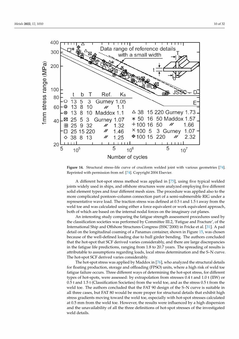
A method centered on the computed stress value 1 mm below the surface in thedirection relating to the expected crack path was developed by Xiao–Yamada [74]. The totalstress distribution along the crack path is the sum of the geometric stress produced by thestructural geometry change and the non-linear local stress generated by the weld itself. Theauthors stated that, if compared to the surface extrapolation technique for structural hotspot stress evaluation, their proposed method [74] has the additional advantage of beingable to consider the size and thickness effect observed in welded joints. Figure 14 showsthe structural stress–life curve of the cruciform welded joint with various geometries [63].
Metals 2022, 12, 1010 10 of 32
Metals 2022, 12, x FOR PEER REVIEW 10 of 33
shows the structural stress–life curve of the cruciform welded joint with various geome-
tries [63].
Figure 14. Structural stress–life curve of cruciform welded joint with various geometries [74]. Re-
printed with permission from ref. [74]. Copyright 2004 Elsevier.
A different hot-spot stress method was applied in [75], using five typical welded
joints widely used in ships, and offshore structures were analyzed employing five differ-
ent solid element types and four different mesh sizes. The procedure was applied also to
the more complicated pontoon–column connection part of a semi-submersible RIG under
a representative wave load. The traction stress was defined at 0.5 t and 1.5 t away from
the weld toe and was calculated using either a force equivalent or work equivalent ap-
proach, both of which are based on the internal nodal forces on the imaginary cut planes.
An interesting study comparing the fatigue strength assessment procedures used by
the classification societies was performed by Committee III.2, ‘Fatigue and Fracture’, of
the International Ship and Offshore Structures Congress (ISSC’2000) in Fricke et al. [31].
A pad detail on the longitudinal coaming of a Panamax container, shown in Figure 15,
was chosen because of the well-defined loading due to hull girder bending. The authors
concluded that the hot-spot that SCF derived varies considerably, and there are large dis-
crepancies in the fatigue life predictions, ranging from 1.8 to 20.7 years. The spreading of
results is attributable to assumptions regarding loads, local stress determination and the
S–N curve. The hot-spot SCF derived varies considerably.
Figure 14. Structural stress–life curve of cruciform welded joint with various geometries [74].Reprinted with permission from ref. [74]. Copyright 2004 Elsevier.
A different hot-spot stress method was applied in [75], using five typical weldedjoints widely used in ships, and offshore structures were analyzed employing five differentsolid element types and four different mesh sizes. The procedure was applied also to themore complicated pontoon–column connection part of a semi-submersible RIG under arepresentative wave load. The traction stress was defined at 0.5 t and 1.5 t away from theweld toe and was calculated using either a force equivalent or work equivalent approach,both of which are based on the internal nodal forces on the imaginary cut planes.
An interesting study comparing the fatigue strength assessment procedures used bythe classification societies was performed by Committee III.2, ‘Fatigue and Fracture’, of theInternational Ship and Offshore Structures Congress (ISSC’2000) in Fricke et al. [31]. A paddetail on the longitudinal coaming of a Panamax container, shown in Figure 15, was chosenbecause of the well-defined loading due to hull girder bending. The authors concludedthat the hot-spot that SCF derived varies considerably, and there are large discrepanciesin the fatigue life predictions, ranging from 1.8 to 20.7 years. The spreading of results isattributable to assumptions regarding loads, local stress determination and the S–N curve.The hot-spot SCF derived varies considerably.
The hot-spot stress was applied by Maddox in [76], who analyzed the structural detailsfor floating production, storage and offloading (FPSO) units, where a high risk of weld toefatigue failure occurs. Three different ways of determining the hot-spot stress, for differenttypes of hot-spots, were assessed: by extrapolation from stresses 0.4 t and 1.0 t (IIW) or0.5 t and 1.5 t (Classification Societies) from the weld toe, and as the stress 0.5 t from theweld toe. The authors concluded that the FAT 90 design of the S–N curve is suitable inall three cases, but FAT 80 would be more proper for structural details that exhibit highstress gradients moving toward the weld toe, especially with hot-spot stresses calculatedat 0.5 mm from the weld toe. However, the results were influenced by a high dispersionand the unavailability of all the three definitions of hot-spot stresses of the investigatedweld details.

Metals 2022, 12, 1010 11 of 32Metals 2022, 12, x FOR PEER REVIEW 11 of 33
Figure 15. Detail of the longitudinal coaming of a Panamax container analyzed by Fricke et al. [31].
Reprinted with permission from ref. [31]. Copyright 2002 Elsevier.
The hot-spot stress was applied by Maddox in [76], who analyzed the structural de-
tails for floating production, storage and offloading (FPSO) units, where a high risk of
weld toe fatigue failure occurs. Three different ways of determining the hot-spot stress,
for different types of hot-spots, were assessed: by extrapolation from stresses 0.4 t and 1.0
t (IIW) or 0.5 t and 1.5 t (Classification Societies) from the weld toe, and as the stress 0.5 t
from the weld toe. The authors concluded that the FAT 90 design of the S–N curve is
suitable in all three cases, but FAT 80 would be more proper for structural details that
exhibit high stress gradients moving toward the weld toe, especially with hot-spot stresses
calculated at 0.5 mm from the weld toe. However, the results were influenced by a high
dispersion and the unavailability of all the three definitions of hot-spot stresses of the in-
vestigated weld details.
Structural details of FPSOs units, applying the hot-spot stress, were investigated also
by Fricke et al. [77]. Five distinct details (some of them used also in shipbuilding) with
different geometry and fatigue loading, were selected, for which stress measurements and
fatigue tests are available. The authors used different FE programs, FE models and differ-
ent mesh size and element types, applying three different stress extrapolation techniques
depending on the plate thickness. The derived hot-spot stresses and the estimated fatigue
lives were matched with the existing design of S–N curves of the International Institute of
Figure 15. Detail of the longitudinal coaming of a Panamax container analyzed by Fricke et al. [31].Reprinted with permission from ref. [31]. Copyright 2002 Elsevier.
Structural details of FPSOs units, applying the hot-spot stress, were investigated alsoby Fricke et al. [77]. Five distinct details (some of them used also in shipbuilding) withdifferent geometry and fatigue loading, were selected, for which stress measurements andfatigue tests are available. The authors used different FE programs, FE models and differentmesh size and element types, applying three different stress extrapolation techniquesdepending on the plate thickness. The derived hot-spot stresses and the estimated fatiguelives were matched with the existing design of S–N curves of the International Instituteof Welding (IIW), concluding that the hot-spot stresses predicted using the three stressextrapolation techniques are suitable with the current design of S–N curves.
Nevertheless, as previously observed, the nominal stress and hot-spot stress ap-proaches have some limitations regarding the thickness effect consideration and are some-times conservative due to the high dispersion. Furthermore, the design of the S–N curvecan be very subjective because the weld classification is based on the dominant loadingmode and the mesh size and not only on the joint geometry. Within this context, Dong [63]proposed a new definition of structural stress which is not mesh sensitive, later applied onvarious ship welded joints, by considering the gradient stress distribution along the weldedplate thickness and establishing equilibrium equations from the elemental node forces. Thisnew structural stress definition, calculated on the potential crack path is based also on the

Metals 2022, 12, 1010 12 of 32
division of the normal stress into the membrane stress and bending stress, resulting in theeffect of the loading mode being able to be taken into account. Thus, the new structuralstress approach can consider different geometries subjected to different loading modes,different thicknesses, and misalignment effects, and it is not mesh sensitive [33,63], beingmore advantageous with respect to the traditional hot-spot structural stress.
The S–N curve obtained by the equivalent structural stress proposed by Dong iscompared to a master S–N curve, in a narrow scatter band, as shown in Figure 16 [78].
Metals 2022, 12, x FOR PEER REVIEW 12 of 33
Welding (IIW), concluding that the hot-spot stresses predicted using the three stress ex-
trapolation techniques are suitable with the current design of S–N curves.
Nevertheless, as previously observed, the nominal stress and hot-spot stress ap-
proaches have some limitations regarding the thickness effect consideration and are some-
times conservative due to the high dispersion. Furthermore, the design of the S–N curve
can be very subjective because the weld classification is based on the dominant loading
mode and the mesh size and not only on the joint geometry. Within this context, Dong
[63] proposed a new definition of structural stress which is not mesh sensitive, later ap-
plied on various ship welded joints, by considering the gradient stress distribution along
the welded plate thickness and establishing equilibrium equations from the elemental
node forces. This new structural stress definition, calculated on the potential crack path is
based also on the division of the normal stress into the membrane stress and bending
stress, resulting in the effect of the loading mode being able to be taken into account. Thus,
the new structural stress approach can consider different geometries subjected to different
loading modes, different thicknesses, and misalignment effects, and it is not mesh sensi-
tive [33,63], being more advantageous with respect to the traditional hot-spot structural
stress.
The S–N curve obtained by the equivalent structural stress proposed by Dong is com-
pared to a master S–N curve, in a narrow scatter band, as shown in Figure 16 [78].
Dong’s approach of the equivalent structural stress was successfully applied to the
orthotropic steel deck (OSD) [63,79], widely applied in shipbuilding [80]. OSDs are excep-
tionally common in the ship building industry and for hydraulic purposes such as tanks,
gates, and locks. In [62,79] it was concluded that the mesh insensitive traction-based struc-
tural stress definition is efficient for describing the relevant stress state responsible for
each of the fatigue failure modes. The same approach was successfully extended through
a formulation of an effective equivalent structural stress transfer function in order to in-
corporate multiaxial non-proportional loading conditions, for the assessment of marine
structures exposed to time-varying loads, in [81].
Figure 16. Master S–N curve obtained from Dong’s structural stress [78].
Furthermore, for fillet-welded specimens, based on typical shipbuilding practices,
the weld penetration effects on the fillet weld load carrying capacity were investigated in
Figure 16. Master S–N curve obtained from Dong’s structural stress [78].
Dong’s approach of the equivalent structural stress was successfully applied to theorthotropic steel deck (OSD) [63,79], widely applied in shipbuilding [80]. OSDs are ex-ceptionally common in the ship building industry and for hydraulic purposes such astanks, gates, and locks. In [62,79] it was concluded that the mesh insensitive traction-basedstructural stress definition is efficient for describing the relevant stress state responsible foreach of the fatigue failure modes. The same approach was successfully extended througha formulation of an effective equivalent structural stress transfer function in order to in-corporate multiaxial non-proportional loading conditions, for the assessment of marinestructures exposed to time-varying loads, in [81].
Furthermore, for fillet-welded specimens, based on typical shipbuilding practices, theweld penetration effects on the fillet weld load carrying capacity were investigated in [82].It was noticed in [82] that both an effective weld throat stress-based criterion by combiningnormal and shear traction stresses and an equivalent effective stress-based criterion basedon the master S–N curve formulation can be applied for the evaluation of the minimumfillet weld leg size beyond which weld toe fatigue failure dominates.
Recently, Dong and co-authors proposed an extension of the structural stress approachfor the low-cycle fatigue life prediction, using a structural strain parameter capable ofcorrelating both LCF and HCF fatigue data of welded structures [35,65].
The structural stress and structural strain methods were particularly used in an ill-defined weld toe [27,34,35,63,65,83]. The equivalent structural strain was applied by Dongand coauthors to girth-welded offshore pipes, considering the cyclic nonlinear behavior [78]which influenced the LCF behavior. However, it is worth noting that if the experimentsare displacement controlled, the structural strain can be calculated through a linear elasticmodel [64,65]. Deeper analyses on the structural strain approach can be followed in [35,64].The results of the equivalent structural strain approach can be compared with a master

Metals 2022, 12, 1010 13 of 32
E–N curve representing over 1000 large scale fatigue tests [83], with the cycle to failureranging from 102 to 108. Actually, there are two Master S–N curves in the ASME code,with one for steel and one for aluminum. However, as shown in ref. [65], LCF fatiguedata using the structural strain approach and fatigue data of different metals (data fromcruciform fillet-welded specimens consisting of two types of aluminum alloys used inshipbuilding, two types of titanium alloys and ship hull steel) can be collapsed in a singlemaster E–N curve. Furthermore, the validation on a ship structural detail and 63 shiphull steel specimens of the structural strain approach was reported in [65] and is shown inFigure 17.
Metals 2022, 12, x FOR PEER REVIEW 13 of 33
[82]. It was noticed in [82] that both an effective weld throat stress-based criterion by com-
bining normal and shear traction stresses and an equivalent effective stress-based criterion
based on the master S–N curve formulation can be applied for the evaluation of the min-
imum fillet weld leg size beyond which weld toe fatigue failure dominates.
Recently, Dong and co-authors proposed an extension of the structural stress ap-
proach for the low-cycle fatigue life prediction, using a structural strain parameter capable
of correlating both LCF and HCF fatigue data of welded structures [35,65].
The structural stress and structural strain methods were particularly used in an ill-
defined weld toe [27,34,35,63,65,83]. The equivalent structural strain was applied by Dong
and coauthors to girth-welded offshore pipes, considering the cyclic nonlinear behavior
[78] which influenced the LCF behavior. However, it is worth noting that if the experi-
ments are displacement controlled, the structural strain can be calculated through a linear
elastic model [64,65]. Deeper analyses on the structural strain approach can be followed
in [35,64]. The results of the equivalent structural strain approach can be compared with
a master E–N curve representing over 1000 large scale fatigue tests [83], with the cycle to
failure ranging from 102 to 108. Actually, there are two Master S–N curves in the ASME
code, with one for steel and one for aluminum. However, as shown in ref. [65], LCF fatigue
data using the structural strain approach and fatigue data of different metals (data from
cruciform fillet-welded specimens consisting of two types of aluminum alloys used in
shipbuilding, two types of titanium alloys and ship hull steel) can be collapsed in a single
master E–N curve. Furthermore, the validation on a ship structural detail and 63 ship hull
steel specimens of the structural strain approach was reported in [65] and is shown in
Figure 17.
Figure 17. Equivalent structural strain range versus cycle to failure: fatigue test data analyzed in
[65]. Reprinted with permission from ref. [65]. Copyright 2019 Elsevier.
A new experimental approach, based on the digital image correlation (DIC) tech-
nique, for the structural strain evaluation in LCF condition of welded joints was firstly
proposed in [84]. The DIC is an experimental technique extremely useful for detecting
very high local displacements and strains and permits a deep analysis of the mechanical
behavior of welded joints, as shown in [85]. The new approach, namely “DIC-based equiv-
alent structural strain approach”, is related to the definition given by [35,65], but it was
evaluated on the specimen surface instead of thickness. The DIC-based structural strain
approach was applied successfully for predicting the LCF life of AA 5083 welded joints,
used for shipbuilding and marine structures [84] The equivalent DIC structural strain
Figure 17. Equivalent structural strain range versus cycle to failure: fatigue test data analyzed in [65].Reprinted with permission from ref. [65]. Copyright 2019 Elsevier.
A new experimental approach, based on the digital image correlation (DIC) technique,for the structural strain evaluation in LCF condition of welded joints was firstly proposedin [84]. The DIC is an experimental technique extremely useful for detecting very highlocal displacements and strains and permits a deep analysis of the mechanical behaviorof welded joints, as shown in [85]. The new approach, namely “DIC-based equivalentstructural strain approach”, is related to the definition given by [35,65], but it was evaluatedon the specimen surface instead of thickness. The DIC-based structural strain approachwas applied successfully for predicting the LCF life of AA 5083 welded joints, used forshipbuilding and marine structures [84] The equivalent DIC structural strain results werecompared to the ASME mean curve [83], representing over 1000 experimental data, showinggood agreement.
The structural stress approaches are generally more accurate than the nominal stressapproach, thus are preferable. However, a distinction of the different kinds of structuralapproaches should be considered. The hot-spot method is often used and has somedrawbacks as different FAT classes based on geometry and loads; furthermore, fine meshesare needed at weld toes. One of the most interesting stress approaches is the equivalentstructural strain proposed by Dong, which overcomes the FAT classes selection and is meshinsensitive. In addition, it can be easily applied also for low-cycle fatigue life prediction,transforming the structural stresses into structural strains. This approach looks very useful,as it could be applied for a large-scale structure since the assessment of the entire structureand not only of the specimen will be more and more required in future ships and offshorestructures design.

Metals 2022, 12, 1010 14 of 32
2.3. Local Approaches
The notch stress approach is a suitable approach for the fatigue assessment of weldedship structural details. Compared to the nominal and the structural hot-spot stress ap-proaches, it offers the possibility to explicitly take into account the local weld geometry.Thus, it can take into account the stress concentrations caused by the geometry of the detail,as well as the thickness effect, and by the local weld toe or root radius. The notch stressmethod contemplates a perfect elastic behavior, and one of its main advantages is given bythe possibility of representing a given type of material by means of a single S–N curve.
Relying on the quality, which is revealed by the cutting procedure and potentialpost treatment, such as grinding, FAT classes between FAT 100 and 160 are used for shipstructural steel welded joints in [27,86].
A so-called effective notch stress approach (ENSN) was proposed [87] for the fatigueassessment of the welded joints. The concept of the effective notch radius implies that theprofile of the weld toe is replaced by a rounded notch with a specific radius, then the stressconcentration factor Kt around the notch can be calculated by FE analysis.
In order to consider the microstructural support effects of the material in the relativelysharp notches of the weld toe or root, Radaj’s approach [87] assumes a fictitious radius(reference radius) of rref = 1 mm and an actual radius of zero in order to be conservative.Detailed discussions can be found in [88].
The size of the effective notch radius depends on the thickness of the welded plates,so it was proposed in [89] to adopt a specific ratio of two dimensions: the radius and adimension of the weld.
A coarse mesh is usually applied far from the singularity zone, while a finer meshis used in proximity of the local weld radii as acknowledged in the IWW documents [88].Exhaustive features of finite element modeling were analyzed by Fricke [88]. FAT 225has been recommended for the S–N curve design of steel structures, using the effectivenotch-stress approach, analyzing ship welded joints [27,73,86].
Fricke and Kahl [90] examined four large-scale test models, in HCF conditions, whichhad two bracket connections and bulb plate stiffeners. The notch stress approach resultswere determined considering an enlarged toe radius, a nominal and the fictitious radiusof 1 mm (worst case approach). Furthermore, the structural hot-spot stress was estimatedaccording to the IIW fatigue design recommendations. The authors [90] concluded thatconsidering the worst case (1 mm fictitious radius) resulted in conservative calculations inrelation to the recommended IIW design S–N curve (FAT 225). The realistic weld profilewith an enlarged weld toe radius resulted in smaller notch stresses, and lower S–N curvesshould be used. In addition, the notch stress approach gives better fatigue predictionscompared to the hot-spot stress approach.
The effective notch stress approach was applied for analyzing the stress distributionsand the fatigue damage of the welded joint at two hot spots of the double hull oil tankerstructural detail, and the fatigue damage assessment, accounting for corrosion deteriorationof the considered hot spots, was considered [91].
In the case of large deformations, the notch stresses could be converted in terms ofnotch strain values. Thus, the notch strain approach is certainly suitable for low-cycle anal-ysis. Generally, the cyclic elastic–plastic material properties have to be priorly known, andthey refer to the crack initiation life obtained from experimental tests. Detailed discussioncan be found in [87]. The notch strain approach was further improved by Sonsino [33,92]with regard to the multiaxial fatigue of welded joints.
The effective notch strain (ENSN) approaches were applied for the detection of thecrack initiation by Saiprasertkit et al. [39,40] to cruciform welded joints used in steel bridgesand offshore platforms [93], who described the fatigue life as the number of cycles whenthe maximum load dropped by 20% due to crack propagation.
The effective notch strain ENSN method was positively used to detect the fatigue crackinitiation of load-carrying cruciform joints [94]. Fricke et al. [95] analyzed the LCF strengthof welded joints in ship structures, proving the effectiveness of the ENSN approach.

Metals 2022, 12, 1010 15 of 32
The notch strain approach was applied on typical butt-welded joints used in shipsin [96], incorporating the effect of misalignment, secondary notch, residual stress andfatigue limit. The authors also developed a strain-based fatigue reliability assessment usinga probabilistic distribution for the low-cycle fatigue stress range.
The limits of the ENSN are due to the difficulty of using elastic–plastic materialproperties that are not always priorly known, and relative fine meshes are required, whichmakes this method not very suitable for large-scale structures, unless the submodelingtechnique is adopted.
The notch stress intensity approach (N-SIF) defines the stress intensification at a notchtip and can be employed to evaluate the fatigue crack initiation life of notched elements.Lazzarin and Tovo [37] developed a notch stress intensity factor (N-SIF) approach forwelded joints achieving good quality results on various welded joints, in terms of S–Ncurves. The region surrounding the weld toe is modeled as a sharp V-notch, and theresults are generally correlated to mode I N-SIF. However, considering a zero radius atthe weld toe can lead to an underestimation of the fatigue life [97]. The initiation phase ishardly separable with respect to the initiation phase; detailed discussion on the propagationapproaches can be found in [98].
Some SIF formulas for welded joints are available, and they are generally restrictedto simple basic weld joint shapes (e.g., butt joint, T-joint, and cruciform joint). Althoughship components could be considered to be made of several simple joints, still the stressdistributions in real ship details are more complex than those of simple joints becauseof the load flow in the structure near the detail as well as the local stress concentrationinfluence. As reported in [99], when complex ship components are assessed using stressintensity factor formulations for simple welded joints, the global nominal membranestresses and global nominal bending stresses must be revised with a stress concentrationfactor that considers the gross structural configuration surrounding the detail, and a stressconcentration factor that considers the difference between the stress concentration of thedetail’s configuration.
In addition, when dealing with marine structures, often, NSIF calculation methods arecomplemented by the influence of wave loads. The prediction of fatigue crack growth in aship detail under wave-induced loading was discussed in [20]. The authors applied a FEmodel procedure to assess the SIF in complex ship structures by using a coarse mesh in theFE model of the whole ship and refining the mesh within a sub-model of the most stressedwelded joint. Furthermore, a procedure of generating the fatigue loading spectrum basedon a design wave approach was presented to face the challenge of the definition of nominalstresses [20], and the Paris law was determined.
A similar procedure was used in [100], where authors presented a complete work fromhydrodynamic analysis to fatigue life prediction of a critical joint connecting cross bracesand pontoons of a very large floating structure (VLFS), concentrating on the SIF calculation.The spectral method was used for the creation of a loading spectrum and was employedfor SIF calculation. The authors introduced also a fatigue crack propagation model andconcluded that this approach is more consistent than the design wave approach, and theuse of sub-model techniques significantly reduced the calculation burden.
The load spectrum obtained in [86] was used for SIF calculation and crack propagationevaluations, using submodeling techniques with refined meshes. The authors comparedthe results with some empirical formulas. In a similar way, a procedure for fatigue lifeprediction based on fracture mechanics and spectral analysis was applied to predict thecrack growth of a very large floating structure in [100], where the SIF was calculated bymeans of the submodeling technique by FEA and through some existing empirical formulasin stochastic sea conditions.
The authors of [101] combined measured strain achieved at a monopile supportstructure of a 3 MW to calculate bending moments together with oceanographic data topredict the remaining fatigue life of offshore wind turbine support structures. The SIFrange was evaluated, and the remaining fatigue life was calculated according to Miner’s
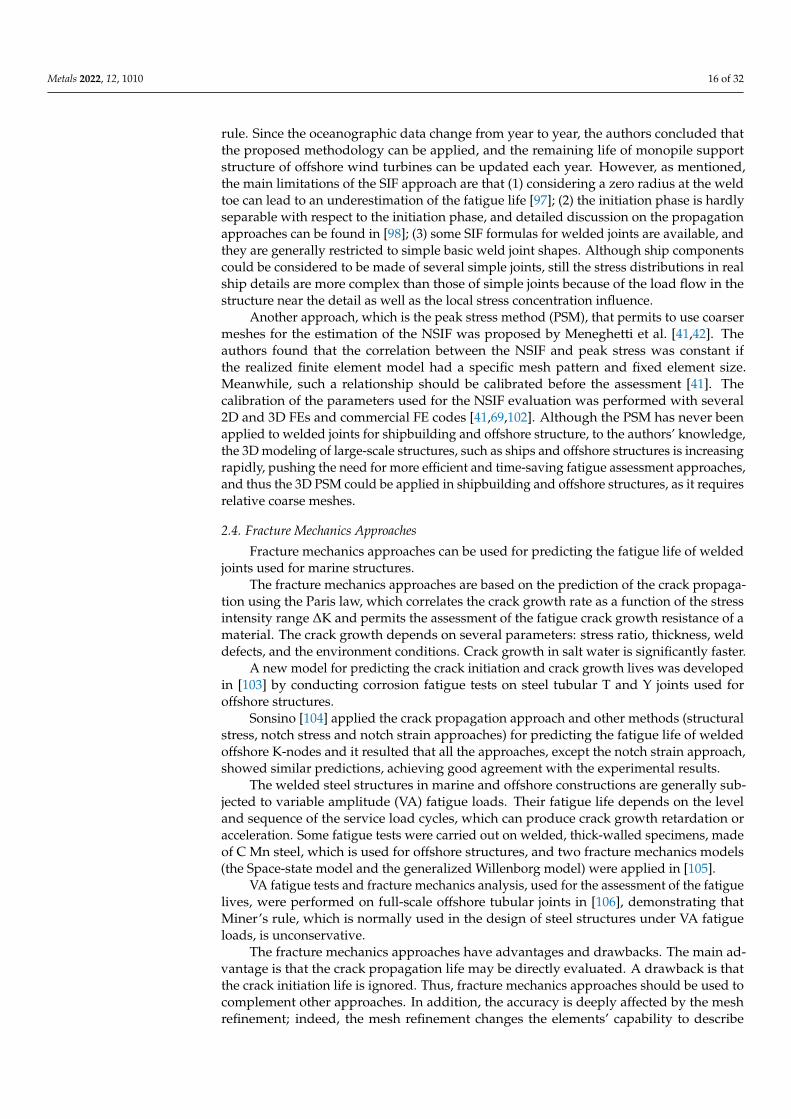
Metals 2022, 12, 1010 16 of 32
rule. Since the oceanographic data change from year to year, the authors concluded thatthe proposed methodology can be applied, and the remaining life of monopile supportstructure of offshore wind turbines can be updated each year. However, as mentioned,the main limitations of the SIF approach are that (1) considering a zero radius at the weldtoe can lead to an underestimation of the fatigue life [97]; (2) the initiation phase is hardlyseparable with respect to the initiation phase, and detailed discussion on the propagationapproaches can be found in [98]; (3) some SIF formulas for welded joints are available, andthey are generally restricted to simple basic weld joint shapes. Although ship componentscould be considered to be made of several simple joints, still the stress distributions in realship details are more complex than those of simple joints because of the load flow in thestructure near the detail as well as the local stress concentration influence.
Another approach, which is the peak stress method (PSM), that permits to use coarsermeshes for the estimation of the NSIF was proposed by Meneghetti et al. [41,42]. Theauthors found that the correlation between the NSIF and peak stress was constant ifthe realized finite element model had a specific mesh pattern and fixed element size.Meanwhile, such a relationship should be calibrated before the assessment [41]. Thecalibration of the parameters used for the NSIF evaluation was performed with several2D and 3D FEs and commercial FE codes [41,69,102]. Although the PSM has never beenapplied to welded joints for shipbuilding and offshore structure, to the authors’ knowledge,the 3D modeling of large-scale structures, such as ships and offshore structures is increasingrapidly, pushing the need for more efficient and time-saving fatigue assessment approaches,and thus the 3D PSM could be applied in shipbuilding and offshore structures, as it requiresrelative coarse meshes.
2.4. Fracture Mechanics Approaches
Fracture mechanics approaches can be used for predicting the fatigue life of weldedjoints used for marine structures.
The fracture mechanics approaches are based on the prediction of the crack propaga-tion using the Paris law, which correlates the crack growth rate as a function of the stressintensity range ∆K and permits the assessment of the fatigue crack growth resistance of amaterial. The crack growth depends on several parameters: stress ratio, thickness, welddefects, and the environment conditions. Crack growth in salt water is significantly faster.
A new model for predicting the crack initiation and crack growth lives was developedin [103] by conducting corrosion fatigue tests on steel tubular T and Y joints used foroffshore structures.
Sonsino [104] applied the crack propagation approach and other methods (structuralstress, notch stress and notch strain approaches) for predicting the fatigue life of weldedoffshore K-nodes and it resulted that all the approaches, except the notch strain approach,showed similar predictions, achieving good agreement with the experimental results.
The welded steel structures in marine and offshore constructions are generally sub-jected to variable amplitude (VA) fatigue loads. Their fatigue life depends on the leveland sequence of the service load cycles, which can produce crack growth retardation oracceleration. Some fatigue tests were carried out on welded, thick-walled specimens, madeof C Mn steel, which is used for offshore structures, and two fracture mechanics models(the Space-state model and the generalized Willenborg model) were applied in [105].
VA fatigue tests and fracture mechanics analysis, used for the assessment of the fatiguelives, were performed on full-scale offshore tubular joints in [106], demonstrating thatMiner’s rule, which is normally used in the design of steel structures under VA fatigueloads, is unconservative.
The fracture mechanics approaches have advantages and drawbacks. The main ad-vantage is that the crack propagation life may be directly evaluated. A drawback is thatthe crack initiation life is ignored. Thus, fracture mechanics approaches should be used tocomplement other approaches. In addition, the accuracy is deeply affected by the meshrefinement; indeed, the mesh refinement changes the elements’ capability to describe
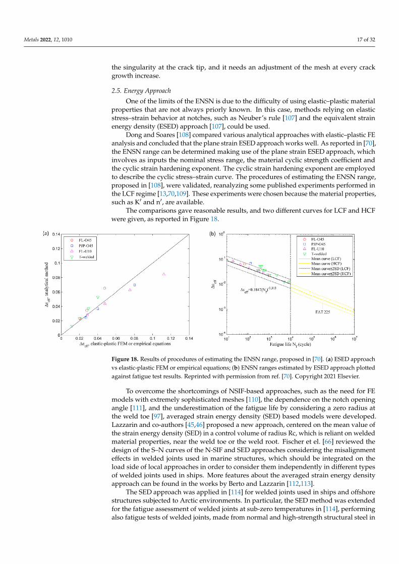
Metals 2022, 12, 1010 17 of 32
the singularity at the crack tip, and it needs an adjustment of the mesh at every crackgrowth increase.
2.5. Energy Approach
One of the limits of the ENSN is due to the difficulty of using elastic–plastic materialproperties that are not always priorly known. In this case, methods relying on elasticstress–strain behavior at notches, such as Neuber’s rule [107] and the equivalent strainenergy density (ESED) approach [107], could be used.
Dong and Soares [108] compared various analytical approaches with elastic–plastic FEanalysis and concluded that the plane strain ESED approach works well. As reported in [70],the ENSN range can be determined making use of the plane strain ESED approach, whichinvolves as inputs the nominal stress range, the material cyclic strength coefficient andthe cyclic strain hardening exponent. The cyclic strain hardening exponent are employedto describe the cyclic stress–strain curve. The procedures of estimating the ENSN range,proposed in [108], were validated, reanalyzing some published experiments performed inthe LCF regime [13,70,109]. These experiments were chosen because the material properties,such as K′ and n′, are available.
The comparisons gave reasonable results, and two different curves for LCF and HCFwere given, as reported in Figure 18.
Metals 2022, 12, x FOR PEER REVIEW 17 of 33
offshore K-nodes and it resulted that all the approaches, except the notch strain approach,
showed similar predictions, achieving good agreement with the experimental results.
The welded steel structures in marine and offshore constructions are generally sub-
jected to variable amplitude (VA) fatigue loads. Their fatigue life depends on the level and
sequence of the service load cycles, which can produce crack growth retardation or accel-
eration. Some fatigue tests were carried out on welded, thick-walled specimens, made of
C Mn steel, which is used for offshore structures, and two fracture mechanics models (the
Space-state model and the generalized Willenborg model) were applied in [105].
VA fatigue tests and fracture mechanics analysis, used for the assessment of the fa-
tigue lives, were performed on full-scale offshore tubular joints in [106], demonstrating
that Miner’s rule, which is normally used in the design of steel structures under VA fa-
tigue loads, is unconservative.
The fracture mechanics approaches have advantages and drawbacks. The main ad-
vantage is that the crack propagation life may be directly evaluated. A drawback is that
the crack initiation life is ignored. Thus, fracture mechanics approaches should be used to
complement other approaches. In addition, the accuracy is deeply affected by the mesh
refinement; indeed, the mesh refinement changes the elements’ capability to describe the
singularity at the crack tip, and it needs an adjustment of the mesh at every crack growth
increase.
2.5. Energy Approach
One of the limits of the ENSN is due to the difficulty of using elastic–plastic material
properties that are not always priorly known. In this case, methods relying on elastic
stress–strain behavior at notches, such as Neuber’s rule [107] and the equivalent strain
energy density (ESED) approach [107], could be used.
Dong and Soares [108] compared various analytical approaches with elastic–plastic
FE analysis and concluded that the plane strain ESED approach works well. As reported
in [70], the ENSN range can be determined making use of the plane strain ESED approach,
which involves as inputs the nominal stress range, the material cyclic strength coefficient
and the cyclic strain hardening exponent. The cyclic strain hardening exponent are em-
ployed to describe the cyclic stress–strain curve. The procedures of estimating the ENSN
range, proposed in [108], were validated, reanalyzing some published experiments per-
formed in the LCF regime [13,70,109]. These experiments were chosen because the mate-
rial properties, such as K′ and n′, are available.
The comparisons gave reasonable results, and two different curves for LCF and HCF
were given, as reported in Figure 18.
Figure 18. Results of procedures of estimating the ENSN range, proposed in [70]. (a) ESED ap-
proach vs elastic-plastic FEM or empirical equations; (b) ENSN ranges estimated by ESED
Figure 18. Results of procedures of estimating the ENSN range, proposed in [70]. (a) ESED approachvs elastic-plastic FEM or empirical equations; (b) ENSN ranges estimated by ESED approach plottedagainst fatigue test results. Reprinted with permission from ref. [70]. Copyright 2021 Elsevier.
To overcome the shortcomings of NSIF-based approaches, such as the need for FEmodels with extremely sophisticated meshes [110], the dependence on the notch openingangle [111], and the underestimation of the fatigue life by considering a zero radius atthe weld toe [97], averaged strain energy density (SED) based models were developed.Lazzarin and co-authors [45,46] proposed a new approach, centered on the mean value ofthe strain energy density (SED) in a control volume of radius Rc, which is reliant on weldedmaterial properties, near the weld toe or the weld root. Fischer et el. [66] reviewed thedesign of the S–N curves of the N-SIF and SED approaches considering the misalignmenteffects in welded joints used in marine structures, which should be integrated on theload side of local approaches in order to consider them independently in different typesof welded joints used in ships. More features about the averaged strain energy densityapproach can be found in the works by Berto and Lazzarin [112,113].
The SED approach was applied in [114] for welded joints used in ships and offshorestructures subjected to Arctic environments. In particular, the SED method was extendedfor the fatigue assessment of welded joints at sub-zero temperatures in [114], performingalso fatigue tests of welded joints, made from normal and high-strength structural steel in

Metals 2022, 12, 1010 18 of 32
the span of 20 ◦C to −50 ◦C. The obtained results were compared with results of studieson the SED-based assessment of notched components at high temperatures. Within thiscontext a temperature modification function for SED was proposed by the authors fordesign purposes.
2.6. Critical Distance Methods
The critical distance approaches describe failure conditions based on the hypothesisthat the failure of a structure occurs when the fatigue limit is surpassed within a regionbordering the notch (critical volume) and not in a local single point. The critical distance,according to Taylor [48], can be expressed in terms of a material length parameter, L,that is defined in terms of the plain specimen endurance limit ∆σ0 and the fatigue crackpropagation threshold ∆Kth. More details about the theory of critical distance, TCD, can befound in [115].
The critical distance method CDM was successfully applied in [49,50] for T weld jointsmade of AA5083 aluminum alloy, extensively used in ship structures. The endurancelimit was evaluated by means of the TCD, from finite element analyses (FEA), obtaininggood estimates of the fatigue strength validated by experimental data. TCD is a relativelysimple approach since it implies a perfectly elastic approach. However, like elastic fracturemechanics, it is not likely to work under general plasticity conditions, or any conditionswhich require a relatively small plastic zone compared to the nearby elastic region. Thebrittle-to-ductile transition is generally linked with a loss of constraint (plane strain toplane stress transition). Sometimes a loss of constraint can take place as the notch radiusincreases, due to the higher applied stress before fracture. In this case, the failure occursafter widespread yield and no longer matches the TCD predictions obtained for the planestrain. However, the TCD prediction can also be performed for plane stress conditions,thus the result of constraint loss should be integrated into the TCD.
Susmel [116] applied TCD along with the modified Wöhler curve method (MWCM), acritical plane approach, to estimate the fatigue life of steel and aluminum welded jointssubjected to multiaxial fatigue loading.
2.7. Thermal Methods
As reported in [117], the thermal methods [118–127], which are based on the detectionof the self-heating effect of the metallic materials subjected to fatigue loading using thethermographic technique, can be classified into several categories.
The thermographic method (TM) [118] is based on the assumption that the fatiguestrength can be evaluated as the highest stress level that produces no temperature incre-ment on the surface of a specimen subjected to fatigue loading. The TM and the energyapproach [119] permit a faster determination of the fatigue strength and the S–N curve ofmaterials and welded joints compared to traditional fatigue tests.
As reported above, the real structures are subjected to VA fatigue loads, so the quanti-tative thermographic method (QTM) [53] was developed in [117]. Then it can be appliedto marine and offshore structures, which are subjected to VA fatigue loads during theirservice lives.
The thermographic methods were applied by the authors for the fatigue assessmentof the following welded joints used in ship and offshore structures: AA5083 T-weldedjoints [50], butt-welded AH36 steel joints [30], butt-welded AH36 steel joints with differentthicknesses (from 5 to 20 mm) [15], butt-welded AH36 steel joints with defects [128], butt-welded S355 steel joints [129], AL/FE explosive welded joints [130], and Ti6Al4V/Inconel625 laser welded joints [131].

Metals 2022, 12, 1010 19 of 32
As already mentioned, the energy approach [119] allows the assessment of the S–Ncurve, and it was applied to three butt-welded AH36 steel specimens in [30]. Figure 19shows the S–N curves (survival probability PS = 50%) predicted by the energy approachand obtained in accordance with the traditional procedure for a comparison. It results thata good agreement is achieved, and the scattering of the S–N curve parameters (m, log C)predicted by the energy approach is lower than that of the traditional S–N curves [30].
Metals 2022, 12, x FOR PEER REVIEW 19 of 33
The thermographic method (TM) [118] is based on the assumption that the fatigue
strength can be evaluated as the highest stress level that produces no temperature incre-
ment on the surface of a specimen subjected to fatigue loading. The TM and the energy
approach [119] permit a faster determination of the fatigue strength and the S–N curve of
materials and welded joints compared to traditional fatigue tests.
As reported above, the real structures are subjected to VA fatigue loads, so the quan-
titative thermographic method (QTM) [53] was developed in [117]. Then it can be applied
to marine and offshore structures, which are subjected to VA fatigue loads during their
service lives.
The thermographic methods were applied by the authors for the fatigue assessment
of the following welded joints used in ship and offshore structures: AA5083 T-welded
joints [50], butt-welded AH36 steel joints [30], butt-welded AH36 steel joints with different
thicknesses (from 5 to 20 mm) [15], butt-welded AH36 steel joints with defects [128], butt-
welded S355 steel joints [129], AL/FE explosive welded joints [130], and Ti6Al4V/Inconel
625 laser welded joints [131]
As already mentioned, the energy approach [119] allows the assessment of the S–N
curve, and it was applied to three butt-welded AH36 steel specimens in [30]. Figure 19
shows the S–N curves (survival probability PS = 50%) predicted by the energy approach
and obtained in accordance with the traditional procedure for a comparison. It results that
a good agreement is achieved, and the scattering of the S–N curve parameters (m, log C)
predicted by the energy approach is lower than that of the traditional S–N curves [30].
Figure 19. S–N curves obtained by traditional and energy approaches [30]. Reprinted with permis-
sion from ref. [30]. Copyright 2021 Elsevier.
The four types of butt-welded AH36 steel joints, investigated in [128], differed for the
presence of weld defects and for thickness values. The evaluation of the defects inside the
investigated butt-welded joints was performed using 3D computed tomography (CT),
which allowed the measurements of cumulative defects volume (V) and maximum defect
size (DMAX). Figure 20 shows the CT analyses of a welded specimen.
Figure 19. S–N curves obtained by traditional and energy approaches [30]. Reprinted with permissionfrom ref. [30]. Copyright 2021 Elsevier.
The four types of butt-welded AH36 steel joints, investigated in [128], differed for thepresence of weld defects and for thickness values. The evaluation of the defects insidethe investigated butt-welded joints was performed using 3D computed tomography (CT),which allowed the measurements of cumulative defects volume (V) and maximum defectsize (DMAX). Figure 20 shows the CT analyses of a welded specimen.
The analysis of the thermographic images allowed the assessment of both the fatiguestrength of the welded joints, applying the rapid thermographic method, and the S–Ncurve by the energy approach [128].
Figures 21 and 22 show the values of the fatigue limits predicted using the energyapproach (∆σeΦTM) versus the cumulative defects volume (VN) and the maximum defectsize (DMAX,N), normalized with respect to the thickness of the welded joints.
Micone and De Waele [132] developed a methodology, based on the direct currentpotential drop (DCPD) technique, for a rapid assessment of the S–N curves of two highstrength offshore steels and compared the so-obtained S–N curves with the ones obtainedby the application of the thermographic technique, achieving a good correlation.
The thermal approaches are particularly suitable and give fast prediction for the fatiguelife of welded structures, especially the rapid thermographic method that theoreticallypredicts the entire S–N curve with only one specimen. However, at least three specimensshould be investigated to consider dispersion and to avoid that the prediction is madetotally considering one specimen that could include defects due to the welding process.The disadvantage is that these approaches are rather experimental than numerical.

Metals 2022, 12, 1010 20 of 32Metals 2022, 12, x FOR PEER REVIEW 20 of 33
Figure 20. CT results for a specimen: (a) defect evaluation; (b,c) tomograms of the cross section of
the weld bead and (d) some along X-rays of the joint. [128].
The analysis of the thermographic images allowed the assessment of both the fatigue
strength of the welded joints, applying the rapid thermographic method, and the S–N
curve by the energy approach [128].
Figures 21 and 22 show the values of the fatigue limits predicted using the energy
approach (ΔσeΦTM) versus the cumulative defects volume (VN) and the maximum defect
size (DMAX,N), normalized with respect to the thickness of the welded joints.
Figure 20. CT results for a specimen: (a) defect evaluation; (b,c) tomograms of the cross section of theweld bead and (d) some along X-rays of the joint. [128].
Metals 2022, 12, x FOR PEER REVIEW 21 of 33
Figure 21. Fatigue strength (ΔσeΦTM) vs. normalized defects cumulative volume (VN) [128].
Figure 22. Fatigue strength (ΔσeΦTM) vs. normalized maximum defect size (DMAX,N) [128].
Micone and De Waele [132] developed a methodology, based on the direct current
potential drop (DCPD) technique, for a rapid assessment of the S–N curves of two high
strength offshore steels and compared the so-obtained S–N curves with the ones obtained
by the application of the thermographic technique, achieving a good correlation.
The thermal approaches are particularly suitable and give fast prediction for the fa-
tigue life of welded structures, especially the rapid thermographic method that theoreti-
cally predicts the entire S–N curve with only one specimen. However, at least three spec-
imens should be investigated to consider dispersion and to avoid that the prediction is
made totally considering one specimen that could include defects due to the welding pro-
cess. The disadvantage is that these approaches are rather experimental than numerical.
3. Future Developments of Welded Joints in Marine Structures
Nowadays, the need for using different materials to optimize the weight and struc-
tural performance of ships and marine structures is rapidly increasing. Within this
Figure 21. Fatigue strength (∆σeΦTM) vs. normalized defects cumulative volume (VN) [128].

Metals 2022, 12, 1010 21 of 32
Metals 2022, 12, x FOR PEER REVIEW 21 of 33
Figure 21. Fatigue strength (ΔσeΦTM) vs. normalized defects cumulative volume (VN) [128].
Figure 22. Fatigue strength (ΔσeΦTM) vs. normalized maximum defect size (DMAX,N) [128].
Micone and De Waele [132] developed a methodology, based on the direct current
potential drop (DCPD) technique, for a rapid assessment of the S–N curves of two high
strength offshore steels and compared the so-obtained S–N curves with the ones obtained
by the application of the thermographic technique, achieving a good correlation.
The thermal approaches are particularly suitable and give fast prediction for the fa-
tigue life of welded structures, especially the rapid thermographic method that theoreti-
cally predicts the entire S–N curve with only one specimen. However, at least three spec-
imens should be investigated to consider dispersion and to avoid that the prediction is
made totally considering one specimen that could include defects due to the welding pro-
cess. The disadvantage is that these approaches are rather experimental than numerical.
3. Future Developments of Welded Joints in Marine Structures
Nowadays, the need for using different materials to optimize the weight and struc-
tural performance of ships and marine structures is rapidly increasing. Within this
Figure 22. Fatigue strength (∆σeΦTM) vs. normalized maximum defect size (DMAX,N) [128].
3. Future Developments of Welded Joints in Marine Structures
Nowadays, the need for using different materials to optimize the weight and structuralperformance of ships and marine structures is rapidly increasing. Within this context, thechallenge of joining different materials denotes an essential task. The prevalent type ofdissimilar welded joints employed for shipbuilding and offshore applications is representedby the Al/Steel type joint (Figure 23).
Metals 2022, 12, x FOR PEER REVIEW 22 of 33
context, the challenge of joining different materials denotes an essential task. The preva-
lent type of dissimilar welded joints employed for shipbuilding and offshore applications
is represented by the Al/Steel type joint (Figure 23).
Figure 23. Example of an Al/Steel EW joint in shipbuilding.
An example of steel hull to Al superstructure connection is shown in Figure 24, where
bimetallic strips were used between the boat’s hull and upper section [133] in order to
weld the steel hull side on the to the steel side and the aluminum upper section to the al
side of the bimetallic joint.
Figure 24. Welding steel hull to Al superstructure [134]. Accessed date 26 February 2022.
Iron has low solubility in solid aluminum and forms a eutectic with aluminum. More-
over, aluminum is a decent deoxidizer and is employed in reduced amounts in iron-based
alloys. Thus, the traditional fusion welding of aluminum and iron-based alloys represents
a technologically and science-intensive task. Still, using laser welding or welding–brazing,
proper joints that meet the requests can be obtained. The mechanical properties of this
kind of joints can reach a level of 70% of the utilized aluminum alloy [135]. Some studies
Figure 23. Example of an Al/Steel EW joint in shipbuilding.
An example of steel hull to Al superstructure connection is shown in Figure 24, wherebimetallic strips were used between the boat’s hull and upper section [133] in order to weldthe steel hull side on the to the steel side and the aluminum upper section to the al side ofthe bimetallic joint.
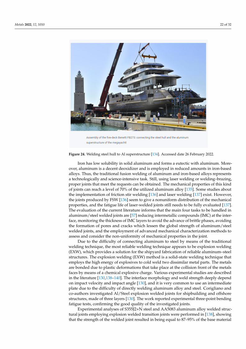
Metals 2022, 12, 1010 22 of 32
Metals 2022, 12, x FOR PEER REVIEW 22 of 33
context, the challenge of joining different materials denotes an essential task. The preva-
lent type of dissimilar welded joints employed for shipbuilding and offshore applications
is represented by the Al/Steel type joint (Figure 23).
Figure 23. Example of an Al/Steel EW joint in shipbuilding.
An example of steel hull to Al superstructure connection is shown in Figure 24, where
bimetallic strips were used between the boat’s hull and upper section [133] in order to
weld the steel hull side on the to the steel side and the aluminum upper section to the al
side of the bimetallic joint.
Figure 24. Welding steel hull to Al superstructure [134]. Accessed date 26 February 2022.
Iron has low solubility in solid aluminum and forms a eutectic with aluminum. More-
over, aluminum is a decent deoxidizer and is employed in reduced amounts in iron-based
alloys. Thus, the traditional fusion welding of aluminum and iron-based alloys represents
a technologically and science-intensive task. Still, using laser welding or welding–brazing,
proper joints that meet the requests can be obtained. The mechanical properties of this
kind of joints can reach a level of 70% of the utilized aluminum alloy [135]. Some studies
Figure 24. Welding steel hull to Al superstructure [134]. Accessed date 26 February 2022.
Iron has low solubility in solid aluminum and forms a eutectic with aluminum. More-over, aluminum is a decent deoxidizer and is employed in reduced amounts in iron-basedalloys. Thus, the traditional fusion welding of aluminum and iron-based alloys representsa technologically and science-intensive task. Still, using laser welding or welding–brazing,proper joints that meet the requests can be obtained. The mechanical properties of this kindof joints can reach a level of 70% of the utilized aluminum alloy [135]. Some studies aboutthe implementation of friction stir welding [136] and laser welding [137] exist. However,the joints produced by FSW [136] seem to give a nonuniform distribution of the mechanicalproperties, and the fatigue life of laser-welded joints still needs to be fully evaluated [137].The evaluation of the current literature informs that the main four tasks to be handled inaluminum/steel welded joints are [57] reducing intermetallic compounds (IMC) at the inter-face, monitoring the thickness of IMC layers to avoid the advance of brittle phases, avoidingthe formation of pores and cracks which lessen the global strength of aluminum/steelwelded joints, and the employment of advanced mechanical characterization methods toassess and consider the non-uniformity of mechanical properties in the joint.
Due to the difficulty of connecting aluminum to steel by means of the traditionalwelding technique, the most reliable welding technique appears to be explosion welding(EXW), which provides a solution for the shipyard fabrication of reliable aluminum–steelstructures. The explosion welding (EXW) method is a solid-state welding technique thatemploys the high energy of explosives to cold weld two dissimilar metal parts. The metalsare bonded due to plastic deformations that take place at the collision front of the metalsfaces by means of a chemical explosive charge. Various experimental studies are describedin the literature [130,138–140]. The interface morphology and weld strength deeply dependon impact velocity and impact angle [130], and it is very common to use an intermediateplate due to the difficulty of directly welding aluminum alloy and steel. Corigliano andco-authors investigated Al/Steel explosion welded joints for shipbuilding and offshorestructures, made of three layers [130]. The work reported experimental three-point bendingfatigue tests, confirming the good quality of the investigated joints.
Experimental analyses of S355J2+N steel and AA5083 aluminum alloy welded struc-tural joints employing explosion welded transition joints were performed in [138], showingthat the strength of the welded joint resulted in being equal to 87–95% of the base material
Metals 2022, 12, 1010 23 of 32
(AA5083) strength; furthermore, rupture never occurred in the explosion welded joint butonly in correspondence of the Al/Al welded zone, confirming once again the reliability ofthe EXW transition joints. However, it should be highlighted that a higher thickness of theEXW transition joints was used for the experiments, according to the recommendations ofthe major classification societies and clad producers.
When other properties, such as higher fatigue and static strength [141], enhancedcorrosion resistance [142,143] and weight reduction, are needed for offshore and oil andgas structures [141], further materials are used in marine environments [144,145]. Forinstance, titanium alloys, stainless steel alloys and Inconel alloys might be used in thesame circumstance to minimize the weight and improve the tensile and corrosion resistantproperties [146,147].
The direct welding of Ti and Ni alloys produces various problems: the development offragile compounds, high residual stresses, and segregation. The characteristic of the weldedjoints is greatly influenced by the development of brittle intermetallic phases, cracks andporosities. Furthermore, due to the variation in terms of thermal expansion coefficientbetween the two alloys, high residual stresses are produced during the welding process,which can decrease the fatigue performance of the joint. Further problems arise because ofthe different density and diffusivity, which imply a strong inhomogeneity of the joint.
Due to the above-mentioned difficulties to weld these kinds of dissimilar materials,only a few studies exist, to the authors’ knowledge [131,148]; principally, Stainless steel-Inconel 625 joints [149] and Superduplex Stainless Steel/HSLA Steel [150,151] joints are cur-rently applied for the offshore and oil and gas industries. A new Inconel 625/Ti6Al4Vlaserwelded joint was investigated by Corigliano and Crupi in [131] who evaluated the fatiguestrength and applied the TM. A new solution was proposed in order to avoid the problemof joining these two alloys and to achieve better weld quality: intermediate layers of vana-dium and stainless steel were used. The fatigue strength assessed experimentally provedthe good quality of the investigated joints and was in good agreement with the valuepredicted by the TM. The value of the fatigue strength obtained is particularly promising,considering that it is even higher than the tensile strength achieved during static testsin [148].
New oil and gas exploration areas have pushed to further hostile environments, i.e.,very deep-water offshore reservoirs, which require the growth of new technologies toguarantee safe and reliable operations. Within this context, the reel-lay method lookslike an efficient technique employed for the installation of subsea pipelines and risers.The main advantage is given by the possibility of onshore welding and inspection ofthe pipeline, which permit high quality welded joints compared to traditional layingtechniques. In addition, a better solution toward the corrosion resistant behavior can betaken. In particular, the use of clad and lined C-Mn steel pipelines, including X65 andX70 grade steels, with a thin interlayer of corrosion resistant alloy (CRA), is becomingfrequently adopted to assure the essential resistance against corrosion [152].
Dissimilar welded joints are often employed in offshore nuclear power plants, with oneor more nuclear reactors that can be positioned on a platform at sea [153]. The world’s firstfloating nuclear power plant was built at the Baltiysky Zavod shipyard in Saint Petersburg.It is an independent site that can supply electricity and heat to zones with difficult accessand, thanks to sea water that absorbs the movements of the sea floor, safeguards the plantfrom earthquakes and tsunamis [154]. As reported in [155], the main building materials oflight water reactors (LWR) are low alloy steels, stainless steels and nickel-base alloys (basematerials as well as weld metals). The reactor pressure vessel (RPV) or a boiling waterreactor (BWR is made of low alloy steel. The inside surface is combined with stainless steelto avoid corrosion.
Another future perspective of the welding is related to autonomous systems for ship-building and offshore industry, which would allow to have faster construction time. Withinthis context, industrial robots are projected to replace labor efforts in actual manufactur-ing and can be seen as the technical form of smart shipbuilding. However, most of the
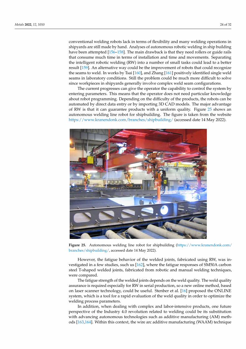
Metals 2022, 12, 1010 24 of 32
conventional welding robots lack in terms of flexibility and many welding operations inshipyards are still made by hand. Analyses of autonomous robotic welding in ship buildinghave been attempted [156–158]. The main drawback is that they need rollers or guide railsthat consume much time in terms of installation and time and movements. Separatingthe intelligent robotic welding (RW) into a number of small tasks could lead to a betterresult [159]. An alternative way could be the improvement of robots that could recognizethe seams to weld. In works by Tsai [160], and Zhang [161] positively identified single weldseams in laboratory conditions. Still the problem could be much more difficult to solvesince workpieces in shipyards generally involve complex weld seam configurations.
The current progresses can give the operator the capability to control the system byentering parameters. This means that the operator does not need particular knowledgeabout robot programming. Depending on the difficulty of the products, the robots can beautomated by direct data entry or by importing 3D CAD models. The major advantageof RW is that it can guarantee products with a uniform quality. Figure 25 shows anautonomous welding line robot for shipbuilding. The figure is taken from the websitehttps://www.kranendonk.com/branches/shipbuilding/ (accessed date 14 May 2022).
Metals 2022, 12, x FOR PEER REVIEW 25 of 33
Figure 25. Autonomous welding line robot for shipbuilding
(https://www.kranendonk.com/branches/shipbuilding/, accessed date 14 May 2022.)
However, the fatigue behavior of the welded joints, fabricated using RW, was inves-
tigated in a few studies, such us [162], where the fatigue responses of SM50A carbon steel
T-shaped welded joints, fabricated from robotic and manual welding techniques, were
compared.
The fatigue strength of the welded joints depends on the weld quality. The weld
quality assurance is required especially for RW in serial production, so a new online
method, based on laser scanner technology, could be useful. Stenber et al. [16] proposed
the ONLINE system, which is a tool for a rapid evaluation of the weld quality in order to
optimize the welding process parameters.
In addition, when dealing with complex and labor-intensive products, one future
perspective of the Industry 4.0 revolution related to welding could be its substitution with
advancing autonomous technologies such as additive manufacturing (AM) methods
[163,164]. Within this context, the wire arc additive manufacturing (WAAM) technique
has shown some potential application in shipbuilding and the marine industry for the
production of large-scale metal components, particularly for complicated double-curved
parts. The use of WAAM technology for the manufacturing of ships parts such as a bulb-
ous bow, ruder and ship propeller, were analyzed and proposed in [163]. Recently, a 3D
printed ship’s propeller, manufactured with the use of the WAAM technology, known as
the ‘‘WAAMpeller’’, was produced in the Netherlands by a group of companies that in-
cludes Damen Shipyards Group, RAMLAB, Promarin, Autodesk, and Bureau Veritas, as
reported in the website www.portofrotterdam.com/en/news-and-press-releases/ramlab-
develops-first-3d-printed-marine-propeller (accessed date 14 May 2022).
A functionally graded material (FGM) consisting of carbon–manganese steel and du-
plex stainless steel, fabricated by WAAM for marine risers, was investigated in [165].
Laminated metal composites (LMCs), consisting of multiple bilayers of alternating
layers of ductile and high-strength steel, processed by WAAM using a computer code
guided welding robot, were investigated in [166]. The WAAM LMCs, produced by RW,
could be applied also in the marine industry.
Figure 25. Autonomous welding line robot for shipbuilding (https://www.kranendonk.com/branches/shipbuilding/, accessed date 14 May 2022).
However, the fatigue behavior of the welded joints, fabricated using RW, was in-vestigated in a few studies, such us [162], where the fatigue responses of SM50A carbonsteel T-shaped welded joints, fabricated from robotic and manual welding techniques,were compared.
The fatigue strength of the welded joints depends on the weld quality. The weld qualityassurance is required especially for RW in serial production, so a new online method, basedon laser scanner technology, could be useful. Stenber et al. [16] proposed the ONLINEsystem, which is a tool for a rapid evaluation of the weld quality in order to optimize thewelding process parameters.
In addition, when dealing with complex and labor-intensive products, one futureperspective of the Industry 4.0 revolution related to welding could be its substitutionwith advancing autonomous technologies such as additive manufacturing (AM) meth-ods [163,164]. Within this context, the wire arc additive manufacturing (WAAM) technique

Metals 2022, 12, 1010 25 of 32
has shown some potential application in shipbuilding and the marine industry for theproduction of large-scale metal components, particularly for complicated double-curvedparts. The use of WAAM technology for the manufacturing of ships parts such as a bul-bous bow, ruder and ship propeller, were analyzed and proposed in [163]. Recently, a3D printed ship’s propeller, manufactured with the use of the WAAM technology, knownas the “WAAMpeller”, was produced in the Netherlands by a group of companies thatincludes Damen Shipyards Group, RAMLAB, Promarin, Autodesk, and Bureau Veritas, asreported in the website www.portofrotterdam.com/en/news-and-press-releases/ramlab-develops-first-3d-printed-marine-propeller (accessed date 14 May 2022).
A functionally graded material (FGM) consisting of carbon–manganese steel andduplex stainless steel, fabricated by WAAM for marine risers, was investigated in [165].
Laminated metal composites (LMCs), consisting of multiple bilayers of alternatinglayers of ductile and high-strength steel, processed by WAAM using a computer codeguided welding robot, were investigated in [166]. The WAAM LMCs, produced by RW,could be applied also in the marine industry.
4. Conclusions
There are several approaches in the fatigue design framework of steel and aluminumalloys welded structures. They are generally classified as nominal, structural, local andfracture mechanics approaches.
The traditional approaches, based on nominal and hot spot stresses, are conservative.The local approaches give more accurate results but require FE models with accurate andfine mesh. Some local approaches, proposed and applied in the technical literature, arebased on local quantities, such as stress (NSIF, PSM), strain energy (SED), critical distance(CDM), and temperature (TM).
The fatigue analysis of ship and offshore welded structures is a complex task becausetheir fatigue strength and durability depend on several parameters (local geometricaldiscontinuity, service loadings, environmental conditions, thickness plate, manufacturingprocess, residual stresses, defects, and materials properties), so the choice of the fatigueassessment approach depends on the specific application. The review of the differentfatigue assessment approaches allows to obtain new insights in order to select the approachthat is more suitable for a specific application, aiming to extend the service life of ship andoffshore welded structures subjected to fatigue loadings.
A first distinction should be done between the fatigue analysis of the welded joints,such as the ones reported in the current standards, and the large welded structures.
The first issue of this study is the critical analysis of the current codes on the fatiguedesign of welded structures, which are accepted by some of the major Ship ClassificationSocieties and based on the nominal stress approach. The current codes report the S–Ncurves of the different fatigue class of the welded joints; this weld classification is basednot only on the geometry of the joint but depends also on the dominant loading mode.The codes are based on the assumption that the S–N curves of welded joints with differentgeometries have about the same slope for a specific material. It was demonstrated that thecodes are very conservative, and that the TM can give reliable and fast predictions of thefatigue life and strength of the welded joints, reported in the current codes or others. Thisapproach is able to take into account the weld quality and the presence of defects, unlikethe codes.
Moreover, the nominal stresses are not always easy to be evaluated in the real weldedstructures with complex geometries, so other fatigue approaches are required.
An interesting approach for HCF life predictions is the PSM. Although, the PSMhas never been applied to welded joints for shipbuilding and offshore structure, to theauthors’ knowledge, the 3D modeling of large-scale structures, such as ships and offshorestructures, is increasing rapidly, pushing the need for more efficient and time-saving fatigueassessment approaches, thus the 3D PSM could be applied in shipbuilding and offshorestructures, as it requires relative coarse meshes in FEA.

Metals 2022, 12, 1010 26 of 32
Some fatigue cracks have been detected in ship welded structures within a few yearsof their service life; their fatigue life cannot be adequately predicted by the HCF approaches,but LCF approaches are required. The most suitable approaches for LCF life predictionsare the effective notch strain approach, that requires that the elastic–plastic material curvesare priorly known, and the equivalent structural strain approach, that presents the sameadvantages of the equivalent structural stress method and can be applied using linearFE models if controlled displacement tests are performed. In addition, being that theequivalent structural stress/strain approaches are mesh insensitive, could be easily appliedfor large-scale structures and not only in simple welded ship details or specimens.
If the fatigue cracks have reached a significant length, which can be measured by NDT,the crack initiation phase can be neglected, and the fracture mechanics approaches couldbe applied for predicting the crack propagation and the fatigue life of the weld.
The fatigue assessment of welded joints becomes more complex when variable am-plitude fatigue loadings and multiaxial stress state occur, and the multiaxial fatigue lifeprediction under VAL remains an open issue. Reliable predictions could be obtainedfor these loading conditions, using some fatigue approaches, such as TCD, QTM andenergy approaches.
A critical plane approach was applied along with TCD to estimate the multiaxialfatigue life of steel and aluminum welded joints.
The marine and offshore welded structures are generally subjected to VA fatigue loadsduring their service lives. The current codes suggest the Palmgren–Miner linear damagesummation rule for predicting their residual fatigue life, but this rule does not consider theloading sequence effect. Thus, the QTM was developed in order to consider the nonlineardamage accumulation under VAL and the fatigue loading sequence effect for predictingthe VAL fatigue life.
The need for using different materials to optimize weight and structural performanceof ships and marine structures is rapidly increasing. Within this context, the challengeof joining different materials denotes an essential task, and several dissimilar weldingtechnologies are being performed. The most used type of dissimilar welded joints isnowadays represented by the Al/Steel type. Due to the difficulty of connecting aluminumto steel by means of the traditional welding technique, the most reliable welding techniqueappears to be explosion welding (EXW). Other properties, such as higher fatigue and staticstrength enhanced corrosion resistance weight reduction, are needed for offshore and oiland gas structures. The research is continuously progressing in this direction, and somepotential solutions to weld light- corrosion-resistant and high strength materials are startingto be individuated.
At last, the use of autonomous welding robots denotes a new frontier in marinewelded structures, although important progress should still be made before they can beimplemented by most industries.
In conclusion, the welded joints should be designed with an adequate weld qualityaccording to the concept “weld for purpose”.
Author Contributions: Conceptualization, V.C. and P.C.; writing—original draft preparation, V.C.and P.C.; writing—review and editing, V.C. and P.C.; visualization, V.C. and P.C.; supervision, V.C.and P.C. All authors have read and agreed to the published version of the manuscript.
Funding: This research received no external funding.
Conflicts of Interest: The authors declare no conflict of interest.
References1. Hirdaris, S.E.; Bai, W.; Dessi, D.; Ergin, A.; Gu, X.; Hermundstad, O.A.; Huijsmans, R.; Iijima, K.; Nielsen, U.D.; Parunov, J.; et al.
Loads for Use in the Design of Ships and Offshore Structures. Ocean Eng. 2014, 78, 131–174. [CrossRef]2. Erny, C.; Thevenet, D.; Cognard, J.Y.; Körner, M. Fatigue Life Prediction of Welded Ship Details. Mar. Struct. 2012, 25, 13–32.
[CrossRef]
Metals 2022, 12, 1010 27 of 32
3. Amirafshari, P.; Barltrop, N.; Wright, M.; Kolios, A. Weld Defect Frequency, Size Statistics and Probabilistic Models for ShipStructures. Int. J. Fatigue 2021, 145, 106069. [CrossRef]
4. Tveiten, B.W.; Moan, T. Determination of Structural Stress for Fatigue Assessment of Welded Aluminum Ship Details. Mar. Struct.2000, 13, 189–212. [CrossRef]
5. Mei, X.; Xiong, M. Effects of Second-Order Hydrodynamics on the Dynamic Responses and Fatigue Damage of a 15 MW FloatingOffshore Wind Turbine. J. Mar. Sci. Eng. 2021, 9, 1232. [CrossRef]
6. Syed Ahmad, S.Z.A.; Abu Husain, M.K.; Mohd Zaki, N.I.; Mukhlas, N.A.; Mat Soom, E.; Azman, N.U.; Najafian, G. OffshoreStructural Reliability Assessment by Probabilistic Procedures—A Review. J. Mar. Sci. Eng. 2021, 9, 998. [CrossRef]
7. Jimenez-Martinez, M. Fatigue of Offshore Structures: A Review of Statistical Fatigue Damage Assessment for Stochastic Loadings.Int. J. Fatigue 2020, 132, 105327. [CrossRef]
8. Pinheiro, B.d.C.; Pasqualino, I.P. Fatigue Analysis of Damaged Steel Pipelines under Cyclic Internal Pressure. Int. J. Fatigue 2009,31, 962–973. [CrossRef]
9. Yang, Q.; Li, G.; Mu, W.; Liu, G.; Sun, H. Identification of Crack Length and Angle at the Center Weld Seam of Offshore PlatformsUsing a Neural Network Approach. J. Mar. Sci. Eng. 2020, 8, 40. [CrossRef]
10. Saini, D.S.; Karmakar, D.; Ray-Chaudhuri, S. A Review of Stress Concentration Factors in Tubular and Non-Tubular Joints forDesign of Offshore Installations. J. Ocean Eng. Sci. 2016, 1, 186–202. [CrossRef]
11. Adedipe, O.; Brennan, F.; Kolios, A. Review of Corrosion Fatigue in Offshore Structures: Present Status and Challenges in theOffshore Wind Sector. Renew. Sustain. Energy Rev. 2016, 61, 141–154. [CrossRef]
12. Albiez, M.; Damm, J.; Ummenhofer, T.; Ehard, H.; Schuler, C.; Kaufmann, M.; Vallée, T.; Myslicki, S. Hybrid Joining of JacketStructures for Offshore Wind Turbines—Validation under Static and Dynamic Loading at Medium and Large Scale. Eng. Struct.2022, 252, 112412. [CrossRef]
13. Corigliano, P.; Crupi, V.; Fricke, W.; Friedrich, N.; Guglielmino, E. Experimental and Numerical Analysis of Fillet-Welded Jointsunder Low-Cycle Fatigue Loading by Means of Full-Field Techniques. Proc. Inst. Mech. Eng. Part C J. Mech. Eng. Sci. 2015,229, 1327–1338. [CrossRef]
14. Schumacher, A.; Borges, L.C.; Nussbaumer, A. A Critical Examination of the Size Effect Correction for Welded Steel TubularJoints. Int. J. Fatigue 2009, 31, 1422–1433. [CrossRef]
15. Crupi, V.; Guglielmino, E.; Maestro, M.; Marinò, A. Thinness Effect on the Fatigue Strength of AH36 Steel Plates Used inShipbuilding. In Proceedings of the NAV 2009, 16th International Conference on Ship and Shipping Research, Messina, Italy, 25November 2009; pp. 189–197.
16. Stenberg, T.; Barsoum, Z.; Åstrand, E.; Öberg, A.E.; Schneider, C.; Hedegård, J. Quality Control and Assurance in Fabrication ofWelded Structures Subjected to Fatigue Loading. Weld. World 2017, 61, 1003–1015. [CrossRef]
17. Jonsson, B.; Dobmann, G.; Hobbacher, A.F.; Kassner, M.; Marquis, G. IIW Guidelines on Weld Quality in Relationship to FatigueStrength; Springer International Publishing: Cham, Switzerland, 2016; ISBN 978-3-319-19197-3.
18. Amirafshari, P.; Barltrop, N.; Bharadwaj, U.; Wright, M.; Oterkus, S. A Review of Nondestructive Examination Methods forNew-Building Ships Undergoing Classification Society Survey. J. Ship Prod. Des. 2017, 34, 9–19. [CrossRef]
19. Madi, Y.; Matheron, P.; Recho, N.; Mongabure, P. Low Cycle Fatigue of Welded Joints: New Experimental Approach. Nucl. Eng.Des. 2004, 228, 161–177. [CrossRef]
20. Yan, X.; Huang, X.; Huang, Y.; Cui, W. Prediction of Fatigue Crack Growth in a Ship Detail under Wave-Induced Loading. OceanEng. 2016, 113, 246–254. [CrossRef]
21. Böhm, M.; Kowalski, M. Fatigue Life Estimation of Explosive Cladded Transition Joints with the Use of the Spectral Method forthe Case of a Random Sea State. Mar. Struct. 2020, 71, 102739. [CrossRef]
22. Osawa, N.; De Gracia, L.; Iijima, K.; Yamamoto, N.; Matsumoto, K. Study on Fatigue Strength of Welded Joints Subject toIntermittently Whipping Superimposed Wave Load. In Lecture Notes in Civil Engineering; Springer: Singapore, 2021; Volume 64,pp. 454–472, ISBN 9789811546716.
23. Woloszyk, K.; Garbatov, Y.; Kłosowski, P. Stress–Strain Model of Lower Corroded Steel Plates of Normal Strength for Fitness-for-Purpose Analyses. Constr. Build. Mater. 2022, 323, 126560. [CrossRef]
24. Garbatov, Y.; Guedes Soares, C.; Parunov, J. Fatigue Strength Experiments of Corroded Small Scale Steel Specimens. Int. J. Fatigue2014, 59, 137–144. [CrossRef]
25. Braun, M.; Ehlers, S. Review of Methods for the High-Cycle Fatigue Strength Assessment of Steel Structures Subjected to Sub-ZeroTemperature. Mar. Struct. 2022, 82, 103153. [CrossRef]
26. Hobbacher, A. Fatigue Design of Welded Joints and Components; Woodhead Publishing: Sawston, UK, 1996; ISBN 1855733153.27. Hobbacher, A. Recommendations for fatigue design of welded joints and components; IIW document IIW-1823-07 ex XIII-2151r4-07/XV-
1254r4-07; doc. XIII-2151r4-07/XV-1254r4-07; International Institute of Welding: Paris, France, 2008.28. EN 1993-1-9; Eurocode 3: Design of Steel Structures—Part 1–9: Fatigue. CEN: Brussels, Belgium, 2005.29. EN 1999-1-3; Eurocode 9: Design of Aluminium Structures—Part 1–3: Structures Susceptible to Fatigue. CEN: Brussels,
Belgium, 2011.30. Crupi, V.; Guglielmino, E.; Maestro, M.; Marinò, A. Fatigue Analysis of Butt Welded AH36 Steel Joints: Thermographic Method
and Design S-N Curve. Mar. Struct. 2009, 22, 373–386. [CrossRef]
Metals 2022, 12, 1010 28 of 32
31. Fricke, W.; Cui, W.; Kierkegaard, H.; Kihl, D.; Koval, M.; Mikkola, T.; Parmentier, G.; Toyosada, M.; Yoon, J.H. ComparativeFatigue Strength Assessment of a Structural Detail in a Containership Using Various Approaches of Classification Societies. Mar.Struct. 2002, 15, 1–13. [CrossRef]
32. Fricke, W. Recent Developments and Future Challenges in Fatigue Strength Assessment of Welded Joints. Proc. Inst. Mech. Eng.Part C: J. Mech. Eng. Sci. 2015, 229, 1224–1239. [CrossRef]
33. Radaj, D.; Sonsino, C.M.; Fricke, W. Recent Developments in Local Concepts of Fatigue Assessment of Welded Joints. Int. J.Fatigue 2009, 31, 2–11. [CrossRef]
34. Dong, P.; Pei, X.; Xing, S.; Kim, M.H. A Structural Strain Method for Low-Cycle Fatigue Evaluation of Welded Components. Int. J.Press. Vessel. Pip. 2014, 119, 39–51. [CrossRef]
35. Pei, X.; Dong, P. An Analytically Formulated Structural Strain Method for Fatigue Evaluation of Welded Components Incorporat-ing Nonlinear Hardening Effects. Fatigue Fract. Eng. Mater. Struct. 2019, 42, 239–255. [CrossRef]
36. Han, Q.; Wang, P.; Lu, Y. Path-dependent Multiaxial Fatigue Prediction of Welded Joints Using Structural Strain Method. FatigueFract. Eng. Mater. Struct. 2021, 44, 2800–2826. [CrossRef]
37. Lazzarin, P.; Tovo, R. A Notch Intensity Factor Approach to the Stress Analysis of Welds. Fatigue Fract. Eng. Mater. Struct. 1998,21, 1089–1103. [CrossRef]
38. Atzori, B.; Lazzarin, P.; Meneghetti, G.; Ricotta, M. Fatigue Design of Complex Welded Structures. Int. J. Fatigue 2009, 31, 59–69.[CrossRef]
39. Saiprasertkit, K. Fatigue Strength Assessment of Load-Carrying Cruciform Joints in Low- and High-Cycle Fatigue Region Basedon Effective Notch Strain Concept. Weld. World 2014, 58, 455–467. [CrossRef]
40. Saiprasertkit, K.; Hanji, T.; Miki, C. Local Strain Estimation Method for Low- and High-Cycle Fatigue Strength Evaluation. Int. J.Fatigue 2012, 40, 1–6. [CrossRef]
41. Meneghetti, G.; Lazzarin, P. Significance of the Elastic Peak Stress Evaluated by FE Analyses at the Point of Singularity of SharpV-Notched Components. Fatigue Fract. Eng. Mater. Struct. 2007, 30, 95–106. [CrossRef]
42. Meneghetti, G.; Guzzella, C. The Peak Stress Method to Estimate the Mode I Notch Stress Intensity Factor in Welded Joints UsingThree-Dimensional Finite Element Models. Eng. Fract. Mech. 2014, 115, 154–171. [CrossRef]
43. Chapetti, M.D.; Jaureguizahar, L.F. Fatigue Behavior Prediction of Welded Joints by Using an Integrated Fracture MechanicsApproach. Int. J. Fatigue 2012, 43, 43–53. [CrossRef]
44. Zerbst, U.; Madia, M. Fracture Mechanics Based Assessment of the Fatigue Strength: Approach for the Determination of theInitial Crack Size. Fatigue Fract. Eng. Mater. Struct. 2015, 38, 1066–1075. [CrossRef]
45. Lazzarin, P.; Zambardi, R. A Finite-Volume-Energy Based Approach to Predict the Static and Fatigue Behavior of Componentswith Sharp V-Shaped Notches. Int. J. Fract. 2001, 112, 275–298. [CrossRef]
46. Livieri, P.; Lazzarin, P. Fatigue Strength of Steel and Aluminium Welded Joints Based on Generalised Stress Intensity Factors andLocal Strain Energy Values. Int. J. Fract. 2005, 133, 247–276. [CrossRef]
47. Taylor, D.; Barrett, N.; Lucano, G. Some New Methods for Predicting Fatigue in Welded Joints. Int. J. Fatigue 2002, 24, 509–518.[CrossRef]
48. Taylor, D. The Theory of Critical Distances: A New Perspective in Fracture Mechanics; Elsevier: Amsterdam, The Netherlands, 2007;ISBN 9780080554723.
49. Crupi, G.; Crupi, V.; Guglielmino, E.; Taylor, D. Fatigue Assessment of Welded Joints Using Critical Distance and Other Methods.Eng. Fail. Anal. 2005, 12, 129–142. [CrossRef]
50. Crupi, V.; Guglielmino, E.; Risitano, A.; Taylor, D. Different Methods for Fatigue Assessment of T Welded Joints Used in ShipStructures. J. Ship Res. 2007, 51, 150–159. [CrossRef]
51. Fan, J.L.; Guo, X.L.; Wu, C.W.; Zhao, Y.G. Research on Fatigue Behavior Evaluation and Fatigue Fracture Mechanisms of CruciformWelded Joints. Mater. Sci. Eng. A 2011, 528, 8417–8427. [CrossRef]
52. Williams, P.; Liakat, M.; Khonsari, M.M.; Kabir, O.M. A Thermographic Method for Remaining Fatigue Life Prediction of WeldedJoints. Mater. Des. 2013, 51, 916–923. [CrossRef]
53. Wang, X.G.; Crupi, V.; Jiang, C.; Guglielmino, E. Quantitative Thermographic Methodology for Fatigue Life Assessment in aMultiscale Energy Dissipation Framework. Int. J. Fatigue 2015, 81, 249–256. [CrossRef]
54. Wei, W.; Li, C.; Sun, Y.; Xu, H.; Yang, X. Investigation of the Self-Heating of Q460 Butt Joints and an S-N Curve Modeling MethodBased on Infrared Thermographic Data for High-Cycle Fatigue. Metals 2021, 11, 232. [CrossRef]
55. Palumbo, D.; Galietti, U. Characterisation of Steel Welded Joints by Infrared Thermographic Methods. Quant. InfraRed Thermogr.J. 2014, 11, 29–42. [CrossRef]
56. Al Zamzami, I.; Davison, B.; Susmel, L. Nominal and Local Stress Quantities to Design Aluminium-to-Steel Thin Welded Jointsagainst Fatigue. Int. J. Fatigue 2019, 123, 279–295. [CrossRef]
57. Al Zamzami, I.; Di Cocco, V.; Davison, J.B.; Iacoviello, F.; Susmel, L. Static Strength and Design of Aluminium-to-Steel ThinWelded Joints. Weld. World 2018, 62, 1255–1272. [CrossRef]
58. Shen, W.; Yan, R.; He, F.; Wang, S. Multiaxial Fatigue Analysis of Complex Welded Joints in Notch Stress Approach. Eng. Fract.Mech. 2018, 204, 344–360. [CrossRef]
59. Sonsino, C.M.; Radaj, D.; Brandt, U.; Lehrke, H.P. Fatigue Assessment of Welded Joints in AlMg 4.5Mn Aluminum Alloy (AA5083) by Local Approaches. Int. J. Fatigue 1999, 21, 985–999. [CrossRef]
Metals 2022, 12, 1010 29 of 32
60. Multiaxial Notch Fatigue. Aircr. Eng. Aerosp. Technol. 2009, 81, 24–31. [CrossRef]61. Al Zamzami, I.; Susmel, L. On the Use of Hot-Spot Stresses, Effective Notch Stresses and the Point Method to Estimate Lifetime of
Inclined Welds Subjected to Uniaxial Fatigue Loading. Int. J. Fatigue 2018, 117, 432–449. [CrossRef]62. Wang, P.; Pei, X.; Dong, P.; Song, S. Traction Structural Stress Analysis of Fatigue Behaviors of Rib-to-Deck Joints in Orthotropic
Bridge Deck. Int. J. Fatigue 2019, 125, 11–22. [CrossRef]63. Dong, P. A Structural Stress Definition and Numerical Implementation for Fatigue Analysis of Welded Joints. Int. J. Fatigue 2001,
23, 865–876. [CrossRef]64. Pei, X.; Dong, P.; Kim, M.H. A Simplified Structural Strain Method for Low-Cycle Fatigue Evaluation of Girth-Welded Pipe
Components. Int. J. Fatigue 2020, 139, 105732. [CrossRef]65. Pei, X.; Dong, P.; Xing, S. A Structural Strain Parameter for a Unified Treatment of Fatigue Behaviors of Welded Components. Int.
J. Fatigue 2019, 124, 444–460. [CrossRef]66. Fischer, C.; Fricke, W.; Rizzo, C.M. Review of the Fatigue Strength of Welded Joints Based on the Notch Stress Intensity Factor
and SED Approaches. Int. J. Fatigue 2016, 84, 59–66. [CrossRef]67. Meneghetti, G.; Campagnolo, A. State-of-the-Art Review of Peak Stress Method for Fatigue Strength Assessment of Welded Joints.
Int. J. Fatigue 2020, 139, 105705. [CrossRef]68. Song, W.; Liu, X. High Cycle Fatigue Assessment of Steel Load-Carrying Cruciform Welded Joints: An Overview of Recent
Results. Frat. Ed Integrita Strutt. 2018, 12, 94–101. [CrossRef]69. Meneghetti, G.; Campagnolo, A.; Avalle, M.; Castagnetti, D.; Colussi, M.; Corigliano, P.; De Agostinis, M.; Dragoni, E.; Fontanari,
V.; Frendo, F.; et al. Rapid Evaluation of Notch Stress Intensity Factors Using the Peak Stress Method: Comparison of CommercialFinite Element Codes for a Range of Mesh Patterns. Fatigue Fract. Eng. Mater. Struct. 2018, 41, 1044–1063. [CrossRef]
70. Dong, Y.; Garbatov, Y.; Guedes Soares, C. Improved Effective Notch Strain Approach for Fatigue Reliability Assessment ofLoad-Carrying Fillet Welded Cruciform Joints in Low and High Cycle Fatigue. Mar. Struct. 2021, 75, 102849. [CrossRef]
71. Polezhayeva, H.; Toumpis, A.I.; Galloway, A.M.; Molter, L.; Ahmad, B.; Fitzpatrick, M.E. Fatigue Performance of Friction StirWelded Marine Grade Steel. Int. J. Fatigue 2015, 81, 162–170. [CrossRef]
72. Van Lieshout, P.S.; Den Besten, J.H.; Kaminski, M.L. Comparative Study of Multiaxial Fatigue Methods Applied to Welded Jointsin Marine Structures. Frat. Ed Integrita Strutt. 2016, 10, 173–192. [CrossRef]
73. Hobbacher, A.F. The New IIW Recommendations for Fatigue Assessment of Welded Joints and Components—A ComprehensiveCode Recently Updated. Int. J. Fatigue 2009, 31, 50–58. [CrossRef]
74. Xiao, Z.G.; Yamada, K. A Method of Determining Geometric Stress for Fatigue Strength Evaluation of Steel Welded Joints. Int. J.Fatigue 2004, 26, 1277–1293. [CrossRef]
75. Kim, Y.; Oh, J.S.; Jeon, S.H. Novel Hot Spot Stress Calculations for Welded Joints Using 3D Solid Finite Elements. Mar. Struct.2015, 44, 1–18. [CrossRef]
76. Maddox, S.J. Review of Fatigue Assessment Procedures for Welded Aluminium Structures. Int. J. Fatigue 2003, 25, 1359–1378.[CrossRef]
77. Fricke, W. Recommended Hot-Spot Analysis Procedure for Structural Details of Ships and FPSOs Based on Round-Robin FEAnalyses. Int. J. Offshore Polar Eng. 2002, 12.
78. Lee, J.H.; Dong, P.; Kim, M.H. Low-Cycle Fatigue Evaluation for Girth-Welded Pipes Based on the Structural Strain MethodConsidering Cyclic Material Behavior. Int. J. Nav. Archit. Ocean Eng. 2020, 12, 868–880. [CrossRef]
79. Yang, H.; Wang, P.; Qian, H.; Dong, P. Fatigue Performance of Different Rib-to-Deck Connections Using Traction Structural StressMethod. Appl. Sci. 2020, 10, 1239. [CrossRef]
80. Kozy, B. Manual for Design, Construction, and Maintenance of Orthotropic Steel Bridges; FHWA: Washington, DC, USA, 2012.81. Ravi, S.K.; Dong, P. A Spectral Fatigue Method Incorporating Non-Proportional Multiaxial Loading. Int. J. Fatigue 2020,
131, 105300. [CrossRef]82. Xing, S.; Dong, P.; Threstha, A. Analysis of Fatigue Failure Mode Transition in Load-Carrying Fillet-Welded Connections. Mar.
Struct. 2016, 46, 102–126. [CrossRef]83. Dong, P.; American Society of Mechanical Engineers. The Master S-N Curve Method: An Implementation for Fatigue Evaluation of
Welded Components in the ASME B & PV Code, Section VIII, Division 2 and API 579-1/ASME FFS-1; Welding Research Council: NewYork, NY, USA, 2010; ISBN 9781581455304.
84. Corigliano, P.; Crupi, V.; Pei, X.; Dong, P. DIC-Based Structural Strain Approach for Low-Cycle Fatigue Assessment of AA 5083Welded Joints. Theor. Appl. Fract. Mech. 2021, 116, 103090. [CrossRef]
85. Corigliano, P. On the Compression Instability during Static and Low-Cycle Fatigue Loadings of AA 5083 Welded Joints: Full-Fieldand Numerical Analyses. J. Mar. Sci. Eng. 2022, 10, 212. [CrossRef]
86. Fricke, W. Fatigue and Fracture of Ship Structures. In Encyclopedia of Maritime and Offshore Engineering; John Wiley & Sons, Ltd.:Chichester, UK, 2017; pp. 1–12.
87. Radaj, D.; Sonsino, C.M.; Fricke, W. Fatigue Assessment of Welded Joints by Local Approaches: Second Edition; Elsevier: Amsterdam,The Netherlands, 2006; ISBN 9781855739482.
88. Fricke, W. IIW Recommendations for the Fatigue Assessment of Welded Structures By Notch Stress Analysis: IIW-2006-09; WoodheadPublishing: Sawston, UK, 2012; ISBN 9780857098559.
89. Schijve, J. Fatigue Predictions of Welded Joints and the Effective Notch Stress Concept. Int. J. Fatigue 2012, 45, 31–38. [CrossRef]

Metals 2022, 12, 1010 30 of 32
90. Fricke, W.; Kahl, A. Local Stress Analysis and Fatigue Assessment of Bracket Toes Based on Measured Weld Profile; International Instituteof Welding: Paris, France, 2007.
91. Tran Nguyen, K.; Garbatov, Y.; Guedes Soares, C. Fatigue Damage Assessment of Corroded Oil Tanker Details Based on Globaland Local Stress Approaches. Int. J. Fatigue 2012, 43, 197–206. [CrossRef]
92. Sonsino, C.M. Multiaxial Fatigue Assessment of Welded Joints—Recommendations for Design Codes. Int. J. Fatigue 2009,31, 173–187. [CrossRef]
93. Nie, J.; Kitazume, D.; Ono, K.; Miyashita, T.; Anami, K.; Matsumura, T. Mechanical Properties and Charpy Absorbed Energyof SBHS400 2019. In Proceedings of the 29th International Ocean and Polar Engineering Conference, Honolulu, HI, USA,16–21 June 2019.
94. Saiprasertkit, K.; Sasaki, E.; Miki, C. Fatigue Crack Initiation Point of Load Carrying Cruciform Joints in Low and High CycleFatigue Regions. Int. J. Fatigue 2014, 59, 153–158. [CrossRef]
95. Fricke, W.; Friedrich, N.; Musumeci, L.; Paetzold, H. Low-Cycle Fatigue Analysis of a Web Frame Corner in Ship Structures. Weld.World 2014, 58, 319–327. [CrossRef]
96. Dong, Y.; Garbatov, Y.; Guedes Soares, C. Strain-Based Fatigue Reliability Assessment of Welded Joints in Ship Structures. Mar.Struct. 2021, 75, 102878. [CrossRef]
97. Radaj, D. State-of-the-Art Review on Extended Stress Intensity Factor Concepts. Fatigue Fract. Eng. Mater. Struct. 2014, 37, 1–28.[CrossRef]
98. Han, J.W.; Han, S.H.; Shin, B.C.; Kim, J.H. Fatigue Crack Initiation and Propagation Life of Welded Joints. Key Eng. Mater. 2005,297–300, 781–787. [CrossRef]
99. Glen, L.F.; Dinovitzer, A.; Malik, L.; Basu, R.; Yee, R. Guide to Damage Tolerance Analysis of Marine Structures; SSC Report 409; ShipStructure Committee: Washington, DC, USA, 2000.
100. Qi, T.; Huang, X.; Li, L. Spectral-Based Fatigue Crack Propagation Prediction for Very Large Floating Structures. Mar. Struct. 2018,57, 193–206. [CrossRef]
101. Mai, Q.A.; Weijtjens, W.; Devriendt, C.; Morato, P.G.; Rigo, P.; Sørensen, J.D. Prediction of Remaining Fatigue Life of WeldedJoints in Wind Turbine Support Structures Considering Strain Measurement and a Joint Distribution of Oceanographic Data. Mar.Struct. 2019, 66, 307–322. [CrossRef]
102. Meneghetti, G. The Peak Stress Method for Fatigue Strength Assessment of Tube-to-Flange Welded Joints under Torsion Loading.Weld. World 2013, 57, 265–275. [CrossRef]
103. Gandhi, P.; Ramachandra Murthy, D.S.; Raghava, G.; Madhava Rao, A.G. Fatigue Crack Growth in Stiffened Steel Tubular Jointsin Seawater Environment. Eng. Struct. 2000, 22, 1390–1401. [CrossRef]
104. Sonsino, C.M. Comparison of Different Local Design Concepts for the Structural Durability Assessment of Welded OffshoreK-Nodes. Int. J. Fatigue 2012, 34, 27–34. [CrossRef]
105. Maljaars, J.; Pijpers, R.; Slot, H. Load Sequence Effects in Fatigue Crack Growth of Thick-Walled Welded C–Mn Steel Members.Int. J. Fatigue 2015, 79, 10–24. [CrossRef]
106. Agerskov, H. Fatigue in Steel Structures under Random Loading. J. Constr. Steel Res. 2000, 53, 283–305. [CrossRef]107. Glinka, G. Calculation of Inelastic Notch-Tip Strain-Stress Histories under Cyclic Loading. Eng. Fract. Mech. 1985, 22, 839–854.
[CrossRef]108. Dong, Y.; Soares, C.G. Estimation of Effective Notch Strain for Fatigue Strength Assessment of Welded Structures under Multiaxial
Stress State. In Towards Green Marine Technology and Transport; CRC Press: Boca Raton, FL, USA, 2015; pp. 417–426.109. Hanji, T.; Saiprasertkit, K.; Miki, C. Low-And High-Cycle Fatigue Behavior of Load-Carrying Cruciform Joints with Incomplete
Penetration and Strength under-Match. Int. J. Steel Struct. 2011, 11, 409–425. [CrossRef]110. MENEGHETTI, G. The Peak Stress Method Applied to Fatigue Assessments of Steel and Aluminium Fillet-Welded Joints
Subjected to Mode I Loading. Fatigue Fract. Eng. Mater. Struct. 2008, 31, 346–369. [CrossRef]111. Lazzarin, P.; Livieri, P. Notch Stress Intensity Factors and Fatigue Strength of Aluminum and Steel Welded Joints. Int. J. Fatigue
2001, 23, 225–232. [CrossRef]112. Berto, F.; Lazzarin, P. A Review of the Volume-Based Strain Energy Density Approach Applied to V-Notches and Welded
Structures. Theor. Appl. Fract. Mech. 2009, 52, 183–194. [CrossRef]113. Berto, F.; Lazzarin, P. Recent Developments in Brittle and Quasi-Brittle Failure Assessment of Engineering Materials by Means of
Local Approaches. Mater. Sci. Eng. R Rep. 2014, 75, 1–48. [CrossRef]114. Braun, M.; Fischer, C.; Fricke, W.; Ehlers, S. Extension of the Strain Energy Density Method for Fatigue Assessment of Welded
Joints to Sub-zero Temperatures. Fatigue Fract. Eng. Mater. Struct. 2020, 43, 2867–2882. [CrossRef]115. Susmel, L. The Theory of Critical Distances: A Review of Its Applications in Fatigue. Eng. Fract. Mech. 2008, 75, 1706–1724.
[CrossRef]116. Susmel, L. Three Different Ways of Using the Modified Wöhler Curve Method to Perform the Multiaxial Fatigue Assessment of
Steel and Aluminium Welded Joints. Eng. Fail. Anal. 2009, 16, 1074–1089. [CrossRef]117. Feng, E.; Wang, X.; Jiang, C.; Crupi, V. Quantitative Thermographic Method for Fatigue Life Prediction under Variable Amplitude
Loading. Fatigue Fract. Eng. Mater. Struct. 2022, 45, 1199–1212. [CrossRef]118. la Rosa, G.; Risitano, a. Thermographic Methodology for Rapid Determination of the Fatigue Limit of Materials and Mechanical
Components. Int. J. Fatigue 2000, 22, 65–73. [CrossRef]
Metals 2022, 12, 1010 31 of 32
119. Fargione, G.; Geraci, a.; la Rosa, G.; Risitano, a. Rapid Determination of the Fatigue Curve by the Thermographic Method. Int. J.Fatigue 2002, 24, 11–19. [CrossRef]
120. Luong, M.P. Fatigue Limit Evaluation of Metals Using an Infrared Thermographic Technique. Mech. Mater. 1998, 28, 155–163.[CrossRef]
121. Meneghetti, G. Analysis of the Fatigue Strength of a Stainless Steel Based on the Energy Dissipation. Int. J. Fatigue 2007, 29, 81–94.[CrossRef]
122. Curà, F.; Curti, G.; Sesana, R. A New Iteration Method for the Thermographic Determination of Fatigue Limit in Steels. Int. J.Fatigue 2005, 27, 453–459. [CrossRef]
123. De Finis, R.; Palumbo, D.; Ancona, F.; Galietti, U. Fatigue Limit Evaluation of Various Martensitic Stainless Steels with NewRobust Thermographic Data Analysis. Int. J. Fatigue 2015, 74, 88–96. [CrossRef]
124. Amiri, M.; Khonsari, M.M. Rapid Determination of Fatigue Failure Based on Temperature Evolution: Fully Reversed BendingLoad. Int. J. Fatigue 2010, 32, 382–389. [CrossRef]
125. Wang, X.G.; Crupi, V.; Jiang, C.; Feng, E.S.; Guglielmino, E.; Wang, C.S. Energy-Based Approach for Fatigue Life Prediction ofPure Copper. Int. J. Fatigue 2017, 104, 243–250. [CrossRef]
126. Acosta, R.; Wu, H.; Venkat, R.S.; Weber, F.; Tenkamp, J.; Walther, F.; Starke, P. SteBlife, a New Approach for the AcceleratedGeneration of Metallic Materials’ Fatigue Data. Metals 2020, 10, 798. [CrossRef]
127. Guo, S.; Liu, X.; Zhang, H.; Yan, Z.; Fang, H. Fatigue Limit Evaluation of AZ31B Magnesium Alloy Based on TemperatureDistribution Analysis. Metals 2020, 10, 1331. [CrossRef]
128. Crupi, V.; Epasto, G.; Guglielmino, E.; Marinò, A. Influence of Weld-Porosity Defects on Fatigue Strength of AH36 Butt JointsUsed in Ship Structures. Metals 2021, 11, 444. [CrossRef]
129. Corigliano, P.; Epasto, G.; Guglielmino, E.; Risitano, G. Fatigue Analysis of Marine Welded Joints by Means of DIC and IR Imagesduring Static and Fatigue Tests. Eng. Fract. Mech. 2017, 183, 26–38. [CrossRef]
130. Corigliano, P.; Crupi, V.; Guglielmino, E.; Mariano Sili, A. Full-Field Analysis of AL/FE Explosive Welded Joints for ShipbuildingApplications. Mar. Struct. 2018, 57, 207–218. [CrossRef]
131. Corigliano, P.; Crupi, V. Fatigue Analysis of TI6AL4V/INCONEL 625 Dissimilar Welded Joints. Ocean Eng. 2021, 221, 108582.[CrossRef]
132. Micone, N.; de Waele, W. On the Application of Infrared Thermography and Potential Drop for the Accelerated Determination ofan S-N Curve. Exp. Mech. 2017, 57, 143–153. [CrossRef]
133. Benetti 65-Meter Custom Yacht fb274 Takes Shape. Hull and Superstructure Joined Together|Benetti Yachts. Available on-line: https://www.benettiyachts.it/news-events/benetti-65-meter-custom-yacht-fb274-takes-shape-hull-and-superstructure-joined-together/ (accessed on 26 February 2022).
134. 70m Benetti Superyacht FB273 Launched—Luxury Projects. Available online: https://www.luxury-projects.it/70m-benetti-superyacht-fb273-launched/ (accessed on 26 February 2022).
135. Kuryntsev, S. A Review: Laser Welding of Dissimilar Materials (Al/Fe, Al/Ti, Al/Cu)—Methods and Techniques, Microstructureand Properties. Materials 2021, 15, 122. [CrossRef]
136. Fukumoto, S.; Tsubakino, H.; Okita, K.; Aritoshi, M.; Tomita, T. Friction Welding Process of 5052 Aluminium Alloy to 304 StainlessSteel. Mater. Sci. Technol. 1999, 15, 1080–1086. [CrossRef]
137. Ozaki, H.; Kutsuna, M. Laser-Roll Welding of a Dissimilar Metal Joint of Low Carbon Steel to Aluminium Alloy Using 2 KWFibre Laser. Weld. Int. 2009, 23, 345–352. [CrossRef]
138. Boronski, D.; Skibicki, A.; Mackowiak, P.; Płaczek, D. Modeling and Analysis of Thin-Walled Al/Steel Explosion WeldedTransition Joints for Shipbuilding Applications. Mar. Struct. 2020, 74, 102843. [CrossRef]
139. Findik, F. Recent Developments in Explosive Welding. Mater. Des. 2011, 32, 1081–1093. [CrossRef]140. Corigliano, P.; Crupi, V.; Guglielmino, E. Non Linear Finite Element Simulation of Explosive Welded Joints of Dissimilar Metals
for Shipbuilding Applications. Ocean Eng. 2018, 160, 346–353. [CrossRef]141. Wang, W.; Pei, X. An Analytical Structural Strain Method for Steel Umbilical in Low Cycle Fatigue. J. Offshore Mech. Arct. Eng.
2019, 141, 011605. [CrossRef]142. Garbatov, Y. Risk-Based Corrosion Allowance of Oil Tankers. Ocean Eng. 2020, 213, 107753. [CrossRef]143. Woloszyk, K.; Garbatov, Y. An Enhanced Method in Predicting Tensile Behaviour of Corroded Thick Steel Plate Specimens by
Using Random Field Approach. Ocean Eng. 2020, 213, 107803. [CrossRef]144. Iannuzzi, M.; Barnoush, A.; Johnsen, R. Materials and Corrosion Trends in Offshore and Subsea Oil and Gas Production. npj
Mater. Degrad. 2017, 1, 1–11. [CrossRef]145. Chandrasekaran, S.; Jain, A. Materials for Ocean Structures. In Ocean Structures; CRC Press: Taylor & Francis Group: Boca Raton,
FL, USA, 2016; pp. 129–194.146. Ninomi, M.; Akiyama, S.; Ikeda, M.; Hagiwara, M.; Maruyama The, K. Update and Trends in Titanium Alloy Riser Applications and
Technology; Japan Institute of Metals: Sendai, Japan, 2007.147. Peacock, D. Titanium for Offshore Applications. Mater. World 1994, 4, 696–698.148. Gao, X.L.; Liu, J.; Zhang, L.J. Dissimilar Metal Welding of Ti6Al4V and Inconel 718 through Pulsed Laser Welding-Induced
Eutectic Reaction Technology. Int. J. Adv. Manuf. Technol. 2018, 96, 1061–1071. [CrossRef]
Metals 2022, 12, 1010 32 of 32
149. Milititsky, M.; Gittos, F.M.; Smith, S.E.; Marques, V. Dissimilar Metals for Sub-Sea Use under Cathodic Protection. In Proceedingsof the Materials Science & Technology 2010, Houston, TX, USA, 17–21 October 2010.
150. Mendoza, B.I.; Maldonado, Z.C.; Albiter, H.A.; Robles, P.E. Dissimilar Welding of Superduplex Stainless Steel/HSLA Steel forOffshore Applications Joined by GTAW. Engineering 2010, 2, 520–528. [CrossRef]
151. Sadeghian, M.; Shamanian, M.; Shafyei, A. Effect of Heat Input on Microstructure and Mechanical Properties of Dissimilar Jointsbetween Super Duplex Stainless Steel and High Strength Low Alloy Steel. Mater. Des. 2014, 60, 678–684. [CrossRef]
152. Souza, R.F.; Ruggieri, C.; Zhang, Z. A Framework for Fracture Assessments of Dissimilar Girth Welds in Offshore Pipelines underBending. Eng. Fract. Mech. 2016, 163, 66–88. [CrossRef]
153. Orr, R.S.; Dotson, C. Offshore Nuclear Power Plants. Nucl. Eng. Des. 1973, 25, 334–349. [CrossRef]154. Briccetti, A.; Buongiorno, J.; Golay, M.; Todreas, N.E. Siting of an Offshore Floating Nuclear Power Plant; Massachusetts Institute of
Technology: Cambridge, MA, USA, 2014.155. Hänninen, H.; Aaltonen, P.; Brederholm, A.; Ehrnsten, U.; Gripenberg, H.; Toivonen, A.; Pitkänen, J.; Virkkunen, I. Dissimilar
Metal Weld Joints and Their Performance in Nuclear Power Plant and Oil Refinery Conditions; VTT: Espoo, Finland, 2006.156. Rooks, B. Robot Welding in Shipbuilding. Ind. Robot 1997, 24, 413–417. [CrossRef]157. Sanders, D.; Tewkesbury, G.; Ndzi, D.; Gegov, A.; Gremont, B.; Little, A. Improving Automatic Robotic Welding in Shipbuilding
through the Introduction of a Corner-Finding Algorithm to Help Recognise Shipbuilding Parts. J. Mar. Sci. Technol. 2011,17, 231–238. [CrossRef]
158. Lee, D.; Ku, N.; Kim, T.W.; Kim, J.; Lee, K.Y.; Son, Y.S. Development and Application of an Intelligent Welding Robot System forShipbuilding. Robot. Comput.-Integr. Manuf. 2011, 27, 377–388. [CrossRef]
159. Muhammad, J.; Altun, H.; Abo-Serie, E. Welding Seam Profiling Techniques Based on Active Vision Sensing for IntelligentRobotic Welding. Int. J. Adv. Manuf. Technol. 2016, 88, 127–145. [CrossRef]
160. Tsai, M.J.; Lee, H.W.; Ann, N.J. Machine Vision Based Path Planning for a Robotic Golf Club Head Welding System. Robot.Comput.-Integr. Manuf. 2011, 27, 843–849. [CrossRef]
161. Zhang, K.; Yan, M.; Huang, T.; Zheng, J.; Li, Z. 3D Reconstruction of Complex Spatial Weld Seam for Autonomous Welding byLaser Structured Light Scanning. J. Manuf. Processes 2019, 39, 200–207. [CrossRef]
162. Han, C.; Yang, C.; Kim, H.; Park, S. The Effects of Robot Welding and Manual Welding on the Low- and High-Cycle Fatigue Livesof SM50A Carbon Steel Weld Zones. Adv. Mech. Eng. 2019, 11, 168781401982826. [CrossRef]
163. Tasdemir, A.; Nohut, S. An Overview of Wire Arc Additive Manufacturing (WAAM) in Shipbuilding Industry. Ships OffshoreStruct. 2021, 16, 797–814. [CrossRef]
164. Astarita, A.; Campatelli, G.; Corigliano, P.; Epasto, G.; Montevecchi, F.; Scherillo, F.; Venturini, G. Microstructure and MechanicalProperties of Specimens Produced Using the Wire-Arc Additive Manufacturing Process. Proc. Inst. Mech. Eng. Part C J. Mech. Eng.Sci. 2021, 235, 1788–1798. [CrossRef]
165. Chandrasekaran, S.; Hari, S.; Amirthalingam, M. Wire Arc Additive Manufacturing of Functionally Graded Material for MarineRisers. Mater. Sci. Eng. A 2020, 792, 139530. [CrossRef]
166. Spalek, N.; Brunow, J.; Braun, M.; Rutner, M. WAAM-Fabricated Laminated Metal Composites. Metals 2021, 11, 1948. [CrossRef]