Zagorsk Pipe Plant (ZTZ) manufactures longitudinal welded ...
Upload
khangminh22Category
view
1download
0
CAMERON T30 SeriesFully welded ball valves

CAMERON T30 Series* fully welded ball valves feature a forged, seal-for-life ball valve design compliant with the latest environmental standards, with field-proven reliability and extended operational service life. These valves are extensively tested and certified to fugitive emissions standard ISO 15848-1 and API Standard 641.
1
ContentCAMERON T30 Series fully welded ball valvesIntroduction � � � � � � � � � � � � � � � � � � � � � � � � � � � � � � � � � � � � � � � � � � � � � � � � � � � � � � � � � � � � � � � � � � � � � � � � � � � � � � � � 2Features and benefits � � � � � � � � � � � � � � � � � � � � � � � � � � � � � � � � � � � � � � � � � � � � � � � � � � � � � � � � � � � � � � � � � � � � 4Standard T31 seat design � � � � � � � � � � � � � � � � � � � � � � � � � � � � � � � � � � � � � � � � � � � � � � � � � � � � � � � � � � � � � � � 6Alternative T32 seat design � � � � � � � � � � � � � � � � � � � � � � � � � � � � � � � � � � � � � � � � � � � � � � � � � � � � � � � � � � � � � 7Accessories � � � � � � � � � � � � � � � � � � � � � � � � � � � � � � � � � � � � � � � � � � � � � � � � � � � � � � � � � � � � � � � � � � � � � � � � � � � � � � � � � 8How to order � � � � � � � � � � � � � � � � � � � � � � � � � � � � � � � � � � � � � � � � � � � � � � � � � � � � � � � � � � � � � � � � � � � � � � � � � � � � � � � 9Standards, specifications, and materials � � � � � � � � � � � � � � � � � � � � � � � � � � � � � � � � � � � � � � � � � � 10Dimensions � � � � � � � � � � � � � � � � � � � � � � � � � � � � � � � � � � � � � � � � � � � � � � � � � � � � � � � � � � � � � � � � � � � � � � � � � � � � � � � 11ASME Class 150 to 2500 [PN 20 to PN 420]
full- and reduced-port valves � � � � � � � � � � � � � � � � � � � � � � � � � � � � � � � � � � � � � � � � � � � � � � � � � � � � � 12API pressure class 2,000-, 3,000-, and 5,000-psi
full- and reduced-port valves � � � � � � � � � � � � � � � � � � � � � � � � � � � � � � � � � � � � � � � � � � � � � � � � � � � � � 25Dimensional data � � � � � � � � � � � � � � � � � � � � � � � � � � � � � � � � � � � � � � � � � � � � � � � � � � � � � � � � � � � � � � � � � � � � � � � � 27Top works dimensions � � � � � � � � � � � � � � � � � � � � � � � � � � � � � � � � � � � � � � � � � � � � � � � � � � � � � � � � � � � � � � � � � 28
1

2
Ville Platte, LA, USA.
About Cameron, a Schlumberger CompanyCameron is a leading provider of valves and valve automation to the oil and gas industry. Our products are primarily used to control and direct the flow of oil and gas as it is moved from individual wellheads through flowlines, gathering lines, and transmission systems to refineries, petrochemical plants, and industrial centers for processing.We provide a wide range of valves for use in upstream, midstream, and downstream applications for both gas and liquid products� Cameron, looking to strengthen its single-source capabilities for a wide scope of customer requirements, has developed the traditional CAMERON T30 Series fully welded ball valve product line with the GROVE* valves, RING-O* subsea valves, TOM WHEATLEY* check valves, and ENTECH* nozzle check valves product lines�
Cameron also provides critical service valves for production, refinery, chemical, and petrochemical processing businesses and for associated storage terminal applications, particularly through the ORBIT* rising stem ball valves and GENERAL VALVE* plug and diverter valves product lines� These brands are complemented by WKM* valves and TEXSTEAM* plug valves, which considerably expand the scope of our product offerings�

3
One of the most trusted valves in the petroleum industry for more than 50 years, the CAMERON T30 Series ball valve is a bidirectional, trunnion-mounted ball valve with a lightweight spherical body design and superior stem seal design compliant with fugitive emission regulations� Its unique design increases service life, reduces leak paths, and resists pipeline pressures and stresses�
CAMERON T30 Series ball valves are available in pressure classes ASME 150 to 2500 [PN 20 to 420] and API 2,000 to 5,000 psi� Made of forged steel to ensure uniform fine-grain structure and toughness, they can be specified in sizes from NPS 2 to 56 [DN 50 to 1,400]�
Engineered for heavy-duty, maintenance-free usage, the CAMERON T30 Series ball valve is commonly selected for a number of applications, including
■ gas transmission ■ product pipelines ■ measurement skids ■ dehydration systems ■ gas separation systems
■ natural gas storage ■ dryer service ■ NGL plants ■ NGL pipelines ■ compressor stations
■ CO2 services ■ offshore ■ subsea�
Overview

4
Features and BenefitsThe distinctive design of the CAMERON T30 Series ball valve gives it strength at reduced weight as well as resistance to both pipeline pressures and stresses� The compact, spherical design eliminates body flanges, reducing overall size and potential leak paths� The design also has a smaller volume in the body cavity, minimizing the loss of product during body pressure relief�
Stem injection port with internal check valve
Superior stem sealing design
Seat injection port with internal check valve
permits safe cleaning of seats and injection
of sealant for fast, simple restoration of tight shutoff in emergency cases
Body bleed fitting allows double block-and-
bleed testing of valve seals in either open or
closed position
Forged body and ball provides superior ductility and strength for added safety
Compact body design gives increased strength with reduced weight
Rotating seat (available in self-relief seats)
Trunnions encased in PTFE impregnated stainless steel bearings for smooth operation without lubrication
Standards and Specifications†
Sizes 2 to 56 in [DN 50 to 1,400] full, reduced, and venturi bore
Pressure classes ASME Class 150 to 2500 [PN 20 to PN 420] API 2,000 to 5,000 psi
Operating temperatures –50 to 375 degF [–46 to 190 degC]
End connections Flanged, weld and weld-by-flange, and more
Body styles Fully welded
Standard material Forged carbon steel
Optional materials Seat and seal trim options include regular, corrosion resistant, and sour (NACE MR0175)† See page 10 for specification details.

5
Superior stem sealing performanceCAMERON T30 Series valves include an adjustable and replaceable seal in an antiblowout stem design� Delta seals and lip seals made of PTFE are incorporated in the upper stem area� PTFE is a low-friction, nondeteriorating material that is not subjected to rapid decompression explosion� Most valve sizes have a provision for the sealant injection to establish a secondary seal and an internal check valve for additional safety�
In the unlikely event of a stem leak, tightening the stem nut will correct the problem� In addition, the upper stem seal can be replaced safely with the valve in service after having vented all pressure from the body cavity�
Low emissionsThese valves have been extensively tested and certified to fugitive emissions standards API Plan 61 and ISO 154848-1 class BM for applications from −50 to 375 degF [−46 to 191 degC] and Class BH for applications at −50 to 250 degF [−46 to 121 degC]�
Reduced cost of ownershipThe spherical design of the valve minimizes material for a lower weight, decreases costs for installation and transportation, and is designed for minimal maintenance, which improves production uptime� The welded body also eliminates body flanges, reducing overall size and potential leak paths�
Fire tested for safetyAll valves are fire safe compliant to API Standards 6FA and 607 or ISO 10497�
Trunnion-mounted ball for low-torque operationHigh-strength forged stems are located in PTFE impregnated stainless steel bearings for smooth, accurate operations� Trunnion-mounted stems absorb the thrust from line pressure, preventing excess friction between the ball and seats, so even at full-rated working pressure, operating torque stays low�
Double block and bleedThis feature allows the verification of the integrity of both seats by blowing down the pressure from the body cavity� This can be done in either fully closed or fully open positions in case fluid transport cannot be disrupted�
Simplified seat injectionThe seat injection system provides a fast and simple way of restoring tight shutoff by flushing the sealing surfaces� This feature can also be used for sealant injection if required�
Robust stem stopsValve stops are integral to the body in a design that withstands actuator torque and helps to accurately set actuator stops in both closed and open positions�
Verifiable valve positionStem stop viewports enable verification of ball positions at all times, which further increases the accuracy of actuator stop settings�
Improved protection with Belleville springsThe Belleville springs have circumferential contact with the seat and body, maintaining constant spring force and protecting the seat-to-body seal from debris�

6
Standard T31 Seat DesignIn service since the early 1960s, the standard seat arrangement is a proven sound design.Features and benefitsUpstream sealingAt low pressure, seat-to-ball contact is maintained by Belleville springs� Belleville springs also protect the sealing area from ingress of particles� At higher pressures, seat contact is reinforced by line pressure�
Automatic internal relief of body pressureRelief of excess body cavity pressure is automatic, avoiding dangerous pressure buildup� Any pressure exceeding downstream line pressure and pressure resulting from spring force pushes the downstream seat away from the ball, allowing the pressure to relieve into the pipeline� This design delivers full protection to the valve body, prevents leaks, and enhances safety in case of fire�
No elastomersNylon, PTFE, Tefzel™, or PEEK® polymer seat seals are not subject to explosive decompression or aging effects and have a low friction coefficient for long service life�
Antiblowout seat insert retentionBecause of its mechanical retention of the insert, the CAMERON T30 Series valve can be used at high pressures and at low and high temperatures� The valve can be operated under full differential pressure and is suitable for quick operating time�
Rotating seat ringsThe exclusive rotating seat feature is standard in CAMERON T30 Series ball valve size 14 in [350 mm] and larger� Both seats rotate 15° each time the valve is closed, delivering the following benefits:
■ Distributes seat wear� Evenly distributing wear over 360° prevents the creation of a pinch point, substantially increasing seat life�
■ Prevents buildup� As the seat rotates, it prevents buildup from occurring or breaks up existing buildup, ensuring proper floating and hence full seating contact of the seat rings�
■ Simplifies maintenance� The rotation improves efficiency of grease, flush, or sealant that is injected by distributing it evenly across the full circumference�
Automatic internal relief of body pressure.
Rotating seat rings.
Trapped line pressure
Escaping pressure
Line pressure

7
Alternative T32 Seat DesignThe CAMERON T30 Series valve is available with double-piston-effect seats to accommodate a variety of applications and customer preferences.Features and benefitsConventional upstream sealingWith upstream pressure, the body-to-seat seal is pushed against the ball by the line pressure through the piston effect�
Downstream sealingIf the pressure in the body cavity is higher than the downstream pressure, the seat-to-body seal shifts, and the piston effect is reversed, maintaining the downstream seat against the ball� With this design, the valve has a double isolation and bleed (DIB) between the upstream and downstream sides of the valve�
Double-piston effect with self reliefThis configuration is also available for applications requiring double isolation in one flow direction and internal body cavity self relief in the opposite flow direction—e�g�, protection of a platform, refinery, or other assets�
Downstream sealing.
Conventional upstream sealing.
T31 and T32 Available SizesSize, in [mm]
ASME Pressure Class150 300 400 600 900 1500 2500
2 [50] ● ● ● ● ● ● ●
3 [80] ● ● ● ● ● ● ●
4 [100] ● ● ● ● ● ● ●
6 [150] ● ● ● ● ● ● ●
8 [200] ■ ■ ■ ■ ■ ● ●
10 [250] ■ ■ ■ ■ ■ ● ●
12 [300] ■ ■ ■ ■ ■ ● ●
14 [350] ■ ■ ■ ■ ■ ● –
16 [400] ■ ■ ■ ■ ■ ● –
18 [450] ■ ■ ■ ■ ■ ● –
20 [500] ■ ■ ■ ■ ■ ● –
22 [550] ■ ■ ■ ■ ■ ● –
24 [600] ■ ■ ■ ■ ■ ● –
26 [650] ■ ■ ■ ■ ■ – –
28 [700] ■ ■ ■ ■ ■ – –
30 [750] ■ ■ ■ ■ ■ – –
32 [800] ■ ■ ■ ■ ■ – –
34 [850] ■ ■ ■ ■ ■ – –
36 [900] ■ ■ ■ ■ ■ – –
42 [1,050] ■ ■ ■ ■ – – –
44 [1,000] ■ ■ ■ ■ – – –
46 [1,150] ■ ■ ■ ■ – – –
48 [1,200] ■ ■ ■ ■ – – –
56 [1,400] ■ ■ ■ ■ – – –● T31 standard design.
■ T31 and T32 designs available.
– Not available.

8
AccessoriesAccessories are available to improve the CAMERON T30 Series ball valve’s adaptability for a variety of situations�
Stem extension for remote operationFor situations in which the CAMERON T30 Series ball valve must be underground, the high head makes the controls accessible above ground� Additional options such as stub-up and auxiliary valves are available� Designed and constructed to withstand harsh environments, it has proved itself in uses all over the world for many years�
Transition piecesCameron can weld transition pieces to the valve during the manufacturing process� Transition can be supplied by the customer or by Cameron to suit the customer’s specifications� A wide variety of weld procedures are offered in accordance with international standards�
Right angle improves flexibilityCAMERON T30 Series ball valves can be specified for tight spaces when fitted with a right-angle extension� The valve control is turned 90° from its usual position, allowing more space at the top of the valve and better access by operators�
Gears and actuators optimize performanceTo complement the operational excellence achieved in our manufactured valves, Cameron offers actuation and gear technologies such as LEDEEN* actuators, MAXTORQUE* high-performance valve products, and DYNATORQUE* valve accessories� Other brands are also available upon request�
Shallow-water subsea configuration.
Stem extension and transition pieces for remote operation.

9
Specify the following when ordering another manufacturer’s power operator to fit a CAMERON T30 Series ball valve:
1� Valve size and pressure class and, if for field conversion, the present operator
2� Maximum differential pressure across valve during operation and any abnormal operating conditions
3� Speed of opening and closing, probable frequency of operation
4� Type of operator desired (electric, hydraulic, pneumatic)
5� Information on power supply� (If electric: voltage, frequency, single- or three-phase, open- or explosion-proof motor� If hydraulic or pneumatic: operating medium and pressure�)
6� Accessories and controls (limit switches, valving, instrumentation, tanks, pumps, etc�)
80 06 0 1 2 1How to order example: API Spec 6D, ASME 600, full bore, RF end connections, worm gear, and standard trim
Pressure Classification01 ASME 150
03 ASME 300
04 ASME 400
06 ASME 600
09 ASME 900
15 ASME 1500
25 ASME 2500
20 API 2,000
30 API 3,000
50 API 5,000
Classification80 API Spec 6D
81 API Spec 6A
82 AFNOR
83 DIN
84 UNI
Bore0 Full
7 Reduced
4 Venturi
9 All others
End Connections1 RF/RF
2 WE/WE
3 RF/WE
4 RTJ/RTJ
5 RTJ/WE
9 All others
Operator
1 Lever
1A Extension lever
2 Worm gear
2A Extension worm gear
4 Subsea gear
4A Subsea gear 300 feet +
7 Direct stem
7A Extension direct stem
8 Worm gear adapted for actuation
8A Extension worm gear adapted for actuation
22 Square
22A Extension square nut with mounting flange
23 Worm gear with 2-in-square operating nut
23A Worm gear with right-angle pinion shaft extension and 2-in-square operating nut
TrimUS EUR Description Seat
MaterialService ASME
001 1111 T31 no NACE Nylon Standard 150 to 2500
004 1113 T31 no NACE PTFE Standard 150 to 600
008 1111 T31 no NACE low-temp Nylon Standard 150 to 2500
123 – T31 no NACE low-temp – Regulating valve 150 to 1500
140 1112 T31 NACE Tefzel Standard 150 to 2500
214 1312 T31 NACE Tefzel Sour 150 to 2500
216 1311 T31 NACE low-temp Nylon Sour 150 to 2500
222 1313 T31 NACE PTFE Sour 150 to 600
259 1341 T31 NACE low-temp 316 inlay Nylon Sour 150 to 2500
438 1314 T31 NACE PEEK Sour 150 to 2500
415 – T31 NACE low-temp Nylon Low corrosive 150 to 2500
466 – T31 NACE low-temp alloy 625 inlay Nylon Deep water 150 to 2500
607 – T31 NACE low-temp alloy 625 inlay Nylon Shallow water 150 to 2500
244 1313 T31 NACE low-temp PTFE Sour 150 to 600
US EUR Description Seat Material
Service ASME
447 – T31 NACE low-temp Tefzel Sour 150 to 2500
452 1111 T32 no NACE low-temp Nylon Standard 150 to 900
454 1311 T32 NACE low-temp Nylon Sour 150 to 900
459 1341 T32 NACE low-temp 316 inlay Nylon Sour 150 to 900
– 1343 T31 NACE low-temp PTFE High corrosion 150 to 600
– 2451 T31 low-temp duplex internals Nylon Extreme corrosion 150 to 2500
– 2452 T31 low-temp duplex internals Tefzel Extreme corrosion 150 to 2500
– 2453 T31 low-temp duplex internals PTFE Extreme corrosion 150 to 600
– 2454 T31 low-temp duplex internals PTFE Extreme corrosion 150 to 2500
– 3461 T31 low-temp full duplex Nylon Extreme corrosion 150 to 2500
– 1321 T31 No NACE low-temp Nylon Ammonia 150 to 2500
US trim manufactured in Ville Platte, Louisiana, USAEUR trim manufactured in Voghera, ItalyEUR trim is equivalent to US trim if both are availableOther trims available upon request
How to OrderSpecify the following when ordering a CAMERON T30 Series ball valve:
1� Valve figure number (see chart below)
2� Pressure classification (ASME 600, API 3,000 psi)
3� End and bore sizes
4� Type of end connections (unequal ends can be furnished)� For weld end valves, specify ID or OD, wall thickness, and grade of pipe
5� Type of operator
6� Stem extension, if desired� Specify distance from valve centerline to center of handwheel, or top of power operator mounting flange
7� Type of trim or application�
Note: Specify any accessories, from lifting eyes, locking devices, and more� Handwheels are included with gearboxes� Operating levers must be ordered separately� Information on special trims and API configurations are available upon request�
Classification
Pressure classification
Bore
Operator
Trim

10
CAMERON T30 Series ball valves covers a wide range of applications and are qualified and certified according to many standards around the globe� Additional testing and certifications may be available upon request�
MaterialsMaterials used in ball valve construction are equivalent at all Cameron manufacturing plants� However, the availability of supplies and the need to conform to national standards and to offer various trims may necessitate some variations� In corrosive applications, valve trims may be offered using various types of alloys and
stainless steels� For more information on material specifications and properties, contact your sales representative�
Weld overlaysCameron valves can be overlayed in case of corrosive service� More frequently used materials are AISI 316L and alloy 625�
Torque informationContact your sales representative to obtain a copy of the engineering bulletin, which provides detailed torque information for power actuators sizing�
Trim MaterialsT31 Trim 001 Standard
T31 Trim 216 NACE
T31 Trim Duplex Internals
T31 Trim Full Duplex
T32 Trim Standard
T32 Trim NACE
Pressure range, ASME Class [PN]
150 to 2500 [20 to 420]
150 to 2500 [20 to 420]
150 to 2500 [20 to 420]
150 to 2500 [20 to 420]
150 to 900 [20 to 150]
150 to 900 [20 to 150]
Temperature range, degF [degC]
−20 to 250 [−29 to 121]
−50 to 250 [−46 to 121]
−50 to 250 [−46 to 121]
−50 to 250 [−46 to 121]
−50 to 250 [−46 to 121]
−50 to 250 [−46 to 121]
Body shell ASTM A350 LF2 or ASTM A516 Gr70†
ASTM A350 LF2 or ASTM A516 Gr70†
ASTM A350 LF2 or ASTM A516 Gr70†
ASTM A182 F51 (duplex) ASTM A350 LF2 or ASTM A516 Gr70†
ASTM A350 LF2 or ASTM A516 Gr70†
End connections ASTM A350 LF2 ASTM A350 LF2 ASTM A350 LF2 ASTM A182 F51 (duplex) ASTM A350 LF2 ASTM A350 LF2
Ball, stem, trunnion AISI 4130 or ASTM A694 Gr F50
AISI 4130 or ASTM A694 Gr F50
ASTM A182 F51 (duplex) ASTM A182 F51 (duplex) AISI 4130 or ASTM A694 Gr F50
AISI 4130 or ASTM A694 Gr F50
Seat rings AISI 1040 AISI 410 SS ASTM A182 F51 (duplex) ASTM A182 F51 (duplex) AISI 1040 AISI 410 SS
Barrier ring Carbon steel Carbon steel nickel plated or Xylan® coated
UNS N07718 UNS N07718 Carbon steel Carbon steel nickel plated or Xylan coated
Delta seals PTFE PTFE PTFE PTFE PTFE PTFE
Body to seat seal PTFE PTFE PTFE PTFE HNBR HNBR
Seat ring insert Nylon Nylon Nylon Nylon Nylon Nylon
Coating on ball, stem, trunnion
001 ENP 003 ENP – – 001 ENP 003 ENP
Trim materials of construction for valves larger than 12 in.Most common trims shown in table. Trims information is available upon request.
Additional Certifications, Testing, and Spare PartsFugitive emissions API Standard 641
ISO 15848-1 perfomance class BM
ISO 15848-1 perfomance class BH (need to specified at the time of the order)
ISO 15848-2 production test
Quality system Include QSL 1, optional QSL-2, QSL-3, and QSL-4
API testing API Spec 6D supplementary tests
API Spec 6DSS testing
API Standard 598
Regulatory compliance Safety Integrity Level (SIL) 3 to IEC 61508
ATEX Directive 2014/34/EU
Pressure Equipment Directive (PED) 2014/68/EU Module HI
Eurasian Conformity (EAC) and TR CU standard compliance
Canadian Registration Number (CRN) system approved
Spare parts Stem seal and body fittings
Standards, Specifications, and Materials
Ville Platte, Louisiana, USA.
Voghera, Italy.
11
SD-24029.SD-24028.SD-24027.
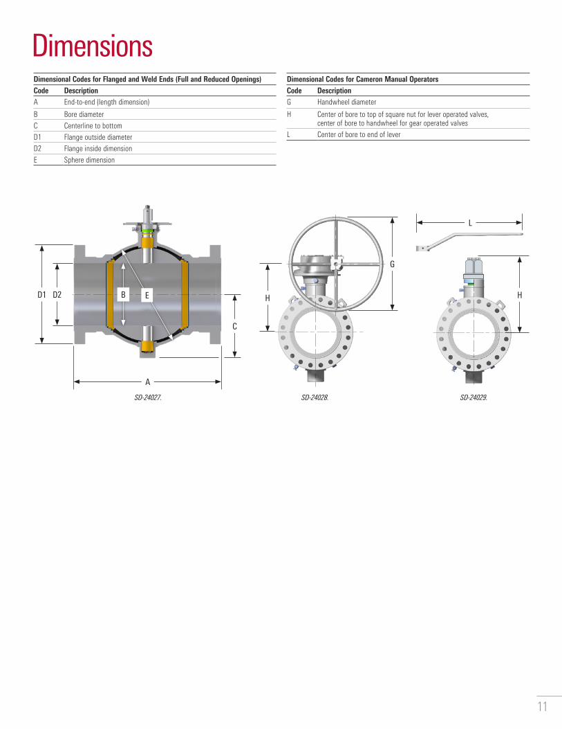
Dimensional Codes for Flanged and Weld Ends (Full and Reduced Openings)Code DescriptionA End-to-end (length dimension)
B Bore diameter
C Centerline to bottom
D1 Flange outside diameter
D2 Flange inside dimension
E Sphere dimension
Dimensional Codes for Cameron Manual OperatorsCode DescriptionG Handwheel diameter
H Center of bore to top of square nut for lever operated valves, center of bore to handwheel for gear operated valves
L Center of bore to end of lever
Dimensions
A
L
B H
G
HD2D1
C
E

12
ASME Class 150 (PN 20)Full bore
DimensionsSize, in Flanged End† Weld
End† Length
C.L. to Bottom
Body Sphere
Lever Length
Diameter Handwheel for Gear
C.L. to Handwheel C.L.
Approximate Valve Weight, lbmNom.
DiameterBall Bore
Stem Size
RF Length
RTJ Length
Diameter Diameter
B A A D1†† D2 A C E L G H Flange Weld2 2.06 1.0 7.0 7.5 6.00 2.06 11.0§ 3.94 5.00 24 – 6.34 39 453 3.13 1.0 8.0 8.5 7.50 3.13 12.5§ 5.12 6.75 24 – 7.44 62 754 4.06 1.5 9.0 9.5 9.00 4.06 14.0 5.94 8.50 36 – 8.43 115 1006 6.00 1.5 15.5 16.0 11.00 6.00 18.0 7.91 11.25 – 12 10.43 200 2258 8.00 2.0 18.0 18.5 13.50 8.00 21.5§ 10.00 15.50 – 18 12.55 428 45010 10.00 2.0 21.0 21.5 16.00 10.00 23.5§ 12.12 18.50 – 18 14.54 705 65012 12.00 3.0 24.0 24.5 19.00 12.00 26.5§ 14.50 22.36 – 18 20.14 1,210 1,10014 13.25 3.0 27.0 27.5 21.00 13.25 28.5‡ 14.64 24.00 – 18 21.16 1,330 1,23016 15.25 3.0 30.0 30.5 23.50 15.25 30.5‡ 16.01 26.32 – 18 22.52 1,650 1,55018 17.25 4.0 34.0 34.5 25.00 17.25 33.5‡ 19.25 29.20 – 24 26.19 2,325 2,20020 19.25 4.0 36.0 36.5 27.50 19.25 35.5‡ 20.81 32.27 – 18 27.75 3,310 2,76022 21.25 4.0 40.0 40.5 29.50 21.25 38.5‡ 22.28 36.00 – 18 29.22 3,875 3,51024 23.25 4.0 42.0 42.5 32.00 23.25 42.0‡ 23.69 38.76 – 18 30.63 4,620 4,26026 25.00 5.0 45.0 – 34.25 25.00 44.5‡ 26.49 41.75 – 24 34.34 6,400 5,60028 27.00 5.0 49.0 – 36.50 27.00 47.0‡ 27.88 44.86 – 24 35.72 7,200 6,50030 29.00 5.0 51.0 – 38.75 29.00 49.0‡ 29.51 47.90 – 24 37.37 9,500 8,80032 30.75 5.0 54.0 – 41.75 30.75 52.0‡ 31.16 52.25 – 24 37.01 ‡‡ ‡‡
34 32.75 5.0 58.0 – 43.75 32.75 54.5‡ 32.16 53.64 – 30 40.01 13,500 12,00036 34.50 5.0 60.0 – 46.00 34.50 56.5‡ 33.76 56.83 – 36 41.60 15,150 14,50040 38.50 7.5 69.0 – 50.75 38.50 65.0‡ 40.14 65.00 – 30 50.25 – –42 41.25 7.5 72.0 – 53.00 41.25 66.5‡ 41.78 68.60 – 42 51.89 – –48 46.50 7.5 80.0 – 59.50 46.50 76.0‡ 45.90 77.00 – – – – –Size, mm Weight, kg50 52 25 178 191 152 52 279§ 100 127 610 – 161 18 2080 80 25 203 216 191 80 318§ 130 171 610 – 189 28 34100 103 38 229 241 229 103 356 151 216 914 – 214 52 45150 152 38 394 406 279 152 457 201 286 – 305 265 91 102200 203 51 457 470 343 203 546§ 254 394 – 457 319 194 204250 254 51 533 546 406 254 597§ 308 470 – 457 369 320 295300 305 76 610 622 483 305 673§ 368 568 – 457 512 549 499350 337 76 686 699 533 337 724‡ 372 610 – 457 537 603 558400 387 76 762 775 597 387 775‡ 407 669 – 457 572 748 703450 438 102 864 876 635 438 851 489 742 – 610 665 1,055 998500 489 102 914 927 699 489 902 529 820 – 457 705 1,501 1,252550 540 102 1,016 1,029 749 540 978‡ 566 914 – 457 742 1,758 1,592600 591 102 1,067 1,080 813 591 1,067‡ 602 985 – 457 778 2,096 1,932650 635 127 1,143 – 870 635 1,130‡ 673 1,060 – 610 872 2,903 2,540700 686 127 1,245 – 927 686 1,194‡ 708 1,139 – 610 907 3,266 2,948750 737 127 1,295 – 984 737 1,245‡ 750 1,217 – 610 949 4,309 3,992800 781 127 1,372 – 1,060 781 1,321‡ 791 1,327 – 610 940 ‡‡ ‡‡
850 832 127 1,473 – 1,111 832 1,384‡ 817 1,362 – 762 1,016 6,123 5,443900 876 127 1,524 – 1,168 876 1,435‡ 858 1,443 – 914 1,057 6,872 6,5771,000 978 191 1,753 – 1,289 978 1,651‡ 1,020 1,651 – 762 1,276 – –1,050 1,048 191 1,829 – 1,346 1,048 1,689‡ 1,061 1,742 – 1,067 1,318 – –1,200 1,181 191 2,032 – 1,511 1,181 1,930‡ 1,166 1,956 – – – – –† Length (A) of a weld × flanged-end valve is one half the sum of length (A) of a weld end and a flange end of the same size and rating.‡ Short pattern.§ Length exceeds specified dimensions in API Spec 6D and ISO 14313.†† Dimensions of 22-in [550-mm] flanges are per MSS-SP-44, and 26-in [650-mm] to 42-in [1,050-mm] flanges are per ASME B16.47 series A.‡‡ For additional information, please contact Cameron engineering team.

13
ASME Class 150 (PN 20)Reduced bore
DimensionsSize, in Flanged End† Weld
End† Length
C.L. to Bottom
Body Sphere
Lever Length
Diameter Handwheel for Gear
C.L. to Handwheel C.L.
Approximate Valve Weight, lbmNom.
DiameterBall Bore
Stem Size
RF Length
RTJ Length
Diagram Diagram
B A A D1†† D2 A C E L G H Flange Weld3 2.06 1.0 8.0 8.5 7.50 3.13 11.0§ 3.94 5.00 24 – 6.34 55 504 3.13 1.0 9.0 9.5 9.00 4.06 12.5§ 5.12 6.75 24 – 7.44 100 876 4.06 1.5 15.5 16.0 11.00 6.00 14.0§ 5.94 8.50 36 – 8.43 170 1508 6.00 1.5 18.0 18.5 13.50 8.00 18.0 7.91 11.25 – 12 10.43 345 29010 8.00 2.0 21.0 21.5 16.00 10.00 21.5§ 10.00 15.50 – 18 12.55 620 52512 10.00 2.0 24.0 24.5 19.00 12.00 23.5§ 12.12 18.50 – 18 14.54 950 84014 12.00 3.0 27.0 27.5 21.00 13.25 26.5§ 14.50 22.36 – 18 20.14 1,280 1,16016 13.25 3.0 30.0 30.5 23.50 15.25 28.5‡ 14.64 24.00 – 18 21.16 1,450 1,33018 15.25 3.0 34.0 34.5 25.00 17.25 30.5‡ 16.01 26.32 – 18 22.52 1,510 1,70020 17.25 4.0 36.0 36.5 27.50 19.25 33.5‡ 19.25 29.20 – 24 26.19 2,410 2,30022 19.25 4.0 40.0 40.5 29.50 21.25 35.5‡ 20.81 32.27 – 18 27.75 3,450 3,05024 21.25 4.0 42.0 42.5 32.00 23.25 38.5‡ 22.28 36.00 – 18 29.22 4,300 3,65026 23.25 4.0 45.0 – 34.25 25.00 42.0‡ 23.69 38.76 – 18 30.63 5,400 5,10028 25.00 5.0 49.0 – 36.50 27.00 44.5‡ 26.49 41.75 – 24 34.34 7,040 6,10030 27.00 5.0 51.0 – 38.75 29.00 47.0‡ 27.88 44.86 – 24 35.72 8,900 7,60032 29.00 5.0 54.0 – 41.75 32.75 49.0‡ 29.51 47.90 – 24 37.37 9,600 8,50036 32.75 5.0 60.0 – 46.00 34.50 54.5‡ 32.16 53.64 – 30 40.01 14,000 12,50042 34.50 5.0 72.0 – 53.00 41.25 56.5‡ 33.76 56.83 – 36 41.60 – –Size, mm Weight, kg80 52 25 203 216 191 80 279§ 100 127 610 – 161 25 23100 80 25 229 241 229 103 318§ 130 172 610 – 189 45 39150 103 38 394 406 279 152 356§ 151 216 914 – 214 77 68200 152 38 457 470 343 203 457 201 286 – 305 265 156 132250 203 51 533 546 406 254 564§ 254 394 – 457 319 281 238300 254 51 610 622 483 305 597§ 308 470 – 457 369 431 381350 305 76 686 699 533 337 673§ 368 568 – 457 512 581 526400 337 76 762 775 597 387 724‡ 372 610 – 457 537 658 603450 387 76 864 876 635 438 774‡ 407 669 – 457 572 685 771500 438 102 914 927 699 489 851‡ 489 741 – 610 665 1,093 1,043550 489 102 1,016 1,029 749 540 902‡ 529 820 – 457 705 1,565 1,383600 540 102 1,067 1,080 813 591 978‡ 566 914 – 457 742 1,950 1,656650 591 102 1,143 – 870 635 1,067‡ 602 985 – 457 778 2,449 2,313700 635 127 1,245 – 927 686 1,130‡ 673 1,061 – 610 872 3,193 2,767750 686 127 1,295 – 984 737 1,194‡ 708 1,139 – 610 907 4,037 3,447800 737 127 1,372 – 1,048 832 1,245‡ 750 1,217 – 610 949 4,355 3,856900 832 127 1,524 – 1,168 876 1,384‡ 817 1,363 – 762 1,016 6,350 5,6701,050 876 127 1,829 – 1,346 1,048 1,435‡ 858 1,444 – 914 1,057 – –† Length (A) of a weld × flanged-end valve is one half the sum of length (A) of a weld end and a flange end of the same size and rating.‡ Short pattern.§ Length exceeds specified dimensions in API Spec 6D and ISO 14313.†† Dimensions of 22-in [550-mm] flanges are per MSS-SP-44, and 26-in [650-mm] to 42-in [1050-,mm] flanges are per ASME B16.47 series A.
Note: Venturi opening or other reduced-bore valves are available upon request.

14
DimensionsSize, in Flanged End† Weld
End† Length
C.L. to Bottom
Body Sphere
Lever Length
Diameter Handwheel for Gear
C.L. to Handwheel C.L.
Approximate Valve Weight, lbmNom.
DiameterBall Bore
Stem Size
RF Length
RTJ Length
Diameter Diameter
B A A D1†† D2 A C E L G H Flange Weld2 2.06 1.0 8.50 9.125 6.50 2.06 11.0§ 3.94 5.00 24 – 6.34 50 453 3.13 1.0 11.125 11.750 8.25 3.13 12.5§ 5.12 6.75 24 – 7.44 80 754 4.06 1.5 12.00 12.625 10.00 4.06 14.0§ 5.94 8.50 36 – 8.43 125 1006 6.00 1.5 15.875 16.500 12.50 6.00 18.0 7.91 11.25 – 12 10.43 250 2258 8.00 2.0 19.75‡‡ 20.375 15.00 8.00 21.5§ 10.00 15.50 – 18 12.55 455 45010 10.00 2.0 22.375 23.000 17.50 10.00 23.5§ 12.12 18.50 – 18 14.54 750 65012 12.00 3.0 25.50 26.125 20.50 12.00 26.5§ 14.50 22.36 – 18 20.14 1,275 1,10014 13.25 3.0 30.00 30.625 23.00 13.25 28.5‡ 14.64 24.00 – 24 21.16 1,370 1,23016 15.25 3.0 33.00 33.625 25.50 15.25 30.5‡ 16.01 26.32 – 24 22.52 1,725 1,55018 17.25 4.0 36.00 36.625 28.00 17.25 33.5‡ 19.25 29.20 – 24 26.19 2,700 2,20020 19.25 4.0 39.00 39.750 30.50 19.25 35.5‡ 20.81 32.27 – 18 27.75 3,400 2,76022 21.25 4.0 43.00 43.875 33.00 21.25 38.5‡ 22.28 36.00 – 24 29.22 4,050 3,51024 23.25 4.0 45.00 45.875 36.00 23.25 42.0‡ 23.69 38.76 – 24 30.63 5,390 4,26026 25.00 5.0 49.00 50.000 38.25 25.00 44.5‡ 26.49 41.75 – 24 34.34 6,625 5,60028 27.00 5.0 53.00 54.000 40.75 27.00 47.0‡ 27.88 44.86 – 24 35.72 7,725 6,50030 29.00 5.0 55.00 56.000 43.00 29.00 49.0‡ 29.51 47.90 – 30 37.37 10,000 8,80032 30.75 5.0 60.0 61.130 45.25 30.75 52.0‡ 31.16 52.25 – 30 37.01 §§ §§
34 32.75 5.0 64.00 65.125 47.50 32.75 54.5‡ 32.16 53.64 – 36 40.01 14,700 12,00036 34.50 7.5 68.00 69.125 50.00 34.50 56.5‡ 36.80 56.83 – 24 46.92 16,300 15,50040 38.50 7.5 74.00 – 48.75 38.50 65.0‡ 40.14 65.00 – 36 50.25 – –42 41.25 7.5 76.00 – 50.75 41.25 66.5‡ 41.78 68.60 – 42 51.89 – –48 46.50 7.5 86.00 – 57.75 46.50 76.0‡ 45.90 77.00 – – – – –Size, mm Weight, kg50 52 25 216 232 165 52 279§ 100 127 610 – 161 23 2080 80 25 283 298 210 80 318§ 130 172 610 – 189 36 34100 103 38 305 321 254 103 356§ 151 216 914 – 214 57 45150 152 38 403 419 318 152 457 201 286 – 305 265 113 102200 203 51 502‡‡ 518 381 203 546§ 254 394 – 457 319 206 204250 254 51 568 584 445 254 597§ 308 470 – 610 369 340 295300 305 76 648 664 521 305 673§ 368 568 – 457 512 578 499350 337 76 762 778 584 337 724‡ 372 610 – 610 537 621 558400 387 76 838 854 648 387 775‡ 407 669 – 610 572 782 703450 438 102 914 930 711 438 851‡ 489 742 – 610 665 1,225 998500 489 102 991 1,010 775 489 902‡ 529 820 – 457 705 1,542 1,252550 540 102 1,092 1,114 838 540 978‡ 566 914 – 610 742 1,837 1,592600 591 102 1,143 1,165 914 591 1,067‡ 602 985 – 610 778 2,445 1,932650 635 127 1,245 1,270 972 635 1,130‡ 673 1,060 – 610 872 3,005 2,540700 686 127 1,346 1,372 1,035 686 1,194‡ 708 1,139 – 610 907 3,504 2,948750 737 127 1,397 1,422 1,092 737 1,245‡ 750 1,217 – 762 949 4,536 3,992800 781 127 1,524 1,553 1,149 781 1,321‡ 791 1,327 – 762 940 §§ §§
850 832 127 1,626 1,654 1,207 832 1,384‡ 817 1,362 – 914 1,016 6,668 5,443900 876 191 1,727 1,756 1,270 876 1,435‡ 935 1,443 – 610 1,192 7,394 7,0311,000 978 191 1,880 – 1,238 978 1,651‡ 1,020 1,651 – 914 1,276 – –1,050 1,048 191 1,930 – 1,289 1,048 1,689‡ 1,061 1,742 – 1,067 1,318 – –1,200 1,181 191 2,184 – 1,467 1,181 1,930‡ 1,166 1,956 – – – – –† Length (A) of a weld × flanged-end valve is one half the sum of length (A) of a weld end and a flange end of the same size and rating.‡ Short pattern.§ Length exceeds specified dimensions in API Spec 6D and ISO 14313.†† Dimensions of 2-in [550-mm] flanges are per MSS-SP-44, and 26-in [650-mm] to 42-in [1,050-mm] flanges are per ASME B16.47 series A.‡‡ Prior to 1/1/98 and manufactured to 16.5-in [419-mm] short-pattern length.§§ For additional information, please contact Cameron engineering team.
ASME Class 300 (PN 50)Full bore

15
ASME Class 300 (PN 50)Reduced bore
DimensionsSize, in Flanged End† Weld
End† Length
C.L. to Bottom
Body Sphere
Lever Length
Diameter Handwheel for Gear
C.L. to Handwheel C.L.
Approximate Valve Weight, lbmNom.
DiameterBall Bore
Stem Size
RF Length
RTJ Length
Diagram Diagram
B A A D1†† D2 A C E L G H Flange Weld3 2.06 1.0 11.125 11.75 8.25 3.13 11.0‡ 3.94 5.00 24 – 6.34 64 504 3.13 1.0 12.00 12.625 10.00 4.06 12.5§ 5.12 6.75 24 – 7.44 95 876 4.06 1.5 15.875 16.500 12.50 6.00 14.0‡ 5.94 8.50 36 – 8.43 180 1508 6.00 1.5 19.75‡‡ 20.375 15.00 8.00 18.0‡ 7.91 11.25 – 12 10.43 365 29010 8.00 2.0 22.375 23.000 17.50 10.00 21.5‡ 10.00 15.50 – 18 12.55 650 52512 10.00 2.0 25.50 26.125 20.50 12.00 23.5‡ 12.12 18.50 – 18 14.54 1,050 84014 12.00 3.0 30.00 30.625 23.00 13.25 26.5‡ 14.50 22.36 – 18 20.14 1,285 1,16016 13.25 3.0 33.00 33.625 25.50 15.25 28.5‡ 14.64 24.00 – 24 21.16 1,660 1,33018 15.25 3.0 36.00 36.625 28.00 17.25 30.5‡ 16.01 26.32 – 24 22.52 1,990 1,70020 17.25 4.0 39.00 39.750 30.50 19.25 33.5‡ 19.25 29.20 – 24 26.19 3,100 2,30022 19.25 4.0 43.00 43.875 33.00 21.25 33.5‡ 20.81 32.27 – 18 27.75 3,600 3,05024 21.25 4.0 45.00 45.875 36.00 23.25 38.5‡ 22.28 36.00 – 24 29.22 4,500 3,65026 23.25 4.0 49.00 50.000 38.25 25.00 42.0‡ 23.69 38.76 – 24 30.63 5,750 5,10028 25.00 5.0 53.00 54.000 40.75 27.00 44.5‡ 26.49 41.75 – 24 34.34 7,260 6,10030 27.00 5.0 55.00 56.000 43.00 29.00 47.0‡ 27.88 44.86 – 24 35.72 9,100 7,60032 29.00 5.0 60.00 61.125 45.25 32.75 49.0‡ 29.51 47.90 – 30 37.37 10,150 8,80036 32.75 5.0 68.00 69.125 50.00 34.50 54.5‡ 32.16 53.64 – 36 40.01 15,350 13,00042 34.50 7.5 76.00 – 50.75 41.25 56.5‡ 36.80 56.83 – 24 49.92 – –Size, mm Weight, kg80 52 25 283 298 210 80 279‡ 100 127 610 – 161 29 23100 80 25 305 321 254 103 318§ 130 171 610 – 189 43 39150 103 38 403 419 318 152 356‡ 151 216 914 – 214 82 68200 152 38 502‡‡ 518 381 203 457‡ 201 286 – 305 265 166 132250 203 51 568 584 445 254 546‡ 254 394 – 457 319 295 238300 254 51 648 664 521 305 597‡ 308 470 – 457 369 476 381350 305 76 762 778 584 337 673‡ 368 568 – 457 512 583 526400 337 76 838 854 648 387 724‡ 372 610 – 610 537 753 603450 387 76 914 930 711 438 775‡ 407 669 – 610 572 903 771500 438 102 991 1,010 775 489 851‡ 489 742 – 610 665 1,406 1,043550 489 102 1,092 1,114 838 540 851‡ 529 820 – 457 705 1,633 1,383600 540 102 1,143 1,165 914 591 978‡ 566 914 – 610 742 2,041 1,656650 591 102 1,245 1,270 972 635 1,067‡ 602 985 – 610 778 2,608 2,313700 635 127 1,346 1,372 1,035 686 1,130‡ 673 1,060 – 610 872 3,293 2,767750 686 127 1,397 1,422 1,092 737 1,194‡ 708 1,139 – 610 907 4,128 3,447800 737 127 1,524 1,553 1,149 832 1,245‡ 750 1,217 – 762 949 4,604 3,992900 832 127 1,727 1,756 1,270 867 1,384‡ 817 1,362 – 914 1,016 6,963 5,8971,050 876 191 1,930 – 1,289 1,048 1,435‡ 935 1,443 – 610 1,192 – –† Length (A) of a weld × flanged-end valve is one half the sum of length (A) of a weld end and a flange end of the same size and rating.‡ Short pattern.§ Length exceeds specified dimensions in API Spec 6D and ISO 14313.†† Dimensions of 2-in [550-mm] flanges are per MSS-SP-44, and 26-in [650-mm] to 42-in [1,050-mm] flanges are per ASME B16.47 series A.‡‡ Prior to 1/1/98 and manufactured to 16.5-in [419-mm] short-pattern length.
Note: Venturi opening or other reduced-bore valves are available upon request.

16
ASME Class 400 (PN 64)Full bore
DimensionsSize, in Flanged End† Weld
End† Length
C.L. to Bottom
Body Sphere
Lever Length
Diameter Handwheel for Gear
C.L. to Handwheel C.L.
Approximate Valve Weight, lbmNom.
DiameterBall Bore
Stem Size
RF Length
RTJ Length
Diameter Diameter
B A A D1§ D2 A C E L G H Flange Weld2 2.06 Use ASME Class 600 valves (PN 100)3 3.13 Use ASME Class 600 valves (PN 100)4 4.06 1.5 16.0 16.125 10.00 4.06 14.0‡ 5.94 8.50 48 – 8.43 150 1006 6.00 1.5 19.5 19.625 12.50 6.00 18.0‡ 7.91 11.25 – 12 10.43 300 2258 8.00 2.0 23.5 23.625 15.00 8.00 21.5‡ 10.00 15.50 – 18 12.55 550 45010 10.00 2.0 26.5 26.625 17.50 10.00 23.5‡ 12.12 18.50 – 24 14.54 850 65012 12.00 3.0 30.0 30.125 20.50 12.00 26.5‡ 14.50 22.36 – 18 20.14 1,400 1,10014 13.25 3.0 32.5 32.625 23.00 13.25 28.5‡ 14.64 24.00 – 24 21.16 1,650 1,23016 15.25 4.0 35.5 35.625 25.50 15.25 30.5‡ 17.84 26.32 – 18 24.78 2,225 1,77018 17.25 4.0 38.5 38.625 28.00 17.25 33.5‡ 19.25 29.20 – 24 26.19 2,850 2,20020 19.25 5.0 41.5 41.750 30.50 19.25 35.5‡ 22.11 32.27 – 24 30.00 3,750 3,00022 21.25 5.0 45.0 45.375 33.00 21.25 38.5‡ 23.63 36.00 – 24 31.53 4,750 3,95024 23.25 5.0 48.5 48.875 36.00 23.25 42.0‡ 25.05 38.76 – 24 32.95 5,600 4,75026 25.00 5.0 51.5 52.000 38.25 25.00 44.5‡ 26.49 41.75 – 24 34.34 7,100 5,60028 27.00 5.0 55.0 55.500 40.75 27.00 47.0‡ 27.88 44.86 – 30 35.72 8,560 6,50030 29.00 5.0 60.0 60.500 43.00 29.00 49.0‡ 29.51 47.90 – 36 37.37 10,600 8,80032 30.75 7.5 65.0 65.630 45.25 30.75 52.0‡ 34.25 52.25 – 24 44.53 †† 10,49434 32.75 7.5 70.0 70.625 47.50 32.75 54.5‡ 35.19 53.64 – 30 45.31 15,400 12,30036 34.50 7.5 74.0 74.625 50.00 34.50 56.5‡ 36.80 56.83 – 30 46.92 18,000 15,50040 38.50 7.5 78.0 – 50.00 38.50 65.0‡ 40.14 65.00 – 42 50.25 25,500 22,25042 41.25 7.5 81.0 – 52.00 41.25 66.5‡ 41.78 68.60 – 42 51.89 28,750 24,75048 46.50 9.0 91.0 – 59.50 46.50 76.0‡ 47.98 77.00 – – – – –Size, mm Weight, kg50 52 Use ASME Class 600 valves (PN 100)80 80 Use ASME Class 600 valves (PN 100)100 103 38 406 410 254 103 356‡ 151 216 1,219 – 214 68 45150 152 38 495 498 318 152 457‡ 201 286 – 305 265 136 102200 203 51 597 600 381 203 546‡ 254 394 – 457 319 249 204250 254 51 673 676 445 254 597‡ 308 470 – 610 369 386 295300 305 76 762 765 521 305 673‡ 368 568 – 457 512 635 499350 337 76 826 829 584 337 724‡ 372 610 – 610 537 748 558400 387 102 902 905 648 387 775‡ 453 669 – 457 629 1,009 803450 438 102 978 981 711 438 851‡ 489 742 – 610 665 1,293 998500 489 127 1,054 1,060 775 489 902‡ 562 820 – 610 762 1,701 1,361550 540 127 1,143 1,153 838 540 978‡ 600 914 – 610 801 2,155 1,792600 591 127 1,232 1,241 914 591 1,067‡ 636 985 – 610 837 2,540 2,155650 635 127 1,308 1,321 9,712 635 1,130‡ 673 1,060 – 610 872 3,221 2,540700 686 127 1,397 1,410 1,035 686 1,194‡ 708 1,139 – 762 907 3,883 2,948750 737 127 1,524 1,537 1,092 737 1,245‡ 750 1,217 – 914 949 4,808 3,992800 781 191 1,651 1,667 1,149 781 1,321‡ 870 1,327 – 610 1,131 †† 4,760850 832 191 1,778 1,794 1,207 832 1,384‡ 894 1,362 – 762 1,151 6,985 5,579900 876 191 1,880 1,895 1,270 876 1,435‡ 935 1,443 – 762 1,192 8,165 7,0311,000 978 191 1,981 – 1,270 978 1,651‡ 1,020 1,651 – 1,067 1,276 11,567 10,0921,050 1,048 191 2,057 – 1,321 1,048 1,689‡ 1,061 1,742 – 1,067 1,318 13,041 11,2261,200 1,181 229 2,311 – 1,511 1,181 1,930‡ 1,219 1,956 – – – – –† Length (A) of a weld × flanged-end valve is one half the sum of length (A) of a weld end and a flange end of the same size and rating.‡ Short pattern.§ Dimensions of 22-in [550-mm] flanges are per MSS-SP-44, and 26-in [650-mm] to 42-in [1,050-mm] flanges are per ASME B16.47 series A.‡‡ For additional information, please contact Cameron engineering team.

17
ASME Class 400 (PN 64)Reduced bore
DimensionsSize, in Flanged End† Weld
End† Length
C.L. to Bottom
Body Sphere
Lever Length
Diameter Handwheel for Gear
C.L. to Handwheel C.L.
Approximate Valve Weight, lbmNom.
DiameterBall Bore
Stem Size
RF Length
RTJ Length
Diameter Diameter
B A A D1§ D2 A C E L G H Flange Weld3 2.06 Use ASME Class 600 valves (PN 100)4 3.13 1.0 16.0 16.125 10.00 4.06 12.5‡ 5.12 6.75 24 – 7.44 125 876 4.06 1.5 19.5 19.625 12.50 6.00 14.0‡ 5.94 8.50 48 – 8.43 189 1508 6.00 1.5 23.5 23.625 15.00 8.00 18.0‡ 7.91 11.25 – 12 10.43 424 29010 8.00 2.0 26.5 26.625 17.50 10.00 21.5‡ 10.00 15.50 – 18 12.55 608 52512 10.00 2.0 30.0 30.125 20.50 12.00 23.5‡ 12.12 18.50 – 24 14.54 1,020 84014 12.00 3.0 32.5 32.625 23.00 13.25 26.5‡ 14.50 22.36 – 18 20.14 1,490 1,16016 13.25 3.0 35.5 35.625 25.25 15.25 28.5‡ 14.64 24.00 – 24 21.16 1,910 1,33018 15.25 4.0 38.5 38.625 28.00 17.25 30.5‡ 17.84 36.32 – 18 24.78 2,400 1,92020 17.25 4.0 41.5 41.750 30.50 19.25 33.5‡ 19.25 29.20 – 24 26.19 3,200 2,65022 19.25 5.0 45.0 45.375 33.00 21.25 35.5‡ 22.11 32.27 – 24 30.00 4,250 3,30024 21.25 5.0 48.5 48.875 36.00 23.25 38.5‡ 23.63 36.00 – 24 31.53 5,050 4,30026 23.25 5.0 51.5 52.000 38.25 25.00 42.0‡ 25.05 38.76 – 24 32.95 6,250 5,10028 25.00 5.0 55.0 55.500 40.75 27.00 44.5‡ 26.49 41.75 – 24 34.34 7,750 6,10030 27.00 5.0 60.0 60.500 43.00 29.00 47.0‡ 27.88 44.86 – 30 35.72 9,500 7,60032 29.00 5.0 65.0 65.625 45.25 32.75 49.0‡ 29.51 47.90 – 36 37.37 11,500 9,35036 32.75 7.5 74.0 74.625 50.00 34.50 54.5‡ 35.19 53.64 – 30 45.31 16,000 13,00042 34.50 7.5 81.0 – 52.00 41.25 56.5‡ 36.80 56.83 – 30 46.92 – –Size, mm Weight, kg80 52 Use ASME Class 600 valves (PN 100)100 80 25 406 410 254 103 318‡ 130 171 610 – 189 57 39150 103 38 495 498 318 152 356‡ 151 216 1,219 – 214 86 68200 152 38 597 600 381 203 457‡ 201 286 – 305 265 192 132250 203 51 673 676 445 254 546‡ 254 394 – 457 319 276 238300 254 51 762 765 521 305 597‡ 308 470 – 610 369 463 381350 305 76 826 829 584 337 673‡ 368 568 – 457 512 676 526400 337 76 902 905 641 387 724‡ 372 610 – 610 537 866 603450 387 102 978 981 711 438 775‡ 453 923 – 457 629 1,089 871500 438 102 1,054 1,060 775 489 851‡ 489 742 – 610 665 1,451 1,202550 489 127 1,143 1,153 838 540 902‡ 562 820 – 610 762 1,928 1,497600 540 127 1,232 1,241 914 591 978‡ 600 914 – 610 801 2,291 1,950650 591 127 1,308 1,321 972 635 1,067‡ 636 985 – 610 837 2,835 2,313700 635 127 1,397 1,410 1,035 686 1,130‡ 673 1,060 – 610 872 3,515 2,767750 686 127 1,524 1,537 1,092 737 1,194‡ 708 1,139 – 762 907 4,309 3,447800 737 127 1,651 1,667 1,149 832 1,245‡ 750 1,217 – 914 949 5,216 4,241900 832 191 1,880 1,895 1,270 876 1,384‡ 894 1,362 – 762 1,151 7,257 5,8971,050 876 191 2,057 – 1,321 1,048 1,435‡ 935 1,443 – 762 1,192 – –† Length (A) of a weld × flanged-end valve is one half the sum of length (A) of a weld end and a flange end of the same size and rating.‡ Short pattern.§ Dimensions of 22-in [550-mm] flanges are per MSS-SP-44, and 26-in [650-mm] to 42-in [1,050-mm] flanges are per ASME B16.47 series A.

18
ASME Class 600 (PN 100)Full bore
DimensionsSize, in Flanged End† Weld
End† Length
C.L. to Bottom
Body Sphere
Lever Length
Diameter Handwheel for Gear
C.L. to Handwheel C.L.
Approximate Valve Weight, lbmNom.
DiameterBall Bore
Stem Size
RF Length
RTJ Length
Diameter Diameter
B A A D1§ D2 A C E L G H Flange Weld2 2.06 1 11.5 11.625 6.5 2.06 11.0‡ 3.94 5 24 – 6.34 60 453 3.13 1 14 14.125 8.25 3.13 12.5‡ 5.12 6.75 36 – 7.44 85 754 4.06 1.5 17 17.125 10.75 4.06 14.0‡ 5.94 8.5 48 – 8.43 165 1006 6.00 1.5 22 22.125 14 6 18.0‡ 7.91 11.25 – 12 10.43 360 2258 8.00 2 26 26.125 16.5 8 21.5‡ 10 15.5 – 18 12.55 650 45010 10.00 2 31 31.125 20 10 23.5‡ 12.12 18.5 – 24 14.54 1,000 65012 12.00 3 33 33.125 22 12 26.5‡ 14.5 22.36 – 18 20.14 1,510 1,10014 13.25 3 35 35.125 23.75 13.25 28.5‡ 14.64 24 – 24 21.16 1,910 1,23016 15.25 4 39 39.125 27 15.25 30.5‡ 17.84 26.32 – 18 24.78 2,400 1,77018 17.25 4 43 43.125 29.25 17.25 33.5‡ 19.25 29.2 – 24 26.19 2,955 2,20020 19.25 5 47 47.25 32 19.25 35.5‡ 22.11 32.27 – 24 30 4,100 3,00022 21.25 5 51 51.375 34.25 21.25 38.5‡ 23.63 36 – 24 31.53 5,400 3,95024 23.25 5 55 55.375 37 23.25 42.0‡ 25.05 38.76 – 30 32.95 6,550 4,75026 25.00 5 57 57.5 40 25 44.5‡ 26.49 41.75 – 36 34.34 7,800 5,60028 27.00 7.5 61 61.5 42.25 27 47.0‡ 30.87 44.86 – 30 40.99 9,500 6,70030 29.00 7.5 65 65.5 44.5 29 49.0‡ 32.53 47.9 – 30 42.65 12,000 9,12032 30.75 7.5 70 70.630 47.00 30.75 52.0‡ 34.25 52.25 42 44.50 13,999 10,49434 32.75 7.5 76 76.625 49 32.75 54.5‡ 35.19 53.64 – 42 45.31 16,025 12,30036 34.5 7.5 82 82.625 51.75 34.5 56.5‡ 36.8 56.83 – 42 46.92 19,100 15,50040 38.5 9 80 – 52 38.5 65.0‡ 42.02 65 – 42 55.425 26,770 23,00042 41.25 9 83 – 55.25 41.25 66.5‡ 43.66 68.6 – 42 57.06 30,500 25,50044 42.75 11 – – – 42.75 70.5‡ 46.95 71.00 – – – – –48 46.50 11 94 – 62.75 46.5 76.0‡ 51.18 77.33 – – – – –56 55.12 13 – – – 55.12 93.7‡ 59.10 91.70 – – – – –Size, mm Weight, kg50 52 25 292 295 165 52 279‡ 100 127 610 – 161 27 2080 80 25 356 359 210 80 318‡ 130 171 914 – 189 39 34100 103 38 432 435 273 103 356‡ 151 216 1,219 – 214 75 45150 152 38 559 562 356 152 457‡ 201 286 – 305 265 163 102200 203 51 660 664 419 203 546‡ 254 394 – 457 319 295 204250 254 51 787 791 508 254 597‡ 308 470 – 610 369 454 295300 305 76 838 841 559 304 673‡ 368 568 – 457 512 685 499350 337 76 889 892 603 337 724‡ 372 610 – 610 537 866 558400 387 102 991 994 686 387 775‡ 453 669 – 457 629 1,089 803450 438 102 1,092 1,095 743 438 851‡ 489 742 – 610 665 1,340 998500 489 127 1,194 1,200 813 489 902‡ 562 820 – 610 762 1,860 1,361550 540 127 1,295 1,305 870 540 978‡ 600 914 – 610 801 2,449 1,792600 591 127 1,397 1,407 940 591 1,067‡ 636 985 – 762 837 2,971 2,155650 635 127 1,448 1,461 1,016 635 1,130‡ 673 1,060 – 914 872 3,538 2,540700 686 191 1,549 1,562 1,073 686 1,194‡ 784 1,139 – 762 1,041 4,309 3,039750 737 191 1,651 1,664 1,130 737 1,245‡ 826 1,217 – 762 1,083 5,443 4,137800 781 191 1,778 1,794 1,193.8 781 1,321‡ 870 1,327 1,067 1,130 6,350 4,760850 832 191 1,930 1,946 1,245 832 1,384‡ 894 1,362 – 1,067 1,151 7,269 5,579900 876 191 2,083 2,099 1,314 876 1,435‡ 935 1,443 – 1,067 1,192 8,664 7,0311,000 978 229 2,032 – 1,321 978 1,651‡ 1,067 1,651 – 1,067 1,408 12,143 10,4331,050 1,048 229 2,108 – 1,403 1,048 1,689‡ 1,109 1,742 – 1,067 1,449 13,835 11,5671,100 1,086 279 – – – 1,086 1,791‡ 1,192 1,803 – – – – –1,200 1,181 279 2,388 – 1,594 1,181 1,930‡ 1,300 1,964 – – – – –1,400 1,400 330 – – – 1,400 2,381‡ 1,501 2,328 – – – – –† Length (A) of a weld × flanged-end valve is one half the sum of length (A) of a weld end and a flange end of the same size and rating.‡ Short pattern.§ Dimensions of 22-in [550-mm] flanges are per MSS-SP-44, and 26-in [650-mm] to 42-in [1,050-mm] flanges are per ASME B16.47 series A.
18

19
ASME Class 600 (PN 100)Reduced bore
DimensionsSize, in Flanged End† Weld
End† Length
C.L. to Bottom
Body Sphere
Lever Length
Diameter Handwheel for Gear
C.L. to Handwheel C.L.
Approximate Valve Weight, lbmNom.
DiameterBall Bore
Stem Size
RF Length
RTJ Length
Diameter Diameter
B A A D1§ D2 A C E L G H Flange Weld3 2.06 1 14 14.125 8.25 3.13 11.0‡ 3.94 5 24 – 6.34 80 504 3.13 1 17 17.125 10.75 4.06 12.5‡ 5.12 6.75 36 – 7.44 150 876 4.06 1.5 22 22.125 14 6 14.0‡ 5.94 8.5 48 – 8.43 250 1508 6.00 1.5 26 26.125 16.5 8 18.0‡ 7.91 11.25 – 12 10.43 470 29010 8.00 2 31 31.125 20 10 21.5‡ 10 15.5 – 18 12.55 850 52512 10.00 2 33 33.125 22 12 23.5‡ 12.12 18.5 – 24 14.54 1,150 84014 12.00 3 35 35.125 23.75 13.25 26.5‡ 14.5 22.36 – 18 20.14 1,640 1,16016 13.25 3 39 39.125 27 15.25 28.5‡ 14.64 24 – 24 21.16 2,225 1,33018 15.25 4 43 43.125 29.25 17.25 30.5‡ 17.84 26.32 – 18 24.78 2,600 1,92020 17.25 4 47 47.25 32 19.25 33.5‡ 19.25 29.2 – 24 26.19 3,500 2,65022 19.25 5 51 51.375 34.25 21.25 35.5‡ 22.11 32.27 – 24 30 4,450 3,30024 21.25 5 55 55.375 37 23.25 38.5‡ 23.63 36 – 24 31.53 5,750 4,30026 23.25 5 57 57.5 40 25 42.0‡ 25.05 38.76 – 30 32.95 7,000 5,10028 25.00 5 61 61.5 42.25 27 44.5‡ 26.49 41.75 – 36 34.34 8,600 6,30030 27.00 7.5 65 65.5 44.5 29 47.0‡ 30.87 44.86 – 30 40.99 10,100 7,80032 29.00 7.5 70.00 70.630 47.00 30.75 49.0‡ 32.53 47.90 – 30 42.65 12,800 9,35034 29.00 7.5 76.00 76.625 49.00 32.75 49.0‡ 32.53 47.90 – 30 42.65 15,200 11,20036 32.75 7.5 82 82.625 51.75 34.5 54.5‡ 35.19 53.64 – 42 45.31 17,600 13,00042 34.50 7.5 83 – 55.25 41.25 56.5‡ 36.8 56.83 – 42 46.92 – –44 38.50 9 – – – 42.75 65.0‡ 42.02 65.00 – – – – –56 46.50 11 – – – 55.10 76.0‡ 51.18 77.32 – – – – –Size, mm Weight, kg80 52 25 356 359 210 80 279‡ 100 127 610 – 161 36 23100 80 25 432 435 273 103 318‡ 130 171 914 – 189 68 39150 103 38 559 562 356 152 356‡ 151 216 1,219 – 214 113 68200 152 38 660 664 419 203 457‡ 201 286 – 305 265 213 132250 203 51 787 791 508 254 546‡ 254 394 – 457 319 386 238300 254 51 838 841 559 305 597‡ 308 470 – 610 369 522 381350 305 76 889 892 603 337 673‡ 368 568 – 457 512 744 526400 337 76 991 994 686 387 724‡ 372 610 – 610 537 1,009 603450 387 102 1,092 1,095 743 438 775‡ 453 669 – 457 629 1,179 871500 438 102 1,194 1,200 813 489 851‡ 489 742 – 610 665 1,588 1,202550 489 127 1,295 1,305 870 540 902‡ 562 820 – 610 762 2,018 1,497600 540 127 1,397 1,407 940 591 978‡ 600 914 – 610 801 2,608 1,950650 591 127 1,448 1,461 1,016 635 1,067‡ 636 985 – 762 837 3,175 2,313700 635 127 1,549 1,562 1,073 686 1,130‡ 673 1,060 – 914 872 3,901 2,858750 686 191 1,651 1,664 1,130 737 1,194‡ 784 1,139 – 762 1,041 4,581 3,538800 737 191 1,778 1,794 1,194 781 1,245‡ 826 1,217 – 762 1,083 5,800 4,250850 737 191 1,930 1,946 1,245 832 1,245‡ 826 1,217 – 762 1,083 6,900 5,100900 832 191 2,083 2,099 1,314 876 1,384‡ 894 1,362 – 1,067 1,151 7,983 5,8971,100 978 229 – – – 1,086 1,651‡ 1,067 1,651 – – – – –1,400 1,181 279 – – – 1,400 1,930‡ 1,300 1,964 – – – – –† Length (A) of a weld × flanged-end valve is one half the sum of length (A) of a weld end and a flange end of the same size and rating.‡ Short pattern.§ Dimensions of 22-in [550-mm] flanges are per MSS-SP-44, and 26-in [650-mm] to 42-in [1,050-mm] flanges are per ASME B16.47 series A.

20
ASME Class 900 (PN 150)Full bore
DimensionsSize, in Flanged End† Weld
End† Length
C.L. to Bottom
Body Sphere
Lever Length
Diameter Handwheel for Gear
C.L. to Handwheel C.L.
Approximate Valve Weight, lbmNom.
DiameterBall Bore
Stem Size
RF Length
RTJ Length
Diameter Diameter
B A A D1§ D2 A C E L G H Flange Weld2 2.06 Use 1,500 Class valves (PN 250)3 3.13 1.5 15.0 15.125 9.50 3.13 13.5‡ 4.88 7.00 36 – 7.44 140 1204 4.06 2.0 18.0 18.125 11.50 4.06 15.0‡ 6.77 9.25 – 12 9.76 250 1906 6.00 2.0 24.0 24.125 15.00 6.00 20.0‡ 8.39 12.50 – 18 10.86 525 4108 8.00 2.0 29.0 29.125 18.50 8.00 23.5‡ 10.00 15.50 – 24 12.55 1,210 59010 10.00 3.0 33.0 33.125 21.50 10.00 25.5‡ 12.88 18.50 – 18 18.49 1,325 1,01012 12.00 3.0 38.0 38.125 24.00 12.00 29.5‡ 14.50 22.36 – 24 20.14 2,250 1,35014 12.75 5.0 40.5 40.875 25.25 12.75 31.5‡ 17.40 24.50 – 24 25.30 3,250 2,15516 14.75 5.0 44.5 44.875 27.75 14.75 33.5‡ 19.02 27.25 – 24 26.92 4,000 2,45018 16.75 5.0 48.0 48.500 31.00 16.75 36.5‡ 20.62 30.07 – 24 28.51 5,300 3,95020 18.625 7.5 52.0 52.500 33.75 18.625 38.5‡ 24.22 33.88 – 24 35.23 7,100 5,25022 20.625 7.5 †† †† †† 20.625 41.5‡ 25.71 36.50 – 24 36.72 †† 5,09924 22.50 7.5 61.0 61.750 41.00 22.50 45.0‡ 28.07 39.95 – 30 38.18 10,500 6,45026 25.00 7.5 65.0 65.880 42.75 25.00 †† 33.63 42.55 – 36 39.59 9,778 ††
28 27.00 7.5 †† 70.840 46.00 27.00 50.0‡ 30.87 47.00 – 36 40.99 †† 8,98830 29.00 7.5 75.0 75.875 48.50 29.00 52.0‡ 32.53 49.88 – 42 42.65 17,500 11,50032 30.75 9.0 †† †† 51.75 30.75 55.0‡ 36.29 53.25 – 40 49.43 †† ††
36 34.50 9.0 90.0 91.125 57.50 34.50 59.5‡ 38.64 58.25 – – 52.03 25,600 17,500Size, mm Weight, kg50 52 Use 1,500 Class valves (PN 250)30 80 38 381 384 241 80 343‡ 124 178 914 – 189 64 54100 103 51 457 460 292 103 381‡ 172 235 – 305 248 113 86150 152 51 610 613 381 152 508‡ 213 318 – 457 276 238 186200 203 51 737 740 410 203 597‡ 254 394 – 610 319 549 268250 254 76 838 841 546 254 648‡ 327 470 – 457 470 601 458300 305 76 965 968 610 305 749‡ 368 568 – 610 512 1,021 612350 324 127 1,029 1,038 641 324 800‡ 442 622 – 610 643 1,474 977400 375 127 1,130 1,140 705 375 851‡ 483 692 – 610 684 1,814 1,111450 425 127 1,219 1,232 787 425 927‡ 524 764 – 610 724 2,404 1,792500 473 191 1,321 1,334 857 473 978‡ 615 861 – 610 895 3,221 2,381550 524 191 †† †† †† 524 1,054‡ 653 927 – 610 933 †† 2,313600 572 191 1,549 1,568 1,041 572 1,143‡ 713 1,015 – 762 970 4,763 2,926650 635 191 1,651 1,673 1,086 635 †† 854 1,081 – 914 1,006 4,435 ††
700 686 191 †† 1,799 1,168 686 1,270‡ 784 1,194 – 914 1,041 †† 4,077750 737 191 1,905 1,927 1,232 737 1,321‡ 826 1,267 – 1,067 1,083 7,938 5,216800 781 229 †† †† 1,314 781 1,397‡ 922 1,353 – 1,016 1,256 †† ††
900 876 229 2,286 2,315 1,461 876 1,511‡ 981 1,480 – – 1,322 11,612 7,938† Length (A) of a weld × flanged-end valve is one half the sum of length (A) of a weld end and a flange end of the same size and rating.‡ Short pattern.§ Dimensions of 22-in [550-mm] flanges are per MSS-SP-44, and 26-in [650-mm] to 42-in [1,050-mm] flanges are per ASME B16.47 series A.†† For additional information, please contact Cameron engineering team.

21
ASME Class 900 (PN 150)Reduced bore
DimensionsSize, in Flanged End† Weld
End† Length
C.L. to Bottom
Body Sphere
Lever Length
Diameter Handwheel for Gear
C.L. to Handwheel C.L.
Approximate Valve Weight, lbmNom.
DiameterBall Bore
Stem Size
RF Length
RTJ Length
Diameter Diameter
B A A D1§ D2 A C E L G H Flange Weld3 2.06 1.0 15.0 15.125 9.50 3.13 11.0‡ 3.94 5.00 24 – 6.34 120 704 3.13 1.5 18.0 18.125 11.50 4.06 13.5‡ 4.88 7.00 36 – 7.44 190 1506 4.06 2.0 24.0 24.125 15.00 6.00 15.0‡ 6.77 9.25 – 12 9.76 400 2608 6.00 2.0 29.0 29.125 18.50 8.00 20.0‡ 8.39 12.50 – 18 10.86 850 65010 8.00 2.0 33.0 33.125 21.50 10.00 23.5‡ 10.00 15.50 – 24 12.55 1,290 72512 10.00 3.0 38.0 38.125 24.00 12.00 25.5‡ 12.88 18.50 – 18 18.49 1,700 1,11014 12.00 3.0 40.5 40.875 25.25 12.75 29.5‡ 14.50 22.36 – 24 20.14 2,750 1,68016 12.75 5.0 44.5 44.875 27.75 14.75 31.5‡ 17.40 24.50 – 24 25.30 3,650 2,300Size, mm Weight, kg80 52 25 381 384 241 80 279‡ 100 127 610 – 161 54 32100 80 38 457 460 292 103 343‡ 124 178 914 – 189 86 68150 103 51 610 613 381 152 381‡ 172 235 – 305 248 181 118200 152 51 737 740 470 203 508‡ 213 318 – 457 276 386 295250 203 51 838 841 546 254 597‡ 254 394 – 610 319 585 329300 254 76 965 968 610 305 648‡ 327 470 – 457 470 771 503350 305 76 1,029 1,038 641 324 749‡ 368 568 – 610 512 1,247 762400 324 127 1,130 1,140 705 375 800‡ 442 622 – 610 643 1,656 1,043† Length (A) of a weld × flanged-end valve is one half the sum of length (A) of a weld end and a flange end of the same size and rating.‡ Short pattern.§ Dimensions of 22-in [550-mm] flanges are per MSS-SP-44, and 26-in [650-mm] to 42-in [1,050-mm] flanges are per ASME B16.47 series A.
Note: Venturi opening or other reduced-bore valves are available upon request.

22
ASME Class 1500 (PN 250)Full bore
DimensionsSize, in Flanged End† Weld
End† Length
C.L. to Bottom
Body Sphere
Lever Length
Diameter Handwheel for Gear
C.L. to Handwheel C.L.
Approximate Valve Weight, lbmNom.
DiameterBall Bore
Stem Size
RF Length
RTJ Length
Diameter Diameter
B A A D1 D2 A C E L G H Flange Weld2 2.06 1.0 14.50 14.625 8.50 2.06 11.0‡ 3.94 5.00 36 – 6.34 100 453 3.13 1.5 18.50 18.625 10.50 3.13 13.5‡ 4.88 7.00 – 12 7.44 180 1204 4.06 2.0 21.50 21.625 12.25 4.06 15.0‡ 6.77 9.25 – 12 9.76 300 1906 6.00 2.0 27.75 28.000 15.50 6.00 20.0‡ 8.39 12.50 – 18 10.86 715 4108 8.00 3.0 32.75 33.125 19.00 8.00 23.5‡ 10.95 16.38 – 18 16.89 1,550 1,07510 10.00 4.0 39.00 39.375 23.00 10.00 25.5‡ 15.15 19.50 – 18 19.96 2,000 1,57512 12.00 4.0 44.50 45.125 26.50 12.00 29.5‡ 17.31 23.38 – 24 21.80 3,250 1,82514 12.75 5.0 49.50 50.250 29.50 12.75 31.5‡ 17.40 26.00 – 24 25.30 4,200 2,55016 14.75 5.0 54.50 55.375 32.50 14.75 33.5‡ 19.02 29.25 – 30 26.92 5,400 2,95018 16.75 7.5 60.50 61.375 36.00 16.75 36.5‡ 22.69 31.57 – 30 33.71 6,350 5,12520 18.625 7.5 65.50 66.375 38.75 18.625 38.5‡ 24.22 34.72 – 30 35.23 9,260 6,02524 22.50 7.5 76.50 77.625 46.00 22.50 45.0‡ 28.07 42.16 – 48 38.18 16,250 9,400Size, mm Weight, kg50 52 25 368 371 216 52 279‡ 100 127 914 – 161 45 2080 80 38 470 473 267 80 343‡ 124 178 – 305 189 82 54100 103 51 546 549 311 103 381‡ 172 235 – 305 248 136 86150 152 51 705 711 394 152 508‡ 213 318 – 457 276 324 186200 203 76 832 841 483 203 597‡ 278 416 – 457 429 703 488250 254 102 991 1,000 584 254 648‡ 385 495 – 457 507 907 714300 305 102 1,130 1,146 673 305 749‡ 440 594 – 610 554 1,474 828350 324 127 1,257 1,276 749 324 800‡ 442 660 – 610 643 1,905 1,157400 375 127 1,384 1,407 826 375 851‡ 483 743 – 762 684 2,449 1,338450 425 191 1,537 1,559 914 425 927‡ 576 802 – 762 856 2,880 2,325500 473 191 1,664 1,686 984 473 978‡ 615 882 – 762 895 4,200 2,733600 572 191 1,943 1,972 1,168 572 1,143‡ 713 1,071 – 1,219 970 7,371 4,264† Length (A) of a weld × flanged-end valve is one half the sum of length (A) of a weld end and a flange end of the same size and rating.‡ Short pattern.
23
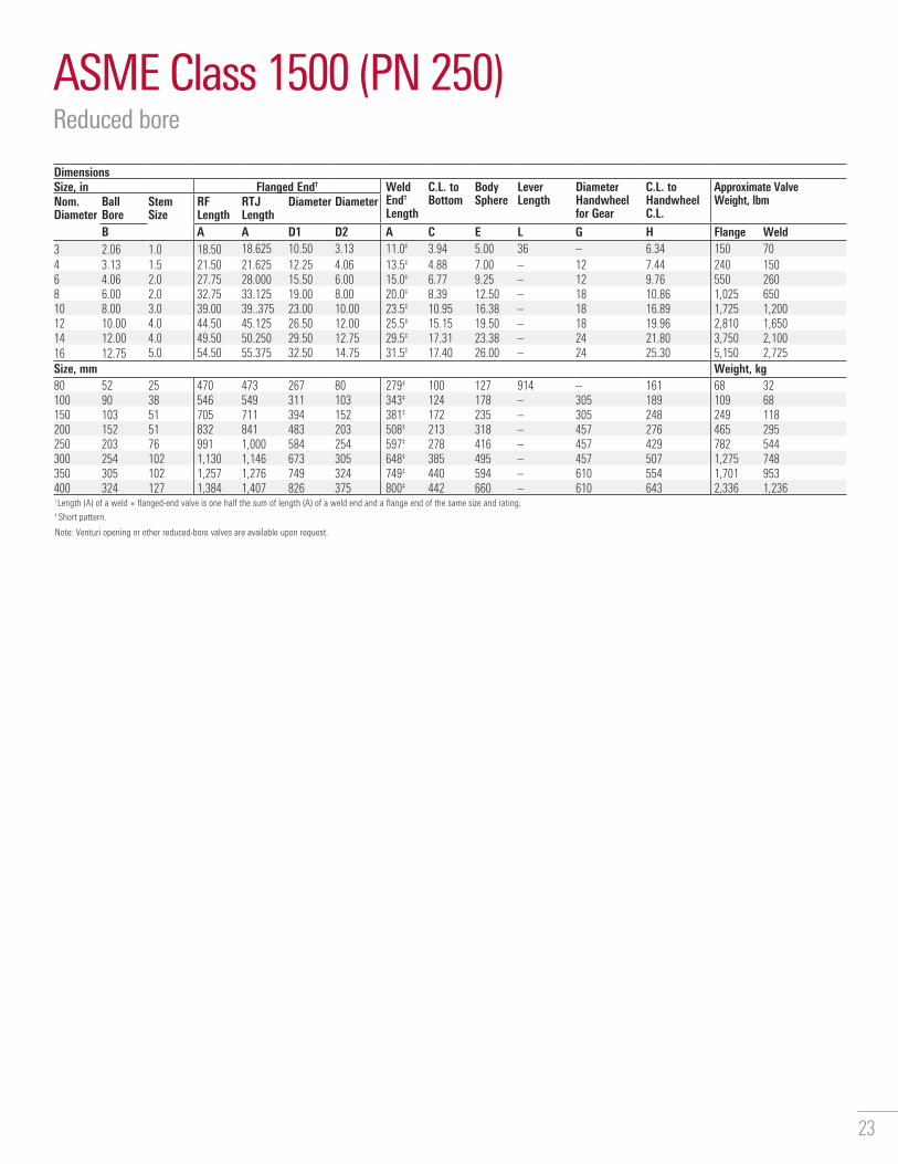
ASME Class 1500 (PN 250)Reduced bore
DimensionsSize, in Flanged End† Weld
End† Length
C.L. to Bottom
Body Sphere
Lever Length
Diameter Handwheel for Gear
C.L. to Handwheel C.L.
Approximate Valve Weight, lbmNom.
DiameterBall Bore
Stem Size
RF Length
RTJ Length
Diameter Diameter
B A A D1 D2 A C E L G H Flange Weld3 2.06 1.0 18.50 18.625 10.50 3.13 11.0‡ 3.94 5.00 36 – 6.34 150 704 3.13 1.5 21.50 21.625 12.25 4.06 13.5‡ 4.88 7.00 – 12 7.44 240 1506 4.06 2.0 27.75 28.000 15.50 6.00 15.0‡ 6.77 9.25 – 12 9.76 550 2608 6.00 2.0 32.75 33.125 19.00 8.00 20.0‡ 8.39 12.50 – 18 10.86 1,025 65010 8.00 3.0 39.00 39..375 23.00 10.00 23.5‡ 10.95 16.38 – 18 16.89 1,725 1,20012 10.00 4.0 44.50 45.125 26.50 12.00 25.5‡ 15.15 19.50 – 18 19.96 2,810 1,65014 12.00 4.0 49.50 50.250 29.50 12.75 29.5‡ 17.31 23.38 – 24 21.80 3,750 2,10016 12.75 5.0 54.50 55.375 32.50 14.75 31.5‡ 17.40 26.00 – 24 25.30 5,150 2,725Size, mm Weight, kg80 52 25 470 473 267 80 279‡ 100 127 914 – 161 68 32100 90 38 546 549 311 103 343‡ 124 178 – 305 189 109 68150 103 51 705 711 394 152 381‡ 172 235 – 305 248 249 118200 152 51 832 841 483 203 508‡ 213 318 – 457 276 465 295250 203 76 991 1,000 584 254 597‡ 278 416 – 457 429 782 544300 254 102 1,130 1,146 673 305 648‡ 385 495 – 457 507 1,275 748350 305 102 1,257 1,276 749 324 749‡ 440 594 – 610 554 1,701 953400 324 127 1,384 1,407 826 375 800‡ 442 660 – 610 643 2,336 1,236† Length (A) of a weld × flanged-end valve is one half the sum of length (A) of a weld end and a flange end of the same size and rating.‡ Short pattern.
Note: Venturi opening or other reduced-bore valves are available upon request.

24
ASME Class 2500 (PN 420)Full and reduced bore
DimensionsSize, in Flanged End† Weld
End† Length
C.L. to Bottom
Body Sphere
Lever Length
Diameter Handwheel for Gear
C.L. to Handwheel C.L.
Approximate Valve Weight, lbmNom.
DiameterBall Bore
Stem Size
RF Length
RTJ Length
Diameter Diameter
B A A D1 D2 A C E L G H Flange WeldFull Opening2 2.06 1.0 17.75 17.875 9.25 2.06 15‡ 4.53 5.43 48 – 7.25 114 943 3.13 1.5 22.75 23.000 12.00 3.13 18‡ 5.67 7.50 – 12 8.94 236 1874 4.06 2.0 26.50 26.875 14.00 4.06 20‡ 7.24 9.75 – 18 11.70 471 3826 6.00 3.0 36.00 36.500 19.00 6.00 24‡ 9.76 13.50 – 24 13.13 943 7378 7.125 4.0 40.50 40.875 21.75 7.125 28‡ 12.84 18.11 – 24 17.88 2,094 1,67610 8.875 4.0 50.00 50.875 26.50 8.875 33‡ 14.84 20.87 – 24 20.00 2,922 2,16612 10.50 5.0 56.00 56.875 30.00 10.50 36‡ 16.65 24.50 – 30 24.75 4,506 3,258Reduced Opening3 2.06 1.0 22.75 23.000 12.00 3.13 15‡ 4.53 5.43 48 – 7.25 156 1294 3.13 1.5 26.50 26.875 14.00 4.06 18‡ 5.67 7.50 – 12 8.94 286 2476 4.06 2.0 36.00 36.500 19.00 6.00 20‡ 7.24 9.75 – 18 11.70 638 5138 6.00 3.0 40.50 40.875 21.75 7.125 24‡ 9.76 13.50 – 24 13.13 1,297 1,01710 7.13 4.0 50.00 50.875 26.50 8.875 28‡ 12.84 18.11 – 24 17.88 2,518 1,91612 8.875 4.0 56.00 56.875 30.00 10.50 33‡ 14.875 20.87 – 24 20.00 3,566 2,657Size, mm Weight, kgFull Opening50 52 25 451 454 235 52 381‡ 115 138 1,219 – 184 52 4380 80 38 578 584 305 80 457‡ 144 191 – 305 227 107 85100 103 51 673 683 356 103 508‡ 184 248 – 457 297 214 173150 152 76 914 927 483 152 610‡ 248 343 – 610 334 428 334200 181 102 1,029 1,038 552.5 181 711‡ 326 460 – 610 454 950 760250 225 102 1,270 1,292 673 225 838‡ 378 530 – 610 508 1,325 983300 267 127 1,422 1,445 762 267 914‡ 423 622 – 762 629 2,044 1,478Reduced Opening80 42 25 578 584 305 80 381‡ 115 138 1,219 – 184 71 59100 80 38 673 683 356 103 457‡ 144 191 – 305 227 130 98150 103 51 914 927 483 152 508‡ 184 248 – 457 297 289 233200 152 76 1,029 1,038 553 181 610‡ 248 343 – 610 334 588 461250 181 102 1,270 1,292 673 225 711‡ 326 460 – 610 454 1,142 869300 225 102 1,422 1,445 762 267 838‡ 377 530 – 610 508 1,618 1,205† Length (A) of a weld × flanged-end valve is one half the sum of length (A) of a weld end and a flange end of the same size and rating.‡ Short pattern.

25
API Flanged 2,000-, 3,000-, and 5,000-psi Working Pressure (WP)Full bore
DimensionsSize, in Flanged End C.L. to
BottomBody Sphere
Lever Length
Diameter Handwheel for Gear
Data for Valve with Operator Normally FurnishedNom.
DiameterBall Bore Stem
SizeLength Diameter Diameter
B A D1 D2 C E L G H Approximate Valve Weight, lbm
2,000-psi WP: 4,000-psi Test2 2.06 1.0 11.625 6.50 2.06 3.94 5.00 36 – 6.34 443 3.13 1.0 14.124 8.25 3.13 5.12 6.75 36 – 7.44 854 4.06 1.5 17.125 10.75 4.06 5.94 8.50 36 – 8.43 1657 6.00 2.0 22.125 14.00 6.00 7.91 11.50 – 24 10.29 4453,000-psi WP: 6,000-psi Test2 2.06 1.0 14.625 8.50 2.06 3.94 5.00 36 – 6.34 903 3.13 1.5 15.125 9.50 3.13 4.88 7.00 36 – 7.44 1304 4.06 2.0 18.125 11.50 4.06 6.77 9.25 36 – 9.76 2557 6.00 2.0 24.125 15.00 6.00 8.39 12.50 – 30 10.92 6755,000-psi WP: 10,000-psi Test2 2.06 2.0 14.625 8.50 2.06 3.94 5.00 36 – 6.34 953 3.13 1.5 18.625 10.50 3.13 4.88 7.00 36 – 7.44 1894 4.06 2.0 21.625 12.25 4.06 6.77 9.25 – 24 9.30 3617 6.00 3.0 28.000 15.50 6.00 8.39 13.50 – 24 13.13 805Size, mm Weight, kg13.8-MPa WP: 27.6-MPa Test50 52.3 25.4 295 165 52 100 127 914 – 161 2080 79.5 25.4 359 210 80 130 171 914 – 189 39100 103.1 38.1 435 274 103 151 216 914 – 214 75180 152.4 50.8 562 356 152 201 292 – 610 261 20220.7-MPa WP: 41.4-MPa Test50 52.3 25.4 371 216 52 100 127 914 – 161 4180 79.5 38.1 384 241 80 124 178 914 – 189 59100 103.1 50.8 460 292 103 172 235 914 – 248 116180 152.4 50.8 613 381 152 213 318 – 762 277 30634.5-MPa WP: 70.0-MPa Test50 52.3 25.4 371 216 52 100 127 914 – 161 4380 79.5 38.1 473 267 80 124 178 914 – 189 86100 103.1 50.8 549 311 103 172 235 914 – 236 164180 152.4 76.2 711 394 152 213 343 – 610 334 365

26
API Flanged 2,000-, 3,000-, and 5,000-psi WPReduced bore
DimensionsSize, in Flanged End C.L. to
BottomBody Sphere
Lever Length
Diameter Handwheel for Gear
Data for Valve with Operator Normally FurnishedNom.
DiameterBall Bore Stem
SizeLength Diameter Diameter
B A D1 D2 C E L G H Approximate Valve Weight, lbm
2,000-psi WP: 4,000-psi Test3.13 2.06 1.0 14.125 8.25 3.13 3.94 5.00 36 – 6.34 804.06 3.13 1.0 17.125 10.75 4.06 5.12 6.75 36 – 7.44 1407.06 4.06 1.5 22.125 14.00 6.00 5.94 8.50 36 – 8.43 2303,000-psi WP: 6,000-psi Test3.13 2.06 1.0 15.125 9.50 3.13 3.94 5.00 36 – 6.34 1054.06 3.13 1.5 18.125 11.50 4.06 4.88 7.00 36 – 7.44 1977.06 4.06 2.0 24.125 15.00 6.00 6.77 9.25 36 – 9.76 3455,000-psi WP: 10,000-psi Test3.13 2.06 1.0 18.625 10.50 3.13 3.94 5.00 36 – 6.34 1304.06 3.13 1.5 21.625 12.25 4.06 4.88 7.00 36 – 7.44 2307.06 4.06 2.0 28.000 15.50 6.00 6.77 9.25 – 24 9.30 490Size, mm Weight, kg13.8-MPa WP: 27.6-MPa Test79.5 52.3 25.4 359 210 80 100 127 914 – 161 36103.1 79.5 25.4 435 273 103 130 171 914 – 189 64179.3 103.1 38.1 562 356 152 151 216 914 – 214 10420.7-MPa WP: 41.4-MPa Test79.5 52.3 25.4 384 241 80 100 127 914 – 161 48103.1 79.5 38.1 460 292 103 124 178 914 – 189 89179.4 103.1 50.8 613 381 152 172 235 914 – 248 15634.5-MPa WP: 70.0-MPa Test79.5 52.3 25.4 473 267 80 100 127 914 – 161 59103.1 79.5 38.1 549 311 103 124 178 914 – 189 104179.3 103.1 50.8 711 394 152 172 235 – 610 236 222

27
Dimensional Data
Dimensions Centerline to Mounting FlangedBore Size, in [mm]
Dimension A ASME Pressure Class
150 300 400 600 900 1500 2500PN 20 PN 50 PN 64 PN 100 PN 150 PN 250 PN 420
2 [50] 4.06 [103] 4.06 [103] 4.06 [103] 4.06 [103] 4.06 [103] 4.06 [103] 4.68 [119]3 [80] 5.08 [129] 5.08 [129] 5.08 [129] 5.08 [129] 4.76 [121] 4.76 [121] 5.71 [145]4 [100] 5.79 [147] 5.79 [147] 5.79 [147] 5.79 [147] 6.61 [168] 6.61 [168] 6.89 [175]6 [150] 7.64 [194] 7.64 [194] 7.64 [194] 7.64 [194] 8.23 [209] 8.23 [209] 12.52 [318]8 [200] 9.92 [252] 9.92 [252] 9.92 [252] 9.92 [252] 9.92 [252] 13.45 [342] 15.39 [391]10 [250] 11.91 [303] 11.91 [303] 11.91 [303] 11.91 [303] 15.05 [382] 15.96 [405] 18.07 [459]12 [300] 16.70 [424] 16.70 [424] 16.70 [424] 16.70 [424] 16.70 [424] 17.80 [452] 19.61 [498]14 [350] 17.72 [450] 17.72 [450] 17.72 [450] 17.72 [450] 20.55 [522] 20.55 [522] –16 [400] 19.08 [485] 19.08 [485] 20.78 [528] 20.78 [528] 22.17 [563] 22.17 [563] –18 [450] 22.19 [564] 22.19 [564] 22.19 [564] 22.19 [564] 23.76 [604] 27.71 [704] –20 [500] 23.75 [603] 23.75 [603] 25.25 [641] 25.25 [641] 29.23 [742] 29.23 [742] –22 [550] 25.22 [641] 25.22 [641] 26.78 [680] 26.78 [680] 30.72 [780] – –24 [600] 26.63 [676] 26.63 [676] 28.20 [716] 28.20 [716] 32.18 [817] 32.18 [817] –26 [650] 29.59 [752] 29.59 [752] 29.59 [752] 29.59 [752] 33.59 [853] – –28 [700] 30.97 [787] 30.97 [787] 30.97 [787] 34.99 [889] 34.99 [889] – –30 [750] 32.62 [829] 32.62 [829] 32.62 [829] 36.65 [931] 36.65 [931] – –32 [800] 34.25 [870] 34.25 [870] 38.53 [979] 38.53 [979] 42.05 [1,068] – –34 [850] 35.26 [896] 35.26 [896] 39.31 [998] 39.31 [998] – – –36 [900] 36.85 [936] 40.92 [1,039] 40.92 [1,039] 40.92 [1,039] 44.65 [1,134] – –40 [1,000] 44.25 [1,124] 44.25 [1,124] 44.25 [1,124] 48.05 [1,220] – – –42 [1,050] 45.89 [1,166] 45.89 [1,166] 45.89 [1,166] 49.69 [1,262] – – –48 [1,200] 50.04 [1,271] 50.04 [1,271] 54.02 [1,372] 56.50 [1,435] – – –The dimensions on this page, combined with the top works dimensions on the following two pages, provide the information required to determine the overall dimensions of a CAMERON T30 Series fully welded ball valve when an actuator is installed.For additional dimensional information on CAMERON T30 Series fully welded ball valves, contact your sales representative.
A

28
Top Works DimensionsSquare nut and adapter flange (BX-1220)
Mounting DimensionsDash Number -1 -2 -3Valve Stem Size, in 1.00 1.50 2.0A Flange diameter 6.50 6.50 8.75B Boss diameter 4.747 4.747 6.997C Height of nut 1.94 2.12 2.62D Bolt size 0.44 0.54 0.66F Width of nut 1.50 2.00 2.50H Number of holes 8 8 16J Diameter bolt circle 5.75 5.75 8.00P Boss height 0.328 0.328 0.328Flange bolt size 3/8 to 16 NC-2 3/8 to 16 NC-2 3/8 to 16 NC-2Bolt torque, lbf.ft 30 30 30Dash Number -1 -2 -3Valve Stem Size, mm 25.40 38.10 50.80A Flange diameter 165.10 165.10 222.25B Boss diameter 120.57 120.57 177.72C Height of nut 49.28 53.85 66.55D Bolt size 11.18 13.72 16.76F Width of nut 38.10 50.8 63.50H Number of holes 8 8 16J Diameter bolt circle 146.05 146.05 203.20P Boss height 8.33 8.33 8.33Flange bolt size 3/8 to 16 NC-2 3/8 to 16 NC-2 3/8 to 16 NC-2Bolt torque, N.m 40.68 40.68 40.68Note: -1 and -2 bolt holes straddle centerline. -3 bolt holes are on centerline.
C
D
P
FA
B

29
Top Works DimensionsKeyed shaft and adapter flange (BX-1221)
Mounting DimensionsDash Number -4 -5 -6 -7 -8 -9 -10 -11Valve Stem Size, in 3.00 4.00 5.00 7.50 9.00 11.00 13.00 15.00A Number of holes 16 16 24 24 24 28 28 32C Diameter bolt circle 10.375 17.25 18.375 24.00 31.00 27.50 27.50 36.00E Max. shaft diameter 2.745 3.245 4.495 5.495 6.245 8.995 8.995 –F Boss diameter 9.122 16.246 17.121 21.746 28.308 25.496 25.496 33.496H Key seat 2.402 2.831 3.786 4.803 5.409 7.887 6.774 –J Height of nut 4.75 5.310 6.25 8.50 9.13 13.31 13.31 19.25K Flange diameter 11.50 18.25 19.380 25.75 32.75 30.00 30.00 39.00N Flange thickness 0.63 0.63 0.63 1.00 1.00 1.25 1.25 1.50Q Key width 0.625 0.75 1.25 1.25 1.50 2.00 2.00 2.25R Key length 3.75 4.310 5.250 7.50 8.13 12.00 12.00 17.50S Overall height 6.120 7.00 8.120 11.00 11.75 16.12 15.84 21.50V Adapter flange
thickness (max.)1.00 1.00 1.00 1.00 1.00 1.25 1.25 1.50
W Boss height 0.328 0.328 0.328 0.328 0.328 0.328 0.328 0.328Flange bolt size 1/2 to 13 NC-2 1/2 to 13 NC-2 1/2 to 13 NC-2 7/8 to 9 NC-2 7/8 to 9 NC-2 11/4 to 8 NC-2 11/4 to 8 NC-2 11/4 to 8 NC-2Bolt torque, lbf.ft 60 60 63 330 330 1,000 1,000 1,600Dash Number -4 -5 -6 -7 -8 -9 -10 -11Valve Stem Size, mm 76.20 101.60 127.00 190.50 228.60 279.40 330.20 381.00A Number of holes 16 16 24 24 24 28 28 32C Diameter bolt circle 263.53 438.15 466.73 609.60 787.40 698.50 698.50 914.40E Max. shaft diameter 69.73 82.43 114.18 139.58 158.63 228.48 228.48 –F Boss diameter 231.69 412.64 434.87 552.34 719.02 647.59 647.59 850.79H Key seat 61.01 71.91 96.16 122.00 137.38 200.32 172.05 –J Height of nut 120.65 134.88 158.75 215.90 231.91 338.03 338.03 488.95K Flange diameter 292.10 463.55 492.26 654.05 831.85 762.00 763.00 990.60N Flange thickness 16.00 16.00 16.00 25.40 25.40 31.75 31.75 38.10Q Key width 15.88 19.05 31.75 31.75 38.10 50.80 50.80 57.15R Key length 95.25 109.48 133.35 190.50 206.51 304.80 304.80 444.50S Overall height 155.45 177.80 206.25 279.40 298.45 409.45 402.34 546.10V Adapter flange
thickness (max.)25.40 25.40 25.40 25.40 25.40 31.75 31.75 38.10
W Boss height 8.33 8.33 8.33 8.33 8.33 8.33 8.33 8.33Flange bolt size 1/2 to 13 NC-2 1/2 to 13 NC-2 1/2 to 13 NC-2 7/8 to 9 NC-2 7/8 to 9 NC-2 11/4 to 8 NC-2 11/4 to 8 NC-2 11/4 to 8 NC-2Bolt torque, N.m 81 81 85 447 447 1,356 1,356 2,169Note: -7 through -11 bolt holes straddle centerline. -4 through -6 holes are on centerline.
SJ
R
V
NW
KH
E
F
O
30
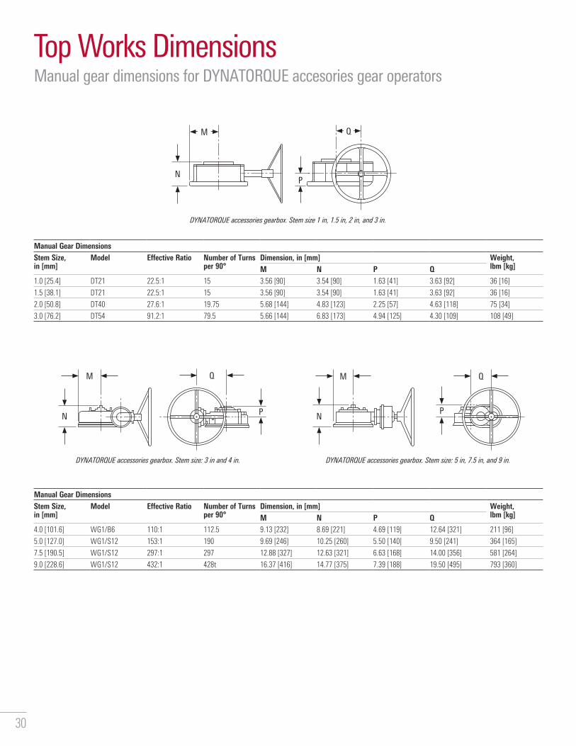
Top Works DimensionsManual gear dimensions for DYNATORQUE accesories gear operators
DYNATORQUE accessories gearbox. Stem size: 3 in and 4 in.
DYNATORQUE accessories gearbox. Stem size 1 in, 1.5 in, 2 in, and 3 in.
DYNATORQUE accessories gearbox. Stem size: 5 in, 7.5 in, and 9 in.
Manual Gear DimensionsStem Size, in [mm]
Model Effective Ratio Number of Turns per 90°
Dimension, in [mm] Weight, lbm [kg]M N P Q
1.0 [25.4] DT21 22.5:1 15 3.56 [90] 3.54 [90] 1.63 [41] 3.63 [92] 36 [16]
1.5 [38.1] DT21 22.5:1 15 3.56 [90] 3.54 [90] 1.63 [41] 3.63 [92] 36 [16]
2.0 [50.8] DT40 27.6:1 19.75 5.68 [144] 4.83 [123] 2.25 [57] 4.63 [118] 75 [34]
3.0 [76.2] DT54 91.2:1 79.5 5.66 [144] 6.83 [173] 4.94 [125] 4.30 [109] 108 [49]
Manual Gear DimensionsStem Size, in [mm]
Model Effective Ratio Number of Turns per 90°
Dimension, in [mm] Weight, lbm [kg]M N P Q
4.0 [101.6] WG1/B6 110:1 112.5 9.13 [232] 8.69 [221] 4.69 [119] 12.64 [321] 211 [96]
5.0 [127.0] WG1/S12 153:1 190 9.69 [246] 10.25 [260] 5.50 [140] 9.50 [241] 364 [165]
7.5 [190.5] WG1/S12 297:1 297 12.88 [327] 12.63 [321] 6.63 [168] 14.00 [356] 581 [264]
9.0 [228.6] WG1/S12 432:1 428t 16.37 [416] 14.77 [375] 7.39 [188] 19.50 [495] 793 [360]
N P
M Q
NP
M Q
NP
M Q

31
Notes

CAMERON T30 Series
slb.com/valves
*Mark of Schlumberger Other company, product, and service names are the properties of their respective owners� Copyright © 2021 Schlumberger� All rights reserved� 18-VL-418654
Copyright © 2022 FDOKUMEN