A theoretical analysis of welded steel joints in rectangular ...
262
UNIVERSITY OF NOTTINGHAM DEPARTMENT OF CIVIL ENGINEERING A theoretical analysis of welded steel joints in rectangular hollow sections by Jeffrey Alan Packer, B. E., M. Sc. i Thesis submitted to the University of Nottingham for the degree of Doctor of Philosophy.
-
Upload
khangminh22 -
Category
Documents
-
view
1 -
download
0
Transcript of A theoretical analysis of welded steel joints in rectangular ...

UNIVERSITY OF NOTTINGHAM
DEPARTMENT OF CIVIL ENGINEERING
A theoretical analysis of welded
steel joints in rectangular hollow sections
by
Jeffrey Alan Packer, B. E., M. Sc.
i
Thesis submitted to the University of
Nottingham for the degree of Doctor of
Philosophy.

i
CONTENTS
Page
Table of Contents i
Abstract v
Acknowledgements vl
vii List of figures
List of tables xiv
Notation xv
Chapter 1: Introduction 1
Chapter 2: Review of literature on RHS joints 15
Chapter 3: Yield strength of gap joints 41
3.1 Introduction to gap joints 41
3.2 Push-pull mechanisms 42
3.3 The effect of branch member yielding
upon the push-pull mechanism yield 45
load
3.4 Comparison of push-pull mechanism
yield loads with test results 50
3.5 Other modes of deformation for gap
joints. 52
Chapter 4: Ultimate strength of gap joints 61
4.1 Large deflection push-pull mechanisms 61
4.1.1 Mechanism with x=0.5 62
4.1.2 Mechanism with x=1.0 66

I
ii
Page
4.2 Comparison of large deflection push-
pull mechanisms with test results 72
4.3 Other gap joint failure modes 74
4.3.1 Local buckling of the compression
bracing 75
4.3.2 Local buckling of the chord behind the
heel of the tension bracing 75
4.3.3 Chord shear failure 78
Cater 5: Ultimate strength of lapped joints 92
5.1 Introduction to lapped joints 92
5.2 Local buckling of RFIS members under 93
axial compression
5.3 Strut buckling mechanism 1 99
5.4 Strut buckling mechanism 2 109
5.5 Comparison of strut buckling
mechanisms with test results ill
5.6 Other lap joint failure modes 112
Chapter 6: Influence of purlin loads on ultimate
joint strength 132
6.1 Reduced joint strength wiVhout
failure of the chord side walls or the
non-connecting face 132
6.1.1 Push-pull mechanisms 133
6.1.2 Strut buckling mechanisms 134

iii
Pace
6.1.3 Chord shearing 135
6.1.4 Chord local buckling 135
6.2 Failure of the chord side walls or
the non-connecting chord face 135
6.2.1 Web buckling failure 136
6.2.2 Chord bearing failure 141
Chapter 7: Parameter studies on gap and lapped
joints 149
7.1 The influence of chord 'preload' 150
7.2 The influence of yield stress 154
7.3 The influence of strut wall slenderness
and other joint parameters upon the
ultimate strength of lap joints 156
7.4 Orientation of bracing members in gap
joints 161
7.5 Influence of the gap size 164
7.6 Influence of the width ratio between
bracings and chord for gap joints 166
7.7 Influence of the bracing angle 167
7.8 Application to CHS bracings 170
Chapter 8: Conclusions and suggestions for
further research 195
8.1 Conclusions 195
8.2 Suggestions for further research 199

iv
Page
References 201
Appendices
1 Joint test data 211
2 Computer program for RHS chord joint
analysis
2.1 Flow diagram for computer program
analysis of a joint between CHS or RHS
bracing members and RHS chord 228
2.2 Data required for computer program input 229
2.3 Listing of computer program 230
3 Detailed example of yield line method
applied to an RHS to RHS T joint 239

V
ABSTRACT
In this thesis a theoretical analysis is presented for
statically loaded structural hollow section (SiuS) lattice
girder joints having one compression bracing member and one
tension bracing member welded to a rectangular hollow section
chord member. A set of joint failure modes are established
for gapped and overlapped bracings and the research is aimed
towards establishing the yield and ultimate loads of such
joints with the yield line method as the main analytical tool.
The results of 150 joint tests, conducted both in isolation
and in complete trusses at testing centres in three different
countries, have been used to verify the theories proposed.
A study of the parameters which are believed to influence
the strength and behaviour of rectangular hollow section joints
has also been made. Finally, a computer program has been written
in Fortran to provide an automatic assessment of the strength
of welded lattice girder joints having a rectangular hollow
section chord member and either rectangular or circular bracing
members.
0

vi
ACKNOWLEDGEMENTS
The author is most grateful for the considerable advice and
encouragement given to him by Dr. G. Davies and Dr. M. G. Coutie
under whose supervision this research work has been carried out,
and for the support of the Head of Department, Professor R. C. Coates.
This research project has been sponsored by the British
Steel Corporation Tubes Division, Corby, Northamptonshire, and
the'Comite international pour le Developpement et 1'Etude de la
Construction Tubulaire (CIDECT), who have both provided
considerable financial support and technical information.
Particular thanks are extended to Mr. T. Giddings and
Dr. AS. Haleem of the B. S. C. Tubes Division Research Centre,
NL. J. Wardenier of Delft University of Technology, Netherlands
and Mr. W. Fose, CIDECT Technical Secretary, for their-
continual assistance and liaison.
Finally the author wishes to thank Miss A. Griffin and
Miss J. Clerbaut for their careful and skilful typing of this
thesis.

vii
LIST OF FIGURES
Figure No. Title Page
1.1 Joints encountered in Warren or Pratt
trusses 10
1.2 Typical welding details 11
1.3 Methods of overlapping bracing members 12
1.4 Definition of overlap 13
1.5 Calculation of actual weld gap 12
1.6 Load v. deflection characteristics of
tubular joints 14
1.7 Location of yield lines and simplification
of. rounded corners 14
2.1 Methods of reinforcing tubular joints 37
2.2 Corby ultimate load curves for 45ON joints 38
2.3 D1N4116 (Static strength of SHS connections)
- Typical design chart 39
2.4 Yield line pattern for RHS to RHS N-braced
gap joints by Davies and Roper (23) 40
2.5 Yield line pattern for RHS to RUS lap joints
by Mouty (51) 40.
3.1 Gap joint failure modes 54
3.2 Typical appearance of a deformed gap joint
(section view)' 55
3.3 Yield line pattern for small deflections of
chord face SG

viii
Figure No. Title Page
3.4 The effect of branch member yielding
upon the push-pull mechanism 57
3.5 The effect of gap size upon the joint
yield strength with yielding at the toes
of the bracing members 58
3.6 Definition of joint yield load 59
3.7 Actual v. predicted yield loads for RHS to
RHS gap joints 60
3.8 Chord shear yielding for RES chord gap joint 59
4.1 Yield line mechanism for large deflections
of the chord face with x=0.5 80
4.2 Yield line mechanism for large deflections
of the chord face with x=1.0 81
4.3 Assumption for strain-hardening of membrane
in the crotch of a gapped joint 82
4.4 Forces acting on one side of a gapped joint 82
4.5 Stress distribution through chord section
at crotch for full plasticity 83
4.6 Actual v. predicted ultimate loads by push-
pull mechanisms for RHS to RHS gap joints 84
4.7 Actual v. predicted ultimate loads by push-
.. pull mechanisms for RHS to REIS gap joints 85
4.8 Theoretical load v. deflection behaviour of a
"'_ gapped joint with X, < 1.0 86

ix
Figure No. Title - Page
4.9 Typical chord local buckle in an isolated
joint 87
4.10(a) Stress concentration causing chord local
buckling according to Haleem (35) for
XS0.7 88
4.10(b) Stress concentration causing chord local
buckling because of noding eccentricity 88
4.11 Actual v. predicted chord local buckling
loads for RHS to RHS gap and lap joints 89
4.12 Actual v. predicted ultimate loads for RHS
to RHS gap joints 90
4.13 Actual v. predicted ultimate loads for MIS
to RHS gap joints 91
5.1 Lap joint failure modes 116
5.2 Effective widths for a side of an RHS for
local buckling 116
5.3 Plate buckling mechanism by Davies et al (25) 117
5.4 Local buckling in strut member 118
5.5 RHS tube under non-axial compression 119
5.6 Interaction between plastic moment capacity
and axial load for a hollow square tube 120
5.7 Strut local buckling mechanism No. 1 shöwn
for a Pratt truss lapped joint 121
5.8 Yield-line pattern for strut buckling
mechanism No. 1 122

:r
X
Figure No. Title Page
5.9 Location of point i for strut buckling
mechanism 1. 123
5.10 Crushing of the tube corners at J 123
5.11 Rotation of lines AH and HE 124
5.12 HJC viewed in the XZ plane 124
5.13 Load/deflection behaviour for strut
125 buckling mechanism 1
5.14 Determination of elastic load line for
strut buckling mechanism 1 125
5.15 Strut local buckling mechanism No. 2 shown
for a Warren truss lapped joint- 126
5.16 Load v. deflection behaviour of joint P7CI 127
5.17 Actual v. predicted local buckling loads for
struts in RHS gap and lap joints 128
5.18 Chord shear failure for lapped joints 129
5.19 Relationship between strut buckling and chord
shearing for an N lap joint 130
5.20 Actual v. predicted ultimate loads for RHS to
RHS lap joints 131
6.1 45° Pratt and Warren truss joints with and
without purlin load. 145
6.2(a) Warren truss joint with load from purlin cleat 145
6.2(b) Cross joint 145
6.3 Methods of jointing at the end of a truss over
a support' 145

xi
Figure No. Title EMS
6.4 Approximation of some of the loads
acting on an element in the chord wall 146
6.5 Model for bearing failure of an RHS
member 146
6.6 Purlin load test for bearing failure of
an RHS member 147
6.7 Bearing capacity of RHS members -
theoretical and experimental comparison 148
7.1 Definition of chord 'preload' (+F or -F) 172
7.2 Reduction in joint strengths caused by
compressive 'preload' 172
7.3 The effect of chord load upon the ultimate
-strength of a gap joint at different width
ratios 173
7.4 The effect of chord load upon the ultimate
strength of a lap joint at different width
ratios 174
7.5 The effect of strut slenderness upon the
ultimate strength of lap joints 175
7.6 The effect of width ratio (X) on the ultimate
strength of lap joints at different t /t l o
ratios 176
7.7 The effect of t /t on the ultimate l o
strength of lap joints at different width
ratios. (X) 177

xii
Figure No. Title Page
7.8 The effect of bl/t1 on the ultimate
strength of lap joints at different
width ratios (A) 178
7.9 Effect of strut length upon the ultimate.
joint strength 179
7.10 Effect of overlap upon the ultimate joint
strength 180
7.11 Actual v. predicted ultimate loads for RHS
to RFIS gap joints 181
7.12 Effect of orientation of branch members in
gap joints 182
7.13 The effect of gap size upon ultimate joint
strength at different width ratios (A) -
b /t = 20 183 o o
7.14 The effect of gap size upon ultimate joint
strength at different width ratios (A) -
b /t = 40 184 o o
7.15 The effect of gap size upon joint yield
strength at different width ratios (X) -
b /t = 20 185 o o
7.16 The effect of gap size upon joint yield
strength at different width ratios (A) -
b0 /t 0=
40 186
7.17 Influence of n upon ultimate gap joint
strength at different b /t values - 0 o
g/b ='0.1 o 187

xiii
Figure No. Title Page
7.18 Influence of X upon joint yield strength
= 0.1 values - g/b at different b /t 188 0 o o
7.19 Influence of bracing angle upon the ultimate
strength of a gapped joint 189
7.20 Influence of bracing angle upon the
ultimate strength of a lapped joint 190
7.21 Influence of bracing angle upon ultimate
joint strength, measured as a bracing force 191
7.22 Variation in gap joint strength measured by
2NSinO1/(1 + Sin91) for various bracing
angles 192
7.23 Actual v. predicted ultimate loads for CHS
to"RHS gap and lap joints. (Side of
square = d) 193
7.24 Actual v. predicted ultimate loads for CHS
to RHS gap and lap joints. (Side of
square = 0.7854d) 194
A3.1 Yield line pattern for RHS to RHS T joint 242

xiv
LIST OF TABLES
Table No. Title page
7.1 Influence of yield and ultimate stress
on gap joint strength - bo/to = 20 171
7.2 Influence of. yield and ultimate stress
on gap joint strength - bo/to = 40 171
0
0

XV
NOTATION
Ai = Sectional area of member
bi = width of member (900 to plane of trussl
h= bi - ti
CHS = Circular Hollow Section
CIDECT = Comite International pour le Developpement et l'Etude de la Construction Tubulaire
di = diameter of member
e= eccentricity - positive being towards the outside of the girder when related to joint noding.
E= Modulus of elasticity
Esh ° Strain - hardening modulus
F= axial load in chord at a joint in addition to the horizontal reaction from bracings. (i. e. force in chord on the compression bracing side of the joint). Positive F represents tension.
pp = squash load of chord
Fpurl = compressive purlin load acting normal to the chord
g* = nominal gap between bracing members on the chord face
g= actual gap between bracing members on the chord face
g' = actual gap between bracing members on the chord face divided by b0'
hi = depth of member (in plane of truss)
hi = hi - ti
Ii length of the strut member measured along its centre line from the chord face. In the case of a truss the length is half the centre-line distance between the inside faces of the two chord members.
mpi plastic moment of resistanca per unit length
mpj' = reduced plastic moment of resistance per unit length due to axial load `

xvi
Mpi = plastic moment capacity
MpiI = reduced plastic moment capacity due to axial load
N, Np = axial load in strut and squash load of strut respectively.
Nult = ultimate joint load measured as a force in the strut
Ny = joint yield load measured as a force in the strut.
P NSinO1
q= amount of overlap
RHS = Rectangular Hollow Section
S, SP = membrane force in joint crotch, and yield load of membrane
T= axial load in tension bracing member
ti = thickness of member
t= length of bearing of purlin
is = thickness of stiffening-plate
w= maximum deflection of buckle dimple
Zi = elastic modulus of member
6= deflection
Eyi = yield strain of member
9i angle between bracing member and chord
bi/b or di/b
(bi + 2x Weld leg length)/b'
Xav '_ (A1 + a2) /2
w poissons ratio
ccrit = critical elastic buckling stress
ai .. = stress in member
adi = limit state design strength of a member
cei = yield stress of a member
The subscripts i=0, '1,2 refer to the chord, strut and tie respectively.

1
CHAPTER 1
INTRODUCTION
Since the first structural hollow sections (SHS). were produced
by Stewarts and Lloyds, (now a part of the British Steel
Corporation), in 1952, their popularity has increased considerably
worldwide, largely due to the increased publicity and knowledge
about their structural behaviour and design, until at present,
for example, tubular steel products account for 28% of total
steel production in Japan. (19)
A popular application of structural hollow sections is in
lattice trusses or girders for reasons of pleasing aesthetics,
structural efficiency and also economy. Tubes are often much
stronger than open section members of the same weight, but the
economic advantage gained from this may be offset by the connection
costs which can be high. The cost of joint fabrication is minimized
if the number of joints is minimal and so initial economy in
tubular trusses can be achieved by designing as a Warren truss
rather than a Pratt or 'N' truss. Furthermore, to avoid profile-
shaping circular hollow section (CBS) members, which is a
facility restricted to only some fabricators, rectangular hollow
sections (RES) which only require straight cutting can be chosen.
MIS joints are thus simpler to fabricate which offsets the dis-
advantage of RHS tube boing generally more expensive than CFIS
tube.,
Most research on welded tubular joints has been confined G731 to circular tubes , and until recently little test evidence has

2
been available for joints made of RHS. (68)
The aim of the research
described in this thesis has been to further the study and under-
standing of hot-rolled RHS joints which are used in two
dimensional lattice girders and which are predominantly statically
loaded. The types of joint configurations which could be-en-
countered in such girders are shown in fig. 1.1, but this study
is limited to joints having one compression bracing member and
one tension bracing member only, such as joint k (without purlin
or applied load) or joint 2. (with purlin or applied load) in
fig. 1.1. The bracing members of such joints can have any angle
of inclination to the chord member and can be overlapped, (also
referred to as lappedl, or gapped at the connection to the chord
face.
Bracing members may be either fillet or butt welded to the
chord member with typical weld details shown in fig. 1.2 for
RES chord Joints. (11,14,15,63 and 71)
Fillet welding is more
common than butt welding and has been used for all the test joints
listed in Appendix 1. In the few cases where butt welds were
made they were overlaid by fillet welds.
General Terminology
(i) Overlap
"Overlap joints, formed when the bracing members of a truss
or isolated joint intersect, necessitate the double shaping of
either one or, both of the bracing members as shown in fig. 1.3.
When bracing members'of lapped joints are of the same width and

3
thickness, it has been suggested that either bracing member be
double-shaped (11),
although it is probably more common to double
mitre the strut (fig. 1.3(b)) in this case because of the belief
that the tie is restrained better if connected directly to the
chord face. Stelco(63) however recommends that both bracing
members be double-shaped at the intersection (fig. 1". 3(c)).
If the widths of the bracing members vary considerably it is
better to double cut the smaller branch member, regardless of
whether it is the strut or tie, but if the widths of the bracing
members are the same yet they have substantially different
thicknesses it is more common to weld the thicker web member
directly on to the chord. This recommendation is borne out in
the recent German draft standard. ý46ý
For Warren girders with
bracing members of the same outside dimensions this will
probably mean welding the compression bracing member directly
on to the chord face. No significant difference in behaviour has
been detected (9,10)
between overlap joints which have the comp-
ression member double mitred and those with the tension member
double mitred.
Authors in different countries have used different methods
for defining the amount of overlap at a joint. With regard to
fig. 1.4 the British percentage overlap is expressed as (CD/AC)
x 100.33) In France and Canada the lap tends to be expressed
by the length DC(63), whereas the Dutch employ the definition
(CP/AB)Ix loo%. (7l) The German definition(45) coincides with
the British, and as this is the recommended CIDECT definition

4
too (60)
it is this expression for lap which is adopted for this
thesis. It has been generally agreed (17)
that it is not necessary
to weld the hidden bracing member toe in a lapped joint (e. g. _If
the tension bracing member was double shaped in fig. 1.4 then
point c is the hidden toe). Generally the toe would be tack
welded in position only whilst the joint or truss was being
fabricated, and this was the procedure for all joints listed in
Appendix 1.
(ii) Eccentricity
For simplicity of design, members are usually arranged so
that all centre-lines are noding but, if a specific gap or lap of
the bracing members is preferred then a moment on the joint is
likely to be produced by the noding eccentricity. If the
eccentricity from the chord centre-line towards the outside of
the truss or girder is termed positive, then gapped joints will
generally have a positive noding eccentricity and lapped joints
will generally have a negative noding eccentricity (see fig. 1.4(a)).
Research at Sheffield University (31,32)
has indicated that
moments produced by noding eccentricities do not significantly
affect the joint strength, although they can affect the strength
of. the chord member on either side of the joint, as the chord
member may be assumed to resist all of this moment. -Since the
chord member is usually continuous through the joint, it is
permissible then to divide the moment equally between the chord
member on either side of the joint, provided that the chord

5
stiffness on one side of the joint is less than, or equal to, 1.5
times the chord stiffness on the other side. In cases where this
ratio is exceeded, the secondary bending moment should be divided
in proportion to the stiffness on either side of the joint
(i. e. the moment of inertia of the chord divided by its
length). 31,32)
For the theoretical analysis of joint strength in this
thesis, the secondary moments produced by noding eccentricity are
treated in this manner and are assumed to only cause an increase
or decrease in the maximum stresses in the chord on either side
of the joint. The joint eccentricity, however, is dependent
upon the member sizes, bracing member angles and the amount of
lap or gap on the chord face, and as these parameters have been
found to affect the joint behaviour and strength, the noding
eccentricity indirectly also becomes a parameter for the
behaviour of a joint.
(iii) Gap
For joints which have a gap between the bracing members
on the chord face, the nominal gap (g )-as shown in fig. 1.5 is
reduced to a smaller actual weld gap (g) because of the fillet
welds around the bracing members. If either bracing angle 9
is less than or equal to 600 then the fillet weld, for the
research in this thesis, is taken to be included in the inter-
Section length of the bracing member at the toe adjoining the
gap, (see äetail'C fig. 1.2), as this was the nature of the

6
welding on P, HS gap joints at Corby. (9)
The relative gap (g')
is then defined by the actual weld gap (AB in fig. 1.5) divided
by b0', the distance between the centres of the chord walls.
Typical load-deflection characteristics for welded tubular
joints are shown in fig. 1.6. After an initial elastic deformation
the joint reaches a yield load provided local buckling does not
occur during the elastic load range (curve d). At this yield
load the joint may deform at almost constant load (curve b), show
an increase in load capacity with increasing deformations (curve a)
or show a reduction in load capacity with increasing deformations
(curve c). The ultimate load of the joint is then defined by
the maximum load which the joint achieved. A recent trend in
European structural design philosophy has been to interpret
structural behaviour in terms of limit state solutions and so
the yield load and ultimate load of a joint are important factors
for assessing the strength of a tubular joint.
In this thesis the theoretical analysis has been directed
towards a means of calculating the yield and ultimate strengths
of welded tubular joints between REIS members. The analytical
tool used for the study was the yield line method which
Johansen(40) originally developed for reinforced concrete slabs.
Calladine13), although pointing out that reinforced concrete
slabs differed from metal plates only in their respective yield
loci, found Johansen's yield line theory suitable for metal
plates and others such as Wood( - 79)
have found good agreement with
test results. - The yield line theory uses a mechanism or geometry

7
approach in which the energy balance is calculated and this
produces a collapse load without considering the equilibrium
equations at all. This collapse load, although an upper
bound solution and hence always 'unsafe', usually gives a
'close' bound and consequently the upper bound method has been
widely used in practice in preference to complex lower bound
methods because the latter are generally not only safe but over-
conservative. (13)
In this thesis the yield line theory, valid for small
deflections which are necessary to form a mechanism, is extended
to -joints in the large deflection range. The post-yield load-
deflection behaviour of curve a in fig. 1.6, which also corresponds'
to the large deflection behaviour of a transversely. loaded
plate (13),
can be obtained by introducing membrane action,
whereas the behaviour of a joint which deforms according to
curve c in fig. 1.6 can be studied by monitoring the unloading
of the joint with increasing deflections. Curves a and c on
fig. 1.6 are the most common modes of deformation for gapped
and overlapped joints respectively.
Apart from strain hardening due to tensile membrane action
in gapped joints, the joint material is considered to be
rigid-perfectly plastic and residual stresses are ignored as
these will have no effect on the attainment of a plastic collapse
mechanism. (13)
Some residual stresses will be present in tubes
due to the, hot forming operation and considerable residual
stresses will be introduced-by the welding of the joint. Residual

8
v
stresses receive further consideration in Chapter 5 part 2 because
of their influence upon the stiffness and buckling load of a
compression member.
Yield line theory was first applied to tubular joints by
Jubb and Redwood(42) who investigated the yield loads of Z' joints
between RHS members, then by Davies and Roper (23,24., 59)
for
Pratt truss (N) gapped joints and by Mouty(51) for Warren joints.
All of these investigations were concerned with the transverse loading
of a plate, (the connecting face of the chord member), by bracing
members whose, width was less than that of the chord member and
reasonable agreement with the joint yield loads was obtained.
Jubb and Redwood used yield line fans around the extreme
corners of the yield pattern as did Davies and Roper, but the
latter showed that straight yield lines give only a very slightly
higher yield load than patterns with yield line fans(23), over
the practical range of joint sizes. Hence rectilinear yield
line patterns have been chosen by the author and these have the
additional advantage of being more easily adapted to calculations
involving large changes in geometry. The yield lines are
assumed to be located at the centres of tube walls and where bracing
members are fillet welded to the chcrd member the yield hinge is
taken to occur at the edge of the connecting weld as shown in
fig. 1.7, which Mouty(51) had also done.
Rectangular hollow section members, which actually have
small corner radii, have been cimplificd to rectangles as shown
in fig. l. % and the sides of an RHS member are then consid^red as

9
connected plates. As these plates are relatively thin, when
they are subjected to transverse loading the load is resisted
mainly by bending stresses and the shearing or compressive stresses
are small. (13 )
As the dominant mode of failure is likely to be different
for a joint when the bracings are overlapped rather than gapped,
the theoretical analysis of gap joint failure modes is treated
in Chapters 3 and 4 whereas the theoretical analysis of lap joint
failure modes is covered by Chapter S. The behaviour of both
joint types when an applied load acts on the connection, or
with variation in one or more of the recognised joint strength
parameters, is discussed in Chapters 6 and 7. Although the
research presented in this thesis is entirely theoretical,
extensive comparison has been made with experimental work cond-
ucted in England(9). Italy (10)
and the Netherlands (28,71)
on
both isolated and truss joints. A total of 110 RHS to RHS
joints have been consulted along with 40 CHS to REIS joints for
use in Chapter 7 part 8. The data for all these tests is given
in Appendix 1.
.., ý
8

No force
JOINT g
\()I
G21
JOINT k
JOINT j
JOINT n JDNT p JOINT q
59- 11. Joints encountered in Warren or Pratt trusses
No force
4
A
No force 10 I,
JOINT c
JOINTe
r
JOINT b
JOINT f
iv
JOINT a
JOINT m
JOINT h
JOINT d
JOINT l

N
os
C U
3
CE
o0 cý
"" n
Q
'v
. 01
0 0
N
L
O
u
EEs Lu
.. /
O
Iz
N
L
0
.P
0) C_
1J d
Se a LL

I-
Fig1F3 Methods of overlapping bracing members
ý-ý,
ýi
to
17.
Calculation of actual weld gap
(a)
Tie double mitred
(b)
Strut double mitred
(c)
Both bracings double mitred

13
(a)Warren joint with negative eccentricity
Percentage overlap =x iß`0°/0
(b) Pratt joint with no eccentricity Def 1rlltioi t Of O\'ý: i ýG`º
1II1IIT11II_1_1

I6 (a)
Load
Deformation accompanying membrane action
Yield load (b)
Post- buckling deformation
(c)
d) Local buckling during elastic load range
Elastic deformation
Deflection
" Fig1.6 Load v deflection characteristics of tubular joints
Yield lines located at Wall of bracing centres of tube walls member.
' s.
RHS " corner lý idealised to a rectangular corner
" Chord member
Figi77 Location of yield lines and simplification of rounded corners

15
CHAPTER 2
REVIEW OF LITERATURE ON RHS JOINTS
The advent of RHS tubes solved the jointing difficulties
which fabricators found with CHS joints but concern grew over
the strength and behaviour of joints with RHS chords, both in
the static state or under fatigue loading. Research in Great
Britain into the behaviour of welded lattice girder joints with
RHS chords began at Sheffield University and more recently
investigations have also been conducted at the British Steel
Corporation Tubes Division, Corby, and Nottingham University.
At Sheffield University, five predominantly experimental
projects were carried out by Blogkley(5,6), Babiker(2)1
Shinouda (61)
Mee (48)
and Chandrakeerthy! 16)
All experimental
work was performed with isolated joint specimens of 'N'
configuration between RHS chord members and cHS or REIS bracing
members, with the diagonal (tension) bracing member always at
450 to the chord.
Blockleyconducted static tests on 60 mild steel joints
with CHS bracing members with a varying gap or overlap and
covering a wide range of member sizes. Blockley found that the
ultimate strength of gap joints was significantly less than if
the bracing members were lapped, and if the chord face was
relatively thin then large local deformations occurred at loads
below the working load of the specimen, for gap joints., Local
deformations encountered in lap joints, on the other hand, were

16
much lower. Blockley claimed that as the joint stiffness was low,
secondary bending stresses caused by joint eccentricities do not
affect the ultimate joint strength and may often be neglected,
but it was suggested that the concept of joint eccentricity be
considered together with the amount of weld gap or overlap of the
bracing members.
Babiker(2) studied the effect of cyclic loading upon 55
mild steel joints with CHS branch members and found that although
a joint may be considered sufficiently strong for static purposes,
its life under fatigue conditions could be so low that it would
be unacceptable as a B. S. 153 Class F joint. Joints with 100%
overlap were fully satisfactory and the bending stresses caused
by the eccentricity with such joints could be neglected as they
are small compared with the direct stress. Babiker found that
partially intersecting joints were slightly lower than the B. S. 153
curve for Class F joints, and because this type of joint has inter-
secting weld beads which can cause stress concentrations, this
type of joint was not recommended. Weld gap joints fell con-
siderably below the B. S. 153 curve and were quite unsafe, so
Babiker recommended a new category of B. S. Class H for such joints.
The width to thickness ratio for both the chord or bracing members
had some effect on fatigue performance but this was insignificant
compared with the effect of joint geometry. It was also found
that no increase in, the fatigue endurance limit could be gained
by using a gusset plate or stiffening rings to connect the members
at a joint.

17
Joints are most easily reinforced either by putting gusset
plates across the bracing members and in the plane of the lattice
girder, or by welding a stiffening plate under the bracing members
to the loaded face of the chord, as shown in fig. 2.1.
Shinouda(61) investigated the latter type of stiffened joint
with a series of 61 tests on CHS to RHS weld gap joints and his
conclusions are the best available guide for the reinforcement of
joints at present. For CHS to RHS gap joints with o/to < 14.3
no stiffening of the joint was necessary. If b0/ 0> 14.3 the
joint could be stiffened according to the following recommendations.
(i) The minimum thickness of the stiffening plate (ts) is
determined by interpolation from: 2/3
3 for dl/bo = 0.25, is = 0.0464 bo C. t
/2 33 for dl/bo = 0.50, is = 0.0582 b0 (2.01)
2/3 3 and for d1/ ö `- 0.75, is = 0.0591 b0
where c in this case is-the ratio of b0 to the desired local chord
deflection, which Shinouda took to be 100.
(ii) The plate and chord wall thicknesses should also
satisfy the following:
for d1/bo = 0.3839 ,s> 75 x 10-4
for dl/bo ='0.5446 ,s> 100 x 10 4, (2.02)
and for dl/bo = 0.6786 ,s> 100 x 10 4
0 8

18
where s= (t03 + ts3) ä2t1' In the formulae above, d1 and tl
could also be replaced by d2 and t2 if the branch members are not
identical.
Mee (48)
undertook research at Sheffield University on the
static strength of RHS to RHS joints with 57 tests on specimens
having varying weld gap or lap and different chord preloads. The
chord compression preload was applied by means of prestressing bars
through the chord section whereas all subsequent joint testing
rigs used hydraulic jacks. Mee confirmed Blockley'sfindings that
the joint strength and stiffness increased as the weld gap
decreased or lap increased, and at a 100% overlap the connection
approximated to a rigid joint. The results also showed that
there was little advantage in having 100% overlap rather than 50%
overlap. The behaviour of RHS joints was again found to depend
mainly upon the joint geometry, and the ultimate strength
increased with increasing A or to. For large bo/to ratios RHS
branch member joints tended to be slightly stronger than CHS branch
member joints, but when bo/to was small the reverse was true.
Mee found that there was little difference between various joints
which had the same geometry but varying prestressing forces. All
subsequent researchers have found that an increasing compression
preload causes a continual reduction in ultimate joint strength,
and the different conclusions about the effect of compression pre-
load may be due to the different way in which t: ce applied it.
Nee carried out a theoretical analysis of the elastic load
r
deformation characteristics of the connecting chord face of. a gap

19
joint by treating it as a laterally loaded plate and analysing
it by means of the "Theory of Thin Plates" using a finite diff-
erence technique. The elastic behaviour of the joint was well
predicted, so an analysis was then carried out to solve for the
secondary moments in a plane framework by taking account of the
joint flexibility.
The work of Blockley(5,6), Babiker(2), Shinouda(61) and
Mee (48)
has also been reported in references 3,4,31,32,58 and
62. Eastwood and Wood (32)
summarized the work done at Sheffield
University up to 1970 by proposing a set of tentative design
rules for hot-rolled CHS or RHS bracing members framing on to
an RHS chord, which are listed below:
(i) Lap Joints. These should have an overlap of not less
than 50% of the mean diameter of the web members, and the
greater the degree of overlap, the smaller the deflections in the
connecting face of the chord member and the greater the
fatigue resistance. When. there is at least 50% overlap
the normal load transmitted to the chord by the bracing
members is unlikely to be a limiting factor, and the chord
face deflections will be small.
(ii) Gap Joints. Where the weld gap is small there will be
less distortion of the face of the rectangular section- than
with a wide gap, but the joint will. be more prone to fatigue
failure. With no stiffening, the vertical component of the
working load normal to the chord should not exceed:
a

20
1.2 ä6e0 for Aav S 0.5
or 1.2t0ce0 11+ 3(2X - 1)1 for 0.5 < Xav S 0.89
(2.03)
or 4t0Qe0 for 0.89 S aav s 1.00
(iii) Eccentricity. For a compression chord the secondary
moment produced by noding eccentricity may be divided equally
between the chord member lengths on either side of the joint,
provided that the chord member is effectively continuous
and that the moment of inertia of either chord member section,
divided by its actual length, does not exceed 1.5 times the
corresponding value for the other length. In cases where
this ratio is exceeded, the bending moment shall be divided
in proportion to the moments of inertia of the chord member
sections, divided by their respective actual lengths. The
bending moments so calculated shall then be assumed to be
inoperative at the neighbouring chord member joints.
For a tension chord, the secondary moment produced by
noding eccentricity bay be divided between the two chord
members intersecting at the joint in any proportion
provided that the resulting total tensile stress shall not
exceed the permissible stress in direct tension in either
member.
(iv) Fatigue. Joints in which the bracing members overlap
by 50 to 100: of tho larger web inember. can be designed for

21
fatigue loading according to Class F in B. S. 153. The
fatigue life of gap joints is seriously reduced and should
be taken as 10% of that for Class F members in B. S. 153.
These recommendations resulting from work at Sheffield
University received particular acceptance in Canada, and are used
by Stelco(63) and the C. I. S. C. (14,15)
A further research
project at Sheffield University was undertaken by Chandrakeerthy(16,78)
who tested 47 RHS to RHS 450N joints made from cold-formed sections,
with test specimens covering gap and lap (50% and 100%) joints.
The aim was to study the influence of typical joint parameters,
identified from tests on hot-rolled sections, on cold-formed RHS
joints. Initial steps were also taken to set up an elasto-
plastic finite element programme for the analysis of tubular joints.
At Nottingham University, complete trusses, for which the
joint design was based upon certain isolated joint tests at
Sheffield, were tested by Dasgupta. (21)
These trusses, 11 in all,
were of 20 foot span and CHS to RHS with small weld gaps. Truss
joint failure loads were found to be up to 30% lower than the
equivalent isolated joint failure loads which was thought to be duo
to additional moments imposcd on the joints when acting as apart
of a complete structure, as well as some inadequately fabricated
joints. Dasgupta also wrote a computer program using the matrix
equilibrium method to analyse trusses with joint eccentricity,
joint flexibility and with the effects of axial forces also
taken into consideration. The actual joint flexibility was
calculated by a finite element analysis. It was found that the

22
secondary moments increase considerably with the increase in axial
flexibility, and the latter increases at a faster rate when X
decreases. The elastic rotational flexibility of the joint was
also small which caused high secondary moments in the bracing
members. These secondary moments in turn cause high stress
concentrations at the crotch of the gapped joint'if there is a posi-
tive noding eccentricity, or conversely relieve the stresses at
the crotch if there is a negative eccentricity.
To complement the research done at Sheffield and Nottingham
Universities, further testing was undertaken by the British
Steel Corporation (22)
at Corby to investigate larger sections and
to provide direct correlation between the testing rigs at the
different establishments. The test specimens were comprised of
30 N-type joints, one having 30° bracing and all others 45°, and
one Warren joint. Of these joints five were RHS to RHS nominal
weld gap joints. In general it was found that the results were
in reasonable agreement with the Sheffield or Nottingham tests.
No generalizations were able to be made from the one test with
the tension bracing member at 30°, which failed at the same load
as its 45° equivalent, or from the Warren joint test which failed
at 18% less than the 450 N joint equivalent.
From the tests at Sheffield, Nottingham and Corby, a series
of ultimate strength curves were empirically derived for both
CPS to RHS and Ri3S to RHS isolated N joints, as shown in fig. 2.2,
which were independent of the weld 1gap parameter and eccentricity.
The vertical axis of these graphs is actually not dimensionless

23
but was found to give the best graphical presentation. These
graphs, known as 'Corby curves', differentiated between CHS and
RHS braced joints which Eastwood and Wood (32) had not done.
In the Netherlands an extensive experimental research
programme has been taking place at the TNO Institute and Delft
University of Technology, sponsored by the E. C. S. C., CIDECT,
the Dutch government and Dutch tube suppliers. About 450 isolated
joint specimens have been tested(68) of which many are with RIS
members. Apart from some tests on Tee joints, Cross joints
and joints between structural hollow section bracing members
joined to an open profile (I or U) chord, the bulk of the
experiments were with Pratt and Warren truss joints with the aim
of studying the following parameters:
(a) the width ratio between bracings (b1/b2)
(b) the height to width ratio of the chord (ho/bo)
(c) the angle between bracings and chord (81,82)
(d) gap and lap of the bracings
(e) axial load or 'preload' in `the chord
(f) additional 'Loads such as purlin loads
(g) grade of material
(h) the thickness ratio between bracings and
chord (tl/t or t2/to)
(i) the weld shape: fillet welds and butt welds
(j) scale effects
" (k) cold finished hollow section joints as
compared with hot-formed ones.

24
(1) the slenderness of the chord wall (bo/to)
and the width ratio between bracings and
chord ((b1 +b2) /2b0)
Measurements relating to the joint tests were well
documented(28) and the results were publicised in a series of
reports (26,27,66,67,69,70,71,72,74)
by Wardenier et al, leading
to the draft version of the Dutch regulations for Tubular
Construction (53),
which were empirically based. It was concluded
that the mean ultimate static strength, (expressed as a force
in the compression bracing member), of Pratt and Warren type joints
in RHS members and with a weld gap, is given by:
1.5 0.5 fh0' 1+Sin61 = f(F/Fp) (2.04) N
ult Saeoto bo aav : bo 2 Sin61
The influence of the chord force, f(F/Fp), was to cause a
reduction in joint strength for both tension and compression chords
according to:
f(F/Fp) = 1.3 omax , but 1 1.0 (2.05)
av ae 0
These formulae were only valid within the following range of
application:
(i) 0.4 s bi/b < 1.0 (ii) ho/tý S 40
(iii) 15 s bo/to .9 35
(v) 3ö sei s 90°
(iv) 0.5 hi/bi S 1.5
(vi) 0.1 5 g* /b 5 1.2 -X 0 av
(vii) IeIcO. Sh

25
Equation (2.04) was then subject to the following checks:
(i) For member strength, NS ae1t1 (2hl-4t I+bm)
and T5 ae2t2 (2h2-4t2+bm )
(ii) For chord shearing, NS Qeoto (2h1/Sine +b1)"SinO 11
and Ts °r eoto (2h2/SinO 2+ n) " Sin6 2 vf3
(2.06)
(2.07)
whenever al < 0.85 , h/bi 5 1.0 or eeiti ? -. 0.58 oe t
00
b= bi + kto
providing bs 2b1 , and the values of k are
av
given below.
0
Values of k
Fe360 Fe430 Fe510
Tension member
Compression member
7
9
7
9
6
8
(iii) Tension bracing members must also comply with b2/t2 S 35
and compression bracing members must have bl/t1 55+ 30 (b1/b ).
8

26
No recommendations were given for the ultimate static strength
of lapped joints, but as these were found to be generally stiffer
and stronger than gap joints, it was suggested that equation (2.04),
subject to its checks, could be used for a conservative estimate
of lap joint strength. Equation (2.04) represented the line of
best fit for the Dutch gap joint tests only, based upon assumed
joint parameters, and which had no chord preload (F = 0). The
reduction factor (equation (2.05)) for the chord force was then
added as a reasonable lower bound on a large scatter of test
results which had chord preloads. A tensile chord preload was
actually found to slightly increase the strength of an isolated
gap joint, but the reduction factor of equation (2.05) was still
applied to tension chords as limited results from truss tests
elsewhere (10).
had indicated that truss joints probably suffered
a loss in strength due to tensile preloads even if isolated joints
generally did not. Although the size of the gap appeared to have
some influence upon the ultimate joint strength depending upon
bo/to and 1aß, the gap parameter is not included in equation (2.04)
as the results were inconclusive as to its effect. No difference
in behaviour regarding the ultimate static strength was evident
between cold forced and hot formed section joints, providing the
yield stresses were based upon stub column tests. The initiation
. of cracks, in cold-formed section joints started earlier, however,
which may seriously reduce the fatigue' strength.
It`is interesting to compare the format of equation (2.04)
with an empirically derived formula for the ultimate load of CHS

27
to CHS Warren gap joints by Washio, Togo and Mitsui (75)
given below:
b2 2t 1 1.5 li_a. 26cos28 N_ Qý oo (1+6.527 ). 1 j. f(g ) (2.08)
ult o4 bo av Sine1
where f(g) = 1.75 - 2.658 /bo for g /bo s 0.2
or f(g*) = 1.15 - O. 06g*/b0 for g*/bo > 0.2
The ultimate load of the joint in this case is dependent
upon b00.5t01.5 , which is the same as proposed by researchers
at Delft, but the factors for the influence of the bracing angles
and gap differ. Washio et al (76)
later changed the bracing angle
influence function from (1-O. 26Cos201)/SinO1 to (1+Sine1)/2Sine 1
which was also later adopted by I'ardenier et al in equation (2.04).
Washio et al also found that while the strength of an isolated
Warren joint was not influenced appreciably by tensile chord
preloads, it was reduced significantly by compressive force in the
chord. Considerably more research has been done on joints having
CBS chords rather than RHS chords, particularly in Japan and
the U. S. A., and the reader may refer to the bibliography compiled
by Wardenier and Verheul (73)
for further references to CHS/CHS
joints.
As part of CIDECT programme 5F, 8 Pratt trusses with RUS
chords and spans of between 14 and 16 metres have been fabricated
in England (33)
and then tested at Pisa University, Italy. (. 10)
These girders were, all designed such that the bays of one half
of each girder had noding joints whilst the bays of the other

28
half of the girder had nominal gap joints. Five girders had CHS
bracings and three had PHS bracings. In association with these
girder tests, some of the joints being investigated in the girders
were reproduced as isolated joint specimens for testing at Corby (9)
to give further correlation, if possible, between the behaviour
of isolated points and similar ones in complete girders. Many
of the isolated joint tests failed by local buckling of the chord
but this did not occur in any of the girder tests, and the latter
also showed no appreciable difference between the strength of
joints on the compression chord and the similar joints on the
tension chord. (35)
From the results of these tests at Pisa (10)
and Corby (9)
as
well as from those in the Netherlands (28,71,72),
it has
been shown by Coutie, Davies, Packer and Haleem(18,36) that the
mean ultimate static strength of RHS or CIIS to RHS gap joints can
be expressed by:
b +b +h +h 2 N= ae b 0.3t 1.7
ult o00 [3.8+10.75
4(bß 2t0 )I Sin91
(2.09)
As with equations(2.04) and (2.08), the ultimate joint strength
again depends on öa. to(2-a) so that the equation is dimensionally
correct, but in this case the angle function 1/Sin©1 gave acceptable
agreement with test results, and a simpler function for the in-
fluence of the chord preload was adopted. For gaps greater than

29
g* = 1.25 ý12 +h 1 +h 2, with dimensions in mm,
(2.10)
the limit state of excessive local deflections becomes operative.
Equation (2.09) is also subject to a check for chord shear (see
fig. 3.1 mode G3) failure:
2ve t /b1ýb2+h1+h2
N Sin81 or TSin62 <oo( +0.2boý_ I F/FP 73-
I 4ho
(2.11)
The mean ultimate static strength of RHS or CHS to RHS lap
joints is given by the equation (18,36)_
N=1.25ae AZ l- F/Fp I. [{b1*,
b
)f o/t I
ftl/t 12 ý -0.25 )
ult 110 0111 0
(2.12)
where b1* = (b1 + h1)/2 (2.13)
The ultimate sti'ength of lap joints is thus considered to be
independent of the bracing angles, and the strut area A1 indicates
that the ultimate lap joint strength is less for CHS bracing
members than for RHS bracing members of the same width, thickness
and grade of steel, when connected to the same chord member.
Equations (2.09) to (2.13) apply to both CHS or RHS bracings, but
for Ciis bracings the terms bl, hl and b2, h2 are replaced by dldI
and d2, d2 respectively. Equation (2.12) is also subject to a
check for chord shear failure similar tc that for gap joints
(equation (2.11)) but the shear area will be slightly increased
dien the bracings lap one another. Equations (2.09) to (2.13)

30
are applicable within the following range:
(i) ti/to Z 0.4 (ii) 30° S0is 900
t
(iii) 0.2 S bi/bo s 1.0 (iv) 0.5 s hi/bis 2.0 .
In West Germany, research on rectangular hollow section
joints has taken place recently at Karlsruhe University of
Technology and the Mannesmann Research Institute, Düsseldorf.
A total of 43 joints had been tested at M. R. I. up until
September 1973, which were CHS or RHS to RHS Warren braced, and
these are reported by Mang. (43)
He found that different curve
characteristics were obtained for Warren joints compared to the
'Corby curves' presented by Davie and Giddings (22)
for N joints.
In 1974 six large size RHS to RHS Warren joints were tested
at Mannesmann (S7) (CIDECT Prig. 5M Series 1) of which three were
gapped and three lapped, with all being fabricated from mild
steel. Hohl's(37) experimental results included the joint yield
load which he defined as the load producing 0.2% strain at the
joint. This strain is measured as the total deflection of the
joint intersection, (using a Williot diagram analysis), in the
direction of the compression bracing member, divided by the length
of the compression bracing member. This concept could be adapted
to different joint test rigs to allow for member restraint
conditions, but is restricted to"joints with equal member lengths. (37)
Hohl also found that a compressive chord preload of up to 70-8O% of
the difference between the chord ultimate and working loads had

31
no effect on the 'loaded behaviour of the joint', but could
substantially lower the failure load. Hohl's test results were
much higher than predicted by the 'Corby curves' of Davie and
Giddings. (22)
In sequel to these tests a further six RHS to RES Warren
joints were tested 8' 14)'(CIDECT
Prog. SM Series 2) but using
all higher yield steel for three tests, and mild steel bracing
members with higher yield steel chord members for the other
three tests. For these joints, all of which were lapped, it was
found that using a higher yield steel chord member generally
produced a 15 to 30% stronger joint, yet there seemed little
additional joint strength obtained by using higher yield steel
bracing members as well, except for small Xav values.
From these tests on isolated RHS joint specimens in West
Germany and also those in the Netherlands by Wardenier et al (28,71,72)
proposals for the German standard DIN4116 on statically loaded
SHS connections, have been drafted by Mang and Striebel. (46)
The
recommendations make use of the joint parameters to/tl or to/t2,
bo/t 0,
Aav and ceo. Using these variables four design charts
are given for four. different bo/to ranges; viz. bo/to S 20,
bo/to _=
25, bo/to = 30 and bo/to = 35. These design charts are
similar in format, a typical one being given in fig. 2.3. For a
particular to/tl, bo/t0, Xav and steel grade, the maximum axial
chord stress can be read off the ordinate axis for the design
cases with wind loading and without wind loading (as these have
different load factors). It is interesting to note that these

32
comprehensive design charts apply to CHS/CHS, CHS/RHS and RIiS/RHS
joints, and for both gap or lap joints too.
Theoretical analyses of RHS to RHS lattice girder joints,
or even joints with RHS chord and CBS bracings are less numerous
than experimental research projects. Elastic analyses were
made by Blockley(5), based on the elastic theory of thin plates
with a finite difference method; Mee (48)
continuing the same
analytical approach; Chandrakeerth y (16)
, using the finite element
method; Dasgupta(21) and Roper (59),
again using a finite element
method but of the complete joint, and Mansour(47) using a finite
difference method. Mang and Striebel 45)
have developed a novel
approach for the elastic analysis of RHS to RHS gap joints using
a spring simulation model but certain joint parameters to be used
in the theory still had to be found or calculated by measurements
from test specimens.
These elastic analyses showed that parts of a joint, such as
the crotch area in a gapped joint, are stressed to the yield
point at well below the joint working load. These severe stress
concentrations in the crotch of a gapped joint are reflected by
the low fatigue strength of the gap joint crotch. Extending
an analysis such as the finite element technique into the plastic
range is likely to be very expensive because'the lack of symmetry
of a typical joint would involve considerable computer time and
storage. Hence the analysin, of a joint in the post-elastic range
has been approached using the yield-line method. As mentioned
in the previous chapter, Jubb and Redwood(42) first applied

33
the simple yield line theory to T joints between REIS members and
then Patel (56)
and Wardenier(711 also did the same finding good
agreement between the joint yield load and the theory.
Davies and Roper (23,24,59)
applied the yield line method,
as early as 1971, to Pratt truss (N) gapped joints with RIIS
bracing members of the same size framing on to an RHS chord member.
The yield line pattern which was used is shown in fig. 2.4, in
which the angle a and the fraction x are both unknown. As the
N joint is non-symmetrical, the point of zero deflection of the
connecting chord face is no longer necessarily midway between the
two bracing members, and so x may not be O. S. An expression for
the yield load of the joint (Ny) can be obtained which is a
function of both a and x. Differentiating to find, the minimum
solution for N gives tan a, and so:
N= 2mp°
+ 8mp
°+ 8mp {)
0 (2x2-2x+1)g'+n(x+(1-x)CosecO2y 91 1-A' 1-aI
(2.14)
n(Cosec92-1) t2 ae ° where x=
4g' +2 and mg° =°4 (2.15)
Davies and Roper (24)
showed that the value of x varies between
0.5 and 1.0 depending upon the angle 0 2, the size of gap and the
value of i;. When x=1.0 the point of zero chord deflection is
adjacent to the toe of the sloping tension bracing member and so
all joint 3efeirrmation is caused by the strut pushing into the
chord. As the weld gap decreases the shear in the joint crotch
increases, until the shear yield of the chord face is reached

34
before the yield failure pattern along the hinges is developed.
Hence there will be a minimum weld gap (g' cs
) below which no
increase in yield load can be obtained because of shear failure
in the crotch. For the N joint in fig. 2.4, this was found (24)
to be given by:
xf3-t o a cs (1+X') b
0
(2.16)
This yield line model for gapped N joints was tested by
comparison with the results of experiments by Mee (48)
and Davie
(22) and Giddings , and acceptable correlation was obtained providing
allowance was made for the fillet welds around the bracing members,
except at large X values. At the large width ratios Davies and
Roper (24)
recognised that other failure modes needed to be con-
sidered, and also pointed out that allowance for the effect of
combined stress on the yield criterion could be made.
Dlouty(51,52) extended the yield line pattern of Davies and
Roper to cover Warren and unsymmetrical gapped joints, and applied
yield line theory to RHS to RHS lapped joints too. Mouty con-
sidered that lapped joints failed by means of a rotational mechanism
of the connecting chord face, which was represented by the yield
line pattern shown in fig. 2.5. By considering the virtual work done
by the mechanism and minimising this with respect to the unknown
angle a, (see fig. 2.5), the following expression for the yield
load of a symmetrical Warren lapped joint was obtained:
2ý
N to Deo L{L+ bo
t --2 '..
}
(2 . 17) Sin61 C
b0 (1-Jl' ) 2L

35
where L and c for this equation are shown on fig. 1.4(. aa. This
equation, however, implies that the strength of a lap joint becomes
infinite as the lap approaches 100% (i. e. as c tends towards zero
on fig. 1.4(a)).
Mouty(51) also considered the effect which axial load has
upon the plastic moment of resistance of a yield line pattern.
It is well known (39)
that an axial load F which is less than
the squash load Fp of a steel member causes a reduction in the
plastic moment of resistance of yield lines normal to the direction
of the force F such that:
iP' = mp(1« - (F/Fp)2) (2.18)
Now consider a yield line which is inclined to the direction
of the force F, such as yield line AB in fig. 2.5 when there is
an axial load (F) in the chord member. The axial load parallel
to the chord which is applied to this hinge AB is equal to
a o.
t0 (b0' - X' bo') /2 .
By resolving this force into components parallel and perpend-
icular to the hinge AB, the force perpendicular to the yield line
is given by
ö obo'(1 - A')Cosu/2
where 11 is shown on fig. 2.5. This force is applied to a section
of area equal to
öbo' (1 - A') / (2CosI)

36
and so the stress normal to the hinge is aö os2U. Substituting
this into a form of equation (2.18) one obtains: -
0 co s2ul 2
mp' = Thp l_l
oQeo
11 i. e. mp' = mp (1 - (F/Fp). CosU). (2.19) 24
The derivation of this relationship assumed that the presence
of a transverse shear has a negligible effect upon the value of
mp, and that an axial force parallel to a yield line also has
negligible effect upon the value of mp. The latter assumption
also checks with the resulting equation (2.19) when u= n/2.
Mouty(51) noted that further strength beyond the yield
load was obtained for aT joint, Warren or Pratt truss gap joint
because of a membrane tension field forming in the connecting face
of the chord. Although the membrane action manifests itself in
directions parallel and transverse to the chord member, Mouty
found that the transverse stiffness of the chord member was
generally so small that membrane effects in this direction could
be neglected.
In subsequent chapters of this thesis the author uses the
yield line method for the yield and ultimate load analysis of
gap and lap joints between RHS members(54,55) as part of an
overall study of their behaviour and modes of failure.

i/
'"
(°
Fig 2.1 Methods of reinforcing tubular joints
a
r
plate

2600. N bo deo
30
201
101
301
20
d.
OL 0
N
i
(a) CHS to RHS
N in tonnes 14 18
"6e0 in kg/sq. mm 24
1 /28 bo
ratios
02 0.4 Aa� 0.6
2600. N (b) RHS to RHS b deo
N in tonnes 6e0 in kg. /sq. mm
N N
r-bi
b2%ß to
LJ
bo
24
28.5 bo ratios to
34
40 55
00 . ".
0.2 0.4.. Aw 0.6.0$ (b; +bz) 1.0
Fig. 2.2 Corby ultimate load curves for 450 N Pints
0-8 (d, +d2 \ 1.0 -bo
14 /'18

Vt
8ý 8
N0 LC)
! -
pJ
f
NN
EE
ZZ O0 N Cr)
oO (L, Co . o0
t: 4 cri M In
lei lý
4
N
U 39 rý+ V 0
0
O s u c
N v ö 'V ä
. ýa
N c 0
a 0
U
N Z
L 0i c:
N
u tl
(0
7
N
(ri OD N
LLI
g "2 bö --
C O4OO
e=ý -V lei CV) $',
+ ceO pOCO

40
)6
i
"e
ý---- hogging yield lines
sagging yield lines
V TLDo LO5eC t92 SIP
Fig2.4 Yield tine pattern for RHS to RHS N- braced gap joints by Davies and Roper (23)
Plan of connecting chord face
Fig. 2"5 Yield tine pattern for RHS to RNS Lap joints by Mouty (51) .
e e
bo ba INbS
N"
1

41
CHAPTER 3
YIELD STRENGTH OF GAP JOINTS
3.1 Introduction to gap joints
The possible failure modes which have been identified in
previous experimental research (9,10,71)
for RHS'gap joints
' are shom in fig. 3.1, and these are :
(i) Failure of the connecting chord face with little
deformation of the chord side walls (G1)
Failure of the connecting chord face and chord walls
around the joint with cracking (G2)
(iii) Chord shear failure (G3)
(iv) Failure of the connecting chord face and chord walls
around the joint without cracking (G4)
(v) Cracking leading to failure of the tension bracing
member (G5)
(vi) Local bucklang of the compression bracing (G6)
(vii) Local buckling of-the chord behind the heel of the
tension bracing (G7)
(viii) Chord face and chord wall failure around the tension
bracing only (GS)
(ix) Chord wall buckling (G9)
The strength of a gap joint may be limited by other failure
modes which do not strictly represent joint failures, such as
elastic local buckling of any compression member due to axial load
only, overall buckling of the-strut or attainment of its yield
load, or yielding being attained throughout the tie. The failure

42
modes, of joints listed ir. Appendix 1 are described by the notation
above. These descriptions are based upon the appearance of a
distorted joint specimen at ultimate load, as observed by a
particular researcher, but the mode of failure which is noted
may not always be the cause of the failure. For example, chord
shear failure- (G3) is a common cause of failure for gap joints
with "X = 1.0 but this is often reported as chord wall buckling
(G9), so not too much emphasis should be placed on the 'observed'
failure mode.
3.2 Push-pull mechanisms
For RHS to RHS gap joints with width ratios (A) less than
about 0.8, the most common failure mode is one in which the
strut force pushes the chord face inwards and the tie force pulls
the chord face outwards, which usually results in cracking of the
chord face (G2) but modes G1, G4, G5, G8 and even G9 are all
associated with this type of deformation (see fig. 3.1). Figure
3.2. shows the typical appearance of a deformed gap joint in which
fracture of the chord face initiated in the joint crotch between
the bracing members. This deformation of the connecting chord
face is idealized by the yield line mechanism of fig. 3.3(b),
in which all the deflection of the chord face is caused by the
vertical components of the bracing member forces only. This model
is hence known as a 'push-pull' mechanism. In this instance no
external loading is applied to the joint, such as a purlin load,
and so the vertical components of the bracing member forces (P) will

43
be equal. The area of contact between the bracing members, the
chord face and the connecting welds is assumed to remain rigid
during deformation.
With regard to the yield line pattern in fig. 3.3, the
internal virtual work done by the yield lines for a small
deflection S beneath the compression bracing member can be
calculated in a manner similar to Appendix 3 and is given by
8mpod ( bo'(1-al') 2mpö 016 E1-(F/Fp)2J {
bo' (1-711' )` 2Tana +n1b' +xgJ} +
xg
8mpod (1-x) ( b0' (1-X2' )l +{+r bo' +g (i-x) J bo'(1-a2')x 2Tanß
4mp0bo'öTana [ 1-(F/Fp)2J
b o'
(1-A1' )
(3.01)
4mpö o'
d (1-x) Tanß [1- (F/Fp) 2]
x. bo'(1-a2')
which can be equated to the total external work done of PS/x.
:. P= 8mp X+ n1
+x+ (1-x)
+ (1-x)n2
+ (g 1_x)
° L2Tana
1-A1' b°'(1-A1') 2Tanß 1-a2' b° '(1-a2')
+ 4mp° C 1-(F/Fp)ý xTana + (1-x)Tanß
+ b0
(3.02)
L 1-al' 1- 12' 2g
As P is an upper bound solution, the minimum value is required, and
this will occur when aP ` O,
lP 0 and
ap O.
as a$ aX
äx.

44
i. e. when Tan a (3.03)
1- (F/Fp) 2
Tan, ß =2 (3.04)
. (F/Fp) 2
b and x=0 Cot ß- Cot a+
2n2 -
2i +
4g
4L1
+11 g 1-T1' 1-a2'
- [1_F/Fp2][T, - 1-al1-X2ý
" (3.05)
If F/Fp = O, alp = A2 and n2 = Cosece2. n1 then equation
(3.05) simplifies to equation (2.15). Equations (3.03) and (3.04)
show that as I F/Fp I increases, Tan a and Tan ß increase, which
means that the yield pattern on the chord face reduces in size,
(see fig. 3.3(c)), and so the joint yield load is slightly reduced
by this effect. I F/Fp I similarly has a small influence on the
value of x', (equation (3.05)), providing the joint is non-symmetrical.
Although this expression for x is the theoretical minimum, the value
given by equation (3.05) may not satisfy the assumed yield pattern
and therefore be invalid. For example, if a joint has Xl, _2
and n2 2pl then equation (3.05) gives:
x nlb°1
+ 0.5 , 4g

45
which may easily be greater than 1.0. In such a case the value of
P is monotonically decreasing as x approaches 1.0 giving a minimum
value of P at the extreme permissible value of x. So as Davies
and Roper (24)
have observed that the value of x lies between 0.5
and 1.0, two separate mechanisms will be analysed - one having
x=0.5 and the other having x=1.0, which are likely to be the
two bounds on the real behaviour.
3.3 The effect of branch member yielding upon the push-pull
mechanism yield load.
High concentrations of stress around the toes of the bracing
members adjacent to the joint crotch have been identified by
previous elastic analyses, so there is the possibility that the
toes of the bracing members may yield and cause a different yield
line pattern to form in the chord face at perhaps a lower joint
yield load. This idea is now investigated to check on the validity
of the assumption in §3.2 that the contact area between the chord
and bracings remains rigid.
For RHS to RES gap joints with width ratios (A) less than
about 0.8, which is the range in which the push-pull failure
mechanism is likely to occur, the easiest and most common way of
welding the bracings to the chord is to use fillet welding rather
than butt welding. However, let us assume that there arc no
fillet welds around the bracing members and that the joint is
butt welded which would result in yield lines forming immediately
adjacent to the edges of the bracing members as shown in fig. 3.4 (b) .

46
Yielding at the toe of a bracing member would effectively increase
the actual weld gap, g, to g+a, g+b or g+a+b where a is
the horizontal length of yielded strut member and b is the hori-
zontal length of yielded tie member. Figure 3.4 shows the case
where yielding at the toes of both bracing members increases the
effective gap size to g+a+b.
As the effective gap size increases due to yielding of a
bracing member toe, the angle of rotation of the two inner hinges
at each send of the effective gap decreases, and so less internal
virtual work is done in forming the yield-line pattern in the
chord face. To counteract this decrease in internal virtual
work done, additional virtual work is done in yielding the toes
of either of the bracing members and this can be calculated
from the approximate extension or compression of a bracing member
toe as shown in fig. 3.4(c) and (d). Consequently, if the extra
virtual work done by the applied loads in yielding the toes of
either bracing member is less than the loss in virtual work
expended in yielding the chord face, then the externally applied
load needed to cause yield failure of the joint may be less than
the load without yielding of the bracing members. This will most
likely occur if the thickness of the bracing members is small
relative to the chord thickness.
Considering fig. 3.4, the internal work done in forming the
yield line pattern is given by:

47
81np° S b°' - bl +n ib°' + xg
b°'-b1 2Tan a
8mp S (g-xg+b) b'-b +°°2+ n2b°' + g(1-x) (3.06)
(xg+a) (b°' - b2) 2Tan
+ 4b°' 6mp° (1- (F/Fp) 2) Tän a+ (g-xg+b) Tan +1 b°'-b1 (xg+a)(b°'-b2) 2(xg+a)
The total internal virtual work needed to yield the compression
bracing member toe is approximately equal to
aelt1Sa bl + (aSinO1 - tl) (3.07)
xg+a
and similarly for the tension bracing member:
ve2t2db b2 + (bSinO2 - t2) (3.08)
xg +a
Equating the sum of these three components to the external
virtual work done of
Pd + PS(g-xg+b) ,
xg+a
gives an expression for the yield load of the joint, P, which will
be a minimum when p=0, aP
=0 and RE
= 0. a« aß ax
i. e. when Tana o bl
(3.09) bo' (1- (F/Fp) 2)
''ý,

48
and Tan ß=°2, (3.10) b0' (1- (F/Fp)2)
2 n2b '2 nibo ' and x=111. Cot - Cot a+o-+
4-4 -
4gLbo'-bl +bo'-b2ý b0 b2 bo bl bo b2
+ 2b
- 2a
- [1_F, 2l Tan a
-Tan b-b b'-b b'-b b '-b
o2o1o1o2
(3.11)
providing xf1.0.
To assess the significance of the change in yield load of
the joint due to yielding in the toes of the bracings, consider a
45° warren joint which is entirely symmetrical, made of the same
steel grade and having F=0. For such a joint,
P tae t2. (xg + a) 1+ nl
+ xg 00 (g+a+b) 2 1-b 1-b1/bo' bo'(1-b1/bo')
+ 2Qe t2 (g-xg+b) 1 n2 g(1-x)
°° (g+a+b) 2 1-b + 1-b1/b°' + b°'(1-bi/bo')
+ csýoto2 xg+a + (g-xg+b)
+ 0.5bo' (g+a+b) /1-b/b0 ti 1-b b'
(3.12)

49
+ (g+a+b)
b1 (a+b) + 0.707 (a2+b2) - t1 (a+b) g+a+
with x=0.5 + (b-a)/4g (3.13)
which implies that -2g < (b-a) 2g (3.14)
If a reduction in the joint yield load is possible, then the
work done in the chord face must be high compared to the work done
in the bracings, so take tl/to to be 0.4 which is a lower pract-
ical limit and assume a value for b1/bo' of 0.4. With nl = 0.5,
bo' = 100 and to = 4, for example, equation (3.12) then reduces to:
p= (x + a) 2.957 + 0.0333 xg 0to2 (g+a+b)
+ (fib)
(g+a+b) 2.957 + 0.0333 g (1-x) (3.15)
+13.84(a+b) + 0.0707(a2+b2) + 50 (g+a+b)
+ 1.291.
The reduction in joint yield strength due to yielding of the
bracing member toes which results is shown in fig. 3.5 for various
gap sizes. The minimum yield load has been obtained by considering
a whole range of values for a and b within the limits of equation
(3.14), and the case in which a=b=0 corresponds to the yield
load of the joint without any yielding in the toes of the bracing

50
members. It can be seen that even for this extreme thickness"
ratio between the bracings and chord, there is no possibility of
a lower yield load for the joint except at very small gap sizes.
(With hybrid trusses in which the chord member is of a higher
steel grade than the bracing members, an effective reduction in the
thickness ratio tl/to will also be caused). At such a gap size
shear failure would normally occur in the joint gap and pre-empt
the formation of a yield line mechanism.
Hence it can be concluded that for butt welded joints, yielding
of the bracing member toes is unlikely to ever cause a yield load
which is lower than that calculated by considering the ends of the
bracing members as being rigid. Normally all gap joints which are
less than full width (X < 1.0) would be fillet welded, in which
case additional internal virtual work would need to be done to
cause the connecting welds to yield at point e on fig. 3.4(c)' and
(d), making the possibility of a reduction in yield load even more
remote for fillet welded joints. Thus the assumption of §3.2
that the contact area between the chord and bracings remains rigid,
is permissible, and gap joints of less than full width will tend to
develop the yield line pattern around the bracings shown in fig. 3.3,
which also assumes that fillet welding is the normal practice.
3.4 Comparison of push-pull mechanism yield loads with test
results.
There is no agreement at present on how to define the yield
load of a lattice girder joint in structural hollow sections from
the experimental load-deflection characteristics. Load-deflection

51
curves for the connecting chord face vary from curve ato curve
b in fig. 3.6, so the joint yield load is not necessarily distinct
and the trend has been to relate experimental results and empirical
deductions to the ultimate joint load, which is simply the maximum
load attained. In Chapter 2a method by Hohl (37)
for determining : the-
joint yield load has been mentioned, based upon calculating the
total- deflection of the joint intersection using a Williot
diagram analysis, but this method is dependent upon the member
sizes and the testing rig used.
Mouty(51) took the load corresponding to a local deflection
of 1% of the chord width (b as the joint yield load whereas the
traditional method has been to interpret the yield load from the
load v. deflection diagram of the connecting chord face, where
possible, in the manner shown for curve b in fig. 3.6. All of
these methods are only approximate and the latter has been used
in this case as it is more generally accepted. Gap joints are
more typical of the deformation given by curve b than curve a
in fig. 3.6 but the determination of the yield load is still sub-
jective by this method. For the isolated Warren joint illustrated
in fig. 3.6 (curve b) it can be seen that the load given by a
deformation of 1% of the chord width is slightly higher, but similar,
to the yield load obtained by the method chosen.
To calculate the theoretical yield load of a gapped joint the
push-pull mechanism outlined in 53.2, which corresponds to fig. 3.3,
has been used, with the assumption that the ends of the bracing mem-
bers remain rigid at the conncction to the chord face. The joint

4
ý_
52
yield load is hence given by equations (3.02), (3.03) and
(3.04) with two cases considered for each joint; one having
x=0.5 and the other having x=1.0. The yield load of the joint
is then taken as the lower yield load predicted by each of these
two cases, although in general the two values are very close to
each other.
Of the RHS to RHS gap joints listed in Appendix 1, some
tests included measurements for the load v. deflection of the chord
face beneath the compression bracing member, and so the joint
yield load could usually be ascertained for such tests in the
manner described above. Correlation between the actual and
theoretical joint yield loads for 41 RHS to RHS gap joints with
width ratios less than 1.0 is shown in fig. 3.7. The agreement
obtained is resonably good for most joints, with theoretical
predictions of the joint yield load usually erring on the conservative
(safe) side. The interpretation of the experimental yield load
is probably the cause of poor correlation for joint P6BI
(fig. 3.7) as good agreement is achieved for the ultimate load
prediction of this joint (Chapter 4).
3.5 Other modes of deformation for gap joints
At the start of this chapter the possible failure modes for
gapped joints were introduced and these are shown diagramatically
in fig. 3.1. Those which are not a result of the push-pull action
of the bracing members on the connecting chord face are:
(i) Local buckling of the compression bracing (G6)

53
(ii) Local buckling of the chord behind the heel of
the tension bracing (G7), and'
(iii) Chord shear failure (G3)
Failure modes (i) and (ii) above are unstable forms of
deformation as unloading of the joint would take place once the
yield load was reached. i. e. the yield load also corresponds
to the ultimate load of the failure 'mechanism'. Local buckling
of the compression bracing and local buckling of the chord are
hence discussed in the next chapter which deals with the ultimate
strength of, gapped joints.
A joint which fails by shearing of the chord, on the other
hand, does have a small reserve of strength after attaining the
shear yield load of the chord side walls as shown in fig. 3.8.
This type of failure can occur when joints have a width ratio near
1.0. Assuming a chord shear area of 2h0t0 and a Von Mises shear
yield criterion with reduction due to axial loading(39) in the
chord, the chord shear yield load is given by:
Pr. 2h ö
öcleo 1- (F/Fp) 2
ý (3.16)
3
This expression does not include the horizontal component of
the compression bracing member force in the axial chord load, as
the effect of the compression bracing member force is complex.
Equation (3.16) tends to be conservative in the estimation of the
shear yield strength.

51, .'
ýý;; ýý
Chord face failure with little deformation of the chord silo walls (Cl)
Chord face and chord wall failure around the joint with cracking (G2)
Chord face and chord Wall failure around the joint without, cracking (G4)
Crocking leading to tie failure (G5)
Chorei face and chord wall failure around tension bracing only (08)
ýj
V
Chorei !, or fciluur' (G3)
.ý ý- r
ýý7
V, V
e t.
=ý=: ý> _ý=-.
Chord woiI buckiirg (Gc, )
,ý `" ,ý :,,: r
`ýý_ 1 Gan ; oi"t fa'A. ire modes
Local buckling of the chord behind the heel of the tension bracing (G7)
Local buckling of the compression b. uciny (CS)

55
3 v
a 0 +J U N N
4J
0 . r,
ro
0 w (1)
ro w 0
N U
rtS ro Q) a Q4 (a
ro U . r{
H
N
M
t3l . 14 w

56
Ltý
F
((1 } ----- hogging yield lines
----- sagging yield tines
S
L bo bo
or
(b}
(c )
F-- tý Cos Of
-N Sin 9, Ton 0,
strut
P
Thin ci 12
E
Xl
92
chord watt I!
GW
P A 1 ý_. l ý --r J
-- --- --ý ---ý--- RT
&2b°' -ý-ý ----------- b0
-2 ichllf
F ig. 3.3 '(i (d li ýc pa±k rr, for small defioctioms of chord face
Plan
Section AA

tý
tU
Yielded portions of tracing member
(c)
6
i ý- g ----- hogging yid lines --ý sagging yield lines
(b)
4- M.
h0. -. b1b, strut
boý_hI 1 bo x. g 2 Tana
x9 +a
(d)
1,2bß-b
57
h
lg-xg+b1
xg }0
Q? 2Tcin13
-_-= tie L 2M: gJ-
(C) Detail of strut toe
C Compression . db Öa Sine, xQ+a
an )cg+ä
ý(
i
riJ. 3ýý+ The effect of brunch member yielding upon the Push-pull mechanism
l_ __ý
d) Detail of tie too
Extension = ad = ab Siýý

to ý
w 4
fý f"ý
*
(0 %4 N -© 0

f
Load in compression bracing as °h of ultimate
100 (a) . (b)
80
60 " joint yield load
40
Joint Delft 22
20
" 00 1.0 2.0 3.0 4.0 5.0 6.0
' Vertical deflection of chord beneath the compression bracing (b) member as a °/° of bo
Ei9.3.6 Definition of joint yield load
59
Chord shear area
to*
Fi9.3"8 Chord shear yielding for RHS chord gap joint
lo

Z'
60
V1 »-" .Y CC
,c 0O0
O O
Ü
c ýo
x0
C " Ö
CL
" d
ý t3 {! 1 - U1
® Ui IE cl:
Ö r VI
" z
mv (ý
Cl-
®0 &IP 'Y
T3
. . C) x a
o V
M a ä
C)
x c c
o - ý
M - -- Z U' x
V CO 4
N v
=NN
2 nV N^
ö00 CO "ü 4 x
x x
ý
x 0 CD (Y)
C"ý %{ i(.: t tf7 C71
D LLI 19 52 b '2 rm
uix #
J p
= ö Ö C3V .1 xX Xy -
X xx
5 ö ü ýo o. 7 3 ;r X%+ x zz
CD
(- VO x NN
`. "+ iJVw
(` `mal Xx
Öf
ý.. 1 _ _
8 ý° 0 - ýoQ 0 o a

ýý. ..
61
CITER 4
ULTIMATE STRENGTH OF GAP JOINTS
4.1 Large deflection push-pull mechanisms
The two yield line patterns which may form in the chord face
around the bracing members of a gapped joint at the yield load are
shown in figs 4.1(b), (for the case in which the point of zero
deflection of the chord face is in the middle of the clear weld
gap), and fig. 4.2(b), (for the case in which the point of zero
deflection of the chord face is adjacent to the toe of the tension
bracing member). As the yield line patterns undergo large
deformations above the yield load and up to the ultimate load, it
is assumed that the bracing members maintain their horizontal
distance apart and only move vertically up or down, which causes
stretching of the panel EFGTNVH, (figs 4.1 (b) and 4.2 (b) ), and
hence membrane forces in the joint crotch. The chord side walls
are considered to be flexible, which Mouty(51) also believes to
be valid (Chapter 2), and capable'of moving towards each other,
hence producing very little membrane action transverse to the
chord.
As the mechanisms deform it has been assumed that the ends
of the yield line pattern LP and RT in fig. 4.1(b), or LP in fig.
4.2(b), maintain their position on the chord member, yet no
membrane action is considered to be formed by stretching oZ the
panels LMNP and QRTS in fig. '4.1(bl , or panel LI1NP in fig. 4.2 (b) .
it is thought that the yield lines LP and RT readjust themselves
to reduce the force in these 1^. ethranes, probably by developing an

62
extensive yielded area around the lines LP and RT. In practice
it seems that any membrane action developed in these ends is
relatively low, and this observation is supported by Mouty(51).
The lengths Ji on figs 4.1(c) and 4.2(c) are taken to be the same
as for the small deflection yield line pattern.
i. e. ii = 0.5b0 171-x 1-. 1-(F/Fp) (4.01)
For both. yield line mechanisms it is assumed that there is
no purlin or applied load on the joint and the vertical components
of the bracing member forces are then equal. The load-deflection
relationship is found'by means of a simple rigid-plastic geometrical
folding of the plates accompanied by membrane action in the crotch.
The plastic moment of resistance. (mpi) of all yield lines is
reduced by the effect of the axial chord force according to
(51) equation (2.19)'by Mouty. The membrane force in the crotch
is calculated from the change in distance between the yield lines
EH and GW, (figs 4.1(b) and 4.2 (b)), based upon an assumed effective
crotch width and an assumed strain-hardening modulus. As the
vertical deflection of the bracing members (d) in the yield line
mechanisms of fig. 4.1 or fig. 4.2 increases by an increment Ad,
the rotation of each yield line in the chord face and the strain
in the crotch produce an incremental change in the internal
virtual work done by the mechanism.
4.1.1 Mechanism with x=0.5
Referring to fig. 4.1 and letting & be the incremental
extension of the inner crotch panel as the mechanism deflects

63
from 8 to 6+ Lid, then
At = gsec(e+ee) - gsece (4.02)
a= gTane/2 , so
AS = gTan(e+1 O) /2 - gTane/2 (4.03)
where 0= rotation of yield lines EH and GW. Letting the rotation
of yield lines LP and ?N be ý1 and the rotation of lines QS and
RT be ý2,
ý1 = Tan-1 (gTanO/2Jl1
. dgl = Tan 1 (gTan(O+19) /2J1) - Tan 1 (gTanO/2J1) (4.04)
Similarly,
0ý2 = Tan 1 (gTan(9+AO)/2J2) - Tan-1 (gTan9/2J21 (4.05)
Letting the rotation of yield lines LF, ME, NH and PV be Y1-"
and the rotation of lines FR, GQ, WS and VT be Y2' then
bo'(1-A1')SinY1/2 and so Y1 = Sin-1 gTanO boy(1-X
1
1 gTan (O+AO)l 1_ grano (4.06) hy, = Sin (b
' (1-a 1) J. - Sin bl 0101 (1-J11 ')J
Similarly,
AY Sin-1 f gTan (O+A6)1
- Sin-1 (-9Tan6
(4.07) 2 bot (1-x2') J bo' (1-7ý2' ))
Letting the rotation of yield lines LM and NP be ßl, and the
rotation of lines QR and ST be ß2, then
8

64
_ (gTan(O+AC) .J TanO. J
Aß1 Sin 1 Ib
01 (1-a1 l I) . LMý - Sin-1 I
(b
0
g(1-A
1' )1. LM, (4.00)
`
1 gran(B+aA). b0' (1-X1 ') _1 gTanO. bo' (1-al' )
+ Tan 2J1.2LM
,- Tan
(
2J1.2LM
where LM = (boI (1-al')/2) + Jl (4.09)
Similarly,
_1 gTan(6+Q81. J2 -1 gTan6. J2
Qß2 Sth tbo' (1-A2') , QRJ -Sin ýb
0' (1-a2') . QR-)
(4.10)
+ Tan -1 rgTan (O+tO)
. bo' (l-X2') _1
gTanO. bo' (1-A2 1) i
2J2.2QR
j- Tan
2J2.2QR J
where QR = (bo' (1-X2') /2)2+ J2 (4.11)
Letting the rotation of yield lines EF and HV be al, and the
rotation of lines FG and VW be a2, then
Tan(O+e8). g 1 gTanO. g dal = Sin '1b 1(1-X I)-2v-F-, - Sin (bo'
(1-A1 " 01) . 2EFý
Tan (e+AO) . b0I cl-Ä1 1) _1
TanO. b01 (1-A1 ,) + Tan-1ý
2EF
,- Tan(
2EF
(4.12)
where EF = (g/2) + ')/2)2 (4.13)
Similarly,
Aa = Sin-1` gTan(O+AO). g 1_ Sin- 1(bo' ciTanO. q
2 `b0' (1-a2') . 2FGJ (1-12') . 2FG)
Tan-1 (Tan (6+Q61. bol Cl-X2' )
-Tan-1 an0. bo! (1-%2 +
FG 2FG
(4. ). 4)

65
where FG (g/2)2 + (bat (1-X 11)/2) " (4.15)
For any deflection, the total extension of the membrane is
gSecO-g which represents a total strain of SecO-l. The membrane
force in the crotch will act between the bracing members and is
hence assumed to be distributed over a width of (b1+b2)/2. If a
linear strain-hardening slope is chosen for the crotch material,
then the stress/strain line can only coincide with the real
stress/strain curve of the crotch material at one particular point
beyond yield. The main point of interest is the average ultimate
strain in the crotch material and so a bilinear stress-strain
model with a strain hardening modulus of Esh = E/300 would be
suitable, as shown in fig. 4.3. Using the guaranteed mechanical (7
properties for hollow sections, the difference between the
" yield and ultimate stresses and the amount of elongation at failure
vary between the different steel grades, but a value of Esh = E/300
will produce an ultimate strain which is near the minimum average
elongation of the various steels (20%).
By using a value of Esh = E/300 one would also only expect
the load-deflection behaviour to coincide with that of a real
joint near failure in the crotch, and to model the load-deflection
curve of a joint accurately a strain-hardening modulus which varies
with strain would be needed. For the value of E, the ECCS
recommends 210 kN/mm2(34), whereas British Standards are proposing
a value of 20G kN/mm2C8).
Hence, if Seca-l S cyo, S= (bl+b2)tö (SecO-1)/2
and if Sece-1 > Cy0, S= (hl+b2) toceo/2
+ (bl+b2)to(Sec9-1-eyo)EJh/2 (4.16)

66
So as the vertical deflection of the bracing members
increases by an increment AS, the rotation of each yield line in
the chord face and the strain in the crotch produce an
incremental change in the internal virtual work done by the
mechanism, which can be equated to the incremental change in
external work done by the applied forces.
' 2POd
a (1+X1' )bo'm 0&&1(1- (F/FP) 2) + (1+X2' )b0'mp A42 (1- (F/Fp) 2)
+ (al'+X2')bo'mpo(1-(S/Sp)2)LO, subject to S= Sp if S> Sp,
+ (4n1bo'+g+2J1)mp tyl + (4n2b0'+g+2J2)m ö&y2 (4.17)
+ 2LMmp0Aß1(1-(F/Fp)2. Cos4X1) + 2QRmp0Aß2(1-(F/Fp)? Cos4X2)
+ 2EFmpoAa1 (1- (F/Fp) 2 . Cos431) + 2FGmp0Aa2 (1- (F/Fp) 2
. Cos4S 2)
+ s. ek
where CosX1 = b0I(1-X1')/2LM, CosX2 = b0I(1-X2ý)/2QR,
Ccm 1"= bo' (1-A i')
/2EF and Coss z= bo' (1-a2') /2FG.
From equation (4.17) the P v. d relationship can then be
calculated for any particular value of F.
4.1.2 Mechanism with x=1.0
The mechanism having x=1.0, in which all deformation is
caused by the pushing-in of the strut member, is shown in fig.
4.2. By using the same notation for yield line rotations as in
94.1.1 (with x=0.5), it can be. found that:

67
Qö - gTan (O+AO) - gTanO (4.18)
and At = gSec(O+AO) gSec6 (4.19)
Aý1 =Tan-' - Tan-1 (gTanO/J1) (4.20)
D Yl = Sin -1 2gTan(8+AO) -
(bo' (1-J, 11),
Sin 1 2gTanO
b' (1-X1')J O
(4.21)
= Aßl Sin 2gTan(O+AO)"J1
_ Sin 1 (bo'
(1-Jai) . LM)
2gTanO. J1 (b'
(1-A (4.22)
1 (gTan (O+t9) bo' -1
gTanO. bo' (1-Xi I) + Tan I J1.2LM
,- Tan( J1.2LM
where LM = (bo'(1-X1')/2) +11 (4.23)
r2gTan(O+, &8). g 2gTan0. g aal = Sin-1 I bo' (1- ai ) EF, -Sin
jb
o' (1-X1') EF,
(4.24) `
_1 Tan(O+tO). b0' (1-al')
_1 TanO. bo' (1-? 1')
+ Tan- an 2EF
,- Tan(
2EF
1
where EF =g+ (by (l-a1 ')/2)4 (4.25)
The total strain in the crotch is again given by Sec9-1 and
the membrane force now acts over a width of bl. The same
assumptions for strain-hardening of the crotch material in §4.1.1
(with x=0.5) are again used. Hence,
If SecO-1 < eyo, S= bItö (SecO-1)
(4.26)
and if SecO-l > cyo, S= b1tocre0 + blto(SecO-l-eyo)Esh
Equating the internal virtual work done to the external work done,
gives:

68
PAÖ a (1+A1t)b0Im 0tý1(1-(F/FP)2)
+ (1+X1')b0 'mpo(1-(S/Sp)2)Ao, subject to S= Sp if S> Sp, f', ý
+ (4nlb01+2g+2J1)mp0ty1 (4.27)
+ 2LMmp0A 1 (3. -(F/Fp)
2. Cos4j(1)
+ 2EFYnpo&a1 (1- (F/Fp) . Cos4ý 1) + SýJý 2
where Cosx1 is given'in §4.1.1 and Cossl = b0'(1-X11)/2EF.
From equation (4.27) the P v. 6 relationship can then be
calculated for this mechanism at any particular value of F.
For both of these push-pull mechanisms now, ultimate load in
the joint will be reached if either:
(a) the membrane stress in the crotch reaches the ultimate
stress of the chord material, or
(b) the entire chord section is stressed to yield because of the
combination of forces and moments acting around the crotch
section (i. e. An upper limit on the tensile force across
the gap is provided by the ability. of the remaining chord
section to withstand. and react to this force without
exceeding the yield stress. )
The former type of failure can be anticipated by monitoring
the membrane force, S, with each increment of chord face
deflection, and the latter will now receive further consideration.
The chord section is likely to be most highly stressed around the
crotch area because of the high local tension force in the membrane,
which only acts over part of the full chord width. The other

69
forces acting on the chord member around the gap, as well as the
membrane tension, S, are shown, in fig. 4.4. Taking a section
through the crotch at the point of zero chord displacement, (AA for
x=0.5 or BB for x=1.0 with regard to fig. 4.4), gives a stress
distribution over the remaining part of the chord section,.
excepting the crotch width, as shown in figs 4.5(a), (b) and (c)
at full plasticity of the chord, which will be the limiting load
capacity of the section. A joint which failed in this manner
would form buckles in the side walls of the chord member (mode G9
in fig. 3.1).
The total axial force on the section AA or BB (fig. 4.4) is
given by:
L= NCos81 -F+ SCos9, (4.28)
and the moment on section AA about the equal area axis is:
M= SCas9. xea + NCos61. xea - NSin81. d - F(xea - ho/21 (4.29)
xea is the distance to the chord equal area axis as shown in fig.
4.5, and d is replaced by d' for the moment on Section B3 (x - 1.0).
To locate the equal area axis
2 (b0 aav', b08)t0/2 + 2(x ea-to)
to = 2(ho xea-tolto + b0t0
xea = (2 o+X '. bo'i/4 (4.301
Neutral Axis in Flange
For the cases shown in figs 4.5(a) and (b) with y> ho-to ,

70
L= 2(h am 2to)t ö ö+(b o ävß
bo')t ö
eo+ (y-ho+to)b ö ac (ho-y) Q eo
L (h
0t0ö ö+bot-2t
2-X 'bo't0/2)
y (4.31) 2 ee bb
000
If v2 to, (bo -X av' bo') to +2 (v-to )t
0= (hQ y) b0
(h 0 -y)b - (b X 'b ')t +"2t
2
and so v= 00 av 000 (4.32) 2t
0
if v5 t, (b -1 'b ')v= (h -y)b 0o av 000
(h°-y) b and so v=0 (4.33)
b-X 'b' o av o
Hence if v>t
M= ae 0 (h
0 -y)b 0 (y-x
ea +h
0 /2-y/2)+tb
o-X av 'b
0 ')t
0 cte
0 (x
ea-to /2)
+2 (v-to) tö eo (x-tom (v-to) /2) (4.34)
which upon substitution becomes:
'2 Jaeob°
aeobo2 M= -y + (4.35)
2 4t 0
ý" "j +y
Joe
obox ea - ce
°b° L-2h ob0
+2(b o -X av'b 0
')t o
+4t ox ea -4t o2J
1
l 4t {aebh2 °
+ 000 -ccbhx 4aet (x -t/2). (b-x 'b ')
2 ooo ea oo ea oo av' 0
ae + °(h b0- [b
-X 'b '3 t) (4t x -h b+ [b -X 'b '] t -4t
2)
4t o0 av 00o ea 00 0 av 000 0
Alternatively, if v< to,
M cue 0 (h
0 -y) b0 (y-x ea
+h 0
/2-y/2) + (b 0 -X öv
lb 0
') v (x-v/2) ce 0
(4.36)
Which upon substitution becomes:

71
b2 veö o cte0 01 M= -y2ý 2+2 (b -a 'b 77-) 0 av 0
+ yf °e° b 2h
00}+ rýe° ° °2 -
Qe0 00l 1(b°-aas b°') 12 2(bß aaý'b°') 1
(4.37)
Equations (4.35) and (4.37) can now be solved for N by
substituting M for the expression in equation (4.29) and y for the
equation (4.31) which is also a function of N. Hence the
maximum permissible value of N can be obtained for a particular
value of the chord 'preload' (F) on the joint, and a particular
S.
Neutral Axis in Web
For the case shown in fig. 4.5(c) with y< ho - to,
L= cleo (4Yto - Xavlb 0t0-
2h0 0tjL
1av'b0 '+2h y= 14Qeot0 +-4 0}
v= ho _y+X av 'b o
'/2
M= ae0(bo^aav'. bo')to(xeä-to/2)
+2 (v-to) to (x ea -v+ (v-tp) /2) creo
(4.38)
(4.39)
(4.40)
(4.41)
+ae 0b0t0
(h o-x ea-to
/2)+2ae0(h0-y-t0)t0(y-x+h 0
/2-y/2-t0/2)
which upon substitution becomes:
M= -y2 {2Qo0t0 }
+y{2ceth+cc t'b ooo 0 o:
} (4.42)

72
+{2ae 0t03-Qe0b0t02+aeoaav
'bo 't 02/2+Qe0b0h0t 0
+aeö 00
2-2ce0 t0 aeet0 02-aeö 0 0Xav'b01
-Qeö av'2. bo'2. t0/4}
The equation above can now be solved for N by substituting M
for the expression in (4.29) and y for the equation (4.39) which
is also a"function of N. Thus the maximum permissible value of
N can again be found for particular values of F and S.
So in summarizing, the procedure which has been adopted for
calculating the ultimate strength of the push-pull mechanisms is
to give each mechanism a series of small increments of deflection,
calculating the tensile stress in the crotch membrane and the
strut load which the mechanism can sustain, each time. The
mechanism is allowed to deform until:
(a) the stress in the crotch membrane reaches the ultimate stress
of the chord, or
(b) the combination of the particular strut load, (which the
mechanism could sustain at that deflection), and the
membrane force, produces yielding of the whole chord
section around the gap. These calculations are carried
out by computer using the program listed in Appendix 2.
4.2 Comparison of large deflection push-pull mechanisms with
test results
55 MIS to RHS gap joints predicted to fail in the chord
connecting face or, side walls, (failure modes GI, G2, G4, GS, Ga

73
and G9 in fig. 3.1), and for which the joint data is given in
Appendix 1, have been analysed by the two push-pull mechanism
approaches. The correlation between the theoretical and actual
ultimate loads of these joints is shown in figs 4.6 and 4.7, with
a reasonable prediction of the ultimate joint strength being
obtained. The analysis becomes conservative for Warren joints
I having a compressive chord-'preload', which accounts for many
test results clustered on the left hand side (safe side) of the
diagonal line in fig. 4.6.
By referring to fig. 4.4 one can see that the total axial
compression force in the chord at the gap reduces if the joint is
a Pratt (N) truss joint as NCos91 =0 and similarly the moment on
the gap section becomes less severe, which means that N joints
are not likely to fail by yielding of the whole chord section
around the crotch and should always fail by ultimate stress
being attained in the crotch. For Warren joints, on the other
hand, the chord may foil by either manner. The presence of a
tension chord 'preload' on a Warren joint makes the joint unlikely
to fail by yielding of the whole chord section at the gap, and it
should always reach failure by fracture of the crotch, because
the tension 'preload' will reduce the chord axial compressive
stress and relieve the moment on the section too.
Figure 4.8 shows a predicted load-deflection behaviour of
the chord connecting- face for an RHS to MIS Warren joint having X
less than 1.0, by the two push-pull mechanisms. The theoretical
load v. deflection curves only bound the real'joint load v.
deflection curve around ultimate load, which is to be expected i

74
because of the choice of a linear, and hence unrealistic, strain-
hardening modulus. Using this strain-hardening modulus the
theoretical post-yield joint deflection cannot-be expected to
correlate well with the actual joint load-deflection behaviour and
a constantly varying value of Esh would be necessary to model the
joint deflections more accurately between the yield and ultimate
- loads. The push-pull yield line mechanisms will, of course, only
' give a post-yield deflection curve and other techniques must be
used to calculate the elastic joint deformations, such as the
finite difference method, finite element analysis or beam on an
elastic, foundation concept which have all been applied to tubular
joints before (see Chapter 2). This would then provide an
elastic load line for the joint deformation from which a complete
joint load-deflection behaviour could be formed.
Although the theoretical load v. deflection curves in fig.
4.8 have a constantly increasing gradient, whereas the actual
deflection curve of a'joint has a constantly decreasing gradient,
the theoretical push-pull mechanism curves have the same shape as
the theoretical load v. large deflection curve of a laterally
(l3) loaded longitudinally restrained steel plate.
4.3 Other gap joint failure modes
Failure modes for a gap joint which are not a result of the
push-pull action of the bracing members on the connecting chord
face have been mentioned in §3.5 and these are:
(ii Local buckling of the compression bracing (G6),

75
UU1 Local buckling of the chord behind the heel of the
tension bracing (G7), and
(iii) Chord shear failure (G3).
4.3.1 Local buckling of the compression bracing
As this is the principal failure mode for lap joints,
theoretical analyses for this type of failure which are applicable
to both gap and lap joints, and based upon two strut buckling
mechanisms, are presented in Chapter S.
4.3.2 Local buckling of the chord behind the heel of the tension
bracing
Chord local buckling is caused by a concentration of
compressive stress in the connecting face of the chord member
behind the heel. of the tension bracing. A typical chord local
buckle in an isolated joint is shown in fig. 4.9. This
compressive stress is a result of the horizontal components of the
bracing member forces, any bending stress in the chord caused by
the moment produced by the noding eccentricity of the member
centre-lines and the chord axial 'preload'.
There are two ways in which a prediction of the chord local
buckling load can be calculated. As the connection of the bracing
members to the chord is made on one face only, the horizontal
components of the bracing member forces are largely transmitted
through the chord connecting face near the joint. From strain
{35- gauged test specimens, Haleem has observed that the horizontal
components of the bracing member forces cause a distribution of

76
stress through the chord section which is triangular behind the
tension bracing member as shown in fig. 4.10(a) regardless of the
joint eccentricity. This implies that for a square hollow section
chord, one half of the horizontal force components are borne by the
connecting chord face. This is only slightly more than the
"approximately one third" suggested by Eastwood and Woodý32ý
previously. However the triangular stress distribution observed
by Haleera was only for width ratios up to X-= 0.7 and for greater
width ratios the stress distribution was uniform. Local buckling
of the chord then occurs when the total compressive stress at the
critical, (most heavily stressed), chord face equals the critical
buckling stress, which is generally the chord yield stress for
hot rolled rectangular hollow sections. As this distribution of
stress through the chord is caused by the connection to only one
face of the chord rather than the noding eccentricity, it applies
to both gapped or lapped joints having X. 0.7.
An alternative view of the horizontal force component
transfer is to consider the extra stress built up on the connecting
chord face being due to the bending moment in the chord produced
by the noding eccentricity of the joint centre-lines. Hence a
bending moment distribution as shöwn in fig. 4.10(b) is produced
in the chord member, and the bending stress in the connecting
chord face is
e (NCosO1+TCos82) / (kZ0) (4.43)
For isolated joints in which the bending moment is taken on one
side of the joint, k=1, but for truss joints in which the chord

77
member' is. continuous on both sides of the joint and is the same
length on either side of the joint to a neighbouring joint, k=2.
Gapped joints will usually have a positive nodin4 eccentricity as
shown in fig. 4.11 which would produce a tensile bending stress
behind the tension bracing member tending to relieve the local
stress concentration. in this case the greatest compressive
stress would occur on the outside of the chord member furthest
from the joint, (for a compression -chord), initiating local
buckling at this position but this has never been observed in any
joint tests.
Applying the triangular stress distribution observed by
Haleem for X5O. 7 can still be unsafe for many lapped joints and
often overestimates the chord local buckling load, whereas
" calculating the local buckling load by this latter method gives
reasonable predictions for joints with positive eccentricity, such
as lapped joints. Hence it'is suggested that the joint local
buckling load be calculated by both methods and the. lower estimate
be taken, but if the noding eccentricity is positive then the
likelihood of local chord buckling starting on the outside of a
girder is remote.
The incidence of chord local buckling in trusses will be much
less than in isolated joint tests because:
(i) The compression chord of a truss will deflect such that the
inside (connecting) face of the chord'member is under less
compressive stress than the outside chord face, and so the
build up of stress behind the heel of the tic member will be
slightly relieved.

78
(ii) The position of maximum chord axial compressive stress is
usually in the middle of the girder and coincides with the
position of the lowest forces in the bracing members.
Similarly the position of the maximum bracing member forces
is usually at the ends of the girder which coincides with
the position of the lowest axial chord loads.
(iii) The bending moment produced by the noding eccentricity will
usually be taken by the chord member on both sides of the
joint in a truss whereas isolated joint tests are one-sided
and all the bending stress is resisted by the chord member
on one side of the joint.
In fact in tests on trusses (10)
which corresponded to
isolated joints which had failed by chord local buckling (9
, no
chord local buckling failures occurred. Fig. 4.11 shows a
comparison between the predicted and the actual chord local
buckling loads for 8 REIS to RHS gapped and lapped joints, with the
agreement obtained between predictions and test results being
reasonably good by taking the lower of the two failure predictions
as recommended.
4.3.3 Chord shear failure
For large width ratios (X and also for rectangular chord
members with the larger side of the rectangle as the connecting
chord face (ho < be), there is a likelihood that the chord section
may fail in shear due to the vertical components of the bracing
member forces acting on the chord walls. Taking the chord shear
area at ultimate load as2(ho+2to) to according to Wardenier an-i
4

79
De Koning(71), and assuming a Von Mises shear yield criterion with
reduction due to axial loading in the chord, the ultimate shear
resistance of the chord section is given by:
ceo Pä 2(ho+2to)to . 1-(F/Fp) (4.44)
An alternative (equation 2.11) has also been proposed but
equation (4.44) is used for the calculation of the ultimate shear
strength of an MIS chord.
The theoretical formulae which have been presented in Chapter
4 to enable one to predict the ultimate strength of an RHS to RHS
gap joint by a series of recognised failure modes, have been
incorporated into a computer program, which is listed in Appendix
2, for the analysis of such joints. By this means, 84 RHS to MIS
gap joints from Appendix 1 have been studied with the resulting
correlation between the predicted and actual ultimate joint loads
shown graphically in figs 4.12 and 4.13.
0
I

r 7---% %'`
-,. .5
F<i
(a)
B LF-,
r
(b)
(6. A6)
(c)
---- -- hogging yield lines
suggincj yield limas
welds membrane field IN/i
r-- A
tie mce
A
tI
A+a6
xg
N Cos Fig
Tar El
IY2 Z 4%,
-. -
IL_
Section AA
---j---ý---- Section BB
f'+g. 4. - rr, '.,. ý; cri ai cr, or-: i fcce

p
F
(a) ---hogging yield lines
------- saggirrj yield lines
welds membrc. nc field
l_ j-A ýF /
chord
ý'c It+ tie 1d:
b' L
ri Al
Icy + A9
, -"0,1
J
F- NCose,
- Nein B TonC
ý, I
Iji
Section A
Section BF-3
Fig4"2 Yield line representat'son of ch.: rd face' deforrn, utio n with x=I. 0
`, All

U2
aultp
aeo
Stress in crotch
1001,
w ___ý E/ 300, =Es h\
Theoretical approximation
True behaviour
ýw, _ Membrane strain in crotch _ Sec 0, -1
Fig. f:. 3 Assumption for strain hardoning of membrane in the crotch of a gapped joint
"4)
U
Fig. + /; Forces acting cri one side' of a gapped joint

b0
1LJ, i
I-- bG - UV
xea
ho equal ureci a : iS
neutral
(a) y>(ha-to) rund v>to (ho-y)
do oc, UJ
3e0
aeo
i__
(b) y> (ho- t0) and v< to
ea
Putra Nc is "I
t0 --- Xea
Y ho
equal area axis
-- --- --4-- -- -
L Ciy (h0, - t,,, ; anü V alwG JS =- t
beo cis. crotch for full plasticity
L-1
beo

I. Z
V1 ý
4 !Q jv U Li
(7 Cl ,D L-
m Nt2ö C Ö := C3 O LL
OLLä. ýÖ
X0O
o
N d N
X
0 x
C3 ýO
Ö x
() O Lf)
ö x x X v
co rs
at rn o
" gix p C) NNX
.. to "ii X a
T v_
v pOn k X-1 Ir a sX
Xb x
s
O- .. e; ý
VN Ir
XNMNQ ýT n CID -T
- x s Fj co r XN
O ÖÖÖ M LL öo M
U n.
" ö °x
. ýc
p
Ji
lcg
"
Q Q
co 8
at

85
CHI. ER ý' M8 i0
C3

I
0
S.
'0 0 O
d E Z) v . 0-
-4-
e
(D (D
"o
v Mio ro
ei ....
86
oIi
r.
0 ö
0 ai
0
th r< t
oc ö
a, CL CL ov cý vn
v .ý 0 I- o
Ui 0
0) .O
oc o
C) O
od N
O
r:. i
ii> C14

ý; ýý .1
ý'1. ^
ý, .ý
I 11K ,I
..
.i
1
R M-01p,
NT iF
1
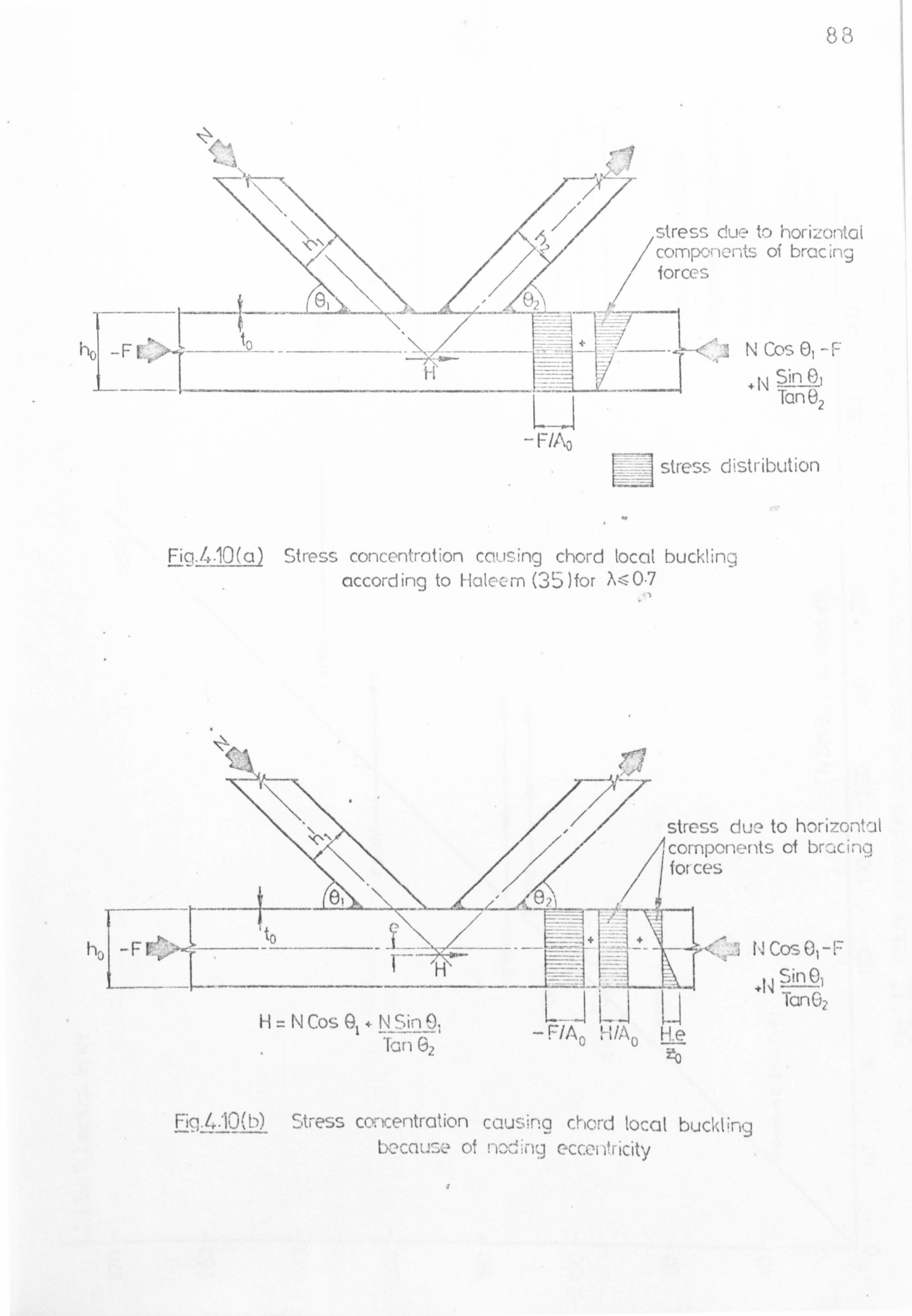
83
A
ho -F
-Erns
stress due to horizontal /componc nts of bracing
forces
`'q NS 0r _F .ahC. Cý_ ý
Tan fez
stress distribution
Fig-4.10(a) Stress concentration cot. ising chord local buckling according to Halecm (35 )for k-0-7
.r
ho _FC
H=NCosG +NSin0, 'Ian 62
stress doe to horizontal components of brucina forces
LJJ U " F/A0 H A0 He
HCos
+N Sin © fanO
Fiq. 430(b) Stress concentration causina chord local buckling bocnu <. z of eccoI if[ IcIty

' ý Ü V 0)
Z7- ý +"' Ü W
ü' :
° x a c c Q
v o 0 V 0" (A
N CD (IV Q) c
, C Q C'
. 0Z .
CL .0 C
. ý X fi 7C w
p a
' n ` -r
c cr)
i Z- co 0 X 04
CY) C.
0 (L Ni x S "
ýp u
= a Nv
C
Z C) O N V
o U 72 W
N _
O
(D
. - a ö d
w
M r
1 cn (7) 0
LL' 119
= . 19
.0 iii IE8
h w :3 x
C z ý7
L/) Z
o
Y <cý
o o 1
Q
C ) C 4
69

Z
c to cc c C$ ö0Ö .o
*10 -2 "O can
D d En Üd l1 17
p
C aa
Dn. LLýp X"p
un s
"x xm o-.
N ý mx�
0 pv XXÖ XX Xý
X .P C)
X
O1 0 öxx x ~ý x
° ýº ° Xxo ö
x ^týN ýO v1 ýv
fNv
`- vs v v °`t
xx Xoý. N Ö XxsX
O "*" o tb 0X X
r^N N VIV
xm e1 XvNx Co 0 17
XÖ MX X ýu 0 XX
x Co 0Nxxiz ° °ý+ýny hri1`^ Mx=X e-2-
.^ Co
50 Zt <D NN V_ X I-
OO 00 os.. ý O sÖÖ
\2x
. Zý sxx L4 ýO e
x
x : XX x ä ssX
a' vQ
Zn. v, "
I` Op CD
7' C: ) CID

91
V1
"ý CC d 'p C
m C> _ 0 ul c: ul
v döýv. M m ° Ný Q ý= C " -- - u i
oxä.
x"a
" N C
0 ý "
C
g a v 00 °'
t
0 0 C)
U a
0 In
Lil
O C
75 U') r' tn Z Q, v
N i
v U Z
ý- a ä ý7
d " y Z, t 9
.: 3
O
2 CU rz T7 Ei
C IT o O ._
kfl -' v x
x XX
0 C "
Z öö
Co
Ö Q Q [ý Q

92
CHAPTER 5
ULTIMATE STRENGTH OF LAPPED JOINTS
5.1 Introduction to lapped joints
The failure modes for overlapped joints which have been
(9 identified by previous experimental research on RHS joints'10,71)
are as follows:
(i) Chord face and wall failure around the joint (L4). This
is usually associated with shearing of the chord section
for large width ratios.
(ii) Local buckling of the compression bracing accompanied by
some deformation of the chord face (L6).
(iii) Chord local buckling behind the heel of the tension bracing
member (L7).
These types of joint failure are shovm in fig. 5.1 along
with a further failure mode in which the compression bracing
member punches into the tension bracing member (LlO). It is
thought that this failure mode may occur for overlapped joints in
which the compression bracing member has a smaller width than the
tension bracing member, but all tests on overlapped joints have
hitherto had bracing members of the same width and this type of
failure has never actually been observed.
As with gapped joints, the strength of an overlapped joint
may be limited by other failure modes which do not strictly
represent joint failures. These have been described in S3.1.
in this chapter the failure of overlapped joints by modes L4, L6

93
and L7 is considered with the emphasis on the ultimate strength of
the joint as this coincides with the 'yield strength' for the
unstable buckling failure modes and is very close to the yield
strength for chord shear failure.
5.2 Local buckling of RHS members under axial compression
For the purpose of axial compression, Timoshenko(64),
Johnston (41)
and Watson and Babb (77 have considered that a
rectangular hollow section can be idealized as four simply
supported plates. Experimental studies on box sections and
plates under uniaxial compression at Cambridge University have
shown that some restraint between the sides does exist. In fact
the elastic buckling load of the wider sides is increased by
rotational restraint from the more narrow sides by up to 30% over
a square section'if the sides are such that hi - 0.5 bi (the
limit for British sections , but the maximum load sustained by
the wider sides is not increased. The result has been that
Dwight (30)
too has concluded that a reasonable design approach is
to consider the four sides of a rectangular hollow section as
being simply supported plates.
Apart from the edge restraint, plate buckling strength will
also be influenced by the stress/strain curve of the material,
residual stresses and the initial out of flatness.. Very little
is known about the latter two effects for RHS members, but it is
thought likely (301
that some moderate mid-width residual
compression stress exists on each side of rectangular hollow
sections. For a uniaxially loaded steel plate which is initially

94
flat and stress free, the elastic critical buckling stress is
given by the classical plate buckling formula,
_ kn2Et2
ýcrit - 12 (1-v2)b2 (5.01)
For large aspect ratios and simply supported edges, k is
very close to 4. Hence with v=0.3 and E= 206 kN/ n2, ý8ý (41)
equation (5.01) simplifies to:
744.7 Q_ kN/ten?
crit (b/t) 2 (5.02)
In this case b is the effective width of the plate, which
for the side of an RHS is not well defined because of the rounded
corners. In light gauge codes the effective plate width is
simply taken as the flat width (bf on fig. 5.21, but Dwight (30).
considers that this is rather optimistic and suggests the
effective plate width be taken as (bf+bin1/2. However if a safe
estimate is to be taken for the effective plate width, b' from
fig. 5.2 could be chosen. The range of currently produced
rectangular hollow sections in Great Britain (12)
has a maximum
b'/t value of 46.6, which means that the lowest elastic critical
buckling stress for any face of an RHS tube is 343 N/mm2.
Consequently no Grade 43 RHS sections are liable to elastic local
buckling and only a few will be liable in the higher steel grades.
At low to moderate b'/t values of the tube side walls,
rectangular hollow sections in higher grades of steel will be
'compact'. The term 'compact' (8)
means that the member can
reach the compressive yield load and also has enough strain
ýä` capacity while holding yield to'enable redistribution of stress

95
to take place. At moderate to high b'/t values, the tube walls
may reach the compressive yield load but have only a limited or
zero plastic plateau, and so the member is termed 'semi-compact'.
For very high b'/t values of the tube side walls. in higher grades
of steel the yield stress may not be reached because of elastic
local buckling, and such sections are called 'slender'(8)
Slender sections will buckle initially at acrit but then exhibit
a post-buckled reserve of strength with a final collapse stress
above ecrit' with a greater reserve of strength being obtained for
higher b/t. values. The maximum stress attained by a slender
section (vmax ) can be calculated (65)
by:
cmax Cr (amax/ae)2 = 0.36 + 0.83 - 0.19 (5.03)
ae carei.
(Qcrit/ae)
which of course is subject to acrit being less than a
Instead of quoting plate strength in terms of amax an
alternative procedure is to use the effective width concept
whereby the load is assumed to be carried by yielding edge strips,
each of half the effective width, while the central portion of
the plate is assumed ineffective. For the purposes of checking
the liability of an RHS member to local buckling under a
particular load, the maximum stress idea would be easier to use
than the latter concept.
Considerable experimental research has been'done at
Cambridge (30)
on welded box-columns by Harrison, Chin, Moxham and
Little, by Jubb at Qranfield, and on individual plates by Ratcliffe
and Moxham at Cambridge which have revealed how the parameters
such as b/t, residual stress, out of flatness, etc., affect tLa

IIU
buckling strength and load-deformation characteristics. The
theoretical prediction of the ultimate strength of plate elements
in compression is a formidible task and has been attempted by
Ratcliffe, Moxham, Crisfield, Frieze, Harding and Little(30) with
the aim of taking account of large deflection behaviour, gradual
spread of plasticity, out-of-flatness and residual stress. These
complex analyses, as well as providing the maximum stress (amax)
which a plate is capable of taking, provide the complete load v.
end shortening characteristic, but they involve considerable
computer time and their application to hot rolled rectangular
hollow sections is still being debated.
A simpler approach to the calculation of plate buckling
strength has been made by Davies, Kemp and Walker(25) using a
yield line method to construct a plastic unloading curve for the
plate. The ultimate load is then found by the intersection of,
this curve with an elastic loading line. The yield line pattern
of the folded plate iss shown in fig. 5.3. ' The'optimum value of
B was shown to be 35.50 and the length of the central yield line
JK was found to be half the plate width on actual test specimens,
thus making the length of the buckle pattern (R) equal to 0.7 of
the plate width. Rawlings and Shapland (57)
tested five thin
walled square box sections in axial compression and presented a
collapse theory also based upon the yield line concept with
folding assumed to, occur along straight lines. However the
buckling of the box sections included a kinking mechanism in the
corner edges which does not occur for hot-rolled MIS members.
96
The ultimate load for the box section in their case was again

97
determined by the intersection of the post-buckling unloading line
with an elastic load line, using an effective width method from
B. S. 153.
With axially loaded RHS members, to check for local buckling
one merely requires to know if the section will be either semi-
compact or compact and reach the yield stress before buckling, for
the particular slenderness ratio of the tube walls, and if the
section is slender then the maximum axial compressive stress which
the tube can take is required. Knowing the specific guaranteed
yield stress of each steel grade, many countries have hence given
maximum slenderness limits for plates or tube walls to avoid
slender sections, but there is vast discrepancy between various
national codes. Based upon suggestions by Dwight(30), British
Standards draft regulations C8)
are now proposing that to avoid
slender sections,
b f/t
# 45 2Q Od8
(5.042
where ad is in N/mm2, and bf is shown on fig. 5.2. This can be
rewritten as
ad :S (b f/tj
2 kN/ 2 (5.05)
Recent Dutch recommendations for tubular structures (53)
give
a limitation of a similar nature but use the whole section width
(b) to calculate the wall slenderness ratio, as given below:
'7raax 1000x (b/) (5.06)
where'vr is a reference stress given by the Dutch code NE-14 3851.
a

98
in the absence of suitable experimental evidence on the local
buckling of hot rolled MIS, a simple approach for the calculation
of the maximum compressive stress will be taken according to
equations (5.02) and (5.03), with the effective plate width being
b' = b-t and neglecting the effects of residual stress and out of
flatness. The maximum compressive stress (amax) for any tube
wall can then be easily calculated, subject to cmax S ee. Thus,
when checking for local buckling of the chord member behind the
heel of the tension bracing as described in §4.3.2, the maximum
compressive stress, (due to both axial loading and the moment
produced by noding eccentricity), which the chord connecting face
can transmit before locally buckling will be given by amax and
this will then restrict the load which can be applied through the
bracings to a joint. This check is incorporated into the
computer program for joint analysis given in Appendix 2, along
with an automatic check to ensure that the load in the compression
bracing of a joint does not produce a compressive stress in any
wall of the strut which exceeds the local buckling stress of that
wall.
If circular hollow section members are used for the bracings
of a joint then there are no hot rolled CHS sections produced in
Britain which are slender (8,30)
and so local buckling due to axial
compression is not a problem. Dutch recommendations (53)
also
confirm this, as they give a limiting tube slenderness of
dot 8.75E a" (5.07)
e
which is outside the range of British hot rolled CRS for all steel
grades.

99
5.3 Strut buckling mechanism 1
Of the failure modes for overlapped joints described in §5.1,
the most common is local buckling of the compression bracing (L6)
near the joint. The typical shape of such a local buckle is shown
in fig. 5.4. This type of local buckling differs from the elastic
local buckling considered in the previous section because this
buckle involves deformation of the connecting chord face and often
the tension bracing member as well, hence making it a joint
failure rather than a member failure. It can be seen in fig. 5.4
that the buckle is non-symmetrical around the strut and that the
largest buckle dimple occurs on the inside connecting face due to
a moment acting on the base of the strut within the plane of the
truss. The magnitude of this moment depends on the properties
and geometry of the joint. The inside (adjacent to tie) face of
the strut is the most heavily stressed and. so begins to buckle
elastically or yield first, but in order for the strut section to
collapse adjacent to the connection, plasticity must spread
sufficiently for the joint as a whole to form a failure mechanism.
Hence this type of local buckling adjacent to a joint could be
called 'plastic buckling'.
As the compression bracing is subject to axial load and a
moment at the joint, consider the case of. an eccentrically
compressed rectangular hollow section as shown in fig. 5.5(a).
With the neutral axis within the tube web, the yield stress
distribution is as shown in fig. 5.5(b)., and hence
N= 2a(2t1)oel and Np = 2(bI'+hl')t1Qe1

100
Mp' = bih12cie1/4 - (bl-2t1)(hi-2t1)26e1/4 - 2t1(2a)2Qe1/4
= Mp - 2tl(2a)2ce1/4 2
N :. Mp' = Mp - 2t1 ve1{4tN
Iael 1
:. M=1.0 -
2t1(bl'+hl')2. (NINA)2 (5.08)
MP blhl - (b1-2t )(hl-2tl)
"i . e. IP=1.0 - fl (N/Np) 2
With the neutral axis within the tube flange, the yield
stress distribution is as shown in fig. 5.5(c), and hence
N= 2(hl-2t 1)t1Qe1 + (2a-h1+2t1)b1ae1
Mp' = b1h12Qe1/4 - bI(2a)2ae1/4
Np and Mp are as above, and so
Mp' = Mp + oel{ (bl-2t1) (hl-2t1) 2- bl (2a)2)/4
J
M, 1 [2t1CN/NPCbi'+hi'_Chi_2t12t1+ (hl-2t1)12-A
ý 1.0 ,J MP bl
blhi2 -A
(5.09)
where A= (bl-2t 1)(hl-2t1)2
i. e. p EEL
= 1.0 -. f2(N/Np)2
The relationship between the moment and axial load at the
end of the member which produces yielding across the whole section
is given by equations (5.08) and (5.09), and the interaction is
shown graphically in fig. 5.6 for square hollow sections with

101
b1/t1 equal to 20 and 30. It can be seen that the neutral axis of
rotation lies within the tube flange for compressive loads greater
than 50% of the tube squash load (Np), and can even be assumed to
be within the flange for as low as N/Np = 0.4 with negligible error.
As test results indicate that this level of compression is always
reached in the strut member before local buckling, it is assumed
for a theoretical buckling model that rotation of the strut section
occurs about a point within the flange. In fact if a square
tubular strut did buckle locally due to a combination of axial load
and end moment, then the strut ultimate load could reach a minimum
of 48% of the squash load, for a tube with bl/tl ö 30. However,
the local buckling load of a strut in a tubular joint will
generally be higher because. of the restraint provided by the
members to which the end of the strut is connected.
A typical joint local buckle, as shown in fig. 5.4, is
represented by the yield line mechanism of fig. 5.7. In this
mechanism rötation of the strut is assumed to take place about the
point A which is where the strut member meets the chord face (, if
the tie is double mitred), or the projection of the inside face
of the strut (if the strut is double mitred). If the tie and
chord members do not suffer plastic deformations to the left of
point J, (see fig. 5.7), then point J is effectively restrained in
position by the constraints at the ends of the tie and chord
members. For this mechanism it is also assumed that JA remains
rigid. Under loading from N, the point D rotates to D' and B
elongates plastically to B' within the tie section, whilst the
base of the strut remains rigid. E is the point of contraf)ecure

102
occurring at the mid-length of a strut in a truss situation, or for
an isolated joint test it represents the position of the lateral
restraint on the strut.
The assumed yield line pattern for the strut buckle is shown
in fig. 5.8. For this mechanism it is assumed that the angle
e2 = 35.50 and also that the line'CD = O. 5b1', which Davies, Kemp
and Walker (25)
observed for their tests on simply supported steel
plates under uniaxial compression (see 95.2 and fig. 5.3).
Dowling (29)
also showed that an angle of s2 = 35° produced a. lower
limit for the simply supported plate mechanism under uniaxial
compression. Hence the length of the buckle on the most critical
tube face is O. 7b1', which compares well with test observations (10)
It is also assumed that the angle c1 = e2 on fig. 5.8. The
load/deflection relationship for this mechanism is found by means
of a rigid-plastic geometrical folding of the plates accompanied
by squashing in the tube corners AE and BF (fig. 5.8) ignoring
axial strains in the yielded portions elsewhere.
The plastic moment of resistance (mp) of all yield lines is
reduced by the effect of the axial strut load (N) according to
equation (2.19) by MMouty (51)
" The presence or distribution of
residual stresses is ignored, as the collapse load of a plastic
mechanism is independent of residual stresses and of the path by
which it was achieved. Whilst this is justified in studying the
ultimate strength, of the joint, it may -not be when considering
the elastic deformation (13)
As the marinen deflection of the buckle dimple w (see fig.
5.8) undergoes an incremental increase to w+ Aw, the rotation of

103
each yield line and of the chord face, or displacement of the load,
can be related to w. The incremental rotation of the yield line
GC is denoted 21ý, t for GA and GE, AT for CII, (dý - AO for AB and
EF, 2A¢ for CD, AE for AH and HE, AX for AJ and JE, and An for AC
and CE.
With regard-to section XX on fig. 5.8,
T= sin 1( (0.35b1') -tia /GA)
T-Aý = sin' ( (0.35b1' ) -(w+tw) /GA)
:. ýý sin-( (0.35b1I -w /GA) - sin 1( (O. 35b1') -(w+pw) /GA)
(5.10)
Point H (fig. 5.8) can be located for any deflection
knowing that it rotates about the point C with a radius of
hl' - 0.25b1', and also about the point A with a radius of
0.4301 b1'. Hence H lies on the intersection of the two spheres
centred at G (given co-ordinates 0,0,0) and A (GA CosT, GA SinT, O),
where the co-ordinate directions are shown on fig. 5.8. Due to
symmetry about Gil, H has zero y co-ordinate. Therefore,
xH2+ 2112 = CH2 (5.11)
and NH - XA) 2+
yA2 + zfl2 Alle (5.12)
GH2 - AH2 - 2GA CosT. xH + (CA CosT)2 + (GA SinT) 2=O
and GH2 - A112 - 2GA Cos (T-A, ý)x, ', + (GA Cos 2
+ (GA Sin (T-A ))) 2=0
xli = (GA2 + (-H` - All? )/ (2GA COST) (5.13)

104
and xHI_ (GA2 + GFI2 - Aii2)/(2 GA Cos (T-A))) (5.14)
where xH'< xe, and substituting into equation (5.11) gives
ZH = /GR2- (5.15)
and Hr GH - (xH')
Hence the point H moves from (xH, O, zH) to H' at (xH', O, zH').
AC = sin 1 (zHI/Nfi) - sin
1 (zH/MH) (5.16)
where MH = O. 35b1'(h1' - ')/b/h 1' + (0.35b1') (5.17)
Z '. h '_z .h' AT 2Sin it H1-
2Sin 1H1
LMHfh1t + (o. 35b1') IM 1' + (O. 35b11)
(5.18)
With regard to fig. 5.8(b),
1') (5.19) dý = Sin 1((w+Aw)/0.35b1')
- Sin-'(w/0.35b
As the tube receives a rigid body rotation of Aý also, the
rotation at the hinges AB or EF is actually A¢ - A*,
= Sin 1 ((w+Aw) /O. 35b1') - Sin 1 (w/O. 35b1') - Sin-1 (�(0.35b1') 2-w2/GA)
+ Sin 1( (O. 35b1o)2- (w+ w)2/CA)
Relative to A, (fig. 5.8(a)), point C moves inwards by
O. 35b1'Siný, and so the co-ordinates about the origin G are:
C: (GA CosT - 0.35b1'Sin4,0, -0.25b11)
and Cl: (GA Cos (T-t ) 0.35b1'Si n4,0, -0.25b1' )
(5.20)

105
To locate the point J, we know that because of'sy mnetry J
lies on the XZ plane as shown on fig. 5.9. It can then be shorn
that with respect to the origin at G, J has co-ordinates of:
(x1 + O. 25b1'Sin(j+k), 0, zH - O. 25b1'Cos(j+k))
and
J': (xc' + O. 25b1'Sin(j+k)', 0, zH' - O. 25b1'Cos(j-0k)')
where (j+k) = Cos 1( (xC xH)2 + (zc zu)2/0.5b11)
+ Tan-' {I (xC x1i) / (z1 zc) I}
When point J moves to the position J', the lines AJ and JE
overlap at J because J does not have the sane x co-ordinate as
point C, and the edge of the tube remains less depressed than the
centre of the buckle CD. The amount of squashing at J can be
calculated from the real and apparent lengths of AJ or JE, as
shown in fig. 5.10, and is denoted SQL where
SQL = 2(O. 35b1' - (xA - xJ)2 + YA + zJ )
ASQL =2 (xA' - xJ') + (YAs)2 + (zJ')
-2 (xA - xJ) + yA + zJ (5.21)
It is assumed that the tube is yielded across the whole
thickness at J and that the amount of squashing tapers linearly
to zero at H and C (see fig. 5.8).
The rotation of yield lines AH and IE (E) can be calculated
by referring to fig. 5.11.

106
xs = 0.814 zHZ(xA xi) 2+ yA2 + zJ2/ (0.4301b1' )
and E= Sin-1{IzS - z31/(0.58 (xA - xJ)2 + yA2 + zJ2)}
+ Siri 1{zH/pg} (5.22)
The total rotation of lines AJ and JE (X) at any instant is
given by the angle al + a2 in fig. 5.12.
X= Tan-1{ (xC - xJ)/ (zC - z3) }+ Tan
1{ (xH - xJ)/(zH - zJ) }
(5.23)
To calculate the rotation of the yield lines AC and CE (n),
J moves from the position (xC, 0,0) to J at (xJ, O, z1) by rotation
about AC.
Hence, n= Sin 1{ (xJ - xC) / (JC Cos 35.50) } (5.24)
The total internal virtual work done in the strut member as
it undergoes an incremental rotation is then given by:
2b1 ' Aiympl (1- (N/Np) 2) + 4CAAEmp1 (1-Cos4, D(N/Np) 2)
+ 2GH, &tmpl (1- (N/NP) 2) + 2b1 I mpl (1- (N/Np) 2)
+2 (O. 5b1') Aýmpl (1- (N/Np) 21 (5.25)
+4 (0.4301b1') AEmpl (1-CosL1 (54.50) (N/Np) 2)
+ 4AJAxmpI + 4ACAnmp1 (1-Cos4 (54.50) (N/Np) 2)_
To this must be added the internal virtual work done in the
corners of the strut, in the chord face and at the base of the
tie member. The internal work done in a compressed corner of
the strut is determined by the amount of squashing at point i

107
necessary to maintain the mechanism geometry, which reduces
linearly to zero squashing at points H and C. Hence the
additional amount of virtual work done in the strut corners
= O. 5b1'tSQLtlße1 (5.26)
For a joint with the bracing members inclined at angles 01
and 02 to the chord, the yielding at the toe of the tie member
produces internal virtual work of
ae2b2t2(q Sin92 - t2/2)Az + 2ae2t2(q. Sin©2 -. t2)2 Az (5.27) 2
for lapped connections where z is the rotation of the chord face
and q is shown on fig. 5.7. This strut buckling mechanism could
also be applied to gapped joints with this component of the internal
work done (equation 5.27) being omitted.
The internal virtual work done in the connecting chord face
is
mp Az 2bo' (1-(F/Fp) 2) + 4h1CosecO
'
l( 1Cose c01
+ (5.28) + 4h1CosecQ 2h
` bo'(1-X1')
Equation (5.28) uses a value for the length DF (see fig. 5.7)
of 0.5bo' 1r (F/Fp)2 similar to the yield line pattern for
the push-pull mechanisms for gapped joints. Membrane action in
the chord is also neglected which is possible because the chord
rotations sustained before the strut collapses are small. The
total internal work done from equations (5.25), (5.26) , (5.27) and

108
(5.28) can then be equated to the total external work done of
Nh1Sin(tz) where dz = 2Aý. The solution by computer gives a
rigid-plastic unloading line for the mechanism, as shown in fig.
5.13 for a particular strut and connection. There is a cut-off
at N/Np = 1.0 in the graph at an out of plane buckle dimple
deflection w/tl of about 0.3. _
This cut-off has also been observed
for plates in uniaxial compression, and Dowling (29)
attributes this
to an in-plane mechanism, or squashing, occurring for very 10w w/tl
values.
An approximate ultimate load for the strut by this failure
mechanism can be achieved by the intersection of this unloading
line with an elastic loading line, a method already tried for the
determination of plate. buckling loads by Davies et al (25)
and
Rawlings and Shapland(57) . This elastic load line is calculated
conservatively by considering the strut reaction to pass through
the face A in fig. 5.7, as represented in fig. 5.14. At any
section XX in the strut there is a bending moment of Nhl'x/2H and
an axial stress of N/A1, where H is the height of the strut member
and Al is the sectional area of the strut. The total strain at
Section XX
N} Nhl x A1. E 2H Z1E
Hence the total cgmpression over the length 11 for the edge
of the tube which is always in maximum compression
jA (N/A1E + Nhl'x/21IZ1E)dx
Jo
h, J (b +h )t ve 2(NINP)`AlE + AE21 1'll2 1 (5.29)

109
The resulting elastic loading line is shown on fig. 5.13,
and although the actual ultimate load is theoretically less than
the intersection of the elastic and rigid-plastic lines, the
conservative selection of the point of load reaction at the base of
the strut reduces the significance of this effect.
5.4 Strut buckling mechanism 2
In this section a further failure mechanism is presented in
which both the strut and tie sections may achieve full plasticity
at less than the strut squash load. For the previous strut
buckling mechanism it was shown that the point J (see figs. 5.15
and 5.7) was restrained in position and rotation was assumed to
occur about A (fig. 5.7), but in this mechanism which is shown in
fig. 5.15, rotation occurs about the point J. Under loading from
N, the point D rotates to D' and the part of the connection which
is overlapping acts as a rigid body attached to JD. As with
mechanism no. 1, point E (fig. 5.15) is the point of contraflexure
occurring at the mid length of a strut in a truss situation, or for
an isolated joint test it represents the position of the lateral
restraint on the strut.
As the chord face undergoes a total rotation of 0, the
internal work done in the tie is given by
. "NSinO l LMP2I +
Sin62 . a210 (5.30)
and in the-strut;
(Mpl'+Nal) 0 (1+LTCosO1; (Ei-o. 5Tan(7r/2-O1)h11)) (5.3]. )

110
where a1 and a2 correspond to the distance a shown in fig. 5.5(c).
The internal virtual work done in the chord face is
i3LT (LT+O. 5b '. 1- (2 ) mPo0(2b
0 ýi-
(F/FP) 2+ 4LT +01
bot(1-al')
." (5.32)
The total internal work done can then be equated to the total
external work done, which for the small deflections incurred up to
failure, is given by
N. LT. 0. SinO1
Hence N. LT. Sin91 =
b2'h2'2Qe2 b2'ße2 NSinO1 1-
2t2 2 44
[inO2. b2'. Qe2
+ ßh2 2t2)(1 - b21
NSin6 NSinO1 ý-
( 2t21 + 2SinO2 SinO2. b2 ae2
+ (h2 2t2)Ill - b2 jI
Jbithi2. crei bIIael N2 1- ltl
+44 b11ae1 + (h1 2t1) I (1
-- blý
}. c2
+2b. ýN e+ (hl'-2t1)(1 -
2b I C2
1e11 Jl
(5.33)
(5.34)
t 2. Qe ' º'1-a '(F/Fp)ý)
2 bo' 1-(F/Fp)2 + 4LT
+ 4LT(LT+0.5b
01.. _
1-A1' bo'(1-al')
where C2 = (1+LT Cos81/ (H-0.5 Tan (7r/2-91) hl') )
Equation (5.34) above uses a value for the length DF (see
fig. 5.15) of 0.5b0 'VI-x 1. /Fp)2, as for the strut buckling
mechanism 1. This equation can then be solved for the strut load,
N, by computer using the progra*a listed . in Appendix 2. The
failure load-for this mechanism is usually higher than that

111
predicted by mechanism 1, but may occasionally be the governing
failure mode for strut buckling.
5.5 Comparison of strut buckling mechanisms with test results
Both of these strut buckling mechanisms can be applied to
the analysis of strut buckling in gapped joints too, as was
mentioned in §4.3.1. For the strut buckling mechanism 1, the
component of virtual work done in yielding the tie member
represented by equation (5.27) becomes zero and the strut is still
taken to rotate about the toe at point A on fig. 5.7. Consequently
the strut buckling load according to mechanism 1 will be constant
for gapped joints which only differ by the size of gap. When
mechanism 2 is applied to the problem of strut buckling in gapped
joints, the distance LT (see fig. 5.15) is affected by the size of
gap, and so the strut buckling mechanism 2 predicts a lower strut
buckling load as the gap increases, (provided the failure load is
less than the strut and tie yield loads).
For an overlapped joint which was expected to fail by the
strut buckling mechanism 1, the theoretically predicted loading
and unloading lines are plotted in fig. 5.16 with the actual
measured deflection of the joint (P7CI) under the heel of the
strut. Very good correlation with the measured deflections was
obtained for this joint, which was tested by BSC at Corby(9).
These two strut buckling mechanisms have been tested by
comparing the predicted buckling loads of REIS to RHS gap 'and lap
joints from Appendix; 1 with the actual ultimate loads obtained.

112
The correlation between the predicted and actual strut buckling
loads is shown in fig. 5.17 with the axes in the non-dimensional
form of maximum strut load divided by strut squash load which shows
that local buckling of the strut can occur at well below the
squash load, and even as low as 53% of it. Some truss tests used
in fig. 5.17 correspond to isolated joints which failed by strut
buckling and in most instances failure of the same joint in the
truss-was not achieved due to failure elsewhere in the truss. The
slight variations between the predicted failure loads for isolated
joints and their identical truss joints are due to the differences
in the lengths of the struts when in a truss and then in an
isolated joint, as this affects the elastic loading line of
mechanism 1.
The correlation between the actual and predicted strut
buckling loads shown in fig. 5.17 is poorest for joints P8ATG and
PGCIL, bearing in mind that joint P7BTG did not actually fail.
These two joints also had long strut members. The length of the
strut is most influential in determining the elastic load line for
strut buckling mechanism 1 (fig. 5.13) so the simple method used
for finding the elastic load line (fig. 5.14) may warrant further
improvement in the light of more test evidence on joints having
this failure mode.
5.6 Other lag joint failure modes
Aside from local buckling of the compression bracing, other
less common modes of failure for MIS to RHS lapped joints which
were described in the introduction to this chapter will be also

113
investigated, such as:
(i) Chord wall shear failure (L4) .
(ii) `Chord local buckling behind the heel of the tension bracing
member (L7).
The latter failure mode also occurs in RHS to RUS gapped
joints and an analysis of this type of failure, which is applicable
to both gapped and lapped joints, has already been presented in
§4.3.2. The former failure mode (L4) will be caused by shearing
of the whole chord section due to the vertical components of the
bracing member forces, and is more likely to occur at large width
ratios (A) or for rectangular chord members with the larger side
, of the rectangle as the connecting chord face (h 0<
bo),
particularly when the overlap is small. In tests on lapped
joints L4 has sometimes been recorded as the failure mode when .X
has been small but in these cases the joints have invariably reached
either the strut squash load or the tie yield load and the joint is
then being plastically distorted.
Chord shear failure
With reference to fig. 5.18, the strut force could cause
shear failure along the path AB1C1, the tie force could cause
shear failure along AB3C3, or alternatively shearing could happen
along the line ABZC2, depending upon the thickness of the bracing
i members. Mathematically each path is egv. ivalent to a normal force
of NSin91 shearing along a vertical line AB2C2, where the'thickness
oAJT AB2 will be the lesser of tlsand tZ and will actually determine

114
the real shear path AB1, AB2 or AB3, (providing the strut and tie
also have the same yield stress). For a Pratt truss (N) joint the
lines AB1 and AB2 will of course coincide.
The shear yield stress T. along lB2 will be reduced by the
forces-in the bracing members, but is neglected at this stage, and
the shear yield stress along B. C. (or B1C1 or B3C3} will be reduced
mainly by the axial chord force (F) as discussed in §3.5 by an
amount equal to l-(F/Fp) . Hence the chord shear load,
assuming A=1.0, is given by:
SinO lSinG2 l
NSinO1 =2q Sin (91+g2) + tl
a' el tl +
Qe 2 (ho+to) to °
ZY /F/Fp)ý
(5.35)
The strut load necessary to cause chord. shearing is the
minimum of the value N calculated in equation (5.35) above, and
the value of N calculated by replacing tl with t2 and ael with
oe2. Equation (5.35) assumes that the corners of the RHS members
are also included in the shear area at ultimate load, which
Wardenier and De Koning(71) had done for shear failure of gapped
joints (equation 4.44) . In tests in which RHS to 'R}IS lapped
joints have a large width ratio and modest overlap, chord shear
may have been anticipated but it was generally preceded by chord
local buckling, but in the case of truss joints where the
possibility of chord local buckling is diminished, chord shearing
may become a likely failure mode.
The interaction between local buckling failure of the strut
and chord shear failure for an RIIS to RUS lap joint of reasonably
large width ratio is shown in fig. 5.1.9. It can be seen that

115
chord shearing becomes the failure mode for small values of lap
whenever the strut and chord thicknesses are approximately equal,
but chord shearing becomes influential over a much larger lap range
if the- strut thickness is greater than the chord thickness.
The theoretical failure mechanisms and formulae which have
been developed for RHS to RHS lapped joints in this chapter are
part of the computer program for joint analysis which is listed in
Appendix 2. With this analytical package, 26 RIIS to RHS lap joints
from Appendix 1 have been studied, with' the resulting correlation
between the predicted and actual ultimate joint loads shown
graphically in fig. 5.20.
0
0
,... ý-

t
I
1110.
0
it, I
Chord local buckling (L7)
Eig. 5.1 Lap joint failure modes
bf
local buckling of strut (L6)
6
t 116
Chord shear or chord deformation (L4)
"
Fig. 5 2 Effective widths for a side of an RHS for local buckling
Strut punch-in (L10)

117
Fig 5.3 Plate buckling mechanism by Davies et at (25)
0

Ll. t
? -t
41
Y-' U)
U
nj U O ,1
ýr Ln
ýý a w

N
B
'i
I I i
.,
I`' 4 Ne
a.
hi
119
0
(a) Eccentrically compressed strut
a
(b) Stress distribution with Neutral axis in tube. web
a. ýJ
IF t _ove1 T lt +
vex
IIt4 N. A. I 2a
W44.4 a
(c) Stress distribution with . Neutral taxis in tube flange
Fig. ý"5 RFIS tube under non-axicl compression

1.3
1.2
1.1
1.0
0.9
o.
Gý
0. E
V
o-j
oý
G
C
120
0 0.1 0.2 0.3 0.4 0.5 0.6 0.7 0.8 0.9 1.0
Fig. 5.6 interaction between plastic moment capacity and ax; al load for a hollow square tube

14 41
N
.. "t
r
2
YIELD LINE ýERN
ON bo CHORD FACE
/ bý p
F ig. S"7 Strut local buckling Mechanism NO 1 shown for
a Pratt truss lapped joint
0 121

122
thickness = tý
- --
>T
w r, 1
t
y
ý: 3
W
ow
(b) Section XX
Movement of side of tube in the vertical plane
10
th
CA _ W. (035 bi)ý 4.
CH = h0.25 bi
NE
E
AH = 0.4301 bI "' krgles T. 0, V' all change
(W, AW) as w increases
Fig_513 Yield-line pattern for Strut Buckling Mechanism N°1
a
Symmetry
2 (býhj JD%,
F
2(bl+h1
lA X

v
+x
Fia 5.9 Location of point J for Strut Buckling Mech. 1
f
4
4
d-
squashing
123
Fig_5.10 Crushing of the tube corners at J

(GA Cos T, GA Sin T. 01
0
Hý
H: (GA2+GAH2 /6H2_ [GA+GH2AH2]2
2GA CosT 0' 2GA CosT
A (GA Cos T. GA Sin T. 0)
Ow
10 3H)
4=Sin 1(0.35bj/CA)
Fig511 Rotation of lines AH and HE
H
F I' .
oc2 ýý_ý
Fig_5_12 HJ C viewed in the XZ plane
C.
C
124

N/Np theoretical 1.0
0-9
a8
0.7
0.6
0.5
0.4 - 10
0.3 -
0.2 -
d_Plast - ýnlýdin line
Actual behaviour
Fig. 513 Load /deflection' behaviour for strut buckling mechanism 1
ul 61t, for rigid-plastic and elastic lines 0.2 0.4 0.6 018 1.0 1.2 1.4 1.6
0 0 1.0 1.5 -Z
'O 2.5 3.0 3.5 4.0 wit, for rigid-plastic line only
'Vhj 2H
125
-- --ý- z ý- + ''.. " WIN- i-
Axial compressive Bending
stress stress =N/A
jß. 514 Determination of elastic load line for strut buckling mechanism 1
N` Lh

" 126
I YIELD LINE PATTERN ON bo 7ýbö bý
CHORD FACE
"" Fig5.15 Strut local buckling Mechanism NO 2
shown for a Warren truss lapped joint
:., S

nv C5 öý
ýý n
Ud E
D O
.. - Oj a
>E (n
.DU CÄV Oa
v. °1
V$ E' -
4) .cc ha- LPI
9
4
c
u
a 'L7 '2
u d
.r V Q
LO
127
0
t
o o "- t u ö
CC
0 a,
0 0ö
0
0 cb
0 U)
0 v
0
0 64
O
O 0

128
N/Np actual 1.0
0.9
0$
07
06
0.5
0.4
0.3
0.2
"O. 1
o 0
1
"P8AIG*P6C1 L
P7X1L0,9P7gIG x012G
o991X xD64G
P7AIGI&P, 7r11 0103E
7 P7CTL / P7XTL fP8CTL
P6XIL0C GCCTL IP7QTG 01PP7ATG P6XTLOAP6CTL
P6ATGiP6CIL AP7GTG
safe unsafe
Joint categories
x Delft isolated joints 0 Pisa isolated joints o Pisa truss joint failures A Max. load (not failure)
of Pisa truss joint -
G= Gap joint at strut end L= Lap joint at strut end
N/Np predicted
0.1 42 030.4 0.5 0.6 0.7 0.8 0.9 1.0
Figs Actual v. predicted local buckling loods for struts in RHS gap and lap joints

129
A
.g t
_q Sin 01 Sin 92
ABZ Sin (e1 +6y 1
q Sin (I in 161+8y)
Fig. 5-18 Chord shear failure for tapped joints

130 U)
0 ul
IT C_
"ý' to O [ý
�ý 11 11 11 11
0
Ü f
d
01 u
2 rn '
C. 3ö
-$ a aý
I
z
rn . ül vº il. l /
V öö IM -0
uC
ü
.:.
---ý
+: '_
i/5
LA ý + Ö O
11 II 11 II
Co Co (D Q
.
0
mW 4. -0- % ý- W
IÖU
4
rn Ö
CP O
n 0
0
1to
"ý 0
Y 0
M Ö
N O
ý0
p C0

131
Z
c c A .ý .°,.. "ý c
.. _ ö
0 o vN . ?
7ö 7ö o cl (A
'ö a °" g v ö
X 0o «
. 04) d N C
y-.
v u.
p
d
CD -x C_ U, Z v
S
1 vi
tÜ n- Uä ono
0 C. ,. o> o VV
`
h L-
U' C 0
a 0
o cr CO o
cr ö O
" U' z. d
O
Ö
E
N Z a
n .c °° ^' C5 v ö
Ln O M
a,
CV) CS4 In
u C3
5 r, ý\ -- -i q ö
c3 0 XX
X pö °mx Öp
XX
Co -. OO
OS S °
O LC)
s +
-- ý f" 'a
ýG x ý' S

.0
132
CHAPTER 6
INFLUENCE OF PURLIN LOADS ON ULTIMATE JOINT STRENGTH
The application of a concentrated compressive load, such as
a purlin load, at a joint may have two effects:
(a) It may reduce the joint strength, measured as a load in
the compression bracing, by means of affecting the joint
failure mechanisms which have been presented in Chapters
4and5, or
(b) It may cause premature failure of the joint by bringing
about failure of the chord side walls (fig. 6.4) or
failure of the chord face immediately beneath the purlin
load (figs 6.5 and 6.6).
6.1 Reduced joint strength without failure of the chord side
walls or the non-connecting face
If the strength of the joint changes due to an applied
compressive purlin load it is only of interest if it decreases.
If an increase in joint strength were taken into account then the
purlin force must be relied upon to always act at its maximum.
Consider the joints shown in fig. 6.1 in which the joint strength,
(measured, as is common, by a force in the strut), decreases
slightly with the addition of a substantial purlin force. if
the ultimate strut load decreased as a-result of the purlin force
then the force in the tension-member drops considerably, as does
the compression force in the chord member too. Therefore the
strut . nem. ber will : end to push in more than before and the tie

133
will pull out less. For each of the possible joint failure
mechanisms previously considered in the joint analysis for both
gapped and lapped joints without purlin loading, the following
changes will now occur in the theory:
6.1.1 Push-pull Mechanisms
As the strut tends to push in more than the tie, the point
of zero displacement of the chord lace will move towards the tie
member. Hence it is necessary to postulate what the relative
displacements would be under each branch member, with strut
displacements being greater than tie displacements. If the
purlin load is significant the push-pull mechanisms will tend
towards the mechanism with x=1.0, but there is usually little
difference between the predicted failure loads with x=0.5 or
x=1.0 except for large gaps. (If anything the ultimate
strength for the mechanisms with x=1.0 will usually be greater
than at x=0.5'. ) If the push-pull mechanism with x=0.5 does
occur then the left-hand side of equation (4.17) becomes
NSinO1A6 + (NSin91-Fpurl )S"""1 (G. 01)
where Fpurl is the compressive purlin load on the joint.
Therefore for a compressive purlin load applied to the joint, the
joint strength, measured as a force in the strut, 'would increase
by Fpurl/2SinOl. However, if a joint was prone to failure of
the chord side walls, (such as a Warren joint with compressive
'preload'), the addition of a compressive purlin force may cause
the chord side walls to yield at a lower joint load. So for the

134
push-pull failure mechanisms the joint strength may either show a
slight increase, remain unchanged, or possibly show a slight
decrease.
6.1.2 Strut Buckling Mechanisms
For the strut buckling mechanism 1 Cfig. 5.7), the analysis
is such that an extensive yield pattern in the strut, tie and
chord face is solved with respect to the force in the strut
member regardless of the force in the tie member. The theoretical
ultimate load capacity of the strut member will thus remain
unchanged with or without a purlin load.
For the strut buckling mechanism 2 (fig. 5.15) there is a
change in the local buckling load of the strut because the
vertical components of the bracing member forces are no longer
equal. As the failure load for this mechanism is generally
higher than that for the strut buckling mechanism 1, it may still
not be critical. . With a purlin force acting, equation (5.34).
now becomes:
N. LTSin0 1
b 'h 'tae 2b2
'ae 2
NSin6 - Fpurl 2 _244 SinO2. b2'ae2
+ (h2'-2t2)(1-2t2/b2')ý
Nsin01 -_'pur, Sinel - Fpurl
2Sin62 Sin62. b2'ae2 + (h2'-2t2)(1-2t2/b 2
[b11e2ae bl'vel N_ +L414bN+ (hl'-2t1) (1-2t1/bl13]]. C
2 (6.02) 2
+2 11 14 [b1'c+ (hl2t1)(1-2t1/bl) C2
1.
Lý
2 eý
bo' 1- (F/Fp) + 4LT
+ 4LT (LT4O. 5bo' /l-X 1- (F/Fp) )
l-al' b o'
il-al')

135
where C2 = (l+LTCos01/(H-Q. 5Tan(7r/2-01)hl'))
6.1.3 Chord Shearing
When a compressive purlin force acts on a chord member, this
load is mainly resisted by compression of the chord side walls,
(see §6.2), and so the actual shear force on the joint is only the
vertical component of a reduced force in the tension member.
Hence the likelihood of chord shear failure decreases with the
application of a purlin load, but the shear on the side walls of
the chord needs to be considered together with the other local
stresses acting, as is discussed in 66.2. Similarly, if a tensile
purlin force acts on a chord member at a joint then the same
conclusion applies.
6.1.4 Chord Local Buckling
As the total horizontal component of the bracing member
forces does not change with the application of a purlin force the
chance of failure by chord local buckling remains the same, but
if the joint strength is measured as a force in the compression
bracing member, then there is a large increase in the strut load
which would be required to cause chord local buckling (see fig.
6.1).
6.2 Failure of the chord side walls or the non-connecting chord
face
Very little research has hitherto been done on the strength _
of RES members loaded transversely to the section causing possible

136
bearing failure in the tube flange or buckling in the tube webs.
6.2.1 Web Buckling Failure
Recently RHS to RHS cross joints, (fig. 6.2(bl), which have
a more severe loading of the chord side walls than a truss joint
with a purlin loading, (fig. 6.2(a)), have been studied by
Czechowski and Brodka(20). The cross joint loading case in a
truss can be avoided by designing the truss such that the support
reaction bears directly on to a strut member (fig. 6.3(a)) rather
than the chord section (fig. 6.3(b)). Czechowski and Brodka did
tests on fabricated square sections in mild steel having bi/ti or
hi/ti S 34 and used a plastic failure analysis to predict the test
failures. They found that for joints with al = 1.0, the ultimate
bracing load (N) was given by
N= (1.06 - 0.021(ho/t0)) aeo. A0, for F=0 (6.03)
For Xl < 1.0, the ultimate bracing load (N) is given by the minimum
of:
N= 2mpoý 1- (F/Fpl .L (2+Y+1/Y) + 4i-X XI
+ 14)ý )
(6.04) 1
and N= 2mpo{/1-(F/Fp)2. L (1+Y+1/Y) + 4Xly
+ 14n (6.05)
where n= hl/bo and y= 1/ 1.273 ,I1. 1l
+ JJJ
Equation (6.05) is for an asymmetrical failure mode which
might occur if the joint was not given sufficient lateral support,
and equation (6.04) is for a symmetrical failure mode. Both of
"
equations 16.04' and (6.05) were based upon the erroneous assumption

137
that the inward deflection of the connecting chord face under the
branch members would be the same as the outward deflection of the
chord side walls at the mid-depth of the chord. Even the test
(2O) results from this investigation may not be representative of
hot-rolled RHS cross joints because the fabricated sections did
not have corner radii.
Morrell(50) found that if a uniform load was applied across
the whole flange width, (such as a full width purlin cleat which
would be the most common cleat connection), then because of the
corner radii involved in hot rolled RHS sections, the load was
transmitted eccentrically through the chord side walls or webs of
the member. So at failure of the side walls an 'equivalent.
eccentricity' was derived which corresponded to the position of
two point loads acting on the flange of the member. This
'equivalent eccentricity', measured-from the outside of the web of
the member was approximated to
e=0.021b0 + 0.8620 (6.06)
This implies that e> to whenever bo/to > 6.57 which is true
for all hot rolled RHS in Britain (12) except 200xlooxl6 RHS.
Consequently there-will always be a small moment on the
chord side walls out of the plane of the joint, as well as a
moment on the chord side walls in the plane of the joint due to
the horizontal components of the braciig member forces. In
addition to this loading the axial force in the chord due to
'preload' and the horizontal components of the bracing member
forces, the axial compression due to the purlin load and the

138
vertical shear force on the chord walls, make the loading
situation on the chord webs extremely complex. Combined with
an unknown area of the chord side wall over which these forces
and moments are concentrated and unknown boundary restraints for
the edges of the chord walls, it is suggested that considerable
practical testing on both gapped and lapped joints with purlin
loading needs to be done first to provide sufficient information,
but empirical rules may be the most reliable solution.
A rigorous analysis of the buckling failure mode for chord
side walls has not been attempted as a thorough investigation is
now under way in Japan (CIDECT Programme 5Y). However two
purlin loaded joint tests have been performed (28,71)
in which
failure occurred by buckling of the chord side walls. For both
of these joints the bracings were full width (A = 1.0) and the
chord section was relatively stocky. In this case there will be
minimal bending moments on the chord side walls and failure of the
walls is also likely to be caused by yielding near the mid-depth
of the chord. Hence a simplified analysis of the chord side
walls is presented in which all bending moments are neglected and
failure is caused by yielding of the side walls due to a normal
shear load of NSinO1- Purl' a normal compression load of Fpurl
and an axial chord force F. It is then hoped that reasonable
predictions of the chord side wall failure load can be obtained
for these two joints mentioned above (144 and D145).
If the length of stiff bearing beneath the purlin or purlin
cleat is tp and the length of the bearing beneath the strut
member is ! tb as shown on fig. 6.4, then an average normal

139
compressive stress on an element in the middle of the chord wall
is
CY v=
Fpurl Pt b+tp)t 0
The average chord stress,
aH -L _F/A0 (6.07)
and the normal shear stress
NSinOi-Fpurl TV _2 (b0+2t0) t0
where the shear area given here is for a gapped joint. Failure
under this combination of stresses could then be reached when:
(a) The maximum principal stress reaches the yield stress.
(Maximum Principal Stress Theory by Rankine)
rHhi i. e. + tv2 + °2 HJ = cle0 (6.08)
or (b) The maximum shear stress reaches the shear yield stress. ,
(Maximum Shear Stress Theory by Tresca)
12 i. e.
FT2
+ [_V2eH)
= Teo (6.091
or (c) The maximum shear strain energy of distortion is reached.
(Von Mises)
i. e. a2+a v2 -cr ii av +3T
v2= ce 02
(6.10)
Of these three failure theories rh. two most commonly used
for steel are those by Tresca and Von Mises(39). These failure
theories can be applied to the two joints (D144 and D145 having

140
A=1.0) which failed by buckling of the chord side walls and very
good estimates of the side wall yield load, (yielding in the chord
side walls would actually produce the appearance of a web buckle),
are obtained, as shown on figs 4.12 and 4.13. For both of these'
joints equation (6.09) gave the lowest predicted failure load.
In all, six tests on puflin loaded joints have been done by
Wardenier and De Koning(28,71), all of which were gapped Warren
joints with no chord 'preload'. The results of these six tests
were compared with six similar tests without purlin loads.
Unfortunately one set of six tests with purlin loading did not
have the same dimensions and properties as the corresponding set
of six tests without purlin loading as there were small differences
in measured sizes of the members and in the material yield stress
when comparing two 'equivalent' joints. So the effect of the
addition of a purlin load to a joint depends upon the particular
expression for joint strength which is used, as it will depend
upon measured member sizes and the member yield stress.
Consequently Dutch (equations 2.04 and. 2.07) and British (equations
2.09 to 2.11) joint strength formulae give a different change in
joint strength with the addition of purlin loading, for these (2ß' 71).
six tests
Apart from two of these joint tests (D144 and D145)
discussed previously, all others failed by cracking of the chord
connecting face or strut buckling. The ultimate strength of
these joints can be predicted by the modified. failure mechanism
theories of §6.1, with the correlation between the predicted and
actual ultimate- loads for these joints, (D146, D147, D150 and

141
D151), being shown in fig. 4.12. The agreement obtained is
reasonable but further experimental results from joints with
purlin loading is certainly required. The joints in the RHS
trusses tested at Pisa (10)
which also had applied loads were not
representative as they were locally reinforced.
National structural steelwork specifications generally do
not give any specific guidance for checking the side walls of BHS
members against buckling due to local loading and imply that they
can be treated as for buckling of I-section webs. The Australian
Institute of Steel Construction(" actually specifies that the
load acting on an RHS member should be dispersed at an angle of
450 to the mid-depth of the member, and then designed as a column
of this width and of thickness to. The slenderness ratio is
given by bo"//to where bo" is the clear depth between root
fillets.
6.2.2 Chord Bearing Failure
This type of failure, as shown in fig. 6.6, has not been
observed in any RHS joint tests but the Australian Institute of
Steel Construction " does give a direct bearing capacity for RHS
webs based upon a dispersion of the load at an angle of 300 out
to the inside of the flange. For calculation of the bearing
capacity of an RilS section the failure mechanism shown in fig.
6.5 is proposed, in which the load is resisted by bending of the
tube flange and support from a yielded foundation of web material.
A CIRIA research project at the University of Aston uses a similar
model for bearing failure in I-sections.

142
As deflections of this mechanism are small, by equating the
internal virtual work done to the external work done by the load
gives:
Fpurl. = 4Mpo'8 + 2v. 2w+ wtp6
where w= upward force from the webs per unit length
= 2toaaeo
aaeo is the upward stress ýrom the chord webs and is determined by
a biaxial stress interaction with the axial chord stress.
purl = 4Mvo,
+ v. w + wtP (6.11)
The minimum value of Fpurl will occur when 9Fpurl /3v = 0;
i. e. when v=2 Mp
it is likely that part of the RHS web just below the flange
will also resist the load in bending. Hence the 'effective'
plastic moment of resistance of the flange would be increased by
this contribution. By trial and error it was found that if the
'effective' plastic moment of resistance of the RHS flange was
twice the value of the nominal moment of resistance (bt02veo/4)
then the final computed bearing strength of the chord was closest
to experimental values. An 'effective' flange thickness of lito
has thus been used.
purl )min =4 Mp + "wtp
and Mp0 bo. 2tfl2a
4 000 (I- (F/Fpl 2)

143
(Fpurl)min = 4t0 ae0(lbtö (1-(F/Fp)Z + O. 5atp) (6.12)
To calculate a consider the stresses acting'in the chord webs
below the flange of the loaded section. The shear stress due to
the vertical components of the branch members will be disseminated
and low on the side of the chord where the purlin. load acts, and
so the dominant stresses will be due to the chord axial force of
F/Ao and the upward stress on the purlin load of aae0. In this
biaxial loading situation the yield criterion for the webs may be
predicted by the maximum shear strain energy of distortion theory
by Von Mises.
i. e. (F/Ao)2 + (-aceo)2 - (F/Ao)(-ace0) = aeö
F oeo. 2F2
-aeo. A + --A - 4aeo2. (F2/A0 2-ae02)
;. a=°° (6.13) 2cseo
To test the validity of equations (6.12) and (6.13), a
limited number of tests have been done at Nottingham University
on RHS specimens such as that in fig. 6.6 which simulate the
local bearing failure which could occur under a full-width purlin
cleat which has been welded all round. Five tests were done
using a lOOxlOOx3.95 RHS with a yield stress of 354 N/rmn2 at
different values of axial chord compression load up to F/Fp -. 72,
(72% of the squash load), and results close to those predicted
theoretically were obtained (see fig. 6.7). Further bearing tests
on other chord sizes are still required to test the general
validity of this model for chord bearing failure.

I 144
In concluding this chapter on the influence of a purlin load
or external load at a joint, the theoretical and limited experimental
evidence which is available indicates that the ultimate joint
strength, measured as a force in the compression bracing member,
will be changed little by a purlin load, and the purlin loading can
probably be ignored in practice providing local failure of the
chord side walls, (i. e. buckling or bearing failure of the side
walls as described in 96.2.1 or 96.2.2), is not liable to occur.
. t.: .
.. - 1

145
1000 kN 1414 kN
1000 kN
0 AV
900kN 8 kN
300 kN 300 kN
E: 19-6-1 45° Pratt and Warren truss joints with and without " ". purlin load
FN
-F-, --
iv
Fiq. 6.2 (a) Warren truss joint with load from purlin cleat
-F-'-
Fig-6.3 Methods of jointing (it the end of tt truss over a support
---c--F
I414 KIN
Fig. 6_2(b) Cross joint

146 Stresses on rlem _nt
d�
zFPurl a, I. _m. _i
Ow
Eg. 6.4 Approximation of some of the loads acting on an element in the chord wall
tp
Fpurl
r
D

L47
Fig. 6.6 Purlin load test for bearing failure of an RHS member

14B
"s
<-
U)
NC
Co Li. E O
1.
E "ti.
0) CL Cl
C5 '0 .Cr
Fev ci
XG .ý
Z6 `'
IL ,ýL.
J cn -1 o.
1r
cr) ý- If LL OU
ill, a cn
öä
X(
C
`-4 ýI ýý
(rI C% V
f! rn c "x '(i_
ý JL
N 41
O' IX1 S LL
tO(
ä° E
LO Ln C- o
min ö
CV

149
..,., ., n, nn .!
PARAMETER STUDIES ON GAP AND LAPPED JOINTS
The modes of failure which have been identified for gap joints
are shown in fig. 3.1 and in Chapter 4 the ultimate strength of
gap joints was determined by means of the following failure models:
(i) Push-pull mechanisms, representing the behaviour of
the connecting chord face (figs 4.1 and 4.2),
(ii) Strut buckling mechanisms 1 and 2, (figs 5.7 and
5.151, which model a local buckling failure in the
compression bracing,
(iii) Local buckling of the chord behind the heel of the
tension bracing (fig. 4.101, and
(iv) Chord shear failure (fig. 3.1).
For overlapped joints the identified failure modes are shown
in fig. 5.1 and in Chapter 5 their ultimate strength was
determined by means of the following failure models:
(il Strut buckling mechanisms 1 and 2, (figs 5.7 and 5.15),
which model a local buckling failure in the compression
bracing,
(ii) Local buckling of the chord behind the heel of the
tension bracing (fig. 4.10), and ,
(iii) Chord shear failure (fig. 5.1 and fig. 5.18) .
From the research presented in this thesis and from
previous research discussed in Chapter 2, it has been decided that
the main parameters which influence joint strength and behaviour

I
are as follows: chord width, chord depth and chord wall slender-
ness, size of bracings relative to the chord member, thickness
ratio between the bracings and chord, wall slenderness of the
150
compression bracing member, length of the compression bracing
member, amount of overlap or size of gap, angle of the bracings to
the chord member, yield stress of the members and chord 'preload'.
The effect of these parameters upon the joint strength and
behaviour will now be discussed in this chapter by considering the
effect of a particular parameter upon the failure models outlined
earlier.
7.1 The influence of chord 'preload'
The term 'preload' originates from tests on isolated joints
in which it is the axial force in the chord member in addition to
the horizontal components of the bracing member forces (i. e. force
F in fig. 7.1(al or -F in fig. 7.1(b)). For a truss joint the
chord 'preload' is the force in the chord member on the compression
bracing side of the joint.
To illustrate a manner in which the chord 'preload' may
influence the ultiiate joint strength, consider the joint shown in
fig. 7.1(c) without 'preload' and in fig. 7.1(b) with a compression
'preload'. Now let-us assume that the mode of joint failure for
both with and without 'preload' is attainment of the chord squash
load (Fp).
Without 'preload': NCos91 + TCos92 -F P
With 'preload': NICos01 + T'CosO2 -p= pP

151
N(Cos91 + Sine 1. cote 2) = N'(Cos81 + SinO1. Coto 2) -F
N' F
N1+ N(CosO1 + SinO1. Cote 2)
i. e. N' = N(i + F/Fp) (7.011
So if the joint strength is measured as a force in the
compression bracing member it is reduced from N to N' by a factor
of (1 + F/Fp) because of the compressive 'preload' and this factor
is often called the 'preload reduction factor'. For this case
considered the reduction in ultimate joint strength with compressive
'preload' is shown by line a on fig. 7.2. This reduction factor
only applies, of course, if yielding of the whole chord section is
the failure mode. At the beginning of this chapter many failure
modes for gap and lapped joints were listed, so if another failure
mode operates a different effect for the influence of the chord
'preload' will almost certainly be obtained, such as line b or line
c on fig. 7.2. By means of the failure theories for gap and lapped
joints described at the beginning of the chapter the influence of
chord 'preload' upon the ultimate strength of joints having
different failure modes will now be discussed.
For Ra joints which fail by the push-pull mechanism model,
(described in §4.1 and shown in figs 4.1 and 4.21, the influence
of chord 'preload' upon the ultimate strength is such that an
increase or decrease in strength may occur as shown in fig. 7.3.
It can be seen that a compressive chord 'preload' may cause a
sharp decrease in the joint strength, for this particular Warren
joint studied. This reduction occurs because full yielding of

152
the chord section at the gap takes place, (fig. 4.5), which restricts
the chord deformation from continuing up to ultimate stress in the
crotch membrane, which it may otherwise have done if there were no
compressive 'preload' applied. If the gap joint deforms until the
ultimate stress in the crotch is reached, both with or without a
chord 'preload', then the 'preload' has a less severe influence on
the change in joint strength. (For example the curve in fig. 7.3
for X=0.2 between F/Fp =0 and F/Fp = -0.6. ) As the width ratio
of the bracing members (A) becomes larger, there is a possibility
that with compressive 'preloads' the ultimate joint load may be
reduced to the joint yield load. Hence in fig. 7.3, for example,
the curve for A=0.6 drops suddenly to the joint yield load with
only a slight compression 'preload' and the joint yield load is
only 53% of the ultimate load attained without any 'preload'.
Thereafter this 'same curve decreases only gradually as this
represents the influence of the compression 'preload' upon the
joint yield load.
For tension 'preloads' at large width ratios there is the
possibility of an apparent increase in joint ultimate strength as
shown by the curve for 71 = 0.7 in fig. 7.3. This phenomenon
occurs because with zero chord 'preload' the joint may have failed
by yielding of the chord section at the gap (fig. 4.5), but when
a tensile chord force is applied to the joint the. likelihood of
this diminishes and the joint is then able to reach the ultimate
stress in the membrane, hence producing an increase in joint
strength with tensile chord 'preloads'. ' From tests on isolated
(71) joints Wardenier and De Koning have also noticed that a tensile
f

153
chord 'preload' may increase the joint ultimate strength.
The curves shown in fig. 7.3 apply to the particular Warren
joint shown in that figure. If an N joint had been chosen then
it is unlikely that the ultimate strength of the joint would have
been limited by plasticity of the chord section around the. gap,
(fig. 4.5), because of the less severe compression force and
moment applied to the chord section around the gap. Hence the
reduction curves for compressive 'preloads' would then be less
severe and generally similar to those for tension 'preloads' in
fig. 7.3.
For Warren joints with compressive 'preloads', the
predictions for the reduction in ultimate joint strength have been
found generally conservative and hence err on the safe side
(i. e. reduction in actual joint strength is not as great as
predicted).
For gap, or more commonly lapped, joints which fail by strut
buckling mechanisms, (described in §5.3 and §5.4 and shown in
figs 5.7 and 5.15), the influence of chord 'preload' upon the
ultimate strength is shown by fig. 7.4. For the strut buckling
mechanisms most of the deformation and hence virtual work is done
in the bracing members and so the reduction in joint strength is
comparatively small.
For the chord shear mode of failure, (described in §4.3.3
and §5.6), a reduction factor of approximately /Fp is
applicable to both gap and lapped joints. This factor is a
, consequence of the Von Mises crLterion for yield under combined I

154
stresses, which can be expressed 39) by the relationship
(F/Fp) 2+ (Ty'/TY)2 =1. (7.02)
where Ty and Ty' are the shear yield stress and reduced shear yield
stress respectively. This reduction factor of l-(F/Fp)is shown
on figs 7.3 and 7.4. For the chord local buckling failure mode,
(described in 94.3.2), a compressive chord 'preload' causes a linear
reduction in the ultimate joint strength as shown by line a in
fig. 7.2 and also in fig. 7.4 for a lapped joint.
From the wide range of reduction effects due to chord 'preload'
shown in figs 7.3 and 7.4 it can be appreciated that each failure
mode really requires its own 'chord preload reduction factor',.
Nevertheless, attempts have been made to give a global reduction
factor which represents a lower bound on all the failure modes.
A draft of the empirically derived Dutch standard for tubular
structures (53)
gives the influence of the axial chord force, for the
purpose of design rules, as
.. °max)
1.3 -2Q I, but 1.0 (7.031 av
Ice 0
This reduction factor had been given earlier by 1.0 - jF/Fpl(71)
Experimental analysis in Britain (18)
has proposed a reduction
factor of l- F/Fp for both tension and compression 'preloads' as
shown in figs 7.3 and 7.4.
7.2 The influence of yield s. -
For For the strut buckling mechanisms 1 (55.3 and fig. 5.7) and
2, (, §5.4 and fig. 5.15), the joint strength is 0-irectly proportionate

155
to the steel yield stress but if hybrid trusses are used, . (bracing
members having a different yield stress to the chord members), then
the joint'strength by strut buckling is most dependent upon the
yield stress of the bracings and to a much lesser extent on the
chord. This has been incorporated into the design proposals of
reference 18 for lapped joints which fail by strut buckling.
The chord shearing mode of failure (94.3.3, §5.6, fig. 3.1,
fig. 5.1 and fig. 5.18) and the chord local buckling mode of
failure (§4.3.2 and fig. 4.9), providing elastic local buckling
does not occur , for both gap and lap joints are dependent upon
the chord yield stress and the strength is proportionate to ceo
too. (Except for chord shear failure in lapped joints in which
there is a slight dependence upon, the yield stress of the bracings
as well. ) So for gap or lapped joints which fail by either strut
buckling, chord local buckling or chord shear, the joint strength
is directly dependent upon the yield stress of the members.
For gapped joints which deform according to the push-pull
mechanisms, (54.1, fig. 4.1 and fig. 4.2), the joint strength will
depend upon both the yield and ultimate stress of the chord
material. Large deformations of the connecting chord face will
develop after the yield load, (dependent only upon the chord yield
stress), and these will continue until either the ultimate chord
stress is reached in the membrane of the crotch or until the whole
chord section around the gap reaches plasticity. As almost no
experimental testing of gap joints in high yield steel has been
done it has been assumed in most empirical formulae to date that
the ultimate strength of a gapped joint was proportionate to rteo.

1 56
Consider the three hypothetical Warren joints in Tables
7.1 and 7.2, having ba/to = 20 and 40, which are made of Grade
43C, 50C and 55C steel. According to British Standards
(7) Specifications the minimum yield stress for each is 255,
355 and 450 N/mm respectively while the ultimate stresses for
each are in the ranges (430-540), (490-620) and (550-700) N/mm2
respectively. Each of the three joints in Table 7.1 and Table
7.2 is based upon the minimum yield stress and the minimum ultimate
stress of each steel grade.
Tables 7.1 and 7.2 show that it is more accurate to consider
the ultimate joint strength being proportional to the chord
" ultimate stress (minimum) rather than the yield stress, providing
failure occurs by cracking of the membrane in the crotch,
particularly for large bo/to values as in Table 7.2. Cracking of
the membrane in the crotch is the likely failure mode for gap
joints except when the chord 'preload' is compressive, the joint
is Warren and the width ratio (A) is not low. This problem
highlights a vital need for experimental research on joints of
high steel grades which has hitherto been neglected.
7.3 The influence of strut wall slenderness and other joint
parameters upon the ultimate strength of lap joints.
Strut local buckling failure, (55.3,55.4, figs. 5.7 and 5.15),
which is the major failure mode for lapped joints and a minor
failure mode for gapped joints, may produce an ultimate joint
load lower than the strut squaph load (or tie yield loadl in many

157
cases. This is shown for lapped joints in figs. 7.5 to 7.11.
If there is a reduction in the joint ultimate load below the strut
squash load, (apart from tie yielding), then the amount of
reduction in strength is influenced by:
(i) b1/t1
(ii) width ratio (A) between bracings and chord
(iii) Thickness ratio (t1/to) between bracings and
chord.
(iv) Flexibility or slenderness of chord (b0/to)
(v) Length of the strut member
(vi) Amount of overlap
Parameters (i) to (iv)
it can be seen that the joint ultimate strength is closely
linked to the strut squash load in figs. 7.5 and 7.6. From
figs. 7.6,7.7 and 7.8 the greatest reduction in strength below
the strut squash load occurs for a width ratio (A) 9 0.5. The
joint strength divided by strut squash load, expressed either in
terms of tl/to or bl/tl, decreases as the width ratio decreases
until Xä0.5, and then increases again for X<0.5 (see figs.
7.7 and 7.8). At the moderate width ratios, the greatest
reduction in joint strength is obtained if the strut thickness is
about 0.75t0, which can be seen on figs. 7.6 and 7.7. At such a
strut thickness the bl/t1 ratio of the strut will be relatively
low as the bl/tl ratio =3 (bo/to) for this arrangement of
parameters. So the'greatest reduction in joint ultimate strength

158
relative to the strut squash load is obtained for relatively thick
strut members with a width ratio in the order of O. S. It is also
apparent that the parameters bl/tl, bl/bo, bo/to and tl/to are
all inter-related, controlled by the dimensions bl, tl, bo and
t. 0
Fig. 7.6 shows that for width ratios of 0.2 or less the strut
squash load would determine the strength of a lapped joint. If
the strut to chord thickness (tl/to) is small, (that is in the
order of 0.25), then the strut squash load again determines the
joint strength provided X is not large enough to induce elastic
local buckling in the strut member, (as described in §5.2) . which
has occurred in fig. 7.6. For joints with a small width ratio
in the order of 0.3 to 0.4 and a high tl/to rätio in the order
of 1.25, the failure of the joint is governed by the strut buckling
mechanism 2 (fig. 5.15) in which both bracing members reach full
plasticity at less than both the strut squash load and strut
buckling mechanism 1' (fig. 5.7) failure load. This is the reason
for the dip in the curve on fig. 7.7 for X=0.3 at high
tl/to values.
The influence of any one of the parameters bl/tl, bl/bo,
bo/to and tl/to cannot be properly assessed theoretically without
affecting another, but the graphs presented in figs. 7.5,7.6,
7.7 and 7.8 have all the other joint variables common. In
discussing the reduction in joint strength below the strut
squash load it is assumed that the tie yield load is not the
critical failure mode, which may be likely in Pratt truss (N)

159
joints with identical bracing members.
For joints with overlapped rectangular bracing members which
are orientated differently, (such as curve B with b1, b2 = 60
and hl, h2 = 30, and curve D with bl, b2 = 30 and hl, h2 = 60
in fig. 7.5), and with all other joint variables being the same,
it is interesting to note that the joint with the larger strut
dimension transverse to the plane of the truss has generally
the greater ultimate strength. (i. e. the orientation such that
X=0.3 is more likely to induce strut local buckling below the
squash load than with A=0.6). This is mainly due to the
amount of internal virtual work which is done in the buckle
" mechanism, this being less for a small strut face adjacent to
the crotch.
Parameter (v)
As the length of. the strut member decreases the strut local
buckling load, (assuming strut buckling mechanism 1 of fig. 5.7
governs), increases until the strut squash load is attained as
shown in fig. 7.9because of the influence upon the elastic loading
line-of strut buckling mechanism 1. (See §5.3). If strut
buckling mechanism 2 governs, which is not common, then the
length of the strut member has no influence upon the joint
strength.
Parameter (vi)
f
By inspection of curves C on fig. 7.5, or fig. 7.10, it can

160
be seen that the joint ultimate strength increases as the amount
of lap increases for the more common strut buckling mechanism 1
because the amount of tie material which must be yielded, and
hence the amount of internal virtual work done, increases,
(providing strut buckling takes place at less than the squash
load of the strut). The increase in strength with increasing
lap is almost linear up to the strut squash load (see fig. 7.10).
The amount of lap can also be seen to have no effect on the strut
buckling mechanism 2 but causes a linear increase in the chord
shear strength (fig. 7.10).
The behaviour of the parameters (i) to (v) affecting strut
buckling which have been discussed above will also apply to
gapped joints.
Lap joint strength V. Gap joint strength
Could a lapped joint ever have a lower ultimate strength
than a joint between the same members which is made gapped?
Only if chord local buckling (§4.3.2 and fig. 4.9) is the govern-
ing failure mode, otherwise the lapped joint will always be as
strong or stronger than the gapped joint. The theoretical reasons
for this conclusion are as follows. The upper limit on the
strength of any joint is the strut squash load and for a lapped
joint to fail below the strut squash load it usually fails by
strut local buckling, but for the same buckling mechanisms the
comparable gapped joint either has the same strut buckling load
(strut buckling mechanism 1 in, fig. 5.7) with any gap, or has a

161
slightly lower buckling load (strut buckling mechanism 2 in
fig. 5.15) with increasing gap. For a gapped joint the 'push-
pull' mechanism (figs. 4.1 and 4.2) ultimate load could never
exceed the strut local buckling load without the latter then
becoming the failure mode. If shear failure of the chord-
(fig. 3.1 and fig. 5.1) occurs then the shear ultimate load of a
gapped joint is always less too because of the smaller shear area
at the critical section. So only for the chord local buckling
mode, (because lapped joints usually have a negative noding
eccentricity and gap joints positive), is it possible, (see §4.3.2
for discussion), that the lap joint strength may be less than the
gap joint strength.
A measure of the amount by ozhich the strength of gap joints is
generally less than for lap joints can be seen by the curve for
strut local buckling mechanism 1 on fig. 7.10. This line shows
the rate of decrease in the ultimate joint strength, for this
failure mechanism, as the amount of overlap tends towards zero
whereupon the joint becomes gapped and the strength of the
joint is less than for all mounts of overlap.
7.4 Orientation of bracing members in gap joints.
Figure 7.1.1 in which the bracing members of a gap joint are
rectangular and orientated in different directions, shows that the
failure mechanisms proposed for gap joints (Chapter 4) still give
reasonable predictions for any orientation of the bracings. Hence
several hypothetical gap joints with bracing members of similar
4.. ...

162
dimensions but orientated in different ways on the chord member
have been analysed and the change in joint ultimate strength is
shown in fig. 7.12.
In order to obtain a simple design formula for the ultimate
gap joint strength, the correct parameter relating to the size of
the bracing members must be chosen. If the width ratio parameter
of (b1 + b2)/2b0 is chosen then the joint strength may be sometimes
highly overestimated. For example, in fig. 7.12 joint 3 would
be expected to, have the same strength as joint 11. This severe
over-prediction of joint strength when using (b1 + b2)/2b0 as
the effective width ratio parameter only arises for joints with
rectangular bracing members in which both the larger dimensions
are transverse to the chord, whereas for most other joints the
ultimate strength is approximately dependent upon the factor
(b1 + b2)/2b0. That is to say that joints 2,4,6,7,8, and
9 would be expected to have the same ultimate strength as joint 1
in fig. 7.12, which for the worst case (joint 4) would give a
20% overprediction of the joint strength. If the effective width
ratio parameter of (b1 + b2 + hl + h2)/4b0 was chosen, then the
result for the joints in fig. 7.12 would be the same except that
joint 3 is estimated to have the strength of joint 1 (rather than
joint 11 as before) and joint 5 is estimated to have the strength
of joint 1 (rather than joint 10 as before). flence the tendency
for overpredicting the joint strength now occurs when both the
larger dimensions of the rectangles are parallel to the chord, but
the amount of overestimation is much less than when (b1 + b2)/2bo
(/

163
was the width ratio parameter and is still less than 20%.
The configuration with the larger dimensions of the rectangles
parallel to the chord is also generally not practical according
(71) to Wardenier and de Koning. Figure 7.12 only shows the
ultimate strength variation for the push-pull failure mech-
anisms (figs. 4.1 and 4.2) and other failure modes such as chord
shearing may sometimes operate for other gap joints. Hence if
a simple effective width ratio between the bracings and the chord
was to be chosen for a joint strength parameter, it would be
better to use (b1 + b2 + h1 + h2)/4b0 rather than (b1 + b2)/2bo,
as the latter can be more unsafe and would not even distinguish
between joints 12 and 3 on fig. 7.12.
The parameter (b1 + b2 + h1 + h2)/4 has been adopted for the
'effective bracing width' in equation (2.09) whereas Wardenier
and de Koning(71) concluded that a parameter of b1+b2+ a (h1+h2)
2 (l+cc)
with 0sas1, would be in better agreement with the test
results. For most joints a value of a=0.33 gives a better
effective width parameter according to theory but for simplicity
Wardenier and de Koning(53,71) have chosen the simple parameter
(b1 + b2)/2bo for the effective width ratio. For tests on
circular hollow section joints in Japan(-76), the width of the
compression bracing only is used as the determining parameter
(i. e. d1/d0), but this would not be satisfactory for rectangular
bracing members.

164
7.5 Influence of the gap size.
The variation in ultimate joint strength, (as predicted by
the push-pull mechanisms of figs. 4.1 and 4.2), with increasing
gap size for a symmetrical Warren joint is shown in fig. 7.13
(for bo/to = 20) and fig. 7.14 (for b0/t0 = 40). These graphs
can be compared with the variation in the gap joint yield
strength with gap size, (i. e. compare fig. 7.15 with fig. 7.13
and fig. 7.16 with fig. 7.14), which has been illustrated
previously by Davies and Roper. (23,24)
For any chord size
and width ratio the minimum ultimate joint strength occurs at
a gap of approximately O. lb0. For stocky chord sections the
ultimate joint strength increases for gap sizes less than O. lbo,
particularly at the small width ratios such as X=0.2 (see fig.
7.13). Above this gap size the joint strength again increases,
with the increase being greater for large X and small bo/to
values. .
Any increase in ultimate joint strength is always subject
to whether the joint reaches the limiting strength by another
failure mechanism such as chord shearing (fig. 3.1), chord local
buckling (fig. 4.10), strut buckling (figs. 5.7 and 5.15) or
attainment of a bracing member's yield strength, and so this
variation in ultimate gap joint strength (figs. 7. l3. and 7.14)
is not always found for tests on joints with variable gap.
Also, if the gap becomes sufficiently large the joint may behave
as two independent T-joints without any interaction between the
strut and tie members. In order for two T-joint mechanisms

165
to have sufficient space to both develop on the chord face(23)1
g> bo' vý 1- Al'/2 + bo' �-1 - x2'/2 (7.04)
An experimental investigation of the gap parameter by
Wardenier and de Koning(71) found that the ultimate joint'
strength was practically constant for small A values at different
bo/to, but at greater width ratios the results were inconclusive.
Wardenier later proposed (53)
an allowable gap range of 0.1 S g*/b 0
< 1.2 - aav, the upper limit of which is very close to the gap
size of equation (7.04) when al = X2 and weld sizes are
insignificant. (i. e. g/bo' _ ). However if the allowable
gap size is up to g*/bo = 1.2 - Xav then very large joint
deformations could be incurred before the ultimate load is
reached, particularly for small A values, and the limit state of
deflection will then restrict the gap.
There is no agreement on what the limiting local joint
deformation should be but Mouty(51) has proposed a working load
limit for local deformations of O. Olbo and has shown that this
occurs very close to the gap joint yield load. Hence if the
ultimate joint strength divided by the load factor is greater
than the yield strength, then in practice the ultimate joint
capacity should be reduced below the strength limit to a lower
limit decided by deflection requirements. The concept of a
local deflection limit has been used in recent British joint
roposalsýlsý in which a gap joint is considered to attain its
ultimate strength with acceptable deformations if

166
12mm <_ g* 5 1.25 b1 + b2 + h1 + h2 , (7.05)
where all dimensions are in mm. and the lower limit of 12mm is
to allow sufficient space for welding.
7.6 Influence of the width ratio between'bracings and chord
for gap joints.
For a joint which has a constant gap size of O. 1b0, the
influence of the width ratio (Xav) and bo/to upon the ultimate
joint strength is shown in fig. 7.17. The curves for this
particular joint consist of three parts. At low to moderate
width ratios failure of the joint occurs by fracture of the
membrane in the joint crotch, (part a of curve in fig. 7.17),
then for higher-width ratios the rate of increase in ultimate
joint strength decreases as the joint often fails by yielding
of the whole chord section (as in fig. 4.5) around the crotch
membrane, (part b of curve in fig. 7.17), ' and then finally
for even higher width ratios chord shearing (as in. fig. 3.1) is
the governing failure mode. The change in ultimate gap joint
strength with X and bo/to is similar to the variation in joint
yield strength, which is shown for the same joint in fig. 7.18.
This variation of joint yield strength has already been noted by (24)
Davies and Roper. It is interesting to note that recent
empirically derived proposals (53,18,36)
for the ultimate strength
of gap joints have made the strength proportional to Xav in one
case (equation 2.04 when a0= 0), and also a function of

167
1z bl +2+ hi +2
in another case (equation 2.09) 4 (b0 2t
0)
7.7 Influence of the bracing angle.
The effect of the inclination of the bracing members to
the chord member upon the ultimate joint strength is shown
in figs. 7.19 and 7.20 for the most likely occurring types of
trusses (viz. Pratt or N type trusses or symmetrical Warren
trusses). In these figures the joint strength plotted is the
force normal to the chord (NSinO1). The smallest angle for the
bracings which is considered is 30O as this is thought to be
the smallest angle at which a weld under the heel of a bracing
member can be properly made. In all cases the chord local
buckling load (figs. 4.10) decreases as @1 or 02 decreases, as
would be expected, because the horizontal component of the bracing
member forces increases. As the tie angle, or both strut and
tie angles, decrease, NSin81 decreases too for all the strut
buckling mechanisms (figs. 5.7 and 5.15) except mechanism 1
(fig. 5.7) when applied to gapped N joints (see figs. 7.19 and
7.20). This apparent decrease in the strut buckling load,
(except for gapped N-joints failing by strut buckling mechanism 1),
occurs because nearly all the joint deformation takes place in the
bracing members and consequently the joint strength. depends on the
axial forces N and T rather than their vertical components.
Strut buckling mechanism 1 (fig. 5.7) is primarily dependent
upon the strut force N and the joint strength measured as NSin©i

168
decreases if SinO1 decreases. Strut buckling mechanism 2 (fig. 5.15)
depends both on the strut force N and the tie force T, so the
ultimate joint strength measured as NSinO1, (which in this case
with no purlin loading equals TSinO2), decreases if Sin©1. or
SinO2 decrease. If the ultimate load of the strut buckling
mechanism 1 is measured by the force N, and the ultimate load
of the strut buckling mechanism 2 is measured by the force T,
for various values of 01 and 0 2, then the curves shown in
fig. 7.19(a) and (b) become those of fig. 7.21(a) and (b), and
the strut buckling curves in fig. 7.20(a) and (b) become those
of fig. 7.21(c) and (d) respectively. Fig. 7.21 thus shows that
the ultimate strut buckling load, if measured by an appropriate
bracing force, has little variation with changes in the
bracing angles 61 and 0 2. The failure mode of strut buckling
is most prevalent in lapped joints and strut buckling mechanism 1
moreover occurs much more often than strut buckling mechanism 2,
so it could be said that lapped joints liable to strut local
buckling'will practically achieve the same ultimate strut force
regardless of the bracing angles (see fig. 7.21(c) and (d)). This
deduction has been incorporated into reference 18 for RHS to RIIS
lapped joints.
The influence of the bracing angles el and 02 upon the
push-pull mechanism strength for gapped joints is shown in
fig. 7.19(a) and (b). As the bracing angle decreases the push-
pull mechanism (figs. 4.1 and 4.2) ultimate strength generally
increases, mainly because the yield line pattern on the chord face

169
is enlarged due to the intersection area of the bracings on the
chord face being increased. This of course does not apply to
the push-pull mechanism with x=1.6 (fig. 4.2) in the case of
N joints (see fig. 7.19(b)). However, if the joint is Warren
and the bracing angles become small, the horizontal components
of the bracing forces may cause the whole chord section to yield
around the crotch as in fig. 4.5, (particularly if the chord
'preload' is compressive and A is large). This type of failure
is the reason for the sudden reduction in gap joint strength in
fig. 7.19(a) for 8i less than about 400.
From experimental research, Wardenier et al have proposed (53,71)
that the ultimate strut force N is proportional to (1 + Sine 1)/2Sin81
for gapped joints, which means that 2NSinO1/(1 + Sine 1) at the
ultimate load should be constant. Fig. 7.22, however, shows
that the variation in joint ultimate strength, (as determined by
the push-pull mechanisms of figs. 4.1 and 4.2), with the function
of (1 + SinO1)/2Sin81 is even greater than if 1/Sin91 was used
(fig. 7.19) and so the latter function is preferable.
The chord shear strength (fig. 3.1) is constant for gapped
joints with any angle of the bracing members, but for lapped
joints the chord shear strength (fig. 5.18) decreases as the bracing
angle decreases (see fig. 7.20) because the shear area through the
overlapped bracings is reduced.
6

170
7.8 Application to CHS bracings.
The theoretical analysis presented in this thesis has been
developed for RHS to RHS truss joints but the computer program
resulting from this theory (Appendix 2) has been applied to 40
CHS to. RHS gap and lap joints (Appendix 1) which have been
tested both in isolation(9) and in trusses. (10)
The joints with
circular bracing members were treated as square RHS bracing
members with a width equal to the outside diameter of the CHS.
The correlation between the theoretical ultimate joint loads
and the actual test ultimate loads is shown in fig. 7.23 and is
very poor with the theoretical predictions erring on the unsafe
side consistently.
However, both the circumference and area of a circular and
square tube, which are of the same diameter or width, are in
the ratio of 11 : 4, so the CHS to RHS joints were then analysed
by changing the bracing members to square hollow sections with
dimensions equal to 7/4 of the original bracing member diameter.
The resulting correlation with test results is shown in
fig. 7.24 and is now very good. This indicates that CHS to RHS
joints can also be analysed by means of the MIS to RHS computer
program of Appendix 2 after adjustment of the bracing member
dimensions. ".

171
90 x5o x4 2{/S
4S. 45
100 x /0 Dx Eo eR&,
9/4, -0z
Nit. Nx ult.
aeox ault0 x ad x N43 eeo43 aulto43 ad o43
x
GRADE 43C 180.0 1.00 1.00 1.00 1.00
GRADE 50C 216.1 1.20 1.39 1.14 1.42
GRADE 55C 246.9 1.37 1.76 1.28 1.67
Table 7.1 Influence of yield and ultimate stress on gap joint strength /t -b = 20
o o
Same joint as shown above
MN) Nult Nx aeö aultö adox . N ult
43 Qeo43 au1t043 ad o43 x
GRADE
43C 47.2 1.00 1.00. 1.00 1.00
GRADE 50C 54.0 1.14 1.39 1.14 1.42
GRADE 55C 59.2 1.25 " 1.76 1.28 1.67
Table 7.2 Influence of yield and ultimate stress on gap joint strength - bo/to = 40

172
(a) Tensile preload
F
(b) Compressive preload
(F-NCos 6, TCos82) -F -(F. -NCos61-TCose2)
N Cos e, +TCoS 02 .
Fig-7.1 Definition of chord 'preload' (+F or -F)
1.0o
08
oe
0.4
a2
0
-F/Fp -0.2 -0.4 " -0.6 -0.8 -1.0
Fig. 7.2 Reduction in joint strength caused by compressive preload'
(c) No preload

.
C O'
L
a
0 -C N IL
U? - LL O o`- OÖ-Ö Cj
112 u $p '1
It it O e< U r< t< '< e<
"Sr
WIf
L °
z C%4 Zqrrý,,,. r` O
Cl) co
Eff J
" ý\
`NaL
öö0 K4 11 n It 42 C9 -P
v6 ä moo,
LL
173

" 174 C 0 U) V)
0- E 8 8
Ll. ý
. -- Ll.. Ov
co [l- "W -t O OOCSO
II I Iý u II II rG rG <. G .G
Ö
"O
ti`
Q cý cN co v . OÖüO
o O 11 0 It It Co e< r< Ö
H
e< r ÖL
ltý LL
C 9
Ö CCL 1JO0 ý a,
:3 -0
aJ
I
N u
d
v .. a 4- c
CL öö
LL. ö c .c
v. c A., 0 'v "ýa,
In V Cv) ZZN
C. 5 0
E
ýI I 72
2Ö
. 4- LL . 0)
t
YL
,, t H
I1_Q'
1

175
Qs .2
5d Co ""ö
top : :3: E +- `-A' Y)
d, un ots c oiJ pN oý u ii ul d) r- oa
ci . Or E° ?'? i 4c
nö n9ý . sc Ia
ö Q.
ii c n.
o ö `r' ö aiI
(0 r oT C5 CC
vv ýý ýo " o\° 'ý O. w
dE
O 5
Lf) r
l LO CY) 94 a
ýN a
f -D Q U1
%ryo vM ed
ý7 f CJ
04 0
/'"'`ý ýý ! c`k' c1)
-1009 -u@ -0. - T- Lol CL z
x (IT - LO c ü)
C) o r '-- g
co ct' Co 00

a 176
I
tT c
v
t ö
ýNN
(n tn
il
I
IN O
O
O
U
0 CL
N C) U) O9 ýOý Np O Gý
11 1 11 U 11 .C C> C) c2
ý. O 1ä
71
"J cs s
"(ÖU -d L. NIIo
O
U .ý`_ v)
'1'
N U Jc
CL
c of Z'
rn LEI
0
t7 ----=

1*77 Cl?
0 CD " II N
Il II
" N O
'e. Cl? ' C (A
c) 0
II
CL E __
t
C- CT (D cv L-
a '{ cn (A
E L
M v
Cl. z b
Z
Om O co tom, to Ö C} Cj Ö

178
C) co
ul)
" N O
r
LO c
O
h I
Lia
%� r-- I --T° ýO V
0
ö C) If
M
Q II
LA-)
Z
Z
I Q 0p In C-0 I-T 1 --ý

e
179
4ö
N
E
z , C
u Ü C, a
c
- z " 0 a
7
s U
17 d O
CJ -o C d Oo
Z -U N
dä
N to
r
200 (0
"
C G
CD- r
cn o - - c
c .
a C
o _J ý4 tt ý I
ä
OI JI I v o (n i
ö Eö o 4
c -r I I 0- 1 -0
e - 2
,ý O)l ; I .
r-ý
V N

0
ZI
180
ä
L
r V
Ü
d -o
CD CV
0
«.,.,. a. u.,... ý

a
0
.. a
181
ON ý Lr)
N

182
of CID
° QJ
OI pý
ýJ
SU
co CV
c3 CC) CE
CDP
co L-i .. v
LA
p
ýý , reg (3
Els C) Cq Lo q-
QW cý'
r cn
d
.a Lý
Q°-ý . ca
Oýs
NN vO(ip
I cm
POLJ
.Iw
I
výI
_
CL , -. .N
-.. _.. _............... _ ,... '. ~
coo "- ýýýý ýw io

19
8
183
f r
0 cP o
ý . f . ö cn I
E, °`92 LO C: )
{ I 3 c
rh
Aki , ", ý
E s 10 C E o vA
º. NtG
Q)
N
'O U1
oJ Ü CV) C>
C
N in d
ON rt. ;
Nd
IYI ý
" v II CTn 3r`
-_= Ln C5 rG "-- - 0
(i% II
rQ
L, m
3
\ ý y
(D O 0 Cýl
Q 0 C) 40 p0

4
I4
o- 0
C3
ýL_J
9
I
d
Q) t I
Q
U
I
A eb
184
(D p
0
C, °
o L
O
L
O r fai ti
E TO E Ad
N 'N n rn ý
V, O M tý CV) Q
d
J
o_ cý a
t- (L) rsl 'Cl
ý or 14
Výj CL I
cTý ý-Q
C14 0 0 eý ý CD iii

185
Oý N
ch il
Od
" v
Lli o d
C
.c e -C Lr) N
N °
'2 i'Cp vl II to
N ' V d .
0 Cl? -
N
0.
O N 5 N Q .
Lf)
" O : Li
V 4.
a 8 U 0 co (0 ° C' ä

"ý 186
" O II 0
.0
O 1P N u CS O P.
(]) L
pt
C
N E o
C5 U) N d
11 o Ol Q C. Q1 Cl) 1 N_ý N 01 C), v 2 t '
11 C ý M
C
to r (n O O 'p O
" U D
lp [ý Q1 z" O ÖO ý
+ 11 II 11 U)
d
o cv ö . -
a " 4
4J
C35' In- o C 4
z
C> 0
N

0 187 4ý
I. II .
I
O o
N o o rn d,.
vu C3 o u
co f.
ö Ii
ecý LJ
v ft
ö r .
l it II II 11 II ö `L,
V
Ln LO U) C*4

188
U `V
aJ t.. O.
C
in . r.
0UN r- r-
'D
N
O
C: h
:p ,C
C'1 O
Ed
'Ö ci N
O cs
ca
d aý' (p L
C7 »- C7t C
U)
d äi
a
MÖ C
u C 0) 7
NC u) O CD Cý
II II 11 11 11 11 i
0
Ä .p .0 .0 .0o
O)
r izi c5
ý7 [- 0NQ

189
EE 0 *9 ýc
CN 9
x
LA L- C: O c> O LO
(A :3CU.. 1> 0
v. _ C6
-5 lýö Q 11 W 11 Tf Ü
L
Ü
2 aý E4EK n- n.
'O aüý
.Y V
O Z
m u O C ý 'z c D
po 7ý0
ý --
i
C14 01
" ä ä
L "C
'U iý ÜO Ü0
O L= V 11 Q/ it
E 'Lon'
0 0 7-C
CD
Lr)
C
0 a) (0 ä
Lr) N a 0 01
°rnI I °' t ... I, rn
o a, N
.0 0
O E 75 QJ
O O
0 a
rn I
f ° O "d
I Lf N
!i°o Ln
v 4!
c
tf C4.
U tt "' "J
v d

m, -
.0§
: See `-
M E . ÜS
ci . ma u u r
ä Z ° 0
. -. s t m U, C
r U)
.0 s 6
6
N
C Z7 ýc t U
D In Lf) N r f-
0 0 ttý Lf) N
ri
L _j
00 U7 Q Q
II fl
ra
s1
L() oý
'NI
`gym ýn ä
nn 1
-C1
.. I
ýýc
Lf) n
CT)
Uý
a
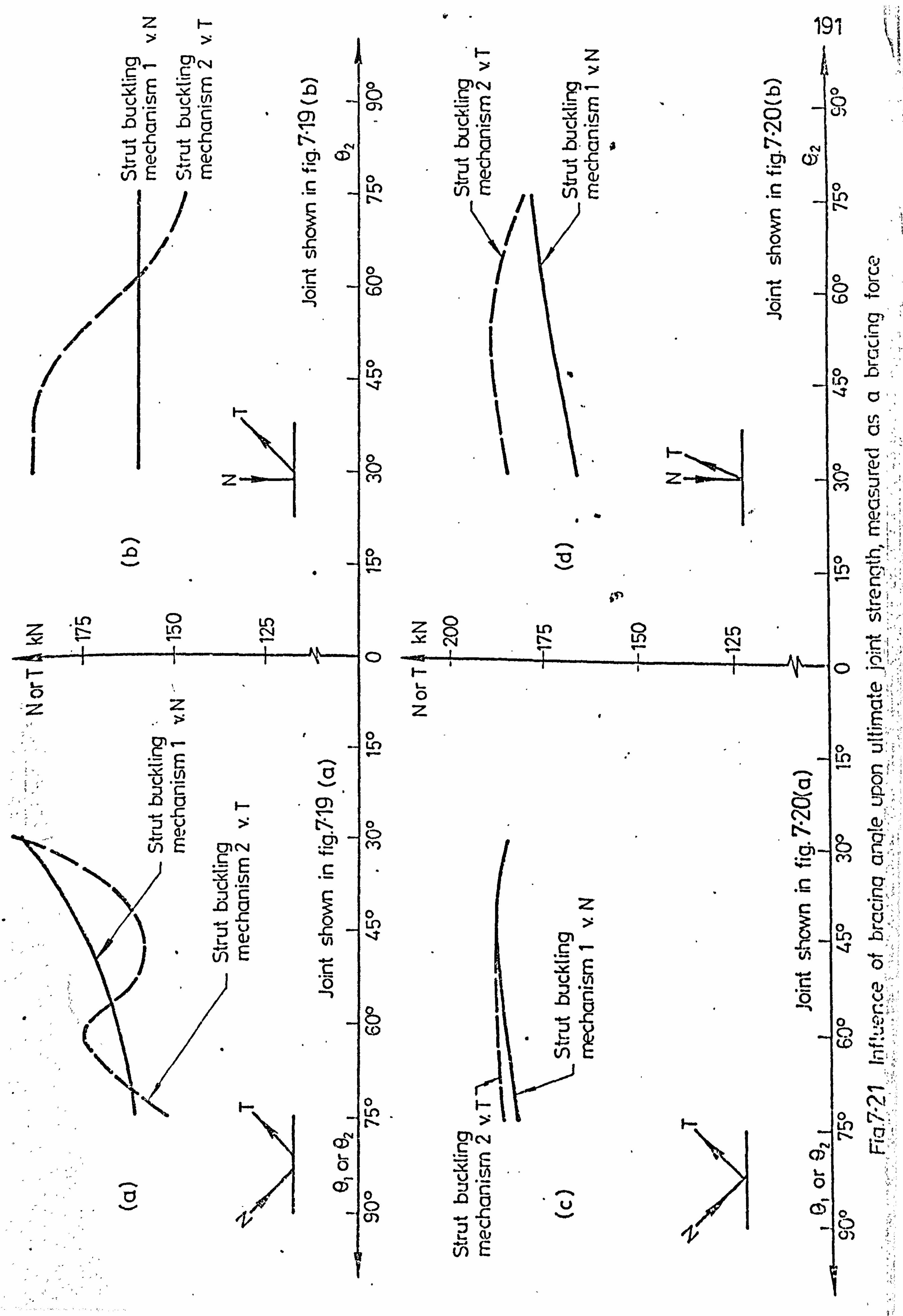
/ / ( I
Fý- I-
z f-- >
ýr- N
üN üN
. fý .ýL
v) E E
0 I-cl
ýo T
.0
^ ' o A a x t"' 1 ý `_ N
Vý
Ln
r N
C p 'p co
N Z
z
An p
ý- Q
can E Q) C4 ýE
/Dc .0v
u b
E
0 0 M
0 LO
NZQ
`- -ý N
F-- I- O Z
0 I-
V
C) t--
0 ýM
C
o Lr-)
C 0
to
0 o
F'. In
ýN
L
O0 /Io
f- Z
"--
ýd ý "d4
yU 'ý Ü
U) E
to E
i .. 'U v
Z
Ot C '- .Y
CPN
C) u
L- (u E
öý'
O r
191
.U o p ui
C Ü " :
C
3 ä 0 N fy
- 0 0
"0
" C
o .G
-Z 0� V a
0,; F..;
2-.
Lh C'-'
In
af a 0
Ö
N ý
C ' p
o CA)
r.:
fý! tz"
LO
i. r
:1

192
C 0 C: >
dLf ö i
v c uu Eft
W it Ex
"
CL ri. N
ä 6 x
0- Q. -
ö -
LO
c d
CV)
ö m ýý. iT)
CD .
V-
Q
I- 0 C) OW
VJ
O O
ar +
I
o C f..
¢ 1] 0
in in E CA ý1 +
ý a- 0
E 1. , ö C'7 4
ýý ä' , pry' J/
, 01 "
rt+ g
0 \
" C6 IV s w
a, if ul c c
C3 0

-k
N d Lfl C 7
d N
M M
M
M j
v X f
_ U ä i
0 rý
f; 7
r X
CL Ü i ä
® ä x
Q cn rcni
In i
v
F U
a ä
ä 0
ZZ v
t v
.. r
a. d O
M ®v
" 11 a N
ä 0 ,
i
Z ci
U/y
V
C i
2
0
4
Z
rn
X CO N 4
1- Q äCL
0. N äD D
M
8
Ný4V ýý C o CC
`^ c " 4 -, 2 ä. ä ö
12
M
'cl
ti m
D
mvuv º_
o- (L en
Oä co t- M I. - CL 0
"d h- Lo CL
a a
4) 60 ', Ui_ ®aF... äLO
gaä a ä: e ,Q mp
N
ºn CL
8 "4
}
LÜ
O O r--
193"
G
U1 00 C
L
"ý ü
0 rn
Oi
cn 'o C ü Z7 Qý C)- 0o
° c» a o : '0 vh°
x g
T C3
a U
U '4. V .r C t°
"^ CD a
c ' Ln z
c c ö u) cn
LL) 0 Q
0) Cu L- ,
N th
_ C"
cs "ý d un c. 7
E Vim
cy) tV
-Is
Xl

.
Z
N
cl; U
ý EJ D
(1: cMh ... V
X a' ® M
v a
q ý
T M
1 v
M F" ý
ct d d p 1 9
1
. m z3 Ü
a tý x
--ý
z x 'd
I. ) U
a, G
U)
L
l/1
01 c N Ct lý QJ
NL
U ýöC) 2
.
El.
OD
0
?P
I--
CL
äN +
vv Ov
~a OD N l
ao-. CL I E30 U,
C m ä
-1 p
v
CO co m ää Pä
aM 0.4
ca º- ö
uý ý q CL E3
0 N
oo LU
194
cs r i
`- y, C O C C
.o . DO
fl. Cd
o cý v,
o p" 0 .r ý Cl m d
C 0
z
C 4: v V ü. ä LC
, -`
x ll.. ý
m T7 v
LO tj
E V) Z
r
L. CT M a N
Ti 1 N.
LO ü "
V .
ý Co 0 (n a
ý7! U) t v < pZ
CO Cr_
8 N
LLI
O
m
r N00
cý r

195
rixnnmvn R
CONCLUSIONS AND SUGGESTIONS FOR FURTHER RESEARCH
8.1 Conclusions
A theoretical analysis for statically loaded structural hollow
section lattice girder joints having one compression bracing
member and one tension bracing member welded to an PJIS chord
member has been undertaken. This analysis is based upon a set
of joint failure modes which enable the yield and ultimate
strengths of such joints to be assessed and a computer program
has been written for this purpose (Appendix 2). The theory has
been checked against the results of a total of 150 joint tests
conducted both in isolation and in complete girders at testing
centres in Corby (England), Delft (Netherlands) and Pisa (Italy).
(i) The push-pull yield line mechanisms which were proposed for
modelling the deformations of RHS to RFIS gap joints
(figs. 3.3,4.1 and 4.2) gave satisfactory predictions for
both the yield load (see fig. 3.7) and ultimate load
(see figs. 4.6 and 4.7) of gapped joints which failed in
this manner. For these yield line models it was shown that
it is permissible to assume that the contact area between
the chord and bracings remains rigid during joint deformation
and yielding at the toes of the bracing members adjacent
to the. crotch, will have very little influence upon the joint
yield line pattern and hence yield load for this failure
mode. Due to the linear strain-hardening iaodulus chosen

196
for the chord material in the joint crotch, the post-yield
load v. deflection curve for the chord connecting face,
which is produced by the theoretical push-pull models,
does not closely represent the actual joint load v.
deflection curve.
(ii) The two strut buckling mechanisms proposed in Chapter 5
(figs. 5.7,5.8 and 5.15) give good agreement between the
predicted and actual strut buckling loads of both gap and
lapped joints (see fig. 5.17), and strut buckling mechanism
1 also models the actual load v. deflection behaviour of
the connecting chord face reasonably well.
(iii) Simple approaches for calculating the ultimate strength of
gap or lapped joints which fail by the chord shearing or
chord local buckling failure modes have been proposed,
and these have been compared with the results of joints
which failed by. these modes. The overall agreement between
the predicted and actual ultimate loads for RHS braced joints,
shown in figs. 4.12 and 4.13 for gap joints, and fig. 5.20
for lapped joints, is good.
(iv) The ultimate strength of a joint, measured as, a force in the
compression bracing member, is changed little by the addition
of a compressive purlin load providing local failure of the
chord side walls by either side wall buckling or bearing
failure does not occur. A yield line mechanism has been
proposed for the calculation of the chord bearing failure
load (fig. 6.5) and this ägrees sufficiently well with

197
the few test result, which are available for this mode of
failure.
(v) An axial load in the chord member in addition to the
horizontal components of the bracing member forces,
%i. e. a chord 'preload'), generally causes a reduction in
joint ultimate strength. This reduction in joint ultimate
strength is different for each of the joint failure
mechanisms which may operate and is often severe.
(see figs. 7.3 and . 7.4).
(vi) The ultimate strength of all joints is directly dependent
upon the yield stress of the members, but the strength
of some gap joints also depends upon the ultimate stress
of the chord member.
(vii) The influence of the parameters bl/tit x, tl/to, bo/to
length of the strut member and the amount of overlap,
upon the ultir; ate strength of lap joints has been studied
(see figs. 7.5. to 7.10). It has been found theoretically
that a lapped joint can never have a lower ultimate strength
than a joint between the same members which is made gapped
rp ovidia chord local buckling is not the failure mode.
(viii) It has been found that the failure mechanisms for gapped
joints proposed in Chapter 4 cope with any orientation of
rectangular bracing members welded to the chord face, and if
it is desired to express the joint strength as a function
of recognised joint parameters such as the 'width ratio'
then a simple appropriate 'width ratio'' parameter for REIS
r

198
bracings would be (b1 + b2 + h1 + h2)/4bo.
(ix) In the practical range of gap sizes, the ultimate gap
joint strength, (providing a joint fails by the push-pull
mode of fig. 4.1 or fig. 4.2), tends to theoretically
increase with increasing gap providing X is not small and
bo/to-is low. For higher bo/to values the tendency is
diminished (see figs. 7.13 and 7.14). In practice a
different mode of failure may limit the increase in ultimate
strength to less than expected at larger gap sizes. Thus
the minimum joint strength, which occurs at a gap of
about O. lb0, could be safely assumed for all gap sizes.
For larger gap sizes the joint deformations increase
considerably, particularly if A is low and 0/t0 is high.
For gap joints the ultimate strength increases sign-
ificantly with an increase in the width ratio (X) in a
similar manner to the joint yield strength (see figs. 7.17
and 7.18).
(x) The ultimate strength of joints which fail by strut local
buckling, (figs 5.4,5.7 and 5.15), measured as a force
in the bracing members, is virtually independent of the
. angle of inclination of the bracings to the chord. The
ultimate strength of gap joints which fail by the push-
pull mode of failure, (figs. 4.1, and 4.2), measured as a
force in the compression bracing, is dependent upon t1_10
angle of inclination of the compression bracing to the chord
and varies approximately with 1/sinel.

199
ti
(xi) The theoretical analysis developed for RHS braced joints
can be applied successfully to CUS braced joints if the
circular bracings of diameter di are made into square
bracing members with dimensions of ¶di/4 and the amount
of gap or overlap is kept the same.
8.2 Suggestions for further research.
(i) The push-pull failure mechanisms for gapped joints could
be modified by incorporating a strain-hardening modulus
for the chord material in the crotch which varies with
strain, instead of using the existing linear modulus.
This might then provide better agreement between the
theoretical and actual load v. deflection curves for the
connecting chord face in the post-yield range.
(ii) In overlapped joints with bracing members of unequal width
the strut member. might possibly punch into the tie member.
This mode of failure was suggested in Chapter 5 (mode L10
in fig. 5.1) but was not investigated further because no
experimental data on such lapped joints was available. Hence
testing, and if necessary theoretical work, could be under-
taken on joints of this type.
(iii) Experimental evidence on the elastic local buckling of
RHS members under axial compression is lacking - particularly
for high yield steel rectangular sections rather than
square sections.
4

200
(iv) More experimental testing of overlapped joints with
bracing thicknesses greater than the chord thickness is
required over a wide range of overlaps.
(v) Further tests are needed on both gap and lapped joints
of all types with purlin loads, ideally comparing them
with analagous joints without purlin loads which are made
of the same steel sections in order to eliminate the
dependency of other joint parameters.
(vi) Further research on web buckling of RHS members loaded
transversely to the section is needed, particularly
with sections of large depth (ho) and in high yield steels.
(vii) There is a real deficiency of joint tests of all types in
higher grades of steel - especially Grade 55.

201
REFERENCES
1. AUSTRALIAN INSTITUTE OF STEEL CONSTRUCTION, "Safe load
tables for structural steel - Metric units", 3rd edition,
Sydney, 1975.
2. BABIKER, D. B., "The fatigue behaviour of welded. joints
between structural hollow sections", Ph. D. thesis, University
of Sheffield, December 1967.
3. BENNETT, C. J., "Research carried out at Sheffield
University into the factors affecting the static and
dynamic strength of tubular joints (Results)", British
Steel Corporation Tubes Division, Corby, CIDECT Report CE
70/7/E, 1970.
4. BENNETT, C. J., COLQUHOUN, I. and MacCORMICK, B., "Design
of welded joints in tubular lattice girders - joints between
CIIS branch members and RHS chord members '(Static loading)",
British Steel Corporation Tubes Division, Corby, CIDECT
Report CE 69/28, November 1969.
5. BLOCKLEY, D. I., "Joints between structural hollow sections
in plane frameworks", Ph. D. thesis, University of Sheffield,
June 1967.
6. BLOCKLEY, D. I., "Joints between structural hollow sections",
Civil Engineering and Public Works Review, November 1972.
7. BRITISH STANDARDS INSTITUTION, "Specification for weldable
structural steels", BS4360 : 1972, Table 12, pp. 31.
8. BRITISH STANDARDS INSTITUTION, "Draft standard specification
for the structural use of steelwork in building. Part 1:

202
Simple construction and continuous construction", B/20
Draft, London, November 1977.
9. BRITISH STEEL CORPORATION TUBES DIVISION, "Tests on
isolated joints", Report CE73/96/D, Corby, August 1977.
10. BRITISH STEEL CORPORATION TUBES DIVISION, "Tests on
complete girders", Draft Report CE73/95, Corby, 1977.
11. BRITISH STEEL CORPORATION TUBES DIVISION, "RHS - Guide to
fabrication and design", Corby, March 1977.
12. BRITISH STEEL CORPORATION TUBES DIVISION, "Hot finished
structural hollow sections. Sizes and properties. ISO
Metric sizes", Corby, 1977.
13. ' CALLADINE, C. R., "Engineering plasticity", Pergamon Press,
Oxford, 1969.
14. CANADIAN INSTITUTE OF STEEL CONSTRUCTION, "Handbook of
Steel Construction", 2nd. edition, Willowdale, Ontario, 1970.
15. CANADIAN INSTITUTE OF STEEL CONSTRUCTION, "Limit states
design steel manual", 1st. edition, Willowdale, Ontario,
January 1977.
16. CHANDRAKEERTHY, S. R. de S., "Structural behaviour related
to stress analysis of joints in cold-formed square hollow
sections", Ph. D. thesis, University of Sheffield, 1972.
17. CIDECT THEORY WORKING GROUP, DUsseldorf Meeting, 8th March,
1978.
1O. ' COUTIE, M. G., DAVIES, G., PACKER, J. A., et al, Draft
recommendations for, "CONSTR1 DO Design Guide on SITS
Connections", CONSTRADO, London, to be published in 1979.

203
19. CRAN, J. A., "World wide applications of structural hollow
sections", Symposium on Tubular Structures, Delft
University of Technology, October 1977.
20. CZECHOWSKI, A. and BRODKA, J., "Etude de la resistance
statique des assemblages soudes en croix de profils
creux rectangulaires", Construction Metallique, No. 3,
Paris, September 1977.
21. DASGUPTA, A., "The behaviour of joints in tubular trusses",
Ph. D. thesis, University of Nottingham, November 1970.
22. DAVIE, J. and GIDDINGS,, T'. W., "Research into the strength
of welded lattice girder joints in structural hollow
sections", British Steel Corporation Tubes Division,. Corby,
CIDECT Report CE 70/3,1970.
23. DAVIES, G. and ROPER, C. G., "Gap joints with tubular members -
A yield line approach", Building Science, Vol. lo, 1975,
pp. 199-205.
24. DAVIES, G. and ROPER, C. G., "Gap joints with tubes -A yield
line modified by shear approach", Building and Environment,
Vol. 12,1977, pp. 31-38.
25. DAVIES, P., KEMP, K. O. and V1ALKER, A. C., "An analysis
of the failure mechanism of an axially loaded simply supported
steel plate", Proceedings of the Institution of Civil
Engineers, Part 2, Vol. 59, December 1975.
26. DE KONING, C. H. M. and WAP. OENIER, J., "Ultimate static
strength of welded lattice girder joints in structural
hollow sections: Series J- Determination of the influence

204
of the weld shape", Report No. BI-75-25/05.3.11.270,
Delft University of Technology, 1975.
27. DE KONING, C. H. M. and UARDENIER, J., "Ultimate static
strength of welded lattice girder joints in rectangular
hollow sections: Series K- Scale effects", Report No.
BI-75-20/05.3.11.270, Delft University of Technology, 1975.
28. DE KONING, C. H. M. and WARDENIER, J., "Supplement test
results of welded joints in structural hollow sections
with rectangular boom", CIDECT Report 76/ll/5Q, Delft
University of Technology, September 1976.
29. DOWLING, P. J., "Some approaches to the non-linear analysis
of plated structures", Structural Analysis Non-Linear
Behaviour and Techniques Symposium, Transport and Road
Research Laboratory, Crowthorne, December 1974.
30. DWIGHT, J. D., "Local buckling in steel hollow sections -
State of the art report", Technical Report No. CUED/C -
Struct/TR. 66, Cambridge University, 1978.
31. EASTWOOD, W. and WOOD, A. A., "Recent research on joints in
' tubular structures", Canadian Structural Engineering
Conference and CIDECT Issue 70/8/E, Toronto, Canada,
February 1970.
32. EASTWOOD, W. and WOOD, A. A., "Welded joints in tubular
structures involving rectangular sections", Conference on Joints
in Structures, Session A Paper 2, University of Sheffield,
July 1970.

205
33. EDWARDS, M. and GIDDINGS, T. W., "The behaviour of welded
joints in complete lattice girders with RIDS chords (Design
and Fabrication)", CIDECT Programme 5F Report 74/3/E,
March 1974.
34. EUROPEAN CONVENTION FOR CONSTRUCTIONAL STEELWORK, "Introd-
uctory report of the Second International Colloquium on
Stability of Steel Structures", Libge, Belgium, April 1977.
35. HALEEM, A. S., "Some aspects of SHS welded joint behaviour",
British Steel Corporation Tubes Division, Corby, January
1977.
36. HALEEM, A. S., "Determination of ultimate joint strength
for statically loaded SITS welded lattice girder joints with
RISS chords", CIDECT Report 77/37, British Steel Corporation
Tubes Division, October 1977.
37. HOHL, "Failure load tests on large size RHS Warren joints",
Mannesmann Research Institute Report No. 93/74 and CIDECT
Report No. 74/15/5M(E), Düsseldorf, West Germany, June 1974.
38. HOHL, "Failure tests on large size RUUS Warren type joints",
Mannesmann Research Institute Report No. 15/76 and CIDECT
Report No. 76/8/5M(E), Düsseldorf, West Germany, February 1976.
39. HORNE, M. R., "Plastic theory of structures", Nelson,
London, 1971.
40. JOHANSEN, K. W., "Yield line theory", Cement and Concrete
Association, London, 1962.
41. JOHNSTON, B. G., "Guide to stability design criteria for
metal structures", 3rd edj. tion, John Wiley and Sons, New York,
1976.

206
42. JUBB, J. E. M. and REDWOOD, R. G., "Design of joints to box
sections", industrial Building and the Structural Engineer,
Institution of Structural Engineers Conference, May 1966.
43. MANG, F., "Report on rectangular hollow sections (RHS)
joint study programme - CIDECT Programme 5P", Mannesmann
Research Institute, Düsseldorf, West Germany, September 1973.
44. MANG, F., "Tests on Warren joints in large size RHS", CIDECT
Programme 5M Interim Report, Mannesmann Research Institute,
Düsseldorf, West Germany, September 1975.
45. MANG, F., "Theoretical models for calculating the strength
and deformation of welded rectangular hollow section joints",
British Steel Corporation Tubes Division Translation No.
TDlo68 of a University of Karlsruhe research report, Corby,
March 1977.
46. MANG, F. and STRIEBEL, A., "Proposals for D1N4116",
Normensitzung 24,11-25,11, University of Karlsruhe,
West Germany, 1978.
47. MANSOUR, M. H., "Theoretical analysis of T-joints in hollow
structural sections", M. Eng. thesis, Mc. Master University,
Hamilton, Canada, March 1978.
48. ME, B. L., "The structural behaviour of joints in rectangular
hollow section", Ph. D. thesis, University of Sheffield,
September 1969.
49. MEHROTRA, L. and REDWOOD, R. G., "Load transfer through
connections between box sections", Canadian Engineering
Journal C-70-BR & STR 10, August/September 1970, pp. 47-52.

207
50. MORRELL, P. J. B., "Beams in RHS - The effective line of
action of loads applied uniformly over the flanges of
RHS beams", Construction Steelwork, March 1972.
51. MOUTY, J., "Calcul des charges ultimes des assemblages
soudes de profils creux carres et rectangulaires",
Construction metallique, No. 2, Paris, June 1976.
52. MOUTY, J., "Behaviour of welded joints of square and
rectangular tubular structures -A theoretical approach
based on the method of yield lines", International Institute
of Welding Annual Assembly, Document XV-426-78, Dublin, 1978.
53. NETHERLANDS STAALBOUWKUNDIG GENOOTSCHAP, "Richtlijnen
voor de berekening van buisconstructies - RB '78", Draft
version, October 1977. ,
54. PACKER, J. A. and DAVIES, G., "Strut local buckling in trusses
of rectangular hollow sections", Regional Colloquium on
Stability of Steel Structures, Budapest/Balatonfüred,
Hungary, October 1977.
55. PACKER, J. A., DAVIES, G. and COUTIE, M. G., "Gap joint
strength of rectangular hollow section trusses", International
Association for Bridge and Structural Engineering Symposium,
Moscow, U. S. S. R., September 1978.
56. PATEL, N. M., "Experimental and analytical investigation
of punching shear characteristics of rectangular tubular
welded joints", Ph. D. thesis, University of Houston, U. s. A.,
December 1972.

203
57. RAWLINGS, B. and SHAPLAND, P., "The behaviour of thin -
walled box sections under gross deformation", The Structural
Engineer, No. 4, Vol. 53, April 1975.
58. ROBINSON, H. C., "Literature survey on tubular steel joints",
Part thesis for Ph. D., University of Sheffield, 1969.
59. ROPER, C. G., "An analytical study of the strength and
flexibility of tubular joints", M. Phil. Thesis, University
of Nottingham, May 1974.
60. ROSE, W., "Data unification - symbols and units", CIDECT
Technical Secretariat, Croydon, January 1977.
61. SHINOUDA, M. R., "Stiffened tubular joints", Ph. D. thesis,
University of Sheffield, June 1967.
62. STEEL COMPANY OF CANADA LIMITED, "Hollow structural
sections welded joint research sianmaries", Technical Report,
Hamilton, Canada, May 1974.
63. STEEL COMPANY OF CANADA LIMITED, "Hollow structural sections
- Design manual for connections", ist. edition, Hamilton,
Canada, September 1976.
64. TIMOSHENKÖ, S., "Theory of elastic stability", Mc. Graw Hill,
1936.
65. WALKER, A. C., "Design and analysis of cold-formed sections",
Intertext Books, Bedfordshire, 1975.
66. WARDENIER, J., "General principles for the verification of
the safety of predominantly statically loaded tubular joints",
Report No. BI-77-16'/35.3.51210, Delft University of
-Technology, January 1977. S

209
67. WARDENIER, J., "Testing and analyses of truss joints in
hollow structural sections", Conference on Structural
Hollow Sections, Toronto, Canada, May 1977.
68. WARDENIER, J., "Results of research E. C. S. C.: Welded
girder joints in structural hollow sections", Acier - Stahl -
Steel, Vol. 43, No. 1,1978, pp. 29-33.
69. WARDENIER, J. and DE KONING, C. H. M., "Static tensile tests
on T-joints in structural hollow sections - determination
of the influence of weld method and type of material",
Report No. BI-74-42/05.3.11.270, Delft University of Technology,
1974.
70. WARDENIER, J., DE KONING, C. U. M. and VAN DOUWEN, A. A.,
"Investigation Into the static strength of welded lattice
girder joints in structural hollow sections", CIDECT
Report 75/29, Delft University of Technology, June 1976.
71. WARDENIER, J. and DE KONING, C. H. M., "Investigation into
the static strength of welded lattice girder joints in
structural hollow sections. Part 1: Rectangular hollow
sections", CIDECT Report 76/12/5Q, Delft University of
Technology, June 1976.
72. WARDENIER, J. and DE KONING, C. H. M., "Investigation into the
static strength of welded lattice girder joints in
structural hollow sections. Part 2: Joints with circular
bracing: and rectangular boom", CIDECT Report 76/13/5Q,
Delft University of Technology, December 1976.

210
73. WARDENIER, J. and VERHEUL, A., "Bibliography of welded
joints in structural hollow sections", Delft University of
Technology Report No. BI-77-5/35.3.51210 and I. I. W.
Annual Assembly in Copenhagen Document No. XV-403-77,
June 1977.
74. WARDENIER, J. and DE KONING, C. H. M., "Investigation into
the static strength of welded joints with three bracings
made of RHS or CHS", CIDECT Report 77/23/5Q, Delft
University of Technology, August 1977.
75. WASHIO, K., TOGO, T. and MITSUI, Y., "Truss joints in
tubular structures", Transactions of the Architectural
Institute of Japan, October 1966.
76. WASHIO, K., TOGO, T. and MITSUI, Y., "Experimental research
on local failure of chord in tubular truss joint",
Transactions of the Architectural Institute of Japan,
August 1967.
77. WATSON, C. and BABB, A. S., "Box columns: progress report
on the determination of stiffening requirements", British
Steel Corporation (Swindon Laboratory), Report DTS 68/718/A,
October 1969.
78. WOOD, A. A., NETIIERCOT, D. A. and CFIP. Iv'DRAKEERTHY, S., "Report
on CIDECT Programme 5G - Welded joint tests with cold-
formed SHS", University of Sheffield, September 1972.
79. WOOD, R. H., "Plastic and elastic design of slabs and plates",
. :, Thames and Hudson, 1961.
8

APPENDIX. 1
JOINT TEST DATA
ý.
.. ..
ý,. `,. ýi
,_t
3 T 4

GAP JGINT DATA RIIS/Rli: S 211
JOINT Delft Delft Delft Delft Delft Delft Delft Delft Delft Delft NUMBER 1 2 3 A 5 6 7 8 9 10.
Al . 99 . 99 . 63 . 60 . 63 . 38 . 40 . 38 . 76 . 69
stru1 TiJ QQ QQ QD QQ QQ 0F1 QQ QQ Qn Q0 1 4.74 2.96 4.00 2.95 4.00 4.00 1.99 4.00 3.85 3.74
Ti
º12 4.74 2.96 4.00 2.95 4.00 3.96 1.99 3.96 4.80 3.92
T3 3.74 2.95 3.96 2.93 3.72 3.72 2.93 3.72 3.75 3.35
r"Y1 . 298 . 224 . 275 . 282 . 275 . 325 . 216 . 325 . 328 . 314
rY2 . 298 . 224 . 275 . 282 . 275 . 325 . 216 . 325 . 328 . 369
rY3 . 322 . 230 . 334 . 232 . 317 . 317 . 232 . 314 . 310 . 292
ULT1 . 448 . 337 . 470 . 434 . 470 . 505 . 314 . 505 . 402 . 436
ULT2 . 448 . 337 . 470 . 434 . 470 . 505 . 314 . 505 . 402 . 504
ULT3 . 460 . 335 . 478 . 337 . 455 . 455 . 337 . 455 . 447 . 438
D 99.8 99.5 99.3 98.9 99.5 99.5 98.4 99.5 99.8 100.2
GAP/L7P 0 0 0 0 0 0 0 0 -. 2 -. 2
Cl 98.9 98.5 62.8 59.8 62.8 38.1 39.7 . 38.1 75.7 F 69.3
C2 98.9 98.5 62.8 59.8 62.8 37.8 39.7 37.8 51.0 51.0
F, 1 98.9 98.5 62.8 59.8 62.8 ,
38.1 39.7 38.1 75.7 69.3
E2 98.9 98.5 62.8 59.8 62.8 37.8 39.7 37.8 51.0 51.0 1
Al . 7854 . 7854 . 7854 . 7854 0 . 7854 . 7854 0 . 7854 . 7854
A2 . 7854 . 7854 . 7854 . 7854 . 7854 . 7854 . 7854 . 7854 . 7854 . 7854 1
E 30.4 30.4 4.6 2.1 46.5 13.2 11.8 15.1 0 0
5: 51 6.7 4.19 5.66 4.17 5.66 5.66 2.81 5.66 5.44 5.29
`,, S2 6.7 4.19 5.66 4.17 5.66 5.66 2.81 5.66 6.79 5.54
0 0 0 0 0 0 0 0 0
ACH 1420 1110 1470 1092" 1420 1420 1092 1420 1420 1275
DEP 99.8 98.5 99.3 98.9 9995 99.5 98.4 99.5 99.8 100.2
EYS 207 207 207 207 207 207 207 207 207 207
11 300.6 300.8 318.6 320.1 350.0 331.0 330.0 350.0 312.2 315.4
FULT1 253 120 198 78 146 113 46 80 172 5 113 5 . . ý ý BZ 1 1 1 1 1 1 1 1 1 1
rPURL 0 0 0 0 0 0 0 0 00
TPURL 0 0 0 0 0 0 0 0 00
rR 1 1 "1 1 1 1 1 11
1'AILURE
MODE _G7 G7 G1 GI G1 " G5 Go C, I G1/G8 G'1/08 REPORTED

ý)l 7
JOINT NU2,13LR
Delft 11
Delft 12
Delft 13
Delft 14
Delft 15
Delft 16
Delft 17
Delft 18
Delft 19'
Delft 19'!
. 76 . 50 . 76 . 71 . 51 . 64 . 61 . 38 1.00 1.00
Strut '1'i c Elm F1 p FIp n= O
Cn DO C7Iý 7 Lý [ý D
T1 3.85 1.91 3.85 2.99 3.98 4.77 2.97 3.30 4.91 2.98
T2 3.98 1.96 4.91 2.98 3.32 4.77 2.97 3.30 4.91 2.98
T3 3.89 3.35 3.75 2.96 3.75 3.75 2.99 3.75 3.84 3.35
FYl . 322 . 192 . 322 . 337 . 305 . 321 . 211 . 325 . 314 . 221
FY2 . 305 . 292 . 314 . 221 . 285 . 321 -
. 211 . 325 . 314 . 221
FY3 . 335 . 292 . 310 . 224 . 310 . 31.0 . 231 . 310 . 335 . 292
ULTI . 497 . 328 . 497 . 431 . 458 . 528 . 322 . 500 . 492 . 350
ULT2 . 458 . 438 . 492 . 350 . 458 . 528 . 322 . 500 . 492 . 350
ULT3 . 480 . 390 . 447 . 340 . 447 . 447 . 339 . 447 . 480 . 438
D 99.1 100.2 99.8 98.9 99.8 99.8 98.7 99.8 99.4 100.2
GAP/LAP -. 2 -. 2 -. 2 -. 2 -. 2 -. 2 -. 2 -. 2 -. 2 -. 2
C1 75.7 50.0 75.7 70.3 50.6 63.4 60.3 38.2 101.2 99.9
C2 50.6 35.0 50.6 50.5 25.2 63.4 60.3 38.2 101.2 99.9
E1 75.7 50.0 75.7 70.3 50.6
, 126.4 99.4 63.0 50.6 50.5
E2 50.6 35.0 101.2 99.9 50.6 126.4 99.4 63.0 50.6 50.5
Al 0 . 7854 '. 7854 . 7854 . 7854 . 7854 . 7854 . 7854 . 7854 . 7854
A2 ' . 7854 . 7854 . 7854 . 7854 . 7854 . 7854 . 7854 . 7854 . 7854 . 7854 E 0 0 0 0 0. 0 0 0 0 0
wSl 5.44 2.70 5.. 44 4.23 5.63 6.75 4.2 4.67 6.94 4.21
IIS2 5.63 2.77 6.94 4.21 4.70 6.75 4.2 4.67 6.94 . 4.21
F. ACII
0 1440
0 1272
0 1420
0 1100
0' 1420
0 1420
0 1128
0 1420
0 1440
0 1275
DEP 99.1 100.2 99.8 98.9 99.8 99.8 98.7 99.8 99.4 100.2
L YS 207 207 207 207 207 207 207 207 207 207
II
FULT1
350
165.4
325
57.5
312.2
195
314.9
88.5
324.7
113
286.8
198.6
300.3
93
318.5
140
324.7
266
324.8
169 BZ
FPUY, (L TPURL.
TR
FAILURE
MODE
REPORTED
I
0 0
1
G6
1
0 0
1
G2
1
0 0
1
G4
1
0 0
1
G5
1
0 0
1
C4/G7
1
0 0
1
G2/G6 I
11
00 00
11
G5 G3/G7
1
0 0
1
G6
1
0 0
1
G5

911
JOINT Delft Delft Delft Delft Delft Delft Delft Delft Delft Delft
NUMBER 19111 20 21 . 22 23 60 64 .
137 6
132" +.
6"
71 . 63 . 89 . 81 . 51 . 51 . 63 . 37 . 64 . 99 . 99
Strut Tie nr-ý aý D Di ED QQ DD QU Ql1
T1 3.31 4.08 2.99 3.30 3.30 4.81 3.89 4.00 4.74 4.74
T2 3.31 4.08 2.99 3.30 3.30 4.81 3.89 4.00 4.74 4.74
T3 3.84 3.75 2.99 3.75 3.75 5.40 5.40 3.72 3.75 3.75
FYl . 325 . 281 . 225 . 285 . 285 . 284 . 335 . 275 . 298 . 298
£Y2 . 325 . 281 . 225 . 285 . 285 . 284 . 335 . 275 . 298 . 298
FY3 . 335 . 310 . 231 . 310 ..
314 . 280 . 280 . 317 . 310 . 310
ULT1 . 500 . 427 . 356 . 458 . 458 . 462 . 502 . 470 '. 448 . 448
ULT2 . 500 . 427 . 356 . 458 . 458 . 462 . 502 . 470 . 448 . 448
. ULT3 . 480 . 447 . 339 . 447 . 464 . 475- . 475 . 454 . 447 . 447
D 99.4 99.8 98.7 99.8 99.8 101.7 101.7 99.5 99.8 99.8
GAP/LAP -. 2 --. 2 -. 2 -. 2 -. 2 0 0 0 -. 2 -. 2
Cl 63.0 88.9 79.7 50.5 50.5 63.6 37.8 63.5 98.9 98.9
C2 63.0 37.9 39.6 25.2 25.2 63.6 37.8 62.8 98.9 98.9
El 38.2 37.9 39.6 25.2 25.2 , 63.6 37.8 63.5 98.9 98.9
E2 38.2 88.6 79.7 50.5 50.5 63.6 37.8 62.8 98.9 fi
98.9
Al . 7854 . 7854 . 7854 . 7854 0 . 7854 . 7854 0 . 7854 . 7854
A2 . 7854 . 7854 . 7854 . 7854 . 7854 . 7854 . 7854 . 7854 . 7854 . 7854
E 0 0 0 0 0 3.5 -14.0 46.3 0 0
WS1 4.68 5.77 4.23 4.67 4.67 6.80. 5.50 5.66 6.70 6.70
wS2 4.68 5.77 4.23 4.67 4.67 6.80 5.50 5.66 6.70 6: 70
F 0 0 0 0 0. 0 0 -306 -88 264.6
ACH 1440 1420 1128 1420 1430 1840 1840 1420 1420 1420
DEP 99.4 99.8 98.7 99.8 99.8 101.7 101.7 99.5 99.8 99 8 I'
EYS 207 207 207 207 207 207 207 207 207 207
I; -330.9 . 331.1 330.2 337.4 350 318.2 331.1 350.0 300.6 300.6
FULT1 153 167 80 101.5 92.6 272 122 91 230 350 j
BZ 1 M
1 1 1 1 1 1 1 1 1 ýý
FPUPNL 0 0 0 0 0 0 0 0 0 0 TPURL 0 0 0 0 0 0 0 0 0 0
TR 1 1 1 1 1 1 1w 1 ý..
1r l1
FAILURE
MODE G8 G8 G5 G5 Tie
Yield CS Cl 07 G7 G7/GG
REPORTED

;? 14
JOINT Delft Delft Delft Delft Delft Delft Delft Delft Delft Delft 137111 137 138 138' 138 138 139 139" 141' 1 41 NUr: BER (-. 20) (f. 59) (-. 20) (+. 60) (-. 20) (+. 60) -. 20 . 6ý .
X1 1.00 1.00 . 63 . 63 . 61 . 61 . 63 . 63 . 37 . 37
Strut "'lir.
QFI QQ QQ QQ QQ QQ QQ QQ QQ QQ Ti 2.95 2.95 4.85 4.85 2.95 2.95 4 . 00 4.00 4.06 4.06
T2 2.95 2.95 4.85 4.85 2.95 2.95 4.00 4.00 4.06 4.06
T3 3.00 2.95 4.92 4.92 3.00 3.00 3.74 3.74 4.92 4.92
FY1 . 230 . 230 . 330 . 330 . 282 . 282 . 275 . 275 . 314 . 314
FY2 . 230 . 230 . 330 . 330 . 282 . 282 . 275 . 275 . 314 . 314
FY3 . 232 . 230 . 296 . 296 ..
232 . 232 . 322 1 . 322 . 296 . 296
ULT1 . 335 . 335 . 510 . 510 . 434 . 434 . 470 . 470 . 466 . 466
ULT2 . 335 . 335 . 510 . 510 . 434 . 434 . 470 _
. 470 . 466 . 466
ULT3 . 337 . 337 . 455 . 455 . 337 . 337 . 460 . 460 . 455 . 455
D 98.4 98.6 100.6 1QO. 6 98.3 98.3 99.8 99.8 100.6 100.6
GAP/LAP -. 203 -. 203 -. 2 -. 2 -. 2 -. 203 -. 2 -. 2 -. 2 -. 2
C1 98.5 98.6 63.4 63.4 59.8 59.8 62.8 62.8 37.5 37.5
C2 98.5 98.6 63.4 63.4 59.8 59.8 62.8 62.8 37.5 37.5
F1 98.5 98.6 63.4 63.4 59.8 1 59.8 62.8 62.8 37.5 37.5
F. 2 95.5 98.6 63.4 63.4 59.8 59.8 62.8 62.8 37.5 37.5 s
Al . 7854 . 7854 . 7854 . 7854 . 7854 . 7854 0 0 . 7854 . 7854 A2 . 7854 . 7854 . 7854 . 7854 . 7854 . 7854 . 7854 . 7854 . 7854 . 7854
E 0 0 0 0 0 0 0 0 0 0
wS1 4.17 4.17 6.8 6.8 4.2 4.17 5.7 5.7 5.7 5.74
ws2 4.17 4.17 6.8 6.8 4.2 4.17 5.7 5.7 5.7 5.74
F -52 150 -112 325 -48 156 -128 274 111.6 320
ACH 1116 1110 1880 1880 1116 1116 1420 1420 1880 18 0
DEP 98.4 98.6 100.6 100.6 98.3 98.3 99.8 99.8 100.6 100.6 6
E, YS 207 207 207 207 207 207 207 207 207 207 300.8 300.7 318.3 318.3 320.1 320 350 350 331.3 331.3
FULT1 110 146 227 290 61 119 130 150 125 137 BZ 1 1 1 1 1 1 1 1 1 1'
r"PURL Q o 0 o 0 0 TPURL 0 0 0 0
Foý 0 0 0 0
~-- 0
TR 1 1 1 1 1 1 1 1 -1 1
rATLURE
MODE G7 G6 G5 G5 G2 G6 G5 G5 G5 G6 REPO: TED

215
JOIIIT Delft Delft Delft Delft Delft Delft Delft Delft: Delft Delft: 141" 141" 141" 141"' 142" 142" 142" 1 142" 140 142"'
fl J4 ER (-0.2) (-0.5) (+0.6) (+0.6) (-. 2) (-. 5) (-. 7) t+. 6) (--. 8) (-. 2)
x1 . 38 . 38 . 38 . 41 . 37 . 37 . 37 . 37 . 38 . 38
Sti" Tie QQ QQ QQ QQ QQ QQ QQ QQ QQ u0
R Ti 3.89 4.06 3.93 2.06 4.06
1 4.06 4.06 4.06 4.00 4.00
'r2 3.93 4.06 3.93 1.93 4.06 4.06 4.06 4.06 3.89 4.00
T3 3.75 3.75 3.75 2.96 4.92 4.92 4.92 4.92 3.96 3.74
r"Yi . 335 . 314 . 345 . 240 . 314 . 314 . 314 ". 314 . 335 . 310 FY2 . 345 . 314 . 345 . 232 . 314 . 314 . 314 . 314 . 335 . 310
FY3 . 314 . 314 . 314 . 224 .. 296 . 296 . 296 . 296 . 334 . 322
ULTI . 502 . 466 . 520 . 368 . 466 . 466 . 466 . 466 . 502 . 483
ULT2 . 520 . 466 . 520 . 360 . 466 . 466 . 466 . 466 . 502 . 483
ULT3 . 454 . 454 . 454 . 337 . 455 . 455 . 455 . 455 . 478 . 460
D 99 99 99 97.9 100.6 100.6 100.6 100.6 99.4 99.8
CAP/LAP -. 2 -. 2 -. 2 -. 204 -. 2 -. 2 -. 2 -. 2 -. 2 -. 2
Cl 37.8 37.8 37.9 40.3 37.5 37.5 37.5 37.5 38.1 37.9
C2 37.9 37.5 37.9 40.0 37.5 37.5 37.5 37.5 37.8 37.9
F1 37.8 37.8 37.9 40.3 37.5 . 37.5 37.5 37.5 38.1 37.9
E2 37.9
7854
37.5
7 4
37.9 40.0 37.5 37.5 1 37.5 37.5 37.8 37.9
Al . . 85 . 7854 . 7854 0 0 0 0, 0 0
A2 . 7854 . 7854 . 7854 . 7854 . 7854 . 7854 . 7854 . 7854 . 7854 . 7854 E 0 0 0 0 0 0 0 0 0 0
Iwsi 5.5 5.7 5.5 2.91 5.7 5.7 5.7 5.7 5.7 5.7
wS2 5.5 5.7 5.5 2.73 5.7_- 5.7 5.7 5.7 5.7 5.7
F -89.8 -200 270 148 -110 (267
-320 324 -400 89 - ACH 1430 1430 1430 1100
1 1880 1880 1880 1880 1470 1420
DEP 99 99 99 97.9 100.6 1100.6
100.6 100.6 99.4 99.8
EYS 207 207 207 207 207 1 207 207 207 207 207
U 331.1 331.3 331.1 329.9 350 350 350 350 350 350
FULT1 101 62 125 50 96 192.5
87 5 123 35 82 . _ 11Z 1 1 1 1 1 1 1 1 F PURL 0 0 0 0 0 j
TPURL 0 0 0 0 0 0 0 0 0 0
TR 1 1 1 1" 1 1 11 .. _ _. '.
FAILURE
MODE G5 G7/G2 G5 G6 G5 -G5 G5 G5 G5/G7 G5 EL PORTE)

I) Ir
JOINT Delft Delft Delft Delft Delft Delft: Delft Delft Delft Delft 14211 14211' 1421x'" 142"" 1421111, '139 142 142' 7CI' 174
NNU: '. 3ER (-. 5) (-. 7) (+. 6) (-. 7) (+. 6) (-. 67)
ýi . 38 . 38 . 38 . 41 . 41 . 38 . 37 . 41 . 41 1.00
Strut ýýrý_.
ý QQ QQ QQ QQ QQ QQ QQ QQ QQ QQ 'r1 3.93 4.00 3.93 1.93 1.93 4.00 4.06 1.93 1.90 1.87
T2 3.93 4.00 3.93 1.93 1.93 3.89 4.06 . 1.93 1.90 1.87
T3 3.75 3.74 3.75 3.00 2.95 3.96 4.92 3.00 2.95 1.87
£Y1 . 325 . 310 . 325 . 232 . 232 . 335 . 314 . 232 . 384 . 228
F Y2 . 345 . 310 . 345 . 232 . 232 . 335 . 314 . 232 . 384 . 228
FY3 . 314 . 322 . 314 . 206 . 230 . 334 . 296 . 206 . 308 . 228
ULT1 . 505 . 483 . 505 . 360 . 360 . 502 . 466 . 360 . 505 . 354
ULT2 . 520 . 483 . 520 . 360 . 360 . 502 . 466 . 360 . 505 . 354
ULT3 . 454 . 460 . 454 . 329 . 335 . 478 . 455 . 329 . 405 . 354
D 99 99.8 99 98.6 98.1 99.4 100.6 98.6 98.3 50.1
GAP/LAP -. 2 -. 2 -. 2 -. 2 -. 2 0 0 -. 2 -. 2 -. 4 ci 37.8 37.9 37.8 40.0 40.0 38.1 37.5 40.0 40.15 50.1
c2 37.8 37.9 37.8 40.0 40.0 37.8 37.5 40.0 40.15 50.1
El. 37.8 37.9 37.8 40.0 40.0 ' 38.1 37.5 40.0 40.15 50.1
E2 37.8 37.9 37.8 40.0 40.0 37.8 37.5 40.0 40.15 50.1
Al 0 0 0 0 0 . 7854 0 0 . 7854 . 7854 A2 . 7854 . 7854 . 7854 . 7854 . 7854 . 7854 . 7854 . 7854 . 7854 . 7854 E 0 0 0 0 0 -13.2 15.1 0 0 0
14sl 5.6 5.7 5.6 2.7 2.73 5.66 5.74 2.73 2.69 2.64
x52 5.6 5.7 5.6 2.7 2.73 5.66 5.74 2.73 2.69 2.64 F -218 -200 268 -100 153 -330 0 0 0 0
ACH 1430 1420 1430 1120 1110 1470 1880 1120 1060 351 DEP 99 99.8 99 98.6 98.1 99.4 100.6 98.6 98.3 50.1 EYe 207 207 207 207 207 207 207 207 207
1207
11 350 350 350 350 350 331 350 350 329.9 _325
1'ULT1 69 65 68 27.2 46 54 100 44 68 48 BZ 1 1 1 1 1 1 1 1 1
f"nURL 0 0 '
0 0 0 ,0 0 0 0 0 TPUflL 0 0 0 0 0 0 0 0 o o
1 1 1 1- :l 1 1 1 1 1
rAILUfE
r-soot 5 G5 G5 G4 G6 G7 G1 G6' v6 c3
RFP0 TT D

217
JOE NT NUMBER
Delft 178
Delft 183
Delft 184
Delft 185
Deift 144
Delft 145
Delft 146
Delft 147
Delft 150
Delft 151
x . 63 1.00 . 60 . 40 1.00 1.00 . 64 . 60 . 39 . 40 i
Sf rut Tie D El DD ED El D
Ti 6.50 4.96 3.95 4.40 4.87 3.35 4.25 3. 00 4.10 1.90
T2 6.50 4.96 3: 95 4.40 4.87 3.35 4.25 3.00 4.10 1.90
T3 8.05 4.05 4.05 4.05 3.87 3.35 3.87 3.35 3.87 3.35
FY1 . 292 . 335 . 374 . 420 . 338 . 292 . 321 . 379 . 342 . 384
FY2 . 292 . 335 . 374 . 420 . 338 . 292 . 321 . 379 . 342 . 384
FY3 . 312 . 330 . 330 . 330 ..
331 . 292 . 331 . 292 . 331 . 292
ULT]. " . 490 . 405 . 410 . 462 . 480 . 390 . 495 . 443 . 477 . 428
ULT2 . 490 . 405 . 410 . 462 . 480 . 390 . 495 . 443 . 477] . 428
ULT3 . 473 . 403 . 403 . 403 . 372 . 390' . 372 . 390 . 372 . 390
D 197.5 100.2 100.0 100 99.4 100.1 99.4 100.1 99.4 100.1
GAP/LAP 0 -. 2 0 0 -. 2 -. 2 -. 2 -. 2 -. 2 -. 2 C]. 125.0 99.8 59.7 40.1 99 100.1 63.2 59.8 38.5 40.15
C2 125.0 99.8 59.7 40.1 99 100.1 63.2 59.8 38.5 40.15
E1 125.0 99.8 59.7 40.1 99 1 100.1 63.2 59.8 38.5 40.15
E2 125.0 99.8 59.7 40.1 99 100.1 63.2 59.8 38.5 , 40.15
Al . 7854 . 7854 . 7854 . 7854 . 7854 . 7854 . 7854 . 7854 . 7854 . 7854
A2 . 7854 . 7854 . 7854 . 7854 . 7854 . -7854 . 7854 . 7854 . 7854 . 7854 -. 5 0 2.4 -11.8 0 0 0 0 0 0
wS1 9.19 7.01 5.59 6.22 6.89 4.74 6.00 4.24 5.80 2.69.
WS2 9.19 7.01 5.59 6.22 6.89 4.74 6.00 4.24 5.80 2.69
0 0 0 0 0 0 0 0 0 0 ACII 6140 1450 1450 1450 1415 1277 1415 1277 1415 1277 DLP 197.5 100.2 100.0 100 99.4 100.1 99.4 100.1 99 .4 100.1
EYS 207 207 207 207 207 207 207 207 207 207
Ii 287.5 300.1 320.2 330 300.3 300 318.4 320.1 330.8 329.9
FrJLT1 710, 272 180 107 270 214 164 105 136 ' 58 13Z
FPURL
TPU: tL
TR
FAILURE
MODE
REPORTED
1
0
0
1
1
0
0
1
G7
1
0
0
1
G1
1
0-
0
2
G1
1
91.6
70
1
G9
1
57.5
70
1
" G9
1
63.8
70
1
G2/G3
1
29.7
70
,
G1/G6
1
50.0
70
G2
1ý
14.4 i
70
1 ý_
G6 P
bý

JOINT Pisa Pisa Pisa Pisa Pisa. Pisa Pisa Pisa Pisa Pisa NUMBER 6AI 6AT 6BI 6BT 7AI 7AT 7BI 7BT 8AI 8K
1 . 60 . 60 . 30 . 30 . 67 . 67 . 33 . 33 . 58 . 58
Strut Tie QQ QQ QQ QQ QQ QQ Q QQ QQ QQ T1 4.90 4.90 4.00 4.00 4.00 4.00 3.20 3.20 3.60 3.6C
T2 9.50 9.50 4.90 4.90 6.30 6.30 4.00 4.00 6.30 6.30
T3 6.30 6.30 6.30 6.30 6.30 6.30 6.30 6.30 6.30 6.30
FYI. . 296 . 296 . 292 . 292 . 339 . 339 . 332 . 332 . 289 . 333
FY2 . 354 . 354 . 416 . 4'16 . 287 . 287 . 323 . 323 . 279 . 279 fi.
FY3 . 358 . 358 . 405 . 405 .. 383 . 383 . 383 . 383 . 405 . 408 1
ULT1' . 472 . 472 . 494 . 494 . 513 . 513 . 522 . 522 . 481 . 496
ULT2 . 481 . 481 . 580 . 580 . 457 . 457 . 503 . 503 . 460 . 46C }
ULT3 . 496 . 496 . 516 . 516 . 496 . 496 . 496 . 496 . 499 . 510
D 254.0 254.0 254.0 254.0 152.4 152.4 152.4 152.4 152.4 152.4
GAP/LAP -. 098 -. 098 -. 098 -. 098 -. 164 -. 164 -. 164 -. 164 -. 164 -. 164
C1 152.4 152.4 76.2 76.2 101.6 101.6 50.8 50.8 88.9 88.9
C2 152.4 152.4 76.2 76.2 101.6 101.6 50.8 50.8 88.9 88.9
E1 152.4 152.4 76.2 76.2 101.6 101.6 50.8 50.8 88.9 88.9'
E2 152.4 152.4 76.2 76.2 101.6 101.6 50.8 50.8 88.9 88.9
Al 0 0 0 0 0 0 0 0 0 0
A2 . 7854 . 7854 . 7854 . 7854 . 7854 . 7854 . 7854 . 7854 . 7854 . 7854
E 0 0 0 0 0 0 0 0 0 0
WS1 6.3 6.3 6.3 6.3 6.3 6.3 6.3 6.3 6.3 6.3
WS2 6.3 6.3 6.3 6.3 6.3 6.3 6.3 6.3 6.3 6". 3
F -604 -604 -731 731 0' 0 .0 0 0 -225.4 ACH 6270 6270 6270 6270 3690 3690 3690 3690 3690 3690
DEP 254.0 254.0 254.0 254.0 152.4 152.4 152.4 152.4 152.4 152.4
EYS 207 207 207 207 207 207 '207 207 207 207
H 573 r
798 573 798 623.8 748.8 623.8 748.8 623.8 748.8
FULT1 242.2 ß 291 194.2 104 380.5 318 166: 7 109.8 310.9 221.6 DZ 1 1 1 1 1 1 1 1 1 '1
FPURL 0 0 0 0 0 0 0 0 0 0
TPURL 0 0 0 0 0' 0 0 0 0 0
I" 11 2 1 2 1 2 1 2 1 2
FAILURE Did Did MODE:
G1 not G1
not G6 Did
G6 Did
G6 Cl jai].
i
fail not fail
not .
REPORTED Lail I

, )I n
JOINT
NUMMER Pisa 881
Pisa S. Ur
Pisa Pisa 7QT
. 50 . 50 . 60 . 67
s, ýnit T;. J QQ QQ QQ QQ TI 3.20 3.20 4.90 4.00
T2 4.00 4.00 9.50 6.30
T3 6.30 6.30 6.30 6.30
FYl . 491 . 491 . 322 . 339 .
FY2 . 322 . 312 . 354 . 287
FY3 . 405 . 408 . 405 . 387
ULT1 . 652 . 652 . 508 . 513
ULT2 . 486 . 467 . 481 . 457
ULT3 . 499 . 510 . 516 . 500
D 152.4 152.4 254 152.4
GAP/LAP -. 164 -. 164 -. 098 -. 164
cl 76.2 76.2 152.4 101.6
C2 76.2 76.2 152.4 101.6
El 76.2 76.2 152.4 101.6
E2 76.2 76.2 152.4 101.6
Al 0 0 0 0
A2 . 7854 . 7854 . 7854 . 7854
E
WSl
v, 52
F
0
6.3
6.3
0
0
6.3
6.3
-918.4
0
6.3
6.3
832.6
0
6.3
6.3
-361.9
ýý-
". E
AOIT 3690 3690 5872 3690
DEP 152.4 152.4 254 152.4
EYS 207 207 207 207
H 623.8 748.8 798 748.8. _- -'ý
rULT1 248.1 155.0 294 316.8
BZ 1 1 1
FPURL 0 0 0 0
TPURL
Till
FAILURE
MODE
I: ßPORTED
0
1
GI
0
2
G1
0
2
G1
0
2,
G1
. ̀ý' .
. _...
! ft
$ýý ý ýý
5 ý,
ýi
.j
ý, qw fý
ý xl
Y3 tý t
iý ýý ý$ 5 :ý tý
ý ; i'

GAP JOINT DATA CIIS/FPMS220
JOIPlT
NUMBER
Pisa 1AI
Pisa IAT
Pisa 1BI
Pisa 1BT
Pisa 2ÄI
Pisa 2AT
Pisa 2BI
Pisa 28T
Pisa 3AI
PJ. sa 3AT
. 76 . 76 . 45 . 45 . 55 . 55 . 35 . 35 . 75 . 75
Strut Tie 00 00 00 00 OO 00 00 QD QQ Q0
T1 4.90 4.90 3.60 3.60 4.50 4.50 4.00 4.00 5.40 5.4C
T2 6.30 6.30 5.40 5.40 6.30 6.30 5.40 5.40 6.30 6.30
T3 6.30 6.30 6.30 6.30 9.50 9.50 9.50 9.50 9.50 9.50 FY1 . 354 . 354 . 374 . 374 . 329 . 329 . 312 . 312 . 368 . 368
FY2 . 314 . 314 . 357 . 357 . 277 . 277 . 377 . 377 . 329 . 329
FY3 . 346 . 346 . 315 . 315 . 300 . 300 . 287 . 287 . 314 . 314
ULT1 . 443 . 443 . 522 . 522 . 578 . 578 . 422 . 422 . 518 . 518
ULT2 . 428 . 428 . 497 . 497 . 463 . 463 . 499 l " . 499 . 463 . 463
ULT3 . 479 . 479 . 440 . 440 . 478 . 478. . 465 . 465 . 471 . 471
D 254 254 254 254 254 254 254 254 152.4 152.4
CAP/LAP -. 098 -. 098 -. C98 -. 098 -. 098 -. 098 -. 098 -. 098 -. 164 -. 164 Cl 193.7 193.7 114.3 114.3 139.7 139.7 88.9 88.9 114.3 114.3
C2 193.7 193.7 114.3 114.3 139.7 139.7 88.9 88.9 114.3 114.3
E1 193.7 193.7 114.3 114.3 139.7 ' 139.7* 88.9 88.9 114.3 114.3 E2 193.7 193.7 114.3 114.3 139.7 139.7 88.9 88.9 114.3 114.3
Al 0 0 0 0 0 0 0 0 0 0
A2 . 7854 . 7854 . 7854 . 7854 . 7854 . 7854 . 7854 . 7854 . 7854 . 7854
0 0 0 0 0 0 0 0 0 0
117S1 . 6.3 6.3 6.3 6.3 6.3 6.3 6.3 6.3 6.3 6.3 6.3 6.3 6.3 6.3 6.3
I 6 .3 6.3 6.3 6.3 6.3
F
ACH
0
6270
-396.2
6270
0
6270
0
6270
- -1098.4
9290
_ ] -804.2
9290 -1078.8
9290
1078.8
9290
0
5400
535.5
5400 DEP 254 254 254 254 254 254 254 254 52 4 152 4 . . . EYS
207 207 207 207 207 207 207 207 20 7
207
II
FU%T1
573
347.2
798
339
573
189.3
798
137
573
355
561.5
370.7
573
254
561.5
203
623.8
539.4
748.5
564.9
BL
FPUR L
TPURL
TR
FAILURE
MODE
REPORTED
2
0
0
1
G1
2
0
0.
2
G1'
2
0
0
1
GI
2
0`
0
2
Did
not fai Z
2
0 '--
J
0
1
G1
2 f
0
0
2"
G1 "
2
0
0
.1
GI
----- 22
00
00
21
Did
not G1 fail
--_.... -, 2
0
0
2.
Cl

-221
JOINT
NUt4BER Pisa1 3BI
Pisa 3BT
Pisa 4AI
Pisa 4kT
Pisa 4BI
Pisa 4IIT
Pisa 5AI
Pisa 5AT
Pisa 5EI
Pisa 5BB'T
X1 . 50 . 50 . 76 . 76 . 45 . 45 . 70 . 70 . 38 . 38
strut Ti. e
TI
00
3.20
00
3.20
00
4.90
00
4.90
00
4.50
00
4.50
00 I
3.20
00
3.20
00
3.20
00
3.20
T2 4.50 4.50 6.30 6.30 6.30 6.30 4.00 4.00 3.20 3.20
T3 9.50 9.50 9.50 9.50 9.50 9.50 4.90 4.90 4.90 4.90
FY1 . 368 . 368 . 317 . 317 . 363 . 363 . 405 . 405 . 440 . 440
FY2 . 381 . 381 . 366 . 366 . 358 . 358 . 383 . 383 . 448 . 448
rY3 . 379 . 379 ". 304 . 304 . 304 . 304 . 394 . 394 . 329 . 329
ULT1 . 514 . 514 . 456 . 456 . 505 . 505 . 532 . 532 . 572 . 572
ULT2 . 505 . 505 . 428 . 428 . 462 . 462 . 525 . 525 . 586 586
ULT3 . 516 . 516 . 471 . 471 . 471 . 471 . 539 . 539 . 489 . 489
D 152.4 152.4 254 254 254 254 127 127 127 127
GAP/LAP -. 164 -. 164 -. 098 -. 098 -. 098 -. 098 -. 197 -. 197 -. 197 -. 197
C1 76.1 76.1 193.7 193.7 114.3 114.3 88.9 88.9 48.3 48.3
C2 76.1 76.1 193.7 193.7 114.3 114.3 88.9 88.9 42.4 42.4
El 76.1 76.1 193.7 193.7 114.3 4 114.3 88.9 88.9 48.3 48.3
E2 76.1 76.1 193.7 193.7 114.3 114.3 88.9 88.9 42.4 42.4
Al 0 0 0 0 0 0 0 0 0 0
A2 . 7854 . 7854 . 7854 . 7854 . 7854 . 7854 . 7854 . 7854 . 7854 . 7854 0 0 0 0 0 0 0T 0 0 0
ý, SL 6.3 6.3 6.3 6.3 6.3 6.3 6.3 6.3 6.3 6.3
w52 6.3 6.3 6.3 6.3 6.3 6.3 6.3 6.3 6.3 6.3
F 0 0 -843.4 1284.7 -1048. 1618.2 0 0 0 438.4
ACti 5400 5400 9290 9290 9290 9290 2370 2370 2370 2370
DEP 152.4 152.4 254 254 254 254 127 127 127 127
EIS 207 207 207 207 207 207 207 207 207 207
FA 623.8 1 748.8 573 798 573 798 636.5 761.5 "36.5 761.5
FULT1 284.4 160.8 479.6 642.4 371.7 245.2 195,2 161.8 71.6 71.6 BZ
FPURL
TPU: 2L
2
0
0
2
0
0
2
0
0
2
0
0
2
0
0
2
0
pr
2
0
0
2
0
0
2
0
0
2
0
0
TR 1 2 1 2
FAILURE
MODE
REPORTED
G6 Did
notZ Cl Cl G1 61 G1
Did
not fail Cl
.
G1

JOINT Pisa Pisa
NUI; LER 2T. T 5QT
. 55 . 70
Si rut Ti. c 00 QQ
Ti 4.50 3.20
T2 6.30 4.00
T3 9.50 4.90
FY1 . 329 . 405
I'Y2 . 277 . 383
FY3 . 287 . 326
ULT1 . 578 . 533
ULT2 . 463 . 525
ULT3 . 465 . 508
D 254 127
GAP/LAP -. 098 -. 197
C1 139.7 88.9
C2 139.7 88.9
H1 139.7 88.9
%'2 139.7 88.9
Al 0 0
A2 . 7854 . 7854
WS1 6.3 6.3
WS2 6.3 6.3
F 1235 -172.6
ACH 9290 2273
DEP 254 127
207 207 ---- EYS
H 498 761.5 "
FULTI 370.7 161.8
BZ 2 2 w
- FPURL ' 0 0 -_
7'PURL 0 0
FAILURE
MODE GI GI
REPORTED

F. i- RHS7RT[T 223 _ ..
OOINT NUMBER
Delft 92
Delft 93
Delft 94
Delft 97
Delft 98
Delft 99
Delft 102
Delft 102'
Delft Delft 103 1.06
X1 . 63 . 62 . 63 . 39 . 40 . 38 . 63 . 61 . 39 . 41.
, trt Tie LU FM- FIT Fi E- i E I ELI]
U. FM
T1 4.25 3.00 4.00 4.10 2.06 3.96 4.00 3.00
T2 4.03 3.00 4.00 4.10 1.95 3.96 4.00 3.00
T3 3.74 2.94 3.74 3.74 3.35 3.74 3.72 2.95
FYI . 321 . 262 . 350 . 342 . 240 . 325 . 275 . 262
FY2 . 272 . 262 . 350 . 342 . 230 . 325 . 275 . '262
FY3 . 321 . 325 . 321 . 321 . 292 . 321 . 319 . 300
ULT1 . 495 . 414 . 470 . 477 . 368 . 505 . 470 . 414
ULT2 . 452 . 414 . 470 . 477 . 262 . 505 . 470 . 414
ULT3' . 453 . 471 . 453 . 453 . 372 . 453 . 447 . 435
D 99.8 97.1 99.8 99.8 100.2 99.6 99.7 97.4
GAP/LAP . 499 . 496 . 599 . 496 . 494 . 599 . 261 . 261
cl . 62.7 60.0 62.8 38.7 40.3 37.7 62.9 59.8
C2 63.3 60.0 62.8 38.7 40.0 37.7 62.9 49.8
El. 62.7 60.0 62.8 38.7 40.3
, 37.7 62.9 59.8
E2 63.3 60.0 62.8 38.7 40.0 37.7 62.9 59.8
Al . 7854 . 7854 0 . 7854 . 7854 0 . 7854 . 7854
. 7854 . 7854 . 7854 . 7854 . 7854 . 7854 . 7854 . 7854
E 0 0 0 0 0 0 0 0
WS1 6.01 4.24 5.66 5.80 2.91 5.60 5.66 4.24
w52 5.70 4.24 5.66 5.80 2.76 5.60 5.66 4.24
F 0 0 0 0 0 ;0 0 0
ACh; 1420 1100 1420 1420 1260 1420 1420 1110
DEP 99.8 97.1 99.8 99.6 100.2 99.8 99.7 97.4
EYS 207 207 207 207 207 207 207 207
g 317.7 320.0 350.0 330.7 329.9 350 318.8 320.1
FULT]. 208.5 115 243.3 184 67.5 131.4 "192.5 95 DZ 1 1 1 1 1 1 1 "1 iii!!:
L 0 0 0 0 0 0 0 0
TPURL 0 0 0 0 0 0 0 0
TR 1 1 1 1 1 1 1 1
FAILURE
MODE
REPORTED
L7 Yield Yield
L7 in in tie strut
L4 L4 Lýý L7
4.03 4.10
4.03 4.10
3.72 3.72 if
. 330 . 325
. 330 . 325 . r.
. 319 . 319 `
. 452 . 495
. 452 . 495 tiýc
. 447 . 447
99.7 99.7.
. 315 . 261
62.7 38.7
62.7 38.7
62.7 38.7 , srrý
62.7 38.7 k1
0 . 7854'Lf VFP
. 7854 . 7854
00
5.7 5.8 A FF }
5.7 5.8
00
1420 1420
99.7 99.7
207 207
350 330.7
223 198
1 1
0 0
0 0
1 1
Yield eil L4
#'
tie { 7

-224-. __
JOINT Delft Delft Delft Delf: Pisa Pisa Pisa Pisa Pisa Pisa NUMBER 106' 91' 91". 6CI 6CT 6XT 6XT 7CI 7
XT '7XT .
. 41 1.00 . 96 1.00 . 60 . 60 . 60 . 60 I . 67 . 67
ý Strut Tie FFII i HH HH UT
Tl 2.06 3.84 2.98 3.84 5.10 5.10 5. A 0 5.10 4.20 4.20
T2 1.95 3.84 2.98 3.84 9.40 9.40 9.40 9.40 6.20 6.20 '
T3 2.95 3.84 3.00 3.96 6.20 6.20 6.00 6.00 5.90 5.90 FY1 . 240 . 335 . 231 . 335 . 292 . 292 . 292 . 296 . 339 . 339
FY2 . 230 . 335 . 231 [
. 335 . 362 . 362 . 362 . 362 . 311 . 311
ß, Y3 . 300 . 335 . 224 . 334 . 363 . 363 . 387 . 387 . 395 . 395
ULT1 . 368 . 480 . 339 . 480 . 473 . 473 . 473 . 473 . 513 . 513
ULT2 . 362 . 480 . 339 . 480 . 496 . 496 . 496 . 496 . 463 . 463
ULT3 . 436 . 480 . 344 . 478 . 483 . 483 . 483 . 486 . 508 . 508
D 97.4 99.4 100.6 99.4 254.0 254.0 254.0 254.0 152.4 152.4
GAP/LAP . 260 . 496 . 496 . 261 . 334 . 334 . 334 . 334 . 434 . 434
C1 40.3 99.4 97.0 99.4 152.4 152.4 152.4 152.4 101.6 101.6
C2 40.0 99.4 97.0 99.4' 152.4 152.4 152.4 152.4 101.6 101.6
F1 40.3 99.4 97.0 99.4 152.4 , 152.4 152.4. 152.4 101.6--1 101.6
E2 40.0 99.4 97.0 99.4 152.4 152.4 152.4 152.4 101.6 101.6
Al . 7854 . 7854 . 7854 . 7854 0 0 0 0 0 0
A2 . 7854 . 7854 . 7854 . 7854 . 7854 . 7854 . 7854 . 7854 . 7854 . 7854
E 0 0 0 0 0 0 0 0 0 0
FdSi 2.91 5.43 4.21 5.43 6.3 6.3 6.3 6.3 6.3 6.3
jvI52 2.76 5.43 4.21 5.43 6.3 6.3 6.3 6.3 6.3 6.3
F 0 0 0 0 -200.0 200.0 -225 +225 -598 +598
ABI 1110 1440 1120 1430 6270 6270 6270 6270 3690 3690 DEP 97.4 99.4 100.6 99.4 54.0 254.0 254.0 254.0 15
2.4 152.4
LYS 207 207 207 207 207 207 207 207 207 207 Iý 329.9
1
1300.3 301.5 300.3 573 798 573 798 623.8 748.8
F'UI1Tl 78 ; "289 149 300 473.7 519.8 529.6 519.8 389.3 372_ 7 BZ 1 1 1 1 1 1 1 1
__...... __ _ 1 1
FPVRL 0 0 0 0 0 0 0 0 0 0 TPURL 0 0 0 0 0 0 0 0 0 0
TIt 1 1 1 1 1 2 1 2 1__ 2w
FAILURE Did
MODE L6 L7 L7 L7 L6 not L6 1,6 L6
Did
not i füi l fail
REPORTED '
rl
-J----.,

nnr
JOINT Pisa Pisa Pisa Pisa Pisa Pisa NUMI3ER 7XI 8CT 8CT 8DI 8DT 6CCT
X1 . 67 . 58 . 58 . 50 . 50 . 60
Strut Tie n-fl- [E] [ED 1E0 Fm
TI 4.20 3.80 3.80 3.60 3.60 4.90
T2 6.20 6.00 6.00 3.80 3.80 9.50
T3 5.90 6.40 6.40 6.40 6.40 6.30
FYI . 339 . 289 . 333 . 491 . 491 . 296 L
FY2 . 311 . 344 . 344 . 322 . 312 . 362
rya . 395 . 384 . 384 . 384 . 408 . 387
UTT1 . 513 . 481 . 496 . 652 . 652 . 473
ULT2 . 463 ' . 530 . 530 . 485 . 467 . 496
ULT3 . 508 . 496 . 496 . 496 . 510 . 486
D 152.4 152.4 152.4 152.4 152.4 254
GAP/LAP . 434 . 319 . 319 . 142 . 142 0
ci 101.6 88.9 88.9 76.2 76.2 152.4
C2 101.6 88.9 88.9 76.2 76.2 152.4
E1 101.6 88.9 88.9 76.2 76.2 152.4
E2 101.6 88.9 88.9 76.2 76.2 152.4
Al 0 0 0 0 0 0
A2 . 7854 . 7854 . 7854 . 7854 . 7854 . 7854
E 0 0 0 0 0 0
WS 1 6.3 6.3 6.3 6.3 6.3 6.3
V, 52 6.3 6.3 6.3 6.3 6.3 6.3
F 0 -541 -541 -922 -922 0
ACI3 3690 3690 3690 3690 3690 6270
DEP 152.4 152.4 152.4 152.4 152.4 254 -ý
EYS 207 207 207 207 207 207
H 623.8 623.8 748.8 623.8 748.8 798
ruLT1 460.9 331.5 279.5 226.5 181 519.8
BZ 1 1 1 1 1 1
FPilRL 0 0 0 0 0 0
TPURL 0 0 0 0 0 0
TR 1 1 2 1, 2 2
FAILURL Did MODE
L6 L6, not L7 - fail REPORTED

LAP vi DATA OIS/REIS 226
JOIIIT Pisa Pisa Pisa Pisa Pisa Pisa Pisa Pisa Pisa Pisa NUMBER 1dI ICT 1Xi 1XT 2CI Xr 2XI 3C1 3CT 3D1
x1 . 76 . 76 . 76 , 76 . 55 . 55 . 55 . 75 . 75 . 50.
St-. rut Tir (7S1 (M CD CD W CD CC) OD
T1 4.90 4.90 4.90 4.90 4.50 4.50 4.50 5.40 5.40 3.20
T2 6.30 6.30 6.30 6.30 6.30 6.30 6.30 6.30 6.30 4.50
T3 -
6.30 6.30 6.30 6.30 9.50 9. *50 9.50 9.50 9.50 9.50
FY1 . 344 . 344 . 354 . 354 . 329 . 343 . 329 . 368 . 368. . 368
FY2 . 314 . 314 . 314 . 314 . 360 . 277 . 360 . 329 . 329 . 346
FY3 . 377 . 377 . 325 . 325 ..
303 . 303 . 289 . 389 . 389 . 389
ULT1 "454 . 454 . 443 . 443 . 578 . 525 . 578 . 518 . 518 . 514
ULT2 . 428 . 428 . 428 . 428 . 522 . 463 . 522 . 463 . 463 . 502
ULT3 . 483 . 483 . 452 . 452 . 481 . 481 . 485 . 527 . 527 . 527
D 254 254 254 254 254 254 254 152.4 152.4 152.4
GAP/LAP 0 0 0 0 0 0 0 0 0 0 Cl 193.7 193.7 193.7 193.7 139.7 139.7 139.7 114.3 114.3 76.1
C2 193.7 193.7 193.7 193.7 139.7 139.7 139.7 114.3 114.3 76.1
El 193.7 193.7 193.7 193.7 139.7 t 139.7. 139.7 114.3 114.3 76.1
E2 193.7 193.7 193.7 193.7 139.7 139.7 139.7 114.3 114.3 76.1
Al 0 0 0 0 0 0 0 0 0 0
A2 . 7854 . 7854 . 7854 . 7854 . 7854 . 7854 . 7854 . 7854 . 7854 . 7854
E 0 0 0 0 0 0 0 0 0 0
vvsl 6.3 6.3 6.3 6.3 6.3 6.3 6.3 6.3 6.3 6.3
w52 6.3 6.3 6.3 6.3 6.3 6.3 6.3 6.3 6.3 63 F -743.4 -743.4 0 0 -1098.4 -1098.4 -1098.4 -1027. 1027.8 0
ACIu 6270 6270 6270 6270 9290 9290 9290 5400 5400 5400 DEP 254 254 254 254 254 254 254 152.4 152.4 152.4
FYS 207 207 207 207 207 207 207 207 207 207
II 573 798 573 798 573 561.5 573 623.8 748.8 623.8
FoLT1 539.4. 0 644.3 0 573.7 397.2 519.8 529.6 504.1 262 8 I
, DZ 2 2 2 2 2 2 2 2 2 _
2 FPURL 0 0 0 0- 0 0
TPURL 0 0 0 0 0 0 0 0 0 0
TR 1 2 I1 2 1 2 1 1 2 1. r..
FAILURE L6 Did Did
NODE L7 not fail
L6 not L6 Did not L6 L6
Did Strut lateral fail fail not
f il f ailutc a
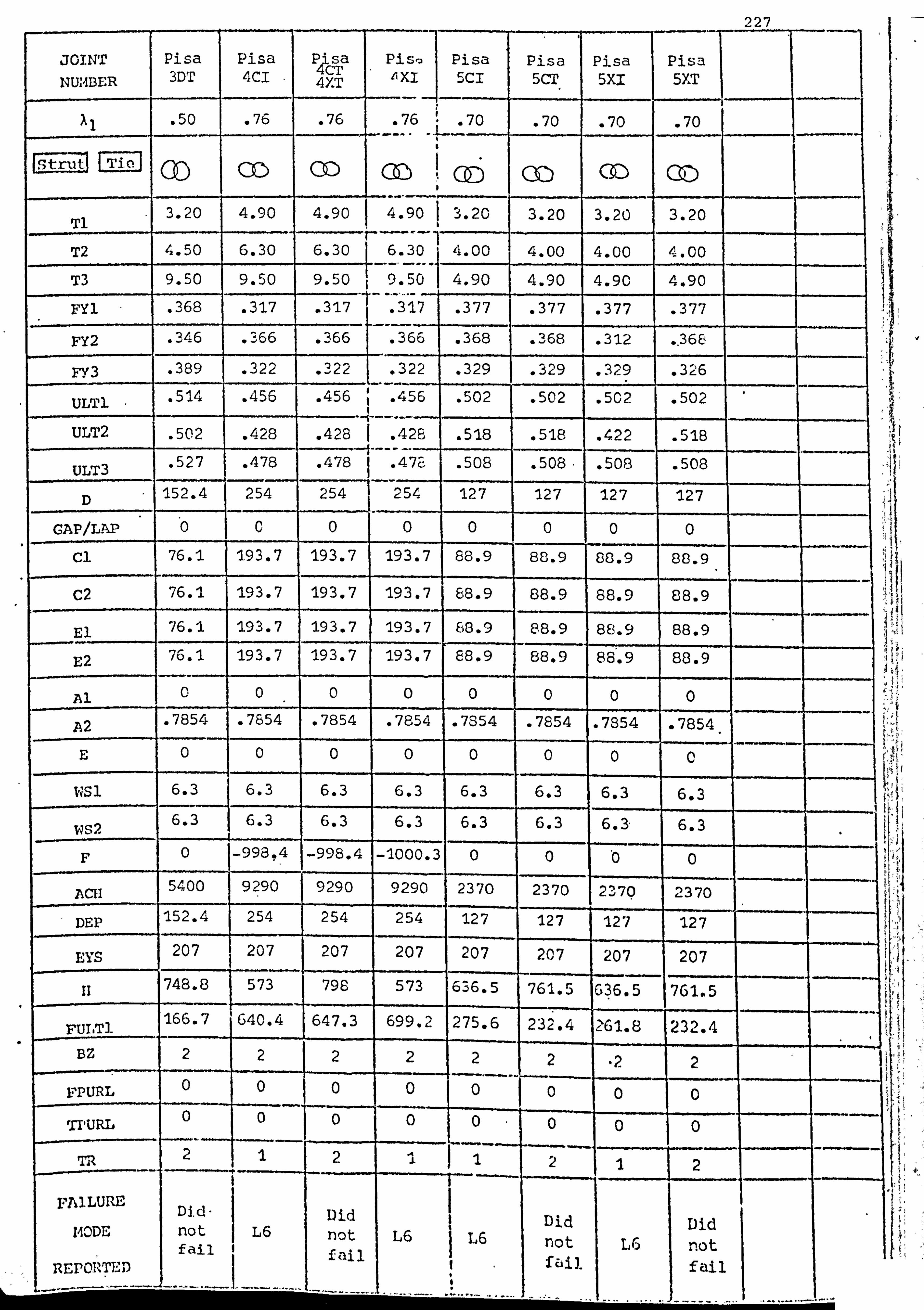
227
im
JOINT Pisa Pisa a P4is Piste Pisa Pisa Pisa Pisa
NUMBER 3DT 4CI r 4YT "XI SCI 5CT 5X1 5XT
al . 50 . 76 . 76 . 76 70 . 70 . 70 . 70 X w
Strut Tic GD co 00 3.20 4.90 4. 90 4.90 3.20 3.20 3.20 3.20
Ti
T2 4.50 6.30 6.30 6.30 4.00 4.00 4.00 4.00
T3 9.50 9.50 9.50 1 9.50 4.90 4.90 4.9C 4.90
FY1 . 368 . 317 . 317 . 317 . 377 . 377 . 377 . 377
FY2 . 346 . 366 . 366 . 366 . 368 . 368 . 312 .. 368
FY3 . 389 . 322 . 322 . 322 . 329 . 329 . 329 . 326
ULT1 . 514 . 456 . 456 . 456 . 502 . 502 . 502 . 502
ULT2 . 502 . 428 . 428 I . 428 . 518 . 518 . 422 . 518
ULT3 . 527 . 478 . 478 . 47E . 508 . 508. . 508 . 508
D 152.4 254 254 254 127 127 127 127
GAP/LAP 0 0 0 0 0 0 0 0
cl 76.1 193.7 193.7 193.7 88.9 88.9 86.9 88.9
C2 76.1 193.7 193.7 193.7 88.9 88.9 88.9 88.9
E1 76.1 193.7 193.7 193.7 88.9 8809 88.9 88.9
E2 76.1 193.7 193.7 193.7 88.9 88.9 88.9 88.9
Al C 0 0 0 0 0 0 0
P2 . 7854 . 7654 . 7854 . 7854 . 7854 . 7854 . 7854 . 7854
E 0 0 0 0 0 0 0 0 ws1 6.3 6.3 6.3 6.3 6.3 6.3 6.3 6.3
WS2 6.3 6.3 6.3 6.3 6.3 6.3 6.3- 6.3
F 0 -998,4 -998.4 -1000.3 0 0 '0 0
ACH 5400 9290 9290 9290 2370 2370 2370 2370
DEP 152.4 254 254 254 127 127 127 127
EYS 207 207 207 207 207 207 207 207
fi 748.8 573 798 573 636.5 761.5 636.5 761.5
FULT1 166.7 640.4 647.3 699.2 275.6 232.4 G61.8 232.4
BZ 2 2 2 22 2 ,2 2
FPURL 0 0 0 y 00 0 0 0
V, URL 0 0 0 00 0 0 0
TR 2 1 2 i 2 1 2
FAILURE Did Did Did Did 140DE not L6 not L6 L6 not L6 not REPORTED
fail fail fail
4. I
1ý
'y r
a,
x{
5 "; 5' P 30 ý -d 6 ý'
i. a, Sý
ýI
=I

APPF. NnTX 2
COMPUTER PROGRAM FOR RHS CHORD JOINT ANALYSIS
i
; ýý;.., ýÄ ::..

Read Data I
I Determine Gap and Lap
Are bracings CHS ? YES
f .
ýOT-
Calculate common joint parameters 1-14
r alculate shear YES Is joint gapped ? NO rength of chord
is X, or ?>0.95?
. 228
Redefine bracing member sizes
Calculate shear strength of chord
Determine ultimate joint-load Determine ultimate joint load YES NO of Push-Push mechanism of Push-Putt mechanism
" with x= 0.5 by iterative with x=1.0 by iterative method. Ultimate load is method. Ultimate load is reached if all of chord reached if all of chord section reaches yield around section reaches yield around the crotch or if the crotch the crotch or if the crotch membrane stress reaches membrane stress reaches ultimate chord stress. ultimate chord 'stress.
is x1 or Aý 0.95 ? YES NO
" Calculate strut buckling load Calculate strut squash load by mechanisms 1&2 by
and tie yield toad iterative procedure. Ultimate load determined by intersection of rigid-plastic unloading line and an
Calculate chord local buckling approximate elastic toad tine load behind the heel of the tension bracing member, by : (a) An experimentally Calculate the elastic stress distribution elastic local
through the chord section. buckling load (if less than
(b) Assuming stress yield load) of the strut concentration is due only member in pure compression to the joint noding away from the joint
eccentricity
Is, there a purlin toad or Calculate the failure load of chord side YES
external load applied to joint? " walls, due to
(a) Buckling "- principal stress reaches yield
lb) Shear stress reaches shear yield NO O ht x imum sh cr strain Energy
Calculate bearing failure load beneath purlin END
Appendix 2.1 Flow diagram for computer program analysis of a joint
% between CHS or RNS bracing members and MIS chord

229
JOINT:
30 Joint Parameters in this order Symbol Units
1. Thickness of compression bracing member Ti mm
2. Thickness of tension bracing member T2 mm 3. Thickness of chord member T3 mm
4. Yield stress of the compression bracing member FY1 kN/mmo
5. Yield stress of the tension bracing member FY2 kN/mm5
6. Yield stress of the chord member FY3 kN/a: m°
7. Ultimate stress of the compression bracing member ULT1 kN/mms
8. i; ltimate stress of the tension bracing member VLT2 kN/mm5
9. Ultimate stress of the chord member ULT3 kN/mm5
10. Width of chord member (900 to plane of truss) D mm
12. For a gapped joint: Nominal gap (neglecting welds) between
braeings divided by the %idth of the chord member, and expressed as a nesativo number. Insert 0.0 if gap is not GAP None known but joint eccentricity is known. For a lapped joint: Express the lap as a decimal fraction (positive number) by CIDECT definition of the lapped length LAP None of bracings, measured along the chord face, divided by the strut depth measured along the chord face. Insert 0.0 if lap is not known but eccentricity is known.
12. Width of compression bracing (900 to plane of truss) cl Orin
13" Width of tension bracing (900 to plane of truss) C2 Dim
. 14. Depth of compression bracing (in plane of truss) El mm
15. Depth of tension bracing (in plane of truss) E2 sun 16. Angle of the compression bracing to the VERTICAL Al radians
17, Angle of the tension bracing to the VERTICAL A2 reidians
18. Eccentricity of Noding - positive is towards the outside E of the girder - insert 0.0 if gap or lap was given in item 11.
1.9. Nominal weld LEG LENGTH' on compression bracing * WS1 Dun
20. Nominal weld LEG LENGTH on tenyion bracing" WS2 am 21. Axial load (preload) in chord in addition to the F VN
horizontal reaction from bracings - tension is positive and compression negative.
22. Cross - sectional area of chord member ACH mms
23" Depth of chord member (in plane of truss) DEp mm 24. Modulus of elasticity** ETS kN/mmm
25. The length of the strut member, measured along its centre-lino, from the chord face. In the case of a truss the length is half the centre-line distance li sun between the inside faces of the two chord members.
26. Ultimate (or maximum if the joint did not fail) load in the ccopression bracing member. Insert 0 if this is not known
FULT1 kN
27. Insert 1 if bracings are RITS, or 2 if bracings are CHS. DZ None
26. Compression load applied by purlin cleat at the joint - FPURL kN
29.. Width of purlin bearing (including welds to the chord), measured along the length of the chord meiner TPURL mm Insert 2 for a joint with chord member continuous on either side, or 1 for chord member continued or, one side only. TR None
« Weld leg length ca:: be assumed to be ff x thickness of the bracing member connected, unless -
otherwise specified.
«* British Standards recommend a value of 206 kN/mm2 (8), and the ECCS (3Q) recommend , 1/ma2, a value of 210 k
Apjendix 2.2 Data required for computer program input

Appendix 2.3 Listing of computer program

230 MASTER VERSION PEAL t1N. JK1. JK2. NUF1. LI. Lo LAP. LTOT. L2. N1. N2. LM. Hi'. J. K. t1STR. Lß. L3
ý'r«frrl«ir+«#b#f 1rM«i*f tf#«f it*****f******* *****##it«liri«rr****«*****k**Mk«t«*A' C
C C YIELD AND ULTIMATE LOAD ANALYSIS OR GAP AND LAP RUS CHORD JOfiJTS C WITH PURLIN LOADING C C BY : J. A. P:. CKER C
OCTOBER 197&
C C Ca*aa*******aa*a*******************a-*********a**r***a*****a*a********a**a*aa*a" C T1=THICLHESS OF COMP. PEM, T2 OF TENS. MEM.. T3 OF CHORD t1EM. C Al=ANGLE(RAOIANS) OF COUP. MEMBER TO VERTICAL C A2=ARGLE(RADIANS) OF TENS. t1E11BER TO VERTICAL C FY12VIELD STRESS OF COMP. 14EM., FY2 OF TENS. MEM., FY3 OF CHORD MEM. C ULTI, ULT2, ULT3=ULTIt1ATE TENSILE STRESS OF STRUT, TIE AND CIiORD RESPECTIVELY C G*Ds72=ACTUAL WELD GAP . D=WIDTH OF CHORD t1EMBER , DEP=DEPTH OF CHORD. C C1=WIDTH OF COIIP. PIER., C2=t"IIDTH OF TENS. MEPI. C E1=DFPTii OF COMP. PIEV. "E2=DEPTH OF TENS. ITEM. C LENGTH OF SIELD LEG ON COMP. MEMBER = WS1 C LENGTH OF tiELD LFG ON TENS. MEMBER = WS2 C EYS=YOUNG'S IIODIJLUS OF ELASTICITY C F=CHnRD AXIAL TENSION PRELOAD . FP=CHORD SQUASH LOAD . ACII=AREA OF CHORD C LAP IS DEFINED DY BSC TERMINOLOGY: OVERLAPPED LENGTH/DEPTH OF STRUT PROJ. C ONTO CHORD FACE. IF JOINT IS LAPPED. THEN 'GAP' IS ACTUALLY THE LAP VALUE C BUT 14RIlTEII. POSITIVE INSTEAD OF NEGATIVE. C E=NUDII: G ECCENTRICITY IN 11M. WITH POSITIVE BEING TOWARDS THE OUTSIDE OF C THE GIRDER. C H=THF LENGTH(IN MM. ) OF THE STRUT t'EMBER, t1EASURED ALONG ITS CENTRE-LINE,
C FROM THE CHORD FACE. IN THE CASE OF A TRUSS THE LENGTH IS HALF THE CENTRE C -LINE DISTANCE BETWEEN THE INSIDE FACES OF THE TWO CHORD MEMBERS. C BZ=1 FOR RHS. =2 FOR CHS DRACINGS. C FULT1=ULTIIIATE LOAD IN STRUT C FPIIRL='JERTICAL POPLIN LOADING, AND TPURL=THICKNESS OF PURLIN LOAD AREA. C TR=2 FOR A JOINT WITH CPIORD MEMBER CONTINUOUS ON EITHER SIDE.
C TR=1 FOR CHORD PIEMBER CUNTIIIUED ON ONE SIDE ONLY. Ca***aa*a+****a*a*a********i************************************aa*a***aa*f*****
WRITF(6.17) 17 FORI4AT(1147, IX, 'ALL VALUES OF LOADS (P) ARE THE VERTICAL COMPONENTS
1 OF THE BRACING MEMBER FORCES. ') WRITF(6.18)
18 FORMAT(? X, 'IF PORLIN LOAD ACTS ON JOINT THEN THE LOADS (P) GIVEN A IRE FOR THE VERTICAL COMPONENT OF THE STRUT MIFMBER')
WRITF(6,51) DO 1n 1=1.500 READ(5.180)T1, T2, T3. FYI, FY2. FY3, 'JLT1. ULT2, ULT3, D, GAP. CI, C2, E1, E2,
1AI, A7. E, WS1,1J52. F, ACH, DEP, EYS. H. FULTI, BZ, FPURL, TPURL, TR 180 FORI1AT(30F0.0)
IF(TI. LE. 0.01)STOP IF(GAP. LT. 0. O)LAP=0.0 IF(GAP. GT. 0.0)LAP=GAP IF(GAP. LT. 0.0)GAP=ABS(GAP) IF(GAP. E0. O. O)CALL ECC(E. D, A1, A2, E1. E2, GAP, LAP) IF(B7.1U. 1.0)GO TO 19 C1=0.7854*C1 EI=C1 C2s0.7554*C2 E2=C2
C IF BRACING IIEMBERS ARE CHS THEN DIAI'FTER 1S MADE INTO A SQUARE H. S. WITH C SIDES EQUAL TO 0.7854*DIAI4ETER.
19 D=D-T3 C FOR CALCULATIONS HINGES ARE IN THE MIDDLE OF THE CHORD WALLS.
21=GAP*(D+T3) ZB=GAP*(D+T3) - 22=Z1-UJSI IF(A1. GT. O. 5)Z2=Z1 G=72/D FXsARS(F) FP=ACH*FY3 RAT1n=F/FP COui1=1. C-(F/FP)**2 L1s(C1+2.0*US1)/D 7Q=(C1+2.0*%IS1)/(D+T3) IF(ZQ. GT. 1.00)ZQ=1-. 00 L2=(C2+2.0*0S2)/P N1s(2*! JS1+E1/COS(A1))/D IF (Al. GT. 0.5)NI=(WS1+E1/COS(A1))/D N2=(I'S24F2/COS(A2))/D WRITF(6,15)1.: 4, PAT10
15 FORI"IAT(2X, 'JOINT I: Ut"1ßER»', I3,1Qr(, 'L1(INCL, IJELDS)x', F4.2,5X, 1'F/FP='ÄF5: 2) ,"`, IF(LAP. f0.0. O)GO'70 20 CALL SHILAHLAP(LAP, EI. A1, A2. T1, T2$73, FY1, CY2, FY3, PEP, CONIE PURL) GO Tn 22
20 CALL SIIEARGAP(DEP. T3, FY3, Ci)N1. FPURL)

IF(L1. G7.0.95. OR. L2. GT. O. 95)GO TO 22 231 CALL PP05(L1, L2ºD, FY3, T3, G. CONT. EYS, F, t1LT3, FX. FP, Z2. Nt, N2, PY5, PU5,
1PSHF1ºPCHB, PSBK, FPURL. AI, A2. DEP, WS1. E1, C1, C2) C IF PIIRLIN LOAD ACTS ON A GAP JOI T J'ND THE GAP IS 'RELATIVELY SNAIL', THE C PP10 IIECHANISM IS 11ORE LIKELY TO :. CCIJR THAN THE PP05 MECHANISM.
44 CALL PP10(L1º1.2. DrFY3ºT3. G. COt: 1, EYS. F, ULT3, FX. FP, Z2ºN1, N2, PY1O. 1PU10ºPSHFI. PCHB. PSBK. FPURL, Al. A2,5EPºWSi, El, Cl. C2)
22 CALL BUCKLE3(T1, T2, T3, FY1, FY2, FY3, ü, LAP, CI, C2. E1. E2. A1, A2, LI. CON1, 1ACH, FYS. H, GAP. Z1, PSQASH, PYEELD, PBUCK3, PBUCK4, L2. FPURL)
26 CALL 000RD(L1. A1. A2. F, ACH, EYS. T3. D. FY3, PCHB, FPIJRL, EI. E2,28, GAP, 1IAP, DEP, TR)
CALL SThIIT(C1, El"EYSºTi. FYI, AI, PSUK) CALL PUkLINJ(D. F. ACH. FPURL, TPURL, 13, FY3, DEP, EI, NI, LAP, AI. A2. T1) CALL PURL1142(FY3, F, ACH, T3, D, TPJRL. FPURI)
10 WRITE(6,51) 51 FORIIAT(2X. '*****a**********r**+*****r*****************r*****rr*rr*
STOP END SUBROUTINE SHEARLAP(LAP. Ei, A1. A2ºT1. T2ºT3. FYI. FY2, FY3, DEP, CON1.
1FPUkI) REAL LAP, L IF(FPURL. NE. O. O)G0 TO 20 l=E1*LAP/COS(Al) CUV=2.0*L*COS(A1)*COS(A2)/SIN(A1+A2) CTV=2.0*(DEP+T3)*T3*FY3*SQRT(CON1)/SQRT(3.0) PSHI=(CUV+2. n*T1)*T1*FYI /SORT (3.0)+CTV P5112=(CUV+2.0*T2)*T2*FY2/SQRT(3.0)+CTV PSHLAP=AI"}IN1 (PSHI "PSH2) WRITE(6,10)PSHLAP
. 10 FORMAT(/. 2X, 'JOI11T IS LAPPED - CHORD SHEAR(ULTINATE) OCCURS AT P=' 1, FR. 7, ' KNS. ')
20 RETURN END SUDROUTINE SHEARGAP(DEP, T3. FY3ºCONI, FPURL) IF(FPURL. NE. O. 0)GO TO 20 PSHFI=2*DEP*T3*FY3*SORT(CONi)/SQRT(3.0) PSIIF2=2*(DEP+2.0*T3)*FY3*SQRT(CUN1)*T3/SQRT(3.0) WRITF(6.10)PSHFI. PSHF2
10 FOR! IAT(/, 2X, 'JOINT 1S GAPPED - CHORD SHEAR YIELD OCCURS AT P='. 118.2. ' KNS. AND ULTIMATE AT P='. F8.2. ' KNS. ')
20 RETURN END SURkOUTINE STRUT(Cl, EI, EYS. TI. FYI. AI. PSBK)
C SUBROUTINE STRUT CALCULATES THE MINIMUM LOCAL'BUCKLING LOAD OF ANY FACE C FOR RMS BY HODE 1. EFFECTIVE STRUT WIDTH=(C1-T1)OR(E1-T1). P11AX IS THE C LOCAL BUCKLING LOAD FOR ALL OF STRUT.
PCRIT=3.55*EYS*T1**3/(C1-T1) PYSTP=(C1-T1)*T1*FY1 IF(PVSTR. LE. PCRIT)GO TO 620 CZ=(0.36*PYSTR*PCRIT+0.83*PCRIT**2)*0.76 PMAX=(SQRT(CZ+PCRIT**2)-PCRIT)/0.38 PMAX=(PIIAX*2.0*((C1-T1)+(E1-T1)))/(C1-T1) GO TO 621
620 PMAX=((C1-Ti)*2.0, (E1-T1)*2.0)*T1*FY1 621 PSTk1: PI1AX*COS(A1)
PCRIT=3.55*EYS*T1**3/(E1-T1) PYSTR=(E1-T1)*T1*FY1 IF(PYSTk. LE. PCRIT)GO TO 654 CZ=(l. 3r. *PYSTR*PCRIT+0. (13*PCRIT**2)*0,76 PMAX=(SURT(CZ+PCRIT**2)-PCRIT)/0.38 PMAX=(P11AX*2.0*((C1-T1)+(E1-T1)))/(E1-T1) GO TO 655
654 PMAX=((C1-T1)*2.0+(E1-T1)*2.0)*T1*FY1 655 PSTR2=P11AX*COS(A1)
PSRK=At1IN1(PSTR1ºPSTR2) WRITE(6,932)PSBK
932 FORMAT(/, 2X, 'STRUT LOCAL BUCKLING DUE TO AXIAL LOAD ONLY OCCURS AT 1 P='. F3.2, ' KNS. ')
RETURN END SÜDROUTINE PP05(L1, L2, D, FY3, T3, G, CONI, EYS. F. (ILT3, FX, FP, Z2, NI. 112. 1PY5, PUS. PSHFI, PCIIB, pSBK. FPURL, AI, A2, PEP. WSIºF. 1. CI C2) REAL L1, L2.1.11, FJ2, LI", Mp, J, K, t1STR. L3
C SUBROUTINE PP05 CALCULATES THE LOAD/DEFLECTION BEHAVIOR OF THE CHORD TOP C FACE SUBJECT TO BRANCH IMEI1BER FORCES, USIN: AN INCREMENTAL DEFLECTION C ANALYSIS. RIGID-PLASTIC BEHAVIOUR IS AS$! 111ED AND MEMBRANE ACTION TAKES C PLACF IN THE CRUTCH ONLY. THE DISTANCES K AND J ARE CONSTANT AT THE C VALUES OF THE S11ALL DEFLECTION ANALYSIS. X IS ALSO SET AT 0.5 C STRAIN HARDENING MODULUS FOR CROTCis IS EYS/300 C ULTIMATE LOAD IS REACHED BY ULTIMATE STRESS IN CROTCH OR THE C WHOLF CHORD CROSS-SECTION REACHING PLASTICITY AT THE CROTCH. C*************i*+*"r******r*********************º****w:
sr***s***r*r***r*r****rr*r K=D*SQRT(1-L1)*O. 5 J=D*SQRT(1-L2)*0.5 IF((J+K). LT. Z2)%IRITE(6.5O)
50 FORI. IAT(/, ZX, 'CLEAR WELD GAP IS L1. RGE ENr, 1; OH FOR SEPARATE T-JOINT A

ICTION') LM=S0RT((D*(1-L1)/2.0)**2+K**2) EF=SQRT((G*D/2.0)**2+(D*(1-L1)/2.0)**2) QR=SlRT((D*(1-L2)/2.0)**2+J**2) FGsSQItT((G*D/2.0)**2+(D*(1-L2)/2.0)**2) C021=1.0-(FX/FP)*(FX/FP)*(0.5*D*(1-L1)/LI1)**4 C072=1.0-(FX/FP)*(FX/FP)*(0.5*D*(1-L2)/QR)**4 C03121.0-(FX/FP)*(FX/FP)*(0.5*Dk(1-L1)/EF)**4 C032=1. O-(FX/FP)*(FX/FP)*(0.5*D*(1-L2)/FG)**4 MP=(FY3*T3**2)/4.0 PYS=0.0 ZZA=0.0
). DEFI"I=0.01*(D+T3)
"TH=0.0 DEL=A. 0 DTII=ATAt(0.0001*(D+T3)/Z2) IF(DTH. LT. 0.0005)DTH=0.0005 DO 1A0 N=1 . 2000 ARG1=G*TAN(TH+DTH)/(1-L1) ARG2=G*TAt1(TH+DTH)/(1-12) IF(ARGI. IT. 1.0. AND". ARG2. LT. 1.0)GO TO 500 WRITF. (6,54)
54 FORIIAT(/, 2X. 'FOR P/P MODEL 111TH X=0.5, THERE IS NO MATH. SOLUTION') WRITF(6,55)TH, DEL
55 FORIIAT(2X, 'AtUD MAX. ROTATION IS REACHED AT THETA=', F6.2, 1' RADIANS, AND DELTA=', F8.2, ' NM. ')
GO Tn 543 500 DL=b*DJCOS(TH+DTH)-G*D/C0S(TH)
DDEL=(G*D/2.0)*(TAN(TH+DTH)-TAN(TH)) DFH1=ATAN(G*0*TAN(TH+DTH)/(Z. O*K))-ATAN(G*D*TAN(TH)/(2.0*K)) DFH2=ATAN(G*D*TAN(TH+DTIi)/(2.0*J))-ATAN(G*D*TAN(TH)/(2.0*J)) DGAI=ASIN(AHG1)-ASIN(G*TAN(TH)/(1-L1)) DGA22ASIN(ARG2)-ASItU(G*TAN(TH)/(1-L2)) DBETA=(U*TAN(TH+DTH)*K)/((1-L1)*LH) DBETR=(G*TAN(TH+DTH)*J)/((1-L2)*QR) DBFT1=ASIN(DBETA) DBETS=ASIN(DBETO) DBFT'=ASIN(G*TAIJ(TH)*K/((1-L1)*LM)) DBFT6=ASTI4(t, *TAII(T11)*J/ ((1-L2)*QR)) DBET3=ATAN((G*D*TAtU(TH+DTII)*D*(1-L1))/(4.0*K*LM)) DOE T7=ATAN((G*D*TAND(TH+DTH)*D*(1-L2))/(4.0*J*QR)) DBET4=ATAtI(6*D*TAN(TH)*D*(1-L1)/(4.0*K*Lt1)) DBFTR=ATAIJ(G*D*TAN(TN)*D*(1-L2)/(4.0*J*QR)) D8F1=D3ET1-06CT2+DBET3-DBET4 DBE2=DOLT5-DBETo+DBCT7-DBET8 DALFI=ASIN((G*TAN(TH+DTH)*G*D)/(2.0*EF*(1-L1))) DALFS_ASIti((f, *TAN(TH+DT1l)*G*D)/(2.0*FG*(1-L2))) DAIF? =ASIN((G*TAN(TH)*G*D)/(2,0*EF*(1-11))) DALF6=ASIN((G*TAN(TH)*G*D)/(2.0*FG*(1-L2))) DAL Fi=ATAJ(TAN(TH+DTH)*D*(1-L1)/(2.0*EF)) RALF'=ATAii(TAN(TH+DTH)*D*(1-L2)/(2.0*FG)) DALF4=ATAN(TAN(TH)*D*(1-11)/(2.0*EF)) DALFF=ATAN(TAt4(TH)*D*(1-12)/(2.0*FG)) DAL1=DALF1-nALF2+DALF3-DALF4
_ DAL2=DALF5-DALFu+DALF7-DALF8 P1=((1+L1)*D*IiP*DFI11*COtJ1+(1+L2)*D*IIP*DFH2*CON1)/(2.0*DDEL) EY=FV3/EYS L3=(C1+C2)/(D*2.0) SP=L1*D*T3*FY3 S=EYS*L3*D*T3*((1. O/COS(TH))-1.0) SZ=Lj*I)*T3*(1.0/COS(TH)-1.0-EY)*EYS/300.0 IF((1.0/COS(TH)-1.0). GT. EY)S=SP+SZ P2=Li*D*i; P*(1.0-(S/SP)**2)*DTti/DDEL P8=L? *D*IIP*(1. O-(S/SP)**2)*DTH/DDEL P2=(P2+P8)/2.0 IF(S. GT. cP)P2=0.0 P3=D*IIP*DGA1*(4.0*N1+G+2.0*K/D) P9=D*IIP*DGA2*(4.0*1*2+G+2.0*J/D) P3=(P3+P9)/(DDEL*2.0) P4=2.0*LM*11P*DBE1*C021 P10=2.0*0R*11P*DDE2*C022 P4=(P4+P10)/(DDEL*2.0) P5=2.0*CF*11P*DAL1*C031 P11=?. 0*FG*IIP*DAL2*C032 P5o(P5+P11)/(DDEL*2.0) P6=(S*DL)/(2.0*DDEL) P7=0.0 P=P1+P2+P3+P4+P5+P6+P7+FPURL/2.0
10 IF(N. GT. 1)GO TO 42 PYS=P
42 IF(ZZA. NE. 0.0)GO TO'99 IF(P. LT. PY5)P=PY5'"' IF(DFL. GT. DEFII)URITE(6,72)P
232
72 FORIIAT(/, 2X, 'LIIIIT OF I PER CENT OF CHORD WIDTH FOR DEFORMATION EX 1CEEDFD'AT P=', F8.2, ' KNS. ') IF(DFL; CT. DEFtI)ZZA-1. O

99 MSTR=1000.0"S/(L3*D+T3) 233 CALL SIDFWALL2(FY3. ULT3ºD. T3ºDEPºA1r'. S1. l2ºTH. MSTR, F, E1º
IL1. L?. PALLOW, CI. C2. P) ULT4=ULT3+1000.0
98 DEL=nEL+DDEL
100 544 515
516
517
THIIAX=TH TH =T H+DTH IF(P. LT. PYS)P=PY5 PUS=P IF(I1GTR. GE. ULT4)G0 TO 544 IF(PALLUW. LT. PUS)GO TO 517 CONTINUE WRITF(6,515)PY5, PU5, THNAX FORMAT (/ o2X# 'FOR P/P MODEL 111TH X=0.5, YIELD LOAD(P)=', F8.2,
1' KAIS. AND ULTIMATE LOAD(P)=', F8.2, ' KNS 8 THETA =', F5.3) WRITF(6.516)P6, PALLOW FORMAT(/, 2X, 'P6='. F3.2. ' KNS. & P"ALLOWANCE FOR HORIZ. CONPS. a'.
1F8.2. ' KNS. ') GO Tn 543 IF( PALL(jIJ. LT. PY5)PALLOW=PY5 WR1TF(6.513)PY5, PALLOU
518 FORI. IAT(/. 2X. 'FOR P/P MODEL 1' KNS. AND ULT. LOAD(DUE TO
543 RETURN
WITH X=0.5, YIELD LOAD(P)=', F8.2, HORIZ. COMPS. )='. F8.2. ' KNS. ')
END SUBROUTINE PP10(L1. L2, D. FY3rT3, G, CONI. EYS, F. ULT3. FX. FP, 22. N1. N20
1PYIO, PUIO, PSHFI, PCHB. PSBK, FPURL, Al, A2. DEP, USI. El. C1. C2) REAL Li. L2. N1, N2, LM, NP. J, K. IISTR. L3
C SUBROUTINE PP10 CALCULATES THE LOAD/DEFLECTION BEHAVIOR OF THE CHORD TOP C FACE SUBJECT TO BRANCH 11EIIBER FORCES, USING AN INCREIIENTAL DEFLECTION C ANALYSIS. RIGID-PLASTIC BEHAVIOUR IS ASSUMED AND MEUBRAHE ACTION TAKES C PLACE IN THE CROTCH ONLY. THE DISTANCE K IS TAKEN TO BE CONSTANT AT THE C VALUE FOR THE SMALL DEFLECTION ANALYSIS. X IS ALSO SET AT 1.0 C STRAIN HARDENING MODULUS FOR CROTCH IS EYS/300 C ULTW ATE LOAD IS REACHED BY ULTIMATE STRESS IN CROTCH OR THE C WHOLE CHORD CROSS-SECTION REACHING PLASTICITY AT THE CROTCH. Crfof**sfºf****f****************** *******ww*trawt********rff**ft*t*A******wf*RR*
K*D*S(1RT(1-L1)*0.5 LM-SORT((D*(1-L1)/2.0)**2+K**2) EF=SORT((G*D)**2+(D*(1-L1)/2.0)**2) C0N2=1.0-(FX/FP)*(FX/FP)*(0.5*D*(1-L1)/LM)**4 CO113=1.0-(FX/FP)*(FX/FP)*(0.5*D*(1-L1)/EF)**4 CON4=1.0-(FX/FP)*(FX/FP)*COS(0.5*D*(1-L1)/EF)**4 MP=(FY3*73**2)/4.0 PY10=0.0 ZZA=0.0 DEFI1 0.01*(D+T3) TH=0.0 DEL=n. 0 D1H=ATAU(0.0001*(D+T3)/Z2) IF(DTH. LT. 0.0005)DTH=0.0005 DO 100 N=1,2000 ARG1=2.0*G*TAN(TII+DTH)/(1-L1) IF(ARGI. LT. 1.0)G0 TO 500 WRITF(6.54)
54 FORIAT(/. 2X. 'FOR P/P MODEL WITH X=1.0*THERE IS NO IIATN, SOLUTION') WRITF(6,55)TII. DEL
55 FORI"; AT(2X. 'AND IIAX. ROTATION IS REACHED AT THETA=', F6.2, 1' RADIANS. AND DELTA='. F8.2. ' f1M. ')
GO TO 543 500 DL=G*D/COS(TH+DTH)-G*D/COS(TH)
DDEL=G*D*TASJ(TH+DTH)-G*D*TAH(TH) DDELTA=SQRT(K**2-(DEL**2)/4.0)-SQRT(K**2-((DEL+DDEL)**2)/4.0) DFItI=ATAH(G*D*TAN(TH+DTH)/K)-ATAN(G*D*TAN(TH)/K) DGAI4=ASIN(ARG1)-ASIN(2.0*G*TAN(TN)/(1-L1)) DßETIxASIN((2.0*G*TAN(TIt+DTH)*K)/((1-L1)*Ltt)) DBET2=ASIN(2.0*G*TA14(TH)*K/((1-11)*LM)) DRET3=ATAN(G*D*TAN(TH+0TI1)*D*(1-L1)/(K*2.0*I. M)) DBET4=ATAN(G*D*TAN(TH)*D*(1-L1)/(K*2.0*LM)) D8ET=D0ET1-DBET2+DBLT3-DßE74 DAIFI=ASIN(2.0*G*TAII(TH+DTH)*G*D/((1-L1)*EF)) DALF? =ASIN(2.0*G*TAII(TH)*G*D/((1-L1)*EF)) DAL F1=ATAN(TAN(TH+DTH)*D*(1-L1)/(2. J+EF)) DALF4=ATAN(TAU(TM)*D*(1-L1)/(2.0*Ef)) DALF=DALF1-DALF2+DALF3-DALF4 P1=(ß+L1)*D*IIP*C0N1*DFHI/DDEL EY=FV3/EYS L3=(C1+C2)/(D*2.0) SP: Ll*D*T3*1Y3 S=EYS*L3*D*T3*((1.0/COS(TA))-1.0) SZ=I3*D*T3*(1.0/COS(T11)-1.0-EY)*EYS/300.0 iF((1. O/CO%(TH)-1.0). GT. EY)S=Sp+SZ P2a(1+L1)*D*I1P*(190-(S/SP)**2)+DTH/05EL IF(S: GT. SP)P2=0. C 2' P3=2.0*D*(?.. 0*N1+G+K/D)*MP*DGAN/DDEL P4=2: 0*LI1*IIP*Dßf. T*C0N2/DDEL P5=2.0*EF*IIP*DALF*CON4/DDEL

P6=S*DL/DDEL 234
P7=0.0 P=pl+P2+P3+p4+P5+P6+P7 IF(N. GT. 1)GO TO 42 PY10=P
42 IF(Z? A. NE. 0.0)G0 TO 99 IF(P. LT. PY10)P=PY10 IF(UFI. GT. DEFIi)URITE(6r72)P
72 FOR11AT(/. 2X. 'LIIIIT OF 1 PER CENT JF CHORD WIDTH FOR DEFORIUATION EX ICEFDF. D AT P=', F8.2, ' KNS. ')
IF(UFL. GT. DEFIi)ZZA=1.0 C**********x*****x******xx*x#***************x**x************x** **********#x#**4
99 MSTk=1000.0*S/(L3*D"T3)
22=Z2*2.0 CALL SIDEWALL2(FY3, ULT3, D, T3, DEP, A1. WSI. 22. TH. MSTR, F. E1. L1, L20
IPALLOW. Cl. C2, P) Z2: Z2/2.0 ULT4=ULT3*1000.0
98 DEL=DEL+DDEL THIIAX=TH TH_TH+DTH IF(P. LT. PY10)P=PYI0 PU1ü=P IF0ISTR. GE. ULT4)G0 TO 544 IF(PALLOW. LT. PUIO)GU TC 517
100 CONTINUE 544 WRITF(6,616)PY10, PU10, THPAX 616 FORMAT(/, 2X, 'FON P/P I40DEL WITH X=1. O, YIELD LOAD(P)=', F8.2,
1' KNS. AND UJLTIIIATE LOAD(P)=', F8.2, ' KHS. & THETA=', F5.3) WRITF(6.516)P6, PALLOW
516 FOR11AT(/, 2X, 'P6='. F3.2, ' KNS. & P-ALLOWANCE FOR HORIZ. COMPS. s', 1F8.2, ' KNS. ')
GO TO 543 517 IF(PALI(i14. LT. PY10)PALLOU=PY10
WRITF(6.518)PY10, PALLOW 518 FORMAT(/, 2X. 'FOR P/P MODEL WITH X=1.0, YIELD LOAD(P)='. F8.2,
1' KNS. AND LILT. LOAD(DUE TO HORIZ. COtIPS. )=', F8.2, ' KNS. ') 543 RETURN
END SUnkOUTINE ILIJCKLF3(T1, T2, T3. FY1, FY2. FY3, D, LAP, CI, C2, E1, E2, A1. A2,
1L1. C(1N1. ACH, F. YS. H, GAP. Z1, PSQASH, PYEELD, PßIJCK3. PBUJCK4, l2, FPURL) REAL 1111. JKI. JK2, NUM, L1, L, LAP, LTOT. L2
C THIS ROUTINE PREDICTS STRUT LOCAL BUCKLING LOADS FOR GAP OR LAP JOINTS, C BY TIRO DIFFERENT 14ECHANISIIS INVOLVING CHORD ROTATION.. Cax*a****. ***#*t*a*xxxx*x*x**x#******xaax**aa****a*ta*x*a**as***a*a***********xa
IF(LAP. LE. 0.0)GAP=ABS(LAP) IF(LAP. LT. 0.0)LAP=0.0 T=T1 C=C1-T1 E=E1-T1 L=F1*LAP/COS(A1) LTOT=E2/COS(A2)+E1/C0S(A1)-L IF(LAP. EQ. 0.0)LTOT=E2/CUS(A2)+E1/COS(Al)+Z1 DW=0.02*T
C C=EFFECTIVE STRUT WIDTH OF (C1-TI) C E=EFFECTIVE STRUT DEPTH OF (E1-TI)
W=0.0 THFTA=0.0
22 1F(Ll. G7.0.95. OR. L2. GT. 0.95)GO TO 26 DO 20 N=1.201 Z=W/T GA=SORT(E*E+(0; 35*C)**2) GH=t-0.25*C MH=0.35*C*(E-0.25*C)/GA AH=SDRT((0.25*C)**2+(0.35*C)**2) IF(((W+DW)*x2). GE. ((0.35*C)**2))G0 TO 17 ROF. =ASI1N(SQH7((0.35*C)**2-W**2)/GA) DROE=ROE-ASIIJ(SuRT((0.35*C)**2-(W+DU)"*2)/;. A) XAl=f6A*COS(ROE) XA2=GA*COS(ROE-DROE) YA1=GA*SIN(ROE) YA2=GA*S1N(RO1-DROE) NU11=GA*(. A+GII*GH-AH*AH XH1=NU11/(2.0*GA*COS(ROE)) XH2 NU1! /(2.0*GA*COS(ROE-DROE)) ARG1=GIH*GH-(NUI1/(2.0*GA*COS (ROE) ))'**2 IF(ARGI. LT. 0.0)ARG1=0.0 ZH1=SQRT(ARG1) ',
., ZH2=SQRT(GH*GH-(NUN/(2.0*GA*COS(ROE-DROE)))**2) DSPR=AS114(Z117/ltH)-ASIN(ZH1, IIH) DTOR=2.0*ASIN(Z42*E/(IIH*GA))-2.0*ASIY. (ZH1*E/(MH*GA)) FHI=ASIN(W/(0.35*C)) DFIII=ASIN((W+DIJ)/(0.35*C))-ASIN(W/(0.35*C)) XC1=AA*COS(ROE)-0.35*C*SIN(. F111) XC?: GA*COS(ROE-DROE)-0.35*C*SIN(FiUI+DF: 11) ZC1=-0.25*C. '=4ý; ZC2x7C1

R=0.? 5*C 235 ANJI=ACOS(SORT((XC1-XH1)**2+(ZH1-ZC1)**2)/(2.0*R)) ANJ2=ATAN(ABS((XC1-XH1)/(ZH1-ZC1))) ANJKI=ANJI+ANJ2 ANK1=ACoS(SIIRT((XC2-XH2)**2"(Z:! 2-ZC? )**2)/(2.0*R)) ANK2=ATAN(AIIS((XC2-XH2)/(ZH2-ZC2))) ANJK? =AN K1+ANK2 XJI=XHI+R*SIN(ANJKI) XJ2=X112+R*SII)(ANJK2) ZJ1=7H1-R*C0S(AIJJKI) ZJ2=7H2-R*CUS(AI4JK2) AJI=SQRT((XA1-XJ1)**2"YAI*YAI+ZJ1*ZJI) AJ2=SORT((XA2-XJ2)**2+YA2*YA2+ZJ2*ZJ2) SQL1=0.7*C-2.0*AJ1 SQL2=0.7*C-2.0*AJ2 I)SOL=SQL2-SUl1 SJI=O.; 8*SORT((XA1-XJ1)**2+YA1*YAI+ZJ1*ZJ1) 5J2=0.5d*SQRT((XA2-XJ2)**2+YA2*YA2+ZJ2*ZJ2) AS 1=n. 314*SQQRT((XA1-XJ1)**2+YA1*YA1+ZJ1*ZJ1) AS2=n. 314*SORT((XA2-XJ2)**2+YA2*YA2+ZJ2*ZJ2) X51=XAI+(AS1/AH)*(XH1-XA1) XS2=XA2+(AS2/AH)*(XI12-XA2) YSI=VAI-(AS1/AH)*YA1 YS2=VA2-(AS2/AH)*YA2 ZS1=(AS1/AH)*ZN1 ZS2=(AS2/AH)*ZH2 CHI=ASIN(0.35*C/GA) PH=U. 35*C*(E-0.25*C)/GA SIG=ASIN(ABS(ZS1-ZJ1)/SJI)+ASIN(ABS(Zti1)/PH) DSIG=ASIN(AIiS(ZS2-ZJ2)/SJ2)+ASI14(ADS(ZH2)/PH)-SIG ARG2=ZII1-ZJ1 IF(ARG2. EQ. 0.0)GO TO 52 HI=ATA! 1((XJ1-XC1)/(ZC1-ZJ1))+ATAN((XH1-XJ1)/(ZH1-ZJ1)) GO TO 53
52 HI=-1.57079o37 53 DH12ATAN((XJ2-XC2)/(ZC2-ZJ2))+ATAN((XH2-XJ2)/(ZH2-ZJ2))-HI
DHI=AUS(Dill) JK1=SIN(0.610591834)*AJ1 JK? =S III(0.61P591884)*AJ2 AKI=fl. 314*AJI AK2=A. 314*AJ2 AC=AH XK1=KAI+(AK1/AC)*(XC1-XA1) XK? =XA2+(AK2/AC)*(XC2-XA2) ETAsASIIv(ADS(XJ1-XK1)/J K1)+ASI11(1.659151302*W/C) DETA=ASIN(ADS(XJ2-XK2)/JK2)+ASIN(1.6591513O2*(U+DW)/C)"ETA AA1=Ö. 5*GA*DSPR*(COS(CHI))**4+0.25*GH*DTOR AA2=n. 02446*C*DSIG AA3=n. O5635*AC*DETA AA=(AA1+AA? +AA3)*T/(C+E) ROTN=DRUE*2.0 B=E*SItU(ROTN) MOVEVEIJT OF P IS MEASURED ALONG DIRECTION OF STRUT FOR CALCULATION OF EXTFPU, 1l VIRTUAL WORK DONE. CC1=n. 375*DF141*C+0.5*GA*DSPR+0.25*GH*DTuR CC2=n. 215*C*DSIG+0.5*AJ1*DHI CC3=n. 5*AC*DETA+0.25*C*(DSQL)/T CC4=FY2*T2*KOTN*(C2*(L*COS(A2)-0.5*T2)+(L*COS(A2)-T2)**2) CC4=CC4/(T*T*FY1*2.0) IF(LAP. EO. O. O)CC4=0.0 CCS=(4. c')*E1/COS(AI))*(2.0*E1/(COS(A1)*D*(1_L1))+1/SQRT(1-L1)) CC5=CC5+(2.0*D+4.0*E1/(COS(A1)*SQRT(1-L1)))*CON1 CCS=CC5*Rt)T1I*0.125*T3*T3*FY3/(T*T*FY1) V=(CC1+CC2+CC3+CC4+CCS)*T/(C+E) XX1=(SORT(B*6+4*AA*V)-B)/(2.0*AA)
161 PP=2.0*(C+E)*T*FY1 IF(XX1. (T. 1.00)XX1=1.00 PBUCK. 3=XX1*PP*C(S(Al)
12 DEFLN=E1*S11I(ASItN(0.35*C/GA)-ROE)/COS(A1) C. DEFLN=VERTICAL DISPLACEMENT OF HEEL OF STRUT MEMBER.
DELTAP=(0.35*C-YA1)*2.0 C DELTA=TUTAL VERTICAL CLOSURE OF OU1SIDE EDGE OF BUCKLE, WITH P FUR C PLASTIC AND F. FOR ELASTIC.
ZNAa(T*(E+T)**213)+T*(C-T)*(E*E+T*T/3)/(E+T) AREA=2.0*(C+F: )*T DELTAF=2.0*(C+E)*T*FY1*11*XX1*((1/AREA)"r(. 25*E/ZNA))/EYS IF(DFLTAP. GI:. DELTAE)GO TO 17
C DELTA=ROTGTION OF CHORD FACE UNDER STRUT. THFTA=THETA+ROTtl
20 W=(J+DºJ C CALCULATIOtUS FOR 14ECHANISII UO. 2 FOL.. OW:
. 17 ZV1=C2*E2*E2*FYZ/4.. 0 ZV2=C2*FY2/4.0 ZV3=CUS(A1)/(COS(A2)+C2*FY2) ZV4=(E2-2.0*T2)*(1.0-2.0*T2/C2, ) ZV5=COS(A1)/(2.0*CQS(A2))
-ZV6=C1*E1*E1*FY1/4'. 0

ZV7=C1*FY1/4.0 ZVII=1.0/(C1*FY1) ZVo=(E1-2.0*T1)*(1.0-2.0*T1/C1) 236 ZVIO=COcd1*(D+2.0*LTUT/SORT(1-L1)) ZVI1=4.0*LTOT*(LTOT+0.5*D*SQRT(1""L5))/(D*(1-L1)) ZVI2=0.5*T3*T3*FY3 ZV1 3=LTt)T*CUS (A1 ) ZV17=1. O+LTOT*SIN(A1)/(11-0.5*TAN(A1)*E1) ZV14=Z'.? *ZV3**2-ZV5*ZV3+ZV7*ZV17*Z'J&**2-0.5*ZV8*ZV17 2V70=FPURL/(COScA2)*C2*FY2) ZV'1=FPIJRL/(2.0*COS(A2)) ZV15=2'113+2.0*ZV2*ZV3*(ZV4-ZV20)+ZV21*ZV3-ZV5*(ZV4-ZV20) Zv15=1Y15+2. O*ZV7*ZV17*ZVB*ZV9-0.5*ZV17*ZV9 ZV16=271-ZV2*(ZV4-ZV20)**2-ZV21*(ZV4-ZV20)+ZV6*ZV17 ZVI6=ZV16-ZV(*ZVQ*ZV7*ZV17+2v12*(ZVIO+ZV11) P=(SQRT(ZV15**2+4.0*ZV14*ZV16)"ZV15)/(2.0*ZV14) IF(P. GT. pp)P=PP PBIICK4=P*COS(Al) PSOASH=PP*CUS(Al) PYEELD=2. O*(C2+E2-2.0*TZ)*T2*FY2*COS(A2) IF(PRUCK4. G7. PYEELD)PBUCK4=PYEELD WRITF(6.13)PBUCK3. PBUCK4
13 FORIIAT(/. 2X. 'STRUT LOCAL BUCKLING LOAD BY MECH. 1=', F7.2. 1' KNS. AND DY HECH. 22'. F7.2, ' KNS. ')
26 PSQASH=2.0*(C*E)*T*FY1*COS(A1) PYEELD=2.0*(C2+E2-2.0*T2)*T2*FY2*COS(A2) WRITF(6.14)PSOASH. PYEELD
14 FORMAT(/. 2X, 'STRUT SQUASH LOAD='. F7.2. ' KNS. AND TIE YIELD LOAD='. 1F7.2. ' KNS. ')
RETURN END SUBknUTINE ECC(E. D, A1, A2, E1. E2, GAP, LAP) REAL L1. L2. LAP
C SÜDROUTINE ECC CALCULATES THE REAL VALUE OF GAP IF DIFFERENT TO ASSUMED TP1=(E+1)/2. )*TAN(A1)-E1/(COS(A1)*2.0) TP2=(E+D/2. )*TAN (A2)-E2/(COS W) *2.0) TP3=TP1+TP2 GAPs0.0 IF(TP3. GT. O. O)GAP=TP3/D LAP=0.0 IF(TP3. LE. O. O)LAPsTP3*COS(A1)/E1 LAP=ADS(LAP) RETURN END SUBROUTINE CHORD( L1. A1. A2, F, ACH, EYS, T3. D. FY3, PCIIB, FPURL.
1f1, E2. Z3. GAP. LAP. DEP. TR) REAL L1. LAP
C SUBROUTINE CHORD CALCULATES THE LOCAL BUCKLING LOAD OF THE CHORD TOP FACE C FOR RHS. FUR AN EFFECTIVE CHORD WIDTH OF (D-T3). C POSITIVE CHORD PRELOAD (F) IS TENSION.
PCRIT=3.55*EYS*T3**3/D PYSTR=D*T3*FY3 IF(PVSTH. LE. PCRIT)GO TO 720 CZ=(A. 36*PYSTR*PCRIT+0.83*PCRIT**2)*0.76 PMAX=(SUURT(CZ+PCRIT**2)-PCRIT)/0.38 GO TO 721
720 PMAX=PYSTR C PMAX: Bt1CKLIFIG LOAD OF CHORD CONNECTING FACE ONLY.
721 BST=PI1AX/(D*T3) ZF(L1. LE. 0.7)FACT=2.0 IF(L1. GT. 0.7)FACT=1.0 PCIIB; (CST*ACH+F+rPURL*TAN(A2)*FACT) PCHH=PCHB/((TAN (A1)+TAN(A2))*FACT) WRITF(6.722)PCHB
722 FORMAT(/, 2X, 'CH(jRD LOCAL BUCKLING OCCURS AT P=', F8.2, ' KNS. ') CALL CHi1RD2(E1. E2. A1. A2. Z8, D. GAP. LAP. DEEP"FPURL. TR. T3.
1F. ACH. OST) RETURN END SUBROUTINE CHORD2(EI, E2, Al, A2. Z8, D. GAP, LAP. DFP. FPURL, TR,
1T3, F. ACH, BST) REAL LAP IF(LAP. tlE. O. O)EXTRA=-LAP*E1/COS(A1) IF(LAP. E4. O. O)EXTRA=Z3 ZEL=((D+T3)*DEP**3-(D-T3)*(DEP-2.0*T3)**3)/12.0 ZEL=ZC L/(DEP/2.0) E=(E7. /(2.0*COS(A2))+E1/(2.0*CPS(A1))+EXTPA)/(TAN(A1)+TAN(A2)) E=E-DEP/2.0. ". WRITF. (6.20)E,
20 FORI4AT(/. 2X. 'ECCEHTRICITY, ', F7.2, ' 11; 4.9) E=ABS(E) P=(EST+F/ACH) / (1 . 0/ACHE/ (TR*ZFL))+rPt'RL*TAIi(A2) P=P/(TA'1(A1)±TAII(A2)) WRITF(6,10)p ":. 10 FOR14AT(/. 2X.. CHOp0 LOCAL BUCK. BY ECC. ItETHOD AT Pa' F8.2, 1, KR. - IGNORE THIS IF ECCENTRICITY IS POSITIVE. ') RETURN

237 END SUCRhUTINE PURLIN(D, F. ACH, FPURL, TPURL, T3. FY3, DEP. EI, NI. LAP, AI, A2,
IT1) PEAL 111. LB. LAP. L
C ; U8RnUTINE PURLIN CALCULATES INC FAILURE LOAD OF THE CHORD SIDE WALLS DUE C TL AN APPLIED COMPRESSIVE PURLIN LOAD AT THE JOINT.
LB=W1*D PART=FPURL/((LB+TPURL)*T3*2.0)+F/(2.0*ACH) W/, LL=2. O*T3*(DEP+2.0*T3) L=F1*LAP/C()S(Al) CU': =(2.0*L*C(, S(A1)*COS (A? )/SIN(AI+A2)+2. O*T1)*T1 IF(LAP. tiE. 0.0)IIALL=CUV+2.0*T3*(DEP+T3) SPGR=(FY3-PART+F/ACH)**2-PART**2 IF(SPGI'.. LT. 0.0)GO TO 20 PPUUNL1=SQRT(SPQR)*WALL+FPURL GO TO 21
20 PPUkLl=F PURL 21 PSQk=(FY3/2.0)**2-PART**2
IF(PSQR. LT. 0.0)40 TO 22 PPUk1.2=SnRT(PSQR)*WALL+FPURL GO TO 23
22 PPl1RL2=FPURL 23 IF(FPURL. EQ. 0.0)GO TO 14
WRITF(6.13)FPURL, PPURLI, PPURL2 13 FORMAT(/, 2X, 'PURLIN LOAD ON JOINTS IS'. F8.2, ' KNS. - CHORD WALL BU
1CKLING LOAD=', F8.2, ' KNS., AND CHORD WALL SHEAR LOAD=', f8.2, ' KNS') PPURl3=FY3*FY3-(F/ACH)**2-(FPURL/((LB+TPIIRL)*T3))**2 DOG=(PPURL3-(F/ACH)*(FPURL/((LB+TPURL)*T3)))/3.0 IF(DO(j. L1.0. '0)G0 TO 30 PPURL4=(SORT(DOG))*WALL+FPURL GO TO 31
30 PPIIUI4=FPURL 31 WRITF(6,12)PPURL4 12 FORMAT(2X, 'AND MAX. SHEAR STRAIN ENERGY EXCEEDED AT ', F8.2, ' KNS')
GO TO 16 14 WRITF(6,15) 15 FORMAT(/, 2X, 'NO PURLIN LOAD APPLIED TO JOINT') 16 RETURN
END SUDWOUTINE PURLIN2(FY3, F, ACH, T3, D, TPURL, FPURL)
C SUnROUTINE I'tJRLIN2 CALCULATES THE BEARING FAILURE LOAD OF A CHORD C FACE DIkFCTLY BENEATH A PURLIN LOAD.
IF(FPURL. E0. A, O)GO TO 14 R=F/ACH 5=F/(AC, I+FY3) ALPIºA=S(4RT(FY3*FY3*R*R-4.0*FY3*FY3*(R*R-FY3*FY3)) ALPHA=(ALPtHA-FY3*R)/(2.0*FY3*FY3) IF(ALPHA. GT. 1.0)ALPHAs1.0 FMAX=SQkT((D+T3)*T3*ALpHA*(1.0-S*S))*4.000+2.0*ALPHA*TPURL FMAX=FItAX*FY3*T3 WRITF(6,10)FliAX
10 FORMAT(/, 2X, 'CHORD WILL FAIL IN BEARING IF PURLIN FORCE REACHES'* 1FR. 2. ' kNS. ')
14 RETURN END SU! DROUTINE SIDEWALL(FY3, ULT3, D, T3. DEP. AI. IJS1.22,
ITN.! iSTR, Frt1, PALLOW) REAL IISTR
C SUDknUTI t SIDEUALL CALCULATES THE IIAXIIIU14 BRACING MEMBER C LOAD UHICH THE CHORD SIDEWALLS CAN SUPPORT BEFORE HORIZONTAL C C011PONENTS CAUSE PLASTICITY IN THEN.
RT=D+F3 AB FV3*RT*(0.5+DT/(4.0*T3)) AC=FV3*IRT*(0.5*DEp-(DEp*DT/(4.0*T3))) AC=AC-FY3*ST*DEP*(0.5+BT/(4.0*73)) DIS=(E1/(2.0*COS(A1)))+WS1+22/2.0 IF(Al. GT. 0.5)DIS=DIS-WS1 S=(11STR/', 000.0)*D*T3 Xz(2.0*DEP-2.0*T3+BT)/4.0 AP: C0: (A1)*DIS-SIN(AI)*X AE=FY3*UT*DEP*(DF. P/2.0-DEP*DT/(4.0iT3))-S*COS(TH)*X AE=AF+F*(X-DEP/2.0) AF=2.0*FV3*BT AG=(DEN '3-T3*T3-BT*DEP+0.5*BT*T3)/BT AH=(S*CuS(TU)-F)/AF-AG AJ=StN(;, 1)*SIN(A1)*AB/(AF*AF) AK=(?.. 2*SIIJ(Al)*AH*AB)/AF+(AC*Sltl(Al))/AF-AD ALAN*, %h*AB+AC*AH-AE PAILOW_((SORT(AK*AK-4.0*AJ*AL)-AK)/(2.0*AJ))*COS(A1) RE'IJRN ENo SUBk0UTINE SIDEWALL2(FY3, ULT3, D, T3, DEP. AI, WS1, Z2, TH, MSTR,
1F. E1, L1, L2, PALL0U, C1, C2. P) REAL L1, L2, tUSTR, L L=(C1tCi)/(D+2.0)
C SUpknUTINE SIDEWALL2 IS SIMILAR TO SUBROUTItiE SIDEWALL C EXCEPT ONLY A PART OF THE TOP CHORD FACE IS REMOVED BY

238
MEtIßPANE ACTION. V=0.0 PALLOW=0.0 Y=9000.0 BT=D+T3 X=(2.0*DEP+L*D)/4.0 S=([iSTR/1000.0)*L*D*T3 IF(A1. CQ. 0.0)G0 TO 20 AB=FV3*IIT/2.0+FY3*BT*CT/(2.0*(BT-L*D)) AC=FV3*[tT*BT*DEP/(BT-L*D) AD=FV3*RT*DEP*DEP/2.0-Fy3*BT*BT*DEP*DEP/(2. O*(RT-L*D))
60 AE=2.0*FY3*BT AF=(UEP*T3-DEP*BT+BT*T3-2.0*T3*T3-L*D*T3/2.0)/BT DIS=(E1/(2.0*COS(A1)))+WS1+Z2/2.0 IF(A1. GT. 0.5)DIS=DIS-WS1 AG=S*COS(T11)*X-F*(X. -DEP/2.0) AH=SIN(AI)*X-COS(A1)*DIS AJ=((S*COS(TH)-F)/AE)-AF AK=SItU(Al)/AE AL=AR*AK*AK AM=AH+2,0*AJ*AK*Aß-AC*AK AN=AG+AJ*AJ*Aß-AC*AJ-AD IF ((At1*Att-4.0*AL*AN). LT. 0.0)GO TO 10 PALLnW=((SIRRT(AI[*At1-4. O*AL*AN)-AM)/(2.0*AL))*COS(A1)
10 Y=(PALLuu*TAN(Al)-F+S*COS(Tti))/(2.0*FY3*BT) Y=Y-(DEP*T3-DEP*BT+ßT*T3-2.0*T3*T3-L*D*73/2.0)/BT IF(V. NE. 0.0)GO TO 50 V=((DEP-Y)*tT)/(BT-L*D) IF(V. GT. 73)Gn To 40 GO TA 50
40 AB=FV3*BT/2. O+FV3*ßT*BT/(4.0*T3) AC=FV3*BT*(DFP*ßT/(2.0*T3)-(BT-L*D)/2.0+T3) AD=[tT*DCp*DEP/2. A-BT*DEP*X+T3*(X-T3/2.0)*(BT-L*D) AZ=(DEP*BT-T3*(ßT-L*D))*(4.0*T3*X-DEP*BT+T3*(BT-L*D)-4.0*T3*T3) AD=((AZ/(4.0*T3))+AD)*FY3 GO TA 63
20 IF(A1. G7.0.0)GO TO 100 PA L LOW=999O9Q9 .O SQ=FV3*T3*2.0*(BT+DEP-L*D/2.0-2.0*T3) SMAX=(Su+F)/COS(TH) IF(S. GT. SIIAX)PALLOIJ=P-0.001 IF(Al. Ct). 0. O)GO TO 100
SO IF(Y. GT. (DEF'-T3))GO TO 100 BF=4.0*FY3*T3 BG=((*D+2.0ºDEP)/4.0 ßC1=?. 0*T3**3-BT*T3*T3+L*D*T3*T3/2. O+BT*DEP*T3 BC2=RT*LFP*DEP-2.0*T3*DEP-T3*DEP*DEP BC1=-T3*DEP*L*D-T3*L*L*D*D/4.0 BC=(RC1+ßC2+BC3)*FY3 BD=2.0*FY3*T3 BE=(?. O+T3*DEP+T3*L*D)*FY3 BH=A(-ßC BJ=SitU(Al)/CF BK=(S*Ci)S(T H)-F)/BF+BG BL=A 14 BM=BD*ßJ+r[IJ BN_bn*CJ*BK-BE*ßJ+BI BP_BN+ßE+BK-BD*BK*BK PALli1W_((SOHT(ßli*ßN-4.0*8I-i*BP)-BN)/(2.0*BM))*COS(A1)
100 RETURN END-
t##tittt####tt####ttt*tt##*#*#it#*ttttt*t*f**tf##iii***it*ift*titti#ttf#i tfi*t*t#tAr***fiiti

239
APPENDIX 3
Detailed example of yield line method applied to an RHS to RAS
'i' Joint
The proposed deformation model, based on a pattern Of yield
lines, for an RHS to RHS T joint with a width ratio loss than 1.0
is shown in fig. A3.1. The plastic moment of each yield line, 2creo
per unit length, is t4
where the assumption is made that the
chord connecting face is of uniform thickness and that the material
is homogeneous and isotropic. The work carried out by any yield
hinge is therefore
t tae o4o OiR, i (A3.01)
where ei and Z are the rotation and length of the yield hinge
respectively. Consequently for a whole set of hinges the total
work done is
I t 2ae
040 Eeýýi (73.02)
The length of the yield lines in fig. A3.1 are as follows:
AE "- GH =n1b0'+b 01 (1-2
11) /Tann.,
AG = I1t =b8, 0
CE = DF = .%Il
bo 1 (A3. o31
CD = El. = boý
AC z= GE = FD =. FH 1) / Mina)

240
and the angular rotations of the hinges are:
26 AB, CD, EF and GH where TanO0 =b '(1-x ')
01
AG, CE, DF and BH -} 61 where TanO 26Tana
(A3.04) 1b1 (1-; k 1)
01
AC, GE, DB and FH 302 where 62 = O0 osa + O1Sina
For small deflections, ö, Tan6 = 0, and so for the hinges
having undergone an angular rotation of 80 (AB, CD, EF and GH),
46 f2 b1+ bo' (1-al' )
E©iR, 1 = b0' (1-X1') l n1 0 Tana }. (A3.05)
For the hinges having undergone an angular rotation of 01 (AG, CE,
DF and BH),
4STana f so 91i = b01 (1-al' ) lbos +A l'bo' }. (A3.05).
For the hinges having undergone an angular rotation of 02 (AC, GE,
DB and FH),
2SCosa 2STanaSina t4bot «-X1t)
F6 Ri - ib '(1-a1') + bo'(1-X1')11 2Sinct I (A3.07)
0
Hence the total work done by the hinges is
t02 ae 0 to 2cseo 8Sn1 +
86 8STana 4 ©iQi
Tana + (1-a1')
} (21-3.08)
This represents the total internal virtual work done by the
yield lines which can then be equated to the total external work
done by the applied load of N.
Bence N Qe t 2{ 2n
+ 2.2Ta
00 (1 -1') Tana + (tan)} (A3.09)
Ad

241
With yield line patterns such as fig. A3.1 in which the
inclined yield lines AC, BD, GE and FH are bounded by yield lines
at right angles to each other,. (for example AB and AG), equation
(A3.08) may be obtained more easily by using a component vector
method for the inclined yield lines.
i. e. to2creo ta2veo
4 ý8ik f=4 {12o + 4AG61} (A3.10)
0
The'value N given by equation (A3.09) is an upper bound to
the yield load but the ininimim value of N will occur when N=U.
i. e. -2Cosec2a + 2Sec2a _0 (1-A1' )
i. e. Tana = (20.11)
By substitution,
( 2ni 4 N= Qeoto +j (A3.12) l1
r
4

242
N
bý
Veh
Fig. A31 Yield line pattern for RHS to RHS T joint