THE BEHAVIOR OF WELDED JOINTS IN STAINLESS AND ...
58
ORNL-4781 THE BEHAVIOR OF WELDED JOINTS IN STAINLESS AND ALLOY STEELS AT ELEVATED TEMPERATURES R. G. Gillilond
-
Upload
khangminh22 -
Category
Documents
-
view
0 -
download
0
Transcript of THE BEHAVIOR OF WELDED JOINTS IN STAINLESS AND ...

ORNL-4781
THE BEHAVIOR OF WELDED JOINTS
IN STAINLESS AND ALLOY STEELS
AT ELEVATED TEMPERATURES
R. G. Gillilond

BLANK PAGE
to/£.-.v;'/-''.-i ' .'*5HfcV "«St»r-i'..'.7<5'p>> T ^ u T v ^ ^ / ? ^ ^ ' ^ ^ " ^ ^ ^ ? ^ ^ ^

Printed in tne United States of America. Available from National Technical Information Service
U.S. Department of Commerce 5285 Port Royal Road, Springfield. Virginia 22151
Price: Printed Copy $3.00; Microfiche $0.95
This report was p spared as an recount of worL sponsor*, by the UniteJ States Government. Neither the United States nor ttv United States Atomic Energy Commission, nor any c* their employees, nor any of their contractors, subcontractors, or their employees, makes any warranty, express or implied, or assumes any legal liability or responsibility for the accuracy, completeness or usefulness of anv information, apparatus, product or process disclosed, or represents that its use would not infringe privately owned rights.

ORNL-4781
UC-80 — Reactor Technology
Contract No. W-7^05-eng-26
Reactor Division
THE BEHAVIOR CI" WELDED JOINTS IN STAINLESS AND ALLOY STEELS AT ELEVATED TEMPERATURES
R. G. Gi l l i land
AUGUST 1972
NOTItt
1 1W» « P ° r t
)teUstf»*ry
??!Zt.lletM- * » S T - * TOT repr«-( urth«T
This report WM N O T I C E
prepared as an accow it of work ejwnsored by the United States GcnenuM •Bv*>« g^ej^aajngnnp
the United States nor the United irate* Atomic Energy ConMahakMi. not any of their crngtoyees, nor any of their contractor*. sabcoatractors, or their easptoyees. •Makes any warranty, express or fenpsJed, or i •saasssany legal HabMty ot rcsponsMsty for the wcvacy, con*- | pwfnsi or ntef 1 item ot any infoonstaM , sppnisias. prodnct or procet • dstdoeed, or represents that its aw wonld not infringe privately owned rights.
OAK RIDGE NATIONAL LABORATORY Oak Ridge, Tennessee 37830
operated by UNION CARBIDE C0FP0RATI0N
for the U.S. ATOMIC ENERGY COMMISSION
PSTP.lSUTiGU Of THIS DOiUMFMT IS UNUMIT
*l

1 X 1
CONTENTS
Page
PREFACE v
ABSTRACT 1
1. INTRODUCTION 1 2. RESULTS OF SURVEY U 3. DISCUSSION OF COLLECTED DATA U3 U. CONCLUSIONS AND RECOKMENDATIONS 1*5 REFERENCES U8

V
PREFACE
This document is one of a series of interpretive, or state-of-the-art, reports prepared as a part of the Oak Ridge National Laboratory program entitled "High-Temperature Structural Design Methods for LMFBR Components." This program has as its goal the development of a verified design technology applicable to the high-temperature, long-term operating conditions expeci,?d for LMFBP vessels, components, and core structures.
In addition to contributing tc the establishment of the overall state of the art of elevated-temperature design technology, these reports are intended to assist in identifying *nd interpreting near-term needs in their respective areas. They will also contribute to the identification and recommendation of potential paths of approach to some of the longer-range needs associated with the generation of a verified technology.
Professor R. G. Gilliland, of the Materials Engineering Department of the University of Wisconsin at Milwaukee, was chosen for the task of preparing this report on the behavior of weldments at elevated temperatures because of his recognized expertise and experience in the area of welding engineering and lecause of his familiarity with welding in the nuclear field. He is currently a consultant to the U.S. Atomic Energy Commission, Division of Compliance, on metallurgical matters, primarily those involving weldments, in nuclear plants.
This report was prepared under Contract No. AT-(li-0-l)-lt076 between the United States Atomic Energy Commission and tho University of Wisconsin, Milwaukee.
J. M. Corum Oak Ridge National Laboratory

THE 3EHAVT0R OF WELDED JOINTS IN STAINLESS AND ALLOY STEELS AT ELEVATED TEMPERATURES
R. G. Gilliland
ABSTRACT
An extensive survey was conducted of the available literature concerning the mechanical properties of weldments in types 30^ and 316 stainless steel and in 2 l/k Cr—1 Mo low-alloy steel. The temperature range of interest was 900 to 1300°F. Data on weldments in these materials were found to be sparse, especially for the case of 3C4 stainless steel. This situation was especially true, for all materials, in the case of cyclic data (fatigue, etc.). Comparisons of weld-mstal/base-metal properties and property variations between filler metals are presented. These data are evaluated with regard to service and fabrication application and experience, and the effect of service-oriented microstructural changes on component integrity is discussed. Finally, recommendations are presented as to additional data and investigations needed to more fully understand the behavior of welded joints in stainless and alloy steels at elevated temperatures.
1. INTRODUCTION
The behavior of weldments or weld regions is an important consideration and one about which relatively little is known by most uesigners and stress analysts. The critical nature of weld regions (particularly the fusion-line and heat-affected-zone areas) is most apparent in situations of high deformation-imposed strain concentrations. Tests have reportedly produced failures in weld regions (between nozzles and vessels, for example) at strains far less than those which would be expected, based on -he properties of the unaffected base material.1'2 Although this potential problem is recognized, design criteria codes often assume that the strength and ductility of the weld and heat-affected zone are equal to or greater than those of the base metal; if tests snow -reduced values, then the stress limits of weld regions must be appropriately reduced. The recently published ASME Boiler and Pressure Vessel Code High-Temperature Nuclear Vessel Code Case 1331-5 approximately accounts for reduced weldment ductility by limiting strains in weld regions to one-half the values permitted

BLANK PAGE

2
for parent material. These approaches largely ignore the complex nature of the problem. The following survey report describes the initial effort in an attempt to remedy this situation.
This survey of the known behavior of weldments at elevated temperatures was initiated to supplement the Oak Ridge National Laboratory (ORM,) program charged with developing a high-temperature structural design technology for liquid -metal fast breeder reactor (I24FBR) vessels, components, and core structurals, including both design methods and associated design criteria. The near-term ORNL effort and emphasis are on evaluating and supporting interim high-temperature design methods and criteria that are needed for the AEC's Fast Flux Test Facility (FFTF) and I/4FBR demonstration plants. Ultimately, however, criteria must be based on an accurate knowledge of time- and temperature-dependent stress and deformation behavior throughout a component. Thus it seemed quite important that a review be conducted of the available knowledge associated with weldment properties pertaining to the particular areas defined by the ORNL program.
Therefore a state-of-the-art survey of the existing literature pertaining to the behavior of weldments at elevated temperatures was conducted and is presented here. The specific materials of primary interest were types 30U and 3l6 stainless steels and 2 l/k Cr—1 Mo low-alloy (Croloy) steel. Of the three, 30^ stainless steel has been emphasized and is considered most important for two reasons: (l) the FFTF uses 30^ primarily, and (2) the ORNL program uses 30k throughout. The other materials have been treated in a relative manner. Th3 temperature range of interest has been that proposed for IMFBRs (900 to 1300°F), and consideration has always been given to thts fact that sodium is the primary coolant.
The data found in this survey generally are associated with one of four different welding processes: (l) gas tungsten-arc, (2) gas metal-arc, (3) shielded metal-arc, and (k) submerged-arc. Each process uses consumable electrodes except the gas tungsten-arc welding method. Processes 1 and 2 utilize an inert gas (argon, helium, carbon dioxide) to sustain (ionize) the arc and protect the electrode and weld metal from atmospheric contamination during welding. These functions are performed by slags or fluxes in the shielded metal-arc and submerged-arc processes. These fluxes

are also used to clean or deoxidize the weld metal and, in some ca.ses, add alloying elements to the weld pool.
Choice of process generally is dependent on the application (joint design, fabrication schedule, etc.); however, some general Garments as to advantages and disadvantages can be stated.3 The gas processes usually produce cleaner welds, especially with respect to inclusions, but these processes obviously require portable gas supplies for field use. Although no gas is needed in submerged-arc welding, a handling system for the granulated flux is required. The shielded metal-arc process is most applicable to field work, because its flux is provided as a coating around the consumable electrode. The flux in both the latter processes is, however, often a source of we Id-metal inclusions. Generally speaking, the £as tungsten-arc and shielded metal-arc processes are low-penetration, slow-welding methods, while the gas asstal-arc ana submerged-arc processes are deep-penetration, fast-welding methods.
Weld filler metals are characterized by their increased alloy content with respect to the base metal on which they will be used. This higher alloy content is needed to provide a match between the as deposited filler metal and base metal a& to composition, integrity, strength properties, and metallurgical behavior. Element loss by cxidatioi and control of hot cracking during solidification are only a few of the reasons for this higher alloy content required in filler metals. As the reader will note, type 308 is the designation for the filler metal used on type 30^ base metal. Type 316 and 2 l/l -l Mo Croioy base metals use filler metals having designations similar to the base metal.
Included in this survey and evaluation are such weldment properties as (l) short-time strength and ductility; (2) creep and creep rupture behavior, including ductility; and (3) fatigue, with fatigue strain as a factor. The effects of welding variables and techniques on the ether properties are discussed, with a related treatment of the time-dependent metallurgical effects. The effects of irradiation on high-temperature weldnent properties are included, and structural implications are emphasized.
The review includes literature published from 1926 to the present in the applicable technical society journals (ASM, ASTM, ASME, AIME, AWS,

k
etc.) — both foreign end domestic — as well as that by government agencies. In addition, significant inforuiation was obtained by private communication with individual investigators.
In summary, this survey effort attempted to: 1. locate and s\unmarize all available data concerned with the materials
of interest and their properties within the parameters stated; 2. present summarizations in a manner such that meaningful comparisons
can be made between materials included in the survey; 3. analyze and interpret the data for quality and usefulness; k. determine the existing need resulting from deficiencies or absences of
data; 5. suggest types of new iata for design applications considered potentially
useful for inelastic design utilization.
2. RESULTS OF SURVEY
The significant and useful data available in the open literature for types 30^ and 316 stainless steels and 2 \/h Cr—1 Mo Croloy steels are presented in Tables 1 through h. Stress-rupture data for these materials are presented in Table 1, stress-rupture ductilities are presented in Table 2, 3levated-temperature tensile and yield strengths are presented in Table 3, and elevated-temperature tensile ductilities are presented in Table k. These weld properties represent the open-literature '" ta considered by the author to be significant and of high quality. Data from all-weld-metal specimens as well as from transverse, or across-the-weld, specimens are included. It should be pointed out that transverse specimens always include the three weld regions (base metal, weld metal, and heat-affected zones). Occasionally, data were found from specimens containing only the heat-affected-zone material. The different types of test specimens can be located in the tables if one notes that all-weld-metal samples do not indicate failure location, whereas across-the-weld specimens do. These tables also include any postweld or preweld heat treatment given to the specimen. The data include specimens from welds produced using either submerged-arc, gas tungsten-arc, or £as metal-arc welding processes, but

Table 1. Streaa-rupture data for typea 30U and 316 stainleaa and Croloy (2 l/k Cr—1 Mo) steel weldments
n.4>. M n n. B a s e « Filler Reference . , a . _ metal metal Postweld .
heat treatment PreweId .
heat treatment Failure location
Tect temperature C?)
Rupture time (hr)
Rupture stress (P«i)
x 1000 h Croloy 1350°F, 1 hr, FC 1650*F, 1 hr HOC 159 20.0
50°F/hr 257 639 962
.18.0 15.0 13.0
Croloy 3 217 20.0 3 530 17.0
4> 4 3 4< 921 13.0 1350°F, 2 hr l650°F, FC 2 10.00 69 33-0
•
2 2 2 2 2 2 2 2 2
170 619 52 :31 V71 1222 136 679 10U
30.0 25.0 20.0 15.c 13.0 11.0 30.0 25.O 20.0
N r st *r 2 V 9>»1 15.0 Croloy 1350°F, 2 hr l650°F, FC for wrought 1 10,00 250 25.0 Casting 1725*F, AC for cast i 1 1
1 1000 uoo 1
1110
389
22.0 20.0 15.0
> t V.' 1
1000 uoo 1 1011 13.0
1200°F, 8 hr, FC Normalized,, drawn h 1100 233 25.0 i Annealed •I 2 i
1200 159 15.0 v > t 9CO-93C )°C None
2 i 1100 220 25. k
when base metal is blank, test is all-weld-metal type. FC - furnace cooled; AC - air cooled; WQ, - water quenched.
c l - Base netal; 2 - weld metal; 3 - fusion line; k - heat-affected zone,
VJ1

Table 1 (continued)
»-«— SL* 2ST Postweld . heat treatment
Pre we Id . heat treatment
Pailurec location Teit
temperature CF) Rupture time (hr)
Rupture street (P«i)
h Croloy Croloy Annealed Casting f 900-930°C
None
Croloy Annealed 900-930'C
None
None
None
None
None
1350°F, 1 hr, furnace cool
z 1000 2 1100 1 1200 17.9
3970 13.u I 23,500 9.0 1200 17 15.7
158 11.1 755 9.0 980 7.8 1U00 6.7 3060 5.6
' \K U800 U.5 2 1000 1600 22. h 2 1000 9300 17.9 2 1100 135 17.9 2 330 15-7 ?. 770 13-U 2 2U50 11.2 2 s/ U900 9-0 1 1000 U97 2U.0 i I I89U 21.0 i I 2206 20.0 1 1200 796 9-0 \ 1 1225 7.6 \ 1 211U 6.0
1000 U23 U5.0 561 Uo.o 78U 35.0 855 32.0 1931 27.0 3098 25.0 316 U5.0 503 Uo.o
3770 25.0 1118 25.0
t l 213U 20.0
OS

Table 1 (continued)
p . Base Filler Postwftld Keierence metal metal heat treatment
PreweId . heat treatment lo«ti™° "7«f u"
Rupture Rupture time atreac (hr) (Pal)
X 1000 61 28.0
99 25.0 218 20.0 52* 18.0 217 15.0 lUUl 10.0 38U0 7.5 5)62 7.0 32 20.0 313 17.5 U87 15.0 683 13.5 1055 12.0 2151 10.0 315 20.0 946 15.0 1398 13-0 11 50.0 12 U5.0 17 UO.O 26 35.0 62 30.0 1* 30.0 50 25.0 22 20.0 89 15.0 202 12.0 110 30.0 1080 26.0 1583 22.0
Croloy Croloy 1350*F, 1 hr, furnace cool
None
t one
1 "T" 1350'F, 2 hr 1
Itone
1100
1000
1050
1100
1000
i

Table 1 (continued)
» r B a a e A p l l l « r Poatweld K*rerence m e t a l » m e t a l h e a t treatment
PreweId . heat treatment iSSsi8 t^:»tur.
Rupture time
Rupture •trees (pal)
x 1000 U Croloy Croloy 3350*?, 2 fcr None
Street relieved at 1350*P
1725*?, air cool • 1350*F
1 1575*P, furnace cool I 1350"P, 1 hr, FC
Croloy i Croloy
I Str«»a relieved None
1000 I
1100
1000
1100
900
2<jU0 10.0 20U0 6.5 96 20.C
13** 18.0 1H93 15.0 1200 10.0 2088 6.0 31.5 35.0 10U 30.0 390 25.0 1U50 20.0 5500 18.0
3.5 35.0 35 30.0 197 25.0 660 22.0 #•00 18.0
',k 35.0 5i 30.0 278 25.0 800 22.0 5 28.0 10 25.0 102 20.0 512 15.0 1*3 80.0 3U9 75.0 1107 70.0 2970 65.0 353^ 55.0 3921 50.0 6557 U5.0 1078 60.0 2U60 55.0 7150 50.0

Table 1 (continued)
Btz? Fil ler Postweld . Rerereuc* m t t i l * m e t a l h e a t treatment
Preweld . heat treatment
Croloy Croloy Stress relieved
308
None
None
None
None
None
None None
lure T M t Rupture Rupture .7 c temperature time •tress it ion ^. p) (hr) (p*i)
X 1000 9po 2650 65.0
2862 60.0 U001 55.c 676U 50.0 502 65.0 1335 60.0 35U1 55.0 7802 50.0 19 75.0 17U 65.0 1730 55.0
4 2697 55.0 1200 7^ 25.0
17U 22.0 250 20.0 1112 18.0 3537 15.0
8 28.0 1071 1U.0 2728 12.0 6037 10.0
4 11,250 8.0 1050 Ul uo.o 260 35-0
U66 30.0 693U 22.0 61U6 22.0 155 35.0 699 30.0 2289 25.0
^ 5336 22. J 1200 3U 25.0
779 15.0 3087 11.0 5929 9.0
* 11,299 7.5

Table 1 (continoed)
w ^ - r , . r t „ Baie Filler Reference a M J t a X * M t a l Poatveld .
heat treatment Prtwld h Failure,, •-.?!!*„,.
heat treatment location0 *«*£•*»*«*• Rupture t<»a (hr)
Rupture •tress (Pit)
x 1000 U 308 None None 1200 100 21.0
100 1100 1000 1000 1000
10,000 10,000
2U.0 19.5 lU.2 18.0 }k.O 7.8 :3.o
T 10,000
100 9.0 36.0
* > J' ^ N T 100 35.0 3 .6 1200*F, 2 hr, AC None 1200 67 21*.0
1550*F, 2 hr, AC r 100 s*.o 1550*F, 2 hr, AC r ^ 168 2U.0 None None 1200 r 35.0 r 30.0
83 158
25.0
J* >r w 295 20.0 1950*F, ! L/2 hr. WQ None 1200 126 25.0 1200*F, 2 hr, AC
87 12V
25.0 25.0 1200*F, 2 hr, AC
no 25.0 1?50*F, 2 hr. AC 107 25.0
^ > '* 80 25.0 N< ne No..-. 186 25.0
706 2828 5708
20.0 15.0 12.5
< ' >J t ^ 69U1 10.5 None None 1200 9 30.0
2Ul 2379 2582
20.0 15.0 1U.23
3300 12.5 > ,< s|/ 5192 10.0
31^ N t ^ t 2000*F, 30 min, AC 2 1200 3 30.0

Table 1 (continued)
Reference Baaa t
metal Filler metal
Pof.tweld eat treatment
Preweld heat treatment
Failure location
Teat temperature
(*F)
Rupture time (hr)
Rupture atreea (Hi)
316 316
316 3l6
3x6 16-e-2
None
I 2000*F, 30 min, AC
None
None
Solution 1350#C
i treatment
None
1100#F, 2 hr, 1925*F, 2 hr, AC
dl6 Cr-8 Ni-e Mcrbal Fe. eNotched teat, f Did not fail - removed from teat.
None
None
None
None
None
x 1000 2 1200 50 25.0 2 280 22.5 2 1U50 21.5
71 32.0 1U38 2«.0 3230 2U.0 2U6U 22.0 1920 17.5
v 6000 12.5 1100 13UU Uo.o
>/ 4^ 602U 35.0 2 1200 100 32.0 2 1000 10.0
1000 13.0 2 10,000 5.0 2 10,000 8.0 ! * 10,000 7.0 2 1300 100 10.0 2 1 100 12.0 2 1 1000 8 .0 2 4, 1000 7 .0 2 1100 J.000 15.0 U UOO(N)* 65.3 55-0 k 116. k 50.0 k 183.5 1*5.0 k 171.9 kO. 0 k 356.5 ,
19,800 DF1 Uo.o
k 356.5 ,
19,800 DF1 35.0 k 8,?J6 DF 30.0 k 33. J 5%0 i s

Table 1 (continutd)
_ . Base Filler Postweld Keierence m e t a l » m e U 1 h e a t treatment0 Preweld
heat treatment Pailuree
location Te«t Rupture Rup~are
temperature 1*F)
time •tr«>§§ temperature 1*F) (h r ) (P^O
x 1000 IIOO(N) 95.7 50.0
180.U U5.0 629.0 uo.o
1187.3 uo.o \f
10,608 DP 35.0 1050 100 36.0
1 1000 28.0 1 10,000 20.0 1200 100 21.0
1 1000 1U.2 4r 10,000 7.8
105 n 100 35.5
i 1000 27.0 i 10,000 20.5 iaoo 100 19.5
1 1000 1U.0 J' 10,000 9.0 1*00 100 22.0 1 1000 16.*
! 10,000 7.7 1*0 100 12.5
I 1000 7.2 I 10,000 3.1 1050 1000 28.0
1000 27.0 10,000 20.0
> / 10,000 20.5 1200 lU 30.0
52 25.0 1U5 ?3 .o 69 2U.C 58 2k.0
\ i 119 2U.0
316 16-8-2 110C*F, 2 hr, 1925*F, 2 hr, AC
6 316
308 LC g
316 LC
30&
316
308 None reported
None
None
I
None
None reported
None
None
1950'F, 1/2 hr. WQ 1
1200*F, 2 hr^ AC
I None I
None
k k k k
•
I 'LC - Low carbon (<0.03%).

Table 2. Streaa-ruptura ductility of weldaenta in typaa 30U and 316 atalnlaaa ataal and Croloy (2 l/k Cr-1 Mo) ataal
Reference Baae Filler octal metal
Poatweld heat treatment
Teat T , , t
heat treatment* typeb *••*•*»*«• Preweld
(#F)
Rupture Rupture time elongation (hr) 7*)
Croloy Croloy Quench, temper None
None None
1350*P, 1 hr, FC
None
i 1350*F, 1 hr, FC
None
i
None None
None
900
1000
1100
1100
is 1100
*FC - furnace cooled; AC - air cooled; WQ - water quenched. 1 - All-weld-metal; 2 - acroaa-the-weld.
502 15.0 1335 13.0 35U1 6.0 7802 5.0 nk
17.0 nk 18.0
1730 11.0 2697 12.0 423 60.0 56l 72.0 78U 32.0 855 37.5 1931 19.0 3098 13.0 316 13.0 503 28.0 3770 16.0 1118 fc6.0 213U 50.1 61 11.8 99 19.0 218 15.0 217 19.U 1M*1 9.5 3euo 5.0 5162 8.0 32 52.0 313 1U.3 U87 20.0

Table 2 (continued)
Reference Base Filler metal metal
Poatveld heat treatment
Previa Te«th *„l!!L i r. heat treatment* typeb *•»«•*«• (#F)
Rupture Rupture time elongation (hr) (*)
Croloy Croloy None None
5 Croloy Croloy Stress relieved None
1100
Croloy Croloy
Quench, tempered
Stress relieved
1350°F, 2 hr, Ft None
900
13!>0oF
1
, 2 hr
Stress relieved 1350°F
1000 I 1100 1200
I
V None
1000 I 1100
1 1000
683 lU.O 1055 15.0 2151 16.0 315 26.0 9U6 33.0 1398 36.0 UU3 2.0 3U9 1.0 2970 7.0 353^ 12.0 3921 15.0 6557 17.0 1078 19.0 2U60 18.0 7150 13.0 2650 3.0 2862 3.0 Uooi U.O 676U 5.0 11 12.0 12 16.0 19 21.0 50 22.0 22 27.0 89 lU.O 202 9.0 110 38.0 1080 37.0 1583 29.0 96 20.0 131* 21.0
1^93 6.0 31.5 29.0 10U 29.0 390 3^.0 1U50 30.0 5;soo 16.5

Table 2 (continued)
Refure^ce Base Filler metal metal
Postweld heat treatment
Test Preveld Typt^ t a t u r e heat treatment type *••««»«•«'«*
Rupture Rupture tim# elongation (hr) 7%)
Croloy Croloy 1750#F, AC + 1350#F
1575*F, FC
V
8 k
301*
30U I
308 LC I 30U
None
1350°F, 1 hr, FC
1350*F, 1 hr, FC
1350*i% 2 hr,
1650*F, FC
None
None
l
1650*F, FC
1350*F, 2 hr
None i
None ^
v
1000
1100 I 1100
1000
1 1100
NT
1000
1100
1000 J-
1100
I 1050 1200 1200 4'
35 U3.0 197 U3.5 660 39.0
2800 3U.5 2s* 31.0 53 32.5 278 U4.5 800 52.0 10 26.1 102 38.0 512 21.0 1.59 U3.0 257 29.0 639 Ul.O 982 33.0 69 19.0 170 17.0 619 23.0 52 29.0 331 13.0 U71 15.0 1222 9-0 136 10.0 679 30.0 10U 30.0 9*41 10.0 250 Uo.O 1110 33.0 UU 38.0 3«9 12.0 1011 10.0 693U.3 3.5 6037.2 3-0 76 23.6 17* 19.0

Tab!? 2 (continued)
Reference base Filler metal metal
Poatveld (
heat treatment heat
30U 30U None
6 6
i None
None
None
316 316
316 No" he 316 Solution treAt*cl, 2U65#F
316 316 None
Preweld treatment
Teat. typeb
Teat temperature
CP)
Rupture time (hr)
Rupture elongation
(*)
None 1200 250 1.7
I 1 1112 i8.l I >< 4- 3537 12 0 None » 1050 iu 17.0 i 260 15.0
j 1 U66 5.5 i 6931* 9.0 j i 6lU6 3.5 1200 1071 U.5 I 2728 • 5
* * icfeo 6037 3.0 None icfeo 155 15.0 1 669
2239 7.0 **.5
< / v J/ 5336 .5 None 1200 3U 17.0
1 779 3087
6.0 1.0
None *
1200 5192.2 U.5 None 2 1200 100 8.0
100 100 1000 1000 1000
10,000 10,000
18.0 27.0 3-0 5.0 12.0 5.0 10.0
1300 10,000
100 15.0 17.0
1000 1000
10,000 10,000
13.0 26.0 20.0 17.0
1100 I
1200
10,000 1000
10,000
15.0 10.0 7.0
N<= ne y
1100 I
1200 Ik 7.0

Table 2 (continued)
Reference Base Filler metal metal
Postweld heat treatment heat tJHtmeut* t?Jeb *«»P«'*ture
Rupture time (hr)
Rupture elongation h)
316 316 None
1950#P, 1/2 hr, WQ
1200*F, 2 hr, AC
1500*F, *2 hr, AC
None
None
I 1950% 1/2 hr, WQ i 1200*F, 2 hr, AC
\ 1550*F, 2 hr, AC
None
4-None
I None
I Nor*
None
1200
Ndhe
None
1200
1200
None
1200
i 1200
52 7.0 1U5 7.0 69 11.5 58 7.5 119 8.5 67 6.5 100 12.5 168 16.0 3** 30.0 83 2U.0 158 23.0 295 20.0 126 3U.5 87 20.5
121+ 28.0 110 23.0 107 21+.5 80 19.0 186 17.5 706 6.0
2828 2.0 5708 1.0 89U1 .5 71 12.5
3230 10.0 21+61+ 20.0 2Ui 2.5
2379 ^.5 2582 2.0 3300 1.5 5192 U.5

Table 3. Elevated-temperature tentile and yield strengths of weldments in types 30U and 316 stainless steel and Croloy (2 1/U Cr-1 Mo) steel
Reference Bate metal
Filler metal
Postweld m
heat treatment Preveld
heat treatment Test, type*
Tent temperature
CF)
Yield strength (Pti)
Ultimate tensile vPti)
Yield strength (Pti)
x 1000 9 Cro loy Croloy 1325*F stress
relief, FC 17^0*F normalize 1325*F temper, FC 2 1022 60.0
12l»o*F normalize 132U*F temper None 1022 U8.0 17Uo*F normalise 1325*F temper 1325T stress relief, FC
None
None
1
2
1022
1022
U5.5
62.5
^ 1325 *F stresit relief, FC None 1 1022 U8.5
10 Croloy
i Croloy 1 hr at 1250*F
1 None 950
1050 1150
56.5 52.5 33.9
78.7 65. k U8.9
11
12
Cro
Cro
J
loy
f loy
i
Crc
Cro
1 J
loy
* loy
1362*C, 2 hr, air cool
i Normalised at 1790*F J' Solution treated 1350*C, quenched
4 None
i Normalised and tempered I
J' *
1 1022 1022 1112 1112
1202 1292
1202
36. k 56.0 U6.0 U5.5
30.0 15.0
25.0
00
•FC - furnace cooled; AC - air cooled; WQ - water que ~hed. b l - All-weld-metal; 2 - scross-the-veld; X - irrad

Table 3 (continued)
Reference Base metal
Filler metal
Poatweld heat treatment
Preweld heat treatment
Test type
Test temperature
(*F*
Yield strength (psi)
Ultimate tensile (psi)
x 1000 12 Croloy Croloy
Croloy
Solution treated Normalized and
U i Croloy
Croloy
Croloy 1350*C, quenched
None tempered
350*F preheat 1 i 1292
900 73.0 13.0
107.75
1 1000 71.0 96.75 1 1100 69.O 7^.0 1350 #F, 1 hr
1 900 1000
60.5 5^.5
66.25 56.75
1350 #F, 1 hr
1 1100 1*7.0 U8.0 1350*F, 2 hr
1325*F
1350*F, 18 hr
UOO*F preheat
i 600*F preheat
1650*F, furnace
900 1000 1050 1100 1050 1050 1050 1050
51.7 Ui.e 37.1 29.6 U8.2 50. U 5U.0 U3.0
65.6 52.0 U7.5 42.6 57.5 60.3 61; .8 56.5
cooled, UOO'F preheat 2 900 30.8 60.2
1000 1050 1100 900 1000 1050 1100
29.U 27. U SJ6.2 32.9 29.9 28.5 25.2
52.2 U5.6 kk.2 59.7 50.2 U5.1 41.2
13 3' * 30U Nc ne None 4? 3. X 932 1*8.2 60.6
1112 37.2 U8.6 •]/ 1202 32.6 36.3
932 1112
35.8 35.7
54.6 ^3.9
+# 1202 30.6 32.1
1 2 X 932 36.8 60.U 1 1 1112 30.5 52.5 M > t > t v t V 1202 87.8 37.0
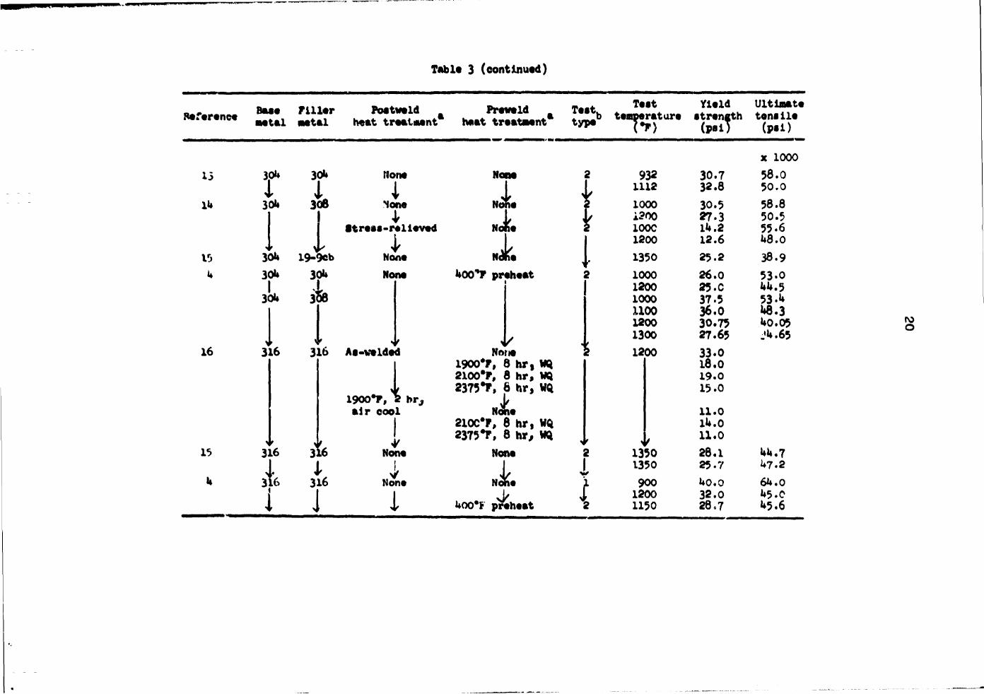
Table 3 (continued)
Reference Baae M U 1
Fi l ler metal
Poatveld heat treet«ent
Preveld heat treataei nt a
Teat. type b
Teat temperature
(*F>
Yield •trength
(pal)
Ultimate tenaile
<P-i> nt a
Yield •trength
(pal)
x 1000 13 3pU 30U None None 2 932 30.7 58.0
i A i L 1112 32.8 50.0 Ik 30U 30B None Nolie T 1000 30.5 58.8
1 4r y L i?00 27.3 50.5 •treaa-relleved Nolie 2 100C 1U.2 55.6 I 1
None i 1200 12.6 U8.0
15 30U 19-9eb 1
None N*fe 1 1350 25.2 38.9 u 30U 30U None MX>*F preheat 2 1000 26.0 53-0
}<* k 1200 1000
25.C 37.5
UU.5 53-U
1 1100 1200
36.0 30.75
U8.3 U0.05
> » I •v i' •' 1300 27.65 JU.65
16 316 3X6 Aa-velded None ? 1200 33.0
\ 1900% 2 br, air oool
1
1900*F, 8 hr, 2100*F, 8 hr, 2375*F, 6 hr, J/ None 210C#F, 8 hr,
WQ WQ
18.0 19.0 15.0
11.0 lU.O
* » \ t 1 2375T, 8 hr, WQ >' >f 11.0 15 316 31 L6 None None 2 1350 28.1 UU.7
U i 316 None Nohe i 1350
900 25-7 uo.o
U7.2 64.0
| 1 i ^
i 1200 32.0 U5.0
J I J i Uoo*F preheat 2 1150 28*7 U5.6

Table U. Elevated-temperature tensile ductility of weldments in types 30k and 316 stainless tteel and Croloy (2 l/U Cr-1 Mo) steel
Reference Base Filler metai metal
Postweld heat treatment
Test Preveld „ Test. • M 1 «^..*.„ 1 - k Elongation heat treatment* type b t«|stratur« fc Reduction in area (%)
12
o
10
17
Croloy Croloy Normalized at 1790*F
i Solution treated 2U65*C, quench
Croloy Croloy A-1325 #F stress relief, FC
B-17**0*F normalise 1325*F temper
B-17Uo*F normalize 1325*F temper
C-1325*F stress relief, FC
C-1325*F stress relief, FC
Croloy Croloy 1 hr at 1250*F
1 Croloy Croloy 1 hr at 1250*F
J i roloy Crol
J 1 *FC - furnace cooled; AC - air cooled; WQ • b l - All-weld-metal; 2 - aoross-the-weld; X
Normalized and tempered 2 1202
1292 15.0 23.0 19.0
1202 1292
3.0 10.0 58.0
17Uo*F normalized 1325*F temper, FC 1022 16.0 (>7.0
None 1022 22.0 69.O
] L 1022 38.0 71.5
1 2 1022 15.0 67.0
^ L 1022 36.0 71.0 None 1
1 f. 950
1050 2150
2U.0 25.0 29.0
68.0 73.0 72.0
1925*F normalise, 1275*P temper 1 932
1 1112 i I 1292
50.0 U7.0 85.0
water quenched. - irra*' «.»d •

Tabla •'» (eontluuad)
9»*m*n*m B a M 'HI™ POitW»l<S n«ar»ne» ^ ^ ^ ^ h € f c t t r # a t i w p 4 i » Prawald haat traataant
Taat. Taat tanparatury
Vf) Elongation (?)
Raduotion in araa (*>
* Croloy Croloy Nona 350*F prahaat . 900 21.0 57.7 1 | I 1000 18.0 5U.7 1 I 1100 18.0 59.8
1350*F, 1 hr
4" 900 1CSO
23.0 25.0
75.3 86.0
1350*F, 1 hr
4" \J f 1100 30.5 90.0 1350'F, 2 hr
1 U00*F prahiat
1 900 1000 1050
16.0 26.0 22.0
5U.0 59.0 51.0
1350'F, 2 hr
1 \ 1100 23.0 2k.0
U5.0 1350'F 600*F prahaat 1050
23.0 2k.0 75.0
,1 1350*F, ? hr
I l650*F, furnaca
1050 1050 1050
23.0 22.0 20.0
68.0 7^.0 67.0
eoolad, U00*F * 4
prahaa; 2 900 16.0 1000 1050
10.0 16.0
Nomallxad, drawn 1100 900
22.0 2U.0
1000 1050 1100
26.0 28.0 30.0
LI Cr3 ioy Croloy 7^0*C. 2 *r t H? \' air cool Nona 1 1022 222.0 75.0
J 1 1022 1112 1112
23. U 27.6 2U.?
8i.o 87.0 8U.D
13 i * Nona Vl na 1 X
j 932 1112
21.3 23.8
j 1 X
j 1202 13.u
1 1 2 X 1
938 1112 1202 932 1112
29.0 21.1 27.1 19.2 23*0
^ > t J \ t ^ V 1202 12.1
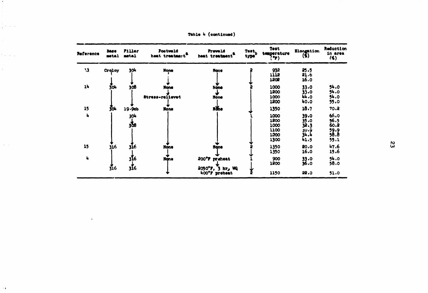
Table U (continued)
Reference m t m l m f A l
Foetwald heat treatment
Freveld Teat. heat treatment type
Teat teaperature
V3
1U
15 4
15
U
Croloy
i
3%
1
30U
v 308
316 316
316
3^
NOIM
Men* 1
Streaa-relleve'l 1
19'9ob None 30U
Hon*
Nona
Hon*
,1 T Nona
I
NOM
200*P preheat I
2050*F, 3 h o V»Q U00*P preheat
7*F)
932 1112 1202 1000 1200 1000 1200 1350 1000 1200 1000 1100 1200 1300 1350 1350 900 1200 1150
Elongation ( ! )
25.5 21.6 16.0 33.0 33.0 UU.O UO.O 18.7 39.0 35.0 32.3 3W.9 3U.U Wl.5 20.0 16.0 33.0 36.0 22.0
Reduction in area
5^.0 5U.0 5U.0 55.0 70.2 66.0 56.5 60.2 31 55.1 U7.6 15.6 5U.0 58.0 51.0

2k
do not indicate which process was used in obtaining each particular set of data. However, the author feels that this is not necessarily important in the overall usefulness of tne information. Of course, if the reader desires, the references for this materia], are given, and the welding process can be found.
The data shown in the tables are summarize^ and presented in Figs. 1 through 9- Figures 1 to 3 represent the collected data for type 30k weldments. Figure 1 shows the stress-rupture and elongation vs time data for specimens tested at 900, 1050. and 1200°F. The data shown on the stress rupture curves represent more than ten data points for each of the temperatures shown. All data are not included as points, in an effort to reduce confusion. Note that the stress-rupture-elongation weld data are for 1050 and 1200°F only. In addition, note the random scatter of the stress-rupture elongation data and the very low elongation values in the higher-temperature—longer-time region. Figure 2 shows the yield and tensile data between 900 and 1300°F for welds in 30U stainless steel. Tensile ductility is shewn in Fig. 3* Note the random and scattered nature of the data.
Figures k to 6 represent the compilation of data for type 316 stainless steel weldments. Figure U is e x;iot similar to Fig. 1 for the stress-rupture elongation data of this material. In this case, both notched and unnotched specimens are shown in the stress rupture curves, and the stress-rupture elongation data include all of the test temperatures shown for the stress-rupture curves in this figure. Again, note the random scatter of the stress-rupture elongation data and the reduction to very low values at high test temperatures. Figures 5 &nd 6 represent the tensile and yield strength and elongation data at elevated temperatures available for this material.
Figures 7 to 9 are the compilations of data for 2 l/k Cr—1 Mo Croloy steel. The stress-rupture data and stress-rupture elongation data are for test temperatures of 900, 1000, 1100, and 12CC/F. The very random scatter of the data points for stress rupture and elongation is observed again, as with tre other two fciterials. Figure 8 represents the tensile and yield strength* of this material between 900 a*^ 1300°F, and Fig. 9 shows the elevated-temperature tensile ductility values.

CO CO
Sf I -co
© z o - I UJ
10*
* 2
101
K>° 101
25
0RNL0W6 71-8731
BASE METAL w 1000 #F • 1100 #F * 1 2 0 0 ^
*—*—*-
H-
* »
-f+
m
4-I
; t ;
m
t t+t
t 1 »
10s 10 3 10 4
RUPTURE LIFE <hr)
FiR. 1. Stress-rupture and elongation data for velds in type 30fe s^Unless steel material tested at 900, 1050, and 1200°F. Creep elonga-ti^a data are fcv tests at 1C50 and 1200°? only. All-veld-aetal samples verr prepared using type 308 stainless steel f i l l e r Metal.

26
0B6TI-C792
MOO
Pig. 2. Tensile and yield strength data for type 30*> stainless steel velds tested betveen 900 and 1300°F. All-veldr-oetal tests vere prepared using type 308 stainless filler aetal.
TO
«o
so sor
1 •.• ALL w€u> mru. : • ACMS5-THE-VELD
1 ! ' 1 1 i 1 1 i
1
t A i 1
i 1 < • t
t. I . • s
« 0
I SO
20 I .
t
.jaff i
coo MOO ISOO 1300 MOO
Tig. 3. Tensile elongation and reduction in area data fcr velds in type 30U (308 filler) stainless steel Material and tested betveen
900 and 1300°F.

27
ORNl-OWG 71-8734
10* TTP I » +-H-
-f—r
a A
-M +-f - i — j - • 4 — *
» f -A- +-* w
to1 > f -
— t
i 1 • M l ; i !
++ i I i t ! » i i t
-A-*-i
H-+r t t ••» M !
tt • i 1 - 4 +tf +4
4 r
10l
•4 L
J_L
i : i I
trt 4-*4-t u
J_L - i A -
l I
I I i I i i
101 10* 1 0 3 10*
RUPTURE UFE (hr)
Fig. U. Stress-rupture and elongation data for welds in type 316 stain! c-ss s t e e l material tested at 1100, 1200, and 130O°F. Data are included from tes ts made using both all-veld-metal and transverse (across-the-weld) specimens (transverse data represented by closed symbols).

28
800 tOO WOO 1100 12O0 1300 MOO TEMPERATURE (*F)
Pig. 5. Tensile and yield strength data from welds made in type 316 (316 filler) stainless steel material and tested between 900 and 1300°F.
CO ORNLOMrt-aTM CO • r" • •
. • ^ ^ ^
50 A
50 •
~ 1 1
< K 40 <
< K 40 < •» Z O P 30
0
Z O P 30
0 * .o ALL WE' 0 METAL
IT • . * ACROSS-THE-WELO
20 20
•
10
40
*0
o to -1 w
IC
r
1
1 1
• ^^ •
800 900 1000 1100 1200 TEMPERATURE (T)
1300 1400
Fig. 6. TensiJe elongation and reduction in area data from wexds made in type 316 (316 filler) stainless steel material and tested between 900 and 1300°F.

29
10:
~ 2 Q.
I -
10'
102
2 O
< O 2 O - I UJ
101
10 10'
• AT 1100°F o AT 1200°F
CLOSEO SYMBOLS INDICATE ACROSS-THE-WELD TEST DATA
BASE METAL -LLj 1000#F 1100#F f t l 1200#F
I M i l l ^^^
4 •
i >
i > A * 4 P * A • ... A ft
A 4
& r i A
> 0 A 1
4 f
« 1
0
0
- j r
>
1 2 * 0
' t • <
o , >
O • >
A 0 0
: M \ t V 0
A ' BASt". M t l A L
* 1000°F * 11 00°F * *,2009F
' BASt". M t l A L * 1000°F * 11 00°F * *,2009F
' BASt". M t l A L * 1000°F * 11 00°F * *,2009F
1 Lo_
10< 10* 10 RUPTURE TIME (hr)
Fig. 7. Streps-rupture and elongation data for velds in 2 1/k Cr—1 Mo s t e e l t e s t ed at 900, 1000, 1100, and 1200°F. Data are included from t e s t s made using both al l-veld-iuetal and t ransverse specimens ( transverse data designated by closed symbols).

I
30
UK)3)
100
AOO 900 1000 1100 1200 #00 900 TEMPEHATURC if)
KOO 1900
Fig. 8. Tensile and yield strength data for velds in 2 1/k Cr—1 Mo Croloy steel terted between 900 and 1300°?. Scatter bands represent data from tests using bcth all-veld-metaJ and transverse (bar) specimens.
Note that, where possible, base-natal properties have been included in the appropriate figures discussed above (the base-metal properties were taken from Refs. 12 18, 19, and 20). A discussion of the relative property differences in these data will be presented later.
In addition to the elevated-temperature properties reported and summarized in the tables and figures discussed above, considerable and important

31
aaa n-artt
80
40
SO
to
10
r — 1 — — i •,* AlXWCLOMCrAl • * ACW»-TMC WOO
l-r—H -i™ • •ASCUCTAL
Si 4-4 - ^ -i J
•00 MO fOOC 1100 ttOO 1900 1400 TCM*€ftAru*c e n
Fig. 9- Tentila floatation and induction in araa data for valda wmft* in 2 l/k Cr-i He Crolcgr ataal and taatad betvaan 900 and 1300°F.

32
information he* been found in tae literature which relates tervice experience, both iri experimental and in actual applications, and Metallurgical behavior of these structural sterls at temperatures in the range of 900 to 13CO#F. The following is a discussion of these data.
Henry et al.a* discussed the room-temperature impact properties of weldments in austenitic stainless steels (type 30U and others) and the effect of long-time aging (15 hr ninifc.ua) at 1200, 13^0, and 1500*F. The test specimens (transverse) included weld metal, the heat-affected zones, and unaffected base metal: both notched and unnotcbed specimens were use£, The resitlts of these tests indicated that the room temperature properties of type 30* Material are not adversely affected when subjected to these temperatures, for at least 1500 hr.
Martin and Slaughter13 presented data describing the elevated-temperature (20 to 900*C) behavior of 30* Material and Incontl 60C in the irradiated and unirradiated cot d it ions. They found that the baae netals and welds were embrittled by irradiation but to a leaser degree in stainless steel than in Inconel. In general, the welds in both Materials behaved in a manner equal to or better than the corresponding base metals.
Mtlone*8 presented results of a study concerned with the effect of ferrite content on service at 650 to 9>0*F. His results indicate that auattnitic-ferritic stainless weld metals of both unstabllized (316) and stabilised (3**?) types are subject to severe signs embrittleaent when the ferrite content exceeds 10$. Embrittlemtnt is increased when held at 885*F for longer times. This work was addressed to overlays on 2 l/U Cr-1 Mo alloys.*
In a paper by Kauheusen and Kauts,8* the experiences of welding austenitic materials in Germany are reviewed. In this survey, the cr^ep values generated in research programs wets used to assess the quality of the welds. Of Interest to this review are the data presented pertaining to type 3'-6 material. The major contribution, other than the creep data, which are similar to tb9*e presented l.i Fig. k, it a discussion of the effect of weld-r-etal fsrrite content on notch impact properties. Data are
•Overlays are considered here to be a surface cladding operation similar to the present practice used for the interior surfaces of the pressure vessel in light-water reactors.
33
presented for 316 weld metal which shows a reduction in impact (notched) strength from 650 to about 93 ft-lb/in.2 after aging at 1100°F for 10,000 hr. The propeity was observed to be drastically reduced even after only 1000 hr aging at 1100°F, where the lUo ft-lb/in.2 level was reached. It is assumed, but not reported, that these are room-temperature properties obtained using the Izod test.
Papers have been reviewed relating experience and testing of the materials in question. Baker and Soldan24 relate experiences of 15 years witij heavy-wall austenitic steels for steam piping in 1050 and 1100°F central station power service, Their experience shows that 3^7 steel is not recommended for heavy sections; this material has been replaced by 3l6, Which has a very good service record. Similar data are presented by Williams and Willoughby.26 Weisbcrg and Soldan28 reported on cyclic heating tests of austenitic and ferritic piping and welds representative of a main steam piping installation for a generating station. These cycles range from room temperature to 1100°F and from s-taosphe ic pressure to 1500 psi. The austenitic materials were generally columbium-stabilized, but 2 l/U Cr—1 Mo alloy steel was included. Their results showed that 100 cycles did not produce any cracks in these materials. The thermal cycles discussed in both of these papers are assumed to be nonuniform in nature, since the data were obtained asing material taken from operating plants.
An excellent article by Isasi et al. 2 7 relates service experience in a reheat steam piping application using a material identified as KROMARC-56, a highly modified type 316 alloy (20 Ni-l6 Cr-10 Mn-2 Mo-0.17 N-0.015 Zr-0.01 B-O.0U C). This interesting paper relates ;hf metallurgical and microstructural changes that the material experiences after extended service periods at 1000°F. The study was conducted on failed pipe elbows that had experienced in-service cracking near weldments. The examination revealed that failure occurred intergranularly in tne heat-affected zone, primarily as a result of a continuous grain boundary network of metallic carbides and nitrides. It is the author's opinion that this information is most important here to aid in illustrating the significance of carbide precipitation (which occurs most readily in the 900 to 13C0CF range) in austenitic materials and the attendant property damage that can occur when this phase becomes continuous.

3*
Data were reported by Hoke and Eberle16on the condition of welded structures for steam superheaters at 5000 psi and 1250*F after lU,28l hr of operation. The experimental test element included 30U and ZlG stainless steel piping. This excellent paper reports room- and elevated-temperature (1350°F) yield, tensile, and ductility data for base metals and transverse weld sections before and after service. Similar data are reported for impact (Charpy V) properties and weld side-bend tests. Finally, e rather comprehensive metallographic study was conducted. The overall findings of this work indicated that no serious deterioration of properties occurred; however, weld impact properties were lowered. Changes in properties were raost rapid during the first 6959 hr of service, followed by a lower rate of change thereafter. The oxidation resistance of both alloys (30U and 316) appeared to be adequate far the service of this cotl-fired unit. The investigation also revealed that the nonstabilized alloys, 30U and 316, suffered no intergranular attack. Impact properties for 3X6 veld metal were found to be 5.5 ft-lb at room temperature and 7*3 ft-lb at 1350°F. Type 316 base-metal properties were found to be U9 ft-lb «t room temperature; no 1350°F data were reported. Columbium-stabilized 19-9 f.Uer metal was used to weld the 30*t material. Impact properties of the 3^7 type weld metal were found to be 6 ft-lb at roan temperature and about 10 ft-lb at 1350°F. The base-metal (type 30U) room-temperature property was found to be 56 ft-lb. Interestingly, data on specimens that had experienced 6950 hr in the 1250*F, 5000-psi steam environment indicated that the impact properties were altered as shown in Table 5*
Table 5* Impact properties of weldments
Room-temperature tests Sample type, 1350*F tests,
metal Before After before service service 6959 hr
30k base 56 25 30^ Cb weld 6 15 10 316 base 1*9 18 316 weld 5.5 2 7.3

35
Significant data are reported concerninc the behavior of the Croloy steels at elevated temperature. Bruscato28 reported on the shielded metal-arc veld deposits of 2 1/2 Cr—1 Mo steel tested for susceptibility to temper and creep embrittlement (a degradation in inpact properties as a result of slow cooling through, or extended exposure to, the 800 to 1000JP temperature range). This study confirmed that the temper embrittlement of this material is chemistry dependent and directly related to the manganese, silicon, phosphorus, tin, antimony, and arsenic content of the veld deposit. It was shown that manganese, silicon, phosphorus, and tin were by far the largest contributors to temper embrittlement' The study included creep rupture testing at 900 *cd 1000*F of two materials at different impurity levels. At these temperatures, the materials containing high temper embrittlement impurities (phosphorus, tin, antimony, and arsenic) exhibit creep embrittlement, as evidenced by a deterioration in ductility properties. TLe material containing low impurities did not experience this deterioration. The deterioration in ductility properties of the veld deposit with a high level of temper eobrittlement is particularly severe at 1050*?.
Blnkley3* has reviewed the state of the art of the veldability of stabilized 2 l/k Cr-1 Mo steels. This review has addressed itself to the addition of titanium, niobium, vanadium, and/or tantalum to this basic steel composition in an effort to stabilize the carbon content and prevent loss of carbon to the flowing sodium in a scdium-to-vat«r steaa generator, such as in IMPBR applications. Although this report contains no oiataricai data as to high-temperature properties, the author feels it is worthy of being inclulad in this review from the standpoint of its high internet to sany laboratory projects currently being performed Often, metallurgical advantages realised by base-metal carbide stabilisation nave resulted in poor weld-metal impact properties when using Croloy filler materials. Ibis paper cites a commercially available alloy that Includes the addition of niobium with 0.5 nickel to improve impact strength of the weld metal. Sinkley discusses problems in weldinf that could arise primarily from veld-associated cracking due to the formation of a eutectic composition between iron and niobium. The conclusion of the paper is that •inc* little actual experience with the alloy exUtJ in the United 8tates, a thorough voidability study of the niobium-stabi»ited Croloy is warrtintod.

36
Egneir*^ reported on the mechanical properties and weldtbility of a columbiuR-stabiiized 2 1/k Cr-1 Mc steel for U4FBR systems. Data presented in this paper indicated +hat solution heat treatments at higher temperatures than 1920*? strongly increased the creep rupture strength when \?sted at 640, 930, and 1020*F. Heat-affected zones in a veld joint have low creep ductility, as indicated by creep rupture tests on materials solution-treated at 2370*F.
A study by Svift 3 1 of the mechanism of stress relief cracking in quenched and tempered 2 1/U Cr—1 Mo steel ha* shown the phenomenon to be closely related to precipitit** t£»t form during stress relieving at elevated temperatures. The results of the welding tests have teen correlated to the Charpy V-notch toughness of the base metal. Modifications in the postweld heat-treating cycle have substantially reduced cracfcing. A similar study with confirming results has been reported by Mullery and Oadmen.17
the rupture ductility of type 3^7 sod 316 material in the temperature range of 1200 to ifcOC** was investigated by &wrson and Jackson.14 They found that the 1200*P yield strength of as-welded tubular 316 specimens was 33,000 psi (vs 73,000 psi at room temperature), but heat treatment between 1900 and 2300*P (grain sixe effects) reduced this differential to about 15,000 psi (by lowering the room-temperature strength). The yield strengths from the heat-treated specimens were always lover than those for as-welded specimens. The plastic ductility of veldtd 31^ tubular specimens. *lven a post/eld heat treatment at 1900*F, was found to be slightly greater than that of corresponding specimens in the as-welded condition. The 1200#F yield strengths of the heavtreated specimen* were lower than those for the as-welded specimens.
Lupekov and Kur'michev** reported on k*e stress rupture of 3l6 stainless steel at 650*C (V2C2T) and 750°C (1382T). Specimens were TI3 (no filler) welded and cut from Uo-mm-dism tubing (3-sm wall). Results showed that 100-hr rupture occurred at 17,000 psi at T>Q*C and 3*,*230 psi at £50*C. Elongations were of the order of 22* for 6*>0*C and y % for 730*C.
Lister, Hicklereith, and Higginbottom** and Trucan and Hardvick* presented tvo excellent papers on the stress-rupture properties of 3l<> stainless steel. The former paper deals with steam pipe applications,

37
includes 2 l/k Cr-1 Mo steels, discusses filler metals and joint designs, and reports data at 600 and 6^0*C. The latter paper reports cnly 316 data at <>00 and 700*C but includes effect; of heat treatment.
The creep properties of 2 l/k Cr—1 No and 31<> weld octal were investigated by Hopkin, Murry, and Duval. 3 4 Their study also included transverse specimens, with 3^7 being the base metal in the case of 316 weld metal, lite data here agree with those previously reported. However, these experiments revealed that failure was most prevalent at the fusion line or within the heat-affected zone.
An excellent review article by Stewart and Schreiti*6 presents creep rate data for Croloy steels. Minimum creep rates of 10 s 6, 10* 4, and lO-H/hr &t 1000*? are reported to occur at 6300, 10,000, end 18,000 psi respectively* Similar data at H00*F are presented, and the esse minimum creep rates are found to occur at 3500, 7200, and 16,000 pel respectively. These data are presented from tests conducted on all-veld-metaJ samples. Fatigue data are given for columtiua-stabilisad stainless steel weld metal at ISO and H O O T .
Very preliminary fatigue data for type 30b stainless steels welded with type 306 stainless steel have been obtained from ORNL.**'** These d&t& are from room-temperature, 1000, and 1200*F tests using both base* metal and all-weld-metal samples, which were tested in either the as-relded or *t *e*s-reli<rved condition* These cursory data are presented in Fig. 10. The preiiminar' nature of the data is obvious from the few data points shown for the elevated-temperature curves. Although the data shown for tests at 1000 and 1200*F are Insufficient for engineering application, they do allow same limited evaluation. The rooa-temperature tests indicated that weld* ments exhibit a reduction in life by a factor of 3 at high strain levels, when compared with the base metal. Even here failures occurred it. the base metal. It «*s assumed that this behavior was the result of the higher yield strength of the weld metal. A stress relief (l850*F for 1/2 hr) seemed to Improve weldment properties. Elevated-temperature vacuum tests (1000 and 12J0*F) again showed that as-welded (the gas tungsten-arc process was used) weldments failed at fewer cycles than base-metal specimens; bow-ever, failure now occurs, in general, in the weld region of the specimen. Zt was reported that failure' cracks appeared to nucleate at weld-metal

38
Fig. 10. Total strain-fatigue data for type 30ty308 veldments.
defects, suet, as pores and inclusions, ultimately resulting in failure. These data a n sufficient evidence that considerable effort should be expended to imvrove on the situation in this area.
Recently, .ow-cycle fatigue data have been published by workers at Combustion Engineering on type 306 weld metal. 3 8 These experiments were performed to determine if premature failure occurred in type 308 weld specimens caqparM with unwelded specimens of type 30k base material when subjected to a combined low-cycle fatigue (*l£ strain) and creep test at 1050*F. The specimens included transverse w*ld, longitudinal veld, and base-metal types. Shielded metal-arc (with controlled residual element?) and submerged-arc type 3<* welds were included in the study. The data revealed that failure always occurred at or below 200 cycles for these 1050*F strain-controlled experiments. In addition, it was concluded that submerged-arc welds appeared to be more susceptible to creep and low-cycle fatigue damage than both shielded metal-arc weld (with controlled residual elements) and the base mecal. Finally, the shielded arc weld was seen to be superior to the base m-rtal with regard to resistance to low-cycle fatigue and creep damage.

39
Significant information is currently being generated in programs sponsored by the AEC concerned with the elevated-temperature properties of weldments in stainless steels, particularly 30U and 316. A cooperative program among the Oak Ridge National Laboratory, Argonne National Laboratory (ANL), Hanford Engineering Development Laboratory (HEDL), and Aerojet Nuclear Company (ANC) is under way, which involves a design test matrix on one batch of FFTF welds and an evaluation of four others.39 The following is a Drief summary of the status of these programs.
The ORNL program is concerned with filler-metal composition and solidification structure and their relationship to the method of welding as applied to 30U stainless steel weldments. This program has direct application to LMFBR systems. The studies have primarily been concentrated in the area of welding using the classical stick electrode (shielded metal-arc welding) and sabmerged-arc techniques.40 Tn all cases, filler-metal wires that conform to the standard specification for type 3C4 electrodes are being used; but, in most cases, compositional modifications have been made to the flux coating on either the rod or shield flux material. The data generated thus far in this program are essentially summarized in Figs. 11 to 13* Figure 11 presents the stress rupture elongation properties of shielded metal-arc welds at 1200°F. The stress vs rupture time for these welds is shown in Fig. 12. Figure 13 shows the elongation vs rupture time of T.elds made using the submerged-arc process, and Fig. Ik
presents the stress vs rupture time data for the same specimens. Note that in all cases the tests were conducted at 1200°F. In those cases where it is appropriate, base-metal values are shown. It is obvious that the trend of these data is toward lower ductility with increasing rupture time (decreasing stress) and that at 1200°F, total elongation values of less than 1$ occur frequently. Currently, data are being generated at 1100°F to confirm that similar ductility losses occur at this lower temperature. Preliminary results 01 tests performed using submerged-arc techniques have recently been published by Weir and Slaughter.14 This report states that the elevated-temperature mechanical properties of the weldment depend on the solidification substructure. Since this substructure can be greatly influenced by variables witir.n a process, the objective of the program is to determine the relationship between welding

uo
60
so
ONNL-CW« Tf-1573
"r^TT
4-1-HU
TT 11
T
! I»i i
•' r , i ! . i i . i • 308 TYPfc o WITH CONTROLLED
h RESCUAL ELEMENTS ! I
W 5 10* 2 5 f r . RUPTURE LIFE 1*1
K>S 2 K>-
Flg. 11. Stress-rupture elongation properties of type 308 stainless steel shielded metal-arc veld deposits at 1200°F. The shaded band is for standard commercial electrode veld metal (see Fig. 1). The open points represent ORHL data from velds made usinj electrodes vith experimental coatings that employed controlled residual elements.
7I»«ST#
t S • » f 4. SEPTUM ijt't I M
TUi, 12. Stress-n$iur« properties for typ* 308 stainless steel «hf*14*4 s*tal-arc v#lda at l*0G*r. The points represent data fro* the £8fc wsxtriciKital *t«4y (see data in Fi*. 1).

1*1
50 r
0MRr3WG'n-£571 • ~ n
10° 2 5 10* 2 5 10* 2 tt% RUPTURE LIFE (Hr)
5 K) 5
Fig. 13. Stress-rupture elongation properties of type 308 stainless s teel submergel-aro weld metal a t 1200°F. The data shown are from the ORNL experimental program (no commercial data are shown for comparison).
Flf. Ik, Stress-rupture properties of type 308 stainless steel sub-tried-arc velds at 1200*?. Data points ere from the CARL program.

U2
variables and substructure and., subsequently, the mechanical properties. Much of the program on submerged-arc wnlaments has progressed only to tne point where unexplained variances deter the disb jninacion of specific data. The creep rupture properties obtained at 1100°F ft' a function of welding heav input and stress are not consistent. The results from shielded metal-arc weldments showed marked ductility loss with increasing time to rupture at 1200°F which was caused by metallurgical instability attributable to small composition differences. This information is an extension of that received earlier in the private communication.40 The results of a study to examine the effect of compositional changes on creep rupture properties at 1200°F and 25 ksi indicited that boron additions to the flux material cf the order of O.OOU to 0.006^ showed the best combination of strength and ductility. In general, the ORNL program will include tensile tests at low strain rates, high-accuracy creep rupture, stress relaxation, and an evaluation of fatigue, properties.
Extensive details of tie programs at HEDL, ANL, and ANC were not available at the time of this writing. However, the following describes the general program functions to be conducted at these facilities. The Westinghouse-Hanford Laboratory will conduct high-strain-rate tensile tests on as-annealed, aged, and irradiated camples. They will perform creep rupture testing at 1000, 1100, and 1200°F, with additional concern for creep-damage evaluation. The Argonne effort will be centered on the establishment of a fatigue design test matrix, which will include the effect of hold time en these properties. The Aerojet program will concentrate on a postirradiation fatigue design test matrix.
Communication with personnel at Westinghouse Advanced Peactor Division related the essential objectives of a proposed program there that would be concerned with the high-temperature property evaluation of welded stainless steel structures.41 It was learned fciat their program would primarily be concerned with: (l) fracture strain data related to the vessel life, or expected vessel life, and (2) the potential effect on these properties of metallurgical notches as manifested primarily by welds. The latter concern is a result of the work being done by Manjoine et al« ' It was related that the proposed Westinghouse program would include the

*3
use of full-size specimens, measuring ^ to 2 3/8 in. in thickness. The progrea would concern itself with tensile and stress-rupware properties of both snail- and full-scale samples, with testing essentially confined to elevated temperatures (1000 to 1100*F). These tests would be performed on each region of the weld (base metal, heat-affected zone, and weld metal) at 1050 and 1100° v. The program would also include a series of stress-rupture specimens with projected failures from 1000 to 10,000 hr at 10*30 and 1100°?, in both the as-fabricated and heat-treated condition. Finally, a limited number of large specimens (on the order of 2 3/8 x 2 3/8 in. cross section) having all three zones would be tested at both of the temperatures mentioned and in both the tensile and stress-rupture testing modes • This proposed program would constitute a major effort in the evaluation of stainless steel in heavier sections and the material's ultimate application to reactor vessels and would be very worth while.
3. DISCUSSION a' COLLECTED DATs
The following is a brief discussion of tb= data presented above and an attempt to compare the data of the three materials under consideration with themselves and with their respective base metals.
A comparison of Figs. 2, 5, and 8 shows that much lower values of tensile and yield strength are exhibited by the Croloy material than by the two stainless steel materials. The comparison of weld-metal and base-metal properties of the materials reveals, generally, only subtle changes. Type 30U base metal is superior, from a tensile strength standpoint, only at the higher test temperatures (1100 to I300*F), while 316 base-metal tensile properties are slightly higher than the weld metal. There seems to be no differences in the Croloy base-metal and weld-metal tensile properties between 900 and 1300°F. Yield strengths of the weld metals in all alloys are superior to those of similar base metals. This is probably a result of the finer microstructure inherent in the weld metal.
Based on stress-rupture data, Croloy is superior to both 30^ and 316 at 900*F. As the temperature is Increased, Croloy loses ground rapidly.

kk
These are not unexpected observations, in the author's opinion. In general, the stress-rupture strength? uf the base metals are superior to those of the veld metals in all three materials. However, in no case is this degradation in properties considered extremely significant. This observation is probably best explained by recognizing that larger grain structures (lower grain boundary surface areas) exhibit higher creep properties than those of fine grain.
The stress-rupture-elongation data are too random to even draw lines or scatter bands; however, Croloy data seem to be less dispersed than those for the other two materials. The small number of rupture elongation data points fox* 30*f is alarming, and work is obviously necessary heie. Note also that the 30*+ data presented here are entirely from all-weld-metal samples, while Croloy and 316 data include both all-veld-metal and transverse samples. Here again it should be stated that the stress-rupture elongation properties of the base metal of each of these alloys are superior to those of the weld metal in similar materials. As mentioned above, this effect is probably due to microstructural differences.
The stress-rupture values for 304 and 3l6, for both base metal and veld metal, seem to depend to a certain extent on the carbon level of the material. Ihis observation is made from an analysis of t'ue reported literature but is not indicated or showr. in the figures. This difference was mors prevalent at 1200°F than at 1050°F. At 1200°F, for low carbon (0.03), these values are 1000 to 5000 psi lower than for carbon levels of 0.08. At 1050°F, no noticeable difference was observed.
While transverse specimens are Included, they do not seem to behave to any great extent differently than the all-weld-metal samples. This is true even though the fracture location varies fvom the heat-af fen ted zone tc the fusion line to the weld metal.
Probably one of the most alarmir^ findings of this effort was the inability to find sufficient fatigue data at temperatures of 900 and 1300°F for weld specimens in the materials of interest. The data which were found 3 7' 3 6 were exceedingly preliminary in nature and only consisted of work on 30U type material and weldmer.ts. Obviously, work not only on 3&
but on 316 stainless steel and the Croloys is warranted. In any case, the

U5
meager data available indicace tnat the weld is inferior to the base metal at elevated temperatures (1000 and 1200°F).
Only in the low-cycle fatigue data27 reported by Combustion Engineering was a real difference in properties observed that related to welding processes. Although there may be significant data variations from process to process, it seems risky, if not both impracticable and impossible, for this author to make such conclusions unless the reference makes such observations. However, the one reference in which such findings were stated may be very significant and further supports the need for more work.
k. CONCLUSIONS AND RECOteffirMTIONS
The discussion Gf data in the above section essentially points out the usefulness and quality of the data found during the survey. It is the author's opinion that most of the data presented here are reliable and represent work of high quality. What is not found is much more alarming than what is found; this is the area to which this section will be addressed.
The use of high-temperature data for design applications primarily centers on a discussion of whether or not design criteria are sought for either a yielding or nonyielding situation. It has been assumed throughout this effort that design data are sought for determining the deformation behavior ->f materials at elevated temperatares in reactor systems. Therefore, Iz appears to the author that the data most useful to a design engineer would be those that would be found in basic creep data, that is, inelastic deformation vs time at constant load (or stress) and temperature. Also, cyclic load and temperature data would, obviously, be just as Important and useful. This kina of information would be as valuable to the design engineer as, say, stress-rupture data. The designer would then be provided with the more neaningful data of first- and second-stage creep plus an indication of the minimum creep rate of the material at the specific conditions of load and temperature. The only information found in this survey similar to this was that which was reported for Croloy at 1000 and 1100°F, and. this paper only reported the minimum creep rate v& load.35

k6
"Jhus, it is the author's recommendation that serious consideration be given to the generation of basic creep data such that information might be available for use related to first- and second-stage creep deformation at the subject temperatures and stress levels. In addition, the absence of fatigue and other cyclic data in welded sections of these materials should lie alleviated, especially the absence of low-cycle data. *tt*e suggEStim here is that more information like that from the Combustion Engineering work27 should be generated. Comparisons could then be made with existing data for base metals, and any problems that might arise because of the differences in these data < ouid be assessed. Thus, it is the author*s recommendation that fatigue testing be included with the generation of basic creep data. This program could prove to be most interesting, since the two material properties (creep and fatigue) at the design temperatures (900 to 1300°F) could affect and interact with the metallurgical reactions known to exist in this temperature range (carbide precipitation, etc.).
As implied above, the testing of materials in fatigue and creep at temperatures between 900 and i;.00°F cau&es stainless steels that are not stabilized with titanium or columbium to undergo metallurgical reactions known as sensitization. This phenomenon is the precipitation of a complex chromium/iron carbide such that the near volumes of the grain boundaries (material within a few microns of the grain boundary) in the material are rendered corrosion-susceptible. Data are available for environments that are proposed in the IMFBR system, and these data show that corrosion does not seem to be a problem. However, the author is mo.v. concerned about the load-carrying abilities, in fatigue and creep situations, of materials that exist for long times in these temperature ranges (900 to 1300*T), resulting in a grain boundary which contains a carbide phase that can be continuous.2
Thus, one could speculate that this grain boundary is now brittle and would easily propagate cracking, causing possible catastrophic failure. This is another metallurgical reason for recommending the generation of creep and fatigue data in these materials in these temperature ranges at the design stress levels, particularly after extended time periods at IWFBR operating conditions. In addition, it may allow a more complete explanation of the
*7
reasons why the 1200*P tests conducted by the ORXL group shear rapid loss in ductility aj 1000-hr test times axe approached.
Interest in fatigue (low cycle, thermal, etc.) and cre**> of welded stainless steel str ictures also occurs ia other area* of nuclear power generation, outside the IJ4FBR program. Recent experiences with operating reactors possessing sensitised nocsle components hare indicated the low level of integrity exhibited by the stainless steel sdcrostructure. These stainless material components have been furnace sensitised during the code-required stress relief necessary during reactor construction and vessel com* ponent fabrication. ASHE reports 1' 2 relate the findings and method of repair of one such failure. The cause of failure has usually been considered stress corrosion, caused by high residual stresses and environmental impurities. However, recent incidents have revealed that fatigue may be a factor, since no environmental impurities and/or excessive residual stress prevailed. Thus, there is an existing need for the propose* generation of long-time high-temperature properties in reactor component materials.
In summary, based on this review, certain major areas of information ai-e found lacking in the current available knowledge with respect to hign-tgmperature properties of veldments in the naterials of interest. These general areas considered by the author to constitute the most important data requirements are listed below. 1. the generation of basic creep data (deformation vs time) for weldments
in the subject materials, providing first- and second-stage creep properties for the proposed temperature range and stress levels;
2. the generation of cyclic load data for weldments in the proposed materials anu in the temperature range of interest, with particular emphasis on the thermally and mechanically induced low-cycle raiijue properties;
3. an evaluation of the overall effect, and interaction*, occurring between time- and temperature-dependent metallurgical reactions and long-time mechanical properties (both cyclic and static) for the temperature range and stress levels of interest. These three areas have been f<rmd to be the major categories where
data are missing and which are most important for the establishment of proper and useful design methods and criteria.

all
1. H. C. Burghard, Jr., and F. F. Lyla, Jr., Instigation of Cracking in Mueller Reactor Primary Piping System. ASHE Publication Ko. 71-PVP-33-
2. E. B. Morris, P. 0. Watson, and R. D. Vylie, Repair of Primary Pres-sure System Piping in a Kuclear Fomer Plant. ASME Publication Ho. 71-PVP-50*
3- Welding Handbook. African Welding Society (sect. 2, 6"h ed.), 1969. U. H . R. Vouchees and J. W. Freeman, "Elevated Temperature Properties of
Veld-Deposited Metal and Weldments," ASM 8TP 22o, 1958. 5. G. K. &mmtsuel and W. E. Leyda, t!Losg-Time High Temperature Properties
of Cr-Mo Veld Metal," Properties of WeldmenU at Elevated Temperatures, American Society for Metals, pp. 1-* (19&B).
6. R. J. Truman and D. Hardvick, "Some Effects of Heat Treatment and Welding on the Rupture Properties of Three Austenitic Steels," ibid.
7. R. J. Christoffel, "Botch Srnsitivity of the Heat-Affected Zone in Type 316 Material," Welding T., pp. 25-s-eB-s (January 1S63).
8. R. D. Wylie, C. L. Corey, arc-. W. E. Leyda, "Stress Rupture Properties of Some Chromiu«-IJickel Staialess Steel Veld Deposits," Trans. ASME 76, 1093-1106 (October 195*0.
9. M. Inagaki, I. Ofcane, anc1 M. Bakajima, "Influence of Heat Treatment on Creep Rupture Strengtd of Welded Joints of 2 1/2 Cr-1 Mo Steel, " Trans. Natl. Res. Inst. Metals B(k), 3 ^ 7 (1966),
10. J. Bland, "The Arc Welding of 2.25% Cr-l.OJt *fc> Alloy Steel Pipe," Welding J., l8l-s-9*-s (April 1956).
11. K. Kremer, "Results of Joint Long-Time Creep Rupture Tests on Weld Metal Deposits of Creep-Resistant Steels," IIW Commissiou II (Arc Welding), Doc. II - 55-63.
12. W. 3err and M. J. ^iverns, "Hot Tensile Properties of 1/2 Cr-i./2 Hcrl/k \ and 2 l/k Cr-1 Mo Steam ^ p * Material," Brit. Weldi/.g J., pp. 238-»f3 (May 1967).
13. W. R. Martin and G. M. Slaughter, "Irradiation Qnbrittlement of Welds and Brakes at Elevated Temperatures," Welding J., pp. 385-S—9I-S (September 1966).

«»9
Ik. J. R. Hair, Jr., ad G. N. Slaughter, Melding Development for aa?BR 8tainles» Steel Components. GKQ>*630 (March 1971).
15* J. H. Hoke and F. Eberle, "Experimental Superheater for Steam at 2000 f*i and 1250*F - Report after lU,28l Hours of Operation," Trans. ASME Jfr 30?-17 (1957).
16. R. W. Emerson and R. W. Jackson, "The Plastic Ductility of Austenitic Piping Containing Melded Joints at 1200%" Melding J., pp. 89-s-loU-s (February 1957).
17. F. Mullery and R. 0. L. Cadman, "Cracking of Melded Joints in Ferritic Heat-Resisting Steels," Brit* Melding J., pp. 212-20 (April 1962).
18. G. V. Smith, An frraluatlon of the Yield. Tensile. Creep, acd Rupture Strengths of Wrought 30*. 316, 321. and 3**7 Stainless Steels at Elenited Temperatures. ASTM Data Series DS 5S2 (Supplement to Publication 06 5, formerly STP 12**), 1969.
19. G. V. Smdth, An Evaluation of the Elevated Temperature Teasile and Qreep-Rupture Properties of Wrought Carbon steel, ASTM Data Series DS 11S1 (Supplement to Publication DS 11, formerly STP 180), 1970.
20. M. L. Creenstreet, J. If. Corum, and C. E. Pugn, Inforaml Progress Reports on Structural Design Methods for LKFBR Components for Period Ending September 30, 1970. ORHL-CF-70-10-56 (Oct. 1, 1970).
21. C. H. Henry, M. A. Cordovl, and G. D. Fischer, "Sigma Pnase in Austenitic Stainless Steel Meldments, " Welding J., pp. 75-s-6l-s (February 1955).
22. M. 0. Malone, "Si^pa and 885°F Embrittlement of Chromium-Nickel Stainless Steel Weld Metals," Welding J., pp. 2Ul-s-53-s (June 1967).
23. E. Kauhausen and H. P. Kautz, "Welding of Crcp Resistant Austenitic Materials," Brit. Welding J., pp. 266-r? (tfay 1962).
2k. R. A. Baker and H. M. Soldan, "Service Experience at 1050 and 1100°F of Piping of Austenitic Steels," Proceedings of Joint International Conference on Creep — ASEM/ASME, pp. U-85-^-91*, 2963.
25. N. T. Williams and G. Willougbby, "Laboratory Assessment of Austenitic Steele for Welded Steam Pipe Joints," Brit. Welding J., pp. 115-23 (March 1962).

26. H. Weisberg and H. M. Soldan, "Cyclic Heating Test of tein Steam Piping Materials and Welds at the Sewarea Generating Station," Trans. ASME J6, 1085-91 (October 195*0-
27. J. A. Isasi, R. C. Bates, and J. Heus?hkel, Analysis of Cracks in Weldei Elbows, *SKE Publication 71-PVP-32, 1971-
26. R. Bruscato, "Temper Embrittlement and Creep aabrittlement of 2 1/U Cr-1 Mo Shielded Metal-Arc Weld Deposits," Welding J., M*(*0, Hi8-s-56-£.
29. N. C. Binkley, State-of-the-Art Review — Weldability of Stabilized 2 l/U Cr-l Mo Steels, draft of report from Metals and Ceramics Division, Oak Ridge National Laboratory, Oak Ridge, Tenn.
30. L. Kgaell, "Mechanical Properties and Weldability of a Columbium Stabilized Steel with 2 l/l*£ Chrome and 1% Molybdenum for Sodium Cooled Past Reactor Systems, " paper presented at ASM Materials Engineering Congress, Oct. 19"22, 1970, Cleveland, Ohio.
31. R. A. Swift, The Mechanism of Stress Relief Cracking in 2 1/4 Cr—1 Mo Steel," Welding J., 50(5), 195-s-200-s (May 1970).
32. I. S. Lupakov and Y. S. Kuz'michev, "Strength and Inter crystalline Corrosion Resistance of Khl8N12M2T Steel Weld Joints," Metalloved. i Term. Obrabotka Metal. 10, 60-63 (1962).
33- E. Lister, J. Mickleraith, and A. iligginbottom, "High Temperature Properties of Stem Pipe Welds." Iron and Steel Institute, Publicc-tion 97, 1967, pp* U73-81.
3^- L. M. T. Kqpkin, D. Murray, and D. Duval, "Creep Properties of Some Putt Welds in Steampipes," J. Iron Steel Inst., pp. 819-25 (August 1965).
35. W. C. Stewart and W. G. Schreitz, "".TieiTnal Shock and Other Comparison Tests of Ferritin Steels for Main St<*aR Piping — A Sumary Report, " Trans. ASME, pp. 1056-67 (August 1953)-
36. Private ccssrz-ication with R. W. Swindeman, Oak Ridge National Laboratory, Metals and Cera" les Division, March 1971-
37. W. L. Greenstreet, J. M. Coruo, and C. E. Pugh, Informal Progress Reports on Structural Design Methods for LMFBR Components for December 1970 and January 1971, 0RNL-CF.71-2.lrtJ (Feb. 1, 1971).

51
38. J. K. Hayes and D. M. Vandergriff, Test Report on Low Cycle Fatigue and Canbined Creep Test of Type j06 Weld Metal, CFHC-1157 (June 1971).
39. A. L. Vard et al. (WADCO Corporation) and G. K. Slaughter et al. (ORNL), Preparation, Characterization, and Testing of Austenix-ic Stainless Steel Weldaents, HEDL-TKE 71-ll£: JC-25 (August 1971).
Uo. Private communication vith G. M. Goodwin, Oak Ridge National Laboratory, Metals and Cei+micz Division, March 1971.
41. Private ci inn i cation with F. Snow, Westinghouse Advanced Reactor Division, Waltz Mill, Fa., March 1971*
U2. S. K. Chan, M. J. Manjoine, and C. Visser, Analysis of Stret is in Pressurized Welded Pipe in the Creep Range. ASMS Publication Ho. fl-PVP-6*.
U3. M. J. Manjoine, "High Temperature Stress-Rupture Analysis," Scientific Paper 71-lE7-**echs-Pl, Westinghouse Research Laboratories, Pittsburgh, Pa., Mar. 9, 1971.