Properties of welded joints made in high strength steel using ...
12
BIULETYN WAT VOL. LXVI, NR 1, 2017 Properties of welded joints made in high strength steel using laser technology TOMASZ ŚLĘZAK, LUCJAN ŚNIEŻEK Military University of Technology, Faculty of Mechanical Engineering, 2 Kaliskiego Str., 00-908 Warsaw, Poland, [email protected] Abstract. e usage of high strength steels (HSS) provides numerous benefits in the form of the cross- -section area reduction causing weight decrease, improvement in exploitation parameters and in result positive financial effect. e most advantageous results are observed in the parts loaded by tensile stresses. e factors most influencing the fatigue strength of the metals, especially the steels of high value of yield point, are stress concentration in the originated geometrical notches, local changes of the stress state or the microstructure of paternal material. Improvement in the fatigue behaviour of HSS steels can be achieved by changing the commonly used technique for high-energy joining technology, namely laser beam welding. Relatively narrow welds and reduced heat-affected zone (HAZ) have minimized the residual stresses and distortions. e paper presents the results of the studies focused on mechanical properties of welded joints of high strength fine-grained steel S960QL. ere was investigated the impact of heat input on the micro- structure, microhardness- and residual stresses in the weld and HAZ. e crucial part is devoted to the fatigue research and fractographic investigation of the fatigue ruptures of laser-made welds. ere were also found in the origins the cause of crack initiation. Keywords: mechanics, fatigue life, high strength steel, laser welding DOI: 10.5604/01.3001.0009.9484 1. Introduction High strength structural steels (HSS) are characterised by unique properties. It results from the right weldability and the low temperature of ductile to brittle fracture transition when saving very high strength. Combination of the above-mentioned properties causes the materials from the grade of HSS steels are widely used in welded structures e.g. jibs and chassis of mobile cranes, gantries frames, pressure vessels,
-
Upload
khangminh22 -
Category
Documents
-
view
3 -
download
0
Transcript of Properties of welded joints made in high strength steel using ...

Biuletyn WAt Vol. lXVi, nr 1, 2017
Properties of welded joints made in high strength steel using laser technology
TOMASZ ŚLĘZAK, LUCJAN ŚNIEŻEK
Military University of Technology, Faculty of Mechanical Engineering, 2 Kaliskiego Str., 00-908 Warsaw, Poland, [email protected]
Abstract. The usage of high strength steels (HSS) provides numerous benefits in the form of the cross--section area reduction causing weight decrease, improvement in exploitation parameters and in result positive financial effect. The most advantageous results are observed in the parts loaded by tensile stresses. The factors most influencing the fatigue strength of the metals, especially the steels of high value of yield point, are stress concentration in the originated geometrical notches, local changes of the stress state or the microstructure of paternal material. Improvement in the fatigue behaviour of HSS steels can be achieved by changing the commonly used technique for high-energy joining technology, namely laser beam welding. Relatively narrow welds and reduced heat-affected zone (HAZ) have minimized the residual stresses and distortions.The paper presents the results of the studies focused on mechanical properties of welded joints of high strength fine-grained steel S960QL. There was investigated the impact of heat input on the micro-structure, microhardness- and residual stresses in the weld and HAZ. The crucial part is devoted to the fatigue research and fractographic investigation of the fatigue ruptures of laser-made welds. There were also found in the origins the cause of crack initiation.Keywords: mechanics, fatigue life, high strength steel, laser weldingDOI: 10.5604/01.3001.0009.9484
1. Introduction
High strength structural steels (HSS) are characterised by unique properties. It results from the right weldability and the low temperature of ductile to brittle fracture transition when saving very high strength. Combination of the above-mentioned properties causes the materials from the grade of HSS steels are widely used in welded structures e.g. jibs and chassis of mobile cranes, gantries frames, pressure vessels,

56 T. Ślęzak, L. Śnieżek
offshore platforms or bridge structures, including the military mobile bridges [1-4]. The main advantages of usage of these steels are significant reduction of the structure’s dead weight or material and labour consumption during production processes.
Strength of the structure is dependent on strength of the weakest spots which are in welded structures, the sites of weld beads. Non-homogenous microstructural changes and phase transitions taking place during the joining processes cause local increase in hardness and decrease in plasticity simultaneously. The described processes are connected with the welding thermal cycle and welding shrinkage. The phenomena result in post-welding residual stresses in the vicinity of the weldment. They are characterised by high gradient and the value of tensile stress which locally reaches the yield point of paternal material. High stresses can result in a distortion of the structure and local softening of the material. This local phenomenon influences the performance of the whole structure adversely.
In predominantly cases, the service loads have variable characteristics. For this reason, it is necessary to perform numerous investigations of the high strength steels welded joints determining their mechanical properties, especially fatigue characteristics and behaviour. The obtained results make it possible to assess the influence of joining technology on structure capacity.
Fine-grained structural steels are characterized by beneficial martensitic — low bainitic structure. Sensitivity to the cold cracking of the welded joints is decreased in comparison with the joints of the low-carbon normalized steels by similar carbon equivalent [5]. Despite the above-mentioned, advantageous weldability of these steels is worse than normalized low-alloy constructional steels and get worse when the yield stress increases [6]. It is commonly known that fatigue strength of the steels does not increase with their ultimate strength proportioning. This phenomenon is observed first and foremost in the case of welded structures. For this reason, the fatigue strength is a vital decisive factor to use steel on welding structure. Moreover, fatigue strength of welded elements made of high strength structural steels can be lower than joints made of low-carbon steels [7].
Many steel grades are difficult or impossible to weld using conventional arc welding but may be joined with a laser beam, without having to modify the welding process [8]. Unquestionable advantages of a laser beam welding are: small amount of the heat input, narrow heat affected zone (HAZ), and small distortions of welded structure. In economic terms, the advantages include high welding speed and one-pass full penetration. The great disadvantages of this process are: high cooling rate, metal evaporation, precise fit-up requirements for the joint geometry and accurate guidance the beam along the weld due to the high depth-to-width ratio of fusion zone (FZ).
Welding of the steels with a yield stress of above 460 MPa is conducted with some difficulties. It results from, firstly, the necessity of using low value of the heat input, and secondly, the temperature-time-cycle occurring during the welding operation, which is characterized by a single parameter, namely the cooling time
57Properties of welded joints made in high strength steel using laser technology
t8/5. It is the time during which the bead and its HAZ cools down from 800°C to 500°C. Use of these procedures makes it possible to decrease the grain growth and to control the phase transitions. Using the above welding conditions there will be finally achieved the weldment with the favourable strength properties. Implementation of the laser beam in joining the HSS steels permits to avoid these difficulties by using one pass welding [9, 10]. A high-power density welding technology allows to decrease the amount of the heat input by reducing the total energy essential for performing single weld or in case of multilayer welds. Moreover, the laser welding technology provides full control and repeatability of welding conditions.
2. Research procedures
2.1. Material
The research was conducted on high strength structural steel S960QL with the thickness of 6 mm. Chemical composition and strength properties are compiled in Table 1.
Table 1Mechanical properties and chemical composition (Wt %) of S960QL steel
Mechanical properties Chemical compositionR0.2
[MPa]Rm
[MPa]A
[%] Si Mn Cr Mo Ni V
1101 1273 9.5 0.38 1.08 0.68 0.70 1.97 0.06
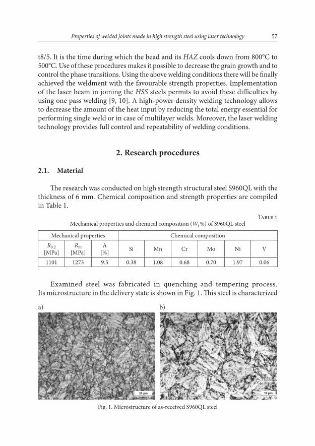
Examined steel was fabricated in quenching and tempering process. Its microstructure in the delivery state is shown in Fig. 1. This steel is characterized
Fig. 1. Microstructure of as-received S960QL steel
a) b)

58 T. Ślęzak, L. Śnieżek
by fine-grained martensitic-bainitic structure with a grain size of 4-10 μm, made by the controlled thermo-mechanical treatment. The presence of vanadium alloying element affects the permanent carbides locking grain growth. As a result of hot rolling there occurred band texture, with a number of ferrite precipitates within small amount of cementite released during the bainitic and martensitic transformations.
2.2. Welded joints
Laser beam welding was carried out at the Centre for Laser Technologies of Metals in Kielce with the CO2 continuous operation TRUMPH laser. Laser is equipped with a numerically controlled table and its maximum power is 6.0 kW. The nominal spot diameter was 0.43 mm. Joints were made with the following welding parameters:
— constant beam power P = 5.0 kW, welding velocity v = 0.8÷1.5 m/min.The details of processing parameters used in the study are presented in Table 2.
The nominal heat input Q from the laser beam can be obtained from the following equation:
60 [kJ/mm],PQv⋅= (1)
where P is the laser power [kW], and v is the welding velocity [mm/min].
Table 2Joining parameters
Welding number Welding speed [m/min] Laser power [kW] Heat input [kJ/mm]Steel S960QL
L-1 0.8 5.0 0.38L-2 1.0 5.0 0.30L-3 1.2 5.0 0.25L-4 1.5 5.0 0.20
Butt joints were made without any filler material and shielded using helium at a flow rate of 10 l/min. Laser beam spot was positioned on the surface of the specimen.
2.3. The range of study
The received joints were assessed during metallographic examination. The sections were cut out from each weldment, transverse to the welding direction. They were used for preparation of metallurgical specimens by grounding, polishing with aluminium oxide, and final etching. The weld bead morphology and macrostructure

59Properties of welded joints made in high strength steel using laser technology
of the welded joints were examined using a metallographic microscope equipped with an image analysis program. The microindentation hardness profiles across the welds using a 100-g test load with a Vickers microhardness machine were performed for some selected specimens. The measurements were conducted in accordance with the standard [11]. The indentations were made within ~1 mm from the specimens’ surface at the face of weld side. The interval of the measuring points was 0.2 mm (in case of large changes 0.1 mm).
During the analysis of actual material effort, it is important to determine the residual stresses caused by the carried-out welding process [12]. Residual stresses are generated by the non-uniform heating of elements and the shrinkage of metal entailed by the thermal cycle. The internal forces are caused by local heating up of relatively narrow area in which the metal expands and shrinks during cooling. The changes of stresses value are caused by movement of temperature field, the position of the welded junction and phase changes in the HAZ.
Measurements of the residual stresses in welded joints were carried out at the Light Metals Division of the Institute of Non-Ferrous Metals in Skawina with X-ray diffraction method using STRAINFLEX PSF-2M apparatus. It was performed at three points: in the weld axis, in heat affected zone (2 mm from the axis), and in the paternal material (10 mm from the axis).
Fatigue tests were carried out on the model samples shown in Fig. 2a. The surface of tested specimens was shown in Fig. 2b.
The fatigue properties were characterized on the basis of the carried-out research. The specimens were exposed to variable levels of the total strain amplitude Dεac from 0.15% to 0.5% and the stable cycle asymmetry ratio R = 0.01 (R = εmin/εmax). The load was sinusoidal with the frequency f = 0.5 Hz. The failure criterion was defined by
Fig. 2. The dimensions of the samples used for fatigue tests (a) and the view of welded joint (b)
a)
b)
196
40
20
47
78
6
R25

60 T. Ślęzak, L. Śnieżek
force drop as the point at which the maximum force decreased by approximately 50% because of a crack comparison to the maximum force in the first reverse [13].
3. Results of the research
3.1. Metallographic examination and microhardness
Very positive results were obtained performing the laser-made butt joints on S960QL steel elements with the assumed welding conditions (Fig. 3). Welds are characterized by symmetry and a small height of the face and the root of weld. In some conditions, the outline coincides with the surface of the work piece (Fig. 3a). At the highest speed of welding, face is characterized by the worst shape (Fig. 3d). On the image of the specimen L-4 it is shown the local lack of melting the fusion face near the root (1). This is due to the difficulty of positioning the laser beam accurately on the axis of welding and a large value of the depth-to-width ratio of a fusion zone (for L-4 width is ~1 mm in some areas). There is important a slight width of the zone of weld with HAZ, which is from 2.3 mm at the narrowest point (for L-4) to 4.5 mm (for L-1).
The results of Vickers hardness test are shown in Fig. 4. Measuring lines of the HV0.1 are marked on the pictures in Fig. 3 with black dashed lines. Fusion lines are also marked on the pictures (Fig. 4) by vertical dashed lines and additionally the zones of partial melting/overheating. The microhardness distribution and values are similar and they change significantly near the fusion lines in all presented
Fig. 3. Laser-made welds of S960QL steel (description in text)
a) b)
c) d)

61Properties of welded joints made in high strength steel using laser technology
results. The greatest changes of hardness are in some distance from fusion line and the surface notch linked to it. Weld and partly heat affected zone has microhardness of 360-380 HV. In the normalized area, it increases up to about 420 HV and then rapidly decreases to 285 HV in the re-crystallization zone. Next, the hardness is gradually increasing to 335 HV (the hardness of the paternal material).
Fig. 4. Changes of microhardness in joint zones of S960QL steel
500
400
300
200
100
00 1 2 3 4 5
Distance from weld center [mm]
Mic
roh
ard
nes
sH
V0
,1
500
400
300
200
100
0
Mic
roh
ard
nes
sH
V0
,1
0 1 2 3 4 5Distance from weld center [mm]
500
400
300
200
100
0
Mic
roh
ard
nes
sH
V0
,1
0 1 2 3 4 5Distance from weld center [mm]
a)
c)
3.2. Residual stresses
Results of the residual stress measurement are presented in Fig. 5. The values measured in the direction perpendicular to the weld axis (X direction) are indicated by the solid lines, whereas in the parallel direction (Y direction) — the dashed lines.
The increase in laser beam travelling speed (at constant laser power) causes the rise of the residual stress value measured in the X direction. In second direction, there are approximately constant. This is directly related to the amount of heat input and cooling rate. At higher welding speed, crystallization of the melting metal progresses very quickly and it also results in high tensile stresses in the HAZ (about

62 T. Ślęzak, L. Śnieżek
350 MPa). Greater amount of heat input at lower speed allows stress relaxation in the HAZ and tensile stresses reduction.
3.3. Fatigue tests
The results of the fatigue life of welded joints made by laser technique (LB1, LB2) were put on the plot in Fig. 6. For comparison, some results for paternal material (PM) and GSAW-made welds (MAG) were plotted. The additional results (PM and MAG) were obtained in own research. The sign LB2 indicates laser welded samples, in which there were observed stress concentrators during SEM assessment
Fig. 5. Residual stresses in laser-welded joints of S960QL
400
200
0
-200
-4000 5 10
Str
ess
[MP
a]
Distance from weld center [mm]
v = 1,5 m/min
v = 1,5 m/min
v = 1,5 m/min
Fig. 6. The strain vs. fatigue life graph for laser welded joints of S960QL steel
1,0
0,5
0,3
0,2
0,1102 103 104 105
– LB1
– LB2
– MAG
– PM
��ac
Number of cycles Nf
To
tals
trai
nam
pli
tud
e[%
]

63Properties of welded joints made in high strength steel using laser technology
of the fatigue rupture, namely a lack of the fusion from root side. Of the two indicated cases, the lack of the fusion in the welded joint with lower fatigue life amounted to approximately 8% of the weld cross sectional area. Nevertheless, the fatigue life of this sample is comparable to the welded joints made by GSAW.
Laser welded joints have a significantly increased fatigue life than the welds performed using classic method. GSAW-made samples, examined under slight values of εac = 0.25%, are ruptured approximately 50% earlier than laser-made examined under more unfavourable conditions (εac = 0.3%). This is due to a beneficial geometry of the weld face and root, narrower HAZ and lack of welding consumable. The crack of laser welded sample tested under load εac = 0.5% propagated through the re-crystallization region. This phenomenon may indicate that the influence of welded joint shape ratio and connected with them stress concentration was less important, and the importance of local mechanical properties in the HAZ regions increased. There occurs a parallel to a quasi-static fatigue under large loads. Similar phenomenon was not observed in the case of the arc-welding joints.
3.4. Fatigue fracture analysis
The fractographic analysis was conducted on the basis of fatigue fractures of the samples tested under strain level εac = 0.5% (Fig. 7). The area of fatigue cracking is enclosed by white dashed curves. The places of fatigue cracks initiation indicated by arrows are analysed in the further part of this paper.
Fig. 7. Fatigue fracture of the laser-made weld joint tested under εac = 0.5%
In case of the laser-made weld, crack propagation is stable and mild (Fig. 7). This character of cracking is caused by the fact that crack initiation and its first stage of growing is located in re-crystallization zone, which has low hardness and strength.
Cracking of these welds has ductile and brittle-ductile nature with many spaces of fracture inhibition and brittle-to-ductile shear zones. Exemplary fractographic picture of fatigue fracture’s surface is presented in Fig. 8. Rolling process caused

64 T. Ślęzak, L. Śnieżek
that numerous and very hard mill scales were indented into surface. Welding has caused local softening of the material strength properties and these indentations have become the origins of fatigue cracking, in detail showed in Fig. 8a and Fig. 8b and indicated by arrows. The area of crack initiation stage is enveloped by dashed line and it has a shape similar to semi-elliptic one.
Fig. 8. The origins (a, b), squashed fatigue striations (c, d) and zone of high propagation rate (e, f) in the laser welded specimens examined under eac = 0.5%
a) b)
c) d)
e) f)
The stage of stable crack propagation is showed in Fig. 8c and Fig. 8.d. There are revealed the traces of squashed fatigue striations. It indicates that the fracture propagates under high values of strains causing high compressive stresses (in compress phase of the load) and has ductile nature. There can be observed numerous secondary

65Properties of welded joints made in high strength steel using laser technology
cracks oriented perpendicularly to the main fracture’s surface what demonstrates that high plastic strains occurred during failure. Sequent two photos, namely Fig. 8e and Fig 8.f show the stage of very high crack propagation rate, and Fig. 8f additionally the phase of monotonic tension performed after stopping the fatigue test in order to reveal the fracture surface. There can be observed numerous pores probably arose during welding process causing additional internal factor which has negative impact on cracking.
4. Conclusions
The application of laser beam welding for joining the high-strength fine grained S960QL steel allows obtaining very good quality of weldment. The obtained joints are characterized by a small range of heat-affected zone and the preferred shape of the face and root of weld, which significantly affects their strength properties. The strengthening mechanism of the steel, which results directly from their chemical composition and processing, influences on the changes in microhardness and residual stress state. An increase in the heat input amount influences positively on the stress distribution. Simultaneously it extends the width of the weld cross-section with higher values of microhardness. For this reason, the welding velocity cannot be excessively increased. High cooling rate increases the martensitic transformation intensity resulting in higher hardness. Too rapid cooling may cause hot cracking, especially in these grades of steel.
The presence of welded joints causes decrease in fatigue life of the tested specimens, in comparison with the specimens without the welds, up to 50-60%. More beneficial shape of the welds decreasing stress concentration and lack of additional welding consumables improve the fatigue life, even if fracture initiators are found.
Crack propagation in laser welds has proceeded in a stable way. The nature of initiation under test condition of the strain amplitude εac = 0.5% is not typical, because it has occurred in HAZ rather than in the vicinity of a fusion line. In this case, the initiators were rolled mill scales in the re-crystallization zone of HAZ.
Founding for this research program was provided through university grant RMN 08-878 aimed to support scientific development of young scientists.
Received May 23, 2016. Revised January 9, 2017.
REFERENCES
[1] Günther H.P., Use and Application of High-Performance Steels for Steel Structures (Structural Engineering Documents 8), IABSE, 2005.
[2] High-strength and ultra-high-strength heavy plates, Information on www.voestalpine.com. [3] Goss Cz., Marecki P., Test results of low cycle fatigue life of WELDOX 900 steel, Biuletyn WAT,
vol. 57, no. 1, Warsaw, 2008, pp. 89-99 (in Polish).
66 T. Ślęzak, L. Śnieżek
[4] Glodeža S. et al., Fatigue and fracture behaviour of high strength steel S1100Q, Engineering Failure Analysis, vol. 16, Issue 7, October 2009, pp. 2348-2356.
[5] Klimpel A., Luksa K., Warcaba L., Szorek T., Kielbasinski A., Robotic GMA welding of S690 and S960 butt joints, Archiwum Technologii Maszyn i Automatyzacji, vol. 30, no. 3, Poznan, 2010, pp. 59-68 (in Polish).
[6] Willms R., High strength steel for steel constructions, Proceedings of the Nordic Steel Construc-tion Conference (NSCC 2009), September 2-4, Malmö, Sweden, 2009.
[7] Miki C., Homma K., Tominaga T., High strength and high performance steels and their use in bridge structures, Journal of Constructional Steel Research, vol. 58, 2002, pp. 3-20.
[8] EN-1011-6:2006, Welding — Recommendations for welding of metallic materials, Part 6: Laser beam welding.
[9] Mazanek K., Śnieżek L., Ślęzak T., Fatigue research of welded joints of high strength S960QL steel, Biuletyn WAT, vol. 57, no. 1, Warsaw, 2013, pp. 253-269 (in Polish).
[10] Ślęzak T., Śnieżek L., Fatigue Properties and Cracking of High Strength Steel S1100QL Welded Joints, Key Engineering Materials, vol. 598, 2014, pp. 237-242.
[11] EN ISO 9015-2:2011. Destructive tests on welds in metallic materials — Hardness testing — Micro-hardness testing of welded joints.
[12] Śnieżek L. et al., Analiza trwałości zmęczeniowej rurociągu przemysłowego (in Polish), Wojskowa Akademia Techniczna, Warszawa, 2010.
[13] ASTM E 606-04. Standard Practice for Strain-Controlled Fatigue Testing, 2005.
T. ŚLĘZAK, L. ŚNIEŻEK
Właściwości połączeń spawanych stali wysokowytrzymałej wykonanych z wykorzystaniem technologii laserowej
Streszczenie. Zastosowanie stali wysokowytrzymałych HSS (high strength steels) w konstrukcjach stalowych powoduje liczne korzyści, do których możemy zaliczyć obniżenie przekroju poprzecznego stosowanych profili powodującego ograniczenie masy własnej konstrukcji oraz poprawę parametrów użytkowych, dających w efekcie końcowym pozytywny wynik ekonomiczny zarówno na etapie produkcji, jak i eksploatacji. Najlepsze rezultaty są obserwowane w przypadku struktur silnie obciążonych naprężeniami rozciągającymi lub zginającymi. Szczególnie wrażliwe na działanie różnego rodzaju karbów są stale o wysokiej granicy plastyczności, co negatywnie wpływa na ich właściwości zmęczeniowe. Czynnikami oddziałującymi na te właściwości w przypadku spoin to koncentracja naprężenia spowodowana karbem geometrycznym, zmiany strukturalne oraz wprowadzenie spawalniczych naprężeń własnych. Poprawa właściwości zmęczeniowych może zostać osiągnięta poprzez zmianę technologii łączenia na techniki wysokoenergetyczne, do których zaliczamy spawanie wiązką laserową. Relatywnie wąska spoina oraz ograniczony zasięg strefy wpływu ciepła (SWC) minimalizują występujące naprężenia własne oraz deformacje spawalnicze. W pracy zostały zaprezentowane wyniki badań ukierunkowane na ocenę właściwości mechanicznych połączeń spawanych wysokowytrzymałej drobnoziarnistej stali konstrukcyjnej S960QL wykonanych techniką laserową. Dokonano oceny wpływu ilości doprowadzonego ciepła podczas spawania na mikrostrukturę, mikrotwardość i naprężenia własne w spoinie i SWC. Główna część pracy poświęcona jest badaniom zmęczeniowym oraz faktograficznym powierzchni przełomów badanych połączeń spawanych wykonanych wiązką laserową. Określona została również przyczyna inicjacji pękania w źródłach pęknięć zmęczeniowych. Słowa kluczowe: mechanika, trwałość zmęczeniowa, stale wysokowytrzymałe, spawanie laseroweDOI: 10.5604/01.3001.0009.9484