Additive Manufacturing with Superduplex Stainless Steel Wire ...
Upload
independentCategory
view
3download
0
1 A FORTUNE Global 500 Company
Subrahmanya Bhat Present Affiliation Dy.General Manager
Materials & Corrosion, Institute of Engineering and Ocean Technology, ONGC Panvel, Navi Mumbai
Academic Qualification
M.Sc. Analytical Chemistry
Area of Specialization
Material selection for (1)Oil and gas field development – high sour reservoirs, and Deep water (2)Underground coal gasification, (3)Coal bed methane field development,(4)In-situ combustion EOR etc. Failure Analysis, Formulation of Corrosion inhibitor and designing its doses for pipelinesExecuted more than 80 projects, majority in material selection includes studies for Iran and Iraq oil fields. Filed for patent for noncarcinogenic corrosion inhibitor.Achievements /
Awards- Petrofed Innovator award 2013 received from Dr.Veerappa Moily, Union Minister of Petroleum and Natural Gas.
- NACE award for excellence in corrosion science 2005 received from Shri Surjeet Singh Barnala,Governor of Tamil Nadu
- 19 papers in reputed journals/conference proceedings, including 4 papers in Material Performance, USAPaper Stainless steel options and its limitations for
tubular of HPHT wells of oil and gas field developmentSubrahmanya Bhat and Anil Bhardwaj

Oil & Natural Gas Corporation Ltd.
SSCS 2013 , 14 August 2013, IIT Mumbai

Stainless Steel Centenary Symposium SSCS 2013
3
ThemeStainless steel options and its
limitations for tubular of HPHT wells of oil and gas field development
By Subrahmanya Bhat & Anil Bhardwaj
Presented bySubrahmanya Bhat
ONGC a Wealth Creator

Presentation overview
4
1 Introduction
2 Tubular Materials for Oil and Gas Wells with Severe Corrosive Environments
3 Wells with Marginal Level of CO2 and Volatile Fatty Acids
4 Wells with High CO2 and Nominal Level of H2S in Marginal Fields
5 Wells with High CO2 and High Level H2S in Marginal Fields
6 Wells with High Temperature Oxidation Environment of EOR
7 Summary
#2 E&P Company in the world
Acknowledgment to ONGC8

Introduction

6 A FORTUNE Global 500 Company
Oil and Gas Well completion

7 A FORTUNE Global 500 Company
Stainless steel requirements for Indian oil & gas wells
CAPEX depends on MOC of well completion
Well completion MOC based on: Corrosion severity Design life Access to Inspection and maintenance Safety and environmental impacts
Carbon steel - basic MOC Severe corrosive environments in Indian oilfields :–
Oil and gas producer wells with high CO2 and H2S contents
Injector wells of in-situ combustion for enhanced oil recovery
Necessitate the use of corrosion resistant alloys (CRA) as MOC for well completion

8 A FORTUNE Global 500 Company
Corrosive components in oil and gas wells
CO2 H2S Elemental Sulphur Formation water with high chloride Oxygen or other acidic materials that enter the well during well construction and down hole operations such as acidisation
Injected polymer or CO2 injection for enhanced oil recovery
High temperature air or steam injection for in-situ combustion for enhanced oil recovery

9 A FORTUNE Global 500 Company
Factors affecting corrosion severity
Flow regimes in various positions cause a change of the phase state of the system
The change process is accompanied by the dissolution and escape of gas, the disruptor of bubbles
Shear and cavitation formation on the flow passage wall
Corrosion aggravated by combined action of mechanical force and electrochemical reactions
Changes in corrosive components over a period of time - increase in water cut, H2S content (due to souring of reservoir)

10 A FORTUNE Global 500 Company
Design parameters for material selection
The corrosion severity shall incorporate effect of
Specified operating conditions including start up and shut-down conditions
Failure probabilities, failure modes and failure consequences to human health & environment
For new Oil and Gas strikes - drill stem test (DST) sampling during drilling the exploratory well
The reservoir fluid sampled through DST is analysed for composition of oil, gas and produced water
In the case of wild cat exploratory wells - data pertaining to similar geological formation in the nearest location

11 A FORTUNE Global 500 Company
Design parameters for material selection
Bottom hole wire line logging Reservoir pressure and temperature
Production testing Production profile - flow rates of oil, gas and water per day
Well head pressure and temperatureGas oil ratio(GOR) & gas liquid ratio (GLR)
PVT studies on well fluid sampleBottom hole pressure & temperaturePressure and temperature profile all through the well trajectory
Bubble point

12 A FORTUNE Global 500 Company
Oil and gas well classifications
Oil Well Gas Oil Ratio < 5000 SCF of gas per day /BOPD water cut is < 40% water in oil emulsion water cut > 40% oil in water emulsion Gas well Gas Oil Ratio >5000 SCF of gas per day /BOPD Water condensation takes place at top portion of tubing Reservoir classification Sweet - H2S absent Sour - H2S present

13 A FORTUNE Global 500 Company
Development field material selection
Development fieldsVicinity of already producing fieldRevamping of the existing field Corrosion severity based on known operating conditions
Materials selection based on well documented histories of successful applications
Oil and gas well - limits of corrosion rate Acceptable - mean rate is < 0.1mm/y Unacceptable - mean rate > 1.0 mm/y. Judgement basis for mean rate : 0.1mm/y to 1.0 mm/y
o Required lifetimeo Technical possibility of inspection, maintenance and repair
o Economic consequences of the first damage by premature failures

14 A FORTUNE Global 500 Company
Sour oil and gas reservoirs
H2S - Embrittle metals causing sulphide stress cracking (SSC), under certain conditions. H2S easily dissolves in water, and its solubility depends on partial pressure and temperature. The produced water of a sulphide containing gas well has high acidity, which cause corrosion.The dissociation reaction is as follows:H2S → HS- + H +
HS- → S 2- + H +
Hydrogen ion is a strong depolariser. Anodic reaction: Fe → Fe 2+ + 2eCathodic reaction : 2H+ + 2e → 2HAnode product : Fe 2+ + S 2- →FeSTotal reaction : Fe + H2S → FeS + 2HH2S and / HS- prevent the hydrogen atom from forming hydrogen molecule

15 A FORTUNE Global 500 Company
Corrosion mechanisms in sour environment
Excessive hydrogen atom form hydrogen pressure to permeate and concentrate toward the metal defects.
Atomic hydrogen diffuse into metal, and reduce the toughness of metal and increase the sensitivity to cracking.
Under the condition of high hydrogen and tensile stress, the steel undergo cracking.
Various Types of cracking failures
Hydrogen-induced cracking (HIC) Sulfide stress cracking (SSC). Hydrogen stress cracking (HSC). Stress-oriented hydrogen-induced cracking (SOHIC). Soft zone cracking (SZC). Stress corrosion cracking (SSC) Hydrogen-induced blister (HIB)

Tubular Materials for Oil and Gas Wells with Severe Corrosive Environments

17 A FORTUNE Global 500 Company
Requirement of CRA on oil & gas wells
• Carbon steel is the basic alloy and most preferred one as MOC for oil and gas well completion
• Corrosion of carbon steel controlled by using inhibitors
Limitation of inhibitor success: Involve continuing high cost Unreliable, especially at higher temperatures
Adding corrosion allowance (C.A.) to the tubing wall increases string weight and reduces interior dimensions.
C.A. provide failure free service only if corrosion is uniform
Most of the oil and gas well tubular failures reported to be due to localised corrosion
Preferred alternative is use of CRA, eliminates inhibitors, lowers Tubular weight, improves safety, eliminates or minimizes work overs, and reduces downtime.

Select CRA that performs successfully and provide Optimum economy Required physical and mechanical properties while resisting the particular environment and expected changes over production life of the field
Options available Martensitic stainless steel (e.g., 13% Cr steel)
Duplex (ferritic/austenitic) stainless steel (e.g. 22% chromium & 5% nickel),
Fully austenitic stainless steel (e.g. 28% chromium & 32% nickel i.e. Alloy 28)
Nickel alloys of various compositions 18 A FORTUNE Global 500 Company
Corrosion resistant alloy choices

19 A FORTUNE Global 500 Company
Nickel alloys for oil field development
Nickel, chromium and molybdenum act as primary determinants of corrosion-resistance
Nickel plays a strong role against stress corrosion cracking in the presence of chlorides
Combination of nickel and molybdenum is effective against sulphide stress cracking
Combination of chromium and molybdenum is effective against pitting and crevice corrosion
Relatively small amounts of copper, niobium, tungsten, aluminium and titanium have significant effects on corrosion-resistance or strength.
20 A FORTUNE Global 500 Company
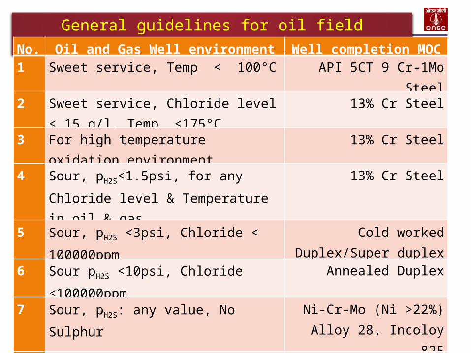
General guidelines for oil field metallurgy
No. Oil and Gas Well environment Well completion MOC1 Sweet service, Temp < 100°C API 5CT 9 Cr-1Mo
Steel2 Sweet service, Chloride level
< 15 g/l, Temp <175°C13% Cr Steel
3 For high temperature oxidation environment
13% Cr Steel
4 Sour, pH2S<1.5psi, for any Chloride level & Temperature in oil & gas
13% Cr Steel
5 Sour, pH2S <3psi, Chloride < 100000ppm
Cold worked Duplex/Super duplex
6 Sour pH2S <10psi, Chloride <100000ppm
Annealed Duplex
7 Sour, pH2S: any value, No Sulphur
Ni-Cr-Mo (Ni >22%)Alloy 28, Incoloy
8258 Sour pH2S <70psi, S,
Chloride: any value, T < 204°C
Incoloy 625
9 Sour pH2S >70psi, S, Chloride : any value, T < 232°C
C-276

Wells with Marginal Level of CO2 and Volatile Fatty Acids

22 A FORTUNE Global 500 Company
Typical well data from Neelam field of western offshore
• Sl.No.
Component Content
1 Chloride [ppm] 202002 Bicarbonate [ppm] 7003 Calcium [ppm] 6004 pCO2 215 H2S [ppm] 176 Bottom hole pressure
[psi]1400
7 Bottom hole temperature [°C]
94
8 Volatile fatty acids[ppm] 1500
23 A FORTUNE Global 500 Company
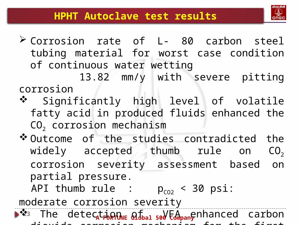
HPHT Autoclave test results
Corrosion rate of L- 80 carbon steel tubing material for worst case condition of continuous water wetting
13.82 mm/y with severe pitting corrosion Significantly high level of volatile fatty acid in produced fluids enhanced the CO2 corrosion mechanism
Outcome of the studies contradicted the widely accepted thumb rule on CO2 corrosion severity assessment based on partial pressure.
API thumb rule : pCO2 < 30 psi: moderate corrosion severity The detection of VFA enhanced carbon dioxide corrosion mechanism for the first time in oil & gas production in India has added a new dimension to age old API thumb rule on severity grading.

24 A FORTUNE Global 500 Company
Selection of MOC for VFA enhanced CO2 corrosion
VFA (CH3COOH) is a stronger acid than carbonic acid (negative logarithm of acid dissociation constant, pKa 4.76 vs. 6.35) The acetate ions form ferrous acetate upon reaction with iron. Fe + 2 CH3COOH →Fe(CH3COO)2 + H2 Ferrous acetate solubility is much higher than ferrous carbonates
Protective film formation does not occur & corrosion rate of carbon steel remains at higher value
Results pf laboratory simulation with HPHT AutoclaveCor.rate for 13 % Cr steel tubing material : 0.02 mm/y & no pitting
13% Cr steel is suitable MOC for well completion for reservoir fluids with high VFA
Wells with High CO2 and Nominal Level of H2S in Marginal Fields

26 A FORTUNE Global 500 Company
Predicted Cor. Rate - Western offshore marginal field
No. Corrosive component Data
Oil well Gas Wells
1 pCO2 [psi] 99 32 - 129
2 pH2S [psi] 0.46 0.01 – 0.523
3 pCO2 / pH2S 215 247 - 3100
4 pH 3.6 3.6 – 3.9
5 Bottom hole temperature [°C]
90 90-100
6 Corrosion rate [mm/y] 1.55 2.32 – 31.6

27 A FORTUNE Global 500 Company
Material selection Predicted in-situ pH = 3.6 -3.9 Corrosion rate = 1.55 to 31.6 mm/y Maximum temp: 100°C Corrosion mechanism is predominantly CO2 controlled and carbon steel is not adequate
13 % Cr steel – resistant to pitting corrosion in produced waters
The limitation (most conservative approach) of applicability of 13% Cr steel tubing :
H2S level : < 1.45 psiTemperature : 150°C
Suitable MOC for well completion : 13% Cr steel conforming to API 5CT L-80 Type 13 Cr steel specifications

Wells with High CO2 and High Level H2S in Marginal Fields

29 A FORTUNE Global 500 Company
Predicted Cor.rate - for Bassein formation of B-series
• No. Corrosive component Data
Oil wells Gas Well
1 ÞCO2, [psi] 87 -190 1722 ÞH2S, [psi] 27 - 111 863 ÞCO2 / ÞH2S 2 – 3.2 24 pH 3.3 – 3.6 3.35 Bottom hole
temperature, [°C]91 - 136 133
6 Corrosion rate,[ mm/y]
4.5 – 20.6
33.4

30 A FORTUNE Global 500 Company
Material selection for well completion
NACE Carbon steel resistant to H2S related corrosion cracking mechanisms
Superficial liquid velocity in the well bottom < 0.5m/s hence likelihood of water wetting of bottom hole tubulars
Ratio pCO2 / pH2S is less than 20 - H2S dominant
In-situ pH = 3.5 and p H2S > 1.25 psi - the protective scaling by Mackinawite on carbon steel can not be guaranteed
High electrochemical metal dissolution , rate much above 1mm/y
Hence NACE CS can not be consideredSuitable material of construction for well completion - CRA
p H2S > 1.5psi : 13 Cr steel is not suitable
Higher CRA selected based on their FPREN value

Pitting resistance equivalent number, FPREN
31
ONGC a Wealth Creator
F PREN = wCr + 3.3 (wMo + 0.5ww) + 16wN
Where wCr is the mass fraction of chromium in the alloy, expressed as a percentage of the total composition
wMo is the mass fraction of molybdenum in the alloy, expresssed as a percentage of the total composition
ww is the mass fraction of tungsten in the alloy, expressed as a percentage of the total composition
wN is the mass fraction of nitrogen in the alloy, expressed as a percentage of the total composition

Selection of suitable MOC for well completion
32
ONGC a Wealth Creator
Upto pH2S 2.9 psi duplex stainless steel with 40≤PREN≤45 (25 Cr steel) suitable
In this marginal field - pH2S : 27 to 111 psi hence duplex stainless steel is ruled out
Nickel based alloys( Ni +Cr +Mo) having nickel in the range of 25% to 45% has high resistance to corrosion and environment cracking resistance, has high strength required for well casing & tubing. Cr improves performance in high temperature. Mo increase corrosion resistance at low pH
Solid solution nickel based alloy suitable for well completion
Classified as material Type 4c, 4d and 4e depending on composition as per guidelines of NACE MR0175/ISO15156

Solid solution Ni based alloy types
33
ONGC a Wealth Creator
Materi
al
Type
Cr
%
(min.
)
Ni +
Co
%
(min.
)
Mo
%
(min.
)
Mo +
W
%
(min.
)
Brand names
Type
4c
19.5 29.5 2.5 Sanicro 28
Type
4d
19.0 45 6 825, 625,
2550,718 & G2Type
4e
14.5 52 12 C-276, G-3 &
G-30

Nickel Institute guidelines for Sour well completion
34
ONGC a Wealth Creator

Delineation of guidelines for arriving at suitable MOC
35
ONGC a Wealth Creator
Well completion MOC for high sour western offshore marginal field shall have : Cr - 19.5 to 20%; Ni - 25% to 29.5%; Mo - 2.5 to 4%
Shall conforms to Type 4c material(NACE) Alloy UNS N08028 complies with above requirements
Cost optimisation by well completion design modifications
Factors High cost of the nickel based alloy (20 times costlier than CS)
Short production life of marginal field wells
Low hydrocarbon volume output Design modificationsIncorporating CRA bottom hole string/liner with top rest as NACE CS, isolating the annular portion and rest of carbon steel intermediate and surface casings by Alloy 718 packer

Modified well completion design
36
ONGC a Wealth Creator
Alloy 718

Wells with Oxidative High Temperature Oxidation Environment of EOR

38 A FORTUNE Global 500 Company
In-situ combustion process for enhanced oil recovery

39 A FORTUNE Global 500 Company
In-situ combustion process for enhanced oil recovery
Create combustion in an impregnated layer by burning some of the heavy oil in place
Facilitate the flow of the un-burnt fractions by injecting air into the formation through perforated injector wells
The process consists of two phases viz: dry and wet phases
Dry phase, compressed air is injected through annulus, natural gas is passed through the tubing and the burner fitted at the bottom of the tubing is ignited and the process continues for 20-25days which sets off combustion, and flame becomes self-propagating
Temperature at the combustion front : 350 °C to 600°C
Combustion front start to move towards producing wells and injection of natural gas through tubing is stopped.

40 A FORTUNE Global 500 Company
In-situ combustion process for enhanced oil recovery
Compressed air is injected through the annulus, which is continued for few months.
The injected air enters the formation and assists in maintaining the temperature of the combustion front by burning with the heavier fractions of the crude oil
Once sufficient heat is generated and the viscous crude becomes lighter, the combustion front pushes the un-burnt fractions of the crude oil forward towards the producing wells

41 A FORTUNE Global 500 Company
High temperature oxidative environment of well bottom
Forward combustion process continue • Thermal efficiency improved by water
injection during wet phase• Wet phase commences with the injection of
water for 24 hours at a time followed by compressed air injection for 6 days through tubing
• Cyclic process continue• Bottom hole temperature enhances oxidation
corrosion• Corrosion product formed is predominantly
hematite in nature and is porous and non protective and likely to accumulate in the bottom of the well tubing leading to reduction in the injection rate
• Corrosion severity is high at well bottom

42 A FORTUNE Global 500 Company
Effect of Cr content on oxidation corrosion resistance
• • •

43 A FORTUNE Global 500 Company
Typical flue gas composition• • •
Sl.No Component Content1 CO2 % 17.22 O2 % 0.23 N2 % 78.874 C1 % 3.45 C2 % 0.286 C3 % 0.087 IC4 % 0.038 nC4 % 0.029 IC5 % 0.0110 NC5 % 0.0111 H2S, [ PPM] 1000 12 CO, [ PPM] 600 13 Specific gravity 1.0508

44 A FORTUNE Global 500 Company
Effect of backflow on Corrosion environment
• pCO2 : 220 psi• pH2S : 1.27 psi• MOC as per NACE : API 5CT L-80 Type
13 Cr steel • Expected bottom hole temp : 350°C• 13 Cr steel is resistant to oxidation
even at 750°C
Suitable MOC for in-situ injector well tubular is API 5CT L-80 Type 13 Cr steel

45 A FORTUNE Global 500 Company
Pre-corrosion of 13 Cr steel tubing
The corrosion resistance of 13 Cr steel surface is attributed to formation of continuous passive layer of Cr2O3 on the surface• Pre-corrosion occurs during transport and
storage, on exposure to salty atmosphere near sea
• Iron oxide contaminant on the surface of 13 Cr steel undergo hydration leading to formation of nuclei to support pitting corrosion.
• The pre-corroded tubing undergoes accelerated corrosion on lowering into the wells. Some pre-corrosion affected tubing failed within one year of lowering to wells
• Utmost precautions in terms of preventing exposure of tubing surface to salt ladened air during transport and storage have to be taken to prevent the pre-corrosion of 13 Cr steel.

46 A FORTUNE Global 500 Company
Pre-corrosion of 13 Cr steel tubing
Nuclei of Pit initiation on surface of new 13% Cr steel tubing
Failed 13% Cr steel tubing retrieved within 1 year
Summary

48 A FORTUNE Global 500 Company
Summary
• Indian oilfield wells with high predicted corrosion rate necessitates the use of corrosion resistant alloys (CRA)
• Suitable MOC for well completion of oilfield reserviors with high VFA, high CO2 and nominal level of H2S is 13 Cr steel
• In some of the marginal fields of western offshore Pitting, crevice, and stress corrosion cracking enhanced by higher temperature, CO2, and H2S, necessitates use of higher grade stainless steel
• Well completion MOC for high CO2 and high level of H2S is Alloy 28
• Well completion MOC for high temperature oxidation environment of in-situ combustion wells is 13 Cr steel
• Cost optimisation achieved through modification in well completion design
Bottom most production liner is high end stainless steel and upper portion carbon steel, separated by special joint and annular isolation achieved through high end SS packer

Acknowledgement

50 A FORTUNE Global 500 Company
Sincere Acknowledgements
The authors are thankful to ONGC for providing the necessary infrastructure for carrying out the study and its gracious approval for publication of the article

51 ONGC a Wealth Creator
Thanks
Copyright © 2022 FDOKUMEN