Additive Manufacturing with Superduplex Stainless Steel Wire ...
18
Metals 2020, 10, 272; doi:10.3390/met10020272 www.mdpi.com/journal/metals Article Additive Manufacturing with Superduplex Stainless Steel Wire by CMT Process Malin Lervåg 1 , Camilla Sørensen 2 , Andreas Robertstad 2 , Bård M. Brønstad 2 , Bård Nyhus 1 , Magnus Eriksson 1 , Ragnhild Aune 1 , Xiaobo Ren 1 , Odd M. Akselsen 1 and Ivan Bunaziv 1, * 1 Materials and Nanotechnology, SINTEF Industry, P.O. Box 4760 Torgarden, NO‐7465 Trondheim, Norway; [email protected] (M.L.); [email protected] (B.N.); [email protected] (M.E.); [email protected] (R.A.); [email protected] (X.R.); [email protected] (O.M.A.) 2 Department of Mechanical and Industrial Engineering, Norwegian University of Science and Technology, Richard Birkelands vei 2B, NO‐7491 Trondheim, Norway; [email protected] (C.S.); [email protected] (A.R.); [email protected] (B.M.B.) * Correspondence: [email protected]; Tel.: +47‐457‐95‐269 Received: 11 January 2020; Accepted: 17 February 2020; Published: 19 February 2020 Abstract: For many years, the oil and gas industry has utilized superduplex stainless steels due to their high strength and excellent corrosion resistance. Wire arc additive manufacturing (WAAM) was used with superduplex filler wire to create walls with different heat input. Due to the multiple heating and cooling cycles during layer deposition, brittle secondary phases may form such as intermetallic sigma (σ) phase. By inspecting deposited walls within wide range of heat inputs (0.40‒ 0.87 kJ/mm), no intermetallic phases formed due to low inter‐pass temperatures used, together with the high Ni content in the applied wire. Lower mechanical properties were observed with high heat inputs due to low ferrite volume fraction, precipitation of Cr nitrides and formation of secondary austenite. The walls showed good toughness values based on both Charpy V‐notch and CTOD (crack tip opening displacement) testing. Keywords: wire arc additive manufacturing (WAAM); stainless steel; microstructure; mechanical properties; toughness 1. Introduction Additive manufacturing (AM) technologies, commonly known as 3D printing, have been the subject of significant progress over the past decade; a comprehensive review of the process is made by DebRoy et al. [1]. AM is based on depositing single layers on the previous layers forming a complex shape with high efficiency of material utilization compared to subtractive processes such as milling. By depositing subsequent layers, previous layers are re‐heated experiencing multiple liquid‐ solid and solid‐state phase transformations. A widely used powder bed fusion (PBF) or selective laser sintering (SLS) process, where the laser or electron beam equipment is typically applied as the power source [2], may create any shape of complexity but more restricted to prototyping since the process is very slow. Wire arc additive manufacturing (WAAM) is a type of direct metal deposition (DMD) process, which utilizes filler wire and arc as heating source, enabling much higher productivity. However, some limitation exists such as low‐to‐medium shape complexities if small part needs to be created [3]. Moreover, WAAM is cheaper and more readily to be implemented in the industry. For AM, a limited choice of alloys is used due to prototyping with specific properties [4]. The most widely used alloy for AM is Ti‐6Al‐4V [1,5–12], especially concerning fatigue properties [13–15], due to wide use in medical, aircraft, aerospace and automotive industries belonging to high‐value complex parts requiring only limited production volumes.
-
Upload
khangminh22 -
Category
Documents
-
view
0 -
download
0
Transcript of Additive Manufacturing with Superduplex Stainless Steel Wire ...

Metals 2020, 10, 272; doi:10.3390/met10020272 www.mdpi.com/journal/metals
Article
Additive Manufacturing with Superduplex Stainless
Steel Wire by CMT Process
Malin Lervåg 1, Camilla Sørensen 2, Andreas Robertstad 2, Bård M. Brønstad 2, Bård Nyhus 1,
Magnus Eriksson 1, Ragnhild Aune 1, Xiaobo Ren 1, Odd M. Akselsen 1 and Ivan Bunaziv 1,*
1 Materials and Nanotechnology, SINTEF Industry, P.O. Box 4760 Torgarden, NO‐7465 Trondheim, Norway;
[email protected] (M.L.); [email protected] (B.N.); [email protected] (M.E.);
[email protected] (R.A.); [email protected] (X.R.); [email protected] (O.M.A.) 2 Department of Mechanical and Industrial Engineering, Norwegian University of Science and Technology,
Richard Birkelands vei 2B, NO‐7491 Trondheim, Norway; [email protected] (C.S.);
[email protected] (A.R.); [email protected] (B.M.B.)
* Correspondence: [email protected]; Tel.: +47‐457‐95‐269
Received: 11 January 2020; Accepted: 17 February 2020; Published: 19 February 2020
Abstract: For many years, the oil and gas industry has utilized superduplex stainless steels due to
their high strength and excellent corrosion resistance. Wire arc additive manufacturing (WAAM)
was used with superduplex filler wire to create walls with different heat input. Due to the multiple
heating and cooling cycles during layer deposition, brittle secondary phases may form such as
intermetallic sigma (σ) phase. By inspecting deposited walls within wide range of heat inputs (0.40‒
0.87 kJ/mm), no intermetallic phases formed due to low inter‐pass temperatures used, together with
the high Ni content in the applied wire. Lower mechanical properties were observed with high heat
inputs due to low ferrite volume fraction, precipitation of Cr nitrides and formation of secondary
austenite. The walls showed good toughness values based on both Charpy V‐notch and CTOD
(crack tip opening displacement) testing.
Keywords: wire arc additive manufacturing (WAAM); stainless steel; microstructure; mechanical
properties; toughness
1. Introduction
Additive manufacturing (AM) technologies, commonly known as 3D printing, have been the
subject of significant progress over the past decade; a comprehensive review of the process is made
by DebRoy et al. [1]. AM is based on depositing single layers on the previous layers forming a
complex shape with high efficiency of material utilization compared to subtractive processes such as
milling. By depositing subsequent layers, previous layers are re‐heated experiencing multiple liquid‐
solid and solid‐state phase transformations. A widely used powder bed fusion (PBF) or selective laser
sintering (SLS) process, where the laser or electron beam equipment is typically applied as the power
source [2], may create any shape of complexity but more restricted to prototyping since the process
is very slow. Wire arc additive manufacturing (WAAM) is a type of direct metal deposition (DMD)
process, which utilizes filler wire and arc as heating source, enabling much higher productivity.
However, some limitation exists such as low‐to‐medium shape complexities if small part needs to be
created [3]. Moreover, WAAM is cheaper and more readily to be implemented in the industry. For
AM, a limited choice of alloys is used due to prototyping with specific properties [4]. The most widely
used alloy for AM is Ti‐6Al‐4V [1,5–12], especially concerning fatigue properties [13–15], due to wide
use in medical, aircraft, aerospace and automotive industries belonging to high‐value complex parts
requiring only limited production volumes.

Metals 2020, 10, 272 2 of 18
For WAAM, the cold metal transfer (CMT) process, introduced 15 years ago [16], is often used
and is based on reciprocating motions of the filler wire and short‐circuiting or dip transfer mode of
the material [17,18]. This enables much lower heat input and reduced spatter compared to
conventional pulsed arc mode. Still, the process provides respectable deposition rates.
Titanium alloys are very popular material for AM and very well understood along with
austenitic stainless steels such as AISI 304 and 316 [19–25]. There are a very few studies available for
duplex stainless steel (22Cr5Ni) consisting of approximately 50% ferrite and 50% austenite. It was
reported [26] that the ferrite content in subsequently deposited layers is reduced along with
hardness compared to the support plate. Stützer et al. [27] used a new approach for estimation of
ferrite (α)/austenite (γ) balance with different wires and CMT technology and achieved a balance of
50%/50% of austenite and ferrite with good mechanical and corrosion properties.
Superduplex stainless steels are more seldom studied. These have higher content of expensive
alloying elements (25Cr7Ni) for more superior corrosion resistance and, thus, more often used in
the oil and gas industry where strength and corrosion are determining factors. Recently, Zhang et
al. [28] showed difficulties in achieving balanced amounts of α/γ phases, where an austenite fraction
increase was inevitable due to precipitation of the intragranular secondary austenite during
deposition. Moreover, the presence of CrN/Cr2N and various impurities were responsible for losses
in mechanical properties.
In the present work, superduplex stainless steel wire was used for WAAM process to
understand the effect of heat input on mechanical properties and to provide more experimental data
and knowledge in 3D printing of this expensive steel due to its rare use. In AM of this steel grade,
there is a concern of inappropriate microstructure evolution and risk of formation/precipitation of
brittle intermetallic phases such as σ (sigma) [29] or χ (chi) [30,31]. They are generated at high
temperatures (650‒950 °C) at certain holding times, as during the reheating in AM. Other harmful
phases that may form are Cr2N (chromium nitride) and γ2 (secondary austenite). Up to recent, σ phase
formation is thought to be most detrimental since it significantly reduces the corrosion resistance,
ductility and toughness [32]. The main elements for increasing the susceptibility to σ phase
precipitation are Cr, Mo and Si [33]. Based on the results obtained, within the employed range of heat
input, σ phase formation was suppressed but formation of Cr nitrides and secondary austenite has
been documented.
2. Methodology
2.1. Materials
A 12 mm thick 2507 superduplex steel was used as support (base) plate (BM). The superduplex
steel filler wire was 1.2 mm in diameter with high Ni and W content and the chemical compositions
(mill certificate values) are reflected in Table 1. The BM had yield and tensile strength of 662 and 834
MPa, respectively, with a ferrite volume fraction of 48 vol.%. The wire gives typical weld metal yield
(0.2% proof strength, Rp0.2) and tensile strength of 655 and 934 MPa in the as welded condition,
respectively, with an impact energy of 100 J at −50 °C (mill certificate values).
Table 1. Chemical composition of selected filler wire and support plate. (Fe is balanced).
Material C Si Mn P S Cr Ni Mo Cu N W
Wire 0.018 0.30 0.70 0.020 0.0010 25.0 9.5 3.7 0.60 0.23 0.6
BM 0.020 0.32 0.85 0.023 0.0003 24.8 6.6 3.7 0.16 0.26 n.a.*
* n.a. = not added.
2.2. Experimental Procedure
All layers were deposited using CMT power source (Fronius TransPuls Synergic 3200 Pipe HE).
The process parameters are shown in Table 2. The arc was with DC+ polarity with an average voltage
of about 14 V. The shielding gas consisted of argon with 2% CO2 and 0.03% NO (group Z according
to ISO 14175 [34]) for arc stability, with a flow rate of 20 L/min. A schematic illustration of the
Metals 2020, 10, 272 3 of 18
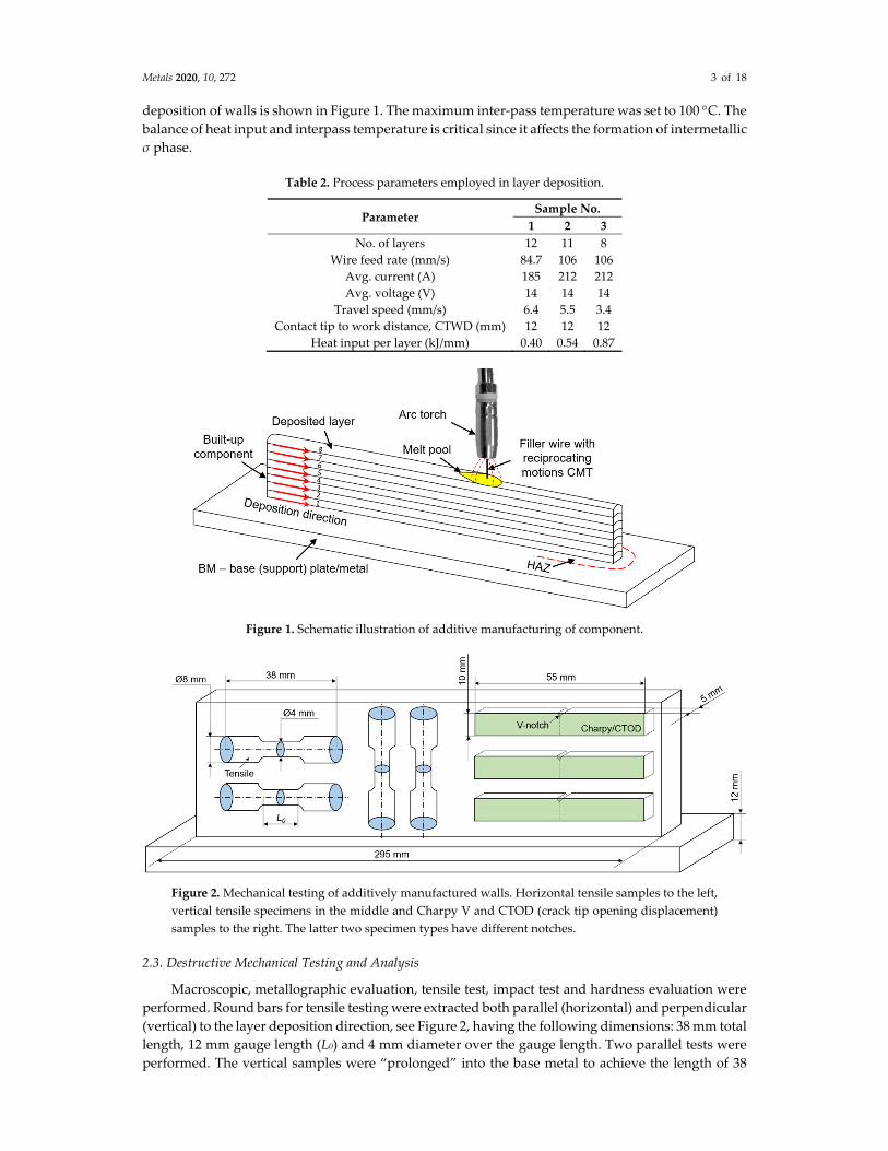
deposition of walls is shown in Figure 1. The maximum inter‐pass temperature was set to 100 C. The balance of heat input and interpass temperature is critical since it affects the formation of intermetallic
σ phase.
Table 2. Process parameters employed in layer deposition.
Parameter Sample No.
1 2 3
No. of layers 12 11 8
Wire feed rate (mm/s) 84.7 106 106
Avg. current (A) 185 212 212
Avg. voltage (V) 14 14 14
Travel speed (mm/s) 6.4 5.5 3.4
Contact tip to work distance, CTWD (mm) 12 12 12
Heat input per layer (kJ/mm) 0.40 0.54 0.87
Figure 1. Schematic illustration of additive manufacturing of component.
Figure 2. Mechanical testing of additively manufactured walls. Horizontal tensile samples to the left,
vertical tensile specimens in the middle and Charpy V and CTOD (crack tip opening displacement)
samples to the right. The latter two specimen types have different notches.
2.3. Destructive Mechanical Testing and Analysis
Macroscopic, metallographic evaluation, tensile test, impact test and hardness evaluation were
performed. Round bars for tensile testing were extracted both parallel (horizontal) and perpendicular
(vertical) to the layer deposition direction, see Figure 2, having the following dimensions: 38 mm total
length, 12 mm gauge length (L0) and 4 mm diameter over the gauge length. Two parallel tests were
performed. The vertical samples were “prolonged” into the base metal to achieve the length of 38

Metals 2020, 10, 272 4 of 18
mm. The gauge area was then displaced towards the layers, providing fracture taking place in the
superduplex wall.
Three parallels of sub‐sized Charpy V‐notch [35] samples were cut with dimensions of 5×10×55
mm3 and subsequently machined (see Figure 2) with the notch position so that the fracture direction
was perpendicular to the deposition direction. The test temperature was −20 C. A total number of
six Charpy V‐notch specimens were cut from BM; three of them with sub‐sized (5×10×55 mm3), and
three with full‐sized (10×10×55 mm3) dimensions, the latter one being reference toughness. According
to the DNVGL‐OS‐F101 standard [36], values for sub‐sized specimens were multiplied by a factor of
two for conversion to full‐sized case.
Fracture toughness CTOD (Crack Tip Opening Displacement) testing was performed at −20 C using sub‐sized SENB (Single Edge Notched Bending) B×2B the standard rectangular specimen, using
the dimensions of B = 5 mm (width) and 2B = 10 mm (height, sample thickness). The notch placement
was the same as Charpy, but with a geometry of a/t = 0.5 (a is the length of notch and fatigue pre‐
crack, W = 2B is thickness). The notch was electro discharged to a depth of 4 mm followed by fatigue
pre‐cracking up to a depth of 4.8 mm.
A transversal cross‐section of the wall for each sample was extracted for macro‐ and microscopic
inspection, the ZwickRoell ZHV unit was used for Vickers hardness measurements (HV10, with 10 kg
force). The microstructure examination of walls was performed in light microscope. For the ferrite
volume fraction assessment, a point counting technique was used for the first, middle and last bead,
including heat affected zone (HAZ) and BM. A total number of 13 fields was included per position
in the wall for ferrite counting. In these fields, a grid system with 100 points was used. The
magnification was ×1000. The ISO 9042 standard [37] recommends 30 grids to achieve a statistical
reliability. However, the standard also reports a multiplication factor if less than 30 grids are used.
In the present case with 13 grids, the factor is 2.16 for calculating the 95% confidence interval.
To obtain good contrast between austenite and ferrite, the specimens were electrolytically etched
in 40% NaOH, operating at a voltage of 7 V for 15 s, followed by a light polish for 10 s. For
identification of the Cr nitrides, the specimens were re‐prepared and electrolytically etched in 10%
oxalic acid, C2H2O4, for 10 s, operating at room temperature with 6 V. Finally, the samples were etched
in 10% oxalic acid for 3 s at 6 V, then in 60% nitric acid for 15 s at 1 V to identify the σ phase.
3. Results and Discussions
3.1. Structure of Additively Manufactured Walls
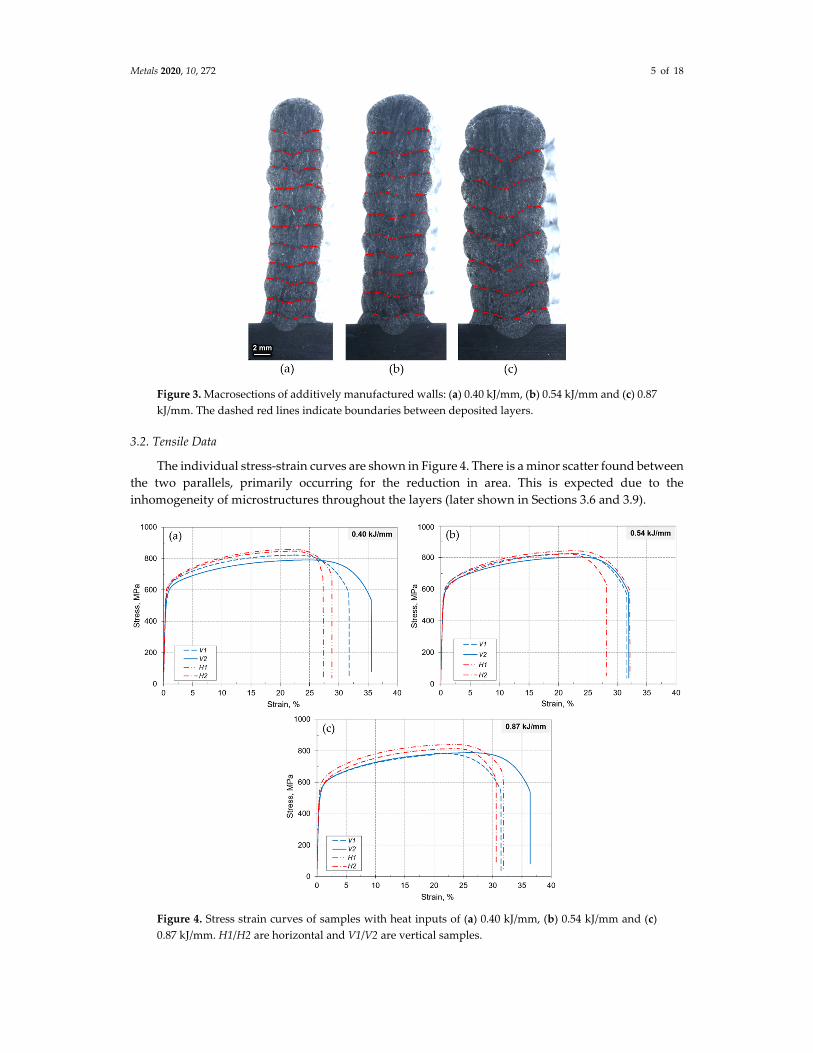
The macrosections of additively deposited walls are represented in Figure 3. The average widths
of the deposited walls were 7.5 mm (sample 1, 0.40 kJ/mm), 8.5 mm (sample 2, 0.54 kJ/mm) and 11.0
mm (sample 3, 0.87 kJ/mm). The average layer height for the three different walls was 2.4, 2.8 and 3.4
mm for samples 1‒3, respectively, which is consistent with the heat input variation. Neither pores
nor cracking were visible, which means that the employed parameters are appropriate for production
of AM walls.
Metals 2020, 10, 272 5 of 18
Figure 3. Macrosections of additively manufactured walls: (a) 0.40 kJ/mm, (b) 0.54 kJ/mm and (c) 0.87
kJ/mm. The dashed red lines indicate boundaries between deposited layers.
3.2. Tensile Data
The individual stress‐strain curves are shown in Figure 4. There is a minor scatter found between
the two parallels, primarily occurring for the reduction in area. This is expected due to the
inhomogeneity of microstructures throughout the layers (later shown in Sections 3.6 and 3.9).
Figure 4. Stress strain curves of samples with heat inputs of (a) 0.40 kJ/mm, (b) 0.54 kJ/mm and (c)
0.87 kJ/mm. H1/H2 are horizontal and V1/V2 are vertical samples.

Metals 2020, 10, 272 6 of 18
One observation is that the WAAM deposited layer gave in most cases lower strength than that
of the support plate, and the strength values fall below the typical values indicated in the wire
datasheet (Section 2.1). This may be linked to the small size of the tensile specimens used in the
present case. More important is that horizontal and vertical samples had different strength and
ductility; the strength of horizontal specimens tends to be slightly higher than those of the vertical
ones. This is probably linked to the fact that vertical samples represent more extensive reheating
effects.
According to data presented in Figure 5, yield and tensile strength are reduced with an increase
of heat input. The slope of the linear trend is larger for the yield (Rp0.2) than for the tensile strength
(Rm). For the highest heat input, the yield strength was reduced by 160 and 100 MPa for vertical and
horizontal samples, respectively, when comparison is made with the BM. The loss in tensile strength
was much smaller (< 20 MPa). However, when compared with the tensile strength of the wire (934
MPa), the loss in the ultimate tensile strength is at the same level as the yield point. By contrast to
strength, the ductility showed an opposite trend as shown in Figure 6.
(a) (b)
Figure 5. Effect of heat input on yield (Rp0.2) and tensile (Rm) strength for (a) vertical samples and (b)
horizontal samples.
Figure 6. Effect of heat input on reduction in area.
3.3. Hardness
Higher hardness was developed in the HAZ of the base metal, where maximum 271 HV was
measured for sample 1 (0.40 kJ/mm), and with slightly lower hardness in deposited layers, see Figure
7. The hardness for the deposited layers and the HAZ satisfies most of requirement set in current
offshore standards (< 300 HV). However, an exception is the requirements for sour service, usually
set to 248 HV according to ISO 15156 [38,39]. The maximum hardness in the HAZ and weld metal

Metals 2020, 10, 272 7 of 18
(WM) can be further reduced through an increase in heat input. Based on the linear trendlines (see
Figure 7), a heat input of 1.0 kJ/mm is required to achieve 248 HV in the HAZ, which is still below a
critical heat input for sigma (σ) phase formation. The problem here is that the heat input should not
be increased further since it may cause formation of brittle phases in the HAZ. By application of
superduplex steel wire, both WM and the HAZ can be more sensitive to formation of σ and χ phases
due to the higher ratio between ferrite (ferrite stabilizing elements are Cr, Mo, Si) and austenite
stabilizers (austenite stabilizing elements are Ni, Mn, Cu, N) than contained in conventional 2205
duplex stainless steels.
Figure 7. Effect of heat input on hardness in deposited layers (WM) and heat affected zone (HAZ).
3.4. Toughness Results
The effect of heat input on the Charpy V‐notch toughness is shown in Figure 8. The results for
sub‐sized samples are converted to full sized samples by multiplication by a factor of two (sub‐sized
samples have only 50% of the cross section of full‐sized ones). It is found that the toughness of
deposited layers is only 30%‒35% compared to the BM. The Charpy V values are almost independent
of the employed heat input. Only a slight reduction in toughness occurs when increasing the heat
input from 0.40 to 0.87 kJ/mm. This is possibly related to the coarsening of the microstructure when
the heat input is increased. Accordingly, it is reasonable to assume that no harmful intermetallics
have been formed (to be discussed later). With the formation of σ, a much sharper fall in toughness
would be expected.
The fracture toughness results (CTOD test) are shown in Figure 9. The CTOD level is around 0.3
mm, although a small enhancement in the average value is found when the heat input is increased.
In general, a value of 0.3 mm provides acceptable toughness values based on DNVGL‐OS‐C401 [40]
the critical value is 0.15 mm.

Metals 2020, 10, 272 8 of 18
Figure 8. Charpy V‐notch toughness of walls and base metal.
Figure 9. CTOD fracture toughness of walls.
3.5. Solidification
Stainless steel may solidify in different modes according to their chemical composition. In
addition, the cooling rate may induce a shift in solidification [41]. In austenitic stainless steels, a three‐
phase reaction region exists (Liquid γ + δ), which can be either eutectic or peritectic for compositions
beyond 15 wt.% Cr and 10 wt.% Ni according to the Fe‐Cr‐Ni ternary phase diagram [42,43]. Here, δ
means the high temperature ferrite and used according to literature. Consequently, the solidification
microstructure, depending on both composition and cooling rate, may become more complex due to
the three‐phase reaction. Depending on the Creq/Nieq ratio, stainless steel can be solidified with four
different solidification modes [44,45], i.e., ferrite mode, ferrite‐austenite mode, austenite‐ferrite mode
and austenite mode (here Liq means—liquid phase of the material):
F mode: Liq Liq + δ δ δ + γ for Creq/Nieq > 2.0 (1a)
FA mode: Liq Liq + δ Liq + δ + γ δ + γ γ for 1.5 < Creq/Nieq < 2.0 (2b)
AF mode: Liq Liq + γ Liq + δ + γ γ + δ γ for 1.37 < Creq/Nieq < 1.5 (3c)
A mode: Liq Liq + γ γ for Creq/Nieq < 1.37 (4d)

Metals 2020, 10, 272 9 of 18
The existence area of these solidification regimes is outlined in Figure 10. The values of Creq and
Nieq are calculated from Equation (2) below (elements in wt.%), taken from the Welding Research
Council 1992 diagram (WRC‐1992):
Creq = Cr + Mo + 0.7Nb (2a)
Nieq = Ni + 35C + 20N + 0.25Cu (2b)
The Cr and Ni equivalents of the examined superduplex steel wire are 28.7 and 14.9,
respectively, which gives a ratio of 1.9. This is indicated in Figure 10 as the red circle marker, which
falls close to the ferrite line. Therefore, it is implied that a primary ferritic or mixed mode solidification
may occur for the current deposited layers. Figure 10 represents the Welding Research Council WRC‐
1992 diagram [46] for Creq from 17 to 31 and Nieq from 9 to 18.
Figure 10. Nomenclature of solidification modes in stainless steels. Adapted from [46]. The wire
composition is represented by the red circle marker based on the Cr and Ni equivalents adopted by
WRC‐1992 (Equation 2).
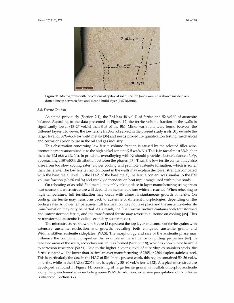
The metallographic investigation demonstrated that the layers solidify by epitaxial nucleation
and growth (Figure 11), which means that the solidifying grains nucleate at the grains located at the
fusion boundary. Due to the high alloying level and high thermal gradient because of poor heat
conduction capacity, a planar solidification front may not be stable, and the primary solidification
mode is cellular‐dendritic. Here, only ferrite with a crystallographic preferential growth orientation
relationship aligned with the heat flow direction will continue to grow. This growth will cease when
the preferred ferrite growth direction reaches a certain deviation from the heat flow direction. Then,
successive nucleation of new ferrite will take place with subsequent growth of those grains with their
preferred growth direction nearly parallel with the heat flow direction.
Metals 2020, 10, 272 10 of 18
Figure 11. Micrographs with indications of epitaxial solidification (one example is shown inside black
dotted lines); between first and second build layer (0.87 kJ/mm).
3.6. Ferrite Content
As stated previously (Section 2.1), the BM has 48 vol.% of ferrite and 52 vol.% of austenite
balance. According to the data presented in Figure 12, the ferrite volume fraction in the walls is
significantly lower (15‒27 vol.%) than that of the BM. Minor variations were found between the
different layers. However, the low ferrite fraction observed in the present study is strictly outside the
target level of 30%‒65% for weld metals [36] and needs procedure qualification testing (mechanical
and corrosion) prior to use in the oil and gas industry.
This observation concerning low ferrite volume fraction is caused by the selected filler wire,
promoting more austenite due to the high nickel content (9.5 wt.% Ni). This is in fact almost 3% higher
than the BM (6.6 wt.% Ni). In principle, overalloying with Ni should provide a better balance of α/γ,
approaching a 50%/50% distribution between the phases [47]. Thus, the low ferrite content may also
arise from too slow cooling rates. Slower cooling will promote austenite formation, which is softer
than the ferrite. The low ferrite fraction found in the walls may explain the lower strength compared
with the base metal level. In the HAZ of the base metal, the ferrite content was similar to the BM
volume fraction (49‒56 vol.%) and weakly dependent on heat input range used within this study.
On reheating of as solidified metal, inevitably taking place in layer manufacturing using arc as
heat source, the microstructure will depend on the temperature which is reached. When reheating to
high temperature, full ferritization may occur with almost instantaneous growth of ferrite. On
cooling, the ferrite may transform back to austenite of different morphologies, depending on the
cooling rates. At lower temperatures, full ferritization may not take place and the austenite‐to‐ferrite
transformation may only be partial. As a result, the final microstructure contains both transformed
and untransformed ferrite, and the transformed ferrite may revert to austenite on cooling [48]. This
re‐transformed austenite is called secondary austenite (γ2).
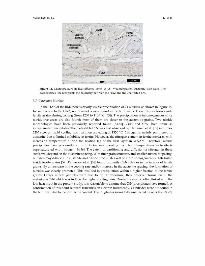
The microstructures shown in Figure 13 represent the top layer and consist of ferrite grains with
extensive austenite nucleation and growth, revealing both elongated austenite grains and
Widmanstätten austenite sideplates (WAS). The morphology and size of the austenite phase may
influence the component properties. An example is the influence on pitting properties [49]. In
reheated areas of the walls, secondary austenite is formed (Section 3.8), which is known to be harmful
to corrosion resistance [50,51]. Due to the higher alloying level of superduplex stainless steels, the
ferrite content will be lower than in similar layer manufacturing of 2205 or 2304 duplex stainless steel.
This is particularly the case in the HAZ of BM. In the present work, this region contained 50‒56 vol.%
of ferrite, while in the HAZ of 2205 there is typically 80‒90 vol.% ferrite [52]. A typical microstructure
developed as found in Figure 14, consisting of large ferrite grains with allotriomorphic austenite
along the grain boundaries including some WAS. In addition, extensive precipitation of Cr nitrides
is observed (Section 3.7).

Metals 2020, 10, 272 11 of 18
Figure 12. Effect of heat input on volume fraction of ferrite in different areas of deposited walls: (a)
WM of top layer, (b) WM between 5th and 6th layer, (c) WM of 5th layer. The dashed red lines
represent volume fraction of ferrite in the BM (48 vol.%).
Figure 13. Microstructure in top layer in; (a) Sample No. 1 (0.40 kJ/mm), (b) Sample No. 2 (0.54 kJ/mm)
and (c) Sample No. 3 (0.87 kJ/mm). WAS—Widmanstätten austenite side‐plate.
Metals 2020, 10, 272 12 of 18
Figure 14. Microstructure in heat‐affected zone. WAS—Widmanstätten austenite side‐plate. The
dashed black line represents the boundary between the HAZ and the unaffected BM.
3.7. Chromium Nitrides
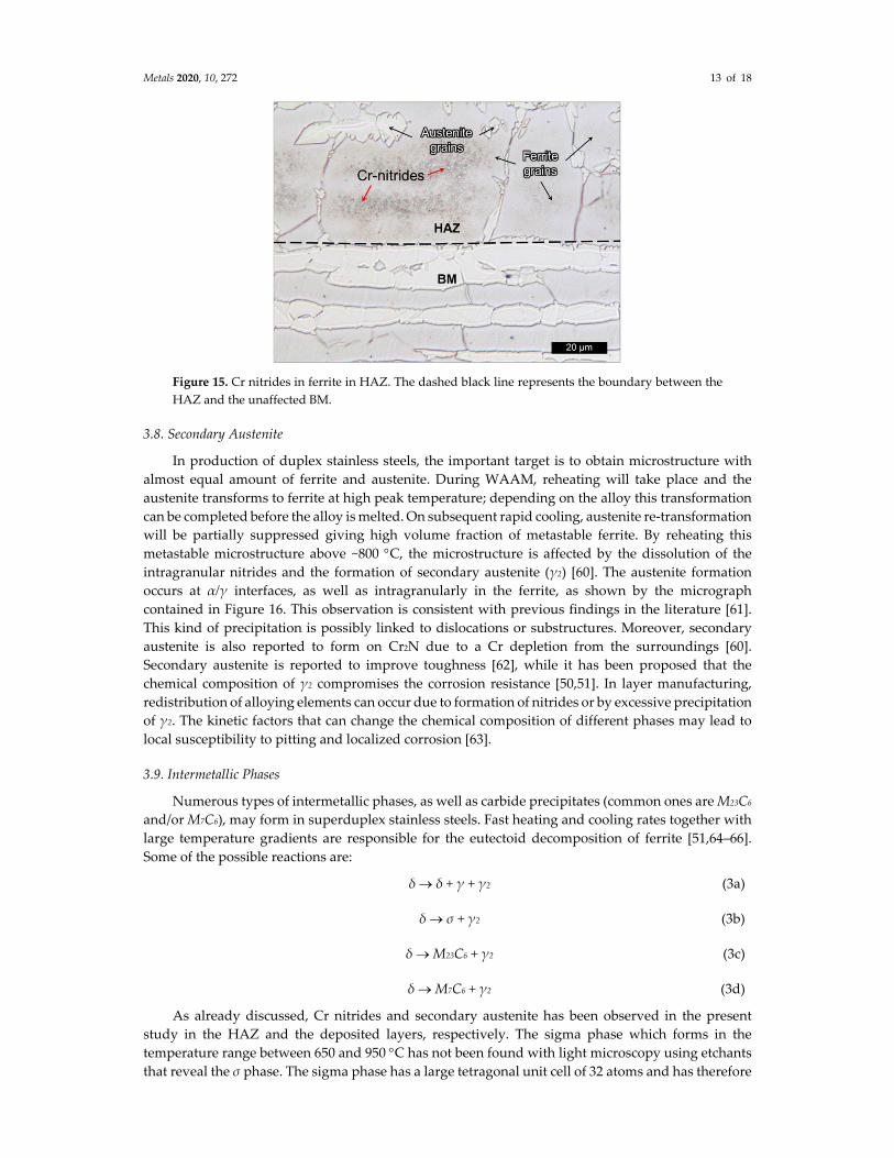
In the HAZ of the BM, there is clearly visible precipitation of Cr nitrides, as shown in Figure 15.
In comparison to the HAZ, no Cr nitrides were found in the built walls. These nitrides form inside
ferrite grains during cooling (from 1250 to 1100 C [53]). The precipitation is inhomogeneous since
nitride‐free areas are also found; most of them are closer to the austenitic grains. Two nitride
morphologies have been previously reported found [53,54], Cr2N and CrN, both occur as
intragranular precipitates. The metastable CrN was first observed by Hertzman et al. [55] in duplex
2205 steel on rapid cooling from solution annealing at 1350 C. Nitrogen is mainly partitioned to
austenite due to limited solubility in ferrite. However, the nitrogen content in ferrite increases with
increasing temperature during the heating leg of the first layer in WAAM. Therefore, nitride
precipitates have propensity to form during rapid cooling from high temperatures as ferrite is
supersaturated with nitrogen [54,56]. The extent of partitioning and diffusion of nitrogen in these
steels will depend on the austenite spacing. With finer grain structure, and smaller austenite spacing,
nitrogen may diffuse into austenite and nitride precipitates will be more homogeneously distributed
inside ferrite grains [57]. Pettersson et al. [58] found primarily Cr2N nitrides in the interior of ferrite
grains. By an increase in the cooling rate and/or increase in the austenite spacing, the formation of
nitrides was clearly promoted. This resulted in precipitation within a higher fraction of the ferrite
grains. Larger nitride particles were also found. Furthermore, they observed formation of the
metastable CrN which was induced by higher cooling rates. Due to the rapid cooling linked with the
low heat input in the present study, it is reasonable to assume that CrN precipitates have formed. A
confirmation of this point requires transmission electron microscopy. Cr nitrides were not found in
the built wall due to the low ferrite content. The toughness seems to be unaffected by nitrides [58,59].
Metals 2020, 10, 272 13 of 18
Figure 15. Cr nitrides in ferrite in HAZ. The dashed black line represents the boundary between the
HAZ and the unaffected BM.
3.8. Secondary Austenite
In production of duplex stainless steels, the important target is to obtain microstructure with
almost equal amount of ferrite and austenite. During WAAM, reheating will take place and the
austenite transforms to ferrite at high peak temperature; depending on the alloy this transformation
can be completed before the alloy is melted. On subsequent rapid cooling, austenite re‐transformation
will be partially suppressed giving high volume fraction of metastable ferrite. By reheating this
metastable microstructure above ~800 C, the microstructure is affected by the dissolution of the
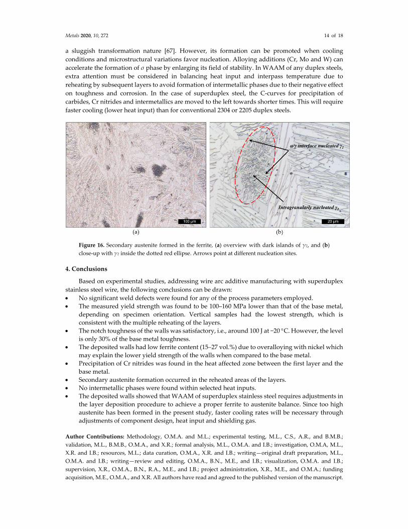
intragranular nitrides and the formation of secondary austenite (γ2) [60]. The austenite formation
occurs at α/γ interfaces, as well as intragranularly in the ferrite, as shown by the micrograph
contained in Figure 16. This observation is consistent with previous findings in the literature [61].
This kind of precipitation is possibly linked to dislocations or substructures. Moreover, secondary
austenite is also reported to form on Cr2N due to a Cr depletion from the surroundings [60].
Secondary austenite is reported to improve toughness [62], while it has been proposed that the
chemical composition of γ2 compromises the corrosion resistance [50,51]. In layer manufacturing,
redistribution of alloying elements can occur due to formation of nitrides or by excessive precipitation
of γ2. The kinetic factors that can change the chemical composition of different phases may lead to
local susceptibility to pitting and localized corrosion [63].
3.9. Intermetallic Phases
Numerous types of intermetallic phases, as well as carbide precipitates (common ones are M23C6
and/or M7C6), may form in superduplex stainless steels. Fast heating and cooling rates together with
large temperature gradients are responsible for the eutectoid decomposition of ferrite [51,64–66].
Some of the possible reactions are:
δ δ + γ + γ2 (3a)
δ σ + γ2 (3b)
δ M23C6 + γ2 (3c)
δ M7C6 + γ2 (3d)
As already discussed, Cr nitrides and secondary austenite has been observed in the present
study in the HAZ and the deposited layers, respectively. The sigma phase which forms in the
temperature range between 650 and 950 C has not been found with light microscopy using etchants
that reveal the σ phase. The sigma phase has a large tetragonal unit cell of 32 atoms and has therefore
Metals 2020, 10, 272 14 of 18
a sluggish transformation nature [67]. However, its formation can be promoted when cooling
conditions and microstructural variations favor nucleation. Alloying additions (Cr, Mo and W) can
accelerate the formation of σ phase by enlarging its field of stability. In WAAM of any duplex steels,
extra attention must be considered in balancing heat input and interpass temperature due to
reheating by subsequent layers to avoid formation of intermetallic phases due to their negative effect
on toughness and corrosion. In the case of superduplex steel, the C‐curves for precipitation of
carbides, Cr nitrides and intermetallics are moved to the left towards shorter times. This will require
faster cooling (lower heat input) than for conventional 2304 or 2205 duplex steels.
Figure 16. Secondary austenite formed in the ferrite, (a) overview with dark islands of γ2, and (b)
close‐up with γ2 inside the dotted red ellipse. Arrows point at different nucleation sites.
4. Conclusions
Based on experimental studies, addressing wire arc additive manufacturing with superduplex
stainless steel wire, the following conclusions can be drawn:
No significant weld defects were found for any of the process parameters employed.
The measured yield strength was found to be 100‒160 MPa lower than that of the base metal,
depending on specimen orientation. Vertical samples had the lowest strength, which is
consistent with the multiple reheating of the layers.
The notch toughness of the walls was satisfactory, i.e., around 100 J at −20 C. However, the level
is only 30% of the base metal toughness.
The deposited walls had low ferrite content (15‒27 vol.%) due to overalloying with nickel which
may explain the lower yield strength of the walls when compared to the base metal.
Precipitation of Cr nitrides was found in the heat affected zone between the first layer and the
base metal.
Secondary austenite formation occurred in the reheated areas of the layers.
No intermetallic phases were found within selected heat inputs.
The deposited walls showed that WAAM of superduplex stainless steel requires adjustments in
the layer deposition procedure to achieve a proper ferrite to austenite balance. Since too high
austenite has been formed in the present study, faster cooling rates will be necessary through
adjustments of component design, heat input and shielding gas.
Author Contributions: Methodology, O.M.A. and M.L.; experimental testing, M.L., C.S., A.R., and B.M.B.;
validation, M.L., B.M.B., O.M.A., and X.R.; formal analysis, M.L., O.M.A. and I.B.; investigation, O.M.A, M.L.,
X.R. and I.B.; resources, M.L.; data curation, O.M.A., X.R. and I.B.; writing—original draft preparation, M.L.,
O.M.A. and I.B.; writing—review and editing, O.M.A., B.N., M.E., and I.B.; visualization, O.M.A. and I.B.;
supervision, X.R., O.M.A., B.N., R.A., M.E., and I.B.; project administration, X.R., M.E., and O.M.A.; funding
acquisition, M.E., O.M.A., and X.R. All authors have read and agreed to the published version of the manuscript.

Metals 2020, 10, 272 15 of 18
Funding: This research was funded by the Norwegian Research Council (Contract No. 281927/E30) and the
industry companies Equinor, Westad, Nordic Additive Manufacturing (NAM) and Vitec.
Conflicts of Interest: The authors declare no conflicts of interest.
References
1. DebRoy, T.; Wei, H.L.; Zuback, J.S.; Mukherjee, T.; Elmer, J.W.; Milewski, J.O.; Beese, A.M.; Wilson‐Heid,
A.; De, A.; Zhang, W. Additive manufacturing of metallic Components—Process, structure and properties.
Prog. Mater. Sci. 2018, 92, 112–224, doi:10.1016/j.pmatsci.2017.10.001.
2. Ding, D.; Pan, Z.; Cuiuri, D.; Li, H. Wire‐feed additive manufacturing of metal components: Technologies,
developments and future interests. Int. J. Adv. Manuf. Technol. 2015, 81, 465–481, doi:10.1007/s00170‐015‐
7077‐3.
3. Oliveira, J.P.; Santos, T.G.; Miranda, R.M. Revisiting fundamental welding concepts to improve additive
manufacturing: From theory to practice. Prog. Mater. Sci. 2020, 107, 100590,
doi:10.1016/j.pmatsci.2019.100590.
4. Frazier, W.E. Metal Additive Manufacturing: A Review. J. Mater. Eng. Perform. 2014, 23, 1917–1928,
doi:10.1007/s11665‐014‐0958‐z.
5. Waryoba, D.R.; Keist, J.S.; Ranger, C.; Palmer, T.A. Microtexture in additively manufactured Ti‐6Al‐4V
fabricated using directed energy deposition. Mater. Sci. Eng. A 2018, 734, 149–163,
doi:10.1016/j.msea.2018.07.098.
6. Hemmasian Ettefagh, A.; Zeng, C.; Guo, S.; Raush, J. Corrosion behavior of additively manufactured Ti‐
6Al‐4V parts and the effect of post annealing. Addit. Manuf. 2019, 28, 252–258,
doi:10.1016/j.addma.2019.05.011.
7. Sabban, R.; Bahl, S.; Chatterjee, K.; Suwas, S. Globularization using heat treatment in additively
manufactured Ti‐6Al‐4V for high strength and toughness. Acta Mater. 2019, 162, 239–254,
doi:10.1016/j.actamat.2018.09.064.
8. Wu, B.; Pan, Z.; Li, S.; Cuiuri, D.; Ding, D.; Li, H. The anisotropic corrosion behaviour of wire arc additive
manufactured Ti‐6Al‐4V alloy in 3.5% NaCl solution. Corros. Sci. 2018, 137, 176–183,
doi:10.1016/j.corsci.2018.03.047.
9. Strantza, M.; Vrancken, B.; Prime, M.B.; Truman, C.E.; Rombouts, M.; Brown, D.W.; Guillaume, P.; Van
Hemelrijck, D. Directional and oscillating residual stress on the mesoscale in additively manufactured Ti‐
6Al‐4V. Acta Mater. 2019, 168, 299–308, doi:10.1016/j.actamat.2019.01.050.
10. Gorji, M.B.; Tancogne‐Dejean, T.; Mohr, D. Heterogeneous random medium plasticity and fracture model
of additively‐manufactured Ti‐6Al‐4V. Acta Mater. 2018, 148, 442–455, doi:10.1016/j.actamat.2018.02.025.
11. Bermingham, M.J.; Kent, D.; Zhan, H.; StJohn, D.H.; Dargusch, M.S. Controlling the microstructure and
properties of wire arc additive manufactured Ti–6Al–4V with trace boron additions. Acta Mater. 2015, 91,
289–303, doi:10.1016/j.actamat.2015.03.035.
12. Carroll, B.E.; Palmer, T.A.; Beese, A.M. Anisotropic tensile behavior of Ti–6Al–4V components fabricated
with directed energy deposition additive manufacturing. Acta Mater. 2015, 87, 309–320,
doi:10.1016/j.actamat.2014.12.054.
13. Ren, D.; Li, S.; Wang, H.; Hou, W.; Hao, Y.; Jin, W.; Yang, R.; Misra, R.D.K.; Murr, L.E. Fatigue behavior of
Ti‐6Al‐4V cellular structures fabricated by additive manufacturing technique. J. Mater. Sci. Technol. 2019,
35, 285–294, doi:10.1016/j.jmst.2018.09.066.
14. Wilson‐Heid, A.E.; Beese, A.M. Fracture of laser powder bed fusion additively manufactured Ti–6Al–4V
under multiaxial loading: Calibration and comparison of fracture models. Mater. Sci. Eng. A 2019, 761,
137967, doi:10.1016/j.msea.2019.05.097.
15. Choi, Y.; Lee, D.‐G. Correlation between surface tension and fatigue properties of Ti‐6Al‐4V alloy fabricated
by EBM additive manufacturing. Appl. Surf. Sci. 2019, 481, 741–746, doi:10.1016/j.apsusc.2019.03.099.
16. Schörghuber, M. Inventor Cold‐Metal‐Transfer Welding Process and Welding Installation. Patent WO
2006/125234 A1, 18 May 2006.
17. Pickin, C.G.; Williams, S.W.; Lunt, M. Characterisation of the cold metal transfer (CMT) process and its
application for low dilution cladding. J. Mater. Process. Technol. 2011, 211, 496–502,
doi:10.1016/j.jmatprotec.2010.11.005.
18. Chen, M.; Zhang, D.; Wu, C. Current waveform effects on CMT welding of mild steel. J. Mater. Process.
Technol. 2017, 243, 395–404, doi:10.1016/j.jmatprotec.2017.01.004.

Metals 2020, 10, 272 16 of 18
19. Tolosa, I.; Garciandía, F.; Zubiri, F.; Zapirain, F.; Esnaola, A. Study of mechanical properties of AISI 316
stainless steel processed by “selective laser melting”, following different manufacturing strategies. Int. J.
Adv. Manuf. Technol. 2010, 51, 639–647, doi:10.1007/s00170‐010‐2631‐5.
20. Yasa, E.; Kruth, J.P. Microstructural investigation of Selective Laser Melting 316L stainless steel parts
exposed to laser re‐melting. Procedia Eng. 2011, 19, 389–395, doi:10.1016/j.proeng.2011.11.130.
21. de Lima, M.S.F.; Sankaré, S. Microstructure and mechanical behavior of laser additive manufactured AISI
316 stainless steel stringers. Mater. Des. 2014, 55, 526–532, doi:10.1016/j.matdes.2013.10.016.
22. Wang, Z.; Palmer, T.A.; Beese, A.M. Effect of processing parameters on microstructure and tensile
properties of austenitic stainless steel 304L made by directed energy deposition additive manufacturing.
Acta Mater. 2016, 110, 226–235, doi:10.1016/j.actamat.2016.03.019.
23. Wang, L.; Xue, J.; Wang, Q. Correlation between arc mode, microstructure, and mechanical properties
during wire arc additive manufacturing of 316L stainless steel. Mater. Sci. Eng. A 2019, 751, 183–190,
doi:10.1016/j.msea.2019.02.078.
24. Barkia, B.; Aubry, P.; Haghi‐Ashtiani, P.; Auger, T.; Gosmain, L.; Schuster, F.; Maskrot, H. On the origin of
the high tensile strength and ductility of additively manufactured 316L stainless steel: Multiscale
investigation. J. Mater. Sci. Technol. 2019, 41, 209–218, doi:10.1016/j.jmst.2019.09.017.
25. Lei, J.; Xie, J.; Zhou, S.; Song, H.; Song, X.; Zhou, X. Comparative study on microstructure and corrosion
performance of 316 stainless steel prepared by laser melting deposition with ring‐shaped beam and
Gaussian beam. Opt. Laser Technol. 2019, 111, 271–283, doi:10.1016/j.optlastec.2018.09.057.
26. Hejripour, F.; Binesh, F.; Hebel, M.; Aidun, D.K. Thermal modeling and characterization of wire arc
additive manufactured duplex stainless steel. J. Mater. Process. Technol. 2019, 272, 58–71,
doi:10.1016/j.jmatprotec.2019.05.003.
27. Stützer, J.; Totzauer, T.; Wittig, B.; Zinke, M.; Jüttner, S. GMAW Cold Wire Technology for Adjusting the
Ferrite–Austenite Ratio of Wire and Arc Additive Manufactured Duplex Stainless Steel Components.
Metals 2019, 9, 13, doi:10.3390/met9050564.
28. Zhang, X.; Wang, K.; Zhou, Q.; Ding, J.; Ganguly, S.; Marzio, G.; Yang, D.; Xu, X.; Dirisu, P.; Williams, S.W.
Microstructure and mechanical properties of TOP‐TIG‐wire and arc additive manufactured super duplex
stainless steel (ER2594). Mater. Sci. Eng. A 2019, 762, 138097, doi:10.1016/j.msea.2019.138097.
29. Ferro, P.; Bonollo, F. A Semiempirical Model for Sigma‐Phase Precipitation in Duplex and Superduplex
Stainless Steels. Metall. Mater. Trans. A 2012, 43, 1109–1116, doi:10.1007/s11661‐011‐0966‐7.
30. Escriba, D.M.; Materna‐Morris, E.; Plaut, R.L.; Padilha, A.F. Chi‐phase precipitation in a duplex stainless
steel. Mater. Charact. 2009, 60, 1214–1219, doi:10.1016/j.matchar.2009.04.013.
31. Llorca‐Isern, N.; López‐Luque, H.; López‐Jiménez, I.; Biezma, M.V. Identification of sigma and chi phases
in duplex stainless steels. Mater. Charact. 2016, 112, 20–29, doi:10.1016/j.matchar.2015.12.004.
32. Pohl, M.; Storz, O.; Glogowski, T. Effect of intermetallic precipitations on the properties of duplex stainless
steel. Mater. Charact. 2007, 58, 65–71, doi:10.1016/j.matchar.2006.03.015.
33. Pardal, J.M.; Tavares, S.S.M.; Fonseca, M.C.; de Souza, J.A.; Côrte, R.R.A.; de Abreu, H.F.G. Influence of the
grain size on deleterious phase precipitation in superduplex stainless steel UNS S32750. Mater. Charact.
2009, 60, 165–172, doi:10.1016/j.matchar.2008.08.007.
34. ISO 14175: Welding Consumables—Gases and Gas Mixtures for Fusion Welding and Allied Processes; ISO:
Geneva, Switzerland, 2008.
35. Wallin, K.; Karjalainen‐Roikonen, P.; Suikkanen, P. Sub‐sized CVN specimen conversion methodology.
Procedia Struct. Integr. 2016, 2, 3735–3742, doi:10.1016/j.prostr.2016.06.464.
36. DNVGL‐OS‐F101: Submarine Pipeline Systems; Det Norske Veritas AS: Høvik, Norway, 2012.
37. ISO 9042: Steels—Manual Point Counting Method for Statistically Estimating the Volume Fraction of a Constituent
with a Point Grid; International Organization for Standardization: Geneva, Switzerland, 1988; p. 4.
38. ISO 15156‐1: Petroleum and Natural Gas Industries—Materials for Use in H2S‐Containing Environments in Oil
and Gas Production—Part 1: General Principles for Selection of Cracking‐Resistant Materials; ISO: Geneva,
Switzerland, 2015.
39. ISO 15156‐3: Petroleum and Natural Gas Industries—Materials for Use in H2S‐Containing Environments in Oil
and Gas Production—Part 3: Cracking‐Resistant CRAs (Corrosion‐Resistant alloys) and Other Alloys; ISO:
Geneva, Switzerland, 2015.
40. DNV Offshore Standard DNVGL‐OS‐C401: Fabrication and Testing of Offshore Structures; Det Norske Veritas
AS: Høvik, Norway, 2015.
Metals 2020, 10, 272 17 of 18
41. Wu, C.; Li, S.; Zhang, C.; Wang, X. Microstructural evolution in 316LN austenitic stainless steel during
solidification process under different cooling rates. J. Mater. Sci. 2016, 51, 2529–2539, doi:10.1007/s10853‐
015‐9565‐0.
42. Takalo, T.; Suutala, N.; Moisio, T. Austenitic solidification mode in austenitic stainless steel welds. Metall.
Trans. A 1979, 10, 1173–1181, doi:10.1007/bf02811663.
43. Hunter, A.; Ferry, M. Phase formation during solidification of AISI 304 austenitic stainless steel. Scr. Mater.
2002, 46, 253–258, doi:10.1016/S1359‐6462(01)01215‐5.
44. Hammar, O.; Svensson, U. Solidification and Casting of Metals: Proceedings of an International Conference on
Solidification; The Metals Society: London, UK, 1979.
45. Suutala, N. Effect of solidification conditions on the solidification mode in austenitic stainless steels. Metall.
Trans. A 1983, 14, 191–197, doi:10.1007/BF02651615.
46. Kotecki, D.J.; Siewert, T.A. WRC‐1992 Constitution Diagram for Stainless Steel Weld Metals: A
Modification of the WRC‐1988 Diagram. Weld. J. 1992, 71, 171–178.
47. Liljas, M. The Welding Metallurgy of Duplex Stainless Steels. In Proceedings of the 4th International
Conference, Welding Processes, Glasgow, Scotland, 1995; pp. 13–16.
48. Palmer, T.A.; Elmer, J.W.; Babu, S.S. Observations of ferrite/austenite transformations in the heat affected
zone of 2205 duplex stainless steel spot welds using time resolved X‐ray diffraction. Mater. Sci. Eng. A 2004,
374, 307–321, doi:10.1016/j.msea.2004.03.037.
49. Park, S.; Shin, B.; Park, J.; Kim, D.; Chung, W. Effect of Austenite Morphology on the Electrochemical
Properties of Super Duplex Stainless UNS S 32750. Int. J. Electrochem. Sci. 2019, 14, 5386–5395,
doi:10.20964/2019.06.32.
50. Karlsson, L. Welding Duplex Stainless Steels—A Review Of Current Recommendations. Weld. World 2012,
56, 65–76, doi:10.1007/bf03321351.
51. Nilsson, J.O.; Karlsson, L.; Andersson, J.O. Secondary austenite for mation and its relation to pitting
corrosion in duplex stainless steel weld metal. Mater. Sci. Technol. 1995, 11, 276–283,
doi:10.1179/mst.1995.11.3.276.
52. Yang, J.; Wang, Q.; Wei, Z.; Guan, K. Weld failure analysis of 2205 duplex stainless steel nozzle. Case Stud.
Eng. Fail. Anal. 2014, 2, 69–75, doi:10.1016/j.csefa.2014.05.001.
53. Pettersson, N.; Pettersson, R.F.A.; Wessman, S. Precipitation of Chromium Nitrides in the Super Duplex
Stainless Steel 2507. Metall. Mater. Trans. A 2015, 46, 1062–1072, doi:10.1007/s11661‐014‐2718‐y.
54. Liao, J. Nitride Precipitation in Weld HAZs of a Duplex Stainless Steel. ISIJ Int. 2001, 41, 460–467,
doi:10.2355/isijinternational.41.460.
55. Hertzman, S.; Pettersson, R.J.; Blom, R.; Kivineva, E.; Eriksson, J. Influence of Shielding Gas Composition
and Welding Parameters on the N‐content and Corrosion Properties of Welds in N‐alloyed Stainless Steel
Grades. ISIJ Int. 1996, 36, 968–976, doi:10.2355/isijinternational.36.968.
56. Chen, T.H.; Yang, J.R. Microstructural characterization of simulated heat affected zone in a nitrogen‐
containing 2205 duplex stainless steel. Mater. Sci. Eng. A 2002, 338, 166–181, doi:10.1016/S0921‐
5093(02)00065‐5.
57. Hereñú, S.; Moscato, M.G.; Alvarez, I.; Armas, A.F. The Influence of Chromium Nitrides Precipitation on
the Fatigue Behavior of Duplex Stainless Steels. Procedia Eng. 2014, 74, 179–182,
doi:10.1016/j.proeng.2014.06.246.
58. Pettersson, R.F.A.; Hertzman, S.; Szakalos, P.; Ferreira, P.J. The Influence of Microstructure on Pitting
Corrosion in Autogenous TlG Duplex Stainless Steel Welds. In Proceedings of the 4th International
Conference, Welding Processes, Glasgow, Scotland, 1994.
59. Muthupandi, V.; Bala Srinivasan, P.; Seshadri, S.K.; Sundaresan, S. Effect of weld metal chemistry and heat
input on the structure and properties of duplex stainless steel welds. Mater. Sci. Eng. A 2003, 358, 9–16,
doi:10.1016/S0921‐5093(03)00077‐7.
60. Atamert, S.; King, J.E. Intragranular nucleation of austenite Z. Fuer Met. 1991, 82, 230–239.
61. Ramirez, A.J.; Lippold, J.C.; Brandi, S.D. The relationship between chromium nitride and secondary
austenite precipitation in duplex stainless steels. Metall. Mater. Trans. A 2003, 34, 1575–1597,
doi:10.1007/s11661‐003‐0304‐9.
62. Lippold, J.C.; Al‐Rumaih, A.M. Toughness and Pitting Corrosion of Duplex Stainless Steel Weld Heat‐
Affected Zone Microstructures Containing Secondary Austenite. In Proceedings of the 5th World
Conference, Duplex Stainless Steels, Maastricht, The Netherlands, 1997; pp. 1005–1010.
Metals 2020, 10, 272 18 of 18
63. Garzón, C.M.; Ramirez, A.J. Growth kinetics of secondary austenite in the welding microstructure of a UNS
S32304 duplex stainless steel. Acta Mater. 2006, 54, 3321–3331, doi:10.1016/j.actamat.2006.03.018.
64. Nilsson, J.O. Super duplex stainless steels. Mater. Sci. Technol. 1992, 8, 685–700, doi:10.1179/mst.1992.8.8.685.
65. Karlsson, L. Review: Intermetallic Phase Precipitation in Duplex Stainless Steels and Weld Metals:
Metallurgy, Influence on Properties and Testing Aspects. Doc. IIW‐1419, Weld. World 1999,43,5 20‐41.
66. Nilsson, J.‐O.; Huhtala, T.; Jonsson, P.; Karlsson, L.; Wilson, A. Structural stability of super duplex stainless
weld metals and its dependence on tungsten and copper. Metall. Mater. Trans. A 1996, 27, 2196–2208,
doi:10.1007/bf02651874.
67. Atamert, S.; King, J.E. Sigma‐phase formation and its prevention in duplex stainless steels. J. Mater. Sci.
Lett. 1993, 12, 1144–1147, doi:10.1007/bf00420548.
© 2020 by the authors. Licensee MDPI, Basel, Switzerland. This article is an open access
article distributed under the terms and conditions of the Creative Commons Attribution
(CC BY) license (http://creativecommons.org/licenses/by/4.0/).