Parametric study on buckling behaviour of thin stainless steel ...
16
MultiCraft International Journal of Engineering, Science and Technology Vol. 2, No. 4, 2010, pp. 134-149 INTERNATIONAL JOURNAL OF ENGINEERING, SCIENCE AND TECHNOLOGY www.ijest-ng.com © 2010 MultiCraft Limited. All rights reserved Parametric study on buckling behaviour of thin stainless steel cylindrical shells for circular dent dimensional variations under uniform axial compression B. Prabu 1 *, A.V. Raviprakash 2 , N. Rathinam 3 1,2 Dept. of Mechanical Engineering, Pondicherry Engineering College, Puducherry – 605014, INDIA 3 Dept. of Mechanical Engineering, Pondicherry Engineering College, Puducherry – 605014, INDIA * Corresponding Author: e-mail:[email protected] Abstract It is well known that thin cylindrical shell structures have wide applications as one of the important structural elements in many engineering fields and its load carrying capacity is decided by its buckling strength which in turn predominantly depends on geometrical imperfections present in it. Geometrical imperfections can be classified as local and distributed geometrical imperfections. But in this work, only local geometrical imperfection namely dent is considered for analysis. The main aim of this study is to determine the more influential dimensional parameter out of two dent dimensional parameters, one is the extent of dent present over a surface area and the other is dent depth, which affect the buckling strength of the cylindrical shells drastically. To account for the parameter “extent of dent present over an area”, the dent is considered as circular dent and its amplitude is considered as dent depth. For this purpose, finite element (FE) models of cylindrical shells with a circular dent at half the height of cylindrical shells having different dent sizes are generated. These FE models are analyzed using ANSYS non- linear buckling analysis. It is concluded that extent of dent present over an area is more influential than dent depth. To verify this conclusion further, FE models of cylindrical shells with two circular dents at half the height of cylindrical shell placed at 180˚ apart having different dent sizes are generated and analyzed. Keywords: Thin cylindrical shell, Buckling strength, Geometrical imperfections, Dents. 1. Introduction Thin cylindrical shell structures are in general highly efficient structures and they have wide applications in the field of mechanical, civil, aerospace, marine, power plants, petrochemical industries etc. The thin cylindrical shell structures are prone to a large number of imperfections, due to their manufacturing difficulties. These imperfections affect the load carrying capacity of these shells. The imperfections which affect the strength of thin cylindrical shells are grouped into three major categories. They are, geometrical (for example, out-of-straightness, initial ovality and geometrical eccentricities, dents, swells, circularity, cylindricity etc.), structural (small holes, cut outs, rigid inclusions, residual stresses and material inhomogenities) and loading imperfections (non-uniform edge load distribution, unintended edge moments, load eccentricities and load misalignments as well as imperfect boundary conditions). Out of all these imperfections, the geometrical imperfections are more dominant in determining the load carrying capacity of thin cylindrical shells. Reliable prediction of buckling strength of these structures is important because the buckling failure is catastrophic in nature. 2. Literature Review One of the most common approaches to model the distributed geometrical imperfections is using the imperfections data taken from actual test specimens. Arbocz and Babcock (1969) carried out experimental and theoretical investigations on the effect of distributed geometrical imperfections on buckling load of thin cylindrical shells under axial compression. The measured
-
Upload
khangminh22 -
Category
Documents
-
view
7 -
download
0
Transcript of Parametric study on buckling behaviour of thin stainless steel ...
MultiCraft
International Journal of Engineering, Science and Technology
Vol. 2, No. 4, 2010, pp. 134-149
INTERNATIONAL JOURNAL OF
ENGINEERING, SCIENCE AND TECHNOLOGY
www.ijest-ng.com
© 2010 MultiCraft Limited. All rights reserved
Parametric study on buckling behaviour of thin stainless steel cylindrical shells for circular dent dimensional variations
under uniform axial compression
B. Prabu1*, A.V. Raviprakash2, N. Rathinam3
1,2 Dept. of Mechanical Engineering, Pondicherry Engineering College, Puducherry – 605014, INDIA 3 Dept. of Mechanical Engineering, Pondicherry Engineering College, Puducherry – 605014, INDIA
*Corresponding Author: e-mail:[email protected]
Abstract It is well known that thin cylindrical shell structures have wide applications as one of the important structural elements in many engineering fields and its load carrying capacity is decided by its buckling strength which in turn predominantly depends on geometrical imperfections present in it. Geometrical imperfections can be classified as local and distributed geometrical imperfections. But in this work, only local geometrical imperfection namely dent is considered for analysis. The main aim of this study is to determine the more influential dimensional parameter out of two dent dimensional parameters, one is the extent of dent present over a surface area and the other is dent depth, which affect the buckling strength of the cylindrical shells drastically. To account for the parameter “extent of dent present over an area”, the dent is considered as circular dent and its amplitude is considered as dent depth. For this purpose, finite element (FE) models of cylindrical shells with a circular dent at half the height of cylindrical shells having different dent sizes are generated. These FE models are analyzed using ANSYS non-linear buckling analysis. It is concluded that extent of dent present over an area is more influential than dent depth. To verify this conclusion further, FE models of cylindrical shells with two circular dents at half the height of cylindrical shell placed at 180˚ apart having different dent sizes are generated and analyzed. Keywords: Thin cylindrical shell, Buckling strength, Geometrical imperfections, Dents. 1. Introduction Thin cylindrical shell structures are in general highly efficient structures and they have wide applications in the field of mechanical, civil, aerospace, marine, power plants, petrochemical industries etc. The thin cylindrical shell structures are prone to a large number of imperfections, due to their manufacturing difficulties. These imperfections affect the load carrying capacity of these shells. The imperfections which affect the strength of thin cylindrical shells are grouped into three major categories. They are, geometrical (for example, out-of-straightness, initial ovality and geometrical eccentricities, dents, swells, circularity, cylindricity etc.), structural (small holes, cut outs, rigid inclusions, residual stresses and material inhomogenities) and loading imperfections (non-uniform edge load distribution, unintended edge moments, load eccentricities and load misalignments as well as imperfect boundary conditions). Out of all these imperfections, the geometrical imperfections are more dominant in determining the load carrying capacity of thin cylindrical shells. Reliable prediction of buckling strength of these structures is important because the buckling failure is catastrophic in nature. 2. Literature Review One of the most common approaches to model the distributed geometrical imperfections is using the imperfections data taken from actual test specimens. Arbocz and Babcock (1969) carried out experimental and theoretical investigations on the effect of distributed geometrical imperfections on buckling load of thin cylindrical shells under axial compression. The measured
Prabu et al./ International Journal of Engineering, Science and Technology, Vol. 2, No. 4, 2010, pp. 134-149
135
imperfections are usually converted into a modal or Fourier series representation which can be easily used for analysis or design. Similar approach of imperfection studies were followed in other studies also. For example on thin metallic shells, Arbocz and Hol (1991), Schneider (1996), Singer (1999) and Athiannan and Palaninathan (2004) and for example on composite thin cylindrical shells, Piening Meyer and Anderegg (1995), Chryssanthopoulos et al (1999 & 2000), Spagnoli et al (1999), Carvelli (2000 & 2001), Bisagni and Cordisco (2003).
In another approach, the distributed geometrical imperfections are modeled using the first eigen buckling mode shape of structure. To obtain accurate results, information is required on the exact size and shape of the imperfections to be modeled. In most cases, these data are not available. In such cases, it is therefore generally recommended that the imperfections can be modeled as first eigen mode shape and depending upon the manufacturing process adopted, amplitude of imperfections is selected. For example, Morris (1991), Spagnoli and Chryssanthopoulos (1999), Featherston (2001), Teng and Song (2001), Kim and Kim (2002) and Khelil (2002), Featherston (2003), in their work, had taken the first eigen mode shape, called First Eigen Affine Mode Shape Imperfection Pattern (FEAMSIP), obtained from the linear eigen buckling analysis as worst imperfection shape and superimposed on the perfect geometry to create imperfect structures.
Studies involving the effect of local geometrical imperfections on the buckling of cylindrical shells are limited in number as mentioned by Shen and Li (2002). Among those, Hutchinson et al. (1971) gave the analysis using asymptotic formula given by Amazigo and Budiansky (1972) (based on Koiter’s general theory) for the compressive buckling strength of axially loaded cylindrical shells with an axisymmetric cosine dimple imperfections. The effect of multiple large diamond shaped dimples on the buckling behavior and load carrying capacity of cylindrical shells under axial compression was investigated experimentally by Krishnakumar and Forster (1991). Hambly and Calladine (1996) took specimens of drinks cans (R/t = 350) with dents. Those specimens were tested under eccentric axial compression and it was found that the nominal stress level in the dent region on buckling was 0.24 times of classical buckling stress. In the work of Holst et al. (1995), the effect of local depression due to rolling process of steel plate and/or shrinkage of weld were studied in detail and it was concluded that these local depressions have more detrimental effect on buckling strength of cylindrical shells. Pircher and Bridge (2001) studied about effect of localized geometrical imperfections induced by circumferential weld on buckling strength of thin walled steel silos and tanks. From the survey of imperfection measurements done by Ding et al. (1996), imperfection data was obtained and mapped to get the general shape of the imperfection to represent shape of imperfections due to circumferential weld (Pircher et al., 2001). Cai et al., (2002) presented the effect of imperfections on axial loading due to frictional traction on the walls of the thin cylindrical silos. Wullschleger and Piening Mayer (2002) in their work discussed about different methods of determining the static and dynamic buckling strengths of cylindrical shells and also considered both the geometrical imperfections spread over the entire surface of the thin carbon fiber reinforced composite (CFRC) cylindrical shell and the local imperfections called ‘single horizontal dent’ or ‘single buckle’ in circumferential direction at half the cylinder height for their numerical analysis. Khamlichi et al. (2004) studied analytically, about the effect of localized axisymmetric initial imperfections on the critical load of thin elastic cylindrical shell subjected to axial compression. Schneider (2006) discussed about the effect of local axisymmetric concave and convex axisymmetric ring shaped imperfection patterns on buckling strength of cylindrical shell under axial compression and one of the conclusion was that as width of imperfection increases buckling strength increases whereas as depth of imperfection increases buckling strength decreases. Prabu et al. (2007) carried out parametric study about the effect of dent dimensions and its orientations on the buckling strength of short stainless steel cylindrical shells under uniform axial compressive force load condition and it was concluded that circumferential dents have more dominant effect than longitudinal dents in reducing the buckling strength of cylindrical shells. Prabu et al. (2009) studied about the nearness effect of two circumferential short dents on buckling strength of cylindrical shell by modeling two short dents at half the height of the perfect cylindrical shell model with varying the centre distance between the dents. Prabu et al. (2010) studied about the buckling behavior of short carbon steel cylindrical shells under uniform displacement controlled axial compression and it was concluded that effect of dent dimensions and orientations on buckling strength of cylindrical shells decreases with a decrease in R/t ratio.
In this work, efforts are made to determine the more influential dimensional parameter out of two dent dimensional parameters, one is the extent of dent present over a surface area and the other is dent depth. To account for the parameter “extent of dent present over an area”, the dent is considered as circular dent and its amplitude is considered as dent depth. For this purpose, FE models of cylindrical shells with a circular dent at half the height of cylindrical shells having different dent sizes are generated. The diameter of the dent (Dd) is varied as 87.5, 112.5 and 137.5mm and depth of the dent (td) varied as 0.625, 1.25, 2.25 and 3.75mm. These FE models are analyzed using ANSYS non-linear buckling analysis. It is concluded that extent of dent present over an area is more influential than dent depth. To verify this conclusion further, FE models of cylindrical shells with two circular dents at half the height of cylindrical shell placed at 180˚ apart having different dent sizes are generated and analyzed. 3. Buckling Analysis Types of buckling analysis are
1. Eigen (or linear) buckling analysis 2. Non-linear buckling analysis

Prabu et al./ International Journal of Engineering, Science and Technology, Vol. 2, No. 4, 2010, pp. 134-149
136
3.1. Eigen buckling analysis: Eigen buckling analysis predicts the theoretical buckling strength of an ideal linear elastic structure. This analysis is used to
predict the bifurcation point using linearised model of elastic structure. It is a technique used to determine buckling loads (critical loads) at which a structure becomes unstable and buckled mode shapes (the characteristic shape associated with a structure’s buckled response). The other name for this Eigen buckling analysis is “Bifurcation Analysis”. The bifurcation buckling refers to unbounded growth of new deformation pattern. This analysis involves calculating the points at which the primary load deflection path is bifurcated by a secondary load deflection path as shown in Figure. 1 (a). ANSYS finite element software package is used to determine the buckling strength of the perfect cylindrical shell through Eigen buckling analysis and this phenomenon is explained in Figure. 1 (b). Sub-space iteration scheme can be used to extract the load factor or Eigen value. In Eigen buckling analysis, imperfections and nonlinearities cannot be included.
Figure 1 (a) Bifurcation buckling (Bushnell, 1995)
Figure 1 (b) FE Analysis of Eigen and non-linear buckling
(Bushnell, 1995) The basic form of the Eigen buckling analysis is given by
[ ]{ } [ ]{ }SK iii φλ=φ (1) where [K] = Structural stiffness matrix, {φi} = Eigen vector, λi = Eigen value, [S] = Stress Stiffness matrix 3.2. Non-linear buckling analysis:
This is a more accurate approach and since this finite element analysis has capability of analyzing the actual structures with imperfections. This approach is highly recommended for design or evaluation of actual structures. This technique employs a non-linear structural analysis with gradually increasing loads to seek the load level at which the structure become unstable and this phenomenon is also explained in Figure. 1 (b). Using this nonlinear technique, features such as initial imperfections, plastic behavior etc., can be included in the model. In this analysis, both geometrical and material nonlinearities are utilized, because the thin shell structures are subjected to large deformations and also at some of the imperfection location(s) on the structures the stresses may exceed elastic limit due to imperfections present in that location(s). Here the material non-linearity is defined with kinematic hardening rule. A full incremental non-linear static stress analysis is used taking initial displacement (imperfections) matrix into account and applying load incrementally. In order to find the maximum load carrying capacity of the structure accurately, snap through approach of the non-linear analysis has to be followed. While using Newton – Raphson iteration scheme to solve system of equation in non-linear analysis near to the critical load of structure, the tangential stiffness matrix may become singular and thereby further load step is not possible. In order to overcome this problem, arc tangent iteration scheme is adopted (Forde and Stiemer, 1987). 4. FE Modelling
An eight noded quadrilateral shell element, SHELL93 of ANSYS is used for modeling the thin cylindrical shells with dents. This element can handle membrane, bending and transverse shear effect, besides forming curvilinear surface satisfactorily. This element also has plasticity, stress stiffening, large deflection and large strain capabilities. 4.1. Validation for linear buckling analysis
To validate the linear buckling analysis carried out, the analytical solution (Timoshenko and Gere, 1965) of the perfect thin cylindrical shell is compared with the FE eigen buckling analysis results as shown in Table 1 and Figure. 2. Thus the buckling strength of the perfect cylindrical shell taken for the study is determined. From the mesh convergence study, the optimum number

Prabu et al./ International Journal of Engineering, Science and Technology, Vol. 2, No. 4, 2010, pp. 134-149
137
of elements for the perfect cylindrical shell to predict the solution accurately is found to be 60 X 37 elements along circumferential and longitudinal directions respectively.
Table 1. Comparison of analytical solution with FEA result
M n Analytical Solution (N/mm2) FEA Result (N/mm2) % Error 1 9 1134.3 1143.8 0.842
Figure 2. First Eigen buckling mode shape front and isometric view
4.2. Validation for non linear buckling analysis
Test steel cylindrical shell used by Jullien and Liman (1998) and by Han et al. (2006) [for validation purposes of their FE models using SHELL181 element], is taken to validate the numerical analysis carried out using SHELL93 element in the present work. Taking a typical element size of 3 mm x 3 mm, both linear and nonlinear analysis is carried out and the comparison of results is presented in Table 2.
Table 2. Verification of Buckling Load of Test Cylindrical Shell taken for Validation
Sl. No. Description of study Buckling load (kN) 1 Present work (linear analysis using SHELL93) 23.884 2 Present work (nonlinear analysis using SHELL93) 22.967 3 Classical buckling load (Timoshenko and Gere, 1965) 23.883 4 Han et al. (linear analysis using SHELL181) 23.690 5 Han et al. (nonlinear analysis using SHELL181) 22.210 6 Jullien and Liman (linear analysis using CASTEM 2000) 25.060
Validation of the imperfect cylindrical shell model (with distributed geometrical imperfections) is done with the published result
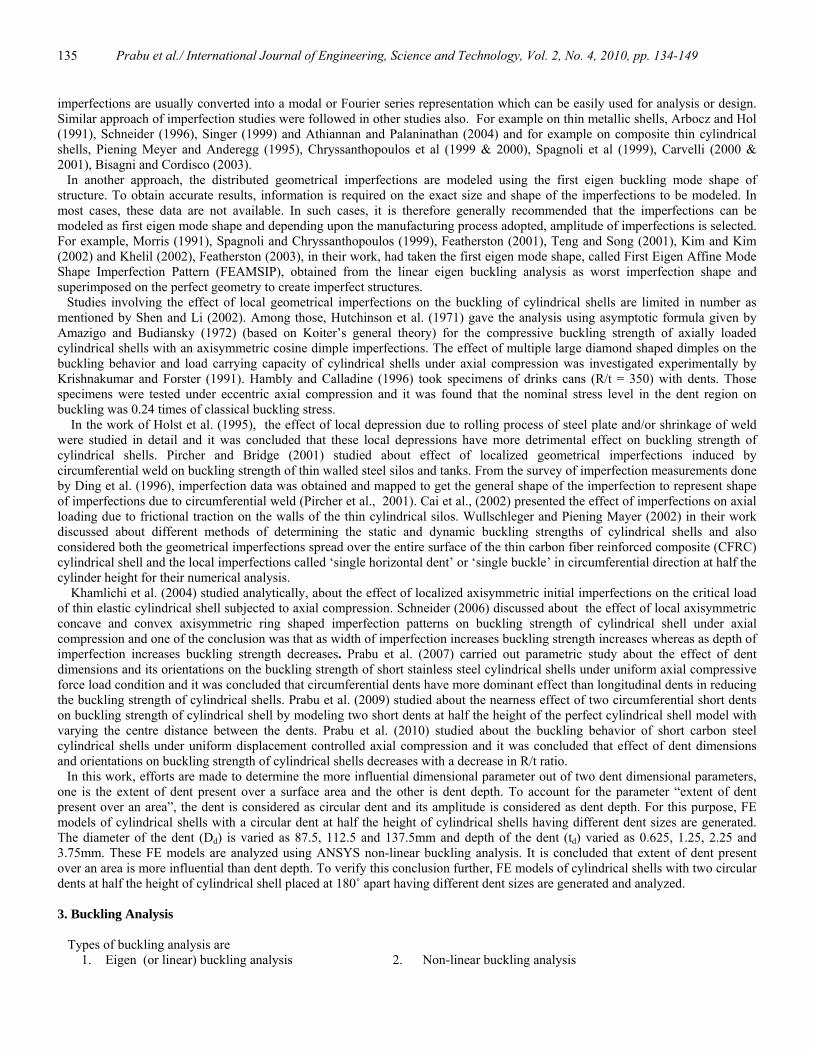
of Jamal et al. (2003). For a mesh size of 4 mm x 4 mm, distributed geometrical imperfections given in the form of equation 32 of Ref. Jamal et al. (2003) are added on the perfect cylindrical shell model. For imperfection amplitude of 0.1 times thickness (t), elastic buckling strength obtained from nonlinear FE analysis is 45.02 N/mm as against 44.59 N/mm obtained in the Ref. using ABACUS. Stress contour with fictitious deformation obtained at limit load condition from the validation work carried out is shown in Figure. 3. By the above verifications, FE model generated is validated with other element (SHELL181) as well as with other published results. This comparison of results clearly indicates that the present non linear analysis using SHELL93 element could adequately simulate the response.
Prabu et al./ International Journal of Engineering, Science and Technology, Vol. 2, No. 4, 2010, pp. 134-149
138
Figure 3. Stress contour with fictitious deformation obtained at limit load condition
4.3. Thin Cylindrical Shell Model:
The thin cylindrical model taken for study is: Radius (R) = 350mm, Length (L) = 340 and 700mm, Thickness (t) = 0.9, 1.25 and 2mm
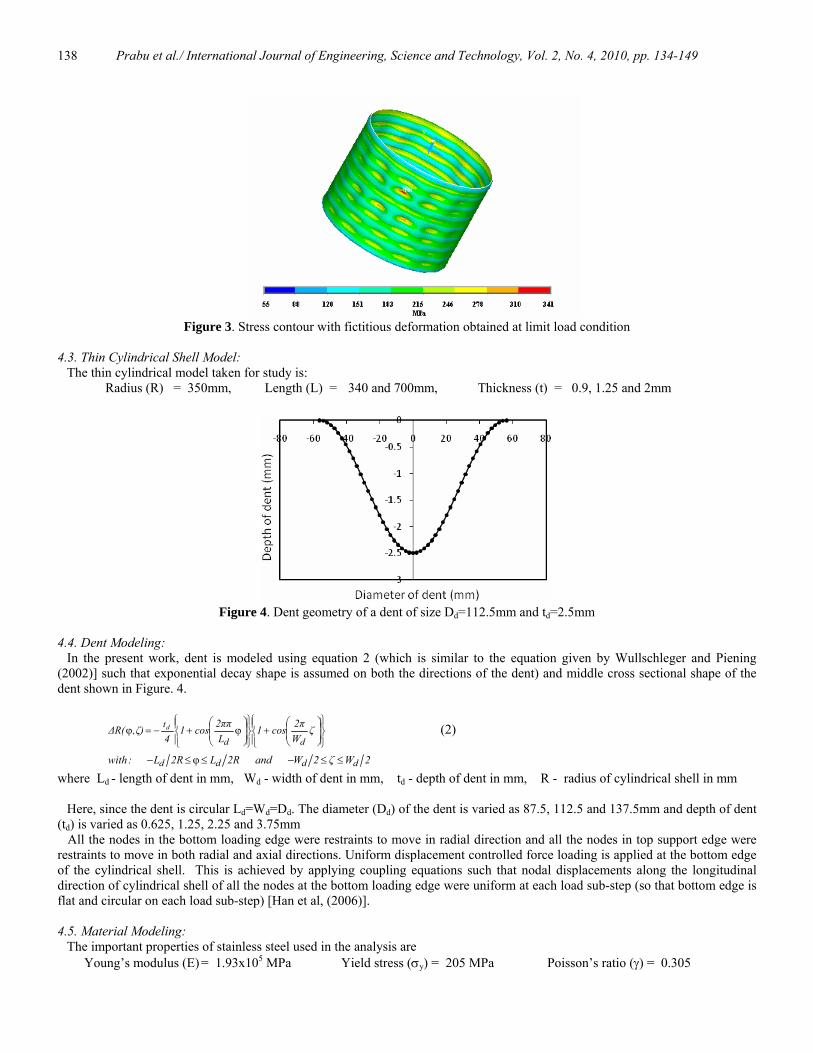
Figure 4. Dent geometry of a dent of size Dd=112.5mm and td=2.5mm
4.4. Dent Modeling:
In the present work, dent is modeled using equation 2 (which is similar to the equation given by Wullschleger and Piening (2002)] such that exponential decay shape is assumed on both the directions of the dent) and middle cross sectional shape of the dent shown in Figure. 4.
⎪⎭
⎪⎬⎫
⎪⎩
⎪⎨⎧
⎟⎟⎠
⎞⎜⎜⎝
⎛+
⎪⎭
⎪⎬⎫
⎪⎩
⎪⎨⎧
⎟⎟⎠
⎞⎜⎜⎝
⎛ϕ+−=ϕ ζ
W2πcos1
L2ππcos1
4ζ),ΔR(
dd
td (2)
2Wζ2Wand2RL2RL:with dddd ≤≤−≤ϕ≤− where Ld - length of dent in mm, Wd - width of dent in mm, td - depth of dent in mm, R - radius of cylindrical shell in mm Here, since the dent is circular Ld=Wd=Dd. The diameter (Dd) of the dent is varied as 87.5, 112.5 and 137.5mm and depth of dent (td) is varied as 0.625, 1.25, 2.25 and 3.75mm All the nodes in the bottom loading edge were restraints to move in radial direction and all the nodes in top support edge were restraints to move in both radial and axial directions. Uniform displacement controlled force loading is applied at the bottom edge of the cylindrical shell. This is achieved by applying coupling equations such that nodal displacements along the longitudinal direction of cylindrical shell of all the nodes at the bottom loading edge were uniform at each load sub-step (so that bottom edge is flat and circular on each load sub-step) [Han et al, (2006)]. 4.5. Material Modeling:
The important properties of stainless steel used in the analysis are Young’s modulus (E) = 1.93x10⁵ MPa Yield stress (σy) = 205 MPa Poisson’s ratio (γ) = 0.305
Prabu et al./ International Journal of Engineering, Science and Technology, Vol. 2, No. 4, 2010, pp. 134-149
139
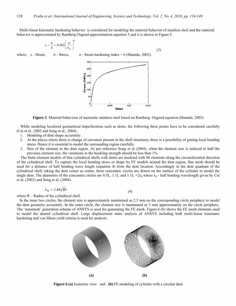
Multi-linear kinematic hardening behavior is considered for modeling the material behavior of stainless steel and the material behavior is approximated by Ramberg Osgood approximation equation 3 and it is shown in Figure 5.
002.0E
n
y ⎟⎟⎠
⎞⎜⎜⎝
⎛
σσ
+σ
=ε (3)
where, ε - Strain, σ - Stress, n - Strain hardening index = 6 (Hautala, 2003).
Figure 5. Material behaviour of austenitic stainless steel based on Ramberg- Osgood equation (Hautala, 2003)
While modeling localized geometrical imperfections such as dents, the following three points have to be considered carefully (Cai et al., 2002 and Song et al., 2004).
1. Modeling of dent shape accurately 2. At the places where there is change of curvature present in the shell structures, there is a possibility of getting local bending
stress. Hence it is essential to model the surrounding region carefully. 3. Size of the element in the dent region. As per reference Song et al (2004), when the element size is reduced to half the
previous element size, the variations in the buckling strength should be less than 1%. The finite element models of thin cylindrical shells with dents are modeled with 80 elements along the circumferential direction of the cylindrical shell. To capture the local bending stress or shape by FE models around the dent region, fine mesh should be used for a distance of half bending wave length (equation 4) from the dent location. Accordingly in the dent quadrant of the cylindrical shell, taking the dent center as center, three concentric circles are drawn on the surface of the cylinder to model the single dent. The diameters of the concentric circles are 0.5L, 1.1L and 1.1L +2λb where λb - half bending wavelength given by Cai et al. (2002) and Song et al. (2004).
Rt44.2b =λ (4) where R – Radius of the cylindrical shell. In the inner two circles, the element size is approximately maintained as 2.5 mm on the corresponding circle periphery to model the dent geometry accurately. In the outer circle, the element size is maintained as 3 mm approximately on the circle periphery. The ‘automesh’ generation scheme of ANSYS is used for generating the FE mesh. Figure.6 (b) shows the FE mesh elements used to model the dented cylindrical shell. Large displacement static analysis of ANSYS including both multi-linear kinematic hardening and von Mises yield criteria is used for analysis.
(a) (b)
Figure 6 (a) Isometric view and (b) FE modeling of cylinder with a circular dent

Prabu et al./ International Journal of Engineering, Science and Technology, Vol. 2, No. 4, 2010, pp. 134-149
140
5. Results and Discussion 5.1 Buckling behavior of thin cylindrical shells with a circular dent of different sizes 5.1.1. Progressive load – Stress conditions
Figure 7 shows the von Mises stress contours of thin cylindrical shells with a circular dent (L=340mm, R=350mm, t=1.25mm, Dd=87.5mm and td=3.75mm) at various load sub-step values (ratio of the actual applied load to the buckling strength of the perfect cylindrical shell) subjected to uniform axial compression
Figure 7(a) shows the stress contours at load sub-step value of 0.28206. The stresses are concentrated at the dent tips. This is because of the fact that dent tips offer resistance to deformation thereby they support the load above the dent effective region. The major part of load applied above the dent effective region reaches the dent tips via trough surfaces formation. On the bridge surfaces, the stress values are lower, because the ridge-trough surfaces formation allows only lesser load via bridge surfaces and also the resistance offered by longitudinal edges of the dent is lesser by allowing local deformations along the longitudinal edges of dent.
As the load applied increases to load sub-step value of 0.31250, the stresses build up along the trough surface and dent tip reaches the initial plastic condition as shown in Figure 7(b). On further loading, at load sub-step value of 0.33912, the stress build up along the trough surfaces on the previous load sub-step value tend to spread to the entire surface and the plastic zone in the dent tip region grows inward along the dent geometry as shown in Figure 7(c). At load sub-step value of 0.35118, the cylindrical shell reaches the limit load condition as shown in Figure 7(d) and it can be seen that most of the dent geometry reaches the plastic condition.
(a) 0.28206 (b) 0.31250
(c) 0.33912 (d) 0.35118
Figure 7. Isometric views of von Mises stress contours of thin cylindrical shells with a circular dent (L=340mm, R=350mm, t=1.25mm, Dd=87.5mm and td=3.75mm) at different load sub-step values
5.1.2. Stress contours at limit load condition
Figure 8 shows the von Mises stress contours of thin cylindrical shells (L=340mm, R=350mm and t=1.25mm) at limit load condition with a circular dent of varying diameters (Dd =87.5, 112.5 and 137.5mm) keeping the depth of the dent td =3.75mm and it can be seen that as expected the stress concentration is maximum at dent tips and in most parts of the dent geometry.

Prabu et al./ International Journal of Engineering, Science and Technology, Vol. 2, No. 4, 2010, pp. 134-149
141
(a) (b) (c)
Figure 8. Isometric views of von Mises stress contours of thin cylindrical shells(L=340mm, R=350mm and t=1.25mm) at limit
load condition with a circular dent keeping td =3.75mm with varied diameters of dent (a) 87.5mm, (b) 112.5mm and (c) 137.5mm
In general, when the axial compressive load is applied on thin cylindrical shells, the dent deforms radially inward further, and also two ridges are formed near the dent tips along with two inclined trough surfaces extending from each ridge one above and one below the dent tips as shown in Figure 9 (a) (The line diagram of the same is shown in Figure 9 (b) to illustrate the terminologies used to represent the buckling behavior). Two bridge surfaces one of which bridges the trough surfaces above the dent and the other bridges the trough surfaces below the dent; also bend radially inward along the longitudinal edges of the dent as shown in Figure 9. Similar ridge-trough surfaces formation was noticed by Wullschleger and Piening Mayer (2002) for a horizontal dent on composite cylindrical shell subjected to axial compression. It is well known that the order of membrane strain energy stored in thin shell structures will be more than the order of bending energy stored. Any deviation from the perfect geometrical shape of the structure will cause storing of bending energy instead of membrane energy and thereby cause failure of thin cylindrical shell much earlier. This formation of local elastic deformation (ridge-trough surfaces formation) around the dent increases the strength of the cylindrical shell around the dent region. The extent of area over which the local deformation effect realized is known as Dent Effective Region (DER). As the load applied increases further, the amplitude of deformations of ridge-trough formation gets increased.
(a)
(b)
Figure 9 (a) Top view of ridge-trough surfaces formation in a circular dent (b) Line diagram to represent the terminologies used to explain the buckling behavior

Prabu et al./ International Journal of Engineering, Science and Technology, Vol. 2, No. 4, 2010, pp. 134-149
142
(a) (b) (c)
Figure 10 (a) Isometric view (b) Front view of displacement contours of thin cylindrical shells with a circular dent (L=340mm, R=350mm, t=1.25mm, Dd=87.5mm and td=3.75mm) at limit load condition and (c) Close-up view of lobe formations
Figure 10(a) shows the isometric view of displacement contours at limit load condition and it can be seen that as expected the
deformation is maximum at dent geometry and the displacement below the dent gradually becomes zero towards supporting edge. Due to the presence of dent, the displacement contours in and around the DER is getting distorted. Figure 10(b) shows lobe formations of ridges and dent geometry in front view at limit load condition
Figure 11 shows stiffness curve of load sub-step value vs. edge displacement of a nodal point at the loading edge taken from the cylindrical shell of size D=700 mm, L=340 mm, t=1.25 mm with a circular dent of size Dd=137.5mm and td=3.75mm (load sub-step value means ratio of actually applied load at that time step of non-linear buckling analysis to the first eigen buckling strength of the perfect cylindrical shell). From the Figure, it can be concluded that stiffness of the cylindrical shell decreases as the load applied increases and at limit load condition, the stiffness becomes zero. On further loading the stiffness of cylindrical shell decreases resulting catastrophic failure.
In all the cases, it can be found that the load on the cylindrical shell is shared by DER and perfect cylindrical portion other than DER. The load above the DER is supported by local deformation formed in and around the dent tips. The major portion of the load above the DER is transferred to the dent tips via trough surfaces, only less amount of load is transferred to dent geometry through bridge surfaces. Because of this, dent tip regions subjected to high stress condition and the bridge surfaces subjected to low stress condition. Further, only limited portion of DER is involved in load carrying action and hence the load shared by the DER is less than that of equivalent size of perfect cylindrical shell portion.
Figure 11. Load sub-step value vs. Edge displacement
Limit load condition
Prabu et al./ International Journal of Engineering, Science and Technology, Vol. 2, No. 4, 2010, pp. 134-149
143
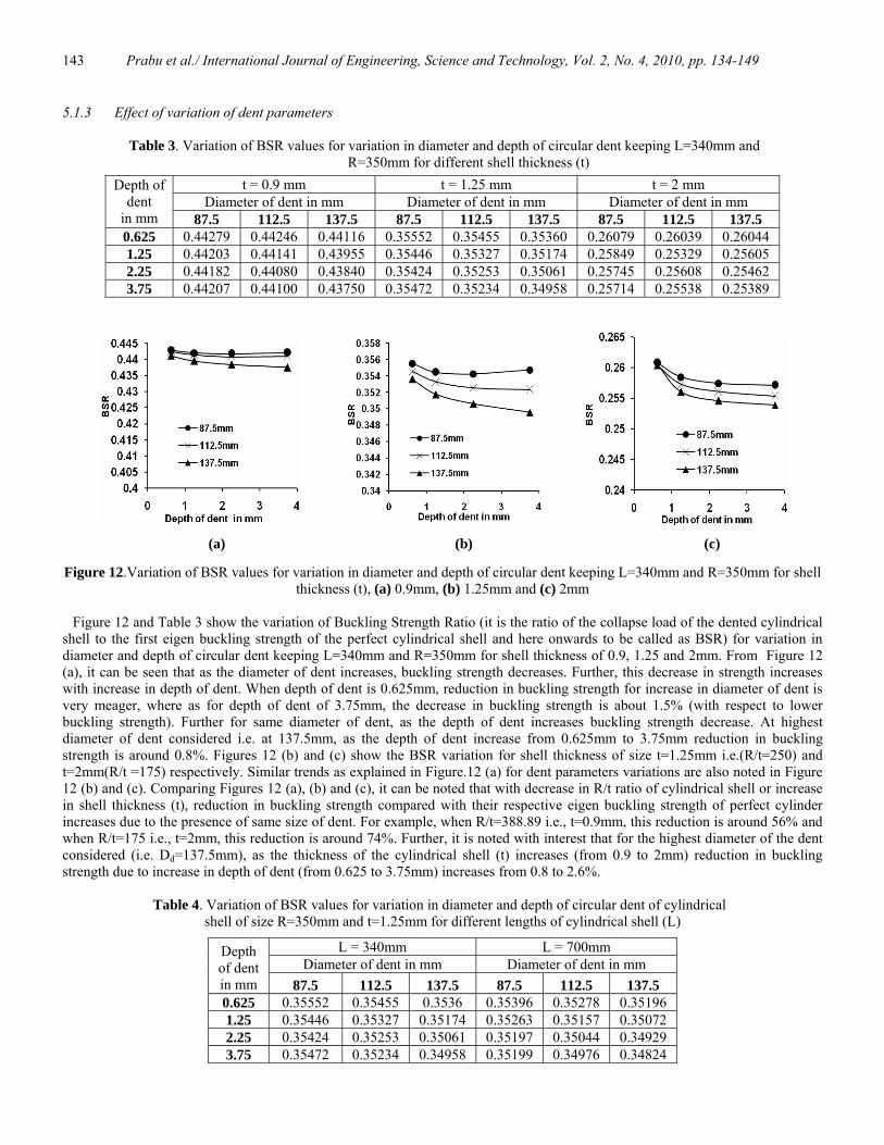
5.1.3 Effect of variation of dent parameters
Table 3. Variation of BSR values for variation in diameter and depth of circular dent keeping L=340mm and R=350mm for different shell thickness (t)
t = 0.9 mm t = 1.25 mm t = 2 mm Diameter of dent in mm Diameter of dent in mm Diameter of dent in mm
Depth of dent
in mm 87.5 112.5 137.5 87.5 112.5 137.5 87.5 112.5 137.5 0.625 0.44279 0.44246 0.44116 0.35552 0.35455 0.35360 0.26079 0.26039 0.26044 1.25 0.44203 0.44141 0.43955 0.35446 0.35327 0.35174 0.25849 0.25329 0.25605 2.25 0.44182 0.44080 0.43840 0.35424 0.35253 0.35061 0.25745 0.25608 0.25462 3.75 0.44207 0.44100 0.43750 0.35472 0.35234 0.34958 0.25714 0.25538 0.25389
Figure 12.Variation of BSR values for variation in diameter and depth of circular dent keeping L=340mm and R=350mm for shell
thickness (t), (a) 0.9mm, (b) 1.25mm and (c) 2mm
Figure 12 and Table 3 show the variation of Buckling Strength Ratio (it is the ratio of the collapse load of the dented cylindrical shell to the first eigen buckling strength of the perfect cylindrical shell and here onwards to be called as BSR) for variation in diameter and depth of circular dent keeping L=340mm and R=350mm for shell thickness of 0.9, 1.25 and 2mm. From Figure 12 (a), it can be seen that as the diameter of dent increases, buckling strength decreases. Further, this decrease in strength increases with increase in depth of dent. When depth of dent is 0.625mm, reduction in buckling strength for increase in diameter of dent is very meager, where as for depth of dent of 3.75mm, the decrease in buckling strength is about 1.5% (with respect to lower buckling strength). Further for same diameter of dent, as the depth of dent increases buckling strength decrease. At highest diameter of dent considered i.e. at 137.5mm, as the depth of dent increase from 0.625mm to 3.75mm reduction in buckling strength is around 0.8%. Figures 12 (b) and (c) show the BSR variation for shell thickness of size t=1.25mm i.e.(R/t=250) and t=2mm(R/t =175) respectively. Similar trends as explained in Figure.12 (a) for dent parameters variations are also noted in Figure 12 (b) and (c). Comparing Figures 12 (a), (b) and (c), it can be noted that with decrease in R/t ratio of cylindrical shell or increase in shell thickness (t), reduction in buckling strength compared with their respective eigen buckling strength of perfect cylinder increases due to the presence of same size of dent. For example, when R/t=388.89 i.e., t=0.9mm, this reduction is around 56% and when R/t=175 i.e., t=2mm, this reduction is around 74%. Further, it is noted with interest that for the highest diameter of the dent considered (i.e. Dd=137.5mm), as the thickness of the cylindrical shell (t) increases (from 0.9 to 2mm) reduction in buckling strength due to increase in depth of dent (from 0.625 to 3.75mm) increases from 0.8 to 2.6%.
Table 4. Variation of BSR values for variation in diameter and depth of circular dent of cylindrical
shell of size R=350mm and t=1.25mm for different lengths of cylindrical shell (L)
L = 340mm L = 700mm Diameter of dent in mm Diameter of dent in mm
Depth of dent in mm 87.5 112.5 137.5 87.5 112.5 137.5 0.625 0.35552 0.35455 0.3536 0.35396 0.35278 0.35196 1.25 0.35446 0.35327 0.35174 0.35263 0.35157 0.35072 2.25 0.35424 0.35253 0.35061 0.35197 0.35044 0.34929 3.75 0.35472 0.35234 0.34958 0.35199 0.34976 0.34824
(a) (b) (c)
Prabu et al./ International Journal of Engineering, Science and Technology, Vol. 2, No. 4, 2010, pp. 134-149
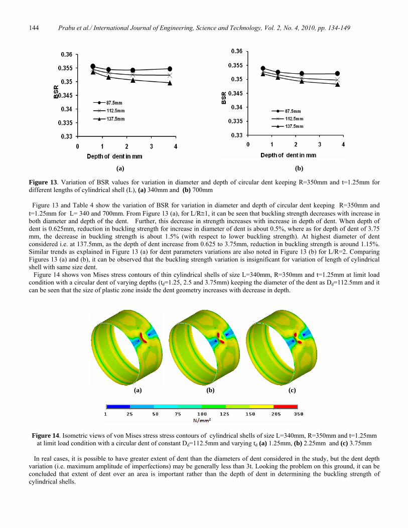
144
Figure 13. Variation of BSR values for variation in diameter and depth of circular dent keeping R=350mm and t=1.25mm for different lengths of cylindrical shell (L), (a) 340mm and (b) 700mm Figure 13 and Table 4 show the variation of BSR for variation in diameter and depth of circular dent keeping R=350mm and t=1.25mm for L= 340 and 700mm. From Figure 13 (a), for L/R≅1, it can be seen that buckling strength decreases with increase in both diameter and depth of the dent. Further, this decrease in strength increases with increase in depth of dent. When depth of dent is 0.625mm, reduction in buckling strength for increase in diameter of dent is about 0.5%, where as for depth of dent of 3.75 mm, the decrease in buckling strength is about 1.5% (with respect to lower buckling strength). At highest diameter of dent considered i.e. at 137.5mm, as the depth of dent increase from 0.625 to 3.75mm, reduction in buckling strength is around 1.15%. Similar trends as explained in Figure 13 (a) for dent parameters variations are also noted in Figure 13 (b) for L/R=2. Comparing Figures 13 (a) and (b), it can be observed that the buckling strength variation is insignificant for variation of length of cylindrical shell with same size dent.
Figure 14 shows von Mises stress contours of thin cylindrical shells of size L=340mm, R=350mm and t=1.25mm at limit load condition with a circular dent of varying depths (td=1.25, 2.5 and 3.75mm) keeping the diameter of the dent as Dd=112.5mm and it can be seen that the size of plastic zone inside the dent geometry increases with decrease in depth.
(a) (b) (c)
Figure 14. Isometric views of von Mises stress stress contours of cylindrical shells of size L=340mm, R=350mm and t=1.25mm at limit load condition with a circular dent of constant Dd=112.5mm and varying td (a) 1.25mm, (b) 2.25mm and (c) 3.75mm
In real cases, it is possible to have greater extent of dent than the diameters of dent considered in the study, but the dent depth variation (i.e. maximum amplitude of imperfections) may be generally less than 3t. Looking the problem on this ground, it can be concluded that extent of dent over an area is important rather than the depth of dent in determining the buckling strength of cylindrical shells.
(a) (b)

Prabu et al./ International Journal of Engineering, Science and Technology, Vol. 2, No. 4, 2010, pp. 134-149
145
5.2 Buckling behavior of thin cylindrical shells with two circular dents of different sizes kept 180˚ apart
From the previous study involving the cylindrical shell with single dent, it was found that extent of dent over an area is more important to determine the buckling strength of thin cylindrical shells taken for study. To verify this further, three FE thin cylindrical shell models (L=340mm, R=350mm and t=1.25mm) with two circular dents at 180˚ apart are generated and analyzed. Dent parameters variations taken for study are shown in Table 5.
Table 5. Dent parameters variations
Dent 1 Dent 2 Model Number Diameter in mm Depth in mm Diameter in mm Depth in mm I 112.5 3.75 87.5 3.75 II 112.5 3.75 112.5 3.75 III 112.5 3.75 137.5 3.75
Two dents are modeled as explained earlier in one dent case and sample of model I is shown in Figure 15.
(a) (b)
Figure 15 (a) Isometric view and (b) FE modeling of cylinder with two circular dents at 180˚ apart
5.2.1Progressive load – Stress conditions.
The Figure 16 shows the von Mises contours of thin cylindrical shells with two circular dents at 180˚apart at various load sub-step values for model-I. The Figure16 (a) shows the stress contours at load sub-step value of 0.28308 and it can be seen that the major part of load applied above the DER reaches the dent tips via trough surfaces formation. At load sub-step value of 0.31276, both the dents 1 and 2 reach the plastic condition almost simultaneously as shown in Figure 16 (b). The Figure 16 (c) shows the stress contours at limit load condition and it can be seen that complete dent geometry tends to reach the plastic condition. Similar stress condition of reaching the plastic condition almost simultaneously by both dents is also noted in model-III. But in model-II, it is noted that two dents reach the plastic condition simultaneously.
(a) 0.28308
Prabu et al./ International Journal of Engineering, Science and Technology, Vol. 2, No. 4, 2010, pp. 134-149
146
(b) 0.31276
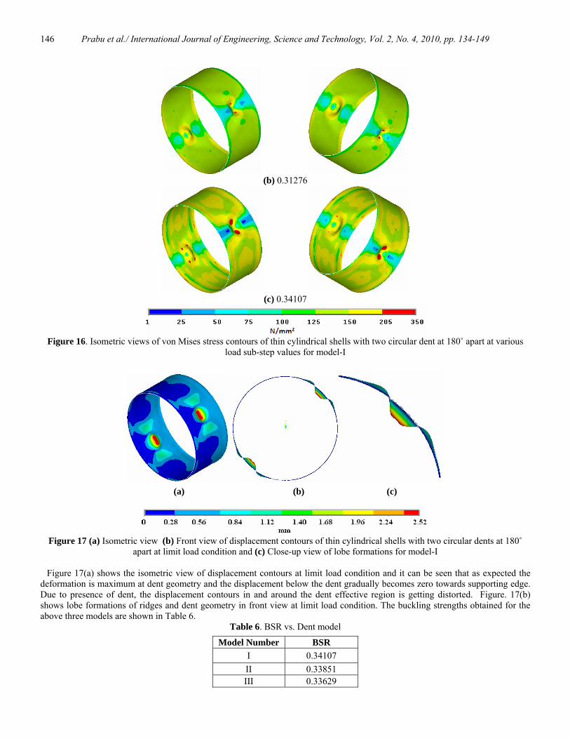
(c) 0.34107
Figure 16. Isometric views of von Mises stress contours of thin cylindrical shells with two circular dent at 180˚ apart at various
load sub-step values for model-I
(a) (b) (c)
Figure 17 (a) Isometric view (b) Front view of displacement contours of thin cylindrical shells with two circular dents at 180˚
apart at limit load condition and (c) Close-up view of lobe formations for model-I
Figure 17(a) shows the isometric view of displacement contours at limit load condition and it can be seen that as expected the deformation is maximum at dent geometry and the displacement below the dent gradually becomes zero towards supporting edge. Due to presence of dent, the displacement contours in and around the dent effective region is getting distorted. Figure. 17(b) shows lobe formations of ridges and dent geometry in front view at limit load condition. The buckling strengths obtained for the above three models are shown in Table 6.
Table 6. BSR vs. Dent model
Model Number BSR I 0.34107 II 0.33851 III 0.33629

Prabu et al./ International Journal of Engineering, Science and Technology, Vol. 2, No. 4, 2010, pp. 134-149
147
From model-I to II, the reduction in buckling strength is 0.76% with respect to lower BSR value. Similarly, from model-II to III, the reduction in buckling strength is 0.66%. In this case also it can be noted that as the size of the dent increases, buckling strength decreases. As the number of dent(s) increases from one to two dent(s), the reduction in buckling strength is 2.96% with respect to lowest BSR value and it can be seen that the deviation between the single and multi-dent case is very small.
Dent geometry is a weak region compared to perfect cylindrical portion. Because of the local deformation around the dent (i.e., in the DER), its strength improves almost equal to that of perfect cylindrical portion. Because of this fact, the variation in the buckling strength of cylindrical shell between single and two dents cases is very less. 6. Conclusions
From the analysis of thin stainless steel dented cylindrical shells taken for study, the following conclusions are derived on the basis of the parameters considered in the study.
(i) The deformation is maximum at dent geometry and the displacement below the dent gradually becomes zero towards supporting edge.
(ii) Stiffness of the cylindrical shell decreases as the load applied increases and at limit load condition, the stiffness becomes zero and on further loading due to negative slope of the stiffness curve, cylindrical shell collapses catastrophically.
(iii) The buckling or collapse strength of dented cylindrical shell decreases with increase in both diameter and depth of the dent. Further, this decrease in strength increases with increase in depth of dent.
(iv) For decrease in R/t ratio of cylindrical shell or increase in shell thickness (t), reduction in buckling strength compared with their respective eigen buckling strength of perfect cylinder increases due to the presence of same size of dent.
(v) For the highest diameter of the dent considered, as the thickness of the cylindrical shell (t) increases reduction in buckling strength due to increase in depth of dent also increases.
(vi) Buckling strength variation is insignificant for variation of length of cylindrical shell with same size dent. (vii) The size of the plastic zone inside the dent geometry increases with decrease in dent depth. (viii) The load above the DER is supported by local deformation formed in and around the dent tips. The major portion
of the load above the DER is transferred to the dent tips via trough surfaces. Because of this, dent tip regions subjected to high stress condition. Further, only limited portion of DER is involved in load carrying action and hence the load shared by the DER is less than that of equivalent size of perfect cylindrical shell portion.
(ix) Because of the load deformation in and around the dent geometry, the load bearing capacity in the dent effective region increases and almost equal to that of perfect cylindrical portion. Hence the buckling strength difference between the single dent case and multi-dent case is less.
In real cases, it is possible to have greater extent of dent than the diameters of dent considered in the study, but the dent depth variation (i.e. maximum amplitude of imperfections) may be generally less than 3t. Looking the problem on this ground, it can be concluded that extent of dent over an area is important rather than the depth of dent in determining the buckling strength of cylindrical shells. Nomenclature
D Diameter of the cylindrical shell L Length of the cylindrical shell R Radius of the cylindrical shell t Thickness of the cylindrical shell m Number of longitudinal lobes n Number of circumferential lobes Ld Length of the dent Wd Width of the dent Dd Diameter of the dent td Depth of dentδ Radial inward displacement for dent geometry θ Angle of inclination of dent E Young’s Modulus ET Tangential Modulus σY Yield Stress γ Poisson’s ratio ρ Density λb Half bending wavelength y1 Distance from the center of the dent to point on the dent along longitudinal axis y2 Distance from the center of the dent to point on the dent along transverse axis
Prabu et al./ International Journal of Engineering, Science and Technology, Vol. 2, No. 4, 2010, pp. 134-149
148
References Amazigo J.C. and Budiansky B., 1972. Asymptotic formulas for the buckling stress of axially compressed cylinders with localized
or random axisymmetric imperfections. Journal of Applied Mechanics ASME, Vol. 39, pp.179-184. ANSYS 12 Reference Manual. Arbocz J. and Babcock Charles D.Jr., 1969. The effect of general imperfection on the buckling of cylindrical shells. Journal of
Applied Mechanics-Transactions of ASME, Vol. 36, pp. 28-38. Arbocz J. and Hol J.M.A.M., 1991. Collapse of axially compressed cylindrical shells with random imperfections. AIAA J., Vol. 29
(12), pp. 2247-2256. Athiannan K. and Palaninathan R., 2004. Experimental investigations on buckling of thin cylindrical shells under axial
compression and transverse shear. Sadhana, Vol. 29, No. 1, pp. 93-115. Bisagni C. and Cordisco P., 2003. An experimental investigation into the buckling and pos John.W.t-buckling of CFRP shells
under combined axial and torsion loading, Composite Structures, Vol.60, No. 4, pp. 391-402. Bushnell., 1985. Computerized buckling analysis of shells, Martinus Niijhoff Publishers. Cai M., Mark J., Holst F.G. and Rotter J.M., 2002. Buckling strength of thin cylindrical shells under localized axial compression.
EM2002, 15th ASCE Engineering Mechanics Conference, Columbia University, NewYork. Carvelli V., Panzeri N. and Poggi C., 2000. Numerical and experimental buckling analysis of GFRP shells for under-water
vehicles, Computational Methods for Shell and Spatial Structures, IASS-IACM, Athens, Greece 2000. Carvelli V., Panzeri N. and Poggi C., 2001. Buckling strength of GFRP under-water vehicles, Composites Part B: Engineering,
Vol. 32, No. 2, pp. 89-101. Chryssanthopoulos M.K., Elghazouli A.Y. and Esong I.E., 1999. Compression tests on antisymmetric two-ply GFRP cylinders,
Composites Part B, Vol. 30, pp. 335-350. Chryssanthopoulos M.K., Elghazouli A.Y and Esong I.E., 2000. Validation of FE models for buckling analysis of woven GFRP
shells, Composite Structures, Vol. 49, No. 4, pp. 355-367. Ding X.L., Coleman R. and Rotter J.M., 1996. Technique for precise measurement of large scale silos and tanks. Journal of
Surveying Engineering, Vol. 122, No. 1, pp. 15-25. Featherston C.A., 2001. Imperfection sensitivity of the flat plates under combined compression and shear. International Journal of
Non-Linear Mechanics, Vol. 36, pp. 249-259. Featherston C.A., 2003. Imperfection sensitivity of curved panels under combined compression and shear. International Journal
of Non-Linear Mechanics, Vol.38, pp. 225-238. Forde W.R.B. and Stiemer S.F., 1987. Improved arc length orthogonality methods for Nonlinear Finite Element Analysis.
Computers & Structures, Vol. 27, No. 5, pp. 625-630. Hambly E.T. and Calladine C.R., 1996. Buckling experiments on damaged cylindrical shells. International Journal of Solids and
Structures, Vol. 33, pp. 35-48. Han H., Cheng J., Taheri F. and Pegg N., 2006. Numerical and experimental investigations of the response of aluminum cylinders
with a cutout subject to axial compression. Thin-Walled Structures, Vol. 44, pp. 254-270. Hautala KT. (2003) Buckling reduction factors for stainless steel structures, http://www.worldstainless.org/NR/rdonlyres/7DE712B1-41EF-414B-AA2F-CC13B20860DE7/2440/Bucklingreductionfactors
forstainlesssteelstru.pdf Holst F.G., Rotter J.M. and Calladine C.R., 1995. Imperfections in cylindrical shells resulting from fabrication misfits. Journal
of Engineering Mechanics, Vol. 125, No. 4, pp. 410-418. Hutchinson J.W., Tennyson R.C. and Muggeridge D.B., 1971. Effect of local axisymmetrical imperfection on the buckling
behavior of a circular cylindrical shell under axial compression. AIAA Journal, Vol. 9, pp. 48-52. Jamal M., Lahlou L., Midani M., Zahrouni H., Limam A., Damil N. and Potier-Ferry M., 2003. A semi-analytical buckling
analysis of imperfect cylindrical shells under axial compression. International Journal of Solids and Structures, Vol. 40, pp. 1311-1327.
Jullien J.F. and Limam A., 1998. Effect of openings on buckling of cylindrical shells subjected to axial compression. Thin-Walled Structures, Vol. 31, pp. 187-202.
Khamlichi M., Bezzazi A. and Limam A., 2004. Buckling of elastic cylindrical shells considering the effect of localized axisymmetric imperfections. Thin-Walled Structures, Vol. 42, pp. 1035-1047.
Khelil., 2002. Buckling of steel shells subjected to non-uniform axial and pressure loadings. Thin-Walled Structures, Vol.40, pp. 955-970.
Kim Seung-Eock and Kim Chang-Sung., 2002. Buckling strength of the cylindrical shell and tank subjected to axially compressive loads. Thin-Walled Structures, Vol.40, pp. 329-353.
Krishnakumar S. and Forster C.G., 1991. Axial load compatibility of cylindrical shells with local geometric defects. Experimental Mechanics, Vol. 31, pp. 104-110.
Morris N.F., 1991. Effect of Imperfections on Lattice Shells, Structural Engineering Division, Vol. 117, No. 6, pp. 1796-1814.

Prabu et al./ International Journal of Engineering, Science and Technology, Vol. 2, No. 4, 2010, pp. 134-149
149
Piening Meyer H.R. and Anderegg R., 1995. Buckling and postbuckling investigations of imperfect curved stringer-stiffened composite shells. Part A: Experimental investigation and effective width evaluation, Thin-Walled Structures. Vol. 23, No. 1-4, pp. 323-338.
Pircher M., Berry P.A., Ding X.L. and Bridge R.Q., 2001. The shape of circumferential weld induced imperfections in thin walled steel silos and tanks. Thin-Walled Structures, Vol. 39, No. 12, pp. 999-1014.
Pircher M. and Bridge R.Q., 2001. The influence of circumferential weld-induced imperfections on the buckling of silos and tanks. Journal of Constructional Steel Research, Vol. 57, pp. 569-580.
Prabu B., Bujjibabu N., Saravanan S. and Venkatraman A., 2007. Effect of a dent of different sizes and angles of inclination on buckling strength of a short stainless steel cylindrical shell subjected to uniform axial compression. Advances in Structural Engineering, Vol. 10, No. 5, pp. 581-591.
Prabu B., Raviprakash A.V. and Venkatraman A., 2009. Neighborhood effect of two short dents on buckling behavior of thin short stainless steel cylindrical shells. International Journal of Computer Aided Engineering & Technology, (Accepted and to be published).
Prabu B., Raviprakash A.V. and Venkatraman A., 2010. Parametric study on buckling behavior of dented short carbon steel cylindrical shells subjected to uniform axial compression. Thin-Walled Structures, (Published online).
Schneider M.H. Jr., 1996. Investigation of stability of imperfect cylinders using structural models. Engineering Structures, Vol. 18 (10), pp. 792-800.
Singer J., 1999. On the importance of shell buckling experiments. Journal of Applied Mechanics Review, Vol.52, No. 6, pp. 17-25. Schneider W., 2006. Stimulating equivalent geometrical imperfections for the numerical buckling strength verification of axially
compressed cylindrical steel shells. Computational Mechanics, Vol. 37, No. 6, pp. 530-536. Shen H.S. and Li Q.S., 2002. Thermo mechanical post buckling of shear deformable laminated cylindrical shells with local
geometric imperfections. International Journal of Solids and Structures, Vol. 39, pp. 4525-4542. Song C.Y., Teng J.G. and Rotter J.M., 2004. Imperfection sensitivity of thin elastic cylindrical shells subjected to partial axial
compression. International Journal of Solids and Structures, Vol. 7155-7180. Spagnoli A. and Chryssanthopoulos M.K., 1999. Elastic buckling and post buckling behaviour of widely-stiffened conical shells
under axial compression, Engineering Structures, Vol. 21, pp. 845–855. Spagnoli A., Elghazouli A. Y. and Chryssanthopoulos M. K., 1999. Numerical simulation of glass-reinforced plastic cylinders
under axial compression, Marine Structures, Vol. 11, No. 9, pp. 347-371. Teng J.G. and Song C.Y., 2001. Numerical models for nonlinear analysis of elastic shells with eigen mode-affine imperfections.
International Journal of Solids and Structures, Vol.38, pp. 3263-3280. Timoshenko S.P. and Gere J.M., 1965. Theory of elastic stability. 2nd ed. McGraw-Hill. Wullschleger L. and Piening Meyer H.R., 2002. Buckling of geometrically imperfect cylindrical shells-definition of a buckling
load. International Journal of Non-Linear Mechanics, Vol. 645-657. Biographical notes Balakrishnan Prabu received the Master of Engineering Degree in Engineering Design from Anna University, Chennai, India in 1993 and PhD Degree in Thin Shell Buckling from Pondicherry (Central) University, Puducherry, India in 2007. At present, he is working as an Associate Professor in the Department of Mechanical Engineering, Pondicherry Engineering College, Puducherry, India. His main research interest is in buckling behavior of thin shell structures. Alwardoss Velayutham Raviprakash received the Master of Engineering Degree in Production Engineering from Annamalai University, Chidambaram, India in 1983 and currently pursuing PhD Degree in Buckling Behaviour of Thin Shell Structures at Pondicherry (Central) University, Puducherry, India. At present, he is working as an Associate Professor in the Department of Mechanical Engineering, Pondicherry Engineering College, Puducherry, India. Natarajan Rathinam received the Master of Engineering Degree in Engineering Design from Bharathiyar University, Coimbatore, India in 2003 and currently pursuing PhD Degree in Buckling Behaviour of Thin Shell Structures at Pondicherry (Central) University, Puducherry, India. At present, he is working as an Assistant Professor in the Department of Mechanical Engineering, Pondicherry Engineering College, Puducherry, India. Received January 2010 Accepted March 2010 Final acceptance in revised form May 2010