Proposal for a dynamic rollover protective system test
10
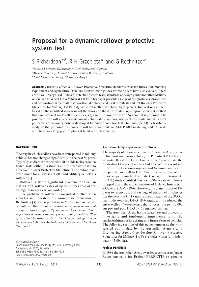
© Woodhead Publishing Ltd 0215 133 IJCrash 2003 Vol. 8 No. 2 pp. 133–141 Corresponding Author: Shane Richardson, DVExperts Pty Ltd, 229 Canterbury Road Canterbury, Vic 3126, Australia Tel +61 3 9880 7399 Fax +61 3 9880 7725 Email [email protected] BACKGROUND The way in which soldiers have been transported in military vehicles has not changed significantly in the past 80 years. Typically soldiers are expected to sit on side facing wooden bench seats without restraints and the vehicles have no effective Rollover Protective Structure. The predominant crash mode for all classes of off-road Military vehicles is rollover [1]. Rollover is also a significant problem for Civilian 4 × 4’s with rollover rates of up to 5 times that of the average passenger car, on roads [2]. The problem of rollover is magnified further when vehicles are operated in a non-urban environment. Rechnitzer [3] et al. reported in an Australian based study on rollover that; “rollover crashes are a common cause of occupant injury especially on non-urban roads. Their importance increases with injury severity: they constitute 19% of occupant fatalities in Australia. This percentage rises to 44% in rural Western Australia and 54% in rural Northern Territory.” Australian Army experience of rollover The majority of rollovers within the Australian Army occur in the most numerous vehicle, the Perentie 4 × 4 soft-top variants. Based on Land Engineering Agency data the Australian Defence Force has had 125 rollovers resulting in 12 deaths 45 serious injuries and 67 minor injuries in the period Jan 1988 to Feb 1996. This was a rate of 1.3 rollovers per month. The Safe Carriage of Troops [4] (SCOT) study identified that post 1996 the rate of rollovers dropped due to the implementation of Defence Instruction – General (DI-G) 19-6. However, the main impact of 19- 6 was to restrict use and carriage of personnel in vehicles like the Perentie 4 × 4 variants. Examination of the SCOT data indicates that DI-G 19-6 significantly reduced the km travelled. Nevertheless, the rollover rate per 10,000 km pre and post DI-G 19-6 remained similar. The Australian Army has instigated several projects to investigate and implement improvements to the crashworthiness of its existing and future fleets of vehicles. The following sections of this paper summarise the work carried out to date by the Australian Army (Land Engineering Agency) to develop Rollover Protective Structures for Military 4 × 4’s (vehicles with a fully laden mass < 5,000 kg). Project PERENTIE In 1986 the Australian Army awarded a contract to Jaguar Rover Australia for Project PERENTIE to procure Proposal for a dynamic rollover protective system test S Richardson* # , R H Grzebieta* and G Rechnitzer° *Monash University Department of Civil Engineering, Australia °Monash University Accident Research Centre (MUARC), Australia # Land Engineering Agency (Australian Army) Abstract: Currently effective Rollover Protective Structure standards exist for Buses, Earthmoving Equipment and Agricultural Tractors. Construction guides for racing cars have also evolved. There are no well-recognised Rollover Protective System tests, standards or design guides for either Military or Civilian (4 Wheel Drive Vehicles) 4 × 4’s. This paper presents a range of test protocols, procedures and demonstration methods that have been developed and used to evaluate and test Rollover Protective Structures for Military 4 × 4’s. A dynamic test method developed by Exponent, Inc. is also examined. Based on the identified weaknesses of the above and the desire to develop a reproducible test method that simulates real world rollover crashes, a dynamic Rollover Protective System test is proposed. The proposed Test will enable evaluation of active safety systems, occupant restraints and structural performance via injury criteria developed for Anthropometric Test Dummies (ATD). A feasibility study of the proposed test concept will be carried out via MADYMO modelling and 1 / 4 scale structure modelling prior to physical build of the test facility.
-
Upload
independent -
Category
Documents
-
view
3 -
download
0
Transcript of Proposal for a dynamic rollover protective system test
© Woodhead Publishing Ltd 0215 133 IJCrash 2003 Vol. 8 No. 2 pp. 133–141
Corresponding Author:Shane Richardson, DVExperts Pty Ltd, 229 Canterbury RoadCanterbury, Vic 3126, AustraliaTel +61 3 9880 7399 Fax +61 3 9880 7725Email [email protected]
BACKGROUND
The way in which soldiers have been transported in militaryvehicles has not changed significantly in the past 80 years.Typically soldiers are expected to sit on side facing woodenbench seats without restraints and the vehicles have noeffective Rollover Protective Structure. The predominantcrash mode for all classes of off-road Military vehicles isrollover [1].
Rollover is also a significant problem for Civilian4 × 4’s with rollover rates of up to 5 times that of theaverage passenger car, on roads [2].
The problem of rollover is magnified further whenvehicles are operated in a non-urban environment.Rechnitzer [3] et al. reported in an Australian based studyon rollover that; “rollover crashes are a common cause ofoccupant injury especially on non-urban roads. Theirimportance increases with injury severity: they constitute 19%of occupant fatalities in Australia. This percentage rises to44% in rural Western Australia and 54% in rural NorthernTerritory.”
Australian Army experience of rollover
The majority of rollovers within the Australian Army occurin the most numerous vehicle, the Perentie 4 × 4 soft-topvariants. Based on Land Engineering Agency data theAustralian Defence Force has had 125 rollovers resultingin 12 deaths 45 serious injuries and 67 minor injuries inthe period Jan 1988 to Feb 1996. This was a rate of 1.3rollovers per month. The Safe Carriage of Troops [4](SCOT) study identified that post 1996 the rate of rolloversdropped due to the implementation of Defence Instruction– General (DI-G) 19-6. However, the main impact of 19-6 was to restrict use and carriage of personnel in vehicleslike the Perentie 4 × 4 variants. Examination of the SCOTdata indicates that DI-G 19-6 significantly reduced thekm travelled. Nevertheless, the rollover rate per 10,000km pre and post DI-G 19-6 remained similar.
The Australian Army has instigated several projects toinvestigate and implement improvements to thecrashworthiness of its existing and future fleets of vehicles.The following sections of this paper summarise the workcarried out to date by the Australian Army (LandEngineering Agency) to develop Rollover ProtectiveStructures for Military 4 × 4’s (vehicles with a fully ladenmass < 5,000 kg).
Project PERENTIE
In 1986 the Australian Army awarded a contract to JaguarRover Australia for Project PERENTIE to procure
Proposal for a dynamic rollover protectivesystem test
S Richardson*#, R H Grzebieta* and G Rechnitzer°*Monash University Department of Civil Engineering, Australia°Monash University Accident Research Centre (MUARC), Australia#Land Engineering Agency (Australian Army)
Abstract: Currently effective Rollover Protective Structure standards exist for Buses, EarthmovingEquipment and Agricultural Tractors. Construction guides for racing cars have also evolved. Thereare no well-recognised Rollover Protective System tests, standards or design guides for either Militaryor Civilian (4 Wheel Drive Vehicles) 4 × 4’s. This paper presents a range of test protocols, proceduresand demonstration methods that have been developed and used to evaluate and test Rollover ProtectiveStructures for Military 4 × 4’s. A dynamic test method developed by Exponent, Inc. is also examined.Based on the identified weaknesses of the above and the desire to develop a reproducible test methodthat simulates real world rollover crashes, a dynamic Rollover Protective System test is proposed. Theproposed Test will enable evaluation of active safety systems, occupant restraints and structuralperformance via injury criteria developed for Anthropometric Test Dummies (ATD). A feasibilitystudy of the proposed test concept will be carried out via MADYMO modelling and 1/4 scalestructure modelling prior to physical build of the test facility.
S Richardson, R H Grzebieta and G Rechnitzer
IJCrash 2003 Vol. 8 No. 2 134 0215 © Woodhead Publishing Ltd
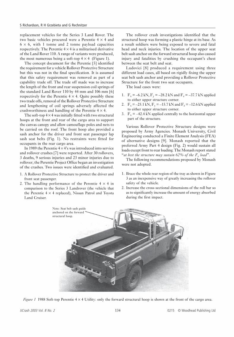
replacement vehicles for the Series 3 Land Rover. Thetwo basic vehicles procured were a Perentie 4 × 4 and6 × 6, with 1 tonne and 2 tonne payload capacitiesrespectively. The Perentie 4 × 4 is a militarised derivativeof the Land Rover 110. A range of variants were produced,the most numerous being a soft-top 4 × 4 (Figure 1).
The concept document for the Perentie [5] identifiedthe requirement for a vehicle Rollover Protective Structurebut this was not in the final specification. It is assumedthat this safety requirement was removed as part of acapability trade off. The trade off made was to increasethe length of the front and rear suspension coil springs ofthe standard Land Rover 110 by 44 mm and 106 mm [6]respectively for the Perentie 4 × 4. Quite possibly thesetwo trade offs, removal of the Rollover Protective Structureand lengthening of coil springs adversely affected thecrashworthiness and handling of the Perentie 4 × 4.
The soft-top 4 × 4 was initially fitted with two structuralhoops at the front and rear of the cargo area to supportthe canvas canopy and allow camouflage poles and nets tobe carried on the roof. The front hoop also provided asash anchor for the driver and front seat passenger lapsash seat belts (Fig. 1). No restraints were fitted foroccupants in the rear cargo area.
In 1989 the Perentie 4 × 4’s was introduced into serviceand rollover crashes [7] were reported. After 30 rollovers,3 deaths, 9 serious injuries and 23 minor injuries due torollover; the Perentie Project Office began an investigationof the crashes. Two issues were identified and evaluated.
1. A Rollover Protective Structure to protect the driver andfront seat passenger.
2. The handling performance of the Perentie 4 × 4 incomparison to the Series 3 Landrover (the vehicle thatthe Perentie 4 × 4 replaced), Nissan Patrol and ToyotaLand Cruiser.
The rollover crash investigations identified that thestructural hoop was forming a plastic hinge at its base. Asa result soldiers were being exposed to severe and fatalhead and neck injuries. The location of the upper seatbelt sash anchor on the forward structural hoop also causedinjury and fatalities by crushing the occupant’s chestbetween the seat belt and seat.
Ludovici [8] produced a requirement using threedifferent load cases, all based on rigidly fixing the upperseat belt sash anchor and providing a Rollover ProtectiveStructure for the front two seat occupants.
The load cases were:
1. Fx = –6.2 kN, Fy = –28.2 kN and Fz = –37.7 kN appliedto either upper structure corner.
2. Fx = –25.1 kN, Fy = –15.7 kN and Fz = –12.6 kN appliedto either upper structure corner.
3. Fx = –42.4 kN applied centrally to the horizontal upperpart of the structure.
Various Rollover Protective Structure designs wereproposed by Army Agencies. Monash University, CivilEngineering conducted a Finite Element Analysis (FEA)of alternative designs [9]. Monash reported that thepreferred Army Part 4 design (Fig. 2) would sustain allloads except front to rear loading. The Monash report stated“at best the structure may sustain 62% of the Fx load”.
The following recommendations proposed by Monashwere not adopted.
1. Brace the whole rear region of the tray as shown in Figure3 as an inexpensive way of greatly increasing the rolloversafety of the vehicle.
2. Increase the cross-sectional dimensions of the roll bar soas to significantly increase the amount of energy absorbedduring the first impact.
Figure 1 1988 Soft-top Perentie 4 × 4 Utility: only the forward structural hoop is shown at the front of the cargo area.
Note: Seat belt sash guideanchored on the forwardstructural hoop.

Proposal for a dynamic rollover protective system test
© Woodhead Publishing Ltd 0215 135 IJCrash 2003 Vol. 8 No. 2
The Part 4 design (Figure 2) was accepted by thePerentie Project Office and fitted to the Utility and FFRvariants of the Perentie 4 × 4.
The Regional Forces Surveillance Vehicle (RFSV),another soft-top 4 × 4 variant, was specifically built for areconnaissance role with a three-person crew. A differentRollover Protective Structure was developed and fitted tothe RFSV based on its external profile. No testing wascarried out to prove either the Part 4 or the RFSV RolloverProtective Structure or to validate the FEA.
Although the Perentie 4 × 4s continued to rollover inthe field the Perentie Project Office observed that thedeath and serious injury rate due to Perentie rollover haddiminished and ceased investigations into the handling ofthe Perentie 4 × 4a. The Project Office concluding thatthrough a combination of improved driver-training,education, licensing controls and the addition of an effectiveRollover Protective Structure, the rollover problem hadbeen solved. This conclusion was not validated.
Following the development of the Rollover ProtectiveStructures Ludovici [10] produced a discussion paperidentifying that the Part 4 and RFSV design was weak toreverse loading and that passengers in the rear of thevehicle were not adequately protected. The Ludovici paperproposed:
1. A test method similar to 86/295/EEC rollover protectiondirective for construction equipment.
2. The test forces as calculated (EEC standard) with anadditional consideration given for forward movement ofthe vehicle.
3. The vertical test force as specified in AS1636 be adopted.4. The seatbelt anchor point rigidity be combined with a
suitable Survival Space.
No action was taken to implement the proposals of theLudovici discussion paper.
Project BUSHRANGER
Project BUSHRANGER was initiated in 1992 with theaim of providing a mix of unarmoured and armouredvehicles to motorise selected Infantry Battalions withinthe Australian Army. There are three phases to the Project.Phase 1 (1994–98) was to provide unarmoured vehiclesfor interim motorisation while the armoured vehicle wasbeing selected. The Phase 1 vehicles are based on thePerentie and were procured using an option within theProject Perentie contract. Phase 2 (1998–99) was acompetitive evaluation of alternative armoured vehicles.Phase 3 (2000–05) is the production and introductioninto service of the selected armoured vehicle.
The specification for the Phase 1 vehicles included aRollover Protective Structure and seat restraints that wouldprotect all the crew in a forward or rollover crash. TheStructural specification was based on previous ProjectPerentie work and defined three load cases and a SurvivalSpace, which could not be infringed upon.
The load cases for the BUSHRANGER Phase 1 4 × 4[11] were:
1. 13 kJ to the front upper corner of the Structure.2. 10 kJ to the rear upper corner of the Structure.3. 72 kN and 5 kJ applied to the forward upper horizontal
part of the Structure.
Impacts 1 and 2 were conducted on the same side of thevehicle.
The size and shape of the Survival Space was modifiedduring testing to include a desirable Survival Space basedon SAE J154 [12] occupant shapes and a smaller essentialSurvival Space. The Bushranger Phase 1 4 × 4’s werecertified using the smaller essential Survival Space.
The method to input the defined energy levels was notdefined.
Project TRANSAFE
During the period 1992–94 there were still a number ofcrashes where soldiers were killed or injured as a result of
7 kN
40 kN
Rearward
40 kN
yx
z
Forward
Figure 2 The Part 4 ROPS design.
Figure 3 Monash proposed ROPS.
Rearward
Forward
aThe Australian Army (Land Engineering Agency) has conducteda range of investigations into the handling of the Perentie 4 × 4variants, which concluded in Dec 2001. A modification package,which significantly improves the handling of all the Perentie 4 × 4variants, has been developed. The modification package involvesfitting an anti-rollbar to the front axle and lowering the chassisattachment points of the rear axle lower trailing control arms. Themodification package is currently being considered forimplementation within current Defence resource limitations.

S Richardson, R H Grzebieta and G Rechnitzer
IJCrash 2003 Vol. 8 No. 2 136 0215 © Woodhead Publishing Ltd
being carried in the rear of military vehicles. As a resultthe Australian Army initiated Project TRANSAFE toexamine Transportation Safety with respect to unarmoured,wheeled military vehicles. One of the conclusions of aninitial engineering assessment of the options [13] for theAustralian Army was “a well-designed Rollover ProtectiveStructure will provide effective Survival Space for theoccupants and if used in combination with seat restraints willimprove occupant safety”.
An investigation to retrofit the Perentie 4 × 4 proceeded.However, the available standards and test methodologieswere considered inadequate or inappropriate. Of theavailable standards either the magnitude of the appliedload appeared too small or the direction of principle forcewas incorrect, based on the investigated Perentie 4 × 4rollover crashes. A TRANSAFE Rollover ProtectionStructure specification was developed to protect all vehicleoccupants. The loading direction from the Bushrangerspecification revised loading requirements, and the SurvivalSpace located in seating positions and derived from SAEJ154 occupant shapes, were used. The load cases were:
1. 13 kJ to the front upper corner of the Structure.2. 10 kJ to the rear upper corner of the Structure.3. 5 kJ applied to the forward upper horizontal part of the
Structure.
Load Cases 1 and 2 were conducted on the same side ofthe vehicle. A impact pendulum was used to apply theenergy, based on the pendulum requirements withinAustralian Design Rule 59 [14].
A conceptual Rollover Protective Structure wasdeveloped (Figure 4) utilising the existing Part 4 structureand the rear structural hoop. The rear structural hoopwas braced diagonally in the same manner as the part 4design. The Part 4 and rear structural hoop were connectedlongitudinally and braced by two rings. The rings providean excellent structural component and also permit militaryconsiderations such as fitting a weapon mount or allowthe soldiers to stand in the rear of the vehicle and dominatea position.
that it was relatively simple to design an open framestructure to withstand the loads. However, transferringthe loads into the vehicle proved a more difficult andfrustrating problem to solve because the vehicle collapsedaround the tubular structure or the structure detachedfrom the vehicle during testing (Fig. 5).
In parallel with the physical testing, Monash University,Department of Civil Engineering [15] modelled thestructure (Fig. 6). Good correlation was achieved betweenthe tests and the Finite Element Analysis of the RolloverProtective Structure with respect to deformation.
During the development of the TRANSAFE RolloverProtective Structure performance requirement, examplesof rolled over Perentie 4 × 4 were continually sought outand, where possible, examined and the crash investigated.
A specific case was the rollover of a RFSV that hadbeen modified and fitted with a RFSV TRANSAFEstructure and occupant restraints. The purpose of themodification was to gain feedback and input as to theeffects on operations of the various safety systems installed.One week after modification and while returning from apatrol, the RFSV rolled over, after the driver lost controland slewed the vehicle into a ditch. At the location wherethe vehicle left the road (Fig. 7) it was travelling atapproximately 80 km/h and slewed 150° to the right(pointing backwards). The vehicle impacted the groundat least 4 times and is estimated to have completely rotated5 times (20 1/4 turns). All 3 occupants survived; the driverhad a 5 cm long cut to the forehead; the front left occupanthad no injuries and the rear seat occupant was knockedunconscious. Figure 8 illustrates the RFSV after therollover. The crash was investigated and the report [16]concluded:
1. There was nothing mechanically wrong with the vehicle.2. The TRANSAFE modification had not caused the accident.3. The accident was a reverse rollover. The vehicle was upside
down and travelling backwards when it first hit the ground.If the occupants had been in a conventional RFSV, therear seat occupant would have been killed and the twofront seat occupants would have been seriously injured ormost probably killed.
The analysis of the above crash and others indicated aninconsistency with the specification. It was decided toalter the order of loading to; upper front, upper horizontaland upper rear with the upper rear loading on the oppositeside to the upper front. The loading to the upper horizontalwas also changed from an energy to a force criterion. Thedetermination of both force and energy criteria were alsoaltered so that values were determined using vehiclegeometry and combat laden mass.
The load cases for the TRANSAFE Perentie 4 × 4were:
1. 13 kJ to the front upper corner of the Structure.2. 72 kN applied to the forward upper horizontal part of the
Structure3. 10 kJ to the rear upper corner of the Structure.
Figure 4 Conceptual TRANSAFE Perentie 4 × 4 ROPS.
To examine options of tube size and attachment methodsand to determine if a retrofit solution was practical andeconomically feasible, several Rollover Protective Structureswere built on vehicles and tested. The testing illustrated
Forward

Proposal for a dynamic rollover protective system test
© Woodhead Publishing Ltd 0215 137 IJCrash 2003 Vol. 8 No. 2
TRANSAFE dynamic demonstration
In order to provide some assurance of the dynamicperformance of designs developed for the TRANSAFEPerformance Specification and to provide effective visualimages to convince soldiers to use the developed systems,a dynamic demonstration was created.
Figure 5 ROPS detaching during testing.
Figure 6 Monash Finite Element Analysis model of theTRANSAFE ROPS.
Figure 7 View back up the road from the point the RFSVleft the road.
Figure 8 Rolled over RFSV.
Impacts 1 and 3 are conducted on opposite sides of thevehicle, as illustrated in Figure 9.
The weakness with the TRANSAFE PerformanceSpecification is that it is a structural test used incombination with Survival Space(s) to evaluate a RolloverProtective System. No consideration is given to occupantkinematics, injury criterion or the performance of therestraints.
LoadingCon’d 3
49°
69°
69°
49°
LoadingCon’d 1
LoadingCon’d 2
7°
Figure 9 Orientation of ROPS Loading Conditions.
Forward
Forward
YX
S Richardson, R H Grzebieta and G Rechnitzer
IJCrash 2003 Vol. 8 No. 2 138 0215 © Woodhead Publishing Ltd
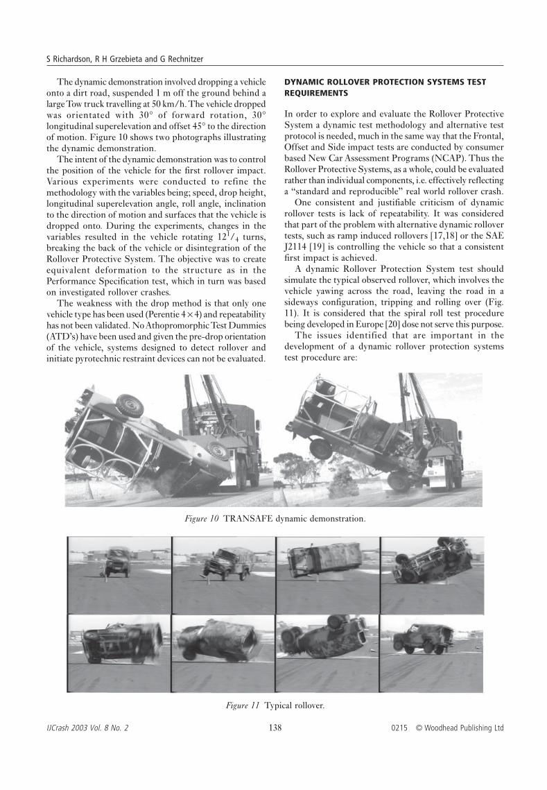
The dynamic demonstration involved dropping a vehicleonto a dirt road, suspended 1 m off the ground behind alarge Tow truck travelling at 50 km/h. The vehicle droppedwas orientated with 30° of forward rotation, 30°longitudinal superelevation and offset 45° to the directionof motion. Figure 10 shows two photographs illustratingthe dynamic demonstration.
The intent of the dynamic demonstration was to controlthe position of the vehicle for the first rollover impact.Various experiments were conducted to refine themethodology with the variables being; speed, drop height,longitudinal superelevation angle, roll angle, inclinationto the direction of motion and surfaces that the vehicle isdropped onto. During the experiments, changes in thevariables resulted in the vehicle rotating 121/4 turns,breaking the back of the vehicle or disintegration of theRollover Protective System. The objective was to createequivalent deformation to the structure as in thePerformance Specification test, which in turn was basedon investigated rollover crashes.
The weakness with the drop method is that only onevehicle type has been used (Perentie 4 × 4) and repeatabilityhas not been validated. No Athopromorphic Test Dummies(ATD’s) have been used and given the pre-drop orientationof the vehicle, systems designed to detect rollover andinitiate pyrotechnic restraint devices can not be evaluated.
DYNAMIC ROLLOVER PROTECTION SYSTEMS TESTREQUIREMENTS
In order to explore and evaluate the Rollover ProtectiveSystem a dynamic test methodology and alternative testprotocol is needed, much in the same way that the Frontal,Offset and Side impact tests are conducted by consumerbased New Car Assessment Programs (NCAP). Thus theRollover Protective Systems, as a whole, could be evaluatedrather than individual components, i.e. effectively reflectinga “standard and reproducible” real world rollover crash.
One consistent and justifiable criticism of dynamicrollover tests is lack of repeatability. It was consideredthat part of the problem with alternative dynamic rollovertests, such as ramp induced rollovers [17,18] or the SAEJ2114 [19] is controlling the vehicle so that a consistentfirst impact is achieved.
A dynamic Rollover Protection System test shouldsimulate the typical observed rollover, which involves thevehicle yawing across the road, leaving the road in asideways configuration, tripping and rolling over (Fig.11). It is considered that the spiral roll test procedurebeing developed in Europe [20] dose not serve this purpose.
The issues identified that are important in thedevelopment of a dynamic rollover protection systemstest procedure are:
Figure 10 TRANSAFE dynamic demonstration.
Figure 11 Typical rollover.

Proposal for a dynamic rollover protective system test
© Woodhead Publishing Ltd 0215 139 IJCrash 2003 Vol. 8 No. 2
1. Rollover metric2. Ejection3. Roof strength4. Injury criterion of occupants5. Correlation to real world crashes6. Repeatability
Rollover metric
Wilber [21] presented Table 1, which clearly shows thatrollovers 41/4 turns or more are the most injurious andfatal.
and FMVSS 201 assesses interior head impact protection.There is however no design rule or rating system thatassesses the effectiveness of occupant protection systemsin the vehicle such as seat belts, curtains, etc in the case ofa rollover crash. There is considerable debate regardingroof crush strength, the adequacy of FMVSS 216 and itsrelationship to occupant injury. [24,25,26,27,28]. The keyto this argument is that the whole system, i.e. roof andseat belt restraints, belt pre-tensioning, side curtain orside air bag, must be assessed to provide adequate protectionto occupants in such crashes. A dynamic rollover test clearlyneeds to addresses these issues.
Injury criteria for occupants
Debate has also ensued regarding which dummy is mostappropriate to use for assessing injuries that may be inflictedin a rollover crash. Hybrid III dummies were used in theMalibu tests [25,26]. There is considerable criticismregarding the neck loads measured and their relation toreal world rollover neck injuries. Autoliv in Sweden hasdeveloped a Rollover Dummy with a biomechanical spinethat may better represent the human spine. It has alsobeen suggested that the Thor dummy displays betterbiomechanical response.
Hence, research work still needs to be carried out toassess if a simple combination such as Hybrid III with asuitable neck developed for rollover, would provide aninjury envelope that encompasses the biomechanicalresponse of the more sophisticated and expensive dummies.Work would also need to be carried out reviewing realworld rollover crashes so as to determine which injurycriteria would be relevant to the dynamic test protocoloutlined below, i.e. HIC, neck and possibly chest.
Correlation to real world crashes
The test protocol needs to be compared with actual realworld crashes to determine the correlation betweenobserved injuries, occupant kinematics and vehicle damage.
Repeatability
The main purpose of the test protocol is to provide arepeatable test. This will be achieved utilising therepeatability performance parameters from barrier andside impact tests.
Proposed Dynamic Rollover Test ProtocolFigure 12 shows the Controlled Rollover Impact System(CRIS) developed by Exponent, Inc in the USA. TheCRIS rig is towed on the back of a truck and the vehicleis continuously rotated prior to release. The ATDs aretethered prior to release. The test vehicle is released usingexplosive bolts. The release of the tethers and vehicle iscomputer controlled and provides a repeatable output.
The main weakness with CRIS is that the vehicle iscontinually rotating prior to being released and this requiresthat the ATDs be tethered. The continual rotation alsoprecludes test and evaluation of active safety systems suchas side curtains or seatbelt pre-tensioners.
Table 1 Injuries v’s 1/4 turns
1/4 turns Single vehicle Injuries Injurieslateral rollovers AISb 1-2 AIS 3-6
One 14.4% 11.3% 6.9%Two 34.3% 38.4% 16.3%Three 9.0% 7.7% 7.3%≥Four 42.4% 42.5% 69.5%
bAIS Abbreviated Injury Scale
One of the fundamental flaws that are attributed toanalysis of rollovers is that rollovers can be comparedusing a Delta V metric. In a frontal, offset, side and orrear collision, Delta V is a good predictor of occupantinjuries. However, in the case of rollover the analysis byWilber suggests that 1/4 turns can be used. The slidingvelocity required to produce 41/4 turns [22] is based onan energy calculation using a trapezoidal geometry profile(rolling cross section of the vehicle), the second momentof mass inertia [23] about the roll axis, vehicle mass andthe centre of gravity location. (Eg. the 41/4 turn slidingvelocity for a 1990 Mitsubishi Pajero is 38.8 km/h).
The aim for the Rollover Protection Systems test is toimpose between 4 to 61/4 turns. In other words at aminimum at least one complete rotation of the vehicle.
Ejection
Occupant full or partial ejection is a major cause of seriousinjury in rollover crashes [24]. It is preferable for theoccupants to be restrained during a rollover crash. Thequestion arises as to what constitutes an appropriaterestraint. Obviously a restraint system that allows full orpartial ejection is inadequate. Pretensioned seat belts andside airbag curtains can be triggered to provide goodcontainment. Hence a dynamic procedure that tests thetriggering (including the sensors) of such restraint systemsand assesses if any part of the occupant’s body extendsoutside the structure is considered essential. In summarythe Rollover Protection System test should be capable ofassessing ejection, the adequacy of restraint systems andthe triggering mechanisms.
Roof strength
US design rule Federal Motor Vehicle Safety Standard(FMVSS) 216 for assesses the strength of a vehicle’s roof

S Richardson, R H Grzebieta and G Rechnitzer
IJCrash 2003 Vol. 8 No. 2 140 0215 © Woodhead Publishing Ltd
However, CRIS produces repeatable tests and is asignificant step in the evolution of a dynamic RolloverProtection System test.
To provide a repeatable test technique for evaluating aroof-to-ground impact, sensor triggering and occupantprotection in a vehicle rollover event, it is essential that atranslating and rotating vehicle drop system be developed.The system must also be compact enough so that it can belocated in a crash test facility. The system would beconstructed such that it holds a vehicle at a pre-set heightand selectable roll, pitch, and yaw attitudes similar to theCRIS system (Figure 11). The restraining structure needsto be made adjustable so that the vehicle can be orientedanywhere in a three dimensional volume (within reasonablelimits). The structure would be propelled forward (towedif in a crash test facility) at a constant preset speed suchthat the test vehicle leads the rig. At a predeterminedpoint the structure is decelerated at around 0.5 g’s (or ata deceleration rate simulating a pre-rollover yaw). Thisdeceleration positions the dummies as in an actual rolloverevent. A flywheel on the rig would then be engaged toinitiate vehicle rotation and milliseconds later the car isreleased at the 41/4 turn sliding speed. Deceleration,rotation and release would need to be synchronised toensure proper vehicle orientation upon contact with theground. High-speed cameras suspended from the testfixture and inside the vehicle would provide detailedinformation regarding firing of on board protection systemsand occupant-roof-ground interactions. Such views arenot available in less-controlled rollover testing techniques,such as dolly rollovers.
This Rollover Protection System test would be differentfrom the CRIS system in that:
• it is propelled with the test vehicle forward of the rig• the test vehicle is held so that it is not continuously rotating• deceleration is used to position the dummies• an inertia fly-wheel is used to initially roll the test vehicle
over• the rig will be compact enough to fit into a crash test
laboratory
This Rollover Protection System test would enable anassessment of a vehicle’s occupant protection systems viainjury criteria of ATD’s. This systems test would includethe evaluation of the rollover trigger sensor systems aswell as on-board protection devices and vehicle structureas a system test.
Monash are currently developing MADYMO modelsof the proposed Rollover Protection System test and intendto develop a 1/4 scale structure to validate repeatabilityprior to the construction of the a full scale structure.
This is a major but worthwhile research initiative andinternational co-operation is being sought to develop thetest procedures.
ACKNOWLEDGEMENTS
The development of the TRANSAFE performance specificationand dynamic demonstration would not have been possiblewithout the assistance of colleagues at the Land EngineeringAgency, specifically R. Hosemans, N. Dyson, A. Sims, RAndriuzzi, the staff of both the Prototype Engineering Centreand Accredited Test Services.
REFERENCES
1. 1999 SAE TOPTEC on Military Vehicle Safety, SanFrancisco, Jun 1999.
2. SNYDER, R G, MCDOLE, T L, LADD W M and MINAHAN, DJ. On-road crash experience of utility vehicles University ofMichigan, UM-HSRI-80-14.
3. RECHNITZER, G, LANE, J and SCOTT, G. Rollover CrashStudy – Vehicle Design and Occupant Injuries, 15th ESV,96-S5-O-10.
4. RECHNITZER, G, HAWORTH, N, DIAMANTOPOULOU, K,GRIFFITHS, P, STEVENS, M, CLAYTON, A, WHEELER, W,KINGHORN, R, POLKINGHORNE, G and DUTTON, M. SafeCarriage of Personnel in General Service Vehicles Study,Aug 1998. This report was prepared for the AustralianDefence Force, Land 121, Project Overlander.
5. Australian Army, Army Staff Requirement 63.11, Army’sRange of light Field Vehicles issued 13 Feb 1981.
6. SIMMONS, K. (MAJ.), Proposal to investigate HandlingImprovements to the Perentie 4 × 4 Family of Vehicles,
Figure 12 Rollover CRIS test structure developed by Exponent.

Proposal for a dynamic rollover protective system test
© Woodhead Publishing Ltd 0215 141 IJCrash 2003 Vol. 8 No. 2
Cranfield University, School of Defence Management, MADissertation 1994.
7. Maintenance Engineering Agency, File 2320-80-1, MinuteLandrover 110 (Perentie), dated 23 Oct 89.
8. Engineering Development Establishment, MobilityEngineering Division, Land Rover 110 4 × 4 – RolloverProtection Finite Element Analysis of Rollbar Structures.
9. GRZEBIETA, R. Rollover Analysis of a 4 × 4 Landrover 110Rollbar, Monash University, 1989.
10. LUDOVICI, D. Discussion Paper – Roll Over ProtectionStandard, Rollover Protection and Roll stability Analysis ofLandrover 110 4 × 4, Technical Working Group,Engineering Development Establishment, Sep 1990.
11. ARMY (AUST) 6835, Project Bushranger Phase 1,Annex C.
12. Operator Space Envelope Dimensions for Off-RoadMachines, SAE J 154.
13. KILLINGWORTH, W and RICHARDSON, S. Project TRANSAFE94 Phase 1, Engineering Development Establishment, dated20 Jun 94.
14. Australian Design rule 59; Omnibuses Rollover ProtectiveStructures.
15. RICHARDSON, S and GRZEBIETA, R. Roll Over ProtectiveStructures for the Safe Carriage of Troops in the Rear ofMilitary Vehicles, Monash University IndustryGeomechanics and Structures Symposium 96.
16. RICHARDSON, S. 2300-Y1-54, ATEA Minute “Note for file”dated 15 Sep 95.
17. WILSON, R and GANNON, R. Rollover Testing, SAE 720495.18. WECH, L and OSTERMANN, B. The safety of convertibles in
realistic rollover crashes, 15th ESV, 96-S5-O-02.19. Dolly Rollover, Recommended Test Procedure-Society of
Automotive Engineers J2114.20. DIGGES, K and KLISCH, S. Analysis of the factors which
influence rollover crash severity, 13th InternationalTechnical Conference on Experimental Safety Vehicles,NHTSA, 1991.
21. WILBER, V H. American Automobile ManufacturesAssociation, Vehicle Rollover Prevention a balancedapproach to a complex problem, 15th ESV, 96-S5-O-07,1996.
22. RICHARDSON, S, GRZEBIETA, R H and BELLION, P. Proposed41/4 turn metric to simulate rollover crashes, 17th ESV 01-S6-W-99, 2001.
23. http://www nrd.nhtsa.dot.gov/vrtc/ca/nhtsa_inertia_database_metric.xls
24. HENDERSON, M and PAINE, M. Passenger Car Roof CrushStrength Requirements, report No. CR176, Federal Officeof Road Safety, Department of Transport and RegionalDevelopment, Australia.
25. ORLOWSKI, K, BUNDORF, R T and MOFFAT, E A. Rollovercrash test: the influence of roof strength on injurymechanics, SAE 851734, in Proceedings 29th Stapp CarCrash Conference, Society of Automotive Engineers 1985.
26. BAHLING, G S, BUNDORF, R T, KASPZYK, G S, MOFFAT, E A,ORLOWSKI, K F and STOCKE, J E. Rollover and drop tests:The influence of roof strength on injury mechanisms usingbelted dummies, SAE 902314, in Proceedings, 34th StappCar Crash Conference, Society of Automotive Engineers,1990.
27. FRIEDMAN, D and FRIEDMAN, K D. Roof Collapse and therisk of Sever Head and Neck Injury, in Proceedings, 13thInternational Technical Conference on Experimental SafetyVehicles, 1991.
28. SYSON, S R. Occupant to roof contact: roll-overs and droptests, SAE 950654, in advances in Occupant ProtectionTechnologies for the mid Nineties, SAE SP 1077, Society ofAutomotive Engineers, 1995.

IJCrash 2003 Vol. 8 No. 2 142 © Woodhead Publishing Ltd