multiple protective shelters
77
Chapter 2 MULTIPLE PROTECTIVE SHELTERS Chapter 2.— MULTIPLE PROTECTIVE SHELTERS Page Overview 33 Theory of Multiple Protective Shelters, 34 Preservation of Location Uncertainty, 35 Sizing the MPS System 40 Weapon Characteristics for MPS ., 44 The Air Force Baseline 45 System Description. 45 SALT Monitoring Operations 58 Siting Criteria 59 Roads 61 Physical Security System 61 Land Use Requirements 64 Water Availability 67 Physical Impacts. 68 Socioeconomic Impacts 73 Regional Energy Development . . 81 System Schedule. 82 System Cost 84 Cost and Schedule of Expanding the MX/MPS . . ., 86 Split Basing 89 Vertical Shelters 92 Shelter Hardness. 92 Missile Mobility 9 3 PLU . . . . . 94 costs. . . 94 Arms Control. ,, 96 Page Some Previous MX/MPS Basing Modes. 97 The Road able Transporter-Erector- Launcher . . . . . . . . . . . . . . . . . 97 The Trench . . . . . . . 99 Minuteman MPS and Northern Plains Basing ,, . ......101 Missile Modifications 101 Cost and Schedule ,. 102 Civilian Fatalities From a Counterforce MPS Strike .. 103 LIST OF TABLES Table No Page 2. 3. 4, 5. 6. 7. 8. 9. 10. 11. Physic Signatures of Missile MPS Example . . . . . . Monitoring Timeline Principal Exclusion/Avoidance Criteria Used During Screening. Candidate Areas . . Water Required for MX . Water Uses. . . . . . . . . Cost Overruns in Large-Scale Projects Estimated and Actual Construction Work Forces for Coal-Fired Powerplants .. . .. System Time Schedule 36 42 59 59 61 68 68 77 78 83
-
Upload
khangminh22 -
Category
Documents
-
view
0 -
download
0
Transcript of multiple protective shelters

Chapter 2
MULTIPLE PROTECTIVE SHELTERS
Chapter 2.— MULTIPLE PROTECTIVE SHELTERS
Page
Overview 33
Theory of Multiple Protective Shelters, 34Preservation of Location Uncertainty, 35Sizing the MPS System 40Weapon Character ist ics for MPS ., 44
The Air Force Baseline 45System Description. 45SALT Monitoring Operations 58Siting Criteria 59Roads 61Physical Security System 61Land Use Requirements 64Water Availability 67Physical Impacts. 68Socioeconomic Impacts 73Regional Energy Development . . 81System Schedule. 82System Cost 84Cost and Schedule of Expanding the
MX/MPS . . ., 86Split Basing 89
Vertical Shelters 92Shelter Hardness. 92M i s s i l e M o b i l i t y 9 3PLU . . . . . 94costs. . . 94Arms Control. ,, 96
Page
Some Previous MX/MPS Basing Modes. 97The Road able Transporter-Erector-
Launcher . . . . . . . . . . . . . . . . . 97The Trench . . . . . . . 99
Minuteman MPS and Northern PlainsBasing ,, . ......101
Missile Modifications 101Cost and Schedule ,. 102
Civilian Fatalities From a CounterforceMPS Strike .. 103
LIST OF TABLES
Table No Page2.3.4,5.
6.7.8.9.
10.
11.
P h y s i c S i g n a t u r e s o f M i s s i l eMPS Example . . . . . .Monitoring TimelinePrincipal Exclusion/Avoidance CriteriaU s e d D u r i n g S c r e e n i n g .Candidate Areas . .Water Required for MX .Water Uses. . . . . . . . .Cost Overruns in Large-Scale ProjectsEstimated and Actual ConstructionWork Forces for Coal-FiredP o w e r p l a n t s . . . . .S y s t e m T i m e S c h e d u l e
364259
5961686877
7883

Table No. Page
12. Air Force Baseline Estimate 4,600Shelters . . . . . . . . . . . . . . . . . 84
13. Comparison of Air Force and OTA CostEstimates ....... . . . . . . . . 86
14. Land Use Requirements . . . . . . . . . 8715, FuIl-ScaIe Operations. . . . . . . . . . . . . 8816. Lifecycle Cost of 4,600, 8,250, and
12,500 Shelters to the Year 2005 . . . . . . 8817. Air Force Estimates of Additional Split
Basing Costs. . . 9018, Lifecycle Costs for Horizontal and
Vertical Shelters Deployed inNevada-Utah . . . . . . . . . . . . . . . 97
19. Minuteman MPS Costs. . . . . . . . . . .102
LIST OF FIGURES
Figure No. Page9. Mu l t ip le Pro tec t i ve She l te rs . . . 33
10. Preservation of Location Uncertaintyand System Design . . . 39
11. Peak Overpressure From l-MT Burst . . 4012. Surviving Missiles v. Threat Growth
for MPS Example . . . . . . . . . . . . . . . . . 4213. MPS Shelter Requirement for
Projected Soviet Force Levels . . 4414. System Description . 4615. Launcher . . 4716. Missile Launch Sequence. . . . . . . 4717. Cannister Construction . . 4818. MX Protective Shelter Site 4919. MX Protective Shelter . . . . . . . 5020. Transporter . . . . . . . . . . . . . . . 5021. Missile Launcher and Simulator—
Transfer Operations. . . . . . . 5122. Mass Simulator and Launcher
Exchanges . . . . . . . . . 5123. Mass Simulator . . . . . . . . . 5224. Cluster Layout . . . . . . . . . . . . . . . . . . . 5225. Shelter and Road Layout . . . . . . . . . . . 5326. Command, Control, and
Communications System . . . . . . . . . . 5427. Electrical Power Distribution. . . . 5528. MX-Cannister/Missile Launch Sequence 5629. Transporter Rapid Relocation Timeline 5730. Dash Timeline . . . . . . . 5831. Geotechnically Suitable Lands. . . . . . . 6032, Road Construction Profiles . . . . . . . . 6233, Area Security . . . . . . . . . 6334, Point Security. . . . . . 6335. Hypothetical MPS Clusters in
Candidate Area . . . . . . . 6536. Potential Vegetative Impact Zone. . . . 71
Figure No. Page37. Construction Work Force, Operating
Personnel, and Secondary Populations. 7538 . Base l ine Work Force Es t imates 7639. Comparison of Onsite and Total
Construction Work Force. . . . . . 7740. Construction Work Force: High-Range
Projection . . . . . . . . . . . . . . . 7841. Range of Secondary Population
Growth. . . . . . . . . . . . . . . . . . . . . . . . 7942. Range of Potential Population
Growth . . . . . . . . . . . . . . . 8043. Cumulative Energy Activity
in the West . . . . . 8244. proposed Split Basing Deployment
Areas . . . . . . . . . . . . . 8945. Summary Comparison of Long-Term
Impact Significance Between theProposed Action and Split Basing . . 91
46. Vertical Shelter . . . 9247. Transporter for Vertical Shelter . 9448. Remove/Install Timelines for
Horizontal and Vertical Shelters . 9549. Dash Timeline for Horizontal Shelter. . 9650. Readable Transporter-Erector-
Launcher . . . . 9851. Trench Layout . . . . . . . . 9952. MX Trench Concepts . . . . . . . . . . . . . .10053. Minu teman/MPS Schedu le . . . .10254A. Population Subject to Fallout v.
Wind Direction (Range: 500 rim). .. ..10354B. Population Subject to Fallout v.
Wind Direction (Range: 1,000 nm) .. .10454C. Population Subject to Fallout v.
Wind Direction (Range: 1,500 nm) .. .10454D. Population Subject to Fallout V.
Wind Direction (Range: 2,000 nm) .. .10455. Downwind Distance v, Total Dose .. .10556. Crosswind Distance v. Total Dose .. .10557A. MX in Texas and New Mexico:
Population Subject to Fallout v.Wind Direction (Range: 500 rim). .. ..106
57B. MX in Texas and New Mexico:Population Subject to Fallout v.Wind Direction (Range: 1,000 nm) .. .106
57C. MX in Texas and New Mexico:Population Subject to Fallout v.Wind Direction (Range 1,500 nm). .. 106
57D. MX in Texas and New Mexico:Population Subject to Fallout v.Wind Direction (Range 2,000 nm). .. 107
58A. Downwind Distance v. Total Dose —500 KT . . . . . . . . . . . . . . ........107
58B. Downwind Distance v. Total Dose—250 KT . . . . . . . . . . . . . . . . . . . .. 107

Chapter 2
MULTIPLE PROTECTIVE SHELTERS
OVERVIEW
The multiple protective shelter (MPS) con-cept seeks to maintain the capabilities of afixed land-based ICBM force, while protectingthe force from Soviet attack, by hiding the m is-siles among a much larger number of missileshelters (see fig. 9). If the attacker does notknow which shelters contain the missiles, allthe shelters must be attacked to ensure thedestruction of the entire missile force Thus,the logic of MPS is to build more shelters thanthe enemy can successfully attack, or at leastto make such an attack unattractive by requir-ing the attacker to devote a large number ofweapons to attack a relatively smalIer force.
In this chapter, the theory, design require-ments, and some of the outstanding issues ofMPS are addressed I n particular, the technicaland operational requirements of hiding themissiIes among the shelters, forma I I y known aspreservation of location uncertainty (PLU), areexamined This wouId be a new task for missiIeland basing, and it is now appreciated as oneof the more challenging aspects of MPS. ThecompatibiIity of the missiIes’ location uncer-tainty with arms control monitoring is also dis-cussed
Figure 9.— Multiple Protective Shelters (MPS)
SOURCE Off Ice of Technology Assessment
Inherent in the strategy of MPS is that thenumber of shelters constructed be keyed to thesize of the Soviet threat. Growth i n the numberof accurate Soviet warheads wouId require alarger deployment of missile shelters to main-tain the same expected survival rate for U.SmissiIes. The sensitivity of missiIe survival andshelter number to the size of the Soviet threatis discussed by performing severaI MPS cal-culations related to possible Soviet growthThe consequences of an “undersized” MPS area I so exam i ned, and shelter number require-ments are calcuIated.
These issues, keeping the missiles suc-cessfuIIy hidden and determining the propersize of the MPS, are common to any MPS-basing mode, and are analyzed in detail in thesection on the theory of MPS.
Much of this chapter is devoted to specificdesigns for an MPS, with a great deal of atten-tion devoted to the Air Force’s baseline sys-tem. This system has been in full-scale engi-neering development since September 1979,and was modified in the spring of 1980 to in-cIude a horizontaI loading dock configurationfor the missile shelter. As proposed, thebaseline system consists of 200 MX missilesamong 4,600 concrete shelters, with each m is-sile deployed in a closed cluster of 23 shelters.These shelters would be spaced about 1 mileapart and arranged in a linear grid pattern.Each shelter would resemble a garage, orloading dock, into which a missile could be in-serted horizontally. Missile location uncertain-ty would rely on the use of specially designedmissile decoys of similar, though not identical,physical characteristics to the real missile, andthe employment of operational proceduresthat would treat missile and decoy alike. Largetransport trucks could shuffle missiles anddecoys among the shelters in order to keep theprecise location of the missiles unknown tooutside observers. Descriptions are providedof the Iayout and operation of this basing, m is-
33

34 ● MX Missile Basing
sile mobility and the “dash” option, command,control, and communications (C3), and esti-mates for system cost and schedule Air Forcecriteria used for siting the MX, and its regionalimpacts are also addressed.
In the discussion of regional impacts, em-phasis has been on two particular issues. Be-cause the A i r Force has aIready completed ex-tensive studies and has published almost sovolumes of materiaIs (MX: Milestone II, FinalEnvironmental impact Statement; DeploymentArea Selection and Land Withdrawal A cquisi-t ion, Draft Environmentl Impact Statement;and MX: Environmental Technical Reports)relating to the environmental impacts of MX/MPS basing, no attempt has been made tocatalog the potential environmental impacts,to evaluate independently all of those impactsidentified by the Air Force, or to critique theAir Force environmental impact statements(EISs), Instead, those documents have beenused as resources, and attempts have beenmade to draw attention to those issues that arebelieved to be of most importance to the con-gressional decision making process, For moredetailed information on particular impactsassociated with MPS, reference should bemade to the Air Force E I S documents and com-ments by the States of Nevada and Utah.
A variation of the proposed system would besplit basing, where the system would be de-ployed in two noncontiguous regions of thecountry: the Great Basin area of Utah andNevada, and the border region between Texasand New Mexico, This basing scheme wouldmitigate the regional impacts, at some addi-tion to system cost.
In addition to discussions of the Air Forcebaseline system and split basing, several alter-native MPS designs are examined. All of thesehave been studied in the past, but rejected by
the Air Force for various reasons. These de-signs incIude housing the MX missiIe in con-ventional Minuteman- like vertical shelters,rather than the horizontaI shelters of the A i rForce basel inc. Greater hardness against nu-clear attack could be achieved with verticalshelters; however, missile mobility would besomewhat simpler with horizontal shelters.
Two previous baseline modes for the MX arealso) discussed: the “trench” design, where themissile wouId reside in a long concrete-hard-ened tunnel several feet underground, and theso-called “ roadab le TE l , ” the immed ia tepredecessor of the present baseline, where themissile and transporter were structuralIy inte-grated, and therefore had greatly enhancedmolbiI it y.
Another possibility would be the deploy-ment of Minuteman /// missiIes in an MPSmode, by constructing a large number of add i-tional vertical shelters in the present Min-uteman missiIe fields. Proponents of thissystem claim it would provide an acceleratedscheduIe for a survivabIe land-based missiIeforce, since Minuteman missiles, support in-frastructure, and most roads are already avail-able. Mod if i cations to the Minuteman misslIewouId be required to deploy it in a mobiIemode, and many additional shelters and mis-sile transporters would need to be built. Theextent of these and other modifications is ad-dressed, as is system cost and schedule forcompletion.
Finally, several calculations of civil ianfatalities resulting from a Soviet attack on MXdeployment in multiple protective shelterfields are presented. These calculations helpaddress the question of the extent to which aSoviet strike against an MPS deployment couldindeed be regarded as “ Iimited, ”
THEORY OF MULTIPLE PROTECTIVE SHELTERS (MPS)
A land-based missile force in MPS relies for site force with confidence, will be forced toits survivability on the assumption that the at- target al I or most of the shelters if it is nottacker, in order to destroy the adversary’s mis- known which of these shelters contains the

Ch. 2—Multiple Protective Shelters 35
missiles. MPS thus tries to draw a distinctionbetween miss i le and target , by “ immers ing”the missiIe force in a “sea” of shelters.
MPS can also be regarded as “anti-MIRV”basing Just as MIRV (mult iple independentlytar-gettable reentry vehicle) technology allowsone to attack many targets with one miss i Ie,MPS forces the attacker to devote many war-heads to destroy one real target.
For this strategy to work, the tasks of“hiding” the missiles among the shelters andproperly sizing the MPS system for a givenlevel of survivability involve two key require-ments Since the nature of these two tasks issimilar for all MPS basing modes, their detailsand impIications are discussed in this sectionof the chapter.
Preservation of Location Uncertainty(PLU)
Inherent in the strategy of MPS is that allshelters appear to the attacker as equally Iike-Iy to contain a missile This assumption is im-portant, since if the attacker were to find outthe location of alI the missiIes, it wouId defeatthe design of the system For the planned 200MX missile deployment, for example, it couldmean targetting as few as 200 reentry vehicles(RVS), one RV per MX missile, which is a smallportion of the Soviet Union’s arsenal. The taskof PLU — or keeping the missile locationsecret — is essential to successful MPS deploy-ment. With increased study of this issue overthe last few years, the defense community hascome to realize the magnitude of the PLU task.What makes PLU so challenging is that It is amany faceted problem, dealing with a varietyof missile details Moreover, PLU must bemade an integral part of the design process atevery level. Furthermore, the present expecta-tion is that the design process for PLU will beongoing throughout deployment, with continu-ous efforts at enforcing and improving missilelocation uncertainty through improved PLUcountermeasures and operations,
To accomplish this task of missile conceal-ment, it is necessary to eliminate all indica-
tions, or signatures, that could give away thelocation of the missile One such set is the setof alI physical signatures of the missiIe andassociated missile equipment. This set includesweight, center of gravity, magnetic field, andmany others By utiIizing these physical signa-tures, missile location might be inferred bymaking measurements outside the shelter ormissile transporter, looking for those signa-tures that could distinguish location of themissile. Such signatures span the spectrum ofphysical phenomena, many with a range of de-tectability of hundreds of miles, if not ade-quately countermeasure.
A second set of missile signatures to beeliminated are operational signatures The taskhere is to eliminate all operating proceduresthat could distinguish the missile and therebybetray its location. Otherwise, missile place-ment might be inferred by observing personneloperations.
Internal information is a third set of sig-natures. This set includes the piecing togetherof many observations to arrive at a pattern rec-ogn it ion of data from which one can infermissile location.
Soviet espionage efforts aimed at breakingPLU wilI also be likely, and counterintelligenceefforts may be necessary.
Signatures
PHYSICAL SIGNATURES
The physical signatures of the missile runinto the scores, with the magnitude and rangeof each dependent on design detaiIs and mate-rial construction of the missile, shelter, andtransporter. Against each of these signaturesthat might compromise missile location it isconsidered desirable to design and install a setof specific countermeasures. These counter-measures include simulating missile signatureswith decoys, masking or reducing the mag-nitude and range of the signatures, and confus-ing an outside observer by engineering a set ofsignatures that vary randomly from decoy todecoy in order to make it more difficult todetermine which shelters contain the missiles.

36 ● MX Missle Basing
Table 2 is a generic list of associated missilesignatures present for any MPS system. A briefdiscussion of them is included here along withsome possible countermeasures. A more de-tailed list and analysis is included in the clas-sified annex.
1, Seismic/ground tilt results from the forceof missile weight on the ground, both as seis-mic waves set up by the motion of the missilein transit, and static measures of its mass, suchas the tilt of the ground in the missile’s prox-imity, The seismic signature is particularlysignificant while the missiIe is in transport be-tween shelters, since seismic waves can prop-agate for miles, with a falloff in wave ampli-tude that varies inversely with distance.Ground tilt caused by depression of the groundunder the missile-laden transporter falls offsomewhat faster with an inverse square law,and a maximum ground depression of theorder of thousandths of an inch. The resultingground tilts are measurable at a distance, Acountermeasure for this signature may includea mass decoy.
2. Thermal sources arise from heat gener-ated by electrical equipment associated withthe missile, such as fans, heaters, and other en-vironmental control systems. A measure of thisheat is the power consumed by each shelter,typically 10 to 20 kilowatts (kW) at full oper-ating power, Countermeasures for this sig-nature might use thermal insulation and dum-my powerloads at the unoccupied shelters.
3. Acoustic sources are due to such items ascooling fans and missile transfer operations atthe shelter site. This signature might be coun-termeasure by simulation, such as suitablyemplaced recording and playback devices.
Table 2.—Physical Signatures of Missile
● Seismic/ground tilt ● Nuclear● Thermal ● R a d a r● Acoustic ● Gravity● Optical ● Magnetic
● Chemical ● ElectromagneticSOURCE Off Ice of Technology Assessment
4. Optical signatures are significant primari-ly while the missiIe is in transport. Assumingthat the transporter is covered, so that themissile is not directly visible, concern must beshown for the modal oscillations of the missiletransporter in a loaded v. unloaded condition,tire deformation, exhaust smoke, and vehiclesway angle around corners. Sensors that mightpick up this distinction range from sophisti-cated optics aboard a high flying plane toground-based lasers or even observation withbinoculars at a distance. A possible counter-measure for this signature is a massive decoyof the same weight and simiIar vibrationalcharacteristics to the missile.
5 Chemical signatures are due to the routinevolatiIe chemical release from the missile,such as propel I ant, coolant, plasticizers, andozone. The missile transporter exhaust maya Isc) differ for a loaded v. unloaded case.Chemical concentrations are expected to be ashigh as 1 part per million (ppm), and methodsof detection include laser scattering infraredabsorption, Raman spectroscopy, and takingonsllte samples for later analysis, Counter-measures may include simuIated effIuents anda massive decoy load for the missiIe trans-porter,
6. The nuclear warhead on the missile has itsown signature characterized by a set of gam-ma ray spectral lines particular to the plu-tonium isotopes contained in it. The warheadmaterial also emits neutrons. UsefuI counter-measures incIude radioactive shielding,
7. Radar is a potential signature due to thelarge radar cross section of metal objects asso-ciated with the missiIe, such as launch equip-ment. I n addition, distinguishing the modaloscillations of the transporter due to differentIoacls may be radar detectable from a distanceof severaI hundred miIes. Countermeasures forradar include a massive missile decoy, and re-liance on the metal rebar and a steel Iine forthe shelter as well as earth overburden toradar-shield its contents,
8. Gravity field and field gradient measure-ments should be able to detect the mass of themissiIe at a range of several hundred feet.

Ch. 2—Multiple Protective Shelters ● 3 7
Mass simulation is the most direct counter-measure to this threat
9. Magnetic field anomalies due to the largeamounts of metal i n the missiIe-launchingequipment, if unshielded, can be detected by amagnetometer. Such detection techniques areanalogous to magnetic anomaly detection ofsubmarines, and simiIar countermeasures canbe utilized. A missile decoy containing anappropriate quantity and distribution of highpermeability (magnetic) metal might be usedto help prevent an observer from distin-guishing it from the missile.
10. Electromagnetic emissions generated bymissile equipment during normal operationsare another potential signature. I n addition,radio frequency communication involving themissile could lead to missile location deter-minat ion by radio direct ion-f inding tech-niques Electrical transients may also be de-tectable Countermeasures to these signaturesmight consist of simulatin g powerl ine c o n -sumption by installing dummy loads inside theshel ter , and communicat ing wi th the miss i ledur ing normal operat ion over secure bur iedcable, rather than radio
The task for a potential attacker to defeatMPS by utilizing these signatures depends onthe range of the signature to be exploited, thecovertness needed to COIIect and transmit thedata, and the degree of security provided forthe MPS deployment area Presently plannedsecurity arrangements for the shelters are com-monIy reterred to as point security, Pointsecurity allows public access to all but a smallrestricted area around the shelter, and there-fore allows access relatively close to the mis-sile shelter Area security, on the other hand,would restrict access to most of the de-ployment area
Designing PLU for short-range observation,which is anticipated for point security, is moredemanding than for long-range surveillance,since most, though not a 11, of the missile sig-natures are signiticantly stronger at closerange For example, magnetic anomaly detec-tion, which relies on measurement of magnetictield gradients, falls off as the inverse cube of
the distance from the source. This means thatthe strength of this signature at 100 ft is morethan 1 million times as intense as this signaturewould be at some 2 miIes away. Since close-inthe magnetic details of the source becomemore important, the distribution of magneticmaterial in the decoy is more critical for ade-quate deception than it would be for distantobservation.
I n addition to the short-range signatures,there are also long-range signatures, such asdetailed motions of the missile transporter andseismic waves, that are measurable at manym i Ies.
The range of missile signatures stronglydetermines the degree of covertness that anagent must employ to collect missile locationinformation. A signature that is visible at longranges might require Iittle or no cover toobserve. I n particuIar, long-range signatureswouId be particuIarly threatening if observ-able by satellite, since security wouId have Iit-tle effect; and the impact on PLU would becatastrophic if such signatures could not besuccessfuIly countermeasure. Similarly, sig-natures that are measurable at several miles ortens of miles are also particularly threatening,since security sweeps would be impracticalover so large an area, even if possible. I n thecase of long-range surveillance, the number ofsensors needed would be small compared tothe number of shelters, with the precise num-ber dependent on signature range. It is notclear whether covert operation of sensorswould pose a problem to the Soviets if theyfound a signature that was observable at suchranges On the other hand, short-range sig-natures wouId require some degree of covert-ness, perhaps by an implanted sensor, a road-side van, or “missile sensing” done under theguise of another activity, such as mining. OncemissiIe location is determined there are anumber of ways to transmit the informationcovert I y.
For short-range shelter surveillance, manyemplaced sensors, on the order of thousands,would be necessary to seriously degrade PLU,since a large portion of the shelter deployment

38 ● MX Missile Basing
would require independent observation. Thistask could pose a severe problem for theenemy agent. I n addition, the areas proximateto the shelter would quite likely be subjectedto frequent sweeps by security forces. On theother hand, covert sensors that could detectmissile presence in the transporter, while themissile is in transport, could be much moreserious. Since point security wouId not securethe roads, implants in the roads must beprevented from determining the contents ofthe transporter. In a Iinear cluster arrange-ment, for example, if PLU on the transporterwere to fail, then one missile-sensing deviceplanted in the middle of the cluster would beable to determine which half of the clustercontained the missiIe, thereby effectively re-ducing the number of shelters in half, There-fore, PLU is particularly important for thetransporter, and it must be constantly supple-mented by security sweeps of the road net-work.
The Air Force program for deal ing with phys-ical missiIe signatures consists of several ap-proaches, the first of which is to eliminate thesignatures, if possible, by system design. Forexample, if one construction material has asmaller signature than another, using the firstmaterial might be preferable, An example ofthis might be the use of nonferromagnetic ma-terial, if practical, rather than iron, in order toreduce or eliminate the magnetic signature.
These technical design requirements due toPLU have been established for the launcher,the mass simulator, the protective shelter, andthe transporter. The Iist of these requirementsneeded to countermeasure the missile/launch-er signatures, some of which were Iisted in theprevious section, and the many others that aresystem- particular, is a very long Iist, that is dis-cussed more fuIIy in the classified annex to thissect ion
The second approach to countermeasurephysical signatures after attempting to designthem away could be to attenuate the signatureby shielding. For example, heavy materialshields gamma radiation. Thermal insulationmight be used for heat signatures, and so forth.
A signature that cannot be designed away orattenuated might conceivably be masked orjammed, For example, a real signature that ismeasurable might be masked by an additionallarge, possibly random signal, thereby makingit more difficuIt to extract the real missiIesignature from ,the “noise. ”
If these approaches were not feasible, an at-tempt to simulate the signature by the use of adecoy might be employed. This simulation isone of the purposes of the MX mass simulator,which will be placed in all of the unoccupiedshelters, and in the transporter when simulat-ing missile transport, Since the simulator isdesigned to weigh the same as the missile/launcher, it automatically countermeasuresthose signatures that arise from total weight.A S discussed in the classified annex to this sec-tion, additional simulations wiII be required.
Finally, there can be physical security for
the deployment area that would consist ofmonitoring the area and sweeps for sensorsthat might compromise missiIe location
OPERATIONAL SIGNATURES
In addition to physical missile signatures, itis necessary that routine procedures of missiIetransport and maintenance do not expose thelocat ion of the miss i le , Th is cons iderat ionmeans that when carrying out missile-relatedand mass-simulator-related operations, person-nel must do the same things, in the same timeinterval , with the same equipment at al I sites.For example, when it becomes necessary toreturn the missiIe from maintenance to theshelter, the transporter must visit all of theshelters and either deposit or simulate depositof the missile. I f the operator knows in whichshelter he is depositing the missile, care mustbe taken that any actions on his part, such asoutward behavior or conversation with col-leagues, do not give clues to missile location.
INTERNAL INFORMATION
T h i s c a t e g o r y i n c l u d e s p i e c i n g t o g e t h e rmany observat ions to ar r ive at any pat ternrecognition of data from which one may infermissiIe location, To deal with this considera-

Ch 2—A4u/t/p/e Protective She/tefs . 39
ponents is underway now Smallfor signatures will be done in the
Figure 10. —Preservation of Locationand System Design
f 1
sca I c testinglatter halt of
Uncertainty
Character ize
I , - .slgnat ure
tSystem
+
1 >
+ 1
Determinebasellne d i s c r i m i n a t e s
Characterizethreat
v r f ? ?Evolved Select Considerbase- Test counter. counter-Ilne measures measures
+ & b +
SOURCE U S AIr Force
1 ~~1 thr~ljgh the $prtng of 1982, with fllll-~c ~1~’testing in the latter- part of 1982 through 1‘)8 3These testj wi I I be crit [( a I in the des Ign of th~~tran 5porter J ncj ma $~ $ i m u I ator, as ~vel I d \ forthe entire P1 U task
Assessment of PLU
Assessing the feasibll ity of the Pi-U effort isa d i f f i c u I t task [- i rs t, I t Is ~ ~E> n u i n e I v n w
problem, a n d not a s] m p I e extra po I a t i o n ofpast e n g i n e e r i n g effort~ SI nce m issi Ie sig-na tu re~ and their cou n t~lrmea ~u res sens I t ive I vde~)end o n the det a i I ed d e~ ign ot t h(~ ~~~tem, i ti \ d i f f i c u I t and c a n be m Is I e ad i ng to m a k e gen-era I statenlent~ about PLU
Afo physical ana I ysIs IS known that can arguet h a t PLU is a phyfic~l l} ir-npossible ta~k I t sa n a I yses and countermeasures rest on WC I 1-u nderftood physic a I pr i n c i p] t’~ U nt I I re( ent I y,however, there has been no research and dt~-velopment program on P 1- U, nor have therebeen fu Ii-scale field tests to val Idate many ofthe conjectures (ind ana Iyt lcal tools needed todesign the sy~tenl I n terms of PLU scopc~, it~deta i 1- i ntens ive c h ara cter, and 5 i m pl y as a newtechn ica I problem, comparable previous ex-perience or data are not ava i Idbie to ~LI Ide Injudging its fea~ibi I ity I t IS t rue that there IJ~orne a na I ogy with submarine detect Ion andl o c a t i o n I ndeecj, some PL LJ signatur(~~t mostnotably magnetic, are corm mon with iu b-mar i nes. St i I I, there are two i m port a n t d I \t i n c -tions First, in antisubmarine wart~~re (A$W),there is no present neecj to d i sc ri m i nat(~ t I1[J ac -tua I submarine from a decoy, a Ithough re\olv-i ng a $U bm a r i ne s i gn at u re from a noisy back-ground may be one of the lead tasks Sec end,at a technical level, the details conf rontcdwith PLU and ASW are quite distinct Th(’ en-vi ron ments and media are different, and there Ieva nt signatures and the ava i I a b I(’ c~ i sta n ceat which the measurements can be performedare different (much closer for MPS) S i replystated, solving the tech n i ca I A SW p rob I emdoes not significantly help solve PLU, ctnd viceversa
I n addition, it is not known at this point oftechn ica I PLU work, how feasible [t wi I I be to

40 . MX Missile Basing
eliminate, attenuate, mask, simulate, or ran-domize all of the missile’s signatures, or whatthe residual signatures will be. Since this is adetailed engineering task, confidence cannotbe obtained until full-scale field tests havebeen done, when missile signatures can bemore retiably identified and analyzed.
Thirdly, it may not be possible to be certainthat PLU has not been broken by the Soviets; abreak (or even a small fracture) of PLU maylikely be a silent event. For all the scores of sig-natures that have been successfulIy counter-measure, it takes only one accessible uncoun-termeasured signature to imperil the sur-vivability of the entire missile force. On theother hand, it is reasonable to expect that per-sonnel running a vigorous program to monitorPLU in operation will be more aware of com-promises in the system than an outside agentwouId Iikely be, Furthermore, a compromise inPLU would not necessarily be catastrophic,since a breach in PLU for several shelters oreven several missiles would not significantlythreaten the entire force. I n any case, con-fidence in our having PLU is an important fac-tor in its own right. In addition to being basedon knowledge of our own system, confidenceis also a state of mind, and not always easy tojudge or predict,
Finally, the extremely high value of theknowledge of missile location must be em-phasized. Because this knowledge holds thekey to MX survival in a Soviet attack, avigorous Soviet effort in this area shouId be ex-pected, underscoring the technical and opera-tional importance of the PLU effort. The AirForce effort for PLU, which several years agomay have underestimated its scope and dif-ficulty, has more recently proceeded with aprogram that is comprehensive and realistic inits approach. However, whether this or anyother program will succeed in developing atechnology that wiII successfully keep the mis-sile hidden is a technical assessment that can-not be made at this point, at least until full-scale hardware exists and can be tested for allmissiIe signatures,
Sizing the MPS System
For MPS to provide a given degree of sur-vivability to its missiIe force, an adequatenumber of shelters must be deployed so thatthe entire system can absorb an attack, andstilI leave the required fraction of the missileforce intact. Determining the number of shel-ters to be built and the deployment area of thesystem depends on a number of factors: thehardness and spacing of the shelters, the accu-racy and reliabiIity of enemy missiIes, the num-ber of threatening warheads, and the size andsurvival requirements of the U.S. missile force,
Since the idea of MPS is not to build ashelter that can survive a direct hit, but onethat can survive the effect of direct hits on itsneighboring shelters, the requirements forshelter hardness are much less than for thetypical Minuteman silo.
The overpressure experienced by the shelterdepends on its distance from the nucleardetonation(see fig. 11). For any MPS system,
Figure 11 .— Peak Overpressure From 1-MT Burst
10’ 1 o’ 10” 10’
Ground range (ft)SOURCE RDA

Ch, 2—Multlple Protective Shelters ● 41
there is a tradeoff between shelter hardnessand shelter spacing. The harder the shelter ismade, the closer the shelters can be spacedand still withstand the effects of nearby nu-clear detonations. Conversely, the fartherapart the shelters are spaced, the less hard theshelters need be made. I n practice, the shelterspacing and hardness combination is deter-mined by cost trade-offs between increasedshelter hardening (that requires a larger shelterand more concrete) and increased shelter spac-ing (that requires more roads and buried com-munications and electrical connections be-tween shelters), in order to reach a cost mini-mum solution.
The reliability and accuracy of enemy mis-siles are also important factors for decidinghow many protective shelters to build, Reli-ability is the probability that the missile, whengiven the order to fire, will fire and operateproperly along its trajectory. When planningfor shelter deployments, more shelters willclearly be needed for a high enemy missiIereli-abiIity than for a low one. Missile reliabilitiesare typically between O 8 and and 1.0, andtheir effect on vulnerability calculations willbe illustrated later in this section.
Missile accuracy is a measure of the mis-sile’s abiIity to land a nuclear warhead on itstarget TypicalIy, missile accuracy is measuredin terms of CEP, or circuIar error probable. CE Pis defined as that distance from the targetwithin which half of the warheads would landif target ted A large CEP means a less accuratemissiIe; a smalI CE P means a more accuratemissi le.
Missile Accuracy depends on a variety offactors, both internal and external to themissile The heart of the missile’s guidance Iiesin its inertial measuring unit (I MU). Placed inthe upper stage of the rocket, the IMU sensesmissile accelerations throughout the boostphase, integrates the signals to get velocityand position data, and uses this data to nav-igate the missiIe to the warhead’s releasepoint Contributions to target miss, called theerror budget, include the following items:
● smalI errors of instrumentation and cali-brat ion,
● knowledge of initial position and velocityof missiIe,
● I MU platform alignment,● knowledge of gravity for the launch point
region and missiIe trajectory,● knowledge of target Iocation,● RV separation from the missile bus, and● errors during atmospheric reentry.
Knowledge of the missile’s CE P and reliability,and the hardness of the target, allow the pro b-abiIity to be calcuIated that the target wiII bedestroyed in an attack There are standardtables for this caIcutat ion, but for present pur-poses, the following formula is adequate torthe probability that a reliable RV will destroyits target, or pk:
P
k = 1 – exp1 26(YH
where
Pk = the probability of killY = the yield of the weapon, in megatonsH = the hardness of the shelter, in thousands of p\ I
CEP = circular error probable, In kilofeet (thousands of
f t )
For example,
Yield Y = 1 MTHardness H = 600” PSI (or () 6 thousand psi)
C E P = 1,800 ft (or 1 .8 k ilofeet)
then
Pk = 50% (or 0.5
This answer corresponds to the fact that the 600psi contour for a 1 MT detonation occurs atthe 1,800-ft contour. Since, by definition ofCEP, half of the time the weapons would fallwithin 1,800 ft of the target, and halt of thetime they wouId falI outside 1,800 ft, then theprobability of k ill is exactly so percent
Typically, modern intercontinental ballisticmissile (ICBM) accuracy is much better thanthis, and for shelters of hardness less than1,000 psi, the probabiIity of k i I I (given theproper yield) is close to 100 percent (or 1 .0).Furthermore, the furture trend is for pk to be soclose to one that the expectation of destroyinga I most any such target is approximately equalto the retiabiIity of the attacking missiIe
42 MX Missile Basing
An MPS Calculation
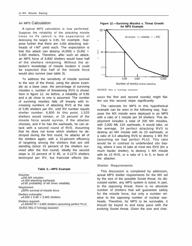
A typical MPS calculation is now performedSuppose the reliability of the attacking missilet i m e s i t s P k ( w h i c h i s t h e e x p e c t a t i o n o fdestroying the target) is 0.85, for example. Sup-pose further that there are 4,000 attacking war-heads of I-MT yield each. The expectation isthat this attack can destroy (4,000) x (0.85) =3,400 shelters. Therefore, after such an attack,an MPS force of 6,800 shelters would have halfof the shelters remaining. Without the at-tacker’s knowledge of missile location it couldbe expected that half of the missile forcewould also survive (see table 3).
To address the sensitivity of missile survivalto the size of the threat, using the above exam-ple as a base case, the percentage of survivingmissiles v, number of threatening RVS is shownhere in figure 12. As before, a reliability of 0.85and a pk close to one is assumed. The numberof surviving misslIes falls off Iinearly with in-creasing numbers of attacking RVS at the rateof 0.85 shelters per RV, until RV number equalsshelter number, 6,800 At this point, 1,020shelters wouId remain, or 15 percent of themissile force would survive, If the attackerchooses, and if he has the warheads, he can at-tack with a second round of RVS. Assumingthat he does not know which shelters he de-stroyed during the first round, he attacks all ofthe shelters again, with a 15-percent efficiencyof targeting among the shelters that are stillstanding (since 15 percent of the shelters sur-vived after the first round). Ideally the secondslope is 15 percent of O 85, or 0.1275 sheltersdestroyed per RV, but fratricide effects (be-
Table 3.—MPS Example
Assume: –
● 200 MX missiIes● 4,000 attacking warheads● 0.85 probability of kill times reliability
Requirement:● 50% survival of missiIe force
Shelters vulnerable:● 4,000 x 0.85 = 3,400 shelters
Shelters required:● 3,400/50°/0 = 6,800 shelters (assuming perfect PLU)
SOURCE Office of Technology Assessment
Figure 12.—Surviving Missiles v. Threat Growthfor MPS Example
100 %
(Example: P k x reliability = O 85)—
c
I
15% —
2 % —
4,000 6,800 13,600
Number of reentry vehicles attacking
SOURCE Office of Technology Assessment
tween the first and second rounds) might flat-ten out this second slope significantly.
The rationale for MPS in this hypotheticalexample can be seen in the following way, Sup-pose the MX missile were deployed in an MPSwith a ratio of 1 missile per 34 shelters. This de-ployment includes a total of 200 MX missiles,with 2,000 Mk 12A warheads, It wouId take, onthe average, 34 perfect attacking RVS todestroy an MX missile with its 10 warheads, ora ratio of 3.4 attacking RVS to destroy 1 MX RV(assuming we had perfect PLU). This ratiowould be in contrast to undefended silo bas-ing, where it wou Id take at most two RVS (for amuch harder shelter), to destroy 1 MX missilewith its 10 RVS, or a ratio of 1 to 5, in favor ofthe attacker.
Shelter Requirements
This discussion is completed by addressing
actual MPS shelter requirements for the MX setby the size of the possible Soviet threat. As dis-cussed earlier, any MPS system is sized, in part,to the opposing threat; there is no absolutenumber of shelters that will guarantee safetyfor the missile force, but only a number rel-ative to the opposing number of nuclear war-heads. Therefore, for MPS to be survivable, itshould be keyed to and keep pace with theevolving Soviet threat. Given the size and char-


44 MX Missile Basing
based on actual MX cost models suggest thatthe ratio of 1 to 23 is not far from cost-optimum. Shelter number requirements areshown in figure 13. This graph shows that foran undefended MPS, approximately 8,000shelters will be needed by 1990, and that by1995, an adequate MPS will require approx-imately 12,500 shelters. (The knee in the curveoccurs on the chart where reliability aloneguarantees the required number of survivingMX missiles.)
Past the point of 8,000 to 9,000 shelters, itmay be decided to deploy a ballistic missiledefense, such as LoADS. It will become ap-parent that LoADS effectively doubles theprice that the attacker must pay to destroy anMX missile in an MPS deployment. Therefore,if LoADS performs properly, an 8,000 shelterdeployment with LoADS defense would beequivalent to a 16,000 shelter, undefendedMPS deployment, and is commensurate withour projections for Soviet threat growth in the1 990’s,
Figure 13.— M PS Shelter Requirement for ProjectedSoviet Force Levels (100 Surviving Missiles)
Number ofshelters
15.300
12,500
8,25C
4 6 0 0,—-2,700 7,000 12,000 15,300
Soviet RVS targeting MX
Assumptions● 1 mlsslle for every 23 shelters● Damage expectancy O 85
SOURCE Office of Technology Assessment
In addition to properly sizing the MPS sys-tem, it is also necessary that it keep pace withthe expanding Soviet threat, so that it is largeenough to meet the threat at any given time i nits deployment. An expanding MPS that lagsbehind the Soviet force growth is not an effec-tive deployment. Therefore, the rate of shelterconstruction should be chosen to keep up withthe expected rate of Soviet growth. For an8,000 shelter requirement by 1990, and an IOC(initial operating capability) for 1986, it wouldmean buiIding shelters at the rate of 2,OOO peryear, instead of the presently planned rate ofabout 1,200 per year. After 1990, additionalshelters would need to be built at the rate ofabout 1,000 per year. Alternatively, a LoADSdefense would need to be installed. It shouldbe pointed out that the decisions on shelterconstruction rate and LoADS defense are long-Ieadtime items, and the decision to proceedwouId need to be made several years prior toconstruct ion.
Weapon Characteristics for M PS
Because the MX missile is stationary in anMPS basing, except for the periodic reloca-tions during missile maintenance, the weap-on’s characteristics are essentiaIIy the same asfixed-silo ICBM basing. Thus, the systempossesses a very high alert rate. It also has aquick and flexible response with a very hardtarget capability. The communications sys-tems available are many and redundant, in-cluding land Iines during peacetime and war-time radio links. Furthermore, the missile forceis not dependent on strategic or tactical warn-ing, unlike the bomber/ALCM leg of the Triad.It also has the highest potential for enduranceand is capable of operating in a dormant (lowpower) mode for long periods of time with self-contained power supply (batteries),
Moreover, fixed land-basedditionally set the standardcuracy, for several reasonsprevious Iist of contributions
ICBMS have tra-for missile ac-
Recalling theto missile CEP,

Ch. 2—Multiple Protective Shelters ● 45
three relevant items are. 1 ) knowledge of initialposition and velocity of the missile, 2) IMUplatform alignment, and 3) the value of gravityin the launch point region and along themissile’s trajectory Because the missile launchposition is fixed, its position and velocity areknown with great precision. Similarly, beingstationary easily allows the IMU to keep trackof its alignment In addition, gravity mapsneed to be prepared for the Iimited area in theproximity of the launch point These itemstend to make pure inertial guidance much
simpIer for fixed missiIe basing than for comtinuously mobiIe basing that must u palate posi-tion coordinates and velocity by external aidsif sufficiently accurate gravity data are notava i table.
For MPS, once the missile is relocated, theguidance platform needs to go through arecaIibration and reaIignment The require-ment to reacquire CEP (i .e , highest accuracy)after relocation is 2 hours.
THE AIR FORCE BASELINE
The Air Force baseline system for the MXmissile is an MPS system for a force of 200 MXmissiIes to be deployed i n the Great Basin re-gion of Utah and Nevada. It would deploythese missiles among 4,600 hardened concreteshelters, a ratio of 23 shelters per missile. Inthe present design, the shelters would be laidout in clusters of 23: one missile per cluster;200 clusters in all. Large, specially constructedtransporter trucks would move the missileswith in the cluster to help preserve location un-certainty and to transport the missiIe to main-tenance when the missile is in need of service.
The present schedule calls for an initialoperating capability (IOC) of 10 clusters (10MX missiles in 230 shelters) for 1986, and a fulloperating capability (FOC) for the completesystem in 1989: an average construction rate ofabout 1 cluster per week, or 1,200 shelters peryear, Testing of the missile itself is planned tobegin early 1983, with a schedule of 20 flighttests before IOC.
This section begins with a detailed designdescription of the system, including missileand launcher equipment, shelters, transporter,and cluster layout. Land use requirements,based on siting criteria, needs of physicalsecurity, and other elements of the system arediscussed, as are the regional impacts, bothphysical and socioeconomic, water availabili-ty, and impacts on regional energy growth.Finally, system schedule and cost for the cur-rent baseline system and the expanded systems
are analyzed. The section is concluded with atreatment of a split-basing mode for MPS.
Discussions of preservation of location un-certainty (PLU) for the missiIe, and determiningadequate shelter number, i.e., sizing the MPS,are covered in the previous section on thetheory of MPS.
System Description
Figure 14 shows the general layout of the de-ployment and assembly area.
The missile is first assembled in an area out-side the deployment area. The missiIe isassembled stage by stage, into a close-fittingmissile cannister, that provides environmentalcontrol, allows for ease of handling duringtransport, and supports “cold” launch ejectionfrom the capsule. This cannisterized missile isthen joined with a specially constructed mis-sile launcher. The launcher (fig. 15) that isdeployed along with the missile as a structural-ly integrated unit, consists of the launchingmechanism that erects the missile for launch,radio receivers for communication, and sur-vival batteries after an attack. The launcheralso contains an environmental control unitfor continuous temperature, humidity, anddust control. The Iauncher’missile assembly isdesigned to weigh about 500,000 lb, and it is in-troduced into the shelter cluster where it isdeposited in the cluster maintenance facility(where minor repairs also can be performed

46 ● MX Misslle Basing
Figure 14.—System Description
Minimum shelter transportationspacing-5,000 ft
Designated assembly area
SOURCE U S Air Force
the cluster main-when necessary). Fromtenance facility, the Iauncher/missile unit isthen moved to its protective shelter via aspecialIy designed and engineered transporter,which is also assembled in the assembly areaand moved to its own cluster. In the currentdesign, each of the 200 clusters will have onecluster maintenance facility and one launcher-lmissile transporter, for a total deployment of200 c luster maintenance fac i l i t ies and 200t ran sporters. A l ternate des igns under con-sideration call for “clustering the clusters, ” sothat fewer cluster maintenance facil i t ies andtransporters, perhaps one quarter of those thata r e p r e s e n t l y p l a n n e d , w i l l n e e d t o b edeployed.
Once the missile is placed in its shelter it re-mains there until movement is necessary,
either for reasons of missiIe or launcher main-tenance, changing missile location if necessaryfor preservation of location uncertainty, or forarms control monitoring by satellite. The samet ran sporter also installs a missile/launcherdecoy, called a mass simulator, into the other22 shelters that do not contain a missile. Thepurpose of the mass simulator is to make it im-possible for an outside observer to determinewhether a missile or a mass simulator is in agiven shelter (or transporter), at a given time,by duplicating many of the physical char-acteristics of the missile with launcher
Throughout the missile deployment areathousands of miles of roads would be con-structed to connect the shelters, clusters, andassembly area; in add it ion, thousands of milesof underground fiber optic cable would pro-

Ch. 2—Multiple Protective Shelters . 47
Figure 15.—Launcher
AFTequipmentmodule
I
Cannister
Forwardequipment Imodule
ILengthDiameteWeight
SOURCE U S Air Force
vide peacetime commun
155 Feet110 Inches
500,000 Pounds
cat ion with the mis-siIe launcher The tiber optics wouId alsotransmit reports on missile and launcherstatus, and couId transmit the order to Iaunchthe missile. Since these land-line commu-nicantions couId be easily interrupted and de-stroyed in a nuclear attack, the MX fields relyon backup radio communication Iinks be-tween the launcher and higher authority Anairborne Iaunch controI center (ALCC), alwayson airborne alert, would serve as a radio relayfor two-way communicat ion with higher au-thority Other radio Iinks presently designed in-to the system that do not rely on the ALCC forrelay, support one-way communication fromhigher authority to the missile launcher. Allradio signaIs are picked u p by a medium fre-quency (MF) antenna, buried nearby eachshelter
Since the missile is stored in a horizontal
position whiIe in the shelter, the missile launchsequence wiII involve opening the shelter door,a partial egress of the missile/launcher so themissile portion of the launcher is fully outsidethe shelter, erection of the missile to a nearvertical position by the launcher, and finallyejection of the MX missiIe from its launch can-nister by generated vapor pressure and subse-quent missile engine ignition (see fig 16)
Figure 16.— Missile Launch Sequence
Launcher emerged and erected to launch position
SOURCE U S Air Force
Along with the above mentioned elements,the Air Force baseline includes two MX op-erating bases, including housing areas and air-fields, three to six area support centers, andother support facilities.
These elements are now discussed in detail.For notational purposes the term “launcher”wiII refer to the missiIe-cannister-launcherassembly.

48 MX Missile Basing
Missile Cannister and Launcher
The missile cannister is a hardened tubularstructure (fig. 17) designed to house the missilehorizontally prior to launch, and to providethe impulse, in the form of high pressuresteam, to eject the missile from the cannister, aprocedure known as cold launching. The mis-sile is supported in the cannister by a series ofpads to restrain the missile and reduce loadson it during transport and nuclear attack. Thepads are arranged as a set of circumferentialrings along the motor casings. The high pres-sure steam for missile ejection is generated bya water cooled gas generator, producing pres-sures sufficient to eject the missile from thecannister with an exit velocity of approx-imatey 130 f t/see.
The launcher assembly (see fig. 15) is madeup of several components, and several sec-tions. These parts include a forward section,consisting of a forward shock isolation systemto help cushion the missile during nuclear at-tack, and a set of rollers for transferring themissile to and from the transporter and pro-tective shelter. The middle section of thelauncher holds the missile/cannister assembly,
Figure 17 .—Cannister Construction
/\ /
Aluminumsplice band
and the aft section contains command, con-trol, and communications gear, emergencybatteries, and a second set of rollers for missiletransfer. Total weight of the missile-launcherunit is expected to be about 500,000 lb,
Erection of the cannister for launch isachieved by a SIiding block and connecting rodIinkage, initiated by a pyrotechnic actuator.
Protective Shelter
The protective shelter would house and con-ceal the launcher and would be designed toprotect it during nuclear attack. Essentially, itwouId be a cylinder of reinforced concrete, ap-proximately 170 ft long, and lined with 3/8 inchsteel to protect the missiIe against nuclearelectromagnetic pulse effects. It would have a14.5-ft inner diameter and 21-inch thickness; itwouId be buried under 5 ft of earth, with an ex-posed concrete and steel door 10 ft off theground, as shown in figures 18 and 19. A garagetype structure, the shelter would house thelauncher hor izontal ly ; hence the name,horizontal shelter.
In the present design, allowance is made tohave two plugs installed in the roof of eachshelter Removing the plugs would allow selec-tive viewing of the shelter contents by satelliteto help assure arms control verifiability.
A fence around each shelter would enclose2.5 acres, an area also guarded by onsite intru-sion sensors and remote sensors as part of thephysical security system.
The shelter support equipment, including
environmental control, AC/DC conversion, andemergency batteries, would be housed outsideeach shelter, but within the fence.
Transporter
The transporter would be a manned road-able vehicle that would carry the launcherwithin a cluster between shelters and thecluster maintenance facility (see fig. 20). It isalso designed to transport the mass simulator,and to perform the exchange of launcher withsimulator whiIe parked at the protect iveshelter.SOURCE. U S Air Force

Ch. 2—Multlple Protective Shelters ● 49
Figure 18.— MX Protective Shelter Site
The transporter would be a heavy vehicle,weighing 1.1 mill ion lb unloaded, and 1.6 mil-lion lb when loaded with the launcher or masssimulator. It would be about 200 ft long, 31 fthigh, and would require 26 tires. The transport-er’s cargo bay would be constructed to hold alauncher and mass s imulator , or two masssimulators, at the same time for purposes ofexchange at a shelter (see f ig. 21) This ex-change is to be accomplished by providing twosets of rolling surfaces in the transporter, onefor the launcher and one for the mass simu-lator, and an elevator inside the transporter toposition the cargo for transport (see fig. 22).Transfer of the cargo at the shelter site wouldbe accomplished by an electrically poweredrolI transfer.
Like the shelter, the transporter is designedto have two ports on its roof to permit selec-
tive viewing of its contents for purposes ofarms control verification.
The transporter is designed to protect itselfand its contents from the electromagneticpulse of a high altitude nuclear burst, but itwouId otherwise be vuInerable to nuclear at-tack. Power to the transporter would be sup-plied by 10 drive motors and 2 turbo genera-tors. It would have a 15 mph capability onlevel road, and would have automatic guid-ance with manual override. It would be man-ned during all transport activities.
Mass Simulator
The MX mass simulator would be an arch-shaped structure made of reinforced concrete(see fig 23). It is designed to match the launch-er’s weight (500,000 lb), center of gravity loca-

50 . MX Missle Basing
Figure 19.— MX Protective Shelter
SOURCE. U S Air Force
Figure 20.—Transporter tion, external magnetic characteristics, and
Characteristics
Length: 201 feet
Width: 16 feet (over tires)25 feet (overall)
Height: 31 ft 6 in.
Weight: 1,600,000 Pounds(loaded)
Tires: 26
Drive motors: 10
other signatures, so that when it occupies ashelter, or when it is carried by the transporter,it could not be distinguished from the missileby an outside observer, Square openings, ornotches, are located in the top of the simuIatorarch, and aligned with the plugs in the shelterroof, so that during arms control verificationactivity, when all of the shelters are occupiedby mass simulators and the shelter plugs areremoved, a satelIiteopenings in the massobserve the absenceshelter.
The mass simulatorwith running gear to accomplish its roll trans-fer into and out of the transporter. Therewould be a separate, upper ledge in the shelterto support the simulator. For reasons of PLU,
could see through thesimulator, and therebyof the launcher in the
also would be provided
the simulator’s running gear and its axial loca-SOURCE U S Air Force tion wouId be the same as the launcher.

Figure 21 .— Missile Launcher and Simulator—Transfer Operations
Simulator-simulator transfer
Simulator
Simuiator-launcher transfer
Simuiator
Launcher
I
I
SOURCE U S Air Force
Cluster Layout
Each cluster would contain 23 shelters, ar-ranged more or less along a Iinear string, andconnected by a cIuster road (see fig. 24). Spac-i ng between adjacent shelters would beapproximately 5,200 ft, with a minimum spac-ing of 5,000” ft In addition to the 23 shelters,
La
Figure 22.— Mass Simulator (MS) andLauncher Exchanges
I
Shelter
MS #1
MS #2
MS/MS fake exchange
A
porter
Launcher/MS exchangeSOURCE U S Air Force
m a In-each cIuster would contain a clustertenance faciIity (CM F), where minor repair-s onthe launcher could be accomplished, and thatcould house the transporter when not in use,Most o f the t ime the c lus ter would be un-manned, except for maintenance activities,SALT verification, and security patrols

Simulator
SOURCE U S Air Force
Figure 24.—Cluster Layout
SOURCE U S Air Force
Within each valley, the shelters would be ar-ranged in a close-packed hexagonal pattern(see fig. 25). The lattice is not completelyfilled, having approximately one-third fewershelters than the spacing actually allows. The
Diameter 150 inches
Length 155 feet
Weight 500,000 pounds
reason for this design is that the confluence ofthe shock fronts from the nuclear detonationsat the vertices of the hexagon could be suffi-cient to destroy a missile placed in a shelter atthe center of the hexagon. Consequently, thiscenter shelter has been left out. In the event ofa Soviet effort to increase their n umber of mis-sile RVS, it is presently contemplated thatthese “gaps” in the hexagonal layout will be“backfil led” with additional shelters. If theSoviets fractionate their warheads, thus de-creasing the individual warhead yields suffi-ciently, backfilling could be feasible.
Command, Control, andCommunications (C3)
The C3 system (see fig, 26) is divided into two
categories: peacetime and wartime. Thepeacetime/preattack C3 system would consistof a centralized command control located inthe operational control center (OCC), at thebase, and a communications network spannedby an extensive underground grid of fiber optic

Ch. 2—Multiple Proctive Shelters ● 5 3
Figure 25.—Shelter and Road Layout
5,200-ft spacing
SOURCE U S Air Force
cable between the OCC and al I of the missilelaunchers The OCC would be in continuoustwo-way communication with higher author-ities, incIuding the airborne national commandposts (Looking Glass, NEACP, etc ) and the Na-tional Military Command System (NMCS) Thefiber optic cable system would have a highdata rate (48 kilobits/sec) with a relatively longattenuation length, Because fiber optic cableis a dieletric, it is resistant to electromagnet Iosspulse (EMP) effects By making the cable suffi-ciently thick, a protective metal sheath mightnot be required to protect it against gophers,gerbils, and the like, Each Iine contains threefibers (one for communication in each direc-tion and one spare) PLU would be maintainedby uniform formatting and message protocolsfor missiles and simulators The entire systemwould require about 11,000 miIes of cable,
The peacetime C3‘ system is not intended tosurvive a nuclear attack, since the operationalcontrol center would be a primary target, andfiber cable connectivity would be interruptedby cratering. The postattack C’ system wouldtake over at this point. The postattack systemwould consist of an airborne launch control
center (ALCC), that wouId have two-way com-m u n i cation with the missile force via MF(medium frequency) radio The ALCC’ planewouId a I ways be airborne, with a backup ALCCon strip aIert. Each shelter would have buriedbeside it a 600 ft crossed M F dipole antenna,that would serve as a receiving and transmit-ting antenna The transmitt ing power at thesheIter is 2 kW, and with a soil propagationloss of – 30 db, wouId transmit 2 watts effe-tive radiative power MF was chosen, in partto combine the advantage of high frequencydata rates with low frequency propagationthrough ionized, nucIear environments. In ad-dition, MF does not propagate through (or, atleast, is greatly distorted by) the ionosphere,making reception intentionaIIy difficult bysateIIite. In the present design, MF wouId bethe only means by which the missiles could“talk” to command authority Therefore, whenthe ALCC would no longer be operational, thelauncher would not be able to report back tohigher authority,
In addition to two-way MF radio, the base-line is designed to have one-way radio com-munication from higher authority directly t o

54 . MX Missile Basing
Figure 26.—Command, Control, and Communications System
VLF/HF
cable
Protective Structure
Launcher C3
MF transceiverVLF HF ReceiversMicroprocessorCrypto
Shelter C3
Fiber optic modemHardened LF VLF MF antennaMicroprocessorCrypto
SOURCE U S Air Force
the launcher via high frequency (HF) and verylow frequency (VLF) when the ALCC is nolonger airborne (in-flight endurance of theALCC is about 14 hours). Two-way communica-tion between higher authority and the launch-er via H F is presently contemplated, so that thelauncher can give status and report back whenthe ALCC is not operational. We should pointout that even if two-way H F were installed itwouId not necessariI y assure continus, long-haul communication. Because the ionospherewould be disturbed for a period of hours afterthe initial attack before slowly recovering,long-haul HF via ionospheric skywave cannot
Characteristics
Command and Control
PreattackOperational control centerAlternate operational
control center OCCCAOCC
PostattackAirborne Launch ControlCenter (ALCC)Airborne National Command Post/National Command Authorities(ABNCP/NCA)
Communications
PreattackFiber optic cableUHFCVHF voicePAS SAC DINCAFSATVLF MF*HF
PostattackVLF MF/HF
always be depended on (Adaptive HI tech-niques wouId not sol VP the interruption oftransmission, a I though it couId recover morequickly than conventional H F ) H F antennaswould probably have to be added to thesystem In addition to the buried MF antennas,since using the same MF antenna for HFtransmission would incur a variety of technicalproblems,
To help assure receipt of the launch com-mand by all of the launchers from the ALCC,the launcher that first received the messagewould rebroadcast the same message by MF

Power Supply System
Figure 27. —Electrical Power Distribution

56 ● MX Mlsslle Basing
Figure 28.— MX.CannisterlMi ssile Launch Sequence
4 Earth berm
Cannisterlmissile full egress
M
u b ~ l l ~
~ 1 1 1
.
.
.-,-
1!..
1Missile cannister -
Launch position
Y
SOURCE U S Air Force
6. The missile is expelled from the cannister porters could also be used for relocation ofby the hot gas steam generator, at an exitvelocity of about 130 ft/sec.
7. The missile’s stage 1 fires,
The entire missile launch sequence is designedto require several minutes.
Missile Mobility
In the baseline system, the transporters areintended primarily to move missiles betweenthe cluster maintenance facilities and sheltersfor the purposes of maintenance, supportingarms control verification, and PLU, The trans-
missiies among cluster shelters (but not be-tween clusters). Because there are 200 trans-porters and 200 missiles, it would be possibleto move al I of the missiles at the same time,although this is considered very unlikely be-cause it wouid leave all of the force outsidethe /protective shelters and exposed to a pre-emptive attack.
Another possibility would be to keep a frac-tion of the missi Ie force on transporters, on theroad. When the warning of an attack came, theon-road missile force would “dash” into thenearest shelters.

Ch. 2—Multiple Protective Shelters ● 5 7
There is some advantage to these mobilityoptions, but there are limitations as well. If apartial or complete breakdown of PLU issuspected, then any number of missiles can berelocated in new shelters, This relocationwouId be performed by a visit of the missiletransporter to each shelter, where it wouldeither simulate or perform a n authentic missiIepickup or deposit The time it would take toperform this operation for the entire missileforce has been estimated to be about 9 to 12hours, after which time the missile could be ina different position so that previous Iocat ioninformation possessed by the enemy would beinvalid Figure 29 shows the timeline for this“rapid” relocation, A decision to relocate allof the missiles at the same time would beunIikely, in view of the earlier discussion.Depending on how PLU was broken, this re-location might or might not reestablish thelocation uncertainty If PLU had been brokenby long-term efforts at data collection or es-pionage or both, then rapid relocation couldreestablish PLU If, on the other hand, theenemy could locate the missiles through tech-nical or other means in a short time, then noamount of relocation would reestablish PLU.
The second mobility option, the “dash” orhide-on-warning option, would place a portionof the missiIe force on the road, i n motion orparked near a shelter Upon warning of attack,the manned transporter would dash to thenearest shelter, deposit the launcher, and backoff from the shelter so that the missile couldegress and launch The time estimate for thisoperation is SIightly u rider 6 minutes, whichwould be required to respond to warning of asubmarine launched ballistic missile (SLBM) at-tack, and secure the missile in the shelterbefore the attacking warheads arrive
The dash timeline for this operation isdisplayed in figure 30. Since the transporter isnot designed to withstand an SLBM attack, itcannot be used after the attack. The ad-vantage of this option is that it acts as a hedgeagainst a complete breakdown of PLU, so thatat least a fraction of the missile force mightsurvive the initial attack This option assumesthat the attacker does not know the location ofthe missile at the time of the attack This mayor may not be true, since it depends on theability of his reconnaissance to observe trans-porter location, and use this information to
Figure 29. —Transporter Rapid Relocation Timeline
Time (minutes)Task o 100 200 300 400 500 600
I I I I I ICMF activities
‘ 540I
9 Hrs -In
ITravel to shelter site 17 17 I
I1II
:
I I
Dwell time at shelter 138It
sites (23 sites — I 11 ;
maximum) I 1I I
Travel time 368 ~ ; 2 3(between 23 shelter 1 :sites 1 ,
Travel to CMF 17 5 4 0
ICMF activities u
Total travel time = 17 + 368 + 17 = 402 minutes
SOURCE U S Air Force

58 . MX Missile Basing
Figure 30.— Dash Timeline
Task
Command initiation 2
Travel time 231
Open closure and position 37transporter for transfer
Prepare for transfer 12
Remove simulator 28
Emplace launcher 46
Remove transporter 5
Secure protective shelter 23
SOURCE U S Air Force
Time (seconds)100 200 300 350
I I III
II
I
- 2 3 3I
196 233
I i2 4 5
I
1
I I
II
328 350II1
target the shelter into which the missile wouldseek cover. Without commenting on the pres-ent Soviet capabilities to accomplish this task,it might not be wise for the United States torely on dash as a substitute for PLU. The job ofreal-time reconnaissance and retargeting ofshelters in order to defeat the dash option isnot technically infeasible, although it may behigh-risk in the near future. Thus, reliance ondash may be a useful hedge against a loss ofPLU in the near term, but its long-term pros-pects are more uncertain.
Secondly, af ter a f i rst at tack, recon-naissance would be able to locate the trans-porter. Since the transporter would be locatednext to the occupied shelter, the attackerwould know the location of the dashed missile,and could attack it on the next wave or bybomber force if the MX missile were notlaunched in the time remaining.
Finally, since dash relies on warning of at-tack, it would have a common failure modewith the bomber force, again underscoring the
importance of maintaining a PLU-perfect sys-tem, rather than relying on missile mobility asa hedge.
SALT Monitoring Operations
The basic need to verify missile numbers foran MPS deployment, without compromisingmissile location uncertainty, is satisfied byallowing the means to count missile numbersWithout determining specific missiIe location.
This capability is being designed into the sys-tem, by following a slow, open, and observablemissile and launcher assembly process in theassembly area. This process would allow na-tional technical means to observe each missileconstructed in the assembly area, before it isdeployed in a shelter cluster. Second, there is aunique paved connecting road between theassembly area and the deployment area, and aspecial transporter vehicle to move the missiIeand launcher to the deployment area, Third,the missiles and launchers would be confinedin clusters, with cluster barriers that would

Ch, 2—Multiple Protective Shelters ● 59
make removal and replacement of launchersand missiles observable by satelIite.
To further facilitate SALT monitoring of themissile force by national technical means(NTM), plugs in the roof of each shelter havebeen designed as part of the system. The moni-toring process would proceed as follows:
2.
3.
4.
The transporter deceptively relocates themissile from the shelter to the clustermaintenance facility, leaving a mass simu-lator in each shelter of the cluster.Special vehicles would clear the 5-ft over-burden on top of the shelter, and the twoSALT concrete ports would be removedfrom the top of the shelter, exposing thecontents of the shelter to satelIite recon-n a issance,The shelters would be left in this con-figuration for 2 days to accommodateNTM viewing,The SALT ports would be replaced, theoverburden restored, and the missiIe re-turned to one of the shelters. The es-timated timeline for this process is il-lustrated in table 4.
Siting Criteria
There are three fundamental siting criteriathat apply to any MPS site selection process:
●
●
first, large areas of relatively flat land arenecessary to permit clusters of sheltersand to allow transport of the missilesamong shelters;second, for the purpose of minimizingconstruction costs, it is desirable to have
Table 4.—Monitoring Timeline
Remove missile 1 day (12 working hours)
Remove SALT ports 1 day (12 working hours)
NTM inspection 2 days
SALT port replacement 2 days
Replace missile 1 day (12 working hours)
Total 7 days—
areas with minimal water resources andhardrock formations near the surface; andthird, for the purpose of minimizing thenumber of people displaced or otherwiseimpacted by construction and to mini-mize threats to PLU from public activities,it is desirable to have a low-populationdensity area,
The siting criteria indicated in table 5 reflectthese principal considerations:
On the basis of these screening criteria, theAir Force identified 83,000 mi 2 of geotechnical-Iy suitable lands throughout the WesternUnited States and defined six candidate areasfor “militarily logical deployment” that were
Table 5.—Principal Exclusion/Avoidance CriteriaUsed During Screening
Category Criteria definition
Geotechnical Surface rock and rock within 50 ft.
Surface water and ground water within50 ft.
Cultural and Federal and State forests, parks,environmental monuments, and recreational areas.
Federal and State wildlife refugees,grasslands, ranges, and preserves.
Indian Reservations.
High potential economic resourceareas, including oil and gas fields,strippable coal, oil shale and uraniumdeposits, and known geothermalresource areas.
Industrial complexes such as activemining areas, tank farms, andpipeline complexes.
20 mi. exclusion radius of cities havingpopulations of 25,000 or more.
3.5 mi. exclusion radius of cities havingpopulations between 5,000 and25,000.
1 mi. exclusion radius of cities havingpopulations less than 5,000.
Topographic Areas having surface gradientsexceeding IO% as determined frommaps at scale 1:250,000.
Areas having drainage densities aver-aging at least two 10 ft. deepdrainages measured parallel to con-tours, as determined from maps atscale of 1:24,000.
SOURCE U S Air Force SOURCE. U.S. Air Force

60 . MX Missile Basing
subsequently evaluated on the basis of dis-tances from coasts (to reduce the potentialeffectiveness of sea-based forces), distancesfrom national borders (to reduce vulnerabilityto “unforeseen threats”)* as well as com-patibility with local activities and the sense of
Congress that the basing mode for the MXmissile should be restricted to location on theleast productive land available that is suitablefor such purpose. ”
Figure 31 indicates the areas of geotech-nically suitable lands identified by the AirForce.
Of these areas, the Great Basin of Nevadaand Utah and the Southern High Plains of west
Figure 31 .—Geotechnicatly Suitable Lands
() ~
t’ui MM Wing VI
/ ’ \ . — — . —
) ) - J ‘ ‘ – – –
/ I I\ -
/ I Northern Weat Plains- > - Wheatgrasa-Needlegraaa-BIU@em1
Mojaveand Jo
White Sands
Scale
o 100 200 300 400Miles
O 100 200 300 400 500 600Kilometers
New Mexico Semidesert Grassland w \
Trans. Pecos ChihuahuanShrubsteppe uSOURCE U S Air Force

Ch, 2—Multiple Protective Shelters ● 6 1
Texas and New Mexico were identified as theonIy “ reasonabIe risk” areas, and the Nevada/Utah location was selected by the Air Force asthe preferred area for MX/MPS.
Table 6 indicates the “candidate areas”identified by thepredominant vegeregion.
Air Force along with theative characteristics of the
Roads
The MPS will have a substantialwork of approximately 8,000 miIes.
The designated transportation
road net-
net work(DTN), consisting of paved asphalt roads, 24-ftwide with 5-ft shoulders, wil I connect theassembly area with each cluster, and will totalbetween 1,300 and 1,.500 miles. Inside eachcluster will be roads connecting alI the sheltersand the cluster maintenance facility. About6,200 miles of these cluster roads will be con-structed, 21 -ft wide with 5-ft shoulders Iders. Theseroads will be unpaved and treated with dustsuppressant, and are designed to support themissiIe transporter. Large earth berms will pre-vent movement of the transporter between theDTN and the cluster roads. In addition, some1,3oO miles of smaller support roads in thecluster area will be built to connect shelterclusters and support SALT-related activities,Figure 32 illustrates the construction profilesof the different roads.
Physical Security System
The Air Force has examined two basic sys-tems for MPS security: area security, invoivingrestricted access and continuous surveiIlanceof the cluster areas; and point security, involv-ing restricted access only to the missileshelters, command facilities, and other mili-tary facilities. Figures 33 and 34 compare theconfigurations of point and a red securitysystems.
Under area security, each cluster of shelterswould be bordered by a warning fence andposted notices. Only authorized personnelwould be permitted in the posted area, andtheir movements would be continuously moni-tored by remote surveiIlance. Security forceswould be available at all times for dispatch tounauthorized intrus ions. To prevent the im-plantation and operation of sensors from air-craft, the airspace over the deployment areawould also be restricted to an altitude of 5,000ft, and controlled to an altitude of 18,000 ft(i.e., a permit would be required).
Under the point security system, each mis-sile shelter would be surrounded by a fencedarea of 2.5 acres, and only those 2.5-acre sitesand necessary military facilities would be ex-cluded from public access. Although the clus-ter roads would be separated from the pavedDTN roads by earth berms to prevent move-ment of the missile transporters, the berms
Table 6.—Candidate Areas
Population Private landArea State Ecosystem Urban Rural ownership
Great Basin NV/UT Desert shrub/sagebrush/range 4,922 1,215 <10%Mojave Desert CA Desert shrub/range 51,811 21,980 < 10%Sonoran Desert AZ Desert shrub 77,670 13,183 10%Highlands AZ/N M/TX Semidesert grassland/desert shrub 57,361 9,449 >50%Southern High Plains TX/NM Plains/rangeland 83,921 15,504 950/0Central High Plains CO/KA/NE Mixed grass prairie 54,479 15,123 >9570Northern Great Plains MT/ND Mixed grass prairie Unavailable Unavailable
SOURCE U.S Air Force

62 ● MX Missile Basing
Figure 32.— Road Construction Profiles
Roads
Designated assembly area
Protectiveshelter
k
,,,1.*
. --I \
I1
\/
P
5’0” Shoulder1 r 5’0” Shoulder
,1 ,24’ ,t I
I I I Iit . .& I ‘Ust Pa ’’’ ave+e+ :
Aggregate base~J
~COmpacted fill
Bituminous surfacing
Designated transportation network (paved)
5’0” Shoulder1 r
5’0” Shoulder
iI I , )4 ‘I I
21 ‘-30’ I 1I I I II t
/Dust palliative I I
I I
- — -
~ j- -
Existing groundlineAggregate base
Cluster road (unpaved)
5’0” Shoulder
7; - 1 0 ’ - 2 0 ’ J 15 ’ 0 ’ ’s h 0 u’ d e r
I 1I 1I I Dust palliative I ~I I
#1
1 I I I
Existing groundline ~ J ~ Compacted fillAggregate base
Support roads (unpaved)
SOURCE U.S Air Force
would be otherwise passable and the public ● four area support centerswould have nominally unrestricted access toall unfenced portions of the deployment area.
To accomplish this task, the physical securi-ty system would include the following safe-guards and activities in the deployment area:
● j n t r u s i o n s e n s o r s a n d a c c e s s m o n i t o r s a tthe (unmanned) shelter sites and clustermaintenance faciIities,
● a large number (2,300) of smalI radars forcluster surveillance,
that wouldhouse helicopters for 30-minute responsetime to cluster-area sensor alarms, and
. roving ground patrols of 20 two-manteams.
Because there would be unrestricted groundmovement, there would also be no restrictionson airspace.
The manning estimate for security police,that includes deployment area patrols, areasupport center, helicopter crews, and base per-

Ch. 2—Mu/tiple Protective Shelters ● 63
Figure 33.— Area Security
Fenced area \
4 ,n fenced
deployment region
\\
Fenced area
SOURCE U S Air Force
Figure 34.— Point Security
ExplosiveRestricted
/Unfenced
SOURCE U S Air Force
sonnel is about 2,300, or about 25 percent ofthe entire manning estimate. This percentage issimiIar to that at the Minuteman wings.
At the same time, unrestricted public accessto the deployment area would require in-creased security measures to counter againstportable or emplaced sensors. Attempts wouldbe made by the security force to deter personswho might be involved in planting sensors formissile detection, attempting to penetrate thesites, or sequentialIy visiting a number ofshelters. Such measures also might includeescorts accompanying al I transporter move-ments, and would, presumably, include fre-quent “security sweeps” to detect implantedsensors.
Furthermore, it is likely that additional con-trols would have to be exercised on activitieswithin the deployment area. The Air Force hasstated that restrictions on public use of thedeployment area would not be necessary, andthat ranching and mining activities could pro-ceed “up to the fences. ” However, mineral ex-ploration and mining activities pose problemsfor PLU security, For example, modern geo-logical exploration and development utilizesophisticated electronic equipment, and testfor the same types of chemical, electrical, andmagnetic signatures as would be associatedwith the MX missile. I n the event that poten-tially detectable differences exist between MXmissiles and the decoys, unrestricted uses ofgeologic testing equipment would pose securi-ty threats,
Increased traff ic due to the necessity ofsecurity sweeps to protect against the covertimplantation of sensors in the areas sur-rounding roads and shelters wou Id, however,substantially increase impacts on the physicalenvironment.
President Carter decided against the use ofan area security system and directed the AirForce to proceed with point security in 1979,The Air Force presently believes that areasecurity wouId be infeasible and unnecessary,Nonetheless, OTA’S assessment of the tech-

64 ● MX Missile Basing
nical problems associated with PLU suggestsseveral implications for the security system re-quirements of MPS. First of all, it is possible, asthe Air Force maintains, that engineering solu-tions to the problems of missile and decoys imi l i tude w i l l pe rmi t po in t security asplanned. Alternately, as has been noted, it ispossible that problems of PLU technology willmake MPS vulnerable to detection regard les<of security measures. Thirdly, it is possible thatweaknesses in PLU technology could be offsetby an area security system. Finally, it is pos-sible that uncertainties in PLU technologywould warrant operational restrictions onpublic activities within the deployment area,but outside the fenced exclusion areas estab-lished for point security, If Federal lands areused, this possibility raises questions regardingpublic access to public lands. For example,mineral explorations that ut i l ize highlysophisticated techniques and equipment forthe measurement of magnetic, gravitational,geochemical, and seismological charac-teristics could pose threats to PLU security ifthey involved the systematic coverage of areascontaining many shelters. Livestock operationscouId be affected by routine PLU activities(such as security sweeps during calvingseason); and any interference with livestockoperations or mineral activities could lead toIitigation claims.
Land Use Requirements
addition to this land, however, 60 mi2 of landW ould be requ i red fo r suppor t fac i l i t i es and122 mi2 would be necessary for roads. Thetotal land area defined by the perimeter of theindividual clusters would be approximately8,000 mi2, and the total deployment areawouId be in the range of 12,000 to 15,000 mi2.
Figure 35 il lustrates the relation of in-dividual clusters to the basing area.
Under a point security system, only the 1 9m i2 of missile shelters, maintenance facilities,and operating bases would be fenced and ex-cluded from public access. Otherwise, it is AirForce policy:
to guarantee civilian access to all butthe fenced portions of the MX deploymentarea. This means that c iv i I i ans wiII haveessentialIy the same access priviIeges tothe deployment area that they haveaIways had. AgricuIture can take placeright up to the shelter fences, and camp-ing, hunting, and mining can continuewithout hindrance by the Air Force.
A potential confIict with this policy exists tothe extent that Department of Defense safetyregulations would require a safety zone ofapproximately 1 mi2 around each missileshelter; but this reguIation would only Iimit theconstruction of habitable structures within thesafety zone, and waivers could be sought fortemporary structures necessary for mining orgeologic exploration.
Thus, the total land requirement for MPSwouId involve an area of 12,000 to 15,000 mi2for the baseline system, of which 8,000 m i2 o rmore wouId be restricted from public accessunder an area security system, and less than 35
mi 2 wouId be restricted from public accessunder the proposed point security system, I neither event, however, approximately 200 mi2of land would be converted from existingrange to missile sites, roads, and operatingbases.

Ch. 2—Multiple Protective Shelters 65
Figure 35.— Hypothetical MPS Clusters in Candidate Area
CarsonCity
\ \ \
I. - l
\
—
II
Las Vegas
I I
SOURCE U S Air Force
I n the proposed deployment area of Nevadaa n d U t ah, virtually all of the lands involvedwouId be federaIIy owned Iand under rider the ju-risdiction of the Bureau of land Managementof the Department of the Interior (BLM) anduse of the Iands for MPS would require con-gressional action pursuant to the Engle Act (re-quiring congressional review of land with-drawals i n excess of 5,000 acres for miIitarypurposes) Additionally, pursuan t to theFederal Land Policy and Management Act, theSecretary of the Interior would have to ap-prove permits for rights-of-way or withdrawalsfor roads, raiIways, pipelines, powerlines, andother construction-related activities.
In the event that non-Federal lands might beused, it wouId be necessary to acquire these
lands through lease, purchase, easement, orcondemnation. I n either case, however, provi-sions would have to be made for the initialwithdrawal of lands substantially in excess ofthe minimum requirements, to allow site-spe-cific engineering studies and flexibiIity i n finalsiting determinations for shelters, roads, andpermanent facilities.
In its simplest form the implications of theseland use requirements are twofold. First, thenecessary withdrawal of lands, whether tem-porary or in perpetuity, and whether of privatelands or public lands, will require the nego-tiated settlement of a wide variety of propertyclaims and constitutionally protected rights. Inthe proposed basing area of Nevada and Utah,these claims would include patented mining

66 MX Missile Basing
claims (that are defined as legal propertyrights), oil and gas leases, BLM grazing permits,water rights, and Native American land rights;all of which are potentialIy Iitigious matters.
BLM Grazing Permits
In the case of BLM grazing permits, for ex-ample, BLM has authority for the integratedmanagement of Federal range resources underthe Taylor Grazing Act of 1934. The carryingcapacity of the lands is defined in terms ofanimal unit months (AU MS, or the amount offorage needed for the complete sustenance ofa single cow or horse or five sheep or goats fora single month). Allotted grazing rights aredetermined on the basis of the relative carry-ing capacities of private and public lands.Thus, the market value of private lands is tiedto allotments for Federal land grazing permits,that are in turn defined by the carrying capaci-ty of the land. The Air Force has estimated thatMPS would affect less than 1 percent of theallotted AUMS in the proposed deploymentarea by dividing the total deployment Iandarea (20,000 m i 2, by the amount of area remov-ed from use (200 mi2). In fact, however, thelands removed from use would be drawn large-ly from the prime grazing lands between thebottomlands and benchlands of the valleys.Even if it were to be assumed that there wouldbe no impacts on the range land beyond those200 miz directly removed from use, it is clearthat the effects on livestock operations wouldbe disproportionately great, and the value ofprivate ranchlands would be diminished as aresult. Similarly, these claims would be com-plicated by any effects of MPS developmenton the water rights that are integrally relatedto the carrying capacities of both the publicand private lands.
Oil and Gas Leases
Although legally distinct, both oil and gasleases, and hardrock mining claims, posesimilar institutional problems. Under theMineral Leasing Act of 1920, Federal landswere made available for oil and gas explora-tion and development. Significant oil and gas
leasing occurs in the proposed deploymentarea and estimates of the potential reserveswithin the overthrust Belt that cuts throughmany of the canal idate areas suggest the poten-tial for greatly expanded exploration and de-velopment within the next decade. The AirForce policy clearly is intended to permit vir-tually unimpaired oil and gas exploration; butconstraints on activities resulting from PLU re-strictions could result in Iitigable claims.
Hardrock Mining Claims
‘Similary, MPS security requirements couldresult in litigiable claims based on hard rockmining activities. Unlike oil and gas activitieson the Federal lands, that are leased rights,hardrock mining claims under the 1872 MiningAct are patent claims; i.e., legal title of thepublic lands are transferred by Governmentdeed into private ownership. As such, patentedmining claims create private property intereststhat are compensable, and to the extent thatconflicts arise with MPS construction and op-erations, these claims wouId have to be set-tled. Unpatented mining claims present similarproblems.
The problem of mining activities is par-ticularly significant because current activitieswithin the proposed deployment area includegold, silver, copper, molybdenum, uranium,fluorspar, barite, alunite, and beryllium; andexploration activities for new deposits utiIizestate-of-the-art sensing equipment for detec-tion of physical anomalies essentially the sameas those involved in PLU discrimination.
Native American Claims
There are a number of complex NativeAmerican issues that are related to the pro-posed Nevada-Utah basing area, probably themost significant of which is the land claim ofthe Western Shoshone. The Western Shoshoneclaim that much of the land in the Great Basinwas never ceded to the United States and right-fully still belongs to them pursuant to the Trea-ty of the Ruby Valley, This claim could be set-tled in many ways ranging from a cash settle-

Ch. 2—Multiple Protective Shelters ● 6 7
ment to establishment of a new reservation,but failure to resolve the matter (which is cur-rently In the courts) couId leave a cloud on pre-sumed Federal ownership of the proposed de-ployment area.
Other Indian land claims involve the des-ignation of a future reservation for the re-cently created Paiute Indian Tribe of Utah (re-s u l t i n g f r o m t h e a m a l g a m a t i o n o f s e v e r a lSouthern Paiute bands and their restoration toa trust status in the 96th Congress), and possi-ble disruption of the small Moapa Reservation(Southern Paiute) and Duckwater Reservation(Western Shoshone). Disruption of Indianwater rights couId also lead to Iitigable claims,and the desecration of sacred ancestral landswould clearly violate the protections of theNative American Religious Freedom Act
Water Ava i lab i l i t y
In the arid lands of the West, water avail-ability is a controversial issue for all growthand development: first, because the physicalavailabliity of water is Iimited; second, be-cause physicalIy available water may be un-suitable for proposed uses; and third, becauseInstltutional requirements for water rights arecompIex and often ambiguous
In the case of MPS, relatively high-qualitywater would be required for construction ac-tivities such as concrete preparation, revegeta-tion, and domestic uses, and lower qualitywater could probably be used for aggregatewashing, equipment cooling, and dust control.
The Air Force has estimated the total waterconsumption of MPS baseline between 310,000and 570,000 acre-feet including construction,and a 20-year operation I period, with a peakdemand of 45,000 acre-feet per year (AFY) inthe late 1980’s and an annual requirement of15,000 to 18,000 AFY during operations.
These estimates include requirements forthe deployment area, operating bases, trans-portation systems, support facilities, irrigationof shelter sites and domestic uses of the workforce, but do not include additional water forreveget at ion of other disturbed lands or es-
timates of larger work force populations. Interms of other large-scale projects, these requirements are roughly comparable to the requirements of large-scale coal-fired power-plants, that require about 10 AFY/MWe, andsynthetic fuel plants, for which estimates ofproposed facilities run from 4,000 to 20,000AFY.
For the purpose of minimizing conflicts withexisting water users, the Air Force has pro-posed using unallocated deep ground water re-serves and has conducted preliminary tests ofground water resources. However, the use ofdeep water reserves poses several problems. Inthe proposed basing area of Nevada and Utah,the interbasin geology and hydrology is socomplex that neither the resources of the deepacquifers nor their relationship to existing sur-face waters can be known with precision.Therefore, if ground water resources are uti-lized, effects on surface water and existingal locations would be difficult to predict. It isapparent, nonetheless, that if ground water re-sources are utilized, certain impacts and trade-offs will be involved:
in some areas, water tables would belowered and both the energy requirementsand the costs of pumping water would bei n creased;surface seeps, streams, and wetlandsmight be reduced or eliminated, thus af-fecting livestock, habitat, and dependentspecies;dislocation of existing surface and groundwater rights could be extensive and leadto subsequent litigation; andparticularly serious water shortage prob-lems and conflicts with prior users appearlikely in the vicinity of the proposedoperating base at Coyote Springs.
Moreover, uncertainties regarding these prob-lems are compounded by the fact that short-comings in monitoring and recordation yieldonly approximate figures in water depletionand water rights.
On the other hand, if the estimated needs ofMPS are compared to the existing surfacewater allocations of the proposed deployment

68 ● MX Missile Basing
area, it is apparent that sufficient water existsto accommodate the proposed baseline sys-tem. In comparison with an estimated annualwater requirement of 15,000 to 18,000 AFY foroperations and 45,000 AFY for peak year con-struction, there are 900,000 AFY of currentlyallocated water rights in the deployment area,and an estimated 300,000 AFY are allocatedfor future energy and mineral development,(See tables 7 and 8.)
Because the economic value of water is sub-stantially greater for synthet ic fuels andenergy development than regional agriculture,proposed energy projects have been able topurchase necessary water rights from willingselIers (as in the case of the IntermountainPower Project scheduled for construction inDelta, Utah, for which rights to 40,000 AFY
Table 7.— Water Required for MX
A c r e - f e e t Year Construction Operation Total
19811982198319841985198619871988198919901991199219931994
2000
1681,2476,807
19,07526,74438,61437,65326,74412,9063,7312,152
761262
0
0
0165510
1,7813,7606,4059,545
13,92517,61520,16620,16620,16620,16620,16620,166
1681,4117,317
20,85731,82545,01847,19940,66931,46423,58522,31920,92820,47520,16620,166
SOURCE Air Force figures Include DDA, OB, transportation system. support faCilities irrigation of shelter sites, and domestic uses for operationspersonnel and their dependents
Table 8.—Water Uses
Irrigation 827,223
Livestock 2,514
Energy and minerals 65,330
Urban/industrial 13,593
Total 908,660
Future energy and minerals (period not indicated) 297,074
SOURCE MX Siting Investication Water Resources Program Industry ActivityInventory Nevada. Utah, Prepared for U S D A F BMO/NAFB, byFugro National, Inc ,02, September 1980
have been purchased). Presumably the AirForce would be able to find willing sellerswith in the MPS deployment area.
“The United States could acquire existingwater rights by eminent domain (condemna-tion) if Congress were to authorize such ac-tions. However, even if existing land and waterrights were not condemned, it is possible, giventhe scope of MPS requirements, that land-owners, lessees, grazing permit ters, andholders of existing water rights could contendthat their rights had been either “taken” (andfile claims for fair and just compensation), or“ injured” (resulting i n a legal claim for dam-ages based on tort and trespass law).
on the other hand, OTA’s assessment in-dicates that ranching (and possibly mining) op-erations in the proposed basing area wouldprobably close down in response to economicpressures, impacts on rangelands, and possiblePLU restrictions resulting from MPS develop-ment. Moreover, the laws and regulations ofboth Nevada and Utah provide for the transferof water rights on either a permanent orlimited-term basis. For this reason it is likelythat water would not be a limiting factor forMPS deployment unless it were necessary toconstruct more than 4,600 shelters or addi-tional water was necessary for revegetation ef-forts. The issue of revegetation, however, is ex-tremely controversial and pivotal to many ofthe physical impacts of MPS basing. Air Forceestimates of water requirements include somewater for revegetation of the missile sites, butno water for revegetation of disturbed lands.Since there are no established methods forrevegetation of arid lands without substantialirrigation, the total water required for re-Vegetaion couId far exceed al I avaiIable re-sources within the deployment area. Assureingan irrigation requirement of 1 AFY/acre, morethan 3 million acre-feet could be necessarybased on OTA’S calculations of possible landuse impacts.
Physical ImpactsAny large-scale construction projects in-
volve physical impacts that are dependent onsite-specific characteristics of the area. Con-

Ch. 2—Mu/tip/e Protective Shelters 6 9
struction generalIy necessitates direct physicalimpacts on the so i ls , vegetat ion, I ivestock,habitat, wildlife, water quality, air quality, andother environmental characteristics of aregion The severity of these impacts dependson their particular characteristics and theirmagnitude, on the abiIity of the ecosystem toadapt and recover from disturbances, and onvalues subjectively placed on the changes thatoccur I n the case of MPS basing, the expan-sive grid-pattern of the system, the magnitudeof the land-use requirements, and the utiIiza-tion of lands that have inherently limitedcapacity to absorb and recover from disturb-ances, could lead to widespread desolation ofthe deployment areas
The Air Force baseline proposal has been de-scribed as the largest construction project inthe history of man, and it would involve, at aminimum, the disruption of 200 m i2 of land formissiIe shelters, roads, and operating bases, aswet I as additional lands for temporary con-struction camps, haul roads, gravel pits, hold-ing areas, and other construction related ac-tivities. I n the absence of irrigated revegeta-tion, or the presence of prolonged drought, thelikelihood of these impacts would increase,possibly causing fugitive dust from decertifiedlands to contribute to drought conditions thatcouId affect agricuIturaI productivity outsidethe boundaries of the deployment area
As indicated above, MPS basing requires alarge deployment area, with a minimum of4,600 shelters spaced at 1 to 2 mile intervalsconnected by 6,000 to 8,000 miIes of roadsthroughout a geographic area of 12,000 to15,000 mi2 The construction of these facilitieswouId directly disrupt at least 200 mi2 of landsurface: but because arid or semiarid landswould be required and the impacts would bespread over a grid rather than confined to abounded area, the attendant impacts couldspread significantly.
Impacts on Soils and Vegetation
The native vegetation of arid lands is nec-essarily highly specialized and inherentlyfragile, resistant to drought but vulnerable tothe impacts of physical disturbance and vehic-
ular traffic. Throughout the arid and semiaridlands of the West, including the proposeddeployment area and most of the geotech-nically suitable candidate areas, “invader”species such as Halogeton and Russian Thistlehave colonized rangelands rapidly followingthe physical disturbance of lands and theremoval of native vegetation. These invaderspecies offer protection against further de-terioration of the soils by agents of erosion,but the protection is of Iimited value insofar asHalogeton does not provide nutritious forageand may be toxic to Iivestock. “Complete re-covery (of disturbed lands), ” the Air Force hasstated, “may take a century or more Longterm establishment of Halogeton could pre-vent reestablishment of native vegetation, andi reversibly degrade the value of vegetation forfuture wildlife and Iivestock use.’”
Alternately, if not colonized by Halogetonor other “invader” species, the arid, loose-packed soils are vulnerable to structural dis-ruption or compaction When compacted thesoils increase the frequency of water runoffand sheet-wash erosion, and when disruptedthe loose particles become susceptible to winderosion. I n either case, the effects of erosionfurther degrade the land by altering both thephysical and chemical profiles of the soil, andby impact ing adjacent lands through thealteration of water flows and the abrasion ofairborne particulates. Because arid lands gen-eralIy have relatively low levels of biologic ac-tivity, soils are slow to reform, native speciesare slow to return, and the alterations of theland are likely to be irreversible without sub-stantial human intervention.
The implications of these processes are ofparticular concern for MPS deployment be-cause of the scale of the project and the poten-tial for “spill-over” effects.
Although the Air Force claims to have beensuccessfuI in confining the impacts of MPS-type construct ion act ivities to designatedareas on test ranges, they have indicated that“a corresponding degree ot succes wiIl pro b-
Deployment Area Selection Land Withdrawal Acquisition
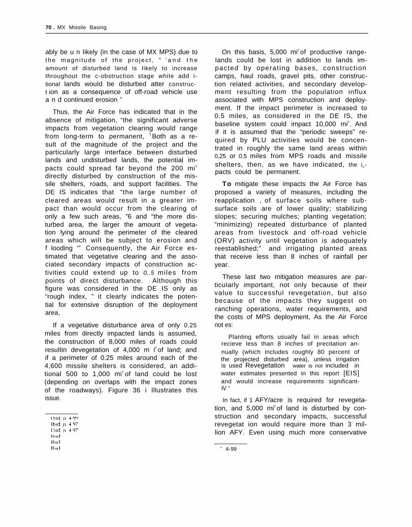
70 . MX Missile Basing
ably be u n Iikely (in the case of MX MPS) due tot h e m a g n i t u d e o f t h e p r o j e c t , ” { a n d t h eamount of disturbed land is Iikely to increasethroughout the c-obstruction stage whiIe add i-tionaI lands wouId be disturbed atter construc-t ion as a consequence of off-road vehicle usea n d continued erosion q
Thus, the Air Force has indicated that in theabsence of mitigation, “the significant adverseimpacts from vegetation clearing would rangefrom long-term to permanent, 5 Both as a re-sult of the magnitude of the project and theparticularly large interface between disturbedlands and undisturbed lands, the potential im-pacts could spread far beyond the 200 mi2
directly disturbed by construction of the mis-sile shelters, roads, and support facilities. TheDE IS indicates that “the large number ofcleared areas would result in a greater im-pact than would occur from the clearing ofonly a few such areas, ”6 and “the more dis-turbed area, the larger the amount of vegeta-tion lying around the perimeter of the clearedareas which wilI be subject to erosion andf looding ’” Consequently, the Air Force es-timated that vegetative clearing and the asso-ciated secondary impacts of construction ac-tivities could extend up to 0..5 miles frompoints of direct disturbance. Although thisfigure was considered in the DE IS only as“rough index, ” it clearly indicates the poten-tial for extensive disruption of the deploymentarea,
If a vegetative disturbance area of only 0.25miles from directly impacted lands is assumed,the construction of 8,000 miles of roads couldresuItin devegetation of 4,000 m i2 of land; andif a perimeter of 0.25 miles around each of the4,600 missile shelters is considered, an addi-tional 500 to 1,000 mi2 of land could be lost(depending on overlaps with the impact zonesof the roadways). Figure 36 i Illustrates thisissue.
On this basis, 5,000 mi2 of productive range-Iands could be lost in addition to lands im-pacted by operat ing bases, construct ioncamps, haul roads, gravel pits, other construc-tion related activities, and secondary develop-ment resulting from the population influxassociated with MPS construction and deploy-ment. If the impact perimeter is increased to0.5 miles, as considered in the DE IS, thebaseline system could impact 10,000 mi2. Andif it is assumed that the “periodic sweeps” re-quired by PLU activities would be concen-trated in roughly the same land areas within0,25 or 0.5 miles from MPS roads and missileshelters, then, as we have indicated, the im-pacts could be permanent.
To mitigate these impacts the Air Force hasproposed a variety of measures, including thereapplication , of surface soils where sub-surface soils are of lower quality; stabilizingslopes; securing mulches; planting vegetation;“minimizing) repeated disturbance of plantedareas from livestock and off-road vehicle(ORV) activity until vegetation is adequatelyreestablished;” and irrigating planted areasthat receive less than 8 inches of rainfall peryear.
These last two mitigation measures are par-ticuIarly important, not only because of theirvalue to successful revegetation, but alsobecause of the impacts they suggest onranching operations, water requirements, andthe costs of MPS deployment, As the Air Forcenot es:
Planting efforts usually fail in areas whichrecieve less than 8 inches of precitation an-nually (which includes roughly 80 percent ofthe projected disturbed area), unless irrigationis used Revegetation water is not incIuded inwater estimates presented in this report [EIS]and would increase requirements significant-I\/ q
In fact, if 1 AFY/acre is required for revegeta-tion, and 5,000 mi2 of land is disturbed by con-struction and secondary impacts, successfulrevegetat ion would require more than 3 mil-lion AFY. Even using much more conservative
9 4-99

Ch. 2—Multiple Protective Shelters ● 71
Figure 36. —Potential Vegetative Impact Zone
SOURCE Off Ice of Technology Assessment
assumptions, the DEIS notes that “a com-prehens ive revegeta t ion program wou ld bevery expensive. 10
These potential impacts of MPS develop-ment are especially significant in the contextof western regional development. During thepast decade, expanded energy developmentand population growth have greatly increased
+‘“1 10 Ibid
pressures on the physical environment to thepoint where they may be straining the region’slife support systems and there is increasingconcern about the potential spread of deser-tification throughout the region. Desertifica-tion generally refers to the degradation of aridlands to the point where they can no longersupport Iife, and it tends to break out, “usuallyat times of drought stress, in areas of naturallyvulnerable lands subject to pressures of land
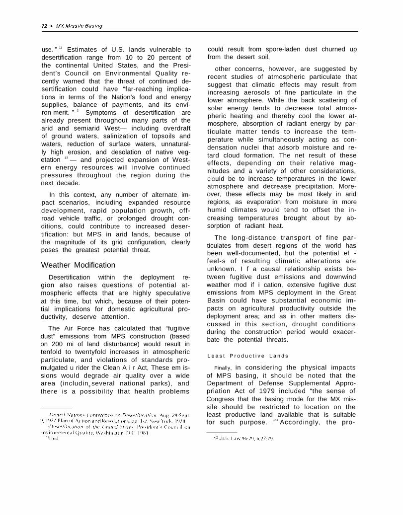
use. ” 11 Estimates of U.S. lands vulnerable todesertification range from 10 to 20 percent ofthe continental United States, and the Presi-dent’s Council on Environmental Quality re-cently warned that the threat of continued de-sertification couId have “far-reaching implica-tions in terms of the Nation’s food and energysupplies, balance of payments, and its envi-ron merit. ” 2 Symptoms of desertification arealready present throughout many parts of thearid and semiarid West— including overdraftof ground waters, salinization of topsoils andwaters, reduction of surface waters, unnatural-ly high erosion, and desolation of native veg-etation 13 — and projected expansion of West-ern energy resources will involve continuedpressures throughout the region during thenext decade.
In this context, any number of alternate im-pact scenarios, inciuding expanded resourcedevelopment, rapid population growth, off-road vehicle traffic, or prolonged drought con-ditions, could contribute to increased deser-tification: but MPS in arid lands, because ofthe magnitude of its grid configuration, clearlyposes the greatest potential threat.
Weather Modification
Desertification within the deployment re-gion also raises questions of potential at-mospheric effects that are highly speculativeat this time, but which, because of their poten-tial implications for domestic agricultural pro-ductivity, deserve attention.
The Air Force has calculated that “fugitivedust” emissions from MPS construction (basedon 200 mi of land disturbance) would result intenfold to twentyfold increases in atmosphericparticulate, and violations of standards pro-mulgated u rider the Clean A i r Act, These em is-sions wouId degrade air quality over a widearea (includin g several national parks), andthere is a possibility that health problems
could result from spore-laden dust churned upfrom the desert soil,
other concerns, however, are suggested byrecent studies of atmospheric particulate thatsuggest that climatic effects may result fromincreasing aerosols of fine particulate in thelower atmosphere. While the back scattering ofsolar energy tends to decrease total atmos-pheric heating and thereby cool the lower at-mosphere, absorption of radiant energy by par-ticulate matter tends to increase the tem-perature while simultaneously acting as con-densation nuclei that adsorb moisture and re-tard cloud formation. The net result of theseeffects, depending on their relative mag-nitudes and a variety of other considerations,C OuId be to increase temperatures in the loweratmosphere and decrease precipitation. More-over, these effects may be most Iikely in aridregions, as evaporation from moisture in morehumid climates would tend to offset the in-creasing temperatures brought about by ab-sorption of radiant heat.
The long-distance transport of fine par-ticulates from desert regions of the world hasbeen well-documented, but the potential ef -feel-s of resulting climatic alterations areunknown. I f a causal relationship exists be-tween fugitive dust emissions and downwindweather mod if i cation, extensive fugitive dustemissions from MPS deployment in the GreatBasin could have substantial economic im-pacts on agricultural productivity outside thedeployment area; and as in other matters dis-cussed in this section, drought conditionsduring the construction period would exacer-bate the potential threats.
L e a s t P r o d u c t i v e L a n d s
Finally, in considering the physical impactsof MPS basing, it shouId be noted that theDepartment of Defense Supplemental Appro-priation Act of 1979 included “the sense ofCongress that the basing mode for the MX mis-sile should be restricted to location on theleast productive land available that is suitablefor such purpose. ”14 Accordingly, the pro-

Ch. 2—Mu/tiple Protective Shelters ● 73
posed deployment area in the Great Basin ofNevada and Utah reflects this criteria, It is notthe /east productive land among the ,geo-technically suitable areas; but it is among theleast productive, and is considerably less pro-ductive than the High Plains regions that ex-tend from Texas and New Mexico up throughColorado and Nebraska to Wyoming,
However, the more productive agriculturallands have an inherently greater capacity toabsorb the impacts of construction activitiesand, in contrast to the Great Basin, could berevegetated with relative confidence. For thisreason, the totaI amount of land lost to agri-cultural productivity might be considerablyless than in areas where revegetation is moredifficult. If it is assumed that 200 mi of {andwouId be lost in a grassland ecosystem andthat the market value of crops is $80/acre/yr,then the total economic loss associated withthis basing option would be approximately$10.2 million per year. And if twice as muchland would be lost to agricultural productivityin the Great Basin, with the market at approx-imately $5/acre/yr, then the net agriculturalloss would still be less than 10 percent of thelost crop value in a grassland ecosystem.Based on this rough estimation, 3,200 mi’ ofrangel and would have to be lost to equal thelost agricultural value of 200 mi2 of crop land.
Therefore r if the impacts of MPS construc-tion can be confined to the designated areasduring construction, and mitigation measuresare not very expensive, the economic costs ofdeployment in “least productive lands” wouldappear to be considerably less than i n moreproductive croplands. But if it is assumedeither that the impacts will spread in aridlands, or that mitigation measures to preventthe spread of impacts will be more than $10mill ion per year, the economic costs of “ leastproductive lands” are Iikely to be at least asgreat as the costs of using more productivelands

74 . MX Missile Basing
larger populations (at least 10,000-25,000 peo-ple) have the capacity to absorb greater popu-lation influxes without suffering adverse af-fects. To the extent that infrastructures ofhousing stock, schools, roads, sewers, healthcare facilities, and administrative services allexist prior to rapid growth, these facilitiesoften can absorb much of the population in-crease, and the marginal costs of expandingservices and facilities are relatively small.Insofar as the Air Force siting criteria for MPSexclude areas with cities of more than 25,OOOpeople within 20 miles, adverse socioeconomiceffects wouId be essentiaIIy unavoid able
Based on recent experience with Westernenergy resource development, these i m pactswouId include a restructuring of the local jobeconomy as new jobs are created and existingresidents change jobs in hope of new oppor-tunities and higher wages; changes in the life-style of relatively isolated and closely in-tegrated communities; inadequate housing,roads, sewers, schools, health care facilitiesand administrative services; regional wage andprice inflation; and increased stresses on in-dividuals, families and communities. It is alsoworth noting that local residents are usuallyunable to compete successfully with newmigrants for skilled labor positions and higherpaying jobs, and that few new jobs go to un-employed residents of the area, fewer still towomen and minorities, and virtually none toIndians.
As a consequence of the influx of newmigrants with a relatively high proportion ofwell-educated or skilled laborers, competitionfor jobs does not always benefit existing com-munity residents. Existing businesses are oftenunable to compete with the higher costs ofwage and price inflation; new small businessoperations are frequently unable to competewith the high capital costs and risks associatedwith meeting rapidly expanding business op-portunities; existing residents may resent theinflux of new residents and associated changesin community lifestyles; incoming residentsoften find adjustment to reduced levels ofsocial services and amenities difficult; and in-
creases in alcoholism and child abuse tend toappear as manifestations of these increasingcommunity pressures.
Finally, in the isolated ranching, mining, andfarming communities of the Western States,social ties between families and neighborstend to be especially strong, and both admin-istrative government and the provision ofsocial services may be deeply rooted in in-formal community mechanisms. This relation-ship is true in general throughout the isolatedcommunities of the Western States, and it isparticularly true of the Mormon communitiesof southern Utah, in which the integral rela-tionship between church, family, and com-munity wouId be profoundly disturbed by theinfIux of a large number of migrants who couldnot be assimilated into the fabric of thiscu It u re.
These issues are complicated by the factthat the Western States are in a process ofrapid growth and transformation, and that vir-tually all of the available Iiterature has beendrawn from experiences with western energyresource developments that have been rel-atively large in relation to the existing com-munity sizes, but that are relatively smalI incomparison with the manpower requirementsand geographic expanse of MPS. In contrast tolarge-scale coal-fired powerplants and syn-thetic fuel facilities with construction workforces of 2000 to 5,000 people, located atspecific sites that could be clearly defined inrelation to the surrounding communities, es-timates of the baseline construction workforce for MPS range from 15,000 to 25,000 peo-ple; and the Air Force is considering the use ofas many as 18 temporary construction campsspread throughout a geographic area of 15,000m i2 for construction of MPS, Furthermore,there is evidence to suggest that in several in-stances the net impact of rapid growth onsmall communities has been positive. Follow-ing the boom-bust cycles of rapid growth anddecline, the communities have readjusted tolifestyles closely resembling preimpact condi-tions, but with the added benefits of expandedfacilities resulting from an increased popula-tion base,

Ch, 2—Mu/t/p/e Protective Shelters ● 75
Thus, it might be the case that individualcommunit ies within the deployment areamight benefit from MPS deployment, or alter-nately, that the effects of MPS deploymentmight be indistinguishable from the effects ofaccelerated mineral resource and energy de-velopment in surrounding areas. I n general,however, it appears that the residents of smallcommunities in the deployment area would beunlikely to benefit from MPS development,and probably would face the loss of existingranching and mining operations within thearea
At the same time, the larger urban areas onthe periphery of the deployment area would beaffected by MPS development in a totally dif-ferent way Unlike small towns faced withneither the administrative nor the financialcapac i t i es to accommodate large-scalegrowth, larger urban areas with these capa-bilit ies would be faced with uncertainties r e-g a r d i n g t h e m a g n i t u d e a n d t h e l o c a t i o n o f t h e
g r o w t h t h a t m i g h t o c c u r . u n l i k e l a r g e - s c a l e
energy developments in which clearly definedlocations for planned facilit ies reduce theuncertainties of planning decisions to ques-tions of timing, financing, and scale, themagnitude of MPS and geographic dispersionof the proposed development complicatesthese issues substantially
In contrast to large-scale powerplant devel-opments with construction work forces of2'000 to 4,000 people, estimates of the onsitework force required for MPS developmentrange from 15,000 to 25,000, and OTA’S anal-ysis indicates that actual construction workforce requirements could be as high as 40,000people In this case, the total population im-pacts of MPS could be in excess of 300,000people Because regional economic impactsare a function of the magnitude and distribu-tion of the work force population and asso-ciated growth, and the range of possible popu-lation impacts is so great, it is worth looking atthe basis for these figures in some detail.
Work Force Estimates
The Air Force has estimated that MPS con-struction wouId require a peak construction
work force of 17,000 workersIation of slightly more thanperiod of overlap betweentivities and initial operations
and a total popu-100,000 during aconstruction ac-
Figure 37 illustrates the approximate rela-tion between the population of the construc-t ion work force, operating personnel, and theirdependents.
I n fact, these figures represent conservativeestimates By the time the DE I S had been pre-pared, the construction work force figures hadbeen revised upwards almost 40 percent* –and they fail to reflect the uncertainties thatare associated with all of these estimates
Figure 38 illustrates the direct constructionwork force estimates (including onsite and“life support” labor) of the Air Force, the ArmyCorps of Engineers, and joint Air Force/ArmyCorps task force on manpower estimates. Fig-ure 39 illustrates the relationship between on-
-—‘ 1 he [)r,]t t f ni lronn~<’nt ‘I I I 11)1)<1( t \t ,Itt’nl{’nt on Artl,) ${JI(I(
t Ion w a ~ pu hl I >h(’d ,] 1( )n x m It h <In t’rr<] t ‘i iht’t~t M h I ( h ( ont,1 I n~’(j
re~’ I ~t’(1 work t or( (’ (>~t I m‘] t t~i h,1 itlci () n ,) I ( ) I n t t,1s k t [ ) r( t, { )t t h(’
Figure 37.—Construction Work Force, OperatingPersonnel, and Secondary Populations
110 I I
Direct andindirectpersonnel +dependent(1000s)
100 “
90 —
80 —
70 —
60 —
50 —
40 —
30 —
20 — Construction
10 —
o1980 1985 1990 1995 2000
Year
SOURCE U S AIr Force

76 ● MX Missile Basing
Figure 38.— Baseline Work Force Estimates24
-
22 - Legend
20 -— A C E‘ o — A . F .
18
16
14
12 —
10 —
8 —
--
6
4 -
2-
82 83 84 85 86 87 88 89 90Annual average direct construction work force (including life support)
A. F./DElS 1,150 2,000 4,450 10,800 17,050 15,450 13,050ACE 1,160 6,940 14,305
4,80019,750 23,730 16,900 12,670
A. F.IACE 2,035 5,590 9,5104,725
17,910 18,560 17,670 12,765 5,490
SOURCE A F /DEIS Chapter 1, Errata Sheet, Table 11
site construction labor estimates and estimatesof the total construction work force required.
Estimates of the costs and manpower re-quirements of major construction projects,however, have characteristically underesti-mated actual costs and manpower needs. Evi-dence from various studies of this problemsuggests that these overruns resuIt in part fromrevisions in engineering designs while con-struction is in progress, delays caused by latedeliveries of major components or bottlenecksin materials supplies, and difficulties in utiliz-ing manpower and materials efficiently on atime-urgent schedule. Tables 9 and 10 providetwo indices of these problems. Table 9 in-
dicates the average cost overruns in weaponssystems, public works projects, major con-struction projects, and energy process plants,and table 10 compares the projected and ac-tual manpower needs of large-scale coal-firedpowerpIants.
If all overrun factor of 73 percent is assumedon the basis of the average manpower overrunassociated with coal-fired power-plants in theWest * the manpower estimates for MX/MPSwould increase to more than 42,000. As a I so
‘ The average manpower overrum from coal p o w e r p l a n t s
I n the West is used here because it represents construction of a known technology (rat her than a new” technology) in the arid
West Other pro jec ts such as nuc lear powerp lant o r syn the t i c
f u e l p l a n t s i n v o l v e h i g h e r d e g r e e s o f n e w t e c h n o l o g h d e v e l o p -
ment

Ch, 2—Multiple Protective Shelters ● 7 7
Figure 39.—Comparison of Onsite and Total Construction Work Force
26
24
22
20
18
16
14
12
10
8
6
4
2
Legend
— — — C o n s t r u c t i o n o n l y
Total “.
.
\●
.
/
\●
● \
82 83 84 85 86 87 88 89
Year
Constructiononly 1,832 5,031 8,559 16,120 16,700 15,900 11,490 4,941Life support 203 559 951 1,790 1,660 1,770 1,275 549Assembly andcheck out o 400 1,000 3,550 6,000 6,000 5,900 5,750
Total 2,034 5,990 10,510 21,460 24,564 23,670 18,665 11,240
SOURCE Off Ice of Technology Assessment
Table 9.—Cost Overruns in Large-Scale Projects
Actual cost/Type of system estimated costWeapons system ... . . . . . . . . . . 1.40-1.89Public works. ., ., ... ... . . . . 1.26-2.14Major construction ., ... ... . . 2.18Energy process plants. . . . . . . . 2,53
SOURCE Office of Technology Assessment, 1981

78 ● MX Missile Basing
Table 10.—Estimated and Actual Construction an accelerated construction schedule and 73Work Forces for Coal-Fired Powerplants percent to allow for manpower overruns.—
-- Estimated Actual Percent ‘Plant (and State) peak peak change
A n t e l o p e V a l l e y - P o p u l a t i o n E s t i m a t e s(N. Dak.). . . . . . . . . . 840 1,370 + 63
Boardman (Oreg.) . . . 760Clay Boswell (Minn.) 900Coal Creek (N. Dak.). 980Laramie River (Wyo.). 1,390White Bluff (Ark.). 1,100
1,4821,5602,1132,2001,900
+ 83+ 73+ 91+ 58+ 72
Similar uncertainties affect estimates of thesecondary populations associated with theconstruction work force. Assumptions must bemade regarding the ratio of new secondary em-ployment (e. g., construction of new housing,grocery stores, gas stations, etc., ) by MPS con-
Figure 40.—Construction Work Force: High-Range Projection
65
60
55
50
45
40
35
30
25
20
15
10
5
—Legend: —
Baseline construction work forcePIUS 600/0
Plus 73 ”/0
●
●
●
✍
✎
●
●
82 83 84 85 86 87 88 89
Year
Baseiineconstructionwork force 2,034 5,990 10,510 21,460 24,S60 23,670 18,666 11240Plus SO% 3 a 9,884 16,816 34,336 39,296 37,872 29,864 17,964
Plus 73 ”/0 5,630 16,860 29,091 59,401 67,993 65,518 51,664 31,112
SOURCE Off Ice of Technology Assessment

Ch. 2—Mu/tiple Protective Shelters ● 7 9
struct ion and operations, and addi t ionalassumptions must be made regarding thedemographic characteristics of the construc-tion work force. Despite the fact that the char-acteristics of western energy project construetion labor forces have been studied, significantuncertainties exist, and the popuIation impactsof MPS couId vary considerably depending notonly on the number of construction workers in-volved, but the relative numbers of single andmarried workers, and choices they make re-garding residential locations and commutingalternatives. Using the Task Force baseline es-
timate of construction work force size (see fig.38), figure 41 illustrates the range of secondarypopulation growth associated with the basecase assumptions using three different sets ofdemographic assumptions,
Finally, if these factors are considered inconjunction with one another, a wider range ofpopulation growth scenarios results. Figure 42illustrates the range of possible populationgrowth scenarios resulting from alternate as-sumptions regarding the location and demo-graphic characteristics of the primary work
Figure 41.— Range of Secondary Population Growth
# - - -120 . S c e n a r i o 1
- - S c e n a r i o 3 S c e n a r i o 5
/ ’105
/ \90
\
x
82 83
I ITable 2 summarizes these data:
Scenario 1 3,404(x 1 .73)
Scenario 2 2,839(x 1 73)
Scenario 3 4,356(x 1 73)
Scenario 4 2,493(x 1 .73)
Scenario 5 2,174(x 1 73)
1982
18,289
12,594
29,689
7,380
6,412
1983
Scenar io 1 0511 s ing le + 0.489 marr iedScenario 2 0375 single + O 25 married +Scenario 3, all workers marriedScenario 4. all workers singleScenar io 5 a l l workers shut t led
8 4 8 5 8 6
I 1 Year I
—
32,576 6 7 , 6 8 1 78,796
22,382 27,789 53,595
53,167 110,876 129,458
12,872 26,346 30,313
11 ,2?5 22,940 26,303
1984 1985 ‘- 1986
0375 shuttled
87 88
I I
—.
76 ,949 62,035
51!917 41,895
126,668 102,449
29,371 23,313
24,629 20,070
1987 1988
89
I
38,699
25,944
64,333
14,169
12,127
1 9 8 9
S O U R C E E R C p 2 0 / O f f i c e o f T e c h n o l o g y A s s e s s m e n t
“ /footnote from page 25
SOURCE Off Ice of Technology Assessment

80 . MX Missile Basing
Figure 42.— Range of Potential Population Growth
360
340 —
320 —
300 —
280 —
260 —
240 —
220 —
200 —
180 —
160 —
140 —
120 —
100
t -80 —
60 “
40 —
20 / / — — ~ -- - *
0 I I 1 I
82
- Accelerated construction;73% overrun; all workersmarried 12,057
Accelerated construction50% 0 married workers 5,446A.F. base case; no over-runs; all workers shuttled 2,174
83 84 85 86 87 88 89
A c c e l e r a t e d c o n s t r u c t i o n ;73% overrun;all workers married
A c c e l e r a t e d c o n s t r u c t i o n50°/0 married workers
A . F . B a s e c a s e ;no overruns;all workers shuttled
82,179 147,166 306,904 358,339 350,617 283,578 178,073
29,262 52,121 108,289 126,072 123,118 99,256 61,918
6,412 11,225 22,940 26,303 24,629 20,629 12,127
SOURCE Off Ice of Technology Assessment


82 MX Missile Basing
Figure 43.—Cumulative Energy Activity in the West
SOURCE AbtlWest. 1981
neers, and experienced managers, is regardedas highly mobile and projected to be in shortsupply, the labor requirements of MPS con-struction could affect resource developmentthroughout this 10-State area. Training pro-grams are underway to offset some of theselabor shortages in several States, but they areunlikely to have a major effect on the short-ages because many of the skiIled positions re-quire training and experience (that are in turn
dependent on skilled instructors) and becausethe clemand for labor changes rapidly withconstruction plans and scheduIes.
System Schedule
The MX/MPS schedule is highly success-oriented and requires specific actions by Con-gress if both IOC and FOC are to be achieved.Given these actions and no major develop-

Ch. 2—Multiple Protective Shelters ● 83
ment problems, it is possible both dates can beaccomplished. In all probability, however,some SIip in IOC shouId be expected. The cur-rent DOD review of basing options is delayingactions required to ensure even a possibility ofmeeting IOC Unless a timely decision is made,Ieadtimes required will inevitably cause adelay in achieving the IOC date.
Table 11 .—System Time Schedule
Land withdrawal appl icat ion f i led 7181Legislation to Congress ., . 1/82L e g i s l a t i o n a p p r o v a l 5182S A T A F a c t i v a t e d , . 1182Start construction to operating base 4182Firstmlsslle test flight . 1/83Misslesslle production contract award . 7183DSARC III-missile . 7183S t a r t c o n s t r u c t i o n i n d e p l o y m e n t a r e a 1/83First cluster available 8/85Ful l base support avai lable 9185Initial operating capability 7186
SOURCE Off Ice of Technology Assessmen t
Most of the land required for the preferredAir Force basin g location for MX/MPS isFederally owned and under the control of theBureau of Land Management, Department ofthe Interior (DO I) Transfer of the necessaryland to DOD requires congressional approval.The schedule, as planned by the Air Force, ispredicated on a basing decision in June 1981,and allows a public comment period betweenJuly and October, with the legislative packageready for congressional consideration in jan-uary 1982 Final approval and land availabilityis scheduled for May 1982.
A June 1981 basing decision did not takeplace while the Air Force and DO I are explor-ing means of expediting the withdrawal ap-plication process, the application must bespecific in terms of base and deployment area,and both the land withdrawal application andcongressional enabling legislation will have toaddress complicated issues such as the landclaims of the Western Shoshone and Stateschool lands in Utah. Slippage of the landwithdrawal action would impact all otherdates associated with base and deploymentarea construction and Ieadtimes would also berequired to ensure adequate electric powersupplies, to purchase water rights where need-ed, and to obtain necessary permits, Although
it is difficult to assess the extent of slippagelikely to occur, it is doubtful that an IOC of1986 can be met, and system costs would esca-late along with any slippage in IOC, Fore-seeable slippages could also impact FOC, al-though a slip in IOC would not necessarily de-lay final operating completion,
The missile deployment and productionschedule may also present some problems. Aproduction decision is scheduled early in theflight test program, and, in fact, before themissile-cannister-shelter tests take place. I n ad-dition, long Ieadtime materials’ authorizationis scheduled to occur in February 1983, or 1month after first flight and 5 months beforethe production decision Problems in the flighttest program under these conditions couldlead to overall program delays, renegotiationof production contracts, and, perhaps, sub-stantially increased costs. It is also not clearthat the Air Force has the authority to releasecontracts for long leadtime material before theproduction decision is formalized
The countermeasures subsystem, both forthe missile and for the decoy system, also maypresent scheduling difficulties Long Ieadtimeitems for prototype systems were scheduledfor approval in April 1981. This has not oc-curred, and the delay wilI probably postponeinitial deliveries of prototype hardware andimpact on qualification tests and perhaps themissile test program itself.
The formal submittal of a budget estimatefor funding deployment area construction isscheduled for October 1981. This submittalwiII include an update of MiIitary ConstructionProgram (MCP) costs based on the outputs ofthe 1980 Systems Design Review a site-spe-cif ic estimates of protective shelter cost.Theuncertaintaties introduced by the DOD review of basing options tend to inhibit the deveopmentof background material and internal Air force- DOD review of the revised baseline estimates supporting the budget request Delays in thebasing decision may make it difficult for theAir Force to adhere to the normal budgetingscheduIe and prduce estimates with the de-gree of accuracy recuired red This problem wiII

84 ● MX Missile Basing
—
be intensified if the basing decision is otherthan horizontal shelters in the Nevada-Utaharea
In OTA’S judgment, the IOC date is likely toslip 6 months to 1 year. A slip in IOC datewould increase costs by approximately $7smill ion per month, so that the anticipated in-crease in MX/MPS cost wouId be on the orderof $0.5 billion to $1,0 billion. Given a decisionto proceed with adequate funding on a year-to-year basis, OTA believes that the FOC datecould be achieved even with the IOC SIippage.This belief is predicated on the fact that fund-ing and procedural mechanisms are providedso that long Ieadti me resources can be mar-shal led for use when required,
System Cost
OTA had an independent cost assessmentconducted of the Air Force baseline system.The cost was estimated for all stages of thesystem, from development and investmentthrough operation and support for 10 years ofdeployment.
In determining system cost, it should beunderstood that the baseIine configuration forMPS is not yet firmly fixed, as certain tech-nological tradeoffs are still being consideredby the Air Force. The Air Force is in the processof updating costs, but until the baseline con-figuration is finalized, new estimates are con-sidered internal Air Force data and were notmade available for OTA’S analysis. In lieu ofthis data, the Air Force provided detailed brief-ings covering methods used to estimate costsand provided substantial backup material tosupport their previous estimate of $33.8 biIIion(fiscal year 1978 dollars) In addition, the draftenvironmental impact statement (DE IS), par-ticularly its technical appendices, contains ad-di t ional information useful for est imatin g
costs. Also, some of the design changesadopted as a result of the late-l 980 designreview have been incorporated into the es-timate. Inputs drawn from the backup materialsupplied by the Air Force have been used butapprop r iate ad jus tments have been made,
based on information contained in the DE IS
and other published sources. Therfore, a sys-tems configuration has been selectected as abasis for cost analysis that is compatible withAir Force plans but which is SIightly different indetail from the configurate ion used for the pre-vious Air Force estimate
There is some contusion about the Air Forcebaseline estimate A cost of $33.8 billion isoften quoted This dllar figure refers to thebaseline estimate, in constant 1978 dollars,and incIudes 1 ()-year O&S (operation and sup-port) costs for a tot alI lifecycle cost This figurewhen escaIated to 1980 dolIars is $399 biIIionIifecycle cost, with a total acquisition cost of$338 bilIion (This estimate also excludes thecost of i m pactmitigation ) The Air force'sbaseline estimate for the 4,600” shelter systemif shown in table 12
Table 12.—Air Force Baseline Estimate 4,600Shelters (June 1978) (billions of dollars)
FY78$ FY80$
Development (RDT&E) . . . . . . . . $ 6.7 $ 7.9
InvestmentAircraft procurement . . . . . . . $ 0.3 $ 0.3Missile procurement . . . . . . . 12.6 14.9Military construction . . . . . . . 9.0 10.7
Total investment ., . . . . . . . $21.9 $25.9Total acquisition. . . . . . . . . $28.6 $33.8
0 & s costs . . . . . . . . . . . . . . . $ 5,3 $ 6,1
Llfecycle costs . . . . . . . . . . $33.8 $39.9SOURCE U S Air Force
Because of the controversy over these es-timates, it is important to understand the con-ditions under which they were developed, andtheir degree of accuracy. The MX Program hascons idered a wide variety of basing modes, in-cluding silos, trenches, and air mobile in add i-tion to the present horizontal plan. For eachbasing mode, several configurations werestudied and costed, an important considera-tion for each mode. In order to have a quick-response estimating capability with a reason-able degree of accuracy, a cost model was de-veloped by the Air Force. This model wasparametric, in which cost factors were de-veloped for specific characteristics (or param-eters) that describe a particular function, and

Ch. 2—Multiple Protective Shelters . 85
estimating. While it is not too difficult to es-timate the construction cost of a given struc-ture, the estimating process becomes verycomplex under the conditions that exist forMPS. First, the workers must be recruited out-side the deployment area since the skills andnumbers required probably do not exist local-ly. Because of this situation, temporary con-struction camps must be established and hous-ing, food, recreation, and heaIth care must beprovided for the workers. Everything from con-struction materials to loaves of bread must bebrought into the area over what is, at best, alimited transportation network. In addition,the technical facilities must meet exactin g
standards to ensure survivability, postat tacklaunch capability, and to protect PLU Thus, inaddition to construction workers, there mustbe managers and inspectors to ensure qualitycontrol, personnel to prepare food, truckdrivers to provide transportation, clerks to re-ceive and store materials, and a number ofother supporting personnel, Solid and liquidwaste must be disposed of i n an environmen-talIy acceptable manner.
Other are as where precise cost estimatesdifficult include:
MX missile. ‘The decision for full -scale pro-duct ion is scheduled to be made longbefore the flight test program is com- p I eted and before the missile/cannisterc o m b i n a t i o n h a s b e e n t e s t e d . S u c h a p r o - -
gram is feasible, but risks c o m p l i c a t i o n slate in the test program causing designc h a n g e s , d e I a y s , a n d p r o d u c t i o n c o s tcreases over those estimated.
Missile Decoy. This system, vitsl to the v iability of MPS is not yet fully designed Projected development and procurement cost are highly uncertain at this time.
Missile Transporter. This transporter will bethe largest truck-like vehicle ever con-structed and it includes highly sophis-ticated automatic controls, communica-tions, and decoy systems.
Command, Control, and Communications(C). Not all portions of this subsystemhave been specified at this time,

86 ● MX Missile Basing
● Electromagnetic Pulse (EMP) Hardening. Itdoes not appear that sufficient attentionto quality control was reflected in theoriginal Air Force estimate. Welds on thesteel Iiners installed in the Safeguard ABMsystem for EMP purposes were found tobe a problem requiring special inspectionprocedures, The MPS documents do notdiscuss the welds required on the steelIiner installed in each shelter.
With the exception of construction issuesand the missile decoy, these uncertainties arenormal for advanced and complex weaponssystems at this stage of development. If theearlier Air Force estimate of $33.8 billion hasnot properly assessed the support required toaccomplish the construction program, the es-timate could be substantially low. An error inestimating the cost of individual protectiveshelters is greatly magnified because a mini-mum of 4,600 shelters is required. Similarly, in-adequate consideration of resources requiredto support the construction effort will be mag-nified because of the remoteness of the pro-posed deployment area.
Notwithstanding these uncertainties, a com-parison of the Air Force baseline estimate toOTA’S estimate has been made (see table 13).OTA estimates the total acquisition cost forthe Air Force baseline, with 4,600 shelters, is$37.2 billion (fiscal year 1980 dollars), and atotal Iifecycle cost of $43.5 billion. As pre-viously mentioned, the OTA estimate is $3.5billion greater than the 1980 baseline estimatedeveloped by the Air Force. This differentialincludes:
●
●
●
●
●
$06 billion in schedule contingency formissile RDT&E,$0.7 billion for engineering changes in sys-tem components,$0.6 billion in construction costs primarilyassociated with increased life supportcosts,$0.7 bill ion in A&CO costs reflectingmilitary pay for the Air Force personnel in-volved in this activity,$0.9 billion in other adjustments.
As indicated in table 13, the Air Force hasnot budgeted costs for the MX program forprogram management and its Site ActivationTask Force,
Cost and Schedule of Expandingthe MX/MPS
As noted above, the proposed 4,600-sheltersystem represents a baseline scenario. How-
Table 13.—Comparison of Air Force and OTA CostEstimates (billions of fiscal year 1980 dollars)
USAF OTAbaseline baselineestimate estimate
DevelpmentMissile related . . . . . . . . . . . . .Base related . . . . . . . . . . . . . . .Other. . . . . . . . . . . . . . . . . . . . .
InvestmentNonrecurring production . . . .Equipment procurement
Missile system . . . . . . . . . . .Transporter/vehicles . . . . . .Decoy . . . . . . . . . . . . . . . . . .C3 . . . . . . . . . . . . ., . . . . . . . .
Ground power. . . . . . . . . . . .Physical security . . . . . . . . .Support equipment . . . . . . .Aircraft procurement. . . . . .
Total equipment & spares
Engineering change order. . . .Facilities construction . . . . . .Assembly and checkout . . . . .Program management. . . . . . .Site activation task force . . . .
Operating and supportReplenishment spares . . . . . .System modifications . . . . . . .Depot maintenance . . . . . . . . .Operations and maintenance.Military personnel . . . . . . . . . .Civilian personnel . . . . . . . . . .Training. . . . . . . . . . . . . . . . . . .Other . . . . . . . . . . . . . . . . . . . . .
Total Iifecycle cost ., . . . . . . . . .
$ 5.0252.839
.710$8.574
$ 1.110
4.9901.6342.3210.9150.5420.3351.6920.350
$12.779$ –
10.0351.318
$25.242
$ 0.6470.1870.2271.4802.0770.4100.1920.910
$6.130$39.946
$ 5.0252.8371.310
$9.172
$ 1.110
5.2261.6342.3210.9150.7560.3351.6920.439
$13.320
$0.66610.649
1.9950.2220.037
$27.999
$0.6470.2340.2271.6112.0770.4100.1920.910
$6.308$43.479
SOURCE Office of Technology Assessment
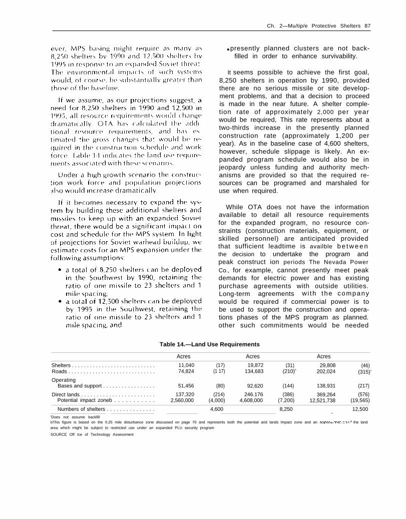
Ch. 2—Mu/tip/e Protective Shelters 87
● presently planned clusters are not back-filled in order to enhance survivability.
It seems possible to achieve the first goal,8,250 shelters in operation by 1990, providedthere are no serious missile or site develop-ment problems, and that a decision to proceedis made in the near future. A shelter comple-tion rate of approximately 2,000 per yearwould be required, This rate represents about atwo-thirds increase in the presently plannedconstruction rate (approximately 1,200 peryear). As in the baseline case of 4,600 shelters,however, schedule slippage is likely. An ex-panded program schedule would also be injeopardy unless funding and authority mech-anisms are provided so that the required re-sources can be programed and marshaled foruse when required.
While OTA does not have the informationavailable to detail alI resource requirementsfor the expanded program, no resource con-straints (construction materials, equipment, orskilled personnel) are anticipated providedthat sufficient leadtime is availble b e t w e e nthe decision to undertake the program andpeak construct ion periods The Nevada PowerCo., for example, cannot presently meet peakdemands for electric power and has existingpurchase agreements with outside utilities.Long-term agreements w i th the companywouId be required if commercial power is tobe used to support the construction and opera-tions phases of the MPS program as planned.other such commitments would be needed
Table 14.—Land Use Requirements
Acres Acres Acres
Shelters . . . . . . . . . . . . . . . . . . . . . . . . . . . . 11,040 (17) 19,872 (31) 29,808 (46)Roads . . . . . . . . . . . . . . . . . . . . . . . . . . . . . 74,824 (1 17) 134,683 (210)b 202,024 (315)’
OperatingBases and support . . . . . . . . . . . . . . . . . 51,456 (80) 92,620 (144) 138,931 (217)
Direct lands . . . . . . . . . . . . . . . . . . . . . . . . 137,320 (214) 246.176 (386) 369,264 (576)Potential impact zoneb . . . . . . . . . . . 2,560,000 (4,000) 4,608,000 (7,200) 12,521,738 (19,565)
Numbers of shelters . . . . . . . . . . . . . . . 4,600 8,250 12,500aDoes not assume backfill
—
bThis figure is based on the 0.25 mile disturbance zone discussed on page 70 and represents both the potential arid lands lmpact zone and an approxlfnatlon of the land
area which might be subject to restricted use under an expanded PLU security program
SOURCE Off Ice of Technology Assessment

Number of shelters
4-,600 8,2<0 12,500
DevelopmentM i : ; s i l e . . . . .B a s i n gOther. . . . . . . . . . . . . .
l-otal . . . . . . .
InvestmentMissile . . . . . . . . . . . . .C a n n i s t e r l l a u n c h e rTransporter .Const ructioniactlvat ionOther. .
l-otal ... .
O p e r a t i n g a n d s u p p o r tcosts
Anlual ... . . . . . . .
Lifecycle costsTo FOC . .To the year 2000. . . . . . .To the year 2005, . . .
Operating personnelM i l i t a r y p e r s o n n e l .C iv i l i an pe rsonne l . .
l-otal . . . . . . . . .
$ 5.0 $ 5.0 $5.02.9 3.0 3.11.3 1.4 1.5
$ 9.2 $ 9.4 $ 9 . 6
$ 4.3 $ 6.1 $8.10.9 1.5 2.21.4 2.4 3.6
12.6 19.9 28.58.8 13.7 19,1
$28.0 $43.6 $61,5
$ 0.469 $ 0.719 $ 0,969
$38.6 $55.2 $77.7$43.5 $62.4 $82.6$45.7 $66.0 $87.4
10,900 16,450 22,0001,700 2,600 3,500
12,600 19,050 25,500—SOURCE Off Ice of Technology Assessment
SOURCE Off Ice of Technology Assessment

Ch. 2—Multiple Protective Shelters ● 89
This method provides reasonable cost es-timates for comparative purposes. Time andinformation available for the estimate did not,however, allow for a full investigation of theimpact of the increased requirements forscarce resources (some missile materials andpropellants) or the potential impacts of eco-nomics or diseconomies of scale on the con-struction program. Final estimates, thereforecontain a significant degree of uncertainty andfurther analysis is required before actual fund-ing levels can be determined with precision.
Split Basing
The proposed MX/MPS basing plan calls forthe location of all shelters and support fa-ciIities over a broad geographic area. De-ployment clusters would be located in valleysof the Great Basin and would be separated bythe mountain ranges which separate thevalIeys; but the system would otherwise beoperationaIIy contiguous.
The “split basing” option would be similar inall functional respects except for the fact thata large area of nondeployment land would sep-arate the operational deployment areas. Inboth cases the same number of missiles,shelters, and land area would be involved, andin both cases there would be two operatingbases. Figure 44 shows the geographic distribu-tion of the proposed Air Force split basingalternative.
From an operational standpoint, there areno significant differences between contiguousbasing and split basing, Both alternatives re-
Figure 44.— Proposed Split BasingDeployment Areas
1’-
\ \ ———
- - ——— /.— — —— — ——,— — —— — — -
Legend
_ Suitable areas
u Unsuitable areas
0 Candidate sltlngregions
—— State boundary
SOURCE A F IDEIS
quire the same number of missiles, shelters,and operating bases; and both have the samefunctional requirements for command, con-trol, communications, security, and support.
From the standpoint of the costs of con-struction and the environmental impacts, how-ever, there are several notable differences,
First, construction of split basing would costapproximately 10 percent more than the base-line, as there would be some necessary du-plication in geotechnical investigations, inelectronic and mechanical systems, in trans-portation and logistics, and some additionalcosts in land acquisition resulting from theneed to negotiate easements or title for alarger percentage of private lands. (See table1 7.)
Second, impacts on both the physical envi-ronment and the regional economy could besubstantially different. Although the generalnature of the impacts would be fundamentallythe same as those resulting from the proposedbasing option, specific impacts could differ
83-4-7 - 1 -

90 ● MX M\ssile Basing
Table 17.—Air Force Estimates of Additional SplitBasing Costs (in millions of fiscal year 1980 dollars)
RDT&E . . . . . . . . . . . . . . . . . . . . . . . . . . . . . . . . . . .
Geotechnical . . . . . . . . . . . . . . . . . . .Electronics . . . . . . . . . . . . . . . . . . . . .Mechanical , . . . . . . . . . . . . . . . . . . .Deployment . . . . . . . . . . . . . . . . . . . .
Procurement . . . . . . . . . . . . . . . . . . . . .Airborne lunch control . . . . . . . . . . .Helicopters . . . . . . . . . . . . . . . . . . . .Initial spares . . . . . . . . . . . . . . . . . . .Mechanical . . . . . . . . . . . . . . . . . . . .Electronics . . . . . . . . . . . . . . . . . . . . .Logistics . . . . . . . . . . . . . . . . . . . . . . .Initial spares . . . . . . . . . . . . . . . . . . .Deployment . . . . . . . . . . . . . . . . . . . .
(A&CO and training)
Milton . . . . . . . . . . . . . . . . . . . . . . . . . . .Real estate . . . . . . . . . . . . . . . . . . . . .Road network.. . . . . . . . . . . . . . . . . .Remote surveillance . . . . . . . . . . . . .Construction O&S . . . . . . . . . . . . . .Training facilities . . . . . . . . . . . . . . .Design funds . . . . . . . . . . . . . . . . . . .Designated assembly area and
contractor support area. . . .
Total . . . . . . . . . . . . . . . . . . . . . . . . . . .
$ 632716
5
. . . . . .59291028
15763
$1,761
. . . . . .$ 527
5311325441
465
. . . . . .
$ 121
2,171
$1,183
$3,475
SOURCE US Air Force
significantly based on the site-specific char-acteristics of the impact regions.
In general split basing would mitigate theimpacts on the physical environment by dis-persing the direct impacts, and could have theeffect of avoiding impacts on certain areasaltogether, or avoiding critical thresholds inpart icular instances. In regard to socio-economic impacts, split basing would com-plicate the issues of land-acquisition and in-tegrated planning, but offers the possibilitythat impact levels would be within the man-agement capabilities of more communities,and thus result in more beneficial impacts andfewer boomtown conditions.
In the case of socioeconomic impacts theremay be a third qualitatively different type ofimpact associated with split basing. In addi-tion to the reduction of adverse impacts noted,and cases in which the reduction in impacts ef-fectively eliminates the adverse impacts (e.g.,a case in which the reduced growth level re-
sulted not only in a reduction of the level ofovercrowding in schools, but reduction to alevel that presented no over-crowding), splitbasing could transform negative impacts intopositive impacts in instances where the level ofnew growth was with in the carrying capacity ofthe existing social infrastructure.
Thus, not only would the level of negativeimpacts be reduced, but in many smalI com-munities, and most Iikely in the larger townsclose to the operating base areas, negative im-pacts could become positive impacts,
Physical Impacts
Based on the Air Force resource analysisrelevant to the split basing option, it is ap-parent that split basing would have significant-Iy less impact on wildlife and the physical en-vironment than the baseline option. * (See fig.45,’)
There are, however, other complicating fac-tors regarding the proposed split basing op-tion. In the Great Basin of Nevada and Utah,virtually al I of the land is owned by the FederalGovernment, and the dominant economic ac-tivities (ranching and mining) are subject tolease and permit authorities. In the split basingdeployment area of New Mexico and westTexas, 95 percent of the land is in privateownership and is used primarily for cropproduction and livestock. The differences be-tween use of rangeland and cropland, and thedifferences between private and public owner-ship of the land, raise potentialIy significantquestions. First, as noted above, the use ofcroplands would take a greater amount of agri-cuItural land directly out of production; but,the higher productive capacity of the landwould also facilitate restoration of the im-pacted areas. AS a result, considerably lessland would be likely to be lost from produc-tivity.
‘ See D[ 15 ma(rll, and J(I p 1-1, includfng vegetat ion, habi tat ,
a n d p r o t e c t ed a n d e n d a n g e r e d spec Ies Add It Iorlal I y, the Alr
Eorce has Ind icated that impacts on the c haracterl~tlcs of the
prl~tlne environment, archaeological and historical sites, local
pc,pulations, and econornlc adjustment, would also be reduced
urlder the SPI It basing opt Ion

Ch. 2—Multiple Protective Shelters ● 91
Figure 45.—Summary Comparison of LongTerm Impact Significance Betweenthe Proposed Action and Split Basinga b
Natural environment resources I
Proposed DDA (Nevada/Utah]
act ion 1 –OB (Coyote Spring Clark Co )(PA)
2– OB (Milford/Beaver Co
DDA (Nevada Utah)
Sp l i t bas ing DDA (Texas New Mexico)
1— OB {Coyote Spring Clark Co
2—OB (ClOVIS Curry Co )
Human environment resources I
Act Ion
Proposed DDA ( Nevada, Utah)
a c t i o n 1 – 06 (Coyote Spring Clark Co(PA)
2 OB (Milford Beaver Co )
DDA Nevada/Utahl
Sp i l t . DDA [Texas New Mexico]
b a s i n g 1 OB (Coyote Spring Clark Co
2 – OB (Clovis Curry Co )
No significant impact Low signif icance Moderate significance[gmflcance High significant impact
aWhile there may be an overall estimate of no impact or low impact when considering the DDA region as a whole it must be recognized that during short term Construe.tion activities specific areas or communities within or near the DDA could be significantly Impacted
bThe reduction in DDA size for Nevada\Utah under split basing does not neceddstily change the significance of impact on a specific resource Many Impacts occur in a
I imited geographic area which IS Included in both the full and spilt deployment DDAs, or are specific to the OB suitability zone
SOURCE U S Air Force/DEIS
Second, the legal basis for conducting nec-essary PLU activities is more clearly defined inrelation to privately owned lands than it is inrelation to public lands. In the case of privatelands, it would be necessary to negotiateeasements to allow for access to shelters andfo r pe r iod ic “ secur i t y sweeps” and in -vestigations; but the contractual basis for sucharrangements are unambiguous In the case ofthe public lands the necessity of periodicsweeps raises legal questions regarding possi-ble restrictions on public use or access topublic lands.
Finally, in terms of land acquisition, it isuncertain whether the political process of landwithdrawals necessary for use of the publiclands might be more or less cumbersome thanthe process of individual negotiations withprivate landholders. It does appear likely,however, that the process of acquiring landsthrough both the congressional land with-drawal process and private negotiations,would be more cumbersome than reliance onFederal lands alone.

92 MX Missile Basing
VERTICAL SHELTERS
An al ternat ive to employing hor izontalshelters for MPS is to house the missiles inmore conventional vertical shelters. (See fig.46. ) Aside from the di f ference betweenwhether the missile is stored horizontally anderected to vertical for launch, or stored ver-tically in a ready launch position, there are
Figure 46. —Vertical Shelter
MobiIe operatisupport equip
F i x e d f o a m
— Missile capsu
Batteries and— egress ac tua t
SOURCE: U.S. Air Force
onalment
Ie
or
several important issues. One issue, andperhaps the primary one, is shelter hardness.Pound for pound of concrete, vertical sheltersare more resistant (harder) to the effects ofnearby nuclear detonations. Shelter responseis easier to analyze and we have more ex-perience in test ing and bui ld ing vert icalshelters. A second important issue is the easeand speed of missile movement, particularlythe insertion and removal times of the missileat the shelter. A horizontal shelter allows asimple roll transfer of the cargo between thetransporter and the shelter; transfer for a ver-tical shelter requires the additional transporteroperation of erecting the missile to vertical forinsertion and removal from the shelter. A thirdissue, arms control monitoring, is discussedbelow.
Shelter Hardness
There are several damage mechanisms to amissile from a nuclear detonation. Thesemechanisms are airblast, ground shock,electromagnetic pulse, radiation, and thermaleffects. Airblast resuIts from the intense com-pression of air at the explosion, that prop-agates away from the source as a supersonicshock wave. An airblast results in overpressuredestruction, and it is particularly severe onaboveground objects (such as the shelter doorof a horizontal shelter) that must withstand thereflected loads of the incident shock front. Fora vertical shelter, with a shelter door that isflush with the surface, there are no reflectedIoads, and door requirements are far lesssevere than for the horizontal shelter. In addi-tion, ovalling of the horizontal tube is a moreserious problem than is the compression on thevertical shelter.
The task of testing and modeling for dy-namic (wind) pressure is also more difficuIt forhorizontal than for vertical shelters. Becausethe dynamic flowfield for the horizontal caseis sufficiently complex, adequate simulationsare difficult. The result is a less complete ca-pability to test and validate a horizontalshelter design. Nevertheless, it is believed that

Ch. 2—Multiple Protective Shelters ● 9 3
with a sufficiently comprehensive validationprogram, confidence in horizontal shelterhardness can be adequately established.
Ground motions result from the “air-slap” ofthe shock front hitting the ground as well aspropagation through the earth of upstreamcoupled energy. The damage mechanism ofdominant concern is the missile coming upagainst and forcibly hitting the shelter wallfrom the inside, as the shelter moves with theground, To design for this in a simple MPSshelter, the missile is given enough space in-side the shelter to move before coming upagainst the shelter wall. This space betweenmissile and shelter is called rattle space, andfor shelters several thousand feet distant froma 1-MT nuclear detonation, typical rattle spaceis tens of inches. Since at ranges of interestground shock motions are typically larger inthe vertical than horizontal direction, verticalshelters require less concrete than do horizon-tal shelters, since the inside diameter of theshelter does not need to be as large. In addi-tion, the missile is constructed to be moreresiIient to motions along its length than trans-verse to it.
For radiation and thermal effects, since theflux direction on the surface is along theground, more stringent requirements for thehorizontal shelter door are necessary than forthe surface-f lush vert ical door. Electro-magnetic pulse effects do not appear to dis-criminate strongly between horizontal and ver-tical shelters, although the greater radiation at-tenuation afforded by the vertical shelterwould ease hardness requirements for radia-tion-induced electromagnetic puIse,
In summary, it appears that building a sur-vivable horizontal shelter is a more demandingtask than would be the vertical shelter, andvertical shelters can be easily made more than1,000 psi hard, whereas the design and hard-ness validation of a 600 psi horizontal shelterpushes state of the art engineering, Neverthe-less, for an MPS system, this hardness shouldbe enough. MPS does not rely on the sheltersurviving a direct attack, but by surviving theeffects of an attack on neighboring shelters, Tothe extent that a fractionated threat would
reduce warhead yield, consideration might begiven to building a sufficiently hard verticalMPS, perhaps several thousand psi hard, inorder to wi thstand the increased threatwithout building more shelters. Nevertheless,because shelter kil l probabilit ies are ex-ceedingly sensitive to missile accuracy, andSoviet missile accuracies are projected to con-tinue to improve, hard vertical shelters stillwould not be likely to survive a direct attack.Therefore, shelter number requirements forvertical shelters might not be significantly dif-ferent from horizontal shelters. (This questionis more thoroughly addressed in the classifiedannex. )
Even though vertical shelters will be harder,the state of knowledge of electromagneticpulse effects is not considered firm enough toallow shelter spacing for any shelter designmuch less thay 5,000 ft, which is the currentspacing for baseline horizontal shelter MPS.However, there exists the possibility that ver-tical shelters could be more densely “packed”in the same area (e. g., by backfilling) andwould therefore require less land for the samenumber of shelters.
Missile Mobility
For the Air Force baseline, it is stated that asa hedge against a loss of PLU, the missileswould have the capability of rapid relocationand an on-road hide-on-warning capabilityagainst SLBM attack. This reliance on missilemobility makes missile transfer timelines im-portant to the choice between horizontal andvertical shelters. The relevant difference hereis the time required for insertion and removalof the missile. Because the transporter for thevertical system must perform missiIe raisingand lowering operations with a strongback,rather than the roll-transfer operation for thehorizontal system, the transporters for the twosystems are designed differently. (See fig. 4 7for the transporter designs that have beenstudied. ) Although a horizontal shelter trans-porter has not yet been constructed to testtimelines, an operational vertical shelteremplacer has been constructed and tested atthe Nevada Test Site (NT S). Remove and install

94 ● MX Missile Basing
Figure 47. —Transporter for Vertical Shelter
Canisteremplacementhoist
I
0 0 0
Concreteshelter wall
I
--------- 7 - >- - - - - - - - - -
J
—Shelterdoor
Emplacement ofmissile canisterin vertical shelter
SOURCE U S Air Force
timelines for horizontal and vertical systemsbased on these transporter designs and on theNTS field tests as shown in figure 48, The ver-tical system timelines are based on extrapola-tion of test data, such as increased automa-tion, adding more hydraulic pumps for thestrongback Iift actuator, and so forth in orderto optimize transfer time. Horizontal systemtimelines are based on the current baselinedesign. Using these two transporter designsand the test figures, emplacement and removaltimes are slightly under 5 minutes for the hor-izontal system, and somewhat over 22 minutesfor the vertical system can be seen, It must beemphasized that these figures are based ongiven transporter designs; different timelinesmay be derived based on unfamiIiar designs.Also, the figure for vertical emplacement isbased only on design mechanical constraints.No consideration has been given to furtherconstraints that may be imposed by explosiveshandling,
Based on these figures, relocation time forthe vertical system is longer than for thehorizontal system, due only to the transfertimes. When adding travel times, relocationfor the horizontal system is about 9 hours, andfor the vertical system, 15 hours.
For hide-on-warning dash from the road, em-placement figures for the baseline horizontalare presented in figure 49 but none was avail-able for the vertical. Because of the very tighttimeline for the dash missile emplacement op-eration, it would necessarily take a very dif-ferent vertical system transporter to satisfy the2-minute insertion schedule needed to supportan SLBM-timeline dash. Among the currentconventional designs, only the horizontal sys-tem could support the SLBM dash.
PLU
Because most of our detailed understandingof PLU has come only in the last several years,when the baseline system has been horizontal,it is difficult to say with confidence if PLU pro-vides an adequate basis for preferring ahorizontal or vertical shelter. We do not knowas much about the signatures and counter-measures for the vertical system to make a re-liable comparison. It is almost certain, how-ever, that many of the countermeasures de-signed for the horizontal system wiII need tobe modified or completely replaced for a ver-tical system. The mass simulator will probablybe quite different. (An early design for a ver-tical simuIator, called the “chimes,” because itwas composed of four vertical rods, may notbe feasible because its vibrational modes aresimiIar to the discarded T E L simuIator con-cept; see pp. 97). Much PLU design work wouldhave to be done to resolve these questions.
costs
OTA estimated the cost of deploying the MXmissile in vertical shelters in the Great Basinregion of Nevada and Utah. The estimateassumes that, with the exception of shelter andtransporter costs, the costs associated with ver-tical shelters are the same as the costs asso-ciated with horizontal shelters, Thus, the costsof the missile, C3, physical security, groundpower, environmental control, support fa-Cilities, roads, and other support elements areconsidered to be independent of shelter designat least in total. Other ground rules include:

Ch. 2—Multiple Protective Shelters ● 95
Figure 48.— Remove/lnstall Timelines for Horizontal and for Vertical Shelters
● Comparison — horizontal/vertica l systems— Co-locatable mass simulator
on site time— Horizontal
. Potential timeline increase due to PLU (O = 8 rein)
Position 1.08t ranspor te r
2.88Remove
3.25Install
Position road 4.43for travel
4.95Retract shield ❑
— Vertical- Superficial PLU analysis performed
Alignmentands t a b i l i z a t i o n =Closure removal andraise strong back -
12.4Install
RemoveInstall closure andlower strong back
Secure site
SOURCE U S Air Force
●
●
●
●
●
4,600 shelters;200 deployed missiles, one per cluster of23 shelters;shelter spacing of about 5,000 ft;approximately 8,000 miIes of roads; andIOC and FOC dates identical to MX/MPSin horizontal shelters.
The total construction costs of 4,600 verticaland horizontal shelters are $5.1 billion and$6.3 billion respectively (in fiscal year 1980dollars), a difference of $1.2 billion. Thesecosts were derived from the application of theAir Force DISPYIC model and cost inputs ap-plicable to the horizontal shelter program(materials costs). Horizontal shelter costs weretaken from material furnished by the Air Force.
20.5
22.5
The major differences between horizontal andvertical shelter costs result from differentmaterial requirements and construction costs.The following characteristics of the two typesof shelters illustrate the reasons for the dif-ferences:
HorizontalLength 171 ftInside diameter 145 ftWall thickness 21.0 inchesConcrete . 934 ydRebarsteel 35 tonsLiner steel 62 tonsMiscellaneous steel 21 tons
VerticaI122 ft (deep)
131 ft101 inches
254 yd ‘15 tons16 tons4 tons
Thus, 4,600 horizontal shelters would re-quire about 3. I million cubic yards more con-

96 ● MX Missile Basing
Figure 49.— Dash Timeline for Horizontal Shelter
Time (seconds)Task 100 200 300 350
0
I I
Command initiation 2 III
Travel time 231 . , 233 II II I
Open closure and position 37 196 233transporter for transfer I
II
2 4 5I
Prepare for transfer 12 III# ;Remove simulator 28 273 ;
I8 :,Emplace launcher 46 319 i
I I
Remove transporter 5 b II
Secure protective shelter 23 3 2 8 i 3 5 0III
SOURCE U S ir Force
rete than vertical shelters and about 380,000tons more steel.
The transporter required for the verticalmode could be smaller than for the horizontalshelter (according to previous Air Force de-signs). This difference would result in a re-duction in cost of about $250 million to $500m i I I ion for the 200 transporters required.
The horizontal shelter program is estimatedto cost about $43.5 billion to the year 2000.This estimate includes $9.2 billion in develop-ment, $28 billion for investment, and $6.3 bil-lion for operating and support costs. A verticalshelter program would be about $1.5 billionless expensive, or a total of about $42 billionfor the Iifecycle covering the deploymentyears (IOC to FOC) and 10 years of full-scaleoperations. Table 18 shows a breakdown ofhorizontal and vertical shelter Iifecycle costs.
Arms Control
There are few differences, in principal, be-tween verifying an arms control agreement fora Vertical or horizontal MPS deployment, if thebasing mode has been designed with arms con-trol agreement verification measures. The keyarms control agreement verification tasksassociated with the basing mode include coun-ting the number of missiles deployed andmonitoring vertical shelter construct ion to en-sure that the shelters are not actually newICBM launchers.
So long as, at a minimum, the MX missileand its associated equipment are assembled inthe open and left exposed for a period of daysto permit accurate counting, the number ofmissiles and associated vehicles could be ade-quately verified. Deployment of the missilesand associated vehicles along a dedicated

Ch. 2—Multiple Protective Shelters ● 9 7
Table 18.— Lifecycle Costs for Horizontaland Vertical Shelters Deployed in Nevada-Utah
(billions of fiscal year 1980 dollars)
Horizontal VerticalNumber of missiles deployedNumber of shelters . . . . . . . . . .
costsDevelopment
Missile ., . . . . . . . . .Basing . . . . . . . . . . . . .Other. . . . . . . . . . . . . . .
Total . . . . . . . . . . . . . .
InvestmentMissile/cannister/launcherTranspor t /veh ic les . . . .c’. ... . . . . . .Other equipment . . . . . . . . .Construction . . . . . . . . . . . . .A&CO . . . . . . . . . . . . . . .Other. . . . . . . . . . . . . . . .
Total investment
Operating and supportProcurement . . ... . .O&M . . ... . . . . . . .Personnel. . . . . . . . . .T r a i n i n gOther. ... . . ... . . . . .
Total O&SLifecycle costs .
2004,600
$ 5.02.91.3
$ 9.2
$ 5.21.60,95,5
10.62.02.2
$ 28,0
$ 0.91.82.50.20.9
$ 6.3$ 43.5
2004,600
$ 5.02.91.3
$ 9.2
$ 5.21.30.95.59.42.02.2
$ 26.5
$ 0.91.82.50.20.9—
$ 6.3$ 42.0
transportation network to the deployment areawould also permit counting of the missiles.These assembly and transportation proceduresare common to the horizontal and verticalshelter deployments, indicat in g that thesearms control monitoring aspects would appearto be the same.
However, the horizontal basing mode ap-pears to some analysts to be a more desirablebasing mode because it facilitates confirma-tion through direct observation that thosemissile shelters said to be empty of missiles donot in fact contain missiles. The Air Forcebaseline system relies on removable plugs inthe shelters to permit such direct observation.The incremental value of such observation toarms cont ro l agreement ver i f ica t ion is con-troversial.
SOURCE Off Ice of Technology Assessment
SOME PREVIOUS MX/MPS BASING MODES
The Roadable Transporter-Erector- Launcher (TEL)
In the period between the start of full-scaleengineering development in September 1979,through the spring of 1980, the missile andlauncher were designed to be structurally in-tegrated with the transporter, into a roadablevehicle called the T E L, for transporter-erector-launcher. (See fig. 50. ) The entire TEL unit wasto be placed in the protective shelter. On com-mand to launch, the shelter door would open,the TEL would plow through any debris, erectthe missile to a near vertical position, andlaunch the missile,
The TEL could exercise several mobility op-tions. One mode, used for maintenance andrapid relocation, would have the TEL trans-ported, and shielded under a towed, wheeledvehicle called the mobile surveiIlance shield.
The surveillance shield would visit everyshelter, simulating a TEL insertion at each oneexcept for the shelter where it actually de-posits the TEL. This operation would bemanned. Travel to all shelters was estimated tobe about 12 hours, as in the current design.
A second mobiIity mode would permit a por-tion of the force to be on the road, under thesurveillance shield. This manned hide-on-warning operation would respond to SLBM at-tack warning, and secure the TEL at the nearestshelter before the attacking warheads arrived.Like the first mode, this is similar to thepresently designed capability,
The third mode of missile mobility wascalled the dash. Dash was to be an unmannedoperation. Upon receipt of warning of anICBM attack, the TEL would leave its shelter,unconcealed, and dash to another shelter

98 ● MX Mlsslle Basing
Figure 50.–Roadable Transporter- Erector.Launcher (TEL)
SOURCE U S Air Force
within the cluster. To be successful, this wouldhave to be done within the 30-minute flightt i m e o f a t t a c k i n g I C B M S . A r r a n g i n g t h es h e l t e r s i n a c l o s e d l o o p w o u l d f a c i l i t a t edashing into any other shelter in the cluster,This closed shelter arrangement with the dashoperation led to the colloquial term, “MXRacetrack. ” This last mobile option could notbe retained in the present “loading dock”design.
The most serious shortcoming of the TEL de-sign is the difficulty of maintaining PLU, ac-cording to Air Force analysis. The TEL shelter islarger than the present shelter design by 2 ft indiameter, and in order to have the possibilityof satisfying PLU, the shelter needed to beeven further expanded to be able to house acredible TEL simulator and still support thedash capability. Wi th the 16 .5 - f t i nnerdiameter shelter of the TEL design as a con-straint, al I decoys studied by the Air Force hada poor signature match to the TEL. One design
used two rods inserted between the inner andouter diameters of the shelter to act as aInissiIe simuIator. However, it was learned thatthe different vibration modes of the rods, aswelI as other d instinctive signatures, would beevident during transit, simulator insertion, andremoval. These arguments are quantitativelyplausible.
Concerning the three mobility options dis-cussed above, the first two are similar to theloading dock arrangement. For the third mo-bility option, unmanned dash, transferring theTEL during an ICBM flight time would leave itexposed during its transit to a coordinatedSLBM attack, since the TEL unit is not de-signed to survive such an attack. Typical hard-ness for such a vehicle wouId be in the range of5 to 10 psi, which lies approximately at the 1 to2 mile contour for an exploding SLBM war-head. If, as suspected, PLU had been brokenand the enemy knew the shelter Iocation of the

Ch. 2—Multiple Protective Shelters ● 99
TEL, then it could be vulnerable to an SLBM at-tack during the dash operation.
Other than the transporter design, dash, thelarger shelter, and the closed cluster layout,this MPS design is the same as the presentbaseline system
The Trench
The trench was an even earlier design forbasing the MX missile, before MX entered full-scale engineering development In this mode,the missiIe, housed on an unmanned trans-porter and launcher, would reside in an under-ground concrete tunnel, out of public view,
(see fig. 51), As in multiple shelters, trench-basing the MX relied on keeping the missilelocation in the trench unknown to the at-tacker. The missile could randomly move inthe trench as an additional PLU measure Inorder to launch the missiIe, the transporterwould break through the roof and erect themissile, preparatory to launching.
Several trenches have been designed for MXbasing. Some trenches were continuouslyhardened, others were hardened in sections.Some trenches had single spurs in which themissile resided, and others had double spurs.Most trenches were designed with inside ribs to
Figure 51 .—Trench Layout
Transpor ter / launcher break ingthrough surface of trenchtrenrh
4,200 (1 ,280 m)/
/ w -
..
-\ -/’ 13 ft (3.96 m)
Plug to protect againstnuclear blast in tunnel
SOURCE Off Ice of Technology Assessment

100 ● MX Missile Basing
accommodate blast plugs, designed to protectthe missile (see fig. 52).
An early concern for trench basing was thepossibility that the trench tube would serve asa shock wave guide. Specifically, the fear wasthat in an attack on the trench, the shock wavepropagating down the tube (largely unat-tenuated due to the trench’s one-dimensionalgeometry) would result in conditions capableof breaching the blast plug and destroying themissile beyond a range where it presumablywould survive the internal airblast. Steps weretaken in trench design to protect the missilefrom the in-trench shock wave propagation.This design included stationing the missile intunnel spurs, so that the plug wouId experiencethe side-on overpressure and not the directrefIected shock.
A series of high-explosive blast tests on thetrench was performed at Luke-Yuma in 1977-
78 (HAVE HOST, T-series), to investigate theabove concepts for missile protection in thetrench. Results of the tests indeed validatedthe blast plug concept on a half-scale trenchtest, and vividly showed the reflected shockventing at the plug. Even more significant,analyses by the Defense Nuclear Agencyshowed that even in the absence of blast plugs,hot air ablation of the tunnel walls (as well asother mechanisms) would attenuate the wave,such that the pressure impulse transferred tothe plug would be approximately the same asif the trench were not even present.
A far more serious problem for the trenchwould have been PLU. Even though the missilewould not be visible, its motion on the trans-porter, 5 ft underground, would not be dif-ficult to detect. A large number of signatureswould enable an observer to establish its loca-tion. (For a generaI discussion of these sig-
Figure 52. —MX Trench Concepts
Minehybridtrench
Turningstructure
Launch
SOURCE U S Air Force

Ch. 2—Multiple Protective Shelters ● 101
natures, see the earlier section “Theory of Moreover, security along the entire trenchMPS. ”) Therefore, missiIe-transporter simu- Iength probably also would be necessary,Iators would be necessary to install, at which which would make the system less acceptablepoint system cost would be a deterring factor. to the deployment region.
MINUTEMAN MPS AND NORTHERN PLAINS BASING
One means proposed to protect the sur-vivability of the Minuteman I I I component ofthe present land-based missile force is toredeploy these 550 missiles in an MPS systemsimilar to that proposed for the MX deploy-ment in Utah and Nevada, For this case, ver-tical shelters would be constructed in the ex-isting Minuteman base areas, The existingMinuteman missiles would be modified so thatthey could be moved more easily among ex-isting silos and the new ones. Like the MX/MPSbasing mode, survivability would be sought byconstructing more shelters than the Sovietshad warheads available to target them. As aweapon, the Minuteman I I I could be improvedto achieve MX design accuracy by backfittingthe MX guidance unit, Such a force could usethe existing Minuteman bases, public roads,and support infrastructure.
Missile Modifications
A number of minor modifications wouldneed to be made to the present Minutemanmissile, To facilitate the increased handling ofthe missile, it would be placed in a cannister.Attachment tabs, or their equivalent, would beinstal led on the stages to accommodate can-nisterization. The entire missile would betransported, unlike the present Minutemanmissile, which moves the first three stages andthe fourth stage, separately, I n addition, sev-eral attachments in the missile that wereoriginalIy built to accommodate vertical orien-tation of the missile, might need strengtheningto support horizontal motion of the missileduring transport. The Minuteman guidanceunit would also need modification, None ofthe modifications to the Minuteman missileappears infeasible,
Most technical risks associated with anMX/MPS deployment would also be a factorfor a Minuteman MPS deployment. Mostnotably, PLU would be Iikely to be as for-midable a task as for MX. Also, demands onsystem expansion due to an increased Sovietthreat would be similar to the case with MX,
Since the Minuteman missiles, roads, and in-frastructure are already available it mightseem possible that the cost and time needed toproceed with such a deployment could be sig-nificantly less than for MX baseline. To ex-amine this hypothesis, Minuteman deploy-ments, corresponding to the baseline MX/MPSdeployment and for expanded threats were ob-served, and estimates were formed for costand schedule. The cases are the following:
●
●
Case 1, Baseline. Encapsulate existing 550deployed Minuteman Ill missiles and 117MM Ill currently in storage and modify forMPS and cold launch. Modify the existing550 silos to accept the encapsulated missile.Build 5,250 new shelters, for a total deploy-ment of 5,800 shelters, spaced a minimum ofl-mile apart. Deploy 5,250 decoys, and onetransport for every two missiles. Reopen theMM I I I production line to replace missilestaken from storage. This mix of missiles andshelters would retain the same number ofsurviving Mark 12A warheads after a Sovietattack as the baseline MX/MPS system whendeployed in conjunction with a plannedMinuteman force of 350 MMIIIs and 450MM IIS,
Case 2, Expanded 1990 Threat. Deploy a costoptimum mix of Minuteman missiles andshelters, determined to be approximately900 missiles and 10,400 shelters.

102 ● MX Missle Basing
Case 3, Expanded 1995 Threat. Deploy a costoptimum mix of Minuteman missiIes andshelters, determined to be approximately1,1 ()() missiles and 15,500 shelters for thisthreat level
Cost and Schedule
Cost estimates are given for these threecases and the A i r Force baseline system i ntable 19.
I n case 1, it is estimated that 5,800 shelterswith 667 MM I I I missiles could be constructedin the Northern Minuteman Wings for about $7billion (fiscal year 80 dollars) less than the AFbaseline system.
In case 2, corresponding to a 1990 Sovietthreat level of 7,000 RV’S the cost estimate is$534 billion for a system of 900 MMIII missilesand 10,400 shelters.
In case 3, corresponding to a 1995 Sovietthreat level of 12,000 RV’S, the cost estimate is$724 bill ion for a system of 1,100 MMIIImissiIes and 15,500 shelters.
The major cost drivers for these cases aremechanical systems (transporters and decoys,
Table 19.—Minuteman MPS Costs(billions of fiscal year 1980 dollars)
Missiles . .Shelters . . . . . .
costR&D ... . . . . . .
InvestmentNonrecurring .Missile . . . . . .Equipment . . . .Aircraft . . . . . .Engineeringchange ordersC o n s t r u c t i o nAssembly andc h e c k o u t . .Other. . . . . . . .
Totali n v e s t m e n t
O&S to year 2,000.
Lifecycle cost. .
Baseline
6675,800
$ 2.5
1.42.79.70.5
0.610.4
2.40.3
28.05.9
36.4
Expanded Expanded1990 Threat 1995 Threat
900 - 1,10010,400 15,500
$ 2.5 $ 2,5
1.4 1.45.3 7.4
14.8 21,70.5 0.5
1,1 1.515.7 21.7
4.1 5.90.3 0.3
43.2 60.47.7 9.5
5 3 . 4 72,4
primarily), construction, and assembly andcheckout in the investment phase, Operationsand maintenance and personnel costs drive theoperating and support phase. MMIII missileR&D effort is minimal in relation to MX,assuming a maximum dependence on the ex-isting Minuteman road network and C net-work, There would still need to be a substan-tial upgrading of the existing roads and newroads to the new shelters wouId be required.
If a decision to deploy Minuteman/MPSwere made in the summer of 1981 it is stillunlikely that IOC could be achieved before1987.
Assuming a period of 18-30 months for siteselection and land acquisition (including E ISpreparation), it could be possible to start con-struction on new silos in late 1984 or early 1985(see fig. 53) with a resultant IOC date of late1986 or early 1987. At the same time other ac-tivities that would have to proceed in parallelwould include:
● development of a missile decoy and PLU,● development of a transporter,● cold launch development, definition of additional C requirements,● upgrading of existing roads and construc-
tion of new roads to withstand the weightand length of a new transporter.
Schedule for FOC depends, in part, on peakconstruction rate. Assuming a peak construc-tion rate of 2,000 shelters per year, by October1986, FOC for Case 1 is projected to be 1989 or
Figure 53.— Minuteman/MPS Schedule
1 IGo-headdecision i
E i SI FSED
Igo-head
I I Land acqIi Facilities constrI I A Shelter constr
CY 1$81 I 1932 I 1$83 I 1084 I 1985 I
SOURCE Office of Technology Assessment SOURCE Off Ice of Technology Assessment

Ch. 2—Multiple Protective Shelters 103
1990 Case 2 and Case 3 FOCs are projected by1991 and 1994, respectively
An additional question which couId be sig-nificant, but which has not been anaIyzed, re-gards the cost associated with upgrading roadsto accommodate a deployment of MX missiIesin the Northern Minuteman fields I n contrast
to the Minuteman transporter, which wouIdweigh approximately 2 15,()()() I b loaded, theloaded MX transporter would weigh close to1 6 milIion I b Modification and opgrading ofroads to accommodate this transporter C Ould affect cost, scheduIe, and socioeconomic im-pacts
CIVILIAN FATALITIES FROM A COUNTERFORCE MPS STRIKE
Interest has been expressed concerning thelevel of civilian fatalities resulting from aSoviet nuclear attack on an MPS-based MX de-ployment. Specifically, because the number ofnuclear detonations in such an attack wouldrun into the many thousands of megatons,there is concern that civilian deaths resultingfrom radiation fat lout would be so large that itmight be questionable if such a n attack couIdin any sense be considered a “ limited counter-force” strike.
I n order to approach this problem, OTA ob-tained a series of calculations on resultantradiation doses over populated areas for anumber of cases involving a nuclear strike onan MPS field. These computations are regard-ed only as representative and approximate atbest. It is customary for such calculations toyield a wide range of results, and these are nodifferent, The reason for this range is thatresu Its are strongly sensitive to a number offactors, including wind speed and direction,wind shear, burst height of the weapon, andthe weapon’s fission fraction, It is not unusualto see variations in calculated fatality levels ofat least an order of magnitude for differingwind speeds. Furthermore, different computercodes for the same physical circumstances(winds, etc ) customarily yield results differingby a factor of 2 or 3. We have not attempted toresolve these differences, but have used a setof runs using the Weapons System EvaluationGroup (WSEG) code as typical among differentcodes. I n addition to these caveats, there aresome additional I imitations to these particularcalculations. First, these computations rely onan urban-only population data base, consisting
of 140 miIIion people Therefore, total fa-tal i ties wiII be underestimated because fa-talities in rural areas wilI not have beencounted. Second, because the number ofnucIear detonations wouId run into the manythousands, significant total doses depend onvery small dose levels from the individualweapons. Because data at these smalI doses isscant, the value of any of these faIlout modelsshould be suspect
As an illustration of our population database, we show in figs. 54 A-D the population in
Figure 54A.— Population Subject to Fallout v.Wind Direction
100Mx in Nevada and Utah
90 — Range: 500 nm
80 —
70 —
60 —
50 —
40 —
30 —
“o 50 100 150 200 250 300 350
Wind direction (in degrees)
SOURCE Lawrence Livermore Laboratory

104 MX Missile Basing
Figure 54B.— Population Subject to Fallout v.Wind Direction
100Mx in Nevada and Utah
90 — Range: 1000 nm
70
60
n-. 50
t
20 —
10
0 50 100 150 200 250 300 350
Wind direction (in degrees)
SOURCE Lawrence Livermore Laboratory
Figure 54C.— Population Subject to Fallout v.Wind Direction
MX in Nevada and Utah90 Range: 1500 nm
80
70
60
50
40
30
20
10
00 50 100 150 200 250 300 350
Wind direction (in degrees)
SOURCE Lawrence Livermore Laboratory
Figure 54D. —Population Subject to Fallout v.Wind Direction
100MX in Nevada and Utah
90 — Range: 2000 nm
80 —
70 —
Ec 60 —
.= 50 —
Wind direction (in degrees)
SOURCE: Lawrence Livermore Laboratory
the path of radiation fallout versus wind direc-tion, at distances from the MPS fields of 500,1,000, 1,500, and 2,000 nautical miles. In thesecharts, a wind direction of 00 is from north tosouth. Similarly, a wind direction of 1800 isfrom south to north. A wind direction of 2700points due east. In fig. 54A, the peak at 250represents the Los Angeles area, 800 cor-responds to the San Francisco Bay area, and soforth.
To determine the range of lethal fallout, andtherefore the magnitude of civilian radiationfatalities, figure 55 shows the dose, in rads,resulting from the detonation of a 1 -MT weap-on with downwind distance. These doses areplotted for a range of possible wind speeds,from 20 knots to 60 knots. For example, with 20knot winds, the one rad contour would extendto about 800 nautical miles (for a single l-MTweapon). This contour would extend to about1,400 nautical miles (or 1,600 statute miles)with 40 knot winds, and so forth. The 10- to 20-km altitude is the region where the mushroomcloud stabilizes and carries the bulk of the

Ch. 2—Multiple Protective Shelters ● 105
Figure 55.— Downwind Distance v. Total Dose
4WSEG model as modified by Ruotanen
= . “ - . ? .
4
0 2 4 6 8 10 12 14 16 18 20 22 24
Downwind distance (in hundreds of nm)
SOURCE Lawrence Livermore Laboratory
radioactive fallout. A survey of wind condi-tions for the proposed MPS deployment areashowed wind speeds at these altitudes thataveraged 30 to 40 knots, depending on season,with a typical wind direction of 2500 to 290i.e., f rom the wes t -sou thwes t to wes t -northwest. FinalIy, figure 56 shows the max-imum width of radiation dose contours withdiffering windspeed for a given wind shear.(This width occurs at approximately half of thedownwind range for a given dose.)
Civilian fatalities will depend on the prevail-ing winds, as well as the degree of protectiontaken by the populace. The 50-percent fatalitylevel occurs at about 450 rads and the 90-per-cent fatality level occurs at about 600 rads.(For our purposes, we use the rad and the rem,for roentgen-equivalent man, i t ter Change-ably. ) Second, the relation between exposedradiation dose and the actual absorbed dosedepends on the degree of protection affordedthe population at the time of attack. This iscommonly expressed as a protection factor,which is a direct proportionality between totaldose absorbed for a given state of protection(e. g., in the basement of a house) and the dose
Figure 56.— Crosswind Distance v. Total Dose
4WSEG model as modified by Ruotanen
3 Yield = 1,000KTWear= .4 MPH/Kilofeet
not-----
* $
-3 “ - ” ~ :“ . , ; ; < % ;
1 1 1 .-4
0 50 100 150 200 250 300 350 400 450 500
Crosswind distance (in nm)
SOURCE Lawrence Livermore Laboratory
collected without any protection, such as outin the open. Typical protection factors varybetween one and 20 (see The Effects of NuclearWeapons, .3rd ., Samuel Glasstone and PhilipDoIan; Table 9.1 20)
An attack on MX in Nevada and Utah mightinvolve the de tona t ions o f 4 ,600 1 -MTweapons, spread over about 20,000 mi2. Basedon these graphs, total doses of 500 to 2,000rads for such a nuclear attack, correspondingto fatal doses for a protection factor of 1 to 4,might occur at a range of 500 to perhaps 1,500nautical miles from the origin of the attack,and depending largely on wind speed. Goingback to figures 54 A, B, and C, depending onwind direction as we I I as winds peed andpopulation protection, civilian fatalities couldrange from less than 1 million to more than 20million. For typical winds in a west or north-west direction, fatalities run from less than 5milIion for a 500 nautical miIe lethal range, upto 20 million to 30 million corresponding toour high lethal range of 1,500 nautical miIes.
It is important to note that these figures in-dicate the expected fatalities due to an attack
8 3 - 4 7 7 0 - B 1 - B

106 MX Missile Basing
on the MX fields alone. However, it seemsprobable that a Soviet attack on MX would belikely to include Minuteman and Titan fields,strategic bomber bases and submarines in port.Because these existing targets are distributedover a large area the added fallout relatedfatalities due to the additional targets in theMPS fields would have a likely range from lessthan 1 million to 5 million. Total fatalities forthis limited counterforce attack have been es-timated to range from 25 million to 50 millionpeople
For an MPS deployment in Northern Texasand New Mexico, corresponding graphs ofpopulation at risk are shown in figures 57A-D.Windspeed and direction,for this area at rele-vant altitudes average 35 to 45 knots, and fromthe west, 2750 - 2800, With these winds, anuclear attack might resuIt i n fatalities of 10m i I I ion to 20 m i I I ion; however even a normalshift of wind direction couId resuIt i n fataIitiesof well over 40 million for an attack on MX/MPS alone
Figure 57A.— MX in Texas and New Mexico:Population Subject to Fallout v. Wind Direction
100 ‘
90 — Range: 500 nm
80 —
70 —
60 —
50 —
40 —
30 —
o 50 100 150 200 250 300 350
Wind direction (in degrees)
SOURCE Lawrence Livermore Laboratory
Figure 57B. —MX in Texas and New Mexico:Population Subject to Fallout v. Wind Direction
100
90 . Range: 1,000 nm
80 —
70
60
.
40
o 50 100 150 200 250 300 350
Wind direction (in degrees)
SOURCE Lawrence Livermore Laboratory
Figure 57C.— MX in Texas and New Mexico:Population Subject to Fallout v. Wind Direction
100
90 — Range: 1,500 nm
80 —
70
o 50 100 150 200 250 300 350
Wind direction (in degrees)
SOURCE Lawrence Livermore Laboratory

Ch. 2—Multiple Protective Shelters ● 107
Figure 57D .—MX in Texas and New Mexico:Population Subject to Fallout v. Wind Direction
90
80
70
60
50
40
30I
Range 2,000 n m
0 50 100 150 200 250
Wind direction (in degrees)
SOURCE Lawrence Livermore Laboratory
Results on civilian fatalities wouldpenal in part on the Soviet responses to
300 350
also de-MPS If,
for example, the Soviets responded by buildingmore missiles, each carrying the same warheadyields as before, then the resulting radiationdoses would go up proportionately, If how-ever, the Soviets respond by fractionating theirwarheads, i.e., increasing the numbers of war-heads with diminished individual yields, thentotal radiation dose would most Iikely godown, and not up. This decrease occurs for tworeasons. First, fractionation customariIy re-duces total yield, resulting in less radioactivebyproduct of the weapon. Secondly, a loweryield weapon resuIts in a slightly lower altitudefor the radioactive mushroom cloud, andhence less fallout range, This distinction canbe seen quantitatively by comparing the onemegaton case in figure 55 with the 500 and 250kT cases shown in figures 58A&B.
Figure 58A .—Downwind Distance v.Total Dose—500 KT
4
WSEG model as modified by RuotanenYield = 500 KT
3 Shear =.4 MPH/KilofeetWind speeds
— 2 0 k n o t s2 - ---- —30 knots
— 4 0 k n o t s— 5 0 k n o t s
1 -
“
.
-2 -
-3 -
0 2 4 6 8 10 12 14 16 18 20 22 24
Downwind distance (in hundreds of nautical miles)
SOURCE Lawrence Livermore Laboratory
Figure 58B .—Downwind Distance v.Total Dose—250 KT
4
3
2
1
0
-1
-2
-3
-4
WSEG model as modified by RuotanenYield = 250 KTShear =.4 MPH/KilofeetWind speeds
— 2 0 k n o t s---- —30 knots. . . . —40 knots. —50 knots — 6 0 k n o t s
0 2 4 6 8 10 12 14 16 18 20 22 2400
Downwind distance (in hundreds of nautical miles)
SOURCE Lawrence Livermore Laboratory