Active Protective Coatings
429
Springer Series in Materials Science 233 Active Protective Coatings Anthony E. Hughes Johannes M.C. Mol Mikhail L. Zheludkevich Rudolph G. Buchheit Editors New-Generation Coatings for Metals
-
Upload
khangminh22 -
Category
Documents
-
view
1 -
download
0
Transcript of Active Protective Coatings
Springer Series in Materials Science 233
Active Protective Coatings
Anthony E. HughesJohannes M.C. MolMikhail L. ZheludkevichRudolph G. Buchheit Editors
New-Generation Coatings for Metals
Springer Series in Materials Science
Volume 233
Series editors
Robert Hull, Charlottesville, USAChennupati Jagadish, Canberra, AustraliaYoshiyuki Kawazoe, Sendai, JapanRichard M. Osgood, New York, USAJürgen Parisi, Oldenburg, GermanyTae-Yeon Seong, Seoul, Korea, Republic of (South Korea)Shin-ichi Uchida, Tokyo, JapanZhiming M. Wang, Chengdu, China

The Springer Series in Materials Science covers the complete spectrum ofmaterials physics, including fundamental principles, physical properties, materialstheory and design. Recognizing the increasing importance of materials science infuture device technologies, the book titles in this series reflect the state-of-the-artin understanding and controlling the structure and properties of all importantclasses of materials.
More information about this series at http://www.springer.com/series/856
Anthony E. Hughes • Johannes M.C. MolMikhail L. ZheludkevichRudolph G. BuchheitEditors
Active Protective CoatingsNew-Generation Coatings for Metals
123
EditorsAnthony E. HughesCommonwealth Scientific and IndustrialResearch Organisation
ClaytonAustralia
Johannes M.C. MolDepartment of Materials Scienceand Engineering
Delft University of TechnologyDelftThe Netherlands
Mikhail L. ZheludkevichDepartment of Ceramics and GlassEngineering
University of AveiroAveiroPortugal
Rudolph G. BuchheitFontana Corrosion CenterThe Ohio State UniversityColumbusUSA
ISSN 0933-033X ISSN 2196-2812 (electronic)Springer Series in Materials ScienceISBN 978-94-017-7538-0 ISBN 978-94-017-7540-3 (eBook)DOI 10.1007/978-94-017-7540-3
Library of Congress Control Number: 2015959943
© Springer Science+Business Media Dordrecht 2016This work is subject to copyright. All rights are reserved by the Publisher, whether the whole or partof the material is concerned, specifically the rights of translation, reprinting, reuse of illustrations,recitation, broadcasting, reproduction on microfilms or in any other physical way, and transmissionor information storage and retrieval, electronic adaptation, computer software, or by similar or dissimilarmethodology now known or hereafter developed.The use of general descriptive names, registered names, trademarks, service marks, etc. in thispublication does not imply, even in the absence of a specific statement, that such names are exempt fromthe relevant protective laws and regulations and therefore free for general use.The publisher, the authors and the editors are safe to assume that the advice and information in thisbook are believed to be true and accurate at the date of publication. Neither the publisher nor theauthors or the editors give a warranty, express or implied, with respect to the material contained herein orfor any errors or omissions that may have been made.
Printed on acid-free paper
This Springer imprint is published by SpringerNatureThe registered company is Springer Science+Business Media B.V. Dordrecht
Contents
1 Introduction. . . . . . . . . . . . . . . . . . . . . . . . . . . . . . . . . . . . . . . . . 1A.E. Hughes, J.M.C. Mol, M.L. Zheludkevich and R.G. Buchheit
Part I Fundamentals
2 Fundamentals of Corrosion Kinetics . . . . . . . . . . . . . . . . . . . . . . . 17G.S. Frankel
3 The Atmosphere Conditions and Surface Interactions . . . . . . . . . . 33I.S. Cole
4 Corrosion Inhibitors. . . . . . . . . . . . . . . . . . . . . . . . . . . . . . . . . . . 59F. Andreatta and L. Fedrizzi
5 Formulating Surface Coatings . . . . . . . . . . . . . . . . . . . . . . . . . . . 85Dominic Richard Harris and Philip Casey
Part II Advances in Active Protective Coatings
6 Fostering Green Inhibitors for Corrosion Prevention . . . . . . . . . . . 107M.F. Montemor
7 Active Protective Coatings: Sense and Heal Conceptsfor Organic Coatings . . . . . . . . . . . . . . . . . . . . . . . . . . . . . . . . . . 139H.R. Fischer and S.J. García
8 Delivery Systems for Self Healing Protective Coatings . . . . . . . . . . 157M.L. Zheludkevich and A.E. Hughes
Part III Characterisation Techniques—Measuring Self Healingor Repair
9 Electrochemical Techniques for the Study of Self HealingCoatings . . . . . . . . . . . . . . . . . . . . . . . . . . . . . . . . . . . . . . . . . . . 203Y. Gonzalez-Garcia, S.J. Garcia and J.M.C. Mol
v
10 Physico-Chemical Characterisation of Protective Coatingsand Self Healing Processes . . . . . . . . . . . . . . . . . . . . . . . . . . . . . . 241Anthony E. Hughes, Sam Yang, Berkem Oezkaya, Ozlem Ozcanand Guido Grundmeier
11 Transport in Protective Coatings . . . . . . . . . . . . . . . . . . . . . . . . . 299Niteen Jadhav, Joseph Byrom, Abhijit Suryawanshiand Victoria Gelling
Part IV Applications
12 Aerospace Coatings . . . . . . . . . . . . . . . . . . . . . . . . . . . . . . . . . . . 315Peter Visser, Herman Terryn and Johannes M.C. Mol
13 Automotive Coatings . . . . . . . . . . . . . . . . . . . . . . . . . . . . . . . . . . 373Mark Nichols and Janice Tardiff
14 Polymer Coatings for Oilfield Pipelines . . . . . . . . . . . . . . . . . . . . . 385Russell J. Varley and K.H. Leong
vi Contents
Contributors
F. Andreatta Dipartimento Politecnico di Ingegneria e Architettura, Università diUdine, Udine, Italy
R.G. Buchheit Materials Science Engineering, The Ohio State University,Columbus, OH, USA
Joseph Byrom Department of Coatings and Polymeric Materials, North DakotaState University, Fargo, ND, USA
Philip Casey Commonwealth Scientific and Industrial Research Organisation,Manufacturing, Clayton, VIC, Australia
I.S. Cole Manufacturing Flagship, Commonwealth Scientific and IndustrialResearch Organisation, Melbourne, Australia
L. Fedrizzi Dipartimento Politecnico di Ingegneria e Architettura, Università diUdine, Udine, Italy
H.R. Fischer TNO Technical Sciences, Materials for Integrated Products, APEindhoven, The Netherlands
G.S. Frankel Fontana Corrosion Center, The Ohio State University, Columbus,OH, USA
S.J. García Novel Aerospace Materials, Delft University of Technology, Delft,The Netherlands
Victoria Gelling Department of Coatings and Polymeric Materials, North DakotaState University, Fargo, ND, USA
Y. Gonzalez-Garcia Materials Science and Engineering Department, DelftUniversity of Technology, Delft, The Netherlands
Guido Grundmeier Technical and Macromolecular Chemistry, University ofPaderborn, Paderborn, Germany
vii
Dominic Richard Harris Commonwealth Scientific and Industrial ResearchOrganisation, Manufacturing, Clayton, VIC, Australia
A.E. Hughes Institute for Frontier Materials, Deakin University, Waurn Ponds,Geelong, Australia; Mineral Resources, Commonwealth Scientific and IndustrialResearch Organisation, Clayton, VIC, Australia
Niteen Jadhav Department of Coatings and Polymeric Materials, North DakotaState University, Fargo, ND, USA
K.H. Leong PETRONAS Research, Kajang, Selangor DE, Malaysia
J.M.C. Mol Department of Materials Science and Engineering, Delft University ofTechnology, Delft, The Netherlands
M.F. Montemor CQE, DEQ—Instituto Superior Técnico, Universidade deLisboa, Lisboa, Portugal
Mark Nichols Ford Motor Company, Dearborn, MI, USA
Berkem Oezkaya Technical and Macromolecular Chemistry, University ofPaderborn, Paderborn, Germany
Ozlem Ozcan Technical and Macromolecular Chemistry, University ofPaderborn, Paderborn, Germany
Abhijit Suryawanshi Department of Coatings and Polymeric Materials, NorthDakota State University, Fargo, ND, USA
Janice Tardiff Ford Motor Company, Dearborn, MI, USA
Herman Terryn Delft University of Technology, Delft, The Netherlands; VrijeUniversiteit Brussel, Brussel, Belgium
Russell J. Varley CSIRO Manufacturing, Clayton South MDC, VICTORIA,Australia
Peter Visser AkzoNobel Performance Coatings, Sassenheim, The Netherlands
Sam Yang CSIRO, Clayton, VIC, Australia
M.L. Zheludkevich Institute of Materials Research, Helmholtz-ZentrumGeesthacht, Zentrum für Material- und Küstenforschung GmbH, Geesthacht,Germany; Department of Materials and Ceramic Engineering, CICECO-AveiroInstitute of Materials, University of Aveiro, Aveiro, Portugal
viii Contributors
Chapter 1Introduction
A.E. Hughes, J.M.C. Mol, M.L. Zheludkevich and R.G. Buchheit
1.1 Introduction
This book is about reviewing and exploring the opportunities for introducingincreased functionality into coating systems. The intention is to not only provide anaccount of recent developments, such as other books of this genre, but to alsoreview, in detail, the nature of the problems that we are trying to address inadvancing the materials science of coating systems. To this end we examine thefundamentals of corrosion science, the materials science of coatings, and devel-opments in characterisation methods that all help to give an overview of the field.Importantly, we also look at the needs of industry with respect to developments inthe coatings field.
Coating systems are used to protect, decorate, or add other functionalities, suchas wear and scratch resistance, to a substrate surface. For some applications onlycosmetic functions such as colour and sheen (reflectivity) are required and these can
A.E. Hughes (&)Mineral Resources, Commonwealth Scientific and Industrial Research Organisation,Private Bag 10, Clayton Sth, Melbourne 3169, VIC, Australiae-mail: [email protected]
A.E. HughesInstitute for Frontier Materials, Deakin University, Geelong Waurn Ponds Campus,Waurn Ponds, VIC, Australia
J.M.C. MolMechanical, Maritime and Materials Engineering, Delft University of Technology,Delft, The Netherlands
M.L. ZheludkevichHelmholtz Zentrum Geesthacht, Magnesium Innovation Centre, Institute of MaterialsResearch, Max-Planck-Str. 1, Geesthacht, Germany
R.G. BuchheitMaterials Science Engineering, The Ohio State University, Columbus, OH, USA
© Springer Science+Business Media Dordrecht 2016A.E. Hughes et al. (eds.), Active Protective Coatings,Springer Series in Materials Science 233, DOI 10.1007/978-94-017-7540-3_1
1
be achieved in a single coating layer. However, in most cases, a coating systemshould provide a greater level of functionality and contains specific additives that allplay a role in its performance including final appearance and durability. In theseinstances the durability and appearance requirements are separated into differentcoating layers: a multi-layer coating system. There are many application areaswhere two functionalities, such as corrosion protection and cosmetic appearance,are incorporated into a two layer system consisting of a primer and topcoatrespectively. These two layer systems are used in a wide variety of applicationsfrom domestic housing to aircraft. In other instances the two functionalities arespread among even more layers, with the auto industry being a good example,where they use up to five layers to achieve the final auto finishes (see Chap. 13).
The materials science of coatings has seen an explosion in activity in recentdecades due to a complicated mixture of drivers. One of the major, and earliest,drivers was the environmental imperative to reduce the amount of volatile organicchemicals as well as dangerous inorganic inhibitors used in the coatings industry[1]. In this latter category chromate-based chemicals have been a target forreplacement for many years now. An emerging, additional driver is to reducecorrosion costs since they constitute a significant proportion of GDP of manyindustrialised countries [2]. This is particularly true for military airfleet operatorswho are looking to significantly reduce maintenance costs [3, 4]. In terms oftechnological changes to coating systems, the need to replace chromate in coatingshas resulted in the search for alternative inhibitors and delivery systems to ensure anoptimised and targeted response to corrosion and coating damage. The reduction inmaintenance costs has driven research into the incorporation of signalling or sensorsystems into coatings [5, 6]. These should, at a minimum, indicate where eithercorrosion or a defect in the coating has occurred and call for adequate and timelymaintenance interventions. Another driver is the extensive introduction of hybridstructures to different industries especially in vehicle design (aircraft and auto)where light weighting means an improvement in energy efficiency and a reductionin CO2 emissions. These hybrid structures include mixed metal components andcomposite materials (metal and polymers). Such mixed structures require newcoating systems applicable for a mixture of substrates and capable of activelypreventing, physical, chemical and galvanic driven degradation.
The breadth of the research into coatings may not have been so wide if not forsubstantial advances in a range of fields including, physics, chemistry, materialsscience and characterisation techniques which have underpinned much of theactivity in the coatings area. Arguably this rapid expansion in materials science hasbeen facilitated in two stages. First, the robotics used in high throughput experi-mentation, which was developed for drug [7, 8] and then polymer discovery andoptimization [9, 10], has led to the development of many new materials as well asapproaches to experimentation in materials science. This has been applied topolymer coatings [11, 12] and inhibitors [13–20]. Second, rapid development inhigh speed electronics through miniaturisation have revolutionised data collectionand processing meaning that large volumes of data can be collected with relativeease. Even techniques for high throughput screening of results have been
2 A.E. Hughes et al.

developed, meaning scientists need only focus on interpretation of relevant resultsrather than all the data. High speed computational modelling approaches are alsodeveloping to the point where they are nearly routine techniques [21].
1.2 The Problem
To begin this exciting journey into the materials science of coatings, it is important todefine and understand the target of our research. At a glance this may seem obvious;the objective is to build smart coatings that have the ability to self repair and increasethe longevity of the substrate that the coating is protecting. However, once we askthe question “OK, where do we start?”, then we discover the very wide range ofapplications to which current coating technologies are applied and the equally widerange of solutions that have been developed. These range from coatings for simplecosmetic appearance to thick protective coatings loaded with other fillers andinhibitors designed to protect in extreme environments such as on oil rigs or inindustrial applications. An additional problem that is often overlooked is the testingrequirements and industry standards that have been developed for different sectors ofthe coatings industry. The effect of standards testing should not be underestimated inintroducing new technologies and this will be addressed in the next section.
To define the problem that we’re attempting to address by building multifunc-tionality into coatings, let’s begin by breaking it down into (i) externally introduceddamage from the in-service environment and (ii) protection of the substrate. In theformer case in-service environmental damage can be caused by aerosol deposition,UV exposure and mechanical damage to name a few sources. In the latter case,protection can be provided at many levels as outlined below.
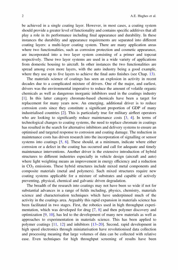
To provide a context for this discussion let’s examine a typical coating systemused in much of the aerospace industry as depicted in Fig. 1.1. This type of system(primer and topcoat) is common to many other application areas. In detail, thecoating consists of a topcoat which serves as a barrier, a carrier of pigment and thepolymer matrix which has some wear resistance. The primer is epoxy-based and isloaded with inhibitor (sparingly soluble chromates), fillers and pigments. (Wateruptake in the primer is rapid and is followed by chromate release [22–25]) Thesurface of the metal has usually undergone treatment which, in the case of alu-minium, could be either anodising or chromate conversion coating (as depicted inFig. 1.1). This surface treatment is largely to achieve the desired level of paintadhesion but also to provide additional protection.
There are different aspects to the level of repair that this coating system provideswhich are depicted in Fig. 1.2. If we begin at the metal/conversion coating interface,there is a level of “pre-emptive healing” (purple double arrow in Fig. 1.2). Thismeans that when water has permeated the primer, inhibitor can diffuse to theinterface and provide additional protection to the surface. This cannot be observedin the chromate case because of the presence of either the anodised coating or theconversion coating. In this instance there is already chromate at the interface
1 Introduction 3
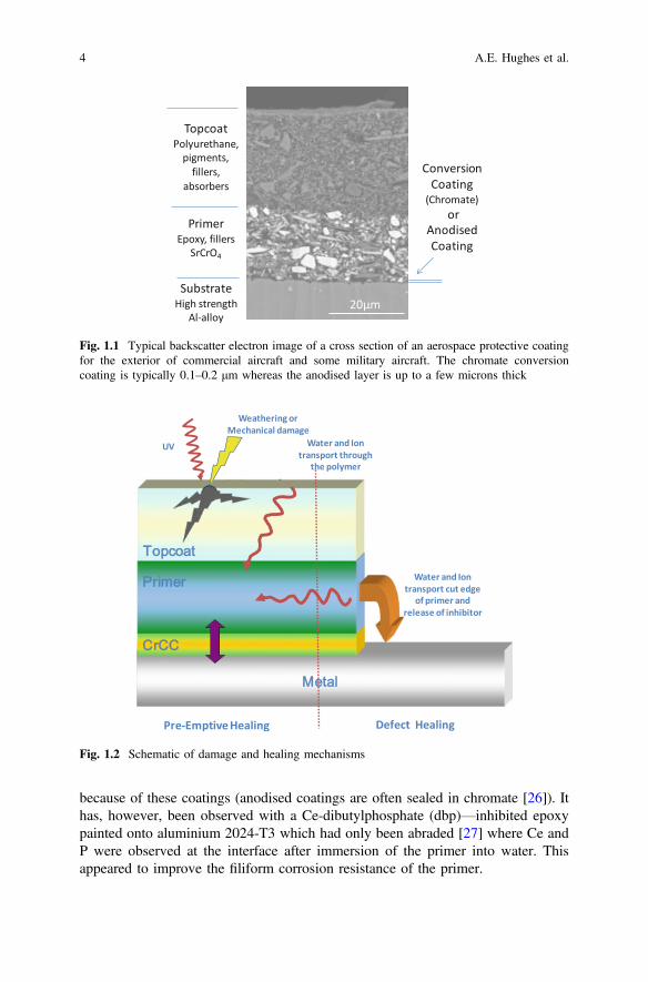
because of these coatings (anodised coatings are often sealed in chromate [26]). Ithas, however, been observed with a Ce-dibutylphosphate (dbp)—inhibited epoxypainted onto aluminium 2024-T3 which had only been abraded [27] where Ce andP were observed at the interface after immersion of the primer into water. Thisappeared to improve the filiform corrosion resistance of the primer.
Fig. 1.2 Schematic of damage and healing mechanisms
Fig. 1.1 Typical backscatter electron image of a cross section of an aerospace protective coatingfor the exterior of commercial aircraft and some military aircraft. The chromate conversioncoating is typically 0.1–0.2 μm whereas the anodised layer is up to a few microns thick
4 A.E. Hughes et al.
The other type of protection this system provides occurs when there is a defect inthe paint system. If the defect penetrates down to the metal then the primer will alsobe ruptured and chromate will be released preventing or arresting corrosion in thedefect [28–30]. This provides a functional repair since it prevents further corrosion.
So the problem that we’re trying to address needs to include the current func-tionalities and desirably, include some additional ones. The first would be to protectthe topcoat and the primer from degradation due to weathering. This repair is largelytargeted at the polymer system for which there are a number of approaches spanningscales from the molecular level to the tens of microns level [31–33]. The otherfunctionality that could be envisaged is “defect filling” where the void left by themechanical damage is “backfilled” to a level where it fully regains its cosmeticappearance. This is not a trivial task for a coating where the volume of the defect is ofsimilar size to the surrounding paint. The full cosmetic recovery would seem tosuggest that a delivery system like a vascular network might be required. An over-view of approaches to embodying these functionalities into coatings is provided in thenext section. These are variously called smart, self healing, regenerative or activecoating systems. For the purposes of simplicity we will use the term “smart” coatingsin this chapter, although we’ll talk about self healing in the following sections.
1.3 What Are Smart Coatings?
Smart coatings are emerging as a major activity in the coatings research area. AsChallener [34] observes “There are as many definitions of smart coatings as thereare scientists conducting research in this very broad field” and perhaps this is truegiven the broad ranges of technologies that are being utilised to increase thefunctionality of coatings. So to begin this chapter, let’s examine the capability ofcurrent technology and look at additional functionality that might be applied toincrease the performance of these coatings.
Within the scenario described above, Fig. 1.3 outlines one possible classificationsystem for smart coatings. At the simplest level, coatings form a barrier between theexternal environment and the substrate material. This type of passive barrier depictedon the left of Fig. 1.3 ismonofunctional andoncebreached has no responsemechanismto provide further protection against corrosion. Thesemonofunctional barrier coatingsare only used in application areas where the probability of failure (during applicationand lifetime) is lowand the subsequent consequencesoffailurearenot significant. Suchapaint systemmight be a simple housepaintwhere abreach causes no immediate threatto the structural integrity, but has some loss of cosmetic appeal.
The next classification for coatings are those that provide a global but primitiveresponse to damage. These types of coatings have the capability to provideresponsive repair, but the response mechanism is neither mediated nor controlled.By way of demonstration let’s examine the chromate inhibited primer as describedin the previous section. Water permeates epoxy-based coatings used for primerapplications relatively quickly [22, 27] beginning the process of solubilising the
1 Introduction 5

strontium chromate inhibitor (the most common chromate inhibitor in paints). Thestrontium chromate can be solubilised anywhere in the primer (i.e. globally) wherewater is present rather than where required at an active corrosion site where the pHhas decreased due to anodic dissolution; hence the label primitive. So in the case ofstrontium chromate some of it may be wasted because soluble chromate may bereleased at the defect long after the repair has been effected. In this instance this isbecause the restoration of a more neutral pH upon repair does not prevent thefurther release of chromate. Moreover, uncontrollable solubility can increaseosmotic blistering effects leading to faster degradation of the coating system.However, the solubility of chromate decreases with increasing pH and speciationchanges as well from dichromate to chromate so even this primitive response hasnuances to it that allows for dosing when it is required [35]. Many inhibitors willhave similar solubility characteristics and speciation changes which may be used totrigger a response more targeted to corrosion. Speciation is important in othertransition metal oxyanion systems such as the vanadates system [36].
The next level of complexity (the third block in Fig. 1.3) is to add a mediatedresponse for local repair, i.e. design a “smart” coating with a mechanism that onlyreleases the amount of material required for repair or healing and then stops. Herethe focus is on the development of smart delivery systems in order to regulate thelocation, the movement and the amount of repair material to match the level ofdamage. Encapsulation is an obvious method to form a barrier between the damagesite and the active functional agent which responds to some aspect of the externaldamage. pH-sensitive capsules are an obvious candidate since a local acid envi-ronment develops during pitting corrosion. Furthermore, there is experience in the
Fig. 1.3 Hierarchy of responses that could be adopted for smart coatings
6 A.E. Hughes et al.
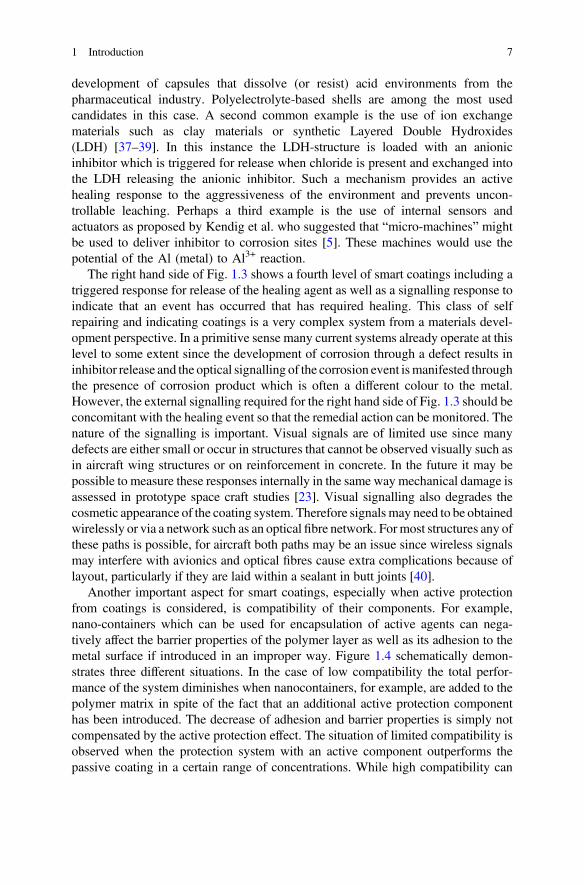
development of capsules that dissolve (or resist) acid environments from thepharmaceutical industry. Polyelectrolyte-based shells are among the most usedcandidates in this case. A second common example is the use of ion exchangematerials such as clay materials or synthetic Layered Double Hydroxides(LDH) [37–39]. In this instance the LDH-structure is loaded with an anionicinhibitor which is triggered for release when chloride is present and exchanged intothe LDH releasing the anionic inhibitor. Such a mechanism provides an activehealing response to the aggressiveness of the environment and prevents uncon-trollable leaching. Perhaps a third example is the use of internal sensors andactuators as proposed by Kendig et al. who suggested that “micro-machines” mightbe used to deliver inhibitor to corrosion sites [5]. These machines would use thepotential of the Al (metal) to Al3+ reaction.
The right hand side of Fig. 1.3 shows a fourth level of smart coatings including atriggered response for release of the healing agent as well as a signalling response toindicate that an event has occurred that has required healing. This class of selfrepairing and indicating coatings is a very complex system from a materials devel-opment perspective. In a primitive sense many current systems already operate at thislevel to some extent since the development of corrosion through a defect results ininhibitor release and the optical signalling of the corrosion event ismanifested throughthe presence of corrosion product which is often a different colour to the metal.However, the external signalling required for the right hand side of Fig. 1.3 should beconcomitant with the healing event so that the remedial action can be monitored. Thenature of the signalling is important. Visual signals are of limited use since manydefects are either small or occur in structures that cannot be observed visually such asin aircraft wing structures or on reinforcement in concrete. In the future it may bepossible to measure these responses internally in the same way mechanical damage isassessed in prototype space craft studies [23]. Visual signalling also degrades thecosmetic appearance of the coating system. Therefore signals may need to be obtainedwirelessly or via a network such as an optical fibre network. Formost structures any ofthese paths is possible, for aircraft both paths may be an issue since wireless signalsmay interfere with avionics and optical fibres cause extra complications because oflayout, particularly if they are laid within a sealant in butt joints [40].
Another important aspect for smart coatings, especially when active protectionfrom coatings is considered, is compatibility of their components. For example,nano-containers which can be used for encapsulation of active agents can nega-tively affect the barrier properties of the polymer layer as well as its adhesion to themetal surface if introduced in an improper way. Figure 1.4 schematically demon-strates three different situations. In the case of low compatibility the total perfor-mance of the system diminishes when nanocontainers, for example, are added to thepolymer matrix in spite of the fact that an additional active protection componenthas been introduced. The decrease of adhesion and barrier properties is simply notcompensated by the active protection effect. The situation of limited compatibility isobserved when the protection system with an active component outperforms thepassive coating in a certain range of concentrations. While high compatibility can
1 Introduction 7
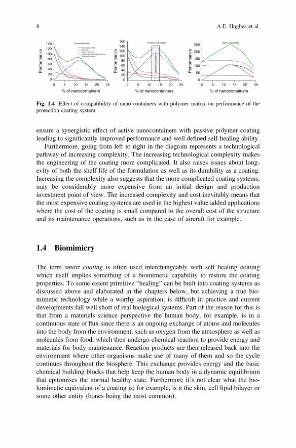
ensure a synergistic effect of active nanocontainers with passive polymer coatingleading to significantly improved performance and well defined self-healing ability.
Furthermore, going from left to right in the diagram represents a technologicalpathway of increasing complexity. The increasing technological complexity makesthe engineering of the coating more complicated. It also raises issues about long-evity of both the shelf life of the formulation as well as its durability as a coating.Increasing the complexity also suggests that the more complicated coating systems,may be considerably more expensive from an initial design and productioninvestment point of view. The increased complexity and cost inevitably means thatthe most expensive coating systems are used in the highest value added applicationswhere the cost of the coating is small compared to the overall cost of the structureand its maintenance operations, such as in the case of aircraft for example.
1.4 Biomimicry
The term smart coating is often used interchangeably with self healing coatingwhich itself implies something of a biomimetic capability to restore the coatingproperties. To some extent primitive “healing” can be built into coating systems asdiscussed above and elaborated in the chapters below, but achieving a true bio-mimetic technology while a worthy aspiration, is difficult in practice and currentdevelopments fall well short of real biological systems. Part of the reason for this isthat from a materials science perspective the human body, for example, is in acontinuous state of flux since there is an ongoing exchange of atoms and moleculesinto the body from the environment, such as oxygen from the atmosphere as well asmolecules from food, which then undergo chemical reaction to provide energy andmaterials for body maintenance. Reaction products are then released back into theenvironment where other organisms make use of many of them and so the cyclecontinues throughout the biosphere. This exchange provides energy and the basicchemical building blocks that help keep the human body in a dynamic equilibriumthat epitomises the normal healthy state. Furthermore it’s not clear what the bio-lomimetic equivalent of a coating is; for example, is it the skin, cell lipid bilayer orsome other entity (bones being the most common).
0 5 10 15 20 250
20406080
100120140160 Limited compatibility
Per
form
ance
% of nanocontainers
optim
al c
once
ntra
tion
0 5 10 15 20 25
020406080
100120140 Low compatibility
% of nanocontainers
Per
form
ance
barrier properties adhesion active protection passive protection performance total performance
0 5 10 15 20 250
50
100
150
200
250
Per
form
ance
% of nanocontainers
Ideal compatibility
Fig. 1.4 Effect of compatibility of nano-containers with polymer matrix on performance of theprotection coating system
8 A.E. Hughes et al.
By contrast, current materials design works on a principle of structured materialswhere atoms and molecules are retained as part of the material structure for thelifetime of the structure. Van der Zwaag highlights this point in comparing designstrategies for self healing systems to traditional materials design [32]. So once thematerial begins to experience bond breakage through oxidation or other chemical orphysical attack, and material loss due to ageing or mechanical damage, thenthe lifetime of the material will be reduced without intervention to remediate thedamage. Industry performance standards also have a significant role to play onthe acceptability of new materials. Self healing systems may be at a significantdisadvantage when assessed against current industry standards since they are gearedtowards assessment of the virgin properties and do not take account of recoveryproperties that are part of the design philosophy for self healing materials.
Of course the materials science of coatings doesn’t only draw on analogies withself healing in biological systems, but also borrows from the actual science. So inlater chapters there will be reference to inhibitor delivery systems which draws onwork from the pharmaceutical industry [41]. It is worth being aware of somefundamental differences between the ability to deliver drugs to a specific target inthe human (or animal body) and being able to deliver targeted healing in coatingssystems. This awareness helps to define the scope of the challenge of incorporatingself healing mechanisms and technologies into coating systems. There are two keyaspects of pharmaceutical delivery systems; one is the encapsulating technology forthe drug and the other delivery mechanism within the body. Clearly, the capsuletechnology can be transferred from the pharmaceutical industry to coating appli-cations assuming compatible chemistry. The delivery within the human bodyhowever, relies strongly on the physiology and biochemistry of the body. In termsof physiology, there are ready made systems within the body such as the digestivetract and cardiovascular system for transporting drugs to the desired target; these donot exist in coatings. The trigger for release of the drug is, in many instances,facilitated by very specific, surface biochemistry. For example, in gene therapy,non-viral vectors (containers carrying the drugs) can be coated with biomoleculessuch as galactopyranoside which recognises asialoglycoprotein receptors on livercells and therefore provides a great method for targeting that organ [42, 43]. Itremains to be seen whether analogous transport paths exist or can be built intocoating systems and we are only at the beginning of devising very specific chemistrytriggers for inhibitor release. More will be said on this in Chaps. 8 and 10. Of course,as seen above, from a practical perspective, very complicated systems may be tooexpensive or too incompatible to introduce into coatings.
1.5 The Structure of the Book
The intention of this book is to provide an overview of advances in multifunctional,self healing approaches as applied to coatings technology.
1 Introduction 9
The first section of the book starts with an examination of the fundamentals ofcorrosion processes leading into atmospheric corrosion. These chapters define theproblem that is being addressed in research focused on the development of newcoating systems. The last two chapters in the first section look at the generalmechanisms of inhibition and the science and technology of coatings into whichinhibitors are incorporated to prevent corrosion.
The second section of the book explores advances in the development of selfhealing coatings in depth. This, of course, includes the developments in newinhibitors as well as in the polymeric resins in which they are incorporated.Inhibitor design itself is undergoing transformation with the development of mul-tifunctional inhibitors that can perform as both cathodic and anodic inhibitors andperhaps even cause functional repair to the polymer resin. The search for newmultifunctional inhibitors has been facilitated with the development of highthroughput techniques for the evaluation of individual and combinations of inhi-bitors [13–15, 17–20, 44–47]. Key aspects of new coatings include both the abilityof the polymer to repair itself and the controlled release of the inhibitor so that onlythe dose required to prevent corrosion is delivered to the attack site. Moreover,additional active mechanisms of corrosion prevention can also be incorporated.These mechanisms include preventive entrapment of aggressive corrosive anionsand the water repelling from defects. While self healing of polymeric coatingsdraws strongly on self healing strategies for bulk polymers [12, 32, 33], there arealso active protection strategies that are peculiar to coating applications. One of themost extensively studied systems in this latter category are conducting polymersand perhaps the use of silanes that form thin, but protective coatings. For inhibitorrelease, there has been broad consideration of a range of delivery systems. Much ofthis work draws from both the pharmaceutical industry and drug delivery systemsas well as the food industry [48] where encapsulation is used extensively for a rangeof reasons: the encapsulated materials can be protected from moisture, heat or otherextreme conditions, thus enhancing their stability and maintaining viability [48].Encapsulation in foods is also utilized to mask odours or preservation of tastes. Theuse of encapsulation for sweeteners such as aspartame and flavours in chewing gumis well known [48]. With respect to the pharmaceutical industry, drug delivery isaimed at the digestive system and particularly the stomach either to bypass it ordeliver in it for orally taken drugs. Fortuitously, the stomach is essentially anaqueous, hydrochloric acid environment, not unlike active corrosion sites, sodevelopments in the pharmaceutical industry can be very easily applied to deliverysystems for inhibitors with the right types of triggers, in principle.
The third section of the book deals with how to measure self healing in coatingsystems. Some of the most important developments in this area are based onelectrochemical techniques particularly scanning localized techniques. Techniquessuch as the scanning vibrating electrode and the scanning electrochemical micro-sope provide new insight into the level of functional (performance) recovery when adefect occurs through a coating and the self repairing mechanism is activated.Physico-chemical techniques are often used in conjunction with electrochemicaltechniques to provide an overall characterisation of materials. Vibrational and
10 A.E. Hughes et al.

electron spectroscopies, for example, can provide useful information on the natureof chemical changes that occur during the healing process. Developments in phaseand adsorption contrast X-ray absorption and computed tomography (CT) fromthese experiments are emerging as powerful tools not only for materials charac-terisation but also to observe and measure healing effects. The combination of CTand electrochemical techniques is an emerging area but should provide a completerepertoire of tools to explore the ability of new self healing systems.
The fourth and final section of the book looks at the industry requirements fromnew mutlifuntional coatings. As pointed out above compatibility of self healingmechanisms and components needs to enhance the overall properties and perfor-mance of the system rather than undermine it. In this section there are contributionsfrom industries that have a range of performance requirements including, auto-motive, aerospace and heavy industry. While these industries can have very dif-ferent coating formulations, there are many common needs across them.
References
1. P.T. LaPuma, J.M. Fox, E.C. Kimmel, Chromate concentration bias in primer paint particles.Regul. Toxicol. Pharmacol. 33(3), 343–349 (2001)
2. G.H. Koch, M.P.H. Brongers, N.G. Thompson, Y.P. Virmani, J.H. Payer, Corrosion Costsand Preventative Strategies in the United States, F.H.A. Department of Transport, Editor.2002, (NACE International, Houston)
3. Anon., Success stories: air force: material substitution and new sealing technologies keepairframes flying longer. AMPTIAC Quarterley. 7(4), 57–61
4. R.A.C Laudise, Aging of U.S. Air Force Aircraft. (National Research Council (United States),Washington D.C, 1997)
5. M. Kendig, M. Hon, L. Warren, ‘Smart’ corrosion inhibiting coatings. Prog. Org. Coat. 47(3–4), 183–189 (2003)
6. A. Trinchi et al. Distributed quantum dot sensors for monitoring the integrity of protectiveaerospace coatings, in 2012 IEEE Aerospace Conference (2012)
7. J.R. Broach, J. Thorner, High-throughput screening for drug discovery. Nature 384(6604), 14–16 (1996)
8. O.G. Schramm et al., Polymeric nanocontainers with high loading capacity of hydrophobicdrugs. Soft Matter 5(8), 1662–1667 (2009)
9. H.Q. Zhang et al., Combinatorial and high-throughput approaches in polymer science. Meas.Sci. Technol. 16(1), 203–211 (2005)
10. R. Hoogenboom, M.A.R. Meier, U.S. Schubert, Combinatorial methods, automated synthesisand high-throughput screening in polymer research: Past and present. Macromol. RapidCommun. 24(1), 16–32 (2003)
11. S. Bode et al., Self-healing metallopolymers based on cadmium bis(terpyridine) complexcontaining polymer networks. Polym. Chem. 4(18), 4966–4973 (2013)
12. S.J. Garcia, H.R. Fischer, S. van der Zwaag, A critical appraisal of the potential of self healingpolymeric coatings. Prog. Org. Coat. 72(3), 211–221 (2011)
13. B.D. Chambers, S.R. Taylor, The high throughput assessment of aluminium alloy corrosionusing fluorometric methods. Part II—A combinatorial study of corrosion inhibitors andsynergistic combinations. Corros. Sci. 49(3), 1597–1609 (2007)
1 Introduction 11
14. B.D. Chambers, S.R. Taylor, High-throughput assessment of inhibitor synergies on aluminumalloy 2024-T3 through measurement of surface copper enrichment. Corrosion 63(3), 268–276(2007)
15. B.D. Chambers, S.R. Taylor, The high throughput assessment of aluminium alloy corrosionusing fluorometric methods. Part I—Development of a fluorometric method to quantifyaluminium ion concentration. Corros. Sci. 49(3), 1584–1596 (2007)
16. Chambers, B.D., The Discovery and Investigation of Synergistic Combinations of CorrosionInhibitors for AA2024-T3. (University of Virginia, Charlottesville, VA, 2007)
17. P.A. White et al., A new high-throughput method for corrosion testing. Corros. Sci. 58, 327–331 (2012)
18. S.J. Garcia et al., Validation of a fast scanning technique for corrosion inhibitor selection:influence of cross-contamination on AA2024-T3. Surf. Interface Anal. 42(4), 205–210 (2010)
19. P.A. White et al., High-throughput channel arrays for inhibitor testing: Proof of concept forAA2024-T3. Corros. Sci. 51(10), 2279–2290 (2009)
20. T.H. Muster et al., A rapid screening multi-electrode method for the evaluation of corrosioninhibitors. Electrochim. Acta 54(12), 3402–3411 (2009)
21. X.Z. Wang et al., Robust QSAR model development in high-throughput catalyst discoverybased on genetic parameter optimisation. Chem. Eng. Res. Des. 87(10A), 1420–1429 (2009)
22. F.H. Scholes et al., Chromate leaching from inhibited primers—Part I. Characterisation ofleaching. Prog. Org. Coat. 56(1), 23–32 (2006)
23. Hoschke, N., et al., Structural Health Monitoring of Space Vehicle Thermal ProtectionSystems, in Structural Health Monitoring: Research and Applications, ed. by W.K. Chiu andS.C. Galea (Trans Tech Publications Ltd, Stafa-Zurich, 2013), pp. 268–280
24. L. Fedrizzi et al., EIS study of environmentally friendly coil coating performances. Prog. Org.Coat. 29(1–4), 89–96 (1996)
25. P. Carbonini et al., Electrochemical characterisation of multilayer organic coatings. Prog. Org.Coat. 29(1–4), 13–20 (1996)
26. S. Wernick, R. Pinner, P.G. Sheasby, The Surface Treatment and Finishing of Aluminium andits Alloys, 5th edn. (Finishing Publications and ASM International, Teddington, 1987)
27. J. Mardel et al., The characterisation and performance of Ce(dbp)3-inhibited epoxy coatings.Prog. Org. Coat. 70(2–3), 91–101 (2011)
28. S.A. Furman et al., Corrosion in artificial defects II. Chromate reactions. Corros. Sci. 48(7),1827–1847 (2006)
29. R.L. Howard et al., Inhibition of cut edge corrosion of coil-coated architectural cladding. Prog.Org. Coat. 37(1–2), 83–90 (1999)
30. I.M. Zin et al., The mode of action of chromate inhibitor in epoxy primer on galvanized steel.Prog. Org. Coat. 33(3–4), 203–210 (1998)
31. S.J. Garcia, Effect of polymer architecture on the intrinsic self-healing character of polymers.Eur. Polymer J. 53(1), 118–125 (2014)
32. Fischer, H.R., Nat. Sci. 2, 873–901 (2010)33. D.Y. Wu, S. Meure, D. Solomon, Self-healing polymeric materials: A review of recent
developments. Prog. Polym. Sci. 33(5), 479–522 (2008)34. C. Challener, The intelligence behind smart coatings. J. Coat. Technol. 2006(January), 50–5535. M.W. Kendig, R.G. Buchheit, Corrosion inhibition of aluminum and aluminum alloys by
soluble chromates, chromate coatings, and chromate-free coatings. Corrosion 59(5), 379–400(2003)
36. K.D. Ralston et al., Corrosion inhibition of aluminum alloy 2024-T3 by aqueous vanadiumspecies. J. Electrochem. Soc. 155(7), C350–C359 (2008)
37. A.N. Salak et al., Anion exchange in Zn-Al layered double hydroxides: In situ X-raydiffraction study. Chem. Phys. Lett. 495(1–3), 73–76 (2010)
38. M.L. Zheludkevich et al., Active protection coatings with layered double hydroxidenanocontainers of corrosion inhibitor. Corros. Sci. 52(2), 602–611 (2010)
12 A.E. Hughes et al.
39. S.K. Poznyak et al., Novel Inorganic Host Layered Double Hydroxides Intercalated withGuest Organic Inhibitors for Anticorrosion Applications. ACS Appl. Mater. Interfaces 1(10),2353–2362 (2009)
40. G. McAdam et al., Fiber optic sensors for detection of corrosion within aircraft. Struct. HealthMonit. 4(1), 47–56 (2005)
41. S.K. Sahoo, V. Labhasetwar, Nanotech approaches to delivery and imaging drug. DrugDiscov. Today 8(24), 1112–1120 (2003)
42. M. Nishikawa et al., Hepatocyte-targeted in vivo gene expression by intravenous injection ofplasmid DNA complexed with synthetic multi-functional gene delivery system. Gene Ther. 7(7), 548–555 (2000)
43. I. Roy et al., Calcium phosphate nanoparticles as novel non-viral vectors for targeted genedelivery. Int. J. Pharm. 250(1), 25–33 (2003)
44. S.R. Taylor, B.D. Chambers, Identification and characterization of nonchromate corrosioninhibitor synergies using high-throughput methods. Corrosion 64(3), 255–270 (2008)
45. S.R. Taylor, B.D. Chambers, The discovery of non-chromate corrosion inhibitors foraerospace alloys using high-throughput screening methods. Corros. Rev. 25(5–6), 571–590(2007)
46. B.D. Chambers, S.R. Taylor, M.W. Kendig, Rapid discovery of corrosion inhibitors andsynergistic combinations using high-throughput screening methods. Corrosion 61(5), 480–489(2005)
47. S.J. Garcia et al., The influence of pH on corrosion inhibitor selection for 2024-T3 aluminiumalloy assessed by high-throughput multielectrode and potentiodynamic testing. Electrochim.Acta 55(7), 2457–2465 (2010)
48. B.F. Gibbs et al., Encapsulation in the food industry: a review. Int. J. Food Sci. Nutr. 50(3),213–224 (1999)
1 Introduction 13

Part IFundamentals
Chapter 2Fundamentals of Corrosion Kinetics
G.S. Frankel
2.1 Introduction
Corrosion, the environmental degradation of materials, is a complex process thatdepends on details of the environment and material, and is controlled by underlyingthermodynamic and kinetic factors. The ultimate goal of a corrosion engineer is topredict and control the rate of corrosion. To do so requires a thorough under-standing of the thermodynamic and kinetic fundamentals. This chapter will reviewthe electrochemical kinetics important to the overall corrosion process, includingactivation controlled kinetics, mixed potential theory, and mass transport effects.
The chapter will begin with a description of the typical anodic and cathodic halfreactions that comprise the corrosion phenomenon. This is followed by an intro-duction to the most fundamental type of electrochemical kinetics, activation con-trolled kinetics, which are applicable in situations where the rate is controlled by thecharge transfer reaction. The Tafel equation describes many of the reactionsinvolved in corrosion. With the basis of simple electrochemical kinetics, it is thenpossible to present mixed potential theory, which predicts corrosion potential andrate on the basis of the kinetics and thermodynamics of all of the reactionsoccurring on an electrode surface. The Evans diagram, a graphical representation ofthis situation, is introduced to, clarify the mixed potential condition. The rate ofcorrosion is often controlled by mass transport of species to the surface from thebulk solution, and the kinetics of mass transport are the next topic of discussion.The inhibition of corrosion, in which the kinetics of one or more of the corrosionreactions are altered by the presence of species added to the environment, will thenbe covered. Passivity, or the spontaneous formation of a thin protective surface film,can be viewed as a form of anodic inhibition and is introduced at the end of thischapter.
G.S. Frankel (&)Fontana Corrosion Center, The Ohio State University, Columbus, OH 432310, USAe-mail: [email protected]
© Springer Science+Business Media Dordrecht 2016A.E. Hughes et al. (eds.), Active Protective Coatings,Springer Series in Materials Science 233, DOI 10.1007/978-94-017-7540-3_2
17

2.2 Corrosion Reactions
Corrosion often involves oxidation of metal atoms to form ionic species with higheroxidation state and the liberation of electrons. For a generic metal M:
M ! Mzþ þ ze� ð2:1Þ
Examples of real metals:
Fe ! Fe2þ þ 2e� ð2:2Þ
Zn ! Zn2þ þ 2e� ð2:3Þ
Al ! Al3þ þ 3e� ð2:4Þ
These are called half-cell reactions because the electrons liberated by the oxi-dation reaction must be consumed by a reduction reaction occurring on the sameelectrode. A reduction reaction that is common in acids is hydrogen evolution:
2Hþ þ 2e� ! H2 ð2:5Þ
The complete corrosion reaction for Zn in an acid would be the sum of theoxidation and reduction reactions:
Znþ 2Hþ ! Zn2þ þH2 ð2:6Þ
The sites for the oxidation reactions are called anodes, and the sites for thereduction reactions are called cathodes. Anodes and cathodes can be spatiallyseparated at fixed locations associated with heterogeneities on the electrode surface.Alternatively, the locations of the anodic and cathodic reactions can fluctuaterandomly across the sample surface. The former case results in a localized form ofcorrosion, such as pitting, crevice corrosion, intergranular corrosion, or galvaniccorrosion, and the latter case results in nominally uniform corrosion.
In most environments of interest to corrosion there is not a large concentration ofmetal ions acting as cathodic reactants (i.e. the reverse of reaction (1)). Theimportant cathodic reactions in corrosion mechanisms involve water. There are twoprimary cathodic reactions, each of which takes a different form in acids or bases.The first is the hydrogen evolution reaction, in acids takes the form shown inEq. 2.5. In neutral or basic solutions the hydrogen evolution reaction is:
2H2O þ 2e� ! H2 gð Þ þ 2OH� ð2:7Þ
Each of the half reactions given in Eqs. 2.1–2.7 will be in equilibrium at aspecific potential called the reversible potential, Erev. When all reactants andproducts are in their standard states with activity of unity, the potential reaches a
18 G.S. Frankel
special value of reversible potential called the standard potential, E0. Thewell-known electromotive force series is a list of half reactions ordered by theirstandard potentials. These standard potentials are derived from the free energies offormation of the species involved in the reactions.
For conditions under which the reactants and products are not in their standardstates, which is the typical condition of corrosion, Erev ≠ E0, and Erev can becalculated from the Nernst equation. The Nernst equation for the hydrogen evo-lution reaction given in Eq. 2.5 at room temperature is:
Erev Hþ=H2ð Þ ¼ E0 Hþ=H2ð Þþ 0:059=2ð Þ log Hþ½ �2¼ 0:059 log Hþ½ �¼ �0:059 pH
ð2:8Þ
It can be easily shown that the Nernst Equation for the base form of thehydrogen evolution reaction, Eq. 2.7, is also Erev = −0.059 pH.
When dissolved oxygen gas is present in the aqueous solution, the followingoxygen reduction reactions are possible, with Eq. 2.9 dominant in acids andEq. 2.10 in neutral or basic solutions:
O2 þ 4Hþ þ 4e� ! 2H2O ð2:9Þ
O2 þ 2H2Oþ 4e� ! 4OH� ð2:10Þ
The Nernst equation for the acid form of the oxygen reduction reaction is:
Erev O2=H2Oð Þ ¼ E0 O2=H2Oð Þ � 0:059=4ð Þlog Hþ½ ��4
¼ 1:229� 0:059 pHð2:11Þ
As for the case of the hydrogen evolution reaction, the Nernst Equation for thebase form of the oxygen reduction reaction is the same as that for the acid form. Thebase form of either the hydrogen evolution reaction or the oxygen reductionreaction is obtained from the acid form by adding a multiple of the water disso-ciation reaction:
H2O ! Hþ þ OH� ð2:12Þ
This chapter deals primarily with the corrosion of a fictitious metal M with norelevant microstructural heterogeneities. In reality, engineering alloys have complexmicrostructures and surface features that can have a large effect on the progressionof the corrosion processes. It was described above, that metal corrosion takes placeby a combination of an anodic half reaction such as given in Eqs. 2.1–2.4, and acathodic half reaction such as in Eqs. 2.5, 2.7, 2.9, and 2.10. The locations of thelocal anodes and cathodes depend on the surface and microstructural details anddetermine the form of corrosion that results.
2 Fundamentals of Corrosion Kinetics 19
The corrosion reactions will tend to occur on the most reactive spots on asurface. An ordered list of increasing reactivity might be: crystal ledges, crystalkinks, emerging dislocations, high index grain faces, impurities, grain boundaries,inclusions and particles, second phases, crevices and cracks. For example, for avery pure metal that is single crystalline and well annealed with a well-preparedsurface, the reactions might take place on crystalline ledges and kink sites. Theform of corrosion might be etch pits at dislocations, grain boundary etching, orsecond phase attack, depending on what are the most susceptible sites present onthe surface. Because most alloy surfaces have heterogeneities that provide reactivesites and surface films, it is rare for attack to be dominated at the less reactive siteslike emergent dislocations.
The anodic and cathodic reactions will take place at separate sites, but those sitesmight be extremely close. For the current to pass from cathode to anode, there mustbe a potential difference. However, if the anodes and cathodes are extremely close,the potential difference will be extremely small. Nominally uniform corrosion willoccur if the local anodic and cathodic sites continually move across the surfaceowing to small changes in surface reactivity as the corrosion process proceeds. Ifthe location of the anodic reaction does not continually move, but stays at localizedsites, the form of attack will be localized. For example, etch pits will form atdislocations if those sites remain the most active sites for dissolution. Extensivelocalized attack in the form of pits, crevices, intergranular corrosion or cracks canoccur if the separation of the anodic and cathodic reactions is sustained.
The cathodic reactions involving water in Eqs. 2.5, 2.7, 2.9, and 2.10 all result inan increase in production of OH− or the consumption of H+. Therefore, the pHtends to increase in the region near a sustained cathode. In contrast, the pH tends todecrease in the region near a sustained anode, such as a pit or crevice owing tometal cation hydrolysis:
Mnþ þ nOH� ! MOHn�1 þ n� 1ð ÞOH� ! M OHð Þn�22 þ n� 2ð ÞOH�. . .
! M OHð Þnð2:13Þ
Hydrolysis will consume hydroxide ions, causing the pH to decrease. Completehydrolysis of the cations to form hydroxide, the right most product in Eq. 2.13, doesnot generally occur. Each of the steps of the hydrolysis process will reach equi-librium, with different equilibrium constants for different cations. If cationhydrolysis were able to go to completion and complete mixing of the anode andcathode environments was possible, every hydroxide ion produced or H+ ionconsumed by the cathodic reaction would be balanced by an equal consumption ofhydroxide ion by hydrolysis and there would be no pH change. However, becauseof the lack of complete cation hydrolysis, the pH of a closed corroding systemalways increases.
For the case of localized corrosion, in which there is sustained spatial separationof the anodic and cathodic reactions, a gradient in chemistry as well as potential will
20 G.S. Frankel
exist between the anode and cathodic sites. Migration of anions toward the anodewill also occur owing to the potential gradient. Therefore, the local anode envi-ronment might be enriched with both chloride anions and H+ cations, forming avery aggressive solution. This will tend to prevent repassivation and sustain thelocalized corrosion.
2.3 Activation Controlled Kinetics
Consider a metallic electrode immersed in a corrosive aqueous environment.Anodic and cathodic reactions will occur spontaneously on the electrode surface,possibly resulting in corrosion of the electrode. The resulting potential of theelectrode will be different from the reversible or equilibrium potentials of each ofthe reactions occurring on the surface. If the concentrations of the reactants andproducts at the electrode surface are the same as in the bulk solution, the differencein potential from the reversible potential for a given reaction is called activationovervoltage or charge transfer overvoltage, η. It stems from the fact that the rate ofcharge transfer at the electrode-electrolyte interface is not infinitely fast. Note thatthe concentration at the electrode surface equals the bulk concentration when therate of mass transport is fast compared to the rate of charge transfer. This aspect willbe discussed in more detail later.
For a reaction in which the rate is limited by activation overvoltage, the rela-tionship between the rate of reaction, which can be expressed by a current density i,and the driving force for the reaction, or potential E, is given by the Butler-Volmerequation:
i ¼ i0 expanF(E� ErevÞ
RT
� �� i0 exp
�ð1� aÞnF(E� ErevÞRT
� �
i ¼ i0 expanFgRT
� �� i0 exp
�ð1� aÞnFgRT
� � ð2:14Þ
where F is the Faraday constant = 96,487 C/equivalent, n is the charge on the ion inequivalents/mol, R is the gas constant = 8.314 J/mol-K, and α is the unitless chargetransfer coefficient. The value of α is usually close to 0.5, but must be between 0and 1.
For a sufficiently large value of anodic polarization from the reversible potential(overpotential ηa > * 50 mV), the first term on the right side of Eq. 2.14 dominatesthe second term. Therefore, at large overpotentials, the Butler-Volmer equationsimplifies to:
inet ¼ i0 expanFgaRT
� �ð2:15Þ
2 Fundamentals of Corrosion Kinetics 21
Rearranging, one gets the Tafel equation:
ga ¼ balog i=i0ð Þ ð2:16Þ
where ba = 2.3 RT/αnF is the anodic Tafel slope. For α = 0.5 and n = 1, ba = 0.12 V(or V/decade). A similar equation is found for cathodic activation polarization:
gc ¼ �bclog ij j=i0ð Þ ð2:17Þ
Corrosion conditions typically are far removed from the reversible potentials forany of the reactions. Therefore, Tafel kinetics are usually an accurate description ofcorrosion kinetics for conditions under which mass transport limitations are notimportant.
2.4 Mixed Potential Theory
Under conditions of importance in corrosion, the predominant cathodic reaction istypically one of the hydrogen or oxygen reactions described above. Furthermore,the electrode potential is usually far from the reversible potentials for the any of thereactions occurring on the surface.
The principle of charge conservation dictates that, to avoid the accumulation ofcharge on a freely-immersed electrode, the sum of all of the oxidation currents mustequal the sum of all of the reduction currents. Any electrode immersed in anenvironment will naturally have a potential, called the corrosion potential, thatfulfills this requirement. Therefore, at the corrosion potential:
RIa þRIc ¼ 0 ð2:18Þ
Note that reduction currents (Ic) are negative. The corrosion potential is alsocalled the open-circuit potential, free potential, or rest potential. The corrosionpotential is a mixed potential indicating that its value depends on the rate of theanodic as well as the cathodic reactions. Furthermore, if the corrosion cell involvesone dissolution reaction and one cathodic reaction, the corrosion potential will bebetween the reversible potentials of the two half reactions.
The situation can best be visualized using an Evans diagram, Fig. 2.1. In thisfigure, the Tafel lines for the anodic and cathodic branches of the hydrogen reactionare shown together with the Tafel lines for the dissolution and plating of a metalwith reversible potential below that for the hydrogen reaction. These are the pos-sible electrochemical reactions for an active metal in acid containing little dissolvedmetal ion, where the primary cathodic reaction is hydrogen evolution. In this figure,ErevM=Mþ and Erev
H=Hþ represent the reversible potentials for the metal M dissolution
and hydrogen evolution reactions, respectively; i0, M/M+ and i0;H2=Hþ represent theexchange current densities for metal dissolution and hydrogen evolution on M,
22 G.S. Frankel
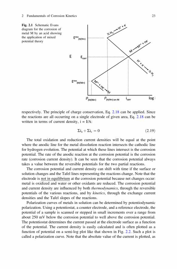
respectively. The principle of charge conservation, Eq. 2.18 can be applied. Sincethe reactions are all occurring on a single electrode of given area, Eq. 2.18 can bewritten in terms of current density, i = I/A:
Ria þRic ¼ 0 ð2:19Þ
The total oxidation and reduction current densities will be equal at the pointwhere the anodic line for the metal dissolution reaction intersects the cathodic linefor hydrogen evolution. The potential at which these lines intersect is the corrosionpotential. The rate of the anodic reaction at the corrosion potential is the corrosionrate (corrosion current density). It can be seen that the corrosion potential alwaystakes a value between the reversible potentials for the two partial reactions.
The corrosion potential and current density can shift with time if the surface orsolution changes and the Tafel lines representing the reactions change. Note that theelectrode is not in equilibrium at the corrosion potential because net changes occur:metal is oxidized and water or other oxidants are reduced. The corrosion potentialand current density are influenced by both thermodynamics, through the reversiblepotentials of the various reactions, and by kinetics, through the exchange currentdensities and the Tafel slopes of the reactions.
Polarization curves of metals in solution can be determined by potentiodynamicpolarization. Using a potentiostat, a counter electrode, and a reference electrode, thepotential of a sample is scanned or stepped in small increments over a range fromabout 250 mV below the corrosion potential to well above the corrosion potential.The potentiostat determines the current passed at the electrode surface as a functionof the potential. The current density is easily calculated and is often plotted as afunction of potential on a semi-log plot like that shown in Fig. 2.2. Such a plot iscalled a polarization curve. Note that the absolute value of the current is plotted, as
Fig. 2.1 Schematic Evansdiagram for the corrosion ofmetal M by an acid showingthe application of mixedpotential theory
2 Fundamentals of Corrosion Kinetics 23
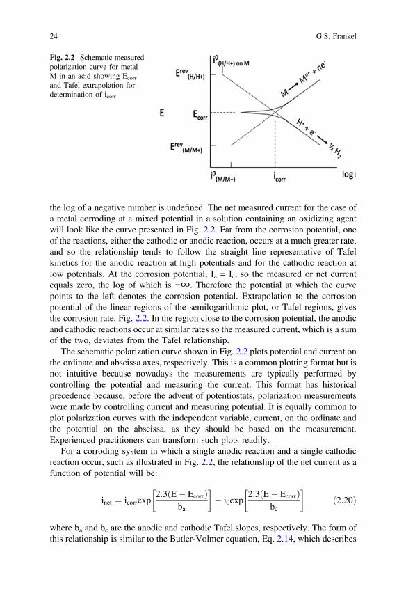
the log of a negative number is undefined. The net measured current for the case ofa metal corroding at a mixed potential in a solution containing an oxidizing agentwill look like the curve presented in Fig. 2.2. Far from the corrosion potential, oneof the reactions, either the cathodic or anodic reaction, occurs at a much greater rate,and so the relationship tends to follow the straight line representative of Tafelkinetics for the anodic reaction at high potentials and for the cathodic reaction atlow potentials. At the corrosion potential, Ia = Ic, so the measured or net currentequals zero, the log of which is −∞. Therefore the potential at which the curvepoints to the left denotes the corrosion potential. Extrapolation to the corrosionpotential of the linear regions of the semilogarithmic plot, or Tafel regions, givesthe corrosion rate, Fig. 2.2. In the region close to the corrosion potential, the anodicand cathodic reactions occur at similar rates so the measured current, which is a sumof the two, deviates from the Tafel relationship.
The schematic polarization curve shown in Fig. 2.2 plots potential and current onthe ordinate and abscissa axes, respectively. This is a common plotting format but isnot intuitive because nowadays the measurements are typically performed bycontrolling the potential and measuring the current. This format has historicalprecedence because, before the advent of potentiostats, polarization measurementswere made by controlling current and measuring potential. It is equally common toplot polarization curves with the independent variable, current, on the ordinate andthe potential on the abscissa, as they should be based on the measurement.Experienced practitioners can transform such plots readily.
For a corroding system in which a single anodic reaction and a single cathodicreaction occur, such as illustrated in Fig. 2.2, the relationship of the net current as afunction of potential will be:
inet ¼ icorrexp2:3ðE� EcorrÞ
ba
� �� i0exp
2:3ðE� EcorrÞbc
� �ð2:20Þ
where ba and bc are the anodic and cathodic Tafel slopes, respectively. The form ofthis relationship is similar to the Butler-Volmer equation, Eq. 2.14, which describes
Fig. 2.2 Schematic measuredpolarization curve for metalM in an acid showing Ecorr
and Tafel extrapolation fordetermination of icorr
24 G.S. Frankel
the kinetics of a single half reaction at potentials above and below the reversiblepotential for that reaction. In contrast, this equation, which has nocommonly-referred to name, describes the net current when two different halfreactions occur on a single electrode surface. Non-linear least squares fitting of theinet(E) data set to Eq. 2.20 by the analysis software provided by the potentiostatmanufacturer is the most common means to evaluate corrosion data as it providesvalues for the constants in the equation, icorr, Ecorr, ba, and bc, in an automatedfashion.
2.5 Mass Transport Controlled Kinetics
For conditions in which the surface concentration of a reactant is not the same as thebulk concentration, the equations describing the reaction kinetics must be altered.The oxygen reduction reaction, Eqs. 2.9 and 2.10, is an important reaction incorrosion that often meets this condition because the reactant, molecular oxygen, isconsumed at the surface, which reduces its surface concentration. This then requiresthe transport of oxygen from the bulk through a layer adjacent to the surface. Forthis condition, the cathodic Tafel equation, which is similar to Eq. 2.15, must bealtered to include the concentration of oxygen in the bulk and at the surface, cb andcs, respectively:
i ¼ �i0cscb
� �exp � ð1� aÞnF
RT
� �E� Erevð Þ
� �ð2:21Þ
The equation shows that the rate of the charge transfer reaction at the interfacedepends not only on the applied potential but also on the concentration of reactingspecies prevailing at the electrode surface.
Consider now a metal sample being corroded by a generic oxidizing agent, B,which is being transported from the bulk and consumed at the surface. For neutralspecies such as oxygen, or charged species present in small amounts in the presenceof a supporting electrolyte, the contribution of migration to transport is small. Forthe subsequent discussion it will be assumed that near the electrode surface there isa stagnant layer of electrolyte of thickness δ, which is called the Nernst Diffusionlayer or, somewhat loosely, the diffusion layer. Within the stagnant diffusion layeronly diffusion contributes to the flux of the reacting species, whereas outside thediffusion layer no concentration gradients exist and convection is the only transportmechanism for the reacting species.
The reaction of species B at the surface will reduce its concentration and thetransport of B from the bulk to the surface through the diffusion layer can bedescribed by the electrochemical equivalent of Fick’s first law:
2 Fundamentals of Corrosion Kinetics 25
i ¼ �nFDBðcB;b � cB;sÞd
ð2:22Þ
where i is the current density associated with the reduction of B, F is the Faradayconstant, and DB is the diffusion coefficient of B. The effect of convection on theelectrode reaction can be understood from this equation by considering thatincreased convection decreases δ and thus increases the flux of B and its reductionrate i.
Solving Eq. 2.22 for surface concentration of B gives
cB;s ¼ cB;b þ idnFDB
ð2:23Þ
Note that in this expression i is a negative quantity as it describes a reductionreaction so it is equivalent to write it as:
cB;s ¼ cB;b � ij jdnFDB
ð2:24Þ
The surface concentration of the reacting species therefore decreases withincreasing current density.
As the cathodic current density increases, the surface concentration of thereacting species, cB,s, decreases until reaching a value of cB,s = 0. The currentassociated with this condition is the maximum possible reduction rate of B and iscalled the limiting current density ilim.
ilim ¼ �nFDBcB;bd
ð2:25Þ
Dividing Eq. 2.22 by Eq. 2.25 yields:
iilim
¼ 1� cB;scB;b
ð2:26Þ
which can be rearranged to give:
cB;scB;b
¼ 1� iilim
ð2:27Þ
Substituting into Eq. 2.20 gives:
i ¼ i0 1� iilim
� �exp
�ð1� aÞnFRT
ðE� ErevÞ� �
ð2:28Þ
26 G.S. Frankel
This can be rearranged to yield Eq. 2.29, which describes the current-potentialrelationship for a cathodic reaction controlled by combined charge transfer kineticsand mass transport.
i ¼i0 exp
�ð1�aÞnFRT ðE� ErevÞ
h i
1� i0ilim
exp �ð1�aÞnFRT ðE� ErevÞ
h i ð2:29Þ
If ilim >> i0 exp {[−(1−α)nF/RT](E − Erev)}, then the denominator of Eq. 2.29goes to 1 and this equation becomes the Tafel equation. However, if ilim << i0 exp{[−(1−α)nF/RT](E − Erev)}, this equation becomes i = ilim and the reaction rate isindependent of potential.
Another way to look at the situation of combined influences of charge transferovervoltage and mass transport is to rearrange Eq. 2.29 to get:
E� Erev ¼ g ¼ � RTð1� aÞnF ln
ii0� RTð1� aÞnF ln 1� i
ilim
� �ð2:30Þ
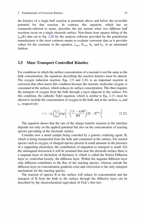
The first term on the right hand side is the charge transfer or activation over-voltage and the second term is concentration overvoltage. The total overvoltage isseen to be a sum of the two. The concentration overvoltage goes to negative infinityas the current approaches the limiting current, Fig. 2.3. According to Eq. 2.25, theilim depends on diffusivity, diffusion layer thickness, and bulk concentration of thereacting species. Diffusion is a thermally activated process and the diffusion layerthickness depends on the solution velocity, so environment temperature and agi-tation will affect ilim. The charge transfer (activation) and concentration overvolt-ages combine as shown in Fig. 2.3. This is the typical polarization behaviorobserved for a system under mixed charge transfer and transport control.
Fig. 2.3 Representation ofthe combine effects ofactivation- andconcentration-controlledkinetics
2 Fundamentals of Corrosion Kinetics 27

Mass transport is of primary importance for the rate of corrosion in environmentswith limited cathodic reactant, for example in a neutral solution containing dis-solved oxygen as reacting species. The maximum corrosion rate in such a situationis given by the limiting current density of the cathodic reactant to the surface,
icorr ¼ ilim ð2:31Þ
An example is corrosion of steel in an aerated neutral solution where the rate ofoxygen reduction reaction is largely controlled by mass transport. An Evans dia-gram for this situation is given in Fig. 2.4. Similarly, the rate of corrosion of iron indilute hydrochloric acid is limited by the rate of the mass transport of the proton tothe iron surface.
2.6 Inhibition
Corrosion inhibitors are chemicals added to an environment to decrease the rate ofcorrosion of metals exposed to that environment. The most common applications ofinhibitors are limited-size or closed systems such as acid pickling baths orclosed-loop water cooling systems. Acidic pickling baths are used to chemicallydissolve the iron oxide scale on steel, and organic inhibitors are added to adsorbonto the metal surface after dissolution of the scale and thereby block the elec-trochemical attack of the steel. Closed-loop water cooling systems used, forinstance, to extract heat from engines are typically neutral or alkaline solutions towhich inorganic molecules are added to promote oxide formation on contactingmetal surfaces or to buffer the pH.
Fig. 2.4 Schematic measuredpolarization curve for thecorrosion of metal M in anenvironment where the rate ofreaction is controlled by thediffusion limitation of O2 tothe surface
28 G.S. Frankel

Inhibitors are also added as soluble pigments in protective organic coatings, orpaint. The poly-electrolyte formed when the paint is saturated with water, protectsthe metal and can release inhibitive species into local environments such asdelaminations or through-scratches so as to protect the exposed metal.
The effect of the inhibitor on the corrosion process can be understood andclassified by comparing polarization curves in environments with and without theinhibitor added. Figure 2.5 shows schematic examples of the types of inhibition andtheir effects on the polarization curves. Inhibitors can be classified as an anodic,cathodic, or mixed inhibitor as shown in this figure. As the names imply, an anodicinhibitor reduces the rate of the anodic reaction while having less of an effect on thecathodic reaction, a cathodic inhibitor reduces the rate of the cathodic reactionwhile having less of an effect on the anodic reaction, and a mixed inhibitor reducesthe rates of both reactions equally. The corrosion potential will often be different ina solution containing inhibitor compared to the value in an uninhibited solution, andthe nature of the change will be different for the different classes of inhibitor. Ecorr
will increase for an anodic inhibitor, decrease for a cathodic inhibitor, and notchange for a mixed inhibitor. As long as the corrosion rate is indeed reduced, theshift in Ecorr can be used as a diagnostic for the type of inhibitor.
2.7 Passivity
In the field of corrosion passivity describes a state in which the corrosion rate of ametal substrate is very low because of the presence of a thin oxide or oxy-hydroxidelayer on the surface that deactivates or passivates the metal. The best passive films,such as those that form on Al and other so-called valve metals like Ti, Zr, Nb, etc.are very thin, on the order of a few nm. Stainless steels have high corrosion
Fig. 2.5 Schematicrepresentation of the effects ofanodic, cathodic and mixedinhibition
2 Fundamentals of Corrosion Kinetics 29
resistance owing to the presence of a Cr-rich passive film on their surfaces. Thehighly corrosion resistant engineering alloys achieve that property by passive films.
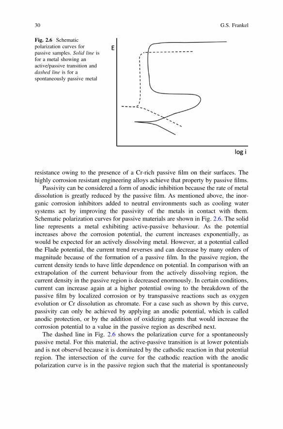
Passivity can be considered a form of anodic inhibition because the rate of metaldissolution is greatly reduced by the passive film. As mentioned above, the inor-ganic corrosion inhibitors added to neutral environments such as cooling watersystems act by improving the passivity of the metals in contact with them.Schematic polarization curves for passive materials are shown in Fig. 2.6. The solidline represents a metal exhibiting active-passive behaviour. As the potentialincreases above the corrosion potential, the current increases exponentially, aswould be expected for an actively dissolving metal. However, at a potential calledthe Flade potential, the current trend reverses and can decrease by many orders ofmagnitude because of the formation of a passive film. In the passive region, thecurrent density tends to have little dependence on potential. In comparison with anextrapolation of the current behaviour from the actively dissolving region, thecurrent density in the passive region is decreased enormously. In certain conditions,current can increase again at a higher potential owing to the breakdown of thepassive film by localized corrosion or by transpassive reactions such as oxygenevolution or Cr dissolution as chromate. For a case such as shown by this curve,passivity can only be achieved by applying an anodic potential, which is calledanodic protection, or by the addition of oxidizing agents that would increase thecorrosion potential to a value in the passive region as described next.
The dashed line in Fig. 2.6 shows the polarization curve for a spontaneouslypassive metal. For this material, the active-passive transition is at lower potentialsand is not observd because it is dominated by the cathodic reaction in that potentialregion. The intersection of the curve for the cathodic reaction with the anodicpolarization curve is in the passive region such that the material is spontaneously
Fig. 2.6 Schematicpolarization curves forpassive samples. Solid line isfor a metal showing anactive/passive transition anddashed line is for aspontaneously passive metal
30 G.S. Frankel
passive at the open circuit potential. In this case, icorr is limited by the anodicreaction and is equal to the passive current density.
The curves shown in Fig. 2.6 were arbitrarily drawn such that the spontaneouslypassive metal has lower values of corrosion current density, passive current densityand breakdown potential, which is given by the potential at which there is a sharpincrease in current. These values will depend on the material properties and envi-ronmental severity.
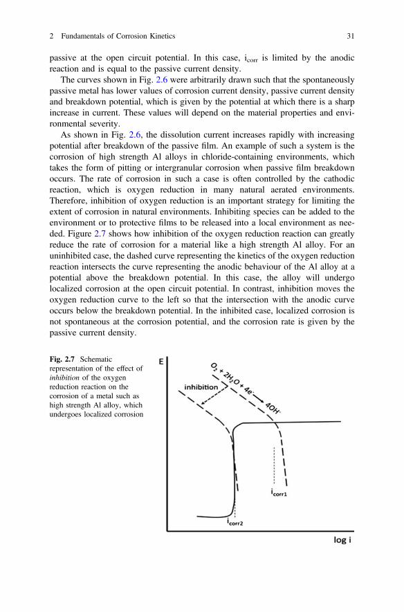
As shown in Fig. 2.6, the dissolution current increases rapidly with increasingpotential after breakdown of the passive film. An example of such a system is thecorrosion of high strength Al alloys in chloride-containing environments, whichtakes the form of pitting or intergranular corrosion when passive film breakdownoccurs. The rate of corrosion in such a case is often controlled by the cathodicreaction, which is oxygen reduction in many natural aerated environments.Therefore, inhibition of oxygen reduction is an important strategy for limiting theextent of corrosion in natural environments. Inhibiting species can be added to theenvironment or to protective films to be released into a local environment as nee-ded. Figure 2.7 shows how inhibition of the oxygen reduction reaction can greatlyreduce the rate of corrosion for a material like a high strength Al alloy. For anuninhibited case, the dashed curve representing the kinetics of the oxygen reductionreaction intersects the curve representing the anodic behaviour of the Al alloy at apotential above the breakdown potential. In this case, the alloy will undergolocalized corrosion at the open circuit potential. In contrast, inhibition moves theoxygen reduction curve to the left so that the intersection with the anodic curveoccurs below the breakdown potential. In the inhibited case, localized corrosion isnot spontaneous at the corrosion potential, and the corrosion rate is given by thepassive current density.
Fig. 2.7 Schematicrepresentation of the effect ofinhibition of the oxygenreduction reaction on thecorrosion of a metal such ashigh strength Al alloy, whichundergoes localized corrosion
2 Fundamentals of Corrosion Kinetics 31

Recommended Reading
1. D.A. Jones, Principles and Prevention of Corrosion, 2nd edn. (Prentice Hall, 1996)2. D. Landolt, Corrosion and Surface Chemistry of Metals (CRC Press, 2007)3. E. McCafferty, Introduction to Corrosion Science (Springer, 2010)4. M. Fontana, N. Greene, Corrosion Engineering (McGraw-Hill, New York, 1978)5. F. Mansfeld (ed.), Corrosion Mechanisms (Marcel Dekkar, New York, 1987)6. P. Marcus (ed.), Corrosion Mechanisms in Theory and Practice, 2nd edn. (Marcel Dekkar, New
York, 2002)7. J.O’M. Bockris, A.K.N. Reddy, Modern Electrochemistry, vol. 2 (Plenum Press, 1970)
32 G.S. Frankel
Chapter 3The Atmosphere Conditions and SurfaceInteractions
I.S. Cole
3.1 Introduction
This chapter will address the aspects of atmospheric interaction with the surface andcorrosion that need to be considered in developing new smart coatings. Recently[1], there have been a number of reviews on the atmosphere and corrosion but to theauthor’s knowledge none that are particular to the development of smart coatings.Most of the atmospheric factors that promote corrosion of bare metals will alsocontrol the degradation of coatings and corrosion of coated metals, however somefactors will affect coatings to a greater extent (notably UV). However, the condi-tions that develop at the coating/atmosphere interface may be substantially differentto those that occur at the interface of uncoated metal and the atmosphere.
This chapter will thus look at:
(1) Factors controlling the deposition of pollutants on the surface of a coatedmetal.
(2) Factors that control the local microclimate at a coating surface and the for-mation of moisture layers
(3) Models of moisture and pollutant movement through coatings.
I.S. Cole (&)Manufacturing Flagship, Commonwealth Scientific and Industrial Research Organisation,Melbourne, Australiae-mail: [email protected]
© Springer Science+Business Media Dordrecht 2016A.E. Hughes et al. (eds.), Active Protective Coatings,Springer Series in Materials Science 233, DOI 10.1007/978-94-017-7540-3_3
33
3.2 Factors Controlling the Deposition of Pollutantson the Surface of a Coated Metal
In discussing pollutant deposition, it is necessary to consider pollutant depositionvia aerosol deposition, or via rain deposition plus interaction of gaseous pollutantswith a coated surface. In considering aerosol deposition it is important to considerthe source of aerosols, their transport, chemical reactions during transport and theirdeposition. In the case of rain, the critical factors are changes in rain chemistry andrain deposition and retention on a surface. For gaseous interaction, two cases arerelevant, deposition into a moisture film on a coating and deposition and reactionwith a dry coating.
The major sources of aerosols [2] are marine aerosols and industrial aerosols andwhile aerosols may range in size from 0.1 to up to 100 μm, fine aerosol (<2.5 μm)will generally not deposit onto surfaces and so are not of interest in coatingdegradation.
Marine aerosols, which may originate from whitecaps [3] (breaking waves thatgenerate white foam) as particles torn from the crests of such ocean whitecaps, orfrom breaking waves on the shore (hereafter referred to as surf produced aerosol)[3]. Fitzgerald [4] found that ocean-produced aerosols had size ranges from <1 togreater 50 μm with the modal frequency range being <1 μm and more than 50 % ofaerosols have a size that is less than 3.73 μm, while McKay et al. [3] found that thesize distribution for surf-produced aerosols was from 5 to >50 μm with the modalfrequency being 25 μm and 50 % of aerosols having a size range that is less than28 μm. Thus surf tends to produce large coarse aerosols, while ocean activityproduces mostly medium sized aerosols. Of course, as the major constituents of seasalt are hygroscopic, marine aerosols will absorb moisture when the ambient RHexceeds the deliquescent RH (DRH) of the constituent salts (75 % at 20 °C forNaCl, and 35 % at 20 °C for MgCl2). Thus marine aerosols increase their diameteras they wet by 20 % at RH of 60–140 % increase at a RH of 90 %.
Industrial aerosols form from a process of nucleation, condensation and accu-mulation (by impact with other other aerosols and absorption of gasses) with theaerosols in the “accumulation stage” having size ranges from 0.1 to 2.5 µm. Studiesshow that land based aerosols have low pH values, that depend on size and com-position reflecting the absorption of gaseous species so that in Hong Kong [5],aerosols consisted of NH4
+ and SO42− at a ratio consistent with letovicite ((NH4)3H
(SO4)2), and at pH values from −1 to 1.5 while Yokohama, Japan [6], the aerosolmajor constituents were NH4
+, SO42– and NO3
– and the aerosol pH was between2.0 and 2.2.
34 I.S. Cole
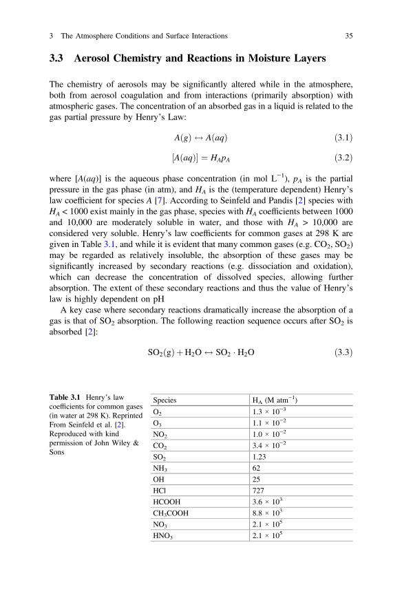
3.3 Aerosol Chemistry and Reactions in Moisture Layers
The chemistry of aerosols may be significantly altered while in the atmosphere,both from aerosol coagulation and from interactions (primarily absorption) withatmospheric gases. The concentration of an absorbed gas in a liquid is related to thegas partial pressure by Henry’s Law:
A gð Þ $ A aqð Þ ð3:1Þ
½A aqð Þ� ¼ HApA ð3:2Þ
where [A(aq)] is the aqueous phase concentration (in mol L−1), pA is the partialpressure in the gas phase (in atm), and HA is the (temperature dependent) Henry’slaw coefficient for species A [7]. According to Seinfeld and Pandis [2] species withHA < 1000 exist mainly in the gas phase, species with HA coefficients between 1000and 10,000 are moderately soluble in water, and those with HA > 10,000 areconsidered very soluble. Henry’s law coefficients for common gases at 298 K aregiven in Table 3.1, and while it is evident that many common gases (e.g. CO2, SO2)may be regarded as relatively insoluble, the absorption of these gases may besignificantly increased by secondary reactions (e.g. dissociation and oxidation),which can decrease the concentration of dissolved species, allowing furtherabsorption. The extent of these secondary reactions and thus the value of Henry’slaw is highly dependent on pH
A key case where secondary reactions dramatically increase the absorption of agas is that of SO2 absorption. The following reaction sequence occurs after SO2 isabsorbed [2]:
SO2 gð ÞþH2O $ SO2 � H2O ð3:3Þ
Table 3.1 Henry’s lawcoefficients for common gases(in water at 298 K). ReprintedFrom Seinfeld et al. [2].Reproduced with kindpermission of John Wiley &Sons
Species HA (M atm−1)
O2 1.3 × 10⁻³
O3 1.1 × 10⁻²
NO2 1.0 × 10⁻²
CO2 3.4 × 10⁻²
SO2 1.23
NH3 62
OH 25
HCl 727
HCOOH 3.6 × 10³
CH3COOH 8.8 × 10³
NO3 2.1 × 10⁵
HNO3 2.1 × 10⁵
3 The Atmosphere Conditions and Surface Interactions 35
SO2 � H2O $ Hþ þ HSO�3 ð3:4Þ
while
HSO�3 $ Hþ þ SO2�
3 ð3:5Þ
The balance between HSO3– and SO3
2– depends on pH, with the former dom-inating at pH values of 2–7, and the latter dominating above this pH range [2].These dissociation reactions may be taken into account by defining an effectiveHenry’s law coefficient that represents the equilibrium dissolved species whensubsequent aqueous reactions are considered. The effective Henry’s law coefficientfor SO2 ranges from 1.23 M atm−1 at a pH of 1 to >107 M atm−1 at a pH of 8. Thishas a dramatic effect on S(IV) concentrations in solution, which for a mixing ratioof 200 ppb (a typical value of a mildly industrial environment of SO2 at 298 K)would increase from 3 × 10⁻⁷ to 3 × 10⁻³ M as pH is increased from 0 to 6.1 In thecase of NH3, the Henry’s law coefficient is 62 M atm−1, and it is more readilyabsorbed than for SO2. In a similar way NH3 and CO2 absorption is highlydependent of subsequent aqueous reaction and thus highly pH dependent.
Another group of gases whose absorption is important to atmospheric corrosionare those such as O3, H2O2 or NOx which may oxidise or catalyse the oxidation ofdissolved species. Nitric acid is extremely water soluble and fully dissolves in allpH > 1 solutions. Ozone has a very low solubility, as indicated by its very lowHenry’s law coefficient [2]. In order to determine the balance between the gas phaseand the absorbed phase for a number of compounds, oxidation reactions also needto be included (as the atmosphere is in general strongly oxidising). An importantexample is the absorption of SO2, where the oxidation of SO3
2– or other forms of S(IV) to SO4
2– or other forms of S(VI) is critical, as it allows the continuedabsorption of SO2, [14]. This oxidation may occur via a variety of mechanisms [8],including reactions with O3, H2O2 and O2 (catalysed by Mn(II), Fe(III) and NO2).
In summary, the pH and species concentration in aerosols will depend on theeffective Henry’s law coefficient and thus on the extent of secondary reactions.Therefore, while the pure Henry law coefficient for SO2 absorption is relatively low(1.23 M atm−1 compared with 727 M atm−1 for HCl), secondary reactions raise theeffective Henry’s law coefficient and the speciation between HSO4
– and SO42– leads
to significant buffering at low pH. This combination makes SO2 levels a criticalfactor in aerosol-induced corrosion. The high Henry’s law coefficients of HCl,HNO3 and NO3 indicate that they are readily absorbed and thus can acidify aero-sols. Oxidants such as O3 (and NO2) are not readily absorbed, however they remainimportant as their relatively low levels in solution can catalyse the oxidation ofS(IV) to S(VI). In fact, the reported [9] synergistic effects between SO2, NO2 andO3 in determining the extent of corrosion are likely to arise, at least in part, from therole of NO2 and O3 in promoting the oxidation of S(IV) and thus the continuedabsorption of SO2 into moisture layers. The absorption of alkali precursor gases isalso critical, and NH3 is the most important of these due to its relatively high
36 I.S. Cole

Henry’s law coefficient and its relative abundance. Thus, the balance between acidand alkali precursors needs to be considered in estimating the likely acidification ofaerosol or rain water.
3.4 Key Aqueous/Gas Reactions
As indicated above, aqueous gas reactions are critical in controlling aerosol andrainwater chemistry. In this short review it is not possible to discuss in detail all theaqueous/gases systems of importance to atmospheric chemistry. Instead this chapterwill highlight two of importance to the degradation of coatings. The sulfuric acidammonia—water system which controls the chemistry of a major group of indus-trial aerosols and the absorption of gases into marine aerosols.
3.4.1 Sulfuric Acid–Ammonia–Water System
This system is of prime importance in determining the chemistry of aerosols inindustrial locations. Due to their high solubility, both H2SO4 and NH3 will bereadily absorbed into aerosols and will react according to form a series of solid anddissolved species, including ((NH4)3H(SO4)2), (NH4)2SO4, NH4HSO4, NH4
+,SO4
2–, HSO4– and NH3). It is illuminating to consider the system at low relative
humidity (RH) (30 %) and a high RH (75 %) at a H2SO4 concentration of10 μg m−3. At low RH and low ammonia levels, the aerosols consist primarily ofH2SO4, with some NH4HSO4(s) and significant water (H2SO4 attracts a significantamount of water even at low RH) [10]. When the ammonia/sulfuric acid ratioincreases above a molar ratio of 0.5, NH4HSO4(s) becomes the dominant species,and H2SO4 and associated water levels fall to zero [10]. As the molar ratioapproaches 1, the salt letovicite (NH4)3H(SO4)2(s) forms and gradually replacesNH4HSO4(s). At a molar ratio of 1.25–1.5, (NH4)3H(SO4)2(s) goes from being thedominant to the sole species, and for molar ratio from of 1.5–2 ammonium sulfatesalts form. At molar ratios of 2 or greater, ammonium sulfate salt is the sole species.
At 75 % RH the results are very different, the system is affected by the deli-quescence of NH4HSO4 (which has a deliquescent relative humidity (DRH) of40 %) and (NH4)3H(SO4)2 (DRH = 69 %), and so is in general a solution of NH4
+
and a sulfate species (whose form depends on ammonia levels). Thus, the aerosol isa liquid solution of H2SO4 at low ammonia levels, HSO4
– at moderate ammonialevels, SO4
2– at ammonia/sulfate ratios above 1.5, while the solid (NH4)2SO4 formsat ratios above 2 when there is sufficient ammonia to completely neutralize thesulfate [10].
It is evident from the above discussion that the composition and hydrogen ionconcentration within a wet aerosol will depend critically on the relative balance ofH2SO4 and NH3 in the atmosphere. The hydrogen ion concentration will determine
3 The Atmosphere Conditions and Surface Interactions 37
the extent of coating degradation promoted by the deposition of the aerosol, andthus the extent of corrosion. This result can be generalized to environmental sys-tems containing a range of S-containing gases and ammonia, and emphasizes theneed for an understanding of both acid and alkali precursors in understanding thecorrosiveness of an environment.
3.5 Reactions in Marine Aerosols
Marine aerosols may be acidified by the absorption of acid precursor gases asoutlined above. In particular, in wet marine aerosols, H2SO4 (or other strong acidssuch as HNO3 that have lower vapour pressures relative to HCl) may be absorbedinto the aerosol, where it will react with NaCl and acidify the solution, causing HClto volatilize [11]:
H2SO4 gð ÞþNaCl $ NaHSO4 þHCl gð Þ ð3:6Þ
This produces the acid salt NaHSO4 which may later dissociate. Thus, gaseousHCl may enter the atmosphere through the dechlorination of airborne sea saltparticles. However, as it is relatively soluble (HA = 727 M atm−1), it is readilyre-absorbed into atmospheric water droplets. In turn, these HCl-rich droplets maythen react with and promote the absorption of other strong acids which may laterdissociate:
HCl aqð ÞþHNO3 gð Þ $ HCl gð ÞþHNO3 aqð Þ ð3:7Þ
HCl aqð ÞþH2SO4 gð Þ $ HCl gð ÞþH2SO4 aqð Þ ð3:8Þ
In effect HCl will act as a buffer and prevent the acidity of marine derivedaerosols falling significantly below a pH of 2. However the gaseous HCl may thenbe re-absorbed and so such cycling of HCl can thus lead to further acidification ofboth aerosols and rain or cloud droplets in marine locations [12], with significantcontamination by industrial or urban pollutants.
In fact, marine aerosol are initially alkaline [13] immediately after breaking freefrom ocean waves (pH = 9.5. at 76.2 % RH) but this pH may subsequently reducedto below 5 within 15 min as a result of aqueous phase reactions (particularly theabsorption of H2SO4) [14]. In fact, Keene et al. [15] recently measured the pH ofthe larger sea-salt fractions (geometric mean diameter (GMD) ≥ 2.9 µm) and foundthat the median pH ranged from 3.1 to 3.4; the median pH for submicron fractionswas ≤ 1.6. Thus, the experimental data reinforces the observations made on thebasis of the equations controlling aerosol chemistry. Both industrial and marineaerosols may be acidified primarily by the absorption of either H2SO4 or SO2 (andsubsequent liquid phase reactions), and the acidified aerosol obtained may besignificantly buffered.
38 I.S. Cole
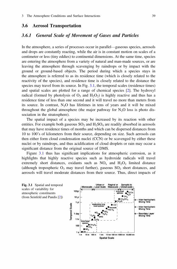
3.6 Aerosol Transportation
3.6.1 General Scale of Movement of Gases and Particles
In the atmosphere, a series of processes occur in parallel—gaseous species, aerosolsand drops are constantly reacting, while the air is in constant motion on scales of acentimeter or less (tiny eddies) to continental dimensions. At the same time, speciesare entering the atmosphere from a variety of natural and man-made sources, or areleaving the atmosphere through scavenging by raindrops or by impact with theground or ground-based objects. The period during which a species stays inthe atmosphere is referred to as its residence time (which is closely related to thereactivity of the species), and residence time is closely related to the distance thespecies may travel from its source. In Fig. 3.1, the temporal scales (residence times)and spatial scales are plotted for a range of chemical species [2]. The hydroxylradical (formed by photolysis of O3 and H2O2) is highly reactive and thus has aresidence time of less than one second and it will travel no more than meters fromits source. In contrast, N2O has lifetimes in tens of years and it will be mixedthroughout the global atmosphere (the major pathway for N2O loss is photo dis-sociation in the stratosphere).
The spatial impact of a species may be increased by its reaction with otherentities. For example both gaseous SO2 and H2SO4 are readily absorbed in aerosolsthat may have residence times of months and which can be dispersed distances from10 to 100’s of kilometers from their source, depending on size. Such aerosols canthen either form cloud condensation nuclei (CCN) or be scavenged by either thesenuclei or by raindrops, and thus acidification of cloud droplets or rain may occur asignificant distance from the original source of DMS.
Figure 3.1 thus has significant implications for atmospheric corrosion, as ithighlights that highly reactive species such as hydroxide radicals will travelextremely short distances, oxidants such as NOx and H2O2 limited distance(although tropospheric O3 may travel further), gaseous SO2 short distances, andaerosols will travel moderate distances from their source. Thus, direct impacts of
Fig. 3.1 Spatial and temporalscales of variability foratmospheric constituents(from Seinfeld and Pandis [2])
3 The Atmosphere Conditions and Surface Interactions 39
gaseous species on metallic corrosion will be limited to tens of kilometers fromsource, while indirect effects via aerosols or rain deposition may be at appreciabledistances from source.
3.6.2 Analytical Approach to Gas Transport
The transport of gases in a turbulent fluid can be modeled [2] using a Gaussiandistribution. The analysis indicates that dispersal of gases from their source wouldbe highly dependent on source height and plume stability. For low-height sources(<10 m) such as short stacks, the maximum pollutant levels will occur at 100–500 m of the source, while for plumes emitted from sources at a height of 100 m themaxima may occur up to 10 km from the source. Thus, gaseous pollutants maydirectly impact on metal structures for distances up to tens of kilometers from theirsource. However, they may also be absorbed in aerosols and transported signifi-cantly greater distances.
3.6.3 Aerosol Transport
The corrosion science literature has concentrated on the transport of marine aero-sols, and within corrosion science there has been little work on the deposition ofindustrial aerosols, which, as outlined previously, are significantly finer(generally <2.5 μm diameter). The factors influencing the transport of marineaerosols will also influence industrial aerosols, but industrial aerosols would be lessaffected by the various deposition processes and would thus have significantlylarger residence times and be transported longer distances.
As indicated above aerosols may transport industrial acids much greater dis-tances than the gas alone could travel, for example, work by Schwartz [16] indicatesthat industry-produced acids may be deposited up to 1000 km from their source.This is confirmed by Poste and Bridgman [17], who studied rainwater and fogacidity at two locations in northern New South Wales, Australia, approximately 200and 500 km from any industrial location, and approximately 40 and 60 km from thecoast, respectively. Both sites exhibited high levels of salts of marine origin andsignificant sulfates from anthropogenic sources. The most common explanation forthis enhanced transportation is that SO2/DiMethylSulphide or DMS (DMS is pro-duced by biological activity in shallow seas) may be absorbed in cloud droplets orwet aerosols (including marine aerosols) and transported via the aerosols (subse-quently the aerosols may be scavenged by fog or rain).
Analytical models of aerosol transport can provide a more accurate picture ofaerosol dispersion. Cole et al. [18]. developed a computation fluid dynamics(CFD) model of marine aerosol transportation, whereby aerosols are lifted by dif-fusion, convected by wind and dragged down by gravity. The study indicates that
40 I.S. Cole
coarse aerosols produced by the surf will generally be transported only 1–2 kmbefore being scavenged or falling to the ground, and thus their residence time isonly likely to be of the order of 1–20 min. In contrast, finer ocean-producedaerosols may travel hundreds of kilometres from the coast, and thus have residencetimes of hours to days. As Chameides and Stelson [19] indicate that it takes 5–15 min for the original alkaline pH of a marine aerosol to be reduced to below 5,there would not be any residence time limitation on absorption phenomena forocean-produced aerosols, but such limitation may exist for surf-produced aerosols.In fact, work by Cole et al. [20] found that the chemistry of deposited material onsalt candles and sample plates close to surf beaches closely reflected marine con-centrations, and did not show any significant non-marine concentration effectswhile that at a distance where only ocean produced aerosols would be expectedcould show significant non-marine sulfate concentrations [21].
3.6.4 Deposition of Pollutants
Traditionally, deposition onto surfaces has been classified as wet or dry deposition,with rain and snow being defined as wet deposition, and deposition by particulatesand aerosols (even when these are wet) being defined as dry. Deposition modes canalso be defined as:
• Deposition of snow, rain or fog.• Deposition of particulates or aerosols.• Deposition of gases into wet surfaces.• Deposition of gases onto dry surfaces.
3.6.4.1 Rain
Raindrops are generally assumed to have a 100 % efficiency of deposition onto asurface. However, once a raindrop falls onto a surface, it may splash off the surfaceand break into smaller drops, which could re-enter the airflow and not redeposit.Analyses by Cole and Paterson [22] indicated that although splash does occur, itdoes not lead to significant loss of deposition efficiency for rain falling onto sta-tionary objects. However, it can be quite significant for fast-moving objects (e.g.airplanes in flight).
3.6.4.2 Gas and Particle Deposition
Similar principles can be applied to both the dry deposition of gases and to thedeposition of particles. In a generic formulation, common in atmospheric physics,
3 The Atmosphere Conditions and Surface Interactions 41
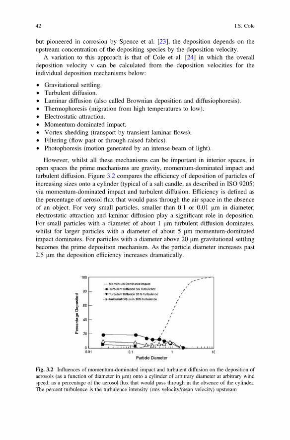
but pioneered in corrosion by Spence et al. [23], the deposition depends on theupstream concentration of the depositing species by the deposition velocity.
A variation to this approach is that of Cole et al. [24] in which the overalldeposition velocity ν can be calculated from the deposition velocities for theindividual deposition mechanisms below:
• Gravitational settling.• Turbulent diffusion.• Laminar diffusion (also called Brownian deposition and diffusiophoresis).• Thermophoresis (migration from high temperatures to low).• Electrostatic attraction.• Momentum-dominated impact.• Vortex shedding (transport by transient laminar flows).• Filtering (flow past or through raised fabrics).• Photophoresis (motion generated by an intense beam of light).
However, whilst all these mechanisms can be important in interior spaces, inopen spaces the prime mechanisms are gravity, momentum-dominated impact andturbulent diffusion. Figure 3.2 compares the efficiency of deposition of particles ofincreasing sizes onto a cylinder (typical of a salt candle, as described in ISO 9205)via momentum-dominated impact and turbulent diffusion. Efficiency is defined asthe percentage of aerosol flux that would pass through the air space in the absenceof an object. For very small particles, smaller than 0.1 or 0.01 μm in diameter,electrostatic attraction and laminar diffusion play a significant role in deposition.For small particles with a diameter of about 1 μm turbulent diffusion dominates,whilst for larger particles with a diameter of about 5 μm momentum-dominatedimpact dominates. For particles with a diameter above 20 μm gravitational settlingbecomes the prime deposition mechanism. As the particle diameter increases past2.5 μm the deposition efficiency increases dramatically.
Fig. 3.2 Influences of momentum-dominated impact and turbulent diffusion on the deposition ofaerosols (as a function of diameter in µm) onto a cylinder of arbitrary diameter at arbitrary windspeed, as a percentage of the aerosol flux that would pass through in the absence of the cylinder.The percent turbulence is the turbulence intensity (rms velocity/mean velocity) upstream
42 I.S. Cole
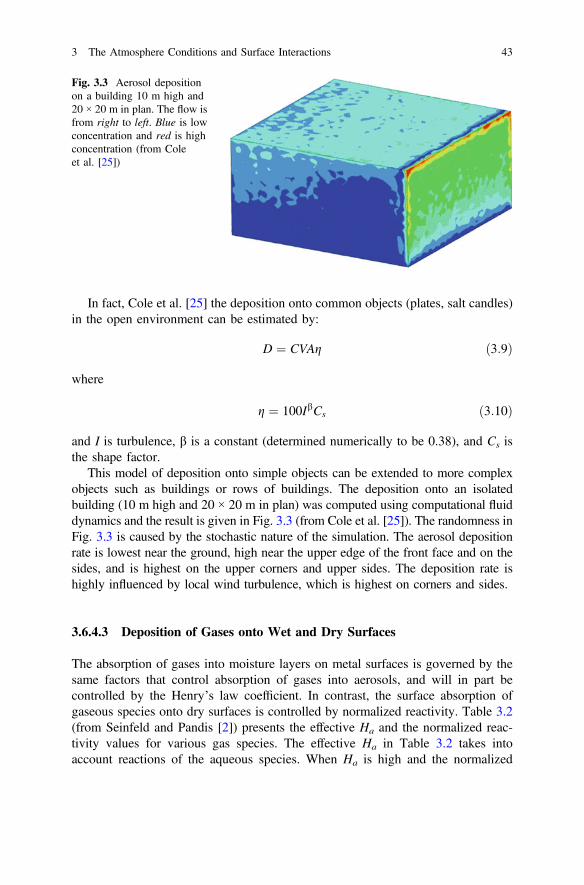
In fact, Cole et al. [25] the deposition onto common objects (plates, salt candles)in the open environment can be estimated by:
D ¼ CVAg ð3:9Þ
where
g ¼ 100IbCs ð3:10Þ
and I is turbulence, β is a constant (determined numerically to be 0.38), and Cs isthe shape factor.
This model of deposition onto simple objects can be extended to more complexobjects such as buildings or rows of buildings. The deposition onto an isolatedbuilding (10 m high and 20 × 20 m in plan) was computed using computational fluiddynamics and the result is given in Fig. 3.3 (from Cole et al. [25]). The randomness inFig. 3.3 is caused by the stochastic nature of the simulation. The aerosol depositionrate is lowest near the ground, high near the upper edge of the front face and on thesides, and is highest on the upper corners and upper sides. The deposition rate ishighly influenced by local wind turbulence, which is highest on corners and sides.
3.6.4.3 Deposition of Gases onto Wet and Dry Surfaces
The absorption of gases into moisture layers on metal surfaces is governed by thesame factors that control absorption of gases into aerosols, and will in part becontrolled by the Henry’s law coefficient. In contrast, the surface absorption ofgaseous species onto dry surfaces is controlled by normalized reactivity. Table 3.2(from Seinfeld and Pandis [2]) presents the effective Ha and the normalized reac-tivity values for various gas species. The effective Ha in Table 3.2 takes intoaccount reactions of the aqueous species. When Ha is high and the normalized
Fig. 3.3 Aerosol depositionon a building 10 m high and20 × 20 m in plan. The flow isfrom right to left. Blue is lowconcentration and red is highconcentration (from Coleet al. [25])
3 The Atmosphere Conditions and Surface Interactions 43
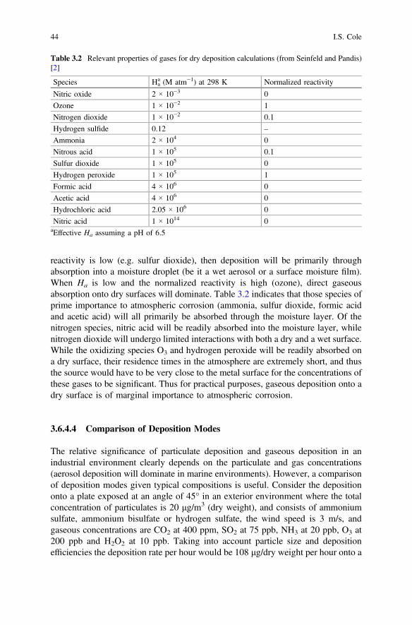
reactivity is low (e.g. sulfur dioxide), then deposition will be primarily throughabsorption into a moisture droplet (be it a wet aerosol or a surface moisture film).When Ha is low and the normalized reactivity is high (ozone), direct gaseousabsorption onto dry surfaces will dominate. Table 3.2 indicates that those species ofprime importance to atmospheric corrosion (ammonia, sulfur dioxide, formic acidand acetic acid) will all primarily be absorbed through the moisture layer. Of thenitrogen species, nitric acid will be readily absorbed into the moisture layer, whilenitrogen dioxide will undergo limited interactions with both a dry and a wet surface.While the oxidizing species O3 and hydrogen peroxide will be readily absorbed ona dry surface, their residence times in the atmosphere are extremely short, and thusthe source would have to be very close to the metal surface for the concentrations ofthese gases to be significant. Thus for practical purposes, gaseous deposition onto adry surface is of marginal importance to atmospheric corrosion.
3.6.4.4 Comparison of Deposition Modes
The relative significance of particulate deposition and gaseous deposition in anindustrial environment clearly depends on the particulate and gas concentrations(aerosol deposition will dominate in marine environments). However, a comparisonof deposition modes given typical compositions is useful. Consider the depositiononto a plate exposed at an angle of 45° in an exterior environment where the totalconcentration of particulates is 20 μg/m3 (dry weight), and consists of ammoniumsulfate, ammonium bisulfate or hydrogen sulfate, the wind speed is 3 m/s, andgaseous concentrations are CO2 at 400 ppm, SO2 at 75 ppb, NH3 at 20 ppb, O3 at200 ppb and H2O2 at 10 ppb. Taking into account particle size and depositionefficiencies the deposition rate per hour would be 108 μg/dry weight per hour onto a
Table 3.2 Relevant properties of gases for dry deposition calculations (from Seinfeld and Pandis)[2]
Species Haa (M atm−1) at 298 K Normalized reactivity
Nitric oxide 2 × 10⁻³ 0
Ozone 1 × 10⁻² 1
Nitrogen dioxide 1 × 10⁻² 0.1
Hydrogen sulfide 0.12 –
Ammonia 2 × 10⁴ 0
Nitrous acid 1 × 10⁵ 0.1
Sulfur dioxide 1 × 10⁵ 0
Hydrogen peroxide 1 × 10⁵ 1
Formic acid 4 × 10⁶ 0
Acetic acid 4 × 10⁶ 0
Hydrochloric acid 2.05 × 10⁶ 0
Nitric acid 1 × 10¹⁴ 0aEffective Ha assuming a pH of 6.5
44 I.S. Cole
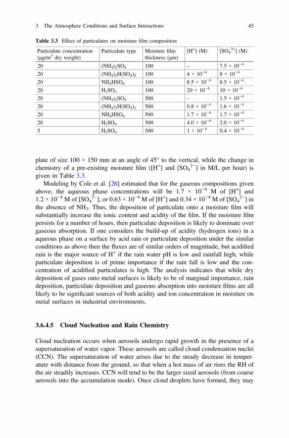
plate of size 100 × 150 mm at an angle of 45° to the vertical, while the change inchemistry of a pre-existing moisture film ([H+] and [SO4
2−] in M/L per hour) isgiven in Table 3.3.
Modeling by Cole et al. [26] estimated that for the gaseous compositions givenabove, the aqueous phase concentrations will be 1.7 × 10⁻⁶ M of [H+] and1.2 × 10−4 M of [SO4
2−], or 0.63 × 10⁻⁴ M of [H+] and 0.34 × 10⁻⁴ M of [SO42−] in
the absence of NH3. Thus, the deposition of particulate onto a moisture film willsubstantially increase the ionic content and acidity of the film. If the moisture filmpersists for a number of hours, then particulate deposition is likely to dominate overgaseous absorption. If one considers the build-up of acidity (hydrogen ions) in aaqueous phase on a surface by acid rain or particulate deposition under the similarconditions as above then the fluxes are of similar orders of magnitude, but acidifiedrain is the major source of H+ if the rain water pH is low and rainfall high, whileparticulate deposition is of prime importance if the rain fall is low and the con-centration of acidified particulates is high. The analysis indicates that while drydeposition of gases onto metal surfaces is likely to be of marginal importance, raindeposition, particulate deposition and gaseous absorption into moisture films are alllikely to be significant sources of both acidity and ion concentration in moisture onmetal surfaces in industrial environments.
3.6.4.5 Cloud Nucleation and Rain Chemistry
Cloud nucleation occurs when aerosols undergo rapid growth in the presence of asupersaturation of water vapor. These aerosols are called cloud condensation nuclei(CCN). The supersaturation of water arises due to the steady decrease in temper-ature with distance from the ground, so that when a hot mass of air rises the RH ofthe air steadily increases. CCN will tend to be the larger sized aerosols (from coarseaerosols into the accumulation mode). Once cloud droplets have formed, they may
Table 3.3 Effect of particulates on moisture film composition
Particulate concentration(μg/m3 dry weight)
Particulate type Moisture filmthickness (μm)
[H+] (M) [SO42+] (M)
20 (NH4)2SO4 100 – 7.5 × 10⁻⁴
20 (NH4)3H(SO4)2 100 4 × 10⁻⁴ 8 × 10⁻⁴
20 NH4HSO4 100 8.5 × 10⁻⁴ 8.5 × 10⁻⁴
20 H2SO4 100 20 × 10−4 10 × 10−4
20 (NH4)2SO4 500 – 1.5 × 10⁻⁴
20 (NH4)3H(SO4)2 500 0.8 × 10⁻⁴ 1.6 × 10⁻⁴
20 NH4HSO4 500 1.7 × 10⁻⁴ 1.7 × 10⁻⁴
20 H2SO4 500 4.0 × 10⁻⁴ 2.0 × 10⁻⁴
5 H2SO4 500 1 × 10⁻⁴ 0.4 × 10⁻⁴
3 The Atmosphere Conditions and Surface Interactions 45
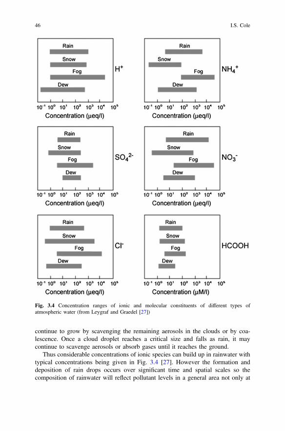
continue to grow by scavenging the remaining aerosols in the clouds or by coa-lescence. Once a cloud droplet reaches a critical size and falls as rain, it maycontinue to scavenge aerosols or absorb gases until it reaches the ground.
Thus considerable concentrations of ionic species can build up in rainwater withtypical concentrations being given in Fig. 3.4 [27]. However the formation anddeposition of rain drops occurs over significant time and spatial scales so thecomposition of rainwater will reflect pollutant levels in a general area not only at
Fig. 3.4 Concentration ranges of ionic and molecular constituents of different types ofatmospheric water (from Leygraf and Graedel [27])
46 I.S. Cole
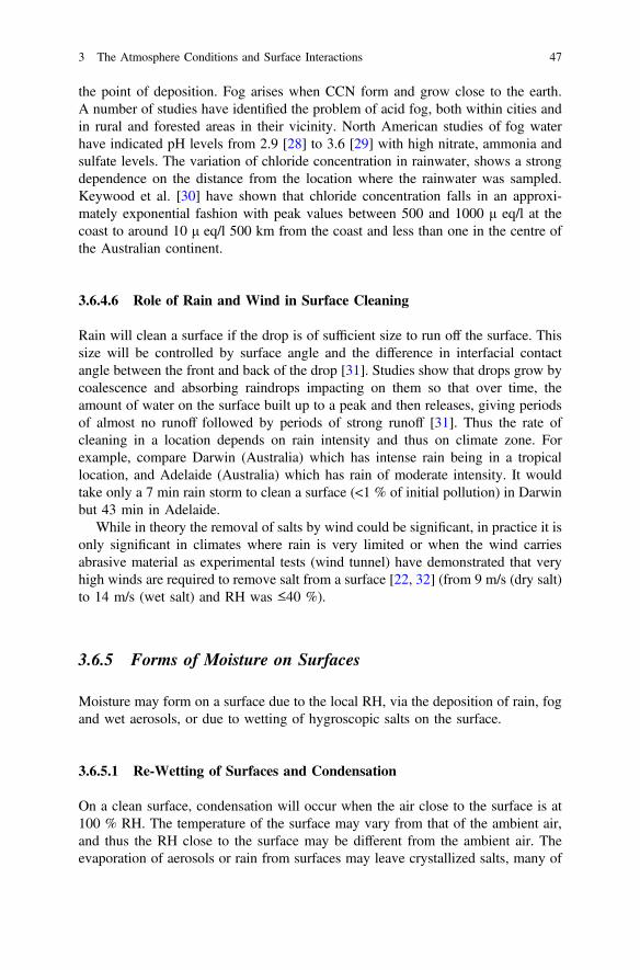
the point of deposition. Fog arises when CCN form and grow close to the earth.A number of studies have identified the problem of acid fog, both within cities andin rural and forested areas in their vicinity. North American studies of fog waterhave indicated pH levels from 2.9 [28] to 3.6 [29] with high nitrate, ammonia andsulfate levels. The variation of chloride concentration in rainwater, shows a strongdependence on the distance from the location where the rainwater was sampled.Keywood et al. [30] have shown that chloride concentration falls in an approxi-mately exponential fashion with peak values between 500 and 1000 μ eq/l at thecoast to around 10 μ eq/l 500 km from the coast and less than one in the centre ofthe Australian continent.
3.6.4.6 Role of Rain and Wind in Surface Cleaning
Rain will clean a surface if the drop is of sufficient size to run off the surface. Thissize will be controlled by surface angle and the difference in interfacial contactangle between the front and back of the drop [31]. Studies show that drops grow bycoalescence and absorbing raindrops impacting on them so that over time, theamount of water on the surface built up to a peak and then releases, giving periodsof almost no runoff followed by periods of strong runoff [31]. Thus the rate ofcleaning in a location depends on rain intensity and thus on climate zone. Forexample, compare Darwin (Australia) which has intense rain being in a tropicallocation, and Adelaide (Australia) which has rain of moderate intensity. It wouldtake only a 7 min rain storm to clean a surface (<1 % of initial pollution) in Darwinbut 43 min in Adelaide.
While in theory the removal of salts by wind could be significant, in practice it isonly significant in climates where rain is very limited or when the wind carriesabrasive material as experimental tests (wind tunnel) have demonstrated that veryhigh winds are required to remove salt from a surface [22, 32] (from 9 m/s (dry salt)to 14 m/s (wet salt) and RH was ≤40 %).
3.6.5 Forms of Moisture on Surfaces
Moisture may form on a surface due to the local RH, via the deposition of rain, fogand wet aerosols, or due to wetting of hygroscopic salts on the surface.
3.6.5.1 Re-Wetting of Surfaces and Condensation
On a clean surface, condensation will occur when the air close to the surface is at100 % RH. The temperature of the surface may vary from that of the ambient air,and thus the RH close to the surface may be different from the ambient air. Theevaporation of aerosols or rain from surfaces may leave crystallized salts, many of
3 The Atmosphere Conditions and Surface Interactions 47
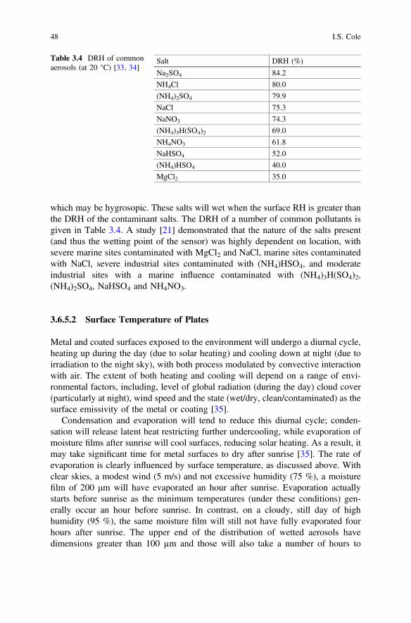
which may be hygrosopic. These salts will wet when the surface RH is greater thanthe DRH of the contaminant salts. The DRH of a number of common pollutants isgiven in Table 3.4. A study [21] demonstrated that the nature of the salts present(and thus the wetting point of the sensor) was highly dependent on location, withsevere marine sites contaminated with MgCl2 and NaCl, marine sites contaminatedwith NaCl, severe industrial sites contaminated with (NH4)HSO4, and moderateindustrial sites with a marine influence contaminated with (NH4)3H(SO4)2,(NH4)2SO4, NaHSO4 and NH4NO3.
3.6.5.2 Surface Temperature of Plates
Metal and coated surfaces exposed to the environment will undergo a diurnal cycle,heating up during the day (due to solar heating) and cooling down at night (due toirradiation to the night sky), with both process modulated by convective interactionwith air. The extent of both heating and cooling will depend on a range of envi-ronmental factors, including, level of global radiation (during the day) cloud cover(particularly at night), wind speed and the state (wet/dry, clean/contaminated) as thesurface emissivity of the metal or coating [35].
Condensation and evaporation will tend to reduce this diurnal cycle; conden-sation will release latent heat restricting further undercooling, while evaporation ofmoisture films after sunrise will cool surfaces, reducing solar heating. As a result, itmay take significant time for metal surfaces to dry after sunrise [35]. The rate ofevaporation is clearly influenced by surface temperature, as discussed above. Withclear skies, a modest wind (5 m/s) and not excessive humidity (75 %), a moisturefilm of 200 μm will have evaporated an hour after sunrise. Evaporation actuallystarts before sunrise as the minimum temperatures (under these conditions) gen-erally occur an hour before sunrise. In contrast, on a cloudy, still day of highhumidity (95 %), the same moisture film will still not have fully evaporated fourhours after sunrise. The upper end of the distribution of wetted aerosols havedimensions greater than 100 µm and those will also take a number of hours to
Table 3.4 DRH of commonaerosols (at 20 °C) [33, 34]
Salt DRH (%)
Na2SO4 84.2
NH4Cl 80.0
(NH4)2SO4 79.9
NaCl 75.3
NaNO3 74.3
(NH4)3H(SO4)2 69.0
NH4NO3 61.8
NaHSO4 52.0
(NH4)HSO4 40.0
MgCl2 35.0
48 I.S. Cole
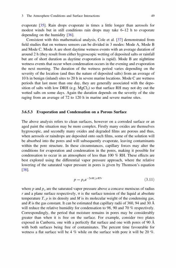
evaporate [35]. Rain drops evaporate in times a little longer than aerosols formodest winds but in still conditions rain drops may take 6–12 h to evaporatedepending on the humidity [36].
Consistent with this mathematical analysis, Cole et al. [37] demonstrated fromfield studies that on wetness sensors can be divided in 3 modes: Mode A, Mode Band Mode C. Mode A are short daytime wetness events with an average duration ofaround 2 h (they result from either hygroscopic wetting of deposited salts or rainfallbut are of short duration as daytime evaporation is rapid). Mode B are nighttimewetness events that occur when condensation occurs in the evening and evaporationthe next morning. The duration of the wetness period varies depending on theseverity of the location (and thus the nature of deposited salts) from an average of10 h in benign (inland) sites to 20 h in severe marine locations. Mode C are wetnessperiods that last more than one day, they are generally associated with the depo-sition of salts with low DRH (e.g. MgCl2) so that surface RH may not dry out thewetted salts on some days. Again the duration depends on the severity of the siteraging from an average of 72 to 120 h in marine and severe marine sites.
3.6.5.3 Evaporation and Condensation on a Porous Surface
The above analysis refers to clean surfaces, however on a corroded surface or anaged paint the situation may be more complex. Firstly many oxides are themselveshygroscopic, and secondly many oxides and degraded films are porous and thus,when aerosols or raindrops are deposited onto such films, some of the solution willbe absorbed into the pores and will subsequently evaporate, leaving contaminantswithin the pore structure. In these circumstances, capillary forces may alter theconditions for evaporation and condensation in the pores, making it possible forcondensation to occur in an atmosphere of less than 100 % RH. These effects arebest explored using the differential vapor pressure approach, where the relativelowering of the saturated vapor pressure in pores is given by Thomson’s equation[38].
p ¼ poe�2rM=qRTr ð3:11Þ
where p and po are the saturated vapor pressure above a concave meniscus of radiusr and a plane surface respectively, σ is the surface tension of the liquid at absolutetemperature T, ρ is its density and M is its molecular weight of the condensing gas,and R is the gas constant. It can be estimated that capillary radii of 360, 94 and 30 Åwill reduce the relative humidity for condensation to 98, 90 and 70 % respectively.Correspondingly, the period that moisture remains in pores may be considerablygreater than when it is free on the surface. For example, consider two platesexposed in Canberra, one with a perfectly flat surface and one with pores of 90 Åwith both surfaces being free of contaminates. The percent time favourable forwetness a flat surface will be 4 % while on the surface with pore it will be 20 %.
3 The Atmosphere Conditions and Surface Interactions 49
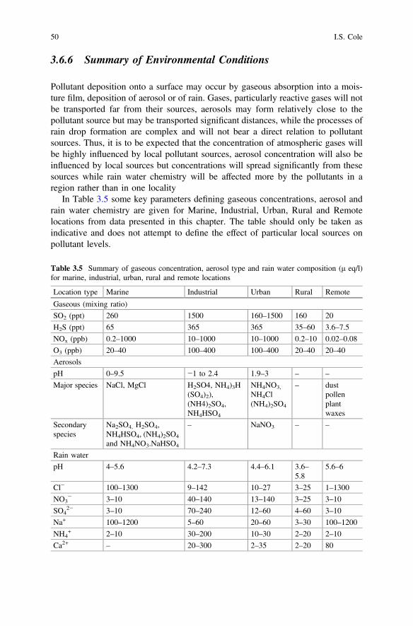
3.6.6 Summary of Environmental Conditions
Pollutant deposition onto a surface may occur by gaseous absorption into a mois-ture film, deposition of aerosol or of rain. Gases, particularly reactive gases will notbe transported far from their sources, aerosols may form relatively close to thepollutant source but may be transported significant distances, while the processes ofrain drop formation are complex and will not bear a direct relation to pollutantsources. Thus, it is to be expected that the concentration of atmospheric gases willbe highly influenced by local pollutant sources, aerosol concentration will also beinfluenced by local sources but concentrations will spread significantly from thesesources while rain water chemistry will be affected more by the pollutants in aregion rather than in one locality
In Table 3.5 some key parameters defining gaseous concentrations, aerosol andrain water chemistry are given for Marine, Industrial, Urban, Rural and Remotelocations from data presented in this chapter. The table should only be taken asindicative and does not attempt to define the effect of particular local sources onpollutant levels.
Table 3.5 Summary of gaseous concentration, aerosol type and rain water composition (μ eq/l)for marine, industrial, urban, rural and remote locations
Location type Marine Industrial Urban Rural Remote
Gaseous (mixing ratio)
SO2 (ppt) 260 1500 160–1500 160 20
H2S (ppt) 65 365 365 35–60 3.6–7.5
NOx (ppb) 0.2–1000 10–1000 10–1000 0.2–10 0.02–0.08
O3 (ppb) 20–40 100–400 100–400 20–40 20–40
Aerosols
pH 0–9.5 −1 to 2.4 1.9–3 – –
Major species NaCl, MgCl H2SO4, NH4)3H(SO4)2),(NH4)2SO4,NH4HSO4
NH4NO3,
NH4Cl(NH4)2SO4
– dustpollenplantwaxes
Secondaryspecies
Na2SO4, H2SO4,NH4HSO4, (NH4)2SO4
and NH4NO3.NaHSO4
– NaNO3 – –
Rain water
pH 4–5.6 4.2–7.3 4.4–6.1 3.6–5.8
5.6–6
Cl− 100–1300 9–142 10–27 3–25 1–1300
NO3− 3–10 40–140 13–140 3–25 3–10
SO42− 3–10 70–240 12–60 4–60 3–10
Na+ 100–1200 5–60 20–60 3–30 100–1200
NH4+ 2–10 30–200 10–30 2–20 2–10
Ca2+ – 20–300 2–35 2–20 80
50 I.S. Cole
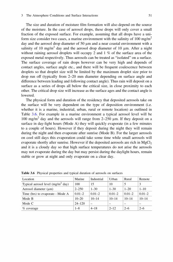
The size and duration of moisture film formation will also depend on the sourceof the moisture. In the case of aerosol drops, these drops will only cover a smallfraction of the exposed surface. For example, assuming that all drops have a uni-form size consider two cases, a marine environment with the salinity of 100 mg/m2
day and the aerosol drop diameter of 50 µm and a near coastal environment with asalinity of 10 mg/m2 day and the aerosol drop diameter of 10 µm. After a nightwithout raining aerosol droplets will occupy 2 and 1 % of the surface area of theexposed metal respectively. Thus aerosols can be treated as “isolated” on a surface.The surface coverage of rain drops however can be very high and depends ofcontact angles, surface angle etc., and there will be frequent coalescence betweendroplets so that droplet size will be limited by the maximum droplet size prior todrop run off (typically from 2–20 mm diameter depending on surface angle anddifference between leading and following contact angle). Thus rain will deposit on asurface as a series of drops all below the critical size, in close proximity to eachother. The critical drop size will increase as the surface ages and the contact angle islowered.
The physical form and duration of the residency that deposited aerosols take onthe surface will be very dependent on the type of deposition environment (i.e.whether it is a marine, industrial, urban, rural or remote location) as outlined inTable 3.6. For example in a marine environment a typical aerosol level will be100 mg/m2 day and the aerosols will range from 2–250 µm. If they deposit on asurface in day-light hours (Mode A) they will quickly evaporate (in a few minutesto a couple of hours). However if they deposit during the night they will remainduring the night and then evaporate after sunrise (Mode B). For the larger aerosolson cool still days this evaporation could take some time while small aerosols willevaporate shortly after sunrise. However if the deposited aerosols are rich in MgCl2and it is a cloudy day so that high surface temperatures do not arise the aerosolsmay not evaporate during the day but may persist during the daylight hours, remainstable or grow at night and only evaporate on a clear day.
Table 3.6 Physical properties and typical duration of aerosols on surfaces
Location Marine Industrial Urban Rural Remote
Typical aerosol level (mg/m2 day) 100 15 10 5 3
Aerosol diameter (µm) 2–250 1–30 1–30 1–20 1–10
Time (hrs) to evaporate—Mode A 0.01–2 0.01–2 0.01–2 0.01–2 0.01–2
Mode B 10–20 10–14 10–14 10–14 10–14
Mode C 24–120 – – – –
% coverage 1–8 4–18 2–12 2–6 2–6
3 The Atmosphere Conditions and Surface Interactions 51

3.7 Relevance of Environmental Conditionsto Moisture Ingress and Inhibitor Stability
In discussing moisture ingress into films, two questions are important, what is themaximum possible volume within the paint film that could be occupied by the dropthat was initially deposited on the surface and how long would it take for this stateto arise.
To the author’s knowledge, no analysis has been undertake of the residual dropvolume that remains on a surface as a drop diffuses into the pores of a polymer film.It is likely that due to surface tension effects, there will be some residual surfacemoisture, however let it be assumed that all the droplet volume diffuses into thefilm. Then the wetted pore volume should equal the initial drop volume. Mardelet al. [39] found that pore volume in a two component epoxy (epoxy Epikote 828with amine cross linker) was 2.2 wt% or given that the epoxy had a density of 1.4then the pore volume was 3 % volume percent. This implies that the wetted areawill occupy approximated 33 times the volume of the original drop. If it is assumedthat the moisture diffuses into the film at a constant rate in all directions then thepenetration in any direction will be approximately 2.9 that of the original dimensionof the drop. Under these assumptions a Mode A aerosol that formed a hemisphericaldrop of radius 5 µm on the surface would form a hemispherical drop of radius ofapproximately 15 µm below the surface. Now this analysis needs to be undertakenin a more detailed way but it illustrates that smaller aerosols typical of non-marinelocations may not lead to thorough wetting of a paint film while the absorption oflarger aerosols typical of marine locations and rain droplets may.
The second issue is whether a droplet on a surface will reside for a sufficient timeto diffuse into the surface before it is removed from that surface (by evaporation orroll off etc.). In terms of water diffusion and uptake through a polymeric film,Prosek and Thierry [40] suggested that the time for the solution to reach the metalsurface through a coating and return to the external surface can be calculated usingthe equation [12]:
d ¼ 2l ¼ ðDtÞ0:5 ð3:12Þ
where d is twice the film thickness l, D is the diffusion coefficient, and t the time.Diffusion coefficients of water in epoxy have been reported in the range of
1 × 10⁻⁹ to 4 × 10⁻⁸ cm2/s by Philippe et al. [41], and 2.8 × 10⁻⁸ cm2/s by Mardel[39] The diffusion of chloride is taken from Hu et al. [42] as 4.7 × 10⁻¹² cm2/s. InTable 3.7 the depth of penetration of moisture and chloride is calculated assumingFick’s law. If the coating is of the order of 80 µm, water will penetrate though thecoating in around 60–120 min (assuming the two highest diffusion constants),although it will only penetrate around 20–30 µm in the same time assuming thelowest diffusion coefficient. Thus penetration of moisture through a paint film willonly occur for droplets which persists for a number of hours. This implies that largeaerosols deposited at night may penetrate through the coating but those deposited
52 I.S. Cole
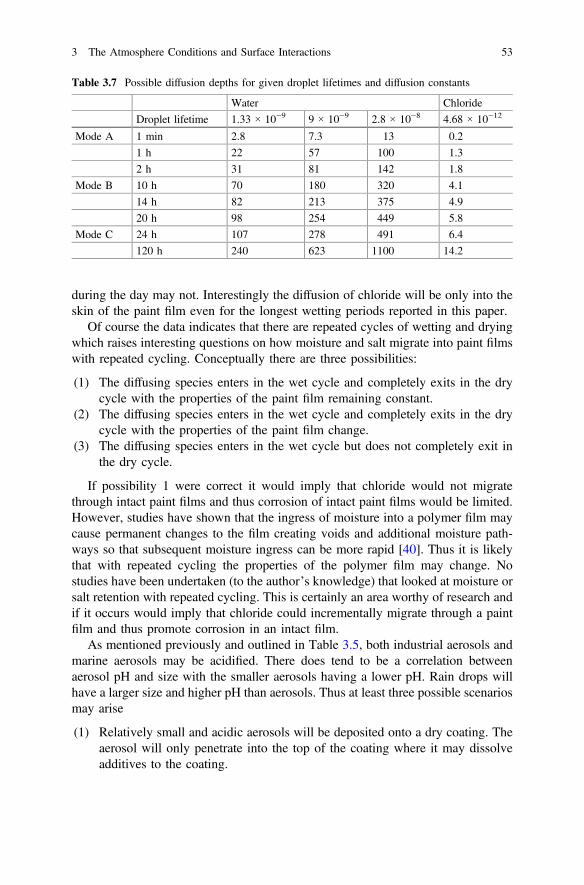
during the day may not. Interestingly the diffusion of chloride will be only into theskin of the paint film even for the longest wetting periods reported in this paper.
Of course the data indicates that there are repeated cycles of wetting and dryingwhich raises interesting questions on how moisture and salt migrate into paint filmswith repeated cycling. Conceptually there are three possibilities:
(1) The diffusing species enters in the wet cycle and completely exits in the drycycle with the properties of the paint film remaining constant.
(2) The diffusing species enters in the wet cycle and completely exits in the drycycle with the properties of the paint film change.
(3) The diffusing species enters in the wet cycle but does not completely exit inthe dry cycle.
If possibility 1 were correct it would imply that chloride would not migratethrough intact paint films and thus corrosion of intact paint films would be limited.However, studies have shown that the ingress of moisture into a polymer film maycause permanent changes to the film creating voids and additional moisture path-ways so that subsequent moisture ingress can be more rapid [40]. Thus it is likelythat with repeated cycling the properties of the polymer film may change. Nostudies have been undertaken (to the author’s knowledge) that looked at moisture orsalt retention with repeated cycling. This is certainly an area worthy of research andif it occurs would imply that chloride could incrementally migrate through a paintfilm and thus promote corrosion in an intact film.
As mentioned previously and outlined in Table 3.5, both industrial aerosols andmarine aerosols may be acidified. There does tend to be a correlation betweenaerosol pH and size with the smaller aerosols having a lower pH. Rain drops willhave a larger size and higher pH than aerosols. Thus at least three possible scenariosmay arise
(1) Relatively small and acidic aerosols will be deposited onto a dry coating. Theaerosol will only penetrate into the top of the coating where it may dissolveadditives to the coating.
Table 3.7 Possible diffusion depths for given droplet lifetimes and diffusion constants
Water Chloride
Droplet lifetime 1.33 × 10⁻⁹ 9 × 10⁻⁹ 2.8 × 10⁻⁸ 4.68 × 10⁻¹²
Mode A 1 min 2.8 7.3 13 0.2
1 h 22 57 100 1.3
2 h 31 81 142 1.8
Mode B 10 h 70 180 320 4.1
14 h 82 213 375 4.9
20 h 98 254 449 5.8
Mode C 24 h 107 278 491 6.4
120 h 240 623 1100 14.2
3 The Atmosphere Conditions and Surface Interactions 53
(2) Large aerosols and rain droplets may deposit onto the dry coating. Their sizeand residency periods will permit through penetration of the coating. Themoderate acidity of the coating may assist the dissolution of additives.Through moisture penetration will permit electrochemical cells to be estab-lished that may also alter the pH of the pore water in the coating.
(3) If aerosols and rain droplets are deposited onto a wet coating then they mayalter the pH of the pore water but the pH may have already have been affectedby the establishment of electrochemical cells prior to the deposition.
3.8 Damage to Coatings
Environmental factors, both those mentioned in this paper (acid deposition, tem-perature, cyclic wetting) and those not discussed (UV), can cause significantdegradation to coatings and clearly an understanding of their degradation is criticalin coating design. This is a subject that has been treated by a number of substantivereviews and the reader is urged to consult [43–45].
3.9 Summary
This chapter has outlined atmospheric factors that may affect the function of smartcoatings. The emphasis has been on the factors that affect the intensity, lifetime andchemistry of aerosols and rain drops that may deposit on coatings.
The paper outlined the source and chemistry of marine and industrial aerosolsand how gaseous absorption can acidify both marine and industrial aerosols.Gaseous absorption is influenced not only by the rate that gases are absorbed intomoisture films but by secondary reactions that transformed the absorbed species andallow absorption to continue. Thus aerosols and rain drops become enriched insulfates via SO2 absorption and transformation despite the fact that the Henry lawcoefficient that measure the rate of SO2 absorption is relatively low. Aerosols maybe transported significant distances from their sources and during this transport theirchemistry may be altered and thus deposition of acidified aerosol may occur at asignificant distance from the pollutant source. Similarly rain drops may be acidifiedthrough the acidification of cloud condensation nuclei and gaseous absorptionduring rainfall so that one again acidified rain may occur at some distance frompollutant sources. Both acid rain and deposition of acidified pH are major sources ofthe flux of acidic species onto a surface.
A surface may wet both from the deposition of rain and aerosols and from therewetting of pollutants that had previously been deposited. Of particular importanceis the deposition and retention of hygrosopic salts. Many aerosols and rainwaterwill leave behind such salts when they evaporate. Of particular importance are the
54 I.S. Cole
ammonium sulfates, magnesium and sodium chlorides and sodium and ammoniumnitrates. These salts will wet when the relative humidity at the coating surfaceexceeds that of the deliquescent RH of the salt (which may vary from 35 % forMgCl2 to 84 % for Na2SO4). The surface RH depends both on the surface tem-perature of the coating and the ambient RH. Ambient RH and surface temperaturewill depend very strongly on the diurnal or daily climate cycle, with a typicalAustralian cycle being high RH and low surface temperatures at night and low RHand high surface temperatures during the day. Thus deposited rain drops andaerosols will tend to evaporate after sun-rise. Thus three modes of droplet durationon a surface associated with aerosol deposition.
(1) Mode A—Aerosols deposited during the day will generally evaporate quickly(minutes to a couple of hours)
(2) Mode B—Aerosols deposited or salts that rewet during the night will notevaporate to after sunrise (total life from 8–14 h)
(3) Mode C—Deposition of aerosols rich in MgCl2 or rewetting of MgCl2 saltsmay lead to drop lifetimes in excess of 24 h as daytime surface RH may notbecome lower than the DRH of MgCl2
The different surface droplet modes and similar factors for rain water control theform that wetting of a coating may take and together with the chemistry of theaerosol or rain droplet this may affect the impact of the wetting event on the coating.Again three scenarios may occur:
(1) Relatively small and acidic aerosols will be deposited onto a dry coating. Theaerosol will only penetrate into the top of the coating where it may dissolveadditives to the coating.
(2) Large aerosols and rain droplets may deposit onto the dry coating. Their sizeand residency periods will permit through penetration of the coating. Themoderate acidity of the coating may assist the dissolution of additives.Through moisture penetration will permit electrochemical cells to be estab-lished that may also alter the pH of the pore water in the coating.
(3) If aerosols and rain droplets are deposited onto a wet coating they may alterthe pH of the pore water but the pH may have already have been affected bythe establishment of electrochemical cells pore to the deposition.
References
1. I.S. Cole, N.S. Azmat, A. Kanta, M. Venkatraman, What really controls the atmosphericcorrosion of zinc? Effect of marine aerosols on atmospheric corrosion of zinc. Int. Mater. Rev.54, 117–133 (2009)
2. J. Seinfeld, S. Pandis, Atmospheric Chemistry and Physics: From Air Pollution to ClimateChange (Wiley Interscience, New York, 1997)
3 The Atmosphere Conditions and Surface Interactions 55

3. W.A. McKay, J.A. Garland, D. Livesley, C.M. Halliwell, M.I. Walker, The characteristics ofthe shore-line sea spray aerosol and the landward transfer of radionuclides discharged tocoastal sea-water. Atmos. Environ. 28, 3299–3309 (1994)
4. J.W. Fitzgerald, Marine aerosols - a review. Atmos. Environ. Part A-General Topics 25, 533–545 (1991)
5. X. Yao, T.Y. Ling, M. Fang, C.K. Chan, Size dependence of in situ pH in submicronatmospheric particles in Hong Kong. Atmos. Environ. 41, 382–393 (2007)
6. M. Takeuchi, H. Okochi, M. Igawa, Characteristics of water-soluble components ofatmospheric aerosols in Yokohama and Mt. Oyama, Japan from 1990 to 2001, Atmos.Environ., 38, 4701–4708 (2004)
7. S.N. Pandis, J.H. Seinfeld, Sensitivity analysis of a chemical mechanism for aqueous-phaseatmospheric chemistry. J. Geophys. Res.-Atmos. 94, 1105–1126 (1989)
8. R. Vogt, P.J. Crutzen, R. Sander, A mechanism for halogen release from sea-salt aerosol in theremote marine boundary layer. Nature 383, 327–330 (1996)
9. M.R. Hoffmann, J.G. Calvert, in Chemical Transformation Modules for Eulerian AcidDeposition Models: Vol.2 - The Aqueous Phase Chemistry, (US Environmental ProtectionAgency Reserach Triangle Park NC, 1985)
10. J.E. Svensson, L.G. Johansson, A laboratory study of the effect of ozone nitrogen-dioxide, andsulfur-dioxide on the atmospheric corrosion of zinc. J. Electrochem. Soc. 140, 2210–2216(1993)
11. C. Pilinis, J.H. Seinfeld, Continued development of a general equilibrium-model for inorganicmulticomponent atmospheric aerosols. Atmos. Environ. 21, 2453–2466 (1987)
12. S.L. Clegg, P. Brimblecombe, A.S. Wexler, Thermodynamic model of the system H + -NH4 + -SO42–NO3–H2O at tropospheric temperatures. J. Phys. Chem. A 102, 2137–2154(1998)
13. W.C. Keene, R. Sander, A.A.P. Pszenny, R. Vogt, P.J. Crutzen, J.N. Galloway, Aerosol pH inthe marine boundary layer: A review and model evaluation. J. Aerosol Sci. 29, 339–356(1998)
14. R. Sander, P.J. Crutzen, Model study indicating halogen activation and ozone destruction inpolluted air masses transported to the sea. J. Geophys. Res.-Atmos. 101, 9121–9138 (1996)
15. W.C. Keene, H. Maring, J.R. Maben, D.J. Kieber, A.A.P. Pszenny, E.E. Dahl, M.A. Izaguirre,A.J. Davis, M.S. Long, X.L. Zhou, L. Smoydzin, R. Sander, Chemical and physicalcharacteristics of nascent aerosols produced by bursting bubbles at a model air-sea interface,J. Geophys. Res.-Atmos. 112 (2007)
16. S.E. Schwartz, Acid deposition - unraveling a regional phenomenon. Science 243, 753–763(1989)
17. D. Post, H.A. Bridgman, G.P. Ayers, Fog and rainwater composition in rural se australia.J. Atmos. Chem. 13, 83–95 (1991)
18. I.S. Cole, D.A. Paterson, W.D. Ganther, Holistic model for atmospheric corrosion - Part1-Theoretical framework for production, transportation and deposition of marine salts. Corros.Eng. Sci. Technol. 38, 129–134 (2003)
19. W.L. Chameides, A.W. Stelson, Aqueous-phase chemical processes in deliquescent sea-saltaerosols–a mechanism that couples the atmospheric cycles of s and sea salt. J. Geophys. Res.-Atmos. 97, 20565–20580 (1992)
20. I.S. Cole, W.D. Ganther, D. Lau, Field studies of surface cleaning and salt retention on openlyexposed metal plates. Corros. Eng. Sci. Technol. 41, 310–320 (2006)
21. I.S. Cole, W.D. Ganther, J.D. Sinclair, D. Lau, D.A. Paterson, A study of the wetting of metalsurfaces in order to understand the processes controlling atmospheric corrosion.J. Electrochem. Soc. 151, B627–B635 (2004)
22. I.S. Cole, D. Lau, F. Chan, D.A. Paterson, Experimental studies of salts removal from metalsurfaces by wind and rain. Corros. Eng. Sci. Technol. 39, 333–338 (2004)
23. J.W. Spence, F.H. Haynie, F.W. Lipfert, S.D. Cramer, L.G. McDonald, Atmospheric corrosionmodel for galvanized steel structures. Corrosion 48, 1009–1019 (1992)
56 I.S. Cole

24. S. Cole I., D.A. Paterson, D. Lau, in Holistic Modeling of Gas and Aerosol Deposition and thedegradation of Cultural Objects, Physical Techniques in the Study of Art, Archeology andCultural Heritage (Elsevier, 2007)
25. I.S. Cole, D.A. Paterson, Holistic model for atmospheric corrosion - Part 5–Factors controllingdeposition of salt aerosol on candles, plates and buildings. Corros. Eng. Sci. Technol. 39, 125–130 (2004)
26. I.S. Cole, Mechanisms of atmospheric corrosion in tropical environments. Am. Soc. TestMater. 33–47 (2000)
27. C. Leygraf, T.E. graedel, Atmospheric Corrosion (Wiley, New York, 2000)28. D.J. Jacob, J.M. Waldman, J.W. Munger, M.R. Hoffmann, Chemical-composition of fogwater
collected along the california coast. Environ. Sci. Technol. 19, 730–736 (1985)29. G.A. Isaac, P.H. Daum, A winter study of air, cloud and precipitation chemistry in Ontario,
Canada. Atmos. Environ. 21, 1587–1600 (1987)30. M.D. Keywood, A.R. Chivas, L.K. Fifield, R.G. Cresswell, G.P. Ayers, The accession of
chloride to the western half of the Australian continent. Aust. J. Soil Res. 35, 1177–1189(1997)
31. I.S. Cole, D.A. Paterson, Holistic model for atmospheric corrosion - Part 7 - Cleaning of saltfrom metal surfaces. Corros. Eng. Sci. Technol. 42, 106–111 (2007)
32. T.H. Muster, I.S. Cole, Attachment efficiencies of salt aerosols onto infrastructure andimplications for atmospheric corrosion. J. Electrochem. Soc. 152, B125–B131 (2005)
45. I.N. Tang, On the equilibrium partial pressures of nitric-acid and ammonia in the atmosphere.Atmos. Environ. 14, 819–828 (1980)
34. I.N. Tang, H.R. Munkelwitz, Composition and temperature-dependence of the deliquescenceproperties of hygroscopic aerosols. Atmos. Environ. Part A-General Topics 27, 467–473(1993)
35. I.S. Cole, D.A. Paterson, Mathematical models of dependence of surface temperatures ofexposed metal plates on environmental parameters. Corros. Eng. Sci. Technol. 41, 67–76(2006)
36. I.S. Cole, R. Holgate, P. Kao, W. Ganther, The rate of drying of moisture from a metal-surfaceand its implication for time of wetness. Corros. Sci. 37, 455–465 (1995)
37. I.S. Cole, W.D. Ganther, Experimental determination of time taken for openly exposed metalsurfaces to dry. Corros. Eng. Sci. Technol. 41, 161–167 (2006)
38. W. Thomson, Proc. Roy. Soc. Edinburgh (1928)39. J. Mardel, S.J. Garcia, P.A. Corrigan, T. Markley, A.E. Hughes, T.H. Muster, D. Lau, T.G.
Harvey, A.M. Glenn, P.A. White, S.G. Hardin, C. Luo, X. Zhou, G.E. Thompson, J.M.C. Mol,The characterisation and performance of Ce(dbp)3-inhibited epoxy coatings. Prog. Org. Coat.70, 91–101 (2011)
40. T. Prosek, D. Thierry, A model for the release of chromate from organic coatings. Prog. Org.Coat. 49, 209–217 (2004)
41. L. Philippe, C. Sammon, S.B. Lyon, J. Yarwood, An FTIR/ATR in situ study of sorption andtransport in corrosion protective organic coatings–1. Water sorption and the role of inhibitoranions. Prog. Org. Coat. 49, 302–314 (2004)
42. J.M. Hu, J.Q. Zhang, C.N. Cao, Determination of water uptake and diffusion of Cl- ion inepoxy primer on aluminum alloys in NaCl solution by electrochemical impedancespectroscopy. Prog. Org. Coat. 46, 273–279 (2003)
43. G.P. Bierwagen, The science of durability of organic coatings - a foreword. Prog. Org. Coat.15, 179–195 (1987)
44. P.A. Sorensen, S. Kiil, K. Dam-Johansen, C.E. Weinell, Anticorrosive coatings: a review.J. Coat. Technol. Res. 6, 135–176 (2009)
45. P.S. Sidky, M.G. Hocking, Review of inorganic coatings and coating processes for reducingwear and corrosion. Br. Corros. J. 34, 171–183 (1999)
3 The Atmosphere Conditions and Surface Interactions 57
Chapter 4Corrosion Inhibitors
F. Andreatta and L. Fedrizzi
4.1 Classification of Corrosion Inhibitors
4.1.1 Definition of Corrosion Inhibitor
A corrosion inhibitor is a chemical compound that is employed to reduce thecorrosion rate of a metal exposed to an aggressive environment. The extent of thereduction of corrosion rate relative to the initial corrosion rate is indicated asinhibitor efficiency, which can be expressed as follows:
RI ¼ v0 � vv0
where: RI is the inhibitor efficiency, v0 is the initial corrosion rate and v is thecorrosion rate after the addition of the inhibitor.
The inhibitor efficiency depends on different parameters such as:
• Type of inhibitor and its concentration• Aggressiveness of the environment• Substrate
The classification of corrosion inhibitors can be done according to [1, 2] (Fig. 4.1):
• Effect of the inhibitor on partial electrochemical reactions
– Anodic inhibitors– Cathodic inhibitors– Mixed inhibitors
F. Andreatta (&) � L. FedrizziDipartimento Politecnico di Ingegneria e Architettura, Università di Udine,Via del Cotonificio 108, Udine 33100, Italye-mail: [email protected]
© Springer Science+Business Media Dordrecht 2016A.E. Hughes et al. (eds.), Active Protective Coatings,Springer Series in Materials Science 233, DOI 10.1007/978-94-017-7540-3_4
59
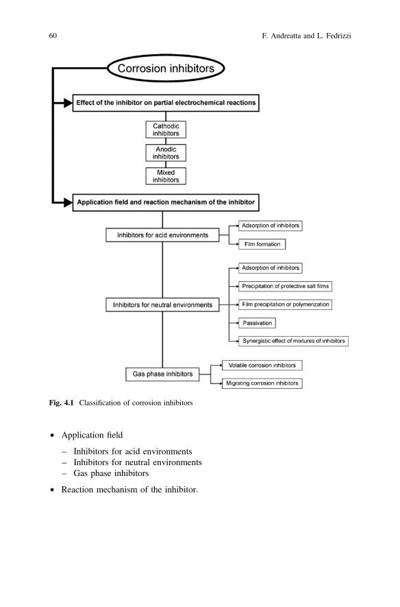
• Application field
– Inhibitors for acid environments– Inhibitors for neutral environments– Gas phase inhibitors
• Reaction mechanism of the inhibitor.
Fig. 4.1 Classification of corrosion inhibitors
60 F. Andreatta and L. Fedrizzi
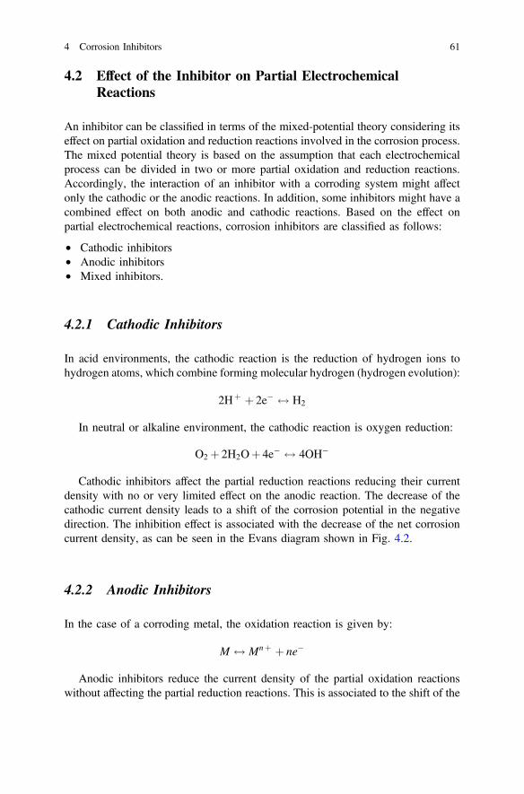
4.2 Effect of the Inhibitor on Partial ElectrochemicalReactions
An inhibitor can be classified in terms of the mixed-potential theory considering itseffect on partial oxidation and reduction reactions involved in the corrosion process.The mixed potential theory is based on the assumption that each electrochemicalprocess can be divided in two or more partial oxidation and reduction reactions.Accordingly, the interaction of an inhibitor with a corroding system might affectonly the cathodic or the anodic reactions. In addition, some inhibitors might have acombined effect on both anodic and cathodic reactions. Based on the effect onpartial electrochemical reactions, corrosion inhibitors are classified as follows:
• Cathodic inhibitors• Anodic inhibitors• Mixed inhibitors.
4.2.1 Cathodic Inhibitors
In acid environments, the cathodic reaction is the reduction of hydrogen ions tohydrogen atoms, which combine forming molecular hydrogen (hydrogen evolution):
2Hþ þ 2e� $ H2
In neutral or alkaline environment, the cathodic reaction is oxygen reduction:
O2 þ 2H2Oþ 4e� $ 4OH�
Cathodic inhibitors affect the partial reduction reactions reducing their currentdensity with no or very limited effect on the anodic reaction. The decrease of thecathodic current density leads to a shift of the corrosion potential in the negativedirection. The inhibition effect is associated with the decrease of the net corrosioncurrent density, as can be seen in the Evans diagram shown in Fig. 4.2.
4.2.2 Anodic Inhibitors
In the case of a corroding metal, the oxidation reaction is given by:
M $ Mnþ þ ne�
Anodic inhibitors reduce the current density of the partial oxidation reactionswithout affecting the partial reduction reactions. This is associated to the shift of the
4 Corrosion Inhibitors 61
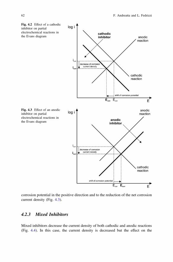
corrosion potential in the positive direction and to the reduction of the net corrosioncurrent density (Fig. 4.3).
4.2.3 Mixed Inhibitors
Mixed inhibitors decrease the current density of both cathodic and anodic reactions(Fig. 4.4). In this case, the current density is decreased but the effect on the
Fig. 4.2 Effect of a cathodicinhibitor on partialelectrochemical reactions inthe Evans diagram
Fig. 4.3 Effect of an anodicinhibitor on partialelectrochemical reactions inthe Evans diagram
62 F. Andreatta and L. Fedrizzi

corrosion potential depends on the relative extent of the partial oxidation andreduction reactions. It can be expected that the effect on the corrosion potential islimited if the current reduction due to the inhibitor is similar for the anodic andcathodic reactions, as represented in Fig. 4.4. In contrast, the corrosion potentialmight shift in the negative direction if the effect of the inhibitor on the cathodicreaction is stronger than on the anodic direction (Fig. 4.5a). Similarly, the corrosionpotential might shift in the positive direction if the effect on the anodic reaction isprevailing on that on the cathodic reaction (Fig. 4.5b).
Fig. 4.4 Effect of a mixedinhibitor on partialelectrochemical reactions inthe Evans diagram
Fig. 4.5 Effect of a mixed inhibitor with prevailing effect on one of the partial electrochemicalreactions in the Evans diagram
4 Corrosion Inhibitors 63
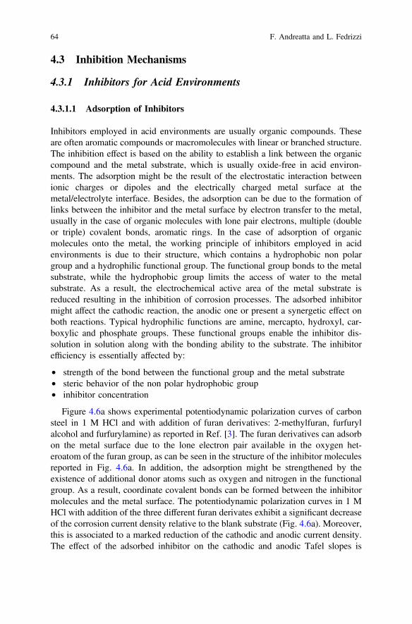
4.3 Inhibition Mechanisms
4.3.1 Inhibitors for Acid Environments
4.3.1.1 Adsorption of Inhibitors
Inhibitors employed in acid environments are usually organic compounds. Theseare often aromatic compounds or macromolecules with linear or branched structure.The inhibition effect is based on the ability to establish a link between the organiccompound and the metal substrate, which is usually oxide-free in acid environ-ments. The adsorption might be the result of the electrostatic interaction betweenionic charges or dipoles and the electrically charged metal surface at themetal/electrolyte interface. Besides, the adsorption can be due to the formation oflinks between the inhibitor and the metal surface by electron transfer to the metal,usually in the case of organic molecules with lone pair electrons, multiple (doubleor triple) covalent bonds, aromatic rings. In the case of adsorption of organicmolecules onto the metal, the working principle of inhibitors employed in acidenvironments is due to their structure, which contains a hydrophobic non polargroup and a hydrophilic functional group. The functional group bonds to the metalsubstrate, while the hydrophobic group limits the access of water to the metalsubstrate. As a result, the electrochemical active area of the metal substrate isreduced resulting in the inhibition of corrosion processes. The adsorbed inhibitormight affect the cathodic reaction, the anodic one or present a synergetic effect onboth reactions. Typical hydrophilic functions are amine, mercapto, hydroxyl, car-boxylic and phosphate groups. These functional groups enable the inhibitor dis-solution in solution along with the bonding ability to the substrate. The inhibitorefficiency is essentially affected by:
• strength of the bond between the functional group and the metal substrate• steric behavior of the non polar hydrophobic group• inhibitor concentration
Figure 4.6a shows experimental potentiodynamic polarization curves of carbonsteel in 1 M HCl and with addition of furan derivatives: 2-methylfuran, furfurylalcohol and furfurylamine) as reported in Ref. [3]. The furan derivatives can adsorbon the metal surface due to the lone electron pair available in the oxygen het-eroatom of the furan group, as can be seen in the structure of the inhibitor moleculesreported in Fig. 4.6a. In addition, the adsorption might be strengthened by theexistence of additional donor atoms such as oxygen and nitrogen in the functionalgroup. As a result, coordinate covalent bonds can be formed between the inhibitormolecules and the metal surface. The potentiodynamic polarization curves in 1 MHCl with addition of the three different furan derivates exhibit a significant decreaseof the corrosion current density relative to the blank substrate (Fig. 4.6a). Moreover,this is associated to a marked reduction of the cathodic and anodic current density.The effect of the adsorbed inhibitor on the cathodic and anodic Tafel slopes is
64 F. Andreatta and L. Fedrizzi
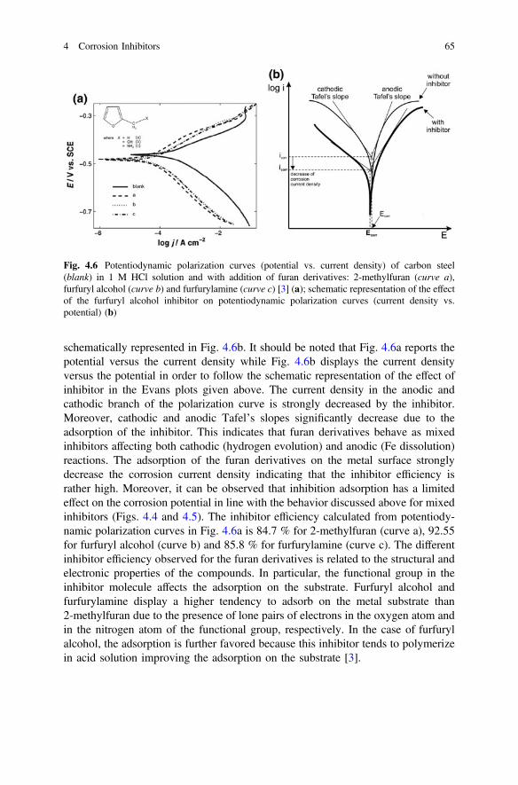
schematically represented in Fig. 4.6b. It should be noted that Fig. 4.6a reports thepotential versus the current density while Fig. 4.6b displays the current densityversus the potential in order to follow the schematic representation of the effect ofinhibitor in the Evans plots given above. The current density in the anodic andcathodic branch of the polarization curve is strongly decreased by the inhibitor.Moreover, cathodic and anodic Tafel’s slopes significantly decrease due to theadsorption of the inhibitor. This indicates that furan derivatives behave as mixedinhibitors affecting both cathodic (hydrogen evolution) and anodic (Fe dissolution)reactions. The adsorption of the furan derivatives on the metal surface stronglydecrease the corrosion current density indicating that the inhibitor efficiency israther high. Moreover, it can be observed that inhibition adsorption has a limitedeffect on the corrosion potential in line with the behavior discussed above for mixedinhibitors (Figs. 4.4 and 4.5). The inhibitor efficiency calculated from potentiody-namic polarization curves in Fig. 4.6a is 84.7 % for 2-methylfuran (curve a), 92.55for furfuryl alcohol (curve b) and 85.8 % for furfurylamine (curve c). The differentinhibitor efficiency observed for the furan derivatives is related to the structural andelectronic properties of the compounds. In particular, the functional group in theinhibitor molecule affects the adsorption on the substrate. Furfuryl alcohol andfurfurylamine display a higher tendency to adsorb on the metal substrate than2-methylfuran due to the presence of lone pairs of electrons in the oxygen atom andin the nitrogen atom of the functional group, respectively. In the case of furfurylalcohol, the adsorption is further favored because this inhibitor tends to polymerizein acid solution improving the adsorption on the substrate [3].
Fig. 4.6 Potentiodynamic polarization curves (potential vs. current density) of carbon steel(blank) in 1 M HCl solution and with addition of furan derivatives: 2-methylfuran (curve a),furfuryl alcohol (curve b) and furfurylamine (curve c) [3] (a); schematic representation of the effectof the furfuryl alcohol inhibitor on potentiodynamic polarization curves (current density vs.potential) (b)
4 Corrosion Inhibitors 65

4.3.1.2 Film Formation
Inhibition can be provided by precipitation of a protective film due to the reactionbetween the corrosion inhibitor and the dissolving metal. This leads to the for-mation of complexes on the metal substrate limiting further dissolution of the metal.The protective film formed on the metal surface acts as a physical barrier for thediffusion of aggressive species to the surface. Figures 4.7 and 4.8 display twoexamples of the effect of film formation induced on carbon steel by addition ofdecylamides of α-amino acid derivatives to an acid electrolyte, as reported in Ref.
Fig. 4.7 Potentiodynamic polarization curves of carbon steel in 1 M HCl solution and withaddition of different concentrations of decylamide of glycine (2-amino-N-decyl-acetamide) [4] (a);schematic representation of the effect of the inhibitor on potentiodynamic polarization curves (b)
Fig. 4.8 Potentiodynamic polarization curves of carbon steel in 1MHCl solution and with additionof different concentrations of decylamide of glycine (2-amino-N-decyl-3-methyl-butylamide) [4] (a);schematic representation of the effect of the inhibitor on potentiodynamic polarization curves (b)
66 F. Andreatta and L. Fedrizzi
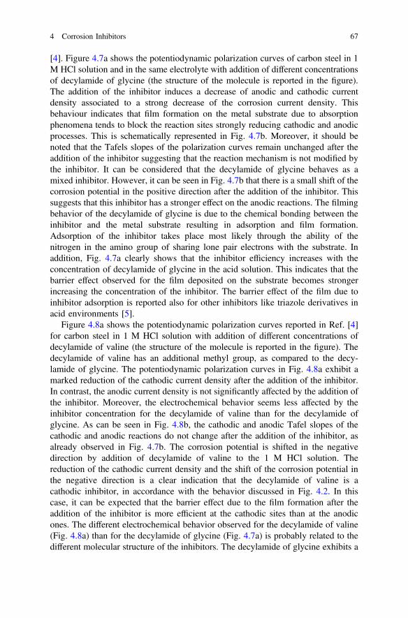
[4]. Figure 4.7a shows the potentiodynamic polarization curves of carbon steel in 1M HCl solution and in the same electrolyte with addition of different concentrationsof decylamide of glycine (the structure of the molecule is reported in the figure).The addition of the inhibitor induces a decrease of anodic and cathodic currentdensity associated to a strong decrease of the corrosion current density. Thisbehaviour indicates that film formation on the metal substrate due to absorptionphenomena tends to block the reaction sites strongly reducing cathodic and anodicprocesses. This is schematically represented in Fig. 4.7b. Moreover, it should benoted that the Tafels slopes of the polarization curves remain unchanged after theaddition of the inhibitor suggesting that the reaction mechanism is not modified bythe inhibitor. It can be considered that the decylamide of glycine behaves as amixed inhibitor. However, it can be seen in Fig. 4.7b that there is a small shift of thecorrosion potential in the positive direction after the addition of the inhibitor. Thissuggests that this inhibitor has a stronger effect on the anodic reactions. The filmingbehavior of the decylamide of glycine is due to the chemical bonding between theinhibitor and the metal substrate resulting in adsorption and film formation.Adsorption of the inhibitor takes place most likely through the ability of thenitrogen in the amino group of sharing lone pair electrons with the substrate. Inaddition, Fig. 4.7a clearly shows that the inhibitor efficiency increases with theconcentration of decylamide of glycine in the acid solution. This indicates that thebarrier effect observed for the film deposited on the substrate becomes strongerincreasing the concentration of the inhibitor. The barrier effect of the film due toinhibitor adsorption is reported also for other inhibitors like triazole derivatives inacid environments [5].
Figure 4.8a shows the potentiodynamic polarization curves reported in Ref. [4]for carbon steel in 1 M HCl solution with addition of different concentrations ofdecylamide of valine (the structure of the molecule is reported in the figure). Thedecylamide of valine has an additional methyl group, as compared to the decy-lamide of glycine. The potentiodynamic polarization curves in Fig. 4.8a exhibit amarked reduction of the cathodic current density after the addition of the inhibitor.In contrast, the anodic current density is not significantly affected by the addition ofthe inhibitor. Moreover, the electrochemical behavior seems less affected by theinhibitor concentration for the decylamide of valine than for the decylamide ofglycine. As can be seen in Fig. 4.8b, the cathodic and anodic Tafel slopes of thecathodic and anodic reactions do not change after the addition of the inhibitor, asalready observed in Fig. 4.7b. The corrosion potential is shifted in the negativedirection by addition of decylamide of valine to the 1 M HCl solution. Thereduction of the cathodic current density and the shift of the corrosion potential inthe negative direction is a clear indication that the decylamide of valine is acathodic inhibitor, in accordance with the behavior discussed in Fig. 4.2. In thiscase, it can be expected that the barrier effect due to the film formation after theaddition of the inhibitor is more efficient at the cathodic sites than at the anodicones. The different electrochemical behavior observed for the decylamide of valine(Fig. 4.8a) than for the decylamide of glycine (Fig. 4.7a) is probably related to thedifferent molecular structure of the inhibitors. The decylamide of glycine exhibits a
4 Corrosion Inhibitors 67
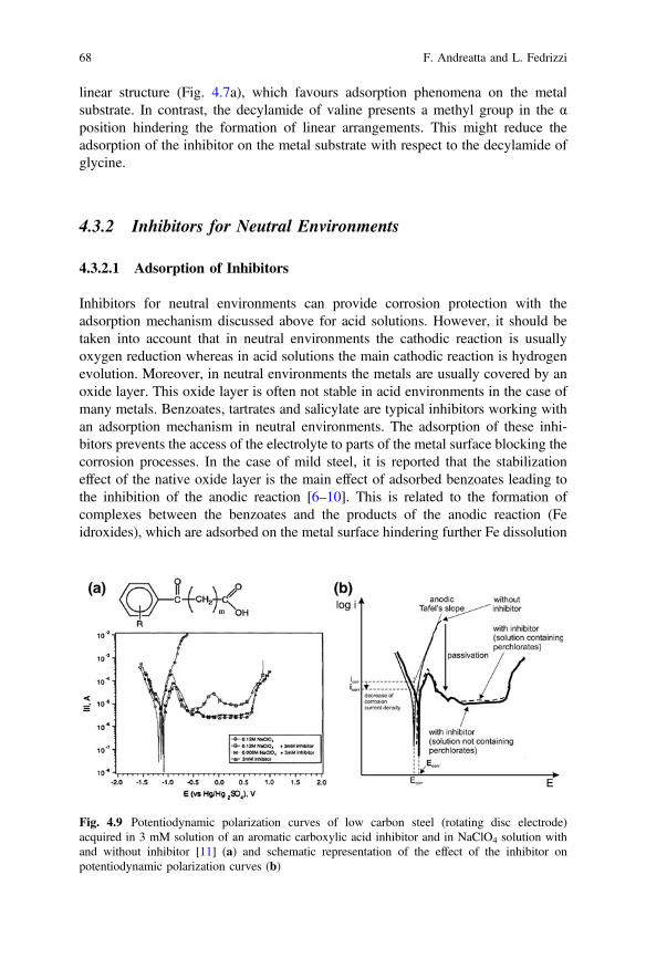
linear structure (Fig. 4.7a), which favours adsorption phenomena on the metalsubstrate. In contrast, the decylamide of valine presents a methyl group in the αposition hindering the formation of linear arrangements. This might reduce theadsorption of the inhibitor on the metal substrate with respect to the decylamide ofglycine.
4.3.2 Inhibitors for Neutral Environments
4.3.2.1 Adsorption of Inhibitors
Inhibitors for neutral environments can provide corrosion protection with theadsorption mechanism discussed above for acid solutions. However, it should betaken into account that in neutral environments the cathodic reaction is usuallyoxygen reduction whereas in acid solutions the main cathodic reaction is hydrogenevolution. Moreover, in neutral environments the metals are usually covered by anoxide layer. This oxide layer is often not stable in acid environments in the case ofmany metals. Benzoates, tartrates and salicylate are typical inhibitors working withan adsorption mechanism in neutral environments. The adsorption of these inhi-bitors prevents the access of the electrolyte to parts of the metal surface blocking thecorrosion processes. In the case of mild steel, it is reported that the stabilizationeffect of the native oxide layer is the main effect of adsorbed benzoates leading tothe inhibition of the anodic reaction [6–10]. This is related to the formation ofcomplexes between the benzoates and the products of the anodic reaction (Feidroxides), which are adsorbed on the metal surface hindering further Fe dissolution
Fig. 4.9 Potentiodynamic polarization curves of low carbon steel (rotating disc electrode)acquired in 3 mM solution of an aromatic carboxylic acid inhibitor and in NaClO4 solution withand without inhibitor [11] (a) and schematic representation of the effect of the inhibitor onpotentiodynamic polarization curves (b)
68 F. Andreatta and L. Fedrizzi

[6]. As an example, Fig. 4.9a displays the effect of an aromatic carboxylic acidbased inhibitor on potentiodynamic polarization curves of mild steel in neutralenvironment (pH = 7.5), as reported in Ref. [11]. The cathodic branch of thepotentiodynamic polarization curve exhibits the same behavior in perchloratesolution, in the inhibitor solution and in the mixed solution containing the per-chlorate and the inhibitor. This indicates that the carboxylic acid based inhibitordoes not affect the cathodic reaction, which is oxygen reduction in the three elec-trolytes considered in the figure. The anodic branch of the potentiodynamicpolarization of mild steel in perchlorate solution shows a typical active behaviorwith a marked increase of the current density for potentials more positive than thecorrosion potential. In contrast, in the inhibitor solution not containing perchlorate,the anodic branch of the potentiodynamic polarization curve exhibits passivebehavior. Moreover, this is accompanied by a shift of the corrosion potential in thepositive direction and by a decrease of the corrosion current density. The samebehavior is observed for the potentiodynamic polarization curve recorded in themixed solution containing the 0.006 M perchlorate and the inhibitor. The passivecurrent slightly increases when the chloride content is increased passing from 0.006to 0.12 M. The behavior of mild steel in perchlorate solution and in the inhibitorsolution with and without perchlorate is schematically represented in Fig. 4.9b. Itcan be observed that the main effect of the inhibitor is on the anodic branch of thepolarization curve. Therefore, it can be stated that the aromatic carboxylic acidbased inhibitor is an anodic inhibitor for mild steel in neutral environment. This isconfirmed by the small shift of the corrosion potential in the positive direction. Themechanism proposed for the inhibition by the carboxylic acid based compoundconsiders the adsorption of the inhibitor molecules on the dissolving Fe substrate,which involves the formation of intermediates between Fe and the inhibitor. Theseintermediates are adsorbed on the metal substrate favoring the passivation of thesubstrate. As a result, the intermediates adsorbed on the surface block furtheradsorption of aggressive ions and the iron dissolution. The potentiodynamicpolarization curve recorded in the mixed solution containing the perchlorate and thecarboxylic acid based inhibitor confirms the existence of competitive adsorptionbetween the inhibitor and perchlorate ions, as can be seen in Fig. 4.9a. In the case ofperchlorate, it can be stated that the inhibitor provides corrosion protection with anadsorption mechanism in the presence of aggressive species (perchlorate ions). Incontrast, sulfate ions exhibit competitive adsorption with the inhibitor impairing thecorrosion protection through the adsorption mechanism [1, 11]. Figure 4.10a showsthe potentiodynamic polarization curves of mild steel in the presence of the sameinhibitor considered in Fig. 4.9a, in sodium sulfate solution and in the mixedsolution containing the sodium sulfate and the inhibitor. The anodic branch of thepotentiodynamic polarization of mild steel in sodium sulfate solution shows activebehavior. The anodic branch of the mild steel exhibits passive behavior in theinhibitor solution not containing sodium sulfate. This is in line with the behaviorobserved in perchlorate solution, where inhibitor adsorption leads to passivation ofthe metal substrate. In contrast, the potentiodynamic polarization curve recorded inthe mixed solution containing the sodium sulfate and the carboxylic acid based
4 Corrosion Inhibitors 69
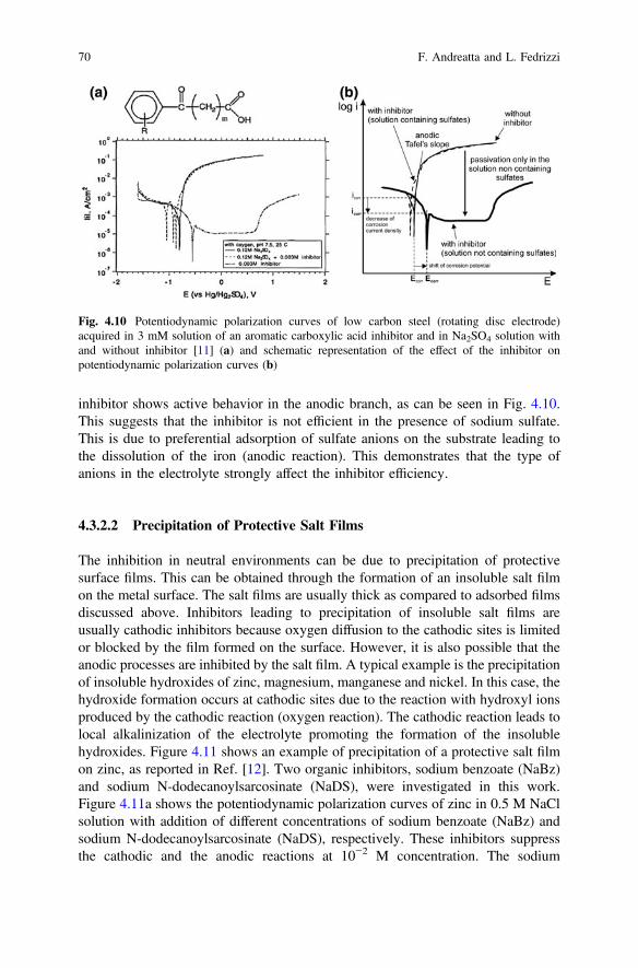
inhibitor shows active behavior in the anodic branch, as can be seen in Fig. 4.10.This suggests that the inhibitor is not efficient in the presence of sodium sulfate.This is due to preferential adsorption of sulfate anions on the substrate leading tothe dissolution of the iron (anodic reaction). This demonstrates that the type ofanions in the electrolyte strongly affect the inhibitor efficiency.
4.3.2.2 Precipitation of Protective Salt Films
The inhibition in neutral environments can be due to precipitation of protectivesurface films. This can be obtained through the formation of an insoluble salt filmon the metal surface. The salt films are usually thick as compared to adsorbed filmsdiscussed above. Inhibitors leading to precipitation of insoluble salt films areusually cathodic inhibitors because oxygen diffusion to the cathodic sites is limitedor blocked by the film formed on the surface. However, it is also possible that theanodic processes are inhibited by the salt film. A typical example is the precipitationof insoluble hydroxides of zinc, magnesium, manganese and nickel. In this case, thehydroxide formation occurs at cathodic sites due to the reaction with hydroxyl ionsproduced by the cathodic reaction (oxygen reaction). The cathodic reaction leads tolocal alkalinization of the electrolyte promoting the formation of the insolublehydroxides. Figure 4.11 shows an example of precipitation of a protective salt filmon zinc, as reported in Ref. [12]. Two organic inhibitors, sodium benzoate (NaBz)and sodium N-dodecanoylsarcosinate (NaDS), were investigated in this work.Figure 4.11a shows the potentiodynamic polarization curves of zinc in 0.5 M NaClsolution with addition of different concentrations of sodium benzoate (NaBz) andsodium N-dodecanoylsarcosinate (NaDS), respectively. These inhibitors suppressthe cathodic and the anodic reactions at 10−2 M concentration. The sodium
Fig. 4.10 Potentiodynamic polarization curves of low carbon steel (rotating disc electrode)acquired in 3 mM solution of an aromatic carboxylic acid inhibitor and in Na2SO4 solution withand without inhibitor [11] (a) and schematic representation of the effect of the inhibitor onpotentiodynamic polarization curves (b)
70 F. Andreatta and L. Fedrizzi
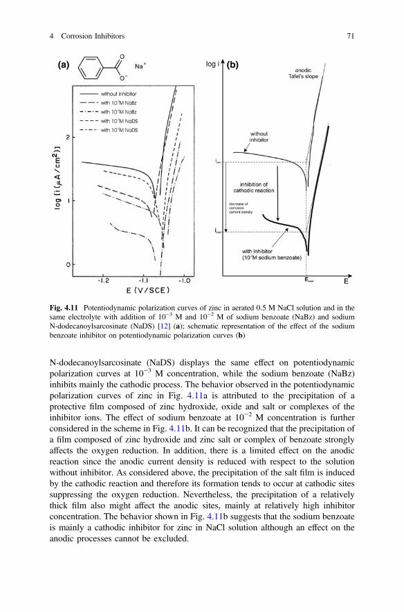
N-dodecanoylsarcosinate (NaDS) displays the same effect on potentiodynamicpolarization curves at 10−3 M concentration, while the sodium benzoate (NaBz)inhibits mainly the cathodic process. The behavior observed in the potentiodynamicpolarization curves of zinc in Fig. 4.11a is attributed to the precipitation of aprotective film composed of zinc hydroxide, oxide and salt or complexes of theinhibitor ions. The effect of sodium benzoate at 10−2 M concentration is furtherconsidered in the scheme in Fig. 4.11b. It can be recognized that the precipitation ofa film composed of zinc hydroxide and zinc salt or complex of benzoate stronglyaffects the oxygen reduction. In addition, there is a limited effect on the anodicreaction since the anodic current density is reduced with respect to the solutionwithout inhibitor. As considered above, the precipitation of the salt film is inducedby the cathodic reaction and therefore its formation tends to occur at cathodic sitessuppressing the oxygen reduction. Nevertheless, the precipitation of a relativelythick film also might affect the anodic sites, mainly at relatively high inhibitorconcentration. The behavior shown in Fig. 4.11b suggests that the sodium benzoateis mainly a cathodic inhibitor for zinc in NaCl solution although an effect on theanodic processes cannot be excluded.
Fig. 4.11 Potentiodynamic polarization curves of zinc in aerated 0.5 M NaCl solution and in thesame electrolyte with addition of 10−3 M and 10−2 M of sodium benzoate (NaBz) and sodiumN-dodecanoylsarcosinate (NaDS) [12] (a); schematic representation of the effect of the sodiumbenzoate inhibitor on potentiodynamic polarization curves (b)
4 Corrosion Inhibitors 71
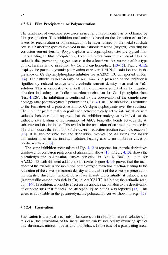
4.3.2.3 Film Precipitation or Polymerization
The inhibition of corrosion processes in neutral environments can be obtained byfilm precipitation. This inhibition mechanism is based on the formation of surfacelayers by precipitation or polymerization. The layer formed on the metal substrateacts as a barrier for species involved in the cathodic reaction (oxygen) lowering thecorrosion current density. Polyphosphates and organophosphates are typical inhi-bitors leading to film precipitation. These inhibitors form thin adherent films oncathodic sites preventing oxygen access at these locations. An example of this typeof mechanism is the inhibition by Ce diphenylphosphate [13–15]. Figure 4.12adisplays the potentiodynamic polarization curves in 1 M NaCl solution and in thepresence of Ce diphenylphosphate inhibitor for AA2024-T3, as reported in Ref.[14]. The cathodic current density of AA2024-T3 in presence of the inhibitor issignificantly reduced relative to the cathodic current density measured in NaClsolution. This is associated to a shift of the corrosion potential in the negativedirection indicating a cathodic protection mechanism for Ce diphenylphosphate(Fig. 4.12b). The inhibition is confirmed by the observation of the sample mor-phology after potentiodynamic polarization (Fig. 4.12a). The inhibition is attributedto the formation of a protective film of Ce diphenylphosphate over the substrate.The inhibitor preferentially deposits at electrochemically active intermetallics withcathodic behavior. It is reported that the inhibitor undergoes hydrolysis at thecathodic sites leading to the formation of Al/Ce bimetallic bonds between the Alsubstrate and the inhibitor. This results in the formation of an insoluble protectivefilm that induces the inhibition of the oxygen reduction reaction (cathodic reaction)[13]. It is also possible that the deposition involves the Al matrix for longerimmersion times in the inhibitor solution leading also to an inhibition effect onanodic reactions [13].
The same inhibition mechanism of Fig. 4.12 is reported for triazole derivativesemployed for corrosion protection of aluminium alloys [16]. Figure 4.13a shows thepotentiodynamic polarization curves recorded in 3.5 % NaCl solution forAA2024-T3 with different additions of triazole. Figure 4.13b proves that the maineffect of the triazole is the inhibition of the oxygen reduction reaction leading to thereduction of the corrosion current density and the shift of the corrosion potential inthe negative direction. Triazole derivatives adsorb preferentially at cathodic sites(intermetallic compounds rich in Cu) in AA2024-T3 inhibiting the cathodic reac-tion [16]. In addition, a possible effect on the anodic reaction due to the deactivationof cathodic sites that reduces the susceptibility to pitting was reported [17]. Thiseffect is not visible in the potentiodynamic polarization curves shown in Fig. 4.13.
4.3.2.4 Passivation
Passivation is a typical mechanism for corrosion inhibitors in neutral solutions. Inthis case, the passivation of the metal surface can be induced by oxidizing specieslike chromates, nitrites, nitrates and molybdates. In the case of a passivating metal
72 F. Andreatta and L. Fedrizzi
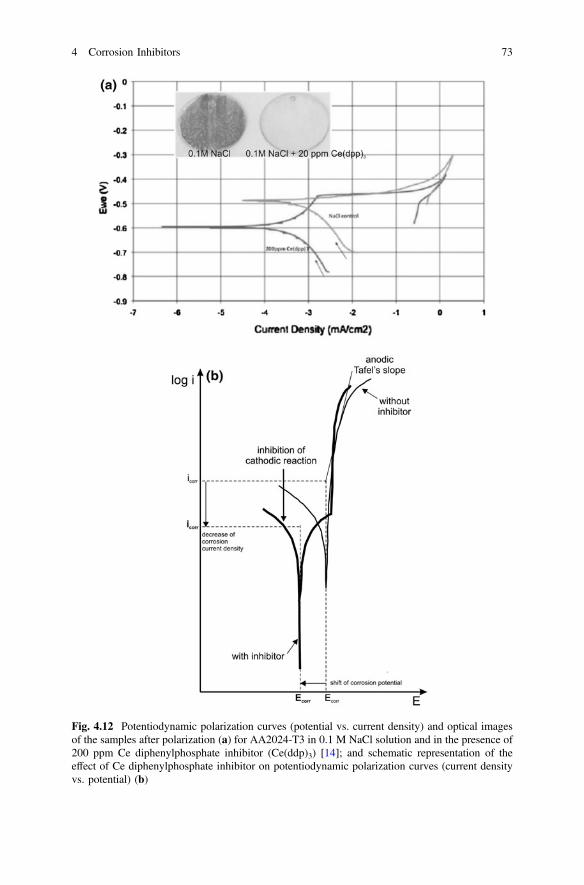
Fig. 4.12 Potentiodynamic polarization curves (potential vs. current density) and optical imagesof the samples after polarization (a) for AA2024-T3 in 0.1 M NaCl solution and in the presence of200 ppm Ce diphenylphosphate inhibitor (Ce(ddp)3) [14]; and schematic representation of theeffect of Ce diphenylphosphate inhibitor on potentiodynamic polarization curves (current densityvs. potential) (b)
4 Corrosion Inhibitors 73
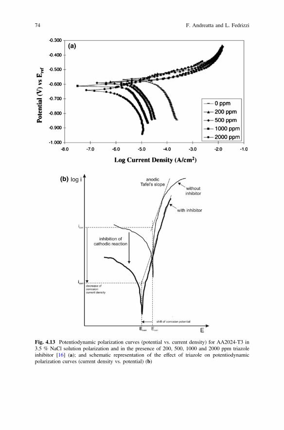
Fig. 4.13 Potentiodynamic polarization curves (potential vs. current density) for AA2024-T3 in3.5 % NaCl solution polarization and in the presence of 200, 500, 1000 and 2000 ppm triazoleinhibitor [16] (a); and schematic representation of the effect of triazole on potentiodynamicpolarization curves (current density vs. potential) (b)
74 F. Andreatta and L. Fedrizzi
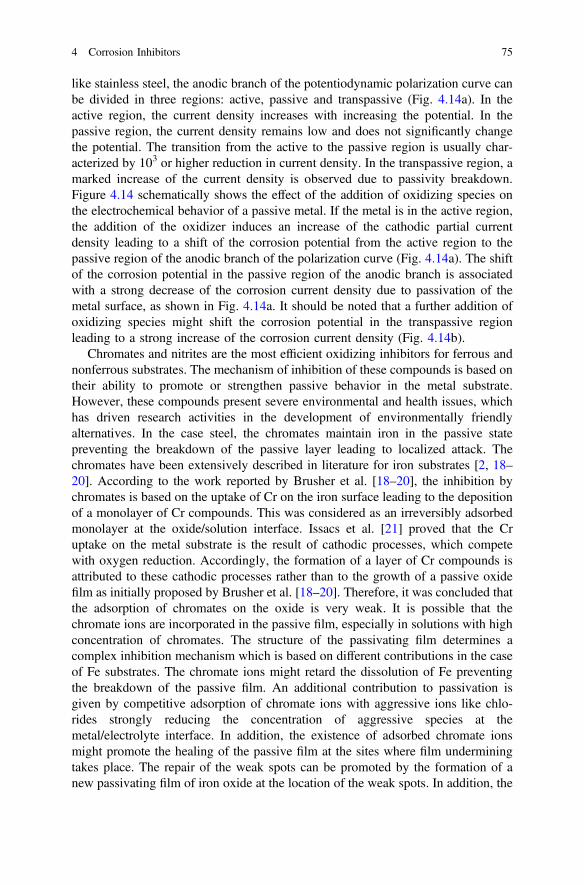
like stainless steel, the anodic branch of the potentiodynamic polarization curve canbe divided in three regions: active, passive and transpassive (Fig. 4.14a). In theactive region, the current density increases with increasing the potential. In thepassive region, the current density remains low and does not significantly changethe potential. The transition from the active to the passive region is usually char-acterized by 103 or higher reduction in current density. In the transpassive region, amarked increase of the current density is observed due to passivity breakdown.Figure 4.14 schematically shows the effect of the addition of oxidizing species onthe electrochemical behavior of a passive metal. If the metal is in the active region,the addition of the oxidizer induces an increase of the cathodic partial currentdensity leading to a shift of the corrosion potential from the active region to thepassive region of the anodic branch of the polarization curve (Fig. 4.14a). The shiftof the corrosion potential in the passive region of the anodic branch is associatedwith a strong decrease of the corrosion current density due to passivation of themetal surface, as shown in Fig. 4.14a. It should be noted that a further addition ofoxidizing species might shift the corrosion potential in the transpassive regionleading to a strong increase of the corrosion current density (Fig. 4.14b).
Chromates and nitrites are the most efficient oxidizing inhibitors for ferrous andnonferrous substrates. The mechanism of inhibition of these compounds is based ontheir ability to promote or strengthen passive behavior in the metal substrate.However, these compounds present severe environmental and health issues, whichhas driven research activities in the development of environmentally friendlyalternatives. In the case steel, the chromates maintain iron in the passive statepreventing the breakdown of the passive layer leading to localized attack. Thechromates have been extensively described in literature for iron substrates [2, 18–20]. According to the work reported by Brusher et al. [18–20], the inhibition bychromates is based on the uptake of Cr on the iron surface leading to the depositionof a monolayer of Cr compounds. This was considered as an irreversibly adsorbedmonolayer at the oxide/solution interface. Issacs et al. [21] proved that the Cruptake on the metal substrate is the result of cathodic processes, which competewith oxygen reduction. Accordingly, the formation of a layer of Cr compounds isattributed to these cathodic processes rather than to the growth of a passive oxidefilm as initially proposed by Brusher et al. [18–20]. Therefore, it was concluded thatthe adsorption of chromates on the oxide is very weak. It is possible that thechromate ions are incorporated in the passive film, especially in solutions with highconcentration of chromates. The structure of the passivating film determines acomplex inhibition mechanism which is based on different contributions in the caseof Fe substrates. The chromate ions might retard the dissolution of Fe preventingthe breakdown of the passive film. An additional contribution to passivation isgiven by competitive adsorption of chromate ions with aggressive ions like chlo-rides strongly reducing the concentration of aggressive species at themetal/electrolyte interface. In addition, the existence of adsorbed chromate ionsmight promote the healing of the passive film at the sites where film underminingtakes place. The repair of the weak spots can be promoted by the formation of anew passivating film of iron oxide at the location of the weak spots. In addition, the
4 Corrosion Inhibitors 75
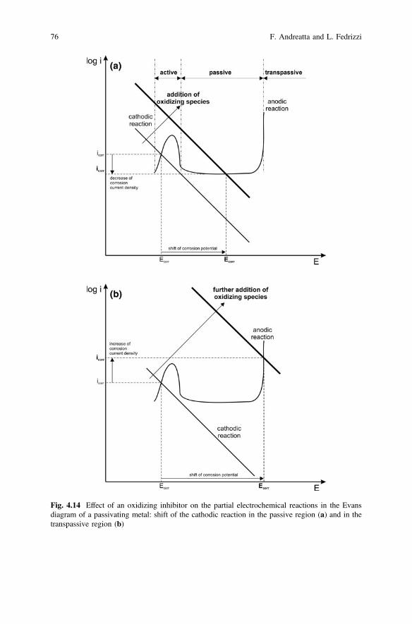
Fig. 4.14 Effect of an oxidizing inhibitor on the partial electrochemical reactions in the Evansdiagram of a passivating metal: shift of the cathodic reaction in the passive region (a) and in thetranspassive region (b)
76 F. Andreatta and L. Fedrizzi
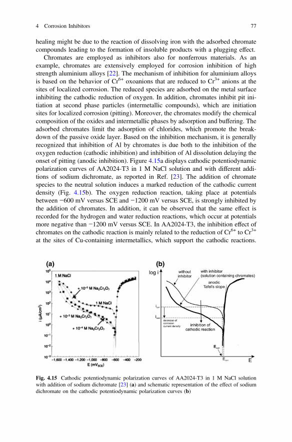
healing might be due to the reaction of dissolving iron with the adsorbed chromatecompounds leading to the formation of insoluble products with a plugging effect.
Chromates are employed as inhibitors also for nonferrous materials. As anexample, chromates are extensively employed for corrosion inhibition of highstrength aluminium alloys [22]. The mechanism of inhibition for aluminium alloysis based on the behavior of Cr6+ oxoanions that are reduced to Cr3+ anions at thesites of localized corrosion. The reduced species are adsorbed on the metal surfaceinhibiting the cathodic reduction of oxygen. In addition, chromates inhibit pit ini-tiation at second phase particles (intermetallic compounds), which are initiationsites for localized corrosion (pitting). Moreover, the chromates modify the chemicalcomposition of the oxides and intermetallic phases by adsorption and buffering. Theadsorbed chromates limit the adsorption of chlorides, which promote the break-down of the passive oxide layer. Based on the inhibition mechanism, it is generallyrecognized that inhibition of Al by chromates is due both to the inhibition of theoxygen reduction (cathodic inhibition) and inhibition of Al dissolution delaying theonset of pitting (anodic inhibition). Figure 4.15a displays cathodic potentiodynamicpolarization curves of AA2024-T3 in 1 M NaCl solution and with different addi-tions of sodium dichromate, as reported in Ref. [23]. The addition of chromatespecies to the neutral solution induces a marked reduction of the cathodic currentdensity (Fig. 4.15b). The oxygen reduction reaction, taking place at potentialsbetween −600 mV versus SCE and −1200 mV versus SCE, is strongly inhibited bythe addition of chromates. In addition, it can be observed that the same effect isrecorded for the hydrogen and water reduction reactions, which occur at potentialsmore negative than −1200 mV versus SCE. In AA2024-T3, the inhibition effect ofchromates on the cathodic reaction is mainly related to the reduction of Cr6+ to Cr3+
at the sites of Cu-containing intermetallics, which support the cathodic reactions.
Fig. 4.15 Cathodic potentiodynamic polarization curves of AA2024-T3 in 1 M NaCl solutionwith addition of sodium dichromate [23] (a) and schematic representation of the effect of sodiumdichromate on the cathodic potentiodynamic polarization curves (b)
4 Corrosion Inhibitors 77
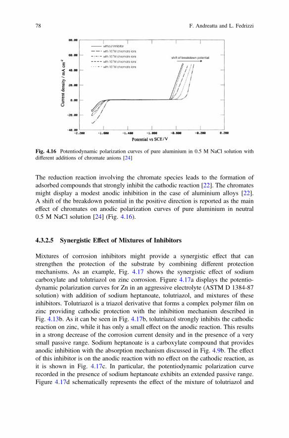
The reduction reaction involving the chromate species leads to the formation ofadsorbed compounds that strongly inhibit the cathodic reaction [22]. The chromatesmight display a modest anodic inhibition in the case of aluminium alloys [22].A shift of the breakdown potential in the positive direction is reported as the maineffect of chromates on anodic polarization curves of pure aluminium in neutral0.5 M NaCl solution [24] (Fig. 4.16).
4.3.2.5 Synergistic Effect of Mixtures of Inhibitors
Mixtures of corrosion inhibitors might provide a synergistic effect that canstrengthen the protection of the substrate by combining different protectionmechanisms. As an example, Fig. 4.17 shows the synergistic effect of sodiumcarboxylate and tolutriazol on zinc corrosion. Figure 4.17a displays the potentio-dynamic polarization curves for Zn in an aggressive electrolyte (ASTM D 1384-87solution) with addition of sodium heptanoate, tolutriazol, and mixtures of theseinhibitors. Tolutriazol is a triazol derivative that forms a complex polymer film onzinc providing cathodic protection with the inhibition mechanism described inFig. 4.13b. As it can be seen in Fig. 4.17b, tolutriazol strongly inhibits the cathodicreaction on zinc, while it has only a small effect on the anodic reaction. This resultsin a strong decrease of the corrosion current density and in the presence of a verysmall passive range. Sodium heptanoate is a carboxylate compound that providesanodic inhibition with the absorption mechanism discussed in Fig. 4.9b. The effectof this inhibitor is on the anodic reaction with no effect on the cathodic reaction, asit is shown in Fig. 4.17c. In particular, the potentiodynamic polarization curverecorded in the presence of sodium heptanoate exhibits an extended passive range.Figure 4.17d schematically represents the effect of the mixture of tolutriazol and
Fig. 4.16 Potentiodynamic polarization curves of pure aluminium in 0.5 M NaCl solution withdifferent additions of chromate anions [24]
78 F. Andreatta and L. Fedrizzi
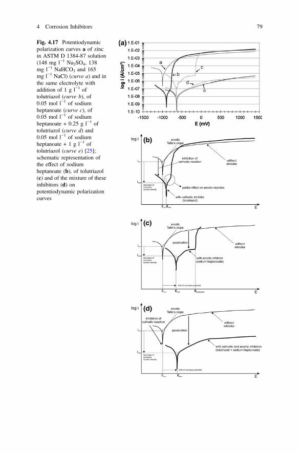
Fig. 4.17 Potentiodynamicpolarization curves a of zincin ASTM D 1384-87 solution(148 mg l−1 Na2SO4, 138mg l−1 NaHCO3 and 165mg l−1 NaCl) (curve a) and inthe same electrolyte withaddition of 1 g l−1 oftolutriazol (curve b), of0.05 mol l−1 of sodiumheptanoate (curve c), of0.05 mol l−1 of sodiumheptanoate + 0.25 g l−1 oftolutriazol (curve d) and0.05 mol l−1 of sodiumheptanoate + 1 g l−1 oftolutriazol (curve e) [25];schematic representation ofthe effect of sodiumheptanoate (b), of tolutriazol(c) and of the mixture of theseinhibitors (d) onpotentiodynamic polarizationcurves
4 Corrosion Inhibitors 79
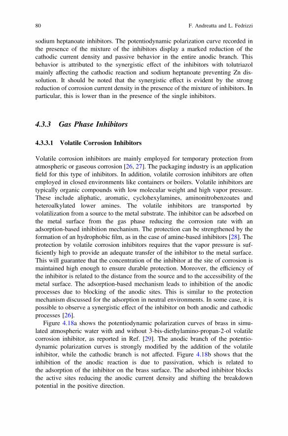
sodium heptanoate inhibitors. The potentiodynamic polarization curve recorded inthe presence of the mixture of the inhibitors display a marked reduction of thecathodic current density and passive behavior in the entire anodic branch. Thisbehavior is attributed to the synergistic effect of the inhibitors with tolutriazolmainly affecting the cathodic reaction and sodium heptanoate preventing Zn dis-solution. It should be noted that the synergistic effect is evident by the strongreduction of corrosion current density in the presence of the mixture of inhibitors. Inparticular, this is lower than in the presence of the single inhibitors.
4.3.3 Gas Phase Inhibitors
4.3.3.1 Volatile Corrosion Inhibitors
Volatile corrosion inhibitors are mainly employed for temporary protection fromatmospheric or gaseous corrosion [26, 27]. The packaging industry is an applicationfield for this type of inhibitors. In addition, volatile corrosion inhibitors are oftenemployed in closed environments like containers or boilers. Volatile inhibitors aretypically organic compounds with low molecular weight and high vapor pressure.These include aliphatic, aromatic, cyclohexylamines, aminonitrobenzoates andheteroalkylated lower amines. The volatile inhibitors are transported byvolatilization from a source to the metal substrate. The inhibitor can be adsorbed onthe metal surface from the gas phase reducing the corrosion rate with anadsorption-based inhibition mechanism. The protection can be strengthened by theformation of an hydrophobic film, as in the case of amine-based inhibitors [28]. Theprotection by volatile corrosion inhibitors requires that the vapor pressure is suf-ficiently high to provide an adequate transfer of the inhibitor to the metal surface.This will guarantee that the concentration of the inhibitor at the site of corrosion ismaintained high enough to ensure durable protection. Moreover, the efficiency ofthe inhibitor is related to the distance from the source and to the accessibility of themetal surface. The adsorption-based mechanism leads to inhibition of the anodicprocesses due to blocking of the anodic sites. This is similar to the protectionmechanism discussed for the adsorption in neutral environments. In some case, it ispossible to observe a synergistic effect of the inhibitor on both anodic and cathodicprocesses [26].
Figure 4.18a shows the potentiodynamic polarization curves of brass in simu-lated atmospheric water with and without 3-bis-diethylamino-propan-2-ol volatilecorrosion inhibitor, as reported in Ref. [29]. The anodic branch of the potentio-dynamic polarization curves is strongly modified by the addition of the volatileinhibitor, while the cathodic branch is not affected. Figure 4.18b shows that theinhibition of the anodic reaction is due to passivation, which is related tothe adsorption of the inhibitor on the brass surface. The adsorbed inhibitor blocksthe active sites reducing the anodic current density and shifting the breakdownpotential in the positive direction.
80 F. Andreatta and L. Fedrizzi
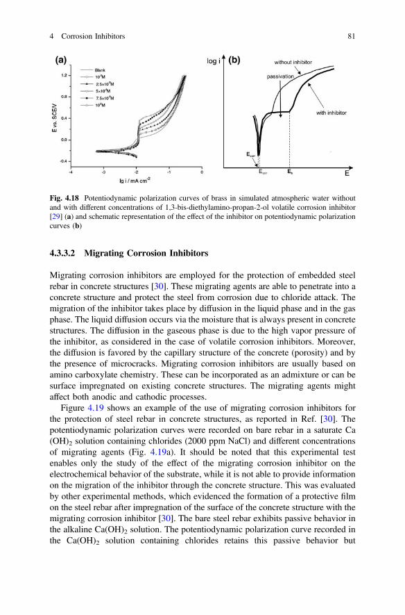
4.3.3.2 Migrating Corrosion Inhibitors
Migrating corrosion inhibitors are employed for the protection of embedded steelrebar in concrete structures [30]. These migrating agents are able to penetrate into aconcrete structure and protect the steel from corrosion due to chloride attack. Themigration of the inhibitor takes place by diffusion in the liquid phase and in the gasphase. The liquid diffusion occurs via the moisture that is always present in concretestructures. The diffusion in the gaseous phase is due to the high vapor pressure ofthe inhibitor, as considered in the case of volatile corrosion inhibitors. Moreover,the diffusion is favored by the capillary structure of the concrete (porosity) and bythe presence of microcracks. Migrating corrosion inhibitors are usually based onamino carboxylate chemistry. These can be incorporated as an admixture or can besurface impregnated on existing concrete structures. The migrating agents mightaffect both anodic and cathodic processes.
Figure 4.19 shows an example of the use of migrating corrosion inhibitors forthe protection of steel rebar in concrete structures, as reported in Ref. [30]. Thepotentiodynamic polarization curves were recorded on bare rebar in a saturate Ca(OH)2 solution containing chlorides (2000 ppm NaCl) and different concentrationsof migrating agents (Fig. 4.19a). It should be noted that this experimental testenables only the study of the effect of the migrating corrosion inhibitor on theelectrochemical behavior of the substrate, while it is not able to provide informationon the migration of the inhibitor through the concrete structure. This was evaluatedby other experimental methods, which evidenced the formation of a protective filmon the steel rebar after impregnation of the surface of the concrete structure with themigrating corrosion inhibitor [30]. The bare steel rebar exhibits passive behavior inthe alkaline Ca(OH)2 solution. The potentiodynamic polarization curve recorded inthe Ca(OH)2 solution containing chlorides retains this passive behavior but
Fig. 4.18 Potentiodynamic polarization curves of brass in simulated atmospheric water withoutand with different concentrations of 1,3-bis-diethylamino-propan-2-ol volatile corrosion inhibitor[29] (a) and schematic representation of the effect of the inhibitor on potentiodynamic polarizationcurves (b)
4 Corrosion Inhibitors 81
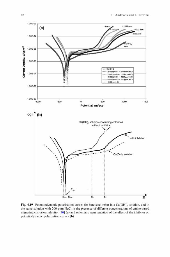
Fig. 4.19 Potentiodynamic polarization curves for bare steel rebar in a Ca(OH)2 solution, and inthe same solution with 200 ppm NaCl in the presence of different concentrations of amine-basedmigrating corrosion inhibitor [30] (a) and schematic representation of the effect of the inhibitor onpotentiodynamic polarization curves (b)
82 F. Andreatta and L. Fedrizzi
passivity breakdown (Eb) is observed at 350 mV versus SCE due to the onset ofpitting corrosion caused by chlorides. The addition of the migrating corrosioninhibitor progressively shifts the breakdown potential in the positive direction. Thebreakdown potential is 600 mV versus SCE with an addition of 2000 ppmmigrating corrosion inhibitor. This indicates that the substrate retains its passivebehavior in the presence of the inhibitor at higher potentials as compared with thesystem without inhibitor. This is schematically shown in Fig. 4.19b, where it can beseen that the inhibition is mainly due to a passivation effect related to the addition ofthe inhibitor, while the cathodic processes are not affected by the inhibitor.
References
1. D. Landolt, Corrosion and Surface Chemistry of Metals (EPFL press, Lausanne, 2007), p. 5442. J.G.N. Thomas, in Corrosion, vol. 2 (Chapter 17), ed. by L.L. Shreir, R.A. Jarman, G.T.
Burstein (Butterworh-Heinemann, Oxford, 1994)3. E. Machnikova, K.H. Whitmire, N. Hackerman, Corrosion inhibition of carbon steel in
hydrochloric acid by furan derivatives. Electrochim. Acta 53, 6024–6032 (2008)4. O. Olivares, N.V. Likhanova, B. Gomez, J. Navarrete, M.E. Llanos-Serrano, E. Arce, J.M.
Hallen, Electrochemical and XPS studies of decylamides of a-amino acids adsorption oncarbon steel in acidic environment. Appl. Surf. Sci. 252, 2894–2909 (2006)
5. M. El Azhar, M. Traisnel, B. Mernari, L. Gengembre, F. Bentiss, M. Lagrenee,Electrochemical and XPS studies of 2,5-bis(n-pyridyl)-1,3,4-thiadiazoles adsorption on mildsteel in perchloric acid solution. Appl. Surf. Sci. 185, 197–205 (2002)
6. K. Takahashi, J.A. Bardwell, B. MacDougall, M.J. Graham, Mechanism of anodic dissolutionof iron—II. Comparison of the behavior in neutral benzoate and acetate buffer solutions.Electrochim. Acta 37, 489–494 (1992)
7. D. Eurof Davies, Q.J.M. Slaiman, Mechanism of the corrosion inhibition of Fe by sodiumbenzoate—I: The influence of concentration and pH in air-saturated solutions of sodiumbenzoate. Corros. Sci. 11, 671–682 (1971)
8. Q.J.M. Slaiman, D. Eurof Davies, Mechanism of the corrosion inhibition of Fe by sodiumbenzoate—II: the inhibitive properties of sodium benzoate in de-aerated and air-saturatedsolutions. Corros. Sci. 11, 683–692 (1971)
9. D. Eurof Davies, Q.J.M. Slaiman, Mechanism of the corrosion inhibition of iron by sodiumbenzoate—III: the role of oxygen. Corros. Sci. 13, 891–905 (1973)
10. G. Reinhard, M. Radtke, U. Rammelt, On the role of the salts of weak acids in the chemicalpassivation of iron and steel in aqueous solutions. Corros. Sci. 33, 307–313 (1992)
11. P. Agarwal, D. Landolt, Effect of anions on the efficiency of aromatic carboxylic acidcorrosion inhibitors in near neutral media: experimental investigation and theoreticalmodeling. Corros. Sci. 40, 673–691 (1998)
12. K. Aramaki, Effects of organic inhibitors on corrosion of zinc in an aerated 0.5 M NaClsolution. Corros. Sci. 43, 1985–2000 (2001)
13. T.A. Markley, M. Forsyth, A.E. Hughes, Corrosion protection of AA2024-T3 using rare earthdiphenyl phosphates. Electrochim. Acta 52, 4024–4031 (2007)
14. T.A. Markley, J.I. Mardel, A.E. Hughes, B.R.W. Hinton, A.M. Glenn, M. Forsyth, Chromatereplacement in coatings for corrosion protection of aerospace aluminium alloys. Mater.Corros. 62, 836–840 (2011)
15. J.A. Hill, T. Markley, M. Forsyth, P.C. Howlett, B.R.W. Hinton, Corrosion inhibition of 7000series aluminium alloys with cerium diphenyl phosphate. J. Alloy. Compd. 509, 1683–1690(2011)
4 Corrosion Inhibitors 83
16. H. Yang, W.J. van Ooij, Plasma-treated triazole as a novel organic slow-release paint pigmentfor corrosion control of AA2024-T3. Prog. Org. Coat. 50, 149–161 (2004)
17. M.L. Zheludkevich, K.A. Yasakau, S.K. Poznyak, M.G.S. Ferreira, Triazole and thiazolederivatives as corrosion inhibitors for AA2024 aluminium alloy. Corros. Sci. 47, 3368–3383(2005)
18. D.M. Brasher, H.A. Kingsbury, D.A. Mercer, Passivation of iron by chromate solutions.Nature 180, 27–28 (1957)
19. D.M. Brasher, H.A. Kingsbury, The study of the passivity of metals in inhibitor solutions,using radioactive tracers. Part 1—the action of neutral chromates on iron and steel. Trans.Faraday Soc. 54, 1214–1222 (1958)
20. D.M. Brasher, D.A. Mercer, Radiotracer studies of the passivity of metals in inhibitorsolutions. Part 3—influence of pH and oxygen content of chromate solutions on film growthon mild steel. Trans. Faraday Soc. 61, 803–811 (1965)
21. H.S. Isaacs, S. Virtanen, M.P. Ryan, P. Schmuki, L.J. Oblonsky, Incorporation of Cr in thepassive film on Fe from chromate solutions. Electrochim. Acta 47, 3127–/3130 (2002)
22. M.W. Kendig, R.G. Buchheit, Corrosion inhibition of aluminum and aluminum alloys bysoluble chromates, chromate coatings, and chromate-free coatings. Corrosion 59, 379–400(2003)
23. A. Sehgal, G.S. Frankel, B. Zoofan, S. Rokhlin, Pit growth study in Al alloys by the foilpenetration technique. J. Electrochem. Soc. 147, 140–148 (2000)
24. S. Zein El Abedin, Role of chromate, molybdate and tungstate anions on the inhibition ofaluminium in chloride solutions. J. Appl. Electrochem. 31, 711–718 (2001)
25. C. Georges, E. Rocca, P. Steinmetz, Synergistic effect of tolutriazol and sodium carboxylateson zinc corrosion in atmospheric conditions. Electrochim. Acta 53, 4839–4885 (2008)
26. P.R. Roberge, Handbook of Corrosion Engineering (McGraw-Hill, New York, 2000), p. 83827. B. Boyle, A look at developments in vapor phase corrosion inhibitors. Met. Finish. 102, 37–41
(2004)28. U. Rammelt, S. Koehler, G. Reinhard, Use of vapour phase corrosion inhibitors in packages
for protecting mild steel against corrosion. Corros. Sci. 51, 921–925 (2009)29. G. Gao, C.H. Liang, 1,3-Bis-diethylamino-propan-2-ol as volatile corrosion inhibitor for brass.
Corros. Sci. 49, 3479–3493 (2007)30. B. Bavarian, The efficacy of using migrating corrosion inhibitors (MCI 2020 & MCI 2020 M)
for reinforced concrete, Report 1137, The Cortec Corporation (2004)
84 F. Andreatta and L. Fedrizzi
Chapter 5Formulating Surface Coatings
Dominic Richard Harris and Philip Casey
5.1 Introduction
Self healing in inhibitive paint coatings tends to mean both a functional repair (e.g.smart ways of releasing inhibitors to stop corrosion) as well as cosmetic repair (e.g.void filling for scratches by reforming ruptured binds). One strategy that has beenadopted to deliver these is the use of capsules that host or hold chemical moietiesthat on release contribute functionally to the self healing mechanism or anotherusing nanoadditives for cosmetic protection or repair. Capsules can generally becategorized by their chemistry (e.g. inorganic or organic) and in formulating theminto a surface coating they can generally be regarded in the same way an additivesuch as a pigment is regarded. Consequently, consideration of both material andproduction factors is important.
Inorganic “Capsules” covers materials that have been ion exchanged or haveabsorbed or adsorbed inhibitors (see Chap. 8). For layered compounds such asphyllosilicate and other clays, exfoliation and assembly into shell structures havealso been tried. Sol-gel approaches also provide a very large number ofpossibilities.
Naturally occurring layered materials include zeolites, layered double hydrox-ides (LDH)(hydrotalcites) and various clays that can provide either a layered ortubular structure (e.g. Halloysite) (see Chap. 8). Manufactured materials includemesoporous materials (i.e. materials with pores between 2 and 50 nm) which aremostly oxides impregnated with inhibitors, inorganic oxyanions (vanadates, tung-states) and organic compounds (thiol and Azo compounds particularly hetero-cyclic). Exfoliated LDH may be used for both inhibitor as well as resin healingagents.
D.R. Harris � P. Casey (&)Commonwealth Scientific and Industrial Research Organisation,Manufacturing, Clayton, VIC, Australiae-mail: [email protected]
© Springer Science+Business Media Dordrecht 2016A.E. Hughes et al. (eds.), Active Protective Coatings,Springer Series in Materials Science 233, DOI 10.1007/978-94-017-7540-3_5
85
Organic “capsules” tend to be used more for healing of the paint resin, althoughsome mecaptans perform both functions. Polymer capsules include ureaformaldehyde and melamine and polyelectrolytes including conductive polymersand polyanion/cations configurations (both resin and inhibitor) (see Chap. 8).
In this chapter, we consider coating formulations using pigmented coatings as anillustrative case as these are the most widely used commercially and provide a goodbasis on which to illustrate the guiding formulation principles pertinent to com-mercial production of self healing coatings. Formulation is especially importantwhen taking an experimental outcome to commercial scale production and appli-cation. In a simple sense, a coating is a suite of ingredients (pigments, fillers,modifiers) held in a host matrix (polymer binder) which is applied to a substrate as aliquid (aqueous or non-aqueous) but which subsequently transforms into a solid.
In the surface coatings industry, formulation is particularly important as itdetermines not only final properties and attributes of the coating but also the mannerand ease with which a coating may be manufactured, applied and transformed intoits final form.
The most commercially relevant pigmented coatings are paints and printing inks:paints require durability and serviceability while inks require brightness of colourand suitability for their method of application. Architectural and decorative paintsare predominately applied by brush, roller or airless spray while industrial auto-motive and aerospace coatings are applied by air-atomized spray, electrostaticspray, dip, or electro-deposition.
The key steps in formulation include:
(i) Component selection(ii) Formulation and Production(iii) Application(iv) Property Testing
Some/all of these steps may be iterative but all implicitly require an under-standing of the interactivity of both materials and processes.
This chapter focuses on the first two of these steps and aims to provide aconsideration of
• Raw materials, composition and disperse phases.• Methods of dispersing pigments• The relationship between physico-chemistry and coating properties including
– particle size, opacity and colour strength,– dispersion and colloidal stabilization,– dispersants and the effect that particle size and surface area has on the
demand for dispersant,– hydrodynamic volume and mobility
Methods of application and property testing are not specifically considered herein any detail.
86 D.R. Harris and P. Casey
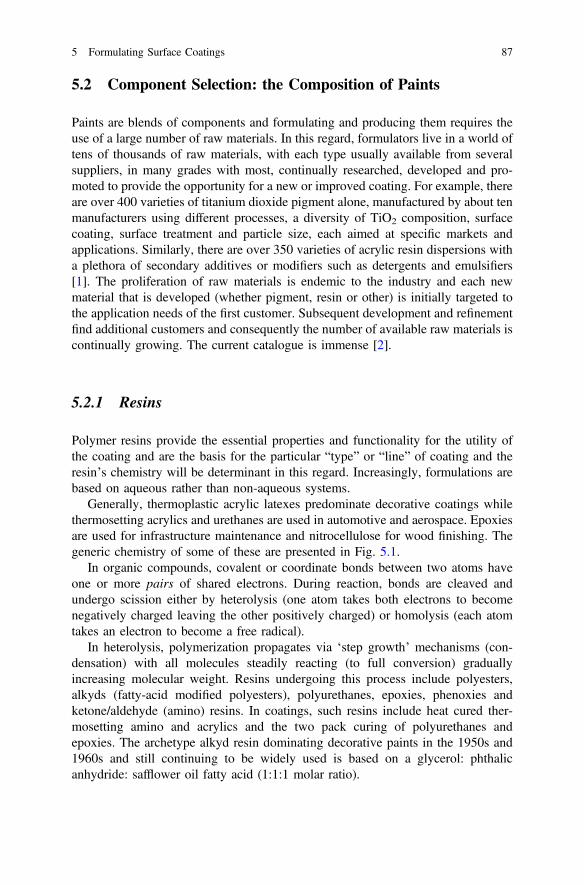
5.2 Component Selection: the Composition of Paints
Paints are blends of components and formulating and producing them requires theuse of a large number of raw materials. In this regard, formulators live in a world oftens of thousands of raw materials, with each type usually available from severalsuppliers, in many grades with most, continually researched, developed and pro-moted to provide the opportunity for a new or improved coating. For example, thereare over 400 varieties of titanium dioxide pigment alone, manufactured by about tenmanufacturers using different processes, a diversity of TiO2 composition, surfacecoating, surface treatment and particle size, each aimed at specific markets andapplications. Similarly, there are over 350 varieties of acrylic resin dispersions witha plethora of secondary additives or modifiers such as detergents and emulsifiers[1]. The proliferation of raw materials is endemic to the industry and each newmaterial that is developed (whether pigment, resin or other) is initially targeted tothe application needs of the first customer. Subsequent development and refinementfind additional customers and consequently the number of available raw materials iscontinually growing. The current catalogue is immense [2].
5.2.1 Resins
Polymer resins provide the essential properties and functionality for the utility ofthe coating and are the basis for the particular “type” or “line” of coating and theresin’s chemistry will be determinant in this regard. Increasingly, formulations arebased on aqueous rather than non-aqueous systems.
Generally, thermoplastic acrylic latexes predominate decorative coatings whilethermosetting acrylics and urethanes are used in automotive and aerospace. Epoxiesare used for infrastructure maintenance and nitrocellulose for wood finishing. Thegeneric chemistry of some of these are presented in Fig. 5.1.
In organic compounds, covalent or coordinate bonds between two atoms haveone or more pairs of shared electrons. During reaction, bonds are cleaved andundergo scission either by heterolysis (one atom takes both electrons to becomenegatively charged leaving the other positively charged) or homolysis (each atomtakes an electron to become a free radical).
In heterolysis, polymerization propagates via ‘step growth’ mechanisms (con-densation) with all molecules steadily reacting (to full conversion) graduallyincreasing molecular weight. Resins undergoing this process include polyesters,alkyds (fatty-acid modified polyesters), polyurethanes, epoxies, phenoxies andketone/aldehyde (amino) resins. In coatings, such resins include heat cured ther-mosetting amino and acrylics and the two pack curing of polyurethanes andepoxies. The archetype alkyd resin dominating decorative paints in the 1950s and1960s and still continuing to be widely used is based on a glycerol: phthalicanhydride: safflower oil fatty acid (1:1:1 molar ratio).
5 Formulating Surface Coatings 87
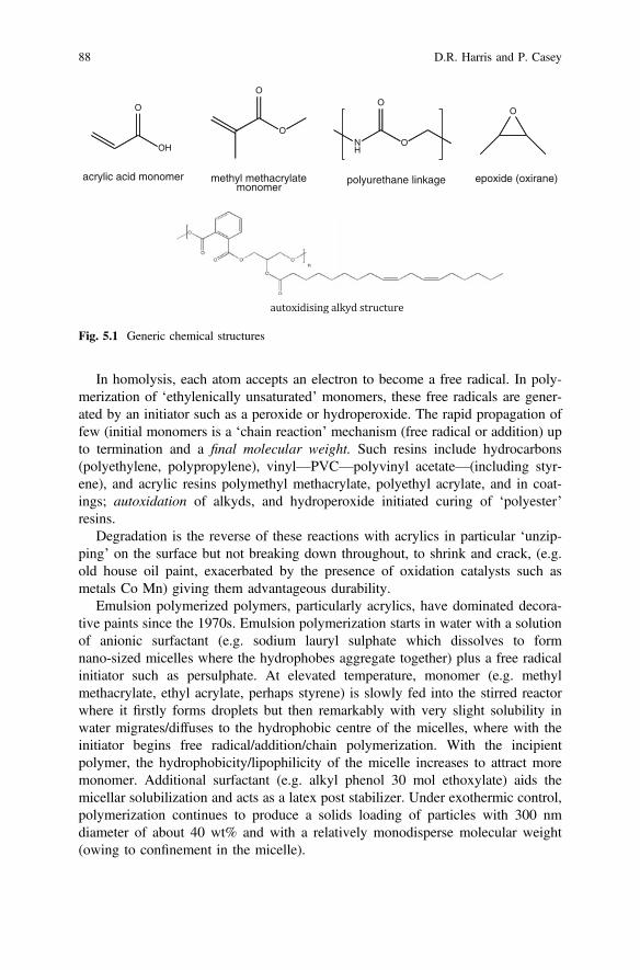
In homolysis, each atom accepts an electron to become a free radical. In poly-merization of ‘ethylenically unsaturated’ monomers, these free radicals are gener-ated by an initiator such as a peroxide or hydroperoxide. The rapid propagation offew (initial monomers is a ‘chain reaction’ mechanism (free radical or addition) upto termination and a final molecular weight. Such resins include hydrocarbons(polyethylene, polypropylene), vinyl—PVC—polyvinyl acetate—(including styr-ene), and acrylic resins polymethyl methacrylate, polyethyl acrylate, and in coat-ings; autoxidation of alkyds, and hydroperoxide initiated curing of ‘polyester’resins.
Degradation is the reverse of these reactions with acrylics in particular ‘unzip-ping’ on the surface but not breaking down throughout, to shrink and crack, (e.g.old house oil paint, exacerbated by the presence of oxidation catalysts such asmetals Co Mn) giving them advantageous durability.
Emulsion polymerized polymers, particularly acrylics, have dominated decora-tive paints since the 1970s. Emulsion polymerization starts in water with a solutionof anionic surfactant (e.g. sodium lauryl sulphate which dissolves to formnano-sized micelles where the hydrophobes aggregate together) plus a free radicalinitiator such as persulphate. At elevated temperature, monomer (e.g. methylmethacrylate, ethyl acrylate, perhaps styrene) is slowly fed into the stirred reactorwhere it firstly forms droplets but then remarkably with very slight solubility inwater migrates/diffuses to the hydrophobic centre of the micelles, where with theinitiator begins free radical/addition/chain polymerization. With the incipientpolymer, the hydrophobicity/lipophilicity of the micelle increases to attract moremonomer. Additional surfactant (e.g. alkyl phenol 30 mol ethoxylate) aids themicellar solubilization and acts as a latex post stabilizer. Under exothermic control,polymerization continues to produce a solids loading of particles with 300 nmdiameter of about 40 wt% and with a relatively monodisperse molecular weight(owing to confinement in the micelle).
O
OH
acrylic acid monomer
O
O
methyl methacrylatemonomer
NH
O
O
polyurethane linkage
O
epoxide (oxirane)
Fig. 5.1 Generic chemical structures
88 D.R. Harris and P. Casey

New and improved resins are being continually developed particularly for ser-vice under extreme conditions and this is where self healing approaches comple-ment and contribute to higher levels of performance.
5.2.2 Pigments
Pigments provide the “shades”/colours, or other variation, for each type/“line” ofcoating: opaque for paint, bright shade for inks, anticorrosive for primers, mattingagents for low gloss, filling for surfaces.
Pigments, which are categorised by their Pigment Colour Number and ColourIndex Number [e.g. Titanium Dioxide: Pigment White 6 (PW6), Colour Index (C I)77891; Copper Phthalocyanine Blue–Beta form: Pigment Blue 15:3 (PB15:3),Colour Index (C I) 74,160], come in a broad range of colours with the final coatingcolour often utilising mixtures of tinting pigments added to a pigment base (typi-cally white) [3]. Pigments may be supplied either as a powder or in a dispersedform.
5.2.2.1 White Pigments
Titanium dioxide (PW6) is the most widely used white pigment (typical particlesize 0.18–0.25 μm). It is extracted from ilmenite and in its rutile form has a veryhigh refractive index (RI = 2.6). At high solids loadings in a coating, light isscattered from, rather than transmitted through, the coating thus promoting itsbrightness and opacity. Zinc Oxide (PW4, particle size 0.2–0.3 μm) which has amuch lower refractive index (RI = 2.00) may also be used in paints. Both TiO2 andZnO are good absorbers of ultra violet light, However, they are very photoactiveand a coating will “chalk” on exterior exposure unless particles are coated with abarrier such as silica. Consequently, they provide a dual function of enhancingopacity while protecting the substrate from degradation by ultraviolet light.
Other “natural” white pigments used as functional fillers, “inert” or “extender”(of opacity) pigments with larger particle sizes (1–15 μm) and lower refractiveindices (1.5–1.7) include dry ground sulphates (Barytes (BaSO4), PW21B], layeredsilicates containing Na, Ca, Al, Mg [PW20 mica/feldspar, PW19 kaolin, PW26talc], carbonates such as PW18 natural limestone/calcium carbonate/chalk and silica[PW27]. As indicated in the introduction some of these may serve as carriers forhealing agents via absorption, surface adsorption or ionic exchange.
“Synthetic” white pigments with similar RIs to their natural counterparts includeprecipitated calcium carbonate [PW18], aluminium silicate [PW19] and synthetic“high brightness” kaolin (i.e. very white) [PW22], Blanc Fixe (precipitated BaSO4);PW24 Al(OH)3; hydrated magnesium silicate Talc [PW26] and synthetic silica gel[PW27].
5 Formulating Surface Coatings 89

Zinc Phosphate [PW32] plus a range of other phosphates are used as “non toxicanticorrosive pigment” in primers on metal surfaces coats.
5.2.2.2 Coloured Pigments
Inorganic coloured pigments range in colour across the spectrum. They are pre-dominantly metal based compounds or complexes (predominantly transition metalssuch as Fe, Co, Cr, Ni, Cu, Zn, Ti, V) that include variant oxides, mixed oxides,titanates, chromates, sulphides, vanadates etc. Included in this category are blackpigments based on carbon (e.g. carbon black) and special effects pigments such aspearlescent, fluorescent or heat reflective pigments.
The most common organic coloured pigments are the Azo pigments which aremade by diazotization of an aromatic amine. Their characteristic colours are due tothe azo (–N=N–) colour forming linkage and determined by the coupled organicmoieties. Other common pigments are those based on phthalocyanine (complexedwith metals). For a comprehensive list of pigments the reader is referred [2, 4–6].
5.2.3 Solvents
Solvents dissolve or carry dispersions of resins and are simultaneously used reduceviscosity for ease of application and assist in the control film formation. The rangeof chemicals that can act as solvents is broad. Water, of course, is the basis foraqueous dispersions while organic solvents are used in non aqueous dispersions. Anexample of the latter are the aliphatic hydrocarbons with aromatic content of 18 %of white spirit (mineral turpentine) that dissolve alkyd resins typically used indecorative coatings.
Historically, the glycol ethers such as Mono-Ethylene-Glycol-Ethyl-Ether(MEGEE, originally called “Cellosolve”) and its variations of Methyl-, Ethyl-,Propyl-, Butyl-; and Mono-, Di- and Tri- Ethylene Glycol, have been importantsolvents, but are now found to be reprotoxic (hazardous to pregnancy) and arelimited in use [7]. The propylene glycol ether analogues, however, are accepted assafe. Ketones and esters including acetate esters of the above glycol ethers areimportant for epoxies and polyurethanes, whereas active hydrogen (–OH) solvents:alcohols and glycol ethers are precluded by their reactivity. Aromatic toluene andxylene contribute to solvency as co-solvents when used in conjunction with oxy-genated solvents.
The solvent plays a key role in application. Solvents for spray are carefullyformulated with low boiling point (‘fast’) solvents for atomization while highboiling point (‘slow’) and strong solvents (for good dissolution) are used to promoteflow and good film formation on the substrate surface. Fast aliphatic solventscontribute to atomization. Neither alcohol nor toluene or xylene dissolve the lacquergrades of nitrocellulose, but in combination they will dissolve them and thus
90 D.R. Harris and P. Casey
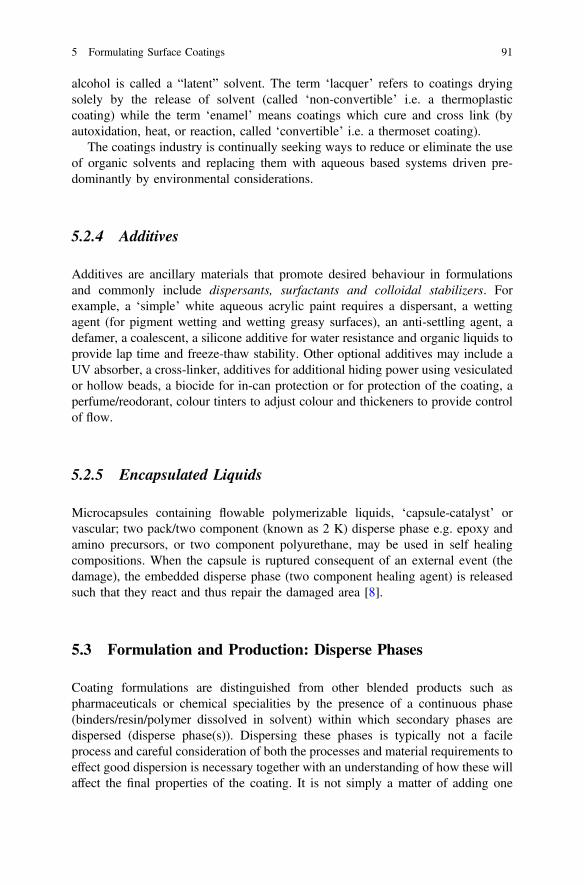
alcohol is called a “latent” solvent. The term ‘lacquer’ refers to coatings dryingsolely by the release of solvent (called ‘non-convertible’ i.e. a thermoplasticcoating) while the term ‘enamel’ means coatings which cure and cross link (byautoxidation, heat, or reaction, called ‘convertible’ i.e. a thermoset coating).
The coatings industry is continually seeking ways to reduce or eliminate the useof organic solvents and replacing them with aqueous based systems driven pre-dominantly by environmental considerations.
5.2.4 Additives
Additives are ancillary materials that promote desired behaviour in formulationsand commonly include dispersants, surfactants and colloidal stabilizers. Forexample, a ‘simple’ white aqueous acrylic paint requires a dispersant, a wettingagent (for pigment wetting and wetting greasy surfaces), an anti-settling agent, adefamer, a coalescent, a silicone additive for water resistance and organic liquids toprovide lap time and freeze-thaw stability. Other optional additives may include aUV absorber, a cross-linker, additives for additional hiding power using vesiculatedor hollow beads, a biocide for in-can protection or for protection of the coating, aperfume/reodorant, colour tinters to adjust colour and thickeners to provide controlof flow.
5.2.5 Encapsulated Liquids
Microcapsules containing flowable polymerizable liquids, ‘capsule-catalyst’ orvascular; two pack/two component (known as 2 K) disperse phase e.g. epoxy andamino precursors, or two component polyurethane, may be used in self healingcompositions. When the capsule is ruptured consequent of an external event (thedamage), the embedded disperse phase (two component healing agent) is releasedsuch that they react and thus repair the damaged area [8].
5.3 Formulation and Production: Disperse Phases
Coating formulations are distinguished from other blended products such aspharmaceuticals or chemical specialities by the presence of a continuous phase(binders/resin/polymer dissolved in solvent) within which secondary phases aredispersed (disperse phase(s)). Dispersing these phases is typically not a facileprocess and careful consideration of both the processes and material requirements toeffect good dispersion is necessary together with an understanding of how these willaffect the final properties of the coating. It is not simply a matter of adding one
5 Formulating Surface Coatings 91
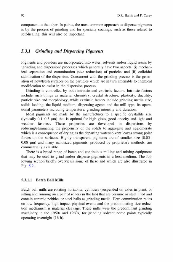
component to the other. In paints, the most common approach to disperse pigmentsis by the process of grinding and for specialty coatings, such as those related toself-healing, this will also be important.
5.3.1 Grinding and Dispersing Pigments
Pigments and powders are incorporated into water, solvents and/or liquid resins by‘grinding and dispersion’ processes which generally have two aspects: (i) mechan-ical separation and comminution (size reduction) of particles and (ii) colloidalstabilisation of the dispersion. Concurrent with the grinding process is the gener-ation of new/fresh surfaces on the particles which are in turn amenable to chemicalmodification to assist in the dispersion process.
Grinding is controlled by both intrinsic and extrinsic factors. Intrinsic factorsinclude such things as material chemistry, crystal structure, plasticity, ductility,particle size and morphology, while extrinsic factors include grinding media size,solids loading, the liquid medium, dispersing agents and the mill type, its opera-tional parameters including temperature, grinding intensity and duration.
Most pigments are made by the manufacturer to a specific crystallite size(typically 0.1–0.3 μm) that is optimal for high gloss, good opacity and light andweather fastness. These properties are developed in dispersions byreducing/eliminating the propensity of the solids to aggregate and agglomeratewhich is a consequence of drying as the departing water/solvent leaves strong polarforces on the surfaces. Highly transparent pigments are of smaller size (0.05–0.08 μm) and many nanosized pigments, produced by proprietary methods, arecommercially available.
There is a broad range of batch and continuous milling and mixing equipmentthat may be used to grind and/or disperse pigments in a host medium. The fol-lowing section briefly overviews some of these and which are also illustrated inFig. 5.2.
5.3.1.1 Batch Ball Mills
Batch ball mills are rotating horizontal cylinders (suspended on axles in plant, orsitting and running on a pair of rollers in the lab) that are ceramic or steel lined andcontain ceramic pebbles or steel balls as grinding media. Here comminution relieson low frequency, high impact physical events and the predominating size reduc-tion mechanism is material cleavage. These mills were the predominant grindingmachinery in the 1950s and 1960s, for grinding solvent borne paints typicallyoperating overnight (16 h).
92 D.R. Harris and P. Casey
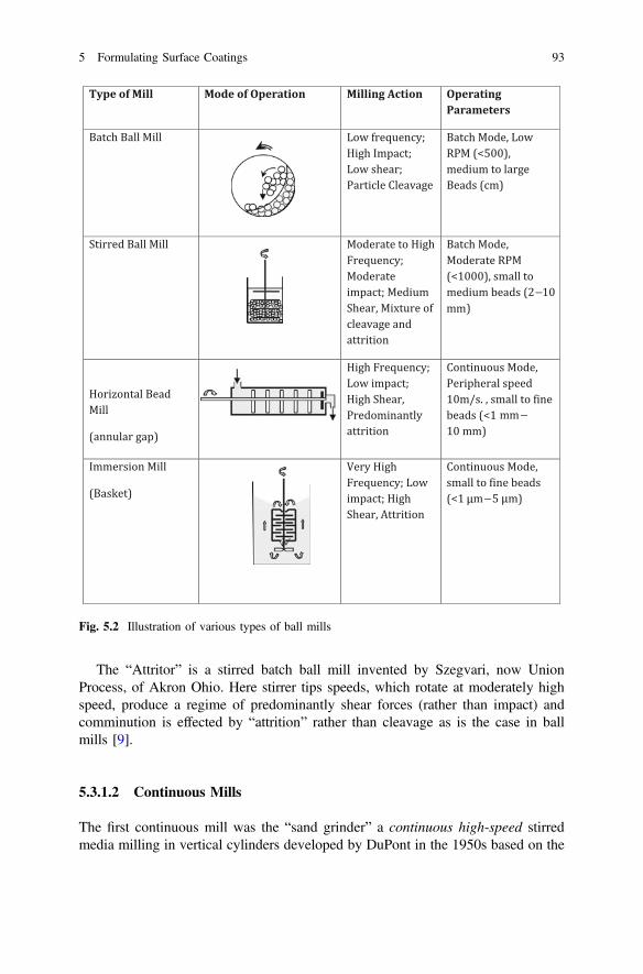
The “Attritor” is a stirred batch ball mill invented by Szegvari, now UnionProcess, of Akron Ohio. Here stirrer tips speeds, which rotate at moderately highspeed, produce a regime of predominantly shear forces (rather than impact) andcomminution is effected by “attrition” rather than cleavage as is the case in ballmills [9].
5.3.1.2 Continuous Mills
The first continuous mill was the “sand grinder” a continuous high-speed stirredmedia milling in vertical cylinders developed by DuPont in the 1950s based on the
–
–
–
Fig. 5.2 Illustration of various types of ball mills
5 Formulating Surface Coatings 93
observation that grinding in ball mills was more effective when smaller ball sizeswere used while accommodating the limitation of Stoke’s law, where settlingvelocity is a function of the radius squared. Here, mill base was fed from a pump ora pressure pot into the bottom of the cylinder in which rotor bearing discs stirredsmall media (sand of about 0.8 mm diameter) with disengagement of beads fromthe mill base via a screen at the top [10].
5.3.1.3 Horizontal Bead Mills with ‘Rotating Gap’
Later, machinery manufacturers built horizontal bead mills, with a rotor bearingvarious shapes of discs, stirring beads of 2–5 mm diameter, and with “rotating gap”bead disengagement. A disc on the end of the rotor shaft is adjacent to a similarsized annular aperture at the endplate of the shell with an adjustable (*0.25 mm)“rotating gap” to centrifuge and disengage the beads. The disadvantage of con-tinuous mills (whether vertical or horizontal) is that the product can have a variablesize distribution. This is because the residence time of the particles in the mill varies(some stay longer others exit more quickly) as a consequence of differences in fluidflow patterns in different parts of the mill chamber [11].
5.3.1.4 Immersion Mills
New mill designs have overcome the above limitation by adopting more sophisti-cated designs that simultaneously produce homogenous fluid flow regimes into andwithin the milling chamber as well as producing greater milling efficiencies byusing a smaller milling chamber immersed in a larger chamber.
An example of this is a Basket Mill which combines expulsion and suction of themill base through the milling “basket” which is immersed in the mill base ensuringthat the entire base product passes through the grinding chamber many times duringthe operation and is progressively uniformly processed. An elegant variant is theimmersion mill by Hockmeyer where the milling chamber (a basket) is immersed inthe mill base contained in a larger vessel or chamber such that high throughputhomogeneous fluid flows into and within the grinding chamber are promoted. Theseflow regimes produce an increased grinding efficiency and by using a combinationof stationary and rotating pegs in the chamber aggressive shear zones are createdthat produce fine product with a narrow size distribution [12].
Pigments may be milled with fine (0.1–0.6 mm) beads in production scale beadmills made by high throughput, fine bead mills in which bead disengagement iseffected by centrifugation. There are laboratory scale mills of these brands.
94 D.R. Harris and P. Casey
5.3.1.5 High Shear Rate Pre-milling
High speed mixing is performed in a regime that invokes high shear rates typicallyusing various rotor configurations at high speed. It differs from milling in that nogrinding media are used. High speed disc mixing began with the invention of theCowles Dissolver: a disc with peripheral sectors alternately bent up and down,slightly inward from the tangent, rotating at the end of a shaft in the mill base at25 m/s, inducing, in preferably dilatent millbases, high intensity mixing withcavitation. High Speed Mixing is now widely used for premilling mill base for othermilling operations. Kinetic dispersers (Kady, Janke, Kunkel Ultra Turrax) havehigh speed nested slotted rotors and stators. The Silverson homogeniser has a highspeed paddle rotor working inside a peripheral ring perforated with holes. There is agreat diversity of high speed homogenisers, particularly at laboratory scale [13].
5.3.1.6 High Shear Stress Milling
Sigma bladed or Z-bladed mixers are batch mills, usually jacketed for heating orcooling, wherein two horizontal rotors, exchanging mill base between them, applyhigh shear forces to the mill base. They are commonly used for high viscosityslurries or dispersions. These mills have had the special application of “flushing”where organic pigment filter-press cake (wet) is mixed with gradual additions ofresin into which the pigment transfers from the aqueous to the organic phase.Separated water is poured off by tilting the mill, and finally the mill is closed,heated via the jacket, and put under vacuum to remove all water. An advantage offlushing is that it avoids the aggregation and agglomeration caused by dryingpigments to powder [14].
5.3.1.7 Testing the End Point
A simple but effective way of assessing whether a good dispersion has beenachieved is to typically use a Hegman gauge or a variant of it. A Hegman gauge is ablock of steel with one or two channels cut into it about 12 mm wide which taperfrom zero to 100 μm depth [15]. A sample of mill base is placed at the deep end andis scraped down the channels using a straight blade. A reading is taken wheresignificant “nibs”, “grits” or “seediness” appear. The fineness gauges are thusreading the proportion of a small but significant population of larger particles.
Paint pigments ground to a particle size required primarily for matte finish have aHegman of *25 μm and for gloss a Hegman *12.7 μm. For viscous inks forexample the limit has been 5 μm or “off the gauge” where the National Printing InkResearch Institute (NIPRI) production grindometer tapers from zero to 25 μm. Moremodern measures of particles size such as Transmission Electron Microscopy
5 Formulating Surface Coatings 95
(TEM), Scanning Electron Microscopy (SEM), X-Ray Diffraction (XRD) and lightscattering or photon correlation spectroscopy (PCS) may reveal, when the disper-sion has been approved by the Hegman gauge, undispersed primary crystallites andaggregates. Thus beyond the endpoint on a Herman gauge there is the possibility ofmore effective grinding towards the primary crystallite size as provided by thepigment supplier.
5.3.2 Colloidal Stabilization
Colloidal stabilization of the ground dispersion is necessary to prevent flocculation,i.e. reversion to a loose association of particles called floccules in the dispersion.A floccule behaves as a large but loosely held particle. Flocculation and undis-persed agglomerates and aggregates are entirely counterproductive to all usefulproperties of coatings. It is typically observed as the contraction of the flocculatedvolume in a standing liquid leaving clear continuous phase, called syneresis, usuallyat the top but it can be on the bottom depending on the density of the dispersedphase. It is desirable to fully grind to provide for full deflocculation and colloidalstabilization in the liquid phase and subsequently in the solid coating. Some resinshave adequate wetting and dispersion power, but improved dispersion anddeflocculation are usually achieved by the addition of dispersants.
5.3.2.1 Settling/Sedimentation
A flocculated dispersion settles quickly and softly (can be easily stirred), owing tothe large effective size of the floccules. A de-flocculated dispersion settles slowlyand the sediment is hard, owing to finer particles becoming more compact.Formation of sediment may be ameliorated or prevented by using a higher viscositymedium or by rheological yield value imparted by ‘antisettling’ agents. Thickenersand rheology modifiers are added to achieve desired rheology typically using cel-lulosics, modified clays or more recently acrylics and urethanes in the form ofassociative thickeners which may be conveniently post-added and stirred into theliquid. Settling can manifest as a real problem during long distance transport.
5.3.2.2 Miscibility
Miscibility must be perfect, regardless of the effectiveness of dispersants, to avoidflocculation. One exception is that surfactants, which become concentrated atparticle-liquid interfaces, need not be entirely miscible. Prediction of miscibility andcompatibility was put on a quantitative basis by a classic article of Burrell
96 D.R. Harris and P. Casey

“Solubility Parameters for Film Formers” [16]. Hildebrand and Hansen predictsolubility parameters using a 3D space based on the energy from dispersion,intermolecular and hydrogen bonding between molecules such that the nearerco-ordinates for molecules are in this space the more likely they are to dissolve intoeach other [17].
5.3.2.3 Dispersants
Dispersing agents like polyacrylic acid are purely dispersant (by adsorption andcharge stabilization). Others reduce the interfacial surface tension making it easierfor dispersion to occur. Most are to some degree oleophilic and capable of surfacetension depression in aqueous systems spreading over and wetting pigment sur-faces. Zinc soaps have been widely used in alkyd resin coatings (generally as agrinding aid) to wet the surface and provide zinc to adsorb carboxylic resins anddispersants. Speciality ranges of grinding aids and dispersants include copolymerswith pigment affinic groups (e.g. the Nuplex “Disperbyk” and “Byk”), low surfaceenergy siloxane, perfluoro alkyls) and high molecular weight polymeric dispersants(Ciba “Efka” range) and others (Tego Dispers, Solsperse Hyperdispersants) to wetsurfaces and disperse particles.
Most pigments are crystalline with sharp edges which have higher surfaceenergy than the bulk of the crystals. These agents wet the crystals to benefitgrinding and prevent recombination. For example, the Solsperse hyperdispersantsdemonstrate significant reduction in viscous inks processing owing to prevention ofrecombination.
The level of dispersant, to gain perfect colloidal dispersion, is a criticalparameter which will vary according to particle size and surface area and is thusdetermined by specific weight per surface area which may typically be 0.005–0.01 g/m2
5.3.3 Modes of Adsorption of Surfactants and Dispersantsat Interfaces
When washing a piece of glass with ordinary soap (sodium palmitate) water wettingoccurs because the soap is surface-active i.e. the soap concentrates at the interfacebetween the glass and water. Because the palmitic hydrophobes (16 carbon alkane)are non-polar with little attraction between them, they are repelled by the highlypolar and self attracting water and subsequently concentrate and spread at thesurface or interface. Thus the soap wets the surface with water and this typicallydescribes the normal adsorption process of soaps, surfactants and detergents [18].
5 Formulating Surface Coatings 97
5.3.3.1 Acid–Base (Lewis) Interaction’ Adsorption/Chemisorption
If the piece of glass is washed in water with a cationic surfactant (e.g. lauryltrimethyl ammonium chloride), the water beads and the surface will remainnon-wettable. This occurs because there is an acid–base (Lewis) interactionbetween the lauryl trimethyl ammonium cation and the silicic acid groups of theglass. Here the adsorption is the reverse of the above with the ammonium cation onthe glass and the hydrophobes oriented towards the water hence beading will occur.
5.3.3.2 Anionic Surfactants and Dispersants
Anionic stabilizers are used in aqueous compositions. In the US the de-factostandard dispersant has been Tamol 731 (also known as Orotan) which is a sodium(or ammonium) salt of a maleic anhydride copolymer, an anionic polyelectrolytewhich is highly carboxylated and has some wetting/surface tension depressionproperties at 1 % aqueous solution. There are many other varieties of ionic stabi-lizers: anionic such as alkyl sulphates, sulphosuccinates, sodium hexametaphos-phate, and “ether” (ethylene oxide) sulphates or “ether” (ethylene oxide)phosphates of alkyl or aryl polyethoxylates.
5.3.3.3 Cationic Surfactants
Lauryl trimethyl ammonium chloride and cetyl trimethyl ammonium bromide arehighly effective in comminution and stabilization of fine pigment particles. Oneparticular application of cationic surfactants is in bitumen/asphalt emulsions forcoating aggregate on roads.
5.3.3.4 Steric Enthalpic Stabilizers
“Enthalpic” is the classification for non-ionic surfactants (ethoxylates) because theirthermodynamic stability comes from heat of hydration necessary to remove wateron collision with the hydrated polyethylene oxide sheaths. Steric stabilizers foraqueous compositions are most particularly the ethylene oxide condensates of avariety of hydrophobes. The most popular were the ethoxylates of nonyl phenol andof the less biodegradable octyl phenol. Environmental concerns about the lack ofsufficient biodegradability and thus toxicity has prohibited the use of ethoxylates ofalkyl phenols in detergents. Fatty alcohol (alkyl) ethoxylates, particularly lauryl anddecyl, may be used as they are biodegradable, but have diminished effectiveness.Ethoxylates are also notable for their inverse solubility with temperature and the“cloud point temperature” is used to control the endpoint of ethoxylation due totemperature dependent hydrogen bonding.
98 D.R. Harris and P. Casey
5.3.3.5 Entropic Stabilizers
Solsperse Hyperdispersants are an effective invention of predominately entropicstabilizers. They were invented within what was ICI Dyestuffs Division and areexcellent for low to moderately polar systems including aliphatic, aromatic (partic-ularly solvent gravure), esters, ketones, and glycol ethers. They comprised a varietyof solvatable polymeric chains combined with a variety of ‘anchor’/‘pigment-affinic’groups which adsorb by Acid–Base (Lewis) Interaction (chemisorption).
The first member was Solsperse 3000 which has a carboxyl group suitable forattaching to basic pigments, particularly Calcium Rubine 4B Toner, Pigment Red57:1, Colour Index 15,850:1, the predominant magenta pigment for trichromatic‘process’ printing (Cyan, Yellow and Magenta). In the range there are a variety ofanchor groups and a variety of solvatable groups which are suitable for mostcombinations of pigment and solvent. There are also two ‘synergists’ to precoatspecific pigments for the Acid–Base (Lewis) Interaction of other appropriateSolsperses.
5.3.3.6 Polymer Resin Dispersancy
In solvent borne-coatings the polymeric resins themselves may have adequatewetting and dispersion properties for the colloidal stability of the suspended pig-ments. Alkyd resins have free hydroxyl and carboxyl groups and solvatable chainsof fatty acids on polyester. Straight polymethyl methacryate (PMMA) has poordispersancy. Acrylic resins, both solvent borne (thermoplastic and thermoset) andaqueous acrylic dispersions, are made with small proportions of carboxylic acidco-monomer to assist adsorption onto the pigment surface and provide colloidalstability.
5.4 Developing a Formulation
Factorial experiments are efficient because they simultaneously measure the effectof several factors, and their interactions, with replication and without wastefulrepetition. In developing a formulation, Two level, multi factor experiments can bevery useful; the number of experiments being 2n where n is the number of factors.Factorial experiments may be used for optimizing the formulation for performanceand cost and for discovering preferred ranges for exemplification in patents or fortroubleshooting performance problems (e.g. solvent boil—bubbles in hot weatheron sprayed automotive lacquers). There are many textbooks on ExperimentalMethod and Process Optimization from [19–23].
5 Formulating Surface Coatings 99
Typically, experimental formulations are advantageously drafted in a spread-sheet where the left hand vertical columns list ingredients with the right handcolumns contain the quantities of the ingredients and pertinent formulationdescriptors or properties (e.g. v/v ratio, density etc.). This format convenientlyallows all kinds of variations based on different raw materials across the pages, andis suitable for factorial experiments.
Coating formulae list ingredients with quantities by weight fraction or per-centage adding up to unity or 100 respectively. This format may be easily ‘ex-tended’ by multiplying by a factor to yield the required scale up of quantities forpreparation or manufacture. Master spread sheets can be used to calculate thevolume relationships: volume solids and pigment volume concentration, withcosting, manufacturing instructions and testing instructions.
Relative volumes of the continuous and dispersed phases are most importantlycalculated, both as liquid and dried solid, by spreadsheet. Experimental variationcan proceed informed by the observable effect of pigment volume concentrations onproperties. From volumes, and measurement of particle size, surface areas may becalculated which are important to determine (1) the level of dispersant and (2) therheology of the dispersion via the thickness of the adsorbed barrier.
Formulations may be usefully managed and recorded in the following ofmanner:
A spread sheet should be able to calculate and provide:
• 100 % total by weight• Volumes of ingredients (from density and weight)• Density of the liquid formula determined from those of the ingredients (kg/L,
Weight per Litre test)• The total weight of solids and volume of solids of the liquid dispersion. The
pigment weight content and pigment volume content of the liquid dispersion;• The levels of additives and of binder on the pigment in pph w/w and v/v;• Pigment weight content of the solid coating (PWC) and• Pigment volume content of the solid coating (PVC)• Costs and Values Columns of raw materials to calculate total cost may be
included.• Manufacturing instructions.• Testing/characterisation instructions
“Extensions” multiplying by a factor the 100 % or unit total by weight, torequired batch sizes.
Table 5.1 presents an illustrative example of an aqueous based formulationcontaining two dense pigments (Pigment 1 density = 4.8 g/cc, Pigment 2 den-sity = 2.94 g/cc) have differing concentrations by weight and volume (30.4 and17.7 %) and which contains a dispersant, a stabiliser (alkaline), the resin base (40 %non volatiles) and make up water.
100 D.R. Harris and P. Casey

Tab
le5.1
Illustrativ
eexam
pleof
form
ulation
Dispersion
w/w
SG
pphw/w
pphv/v
Asmade
Solid
sDensity
Volum
eSu
rface
area
SA
PrepNo:
Onpigm
ent
Onpigm
ent
Weigh
tw
orNV
dv
m2
Ingredients
Pigm
ent1
4.80
4.80
4.80
1.00
100
Pigm
ent2
11.20
11.20
2.94
3.81
381
Dispersant
3089
4.80
4.80
1.12
4.29
Resin
41%NV
6017
823
.40
9.59
1.12
8.57
AlkalinestabiliserNH325
%aq
6.00
1.00
6.00
WATER
(Holdou
t5%
forfinalwasho
utandmakeup)
49.80
1.00
49.80
Totals
9026
710
0.00
30.4
1.36
73.5
481
Con
stan
ts
Total
pigm
ent
16.00
4.96
4.81
Total
weigh
tof
dispersion
100.00
Total
volumeof
dispersion
73.5
Weigh
tSo
lidsor
NV
ofdispersion
w/w
30.4
Volum
eSo
lidsor
NV
ofdispersion
v/w
17.7
Pigm
entweigh
tcontentof
dispersion
w/w
16.0
%
Pigm
entvo
lumecontentof
dispersion
v/v
6.5%
Pigm
entweigh
tconcentrationPW
Cof
coating
52.6
%
Pigm
entvo
lumeconcentrationPV
Cof
coating
27.2
%
Dispersantpersquare
metre
atsurfacearea,g
0.01
0(D
ispersant+resin)
persquare
metre
atsurfacearea,g
0.03
0(con
tinued)
5 Formulating Surface Coatings 101

Tab
le5.1
(con
tinued)
Dispersion
w/w
SG
pphw/w
pphv/v
Asmade
Solid
sDensity
Volum
eSu
rface
area
SA
PrepNo:
Onpigm
ent
Onpigm
ent
Weigh
tw
orNV
dv
m2
Ingredients
Man
ufacturing
instructions
Chargewater
andNH3(aq)to
prem
ixvessel
Chargeanddissolve
dispersant
andaqueou
sresin
Chargeandprem
ixpigm
ents.
Feed
mill
base
viathehigh
recirculationrate
mill
tothereceiving
vessel:-
W.O.Bacho
fenDyn
o‘ECM’,or
Netzsch
‘Zeta’,or
Drais‘D
CP’
Whenprem
ixtank
isem
pty—
mill
with
recirculationathigh
rate
from
andwith
return
toreceivingvessel.
Prog
ressivelytestagainststand
ardsampleforcolouristic
streng
thun
tilendpo
intisreached
Mill
batchto
anem
ptyvessel
(‘pass’or
‘passage’mill)to
complete
milling.
Tests:CIELab
colour,Gloss,Sp
ecificgravity
,Viscosity.
NVno
nvo
latiles
pphpartsperhu
ndred
pphw/w
onpigm
entpartsby
weigh
tof
dispersant
andresinon
100partsby
weigh
tof
pigm
ent
=wtof
dispersant/[(w
tof
pigm
ent1+wtof
pigm
ent2)/100
]=4.8/[(4.8+11
.2)/10
0]=30
pphv/von
pigm
entpartsby
volumeof
dispersant
andresinon
100partsby
volumeof
pigm
ent
=vo
lof
dispersant/[(vol
ofpigm
ent1+vo
lof
pigm
ent2)/100
]=
(wtof
dispersant/density
ofdispersant)/[(wtof
pigm
ent1/density
ofpigm
ent1)
+(w
tof
pigm
ent2/density
ofpigm
ent2)}/100
=(4.8/1.12)/[((4.8/4.8)
+(11.2/2.94
))/100
]=4.28
/[(1
+3.8)/100
]=42
8/4.8=89
SurfaceAreamay
becalculated
from
theory
(based
onsize
ofparticle)or
determ
ined
from
empiricalor
repo
rted
data
PWC
pigm
entweigh
tconcentration;
PVC
pigm
entvo
lumeconcentration
102 D.R. Harris and P. Casey
5.5 Summary
Self healing coatings have considerable technological and industrial potential forapplication across a number of sectors. To assist easy entry into the market place,self healing function needs to be incorporated or formulated into a coating in amanner typical to the coatings industry. This requires an understanding of whatmaterial considerations are important in formulating a commercial coating for easydeployment and application performance. This chapter has provided a brief guide tosome of these considerations particularly in relation to component selection, for-mulation and production. It hopefully has provided the reader with an appreciationof the complexity that may arise when producing a formulation and reinforced thenotion that it is not simply a matter of adding one component to another to producethe coating. It has not focused on any specific self healing agents but rather taken anoverview using pigmented coatings as a model illustrative system and that subse-quently the reader is better equipped to address the challenges in taking a selfhealing coating concept from the laboratory to a higher level of technologyreadiness.
To this end the main points of the chapter are that:
• Paints are blends of components and formulating and producing them requiresthe selection and use from a large number of raw materials.
• Polymer resins provide the essential properties and functionality for the utility ofthe coating.
• Polymerization propagates via either (i) ‘step growth’ mechanisms (condensa-tion) with all molecules steadily reacting (to full conversion) graduallyincreasing molecular weight or (ii) a ‘chain reaction’ mechanism (free radical oraddition) with the rapid propagation of few initial monomers up to terminationand a final molecular weight.
• Pigments may be inorganic, used for hiding/opacity, as fillers, and for anti-corrosive properties or they may be organic used for colour.
• Solvents and additives, in addition to polymer resins and pigments, are majorcomponents of coatings. Dispersant additives are particularly important forproviding, in both liquid and solid phases, colloidal stability.
• Formulation may be assisted by preliminary factorial experiments.
A formulation is better understood and managed when the volume relationships(such as pigment volume concentration PVC) are calculated on a spread sheet.
References
1. McCutcheon’s Emulsifiers & Detergents, McCutcheon Division, vol. 1 (MC PublishingCompany, 2014)
2. The Raw Materials Index RMI, vol. RMI 8, (Surface Coating Association of Australia, 2008)3. Colour Index International, http://www.colour-index.com/
5 Formulating Surface Coatings 103
4. G.B.A.G. Paff (ed.), Industrial Inorganic Pigments, 3rd edn. (Wiley, Germany, 2005)5. Industrial Organic Pigments, 3rd edn. (Wiley, 2006)6. High Performance Pigments, 2nd edn. Revised and Expanded (Wiley, 2009)7. A. Ostman, Reducing the use of Dangerous Glycol Ethers (Nordic Council of Ministers,
Chemical Group, Copenhagen, 1993)8. B.K. Blaiszik, S.L.B. Olugebefola, S.C. Moore, J.S. Sottos, N.R. White, Self Healing
Polymers and Composites, in Annual Review of Materials Research (Annual Reviews, USA,2010) p. 32
9. A. Szegvari, M. Yang, in Seminar on Dispersion of Pigments and Resins in Fluid Media.Attritor Grinding and Dispersing Equipment (Union Process, Kent State University, 1999),p. 7
10. S. Hochberg, Process for Dispersing Pigments in Film-Forming Materials (Du Pont, USA,1952)
11. K. Engels, Stirring Mill (Draiswerke Gmbh, USA, 1978)12. H. Herman, H.Z. Hockmeyer, Basket Media Mill with Stirring Rods and Counterpart Stators,
in US Patents Office, USPTO ed. (Hockmeyer Equipment Corp., USA, 1998), p. 913. S.X. Jinli Zhang, L. Wei, High shear mixers: a review of typical applications and studies on
power draw, flow pattern, energy dissipation and transfer properties. Chem. Eng. Process. 57–58, 16 (2012)
14. K. Robin, J.L.K. Connelly, 3D numerical simulation of the flow of viscous newtonian andshear thinning fluids in a twin sigma blade mixer. Adv. Polym. Technol. 25(3), 12 (2006)
15. Fineness of Grind Gauges, http://www.gardco.com/pages/dispersion/fg/finenessofgrind.cfm16. B. Hansen, Solubility Parameters for Film Formers. Official Digest of Federation of Society of
Paint Technoogy (the former name of J. Coat. Technol. Res.), 27(369), 32 (1972)17. C.M. Hansen, Hansen Solubility Parameters: A User’s Handbook, 2nd edn. (CRC Press,
2007), p. 54418. D.A.B. Ward, Orientation of surfactants adsorbed on a hydrophobic surface. J. Phys. Chem
97, 2 (1993)19. Fisher, R.A., The Design of Experiments (Macmillan Pub Co., 1971)20. E.P. George, J.S.H. Box, G. William, Hunter Statistics for Experimenters: Design, Innovation,
and Discovery, 2nd edn. Probability and Statistics (Wiley, 2005)22. D.C.W. Abdullah Ekin, J.W. Daniels, S.J. Stafslien, F. Cassé, A. James, M.E. Callow, Callow,
Synthesis, formulation, and characterization of siloxane–polyurethane coatings for underwatermarine applications using combinatorial high-throughput experimentation. J. Coat. Technol.Res. 4(4), 6 (2007)
23. L.R.R.A. Price, X.H. Li et al., Investigation of the effects of formulation on selected propertiesof UV curable IPN coatings. J. Coat. Technol. Res. 70(885), 5 (1996)
104 D.R. Harris and P. Casey

Part IIAdvances in Active Protective Coatings
Chapter 6Fostering Green Inhibitors for CorrosionPrevention
M.F. Montemor
6.1 Introduction
Inhibitors are chemical species that can interact with a metallic surface in a way thatthe result is the decrease of the corrosion activity and corrosion rate. Classificationof corrosion inhibitors have been the subject of some controversy. However,nowadays, inhibitors are commonly grouped according to their mechanism ofinhibition as follows: anodic (or passivating) inhibitors, cathodic inhibitors, mixedinhibitors and volatile corrosion inhibitors.
Passivating inhibitors (also classified as anodic inhibitors) are in general oxidizingsubstances that when above a certain critical value, provide corrosion protection dueto one (or more) mechanisms: (i) ability to shift the corrosion potential towards morepositive values, forcing the metallic surface into the passive range; (ii) stabilization ofpassive oxide layers; (iii) repair of damaged protective (namely oxide) layers;(iv) Enhancement of the passive ability by incorporation of species into the passivelayer; (v) decrease of the probability of absorption of aggressive ions, such as chlorideions. Well known examples of passivating inhibitors are chromates, nitrites andmolybdates. These inhibitors are stable in various pH ranges, being quite effective innear-neutral solutions, forming sparingly soluble corrosion products, such as oxides,hydroxides, or salts, which are protective in various surfaces.
Cathodic inhibitors either slow down the rate of the cathodic reaction or,selectively, precipitate at the cathodic areas, where the pH increases due to hydroxylrelease, raising the local impedance and hindering the diffusion of reducible speciesinto these areas. These inhibitors work by different mechanisms that include:(i) decreasing of the reduction reaction rates (cathodic poisons); (ii) selective pre-cipitation on the cathodic areas (cathodic precipitators). Oxygen scavengers are
M.F. Montemor (&)CQE, DEQ—Instituto Superior Técnico, Universidade de Lisboa,Av. Rovisco Pais, 1049-001 Lisboa, Portugale-mail: [email protected]
© Springer Science+Business Media Dordrecht 2016A.E. Hughes et al. (eds.), Active Protective Coatings,Springer Series in Materials Science 233, DOI 10.1007/978-94-017-7540-3_6
107
often classified as cathodic inhibitors. Well known example are rare-earths, namelythe cerium cation that is able to form hydroxides or stable oxides on the cathodicareas [1, 2].
Mixed corrosion inhibitors are mainly organic compounds that can be neitherclassified as cathodic nor as anodic inhibitors, because they affect both processes.However, many of these are more effective in hindering one redox reaction,comparatively to the other. The effectiveness of mixed corrosion inhibitors iscontrolled by their ability to adsorb on metal surface and by the subsequent degreeof coverage. This process strongly depends on the chemical composition andstructure of the inhibitor and metallic surface morphology, roughness and com-position. Typically mixed corrosion inhibitors work by physical adsorption,chemisorption and formation of stable surface layers. Whatever may be themechanism of adsorption, the electron density of the functional groups, polarizingability and electronegativity are important parameters that control the inhibitionefficiency. Several organic inhibitors show ability to inhibit both the anodic andcathodic processes. For example 8-hydroxyquinoline, salicylaldoxime and quinal-dic acid form insoluble chelate layers that impede chloride adsorption on themetallic surface. Concerning the localized corrosion of AA2024 in the presence ofchlorides, these inhibitors act by chemisorption and formation of complexes on theAl surface, including over the reactive intermetallics and hinder the corrosionprocess, reducing the rate of the anodic and cathodic processes [3]. Volatile cor-rosion inhibitors (VCIs), also called vapor-phase inhibitors (VPIs), are normallyused in closed environments. They are expected to disperse and, when in contactwith the metal surface, the vapor of these inhibitors (typically salts) condenses andreacts with moisture producing protective species. Amine based compounds arecommonly used as VCIs. Over the years, the field of usage of VCIs has widened,now covering electronics, packaging, process industries, reinforced concrete,coatings and metalworking fluids.
Corrosion inhibitors can be applied to hinder all corrosion forms in a wide arrayof environments. However, the selection and application of a corrosion inhibitor isan extremely complex process, greatly influenced by the environmental parameters,aggressive agents, forms and mechanism of corrosion and other factors, that alto-gether govern the corrosion process and determine the inhibitor efficiency.Moreover, the choice is also greatly influenced by external factors such as regu-lations that limit the choice because of toxicity risks, disposal, health issues andenvironmental impact. Well-known is the actual legislation that has been created toreplace inhibitive species containing hexavalent chromium compounds, which areknown to be carcinogenic and non-environmentally friendly. The same trend iscurrently applied to some conventional organic inhibitors and, therefore there is anincreasing pressure on finding more environmentally friendly and effective corro-sion inhibitors.
This chapter aims at reviewing the most recent trends in corrosion inhibitorsresearch for corrosion prevention of metallic parts. Thus, corrosion inhibitors ofdifferent natures, with emphasis on inhibitors having a clear “green” label arereviewed in this chapter.
108 M.F. Montemor
6.1.1 Importance of Corrosion Inhibitors
A particular advantage of corrosion inhibition is that it can be easily implementedin situ, most of the times without disrupting the metallic application, and can be usedto control a wide range of corrosion processes. The major industries applying cor-rosion inhibitors are the oil and gas industry, the chemical and petrochemicalindustry, heavy industrial manufacturing steel industry, water treatment facilities,mining, coatings industry and the product additive industries. The largest con-sumption of corrosion inhibitors world over is allocated to the oil industry, particu-larly primary and secondary production of oil and subsequent refining and transportprocesses. Different types of corrosion can be found in oilfield onshore and offshoreunder extremely aggressive environments that include high temperatures, highpressures, high contents of CO2, H2S and chlorides. Therefore very effective mix-tures, working efficiently in a wide range of environmental conditions are required. Inmany cases, tons of inhibitors are used, and this demands very rigid regulationsconcerning disposal and waste treatment. In the end, there is an important economicimpact in the operations cost. Therefore, there is a strong economic pressure drivingthe search for more effective and environmentally friendly corrosion inhibitors.
In a wide array of technical applications, inhibitors are rarely used in the form ofsingle compounds. Currently, it is quite usual to employ formulations made up fromtwo, three or even more inhibitors. This need is justified by the fact that protectionprovided by single inhibitors is only for a limited number of metals and thatprotection of multi-metal systems requires the presence of more than one inhibitor.Another reason is that more effectiveness can be achieved if, for example, bothanodic and cathodic reactions are inhibited, requiring inhibitors of the anodic andcathodic types. Although this is a common procedure in many applications there isstill a lack of knowledge related to the inhibition efficiency, detrimental interactionsbetween inhibitors and optimal ratios in inhibitors mixtures. Some attempts arebeing made to overcome this gap [4, 5]. The forecasts indicate that the inhibitorsmarket will increase in the near future mainly boosted by the economic growth ofemerging economies. In this sense, all knowledge contributing to new generationsof safe and effective inhibition systems is of utmost relevance.
6.1.2 New Trends Towards “Green” Inhibitors
Nowadays there is a growing search and demand for and the application of corrosioninhibitors that are less toxic and biodegradable compared to traditional formulations.Hence, “green” labeled corrosion inhibitors are attracting a lot of attention. Theseinhibitors must display high effectiveness and improved environmental compatibil-ity. Undoubtedly, these will be the ones most widely used in the future.
The employment of green eco-friendly natural molecules, extracted from leaves,seeds, plants, biological systems and even from natural and synthetic drugs for
6 Fostering Green Inhibitors for Corrosion Prevention 109
example, are gaining large preference as corrosion inhibitors. If by one side thesemolecules are safe, easy to apply and biodegradable, they also need to present lowcost and easy extraction from renewable sources. Thus, these compounds need to beeffective, but also competitive both from the economic point of view and envi-ronmental friendliness. Abundance, renewal and bio disposal are the key for theimplementation of such inhibitors.
The action mechanism of a corrosion inhibitor depends upon its chemical nature.For example, organic corrosion inhibitors (OI), when added in solution, adsorb onthe metallic surface by displacing the water molecules (and eventually aggressiveagents such as chloride ions) according to the reaction scheme depicted below.
OIðelectrolyteÞ þ nH2Oðads:Surf:Þ , OIðads:Surf:Þ þ nH2O electrolyteð Þ
In organic molecules, the presence of heteroatoms such as O, N, and S, whichpossess higher electron density and act as active centers for physical or chemicaladsorption on the surface are the main reason for the inhibition ability of themolecule. Other parameters governing the effectiveness of the corrosion inhibitorinclude: the chemical structure of functional groups; the electron density at thevarious donor atoms, the presence of π bonds, non-bonding p-orbitals and theelectronic properties of the molecule. All these factors contribute to the formation ofhomogeneous chemically or physically adsorbed layers, or stable inhibiting com-pounds, which are the key for an effective corrosion inhibition process. Thereforethe selection of the inhibitors, either natural or synthetic has to be carefully definedin function of all the parameters that affect the inhibitor effectiveness. Most of thetime, in natural or biological inhibitors the challenge is to identify and to isolate theactive agents that present higher inhibition potential.
6.2 Biological Inhibitors
Biological inhibitors are species that are present in biological tissues and that arebeing probed and evaluated as corrosion inhibitors. The border between biologicalinhibitors and vegetable inhibitors is not precise. However, in this review, inhibitorsextracted from plants, seeds, roots and shells are classified as vegetables, and thusdiscussed in the following section. The ones related with biological processes aretreated in this section.
6.2.1 Chitosan
Chitosan (CS), which is derived from the polysaccharide chitin, is well known as alow cost, renewable marine polymer. The main source of chitin is the structuralcomponents of the shells of crustaceans, such as shrimps, lobsters and crabs.
110 M.F. Montemor
Chitosan is one of the most abundant natural polymers next to cellulose. From achemical point of view, chitosan is essentially a linear copolymer of (1-4)-2-amido-2-de-oxyd-glucan (glucosamine) and (1-4)-2-acetamido-deoxy-d-glucan(N-acetylglucosamine). It can be produced from chitin by means of alkalineN-deacetylation. Chitosan possesses unique physicochemical properties namelybiocompatibility, antimicrobial activity, biodegradability and excellentfilm-forming ability. Indeed, it can be used to form thin coatings to protect metallicsurfaces. When chitosan is dissolved in dilute acidic electrolytes, the amine groupsare easily protonated and the additional positive charge confers a behavior that issimilar to that of some polyelectrolyte macromolecules. This chemical functionalityis extremely relevant when chitosan is used as corrosion inhibitor.
Another derivative of chitin is carboxymethyl chitosan that was tested as cor-rosion inhibitor for mild steel. It was shown that the amino groups and the hydroxylends can displace the chloride ions from the iron surface, thus providing corrosionprotection [6]. Moreover, it was demonstrated that this inhibitor forms a complex inthe presence of Cu2+. This compound provides additional corrosion inhibition ofmild steel in acidic environments like HCl electrolytes [7].
Fekry and Mohamed [8] synthesized acetyl thiourea chitosan in the form of apolymer that was used to inhibit the corrosion processes on mild steel exposed toacidic media. The results show that the corrosion rate increases when the temper-ature increases and when the polymer concentration decreases. The inhibitionefficiency determined in a 0.5 M sulphuric acid solution reached 94.5 % for aninhibitor concentration of 0.76 mM. The chitosan quaternary ammonium was alsotested as corrosion inhibitor for carbon steel in the same electrolyte with positiveresults [9].
The corrosion inhibition ability of chitosan was also tested on stainless steel inacidic media with relevant efficiency and acting mainly as an anodic inhibitor asreported elsewhere [10].
Chitosan can inhibit corrosion of copper in acidic media, namely in HCl elec-trolytes, and literature reports that chitosan acts essentially as a mixed-type inhi-bitor, which follows a Langmuir isotherm. Moreover, by chemical modelling it wasfound that the nitrogen and oxygen atoms in the chitosan molecule are the mainactive sites that result in adsorption of chitosan on the copper surface as depicted inFig. 6.1 [11].
These works demonstrate that chitosan based compounds can be effectively usedto mitigate the corrosion activity on steel and cooper substrates exposed to acidicenvironments. However, the mechanism is not clear. In some cases it is reported asanodic inhibitor and in other cases as mixed corrosion inhibitor.
Chitosan, because of its molecular structure, has been used to prepare coatingsfor corrosion protection of various metallic substrates. A protective coating forAA2024 was composed of a chitosan-based pre-layer deposited onto the metalsurface followed by a barrier hybrid film. The chitosan layer could serve asreservoir, where other corrosion inhibitors, such as cerium ions could be stored forenhanced protection of AA2014. It was demonstrated that cerium ions form acomplex with the functional groups of the chitosan macromolecules, providing a
6 Fostering Green Inhibitors for Corrosion Prevention 111
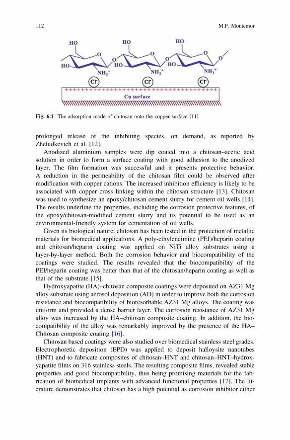
prolonged release of the inhibiting species, on demand, as reported byZheludkevich et al. [12].
Anodized aluminium samples were dip coated into a chitosan–acetic acidsolution in order to form a surface coating with good adhesion to the anodizedlayer. The film formation was successful and it presents protective behavior.A reduction in the permeability of the chitosan film could be observed aftermodification with copper cations. The increased inhibition efficiency is likely to beassociated with copper cross linking within the chitosan structure [13]. Chitosanwas used to synthesize an epoxy/chitosan cement slurry for cement oil wells [14].The results underline the properties, including the corrosion protective features, ofthe epoxy/chitosan-modified cement slurry and its potential to be used as anenvironmental-friendly system for cementation of oil wells.
Given its biological nature, chitosan has been tested in the protection of metallicmaterials for biomedical applications. A poly-ethyleneimine (PEI)/heparin coatingand chitosan/heparin coating was applied on NiTi alloy substrates using alayer-by-layer method. Both the corrosion behavior and biocompatibility of thecoatings were studied. The results revealed that the biocompatibility of thePEI/heparin coating was better than that of the chitosan/heparin coating as well asthat of the substrate [15].
Hydroxyapatite (HA)–chitosan composite coatings were deposited on AZ31 Mgalloy substrate using aerosol deposition (AD) in order to improve both the corrosionresistance and biocompatibility of bioresorbable AZ31 Mg alloys. The coating wasuniform and provided a dense barrier layer. The corrosion resistance of AZ31 Mgalloy was increased by the HA–chitosan composite coating. In addition, the bio-compatibility of the alloy was remarkably improved by the presence of the HA–Chitosan composite coating [16].
Chitosan based coatings were also studied over biomedical stainless steel grades.Electrophoretic deposition (EPD) was applied to deposit halloysite nanotubes(HNT) and to fabricate composites of chitosan–HNT and chitosan–HNT–hydrox-yapatite films on 316 stainless steels. The resulting composite films, revealed stableproperties and good biocompatibility, thus being promising materials for the fab-rication of biomedical implants with advanced functional properties [17]. The lit-erature demonstrates that chitosan has a high potential as corrosion inhibitor either
Fig. 6.1 The adsorption mode of chitosan onto the copper surface [11]
112 M.F. Montemor
in acidic media or neutral media in various metallic substrates and in variousapplications. It can be used by direct addition to the electrolyte or to fabricatefunctional or composite coatings. Furthermore it can be used to confine otherinhibitors or functional agents through a layer by layer approach in which theprotective species are stored between chitosan layers. It can also be used as surfacemodifier of natural clays for improved corrosion protection.
Undoubtedly the potential of chitosan as a corrosion inhibitor is very high and itsabundance, low prices and availability, combined with its biological nature willattract attention in the near future.
6.2.2 Aminoacids
Aminoacids are a class of molecules that can be classified either as biological ornatural. In this review it was decided to include them as biological molecules due toits role in the biological processes. Aminoacids are abundant, not expensive andeasy to produce with a purity near 100 %. They contain heteroatoms and π-typeelectrons that make these molecules potential corrosion inhibitors. Moreover, thepresence of amino groups that can be protonated, make the molecule able to interactwith metallic surfaces. In fact, the inhibition efficiency of different aminoacids wascompared and simulated by using computational tools. Quantum chemical studiesrevealed that amino acids can interact with nickel surface in the protonated ratherthan in the neutral state—Fig. 6.2 [18].
Aminoacids were tested as corrosion inhibitors for Cu and Ni alloys in neutralelectrolytes. These alloys are of extremely high industrial relevance since they areused in power stations, boilers and heat exchangers. The problem is that they aresensitive to corrosion mainly because of the circulating water. Aminoacids, espe-cially glycine, are able to inhibit the corrosion processes of these alloys. Themechanism of inhibition involves the adsorption of the amino acid on the activecorrosion sites and/or the deposition of corrosion products with the formation of a3-D layer on the alloy surface as reported by Badawy et al. [19].
Copper is also susceptible to corrosion in the presence of sulphates. Therefore,N-(5,6-diphenyl-4,5-dihydro-[1, 2, 4] triazin-3-yl)-guanidine (NTG) was evaluatedas a corrosion inhibitor for copper in the presence of sulphates. The aminoacidderived compound provides corrosion protection of copper surfaces, acting by acathodic inhibition mechanism. The process was concentration dependent becausethe thickness of the inhibiting layer increases as the concentration increases [20].Effective corrosion inhibition was also observed for copper surfaces exposed to 3 %NaCl. However, in such environment, the process was associated with a mixedinhibitor mechanism [21]. The corrosion inhibition ability of various aminoacidswas assessed in different metallic substrates used in various technological appli-cations. Aminoacids were studied as corrosion inhibitors of vanadium substrates. Inthe presence of chlorides, the corrosion processes prevent the adsorption of the
6 Fostering Green Inhibitors for Corrosion Prevention 113
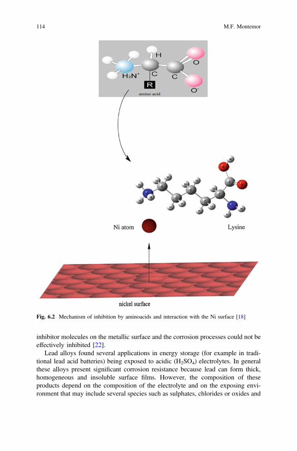
inhibitor molecules on the metallic surface and the corrosion processes could not beeffectively inhibited [22].
Lead alloys found several applications in energy storage (for example in tradi-tional lead acid batteries) being exposed to acidic (H2SO4) electrolytes. In generalthese alloys present significant corrosion resistance because lead can form thick,homogeneous and insoluble surface films. However, the composition of theseproducts depend on the composition of the electrolyte and on the exposing envi-ronment that may include several species such as sulphates, chlorides or oxides and
Fig. 6.2 Mechanism of inhibition by aminoacids and interaction with the Ni surface [18]
114 M.F. Montemor
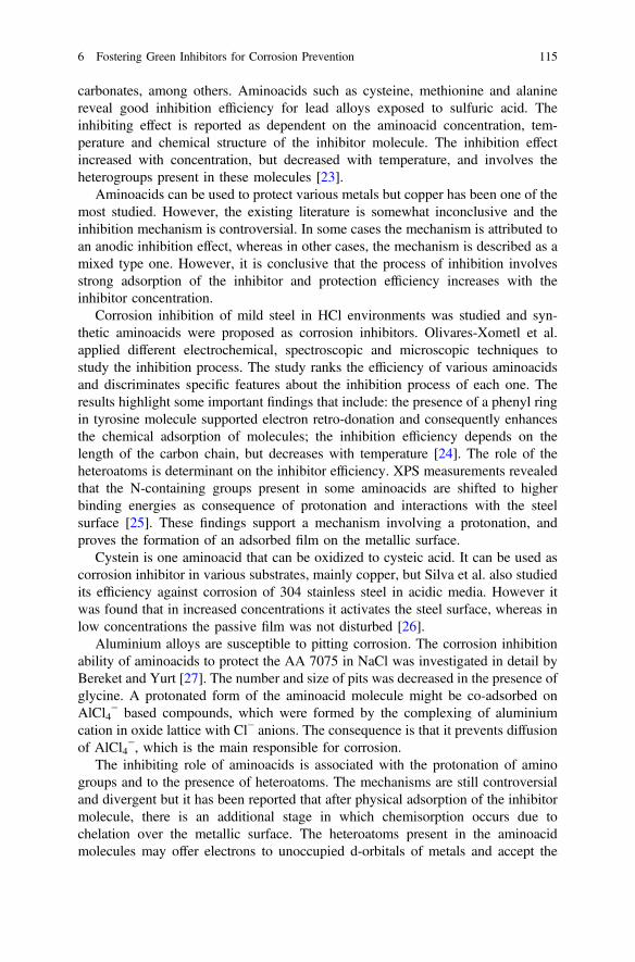
carbonates, among others. Aminoacids such as cysteine, methionine and alaninereveal good inhibition efficiency for lead alloys exposed to sulfuric acid. Theinhibiting effect is reported as dependent on the aminoacid concentration, tem-perature and chemical structure of the inhibitor molecule. The inhibition effectincreased with concentration, but decreased with temperature, and involves theheterogroups present in these molecules [23].
Aminoacids can be used to protect various metals but copper has been one of themost studied. However, the existing literature is somewhat inconclusive and theinhibition mechanism is controversial. In some cases the mechanism is attributed toan anodic inhibition effect, whereas in other cases, the mechanism is described as amixed type one. However, it is conclusive that the process of inhibition involvesstrong adsorption of the inhibitor and protection efficiency increases with theinhibitor concentration.
Corrosion inhibition of mild steel in HCl environments was studied and syn-thetic aminoacids were proposed as corrosion inhibitors. Olivares-Xometl et al.applied different electrochemical, spectroscopic and microscopic techniques tostudy the inhibition process. The study ranks the efficiency of various aminoacidsand discriminates specific features about the inhibition process of each one. Theresults highlight some important findings that include: the presence of a phenyl ringin tyrosine molecule supported electron retro-donation and consequently enhancesthe chemical adsorption of molecules; the inhibition efficiency depends on thelength of the carbon chain, but decreases with temperature [24]. The role of theheteroatoms is determinant on the inhibitor efficiency. XPS measurements revealedthat the N-containing groups present in some aminoacids are shifted to higherbinding energies as consequence of protonation and interactions with the steelsurface [25]. These findings support a mechanism involving a protonation, andproves the formation of an adsorbed film on the metallic surface.
Cystein is one aminoacid that can be oxidized to cysteic acid. It can be used ascorrosion inhibitor in various substrates, mainly copper, but Silva et al. also studiedits efficiency against corrosion of 304 stainless steel in acidic media. However itwas found that in increased concentrations it activates the steel surface, whereas inlow concentrations the passive film was not disturbed [26].
Aluminium alloys are susceptible to pitting corrosion. The corrosion inhibitionability of aminoacids to protect the AA 7075 in NaCl was investigated in detail byBereket and Yurt [27]. The number and size of pits was decreased in the presence ofglycine. A protonated form of the aminoacid molecule might be co-adsorbed onAlCl4
− based compounds, which were formed by the complexing of aluminiumcation in oxide lattice with Cl− anions. The consequence is that it prevents diffusionof AlCl4
−, which is the main responsible for corrosion.The inhibiting role of aminoacids is associated with the protonation of amino
groups and to the presence of heteroatoms. The mechanisms are still controversialand divergent but it has been reported that after physical adsorption of the inhibitormolecule, there is an additional stage in which chemisorption occurs due tochelation over the metallic surface. The heteroatoms present in the aminoacidmolecules may offer electrons to unoccupied d-orbitals of metals and accept the
6 Fostering Green Inhibitors for Corrosion Prevention 115
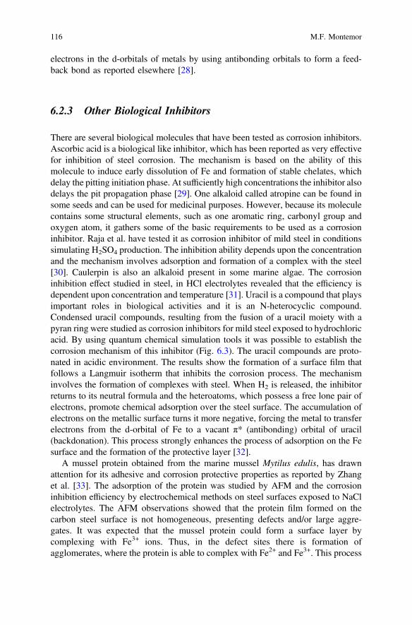
electrons in the d-orbitals of metals by using antibonding orbitals to form a feed-back bond as reported elsewhere [28].
6.2.3 Other Biological Inhibitors
There are several biological molecules that have been tested as corrosion inhibitors.Ascorbic acid is a biological like inhibitor, which has been reported as very effectivefor inhibition of steel corrosion. The mechanism is based on the ability of thismolecule to induce early dissolution of Fe and formation of stable chelates, whichdelay the pitting initiation phase. At sufficiently high concentrations the inhibitor alsodelays the pit propagation phase [29]. One alkaloid called atropine can be found insome seeds and can be used for medicinal purposes. However, because its moleculecontains some structural elements, such as one aromatic ring, carbonyl group andoxygen atom, it gathers some of the basic requirements to be used as a corrosioninhibitor. Raja et al. have tested it as corrosion inhibitor of mild steel in conditionssimulating H2SO4 production. The inhibition ability depends upon the concentrationand the mechanism involves adsorption and formation of a complex with the steel[30]. Caulerpin is also an alkaloid present in some marine algae. The corrosioninhibition effect studied in steel, in HCl electrolytes revealed that the efficiency isdependent upon concentration and temperature [31]. Uracil is a compound that playsimportant roles in biological activities and it is an N-heterocyclic compound.Condensed uracil compounds, resulting from the fusion of a uracil moiety with apyran ring were studied as corrosion inhibitors for mild steel exposed to hydrochloricacid. By using quantum chemical simulation tools it was possible to establish thecorrosion mechanism of this inhibitor (Fig. 6.3). The uracil compounds are proto-nated in acidic environment. The results show the formation of a surface film thatfollows a Langmuir isotherm that inhibits the corrosion process. The mechanisminvolves the formation of complexes with steel. When H2 is released, the inhibitorreturns to its neutral formula and the heteroatoms, which possess a free lone pair ofelectrons, promote chemical adsorption over the steel surface. The accumulation ofelectrons on the metallic surface turns it more negative, forcing the metal to transferelectrons from the d-orbital of Fe to a vacant π* (antibonding) orbital of uracil(backdonation). This process strongly enhances the process of adsorption on the Fesurface and the formation of the protective layer [32].
A mussel protein obtained from the marine mussel Mytilus edulis, has drawnattention for its adhesive and corrosion protective properties as reported by Zhanget al. [33]. The adsorption of the protein was studied by AFM and the corrosioninhibition efficiency by electrochemical methods on steel surfaces exposed to NaClelectrolytes. The AFM observations showed that the protein film formed on thecarbon steel surface is not homogeneous, presenting defects and/or large aggre-gates. It was expected that the mussel protein could form a surface layer bycomplexing with Fe3+ ions. Thus, in the defect sites there is formation ofagglomerates, where the protein is able to complex with Fe2+ and Fe3+. This process
116 M.F. Montemor
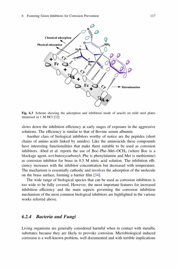
slows down the inhibition efficiency at early stages of exposure in the aggressivesolutions. The efficiency is similar to that of Bovine serum albumin.
Another class of biological inhibitors worthy of notice are the peptides (shortchains of amino acids linked by amides). Like the aminoacids these compoundshave interesting functionalities that make them suitable to be used as corrosioninhibitors. Abed et al. reports the use of Boc–Phe–Met–OCH3 (where Boc is ablockage agent, tert-butoxycarbonyl; Phe is phenylalanine and Met is methionine)as corrosion inhibitor for brass in 0.5 M nitric acid solution. The inhibition effi-ciency increases with the inhibitor concentration but decreased with temperature.The mechanism is essentially cathodic and involves the adsorption of the moleculeon the brass surface, forming a barrier film [34].
The wide range of biological species that can be used as corrosion inhibitors istoo wide to be fully covered. However, the most important features for increasedinhibition efficiency and the main aspects governing the corrosion inhibitionmechanism of the most common biological inhibitors are highlighted in the variousworks referred above.
6.2.4 Bacteria and Fungi
Living organisms are generally considered harmful when in contact with metallicsubstrates because they are likely to provoke corrosion. Microbiological inducedcorrosion is a well-known problem, well documented and with terrible implications
Fig. 6.3 Scheme showing the adsorption and inhibition mode of uracils on mild steel platesimmersed in 1 M HCl [32]
6 Fostering Green Inhibitors for Corrosion Prevention 117

in structural materials. However, there have been a few cases in which livingorganisms can provide corrosion protection. For example, a biological patina wasreported to preserve copper artefacts. The capacity of a fungal strain, Beauveriabassiana, to precipitate copper oxalates was exploited for the stabilization of sol-uble patinas (copper hydroxysulfates) or the conversion of active corrosion prod-ucts (copper hydroxychlorides) into protective compounds. In fact, copper oxalatesform green compact patinas, showing a high degree of insolubility and chemicalstability even in acid atmospheres close to pH 3 [35].
Stainless steel is very susceptible to corrosion in the presence of living organ-isms in inorganic media. Indeed, this is a severe phenomenon in marine environ-ments and bio corrosion control is of the utmost relevance in ensuring the reliabilityof steel structures exposed to seawater. However, there are interesting findings inwhich some bacteria are reported to inhibit the corrosion process of stainless steel.Two bacterial species (Pseudomonas sp. and B. megaterium) were found to inhibitstainless steel 304 (SS 304) pitting corrosion in inorganic medium, containingnitrates and phosphates. The bacteria increase the production of extracellularpolysaccharides and, hence, these promote the passivity of SS 304. The inhibitionprocess could be related to the increased production of bacterial metabolites andformation of a passive film, composed of a dense and thick Fe2O3 and Cr2O3 layers.However, in organic media, the effect is the opposite and the same bacteria stim-ulate the pitting process [36].
The composition of the environment, the metal nature and the composition ofinterfacial electrolytes (e.g. pH, ions and their concentration, the oxygen amount)define the chemical composition and the properties of the protective films formedunder biological activity. Therefore, it is very likely that in some specific conditionsas the ones reported above, the microbial activity may induce protection of themetallic surfaces. The process generally involves either stabilization of protectivesurface layers or anodic inhibition.
6.3 Vegetable Inhibitors
Plant extracts, seeds and natural shell extracts are gaining importance nowadays ascorrosion inhibitors. The reason is that these are classified as “green”, biodegrad-able and in most of the cases very abundant and renewable. In general, vegetableextracts contain several constituents that may present functional groups that allowthe formation of protective species or adsorbed layers on the metallic surface.
6.3.1 Extracts of Plants
Henna extracts (Lawsonia inermis) have been used, for centuries, in many appli-cations, with different functions. The main constituents of Henna are lawsone, gallic
118 M.F. Montemor

acid, glucose and tannic acid. These extracts were investigated as corrosion inhi-bitors for mild steel coupons exposed to 1 M HCl. The inhibition efficiency dependsupon the concentration of the henna extract. Electrochemical impedance mea-surements showed that the polarization resistance increased by about one order ofmagnitude when the concentration of the extract increased from zero up to 1.2 g/L.In addition in the presence of henna extract, the pitting potential is shifted towardsmore positive values. The inhibitor adsorbs on the iron surface and a chemisorptionmechanism is likely to occur. However, the inhibition mechanism is dependent onthe henna constituents. For example the inhibition by lawsone was attributed to theformation of sparingly insoluble complex compounds with the Fe2+ cations.Moreover, this compound, which is the most effective amongst the henna con-stituents, also shows good oxygen scavenging properties [37].
Another work reports that the extract of Lawsonia leafs can work as an effectiveinhibitor against corrosion of carbon steel, nickel and zinc in acidic, neutral andalkaline media. This inhibitor acts by a mixed mechanism, because it adsorbs onboth the anodic and cathodic sites. When used with zinc substrates, it shifts thecorrosion potential towards the anodic direction and decreases the corrosion currentdensity in various media. However, the inhibition of zinc dissolution decreases inthe order: neutral > alkaline > acid. The dependence of the corrosion inhibitionefficiency on the electrolyte pH is quite different from that observed for the cor-rosion inhibition of carbon steel and nickel. For these two metals, the inhibitorforms stable and insoluble complexes on the surface that hinder the dissolution ofthe metal [38].
Acalypha torta is an extract that is used for medicinal purposes. However, it wasalso tested as corrosion inhibitor for mild steel in acidic media. The EIS resultsrevealed improved protection with increased concentration of inhibitor—Fig. 6.4.
The extract behaves as a mixed inhibitor and its efficiency decreases withtemperature. The inhibition mechanism proposes that some constituents of themolecule can be protonated, being able to form a protective surface film on thesteel. The inhibition process follows the conventional mechanism, which involves
Fig. 6.4 Electrochemicalimpedance spectroscopyNyquist plots (solid lineshows fitted results) obtainedon mild steel in 1 M HCl inthe absence and presence ofdifferent concentrations ofinhibitor [39]
6 Fostering Green Inhibitors for Corrosion Prevention 119
the π-electrons of aromatic rings and lone pairs of electrons of heteroatoms [39].Date palm (Phoenix dactylifera L.) is one of the most abundant palms. Extracts oftheir leaves can be used as corrosion inhibitors. Gerengi [40, 41] investigated itseffectiveness in protecting aluminum alloys (AA) 7075 exposed to NaCl solutions.As it is well known this alloy is highly susceptible to pitting attack in the presenceof chloride ions. The alloy contains zinc, as a primary alloying element along withcopper and magnesium that create numerous types of intermetallics and precipitateson the surface, serving either as anodic or cathodic sites relatively to the metallicmatrix. The extract of palm was found to act as a mixed corrosion inhibitor, withpredominance of the cathodic effect. It was also demonstrated that the polarizationresistance increased with the concentration of inhibitor. The extract forms aphysically adsorbed surface layer, a process that seems to be closely associated withglucose compounds, which are present in the extract [40, 41].
The corrosion of aluminum plates in electrolytes of different pH and in thepresence of different halides as aggressive anions was studied in the presence of S.trifasciata extract, which is obtained from the leafs of a plant. The results show thatthis extract inhibits aluminum corrosion by an adsorption process that follows aFreundlich isotherm. Moreover, it was found that the inhibition efficiency increasedwith the extract concentration and decreased with temperature, suggesting that aphysical adsorption process is likely to explain the corrosion inhibition process. Thepresence of halide salts affects the inhibition efficiency of the extract [42]. Extractsof olive leaf displayed good inhibition ability for carbon steel exposed to acidic(HCl) electrolytes. The inhibition process was studied by El-Etre [43]. The resultsreport that phenolic compounds, mainly oleuropein and hydroxytyrosol present inthe olive leaf extract can physically adsorb on the steel surface, leading to aneffective protection effect. The extract behaves essentially as a mixed inhibitor andit was found that it decreased the current density in the transpassive region. Anotherinhibitor tested on steel exposed to acid electrolytes (H3PO4) was artemisia oil. Itcontains various constituents, namely beta-thujone and works as cathodic inhibitoraffecting the hydrogen reduction reaction [44].
Aloe vera is well known because of its medicinal properties. However, theliterature reports that it can be an effective inhibitor for mild steel and aluminium inacidic environments [45]. Aloe vera contains heterocyclic compounds of highmolecular weight and its molecular structure also contains oxygen and nitrogenatoms. Its inhibition efficiency was also tested on zinc exposed to HCl electrolytes.The maximum efficiency reported was 67 %, decreasing with an increase in tem-perature and the mechanism follows a Langmuir isotherm [46].
6.3.2 Shells and Seeds
The linseed oil molecule (see Fig. 6.5) is one of the most popular seed extracts forcorrosion inhibition. This compound is compatible with various surface treatmentsand coatings and can also be encapsulated to prepare self-healing coatings. Thin
120 M.F. Montemor

silane pre-treatments modified with linseed oil display better tribological propertiesand increased corrosion protection as reported by Bexell et al. [47].
Linseed oil is an effective inhibitor for steel. This effect was tested by encap-sulating linseed oil in urea-formaldehyde capsules (also see Chap. 8). The incor-poration of inhibitor was made during the synthesis of the capsules. The linseed oilis expected to be released from the filled microcapsules through the mechanicalaction of cracks that propagate in the coating in which the capsules are embedded.The released inhibitor can form a surface a film, resulting from oxidative poly-merization of the molecules, that is able to prevent the ingress of dissolvedaggressive agents [48]. The anti-corrosion behavior of encapsulated linseed oil inmicrocapsules for steel applications was also reported by Pilbáth et al. [49].
The corrosion inhibition of AA6061 in seawater in the presence of tapioca starchwas studied by Rosliza and Wan Nik [50]. This molecule presents several hydroxylgroups as can be seen in the spectra depicted in Fig. 6.6. This spectrum reveals thatthe compound contains two main constituents, both polymers of glucose. One ofthese is amylpectin, which contains phosphate groups that establish stable bondswith the aluminum surface. The efficiency of the starch was reported to increasewith the concentration of extract and the corrosion inhibition process involves theformation of stable precipitates on the metallic surface. The electrochemical mea-surements revealed that the extract works mainly as mixed inhibitor, however withpredominance of cathodic inhibition.
Fig. 6.5 Molecular structure of the linseed oil [47]
Fig. 6.6 FTIR spectra for the tapioca starch [50]
6 Fostering Green Inhibitors for Corrosion Prevention 121
Caffeic acid (3-(3,4-dihydroxyphenyl)-2-propenoic acid, is a molecule extractedfrom the coffee grains and possessed properties and functional characteristics thatsuggest that it can work as corrosion inhibitor. Moreover, these compounds aresoluble in water, in a wide pH range, being easy to use in different aggressiveelectrolytes. The compound was tested on iron coupons exposed in acidic media.The inhibitor works by adsorption on the steel surface, leading to a reduction of theanodic and cathodic current densities. Thus, by one side the inhibitor blocksthe cathodic active sites and, on the other hand, it modifies the activation energy ofthe anodic reaction [51]. Caffeine was also tested as corrosion inhibitor for copperplates exposed to nitrate containing electrolytes. Voltammetric scans show that theanodic current decreased because of the formation of an adsorbed surface layer. Theeffect was observed even in the presence of KCl in the testing electrolyte [52].Inhibitive effects were also observed on zinc surfaces exposed to caffeine [53].Coconut derivatives were tested as corrosion inhibitors. An interesting performancewas observed for mild steel in acidic media [54]. The Coconut nucifera L. isanother extract that can be used as corrosion inhibitor. It shows good performanceon aluminum coupons exposed to HCl electrolytes. The maximum inhibition effi-ciency was 93 % at 7.5 % (v/v) concentration. The inhibition mechanism follows anadsorption process that obeys a Langmuir adsorption isotherm [55]. There arenumerous extracts of seeds with potential to be used as corrosion inhibitors. Ingeneral the mechanism depends upon the functional groups present in the activemolecules. There are many instances in which the effectiveness of the extracts arereported, but little is known about either the active components or chemical com-position and therefore, the mechanisms of corrosion inhibition are not fullyexplained and understood. These inhibitors are abundant and can be a renewablesource of molecules with corrosion inhibition effectiveness.
6.3.3 Tannins
Tannins and polyphenolic compounds are very abundant and easy to extract fromdifferent sources. These molecules are well characterized and possess oxygengroups that can easily form chelates with metallic surfaces such as iron. Thehydroxyl groups can form tannates with metallic ions, giving a dark product thatstabilizes the surface oxides.
Tannins can be classified in two different families: (i) hydrolyzable tannins and(ii) condensed tannins. The corrosion efficiency of tannic acid depends on the metalor alloy to be protected and also on the characteristics of the environment.
Tannins can be used in a wide range of environments since the molecules arestable under different pHs. Mimosa tannin inhibits the corrosion of steel in alkalinemedia simulating reinforcing steel, in the presence of chlorides. The mechanism isexplained by the formation of chelates with Fe(III) species that stabilize the oxidefilms [56]. The same inhibitor was also tested in acidic media (pH 1–2) and behavesas a mixed corrosion inhibitor, leading to the formation of adsorbed species on the
122 M.F. Montemor
steel surface. The mechanism of inhibition includes the formation of physicallyadsorbed ferric-tannate multilayers when the pH increased, as reported by Martinezand Stem [57]. The same authors reported that the inhibition efficiency decreasedfrom pH 3–1.
Tannic acid was tested against mild steel corrosion in seawater under wet/drycyclic conditions. The inhibition process was studied by weight loss measurements,DC polarization and electrochemical impedance spectroscopy. The inhibition effectof the compound was attributed to the formation of a protective ferric tannate film,which is relatively stable during the wet/dry cycles [58].
Mangrove tannins were studied as corrosion inhibitors for carbon steel exposed toHCl solutions. All the compounds tested are reported to act as cathodic inhibitors andtheir inhibitive efficiency was dependent on the concentration. Moreover, the effi-ciency is also pH dependent, being more effective in more acidic electrolytes [59].
The fundamentals of the inhibitive mechanism of chestnut tannin were studiedby means of the frontier orbital and the inhibitor adsorption theories. Resultsobtained on cold rolled steel exposed to acidic electrolytes, evidenced that thevarious tannin constituents are most likely to adsorb as neutral molecules by meansof electrostatic forces that are established between the dipoles of the molecule andthe iron charged surface. The study highlights the fact that the chemisorptionmechanism, via sharing of the oxygen lone-pair electrons or the aromatic ring π-electrons, between the inhibitor molecule and the vacant d-orbitals of iron, is notlikely to occur. A plausible explanation resides on the unfavorable orientation of themolecules due to their complex geometric and structural properties. This resultreveals that other mechanisms may be important to describe the inhibitive action oftannins [60]. Although tannins are established as effective corrosion inhibitors invarious metallic substrates and, mainly, on steel, the action mechanism is not fullyunderstood.
6.4 Pharmaceutical Drugs
Although very controversial, pharmaceutical drugs are attracting attention as cor-rosion inhibitors. There is some divergence in what concerns the “green” label ofthese molecules as corrosion inhibitors. Nevertheless, some relevant findingsregarding their potential in corrosion inhibition are reviewed in this section.
Carbocyclic and heterocyclic compounds, with 5–6 rings are commonly found inmany drugs. Moreover, benzene rings containing different substitutes are alsocommonly present in the molecular structure. The corrosion potential of numerouscompounds were reviewed by Gece et al. in a recent review [61]. According to theliterature, the most promising drugs are the ones that include in their molecularstructure reactive centers like O, N and/or S atoms, containing lone pairs of elec-trons and aromatic rings with delocalized π-electrons and sufficiently high molec-ular weight. These molecular features are necessary to ensure that adsorption occurson the metallic surface and that the metallic surface is effectively covered by the
6 Fostering Green Inhibitors for Corrosion Prevention 123
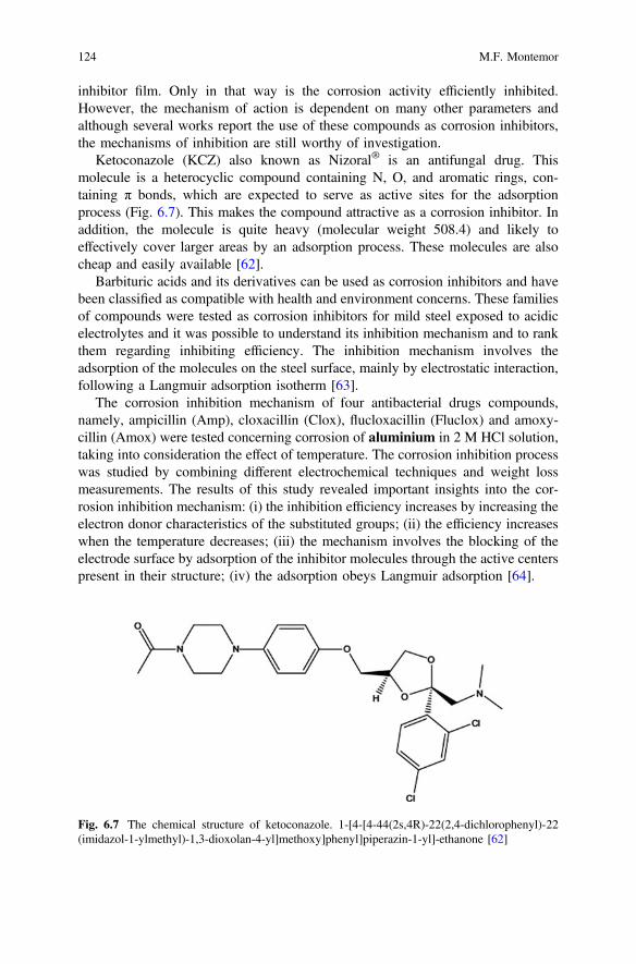
inhibitor film. Only in that way is the corrosion activity efficiently inhibited.However, the mechanism of action is dependent on many other parameters andalthough several works report the use of these compounds as corrosion inhibitors,the mechanisms of inhibition are still worthy of investigation.
Ketoconazole (KCZ) also known as Nizoral® is an antifungal drug. Thismolecule is a heterocyclic compound containing N, O, and aromatic rings, con-taining π bonds, which are expected to serve as active sites for the adsorptionprocess (Fig. 6.7). This makes the compound attractive as a corrosion inhibitor. Inaddition, the molecule is quite heavy (molecular weight 508.4) and likely toeffectively cover larger areas by an adsorption process. These molecules are alsocheap and easily available [62].
Barbituric acids and its derivatives can be used as corrosion inhibitors and havebeen classified as compatible with health and environment concerns. These familiesof compounds were tested as corrosion inhibitors for mild steel exposed to acidicelectrolytes and it was possible to understand its inhibition mechanism and to rankthem regarding inhibiting efficiency. The inhibition mechanism involves theadsorption of the molecules on the steel surface, mainly by electrostatic interaction,following a Langmuir adsorption isotherm [63].
The corrosion inhibition mechanism of four antibacterial drugs compounds,namely, ampicillin (Amp), cloxacillin (Clox), flucloxacillin (Fluclox) and amoxy-cillin (Amox) were tested concerning corrosion of aluminium in 2 M HCl solution,taking into consideration the effect of temperature. The corrosion inhibition processwas studied by combining different electrochemical techniques and weight lossmeasurements. The results of this study revealed important insights into the cor-rosion inhibition mechanism: (i) the inhibition efficiency increases by increasing theelectron donor characteristics of the substituted groups; (ii) the efficiency increaseswhen the temperature decreases; (iii) the mechanism involves the blocking of theelectrode surface by adsorption of the inhibitor molecules through the active centerspresent in their structure; (iv) the adsorption obeys Langmuir adsorption [64].
Fig. 6.7 The chemical structure of ketoconazole. 1-[4-[4-44(2s,4R)-22(2,4-dichlorophenyl)-22(imidazol-1-ylmethyl)-1,3-dioxolan-4-yl]methoxy]phenyl]piperazin-1-yl]-ethanone [62]
124 M.F. Montemor
The inhibiting action of some antihypertensive drugs (Enalapril maleate,Atenolol, Etilefrine hydrochloride) was studied in Al and three alloys of Al–Siexposed to hydrochloric acid. These compounds are expected to inhibit both uni-form and pitting corrosion. The inhibition process is believed to be controlled bythe formation of insoluble complexes on the aluminium surface. As the concen-tration of inhibitor increases, the efficiency also increases and the pitting potential isshifted towards more positive values. The inhibitor molecules can react with Al3+
ions; the process being dependent upon details of the molecular structure [65].Xanthone is an organic compound with the molecular formula C13H8O2 that can
be used as an insecticide and to mitigate some bacterial activity. The molecule hashigh molecular weight and contains a carbonyl group and aromatic rings withdelocalized bonds that can serve as initiator sites for the adsorption processes. Mildsteel was exposed to sulphuric acid media and the corrosion inhibition was studied.The results reveal that the inhibitor efficiency increases when the concentrationincreases, but decreases when the temperature rises, effects that are likely to beassociated with physical adsorption mechanisms [66].
Antibiotic molecules are also reported as potential corrosion inhibitors. Forexample, Cefatrexyl the commercial name of the sodium salt 7-[a-(4-pyridylthio)-acetamido]-cephalosporanic acid or simply, cephapirin sodium was tested as cor-rosion inhibitor for steel exposed to different acids. The inhibition efficiencydepends upon the acid nature and temperature. Adsorption of cefatrexyl on ironsurface follows a Langmuir isotherm in HCl solution, whereas in H2SO4, H3PO4
and HClO4 electrolytes, the adsorption process follows Temkin’s isotherm. Theefficiency was found to be significantly decreased for HCl, especially at increasedtemperatures. The best performance was found in H2SO4 and H3PO4. In H2SO4 theneutral cefatrexyl molecules adsorb preferentially at the anodic areas, through achemisorption process with the Fe surface. The process involves the unshared pairsof electrons existing on the N, S and O atoms and the vacant d-orbitals of Fe atoms.The process is more effective, if the inhibitor molecules follow an orientationparallel to the iron surface. A similar process was observed for H3PO4 [67]. Anidentical mechanism corrosion inhibition was reported for Streptomycin. Thiscompound protonates in acidic media and behaves essentially as mixed corrosioninhibitor. In the process, the protonated species adsorb at the cathodic sites andinhibit H2 evolution. Concomitantly, the adsorption on anodic sites occurs throughπ-electrons of the aromatic ring and the lone pairs of electrons present in thenitrogen atom, hindering the anodic dissolution of iron [68]. The effect of rhodaninedrugs was evaluated in stainless steel 304 exposed to HCl electrolytes. Thesemolecules are likely to provide corrosion protection, working by a mixed mecha-nism. The presence of methoxy groups in the inhibiting molecule seems to improvethe inhibitor efficiency. The inhibition mechanism follows a Langmuir adsorptionisotherm and the efficiency decreases with temperature [69].
It is clear that several drugs can be used as corrosion inhibitors and can be usedto protect various metallic substrates. As concluded for the previous inhibitors(biological and vegetable) the mechanism depends on specific features of the
6 Fostering Green Inhibitors for Corrosion Prevention 125
inhibiting molecule, nature of the metallic surface and environmental parameters(pH, aggressive agents, temperature) and concentration of inhibitor.
6.5 Rare-Earth Inhibitors
Amongst the rare-earth corrosion inhibitors, cerium and lanthanum salts have beenwidely studied. Others such as yttrium and praseodymium have also been studiedbut to a much less extent. Its inhibition efficiency has been reported for aluminium(including various aluminium alloys), steel, galvanized steel and stainless steels.The mechanisms have been widely discussed but are strongly dependent on themetallic surface chemistry, local pH variations and nature of the rare-earth salt ion.For example cerium ions seem quite effective over aluminium and zinc, but muchless on iron substrates. Rare-earths have been tested as direct additives in solution,to prepare conversion coatings or as additives in protective coatings.
6.5.1 Rare-Earth Cations
Water soluble rare-earth salts are one of the most effective sources of rare earthcations. Blin et al. reported the corrosion inhibition mechanism of rare earth cin-namate compounds, REM-4 hydroxy cinnamate (4-OHCin) (REM being lanthanumand mischmetal), on steel exposed to NaCl solutions. The electrochemical resultsrevealed that La(4-OHCin)3 affects both the rate of the anodic and cathodic reac-tions. However, there is a predominance of anodic inhibition, which reduces pittingactivity on steel. Electrochemical impedance results revealed that the corrosioninhibition processes were accompanied by the build-up of a protective film overtime. Furthermore, this film seems to have regions with different roles. Thus, theouter surface layers seem to offer less resistance to the diffusion of electrochemi-cally active species than the highly resistive inner layer at the film/metal interface[70].
Steel corrosion induced by CO2 and in NaCl in aerated electrolytes was studiedin the presence of Praseodymium 4-hydroxycinnamate (Pr(4OHCin)3). Innaturally-aerated systems the rare earth inhibitor leads to the formation of a con-tinuous and protective surface film, while in CO2-saturated systems, more hetero-geneous surface films are formed thus being less effective. The electrochemical datarevealed that the Pr(4OHCin)3 provides anodic and cathodic inhibition in thepresence of CO2 (in contrast to the predominantly anodic inhibition in aerated NaClmedia) [71].
Cerium and other rare-earths have been widely investigated as inhibitors foraluminum alloys, namely the AA2024. Yasakau et al. [72] report that the additionof lanthanum(III) or cerium(III) cations leads to formation of rare-earth hydroxidesover the active intermetallics, specifically the S-phase (Al2CuMg), hindering both
126 M.F. Montemor

the anodic and the cathodic reactions, occurring at these corrosion sensitive loca-tions. The hydroxide precipitation is a consequence of the pH increase that occursin the neighborhood of the active S-phase. The presence of these precipitates slowsdown the copper re-deposition process and therefore the overall corrosion rate. Theresults also account for a linear time dependence of the rare-earth hydroxidesgrowth, revealing that the corrosion processes require a balance between diffusionand electrochemical reactions. The work also demonstrates that cerium nitrateshows superior corrosion inhibition properties in comparison with lanthanum nitrate[72]. Cerium cinnamate is also reported as an effective inhibitor for AA2024,behaving as an anodic inhibitor at early stages. However, at later stages after pittingonset it works as a mixed inhibitor, delaying pitting propagation [73]. The corrosioninhibition of various AA 7xxx in the presence of cerium diphenyl phosphate wasinvestigated by Hill et al. [74] and the results demonstrate that the surface of thealloys are protected because it is covered by a fine surface film, composed ofdistributed discrete Ce containing particles, either on the matrix or over the cathodicCu containing intermetallics. Moreover, through TOF-SIMS analysis it wasdemonstrated that there was the formation of a complex involving Al cations andthe cerium organophosphate.
A comparison between the inhibition efficiency of LaCl3 and CeCl3 in purealuminium exposed to NaCl solutions was reported by Mishra andBalasubramaniam [1]. Both species lead to the formation of stable oxides andhydroxides precipitates over the cathodic regions. By increasing the LaCl3 con-centration up to 1000 ppm it was demonstrated that the Al surface was covered witha fine and relatively homogeneous surface film made of globular precipitates. Theinhibition efficiency was found to be slightly better for LaCl3 and the effects seemto be controlled by the more uniform distribution of precipitates.
Recently Yasakau et al. [72] reported that cerium molybdate nanowires inhibitthe corrosion process in AA2024. It was demonstrated that the S phase was morestable in NaCl, when nanowires were added as anti-corrosion additive. The cor-rosion mechanism is related with the release of cerium ions from the ceriumnanowires that precipitate preferentially over the anodic sites, especially at laterstages of the corrosion process. The molybdate cations also play a relevant role,suppressing dissolution of Al and Mg.
6.5.2 Rare-Earth Conversion Coatings
Rare earth metals have been preferred to deposit corrosion protective conversioncoatings, aiming to replace chromate based surface pre-treatments. These conver-sion coatings are being applied to various substrates. The corrosion protectivebehavior depends on several factors such as the nature of the anion in the rare-earthsalt. This effect was investigated by Montemor et al. [75] on Mg AZ31 alloys and itwas found that the anion has a great influence on the inhibition of corrosion activityof the bare material. Potentiodynamic polarization measurements revealed that the
6 Fostering Green Inhibitors for Corrosion Prevention 127
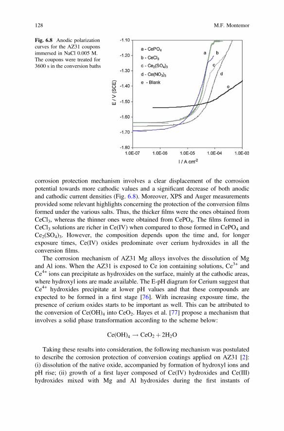
corrosion protection mechanism involves a clear displacement of the corrosionpotential towards more cathodic values and a significant decrease of both anodicand cathodic current densities (Fig. 6.8). Moreover, XPS and Auger measurementsprovided some relevant highlights concerning the protection of the conversion filmsformed under the various salts. Thus, the thicker films were the ones obtained fromCeCl3, whereas the thinner ones were obtained from CePO4. The films formed inCeCl3 solutions are richer in Ce(IV) when compared to those formed in CePO4 andCe2(SO4)3. However, the composition depends upon the time and, for longerexposure times, Ce(IV) oxides predominate over cerium hydroxides in all theconversion films.
The corrosion mechanism of AZ31 Mg alloys involves the dissolution of Mgand Al ions. When the AZ31 is exposed to Ce ion containing solutions, Ce3+ andCe4+ ions can precipitate as hydroxides on the surface, mainly at the cathodic areas,where hydroxyl ions are made available. The E-pH diagram for Cerium suggest thatCe4+ hydroxides precipitate at lower pH values and that these compounds areexpected to be formed in a first stage [76]. With increasing exposure time, thepresence of cerium oxides starts to be important as well. This can be attributed tothe conversion of Ce(OH)4 into CeO2. Hayes et al. [77] propose a mechanism thatinvolves a solid phase transformation according to the scheme below:
Ce(OH)4 ! CeO2 þ 2H2O
Taking these results into consideration, the following mechanism was postulatedto describe the corrosion protection of conversion coatings applied on AZ31 [2]:(i) dissolution of the native oxide, accompanied by formation of hydroxyl ions andpH rise; (ii) growth of a first layer composed of Ce(IV) hydroxides and Ce(III)hydroxides mixed with Mg and Al hydroxides during the first instants of
Fig. 6.8 Anodic polarizationcurves for the AZ31 couponsimmersed in NaCl 0.005 M.The coupons were treated for3600 s in the conversion baths
128 M.F. Montemor
immersion; (iii) thickening of the surface film and weaker pH changes with pref-erential deposition of Ce(OH)4 and its conversion into CeO2, forming an outerlayer, richer in Ce(IV) species. Identical mechanism can also be applied to lan-thanum conversion layers.
The mechanism of corrosion inhibition of rare-earth conversion coatings wasobserved in various metallic substrates. For example, conversion layers on galva-nized steel from cerium, yttrium and lanthanum nitrate solutions result in a surfacefilm that constrains the cathodic reduction of oxygen and the anodic dissolution ofzinc, leading to a decrease of the corrosion rate. The effectiveness is dependentupon the cation, with lanthanum nitrate being more effective than cerium nitrate[78]. Corrosion inhibition of galvanized steel corrosion by lanthanum conversionlayers was studied in the presence of citric acid. The mechanism involves inhibitionof the anodic and cathodic activity [79].
6.5.3 Rare-Earth Compounds Additives in Coatings
The inhibition ability of rare earth compounds make them attractive to be used asadditives in organic, hybrid and inorganic coatings. Montemor et al. reported theinhibition ability of Ce modified silane coatings and it was found that the presenceof cerium provides corrosion protection due to the formation of protective species atthe active corrosion sites and by increasing the crosslinking of hybrid silane films.The protective role of Ce modified coatings was confirmed to various substrates:galvanized steel, cold rolled steel and Mg alloys [80–83]. The effects of corrosioninhibition on AA 2024-T3 provided by cerium cations and cinnamate anions addedto epoxy coatings were investigated by Shi et al. [84]. The corrosion activity inartificial defects was investigated by the scanning vibrating electrode technique.The results revealed a cathodic inhibition mechanism, in which Ce(III) hydroxidesare converted into CeO2 precipitates over the cathodic sites. The mechanism ofinhibition was supported by XPS measurements that revealed the formation of Cecontaining compounds at the metal-coating interface.
Incorporation of cerium nitrate in smart reservoirs or on the surface of pHsensitive nanoparticles, such as hydroxyapatite, calcium carbonate microbeads andnanoclays is a very interesting strategy for developing self-healing coatings and hasbeen investigated by various authors. It was shown that cerium loaded carriers canprovide enhanced corrosion inhibition [85, 86]. Effective corrosion inhibitioneffects were also observed for silica and ceria particles loaded with Ce(III) ions.These cerium modified additives are compatible with sol-gel coatings and providecorrosion protection of galvanized steel substrates. In these systems the corrosionprotection mechanisms present some particularities. It was demonstrated that ceriaparticles, by themselves could shift the corrosion potential of zinc towards moreanodic values, with a simultaneous reduction of the anodic current density.However, the loading of the ceria nanoparticles with cerium ions induced relevantchanges in the corrosion protection mechanism that included a significant reduction
6 Fostering Green Inhibitors for Corrosion Prevention 129
of the cathodic current density [81]. The corrosion inhibition mechanism of ceriumloaded inorganic nanoparticles is linked with the formation of stable and protectivelayers of metallic oxides and hydroxides formed under the alkaline environmentthat characterizes the cathodic processes. Recently it was reported that this processis effective only if the inhibitor is able to penetrate in the alkaline region. This effectwas demonstrated by simulation results, which reveal a threshold for the corrosioninhibitor solubility below which no passivation of the cathode occurs [87].
The literature points out that rare-earth compounds fulfill various requirementsthat classify them as environmentally friendly since they have low toxicity and verygood efficiency. However, being rare-earths there are some concerns regarding theirprice and availability as corrosion inhibitors for massive application [88].Nevertheless, taking into account the corrosion inhibition effectiveness of rareearths in various metallic substrates and the possibility of using them in variousformulations, namely the possibility of encapsulation, makes these compounds veryattractive to solve several corrosion problems.
6.6 Mixtures and Synergies of New Inhibitors
Synergistic combination of corrosion inhibitors is a strategy that presents highpotential in the advancement of novel corrosion protection strategies. Through thisprocess it is possible to combine different inhibitors, allowing them to worktogether in a synergistic way. This ensures higher inhibition efficiency and, even-tually the use of smaller amounts of corrosion inhibitors, which might haveimportant implications, for example, in coatings design.
Mixtures of rare earth cations can provide synergistic effects for corrosioninhibition of AA2024 immersed in NaCl. A combinatorial matrix of rare earthchloride mixtures was studied recently and it allowed the definition of the bestcombinations of inhibitors. Figure 6.9 displays modelling results that show how thecorrosion current density is expected to change for various combinations of rareearth inhibitors. The results show that the highest inhibition efficiency is obtainedwith a ratio of Ce:(La, Pr) of around 3:1. It is demonstrated that as the amount of Cedecreased from levels of 1E-3 M, the corrosion inhibition effect is expected todecrease, regardless of the concentration of other inhibitors present in solution (La,Pr and Nd) and regardless of the fact that they are added alone or combined.Moreover, the individual rare-earth inhibitors, La, Pr and Nd display levels ofefficiency that are in general lower than that of Cerium ions. In the absence of Ce,the most promising mixture is based on approximately 50 % Pr and 50 % Nd [89].
The corrosion protective synergies between cerium(IV) ions and vanillin wasassessed on cold rolled steel (CRS) in 1.0 M HCl. The individual inhibitors pro-vided some corrosion protection, but when combined there was an importantimprovement of the process of corrosion inhibition. Vanillin, individually, behavesas mixed corrosion inhibitor, but with predominance of cathodic inhibition. On theother hand, Ce(IV) by itself shows little effects on the corrosion of steel, but the
130 M.F. Montemor
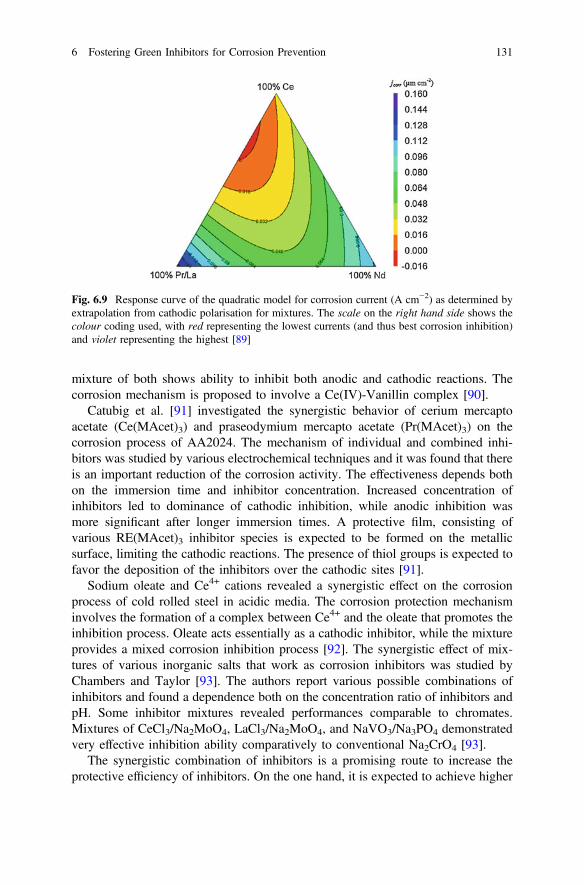
mixture of both shows ability to inhibit both anodic and cathodic reactions. Thecorrosion mechanism is proposed to involve a Ce(IV)-Vanillin complex [90].
Catubig et al. [91] investigated the synergistic behavior of cerium mercaptoacetate (Ce(MAcet)3) and praseodymium mercapto acetate (Pr(MAcet)3) on thecorrosion process of AA2024. The mechanism of individual and combined inhi-bitors was studied by various electrochemical techniques and it was found that thereis an important reduction of the corrosion activity. The effectiveness depends bothon the immersion time and inhibitor concentration. Increased concentration ofinhibitors led to dominance of cathodic inhibition, while anodic inhibition wasmore significant after longer immersion times. A protective film, consisting ofvarious RE(MAcet)3 inhibitor species is expected to be formed on the metallicsurface, limiting the cathodic reactions. The presence of thiol groups is expected tofavor the deposition of the inhibitors over the cathodic sites [91].
Sodium oleate and Ce4+ cations revealed a synergistic effect on the corrosionprocess of cold rolled steel in acidic media. The corrosion protection mechanisminvolves the formation of a complex between Ce4+ and the oleate that promotes theinhibition process. Oleate acts essentially as a cathodic inhibitor, while the mixtureprovides a mixed corrosion inhibition process [92]. The synergistic effect of mix-tures of various inorganic salts that work as corrosion inhibitors was studied byChambers and Taylor [93]. The authors report various possible combinations ofinhibitors and found a dependence both on the concentration ratio of inhibitors andpH. Some inhibitor mixtures revealed performances comparable to chromates.Mixtures of CeCl3/Na2MoO4, LaCl3/Na2MoO4, and NaVO3/Na3PO4 demonstratedvery effective inhibition ability comparatively to conventional Na2CrO4 [93].
The synergistic combination of inhibitors is a promising route to increase theprotective efficiency of inhibitors. On the one hand, it is expected to achieve higher
Fig. 6.9 Response curve of the quadratic model for corrosion current (A cm−2) as determined byextrapolation from cathodic polarisation for mixtures. The scale on the right hand side shows thecolour coding used, with red representing the lowest currents (and thus best corrosion inhibition)and violet representing the highest [89]
6 Fostering Green Inhibitors for Corrosion Prevention 131
efficiency with the combination, but on the other hand it is expected to reduce theusage of the inhibitors, as efficiency above the sum of the individuals is expected.However, it is essential to ensure that no detrimental interactions occur betweendistinct inhibitor compounds, with negative results. One way to achieve successfulresults consists on combining inhibitors that have different inhibition mechanismsor different kinetics of inhibition. In general dual combinations are reported, but thecombinative options can be wider and mixtures of three or even more inhibitors canbe applied to force synergistic corrosion inhibition efficiency.
6.7 Future Trends
The search for corrosion inhibitors that can be classified as “green” and that can beeasily found and extracted from renewable sources is undoubtedly one research areawhere several developments are continually evolving. This chapter overviewedsome of the most relevant insights concerning the latest developments in this field.If on the one hand several compounds have been established as promising corrosioninhibitors, on the other hand the corrosion inhibition mechanisms of several cor-rosion inhibitors from “green” generations are still unknown. Thus, this uncertaintyopens a wide array of possibilities to explore in the future.
Effective corrosion inhibitors can be found in biological species and vegetablemixtures or even in synthetic molecules that aim at mirroring natural compounds.Several organic compounds can be proposed as green and natural corrosion inhi-bitors. Although numerous studies have been reported in the literature, the corro-sion inhibition mechanisms are still unknown in many cases. Generally thecorrosion inhibition process proceeds by one (or more) mechanisms: (i) physicaland/or chemical adsorption at the metal/electrolyte interface; (ii) electrostaticinteractions that involve protonated groups that exist in the inhibitor molecule andmetallic cations; (iii) chemical interaction between the unshared electrons (likethose present on N, S and O atoms) and vacant d-orbitals present in the electronicstructure of metallic atoms; (iii) formation of stable inhibitor-metallic complexes.However, corrosion efficiency is strongly controlled by the formation of chemicallystable, homogeneous and well organized protective surfaces. The stability of pro-tective species is also controlled by the physical and chemical properties of theinhibiting compounds, the presence of functional groups such as hydroxyl, car-bonyl, amino and aromatic rings. Other relevant parameters include the density ofelectronic donors, composition of the aggressive electrolyte, local and bulk pH andoxygen contents, morphology, chemical composition and charge characteristics ofthe metal surface.
Rare-earth compounds play a major role in inhibiting the corrosion activity invarious substrates. Generally for these compounds a cathodic inhibition process thatinvolves the formation of stable hydroxides and oxides is reported. However, someother mechanisms that include anodic inhibition, mixed inhibition and formation ofcomplexes are necessary to explain the effective role of rare-earths.
132 M.F. Montemor
Undoubtedly, synergistic mixtures of corrosion inhibitors, presenting differentmechanisms of action and kinetics of release, will become important routes tomitigate corrosion activity in various technical domains. The exploration of thevarious possibilities open an avenue of new research lines with a high technical andeconomic impact.
Of utmost relevance, is the use of mixtures of compounds that both providesynergistic corrosion inhibition as well as the beneficial effects over other propertiesrequired for the metallic substrate such as wear, lubricating and hydrophilic orhydrophobic properties, among others. These multifunctional corrosion inhibitors,of green label and natural origin, especially if able to form functional layers on themetallic surface to be protected can lead to disruptive discoveries in the near future.
Acknowledgement FCT for financial support to CQE- UID/QUI/00100/2013.
References
1. A.K. Mishra, R. Balasubramaniam, Corrosion inhibition of aluminium by rare earth chlorides.Mater. Chem. Phys. 103(2–3), 385–393 (2007)
2. M.F. Montemor, A.M. Simoes, M.J. Carmezim, Characterization of rare-earth conversionfilms formed on the AZ31 magnesium alloy and its relation with corrosion protection. Appl.Surf. Sci. 253(16), 6922–6931 (2007)
3. S.V. Lamaka, M.L. Zheludkevich, K.A. Yasakau, M.F. Montemor, M.G.S. Ferreira, Higheffective organic corrosion inhibitors for 2024 aluminium alloy. Electrochim. Acta 52(25),7231–7247 (2007)
4. M.R. Arshadi, M. Lashgari, G.A. Parsafar, Cluster approach to corrosion inhibition problems:interaction studies. Mater. Chem. Phys. 86(2–3), 311–314 (2004)
5. A.E. Hughes, F.H. Scholes, A.M. Glenn, D. Lau, T.H. Muster, S.G. Hardin, Factorsinfluencing the deposition of Ce-based conversion coatings, Part I: The role of Al3+ ions. Surf.Coat. Technol. 203(19), 2927–2936 (2009)
6. S. Cheng, S. Chen, T. Liu, X. Chang, Y. Yin, Carboxymenthylchitosan as an ecofriendlyinhibitor for mild steel in 1 M HCl. Mater. Lett. 61(14–15), 3276–3280 (2007)
7. S. Cheng, S. Chen, T. Liu, X. Chang, Y. Yin, Carboxymethylchitosan + Cu2+ mixture as aninhibitor used for mild steel in 1 M HCl. Electrochim. Acta 52(19), 5932–5938 (2007)
8. A.M. Fekry, R.R. Mohamed, Acetyl thiourea chitosan as an eco-friendly inhibitor for mildsteel in sulphuric acid medium. Electrochim. Acta 55(6), 1933–1939 (2010)
9. X.-H. Yang, S.-Q. Liao, J.-H. Liao, Study on corrosion inhibition of chitosan quaternaryammonium for carbon steel in sulfuric acid. Corros. Sci. Prot. Technol. 19, 255–258 (2007)
10. A. Eddib, Y.A. Albrimi, A.A. Addi, J. Douch, R.M. Souto, M. Hamdani, Inhibitory action ofnon toxic compounds on the corrosion behaviour of 316 austenitic stainless steel inhydrochloric acid solution: comparison of chitosan and cyclodextrin. Int. J. Electrochem. Sci.7, 6599–6610 (2012)
11. M.N. El-Haddad, Chitosan as a green inhibitor for copper corrosion in acidic medium. Int.J. Biol. Macromol. 55, 142–149 (2013)
12. M.L. Zheludkevich, J. Tedim, C.S.R. Freire, S.C.M. Fernandes, S. Kallip, A. Lisenkov, A.Gandini, M.G.S. Ferreira, Self-healing protective coatings with “green” chitosan basedpre-layer reservoir of corrosion inhibitor. J. Mater. Chem. 21(13), 4805–4812 (2011)
6 Fostering Green Inhibitors for Corrosion Prevention 133
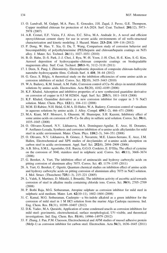
13. O. Lundvall, M. Gulppi, M.A. Paez, E. Gonzalez, J.H. Zagal, J. Pavez, G.E. Thompson,Copper modified chitosan for protection of AA-2024. Surf. Coat. Technol. 201(12), 5973–5978 (2007)
14. A.R. Cestari, E.F. Vieira, F.J. Alves, E.C. Silva, M.A. Andrade Jr., A novel and efficientepoxy/chitosan cement slurry for use in severe acidic environments of oil wells-structuralcharacterization and kinetic modeling. J. Hazard. Mater. 213–214, 109–116 (2012)
15. P. Dong, W. Hao, Y. Xia, G. Da, T. Wang, Comparison study of corrosion behavior andbiocompatibility of polyethyleneimine (PEI)/heparin and chitosan/heparin coatings on NiTialloy. J. Mater. Sci. Technol. 26(11), 1027–1031 (2010)
16. B.-D. Hahn, D.-S. Park, J.-J. Choi, J. Ryu, W.-H. Yoon, J.-H. Choi, H.-E. Kim, S.-G. Kim,Aerosol deposition of hydroxyapatite–chitosan composite coatings on biodegradablemagnesium alloy. Surf. Coat. Technol. 205(8–9), 3112–3118 (2011)
17. I. Deen, X. Pang, I. Zhitomirsky, Electrophoretic deposition of composite chitosan–halloysitenanotube–hydroxyapatite films. Colloids Surf. A 410, 38–44 (2012)
18. G. Gece, S. Bilgiç, A theoretical study on the inhibition efficiencies of some amino acids ascorrosion inhibitors of nickel. Corros. Sci. 52(10), 3435–3443 (2010)
19. W.A. Badawy, K.M. Ismail, A.M. Fathi, Corrosion control of Cu–Ni alloys in neutral chloridesolutions by amino acids. Electrochim. Acta 51(20), 4182–4189 (2006)
20. K.F. Khaled, Adsorption and inhibitive properties of a new synthesized guanidine derivativeon corrosion of copper in 0.5 M H2SO4. Appl. Surf. Sci. 255(5), 1811–1818 (2008)
21. K.F. Khaled, Guanidine derivative as a new corrosion inhibitor for copper in 3 % NaClsolution. Mater. Chem. Phys. 112(1), 104–111 (2008)
22. M.M. El-Rabiee, N.H. Helal, G.M.A. El-Hafez, W.A. Badawy, Corrosion control of vanadiumin aqueous solutions by amino acids. J. Alloy. Compd. 459(1–2), 466–471 (2008)
23. M.A. Kiani, M.F. Mousavi, S. Ghasemi, M. Shamsipur, S.H. Kazemi, Inhibitory effect ofsome amino acids on corrosion of Pb–Ca–Sn alloy in sulfuric acid solution. Corros. Sci. 50(4),1035–1045 (2008)
24. O. Olivares-Xometl, N.V. Likhanova, M.A. Domínguez-Aguilar, E. Arce, H. Dorantes,P. Arellanes-Lozada, Synthesis and corrosion inhibition of α-amino acids alkylamides for mildsteel in acidic environment. Mater. Chem. Phys. 110(2–3), 344–351 (2008)
25. O. Olivares, N.V. Likhanova, B. Gómez, J. Navarrete, M.E. Llanos-Serrano, E. Arce, J.M.Hallen, Electrochemical and XPS studies of decylamides of α-amino acids adsorption oncarbon steel in acidic environment. Appl. Surf. Sci. 252(8), 2894–2909 (2006)
26. A.B. Silva, S.M.L. Agostinho, O.E. Barcia, G.G.O. Cordeiro, E. D’Elia, The effect of cysteineon the corrosion of 304L stainless steel in sulphuric acid. Corros. Sci. 48(11), 3668–3674(2006)
27. G. Bereket, A. Yurt, The inhibition effect of aminoacids and hydroxy carboxylic acids onpitting corrosion of aluminum alloy 7075. Corros. Sci. 43, 1179–1195 (2011)
28. A. Yurt, G. Bereket, C. Ogretir, Quantum chemical studies on inhibition effect of amino acidsand hydroxy carboxylic acids on pitting corrosion of aluminium alloy 7075 in NaCl solution.J. Mol. Struct. (Thoechem) 725(1–3), 215–221 (2005)
29. L. Valek, S. Martinez, D. Mikulić, I. Brnardić, The inhibition activity of ascorbic acid towardscorrosion of steel in alkaline media containing chloride ions. Corros. Sci. 50(9), 2705–2709(2008)
30. P. Bothi Raja, M.G. Sethuraman, Atropine sulphate as corrosion inhibitor for mild steel insulphuric acid medium. Mater. Lett. 62(10–11), 1602–1604 (2008)
31. C. Kamal, M.G. Sethuraman, Caulerpin—a bis-indole alkaloid as a green inhibitor for thecorrosion of mild steel in 1 M HCl solution from the marine Alga Caulerpa racemosa. Ind.Eng. Chem. Res. 51(31), 10399–10407 (2012)
32. D.K. Yadav, M.A. Quraishi, Application of some condensed uracils as corrosion inhibitors formild steel: gravimetric, electrochemical, surface morphological, UV–visible, and theoreticalinvestigations. Ind. Eng. Chem. Res. 51(46), 14966–14979 (2012)
33. F. Zhang, J. Pan, P.M. Claesson, Electrochemical and AFM studies of mussel adhesive protein(Mefp-1) as corrosion inhibitor for carbon steel. Electrochim. Acta 56(3), 1636–1645 (2011)
134 M.F. Montemor
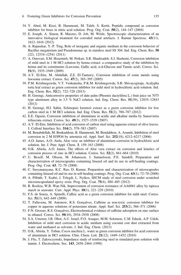
34. Y. Abed, M. Kissi, B. Hammouti, M. Taleb, S. Kertit, Peptidic compound as corrosioninhibitor for brass in nitric acid solution. Prog. Org. Coat. 50(2), 144–147 (2004)
35. E. Joseph, A. Simon, R. Mazzeo, D. Job, M. Wörle, Spectroscopic characterization of aninnovative biological treatment for corroded metal artefacts. J. Raman Spectrosc. 43(11),1612–1616 (2012)
36. A. Rajasekar, Y.-P. Ting, Role of inorganic and organic medium in the corrosion behavior ofBacillus megaterium and Pseudomonas sp. in stainless steel SS 304. Ind. Eng. Chem. Res. 50(22), 12534–12541 (2011)
37. A. Ostovari, S.M. Hoseinieh, M. Peikari, S.R. Shadizadeh, S.J. Hashemi, Corrosion inhibitionof mild steel in 1 M HCl solution by henna extract: a comparative study of the inhibition byhenna and its constituents (Lawsone, Gallic acid, α-d-Glucose and Tannic acid). Corros. Sci.51(9), 1935–1949 (2009)
38. A.Y. El-Etre, M. Abdallah, Z.E. El-Tantawy, Corrosion inhibition of some metals usinglawsonia extract. Corros. Sci. 47(2), 385–395 (2005)
39. P.M. Krishnegowda, V.T. Venkatesha, P.K.M. Krishnegowda, S.B. Shivayogiraju, Acalyphatorta leaf extract as green corrosion inhibitor for mild steel in hydrochloric acid solution. Ind.Eng. Chem. Res. 52(2), 722–728 (2013)
40. H. Gerengi, Anticorrosive properties of date palm (Phoenix dactylifera L.) fruit juice on 7075type aluminum alloy in 3.5 % NaCl solution. Ind. Eng. Chem. Res. 51(39), 12835–12843(2012)
41. H. Gerengi, H.I. Sahin, Schinopsis lorentzii extract as a green corrosion inhibitor for lowcarbon steel in 1 M HCl solution. Ind. Eng. Chem. Res. 51(2), 780–787 (2012)
42. E.E. Oguzie, Corrosion inhibition of aluminium in acidic and alkaline media by Sansevieriatrifasciata extract. Corros. Sci. 49(3), 1527–1539 (2007)
43. A.Y. El-Etre, Inhibition of acid corrosion of carbon steel using aqueous extract of olive leaves.J. Colloid Interface Sci. 314(2), 578–583 (2007)
44. M. Benabdellah, M. Benkaddour, B. Hammouti, M. Bendahhou, A. Aouniti, Inhibition of steelcorrosion in 2 M H3PO4 by artemisia oil. Appl. Surf. Sci. 252(18), 6212–6217 (2006)
45. A.O. James, A.O. Atela, Aloe vera: an inhibitor of aluminium corrosion in hydrochloric acidsolution. Int. J. Pure Appl. Chem. 3, 159–163 (2008)
46. O.K. Abiola, A.O. James, The effects of Aloe vera extract on corrosion and kinetics ofcorrosion process of zinc in HCl solution. Corros. Sci. 52(2), 661–664 (2010)
47. U. Bexell, M. Olsson, M. Johansson, J. Samuelsson, P.E. Sundell, Preparation andcharacterization of microcapsules containing linseed oil and its use in self-healing coatings.Prog. Org. Coat. 63, 72–78 (2008)
48. C. Suryanarayana, K.C. Rao, D. Kumar, Preparation and characterization of microcapsulescontaining linseed oil and its use in self-healing coatings. Prog. Org. Coat. 63(1), 72–78 (2008)
49. A. Pilbáth, T. Szabó, J. Telegdi, L. Nyikos, SECM study of steel corrosion under scratchedmicroencapsulated epoxy resin. Prog. Org. Coat. 75(4), 480–485 (2012)
50. R. Rosliza, W.B. Wan Nik, Improvement of corrosion resistance of AA6061 alloy by tapiocastarch in seawater. Curr. Appl. Phys. 10(1), 221–229 (2010)
51. F.S. de Souza, A. Spinelli, Caffeic acid as a green corrosion inhibitor for mild steel. Corros.Sci. 51(3), 642–649 (2009)
52. T. Fallavena, M. Antonow, R.S. Gonçalves, Caffeine as non-toxic corrosion inhibitor forcopper in aqueous solutions of potassium nitrate. Appl. Surf. Sci. 253(2), 566–571 (2006)
53. F.N. Grosser, R.S. Gonçalves, Electrochemical evidence of caffeine adsorption on zinc surfacein ethanol. Corros. Sci. 50(10), 2934–2938 (2008)
54. S.A. Umoren, I.B. Obot, A.U. Israel, P.O. Asuquo, M.M. Solomon, U.M. Eduok, A.P. Udoh,Inhibition of mild steel corrosion in acidic medium using coconut coir dust extracted fromwater and methanol as solvents. J. Ind. Eng. Chem. (2013)
55. O.K. Abiola, Y. Tobun, Cocos nucifera L. water as green corrosion inhibitor for acid corrosionof aluminium in HCl solution. Chin. Chem. Lett. 21(12), 1449–1452 (2010)
56. J. Flis, T. Zakroczymski, Impedance study of reinforcing steel in simulated pore solution withtannin. J. Electrochem. Soc. 143, 2458–2464 (1998)
6 Fostering Green Inhibitors for Corrosion Prevention 135
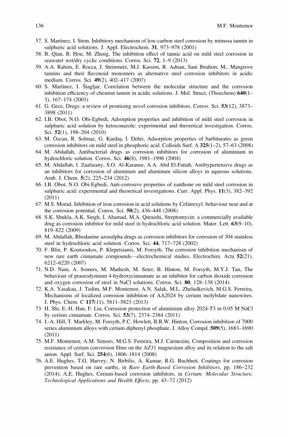
57. S. Martinez, I. Stem, Inhibitory mechanism of low-carbon steel corrosion by mimosa tannin insulphuric acid solutions. J. Appl. Electrochem. 31, 973–978 (2001)
58. B. Qian, B. Hou, M. Zheng, The inhibition effect of tannic acid on mild steel corrosion inseawater wet/dry cyclic conditions. Corros. Sci. 72, 1–9 (2013)
59. A.A. Rahim, E. Rocca, J. Steinmetz, M.J. Kassim, R. Adnan, Sani Ibrahim, M., Mangrovetannins and their flavonoid monomers as alternative steel corrosion inhibitors in acidicmedium. Corros. Sci. 49(2), 402–417 (2007)
60. S. Martinez, I. Štagljar, Correlation between the molecular structure and the corrosioninhibition efficiency of chestnut tannin in acidic solutions. J. Mol. Struct. (Thoechem) 640(1–3), 167–174 (2003)
61. G. Gece, Drugs: a review of promising novel corrosion inhibitors. Corros. Sci. 53(12), 3873–3898 (2011)
62. I.B. Obot, N.O. Obi-Egbedi, Adsorption properties and inhibition of mild steel corrosion insulphuric acid solution by ketoconazole: experimental and theoretical investigation. Corros.Sci. 52(1), 198–204 (2010)
63. M. Özcan, R. Solmaz, G. Kardaş, İ. Dehri, Adsorption properties of barbiturates as greencorrosion inhibitors on mild steel in phosphoric acid. Colloids Surf. A 325(1–2), 57–63 (2008)
64. M. Abdallah, Antibacterial drugs as corrosion inhibitors for corrosion of aluminium inhydrochloric solution. Corros. Sci. 46(8), 1981–1996 (2004)
65. M. Abdallah, I. Zaafarany, S.O. Al-Karanee, A.A. Abd El-Fattah, Antihypertensive drugs asan inhibitors for corrosion of aluminum and aluminum silicon alloys in aqueous solutions.Arab. J. Chem. 5(2), 225–234 (2012)
66. I.B. Obot, N.O. Obi-Egbedi, Anti-corrosive properties of xanthone on mild steel corrosion insulphuric acid: experimental and theoretical investigations. Curr. Appl. Phys. 11(3), 382–392(2011)
67. M.S. Morad, Inhibition of iron corrosion in acid solutions by Cefatrexyl: behaviour near and atthe corrosion potential. Corros. Sci. 50(2), 436–448 (2008)
68. S.K. Shukla, A.K. Singh, I. Ahamad, M.A. Quraishi, Streptomycin: a commercially availabledrug as corrosion inhibitor for mild steel in hydrochloric acid solution. Mater. Lett. 63(9–10),819–822 (2009)
69. M. Abdallah, Rhodanine azosulpha drugs as corrosion inhibitors for corrosion of 304 stainlesssteel in hydrochloric acid solution. Corros. Sci. 44, 717–728 (2002)
70. F. Blin, P. Koutsoukos, P. Klepetsianis, M. Forsyth, The corrosion inhibition mechanism ofnew rare earth cinnamate compounds—electrochemical studies. Electrochim. Acta 52(21),6212–6220 (2007)
71. N.D. Nam, A. Somers, M. Mathesh, M. Seter, B. Hinton, M. Forsyth, M.Y.J. Tan, Thebehaviour of praseodymium 4-hydroxycinnamate as an inhibitor for carbon dioxide corrosionand oxygen corrosion of steel in NaCl solutions. Corros. Sci. 80, 128–138 (2014)
72. K.A. Yasakau, J. Tedim, M.F. Montemor, A.N. Salak, M.L. Zheludkevich, M.G.S. Ferreira,Mechanisms of localized corrosion inhibition of AA2024 by cerium molybdate nanowires.J. Phys. Chem. C 117(11), 5811–5823 (2013)
73. H. Shi, E.-H. Han, F. Liu, Corrosion protection of aluminium alloy 2024-T3 in 0.05 M NaClby cerium cinnamate. Corros. Sci. 53(7), 2374–2384 (2011)
74. J.-A. Hill, T. Markley, M. Forsyth, P.C. Howlett, B.R.W. Hinton, Corrosion inhibition of 7000series aluminium alloys with cerium diphenyl phosphate. J. Alloy Compd. 509(5), 1683–1690(2011)
75. M.F. Montemor, A.M. Simoes, M.G.S. Ferreira, M.J. Carmezim, Composition and corrosionresistance of cerium conversion films on the AZ31 magnesium alloy and its relation to the saltanion. Appl. Surf. Sci. 254(6), 1806–1814 (2008)
76. A.E. Hughes, T.G. Harvey, N. Birbilis, A. Kumar, R.G. Buchheit, Coatings for corrosionprevention based on rare earths, in Rare Earth-Based Corrosion Inhibitors, pp. 186–232(2014); A.E. Hughes, Cerium-based corrosion inhibitors, in Cerium: Molecular Structure,Technological Applications and Health Effects, pp. 43–72 (2012)
136 M.F. Montemor
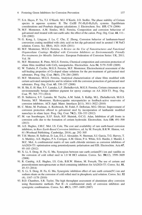
77. S.A. Hayes, P. Yu, T.J. O’Keefe, M.J. O’Keefe, J.O. Stoffer, The phase stability of Ceriumspecies in aqueous systems: II. The Ce(III IV)-H2O-H2O2O2 systems. Equilibriumconsiderations and Pourbaix diagram calculations. J. Electrochem. Soc. 153, C74 (2006)
78. M.F. Montemor, A.M. Simões, M.G. Ferreira, Composition and corrosion behaviour ofgalvanised steel treated with rare-earth salts: the effect of the cation. Prog. Org. Coat. 44, 111–120 (2002)
79. G. Kong, L. Lingyan, J. Lu, C. Che, Z. Zhong, Corrosion behavior of lanthanum-basedconversion coating modified with citric acid on hot dip galvanized steel in aerated 1 M NaClsolution. Corros. Sci. 53(4), 1621–1626 (2011)
80. M.F. Montemor, M.G.S. Ferreira, A Review on the Use of Nanostructures and FunctionalOrganosilane Coatings Modified with Corrosion Inhibitors as Environmentally FriendlyPre-treatments for Metallic Substrates. European Federation of Corrosion Series: UK, 2011;Vol. 58
81. M.F. Montemor, R. Pinto, M.G.S. Ferreira, Chemical composition and corrosion protection ofsilane films modified with CeO2 nanoparticles. Electrochim. Acta 54, 5179–5189 (2009)
82. W. Trabelsi, P. Cecilio, M.G.S. Ferreira, M.F. Montemor, Electrochemical assessment of theself-healing properties of Ce-doped silane solutions for the pre-treatment of galvanised steelsubstrates. Prog. Org. Coat. 54(4), 276–284 (2005)
83. M.F. Montemor, M.G.S. Ferreira, Analytical characterization of silane films modified withcerium activated nanoparticles and its relation with the corrosion protection of galvanised steelsubstrates. Prog. Org. Coat. 63, 330–337 (2008)
84. H. Shi, E.-H. Han, S.V. Lamaka, L.F. Zheludkevich, M.G.S. Ferreira, Cerium cinnamate as anenvironmentally benign inhibitor pigment for epoxy coatings on AA 2024-T3. Prog. Org.Coat. 77, 765–773 (2014)
85. D. Snihirova, S.V. Lamaka, M. Taryba, A.M. Salak, S. Kallip, M.L. Zheludkevich, M.G.S.Ferreira, M.F. Montemor, Hydroxyapatite microparticles as feedback-active reservoirs ofcorrosion inhibitors. ACS Appl. Mater. Interfaces 2(11), 3011–3022 (2010)
86. C. Motte, M. Poelman, A. Roobroeck, M. Fedel, F. Deflorian, M.G. Olivier, Improvement ofcorrosion protection offered to galvanized steel by incorporation of lanthanide modifiednanoclays in silane layer. Prog. Org. Coat. 74(2), 326–333 (2012)
87. M. van Soestbergen, S.J.F. Erich, H.P. Huinink, O.C.G. Adan, Inhibition of pH fronts incorrosion cells due to the formation of cerium hydroxide. Electrochim. Acta 110, 491–500(2013)
88. A.E. Hughes, J.M.C. Mol, I.S. Cole, The cost and availability of rare earth-based corrosioninhibitors, in Rare Earth-Based Corrosion Inhibitors, ed. by M. Forsyth, B.R.W. Hinton, vol.61 (Woohead Publishing, Cambridge, 2014), pp. 292–305
89. T.H. Muster, H. Sullivan, D. Lau, D.L.J. Alexander, N. Sherman, S.J. Garcia, T.G. Harvey, T.A. Markley, A.E. Hughes, P.A. Corrigan, A.M. Glenn, P.A. White, S.G. Hardin, J. Mardel, J.M.C. Mol, A combinatorial matrix of rare earth chloride mixtures as corrosion inhibitors ofAA2024-T3: optimisation using potentiodynamic polarisation and EIS. Electrochim. Acta 67,95–103 (2012)
90. X. Li, S. Deng, H. Fu, G. Mu, Synergism between rare earth cerium(IV) ion and vanillin onthe corrosion of cold rolled steel in 1.0 M HCl solution. Corros. Sci. 50(12), 3599–3609(2008)
91. R. Catubig, A.E. Hughes, I.S. Cole, B.R.W. Hinton, M. Forsyth, The use of cerium andpraseodymium mercaptoacetate as thiol-containing inhibitors for AA2024-T3. Corros. Sci. 81,45–53 (2014)
92. X. Li, S. Deng, H. Fu, G. Mu, Synergistic inhibition effect of rare earth cerium(IV) ion andsodium oleate on the corrosion of cold rolled steel in phosphoric acid solution. Corros. Sci. 52(4), 1167–1178 (2010)
93. B.D. Chambers, S.R. Taylor, The high throughput assessment of aluminium alloy corrosionusing fluorometric methods. Part II—A combinatorial study of corrosion inhibitors andsynergistic combinations. Corros. Sci. 49(3), 1597–1609 (2007)
6 Fostering Green Inhibitors for Corrosion Prevention 137
Chapter 7Active Protective Coatings: Sense and HealConcepts for Organic Coatings
H.R. Fischer and S.J. García
7.1 Introduction
Smart engineering materials able to mimic sense-response principles found innature are a long dream of engineers, scientists and constructors [1]. In nature, thisconcept of sense-response ensures the survival of organisms and increases theirchances of survival, reproduction and further evolution. Many very complexexamples of smart materials or systems can be found in nature as integral parts or ascomplete smart structures and organisms. The common ground for all naturalresponsive structures is that they are composed of numerous elements includingsensors, actuators, control algorithms, processing units, and structural parts able toperform the necessary corrective actions required in processes such as healing (e.g.skin system). Some natural systems are thus capable of initiating a responsedepending on the level of impact/damage of its own system by translatingmechanical, physical or chemical changes into readable signals. Engineering smartmaterials aim thus at implementing the capability of sensing and monitoring theirstatus during their service lifetime in order to be able to promote the restoration(healing) of a lost functionality when needed.
Damage during the preparation and operation of material systems is practicallyunavoidable with the consequence of a partial or total loss of a certain function ofthe original system. The traditional approach to deal with damage is the use ofbetter, stronger and more resistant materials and systems resulting in systems withinitially much higher performance than required for a certain application leading to
H.R. Fischer (&)TNO Technical Sciences, Materials for Integrated Products,De Rondom 1, 5612, AP Eindhoven, The Netherlandse-mail: [email protected]
S.J. GarcíaDelft University of Technology, Novel Aerospace Materials,Kluyverweg 1, 2629, HS Delft, The Netherlands
© Springer Science+Business Media Dordrecht 2016A.E. Hughes et al. (eds.), Active Protective Coatings,Springer Series in Materials Science 233, DOI 10.1007/978-94-017-7540-3_7
139
the so called of the safety factor. This traditional approach is nevertheless not themost preferred approach anymore. As materials become scarce, these need to beused as efficiently as possible during the longest possible time while maintainingcertain possibilities for re-use and recycling. An alternative to the traditionalapproach are strategies using the concept of “damage management”. Such strategiesare based on the acceptance that damage will eventually occur as opposite to theclassical strategy of “damage avoidance” where materials are stronger to try todelay the damaging event. The more preferable strategy follows a more dynamicapproach, compared to the classical static one. Under this concept, known asself-healing or self-repair, the initial system properties may be just sufficient to meetthe requirements. In return, the system needs to have incorporated functionalities tosense damage, process the obtained signals and to initiate single or multiple healingevents or processes. The healing process is fundamentally based on (local) mobilityresulting in a full or partial recovery of the original properties leading to anextension of the service life-time of the system. Only the very parts of the system, inwhich damage is to be expected, need to be equipped with such functionalitieswhich saves again resources and limits complexity. Depending on the dimensionsor scale of damage, different strategies of repair may be possible [2]; however,detection of damage should start preferably during or immediately after theoccurrence of damage. Figure 7.1 shows the implementation scheme of such astrategy. Route “a” in Fig. 7.1 shows the concept damage-sense-monitor-manualrepair as has been implemented so far, while route “b” shows the idealdamage-sense-healing or damage-sense-monitor-healing routes. Despite route “a”being the most common one; route “b” represents the ideal concept to be imple-mented in order to develop the full potential of the self-healing concept.
This chapter will focus on different concepts for damage sensing and healing ofanticorrosive coatings not aiming at showing all existing concepts but more aimingat inspiring the reader in the concept of sense and repair while at the same timeoffering the reader an overview of systems and concepts in use or ready to be used.
7.2 Organic Polymeric Coatings
(Organic) coatings can be understood as thin (organic) solid phases mechanicallyor/and chemically attached to a much thicker substrate or structure in order to add acertain functionality such as mechanical and chemical (corrosion) protection, wearresistance, thermal protection, electrical and thermal conductivity or isolation, colour,gloss or a specific roughness, light reflectance, hydrophobicity or hydrophilicity,self-cleaning, or other functionalities not obtainable from the substrate material itself[2]. Such systems are commonly known as paints [3], although the words “coating”and “paint” are interchanged in daily use. Major components of all paints are a binder(resin and plasticizers), and fillers (colouring and protective pigments) combinedwithother substances added in low quantities like surface-active agents, biocides orthickeners (this is discussed in detail in Chap. 5). The binder forms a continuous
140 H.R. Fischer and S.J. García
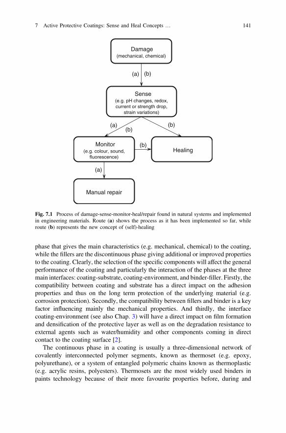
phase that gives the main characteristics (e.g. mechanical, chemical) to the coating,while the fillers are the discontinuous phase giving additional or improved propertiesto the coating. Clearly, the selection of the specific components will affect the generalperformance of the coating and particularly the interaction of the phases at the threemain interfaces: coating-substrate, coating-environment, and binder-filler. Firstly, thecompatibility between coating and substrate has a direct impact on the adhesionproperties and thus on the long term protection of the underlying material (e.g.corrosion protection). Secondly, the compatibility between fillers and binder is a keyfactor influencing mainly the mechanical properties. And thirdly, the interfacecoating-environment (see also Chap. 3) will have a direct impact on film formationand densification of the protective layer as well as on the degradation resistance toexternal agents such as water/humidity and other components coming in directcontact to the coating surface [2].
The continuous phase in a coating is usually a three-dimensional network ofcovalently interconnected polymer segments, known as thermoset (e.g. epoxy,polyurethane), or a system of entangled polymeric chains known as thermoplastic(e.g. acrylic resins, polyesters). Thermosets are the most widely used binders inpaints technology because of their more favourite properties before, during and
Damage (mechanical, chemical)
Sense(e.g. pH changes, redox, current or strength drop,
strain variations)
Monitor(e.g. colour, sound,
fluorescence)Healing
(a) (b)
(b)(a)
(a)
(b)
(b)
Manual repair
Fig. 7.1 Process of damage-sense-monitor-heal/repair found in natural systems and implementedin engineering materials. Route (a) shows the process as it has been implemented so far, whileroute (b) represents the new concept of (self)-healing
7 Active Protective Coatings: Sense and Heal Concepts … 141

after application and especially their final network architecture which offers higherresistance to chemicals, solvents and mechanical stresses compared tothermoplastics.
Coatings in general, can be applied as a single paint (coating) layer for certainapplications, but most generally they are applied as layered systems, where eachlayer has been optimized to maximize a different functionality [2]. For example, ananticorrosive paint system in the aerospace industry has three main layers: (1) aconversion coating of 100 nm (e.g. chromate conversion coating) up to a fewmicrons (e.g. anodizing layer) just above the metallic surface to offer good adhesionof the subsequent polymeric layer and to offer active corrosion protection; (2) aprimer, which is normally an epoxy layer of around 20–25 μm containing anti-corrosion inhibitors to be leached out when damage takes place; and (3) a topcoat,generally a polyurethane, which can have different thicknesses from 50 to 100 μmand offer functional properties as colour, barrier, hydrophobicity, gloss or UVresistance.
7.3 Sensing Mechanisms Incorporated into OrganicCoatings
Ideally, paints offer their intended functionalities (e.g. colour, corrosion protectionof the underlying substrate) during the whole lifetime of the structure.Unfortunately, and despite the great advances in coatings technology, this is notwhat usually happens. Coatings degrade due to mechanical factors such as impacts,scratches, thermal cycles, and fatigue related to the use of the structure, as well aschemical factors as UV radiation, acid and alkali aggressions, moisture and oxygeninfluences, and thermo-oxidation; processes globally known as weathering andageing. In the case of a sudden damage event like a key scratching the paint of a cardoor, the damage is directly at the macro scale, although it implies damage at thenano-scale (i.e. bonds breaking). However, in the case of a time-related degradationprocess (fatigue damage), all scales are involved. For example, the time-degradationof a coating will start at the nano-scale due to hydrolysis combined with polymeroxidation amongst others, followed by the micro scale because aging and weath-ering leads to crazing, finally involving the macro scale where the coating breaksdown due to the progressive embrittlement of the polymer, all being a combinationof degradation processes related to ambient humidity, and mechanical forces relatedto the normal use.
This means, that sensing of a possible damage should start ideally at a molecularlevel, and immediately alter the occurrence of damage relying on a materialundergoing a transformation through its interaction with the damaging environ-ment. On the other side, the ability to sense damage should be present or preservedduring the whole service life-time of the coating.
142 H.R. Fischer and S.J. García
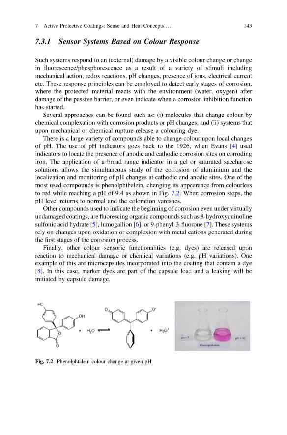
7.3.1 Sensor Systems Based on Colour Response
Such systems respond to an (external) damage by a visible colour change or changein fluorescence/phosphorescence as a result of a variety of stimuli includingmechanical action, redox reactions, pH changes, presence of ions, electrical currentetc. These response principles can be employed to detect early stages of corrosion,where the protected material reacts with the environment (water, oxygen) afterdamage of the passive barrier, or even indicate when a corrosion inhibition functionhas started.
Several approaches can be found such as: (i) molecules that change colour bychemical complexation with corrosion products or pH changes; and (ii) systems thatupon mechanical or chemical rupture release a colouring dye.
There is a large variety of compounds able to change colour upon local changesof pH. The use of pH indicators goes back to the 1926, when Evans [4] usedindicators to locate the presence of anodic and cathodic corrosion sites on corrodingiron. The application of a broad range indicator in a gel or saturated saccharosesolutions allows the simultaneous study of the corrosion of aluminium and thelocalization and monitoring of pH changes at cathodic and anodic sites. One of themost used compounds is phenolphthalein, changing its appearance from colourlessto red while reaching a pH of 9.4 as shown in Fig. 7.2. When corrosion stops, thepH level returns to normal and the coloration vanishes.
Other compounds used to indicate the beginning of corrosion even under virtuallyundamaged coatings, are fluorescing organic compounds such as 8-hydroxyquinolinesulfonic acid hydrate [5], lumogallion [6], or 9-phenyl-3-fluorone [7]. These systemsrely on changes upon oxidation or complexion with metal cations generated duringthe first stages of the corrosion process.
Finally, other colour sensoric functionalities (e.g. dyes) are released uponreaction to mechanical damage or chemical variations (e.g. pH variations). Oneexample of this are microcapsules incorporated into the coating that contain a dye[8]. In this case, marker dyes are part of the capsule load and a leaking will beinitiated by capsule damage.
Fig. 7.2 Phenolphtalein colour change at given pH
7 Active Protective Coatings: Sense and Heal Concepts … 143
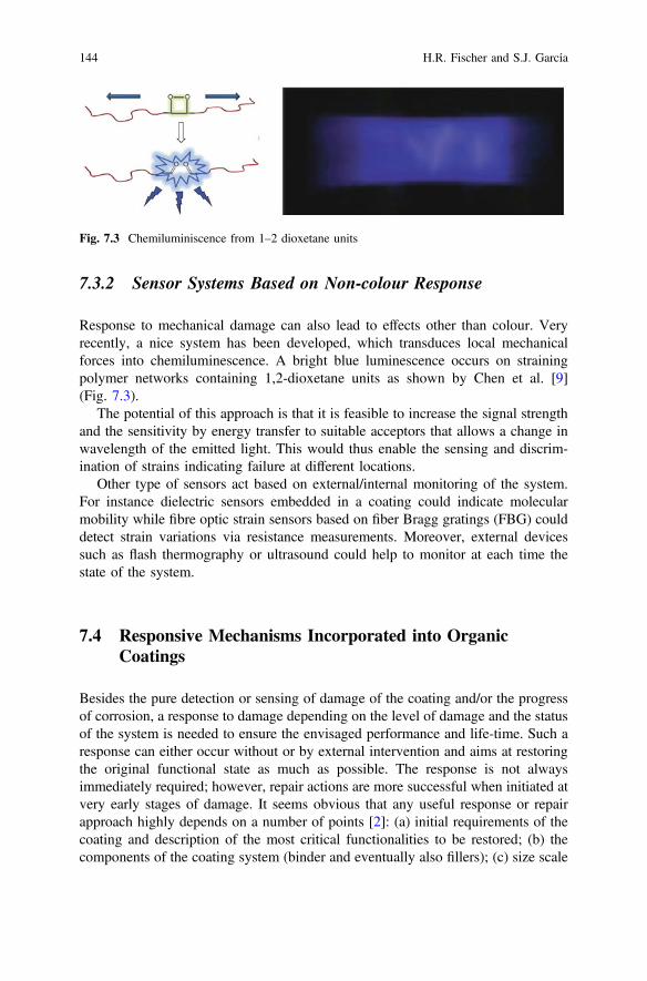
7.3.2 Sensor Systems Based on Non-colour Response
Response to mechanical damage can also lead to effects other than colour. Veryrecently, a nice system has been developed, which transduces local mechanicalforces into chemiluminescence. A bright blue luminescence occurs on strainingpolymer networks containing 1,2-dioxetane units as shown by Chen et al. [9](Fig. 7.3).
The potential of this approach is that it is feasible to increase the signal strengthand the sensitivity by energy transfer to suitable acceptors that allows a change inwavelength of the emitted light. This would thus enable the sensing and discrim-ination of strains indicating failure at different locations.
Other type of sensors act based on external/internal monitoring of the system.For instance dielectric sensors embedded in a coating could indicate molecularmobility while fibre optic strain sensors based on fiber Bragg gratings (FBG) coulddetect strain variations via resistance measurements. Moreover, external devicessuch as flash thermography or ultrasound could help to monitor at each time thestate of the system.
7.4 Responsive Mechanisms Incorporated into OrganicCoatings
Besides the pure detection or sensing of damage of the coating and/or the progressof corrosion, a response to damage depending on the level of damage and the statusof the system is needed to ensure the envisaged performance and life-time. Such aresponse can either occur without or by external intervention and aims at restoringthe original functional state as much as possible. The response is not alwaysimmediately required; however, repair actions are more successful when initiated atvery early stages of damage. It seems obvious that any useful response or repairapproach highly depends on a number of points [2]: (a) initial requirements of thecoating and description of the most critical functionalities to be restored; (b) thecomponents of the coating system (binder and eventually also fillers); (c) size scale
Fig. 7.3 Chemiluminiscence from 1–2 dioxetane units
144 H.R. Fischer and S.J. García
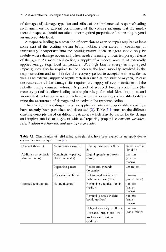
of damage; (d) damage type; (e) and effect of the implemented response/healingmechanism on the general performance of the coating meaning that the imple-mented response should not affect other required properties of the coating beyondan unacceptable level.
A response leading to a cessation of corrosion or even to repair requires at leastsome part of the coating system being mobile, either stored in containers orintrinsically incorporated into the coating matrix. Such an agent should only bemobile where damage occurs and when needed meaning a local temporary releaseof the agent. As mentioned earlier, a supply of a modest amount of externallyapplied energy (e.g. local temperature, UV, high kinetic energy in high speedimpacts) may also be required to the increase the local mobility involved in theresponse action and to minimize the recovery period to acceptable time scales aswell as an external supply of agents/materials (such as moisture or oxygen) in casethe restoration of the damage site requires the supply of new material to fill theinitially empty damage volume. A period of reduced loading conditions (therecovery period) to allow healing to take place is preferential. Most important, andan essential part of an active protective casting, is a sensing system able to deter-mine the occurrence of damage and to activate the response action.
The existing self-healing approaches applied or potentially applicable to coatingshave recently been published and discussed [2]. Table 7.1 sums up the differentexisting concepts based on different categories which may be useful for the designand implementation of a system with self-repairing properties: concept, architec-ture, healing mechanism, and damage size-scale.
Table 7.1 Classification of self-healing strategies that have been applied or are applicable toorganic coatings (adapted from [2])
Concept (level 1) Architecture (level 2) Healing mechanism (level3)
Damage scale(level 4)
Additives or extrinsic(discontinuous)
Containers (capsules,fibers, networks)
Liquid spreads and reacts(flow)
μm–mm(micro–macro)
Expansive phases Reacts and expands(expansion)
μm (micro)
Corrosion inhibitors Release and reacts withmetallic surface (flow)
nm–μm(nano–micro)
Intrinsic (continuous) No architecture Reversible chemical bonds(re-flow)
nm–mm(nano–macro)
Reversible non covalentbonds (re-flow)
nm–mm(nano–macro)
Delayed elasticity (re-flow) nm–μm(nano–micro)Unreacted groups (re-flow)
Surface stratification(re-flow)
7 Active Protective Coatings: Sense and Heal Concepts … 145

Another design criterion for such systems and often used refers to the mode ofrepair action, whether it is autonomous or non-autonomous. However such differ-entiation may be difficult, since systems that are considered non-autonomous undercertain circumstances can be autonomous under others. For instance, the use ofisocyanate based coatings with retarded elasticity from Bayer [10] andAkzoNobel-Sikkens [11] are autonomous in a sunny day, but in cold and cloudyweathers heat needs to be applied directly to the damaged site. Strictly speaking anon-autonomous system would be one that would require external interference, adirect action of an agent that is not in the normal environment of use of the systemor a supply of energy of any kind.
7.4.1 Corrosion Triggered Protective Response: UnderlyingMetal Protection
Despite not being named as such until the nineties, the most traditional way toresponse and to cease corrosion at damaged coatings sites is by the use of corrosioninhibitors that are released from the coatings via leaching [12, 13]. In such systems,the corrosion inhibitor leaches upon interaction with water at the corrosion site andby the ingress of water at the periphery of the damaged coating. Once leached outthe corrosion inhibitor subsequently coordinates with the metallic surface to create apassive layer that replaces the original corrosion protection (Fig. 7.4).
This response mechanism works already in intact organic coatings, since waterand oxygen ingress through coatings is always present to some extent. Therefore,an active protection is always needed as well. So far, the most efficient corrosioninhibitors are based on hexavalent chromium [14], but the toxicity issues andcarcinogenic effects associated with their use, despite being known since theeighties [15], have become increasingly highlighted in recent years [16–18]. Thisfact has created, in recent years, a high effort into the development of new envi-ronmentally friendly corrosion inhibitors [19–24] which can offer equal or bettercorrosion protection to CrVI based ones, as well as on the development ofhigh-throughput techniques to develop and evaluate corrosion inhibitors in reducedtimes [19, 25–28]. The incorporation of such new corrosion inhibitors into coatingsto offer an effective and long term protection independently of the polymer matrix
Fig. 7.4 Release of corrosioninhibitors by desorption [2]
146 H.R. Fischer and S.J. García
has also been object of extensive studies; thus creating a whole area of researchunder the umbrella of self-healing materials. Several new concepts aiming at acontrolled release from carriers have thus been developed. So far most the studiedand successful concepts include delivery of inhibitors from inorganic carriers by ionexchange and/or desorption and the release of inhibitors from organic carriers bypH environmental changes.
7.4.1.1 Controlled Release by Desorption and Ion Exchange
Changes and increase in local ion concentration and mobility due to the start of thecorrosion process can be used as trigger mechanism to release corrosion inhibitors ondemand. For such concept nano and micro inorganic minerals can be used as carriersand support of the inhibitors. Such materials are either cation exchangers such assmectite type alumosilicate materials (e.g. montmorillonite) but also anion-ex-changers such as the layered double hydroxides (LDH’s) or hydrotalcites (see alsoChap. 8). These carriers can be doped with a single corrosion inhibitor (cationic oranionic) that is released by desorption or ion exchange once the corrosion process hasstarted as introduced in the very extensive works done by, amongst others, Shchukin,Zheludkevich and Buchheit [29–39]. As an alternative to single inhibitor-carrierconcept, Garcia et al. [40] recently introduced the concept of dual kinetic release by adual inhibitor doping of nanocarriers (a cathodic and an anionic inhibitor). This newconcept was demonstrated with zeolites and proposes a fast release of one inhibitor bydesorption followed by a slow release of the second inhibitor by ion exchangewhereby one inhibitor can be cathodic inhibitor and the other anodic. This promisingconcept opens the path for the development of more efficient and multifunctionalcarriers using the traditional idea of nanocarrier doped systems.
It is worth mentioning that LDH’s have not only the potential to release anioniccorrosion inhibitors upon ion exchange but also upon pH-changes, being thuspossible the release of active metal ions due to decomposition of the carrierthemselves [41, 42]. A follow up of the doped nanocarrier concept is the incor-poration of inhibiting cations like Ce3+ into amorphous oxide nanoparticles (e.g.ZrO2) which act as reinforcement of a sol-gel matrix and at the same time asreservoir of the inhibitor [43]. Finally also microgels as storage entities for corro-sion inhibitors were exploited showing a similar controlled desorption [44].
7.4.1.2 Controlled Release by Environmental pH Changes
Different from a desorption or ion controlled release is the controlled release ofinhibitors initiated by local changes of pH during the corrosion process. To increasethe control over the release of inhibitors, inorganic nanocarriers based on SiO2 werecoated with polyelectrolyte shells using the Layer-by-Layer (LbL) assembly tech-nique [32, 45, 46]. The corrosion inhibitor benzotriazole was incorporated betweenoppositely charged polyelectrolyte layers. The aim was to use the permeability
7 Active Protective Coatings: Sense and Heal Concepts … 147
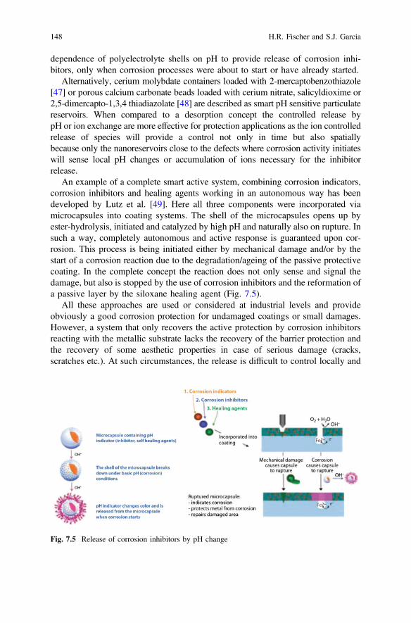
dependence of polyelectrolyte shells on pH to provide release of corrosion inhi-bitors, only when corrosion processes were about to start or have already started.
Alternatively, cerium molybdate containers loaded with 2-mercaptobenzothiazole[47] or porous calcium carbonate beads loaded with cerium nitrate, salicyldioxime or2,5-dimercapto-1,3,4 thiadiazolate [48] are described as smart pH sensitive particulatereservoirs. When compared to a desorption concept the controlled release bypH or ion exchange are more effective for protection applications as the ion controlledrelease of species will provide a control not only in time but also spatiallybecause only the nanoreservoirs close to the defects where corrosion activity initiateswill sense local pH changes or accumulation of ions necessary for the inhibitorrelease.
An example of a complete smart active system, combining corrosion indicators,corrosion inhibitors and healing agents working in an autonomous way has beendeveloped by Lutz et al. [49]. Here all three components were incorporated viamicrocapsules into coating systems. The shell of the microcapsules opens up byester-hydrolysis, initiated and catalyzed by high pH and naturally also on rupture. Insuch a way, completely autonomous and active response is guaranteed upon cor-rosion. This process is being initiated either by mechanical damage and/or by thestart of a corrosion reaction due to the degradation/ageing of the passive protectivecoating. In the complete concept the reaction does not only sense and signal thedamage, but also is stopped by the use of corrosion inhibitors and the reformation ofa passive layer by the siloxane healing agent (Fig. 7.5).
All these approaches are used or considered at industrial levels and provideobviously a good corrosion protection for undamaged coatings or small damages.However, a system that only recovers the active protection by corrosion inhibitorsreacting with the metallic substrate lacks the recovery of the barrier protection andthe recovery of some aesthetic properties in case of serious damage (cracks,scratches etc.). At such circumstances, the release is difficult to control locally and
Fig. 7.5 Release of corrosion inhibitors by pH change
148 H.R. Fischer and S.J. García
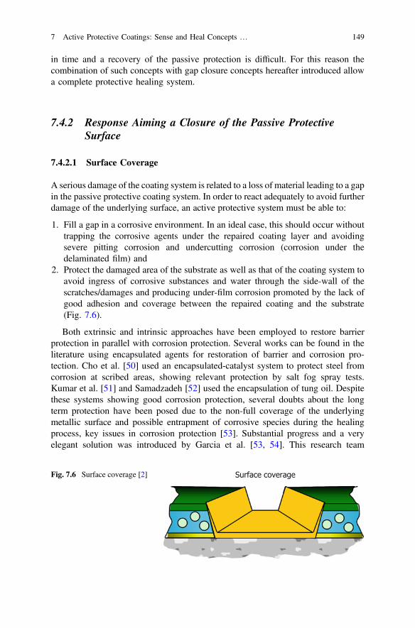
in time and a recovery of the passive protection is difficult. For this reason thecombination of such concepts with gap closure concepts hereafter introduced allowa complete protective healing system.
7.4.2 Response Aiming a Closure of the Passive ProtectiveSurface
7.4.2.1 Surface Coverage
A serious damage of the coating system is related to a loss of material leading to a gapin the passive protective coating system. In order to react adequately to avoid furtherdamage of the underlying surface, an active protective system must be able to:
1. Fill a gap in a corrosive environment. In an ideal case, this should occur withouttrapping the corrosive agents under the repaired coating layer and avoidingsevere pitting corrosion and undercutting corrosion (corrosion under thedelaminated film) and
2. Protect the damaged area of the substrate as well as that of the coating system toavoid ingress of corrosive substances and water through the side-wall of thescratches/damages and producing under-film corrosion promoted by the lack ofgood adhesion and coverage between the repaired coating and the substrate(Fig. 7.6).
Both extrinsic and intrinsic approaches have been employed to restore barrierprotection in parallel with corrosion protection. Several works can be found in theliterature using encapsulated agents for restoration of barrier and corrosion pro-tection. Cho et al. [50] used an encapsulated-catalyst system to protect steel fromcorrosion at scribed areas, showing relevant protection by salt fog spray tests.Kumar et al. [51] and Samadzadeh [52] used the encapsulation of tung oil. Despitethese systems showing good corrosion protection, several doubts about the longterm protection have been posed due to the non-full coverage of the underlyingmetallic surface and possible entrapment of corrosive species during the healingprocess, key issues in corrosion protection [53]. Substantial progress and a veryelegant solution was introduced by Garcia et al. [53, 54]. This research team
Fig. 7.6 Surface coverage [2]
7 Active Protective Coatings: Sense and Heal Concepts … 149
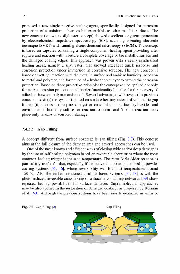
proposed a new single reactive healing agent, specifically designed for corrosionprotection of aluminium substrates but extendable to other metallic surfaces. Thenew concept (known as silyl ester concept) showed excellent long term protectionby electrochemical impedance spectroscopy (EIS), scanning vibrating electrodetechnique (SVET) and scanning electrochemical microscopy (SECM). The conceptis based on capsules containing a single component healing agent providing afterrupture and reaction with moisture a complete coverage of the metallic surface andthe damaged coating edges. This approach was proven with a newly synthesizedhealing agent, namely a silyl ester, that showed excellent quick response andcorrosion protection under immersion in corrosive solution, The new concept isbased on wetting, reaction with the metallic surface and ambient humidity, adhesionto metal and polymer, and formation of a hydrophobic layer to extend the corrosionprotection. Based on these protective principles the concept can be applied not onlyfor active corrosion protection and barrier functionality but also for the recovery ofadhesion between polymer and metal. Several advantages with respect to previousconcepts exist: (i) the system is based on surface healing instead of volumetric-gapfilling; (ii) it does not require catalyst or crosslinker as surface hydroxides andenvironmental humidity suffice for reaction to occur; and (iii) the reaction takesplace only in case of corrosion damage
7.4.2.2 Gap Filling
A concept different from surface coverage is gap filling (Fig. 7.7). This conceptaims at the full closure of the damage area and several approaches can be used.
One of the most known and efficient ways of closing wide and/or deep damage isby the use of self-healing polymers based on reversible chemistries where the mostcommon healing trigger is induced temperature. The retro-Diels-Alder reaction isparticularly useful for that, especially if the active components are used in powdercoating systems [55, 56], where reversibility was found at temperatures around150 °C. Also the earlier mentioned disulfide based systems [57, 58] as well thephoto-induced reversible crosslinking of antracene containing networks [59] showrepeated healing possibilities for surface damages. Supra-molecular approachesmay be also applied in the restoration of damaged coatings as proposed by Bosmanet al. [60]. Although the previous systems have been mostly evaluated in terms of
Fig. 7.7 Gap filling [2]
150 H.R. Fischer and S.J. García
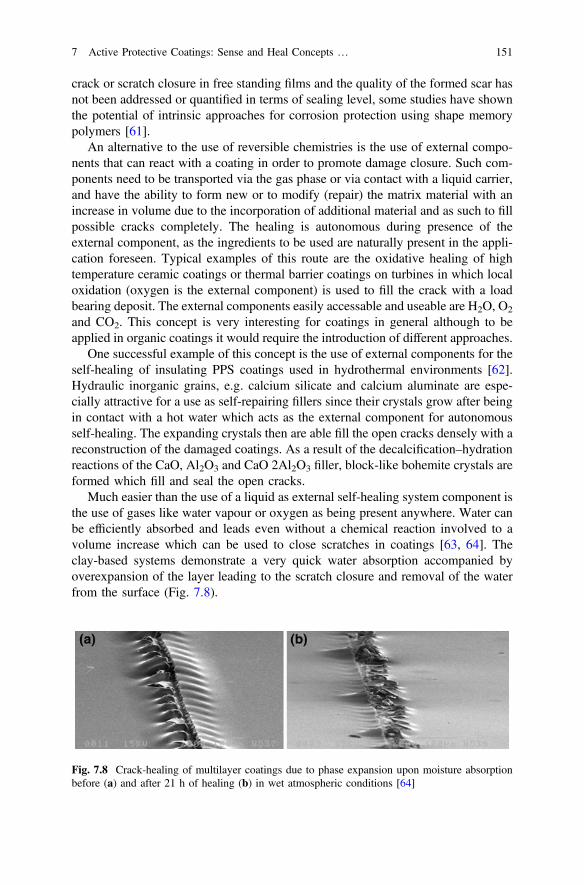
crack or scratch closure in free standing films and the quality of the formed scar hasnot been addressed or quantified in terms of sealing level, some studies have shownthe potential of intrinsic approaches for corrosion protection using shape memorypolymers [61].
An alternative to the use of reversible chemistries is the use of external compo-nents that can react with a coating in order to promote damage closure. Such com-ponents need to be transported via the gas phase or via contact with a liquid carrier,and have the ability to form new or to modify (repair) the matrix material with anincrease in volume due to the incorporation of additional material and as such to fillpossible cracks completely. The healing is autonomous during presence of theexternal component, as the ingredients to be used are naturally present in the appli-cation foreseen. Typical examples of this route are the oxidative healing of hightemperature ceramic coatings or thermal barrier coatings on turbines in which localoxidation (oxygen is the external component) is used to fill the crack with a loadbearing deposit. The external components easily accessable and useable are H2O, O2
and CO2. This concept is very interesting for coatings in general although to beapplied in organic coatings it would require the introduction of different approaches.
One successful example of this concept is the use of external components for theself-healing of insulating PPS coatings used in hydrothermal environments [62].Hydraulic inorganic grains, e.g. calcium silicate and calcium aluminate are espe-cially attractive for a use as self-repairing fillers since their crystals grow after beingin contact with a hot water which acts as the external component for autonomousself-healing. The expanding crystals then are able fill the open cracks densely with areconstruction of the damaged coatings. As a result of the decalcification–hydrationreactions of the CaO, Al2O3 and CaO 2Al2O3 filler, block-like bohemite crystals areformed which fill and seal the open cracks.
Much easier than the use of a liquid as external self-healing system component isthe use of gases like water vapour or oxygen as being present anywhere. Water canbe efficiently absorbed and leads even without a chemical reaction involved to avolume increase which can be used to close scratches in coatings [63, 64]. Theclay-based systems demonstrate a very quick water absorption accompanied byoverexpansion of the layer leading to the scratch closure and removal of the waterfrom the surface (Fig. 7.8).
Fig. 7.8 Crack-healing of multilayer coatings due to phase expansion upon moisture absorptionbefore (a) and after 21 h of healing (b) in wet atmospheric conditions [64]
7 Active Protective Coatings: Sense and Heal Concepts … 151
This expansive layer system has recently been studied by numerical methods inorder to establish the key parameters to be considered when trying to improve thehealing efficiency while decreasing the side negative effects as the levelling at thehealed area [65]. In the study it was found that the scratch closing behaviour wasdependent on relative thickness of the layers in the system, relative stiffness of thesame, but also on the length of initial interfacial debonding, finding that some initiallateral debonding was necessary to obtain the healing of the system.
Another more straight forward approach of the use of humidity as the healingagent comes from the work done by South and Lyon [66] on hydrogel thin films,who show how damage at the surface of the microgel polyelectrolyte multilayersexhibit repeatable self-healing behaviour upon multiple mechanical deformations,which could be an important advance in the application of hydrogel biomaterialcoatings likely to be damaged by routine surgical handling.
The obvious advantages of such systems are their efficiency in repair action viathe volume expansion providing a complete filling of cracks and scratches and theoption to perform a multiple repair action, their flexibility in design and the absenceof fluids as repairing components, whereas the main drawback is their obviousdependency on the external components. Furthermore, the ability of these com-pounds to react with species present in the environment makes the isolation of thereactive agents in intact coatings a key priority to avoid reactions occurring prior tothe occurrence of damage.
7.4.3 Recovery of Other Functionalities
So far, in organic coatings, the active response concept has been applied, mainly,for the detection and recovery of macro and micro damages, as exposed in theprevious points. This section evaluates the attempts to recover specific function-alities such as interfacial adhesion/bonding. The recovery of the interfacial bondingbetween coatings and metal substrates has attracted some attention already [19],although much less than other concepts due to the complexity of the adhesion itselfand the lack of perfect understanding of the underlying mechanisms. So far, and upto the knowledge of the authors, no clear successful attempts has been reported inthis field, although Mardel et al. [67] demonstrated that the incorporation of certaincorrosion inhibitors (i.e. Ce(dbp)3) improved the resistance to filiform corrosion bythe formation of an adhesive oxide between the metal and the coating once exposedto humid environments. Other alternative approaches to this could usenano-encapsulated or compartmented adhesion promoters that upon damage arereleased and wet both the coating and metal interface reacting with either materials.Interestingly, Lane et al. [68] showed a proof of concept for this approach for therepair of dielectric interfaces, although the concept has not been further developed.
152 H.R. Fischer and S.J. García

7.5 Concluding Remarks
This work presents several concepts for sense, monitor and heal that have beenimplemented or can be implemented into coatings. Clearly many differentapproaches can be applied to organic coatings although the level of success dependson the application of the coatings themselves and response wanted and needed.Sensing and signalling/monitoring of mechanical failure and/or corrosion initiationis very useful, however, in most cases a manual intervention to stop the corrosionand to prevent excessive damage is needed but not possible. This opens the need todevelop coating systems that do not only sense but also act (heal) damages, thusdeveloping implemented concepts of sense and heal. Encapsulated approaches havealready been implemented under different concepts and seem to be already at thestage of production and real applications, although certain issues such as theentrapment of corrosive species under the healed area and the lack of completecoating-metal adhesion recovery should be revised as they can be more detrimentalto the system than the damage itself. A combination of sensing/signalling, corrosioninhibition and repair (heal) of the barrier seems up to now the most advancedsystem. The use of expansive phases seems to be very appropriate for certainapplications but issues like the adhesion to the underlying surface should be takeninto account. For such systems, mathematical models have shown the stronginfluence of the coating architecture and damage topology.
Furthermore, functionalities of coatings other than mechanical and electro-chemical substrate protection (e.g. adhesion, color, surface tension) have not yetreceived enough attention to be sufficiently developed and further efforts arenecessary.
Acknowledgments The authors gratefully acknowledge the sustained financial support from theInnovative Research Program (IOP) in The Netherlands.
References
1. H. Fischer, Self-repairing material systems-a dream or a reality? Nat. Sci. 2, 873–901 (2010)2. S.J. García, H.R. Fischer, S. Van Der Zwaag, A critical appraisal of the potential of self
healing polymeric coatings. Prog. Org. Coat. 72, 211–221 (2011)3. J. Boxall, J.A. von Fraunhofer, Paint Formulation: Principles and Practice (George Godwin
Limited, London, UK, 1980)4. U.R. Evans, The fundamental principles of corrosion. J. Soc. Chem. Ind. 45, 504–516 (1926)5. D.E. Bryant, D. Greenfield, The use of fluorescent probes for the detection of under-film
corrosion. Prog. Org. Coat. 57, 416–420 (2006)6. M.P. Sibi, Z. Zong, Determination of corrosion on aluminum alloy under protective coatings
using fluorescent probes. Prog. Org. Coat. 47, 8–15 (2003)7. S.-M. Li, H.-R. Zhang, J.-H. Liu, Preparation and performance of fluorescent sensing coating
for monitoring corrosion of Al alloy 2024. Trans. Nonferrous Met. Soc. China (EnglishEdition) 16 (SUPPL.), 159–s164 (2006)
7 Active Protective Coatings: Sense and Heal Concepts … 153
8. C. Suryanarayana, K.C. Rao, D. Kumar, Preparation and characterization of microcapsulescontaining linseed oil and its use in self-healing coatings. Prog. Org. Coat. 63, 72–78 (2008)
9. Y. Chen, A.J.H., Spiering, S. Karthikeyan, G.W.M. Peters, E.W. Meijer, R.P. Sijbesma,Mechanically induced chemiluminescence from polymers incorporating a 1,2-dioxetane unitin the main chain. Nat. Chem. 4, 559–562 (2012)
10. www.bayer.com11. www.akzonobel.com12. S. van der Zwaag (ed.) in Self-Healing Materials: An Alternative Approach to 20 Centuries of
Materials Science. Springer Series in Materials Science, vol 100. (Springer, Dordrecht, TheNetherlands, 2007)
13. J. Sinko, Prog. Org. Coat. 42, 267 (2001)14. J. Zhao, G.S. Frankel, R.L. McCreery, J. Electrochem. Soc. 145, 2258 (1998)15. US Public Health Service, Toxicological Profile for Chromium, Report No. ATSDR/TP-88/10,
July, 198916. M. Costa, C.B. Klein, Crit. Rev. Toxicol. 36, 155 (2006)17. P.T. La Puma, J.M. Fox, E.C. Kimmel, Regul. Toxicol. Pharmacol. 33, 343 (2001)18. N.A. Dalager, T.J. Mason, J.F. Fraumeni, R. Hoover, W.W. Payne, J. Occup. Med. Toxicol.
22, 25 (1980)19. S.J. García, J.M.C. Mol, T.H. Muster, A.E. Hughes, J. Mardel, T. Miller, T. Markely, H.
Terryn, J.H.W. de Wit, Advances in the selection and use of Rare-Earth-Based Inhibitors forSelf Healing Organic Coatings, in European Federation of Corrosion Series: Self-HealingProperties of New Surface Treatments ed. by L. Fedrizzi, vol. 58 (ISBN: 978 1906540364,Maney Publishing, March 2011)
20. J. Mardel, S.J. García, P.A. Corrigan, T. Markley, A.E. Hughes, T.H. Muster, D. Lau, T.G.Harvey, A.M. Glenn, P.A. White, S.G. Hardin, C. Luo, X. Zhou, G.E. Thompson, J.M.C. Mol,Prog. Org. Coat. 70, 90–101 (2011)
21. M. Forsyth, T. Markley, D. Ho, G.B. Deacon, P. Junk, B. Hinton, A. Hughes, Corrosion 64,191 (2008)
22. N. Birbilis, R.G. Buchheit, D.L. Ho, M. Forsyth, Electrochem. Solid. State. Lett. 8 C180(2005)
23. D. Ho, N. Brack, J. Scully, T. Markley, M. Forsyth, B. Hinton, J. Electrochem. Soc. 153(B392) (2006)
24. M. Forsyth, C.M. Forsyth, K. Wilson, T. Behrsing, G.B. Deacon, Corros. Sci. 44, 2651 (2002)25. B.D. Chambers, S.R. Taylor, M.W. Kendig, Corrosion 61, 480 (2005)26. T.H. Muster, A.E. Hughes, S.A. Furman, T. Harvey, N. Sherman, S. Hardin, P. Corrigan, D.
Lau, F.H. Scholes, P.A. White, M. Glenn, J. Mardel, S.J. García, J.M.C. Mol, Electrochim.Acta 54, 3402 (2009)
27. S.J. García, T.H. Muster, Ö. Özkanat, N. Sherman, A.E. Hughes, H. Terryn, J.H.W. de Wit, J.M.C. Mol, Electrochim. Acta 55, 2457 (2010)
28. P.A. White, A.E. Hughes, S.A. Furman, N. Sherman, P.A. Corrigan, M.A. Glenn, D. Lau, S.G.Hardin, T.G. Harvey, J. Mardel, T.H. Muster, S.J. García, C. Kwakernaak, J.M.C. Mol,Corros. Sci. 51, 2279 (2009)
29. D.G. Shchukin, D.O. Grigoriev, H. Mohwald, Soft Matter 6, 720 (2010)30. D.V. Andreeva, D. Fix, H. Mohwald et al., Adv. Mater. 20, 2789 (2008)31. S.V. Lamaka, M.L. Zheludkevich, K.A. Yasakau, M.F. Montemor, P. Cecílio, M.G.S.
Ferreira, Electrochem. Commun. 8, 421 (2006)32. D.G. Shchukin, M.L. Zheludkevich, K.A. Yasakau, S.V. Lamaka, H. Möhwald, M.G.S.
Ferreira, Adv. Mater. 18, 1672 (2006)33. S.V. Lamaka, M.L. Zheludkevich, K.A. Yasakau, R. Serra, S.K. Poznyak, M.G.S. Ferreira,
Prog. Org. Coat. 58, 127 (2007)34. S.V. Lamaka, M.L. Zheludkevich, K.A. Yasakau, M.F. Montemor, M.G.S. Ferreira,
Electrochim. Acta 52, 7231 (2007)35. D.G. Shchukin, S.V. Lamaka, K.A. Yasakau, M.L. Zheludkevich, H. Möhwald, M.G.S.
Ferreira, J. Phys. Chem. 112, 958 (2007)
154 H.R. Fischer and S.J. García
36. M.L. Zheludkevich, D.G. Shchukin, K.A. Yasakau, H. Möhwald, M.G.S. Ferreira, Chem.Mater. 19, 402 (2007)
37. M. Zheludkevich, Self healing anticorrosion coatings, Ch. 4, in Self-Healing Materials:Fundamentals, Design Strategies, and Applications ed. by S.K. Ghosh (Wiley-VCH, 2009),pp. 101–139
38. S.P.V. Mahajanarn, R.G. Buchheit, Corrosion 64, 230 (2008)39. R.G. Buchcheit, H. Guan, JCT Res. 1, 277 (2004)40. E.L. Ferrer, A.P. Rollon, H.D. Mendoza, U. Lafont, S.J. Garcia, Double-doped zeolites for
corrosion protection of aluminium alloys. Microporous Mesoporous Mater. 188, 8–15 (2014)41. Z. Yang, H. Fischer, J. Cerezo, J.M.C. Mol, R. Polder, Aminobenzoate modified MgAl
hydrotalcites as a novel smart additive of reinforced concrete for anticorrosion applications.Constr. Build. Mater. 47, 1436–1443 (2013)
42. Z. Yang, H. Fischer, R. Polder, Synthesis and characterization of modified hydrotalcites andtheir ion exchange characteristics in chloride-rich simulated concrete pore solution. CementConcr. Compos. 47, 87–93 (2014)
43. M.L. Zheludkevich, J. Tedim, M.G.S. Ferreira, “Smart” coatings for active corrosionprotection based on multi-functional micro and nanocontainers. Electrochim. Acta 82, 314–323 (2012)
44. A. Latnikova, D. Grigoriev, M. Schenderlein, H. Möhwald, D. Shchukin, A new approachtowards “active” self-healing coatings: exploitation of microgels. Soft Matter 8, 10837–10844(2012)
45. D.O. Grigoriev, T. Bukreeva, H. Möhwald, D.G. Shchukin, New method for fabrication ofloaded micro- and nanocontainers: emulsion encapsulation by polyelectrolyte layer-by-layerdeposition on the liquid core. Langmuir 24, 999–1004 (2008)
46. D.G. Shchukin, H. Möhwald, Surface-engineered nanocontainers for entrapment of corrosioninhibitors. Adv. Funct. Mater. 17, 1451–1458 (2007)
47. I.A. Kartsonakis, A.C. Balaskas, E.P. Koumoulos, C.A. Charitidis, G. Kordas, Evaluation ofcorrosion resistance of magnesium alloy ZK10 coated with hybrid organic-inorganic filmincluding containers. Corros. Sci. 65, 481–493 (2012)
48. D. Snihirova, S.V. Lamaka, M.F. Montemor, “SMART” protective ability of water basedepoxy coatings loaded with CaCO3 microbeads impregnated with corrosion inhibitors appliedon AA2024 substrates. Electrochim. Acta 83, 439–447 (2012)
49. http://ntrs.nasa.gov/archive/nasa/casi.ntrs.nasa.gov/20120003396.pdf50. S.H. Cho, S.R. White, P.V. Braun, Adv. Mater. 21, 645 (2009)51. A. Kumar, L.D. Stephenson, J.N. Murray, Prog. Org. Coat. 55, 244–253 (2006)52. M. Samadzadeh, S. Hatami Boura, M. Peikari, A. Ashrafi, S.M. Kasiriha, Prog. Org. Coat. 70,
383–387 (2011)53. S.J. García, H.R. Fischer, P.A. White, J. Mardel, Y. González-García, J.M.C. Mol, A.E.
Hughes, Prog. Org. Coat. 70, 142–149 (2011)54. Y. González-García, S.J. García, H.R. Fischer, A.E. Hughes, J.M.C. Mol, Local
electrochemical evaluation of a self-healing coating based on encapsulated healing-agent. in18th International Corrosion Congress, vol. 1, 2011. pp. 408–413
55. M. Wouters, E. Craenmehr, K. Tempelaars, H. Fischer, N. Stroeks, J. van Zanten, Prog. Org.Coat. 64, 156–162 (2009)
56. M. Wouters, M. Burghoorn, B. Ingenhut, K. Timmer, C. Rentrop, T. Bots, G. Oosterhuis, H.Fischer, Tuneable adhesion through novel binder technologies. Prog. Org. Coat. 72, 152–158(2011)
57. J. Canadell, H. Fischer, G. de With, R.A.T.M. van Benthem, J. Polym. Sci., Part A: Polym.Chem. 48, 3456–3467 (2010)
58. J.A. Yoon, J. Kamada, K. Koynov, J. Mohin, R. Nicolaÿ, Y. Zhang, A.C. Balazs, T.Kowalewski, K. Matyjaszewski, Self-healing polymer films based on thiol-disulfide exchangereactions and self-healing kinetics measured using atomic force microscopy. Macromolecules45, 142–149 (2012)
7 Active Protective Coatings: Sense and Heal Concepts … 155

59. P. Froimowicz, H. Frey, K. Landfester, Towards the generation of self-healing materials bymeans of a reversible photo-induced approach. Macromol. Rapid Commun. 32, 468–473(2011)
60. R.P. Bosman, R.P. Sijbesma, E.W. Meijer, Supramolecular polymers at work. Mater. Today34–39 (2004)
61. J.-B. Jorcin, G. Scheltjens, Y. Van Ingelgem, E. Tourwé, G. Van Assche, I. De Graeve, B. VanMele, H. Terryn, A. Hubin, Investigation of the self-healing properties of shape memorypolyurethane coatings with the ‘odd random phase multisine’ electrochemical impedancespectroscopy. Electrochim. Acta 55, 6195–6203 (2010)
62. T. Sugama, K. Gawlik, Mater. Lett. 57, 4282–4290 (2003)63. A. Hikasa, T. Sekino, Y. Hayashi, R. Rajagopalan, K. Niihara, Mater. Res. Innovations 8, 84–
88 (2004)64. F. Miccichè, H. Fischer, R. Varley, S. van der Zwaag, Surf. Coat. Technol. 202, 3346–3353
(2008)65. R. Rey, E. Javierre, S.J. Garcia, S. van der Zwaag, J.M. Garcia-Aznar, Numerical study of the
scratch-closing behaviour of coatings containing an expansive layer. Surf. Coat. Technol. 206,2220–2225 (2012)
66. A.B. South, L.A. Lyon, Angew. Chem. Int. Ed. 49, 767–771 (2010)67. J. Mardel, S.J. García, P.A. Corrigan, T. Markley, A.E. Hughes, T.H. Muster, D. Lau, T.G.
Harvey, A.M. Glenn, P.A. White, S.G. Hardin, C. Luo, X. Zhou, G.E. Thompson, J.M.C. Mol,Prog. Org. Coat. 70, 90–101 (2011)
68. M.W. Lane, A. Roush, S.E. Callahan, in Tenth International Workshop on Stress-InducedPhenomena in Metallization. AIP Conference Proceedings, vol. 1143, 2009, pp. 71-86
156 H.R. Fischer and S.J. García
Chapter 8Delivery Systems for Self HealingProtective Coatings
M.L. Zheludkevich and A.E. Hughes
8.1 Introduction
Application of protective coatings is the most common and cost effective method ofcorrosion protection for a wide range of engineering structures, from cars to air-crafts, from heavy industry, energy industries and chemical factories to householdequipment. The main role of coating in corrosion protection is to provide a densebarrier against corrosive species. Additionally the protective coatings can conferother important functions such as desired aesthetic appearance, improvedmechanical properties, and self-cleaning just to mention a few. However, defectsare inevitable during the lifetime of coated structures leading to local disruption ofthe barrier function. The corrosion processes develop faster after failure of theprotective barrier. Therefore active self-healing of defects in coatings is necessaryin order to provide effective long-term protection.
The term self-healing in materials science was actively introduced byWhite only inbeginning of 21st century [1]. The main definition of self-healing is based onself-recovery of the initial properties of thematerial after degradation due to the externalenvironment. The same definition can be also used for protective coatings. The classical
M.L. Zheludkevich (&)Institute of Materials Research, Helmholtz-Zentrum Geesthacht,Zentrum für Material- und Küstenforschung GmbH, Max-Planck-Straße 1,21502 Geesthacht, Germanye-mail: [email protected]
M.L. ZheludkevichDepartment of Materials and Ceramic Engineering, CICECO-Aveiro Institute of Materials,University of Aveiro, 3810-193 Aveiro, Portugal
A.E. HughesInstitute for Frontier Materials, Deakin University, Waurn Ponds Geelong, Australia
A.E. HughesCSIRO Mineral Resources, Clayton, VIC 3169, Australia
© Springer Science+Business Media Dordrecht 2016A.E. Hughes et al. (eds.), Active Protective Coatings,Springer Series in Materials Science 233, DOI 10.1007/978-94-017-7540-3_8
157
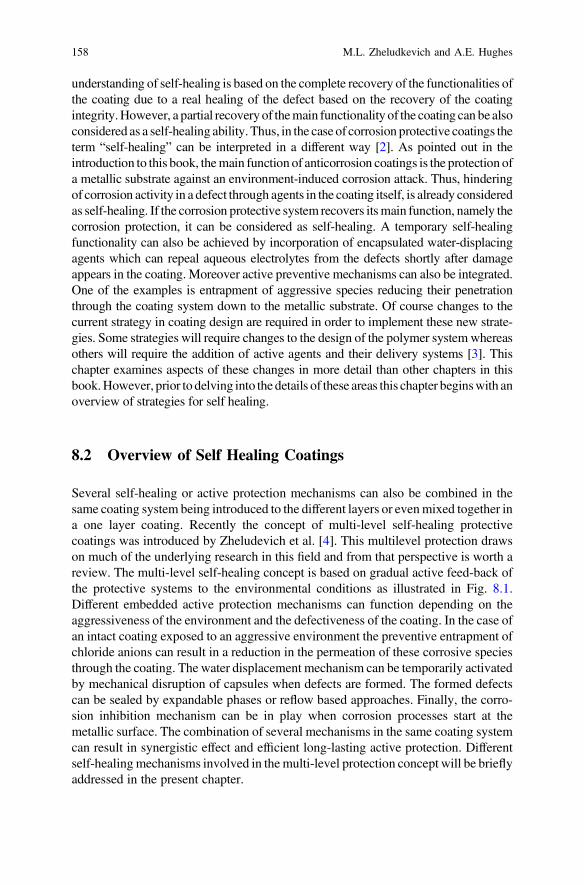
understanding of self-healing is based on the complete recovery of the functionalities ofthe coating due to a real healing of the defect based on the recovery of the coatingintegrity.However, a partial recoveryof themain functionality of the coating can be alsoconsidered as a self-healing ability. Thus, in the case of corrosion protective coatings theterm “self-healing” can be interpreted in a different way [2]. As pointed out in theintroduction to this book, themain function of anticorrosion coatings is the protection ofa metallic substrate against an environment-induced corrosion attack. Thus, hinderingof corrosion activity in a defect through agents in the coating itself, is already consideredas self-healing. If the corrosion protective system recovers itsmain function, namely thecorrosion protection, it can be considered as self-healing. A temporary self-healingfunctionality can also be achieved by incorporation of encapsulated water-displacingagents which can repeal aqueous electrolytes from the defects shortly after damageappears in the coating. Moreover active preventive mechanisms can also be integrated.One of the examples is entrapment of aggressive species reducing their penetrationthrough the coating system down to the metallic substrate. Of course changes to thecurrent strategy in coating design are required in order to implement these new strate-gies. Some strategies will require changes to the design of the polymer systemwhereasothers will require the addition of active agents and their delivery systems [3]. Thischapter examines aspects of these changes in more detail than other chapters in thisbook.However, prior to delving into the details of these areas this chapter beginswith anoverview of strategies for self healing.
8.2 Overview of Self Healing Coatings
Several self-healing or active protection mechanisms can also be combined in thesame coating system being introduced to the different layers or evenmixed together ina one layer coating. Recently the concept of multi-level self-healing protectivecoatings was introduced by Zheludevich et al. [4]. This multilevel protection drawson much of the underlying research in this field and from that perspective is worth areview. The multi-level self-healing concept is based on gradual active feed-back ofthe protective systems to the environmental conditions as illustrated in Fig. 8.1.Different embedded active protection mechanisms can function depending on theaggressiveness of the environment and the defectiveness of the coating. In the case ofan intact coating exposed to an aggressive environment the preventive entrapment ofchloride anions can result in a reduction in the permeation of these corrosive speciesthrough the coating. The water displacement mechanism can be temporarily activatedby mechanical disruption of capsules when defects are formed. The formed defectscan be sealed by expandable phases or reflow based approaches. Finally, the corro-sion inhibition mechanism can be in play when corrosion processes start at themetallic surface. The combination of several mechanisms in the same coating systemcan result in synergistic effect and efficient long-lasting active protection. Differentself-healingmechanisms involved in the multi-level protection concept will be brieflyaddressed in the present chapter.
158 M.L. Zheludkevich and A.E. Hughes
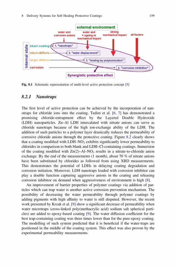
8.2.1 Nanotraps
The first level of active protection can be achieved by the incorporation of nan-otraps for chloride ions into the coating. Tedim et al. [6, 7] has demonstrated apromising chloride-entrapment effect by the Layered Double Hydroxide(LDH) nanoparticles. Zn–Al LDH intercalated with nitrate anions can serve aschloride nanotraps because of the high ion-exchange ability of the LDH. Theaddition of such particles to a polymer layer drastically reduces the permeability ofcorrosive chloride anions through the protective coating. Figure 8.2 clearly showsthat a coating modified with LDH–NO3 exhibits significantly lower permeability tochlorides in comparison to both blank and LDH–Cl-containing coatings. Immersionof the coating modified with Zn(2)–Al–NO3 results in a nitrate-to-chloride anionexchange. By the end of the measurements (1 month), about 70 % of nitrate anionshave been substituted by chlorides as followed from using XRD measurements.This demonstrates the potential of LDHs in delaying coating degradation andcorrosion initiation. Moreover, LDH nanotraps loaded with corrosion inhibitor canplay a double function capturing aggressive anions in the coating and releasingcorrosion inhibitor on demand when aggressiveness of environment is high [8].
An improvement of barrier properties of polymer coatings via addition of par-ticles which can trap water is another active corrosion prevention mechanism. Thepossibility of decreasing the water permeability through polymer coatings byadding pigments with high affinity to water is still disputed. However, the recentwork presented by Krzak et al. [9] show a significant decrease of permeability whenwater microtraps (cross-linked poly(methacrylic acid) sodium salt spherical parti-cles) are added to epoxy-based coating [9]. The water diffusion coefficient for thebest trap-containing coating was three times lower than for the pure epoxy coating.The modelling of such system predicted that it is beneficial if the water-traps arepositioned in the middle of the coating system. This effect was also proven by theexperimental permeability measurements.
Fig. 8.1 Schematic representation of multi-level active protection concept [5]
8 Delivery Systems for Self Healing Protective Coatings 159
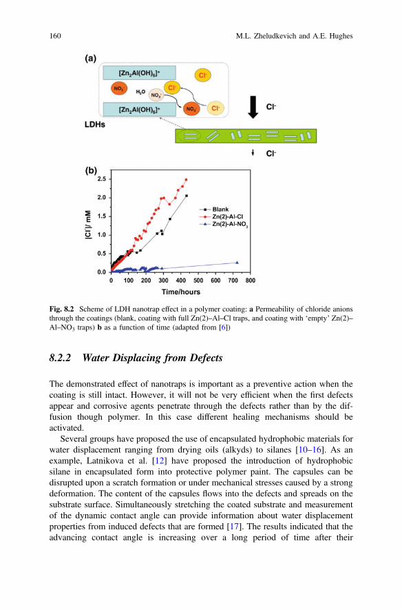
8.2.2 Water Displacing from Defects
The demonstrated effect of nanotraps is important as a preventive action when thecoating is still intact. However, it will not be very efficient when the first defectsappear and corrosive agents penetrate through the defects rather than by the dif-fusion though polymer. In this case different healing mechanisms should beactivated.
Several groups have proposed the use of encapsulated hydrophobic materials forwater displacement ranging from drying oils (alkyds) to silanes [10–16]. As anexample, Latnikova et al. [12] have proposed the introduction of hydrophobicsilane in encapsulated form into protective polymer paint. The capsules can bedisrupted upon a scratch formation or under mechanical stresses caused by a strongdeformation. The content of the capsules flows into the defects and spreads on thesubstrate surface. Simultaneously stretching the coated substrate and measurementof the dynamic contact angle can provide information about water displacementproperties from induced defects that are formed [17]. The results indicated that theadvancing contact angle is increasing over a long period of time after their
Fig. 8.2 Scheme of LDH nanotrap effect in a polymer coating: a Permeability of chloride anionsthrough the coatings (blank, coating with full Zn(2)–Al–Cl traps, and coating with ‘empty’ Zn(2)–Al–NO3 traps) b as a function of time (adapted from [6])
160 M.L. Zheludkevich and A.E. Hughes
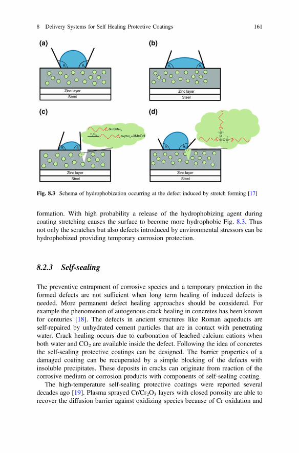
formation. With high probability a release of the hydrophobizing agent duringcoating stretching causes the surface to become more hydrophobic Fig. 8.3. Thusnot only the scratches but also defects introduced by environmental stressors can behydrophobized providing temporary corrosion protection.
8.2.3 Self-sealing
The preventive entrapment of corrosive species and a temporary protection in theformed defects are not sufficient when long term healing of induced defects isneeded. More permanent defect healing approaches should be considered. Forexample the phenomenon of autogenous crack healing in concretes has been knownfor centuries [18]. The defects in ancient structures like Roman aqueducts areself-repaired by unhydrated cement particles that are in contact with penetratingwater. Crack healing occurs due to carbonation of leached calcium cations whenboth water and CO2 are available inside the defect. Following the idea of concretesthe self-sealing protective coatings can be designed. The barrier properties of adamaged coating can be recuperated by a simple blocking of the defects withinsoluble precipitates. These deposits in cracks can originate from reaction of thecorrosive medium or corrosion products with components of self-sealing coating.
The high-temperature self-sealing protective coatings were reported severaldecades ago [19]. Plasma sprayed Cr/Cr2O3 layers with closed porosity are able torecover the diffusion barrier against oxidizing species because of Cr oxidation and
Fig. 8.3 Schema of hydrophobization occurring at the defect induced by stretch forming [17]
8 Delivery Systems for Self Healing Protective Coatings 161

closing the defects when exposed to an oxidizing environment at temperaturesabove 900 °C. Sugama and Gawlik [20] have reported a poly (phenylenesulfide)(PPS) self-sealing coating for protection of carbon steel heat exchanger tubesoperating at brine temperatures up to 200 °C. The calcium aluminate fillers dis-persed in the coating matrix undergo the decalcification–hydration reactions closeto the defect promoting a fast growth of boehmite crystals in the cracks. Theblock-like boehmite crystals (*4 μm in size) fill the cracks increasing the poreresistance of the damaged coating about two orders of magnitude after 24 h.Extension of the exposure time to 20 days results in a stable value of pore resistancemeaning that the sealing of the cracks by boehmite crystals plays an essential role inthe recovery of the protective function of a PPS coating.
The self-sealing coatings operating at lower temperatures have been alsoreported [21]. The two layer coating consisting of an expandable clay layer and apolymer top coat was designed. The idea is based on the expansion of the clayphase in the defects leading to its partial sealing. Figure 8.4 demonstrates theschematics of the coating and micrographs of scratched zone before and aftersealing. Fast filling of cracks occurred mainly within the first two hours of exposureresulting in a good restoration of the surface flatness. A similar approach was alsosuggested by Hikasa et al. [22], where a sodium-clay (hectorite) and silica multi-layers were deposited using spin coating technique. The hectorite is a swelling claywhich expands cubically due to the reaction with water. When water penetrates to
Fig. 8.4 SEM images of a scratch on a multi-layer coating obtained by a 0.15 N load before(a) and after 21 h of healing (b); (c) graphical representation of the two-layer coating used tomodel the crack-filling effect; d = scratch width and h0 = clay layer height. Adapted from [21]
162 M.L. Zheludkevich and A.E. Hughes
the crack in clay/silica composite film it reacts with hectorite causing its swellingand consequent blocking of the defect.
The swelling function can also be achieved by addition of superabsorbentpolymers as active pigments [23]. The protective vinyl ester polymer coatingcontaining superabsorbent polymer particles were developed to ensure active pro-tection of steel substrates. Electrochemical impedance study demonstrates thatbarrier properties of the coating damaged by a knife increase remarkably uponimmersion in electrolyte. The swelled polymer particles create a layer which pre-vents the diffusion of oxygen from the bulk solution to the scratched surface of thesubstrate.
In spite of the proof of several self-sealing concepts the real application ofself-sealing coatings for low-temperature corrosion protection has not yet beendemonstrated. One of the important restrictions is the limited degree of barrierrecovery. The sealing often is not sufficient to fully prevent ingress of electrolyteand oxygen into the defect.
8.3 Self Healing in Polymer Networks
Another approach widely discussed in self-healing polymer or composite bulkmaterials is based on reversible formation of polymer bonds under different con-ditions. This type of self-healing is often called as intrinsic healing. In this case thehealing capability is intrinsically connected to the polymer matrix. The two parts ofthe damaged polymer should be brought together at the first stage in order to ensurethe contact. Only then the reconstruction of polymer bonds and recovery of thepolymer matrix integrity can be achieved [24]. There are two main chemicalapproaches based on supramolecular interactions (e.g., hydrogen bonding [25],ionic interactions [26], π–π interactions, or host-guest interactions)) or reversiblecovalent bond formation (e.g., based on the Diels-Alder (DA) reaction) [27].A comprehensive review on the different self-healing polymer based materials isout of scope for this chapter since most of the approaches are not applicable toprotective coatings. In the case of coating the geometrical limitations can play asignificant role. A relative high mobility of the polymer matrix is needed to closethe gap by relatively thin layer of polymer. In many cases the width of the defect islarger than the thickness of the polymer coating. Nevertheless several intrinsicself-healing polymer coatings were recently developed as briefly overviewedbelow.
An example of supramolecular copolymer used to create self-healing coatingwas recently presented by Bode et al. [28]. The chains forming the copolymernetwork are connected by metal-ligand interactions in this case. The healing processoccurs on the molecular level via formation of ionic clusters which consist ofdoubly positively charged iron center and two terpyridines as ligands (Fig. 8.5).However, certain energy is required to reach sufficient mobility of polymer networkfor the reformation of ionic clusters.
8 Delivery Systems for Self Healing Protective Coatings 163
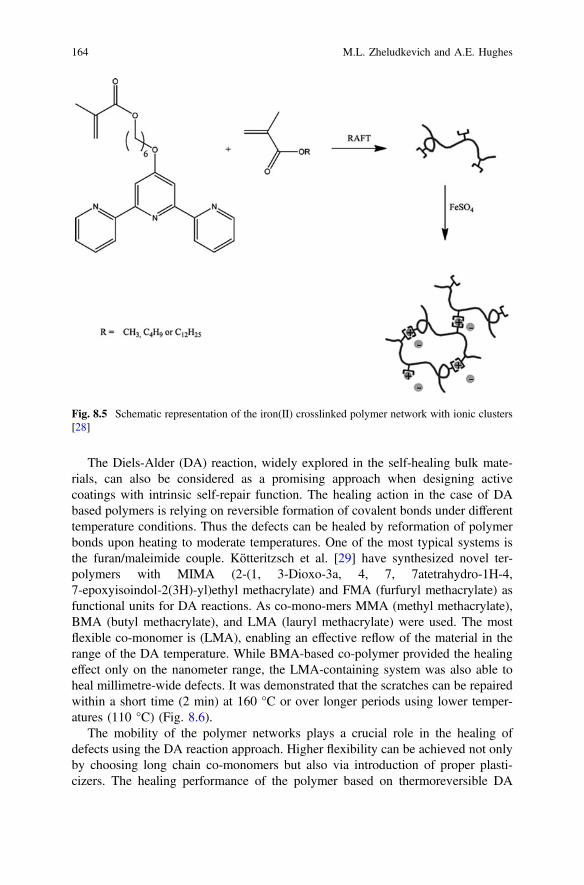
The Diels-Alder (DA) reaction, widely explored in the self-healing bulk mate-rials, can also be considered as a promising approach when designing activecoatings with intrinsic self-repair function. The healing action in the case of DAbased polymers is relying on reversible formation of covalent bonds under differenttemperature conditions. Thus the defects can be healed by reformation of polymerbonds upon heating to moderate temperatures. One of the most typical systems isthe furan/maleimide couple. Kötteritzsch et al. [29] have synthesized novel ter-polymers with MIMA (2-(1, 3-Dioxo-3a, 4, 7, 7atetrahydro-1H-4,7-epoxyisoindol-2(3H)-yl)ethyl methacrylate) and FMA (furfuryl methacrylate) asfunctional units for DA reactions. As co-mono-mers MMA (methyl methacrylate),BMA (butyl methacrylate), and LMA (lauryl methacrylate) were used. The mostflexible co-monomer is (LMA), enabling an effective reflow of the material in therange of the DA temperature. While BMA-based co-polymer provided the healingeffect only on the nanometer range, the LMA-containing system was also able toheal millimetre-wide defects. It was demonstrated that the scratches can be repairedwithin a short time (2 min) at 160 °C or over longer periods using lower temper-atures (110 °C) (Fig. 8.6).
The mobility of the polymer networks plays a crucial role in the healing ofdefects using the DA reaction approach. Higher flexibility can be achieved not onlyby choosing long chain co-monomers but also via introduction of proper plasti-cizers. The healing performance of the polymer based on thermoreversible DA
Fig. 8.5 Schematic representation of the iron(II) crosslinked polymer network with ionic clusters[28]
164 M.L. Zheludkevich and A.E. Hughes
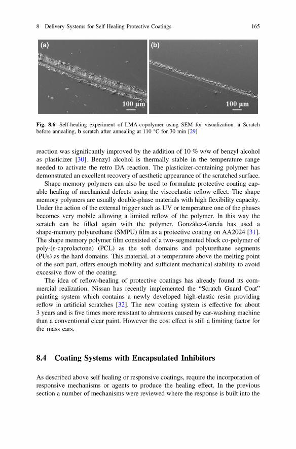
reaction was significantly improved by the addition of 10 % w/w of benzyl alcoholas plasticizer [30]. Benzyl alcohol is thermally stable in the temperature rangeneeded to activate the retro DA reaction. The plasticizer-containing polymer hasdemonstrated an excellent recovery of aesthetic appearance of the scratched surface.
Shape memory polymers can also be used to formulate protective coating cap-able healing of mechanical defects using the viscoelastic reflow effect. The shapememory polymers are usually double-phase materials with high flexibility capacity.Under the action of the external trigger such as UV or temperature one of the phasesbecomes very mobile allowing a limited reflow of the polymer. In this way thescratch can be filled again with the polymer. González-García has used ashape-memory polyurethane (SMPU) film as a protective coating on AA2024 [31].The shape memory polymer film consisted of a two-segmented block co-polymer ofpoly-(ɛ-caprolactone) (PCL) as the soft domains and polyurethane segments(PUs) as the hard domains. This material, at a temperature above the melting pointof the soft part, offers enough mobility and sufficient mechanical stability to avoidexcessive flow of the coating.
The idea of reflow-healing of protective coatings has already found its com-mercial realization. Nissan has recently implemented the “Scratch Guard Coat”painting system which contains a newly developed high-elastic resin providingreflow in artificial scratches [32]. The new coating system is effective for about3 years and is five times more resistant to abrasions caused by car-washing machinethan a conventional clear paint. However the cost effect is still a limiting factor forthe mass cars.
8.4 Coating Systems with Encapsulated Inhibitors
As described above self healing or responsive coatings, require the incorporation ofresponsive mechanisms or agents to produce the healing effect. In the previoussection a number of mechanisms were reviewed where the response is built into the
Fig. 8.6 Self-healing experiment of LMA-copolymer using SEM for visualization. a Scratchbefore annealing, b scratch after annealing at 110 °C for 30 min [29]
8 Delivery Systems for Self Healing Protective Coatings 165
polymer itself. However, there is a very broad range of self healing applicationswhere it is either desirable or necessary to isolate the healing agent from thepolymer matrix using a variety of encapsulation approaches. There are good reasonsto isolate the healing agents because (i) it may react with the polymer matrixmaterial, (ii) it may be easily leached from the polymer or (iii) it may be desired tohave a triggered release and so the capsule must respond to the triggeringmechanism.
The term encapsulation itself encapsulates a wide variety of approaches toincorporating agents into coatings. It can range from inert capsules which play noother role than to isolate the active agent from the polymer resin [16], to ionexchange materials where the healing agent (e.g. chromate) that is released isexchanged for an agent that causes degradation (e.g. the chloride ion) [33]. Thereare several good reviews on this subject [34, 35]. There is no straight forwardclassification system for encapsulated, self healing agents since they could beclassified based on capsule geometry, size, material, mechanism (e.g. ion exchangecapacity mentioned above), or application to cite just a few possible classificationsystems. The approach adopted here is to classify the capsules based on the materialfrom which they are made.
Before we discuss in detail the different capsule types, it is worth noting thatmany of the encapsulation approaches adopted by researchers in the field areborrowed from either the food or pharmaceutical industries where encapsulation isused extensively. In the food industry one of the major uses is for encapsulatingflavours [36]. In the pharmaceutical industry it is used for targeted delivery of drugs[37–41]. It is interesting to note that for many oral pharmaceuticals, the acidenvironment of the stomach is a key target environment for the design of encap-sulation systems. Different design strategies may vary from slow release to com-plete inertness in the stomach to allow the capsule to survive the stomachenvironment to release “downstream” in the intestines. The reason why thisapplication is of interest is that the stomach is a hydrochloric acid environment ofpH 3 which is similar to the anolyte solution in an active pit [42, 43], which can beused as a trigger mechanism.
Encapsulating containers for coating applications have different requirementsthan for other applications. The most obvious limitation is that the width of thecontainer must be smaller than the thickness of the coating as noted above.Convoluted with this issue is the amount of material that is required for healing.Approaches to this issue involve hollow tubes that can form 2-D structures [44] tomethods for the manufacture of elongated capsules [45].
Prior to further description of encapsulation, particularly where an active agent isabsorbed into a porous material, it is important to note that there are IUPACdefinitions for porosity [46]. These are:
(i) micropores: less than 2 nm(ii) mesopores: between 2 and 50 nm(iii) macropores: greater than 50 nm
166 M.L. Zheludkevich and A.E. Hughes
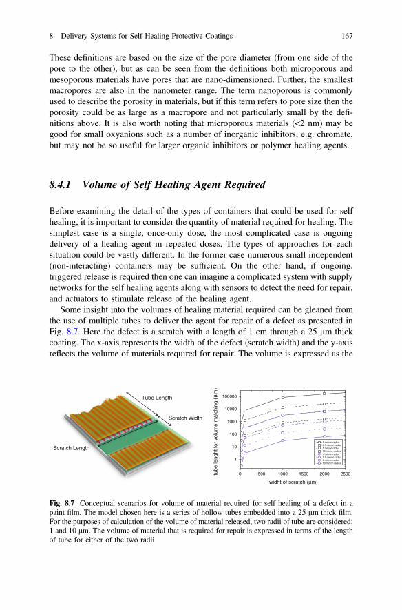
These definitions are based on the size of the pore diameter (from one side of thepore to the other), but as can be seen from the definitions both microporous andmesoporous materials have pores that are nano-dimensioned. Further, the smallestmacropores are also in the nanometer range. The term nanoporous is commonlyused to describe the porosity in materials, but if this term refers to pore size then theporosity could be as large as a macropore and not particularly small by the defi-nitions above. It is also worth noting that microporous materials (<2 nm) may begood for small oxyanions such as a number of inorganic inhibitors, e.g. chromate,but may not be so useful for larger organic inhibitors or polymer healing agents.
8.4.1 Volume of Self Healing Agent Required
Before examining the detail of the types of containers that could be used for selfhealing, it is important to consider the quantity of material required for healing. Thesimplest case is a single, once-only dose, the most complicated case is ongoingdelivery of a healing agent in repeated doses. The types of approaches for eachsituation could be vastly different. In the former case numerous small independent(non-interacting) containers may be sufficient. On the other hand, if ongoing,triggered release is required then one can imagine a complicated system with supplynetworks for the self healing agents along with sensors to detect the need for repair,and actuators to stimulate release of the healing agent.
Some insight into the volumes of healing material required can be gleaned fromthe use of multiple tubes to deliver the agent for repair of a defect as presented inFig. 8.7. Here the defect is a scratch with a length of 1 cm through a 25 μm thickcoating. The x-axis represents the width of the defect (scratch width) and the y-axisreflects the volume of materials required for repair. The volume is expressed as the
0 500 1000 1500 2000 2500
1
10
100
1000
10000
100000
tube
leng
ht fo
r vo
lum
e m
atch
ing
(m
)
widht of scratch ( m)
1 micron radius 2.5 micron radius 5 micron radius 10 micron radius 1 micron radius 2.5 micron radius 5 micron radius 10 micron radius
Scratch Width
Tube Length
Scratch Length
µ
µ
Fig. 8.7 Conceptual scenarios for volume of material required for self healing of a defect in apaint film. The model chosen here is a series of hollow tubes embedded into a 25 μm thick film.For the purposes of calculation of the volume of material released, two radii of tube are considered;1 and 10 μm. The volume of material that is required for repair is expressed in terms of the lengthof tube for either of the two radii
8 Delivery Systems for Self Healing Protective Coatings 167
length of tube (tube length) that is required for four different radii of tubes (1–10 μm) that are embedded into the film. A 10 μm radius for the tube is close thethickness of the film. The calculation for the data presented in Fig. 8.7 assumes thatthere are 1000 tubes supplying the defect. In the case of the tubes with a 10 μmradius the tubes will be nearly touching each other along the walls of the scratch. Itis immediately clear that as the scratch widens there is a significant increase (ordersof magnitude) in the volume of material required for volume filling of the scratchwhich is equivalent to full functional and cosmetic repair as represented by the datain black. As an example a 1 mm (1000 μm) scratch would require all 1000 tubes torelease healing agent from around 10 cm of their length which will limit theavailability of healing agent for further repairs. On the other hand, if the objective isto simply provide a functional repair then, represented by a 1 μm thick film inFig. 8.7, then only 1 mm length of tube is required to release enough material fromall the tubes to provide a functional repair thus reducing the design demands for thecoating system. This reasoning is what has driven a lot of self healing activity in thecoatings area for a functional, as opposed to full cosmetic, repair.
The strategies based on encapsulation of self-healing agents in single capsulesconfront the same issues related to the amount of healing agent available at thedefects. The number of capsules and their diameter play the major role. Recenttheoretical analysis has demonstrated that the size of the microcapsule and thegeometry of the crack are very important in coating healing [47]. In the case ofsmall cracks the optimal diameter of microcapsule has to be used. The probabilityof healing significantly decreases with an increase in diameter and volume ofavailable healing agent in a single capsule since the probability of rupturing spar-sely located large microcapsules by a small crack is very low. In the case of a largecrack the maximum possible microcapsule diameter has to be used for efficienthealing. It is related to the fact that the probability of hitting the capsules by thecrack is close to 1 and repair depends only on the amount of healing agent avail-able. The dependence of the theoretical healing efficiency on the capsule dimen-sions for different loading levels and different crack sizes is demonstrated inFig. 8.8. It can be clearly seen that even at high loading levels such as 15 % the firstremarkable signs of a self-healing effect can be expected only in the case of cap-sules larger than 20 µm. However, as stated, capsules of this size approach the filmthickness for many potential applications. Therefore the self-healing coatings withpolymerizable agents can be only efficient for coatings with much higher thicknessused in oil and gas or marine industries for example.
The only possible way to achieve the recovery of mechanical integrity isapplication of polymerizable agents which form expanding phases where the vol-ume of the polymer is significantly higher than the volume of original monomers. Itcan be achieved for example by use of polyepoxide or polyurethane foams [48].
Beyond these conceptual ideas for addressing the issue of the volume of requiredhealing agents that is required, are the mechanics and materials science of incor-porating these concepts into real coatings. Small isolated containers will have aninfluence on the mechanical properties of the coating on the local scale, whereas theincorporation of flow networks, sensors and actuators will have an obvious
168 M.L. Zheludkevich and A.E. Hughes
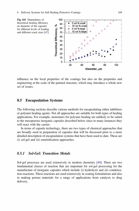
influence on the local properties of the coatings but also on the properties andengineering at the scale of the painted structure, which may introduce a whole newset of issues.
8.5 Encapsulation Systems
The following sections describe various methods for encapsulating either inhibitorsor polymer healing agents. Not all approaches are suitable for both types of healingapplications. For example, monomers for polymer healing are unlikely to be suitedto the mesoporous inorganic capsules described below since in many instances theywill react with the carrier.
In terms of capsule technology, there are two types of chemical approaches thatare broadly used in preparation of capsules that will be discussed prior to a moredetailed description of encapsulation systems that have been used to date. These are(i) sol-gel and (ii) emulsification approaches.
8.5.1 Sol-Gel: Transition Metals
Sol-gel processes are used extensively in modern chemistry [49]. There are twofundamental classes of reaction that are important for sol-gel processing for themanufacture of inorganic capsules which include (i) hydrolysis and (ii) condensa-tion reactions. These reactions are used extensively in coating formulations and alsoin making porous materials for a range of applications from catalysis to drugdelivery.
Fig. 8.8 Dependence oftheoretical healing efficiencyon diameter of the capsulesfor different levels of loadingand different crack sizes [47]
8 Delivery Systems for Self Healing Protective Coatings 169

Metals ions dissolved in water are solvated by water molecules. Hydrolysis ofthese metal ions can be generally defined by the following equilibria:
½MðOH2Þ�zþ $ ½M�OH�ðz�1Þþ þHþ $ ½M=OÞ�ðz�2Þþ þ 2Hþ ð8:1Þ
Where there are three types of non-complexing ligands including the aquoligand M(OH2), the hydroxo ligand (M–OH) and the oxo ligand (M = O). Theequilibrium species will depend on the co-ordination number (N), the charge (z),the electronegativity and the pH. A general representation of these precursor speciesis [MONH2N-h]
(z−h)+ where h is the molar ratio of hydrolysis. In terms of thespecies, if h = 0 then it is an aquo ion [MONH2N]
(z)+, and if h = 2 N then it is an oxoion [MON]
(2N−z)−. At intermediate values of h there are oxy-hydroxo complexes[MOx(OH)N-x]
(N+x−z)− or hydroxo-aquo complexes [M(OH)x(OH2)N-x](z−x)+. In the
case of the transition metal cations, there is charge transfer into the d orbitals fromthe 3a1 bonding orbital of water. In the case of the rare earths the f orbitals will alsobe involved.
These species can then interact to form structures that eventually result in pre-cipitates; a process called condensation. This can proceed via two nucleophylicmechanisms either nucleophylic substitution where the preferred co-odination issatisfied [49]:
ð8:2Þ
or nucleophylic addition where the preferred co-ordination is not satisfied:
ð8:3Þ
Condensation occurs via olation or oxolation (which includes alcoxolation) asdescribed below. During olation a hydroxyl bridge(s) is formed between two metalcentres whereas oxolation is a process where an oxo bridge(s) is formed betweentwo metal centres with one type of oxo-bridge depicted in the schema below. Wherethe metal is co-ordinatively unsaturated then oxolation occurs by nucleophylicaddition and leads to edge sharing or face sharing polyhedral [49]. Forco-ordinatively saturated metal ions then oxolation occurs by 2 step nucleophylicsubstitution leading to a M–O–M bond and water elimination. Oxolation occurs via:
ð8:4Þ
170 M.L. Zheludkevich and A.E. Hughes
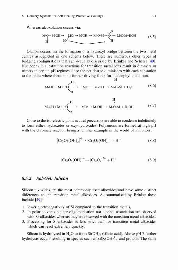
Whereas alcoxolation occurs via:
ð8:5Þ
Olation occurs via the formation of a hydroxyl bridge between the two metalcentres as depicted in one schema below. There are numerous other types ofbridging configurations that can occur as discussed by Brinker and Scherer [49].Nucleophylic substitution reactions for transition metal ions result in dimmers ortrimers in certain pH regimes since the net charge diminishes with each substationto the point where there is no further driving force for nucleophylic addition.
ð8:6Þ
ð8:7Þ
Close to the iso-electric point neutral precursors are able to condense indefinitelyto form either hydroxides or oxy-hydroxides. Polyanions are formed at high pHwith the chromate reaction being a familiar example in the world of inhibitors:
Cr2O5ðOHÞ2� �0! Cr2O6ðOHÞ½ �� þHþ ð8:8Þ
Cr2O6ðOHÞ½ ��! Cr2O7½ �2� þHþ ð8:9Þ
8.5.2 Sol-Gel: Silicon
Silicon alkoxides are the most commonly used alkoxides and have some distinctdifferences to the transition metal alkoxides. As summarised by Brinker theseinclude [49]:
1. lower electronegativity of Si compared to the transition metals,2. In polar solvents neither oligomerisation nor alcohol association are observed
with Si-alkoxides whereas they are observed with the transition metal alkoxides,3. Processing for Si-alkoxides is less strict than for transition metal alkoxides
which can react extremely quickly.
Silicon is hydrolysed in H2O to form Si(OH)4 (silicic acid). Above pH 7 furtherhydrolysis occurs resulting in species such as SiOx(OH)4-x
4− and protons. The same
8 Delivery Systems for Self Healing Protective Coatings 171
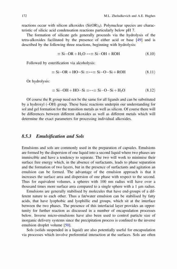
reactions occur with silicon alkoxides (Si(OR)4). Polynuclear species are charac-teristic of silicic acid condensation reactions particularly below pH 7.
The formation of silicate gels generally proceeds via the hydrolysis of thetetra-alkoxides facilitated by the presence of either acid or base [49] and isdescribed by the following three reactions, beginning with hydrolysis:
� Si�ORþH2O $� Si�OHþROH ð8:10Þ
Followed by esterification via alcoholysis:
� Si�ORþHO�Si �$� Si�O�SiþROH ð8:11Þ
Or hydrolysis:
� Si�OHþHO�Si �$� Si�O�SiþH2O ð8:12Þ
Of course the R group need not be the same for all ligands and can be substitutedby a hydroxyl (–OH) group. These basic reactions underpin our understanding forsol and gel formation for the transition metals as well as silicon. Of course there willbe differences between different alkoxides as well as different metals which willdetermine the exact parameters for processing individual alkoxides.
8.5.3 Emulsification and Sols
Emulsions and sols are commonly used in the preparation of capsules. Emulsionsare formed by the dispersion of one liquid into a second liquid where two phases areimmiscible and have a tendency to separate. The two will work to minimise theirsurface free energy which, in the absence of surfactants, leads to phase separationand the formation of two layers, but in the presence of surfactants and agitation anemulsion can be formed. The advantage of the emulsion approach is that itincreases the surface area and dispersion of one phase with respect to the second.Thus for equivalent volumes, a spheres with 100 nm radius will have over athousand times more surface area compared to a single sphere with a 1 μm radius.
Emulsions are generally stabilised by molecules that have end-groups of a dif-ferent nature to each other. Thus a fat/water emulsion can be stabilised by fattyacids, that have lyophobic and lyophillic end groups, which sit at the interfacebetween the two phases. The presence of this interfacial layer provides an oppor-tunity for further reaction as discussed in a number of encapsulation processesbelow. Inverse micro-emulsions have also been used to control particle size ofinorganic delivery systems since the precipitation process is confined to the inverseemulsion droplet volume [50].
Sols (solids suspended in a liquid) are also potentially useful for encapsulationvia processes which involve preferential interaction at the surfaces. Sols are often
172 M.L. Zheludkevich and A.E. Hughes
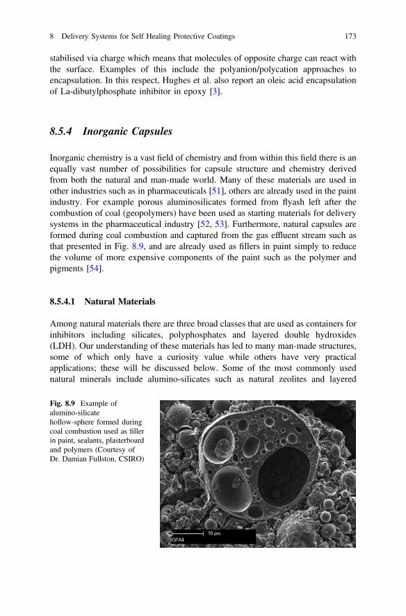
stabilised via charge which means that molecules of opposite charge can react withthe surface. Examples of this include the polyanion/polycation approaches toencapsulation. In this respect, Hughes et al. also report an oleic acid encapsulationof La-dibutylphosphate inhibitor in epoxy [3].
8.5.4 Inorganic Capsules
Inorganic chemistry is a vast field of chemistry and from within this field there is anequally vast number of possibilities for capsule structure and chemistry derivedfrom both the natural and man-made world. Many of these materials are used inother industries such as in pharmaceuticals [51], others are already used in the paintindustry. For example porous aluminosilicates formed from flyash left after thecombustion of coal (geopolymers) have been used as starting materials for deliverysystems in the pharmaceutical industry [52, 53]. Furthermore, natural capsules areformed during coal combustion and captured from the gas effluent stream such asthat presented in Fig. 8.9, and are already used as fillers in paint simply to reducethe volume of more expensive components of the paint such as the polymer andpigments [54].
8.5.4.1 Natural Materials
Among natural materials there are three broad classes that are used as containers forinhibitors including silicates, polyphosphates and layered double hydroxides(LDH). Our understanding of these materials has led to many man-made structures,some of which only have a curiosity value while others have very practicalapplications; these will be discussed below. Some of the most commonly usednatural minerals include alumino-silicates such as natural zeolites and layered
Fig. 8.9 Example ofalumino-silicatehollow-sphere formed duringcoal combustion used as fillerin paint, sealants, plasterboardand polymers (Courtesy ofDr. Damian Fullston, CSIRO)
8 Delivery Systems for Self Healing Protective Coatings 173
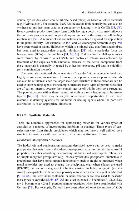
double hydroxides which can be silicate-based (clays) or based on other elements(e.g. Hydrotalcites). For example, NaX Zeolite occurs both naturally but can also besynthesised and has been used as a container by loading it with Ce(III) [55, 56].Even corrosion product itself may form LDHs having a porosity that may influencethe corrosion process as well as provide opportunities for the design of self healingmechanisms [57]. A number of natural materials have been explored for applicationin the paint industry. For example Ce [58] and Ca-exchanged bentonite clays [59]have been tested in paints. Halloysite, which is a mineral clay that forms nanotubes,has been used to encapsulate organic inhibitors [51] with a particular focus onbenzotriazole (BTA) as the inhibitor [51, 60, 61]. Endcaps for the Halloysite tubeswere formed by exposure to a CuSO4 and controlled release was achieved bytreatment of the capsules with ammonia. Release of the active component fromthese materials is generally triggered by either ion exchange, pH and or solubility(or a combination thereof).
The materials mentioned above operate as “capsules” at the molecular level, i.e.,largely as microporous materials. However, mesoporous or macroporous materialscan also be of interest since the larger scale pore structure in these materials can beused to store healing agents. For example, there are many types of porous rocks thatare of current interest because they contain gas or oil within their pore structures.The pore structures within these natural minerals are only beginning to be inves-tigated [62, 63]. There may be as yet undiscovered opportunities to use thesematerials as delivery systems for inhibitors or healing agents where the pore sizedistribution is of an appropriate dimension.
8.5.4.2 Synthetic Materials
There are numerous approaches for synthesising materials for various types ofcapsules as a method of incorporating inhibitors in coatings. These types of cap-sules can vary from simple precipitates which may not have a well defined porestructure to materials with more ordered structures as discussed below.
Disordered Mesoporous Structures
The hydrolysis and condensation reactions described above can be used to makeprecipitates that may have a disordered mesoporous structure but still have usefulproperties for either adsorbing or absorbing inhibitors and other agents. These canbe simple inorganic precipitates (e.g., oxides hydroxides, phosphates, sulphates) toprecipitates that have some organic functionality such as might be produced whenmetal alkoxides are used to prepare the precipitate, e.g., when silanes are used(RSiOR’). A second category of inhibitor carriers includes inorganic (usuallyoxide) nano-particles with no microporosity onto which an active agent is adsorbed[5, 64–68]; the term nano-containers or nano-reservoirs are also used to describethese types of capsules [5, 65, 68–70] and even extended to boehmite (Al2O3.nH2O,n = 1; boehmite, n = 2 or 3; pseudoboehmite) particles which have been loaded withCe ions [71]. For example, Ce ions have been adsorbed onto the surface of ZrO2
174 M.L. Zheludkevich and A.E. Hughes
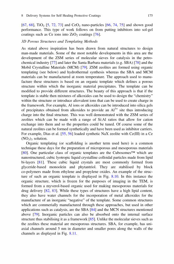
[67, 68], TiO2 [5, 72, 73] and CeO2 nano-particles [66, 74, 75] and shown goodperformance. This type of work follows on from putting inhibitors into sol-gelcoatings such as Ce ions into ZrO2 coatings [76].
3D Porous Structures and Templating Methods
As stated above inspiration has been drawn from natural structures to designman-made materials. Some of the most notable developments in this area are thedevelopment of the ZSM series of molecular sieves for catalysis in the petro-chemical industry [77] and later the Santa Barbara materials (e.g. SBA) [78] and theMobil Crystalline Materials (MCM) [79]. ZSM zeolites are formed using organictemplating (see below) and hydrothermal synthesis whereas the SBA and MCMmaterials can be manufactured at room temperature. The approach used to manu-facture these structures is based on an organic template which defines a porousstructure within which the inorganic material precipitates. The template can bemodified to provide different structures. The beauty of this approach is that if thetemplate is stable then mixtures of alkoxides can be used to design the “chemistry”within the structure or introduce aliovalent ions that can be used to create charge inthe framework. For example, Al ions or alkoxides can be introduced into silica gelsof precipitates obtained from alkoxides to provide an Al3+ site thus introducingcharge into the final structure. This was well demonstrated with the ZSM series ofzeolites which can be made with a range of Si:Al ratios that allow for cationexchange into them and so the properties could be tuned. Of course some of thenatural zeolites can be formed synthetically and have been used as inhibitor carriers.For example, Dias et al. [55, 56] loaded synthetic NaX zeolite with Ce(III) in a Ce(NO3)3 solution.
Organic templating (or scaffolding is another term used here) is a commontechnique these days for the preparation of microporous and mesoporous materials[80]. One particular class of organic templates are the Cubosomes™ which arenanostructured, cubic lyotropic liquid crystalline colloidal particles made from lipidbi-layers [81]. These cubic liquid crystals are most commonly formed fromglyceride-based monoolein and phytantriol. They are stabilised by blockco-polymers made from ethylene and propylene oxides. An example of the struc-ture of such an organic template is displayed in Fig. 8.10. In this instance theorganic structure, which is frozen for the purposes of imaging in the TEM, isformed from a myverol-based organic used for making mesoporous materials fordrug delivery [82, 83]. While these types of structures have a high lipid content,they also have water channels for the incorporation of metal alkoxides for themanufacture of an inorganic “negative” of the template. Some common structureswhich are commerially manufactured through these approaches, but used in otherapplications such as catalysis, are the SBA [84] and the MCN structures mentionedabove [79]. Inorganic particles can also be absorbed onto the internal surfacestructure thus stabilising it as a framework [85]. Unlike the molecular sieves such asthe zeolites these material are mesoporous structures. SBA, for example, has uni-axial channels around 5 nm in diameter and smaller pores along the walls of thechannels as displayed in Fig. 8.11.
8 Delivery Systems for Self Healing Protective Coatings 175
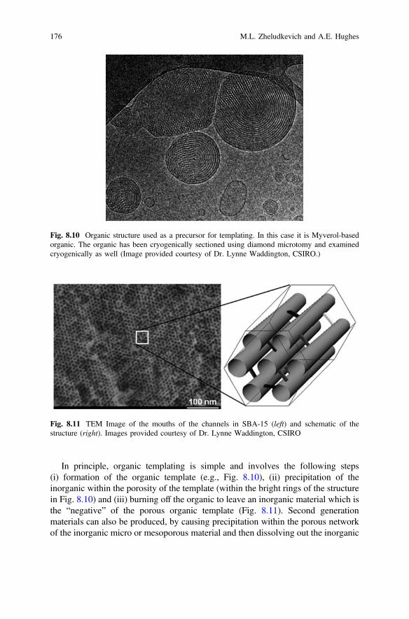
In principle, organic templating is simple and involves the following steps(i) formation of the organic template (e.g., Fig. 8.10), (ii) precipitation of theinorganic within the porosity of the template (within the bright rings of the structurein Fig. 8.10) and (iii) burning off the organic to leave an inorganic material which isthe “negative” of the porous organic template (Fig. 8.11). Second generationmaterials can also be produced, by causing precipitation within the porous networkof the inorganic micro or mesoporous material and then dissolving out the inorganic
Fig. 8.10 Organic structure used as a precursor for templating. In this case it is Myverol-basedorganic. The organic has been cryogenically sectioned using diamond microtomy and examinedcryogenically as well (Image provided courtesy of Dr. Lynne Waddington, CSIRO.)
Fig. 8.11 TEM Image of the mouths of the channels in SBA-15 (left) and schematic of thestructure (right). Images provided courtesy of Dr. Lynne Waddington, CSIRO
176 M.L. Zheludkevich and A.E. Hughes

material. In the case of silicates using hydrofluoric acid or strong alkali results indissolution of the structure. The second generation precipitation generally involvesinorganic materials that are HF and alkali resistant. This results in a reproduction ofthe original organic framework. The inorganics are typically metal alkoxides, butsilicon alkoxides are by far the most characterised and best understood as describedin the sol-gel section.
The structure of the organic template is sensitive to the chemistry and can beeasily destroyed, thus templating with other metal alkoxides may not be so straightforward as with silicon alkoxides. As discussed above, the rapidity of hydrolysisand condensation reactions for the transition metal alkoxides is one difficulty, butothers include whether the optimum pH is achieved for hydrolysis and condensa-tion reactions, or whether the rapid release of alcohols destabilises the templatingstructure. For the rapidity of hydrolysis, Zheludkevich et al. [86] rates the reactivityof a number of metal alkoxides with similar alkoxides groups as Si(OR)4 « Sn(OR)4 < Ti(OR)4 < Zr(OR)4 < Ce(OR)4. Nevertheless examples based on using Tipropoxides [87] Zr-oxychlorides [88] and Ce acetate have been reported [89].
All these templating processes rely on sol-gel chemistry described above wheremetal alkoxides undergo full hydrolysis followed by polymerisation. A variant onthis process is where traditional hydrolysis and condensation is performed in thepresence of silanes. The species here are of the form RnSi(OR′)4-n where the Rgroups can perform some additional function such as providing linkers for crosslinking and coating formation. These materials are called Ormosils after “organi-cally modified silicate” [90]. This type of sol-gel chemistry is used widely incoatings research and there are many excellent reviews of this area [86, 90–92].There are numerous examples of sol-gel coatings in the inhibitor and coatingsliterature including silica- [93–101], titania- [72, 102], zirconia- [67, 103–108],ceria- [76, 109] and molybdate- [110] based processes. Some examples include theloading of titania nanocontainers with 8-hydroxyquinilone (8-HQ) [72] or benzo-triazole [102]. There is an equally large literature looking at the incorporation ofnanoparticles or inhibiting ions into sol-gel coatings [64, 65, 68, 76, 95, 106, 111,112]. Often sol-gel approaches are used in hybrid applications where native oxidethickening is also employed [109, 110, 113, 114]. Even conversion coatings such asthe chromate conversion coating has been viewed from the perspective of sol-gelprocesses [115].
The most common silicon alkoxides that are used in this application is tetra-ethoxy silane (TEOS), tetramethoxy silane (TMOS) and glycidoxypropy-ltrimethoxysilane (GTMS). Bis-(triethoxysilylpropyl)-tetrasulfide silane has alsobeen explored extensively [116–119]. The most common titanium and zirconiumalkoxides that are used are the metal propoxides [120].
Triggering release from the pore structure in these materials is often via simpledissolution, but more sophisticated approaches can be designed. “Gates” andcoatings sensitive to pH are some of the most obvious approaches and are borrowedfrom the pharmaceutical industry [121].
8 Delivery Systems for Self Healing Protective Coatings 177
8.5.4.3 Sheet Materials
Layered Double Hydroxides
Layered double hydroxides (LDH) or hydrotalcite-like structures have been of greatinterest in recent years as carriers for inhibitors. As mentioned above HT materialsexchange carbonate most efficiently in the presence of chloride ions [122] makingthis class of materials very suitable for use in corrosion since the presence ofchloride can be used as a trigger. Thus the exchange of organic inhibitors such asbenzotriazole [123] and inorganic inhibitors such as nitrate, chromate [33] orvanadates [124, 125] for chloride ions has been reported in the literature. Othertypes of LDH include “green rust” which is a natural occurring Fe(II)–Fe(III) LDHand a transient species in iron corrosion [126] and may delay the onset of corrosion.LDHs have the following composition:
M2þ1�xM
3þx OHð Þ2
� �xþAn�
x=n
� �:mH2O;
where the divalent and trivalent metal ions can undergo isomorphic substitution.The structure consists of Brucite-like layers with edge M(OH)6 octahedra. Methodsfor making synthetic hydrotalcites are well known and they can be manufacturedfrom the desired chlorides (typically Mg or Zn with Al) under pH control.
LDHs can be used as coatings themselves [127–129] as well as pigments incoating formulations [130–132]. The synthesis of HTs is well known [133] and hasbeen applied to the manufacture of vanadate- [131, 132] and molybdate [134]containing HT pigments. When these pigments have been incorporated into a paintcoating they demonstrate a considerable improvement in filiform corrosion resis-tance due to chloride uptake [33]. As noted above, HT-based coatings themselveshave also been explored as alternatives to chromate conversion coatings eithergrown using elements of the substrate metal [129, 135, 136] or cast onto a surfaceusing spin coating [127].
Inhibitors that have been incorporated into LDHs include inorganic [124, 130,137] and organic inhibitors [123, 137–139]. Buchheit et al. [131] reported that thereplacement of decavanadate during the uptake of the chloride ion results in achange in the crystal structure of the host Zn(II)–Al(III) hydrotalcite which can bedetected by X-ray diffraction. They further concluded that this could be used as asensor for signalling chloride ingress. Zheludkevich et al. also noted significantchanges in XRD patterns with inhibitor loading and treatment conditions for Mg(II)–Al(III) and Zn(II)–Al(III) hydrotalictes [132, 138]. Kendig and Hon [139]reported good performance for a 2, 5-dimercapto-1, 3, 4-thiadiazole/HT pigment onAA2024-T3 with the inhibitor itself showing good performance on Cu [140].Trujillano et al. [141] prepared Cu(II)–Al(III) LDH with intercalated sulphonateswhich are of interest in catalysis and also for their magnetic properties, but may alsobe good containers for homo or heterocyclic thio inhibitors [142].
178 M.L. Zheludkevich and A.E. Hughes
Phosphates
Similar to the zeolite molecular sieves are the phosphate based molecular sieves[143, 144] which were developed in the late 1980s and early 1990s. As with theZSM series of zeolites, the small pore diameters in these materials makes them lessattractive for inhibitor capture. Other phosphate structures exist within the apatitefamily with the best known being hydroxyapatite which is used as a scaffold forbone regeneration [145]. The preparation of high surface area boron phosphates[146] and titanium organo phosphates [147] has also been reported. The exfoliationof layered Zr-phosphates been investigated for coating formation but more from theperspective of better adhesion rather than for corrosion protection [148]. Exfoliationwas achieved by loading the interlayer space with tetra-(n-buytlammonium) ion. Tothe authors knowledge these have not been used to encapsulation inhibitor com-pounds in coatings.
Many phosphates themselves have inhibitive properties as well solubilities thatmake them suitable for direct incorporation into paint systems although their per-formance is generally not considered to be as good as chromate [149–156], butexceptions have been reported. For example, Kalendova et al. [157, 158] examined arange of phosphate-based materials and found that Zn and Ca phosphates performedbetter than strontium chromate in epoxyester paints at a pigment volume concen-tration (PVC) of 10 % and a PVC/CPVC of 0.65. Pokhmurs’kyi et al. found thatCa-hyperphosphate inhibition approached that of strontium chromate [159]. Howardet al. [155] found that commercial phosphate pigment was similar in performance tochromate, but that performance was related more to release rate rather than intrinsicinhibition. Raps et al. [106] found that phosphates added during sol-gel formationimproved the barrier functions of sol-gel coatings. On the other hand these materialsare not being exploited as delivery systems for other inhibitors as is the case whereother porous materials have been employed as containers for inhibitors, so there maybe opportunities to develop new inhibitor delivery system using porous phosphates.
8.5.5 Exfoliation and Reassembly into Capsules—PickeringParticles
Exfoliation of layered structures is well known and extensively studied in recentdecades. Delamination involves intercalation of fatty or amino acids followed bytreatment in organic acids [160, 161] but treatment in formamide has also beenreported [162]. Exfoliated layered materials are generally used to improve themechanical properties of materials. For example, exfoliated clays are used exten-sively for mechanical reinforcement in polymers and laminates more commonlyknown as nano-composites [163–165]. They increase the strength of these polymersby arresting crack propagation. Exfoliated layered material is also used to increasefire resistance in polymers since the addition of an inorganic to the organic matrixretards combustion [166].
8 Delivery Systems for Self Healing Protective Coatings 179
In encapsulation, the exfoliated layers are used as interfacial layers between twophases in emulsions to form shells [162]. Li et al. [162] described a process forcoating polystyrene (PS) beads with HT exfoliated sheets. The PS was subsequentlyburnt out of the structure. Bon et al. described a process for coating using exfoliatedLaponite clay sheets [167, 168] as well as a process using TiO2 nanoparticles as theinorganic phase [169]. Bon et al. [170] also described a process for makingnon-spherical droplets to demonstrate the manufacture of nonspherical rods byforcing clay-shell stabilised oil emulsions through a tube. In principle, exfoliatedphosphate layers (see above) could also be used for shell manufacture [148].
8.5.6 Polymer Capsules
Polymer capsules have been used in a number of examples of self healing in thecoatings area. These are derived from the food industry where polymeric encap-sulation is used for a range of applications but typically for extending the lifetime offlavours [171]. In both applications the mechanism of release is via breakage of thecapsule. Thus they provide a once-only dose. There are other approaches to usingpolymers for encapsulation such as polyelectrolyes or conducting polymers whichrespond to pH changes and these are discussed below. Only the hard polymercapsule approaches will be discussed in this section.
Hard polymer capsule approaches have been used to encapsulate both inhibitorsand polymeric healing agents [172–175]. There are a number of methods of makingpolymeric capsules but they all use the emulsion processes described earlier. Thereare both one-step and two-step processes described in the literature for thedispersion/polymerisation steps for the manufacture of the polymer shells, althoughall processes use an acid polymerisation step [13].
The polymer capsule approach for self healing in epoxy systems have beenreported for both composite materials and coatings [34, 176]. For example incomposites, epoxy and mercaptans were separately encapsulated and demonstratedin a number of studies [177–180] to provide healing in epoxy coatings. In thisinstance the mercaptan was used as the hardener and highlights the multiplefunctions that chemicals can have since mercaptans can also be used as inhibitors[142, 181–184]. It also highlights that good organic inhibitors, such asthio-compounds, can interfere with polymerisation and need to be isolated duringfilm-formation. Nesterova et al. [13] examined the synthesis conditions for ureaformaldehyde and melamine urea formaldehyde formulations when the encapsulantwas a polymer healing agent. It was found that encapsulation procedures needed tobe adjusted for each encapsulant and that viscous materials, such as bisphenol A orbishenol F epoxidised resins, were difficult to encapsulate. These led to stickyproducts rather than free flowing powders. An example of hard polymer shellsincorporated into PMMA/PS is shown in Fig. 8.12. In this instance the polymershell comprises ureaformaldehyde containing a solvent for solvent welding of thePMMA/PS. Other polymer capsule formulations have been reported that may avoid
180 M.L. Zheludkevich and A.E. Hughes
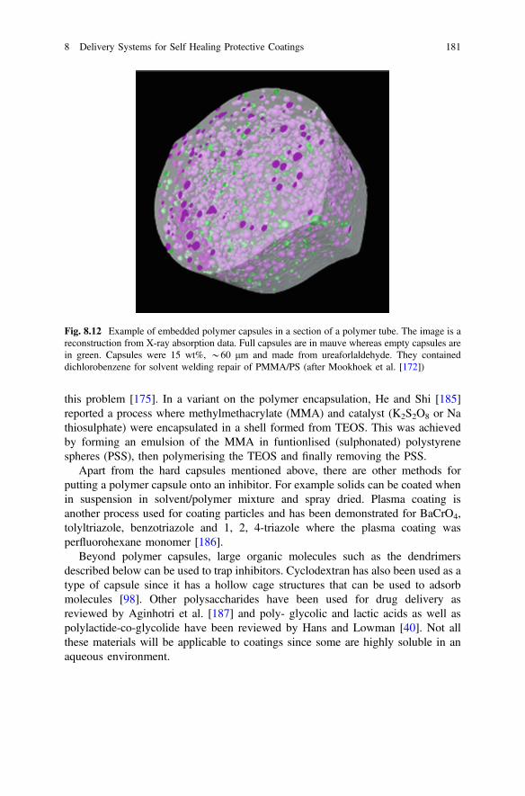
this problem [175]. In a variant on the polymer encapsulation, He and Shi [185]reported a process where methylmethacrylate (MMA) and catalyst (K2S2O8 or Nathiosulphate) were encapsulated in a shell formed from TEOS. This was achievedby forming an emulsion of the MMA in funtionlised (sulphonated) polystyrenespheres (PSS), then polymerising the TEOS and finally removing the PSS.
Apart from the hard capsules mentioned above, there are other methods forputting a polymer capsule onto an inhibitor. For example solids can be coated whenin suspension in solvent/polymer mixture and spray dried. Plasma coating isanother process used for coating particles and has been demonstrated for BaCrO4,tolyltriazole, benzotriazole and 1, 2, 4-triazole where the plasma coating wasperfluorohexane monomer [186].
Beyond polymer capsules, large organic molecules such as the dendrimersdescribed below can be used to trap inhibitors. Cyclodextran has also been used as atype of capsule since it has a hollow cage structures that can be used to adsorbmolecules [98]. Other polysaccharides have been used for drug delivery asreviewed by Aginhotri et al. [187] and poly- glycolic and lactic acids as well aspolylactide-co-glycolide have been reviewed by Hans and Lowman [40]. Not allthese materials will be applicable to coatings since some are highly soluble in anaqueous environment.
Fig. 8.12 Example of embedded polymer capsules in a section of a polymer tube. The image is areconstruction from X-ray absorption data. Full capsules are in mauve whereas empty capsules arein green. Capsules were 15 wt%, *60 μm and made from ureaforlaldehyde. They containeddichlorobenzene for solvent welding repair of PMMA/PS (after Mookhoek et al. [172])
8 Delivery Systems for Self Healing Protective Coatings 181
8.5.7 Hollow Tubes
The introduction of tubes within materials offers a primitive approach to buildingproto-vascular networks for the supply of inhibitors and healing agents. Whileinorganic and organic hollow tubes have been explored for concrete [188] andcomposites [189], the manufacture of hollow tubes in the size ranges required forcoatings is still an active area of research. In addition it is uncertain how theincorporation of tubes into coatings modifies the properties of the coating partic-ularly the mechanical properties and durability. Clearly the rupture of the tubewould provide the triggering mechanism for release of the healing agent. Perhapssoluble tubes as well as porous tubes might also be options.
Inorganic Hollow Tubes
Inorganic hollow tubes can be formed by anodising metals. Anodising aluminiumproduces columnar structures which are hollow and often treated with inhibitors ordyes for colouring and then sealed in hot water [190]. Chromate sealing has beenused for many years in anodising processes so in a sense filled hollow tubes havebeen around for a long time. Similarly titanium can also be anodised producingsimilar structures to aluminium. Kowalski et al. [191] looked at filling Ti anodisedlayer with polypyrrole and found a range of structures could be produced. Whilethese tubes are not free tubes that can be manipulated and then incorporated into acoating, they can, in combination with a paint coating, be used to manufacture a selfhealing system. However, free tubes manufactured from anodised coatings, havebeen removed from their substrate and used as membranes or sensor arrays [192],so the potential is there is further explore these types of inorganic materials.
Organic Hollow Fibres
Porous polypropylene fibres have been used for self healing applications in concretestructures [188]. Capability now exists for building a range of internal structures inpolymer fibres.
8.5.8 Self Assembly
Self assembly is a process where entities, typically molecules organise themselvesinto structures to minimise their free energy. As described above the driving forcefor mixtures of immiscible liquids is for them to separate into phases.“Suspensions” of one phase dispersed in a second phase can be stabilised asmicelles or inverse micelles [92]. This requires “self assembly” of surfactants at theinterface between the two phases as described above.
182 M.L. Zheludkevich and A.E. Hughes
In the coatings area self assembly for corrosion prevention has been investigatedfor metal surfaces, particularly thiols and phosphonates for Fe and Cu surfaces[152] and phosphonates for aluminium [152, 193]. Many of these films that selfassemble have protective properties and some are used commercially [194].Nothing more than a summary of this work will be provided here because, apartfrom the micelle application, the topic of self assembly on surfaces is not reallydevoted to encapsulation. Knag [195], Knag et al. [196] found that docoyltriethy-lammonim bromide and 1-octadeanol formed monolyers reducing the corrosion by60 and 5 % on Fe substrates respectively. Ramachandran et al. explored imidizolederivates adsorbed onto Fe2O3 single crystal surfaces and found that the longhydrophobic tail tilts to form a packed hydrophobic monolayer [197]. Felhősi et al.[198] found that 1-phosphono-alkane derivates rapidly adsorbed on Fe surfaces butunderwent a longer term ordering process. From an encapsulation perspectivead-micelles are often observed on surfaces [199] and it may be possible to fill thesewith inhibitor and incorporate them into a coating. Shida et al. [200] reported a selfassembling Zr-based coating on AA 1100 produced in a multistep process thatprovided some protection. Other surfaces can be coated as well such as the selfassembly of Zr-phosphate layers in Si reported above [148].
Another form of self assembly that appears in the literature are theself-assembled nanophase coating process (SNAP) [94, 201, 202] coatings. The selfassembly here refers to the production of nanoparticles based on SiOx(OR)4–x onaddition of TMOS and GPTMS to acidified solution. These functionlised particlesare then connected by the addition of cross linking agents when coating formationis required. SNAP coatings themselves have good barrier properties but do notrepresent an encapsulation system. Encapsulated inhibitors need to be added to thecoatings to further improve the performance. For example, encapsulation of organicinhibitors in inhibitor/β-cyclodextrin complexes has been reported for this system[98]. The inhibitors being mercaptobenzothiazole and mercaptobenzimidazole [98,203].
8.5.9 Dendrimers
Dendrimers form a class of materials where branching occurs at the molecular level.There are several good reviews of dendrimers in the literature [39, 204]. As can beseen in Fig. 8.13, the key structural feature of the dendrimer is the generation stepwhere branching occurs. Dendrimers are ideal for hosting substances at themolecular level and are used in drug delivery. According to Sahoo and Labhastewar[39] dendrimers can be manufactured either divergently (from the centre outwards)or convergently (from the exterior inwards). Agents can be incorporated eitherwithin the internal volume or attached to the outside of the dendrimer. There is littlein the corrosion/inhibition literature on the use of dendrimers as carriers for healingagent, but these molecules seem to offer opportunities for further exploration, butgenerally these types of molecules would be suited to organic inhibitors [205, 206].
8 Delivery Systems for Self Healing Protective Coatings 183
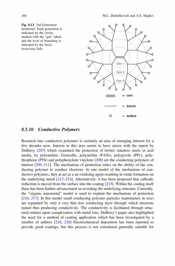
8.5.10 Conductive Polymers
Research into conductive polymers is certainly an area of emerging interest for afew decades now. Interest in this area seems to have arisen with the report byDeBerry [207] which examined the protection of ferritic stainless steels in acidmedia, by polyaniline. Generally, polyaniline (PANi), polypyrole (PPy), poly-thiophene (PTh) and polyphenylene vinylene [208] are the conducting polymers ofinterest [209–211]. The mechanism of protection relies on the ability of the con-ducting polymer to conduct electrons. In one model of the mechanism of con-ductive polymers, they at act as a an oxidising agent resulting in oxide formation onthe underlying metal [212–214]. Alternatively, it has been proposed that cathodicreduction is moved from the surface into the coating [215]. Within the coating itselfthere has been further advancement in revealing the underlying structure. Currently,the “organic nanometal” model is used to explain the mechanism of protection[216, 217]. In this model small conducting polymer particles (nanometers in size)are separated by only a very thin less conducting layer through which electronstunnel thus producing conductivity. The conductivity is facilitated through struc-tural entities upon complexation with metal ions. DeBerry’s paper also highlightedthe need for a method of coating application which has been investigated by anumber of authors [210, 218] Electrochemical deposition has been reported toprovide good coatings, but this process is not considered generally suitable for
Fig. 8.13 3rd Generationdendrimer. Each generation isindicated by the circlesmarked with the “gen” labelsand the level of branching isindicated by the blackbranching links
184 M.L. Zheludkevich and A.E. Hughes

industry. The issues associated with dispersion into a solvent has also beeninvestigated [217, 219].
Much of the work in this area has focused on the corrosion protection offered bythe coating itself as described above. Of course the interest in conducting polymersin this chapter is their role as delivery systems for self healing agents [220]. Releaseof species in response to external stimuli was first reported by Barisci et al. [221] fora range of applications including corrosion protection. Since then a number ofdifferent inhibitors have been incorporated into PANi including mercaptothiadia-zole [140], ammonium salt, dithiocarbamate [140], molybdates [220] varioustransition metal ions [217] and oxyanions [222]. Conducting polymers have alsobeen stored in nanowires for later release [191].
8.6 Summarizing Discussion on Triggering Mechanisms
As discussed in the introduction of this book there are many types and degrees ofcomplexity of triggering that can be envisaged. In the end, the level of sophisti-cation of the triggering will depend on the application area, which defines thetriggers that are available, and the cost, which will determine the cost/benefit bal-ance for the application.
8.6.1 Autonomic Triggering
The most obvious triggers are those that occur during normal operation and areprovided by cycles in the operational environment. The triggers for autonomicrelease, listed in Table 8.1, are based on variables of the ambient environment thatregularly go through cycles and could be used for self-responding systems. But aspointed out by Garcia et al. [35] a self healing mechanism such as the Diels-Aldermethod for repair of autopaint coatings requires that the ambient temperature risesabove the transition temperature for repair to be effected. In the middle of winter inthe northern hemisphere, this temperature may never be reached and the required
Table 8.1 Triggerclassification
Autonomictriggering
External
pH Field gradients
Water Sensors
Temperature Actuators
Mechanical damage Centrally controlled delivery systems
UV radiation
Corrosive ions
8 Delivery Systems for Self Healing Protective Coatings 185

temperature may need to be applied by an auto-technician making it an externalrather than an autonomic trigger. So the classifications listed in Table 8.1 must betaken as guidelines rather than strict classifications.
In the examples of various encapsulation techniques presented above the mostprominent triggers for release of the healing agent are mechanical damage for hardcapsules [10, 14, 16, 172], pH for configurational change of polyelectrolytes [223]or conducting polymers [140], pH for dissolution of sparingly soluble inhibitors[55, 56], and ion-exchange into porous materials such as LDHs [33, 124, 137].Temperature and UV radiation are more common as triggers for polymer healingthan for inhibitor release [176].
Some authors discuss the use of internal signalling to internal agents to effect therelease of the healing agent. The advantage of this approach for individual healingevents is not immediately obvious since using the trigger directly to effect thehealing event seems more efficient. On the other hand, if sequential healing eventsare required such as inhibitor release followed by polymer healing and the eventsinterfere with each other then internal autonomic control of the release is necessary.
8.6.2 External Triggering and Transduction
Externally triggered systems require some level of added intervention aboveautonomic triggering. Furthermore, it also implies that signalling events occur,either within the coating or to an external agent. On detection of the signal,intervention could be delivered using sensors and monitoring systems which acti-vate a response automatically or via human intervention. Of course these types ofsystems are likely to cost more than autonomic systems, therefore the benefit in theapplication area will need to outweigh the cost. Some applications where this typeof technology might be cost effective include off-shore structures (oil rigs andwindmills), onshore pipelines, bridges and aircraft, particularly where it is difficultto inspect. Specifically these could become cost effective where there are occludedspaces such as in aircraft wings, hazardous environments such as off-shore struc-tures, bridges or chemically dangerous environments or extended structures such asoil pipelines where monitoring thousands of kilometres of pipeline is a challengingtask. Additionally, external triggering, or signal transduction will need to be builtinto service equipment.
Sensor and signalling systems can include colour [224–227], changes in trans-mittance, or fluorescence [228–230] to name a few signals. Closely related tomolecular level sensing and signalling are the nanosensors. The challenge here is toproduce significant signal level from very small sensors that have very little effecton the mechanical properties when incorporated into a polymer matrix. Oneexample of these includes Surface Enhanced Raman Spectroscopy (SERS) sensorswhich make use the enhancement of Raman signal produced as a result of surfaceplasmons. SERS sensors typically contain Ag or Cu nanoparticles and can be usedas sensors to detect organic molecules and potentially inhibitor release. For
186 M.L. Zheludkevich and A.E. Hughes
example, SERS has been used to detect adsorbed citrate [231] suggesting thepossibility of detecting other carboxylates. It has also been used to detect proteins,even in the presence of potentially interfering molecules, through surface fun-tionalisation [232]. Quantum dots are also being explored for these types ofapplication. Current generation CdSe/ZnS have been used to demonstrate howmuch chromate is left in an epoxy coating [233]. However, the use ofCd-containing sensors represents a challenge from a health and safety perspectiveand other types of Q-dots are being explored.
8.7 Practical Considerations
From this short overview of different approaches to designing self-healing pro-tective coatings it is clear that intrinsic self-healing mechanisms require a completechange of current paradigms for coating chemistry. Moreover full cosmetic healingof large defects can only be achieved when using mobility of the polymeric chainsat relatively high temperatures. Unfortunately, high mobility is often associatedwith relatively weak barrier properties. The recovery of mechanical integrityencapsulated polymerizable agents has the important physical limitation that it isnot possible to provide a sufficient volume of polymerizable component to fill thedefect in thin coatings. However, this type of healing mechanism is likely to beapplicable to industries where relatively thick polymer coatings are applied: marineindustry, oil and gas sector, and large infrastructures.
The concepts based on incorporation of corrosion inhibitors seem to be the mostmatured and close to applications at current stage. The introduction of self-healingfunctionality can be achieved with minimal modifications of existing coating for-mulations. The encapsulated inhibitors can be added in the form of pigments andcombined in different proportions in order to achieve potentially synergistic com-binations of different inhibiting species in the same coating. Moreover, someimmobilization approaches are based on the nano-sized containers which can beadded even to very thin coating layers without disrupting the barrier properties.
In spite of many encapsulation approaches developed during last decade most ofthe active coatings based on such reservoirs do not offer expected self-healingperformance. Very often only a minor inhibition effect in artificial defects isobserved. At the same time in majority of the cases the barrier properties ofpolymers are negatively influenced causing a total underperformance of protectivelayers.
The most critical factor is the local concentration of corrosion inhibitor whichcan be achieved in the defect close to metal surface. The local inhibitor concen-tration in the defect of nanoreservoir-containing coatings is defined by the numberof factors:
8 Delivery Systems for Self Healing Protective Coatings 187
• loading of nanocontainer with inhibitor;• concentration of nanocontainers within the matrix;• total concentration of available inhibitor;• kinetics of inhibitor release from NCs;• kinetics of delivery to the defect (diffusion through the coating or along the
interface);• electrolyte conditions (concentration, amount, flow, cycling).
When the combination of the abovementioned factors does not allow the inhi-bitor to reach a minimal necessary concentration at the metal surface the activeprotection will not be effected. Therefore often the inhibitors that are efficient intests with direct addition to electrolyte do not perform well when used in the activeprotective coatings. The efficiency of inhibiting compounds is normally evaluatedon bare metallic substrates adding the corrosion inhibitor to the corrosive electrolytein mM concentration range. However such concentrations rarely can be achieved inthe defects when thin coatings with relatively low amount of containers. Forexample, it is hard to expect that the addition of 0.01 wt% of benzotriazole-loaded(5 wt%) nanocontainers in the coating can ensure any efficient long-term inhibitionin a defect [51]. The same is applied for the cases when very low loading ofnanocontainers with corrosion inhibitors is used as in the case of work reported byZhao et al. [234]. Some recent work on treating the polymer as the paint itself as theencapsulating medium and developing appropriate network of channels is alsoemerging as an alterntive method for packaging the inhibitor [235].
One of the main advantages of many different types of nanocontainers is theirrelease on demand functionality. It is especially important from the standpoint oflong-term corrosion protection since uncontrollable fast leaching of inhibitor can beprevented, keeping an acceptable level of inhibitor concentration in the system for along time. Additionally, it ensures that no inhibitor is leached out of nanocontainersduring preparation and shelf-life of the coating formulations. Combining thenanocontainers which release corrosion inhibitors at different rates under action ofdifferent triggers opens a wide range of possibilities to tailor the active protectioncoating for long service life. For example, one type of nanocontainer can deliver ahigh amount of inhibitor under extremely aggressive conditions while the secondone can ensure very slow release of small amounts during long service [236].
Analysing different possibilities for self-healing coatings from standpoint ofproximity to real applications, in the short term coatings containing encapsulatedcorrosion inhibitors seem to be the most promising. There are several types ofnanocontainers which can be easily upscaled such as nano-clay basedion-exchangers. The nano-clays can also have a good compatibility with traditionalpolymer coating formulations and ensure an additional nano-trap role for corrosivespecies. The important next steps to ensure faster industrial implementation shouldbring more efficient inhibiting systems. Therefore the loading of existingnanocontainers has to be increased and more efficient corrosion inhibitors whichconfer healing even at very low concentration level should be explored.
188 M.L. Zheludkevich and A.E. Hughes
From a medium-term perspective the systems which combine corrosion inhibi-tion with another active protection mechanism might become feasible. The coatingswhich combine capsules with water-displacing agent mixed with corrosion inhibitorseem promising especially when exploited at conditions where there is noimmersion. The nanocontainers of corrosion inhibitors which can also be traps forcorrosive species are also of high interest.
The self-healing coatings which can provide a recovery of physical integrity ofthe polymer layers still need to mature more to be considered for real applications.This is especially true for polymer coatings with intrinsic healing properties sincemost of the basic polymer formulations currently used in industry have to bereconsidered. The self-healing coatings based on encapsulation of liquid poly-merazable agents have important limitations in the case of relatively thin coatings.However this technology can be accepted for thick coatings already in a relativelyshort time if long term performance in service conditions is demonstrated. Theeconomic aspects will play a decisive role here as well.
8.8 Conclusions
This chapter has covered a considerable body of work on the delivery systems thatare being investigated for self healing coatings. These delivery systems cover twobroad areas; (i) those used for polymer healing and (ii) those used for corrosioninhibition. Clearly there is a very broad range of chemical approaches being takento the delivery of self healing in coatings which covers inorganic, polymer andorganic chemistry. Given the breadth of these areas there is an almost unlimitedrange of possibilities. However, for uptake by industry, the practical considerationsdelineated in the previous section will probably dictate which technologies willeventually be taken up. In the polymer area there is probably scope for technologyinvolving reversible bonds since these are multiply rehealable. For inhibitors,delivery systems based on silicon sol-gel chemistry, hard capsules (organic orinorganic) or using the polymer film itself are likely to be avenues of fruitfulresearch. In the inhibitor case, because the critical inhibitor concentration [149] ofchromate replacement inhibitors is likely to be higher than that of chromate (10−5 M[237]), then the search will be for the delivery which can deliver the largest amountof inhibitor.
References
1. S.R. White et al., Autonomic healing of polymer composites. Nature 409(6822), 794–797(2001)
2. M.L. Zheludkevich, in Self-Healing Materials, ed. by S.K. Ghosh. Self-HealingAnticorrosion Coatings (Wiley-VCH, 2008)
8 Delivery Systems for Self Healing Protective Coatings 189
3. A.E. Hughes, I.S. Cole, T.M. Muster, R.J. Varley, Combining green and self healing for anew generation of coatings for metal protection. Nat. Asia Mater. 2(4), 143–151 (2010)
4. M.L. Zheludevich, D. Raps, A.C. Bastos, T. Hack, M.G.S. Ferreira, Self Healing Coatingswith Multiple Level Protection Based on Active Nanoparticles, in NANOSPAIN-2008 (Braga,Portugal, 2008)
5. M. Zheludkevich, M. Ferreira, S. Poznyak, in Self-Healing Corrosion Protection Coatingswith Nanocontainers of Corrosion Inhibitors. ed by V.E. Borisenko, S.V. Gaponenko, V.S.Gurin. Physics, Chemistry and Application of Nanostructures: Reviews and Short Notes(2007), pp. 380–383
6. J. Tedim et al., Enhancement of active corrosion protection via combination ofinhibitor-loaded nanocontainers. ACS Appl. Mater. Interfaces 2(5), 1528–1535 (2010)
7. J.K. Tedim, A.N. Salak, F. Montemor, D. Snihirova, M. Pilz, M.L. Zheludkevich, M.G.S.Ferreira, Zn–Al layered double hydroxides as chloride nanotraps in active protectivecoatings. Corros. Sci. 55, 1–4 (2012)
8. T. Stimpfling, F. Leroux, H. Hintze-Bruening, Organo-modified layered double hydroxide incoating formulation to protect AA2024 from corrosion. Colloids Surf. A 458, 147–154(2014)
9. M. Krzak, Z. Tabor, P. Nowak, P. Warszyński, A. Karatzas, I.A. Kartsonakis, G.C. Kordas,Water diffusion in polymer coatings containing water-trapping particles. Part 2 experimentalverification of the mathematical model. Prog. Org. Coat. 75, 207–214 (2012)
10. S.J. Garcia et al., Self-healing anticorrosive organic coating based on an encapsulated waterreactive silyl ester: synthesis and proof of concept. Prog. Org. Coat. 70(2–3), 142–149 (2011)
11. Y. Gonzalez-Garcia et al., A combined redox-competition and negative-feedback SECMstudy of self-healing anticorrosive coatings. Electrochem. Commun. 13(10), 1094–1097(2011)
12. A. Latnikova et al., Polyfunctional active coatings with damage-triggered water-repellingeffect. Soft Matter 7(2), 369–372 (2011)
13. T. Nesterova, K. Dam-Johansen, S. Kiil, Synthesis of durable microcapsules for self-healinganticorrosive coatings: a comparison of selected methods. Prog. Org. Coat. 70(4), 342–352(2011)
14. C. Suryanarayana, K.C. Rao, D. Kumar, Preparation and characterization of microcapsulescontaining linseed oil and its use in self-healing coatings. Prog. Org. Coat. 63(1), 72–78(2008)
15. M. Samadzadeh et al., Tung oil: an autonomous repairing agent for self-healing epoxycoatings. Prog. Org. Coat. 70(4), 383–387 (2011)
16. A. Kumar, L.D. Stephenson, J.N. Murray, Self-healing coatings for steel. Prog. Org. Coat. 55(3), 244–253 (2006)
17. M. Wiesener et al., In-situ contact angle studies of the release of water displacing agents fromcapsule filled organic coatings. Surf. Coat. Technol. 206(21), 4481–4487 (2012)
18. T.G. Nijland, J.A. Larbi, R.P.J. van Hees, B. Lubelli, M. de Rooij, Self Healing Phenomenain Concretes and Masonry Mortars: a Microscopic Study, in Self Healing Materials(Springer, Eindhoven, 2007), p. 31
19. G. Perugini, Plasma-sprayed self-sealing ceramic coatings: materials chemistry and hightemperature protective properties. Thin Solid Films 108(4), 415–425 (1983)
20. T. Sugama, K. Gawlik, Self-repairing poly(phenylenesulfide) coatings in hydrothermalenvironments at 200 °C. Mater. Lett. 57(26–27), 4282–4290 (2003)
21. F. Miccichè et al., Moisture induced crack filling in barrier coatings containingmontmorillonite as an expandable phase. Surf. Coat. Technol. 202(14), 3346–3353 (2008)
22. A. Hikasa et al., Preparation and corrosion studies of self-healing multi-layered nano coatingsof silica and swelling clay. Mater. Res. Innovations 8(2), 84–88 (2004)
23. A. Yabuki, K. Okumura, Self-healing coatings using superabsorbent polymers for corrosioninhibition in carbon steel. Corros. Sci. 59, 258–262 (2012)
24. S.J. Garcia, Effect of polymer architecture on the intrinsic self-healing character of polymers.Eur. Polymer J. 53(1), 118–125 (2014)
190 M.L. Zheludkevich and A.E. Hughes
25. P. Cordier et al., Self-healing and thermoreversible rubber from supramolecular assembly.Nature 451(7181), 977–980 (2008)
26. S.J. Kalista Jr, T.C. Ward, Thermal characteristics of the self-healing response in poly(ethylene-co-methacrylic acid) copolymers. J. R. Soc. Interface 4(13), 405–411 (2007)
27. X. Chen et al., A thermally re-mendable cross-linked polymeric material. Science 295(5560),1698–1702 (2002)
28. S. Bode et al., Self-healing metallopolymers based on cadmium bis (terpyridine) complexcontaining polymer networks. Polym. Chem. 4(18), 4966–4973 (2013)
29. J. Kötteritzsch et al., One-component intrinsic self-healing coatings based on reversiblecrosslinking by diels-alder cycloadditions. Macromol. Chem. Phys. 214(14), 1636–1649(2013)
30. G. Postiglione, S. Turri, M. Levi, Effect of the plasticizer on the self-healing properties of apolymer coating based on the thermoreversible Diels-Alder reaction. Prog. Org. Coat. 78,526–531 (2015)
31. Y. Gonzalez-Garcia et al., A combined mechanical, microscopic and local electrochemicalevaluation of self-healing properties of shape-memory polyurethane coatings. Electrochim.Acta 56(26), 9619–9626 (2011)
32. Nissan Develops World’s First Clear Paint that Repairs Scratches on Car Surfaces. JCNNNews, 2005
33. H.N. McMurray, G. Williams, Inhibition of filiform corrosion on organic-coated aluminumalloy by hydrotalcite-like anion-exchange pigments. Corrosion 60(3), 219–228 (2004)
34. H.R. Fischer, Self-repairing material systems―a dream or a reality? Nat. Sci. 2, 873–901(2010)
35. S.J. Garcia, H.R. Fischer, S. van der Zwaag, A critical appraisal of the potential of selfhealing polymeric coatings. Prog. Org. Coat. 72(3), 211–221 (2011)
36. B.F. Gibbs et al., Encapsulation in the food industry: a review. Int. J. Food Sci. Nutr. 50(3),213–224 (1999)
37. I. Roy et al., Calcium phosphate nanoparticles as novel non-viral vectors for targeted genedelivery. Int. J. Pharm. 250(1), 25–33 (2003)
38. M. Nishikawa et al., Hepatocyte-targeted in vivo gene expression by intravenous injection ofplasmid DNA complexed with synthetic multi-functional gene delivery system. Gene Ther. 7(7), 548–555 (2000)
39. S.K. Sahoo, V. Labhasetwar, Nanotech approaches to delivery and imaging drug. DrugDiscovery Today 8(24), 1112–1120 (2003)
40. M.L. Hans, A.M. Lowman, Biodegradable nanoparticles for drug delivery and targeting.Curr. Opin. Solid State Mater. Sci. 6(4), 319–327 (2002)
41. O.G. Schramm et al., Polymeric nanocontainers with high loading capacity of hydrophobicdrugs. Soft Matter 5(8), 1662–1667 (2009)
42. J.R. Galvele, Transport processes and mechanism of pitting of metals. J. Electrochem. Soc.123(4), 464–474 (1976)
43. W.H. Slabaugh et al., Filiform corrosion of aluminum. J. Paint Technol. 44(566), 76–&(1972)
44. S.D. Mookhoek, H.R. Fischer, S. van der Zwaag, Alginate fibres containing discrete liquidfilled vacuoles for controlled delivery of healing agents in fibre reinforced composites.Compos. A Appl. Sci. Manuf. 43(12), 2176–2182 (2012)
45. S.D. Mookhoek, H.R. Fischer, S. van der Zwaag, A numerical study into the effects ofelongated capsules on the healing efficiency of liquid-based systems. Comput. Mater. Sci. 47(2), 506–511 (2009)
46. J. Rouquerol et al., Recommendations for the characterization of porous solids. Pure Appl.Chem. 66(8), 1739–1758 (1994)
47. T. Nesterova, Self-Healing Anticorrosive Coatings, in Materials Science (TechnicalUniversity of Denmark, Copenhagan, 2012)
8 Delivery Systems for Self Healing Protective Coatings 191
48. S.I. Rae, et al. in Novel Self-Healing Systems: Expanding and Inhibited Healing Agents.ASME 2014 Conference on Smart Materials, Adaptive Structures and Intelligent Systems,SMASIS 2014. 2014
49. C.J. Brinker, G.W. Scherer, Sol-Gel Science, 1st edn. (Academic Press, San Diego, 1990)50. C. Lai et al., Formation of calcium phosphate nanoparticles in reverse microemulsions.
Mater. Lett. 59(2–3), 210–214 (2005)51. Y.M. Lvov et al., Halloysite clay nanotubes for controlled release of protective agents. ACS
Nano 2(5), 814–820 (2008)52. E. Jamstorp et al., Mechanically strong geopolymers offer new possibilities in treatment of
chronic pain. J. Controlled Release 146(3), 370–377 (2010)53. J. Forsgren et al., A ceramic drug delivery vehicle for oral administration of highly potent
opioids. J. Pharm. Sci. 99(1), 219–226 (2010)54. H. Ku et al., Fracture toughness of phenol formaldehyde composites reinforced with
E-spheres. J. Compos. Mater. 43(7), 741–754 (2009)55. S.A.S. Dias et al., Sol–gel coatings modified with zeolite fillers for active corrosion
protection of AA2024. Corros. Sci. 62, 153–162 (2012)56. S.A.S. Dias et al., The role of Ce(III)-enriched zeolites on the corrosion protection of
AA2024-T3. Electrochim. Acta 112, 549–556 (2013)57. S. Thomas et al., Self-repairing oxides to protect zinc: review, discussion and prospects.
Corros. Sci. 69, 11–22 (2013)58. S. Bohm et al., Novel environment friendly corrosion inhibitor pigments based on naturally
occurring clay minerals. Materials and Corrosion-Werkstoffe Und Korrosion 52(12), 896–903 (2001)
59. N. Granizo et al., Ion-exchange pigments in primer paints for anticorrosive protection of steelin atmospheric service: Cation-exchange pigments. Prog. Org. Coat. 75(3), 147–161 (2012)
60. E. Abdullayev, Y. Lvov, Clay nanotubes for corrosion inhibitor encapsulation: releasecontrol with end stoppers. J. Mater. Chem. 20(32), 6681–6687 (2010)
61. D.G. Shchukin et al., Halloysite nanotubes as biomimetic nanoreactors. Small 1(5), 510–513(2005)
62. H.P. Wang et al., Data-constrained modelling of an anthracite coal physical structure withmulti-spectrum synchrotron X-ray CT. Fuel 106, 219–225 (2013)
63. S. Yang, T.E. Gureyev, M.B. Tulloh, M.B. Clennell, M. Pervukhina, Feasibility of a dataconstrained prediction of hydrocarbon reservoir sandstone microstructures. Meas. Sci.Technol. 21, (2010)
64. M.F. Montemor et al., The synergistic combination of bis-silane and CeO2.ZrO2
nanoparticles on the electrochemical behaviour of galvanised steel in NaCl solutions.Electrochim. Acta 53, 5913–5922 (2008)
65. M.L. Zheludkevich et al., Anticorrosion coatings with self-healing effect based onnanocontainers impregnated with corrosion inhibitor. Chem. Mater. 19(3), 402–411 (2007)
66. M.F. Montemor, R. Pinto, M.G.S. Ferreira, Chemical composition and corrosion protectionof silane films modified with CeO(2) nanoparticles. Electrochim. Acta 54(22), 5179–5189(2009)
67. M.L. Zheludkevich et al., Nanostructured sol-gel coatings doped with cerium nitrate aspre-treatments for AA2024-T3-corrosion protection performance. Electrochim. Acta 51(2),208–217 (2005)
68. M.L. Zheludkevich et al., Oxide nanoparticle reservoirs for storage and prolonged release ofthe corrosion inhibitors. Electrochem. Commun. 7(8), 836–840 (2005)
69. M.L. Zheludkevich et al., Corrosion protective properties of nanostructured sol-gel hybridcoatings to AA2024-T3. Surf. Coat. Technol. 200(9), 3084–3094 (2006)
70. D.G. Shchukin, M. Zheludkevich, H. Moehwald, Feedback active coatings based onincorporated nanocontainers. J. Mater. Chem. 16(47), 4561–4566 (2006)
71. N.P. Tavandashti, S. Sanjabi, Corrosion study of hybrid sol-gel coatings containing boehmitenanoparticles loaded with cerium nitrate corrosion inhibitor. Prog. Org. Coat. 69, 384–389(2010)
192 M.L. Zheludkevich and A.E. Hughes
72. A.C. Balaskas et al., Improvement of anti-corrosive properties of epoxy-coated AA 2024-T3with TiO2 nanocontainers loaded with 8-hydroxyquinoline. Prog. Org. Coat. 74(3), 418–426(2012)
73. E.D. Mekeridis, I.A. Kartsonakis, G.C. Kordas, Multilayer organic-inorganic coatingincorporating TiO2 nanocontainers loaded with inhibitors for corrosion protection ofAA2024-T3. Prog. Org. Coat. 73(2–3), 142–148 (2012)
74. M.F. Montemor, M.G.S. Ferreira, Analytical characterization of silane films modified withcerium activated nanoparticles and its relation with the corrosion protection of galvanisedsteel substrates. Prog. Org. Coat. 63(3), 330–337 (2008)
75. E.D. Mekeridis et al., Release studies of corrosion inhibitors from cerium titanium oxidenanocontainers. J. Nanopart. Res. 13(2), 541–554 (2011)
76. M. Schem et al., CeO2-filled sol-gel coatings for corrosion protection of AA2024-T3aluminium alloy. Corros. Sci. 51(10), 2304–2315 (2009)
77. H. Lermer et al., Synthesis and structure refinement of ZSM-5 single-crystals. Zeolites 5(3),131–134 (1985)
78. F. Kleitz et al., Transformation of highly ordered large pore silica mesophases (Fm3 m,Im3 m and p6 mm) in a ternary triblock copolymer-butanol-water system. Chem. Commun.13, 1536–1537 (2004)
79. C.T. Kresge et al., Ordered mesoporous molecular-sieves synthesized by a liquid-crystaltemplate mechanism. Nature 359(6397), 710–712 (1992)
80. K.M. Ryan et al., Control of pore morphology in mesoporous silicas synthesized fromtriblock copolymer templates. Langmuir 18(12), 4996–5001 (2002)
81. J.Y.T. Chong et al., Steric stabilisation of self-assembled cubic lyotropic liquid crystallinenanoparticles: high throughput evaluation of triblock polyethylene oxide-polypropyleneoxide-polyethylene oxide copolymers. Soft Matter 7(10), 4768–4777 (2011)
82. X. Mulet et al., High throughput preparation and characterisation of amphiphilicnanostructured nanoparticulate drug delivery vehicles. Int. J. Pharm. 395(1–2), 290–297(2010)
83. D. Ebrahimi et al., High throughput screening arrays of rhodium and iridium complexes ascatalysts for intramolecular hydroamination using parallel factor analysis. Analyst 133, 817–822 (2008)
84. D.Y. Zhao et al., Morphological control of highly ordered mesoporous silica SBA-15. Chem.Mater. 12(2), 275–279 (2000)
85. P.J. Colver, S.A.F. Bon, Cellular polymer monoliths made via pickering high internal phaseemulsions. Chem. Mater. 19(7), 1537–1539 (2007)
86. M.L. Zheludkevich, I.M. Salvado, M.G.S. Ferreira, Sol-gel coatings for corrosion protectionof metals. J. Mater. Chem. 15(48), 5099–5111 (2005)
87. A. Bhaumik, Mesoporous titanium phosphates and related molecular sieves: synthesis,characterization and applications. Proc. Indian Acad. Sci. Chem. Sci. 114(4), 451–460 (2002)
88. M. Mokhtar, S.N. Basahel, T.T. Ali, Effect of synthesis methods for mesoporous zirconia onits structural and textural properties. J. Mater. Sci. 48(6), 2705–2713 (2013)
89. D.M. Lyons, K.M. Ryan, M.A. Morris, Preparation of ordered mesoporous ceria withenhanced thermal stability. J. Mater. Chem. 12(4), 1207–1212 (2002)
90. T.L. Metroke, R.L. Parkhill, E.T. Knobbe, Passivation of metal alloys using sol-gel-derivedmaterials—a review. Prog. Org. Coat. 41(4), 233–238 (2001)
91. D. Wang, G.R. Bierwagen, Sol-gel coatings on metals for corrosion protection. Prog. Org.Coat. 64(4), 327–338 (2009)
92. F.J. Rossier-Miranda, C. Schroen, R.M. Boom, Colloidosomes: versatile microcapsules inperspective. Colloids Surf., A 343(1–3), 43–49 (2009)
93. S.E. Hornstrom et al., Paint adhesion and corrosion performance of chromium-freepretreatments of 55 % Al-Zn-coated steel. J. Adhes. Sci. Technol. 10(9), 883–904 (1996)
94. A.N. Khramov et al., Nanostructured sol-gel derived conversion coatings based on epoxy-and amino-silanes. Prog. Org. Coat. 47(3–4), 207–213 (2003)
8 Delivery Systems for Self Healing Protective Coatings 193
95. L.S. Kasten et al., An XPS study of cerium dopants in sol–gel coatings for aluminum2024-T3. Surf. Coat. Technol. 140(1), 11–15 (2001)
96. L. Mascia et al., Molybdate doping of networks in epoxy-silica hybrids: domain structuringand corrosion inhibition. Prog. Org. Coat. 56(1), 13–22 (2006)
97. N.C. Rosero-Navarro et al., Improved corrosion resistance of AA2024 alloys through hybridorganic–inorganic sol–gel coatings produced from sols with controlled polymerisation. Surf.Coat. Technol. 203(13), 1897–1903 (2009)
98. A.N. Khramov et al., Hybrid organo-ceramic corrosion protection coatings with encapsulatedorganic corrosion inhibitors. Thin Solid Films 447, 549–557 (2004)
99. A. Wittmar et al., Hybrid sol-gel coatings doped with transition metal ions for the protectionof AA 2024-T3. J. Sol-Gel. Sci. Technol. 61(3), 600–612 (2012)
100. S.M.A. Hosseini, A.H. Jafari, E. Jamalizadeh, Self-healing corrosion protection bynanostructure sol-gel impregnated with propargyl alcohol. Electrochim. Acta 54(28),7207–7213 (2009)
101. N.C. Rosero-Navarro et al., Effects of Ce-containing sol-gel coatings reinforced with SiO2
nanoparticles on the protection of AA2024. Corros. Sci. 50(5), 1283–1291 (2008)102. D.G. Shchukin et al., Layer-by-layer assembled nanocontainers for self-healing corrosion
protection. Adv. Mater. 18(13), 1672–1678 (2006)103. I.A. Kartsonakis et al., Hybrid organic–inorganic multilayer coatings including
nanocontainers for corrosion protection of metal alloys. Corros. Sci. 57, 56–66 (2012)104. F. Andreatta et al., Water-based ZrO2 pretreatment for AA2024 aluminum alloy. Surf.
Interface Anal. 42(4), 293–298 (2010)105. F. Andreatta et al., Corrosion behaviour of sol–gel treated and painted AA2024 aluminium
alloy. Prog. Org. Coat. 69(2), 133–142 (2010)106. D. Raps et al., Electrochemical study of inhibitor-containing organic-inorganic hybrid
coatings on AA2024. Corros. Sci. 51(5), 1012–1021 (2009)107. N.N. Voevodin et al., An organically modified zirconate film as a corrosion-resistant
treatment for aluminum 2024-T3. Prog. Org. Coat. 41(4), 287–293 (2001)108. R.B. Greegor et al., X-ray spectroscopic investigation of the Zr-site in thin film sol-gel
surface preparations. J. Sol-Gel. Sci. Technol. 20(1), 35–50 (2001)109. A.S. Hamdy, Advanced nano-particles anti-corrosion ceria based sol gel coatings for
aluminum alloys. Mater. Lett. 60(21–22), 2633–2637 (2006)110. A.S. Hamdy, A clean low cost anti-corrosion molybdate based nano-particles coating for
aluminum alloys. Prog. Org. Coat. 56(2–3), 146–150 (2006)111. S.R. Taylor et al., Increasing the functionality of military coatings using nano-dimensioned
materials. Corros. Rev. 25(5–6), 491–522 (2007)112. V. Palanivel, D.Q. Zhu, W.J. van Ooji, Nanoparticle-filled silane films as chromate
replacements for aluminum alloys. Prog. Org. Coat. 47(3–4), 384–392 (2003)113. A.S. Hamdy, D.P. Butt, Novel anti-corrosion nano-sized vanadia-based thin films prepared
by sol-gel method for aluminum alloys. J. Mater. Process. Technol. 181(1–3), 76–80 (2007)114. C. Sanchez et al., Designed hybrid organic-inorganic nanocomposites from functional
nanobuilding blocks. Chem. Mater. 13(10), 3061–3083 (2001)115. J.H. Osborne, Observations on chromate conversion coatings from a sol-gel perspective.
Prog. Org. Coat. 41(4), 280–286 (2001)116. A. Kumar et al., A pseudoboehmite-silane hybrid coating for enhanced corrosion protection
of AA2024-T3. J. Electrochem. Soc. 157(10), C346–C356 (2010)117. A. Cabral et al., Analytical characterisation and corrosion behaviour of bis-
triethoxysilylpropyl tetrasulphide pre-treated AA2024-T3. Corros. Sci. 47(3), 869–881(2005)
118. D.Q. Zhu, W.J. van Ooij, Corrosion protection of AA 2024-T3 by bis-3-(triethoxysilyl)propyl tetrasulfide in neutral sodium chloride solution. Part 1: corrosion of AA 2024-T3.Corros. Sci. 45(10), 2163–2175 (2003)
194 M.L. Zheludkevich and A.E. Hughes
119. D.Q. Zhu, W.J. van Ooij, Corrosion protection of AA 2024-T3 by bis-3-(triethoxysilyl)propyl tetrasulfide in sodium chloride solution. Part 2: mechanism for corrosion protection.Corros. Sci. 45(10), 2177–2197 (2003)
120. S.V. Lamaka et al., Novel hybrid sol-gel coatings for corrosion protection of AZ31Bmagnesium alloy. Electrochim. Acta 53(14), 4773–4783 (2008)
121. A. Bögershausen et al., Drug release from self-assembled inorganic—Organic hybrid gelsand gated porosity detected by positron annihilation lifetime spectroscopy. Chem. Mater. 18(3), 664–672 (2006)
122. N. Iyi et al., Deintercalation of carbonate ions from a hydrotalcite-like compound: enhanceddecarbonation using acid-salt mixed solution. Chem. Mater. 16(15), 2926–2932 (2004)
123. G. Williams, H.N. McMurray, Inhibition of filiform corrosion on polymer coatedAA2024-T3 by hydrotalcite-like pigments incorporating organic anions. Electrochem.Solid State Lett. 7(5), B13–B15 (2004)
124. A.N. Salak et al., Anion exchange in Zn-Al layered double hydroxides: in situ X-raydiffraction study. Chem. Phys. Lett. 495(1–3), 73–76 (2010)
125. S.P.V. Mahajanam, R.G. Buchheit, in Corrosion and Protection of Light Metal Alloys, ed. byR.G. Buchheit et al. Characterization of Zn-Al-V10O286-Corrosion-Inhibiting HydrotalcitePigments in Epoxy Resins (2004), pp. 270–282
126. M. Mullet, V. Khare, C. Ruby, XPS study of Fe(II)-Fe(III) (oxy) hydroxycarbonate greenrust compounds. Surf. Interface Anal. 40(3–4), 323–328 (2008)
127. F.H. Zhang et al., Fabrication of oriented layered double hydroxide films by spin coating andtheir use in corrosion protection. Chem. Eng. J. 141(1–3), 362–367 (2008)
128. R.B. Leggat et al., Performance of hydrotalcite conversion treatments on AA2024-T3 whenused in a coating system. Corrosion 58(4), 322–328 (2002)
129. R.G. Buchheit et al., Active corrosion protection in Ce-modified hydrotalcite conversioncoatings. Corrosion 58(1), 3–14 (2002)
130. S.P.V. Mahajanarn, R.G. Buchheit, Characterization of inhibitor release from Zn-Al-[V10O28]
6-hydrotalcite pigments and corrosion protection from hydrotalcite-pigmented epoxycoatings. Corrosion 64(3), 230–240 (2008)
131. R.G. Buchheit et al., Active corrosion protection and corrosion sensing in chromate-freeorganic coatings. Prog. Org. Coat. 47(3–4), 174–182 (2003)
132. M.L. Zheludkevich et al., Active protection coatings with layered double hydroxidenanocontainers of corrosion inhibitor. Corros. Sci. 52(2), 602–611 (2010)
133. N. Granizo et al., Ion-exchange pigments in primer paints for anticorrosive protection of steelin atmospheric service: anion-exchange pigments. Prog. Org. Coat. 76(2–3), 411–424 (2013)
134. X. Yu et al., One-step synthesis of lamellar molybdate pillared hydrotalcite and itsapplication for AZ31 Mg alloy protection. Solid State Sci. 11(2), 376–381 (2009)
135. R.G. Buchheit, H. Guan, Formation and characteristics of Al-Zn hydrotalcite coatings ongalvanized steel. JCT Res. 1(4), 277–290 (2004)
136. W. Zhang, R.G. Buchheit, Hydrotalcite coating formation on Al-Cu-Mg alloys fromoxidizing bath chemistries. Corrosion 58(7), 591–600 (2002)
137. G. Williams, H.N. McMurray, Anion-exchange inhibition of filiform corrosion on organiccoated AA2024-T3 aluminum alloy by hydrotalcite-like pigments. Electrochem. Solid StateLett. 6(3), B9–B11 (2003)
138. S.K. Poznyak et al., Novel inorganic host layered double hydroxides intercalated with guestorganic inhibitors for anticorrosion applications. ACS Appl. Mater. Interfaces 1(10), 2353–2362 (2009)
139. M. Kendig, M. Hon, A hydrotalcite-like pigment containing an organic anion corrosioninhibitor. Electrochem. Solid State Lett. 8(3), B10–B11 (2005)
140. M. Kendig, M. Hon, Environmentally triggered release of oxygen-reduction inhibitors frominherently conducting polymers. Corrosion 60(11), 1024–1030 (2004)
141. R. Trujillano et al., Preparation, physicochemical characterisation and magnetic properties ofCu-Al layered double hydroxides with CO3
2- and anionic surfactants with different alkylchains in the interlayer. Physica B 373(2), 267–273 (2006)
8 Delivery Systems for Self Healing Protective Coatings 195
142. T.G. Harvey et al., The effect of inhibitor structure on the corrosion of AA2024 and AA7075.Corros. Sci. 53(6), 2184–2190 (2011)
143. D. Hasha et al., Studies of silicoaluminophosphates with the sodalite structure. J. Am. Chem.Soc. 110(7), 2127–2135 (1988)
144. M.E. Davis et al., A molecular-sieve with 18-membered rings. Nature 331(6158), 698–699(1988)
145. H.K. Varma et al., Porous calcium phosphate coating over phosphorylated chitosan film by abiomimetic method. Biomaterials 20(9), 879–884 (1999)
146. J.B. Moffat, J.F. Neeleman, Preparation and some properties of high surface-area boronphosphate. J. Catal. 31(2), 274–277 (1973)
147. K. Sarkar et al., A porous open-framework titanium oxophenylphosphate. J. Solid StateChem. 181(8), 2065–2072 (2008)
148. H.N. Kim et al., Characterization of zirconium phosphate polycation thin films grown bysequential adsorption reactions. Chem. Mater. 9(6), 1414–1421 (1997)
149. J. Sinko, Challenges of chromate inhibitor pigments replacement in organic coatings. Prog.Org. Coat. 42(3–4), 267–282 (2001)
150. H.F. Clay, J.H. Cox, Chromate and phosphate pigments in anti-corrosive primers. J. OilColour Chem. Assoc. 56(1), 13–16 (1973)
151. A.C. Bastos, M.G.S. Ferreira, A.M. Simoes, Comparative electrochemical studies of zincchromate and zinc phosphate as corrosion inhibitors for zinc. Prog. Org. Coat. 52(4), 339–350 (2005)
152. N.S. McIntyre et al., XPS studies of octadecylphosphonic acid (OPA) monolayer interactionswith some metal and mineral surfaces. Surf. Interface Anal. 37(9), 749–754 (2005)
153. X.F. Liu, S.J. Huang, H.C. Gu, Crack growth behaviour of high strength aluminium alloy in3.5 %NaCl solution with corrosion inhibiting pigments. Int. J. Fatigue 24(7), 803–809 (2002)
154. B. del Amo et al., High performance water-based paints with non-toxic anticorrosivepigments. Prog. Org. Coat. 45(4), 389–397 (2002)
155. R.L. Howard et al., Inhibition of cut edge corrosion of coil-coated architectural cladding.Prog. Org. Coat. 37(1–2), 83–90 (1999)
156. R.L. Twite, G.P. Bierwagen, Review of alternatives to chromate for corrosion protection ofaluminum aerospace alloys. Prog. Org. Coat. 33(2), 91–100 (1998)
157. A. Kalendova, D. Vesely, Study of the anticorrosive efficiency of zincite and periclase-basedcore-shell pigments in organic coatings. Prog. Org. Coat. 64(1), 5–19 (2009)
158. A. Kalendova et al., Anticorrosion properties of inorganic pigments surface-modified with apolyaniline phosphate layer. Prog. Org. Coat. 63(2), 209–221 (2008)
159. V.I. Pokhmurs’kyi et al., Corrosion protection of aluminum alloys by inhibiting pigments.Mater. Sci. 42(5), 573–578 (2006)
160. M. Adachi-Pagano, C. Forano, J.P. Besse, Delamination of layered double hydroxides by useof surfactants. Chem. Commun. 1, 91–92 (2000)
161. T. Hibino, W. Jones, New approach to the delamination of layered double hydroxides.J. Mater. Chem. 11(5), 1321–1323 (2001)
162. L. Li et al., Hollow nanoshell of layered double hydroxide. Chem. Commun. 29, 3125–3127(2006)
163. P.C. Lebaron, Z. Wang, T.J. Pinnavaia, Polymer-layered silicate nanocomposites: anoverview. Appl. Clay Sci. 15(1–2), 11–29 (1999)
164. K. Haraguchi, Synthesis and properties of soft nanocomposite materials with novelorganic/inorganic network structures. Polym. J. 43(3), 223–241 (2011)
165. J.J. Luo, I.M. Daniel, Characterization and modeling of mechanical behavior of polymer/claynanocomposites. Compos. Sci. Technol. 63(11), 1607–1616 (2003)
166. A. Okada, A. Usuki, Twenty years of polymer-clay nanocomposites. Macromol. Mater. Eng.291(12), 1449–1476 (2006)
167. S.A.F. Bon, T. Chen, Pickering stabilization as a tool in the fabrication of complexnanopatterned silica microcapsules. Langmuir 23(19), 9527–9530 (2007)
196 M.L. Zheludkevich and A.E. Hughes

168. S.A.F. Bon, P.J. Colver, Pickering miniemulsion polymerization using Laponite clay as astabilizer. Langmuir 23(16), 8316–8322 (2007)
169. T. Chen, P.J. Colver, S.A.F. Bon, Organic-inorganic hybrid hollow spberes prepared fromTiO2-stabilized pickering emulsion polymerization. Adv. Mater. 19(17), 2286–2289 (2007)
170. S.A.F. Bon et al., Route to stable non-spherical emulsion droplets. Eur. Polymer J. 43(11),4839–4842 (2007)
171. F.J. Rossier-Miranda, K. Schroen, R. Boom, Mechanical characterization and pH response offibril-reinforced microcapsules prepared by layer-by-layer adsorption. Langmuir 26(24),19106–19113 (2010)
172. S.D. Mookhoek et al., Applying SEM-based X-ray microtomography to observe self-healingin solvent encapsulated thermoplastic materials. Adv. Eng. Mater. 12(3), 228–234 (2010)
173. S.H. Cho, S.R. White, P.V. Braun, Self-healing polymer coatings. Adv. Mater. 21(6), 645–649 (2009)
174. D.S. Xiao et al., Self-healing epoxy based on cationic chain polymerization. Polymer 50(13),2967–2975 (2009)
175. D.S. Xiao, M.Z. Rong, M.Q. Zhang, A novel method for preparing epoxy-containingmicrocapsules via UV irradiation-induced interfacial copolymerization in emulsions.Polymer 48(16), 4765–4776 (2007)
176. D.Y. Wu, S. Meure, D. Solomon, Self-healing polymeric materials: a review of recentdevelopments. Prog. Polym. Sci. 33(5), 479–522 (2008)
177. Y.C. Yuan et al., Self-healing polymeric materials using epoxy/mercaptan as the healant.Macromolecules 41(14), 5197–5202 (2008)
178. T. Yin et al., Self-healing epoxy composites—preparation and effect of the healant consistingof microencapsulated epoxy and latent curing agent. Compos. Sci. Technol. 67(2), 201–212(2007)
179. G. Bierwagen et al., Active metal-based corrosion protective coating systems for aircraftrequiring no-chromate pretreatment. Prog. Org. Coat. 68(1–2), 48–61 (2010)
180. E.N. Brown, S.R. White, N.R. Sottos, Microcapsule induced toughening in a self-healingpolymer composite. J. Mater. Sci. 39(5), 1703–1710 (2004)
181. M.L. Zheludkevich et al., Triazole and thiazole derivatives as corrosion inhibitors forAA2024 aluminium alloy. Corros. Sci. 47(12), 3368–3383 (2005)
182. M. Benmessaoud et al., Inhibiting effect of 2-mercaptobenzimidazole on the corrosion ofCu-30Ni alloy in aerated 3 % NaCl in presence of ammonia. Corros. Sci. 49(10), 3880–3888(2007)
183. H.F. Yang et al., pH-dependent 2-amino-5-mercapto-1, 3, 4-thiadiazole monolayers at thesilver surface: surface enhanced Raman scattering spectroscopic and electrochemicalobservations. Appl. Surf. Sci. 255(5), 2994–2999 (2008)
184. L.J. Zhang et al., 2-Amino-5-(4-pyridinyl)-1,3,4-thiadiazole film at the silver surface:observation by Raman spectroscopy and electrochemical methods. Appl. Surf. Sci. 257(15),6347–6352 (2011)
185. X.D. He, X.M. Shi, Self-repairing coating for corrosion protection of aluminum alloys. Prog.Org. Coat. 65(1), 37–43 (2009)
186. H. Yang, W.J. van Ooij, Plasma deposition of polymeric thin films on organiccorrosion-inhibiting paint pigments: a novel method to achieve slow release. PlasmasPolym. 8(4), 297–323 (2003)
187. S.A. Agnihotri, N.N. Mallikarjuna, T.M. Aminabhavi, Recent advances on chitosan-basedmicro- and nanoparticles in drug delivery. J. Controlled Release 100(1), 5–28 (2004)
188. C.M. Dry, M.J.T. Corsaw, A time-release technique for corrosion prevention. Cem. Concr.Res. 28(8), 1133–1140 (1998)
189. K.S. Toohey et al., Self-healing materials with microvascular networks. Nat. Mater. 6(8),581–585 (2007)
190. S. Wernick, R. Pinner, P.G. Sheasby, The Surface Treatment and Finishing of Aluminiumand its Alloys, 5th edn. (Finishing Publications and ASM International, Teddington, 1987)
8 Delivery Systems for Self Healing Protective Coatings 197
191. D. Kowalski, A. Tighineanu, P. Schmuki, Polymer nanowires or nanopores? site selectivefilling of titania nanotubes with polypyrrole. J. Mater. Chem. 21(44), 17909–17915 (2011)
192. C.Y. Han et al., Anodized aluminum oxide membranes as templates for nanoscale structures.Plat. Surf. Finish. 91(7), 40–45 (2004)
193. M. Rohwerder, M. Stratmann, Surface modification by ordered monolayers: new ways ofprotecting materials against corrosion. MRS Bull. 24(7), 43–47 (1999)
194. T. Schmidt-Hansberg, P. Schubach, A comparative study of innovative aluminiumpretreatments. ATB Metallurgie 43(1–2), 9–14 (2003)
195. M. Knag, Fundamental behavior of model corrosion inhibitors. J. Dispersion Sci. Technol.27(5), 587–597 (2006)
196. M. Knag et al., Langmuir-Blodgett films of dococyltriethylammonium bromide andoctadecanol on iron. Deposition and corrosion inhibitor performance in CO2 containingbrine. Corros. Sci. 48(9), 2592–2613 (2006)
197. S. Ramachandran et al., Self-assembled monolayer mechanism for corrosion inhibition ofiron by imidazolines. Langmuir 12(26), 6419–6428 (1996)
198. I. Felhősi et al., Kinetics of self-assembled layer formation on iron. Electrochim. Acta 47(13–14), 2335–2340 (2002)
199. V. Subramanian, W.A. Ducker, Counterion effects on adsorbed micellar shape: experimentalstudy of the role of polarizability and charge. Langmuir 16(10), 4447–4454 (2000)
200. A. Shida et al., Zirconium-phosphate films self-assembled on aluminum substrate towardcorrosion protection. Surf. Coat. Technol. 169, 686–690 (2003)
201. M.S. Donley, V.N. Balbyshev, N.N. Voevodin, Self-assembled NAnophase Particle (SNAP)surface treatments for corrosion protection of AA2024-T3. Prog. Org. Coat. 52(1), 34–38(2005)
202. N.N. Voevodin et al., Nanostructured coatings approach for corrosion protection. Prog. Org.Coat. 47(3–4), 416–423 (2003)
203. A. Khramov et al., Sol-gel-derived corrosion-protective coatings with controllable release ofincorporated organic corrosion inhibitors. Thin Solid Films 483(1–2), 191–196 (2005)
204. A. Trinchi, T.H. Muster, A review of surface functionalized amine terminated dendrimers forapplication in biological and molecular sensing. Supramol. Chem. 19(7), 431–445 (2007)
205. T. Wang, G. Zhang, F. Fei, Synthesis and application of imidazoline dendrimer corrosioninhibitor. Speciality Petrochemicals 27(5), 1–5 (2010)
206. G. Fan, J. Ge, L. Chai, Synthesis and evaluation of new kind of imidazoline corrosioninhibitor. Speciality Petrochemicals 28(1), 73–76 (2011)
207. D.W. DeBerry, Modification of the electrochemical and corrosion behavior of stainless steelswith an electroactive coating. J. Electrochem. Soc. 132(5), 1022–1026 (1985)
208. P. Zarras, J. He, D.E. Tallman, N. Anderson, A. Guenthner, C. Webber, J.D. Stenger-Smith,J.M. Pentony, S. Hawkins, L. Baldwin (ed.), in Chapter 10 Electroactive Polymer Coatingsas replacements for Chromate Conversion Coatings. Smart Coatings, ACS SymposiumSeries, ed. by T.E.A. Prover (American Chemical Society, Washington, 2007)
209. J.O. Iroh, Conducting polymer coating: a viable alternative to chromate conversion coating.Surf. Eng. 17(4), 265–267 (2001)
210. M. Rohwerder, A. Michalik, Conducting polymers for corrosion protection: What makes thedifference between failure and success? Electrochim. Acta 53(3), 1300–1313 (2007)
211. M. Rizzi, M. Trueba, S.P. Trasatti, Polypyrrole films on Al alloys: the role of structuralchanges on protection performance. Synth. Met. 161(1–2), 23–31 (2011)
212. B. Wessling, Scientific engineering of anti-corrosion coating systems based on organicmetals (polyaniline). J. Corros. Sci. Eng. 1, (1999)
213. J. Reut, A. Opik, K. Idla, Corrosion behavior of polypyrrole coated mild steel. Synth. Met.102(1–3), 1392–1393 (1999)
214. M.M. Attar, J.D. Scantlebury, Polyaniline as a possible inhibitor for the corrosion of mildsteel. J. Corros. Sci. Eng. 1, (1997)
215. A. Michalik, M. Rohwerder, Conducting polymers for corrosion protection: a critical view.Zeitschrift fur Physikalische Chemie 219(11), 1547–1559 (2005)
198 M.L. Zheludkevich and A.E. Hughes
216. B. Wessling, Polymers to organic metals. Chem. Innov. 31(1), 35–40 (2001)217. B. Wessling, New insight into organic metal polyaniline morphology and structure. Polymers
2(4), 786–798 (2010)218. M. Rohwerder, Conducting polymers for corrosion protection: a review. Int. J. Mater. Res.
100(10), 1331–1342 (2009)219. J. He et al., Conducting polymers and corrosion III. A scanning vibrating electrode study of
poly (3-octyl pyrrole) on steel and aluminum. J. Electrochem. Soc. 147(10), 3667–3672(2000)
220. M. Rohwerder, in ACS Symposium Series. Intelligent corrosion protection by conductingpolymers (2009), pp. 274–287
221. J.N. Barisci et al., Conducting polymers as a basis for responsive materials systems. J. Intell.Mater. Syst. Struct. 9(9), 723–731 (1998)
222. N. Jadhav, M.B. Jensen, V. Gelling, Tungstate and vanadate-doped polypyrrole/aluminumflake composite coatings for the corrosion protection of aluminum 2024-T3. J. Coat.Technol. Res. 12(2), 259–276 (2015)
223. D.V. Andreeva, E.V. Skorb, D.G. Shchukin, Layer-by-layer polyelectrolyte/inhibitornanostructures for metal corrosion protection. ACS Appl. Mater. Interfaces 2(7), 1954–1962 (2010)
224. A.J. Vreugdenhil, M.E. Woods, Triggered release of molecular additives from epoxy-aminesol-gel coatings. Prog. Org. Coat. 53(2), 119–125 (2005)
225. C. Rottman, G. Grader, D. Avnir, Polarities of Sol-Gel-derived ormosils and of theirinterfaces with solvents. Chem. Mater. 13(10), 3631–3634 (2001)
226. E.V. Skorb et al., Light responsive protective coatings. Chem. Commun. 40, 6041–6043(2009)
227. J. Zhang, G.S. Frankel, Corrosion-sensing behavior of an acrylic-based coating system.Corrosion 55(10), 957–967 (1999)
228. M. Buchler, T. Watari, W.H. Smyrl, Investigation of the initiation of localized corrosion onaluminum alloys by using fluorescence microscopy. Corros. Sci. 42(9), 1661–1668 (2000)
229. G. Liu, H.G. Wheat, in Coatings for Early Corrosion Detection, in Corrosion, ed. by D.C.Hansen, A. Alfantazi, V.J. Gelling (2010), pp. 239–247
230. H.G. Wheat, G. Liu, in Proceedings of the Eighteenth. ed. by H.W. Jin, Y.Y. Wang, D.B.Lillig. Fluorescent Coatings for Corrosion Detection (2008), pp. 217–223
231. D. Fornasiero, F. Grieser, Analysis of the visible absorption and SERS excitation spectra ofsilver sols. J. Chem. Phys. 87(5), 3213–3217 (1987)
232. F.H. Scholes et al., Silica-overcoated substrates for detection of proteins by surface-enhancedRaman spectroscopy. J. Raman Spectrosc. 39(5), 673–678 (2008)
233. A. Trinchi et al., in 2012 IEEE Aerospace Conference. Distributed Quantum Dot Sensors forMonitoring the Integrity of Protective Aerospace Coatings (2012)
234. D. Zhao et al., The fabrication and corrosion resistance of benzotriazole-loadedraspberry-like hollow polymeric microspheres. Surf. Coat. Technol. 238, 15–26 (2014)
235. A.E. Hughes et al., Revelation of intertwining organic and inorganic fractal structures inpolymer coatings. Adv. Mater. 26, 4504–4508(2014)
236. M.F. Montemor et al., Evaluation of self-healing ability in protective coatings modified withcombinations of layered double hydroxides and cerium molibdate nanocontainers filled withcorrosion inhibitors. Electrochim. Acta 60, 31–40 (2012)
237. M.W. Kendig, R.G. Buchheit, Corrosion inhibition of aluminum and aluminum alloys bysoluble chromates, chromate coatings, and chromate-free coatings. Corrosion 59(5), 379–400(2003)
8 Delivery Systems for Self Healing Protective Coatings 199

Part IIICharacterisation Techniques—Measuring
Self Healing or Repair
Chapter 9Electrochemical Techniques for the Studyof Self Healing Coatings
Y. Gonzalez-Garcia, S.J. Garcia and J.M.C. Mol
9.1 Electrochemistry in the Context of Corrosion
As discussed in chapter one, corrosion can be defined as the degradation of thematerial properties due to its interaction with the environment [1]. In general thisinteraction takes place by an electrochemical reaction. While in chemical reactionselements are added or removed from a chemical species in electrochemical reac-tions electrons are also involved in the process. In electrochemical reactions ele-ments might be added or removed from a chemical species but also at least onespecies undergoes a change in the number of valence electrons (oxidation orreduction). Electrochemistry is thus the branch of chemistry focused mainly on thestudy of chemical changes caused by the passage of an electric current and theproduction of electrical energy by chemical reactions.
There are four necessary prerequisites for electrochemical reactions to take placethereby triggering the corrosion process: an anode (where oxidation occurs), acathode (where reduction takes place consuming the electrons released from theanode), an electrolytic path for ionic conduction between the two reaction sites, andan electrical path for electron conduction between the reaction sites. Theserequirements are illustrated schematically in Fig. 9.1.
Y. Gonzalez-Garcia (&) � J.M.C. MolMaterials Science & Engineering Department, Delft University of Technology,Mekelweg 2 2628 CD, Delft, The Netherlandse-mail: [email protected]
S.J. GarciaNovel Aerospace Materials, Delft University of Technology,Kluyverweg 1 2629 HS, Delft, The Netherlands
© Springer Science+Business Media Dordrecht 2016A.E. Hughes et al. (eds.), Active Protective Coatings,Springer Series in Materials Science 233, DOI 10.1007/978-94-017-7540-3_9
203
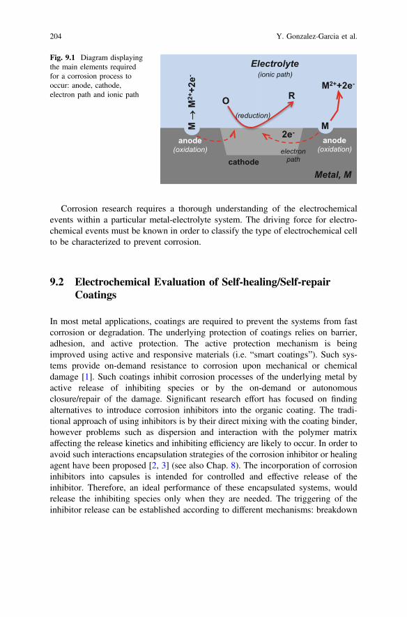
Corrosion research requires a thorough understanding of the electrochemicalevents within a particular metal-electrolyte system. The driving force for electro-chemical events must be known in order to classify the type of electrochemical cellto be characterized to prevent corrosion.
9.2 Electrochemical Evaluation of Self-healing/Self-repairCoatings
In most metal applications, coatings are required to prevent the systems from fastcorrosion or degradation. The underlying protection of coatings relies on barrier,adhesion, and active protection. The active protection mechanism is beingimproved using active and responsive materials (i.e. “smart coatings”). Such sys-tems provide on-demand resistance to corrosion upon mechanical or chemicaldamage [1]. Such coatings inhibit corrosion processes of the underlying metal byactive release of inhibiting species or by the on-demand or autonomousclosure/repair of the damage. Significant research effort has focused on findingalternatives to introduce corrosion inhibitors into the organic coating. The tradi-tional approach of using inhibitors is by their direct mixing with the coating binder,however problems such as dispersion and interaction with the polymer matrixaffecting the release kinetics and inhibiting efficiency are likely to occur. In order toavoid such interactions encapsulation strategies of the corrosion inhibitor or healingagent have been proposed [2, 3] (see also Chap. 8). The incorporation of corrosioninhibitors into capsules is intended for controlled and effective release of theinhibitor. Therefore, an ideal performance of these encapsulated systems, wouldrelease the inhibiting species only when they are needed. The triggering of theinhibitor release can be established according to different mechanisms: breakdown
Fig. 9.1 Diagram displayingthe main elements requiredfor a corrosion process tooccur: anode, cathode,electron path and ionic path
204 Y. Gonzalez-Garcia et al.
by mechanical damage, pH, dissolution, exchange, humidity or moisture, to name afew. In the end, the ability to suppress or decrease corrosion to tolerable levels willdepend on efficiency of the healing behavior of the coating system. It is at this pointwhere the evaluation methods are relevant. The techniques used for evaluation of(self-healing) anticorrosive coatings can be divided in three main groups:
• accelerated tests used in industry• conventional (global) electrochemical methods, and• localized electrochemical techniques.
Accelerated testing is possibly the most widespread methodology for corrosionresistance evaluation at an industrial scale and presents many different variants andadaptations. These tests are typically based on exposure of the material to controlled(atmospheric) severe conditions: humidity, salinity, pollutants, temperature, etc.Alternating wet/dry cycles changes the thickness of electrolyte layer. The presenceof water, temperature, and chloride ions promotes the corrosion processes at thescribe (degree of corrosion) as well as at the intact coating (delamination, blisters).The degradation of coated metals (or materials in general) is assessed by visualinspection. Accelerated tests only provide information that allows a ranking of thespecimen from “unacceptable” to “excellent”. They are screening methods to dif-ferentiate corrosion performance of the specimen under study. However, acceler-ated test results form no basis for the understanding of the corrosion (or protection)mechanism. These types of evaluation can accumulate sometimes large amounts oferror due to the extreme aggressive conditions, the long duration of the test and asubjective, user-dependent evaluation. Moreover, despite all its drawbacks, since itis used broadly in industry, this is an almost mandatory technique before anysystem is introduced in the market. More about the evaluation and application ofself-healing systems from an industrial point of view is discussed in Chaps. 12–14.
To gain insight into the healing-process behind the behaviour of the system othertechniques have to be used. These techniques include electrochemical techniquesdescribed in this chapter and physico-chemical characterization described inChap. 10.
Electrochemical methods are versatile and they can provide a wide range ofinformation that can include the understanding of multi-step reactions, the kineticsof heterogeneous electron-transfer reactions, coupled chemical reactions andadsorption processes. For corrosion studies, electrochemical evaluation providesvaluable information such as kinetics of the corrosion or protection processes,formation of protective films, evolution of barrier properties, identification andquantification of redox species.
Potential measurements, potentiodynamic experiments (including polarizationcurves and cyclic voltammetry) and electrochemical impedance spectroscopy(EIS) are the most common electrochemical methods used for corrosion andself-healing research. In this chapter they are classified as global methods. More
9 Electrochemical Techniques for the Study of Self Healing Coatings 205
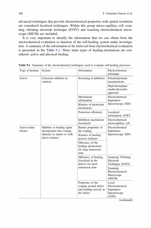
advanced techniques that provide electrochemical properties with spatial resolutionare considered localized techniques. Within this group micro-capillary cell, scan-ning vibrating electrode technique (SVET) and scanning electrochemical micro-scope (SECM) are included.
It is very important to identify the information that we can obtain from theelectrochemical evaluation as function of the self-healing system under investiga-tion. A summary of the information to be retrieved from electrochemical evaluationis presented in the Table 9.1. Three main types of healing-mechanism are con-sidered: active and physical healing.
Table 9.1 Summary of the electrochemical techniques used to evaluate self-healing processes
Type of healing System Information Electrochemicaltechnique
Active Corrosion inhibitor insolution
Screening of inhibitors Potentiodynamicmeasurements
High-throughput(multi-electrode)approach
Mechanisticinformation
ElectrochemicalImpedanceSpectroscopy (EIS)Kinetics of protection
mechanism
Protection efficiency Localizedinformation: SVET
Inhibition mechanism(localized)
Electrochemicalmicrocapillary cell
Active-smartrelease
Inhibitor or healing agentincorporated into coating(directly in matrix or withmicro-carriers)
Barrier properties ofthe coating
ElectrochemicalImpedanceSpectroscopy (EIS)Kinetics of healing
process (release)
Efficiency of thehealing (protection)for long immersiontime
Efficiency of healing(localized in thedefect) for shortimmersion time
Scanning VibratingElectrodeTechnique (SVET)
ScanningElectrochemicalMicroscope(SECM)
Properties of thecoating around defectand healing activity inthe defect
LocalElectrochemicalImpedanceSpectroscopy(LEIS)
(continued)
206 Y. Gonzalez-Garcia et al.
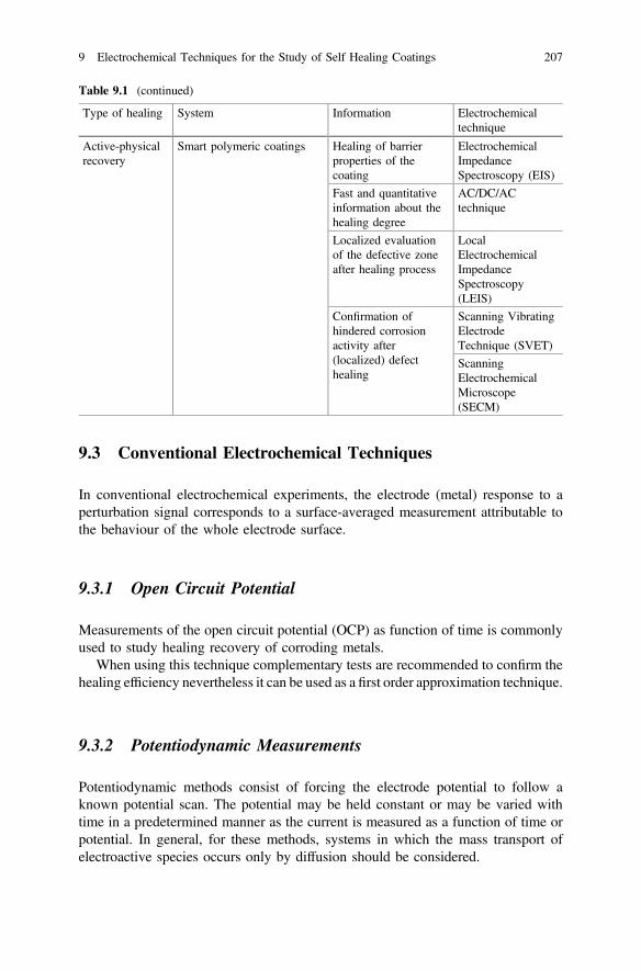
9.3 Conventional Electrochemical Techniques
In conventional electrochemical experiments, the electrode (metal) response to aperturbation signal corresponds to a surface-averaged measurement attributable tothe behaviour of the whole electrode surface.
9.3.1 Open Circuit Potential
Measurements of the open circuit potential (OCP) as function of time is commonlyused to study healing recovery of corroding metals.
When using this technique complementary tests are recommended to confirm thehealing efficiency nevertheless it can be used as a first order approximation technique.
9.3.2 Potentiodynamic Measurements
Potentiodynamic methods consist of forcing the electrode potential to follow aknown potential scan. The potential may be held constant or may be varied withtime in a predetermined manner as the current is measured as a function of time orpotential. In general, for these methods, systems in which the mass transport ofelectroactive species occurs only by diffusion should be considered.
Table 9.1 (continued)
Type of healing System Information Electrochemicaltechnique
Active-physicalrecovery
Smart polymeric coatings Healing of barrierproperties of thecoating
ElectrochemicalImpedanceSpectroscopy (EIS)
Fast and quantitativeinformation about thehealing degree
AC/DC/ACtechnique
Localized evaluationof the defective zoneafter healing process
LocalElectrochemicalImpedanceSpectroscopy(LEIS)
Confirmation ofhindered corrosionactivity after(localized) defecthealing
Scanning VibratingElectrodeTechnique (SVET)
ScanningElectrochemicalMicroscope(SECM)
9 Electrochemical Techniques for the Study of Self Healing Coatings 207
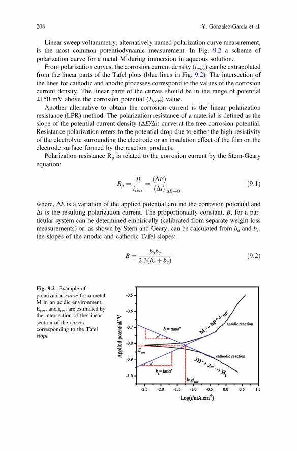
Linear sweep voltammetry, alternatively named polarization curve measurement,is the most common potentiodynamic measurement. In Fig. 9.2 a scheme ofpolarization curve for a metal M during immersion in aqueous solution.
From polarization curves, the corrosion current density (icorr) can be extrapolatedfrom the linear parts of the Tafel plots (blue lines in Fig. 9.2). The intersection ofthe lines for cathodic and anodic processes correspond to the values of the corrosioncurrent density. The linear parts of the curves should be in the range of potential±150 mV above the corrosion potential (Ecorr) value.
Another alternative to obtain the corrosion current is the linear polarizationresistance (LPR) method. The polarization resistance of a material is defined as theslope of the potential-current density (ΔE/Δi) curve at the free corrosion potential.Resistance polarization refers to the potential drop due to either the high resistivityof the electrolyte surrounding the electrode or an insulation effect of the film on theelectrode surface formed by the reaction products.
Polarization resistance Rp is related to the corrosion current by the Stern-Gearyequation:
Rp ¼ Bicorr
¼ DEð ÞDið Þ DE!0
ð9:1Þ
where, ΔE is a variation of the applied potential around the corrosion potential andΔi is the resulting polarization current. The proportionality constant, B, for a par-ticular system can he determined empirically (calibrated from separate weight lossmeasurements) or, as shown by Stern and Geary, can be calculated from ba and bc,the slopes of the anodic and cathodic Tafel slopes:
B ¼ babc2:3 ba þ bcð Þ ð9:2Þ
Fig. 9.2 Example ofpolarization curve for a metalM in an acidic environment.Ecorr and icorr are estimated bythe intersection of the linearsection of the curvescorresponding to the Tafelslope
208 Y. Gonzalez-Garcia et al.
The Tafel slopes themselves can be evaluated experimentally using real polar-ization plots. A high Rp for a metal implies high corrosion resistance and a low Rp
implies low corrosion resistance.The extrapolation from the Tafel curves is only valid when the anodic and
cathodic reactions are under activation control. In practice, determining the linearsection of the Tafel plot is not always straightforward. Experimental polarizationcurves sometimes can present peculiarities that bring doubts about where to choosethe linear section in the curve. This issue is a regular cause of errors when esti-mating the corrosion current.
Corrosion current is correlated to corrosion rate (r) of the process throughFaraday’s law by the following equation:
r ¼ aicorrnFD
ð9:3Þ
where a is the atomic number of the metal, n number of electrons, F the Faradayconstant and D the density of the metal.
Within the context of self-healing materials, polarization methods are commonlyused to evaluate and compare corrosion inhibitor performance in solution. The testconsists of analyzing the response of the metal while it is immersed in solutioncontaining dissolved corrosion inhibitor [4]. The resulting polarization curves giveaccess to the corrosion rate. Furthermore it visualizes the anodic, cathodic or mixedprotection performance of the inhibitor (Fig. 9.2). The analysis of the curves andinterpretation of the results is well explained in Chap. 4.
Conventional potentiodynamic methods are usually not applicable for coatedsubstrates due to important limitations arising from the high IR drop over thecoating. This method cannot give any useful information on the active corrosionprotection and the self-healing ability of protective coatings.
An alternative is the direct current (DC) measurement. For this case the coatedsample is kept at high constant potential (potentiostatic method) and the current thatflows through the system is measured. The electrochemical measurements arecarried out in an electrochemical cell with typically a three electrode system(working, reference and counter electrodes) immersed in an electrolyte. Theapplication of this constant potential can fully reduce or oxidize species in a givensolution depending on the potential values, the substrate, pH of the electrolyte andother factors. It moves the systems out of electrochemical equilibrium possiblyleading to (i) accelerated degradation of the system; or (ii) forceddeposition-reaction of healing agents.
This technique has been used to study the healing capabilities of epoxy-aminecoating doped with organic fillers containing inorganic corrosion inhibitors on steel[1] by monitoring the current density values at fixed potential (−0.85 VAg/AgCl and−1.1 VAg/AgCl) with time. In this study, healing was detected by a decrease of thecurrent density in a scratched doped-system, while the non-doped one showed anincrease. The same system evaluated by electrochemical impedance spectroscopy(EIS) only showed a slight improvement with respect to the reference one. A similar
9 Electrochemical Techniques for the Study of Self Healing Coatings 209
method has been also employed to assess healing of a steel plate coated with aself-healing coating using microencapsulation of liquid healing agents [5]. In thiscase, the experiment was performed at 3 V polarization measuring the currentdensity evolution with time of the scratched samples. Healed samples showed twoorders of magnitude lower current density than the reference systems indicating theformation of a barrier layer at the scribe (gap filling of the damage).
The evaluation of healing properties under high potentiostatic polarization isuseful mostly when the final application of the coating requires similar conditionsas the applied experimental parameters.
9.3.3 Electrochemical Impedance Spectroscopy (EIS)
Electrochemical impedance spectroscopy (EIS) is one of the most used techniquesat scientific level in the fields of corrosion and coatings technology and thus itsextension and importance in the evaluation of self-healing (anticorrosive) coatings.EIS is a non-destructive test that allows assessment of the degradation (or healing)of the system with time. But more importantly it provides quantitative informationof the processes taking place within the system.
Electrochemical impedance spectroscopy is based on electric circuit theory andthe description of the different electrochemical processes occurring in thecoating-oxide-metal system by a combination of electrical parameters such asresistors and capacitors. The technique uses the description of the behaviour of anelectric circuit when an alternating current or voltage is applied as a function of thefrequency.
The concept of electrical resistance is well known and is defined by Ohm’s law.Resistance is the ability of a circuit to resist the flow of current, mathematicallyexpressed as:
R ¼ V=I ð9:4Þ
where R is resistance in ohms, V is voltage in volts, and I is current in amperes.However, this simple relationship is limited to one circuit element, the resistor, andit does not represent more complex behaviour that many systems exhibit in the realworld. Therefore, the concept of impedance (Z) is introduced. The impedance is ameasure of the tendency of a circuit to resist the flow of an alternating electricalcurrent. The equivalent mathematical expression of Eq. (3) for the case of impe-dance is:
Z ¼ Vac=Iac ð9:5Þ
This simple and basic equation actually hides some more complicatedassumptions and concepts. First, it applies only to the time-varying, alternating, orac components of the current and voltage. Secondly, it is not sufficient to just
210 Y. Gonzalez-Garcia et al.
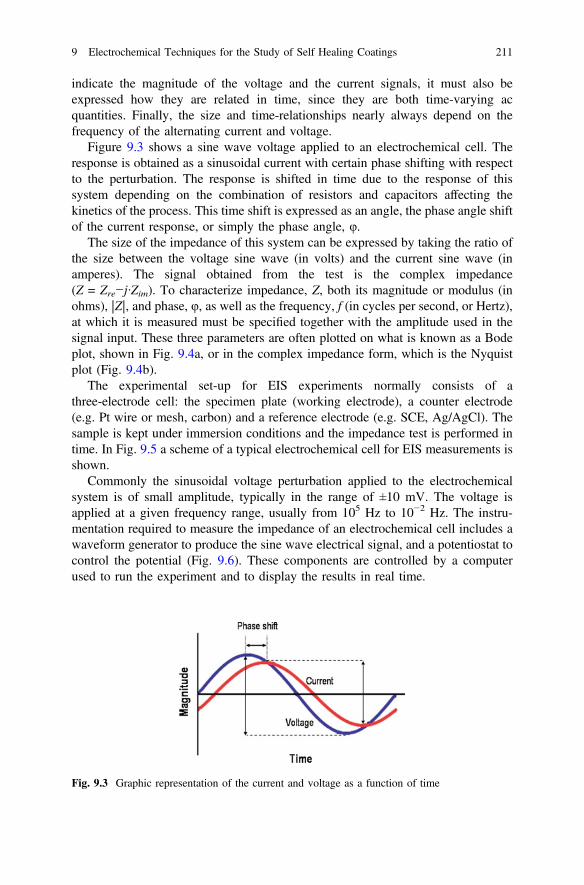
indicate the magnitude of the voltage and the current signals, it must also beexpressed how they are related in time, since they are both time-varying acquantities. Finally, the size and time-relationships nearly always depend on thefrequency of the alternating current and voltage.
Figure 9.3 shows a sine wave voltage applied to an electrochemical cell. Theresponse is obtained as a sinusoidal current with certain phase shifting with respectto the perturbation. The response is shifted in time due to the response of thissystem depending on the combination of resistors and capacitors affecting thekinetics of the process. This time shift is expressed as an angle, the phase angle shiftof the current response, or simply the phase angle, φ.
The size of the impedance of this system can be expressed by taking the ratio ofthe size between the voltage sine wave (in volts) and the current sine wave (inamperes). The signal obtained from the test is the complex impedance(Z = Zre−j·Zim). To characterize impedance, Z, both its magnitude or modulus (inohms), |Z|, and phase, φ, as well as the frequency, f (in cycles per second, or Hertz),at which it is measured must be specified together with the amplitude used in thesignal input. These three parameters are often plotted on what is known as a Bodeplot, shown in Fig. 9.4a, or in the complex impedance form, which is the Nyquistplot (Fig. 9.4b).
The experimental set-up for EIS experiments normally consists of athree-electrode cell: the specimen plate (working electrode), a counter electrode(e.g. Pt wire or mesh, carbon) and a reference electrode (e.g. SCE, Ag/AgCl). Thesample is kept under immersion conditions and the impedance test is performed intime. In Fig. 9.5 a scheme of a typical electrochemical cell for EIS measurements isshown.
Commonly the sinusoidal voltage perturbation applied to the electrochemicalsystem is of small amplitude, typically in the range of ±10 mV. The voltage isapplied at a given frequency range, usually from 105 Hz to 10−2 Hz. The instru-mentation required to measure the impedance of an electrochemical cell includes awaveform generator to produce the sine wave electrical signal, and a potentiostat tocontrol the potential (Fig. 9.6). These components are controlled by a computerused to run the experiment and to display the results in real time.
Fig. 9.3 Graphic representation of the current and voltage as a function of time
9 Electrochemical Techniques for the Study of Self Healing Coatings 211

0.01 0.1 1 10 100 100010
100
1000
10000
-90
-75
-60
-45
-30
-15
0
x
f
0 1000 2000 3000 4000 50000
1000
2000
3000
4000
5000
(a)
(b)
Fig. 9.4 Data representationfor impedance data: a Bodeplot and b Nyquist plot
Fig. 9.5 Electrochemical cellused in EIS experiments: WE,working electrode; RE,reference electrode; and CE,auxiliary electrode
212 Y. Gonzalez-Garcia et al.
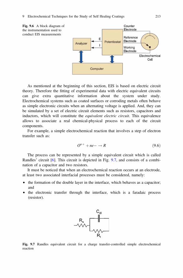
As mentioned at the beginning of this section, EIS is based on electric circuittheory. Therefore the fitting of experimental data with electric equivalent circuitscan give extra quantitative information about the system under study.Electrochemical systems such as coated surfaces or corroding metals often behaveas simple electronic circuits when an alternating voltage is applied. And, they canbe simulated by a set of electric circuit elements such as resistors, capacitors andinductors, which will constitute the equivalent electric circuit. This equivalenceallows to associate a real chemical-physical process to each of the circuitcomponents.
For example, a simple electrochemical reaction that involves a step of electrontransfer such as:
Onþ þ ne� ! R ð9:6Þ
The process can be represented by a simple equivalent circuit which is calledRandles’ circuit [6]. This circuit is depicted in Fig. 9.7, and consists of a combi-nation of a capacitor and two resistors.
It must be noticed that when an electrochemical reaction occurs at an electrode,at least two associated interfacial processes must be considered, namely:
• the formation of the double layer in the interface, which behaves as a capacitor;and
• the electronic transfer through the interface, which is a faradaic process(resistor).
Fig. 9.6 A block diagram ofthe instrumentation used toconduct EIS measurements
Fig. 9.7 Randles equivalent circuit for a charge transfer-controlled simple electrochemicalreaction
9 Electrochemical Techniques for the Study of Self Healing Coatings 213
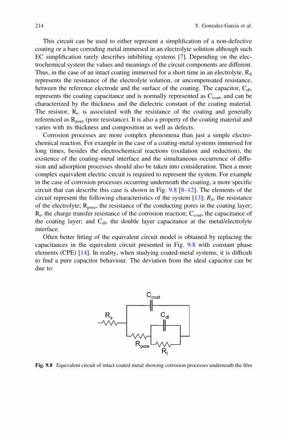
This circuit can be used to either represent a simplification of a non-defectivecoating or a bare corroding metal immersed in an electrolyte solution although suchEC simplification rarely describes inhibiting systems [7]. Depending on the elec-trochemical system the values and meanings of the circuit components are different.Thus, in the case of an intact coating immersed for a short time in an electrolyte, RS
represents the resistance of the electrolyte solution, or uncompensated resistance,between the reference electrode and the surface of the coating. The capacitor, Cdl,represents the coating capacitance and is normally represented as Ccoat, and can becharacterized by the thickness and the dielectric constant of the coating material.The resistor, Rt, is associated with the resistance of the coating and generallyreferenced as Rpore (pore resistance). It is also a property of the coating material andvaries with its thickness and composition as well as defects.
Corrosion processes are more complex phenomena than just a simple electro-chemical reaction. For example in the case of a coating-metal systems immersed forlong times, besides the electrochemical reactions (oxidation and reduction), theexistence of the coating-metal interface and the simultaneous occurrence of diffu-sion and adsorption processes should also be taken into consideration. Then a morecomplex equivalent electric circuit is required to represent the system. For examplein the case of corrosion processes occurring underneath the coating, a more specificcircuit that can describe this case is shown in Fig. 9.8 [8–12]. The elements of thecircuit represent the following characteristics of the system [13]; RS, the resistanceof the electrolyte; Rpore, the resistance of the conducting pores in the coating layer;Rt, the charge transfer resistance of the corrosion reaction; Ccoat, the capacitance ofthe coating layer; and Cdl, the double layer capacitance at the metal/electrolyteinterface.
Often better fitting of the equivalent circuit model is obtained by replacing thecapacitances in the equivalent circuit presented in Fig. 9.8 with constant phaseelements (CPE) [14]. In reality, when studying coated-metal systems, it is difficultto find a pure capacitor behaviour. The deviation from the ideal capacitor can bedue to:
Fig. 9.8 Equivalent circuit of intact coated metal showing corrosion processes underneath the film
214 Y. Gonzalez-Garcia et al.
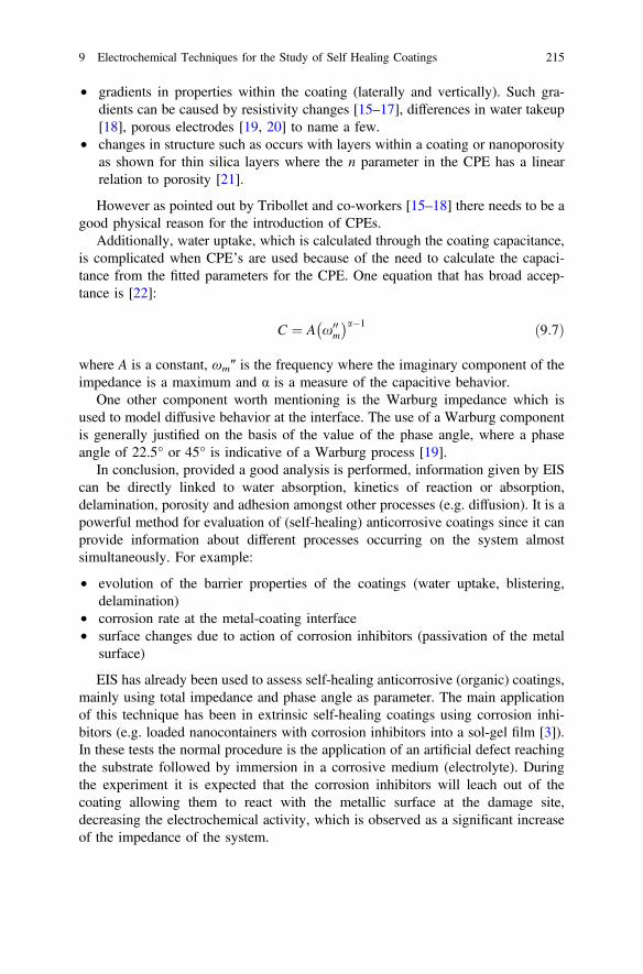
• gradients in properties within the coating (laterally and vertically). Such gra-dients can be caused by resistivity changes [15–17], differences in water takeup[18], porous electrodes [19, 20] to name a few.
• changes in structure such as occurs with layers within a coating or nanoporosityas shown for thin silica layers where the n parameter in the CPE has a linearrelation to porosity [21].
However as pointed out by Tribollet and co-workers [15–18] there needs to be agood physical reason for the introduction of CPEs.
Additionally, water uptake, which is calculated through the coating capacitance,is complicated when CPE’s are used because of the need to calculate the capaci-tance from the fitted parameters for the CPE. One equation that has broad accep-tance is [22]:
C ¼ A x00m
� �a�1 ð9:7Þ
where A is a constant, ωm″ is the frequency where the imaginary component of theimpedance is a maximum and α is a measure of the capacitive behavior.
One other component worth mentioning is the Warburg impedance which isused to model diffusive behavior at the interface. The use of a Warburg componentis generally justified on the basis of the value of the phase angle, where a phaseangle of 22.5° or 45° is indicative of a Warburg process [19].
In conclusion, provided a good analysis is performed, information given by EIScan be directly linked to water absorption, kinetics of reaction or absorption,delamination, porosity and adhesion amongst other processes (e.g. diffusion). It is apowerful method for evaluation of (self-healing) anticorrosive coatings since it canprovide information about different processes occurring on the system almostsimultaneously. For example:
• evolution of the barrier properties of the coatings (water uptake, blistering,delamination)
• corrosion rate at the metal-coating interface• surface changes due to action of corrosion inhibitors (passivation of the metal
surface)
EIS has already been used to assess self-healing anticorrosive (organic) coatings,mainly using total impedance and phase angle as parameter. The main applicationof this technique has been in extrinsic self-healing coatings using corrosion inhi-bitors (e.g. loaded nanocontainers with corrosion inhibitors into a sol-gel film [3]).In these tests the normal procedure is the application of an artificial defect reachingthe substrate followed by immersion in a corrosive medium (electrolyte). Duringthe experiment it is expected that the corrosion inhibitors will leach out of thecoating allowing them to react with the metallic surface at the damage site,decreasing the electrochemical activity, which is observed as a significant increaseof the impedance of the system.
9 Electrochemical Techniques for the Study of Self Healing Coatings 215
EIS has also been successfully employed for liquid encapsulated extrinsicself-healing coatings using two component microencapsulated liquid healing agents[23] or one component microencapsulated healing agent [24] in both cases withexcellent results of the use of the technique. In the case of systems usingmicro-encapsulation, the technique generally shows a more significant increase inimpedance than when used for corrosion inhibitor systems due to the restoration ofthe barrier effect offered by gap filling or full surface coverage [22] in encapsulatedconcepts and thus major hindering of the electrochemical reactions. EIS has alsobeen recently combined with X-ray microtomography to further understand themechanisms of protection of single reactive healing agents such as the silyl esterinvolving delamination and underfilm pitting processes [25].
9.3.4 Odd-Random Phase Multisine ElectrochemicalImpedance Spectroscopy
As an extension of use of EIS, the odd random phase multisine electrochemicalimpedance spectroscopy (ORP-EIS) has also been used as a characterization toolfor diverse electrochemical processes [26, 27]. ORP-EIS cannot be considered asconventional electrochemical test, but it is included in this section as it providesglobal (averaged) information of the specimen.
In the previous section the capacity of EIS for the study and evaluation of diverseself-healing systems was presented. A reliable model that describes the system underinvestigation can only be obtained if the measurement fulfills the conditions ofcausality, linearity and time-invariance. However, the two last conditions can bedifficult to satisfy. EIS measurements are often performed with very small amplitudeexcitation signals (for reasons of linearity) in the steady state regime of the process (forreasons of time-invariance). As a consequence, the measurements (i) can suffer frompoor signal-to-noise ratios and (ii) cannot describe the initial, mostly rapidly evolving,stages of electrochemical phenomena of corrosion processes. Moreover proper fittingof the model to experimental data needs to be achieved, by minimising the residualsbetween the data and the fit across the whole frequency range [7, 28, 29].
Apart for shorter time measurements ORP-EIS allows measuring the level ofdisturbing noise, the level of the non-linear distortions and the level of thenon-stationary behaviour. The additional information given by this methodology isuseful to verify the quality of the measurement. In Fig. 9.9 a typical ORP-EISspectrum is shown, in which, additional to the conventional impedance data, it ispossible to observe the noise level and non-stationary behaviour of the system [30].As happens with traditional EIS, ORP-EIS becomes a powerful method whencombined with the fitting of the data. The additional information helps to reject,accept or improve electrical equivalent circuit models used to fit the conventionalimpedance spectra. The advantage of the technique has been demonstrated on anelectric circuit [27] and the study of corrosion of coated metal [31]. However, it isstill scarcely used on the study of self-healing corrosion systems.
216 Y. Gonzalez-Garcia et al.
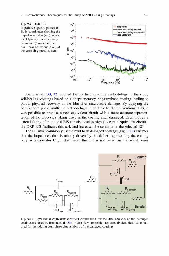
Jorcin et al. [30, 32] applied for the first time this methodology to the studyself-healing coatings based on a shape memory polyturethane coating leading topartial physical recovery of the film after macroscale damage. By applying theodd-random phase multisine methodology in contrast to the conventional EIS, itwas possible to propose a new equivalent circuit with a more accurate represen-tation of the processes taking place in the coating after damaged. Even though acareful fitting of traditional EIS can also lead to highly accurate equivalent circuits,the ORP-EIS facilitates this task and increases the certainty in the selected EC.
The EC most commonly used circuit to fit damaged coatings (Fig. 9.10) assumesthat the impedance data is mainly driven by the defect, representing the coatingonly as a capacitor Ccoat. The use of this EC is not based on the overall error
Rs
Rpore
Rox Rf-scratch
Ccoat
CPEox CPEf-cratch
CPEf
Rf Coating
Scratch
Fig. 9.10 (left) Initial equivalent electrical circuit used for the data analysis of the damagedcoatings proposed by Bonora et al. [33]. (right) New proposition for an equivalent electrical circuitused for the odd-random phase data analysis of the damaged coatings
Fig. 9.9 ODR-EISImpedance spectra plotted onBode coordinates showing theimpedance value (red), noiselevel (green), non-stationarybehaviour (black) and thenon-linear behaviour (blue) ofthe corroding metal system
9 Electrochemical Techniques for the Study of Self Healing Coatings 217

minimization [7, 24] but on the chi-square, however, it is generally acceptedwithout questioning its validity. When this circuit is applied to fit the odd-randomEIS data, a residue (difference between model and experimental data) higher thanthe stochastic noise of the measurement is observed. This is a clear indication thatthe equivalent circuit is not well adapted to this electrochemical system probably asa result of a simplification of the physical phenomenon in a damaged coating. Basedon this lack of correlation it was possible to propose a new EC consisting in twoparts [30]: one related to the organic coating and one related to the phenomenaoccurring in the artificial defect. The fitting of the data with this new model pre-sented a residue at the level of stochastic noise of the measurement, indicating thatall information in the spectrum is taken into account.
The odd-random phase impedance spectroscopy (ORP-EIS) appears as a valu-able alternative to conventional impedance methodology for the study of corrosionand self-healing processes. The main advantages are: rapid acquisition of the dataand more accurate information to model the system of interest. Nevertheless,analysis of the spectra and the fitting procedure is still tedious and requires a certainlevel of expertise that makes it not accessible yet for routine research.
9.3.5 AC/DC/AC Accelerated Electrochemical Protocol
Despite the fact that EIS and ORP-EIS can lead to very reliable information aboutthe properties of intact and damaged coatings, they require very long times to assessintact high impedance coatings. In the case of intrinsic self-healing coatings, EISand ORP-EIS can discern quickly the level of healing when the healed interface isonly weakly healed (closed). When the damage interface of the healed coating is ofhigh quality and close to the original network properties non-destructive EISrequires very long times to assess the healing of the scribe. A very recent study withhighly efficient intrinsic healing coatings demonstrated that EIS is not capable ofdetecting any difference between the intact coating and healed coating (macroscalescratches) even after 30 days immersion in corrosive media [34]. In order to detectthe healing state (healing degree) the researchers introduced the use of an accel-erated destructive electrochemical protocol named AC/DC/AC or ACET. Suchtechnique consists of cycles of EIS measurements/polarization to −2 or −4 Vdepending on the coating quality/potential relaxation/new EIS to measure the afterdamage state. [35–38]. When this protocol was applied to self-healing coatings [34]the healed scratches (interfaces) were detected after a number of cycles by a suddendrop of the impedance spectrum. While EIS indicated that the healed coatingbehaved as a high impedance coating (same behavior as the intact coating) for atleast 30 days the AC/DC/AC indicated in three cycles (approximately 12 h) that thedamages do act as heterogeneities in the coating even when the healing degree ishigh (Fig. 9.11). Such a result suggests that healed interfaces can protect damagesfor long times (at least 1 year as shown in the same article) but that the polymernetwork at the healed interface remains different from the bulk coating. This first
218 Y. Gonzalez-Garcia et al.

time results suggest that the AC/DC/AC technique can be a powerful technique toevaluate healing in intrinsic coatings and potentially even quantify healing degreebased on the number of cycles to failure as well as polarization potential applied.
9.4 High-Throughput Screening Techniques
In the previous section the most common electrochemical methods to evaluate theefficiency of self-healing systems were introduced. In general, these techniquesrequire testing times ranging from hours (in the case of electrochemical studies) toweeks (for accelerated laboratory testing, mass loss testing) or even years (in thecase of outdoor exposure testing) and produce data on only one system of interest ata time. Hence, if a broad range of systems is to be investigated, more rapid means ofevaluating their performance need to be found. This is typically an issue for theresearch focused on development of new corrosion inhibitive coatings. Restrictionson using Cr(VI) compounds for corrosion protection has forced an increase in theeffort to search for equally efficient substitute inhibitors. Up to now the research ofalternative corrosion inhibitors for all sorts of metals is still an ongoing topic.Within the development of new protective coatings we can identify five stages ormilestones (Fig. 9.12):
• selection of alternative inhibitor candidates• evaluation of their intrinsic efficiency• incorporation into the coating• total performance evaluation• final optimization of delivery kinetics
In all these steps the main problem, apart from finding the perfect inhibitor, isthat it is a very time consuming process, especially when thousands of inhibitorcandidates have to be tested. For this reason the introduction of high throughput
10 -1 10 0 10 1 10 2 10 3 10 4 10 5
10 3
10 4
10 5
10 6
10 7
108
10 9
10 10 EIS - 30 min EIS - 30 days
|Z| (
Ω.c
m2 )
f (Hz)
10 -1 10 0 10 1 10 2 10 3 10 4 10 5
103
104
105
106
10 7
108
10 9
1010 Initial
1st Cycle 2nd Cycle 3rd Cycle 4th Cycle 5th Cycle 6th Cycle
|Z| (
Ω.c
m2 )
f (Hz)
Fig. 9.11 Healed coating after 30 days exposure to electrolyte measured by EIS (left) and after 6cycles of the AC/DC/AC procedure (right). (adapted from [34])
9 Electrochemical Techniques for the Study of Self Healing Coatings 219
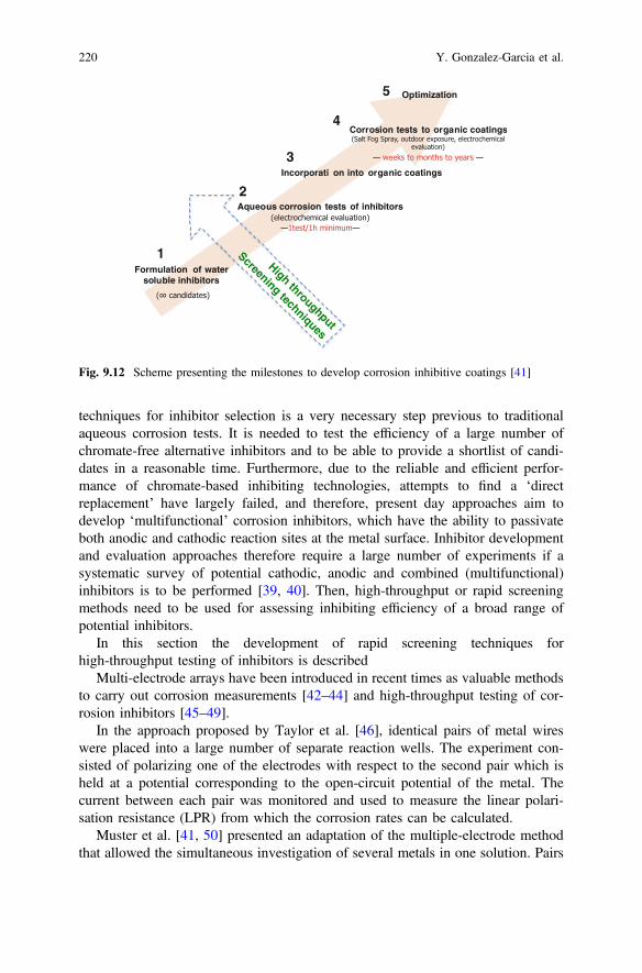
techniques for inhibitor selection is a very necessary step previous to traditionalaqueous corrosion tests. It is needed to test the efficiency of a large number ofchromate-free alternative inhibitors and to be able to provide a shortlist of candi-dates in a reasonable time. Furthermore, due to the reliable and efficient perfor-mance of chromate-based inhibiting technologies, attempts to find a ‘directreplacement’ have largely failed, and therefore, present day approaches aim todevelop ‘multifunctional’ corrosion inhibitors, which have the ability to passivateboth anodic and cathodic reaction sites at the metal surface. Inhibitor developmentand evaluation approaches therefore require a large number of experiments if asystematic survey of potential cathodic, anodic and combined (multifunctional)inhibitors is to be performed [39, 40]. Then, high-throughput or rapid screeningmethods need to be used for assessing inhibiting efficiency of a broad range ofpotential inhibitors.
In this section the development of rapid screening techniques forhigh-throughput testing of inhibitors is described
Multi-electrode arrays have been introduced in recent times as valuable methodsto carry out corrosion measurements [42–44] and high-throughput testing of cor-rosion inhibitors [45–49].
In the approach proposed by Taylor et al. [46], identical pairs of metal wireswere placed into a large number of separate reaction wells. The experiment con-sisted of polarizing one of the electrodes with respect to the second pair which isheld at a potential corresponding to the open-circuit potential of the metal. Thecurrent between each pair was monitored and used to measure the linear polari-sation resistance (LPR) from which the corrosion rates can be calculated.
Muster et al. [41, 50] presented an adaptation of the multiple-electrode methodthat allowed the simultaneous investigation of several metals in one solution. Pairs
Fig. 9.12 Scheme presenting the milestones to develop corrosion inhibitive coatings [41]
220 Y. Gonzalez-Garcia et al.
of metals were immersed into various inhibitor solutions at relatively low polar-ization. The current flowing between the individual electrodes of each metal pairwas measured. The current exchange between the individual electrodes of the samemetal then was expressed in inhibitor efficiency with respect to that in uninhibitedsolutions.
Other main differences with respect to Taylor and Chambers approach are:
• no reference electrode is used to fix electrode potentials of the metals• a blank sample is used as a control for each inhibitor evaluation
Electrochemical methods are usually not carried out in the absence of a referenceelectrode. However, for the rapid screening of multifunctional corrosion inhibitors,the omission of the reference electrode offers the benefit of simplicity whilstretaining the key information regarding inhibition.
High-throughput screening methods reduce the experimental time significantly.For example, in the work of Taylor and Chambers [45, 46] potential corrosioninhibitors and their synergistic combinations for aluminium alloy AA2024 werestudied. The inhibition characteristics of 50 separate chemistries were assessedsimultaneously. The test using direct current (DC) polarization in themultiple-electrode system was performed within 9 h while for electrochemicalimpedance experiments for the same number of inhibitors at least 10 days ofmeasurements was needed.
In addition to electrochemical techniques that aim to determine the corrosioncurrent, or potentiostatic current as above, high throughput studies of corrosioninhibition have also been applied to the detection of chemical changes. Thesetechniques are non-electrochemical, high-throughput screening methods. Thesemethods are based on fluorimetric [45, 51] and spectroscopic measurements [52].They are used to determine the concentration of chemical species in solution.
A different type of method for high-throughput screening is based on micro-fluidic approaches [53]. These differ from the multielectrode in that only one metalcan be studied in the one test. The metal is exposed to a range of aqueous corrosioninhibitors and concentrations via micro-fluidic channels. The sample is visuallyinspected and solutions are chemically analyzed. Another non-electrochemicalhigh-throughput test employs arrays of wells which are filled with inhibitor-dopedsolutions and after exposure the bottom wells are then examined by digitalmicrograph analysis [54].
9.5 Local Electrochemical Techniques
In Sect. 9.3, general electrochemical methods were presented. These methods arecharacterized by having the sample of interest as working electrode. The obtainedresults provide averaged information of the electrochemical processes taking placeon the entire surface of the working electrode. In this section we examine localisedelectrochemical techniques.
9 Electrochemical Techniques for the Study of Self Healing Coatings 221
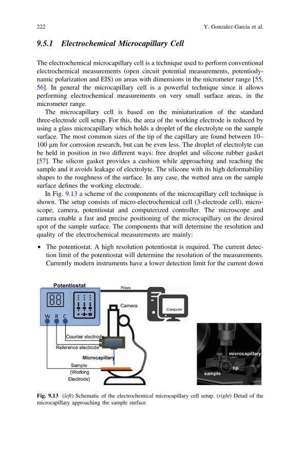
9.5.1 Electrochemical Microcapillary Cell
The electrochemical microcapillary cell is a technique used to perform conventionalelectrochemical measurements (open circuit potential measurements, potentiody-namic polarization and EIS) on areas with dimensions in the micrometer range [55,56]. In general the microcapillary cell is a powerful technique since it allowsperforming electrochemical measurements on very small surface areas, in themicrometer range.
The microcapillary cell is based on the miniaturization of the standardthree-electrode cell setup. For this, the area of the working electrode is reduced byusing a glass microcapillary which holds a droplet of the electrolyte on the samplesurface. The most common sizes of the tip of the capillary are found between 10–100 μm for corrosion research, but can be even less. The droplet of electrolyte canbe held in position in two different ways: free droplet and silicone rubber gasket[57]. The silicon gasket provides a cushion while approaching and reaching thesample and it avoids leakage of electrolyte. The silicone with its high deformabilityshapes to the roughness of the surface. In any case, the wetted area on the samplesurface defines the working electrode.
In Fig. 9.13 a scheme of the components of the microcapillary cell technique isshown. The setup consists of micro-electrochemical cell (3-electrode cell), micro-scope, camera, potentiostat and computerized controller. The microscope andcamera enable a fast and precise positioning of the microcapillary on the desiredspot of the sample surface. The components that will determine the resolution andquality of the electrochemical measurements are mainly:
• The potentiostat. A high resolution potentiostat is required. The current detec-tion limit of the potentiostat will determine the resolution of the measurements.Currently modern instruments have a lower detection limit for the current down
Fig. 9.13 (left) Schematic of the electrochemical microcapillary cell setup. (right) Detail of themicrocapillary approaching the sample surface
222 Y. Gonzalez-Garcia et al.
to pA and fA levels. Furthermore, adequate isolation and filters to reduce noiseinfluencing the measurements is required.
• Microcapillary. Preparation of the microcapillary consists of “pulling” a glasscapillary until the desired shape and diameter is obtained. The final size of thecapillary is achieved by careful grounding and polishing of the capillarytip. Afterwards, the silicone gasket is applied. The final inner diameter of thecapillary will influence the limiting current density during the measurements. Itis important to take into account this factor when planning a experiment. Forexample, a current density of 10 μA/cm2 corresponds to a capillary of 1 μmdiameter (exposed area). This is equivalent to corrosion currents in the order of10 fA [57].
The electrochemical microcapillary cell is a very attractive technique to study theeffect of microstructural features on the corrosion mechanisms of metal alloys. Themicrocapillary cells have been successfully used to the study of the local behaviourof intermetallics in aluminium alloys [58–60] and pit initiation of steels [61–63].
In this sense, the microcapillary cell can be used to study the protectionmechanism of corrosion inhibitors for individual phases or intermetallics from themetal alloy. Some works have been done focusing on rare-earth corrosion inhibitorsand their cathodic-type behaviour for AA2024 alloy.
Birbilis et al. [64] studied the protection mechanism of AA2024 alloy offered bycerium dibutyl phosphate (Ce(dbp)3). Taking advantage of the capabilities of themicrocapillary cell, it was possible to perform potentiodynamic measurements onindividual intermetallics and to study their behaviour in presence and absence of theinhibitor. Cathodic polarization curves on the main cathodic phases (Al2Cu,Al7Cu2Fe, Al20Cu2Mn3, and Al3Fe) showed that the Ce(dbp)3 effectively inhibitsoxygen reduction on each of them. Interestingly, anodic polarization curves mea-sured for anodic phases (Al7Cu2Fe and Al2CuMg) demonstrated that the inhibitor isable to stabilize the passivity of these phases. This work suggested that Ce(dbp)3acts as a mixed inhibitor offering cathodic and anodic inhibition for the AA2024alloy. It may effectively inhibit localized corrosion owing to its mixed nature,providing retardation of the oxygen reduction reaction upon noble intermetallicsand concomitant retardation of dissolution of phases that may be prone to attack.
In the work of Andreatta et al. [65] the localized corrosion inhibition of CeCl3was investigated for clad AA2024. In this case the research focused on the beha-viour of areas containing Fe-rich intermetallic compounds and areas withoutinclusions (matrix). Microcapillary based potentiodynamic polarization evidencedthat the deposition of Ce-species occurs on the entire sample surface being affectedby the alloy microstructure. Moreover, it is activated by alkaline etching of thesubstrate. The deposition takes place preferentially at the sites of intermetallics dueto their cathodic behaviour and to local alkalinization associated with cathodicreactions. It was possible to demonstrate that the amount of Ce detected at the sitesof intermetallics is larger than on the matrix.
More recently, the microcapillary cell has been used to characterize the pro-tective layer formed in a scratch by inhibitor released from the coating after it is
9 Electrochemical Techniques for the Study of Self Healing Coatings 223

damaged. In this work by Recloux et al. [66], benzotriazole (BTA) inhibitor wasincorporated into a silica mesoporous thin film as pretreatment applied on anAA2024 alloy sample. The acquisition of local anodic polarization curves with themicrocapillary cell on the bare metal exposed in the scribed coating was used tomonitor the formation of a passive film by the BTA within the defect. The resultsdemonstrated that the inhibitor was directly released from the mesoporous pre-treatment once the top coat was damaged and acted rapidly to protect the bare metaland to delay the initial stage of corrosion phenomena.
It is clear that this type of information and conclusions are not accessible fromconventional (macroscopic) potentiodynamic experiments. The microcapillary cellis a powerful method for localised electrochemical measurements and to establishcorrelation between corrosion/inhibition mechanisms and microstructural featuresat metal surfaces.
Nevertheless, the electrochemical microcapillary cell technique also presentsseveral drawbacks or precautions:
• risk of crevice corrosion at the silicon periphery of the capillary• requires a large number of measurements to assure the reproducibility of the
results• possibility of contamination of the solution during the measurement• small size of the microcapillary can affect the transport of species to the sub-
strate, such as oxygen and protons resulting in diffusion limited corrosionbehaviour
• problems with high ohmic resistance between working and counter electrodecan occur. The choice of an appropriate geometry of the cell will minimize thisissue.
9.5.2 Scanning Vibrating Electrode Technique (SVET)
The SVET technique produces in situ measurements with high spatial resolutionand provides valuable information on the behaviour of the corroding system at amicroscopic level [67, 68]. The SVET offers the possibility of mapping variationsin the ionic current densities in the micrometric range facilitating the location ofanodic and cathodic zones (related to corrosion processes). This technique is basedon the detection of electric fields generated in a solution due to ionic concentrationgradients. The electric field is zero when the solution is at rest, but if there is agradient of concentration caused by a source of ions, a variation of potential in thesolution occurs. Ionic flows can arise from corrosion processes on a metal. Theoxidation reactions occurring at anodic sites on a metal surface in contact with anelectrolyte cause electrons to flow through the metal substrate to adjacent cathodicareas. This flow of electrons through the metal is supported by a flow of ioniccurrent in the electrolyte, which in turn causes potential gradients to exist in thesolution close to sites of localized corrosion. Figure 9.14 depicts a scheme of the
224 Y. Gonzalez-Garcia et al.
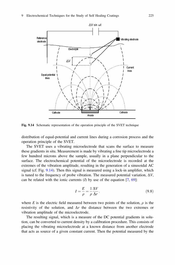
distribution of equal-potential and current lines during a corrosion process and theoperation principle of the SVET.
The SVET uses a vibrating microelectrode that scans the surface to measurethese gradients in situ. Measurement is made by vibrating a fine tip microelectrode afew hundred microns above the sample, usually in a plane perpendicular to thesurface. The electrochemical potential of the microelectrode is recorded at theextremes of the vibration amplitude, resulting in the generation of a sinusoidal ACsignal (cf. Fig. 9.14). Then this signal is measured using a lock-in amplifier, whichis tuned to the frequency of probe vibration. The measured potential variation, ΔV,can be related with the ionic currents (I) by use of the equation [7, 69]:
I ¼ Eq¼ 1
qDVDr
: ð9:8Þ
where E is the electric field measured between two points of the solution, ρ is theresistivity of the solution, and Δr the distance between the two extremes orvibration amplitude of the microelectrode.
The resulting signal, which is a measure of the DC potential gradients in solu-tion, can be converted to current density by a calibration procedure. This consists ofplacing the vibrating microelectrode at a known distance from another electrodethat acts as source of a given constant current. Then the potential measured by the
Fig. 9.14 Schematic representation of the operation principle of the SVET technique
9 Electrochemical Techniques for the Study of Self Healing Coatings 225
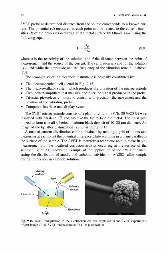
SVET probe at determined distance from the source corresponds to a known cur-rent. The potential (V) measured in each point can be related to the current inten-sities (I) of the processes occurring at the metal surface by Ohm’s Law, using thefollowing equation:
V ¼ Iq2pd
ð9:9Þ
where ρ is the resistivity of the solution, and d the distance between the point ofmeasurement and the source of the current. The calibration is valid for the solutionused and while the amplitude and the frequency of the vibration remain unaltered[70].
The scanning vibrating electrode instrument is basically constituted by:
• The electrochemical cell (detail in Fig. 9.15)• The piezo-oscillator system which produces the vibration of the microelectrode• Two lock-in amplifiers that measure and filter the signal produced in the probe.• Tri-axial piezoelectric motors to control with precision the movement and the
position of the vibrating probe• Computer, interface and display system
The SVET microelectrode consists of a platinum/iridium (Pt/Ir: 80 %/20 %) wireinsulated with paralene C® and arced at the tip to face the metal. The tip is pla-tinized to form a small spherical platinum black deposit of 10–20 μm diameter. Animage of the tip after platinization is shown in Fig. 9.15.
A map of current distribution can be obtained by making a grid of points andmeasuring at each point the potential difference while scanning in a plane parallel tothe surface of the sample. The SVET is therefore a technique able to make in situmeasurements of the localised corrosion activity occurring at the surface of thesample. Figure 9.16 shows an example of the application of the SVET for mea-suring the distribution of anodic and cathodic activities on AA2024 alloy sampleduring immersion in chloride solution.
Fig. 9.15 (left) Configuration of the electrochemical cell employed in the SVET experiments(right) Image of the SVET microelectrode tip after platinization
226 Y. Gonzalez-Garcia et al.
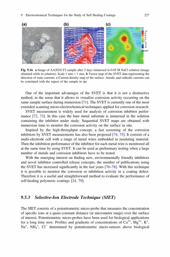
One of the important advantages of the SVET is that it is not a destructivemethod, in the sense that it allows to visualize corrosion activity occurring on thesame sample surface during immersion [71]. The SVET is currently one of the mostextended scanning micro-electrochemical techniques applied for corrosion research.
SVET measurement is widely used for analysis of corrosion inhibitor perfor-mance [72, 73]. In this case the bare metal substrate is immersed in the solutioncontaining the inhibitor under study. Sequential SVET maps are obtained withimmersion time to monitor the corrosion activity on the surface in situ.
Inspired by the high-throughput concept, a fast screening of the corrosioninhibitors by SVET measurements has also been proposed [74, 75]. It consists of amulti-electrode cell with a range of metal wires embedded in insulating material.Then the inhibition performance of the inhibitor for each metal wire is monitored allat the same time by using SVET. It can be used as preliminary testing when a largenumber of metals and corrosion inhibitors have to be tested.
With the emerging interest on finding new, environmentally friendly inhibitorsand novel inhibitor controlled release concepts, the number of publications usingthe SVET has increased significantly in the last years [76–78]. With this techniqueit is possible to monitor the corrosion or inhibition activity in a coating defect.Therefore it is a useful and straightforward method to evaluate the performance ofself-healing polymeric coatings [24, 79].
9.5.3 Selective-Ion Electrode Technique (SIET)
The SIET consists of a potentiometric micro-probe that measures the concentrationof specific ions at a quasi-constant distance (at micrometer range) over the surfaceof interest. Potentiometric micro-probes have been used for biological applicationsfor a long time now. Profiles and gradients of concentrations of Ca2+, Mg2+, K+,Na+, NH4
+, Cl− determined by potentiometric micro-sensors above biological
Fig. 9.16 a Image of AA2024-T3 sample after 2 days immersed in 0.05 M NaCl solution (imageobtained while in solution). Scale 1 mm × 1 mm. b Vector map of the SVET data representing thedirection of ionic currents. c Current density map of the surface. Anodic and cathodic currents canbe correlated with the aspect of the sample in (a)
9 Electrochemical Techniques for the Study of Self Healing Coatings 227
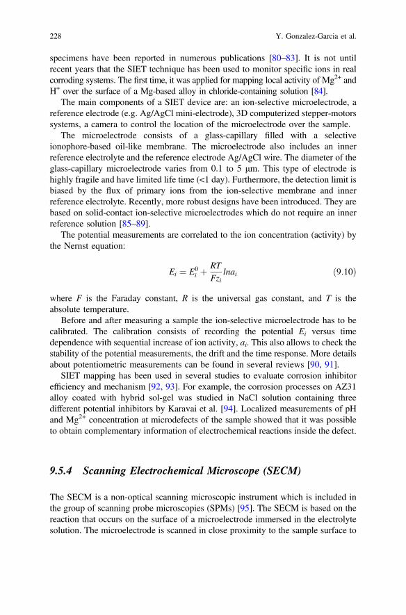
specimens have been reported in numerous publications [80–83]. It is not untilrecent years that the SIET technique has been used to monitor specific ions in realcorroding systems. The first time, it was applied for mapping local activity of Mg2+ andH+ over the surface of a Mg-based alloy in chloride-containing solution [84].
The main components of a SIET device are: an ion-selective microelectrode, areference electrode (e.g. Ag/AgCl mini-electrode), 3D computerized stepper-motorssystems, a camera to control the location of the microelectrode over the sample.
The microelectrode consists of a glass-capillary filled with a selectiveionophore-based oil-like membrane. The microelectrode also includes an innerreference electrolyte and the reference electrode Ag/AgCl wire. The diameter of theglass-capillary microelectrode varies from 0.1 to 5 μm. This type of electrode ishighly fragile and have limited life time (<1 day). Furthermore, the detection limit isbiased by the flux of primary ions from the ion-selective membrane and innerreference electrolyte. Recently, more robust designs have been introduced. They arebased on solid-contact ion-selective microelectrodes which do not require an innerreference solution [85–89].
The potential measurements are correlated to the ion concentration (activity) bythe Nernst equation:
Ei ¼ E0i þ
RTFzi
lnai ð9:10Þ
where F is the Faraday constant, R is the universal gas constant, and T is theabsolute temperature.
Before and after measuring a sample the ion-selective microelectrode has to becalibrated. The calibration consists of recording the potential Ei versus timedependence with sequential increase of ion activity, ai. This also allows to check thestability of the potential measurements, the drift and the time response. More detailsabout potentiometric measurements can be found in several reviews [90, 91].
SIET mapping has been used in several studies to evaluate corrosion inhibitorefficiency and mechanism [92, 93]. For example, the corrosion processes on AZ31alloy coated with hybrid sol-gel was studied in NaCl solution containing threedifferent potential inhibitors by Karavai et al. [94]. Localized measurements of pHand Mg2+ concentration at microdefects of the sample showed that it was possibleto obtain complementary information of electrochemical reactions inside the defect.
9.5.4 Scanning Electrochemical Microscope (SECM)
The SECM is a non-optical scanning microscopic instrument which is included inthe group of scanning probe microscopies (SPMs) [95]. The SECM is based on thereaction that occurs on the surface of a microelectrode immersed in the electrolytesolution. The microelectrode is scanned in close proximity to the sample surface to
228 Y. Gonzalez-Garcia et al.
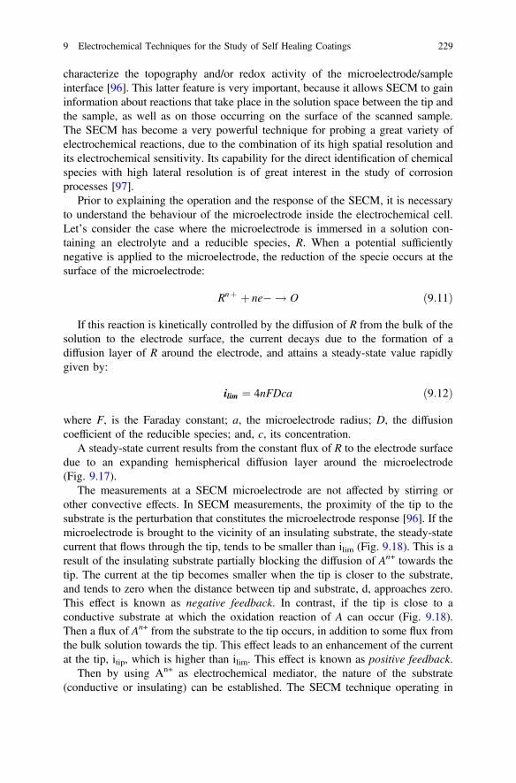
characterize the topography and/or redox activity of the microelectrode/sampleinterface [96]. This latter feature is very important, because it allows SECM to gaininformation about reactions that take place in the solution space between the tip andthe sample, as well as on those occurring on the surface of the scanned sample.The SECM has become a very powerful technique for probing a great variety ofelectrochemical reactions, due to the combination of its high spatial resolution andits electrochemical sensitivity. Its capability for the direct identification of chemicalspecies with high lateral resolution is of great interest in the study of corrosionprocesses [97].
Prior to explaining the operation and the response of the SECM, it is necessaryto understand the behaviour of the microelectrode inside the electrochemical cell.Let’s consider the case where the microelectrode is immersed in a solution con-taining an electrolyte and a reducible species, R. When a potential sufficientlynegative is applied to the microelectrode, the reduction of the specie occurs at thesurface of the microelectrode:
Rnþ þ ne� ! O ð9:11Þ
If this reaction is kinetically controlled by the diffusion of R from the bulk of thesolution to the electrode surface, the current decays due to the formation of adiffusion layer of R around the electrode, and attains a steady-state value rapidlygiven by:
ilim ¼ 4nFDca ð9:12Þ
where F, is the Faraday constant; a, the microelectrode radius; D, the diffusioncoefficient of the reducible species; and, c, its concentration.
A steady-state current results from the constant flux of R to the electrode surfacedue to an expanding hemispherical diffusion layer around the microelectrode(Fig. 9.17).
The measurements at a SECM microelectrode are not affected by stirring orother convective effects. In SECM measurements, the proximity of the tip to thesubstrate is the perturbation that constitutes the microelectrode response [96]. If themicroelectrode is brought to the vicinity of an insulating substrate, the steady-statecurrent that flows through the tip, tends to be smaller than ilim (Fig. 9.18). This is aresult of the insulating substrate partially blocking the diffusion of An+ towards thetip. The current at the tip becomes smaller when the tip is closer to the substrate,and tends to zero when the distance between tip and substrate, d, approaches zero.This effect is known as negative feedback. In contrast, if the tip is close to aconductive substrate at which the oxidation reaction of A can occur (Fig. 9.18).Then a flux of An+ from the substrate to the tip occurs, in addition to some flux fromthe bulk solution towards the tip. This effect leads to an enhancement of the currentat the tip, itip, which is higher than ilim. This effect is known as positive feedback.
Then by using An+ as electrochemical mediator, the nature of the substrate(conductive or insulating) can be established. The SECM technique operating in
9 Electrochemical Techniques for the Study of Self Healing Coatings 229
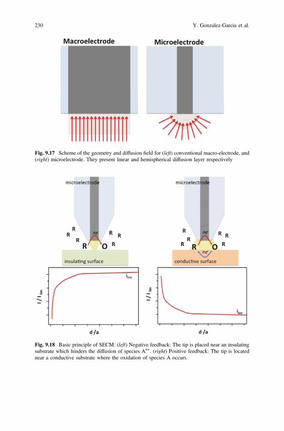
Fig. 9.18 Basic principle of SECM: (left) Negative feedback: The tip is placed near an insulatingsubstrate which hinders the diffusion of species An+. (right) Positive feedback: The tip is locatednear a conductive substrate where the oxidation of species A occurs
Fig. 9.17 Scheme of the geometry and diffusion field for (left) conventional macro-electrode, and(right) microelectrode. They present linear and hemispherical diffusion layer respectively
230 Y. Gonzalez-Garcia et al.
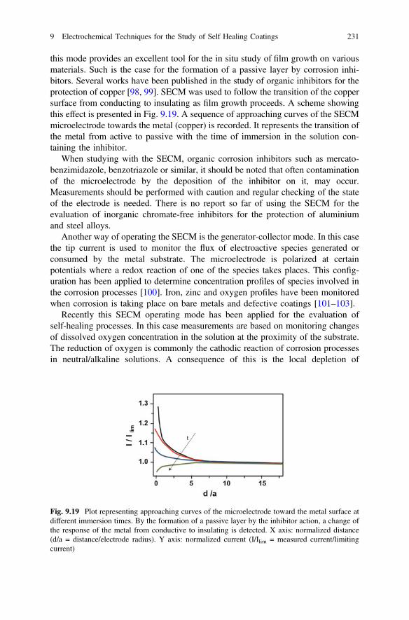
this mode provides an excellent tool for the in situ study of film growth on variousmaterials. Such is the case for the formation of a passive layer by corrosion inhi-bitors. Several works have been published in the study of organic inhibitors for theprotection of copper [98, 99]. SECM was used to follow the transition of the coppersurface from conducting to insulating as film growth proceeds. A scheme showingthis effect is presented in Fig. 9.19. A sequence of approaching curves of the SECMmicroelectrode towards the metal (copper) is recorded. It represents the transition ofthe metal from active to passive with the time of immersion in the solution con-taining the inhibitor.
When studying with the SECM, organic corrosion inhibitors such as mercato-benzimidazole, benzotriazole or similar, it should be noted that often contaminationof the microelectrode by the deposition of the inhibitor on it, may occur.Measurements should be performed with caution and regular checking of the stateof the electrode is needed. There is no report so far of using the SECM for theevaluation of inorganic chromate-free inhibitors for the protection of aluminiumand steel alloys.
Another way of operating the SECM is the generator-collector mode. In this casethe tip current is used to monitor the flux of electroactive species generated orconsumed by the metal substrate. The microelectrode is polarized at certainpotentials where a redox reaction of one of the species takes places. This config-uration has been applied to determine concentration profiles of species involved inthe corrosion processes [100]. Iron, zinc and oxygen profiles have been monitoredwhen corrosion is taking place on bare metals and defective coatings [101–103].
Recently this SECM operating mode has been applied for the evaluation ofself-healing processes. In this case measurements are based on monitoring changesof dissolved oxygen concentration in the solution at the proximity of the substrate.The reduction of oxygen is commonly the cathodic reaction of corrosion processesin neutral/alkaline solutions. A consequence of this is the local depletion of
Fig. 9.19 Plot representing approaching curves of the microelectrode toward the metal surface atdifferent immersion times. By the formation of a passive layer by the inhibitor action, a change ofthe response of the metal from conductive to insulating is detected. X axis: normalized distance(d/a = distance/electrode radius). Y axis: normalized current (I/Ilim = measured current/limitingcurrent)
9 Electrochemical Techniques for the Study of Self Healing Coatings 231
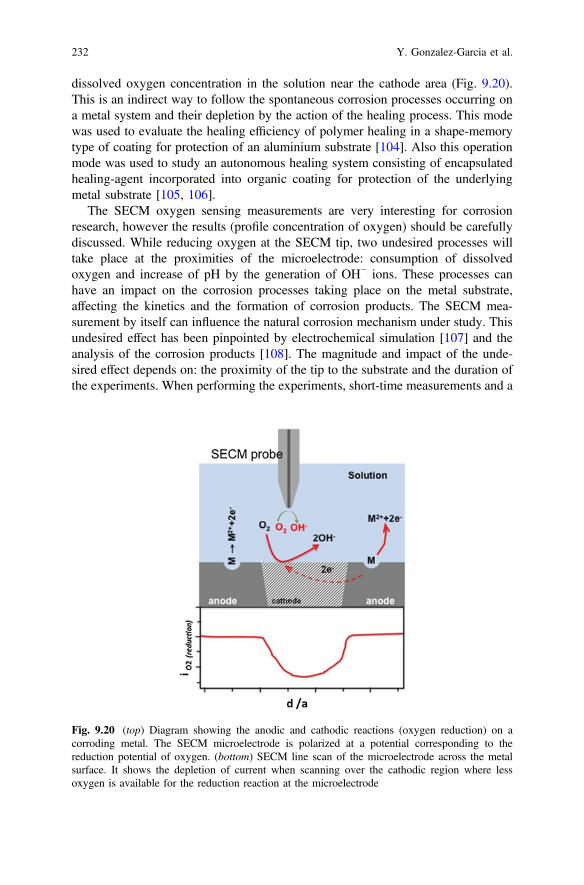
dissolved oxygen concentration in the solution near the cathode area (Fig. 9.20).This is an indirect way to follow the spontaneous corrosion processes occurring ona metal system and their depletion by the action of the healing process. This modewas used to evaluate the healing efficiency of polymer healing in a shape-memorytype of coating for protection of an aluminium substrate [104]. Also this operationmode was used to study an autonomous healing system consisting of encapsulatedhealing-agent incorporated into organic coating for protection of the underlyingmetal substrate [105, 106].
The SECM oxygen sensing measurements are very interesting for corrosionresearch, however the results (profile concentration of oxygen) should be carefullydiscussed. While reducing oxygen at the SECM tip, two undesired processes willtake place at the proximities of the microelectrode: consumption of dissolvedoxygen and increase of pH by the generation of OH− ions. These processes canhave an impact on the corrosion processes taking place on the metal substrate,affecting the kinetics and the formation of corrosion products. The SECM mea-surement by itself can influence the natural corrosion mechanism under study. Thisundesired effect has been pinpointed by electrochemical simulation [107] and theanalysis of the corrosion products [108]. The magnitude and impact of the unde-sired effect depends on: the proximity of the tip to the substrate and the duration ofthe experiments. When performing the experiments, short-time measurements and a
Fig. 9.20 (top) Diagram showing the anodic and cathodic reactions (oxygen reduction) on acorroding metal. The SECM microelectrode is polarized at a potential corresponding to thereduction potential of oxygen. (bottom) SECM line scan of the microelectrode across the metalsurface. It shows the depletion of current when scanning over the cathodic region where lessoxygen is available for the reduction reaction at the microelectrode
232 Y. Gonzalez-Garcia et al.
large tip-substrate distance is desired. The SECM oxygen sensing mode is avaluable method for qualitative indication of corrosion activity on the metal sur-face, but quantitative data should be carefully interpreted.
In general the main components of the scanning electrochemical microscope are:
• The tip movement and position controller, which is the SPM component.• The electrochemical cell, which is formed by the tip, the counter electrode, the
reference electrode and the substrate that, occasionally, can act as secondworking electrode.
• The bipotentiostat, which constitutes the SECM electrochemical setup togetherwith the electrochemical cell. The bipotentiostat allows to polarize microelec-trode and sample.
• Computer, interface and display system.
The most common microelectrode used for corrosion research is a platinum wireembedded in a glass capillary, resulting in a microdisc electrode. The diameter sizeof the electrode can vary from 1 to 25 μm.
SECM is a more versatile technique when compared to SVET or the micro-capillary cell since it provides higher resolution (wide range of microelectrodesizes) and chemical selectivity at the same time to monitor electrochemical pro-cesses occurring on the surface. When performing SECM measurements severalfacts needs to be considered:
• resolution of the measurement depends on the microelectrode dimensions andtip-sample distance,
• possible contamination or poisoning of the microelectrode. It is important tocheck the state of the tip after experiments,
• undesired influence of the SECM measurement on the system to be studied, Theredox processes occurring on the microelectrode can affect the electrochemicalprocesses taking place on the sample.
• select the adequate scan rate to assure limiting steady-state during measurement
9.5.5 Local Electrochemical Impedance Spectroscopy(LEIS)
SVET and SECM are based on the measurements of events or processes takingplace between the probe and the specimen. A disadvantage of both these techniquesis that this information may be disturbed by noise or limited response from thesubstrate, and the impossibility to obtain information of the processes underneath acoating. Local Electrochemical Impedance Spectroscopy (LEIS) appears an alter-native where it is important to have direct information of the response of thesubstrate under different conditions such as during a healing event.
9 Electrochemical Techniques for the Study of Self Healing Coatings 233
The LEIS technique is based on the hypothesis that the local impedance can begenerated by measuring the AC-local current density in the vicinity of the workingelectrode in a three-electrode cell configuration. This was introduced by the Isaacsgroup in the 1990s [109]. Quantitative information was achieved by using a dualmicroelectrode for sensing the local AC-potential gradient, and therefore the localcurrent by direct application of Ohm’s law. The use of a multichannel frequencyresponse analyzer also allows for the simultaneous measurement of global and localresponse of the specimens. The resolution of the technique depends on the size ofthe electrodes used in the bi-electrode probe to sense the local potential and thespacing between the electrodes. More detailed information about the fundaments ofLEIS can be found in the recent review by Huang et al. [110].
The first applications of LEIS method were in the study of corrosion processesand focused on the investigation of localized delamination of coatings. As anexample, Jorcin et al. in 2006 [32] mapped local electrochemical impedance whichallowed them to observe and quantify the delamination process beneath thesteel/epoxy-vinyl primer interface. An interesting observation was that the delam-inated surface area measured by LEIS was significantly higher than that observedby visual examination of the systems. These results pointed out that LEIS is apowerful technique for visualizing, with high accuracy, the zones of coatings whereadherence to the metal substrate has been lost.
The use of LEIS to evaluate the local efficiency of a healing mechanism againstcorrosion is becoming more common in recent years. Several works havedemonstrated the capabilities of LEIS method for evaluation of corrosion inhibitorperformance [111, 112]. Snihirova et al. [113] presented a new smart anticorrosionsystem for AA2024, based on the incorporation of encapsulated inhibitor into acoating. Controlled delivery was triggered by local changes of pH induced by thecorrosion processes. Conventional EIS and local impedance spectroscopy wereused to evaluate the efficiency of the systems as function of the active inhibitoremployed and their incorporation into the coating.
The resolution of the LEIS technique depends on the size of the electrode/sensorand the distance between the electrode and the sample. The ultimate resolutionachievable is constrained by the sensitivity of the potential measuring circuitry.Measurement sensitivity in the order of 1 nV limits the resolution to the micrometerrange [110].
9.6 Conclusions
This chapter describes several global and local electrochemical techniques used forthe evaluation and characterization of novel protection approaches based onextrinsic and intrinsic self-healing concepts.
Potential measurements, potentiodynamic experiments and electrochemicalimpedance spectroscopy (EIS) are the most commonly used methods used forcorrosion and self-healing research. These global methods provide kinetic and
234 Y. Gonzalez-Garcia et al.
mechanistic information of the self-healing processes. Apart from these traditionaltechniques some newer methods based on EIS have been proposed to obtain fasterand more accurate information about the healing degrees and process such as theodd-random EIS and the AC/DC/AC protocol.
High-throughput techniques have also attracted considerable interest due to theirpowerful use for fast screening of a large number of samples. This is tremendouslyuseful for evaluation of potential corrosion inhibitors of potential use in self-healingconcepts.
In order to obtain local information about the evolution of damage and protectedor healed damage local electrochemical techniques with spatial resolution havebeen proposed. Within this group micro-capillary cell, scanning vibrating electrodetechnique (SVET), selective ion-electrode technique (SIET), scanning electro-chemical microscope (SECM), and local electrochemical impedance spectroscopy(LEIS) are the most common. Even though these techniques have so far only beenused to obtain pseudo-quantitative information about the healing degree they havethe potential to be used for more quantitative studies of the healing processesthemselves.
There is no doubt that electrochemical evaluation of self-healing processes isconsidered a key requirement to understand the healing mechanisms and to evaluatethe corrosion performance of new developments. Nevertheless, these studies shouldalways be supported by dedicated complementary surface, optical and/or physicalchemical analysis.
References
1. V. Sauvant-Moynot, S. Gonzalez, J. Kittel, Self-healing coatings: an alternative route foranticorrosion protection. Prog. Org. Coat. 63(3), 307–315 (2008)
2. S.R. White et al., Autonomic healing of polymer composites. Nature 409(6822), 794–797(2001)
3. D.G. Shchukin et al., Layer-by-layer assembled nanocontainers for self-healing corrosionprotection. Adv. Mater. 18(13), 1672–1678 (2006)
4. K. Aramaki, The inhibition effects of cation inhibitors on corrosion of zinc in aerated 0.5 MNaCl. Corros. Sci. 43(8), 1573–1588 (2001)
5. S.H. Cho, S.R. White, P.V. Braun, Self-healing polymer coatings. Adv. Mater. 21(6), 645–649 (2009)
6. J.E.B. Randles, K.W. Somerton, Kinetics of rapid electrode reactions. Part 3. - Electronexchange reactions. Trans. Faraday Soc. 48, 937–950 (1952)
7. S.J. Garcia et al., Unravelling the corrosion inhibition mechanisms of bi-functional inhibitorsby EIS and SEM-EDS. Corros. Sci. 69, 346–358 (2013)
8. J.M. Hu, J.Q. Zhang, C.N. Cao, Determination of water uptake and diffusion of Cl- ion inepoxy primer on aluminum alloys in NaCl solution by electrochemical impedancespectroscopy. Prog. Org. Coat. 46, 273–279 (2003)
9. V.B. Miskovic-Stankovic et al., Corrosion behaviour of epoxy coatings on modifiedaluminium surfaces. Bull. Electrochem. 18(8), 343–348 (2002)
10. V.B. Mišković-stanković, D.M. Dražić, M.J. Teodorović, Electrolyte penetration throughepoxy coatings electrodeposited on steel. Corros. Sci. 37(2), 241–252 (1995)
9 Electrochemical Techniques for the Study of Self Healing Coatings 235
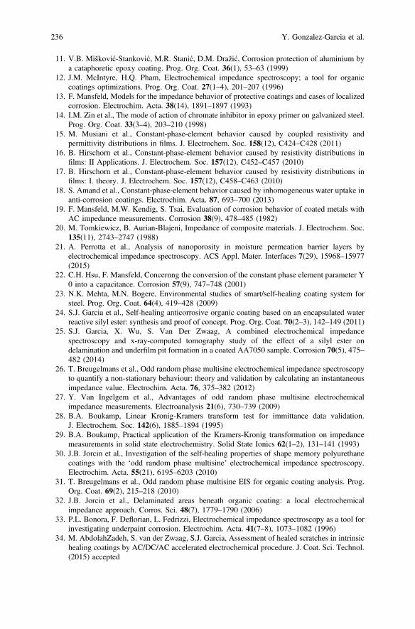
11. V.B. Mišković-Stanković, M.R. Stanić, D.M. Dražić, Corrosion protection of aluminium bya cataphoretic epoxy coating. Prog. Org. Coat. 36(1), 53–63 (1999)
12. J.M. McIntyre, H.Q. Pham, Electrochemical impedance spectroscopy; a tool for organiccoatings optimizations. Prog. Org. Coat. 27(1–4), 201–207 (1996)
13. F. Mansfeld, Models for the impedance behavior of protective coatings and cases of localizedcorrosion. Electrochim. Acta. 38(14), 1891–1897 (1993)
14. I.M. Zin et al., The mode of action of chromate inhibitor in epoxy primer on galvanized steel.Prog. Org. Coat. 33(3–4), 203–210 (1998)
15. M. Musiani et al., Constant-phase-element behavior caused by coupled resistivity andpermittivity distributions in films. J. Electrochem. Soc. 158(12), C424–C428 (2011)
16. B. Hirschorn et al., Constant-phase-element behavior caused by resistivity distributions infilms: II Applications. J. Electrochem. Soc. 157(12), C452–C457 (2010)
17. B. Hirschorn et al., Constant-phase-element behavior caused by resistivity distributions infilms: I. theory. J. Electrochem. Soc. 157(12), C458–C463 (2010)
18. S. Amand et al., Constant-phase-element behavior caused by inhomogeneous water uptake inanti-corrosion coatings. Electrochim. Acta. 87, 693–700 (2013)
19. F. Mansfeld, M.W. Kendig, S. Tsai, Evaluation of corrosion behavior of coated metals withAC impedance measurements. Corrosion 38(9), 478–485 (1982)
20. M. Tomkiewicz, B. Aurian-Blajeni, Impedance of composite materials. J. Electrochem. Soc.135(11), 2743–2747 (1988)
21. A. Perrotta et al., Analysis of nanoporosity in moisture permeation barrier layers byelectrochemical impedance spectroscopy. ACS Appl. Mater. Interfaces 7(29), 15968–15977(2015)
22. C.H. Hsu, F. Mansfeld, Concernng the conversion of the constant phase element parameter Y0 into a capacitance. Corrosion 57(9), 747–748 (2001)
23. N.K. Mehta, M.N. Bogere, Environmental studies of smart/self-healing coating system forsteel. Prog. Org. Coat. 64(4), 419–428 (2009)
24. S.J. Garcia et al., Self-healing anticorrosive organic coating based on an encapsulated waterreactive silyl ester: synthesis and proof of concept. Prog. Org. Coat. 70(2–3), 142–149 (2011)
25. S.J. Garcia, X. Wu, S. Van Der Zwaag, A combined electrochemical impedancespectroscopy and x-ray-computed tomography study of the effect of a silyl ester ondelamination and underfilm pit formation in a coated AA7050 sample. Corrosion 70(5), 475–482 (2014)
26. T. Breugelmans et al., Odd random phase multisine electrochemical impedance spectroscopyto quantify a non-stationary behaviour: theory and validation by calculating an instantaneousimpedance value. Electrochim. Acta. 76, 375–382 (2012)
27. Y. Van Ingelgem et al., Advantages of odd random phase multisine electrochemicalimpedance measurements. Electroanalysis 21(6), 730–739 (2009)
28. B.A. Boukamp, Linear Kronig-Kramers transform test for immittance data validation.J. Electrochem. Soc. 142(6), 1885–1894 (1995)
29. B.A. Boukamp, Practical application of the Kramers-Kronig transformation on impedancemeasurements in solid state electrochemistry. Solid State Ionics 62(1–2), 131–141 (1993)
30. J.B. Jorcin et al., Investigation of the self-healing properties of shape memory polyurethanecoatings with the ‘odd random phase multisine’ electrochemical impedance spectroscopy.Electrochim. Acta. 55(21), 6195–6203 (2010)
31. T. Breugelmans et al., Odd random phase multisine EIS for organic coating analysis. Prog.Org. Coat. 69(2), 215–218 (2010)
32. J.B. Jorcin et al., Delaminated areas beneath organic coating: a local electrochemicalimpedance approach. Corros. Sci. 48(7), 1779–1790 (2006)
33. P.L. Bonora, F. Deflorian, L. Fedrizzi, Electrochemical impedance spectroscopy as a tool forinvestigating underpaint corrosion. Electrochim. Acta. 41(7–8), 1073–1082 (1996)
34. M. AbdolahZadeh, S. van der Zwaag, S.J. Garcia, Assessment of healed scratches in intrinsichealing coatings by AC/DC/AC accelerated electrochemical procedure. J. Coat. Sci. Technol.(2015) accepted
236 Y. Gonzalez-Garcia et al.
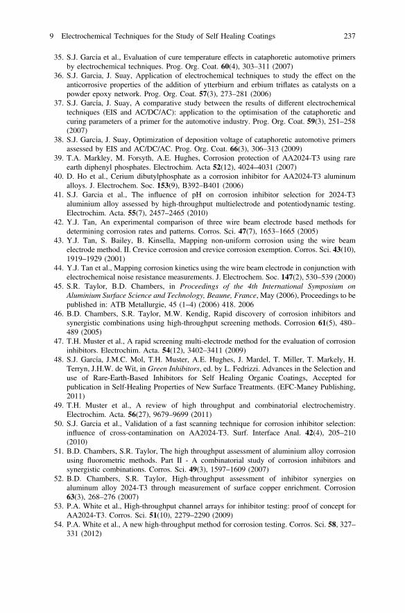
35. S.J. García et al., Evaluation of cure temperature effects in cataphoretic automotive primersby electrochemical techniques. Prog. Org. Coat. 60(4), 303–311 (2007)
36. S.J. Garcia, J. Suay, Application of electrochemical techniques to study the effect on theanticorrosive properties of the addition of ytterbiurn and erbium triflates as catalysts on apowder epoxy network. Prog. Org. Coat. 57(3), 273–281 (2006)
37. S.J. García, J. Suay, A comparative study between the results of different electrochemicaltechniques (EIS and AC/DC/AC): application to the optimisation of the cataphoretic andcuring parameters of a primer for the automotive industry. Prog. Org. Coat. 59(3), 251–258(2007)
38. S.J. García, J. Suay, Optimization of deposition voltage of cataphoretic automotive primersassessed by EIS and AC/DC/AC. Prog. Org. Coat. 66(3), 306–313 (2009)
39. T.A. Markley, M. Forsyth, A.E. Hughes, Corrosion protection of AA2024-T3 using rareearth diphenyl phosphates. Electrochim. Acta 52(12), 4024–4031 (2007)
40. D. Ho et al., Cerium dibutylphosphate as a corrosion inhibitor for AA2024-T3 aluminumalloys. J. Electrochem. Soc. 153(9), B392–B401 (2006)
41. S.J. Garcia et al., The influence of pH on corrosion inhibitor selection for 2024-T3aluminium alloy assessed by high-throughput multielectrode and potentiodynamic testing.Electrochim. Acta. 55(7), 2457–2465 (2010)
42. Y.J. Tan, An experimental comparison of three wire beam electrode based methods fordetermining corrosion rates and patterns. Corros. Sci. 47(7), 1653–1665 (2005)
43. Y.J. Tan, S. Bailey, B. Kinsella, Mapping non-uniform corrosion using the wire beamelectrode method. II. Crevice corrosion and crevice corrosion exemption. Corros. Sci. 43(10),1919–1929 (2001)
44. Y.J. Tan et al., Mapping corrosion kinetics using the wire beam electrode in conjunction withelectrochemical noise resistance measurements. J. Electrochem. Soc. 147(2), 530–539 (2000)
45. S.R. Taylor, B.D. Chambers, in Proceedings of the 4th International Symposium onAluminium Surface Science and Technology, Beaune, France, May (2006), Proceedings to bepublished in: ATB Metallurgie, 45 (1–4) (2006) 418. 2006
46. B.D. Chambers, S.R. Taylor, M.W. Kendig, Rapid discovery of corrosion inhibitors andsynergistic combinations using high-throughput screening methods. Corrosion 61(5), 480–489 (2005)
47. T.H. Muster et al., A rapid screening multi-electrode method for the evaluation of corrosioninhibitors. Electrochim. Acta. 54(12), 3402–3411 (2009)
48. S.J. García, J.M.C. Mol, T.H. Muster, A.E. Hughes, J. Mardel, T. Miller, T. Markely, H.Terryn, J.H.W. de Wit, in Green Inhibitors, ed. by L. Fedrizzi. Advances in the Selection anduse of Rare-Earth-Based Inhibitors for Self Healing Organic Coatings, Accepted forpublication in Self-Healing Properties of New Surface Treatments. (EFC-Maney Publishing,2011)
49. T.H. Muster et al., A review of high throughput and combinatorial electrochemistry.Electrochim. Acta. 56(27), 9679–9699 (2011)
50. S.J. Garcia et al., Validation of a fast scanning technique for corrosion inhibitor selection:influence of cross-contamination on AA2024-T3. Surf. Interface Anal. 42(4), 205–210(2010)
51. B.D. Chambers, S.R. Taylor, The high throughput assessment of aluminium alloy corrosionusing fluorometric methods. Part II - A combinatorial study of corrosion inhibitors andsynergistic combinations. Corros. Sci. 49(3), 1597–1609 (2007)
52. B.D. Chambers, S.R. Taylor, High-throughput assessment of inhibitor synergies onaluminum alloy 2024-T3 through measurement of surface copper enrichment. Corrosion63(3), 268–276 (2007)
53. P.A. White et al., High-throughput channel arrays for inhibitor testing: proof of concept forAA2024-T3. Corros. Sci. 51(10), 2279–2290 (2009)
54. P.A. White et al., A new high-throughput method for corrosion testing. Corros. Sci. 58, 327–331 (2012)
9 Electrochemical Techniques for the Study of Self Healing Coatings 237
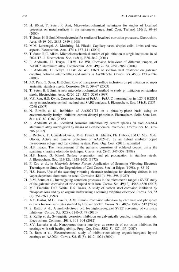
55. H. Böhni, T. Suter, F. Assi, Micro-electrochemical techniques for studies of localizedprocesses on metal surfaces in the nanometer range. Surf. Coat. Technol. 130(1), 80–86(2000)
56. T. Suter, H. Böhni, Microelectrodes for studies of localized corrosion processes. Electrochim.Acta. 43(19–20), 2843–2849 (1998)
57. M.M. Lohrengel, A. Moehring, M. Pilaski, Capillary-based droplet cells: limits and newaspects. Electrochim. Acta. 47(1), 137–141 (2001)
58. T. Suter, R.C. Alkire, Microelectrochemical studies of pit initiation at single inclusions in Al2024-T3. J. Electrochem. Soc. 148(1), B36–B42 (2001)
59. F. Andreatta, H. Terryn, J.H.W. De Wit, Corrosion behaviour of different tempers ofAA7075 aluminium alloy. Electrochim. Acta. 49(17–18), 2851–2862 (2004)
60. F. Andreatta, H. Terryn, J.H.W. de Wit, Effect of solution heat treatment on galvaniccoupling between intermetallics and matrix in AA7075-T6. Corros. Sci. 45(8), 1733–1746(2003)
61. J.O. Park, T. Suter, H. Böhni, Role of manganese sulfide inclusions on pit initiation of superaustenitic stainless steels. Corrosion 59(1), 59–67 (2003)
62. T. Suter, H. Böhni, A new microelectrochemical method to study pit initiation on stainlesssteels. Electrochim. Acta. 42(20–22), 3275–3280 (1997)
63. V.S. Rao, H.S. Kwon, Corrosion Studies of Fe3Al – Fe3AlC intermetallics in 0.25 N H2SO4using microelectrochemical method and SAES analysis. J. Electrochem. Soc. 154(5), C255–C260 (2007)
64. N. Birbilis et al., Inhibition of AA2024-T3 on a phase-by-phase basis using anenvironmentally benign inhibitor, cerium dibutyl phosphate. Electrochem. Solid State Lett.8(11), C180–C183 (2005)
65. F. Andreatta et al., Localized corrosion inhibition by cerium species on clad AA2024aluminium alloy investigated by means of electrochemical micro-cell. Corros. Sci. 65, 376–386 (2012)
66. I. Recloux, Y. Gonzalez-Garcia, M-E. Druart, K. Khelifa, Ph. Dubois, J.M.C. Mol, M-G.Olivier, Active and passive protection of AA2024-T3 by an hybrid inhibitor dopedmesoporous sol-gel and top coating system. Prog. Org. Coat. (2015) submitted
67. H.S. Isaacs, The measurement of the galvanic corrosion of soldered copper using thescanning vibrating electrode technique. Corros. Sci. 28(6), 547–558 (1988)
68. H.S. Isaacs, G. Kissel, Surface preparation and pit propagation in stainless steels.J. Electrochem. Soc. 119(12), 1628–1632 (1972)
69. F. Zou et al., in Materials Science Forum. Application of Scanning Vibrating ElectrodeTechniques to Study the Degradation of Coil-Coated Steel at Edges (1998), p. 83–92
70. H.S. Isaacs, Use of the scanning vibrating electrode technique for detecting defects in ionvapor-deposited aluminum on steel. Corrosion 43(10), 594–598 (1987)
71. R.M. Souto et al., Investigating corrosion processes in the micrometric range: a SVET studyof the galvanic corrosion of zinc coupled with iron. Corros. Sci. 49(12), 4568–4580 (2007)
72. M.J. Franklin, D.C. White, H.S. Isaacs, A study of carbon steel corrosion inhibition byphosphate ions and by an organic buffer using a scanning vibrating electrode. Corros. Sci. 33(2), 251–260 (1992)
73. A.C. Bastos, M.G. Ferreira, A.M. Simões, Corrosion inhibition by chromate and phosphateextracts for iron substrates studied by EIS and SVET. Corros. Sci. 48(6), 1500–1512 (2006)
74. S. Kallip et al., A multi-electrode cell for high-throughput SVET screening of corrosioninhibitors. Corros. Sci. 52(9), 3146–3149 (2010)
75. S. Kallip et al., Synergistic corrosion inhibition on galvanically coupled metallic materials.Electrochem. Commun. 20(1), 101–104 (2012)
76. S.V. Lamaka et al., Nanoporous titania interlayer as reservoir of corrosion inhibitors forcoatings with self-healing ability. Prog. Org. Coat. 58(2–3), 127–135 (2007)
77. D. Raps et al., Electrochemical study of inhibitor-containing organic-inorganic hybridcoatings on AA2024. Corros. Sci. 51(5), 1012–1021 (2009)
238 Y. Gonzalez-Garcia et al.
78. M.L. Zheludkevich, J. Tedim, M.G.S. Ferreira, “Smart” coatings for active corrosionprotection based on multi-functional micro and nanocontainers. Electrochim. Acta. 82, 314–323 (2012)
79. M.L. Zheludkevich et al., On the application of electrochemical impedance spectroscopy tostudy the self-healing properties of protective coatings. Electrochem. Commun. 9(10), 2622–2628 (2007)
80. M. Marenzana et al., Bone as an ion exchange organ: evidence for instantaneouscell-dependent calcium efflux from bone not due to resorption. Bone 37(4), 545–554 (2005)
81. J.G. Kunkel et al., in Plant Electrophysiology: theory and Methods. Use of Non-InvasiveIon-Selective Microelectrode Techniques for the Study of Plant Development (2006), p. 109–137
82. L. Shabala et al., Non-invasive microelectrode ion flux measurements to study adaptiveresponses of microorganisms to the environment. FEMS Microbiol. Rev. 30(3), 472–486(2006)
83. C.E.M. Berger, B.R. Horrocks, H.K. Datta, Application of ion-selective microelectrodes tothe detection of calcium release during bone resorption. Electrochim. Acta. 44(16), 2677–2683 (1999)
84. S.V. Lamaka et al., Monitoring local spatial distribution of Mg2+, pH and ionic currents.Electrochem. Commun. 10(2), 259–262 (2008)
85. F. Sundfors et al., Microcavity based solid-contact ion-selective microelectrodes.Electroanalysis 18(13–14), 1372–1378 (2006)
86. R.E. Gyurcsányi et al., Novel polypyrrole based all-solid-state potassium-selectivemicroelectrodes. Analyst 123(6), 1339–1344 (1998)
87. G. Gyetvai et al., Solid contact micropipette ion selective electrode for potentiometric SECM.Electroanalysis 19(10), 1116–1122 (2007)
88. M.G. Taryba, S.V. Lamaka, Plasticizer-free solid-contact pH-selective microelectrode forvisualization of local corrosion. J. Electroanal. Chem. 725, 32–38 (2014)
89. E.A. Zdrachek et al., H+-selective microelectrodes with optimized measuring range forcorrosion studies. Sens. Actuat. B: Chem. 207(PB), 967–975 (2015)
90. P. Bühlmann, E. Pretsch, E. Bakker, Carrier-based ion-selective electrodes and bulk optodes.2. Ionophores for potentiometric and optical sensors. Chem. Rev. 98(4), 1593–1687 (1998)
91. J. Bobacka, A. Ivaska, A. Lewenstam, Potentiometric ion sensors. Chem. Rev. 108(2), 329–351 (2008)
92. A.C. Bastos et al., Localised measurements of pH and dissolved oxygen as complements toSVET in the investigation of corrosion at defects in coated aluminum alloy. Electroanalysis22(17–18), 2009–2016 (2010)
93. M. Taryba et al., The combined use of scanning vibrating electrode technique andmicro-potentiometry to assess the self-repair processes in defects on “smart” coatings appliedto galvanized steel. Electrochim. Acta. 56(12), 4475–4488 (2011)
94. O.V. Karavai et al., Localized electrochemical study of corrosion inhibition in microdefectson coated AZ31 magnesium alloy. Electrochim. Acta. 55(19), 5401–5406 (2010)
95. A.J. Bard et al., Scanning electrochemical microscopy. Introduction and principles. Anal.Chem. 61(2), 132–138 (1989)
96. A.J. Bard, M.V. Mirkin (ed.), Scanning Electron Microscopy (Marcel-Dekker, New York,2001)
97. L. Niu et al., Application of scanning electrochemical microscope in the study of corrosion ofmetals. J. Mater. Sci. 44(17), 4511–4521 (2009)
98. K. Mansikkamäki et al., Adsorption of benzotriazole on the surface of copper alloys studiedby SECM and XPS. J. Electrochem. Soc. 153(8), B311–B318 (2006)
99. J. Izquierdo et al., Scanning microelectrochemical characterization of the anti-corrosionperformance of inhibitor films formed by 2-mercaptobenzimidazole on copper. Prog. Org.Coat. 74(3), 526–533 (2012)
9 Electrochemical Techniques for the Study of Self Healing Coatings 239

100. A.C. Bastos et al., Imaging concentration profiles of redox-active species in open-circuitcorrosion processes with the scanning electrochemical microscope. Electrochem. Commun. 6(11), 1212–1215 (2004)
101. A.M. Simoes et al., SVET and SECM imaging of cathodic protection of aluminium by aMg-rich coating. Corros. Sci. 49(10), 3838–3849 (2007)
102. A.C. Bastos et al., Application of the scanning electrochemical microscope to theexamination of organic coatings on metallic substrates. Prog. Org. Coat. 53(3), 177–182(2005)
103. R.M. Souto et al., On the use of mercury-coated tips in scanning electrochemical microscopyto investigate galvanic corrosion processes involving zinc and iron. Corros. Sci. 55, 401–406(2012)
104. Y. González-García et al., SECM study of defect repair in self-healing polymer coatings onmetals. Electrochem. Commun. 13(2), 169–173 (2011)
105. Y. Gonzalez-Garcia et al., A combined redox-competition and negative-feedback SECMstudy of self-healing anticorrosive coatings. Electrochem. Commun. 13(10), 1094–1097(2011)
106. A. Pilbáth et al., SECM study of steel corrosion under scratched microencapsulated epoxyresin. Prog. Org. Coat. 75(4), 480–485 (2012)
107. L.C. Abodi et al., Modeling localized aluminum alloy corrosion in chloride solutions undernon-equilibrium conditions: steps toward understanding pitting initiation. Electrochim. Acta.63, 169–178 (2012)
108. M.G. Taryba et al., Novel use of a micro-optode in overcoming the negative influence of theamperometric micro-probe on localized corrosion measurements. Corros. Sci. 95, 1–5 (2015)
109. R.S. Lillard, P.J. Moran, H.S. Isaacs, Novel method for generating quantitative localelectrochemical impedance spectroscopy. J. Electrochem. Soc. 139(4), 1007–1012 (1992)
110. V.M. Huang et al., Local electrochemical impedance spectroscopy: a review and some recentdevelopments. Electrochim. Acta. 56(23), 8048–8057 (2011)
111. R.M. Souto et al., in ECS Transactions. Local Electrochemical Impedance SpectroscopyInvestigation of Corrosion Inhibitor Films on Copper (2012)
112. D. Snihirova, S.V. Lamaka, M.F. Montemor, “SMART” protective ability of water basedepoxy coatings loaded with CaCO 3 microbeads impregnated with corrosion inhibitorsapplied on AA2024 substrates. Electrochim. Acta. 83, 439–447 (2012)
113. D. Snihirova, S.V. Lamaka, M. Taryba, A.M. Salak, S. Kallip, M.L. Zheludkevich, M.G.S.Ferreira, M.F. Montemor, Hydroxyapatite microparticles as feedback-active reservoirs ofcorrosion inhibitors. ACS Appl. Mater. Interfaces 2(11), 3011–3022 (2010)
240 Y. Gonzalez-Garcia et al.
Chapter 10Physico-Chemical Characterisationof Protective Coatings and Self HealingProcesses
Anthony E. Hughes, Sam Yang, Berkem Oezkaya, Ozlem Ozcanand Guido Grundmeier
10.1 Introduction
Achieving high adhesion strength and corrosion resistance at polymer/metalinterfaces, even in hostile environments, is one of the most important challenges ofinterface engineering and is relevant to many technical applications. In most cases,the materials susceptible to corrosive attack are protected by means of polymericfilms such as coatings, paints or adhesives [1–8]. All organic coatings applied tometals such as steel, zinc-coated steel, aluminum, and magnesium require stronginterfacial adhesion forces that are able to withstand severe forming operations andlong-time exposure to corrosive environments.
In certain cases, polymeric films such as coatings or adhesives are directlyapplied on the metal surface, which is covered by its native oxide. However,nowadays it is quite common that the metal is processed via chemical, electro-chemical, physical, or mechanical pre-treatments to improve the interfacial stability[4, 9–20]. It is well known today that, the long-term stability of the polymer/metalinterface in corrosive environments determines the performance of the compositeinterface and the necessary initial adhesion is rather easily achieved.
To understand the interaction mechanisms between polymers and metal/metaloxide surfaces, as well as to clarify how such interfaces degrade when exposed tocorrosive environments, various in situ techniques have been developed in elec-trochemistry, spectroscopy and microscopy. Such in situ techniques have emergedas advantageous alternatives to the classical ex situ methods and enabled the
A.E. Hughes � S. YangCSIRO, Gate 5, Normanby Road, Clayton, VIC 3168, Australia
B. Oezkaya � O. Ozcan � G. Grundmeier (&)Technical and Macromolecular Chemistry, University of Paderborn, Warburgerstr. 100,33098 Paderborn, Germanye-mail: [email protected]
© Springer Science+Business Media Dordrecht 2016A.E. Hughes et al. (eds.), Active Protective Coatings,Springer Series in Materials Science 233, DOI 10.1007/978-94-017-7540-3_10
241
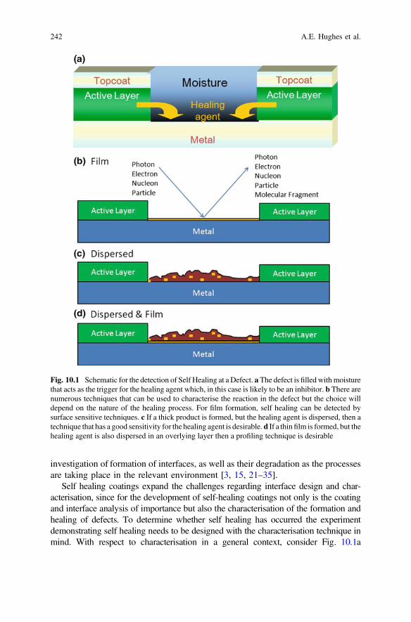
investigation of formation of interfaces, as well as their degradation as the processesare taking place in the relevant environment [3, 15, 21–35].
Self healing coatings expand the challenges regarding interface design and char-acterisation, since for the development of self-healing coatings not only is the coatingand interface analysis of importance but also the characterisation of the formation andhealing of defects. To determine whether self healing has occurred the experimentdemonstrating self healing needs to be designed with the characterisation technique inmind. With respect to characterisation in a general context, consider Fig. 10.1a
Fig. 10.1 Schematic for the detection of Self Healing at a Defect. aThe defect is filled withmoisturethat acts as the trigger for the healing agent which, in this case is likely to be an inhibitor. b There arenumerous techniques that can be used to characterise the reaction in the defect but the choice willdepend on the nature of the healing process. For film formation, self healing can be detected bysurface sensitive techniques. c If a thick product is formed, but the healing agent is dispersed, then atechnique that has a good sensitivity for the healing agent is desirable.d If a thinfilm is formed, but thehealing agent is also dispersed in an overlying layer then a profiling technique is desirable
242 A.E. Hughes et al.
displaying a self healing action in a defect. In this instance the defect is filled withmoisture that acts as the trigger for the healing agent which, in this case, is likely to beeither an inhibitor [36–38] or a film forming agent [39–43]. There are numeroustechniques that can be used to study the reaction in the defect with some of theexciting radiations listed in Fig. 10.1b including photons (infrared, ultraviolet, X-ray,optical), electrons, nucleons (protons and neutrons) and particles/ions (α-particles, ionbeam sources (see below under SIMS)). Emitted radiation can include photons,electrons, nucleons, particles and molecular fragments. Characterisation of the reactionin the defect will depend on the nature of the healing process. For film formation, selfhealing can be detected by surface sensitive techniques such as XPS, Static SIMS,TOF-SIMS, vibrational spectroscopies (FTIR, Raman) and nuclear techniques that useeither protons or α-particles as exciting radiation such Rutherford BackscatteringSpectroscopy (RBS) or Particle Induced X-ray Emission (PIXE) all have good sen-sitivity for thin films. However, if a thick product is formed and the healing agent isdispersed within the product at low levels Fig. 10.1c; this may require a combinationof depth profiling and a technique that is sensitive to the healing agent. If a thin film isformed, but the healing agent is also dispersed in an overlying layer then again aprofiling technique is desirable with high sensitivity to the healing agent. While theapproach outlined here sounds straight forward there is not always a technique orcombination of techniques, which will be able to identify the healing agent. One finalpoint to make about characterization of self healing is that it needs to be performed incombination with a technique that demonstrates recovery (see Chap. 9).
In the following sections, suitable methods for the analysis of the protectivecoatings and self healing processes will be summarized with a special focus onspectroscopic, microscopic and tomographic methods.
10.2 Tomography and Microscopy
10.2.1 Tomographical Methods
The word tomography is derived from the Greek for ‘cut’ and thus tomographicmethods allow us to characterize sample in three dimensions by sectioning theobject either physically in the case of destructive methods such as micro-tomingand focused ion beam milling, or virtually by using non-destructive techniques suchas X-ray tomography.
The study of three dimensional structures within materials and changes in thosestructures is of growing importance in modern materials science. The key materialsscience challenges in this area are (i) probing multiple and smaller length scales,(ii) revealing chemistry and (iii) revealing changes to structures as a result ofprocessing or other external influences such as degradation mechanisms.
In the area of active protective coatings the key areas are alloy microstructuresand related corrosion processes, and the protective coating, including the distri-bution of inhibitor and other inorganic phases and changes to it in response to
10 Physico-Chemical Characterisation of Protective Coatings … 243
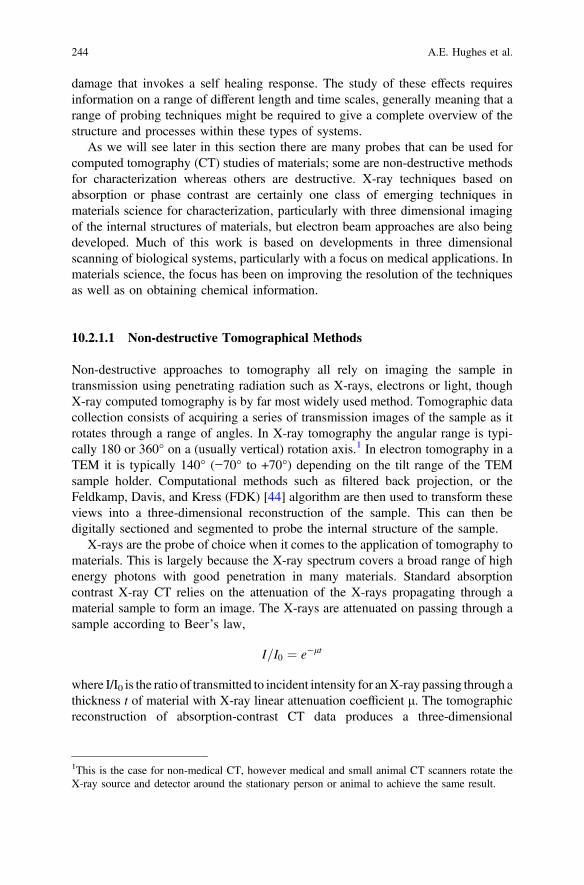
damage that invokes a self healing response. The study of these effects requiresinformation on a range of different length and time scales, generally meaning that arange of probing techniques might be required to give a complete overview of thestructure and processes within these types of systems.
As we will see later in this section there are many probes that can be used forcomputed tomography (CT) studies of materials; some are non-destructive methodsfor characterization whereas others are destructive. X-ray techniques based onabsorption or phase contrast are certainly one class of emerging techniques inmaterials science for characterization, particularly with three dimensional imagingof the internal structures of materials, but electron beam approaches are also beingdeveloped. Much of this work is based on developments in three dimensionalscanning of biological systems, particularly with a focus on medical applications. Inmaterials science, the focus has been on improving the resolution of the techniquesas well as on obtaining chemical information.
10.2.1.1 Non-destructive Tomographical Methods
Non-destructive approaches to tomography all rely on imaging the sample intransmission using penetrating radiation such as X-rays, electrons or light, thoughX-ray computed tomography is by far most widely used method. Tomographic datacollection consists of acquiring a series of transmission images of the sample as itrotates through a range of angles. In X-ray tomography the angular range is typi-cally 180 or 360° on a (usually vertical) rotation axis.1 In electron tomography in aTEM it is typically 140° (−70° to +70°) depending on the tilt range of the TEMsample holder. Computational methods such as filtered back projection, or theFeldkamp, Davis, and Kress (FDK) [44] algorithm are then used to transform theseviews into a three-dimensional reconstruction of the sample. This can then bedigitally sectioned and segmented to probe the internal structure of the sample.
X-rays are the probe of choice when it comes to the application of tomography tomaterials. This is largely because the X-ray spectrum covers a broad range of highenergy photons with good penetration in many materials. Standard absorptioncontrast X-ray CT relies on the attenuation of the X-rays propagating through amaterial sample to form an image. The X-rays are attenuated on passing through asample according to Beer’s law,
I=I0 ¼ e�lt
where I/I0 is the ratio of transmitted to incident intensity for anX-ray passing through athickness t of material with X-ray linear attenuation coefficient μ. The tomographicreconstruction of absorption-contrast CT data produces a three-dimensional
1This is the case for non-medical CT, however medical and small animal CT scanners rotate theX-ray source and detector around the stationary person or animal to achieve the same result.
244 A.E. Hughes et al.
microscopic map of the linear attenuation coefficient in the sample, however this isoften insufficient to determine compositional distributions within heterogeneousmaterials as different materials may have similar attenuation coefficients.
Phase-contrast imaging utilizes the refraction of X-rays. It is based on the prin-ciple that different materials produce different shifts in the phase of the X-rayspassing through them. It is more sensitive to edge effects and is thus suitable for thedetermination of structure gradients, particularly where there is a well-definedboundary between different regions in a material. X-rays passing through an objectof varying refractive index will have their propagation direction modified by thesample. Unlike visible light this effect is small and subtle in the case of X-rays.Nonetheless, at boundaries in the sample there will be sharp changes in the propa-gation direction of adjacent X-rays passing through either side of the boundary. Witha micro-focus or synchrotron X-ray source this refractive effect can easily betransformed into intensity changes by leaving a gap between the sample anddetector. The propagation of these deflected X-rays from sample to detector resultsin interference and produces characteristic fringes in the X-ray image, enhancingthe visibility of high gradient regions such as edges, voids, cracks and fine features ofthe sample. This form of X-ray imaging is known as in-line phase-contrast and is thesimplest X-ray imaging mode which can make use of X-ray refraction.
It should be noted that, in X-ray CT, both amplitude attenuation and phasecontrast effects exist at the same time. It is often the case that careful considerationsare made during projection image acquisitions and CT reconstruction to reduce theeffect of one or the other.
Sample requirements
In order to successfully carry out X-ray tomography on a sample the thickest or moststrongly absorbing part of the sample should not completely attenuate the X-rayspassing through it. This means that a very absorbing sample may require harder,more penetrating X-rays to image it, or else a small subsection of the sample will berequired. Conversely the X-rays should have sufficiently strong interaction with thesample to form good contrast in the resulting images. In the case of absorptioncontrast this means that the sample should absorb a significant fraction of the X-rayspassing through it. For phase-contrast imaging absorption is not required but theX-ray refraction should be sufficient to result in good fringes in the image corre-sponding to surfaces and boundaries within the sample. This will depend on theX-ray energy and the imaging geometry and detector resolution. Softer X-rays willgenerate stronger fringes, and the detector resolution and magnification of the imageshould be sufficient that the fringes are well resolved by the detector.
Types of X-ray sources
Two main classes of X-ray sources are widely used for X-ray tomography.Lab-based sources and synchrotron sources. Lab-based sources generate X-rays byfocusing a multi-keV electron beam onto a target, usually a solid metal such astungsten or molybdenum, though some new systems use a liquid metal jet as thetarget [45]. The X-rays produced by lab sources comprise broad spectrum
10 Physico-Chemical Characterisation of Protective Coatings … 245
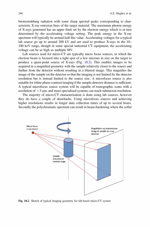
bremsstrahlung radiation with some sharp spectral peaks corresponding to char-acteristic X-ray emission lines of the target material. The maximum photon energyof X-rays generated has an upper limit set by the electron energy which is in turndetermined by the accelerating voltage setting. The peak energy in the X-rayspectrum will typically be around half this value. Accelerating voltages for a typicallab source go up to around 200 kV and are used to produce X-rays in the 10–100 keV range, though in some special industrial CT equipment, the acceleratingvoltage can be as high as multiple MV.
Lab sources used for micro-CT are typically micro focus sources, in which theelectron beam is focused into a tight spot of a few microns in size on the target toproduce a quasi-point source of X-rays (Fig. 10.2). This enables images to beacquired in a magnified geometry with the sample relatively closer to the source andfurther from the detector without resulting in a blurred image. This magnifies theimage of the sample on the detector so that the imaging is not limited by the detectorresolution but is instead limited to the source size. A microfocus source is alsosuitable for inline phase-contrast imaging if the sample-detector distance is sufficient.A typical microfocus source system will be capable of tomographic scans with aresolution of*5 μm, and more specialised systems can reach submicron resolution.
The majority of micro-CT characterisation is done using lab sources, howeverthey do have a couple of drawbacks. Using microfocus sources and achievinghigher resolutions results in longer data collection times of up to several hours.Secondly the polychromatic spectrum can result in beam-hardening where the softer
Fig. 10.2 Sketch of typical imaging geometry for lab-based micro-CT system
246 A.E. Hughes et al.
components of the spectrum are much more strongly attenuated than the hard (highenergy) components. This results in reconstruction artefacts but these can beameliorated by using filters to remove the softest X-rays from the spectrum, or bydoing a beam hardening correction after data collection. In some special cases withsoft X-ray systems it is also possible to get quasi-monochromatic spectra from a labsource using K emission lines [46].
Synchrotron sources are highly specialised X-ray sources available at syn-chrotron facilities rather than in the lab. However, the special qualities of syn-chrotron radiation, particularly the very high-power monochromatic X-ray beam,means that synchrotron micro-CT is ideal for certain types of experiments thatcannot be performed in the lab.
The synchrotron is based on a particle accelerator which accelerates electrons tothe GeV energy range and then injects them into a circular storage ring. The elec-trons travelling round the storage ring have their trajectories guided and modified bybending magnets and insertion devices. As the electrons are accelerated into curvedtrajectories by these devices they emit a powerful, highly focused beam of radiationin the forward direction. The resulting X-ray beams come off at a tangent to the mainring and are collected in a series of beamlines set around the storage ring, where theyare used for a variety of experiments including X-ray imaging and tomography.
Thus X-rays have a broad polychromatic spectrum with a far higher intensitythan a laboratory source. The beam is usually filtered using a monochromator toproduce a monochromatic X-ray beam with sufficient intensity for rapid imageacquisition. The photon energy of the X-ray beam can be adjusted conveniently in awide energy range, typically in 8–60 keV. A monochromatic beam avoids thebeam-hardening artefacts that can occur in tomography with polychromatic X-rays.Tomographic scans can also be performed in the same sample at different energieswhich can give more information on sample composition by exploiting the variationin attenuation coefficients with energy, which vary for different materials, partic-ularly near absorption edges of their constituent elements. The high intensity of theX-ray beam also makes synchrotron sources very suitable for time-resolved, or ‘4D’tomography, enabling the observation of dynamic processes in three dimensions.Typical tomographic scan times at a synchrotron are of the order of a few minutes,but sub-second speed have been achieved for high-speed studies.
At a synchrotron the X-ray beam is approximately parallel so there is no mag-nification of the image as seen in a typical lab-system. Consequently the resolutionis determined by the detector with a best resolution of around half a micron. Somevery specialised beamlines using X-ray optics and softer X-rays are capable ofresolution down to tens of nm, however, these are limited to very small samples andlow density materials.
Practicalities of data collection
X-ray tomographic data is typically collected using a CCD or CMOS based detectoras the imaging device, optically coupled to an X-ray sensitive phosphor or scintillatorvia optic fibres or lenses and mirrors. The sample is mounted on a high-precisionrotation stage, which normally rotates around a vertical axis. A sequence of
10 Physico-Chemical Characterisation of Protective Coatings … 247

projection images are acquired with an equal angle increment for a total samplerotation of 180 or 360°. For adequate reconstruction of the 3D map of the sample, themaximum linear displacement at any part of the sample should not be greater than thedetector size. Consequently, for a sample with a maximum horizontal projection sizeof n pixels, the number of required projections should be as high as
N ¼ p2n
In practice, acceptable reconstructions can be achieved with
N ¼ p6n
projections.In addition to acquiring sample projection images, flat-field and dark-field images
are acquired to correct for detector and illumination artifacts. Flat-field images areacquired with the X-ray source on and the sample out of the field-of-view. They areused to compensate for detector and detector-ray illumination inhomogeneity. Thelatter is particularly important with synchrotron sources where flat-field images areoften acquired at intervals during the image projection, by moving the sample out ofthe field of view. This is required when there are time-varying illumination ordetector inhomogeneities during the data collection. Dark-field images are acquiredwith no X-ray illumination and are used to compensate for the ‘dark signal’ thataccumulates in the detector in the absence of illumination. Some detectors, partic-ularly those with optic-fibre coupling between the detector and X-rayscintillator/phosphor additionally require a geometric correction to account fordistortions in the image introduced by the optical coupling.
Data Processing
After correction for the various imaging artefacts the projection data is transformedinto a three-dimensional digital reconstruction of the sample using one of a number oftomographic reconstruction algorithms. Filtered-back-projection is a typical algo-rithm for parallel-beam (e.g. synchrotron) geometry data, and the FDK algorithm fora cone-beam, magnifying geometry as found on a lab system, though there are manyalternatives [47]. Tomographic reconstruction is computationally intensive butcontinuing developments in computer hardware and parallelised algorithms haveenabled reconstruction of tomographic data on standalone multi-core computers inreasonable time-frames of a few minutes to an hour depending on the dataset size.Phase-contrast data can be processed in much the same way as conventionalabsorption contrast data with the addition of a phase-retrieval step [48]. Phaseretrieval is a specialised low-pass filter that precisely compensates for theedge-enhancement of phase-contrast images (Fig. 10.3). This can be carried out prioror during tomographic reconstruction depending on the type of data and algorithm
248 A.E. Hughes et al.
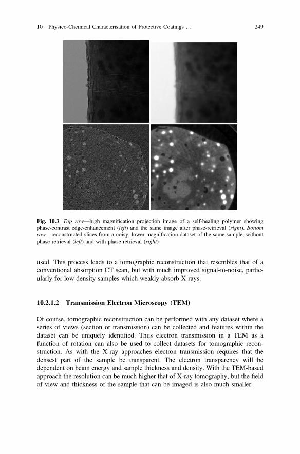
used. This process leads to a tomographic reconstruction that resembles that of aconventional absorption CT scan, but with much improved signal-to-noise, partic-ularly for low density samples which weakly absorb X-rays.
10.2.1.2 Transmission Electron Microscopy (TEM)
Of course, tomographic reconstruction can be performed with any dataset where aseries of views (section or transmission) can be collected and features within thedataset can be uniquely identified. Thus electron transmission in a TEM as afunction of rotation can also be used to collect datasets for tomographic recon-struction. As with the X-ray approaches electron transmission requires that thedensest part of the sample be transparent. The electron transparency will bedependent on beam energy and sample thickness and density. With the TEM-basedapproach the resolution can be much higher that of X-ray tomography, but the fieldof view and thickness of the sample that can be imaged is also much smaller.
Fig. 10.3 Top row—high magnification projection image of a self-healing polymer showingphase-contrast edge-enhancement (left) and the same image after phase-retrieval (right). Bottomrow—reconstructed slices from a noisy, lower-magnification dataset of the same sample, withoutphase retrieval (left) and with phase-retrieval (right)
10 Physico-Chemical Characterisation of Protective Coatings … 249
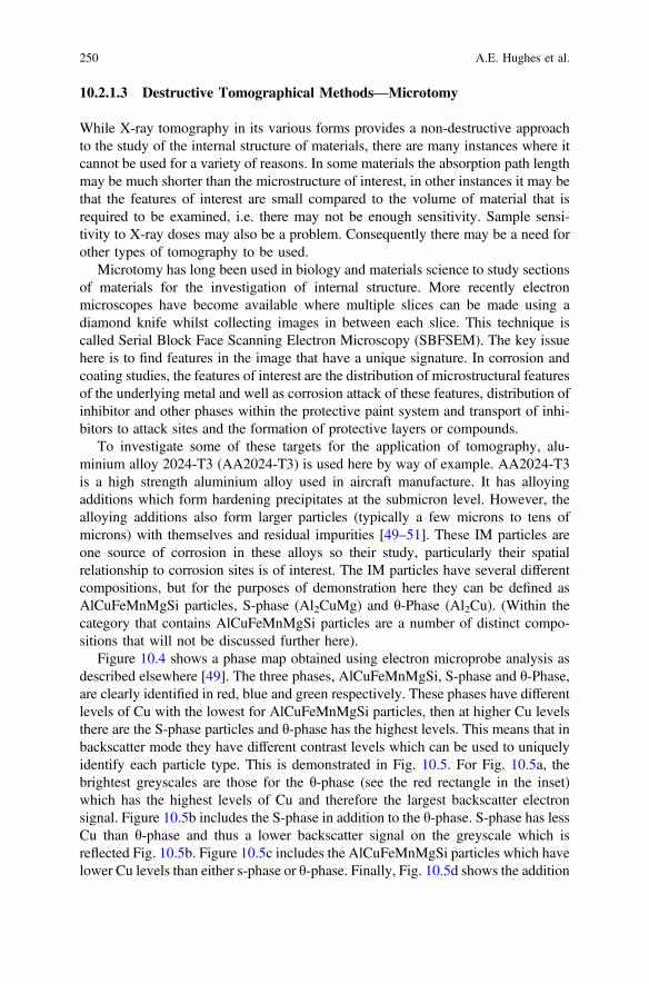
10.2.1.3 Destructive Tomographical Methods—Microtomy
While X-ray tomography in its various forms provides a non-destructive approachto the study of the internal structure of materials, there are many instances where itcannot be used for a variety of reasons. In some materials the absorption path lengthmay be much shorter than the microstructure of interest, in other instances it may bethat the features of interest are small compared to the volume of material that isrequired to be examined, i.e. there may not be enough sensitivity. Sample sensi-tivity to X-ray doses may also be a problem. Consequently there may be a need forother types of tomography to be used.
Microtomy has long been used in biology and materials science to study sectionsof materials for the investigation of internal structure. More recently electronmicroscopes have become available where multiple slices can be made using adiamond knife whilst collecting images in between each slice. This technique iscalled Serial Block Face Scanning Electron Microscopy (SBFSEM). The key issuehere is to find features in the image that have a unique signature. In corrosion andcoating studies, the features of interest are the distribution of microstructural featuresof the underlying metal and well as corrosion attack of these features, distribution ofinhibitor and other phases within the protective paint system and transport of inhi-bitors to attack sites and the formation of protective layers or compounds.
To investigate some of these targets for the application of tomography, alu-minium alloy 2024-T3 (AA2024-T3) is used here by way of example. AA2024-T3is a high strength aluminium alloy used in aircraft manufacture. It has alloyingadditions which form hardening precipitates at the submicron level. However, thealloying additions also form larger particles (typically a few microns to tens ofmicrons) with themselves and residual impurities [49–51]. These IM particles areone source of corrosion in these alloys so their study, particularly their spatialrelationship to corrosion sites is of interest. The IM particles have several differentcompositions, but for the purposes of demonstration here they can be defined asAlCuFeMnMgSi particles, S-phase (Al2CuMg) and θ-Phase (Al2Cu). (Within thecategory that contains AlCuFeMnMgSi particles are a number of distinct compo-sitions that will not be discussed further here).
Figure 10.4 shows a phase map obtained using electron microprobe analysis asdescribed elsewhere [49]. The three phases, AlCuFeMnMgSi, S-phase and θ-Phase,are clearly identified in red, blue and green respectively. These phases have differentlevels of Cu with the lowest for AlCuFeMnMgSi particles, then at higher Cu levelsthere are the S-phase particles and θ-phase has the highest levels. This means that inbackscatter mode they have different contrast levels which can be used to uniquelyidentify each particle type. This is demonstrated in Fig. 10.5. For Fig. 10.5a, thebrightest greyscales are those for the θ-phase (see the red rectangle in the inset)which has the highest levels of Cu and therefore the largest backscatter electronsignal. Figure 10.5b includes the S-phase in addition to the θ-phase. S-phase has lessCu than θ-phase and thus a lower backscatter signal on the greyscale which isreflected Fig. 10.5b. Figure 10.5c includes the AlCuFeMnMgSi particles which havelower Cu levels than either s-phase or θ-phase. Finally, Fig. 10.5d shows the addition
250 A.E. Hughes et al.
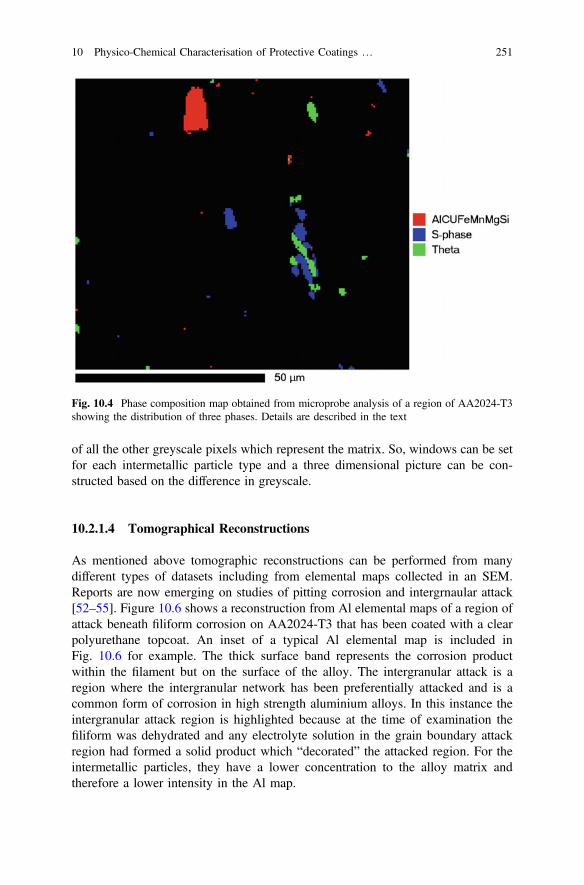
of all the other greyscale pixels which represent the matrix. So, windows can be setfor each intermetallic particle type and a three dimensional picture can be con-structed based on the difference in greyscale.
10.2.1.4 Tomographical Reconstructions
As mentioned above tomographic reconstructions can be performed from manydifferent types of datasets including from elemental maps collected in an SEM.Reports are now emerging on studies of pitting corrosion and intergrnaular attack[52–55]. Figure 10.6 shows a reconstruction from Al elemental maps of a region ofattack beneath filiform corrosion on AA2024-T3 that has been coated with a clearpolyurethane topcoat. An inset of a typical Al elemental map is included inFig. 10.6 for example. The thick surface band represents the corrosion productwithin the filament but on the surface of the alloy. The intergranular attack is aregion where the intergranular network has been preferentially attacked and is acommon form of corrosion in high strength aluminium alloys. In this instance theintergranular attack region is highlighted because at the time of examination thefiliform was dehydrated and any electrolyte solution in the grain boundary attackregion had formed a solid product which “decorated” the attacked region. For theintermetallic particles, they have a lower concentration to the alloy matrix andtherefore a lower intensity in the Al map.
Fig. 10.4 Phase composition map obtained from microprobe analysis of a region of AA2024-T3showing the distribution of three phases. Details are described in the text
10 Physico-Chemical Characterisation of Protective Coatings … 251
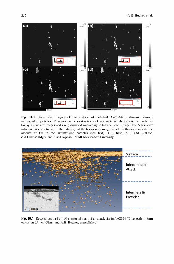
Fig. 10.5 Backscatter images of the surface of polished AA2024-T3 showing variousintermetallic particles. Tomographic reconstructions of intermetallic phases can be made bytaking a series of images and using diamond microtomy in between each image. The “chemical”information is contained in the intensity of the backscatter image which, in this case reflects theamount of Cu in the intermetallic particles (see text). a θ-Phase. b θ and S-phase.c AlCuFeMnMgSi and θ and S-phase. d All backscattered intensity
Fig. 10.6 Reconstruction from Al elemental maps of an attack site in AA2024-T3 beneath filiformcorrosion (A. M. Glenn and A.E. Hughes, unpublished)
252 A.E. Hughes et al.
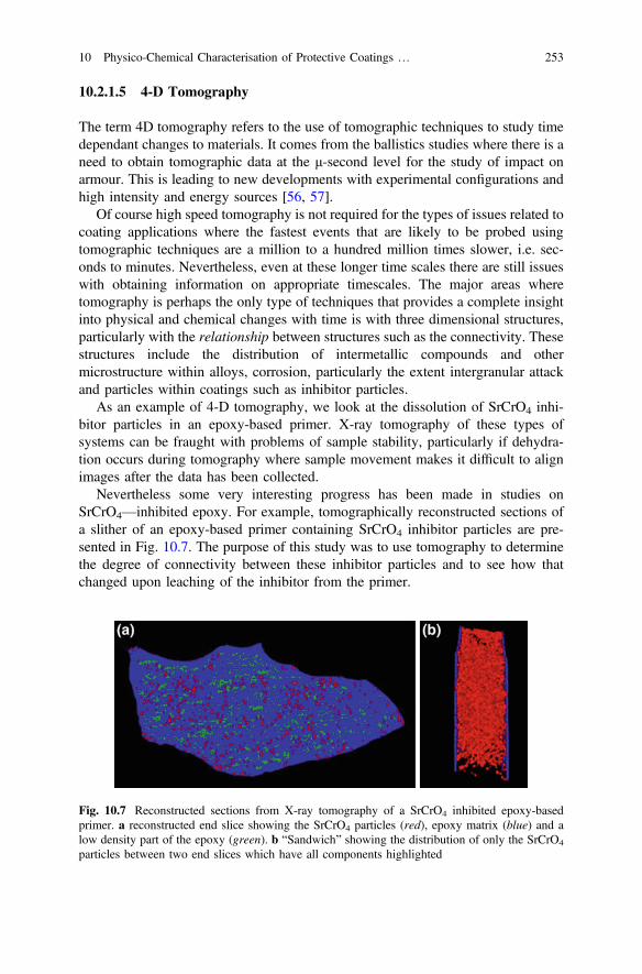
10.2.1.5 4-D Tomography
The term 4D tomography refers to the use of tomographic techniques to study timedependant changes to materials. It comes from the ballistics studies where there is aneed to obtain tomographic data at the μ-second level for the study of impact onarmour. This is leading to new developments with experimental configurations andhigh intensity and energy sources [56, 57].
Of course high speed tomography is not required for the types of issues related tocoating applications where the fastest events that are likely to be probed usingtomographic techniques are a million to a hundred million times slower, i.e. sec-onds to minutes. Nevertheless, even at these longer time scales there are still issueswith obtaining information on appropriate timescales. The major areas wheretomography is perhaps the only type of techniques that provides a complete insightinto physical and chemical changes with time is with three dimensional structures,particularly with the relationship between structures such as the connectivity. Thesestructures include the distribution of intermetallic compounds and othermicrostructure within alloys, corrosion, particularly the extent intergranular attackand particles within coatings such as inhibitor particles.
As an example of 4-D tomography, we look at the dissolution of SrCrO4 inhi-bitor particles in an epoxy-based primer. X-ray tomography of these types ofsystems can be fraught with problems of sample stability, particularly if dehydra-tion occurs during tomography where sample movement makes it difficult to alignimages after the data has been collected.
Nevertheless some very interesting progress has been made in studies onSrCrO4—inhibited epoxy. For example, tomographically reconstructed sections ofa slither of an epoxy-based primer containing SrCrO4 inhibitor particles are pre-sented in Fig. 10.7. The purpose of this study was to use tomography to determinethe degree of connectivity between these inhibitor particles and to see how thatchanged upon leaching of the inhibitor from the primer.
Fig. 10.7 Reconstructed sections from X-ray tomography of a SrCrO4 inhibited epoxy-basedprimer. a reconstructed end slice showing the SrCrO4 particles (red), epoxy matrix (blue) and alow density part of the epoxy (green). b “Sandwich” showing the distribution of only the SrCrO4
particles between two end slices which have all components highlighted
10 Physico-Chemical Characterisation of Protective Coatings … 253
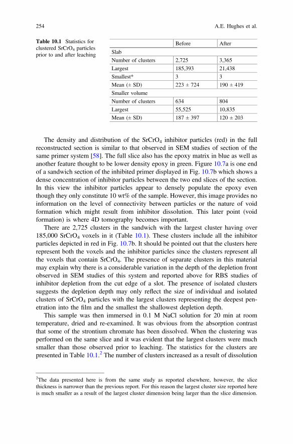
The density and distribution of the SrCrO4 inhibitor particles (red) in the fullreconstructed section is similar to that observed in SEM studies of section of thesame primer system [58]. The full slice also has the epoxy matrix in blue as well asanother feature thought to be lower density epoxy in green. Figure 10.7a is one endof a sandwich section of the inhibited primer displayed in Fig. 10.7b which shows adense concentration of inhibitor particles between the two end slices of the section.In this view the inhibitor particles appear to densely populate the epoxy eventhough they only constitute 10 wt% of the sample. However, this image provides noinformation on the level of connectivity between particles or the nature of voidformation which might result from inhibitor dissolution. This later point (voidformation) is where 4D tomography becomes important.
There are 2,725 clusters in the sandwich with the largest cluster having over185,000 SrCrO4 voxels in it (Table 10.1). These clusters include all the inhibitorparticles depicted in red in Fig. 10.7b. It should be pointed out that the clusters hererepresent both the voxels and the inhibitor particles since the clusters represent allthe voxels that contain SrCrO4. The presence of separate clusters in this materialmay explain why there is a considerable variation in the depth of the depletion frontobserved in SEM studies of this system and reported above for RBS studies ofinhibitor depletion from the cut edge of a slot. The presence of isolated clusterssuggests the depletion depth may only reflect the size of individual and isolatedclusters of SrCrO4 particles with the largest clusters representing the deepest pen-etration into the film and the smallest the shallowest depletion depth.
This sample was then immersed in 0.1 M NaCl solution for 20 min at roomtemperature, dried and re-examined. It was obvious from the absorption contrastthat some of the strontium chromate has been dissolved. When the clustering wasperformed on the same slice and it was evident that the largest clusters were muchsmaller than those observed prior to leaching. The statistics for the clusters arepresented in Table 10.1.2 The number of clusters increased as a result of dissolution
Table 10.1 Statistics forclustered SrCrO4 particlesprior to and after leaching
Before After
Slab
Number of clusters 2,725 3,365
Largest 185,393 21,438
Smallest* 3 3
Mean (± SD) 223 ± 724 190 ± 419
Smaller volume
Number of clusters 634 804
Largest 55,525 10,835
Mean (± SD) 187 ± 397 120 ± 203
2The data presented here is from the same study as reported elsewhere, however, the slicethickness is narrower than the previous report. For this reason the largest cluster size reported hereis much smaller as a result of the largest cluster dimension being larger than the slice dimension.
254 A.E. Hughes et al.
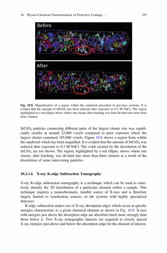
SrCrO4 particles connecting different parts of the largest cluster size was signifi-cantly smaller at around 22,000 voxels compared to prior exposure where thelargest cluster contained 185,000 voxels. Figure 10.8 shows a region from withinthe sandwich which has been magnified. It is evident that the amount of SrCrO4 wasreduced after exposure to 0.1 M NaCl. The voids created by the dissolution of theSrCrO4 are not shown. The region, highlighted by a red ellipse, shows where onecluster, after leaching, was divided into more than three clusters as a result of thedissolution of some intervening particles.
10.2.1.6 X-ray K-edge Subtraction Tomography
X-ray K-edge subtraction tomography is a technique which can be used to selec-tively identify the 3D distribution of a particular element within a sample. Thistechnique requires a monochromatic, tunable source of X-rays and is thereforelargely limited to synchrotron sources, or lab systems with highly specializeddetectors.
K-edge subtraction makes use of X-ray absorption edges which occur at specificenergies characteristic to a given chemical element as shown in Fig. 10.9. X-rayswith energies just above the absorption edge are absorbed much more strongly thanthose below it. Two X-ray tomographic datasets are acquired at closely spacedX-ray energies just above and below the absorption edge for the element of interest.
Fig. 10.8 Magnification of a region within the sandwich presented in previous sections. It isevident that the amount of SrCrO4 has been reduced after exposure to 0.1 M NaCl. The regionhighlighted in a red ellipse shows where one cluster after leaching was been divided into more thanthree clusters
10 Physico-Chemical Characterisation of Protective Coatings … 255
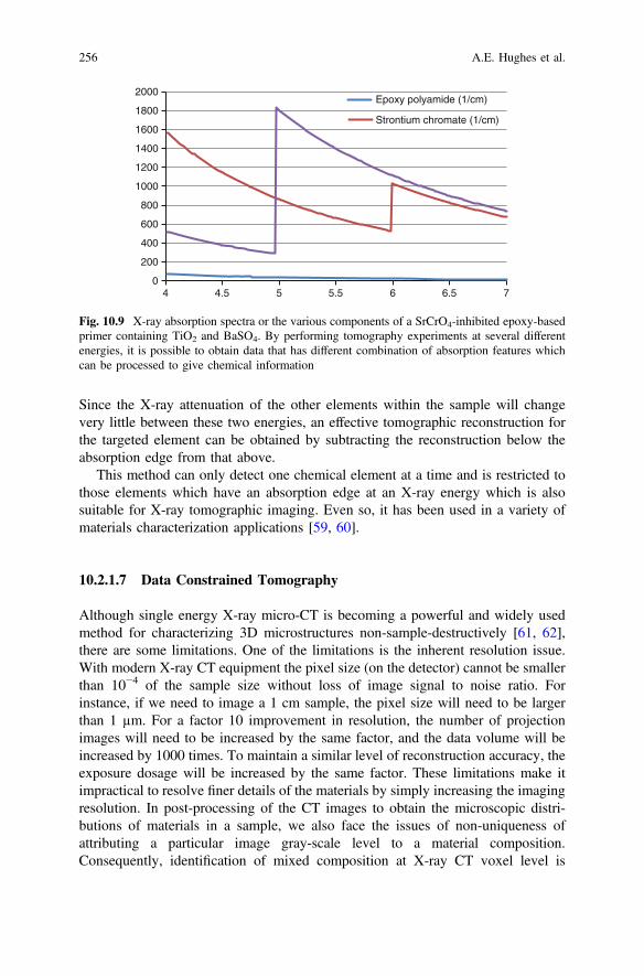
Since the X-ray attenuation of the other elements within the sample will changevery little between these two energies, an effective tomographic reconstruction forthe targeted element can be obtained by subtracting the reconstruction below theabsorption edge from that above.
This method can only detect one chemical element at a time and is restricted tothose elements which have an absorption edge at an X-ray energy which is alsosuitable for X-ray tomographic imaging. Even so, it has been used in a variety ofmaterials characterization applications [59, 60].
10.2.1.7 Data Constrained Tomography
Although single energy X-ray micro-CT is becoming a powerful and widely usedmethod for characterizing 3D microstructures non-sample-destructively [61, 62],there are some limitations. One of the limitations is the inherent resolution issue.With modern X-ray CT equipment the pixel size (on the detector) cannot be smallerthan 10−4 of the sample size without loss of image signal to noise ratio. Forinstance, if we need to image a 1 cm sample, the pixel size will need to be largerthan 1 µm. For a factor 10 improvement in resolution, the number of projectionimages will need to be increased by the same factor, and the data volume will beincreased by 1000 times. To maintain a similar level of reconstruction accuracy, theexposure dosage will be increased by the same factor. These limitations make itimpractical to resolve finer details of the materials by simply increasing the imagingresolution. In post-processing of the CT images to obtain the microscopic distri-butions of materials in a sample, we also face the issues of non-uniqueness ofattributing a particular image gray-scale level to a material composition.Consequently, identification of mixed composition at X-ray CT voxel level is
0
200
400
600
800
1000
1200
1400
1600
1800
2000
4 4.5 5 5.5 6 6.5 7
Epoxy polyamide (1/cm)
Strontium chromate (1/cm)
Fig. 10.9 X-ray absorption spectra or the various components of a SrCrO4-inhibited epoxy-basedprimer containing TiO2 and BaSO4. By performing tomography experiments at several differentenergies, it is possible to obtain data that has different combination of absorption features whichcan be processed to give chemical information
256 A.E. Hughes et al.
difficult, although it is potentially very useful when attempting to reconstruct afaithful image of the material microstructure distribution.
Considerable effort has been devoted to dual energy (spectrum) approach incharacterisation of various materials [63, 64]. These approaches were targeted toresolve the density and atomic number distributions. The dual energy X-ray CTworks well in resolving materials with large atomic number difference. However, itis still inadequate in resolving mixing of multiple materials phases and void at theX-ray CT pixel level.
Recently, a data-constrained model (DCM) has been developed [65, 66]. DCMis based on a lattice statistical mechanics model. Multiple sets of X-ray CT dataacquired at different X-ray beam energies are used as pervasive boundary condi-tions to constraint the model. Computationally, the DCM model is defined on asimple-cubic lattice grid with a cubic voxel on each grid point and with the totalnumber of voxels as N. The X-ray absorption coefficients (μn) for each voxel areobtained from X-ray CT. For a voxel at n ðn ¼ 1; 2; . . .;NÞ, the computationalmodel minimizes the following objective function:
Tn ¼XLl¼1
dlðlÞnh i2f
þEn ð10:1Þ
where L is the number of X-ray CT data sets acquired from the same sample usingL different beam energies.
For each X-ray spectrum (beam energy) l, the relative CT error is expressed as
dlðlÞn ¼ 1
lðlÞmax
XMm¼0
lðm;lÞvðmÞn � l̂ðlÞn
����������; ð10:2Þ
where lðm;lÞ is the linear absorption coefficient (or linear phase-shift coefficient, or realor imaginary part of the complex refractive coefficient) for material m, l̂ðlÞn is the CTreconstructed linear absorption coefficient (or linear phase-shift coefficient, or real orimaginary part of the complex refractive coefficient), and
lðlÞmax ¼ maxflðm;lÞ;m ¼ 0; 1; 2; . . .;Mg. The optimization is achieved by adjusting
the volume fraction variables vðmÞn ðm ¼ 0; 1; 2; . . .;MÞ for each material compositionm,whereM is the total numberof compositions in the system, subject to the constraints:
XMm¼0
vðmÞn ¼ 1 where 0� vðmÞn � 1 form ¼ 0; 1; 2. . .;M ð10:3Þ
The dimensionless phenomenological interaction energy is expressed as
En ¼XMm¼0
vðmÞn SðmÞ þXKk¼0
XNðkÞ
j¼1
XMm1¼0
XMm2¼m1
vðm1Þn vðm2Þ
nþ nðkÞj
� �g
Iðm1;m2Þk ð10:4Þ
10 Physico-Chemical Characterisation of Protective Coatings … 257
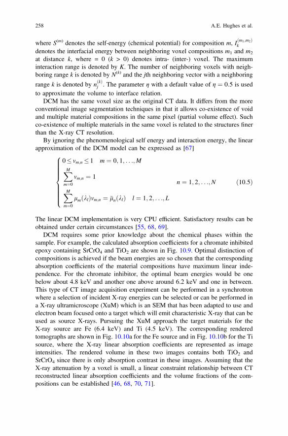
where S(m) denotes the self-energy (chemical potential) for composition m, Iðm1;m2Þk
denotes the interfacial energy between neighboring voxel compositions m1 and m2
at distance k, where = 0 (k > 0) denotes intra- (inter-) voxel. The maximuminteraction range is denoted by K. The number of neighboring voxels with neigh-boring range k is denoted by N(k) and the jth neighboring vector with a neighboring
range k is denoted by nðkÞj . The parameter η with a default value of g ¼ 0:5 is usedto approximate the volume to interface relation.
DCM has the same voxel size as the original CT data. It differs from the moreconventional image segmentation techniques in that it allows co-existence of voidand multiple material compositions in the same pixel (partial volume effect). Suchco-existence of multiple materials in the same voxel is related to the structures finerthan the X-ray CT resolution.
By ignoring the phenomenological self energy and interaction energy, the linearapproximation of the DCM model can be expressed as [67]
0� vm;n � 1 m ¼ 0; 1; . . .;M
XMm¼0
vm;n ¼ 1
XMm¼0
lm klð Þvm;n ¼ �ln klð Þ l ¼ 1; 2; . . .; L
8>>>>>>><>>>>>>>:
n ¼ 1; 2; . . .;N ð10:5Þ
The linear DCM implementation is very CPU efficient. Satisfactory results can beobtained under certain circumstances [55, 68, 69].
DCM requires some prior knowledge about the chemical phases within thesample. For example, the calculated absorption coefficients for a chromate inhibitedepoxy containing SrCrO4 and TiO2 are shown in Fig. 10.9. Optimal distinction ofcompositions is achieved if the beam energies are so chosen that the correspondingabsorption coefficients of the material compositions have maximum linear inde-pendence. For the chromate inhibitor, the optimal beam energies would be onebelow about 4.8 keV and another one above around 6.2 keV and one in between.This type of CT image acquisition experiment can be performed in a synchrotronwhere a selection of incident X-ray energies can be selected or can be performed ina X-ray ultramicroscope (XuM) which is an SEM that has been adapted to use andelectron beam focused onto a target which will emit characteristic X-ray that can beused as source X-rays. Pursuing the XuM approach the target materials for theX-ray source are Fe (6.4 keV) and Ti (4.5 keV). The corresponding renderedtomographs are shown in Fig. 10.10a for the Fe source and in Fig. 10.10b for the Tisource, where the X-ray linear absorption coefficients are represented as imageintensities. The rendered volume in these two images contains both TiO2 andSrCrO4 since there is only absorption contrast in these images. Assuming that theX-ray attenuation by a voxel is small, a linear constraint relationship between CTreconstructed linear absorption coefficients and the volume fractions of the com-positions can be established [46, 68, 70, 71].
258 A.E. Hughes et al.
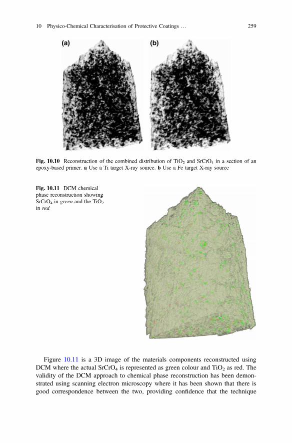
Figure 10.11 is a 3D image of the materials components reconstructed usingDCM where the actual SrCrO4 is represented as green colour and TiO2 as red. Thevalidity of the DCM approach to chemical phase reconstruction has been demon-strated using scanning electron microscopy where it has been shown that there isgood correspondence between the two, providing confidence that the technique
Fig. 10.10 Reconstruction of the combined distribution of TiO2 and SrCrO4 in a section of anepoxy-based primer. a Use a Ti target X-ray source. b Use a Fe target X-ray source
Fig. 10.11 DCM chemicalphase reconstruction showingSrCrO4 in green and the TiO2
in red
10 Physico-Chemical Characterisation of Protective Coatings … 259
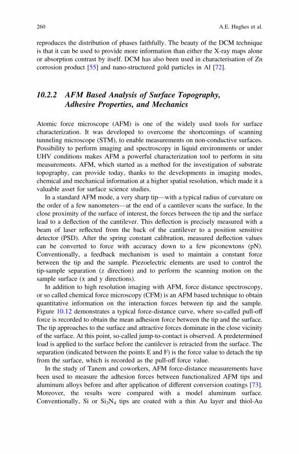
reproduces the distribution of phases faithfully. The beauty of the DCM techniqueis that it can be used to provide more information than either the X-ray maps aloneor absorption contrast by itself. DCM has also been used in characterisation of Zncorrosion product [55] and nano-structured gold particles in Al [72].
10.2.2 AFM Based Analysis of Surface Topography,Adhesive Properties, and Mechanics
Atomic force microscope (AFM) is one of the widely used tools for surfacecharacterization. It was developed to overcome the shortcomings of scanningtunneling microscope (STM), to enable measurements on non-conductive surfaces.Possibility to perform imaging and spectroscopy in liquid environments or underUHV conditions makes AFM a powerful characterization tool to perform in situmeasurements. AFM, which started as a method for the investigation of substratetopography, can provide today, thanks to the developments in imaging modes,chemical and mechanical information at a higher spatial resolution, which made it avaluable asset for surface science studies.
In a standard AFM mode, a very sharp tip—with a typical radius of curvature onthe order of a few nanometers—at the end of a cantilever scans the surface. In theclose proximity of the surface of interest, the forces between the tip and the surfacelead to a deflection of the cantilever. This deflection is precisely measured with abeam of laser reflected from the back of the cantilever to a position sensitivedetector (PSD). After the spring constant calibration, measured deflection valuescan be converted to force with accuracy down to a few piconewtons (pN).Conventionally, a feedback mechanism is used to maintain a constant forcebetween the tip and the sample. Piezoelectric elements are used to control thetip-sample separation (z direction) and to perform the scanning motion on thesample surface (x and y directions).
In addition to high resolution imaging with AFM, force distance spectroscopy,or so called chemical force microscopy (CFM) is an AFM based technique to obtainquantitative information on the interaction forces between tip and the sample.Figure 10.12 demonstrates a typical force-distance curve, where so-called pull-offforce is recorded to obtain the mean adhesion force between the tip and the surface.The tip approaches to the surface and attractive forces dominate in the close vicinityof the surface. At this point, so-called jump-to-contact is observed. A predeterminedload is applied to the surface before the cantilever is retracted from the surface. Theseparation (indicated between the points E and F) is the force value to detach the tipfrom the surface, which is recorded as the pull-off force value.
In the study of Tanem and coworkers, AFM force-distance measurements havebeen used to measure the adhesion forces between functionalized AFM tips andaluminum alloys before and after application of different conversion coatings [73].Moreover, the results were compared with a model aluminum surface.Conventionally, Si or Si3N4 tips are coated with a thin Au layer and thiol-Au
260 A.E. Hughes et al.

chemistry is used to deposit self-assembled monolayers with desired end-groups.Figure 10.13 compares the adhesion forces between a—COOH functionalizedAFM tip and aluminum substrates. It has been reported that the adhesion forcebetween the chromate conversion-coated (CCC) aluminum alloy and the tip wassignificantly increased in comparison to uncoated surface likely due to the increaseof hydrogen bonding. However, a decrease of adhesion force was observed after24 h due to aging of the CCC. Moreover, it has been reported that chromate freeTi-Zr based treatment also increased the adhesion although the measured forcesvaried significantly due to the non-uniform nature of the technical alloy. Themeasured AFM adhesion forces were qualitatively correlated with macroscopic
Fig. 10.12 Schematic curve of cantilever deflection versus displacement (distance to surface) inAFM adhesion force measurements. Reprinted from [73], Copyright (2009), with permission fromElsevier
Fig. 10.13 Average adhesion force measured on the α-Al (Fe,Mn)Si particles (p) and aluminummatrix (m) of the uncoated ultra-microtomed (UM), chromated (CCC) and Ti–Zr-treated surfaces.Measurements were performed within 2 h after surface treatment, using a COOH functionalizedtip. Reprinted from [73], Copyright (2009), with permission from Elsevier
10 Physico-Chemical Characterisation of Protective Coatings … 261
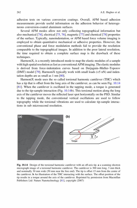
adhesion tests on various conversion coatings. Overall, AFM based adhesionmeasurements provide useful information on the adhesion behavior of heteroge-neous conversion-coated aluminum surfaces.
Several AFM modes allow not only collecting topographical information butalso mechanical [74], electrical [75, 76], magnetic [77] and chemical [78] propertiesof the surface. Typically, nanoindentation, or AFM based force volume imaging isemployed to obtain quantitative mechanical or adhesive properties. However, theconventional phase and force modulation methods fail to provide the resolutioncomparable to the topographical images. In addition to the poor lateral resolution,the time required to obtain a complete surface map is the drawback of thesetechniques.
HarmoniX, is a recently introduced mode to map the elastic modulus of a samplewith high spatial resolution as fast as conventionalAFM imaging. The elasticmodulusis derived from force-indentation curves based on Derjaguin–Muller–Toporov(DMT) model [79]. HarmoniX typically work with small loads (<5 nN) and inden-tation depths are as small as 1 nm [80].
HarmoniX mode uses the so called torsional harmonic cantilever (THC) whichhas a tip that is offset from the long axis of the cantilever, as can be seen Fig. 10.14[81]. When the cantilever is oscillated in the tapping mode, a torque is generateddue to the tip-sample interaction (Fig. 10.14b). This torsional motion along the longaxis of the cantilever moves the reflected laser spot horizontally on the PSD. Similarto the tapping mode, the conventional vertical oscillations are used to followtopography while the torsional vibrations are used to calculate tip-sample interac-tions in sub microsecond resolution.
Fig. 10.14 Design of the torsional harmonic cantilever with an off-axis tip. a a scanning electronmicrograph image of a torsional harmonic cantilever. The cantilever is 300 mm long, 3 mm thickand nominally 30 mm wide (50 mm near the free end). The tip is offset 15 mm from the centre ofthe cantilever. b An illustration of the THC interacting with the surface. The offset position of thetip results in a torque around the axis of the cantilever. Reprinted by permission from MacmillanPublishers Ltd: Nature Nanotechnology [81], copyright (2007)
262 A.E. Hughes et al.
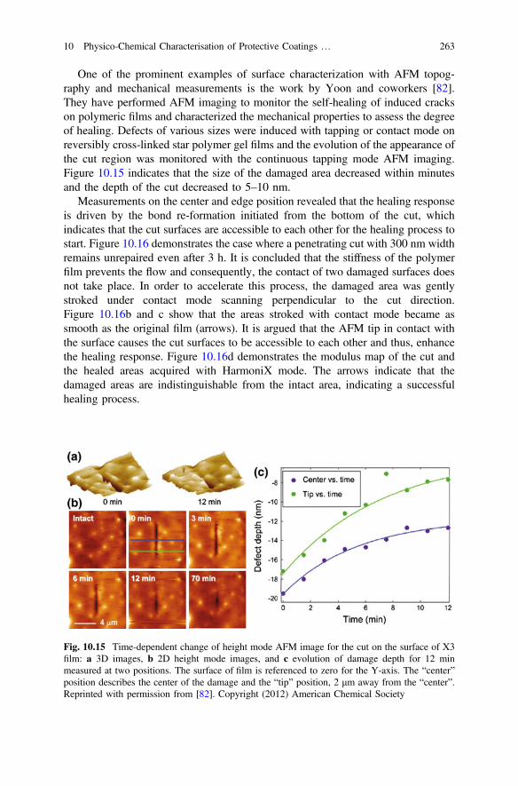
One of the prominent examples of surface characterization with AFM topog-raphy and mechanical measurements is the work by Yoon and coworkers [82].They have performed AFM imaging to monitor the self-healing of induced crackson polymeric films and characterized the mechanical properties to assess the degreeof healing. Defects of various sizes were induced with tapping or contact mode onreversibly cross-linked star polymer gel films and the evolution of the appearance ofthe cut region was monitored with the continuous tapping mode AFM imaging.Figure 10.15 indicates that the size of the damaged area decreased within minutesand the depth of the cut decreased to 5–10 nm.
Measurements on the center and edge position revealed that the healing responseis driven by the bond re-formation initiated from the bottom of the cut, whichindicates that the cut surfaces are accessible to each other for the healing process tostart. Figure 10.16 demonstrates the case where a penetrating cut with 300 nm widthremains unrepaired even after 3 h. It is concluded that the stiffness of the polymerfilm prevents the flow and consequently, the contact of two damaged surfaces doesnot take place. In order to accelerate this process, the damaged area was gentlystroked under contact mode scanning perpendicular to the cut direction.Figure 10.16b and c show that the areas stroked with contact mode became assmooth as the original film (arrows). It is argued that the AFM tip in contact withthe surface causes the cut surfaces to be accessible to each other and thus, enhancethe healing response. Figure 10.16d demonstrates the modulus map of the cut andthe healed areas acquired with HarmoniX mode. The arrows indicate that thedamaged areas are indistinguishable from the intact area, indicating a successfulhealing process.
Fig. 10.15 Time-dependent change of height mode AFM image for the cut on the surface of X3film: a 3D images, b 2D height mode images, and c evolution of damage depth for 12 minmeasured at two positions. The surface of film is referenced to zero for the Y-axis. The “center”position describes the center of the damage and the “tip” position, 2 μm away from the “center”.Reprinted with permission from [82]. Copyright (2012) American Chemical Society
10 Physico-Chemical Characterisation of Protective Coatings … 263
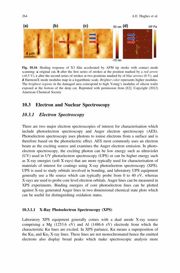
10.3 Electron and Nuclear Spectroscopy
10.3.1 Electron Spectroscopy
There are two major electron spectroscopies of interest for characterisation whichinclude photoelectron spectroscopy and Auger electron spectroscopy (AES).Photoelectron spectroscopy uses photons to ionise electrons from a surface and istherefore based on the photoelectric effect. AES most commonly uses an electronbeam as the exciting source and examines the Auger electron emission. In photo-electron spectroscopy, the exciting photon can be low energy such as ultraviolet(UV) used in UV photoelectron spectroscopy (UPS) or can be higher energy suchas X-ray energies (soft X-rays) that are more typically used for characterisation ofmaterials of interest for coatings using X-ray photoelectron spectroscopy (XPS).UPS is used to study orbitals involved in bonding, and laboratory UPS equipmentgenerally use a He source which can typically probe from 0 to 40 eV, whereasX-rays are used to probe core level electron orbitals. Auger lines can be measured inXPS experiments. Binding energies of core photoelectron lines can be plottedagainst X-ray generated Auger lines in two dimensional chemical state plots whichcan be useful for distinguishing oxidation states.
10.3.1.1 X-Ray Photoelectron Spectroscopy (XPS)
Laboratory XPS equipment generally comes with a dual anode X-ray sourcecomprising a Mg (1253.6 eV) and Al (1486.6 eV) electrode from which thecharacteristic Kα lines are excited. In XPS parlance, Kα means a superposition ofthe Kα1 and Kα2 X-ray lines. These lines are not monochromated hence the emittedelectrons also display broad peaks which make spectroscopic analysis more
Fig. 10.16 Healing response of X3 film accelerated by AFM tip stroke with contact modescanning: a original cut, b after the first series of strokes at the position marked by a red arrow(+0.5 V), c after the second series of strokes at two positions marked by of blue arrows (0 V), andd HarmoniX mode modulus map in a logarithmic scale. Brighter color represents higher modulus.The brightest regions in the damaged area correspond to high Young’s modulus of silicon waferexposed at the bottom of the deep cut. Reprinted with permission from [82]. Copyright (2012)American Chemical Society
264 A.E. Hughes et al.
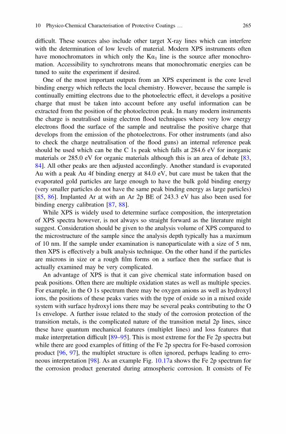
difficult. These sources also include other target X-ray lines which can interferewith the determination of low levels of material. Modern XPS instruments oftenhave monochromators in which only the Kα1 line is the source after monochro-mation. Accessibility to synchrotrons means that monochromatic energies can betuned to suite the experiment if desired.
One of the most important outputs from an XPS experiment is the core levelbinding energy which reflects the local chemistry. However, because the sample iscontinually emitting electrons due to the photoelectric effect, it develops a positivecharge that must be taken into account before any useful information can beextracted from the position of the photoelectron peak. In many modern instrumentsthe charge is neutralised using electron flood techniques where very low energyelectrons flood the surface of the sample and neutralise the positive charge thatdevelops from the emission of the photoelectrons. For other instruments (and alsoto check the charge neutralisation of the flood guns) an internal reference peakshould be used which can be the C 1s peak which falls at 284.6 eV for inorganicmaterials or 285.0 eV for organic materials although this is an area of debate [83,84]. All other peaks are then adjusted accordingly. Another standard is evaporatedAu with a peak Au 4f binding energy at 84.0 eV, but care must be taken that theevaporated gold particles are large enough to have the bulk gold binding energy(very smaller particles do not have the same peak binding energy as large particles)[85, 86]. Implanted Ar at with an Ar 2p BE of 243.3 eV has also been used forbinding energy calibration [87, 88].
While XPS is widely used to determine surface composition, the interpretationof XPS spectra however, is not always so straight forward as the literature mightsuggest. Consideration should be given to the analysis volume of XPS compared tothe microstructure of the sample since the analysis depth typically has a maximumof 10 nm. If the sample under examination is nanoparticulate with a size of 5 nm,then XPS is effectively a bulk analysis technique. On the other hand if the particlesare microns in size or a rough film forms on a surface then the surface that isactually examined may be very complicated.
An advantage of XPS is that it can give chemical state information based onpeak positions. Often there are multiple oxidation states as well as multiple species.For example, in the O 1s spectrum there may be oxygen anions as well as hydroxylions, the positions of these peaks varies with the type of oxide so in a mixed oxidesystem with surface hydroxyl ions there may be several peaks contributing to the O1s envelope. A further issue related to the study of the corrosion protection of thetransition metals, is the complicated nature of the transition metal 2p lines, sincethese have quantum mechanical features (multiplet lines) and loss features thatmake interpretation difficult [89–95]. This is most extreme for the Fe 2p spectra butwhile there are good examples of fitting of the Fe 2p spectra for Fe-based corrosionproduct [96, 97], the multiplet structure is often ignored, perhaps leading to erro-neous interpretation [98]. As an example Fig. 10.17a shows the Fe 2p spectrum forthe corrosion product generated during atmospheric corrosion. It consists of Fe
10 Physico-Chemical Characterisation of Protective Coatings … 265
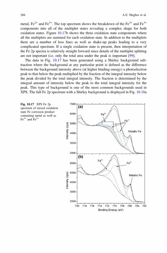
metal, Fe2+ and Fe3+. The top spectrum shows the breakdown of the Fe2+ and Fe3+
components into all of the multiplet states revealing a complex shape for bothoxidation states. Figure 10.17b shows the three oxidation state components whereall the multiplets are summed for each oxidation state. In addition to the multipletsthere are a number of loss lines as well as shake-up peaks leading to a verycomplicated spectrum. If a single oxidation state is present, then interpretation ofthe Fe 2p spectra is relatively straight forward since details of the multiplet splittingare not important (i.e. only the total area under the peak is important [99].
The data in Fig. 10.17 has been generated using a Shirley background sub-traction where the background at any particular point is defined as the differencebetween the background intensity above (at higher binding energy) a photoelectronpeak to that below the peak multiplied by the fraction of the integral intensity belowthe peak divided by the total integral intensity. The fraction is determined by theintegral amount of intensity below the peak to the total integral intensity for thepeak. This type of background is one of the most common backgrounds used inXPS. The full Fe 2p spectrum with a Shirley background is displayed in Fig. 10.18a
Fig. 10.17 XPS Fe 2pspectrum of mixed oxidationstate Fe corrosion productcontaining metal as well asFe2+ and Fe3+
266 A.E. Hughes et al.

[100–102]. Linear backgrounds are also commonly used in XPS, although not socommonly for photoelectron peaks where there is a large increase in the back-ground intensity such as for the Fe 2p spectrum. Figure 10.18b shows a linearbackground. A third type of background is the Tougaard background [103, 104]which is based on the fundamental physics of electron scattering [103–105]; it isshown in Fig. 10.18c.
Fig. 10.18 Various methodsof fitting of Fe 2p3 core levelpeaks. a Shirley, b, linear andc Tougaard backgrounds. Thesolid black line is the data, thedashed blue line is the fit anddashed black lines are theindividual component for thedifferent Fe oxidation statesand the dotted lines are theshakeup satellites
10 Physico-Chemical Characterisation of Protective Coatings … 267
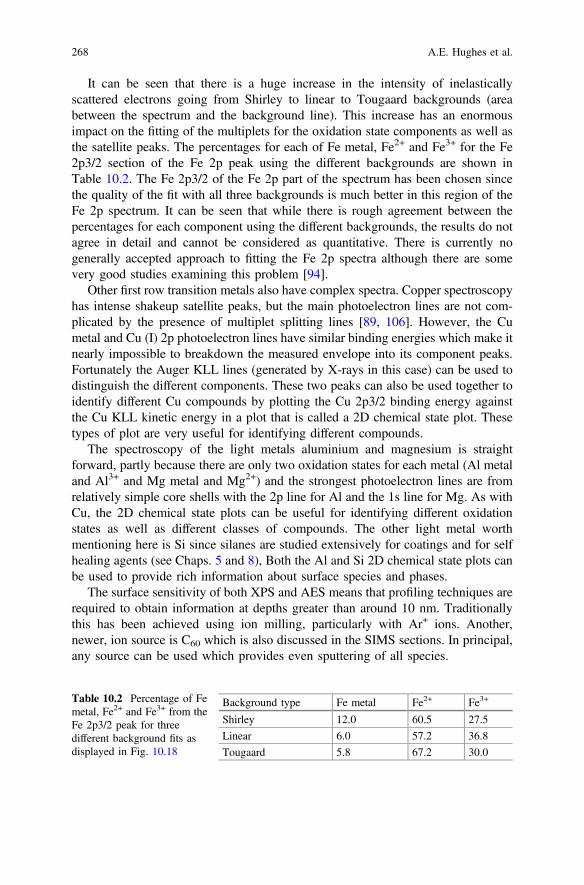
It can be seen that there is a huge increase in the intensity of inelasticallyscattered electrons going from Shirley to linear to Tougaard backgrounds (areabetween the spectrum and the background line). This increase has an enormousimpact on the fitting of the multiplets for the oxidation state components as well asthe satellite peaks. The percentages for each of Fe metal, Fe2+ and Fe3+ for the Fe2p3/2 section of the Fe 2p peak using the different backgrounds are shown inTable 10.2. The Fe 2p3/2 of the Fe 2p part of the spectrum has been chosen sincethe quality of the fit with all three backgrounds is much better in this region of theFe 2p spectrum. It can be seen that while there is rough agreement between thepercentages for each component using the different backgrounds, the results do notagree in detail and cannot be considered as quantitative. There is currently nogenerally accepted approach to fitting the Fe 2p spectra although there are somevery good studies examining this problem [94].
Other first row transition metals also have complex spectra. Copper spectroscopyhas intense shakeup satellite peaks, but the main photoelectron lines are not com-plicated by the presence of multiplet splitting lines [89, 106]. However, the Cumetal and Cu (I) 2p photoelectron lines have similar binding energies which make itnearly impossible to breakdown the measured envelope into its component peaks.Fortunately the Auger KLL lines (generated by X-rays in this case) can be used todistinguish the different components. These two peaks can also be used together toidentify different Cu compounds by plotting the Cu 2p3/2 binding energy againstthe Cu KLL kinetic energy in a plot that is called a 2D chemical state plot. Thesetypes of plot are very useful for identifying different compounds.
The spectroscopy of the light metals aluminium and magnesium is straightforward, partly because there are only two oxidation states for each metal (Al metaland Al3+ and Mg metal and Mg2+) and the strongest photoelectron lines are fromrelatively simple core shells with the 2p line for Al and the 1s line for Mg. As withCu, the 2D chemical state plots can be useful for identifying different oxidationstates as well as different classes of compounds. The other light metal worthmentioning here is Si since silanes are studied extensively for coatings and for selfhealing agents (see Chaps. 5 and 8), Both the Al and Si 2D chemical state plots canbe used to provide rich information about surface species and phases.
The surface sensitivity of both XPS and AES means that profiling techniques arerequired to obtain information at depths greater than around 10 nm. Traditionallythis has been achieved using ion milling, particularly with Ar+ ions. Another,newer, ion source is C60 which is also discussed in the SIMS sections. In principal,any source can be used which provides even sputtering of all species.
Table 10.2 Percentage of Femetal, Fe2+ and Fe3+ from theFe 2p3/2 peak for threedifferent background fits asdisplayed in Fig. 10.18
Background type Fe metal Fe2+ Fe3+
Shirley 12.0 60.5 27.5
Linear 6.0 57.2 36.8
Tougaard 5.8 67.2 30.0
268 A.E. Hughes et al.

Physical sectioning is another technique that can be used to obtain depthinformation. This can be achieved by a variety of methods including mechanicalmilling, polishing at an angle to the normal or cutting at an angle to the normal. Inthis latter process the objective is to “spread” out the layer in the section to suit thelateral resolution of the technique, so the thinner the layer the closer the angle has tobe to the surface parallel. Hinder et al. demonstrated this process for XPS [107] andalso for Tof-SIMS approach [108].
The application of XPS to self-healing coatings is limited and generally used tosupport other techniques. It can be used to study components of coating systems,such as the polymer resin, inhibitors and other additives as well as the effects of selfhealing such as inhibitor or healing agent reactions on a surface. For example,double layer hydroxides have been used extensively as carriers for inhibitors [36–38, 109–113]. XPS has been used for characterisation of the inhibitor in these typesof double layer hydroxides structures such as hydrotalcites [114] and Fe-basedstructures [115], the latter occurring in green rust [96, 97]. In self healing studiesXPS can be very useful in studying well prepared surfaces exposed to extracts fromnew inhibitor pigments. For example, Granizo et al. [99, 116] examined steelsurfaces after exposure to extracts from various vanadates exchanged hydrotalcitepigments and found the surfaces after exposure had films incorporating the inhibitorspecies. Similarly XPS has been used to examined Ce release and interaction withAA2024-T3 [114, 117] and Mg alloys [118].
For novel inhibitors, it has been applied to determine the layer thickness bymonitoring the Si photoelectron lines of an organo-silane coating on latex particles[119]. It has also been used to study the Mo 3d lines during molybate inhibition[120]. The rare earths and in particular, Ce (Ce 3d) which have been used exten-sively in aluminium inhibition [121–125]. Ho et al. [126] used XPS to determineoxidation states on AA2024-T3 surfaces and to examine Ce diphenyl phosphateinteraction with steel surfaces [126]. In this case the self healing properties of thesefilms were determined using EIS.
In the case of coatings, there is a wealth of information to be obtained from thespectroscopy of C 1 s and N1 s peaks which have been used extensively to studyconducting polymer coatings [125, 127, 128]. Trabelsi et al. [121] used XPS todetermine the cerium oxidation state in silane derived sol-gel films. On a variationon the self healing theme Jakab and Scully used XPS to confirm the segregation ofCo and Ce for forming a protective, self healing coating on an Al-Co-Ce alloy[129].
10.3.1.2 Spatially Resolved XPS
Spatially resolved XPS is now a common technique in many XPS instruments withspatial resolution down to 1 μm, although the fine resolution comes with a loss ofsignal to noise [130]. Some of the early applications of XPS included failure
10 Physico-Chemical Characterisation of Protective Coatings … 269
analysis in adhesively bonded structures where the large area analysis of earlyinstruments was not an impediment to studying different area of adhesive failure [7,131]. While it has been used to study Pb pigments in paintings [132] and coatinginterfacial chemistry, particularly cohesive or adhesive failure [133], its use in selfhealing applications is not widespread. Mapping has also been used in corrosionstudies [130, 134]. The approach used in these applications can be logicallyextended to self healing, but only if there is a unique “marker” in the healing agentthat can be used to reveal the spatial distribution of the healing agent. Thus, in selfhealing systems where there is encapsulated monomer which is released andpolymerises, then XPS is not likely to be able to detect the healing processes.
10.3.1.3 Auger Electron Spectroscopy (AES)
AES as an electron beam characterisation technique, has the potential for excellentspatial resolution, however, much self healing work is on non-conductors whichmeans that charging is a significant problem. Non-conductors include polymers,hybrid (organic/inorganic composites) and inorganic coatings as well as failure siteswhere non conducting corrosion product occurs.
Despite these difficulties AES has been used to study inhibition in a defectthrough a coating on galvanised steel by Montemor and Ferreira [123]. In their casethey used a variation of the techniques described in Fig. 10.1 by taking lines scansacross and along the length of a scribe. They detected that cerium was present in thedefect and had leached from an adjacent sol-gel coating during immersion.
10.3.2 Nuclear and Ion Spectroscopy
There are two nuclear techniques that are worth mentioning for characterisation ofself healing systems. The techniques are Rutherford Backscattering Spectroscopy(RBS) and Particle induced X-ray Emission (PIXE) spectroscopy. Both techniquesuse either protons or α-particles (2 protons and 2 neutrons—i.e. a He nucleus)which are accelerated in an accelerator up to energies in the vicinity of MeV. Theseprobes then interact with the system under study; in the case of RBS the quasielastically scattered particles are measured (the measurement angle is typically170°), but in PIXE the X-ray emission spectrum is measured. Both PIXE and RBShave spatial resolution that can resolve features down to the micron scale and aretherefore ideal to measure interactions in a defect that reflect a healing process. Thedisadvantage of these techniques is that they require an accelerator which typicallyis the size of a small building.
The sensitivity and data analysis requirements of the two techniques are quitedifferent because the emitted radiation is so different (backscattered particles versusX-ray emission). As an example Fig. 10.19 shows an optical image and
270 A.E. Hughes et al.
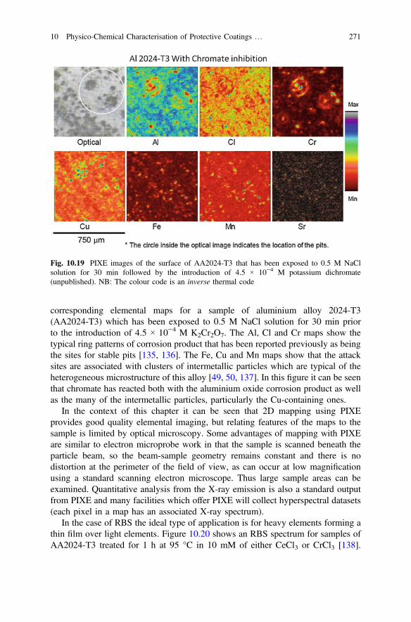
corresponding elemental maps for a sample of aluminium alloy 2024-T3(AA2024-T3) which has been exposed to 0.5 M NaCl solution for 30 min priorto the introduction of 4.5 × 10⁻⁴ M K2Cr2O7. The Al, Cl and Cr maps show thetypical ring patterns of corrosion product that has been reported previously as beingthe sites for stable pits [135, 136]. The Fe, Cu and Mn maps show that the attacksites are associated with clusters of intermetallic particles which are typical of theheterogeneous microstructure of this alloy [49, 50, 137]. In this figure it can be seenthat chromate has reacted both with the aluminium oxide corrosion product as wellas the many of the intermetallic particles, particularly the Cu-containing ones.
In the context of this chapter it can be seen that 2D mapping using PIXEprovides good quality elemental imaging, but relating features of the maps to thesample is limited by optical microscopy. Some advantages of mapping with PIXEare similar to electron microprobe work in that the sample is scanned beneath theparticle beam, so the beam-sample geometry remains constant and there is nodistortion at the perimeter of the field of view, as can occur at low magnificationusing a standard scanning electron microscope. Thus large sample areas can beexamined. Quantitative analysis from the X-ray emission is also a standard outputfrom PIXE and many facilities which offer PIXE will collect hyperspectral datasets(each pixel in a map has an associated X-ray spectrum).
In the case of RBS the ideal type of application is for heavy elements forming athin film over light elements. Figure 10.20 shows an RBS spectrum for samples ofAA2024-T3 treated for 1 h at 95 °C in 10 mM of either CeCl3 or CrCl3 [138].
Fig. 10.19 PIXE images of the surface of AA2024-T3 that has been exposed to 0.5 M NaClsolution for 30 min followed by the introduction of 4.5 × 10⁻⁴ M potassium dichromate(unpublished). NB: The colour code is an inverse thermal code
10 Physico-Chemical Characterisation of Protective Coatings … 271
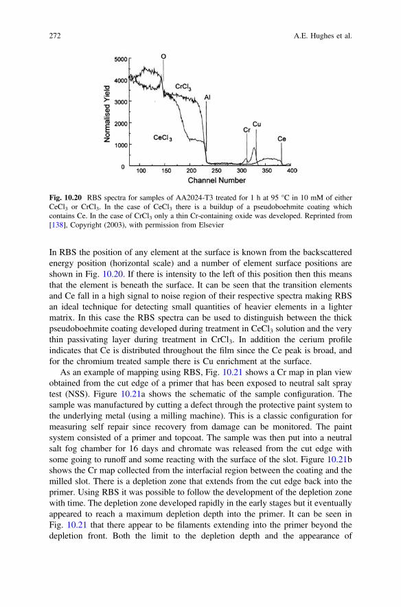
In RBS the position of any element at the surface is known from the backscatteredenergy position (horizontal scale) and a number of element surface positions areshown in Fig. 10.20. If there is intensity to the left of this position then this meansthat the element is beneath the surface. It can be seen that the transition elementsand Ce fall in a high signal to noise region of their respective spectra making RBSan ideal technique for detecting small quantities of heavier elements in a lightermatrix. In this case the RBS spectra can be used to distinguish between the thickpseudoboehmite coating developed during treatment in CeCl3 solution and the verythin passivating layer during treatment in CrCl3. In addition the cerium profileindicates that Ce is distributed throughout the film since the Ce peak is broad, andfor the chromium treated sample there is Cu enrichment at the surface.
As an example of mapping using RBS, Fig. 10.21 shows a Cr map in plan viewobtained from the cut edge of a primer that has been exposed to neutral salt spraytest (NSS). Figure 10.21a shows the schematic of the sample configuration. Thesample was manufactured by cutting a defect through the protective paint system tothe underlying metal (using a milling machine). This is a classic configuration formeasuring self repair since recovery from damage can be monitored. The paintsystem consisted of a primer and topcoat. The sample was then put into a neutralsalt fog chamber for 16 days and chromate was released from the cut edge withsome going to runoff and some reacting with the surface of the slot. Figure 10.21bshows the Cr map collected from the interfacial region between the coating and themilled slot. There is a depletion zone that extends from the cut edge back into theprimer. Using RBS it was possible to follow the development of the depletion zonewith time. The depletion zone developed rapidly in the early stages but it eventuallyappeared to reach a maximum depletion depth into the primer. It can be seen inFig. 10.21 that there appear to be filaments extending into the primer beyond thedepletion front. Both the limit to the depletion depth and the appearance of
Fig. 10.20 RBS spectra for samples of AA2024-T3 treated for 1 h at 95 °C in 10 mM of eitherCeCl3 or CrCl3. In the case of CeCl3 there is a buildup of a pseudoboehmite coating whichcontains Ce. In the case of CrCl3 only a thin Cr-containing oxide was developed. Reprinted from[138], Copyright (2003), with permission from Elsevier
272 A.E. Hughes et al.

filaments are consistent with some recently published work that identified clustersof connected SrCrO4 particles within these types of primers [58, 139]. It wasobserved that only the clusters connected to the surface were the ones that wereleached out leading to a general depletion depth for those clusters connected to thesurface but also some deeper penetration due to the dissolution of larger clusters.This model is extremely important for the design of paint systems more generally,but also for strategies for self healing where the internal structures of coatings canbe used for delivery systems for various agents. It is also discussed in more detail inthe tomography section.
The area of Secondary Ion (or Neutral) Mass Spectroscopy (SIMS or SNMS) isan area where there has been considerable development in a range of techniqueswhich are covered in a number of good reviews in the literature [140–142].Considerable effort has been put into the development of the techniques for softmaterial analysis, particularly for biological applications. The developments havefocused on ionisation techniques that deliver large molecules into the gas phase.These include matrix assisted laser desorption/ionisation (MALDI) and electrospray
Fig. 10.21 Cr map obtainedusing RutherfordBackscattering Spectroscopy.a Schematic showing theconfiguration of the sample insection. The sample wasmanufactured by cutting adefect through the protectivepaint system the underlyingmetal (using a millingmachine). The paint systemconsisted of a primer andtopcoat. The sample was thenput into a neutral salt fogchamber for 16 days. b Planview of the slot (defect, right)and the paint system (left) andthe depletion zone at the cutedge
10 Physico-Chemical Characterisation of Protective Coatings … 273
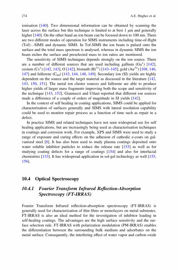
ionisation [140]. Two dimensional information can be obtained by scanning thelaser across the surface but this technique is limited to at best 1 μm and generallyhigher [140]. On the other hand an ion beam can be focused down to 100 nm. Thereare two different modes of operation for SIMS instruments including time-of-flight(Tof)—SIMS and dynamic SIMS. In Tof-SIMS the ion beam is pulsed onto thesurface and the total mass spectrum is analysed, whereas in dynamic SIMS the ionbeam etches the surface and preselected mass to ion ratios are monitored.
The sensitivity of SIMS techniques depends strongly on the ion source. Thereare a number of different sources that are used including gallium (Ga+) [142],cesium (Cs+) [142, 143], O [142], bismuth (Bi3+) [143–145], gold (Au3+) [108, 146,147] and fullerene (C60) [143, 144, 148, 149]. Secondary ion (SI) yields are highlydependent on the source and the target material as discussed in the literature [142,143, 150, 151]. The metal ion cluster sources and fullerene are able to producehigher yields of larger mass fragments improving both the scope and sensitivity ofthe technique [143, 152]. Giannuzzi and Utlaut reported that different ion sourcesmade a difference of a couple of orders of magnitude in SI yields [142].
In the context of self healing in coating applications, SIMS could be applied forcharacterisation of surfaces generally and SIMS with lateral resolution capabilitycould be used to monitor repair process as a function of time such as repair in adefect.
In practice SIMS and related techniques have not seen widespread use for selfhealing applications, but are increasingly being used as characterisation techniquesin coatings and corrosion work. For example, XPS and SIMS were used to study arange of exposure and curing effects on the adhesion of cathodic e-coats on gal-vanised steel [8]. It has also been used to study plasma coatings deposited ontowater soluble inhibitor particles to reduce the release rate [153] as well as forstudying coating defects for a range of coatings [154] and also for interfacialchemistries [133]. It has widespread application in sol-gel technology as well [155,156].
10.4 Optical Spectroscopy
10.4.1 Fourier Transform Infrared Reflection-AbsorptionSpectroscopy (FT-IRRAS)
Fourier Transform Infrared reflection-absorption spectroscopy (FT-IRRAS) isgenerally used for characterization of thin films or monolayers on metal substrates.FT-IRRAS is also an ideal method for the investigation of inhibitor loading inself-healing coatings. The advantages are the high surface sensitivity and the sur-face selection rule. FT-IRRAS with polarization modulation (PM-IRRAS) enablesthe differentiation between the surrounding bulk medium and adsorbates on themetal surface. Consequently, the interfering effect of water vapor and carbon oxide
274 A.E. Hughes et al.

can be eliminated. IRRAS is dependent on the optical constants of the thin film andsubstrate, and the angle of incidence, as well as the polarization of the incident IRradiation can be varied to obtain the optimum information. The surface selectionrule enables the investigation of the molecular orientation of thin films or mono-layers deposited on metal or dielectric substrates.
The methods for the evaluation of the molecular orientation is recently sum-marized by Arnold et al. [157]. The transition dipole moment (TDM) of a molecularvibration can be decomposed into two components, one oriented normal (TDMz)and the second one oriented parallel (TDMx) to the surface (see Fig. 10.22a). Thetilt angle Θ can be calculated from the equation:
tanH ¼ TDMx
TDMz
At a metal surface the parallel component of the electrical field Ex is almostcompletely screened by the electrons of the metal substrate (Fig. 10.22b) [157,158]. As a consequence, TDMx does not contribute and for a single vibrationalmode, the tilt angle can only be calculated if the absolute magnitude of the tran-sition dipole moment, |TDM|, is known.
If two vibrational modes with different orientations of their transition dipolemoments can be measured (Fig. 10.22c) the ratio (|TDM1|/|TDM2|)
2 can be cal-culated from the ratio of their intensities (I1 bulk/I2 bulk) of the bulk spectrum.Similarly, the ratio (TDM1,z/TDM2,z)
2 is equal to the ratio (I1 SAM/I2 SAM). If theseratios can be evaluated the tilt angle can be calculated using [157]:
ðtanHÞ2 ¼ Ibulk1 ISAM2
Ibulk2 ISAM1
The details on the relative method was described by Debe and the interested reader isreferred to this article [159]. Parikh and Allara have proposed in 1992 an alternativemethod, based on the determination of the absolute excitation probability, whichcorresponds to |TDM| of a given mode in the bulk [157, 160]. Considering thegeometrical approximation by Tillman et al. [161], Bram et al. [162] calculated the
Fig. 10.22 Orientation of the transition dipole moments (TDM) of molecular vibrations (a, c) andthe electric field (b) at the surface. Reprinted with permission from [157]. Copyright (2001)American Chemical Society
10 Physico-Chemical Characterisation of Protective Coatings … 275
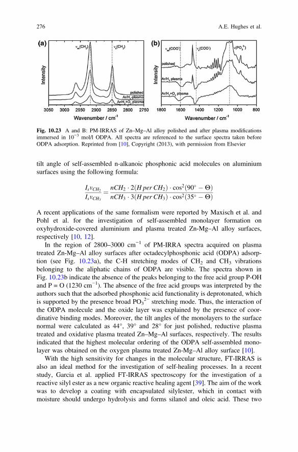
tilt angle of self-assembled n-alkanoic phosphonic acid molecules on aluminiumsurfaces using the following formula:
IsmCH2
IsmCH3
¼ nCH2 � 2ðH per CH2Þ � cos2ð90� �HÞnCH3 � 3ðH per CH3Þ � cos2ð35� �HÞ
A recent applications of the same formalism were reported by Maxisch et al. andPohl et al. for the investigation of self-assembled monolayer formation onoxyhydroxide-covered aluminium and plasma treated Zn-Mg–Al alloy surfaces,respectively [10, 12].
In the region of 2800–3000 cm−1 of PM-IRRA spectra acquired on plasmatreated Zn-Mg–Al alloy surfaces after octadecylphosphonic acid (ODPA) adsorp-tion (see Fig. 10.23a), the C-H stretching modes of CH2 and CH3 vibrationsbelonging to the aliphatic chains of ODPA are visible. The spectra shown inFig. 10.23b indicate the absence of the peaks belonging to the free acid group P-OHand P = O (1230 cm−1). The absence of the free acid groups was interpreted by theauthors such that the adsorbed phosphonic acid functionality is deprotonated, whichis supported by the presence broad PO3
2− stretching mode. Thus, the interaction ofthe ODPA molecule and the oxide layer was explained by the presence of coor-dinative binding modes. Moreover, the tilt angles of the monolayers to the surfacenormal were calculated as 44°, 39° and 28° for just polished, reductive plasmatreated and oxidative plasma treated Zn–Mg–Al surfaces, respectively. The resultsindicated that the highest molecular ordering of the ODPA self-assembled mono-layer was obtained on the oxygen plasma treated Zn-Mg–Al alloy surface [10].
With the high sensitivity for changes in the molecular structure, FT-IRRAS isalso an ideal method for the investigation of self-healing processes. In a recentstudy, Garcia et al. applied FT-IRRAS spectroscopy for the investigation of areactive silyl ester as a new organic reactive healing agent [39]. The aim of the workwas to develop a coating with encapsulated silylester, which in contact withmoisture should undergo hydrolysis and forms silanol and oleic acid. These two
Fig. 10.23 A and B: PM-IRRAS of Zn–Mg–Al alloy polished and after plasma modificationsimmersed in 10−3 mol/l ODPA. All spectra are referenced to the surface spectra taken beforeODPA adsorption. Reprinted from [10], Copyright (2013), with permission from Elsevier
276 A.E. Hughes et al.
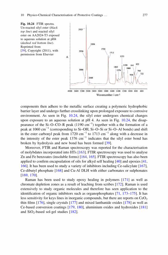
components then adhere to the metallic surface creating a polymeric hydrophobicbarrier layer and undergo further crosslinking upon prolonged exposure to corrosiveenvironment. As seen in Fig. 10.24, the silyl ester undergoes chemical changesupon exposure to an aqueous solution at pH 4. As seen in Fig. 10.24, the disap-pearance of the Si–O–CO–R peak (1190 cm−1) together with a the formation of apeak at 1060 cm−1 (corresponding to Si–OH, Si–O–Si or Si–O–Al bonds) and shiftin the ester carbonyl peak from 1720 cm−1 to 1713 cm−1 along with a decrease inthe intensity of the ester peak 1376 cm−1 indicates that the silyl ester bond hasbroken by hydrolysis and new bond has been formed [39].
Moreover, FTIR and Raman spectroscopy was reported for the characterisationof molybdates incorporated into HTs [163]. FTIR spectroscopy was used to analyseZn and Fe benzoates (insoluble forms) [164, 165]. FTIR spectroscopy has also beenapplied to confirm encapsulation of oils for alkyd self healing [40] and epoxies [41,166]. It has been used to study a variety of inhibitors including Ce-salicylate [167],Ce-dibutyl phosphate [168] and Cu-Al DLH with either carbonates or sulphonates[169, 170].
Raman has been used to study epoxy healing in polymers [171] as well aschromate depletion zones as a result of leaching from scribes [172]. Raman is usedextensively to study organic molecules and therefore has seen application to theidentification of organic inhibitors such as organophosphates [71, 173–175]. It hasless sensitivity for keys lines in inorganic compounds, but there are reports on CeO2
thin films [176], single crystals [177] and mixed lanthanide oxides [178] as well asCe-based conversion coatings [179, 180], aluminium oxides and hydroxides [181]and SiO2-based sol-gel studies [182].
Fig. 10.24 FTIR spectra.Un-reacted silyl ester (blacktop line) and reacted silylester on AA2024-T3 exposedto aqueous solution at pH4(dashed red bottom line).Reprinted from[39], Copyright (2011), withpermission from Elsevier
10 Physico-Chemical Characterisation of Protective Coatings … 277
10.4.2 Attenuated Total Reflection Infrared Spectroscopy(ATR-FTIR) and Surface EnhancedATR-Spectroscopy
ATR-FTIR is based on the phenomenon of total internal reflection and the gener-ation of evanescent fields at an internal reflection element (IRE)/sample interface.An electromagnetic radiation travelling from a medium with a higher refractiveindex (n1) to a medium with a lower refractive index (n2) is found to totally interlayreflect in the incident medium if the incidence angle of the beam exceeds a certainvalue, known as the critical angle (θc) ZnSe, silicon, germanium and diamond areused typically as IRE due to their high refractive index. The penetration depth of theevanescent wave depends on the wavelength of the incident radiation, angle ofincidence and the refractive index of the IRE and the sample. However, the spectralinformation obtained is the average over the wave that is decaying exponentiallywith the distance from the surface. The evanescent field penetration depth is usuallyin the low nanometer or the micrometer range.
Non-enhanced attenuated total reflection (ATR) spectroscopy provides infor-mation from the interphase region within depths between a few hundred nanometersup to few micrometers, where the information depth is dependant on on the angle ofincidence and the refractive index of the ATR crystal [183]. However, the depo-sition of nanoparticles of coinage metals on surfaces of ATR crystals enable muchmore localized and enhanced fields at the interface between the analyzed mediumand the optical crystal. For more information on the evolution of the SEIRAStechnique, the readers are referred to the review article by Grundmeier andStratmann and the references therein [5].
Attenuated total reflection infrared spectroscopy [184] has been applied for thedetermination of water ingress into polymer films. Due to the high sensitivity to thelocal environment of the adsorbates, ATR spectroscopy allows for an identificationof different interaction modes of water at the interface, such as the formation ofclusters or molecular water layers, hydrogen bonding between the polymer andwater and surface hydroxylation of the metal oxide [29, 30, 33–35, 185].
Öhman and coworkers recently reported the application of ATR spectroscopy tothe investigation of the burried zinc—conversion layer—polyester and aluminium—silane—epoxy interfaces [31, 32, 186]. Figure 10.25a shows the ATR-FTIRabsorption spectra when the thin zinc film with a conversion layer was exposed tothe NaSCN electrolyte. Figure 10.25b and c show the corresponding Bode impe-dance and phase angle plots.
Figure 10.25a, the broad band at about 3400 cm−1 was assigned to hydroxylstretching vibrations of water and zinc hydroxide. The narrow peaks at 1650 and2075 cm−1were assigned to bending vibrations ofwater andC-N stretching vibrationsof thiocyanate, respectively.Theauthors report thatwater-induced reactionsduring theexposure to the electrolyte result in the appearance of a band between 1150 and850 cm−1with amaximum at about 1030 cm−1which is in agreementwith the bendingvibrations of Zn(OH)2 at 1080 and 1025 cm
−1 indicating a less ordered zinc hydroxide
278 A.E. Hughes et al.
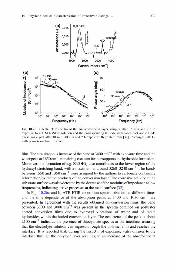
film. The simultaneous increase of the band at 3400 cm−1 with exposure time and thewater peak at 1650 cm−1 remaining constant further supports the hydroxide formation.Moreover, the formation of e.g. Zn(OH)2 also contributes to the lower region of thehydroxyl stretching band, with a maximum at around 3260–3240 cm−1. The bandsbetween 1550 and 1350 cm−1 were assigned by the authors to carbonate containingreformation/oxidation products of the conversion layer. The corrosive activity at thesubstrate surfacewas also detected by the decrease of themodulus of impedance at lowfrequencies, indicating active processes at the metal surface [32].
In Fig. 10.26a and b, ATR-FTIR absorption spectra obtained at different timesand the time dependence of the absorption peaks at 3400 and 1030 cm−1 arepresented. In agreement with the results obtained on conversion films, the bandbetween 3700 and 3000 cm−1 was present in the spectra obtained on polyestercoated conversion films due to hydroxyl vibrations of water and of metalhydroxides within the buried conversion layer. The occurrence of the peak at about2100 cm−1 indicates the presence of thiocyanate species at the interface, assuringthat the electrolyte solution can ingress through the polymer film and reaches theinterface. It is reported that, during the first 3 h of exposure, water diffuses to theinterface through the polymer layer resulting in an increase of the absorbance at
Fig. 10.25 a ATR-FTIR spectra of the zinc-conversion layer samples after 15 min and 2 h ofexposure to a 1 M NaSCN solution and the corresponding b Bode impedance plot and c Bodephase angle plot after 10 min, 30 min and 2 h exposure. Reprinted from [32], Copyright (2011),with permission from Elsevier
10 Physico-Chemical Characterisation of Protective Coatings … 279
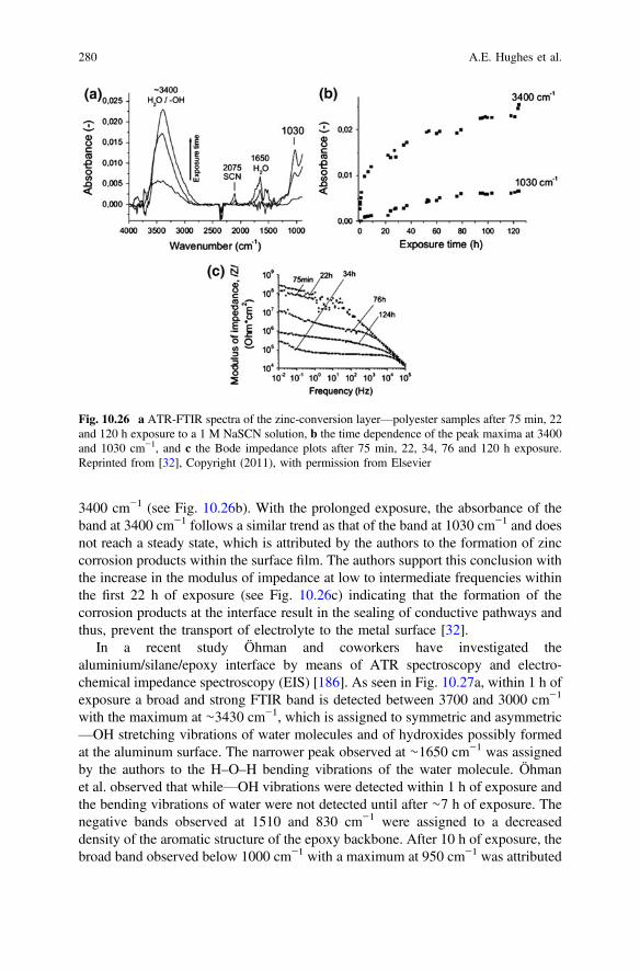
3400 cm−1 (see Fig. 10.26b). With the prolonged exposure, the absorbance of theband at 3400 cm−1 follows a similar trend as that of the band at 1030 cm−1 and doesnot reach a steady state, which is attributed by the authors to the formation of zinccorrosion products within the surface film. The authors support this conclusion withthe increase in the modulus of impedance at low to intermediate frequencies withinthe first 22 h of exposure (see Fig. 10.26c) indicating that the formation of thecorrosion products at the interface result in the sealing of conductive pathways andthus, prevent the transport of electrolyte to the metal surface [32].
In a recent study Öhman and coworkers have investigated thealuminium/silane/epoxy interface by means of ATR spectroscopy and electro-chemical impedance spectroscopy (EIS) [186]. As seen in Fig. 10.27a, within 1 h ofexposure a broad and strong FTIR band is detected between 3700 and 3000 cm−1
with the maximum at ∼3430 cm−1, which is assigned to symmetric and asymmetric—OH stretching vibrations of water molecules and of hydroxides possibly formedat the aluminum surface. The narrower peak observed at ∼1650 cm−1 was assignedby the authors to the H–O–H bending vibrations of the water molecule. Öhmanet al. observed that while—OH vibrations were detected within 1 h of exposure andthe bending vibrations of water were not detected until after ∼7 h of exposure. Thenegative bands observed at 1510 and 830 cm−1 were assigned to a decreaseddensity of the aromatic structure of the epoxy backbone. After 10 h of exposure, thebroad band observed below 1000 cm−1 with a maximum at 950 cm−1 was attributed
Fig. 10.26 a ATR-FTIR spectra of the zinc-conversion layer—polyester samples after 75 min, 22and 120 h exposure to a 1 M NaSCN solution, b the time dependence of the peak maxima at 3400and 1030 cm−1, and c the Bode impedance plots after 75 min, 22, 34, 76 and 120 h exposure.Reprinted from [32], Copyright (2011), with permission from Elsevier
280 A.E. Hughes et al.
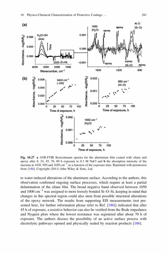
to water-induced alterations of the aluminum surface. According to the authors, thisobservation confirmed ongoing surface processes, which require at least a partialdelamination of the silane film. The broad negative band observed between 1050and 1000 cm−1 was assigned to more loosely bonded Si–O–Si, keeping in mind thatchanges in this spectral region could also stem from possible structural alterationsof the epoxy network. The results from supporting EIS measurements (not pre-sented here, for further information please refer to Ref. [186]) indicated that after45 h of exposure, a resistive behavior can also be verified from the Bode impedanceand Nyquist plots where the lowest resistance was registered after about 70 h ofexposure. The authors discuss the possibility of an active surface process withelectrolytic pathways opened and physically sealed by reaction products [186].
Fig. 10.27 a ATR-FTIR Kretschmann spectra for the aluminium film coated with silane andepoxy after 8, 24, 45, 70, 89 h exposure to 0.1 M NaCl and b the absorption intensity of themaxima at 3430, 950 and 1650 cm−1 as a function of the exposure time. Reprinted with permissionfrom [186]. Copyright (2011) John Wiley & Sons, Ltd.
10 Physico-Chemical Characterisation of Protective Coatings … 281
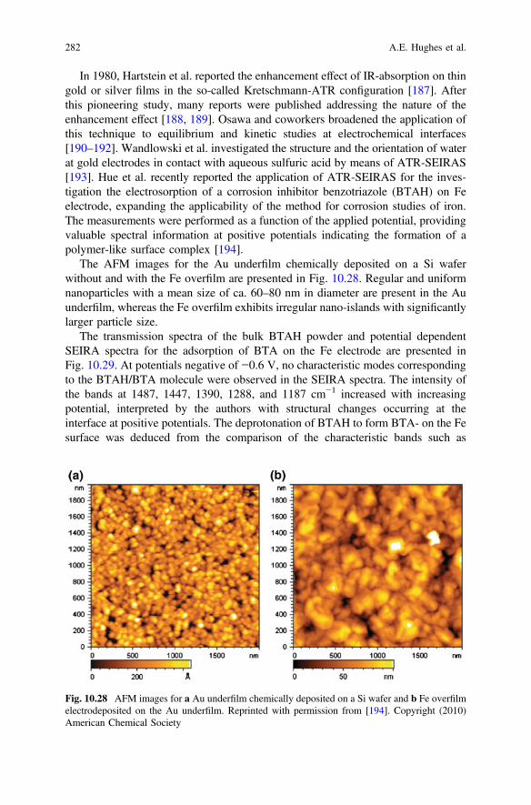
In 1980, Hartstein et al. reported the enhancement effect of IR-absorption on thingold or silver films in the so-called Kretschmann-ATR configuration [187]. Afterthis pioneering study, many reports were published addressing the nature of theenhancement effect [188, 189]. Osawa and coworkers broadened the application ofthis technique to equilibrium and kinetic studies at electrochemical interfaces[190–192]. Wandlowski et al. investigated the structure and the orientation of waterat gold electrodes in contact with aqueous sulfuric acid by means of ATR-SEIRAS[193]. Hue et al. recently reported the application of ATR-SEIRAS for the inves-tigation the electrosorption of a corrosion inhibitor benzotriazole (BTAH) on Feelectrode, expanding the applicability of the method for corrosion studies of iron.The measurements were performed as a function of the applied potential, providingvaluable spectral information at positive potentials indicating the formation of apolymer-like surface complex [194].
The AFM images for the Au underfilm chemically deposited on a Si waferwithout and with the Fe overfilm are presented in Fig. 10.28. Regular and uniformnanoparticles with a mean size of ca. 60–80 nm in diameter are present in the Auunderfilm, whereas the Fe overfilm exhibits irregular nano-islands with significantlylarger particle size.
The transmission spectra of the bulk BTAH powder and potential dependentSEIRA spectra for the adsorption of BTA on the Fe electrode are presented inFig. 10.29. At potentials negative of −0.6 V, no characteristic modes correspondingto the BTAH/BTA molecule were observed in the SEIRA spectra. The intensity ofthe bands at 1487, 1447, 1390, 1288, and 1187 cm−1 increased with increasingpotential, interpreted by the authors with structural changes occurring at theinterface at positive potentials. The deprotonation of BTAH to form BTA- on the Fesurface was deduced from the comparison of the characteristic bands such as
Fig. 10.28 AFM images for a Au underfilm chemically deposited on a Si wafer and b Fe overfilmelectrodeposited on the Au underfilm. Reprinted with permission from [194]. Copyright (2010)American Chemical Society
282 A.E. Hughes et al.
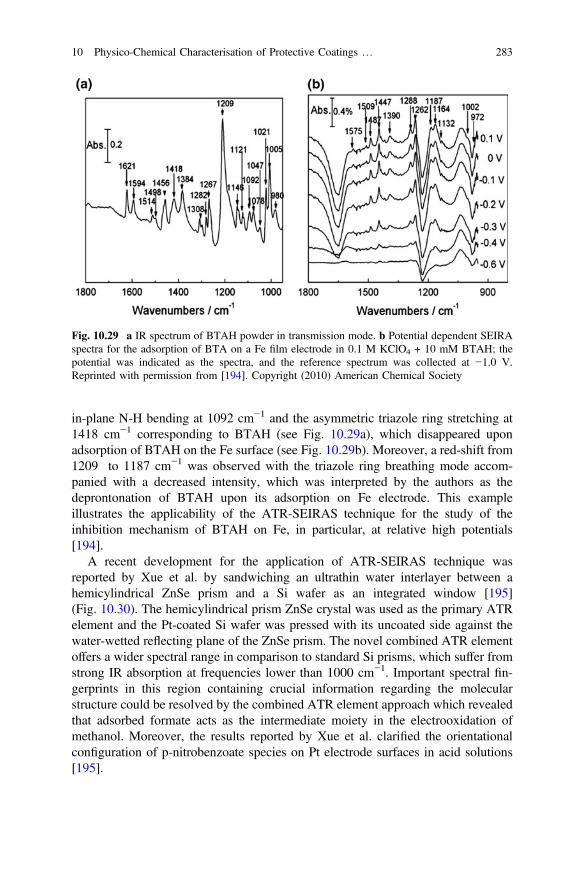
in-plane N-H bending at 1092 cm−1 and the asymmetric triazole ring stretching at1418 cm−1 corresponding to BTAH (see Fig. 10.29a), which disappeared uponadsorption of BTAH on the Fe surface (see Fig. 10.29b). Moreover, a red-shift from1209 to 1187 cm−1 was observed with the triazole ring breathing mode accom-panied with a decreased intensity, which was interpreted by the authors as thedeprontonation of BTAH upon its adsorption on Fe electrode. This exampleillustrates the applicability of the ATR-SEIRAS technique for the study of theinhibition mechanism of BTAH on Fe, in particular, at relative high potentials[194].
A recent development for the application of ATR-SEIRAS technique wasreported by Xue et al. by sandwiching an ultrathin water interlayer between ahemicylindrical ZnSe prism and a Si wafer as an integrated window [195](Fig. 10.30). The hemicylindrical prism ZnSe crystal was used as the primary ATRelement and the Pt-coated Si wafer was pressed with its uncoated side against thewater-wetted reflecting plane of the ZnSe prism. The novel combined ATR elementoffers a wider spectral range in comparison to standard Si prisms, which suffer fromstrong IR absorption at frequencies lower than 1000 cm−1. Important spectral fin-gerprints in this region containing crucial information regarding the molecularstructure could be resolved by the combined ATR element approach which revealedthat adsorbed formate acts as the intermediate moiety in the electrooxidation ofmethanol. Moreover, the results reported by Xue et al. clarified the orientationalconfiguration of p-nitrobenzoate species on Pt electrode surfaces in acid solutions[195].
Fig. 10.29 a IR spectrum of BTAH powder in transmission mode. b Potential dependent SEIRAspectra for the adsorption of BTA on a Fe film electrode in 0.1 M KClO4 + 10 mM BTAH; thepotential was indicated as the spectra, and the reference spectrum was collected at −1.0 V.Reprinted with permission from [194]. Copyright (2010) American Chemical Society
10 Physico-Chemical Characterisation of Protective Coatings … 283
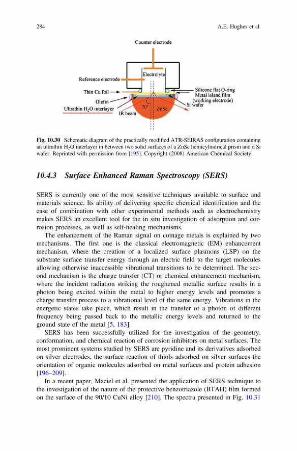
10.4.3 Surface Enhanced Raman Spectroscopy (SERS)
SERS is currently one of the most sensitive techniques available to surface andmaterials science. Its ability of delivering specific chemical identification and theease of combination with other experimental methods such as electrochemistrymakes SERS an excellent tool for the in situ investigation of adsorption and cor-rosion processes, as well as self-healing mechanisms.
The enhancement of the Raman signal on coinage metals is explained by twomechanisms. The first one is the classical electromagnetic (EM) enhancementmechanism, where the creation of a localized surface plasmons (LSP) on thesubstrate surface transfer energy through an electric field to the target moleculesallowing otherwise inaccessible vibrational transitions to be determined. The sec-ond mechanism is the charge transfer (CT) or chemical enhancement mechanism,where the incident radiation striking the roughened metallic surface results in aphoton being excited within the metal to higher energy levels and promotes acharge transfer process to a vibrational level of the same energy. Vibrations in theenergetic states take place, which result in the transfer of a photon of differentfrequency being passed back to the metallic energy levels and returned to theground state of the metal [5, 183].
SERS has been successfully utilized for the investigation of the geometry,conformation, and chemical reaction of corrosion inhibitors on metal surfaces. Themost prominent systems studied by SERS are pyridine and its derivatives adsorbedon silver electrodes, the surface reaction of thiols adsorbed on silver surfaces theorientation of organic molecules adsorbed on metal surfaces and protein adhesion[196–209].
In a recent paper, Maciel et al. presented the application of SERS technique tothe investigation of the nature of the protective benzotriazole (BTAH) film formedon the surface of the 90/10 CuNi alloy [210]. The spectra presented in Fig. 10.31
Fig. 10.30 Schematic diagram of the practically modified ATR-SEIRAS configuration containingan ultrathin H2O interlayer in between two solid surfaces of a ZnSe hemicylindrical prism and a Siwafer. Reprinted with permission from [195]. Copyright (2008) American Chemical Society
284 A.E. Hughes et al.
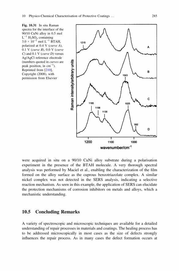
were acquired in situ on a 90/10 CuNi alloy substrate during a polarisationexperiment in the presence of the BTAH molecule. A very thorough spectralanalysis was performed by Maciel et al., enabling the characterization of the filmformed on the alloy surface as the cuprous benzotriazolate complex. A similarnickel complex was not detected in the SERS analysis, indicating a selectivereaction mechanism. As seen in this example, the application of SERS can elucidatethe protection mechanisms of corrosion inhibitors on metals and alloys, which amechanistic understanding.
10.5 Concluding Remarks
A variety of spectroscopic and microscopic techniques are available for a detailedunderstanding of repair processes in materials and coatings. The healing process hasto be addressed microscopically in most cases as the size of defects stronglyinfluences the repair process. As in many cases the defect formation occurs at
Fig. 10.31 In situ Ramanspectra for the interface of the90/10 CuNi alloy in 0.5 molL−1 H2SO4 containing3.0 × 10−2 mol L−1 BTAH,polarized at 0.4 V (curve A),0.1 V (curve B), 0.0 V (curveC) and 0.1 V (curve D) versusAg/AgCl reference electrode(numbers quoted in curves arepeak position, in cm−1).Reprinted from [210],Copyright (2008), withpermission from Elsevier
10 Physico-Chemical Characterisation of Protective Coatings … 285
buried interfaces, the spectroscopic and microscopic methods have to be adapted tothe studied system. Moreover in situ techniques which can monitor the defectformation and self-healing under ambient and corrosive conditions will becomemore and more important.
References
1. H. Leth-Olsen, K. Nisancioglu, Filiform corrosion of aluminium sheet. I. Corrosionbehaviour of painted material. Corros. Sci. 40(7), 1179–1194 (1998). doi:10.1016/S0010-938X(98)00026-2
2. R. Posner, T. Titz, K. Wapner, M. Stratmann, G. Grundmeier, Transport processes ofhydrated ions at polymer/oxide/metal interfaces Part 2. Transport on oxide covered iron andzinc surfaces. Electrochim. Acta. 54(3), 900–908 (2009). doi:10.1016/j.electacta.2008.07.011
3. J. Wielant, R. Posner, R. Hausbrand, G. Grundmeier, H. Terryn, Cathodic delamination ofpolyurethane films on oxide covered steel - Combined adhesion and interfaceelectrochemical studies. Corros. Sci. 51(8), 1664–1670 (2009). doi:10.1016/j.corsci.2009.04.014
4. F. Deflorian, S. Rossi, L. Fedrizzi, Silane pre-treatments on copper and aluminium.Electrochim. Acta 51(27), 6097–6103 (2006). doi:10.1016/j.electacta.2006.02.042
5. G. Grundmeier, M. Stratmann, Adhesion and De-adhesion mechanisms at polymer/metalinterfaces: mechanistic understanding based on in situ studies of buried interfaces. Annu.Rev. Mater. Res. 35, 571–615 (2005). doi:10.1146/annurev.matsci.34.012703.105111
6. P. Bonora, F. Deflorian, L. Fedrizzi, Electrochemical impedance spectroscopy as a tool forinvestigating underpaint corrosion. Electrochim. Acta. 41(7–8), 1073–1082 (1996). doi:10.1016/0013-4686(95)00440-8
7. L.P. Haack, M.A. DeBolt, S.L. Kaberline, J.E. Devries, R.A. Dickie, XPS mappingtechnique for the identification of adhesion loss mechanisms. Surf. Interface Anal. 20(2),115–120 (1993). doi:10.1002/sia.740200205
8. W.J. van Ooij, A. Sabata, A.D. Appelhans, Application of surface analysis techniques to thestudy of paint/metal interfaces related to adhesion and corrosion performance. Surf. InterfaceAnal. 17(7), 403–420 (1991). doi:10.1002/sia.740170703
9. O. Ozcan, K. Pohl, B. Ozkaya, G. Grundmeier, Molecular studies of adhesion andDe-Adhesion on ZnO nanorod film-covered metals. J. Adhes. 89(2), 128–139 (2013). doi:10.1080/00218464.2012.731928
10. K. Pohl, J. Otte, P. Thissen, M. Giza, M. Maxisch, B. Schuhmacher, G. Grundmeier,Adsorption and stability of self-assembled organophosphonic acid monolayers on plasmamodified Zn-Mg-Al alloy surfaces. Surf. Coat. Technol. 218, 99–107 (2013). doi:10.1016/j.surfcoat.2012.12.035
11. G. Fonder, I. Minet, C. Volcke, S. Devillers, J. Delhalle, Z. Mekhalif, Anchoring ofalkylphosphonic derivatives molecules on copper oxide surfaces. Appl. Surf. Sci. 257(14),6300–6307 (2011). doi:10.1016/j.apsusc.2011.02.071
12. M. Maxisch, P. Thissen, M. Giza, G. Grundmeier, Interface chemistry and molecularinteractions of phosphonic acid self-assembled monolayers on oxyhydroxide-coveredaluminum in humid environments. Langmuir 27(10), 6042–6048 (2011). doi:10.1021/la200445x
13. M. Santa, R. Posner, G. Grundmeier, Wet- and corrosive De-Adhesion processes ofwater-borne epoxy film coated steel. J. Electrochem. Soc. 158(3), C36–C41 (2011). doi:10.1149/1.3525240
286 A.E. Hughes et al.
14. K. Wapner, M. Stratmann, G. Grundmeier, Structure and stability of adhesion promotingaminopropyl phosphonate layers at polymer/aluminium oxide interfaces. Int. J. Adhes.Adhes. 28(1–2), 59–70 (2008). doi:10.1016/j.ijadhadh.2007.05.001
15. G. Klimow, N. Fink, G. Grundmeier, Electrochemical studies of the inhibition of the cathodicdelamination of organically coated galvanised steel by thin conversion films. Electrochim.Acta 53(3), 1290–1299 (2007). doi:10.1016/j.electacta.2007.05.045
16. G. Grundmeier, B. Rossenbeck, K. Roschmann, P. Ebbinghaus, M. Stratmann, Corrosionprotection of Zn-phosphate containing water borne dispersion coatings - Part 2:investigations of the corrosive de-adhesion of model latex coatings on iron. Corros. Sci.48(11), 3716–3730 (2006). doi:10.1016/j.corsci.2006.01.007
17. T. Narayanan, Surface pretreatment by phosphate conversion coatings - a review. Rev. Adv.Mater. Sci. 9(2), 130–177 (2005)
18. G. Grundmeier, C. Reinartz, M. Rohwerder, M. Stratmann, Corrosion properties ofchemically modified metal surfaces. Electrochim. Acta 43(1–2), 165–174 (1998). doi:10.1016/S0013-4686(97)00221-1
19. I. Maege, E. Jaehne, A. Henke, H. Adler, C. Bram, C. Jung, M. Stratmann, Self-assemblingadhesion promoters for corrosion resistant metal polymer interfaces. Prog. Org. Coat. 34(1–4),1–12 (1998)
20. I. Maege, E. Jaehne, A. Henke, H. Adler, C. Bram, C. Jung, M. Stratmann, Ultrathin organiclayers for corrosion protection. Macromol. Symp. 126, 7–24 (1998). doi:10.1002/masy.19981260104
21. M. Wiesener, R. Regenspurger, M. Pilz, D. Shchukin, A. Latnikova, J. Yang, G.Grundmeier, In-situ contact angle studies of the release of water displacing agents fromcapsule filled organic coatings. Surf. Coat. Technol. 206(21), 4481–4487 (2012). doi:10.1016/j.surfcoat.2012.05.021
22. M. Giza, G. Grundmeier, Combination of FTIR reflection absorption spectroscopy and workfunction measurements for in situ studies of plasma modified passive films on MgZn2.Plasma Processes Polym. 8(7), 607–616 (2011). doi:10.1002/ppap.201000198
23. R. Posner, M. Santa, G. Grundmeier, Wet- and corrosive De-Adhesion processes ofwater-borne epoxy film coated steel. J. Electrochem. Soc. 158(3), C29–C35 (2011). doi:10.1149/1.3525239
24. R. Posner, K. Wapner, S. Amthor, K. Roschmann, G. Grundmeier, Electrochemicalinvestigation of the coating/substrate interface stability for styrene/acrylate copolymer filmsapplied on iron. Corros. Sci. 52(1), 37–44 (2010). doi:10.1016/j.corsci.2009.08.038
25. T. Titz, F. Horzenberger, K. Van den Bergh, G. Grundmeier, Correlation of interfacialelectrode potential and corrosion resistance of plasma polymer coated galvanized steel. Part1: ultra-thin plasma polymer films of varying thickness. Corros. Sci. 52(2), 369–377 (2010).doi:10.1016/j.corsci.2009.09.024
26. T. Titz, F. Horzenberger, K. Van den Bergh, G. Grundmeier, Correlation of interfacialelectrode potential and corrosion resistance of plasma polymer coated galvanized steel. Part2: influence of forming induced defects. Corros. Sci. 52(2), 378–386 (2010). doi:10.1016/j.corsci.2009.09.027
27. M. Geisler, D. Horinek, T. Hugel, Single molecule adhesion mechanics on rough surfaces.Macromolecules 42(23), 9338–9343 (2009). doi:10.1021/ma9017372
28. R. Posner, G. Giza, R. Vlasak, G. Grundmeier, In situ electrochemical scanning Kelvin probeblister-test studies of the de-adhesion kinetics at polymer/zinc oxide/zinc interfaces.Electrochim. Acta 54(21), 4837–4843 (2009). doi:10.1016/j.electacta.2009.03.089
29. K. Wapner, M. Stratmann, G. Grundmeier, In situ infrared spectroscopic and scanningKelvin probe measurements of water and ion transport at polymer/metal interfaces.Electrochim. Acta. 51(16), 3303–3315 (2006). doi:10.1016/j.electacta.2005.09.024
30. I. Linossier, F. Gaillard, M. Romand, T. Nguyen, A spectroscopic technique for studies ofwater transport along the interface and hydrolytic stability of polymer/substrate systems.J. Adhes. 70(3–4), 221–239 (1999). doi:10.1080/00218469908009557
10 Physico-Chemical Characterisation of Protective Coatings … 287
31. M. Ohman, D. Persson, ATR-FTIR Kretschmann spectroscopy for interfacial studies of ahidden aluminum surface coated with a silane film and epoxy I. Characterization by IRRASand ATR-FTIR. Surf. Interface Anal. 44(2), 133–143 (2012). doi:10.1002/sia.3779
32. M. Ohman, D. Persson, D. Jacobsson, In situ studies of conversion coated zinc/polymersurfaces during exposure to corrosive conditions. Prog. Org. Coat. 70(1), 16–22 (2011).doi:10.1016/j.porgcoat.2010.09.012
33. M. Ohman, D. Persson, C. Leygraf, A spectroelectrochemical study of metal/polymerinterfaces by simultaneous in situ ATR-FTIR and EIS. Electrochem. Solid State Lett. 10(4),C27–C30 (2007). doi:10.1149/1.2436647
34. M. Ohman, D. Persson, An integrated in situ ATR-FTIR and EIS set-up to study buriedmetal-polymer interfaces exposed to an electrolyte solution. Electrochim. Acta. 52(16),5159–5171 (2007). doi:10.1016/j.electacta.2007.02.007
35. M. Ohman, D. Persson, C. Leygraf, In situ ATR-FTIR studies of the aluminium/polymerinterface upon exposure to water and electrolyte. Prog. Org. Coat. 57(1), 78–88 (2006).doi:10.1016/j.porgcoat.2006.07.002
36. M. Kendig, M. Hon, A hydrotalcite-like pigment containing an organic anion corrosioninhibitor. Electrochem. Solid State Lett. 8(3), B10–B11 (2005). doi:10.1149/1.1857743
37. H.N. McMurray, G. Williams, Inhibition of filiform corrosion on organic-coated aluminumalloy by hydrotalcite-like anion-exchange pigments. Corrosion 60(3), 219–228 (2004)
38. G. Williams, H.N. McMurray, Anion-exchange inhibition of filiform corrosion on organiccoated AA2024-T3 aluminum alloy by hydrotalcite-like pigments. Electrochem. Solid StateLett. 6(3), B9–B11 (2003). doi:10.1149/1.1539771
39. S.J. Garcia, H.R. Fischer, P.A. White, J. Mardel, Y. Gonzalez-Garcia, J.M.C. Mol, A.E.Hughes, Self-healing anticorrosive organic coating based on an encapsulated water reactivesilyl ester: synthesis and proof of concept. Prog. Org. Coat. 70(2–3), 142–149 (2011). doi:10.1016/j.porgcoat.2010.11.021
40. C. Suryanarayana, K.C. Rao, D. Kumar, Preparation and characterization of microcapsulescontaining linseed oil and its use in self-healing coatings. Prog. Org. Coat. 63(1), 72–78(2008). doi:10.1016/j.porgcoat.2008.04.008
41. T. Yin, M.Z. Rong, M.Q. Zhang, G.C. Yang, Self-healing epoxy composites - Preparationand effect of the healant consisting of microencapsulated epoxy and latent curing agent.Compos. Sci. Technol. 67(2), 201–212 (2007). doi:10.1016/j.compscitech.2006.07.028
42. A. Kumar, L.D. Stephenson, J.N. Murray, Self-healing coatings for steel. Prog. Org. Coat. 55(3), 244–253 (2006). doi:10.1016/j.porgcoat.2005.11.010
43. E.N. Brown, S.R. White, N.R. Sottos, Microcapsule induced toughening in a self-healingpolymer composite. J. Mater. Sci. 39(5), 1703–1710 (2004). doi:10.1023/B:JMSC.0000016173.73733.dc
44. L.A. Feldkamp, L.C. Davis, J.W. Kress, PRACTICAL CONE-BEAM ALGORITHM.J. Opt. Soc. Am. a-Optics Image Sci. Vis. 1(6), 612–619 (1984). doi:10.1364/josaa.1.000612
45. O. Hemberg, M. Otendal, H.M. Hertz, Liquid-metal-jet anode electron-impact X-ray source.Appl. Phys. Lett. 83(7), 1483–1485 (2003). doi:10.1063/1.1602157
46. S.C. Mayo, A.M. Tulloh, A. Trinchi, S.Y.S. Yang, Data-constrained microstructurecharacterization with multispectrum X-ray micro-ct. Microsc. Microanal. 18(3), 524–530(2012)
47. X.C. Pan, E.Y. Sidky, M. Vannier, Why do commercial CT scanners still employ traditional,filtered back-projection for image reconstruction? Inverse Prob. 25(12) (2009). doi:10.1088/0266-5611/25/12/123009
48. D. Paganin, S.C. Mayo, T.E. Gureyev, P.R. Miller, S.W. Wilkins, Simultaneous phase andamplitude extraction from a single defocused image of a homogeneous object. J Microsc. -Oxford 206, 33–40 (2002)
49. A.E. Hughes, A.M. Glenn, N. Wilson, A. Moffatt, A.J. Morton, R.G. Buchheit, A consistentdescription of intermetallic particle composition: an analysis of ten batches of AA2024-T3.Surf Interface Anal, n/a-n/a (2013). doi:10.1002/sia.5207
288 A.E. Hughes et al.
50. R.G. Buchheit, R.P. Grant, P.F. Hlava, B. McKenzie, G.L. Zender, Local dissolutionphenomena associated with S phase (Al2CuMg) particles in aluminum alloy 2024-T3.J. Electrochem. Soc. 144(8), 2621–2628 (1997)
51. A.E. Hughes, N. Birbilis, J.M.C. Mol, S.J. Garcia, X. Zhou, G.E. Thompson, High strengthAl-Alloys: microstructure, corrosion and principles of protection, in Recent Trends inProcessing and Degradation of Aluminium Alloys, ed. by Z. Ahmad (Intech Publishing,Rijeka, 2011)
52. X. Zhou, C. Luo, T. Hashimoto, A.E. Hughes, G.E. Thompson, Study of localized corrosionin AA2024 aluminium alloy using electron tomography. Corros. Sci. 58, 299–306 (2012).doi:10.1016/j.corsci.2012.02.001
53. S.M. Ghahari, A.J. Davenport, T. Rayment, T. Suter, J.P. Tinnes, C. Padovani, J.A.Hammons, M. Stampanoni, F. Marone, R. Mokso, In situ synchrotron X-raymicro-tomography study of pitting corrosion in stainless steel. Corros. Sci. 53(9), 2684–2687 (2011)
54. S.P. Knight, M. Salagaras, A.M. Wythe, F. De Carlo, A.J. Davenport, A.R. Trueman, In situX-ray tomography of intergranular corrosion of 2024 and 7050 aluminium alloys. Corros.Sci. 52(12), 3855–3860 (2010). doi:10.1016/j.corsci.2010.08.026
55. Y. Wang, Y. Yang, T. Xiao, K. Liu, B. Clennell, G. Zhang, H.Wang, Synchrotron-baseddata-constrained modeling analysis of microscopic mineral distributions in limestone. Int.J. Geosci. 4(2), 344–351 (2013). doi:10.4236/ijg.2013.42032
56. S. Miller, B. Singh, S. Cool, G. Entine, L. Campbell, R. Bishel, R. Rushing, V.V. Nagarkar,Ultrahigh-speed X-ray imaging of hypervelocity projectiles. Nucl. Instrum. Methods Phys.Res., Sect. A-Accelerators Spectrometers Detectors and Associated Equipment 648, S293–S296 (2011). doi:10.1016/j.nima.2010.11.048
57. G.A. Johansen, U. Hampel, B.T. Hjertaker, Flow imaging by high speed transmissiontomography. Appl. Radiat. Isot. 68(4–5), 518–524 (2010). doi:10.1016/j.apradiso.2009.09.004
58. A.E. Hughes, A. Trinchi, F.F. Chen, Y.S. Yang, I.S. Cole, S. Sellaiyan, J. Carr, P.D. Lee, G.E. Thompson, T.Q. Xiao, Revelation of intertwining organic and inorganic fractal structuresin polymer coatings. Adv. Mater. n/a-n/a (2014). doi:10.1002/adma.201400561
59. D.M.L. Cooper, L.D. Chapman, Y. Carter, Y. Wu, A. Panahifar, H.M. Britz, B. Bewer, W.Zhouping, M.J.M. Duke, M. Doschak, Three dimensional mapping of strontium in bone bydual energy K-edge subtraction imaging. Phys. Med. Biol. 57(18), 5777–5786 (2012).doi:10.1088/0031-9155/57/18/5777
60. H. Toda, K. Shimizu, K. Uesugi, Y. Suzuki, M. Kobayashi, Application of dual-energyK-Edge subtraction imaging to assessment of heat treatments in Al-Cu alloys. Mater. Trans.51(11), 2045–2048 (2010). doi:10.2320/matertrans.L-M2010819
61. C.H. Arns, F. Bauget, A. Ghous, A. SakellarioU, T.J. Senden, A.P. Sheppard, R.M. Sok, W.V. Pinczewski, J.C. Kelly, M.A. Knackstedt, Digital core laboratory: petrophysical analysisfrom 3D imaging of reservoir core fragments. Petrophysics 46(4), 260–277 (2005)
62. M. Van Geet, R. Swennen, M. Wevers, Towards 3-D petrography: application of microfocuscomputer tomography in geological science. Comput. Geosci. 27(9), 1091–1099 (2001)
63. Z.R. Ying, R. Naidu, C.R. Crawford, Dual energy computed tomography for explosivedetection. J X-Ray Sci. Technol. 14(4), 235–256 (2006)
64. S. Neethirajan, D.S. Jayas, C. Karunakaran, Dual energy X-ray image analysis for classifyingvitreousness in durum wheat. Postharvest Biol. Technol. 45(3), 381–384 (2007). doi:10.1016/j.postharvbio.2007.03.009
65. Y.S. Yang, A data-constrained non-linear optimisation approach to a data-constrained modelfor compositional microstructure prediction. Lecture Notes Inform. Technol. 15, 198–205(2012)
66. H.P. Wang, Y.S. Yang, Y.D. Wang, J.L. Yang, J. Jia, Y.H. Nie, Data-constrained modellingof an anthracite coal physical structure with multi-spectrum synchrotron X-ray CT. Fuel 106,219–225 (2013)
10 Physico-Chemical Characterisation of Protective Coatings … 289
67. Y.S. Yang, A. Tulloh, I. Cole, S. Furman, A. Hughes, A data-constrained computationalmodel for morphology structures. J. Aust. Ceram. Soc. 43(2), 159–164 (2007)
68. S. Yang, T.E. Gureyev, M.B. Tulloh, M.B. Clennell, M. Pervukhina, Feasibility of a dataconstrained prediction of hydrocarbon reservoir sandstone microstructures. Meas. Sci.Technol. 21 (2010). doi:10.1088/0957-0233/21/4/047001
69. Y.S. Yang, K.Y. Liu, S. Mayo, A. Tulloh, M.B. Clennell, T.Q. Xiao, A data-constrainedmodelling approach to sandstone microstructure characterisation. J. Petrol. Sci. Eng. 105,76–83 (2013)
70. S. Yang, D.C. Gao, T. Muster, A. Tulloh, S. Furman, S. Mayo, A. Trinchi, Microstructure ofa paint primer - a data-constrained modeling analysis. In: J.F. Nie, A. Morton (eds.) Pricm 7,Pts 1–3, vol 654–656. Materials Science Forum, pp. 1686–1689 (2010)
71. A.E. Hughes, S. Mayo, Y.S. Yang, T. Markley, S.V. Smith, S. Sellaiyan, A. Uedono, S.G.Hardin, T.H. Muster, Using X-ray tomography, PALS and Raman spectroscopy forcharacterization of inhibitors in epoxy coatings. Prog. Org. Coat. 74(4), 726–733 (2012)
72. A. Trinchi, Y.S. Yang, J.Z. Huang, P. Falcaro, D. Buso, L.Q. Cao, Study of 3D compositionin a nanoscale sample using data-constrained modelling and multi-energy X-ray CT. Model.Simul. Mater. Sci. Eng. 20(1) (2012)
73. B.S. Tanem, O. Lunder, A. Borg, J. Mardalen, AFM adhesion force measurements onconversion-coated EN AW-6082-T6 aluminium. Int. J. Adhes. Adhes. 29(5), 471–477(2009). doi:10.1016/j.ijadhadh.2008.09.005
74. B. Bhushan, V.N. Koinkar, Nanoindentation hardness measurements using atomic-forcemicroscopy. Appl. Phys. Lett. 64(13), 1653–1655 (1994). doi:10.1063/1.111949
75. F. Hane, B. Moores, M. Amrein, Z. Leonenko, Effect of SP-C on surface potentialdistribution in pulmonary surfactant: atomic force microscopy and Kelvin probe forcemicroscopy study. Ultramicroscopy 109(8), 968–973 (2009). doi:10.1016/j.ultramic.2009.03.046
76. E. Finot, Y. Leonenko, B. Moores, L. Eng, M. Amrein, Z. Leonenko, Effect of cholesterol onelectrostatics in lipid-protein films of a pulmonary surfactant. Langmuir 26(3), 1929–1935(2010). doi:10.1021/La904335m
77. A. Wadas, P. Grutter, H.J. Guntherodt, Analysis of magnetic bit pattern by magnetic forcemicroscopy. J. Vac. Sci. Technol. A 8(1), 416–420 (1990). doi:10.1116/1.576410
78. I. Sokolov, Q.K. Ong, H. Shodiev, N. Chechik, D. James, M. Oliver, AFM study of forcesbetween silica, silicon nitride and polyurethane pads. J. Colloid. Interf. Sci. 300(2), 475–481(2006). doi:10.1016/j.jcis.2006.04.023
79. B.V. Derjaguin, V.M. Muller, Y.P. Toporov, Effect of contact deformations on the adhesionof particles. Prog. Surf. Sci. 45(1–4), 131–143 (1994). doi:10.1016/0079-6816(94)90044-2
80. M.E. Dokukin, I. Sokolov, Quantitative mapping of the elastic modulus of soft materials withHarmoniX and peak force QNM AFM modes. Langmuir 28(46), 16060–16071 (2012).doi:10.1021/La302706b
81. O. Sahin, S. Magonov, C. Su, C.F. Quate, O. Solgaard, An atomic force microscope tipdesigned to measure time-varying nanomechanical forces. Nat. Nanotechnol. 2(8), 507–514(2007). doi:10.1038/nnano.2007.226
82. J.A. Yoon, J. Kamada, K. Koynov, J. Mohin, R. Nicolay, Y.Z. Zhang, A.C. Balazs, T.Kowalewski, K. Matyjaszewski, Self-Healing polymer films based on thiol-disulfideexchange reactions and self-healing kinetics measured using atomic force microscopy.Macromolecules 45(1), 142–149 (2012). doi:10.1021/Ma2015134
83. P. Swift, Adventitious carbon - the panacea for energy referencing. Surf. Interface Anal. 4(2),47–51 (1982). doi:10.1002/sia.740040204
84. C.D. Wagner, L.H. Gale, R.H. Raymond, 2-dimensional chemical-state plots - standardizeddata set for use in identifying chemical-states by X-ray photoelectron-spectroscopy. Anal.Chem. 51(4), 466–482 (1979). doi:10.1021/ac50040a005
85. Y. Uwamino, T. Ishizuka, H. Yamatera, Charge correction by gold deposition ontonon-conducting samples in X-ray photoelectron-spectroscopy. J. Electron Spectrosc. Relat.Phenom. 23(1), 55–62 (1981). doi:10.1016/0368-2048(81)85036-0
290 A.E. Hughes et al.
86. S. Kohiki, K. Oki, An appraisal of evaporated gold as an energy reference in X-rayphotoelectron-spectroscopy. J. Electron Spectrosc. Relat. Phenom. 36(1), 105–110 (1985).doi:10.1016/0368-2048(85)80011-6
87. A.E. Hughes, B.A. Sexton, The use of implanted ar as a binding-energy reference - comment.J. Electron Spectrosc. Relat. Phenom. 50(3), C15–C18 (1990)
88. S. Kohiki, T. Ohmura, K. Kusao, A new charge-correction method in X-rayphotoelectron-spectroscopy. J. Electron Spectrosc. Relat. Phenom. 28(4), 229–237 (1983).doi:10.1016/0368-2048(83)80001-2
89. C.S. Fadley, D.A. Shirley, Multiplet splitting of metal-atom electron binding energies. Phys.Rev. A 2(4), 1109–1120 (1970). doi:10.1103/PhysRevA.2.1109
90. D. Briggs, V.A. Gibson, Direct observation of multiplet splitting in 2p photoelectron peaks ofcobalt complexes. Chem. Phys. Lett. 25(4), 493–496 (1974). doi:10.1016/0009-2614(74)85350-9
91. H. Basch, Multiplet splitting of core level binding-energies in paramagnetic species andunpaired orbital spin density distribution. Chem. Phys. Lett. 20(3), 233–237 (1973). doi:10.1016/0009-2614(73)85165-6
92. R.P. Gupta, S.K. Sen, Calculation of multiplet structure of core p-vacancy levels .Phys. Rev.B 12(1), 15–19 (1975). doi:10.1103/PhysRevB.12.15
93. R.P. Gupta, S.K. Sen, Calculation of multiplet structure of core para-vacancy levels. Phys.Rev. B 10(1), 71–77 (1974). doi:10.1103/PhysRevB.10.71
94. A.P. Grosvenor, B.A. Kobe, M.C. Biesinger, N.S. McIntyre, Investigation of multipletsplitting of Fe 2p XPS spectra and bonding in iron compounds. Surf. Interface Anal. 36(12),1564–1574 (2004). doi:10.1002/sia.1984
95. M. Aronniemi, J. Sainio, J. Lahtinen, Chemical state quantification of iron and chromiumoxides using XPS: the effect of the background subtraction method. Surf. Sci. 578(1–3), 108–123 (2005). doi:10.1016/j.susc.2005.01.019
96. M. Mullet, V. Khare, C. Ruby, XPS study of Fe(II)-Fe(III) (oxy)hydroxycarbonate green rustcompounds. Surf. Interface Anal. 40(3–4), 323–328 (2008). doi:10.1002/sia.2758
97. M. Mullet, Y. Guillemin, C. Ruby, Oxidation and deprotonation of synthetic Fe-II-Fe-III(oxy)hydroxycarbonate green rust: an X-ray photoelectron study. J. Solid State Chem. 181(1), 81–89 (2008). doi:10.1016/j.jssc.2007.10.026
98. Y.S. Hao, F.C. Liu, E.H. Han, Protection of epoxy coatings containing polyaniline modifiedultra-short glass fibers. Prog. Org. Coat. 76(4), 571–580 (2013). doi:10.1016/j.porgcoat.2012.11.012
99. N. Granizo, J.M. Vega, D. de la Fuente, B. Chico, M. Morcillo, Ion-exchange pigments inprimer paints for anticorrosive protection of steel in atmospheric service: anion-exchangepigments. Prog. Org. Coat. 76(2–3), 411–424 (2013). doi:10.1016/j.porgcoat.2012.10.009
100. D.A. Shirley, High-resolution X-ray photoemission spectrum of valence bands of gold. Phys.Rev. B 5(12), 4709–4714 (1972). doi:10.1103/PhysRevB.5.4709
101. J. Vegh, The analytical form of the shirley-type background. J. Electron Spectrosc. Relat.Phenom. 46(4), 411–417 (1988). doi:10.1016/0368-2048(88)85038-2
102. A. Proctor, P.M.A. Sherwood, Data-analysis techniques in X-ray photo-electronspectroscopy. Anal. Chem. 54(1), 13–19 (1982). doi:10.1021/ac00238a008
103. S. Tougaard, B. Jorgensen, Inelastic background intensities in XPS spectra. Surf. Sci. 143(2–3), 482–494 (1984). doi:10.1016/0039-6028(84)90554-5
104. S. Tougaard, P. Sigmund, Influence of elastic and inelastic-scattering on energy-spectra ofelectrons emitted from solids. Phys. Rev. B 25(7), 4452–4466 (1982). doi:10.1103/PhysRevB.25.4452
105. S. Tougaard, Inelastic background correction and quantitative surface-analysis. J. ElectronSpectrosc. Relat. Phenom. 52, 243–271 (1990). doi:10.1016/0368-2048(90)85022-2
106. C.S. Fadley, D.A. Shirley, X-ray photoelectron spectroscopic study of iron cobalt nickelcopper and platinum. Phys. Rev. Lett. 21(14), 980–983 (1968). doi:10.1103/PhysRevLett.21.980
10 Physico-Chemical Characterisation of Protective Coatings … 291
107. S.J. Hinder, J.F. Watts, C. Lowe, Interface analysis and compositional depth profiling byXPS of polymer coatings prepared using ultra-low-angle microtomy. Surf. Interface Anal. 36(8), 1032–1036 (2004). doi:10.1002/sia.1830
108. S.J. Hinder, C. Lowe, J.T. Maxted, J.F. Watts, A ToF-SIMS investigation of a buriedpolymer/polymer interface exposed by ultra-low-angle microtomy. Surf. Interface Anal. 36(12), 1575–1581 (2004). doi:10.1002/sia.1985
109. G. Williams, H.N. McMurray, Inhibition of filiform corrosion on polymer coatedAA2024-T3 by hydrotalcite-like pigments incorporating organic anions. Electrochem.Solid State Lett. 7(5), B13–B15 (2004). doi:10.1149/1.1691529
110. S. Bohm, H.N. McMurray, S.M. Powell, D.A. Worsley, Novel environment friendlycorrosion inhibitor pigments based on naturally occurring clay minerals. MaterialsCorrosion-Werkstoffe Und Korrosion 52(12), 896–903 (2001)
111. A.N. Salak, J. Tedim, A.I. Kuznetsova, M.L. Zheludkevich, M.G.S. Ferreira, Anionexchange in Zn-Al layered double hydroxides: in situ X-ray diffraction study. Chem. Phys.Lett. 495(1–3), 73–76 (2010). doi:10.1016/j.cplett.2010.06.041
112. M.L. Zheludkevich, S.K. Poznyak, L.M. Rodrigues, D. Raps, T. Hack, L.F. Dick, T. Nunes,M.G.S. Ferreira, Active protection coatings with layered double hydroxide nanocontainers ofcorrosion inhibitor. Corros. Sci. 52(2), 602–611 (2010). doi:10.1016/j.corsci.2009.10.020
113. S.P.V. Mahajanarn, R.G. Buchheit, Characterization of inhibitor release from Zn-Al-V10O28 (6-) hydrotalcite pigments and corrosion protection from hydrotalcite-pigmentedepoxy coatings. Corrosion 64(3), 230–240 (2008)
114. R.G. Buchheit, S.B. Mamidipally, P. Schmutz, H. Guan, Active corrosion protection inCe-modified hydrotalcite conversion coatings. Corrosion 58(1), 3–14 (2002)
115. C. Ruby, M. Usman, S. Naille, K. Hanna, C. Carteret, M. Mullet, M. Francois, M.Abdelmoula, Synthesis and transformation of iron-based layered double hydroxides. Appl.Clay Sci. 48(1–2), 195–202 (2010). doi:10.1016/j.clay.2009.11.017
116. N. Granizo, J.M. Vega, D. de la Fuente, J. Simancas, M. Morcillo, Ion-exchange pigments inprimer paints for anticorrosive protection of steel in atmospheric service: cation-exchangepigments. Prog. Org. Coat. 75(3), 147–161 (2012). doi:10.1016/j.porgcoat.2012.04.013
117. E.A. Matter, S. Kozhukharov, M. Machkova, V. Kozhukharov, Comparison between theinhibition efficiencies of Ce(III) and Ce(IV) ammonium nitrates against corrosion of AA2024aluminum alloy in solutions of low chloride concentration. Corros. Sci. 62, 22–33 (2012).doi:10.1016/j.corsci.2012.03.039
118. H. Ardelean, C. Fiaud, P. Marcus, Enhanced corrosion resistance of magnesium and itsalloys through the formation of cerium (and aluminium) oxide surface films. MaterialsCorrosion-Werkstoffe Und Korrosion 52(12), 889–895 (2001). doi:10.1002/1521-4176(200112)52:12<889:aid-maco889>3.0.co;2-0
119. B.L. Liu, B.T. Zhang, S.S. Cao, X.B. Deng, X.H. Hou, H.L. Chen, Preparation of the stablecore-shell latex particles containing organic-siloxane in the shell. Prog. Org. Coat. 61(1), 21–27 (2008). doi:10.1016/j.porgcoat.2007.08.008
120. A.S. Hamdy, A clean low cost anti-corrosion molybdate based nano-particles coating foraluminum alloys. Prog. Org. Coat. 56(2–3), 146–150 (2006). doi:10.1016/j.porgcoat.2006.03.002
121. W. Trabelsi, P. Cecilio, M.G.S. Ferreira, M.F. Montemor, Electrochemical assessment of theself-healing properties of Ce-doped silane solutions for the pre-treatment of galvanised steelsubstrates. Prog. Org. Coat. 54(4), 276–284 (2005). doi:10.1016/j.porgcoat.2005.07.006
122. A.S. Hamdy, Advanced nano-particles anti-corrosion ceria based sol gel coatings foraluminum alloys. Mater. Lett. 60(21–22), 2633–2637 (2006). doi:10.1016/j.matlet.2006.01.049
123. M.F. Montemor, M.G.S. Ferreira, Analytical characterization of silane films modified withcerium activated nanoparticles and its relation with the corrosion protection of galvanisedsteel substrates. Prog. Org. Coat. 63(3), 330–337 (2008). doi:10.1016/j.porgcoat.2007.11.008
292 A.E. Hughes et al.
124. M.L. Zheludkevich, R. Serra, M.F. Montemor, K.A. Yasakau, I.M.M. Salvado, M.G.S.Ferreira, Nanostructured sol-gel coatings doped with cerium nitrate as pre-treatments forAA2024-T3 - Corrosion protection performance. Electrochim. Acta. 51(2), 208–217 (2005).doi:10.1016/j.electacta.2005.04.021
125. L.S. Kasten, J.T. Grant, N. Grebasch, N. Voevodin, F.E. Arnold, M.S. Donley, An XPSstudy of cerium dopants in sol–gel coatings for aluminum 2024-T3. Surf. Coat. Technol. 140(1), 11–15 (2001). doi:10.1016/s0257-8972(01)01004-0
126. D. Ho, N. Brack, J. Scully, T. Markley, M. Forsyth, B. Hinton, Cerium dibutylphosphate as acorrosion inhibitor for AA2024-T3 aluminum alloys. J. Electrochem. Soc. 153(9), B392–B401 (2006). doi:10.1149/1.2217260
127. N. Sheng, T. Ohtsuka, Preparation of conducting poly-pyrrole layer on zinc coated Mg alloyof AZ91D for corrosion protection. Prog. Org. Coat. 75(1–2), 59–64 (2012). doi:10.1016/j.porgcoat.2012.03.008
128. Y. Hao, F. Liu, E.-H. Han, Protection of epoxy coatings containing polyaniline modifiedultra-short glass fibers. Prog. Org. Coat. (0). doi:http://dx.doi.org/10.1016/j.porgcoat.2012.11.012
129. M.A. Jakab, J.R. Scully, On-demand release of corrosion-inhibiting ions from amorphousAl-Co-Ce alloys. Nat. Mater. 4(9), 667–670 (2005). doi:10.1038/nmat1451
130. N.S. McIntyre, R.D. Davidson, G. Kim, J.T. Francis, New frontiers in X-ray photoelectronspectroscopy. Vacuum 69(1–3), 63–71 (2002). doi:10.1016/s0042-207x(02)00308-1
131. D.J. Bland, A.J. Kinloch, V. Stolojan, J.F. Watts, Failure mechanisms in adhesively bondedaluminium: an XPS and PEELS study. Surf. Interface Anal. 40(3–4), 128–131 (2008).doi:10.1002/sia.2651
132. B.J. James, R. Cameron, C. Baskcomb, Selected area XPS analysis for identification ofpigment compounds in microscopic paint flakes. Adv. Mater. Sci. Eng. 2008 (2008)
133. J.E. Devries, L.P. Haack, T.J. Prater, S.L. Kaberline, J.L. Gerlock, J.W. Holubka, R.A.Dickie, J. Chakel, Characterization of interfacial chemistries associated with polymersystems by spatially-resolved surface analytical methodologies. Prog. Org. Coat. 25(1), 95–108 (1994). doi:10.1016/0300-9440(94)00505-2
134. J.T. Francis, N.S. McIntyre, R.D. Davidson, S. Ramamurthy, A.M. Brennenstuhl, A.McBride, A. Roberts, Mechanisms for pitting corrosion in alloy N04400 as revealed byimaging XPS, ToF-SIMS and low-voltage SEM. Surf. Interface Anal. 33(1), 29–34 (2002).doi:10.1002/sia.1157
135. A.E. Hughes, A. Boag, A.M. Glenn, D. McCulloch, T.H. Muster, C. Ryan, C. Luo, X. Zhou,G.E. Thompson, Corrosion of AA2024-T3 Part II Co-operative corrosion. Corros. Sci. 53(1),27–39 (2011). doi:10.1016/j.corsci.2010.09.030
136. A. Boag, R.J. Taylor, T.H. Muster, N. Goodman, D. McCulloch, C. Ryan, B. Rout, D.Jamieson, A.E. Hughes, Stable pit formation on AA2024-T3 in a NaCl environment. Corros.Sci. 52(1), 90–103 (2010). doi:10.1016/j.corsci.2009.08.043
137. A.E. Hughes, C. MacRae, N. Wilson, A. Torpy, T.H. Muster, A.M. Glenn, SheetAA2024-T3: a new investigation of microstructure and composition. Surf. Interface Anal. 42(4), 334–338 (2010). doi:10.1002/sia.3163
138. J.D. Gorman, A.E. Hughes, D. Jamieson, P.J.K. Paterson, Oxide formation on aluminiumalloys in boiling deionised water and NaCl, CeCl3 and CrCl3 solutions. Corros. Sci. 45(6),1103–1124 (2003)
139. S. Sellaiyan, A.E. Hughes, S.V. Smith, A. Uedono, J. Sullivan, S. Buckman, Leachingproperties of chromate-containing epoxy films using radiotracers, PALS and SEM. Prog.Org. Coat. 77(1), 257–267 (2014)
140. S.G. Boxer, M.L. Kraft, P.K. Weber, Advances in imaging secondary ion mass spectrometryfor biological samples. In: Ann. Rev. Biophys. 38, 53–74 (2009)
141. N.P. Lockyer, J.C. Vickerman, Progress in cellular analysis using ToF-SIMS. Appl. Surf.Sci. 231, 377–384 (2004). doi:10.1016/j.apsusc.2004.03.103
142. L.A. Giannuzzi, M. Utlaut, A review of Ga + FIB/SIMS. Surf. Interface Anal. 43(1–2), 475–478 (2011). doi:10.1002/sia.3454
10 Physico-Chemical Characterisation of Protective Coatings … 293
143. K.M. Ng, Y.T.R. Lau, C.M. Chan, L.T. Weng, J.S. Wu, Surface studies of halloysitenanotubes by XPS and ToF-SIMS. Surf. Interface Anal. 43(4), 795–802 (2011). doi:10.1002/sia.3627
144. S.J. Hinder, C. Lowe, J.F. Watts, ToF-SIMS depth profiling of a complex polymeric coatingemploying a C-60 sputter source. Surf. Interface Anal. 39(6), 467–475 (2007). doi:10.1002/sia.2546
145. S.J. Hinder, C. Lowe, J.F. Watts, An XPS and ToF-SIMS investigation of the outermostnanometres of a poly(vinylidene difluoride) coating. Prog. Org. Coat. 60(3), 255–261 (2007).doi:10.1016/j.porgcoat.2007.07.016
146. S.J. Hinder, J.F. Watts, C. Lowe, Surface and interface analysis of complex polymeric paintformulations. Surf. Interface Anal. 38(4), 557–560 (2006). doi:10.1002/sia.2325
147. N. Davies, D.E. Weibel, P. Blenkinsopp, N. Lockyer, R. Hill, J.C. Vickerman, Developmentand experimental application of a gold liquid metal ion source. Appl. Surf. Sci. 203, 223–227(2003). doi:10.1016/s0169-4332(02)00631-1
148. S.J. Hinder, J.F. Watts, G.C. Simmons, C. Lowe, An investigation of the distribution ofminor components in complex polymeric paint formulations using ToF-SIMS depthprofiling. Surf. Interface Anal. 40(3–4), 436–440 (2008). doi:10.1002/sia.2712
149. S.C.C. Wong, R. Hill, P. Blenkinsopp, N.P. Lockyer, D.E. Weibel, J.C. Vickerman,Development of a C-60(+) ion gun for static SIMS and chemical imaging. Appl. Surf. Sci.203, 219–222 (2003). doi:10.1016/s0169-4332(02)00629-3
150. A. King, T. Henkel, D. Rost, I.C. Lyon, Determination of relative sensitivity factors duringsecondary ion sputtering of silicate glasses by Au + , Au-2(+) and Au-3(+) ions. RapidCommun. Mass Spectrom. 24(1), 15–20 (2010). doi:10.1002/rcm.4351
151. T. Henkel, D. Rost, I.C. Lyon, Improvements in quantification accuracy of inorganictime-of-flight secondary ion mass spectrometric analysis of silicate materials by using C-60primary ions. Rapid Commun. Mass Spectrom. 23(21), 3355–3360 (2009). doi:10.1002/rcm.4257
152. N. Winograd, The magic of cluster SIMS. Anal. Chem. 77(7), 142A–149A (2005). doi:10.1021/ac053355f
153. H. Yang, W.J. van Ooij, Plasma deposition of polymeric thin films on organiccorrosion-inhibiting paint pigments: a novel method to achieve slow release. PlasmasPolym. 8(4), 297–323 (2003). doi:10.1023/a:1026389311431
154. M. Brenda, R. Doring, U. Schernau, Investigation of organic coatings and coating defectswith the help of time-of-flight-secondary ion mass spectrometry (TOF-SIMS). Prog. Org.Coat. 35(1–4), 183–189 (1999). doi:10.1016/s0300-9440(99)00035-1
155. J. Fang, B.J. Flinn, Y.L. Leung, P.C. Wong, K.A.R. Mitchell, T. Foster, A characterization ofthe gamma-glycidoxypropyltrimethoxysilane and aluminium interface by SIMS and XPS.J Mater. Sci. Lett. 16(20), 1675–1676 (1997). doi:10.1023/a:1018530231931
156. M.L. Abel, R.P. Digby, I.W. Fletcher, J.F. Watts, Evidence of specific interaction betweengamma-glycidoxypropyltrimethoxysilane and oxidized aluminium using high-massresolution ToF-SIMS. Surf. Interface Anal. 29(2), 115–125 (2000). doi:10.1002/(sici)1096-9918(200002)29:2<115:aid-sia702>3.3.co;2-y
157. R. Arnold, A. Terfort, C. Woll, Determination of molecular orientation in self-assembledmonolayers using IR absorption intensities: the importance of grinding effects. Langmuir 17(16), 4980–4989 (2001). doi:10.1021/la010202o
158. M. Born, E. Wolf, Principles of Optics, 7th edn. Cambridge University Press, Cambridge(1999)
159. M. Debe, Extracting physical structure information from thin organic films with reflectionabsorption infrared-spectroscopy. J. Appl. Phys. 55(9), 3354–3366 (1984). doi:10.1063/1.333374
160. A. Parikh, D. Allara, Quantitative-determination of molecular-structure in multilayeredthin-films of biaxial and lower symmetry from photon spectroscopies.1. reflection infraredvibrational spectroscopy. J. Chem. Phys. 96(2), 927–945 (1992). doi:10.1063/1.462847
294 A.E. Hughes et al.

161. N. Tillman, A. Ulman, J. Schildkraut, T. Penner, Incorporation of phenoxy groups inself-assembled monolayers of trichlorosilane derivatives - effects on film thickness,wettability, and molecular-orientation. J. Am. Chem. Soc. 110(18), 6136–6144 (1988).doi:10.1021/ja00226a031
162. C. Bram, C. Jung, M. Stratmann, Self assembled molecular monolayers on oxidizedinhomogeneous aluminum surfaces. Fresenius J. Anal. Chem. 358(1–2), 108–111 (1997).doi:10.1007/s002160050357
163. X. Yu, J. Wang, M. Zhang, P. Yang, L. Yang, D. Cao, J. Li, One-step synthesis of lamellarmolybdate pillared hydrotalcite and its application for AZ31 Mg alloy protection. Solid StateSci. 11(2), 376–381 (2009). doi:10.1016/j.solidstatesciences.2008.08.003
164. G. Blustein, R. Romagnoli, J.A. Jaén, A.R. Di Sarli, B. del Amo, Zinc basic benzoate aseco-friendly steel corrosion inhibitor pigment for anticorrosive epoxy-coatings. ColloidsSurf., A 290(1–3), 7–18 (2006). doi:10.1016/j.colsurfa.2006.04.043
165. G. Blustein, A.R. Di Sarli, J.A. Jaén, R. Romagnoli, B. Del Amo, Study of iron benzoate as anovel steel corrosion inhibitor pigment for protective paint films. Corros. Sci. 49(11), 4202–4231 (2007). doi:10.1016/j.corsci.2007.05.008
166. L. Mascia, L. Prezzi, G.D. Wilcox, M. Lavorgna, Molybdate doping of networks inepoxy-silica hybrids: domain structuring and corrosion inhibition. Prog. Org. Coat. 56(1),13–22 (2006). doi:10.1016/j.porgcoat.2006.01.013
167. M. Forsyth, C.M. Forsyth, K. Wilson, T. Behrsing, G.B. Deacon, ATR characterisation ofsynergistic corrosion inhibition of mild steel surfaces by cerium salicylate. Corros. Sci. 44,2651–2656 (2002)
168. J. Mardel, S.J. Garcia, P.A. Corrigan, T. Markley, A.E. Hughes, T.H. Muster, D. Lau, T.G.Harvey, A.M. Glenn, P.A. White, S.G. Hardin, C. Luo, X. Zhou, G.E. Thompson, J.M.C.Mol, The characterisation and performance of Ce(dbp)3-inhibited epoxy coatings. Prog. Org.Coat. 70(2–3), 91–101 (2011). doi:10.1016/j.porgcoat.2010.10.009
169. R. Trujillano, M.J. Holgado, V. Rives, Obtention of low oxidation states of copper fromCu2 + -Al3 + layered double hydroxides containing organic sulfonates in the interlayer. SolidState Sci. 11(3), 688–693 (2009). doi:10.1016/j.solidstatesciences.2008.10.015
170. R. Trujillano, M.J. Holgado, F. Pigazo, V. Rives, Preparation, physicochemicalcharacterisation and magnetic properties of Cu-Al layered double hydroxides with CO32-and anionic surfactants with different alkyl chains in the interlayer. Physica B-Condens.Matter 373(2), 267–273 (2006). doi:10.1016/j.physb.2005.11.154
171. Y.C. Yuan, M.Z. Rong, M.Q. Zhang, J. Chen, G.C. Yang, X.M. Li, Self-healing polymericmaterials using epoxy/mercaptan as the healant. Macromolecules 41(14), 5197–5202 (2008).doi:10.1021/ma800028d
172. F.H. Scholes, S.A. Furman, A.E. Hughes, T. Nikpoura, N. Wrighta, P.R. Curtis, C.M.Macrae, S. Intem, A.J. Hill, Chromate leaching from inhibited primers - Part I.Characterisation of leaching. Prog. Org. Coat. 56(1), 23–32 (2006). doi:10.1016/j.porgcoat.2006.01.015
173. F.H. Scholes, A.E. Hughes, D. Jamieson, K. Inoue, S.A. Furman, T.H. Muster, S.G. Hardin,D. Lau, T.G. Harvey, P. Corrigan, M. Glenn, P.A. White, J. Mardel, M. Forsyth, Interactionof Ce(dbp)(3) with surface of aluminium alloy 2024-T3 using macroscopic models ofintermetallic phases. Corros. Eng. Sci. Technol. 44(6), 416–424 (2009). doi:10.1179/147842208x320333
174. T.A. Markley, A.E. Hughes, T.C. Ang, G.B. Deacon, P. Junk, M. Forsyth, Influence ofpraseodymium - Synergistic corrosion inhibition in mixed rare-earth diphenyl phosphatesystems. Electrochem. Solid State Lett. 10(12), C72–C75 (2007). doi:10.1149/1.2790724
175. B.R.W. Hinton, N. Dubrule, A.E. Hughes, M. Forsyth, T. Markley, D. Ho, F.H. Scholes, S.A. Furman, Raman, EDS and SEM studies of the interaction of corrosion inhibitor Ce(dbp)3with AA2024-T3. In: Paper presented at the 4th International Symposium on AluminiumSurface Science and Technology, Beaune, France
10 Physico-Chemical Characterisation of Protective Coatings … 295

176. S.Y. Wang, W. Wang, J. Zuo, Y.T. Qian, Study of the Raman spectrum of CeO2 nanometerthin films. Mater. Chem. Phys. 68(1–3), 246–248 (2001). doi:10.1016/s0254-0584(00)00357-6
177. W.H. Weber, K.C. Hass, J.R. McBride, Raman-study of ceo2 - 2nd-order scattering,lattice-dynamics and particle-size effects. Phys. Rev. B 48(1), 178–185 (1993). doi:10.1103/PhysRevB.48.178
178. J.R. McBride, K.C. Hass, B.D. Poindexter, W.H. Weber, Raman and X-ray studies ofCE1-XREXO2-Y, where RE = LA, PR, ND, EU, GD and TB. J. Appl. Phys. 76(4), 2435–2441 (1994). doi:10.1063/1.357593
179. A.E. Hughes, F.H. Scholes, A.M. Glenn, D. Lau, T.H. Muster, S.G. Hardin, Factorsinfluencing the deposition of Ce-based conversion coatings, part I: the role of Al3 + ions.Surf. Coat. Technol. 203(19), 2927–2936 (2009). doi:10.1016/j.surfcoat.2009.03.022
180. F.H. Scholes, C. Soste, A.E. Hughes, S.G. Hardin, P.R. Curtis, The role of hydrogenperoxide in the deposition of cerium-based conversion coatings. Appl. Surf. Sci. 253(4),1770–1780 (2006). doi:10.1016/j.apsusc.2006.03.010
181. H.D. Ruan, R.L. Frost, J.T. Kloprogge, D.G. Schulze, L. Duong, FT-Raman spectroscopyand SEM of gibbsite, bayerite, boehmite and diaspore in relation to the characterization ofbauxite. 2001 - a Clay Odyssey, (2003)
182. A. Bertoluzza, C. Fagnano, M.A. Morelli, M. Guglielmi, G. Scarinci, N. Maliavski,Raman-spectra of sio2 gel glasses prepared from alkoxide, colloidal and amine silicatesolutions. J. Raman Spectrosc. 19(4), 297–300 (1988). doi:10.1002/jrs.1250190414
183. P. Bohn, Localized optical phenomena and the characterization of materials interfaces. Annu.Rev. Mater. Sci. 27, 469–498 (1997). doi:10.1146/annurev.matsci.27.1.469
184. G. Fieldson, T. Barbari, The use of FTIR-ATR spectroscopy to characterize penetrantdiffusion in polymers. Polymer 34(6), 1146–1153 (1993). doi:10.1016/0032-3861(93)90765-3
185. R. Vlasak, I. Klueppel, G. Grundmeier, Combined EIS and FTIR-ATR study of water uptakeand diffusion in polymer films on semiconducting electrodes. Electrochim. Acta 52(28),8075–8080 (2007). doi:10.1016/j.electacta.2007.07.003
186. M. Ohman, D. Persson, ATR-FTIR Kretschmann spectroscopy for interfacial studies of ahidden aluminum surface coated with a silane film and epoxy II. Analysis by integratedATR-FTIR and EIS during exposure to electrolyte with complementary studies by in situATR-FTIR and in situ IRRAS. Surf. Interface Anal. 44(1), 105–113 (2012). doi:10.1002/sia.3780
187. A. Hartstein, J. Kirtley, J. Tsang, Enhancement of the infrared-absorption from molecularmonolayers with thin metal overlayers. Phys. Rev. Lett. 45(3), 201–204 (1980). doi:10.1103/PhysRevLett.45.201
188. A. Hatta, Y. Suzuki, W. Suetaka, Infrared-absorption enhancement of monolayer species onthin evaporated ag films by use of a kretschmann configuration - evidence for 2 types ofenhanced surface electric-fields. Appl. Phys. Mater. Sci. Process. 35(3), 135–140 (1984).doi:10.1007/BF00616965
189. M. Osawa, K. Ataka, K. Yoshii, Y. Nishikawa, Surface-enhanced infrared-spectroscopy - theorigin of the absorption enhancement and band selection rule in the infrared-spectra ofmolecules adsorbed on fine metal particles. Appl. Spectrosc. 47(9), 1497–1502 (1993).doi:10.1366/0003702934067478
190. M. Osawa, K. Ataka, K. Yoshii, T. Yotsuyanagi, Surface-enhanced infrared atr spectroscopyfor in-situ studies of electrode-electrolyte interfaces. J. Electron Spectrosc. Relat. Phenom.64–5, 371–379 (1993). doi:10.1016/0368-2048(93)80099-8
191. Y. Yan, Q. Li, S. Huo, M. Ma, W. Cai, M. Osawa, Ubiquitous strategy for probing ATRsurface-enhanced infrared absorption at platinum group metal-electrolyte interfaces. J.Phys.Chem. B 109(16), 7900–7906 (2005). doi:10.1021/jp044085s
296 A.E. Hughes et al.
192. K. Ataka, G. Nishina, W. Cai, S. Sun, M. Osawa, Dynamics of the dissolution of anunderpotentially deposited Cu layer on Au(111): a combined time-resolved surface-enhancedinfrared and chronoamperometric study. Electrochem. Commun. 2(6), 417–421 (2000).doi:10.1016/S1388-2481(00)00053-9
193. T. Wandlowski, K. Ataka, S. Pronkin, D. Diesing, Surface enhanced infrared spectroscopy -Au(1 1 1-20 nm)/sulphuric acid - new aspects and challenges. Electrochim. Acta. 49(8),1233–1247 (2004). doi:10.1016/j.electacta.2003.06.002
194. S. Huo, J. Wang, J. Yao, W. Cai, Exploring electrosorption at iron electrode with in situsurface-enhanced infrared absorption spectroscopy. Anal. Chem. 82(12), 5117–5124 (2010).doi:10.1021/ac1002323
195. X. Xue, J. Wang, Q. Li, Y. Yan, J. Liu, W. Cai, Practically modified attenuated totalreflection surface-enhanced IR absorption spectroscopy for high-quality frequency-extendeddetection of surface species at electrodes. Anal. Chem. 80(1), 166–171 (2008). doi:10.1021/ac7017487
196. Q. Huang, X. Lin, Z. Yang, J. Hu, Z. Tian, An investigation of the adsorption of pyrazine andpyridine on nickel electrodes by in situ surface-enhanced Raman spectroscopy.J. Electroanal. Chem. 563(1), 121–131 (2004). doi:10.1016/j.jelechem.2003.08.015
197. J. Chowdhury, M. Ghosh, T. Misra, pH-Dependent surface-enhanced Raman scattering of8-hydroxy quinoline adsorbed on silver hydrosol. J. Colloid Interface Sci. 228(2), 372–378(2000). doi:10.1006/jcis.2000.6977
198. Y. Xie, X. Wang, X. Han, X. Xue, W. Ji, Z. Qi, J. Liu, B. Zhao, Y. Ozaki, Sensing ofpolycyclic aromatic hydrocarbons with cyclodextrin inclusion complexes on silvernanoparticles by surface-enhanced Raman scattering. Analyst 135(6), 1389–1394 (2010).doi:10.1039/c0an00076k
199. Y. Nishikawa, T. Nagasawa, K. Fujiwara, M. Osawa, Silver island films forsurface-enhanced infrared-absorption spectroscopy - effect of island morphology on theabsorption enhancement. Vib. Spectrosc. 6(1), 43–53 (1993). doi:10.1016/0924-2031(93)87021-K
200. E. Cortes, P. Etchegoin, E. Le Ru, A. Fainstein, M. Vela, R. Salvarezza, Strong correlationbetween molecular configurations and charge-transfer processes probed at thesingle-molecule level by surface-enhanced raman scattering. J. Am. Chem. Soc. 135(7),2809–2815 (2013). doi:10.1021/ja312236y
201. A. Kudelski, Structures of monolayers formed from different HS-(CH2)(2)-X thiols on gold,silver and copper: comparitive studies by surface-enhanced Raman scattering. J. RamanSpectrosc. 34(11), 853–862 (2003). doi:10.1002/jrs.1062
202. Y. Chen, G. Carter, S. Tripathy, Study of langmuir-blodgett polydiacetylene polymer-filmsby surface enhanced raman-scattering. Solid State Commun. 54(1), 19–22 (1985). doi:10.1016/0038-1098(85)91024-5
203. C. Constantino, J. Duff, R. Aroca, Surface enhanced resonance Raman scattering imaging ofLangmuir-Blodgett monolayers of bis (benzimidazo) thioperylene. Spectrochimica Acta. Parta-Molecular and Biomolecular Spectrosc. 57(6), 1249–1259 (2001). doi:10.1016/S1386-1425(00)00470-4
204. D. Jeanmaire, R. Vanduyne, Surface raman spectroelectrochemistry.1. heterocyclic,aromatic, and aliphatic-amines adsorbed on anodized silver electrode. J. Electroanal.Chem. 84(1), 1–20 (1977). doi:10.1016/S0022-0728(77)80224-6
205. J. Neng, M. Harpster, W. Wilson, P. Johnson, Surface-enhanced Raman scattering (SERS)detection of multiple viral antigens using magnetic capture of SERS-active nanoparticles.Biosens. Bioelectron. 41, 316–321 (2013). doi:10.1016/j.bios.2012.08.048
206. K. Kneipp, H. Kneipp, I. Itzkan, R. Dasari, M. Feld, Surface-enhanced Raman scattering andbiophysics. J. Phys. Condens. Matter 14(18), R597–R624 (2002). doi:10.1088/0953-8984/14/18/202
207. H. Long, Z. Zhen, L. Tang, J. Jiang, Surface-enhanced raman scattering based biosensor forhistone acetylation detection. Acta. Chim. Sinica 71(5), 739–742 (2013). doi:10.6023/A13020171
10 Physico-Chemical Characterisation of Protective Coatings … 297

208. K. Kim, D. Shin, H. Lee, K. Shin, Surface-enhanced Raman scattering of4-aminobenzenethiol on gold: the concept of threshold energy in charge transferenhancement. Chem. Commun. 47(7), 2020–2022 (2011). doi:10.1039/c0cc04925e
209. R. Aroca, C. Constantino, Surface-enhanced Raman scattering: imaging and mapping ofLangmuir-Blodgett monolayers physically adsorbed onto silver island films. Langmuir 16(12), 5425–5429 (2000). doi:10.1021/la991478n
210. J. Maciel, R. Jaimes, P. Corio, J. Rubim, P. Volpe, A. Agostinho, S. Agostinho, Thecharacterisation of the protective film formed by benzotriazole on the 90/10 copper-nickelalloy surface in H2SO4 media. Corros. Sci. 50(3), 879–886 (2008). doi:10.1016/j.corsci.2007.10.011
298 A.E. Hughes et al.
Chapter 11Transport in Protective Coatings
Niteen Jadhav, Joseph Byrom, Abhijit Suryawanshiand Victoria Gelling
11.1 Introduction
Corrosion is a thermodynamically favorable electrochemical process in which metalis transformed to its original oxide form. Coatings are the effective means ofprotecting metals and their alloys from the corrosion. Inorganic and organic coat-ings are applied to metal substrates for corrosion protection. Water/moisture,oxygen, corrosive ions are the components which induce corrosion. The process ofcorrosion in the case of metals coated with coatings is dependent on followingfactors [1–3].
1. Water, oxygen, and ionic species diffusion through the coating2. Delamination, loss of adhesion at coating metal interface3. Changes in composition and continuity of coating4. Charge transfer process5. Surface treatment/modification of metal substrate
Water and moisture permeation through the polymeric coating is factually dif-ferent as the kinetic energy of the water molecules in the vapor form (ca. 450 m/s) ismuch higher, than the water molecules resulting in the different behavior of thepermeation by water and water vapors. Accumulation of the diffused water at thecoating/substrate interface results in delamination of the coating leading to loss inadhesion and finally leads to the increased rate of corrosion. The permeation ofwater/moisture, oxygen, corrosive ions leads to changes in the composition of thecoating binder and induces the inhomogeneity in the coating matrix resulting in theincreased corrosion rate. The active nature of the corrosive inhibiting pigments in
N. Jadhav � J. Byrom � A. Suryawanshi � V. Gelling (&)Department of Coatings & Polymeric Materials, North Dakota State University,1735 NDSU Research Park Drive, Fargo, ND, USAe-mail: [email protected]; [email protected]
© Springer Science+Business Media Dordrecht 2016A.E. Hughes et al. (eds.), Active Protective Coatings,Springer Series in Materials Science 233, DOI 10.1007/978-94-017-7540-3_11
299
the coating for corrosion protection results in the charge transfer process at metalsubstrate interface. Proper surface treatment is important for the adhesion of thecoating on the substrate as good adhesion results in better corrosion protection.
11.2 Water and Oxygen Transport in Polymersand Coatings
Water is the main means of transportation of aggressive ions as well as watersoluble gases through the coating [4]. Water has high hydrogen bonding capacitywhich leads to changes in the coatings resulting in loss in mechanical, electrical andadhesive properties. Paint film properties such as water uptake, permeability,permselectivity, and ion exchange capacity could be analyzed for studying thetransport properties. Furthermore, water transport is also the function of bindercomposition, molecular weight, concentration of additives, solvents, coating curingconditions, pigment volume concentration, polymer crystallinity, orientation,crosslinking and functionality [5]. Water diffusion through the coatings is importantphenomenon which has tremendous impact on the protective properties of thecoating.
Diffusion in the steady state is given by Fick’s first law of diffusion asdemonstrated in Eq. (11.1)
J ¼ �Dð@c=@xÞ ð11:1Þ
where, J is the flux in the flow direction, c, is the concentration, @c=@x is theconcentration gradient in the direction x and D is the diffusion coefficient.Non-steady state diffusion is given by Fick’s second law of diffusion as demon-stratated in Eq. (11.2). It states the effect of time on the changes in the concentrationof the permeating species.
@c=@t ¼ Dð@c2=@x2Þ ð11:2Þ
Diffusion processes occurring in the coating have been characterized by severaltechniques such as Fourier transform infrared spectroscopy (FTIR), attenuated totalreflection Fourier transform infrared spectroscopy (ATR-FTIR), solid state nuclearmagnetic resonance (NMR), positron annihilation lifetime spectroscopy (PALS),gravimetry (Gravimetric cup method, Manometric cell method), neutron reflectivitytechnique, capacitance, molecular simulations, dielectric relaxation measurements,ultraviolet (UV) reflection, and radiotracer technology [6–8].
Changes in the capacitance values of the coating can be determined using EIS atvarious time intervals. The capacitance values of organic coatings vary with per-meation of water through the coating, thus the volume fraction of penetrated watercan be calculated. Water uptake, in terms of volume fraction of water absorbed (Vt),can be determined using Brasher/Kingsbury expression (as shown in Eq. 11.3) at
300 N. Jadhav et al.
capacitance values C0 and Ct after 0 and t hours respectively, where ɛ is thedielectric constant of water [9].
Vt ¼ 100 logðCt=C0Þlog e
ð11:3Þ
Furthermore, if saturated coatings of thickness L have capacitance of C∞, dif-fusion coefficient of water can be determined using the following Eq. (11.4)
D ¼ L2p4t
logðCt=C0ÞlogðC1=C0Þ
� �2ð11:4Þ
Diffusion kinetics can also be monitored using FTIR-ATR, increase in absorp-tion intensity at approximately 3000–3700 cm−1 corresponding to characteristic OHabsorption, in FTIR spectrum can be observed with water permeation throughcoating [6]. A combination of FTIR-ATR and EIS has also been studied recently;simultaneously two sets of data were obtained from a single set-up, howevercomplex data was obtained due to consideration of space charge distribution of thesemiconducting electrodes used in the study [10].
Water vapor permeability can be measured using the gravimetric cup method(ASTM D96), wherein, the weight of the cup containing distilled water or anhy-drous calcium chloride, attached with the film of interest is measured for themovement of water vapor through the film. The test is conducted in a controlledatmosphere. Infrared spectroscopy can also be utilized to measure water vaporpermeability. Similar to gravimetric cup method oxygen permeability can bedetermined using a chamber which is separated in two parts by the film of interest.Oxygen free environment is created in one chamber, while oxygen is introduced inthe other chamber. The permeation of oxygen to the former chamber is measured bya coulorimetric detector which produces electric current proportional to permeatedoxygen per unit time. The gaseous permeation can also be determined usingmanometric cell method which relates to the drop/increase in pressure because ofpermeation of gas from one chamber to the other through the film that separates thetwo chambers [11].
Scanning Kelvin probe (SKP) and scanning acoustic microscopy (SAM) are twotechniques which are often used to study transport phenomenon at the interlayer ofcoating and metal substrate [12]. Some of the advanced quantitative techniques forstudying water transport in the protective coatings are summarized in Table 11.1.
Permeability can be explained with solution-diffusion theory according to whichfirst sorption of penetrating species occurs followed by diffusion of penetratingspecies from high concentration to low concentration, ending with desorption ofpenetrating species from other side of film. The solution-diffusion theory can beexpressed by Eq. (11.5).
11 Transport in Protective Coatings 301
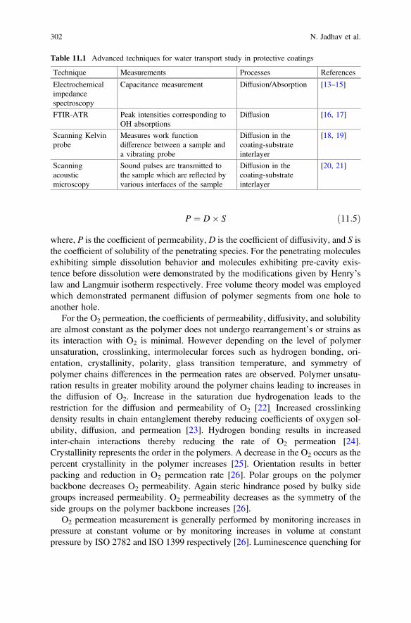
P ¼ D� S ð11:5Þ
where, P is the coefficient of permeability, D is the coefficient of diffusivity, and S isthe coefficient of solubility of the penetrating species. For the penetrating moleculesexhibiting simple dissolution behavior and molecules exhibiting pre-cavity exis-tence before dissolution were demonstrated by the modifications given by Henry’slaw and Langmuir isotherm respectively. Free volume theory model was employedwhich demonstrated permanent diffusion of polymer segments from one hole toanother hole.
For the O2 permeation, the coefficients of permeability, diffusivity, and solubilityare almost constant as the polymer does not undergo rearrangement’s or strains asits interaction with O2 is minimal. However depending on the level of polymerunsaturation, crosslinking, intermolecular forces such as hydrogen bonding, ori-entation, crystallinity, polarity, glass transition temperature, and symmetry ofpolymer chains differences in the permeation rates are observed. Polymer unsatu-ration results in greater mobility around the polymer chains leading to increases inthe diffusion of O2. Increase in the saturation due hydrogenation leads to therestriction for the diffusion and permeability of O2 [22]. Increased crosslinkingdensity results in chain entanglement thereby reducing coefficients of oxygen sol-ubility, diffusion, and permeation [23]. Hydrogen bonding results in increasedinter-chain interactions thereby reducing the rate of O2 permeation [24].Crystallinity represents the order in the polymers. A decrease in the O2 occurs as thepercent crystallinity in the polymer increases [25]. Orientation results in betterpacking and reduction in O2 permeation rate [26]. Polar groups on the polymerbackbone decreases O2 permeability. Again steric hindrance posed by bulky sidegroups increased permeability. O2 permeability decreases as the symmetry of theside groups on the polymer backbone increases [26].
O2 permeation measurement is generally performed by monitoring increases inpressure at constant volume or by monitoring increases in volume at constantpressure by ISO 2782 and ISO 1399 respectively [26]. Luminescence quenching for
Table 11.1 Advanced techniques for water transport study in protective coatings
Technique Measurements Processes References
Electrochemicalimpedancespectroscopy
Capacitance measurement Diffusion/Absorption [13–15]
FTIR-ATR Peak intensities corresponding toOH absorptions
Diffusion [16, 17]
Scanning Kelvinprobe
Measures work functiondifference between a sample anda vibrating probe
Diffusion in thecoating-substrateinterlayer
[18, 19]
Scanningacousticmicroscopy
Sound pulses are transmitted tothe sample which are reflected byvarious interfaces of the sample
Diffusion in thecoating-substrateinterlayer
[20, 21]
302 N. Jadhav et al.
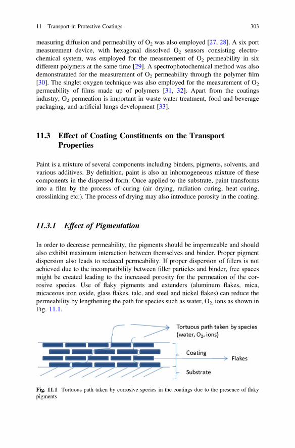
measuring diffusion and permeability of O2 was also employed [27, 28]. A six portmeasurement device, with hexagonal dissolved O2 sensors consisting electro-chemical system, was employed for the measurement of O2 permeability in sixdifferent polymers at the same time [29]. A spectrophotochemical method was alsodemonstratated for the measurement of O2 permeability through the polymer film[30]. The singlet oxygen technique was also employed for the measurement of O2
permeability of films made up of polymers [31, 32]. Apart from the coatingsindustry, O2 permeation is important in waste water treatment, food and beveragepackaging, and artificial lungs development [33].
11.3 Effect of Coating Constituents on the TransportProperties
Paint is a mixture of several components including binders, pigments, solvents, andvarious additives. By definition, paint is also an inhomogeneous mixture of thesecomponents in the dispersed form. Once applied to the substrate, paint transformsinto a film by the process of curing (air drying, radiation curing, heat curing,crosslinking etc.). The process of drying may also introduce porosity in the coating.
11.3.1 Effect of Pigmentation
In order to decrease permeability, the pigments should be impermeable and shouldalso exhibit maximum interaction between themselves and binder. Proper pigmentdispersion also leads to reduced permeability. If proper dispersion of fillers is notachieved due to the incompatibility between filler particles and binder, free spacesmight be created leading to the increased porosity for the permeation of the cor-rosive species. Use of flaky pigments and extenders (aluminum flakes, mica,micaceous iron oxide, glass flakes, talc, and steel and nickel flakes) can reduce thepermeability by lengthening the path for species such as water, O2, ions as shown inFig. 11.1.
Fig. 11.1 Tortuous path taken by corrosive species in the coatings due to the presence of flakypigments
11 Transport in Protective Coatings 303

Protective properties of the coatings dramatically change above critical pigmentvolume concentration (CPVC). Above the CPVC there is not enough binder presentin the coating to hold pigment and filler particles together which induces porosity inthe coating [34]. As shown in Fig. 11.2, permeability and rusting increases above theCPVC. Above the CPVC the tendency to blistering also increases. This is valid forbarrier coatings whereas in case of metal rich coatings, where electrical contactbetween two particles is necessary, the coatings are formulated at or near CPVC.This ensures mutual contact of metal particles as well as their contact with under-lying substrates (steel substrate in case of zinc-rich primers and aluminum substratein case of magnesium-rich primers) [35]. Pigment and filler addition also affects theadhesion of the paint film to the substrate. There is also the possibility of adsorptionof moisture onto the pigment particles during storage. The adsorbed moisture mightresult in incompatibility in dispersing the pigment in non-aqueous media resulting inpoor dispersion and compromising water and O2 barrier properties.
11.3.2 Effect of Binder
Most of the information regarding the effect of the binder on transport propertieshas been explained in the earlier section (Water and oxygen transport in polymersand coatings) of this chapter. It has been found that water necessary for the cor-rosion of unpainted steel (0.003–0.06 mg cm−2 d−1) is an order of magnitude lessthan the actual permeation rate of water through most of the binder systems. Watervapor permeability on a 100 µm film thickness for alkyd resin was observed to be2.3 mg cm−2 d−1 and chlorinated rubber was observed to be 1 mg cm−2 d−1 [11].Oxygen necessary for corrosion of unpainted steel was observed to be 0.008–0.150 mg cm−2 d−1 whereas the O2 permeability for at 100 µm film thickness foralkyd resin was observed to be 0.0103 mg cm−2 d−1 and chlorinated rubber wasobserved to be 0.0022 mg cm−2 d−1 [11]. It is still a matter of debate whether O2
permeation through the coating is the rate determining step for the corrosionoccurring on the metal substrate.
Fig. 11.2 Effect of CPVC onpaint characteristics. Adaptedwith permission from Ref.[34] Copyright (1949)American Chemical Society
304 N. Jadhav et al.
Solvent borne coatings usually cure by a crosslinking mechanism in which smallmolecular weight precursors get transformed into the high molecular weight coat-ing. Increased crosslinking density leads to a lower water and O2 permeation. Waterbased coatings generally cure by coalescence of the latex particles. Finally apolyhydric structure is formed but there are still doubts about the homogeneity ofsuch films which might compromise the protective nature of the coating towardspermeation of water and O2. Interfaces of latex particles might serve as an avenuefor water vapor transportation [36].
11.3.3 Effect of Additives
Coatings contains several additives such as wetting and dispersing agents, rheologymodifiers, flow and leveling agents, defoamers, biocides, colorants, high boilingsolvents, etc. Some of the additives have affinity for the water and so there is atendency for them to leach out. Leached additive might leave pores behind incoating leading to increased permeation of water and O2 in the coating. Surfactantsemployed for the latex synthesis for water-based coating are water sensitive. Theyincrease the water transmission rate. Anionic surfactants have been found to showlower permeation (due to ability to form denser films) as compared to cationicsurfactant [37]. Plasticized films due to addition of plasticizers show increasedsegmental mobility thereby increasing O2 permeability.
11.4 Transport in Rebar Reinforced Concrete
Corrosion underneath porous materials is also a very important phenomenon withrebar reinforced concrete being one of the most widely used building materials.Rebar located inside a concrete matrix typically does not corrode due to the passivelayer formed on the iron. Penetration of corrosive species is problematic, however,due to the porous structure of the concrete surrounding the rebar. With sufficientcarbon dioxide penetration, the pH surrounding the rebar can drop low enough tocause dissolution of the passive layer and facilitate corrosion processes to occur[38]. Corrosion byproducts of rebar have much lower densities and as such, caninduce stresses that can cause mechanical failures in concrete which can end upbeing costly to repair, or life threatening.
Permeation of these corrosive species can be facilitated through three differentmechanisms: diffusion, absorption, and permeation [39]. Permeation of the invasivematerials occurs slightly differently than described in the previous section. Thepermeation of corrosive species in porous materials can best be described byDarcy’s law shown in Eq. (11.6).
11 Transport in Protective Coatings 305
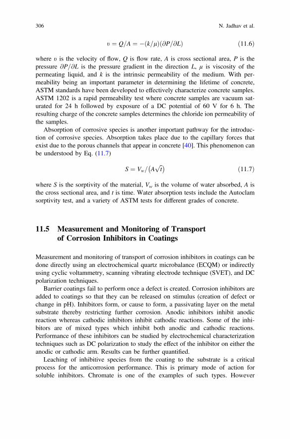
t ¼ Q=A ¼ � k=lð Þ @P=@Lð Þ ð11:6Þ
where υ is the velocity of flow, Q is flow rate, A is cross sectional area, P is thepressure @P=@L is the pressure gradient in the direction L, µ is viscosity of thepermeating liquid, and k is the intrinsic permeability of the medium. With per-meability being an important parameter in determining the lifetime of concrete,ASTM standards have been developed to effectively characterize concrete samples.ASTM 1202 is a rapid permeability test where concrete samples are vacuum sat-urated for 24 h followed by exposure of a DC potential of 60 V for 6 h. Theresulting charge of the concrete samples determines the chloride ion permeability ofthe samples.
Absorption of corrosive species is another important pathway for the introduc-tion of corrosive species. Absorption takes place due to the capillary forces thatexist due to the porous channels that appear in concrete [40]. This phenomenon canbe understood by Eq. (11.7)
S ¼ Vw= Affiffit
p� � ð11:7Þ
where S is the sorptivity of the material, Vw is the volume of water absorbed, A isthe cross sectional area, and t is time. Water absorption tests include the Autoclamsorptivity test, and a variety of ASTM tests for different grades of concrete.
11.5 Measurement and Monitoring of Transportof Corrosion Inhibitors in Coatings
Measurement and monitoring of transport of corrosion inhibitors in coatings can bedone directly using an electrochemical quartz microbalance (ECQM) or indirectlyusing cyclic voltammetry, scanning vibrating electrode technique (SVET), and DCpolarization techniques.
Barrier coatings fail to perform once a defect is created. Corrosion inhibitors areadded to coatings so that they can be released on stimulus (creation of defect orchange in pH). Inhibitors form, or cause to form, a passivating layer on the metalsubstrate thereby restricting further corrosion. Anodic inhibitors inhibit anodicreaction whereas cathodic inhibitors inhibit cathodic reactions. Some of the inhi-bitors are of mixed types which inhibit both anodic and cathodic reactions.Performance of these inhibitors can be studied by electrochemical characterizationtechniques such as DC polarization to study the effect of the inhibitor on either theanodic or cathodic arm. Results can be further quantified.
Leaching of inhibitive species from the coating to the substrate is a criticalprocess for the anticorrosion performance. This is primary mode of action forsoluble inhibitors. Chromate is one of the examples of such types. However
306 N. Jadhav et al.

chromates are toxic and carcinogenic, and when leached into environment causeserious problems.
Al–Zn hydroxide-based hydrotalcite (HT) with decavanadate ascorrosion-inhibiting, charge-balancing anions were dispersed as additive in the epoxycoating. This coating was applied to an aluminum 2024-T3 substrate. Decavanadategets released under appropriate conditions of the corrosion and chlorides and sulfatesare adsorbed on HT for charge compensation as evidenced in Fig. 11.3. In Fig. 11.3,HtInh refers to inhibitor and HTCl refers to chloride in the gallery of HT. Thisexchange resulted in a change in crystal structure as evidenced in X-ray diffraction(XRD) studies. Changes in the diffraction pattern of the coating were monitoredwhich can serve as a tool for observing corrosion inhibition in the coating [41].
In smart coatings, dopants are released on demand. The efficiency of the Cr(VI)and Ce3+ ions was studied by rotating disc electrode experiments. It was found thatthe current density (Fig. 11.4) was less in the case of inhibitor as against the onewithout inhibitor [42].
Conducting polymers such as polyaniline (PAni) and polypyrrole (PPy) can bedoped with corrosive inhibiting dopants which can be released once the polymer isreduced in the corrosive environment (Fig. 11.5). Incorporation of dopants alsoimproves PPy properties such as solubility and electrical conductivity. The releaseddopant then can combine with metal cations to form an impervious layer due topassivation. This passivation results in reduced current and shift in the positivedirection in DC polarization experiments. In electrochemical impedance spec-troscopy (EIS) experiments, passivation leads to increased low frequency impe-dance suggesting better corrosion protection.
Fig. 11.3 Anion exchange in hydrotalcite clays, Reprinted from Ref. [41] with permission fromElsevier
11 Transport in Protective Coatings 307
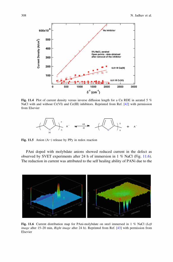
PAni doped with molybdate anions showed reduced current in the defect asobserved by SVET experiments after 24 h of immersion in 1 % NaCl (Fig. 11.6).The reduction in current was attributed to the self healing ability of PANi due to the
Fig. 11.4 Plot of current density versus inverse diffusion length for a Cu RDE in aerated 5 %NaCl with and without Cr(VI) and Ce(III) inhibitors. Reprinted from Ref. [42] with permissionfrom Elsevier
+e
-e
0+
n nN NH
A –A –+
Fig. 11.5 Anion (A−) release by PPy in redox reaction
Fig. 11.6 Current distribution map for PAni-molybdate on steel immersed in 1 % NaCl (Leftimage after 15–20 min, Right image after 24 h). Reprinted from Ref. [43] with permission fromElsevier
308 N. Jadhav et al.

release of molybdate dopant and its combination with iron to form aniron-molybdate complex [43, 44].
In another study, mass change and mobility study of the molybdate dopant wasperformed by employing EQCM in combination with cyclic voltammetry [45].From the mass-potential curve a mass decrease was observed as reduction of PPyoccurred suggesting the release of dopant molybdate (Fig. 11.7). A gain an increasein the mass was observed when oxidation occurred suggesting bromide ioncountercharge.
11.6 Summary
As discussed in this chapter, physical processes such as diffusion, permeation, andabsorption play important roles in the transport of water, O2 and other corrosivespecies through the coatings. The role of coating ingredients (pigments, binders,and additives) significantly affect the protective properties of the coatings. Severaltechniques including specialized electrochemical techniques can be employed forstudying and quantifying the transport of corrosive species as well as inhibitingdopants in the protective coatings.
Fig. 11.7 Cyclic voltammogram (…) and the EQCM mass change (—) versus potential of Ppy(MoO4) in 0.1 M tetrabutylammoniumbromide (N(Bu)4Br) solution. Reprinted from Ref. [45]with permission from Springer
11 Transport in Protective Coatings 309
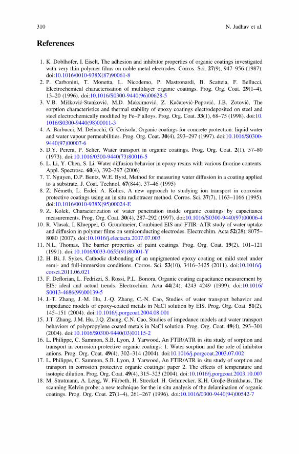
References
1. K. Doblhofer, I. Eiselt, The adhesion and inhibitor properties of organic coatings investigatedwith very thin polymer films on noble metal electrodes. Corros. Sci. 27(9), 947–956 (1987).doi:10.1016/0010-938X(87)90061-8
2. P. Carbonini, T. Monetta, L. Nicodemo, P. Mastronardi, B. Scatteia, F. Bellucci,Electrochemical characterisation of multilayer organic coatings. Prog. Org. Coat. 29(1–4),13–20 (1996). doi:10.1016/S0300-9440(96)00628-5
3. V.B. Mišković-Stanković, M.D. Maksimović, Z. Kačarević-Popović, J.B. Zotović, Thesorption characteristics and thermal stability of epoxy coatings electrodeposited on steel andsteel electrochemically modified by Fe–P alloys. Prog. Org. Coat. 33(1), 68–75 (1998). doi:10.1016/S0300-9440(98)00011-3
4. A. Barbucci, M. Delucchi, G. Cerisola, Organic coatings for concrete protection: liquid waterand water vapour permeabilities. Prog. Org. Coat. 30(4), 293–297 (1997). doi:10.1016/S0300-9440(97)00007-6
5. D.Y. Perera, P. Selier, Water transport in organic coatings. Prog. Org. Coat. 2(1), 57–80(1973). doi:10.1016/0300-9440(73)80016-5
6. L. Li, Y. Chen, S. Li, Water diffusion behavior in epoxy resins with various fluorine contents.Appl. Spectrosc. 60(4), 392–397 (2006)
7. T. Nguyen, D.P. Bentz, W.E. Byrd, Method for measuring water diffusion in a coating appliedto a substrate. J. Coat. Technol. 67(844), 37–46 (1995)
8. Z. Németh, L. Erdei, A. Kolics, A new approach to studying ion transport in corrosionprotective coatings using an in situ radiotracer method. Corros. Sci. 37(7), 1163–1166 (1995).doi:10.1016/0010-938X(95)00024-E
9. Z. Kolek, Characterization of water penetration inside organic coatings by capacitancemeasurements. Prog. Org. Coat. 30(4), 287–292 (1997). doi:10.1016/S0300-9440(97)00006-4
10. R. Vlasak, I. Klueppel, G. Grundmeier, Combined EIS and FTIR–ATR study of water uptakeand diffusion in polymer films on semiconducting electrodes. Electrochim. Acta 52(28), 8075–8080 (2007). doi:10.1016/j.electacta.2007.07.003
11. N.L. Thomas, The barrier properties of paint coatings. Prog. Org. Coat. 19(2), 101–121(1991). doi:10.1016/0033-0655(91)80001-Y
12. H. Bi, J. Sykes, Cathodic disbonding of an unpigmented epoxy coating on mild steel undersemi- and full-immersion conditions. Corros. Sci. 53(10), 3416–3425 (2011). doi:10.1016/j.corsci.2011.06.021
13. F. Deflorian, L. Fedrizzi, S. Rossi, P.L. Bonora, Organic coating capacitance measurement byEIS: ideal and actual trends. Electrochim. Acta 44(24), 4243–4249 (1999). doi:10.1016/S0013-4686(99)00139-5
14. J.-T. Zhang, J.-M. Hu, J.-Q. Zhang, C.-N. Cao, Studies of water transport behavior andimpedance models of epoxy-coated metals in NaCl solution by EIS. Prog. Org. Coat. 51(2),145–151 (2004). doi:10.1016/j.porgcoat.2004.08.001
15. J.T. Zhang, J.M. Hu, J.Q. Zhang, C.N. Cao, Studies of impedance models and water transportbehaviors of polypropylene coated metals in NaCl solution. Prog. Org. Coat. 49(4), 293–301(2004). doi:10.1016/S0300-9440(03)00115-2
16. L. Philippe, C. Sammon, S.B. Lyon, J. Yarwood, An FTIR/ATR in situ study of sorption andtransport in corrosion protective organic coatings: 1. Water sorption and the role of inhibitoranions. Prog. Org. Coat. 49(4), 302–314 (2004). doi:10.1016/j.porgcoat.2003.07.002
17. L. Philippe, C. Sammon, S.B. Lyon, J. Yarwood, An FTIR/ATR in situ study of sorption andtransport in corrosion protective organic coatings: paper 2. The effects of temperature andisotopic dilution. Prog. Org. Coat. 49(4), 315–323 (2004). doi:10.1016/j.porgcoat.2003.10.007
18. M. Stratmann, A. Leng, W. Fürbeth, H. Streckel, H. Gehmecker, K.H. Groβe-Brinkhaus, Thescanning Kelvin probe; a new technique for the in situ analysis of the delamination of organiccoatings. Prog. Org. Coat. 27(1–4), 261–267 (1996). doi:10.1016/0300-9440(94)00542-7
310 N. Jadhav et al.
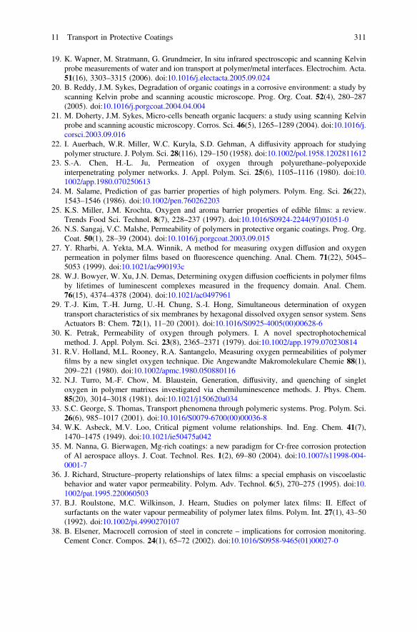
19. K. Wapner, M. Stratmann, G. Grundmeier, In situ infrared spectroscopic and scanning Kelvinprobe measurements of water and ion transport at polymer/metal interfaces. Electrochim. Acta.51(16), 3303–3315 (2006). doi:10.1016/j.electacta.2005.09.024
20. B. Reddy, J.M. Sykes, Degradation of organic coatings in a corrosive environment: a study byscanning Kelvin probe and scanning acoustic microscope. Prog. Org. Coat. 52(4), 280–287(2005). doi:10.1016/j.porgcoat.2004.04.004
21. M. Doherty, J.M. Sykes, Micro-cells beneath organic lacquers: a study using scanning Kelvinprobe and scanning acoustic microscopy. Corros. Sci. 46(5), 1265–1289 (2004). doi:10.1016/j.corsci.2003.09.016
22. I. Auerbach, W.R. Miller, W.C. Kuryla, S.D. Gehman, A diffusivity approach for studyingpolymer structure. J. Polym. Sci. 28(116), 129–150 (1958). doi:10.1002/pol.1958.1202811612
23. S.-A. Chen, H.-L. Ju, Permeation of oxygen through polyurethane–polyepoxideinterpenetrating polymer networks. J. Appl. Polym. Sci. 25(6), 1105–1116 (1980). doi:10.1002/app.1980.070250613
24. M. Salame, Prediction of gas barrier properties of high polymers. Polym. Eng. Sci. 26(22),1543–1546 (1986). doi:10.1002/pen.760262203
25. K.S. Miller, J.M. Krochta, Oxygen and aroma barrier properties of edible films: a review.Trends Food Sci. Technol. 8(7), 228–237 (1997). doi:10.1016/S0924-2244(97)01051-0
26. N.S. Sangaj, V.C. Malshe, Permeability of polymers in protective organic coatings. Prog. Org.Coat. 50(1), 28–39 (2004). doi:10.1016/j.porgcoat.2003.09.015
27. Y. Rharbi, A. Yekta, M.A. Winnik, A method for measuring oxygen diffusion and oxygenpermeation in polymer films based on fluorescence quenching. Anal. Chem. 71(22), 5045–5053 (1999). doi:10.1021/ac990193c
28. W.J. Bowyer, W. Xu, J.N. Demas, Determining oxygen diffusion coefficients in polymer filmsby lifetimes of luminescent complexes measured in the frequency domain. Anal. Chem.76(15), 4374–4378 (2004). doi:10.1021/ac0497961
29. T.-J. Kim, T.-H. Jurng, U.-H. Chung, S.-I. Hong, Simultaneous determination of oxygentransport characteristics of six membranes by hexagonal dissolved oxygen sensor system. SensActuators B: Chem. 72(1), 11–20 (2001). doi:10.1016/S0925-4005(00)00628-6
30. K. Petrak, Permeability of oxygen through polymers. I. A novel spectrophotochemicalmethod. J. Appl. Polym. Sci. 23(8), 2365–2371 (1979). doi:10.1002/app.1979.070230814
31. R.V. Holland, M.L. Rooney, R.A. Santangelo, Measuring oxygen permeabilities of polymerfilms by a new singlet oxygen technique. Die Angewandte Makromolekulare Chemie 88(1),209–221 (1980). doi:10.1002/apmc.1980.050880116
32. N.J. Turro, M.-F. Chow, M. Blaustein, Generation, diffusivity, and quenching of singletoxygen in polymer matrixes investigated via chemiluminescence methods. J. Phys. Chem.85(20), 3014–3018 (1981). doi:10.1021/j150620a034
33. S.C. George, S. Thomas, Transport phenomena through polymeric systems. Prog. Polym. Sci.26(6), 985–1017 (2001). doi:10.1016/S0079-6700(00)00036-8
34. W.K. Asbeck, M.V. Loo, Critical pigment volume relationships. Ind. Eng. Chem. 41(7),1470–1475 (1949). doi:10.1021/ie50475a042
35. M. Nanna, G. Bierwagen, Mg-rich coatings: a new paradigm for Cr-free corrosion protectionof Al aerospace alloys. J. Coat. Technol. Res. 1(2), 69–80 (2004). doi:10.1007/s11998-004-0001-7
36. J. Richard, Structure–property relationships of latex films: a special emphasis on viscoelasticbehavior and water vapor permeability. Polym. Adv. Technol. 6(5), 270–275 (1995). doi:10.1002/pat.1995.220060503
37. B.J. Roulstone, M.C. Wilkinson, J. Hearn, Studies on polymer latex films: II. Effect ofsurfactants on the water vapour permeability of polymer latex films. Polym. Int. 27(1), 43–50(1992). doi:10.1002/pi.4990270107
38. B. Elsener, Macrocell corrosion of steel in concrete – implications for corrosion monitoring.Cement Concr. Compos. 24(1), 65–72 (2002). doi:10.1016/S0958-9465(01)00027-0
11 Transport in Protective Coatings 311
39. L. Basheer, J. Kropp, D.J. Cleland, Assessment of the durability of concrete from itspermeation properties: a review. Constr. Build. Mater. 15(2–3), 93–103 (2001). doi:10.1016/S0950-0618(00)00058-1
40. M.H.F. Medeiros, P. Helene, Surface treatment of reinforced concrete in marine environment:influence on chloride diffusion coefficient and capillary water absorption. Constr. Build.Mater. 23(3), 1476–1484 (2009). doi:10.1016/j.conbuildmat.2008.06.013
41. R.G. Buchheit, H. Guan, S. Mahajanam, F. Wong, Active corrosion protection and corrosionsensing in chromate-free organic coatings. Prog. Org. Coat. 47(3–4), 174–182 (2003). doi:10.1016/j.porgcoat.2003.08.003
42. M. Kendig, M. Hon, L.Warren, ‘Smart’ corrosion inhibiting coatings. Prog. Org. Coat. 47(3–4),183–189 (2003). doi:10.1016/S0300-9440(03)00137-1
43. V. Karpakam, K. Kamaraj, S. Sathiyanarayanan, G. Venkatachari, S. Ramu, Electrosynthesisof polyaniline–molybdate coating on steel and its corrosion protection performance.Electrochim. Acta 56(5), 2165–2173 (2011). doi:10.1016/j.electacta.2010.11.099
44. P.J. Kinlen, Y. Ding, D.C. Silverman, Corrosion protection of mild steel using sulfonic andphosphonic acid-doped polyanilines. Corrosion 58(6), 490–497 (2002). doi:10.5006/1.3277639
45. U. Rammelt, L. Duc, W. Plieth, Improvement of protection performance of polypyrrole bydopant anions. J. Appl. Electrochem. 35(12), 1225–1230 (2005). doi:10.1007/s10800-005-9033-7
312 N. Jadhav et al.

Part IVApplications
Chapter 12Aerospace Coatings
Peter Visser, Herman Terryn and Johannes M.C. Mol
12.1 Introduction
Since the first flight of Orville and Wilbur Wright on Dec. 17, 1903, the aviationindustry evolved from pioneers that wanted to fly, into a global high-tech engi-neering industry that enables transport and travel around the world, with animpressive safety record. Aviation has become an integral part of society; it bringspeople closer together, contributes to economic growth, and plays an important rolein today’s global economy. As air travel continues to grow and new businessmodels expand, the evolution of the industry continues and provides new aircraftdesigns and construction materials. Over the years, aircraft design evolved fromwooden structures covered with fabric into complex multi-material models opti-mized in terms of strength to weight ratio, fatigue, aerodynamics and operationalperformance.
Aerospace coatings play an important role in aircraft design. They have a dec-orative role, but an active protective function as well. Coatings for aircraft mustcope with extreme conditions. In daily service they have to withstand rapid tem-perature changes when taking off for example from the desert at +50 °C, andclimbing to a cruising altitude of 10 km with temperatures as low as −55 °C andhigh levels of UV irradiation. On the other hand, these coatings need to withstandrepeated dry and wet cycles due to condensation, erosion and impact effects, thevibrations of the engines and structural flexing due to turbulence, pressurizing
P. Visser (&)AkzoNobel Performance Coatings, Sassenheim, The Netherlandse-mail: [email protected]
H. Terryn � J.M.C. MolDelft University of Technology, Delft, The Netherlands
H. TerrynVrije Universiteit Brussel, Brussel, Belgium
© Springer Science+Business Media Dordrecht 2016A.E. Hughes et al. (eds.), Active Protective Coatings,Springer Series in Materials Science 233, DOI 10.1007/978-94-017-7540-3_12
315

effects and wing movements. In addition to this, the coating systems are from timeto time exposed to various fluids and chemicals, such as de-icing fluids, aviationfuel, cleaning chemicals, and hydraulic fluids. Last but not least, other environ-mental stresses such as accumulated dirt and potentially corrosive salts from coastaland maritime environments, and acids formed by industrial air pollution and vol-cano eruptions have a detrimental effect on the coating system integrity [1].
Each aircraft is exposed to unique conditions during its operational life. Forexample, long haul with low cycles or regional service with many cycles and theoperational route (transatlantic or continental, northern hemisphere or southernhemisphere) and geographical areas (Europe or South-East Asia). Whereas com-mercial aircraft may fly up to 4000 h per year, defence aircraft or business jets canhave only limited flight time. Some aircraft are even parked in the desert for asignificant period of time. Despite all these factors and impacts originating from thein-service environment the aircraft needs to be colourful and glossy on the outsideand the coating systems should protect the structure against corrosion for the entireservice life. Aerospace coatings have been designed to address these specific needsof this highly regulated and demanding industry.
12.2 Aerospace Market
The Aerospace coatings market can be divided in four segments: commercialpassenger aircraft, defence aircraft, general aviation and space. The first two mar-kets account for most of the sales and volume of the market. The commercialsegment is a growing segment whereas the military and defence markets areexpected to decline over the coming years [2]. The general aviation market pro-duces private and business jets and depends strongly on the economical climate andis slowly recovering after production dropped from 4277 units in 2007 to about2100 per year in 2012 [3].
According to the long-term outlook of large commercial aircraft manufacturers,air travel will keep growing together with the expansion of the world’s aviationnetwork and connectivity and more capacity between major populations centres.Based on this, they produce between 27,000 and 34,000 commercial aircraft in thecoming 20 years [4, 5]. The in-service fleet of 20,341 commercial aircraft with acapacity of more than 100 passengers is expected to grow an average of 3.6 % peryear to double its size to more than 41,000 aircraft by 2032. Growth of passengertravel in Asia and Middle East and the need for more fuel-efficient aircraft aredriving this growth. Over a 23-year period the 7-year moving average of aircraftdeliveries grew from 500 to more than 1000 in 2013 and is expected to grow evenfurther [2].
The aerospace coatings business has evolved to a global business. All segmentshave their Original Equipment Manufacturers (OEM’s) and Maintenance, Repaintand Overhaul (MRO) facilities. In addition to their final assembly lines, OEM’s
316 P. Visser et al.
have an extensive network of contractors and subcontractors all over the world thatsupply a variety of parts and assemblies. These suppliers must apply coatingsspecified by the OEM’s. Most airlines repaint their aircraft every 5–7 years ofservice during maintenance intervals or for rebranding purposes. Considering theaverage service life of an aircraft being more than 20 years, the volume of paint forthis MRO business is significant [6].
Historically, the final assembly lines of the OEM’s were concentrated in Europeand North America. Now, manufacturing and maintenance operations are movingto Asia and South America to take advantage of the lower labour costs. In particularthe aerospace industry of China is growing rapidly in terms of airline operations,maintenance and aircraft production [7].
12.3 Corrosion Control in the Aerospace Industry
Air transport plays an important role in the world’s economic activities. Safety is akey element next to efficient and environmentally sustainable operations on regionaland global level. Due to many safety management programs and systems that arebased on risk management principles, the safety record of the industry dramaticallyimproved, with 2013, as the safest year ever in terms of fatalities for scheduledinternational air transport operations [8]. Despite this achievement corrosion controlremains a very important aspect of the aerospace industry. The cost of corrosion is asignificant percentage of the total aircraft maintenance costs [9]. In addition to this,corrosion impacts safety and aircraft availability. Corrosion compromises thestructural integrity of aircraft structures and in the event of corrosion consequencescan be dramatic. In the design phase of an aircraft many requirements such asweight, aerodynamics, fatigue and fuel properties are determined. An aircraft designcomprises many dissimilar metals, complex geometrical structures, joining tech-niques and many difficult-to-inspect areas. Corrosion is a very important but dif-ficult parameter to take into account because the prediction of corrosion initiationand extent of structural damage is hard to determine. Despite advances in corrosionknowledge, computational design capabilities, maintenance data analysis andsimulations, there is no reliable model for predicting corrosion [10]. Aircraftstructures are exposed to a number of stresses and conditions depending on theoperating environment of the aircraft. The aircraft is designed to resist various typesof corrosion through selection of the proper materials, alloys, tempers,pre-treatments, coating systems (defined as the corrosion protective scheme), andthe use of drainage points, sealants and corrosion inhibitors. These designs arebased on knowledge and experience of what causes corrosion and the types ofcorrosion that occur in airplane structures. In addition to this design, a corrosioncontrol program is needed throughout the service life of the aircraft. This isessential to control corrosion to a predictable, manageable level that does notdegrade structure or jeopardize the ability of the airplane to carry its intended design
12 Aerospace Coatings 317
loads. The use of the current corrosion schemes and corrosion managementprograms has made it possible for aircraft to operate beyond their designed lifewithout compromising safety performance.
12.3.1 Introduction to the Corrosion Protection Scheme
The corrosion protection scheme is a key element of the aircraft design. Each part ofthe structure has several protecting layers to ensure the structural integrity duringthe service life. In general it can be stated that the ‘state of the art’ corrosionprotection scheme is applied on top of the substrate, aerospace aluminium alloys,and consists of 2 or 3 layers, which typically is a pre-treatment and a coatingsystem. The pre-treatment can be a chemical conversion coating, wash-primer or ananodic film (anodising layer). Whereas, the second layer is an organic coating,which can be a primer or a primer-topcoat system. The main function of such acorrosion protection scheme is to act as a barrier between the alloy and the oper-ating environment (passive protection). In addition, the corrosion protection schemeneeds to provide active corrosion protection, through the ability to release aninhibitor (leaching mechanism) to provide corrosion protection in case this barrier isdamaged. Today, this leaching mechanism is a key feature in the active corrosionprotection mechanism of the “state of the art” corrosion protective scheme. Thismeans, when the corrosion protective scheme is damaged and the substrate isexposed to the environment, the inhibitor dissolves from the coating due tomoisture ingress and will be transported to the exposed or damaged area and formsa new barrier layer and protects the alloy from the aggressive environment andcorrosion.
For decades, the aerospace industry has been, and still is relying on hexavalentchromium-based (Cr(VI)) compounds (chromates) as active corrosion inhibitingmaterial for the corrosion protection of the structures. These hexavalent chromiumcompounds are used in many processes such as: deoxidizers, anodising processes,conversion coatings, sealants and organic coatings. The corrosion inhibitionmechanism of these compounds has been studied extensively [11]. Their solubilitycombined with the ability to act as both an anodic or cathodic inhibitor and thecomplex oxidation/reduction chemistry, provide them with unique properties toinhibit corrosion on ferrous and non-ferrous metals at low concentrations and over awide pH range. Chromates have a proven track record for many years. They are notperfect, but over the years, the industry has based all the designs, specifications,processes, and corrosion management programs around the solid performance ofthis class of inhibitors. Unfortunately, these hexavalent chromium compounds aretoxic and proven to be carcinogenic [12]. Hence, elimination of these compoundshas been an important topic for more than 20 years [13].
318 P. Visser et al.
12.3.1.1 Aluminium Alloys Used in Aerospace
Aluminium is the most dominant substrate in aircraft design, because of its light-weight properties and high strength-to-weight ratio. The mechanical, physical andchemical properties of aluminium alloys depend on the composition andmicrostructure. The addition of selected alloying elements in combination with themechanical and thermal treatments (tempering) provide the desired properties forthe intended application of the aluminium alloy [14]. Wrought alloys such asAA2024 and AA7075 are most commonly used for the legacy aircraft. The firstdigit of the alloy indicates the major alloying element. This is copper for AA2024and zinc for AA7075. The second digit indicates modifications from the originalalloy and the last two digits identify the specific alloy. The alloy designation isfollowed by a temper designation, for example T3 or T6. This designates the heattreatment used. T3 is solution heat treated, cold worked, and naturally aged. The T6temper is solution heat treated and artificially aged [15–17]. AA2024 is mainly usedfor the fuselage skin and frame along with other structural parts, AA7075 is oftenused for a wide variety of structural parts.
The addition of alloying elements such as copper and zinc to aluminium hassignificant benefits for the strength-to-weight ratio but it also reduces the corrosionresistance. The heterogeneous microstructure of these aluminium alloys, crystal-lography, grain size and shape, residual stresses and intermetallic particles, plays animportant role in the reduced corrosion resistance of these alloys. In recent years,understanding of the microstructure and the influence on corrosion of high strengthaluminium alloys advanced significantly [18].
Weight reduction is one of the most important driving forces in new aircraftdesign [19]. Lower weight reduces fuel consumption, increases payload and range.New construction materials should also provide improved and optimised mechan-ical properties to increase maintenance intervals and reduced repair costs.Reduction of the material density is the most effective way to reduce the weight ofthe aircraft. Hence, composites and fibre metal laminates (GLARE) have beenintroduced and new alloys are being developed. Although, the use of composite innew aircraft models reduced the role of high strength aluminium alloys to someextend, the aluminium alloys remain important in the aircraft design due to theirlow cost, lightweight properties and easy low cost workability. Besides the 2000and 7000 series aluminium alloys, the 3rd generation aluminium-lithium (Al–Li)alloys are finding their application in new aircraft designs. This new generation ofalloys provides weight savings, but also higher strength and improved fracturetoughness. Al–Li 2199 is used for the fuselage and lower wing applications. Al–Li2099 is used for extrusions for the internal structure (Table 12.1).
12.3.1.2 Surface Treatment of Aluminium
The surface treatment is the first step of the corrosion protective scheme after theselection of the alloy. These treatments are the first defensive layer to protect the
12 Aerospace Coatings 319
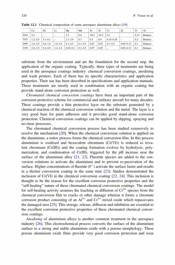
substrate from the environment and are the foundation for the second step, theapplication of the organic coating. Typically, three types of treatments are beingused in the aerospace coatings industry: chemical conversion coatings, anodisingand wash primers. Each of them has its specific characteristics and applicationproperties. Their use has been described in specifications and application manuals.These treatments are mostly used in combination with an organic coating butprovide stand-alone corrosion protection as well.
Chromated chemical conversion coatings have been an important part of thecorrosion protective scheme for commercial and military aircraft for many decades.These coatings provide a thin protective layer on the substrate generated by achemical reaction of the chemical conversion solution and the metal. The layer is avery good base for paint adhesion and it provides good stand-alone corrosionprotection. Chemical conversion coatings can be applied by dipping, spraying andno-rinse processes.
The chromated chemical conversion process has been studied extensively toresolve the mechanism [20]. When the chemical conversion solution is applied onthe aluminium, a redox process forms the chemical conversion film. In this processaluminium is oxidized and hexavalent chromium (Cr(VI)) is reduced to triva-lent chromium (Cr(III)) and the coating formation evolves by hydrolysis, poly-merization, and condensation of Cr(III), triggered by the pH increase near thesurface of the aluminium alloy [21, 22]. Fluoride species are added to the con-version solutions to activate the aluminium and to prevent re-passivation of thesurface. Higher concentrations of fluoride (F−) activate the surface faster and resultsin a thicker conversion coating in the same time [23]. Studies demonstrated theinclusion of Cr(VI) in the chemical conversion coating [22, 24]. This inclusion isthought to be the reason for the excellent corrosion protective properties and the“self-healing” nature of these chromated chemical conversion coatings. The modelfor self-healing activity assumes the leaching or diffusion of Cr6+ species from thechemical conversion film to cracks or other damage whereas it forms a chromatecorrosion product consisting of an Al3+ and Cr3+ mixed oxide which repassivatesthe damaged area [25]. This storage, release, diffusion and inhibition are essential tothe excellent corrosion protective properties of these chromated chemical conver-sion coatings.
Anodising of aluminium alloys is another common treatment in the aerospaceindustry [26]. This electrochemical process converts the surface of the aluminiumsurface to a strong and stable aluminium oxide with a porous morphology. Theseporous aluminium oxide films provide very good corrosion protection and wear
Table 12.1 Chemical composition of some aerospace aluminium alloys [19]
Cu Zn Li Mg Mn Fe Si Cr Zr Ti Al
2024 4.4 – – 1.5 0.6 ≤0.5 ≤0.5 0.1 0.15 Balance
7075 1.2–2.0 5.1–6.1 – 2.1–2.9 0.3 0.5 0.4 0.18–0.28 – 0.2 Balance
2099 2.4–3.0 0.4–1.0 1.6–2.0 0.1–0.5 0.1–0.5 0.07 0.05 0.1–0.5 0.05–0.12 0.1 Balance
2199 2.0–2.9 0.2–0.9 1.4–1.8 0.05–0.4 0.1–0.5 0.07 0.05 – 0.05–0.12 0.1 Balance
320 P. Visser et al.
properties. Also, it serves as a good foundation for adhesive bonding and adhesionof organic paint films.
Such an anodic layer is typically 2–5 μm thick and consists of millions of poresper cm2. The film has a thin non-porous barrier layer of 10–50 nm thick. On top ofthis layer there is the porous structure with a close packed hexagonal (honeycomb)cell arrangement, each cell consists of an amorphous anodic alumina with a centralpore. The pore and cell dimensions can be influenced by selection of the anodisingelectrolyte and the anodising parameters, such as pH, time, temperature, currentdensity, and voltage etc. [27]. The desired morphology and anodic film charac-teristics depend on the properties needed for the application, for example adhesionbonding, painting or stand-alone corrosion protection.
There are many types of anodising processes. In the aerospace industry, chromicacid and sulphuric acid electrolytes are widely used for the protection of aircraftparts. Chromic Acid Anodising (CAA) provides excellent corrosion protection witha relatively thin coating and without significant decrease in the fatigue strength ofthe material [28]. Sulphuric Acid Anodising (SAA) and Phosphoric Acid Anodising(PAA) are frequently used as well. Boric sulphuric acid electrolytes have beenintroduced to overcome the fatigue issues, which are the main drawback of thetraditional sulphuric acid anodising processes. Tartaric Sulphuric acid (TSA) andBoric Sulphuric acid anodising (BSAA) have been introduced as a replacement ofthe hexavalent chromium CAA process.
In some cases, anodised parts are subjected to a sealing procedure. Sealing in hotwater or hot dilute dichromate solution will convert the amorphous aluminiumoxide to a monohydrate. This process partially or fully closes the pores andenhances the corrosion resistance. However, sealed anodised layers are not verysuitable for adhesive bonding or coating adhesion. If painting or bonding isrequired, the sealing step must be eliminated or carefully controlled to ensure goodadhesion. Anodising is much more expensive than a chemical conversion processand not suitable for all types of parts. Critical structures are often anodized formaximum corrosion protection.
Wash primers, also known as etch primers, have been used as metal conditionerand alternative to the “wet” chemical conversion process. Polyvinyl butyral basedwash primers have been used extensively on military and commercial aircraft. Thereactions of a curing chromated wash primer are complex. They are available in twocomponent and one-pack systems. A typical two-component wash primer consistsof a base component and an activator. The base component contains: polyvinyl-butyral, zinc tetraoxychromate, talc, and solvents such as isopropanol and butanol.The activator is a solution of water isopropanol and phosphoric acid [29]. Uponmixing of the base with the activator many different reactions take place that areunique for this chemistry and make it very difficult to develop alternative chromatefree formulations. Wash primers were mainly used in repair schemes and in themaintenance area for repainting of commercial aircraft using chromated orchromate-free epoxy or urethane intermediate primer over it. Various wash primersystems are qualified according to maintenance specifications. However, the use of
12 Aerospace Coatings 321
wash primers has declined over recent years due to the introduction of newpre-treatments and coating solutions.
12.3.1.3 Organic Coatings
The organic coatings are the last part of the corrosion protection scheme. They actas the first barrier against the environmental conditions and need to fulfil a widerange of functions. Secondly, they have to be able to actively protect the substratewhen a damage, crack or delamination occurs. Typically, the organic coating isapplied in one (primer only) or two (primer/topcoat) layers. The primer is designedto maintain adhesion on the various treatments and contains corrosion inhibitors foractive corrosion protection. Their composition has been carefully formulated toensure the performance throughout the service life of the aircraft. In other cases, asecond layer (top coat) is applied to the corrosion protective scheme. This topcoatcan have a decorative or an additional protective function. Together with thepre-treatment, the coating system protects the substrate or alloy against environ-mental effects. There are many different coating systems specified in an aircraftdesign. For example, a fuel tank coating system has a different build-up andrequirements differ compared to exterior decorative systems. The specific require-ments of each coating system is defined in specifications defined by the OEM’s.
12.3.2 Types of Corrosion and Failures
Corrosion occurs in many forms on the aircraft structure. These complex phe-nomena, although mechanistically different, are similar in terms of their potentialeffects in reducing the structural integrity. The corrosion processes of the alu-minium in the aerospace industry are electrochemically driven. The local electro-chemical potential differences at the alloy surface create the driving force forcorrosion initiation [30–32]. Active spots become anodes, whereas the more nobleareas act as a cathode. The form of corrosion is influenced by factors such as alloyand temper used, environmental conditions, corrosive agents present, geometry,design, and mechanical loading. The various types of corrosion are briefly dis-cussed below.
Filiform corrosion is a very common type of corrosion in aircraft structures. Thisworm-like type of corrosion occurs between the metal and the polymeric coating. Itinitiates at a crack or rupture around a rivet head or lap joint under acidic, chlorine-rich and humid conditions. Once initiated, the propagation is determined by anodicundermining [33]. In addition to the environmental effects, filiform corrosion is alsoaffected by the microstructure of the aluminium alloys and the properties of theapplied coating system [34].
322 P. Visser et al.
Pitting is another type of corrosion that occurs frequently in aerospace structures.It is different from general corrosion because of the absence of measurable materialthinning. This is an extremely localized form of corrosion that results in holes andpits that penetrate in the structure and leads to degradation of the structural capa-bilities. The typical 2000 and 7000 series aluminium alloys used in the aerospaceindustry are susceptible to pitting corrosion and therefore have been studied ex-tensively [35–41]. These studies have led to improved knowledge on the nucleationof pits on high strength alloys such as AA2024-T3. However, the establishment andpropagation of stable pits is still being investigated.
Intergranular corrosion and to a greater extent exfoliation corrosion typicallyoccurs on 2000 and 7000 series high strength aluminium alloys [42–44]. Especially,the AA7075-T6 alloy is susceptible to intergranular and exfoliation corrosion, thisalloy contains both copper and zinc. Due to processing and heat treatments copperand/or zinc accumulate at the grain boundaries. These grain boundaries preferen-tially corrode because of the galvanic couple between the grain bodies andboundaries and the anodic behaviour of aluminium towards copper. Intergranularcorrosion can start at a pit, second phase intermetallic particle or at grain boundariesat the surface and it penetrates much faster into the alloy compared to pittingcorrosion. Exfoliation corrosion has a very characteristic appearance of leafingaluminium layers due to corrosion of a very elongated and flattened grain structureparallel to the alloy surface due to the rolling. It originates from intergranularcorrosion at the edges of riveted and bolted aircraft components. The susceptibilityto exfoliation corrosion can be reduced by the modification of the annealing processto obtain a more favourable distribution of precipitates [45, 46].
Stress corrosion cracking (SCC) [47–49] or environmental assisted stress cor-rosion can be one of the most destructive types of corrosion. This form of corrosioncauses a loss of load-carrying capability from the combined effect of tensile stressand corrosion. There are two forms of SCC: intergranular and transgranular SCC.Aluminium alloys typically show intergranular SCC. Under corrosive conditions(humid environments with chloride) stress corrosion is initiated rapidly and followsthe grain boundaries in aluminium alloys. There are two mechanisms proposed forSCC: anodic dissolution and hydrogen embrittlement. However, the exact mecha-nisms have not been resolved yet, despite extensive work in modelling of SCC andelucidating microstructural features along grain boundaries that influence stressassisted corrosion. The most effective way to control this kind of corrosion is to usematerials that are not susceptible to SCC at design stress levels and protection fromcorrosion initiation by coatings and excluding electrolytes.
Crevice corrosion [47] or concentration cell corrosion is the most common typeof corrosion in aircraft. It occurs when moisture is trapped between surfaces. Thiscan be at fasteners, delaminated paint, and unsealed joints or within a delaminatedbond line. This type of corrosion is aggressive and can initiate pitting and exfoli-ation corrosion depending on the alloy, temper and form of the material that isaffected. It is driven by a differential concentration mechanism [50]. The most
12 Aerospace Coatings 323
effective way to prevent crevice corrosion is to avoid water penetration by theapplication of sealants and water-displacing corrosion inhibiting compounds [51].
The aircraft design does not only contain aluminium alloys but also many dis-similar materials like: titanium, magnesium, stainless steel and composites. Withoutproper protection the combination of these dissimilar materials can lead to galvaniccorrosion. This occurs when two dissimilar materials are connected in the presenceof an electrolyte. Recent aircraft designs use more and more carbon-reinforcedplastics. These composite materials can induce galvanic potential differences due tothe very conductive carbon fibres in the material. When joined to the aluminiumstructure, composite materials can act as a cathode and accelerate the electro-chemical dissolution of the aluminium. The rate of corrosion depends on the surfaceratio between the cathode and the anode design geometry. A large cathode surfacearea with respect to the anode surface area can lead to fast and severe corrosion. Theonly way to prevent galvanic corrosion is to prevent direct contact of the dissimilarmetals and the ingress of moisture (electrolyte). This can be done with the use of aphysical barrier in the form of a coating, sealant and/or corrosion inhibiting com-pounds (CIC’s).
12.3.3 Corrosion Protection and Design
Corrosion can be initiated by many sources and affect the aircraft structure. Thesesources can be identified at the manufacturer and operator level [50]. The basicdesign combined with manufacturing and processing are the most important factorsin corrosion protection at the manufacturing level. At the operator level there aredifferent factors that potentially could initiate corrosion of the structure, amongthem improper maintenance, deterioration of the coating system, operationalenvironment, accidental contaminations, and the environmental conditions in theaircraft.
Corrosion can initiate when the following three parameters are present:
• A cathode and an anode.• A metallic connector between the anode and cathode.• An electrolyte (water).
Elimination of these three conditions is limited by feasibility, practicality, andfunctionality. Each part of the aircraft is designed to withstand the stresses andoperating environment for the service life of the aircraft. Therefore, six key ele-ments need to be considered when designing for corrosion control:
• Selection of materials• Coating system• Sealants• Corrosion inhibiting compounds• Avoidance of contact between dissimilar metals
324 P. Visser et al.
• Drainage• Access for maintenance
For the material selection, the design considers many parameters such as, alloy,shape, weight to strength ratio strength, durability and fatigue properties. Whereasthe high-strength aluminium alloys are used most widely in the aircraft design,coupling to other materials like Titanium (6-AL-4 V), Magnesium, Stainless steel,low alloy, high strength carbon steel, and increasing amounts of CarbonFibre-Reinforced Plastics (CFRP) can set up galvanic corrosion cells which need tobe eliminated in the design stage.
The coating system is a key element to protect the selected material from theoperating environment. This barrier typically consists of multiple layers which mayinclude anodised layer or chemical conversion coatings that are coated with cor-rosion inhibiting primers. Exterior surfaces and some structural areas are coatedwith chemical resistant topcoats. Titanium alloys are anodized or coated andstainless steel is most commonly cadmium plated before being primed. The activeprotective primers are a key element in the protection scheme and will be discussedin more detail.
It is not always possible to avoid dissimilar metal contact, crevices and the use ofspecific alloys because of weight, cost, and functional issues. However, thepotential for corrosion can be minimized by using polysulfide sealants that aretypically applied to faying surfaces of the joints to prevent moisture ingress leadinglap joint or crevice corrosion or to prevent dissimilar metal contact. They areapplied at many connections like stringer to stringer and skin-to-shear tie joints,skin splices and skin doublers and pressure the bulkhead. In addition to this,exterior fasteners and fasteners that penetrate pressurized areas are installed with asealant.
Moisture cannot be eliminated during operations. Therefore, it needs to becontrolled by drainage and corrosion-inhibiting compounds (CIC’s). Drainage ofthe aircraft structure by the use of drain paths, drain holes is important to prevententrapment of moisture and corrosive fluids in crevices and lower fuselage area.The design is optimized to direct the fluids towards the drain holes. CIC’s are usedto provide additional corrosion protection. These CIC’s are petroleum basedwater-displacing compounds with corrosion inhibitors and are sprayed on thestructure to penetrated faying surfaces. The CIC’s are applied in areas that are proneto corrosion (lower fuselage). Low viscosity CIC’s are able to penetrate crevicesand displace water, whereas viscous CIC’s will act as a coating.
The features discussed above must ensure a safe and economical service life.However, the aircraft design must ensure easy access for maintenance and corro-sion inspections as part of a corrosion management/maintenance program.Corrosion cannot be eliminated but, timely inspections will help to detect corrosion,trapped moisture, plugged drain-holes, and chipped or missing paint at an earlystage and combined with sealant and CIC’s applications much corrosion can beprevented.
12 Aerospace Coatings 325
12.4 Introduction into Aerospace Coatings
Aerospace coatings serve as decorative and protective layers for all types of pas-senger, freight and military aircraft. The systems evolved over the years from verysimple formulations into complicated materials with specific functions and animportant role in the corrosion protective scheme of today’s aircraft industry. Threetypes of coating systems can be recognized. The exterior decorative system, whichprovides image and recognisability. Structural coatings that are an integral part ofthe corrosion protection scheme of the aircraft structure, and finally the specialpurpose systems. Each of these coating systems has their own requirements andmust be able to withstand a wide range of stresses during their operational life.
12.4.1 History of Aerospace Coatings
In the early days, 1910, the first aircraft were painted with colourless single com-ponent cellulose lacquers to provide tension to the linen (fabric). Around 1915,pigmented or coloured coatings were introduced to provide camouflage for militaryaircraft during World War I. Up to 1935, aircraft were mainly constructed fromwood, linen and steel. Cellulose lacquers and alkyd enamels were mainly used ascoatings for the protection of these aircraft. Around 1935, the first metal aircraftwere designed. New coatings were developed to protect these aircraft from corro-sion, such as zinc chromate alkyd primers and chromated chemical conversioncoatings (CCC), wash or etch primers, acrylic lacquers and alkyd enamels. Theproducts were used on commercial as well as on military aircraft. In 1960, the firstgeneration of jet engine powered aircraft, McDonnell-Douglas DC-8 and theBoeing B-707, were introduced. New highly chemical resistant coatings wererequired to withstand the hydraulic fluids that were introduced with these newaircraft. These developments are the basis of the coating technologies used today.Two component paint systems were developed such as epoxy -amine or -amideprimer technology and polyurethane (polyester/isocyanate) topcoats. In the mid1980s clear coat technologies were introduced because of atmospheric acidificationdue to volcanic eruptions (Mt Pinatubo) caused severe damage to the paint systems.At the same time environmental awareness started to influence the aerospacecoatings industry. Toxic materials such as lead and cadmium were removed fromthe coatings and the quest for the replacement of carcinogenic hexavalent chro-mium was started. Solvent emissions needed to be reduced. This led to the intro-duction of high solid primers and topcoats and water-based coatings. Benzylalcohol based paint removers replaced methylene chloride and phenol containingpaint removers. These can be neutral, acid or hydro peroxide activated. This ini-tiated the introduction of selective strippable paint systems. In early 2000, devel-opments were focused on efficiency improvements like super durable topcoats,weight reduction, less layers, easy application fast curing systems. This led to the
326 P. Visser et al.
introduction of base coat/clear coat systems for the aerospace industry. Over theyears aerospace coatings evolved into high performance coatings that are able towithstand aggressive environments. Currently the aerospace coatings industry isfacing new challenges with the introduction of all composite fuselage designs andthe replacement of hexavalent chromium for structural applications.
12.4.2 Aerospace Coating Systems and Their Requirements
The main reasons for painting aircraft are corrosion protection, airline identification,appearance and survivability. The paint system on the aircraft protects the metal andcomposite structures from the environment. Many aircraft components are designedfor structural and fatigue performance and are not very resistant to the atmosphericexposure. Aerospace coating systems have to cope with extreme in-service con-ditions. Because of this, the systems evolved over the years in terms of chemicaland fluid resistance, corrosion resistance and exterior durability. Many differentsystems were developed to protect the various areas of the aircraft. In general,aerospace coating systems can be categorized into 3 main groups: exterior systems,structural systems, and special purpose systems.
12.4.2.1 Exterior Systems
Exterior coating systems are applied on the fuselage and other exterior areas of theaircraft. These systems reflect the identity and image of the airline. Historicallyaircraft were mainly white. Today, aircraft liveries have to be glossy and oftenfeature vibrant colours which are used as a marketing tool (Fig. 12.1). The exte-rior coating systems have to be able to withstand a wide range of environmentalstresses like temperature changes, high levels of UV irradiation, humidity exposure,erosion and exposure to aggressive media including fuel, de-icing fluids, hydraulicfluids, potentially corrosive salts due to maritime areas and acidic aerosols in theatmosphere due to volcano eruptions and industrial pollution. These stresses com-bined with the vibration effects of the powerful engines and structural flexing due topressurizing of the fuselage and turbulence put the coatings under severe stress.
A typical exterior coating system is a multi-layered system and consists of apre-treatment layer (anodised layer or chemical conversion coating), and a primerlayer of 15–25 μm, which is covered with a pigmented decorative topcoat of 60–120 μm (Fig. 12.2). The airline livery is applied with the decoration colours on topof this basic topcoat layer.
Recently, the base coat/clear coat topcoat philosophy has been introduced intothe aerospace market. In this philosophy the decorative topcoat is replaced by afast-drying, highly pigmented coloured base coat making it possible to reduce theprocess time of painting an aircraft, particularly complex liveries. Once all the
12 Aerospace Coatings 327
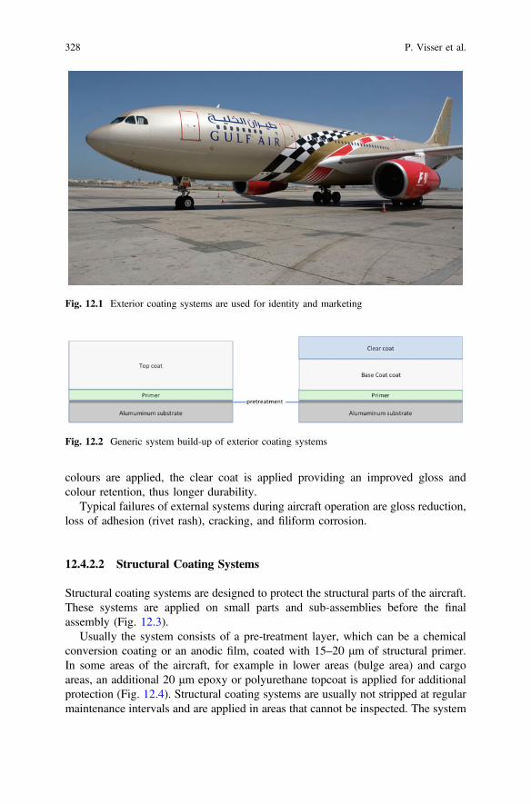
colours are applied, the clear coat is applied providing an improved gloss andcolour retention, thus longer durability.
Typical failures of external systems during aircraft operation are gloss reduction,loss of adhesion (rivet rash), cracking, and filiform corrosion.
12.4.2.2 Structural Coating Systems
Structural coating systems are designed to protect the structural parts of the aircraft.These systems are applied on small parts and sub-assemblies before the finalassembly (Fig. 12.3).
Usually the system consists of a pre-treatment layer, which can be a chemicalconversion coating or an anodic film, coated with 15–20 μm of structural primer.In some areas of the aircraft, for example in lower areas (bulge area) and cargoareas, an additional 20 μm epoxy or polyurethane topcoat is applied for additionalprotection (Fig. 12.4). Structural coating systems are usually not stripped at regularmaintenance intervals and are applied in areas that cannot be inspected. The system
Fig. 12.1 Exterior coating systems are used for identity and marketing
Fig. 12.2 Generic system build-up of exterior coating systems
328 P. Visser et al.
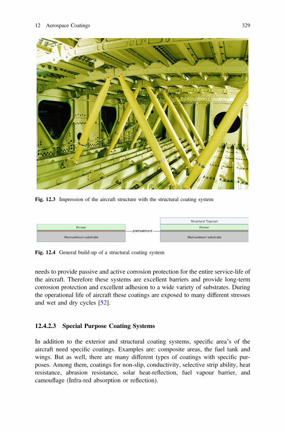
needs to provide passive and active corrosion protection for the entire service-life ofthe aircraft. Therefore these systems are excellent barriers and provide long-termcorrosion protection and excellent adhesion to a wide variety of substrates. Duringthe operational life of aircraft these coatings are exposed to many different stressesand wet and dry cycles [52].
12.4.2.3 Special Purpose Coating Systems
In addition to the exterior and structural coating systems, specific area’s of theaircraft need specific coatings. Examples are: composite areas, the fuel tank andwings. But as well, there are many different types of coatings with specific pur-poses. Among them, coatings for non-slip, conductivity, selective strip ability, heatresistance, abrasion resistance, solar heat-reflection, fuel vapour barrier, andcamouflage (Infra-red absorption or reflection).
Fig. 12.3 Impression of the aircraft structure with the structural coating system
Fig. 12.4 General build-up of a structural coating system
12 Aerospace Coatings 329
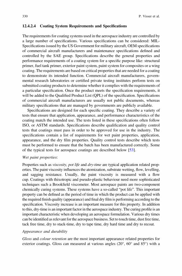
12.4.2.4 Coating System Requirements and Specifications
The requirements for coating systems used in the aerospace industry are controlled bya large number of specifications. Various specifications can be considered: MIL-Specifications issued by the USGovernment for military aircraft, OEM specificationsof commercial aircraft manufacturers and maintenance specifications defined andcontrolled by the SAE group. Specifications describe the general properties andperformance requirements of a coating system for a specific purpose like: structuralprimer, fuel tank primer, exterior paint system, paint system for composites or a wingcoating. The requirements are based on critical properties that are needed for a coatingto demonstrate its intended function. Commercial aircraft manufacturers, govern-mental research laboratories or certified private testing institutes perform tests onsubmitted coating products to determine whether it complies with the requirements ofa particular specification. Once the product meets the specification requirements, itwill be added to the Qualified Product List (QPL) of the specification. Specificationsof commercial aircraft manufacturers are usually not public documents, whereasmilitary specifications that are managed by governments are publicly available.
Specifications are designed for each specific coating. They describe a variety oftests that ensure that application, appearance, and performance characteristics of thecoating match the intended use. The tests listed in these specifications often followISO, or ASTM standards. Specifications describe qualification and quality controltests that coatings must pass in order to be approved for use in the industry. Thespecifications contain a list of requirements for wet paint properties, application,appearance, and the dry film properties. Quality control tests describe which testsmust be performed to ensure that the batch has been manufactured correctly. Someof the typical tests for aerospace coatings are described below [53].
Wet paint properties:
Properties such as viscosity, pot life and dry-time are typical application related prop-erties. The paint viscosity influences the atomization, substrate wetting, flow, levelling,and sagging resistance. Usually, the paint viscosity is measured with a flowcup. Coatings with thixotropic and pseudo-plastic behaviour need more sophisticatedtechniques such a Brookfield viscometer. Most aerospace paints are two-componentchemically curing systems. These systems have a so-called “pot life”. This importantproperty can be defined as the period of time in which the product can be applied withthe required finish quality (appearance) and final dry film is performing according to thespecification. Viscosity increase is an important measure for this property. In additionto this, dry-time is an important factor in the aerospace industry. The curing profile is animportant characteristic when developing an aerospace formulation. Various dry timescan be identified as relevant for the aerospace business. Set to touch time, dust free time,tack free time, dry to stack-time, dry to tape time, dry hard time and dry to recoat.
Appearance and durability
Gloss and colour retention are the most important appearance related properties forexterior coatings. Gloss can measured at various angles (20°, 60° and 85°) with a
330 P. Visser et al.
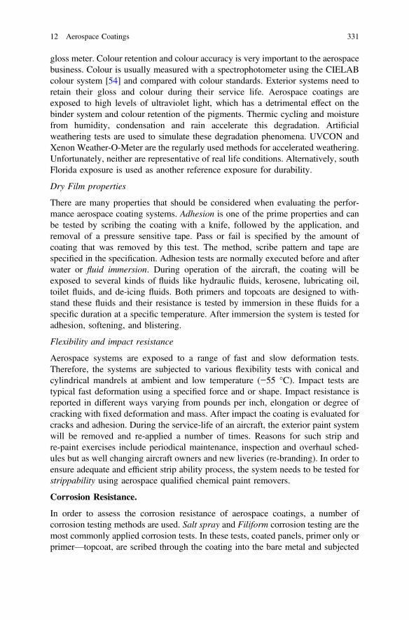
gloss meter. Colour retention and colour accuracy is very important to the aerospacebusiness. Colour is usually measured with a spectrophotometer using the CIELABcolour system [54] and compared with colour standards. Exterior systems need toretain their gloss and colour during their service life. Aerospace coatings areexposed to high levels of ultraviolet light, which has a detrimental effect on thebinder system and colour retention of the pigments. Thermic cycling and moisturefrom humidity, condensation and rain accelerate this degradation. Artificialweathering tests are used to simulate these degradation phenomena. UVCON andXenon Weather-O-Meter are the regularly used methods for accelerated weathering.Unfortunately, neither are representative of real life conditions. Alternatively, southFlorida exposure is used as another reference exposure for durability.
Dry Film properties
There are many properties that should be considered when evaluating the perfor-mance aerospace coating systems. Adhesion is one of the prime properties and canbe tested by scribing the coating with a knife, followed by the application, andremoval of a pressure sensitive tape. Pass or fail is specified by the amount ofcoating that was removed by this test. The method, scribe pattern and tape arespecified in the specification. Adhesion tests are normally executed before and afterwater or fluid immersion. During operation of the aircraft, the coating will beexposed to several kinds of fluids like hydraulic fluids, kerosene, lubricating oil,toilet fluids, and de-icing fluids. Both primers and topcoats are designed to with-stand these fluids and their resistance is tested by immersion in these fluids for aspecific duration at a specific temperature. After immersion the system is tested foradhesion, softening, and blistering.
Flexibility and impact resistance
Aerospace systems are exposed to a range of fast and slow deformation tests.Therefore, the systems are subjected to various flexibility tests with conical andcylindrical mandrels at ambient and low temperature (−55 °C). Impact tests aretypical fast deformation using a specified force and or shape. Impact resistance isreported in different ways varying from pounds per inch, elongation or degree ofcracking with fixed deformation and mass. After impact the coating is evaluated forcracks and adhesion. During the service-life of an aircraft, the exterior paint systemwill be removed and re-applied a number of times. Reasons for such strip andre-paint exercises include periodical maintenance, inspection and overhaul sched-ules but as well changing aircraft owners and new liveries (re-branding). In order toensure adequate and efficient strip ability process, the system needs to be tested forstrippability using aerospace qualified chemical paint removers.
Corrosion Resistance.
In order to assess the corrosion resistance of aerospace coatings, a number ofcorrosion testing methods are used. Salt spray and Filiform corrosion testing are themost commonly applied corrosion tests. In these tests, coated panels, primer only orprimer—topcoat, are scribed through the coating into the bare metal and subjected
12 Aerospace Coatings 331
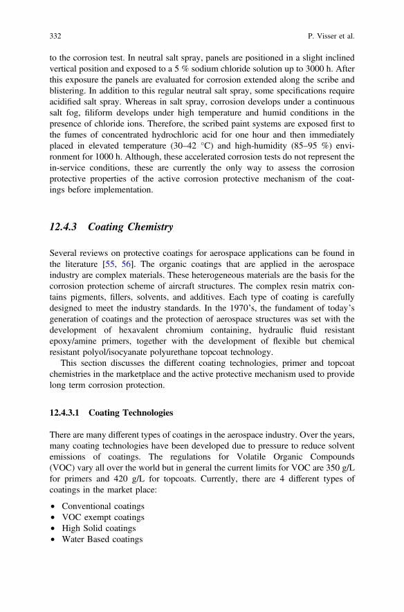
to the corrosion test. In neutral salt spray, panels are positioned in a slight inclinedvertical position and exposed to a 5 % sodium chloride solution up to 3000 h. Afterthis exposure the panels are evaluated for corrosion extended along the scribe andblistering. In addition to this regular neutral salt spray, some specifications requireacidified salt spray. Whereas in salt spray, corrosion develops under a continuoussalt fog, filiform develops under high temperature and humid conditions in thepresence of chloride ions. Therefore, the scribed paint systems are exposed first tothe fumes of concentrated hydrochloric acid for one hour and then immediatelyplaced in elevated temperature (30–42 °C) and high-humidity (85–95 %) envi-ronment for 1000 h. Although, these accelerated corrosion tests do not represent thein-service conditions, these are currently the only way to assess the corrosionprotective properties of the active corrosion protective mechanism of the coat-ings before implementation.
12.4.3 Coating Chemistry
Several reviews on protective coatings for aerospace applications can be found inthe literature [55, 56]. The organic coatings that are applied in the aerospaceindustry are complex materials. These heterogeneous materials are the basis for thecorrosion protection scheme of aircraft structures. The complex resin matrix con-tains pigments, fillers, solvents, and additives. Each type of coating is carefullydesigned to meet the industry standards. In the 1970’s, the fundament of today’sgeneration of coatings and the protection of aerospace structures was set with thedevelopment of hexavalent chromium containing, hydraulic fluid resistantepoxy/amine primers, together with the development of flexible but chemicalresistant polyol/isocyanate polyurethane topcoat technology.
This section discusses the different coating technologies, primer and topcoatchemistries in the marketplace and the active protective mechanism used to providelong term corrosion protection.
12.4.3.1 Coating Technologies
There are many different types of coatings in the aerospace industry. Over the years,many coating technologies have been developed due to pressure to reduce solventemissions of coatings. The regulations for Volatile Organic Compounds(VOC) vary all over the world but in general the current limits for VOC are 350 g/Lfor primers and 420 g/L for topcoats. Currently, there are 4 different types ofcoatings in the market place:
• Conventional coatings• VOC exempt coatings• High Solid coatings• Water Based coatings
332 P. Visser et al.
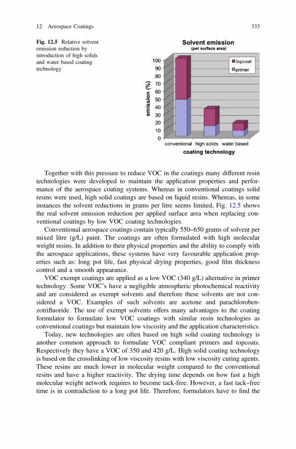
Together with this pressure to reduce VOC in the coatings many different resintechnologies were developed to maintain the application properties and perfor-mance of the aerospace coating systems. Whereas in conventional coatings solidresins were used, high solid coatings are based on liquid resins. Whereas, in someinstances the solvent reductions in grams per litre seems limited, Fig. 12.5 showsthe real solvent emission reduction per applied surface area when replacing con-ventional coatings by low VOC coating technologies.
Conventional aerospace coatings contain typically 550–650 grams of solvent permixed litre (g/L) paint. The coatings are often formulated with high molecularweight resins. In addition to their physical properties and the ability to comply withthe aerospace applications, these systems have very favourable application prop-erties such as: long pot life, fast physical drying properties, good film thicknesscontrol and a smooth appearance.
VOC exempt coatings are applied as a low VOC (340 g/L) alternative in primertechnology. Some VOC’s have a negligible atmospheric photochemical reactivityand are considered as exempt solvents and therefore these solvents are not con-sidered a VOC. Examples of such solvents are acetone and parachloroben-zotrifluoride. The use of exempt solvents offers many advantages to the coatingformulator to formulate low VOC coatings with similar resin technologies asconventional coatings but maintain low viscosity and the application characteristics.
Today, new technologies are often based on high solid coating technology isanother common approach to formulate VOC compliant primers and topcoats.Respectively they have a VOC of 350 and 420 g/L. High solid coating technologyis based on the crosslinking of low viscosity resins with low viscosity curing agents.These resins are much lower in molecular weight compared to the conventionalresins and have a higher reactivity. The drying time depends on how fast a highmolecular weight network requires to become tack-free. However, a fast tack–freetime is in contradiction to a long pot life. Therefore, formulators have to find the
Fig. 12.5 Relative solventemission reduction byintroduction of high solidsand water based coatingtechnology
12 Aerospace Coatings 333
right balance between these properties. Additionally, low molecular resins andcuring agents provide very highly cross-linked systems. This is very beneficial for agood chemical resistance but can be detrimental to the flexibility. Usually highsolids coating formulations are blends of various resins and curing agents to find theright balance between the dry film and application properties.
Progress in the resin industry has helped it to develop water-based coatingtechnologies for aerospace applications. In the late 1980’s, the first water reducibleprimers were introduced for military aircraft. Today, there are multiple water basedprimer technologies available for structural applications. Water-reducible coatingsare based on high solid resins made in solvents that form a dispersion of resin inwater when reduced with water. Modern water-based systems are based on dis-persions and emulsions of resins that easily mix and can be used without theaddition of additional water. These systems provide a further reduction of solventemissions (250 g/L excluding water) and application properties of conventionalcoating systems such as fast cure and good film thickness control.
12.4.3.2 Aerospace Primer Coating Technologies
Primers are used for exterior and structural protection of the aircraft. They provideactive corrosion protection towards the substrate and provide adhesion to the top-coats. These primers have to comply with many criteria. These include:
• Room temperature cure• Excellent adhesion to multiple substrates• High chemical resistance• Sufficient flexibility• Long term corrosion resistance• Good compatibility with the topcoat• Applicable under various climatic conditions
Epoxy primer technologyThe majority of the primers in the aerospace coatings market are 2 componentepoxy/amine primers. The base component comprises a mixture of epoxy resins,pigments, corrosion inhibitors, extenders, additives, and solvents. The secondcomponent, the hardener or curing solution, contains curing agents (amine or polyamide) and solvents. Corrosion inhibitors such as barium chromate and strontiumchromate have been and are still most commonly used as corrosion inhibitor. Epoxyprimer technology is used because of its very versatile properties. It has goodadhesion to many substrates, good corrosion resistance, and can be formulated tofind a balance between the chemical resistance, flexibility, impact resistance andhardness requirements of the aerospace industry. On the other hand, epoxy amineprimers are difficult to strip, have relative long drying times and limited exteriordurability.
334 P. Visser et al.

Epoxy resins
There is a wide range of epoxy resins available. The majority of the epoxy resinsare derived from the reaction between epichlorohydrin and diphenylol propane(Bisphenol A) [57]. There are mainly 4 groups of epoxy resins (Fig. 12.6):
• Bisphenol A epoxy resins• Bisphenol F epoxy resins• Epoxy Novolacs• Epoxy functional diluents and modifiers
Each type of resin has a range of variations in molecular weight and function-ality. The selection of an epoxy resin depends on for which specification orapplication the coating needs to be developed. Many products contain mixtures ofepoxy resins to obtain the specific coating properties needed for aerospace appli-cations. High functional resins are blended with flexible epoxies for increasedelongation properties whereas solid high functional resins are blended for fastphysical drying and chemical resistance. Bisphenol A and F resins are blended toadapt the cure speed and epoxy functional reactive diluents are added to reduceviscosity and increase flexibility.
Fig. 12.6 Types of epoxy resins
12 Aerospace Coatings 335
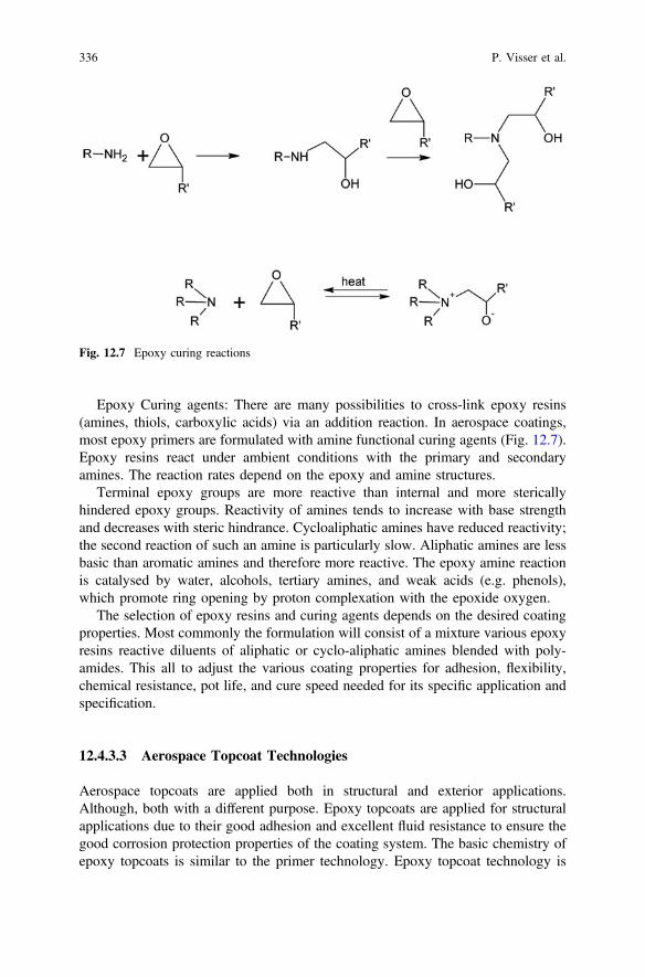
Epoxy Curing agents: There are many possibilities to cross-link epoxy resins(amines, thiols, carboxylic acids) via an addition reaction. In aerospace coatings,most epoxy primers are formulated with amine functional curing agents (Fig. 12.7).Epoxy resins react under ambient conditions with the primary and secondaryamines. The reaction rates depend on the epoxy and amine structures.
Terminal epoxy groups are more reactive than internal and more stericallyhindered epoxy groups. Reactivity of amines tends to increase with base strengthand decreases with steric hindrance. Cycloaliphatic amines have reduced reactivity;the second reaction of such an amine is particularly slow. Aliphatic amines are lessbasic than aromatic amines and therefore more reactive. The epoxy amine reactionis catalysed by water, alcohols, tertiary amines, and weak acids (e.g. phenols),which promote ring opening by proton complexation with the epoxide oxygen.
The selection of epoxy resins and curing agents depends on the desired coatingproperties. Most commonly the formulation will consist of a mixture various epoxyresins reactive diluents of aliphatic or cyclo-aliphatic amines blended with poly-amides. This all to adjust the various coating properties for adhesion, flexibility,chemical resistance, pot life, and cure speed needed for its specific application andspecification.
12.4.3.3 Aerospace Topcoat Technologies
Aerospace topcoats are applied both in structural and exterior applications.Although, both with a different purpose. Epoxy topcoats are applied for structuralapplications due to their good adhesion and excellent fluid resistance to ensure thegood corrosion protection properties of the coating system. The basic chemistry ofepoxy topcoats is similar to the primer technology. Epoxy topcoat technology is
Fig. 12.7 Epoxy curing reactions
336 P. Visser et al.
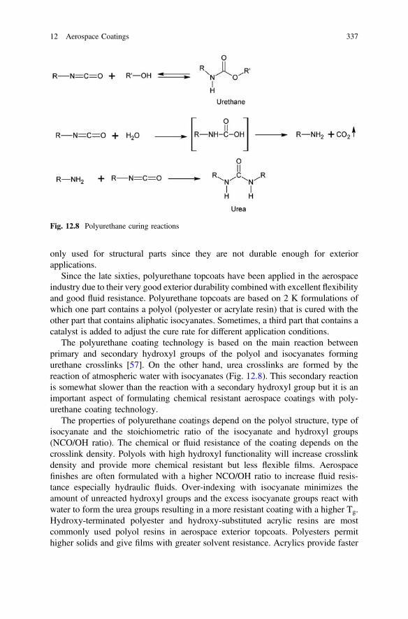
only used for structural parts since they are not durable enough for exteriorapplications.
Since the late sixties, polyurethane topcoats have been applied in the aerospaceindustry due to their very good exterior durability combined with excellent flexibilityand good fluid resistance. Polyurethane topcoats are based on 2 K formulations ofwhich one part contains a polyol (polyester or acrylate resin) that is cured with theother part that contains aliphatic isocyanates. Sometimes, a third part that contains acatalyst is added to adjust the cure rate for different application conditions.
The polyurethane coating technology is based on the main reaction betweenprimary and secondary hydroxyl groups of the polyol and isocyanates formingurethane crosslinks [57]. On the other hand, urea crosslinks are formed by thereaction of atmospheric water with isocyanates (Fig. 12.8). This secondary reactionis somewhat slower than the reaction with a secondary hydroxyl group but it is animportant aspect of formulating chemical resistant aerospace coatings with poly-urethane coating technology.
The properties of polyurethane coatings depend on the polyol structure, type ofisocyanate and the stoichiometric ratio of the isocyanate and hydroxyl groups(NCO/OH ratio). The chemical or fluid resistance of the coating depends on thecrosslink density. Polyols with high hydroxyl functionality will increase crosslinkdensity and provide more chemical resistant but less flexible films. Aerospacefinishes are often formulated with a higher NCO/OH ratio to increase fluid resis-tance especially hydraulic fluids. Over-indexing with isocyanate minimizes theamount of unreacted hydroxyl groups and the excess isocyanate groups react withwater to form the urea groups resulting in a more resistant coating with a higher Tg.Hydroxy-terminated polyester and hydroxy-substituted acrylic resins are mostcommonly used polyol resins in aerospace exterior topcoats. Polyesters permithigher solids and give films with greater solvent resistance. Acrylics provide faster
Fig. 12.8 Polyurethane curing reactions
12 Aerospace Coatings 337
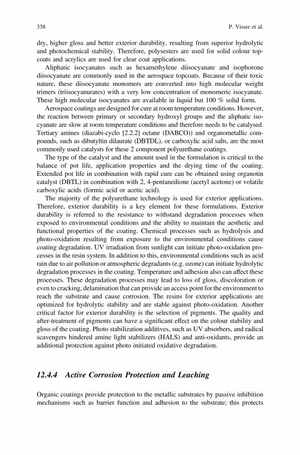
dry, higher gloss and better exterior durability, resulting from superior hydrolyticand photochemical stability. Therefore, polysesters are used for solid colour top-coats and acrylics are used for clear coat applications.
Aliphatic isocyanates such as hexamethylene diisocyanate and isophoronediisocyanate are commonly used in the aerospace topcoats. Because of their toxicnature, these diisocyanate monomers are converted into high molecular weighttrimers (triisocyanurates) with a very low concentration of monomeric isocyanate.These high molecular isocyanates are available in liquid but 100 % solid form.
Aerospace coatings are designed for cure at room temperature conditions. However,the reaction between primary or secondary hydroxyl groups and the aliphatic iso-cyanate are slow at room temperature conditions and therefore needs to be catalysed.Tertiary amines (diazabi-cyclo [2.2.2] octane (DABCO)) and organometallic com-pounds, such as dibutyltin dilaurate (DBTDL), or carboxylic acid salts, are the mostcommonly used catalysts for these 2 component polyurethane coatings.
The type of the catalyst and the amount used in the formulation is critical to thebalance of pot life, application properties and the drying time of the coating.Extended pot life in combination with rapid cure can be obtained using organotincatalyst (DBTL) in combination with 2, 4-pentanedione (acetyl acetone) or volatilecarboxylic acids (formic acid or acetic acid).
The majority of the polyurethane technology is used for exterior applications.Therefore, exterior durability is a key element for these formulations. Exteriordurability is referred to the resistance to withstand degradation processes whenexposed to environmental conditions and the ability to maintain the aesthetic andfunctional properties of the coating. Chemical processes such as hydrolysis andphoto-oxidation resulting from exposure to the environmental conditions causecoating degradation. UV irradiation from sunlight can initiate photo-oxidation pro-cesses in the resin system. In addition to this, environmental conditions such as acidrain due to air pollution or atmospheric degradants (e.g. ozone) can initiate hydrolyticdegradation processes in the coating. Temperature and adhesion also can affect theseprocesses. These degradation processes may lead to loss of gloss, discoloration oreven to cracking, delamination that can provide an access point for the environment toreach the substrate and cause corrosion. The resins for exterior applications areoptimized for hydrolytic stability and are stable against photo-oxidation. Anothercritical factor for exterior durability is the selection of pigments. The quality andafter-treatment of pigments can have a significant effect on the colour stability andgloss of the coating. Photo stabilization additives, such as UV absorbers, and radicalscavengers hindered amine light stabilizers (HALS) and anti-oxidants, provide anadditional protection against photo initiated oxidative degradation.
12.4.4 Active Corrosion Protection and Leaching
Organic coatings provide protection to the metallic substrates by passive inhibitionmechanisms such as barrier function and adhesion to the substrate; this protects
338 P. Visser et al.
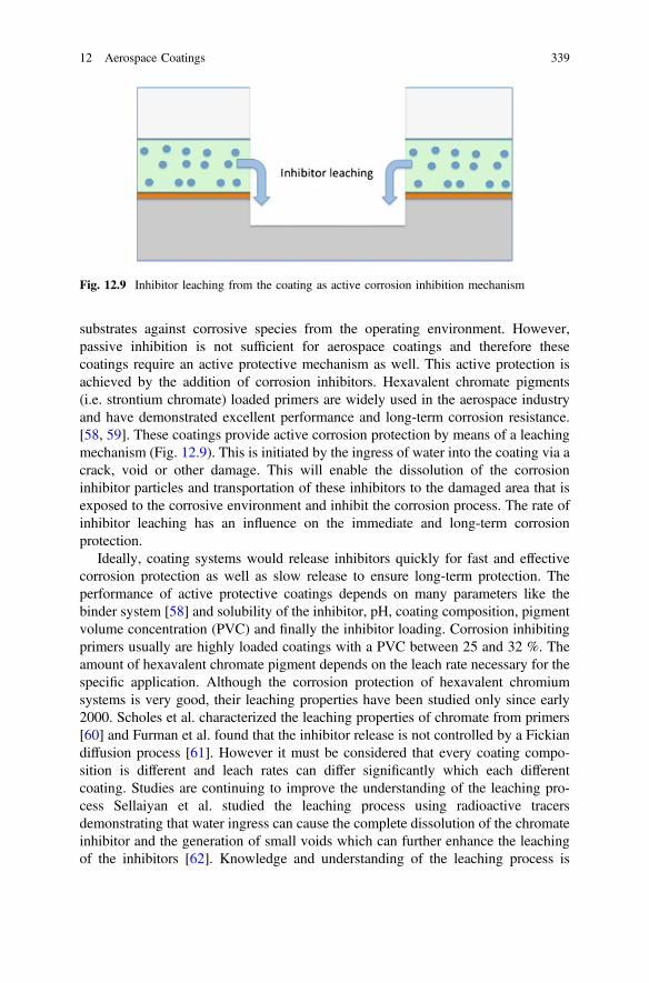
substrates against corrosive species from the operating environment. However,passive inhibition is not sufficient for aerospace coatings and therefore thesecoatings require an active protective mechanism as well. This active protection isachieved by the addition of corrosion inhibitors. Hexavalent chromate pigments(i.e. strontium chromate) loaded primers are widely used in the aerospace industryand have demonstrated excellent performance and long-term corrosion resistance.[58, 59]. These coatings provide active corrosion protection by means of a leachingmechanism (Fig. 12.9). This is initiated by the ingress of water into the coating via acrack, void or other damage. This will enable the dissolution of the corrosioninhibitor particles and transportation of these inhibitors to the damaged area that isexposed to the corrosive environment and inhibit the corrosion process. The rate ofinhibitor leaching has an influence on the immediate and long-term corrosionprotection.
Ideally, coating systems would release inhibitors quickly for fast and effectivecorrosion protection as well as slow release to ensure long-term protection. Theperformance of active protective coatings depends on many parameters like thebinder system [58] and solubility of the inhibitor, pH, coating composition, pigmentvolume concentration (PVC) and finally the inhibitor loading. Corrosion inhibitingprimers usually are highly loaded coatings with a PVC between 25 and 32 %. Theamount of hexavalent chromate pigment depends on the leach rate necessary for thespecific application. Although the corrosion protection of hexavalent chromiumsystems is very good, their leaching properties have been studied only since early2000. Scholes et al. characterized the leaching properties of chromate from primers[60] and Furman et al. found that the inhibitor release is not controlled by a Fickiandiffusion process [61]. However it must be considered that every coating compo-sition is different and leach rates can differ significantly which each differentcoating. Studies are continuing to improve the understanding of the leaching pro-cess Sellaiyan et al. studied the leaching process using radioactive tracersdemonstrating that water ingress can cause the complete dissolution of the chromateinhibitor and the generation of small voids which can further enhance the leachingof the inhibitors [62]. Knowledge and understanding of the leaching process is
Fig. 12.9 Inhibitor leaching from the coating as active corrosion inhibition mechanism
12 Aerospace Coatings 339
important to understand the leaching mechanisms. Computed tomography tech-niques are becoming more and more common in corrosion [63, 64] and paintresearch [65]. These techniques make it possible to study microstructural changes ina paint film. For example, Hughes et al. studied the transport pathways of achromate inhibitor loaded model primer using Quasi 4D computed tomography anddemonstrated that there is no chromate transport through the epoxy resin matrixitself [66]. However, the chromate release occurs via direct dissolution of chromateclusters, which are in contact with the electrolyte at the surface and at a later stagethrough the micro-capillaries and voids left after the dissolution of the inhibitorpigment. This work defines a model that considers fast initial release due to dis-solution and a slower release mechanism of inhibitor dissolution and transportthrough the fractal network. Clusters that were not connected to the electrolyte werenot dissolved and are considered inhibitor reservoirs in case of any further localdamage. These inhibitor transport studies and models are important for the devel-opment of new hexavalent chromium free systems to tailor the release of alternativeinhibitors for immediate and long term protection [67]. All corrosion inhibitingprimers in the aerospace industry use this leaching mechanism for the active pro-tection mechanism. The unique solubility and corrosion inhibiting properties ofthese chromated primers is the basis for the good track record and confidence of thechromated primer technologies for the protection of aircraft structures.
12.4.5 Application
Today, most aerospace coatings are applied with hand-held spray equipment. Thelarge variety of parts that need painting before assembly and the dimension andshape of the aircraft have made automation difficult. Especially, the exteriorpainting process is still a labour-intensive job due to the pre-treatment steps and themasking and de-masking processes involved prior to and during the painting pro-cess (Fig. 12.10). In addition to this, there are several other factors that influence thepainting process. Hangar conditions can vary from 23 °C and 55 % RelativeHumidity (RH) in climatized hangers to severe conditions with high temperaturesand high humidity (35 °C/90 % RH) or low tow temperature conditions with verylow humidity conditions. Some hangars are equipped with movable platforms andothers have fixed scaffolding. Under these varying conditions, the quality of thefinish depends on factors like, teamwork, experience, and skills of the painters.Another important factor is the application equipment.
12.4.5.1 Equipment
There are many different types of equipment for the application of aerospace coat-ings. The most conventional type is the air-atomized spray. This type of spray gunsuses air to atomize the paint in very small droplets that results in a very smooth finish.
340 P. Visser et al.

The equipment is not expensive, easy to clean and is easy to maintain. Although, ithas a low transfer efficiency of approximately 20–30 % and is not suitable for largearea application. Over the years several alternative types of air atomized spray gunshave been developed to improve the transfer efficiency. Examples are HVLP (HighVolume Low Pressure) and HR/RP (High Return/Reduced Pressure) spray guns. AirLess spray equipment uses hydraulic pressure instead of air to atomize the paint. Thepaint is forced through the nozzle with 100–150 bar of pressure to atomize the paint.The velocity of the atomized droplets is less compared to air atomized spray, whichresults in a higher transfer efficiency. The equipment has a high flow rate providing afaster application speed. Airless air assisted spray equipment combines both of bothworlds in air atomized and airless spray. Another way to reduce overspray andincrease transfer efficiency is the use of electrostatic spray equipment. The atomizeddroplets are charged using a high voltage (60–90 kV)/low current generator andattracted to a grounded conductive object. Transfer efficiencies of 70 % are possible.This transfer efficiency depends on the coating formulation. This type of equipment ismost frequently in OEM and MRO paint shops.
Plural component spray equipment is becoming more common in the structuralcoatings market but as well for exterior aircraft painting. The equipment mixes thecomponents (base, hardener and activator) at the desired mixing ratios just before orat the spray gun. This equipment reduces the pot-life factor of 2 component paintsand reduces the amount of waste from unused mixed paint.
Fig. 12.10 Aircraft painting
12 Aerospace Coatings 341
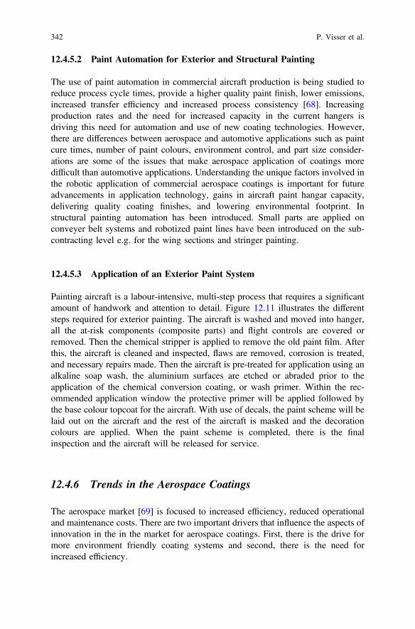
12.4.5.2 Paint Automation for Exterior and Structural Painting
The use of paint automation in commercial aircraft production is being studied toreduce process cycle times, provide a higher quality paint finish, lower emissions,increased transfer efficiency and increased process consistency [68]. Increasingproduction rates and the need for increased capacity in the current hangers isdriving this need for automation and use of new coating technologies. However,there are differences between aerospace and automotive applications such as paintcure times, number of paint colours, environment control, and part size consider-ations are some of the issues that make aerospace application of coatings moredifficult than automotive applications. Understanding the unique factors involved inthe robotic application of commercial aerospace coatings is important for futureadvancements in application technology, gains in aircraft paint hangar capacity,delivering quality coating finishes, and lowering environmental footprint. Instructural painting automation has been introduced. Small parts are applied onconveyer belt systems and robotized paint lines have been introduced on the sub-contracting level e.g. for the wing sections and stringer painting.
12.4.5.3 Application of an Exterior Paint System
Painting aircraft is a labour-intensive, multi-step process that requires a significantamount of handwork and attention to detail. Figure 12.11 illustrates the differentsteps required for exterior painting. The aircraft is washed and moved into hanger,all the at-risk components (composite parts) and flight controls are covered orremoved. Then the chemical stripper is applied to remove the old paint film. Afterthis, the aircraft is cleaned and inspected, flaws are removed, corrosion is treated,and necessary repairs made. Then the aircraft is pre-treated for application using analkaline soap wash, the aluminium surfaces are etched or abraded prior to theapplication of the chemical conversion coating, or wash primer. Within the rec-ommended application window the protective primer will be applied followed bythe base colour topcoat for the aircraft. With use of decals, the paint scheme will belaid out on the aircraft and the rest of the aircraft is masked and the decorationcolours are applied. When the paint scheme is completed, there is the finalinspection and the aircraft will be released for service.
12.4.6 Trends in the Aerospace Coatings
The aerospace market [69] is focused to increased efficiency, reduced operationaland maintenance costs. There are two important drivers that influence the aspects ofinnovation in the in the market for aerospace coatings. First, there is the drive formore environment friendly coating systems and second, there is the need forincreased efficiency.
342 P. Visser et al.
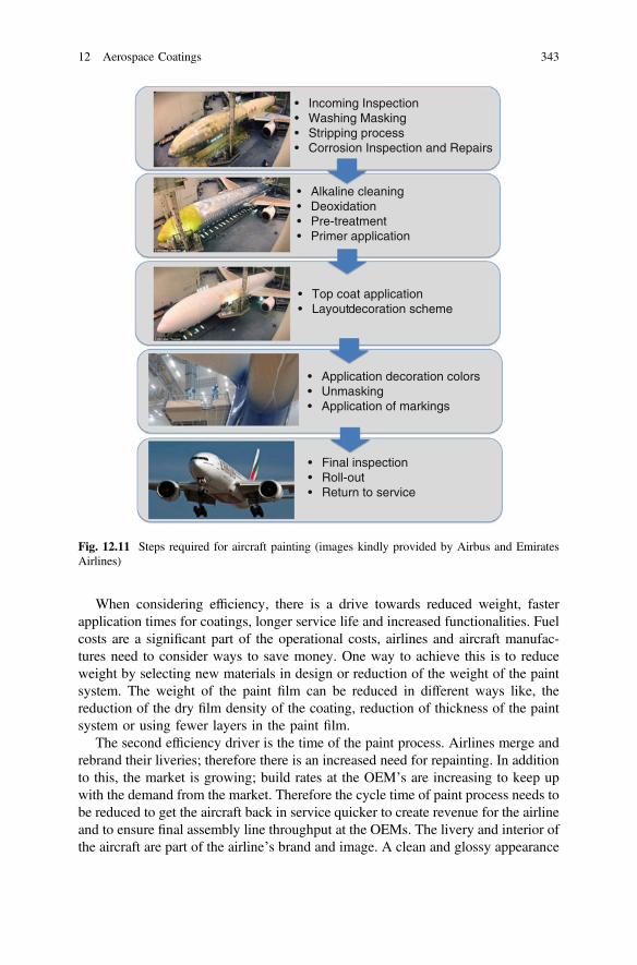
When considering efficiency, there is a drive towards reduced weight, fasterapplication times for coatings, longer service life and increased functionalities. Fuelcosts are a significant part of the operational costs, airlines and aircraft manufac-tures need to consider ways to save money. One way to achieve this is to reduceweight by selecting new materials in design or reduction of the weight of the paintsystem. The weight of the paint film can be reduced in different ways like, thereduction of the dry film density of the coating, reduction of thickness of the paintsystem or using fewer layers in the paint film.
The second efficiency driver is the time of the paint process. Airlines merge andrebrand their liveries; therefore there is an increased need for repainting. In additionto this, the market is growing; build rates at the OEM’s are increasing to keep upwith the demand from the market. Therefore the cycle time of paint process needs tobe reduced to get the aircraft back in service quicker to create revenue for the airlineand to ensure final assembly line throughput at the OEMs. The livery and interior ofthe aircraft are part of the airline’s brand and image. A clean and glossy appearance
• Incoming Inspection• Washing Masking• Stripping process• Corrosion Inspection and Repairs
• Alkaline cleaning• Deoxidation• Pre-treatment• Primer application
• Top coat application• Layout decoration scheme
• Application decoration colors• Unmasking • Application of markings
• Final inspection • Roll-out• Return to service
Fig. 12.11 Steps required for aircraft painting (images kindly provided by Airbus and EmiratesAirlines)
12 Aerospace Coatings 343

with vibrant colours is a key aspect of the branding strategy of an airline. Tosupport this, basecoat/clear coat paint systems have been introduced into themarket. These fast curing collared basecoats are covered with a clear coat to ensurelong-term durability (gloss and colour). In addition to this, the industry is lookingfor increased coating functionalities in the coating. Examples of such functionalitiesare: drag reduction, anti-icing, solar hear reflection/heat dissipation, andself-healing abilities.
The other important aspect is the environmental impact of the coatings. Termssuch as eco-efficiency, sustainability, and carbon footprint are an integral part of thedevelopment of new products for the aerospace industry. Not only for the coatingmanufacturers, but for the entire supply chain from raw material to end-user.More importantly, new legislations such as REACH (Registration, Evaluation,Authorization, and Restriction of Chemicals) and regulations from governmentalinstitutions such as the Environmental Protection Agency (EPA) and OccupationalSafety and Health Administration (OSHA) are applying enormous pressure todevelop more sustainable products with a lower environmental impact.The REACH legislation targets the ban of all chemicals that may be consideredhazardous. Over the years, this has resulted in the replacement of many hazardousmaterials with more acceptable alternatives and solvent emissions have beenreduced.
In the field of aerospace coatings there have been many advances [70]. Today,solvent emissions can be reduced significantly. Conventional coatings, with lowsolids and high solvent content can be replaced by high solids or water-basedcoatings. Water based cleaners and pre-treatments have been introduced andenvironmentally friendly paint removers were developed.
The elimination of hexavalent chromium or chromate from the protectivecoatings and coating processes is a key topic for the aerospace industry, which willbe discussed below.
12.5 Developments Towards a Chromate Free CorrosionProtective Scheme
For more than 50 years the aerospace industry has been using hexavalent chromiumas corrosion inhibiting compounds for the protection of the aircraft structure inmany processes and products. However, the health issues associated with the use ofthese chromate materials and new regulations and legislations are putting pressureon the industry to find alternative solutions [12, 71, 72]. The European REACH(Registration, Evaluation, Authorization and restriction of Chemicals) regulation(EC N° 1907.2006), hexavalent chromium compounds have been included as aSubstances of Very High Concern (SVHC) and are subject to a formal and timelimited authorization for use. This means that they cannot be used after the “sunsetdate” unless there is an authorization. In the USA, the Occupational Safety and
344 P. Visser et al.
Health Administration (OSHA) reduced the employee permissible exposure limits(PEL) to hexavalent chromium from 52 to 5 μg/m3 inducing strict expose controlsof these chemicals.
Through significant efforts in the different areas of the industry various chromatefree alternatives have been developed and qualified to aerospace standards andspecifications, and introduced to the market place [13, 73–79]. Examples of this arechromate free anodising, acid pickling, conversion coatings, sealants and coatings.This part of the chapter provides an overview of the developments in chromate freecoating technology from pre-treatments, coatings and some more innovativeapproaches which should lead eventually towards a fully chromate free corrosionprotective scheme for the protection of the aircraft structures.
12.5.1 Chromate-Free Pre-treatments
Various processes can be utilized prior to the application of the organic coating. Thespecific process used depends on the substrate, and the performance characteristicsrequired for the protective system. Typically, a process will start with a cleaningstep to remove organic contaminations. This will be followed by a deoxidation orpickling step and the application of a surface treatment for corrosion protection andpaint adhesion [80, 81]. The use of non-chrome processing solutions for cleaning,deoxidation, desmutting and etching has increased over the recent years. In additionto this, several alternative solutions for surface treatment have been developed andintroduced to the market place. These hexavalent chromate free surface treatmentsare the new base for the future hexavalent chromate free corrosion protectivescheme.
12.5.1.1 Chemical Conversion Coatings
Significant effort has been spent to develop a suitable alternative to the chromatedchemical conversion coatings. The coatings developed from chromate solutions havea robust performance in processing, corrosion protection and adhesion performance.A wide range of technologies has been investigated, demonstrating the array ofalternative chemistries available for aluminium. These include molybdates, vana-dates [82], permanganate [83–85], phosphates, silanes, sol-gels, self-assemblingmonolayers, hydrotalcites [86–91], and rare earth (cerium) based chemistries [92].Only a few chemistries have been able to come close or meet the corrosion protectionrequirements of aluminium according to the MIL-DTL-81706/5541 specification.Examples of this are conversion coatings based on trivalent chromium (Cr(III))processes (TCP) and cerium. Both these approaches are commercially available andfound their application as part of a coating system [81].
Rare earth based salts are promising options for chromate replacement inchemical conversion coatings for the protection of aluminium alloys. Several rare
12 Aerospace Coatings 345

earths have been identified as cathodic inhibitors [93, 94]. These materials tend toprecipitate as metal hydroxide at local areas that are associated with a pH increasedue to the oxygen reduction reaction at the cathode [95]. This results in thedeposition of a hydrated oxide layer on the aluminium surface [96–98].Unfortunately, most rare earths are too costly for commercial use. However, ceriumis the most active rare and has been studied extensively since the early 1990’s [93].A review by Harvey is the most recent that covers specifically cerium-based con-version coatings [92]. Several cerium-based chemical conversion coating have beendeveloped and commercialised [99–102].
On the other hand, the trivalent chromium (Cr(III)) processes have been devel-oped as alternative to hexavalent chromium pre-treatments. The Naval Air SystemsCommand (NAVAIR) has developed and patented a range of processes usingtrivalent chromium and zirconium fluoride [103]. This process has been approvedaccording to MIL-PRF-81706/5541 and has been licensed to various parties. Thesetrivalent chromium conversion coatings have been introduced into the hexavalentchromium free surface finishes of the US Navy [104–106] and slowly finds it way tothe civil aviation market. There have been many studies on this Trivalent ChromiumProcess (TCP). Guo and Frankel studied the conversion layers and the self-healing oractive corrosion inhibition properties of TCP [107, 108]. On the coating surface adense layer of 40–120 nm was found. The protective barrier layer provides corrosionprotection by suppression of the oxygen reduction reaction. Moreover, the TCPcoating is able to release chromium from the coating proving self-healing or activecorrosion inhibition properties. No hexavalent chromium has been detected in thesecoatings after deposition and corrosion testing [109, 110].
The performance of these new chemical conversion coatings is not at the samelevel as the hexavalent chromated conversion coatings. Although, these chromatefree chemical conversion coatings are finding their place in the aerospace industryand potentially are the new base for the chromate free coatings systems.
12.5.1.2 Anodising
Traditionally, the anti-corrosion performances were achieved by chromic acidanodizing (CAA), followed by painting. However, environmental issues andassociated costs for the disposal of chromate wastes, require the development ofnew approaches for anodizing of aluminium alloys. Phosphoric acid anodising(PAA) and sulphuric acid anodising (SAA) have been available to the industry butwere not suitable chromate free alternatives to CAA because of degradation offatigue life, corrosion resistance, adhesive bonding or paint adhesion. Boric sul-phuric acid (BSA) and tartaric sulphuric acid (TSA) electrolyte anodising processeshave been developed and introduced as suitable alternatives to CAA for corrosionprotection [111–113]. Phosphoric sulphuric acid (PSA) anodizing is used forstructural bonding. These processes have been optimized balancing 3 criteria:Adhesion, corrosion resistance and fatigue properties. The new processes provideanodic film with a similar thickness as the conventional chromate containing
346 P. Visser et al.
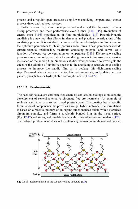
process and a regular open structure using lower anodizing temperatures, shorterprocess times and reduced voltages.
Further research is focused to improve and understand the chromate free ano-dising processes and their performance even further [114, 115]. Reduction ofenergy costs [116] modification of film morphologies [117] Potentiodynamicanodising is a new tool that allows fundamental and practical investigations of theanodising process. It is suitable to compare different electrolytes and to determinethe optimum parameters to obtain porous anodic films. These parameters includecurrent-potential relationship, maximum anodizing potential and current as afunction of electrolyte concentration or temperature [118]. Dichromate sealingprocesses are commonly used after the anodising process to improve the corrosionresistance of the anodic film. Numerous studies were performed to investigate theeffect of the addition of inhibitive species to the anodizing electrolyte or as sealingprocess to improve the anodic film or to replace this dichromate-sealingstep. Proposed alternatives are species like cerium nitrate, molybdate, perman-ganate, phosphates, or hydrophobic carboxylic acids [119–122].
12.5.1.3 Pre-treatments
The need for hexavalent chromate free chemical conversion coatings stimulated thedevelopment of several alternative chromate free pre-treatments. An example ofsuch an alternative is a sol-gel based pre-treatment. This coating has a specificformulation of components that provides a sol-gel hybrid network. The formulationis based on a reactive mixture of an organo-functionalized silane with a stabilizedzirconium complex and forms a covalently bonded film on the metal surface(Fig. 12.12) and strong and durable bonds with paints adhesives and sealants [123].The sol-gel pre-treatment does not contain any corrosion inhibitors and has no
Fig. 12.12 Representation of the sol–gel coating structure [125]
12 Aerospace Coatings 347
significant “stand-alone” corrosion protection. However, it is compliant to theaerospace specifications when used in combination with appropriate paint systems.In 2008, this pre-treatment was introduced to the OEM end-lines for exteriorpainting. Since then it was licensed to several parties and is currently used in OEMand the MRO sector as part of chromated and chromate free coating systems. Inaddition to the environmental and health, and safety benefits, “in-service” flightdata demonstrated that the sol-gel pre-treatment reduced the occurrence of “rivetrash” adhesion failures, which has been a serious issue for many years. The materialcan be applied by spray, brush or flooding. This pre-treatment did not only elim-inate the use of hexavalent chromium in the conversion coating step but, it sim-plified the application process, reduced drying times, water consumption and, thetime required to paint an aircraft [81, 124].
In addition to the sol-gel technology, other chromate-free pre-treatment tech-nologies were introduced into the marketplace. These products do not only elimi-nate hexavalent chromium from the pre-treatment step but as well acid brighteners,solvents and alkaline washes [126]. These particular pre-treatments clean the sur-face to be painted and deposit a molecular layer that bonds to the metal. This layerimproves the adhesion of the coating system to the metal, but do not have anystand-alone corrosion protection. However, they provide an environmentallyfriendly alternative to the hexavalent chromate containing chemical conversioncoatings in combination with aerospace qualified coating systems [73, 77].
12.5.2 Developments in Chromate-Free Organic Coatings
The hexavalent chromate-free surface treatments as discussed above provide thefirst basis of the corrosion protective scheme. Today, the majority of these envi-ronmental friendly surface treatments are coated with chromate containing organiccoatings (primers). On the other hand, there is an enormous effort ongoing to findsuitable alternatives for hexavalent chromium in coatings for the aerospaceindustry. Many inhibitors were evaluated over the years, however with limitedsuccess [58, 127]. For a long time, the objective was to mimic the activity ofchromates which are very effective in low concentrations and in a wide pH range[128]. Many inhibitors were identified in electrochemical studies but, often thesewere out-performed by the unique properties of hexavalent chromium or theyneeded the support of chromated chemical conversion coatings, wash primers oranodising. The quest has not yet been resolved but, there has been promisingprogress in chromate free coatings development and total chromate free coatingsystems are being introduced into the market place for exterior painting. With thisachievement, the industry will be able realign its focus to the elimination of hex-avalent chromium from the structure of the aircraft.
348 P. Visser et al.
12.5.2.1 Corrosion Inhibiting Strategies
Multiple corrosion inhibiting strategies have been developed for chromate freeactive protective coatings. First, there is the traditional “leaching” process, whereasa corrosion inhibitor is incorporated in a paint film and moisture dissolves thecorrosion inhibitor and transports it to the damaged area as discussed inSect. 12.4.4. Second, there is the mechanism of galvanic inhibition, this inhibitingstrategy is based on sacrificial oxidation (cathodic protection) using metallic par-ticles which are electrically connected and more anodic (reactive) than the substratein the electrochemical series and last, there are the “smart” coating approaches withinhibition through self-healing properties and on-demand inhibitor release. The“leaching” and “galvanic” inhibition strategies have been introduced to the marketplace [129] and the “smart” coating approaches are still under development.
12.5.2.2 Inhibition Through Leaching
The traditional “leaching” mechanism is the fundament of current aerospacespecifications for active protective coatings in the aerospace industry. The perfor-mance of hexavalent chromium corrosion inhibiting pigments provided a proventrack record and is currently the benchmark for all new chromate free active pro-tective coatings. The leaching inhibitors need to provide active corrosion inhibitionwhen the measures of the corrosion protection scheme are failing (substrate,pre-treatment, sealant, drainage) and the system is damaged by means of a crack,drilling hole or, scratch. At this stage, moisture ingresses into the crack or system,the inhibitor should be dissolved and transported to the damage. Where chromateswere unrivalled for a long time, chromate-free alternatives are being introduced intothe market place.
Leaching inhibitors have to be versatile and it is the question whether it ispossible to find the complete package (like chromates) in a single inhibitor. Thereare many chromate-free inhibitors that demonstrate activity but do not performwhen incorporated into a coating due to various reasons like: solubility, efficacy, orcompatibility with the binder system. Therefore the leaching capabilities should beconsidered from coating/inhibitor perspective and have adequate solubility andleaching characteristics, fast and effective formation of an irreversible protectivelayer in the damaged area, underneath the coating and, maintain a good coatingintegrity (adhesion and barrier function). Many inhibitors have been developed andinvestigated in the academic environment but as well in the industry. Many patentshave been filed and published on a range of corrosion inhibiting materials. Severalof them have been introduced to the market place but none of them can be reallyconsidered as the true replacement and alternative to hexavalent chromium. Someexamples are mentioned below.
Most of the inhibitors are based on inorganic materials, among them inhibitorsbased on rare earths (cerium and praseodymium), molybdates and vanadates [130,131]. Praseodymium has received considerable attention. Stoffer et al. claim a
12 Aerospace Coatings 349
corrosion inhibiting coating composition based on a rare earth compound (pra-seodymium oxide) and a neutral to acidic generating extender (Calcium Sulphate)[132]. Praseodymium oxide (Pr2O3) provides the best protection across a pH rangefrom 5 to 8. Praseodymium-rich species leach from the coating and precipitate ashydroxy carbonates in the damaged area near cathodic sites [133]. Pipko and Vitnerdeveloped and claimed compositions of oxyaminophosphate salts of magnesium asleaching inhibitors. These slow releasing materials were found to form stablemagnesia layers on the metal surface [134, 135]. Yu et al. claimed anon-carcinogenic corrosion-inhibiting additive comprises an anodic corrosioninhibitor and/or a cathodic corrosion inhibitor. This leaching inhibitor uses amolybdate salt as anodic inhibitor, cerium as cathodic inhibitor and citrate as ametal-complexing compound [136, 137]. Walters and Schneider claim a coatingscomposition utilizing nano-sized Magnesium oxide particles as alternative to hex-avalent chromium [138]. Visser and Hayes propose lithium salts as corrosioninhibitor for 2024-T3 aluminium alloys [139]. Whereas, organic inhibitors and rareearth species are active on active copper intermetallic (cathodes) [140], leaching oflithium species from organic coatings results in the formation of a protective layerwith a characteristic 3 layered morphology on the aluminium in the damaged area[141]. Boocock used a composition with amorphous zirconium vanadiumoxide/hydroxide for the protection of high strength aluminium alloys [142], andBecker et al. proposed a coatings composition containing a corrosion inhibitor andat least one quaternary ammonium compound [143].
In addition to the inorganic inhibitors, there are many organic inhibitors that areand have been investigated. Harvey et al. investigated the effect of the inhibitorstructure on the corrosion of AA2024-T3 and AA7075-T6 and found good inhibitorefficiencies for most of these well-known “copper” inhibitors, Among themBenzotriazole, 2-mercaptothiazole, dithiocarbamates, dimercapto thiadiazoles [144].Sinko designed different hybrid organic-inorganic corrosion-inhibiting micro com-posite pigment grades that contain 2, 5 dimercapto-1, 3, 4-thiadiazole, zinc oxide,zinc phosphate and zinc cyanimide [145–147]. Furthermore, together with Kendig,Sinko proposed a guest–host pigment (hydrotalcite based) that can be loaded with anorganic inhibitor [148, 149]. Hayes et al. proposed a pigment comprising a neu-tralized metal salt of a corrosion inhibiting organic anion, wherein 2.5 % by weightaqueous mixture of the dry salts has a pH above 6 and below 8 [150].
Other researchers have tried to find viable alternatives for hexavalent chromiumcombining the best of both inorganic and organic inhibitors. Examples are ceriumsalts of organic inhibitors cerium cinnamate [151], cerium dibutylphosphate [152,153] and cerium or praseodymium mercapto acetate [154].
12.5.2.3 Galvanic Inhibition
Cathodic protection or galvanic inhibition is a method that is extensively used forthe protection of steel structures. The protection is based on a sacrificial mechanism.In the case of steel, zinc (Zn) is used because it is more reactive (anodic) compared
350 P. Visser et al.
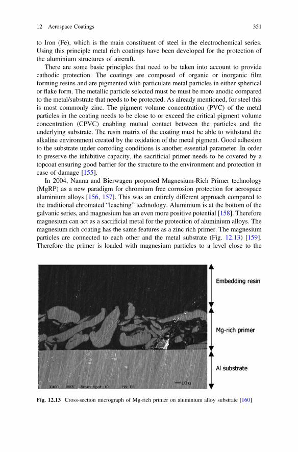
to Iron (Fe), which is the main constituent of steel in the electrochemical series.Using this principle metal rich coatings have been developed for the protection ofthe aluminium structures of aircraft.
There are some basic principles that need to be taken into account to providecathodic protection. The coatings are composed of organic or inorganic filmforming resins and are pigmented with particulate metal particles in either sphericalor flake form. The metallic particle selected must be must be more anodic comparedto the metal/substrate that needs to be protected. As already mentioned, for steel thisis most commonly zinc. The pigment volume concentration (PVC) of the metalparticles in the coating needs to be close to or exceed the critical pigment volumeconcentration (CPVC) enabling mutual contact between the particles and theunderlying substrate. The resin matrix of the coating must be able to withstand thealkaline environment created by the oxidation of the metal pigment. Good adhesionto the substrate under corroding conditions is another essential parameter. In orderto preserve the inhibitive capacity, the sacrificial primer needs to be covered by atopcoat ensuring good barrier for the structure to the environment and protection incase of damage [155].
In 2004, Nanna and Bierwagen proposed Magnesium-Rich Primer technology(MgRP) as a new paradigm for chromium free corrosion protection for aerospacealuminium alloys [156, 157]. This was an entirely different approach compared tothe traditional chromated “leaching” technology. Aluminium is at the bottom of thegalvanic series, and magnesium has an even more positive potential [158]. Thereforemagnesium can act as a sacrificial metal for the protection of aluminium alloys. Themagnesium rich coating has the same features as a zinc rich primer. The magnesiumparticles are connected to each other and the metal substrate (Fig. 12.13) [159].Therefore the primer is loaded with magnesium particles to a level close to the
Fig. 12.13 Cross-section micrograph of Mg-rich primer on aluminium alloy substrate [160]
12 Aerospace Coatings 351
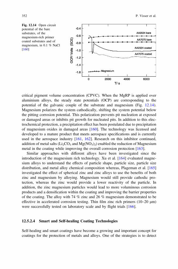
critical pigment volume concentration (CPVC). When the MgRP is applied overaluminium alloys, the steady state potentials (OCP) are corresponding to thepotential of the galvanic couple of the substrate and magnesium (Fig. 12.14).Magnesium polarizes the system cathodically, shifting the system potential belowthe pitting corrosion potential. This polarization prevents pit nucleation at exposedor damaged areas or inhibits pit growth for nucleated pits. In addition to this elec-trochemical protection, a precipitation effect has been postulated due to precipitationof magnesium oxides in damaged areas [160]. The technology was licensed anddeveloped to a mature product that meets aerospace specifications and is currentlyused in the aerospace industry [161, 162]. Research on this inhibitor continued,addition of metal salts (Li2CO3 and Mg(NO3)2) enabled the reduction of Magnesiummetal in the coating while improving the overall corrosion protection [163].
Similar approaches with different alloys have been investigated since theintroduction of the magnesium rich technology. Xu et al. [164] evaluated magne-sium alloys to understand the effects of particle shape, particle size, particle sizedistribution, and metal alloy chemical composition whereas, Plageman et al. [165]investigated the effect of spherical zinc and zinc alloys to use the benefits of bothzinc and magnesium by alloying. Magnesium would still provide cathodic pro-tection, whereas the zinc would provide a lower reactivity of the particle. Inaddition, the zinc magnesium particles would lead to more voluminous corrosionproducts and a densification within the coating and improving the barrier propertiesof the coating. The alloy with 74 % zinc and 26 % magnesium demonstrated to beeffective in accelerated corrosion testing. Thin film zinc rich primers (10–20 μm)were successfully tested on laboratory scale and by flight trials [166].
12.5.2.4 Smart and Self-healing Coating Technologies
Self-healing and smart coatings have become a growing and important concept forcoatings for the protection of metals and alloys. One of the strategies is to detect
Fig. 12.14 Open circuitpotential of the baresubstrates, of themagnesium-rich primercoated substrates and ofmagnesium, in 0.1 % NaCl[160]
352 P. Visser et al.
and heal damage in a coating and to recover the initial functionality of the coatingsystem. Since this pioneering work of White et al. [167], self-healing or smartcoatings discipline took a flight and resulted in a rapid increase of approaches. Themain self-healing strategies are aesthetics and barrier recovery (gap filling) andactive corrosion inhibition [168]. The strategies include the release of liquid reac-tive healing agents from capsules due to a mechanical damage, expansive phases,flow and reflow of material followed by a chemical reaction or restoration ofphysical bonds. The other approach is the release corrosion inhibitors or surfacereactive compounds from microcapsules. Inhibitor release from these capsules canbe triggered by mechanical damage, diffusion, ion exchange or change of pH. In2011 Zheludkevich provided a comprehensive review of these smart and selfhealing technologies [169]. Since then, new approaches have been proposed. Garciaet al. proposed a self-healing concept based on an encapsulated water reactive silylester that is based on wetting and a reaction with ambient humidity and the metallicsurface and it finally forms a hydrophobic layer to extend corrosion protection[170]. Other micro-capsule approaches have been proposed including: inhibitorimpregnated CaCO3 micro beads [171], TiO2 nano-containers loaded with8-hydroxyquinoline [172], Silica nano-containers with a regular shape and diameterbetween 100 and 150 nm loaded with 2-mercaptobenzothiazole [173], EDTAloaded layered double hydroxides [174], and Cerium and diethyldithiocarbamate(DEDTC) double doped zeolites [175]. Also some patents have been filed to claimthe use of such strategies for the protection of aluminium structures for aerospaceapplications. Gammel et al. propose a coating with embedded micro-capsulescontaining 2-mercaptobenothiazole [176]. Barbe et al. claim a coating compositionthat comprises ceramic particles with a releasable active material homogeneouslydistributed in each particle [177].
Another approach is the use of conducting polymers. Tallman et al. reportedcorrosion protective properties of conductive polymer coatings [178, 179]. Most ofthe investigated conductive polymers are based on polyaniline (Pani). The galvanicinteraction between the oxidized and conducting form of Pani, the emeraldine salt(ES) and the aluminium substrate leads to positive polarization of the aluminiumsubstrate and the reduction of Pani ES to the leucoemeraldine base (EB) of Pani andthe release of a dopant anion [180]. The dopant can play a role in the corrosionprotection due to the formation of a metal-dopant interface, Kendig et al. proposedto dope Pani ES with specific anions that could work as cathodic inhibitors andreduce the oxygen reduction reaction at copper-rich intermetallic particles [181,182]. However the exact protective mechanism for aluminium alloys has not beenresolved yet [183, 184]. Concepts of such ‘smart’ conductive coating have beendeveloped by Kinlen and Kendig et al. [185, 186], and the first field testing studies,as an alternative to chromated chemical conversion coatings, have been reported[187].
Both the self-healing and conductive coating approaches are still under devel-opment and do not provide the industry with a drop-in alternative for hexavalentchromium, however the knowledge that is generated from this work can providefuture tools for chromate free corrosion protection of aircraft structures.
12 Aerospace Coatings 353
12.5.2.5 Alternative Coating Techniques
The aerospace industry has been rather conservative in terms of accepting alter-native coating technologies. The coating systems have been improved incremen-tally over the years and no real new coatings concepts have been introduced.However, with the current demands of the industry in terms of productivity andenvironmental impact, alternative coating techniques can be considered. Examplesof such alternative coating techniques are electro-deposition paints, powder coat-ings and UV-curable coatings.
Electro-deposition primers are widely used in the automotive industry. However,it was not introduced in the aerospace industry because of bath stability issues,coating thickness, high curing temperature and large capital investment. Recentdevelopments make it possible to coat small parts with a chromate-free electrodeposition process [188]. In this efficient coating process, an electrical field isapplied and water dispersed paint particles will be negatively charged and move tothe anode. When the surface is coated, the part will be rinsed and thermally cured.Introduction of this technology will increase transfer efficiency and reduce overspray and solvent emissions, waste, and improved layer thickness control. Thetechnology is based on anaphoretic paint deposition, which cures below 120 °C. AnElectro-deposition coating provides anodisation and coating application in the samestep. An interfacial oxide layer is formed during the anaphoretic paint deposition[189]. The oxide layer is composed of a dense sub-layer on the substrate with oxidefilaments interpenetrating in the coating with a film thickness of 20 μm. Thetechnology is being introduced to the aerospace industry [190].
Since the early 1980’s there have been developments on powder coatings foraerospace applications [191]. This technology would eliminate solvent emissions,hazardous air pollutants, and reduce waste. In addition, it can provide improvedefficiency due to faster curing, eliminate pot life issues, and increased transferefficiency. The main issue of powder coatings has been the high temperaturesneeded to get a full cure of the system. These high curing temperatures, 220 °C andhigher, might affect the strength of the aluminium alloy. Research has resulted inlow temperature and UV curable approaches, but the technology is not widely usedin the industry [192, 193].
Ultraviolet (UV) curing is the other alternative technology that can be used incoatings. These coatings can be formulated as 100 % solids, without the use ofVOC and hazardous air pollutants and can be polymerized, cross-linked in a matterof seconds and provide films that are decorative and functional. The UV curingmechanism is a photo-chemical process by which a liquid coating is completelycross-linked to solid polymer through exposure to UV radiation without the needfor isocyanate cross-linking agents. There are two classes of UV-curing technology,based on the nature of photo-initiators and resin chemistry: free radical (mostlyacrylate) and cationic (epoxy). Acrylate self-priming topcoat approaches wereproposed for the protection of aerospace aluminium alloys. Although the approach
354 P. Visser et al.
was over chromated conversion coatings, energy savings and solvent emissionreductions were additional benefits to the reduction of chromates in the total paintsystem [194, 195]. Moreau et al. designed UV-curable hybrid sol-gel formulationsbased on both organic and inorganic photo polymerization [196]. This process isbased on the liberation of photo acids by the UV decomposition of an iodoniumsalt. This triggers simultaneously the sol-gel process and epoxy cationic polymer-ization [197]. The one-step UV-curing process hybrid sol-gel coatings can providehigh corrosion resistance on metallic substrates and protection of composites.
12.5.3 New Approaches Towards Chromate Free CoatingsTechnology
Chromate-free coating technology is evolving rapidly. Over the years, many inhi-bitors have been tested. However, corrosion testing is one of the bottlenecks in thecoating development process. There is a need for faster and more accurate screeningof new chromate-free candidates. Inhibitors need to be tested for synergistic per-formance or activity over a wide pH range. In addition to this, chromate-freecorrosion inhibiting coating technologies became better and therefore it becomesmore difficult to discriminate between the current technologies and possibleimprovements, resulting in longer testing. Evaluation of corrosion results is stillrather old fashioned and difficult to obtain absolute numbers. High throughputexperimentation and imaging techniques are two examples of tools that can be usedto accelerate the development of new chromate-free inhibiting technology.
12.5.3.1 High-Throughput Experimentation
Corrosion performance has been historically evaluated using electrochemicaltechniques, accelerated corrosion testing, or even outdoor exposure. These methodsrequire testing times ranging from hours to years. Advances in material sciencehave broadened in the scope for the discovery of new corrosion inhibitors. Recentdevelopments consider the combination of two or more inhibitor technologies (i.e.anodic and cathodic inhibitors) to obtain multifunctional or synergistic performance[198, 199]. There has been a considerable effort to develop high throughputexperimentation techniques to increase the rate of new inhibitor screening and tofind combinations for synergistic and antagonistic effects. High-throughput com-bination and electrochemical characterization have provided new tools for theexploration and understanding of new corrosion inhibitors. Chambers et al.investigated the inhibition characteristics of 50 different chemistries within 9 hoursusing a direct current (DC) polarization between two AA2024-T3 wire electrodesand a multiple—electrode-testing system [200]. Garcia et al. used a multi-metal
12 Aerospace Coatings 355
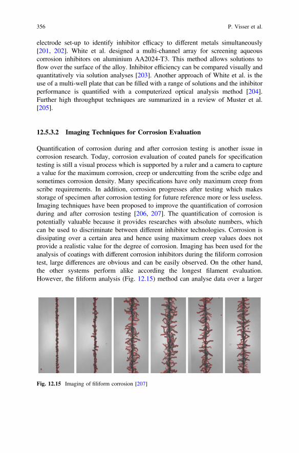
electrode set-up to identify inhibitor efficacy to different metals simultaneously[201, 202]. White et al. designed a multi-channel array for screening aqueouscorrosion inhibitors on aluminium AA2024-T3. This method allows solutions toflow over the surface of the alloy. Inhibitor efficiency can be compared visually andquantitatively via solution analyses [203]. Another approach of White et al. is theuse of a multi-well plate that can be filled with a range of solutions and the inhibitorperformance is quantified with a computerized optical analysis method [204].Further high throughput techniques are summarized in a review of Muster et al.[205].
12.5.3.2 Imaging Techniques for Corrosion Evaluation
Quantification of corrosion during and after corrosion testing is another issue incorrosion research. Today, corrosion evaluation of coated panels for specificationtesting is still a visual process which is supported by a ruler and a camera to capturea value for the maximum corrosion, creep or undercutting from the scribe edge andsometimes corrosion density. Many specifications have only maximum creep fromscribe requirements. In addition, corrosion progresses after testing which makesstorage of specimen after corrosion testing for future reference more or less useless.Imaging techniques have been proposed to improve the quantification of corrosionduring and after corrosion testing [206, 207]. The quantification of corrosion ispotentially valuable because it provides researches with absolute numbers, whichcan be used to discriminate between different inhibitor technologies. Corrosion isdissipating over a certain area and hence using maximum creep values does notprovide a realistic value for the degree of corrosion. Imaging has been used for theanalysis of coatings with different corrosion inhibitors during the filiform corrosiontest, large differences are obvious and can be easily observed. On the other hand,the other systems perform alike according the longest filament evaluation.However, the filiform analysis (Fig. 12.15) method can analyse data over a larger
Fig. 12.15 Imaging of filiform corrosion [207]
356 P. Visser et al.
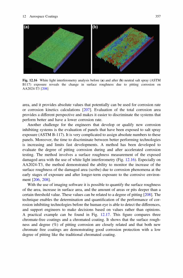
area, and it provides absolute values that potentially can be used for corrosion rateor corrosion kinetics calculations [207]. Evaluation of the total corrosion areaprovides a different perspective and makes it easier to discriminate the systems thatperform better and have a lower corrosion rate.
Another challenge for the engineers that develop or qualify new corrosioninhibiting systems is the evaluation of panels that have been exposed to salt sprayexposure (ASTM B-117). It is very complicated to assign absolute numbers to thesepanels. Moreover, the time to discriminate between better performing technologiesis increasing and limits fast developments. A method has been developed toevaluate the degree of pitting corrosion during and after accelerated corrosiontesting. The method involves a surface roughness measurement of the exposeddamaged area with the use of white light interferometry (Fig. 12.16). Especially onAA2024-T3, the method demonstrated the ability to monitor the increase of thesurface roughness of the damaged area (scribe) due to corrosion phenomena at theearly stages of exposure and after longer-term exposure to the corrosive environ-ment [206, 208].
With the use of imaging software it is possible to quantify the surface roughnessof the area, increase in surface area, and the amount of areas or pits deeper than acertain threshold value. These values can be related to a degree of pitting [208]. Thetechnique enables the determination and quantification of the performance of cor-rosion inhibiting technologies before the human eye is able to detect the differences,and support engineers to make decisions based on values rather than opinions.A practical example can be found in Fig. 12.17. This figure compares threechromate-free coatings and a chromated coating. It shows that the surface rough-ness and degree (%) of pitting corrosion are closely related and that both newchromate free coatings are demonstrating good corrosion protection with a lowdegree of pitting like the traditional chromated coating.
Fig. 12.16 White light interferometry analysis before (a) and after (b) neutral salt spray (ASTMB117) exposure reveals the change in surface roughness due to pitting corrosion onAA2024-T3 [208]
12 Aerospace Coatings 357
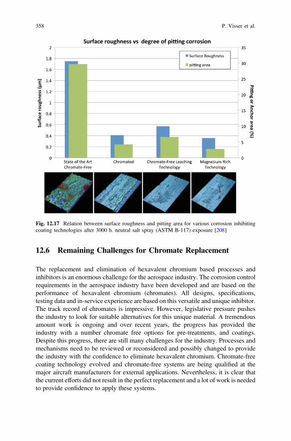
12.6 Remaining Challenges for Chromate Replacement
The replacement and elimination of hexavalent chromium based processes andinhibitors is an enormous challenge for the aerospace industry. The corrosion controlrequirements in the aerospace industry have been developed and are based on theperformance of hexavalent chromium (chromates). All designs, specifications,testing data and in-service experience are based on this versatile and unique inhibitor.The track record of chromates is impressive. However, legislative pressure pushesthe industry to look for suitable alternatives for this unique material. A tremendousamount work is ongoing and over recent years, the progress has provided theindustry with a number chromate free options for pre-treatments, and coatings.Despite this progress, there are still many challenges for the industry. Processes andmechanisms need to be reviewed or reconsidered and possibly changed to providethe industry with the confidence to eliminate hexavalent chromium. Chromate-freecoating technology evolved and chromate-free systems are being qualified at themajor aircraft manufacturers for external applications. Nevertheless, it is clear thatthe current efforts did not result in the perfect replacement and a lot of work is neededto provide confidence to apply these systems.
Fig. 12.17 Relation between surface roughness and pitting area for various corrosion inhibitingcoating technologies after 3000 h. neutral salt spray (ASTM B-117) exposure [208]
358 P. Visser et al.
Multiple chromate free alternative processes have been introduced to theindustry [80, 106]. Especially on pre-treatment level, alternative solutions wereintroduced but still to be used in combination with chromated coating systemsTherefore, many challenges have to be overcome before hexavalent chromium andchromates can be eliminated from the aerospace industry. These challenges are:
• Technical performance• Processes and requirements• Industry confidence• Service life prediction
First, the primary challenge is to find suitable alternative inhibitors and coatingsystems that demonstrate an equal or better technical performance compared to thehexavalent chromium. The superior inhibiting efficiency and versatile behaviour ofchromates and hexavalent chromium materials make it very difficult to replace it bya single drop-in material. Chromate inhibition mechanisms have been studied [20],but mimicking chromates has not been very successful and possibly new approa-ches are necessary to provide a similar protection. Nevertheless, in recent yearsmany inhibitors were identified and tested extensively. Some are promising can-didates and some are very close to the performance of chromates in acceleratedcorrosion tests. However, the performance in service is still unclear.
The second challenge concerns the processes and requirements of the aerospaceindustry. Hexavalent chromium is the primary corrosion control material. It isembedded in all parts in aerospace industry, from the smallest clip to the largeststringer, fasteners and sealants, coatings and pre-treatments. Chromate containingproducts processes are specified by material specifications for new aircraft but aswell in the maintenance manuals of legacy aircraft currently in service. Thereplacement of chromates will be a long process with many hurdles.
Industry confidence is the third challenge. First of all, is the performance of thenew chromate free technologies and the confidence of the industry sufficient enoughto make a switch to total chromate free aircraft when legislation and regulations banthe use of these carcinogenic materials. Today, alternative solutions have beenintroduced, these solutions passed the material specification requirements but stillare not as good or robust as chromated technology. When these individual qualifiedmaterials are introduced in a system, it is possible that the total system does notalways meet the requirements. The laboratory performance of new systems isknown, but the in-service behaviour and performance is unknown. Therefore, newchromate-free systems need to be tested extensively to provide confidence to theaerospace engineers to justify a switch to chromate-free coating technology.
The final challenge is service-life prediction. Chromated systems have a proventrack record of more than 50 years within the aerospace industry. The protection ofaircraft structure has been ensured for more than 30 years. With the introduction ofthe chromate-free technology it is a brand new story. Developments demonstratethat it is possible to meet the aerospace specification requirements. However, itremains unclear how the system behaves under in-service conditions. The challenge
12 Aerospace Coatings 359

is how to predict the long-term performance of a new chrome-free coating systemso it protects the aircraft structure for more than 30 years. Reduced performancewill lead to higher maintenance and depreciation costs.
12.7 Summary and Conclusion
Aviation is an integral part of society of today. Air travel is increasing and thenumber of aircraft is expected to double over the coming 20 years. Aircraft have verycomplex designs with a variety of metals and composite materials. With an expectedservice- life of about 30 years and the harsh operating environment with many flightcycles makes fatigue properties and corrosion protection important concerns.
Aluminium is the predominant construction material for aircraft. Especially,AA2024-T3 andAA7075-T3 are commonly used because of their favourable strengthto weight ratio. However, these alloys are susceptible to various types of corrosion.Corrosion control is a key element next to efficient and environmental sustainableoperations Coatings and surface treatments is one of the critical factors in the corro-sion protection scheme to ensure the long- term protection of the aircraft structure.
Aerospace coatings are used on all types of commercial and military aircraft asprotective and decorative finishes. These coatings are designed and formulated towithstand challenging aerospace operating conditions. The requirements andproperties for aerospace coatings are controlled by specifications. There are threecategories of aerospace coatings: structural systems, exterior systems and specialpurpose systems. They are usually applied with hand-held spray equipment andcured at ambient conditions.
Current aerospace coating systems are mainly based on a pre-treatment (e.g.chemical conversion coating or anodising) on the aluminium alloy, a corrosioninhibiting epoxy-amine primer, and a protective or decorative polyurethane topcoat.Hexavalent chromium compounds are widely used in these aerospace coatings andpre-treatments, these materials exhibit excellent anticorrosive properties and pro-vided the foundation of the corrosion protection of today’s aircraft structures.
The industry has been using hexavalent chromium inhibition since the intro-duction of the aluminium aircrafts. However, health issues and new legislations andregulations are putting pressure on the industry to find sustainable alternatives toreplace hexavalent chromium compounds. Already since the 1980’s fundamentaland applied research has been searching for alternatives and resolving the inhibitionmechanism of hexavalent chromium. The quest for chromate-free coatings systemsthat provides corrosion protection better than or equal to the chromated technologyhas resulted in a range of chromate-free pre-treatments and coating systems. Severalof them have been qualified and introduced into the market place. The research alsoprovided new inhibition strategies like: cathodic protection, conductive polymers,self-healing approaches, high throughput technologies, and advanced corrosionassessment tools.
360 P. Visser et al.
Despite the availability of these chromate-free materials and systems, it can bestated that there is no direct replacement for hexavalent chromium available to date.Therefore, research continues to meet the technical performance of chromatedtechnology and to overcome the challenges associated chromate-free inhibitionsystems for aerospace coatings and to provide the confidence to the industry tointroduce the chromate-free alternatives and eliminate hexavalent chromium com-pounds from the industry.
References
1. O. Guseva, S. Brunner, P. Richner, Analysis of the environmental parameters for aircraftcoatings. Macromol. Symp. 187, 883–893 (2002). doi:10.1002/1521-3900(200209)187:1<883:AID-MASY883>3.0.CO;2-M
2. Deloitte, 2013 Global aerospace and defense industry outlook (2013), http://www.deloitte.com/aerospace&defense/2013a&doutlook. Accessed 12 March 2014
3. GAMA, 2012 general aviation statistical databook & industry outlook. General aviationmanufacturers association (GAMA) (2012), http://www.gama.aero/media-center/industry-facts-and-statistics/. Accessed 10 Oct 2013
4. Airbus, Airbus global market forecast 2012–2031 (2013), http://www.airbus.com/company/market/forecast/?. Accessed Aug 2013
5. Boeing, Current market outlook 2013–2032 (2013), http://www.boeing.com/assets/pdf/commercial/cmo/pdf/Boeing_Current_Market_Outlook_2013.pdf. Accessed Aug 2013
6. H. Jiang, Key Findings on airplane economic life. The boeing company (2013), http://www.boeing.com/boeing/commercial/industry_info.page. Accessed 12 Dec 2013
7. T. Wright, Aerospace coatings. Coat. World 15(8), 28–31 (2010)8. Organization ICA, ICAO safety report 2014 edition. International civil aviation organization
(2014), http://www.icao.int/safety/Documents/ICAO_2014_Safety_Report_final_02042014_web.pdf. Accessed 13 March 2014
9. G.H. Koch, Cost of corrosion Appendix P aircraft. CC technologies, http://corrosionda.com/transportation/aircraft/index.htm. Accessed 13 March 2014
10. J.A. DeRose, T. Suter, T. Hack, R. Adey, Aluminium Alloy Corrosion of Aircraft Structures:Modelling and Simulation (WIT Press, 2013)
11. M. Kendig, S. Jeanjaquet, R. Addison, J. Waldrop, Role of hexavalent chromium in theinhibition of corrosion of aluminum alloys. Surf. Coat. Technol. 140(1), 58–66 (2001).doi:10.1016/S0257-8972(01)01099-4
12. National Toxicology P NTP, 12th Report on Carcinogens. Report on Carcinogens :Carcinogen profiles/US Dept of Health and Human Services, Public Health Service, NationalToxicology Program 12, 106–109 (2011)
13. D.C.V. Beelen, P. Rouw, R. Boomgaard, K. Zabel, Aviox CF priamer: a new generationprimer for aircraft maintenance. Anti-Corros. Methods Mater. 44(2), 28–33 (1997)
14. J.G. Kaufman, Introduction to Aluminum Alloys and Tempers (ASM International, 2000)15. J.R. Davis, Corrosion of Aluminum and Aluminum Alloys (ASM International, 1999)16. T. Richardson, B. Cottis, D. Scantlebury, R. Lindsay, S. Lyon, M. Graham, Shreir’s
Corrosion (Elsevier, 2010)17. I.J. Polmear, Light Alloys (Elsevier Ltd, 2005)18. A.E. Hughes, N. Birbilis, J.M.C. Mol, J. Santiago, S.J. Garcia, X. Zhou, G.E Thompson, in
Recent Trends in Processing and Degradation of Aluminium Alloys, ed by P.Z. Ahmad.Thompson, High Strength Al-Alloys: Microstructure, Corrosion and Principles of Protection.In Tech. doi:10.5772/18766
12 Aerospace Coatings 361
19. T. Dursun, C. Soutis, Recent developments in advanced aircraft aluminium alloys. Mater.Des. 56, 862–871 (2014). doi:10.1016/j.matdes.2013.12.002
20. G.S. Frankel, Mechanism of Al alloy corrosion and the role of chromate inhibitors finalreport. STAR 40 (2002)
21. L. Xia, R.L. McCreery, Chemistry of a chromate conversion coating on aluminum alloyAA2024-T3 probed by vibrational spectroscopy. J. Electrochem. Soc. 145(9), 3083–3089(1998). doi:10.1149/1.1838768
22. J.H. Osborne, Observations on chromate conversion coatings from a sol-gel perspective.Prog. Org. Coat. 41(4), 280–286 (2001). doi:10.1016/S0300-9440(01)00143-6
23. P. Campestrini, G. Goeminne, H. Terryn, J. Vereecken, J.H.W. De Wit, Chromateconversion coating on aluminum alloys I. formation mechanism. J. Electrochem. Soc. 151(2),B59–B70 (2004). doi:10.1149/1.1637355
24. L. Xia, E. Akiyama, G. Frankel, R. McCreery, Storage and release of soluble hexavalentchromium from chromate conversion coatings. Equilibrium aspects of CrVI concentration.J. Electrochem. Soc. 147(7), 2556–2562 (2000). doi:10.1149/1.1393568
25. J.D. Ramsey, R.L. McCreery, In situ Raman microscopy of chromate effects on corrosionpits in aluminum alloy. J. Electrochem. Soc. 146(11), 4076–4081 (1999). doi:10.1149/1.1392594
26. G.E. Thompson, H. Habazaki, K. Shimizu, M. Sakairi, P. Skeldon, X. Zhou, G.C. Wood,Anodizing of aluminium alloys. Aircraft Engineering and Aerospace Technology 71(3), 228–238 (1999). doi:10.1108/00022669910270709
27. G.C. Wood, J.P. O’Sullivan, The anodizing of aluminium in sulphate solutions. Electrochim.Acta 15(12), 1865–1876 (1970). doi:10.1016/0013-4686(70)85024-1
28. A.D. Juhl, Overview of anodizing in the aerospace industry. Met. Finish. 108(2), 20–21(2010). doi:10.1016/S0026-0576(10)00011-5
29. H. Rosenboom, Chemistry of wash primers. Ind. Eng. Chem. 45(11), 2982 (1953)30. R.G. Buchheit, A compilation of corrosion potentials reported for intermetallic phases in
aluminum-alloys. J. Electrochem. Soc. 142(11), 3994–3996 (1995). doi:10.1149/1.204844731. R.G. Buchheit, R.P. Grant, P.F. Hlava, B. McKenzie, G.L. Zender, Local dissolution
phenomena associated with S phase (Al2CuMg) particles in aluminum alloy 2024-T3.J. Electrochem. Soc. 144(8), 2621–2628 (1997). doi:10.1149/1.1837874
32. N. Birbilis, R.G. Buchheit, Electrochemical characteristics of intermetallic phases inaluminum alloys—an experimental survey and discussion. J. Electrochem. Soc. 152(4),B140–B151 (2005). doi:10.1149/1.1869984
33. J.H.W. de Wit, New knowledge on localized corrosion obtained from local measuringtechniques. Electrochim. Acta 46(24–25), 3641–3650 (2001). doi:10.1016/S0013-4686(01)00642-9
34. J.M.C. Mol, A.E. Hughes, B.R.W. Hinton, S. van der Zwaag, A morphological study offiliform corrosive attack on chromated and alkaline-cleaned AA2024-T351 aluminium alloy.Corros. Sci. 46(5), 1201–1224 (2004). doi:10.1016/j.corsci.2003.09.012
35. Z. Szklarska-Smialowska, Pitting corrosion of aluminum. Corros. Sci. 41(9), 1743–1767(1999). doi:10.1016/S0010-938X(99)00012-8
36. A. Boag, A.E. Hughes, A.M. Glenn, T.H. Muster, D. McCulloch, Corrosion of AA2024-T3Part I: localised corrosion of isolated IM particles. Corros. Sci. 53(1), 17–26 (2011). doi:10.1016/j.corsci.2010.09.009
37. A.E. Hughes, A. Boag, A.M. Glenn, D. McCulloch, T.H. Muster, C. Ryan, C. Luo, X. Zhou,G.E. Thompson, Corrosion of AA2024-T3 Part II: co-operative corrosion. Corros. Sci. 53(1),27–39 (2011). doi:10.1016/j.corsci.2010.09.030
38. A.M. Glenn, T.H. Muster, C. Luo, X. Zhou, G.E. Thompson, A. Boag, A.E. Hughes,Corrosion of AA2024-T3 part III: propagation. Corros. Sci. 53(1), 40–50 (2011). doi:10.1016/j.corsci.2010.09.035
39. A. Boag, R.J. Taylor, T.H. Muster, N. Goodman, D. McCulloch, C. Ryan, B. Rout, D.Jamieson, A.E. Hughes, Stable pit formation on AA2024-T3 in a NaCl environment. Corros.Sci. 52(1), 90–103 (2010). doi:10.1016/j.corsci.2009.08.043
362 P. Visser et al.
40. S.T. Pride, J.R. Scully, J.L. Hudson, Metastable pitting of aluminum and criteria for thetransition to stable pit growth. J. Electrochem. Soc. 141(11), 3028–3040 (1994). doi:10.1149/1.2059275
41. M.B. Vukmirovic, N. Dimitrov, K. Sieradski, Dealloying and corrosion of Al alloy 2024-T3.J. Electrochem. Soc. 149(9), B428–B439 (2002). doi:10.1149/1.1498258
42. C. Luo, X. Zhou, G.E. Thompson, A.E. Hughes, Observations of intergranular corrosion inAA2024-T351: The influence of grain stored energy. Corros. Sci. 61, 35–44 (2012). doi:10.1016/j.corsci.2012.04.005
43. X. Zhou, C. Luo, Y. Ma, T. Hashimoto, G.E. Thompson, A.E. Hughes, P. Skeldon,Grain-stored energy and the propagation of intergranular corrosion in AA2xxx aluminiumalloys. Surf. Interface Anal. 45(10), 1543–1547 (2013). doi:10.1002/sia.5218
44. F. Andreatta, H. Terryn, J.H.W. De Wit, Corrosion behaviour of different tempers ofAA7075 aluminium alloy. Electrochim. Acta 49(17–18), 2851–2862 (2004). doi:10.1016/j.electacta.2004.01.046
45. T. Marlaud, B. Malki, C. Henon, A. Deschamps, B. Baroux, Relationship between alloycomposition, microstructure and exfoliation corrosion in Al-Zn-Mg-Cu alloys. Corros. Sci.53(10), 3139–3149 (2011). doi:10.1016/j.corsci.2011.05.057
46. M. Tanaka, C. Hénon, T. Warner, in Microstructural Evolution of a New Aerospace 7XXXAlloy During Retrogression and Re-ageing Treatment, vol 519–521 (Vancouver, 2006)
47. R.T. Foley, Localized corrosion of aluminum alloys—a review. Corrosion 42(5), 277–288(1986)
48. R. Braun, Environmentally assisted cracking of aluminium alloys. Materialwiss.Werkstofftech. 38(9), 674–689 (2007). doi:10.1002/mawe.200700204
49. R.C. Newman, in Stress Corrosion Cracking (Elsevier, 2010), pp. 864–90150. D.B. Jam, M. Mohaghegh, Design for corrosion control. Boeing commercial airplanes group
(1999), http://www.boeing.com/commercial/aeromagazine/aero_07/corrosn.html—methods.Accessed 22 Dec 2013
51. O.M. Matarredona, K. Mach, M.M. Rieger, E.A. O’Rear, Alteration of wettability andinhibition of corrosion in narrow aluminium 7075 gaps by thin polymer films. Corros. Sci.45(11), 2541–2562 (2003). doi:10.1016/s0010-938x(03)00084-2
52. I.S. Cole, W.G. Ganther, P. Corrigan, S. Galea, P. Trathen, B. Hinton, Frequency andduration of wetness periods on surfaces in airframes. Corros. Eng. Sci. Technol. 47(7), 529–535 (2012). doi:10.1179/1743278212Y.0000000003
53. J.V. Koleske, Paint and Coating Testing Manual: Fourteenth Edition of the Gardner-SwardHandbook. (ASTM, 1995)
54. N. Ohta, A.R. Robertson, in Colorimetry. CIE Standard Colorimetric System (Wiley, 2006),pp. 63–114. doi:10.1002/0470094745.ch3
55. A.K. Chattopadhyay, M.K.R. Zentner, Aerospace and Aircraft Coatings. (Federation ofSocieties for Coatings Technology, 1990)
56. G.P. Bierwagen, D.E. Tallman, Choice and measurement of crucial aircraft coatings systemproperties. Prog. Org. Coat. 41(4), 201–216 (2001). doi:10.1016/S0300-9440(01)00131-X
57. Z.W. Wicks, F.N. Jones, S.P. Pappas, D.A. Wicks, Organic Coatings: Science andTechnology. Organic Coatings: Science and Technology (Wiley, 2006). doi:10.1002/9780470079072
58. J. Sinko, Challenges of chromate inhibitor pigments replacement in organic coatings. Prog.Org. Coat. 42(3–4), 267–282 (2001). doi:10.1016/S0300-9440(01)00202-8
59. M.W. Kendig, R.G. Buchheit, Corrosion inhibition of aluminum and aluminum alloys bysoluble chromates, chromate coatings, and chromate-free coatings. Corrosion 59(5), 379–400(2003). doi:0010-9312/03/000079
60. F.H. Scholes, S.A. Furman, A.E. Hughes, T. Nikpour, N. Wright, P.R. Curtis, C.M. Macrae,S. Intem, A.J. Hill, Chromate leaching from inhibited primers. Part I. characterisation ofleaching. Prog. Org. Coat. 56(1), 23–32 (2006). doi:10.1016/j.porgcoat.2006.01.015
12 Aerospace Coatings 363

61. S.A. Furman, F.H. Scholes, A.E. Hughes, D. Lau, Chromate leaching from inhibited primers.Part II: modelling of leaching. Prog. Org. Coat. 56(1), 33–38 (2006). doi:10.1016/j.porgcoat.2006.01.016
62. S. Sellaiyan, A.E. Hughes, S.V. Smith, A. Uedono, J. Sullivan, S. Buckman, Leachingproperties of chromate-containing epoxy films using radiotracers, PALS and SEM. Prog.Org. Coat. 77(1), 257–267 (2014). doi:10.1016/j.porgcoat.2013.09.014
63. X. Zhou, C. Luo, T. Hashimoto, A.E. Hughes, G.E. Thompson, Study of localized corrosionin AA2024 aluminium alloy using electron tomography. Corros. Sci. 58, 299–306 (2012).doi:10.1016/j.corsci.2012.02.001
64. S.P. Knight, M. Salagaras, A.M. Wythe, F. De Carlo, A.J. Davenport, A.R. Trueman, In situX-ray tomography of intergranular corrosion of 2024 and 7050 aluminium alloys. Corros.Sci. 52(12), 3855–3860 (2010). doi:10.1016/j.corsci.2010.08.026
65. A. Trueman, S. Knight, J. Colwell, T. Hashimoto, J. Carr, P. Skeldon, G. Thompson, 3-Dtomography by automated in situ block face ultramicrotome imaging using an FEG-SEM tostudy complex corrosion protective paint coatings. Corros. Sci. 75, 376–385 (2013). doi:10.1016/j.corsci.2013.06.021
66. A.E. Hughes, A. Trinchi, F.F. Chen, Y.S. Yang, I.S. Cole, S. Sellaiyan, J. Carr, P.D. Lee, G.E. Thompson, T.Q. Xiao, The application of multiscale quasi 4D CT to the study of SrCrO4distributions and the development of porous networks in epoxy-based primer coatings. Prog.Org. Coat. 77(11), 1946–1956 (2014). doi:10.1016/j.porgcoat.2014.07.001
67. E. Javierre, S.J. García, J.M.C. Mol, F.J. Vermolen, C. Vuik, S. van der Zwaag, Tailoring therelease of encapsulated corrosion inhibitors from damaged coatings: controlled releasekinetics by overlapping diffusion fronts. Prog. Org. Coat. 75(1–2), 20–27 (2012). doi:10.1016/j.porgcoat.2012.03.002
68. P.E. Jennerjohn, Unique aspects involved in the robotic painting of commercial aircraftstructures. SAE Tech. Pap. (2011). doi:10.4271/2011-01-2790
69. K. Pianoforte, Aerospace coatings market. coatings world (2013), http://www.coatingsworld.com/issues/2013-05/view_features/aerospace-coatings-market-316334/. Accessed 08 July2013
70. G. Bierwagen, Next generation of aircraft coatings systems. J. Coat. Technol. 73(915), 45–52(2001)
71. M. Costa, C.B. Klein, Toxicity and carcinogenicity of chromium compounds in humans.Crit. Rev. Toxicol. 36(2), 155–163 (2006). doi:10.1080/10408440500534032
72. U.P.H. Service, Toxicological profile for chromium (1989). Report No ATSDR/TP 88/1073. W. Robison, Pantheon’s preKote surface pretreatment qualifies to AMS 3095A with three
coatings systems. Pantheon enterprises (2013). http://www.reuters.com/article/2013/04/30/az-pantheon-enterprises-idUSnBw306717a+100+BSW20130430
74. A. Davis, Boeing delivers KLM 777-300ER in SkyTeam livery (2009), http://www.prnewswire.com/news-releases/boeing-delivers-klm-777-300er-in-skyteam-livery-62024167.html
75. T. Pennington, PPG aerospace chromate-free primer first to be qualified by Boeing. Prod.Finish. 75(9), 12 (2011)
76. Anonymous, Army approves hex-chrome-free coating. Prod. Finish. 72(9), 12 (2008)77. T. Pennington, PPG industries, AkzoNobel launch new aerospace coating products. Prod.
Finish. (Cincinnati) 76(8), 32–33 (2012)78. T. Pennington, Aerospace drives more calls for non-chrome passivate finishes. Prod. Finish.
76(8), 16–21 (2012)79. L. Roberts, A. Galanis, Eliminating hexavalent chrome. Ind. Paint Powder 82(5), 13–16
(2006)80. E. Eichinger, J.H. Osborne, Hexavalent chromium elimination: an aerospace industry
progress report. Metal Finish.(USA) 95(3), 36–41 (1997)81. J.H. Osborne, Development of non-chromium aerospace surface treatments. Paper presented
at the Surfair, Biarritz, 5–6 June 2008
364 P. Visser et al.
http://www.reuters.com/article/2013/04/30/az-pantheon-enterprises-idUSnBw306717a%2b100%2bBSW20130430
82. A.S. Hamdy, I. Doench, H.Möhwald, Intelligent self-healing corrosion resistant vanadia coatingfor AA2024. Thin Solid Films 520(5), 1668–1678 (2011). doi:10.1016/j.tsf.2011.05.080
83. A.E. Hughes, J.D. Gorman, T.G. Harvey, A. Galassi, G. McAdam, Development ofpermanganate-based coatings on aluminum alloy 2024-T3. Corrosion 62(9), 773–780 (2006)
84. S.A. Kulinich, A.S. Akhtar, P.C. Wong, K.C. Wong, K.A.R. Mitchell, Growth ofpermanganate conversion coating on 2024-Al alloy. Thin Solid Films 515(23), 8386–8392(2007). doi:10.1016/j.tsf2007.04.164
85. G. Yoganandan, J.N. Balaraju, V.K.W. Grips, The surface and electrochemical analysis ofpermanganate based conversion coating on alclad and unclad 2024 alloy. Appl. Surf. Sci.258(22), 8880–8888 (2012). doi:10.1016/j.apsusc.2012.05.108
86. R.G. Buchheit, M.D. Bode, G.E. Stoner, Corrosion-resistant, chromate free Talc coatings foraluminum. Corrosion 50(3), 205–214 (1994)
87. C.A. Drewien, M.O. Eatough, D.R. Tallant, C.R. Hills, R.G. Buchheit,Lithium-aluminum-carbonate-hydroxide hydrate coatings on aluminum: composition,structure and processing bath chemistry. J. Mater. Res. 11(6), 1507–1513 (1996)
88. R.G. Buchheit, G.E. Stoner, Formation of protective film on the surfaces of aluminium@alloys contg. lithium@—by immersion in inexpensive, non-toxic alkaline salt soln. whichforms salt film with the lithium, affording improved corrosion resistance. US5266356-A;US35576-E (1993)
89. M.R.S. Castro, J.C. Nogueira, G.P. Thim, M.A.S. Oliveira, Adhesion and corrosion studiesof a lithium based conversion coating film on the 2024 aluminum alloy. Thin Solid Films457(2), 307–312 (2004). doi:10.1016/j.tsf.2003.10.024
90. C.M. Rangel,M.A. Travassos, Li-based conversion coatings on aluminium: an electrochemicalstudy of coating formation and growth. Surf. Coat. Technol. 200, 5823–5828 (2006)
91. C.M. Rangel, M.A. Travassos, The passivation of aluminium in lithiumcarbonate/bicarbonate solutions. Corros. Sci. 33(3), 327–343 (1992). doi:10.1016/0010-938X(92)90064-A
92. T.G. Harvey, Cerium-based conversion coatings on aluminium alloys: a process review.Corros. Eng. Sci. Technol. 48(4), 248–269 (2013). doi:10.1179/1743278213Y.0000000089
93. M. Bethencourt, F.J. Botana, J.J. Calvino, M. Marcos, M.A. Rodriguez-Chacon, Lanthanidecompounds as environmentally-friendly corrosion inhibitors of aluminium alloys: a review.Corros. Sci. 40(11), 1803–1819 (1998). doi:10.1016/s0010-938x(98)00077-8
94. A.J. Aldykewicz Jr, H.S. Isaacs, A.J. Davenport, Investigation of cerium as a cathodicinhibitor for aluminum-copper alloys. J. Electrochem. Soc. 142(10), 3342–3350 (1995).doi:10.1149/1.2049985
95. S.A. Hayes, P. Yu, T.J. O’Keefe, M.J. O’Keefe, J.O. Stoffer, The phase stability of ceriumspecies in aqueous systems. I. E-pH diagram for the Ce-HClO4-H2O system. J. Electrochem.Soc. 149(12), C623–C630 (2002). doi:10.1149/1.1516775
96. P. Campestrini, H. Terryn, A. Hovestad, J.H.W. de Wit, Formation of a cerium-basedconversion coating on AA2024: relationship with the microstructure. Surf. Coat. Technol.176(3), 365–381 (2004). doi:10.1016/s0257-8972(03)00743-6
97. A.E. Hughes, F.H. Scholes, A.M. Glenn, D. Lau, T.H. Muster, S.G. Hardin, Factorsinfluencing the deposition of Ce-based conversion coatings, part I: the role of Al3 + ions.Surf. Coat. Technol. 203(19), 2927–2936 (2009). doi:10.1016/j.surfcoat.2009.03.022
98. D. Lau, A.M.Glenn, A.E. Hughes, F.H. Scholes, T.H.Muster, S.G.Hardin, Factors influencingthe deposition of Ce-based conversion coatings, part II: the role of localised reactions. Surf.Coat. Technol. 203(19), 2937–2945 (2009). doi:10.1016/j.surfcoat.2009.03.016
99. M.J. O’Keefe, S. Geng, S. Joshi, Cerium-based conversion coatings as alternatives to hexchrome. Rare-earth compounds provide resistance against corrosion for aluminum alloys inmilitary applications. Met. Finish. 105(5), 25–28 (2007). doi:10.1016/S0026-0576(07)80547-2
100. S. Geng, P. Yu, M.J. O’Keefe, W.G. Fahrenholtz, T.J. O’Keefe, Screening study of spraysolution parameters for depositing cerium-based conversion coatings on Al alloy 2024-T3.J. Appl. Electrochem. 40(3), 551–559 (2010). doi:10.1007/s10800-009-0027-8
12 Aerospace Coatings 365
101. T.S. Schmidt-Hansberg, A comparative study of innovative aluminium pretreatments. ATBMetallurgie 43, 9–14 (2003)
102. E. Morris, Implementation of rare earth primers and pretreatments for military applications.Paper presented at the ASETSDefense 2012, Sustainable Surface Engineering for Aerospaceand Defense Workshop, San Diego, CA, 27–30 Aug 2012
103. C. Matzdorf, M. Kane, J. Green, Preparation of coating aluminum substrates for protectionagainst corrosion, involves treating substrates with acidic aqueous solution containingtrivalent chromium salt, hexafluorozirconate thickener, and surfactant. WO200255758-A;EP1404894-A; US6375726-B1 (2002)
104. H. Bhatt, A. Manavbasi, D. Rosenquist, Trivalent chromium for enhanced corrosionprotection on aluminum surfaces. Met. Finish. 107(7–8), 31–37 (2009). doi:10.1016/S0026-0576(09)80203-1
105. C. Matzdorf, Naval aviation progress in implementing non-hexavalent chromium surfacefinishes. Paper presented at the ASETS Defense 2012, Sustainable Surface Engineering forAerospace and Defense Workshop, San Diego, Ca, USA, 27–30 Aug 2012
106. K. Legg, in DoD Metal Finishing Workshop—Chromate Alternatives for Metal Treatmentand Sealing, Report DoD Metal Finishing Workshop—Chromate Alternatives for MetalTreatment and Sealing, Layton, Utah, USA, 15–17 May 2007
107. Y. Guo, G.S. Frankel, Active corrosion inhibition of AA2024-T3 by trivalent chrome processtreatment. Corrosion 68(4) (2012). doi:10.5006/0010-9312-68-4-3
108. Y. Guo, G.S. Frankel, Characterization of trivalent chromium process coating onAA2024-T3. Surf. Coat. Technol. 206(19–20), 3895–3902 (2012). doi:10.1016/j.surfcoat.2012.03.046
109. A. Iyer, W. Willis, S. Frueh, W. Nickerson, A. Fowler, J. Barnes, L. Hagos, J. Escarsega,J. La Scala, S.L. Suib, Characterization of NAVAIR trivalent chromium process(TCP) coatings and solutions. Plat. Surf. Finish. 97(4), 32–41 (2010)
110. S.L. Suib, J. La Scala, W. Nickerson, A. Fowler, N. Zaki, Determination of hexavalentchromium in NAVAIR trivalent chromium process (TCP) coatings and process solutions.Metal Finish. 107(2), 28–31, 33–34 (2009). doi:10.1016/S0026-0576(09)80028-7
111. F.T. Museux FT, Introducing more eco-efficient chemical treatments for aircraft structure.Flight Airworthiness Support Technology. Airbus Technical Magazine (2009)
112. J.H. Osborne, Nonchromate conversion coatings in use at Boeing. Paper presented at theDoD metal finishing workshop—chromate alternatives for metal treatment and sealing,Layton, Utah, 16 & 17 May 2007
113. Company TB preferred materials and processes. http://www.boeingsuppliers.com/environmental/chromic.html. Accessed 19 Oct 2013
114. L. Zhang, G.E. Thompson, M. Curioni, P. Skeldon, Anodizing of aluminum in sulfuricacid/boric acid mixed electrolyte. J. Electrochem. Soc. 160(4), C179–C184 (2013). doi:10.1149/2.032306jes
115. M. Curioni, P. Skeldon, E. Koroleva, G.E. Thompson, J. Ferguson, Role of tartaric acid onthe anodizing and corrosion behavior of AA 2024 T3 aluminum alloy. J. Electrochem. Soc.156(4), C147–C153 (2009). doi:10.1149/1.3077602
116. M. Curioni, P. Skeldon, J. Ferguson, G.E. Thompson, Reducing the energy cost of protectiveanodizing. J. Appl. Electrochem. 41(7), 773–785 (2011). doi:10.1007/s10800-011-0295-y
117. M. Curioni, P. Skeleton, G.E. Thompson, J. Ferguson, Graded anodic film morphologies forsustainable exploitation of aluminium alloys in aerospace. vol 38 (2008)
118. M. Curioni, T. Gionfini, A. Vicenzo, P. Skeldon, G.E. Thompson, Optimization of anodizingcycles for enhanced performance. Surf. Interface Anal. 45(10), 1485–1489 (2013). doi:10.1002/sia.5222
119. M. Mohammadi, A. Yazdani, M.E. Bahrololoom, A. Alfantazi, Corrosion behavior of 2024aluminum alloy anodized in presence of permanganate and phosphate ions. J. Coat. Technol.Res. 10(2), 219–229 (2013). doi:10.1007/s11998-012-9459-x
366 P. Visser et al.
120. F. Mansfeld, C. Chen, C.B. Breslin, D. Dull, Sealing of anodized aluminum alloys with rareearth metal salt solutions. J. Electrochem. Soc. 145(8), 2792–2798 (1998). doi:10.1149/1.1838716
121. M. Garcia-Rubio, M.P. de Lara, P. Ocon, S. Diekhoff, M. Beneke, A. Lavia, I. Garcia, Effectof postreatment on the corrosion behaviour of tartaric-sulphuric anodic films. Electrochim.Acta 54(21), 4789–4800 (2009). doi:10.1016/j.electacta.2009.03.083
122. G. Boisier, A. Lamure, N. Pebere, N. Portail, M. Villatte, Corrosion protection of AA2024sealed anodic layers using the hydrophobic properties of carboxylic acids. Surf. Coat.Technol. 203(22), 3420–3426 (2009). doi:10.1016/j.surfcoat.2009.05.008
123. K.A. Krienke, K.Y. Blohowiak, J.H. Osborne, Sol for improving corrosion resistance andadhesion of titanium@ or aluminium@ alloys, to organic matrix resin or adhesive—comprises alkoxy:zirconium, organo:silane coupling agent, organic acid catalyst andstabiliser, and e.g. ammonia for disrupting zirconium = acetate complex. US5814137-A
124. K.Y. Blohowiak, J.H. Osborne, J.E. Seebergh, Development and implementation of sol-gelcoatings for aerospace applications. SAE Tech. Papers (2009). doi:10.4271/2009-01-3208
125. J.H. Osborne, K.Y. Blohowiak, S.R. Taylor, C. Hunter, G. Bierwagon, B. Carlson, D.Bernard, M.S. Donley, Testing and evaluation of nonchromated coating systems foraerospace applications. Prog. Org. Coat. 41(4), 217–225 (2001). doi:10.1016/S0300-9440(01)00132-1
126. L. Roberts, A. Galanis, Proven non-chromated technology. Paint Coat. Ind. 19(10), 86 (2003)127. R.L. Twite, G.P. Bierwagen, Review of alternatives to chromate for corrosion protection of
aluminum aerospace alloys. Prog. Org. Coat. 33(2), 91–100 (1998). doi:10.1016/S0300-9440(98)00015-0
128. G.S. Frankel, Mechanism of Al Alloy Corrosion and the Role of Chromate Inhibitors(AFOSR Multidisciplinary University Research Initiative, 2001)
129. P. Visser, Chrome free corrosion inhibiting coating technology for the protection of highstrength aluminum alloys. In, Chicago, IL, 2013. National Association for Surface FinishingAnnual Conference and Trade Show, SUR/FIN 2013. pp. 514–526
130. M. Iannuzzi, G.S. Frankel, Mechanisms of corrosion inhibition of AA2024-T3 by vanadates.Corros. Sci. 49(5), 2371–2391 (2007). doi:10.1016/j.corsci.2006.10.027
131. M. Iannuzzi, T. Young, G.S. Frankel, Aluminum alloy corrosion inhibition by vanadates.J. Electrochem. Soc. 153(12), B533–B541 (2006). doi:10.1149/1.2358843
132. J.O. Stoffer, T.J. O’Keefe, E. Morris, P. Yu, S. Hayes, J. Stoffer, T. Okeefe, S.A. Hayes, E.L.Morris, T.J. Okeefe, Corrosion inhibiting composition used in coating substrate used for e.g.aerospace comprises a rare earth compound, and a binder. WO2004065497-A2;US2004249043-A1 (2004)
133. M. O’Keefe, B. Fahrenholtz, E. Morris, R. Albers, Corrosion resistant polymer coatingscontaining rare earth compounds. In, Chicago, IL, 2013. National Association for SurfaceFinishing Annual Conference and Trade Show, SUR/FIN 2013. pp. 501–513
134. G. Pipko, Anti-corrosive compositions for use in paints for water systems and steamgenerators—containing an oxy-amino-phosphate pigment comprising oxy-nitritecompounds, oxy-metal-phosphate compounds, oxy-forate compounds or oxy-silicatecompounds. WO9840440-A; EP988347-A (1998)
135. G. Pipko, A. Vitner, A. Vinter, Anti-corrosive pigment comprises metal salt comprisingmetal cation and anion with specific molar ratio of total metal to anion.WO200299002-A (2002)
136. X. Yu, W. Zhang, T. Garosshen, P. Bhatia, M. Jaworowski, F. Lamm, X. Tang, A. Besing,M.A. Kryzman, X. Chang, J. Yu, C. Xiaoyuan, B. Amy, Z. Weilong, Y.J. Xiaomei, B.Promila, L. Foster, T. Xia, G.T. Mar, Non-carcinogenic corrosion inhibiting additive for usein, e.g. adhesives, comprises anodic corrosion inhibitor and/or cathodic corrosion inhibitor,and metal complexing agent for increasing solubility of the inhibitor(s). US2004262580-A1(2004)
12 Aerospace Coatings 367
137. J.W. Putnam, M. Jaworowski, Non-carcinogenic corrosion inhibiting additive for adhesives,paints and primers, sealants and epoxies, comprises anodic corrosion inhibitor and cathodiccorrosion inhibitor. EP1191073-A2 (2003)
138. D.N. Walters, J.R. Schneider, Composition, useful e.g. in primer, aluminum substrate andarchitectural coating, comprises thermosetting film-forming resin and corrosion resistingparticles comprising magnesium oxide particles. CN101287784-B; US2008090069-A1;US8231970-B2 (2007)
139. P. Visser, S.A. Hayes, Low-temperature-curable coating composition useful as anticorrosiveprimer coating for non-ferrous metal substrates, particularly aluminum or aluminum alloy,comprises film-forming resin, curing agent, and lithium salt. WO2010112605-A1 (2010)
140. S.J. Garcia, T.A. Markley, J.M.C. Mol, A.E. Hughes, Unravelling the corrosion inhibitionmechanisms of bi-functional inhibitors by EIS and SEM-EDS. Corros. Sci. 69, 346–358(2013). doi:10.1016/j.corsci.2012.12.018
141. P. Visser, Y. Lui, X. Zhou, T. Hashimoto, G. Thompson, S. Lyon, L.G.J. van der Ven, A.J.M.C. Mol, H. Terryn, The corrosion protection of AA 2024-T3 aluminium alloy by leachingof lithium-containing salts from organic coatings. Faraday Discuss. (2015). doi:10.1039/C4FD00237G
142. S. Boocock, Amorphous zirconium vanadium oxide/hydroxide composition useful as ananti-corrosive pigment in zinc or zinc-aluminum alloy coil stock or aerospace gradealuminum alloy. WO2008118950-A2; US2009092839-A1
143. D. Becker, M. Geistbeck, C. Gerlach, M. Kaune, J. Kuever, A. Rabenstein, S. Schroeder, Y.Wilke, C. Gerlach, T. Pietzker, O. Schramm, S. Schroder, J. Kuver, D. Becq, O. Skram, T.Pertztek, Y.A. Kyufer, A. Rubenstein, I. Wilke, M. Gaystbek, C. Gerlah, Composition,useful e.g. as a corrosion protection agent for metals or metal alloys, preferably aluminum oraluminum alloys, comprises a binder, hardener, corrosion inhibitor and a quaternaryammonium compound. WO2009094975-A1 (2009)
144. T.G. Harvey, S.G. Hardin, A.E. Hughes, T.H. Muster, P.A. White, T.A. Markley, P.A.Corrigan, J. Mardel, S.J. Garcia, J.M.C. Mol, A.M. Glenn, The effect of inhibitor structure onthe corrosion of AA2024 and AA7075. Corros. Sci. 53(6), 2184–2190 (2011). doi:10.1016/j.corsci.2011.02.040
145. J. Sinko, Synergistic corrosion inhibiting composition for application to metals such as steel,copper or aluminium. US5948147-A (1997)
146. J. Sinko, Corrosion inhibitor for metals comprising a hybrid organic-inorganicmicrocomposite. WO9918044-A (1999)
147. J. Sinko, Protection against atmospheric corrosion, for aluminum substrates, steel, involvescoating substrate with material having limited solubility in water such as di-mercapto,poly-mercapto compounds or their derivatives. WO200292880-A; US2002197468-A1(2002)
148. J. Sinko, M.W. Kendig, Pigment grade corrosion inhibitor for paint formulations and organiccoatings, contains host species comprising inorganic compound having layered structure andguest species comprising anion of weak acid. WO2005003408-A2; US2005022693-A1(2008)
149. M. Kendig, M. Hon, A hydrotalcite-like pigment containing an organic anion corrosioninhibitor. Electrochem. Solid State Lett. 8(3), B10–B11 (2005). doi:10.1149/1.1857743
150. S. Hayes, P.J. Kinlen, P. Kinlen, Corrosion-responsive agent, useful for reducing orpreventing the corrosion of a metal which is a copper-containing aluminum alloy, comprisesa neutralized metal salt of a corrosion inhibiting organic anion. US2008216705-A1;WO2008140648-A2 (2008)
151. H. Shi, E.H. Han, S.V. Lamaka, M.L. Zheludkevich, F. Liu, M.G.S. Ferreira, Ceriumcinnamate as an environmentally benign inhibitor pigment for epoxy coatings on AA2024-T3. Prog. Org. Coat. (2014). doi:10.1016/j.porgcoat.2014.01.003
152. M. Van Soestbergen, V. Baukh, S.J.F. Erich, H.P. Huinink, O.C.G. Adan, Release of ceriumdibutylphosphate corrosion inhibitors from highly filled epoxy coating systems. Prog. Org.Coat. 77(10), 1562–1568 (2014). doi:10.1016/j.porgcoat.2013.12.018
368 P. Visser et al.
153. D. Ho, N. Brack, J. Scully, T. Markley, M. Forsyth, B. Hinton, Cerium dibutylphosphate as acorrosion inhibitor for AA2024-T3 aluminum alloys. J. Electrochem. Soc. 153(9), B392–B401 (2006). doi:10.1149/1.2217260
154. R. Catubig, A.E. Hughes, I.S. Cole, B.R.W. Hinton, M. Forsyth, The use of cerium andpraseodymium mercaptoacetate as thiol-containing inhibitors for AA2024-T3. Corros. Sci.81, 45–53 (2014). doi:10.1016/j.corsci.2013.12.001
155. R.W. Revie, Uhlig’s Corrosion Handbook, 2nd edn. Corrosion Control of Steel by OrganicCoatings, Chapter 55 (Wiley)
156. M.E. Nanna, G.P. Bierwagen, Mg-rich coatings: a new paradigm for Cr-free corrosionprotection of al aerospace alloys. JCT Res. 1(2), 69–80 (2004)
157. G.P. Bierwagen, M.E. Nanna, D. Battocchi, G. Bierwagen, M. Nanna, Treatment of metal,i.e. aluminum, or preferably aluminum alloy, which is copper-containing aluminum alloy,used in airplanes and other aircraft, by applying, to surface of metal, coating, whichcomprises magnesium powder and binder. WO2005051551-A1; EP1689534-A1 (2005)
158. S.D. Cramer, B.S. Covino, Jr. ASM handbook, volume 13A—corrosion: fundamentals,testing, and protection. ASM International
159. D. Battocchi, N. Richter, S. Hayes, M. Yan, D.E. Tallmann, G.P. Bierwagen, E. Tallman, G.Bierwagen, Electrochemical study of the galvanic interaction between the Mg rich primerand its Al substrate. 14–18 March 2010
160. D. Battocchi, A.M. Simões, D.E. Tallman, G.P. Bierwagen, Electrochemical behaviour of aMg-rich primer in the protection of Al alloys. Corros. Sci. 48(5), 1292–1306 (2006). doi:10.1016/j.corsci.2005.04.008
161. R. Brown, Protecting metal with magnesium. Finish. Today 83(3), 40–42 (2007)162. G. Bierwagen, R. Brown, D. Battocchi, S. Hayes, Active metal-based corrosion protective
coating systems for aircraft requiring no-chromate pretreatment. Prog. Org. Coat. 67(2), 195–208 (2010). doi:10.1016/j.porgcoat.2009.10.009
163. B.J.E. Merten, D. Battocchi, G.P. Bierwagen, Aluminum alloy 2024-T3 protection bymagnesium-rich primer with chromate-free metal salts. Prog. Org. Coat. 78, 446–454 (2015).doi:10.1016/j.porgcoat.2014.09.013
164. H. Xu, D. Battocchi, D.E. Tallman, G.P. Bierwagen, Use of magnesium alloys as pigments inmagnesium-rich primers for protecting aluminum alloys. Corrosion 65(5), 318–325 (2009)
165. P. Plagemann, J. Weise, A. Zockoll, Zinc-magnesium-pigment rich coatings for corrosionprotection of aluminum alloys. Prog. Org. Coat. 76(4), 616–625 (2013). doi:10.1016/j.porgcoat.2012.12.001
166. K.N. Allahar, D. Battocchi, M.E. Orazem, G.P. Bierwagen, D.E. Tallman, Modeling ofelectrochemical impedance data of a magnesium-rich primer. J. Electrochem. Soc. 155(10),E143–E149 (2008). doi:10.1149/1.2965519
167. S.R. White, N.R. Sottos, P.H. Geubelle, J.S. Moore, M.R. Kessler, S.R. Sriram, E.N. Brown,S. Viswanathan, Autonomic healing of polymer composites. Nature 409(6822), 794–797(2001). doi:10.1038/35057232
168. S.J. Garcia, H.R. Fischer, S. van der Zwaag, A critical appraisal of the potential of selfhealing polymeric coatings. Prog. Org. Coat. 72(3), 211–221 (2011). doi:10.1016/j.porgcoat.2011.06.016
169. M.G.S. Ferreira, M.L. Zheludkevich, J. Tedim, in Nanocoatings and Ultra-Thin FilmsAdvanced Protective Coatings for Aeronautical Applications, ed. by A.S.H.M. Tiginyanu(Woodhead Publishing Series, 2011), pp. 235–279. doi:10.1533/9780857094902.2.235
170. S.J. Garcia, H.R. Fischer, P.A. White, J. Mardel, Y. Gonzalez-Garcia, J.M.C. Mol, A.E.Hughes, Self-healing anticorrosive organic coating based on an encapsulated water reactivesilyl ester: synthesis and proof of concept. Prog. Org. Coat. 70(2–3), 142–149 (2011). doi:10.1016/j.porgcoat.2010.11.021
171. D. Snihirova, S.V. Lamaka, M.F. Montemor, “SMART” protective ability of water basedepoxy coatings loaded with CaCO 3 microbeads impregnated with corrosion inhibitorsapplied on AA2024 substrates. Electrochim. Acta 83, 439–447 (2012). doi:10.1016/j.electacta.2012.07.102
12 Aerospace Coatings 369

172. A.C. Balaskas, I.A. Kartsonakis, L.A. Tziveleka, G.C. Kordas, Improvement ofanti-corrosive properties of epoxy-coated AA 2024-T3 with TiO2 nanocontainers loadedwith 8-hydroxyquinoline. Prog. Org. Coat. 74(3), 418–426 (2012). doi:10.1016/j.porgcoat.2012.01.005
173. F. Maia, J. Tedim, A.D. Lisenkov, A.N. Salak, M.L. Zheludkevich, M.G.S. Ferreira, Silicananocontainers for active corrosion protection. Nanoscale 4(4), 1287–1298 (2012). doi:10.1039/c2nr11536k
174. T. Stimpfling, F. Leroux, H. Hintze-Bruening, Unraveling EDTA corrosion inhibition wheninterleaved into Layered Double Hydroxide epoxy filler system coated onto aluminum AA2024. Appl. Clay Sci. 83–84, 32–41 (2013). doi:10.1016/j.clay.2013.08.005
175. E.L. Ferrer, A.P. Rollon, H.D. Mendoza, U. Lafont, S.J. Garcia, Double-doped zeolites forcorrosion protection of aluminium alloys. Microporous Mesoporous Mater. 188, 8–15(2014). doi:10.1016/j.micromeso.2014.01.004
176. F. Gammel, T. Hack, D. Raps, J. Wehr, Lacquer composition, useful for protecting metallicsubstrates against corrosion, comprises a matrix material, which contains embeddedmicrocapsules comprising an anti-corrosive agent, preferably mercaptobenzothiazole.WO2009087043-A2 (2009)
177. C.J.A. Barbe, N. Caldeira, E. Campazzi, K.S. Finnie, L. Kong, M. Villatte, C. Barbe, N.M.Caldeira, C.H. Barbe, Coating composition, useful for the protection against corrosion inmetallic devices, preferably aircraft, comprises ceramic particles comprising a releasableactive material homogeneously distributed in each particle. WO2010146001-A1;US2012085261-A1 (2010)
178. D.E. Tallman, Y. Pae, G.P. Bierwagen, Conducting polymers and corrosion: Part 2—polyaniline on aluminum alloys. Corrosion 56(4), 401–410 (2000)
179. D.E. Tallman, Y. Pae, G.P. Bierwagen, Conducting polymers and corrosion: polyaniline onsteel. Corrosion 55(8), 779–786 (1999)
180. G. Williams, H.N. McMurray, Polyaniline inhibition of filiform corrosion on organic coatedAA2024-T3. Electrochim. Acta 54(17), 4245–4252 (2009). doi:10.1016/j.electacta.2009.02.077
181. M. Kendig, M. Hon, L. Warren, ‘Smart’ corrosion inhibiting coatings. Prog. Org. Coat.47(3–4), 183–189 (2003). doi:10.1016/s0300-9440(03)00137-1
182. M. Kendig, P. Kinlen, Demonstration of galvanically stimulated release of a corrosioninhibitor—basis for “smart” corrosion inhibiting materials. J. Electrochem. Soc. 154(4),C195–C201 (2007). doi:10.1149/1.2436628
183. M.C. Yan, D.E. Tallman, G.R. Bierwagen, Role of oxygen in the galvanic interactionbetween polypyrrole and aluminum alloy. Electrochim. Acta 54(2), 220–227 (2008). doi:10.1016/j.electacta.2008.08.008
184. T. Stimpfling, F. Leroux, H. Hintze-Bruening, Organo-modified layered double hydroxide incoating formulation to protect AA2024 from corrosion. Colloids Surf., A (2014). doi:10.1016/j.colsurfa.2014.01.042
185. P.J. Kinlen, Protection of metal surface against corrosion comprises applying to surface acoating formulation having radiation curable resin and corrosion-responsive agent.WO2003102034-A;US2004035498-A1 (2003)
186. M.W. Kendig, M. Hon, L. Warren, Corrosion inhibition of metallic substrate involvescoating metallic substrate with cationic film containing inhibiting anion, reducing cationicfilm via electron uptake and releasing anion. EP1382721-A; US2004005478-A1;EP1382721-A1; US6942899-B2; EP1382721-B1 (2004)
187. P. Zarras, N. Anderson, C. Webber, J.D. Stenger-Smith, M. Spicer, D. Buhrmaster,Electroactive materials as smart corrosion-inhibiting coatings for the replacement ofhexavalent chromium. JCT Coatingstech 8(1), 40–44 (2011)
188. M. Pawlik, Electrocoat primers for the aerospace industry. Paper presented at theASETSDefense 2009, Sustainable Surface Engineering for Aerospace and DefenseWorkshop, Westminster, CO, USA., Aug 31–Sept 3 2009
370 P. Visser et al.

189. M. Collinet-Fressancourt, N. Nuns, S. Bellayer, M. Traisnel, Characterization by TEM andToF-SIMS of the oxide layer formed during anaphoretic paint electrodeposition on Al-alloys.Appl. Surf. Sci. 277, 186–191 (2013). doi:10.1016/j.apsusc.2013.04.023
190. A. Fujimoto, PPG Introduces E-coat primer for aerospace use. PPG Industries (2012). http://www.ppg.com/en/newsroom/news/pages/20120104a.aspx. Accessed 3 Dec 2013
191. E. Charves, Evaluation of powder coatings for application to aircraft component parts. volProj. WR02206 (1980)
192. J.L. Duncan, Powder coatings as an environmentally acceptable alternate to the system ofMIL-P-53022 and MIL-PRF-22750. STAR 41(18) (2003)
193. C. Geib, Environmentally advantaged powder coatings for aerospace applications. Paperpresented at the SERDP/ESTCP workshop—surface finishing and repair issues for sustainingnew military aircraft, Tempe, Arizona, USA, 26–28 Feb (2008)
194. M.J. O’Keefe, W.G. Fahrenholtz, B.S. Curatolo, Multifunctional UV (MUV) curablecorrosion coatings for aerospace applications. Met. Finish. 108(2), 28–31 (2010). doi:10.1016/S0026-0576(10)80038-8
195. J.R. Deantoni, B.S. Curatolo, Coating for surface e.g. military and commercial aircraft andspacecraft, comprises: acrylate oligomer e.g. acrylate, methacrylate or diacrylate; monomere.g. acrylate, allyl compound or vinyl ether; photoinitiator; and corrosion inhibitor.US2008118659-A1 (2006)
196. N. Moreau, L. Ni, C. Croutxe-Barghorn, A. Chemtob, T. Bouder, G. Hervé, UV-cured hybridsol-gel coatings for aeronautical and Direct-To-Metal (DTM) applications. Polym. PaintColour J. 204(4595), 36–37 (2014)
197. L. Ni, N. Moreau, A. Chemtob, C. Croutxé-Barghorn, Organic-inorganic tandem route topolymer nanocomposites: Kinetic products versus thermodynamic products. J. Sol. Gel. Sci.Technol. 64(2), 500–509 (2012). doi:10.1007/s10971-012-2882-8
198. T.H. Muster, D. Lau, H. Wrubel, N. Sherman, A.E. Hughes, T.G. Harvey, T. Markley, D.L.J. Alexander, P.A. Corrigan, P.A. White, S.G. Hardin, M.A. Glenn, J. Mardel, S.J. Garcia, J.M.C. Mol, An investigation of rare earth chloride mixtures: combinatorial optimisation forAA2024-t3 corrosion inhibition. Surf. Interface Anal. 42(4), 170–174. doi:10.1002/sia.3172
199. T.A. Markley, M. Forsyth, A.E. Hughes, Corrosion protection of AA2024-T3 using rareearth diphenyl phosphates. Electrochim. Acta 52(12), 4024–4031 (2007). doi:10.1016/j.electacta.2006.11.028
200. B.D. Chambers, S.R. Taylor, M.W. Kendig, Rapid discovery of corrosion inhibitors andsynergistic combinations using high-throughput screening methods. Corrosion 61(5), 480–489 (2005)
201. S.J. García, T.H. Muster, O. Özkanat, N. Sherman, A.E. Hughes, H. Terryn, J.H.W. de Wit,J.M.C. Mol, The influence of pH on corrosion inhibitor selection for 2024-T3 aluminiumalloy assessed by high-throughput multielectrode and potentiodynamic testing. Electrochim.Acta 55(7), 2457–2465 (2010). doi:10.1016/j.electacta.2009.12.013
202. J.C. Myland, K.B. Oldham, Anal. Chem. 72, 3972 (2000); J. Newman, J. Electrochem. Soc.(December), 1235 (1966); W. Zhang, G.S. Frankel, Electrochem. Solid-State Lett. 3, 268(2000), 10.1002/sia.3150
203. P.A. White, A.E. Hughes, S.A. Furman, N. Sherman, P.A. Corrigan, M.A. Glenn, D. Lau, S.G. Hardin, T.G. Harvey, J. Mardel, T.H. Muster, S.J. Garcia, C. Kwakernaak, J.M.C. Mol,High-throughput channel arrays for inhibitor testing: proof of concept for AA2024-T3.Corros. Sci. 51(10), 2279–2290 (2009). doi:10.1016/j.corsci.2009.06.038
204. P.A. White, G.B. Smith, T.G. Harvey, P.A. Corrigan, M.A. Glenn, D. Lau, S.G. Hardin,J. Mardel, T.A. Markley, T.H. Muster, N. Sherman, S.J. Garcia, J.M.C. Mol, A.E. Hughes, Anew high-throughput method for corrosion testing. Corros. Sci. 58, 327–331 (2012). doi:10.1016/j.corsci.2012.01.016
205. T.H. Muster, A. Trinchi, T.A. Markley, D. Lau, P. Martin, A. Bradbury, A. Bendavid, S.Dligatch, A review of high throughput and combinatorial electrochemistry. Electrochim.Acta 56(27), 9679–9699 (2011). doi:10.1016/j.electacta.2011.09.003
12 Aerospace Coatings 371

206. P. Visser, Novel totally chrome free corrosion inhibiting coating technology for protection ofaluminium alloys. Trans. Inst. Metal Finish. 89(6), 291–294 (2011). doi:10.1179/174591911X13172025236839
207. P. Visser, Protection for high flyers. Eur. Coat. J. 12, 88–92 (2010)208. P. Visser, Chrome free corrosion inhibiting coating technology for the protection of high
strength aluminum alloys. In: National Association for Surface Finishing Annual Conferenceand Trade Show, SUR/FIN 2013, Chicago, IL, (2013), pp. 514–526
372 P. Visser et al.
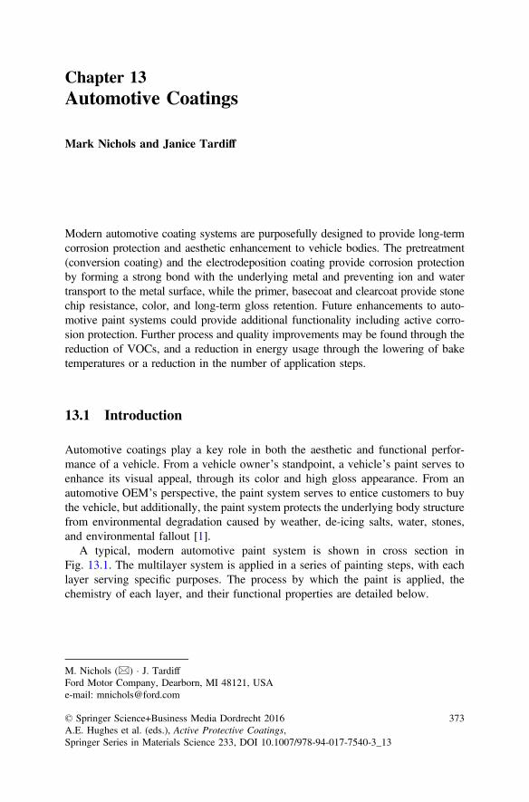
Chapter 13Automotive Coatings
Mark Nichols and Janice Tardiff
Modern automotive coating systems are purposefully designed to provide long-termcorrosion protection and aesthetic enhancement to vehicle bodies. The pretreatment(conversion coating) and the electrodeposition coating provide corrosion protectionby forming a strong bond with the underlying metal and preventing ion and watertransport to the metal surface, while the primer, basecoat and clearcoat provide stonechip resistance, color, and long-term gloss retention. Future enhancements to auto-motive paint systems could provide additional functionality including active corro-sion protection. Further process and quality improvements may be found through thereduction of VOCs, and a reduction in energy usage through the lowering of baketemperatures or a reduction in the number of application steps.
13.1 Introduction
Automotive coatings play a key role in both the aesthetic and functional perfor-mance of a vehicle. From a vehicle owner’s standpoint, a vehicle’s paint serves toenhance its visual appeal, through its color and high gloss appearance. From anautomotive OEM’s perspective, the paint system serves to entice customers to buythe vehicle, but additionally, the paint system protects the underlying body structurefrom environmental degradation caused by weather, de-icing salts, water, stones,and environmental fallout [1].
A typical, modern automotive paint system is shown in cross section inFig. 13.1. The multilayer system is applied in a series of painting steps, with eachlayer serving specific purposes. The process by which the paint is applied, thechemistry of each layer, and their functional properties are detailed below.
M. Nichols (&) � J. TardiffFord Motor Company, Dearborn, MI 48121, USAe-mail: [email protected]
© Springer Science+Business Media Dordrecht 2016A.E. Hughes et al. (eds.), Active Protective Coatings,Springer Series in Materials Science 233, DOI 10.1007/978-94-017-7540-3_13
373
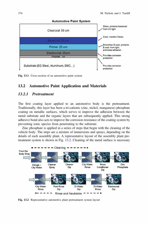
13.2 Automotive Paint Application and Materials
13.2.1 Pretreatment
The first coating layer applied to an automotive body is the pretreatment.Traditionally, this layer has been a tri-cationic (zinc, nickel, manganese) phosphatecoating on metallic surfaces, which serves to improve the adhesion between themetal substrate and the organic layers that are subsequently applied. This strongadhesive bond also acts to improve the corrosion resistance of the coating system bypreventing ionic species from penetrating to the substrate.
Zinc phosphate is applied in a series of steps that begin with the cleaning of thevehicle body. The steps are a mixture of immersions and sprays, depending on thedetails of each assembly plant. A representative layout of the assembly plant pre-treatment system is shown in Fig. 13.2. Cleaning of the metal surface is necessary
Fig. 13.1 Cross-section of an automotive paint system
Fig. 13.2 Representative automotive plant pretreatment system layout
374 M. Nichols and J. Tardiff
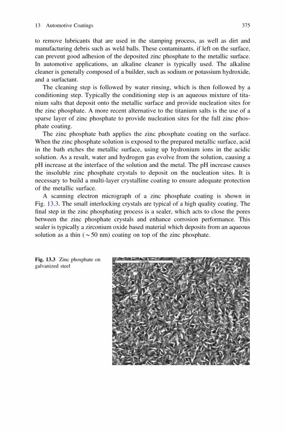
to remove lubricants that are used in the stamping process, as well as dirt andmanufacturing debris such as weld balls. These contaminants, if left on the surface,can prevent good adhesion of the deposited zinc phosphate to the metallic surface.In automotive applications, an alkaline cleaner is typically used. The alkalinecleaner is generally composed of a builder, such as sodium or potassium hydroxide,and a surfactant.
The cleaning step is followed by water rinsing, which is then followed by aconditioning step. Typically the conditioning step is an aqueous mixture of tita-nium salts that deposit onto the metallic surface and provide nucleation sites forthe zinc phosphate. A more recent alternative to the titanium salts is the use of asparse layer of zinc phosphate to provide nucleation sites for the full zinc phos-phate coating.
The zinc phosphate bath applies the zinc phosphate coating on the surface.When the zinc phosphate solution is exposed to the prepared metallic surface, acidin the bath etches the metallic surface, using up hydronium ions in the acidicsolution. As a result, water and hydrogen gas evolve from the solution, causing apH increase at the interface of the solution and the metal. The pH increase causesthe insoluble zinc phosphate crystals to deposit on the nucleation sites. It isnecessary to build a multi-layer crystalline coating to ensure adequate protectionof the metallic surface.
A scanning electron micrograph of a zinc phosphate coating is shown inFig. 13.3. The small interlocking crystals are typical of a high quality coating. Thefinal step in the zinc phosphating process is a sealer, which acts to close the poresbetween the zinc phosphate crystals and enhance corrosion performance. Thissealer is typically a zirconium oxide based material which deposits from an aqueoussolution as a thin (*50 nm) coating on top of the zinc phosphate.
Fig. 13.3 Zinc phosphate ongalvanized steel
13 Automotive Coatings 375
13.2.2 Electrocoat
The electrocoat (e-coat) layer is applied on top of the pretreatment layer. The e-coat’sprimary function is to provide outstanding corrosion protection to the underlyingmetallic substrate. It does this by forming a tight adhesive bond with the pretreatmentand by suppressing the transport of ionic species to the substrate [2].
The electrocoat is applied via a cathodic deposition process in a large bath. Thevehicle acts as the cathode and anodes are positioned along the sides and bottom ofthe electrocoat tank. The process is run between 200 and 275 V with a vehicleresidence time of approximately 3 min in the bath. The electrocoat solution is awater based material that contains paint resin and pigments. The paint particles arepositively charged and migrate to the cathode. At the cathode (the vehicle) water inthe solution is reduced, resulting in hydrogen evolution and hydroxyl formation [3].
2H2Oþ 2e� ! H2 þ 2OH�
The hydroxyl ions neutralize the charged paint particles and the particles pre-cipitate onto the surface of the vehicle. As the paint particles build up on thecathode surface, the resistance of the paint film increases and deposition on thesurface slows. Nearby unpainted surfaces will then be coated since the surfaceresistivity on these surfaces is lower than on the painted surface. This processcontinues while the vehicle remains in the electrocoat bath, with exterior locationscoated first, followed by interior locations, and finally recessed cavities of thevehicle body. The efficiency of the process of coating all surfaces of the vehiclebody is termed the throw power of the electrocoat material [3].
A challenge in the electrocoating process is to adequately coat all exterior andinterior surfaces of the vehicle body. Electrodeposition is dependent on both paintmaterial contact with the surface and the availability of electric current. The exteriorsurface of a vehicle body sees both the material and current, but there are manylocations on a vehicle body that are not in the sight line of the anodes. Deposition ofelectrocoat in these recessed locations is dependent on access of the electric field.An example of the behavior of the electric field in recessed locations is shown inFig. 13.4.
The thickness of the deposited film varies as a function of the applied voltage,the bath temperature, and the resin concentration in solution. Evidence indicatesthat the coagulated material deposits in such a way that creates pores within thedeposited material. By varying the electrocoat bath parameters, the size of the porescan be reduced to create a more compact coating that is more resistant to thediffusion of water, salts, and other contaminants to the metal or pretreated surface. Ifthese contaminants reach the metal-coating interface, they can adversely affect theadhesion and corrosion performance of the paint system [3].
There are multiple rinse steps following the electrocoat deposition process,primarily to remove excess coagulated resin material that has not fully depositedonto the surface as a film. The intent is for all electrocoated surfaces to be uniformly
376 M. Nichols and J. Tardiff
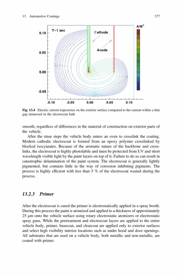
smooth, regardless of differences in the material of construction on exterior parts ofthe vehicle.
After the rinse steps the vehicle body enters an oven to crosslink the coating.Modern cathodic electrocoat is formed from an epoxy polymer crosslinked byblocked isocyanates. Because of the aromatic nature of the backbone and cross-links, the electrocoat is highly photolabile and must be protected from UV and shortwavelength visible light by the paint layers on top of it. Failure to do so can result incatastrophic delamination of the paint system. The electrocoat is generally lightlypigmented, but contains little in the way of corrosion inhibiting pigments. Theprocess is highly efficient with less than 5 % of the electrocoat wasted during theprocess.
13.2.3 Primer
After the electrocoat is cured the primer is electrostatically applied in a spray booth.During this process the paint is atomized and applied to a thickness of approximately25 μm onto the vehicle surface using rotary electrostatic atomizers or electrostaticspray guns. While the pretreatment and electrocoat layers are applied to the entirevehicle body, primer, basecoat, and clearcoat are applied only to exterior surfacesand select high visibility interior locations such as under hood and door openings.All substrates that are used on a vehicle body, both metallic and non-metallic, arecoated with primer.
Fig. 13.4 Electric current trajectories on the exterior surface compared to the current within a thingap immersed in the electrocoat bath
13 Automotive Coatings 377
The voltage used to apply the primer material at the applicator can varydepending on the material and the application conditions, but generally is 60–80 kV.To keep the atomized paint directed at the target (the vehicle body), shaping air isused. A goal in electrostatic painting is to direct the majority of the paint onto thetarget with minimal losses to the environment. The transfer efficiency is a measure ofthe amount of paint that reaches the target compared to the amount of paint that wassprayed. A good transfer efficiency is greater than 80 % but most modern automotivepaint applicators provide transfer efficiencies in excess of 85 %.
Although new application processes are being utilized that reduce energy usagein the paint application facilities, the standard practice to date has been to cure theprimer layer in an oven after application. As with the electrocoat oven, the primeroven crosslinks the deposited material and provides a smooth and uniform surfacefor further paint application.
The primer layer serves many functions in an automotive paint system. Asmentioned earlier, it must protect the underlying electrocoat from damaging light,thus it is typically highly pigmented and hides very well. The primer also plays aprimary role in smoothing the surface of the e-coat to ensure a smooth topcoatappearance. Both the e-coat and substrate metal can display objectionable surfaceroughness. This roughness must be mitigated to ensure a superior paint systemappearance. By bridging and filling the valleys between surface features, the primerreduces the surface texture. In addition, the primer also plays a substantial role inthe chip resistance of a paint system. The high speed impact of rocks and stonesproduced by other vehicles can be extremely damaging to a paint system.A significant amount of energy, concentrated in a small area, must be dissipated bythe paint system during a very short impact event. The primer serves to absorb thisenergy and prevent delamination and cracking of the paint system due to stoneimpact [4, 5]. Modern automotive primers are typically formulated from acrylic orpolyester polymers crosslinked with alkoxylated melamine or from polyurethanesand can be either solventborne, waterborne or powder based. Often primers are“color-keyed” with the subsequently applied basecoats. This means that the color ofprimer sprayed on a vehicle is matched to the color of basecoat that will subse-quently be applied. Thus, the amount of basecoat required to achieve hiding isminimized and the visual impact of stones chips is reduced.
13.2.4 Basecoat and Clearcoat
After primer application and cure, the topcoat, which includes the basecoat andclearcoat layers, is applied. As with the primer, the paint is atomized using rotaryelectrostatic atomizers or electrostatic spray guns. Basecoat and clearcoat areapplied sequentially without a baking step in between the application steps. Thetime between the basecoat and clearcoat application allows the solvents used in thepaint to evaporate. This prevents the clearcoat from striking into the basecoat,which can cause appearance issues by altering the flake orientation in the basecoat.
378 M. Nichols and J. Tardiff
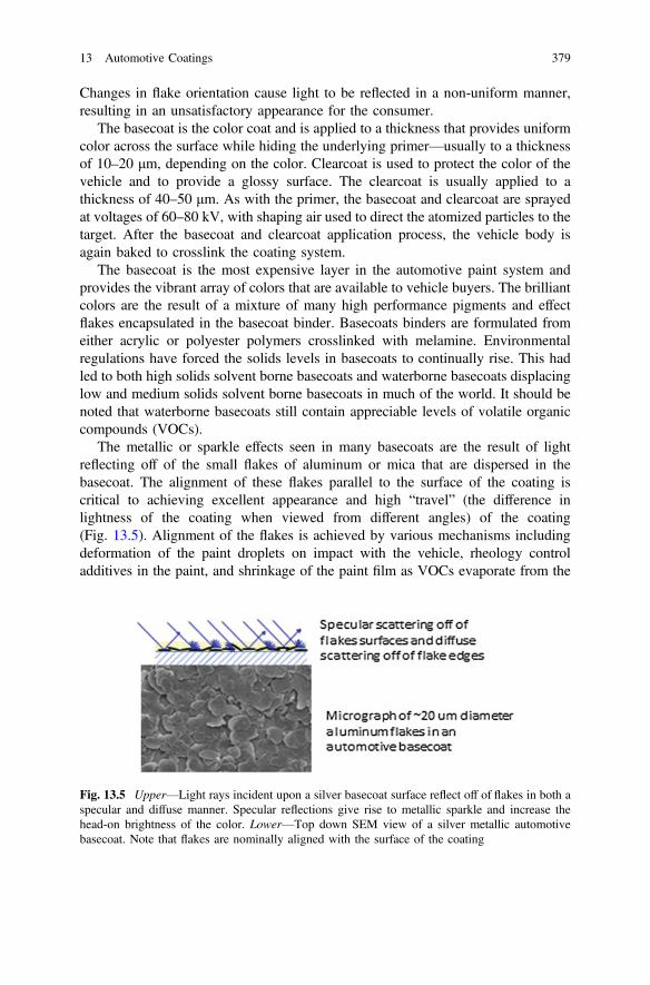
Changes in flake orientation cause light to be reflected in a non-uniform manner,resulting in an unsatisfactory appearance for the consumer.
The basecoat is the color coat and is applied to a thickness that provides uniformcolor across the surface while hiding the underlying primer—usually to a thicknessof 10–20 μm, depending on the color. Clearcoat is used to protect the color of thevehicle and to provide a glossy surface. The clearcoat is usually applied to athickness of 40–50 μm. As with the primer, the basecoat and clearcoat are sprayedat voltages of 60–80 kV, with shaping air used to direct the atomized particles to thetarget. After the basecoat and clearcoat application process, the vehicle body isagain baked to crosslink the coating system.
The basecoat is the most expensive layer in the automotive paint system andprovides the vibrant array of colors that are available to vehicle buyers. The brilliantcolors are the result of a mixture of many high performance pigments and effectflakes encapsulated in the basecoat binder. Basecoats binders are formulated fromeither acrylic or polyester polymers crosslinked with melamine. Environmentalregulations have forced the solids levels in basecoats to continually rise. This hadled to both high solids solvent borne basecoats and waterborne basecoats displacinglow and medium solids solvent borne basecoats in much of the world. It should benoted that waterborne basecoats still contain appreciable levels of volatile organiccompounds (VOCs).
The metallic or sparkle effects seen in many basecoats are the result of lightreflecting off of the small flakes of aluminum or mica that are dispersed in thebasecoat. The alignment of these flakes parallel to the surface of the coating iscritical to achieving excellent appearance and high “travel” (the difference inlightness of the coating when viewed from different angles) of the coating(Fig. 13.5). Alignment of the flakes is achieved by various mechanisms includingdeformation of the paint droplets on impact with the vehicle, rheology controladditives in the paint, and shrinkage of the paint film as VOCs evaporate from the
Fig. 13.5 Upper—Light rays incident upon a silver basecoat surface reflect off of flakes in both aspecular and diffuse manner. Specular reflections give rise to metallic sparkle and increase thehead-on brightness of the color. Lower—Top down SEM view of a silver metallic automotivebasecoat. Note that flakes are nominally aligned with the surface of the coating
13 Automotive Coatings 379
wet film [6]. The strive for higher solids has challenged paint formulators tomaintain good metallic appearance. In addition to the effect flakes, the pigments inmodern basecoats are typically high performance transparent organic pigments(perylenes, quinacridones, …) and inorganic pigments (TiO2, carbon black, ironoxides…). These pigments must be highly UV and thermally stable to ensureminimal color fade during the lifetime of a vehicle.
The clearcoat, the uppermost layer in the automotive paint system, functions tomaintain the high gloss appearance of the vehicle for many years. It must be able towithstand the severe environmental pressures that a vehicle is exposed to such asUV radiation, temperature, environmental fallout (acid rain and industrial pollu-tants), mechanical deformation and water. Only the most durable polyurethanes oracrylics functionalized with hydroxyl, carbamate, or epoxy groups are suitable foruse. These resins are crosslinked with melamine or aliphatic isocyanates. Toenhance their durability and meet 10+ year life requirements, all clearcoats areformulated with ultraviolet light absorbers (UVAs) and hindered amine light sta-bilizers (HALS). The stabilizer additives inhibit and reduce the rate of photooxi-dation induced by UV radiation. The UVA also acts to screen the underlyingbasecoat layer from UV light, thereby enhancing the basecoat’s longevity [7].
In addition to UV durability, the clearcoat must protect against mechanicalstresses from stone impact and scratch events. Keys, tree branches, fingernails andother asperities are often abraded across the surface of the clearcoat during avehicle’s life. Its ability to resist plastic deformation and fracture is key to mini-mizing the visual appearance of these scratches [8].
13.2.5 Compact Paint Processes
To reduce the footprint and operational costs of vehicle painting, automotive OEMshave begun to implement “compact painting” processes. In general, compactpainting processes eliminate the stand alone primer booth and oven. Instead, theprimer is applied as the first step in the basecoat/clearcoat booth. Thus, compactpainting necessitates the application of three wet layers on top of each other and thesubsequent co-cure of those layers. The elimination of the primer booth and ovenreduces the energy consumption by *15 %, the effective CO2 emissions by*15 %, and the VOCs released by *10 % [9]. To-date, compact paint processeshave been deployed in medium solids solventborne, high solids solventborne, andwaterborne coatings. These processes go by various names and are sometimesreferred to as “primerless” when the primer layer is replaced by a layer that moreclosely resembles the basecoat layer. In all compact processes, film build control iscritical to maintain opacity at low film builds (to protect the electrocoat) and on thehigh end to avoid pops and sags.
380 M. Nichols and J. Tardiff

13.3 Future Technologies Needs
As one looks to the future of automotive painting, three underlying themes willdrive most of the innovation: reduced costs, lower environmental footprint, andincreased functionality. The first theme, reduced costs, will likely result in thecontinued roll-out of compact painting processes in all assembly plants where it isfeasible. The economic and environmental benefits are too compelling to reversethis trend. There is relatively little that can be done to lower the cost of rawmaterials and the coating layers themselves. Because of stringent performancecriteria, the pigments and binders are relatively costly compared to those used incoating systems for other manufactured goods. Instead, much of the cost oppor-tunities lie in the improved efficiency of the various painting operations.
A reduction in the environmental footprint of automotive painting means that theuse of energy and the output of waste must decrease. The main waste streams fromautomotive painting are wastewater; which comes from the pretreatment operationsand from capture of the primer and topcoat overspray; VOCs, which are releasedduring application of both solventborne and waterborne coatings; paint sludge,which is produced during both pretreating and paint spraying; and CO2, which isproduced by the burning of fossil fuels for ovens, the generation of electricity tocirculate enormous volumes of air in the spray booths, and the conditioning (cooling,heating, and (de)humidification) of air in the spray booths. Several technologies arenow beginning to be implemented that provide significant advantages in these areas.
As zinc phosphate produces significant amounts of metal-containing sludge,particularly when significant aluminum is incorporated into the vehicle body, thinfilm pretreatments are poised to supplant zinc phosphate in the near future. Thesethin film pretreatments are based on zirconium oxide chemistry that etch the surfaceof the vehicle body much less than traditional pretreatments. Reduced etch results inup to a 90 % reduction in solid waste produced. In addition, these pretreatmentsbaths operate at lower temperatures and with fewer process steps. The technicalchallenges for such pretreatments, however, are not insignificant. In particular,achieving acceptable corrosion performance on mixed metal (steel, galvanizedsteel, and aluminum) vehicle bodies is difficult due to the need to balance depo-sition rates on each substrate.
Due to significantly higher fuel economy targets, vehicle weights will decrease,perhaps substantially, in the near future. The incorporation of lighter substrates maydrive new coating strategies. For example, magnesium is used sparingly on currentvehicles due to its strong tendency to corrode, particularly at joints with dissimilarmetals. Most magnesium parts are pretreated and coated, typically powder coated,before careful assembly and isolation onto a vehicle body. The ability to pretreatand coat magnesium parts in parallel with the rest of the vehicle would be anenormous benefit. However, no pretreatment system currently exists that wouldenable all relevant substrates to be pretreated together.
Similarly, the extensive use of carbon fiber composites could lower the weight ofvehicles and improve fuel economy. The current bake temperatures in the electrocoat
13 Automotive Coatings 381
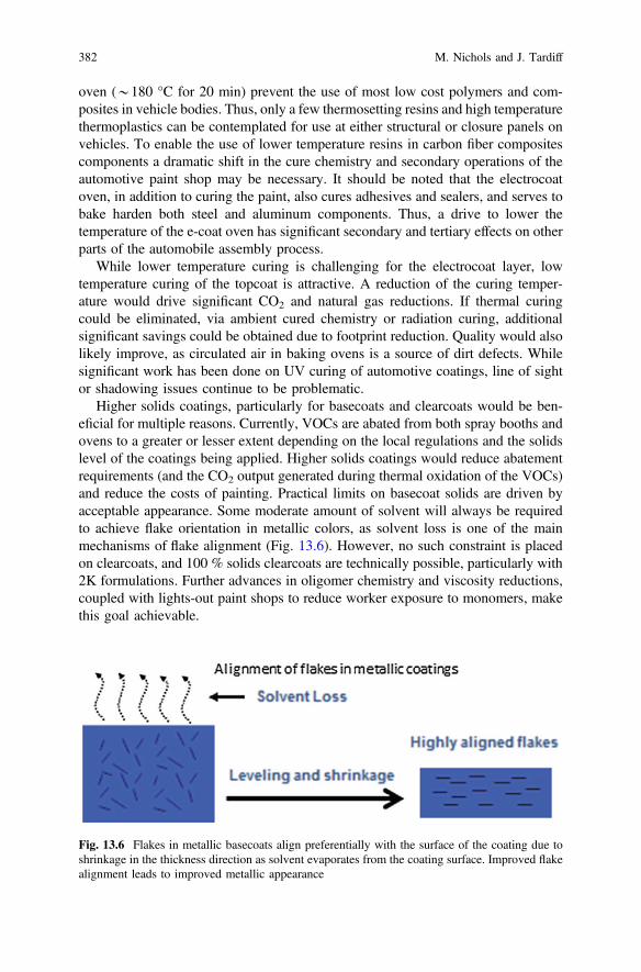
oven (*180 °C for 20 min) prevent the use of most low cost polymers and com-posites in vehicle bodies. Thus, only a few thermosetting resins and high temperaturethermoplastics can be contemplated for use at either structural or closure panels onvehicles. To enable the use of lower temperature resins in carbon fiber compositescomponents a dramatic shift in the cure chemistry and secondary operations of theautomotive paint shop may be necessary. It should be noted that the electrocoatoven, in addition to curing the paint, also cures adhesives and sealers, and serves tobake harden both steel and aluminum components. Thus, a drive to lower thetemperature of the e-coat oven has significant secondary and tertiary effects on otherparts of the automobile assembly process.
While lower temperature curing is challenging for the electrocoat layer, lowtemperature curing of the topcoat is attractive. A reduction of the curing temper-ature would drive significant CO2 and natural gas reductions. If thermal curingcould be eliminated, via ambient cured chemistry or radiation curing, additionalsignificant savings could be obtained due to footprint reduction. Quality would alsolikely improve, as circulated air in baking ovens is a source of dirt defects. Whilesignificant work has been done on UV curing of automotive coatings, line of sightor shadowing issues continue to be problematic.
Higher solids coatings, particularly for basecoats and clearcoats would be ben-eficial for multiple reasons. Currently, VOCs are abated from both spray booths andovens to a greater or lesser extent depending on the local regulations and the solidslevel of the coatings being applied. Higher solids coatings would reduce abatementrequirements (and the CO2 output generated during thermal oxidation of the VOCs)and reduce the costs of painting. Practical limits on basecoat solids are driven byacceptable appearance. Some moderate amount of solvent will always be requiredto achieve flake orientation in metallic colors, as solvent loss is one of the mainmechanisms of flake alignment (Fig. 13.6). However, no such constraint is placedon clearcoats, and 100 % solids clearcoats are technically possible, particularly with2K formulations. Further advances in oligomer chemistry and viscosity reductions,coupled with lights-out paint shops to reduce worker exposure to monomers, makethis goal achievable.
Fig. 13.6 Flakes in metallic basecoats align preferentially with the surface of the coating due toshrinkage in the thickness direction as solvent evaporates from the coating surface. Improved flakealignment leads to improved metallic appearance
382 M. Nichols and J. Tardiff
Currently, appearance and corrosion protection are the two main functions of anautomotive paint system, coating systems in the future may be required to performadditional functions or perform traditional functions in fundamentally different ways.For example, corrosion protection is currently achieved through a combination ofsacrificial coatings (zinc galvanized), barrier to ions and water (e-coat) and strongadhesion (zinc phosphate and e-coat). Future corrosion protection may occur throughself-healing of coatings. Micro or nano-spheres that release corrosion inhibitors orcrack healing agents after pH changes or mechanical stress are active areas ofresearch [10, 11]. Currently, little work has been done to make these coatings elec-trodepositable or to make the spheres small enough for incorporation into thin paintlayers. These deficits represent rich and meaningful research opportunities.
As vehicle electrification grows, some have proposed that the surface of thevehicle would be a valuable solar energy collector, and photovoltaic paints havebeen developed [12]. However, the practicality of these proposals is doubtful.Unlike traditional solar cells, automotive paint is subjected to significant damageevents in terms of scratches and stone impacts. The impact on cell output (shortcircuits, reduced performance…) has not been addressed. In addition, the availablesurface area of a vehicle is not sufficient to contribute a significant amount to thevehicle’s energy budget. [For example, a typical electric vehicle might have 4 m2 ofsurface area that could be used for solar cells with perhaps 50 % ever facing the sun.A 20 % efficient solar cell operating during 8 h of peak sunshine in a typicalenvironment would deliver less than 1.3 kW h of energy to the vehicle(400 W/m2 × 4 m2 × 0.5 × 0.2 × 8 h). A typical EV or PHEV battery is on the orderof 16–20 kW h.] The impact of these coatings on appearance would also likely notbe met with customer approval.
Other functional enhancements to automotive paint have also been envisaged.Pigments that respond to external stimuli (pH, temperature, UV light) or that areluminescent have been utilized in less demanding applications such as nail polish ortoys. However, their use in automotive coatings is questionable due to durability,and color harmony issues. Also, consumers are less likely to indulge in trendy orwhimsical colors on expensive items that last 10+ years. Luminescent pigments areproblematic as lighting on the exterior of vehicles is highly regulated by mostfederal governments for safety reasons.
13.4 Summary
Significant unmet needs will continue to guide innovations in automotive coatingstechnology. Reductions in cost and environmental footprint, in addition toimproved functionality, will drive many of these future changes. The high volumeand stringent functional requirements will ensure that only the most robust andpractical materials and process solutions will be implemented.
13 Automotive Coatings 383
References
1. D.W. Boyd, R.R. Zwack, Prog. Org. Coat. 27 (1996)2. D.W. Boyd, R.R. Zwack, Predicting electrocoat efficiency: a simple data-based model for
predicting electrocoat usage. Prog. Org. Coat. 27(1–4), 25–32 (1996). doi:10.1016/0300-9440(95)00516-1
3. V. Miskovic-Stankovic, The mechanism of cathodic electrodeposition of epoxy coatings andthe corrosion behaviour of the electrodeposited coatings. J. Serb. Chem. Soc. 27(5), 305–324(1996)
4. P. Pierce, J. Coat. Technol. 53 (1981)5. H. Hintze-Bruening, A.-L. Troutier-Thuilliez, F. Leroux, Layered particle-based polymer
composites for coatings: Part II—Stone chip resistant automotive coatings. Prog. Org. Coat. 64(2–3), 193–204 (2009). doi:10.1016/j.porgcoat.2008.09.020
6. D. Bhattacharya, K. Seo, L.T. Germinario, M.D. Clark, K.W. McCreight, C. Williams, Noveltechniques to investigate the impact of cellulose esters on the rheological properties andappearance in automotive basecoat systems. J. Coat. Technol. Res. 4(2), 139–150 (2007)
7. J.L. Gerlock, A.V. Kucherov, M.E. Nichols, On the combined use of UVA, HALS,photooxidation, and fracture energy measurements to anticipate the long-term weatheringperformance of clearcoat/basecoat automotive paint systems. J. Coat. Technol. 73(918), 45–54(2001)
8. C. Seubert, M. Nichols, Scaling behavior in the scratching of automotive clearcoats. J. Coat.Technol. Res. 4(1), 21–30 (2007). doi:10.1007/s11998-007-9006-3
9. M. Vandelinder, D. Havlin, M.E. Rosenberger, T. Weingartz, in Proceedings of SURCAR,Cannes (2007)
10. S.H. Cho, S.R. White, P.V. Braun, Self-healing polymer coatings. Adv. Mater. 21(6), 645+(2009). doi:10.1002/adma.200802008
11. B. Ghosh, M.W. Urban, Self-repairing oxetane-substituted chitosan polyurethane networks.Science 323(5920), 1458–1460 (2009). doi:10.1126/science.1167391
12. M.P. Genovese, I.V. Lightcap, P.V. Kamat, Sun-believable solar paint. A transformativeone-step approach for designing nanocrystalline solar cells. ACS Nano 6(1), 865–872 (2012)
384 M. Nichols and J. Tardiff
Chapter 14Polymer Coatings for Oilfield Pipelines
Russell J. Varley and K.H. Leong
14.1 Introduction
Pipes and pipeline systems are an integral part of modern society, from the networkof pipes that transport water, gas and sewage of our daily needs to the continuoustransmission of hydrocarbons across continents satisfying the energy demands ofthe global economy. Despite the enormous distances and the harsh environmentsinvolved, oil and gas pipelines are the most efficient and environmentally safe formof hydrocarbon transportation currently available today. For this reason, they arecritical to continued global prosperity in the 21st century.
The oil and gas (O&G) industry, primarily uses steel pipelines to transportnatural gas, crude oil, water, as well as petrochemical feedstocks and petroleumproducts which are susceptible to corrosion from their surrounding environment, beit soil (buried lines), or seawater (subsea lines) and compromising their service life.The life expectancy of oilfield pipelines ranges typically between 25–35 years soreliable protection during this period is of utmost importance. External coatings areone of the most widely used methods for providing a barrier to the steel surfaceagainst air (oxygen) and water (electrolytes), the two critical factors which mostimpact the electrochemical process of corrosion. Despite this, all coatings deteri-orate over time due to inter alia soil stress, moisture and gas ingress, reducedadhesion, chemical attack and mechanical damage, thus imposing the challenge ofmaintaining the required durability and performance over the intended service life.
R.J. Varley (&)CSIRO Manufacturing, Private Bag 10, Clayton South MDC,VICTORIA 3169, Australiae-mail: [email protected]
K.H. LeongPETRONAS Research, Lot 3288/3289 off Jalan Ayer Itam,Kawasan Institusi Bangi, 43000 Kajang, Selangor DE, Malaysiae-mail: [email protected]
© Springer Science+Business Media Dordrecht 2016A.E. Hughes et al. (eds.), Active Protective Coatings,Springer Series in Materials Science 233, DOI 10.1007/978-94-017-7540-3_14
385
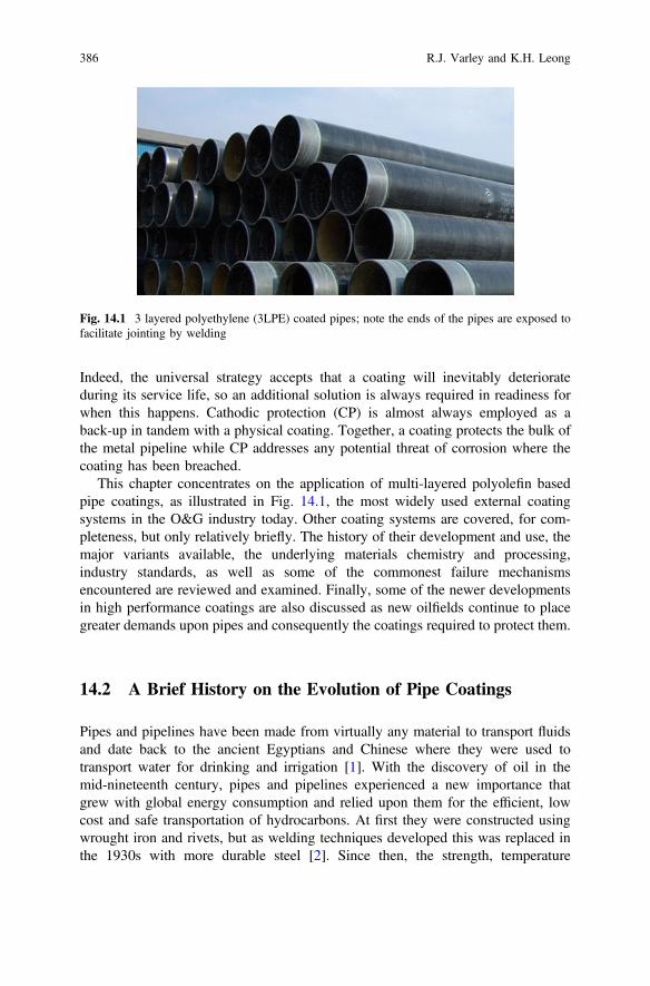
Indeed, the universal strategy accepts that a coating will inevitably deteriorateduring its service life, so an additional solution is always required in readiness forwhen this happens. Cathodic protection (CP) is almost always employed as aback-up in tandem with a physical coating. Together, a coating protects the bulk ofthe metal pipeline while CP addresses any potential threat of corrosion where thecoating has been breached.
This chapter concentrates on the application of multi-layered polyolefin basedpipe coatings, as illustrated in Fig. 14.1, the most widely used external coatingsystems in the O&G industry today. Other coating systems are covered, for com-pleteness, but only relatively briefly. The history of their development and use, themajor variants available, the underlying materials chemistry and processing,industry standards, as well as some of the commonest failure mechanismsencountered are reviewed and examined. Finally, some of the newer developmentsin high performance coatings are also discussed as new oilfields continue to placegreater demands upon pipes and consequently the coatings required to protect them.
14.2 A Brief History on the Evolution of Pipe Coatings
Pipes and pipelines have been made from virtually any material to transport fluidsand date back to the ancient Egyptians and Chinese where they were used totransport water for drinking and irrigation [1]. With the discovery of oil in themid-nineteenth century, pipes and pipelines experienced a new importance thatgrew with global energy consumption and relied upon them for the efficient, lowcost and safe transportation of hydrocarbons. At first they were constructed usingwrought iron and rivets, but as welding techniques developed this was replaced inthe 1930s with more durable steel [2]. Since then, the strength, temperature
Fig. 14.1 3 layered polyethylene (3LPE) coated pipes; note the ends of the pipes are exposed tofacilitate jointing by welding
386 R.J. Varley and K.H. Leong

resistance and durability of steel has made it the logical choice for oilfield pipelines.So began the need for advanced pipe coatings that have become integral to ensuringthat steel pipelines function as they were intended over their design life, with no orminimum disruption.
The first pipe coatings to emerge during the 1860s were made from coaltar/asphalt enamel and typically were applied manually in the field and thus highlyvariable in quality and performance [3, 4]. It was soon recognised that theirresistance to corrosion left much to be desired, and as well as being highly sus-ceptible to oxidation, cracking and soil stress, were limited to low stress andtemperature environments. The need to reduce these deficiencies led to a gradualimprovement throughout the first part of the 20th century as better materials andmore controlled application methods became available. Asbestos, for example, wasused to reinforce coal tar coatings while waxy coatings were also introduced aroundthe same time [5].
In fact, coal tar coatings remain in use today due to its ease of application andminimal surface preparation. As a by-product from refineries, it is often also thecheapest coating option for many pipeline projects further enhancing its usefulness,but its inherent disadvantages, including health-related concerns [6], limited widerusage, particularly as better two layer extruded polyethylene tape coating systemsemerged in the 1940s and followed by fusion bonded epoxy systems. Applicationmethods continued to improve and by the 1950s it was recognised that the com-bination of cathodic protection and pipe coatings was the best long-term defenceagainst corrosion.
Modern oilfield pipeline coatings however, are not just required to provideexternal protection against corrosion but, where necessary, also protect againststructural damage, such as impact during transportation and installation; maintainon-bottom stability; and/or provide insulation. Driven by the need to explore andoperate in harsher and more remote locations, pipe coating suppliers face theconstant challenge to meet the increasingly demanding requirements of the industry[7]. Indeed, continuous development of pipe coatings over the years has improvedtheir properties, and cost competitiveness, such that coatings encountered in thefield today range from being single layered asphaltic or thermosetting polymersystems to multilayered polyolefin-based coatings, depending on budget and ser-vice condition requirements [8, 9].
Despite the wide variety of environments, materials and applications available,the majority of oilfield pipe coatings can be generally categorised into a smallnumber of different types of coatings as shown in Table 14.1. Each system isspecified by pipeline owners/operators and consultants for particular pipeline pro-jects and based on factors, including short-term cost, long-term investments, captiveusage, regional availability of the coating material, control on handling, trans-portation and installation of pipelines, as well as technical requirements. Matchingintended service conditions with the right materials is necessary to ensure coatinglongevity [10]. Figure 14.2 shows a historical timeline illustrating the developmentof external and field joint coatings from the 1940s to the present day.
14 Polymer Coatings for Oilfield Pipelines 387
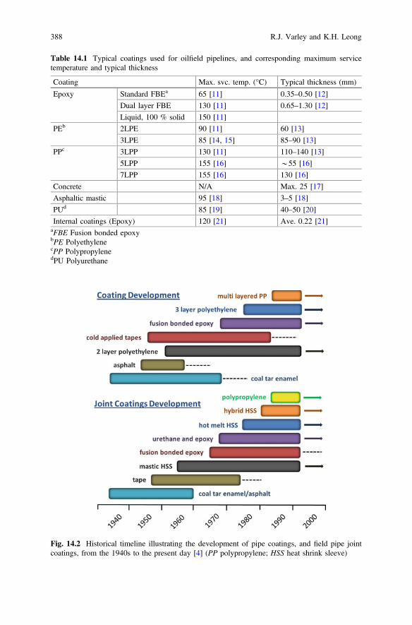
Table 14.1 Typical coatings used for oilfield pipelines, and corresponding maximum servicetemperature and typical thickness
Coating Max. svc. temp. (°C) Typical thickness (mm)
Epoxy Standard FBEa 65 [11] 0.35–0.50 [12]
Dual layer FBE 130 [11] 0.65–1.30 [12]
Liquid, 100 % solid 150 [11]
PEb 2LPE 90 [11] 60 [13]
3LPE 85 [14, 15] 85–90 [13]
PPc 3LPP 130 [11] 110–140 [13]
5LPP 155 [16] *55 [16]
7LPP 155 [16] 130 [16]
Concrete N/A Max. 25 [17]
Asphaltic mastic 95 [18] 3–5 [18]
PUd 85 [19] 40–50 [20]
Internal coatings (Epoxy) 120 [21] Ave. 0.22 [21]aFBE Fusion bonded epoxybPE PolyethylenecPP PolypropylenedPU Polyurethane
Fig. 14.2 Historical timeline illustrating the development of pipe coatings, and field pipe jointcoatings, from the 1940s to the present day [4] (PP polypropylene; HSS heat shrink sleeve)
388 R.J. Varley and K.H. Leong
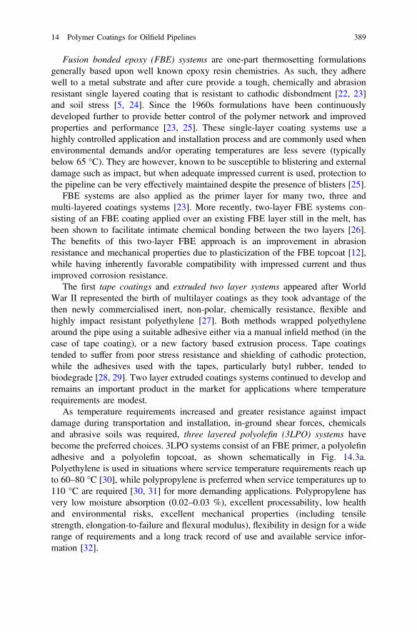
Fusion bonded epoxy (FBE) systems are one-part thermosetting formulationsgenerally based upon well known epoxy resin chemistries. As such, they adherewell to a metal substrate and after cure provide a tough, chemically and abrasionresistant single layered coating that is resistant to cathodic disbondment [22, 23]and soil stress [5, 24]. Since the 1960s formulations have been continuouslydeveloped further to provide better control of the polymer network and improvedproperties and performance [23, 25]. These single-layer coating systems use ahighly controlled application and installation process and are commonly used whenenvironmental demands and/or operating temperatures are less severe (typicallybelow 65 °C). They are however, known to be susceptible to blistering and externaldamage such as impact, but when adequate impressed current is used, protection tothe pipeline can be very effectively maintained despite the presence of blisters [25].
FBE systems are also applied as the primer layer for many two, three andmulti-layered coatings systems [23]. More recently, two-layer FBE systems con-sisting of an FBE coating applied over an existing FBE layer still in the melt, hasbeen shown to facilitate intimate chemical bonding between the two layers [26].The benefits of this two-layer FBE approach is an improvement in abrasionresistance and mechanical properties due to plasticization of the FBE topcoat [12],while having inherently favorable compatibility with impressed current and thusimproved corrosion resistance.
The first tape coatings and extruded two layer systems appeared after WorldWar II represented the birth of multilayer coatings as they took advantage of thethen newly commercialised inert, non-polar, chemically resistance, flexible andhighly impact resistant polyethylene [27]. Both methods wrapped polyethylenearound the pipe using a suitable adhesive either via a manual infield method (in thecase of tape coating), or a new factory based extrusion process. Tape coatingstended to suffer from poor stress resistance and shielding of cathodic protection,while the adhesives used with the tapes, particularly butyl rubber, tended tobiodegrade [28, 29]. Two layer extruded coatings systems continued to develop andremains an important product in the market for applications where temperaturerequirements are modest.
As temperature requirements increased and greater resistance against impactdamage during transportation and installation, in-ground shear forces, chemicalsand abrasive soils was required, three layered polyolefin (3LPO) systems havebecome the preferred choices. 3LPO systems consist of an FBE primer, a polyolefinadhesive and a polyolefin topcoat, as shown schematically in Fig. 14.3a.Polyethylene is used in situations where service temperature requirements reach upto 60–80 °C [30], while polypropylene is preferred when service temperatures up to110 °C are required [30, 31] for more demanding applications. Polypropylene hasvery low moisture absorption (0.02–0.03 %), excellent processability, low healthand environmental risks, excellent mechanical properties (including tensilestrength, elongation-to-failure and flexural modulus), flexibility in design for a widerange of requirements and a long track record of use and available service infor-mation [32].
14 Polymer Coatings for Oilfield Pipelines 389

Multi-layered coating systems are typically made up of 5–7 layers with theadditional layers providing insulation and added protection from damage [33, 34].Foam insulation layers are often made from polyurethane or polypropylene, thoughepoxy-based systems are also available albeit less popular [35]. They are primarilydesigned to control excessive cooling of the crude oil to prevent wax formation andcrystallisation of clathrate hydrate crystals which can otherwise adversely affect theflow assurance of the pipeline. These coating systems are normally associated withdeeper water fields which also increases the required service temperatures andcompressive properties. Figure 14.3b shows an idealised 5 layer pipe coatingsystem, differentiated from the 3 layered coating systems by the addition of apolypropylene foam layer and an additional solid polypropylene layer providingfurther thermal barrier protection. Table 14.2 lists several subsea insulation coatingssystems used in the industry. It is noteworthy that other than wet insulation,pipe-in-pipe, which tends to be a heavier option, and the flexible insulated pipe,often more expensive but cost-effective in niche applications such as flowlines andrisers on Floating Production, Storage and Offloading vessels (FPSOs), are alsoavailable to afford heat insulation to pipelines [35].
Concrete coatings, typically applied over the aforementioned coating systems,are an important part of the pipe coating family. They are targeted primarily forbuoyancy control of subsea pipelines, and/or for rugged outdoor applicationssubject to potentially heavy impact during and/or after installation. Guan [36] listedfour different methods of applying concrete coating to a steel pipe that had beenpre-coated with an anti-corrosion coating. The processes are impingement, com-pressive wrapping, casting and gunniting. A typical concrete coated steel pipe isshown in Fig. 14.4 illustrating how it is used in addition to a 3LPE system.
The types of internal pipe coating used are dependent upon the media trans-ported by the pipeline. Generally, they are used to reduce pressure drop due tosurface roughness by inhibiting corrosion, preventing precipitation on the pipe wall,and modifying the surface energies of the pipe wall [21]. Internal FBE is sometimesused in combination with a phenolic primer that is applied prior to powder
Fig. 14.3 Schematics of multilayer polyolefin pipe coating systems. a 3 layer systems: FBEprimer (80–100 μm), polyolefin adhesive (350 μm) and polyolefin topcoat (1–3 mm). b 5 layersystems: FBE primer, polypropylene adhesive, solid polypropylene layer, polypropylene foam andpolypropylene topcoat
390 R.J. Varley and K.H. Leong
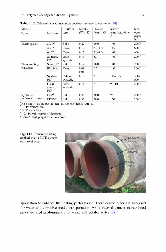
application to enhance the coating performance. These coated pipes are also usedfor water and corrosive media transportation, while internal cement mortar linedpipes are used predominantly for waste and potable water [37].
Table 14.2 Selected subsea insulation coatings systems in use today [20]
Material Insulationtype
K-value(W/m K)
U-value(W/m2 K)†
Servicetemp. capability(°C)
Max.waterdepth(m)
Type Insulation
Thermoplastic 3LPPb Solid 0.22 10.0 140 2000a
4LPPb Foam 0.17 3.0–4.0 115 600nLPPb Foam 0.17 3.0–4.0 140 600SyntacticPPb
Glasssyntactic
0.19 3.0 140 2000a
Thermosettingelastomer
Solid PUc Solid 0.19 10.0 140 2000a
PUc foam Foam 0.03–0.04
0.7 140 2000a
SyntacticPUc
Polymersyntactic
0,12 2.0 115–125 300–600
GlasssyntacticPUc
Glasssyntactic
0.16 2.0 90–100 2000a
Syntheticrubbers/elastomers
PCPd Solid 0.35 30.0 95 2000a
EPDMe Solid 0.35 30.0 150 2000aaAlso known as the overall heat transfer coefficient (OHTC)bPP PolypropylenecPU PolyurethanedPCP Polychloroprene (Neoprene)eEPDM Ethyl propyl diene monomer
Fig. 14.4 Concrete coatingapplied over a 3LPE systemon a steel pipe
14 Polymer Coatings for Oilfield Pipelines 391

14.3 Materials and Processing
This section discusses some of the chemistry and process engineering that under-pins the effectiveness of the most commonly used coating systems: FBE; threelayered polyolefin; and multilayered thermally insulated coatings.
14.3.1 Fusion Bonded Epoxy Coatings
Fusion bonded epoxy coatings are multi-component formulations containing epoxyresins, curing agents, corrosion inhibitors and fillers to control viscosity, color ortoughness. Their primary role in either single or multi-layered coatings is to preventcorrosion, but when applied as a single layer are also required to protect the pipefrom damage.
Corrosion is an electrochemical reaction, shown schematically in Fig. 14.5,consisting of oxidation at a metal surface in the presence of water and air to formiron oxides. Thus in the context of a coating, a strong and durable polymer andpolymer/steel interface is required to separate air and moisture from the metalsubstrate and inhibit the electrochemical process of corrosion.
Clearly, this can only be achieved through the optimisation of the FBE resinchemistry, cure process and suitable coating deposition methodologies. To achievethis, the pipe is pre-heated prior to FBE application, using an oven or inductionmethods, so that when it is applied to the pipe, the resin viscosity rapidly decreases
Oxidation of ferrous steel at anode Reduction of oxygen at cathode
Rust
2Femetal 2Fe2++ 4e- O2 + 4e- + H2O 4OH-
2OH-+Fe2+ Fe(OH)2
Fig. 14.5 Schematic representation and the chemical reactions of the electrochemical processesoccurring during corrosion illustrating the impact of electron movement on the formation of Fe(OH)2
392 R.J. Varley and K.H. Leong

as it melts, promoting resin flow and even wetting over the pipe. It is noteworthythat pipes are heated to a temperature of approximately 180 °C when the FBE isused as primer, or to as high as 250 °C when used as a top coat [36]. At this point,the relatively polar nature of the epoxy monomers in the FBE facilitates goodinteraction and dissolution with the inorganic metal oxide on the pipe surface alsopromoting adhesion. The hardener within the FBE, typically dicyandiamide, wellknown for its latency, initiates resin cure which increases viscosity until the epoxynetwork forms an intractable gel. Continued cure consumes reactive groups, furtherincreasing crosslink density of the network, to produce a tough, durable andabrasion resistant coating. Final properties therefore are a function of manyparameters such as the extent of cure, molecular structure, stoichiometry, curetemperature and time, all of which need to be tuned for optimum performance.
FBE coatings are often made from high molecular weight bisphenol A basedepoxy resins partly because of their low cost and availability, but also due to theircomparatively high toughness in epoxy networks. This is particularly advantageousfor materials that need to accommodate significant flex and to resist impact damageduring their lifetime such as pipe coatings. A schematic representation of thephysical and chemical transformations occurring during FBE application and cure isshown in Fig. 14.6, along with the chemical structures of the epoxy resin andhardener, dicyandiamide, typically used in advanced FBE formulations.
A. Solid particles in fluidized bed prior to application.B. Particles melts onto pipe, evenly wetting surfaceC. Epoxy begins crosslinking to form intractable gelD. Completion of cure to form durable hard coating
A. B. C. D.
visc
osity
seconds timeminutes
OO
O OOH
OO
n
H2N NH
NH
CN
(a)
(b)
Fig. 14.6 a Schematic representation of the rheological transformations of the FBE during pipecoating from the melting and wetting of the FBE, through gelation and finally to full cure.b Chemical structures of high molecular weight diglycidyl ether of bisphenol A epoxy resin, andhardener, dicyandiamide
14 Polymer Coatings for Oilfield Pipelines 393
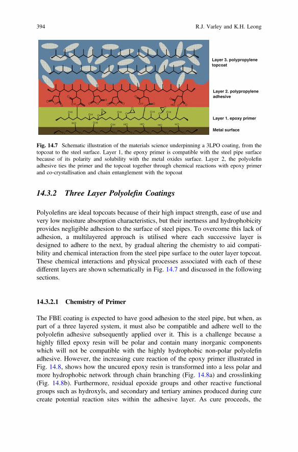
14.3.2 Three Layer Polyolefin Coatings
Polyolefins are ideal topcoats because of their high impact strength, ease of use andvery low moisture absorption characteristics, but their inertness and hydrophobicityprovides negligible adhesion to the surface of steel pipes. To overcome this lack ofadhesion, a multilayered approach is utilised where each successive layer isdesigned to adhere to the next, by gradual altering the chemistry to aid compati-bility and chemical interaction from the steel pipe surface to the outer layer topcoat.These chemical interactions and physical processes associated with each of thesedifferent layers are shown schematically in Fig. 14.7 and discussed in the followingsections.
14.3.2.1 Chemistry of Primer
The FBE coating is expected to have good adhesion to the steel pipe, but when, aspart of a three layered system, it must also be compatible and adhere well to thepolyolefin adhesive subsequently applied over it. This is a challenge because ahighly filled epoxy resin will be polar and contain many inorganic componentswhich will not be compatible with the highly hydrophobic non-polar polyolefinadhesive. However, the increasing cure reaction of the epoxy primer illustrated inFig. 14.8, shows how the uncured epoxy resin is transformed into a less polar andmore hydrophobic network through chain branching (Fig. 14.8a) and crosslinking(Fig. 14.8b). Furthermore, residual epoxide groups and other reactive functionalgroups such as hydroxyls, and secondary and tertiary amines produced during curecreate potential reaction sites within the adhesive layer. As cure proceeds, the
Layer 2. polypropylene adhesive
Layer 3. polypropylene topcoat
Layer 1. epoxy primer
Metal surface
Fig. 14.7 Schematic illustration of the materials science underpinning a 3LPO coating, from thetopcoat to the steel surface. Layer 1, the epoxy primer is compatible with the steel pipe surfacebecause of its polarity and solubility with the metal oxides surface. Layer 2, the polyolefinadhesive ties the primer and the topcoat together through chemical reactions with epoxy primerand co-crystallisation and chain entanglement with the topcoat
394 R.J. Varley and K.H. Leong
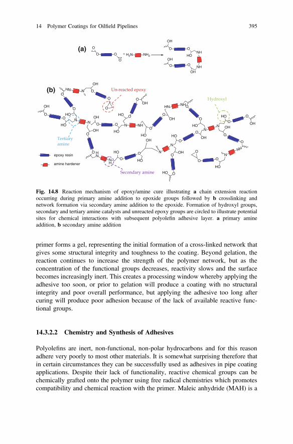
primer forms a gel, representing the initial formation of a cross-linked network thatgives some structural integrity and toughness to the coating. Beyond gelation, thereaction continues to increase the strength of the polymer network, but as theconcentration of the functional groups decreases, reactivity slows and the surfacebecomes increasingly inert. This creates a processing window whereby applying theadhesive too soon, or prior to gelation will produce a coating with no structuralintegrity and poor overall performance, but applying the adhesive too long aftercuring will produce poor adhesion because of the lack of available reactive func-tional groups.
14.3.2.2 Chemistry and Synthesis of Adhesives
Polyolefins are inert, non-functional, non-polar hydrocarbons and for this reasonadhere very poorly to most other materials. It is somewhat surprising therefore thatin certain circumstances they can be successfully used as adhesives in pipe coatingapplications. Despite their lack of functionality, reactive chemical groups can bechemically grafted onto the polymer using free radical chemistries which promotescompatibility and chemical reaction with the primer. Maleic anhydride (MAH) is a
H2N NH2O O
O
O
O O
OH
HONH
NHOO
OH
OH
+
OO
OH
HON
N O O
OH
HO
N NH
O
O
HO
HN N
O
OOH
O
O
OH
HO
HN
NH
O
O HO
HO
O
O
O
OH
O
O OH
HO
NN
O
OOHHO
N
N
O
O
OH
HN
N
O
O
HO
O
O
HO
OH
NHHN
O
O
HO
OH
O O
O
HO
OH
epoxy resin
amine hardener
(a)
(b)
Fig. 14.8 Reaction mechanism of epoxy/amine cure illustrating a chain extension reactionoccurring during primary amine addition to epoxide groups followed by b crosslinking andnetwork formation via secondary amine addition to the epoxide. Formation of hydroxyl groups,secondary and tertiary amine catalysts and unreacted epoxy groups are circled to illustrate potentialsites for chemical interactions with subsequent polyolefin adhesive layer. a primary amineaddition, b secondary amine addition
14 Polymer Coatings for Oilfield Pipelines 395
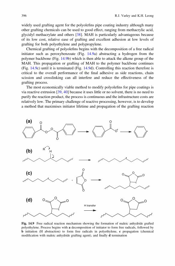
widely used grafting agent for the polyolefins pipe coating industry although manyother grafting chemicals can be used to good effect, ranging from methacrylic acid,glycidyl methacrylate and others [38]. MAH is particularly advantageous becauseof its low cost, relative ease of grafting and excellent adhesion at low levels ofgrafting for both polyethylene and polypropylene.
Chemical grafting of polyolefins begins with the decomposition of a free radicalinitiator such as peroxybenzoate (Fig. 14.9a) abstracting a hydrogen from thepolymer backbone (Fig. 14.9b) which is then able to attack the alkene group of theMAH. This propagation or grafting of MAH to the polymer backbone continues(Fig. 14.9c) until it is terminated (Fig. 14.9d). Controlling this reaction therefore iscritical to the overall performance of the final adhesive as side reactions, chainscission and crosslinking can all interfere and reduce the effectiveness of thegrafting process.
The most economically viable method to modify polyolefins for pipe coatings isvia reactive extrusion [39, 40] because it uses little or no solvent, there is no need topurify the reaction product, the process is continuous and the infrastructure costs arerelatively low. The primary challenge of reactive processing, however, is to developa method that maximises initiator lifetime and propagation of the grafting reaction
OO
O
O
O
O
RH
O
O
O
OO O
+
OO OOO O
H transfer
(a)
(b)
(c)
(d)
Fig. 14.9 Free radical reaction mechanism showing the formation of maleic anhydride graftedpolyethylene. Process begins with a decomposition of initiator to form free radicals, followed byb initiation (H abstraction) to form free radicals in polyethylene, c propagation (chemicalmodification with maleic anhydride grafting agent), and finally d termination
396 R.J. Varley and K.H. Leong
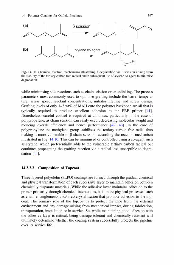
while minimising side reactions such as chain scission or crosslinking. The processparameters most commonly used to optimise grafting include the barrel tempera-ture, screw speed, reactant concentrations, initiator lifetime and screw design.Grafting levels of only 1–2 wt% of MAH onto the polymer backbone are all that istypically required to produce excellent adhesion to the FBE primer [41].Nonetheless, careful control is required at all times, particularly in the case ofpolypropylene, as chain scission can easily occur, decreasing molecular weight andreducing overall efficiency and hence performance [42, 43]. In the case ofpolypropylene the methylene group stabilises the tertiary carbon free radial thusmaking it more vulnerable to β chain scission, according the reaction mechanismillustrated in Fig. 14.10. This can be minimised or controlled using a co-agent suchas styrene, which preferentially adds to the vulnerable tertiary carbon radical butcontinues propagating the grafting reaction via a radical less susceptible to degra-dation [44].
14.3.2.3 Composition of Topcoat
Three layered polyolefin (3LPO) coatings are formed through the gradual chemicaland physical transformation of each successive layer to maintain adhesion betweenchemically disparate materials. While the adhesive layer maintains adhesion to theprimer primarily through chemical interactions, it is more physical processes suchas chain entanglements and/or co-crystallisation that promote adhesion to the top-coat. The primary role of the topcoat is to protect the pipe from the externalenvironment and any damage arising from mechanical impact, during fabrication,transportation, installation or in service. So, while maintaining good adhesion withthe adhesive layer is critical, being damage tolerant and chemically resistant willultimately determine whether the coating system successfully protects the pipelineover its service life.
+β scission
Ph
styrene co-agent
(a)
(b)
Fig. 14.10 Chemical reaction mechanisms illustrating a degradation via β scission arising fromthe stability of the tertiary carbon free radical and b subsequent use of styrene co-agent to minimisedegradation
14 Polymer Coatings for Oilfield Pipelines 397
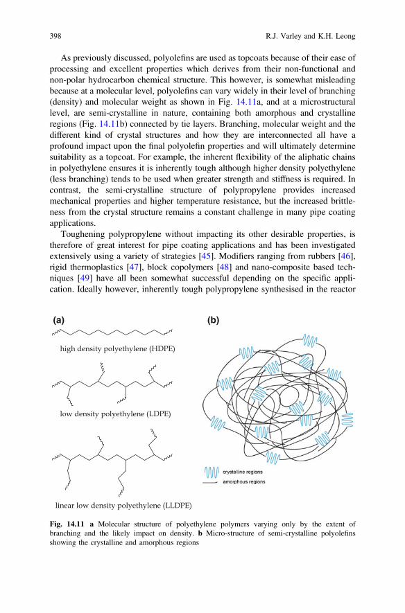
As previously discussed, polyolefins are used as topcoats because of their ease ofprocessing and excellent properties which derives from their non-functional andnon-polar hydrocarbon chemical structure. This however, is somewhat misleadingbecause at a molecular level, polyolefins can vary widely in their level of branching(density) and molecular weight as shown in Fig. 14.11a, and at a microstructurallevel, are semi-crystalline in nature, containing both amorphous and crystallineregions (Fig. 14.11b) connected by tie layers. Branching, molecular weight and thedifferent kind of crystal structures and how they are interconnected all have aprofound impact upon the final polyolefin properties and will ultimately determinesuitability as a topcoat. For example, the inherent flexibility of the aliphatic chainsin polyethylene ensures it is inherently tough although higher density polyethylene(less branching) tends to be used when greater strength and stiffness is required. Incontrast, the semi-crystalline structure of polypropylene provides increasedmechanical properties and higher temperature resistance, but the increased brittle-ness from the crystal structure remains a constant challenge in many pipe coatingapplications.
Toughening polypropylene without impacting its other desirable properties, istherefore of great interest for pipe coating applications and has been investigatedextensively using a variety of strategies [45]. Modifiers ranging from rubbers [46],rigid thermoplastics [47], block copolymers [48] and nano-composite based tech-niques [49] have all been somewhat successful depending on the specific appli-cation. Ideally however, inherently tough polypropylene synthesised in the reactor
(a) (b)
Fig. 14.11 a Molecular structure of polyethylene polymers varying only by the extent ofbranching and the likely impact on density. b Micro-structure of semi-crystalline polyolefinsshowing the crystalline and amorphous regions
398 R.J. Varley and K.H. Leong
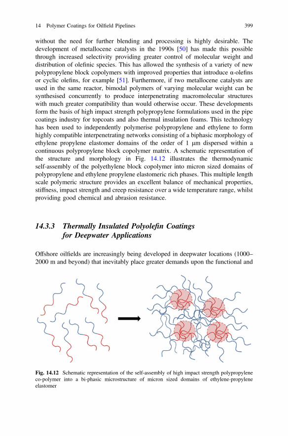
without the need for further blending and processing is highly desirable. Thedevelopment of metallocene catalysts in the 1990s [50] has made this possiblethrough increased selectivity providing greater control of molecular weight anddistribution of olefinic species. This has allowed the synthesis of a variety of newpolypropylene block copolymers with improved properties that introduce α-olefinsor cyclic olefins, for example [51]. Furthermore, if two metallocene catalysts areused in the same reactor, bimodal polymers of varying molecular weight can besynthesised concurrently to produce interpenetrating macromolecular structureswith much greater compatibility than would otherwise occur. These developmentsform the basis of high impact strength polypropylene formulations used in the pipecoatings industry for topcoats and also thermal insulation foams. This technologyhas been used to independently polymerise polypropylene and ethylene to formhighly compatible interpenetrating networks consisting of a biphasic morphology ofethylene propylene elastomer domains of the order of 1 μm dispersed within acontinuous polypropylene block copolymer matrix. A schematic representation ofthe structure and morphology in Fig. 14.12 illustrates the thermodynamicself-assembly of the polyethylene block copolymer into micron sized domains ofpolypropylene and ethylene propylene elastomeric rich phases. This multiple lengthscale polymeric structure provides an excellent balance of mechanical properties,stiffness, impact strength and creep resistance over a wide temperature range, whilstproviding good chemical and abrasion resistance.
14.3.3 Thermally Insulated Polyolefin Coatingsfor Deepwater Applications
Offshore oilfields are increasingly being developed in deepwater locations (1000–2000 m and beyond) that inevitably place greater demands upon the functional and
Fig. 14.12 Schematic representation of the self-assembly of high impact strength polypropyleneco-polymer into a bi-phasic microstructure of micron sized domains of ethylene-propyleneelastomer
14 Polymer Coatings for Oilfield Pipelines 399

mechanical performance of pipe coatings. At such depths, thermal insulation isnecessary to prevent crystallisation of paraffin waxes and hydrates during shut-downs and maintain fluid temperature to facilitate separation of the oil at the surface[52]. Hydrates are crystals of methane and water formed during high pressure andlow temperature flows and are a major source of pipeline blockages and is exac-erbated at greater depths. The oil and gas extracted at these depths is also hottermaking pipe coating reliability even more important to the economic recovery ofthe oil. Thermally insulated coatings, therefore, are necessary for preventing [53]:
• flow difficulties;• phase separation;• unplanned shutdown due to formation of hydrate plugs;• wax formation;• reduced fluid viscosity; and• rapid temperature drop.
From a mechanical performance perspective, increased water depth also meanshigher hydrostatic pressure, so it is important that the pipe coating has the strengthto withstand this pressure and not collapse or undergo creep significantly. Pipecoatings at extreme depths, therefore, require high compressive strength and stiff-ness, as well as sufficient temperature resistance and insulative capacities. Polymerfoam, either polypropylene or polyurethane, is widely used for thermal insulation atthese depths, although polypropylene is often the material of choice because of itscombination of properties and compatibility with the other layers in the coatingsystem.
Foam is typically applied by extruding an additional layer over an existing threelayer coating system which produces a five layer system from an additional topcoatover the foam layer, as shown earlier in Fig. 14.3b. The foam is typically createdfrom one of two different routes, either through an in situ gas expansion extrusionprocess or through the addition of micro-spheres (syntactic polypropylene).
Fig. 14.13 Scanning electron micrographs of polypropylene foam made using a glassmicro-spheres [54] and b in situ foam [55] formation
400 R.J. Varley and K.H. Leong
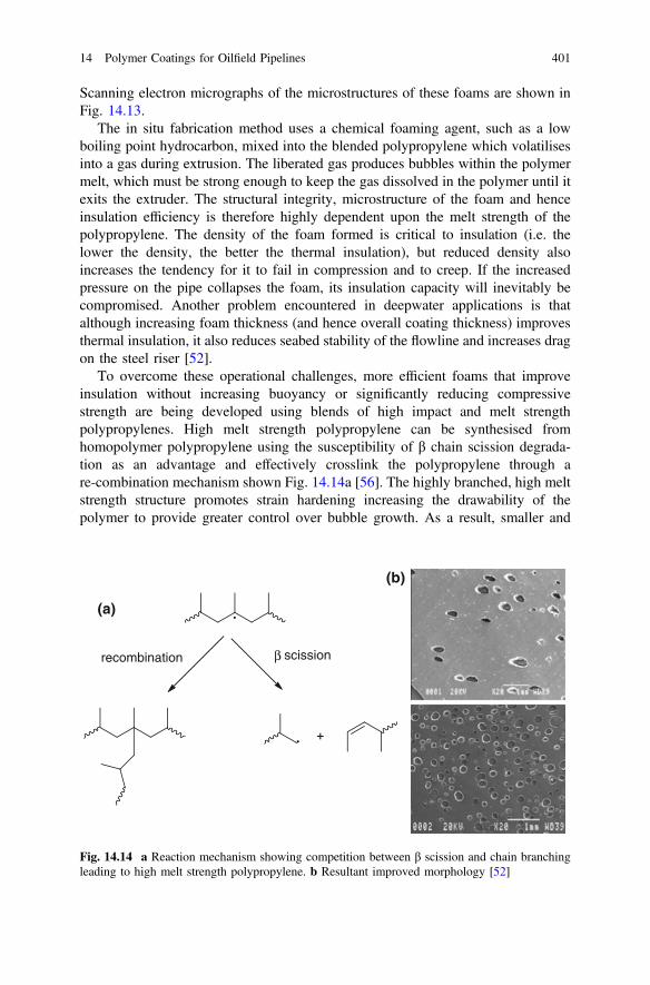
Scanning electron micrographs of the microstructures of these foams are shown inFig. 14.13.
The in situ fabrication method uses a chemical foaming agent, such as a lowboiling point hydrocarbon, mixed into the blended polypropylene which volatilisesinto a gas during extrusion. The liberated gas produces bubbles within the polymermelt, which must be strong enough to keep the gas dissolved in the polymer until itexits the extruder. The structural integrity, microstructure of the foam and henceinsulation efficiency is therefore highly dependent upon the melt strength of thepolypropylene. The density of the foam formed is critical to insulation (i.e. thelower the density, the better the thermal insulation), but reduced density alsoincreases the tendency for it to fail in compression and to creep. If the increasedpressure on the pipe collapses the foam, its insulation capacity will inevitably becompromised. Another problem encountered in deepwater applications is thatalthough increasing foam thickness (and hence overall coating thickness) improvesthermal insulation, it also reduces seabed stability of the flowline and increases dragon the steel riser [52].
To overcome these operational challenges, more efficient foams that improveinsulation without increasing buoyancy or significantly reducing compressivestrength are being developed using blends of high impact and melt strengthpolypropylenes. High melt strength polypropylene can be synthesised fromhomopolymer polypropylene using the susceptibility of β chain scission degrada-tion as an advantage and effectively crosslink the polypropylene through are-combination mechanism shown Fig. 14.14a [56]. The highly branched, high meltstrength structure promotes strain hardening increasing the drawability of thepolymer to provide greater control over bubble growth. As a result, smaller and
recombination β scission
(a)
(b)
Fig. 14.14 a Reaction mechanism showing competition between β scission and chain branchingleading to high melt strength polypropylene. b Resultant improved morphology [52]
14 Polymer Coatings for Oilfield Pipelines 401
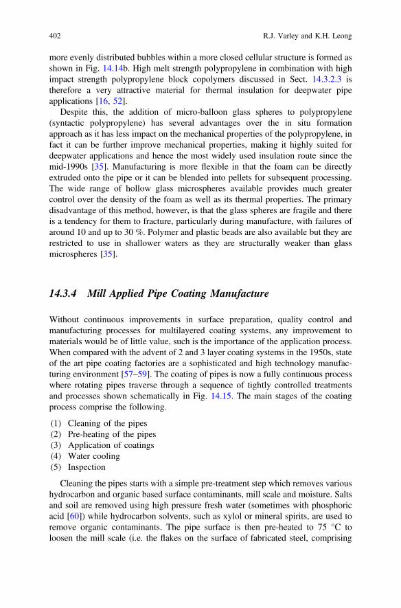
more evenly distributed bubbles within a more closed cellular structure is formed asshown in Fig. 14.14b. High melt strength polypropylene in combination with highimpact strength polypropylene block copolymers discussed in Sect. 14.3.2.3 istherefore a very attractive material for thermal insulation for deepwater pipeapplications [16, 52].
Despite this, the addition of micro-balloon glass spheres to polypropylene(syntactic polypropylene) has several advantages over the in situ formationapproach as it has less impact on the mechanical properties of the polypropylene, infact it can be further improve mechanical properties, making it highly suited fordeepwater applications and hence the most widely used insulation route since themid-1990s [35]. Manufacturing is more flexible in that the foam can be directlyextruded onto the pipe or it can be blended into pellets for subsequent processing.The wide range of hollow glass microspheres available provides much greatercontrol over the density of the foam as well as its thermal properties. The primarydisadvantage of this method, however, is that the glass spheres are fragile and thereis a tendency for them to fracture, particularly during manufacture, with failures ofaround 10 and up to 30 %. Polymer and plastic beads are also available but they arerestricted to use in shallower waters as they are structurally weaker than glassmicrospheres [35].
14.3.4 Mill Applied Pipe Coating Manufacture
Without continuous improvements in surface preparation, quality control andmanufacturing processes for multilayered coating systems, any improvement tomaterials would be of little value, such is the importance of the application process.When compared with the advent of 2 and 3 layer coating systems in the 1950s, stateof the art pipe coating factories are a sophisticated and high technology manufac-turing environment [57–59]. The coating of pipes is now a fully continuous processwhere rotating pipes traverse through a sequence of tightly controlled treatmentsand processes shown schematically in Fig. 14.15. The main stages of the coatingprocess comprise the following.
(1) Cleaning of the pipes(2) Pre-heating of the pipes(3) Application of coatings(4) Water cooling(5) Inspection
Cleaning the pipes starts with a simple pre-treatment step which removes varioushydrocarbon and organic based surface contaminants, mill scale and moisture. Saltsand soil are removed using high pressure fresh water (sometimes with phosphoricacid [60]) while hydrocarbon solvents, such as xylol or mineral spirits, are used toremove organic contaminants. The pipe surface is then pre-heated to 75 °C toloosen the mill scale (i.e. the flakes on the surface of fabricated steel, comprising
402 R.J. Varley and K.H. Leong
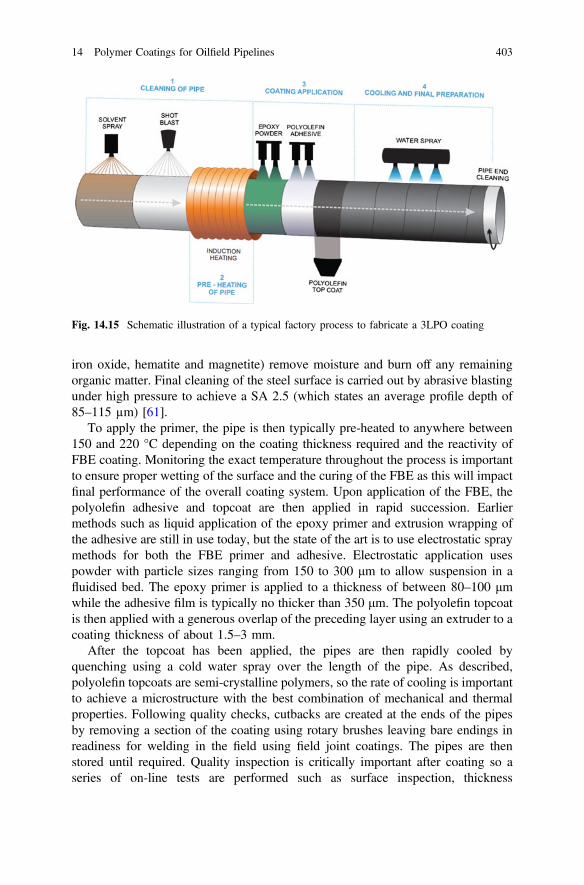
iron oxide, hematite and magnetite) remove moisture and burn off any remainingorganic matter. Final cleaning of the steel surface is carried out by abrasive blastingunder high pressure to achieve a SA 2.5 (which states an average profile depth of85–115 µm) [61].
To apply the primer, the pipe is then typically pre-heated to anywhere between150 and 220 °C depending on the coating thickness required and the reactivity ofFBE coating. Monitoring the exact temperature throughout the process is importantto ensure proper wetting of the surface and the curing of the FBE as this will impactfinal performance of the overall coating system. Upon application of the FBE, thepolyolefin adhesive and topcoat are then applied in rapid succession. Earliermethods such as liquid application of the epoxy primer and extrusion wrapping ofthe adhesive are still in use today, but the state of the art is to use electrostatic spraymethods for both the FBE primer and adhesive. Electrostatic application usespowder with particle sizes ranging from 150 to 300 μm to allow suspension in afluidised bed. The epoxy primer is applied to a thickness of between 80–100 μmwhile the adhesive film is typically no thicker than 350 μm. The polyolefin topcoatis then applied with a generous overlap of the preceding layer using an extruder to acoating thickness of about 1.5–3 mm.
After the topcoat has been applied, the pipes are then rapidly cooled byquenching using a cold water spray over the length of the pipe. As described,polyolefin topcoats are semi-crystalline polymers, so the rate of cooling is importantto achieve a microstructure with the best combination of mechanical and thermalproperties. Following quality checks, cutbacks are created at the ends of the pipesby removing a section of the coating using rotary brushes leaving bare endings inreadiness for welding in the field using field joint coatings. The pipes are thenstored until required. Quality inspection is critically important after coating so aseries of on-line tests are performed such as surface inspection, thickness
Fig. 14.15 Schematic illustration of a typical factory process to fabricate a 3LPO coating
14 Polymer Coatings for Oilfield Pipelines 403
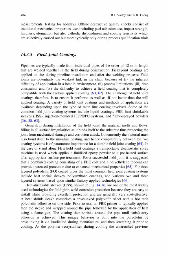
measurements, testing for holidays. Offline destructive quality checks consist oftraditional mechanical properties tests including peel adhesion test, impact strength,hardness, elongation but also cathodic disbondment and coating resistivity whichare selectively carried out but more typically only during process qualification trials
14.3.5 Field Joint Coatings
Pipelines are typically made from individual pipes of the order of 12 m in lengththat are welded together in the field during construction. Field joint coatings areapplied on-site during pipeline installation and after the welding process. Fieldjoints are potentially the weakest link in the chain because of (i) the inherentdifficulty of application in a hostile environment, (ii) process limitations, (iii) timeconstraints and (iv) the difficulty to achieve a field coating that is completelycompatible with the factory applied coating [60, 62]. The challenge of field jointcoatings therefore, is to ensure it performs as well as, if not better than the millapplied coating. A variety of field joint coatings and methods of application areavailable depending upon the type of main line coating involved. Some of thecommon field joint coating systems include liquid coatings, FBE, heat shrinkablesleeves (HSS), injection-moulded PP/PE/PU systems, and flame-sprayed powders[36, 50, 63].
Generally, during installation of the field joint, the material melts and flows,filling in all surface irregularities as it binds itself to the substrate thus protecting thejoint from mechanical damage and corrosion attack. Concurrently the material mustalso bond itself to the mainline coating, and hence compatibility between the twocoating systems is of paramount importance for a durable field joint coating [64]. Inthe case of stand alone FBE field joint coatings a transportable electrostatic spraymachine is used which applies a fluidised epoxy powder to a pre-heated surfaceafter appropriate surface pre-treatment. For a successful field joint it is suggestedthat a combined coating consisting of a FBE coat and a polyethylene topcoat canprovide increased protection due to enhanced mechanical properties [65]. For threelayered polyolefin (PO) coated pipes the most common field joint coating systemsinclude heat shrink sleeves, polyurethane coatings, and various two and threelayered systems based upon similar factory applied technologies [66].
Heat-shrinkable sleeves (HSS), shown in Fig. 14.16, are one of the most widelyused technologies for field girth-weld corrosion protection because they are easy toinstall while providing excellent protection and are generally very cost-effective.A heat shrink sleeve comprises a crosslinked polyolefin sheet with a hot meltpolyolefin adhesive on one side. Prior to use, an FBE primer is typically appliedthen the sleeve and wrapped around the pipe followed by the application of heatusing a flame gun. The coating then shrinks around the pipe until satisfactoryadhesion is achieved. This unique behavior is built into the polyolefin bycrosslinking it via irradiation during manufacture, and then stretching it prior tocooling. As the polymer recrystallises during cooling the unstretched previous
404 R.J. Varley and K.H. Leong
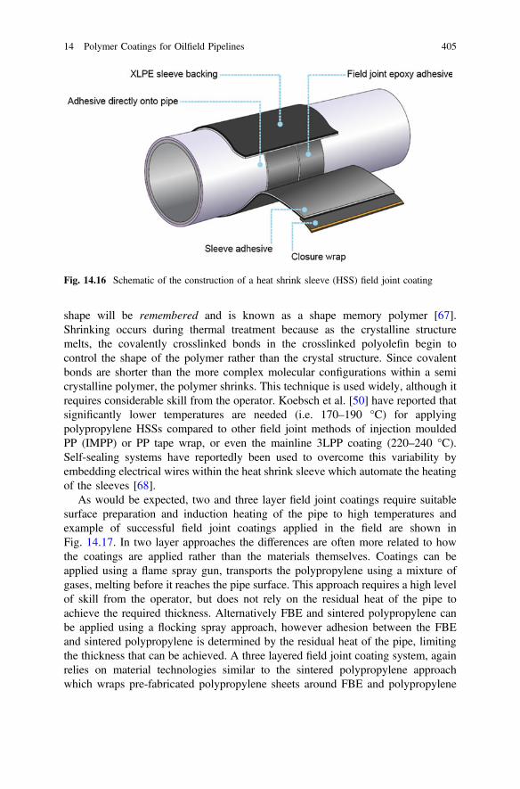
shape will be remembered and is known as a shape memory polymer [67].Shrinking occurs during thermal treatment because as the crystalline structuremelts, the covalently crosslinked bonds in the crosslinked polyolefin begin tocontrol the shape of the polymer rather than the crystal structure. Since covalentbonds are shorter than the more complex molecular configurations within a semicrystalline polymer, the polymer shrinks. This technique is used widely, although itrequires considerable skill from the operator. Koebsch et al. [50] have reported thatsignificantly lower temperatures are needed (i.e. 170–190 °C) for applyingpolypropylene HSSs compared to other field joint methods of injection mouldedPP (IMPP) or PP tape wrap, or even the mainline 3LPP coating (220–240 °C).Self-sealing systems have reportedly been used to overcome this variability byembedding electrical wires within the heat shrink sleeve which automate the heatingof the sleeves [68].
As would be expected, two and three layer field joint coatings require suitablesurface preparation and induction heating of the pipe to high temperatures andexample of successful field joint coatings applied in the field are shown inFig. 14.17. In two layer approaches the differences are often more related to howthe coatings are applied rather than the materials themselves. Coatings can beapplied using a flame spray gun, transports the polypropylene using a mixture ofgases, melting before it reaches the pipe surface. This approach requires a high levelof skill from the operator, but does not rely on the residual heat of the pipe toachieve the required thickness. Alternatively FBE and sintered polypropylene canbe applied using a flocking spray approach, however adhesion between the FBEand sintered polypropylene is determined by the residual heat of the pipe, limitingthe thickness that can be achieved. A three layered field joint coating system, againrelies on material technologies similar to the sintered polypropylene approachwhich wraps pre-fabricated polypropylene sheets around FBE and polypropylene
Fig. 14.16 Schematic of the construction of a heat shrink sleeve (HSS) field joint coating
14 Polymer Coatings for Oilfield Pipelines 405
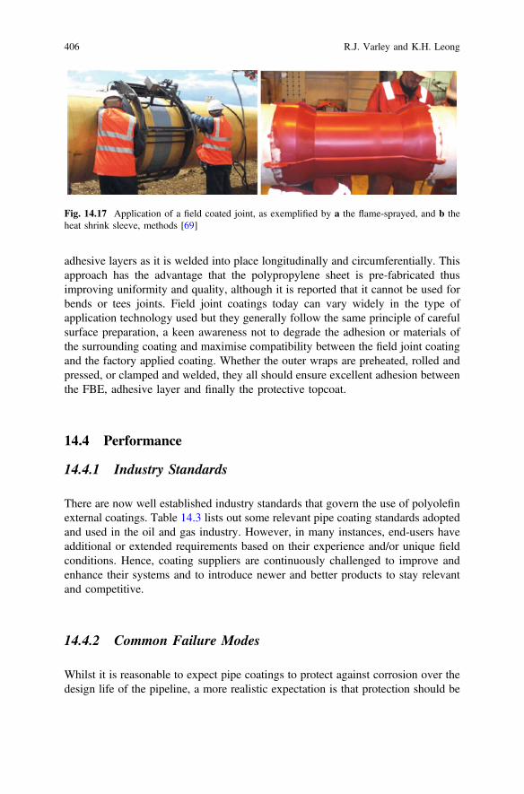
adhesive layers as it is welded into place longitudinally and circumferentially. Thisapproach has the advantage that the polypropylene sheet is pre-fabricated thusimproving uniformity and quality, although it is reported that it cannot be used forbends or tees joints. Field joint coatings today can vary widely in the type ofapplication technology used but they generally follow the same principle of carefulsurface preparation, a keen awareness not to degrade the adhesion or materials ofthe surrounding coating and maximise compatibility between the field joint coatingand the factory applied coating. Whether the outer wraps are preheated, rolled andpressed, or clamped and welded, they all should ensure excellent adhesion betweenthe FBE, adhesive layer and finally the protective topcoat.
14.4 Performance
14.4.1 Industry Standards
There are now well established industry standards that govern the use of polyolefinexternal coatings. Table 14.3 lists out some relevant pipe coating standards adoptedand used in the oil and gas industry. However, in many instances, end-users haveadditional or extended requirements based on their experience and/or unique fieldconditions. Hence, coating suppliers are continuously challenged to improve andenhance their systems and to introduce newer and better products to stay relevantand competitive.
14.4.2 Common Failure Modes
Whilst it is reasonable to expect pipe coatings to protect against corrosion over thedesign life of the pipeline, a more realistic expectation is that protection should be
Fig. 14.17 Application of a field coated joint, as exemplified by a the flame-sprayed, and b theheat shrink sleeve, methods [69]
406 R.J. Varley and K.H. Leong
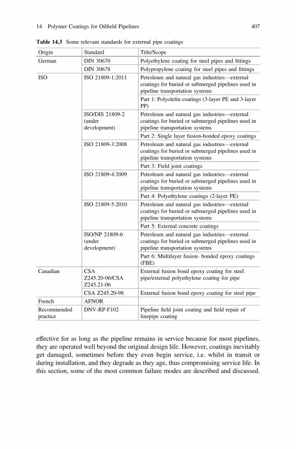
effective for as long as the pipeline remains in service because for most pipelines,they are operated well beyond the original design life. However, coatings inevitablyget damaged, sometimes before they even begin service, i.e. whilst in transit orduring installation, and they degrade as they age, thus compromising service life. Inthis section, some of the most common failure modes are described and discussed.
Table 14.3 Some relevant standards for external pipe coatings
Origin Standard Title/Scope
German DIN 30670 Polyethylene coating for steel pipes and fittings
DIN 30678 Polypropylene coating for steel pipes and fittings
ISO ISO 21809-1:2011 Petroleum and natural gas industries—externalcoatings for buried or submerged pipelines used inpipeline transportation systems
Part 1: Polyolefin coatings (3-layer PE and 3-layerPP)
ISO/DIS 21809-2(underdevelopment)
Petroleum and natural gas industries—externalcoatings for buried or submerged pipelines used inpipeline transportation systems
Part 2: Single layer fusion-bonded epoxy coatings
ISO 21809-3:2008 Petroleum and natural gas industries—externalcoatings for buried or submerged pipelines used inpipeline transportation systems
Part 3: Field joint coatings
ISO 21809-4:2009 Petroleum and natural gas industries—externalcoatings for buried or submerged pipelines used inpipeline transportation systems
Part 4: Polyethylene coatings (2-layer PE)
ISO 21809-5:2010 Petroleum and natural gas industries—externalcoatings for buried or submerged pipelines used inpipeline transportation systems
Part 5: External concrete coatings
ISO/NP 21809-6(underdevelopment)
Petroleum and natural gas industries—externalcoatings for buried or submerged pipelines used inpipeline transportation systems
Part 6: Multilayer fusion- bonded epoxy coatings(FBE)
Canadian CSAZ245.20-06/CSAZ245.21-06
External fusion bond epoxy coating for steelpipe/external polyethylene coating for pipe
CSA Z245.20-98 External fusion bond epoxy coating for steel pipe
French AFNOR
Recommendedpractice
DNV-RP-F102 Pipeline field joint coating and field repair oflinepipe coating
14 Polymer Coatings for Oilfield Pipelines 407
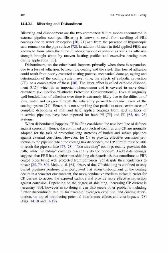
14.4.2.1 Blistering and Disbondment
Blistering and disbondment are the two commonest failure modes encountered inexternal pipeline coatings. Blistering is known to result from swelling of FBEcoatings due to water absorption [70, 71] and from the presence of hygroscopicsalts remnant on the pipe surface [72]. In addition, blisters in field applied FBEs areknown to form when the force of abrupt vapour expansion exceeds its adhesivestrength brought about by uneven heating profiles and excessive heating ratesduring application [73].
Disbondment, on the other hand, happens primarily when there is separation,due to a loss of adhesion, between the coating and the steel. This loss of adhesioncould result from poorly executed coating process, mechanical damage, ageing anddeterioration of the coating system over time, the effects of cathodic protection(CP), or a combination of these [30]. The latter effect is called cathodic disbond-ment (CD), which is an important phenomenon and is covered in more detailelsewhere (i.e. Section “Cathodic Protection Considerations”). Even if originallywell-bonded, loss of adhesion over time is extremely likely due to the diffusion ofions, water and oxygen through the inherently permeable organic layers of thecoating system [74]. Hence, it is not surprising that partial to more severe cases ofcomplete debonding of mill and field applied coatings from steel surfaces ofin-service pipelines have been reported for both PE [75] and PP [63, 64, 76]systems.
When disbondment happens, CP is often considered the next best line of defenceagainst corrosion. Hence, the combined approach of coatings and CP are normallyadopted for the task of protecting long stretches of buried and subsea pipelinesagainst external corrosion. However, for CP to provide effective corrosion pro-tection to the pipeline when the coating has disbonded, the CP current must be ableto reach the pipe surface [77, 78]. “Non-shielding” coatings readily provides thispath, while “shielding” coatings essentially do the opposite. Field data stronglysuggests that FBE has superior non-shielding characteristics that contribute to FBEcoated pipes being well protected from corrosion [25] despite their tendencies toblister [25, 79, 80]. Melot et al. [64] observed that CP shielding is confined to onlyburied pipelines onshore. It is postulated that when disbondment of the coatingoccurs in a seawater environment, the more conductive medium makes it easier forCP current to access the exposed cathode and provide more effective protectionagainst corrosion. Depending on the degree of shielding, increasing CP current isnecessary [30], however in so doing it can also create other problems includingfurther disbondment due to, for example, hydrogen evolution, and coating deteri-oration, on top of introducing potential interference effects and cost impacts [78](Figs. 14.18 and 14.19).
408 R.J. Varley and K.H. Leong
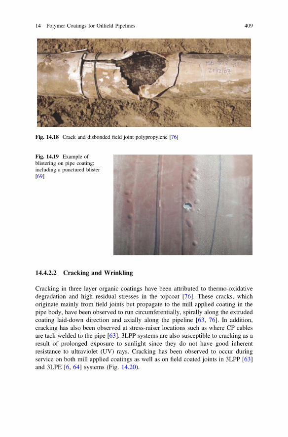
14.4.2.2 Cracking and Wrinkling
Cracking in three layer organic coatings have been attributed to thermo-oxidativedegradation and high residual stresses in the topcoat [76]. These cracks, whichoriginate mainly from field joints but propagate to the mill applied coating in thepipe body, have been observed to run circumferentially, spirally along the extrudedcoating laid-down direction and axially along the pipeline [63, 76]. In addition,cracking has also been observed at stress-raiser locations such as where CP cablesare tack welded to the pipe [63]. 3LPP systems are also susceptible to cracking as aresult of prolonged exposure to sunlight since they do not have good inherentresistance to ultraviolet (UV) rays. Cracking has been observed to occur duringservice on both mill applied coatings as well as on field coated joints in 3LPP [63]and 3LPE [6, 64] systems (Fig. 14.20).
Fig. 14.18 Crack and disbonded field joint polypropylene [76]
Fig. 14.19 Example ofblistering on pipe coating;including a punctured blister[69]
14 Polymer Coatings for Oilfield Pipelines 409
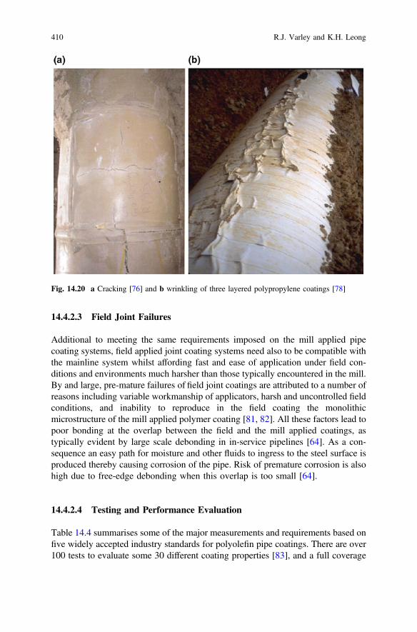
14.4.2.3 Field Joint Failures
Additional to meeting the same requirements imposed on the mill applied pipecoating systems, field applied joint coating systems need also to be compatible withthe mainline system whilst affording fast and ease of application under field con-ditions and environments much harsher than those typically encountered in the mill.By and large, pre-mature failures of field joint coatings are attributed to a number ofreasons including variable workmanship of applicators, harsh and uncontrolled fieldconditions, and inability to reproduce in the field coating the monolithicmicrostructure of the mill applied polymer coating [81, 82]. All these factors lead topoor bonding at the overlap between the field and the mill applied coatings, astypically evident by large scale debonding in in-service pipelines [64]. As a con-sequence an easy path for moisture and other fluids to ingress to the steel surface isproduced thereby causing corrosion of the pipe. Risk of premature corrosion is alsohigh due to free-edge debonding when this overlap is too small [64].
14.4.2.4 Testing and Performance Evaluation
Table 14.4 summarises some of the major measurements and requirements based onfive widely accepted industry standards for polyolefin pipe coatings. There are over100 tests to evaluate some 30 different coating properties [83], and a full coverage
Fig. 14.20 a Cracking [76] and b wrinkling of three layered polypropylene coatings [78]
410 R.J. Varley and K.H. Leong
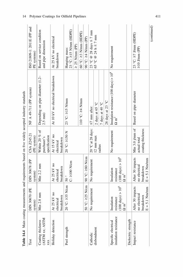
Tab
le14
.4Maincoatingmeasurementsandrequ
irem
entsbasedon
five
widelyaccepted
indu
stry
standards
Test
DIN
3067
0(PE
system
)DIN
3067
8(PP
system
)CSA
Z24
5.21
(PEsystem
)NFA
49-711
(PPsystem
)ISO
2180
9-1:
2011
E(PPand
PEsystem
s)
Coatin
gthickn
ess
(AST
Mxx
;AST
Mxx
x
Min
2.8mm
Min
2.2mm
With
in20
%of
purchaser’s
specificatio
n
Depending
onpipe
diam
eter
(1.2–
2.5mm)
Based
onservicecond
ition
andpipe
dimension
Holiday
detection
At25
kVno
electrical
breakd
own
At25
kVno
electrical
breakd
own
At15
kVno
electrical
breakd
own
At10
kVno
electrical
breakd
own
At25
kVno
electrical
breakd
own
Peel
streng
th20
°C:≥35
N/cm
50°
C:≥10
0N/cm
20°C
:≥15
0N
23°C
:≥15
N/m
mHanging
mass:
23°C
:≥15
N/m
m(H
DPE
)
≥25
N/m
m(PP)
110°C
:≥4N/m
m60
°C:≥3N/m
m(H
DPE
)
90°C
:≥80
N/cm
90°C
:≥4N/m
m(PP)
50°C
:≥25
N/cm
Catho
dic
disbon
dment
Norequ
irem
ent
Norequ
irem
ent
20°C
at28
days:
12mm
max
radius
≤7mm
after:
23°C
@28
days
≤7mm
65°C
@24
h≤7mm
2days
at65
°C
7days
at40
°C
28days
at23
°C
Specificelectrical
insulatio
nresistance
Insulatio
nresistance
(100
days)>10
8
Ωm
2
Insulatio
nresistance
(100
days)>10
8
Ωm
2
Norequ
irem
ent
Insulatio
nresistance
(100
days)>
108
Ωm
2Norequ
irem
ent
Dielectricstreng
th
Impact
resistance
After
30im
pacts
noelectrical
breakd
own
E=5.1Nm/m
m
After
30im
pacts
noelectrical
breakd
own
E=5.1Nm/m
m
Min
3.0j/m
mof
actual
total
coatingthickn
ess
Based
onpipe
diam
eter
23°C
:≥7J/mm
(HDPE
)≥10
J/mm
(PP)
(con
tinued)
14 Polymer Coatings for Oilfield Pipelines 411
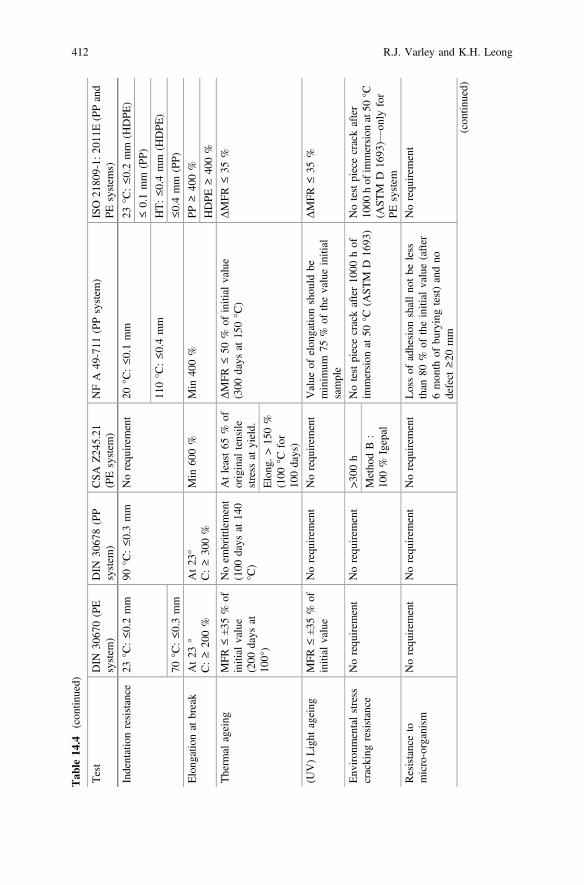
Tab
le14
.4(con
tinued)
Test
DIN
3067
0(PE
system
)DIN
3067
8(PP
system
)CSA
Z24
5.21
(PEsystem
)NFA
49-711
(PPsystem
)ISO
2180
9-1:
2011
E(PPand
PEsystem
s)
Indentationresistance
23°C
:≤0.2mm
90°C
:≤0.3mm
Norequ
irem
ent
20°C
:≤0.1mm
23°C
:≤0.2mm
(HDPE
)
≤0.1mm
(PP)
110°C
:≤0.4mm
HT:≤0.4mm
(HDPE
)
70°C
:≤0.3mm
≤0.4mm
(PP)
Elong
ationat
break
At23
°C:≥20
0%
At23
°C:≥30
0%
Min
600%
Min
400%
PP≥40
0%
HDPE
≥40
0%
Therm
alageing
MFR
≤±35
%of
initial
value
(200
days
at10
0°)
Noem
brittlement
(100
days
at14
0°C
)
Atleast65
%of
original
tensile
stress
atyield.
ΔMFR
≤50
%of
initial
value
(300
days
at15
0°C
)ΔMFR
≤35
%
Elong
.>15
0%
(100
°Cfor
100days)
(UV)Light
ageing
MFR
≤±35
%of
initial
value
Norequ
irem
ent
Norequ
irem
ent
Value
ofelon
gatio
nshou
ldbe
minim
um75
%of
thevalueinitial
sample
ΔMFR
≤35
%
Env
iron
mentalstress
cracking
resistance
Norequ
irem
ent
Norequ
irem
ent
>300
hNotestpiececrackafter10
00hof
immersion
at50
°C(A
STM
D16
93)
Notestpiececrackafter
1000
hof
immersion
at50
°C(A
STM
D16
93)—
only
for
PEsystem
Metho
dB:
100%
Igepal
Resistanceto
micro-organism
Norequ
irem
ent
Norequ
irem
ent
Norequ
irem
ent
Lossof
adhesion
shallno
tbe
less
than
80%
oftheinitial
value(after
6mon
thof
buryingtest)andno
defect
≥20
mm
Norequ
irem
ent
(con
tinued)
412 R.J. Varley and K.H. Leong

Tab
le14
.4(con
tinued)
Test
DIN
3067
0(PE
system
)DIN
3067
8(PP
system
)CSA
Z24
5.21
(PEsystem
)NFA
49-711
(PPsystem
)ISO
2180
9-1:
2011
E(PPand
PEsystem
s)
Bendability/flexibility
Norequ
irem
ent
Norequ
irem
ent
Norequ
irem
ent
Ableto
with
standbend
ingwith
radius
ofcurvatureequalto
20tim
esthediam
eter
ofthetube
with
out
visibledamage
Nocracking
atan
angleof
2.0°
perpipe
diam
eter
leng
th
Hot
water
immersion
Norequ
irem
ent
Norequ
irem
ent
Norequ
irem
ent
Norequ
irem
ent
Average
≤2mm
Maxim
um≤3mm
14 Polymer Coatings for Oilfield Pipelines 413
of them are beyond the scope of this chapter. Suffice to say that these tests coveraspects of surface preparation, raw material properties and performance of thecomplete coating system. Only the main properties are presented and discussedhere, and for a more comprehensive coverage of the tests, the reader is referred tothe review articles published by Papavinasam and colleagues [84].
Adhesion
The quality of adhesion between a virgin 3LPO coating system and steel substrate isevaluated using a peel test. The test involves measuring the force necessary todetach the coating from its substrate when subjected to a constant rate of pull(viz. 10–300 mm min−1, depending on specification [11]). Hence the test is carriedout by gripping and pulling at 90° to the tangent of the pipe surface a peel strip (or,“tongue”). The strip is of a pre-determined width (typically 25 mm) which isformed by carefully cutting and chiselling into the coated pipe [85–87], seeFig. 14.21. Alternatively, the rate at which the coating is peeled from the metalsubstrate due to a constant load, effected by means of a hanging mass, can also beused as the measure of adhesion strength [88]. Standards generally recommend thatthe test be carried out at different temperatures, covering the field conditions ofroom/ambient, low and high temperatures, although the exact recommended tem-peratures may vary somewhat between different standards [85, 86, 88]. Similarly,different hang-off masses are also used per specification in the relevant standard[88]. The test requires cohesive failure of the adhesive layer for values to be deemedvalid.
Note that the peel test only measures the level of adhesion of a virgin coatedpipe. Long-term behaviour and properties of the bond of the coating to the steelsubstrate cannot be predicted reliably, and, hence, should not be, inferred from theresults of this test. The test is normally used to qualify a coating system with respectto the process, including the associated conditions and parameters.
Cathodic Protection Considerations
In order to provide effective corrosion protection, the electrochemical process of CPis required to alkalinise (to a pH range of 9–13) the surrounding environmentaround the cathode (i.e. pipe, tank, etc.) [77]. During the process hydrogen isevolved, which is coupled with other potentially damaging electrochemical changesin the environment that could lead to disbondment of the 3LPO coating from itssubstrate. This degradation in adhesion of the coating due to CP is more commonlyreferred to as cathodic disbondment (CD) (see also Sect. 14.4.2.1). Papavinasamand colleagues [70] attributed CD to factors such as pH, cathodic potential, stabilityof the interfacial oxide, substrate surface roughness, defect geometry, coating for-mulations, wet-dry fluctuations, and water ingress. The complex array of factors
414 R.J. Varley and K.H. Leong
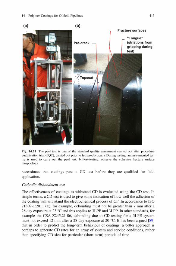
necessitates that coatings pass a CD test before they are qualified for fieldapplication.
Cathodic disbondment test
The effectiveness of coatings to withstand CD is evaluated using the CD test. Insimple terms, a CD test is used to give some indication of how well the adhesion ofthe coating will withstand the electrochemical process of CP. In accordance to ISO21809-1:2011 (E), for example, debonding must not be greater than 7 mm after a28 day exposure at 23 °C and this applies to 3LPE and 3LPP. In other standards, forexample the CSA Z245.21-06, debonding due to CD testing for a 3LPE systemmust not exceed 12 mm after a 28 day exposure at 20 °C. It has been argued [89]that in order to predict the long-term behaviour of coatings, a better approach isperhaps to generate CD rates for an array of system and service conditions, ratherthan specifying CD size for particular (short-term) periods of time.
“Tongue” (striations from gripping during test)
Pre-crack
Topcoat
Fracture surfaces (a) (b)
Fig. 14.21 The peel test is one of the standard quality assessment carried out after procedurequalification trial (PQT), carried out prior to full production. a During testing: an instrumented testrig is used to carry out the peel test. b Post-testing: observe the cohesive fracture surfacemorphology
14 Polymer Coatings for Oilfield Pipelines 415
It is noteworthy that there is no justification for the limits to disbondment set outin specifications; limits are just ideas of what it is thought maximum disbondmenttolerable [90]. In fact, over a period of 30 years, from 1965, CD resistance isreported to have improved from approximately 65 mm to less than 10 mm, for FBEsystems [23], thus showing tremendous enhancement in the performance of coatingsystems in line with ever demanding field requirements.
Hot CD test
With the advent of high temperature coatings, normally required for deepwaterapplications, the need for CD tests to be conducted at elevated temperatures hasbecome increasingly necessary. One of the limitations of standard CD tests is thatthe electrolyte used to instigate disbondment is water-based and hence not suitablefor high temperature (beyond 100 °C) assessment. Buchanan [11] highlighted thatpublished data have indicated that a CD test carried out above 95 °C is indeed notpractical, nor is it representative of in-service conditions while CD testing at a lowertemperature of 65 °C can actually be more severe. Others [91, 92] have pointed outthat CD tests should be carried out at temperatures beyond the limitations of theboiling point of water, to better simulate and represent the conditions to which hightemperature structural coatings are exposed. This is because other degradationmechanisms could come into play when the service conditions reach these highertemperatures [92]. Attempts to carry out CD testing at temperatures above 100 °Chave been investigated using autoclaves [93] and by heating the test specimenabove 100 °C while maintaining the temperature of the test (aqueous) solution atbelow boiling point of water [94]. In addition, using concentrated salt brines that arethermodynamically stable above 100 °C has also been proposed [95]. Much workremains to ascertain the suitability of these modified test procedures in predictinglong-term behaviours of high temperature polymer coatings. Research into theeffects of coating thickness with respect to CD at “low” [89] and “high” [92]temperatures is also being pursued.
Dielectric strength and Insulation resistance
All coatings have varying dielectric properties that reduce the tendency of theelectrolyte to complete the electrical circuit between adjacent anodic and cathodicsites on a substrate, that is necessary to mitigate corrosion in the event of localisedcoating failure [78].
Ideally, a coating should have a high enough dielectric strength to resist cor-rosion while the coating is bonded, but at the same time sufficiently low to allowprotective CP current to reach the pipe when disbonded. Such coatings are clas-sified as non-shielding. FBE is known to provide excellent non-shielding charac-teristics which explains how well in-service FBE coated pipes protected againstcorrosion [25] despite their tendencies to blister [79, 80].
416 R.J. Varley and K.H. Leong
Presence of Holidays
The presence of defects such as voids, pores and pinholes, or holidays, that result indiscontinuities are unavoidable in polymeric coatings. Such discontinuities in thecoating are frequently minute and not readily visible. ASTM D5162–08 [96] rec-ommends a method for picking up unacceptable levels of these discontinuities byapplying low voltage electric circuit (which is also connected in series with an LEDor noise-producing component such as a piezoelectric speaker) so that if electricalflow is detected then the affected area is termed as conductive thus indicating thepresence of holidays. The flaws are picked up by an electric arc that forms betweenthe sensor electrode and the metallic support. The allowable number of disconti-nuities should be pre-determined prior to conducting the test since the acceptablequantity of discontinuities will vary depending on coating film thickness, design,and service conditions.
14.4.2.5 Long-Term Exposure to Elevated Temperatures
Pipe coatings are increasingly required to service elevated temperature conditions.These services include transmission of oil sands and heavy oils which, at 25 °C, haveviscosities, that are in the order of a million times higher than conventional crude oil.For transmission at parity with crude oil, these highly viscous hydrocarbon need tobe transported at temperatures around 200 °C [95]. Hence, thermal ageing ofcoatings need to be better assessed using a wet medium, rather than restricted to onlydry environments, and at higher temperatures that are either akin to actual fieldconditions, or even to higher to accelerate the effects of long term, elevated tem-perature exposures. This is an area of on-going research and development.
Thermal ageing
Moosavi et al. [76] have revealed discoloration and severe spiral cracking in 3LPPwhen subjecting it to 1000-h thermal ageing in an oven at 150 °C. They suggestedthe use of 150 °C for the thermo-oxidative test in order to accelerate thermaldegradation, and as a minimum qualification requirement, the specimen shouldsurvive a 4000 h continuous exposure.
Hot wet soak test
The electrical resistance of polymeric materials are high, in the region of 1014 Ω,and 3LPO coatings can hence be expected to provide effective insulation for thesteel pipeline to which it provides corrosion protection. However, the resistance isexpected to degrade over time with the ingress of fluids into the coating thusdeteriorating its corrosion protection capability [83]. An example of the hot wetsoak test can be referenced to ISO 21809-1: 2011E (Annex M) [88]. However, themaximum temperature is set at only 95 °C and it has been proposed that this testconditions could misrepresent the actual ones experienced by high temperaturecoatings [95].
14 Polymer Coatings for Oilfield Pipelines 417
14.5 New Developments
14.5.1 Toughness and Durability
From fabrication, transportation, installation to in-service conditions, pipe coatingsare subject to various potential damage events and as pipes are deployed in moredemanding environments their susceptibility to damage increases. Thus there is aon-going need for tougher and more damage resistant as well as more durablecoatings whether single layered FBE, dual or multi-layered coatings. Some inno-vative approaches and new materials which seek to address some of this challengeare discussed below.
Commonly referred to simply as a high performance composite coating (HPCC)[16, 97], this polyethylene based coating is a multi-component system applied in asingle step using spray coating application methods that claims to be less suscep-tible to internal stress development over wide temperature variations and less likelyto delaminate under cyclic conditions. Applied as a single coating, themulti-component system essentially phase separates into a three layered FBE,adhesive and topcoat structure after application and cure. The lack of a sharp or welldefined boundary between the layers is understood to produce strongly interlockingand compatible layers which provide this improved resistance to delamination,penetration and abrasion, all of which are existing problems for three layer poly-ethylene coatings [98]. Its primary target application is situations where FBEcoatings have been determined to be inadequate [99] and it has been demonstratedto be extremely beneficial in onshore underground situations where the resistance toimpact during installation is particularly important [100].
This technology has been further developed [101] to overcome common prob-lems such as “weld tenting” and low coating thickness over welds. A polyethylenecoating, minimum 2.2 mm in thickness, is applied using a side extruder wrappingprocess over the multi-component HPCC system. In this case HPCC is typicallyused to replace the FBE and polyolefin adhesive layers in three layered systemswith the polyolefin topcoat being subsequently wrapped over the HPCC
In addition to the use of block copolymers and related systems, polypropylenecan also be further toughened via β nucleation [102, 103], a technique whichcatalyses the formation of an alternative and more inherently tougher β crystalstructure at the expense of the more thermodynamically favorable yet brittle αcrystalline phase. The transformation is illustrated in Fig. 14.22 as large α spher-ulites with sharp, distinct boundaries become much smaller, more diffuse β crys-tallites and hard to observe boundaries at only 0.1 wt% of nucleant. This approachis very attractive for pipe coatings applications because only very small concen-trations of β nucleant are required to significantly improve impact strength ensuringlittle impact upon processability [104]. Recent work has combined the β nucleationapproach with elastomer modification, in the search for synergistic improvement inproperties [105, 106] with some success, thus improving performance even further[107, 108].
418 R.J. Varley and K.H. Leong

FBE coatings, whether applied as single, dual or three layered coatings, willalways remain susceptible to damage to some degree because of their crosslinkednetwork structure. As such a range of approaches have been tried to improve theirtoughness and in-service durability. Block copolymers are one such approachbecause they are known to self assemble into nanostructured morphologies withadvantageous properties [110]. This technology produces a gradient of interactionswith the curing epoxy resin to produce nano and microscale morphologies withenhanced performance. The particular advantages of this is that both the flexibilityand impact strength of the coating are increased dramatically with little impact uponother properties such as glass transition temperature, flowability and corrosionresistance. Another nanotechnology based strategy [9, 111] that also claims tosimultaneously improve the impact strength and flexibility of FBE coatings does soby applying a second abrasion resistance outer (ARO) layer. Although thenano-modifier is not identified this dual layer coating method is reported to improveresistance to crack propagation and maintain cold temperature flexibility similar tothat of a single layer FBE, without compromising impact or gouge resistance.
14.5.2 Self-healing Capabilities
Pipelines and pipe coatings are expected to last many years in hostile environmentswithout the need for constant repair or major interventions once they are installed.However, despite the best use of available materials and engineered design,materials deteriorate and age over time, eventually failing. Failure of coatings couldmean under-protected pipelines which would subsequently lead to premature failureof the pipelines themselves. Repair of pipelines are typically intrusive in nature, andis a costly and time consuming process, made even more difficult by the need to
Fig. 14.22 Illustration of the impact of β nucleants, transforming polypropylene from the a) αphase consisting of large spherulitic structures with sharp boundaries and little interaction, into theβ crystal phase with its very small crystals which are much more interconnected [109]
14 Polymer Coatings for Oilfield Pipelines 419
achieve factory quality finishes in the field. If the need for field repairs could beeliminated or transformed into a simple process with minimal intrusion, theeffective service life of a pipe coating and pipeline could be enhanced therebybringing enormous economic benefits. Self-healing and/or in situ activated healingcoatings are part of an emerging technology that despite being in their infancy havealready been shown to improve pipe coating lifetimes through corrosion preventionand the use of viscoelastic materials [112].
A type of self-healing coating based upon a poly-isobutene viscoelastic adhesivesubstrate and a mechanical polyolefin protective topcoat is already on the markettoday. The self-healing adhesive is fully amorphous and remains soft and tacky yetresistant to weathering, chemicals, moisture ingress and bacteria [113]. It canrestore adhesion to a metallic surface after failure through its ability to flow even atlow temperatures such that all pores, anomalies and cavities would eventually befilled. Conversely, despite its ability to flow over time, its modulus of elasticityprovides high strength solid like behaviour which further resists failure duringdeformation. This self-healing mechanism has been adapted for use in rehabilitationof buried steel pipelines using a three ply tape consisting of a central polyethylenecarrier film and a butyl rubber “self-amalgamating” adhesive used on both sides[114]. When the tape is wrapped around the pipe the butyl adhesive intermingles inthe overlapping areas and because of the viscous nature of the butyl rubber, theinterfacial regions ultimately disappears completely.
Viscoelastic modifiers have been used in polyethylene adhesive formulations totransform three layered coatings into a system that can heal the adhesive via in situthermal activation. This method is an adaptation of the pressure delivery healingmechanism created by poly(ethylene-co-methacrylic acid) (EMAA) in epoxy net-works [115]. Meure et al showed that when EMAA is added to the polyolefinadhesive, a two phase morphology consisting of EMAA particles dispersed within apolyolefin adhesive is produced. If good adhesion between the matrix and particlesis achieved and the particles are sufficiently large, complete restoration of adhesioncan be achieved after thermal activation. Scanning electron micrographs of thefracture surfaces are shown in Fig. 14.23 which suggests that the healing mecha-nism is derived from the ability of the phase separated EMAA functioning effec-tively as reservoirs which provide polymer that can flow into any cavity duringthermal activation. Upon cooling, the inherent adhesive performance of the EMAAthen binds both the primer and polyolefin surfaces together via hydrogen bondingand van der Waals interactions.
14.5.3 High Temperature Adhesives
Within a three layered polyolefin coating system, the polyolefin adhesive is themost susceptible to failure at high temperature because reactive processing inevi-tably causes some degradation or chain scission during grafting. An alternativeapproach to traditional reactive grafted adhesives is to use an intimately blended
420 R.J. Varley and K.H. Leong
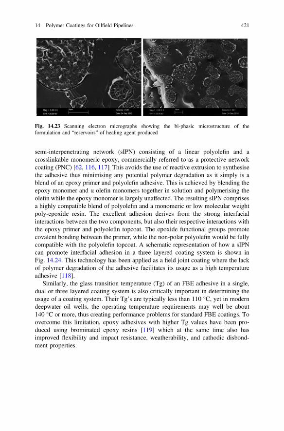
semi-interpenetrating network (sIPN) consisting of a linear polyolefin and acrosslinkable monomeric epoxy, commercially referred to as a protective networkcoating (PNC) [62, 116, 117]. This avoids the use of reactive extrusion to synthesisethe adhesive thus minimising any potential polymer degradation as it simply is ablend of an epoxy primer and polyolefin adhesive. This is achieved by blending theepoxy monomer and α olefin monomers together in solution and polymerising theolefin while the epoxy monomer is largely unaffected. The resulting sIPN comprisesa highly compatible blend of polyolefin and a monomeric or low molecular weightpoly-epoxide resin. The excellent adhesion derives from the strong interfacialinteractions between the two components, but also their respective interactions withthe epoxy primer and polyolefin topcoat. The epoxide functional groups promotecovalent bonding between the primer, while the non-polar polyolefin would be fullycompatible with the polyolefin topcoat. A schematic representation of how a sIPNcan promote interfacial adhesion in a three layered coating system is shown inFig. 14.24. This technology has been applied as a field joint coating where the lackof polymer degradation of the adhesive facilitates its usage as a high temperatureadhesive [118].
Similarly, the glass transition temperature (Tg) of an FBE adhesive in a single,dual or three layered coating system is also critically important in determining theusage of a coating system. Their Tg’s are typically less than 110 °C, yet in moderndeepwater oil wells, the operating temperature requirements may well be about140 °C or more, thus creating performance problems for standard FBE coatings. Toovercome this limitation, epoxy adhesives with higher Tg values have been pro-duced using brominated epoxy resins [119] which at the same time also hasimproved flexibility and impact resistance, weatherability, and cathodic disbond-ment properties.
Fig. 14.23 Scanning electron micrographs showing the bi-phasic microstructure of theformulation and “reservoirs” of healing agent produced
14 Polymer Coatings for Oilfield Pipelines 421
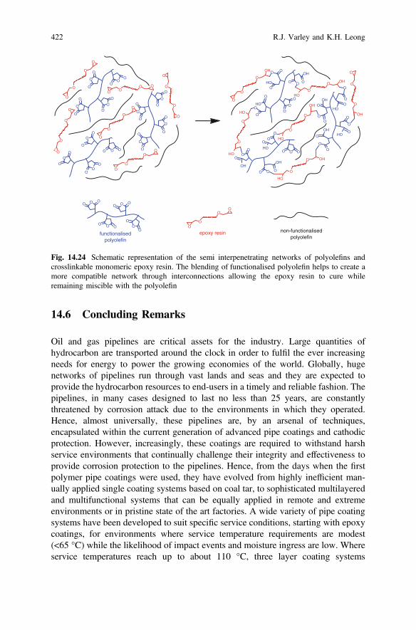
14.6 Concluding Remarks
Oil and gas pipelines are critical assets for the industry. Large quantities ofhydrocarbon are transported around the clock in order to fulfil the ever increasingneeds for energy to power the growing economies of the world. Globally, hugenetworks of pipelines run through vast lands and seas and they are expected toprovide the hydrocarbon resources to end-users in a timely and reliable fashion. Thepipelines, in many cases designed to last no less than 25 years, are constantlythreatened by corrosion attack due to the environments in which they operated.Hence, almost universally, these pipelines are, by an arsenal of techniques,encapsulated within the current generation of advanced pipe coatings and cathodicprotection. However, increasingly, these coatings are required to withstand harshservice environments that continually challenge their integrity and effectiveness toprovide corrosion protection to the pipelines. Hence, from the days when the firstpolymer pipe coatings were used, they have evolved from highly inefficient man-ually applied single coating systems based on coal tar, to sophisticated multilayeredand multifunctional systems that can be equally applied in remote and extremeenvironments or in pristine state of the art factories. A wide variety of pipe coatingsystems have been developed to suit specific service conditions, starting with epoxycoatings, for environments where service temperature requirements are modest(<65 °C) while the likelihood of impact events and moisture ingress are low. Whereservice temperatures reach up to about 110 °C, three layer coating systems
OO
O
OO
O
OO
O
OO O
O
O
O
O
O
O
O
O
O
OO
O
O
O
O
O
O
OO
O
O
O
O
O
O
O
O
O
OO O
OO
O
O
O
O
OO
O
O
O
O
O
O
O
O
O
OO
O
O
OO
OO O
OO O
O
O
O
O
O
O
O
OO O
O
O
O
OO
O
O
O
OO
O
O
OH
HO
O
O OH
HOO
O
OH
O
O
O OH
HO
O
O
HO
HO
O
O
O
OH
HO
OH
OH
HO
HOO
O
O
O
OH
HO
OH
O
OO
O
O OO O O
O
OOO O
O
Ofunctionalised
polyolefinepoxy resin non-functionalised
polyolefin
HO
OH
Fig. 14.24 Schematic representation of the semi interpenetrating networks of polyolefins andcrosslinkable monomeric epoxy resin. The blending of functionalised polyolefin helps to create amore compatible network through interconnections allowing the epoxy resin to cure whileremaining miscible with the polyolefin
422 R.J. Varley and K.H. Leong
consisting of an epoxy primer, applied in conjunction with a polyolefin adhesiveand topcoat, are more commonly used. First and foremost against corrosion, butalso against exposure to physical damage incurred during fabrication, transporta-tion, installation and actual service. In service conditions where temperatures of upto 140 °C and thermal insulation becomes important for flow assurance,multi-layered (5 or more) systems comprising layers of foam that are interspersedbetween the adhesive and topcoat layers are more commonly used.
The need to understand the underpinning materials science and engineering ofeach and every aspect of the fabrication and application of these materials thereforeis clear whether for factory or in the field applied coatings. Without this knowledge,pipe coatings that protect pipelines against corrosion and impact damagethroughout their lifetime would not be achieved. Standardisation and specificationsare equally critical to this process, as it will ensured quality control, reproducibilityand a level of confidence to the industry enabling it to continue making better pipecoatings.
As the O&G industry continues to explore in more challenging oilfields, e.g.deepwater offshore, desert or arctic, the need for improved performance anddurability at extreme temperatures and pressures will continue unabated.Developments in materials and processes are continuing to evolve, ranging fromself healing systems, high temperature adhesives to high compression strengthfoams and tougher adhesives and top coats, to meet these demands. Similarly,developments in testing methods are actively pursued so that the performance ofcoatings can be more accurately assessed and determined consistent with moreextreme service conditions. Indeed the amount of new innovations seen in the pipecoating industry have been tremendous in recent times, particularly in this newmillennium, in order to keep up with the demands of the end-users. It is anticipatedthat due to its versatility and effectiveness, both economically as well as technically,polymer based coatings will continue to dominate as one of the most importantcorrosion protection systems for oilfield pipelines.
Acknowledgements The authors are grateful for the many useful discussions with colleaguesfrom both within and outside their respective organisations, with particular thanks to M. Dell’Olioof CSIRO, and M.S.F. Samsudin and Z. Ahamid of PETRONAS. The help of MSFS in compilingTable 14.4 is also gratefully acknowledged.
References
1. P. Hopkins, Oil and Gas Pipelines: Yesterday and Today, International PetroleumTechnology Institute, special article written for American Society of Mechanical Engineers(2007)
2. D. Howell, A Brief History of Steel Pipe, Pipeline Equities, Pipeline Appraisals andRecovery (2010)
3. M. Romano, The ins and outs of pipeline coatings. J. Protect. Coat. Linings 41–47 (2005)
14 Polymer Coatings for Oilfield Pipelines 423
4. R. Buchanan, Pipeline coatings & joint protection: a brief history, conventional thinking &new technologies, in Rio Pipeline Conference and Expo, 22–24 October 2003, Rio deJaneiro, Brazil (2003)
5. R.N. Sloan, Fifty years of pipe coatings—we’ve come a long way. Mater. Perform. 36(6),42–47 (1993) (Energy Coatings Company, Houston Texas)
6. M. Roche, D. Melot, G. Paugam, Recent experience with pipeline coating failures. J. Protect.Coat. Linings 18–28 (2006)
7. N. Tsalic, Trends and development in the market for pipe coating, plastic pressure pipe 2012,22–23 February 2012, Cologne Germany, Applied Market Information
8. J.W. Cox, Multi-coat systems of HDPE for exterior anti-corrosion. Protection of steelpipelines based on 50 year service life, in Technical Presentation for Pemex and MexicanPetroleum Industry, 24–26 Nov 1999 (1999)
9. J.A. Kehr, M. Mallozzi, Fast, worry free pipeline installation with dual-layer fbe coatings,Corrosion and Prevention 2007 Paper 010 (2007)
10. A. Jackson, E. Simonsen, T. Stark, R. Nixon, B. Melve, D. Ali, Long term ageing ofpolypropylene foam. The results of testing performed after 18 years of exposure in a subseaenvironment, in MERL Oilfield Engineering with Polymers, London, UK, October 2012(2012)
11. R. Buchanan, Feeling the heat, World Pipelines, March 2006, 5 pp12. K. Varughese, Dual powder FBE systems for directional drill and high temperature pipelines
—field experience, in Proceedings of the Conference on 15th International Conference onPipeline Protection, Aachen Germany, October 2003, pp. 199–207 (2003)
13. W. Hodgins, R. Buchanan, High Temperature Pipeline Coatings—Field Joint Challenges inRemote Construction, Canusa-Canada
14. J.P.L. Fontaine, Trends in Pipe Coating—An Operator’s Perspective. Exxon MobileDevelopment
15. U. Anees, S.A. Malik, I. Andijani, Corrosion Protection Evaluation of Some OrganicCoatings in Water Transmission Pipes. Research & Development Center, Kingdom of SaudiArabia (1999)
16. S.W. Guan, N. Gritis, G. Bick, A. Jackson, P. Singh, Advanced onshore and offshorepipeline coating technologies, in China International Oil and Gas Pipe TechnologyConference & Expo, 14–17 September 2005, Shanghai, China (2005)
17. Hevicote Product Datasheet CWC, BrederoShaw18. R.J. Chi Ming Lee, P. Morgan, R. Weatherhead, International experiences with cathodic
protection of Offshore pipeline and flowlines. TWI Report, November 2007 (2007)19. M. Batallas, H. Yih, P. Singh, Determining the performance of polyurethane foam pipe
insulation for high temperature service, in NACE International Northern Area WesternConference, Calgary Alberta (2006)
20. S.W. Guan, Insulation for flowlines and risers, in PETRONAS—ETRAD-INTSOK-CCOPworkshop on Deepwater Subsea Tieback Kuching, Malaysia Jan 2011 (2011)
21. O.Ø. Knudsen, A. Bjørgum, A.K. Kvernbråten, Internal coating of multiphase pipelines—requirements for the Coating, Paper 10004, NACE Corrosion 2010, March 14–18 SanAntonio (2010)
22. J.A. Kehr, M. Dabiri, R. Hislop, Dual-layer fusion-bonded epoxy (FBE) coatings protectpipelines, BHR Group, in 15th International Conference on Pipeline Protection, 29–31October 2003, Aachen, Germany (2003)
23. J.A. Kehr, D.G. Enos, FBE, a foundation for pipeline corrosion coatings, Paper 00757,NACE Corrosion 2000, March 26–31 Orlando Fl (2000)
24. J.A. Kehr, FBE pipeline and rebar corrosion coatings, in PICon Internet Conference onPipeline Reliability (2000)
25. T. Fore, K. Varughese, FBE found effective after 30 years of service. Pipeline Gas J. 64–65(2006)
424 R.J. Varley and K.H. Leong
26. J.A. Kehr, Dual-layer fusion bonded epoxy (FBE) coatings protect pipelines, in 15thinternational conference on Pipeline Protection, 29–31 October 2003 Aachen, Germany(2003)
27. M. Demirors, in Chap 9: The History of Polyethylene in 100+ Years of Plastics. LeoBaekeland and Beyond, ACS Symp. Series, vol. 1080 (2011), pp. 115–156
28. History of traditional pipeline coatings, assessing the future of coating work, in Proceedingsof the PCE 2000 Conference and Exhibition, 8–10 March 2000, Genoa, Italy (2000)
29. M. Wilmott, J. Highams, R. Ross, A. Kopystinski, Coating and thermal insulation of subseaor buried pipelines. J. Protect. Coat. Linings 17(11), 47–54 (2000)
30. C. Argent, D. Norman, Fitness for purpose issues relating to FBE and three layer PEcoatings, in Paper 05034, NACE Corrosion 2005, 3–7 April 2005, Houston, Texas (2005)
31. G.P. Guidetti, G.L. Rigosi, R. Marzola, The use of polypropylene in pipeline coatings. Prog.Org. Coat. 27, 79–85 (1996)
32. B.J. Turner, Polypropylene coatings for high temperature and thermal insulation of pipelines,im Paper 11030, Corrosion 2011, 13–17 March 2011, Houston, Texas (2011)
33. A.B. Hansen, A. Delesalle, Cost effective thermal insulation systems for deep water WestAfrica in combination with direct heating, in Offshore West Africa 2000 Conference andExhibition, 21–23 March 2000, Abidjan, Cote d-Ivoire (2000)
34. C. Rydin, L. Sjoberg, Polypropylene thermal insulation systems for offhsore pipelineapplication. J. Protect. Coat. Linings 19(10), 42–49 (2002)
35. R. Hunter, Wet insulation evolves to meet subsea flowline performance demands. Offshore68(10), 122–129 (2008)
36. S.W. Guan, Challenges and New Developments in Pipeline Coating Technology, Pipeliner2011, pp. 36
37. www.bauhuis.com/Pipe-coating38. G. Moad, The synthesis of polyolefin graft copolymer be reactive extrusion. Prog. Polym.
Sci. 24, 81–92 (1999)39. S.B. Brown, in Reactive Extrusion, ed. by M. Xanthos (Hanser, Munich, 1992), p. 7540. R.C. Kowalski, in Reactive Extrusion, ed. by M. Xanthos (Hanser, Munich, 1992), pp. 7–3241. S. Sanchez-Valdes, F. Orona-Villarreal, M. Lopez-Quintanilla, I. Yanez-Flores, L.F.R.D.
Valle, C. Guerrero-Salazar, Performance of multilayer films using maleated linearlow-density polyethylene blends. Polym. Eng. Sci. 38, 150 (1998)
42. M. Xanthos (ed.), Reactive Extrusion (Hanser, Munich, 1992), p. 3343. M. Dorn, Modification of molecular weight and flow properties of thermoplastics. Adv.
Polym. Tech. 5, 87–97 (1985)44. X. Li, X.M. Xie, B.H. Guo, Study on styrene-assisted melt free radical grafting of maleic
anhydride onto polypropylene. Polymer 42, 3419–3425 (2001)45. J.Z. Liang, R.K.Y. Li, Rubber toughening in polypropylene: a review. J. Appl. Polym. Sci.
77, 409 (2000)46. P.R. Hornsby, K. Premphet, Fracture toughness of multiphase polypropylene composites
containing rubbery and particulate inclusions. J. Mater. Sci. 32, 4767 (1997)47. J. Lu, G.X. Wei, H.J. Sue, J. Chu, Toughening mechanisms in commercial thermoplastic
polyolefin blends. J. Appl. Polym. Sci. 76, 311 (2000)48. H. Mae, M. Omiya, K. Kishimoto, Material ductility and toughening mechanism of
polypropylene blended with bimodal distributed particle size ofstyrene-ethylene-butadiene-styrene triblock copolymer at high strain rate. J. Appl. Polym.Sci. 110, 3941 (2008)
49. D.N. Bikiaris, G.Z. Papageorgiou, E. Pavlidou, N. Vouroutzis, P. Palatzoglou, G.P. Karayannidis, Preparation by melt mixing and characterization of isotacticpolypropylene/SiO2 nanocomposites containing untreated and surface-treatednanoparticles. J. Appl. Polym. Sci. 100, 2684 (2006)
50. A. Koebsch, A.L. Lemuchi, R.R. Oliveira, R. Buchanan, Advantages of polypropylene basedcoatings for buried or submerged pipelines operating in aggressive environments, in Rio
14 Polymer Coatings for Oilfield Pipelines 425
Pipeline Conference and Expo, 20–22 September 2011, Rio de Janeiro, Brazil. PaperIBP1094_11
51. M. Ratzsch, Special PP’s for a developing and future market. J. Macromol. Sci. Part A: PureAppl. Chem. 31(11), 1587–1611
52. A.B. Hansen, C. Rydin, Development and qualification of novel thermal insulation systemsfor deepwater flowlines and risers based on polypropylene, in Offshore TechnologyConference, Houston Texas, USA, 6–9 May 2002
53. B. Cavalie, APIA54. N. Gupta, V.C. Shunmugasamy, High strain rate compressive response of syntactic foams:
trends in mechanical properties and failure mechanisms. Mater. Sci. Eng. A 528, 7596–7605(2011)
55. M. Aureli, M. Porfiri, N. Gupta, Effect of polydispersity and porosity on the elastic propertiesof hollow particle filled composites. Mech. Mater. 42, 726–739 (2010)
56. G. Shearer, C. Tzonganakis, Free radical hydrosilylation of polypropylene. J. Appl. Polym.Sci. 65, 439–447 (1997)
57. J.D. Kellner, A.J. Doheny, B.B. Patil, A 3 layer polyethylene coating for plant application.Mater. Perform. 37, 6 (1998)
58. C. Bates, Chemical Treatment Enhances Pipe Coating Quality, Pipe Line Industry,September 1989
59. 3-Layer Polyethylene Coating Systems, PRD, Pipe Manufacturing Systems, www.prdcompany.com
60. A.N. Moosavi, Advances in field joint coating for underground pipelines, in NACECorrosion 2000 Conference and Expo. Paper No. 00754 (2000)
61. SA 2.5 refers to Swedish Standard SIS 05 59 00 (1967) Pictorial Surface PreparationStandards for Painting Steel Surface, that prescribes a specific level of cleanliness referred toas near white metal 85 % clean
62. M. Mallozzi, M. Perez, A new 3 LPP offhsore field joint coating, in NACE Corrosion 2010paper 10010, March 14–18 2010, San Antonio, TX, USA (2010)
63. A.N. Moosavi, S. Al Mutawa, S. Balboul, M. Saady, Hidden problems with three layerpolypropylene pipeline coatings, in Corrosion NACE 2006, Paper 06057 (2006)
64. D. Melot, G. Paugam, M. Roche, Disbondments of pipeline coatings and their effects oncorrosion risk. J. Protect. Coat. Linings 18–31 (2009)
65. V. Rodriguez, E. Perozo, E. Alvarez, Coating application and evaluation for heavy wallthickness, temperature and pressure pipe. Mater. Perform. 37, 2 (1998)
66. A.N. Moosavi, Advances in field joint coatings for underground pipelines. Mater. Perform.39, 8 (2000)
67. www.canusaps.com68. Y. Okano, N. Shoji, T. Namioka, M. Komura, The development of auto-sealing systems for
field joints of polyethylene coated pipelines, in Corrosion 97, Paper 38969. M. Surkein, J. Didas, Pipe coating and failure modes of mainline and field joint coatings—
pictorial learnings, in Presentation to the OGP Coatings Committee, London, England.16 November 2011, http://info.ogp.org.uk/standards/11LondonCoatings/Presentations/Presentation06.pdf
70. S. Papavinasam et al. External polymeric pipeline coatings failure modes. Mater. Perform.28–30 (2006)
71. K. Varughese, Dual powder FBE systems for directional drill and high temperature pipelines—field experience, in 15th International Conference on Pipeline Coating, Oct 2003, p 199–207. BHR Group 2003 Pipeline Protection (2003)
72. D. Norman, Excellent pipeline coatings require excellent pipeline substrates, in NACECorrosion 2004, Paper 04035, 28 March–1 April 2004, New Orleans, La (2004)
73. S.W. Guan, petromin Pipeliner, p 3674. K. Varughese, Improving adhesion properties of three layer polyethylene systems. Corrosion
6 (2003)75. al FFLe. Paper 10003, NACE 2010
426 R.J. Varley and K.H. Leong
76. A.N. Moosavi, B.T.A. Chang, K. Morsi, Failure analysis of three layer polypropylene pipecoatings, in NACE Corrosion 2010 Conference and Expo, March 14–18, 2010, San Antonio,TX, Paper 10002 (2010)
77. R. Norsworthy, Study examines coating compatibility with CP. J. Oil Gas 107(20), 52 (2009)78. R. Norsworthy, Coatings used in conjunction with cathodic protection—shielding vs
non-shielding pipeline coatings, in NACE Corrosion 2009, Paper 09043. March 22–261,2009, Atlanta, GA (2009)
79. Non-shielding coating systems now part of new US regulatory requirement, Next GenerationOil and Gas MENA, Issue 5, No 67 (2010)
80. R. Norsworthy, Is your pipeline coating “fail safe”? Pipeline Gas J. 62–63 (2006)81. M. Surkein, J. Didas, Pipe Coating and Failure Modes of Mainline & Field Joint Coatings.
OGP Coatings Committee–London82. C. Dasgupta, New field joint coating technology: eliminates “weak link” in the pipeline, in
Presented at the India O&G Pipeline Infrastructure Conference, New Delhi (2011)83. S. Papavinasam, R.W. Revie, Review of standards for evaluating coatings to control external
corrosion of pipelines. Corros. Rev. 26(5&6), 295–371 (2008)84. S.S. Papavinasam, N. Zaver, J. Pollock, Comparison of international standards to evaluate
field-applied pipeline girth weld coatings. Corros. Rev. 30(5&6), 171–197 (2012)85. DIN 3067086. DIN 3067887. CSA Z245.2188. ISO 21809–1:2011 (E)89. S.W. Guan, Long-term performance, World Pipelines, November 200890. J.M. Leeds, S.S. Leeds, Coating properties and test procedures. Pipeline Gas J. 237(3) (2010)91. A.A. Borno, M. Brown, S. Rao, High temperature cathodic disbondment tests, in NACE
Corrosion Conference and Expo 2010, Paper 10008, 14–18 March 2010, San Antonio, TX,USA (2010)
92. O.Ø. Knudsen, T.G. Eggen, K.K. Brende, Test method for studying cathodic disbonding athigh temperature, in NACE Corrosion Conference and Expo 2010, Paper 10007, 14–18March 2010, San Antonio, TX, USA (2010)
93. B. Melve, D. Ali, Corrosion coating for high temperature water immersion service, inCorrosion 2006, Paper 06021, Houston, TX, USA (2006)
94. M. Batallas, P. Singh, Evaluation of anticorrosion coatings for high temperature service, inCorrosion 2008, Paper 08039, Houston TX, USA (2008)
95. P.K. Shukla, R. Pabalan, L. Yang, M.A. Smith, On development of accelerated testingmethods for evaluating organic coating performance above 100 °C, in Corrosion 2010,Paper 10006, 14–18 March 2010, San Antonio, TX (2010)
96. ASTM D5162-08 Standard Practice for Discontinuity (Holiday) Testing of NonconductiveProtective Coating on Metallic Substrates
97. G.R. Howell, Y.F. Cheng, Characterisation of high performance composite coating for thenorthern pipeline application. Prog. Org. Coat. 60, 148–152 (2007)
98. I. Williamson, P. Singh, J. Hancock, The resistance of advanced pipeline coatings topenetration and abrasion by hard rock, in Proceedings of IPC 2000: International PipelineConference, The Palliser, Calgary, Alberta, Canada, 1–5 Oct 2000 (2000)
99. P. Singh, S. Haberer, N. Gritis, R. Worthington, M. Cetiner, New developments in highperformance coatings, BHR Group 2005. Pipeline Protect. 16, 55–66 (Paphos, Cyprus)(2005)
100. P. Singh, J. Cox, Development of coat effective powder coated multi-component coating forunderground pipelines
101. C.N.C. Lam, D.T. Wong, R.E. Steele, S.J. Edmonson, A new approach to high performancepolyolefin coatings, in Corrosion 2007, Conference and Expo, NACE International paper07023 (2007)
102. J. Karger-Koscis, How does phase transformation toughening work in semi-crystallinepolymer. Polym. Eng. Sci. 36, 203 (1996)
14 Polymer Coatings for Oilfield Pipelines 427

103. E. Nezbedova, V. Pospisil, P. Bohaty, B. Vlach, Fracture Behaviour of beta polypropylene asa function of processing conditions. Macromol. Symp. 170(1), 349–357 (2001)
104. P. Jacoby, Beta nucleating masterbatch offers enhanced properties in polypropylene products.Plast. Add. Compd. 9, 32 (2007)
105. M. Slouf, J. Kolarik, J. Kotek, Rubber-toughened polypropylene/acrylonitrile-co-butadiene-styrene blends: morphology and mechanical properties. Polym. Eng. Sci. 47, 482 (2007)
106. J. Kotek, J. Scudla, M. Slouf, M. Raab, Combined effect of specific nucleation and rubberdispersion on morphology and mechanical behaviour of iso-tactic polypropylene. J. Appl.Polym. Sci. 103, 3539 (2007)
107. C. Grein, M. Gahleitner, On the influence of nucleation on the toughness of iPP/EPR blendswith different rubber molecular architectures. Exp. Polym. Lett. 392, 2 (2008)
108. W. Bai, Y. Wang, B. Song, X. Fan, Z. Zhou, Y.L. Li, Nucleating agent induced impactfracture behaviour change in PP/PEO blend. Polym. Bull. 62, 405 (2009)
109. R.J. Varley, M. Dell’Olio, Y. Qiang, S. Khor, K. Leong, S. Bateman, different beta nucleantsand the resultant microstructural, fracture, and tensile properties for filled and unfilled isopolypropylene. J. Appl. Polym. Sci. 128(1), 619–627 (2013)
110. H. Pham, F. Aguiie, M. Dettloff, N. Verghese, Development of Novel TougheningTechnology for Fusion Bonded (FBE) Powder Coatings, Paint and Coatings Industry,October 2007
111. J.K. Pratt, M. Mallozzi, A. D’Souza, Advances in damage resistant coating technology, inNACE Corrosion 2011 Conference and Expo (2011)
112. S.J. García, H.R. Fischer, P.A. White, J. Mardel, Y. González-García, J.M.C. Mol et al.,Self-healing anticorrosive organic coating based on an encapsulated water reactive silyl ester:synthesis and proof of concept. Prog. Org. Coat. 70(2–3), 142–149 (2011)
113. J.F. Doddema, The use of viscoelastic self healing pipeline coating, in NACE Corrosion 2010Conference and Expo paper 10042 (2010)
114. M. Quast, Rehabilitation of corrosion proactive coatings on buried steel pipelines withself-amalgamating three ply tapes
115. S. Meure, R.J. Varley, D.Y. Wu, S. Mayo, K. Nairn, S. Furman, Confirmation of the healingmechanism in a mendable EMAA-epoxy resin. Eur. Polym. J. 48(3), 524–531 (2012)
116. Proprietary product of 3M, USA117. J.A. Kehr, S. Attaguile, M. Smith, M. Perez, New technology helps develop coatings for high
temperature operating pipelines, in NACE International Corrosion Conference 2008 (2008)118. M. Mallozzi, M. Perez, A new three layer polypropylene offshore field-joint coating. Mater.
Perform. 49(10), 36 (2010)119. W. Zhou, T.E. Jeffers, O.H. Decker, Properties of a new high Tg FBE coating for high
temperature service. Mater. Perform. 46, 4 (2007)
428 R.J. Varley and K.H. Leong