Coatings for corrosion protection - Nvlpubs.nist.gov
276
\ > 'i AZ/Sr Special Publication 1035 f iCoatings for Corrosion Protection: fpffshore Oil and Gas Operation Facilities, IjMarine Pipeline and Ship Structures I iApril 14-16, 2004 I iBiloxi, Mississippi f jllEdited by: : I Icharles Smith, Tom Siewert, Brajendra Mishra, I I {David Olson, and Angellque Lasslegne I Sponsored in part by: P ^ • - ' I I .Nisr National Institute of Standards and Technology J' I , • I {'^te " ^ ^ I i^', American Bureau of Shipping ; I InM^ Colorado School of Mines I . ..J ^ |i Mineral Management Service e of Pipeline Safety National Institute of Standards and Technology Technology Administration, U.S. Department of Commerce
-
Upload
khangminh22 -
Category
Documents
-
view
8 -
download
0
Transcript of Coatings for corrosion protection - Nvlpubs.nist.gov
\ > 'i
AZ/Sr Special Publication 1035
fiCoatings for Corrosion Protection:
fpffshore Oil and Gas Operation Facilities,
IjMarine Pipeline and Ship Structures
IiApril 14-16, 2004
IiBiloxi, Mississippi
f jllEdited by:
: IIcharles Smith, Tom Siewert, Brajendra Mishra,
I
I
{David Olson, and Angellque Lasslegne
ISponsored in part by:
P ^
• - '
I
I.Nisr National Institute of Standards and Technology
J' I ,•
I {'^te" ^ ^
Ii^', American Bureau of Shipping
;
I InM^ Colorado School of Mines
I . ..J
^ |i Mineral Management Service
e of Pipeline Safety
National Institute of Standards and TechnologyTechnology Administration, U.S. Department of Commerce
rhe National Institute of Standards and Technology was established in 1988 by Congress to "assist industryin the development of technology ... needed to improve product quality, to modernize manufacturingprocesses, to ensure product reliability ... and to facilitate rapid commercialization ... of products based on
new scientific discoveries."
NIST, originally founded as the National Bureau of Standards in 1901, works to strengthen U.S.industry's competitiveness; advance science and engineering; and improve public health, safety, and the
environment. One of the agency's basic functions is to develop, maintain, and retain custody of the national
standards of measurement, and provide the means and methods for comparing standards used in science,
engineering, manufacturing, commerce, industry, and education with the standards adopted or recognized by the
Federal Government.
As an agency of the U.S. Commerce Department's Technology Administration, NIST conducts basic and
applied research in the physical sciences and engineering, and develops measurement techniques, test methods,
standards, and related services. The Institute does generic and precompetitive work on new and advanced
technologies. NIST's research facilities are located at Gaithersburg, MD 20899. and at Boulder, CO 80303. Major
technical operating units and their principal activities are listed below. For more information visit the NISTWebsite at http://www.nist.gov, or contact the Publications and Program Inquiries Desk, 301-975-3058.
Office of the Director
•National Quality Program
International and Academic Affairs
Technology Services
•Standards Services
•Technology Partnerships
Measurement Services
•Information Services
•Weights and Measures
Advanced Technology Program•Economic Assessment
•Information Technology and Applications
•Chemistry and Life Sciences
•Electronics and Photonics Technology
Manufacturing Extension Partnership
Program•Regional Programs
•National Programs
•Program Development
Electronics and Electrical Engineering
Laboratory•Microelectronics
•Law Enforcement Standards
•Electricity
•Semiconductor Electronics
•Radio-Frequency Technology'
•Electromagnetic Technology'
•Optoelectronics'
•Magnetic Technology'Information Technology Laboratory•Mathematical and Computational Sciences"
•Advanced Network Technologies
•Computer Security
•Information Access
•Convergent Information Systems
•Information Services and Computing
•Software Diagnostics and Conformance Testing
•Statistical Engineering
Materials Science and Engineering
Laboratory•Intelligent Processing of Materials
•Ceramics
•Materials Reliability'
•Polymers
•Metallurgy
•NIST Center for Neutron Research
'At Boulder, CO 80305
"Some elements at Boulder, CO
NIST Special Publication 1035
Coatings for Corrosion Protection:
Offshore Oil and Gas Operation Facilities,
Marine Pipeline and Ship Structures
April 14-16, 2004Biloxi, Mississippi
Edited by:
Charles Smith, Tom Siewert, Brajendra Mishra,
David Olson, and Angelique Lassiegne
Sponsored in part by:
National Institute of Standards and Technology
American Bureau of Shipping
Colorado School of Mines
Mineral Management Service
Office of Pipeline Safety
March 2005
U.S. Department of CommerceCarlos M. Gutierrez, Secretary
»
Technology Administration
Phillip J. Bond, Under Secretary for Technology
National Institute of Standards and TechnologyHratch G. Semerjian, Acting Director
Certain commercial entities, equipment, or materials may be
identified in this document in order to describe an experimental
procedure or concept adequately. Such identification is not
intended to imply recommendation or endorsement by the
National Institute of Standards and Technology, nor is it intended
to imply that the entities, materials, or equipment are necessarily
the best available for the ouroose.
National Institute of Standards and Technology Special Publication 1035
Natl. Inst. Stand. Technol. Spec. Publ. 1035, 270 pages (March 2005)
CODEN: NTNOEF
U.S. Government Printing Office
Washington: 2005
For sale by the Superintendent of Documents, U.S. Government Printing Office
Internet bookstore: gpo.gov Phone: 202-512-1800 Fax: 202-512-2250
Mail: Stop SSOP, Washington, DC 20402-0001
Contents
Abstract v
Executive Summary vi
Recommendations vii
Organizational Committee xi
Sponsors xii
Introduction 1
Welcoming Remarks Section 1
Charles Schoennagel (Minerals Management Service) 7
James Card (American Bureau of Shipping) 14
Larry Christie (NACE) 17
Keynote Addresses Section 2
Research and Development of Coatings for Alaska Tanker CompanyJack Thibault (Alaska Tankers) 23
Practical Experience
Adolpho Bastiani (MODEC International) 29
Theme Papers Section 3
Health and Safety Concerns: Coating Application and RemovalJoseph B. Loring (U.S. Coast Guard) .....37
Tankers and FPSO Corrosion
Ian Rowell (International Paint) 41
Inspection and Repair of Coatings
Rogest Dively (EDG & Associates, Inc.) 72
Past, Present and Future "Smart" Protective Coating
Martin Kendig (Rockwell Scientific Co.) 90
Risk Assessment and Economic Considerations whenCoating Ballast Tanks
Kenneth Tator (KTA-Tator) 101
Decision Making in Coating Selection in Marine/Offshore Environments
Kirk Brownlee (Stress Engineering Services, Inc.),
Charlie Speed (Ammonite Corrosion Engineering), andRaleigh Whitehead (Carboline) 115
111
Corrosion Protection for Offshore Pipelines
Ernest Klechka, P.E. (CC Technologies) 132
Experience witli Coating for Corrosion Protection from the
Norwegian Continental Shelf
Roger Leonhardsen, Helge I. Vestre, Rolf H. Hinderaker
(Petroleum Safety Authority Norway) 144
Working Group White Papers Section 4
#1 - U.S. Shipyard Paint Shops: Current Issues and Future NeedsMark Panosky (General Dynamics-Electric Boat) 159
#2 - Rationalization and Optimization of Coatings Maintenance
Programs for Corrosion Management on Offshore Platforms
Paul Versowsky (Chevron-Texaco) 170
#3 - Coatings for Pipelines
S. Paapavinasam and R. Winston Revie, Natural Resources Canada 178
#4 - Coatings for Port Facilities
John Webb (Mississippi State Port Authority), Daniel A. Zarate
(Naval Facilities Engineering Service Center), and David L. Olson
(Colorado School of Mines) 209
#5 - Near 100 Percent Solids Tank Linings—Panacea or PandemoniumBenjamin S. Fultz (Bechtel Corporation) 212
#6 - Evaluating the Current State of Inspection Practices for Protective
Coatings (In process and Continued Evaluation) and the Exploration of
Opportunities for Improvement of these Practices
Ray Stone (CCC&I), Malcolm McNeil (McNeil Coatings Consultants, Inc.),
and D. Terry Greenfield (CorroMetrics, Inc.) 216
Special Lectures Section 5
Plenary Lecture: Coatings for U.S. Navy Ships: Developmentsand Status
A. I. Kaznoff (Naval Sea Systems Command) 231
Single Coat and Rapid Cure Tank Coating Systems:
Improved Tank Preservation ProcessesArthur Webb (Naval Research Laboratory) 242
IV
Abstract
This workshop on Coatings for Corrosion Protection: Offshore Oil and GasOperation Facilities, Marine Pipelines, Ship Structures, and Port Facilities washeld on April 14-16, 2004 in Biloxi, Mississippi. This workshop of 150 attendees
drew participation by internationally recognized marine coating experts, material
specialists, inspection specialists, coating manufacturers, maintenance engineers,
and designers. The workshop was crafted to include multiple viewpoints:
industrial, academic, environmental, regulatory, standardization, and certification.
Keynote and topic papers were presented to establish a current information base
for discussions. Six discussion groups addressed specific issues and identified,
prioritized, and recommended specific research and development topics for the
government and industries to undertake. The recommendations of this workshopoffer a clear identification of research and development issues and create a
roadmap for achieving them.
Keywords
coatings; corrosion protection; offshore structures; pipelines; ship structures
V

Executive Summary
This workshop on Coatings for Corrosion Protection: Offshore Oil and GasOperation Facilities, Marine Pipelines, Ship Structures, and Port Facilities washeld on April 14-16, 2004, in Biloxi, Mississippi. This workshop was organized by
an industrial-based committee and hosted by the Colorado School of Mines for
the U.S. Department of Interior (Mineral Management Service), U.S. Department
of Transportation (Office of Pipeline Safety), U.S. Department of Commerce(National Institute of Standards and Technology), U.S. Department of Energy
(Economic Regulatory Administration), U.S. Department of Homeland Security
(U.S. Coast Guard-Ship Structure Committee), Norwegian Petroleum Directorate,
California State Lands Commission, American Bureau of Shipping, Natural
Resources of Canada, NACE International, and SSPC (The Society for
Protective Coatings).
This workshop drew participation by internationally recognized marine coating
experts, material specialists, inspection specialists, coating manufacturers,
maintenance engineers, and designers. The workshop was designed to include
multiple viewpoints: industrial, academic, environmental, regulatory,
standardization, and certification.
Keynote and topic papers were presented to establish a current information basefor discussions. Six discussion groups addressed specific issues and identified,
prioritized, and recommended specific research and development topics for the
government and industries to undertake. This workshop undertook a complete
assessment of opportunities for research and development of coating practice,
coating materials, coating application, repair, nondestructive evaluation, andextended coating life prediction. This workshop defined the state of the art,
assessed the current practices and their limitations, discussed field experiences,
and charted a course for the best corrosion protection methodologies of offshore
structures, pipelines, and ship structures, including sensing and monitoring.
The recommendations of this workshop offer a clear identification of research
and development issues and create a roadmap for achieving them. Theserecommendations are classified in a general fashion as Research, Development,Administration, and Operations. The recommendations are written in a format of
broad agency announcement and offered in part or whole topics for consideration
by agencies, technical societies, industry, and certification organizations for
support and implementation.
VI
Recommendations from the Discussion Groups
ProgramsPrograms consist of numerous projects which must be completed to achieve the
intended goal.
Research
1. Quantitative evaluation of the long-term field performance of pipeline
coatings. One project should install coated pipe samples in the field at
carefully selected locations representative of different environmental
conditions. Several monitoring methods should be used. In addition, the
coating performance evaluation should include both consistent and
fluctuating temperatures with transient and cyclic temperature fluctuations.
A one-day scoping meeting prior to this investigation should be held with
good representation of the interested parties.
2. Development of practices for evaluating pipeline coatings for service under
extreme conditions such as: Offshore-deep sea, Offshore-Arctic, Onshore-
equator is recommended. These investigations should include three types
of coatings: Anti-corrosion coatings, Abrasion-resistant coatings, and
Insulation coatings.
3. Development of a non-destructive method of evaluating the application of
coating systems. Programs need to explore the feasibility of thermography,
magnetic flux leakage, electrical impedance, and eddy current phase array.
Modeling using EIS is not reliable.
4. Development of specific advancements in coating materials. A project for
non-skid deck coating systems that will last when applied over less than
perfect surface preparations. Parameters that control coating performance.
Modeling of performance of all coatings (not only FBE). A project should
include the evaluation of coatings at higher temperature in the laboratory.
Performance of insulation coating should be investigated. Research project
to develop coating systems that respond to exposure stresses needs to be
performed.
vii
Development
5. Improvement in the effective use of coatings for port facilities and the
development of the necessary performance-based specifications. Thedevelopment of generally accepted design standards and practices for port
authorities needs to be established. These standards and practices need to
be beneficial to the owner. Also the program needs to develop generally
accepted design standards and acceptances for port facilities. This
development may need to be geographically specific such as: blue water
specific or brown water specific.
6. Advanced methodologies for applications of coatings. A project needs to
address paint application issues without the use of brushes and rollers to
increase productivity, lower costs, and less personnel exposure. Theproposed investigation should include concerns of issues such as: curing
time compared to burial or immersion time and adhesion of field-applied
coatings to mill-applied coatings. An investigation to assess the effects of
stockpiling of coating products on pipeline coatings performance including
the effect of temperature, ultra-violet light, and time needs to be established.
Development of high solid products, which meet VOC requirements that
have less tendency to embrittle over time. Develop a mechanism to aid the
painter in being able to achieve more uniform film thicknesses with high
solid coatings in the field. The use of a capture device at the spray gunversus total encapsulation of the space to be painted should be investigated.
Evaluate the need to increase the investment in coating application
technology R&D. Establishment of a welding procedure for welding on
painted surfaces is recommended.
7. Assessment of new technologies for surface preparation before coating.
This program should include projects on the feasibility of using microwavetechnology for surface preparation, hand-held x-ray fluorescence system to
detect salts on the surface, and a project to improve the dissemination andclarity of information on allowable surface chlorides. Improvement of
application equipment to facilitate applying high solid coatings in the field to
inaccessible areas. A project investigating the effects of minor variations in
surface preparation and effects of variation in composition of surface
contamination, including mill scale, on long-term coatings performance is
necessary. A project on secondary surface preparation critera / Standards
(example: exceeding the recoat window of an epoxy- Methodology for
evaluation) needs to be established. The cost of surface preparation andcoating application for underwater hull areas is going up and the designs of
coating technology for this area has not kept pace.
viii
I
Administration
8. Standardized methodology for data collection and management. Anunbiased tinird party to compile an industry wide historical data base on
pipeline coating performance and evaluate the data critically needs to be
established and funded, A program to establish user-friendly
standardization needs to be initiated and performed. The program would
include a project on the standard/ recommended practices for
implementation of inspection for protective coatings projects.
9. Formulation of a roadmap for coatings research and/or development that
indicates the proper sequence of projects. The roadmap needs to be
periodically updated by industrial organizations as well as government
research agencies and industrial users of coated structures. Such a
roadmap would be helpful in prioritizing national and international needs and
to assist in obtaining the necessary funding. The roadmap program will
need to be annually updated by NACE International and SSPC (The Society
for Protective Coatings).
10, A working group, national or regional, to increase exchange of information
on the performance of coating products and application. The working group
can formulate through user conscience new performance based
specifications, design standards, and practices for port facilities. There
already exists the working structure for such a working group in the existing
coating and corrosion societies. It needs an initiator. (Note: Loosely exists at
SSPC).
11, Evaluation of the economic issues of coating materials, their application,
and their service behavior, A specific project on the study of the
measurable economic contribution of the inspection of coatings project
successes and performance needs to be performed. A project to study
economics of coating technology to suggest and recommend the most cost
effective use of the present technology should be implemented. The issue
is that use and deployment of new coating technology is hampered by high
cost of new equipment. Look into what can be done to utilize existing
equipment: lower the cost of new equipment: or provide the financial
incentives needed. Consumer and coating industry feedback loop needs to
be improved. Problems are generally reported and investigated: however,
successful applications rarely are investigated to confirm good practice.
ix
Operations
12. Advanced methods for coating repair. This program should include a
project on standards for quantification of performance and repair criteria and
a project to quantify the effect of "repairs" on newly installed coatings
system's performance.
13. Training, education, and certification of painters, corrosion engineers, and
inspectors in the marine and pipeline industry. Develop a certification and
training program for painters in the marine industry. Help develop an
engineering technologist degree / vocational training program for coating
specification. Guidelines/Practices/Standards for evaluating In-Service
Coatings and the training of Coating Survey Inspectors, with focus on
Inspection and Evaluation of In-Service Coatings and tools for evaluation
needs to be organized. A special program for educating Coast Guard and
MMS inspectors to establish consistency with the offshore industrial
standards. Development of a hiring program offering training and
certification plus weekly pay, which would have an impact on safety,
employee morale, and salary.
14. Development of coating/corrosion assessment criteria and acceptable
corrosion levels for use by corrosion engineers and regulators in the
development and assessment of Asset Integrity Management Programs.
Development of a criteria for determining the most cost effective
maintenance effort and tools to quantify: coatings age and degradation,
ability to apply over-coatings, and consistent evaluation needs to be
established.
15. Address the environmental and health and safety issues regarding paint
materials and their application. A project for the determination of the effects
of environmental conditions and variations in coating procedures on the
performance of field-applied pipeline coatings needs to be instituted. Aproject on the development and research of environment tolerant coatings
that can be used year round with increased quality. The development of
pipeline coatings with anti-microbial properties. This development mustachieve coating acceptable ecological concerns.
X

Organizational Committee
An organizational committee of recognized experts in coating technology and
marine structural integrity was established to assist and advise the principal
organizers on the final format of the workshop. They also recommended
speakers, committee co-chairpersons, and authors for the various papers
(keynote, theme, and white). The papers' authors and speakers were carefully
chosen from those who have recently contributed to the technical literature
(especially the state of the art in marine coating technology), based on industrial
experience.
Angelique Lasseigne: CSMBernard Appleman: KTA-
Tator/SSPC
Betty Felber: U.S. DOE-Tulsa
Brajendra Mishra: CSMCharles Smith: MMSDavid Olson: CSMDavid Shifler: NAVSEADiana Diettrich: ABSDoug Moore: Carboline
Garrett Atkins: Exxon
George Wang: ABSHelena Alexander: NACE
Howard Mitschke: Shell Global
Jack Spencer: ABSJames Merritt: DOT-OPSJames Phipps: ABS Consulting, UKJoel McMinn: Chevron-Texaco
Kirk Brownlee: STRESS, INC.
Louis Sumbry: BP-AmocoPat Fallwell: ABSRobert Rogers: Exxonmobil
Robert W. Smith: DOT-OPSRon Scrivner: Transcon. Pipeline
Tom Siewert: NIST
Winston Revie: NRC-CanadaWm. Michael Drake: LANL
xi
Sponsors
The sponsors of the workshop were:
• American Bureau of Shipping
• California State Lands
Commission
• Colorado School of Mines
• MADCON Corporation
• NACE International
• National Institute of Standards
and Technology
• Natural Resources Canada• Norwegian Petroleum Directorate
• SSPC• Trenton Corporation
• US Coast Guard - Ship Structure
Committee
• U.S. Department of Energy
• U.S. Department of Interior-
Minerals Management Service
• U.S. Department of
Transportation - Office of
Pipeline Safety
xii
Introduction
The Colorado School of Mines organized an International Workshop on
Advanced Research and Development of Coatings for Corrosion Protection of
Offshore Oil and Gas Operation Facilities, Marine Pipelines, and Ship Structures,
with specific emphasis on Life of Coating, Materials, Repair of Coatings and
NDE. The workshop was primarily sponsored by the Minerals ManagementService of the U.S. Department of Interior. In addition, the workshop was co-
sponsored by the U.S. Department of Energy, American Bureau of Shipping,
National Institute of Standards and Technology, National Association of
Corrosion Engineers- International, and other private companies. The workshop
was held in Biloxi, Mississippi from April 14-16, 2004. The sponsors recognize
that new technologies for remotely sensing and monitoring the corrosion damageof coated structures are important in guaranteeing structural integrity.
This workshop was undertaken to completely assess the opportunities for
research and development to enhance coating practices, coating materials,
application, repair, nondestructive evaluation, and coating life prediction. Theworkshop defined the state of the art, assessed the current practices and its
limitations, discussed field experiences and charted a course for the best
corrosion protection methodologies of offshore structures, pipelines, and ship
structures, including sensing and monitoring. This workshop was designed to
clearly identify the research and development issues and to chart a course for
achieving them. The workshop achieved its objectives.
Internationally recognized marine coating experts, material specialists, inspection
specialists, coating manufacturers, maintenance engineers, and designers
participated in the deliberations. Industrial, university, environmental, regulatory,
standardization and certification leaders provided a breadth of knowledge and
experience to the endeavor. This book presents an archival record of the
workshop proceedings.
The best forum for an assessment and R&D path determination as the onedescribed above is a dynamic workshop. An advanced coating workshop is a
very cost-effective method to: (1) transfer information, (2) learn about newtechnologies and materials, (3) assess future needs, and (4) define the best
opportunities for research. New technologies for remotely sensing and
monitoring the corrosion damage of coated structures are important to guarantee
integrity.
The Opportunity: The marine environment is particularly aggressive, and all
marine vessels and offshore structures need protection from corrosion. The
selection of the coating system depends on the location of its application, such
as the hull, waterline area, topsides, decks, interior, and tanks, etc. Owing to their
low cost, availability, and ease of application, paints and coatings have been the
1
preferred method of topside protection. Advances in zinc, polyurethane and
powder coating technologies make them a superior alternative to epoxy resin
technology for longer-term service life. Zinc provides cathodic protection as thin
coatings, polyurethane is effective and aesthetically appealing, while powder
coatings can meet the environmental and regulatory challenges. The present
need for marine coatings go beyond performance, as they are required to comply
with various environmental regulations.^
Much progress has been made in the practice of using coating technology to
offer corrosion protection to offshore structures, inner-hull tanks in fuel tankers,
ship hulls, underwater pipes, etc. New methods have been developed to repair
and protect concrete and steel structures in coastal and offshore waters, such as
the all-polymer encapsulation technique to repair and protect structures in the
splash zone.^ But the fact still remains that there is demand from the engineering
community responsible for integrity of offshore structures, ship hulls, inner hull
compartments, and pipelines for significant advancements to the present long-life
coatings. When designing any structure for service in an aggressive offshore
environment, undesirable outcomes (such as overdesign, structural failure, costly
and inadequate maintenance, product loss, production downtime and
inefficiency) will likely occur, unless they are considered during the design
process.^ Long-term structural or mechanical requirements for a particular
application can be assured through corrosion protection, through either coatings
or a combination of cathodic protection and coatings.
Advances in coating technology can offer significant cost saving if developed and
successfully demonstrated. This coating workshop has allowed technological
transfer of new coating approaches to offshore platform and pipeline operators
and designers. This workshop has also permitted a thorough assessment of the
state of the practice and identified the best pathway to extend the life of coatings,
and thus coated structures.
The workshop objectives were
1 . To discuss the effectiveness of various coating materials and practices,
2. To identify both the technical and non-technical hindrances to the application
of new coating materials and practices,
3. To identify the research activities that can significantly improve coating
materials, application, inspection and estimation of service life, and thus
deserve support,
4. To provide an international forum, attracting participants from all aspects of
coating use and repair (corporate leadership, coating material manufacturers,
designers, maintenance engineers, inspectors, coating engineers and leading
contributing scientists),
2
5. To promote the use of cost-effective advanced coating nnetiiods for nnarine
structures, and
6. To produce an archival record (planned to be a hardbound book), which
thoroughly describes both the current coating technology and practices and
identify opportunities for potential advancements for coated marine structures.
A careful balance of (1) presentations on current status of marine coating
technology at the research and production levels, (2) position white papers for
working group discussions on specific coating materials, method of application,
regulations, assessment of coating service life and inspection issues, and (3)
identification of the educational, research, and development needs regarding
advancement in coating materials, coating application and nondestructive
evaluation technologies for marine structures were included in the workshop
program and is reflected in this proceeding.
The attendees were divided into discussion groups on:
1. Coatings for ships,
2. Coatings for offshore structures,
3. Coatings for pipelines,
4. Coatings for port facilities,
5. Coating materials and deposition technologies, and
6. Coatings inspection and repair.
In addition, eight theme papers were presented on
1. Environment, health and safety: training, waste disposal, blasting, anti-
fouling;
2. Tankers and FPSOs corrosion: double and single hulls, operations of
tankers and FPSOs, ballast tanks, fixed and floating structures;
3. Inspection and repair: coating on existing structures, new techniques and
standards, third-party versus contract inspection;
4. Ensuring coating performance: roles and responsibilities for coating
systems: paint manufacturers, contractors, inspectors, owners, coating
warranty;
5. Emerging technologies in: progress in other relevant industries (navy,
space, etc.), academia. Materials, anodes, high-temperature coating,
composite, NDT, smart coatings, implementation of new techniques;
6. Risk assessment and economic issues: lifetime prediction, failure modes,
condition surveys, RBI, integrity management;
3
7. Decision making in coatings selections: new structure, qualification and
associated procedures; and
8. Corrosion protection in pipelines: internal and external, insulation coating,
weight coating, corrosion protection coating, and efficiencies in coating.
4

Section 1
Welcoming Remarks
5
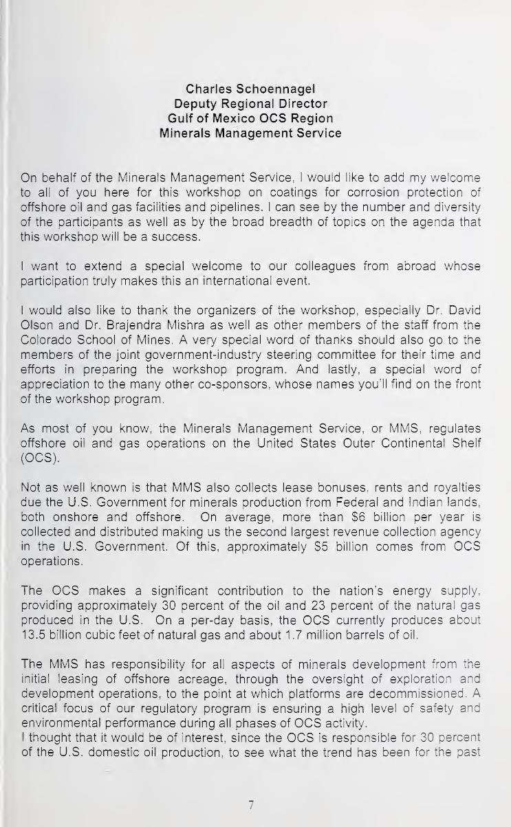
Charles SchoennagelDeputy Regional Director
Gulf of Mexico OCS RegionMinerals Management Service
On behalf of the Minerals Management Service. I would like to add my welcometo all of you here for this workshop on coatings for corrosion protection of
offshore oil and gas facilities and pipelines. I can see by the number and diversity
of the participants as well as by the broad breadth of topics on the agenda that
this workshop will be a success.
I want to extend a special welcome to our colleagues from abroad whoseparticipation truly makes this an international event,
I would also like to thank the organizers of the workshop, especially Dr, David
Olson and Dr. Brajendra Mishra as well as other members of the staff from the
Colorado School of Mines, A very special word of thanks should also go to the
members of the joint government-industry steering committee for their time and
efforts in preparing the workshop program. And lastly, a special word of
appreciation to the many other co-sponsors, whose names you'll find on the front
of the workshop program.
As most of you know, the Minerals Management Service, or MMS, regulates
offshore oil and gas operations on the United States Outer Continental Shelf
(OCS).
Not as well known is that MMS also collects lease bonuses, rents and royalties
due the U.S. Government for minerals production from Federal and Indian lands,
both onshore and offshore. On average, more than S6 billion per year is
collected and distributed making us the second largest revenue collection agency
in the U.S. Government, Of this, approximately S5 billion comes from OCSoperations.
The OCS makes a significant contribution to the nation's energy supply,
providing approximately 30 percent of the oil and 23 percent of the natural gas
produced in the U.S. On a per-day basis, the OCS currently produces about
13.5 billion cubic feet of natural gas and about 1 ,7 million barrels of oil.
The MMS has responsibility for all aspects of minerals development from the
initial leasing of offshore acreage, through the oversight of exploration and
development operations, to the point at which platforms are decommissioned. Acritical focus of our regulatory program is ensuring a high level of safety and
environmental performance during all phases of OCS activity,
I thought that it would be of interest, since the OCS is responsible for 30 percent
of the U.S. domestic oil production, to see what the trend has been for the past
7
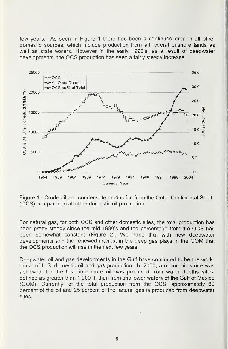
few years. As seen in Figure 1 there has been a continued drop in all other
domestic sources, which include production from all federal onshore lands as
well as state waters. However in the early 1990's, as a result of deepwater
developments, the OCS production has seen a fairly steady increase.
25000
20000
.o
oQ
6
CO
8
15000
OCSAll Other Domestic
OCS as % of Total
10000
5000
35.0
30.0
0.0
1954 1959 1964 1969 1974 1979 1984 1989 1994 1999 2004
Calendar Year
Figure 1 - Crude oil and condensate production from the Outer Continental Shelf
(OCS) compared to all other domestic oil production
For natural gas, for both OCS and other domestic sites, the total production has
been pretty steady since the mid 1980's and the percentage from the OCS has
been somewhat constant (Figure 2). We hope that with new deepwaterdevelopments and the renewed interest in the deep gas plays in the GOM that
the OCS production will rise in the next few years.
Deepwater oil and gas developments in the Gulf have continued to be the work-
horse of U.S. domestic oil and gas production. In 2000, a major milestone wasachieved, for the first time more oil was produced from water depths sites,
defined as greater than 1 ,000 ft, than from shallower waters of the Gulf of Mexico
(GOM). Currently, of the total production from the OCS, approximately 60percent of the oil and 25 percent of the natural gas is produced from deepwater
sites.
8

25000
-o 20000
om
ocsAll Other Domestic
OCS as % of Total|
15000COoEoQa3
^ 10000
>COoo
5000
1954 1959 1964 1969 1974 1979 1984
Calendar Year
35
30
0
1989 1994 1999 2004
Figure 2 - Natural gas production from the Outer Continental Shelf (OCS)compared to all other domestic oil production
The U.S. is now in its tenth year of sustained expansion of domestic oil and gas
developments in the deepwater areas of the Gulf of Mexico, and it shows no sign
of diminishment. This resource potential for the nation continues to grow with
each new discovery in ultra-deepwater.
For oil and gas producers, operating in deepwater has brought continued
prosperity, but also new challenges. Producers are constantly pushing logistical
and technological limits. New solutions are constantly being demanded to meetthese challenges in order to further an excellent operational record. For instance,
there were five announced discoveries in 5,000 ft of water or greater in 2001,
three in 2002, and six in 2003 and this year for the first time, 12 rigs are drilling
for oil and gas in 5,000 feet of water or greater.
Industry continues to operate and conduct exploration drilling in the shallow-
water areas of the Gulf of Mexico. The new exploration has been focused on
finding new oil and natural gas resources that are being identified by newtechnology and/or geophysical data interpellations.
Also the deep gas plays in the shallow waters of the GOM are being developed
where drilling is being conducted from existing wells to depth between 15,000 to
25,000 feet.
9
As these platforms and pipelines continue to age, MMS is increasingly concerned
with the means to ensure the integrity of these older facilities and is working with
the industry on means available to conduct integrity assessments.
Aging or damaged offshore facilities present many challenges to the offshore
industry and regulators worldwide. Currently, over 6,500 platforms and
associated pipelines are operating in some 50 countries. These facilities are of
various sizes, shapes, and degrees of complexity, some being installed in the
1950's and many operating well beyond their intended service life.
Many of these existing facilities were designed in accordance with lower
standards than are currently prescribed. Others have suffered damage as a
result of storms or accidents or, because of the lack of active maintenance
programs have deteriorated to the extent that their future structural integrity is in
question.
Addressing issues related to inspection, maintenance and the repair of platforms
and pipelines is not new to the offshore industry. However, the growing numberof aging facilities, their share of the total production, their perceived vulnerability
as well as the high cost of replacement have focused attention on their integrity
and the need to develop acceptable maintenance guidelines.
For example, in the Gulf of Mexico we have approximately 4000 platforms. Thetotal platform population continues to rise as we have about 140 new installations
per year with about 125 removals per year. The MMS receives reports on about
800 underwater facility inspections a year and up to 4000 topside and cathodic
protection inspections per year.
To put things into a little more perspective, I would like to note some of the
statistics on the facilities in the Gulf of Mexico.
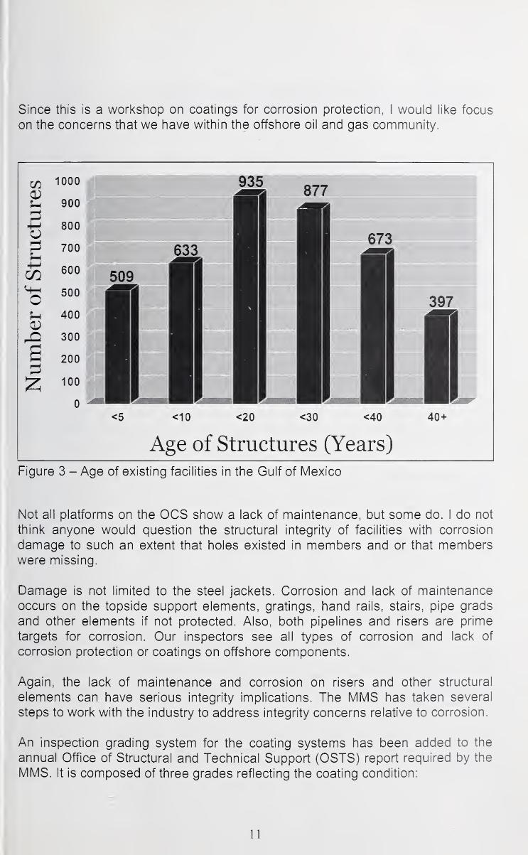
As shown in Figure 3, the average age of existing facilities in the GOM is 20years, a figure which was often used to derive the "design life" of most of them. It
is also interesting to note that 25 percent are 30 years old or older. In fact 10
percent are older than 40 years of age. Of the total number of fixed facilities over
65 percent are in water depths less than 100 feet and what may be considered
more surprising, 95 percent are in water depths less than 300 feet
Of the total number of fixed structures, 40 percent are steel caissons or well-
head platforms and the remaining 60 percent are steel jacket structures.
A large percentage of the facilities are well maintained, however a few are not. In
the lean years, and with the high cost of deepwater exploration and development,for some companies the maintenance of the existing older facilities was not a
high priority.
10
Since this is a worksliop on coatings for corrosion protection, I would like focus
on the concerns that we have within the offshore oil and gas community.
<5 <10 <20 <30 <40 40+
Age of Structures (Years)
Figure 3 - Age of existing facilities in the Gulf of Mexico
Not all platforms on the OCS show a lack of maintenance, but some do. I do not
think anyone would question the structural integrity of facilities with corrosion
damage to such an extent that holes existed in members and or that memberswere missing.
Damage is not limited to the steel jackets. Corrosion and lack of maintenance
occurs on the topside support elements, gratings, hand rails, stairs, pipe grads
and other elements if not protected. Also, both pipelines and risers are prime
targets for corrosion. Our inspectors see all types of corrosion and lack of
corrosion protection or coatings on offshore components.
Again, the lack of maintenance and corrosion on risers and other structural
elements can have serious integrity implications. The MMS has taken several
steps to work with the industry to address integrity concerns relative to corrosion.
An inspection grading system for the coating systems has been added to the
annual Office of Structural and Technical Support (OSTS) report required by the
MMS. It is composed of three grades reflecting the coating condition:
11
A = Good condition - no maintenance needed in 3 years
B = Fair condition - maintenance required in 3 years
C = Poor condition - maintenance needed in 12 months
For facilities in poor condition, the MMS will discuss mitigation measures with the
operator during their annual performance review.
We are also in the process of rewriting Subpart I, Platforms and Structures, to
include relative standards from the National Association of Corrosion Engineers
(NACE) and will maintain photos of relevant facilities in our TIMS database for
future reference.
We have taken an active role in sponsoring workshops such as this to address
the issues and to seek solutions to include hiring additional structural engineers
to work the problem.
As I have previously stated, oil and natural gas derived from the OCS are major
resources in meeting the energy needs of the nation and its role will only
continue to expand in the future. The base of existing facilities and associated
infrastructure are keys to this expansion and we must maintain their integrity.
We in MMS believe there is tremendous benefit from collaboration between the
industry and regulator and are working together to ensure that each party's goals
are met. That is why we are here - to learn together and plan for the future.
Bud Danenberger of the MMS stated in his opening remarks for the Corrosion
Workshop that was held in Galveston in 1999 that "There's no corrosion crisis.
We have a number of concerns, but there's no crisis." This is still true. Corrosion
is the leading cause of pipeline failures and is of growing concern relative to the
aging fleet of platforms. And when you have facilities with corrosion problems,
there is the potential for a serious incident and associated economical impacts.
In closing, let me note that the MMS fully supports this effort and encourageseveryone here to actively participate so that the workshop will generate useful
guidance for future standards or research.
We look forward to the discussions and interchange of opinions over the next
several days, and particular to the conclusions and direction that the workshopwill provide in the area of coatings for offshore and marine structures. These will
undoubtedly be a great value to the offshore and marine industry and to other
industries as well.
Again, I would like to thank Dr. Olson and the steering committee for organizing
this workshop and the many co-sponsors for their support as well as your
participation.
12
It has been a pleasure to speak to you this morning, to share our enthusiasm for
this workshop and to briefly describes MMS's interests and desires for
improvements in coatings for corrosion protection.
13
James Card
Senior Vice President, American Bureau of Shipping
USCG Vice Admiral (ret.)
On behalf of the American Bureau of Shipping, I would like to welcome all of you
here for this international workshop on Advanced Research & Development of
Coatings for Corrosion Protection. My thanks to Prof. Olson and the Colorado
School of Mines for organizing this workshop, and for inviting me to speak before
this distinguished group.
As you are probably aware, the American Bureau of Shipping is a leading
worldwide classification society. Its mission is to promote the security of life and
property at sea, and protection of the natural environment. ABS does this by
setting standards for design, construction and operation for shipping and offshore
industries. These standards also include survey of structural conditions through
out the life of the vessels. As coatings are a key preventative measure for
deterioration of steel structures, ABS is keenly interested in the topics under
discussion at the Workshop.
We look forward to the discussions and interchange of opinion over the next
several days, and particularly to the recommendations and direction that the
Workshop will provide for the marine and offshore industry.
Corrosion
It was recently estimated (in a NACE report) that the average cost of corrosion
protection due to new ship construction is $7.5 billion per year. This equates to
approximately seven to ten percent of the cost of the vessel, with chemical
tankers as high as thirty percent. The annual cost for repair and maintenancedue to corrosion was estimated at $5.4 billion with an additional $5.2 billion cost
associated with downtime.
Vessels continue to be constructed of steel, but now probably less steel due to
analytical ability to optimize deigns. Tankers are now required to be constructed
with double hulls, introducing changes to operating conditions in ballast tanks.
There have been dramatic offshore advances into deep water. FPSO's are being
installed with expectations of remaining on location for twenty plus years. Howhas the state of the art in corrosion protection faired along side these design andoperational advances?
14
Coating and Classification Surveys^
Traditionally, classification has required all steel work to be suitably coated with
paint or an equivalent. Certain areas are required to be protected with an epoxy
type coating including salt-water ballast tanks and cargo holds of bulk carriers. Is
there a need to extend this to cargo tanks? This topic is currently being debated.
Coatings are necessary but who is responsible for establishing the minimum or
recommended standards: the coating manufacturer, the shipyard, or the owner?There are various schemes in effect and available now. Some class societies
offer optional notations to cover coatings. These range from the approval of
coating only as meeting a specification to full involvement with the application of
the coating. Recent SOLAS regulations require submittal of documentation on
the scheme for the selection, application and maintenance of the coating system.
How can interested parties be assured appropriate coatings are applied for a
given situation?
ABS provides guidance for grading the condition of coatings in the Guidance
Notes on the Application and Maintenance of Marine Coating Systems. TheseGuidance Notes, developed by an ad hoc panel of coating experts from
manufactures to vessel operators, contains over fifty pictures of coatings with
their assigned condition grade. Is this system of grading coating condition the
best available? Is there more advanced technology that could be used?
In the case of salt-water ballast tanks, class judges the condition of the coating
(good, fair, poor) as a basis for subsequent classifications examinations.
Coatings of salt-water ballast tanks found in less than Good condition for tankers
subject to Enhanced Survey Program require annual examination of the tank.
"Good" is defined as a condition with only minor spot rusting. What constitutes
satisfactory repair of the coating back to a "Good" condition?
Expectations of the Workshop
The need for coating and corrosion protection is evident. We need to
understand the practical issues of today and be open to identify tomorrow's
issues with both corrosion science and coatings technology. Workshops like this
are a venue for cross industry discussions that can lead to understanding and
identification of the solutions.
15

I would like to challenge all of you to consider these three very practical issues:
• How can the marine industry best determine what areas coatings
should protect?
• How can interested parties be assured appropriate coatings are
applied for a given situation?
• How can operators be assured that the applied coating performs in
a satisfactory manner?
The American Bureau of Shipping fully supports the ongoing efforts in coating
design, manufacturing, application, and continued discussions of these topics.
ABS encourages everyone here to actively participate, so that these workshops
will develop useful guidance for the direction of application, inspection and future
research. The commercial marine sector will benefit greatly with the
advancement and collation of coating technology.
It has been a pleasure to speak before you this morning to share our enthusiasm
for this workshop, and to briefly describe ABS' interest, experience, and desired
improvements.
16

Larry Christie
^NACEINTER. NATIONALTHE CORROSION SOCIETY
NACE International, The Corrosion Society, welcomes you to this important event on
Coatings for Corrosion Protection. NACE is a technical society that serves as
a clearinghouse for information on all forms of corrosion control. We also recognize that
coatings technology is the number one method employed worldwide to protect all structures
from corrosion, from offshore structures, to pipelines, to ships and beyond.
My name is Larry Christie, and I began working at NACE two weeks ago as the " Coatings
Market Manager ", a new position created by NACE because it recognized the need to
more thoroughly integrate coatings technologies into all activities throughout NACE. Since
sixty percent of NACE's 15,000 members report that they have some level of
responsibility with coatings work, I appreciate being able to participate in a conference like
this one. As a side note, the NACE past president and current interim Executive Director,
Pierre Crevolin, could not be here since he now works for NACE in Houston, and went hometo Canada for the Easter holiday. On Monday, U.S. Customs decided that if Pierre is
not being paid for engineering work by the hour in Houston, then his work visa is invalid
and he was not allowed to return to NACE in Houston, or to Biloxi for this conference. I ama fellow Canadian of Pierre's and obviously we have not figured out how NAFTA applies to
us.
To begin, I would like to help quantify the importance of the coatings industry in the U.S. by
sharing some facts. NACE recently completed a Cost of Corrosion Study with funding from
the Federal Highways Administration, which concluded that corrosion costs the U.S. $276billion a year and yes, that was $276 billion, which is equal to 3.1 percent of the US Gross
Domestic Product. More astounding was the role of coatings in preventing corrosion. There
are many technologies -- coatings, cathodic protection, materials design, chemical inhibition,
etc., to help reduce the affects of corrosion. The Cost of Corrosion Study said that the cost
of these services totals about $121 billion per year. Of that, however, $108 billion dollars, or
eighty-nine percent of the money being spent today to help prevent corrosion is in the
coatings service sector.
Obviously, then, the pressure is on the coatings industry to make advances in technologies
that are reflected in lower overall costs related to corrosion. By helping to organize events
such as this with the Colorado School of Mines, the MMS, and the American Bureau of
Shipping, NACE hopes to facilitate cross-fertilization of ideas and the dissemination of
information that will lower the cost of corrosion in the future. In fact, it is not just our hope, it
is our mission and a key element in our strategic plan. As I noted before, NACE feels so
strongly about the importance of the coatings industry to its mission that it recently added a
Coatings Market Manager (me) to its staff to provide specific direction and focus to these
efforts.
17
^nd what else did the Cost of Corrosion Study tell us? It said that achieving the mostffective corrosion control strategies still requires widespread changes in industry
lanagement and government policies and additional advances in science and technology,
hese needed changes directly correlate to the purpose of this event here in Biloxi; we hopelat in five to ten years, the next Cost of Corrosion Study will show that technical conferences
ke this one have had a positive impact on our ability to reduce the cost of corrosion overall.
he preventative strategies recommended in the Cost of Corrosion Study will certainly be
dvanced by your activities this week. The preventative strategies are to:
1 . Increase awareness of large corrosion costs, and potential savings
2. Change the misperception that nothing can be done about corrosion
3. Change policies, standards, regulations, and management practices to increase
corrosion savings
4. Improve education and training of staff
he papers that you will discuss and debate this week also address the study's technical
reventative strategies:
1 . Advance design practices for better corrosion management2. Advance life prediction and performance assessment methods3. Advance corrosion technology through research, development, and implementation
he Cost of Corrosion Study really has highlighted the role of coatings in protecting assets
nd reducing expenses related to corrosion. NACE supports events such as this one
ecause everyone here has to work together to generate ideas and share information that
/ill reduce the affects of corrosion. Finally, as an industry, the corrosion control profession
as to do better at using its talent to make both short- and long-term impacts on the
reservation of assets and the environment. We know that this lively and energetic forum will
ertainly work toward that goal.
"he conference organizers have asked us to make remarks on why a conference like this is
0 important to our organizations ~ in this case, to NACE. That's easy. Every industry
eeds leaders. And conferences such as this one are where the leading is done. Youilready know that this conference is focused on progress, on change, and on moving forward
D new and improved technologies. The workshops that you participate in this week are
tructured to encourage debate and stimulate forward thinking. I hope each of you will share
our ideas openly, candidly, and enthusiastically while participating in these workshops. Theesulting industry papers, at the end of the week, may be more valuable to industry than any
ither papers from recent events.
another reason that this conference is so important is that it facilitates cross-fertilization of
jeas. Many of you are from different industries such as: shipping, pipeline, offshore, and
(thers. Like NACE, this conference places value on helping you to see what technologies
18
Iand techniques other industries are using that could be applied in your industry. There are
' many smaller conferences that you might attend that include only your colleagues in your
I
industry, and they also have their purpose. We hope that you will take some time this week
I
to listen to what others are doing and reflect on how you might take advantage of what you
learn from them.
While I am here, I also wish to make a plug for the new NACE Foundation. All of you are
here at this event to learn more about technologies that can help you in your job or your
career. Two years ago, NACE endeavored to increase the stature of the coatings industry
and other corrosion control industries by establishing the NACE Foundation. Its mission is to
excite students and the public about what you do, so that the public is more aware of the
importance of your work, and so that young students are more likely to seek career paths in
our industries. Please drop by the NACE booth to see the Foundation's new NACE Inspector
Protector Storybook and take one of these booklets home to your kids to show them what
you do! Maybe they will start calling you Inspector Protector, Super Coat, Smart Pig,
Captain Cathode, or one of our other corrosion heroes. Hopefully they won't call you one of
the villains like Count Corrosion or Dr. Forbidden.
Again, I wish to thank the Colorado School of Mines for asking NACE to participate and for
doing such an excellent job with this technical program, and on behalf of NACE I welcomeyou to this conference and hope that you find the program to be intellectually challenging andproductive. Thank you.
19

I
20

Section 2
Keynote Addresses
21
I
22
Research & Development of Coatings for Alaska Tanker Company
Jack Thibault
Engineering Team LeaderAlaska Tanker Company, LLC
When ATC was approached several months ago and asked if we were interested
in presenting at this conference, our response was immediate and affirmative. In
today's maritime world of strict regulatory control, the strong emphasis on vessel
condition and the ever present focus on efficiency, have forced operating
companies such as ATC to make difficult decisions on vessel retirement andinvestment protocol for new construction.
To better explain ATC's position in this regard, allow me to first set the stage by
summarizing our company's history and operating philosophy.
ATC was formed in April of 1999. Our company's charter limits us to the carriage
of Alaskan hydrocarbons-primarily North Slope Crude Oil. We presently operate
a fleet of eight vessels and are the largest transporter of ANS crude in the Trans-
Alaskan Pipeline trade.
ATC's combined Health, Safety and Environmental (HSE) performance excels or
is at least on par with any major shipping company in the world. During 2002and 2003, ATC transported 311 million barrels of crude oil with less than three
total gallons of oil (from any source) being spilled to sea ANYWHERE. ATC has
completed five million man-hours without a Lost Time Injury. The Loss TimeInjury frequency rate has been zero for both 2002 and 2003, and the 12-month
total recordable injury frequency rate has fallen to 0.54 as of December 2003.
ATC has been recognized for its superior performance by the Alaska State
Legislature, the Prince William Sound Regional Citizens Advisory Council
(RCAC) and the Washington State Department of Ecology. ATC is one of the
few shipping company's worldwide to be SQE certified by the American Bureau
of Shipping (ISM, ISO 9002, and ISO 14,000).
At ATC, we believe our HSE performance culture and our proactive HSEprograms lead to sound preventative maintenance practices that help to deliver
fiscal performance. In the course of delivering outstanding HSE performance, wehave reduced our total operating budget by fifteen percent, since our company's
inception.
Since the passage of the Oil Pollution Act of 1990, vessels operating in the
Trans-Alaskan Pipeline Trade have become one of the most scrutinized fleets
presently operating in the world. Our vessels are removed from service 26 days
of every year to complete a thorough structural examination of the vessel's entire
23
cargo block. On average, the cost to complete this examination and subsequentrepair is approximately $500,000.
Internationally, recent marine casualties have further toughened the inspection
criteria of all vessels, especially vessels operating in the tanker trade. NewClassification Society Rules with respect to close-up examination and the grading
parameters of existing coating systems could effectively result in the early
retirement of vessels that would previously have continued in service.
As a result of increasing awareness of the risk inherent to the Oil Majors brought
by the carriage of oil at sea, most of the Majors have implemented a vessel
inspection system independent of regulatory and statutory entities. Theseinspections, known as vettings, are independently ordered by the Oil Majors prior
to acceptance of the vessel for the carriage of their oil. The vettings adhere to
the standards of the Ship Inspection Report Program (SIRE), a system
developed by the OCIMF (Oil Companies International Marine Forum) in 1993 to
address concerns of the Oil Majors with respect to the chartering of sub-standard
vessels.
SIRE requires that the inspectors use a uniform inspection protocol. The results
of these inspections are then made available to all program participants. All of
the oil majors use the information kept in the SIRE database to determine if the
vessel candidate exposes the Oil Major to unacceptable risk.
The complexities of operating an aging fleet while meeting all SIRE Programrequirements has forced ATC to make major policy decisions about how we will
conduct business.
As a partial result of inspection criteria set forth in SIRE, ATC decided that no
company-operated vessel would continue in service with known areas of
substantial corrosion. Simply defined, substantial corrosion is wastage in excess
of 75 percent of the allowable margin but still within acceptable limits for
continued service.
ATC also implemented a policy of repairing any structural defect, including the
repair of any fracture to any structural member one-half inch (12 mm) in length or
longer.
Prolonged structural integrity is directly connected to the coating system selected
for each vessel dependent on the vessel's trade. The average cost of grit blasting
and re-coating one set of double bottoms on one of our 120,000 DWT tankers in
the United States is approximately $1.2 million.
Recent changes by Classification Societies concerning the grading of ballast tank
coatings have essentially created only two grades, good and poor. While the fair
coating condition grade still exists, tanks receiving this grade are required to be
24
internally examined annually, resulting in costly out-of-service time for the vessel.
More importantly, this item will be seen on vetting reports, which could make the
vessel less attractive from a chartering perspective.
Technological improvements in repairing existing coating systems have becomean operational necessity. We have not completed a drydocking since 2002where some form of coating repair or complete recoating of a ballast tank has not
been required.
For vessels constructed with reduced scantlings, it is mandatory that coating
systems be adequately maintained. If additional thickness measurements are
required where substantial corrosion is found, the results will be evaluated on the
scantlings prior to the reduction.
A Condition Assessment Survey as completed by, in our case, the American
Bureau of Shipping, is a complete evaluation of a vessel's machinery, structure,
and associated equipment. This Survey is requested by the Owner/Operator,
and is independent of Class Surveys. The Survey assigns a grade to the ship:
• Grade 1 : Vessel is considered good in all respects.
• Grade 2: Vessel is considered satisfactory, being well-maintained with only
minor deficiencies.
• Grade 3: Vessel is considered below average. Though still serviceable, mayrequire short-term corrective action.
• Grade 4: Vessel is unsatisfactory, in need of immediate corrective action.
Many of the Oil Majors require vessels deemed acceptable for charter to
maintain a Condition assessment of Grade 2 or better.
To better illustrate the commercial and operational impacts in today's
marketplace concerning vessel condition, I would like to discuss the life-stories of
two particular vessels.
The first vessel was the ST Prince William Sound. She was built as the first of a
newly intended Double Hull Ecology Class Tanker. At construction, none of the
vessel's wing, double-bottom or peak ballast tanks were coated.
By 1990, a significant amount of steel renewals were required in way of the inner
bottom tank top plating. To arrest further corrosion, all saltwater ballast tanks
were hard epoxy coated during this repair period. The coating materials that
were applied, the surface preparation, the method of application and the actual
diminution of strength of the members at the time of re-coating are not known to
us, but have played an important role in the subsequent life of the vessel.
In 1994, a re-coating program had been commenced as the coating system
applied in 1990 had already begun to fail. As the re-coating program continued
25
through subsequent drydockings, the amount of steel renewals required
continued to increase. During drydockings in 1996, 1998, and 2000,
approximately 250 metric tons of steel required renewal. Upon leaving the
drydock in 2000, the vessel had approximately 125 tons of steel identified as
having substantial corrosion.
In January 2002, a SIRE vetting was completed on the vessel. Noted in the
vetting report was the fact that the vessel had an additional 125 tons of
substantially corroded steel. Even though the vessel was built "Over Scantling"
and the level of corrosion was not to the point of requiring renewal by Class, it
became apparent the vessel was in jeopardy of not being acceptable for charter.
It was at this point that ATC adopted its position on substantial corrosion.
Over the course of the next 12 months, ATC undertook the project of evaluating
the structural health of the vessel. Nearly 100,000 ultrasonic thickness
measurements were taken. At the request of ATC, ABS commenced a SafeHull
Condition Assessment of the vessel.
In June of 2003, the vessel proceeded to Singapore for short-term layup andcommencement of her scheduled drydock and repair period. The work on the
vessel commenced in October of 2003, lasting until February of 2004. 783 tons
of steel was renewed throughout the length and breadth of the vessel. In
conjunction with the steel renewals the forepeak, afterpeak, and aft transverse
ballast tanks were grit blasted and a new epoxy coating system applied. Thoseareas of the structure where renewals were made (thus disturbing the existing
coating) were:
• Hydro-blasted.
• Cleaned with chloride removal chemicals.
• "Hand Tooled" in areas surrounding the blasted areas
• Coated with a three-coat epoxy system.
Using the above procedure, we have enjoyed success with coating repairs wherethe failure rates in the affected ballast tanks are in the five to ten percent range.
We have shown this type of repair to dependably endure for a 5-year period.
The cost of completing this repair is generally 1/10 the cost of total blast and re-
coat. This type of repair is of particular importance on those vessels with a
limited remaining service life, but that is still required to have their coating
systems maintained in a "GOOD" condition for Class and vetting consideration.
The Alaskan Frontier, the first of four 185,000 MT DWT vessel's presently under
construction at NASSCO in San Diego, is the future for ATC. Each vessel is
constructed for the transportation of crude oil world wide, with an emphasis on
the high visibility associated with the Trans Alaskan Pipeline Trade. The four
vessels are owned by British Petroleum and represent a capital investment of $1
billion dollars.
26
The vessels are double-hulled crude carriers, constructed with an eye towards
redundancy. Included are two independent engine rooms, two diesel-electric
propulsion systems, two fixed pitch propellers, two steering gears, and two
rudders.
The two propulsion plants, together with the essential auxiliary machinery and
steering gears, are arranged in two fire tight, gas tight, and watertight machinery
rooms. The spaces are arranged such that a catastrophic fire or flooding in any
one space will not incapacitate the propulsion machinery, its auxiliary support
equipment and associated steering systems in the other spaces.
Environmentally, the Alaskan Class Vessels will be the first vessels in the Trans-
Alaskan Pipeline trade to employ a water-cooled Stern Tube Bearing.
Historically, leakage of oil through the stern tube seal, though minor in scope,
has been a major area of concern in spills to sea.
The cargo tanks are divided into six (6) tank blocks longitudinally. The cargo
tanks are arranged three (3) abreast separated by oil tight longitudinal bulkheads
running the length of the cargo block. The arrangement allows for a total of
eighteen cargo tanks and two (2) slop tanks.
The vessel's equipment is designed for an expected service life of twenty-five
years.
Structurally the vessels have been designed such that the builder must
demonstrate the longitudinal structure will have a fatigue life of not less than fifty
years operating in the Taps Trade environment. This has been demonstrated
through the utilization of SafeHull Phase-B and spectral fatigue analysis.
With regard to the vessel's coating/corrosion protection systems:
• The ballast tanks of each vessel are designed for not less than 15 years of
service life.
• The underwater area of the outer hull is protected by an anti-fouling corrosive
paint system with a minimum of fifteen-year coating life
• The underwater area of the hull will also have a tin-free anti-fouling paint
system suitable for a minimum life of three years in service.
• Zinc anodes are provided for tanks in contact with seawater and are suitable
for five years of service life.
• All coated tank hull structures will have all sharp edges removed by edgegrinding. Grinding will be accomplished to ensure a 2 mm edge radius. (The
attention to detail in respect to this requirement has been phenomenal. Credit
should be given to Nassco in their adherence to this requirement.)
• External to the hull all required frame markings required to allow the vessel to
complete an underwater examination in lieu of drydocking will be provided.
27
The intent is for the vessels to be structurally sound and capable of a five-
year drydock interval.
As a tank-ship operator with vessels operating under the authority of the Jones
Act, our concerns are particularly unique. While we are expected to meetInternational Standards for vessel condition, many times our vessels are
disqualified by age alone. Despite the fact that we take great pride over the level
to which our vessels are maintained, the remainder of our single hull and double
bottom vessels will be retired within the next two years. Our entire fleet will be
comprised of double hull vessels.
We have shown how increased scrutiny by regulators about coating condition
and the overall structural integrity of vessels demands the advancement of
coating systems and their application. If coating systems are allowed to degrade,
not only will inspection criteria become more stringent, but the vessels will quite
possibly be considered a commercial risk and therefore, unfit for charter. If
coating systems do not continue to advance in durability, cost of application, and
level of protection, it will be difficult to stand the ever-increasing scrutiny while
continuing to remain economically viable.
We have looked at the life cycle of the PRINCE WILLIAM SOUND, a vessel whostarted her career with uncoated tanks. We have seen the results of that flawed
decision, and the many millions of dollars spent to return her to a condition that
will make her commercial viable for the carriage of oil at sea.
Finally, we have looked at the future of our business with the construction of the
Alaskan Class vessels. We expect the technology in place today and upcoming
future developments will allow this vessel to fulfill its planned life cycle with
reasonable economy. The staggering replacement cost of these vessels will
necessitate technological advancement in coating system repairs and prolonged
life cycles of entire coating systems.
28
Practical Experience
Adolfo Bastiani
Vice-president Offshore Operations
IVIODEC International LLC, Houston
Introduction:
This seminar is organized to discuss, at a high technical level, the causes, effects
and remedial measures to combat corrosion in the offshore industry. I will leave
the more technical aspects of this discussion to other distinguished speakers. Mypresentation here will outline our practical experience of one MODEC operated
ship shaped FSO located in the southern Gulf of Mexico. That this body of water
is also called the US Gulf should be of particular interest to many of the
participants in this seminar, in the sense that it is a common body of water. Overthe past couple of years, concern has been expressed that locating FSO/FPSO'sin U.S. waters is not safe from pollution point of view. MODEC's experience with
operating our FSO in GOM has been quite successful over the past six years
without any incident of oil pollution and has an excellent HSE record.
The very concept of FPSO's is based on exploiting marginal oil fields and it is
customary for all our clients to demand an FPSO that will operate in one location
for 15 to 20 or even 25 years WITHOUT DRY-DOCKING. Whether it is a newbuild or a converted hull, this long life expectancy is a tall order indeed. Besides
no dry-docking, the contract is always quite demanding re downtime. Either zero
or minimal few hours every month, the downtime does not allow the contractor
any freedom for remedying corrosion wastage during operations, particularly in
inaccessible areas of underwater hull, moorings, sub-sea structures and even
cargo/ballast tanks. The rationale of not stopping production is fully understood
by the contractor as this has substantial and often unbearable economic impact.
Right from FEED study, the contractor must ensure optimum corrosion protection
for the operational life. In addition, he must take into account thickness of steel
plating, such that if there is failure of paint coatings, the wastage caused by direct
attack of corrosive seawater, still retains the integrity of the hull over the entire
life expectancy. As always, all such studies are done and must be implemented
under strict budgetary control.
TA'KUNTAH - General Information and Capabilities
TA'KUNTAH was converted to an FSO in Singapore in 1997/98 from a ULCChull, which was then twenty years old. A study of past trading pattern, extensive
29
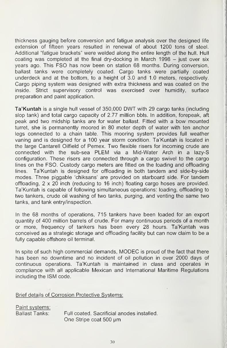
thickness gauging before conversion and fatigue analysis over the designed life
extension of fifteen years resulted in renewal of about 1200 tons of steel.
Additional "fatigue brackets" were welded along the entire length of the hull. Hull
coating was completed at the final dry-docking in March 1998 - just over six
years ago. This FSO has now been on station 68 months. During conversion,
ballast tanks were completely coated. Cargo tanks were partially coated
underdeck and at the bottom, to a height of 3.0 and 1.0 meters, respectively.
Cargo piping system was designed with extra thickness and was coated on the
inside. Strict supervisory control was exercised over humidity, surface
preparation and paint application.
Ta'Kuntah is a single hull vessel of 350,000 DWT with 29 cargo tanks (including
slop tank) and total cargo capacity of 2.77 million bbls. In addition, forepeak, aft
peak and two midship tanks are for water ballast. Fitted with a bow mountedturret, she is permanently moored in 80 meter depth of water with ten anchor
legs connected to a chain table. This mooring system provides full weather
vaning and is designed for a 100 year storm condition. Ta'Kuntah is located in
the large Cantarell Oilfield of Pemex. Two flexible risers for incoming crude are
connected with the sub-sea PLEM via a Mid-Water Arch in a lazy-S
configuration. These risers are connected through a cargo swivel to the cargo
lines on the FSO. Custody cargo meters are fitted on the loading and offloading
lines. Ta'Kuntah is designed for offloading in both tandem and side-by-side
modes. Three piggable 'chiksans' are provided on starboard side. For tandemoffloading, 2 x 20 inch (reducing to 16 inch) floating cargo hoses are provided.
Ta'Kuntah is capable of following simultaneous operations: loading, offloading to
two tankers, crude oil washing of two tanks, purging, and venting the same two
tanks, and tank entry/inspection.
In the 68 months of operations, 715 tankers have been loaded for an export
quantity of 400 million barrels of crude. For many continuous periods of a month
or more, frequency of tankers has been every 28 hours. Ta'Kuntah wasconceived as a strategic storage and offloading facility but can now claim to be a
fully capable offshore oil terminal.
In spite of such high commercial demands, MODEC is proud of the fact that there
has been no downtime and no incident of oil pollution in over 2000 days of
continuous operations. Ta'Kuntah is maintained in class and operates in
compliance with all applicable Mexican and International Maritime Regulations
including the ISM code.
Brief details of Corrosion Protective Systems:
Paint svstems:
Ballast Tanks: Full coated. Sacrificial anodes installed.
One Stripe coat 500 pm
30
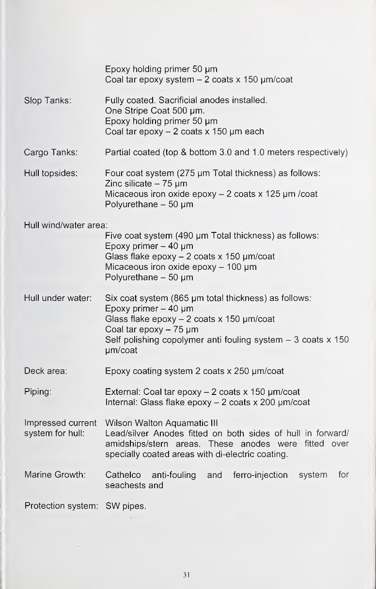
Epoxy holding primer 50 |jm
Coal tar epoxy system - 2 coats x 150 pm/coat
Slop Tanks: Fully coated. Sacrificial anodes installed.
One Stripe Coat 500 jjm.
Epoxy holding primer 50 jjm
Coal tar epoxy - 2 coats x 150 |jm each
Cargo Tanks: Partial coated (top & bottom 3.0 and 1 .0 meters respectively)
Hull topsides: Four coat system (275 [jm Total thickness) as follows:
Zinc silicate - 75 |jm
Micaceous iron oxide epoxy - 2 coats x 125 |jm /coat
Polyurethane - 50 pm
Hull wind/water area:
Five coat system (490 pm Total thickness) as follows:
Epoxy primer - 40 pmGlass flake epoxy - 2 coats x 150 pm/coat
Micaceous iron oxide epoxy - 100 pmPolyurethane - 50 pm
Hull under water: Six coat system (865 pm total thickness) as follows:
Epoxy primer - 40 pmGlass flake epoxy - 2 coats x 150 pm/coat
Coal tar epoxy - 75 pmSelf polishing copolymer anti fouling system - 3 coats x 150
pm/coat
Deck area: Epoxy coating system 2 coats x 250 pm/coat
Piping: External: Coal tar epoxy - 2 coats x 150 pm/coat
Internal: Glass flake epoxy - 2 coats x 200 pm/coat
Impressed current Wilson Walton Aquamatic III
system for hull: Lead/silver Anodes fitted on both sides of hull in forward/
amidships/stern areas. These anodes were fitted over
specially coated areas with di-electric coating.
Marine Growth: Catheico anti-fouling and ferro-injection system for
seachests and
Protection system: SW pipes.
31
Corrosion Control During Operations:
In recognition of the fifteen years designed life expectancy, following controls are
exercised during operations:
a. ICCP and Catheico readings are monitored daily and monthly log is sent
to technical department of supplier for their appraisal andrecommendations if any are duly complied with.
b. At every periodic tank inspection, coating is touched up wherever it maybe disturbed. Surface is prepared by hand tools. In this regard, particular
attention is paid to the aftermost bay and area just below the suction bell
mouth, which is subject to cavitation. During conversion, the bell mouthwas raised by two inches to gain access for this maintenance.
c. At every periodic inspection inside the tanks, thickness gauging is carried
out and readings compared with original readings from the conversion
yard. By and large, coatings are found better than 99 percent intact andthickness readings do not show any deterioration.
d. Tank anodes are inspected for any wastage. Having been fitted in already
coated areas, the wastage so far is noted to be negligible.
e. Acidic attack that can be caused by the presence of H2S gas released by
the Maya crude cargo on the upper parts of cargo tanks, is minimized
through dilution with fresh inert gas and purging.
f. PV valves and self closing devices on the tank vent pipes for ballast tanks
are maintained in good condition to prevent ingress of fresh air into tanks.
g. The 'in & out' lengths of anchor chains are measured for thickness at
every five yearly interval to check on undue wastage. At last recording,
this wastage was noted to be less than two percent on the diameter.
h. Maintenance of deck plating and fittings above deck are continuous
maintenance items and are descaled and touched up or coated as
necessary.
i. The exterior of the hull, where accessible, is touched up with paint as
necessary.
j. The glass flakes coating in way of fenders provide extra protection against
abrasion.
k. The inaccessible underwater areas of hull are inspected with the help of
divers every 2.5 years. Obviously, no maintenance by way of recoating is
possible. However, at such inspections, it has been noted that the
extensive coating system applied at the conversion yard is by and large
fully intact. Where superficially disturbed, it is noted that substrata of paint
coating is quite intact still. At last underwater inspection carried out by
divers and monitored on deck with video cameras, in March 2003 (i.e. five
years after dry-docking), showed that there was hardly any sea growth -
32
barnacles etc. This indicates that anti-fouling coats are still effective. Wehave no delusions that this can continue for another 10 years. However,
we feel confident that corrosion if/when it starts will not cause the integrity
of hull to be unduly effected. It nnay be added that the rudder and
propeller areas, which are isolated from the ICCP system, are extensively
covered with barnacles. This is inconsequential for FSO/FPSO, as at the
end of their life they will be towed away.
I. During such underwater inspection, particular attention is paid to the
seachests and their external gratings. If necessary, gratings are removedto the deck and recoated. Anodes inside the tanks are noted to be quite
active and when needed, they can be replaced.
Let me end my presentation by stating that the corrosion protection provided
at the time of conversion six years ago and subsequent inspections and
corrective measures and controls exercised during operations of this FSOlocated in its particular area in GOM, give us the confidence that Ta'Kuntah
will outlive its life expectancy of fifteen years.
33

34
It

Section 3
Theme Papers
35
36
Health & Safety Concerns:Coating Application & Removal
Joseph B. Loring
Safety and Environmental Health Officer
U.S. Coast Guard
Introduction:
The intent of the paper is to provide a very brief summary of potential safety andhealth concerns/hazards associated with the coatings industry for inclusion in this
publication. This paper is far from a detailed, thorough assessment of any andall hazards associated with the practices of this industry.
Extremely simplified, the application of a coating involves the removal of any
previous coatings/paints, followed by surface preparation, and subsequently, the
application of new coating.
Removal of old coatings and surface preparation is usually accomplished via
water blasting, steam blasting or abrasive blasting. This process often creates a
large debris cloud of both blasting media and removed product.
The application of a coating involves either spraying or brushing the material onto
the prepared surface. This frequently results in an atmosphere with high
concentrations of aerosolized coating material.
Most coatings, paints, and protective agents are comprised of a long list of
materials, many of which have properties that make them potentially harmful to
human health. Ingredients will likely include some type of solvent (aromatic and
aliphatic hydrocarbons) mixed with pigments and additives. The additives mayinclude organo-mercury compounds, copper oxide, arsenic, organo-tin
compounds, cadmium, chromium, lead, zinc chloride, and others.
The process of surface preparation and application of the coating, coupled with
the potentially hazardous materials used in the coating, create occupational
health risks that could cause both acute and chronic illnesses to workers.
General Safety Concepts:
The most effective way to assess the potential hazards associated with utilizing a
product is by consulting its Material Safety Data Sheet (MSDS). The application
of coatings is no exception. It is imperative that workers that will be handling the
37
coatings acquire the appropriate MSDSs and gather information on the hazards,
handling procedures, PPE requirements, etc.
Utilizing controls is essential. The control hierarchy dictates that engineering
controls should be considered first, followed by administrative controls, andfinally the use of Personal Protective Equipment (PPE).
Engineering controls are those that can eliminate the hazard through technology.
Installing blockades, shields, local ventilation, or isolation booths are engineering
controls that isolate the hazard from the worker or the worker from the hazard.
Administrating controls are policies or procedures aimed at limiting or minimizing
workers exposure to hazards. Work rest cycles, warning signs, and worker
training are all admin controls that can reduce the likelihood of injury or illness
due to hazard exposure.
The last control is the use of PPE. Often times unavoidable due to procedures
and practices, the use of respirators, gloves, coveralls, etc will minimize workers
exposure to certain chemicals/hazards.
The control hierarchy should always be addressed prior to commencing a job to
determine the best way to protect the workers and the surrounding area.
Fire and Explosion Hazards:
The vast majority of paints and coatings contain some type of solvent. Thesesolvents are commonly the carriers of any pigments and additives used in the
coating. Examples of commonly used solvents include mineral spirits, benzene,
toluene, acetone, methyl ethyl ketone (MEK), and others. Though all have
differing physical and chemical characteristics, one property common amongmost solvents is that they are extremely flammable.
Whether applied via spraying, brushing or other technique, all are likely to create
a potentially explosive atmosphere. This atmosphere combined with a source of
ignition may result in a catastrophic explosion.
Sources of ignition could include hot-work (welding, cutting, grinding), non-
intrinsically safe equipment/tools, human error, etc.
Often times sources of homogenous to the job site and cannot be eliminated. Assuch, the best preventive measure is to aggressively ventilate the space.
Exhaust ventilation must be utilized to ensure flammable solvent vapor
concentrations are <10 percent LEL.
38
Respiratory Hazards:
Solvents, pigments and additives may all be respiratory hazards.
Application or removal of coatings in confined or enclosed spaces could result in
an oxygen deficient atmosphere or an atmosphere with high levels of toxic
material. Potential health effects due to exposure to some products may include
irritation, sensitization, organ damage, cancer, neurological damage,asphyxiation, or death. Therefore, respiratory protection in the form of air-
purifying respirators (APR), supplied air respirators, or self-contained breathing
apparatus is a must in most situations. In confined spaces and enclosed spaces
without ventilation, airline respirators are required. In well-ventilated areas, air-
purifying respirators with appropriate cartridges are acceptable.
The best preventive measure is again ventilation and real-time air monitoring to
ensure toxics remain below OSHA's Permissible Exposure Level (PEL) and
ACGIH's Threshold Limit Value (TLV).
Contact with Coatings or Solvents:
Components of many coatings can cause irritation, sensitization, allergic
reactions, chemical burns, organ damage, etc. if they come into contact with skin
or eyes. Proper PPE should always be utilized including utilizing full body
coverall, face and eye protection, gloves, boots etc. Eyewash stations and
emergency showers must be available for worker use.
Limited Access/Egress and Confined Space Entrv:
Painting and coating operations that take place inside tanks and other voids
commonly result in blocked access openings and limited egress. It is im.perative
that these entry and exit points remain clear to avoid the hindrance of escape in
the event of an emergency.
Proper confined space entry procedures must be followed when entering space
to apply or remove coatings. Certified Marine Chemists and shipyard competent
persons must be used to test the spaces for oxygen content, flammable
atmosphere, and the presence of toxics.
Work Environment Temperature and Related Hazards:
If not properly accounted for, both heat and cold stress can create dangerous
work environments.
39
The most important action required is the monitoring of the environment.
Utilizing a Wet Bulb Globe Temperature (WBGT) monitor, a health tech can
determine whether temperature related stress is an issue. Administrative
controls should also be considered which include work / rest cycles, frequent
breaks, hydration, and awareness training.
Slip, Trip, and Fall Hazards:
Injuries due to simple trips and falls are by far the most common injuries
occurring in the occupational environment. The field of coatings and paint
application is not an exception to this trend. It is imperative that all workers are
familiar with their environment and are aware of the uneven work surfaces, deck
openings, platforms, overhead hazards, etc that are potential sources of injury.
High Pressure Hazards:
High-pressure pneumatics is routinely called upon for the application/removal of
coatings and paints. Pressurized steam, water and abrasives are commonlyused to remove old product and otherwise prep surfaces for new coatings. This
exposes workers to noise, thermal, injection, physical (eye & skin), and inhalation
hazards.
Electrical Hazards:
The coatings industry obviously relies heavily on electrical power to run
equipment, tools, lighting, ventilation, etc. With this reliance, come the
associated hazards. These hazards may include shocks, arc burns, blasts and
sparks resulting in electrocution, vapor ignition, and secondary injuries such as
falling after a shock. Vigilance must be applied to the inspection of equipment,
cords, tools and potential static build-up.
Detailed Health and Safety Information:
As stated above, this information is a very broad, simplified look at potential
health and safety issues that may be associated with the coatings industry. Thefollowing references are valuable sources for more detailed information:
http://www.osha.gov/SLTC/etools/shipvard/shiprepair/painting/index paint.html
http://www.cdc.gov/niosh/homepage.html
http://www.epa.gov
40
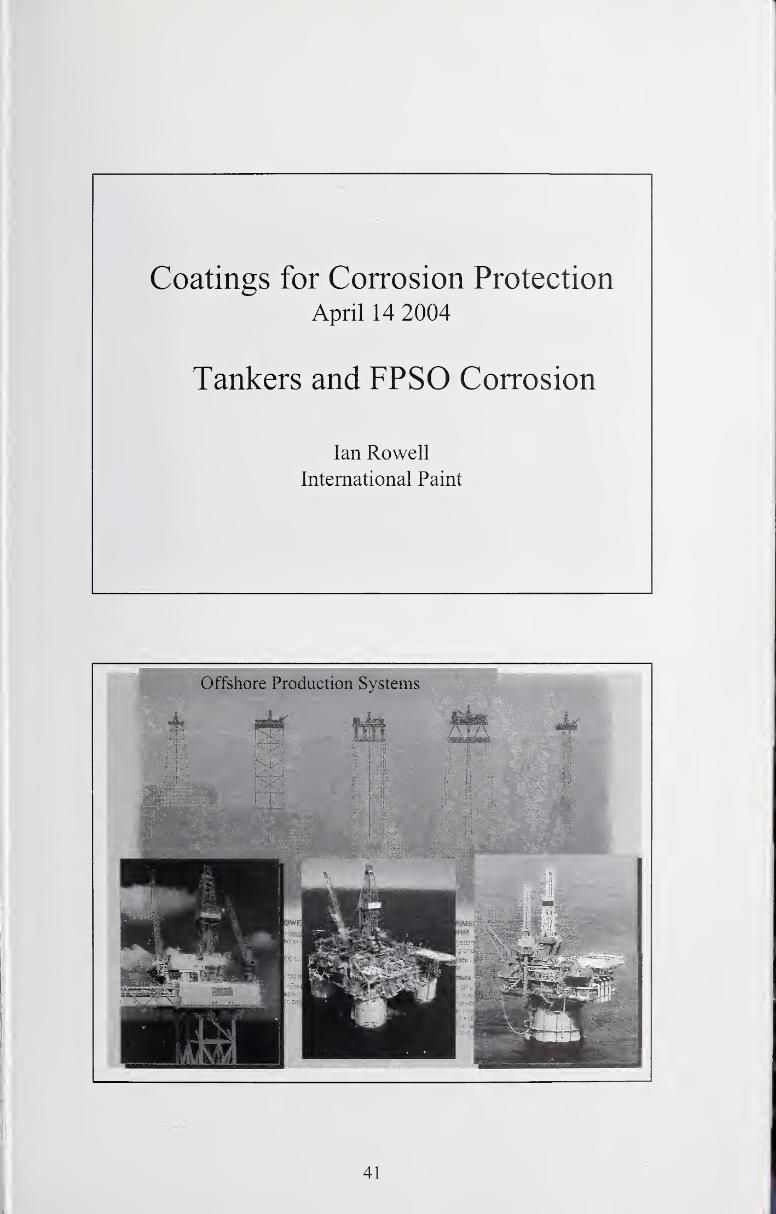
Coatings for Corrosion Protection
April 14 2004
Tankers and FPSO Corrosion
Ian Rowell
International Paint
Offshore Production Systems
41
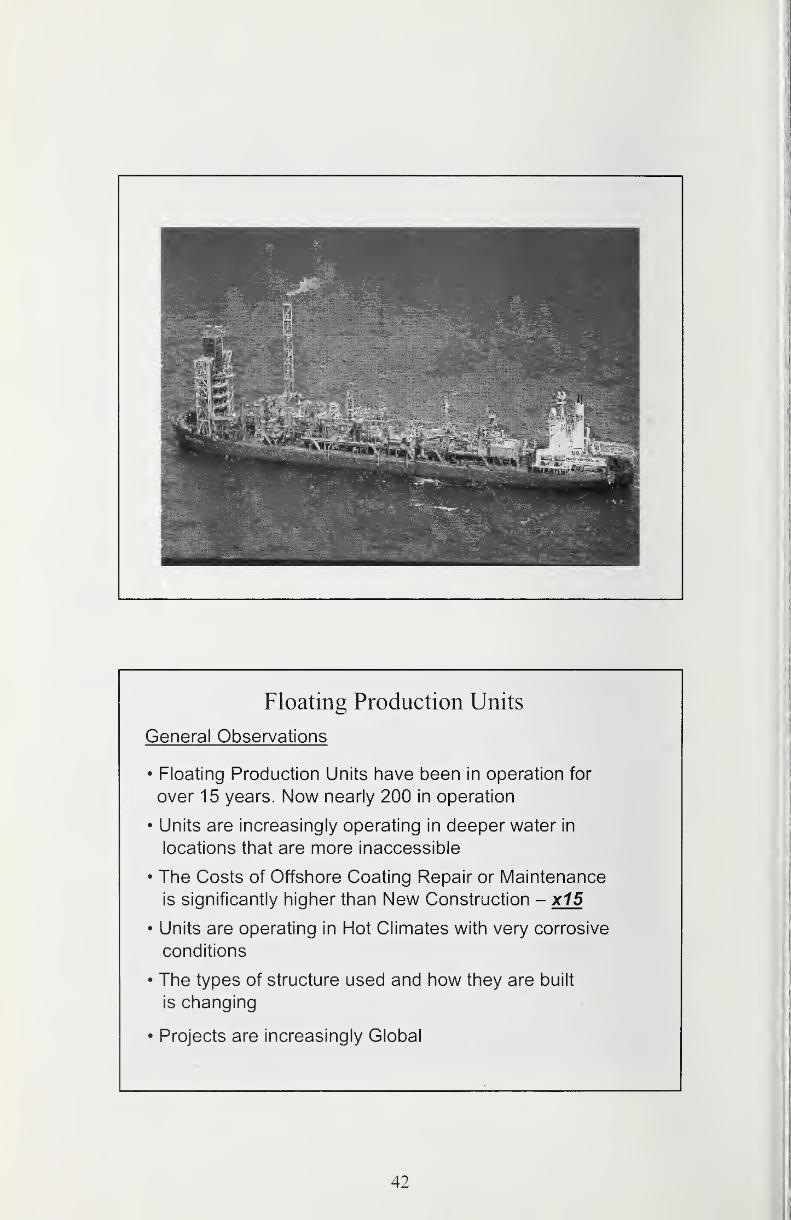
Floating Production Units
General Observations
• Floating Production Units have been in operation for
over 15 years. Now nearly 200 in operation
• Units are increasingly operating in deeper water in
locations that are more inaccessible
• The Costs of Offshore Coating Repair or Maintenance
is significantly higher than New Construction - x15
• Units are operating in Hot Climates with very corrosive
conditions
• The types of structure used and how they are built
is changing
• Projects are increasingly Global
42
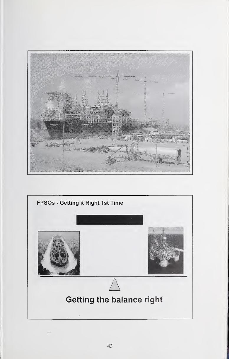
FPSOs - Getting it Right 1st Time
Getting the balance right
43
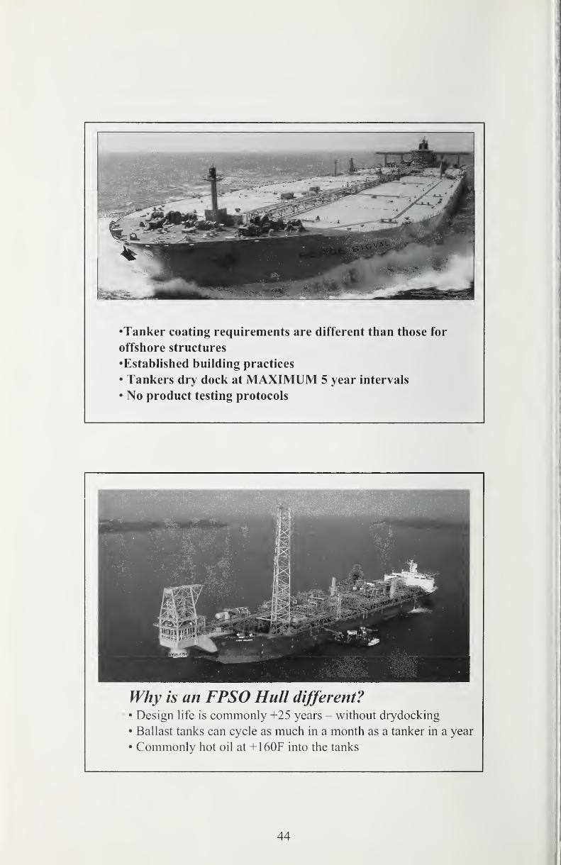
•Tanker coating requirements are different than those for
offshore structures
•Established building practices
• Tankers dry dock at MAXIMUM 5 year intervals
• No product testing protocols
Why is an FPSO Hull different?• Design life is commonly +25 years - without drydocking
• Ballast tanks can cycle as much in a month as a tanker in a year
• Commonly hot oil at +160F into the tanks
44
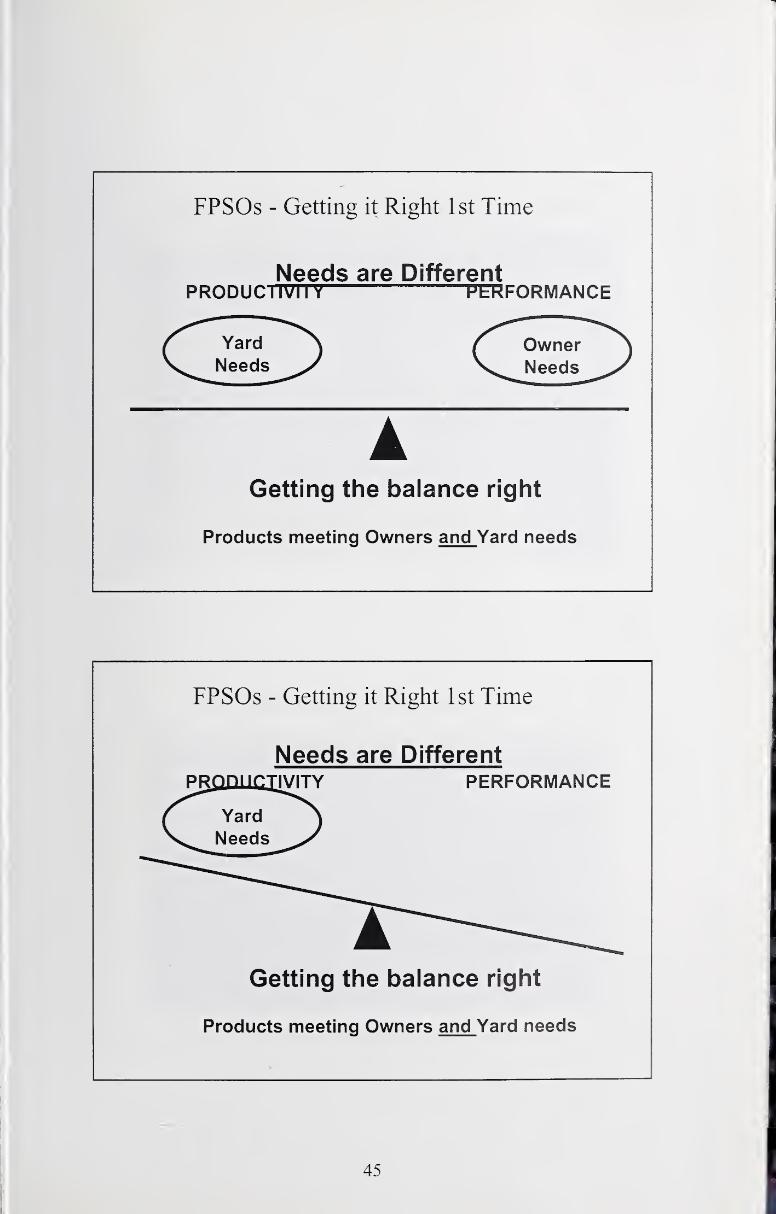
FPSOs - Getting it Right 1st Time
Needs are DifferentPRODUCIIVII Y PERFORMANCE
Getting the balance right
Products meeting Owners and Yard needs
FPSOs - Getting it Right 1st Time
Needs are Different
Getting the balance right
Products meeting Owners and Yard needs
45
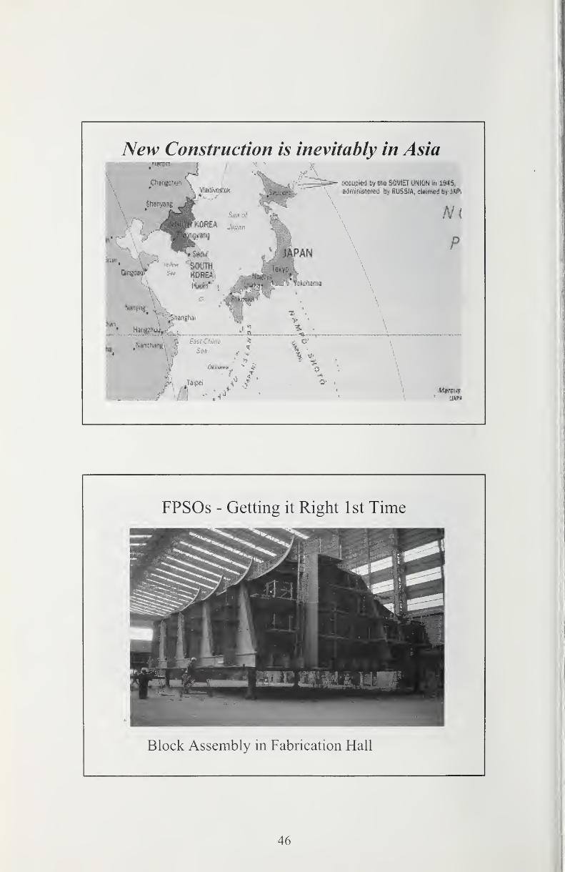
New Construction is inevitably in Asia
~=ri^ L-Ki^ \ti mt SOVIETmm hi i94S,
am
FPSOs - Getting it Right 1st Time
Block Assembly in Fabrication Hall
46
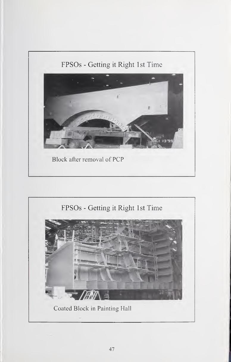
FPSOs - Getting it Right 1st Time
Block after removal of PCP
FPSOs - Getting it Right 1st Time
Coated Block in Painting Hall
47
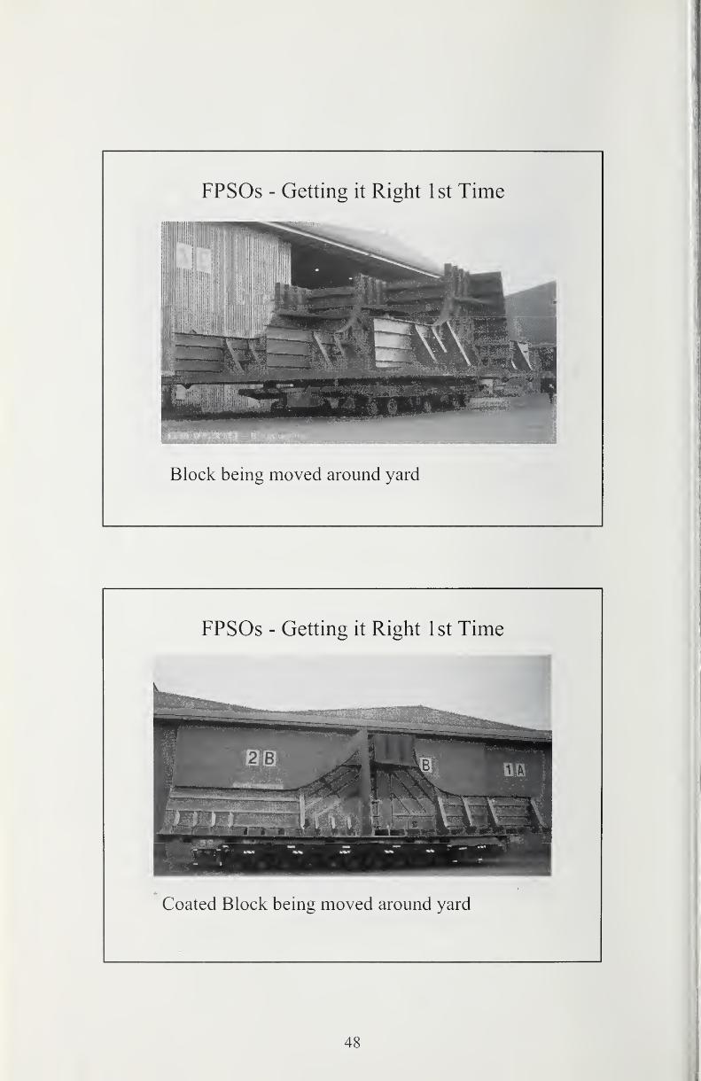
i
FPSOs - Getting it Right 1st Time
Block being moved around yard
FPSOs - Getting it Right 1st Time
Coated Block being moved around yard
48
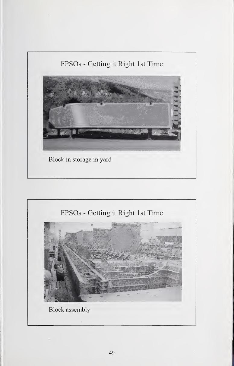
FPSOs - Getting it Right 1st Time
Block in storage in yard
FPSOs - Getting it Right 1st Time
Block assembly
49
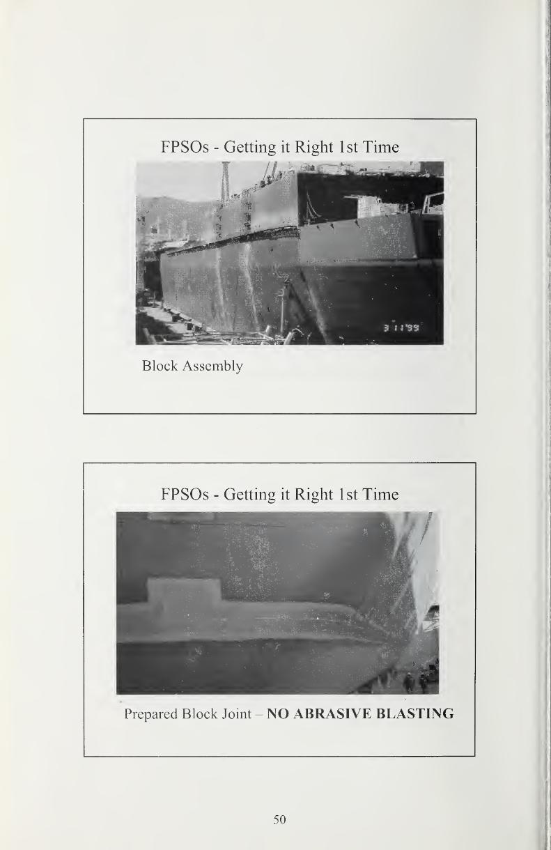
FPSOs - Getting it Right 1st Time
Block Assembly
FPSOs - Getting it Right 1st Time
Prepared Block Joint - NO ABRASIVE BLASTING
50
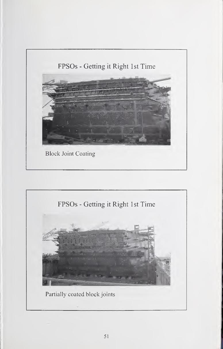
FPSOs - Getting it Right 1st Time
Partially coated block joints
51
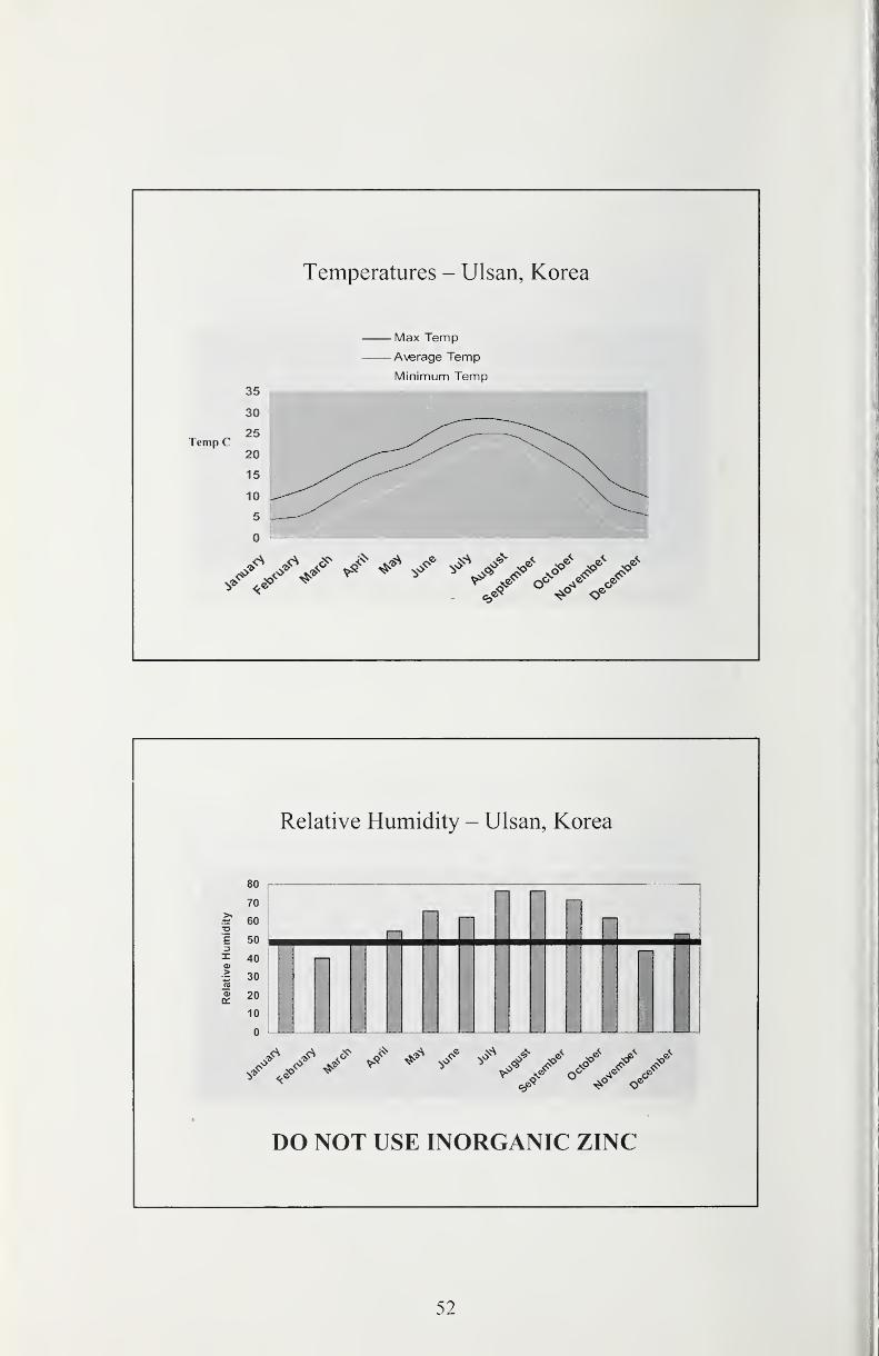
Temperatures - Ulsan, Korea
Max Temp
Average Temp
Minimum Temp35
30
Relative Humidity - Ulsan, Korea
on
70
^ 60a1 50 13^ 40o~ 30(0
^ 20
10
n
DO NOT USE INORGANIC ZINC
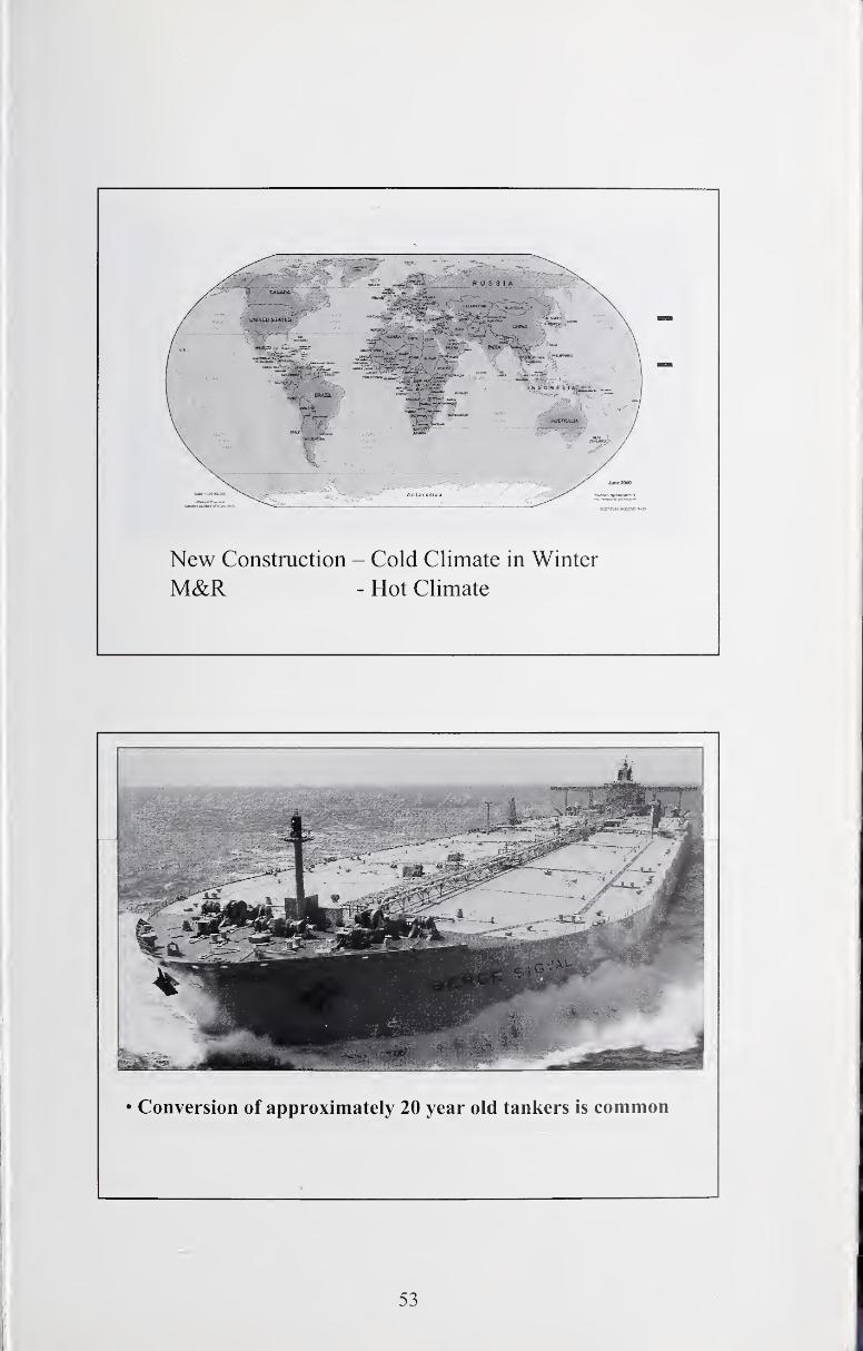
New Construction - Cold Climate in Winter
M&R - Hot Climate
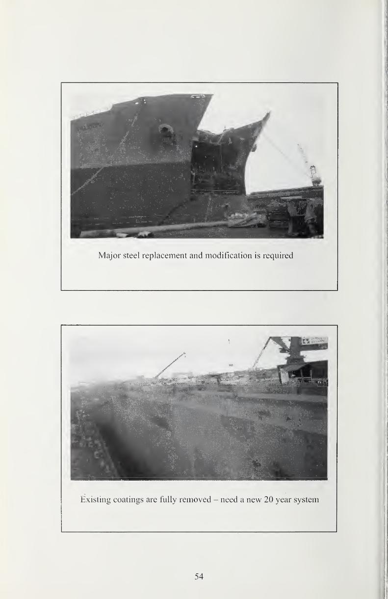
Existing coatings are fully removed - need a new 20 year system
54
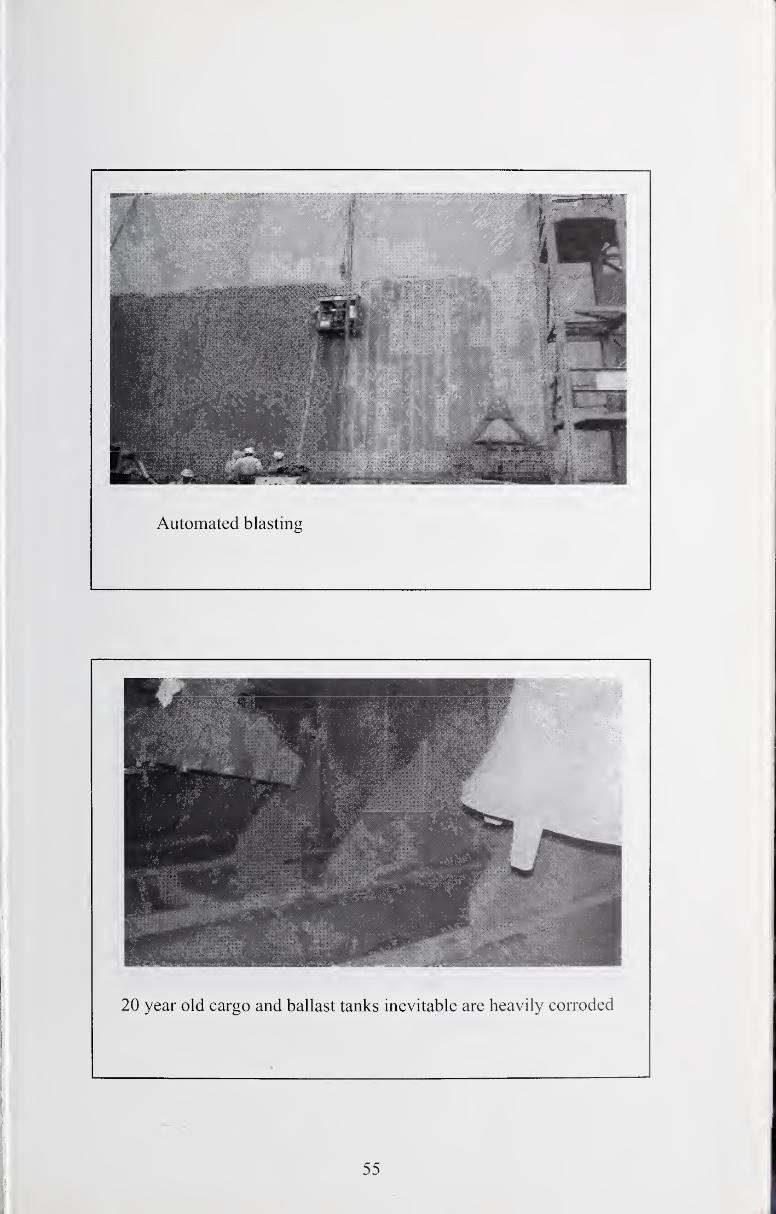
Automated blasting
20 year old cargo and ballast tanks inevitable are heavily corroded
55
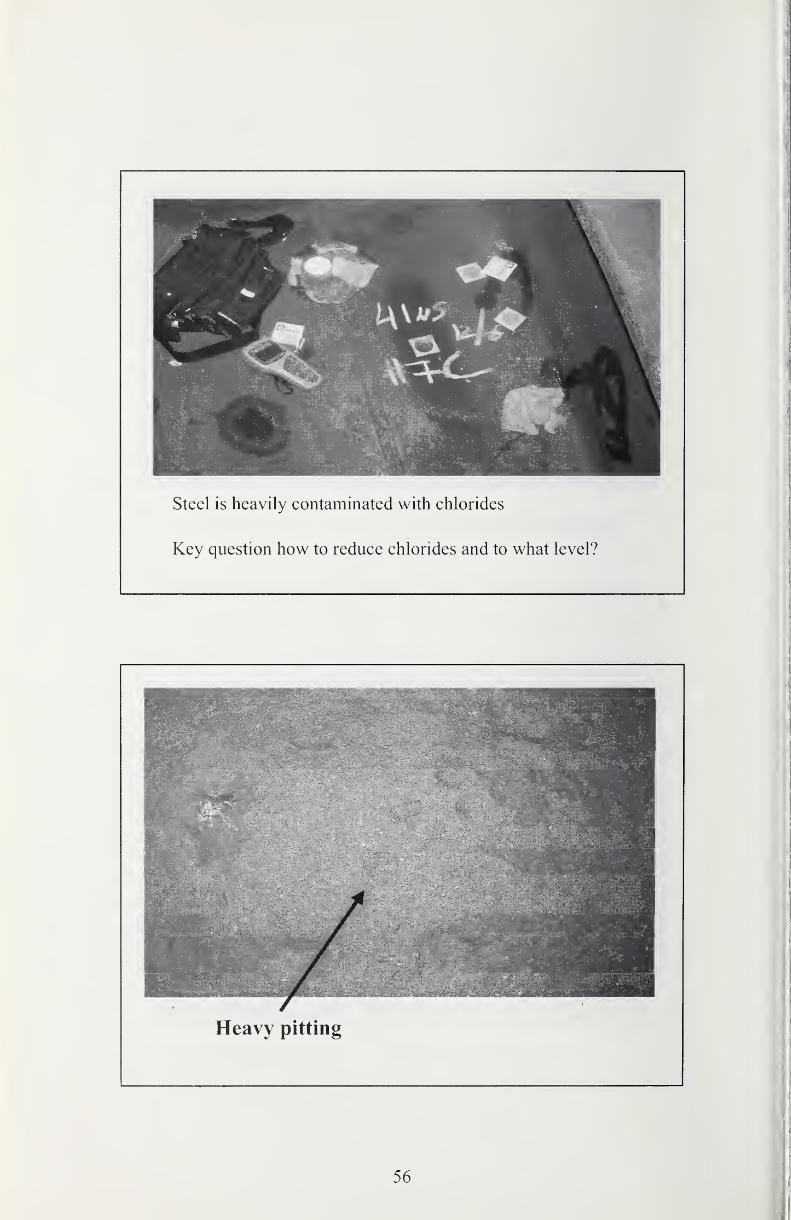
Steel is heavily contaminated with chlorides
Key question how to reduce chlorides and to what level?
Heavy pitting
56
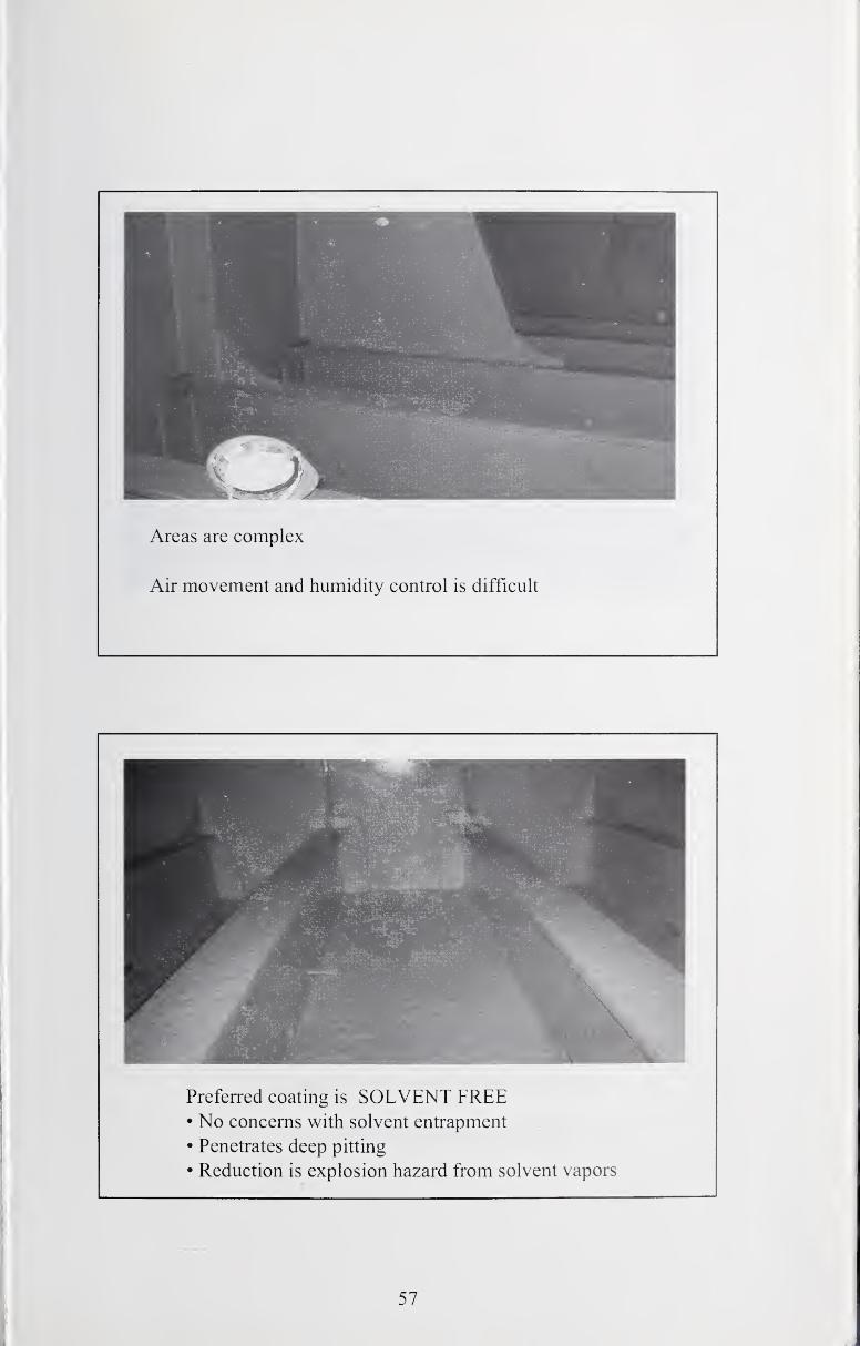
Areas are complex
Air movement and humidity control is difficult
Preferred coating is SOLVENT FREE• No concerns with solvent entrapment
• Penetrates deep pitting
• Reduction is explosion hazard from solvent vapors
57
Yard Product - New Construction
Multi Purpose
- Ballast,Cargo & Slop Tanks
- Underwater Hull
- Over Zinc Primer as build coat
- Decks
Fast Recoat, Rapid Handling
Long Maximum Recoat
Low Temperature Cure
Not dependant on humidity
58
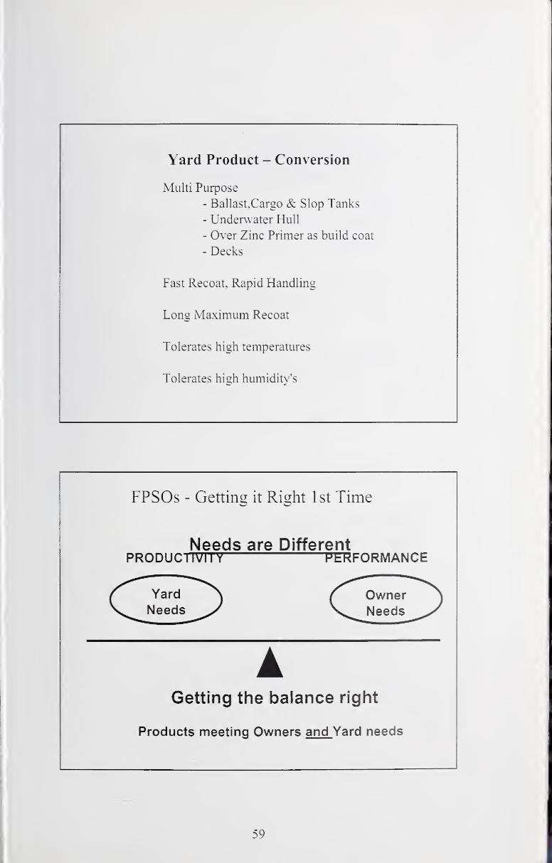
Yard Product - Conversion
Multi Purpose
- Ballast.Cargo & Slop Tanks
- Underwater Hull
- Over Zinc Primer as build coat
- Decks
Fast Recoat, Rapid Handling
Long Maximum Recoat
Tolerates high temperatures
Tolerates high humidity's
FPSOs - Getting it Right 1st Time
Needs are DifferentPRODUCIIVII Y PERFORMANCE
Yard
Needs
AGetting the balance right
Products meeting Owners and Yard needs
59
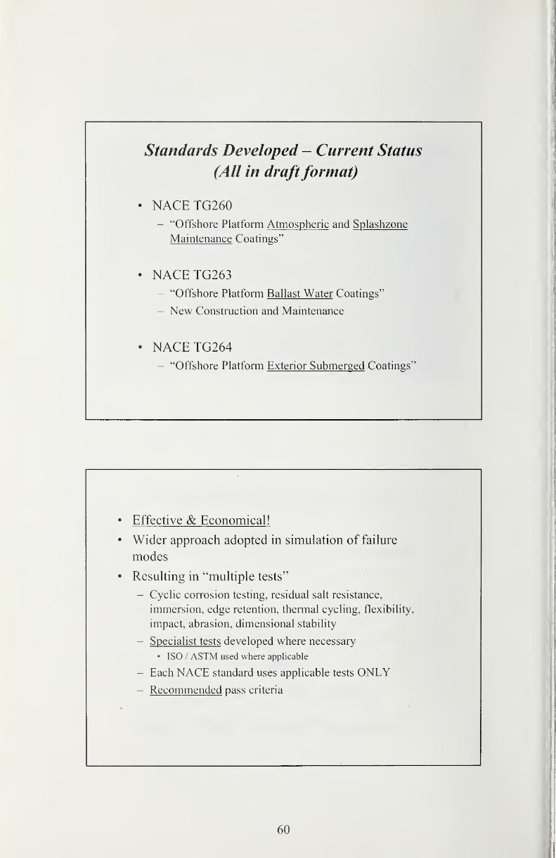
Standards Developed - Current Status
(All in draftformat)
NACETG260- "Offshore Platform Atmospheric and Splashzone
Maintenance Coatings"
NACETG263- "Offshore Platform Ballast Water Coatings"
- New Construction and Maintenance
NACE TG264- "Offshore Platform Exterior Submerged Coatings"
• Effective & Economical!
• Wider approach adopted in simulation of failure
modes
• Resulting in "multiple tests"
- Cyclic corrosion testing, residual salt resistance,
immersion, edge retention, thermal cycling, flexibility,
impact, abrasion, dimensional stability
- Specialist tests developed where necessary
• ISO / ASTM used where applicable
- Each NACE standard uses applicable tests ONLY- Recommended pass criteria
60
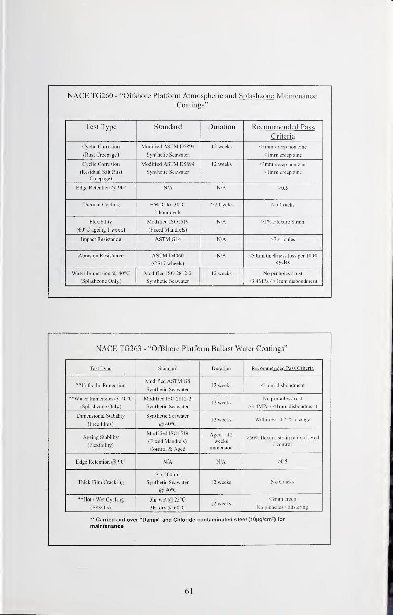
NACE TG260 - "Offshore Platform Atmospheric and Splashzone Maintenance
Coatings"
Test Type Standard Duration Recommended Pass
Criteria
Cyclic Corrosion
(Rust Creepage)
Modified ASTM D5894
Synthetic Seawater
12 weeks <3mm creep non zinc
<lmm creep zinc
Cyclic Corrosion
(Residual Salt Rust
Creepage)
Modified ASTM D5894
Synthetic Seawater
12 weeks <3mm creep non zinc
<lmm creep zinc
Edge Retention (a) 90° N/A N/A >0.5
Thermal Cycling +60°C to -30°C
2 hour cycle
252 Cycles No Cracks
Flexibility
(60°C ageing 1 week)
Modified IS01519
(Fixed Mandrels)
N/A >1% Flexure Strain
Impact Resistance ASTM G14 N/A >3.4 joules
Abrasion Resistance ASTM D4060
(CS17 wheels)
N/A <50nm thickness loss per 1000
cycles
Water Immersion @ 40°C
(Splashzone Only)
Modified ISO 2812-2
Synthetic Seawater
12 weeks No pinholes / rust
>3.4MPa / <lmm disbondment
NACE TG263 - "Offshore Platform Ballast Water Coatings"
Test Type Standard Duration Recommended Pass Criteria
**Cathodic ProtectionModified ASTM G8
Synthetic Seawater12 weeks <lmm disbondment
**Water Immersion @ 40°C
(Splashzone Only)
Modified ISO 2812-2
Synthetic Seawater12 weeks
No pinholes / rust
>3.4MPa / <lmm disbondment
Dimensional Stability
(Free films)
Synthetic Seawater
@40°C12 weeks Within +/- 0.75% change
Ageing Stability
(Flexibility)
Modified ISO 15 19
(Fixed Mandrels)
Control & Aged
Aged= 12
weeks
immersion
>50% flexure strain ratio of aged
/ control
Edge Retention @ 90° N/A N/A >0.5
Thick Film Cracking
3 X 500nm
Synthetic Seawater
@40°C
12 weeks No Cracks
**Hot / Wet Cycling
(FPSO's)
3hr wet @ 23°C
3hr dry @ 60°C12 weeks
<3miTi creep
No pinholes / blistering
** Carried out over "Damp" and Chloride contaminated steel (lOng/cm^) for
maintenance
61
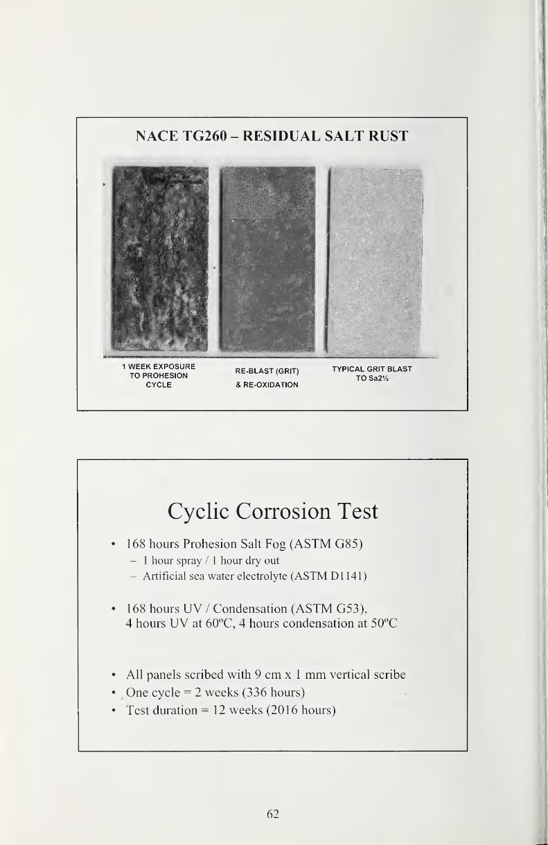
NACE TG260 - RESIDUAL SALT RUST
Cyclic Corrosion Test
• 168 hours Prohesion Salt Fog (ASTM G85)- 1 hour spray / 1 hour dry out
- Artificial sea water electrolyte (ASTM Dl 141)
• 1 68 hours UV / Condensation (ASTM G53),
4 hours UV at 60°C, 4 hours condensation at 50°C
• All panels scribed with 9 cm x 1 mm vertical scribe
• One cycle = 2 weeks (336 hours)
• Test duration = 12 weeks (2016 hours)
62
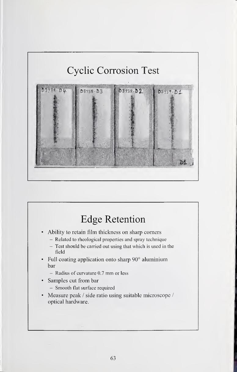
Cyclic Corrosion Test
Edge Retention
• Ability to retain film thickness on sharp comers
- Related to rheological properties and spray technique
- Test should be carried out using that which is used in the
field
• Full coating application onto sharp 90° aluminium
bar
- Radius of curvature 0.7 mm or less
• Samples cut from bar
- Smooth flat surface required
• Measure peak / side ratio using suitable microscope /
optical hardware.
63
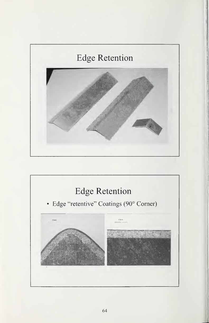
Edge Retention
Edge Retention
• Edge "retentive" Coatings (90° Comer)
OBmni 0.5mm
64
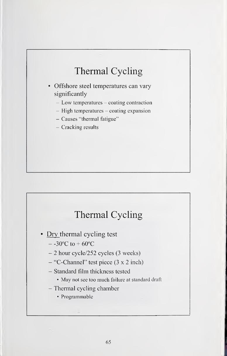
Thermal Cycling
• Offshore steel temperatures can vary
significantly
- Low temperatures - coating contraction
- High temperatures - coating expansion
- Causes "thermal fatigue"
- Cracking results
Thermal Cycling
• Dry thermal cycling test
- to + 60^C
- 2 hour cycle/252 cycles (3 weeks)
- "C-Channel" test piece (3x2 inch)
- Standard film thickness tested
• May not see too much failure at standard draft
- Thermal cycling chamber
• Programmable
65
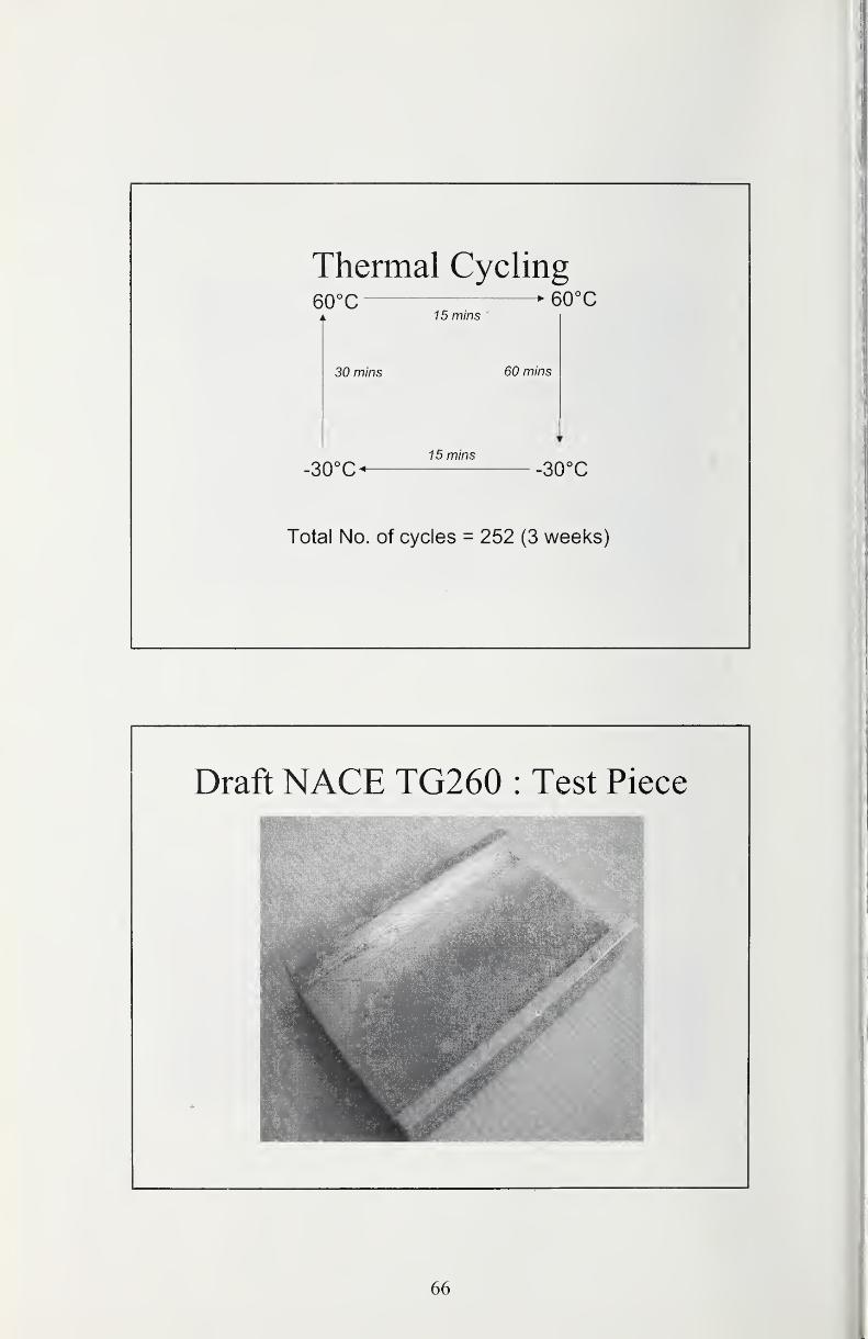
Thermal Cycling60°C ^ 60°C
7 5 mins
30 mins 60 mins
15 mins
30°C< -SOX
Total No. of cycles = 252 (3 weeks)
Draft NACE TG260 : Test Piece
66

Cyclic Corrosion Test
• Draft ISO 20340
- 72 hours UV/Condensation (ASTM G53),
4 hours V at 60°C, 4 hours condensation at 50°C
- 72 hours Neutral Salt Fog (ISO 7253)
• 5% Sodium Chloride electrolyte
- 24 hours freeze at -20°C (or optional +23°C)
• One cycle = 1 week (168 hours)
• Test duration = 25 weeks (4200 hours) .
• Consider freeze as being the more appropriate choice - stress
ISO 20340 (4,200hrs) without Freeze
Photo no. L Panels after Cyclic i-all spray / UVA test
7.4 mm creep 7.2 mm creep 7.4 mm creep
67
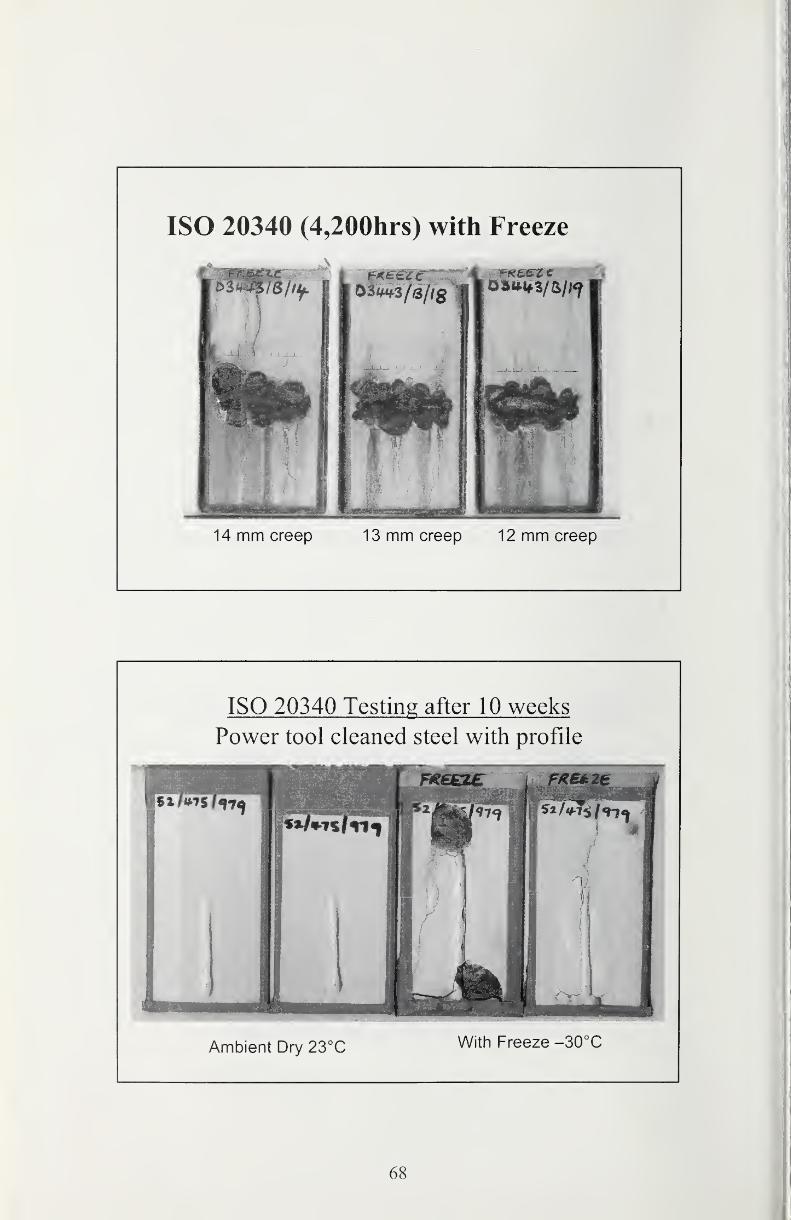
ISO 20340 (4,200hrs) with Freeze
14 mm creep 13 mm creep 12 mm creep
ISO 20340 Testing after 10 weeks
Power tool cleaned steel with profile
Ambient Dry 23°C With Freeze -SOX
68
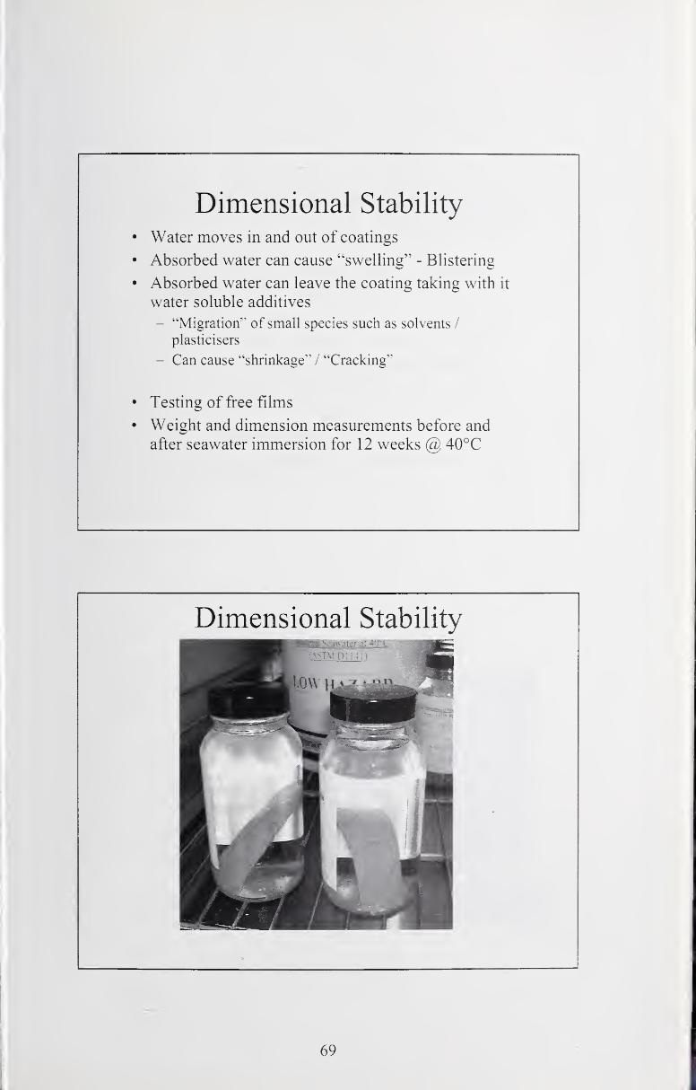
Dimensional Stability
Water moves in and out of coatings
Absorbed water can cause "swelling" - Blistering
Absorbed water can leave the coating taking with it
water soluble additives
- "Migration"" of small species such as solvents /
plasticisers
- Can cause "shrinkage" / "Cracking"
Testing of free films
Weight and dimension measurements before and
after seawater immersion for 12 weeks (5) 40°C
Dimensional Stability
69

Cathodic Disbondment Test (ISO 1571 1)
• Defines two methods
- Method A Impressed Current (-1.050 volts)
- *MethodB Sacrificial Zinc Anode (-1.050 volts)
• Electrolyte
- Artificial seawater or natural seawater
- Ambient temperature (23 °C)
- Testing required to 60°C
• Test Duration = 6 months
*Note : Method B is identical to SIVIT 97
Global Assurance of Product Quality
How can you get
assurance of product
performance ?????
• Life expectancy is
derived
from performance during
the testing program
• Paint systems are
tested to develop a
performance
profile
• Paint formulations are
easy to change
70
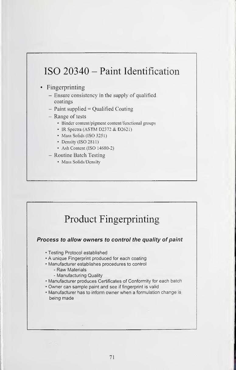
ISO 20340 - Paint Identification
• Fingerprinting
- Ensure consistency in the supply of qualified
coatings
- Paint supplied = Qualified Coating
- Range of tests
• Binder content/pigment content/functional groups
• IR Spectra (ASTMD2372&D2621)• Mass Solids (ISO 3251)
• Density (ISO 2811)
• Ash Content (ISO 14680-2)
- Routine Batch Testing
• Mass Solids/Density
Product Fingerprinting
Process to allow owners to control the quality of paint
• Testing Protocol established
• A unique Fingerprint produced for each coating
• Manufacturer establishes procedures to control
- Raw Materials
- Manufacturing Quality
• Manufacturer produces Certificates of Conformity for each batch
• Owner can sample paint and see if fingerprint is valid
• Manufacturer has to inform owner when a formulation change is
being made
71
Inspection and Repair of Coatings
Rogest W. Dively
EDG & Associates, Inc.
PO Box 320478Cocoa Beach, FL 32932-0478
Abstract
From the "birth" in the laboratory to manufacture, application and service use,
inspection and repair protocols must be invoked to ensure optimum coating
system performance. This theme paper reviews current practices and suggests
broad areas of research efforts to improve the art. Because of the diverse nature
of coating chemistries in use today, the focus will be directed to issues that are
common to most of the available technologies. Because of the economicconsiderations associated with the repair process, a review of the major issues to
address in the maintenance decision-making process is provided.
Introduction
The ultimate performance of coatings used for corrosion protection can be traced
to the successful implementation of the following processes:
1. Formulation
2. Performance testing of new formulations
3. Manufacture
4. Transport and Storage
5. Initial system installation and inspection
6. In service inspection and repair
Given the large scope inherent in the processes described above, this themepaper assumes that coating materials have been properly formulated, screened
for performance in the intended corrosive environment, and properly
manufactured and delivered to the project site. Additionally, it is assumed that
the correct materials and procedures have been selected for the intended service
in the form technical and administrative specifications prepared by an
engineering agency.
Given the assumptions mentioned above, inspection and repair of coating
systems will be reviewed and opportunities for R&D initiatives to improve these
processes will be identified. It should be understood that the term "inspection"
72
actually refers to two distinct processes that have different foci and prerequisite
skills:
• in-process Inspection: The in-process inspector is responsible for
ensuring that the coating system is installed in accordance with Project
specifications. The in-process inspector conducts various tests on
equipment, prepared surfaces and the applied coating film that establishes
conformance to industry standards (typically consensus standards).
Installation contractor's personnel, owner's personnel, "third-party"
organizations, or a combination may perform the in-process inspection
process. Part of the installation process may involve repairs to the system
damaged by other trades or during the course of destructive testing.
• In-service Inspection: The in-service inspector is responsible for
identifying the extent and degree of system deterioration (in relation to the
system's ability to perform its intended function), identify "premature"
failures and evaluate the system for three repair options. The three repair
options are:
o Touch-up: Addressing isolated failures of the installed system by
the application of a repair system (that may or may not be the sameas the installed system).
o Refresh: Involves the combination of touch-up, followed by the
application of a new topcoat. The existing system must be
evaluated for its ability to receive the new topcoat.
o Restore: Involves the complete removal of the existing system and
the installation of a new system (not necessarily the same as the
existing system).
The in-service inspection process carries with it a strong economic element.
Repairs to existing coatings are typically more complicated and expensive than
original installation. This is particularly true in terms of operating facilities, as the
repair process may significantly impact the revenue stream generated by these
facilities. Also, existing accounting system procedures penalize owners in terms
of treating maintenance expenditures.
73
In-Process Inspection
The in-process inspector is often assigned a variety of responsibilities in a
coating project. These duties may range from strictly addressing inspection
issues to assumption of traditionally project manager duties. Bearing in mind that
many maintenance projects encompass more than the application of coatings,
the in-process inspector may have to assume responsibility or work closely with
other personnel (welding inspectors, QA/QC, engineers, operational personnel,
etc.). Generally, the in-process inspector is responsible for:
• Preliminary inspection responsibilities
• Inspection of preexisting conditions
• Inspection of surface preparation
• Inspection of mixing, thinning and coating application
• Post-application inspection
• Documentation and reporting
Preliminary Inspection Responsibilities
Depending on the particular project, the inspector may be tasked with a variety of
actions prior to the commencement of work, including:
• Reading and understanding the project specification
• Reviewing drawings, reports, plans, and other project documentation
• Reviewing submittals from the contractor such as product data sheets,
MSDSs, schedules, QA/QC plans, safety plans, etc.
• Reviewing reports, such as inspection reports from fabrication shops.
• Reviewing modifications of the contract
• Attendance at the pre-job conference
• Inspection of jobsite
• Inspection of equipment
The actual extent of the in-process inspector's involvement in these preliminary
actions is solely a function of the of individual project management organization.
In fact, an in-process inspector may not become involved until the coating
application contractor has been mobilized and has started the work. Conversely,
the in-process inspector may be given responsibilities beyond strictly coating
inspection, especially in cases where the size of the project restricts the
assignment of a full-time project manager/engineer.
74
At this point, it behooves us to view the in-process inspector's role in light of the
project as a whole and question the feasibility and desirability of involving the
inspector in all of the actions listed above.
The project specification refers to the technical requirements of the coating
project. The overall project is guided by a contract, typically between the Ownerand Contractor. The contract consists of terms and condition, specifications,
drawings and a signed agreement. The collection of all these elements is
commonly referred to as the Project Manual and is a legally binding documentbetween the signatories. The in-process inspector's role is primarily to ensure
the technical requirements are met and not necessarily be the interpreter of the
intent, if there is any disagreement or conflict. Nor is the in-process inspector
always qualified to pass judgment on submittals, change orders, reports andmodifications to the contract. This is especially true if coatings represent only a
portion of the specified work. Although an in-process inspector may be capable
of such actions by virtue of accumulated experience, in-process inspector
training programs may not necessarily provide sufficient training in this area.
The inspection of the Jobsite and equipment may also be problematic. The in-
process inspector may not be qualified to assess the conditions observed and
may lack the authority (other than reporting) to act on any perceived deficiencies.
In most contracts the application contractor is responsible for safety, quality of
finished product, productivity, and selection of means and methods to meetspecified requirements. The use of an in-process inspector (especially third party
inspection) in areas other than assuring specification compliance may tend to
blur the distinction between addressing technical requirements and evaluating
the productivity of the contractor. In any event, the in-process coating inspector
now assumes at least partial liability in the event of a coating failure or jobsite
accident.^
There are numerous consensus standards and guides for defining the training,
experience and responsibilities of in-process coating inspectors. ^'^ There are also
several organizations that train and certify in-process coating inspectors,
including:
• NACE International: After three training courses (each with an
examination) and a peer review, in-process inspectors can attain certified
status. ^° This program is the largest and most widely recognized
certification body and extends internationally.
• The Society for Protective Coatings (SSPC): After a five-day training
course and successful examination in-process inspectors can be certified
as a NAVSEA Basic Painting Inspector, qualifying the inspector to perform
quality assurance functions on U.S. Navy painting projects.
• ACQPA/FROSIO Inspector's Certification: Certifies in-process inspectors
to Norwegian standards.
75

In-process coating inspection is viewed as a career ladder for painters capable of
attaining the required training and certification. In the U.S., coating inspection for
the most part represents seasonal work centering on the maintenance cycles of
the industries affected. Third party inspection firms depend on a relatively limited
pool of people and permanent employment with these firms is not the norm.
Specifying bodies tend to focus on the use of certified inspectors, often ignoring
the utility of those inspectors still in the process of certification. NACEinternational has trained approximately 10,000 people at the basic level and has
certified approximately 2,000 inspectors. Active certified inspectors (those
actually performing roles in coating projects) probably number around 1,000 -
1,200. There are few, if any, studies addressing the requirements for a
workforce of third party inspectors to support the coating industry. Because of
the inherent transitory nature of the work, in-process coating inspectors have not
generated a "critical mass" in terms of recognition as separate professional
cadre.
While anecdotal evidence exists to justify the costs of in-process inspection, the
industry has developed few business models to objectively quantify the benefits.
Coating inspection has been attributed as a major factor in reducing premature
coating failures, by raising awareness of the need to address the factors
necessary for effective coating installation. It appears that development of a
more professional applicator workforce is being initiated, especially in
government funded coatings projects. Raising the level of training of the person
accomplishing surface preparation and coating application actions would appear
to be advantageous to the industry as a whole. How these initiatives would affect
in-process inspection remains unknown.
In terms of potential R&D efforts, the following broad areas should be addressed:
Inspection of Preexisting Conditions
The presence of certain contaminants and fabrication conditions may have
adverse affects on the ability of a coating system to perform. These are best
addressed before surface preparation activities, as the specified methods maynot remove detrimental conditions. The in-process inspector's role involves
investigation of the following conditions:
1 . Presence of surface contaminants, both visible and non-visible.
2. Presence of fabrication and design defects and issues.
Surface contamination and fabrication issues are dependent on the substrate
(especially when contrasting steel and concrete) and generally include
consideration of the following:
• Surface pH
• Soluble salts
• Chlorides
76
Ferrous ions
• Sulfate
• Grease or oil
• Weak surface layers
• Residuals from chemical paint removal operations
• Dust
• Welds and associated weld spatter
• Difficult to access configurations
There exist standards and guidelines to perform testing for the presence of
contaminants and the existence of other potentially deleterious conditions.
Professional organizations have active committees addressing the needs of
industry in developing new standards as the result of technological progress in
the field of protective coatings. These organizations include:
• NACE International (NACE)
• The Society for Protective Coatings (SSPC)
• American Concrete Institute (AC I)
• International Concrete Repair Institute (ICRI)
• American Water Works Association (AWWA)
• American Society of Testing and Materials (ASTM)
• International Organization for Standardization (ISO)
However, there remain questions concerning the implications of the results of
such testing, especially when considering the most often cited moieties in relation
to premature failure, chlorides and residual dust (generated either during surface
preparation actions or as the result of outside influences).
Various agencies have published maximum allowable concentrations of
contaminants. It is presently unclear what rationales was used to establish these
limits and whether or not there are differences in susceptibility of failure with
different coating formulations. Finding potentially deleterious contaminants such
as chloride (ubiquitous in the marine environment) is not surprising. Attaching
the presence of these contaminants to specific failure modes is lacking, although
generally speaking, osmotic effects are usually fingered as the culprit. The
accuracy and precision of the various detection methods have not been
emphasized generally. Efforts to remove such contamination can significantly
increase the cost of a coating project.
77
Industry has responded to the perceived need to deal with soluble salts
(especially chlorides) by the introduction of materials to sequester or otherwise
render them innocuous to coating performance.
Dealing with design and fabrication issues, such as welds, sharp edges, anddifficult-to-coat surfaces are, to this day, difficult to deal with because of the
interaction of various trades and the emphasis on the most efficient structural
design (which may not be compatible with optimum coating conditions).
Typically, these issues are only addressed in more severe services, such as
immersion.
Inspection of Surface Preparation
Once preexisting conditions are evaluated and dealt with, the coating contractor
must prepare the surface to receive the specified coating materials. Generally,
these actions involve the input of energy and may be both expensive and time
consuming. The most studied substrate has been steel, but interest in the
coating of concrete has initiated efforts in developing standards in this area. Dry
abrasive blasting has been the method of choice for decades. Environmental
and worker health and safety concerns have spurred the introduction of moreadvanced processes, such as high and ultrahigh water jetting. Evaluating
conditions of the prepared surface is covered by a multitude of standards.^^'^^
Inspection of surface preparation on steel substrates focuses on two attributes:
1 . Removal of contaminants that interfere with coating adhesion or that might
induce premature failure.
2. Roughening the surface to promote coating adhesion (increasing the
number of potentially reactive sites) often referred to as surface profile.
Inspection of surface preparation on concrete focuses on three attributes:
1 . Removal of contaminants that interfere with coating adhesion or that might
induce premature failure.
2. Roughening the surface to promote coating adhesion (increasing the
number of potentially reactive sites) often referred to as surface profile.
3. Removal of weak surface layers that cannot support the stresses imparted
by the coating system.
Inspection of Mixing, Thinning, and Coating Application
Modern protective coatings represent highly complex chemical technologies
requiring specific knowledge for successful use. Coatings arrive at the jobsite in
an unassembled form, and typically require specialized processes and
equipment for effective application.
78
Economic considerations involving the loss of use of facilities is a strong driver in
the introduction of rapidly curing coating materials. Environmental and worker
health and safety are strong drivers in the introduction of materials with little or no
solvents (added to formulations for application efficiency). Both of these forces
have generated the development of "plural component" materials and application
technology that has taxed the ability of the in-process inspector to adequately
assure performance. In the past, mixing, thinning, application and cure of the
coating material involved hours or days, allowing for a fairly long period to assess
the adequacy of application. Technologies now exist where the mixing,
application and cure occurs in seconds. Whether the focus should be on
increased applicator sophistication or new inspection requirements is still being
debated.
Post-Application Inspection
After application, the coating system is evaluated in terms of specification
compliance in areas including:
• State of cure
• Dry film thickness
• Holiday (defect) detection
• Adhesive strength
• Appearance
Again, there are many standards covering these actions^^'^^, as well as active
committees that revise standards and initiate the development of new standards.
Documentation and Reporting
The in-process inspector generates a variety of reports on a daily, weekly and
as-required basis. In addition to documentation in terms of specification
compliance, these reports generally contribute to the success of the project by
highlighting:
• Instances of non-conformance that may require resolution by project
engineering or management personnel
• Objective determination of progress by the contractor
• Recommendations to improve project efficiency
• Coordinating the efforts of multiple parties in resolving disputes.
79
In-Service Inspection and Repair
The in-service inspection of coating systems (as well as other corrosion
protection systems) is initiated to determine the need for maintenance (repair).
The results of in-service inspection is invariably linked to maintenance budgets.
Thus, there is a continual striving for balance between two extremes: on the onehand, maintenance organizations desire long periods of time between initial
application and maintenance actions, conversely there is a point at which
relatively minor maintenance can significantly increase a system's service life.
Equitably resolving these extremes is difficult in practice. Prolonging intervals
between maintenance periods risks damage to the substrate being protected
(necessitating expense repair and replacement efforts). Performing maintenance
too early wastes limited resources. Coatings have been determined to be an
effective corrosion control strategy, and much emphasis in research focuses on
improvements to materials and processes used in initial installation. Less
attention has been given to the evaluation of existing systems to allow
economically sound decisions within the overall maintenance perspective.
Given the three basic repair options discussed above, maintenance planners
must determine:
• Is the existing system performing as expected? If not, what are the
reasons for either a system performing below or above expectations?
• Given an existing condition, how long can maintenance be postponed?
• Which option provides the most economic results
Most in-service inspections are prompted by the need for maintenance planning.
Typically, a "condition survey" is conducted to gain information on the:
• Extent of damage to the coating system
• Extent of deterioration to the protected substrate
• Flagging of unusual or unexpected conditions
The condition survey provides information on both the type of maintenance
required and on the scope (quantity) of work involved. Estimates of project costs
based on condition surveys are then incorporated into budget processes. A lack
of information on condition can lead to highly ineffective maintenance decisions.
The cost of the surveys can be substantial in large facilities or in widely dispersed
facilities where logistic costs become a significant factor.
There exists a large support infrastructure for the in-process inspector. In-
process inspectors have many tools to verify compliance with specified
standards. In-process inspectors, in most cases, also have the advantage of
well-defined criteria in terms of the standards being used.
80
The in-service inspector does not have comparable resources. In-service
inspectors are commonly owner's personnel in operational facilities without
specific knowledge of coatings technology. While consultants are available with
expertise, the inspectors used for in-service inspection are often those
specifically trained as in-process inspectors. It is generally perceived in the
industry that the in-process inspector (especially one that is certified) can be
used effectively during in-service inspection. This perception has several
potential weaknesses.
The in-process inspector deals primarily with well-defined industrial processes
(surface preparation and coating application), where the inspector may well have
been an applicator previously. A large part of the in-process inspector's job
revolves around effective communication with other project participants within a
structured organization with many support resources. Contrast this with in-
process inspection. The in-process inspector mainly deals with "things". The in-
process inspector must look at a wide variety of elements, from structural steel to
process equipment, and be able to assess their "condition". Most condition
assessments are made based on grading systems. The grading system mayincorporate just the condition of the coating or may include an assessment of the
substrate. There are few industry-wide standardized grading systems, and
where such systems exist (i.e., ABS, MMS), they are subject to debate as to the
meanings of each grade, especially when the grades are only given written
definitions.
The in-service inspector (or the agency using information gathered by the in-
service inspector), has to determine the viability of repairs involving touch-up and
refresh (touch-up and overcoat) operations. The operations are particularly
problematic because the ability of the existing system to receive such treatment
must be ascertained to avert potential failure. The ability of the system to receive
this treatment is a function of the modes of deterioration, specific coating
formulation chemistries, as well as the "structural integrity" of the existing coating.
The science associated with determining this ability is still in its infancy.
The in-service inspector is also challenged to ascertain the economically useful
remaining service life of an existing system and the consequences of loss of
substrate. This involves consideration of factors not normally addressed in
existing training programs, such as:
• Use of structural assessment protocols
• Implementation of economic models
• Risk assessment and management
• Evaluation of statistical deterioration models
81
• Consideration of alternate maintenance regimes
• Communication with engineering, programming, budgeting and
contracting personnel
The materials and processes for the repair of coatings rely almost entirely on
coatings formulated for application over blasted surfaces. The interaction of
these coatings when used in repair processes may be detrimental to otherwise
suitable existing systems, due to the stresses being imposed.
82
Summary
There exists a strong and active effort in the development of standards,
guidelines and practices to support industry efforts in advancing technology
development. This effort is accomplished by a variety of professional societies
using consensus-based review by the major players: contractors, manufacturers,
specifiers and owners. Major areas for R&D initiatives include:
Inspection of Coatings
• Conduct of cost/benefit analyses for coating inspection
• Elucidation of the mechanisms leading to premature failure of coating
systems, especially in the area of surface contaminants
• Establishing consistent metrics for limitation of contaminants
• Increased emphasis on developing tools for in-service inspection
• Elucidation of the mechanisms of deterioration of coatings in service and
the effects of this deterioration on remaining service life
• Establishing consistent metrics for evaluating coating in-service
• Developing procedures for inspecting application of rapid cure coating
systems
Repair of Coatings
• Elucidation of the parameters essential for effective, long-term repair of
coatings
• Development of tools to allow in-service inspector to quantify the
parameters essential for effective, long-term repair
• Establish metrics for the determination of remaining service life
• Develop economic models for aiding in the repair decision making process
• Investigating the need for materials specifically formulated for touch-up
and overcoat
83
References
1. Pinney, S.G., "Coating Inspection, What's Changed?", Corrosion 2000Paper # 0061 1 , NACE International, Houston TX
2. SSPC-QP 5, "Standard Procedures for Evaluating the Qualifications of
Coating and Lining Inspection Companies", The Society for Protective
Coatings, Pittsburgh, PA
3. ASTM D 5161, "Standard Guide for Specifying Inspection Requirements
for Coating and Lining Work (Metal Substrates)", American Society of
Testing and Materials, Philadelphia, PA
4. ASTM F 941, "Standard Practice for Inspection of Marine Surface
Preparation and Coating Application", American Society of Testing andMaterials, Philadelphia, PA
5. ASTM D 6237, "Standard Guide for Painting Inspectors (Concrete andMasonry Substrates)", American Society of Testing and Materials,
Philadelphia, PA
6. ASTM D 3276, "Standard Guide for Painting Inspectors (Metal
Substrates)", American Society of Testing and Materials, Philadelphia,
PA
7. Drisko, R.W., "Inspection of Contract Painting of Shore Facilities", NCELNo. 52-91-03, Navel Civil Engineering Laboratory, Port Hueneme, CA,
1990.
8. ASTM F 718, "Standard for Shipbuilders and Marine Paints and
Coatings Product/Procedure Data Sheet", American Society of Testing
and Materials, Philadelphia, PA
9. NACE RP0288, "Inspection of Linings on Steel and Concrete", NACEInternational, Houston, TX
10. http://www.nace.Org/nace/content/education/Certification/cip/CIPIndex.a
sp
1 1 . http://www.sspc.org/training/NBPI.html
12. http://www.acqpa.eom/uk/inspecteurs_uk.htm#pose1
13. ISO 8501-1, "Preparation of Substrates Before Application of Paints and
Related Products-Visual Assessment of Surface Cleanliness"
14. ISO 8502-1, "Preparation of Substrates Before Applications of Paints
and Related Products-Tests for Assessment of Surface Cleanliness:
Soluble Iron Products"
84
15. ISO 8502-2, "Preparation of Substrates Before Applications of Paints
and Related Products-Tests for the Assessment of Surface Cleanliness-
Laboratory Determination of Chloride on Cleaned Surfaces"
16. ISO 8502-3, "Preparation of Substrates Before Applications of Paints
and Related Products-Tests for the Assessment of Surface Cleanliness-
Assessment of Dust on Steel Surfaces Prepared for Painting (Pressure
Sensitive Tape Method)"
17. ISO 8502-4, "Preparation of Substrates Before Applications of Paints
and Related Products-Tests for the Assessment of Surface Cleanliness-
Guidance on Estimation of the Probability of Condensation Prior to Paint
Application"
18. ISO 8502-6, "Preparation of Substrates Before Applications of Paints
and Related Products-Tests for the Assessment of Surface Cleanliness-
Field Extraction of Water Soluble Salts (Dr. Bresle Method)"
19. ISO 8502-9, "Preparation of Substrates Before Applications of Paints
and Related Products-Tests for the Assessment of Surface Cleanliness-
Field Evaluation of Water Soluble Salts by Conductimetric Evaluation"
20. NACE RP0178, Fabrication Details, Surface Finish Requirements, and
Proper Design Considerations for Tanks and Vessels to Be Lined for
Immersion Service", NACE International, Houston, TX
21. ASTM E 377, "Standard Test Method for Measuring Humidity with
Psychrometer (The Measurement of Wet- and Dry-Bulb Temperatures)"
22. ASTM D 4262, "Standard Test Method for pH of Chemically Cleaned or
Etched Concrete Surfaces", American Society of Testing and Materials,
Philadelphia, PA
23. ASTM D 4285, "Standard Test Method for Indicating Oil or Water in
Compressed Air"
24. ASTM D 4920, "Standard Test Methods for Field Measurement of
Surface Profile of Blast Cleaned Steel"
25. NACE RP0287, "Field Measurement of Surface Profile of Abrasive Blast
Cleaned Steel Surfaces Using a Replica Tape", NACE International,
Houston, TX
26. Stachnik, R.V., "The Art and Science of Surface Profile Measurement",
Corrosion 2000 Paper # 00612, NACE International, Houston TX
27. ASTM D 4940, "Standard Test Method for Conducting Conductimetric
Analysis of Water Soluble Ionic Contamination of Blasting Abrasives",
American Society of Testing and Materials, Philadelphia, PA
85
28. ASTM D 5064, "Standard Practice for Conducting a Patch Test to
Assess Coating Compatibility", American Society of Testing andMaterials, Philadelphia, PA
29. ISO 8503-1,"Preparation of Substrates Before Application of Paints and
Related Products-Surface Roughness Characteristics of Blast-Cleaned
Steel Substrates-Comparator Procedure"
30. ISO 8503-2, "Preparation of Substrates Before Application of Paints andRelated Products-Surface Roughness Characteristics of Blast-Cleaned
Steel Substrates-Method for the Calibration of ISO Surface Profile
Comparators and for the Determination of Surface"
31. ISO 8503-4, "Preparation of Substrates Before Application of Paints and
Related Products-Surface Roughness Characteristics of Blast-Cleaned
Steel Substrates-Method for the Calibration of ISO Surface Profile
Comparators and for the Determination of Surface Profile"
32. ISO 8504-1, "Preparation of Substrates Before Application of Paints and
Related Products-Surface Preparation Methods-General Guidelines"
33. ISO 8504-2, "Preparation of Substrates Before Application of Paints and
Related Products-Surface Preparation Methods-Abrasive-Blast
Cleaning"
34. ISO 8504-3, "Preparation of Substrates Before Application of Paints and
Related Products-Surface Preparation Methods-Hand and Power Tool
Cleaning"
35. SSPC-AB 1, "Mineral and Slag Abrasives", The Society for Protective
Coatings, Pittsburgh, PA
36. SSPC-AB 2, "Cleanliness of Recycled Ferrous Metallic Abrasives", TheSociety for Protective Coatings, Pittsburgh, PA
37. SSPC-AB 3, "Newly Manufactured or Re-Manufactured Steel
Abrasives", The Society for Protective Coatings, Pittsburgh, PA
38. SSPC-Vis 1 , "Visual Standard for Abrasive Blast Cleaned Steel", TheSociety for Protective Coatings, Pittsburgh, PA
39. SSPC-Vis 3, "Visual Standard for Power and Hand Tool Cleaned Steel",
The Society for Protective Coatings, Pittsburgh, PA
40. SSPC-Vis 4, "Visual Reference Photographs for Steel Cleaned by Water
Jetting", The Society for Protective Coatings, Pittsburgh, PA
41. SSPC-SP 1, "Solvent Cleaning", The Society for Protective Coatings,
Pittsburgh, PA
86
42. SSPC-SP 2, "Hand Tool Cleaning", The Society for Protective Coatings,
Pittsburgh, PA
43. SSPC-SP 3, "Power Tool Cleaning", The Society for Protective
Coatings, Pittsburgh, PA
44. SSPC-SP 5, "White Metal Blast Cleaning", The Society for Protective
Coatings, Pittsburgh, PA
45. SSPC-SP 6, "Commercial Blast Cleaning", The Society for Protective
Coatings, Pittsburgh, PA
46. SSPC-SP 7, "Brush-Off Blast Cleaning", The Society for Protective
Coatings, Pittsburgh, PA
47. SSPC-SP 10, "Near-White Blast Cleaning", The Society for Protective
Coatings, Pittsburgh, PA
48. SSPC-SP 11, "Power Tool Cleaning to Bare Metal", The Society for
Protective Coatings, Pittsburgh, PA
49. SSPC-SP 12, "Surface Preparation and Cleaning of Steel and Other
Hard Materials by High- and Ultrahigh Pressure Water Jetting Prior to
Recoating", The Society for Protective Coatings, Pittsburgh, PA
50. SSPC-SP 13, "Surface Preparation of Concrete", The Society for
Protective Coatings, Pittsburgh, PA
51. SSPC-SP 14, "Industrial Blast Cleaning", The Society for Protective
Coatings, Pittsburgh, PA
52. ASTM D 4258, "Standard Practice for Surface Cleaning Concrete for
Coating", American Society of Testing and Materials, Philadelphia, PA
53. ASTM D 4258, "Standard Practice for Surface Cleaning Concrete for
Coating", American Society of Testing and Materials, Philadelphia, PA
54. ASTM D 4259, "Standard Practice for Abrading Concrete", American
Society of Testing and Materials, Philadelphia, PA
55. ASTM D 4260, "Standard Practice for Acid Etching Concrete", American
Society of Testing and Materials, Philadelphia, PA
56. ASTM D4261, "Standard Practice for Surface Cleaning Concrete Unit
Masonry for Coating", American Society of Testing and Materials,
Philadelphia, PA
57. ASTM D4262, "Standard Test Method for pH of Chemically Cleaned or
Etched Concrete Surfaces", American Society of Testing and Materials,
Philadelphia, PA
87
58. ASTM D 4263, "Standard Test Method for Indicating Moisture in
Concrete by the Plastic Sheet Method", American Society of Testing andMaterials, Philadelphia, PA
59. SSPC-TU 4, "Overcoating", The Society for Protective Coatings,
Pittsburgh, PA
60. ASTM D 4212, "Standard Test Method for Viscosity by Dip-Type
Viscosity Cups", American Society of Testing and Materials,
Philadelphia, PA
61. ASTM D 1186, "Standard Test Methods for Nondestructive
Measurement of Dry Film Thickness of Nonmagnetic Coatings Applied
to a Ferrous Base", American Society of Testing and Materials,
Philadelphia, PA
62. ASTM D 1212, "Standard Test Methods for Measurement of Wet Film
Thickness of Organic Coatings", American Society of Testing andMaterials, Philadelphia, PA
63. ASTM D 1400, "Standard Test Method for Nondestructive Measurementof Dry Film Thickness of Nonconductive Coatings Applied to a
Nonferrous Metal Base", American Society of Testing and Materials,
Philadelphia, PA
64. ASTM D 2197, "Standard Test Method for Adhesion of Organic Coatings
by Scrape Adhesion", American Society of Testing and Materials,
Philadelphia, PA
65. ASTM D 2240, "Standard Test Method for Rubber Property—DurometerHardness", American Society of Testing and Materials, Philadelphia, PA
66. ASTM D 2583, "Standard Test Method for Indentation Hardness of
Rigid Plastics by Means of a Barcol Impressor", American Society of
Testing and Materials, Philadelphia, PA
67. SSPC-PA2, "Measurement of Dry Coating Thickness with Magnetic
Gages", The Society for Protective Coatings, Pittsburgh, PA
68. ASTM D 3359, "Standard Test Methods for Measuring Adhesion by
Tape Test", American Society of Testing and Materials, Philadelphia, PA
69. ASTM D 3363, "Standard Test Method for Film Hardness by Pencil
Test", American Society of Testing and Materials, Philadelphia, PA
70. ASTM D 4138, "Standard Test Methods for Measurement of Dry Film
Thickness of Protective Coating Systems by Destructive Means".
American Society of Testing and Materials, Philadelphia, PA
88
71. ASTM D 4541, 'Standard Test Method for Pull-Off Strength of Coatings
Using Portable Adhesion Testers", American Society of Testing and
Materials, Philadelphia, PA
72. ASTM D 4752, "Standard Test Method for Measuring MEK Resistance
of Ethyl Silicate (Inorganic) Zinc-Rich Primers by Solvent Rub",
American Society of Testing and Materials, Philadelphia, PA
73. ASTM D 4787, "Standard Practice for Continuity Verification of Liquid or
Sheet Linings Applied to Concrete Substrates", American Society of
Testing and Materials, Philadelphia, PA
74. ASTM D 5162, "Standard Practice for Discontinuity (Holiday) Testing of
Nonconductive Protective Coating on Metallic Substrates", American
Society of Testing and Materials, Philadelphia, PA
75. ASTM D 5162, "Standard Practice for Discontinuity (Holiday) Testing of
Nonconductive Protective Coating on Metallic Substrates", American
Society of Testing and Materials, Philadelphia, PA
76. ASTM D 5295, "Standard Guide for Preparation of Concrete Surfaces
for Adhered (Bonded) Membrane Waterproofing Systems", American
Society of Testing and Materials, Philadelphia, PA
77. ASTM D 6132, "Standard Test Method for Nondestructive Measurementof Dry Film Thickness of Applied Organic Coatings Over Concrete Using
an Ultrasonic Gage", American Society of Testing and Materials,
Philadelphia, PA
89
Past, Present and Future 'Smart' Protective Coatings
IVIartin KendigRockwell Scientific Company LLC
1049 Camino dos Rios
Thousand Oaks, CA 91360mkendig(!S)rwsc.com
Abstract
The best coatings for corrosion protection provide not only barriers to corrosion,
but also a 'smart' release of a corrosion inhibitor as demanded by coating
damage and the presence of a corrosive environment. Future development of
protective coatings will take advantage of this aspect of coating technology. Past
examples include coatings containing metallic zinc and chromate. Present andfuture efforts will take advantage of inherently conducting polymers as carriers for
controlled release of inhibitors. Development of this technology requires an assay
for evaluating the release of inhibitors from coatings.
Introduction
Historically, metallic zinc and chromate-containing primers have provided the
excellent corrosion protection. Coatings made from these materials have
properties that allow them to actively respond to the corrosive environment while
maintaining a barrier to the environment. For a number of reasons, these coating
have limited application particularly for materials used in aircraft manufacturing.
New technology related to inherently conducting polymers (ICPs), battery
technology, and drug delivery suggests approaches for engineering new 'smart'
or damage responsive coatings. Here we review available concepts for 'smart'
corrosion protective coating technology and describe recent progress as
previously reported (1).
The demand to minimize maintenance of metallic structures while optimizing
performance requires protective coatings that can self diagnose and respond to
damage and changes in the external environment. Furthermore, the coatings
must constitute no hazard to the environment and maintenance personnel and
must be applied using conventional methods currently used to coat structures for
environmental protection. New materials such as nano-structured materials and
organic metals present opportunities for engineering damage-responsive
coatings and structures. Such materials must be cost effective and non-
hazardous.
90
Chromate and Galvanic Coatings
Among existing 'smart' coating technologies, chromate-containing coatings and
galvanized coatings have been used over the last century or more. Chromate-
containing coatings release the inhibiting hexavalent chromium when exposed to
a corrosive environment (2-6). Release of this species passivates metal exposed
at defects in the coating. The overwhelming success of chromate-containing
paints and conversion coatings used over the last century and into the 21st
century, despite the environmental hazard, can be attributed to its performance
as a 'damage responsive' material. Xia et al. have reported evidence that the
coatings release chromate not simply by mass-action dissolution from the
coating, but as a result of electrochemical corrosion reactions that concentrate
alkali at cathodic sites, thereby stimulating the chromate release (5).
Unfortunately, hexavalent chromium has limited use for corrosion protection due
to its toxic and carcinogenic properties. Replacements must be found.
Furthermore, the search for replacements must include a search for materials
that will provide a damage-responsiveness.
Prof. G.S. Frankel provides a concise summary of the point made here regarding
the responsive functionality of chromate:
"Actually CCCs [chromate conversion coatings] are already rather smart. Theystore an inhibitor, release it into aggressive solutions in which it migrates to an
active site and irreversibly reduce to quench corrosive attack. Even duplicating
the efficacy of CCCs is a considerable challenge (7)."
Besides chromate, the other old 'smart' or 'damage-responsive' coating
technology that remains viable for certain applications is use of metallic zinc in
coatings. Metallic zinc not only acts as a sacrificial material to electrochemically
bias the substrate away from potentials where it anodically reacts, but it also
generates a product, Zn (II) ion, that is corrosion inhibiting. Galvanized coatings
are thus ideally 'damage-responsive' in that they will polarize a defect in the
coating and in so doing release a corrosion inhibitor. The cost and weight of
these coatings and their general ineffectiveness for the lighter alloys along with
some concern for their environmental impact make them less than ideal for manyaerospace applications.
Semi-conductive Coatings
In the mid 1980's the Naval Air Warfare Center supported development of a
damage-responsive semi-conducting coating that would provide an electronic
barrier at the metal coating interface (8,9). No practical application seems to
have come from this approach.
91
Microencapsulated Inhibitors and Sol-Gel Coatings
The recent literature provides an overwhelming list of citations for sol-gel
coatings used for corrosion protection. Notable in this list are those that include
corrosion inhibitors, particularly when connbined with the controllable
microstructure and nano-structure of such materials (10). J. Osborne notes the
similarity of the physical chemistry of sol-gel film formation and chromate
conversion coating (11).
The ability of sol-gels to form nano-structures capable of encapsulating reagents
(12) may lead to their ability to hold otherwise soluble inhibitors for release as a
result of chemical or mechanical stress from the environment. Sol-gel structures
have been used to encapsulate biomolecular catalysts (12). As such they help
advance 'damage-responsive' protective coating technology. While locally
formed increase or decrease in pH due to the onset of corrosion can trigger such
mechanisms, the generally insulating properties of the oxidic coatings preclude a
trigger that is purely galvanic. There are exceptions, of course. For example, sol-
gel oxides can be conductive, as is the case of the vanadia aerogel considered
for battery materials (13).
Related to this approach, Yang and van Ooij (13) have encapsulated soluble
corrosion inhibitors using plasma polymerization. Such inhibitors can then be
used in paints much as the conventional solid inhibitors are used. The inhibitor is
slowly released as it diffuses through the thin polymer film. While this provides a
mass-action governed release mechanism, it is a less selective process
regarding damage-induced activation.
Also relevant to this discussion of damage-responsive coatings is the sol-gel
coating that protects orthopaedic prostheses. Silica sol-gel films containing glass
particulates can stimulate the growth of a protective apatite (15). This coating
demonstrates an instance of a smart environmentally-responsive coating.
Stimulated Protective Bio-films
Some coatings may stimulate the formation of protective bio-films. For example,
a recent note (16) suggests that biogenetically engineered bacteria may be able
to release corrosion-inhibiting species such as certain polypeptides and
polyphosphates. While this approach suggests an interesting process for active
release of inhibitors, not clear is how it can be used for controlled release as a
response to damage.
92
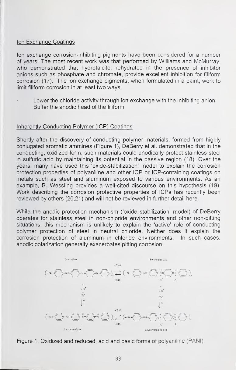
Ion Exchange Coatings
Ion exchange corrosion-inhibiting pigments have been considered for a numberof years. The most recent work was that performed by Williams and McMurray,
who demonstrated that hydrotaicite, rehydrated in the presence of inhibitor
anions such as phosphate and chromate, provide excellent inhibition for filiform
corrosion (17). The ion exchange pigments, when formulated in a paint, work to
limit filiform corrosion in at least two ways:
Lower the chloride activity through ion exchange with the inhibiting anion
Buffer the anodic head of the filiform
Inherently Conducting Polymer (ICP) Coatings
Shortly after the discovery of conducting polymer materials, formed from highly
conjugated aromatic ammines (Figure 1), DeBerry et al. demonstrated that in the
conducting, oxidized form, such materials could anodically protect stainless steel
in sulfuric acid by maintaining its potential in the passive region (18). Over the
years, many have used this 'oxide-stabilization' model to explain the corrosion
protection properties of polyaniline and other ICP or ICP-containing coatings on
metals such as steel and aluminum exposed to various environments. As an
example, B. Wessling provides a well-cited discourse on this hypothesis (19).
Work describing the corrosion protective properties of ICPs has recently been
reviewed by others (20,21) and will not be reviewed in further detail here.
While the anodic protection mechanism ('oxide stabilization' model) of DeBerry
operates for stainless steel in non-chloride environments and other non-pitting
situations, this mechanism is unlikely to explain the 'active' role of conducting
polymer protection of steel in neutral chloride. Neither does it explain the
corrosion protection of aluminum in chloride environments. In such cases,
anodic polarization generally exacerbates pitting corrosion.
Emeirstdine EmersJcline satt
+ 2HA
-2HA A- A
LsucEmeraldine Lsucemeraldine salt
Figure 1. Oxidized and reduced, acid and basic forms of polyaniline (PANI).
93
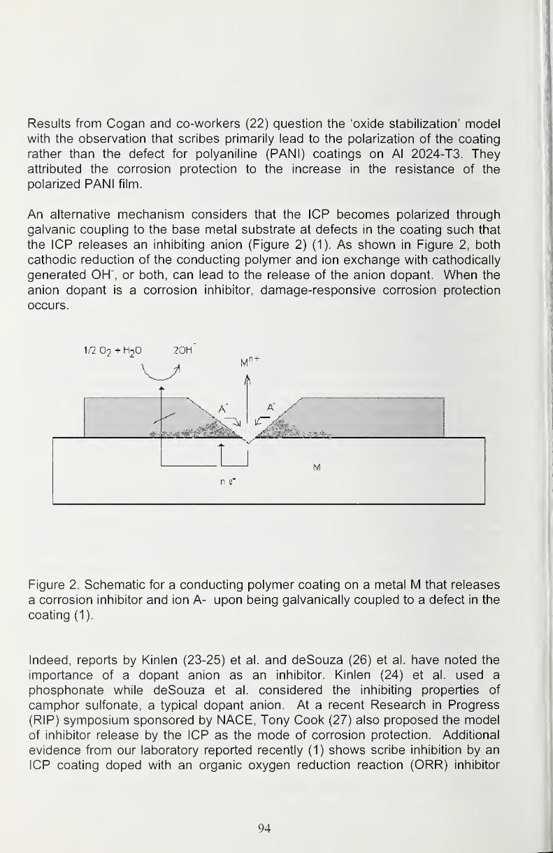
Results from Cogan and co-workers (22) question the 'oxide stabilization' modelwith the observation that scribes primarily lead to the polarization of the coating
rather than the defect for polyaniline (PANI) coatings on Al 2024-T3. Theyattributed the corrosion protection to the increase in the resistance of the
polarized PANI film.
An alternative mechanism considers that the ICP becomes polarized through
galvanic coupling to the base metal substrate at defects in the coating such that
the ICP releases an inhibiting anion (Figure 2) (1). As shown in Figure 2, both
cathodic reduction of the conducting polymer and ion exchange with cathodically
generated OH", or both, can lead to the release of the anion dopant. When the
anion dopant is a corrosion inhibitor, damage-responsive corrosion protection
occurs.
^.r2 O9 + HnO 20H
Figure 2. Schematic for a conducting polymer coating on a metal M that releases
a corrosion inhibitor and ion A- upon being galvanically coupled to a defect in the
coating (1).
Indeed, reports by Kinlen (23-25) et al. and deSouza (26) et al. have noted the
importance of a dopant anion as an inhibitor. Kinlen (24) et al. used a
phosphonate while deSouza et al. considered the inhibiting properties of
camphor sulfonate, a typical dopant anion. At a recent Research in Progress
(RIP) symposium sponsored by NACE, Tony Cook (27) also proposed the model
of inhibitor release by the ICP as the mode of corrosion protection. Additional
evidence from our laboratory reported recently (1) shows scribe inhibition by an
ICP coating doped with an organic oxygen reduction reaction (ORR) inhibitor
94

(Figure 3). An extensive review of corrosion protection by ICRs also recognized
the potential for an inhibitor-release mechanism (20,21).
While the original anodic protection model of DeBerry (18) operates for stainless
steel in non-chloride acidic solution, one must remain skeptical of this
mechanism for chloride rich environments where passivity typically does not
occur. A better explanation for this latter case appears to invoke the presence of
releasable dopants in the conducting polymers making ICRs clear candidates for
damage-responsive coatings.
Ur^doped ^^P®^
Figure 3. RANI coated Al 2024-T3 after 48 h of B117 salt fog exposure. Theregion to the right was doped with an organic anionic corrosion inhibitor (27).
Drug Release
The development of damage-responsive coatings, particularly those having
properties for controlled release of a corrosion inhibitor can benefit from early
research focused on drug release. Among the first to consider conducting
polymers for this application was the University of Minnesota group of L.L. Miller
who with B. Zinger provided the first example of the application of conductive
polymers for the controlled release of biologically significant reagents. In 1984,
they demonstrated the controlled release of ferrocyanide and glutamate from
polypyrrole (28). Other anions that have been released under electrochemical
control from ICRs include salicylate (29), and adenosine 5'triphosphate
95
(ATP)(30,31 ). This work begs the question, why cannot the anions that typically
inhibit corrosion be incorporated as dopants in ICRs? Such anionic inhibitors
may include phosphate, phosphonate, borate and nitrite as well as organic ORRanions.
Identification of Corrosion Inhibitors
Clearly protective coatings must release an effective inhibitor and provide a
sufficient barrier to the environment. Both must work in concert. Neither an
ideally hydrophobic coating that provides no protection for a defect nor a porous
material that releases an inhibitor while transmitting water and ions poses an
effective coating. Both of these requirements must be present. Electrochemical
impedance spectroscopy provides an effective means for assessing the barrier
properties of paints.
Recent work at Rockwell Scientific has led to a test that rapidly assesses the
release of ORR (oxygen reduction reaction) inhibitors. Clarke and McCreery (32)
showed that chromate functions primarily as an ORR inhibitor. Due to the fine
distribution of a catalytic Cu-rich secondary phase cathode, the ORR, even for a
scribed coated surface, remains critical to the corrosion of these alloys. For
example, a scribe in a coated alloy will contain both the cathodic intermetallic
sites where ORR occurs and anodic site of rapid dissolution. A coating that
releases an ORR inhibitor can slow the entire corrosion process by inhibiting the
cathodes that must reduce oxygen for the anodic dissolution to occur. Since the
cathodes represent about four percent of the total surface area, it makes moresense to focus on an inhibitor that blocks the part of the corrosion reaction that
requires these dilute sites. Based on previous work by llevbare and Scully
(33,34), a Cu rotating disk electrode (RDE) placed at a precise location above
the coating can detect the release of an ORR inhibitor through a decrease in the
ORR current density. Even for ferrous materials in neutral aqueousenvironments, ORR at defects in porous rust layers governs the corrosion rate in
a similar fashion (35).
The inhibition of the oxygen reduction reaction (ORR) may be expressed as the
ratio of ORR current, lo, without the presence of inhibitor to I, that in the
presence of the inhibitor. This ratio lo/l defines a particular ratio, R, when the
diffusion length, 5 (inversely proportional to the square root of the electrode
rotation rate) equals 1 micron, a dimension typical of the catalytic cathodic
phase.
Evaluation of solid corrosion inhibiting pigments in 1g/100 mL slurries of inhibiting
pigment are made through a determination of the ORR current for a Cu rotating
disk electrode (RDE) as a function of the inverse diffusion length in the absenceof the inhibitor, in the presence of the inhibitor and after Cu RDE has been
removed from the inhibitor slurry and placed back in a baseline inhibitor-free
96
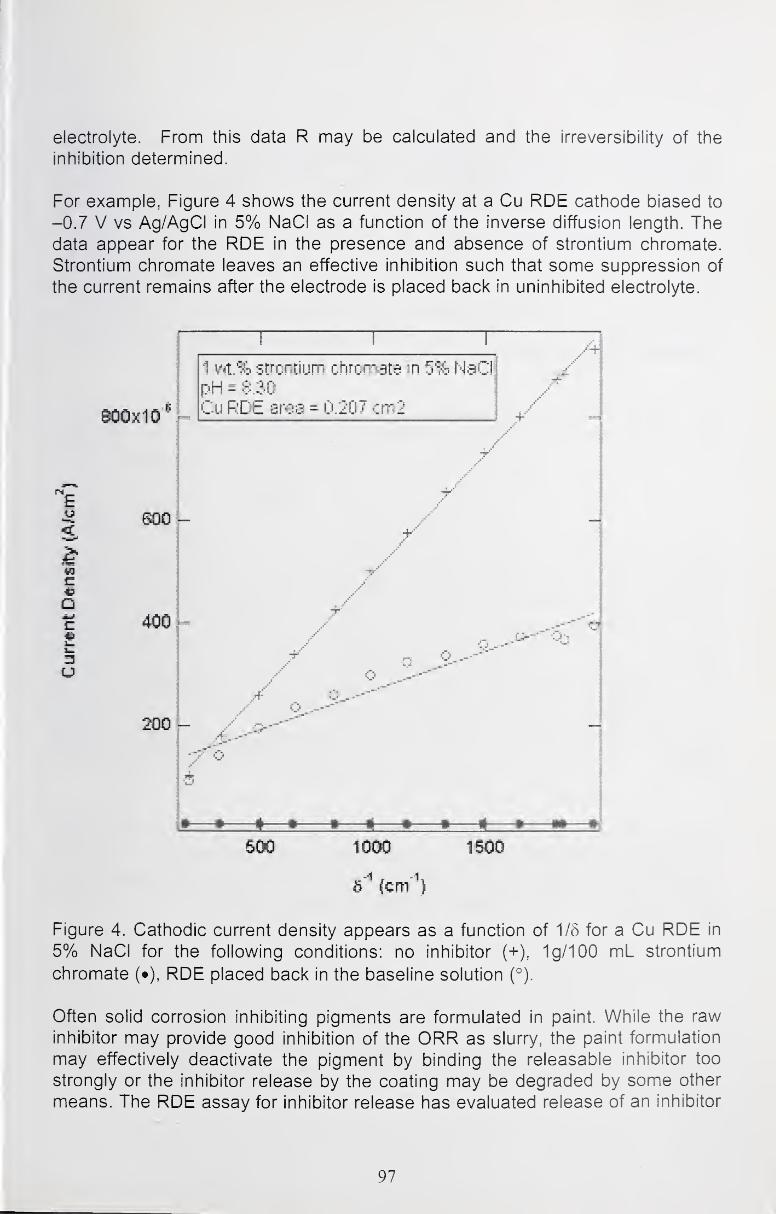
electrolyte. From this data R may be calculated and the irreversibility of the
inhibition determined.
For example, Figure 4 shows the current density at a Cu RDE cathode biased to
-0.7 V vs Ag/AgCI in 5% NaCI as a function of the inverse diffusion length. Thedata appear for the RDE in the presence and absence of strontium chromate.
Strontium chromate leaves an effective inhibition such that some suppression of
the current remains after the electrode is placed back in uninhibited electrolyte.
1 Strontium chrcrr^gte m 5% NaCpH - 8.30
Cu RDE aros = O.207 crn2
Emo - /
/
c
Q41^
20Q -
//
Q
^ n *
BOO 1000 ISOO
6^ (cm''')
Figure 4. Cathodic current density appears as a function of 1/5 for a Cu RDE in
5% NaCI for the following conditions: no inhibitor (+), 1g/100 mL strontium
chromate (•), RDE placed back in the baseline solution (°).
Often solid corrosion inhibiting pigments are formulated in paint. While the raw
inhibitor may provide good inhibition of the ORR as slurry, the paint formulation
may effectively deactivate the pigment by binding the releasable inhibitor too
strongly or the inhibitor release by the coating may be degraded by some other
means. The RDE assay for inhibitor release has evaluated release of an inhibitor
97
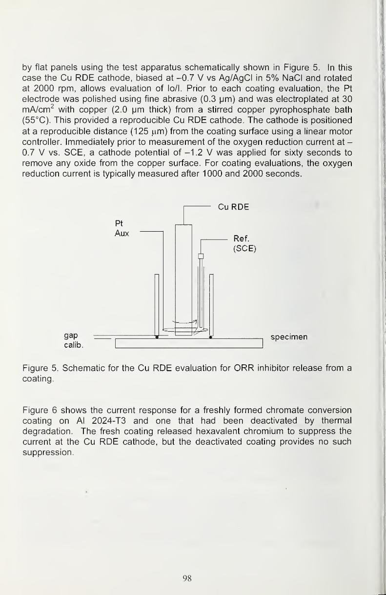
by flat panels using the test apparatus schematically shown in Figure 5. In this
case the Cu RDE cathode, biased at -0.7 V vs Ag/AgCI in 5% NaCI and rotated
at 2000 rpm, allows evaluation of lo/l. Prior to each coating evaluation, the Pt
electrode was polished using fine abrasive (0.3 |jm) and was electroplated at 30
mA/cm^ with copper (2.0 |jm thick) from a stirred copper pyrophosphate bath
(55°C). This provided a reproducible Cu RDE cathode. The cathode is positioned
at a reproducible distance (125 |um) from the coating surface using a linear motor
controller. Immediately prior to measurement of the oxygen reduction current at -
0.7 V vs. SCE, a cathode potential of -1.2 V was applied for sixty seconds to
remove any oxide from the copper surface. For coating evaluations, the oxygenreduction current is typically measured after 1000 and 2000 seconds.
Cu RDE
Pt
AuxRef.
(SCE)
gapcalib.
specimen
Figure 5. Schematic for the Cu RDE evaluation for ORR inhibitor release from a
coating.
Figure 6 shows the current response for a freshly formed chromate conversion
coating on Al 2024-T3 and one that had been deactivated by thermal
degradation. The fresh coating released hexavalent chromium to suppress the
current at the Cu RDE cathode, but the deactivated coating provides no such
suppression.
98
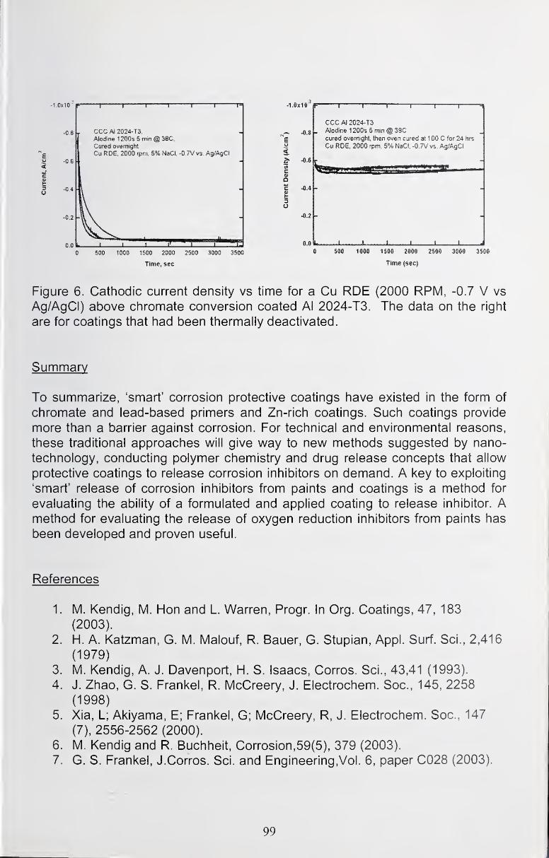
-1.0x10"
-0.8
u -0.6
I5
-0,2
pr
1 1 r— 1 1 T"
_ CCC Al 2024-T3,
Aiodrne 1 200s 5 min @ 38C,
Cured ovsmight
Cu RDE, 2000 rpm, 5% NaCI,
L-O.TVvs. Ag/AgCI
L i 1 11'
500 1000 1500 2000
Time, sec
2500 3000 3500
.1.0x10 IF
^.8 -
3.
c«Q
-0.6
-0.4
-0.2 -
0.0k
T T T T T
CCC Al 2024-T3
Modine 1 200s 5 min @ 38Ccured overnight, then oven ci^ed aH 00 C for 24 hrs
Cu ROE, 2000 rpm, S% NaCI. -0.7V vs. Ag/AgCI
„,i„, J.m mo nOO 2000 2500
Time (sec)
3000 3500
Figure 6. Cathodic current density vs time for a Cu RDE (2000 RPM, -0.7 V vs
Ag/AgCI) above chromate conversion coated Al 2024-T3. Tiie data on the right
are for coatings that had been thermally deactivated.
Summary
To summarize, 'smart' corrosion protective coatings have existed in the form of
chromate and lead-based primers and Zn-rich coatings. Such coatings provide
more than a barrier against corrosion. For technical and environmental reasons,
these traditional approaches will give way to new methods suggested by nano-
technology, conducting polymer chemistry and drug release concepts that allow
protective coatings to release corrosion inhibitors on demand. A key to exploiting
'smart' release of corrosion inhibitors from paints and coatings is a method for
evaluating the ability of a formulated and applied coating to release inhibitor. Amethod for evaluating the release of oxygen reduction inhibitors from paints has
been developed and proven useful.
References
1. M. Kendig, M. Hon and L. Warren, Progr. In Org. Coatings, 47, 183
(2003).
2. H. A. Katzman, G. M. Malouf, R. Bauer, G. Stupian, Appl. Surf. Sci., 2,416
(1979)
3. M. Kendig, A. J. Davenport, H. S. Isaacs, Corros. Sci., 43,41 (1993).
4. J. Zhao, G. S. Frankel, R. McCreery, J. Electrochem. Soc, 145, 2258
(1998)
5. Xia, L; Akiyama, E; Frankel, G; McCreery, R, J. Electrochem. Soc, 147
(7), 2556-2562 (2000).
6. M. Kendig and R. Buchheit, Corrosion, 59(5), 379 (2003).
7. G. S. Frankel, J.Corros. Sci. and Engineering,Vol. 6, paper C028 (2003).
99
8. Jain F C; Rosato J J; Kalonia K S; Agarwala V S, Adhesives,Sealants,andCoatings for Space and Harsh Environments.Conference Proceedings,
ACS, Colorado (1987).
9. Jain F C; Rosato J J; Kalonia K S; Agarwala V S, Corrosion, 1986
,
Volume: 42 , Number: 12,Page: 700-707 (1986).
10. Voevodin et al. Surface & Coatings Technology, 140 (1): 24-28( 2001)
11. J. Osborne, Progress In Organic Coatings, 41 (4): 280-286(2001).
12. Bhatia, R. B.; Brinker, C.J.; Gupta, A.K.; Singh, A.K. Chemistry OfMaterials, 12 (8): 2434-2441 Aug 2000
13. E. Shouji and D. Buttry, Langmuir, 15, 669 (1999).
14. H. Yang and W. vanOoij, PLASMAS AND POLYMERS, 8 (4): 297-323
DEC 200315. Gallardo, J; Galliano, P; Duran, A Journal Of Sol-Gel Science And
Technology, 21 (1-2): 65-74 (2001).
16. F. Mansfeld, C. Hsu, Z Sun, D Ornek and t. Wood, Corrosion, 58(3) , 187
(2002).
17. G. Williams and H. N. McMurray, Electrochemical and Solid State Letters,
6(3), B9-B11 (2003).
18. D. DeBerry, J. Eiectrochem. Soc. 132, 1022 (1985)
19. B. Wessling, Materials and Corrosion, 47, 439 (1996).
20.Spinks, GM; Dominis, AJ; Wallace, GG; Tallman, DE, J. Solid State
Electrochemistry, , 6 (2): 85-100 (2002).
21.Spinks, GM; Dominis, AJ; Wallace, GG; Tallman, DE J. Solid State
Electrochemistry 5(1) (2001).
22. S. Cogan, M. Gilbert,G. Holleck, J. Ehrlich, M. Jillson, J. Eiectrochem.
Soc, 147(6), 2143 (2000).
23. Kinlen, PJ; Ding, Y; Silverman, DC, Corrosion, 58 (6): 490-497 (2002).
24. Kinlen, PJ; Menon, V; Ding, YW, J. Eiectrochem. Soc, 146 (10): 3690-
3695 (1999).
25. P. Kinlen, J. Liu , Y. Ding C. R. Graham, E.E. Remsen, Macromolecules,
31, 1735 (1998).
26. S. de Souza, J. Pereira, S. Cordoba de Torres, M. Temperini, R. Torresi,
Electrochemical and Solid State Letters, 4(8), B27 (2001).
27. A. Cook, Research in Progress, NACE, Corrosion 2002.
28. B. Zinger and L.L. Miller, J. Amer. Chem. Soc, 106,6861 (1984).
29. A. Chang, L. L. Miller, J. Electroanal. Chem., 247, 173 (1998).
30. M. Pyo and J. R. Reynolds, Chem. Mater., 8, 128 (1996).
31. J-M. Pernautand J. R. Reynolds, J. Phys. Chem. B, 104, 4080 (2000).
32. W. Clark, J. Ramsey, R. McCreery and J. Frankel, J. Eiectrochem. Soc,149(5),B179 (2002).
33. G. O. Ilevbare and J. R. Scully, J. Eiectrochem. Soc, 148(5), B196 (2001).
34. G. O. Ilevbare and J. R. Scully, Corrosion, 57(2), 134 (2001).
35. F. Mansfeld, M. Kendig and W. Lorenz, J. Eiectrochem. Soc,132(2), 290
(1985).
100
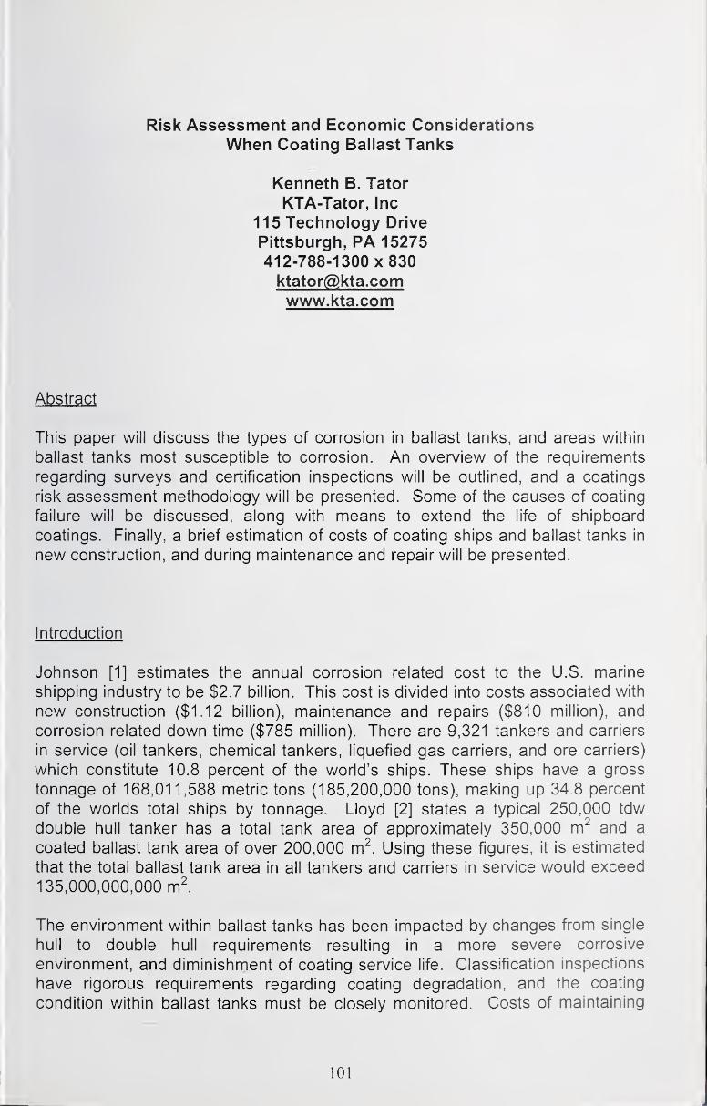
Risk Assessment and Economic Considerations
When Coating Ballast Tanks
Kenneth B. Tator
KTA-Tator, Inc
115 Technology Drive
Pittsburgh, PA 15275412-788-1300x830ktator(5)kta.com
www.kta.com
Abstract
This paper will discuss the types of corrosion in ballast tanks, and areas within
ballast tanks most susceptible to corrosion. An overview of the requirements
regarding surveys and certification inspections will be outlined, and a coatings
risk assessment methodology will be presented. Some of the causes of coating
failure will be discussed, along with means to extend the life of shipboard
coatings. Finally, a brief estimation of costs of coating ships and ballast tanks in
new construction, and during maintenance and repair will be presented.
Introduction
Johnson [1] estimates the annual corrosion related cost to the U.S. marine
shipping industry to be $2.7 billion. This cost is divided into costs associated with
new construction ($1.12 billion), maintenance and repairs ($810 million), and
corrosion related down time ($785 million). There are 9,321 tankers and carriers
in service (oil tankers, chemical tankers, liquefied gas carriers, and ore carriers)
which constitute 10.8 percent of the world's ships. These ships have a gross
tonnage of 168,011,588 metric tons (185,200,000 tons), making up 34.8 percent
of the worlds total ships by tonnage. Lloyd [2] states a typical 250,000 tdw
double hull tanker has a total tank area of approximately 350,000 m^ and a
coated ballast tank area of over 200,000 m^. Using these figures, it is estimated
that the total ballast tank area in all tankers and carriers in service would exceed
135,000,000,000 m^.
The environment within ballast tanks has been impacted by changes from single
hull to double hull requirements resulting in a more severe corrosive
environment, and diminishment of coating service life. Classification inspections
have rigorous requirements regarding coating degradation, and the coating
condition within ballast tanks must be closely monitored. Costs of maintaining
101
coatings and controlling corrosion on ships and in ballast tanks is a major
expense, when both the costs of the recoating work, and associated down-time
are considered.
New coating materials must be developed, along with new application techniques
for those materials. Shipyards must be prepared to take the necessary amountof time to do a high quality coating application job during new construction, andanytime remedial coating work is done. The owners must recognize this need for
utmost quality, and understand that the additional monies spent up-front for a
better coating system will extend the service life of the coating and will be moreeconomical over the long run.
Corrosion Within Ballast Tanks
On March 24, 1989, the Exxon Valdez ran aground in Prince William Sound,
Alaska spilling 11 million gallons of crude oil. As a direct result, in 1990,
Congress passed the Oil Pollution Act, which among other things, required all
new tankers operating within U.S. waters to have a double hull. The double hull
was used to insulate the cargo tanks from damage by providing both a primary
and secondary containment in order to minimize, or hopefully eliminate any
future spillage. The compartments within the double hull are used as water
ballast tanks.
Initially, ship owners anticipated corrosion rates to be similar to those
encountered in single hulled ballast tanks. It was known that repairs and steel
replacement would have to be performed after the third special survey when the
ship was 15 years old; however owners of the early double-hulled tankers found
significant corrosion and pitting at the first special survey after only 5 years [1].
The reasons for the accelerated corrosion accrue to the use of higher tensile
strength steels in the newer ships which allow for thinner plates that flex morethan the carbon steel plates used in the older tankers. Also, when a hot cargo,
such as crude oil loaded in the Middle East, Africa, South Pacific the Gulf Coast
and other high temperature regions, the cargo heats the ballast tanks. Without a
double hull, the cargo would be cooled by seawater on the opposite side of the
single hull. However, the double hull void space insulated the cargo, slowing its
cooling. Ballast tanks, even when empty, have water (and often silt) in their
bottoms, and condensing humidity throughout. The elevated temperature of the
cargo increases the rate of corrosion within the ballast tanks, doubling it for every
10°C increase in temperature. Thus if the average temperature of a ballast tank
is 20 °C warmer than previously, the corrosion rate would be quadrupled.
Cracking of paint due to brittleness or loss of flexibility with ageing is considered
a primary factor in corrosion damage to the steel structures of ship's hulls,
notably in seawater ballast tanks. This cracking is typically found in areas of
coating stress concentrations such as sharp angles, fillet welds, transitions
102

between structural details, weld toes, etc. Cracking is more severe for structural
details nnade of high strength steel than for normal strength steel. This cracking is
because thinner sheets of the high strength steel are used, and the lesser
thickness results in greater flexing when the vessel is underway in rough seas.
Lloyd [2] identifies areas of local areas of high stress in transverse web frames.
Areas of concern are at the end of brackets, toes and similar connections; endsof spans; and connections between longitudinals and web frames. These areas
are depicted in Figure 1 below.
A - At end of brackets, toes suad sicnilaTB - High shear stress at ends of spanC - Local higli stresses at coQiiections l>etweei3 loogitii<iiixais and
wel> firame, particauLlaxly within area of wind and water levels
where both web and longitudinal exposed.
Figure 1: Schematic of longitudinal and web structural members in an oil tanker.
Lloyd also identifies areas of corrosion on the bottom plating of ballast tank steel.
Areas of heaviest steel loss occur adjacent to the cut-outs in longitudinals, and at
cut-outs of transverse web frames on the bottom deck plating. Moderate steel
loss areas cover most of the bottom deck plate steel, particularly where there is
opportunity for water flow through the cut-out areas. Pitting occurs on the
horizontal surfaces of most members. Vertical sections of web frames and
longitudinals are least affected by corrosion. These areas are depicted in Figure
2:
103
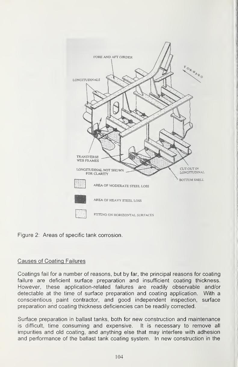
Figure 2: Areas of specific tank corrosion.
Causes of Coating Failures
Coatings fail for a number of reasons, but by far, the principal reasons for coating
failure are deficient surface preparation and insufficient coating thickness.
However, these application-related failures are readily observable and/or
detectable at the time of surface preparation and coating application. With a
conscientious paint contractor, and good independent inspection, surface
preparation and coating thickness deficiencies can be readily corrected.
Surface preparation in ballast tanks, both for new construction and maintenance
is difficult, time consuming and expensive. It is necessary to remove all
impurities and old coating, and anything else that may interfere with adhesion
and performance of the ballast tank coating system. In new construction in the
104
U.S., the length of the ship construction sequence is usually long enough for rust
through and corrosion to commence through the pre-construction primer.
Moreover, the act of cutting, welding and general construction activity provides
for contamination of the pre-construction primer with weld spatter and oily
residues from weld fluxes and fumes. As most shipyards are close to the ocean,
salt deposits on the steel and coating are almost unavoidable. All these
contaminates must be removed in order for any coating applied to the steel, or
over a pre-construction primer to attain optimum service life. To enable coating
adhesion, not only must the surface be properly cleaned, but there should be
suitable surface roughness, or anchor pattern, to enable adequate adhesion of
the coating, particularly if there will be flexing or vibration of the steel substrate.
Application of each coat of the coating system must be done properly and to
sufficient thickness. When observing failures within ballast tanks, there is far
more corrosion on edges than there is on plate steel. Because all liquid applied
coatings draw thin over sharp edges and protruding irregularities, these areas
need to be stripe-coated. Paint "daubing" brushes, generally round, fine bristled
brushes that can hold a lot of paint are often used to stripe-coat rat holes, cutouts
and other irregularities in order to apply a greater paint thickness. Stripe-coating
is usually done after the first full spray coat has been applied to the blast-cleaned
steel, or over the pre-construction primer if it is not removed. Striping may be
done either before or after application of each subsequent coat of paint. The"mechanical" action of the brush bristles working the paint into irregularities, and
displacing any remaining dust, dirt or debris from the surface is an important
factor in obtaining good adhesion. Also, where there are inside angles and
corners, pits and other recessed areas, the bristles of the brush work the paint
into the depressions much better than a spray application.
When the coating has been properly applied to a properly prepared surface,
stress in paint films is a major factor in coating failure, usually resulting in
cracking, peeling, or disbonding. Such stress occurs as a result of:
• Shrinkage due to chemical curing and cross linking of the epoxy
lattice. This linear shrinkage upon initial cure is relatively low for
bis-phenol A epoxies, usually about 0.6%. More highly cross linked
novolacs and cresols that are becoming increasingly common have
a much higher shrinkage rate.
• After-shrinkage due to migration and loss of low-molecular
components from the coating film. Migrating low molecular weight
plasticizers are particularly responsible for this, particularly if the
coating is exposed to elevated temperatures.
• Environmental impacts (mainly chemical degradation but also
stress). Oxidation and degradation of the paint film caused by
reactions with air; cyclical water up-take and drying; and hydrostatic
pressures and flexing due to ballasting and deballasting.
105

• strain in the steel substrate, particularly increased flexing as a
result of the use of thinner plate sections of high yield strength
steel.
• Mechanical impacts such as direct and reverse impact from use of
heavy loading equipment, or tool impacts.
• Loss of entrapped solvents that did not volatilize while the coating
was drying due to low application or curing temperatures.
Mills [3] has seen osmotic activity in the "anode" areas of welding heat-affected
zones within ballast tanks. Here the weld metal is cathodic to the adjacent heat
affected zone of the steel plate. These areas may not be able to be cleaned as
well, and may also be hardened by the heat. Blistering may form over the heat-
affected zone adjacent to the weld. The coating over the weld remains
unblistered, with good adhesion.
Mills also does not recommend the installation of anodes in newly fabricated
ballast tanks, although he recommends the installation of anode brackets for later
anode installation when coating breakdown warrants their use. Anodes are only
operative when the ballast tank is filled. When the tanks are empty, the anodescannot function. Anodes and zinc holding shop primers do not go well together.
Zinc is amphoteric (soluble in both low and high pH solutions) and dissolves in
the high pH solutions that develop upon reduction of oxygen (at the cathode).
While corrosion of steel does not occur due to the high pH, the dissolved zinc
forms tetra hydroxyl zincate ions [Zn (0H)4"]. These ions drive the osmotic
destruction (blistering) of the coating as any ionic contamination will do.
Of course, all of this presumes that the proper coating system for the ballast tank
environment is chosen and applied correctly. An unsuitable system, no matter
how well applied, will fail and an excellent coating system poorly applied may fail
even faster.
Survevs and Certification Inspections
The International Association of Classification Societies (lACS) document"Requirements concerning Survey and Certification" [4] rev 2004 is a 402 page
document consisting of 27 sections covering hull and classification surveys of oil
tankers, bulk carriers, chemical tankers, double hulled oil tankers, double side
skin bulk carriers and general dry cargo ships, and other marine vessels,
machinery, hatch covers and coamings, propeller and shaft tubing and other
features critical to marine vessels.
Hull Classification Surveys (Special surveys) must be carried out every five years
to renew the Class Certification. The scope of the survey is to ensure that "...the
ship is fit for its intended purpose for the next 5 year class period, subject to
106
proper maintenance and operation and the periodical surveys being carried out
at the due dates" (2.2.1 page Z7-3).
Some relevant definitions are as follows (from pages Z7-2 and Z7-4):
1.2.5 Suspect areas are locations showing Substantial Corrosion and/or are
considered by the Surveyor to be prone to rapid wastage.
1.2.6 Substantial Corrosion is an extent of corrosion such that assessment of
corrosion pattern indicated a wastage in excess of 75 percent of allowable
margins, but within acceptable limits.
1.2.7 Protective Coatings are to usually be epoxy coating or equivalent. Other
coating systems may be considered acceptable as alternatives provided that they
are applied and maintained in compliance with the manufacturer's specification.
1 .2.8 Coating Condition is defined as follows:
GOOD-condition with only minor spot rusting
FAIR -condition with local breakdown at edges of stiffeners and weld
connections, light rusting over 20 percent or more of areas under consideration,
but less than defined for POOR condition. POOR-condition with general
breakdown of coating every 20 percent or more of areas or hard scale at 10
percent or more of areas under consideration.
NOTE: The definition of "Good", "Fair" and "Poor" is under review at the time of
this writing. The cut off for annual inspection may soon be FAIR (or "NOTGOOD) as opposed to POOR as in the past.
The bottom limit of GOOD may be interpreted to be:
General coating breakdown less than 3 percent
Edge and weld coating breakdown less than 20 percent
This limit is for the ship's life. This means that a greater coating breakdown than
3 percent (in 20 or even 25 years) will cause problems!!
2.2.7 For spaces used for salt water ballast, excluding double bottom tanks, if
there is no protective coating, soft coating or POOR protective coating condition
and it is not renewed, maintenance of class is to be subject to spaces in question
being internally examined at annual intervals. Waiver of internal examination at
annual intervals for tanks of 12 m^ or less in size, with soft coating, may be
considered.
2.2.8 When such conditions are found in salt water ballast double bottom tanks,
maintenance of class may be subject to the spaces in question being internally
examined at annual intervals.
107

2.2. 11 Thickness measurements are to be carried out in accordance with Table 1
"Minimum Requirements for Thickness Measurements at Special Surveys" (not
included in this paper). Additionally, any part of the vessel where wastage is
evident or suspect, the Surveyor may require thickness measurements in order
to ascertain the actual thickness of the material.
2.2.12 When thickness measurements indicate Substantial Corrosion, the
number of thickness measurements is to be increased to determine the extent of
Substantial Corrosion. Table 2 (below) may be used as guidance for additional
thickness measurements.
Table 2: GUIDANCE FOR ADDITIONAL THICKNESS MEASUREMENTS IN
WAY OF SUBSTANTIAL CORROSION
STRUCTURALMEMBER
EXTENT OF MEASUREMENT PATTERN OFMEASURMENT
Plating Support areas and adjacent
plates
5 point pattern over 1
square meter
Stiffeners Suspect area 3 measurements each
in line across web and
flange
4. Intermediate Survey
4.1 Schedule-The intermediate survey is to be carried out at or between the
second and third Annual Survey.
4.2.1 The scope of the second or third Annual Survey is to be extended to
include the following:
4.2.1 .1 For vessels over five years of age, a general, internal examination of
representatives spaces used for salt water ballast is to be carried out. If there is
no protective coating, soft coating, or POOR coating condition, the examination is
to be extended to other ballast spaces of the same type.
4.2.1 .2 For vessels over ten years of age, a general, internal examination of all
spaces used for salt water ballast is to be carried out.
4.2.3 For spaces used for salt water ballast, excluding double bottom tanks, if
there is no protective coating, soft coating or POOR protective coating condition
and it is not renewed, maintenance of class is to be subject to spaces in question
being internally examined at annual intervals. Waiver of internal examination at
annual intervals for tanks of 12 m^ or less in size, with soft coating, may be
considered.
108
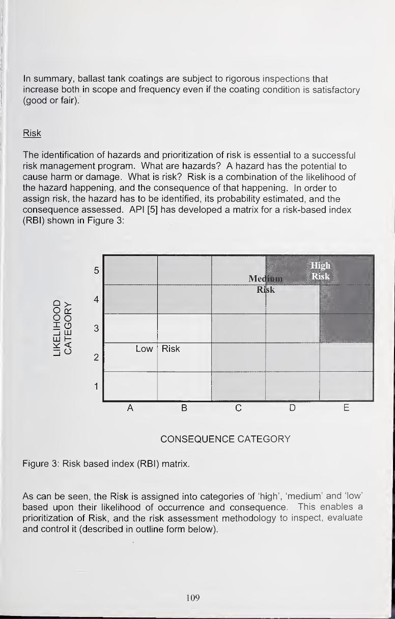
In summary, ballast tank coatings are subject to rigorous inspections that
increase both in scope and frequency even if the coating condition is satisfactory
(good or fair).
Risk
The identification of hazards and prioritization of risk is essential to a successful
risk management program. What are hazards? A hazard has the potential to
cause harm or damage. What is risk? Risk is a combination of the likelihood of
the hazard happening, and the consequence of that happening. In order to
assign risk, the hazard has to be identified, its probability estimated, and the
consequence assessed. API [5] has developed a matrix for a risk-based index
(RBI) shown in Figure 3:
ABODECONSEQUENCE CATEGORY
Figure 3: Risk based index (RBI) matrix.
As can be seen, the Risk is assigned into categories of 'high', 'medium' and 'low'
based upon their likelihood of occurrence and consequence. This enables a
prioritization of Risk, and the risk assessment methodology to inspect, evaluate
and control it (described in outline form below).
109
Risk Assessment Methodology
Risk Assessment is subset of a corporation's overall policy and procedure for
proactively managing a facility for health and safety issues. The steps necessary
to establishing a successful Risk Management Policy, adapted from Capcis [6]
are outlined as follows:
1. Establish the Corporate Policy-upper management must decide whattheir tolerance/position is for a given risk. It is essential that upper
management "buys-into" whatever policy is decided upon, for
implementation will require time and money.
2. Convene an Organization/Staff-individuals who are knowledgeable,
concerned and involved must be assigned, and their supervisors mustconcur that appropriate time and effort can be delegated to risk
management.3. Planning and Setting Standards-planning is based upon long-term
strategies and objectives (as developed in step 1). The planning needs
to develop a systematic means to accomplish the strategy as
measured by the objectives. Standards need to be established,
usually based upon company guidelines, industry standards, and
governmental requirements. There needs to be an acceptance
criterion, which will be used to measure performance against the
standards. The acceptance criteria need to be realistic, measurable
and achievable.
4. Performance Measurement-inspections, surveillance and observations,
in a systematic fashion, as developed in Step 3 needs to be done in
order to establish conformance with the acceptance criteria that has
been established. This step can be very time consuming, and require
a lot of documentation that will need summation and analysis in order
to determine whether progress is being made toward proper
management and control of risks. Two types of monitoring systems
are used: Active Monitoring (checks and inspections) on an on-going
basis to assess conformance with the acceptance criteria; and
Reactive Monitoring, or "after failure-post mortem" examinations to
determine what went wrong, and how to avoid a repeat of the problem.
5. Audit and Review-the performance measurements outlined in Step 4
must be assessed to determine if the acceptance criteria have been
met and management of risk has been successful. The process needs
to be audited and updated on a periodic basis to remedy problems in
the process that may make it less effective.
110
Means to Extend Coating Life
Because of the problems described above, there is concern regarding the
longevity of ballast tank coatings and the high costs of repair/replacement. Anumber if diversified ship owners have expressed concern and maderecommendations regarding their approach to resolve the longevity problem.
Eliasson and Mills [7] conclude the most appropriate time to fully and properly
coat ballast tanks is at the new construction stage. They contend that presently
used fast curing and low temperature coating systems are not sufficient, and
challenge the coating manufacturers to develop new long lasting coatings
possibly based upon hot amine cured 100 percent novolac epoxy resins. Theyalso suggest an application sequence that should allow shipyards a faster
throughput.
Webb, Brinkerhoff, Rice and Bizol [8] describe the U.S. Navy's use of high solids
coatings and plural spray equipment to reduce preservation costs and the
adverse effects of painting operations on the environment. The U.S. Navyadvocates the use of new "edge retentive" coatings that build to higher
thicknesses on sharp edges and protrusions than conventional epoxies. Thesenew materials have a short pot life and/or require heating. Accordingly, plural
component spray (where the coating components are proportioned and mixed
either immediately before the spray gun, or by impingement during spray
application) must be used.
Shell International Trading and Shipping Company Ltd. [9] provides an overview
of Tank Structural Co-Operative Forum (TSCF) guidelines for a 10, 15 and 25-
year system specification. All systems require initial surface preparation to Sa2/4 (near-white blast cleaning) with a 30-75 micron profile. Soluble salts are
limited to 30 mg/m^. A pre-construction ethyl-zinc silicate primer is specified.
• For the ten year system, Preparation grade PI, one pass edge grinding,
Sa 1 (brush-off blast cleaning) removal of 30 percent of the pre-
construction primer, and Sa 2/4 at damaged areas and welds is required,
followed by 250 micron minimum dry film thickness of a light colored
epoxy applied in a minimum of one full stripe coat and two full spray coats.
• For the fifteen year system. Preparation grade P2, three pass edge
grinding, and Sa 2 (commercial blast cleaning) removal of 70 percent of
the intact pre-construction primer, and Sa 2V2 at damaged areas and
welds is required, followed by 300 microns minimum of a light colored
epoxy applied in 2 full stripe coats and two full spray coats.
• The twenty-five year system requires Preparation grade P2, edge grinding
to radius and Sa 2 Vz removal of the pre-construction primer. Application of
a light colored epoxy to 350 microns minimum in three full stripe coats and
three full spray coats is required.
Ill
The Naval Surface Warfare Center, Carderock Division [10] is currently
investigating the following methods and materials for ship preservation:
• Improved high solids epoxies
• Thermoplastics and powder coatings
• Composite materials
• Thermal-sprayed aluminum
• Ultra-violet (UV) cured coatings
• 100% solids-high build coating systems
There are a number of interesting possibilities for improvement of coating
systems and application methodologies to improve ballast tank coating service
life, reduce costs and minimize environmental impact.
Costs of Coating
Johnson [1] estimates that for new ship construction, the coat for coating mostships is seven percent of the total cost of the ship. This, however, includes all
coatings, not just ballast tank coatings. While the cost to apply a proper coating
is expensive, it was four to fourteen times more expensive to replace corroded
steel than to apply a coating during construction, and maintain that coating. Thecost of coating oil tankers was estimated higher, at ten percent of the ship's
construction cost. This is because better coatings are required due to the
presence of hydrogen sulfide in crude oil. Johnson also estimated the annual
repair and maintenance costs, including down time, for corrosion protection
(mostly coatings, but also all other forms of corrosion protection such as anodes,
metal replacement, etc.), for ships classified as follows:
• Oil Tankers $340,000
• Chemical Tankers $440,000
• Bulk Dry Carriers $106,000
• Cargo Roll-on/Roll-off $123,000
Johnson further estimates the costs of solvent-free epoxies to be, on average,
$6.60 per square meter, compared to coal tar epoxies and solvent-borne epoxies
that cost, on average $1.80 and $2.80 per square meter respectively. For the
amount of coating needed to coat a ship, it is approximately $150,000 moreexpensive to use a solvent-free epoxy over coal tar epoxy, and $120,000 moreexpensive than use of a solvent borne epoxy. However, he states that the
additional $150,000 spent during construction can pay major dividends during the
operational life of the ship. If the cheaper coal tar epoxy coating is used during
construction, the coating will have to be reapplied two or three times over the
estimated twenty-five year life of the tanker. To perform the re-coating, the tanks
112
would first have to be cleaned and grit blasted before the coating is applied. Thetotal cost of such a job on a large tanker would be approximately $3 million.
Eliasson and Mills [7] state that "to recoat a double skin Very Large Crude oil
Carrier (VLCC=2 million barrels=280,000 tons) with 250,000 m^ in the ballast
tanks would take 250 days and cost about $20 million" including down time.
Webb, Brinckerhoff, Rice, and Bizol [8] state that the high-solids coating
materials used in their study cost typically $38/gallon compared with roughly $20/ gallon for solvent borne epoxies. Waste disposal costs at one naval facility
were $0.12 per pound for solidified epoxy waste, and $1 /pound for solvent
bearing waste. Overall, the one-time application costs of the high-solids epoxy
paint system, with an estimated service life of twenty years, increased from
approximately $5.70 to approximately $6.25 per square foot ($62 to $69 per
square meter) exclusive of labor, or approximately ten percent over the cost of
applying a conventional epoxy polyamide system.
In summary, new coating materials must be developed, along with newapplication techniques for those materials. Shipyards must be prepared to take
the necessary amount of time to do a high quality coating application job during
new construction, and anytime remedial coating work is done. The owners mustrecognize this need for utmost quality and timely maintenance, and understand
that the additional monies spent up-front for a better coating system will extend
the service life of the coating and will be more economical over the long run.
Acknowledgment
The author is indebted to his good friends Johnny Eliasson, Materials Protection
Project Manager for Stolt-Nielsen Transportation Group B.V., Schiedam,
Netherlands; and Dr. George Mills of George Mills & Associates International,
Inc., Houston TX for their assistance and timely review with pointed constructive
comments during the preparation of this paper.
References
1. Joshua T. Johnson; "Cost of Corrosion"; Appendix O "Ships"; USDepartment of Transportation, Federal Highway Administration Report
FHWA-RD-01-156; 2001; www.corrosioncost.com .
2. Germanischer Lloyd; "Presentation of the 1997 TSCF Guidance Manual
for Tanker Structures" Tanker Structure Co-Operative Forum; 2000
Shipbuilders Meeting, Tokyo, October 2000.
3. George Mills; personal e-mail communication, February 23, 2004
113
4. "Requirements Concerning Survey and Classification"; International
Association of Classification Societies; lACS, 5 Old Queen Street, London,
SW1H 9JA, UK.
5. American Petroleum Institute Recommended Practice RP 580 "Application
of Risk-based Inspection Methodology in the Production andPetrochemical Industry"; American Petroleum Institute • 1220 L Street,
NW, Washington, DC 20005-4070.
6. Capis Limited; J. Dawson, K. Bruce, D. G. John; "Corrosion Risk
Assessment and Safety Management for Offshore Processing Facilities"
Offshore Technology Report 1999/064; Capis House, 1 Echo Street, Ml7DP United Kingdom.
7. Johnny Eliasson, George Mills; "Future Cargo and Ballast Tank Lining for
Ship Tanks-Forward Looking Technology"; SSPC 2003, New Orleans,
LA.; SSPC: The Society for Protective Coatings, Pittsburgh, PA 15222.
8. Arthur A. Webb, Beau Brinckerhoff, Lee Rice, Paul Bizol "Reducing NavyFleet Maintenance Costs with High-Solids Coatings and Plural-
Component Spray Equipment"; "Journal of Protective Coatings andLinings"; Pittsburgh, PA. 15203; March 2003, pages 54-63.
9. Shell International Trading and Shipping Company Ltd. "Ballast Tanks-An
Overview of the TSCF Guidelines for Ballast Tank Coating Systems and
Surface Preparation"; Tanker Structure Co-Operative Forum; 2000Shipbuilders Meeting, Tokyo, October 2000.
10. Naval Surface Warfare Center, Carderock Division; www.dt.navv.mil
114

Decision IVIaking in Coating Selection in IVIarine/Offshore Environments
Kirk Brownlee Kirk BrownleeStaff Consultant
Stress Engineering Services, Inc.
Houston, TX281/955-2900
[email protected]://www.stress.com
Charlie SpeedMaterials/lnspection/Corrosion Consultant
Ammonite Corrosion Engineering
New Orleans. LA504/400-7878
Raleigh WhiteheadCarboline
St Louis, MO
Introduction
Given tine myriad of possible choices, selecting a coating system to protect an
offshore structure, a marine pipeline, or a ship from corrosion damage is a
difficult decision. Selection includes a number of coating systems, which address
many different components from structural components, piping systems, static
pressure equipment (tanks and vessels), power systems (compressors and
pumps) and a multitude of instrumentation and electrical infrastructures.
In order to make a practical, cost-effective recommendation, the selector must
solicit and synthesize input from multiple sources, many of which have competing
economic agendas. He/she must consider the coating's basic function, i.e.,
corrosion protection, aesthetics, etc., as well as technical subjects such as the
coating's compatibility with the service environment, the coating's physical and
mechanical properties, and accessibility to the structure in time and space,
115
environmental factors, and life-cycle costs. Additionally, he/she must consider
whether the substrate to be protected is new, previously coated, or corroded.
Since no one protective coating is suitable for all potential applications, selection
of a coating for a particular application always means balancing economic andtechnical considerations to achieve a solution, i.e., coating selection is a
compromise.
Despite these difficulties and the importance of coating selection to the long-term
integrity of offshore installations, coating selection is often carried out by non-
specialists who use largely subjective and undocumented procedures.
Misapplication may result in poor coating performance, premature failures,
increased life-cycle costs, and missed business opportunities. The authors of
this paper attempt to provide some basic approaches to coating system
selection. Selection is a dynamic process, and one should always seek a better
approach-looking for the best way of selecting a coating system that works for
new construction and maintenance coating projects for any equipment whether a
marine vessel, floating production facility, fixed or floating platform or simple
pipeline.
The Cost of Corrosion
Therefore, let's first look at the cost of corrosion before moving on to decision
making and the technical and economic factors that affect coating selection.
Various estimates exist with respect to the cost of corrosion. Cost tracking
include the following:
1950s -UK $1.25 billion
1980 -USA $5.5 billion
Approximately 4% of USA GNP ($276B)
Approximately 40 million gallons of high-performance paints were sold in 1979.
The offshore structures protected by these coatings largely represent the world's
oil and gas production and transportation facilities, the value of which are
increasing at a rapid rate, making good coating selection a necessity rather than
a luxury.
The cost of poorly made coating selection is often high. Looking at how coating
selections are typically made, justifies the need for an improved approach.
The Decision-Making Process
The following are typical answers received when one asks how to make coating
selections:
116
• Use what we always use
• Do what others are doing in the same or similar industries and perhaps
change when others apply the applications (Always be safe and second)
• Use what is dictated by global purchasing agreement
• Use what the supplier/manufacturer recommends• Use lowest price coating
• React to failures and rumors or failures
Contrasting and comparing these coating-selection methodologies with someclassical decision making techniques begins the process selection and is another
step forward, in his book "The Art of Making Decisions", Wire Assessing reviews
typical ways that people make decisions:
Pray/ask fortune tellers
Dictatorial/Monarchial
Egotistical
Delegate to Subordinates
Pass the BuckRely on Gut Feelings
Postpone
By ConsensusFollow Tradition/Superstition/Established Rules
Pattern Recognition
Gambling
Heuristics
Mathematical Decision Analysis
The methods used run the gamut from humorous to serious and from simple to
highly complex. However, as shown in the table below, in the final analysis the
decision-making process used in making technical decisions does not differ
much from the methods used everyday in making non-technical decisions.
Is there a better way? Yes, there is a better way. How complex does the process
need be to be judged useful and successful? Is there a way to calibrate or
validate our decisions? The level of complexity required in the decision-making
process depends on the context of the decision. The level of "calibration" or
validation required of a particular decision depends on the overall level of risk.
117
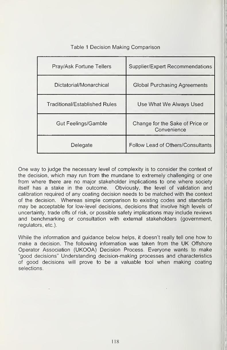
Table 1 Decision IVlaking Comparison
Pray/Ask Fortune Tellers Supplier/Expert Recommendations
Dictatorial/Monarchical Global Purchasing Agreements
Traditional/Established Rules Use What We Always Used
Gut Feelings/Gamble Change for the Sake of Price or
Convenience
Delegate Follow Lead of Others/Consultants
One way to judge the necessary level of complexity is to consider the context of
the decision, which may run from the mundane to extremely challenging or one
from where there are no major stakeholder implications to one where society
itself has a stake in the outcome. Obviously, the level of validation and
calibration required of any coating decision needs to be matched with the context
of the decision. Whereas simple comparison to existing codes and standards
may be acceptable for low-level decisions, decisions that involve high levels of
uncertainty, trade offs of risk, or possible safety implications may include reviews
and benchmarking or consultation with external stakeholders (government,
regulators, etc.).
While the information and guidance below helps, it doesn't really tell one how to
make a decision. The following information was taken from the UK Offshore
Operator Association (UKOOA) Decision Process. Everyone wants to make"good decisions" Understanding decision-making processes and characteristics
of good decisions will prove to be a valuable tool when making coating
selections.
118
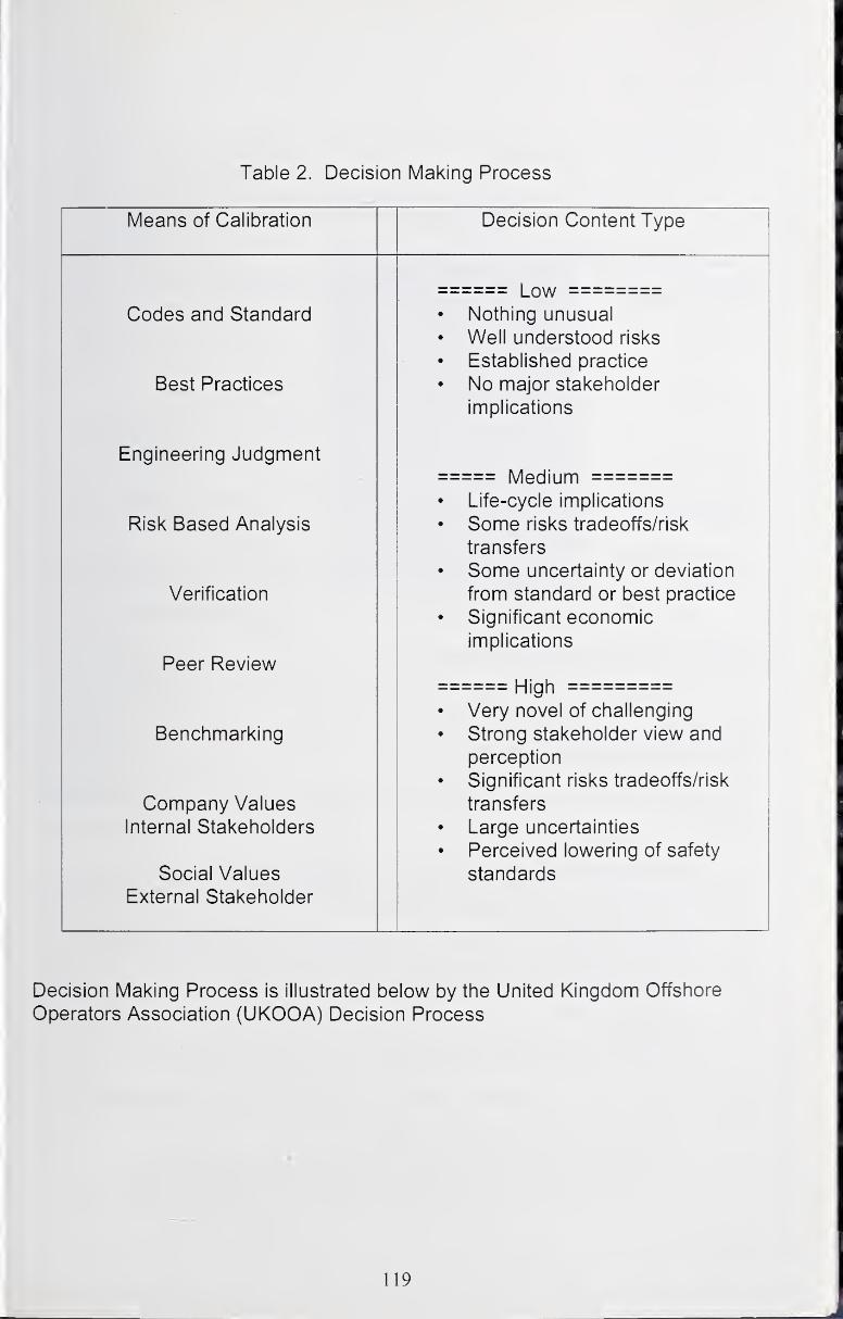
Table 2. Decision Making Process
Means of Calibration Decision Content Type
LowCodes and Standard • Nothing unusual
• Well understood risks
• Established practice
Best Practices • No major stakeholder
implications
Engineering JudgmentMedium
• Life-cycle implications
Risk Based Analysis • Some risks tradeoffs/risk
transfers
• Some uncertainty or deviation
Verification from standard or best practice
• Significant economic
implications
Peer ReviewHigh
• Very novel of challenging
Benchmarking • Strong stakeholder view and
perception
• Significant risks tradeoffs/risk
Company Values transfers
Internal Stakeholders • Large uncertainties
• Perceived lowering of safety
Social Values standards
External Stakeholder
Decision Making Process is illustrated below by the United Kingdom Offshore
Operators Association (UKOOA) Decision Process
119
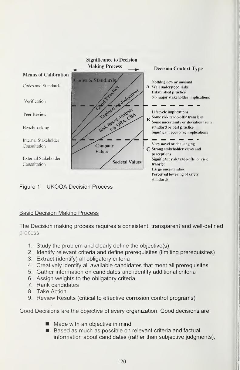
Significance to Decision
Making Process
Means of Calibration
Codes and Standards
Verification
Peer Review
Benchmarking
Internal Stakeholder
Consultation
External Stakeholder
Consultation
Codes & Standards
Societal Values
Decision Context Type
Nothing new or unusual
A Well understood risks
Established practice
No major stakeholder implications
B
Lifecycle implications
Some risk trade-offs/ transfers
Some uncertainty or deviation from
standard or best practice
Significant economic implications
Very novel or challenging
C Strong stakeholder views and
perceptions
Significant risk trade-offs or risk
transfer
Large uncertainties
Perceived lowering of safety
standards
Figure 1. UKOOA Decision Process
Basic Decision Making Process
The Decision making process requires a consistent, transparent and well-defined
process.
1 . Study the problem and clearly define the objective(s)
2. Identify relevant criteria and define prerequisites (limiting prerequisites)
3. Extract (identify) all obligatory criteria
4. Creatively identify all available candidates that meet all prerequisites
5. Gather information on candidates and identify additional criteria
6. Assign weights to the obligatory criteria
7. Rank candidates
8. Take Action
9. Review Results (critical to effective corrosion control programs)
Good Decisions are the objective of every organization. Good decisions are:
Made with an objective in mind
Based as much as possible on relevant criteria and factual
information about candidates (rather than subjective judgments),
120
Flexible (subject to change based on better quality information or
new criteria),
Aligned with applicable laws, regulations and policies, andMade with informed consent of stakeholders
We mentioned criteria and candidates; what do these terms mean? Criteria are
specific characteristics of the candidates, and candidates are possible solutions
to the problem,
Criteria come in three flavors:
Prerequisites (for candidate selection)
Obligatory criteria (must have features)
Desirable criteria (nice-to-have features)
Criteria receive weight in the ranking of candidates, which must meet obligatory
criteria and prerequisites and which may exhibit other desirable characteristics
How does one weigh the criteria?
Weighing the Criteria can be performed in various ways. Two methods are:
(1) A distribution technique where 100 percent is distributed among the criteria
and a (2) scaling technique where each criteria is assigned a number or points
indicating preference (1 = low preference; normalize on total points, then
multiplied by 100 to get percent). The Table below illustrates a method used by
Shell Offshore in 1996. Qualitative words such as low, medium, high can be used
to represent preferences.
How does one rank the candidates?
Ranking Candidates can be performed by using a Matrix method, which is the
most common technique used by businesses for making decisions. Other
methods abound such as: Pair wise Comparison; Pros & Cons;
Piuses/Minuses/Implications (PMI) and Force Field Analysis. The point is to
choose one and stick with it as long as it provides transparency and reliable
rankings that prove out by experience.
121
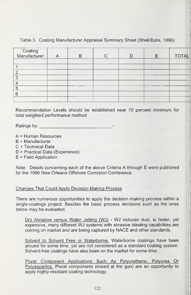
Table 3. Coating Manufacturer Appraisal Summary Sheet (Shell/Estis, 1996)
Coating
Manufacturer A B C D E TOTAL
1
2
3
4
5
6
Recommendation Levels should be established near 70 percent minimum for
total weighted performance method
Ratings by: -
A = Human Resources
B = Manufacturer
C = Technical Data
D = Practical Data (Experience)
E = Field Application
Note. Details concerning each of the above Criteria A through E were published
for the 1996 New Orleans Offshore Corrosion Conference.
Changes That Could Appiv Decision Making Process
There are numerous opportunities to apply the decision making process within a
single-coatings project. Besides the basic process decisions such as the ones
below may be evaluated.
Dry Abrasive versus Water Jetting (WJ) - WJ reduces dust, is faster, yet
expensive, many different WJ systems with abrasive blasting capabilities are
coming on market and are being captured by NACE and other standards.
Solvent to Solvent Free or Waterborne. Waterborne coatings have been
around for some time, yet are not considered as a standard coating system.
Solvent-free coatings have also been on the market for some time.
Plural Component Applications Such As Polvurethane. Polvurea Or
Polyaspartics. Plural components (mixed at the gun) are an opportunity to
apply highly resistant coating technology
122
Traditional Epoxy/Polyurethane to Polysiloxanes (3 coats vs. 2 coats).
Polysiloxanes have a number of benefits (resilience and gloss retention)
besides requiring only two coats
Use of Surface Tolerant Coatings. Surface tolerant coating systems are
being used by the mature offshore maintenance industry. Two-coat systems
are being utilized based on short-life cycle requirements (or maybe just to
reduce expenses).
Single-Coat Zinc Versus Multicoated Systems. Single-coat zinc is well
known to give long-life protection if properly applied and remains a goodcandidate coating because they are often used when the fabricator does not
have time to apply multi-coat systems. Zinc has demonstrated a good
record of accomplishment when properly applied. The good record of
accomplishment in the Offshore Australia offshore and bridge maintenance
industry has been documented (Alex S 1992).
Single-Coat Glass Filled Polyester Glass-Filled Polyester (GFP) is another
coating system used in the offshore oil and gas industry (Corrosion 2004
#009, Tiong).
Conventional Vs. Airless. In the Gulf of Mexico maintenance programs (one-
step trigger to two-step trigger gun spay mode) has long been an area that
does not use airless possibly due to contractor driven practices.
Conventional Spray Coating to Metallizing. The use of Thermospray
technology needs industry to make a greater effort to use and evaluate it
with respect to life-cycle economics (Tiong, 2004).
Considerations in Coating Selection
Now that we know what makes a good decision; how to make one and have a list
of potential opportunities some basic considerations and criteria for selection of
coatings for offshore applications can be reviewed.
Prereguisites for Offshore Coatings
There are a number of prerequisites for selecting offshore coatings. Primary
considerations include using the coating systems recommended by the supplier
or the manufacturer for the appropriate application; ease of application provided
by the supplier and the application contractor. Ensuring that the system used will
123

be maintainable over the required life of the facility. In addition, most important
consideration is that the result will be a high performance/cost ratio over the life
of the asset.
Coating Selection Criteria for Offshore Service
Obligatory Criteria
Obligatory criteria listed below are considered the major factors affecting coating
performance
Resistant to service environment
Meets applicable regulatory requirements
Compatible with substrate and surface preparation
Compatible with available application techniques
Compatible with cathodic protection
Desirable Criteria
Desirable Criteria listed below many be considered necessary to project success
• Costs required to achieve effective protection
o Low first cost
o Low life-cycle cost
• Duration of effective protection
• Others
Suppliers and Manufacturers Input and Experience
Suppliers and coating manufactures are invaluable sources for coatings
information. Although it must be understood that the information provided is not
exhaustive. Previous experience and success can be much more important to
evaluate. Short-term laboratory testing and on-site tests in accordance with
ASTM D5064 or other specification will improve the end product should schedule
and budget allow.
Ease of Application
The ability to apply coating with available equipment and level of operator
experience can be important criterion. The level of inspection required to avoid
excess/insufficient dry film thickness (DFT) at "hard to coat" areas, cavities, weld
toes, re-entrant angles, and edges and curing and recoat time requirement
124
makes inspection another desirable criteria. Using new coating systems or
application equipment will make the ease of application of the coating a key
performance indicator. Special equipment will require special personnel or
special training.
Maintainability
Coating system selection should include answering the questions," Who will
perform the maintenance coating? Plant personnel? Contractors? How often is
maintenance likely to be required? What is the tolerance of coating to installation
damage? With longer life cycle performance maintenance coating andequipment integrity improves; however, when looking at the inspection, repair
and maintenance record of accomplishment it has been found that the condition
projects are delivered in are the root cause of coating and corrosion related
equipment failure.
Maintenance coating must be addressed much like other preventative-
maintenance practices. There must be a commitment schedule and a clear
application scope. One needs to have a commitment from financial and humanresources to do the work. The work must be manageable addressing zones of
failure rather than isolated spots. The program that puts together a good paint
crew and keeps it working reduces the dollar per square foot cost and results in a
longer performing corrosion barrier. Many offshore operators have learned that
keeping one or more good paint crews working all year round produces the most
efficient results.
Cost
When looking at the cost of a coating system, one must consider performance.
Comparisons must be normalized on an equal basis. Generic type of coating,
solids content and various other properties must be compared. Again, cost is
less important than performance in most instances.
Service Environment
All the various service environments and any future changes must be
considered. These variables include:
• Temperature extremes and thermal cycling
• Relative humidity
125
• Immersion, wet/dry cycling, or dry
• Redox potential of environment
• pH extremes
• Potential for solvent, chemical, cargo or operations exposure
• Potential for UV exposure
• Potential for mechanical impact/abrasion damage• Marine organisms
Regulatory Requirements
Regulatory requirements include the amount of volatile organic compounds(VOCs) that may be emitted to the atmosphere during application and curing are
becoming more and more restricted. Regulations may vary by locality. Low-VOCcoatings are becoming more available, but they are generally less effective than
older high-VOC formulations, and selectors must consider the performance
differences when making the final selection or recommendations. Hazardous Air
Pollutants (HAPs) regulations is also a consideration.
Substrate Compatibility
Coating selections for new construction and maintenance painting must be
compatible with the substrate over which they will be applied. Will new coating be
applied over existing coating or bare metal? Will the substrate be new steel,
rusted steel, and/or pitted steel?
What level of surface preparation can be achieved reliably with respect to the
condition of the substrate and the recommended primer coating? Climate
conditions must to noted (temperature, relative humidity, wind). With today's
computer databases, this type of information may be much better predicted. Thedegree of tolerance of coating to surface preparation irregularities is also
considered.
Application Alternatives
Application including access requirements and surface preparation represents
the majority of installed costs for most coating systems. The Selector should
consider all feasible access scenarios and abrasive blasting practices evaluating
applications alternatives, including brush, roller, and various spray applications.
Final coating selection may depend more on regulatory requirements, control of
overspray, etc. than on technical performance factors. Tough application
126
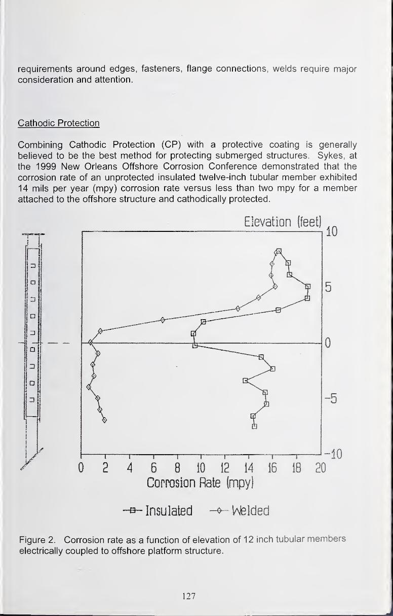
requirements around edges, fasteners, flange connections, welds require major
consideration and attention.
Cathodic Protection
Combining Cathodic Protection (CP) with a protective coating is generally
believed to be the best method for protecting submerged structures. Sykes, at
the 1999 New Orleans Offshore Corrosion Conference demonstrated that the
corrosion rate of an unprotected insulated twelve-inch tubular member exhibited
14 mils per year (mpy) corrosion rate versus less than two mpy for a memberattached to the offshore structure and cathodically protected.
Corrosion Rate (mpy!
Insulated -^l^lded
Figure 2. Corrosion rate as a function of elevation of 12 inch tubular members
electrically coupled to offshore platform structure.
127
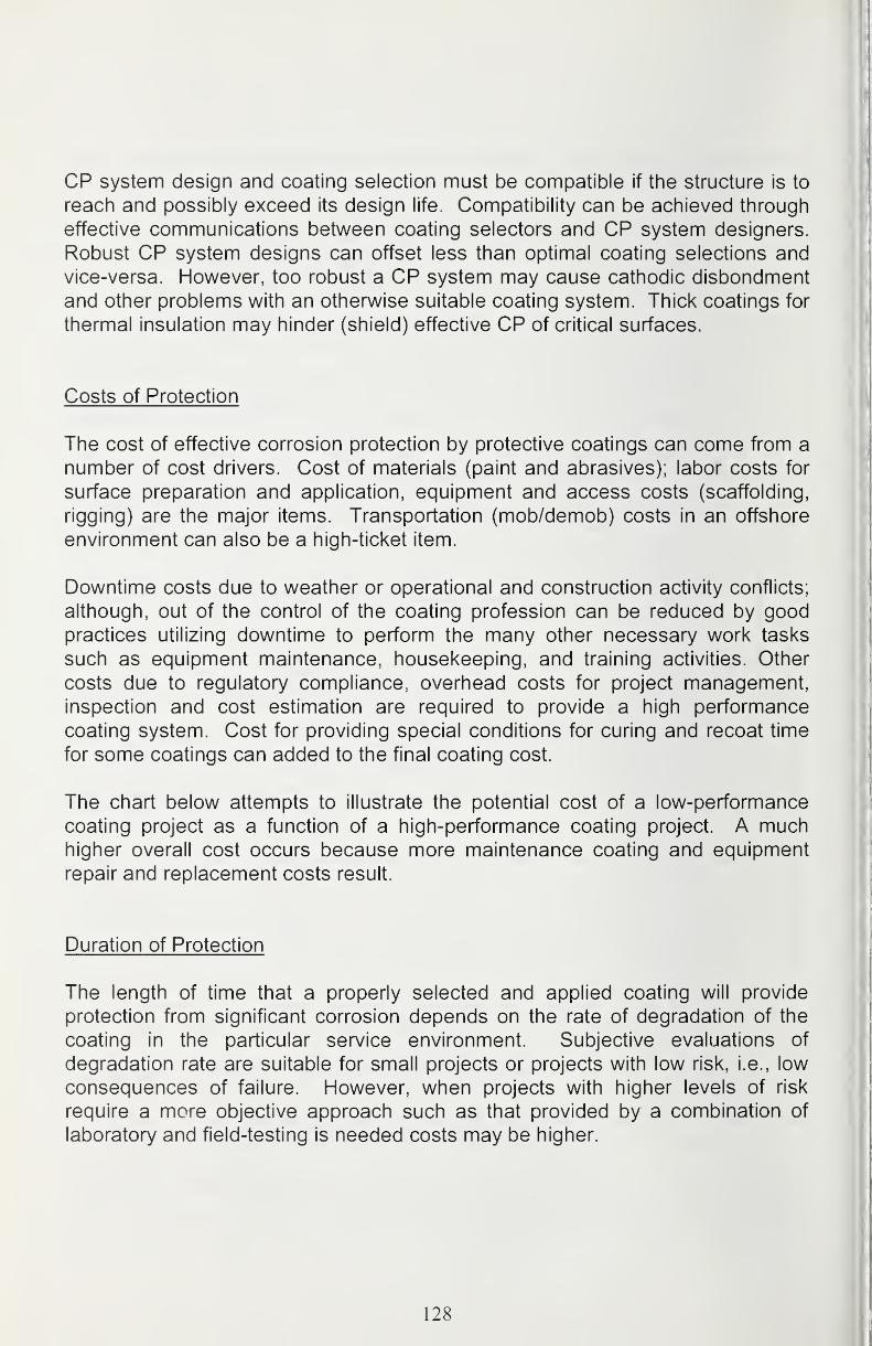
CP system design and coating selection must be compatible if the structure is to
reach and possibly exceed its design life. Compatibility can be achieved through
effective communications between coating selectors and CP system designers.
Robust CP system designs can offset less than optimal coating selections andvice-versa. However, too robust a CP system may cause cathodic disbondment
and other problems with an otherwise suitable coating system. Thick coatings for
thermal insulation may hinder (shield) effective CP of critical surfaces.
Costs of Protection
The cost of effective corrosion protection by protective coatings can come from a
number of cost drivers. Cost of materials (paint and abrasives); labor costs for
surface preparation and application, equipment and access costs (scaffolding,
rigging) are the major items. Transportation (mob/demob) costs in an offshore
environment can also be a high-ticket item.
Downtime costs due to weather or operational and construction activity conflicts;
although, out of the control of the coating profession can be reduced by goodpractices utilizing downtime to perform the many other necessary work tasks
such as equipment maintenance, housekeeping, and training activities. Other
costs due to regulatory compliance, overhead costs for project management,inspection and cost estimation are required to provide a high performance
coating system. Cost for providing special conditions for curing and recoat time
for some coatings can added to the final coating cost.
The chart below attempts to illustrate the potential cost of a low-performance
coating project as a function of a high-performance coating project. A muchhigher overall cost occurs because more maintenance coating and equipment
repair and replacement costs result.
Duration of Protection
The length of time that a properly selected and applied coating will provide
protection from significant corrosion depends on the rate of degradation of the
coating in the particular service environment. Subjective evaluations of
degradation rate are suitable for small projects or projects with low risk, i.e., low
consequences of failure. However, when projects with higher levels of risk
require a more objective approach such as that provided by a combination of
laboratory and field-testing is needed costs may be higher.
128
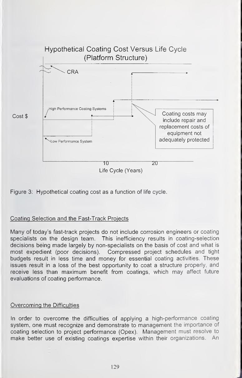
Hypothetical Coating Cost Versus Life Cycle
(Platform Structure)
Costs
CRA
High Performance Coating Systems
Low Performance System
Coating costs mayinclude repair and
replacement costs of
equipment not
adequately protected
Life Cycle (Years)
Figure 3: Hypothetical coating cost as a function of life cycle.
Coating Selection and the Fast-Track Projects
Many of today's fast-track projects do not include corrosion engineers or coating
specialists on the design team. This inefficiency results in coating-selection
decisions being made largely by non-specialists on the basis of cost and what is
most expedient (poor decisions). Compressed project schedules and tight
budgets result in less time and money for essential coating activities. These
issues result in a loss of the best opportunity to coat a structure properly, and
receive less than maximum benefit from coatings, which may affect future
evaluations of coating performance.
Overcoming the Difficulties
In order to overcome the difficulties of applying a high-performance coating
system, one must recognize and demonstrate to management the importance of
coating selection to project performance (Opex). Management must resolve to
make better use of existing coatings expertise within their organizations. An
129
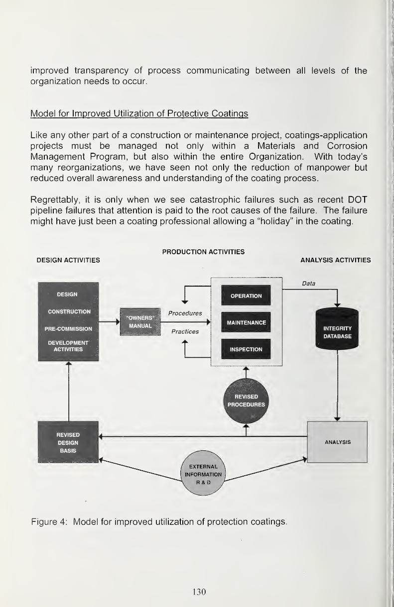
improved transparency of process communicating between all levels of the
organization needs to occur.
Model for Improved Utilization of Protective Coatings
Like any other part of a construction or maintenance project, coatings-application
projects must be managed not only within a Materials and Corrosion
Management Program, but also within the entire Organization. With today's
many reorganizations, we have seen not only the reduction of manpower but
reduced overall awareness and understanding of the coating process.
Regrettably, it is only when we see catastrophic failures such as recent DOTpipeline failures that attention is paid to the root causes of the failure. The failure
might have just been a coating professional allowing a "holiday" in the coating.
PRODUCTION ACTIVmESDESIGN ACTIVITIES ANALYSIS ACTIVITIES
DESIGN
CONSTRUCTION
PRE-COMMISSION
DEVELOPMENTACTIVITIES a.
"OWNERS"
MANUAL
Data
INTEGRITY
DATABASE
REVISED
DESIGN
BASIS
Figure 4: Model for improved utilization of protection coatings.
130

Conclusions
Coating selection for offshore service is important and difficult.
1. The coating selection process can be improved by applying classical
decision-making theory to the problem.
2. Level of complexity required in making the decision depends upon context
and level of risk.
3. Whatever decision making process for coating selection is chosen by an
organization, it should be well documented and transparent; and it should
deliver practical, cost-effective solutions.
4. Coating selections should be made by experienced individuals wheneverpossible, and the selections should reflect proper balance of technical andeconomic factors.
5. The root cause of many coating failures i.e. premature coating breakdowncomes from allowing outside forces to compromise the coating application
process.
Although there are many components to implementing and maintaining a
successful coating program, one needs to remember that these key componentsof a coating system are based on actual service environments, surface
preparation requirements and coating application options. Finally, one should
always remember to follow the Health, Safety and Environmental managementprograms within various organizations involved with producing a high
performance coating system.
References
Larry J. Sykes, Results Of Test Member Exposure at an Offshore Platform NACEInternational, Offshore Corrosion Conference, New Orleans LA 1992
NOROSK Standard, M-501 Surface Preparation and Protective Coatings
SSPC Steel Structures Painting Manual, Volume 2 Pittsburg PA, 1995
United Kingdom Offshore Operators (UKOOA), London, UK
US Army Corp of Engineers, New Construction and Maintenance Engineering
Manual EM1 1 10-2-3400, April 1995
131

Corrosion Protection for Offshore Pipelines
Ernest W. Klechka, Jr., P.E.
CC TechnologiesDublin, Ohio
Abstract
Offshore pipelines frequently have an expected service life in excess of thirty
years. To survive sub-sea, offshore pipelines are protected from corrosion with
protective coatings and cathodic protection. Coatings must be tough, have goodadhesion to the pipe, resist mechanical damage during installation, easily
repaired, easily coated in the weld lanes, and be compatible with cathodic
protection. Cathodic protection is provided by sacrificial bracelet anode systems
or impressed current cathodic protection systems (ICCP).
Many different types of coatings are used for offshore pipeline applications.
These include fusion bond epoxy (FBE), dual and multilayer FBE, three-layer
FBE Polyolefin, polyolefin, and coal tar enamel coatings [1][2][3]. In addition to
protective coatings, sub-sea pipelines are often coated with cement-weight
coatings to provide negative buoyancy.
Internal corrosion control methods are dependent upon service conditions. For
gas pipelines internal corrosion controls includes lowering the dew point of the
gas and use of inhibitors. For oil pipelines, reducing the water cut, corrosion and
scale inhibition, and biological controls are used to mitigate internal corrosion.
For both gas and oil pipelines internal corrosion coupons are used to monitor the
effectiveness of the corrosion controls. Erosion corrosion can be controlled by
removing solids from the stream and by mechanical design. Droplet corrosion in
gas streams are controlled by decreasing the dew point of the gas to a
temperature below the lowest expected temperature of the pipeline. To minimize
erosion sand removal from the production stream in an important part of the
corrosion control design.
Corrosion allowance for internal corrosion is frequently used to provide additional
metal for corrosion loss. Corrosion and scale Inhibitors as well as biocides
cannot be relied upon to be more than 90 percent effective; therefore, to allow for
small amounts of corrosion, addition metal is added to the pipe wall thickness.
The corrosion allowance should anticipate the maximum metal loss over the life
of the pipeline.
132 I
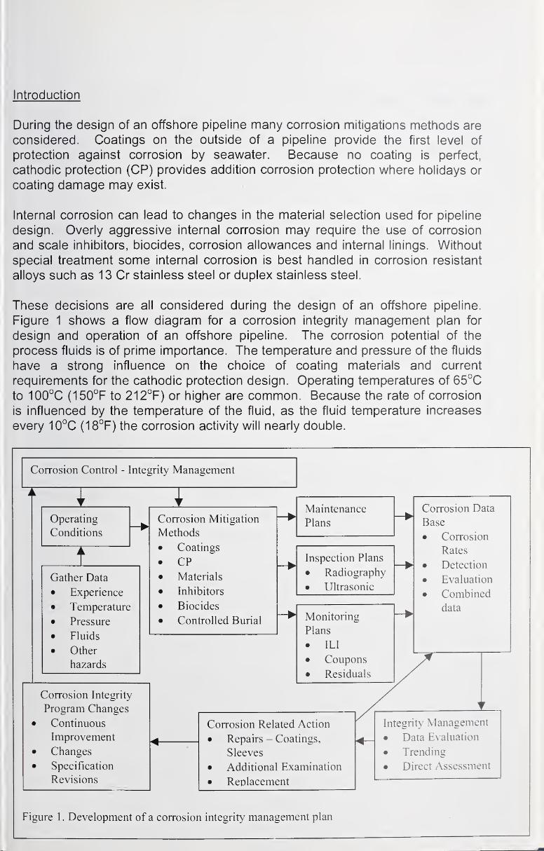
Introduction
During the design of an offshore pipeline many corrosion mitigations methods are
considered. Coatings on the outside of a pipeline provide the first level of
protection against corrosion by seawater. Because no coating is perfect,
cathodic protection (CP) provides addition corrosion protection where holidays or
coating damage may exist.
Internal corrosion can lead to changes in the material selection used for pipeline
design. Overly aggressive internal corrosion may require the use of corrosion
and scale inhibitors, biocides, corrosion allowances and internal linings. Without
special treatment some internal corrosion is best handled in corrosion resistant
alloys such as 13 Cr stainless steel or duplex stainless steel.
These decisions are all considered during the design of an offshore pipeline.
Figure 1 shows a flow diagram for a corrosion integrity management plan for
design and operation of an offshore pipeline. The corrosion potential of the
process fluids is of prime importance. The temperature and pressure of the fluids
have a strong influence on the choice of coating materials and current
requirements for the cathodic protection design. Operating temperatures of 65°C
to 100°C (150°F to 212°F) or higher are common. Because the rate of corrosion
is influenced by the temperature of the fluid, as the fluid temperature increases
every 10°C (18°F) the corrosion activity will nearly double.
Corrosion Control - Integrity Management
IOperating
Conditions
IGather Data
Experience
Temperature
Pressure
Fluids
Other
hazards
Corrosion Integrity
Program Changes
Continuous
Improvement
Changes
Specification
Revisions
ICorrosion Mitigation
Methods
Coatings
CPMaterials
Inhibitors
Biocides
Controlled Burial
Maintenance
Plans
Inspection Plans
• Radiography
• Ultrasonic
Monitoring
Plans
• ILI
• Coupons
• Residuals
Corrosion Data
Base
• Corrosion
Rates
• Detection
• Evaluation
• Combined
data
Corrosion Related Action
• Repairs - Coatings,
Sleeves
• Additional Examination
• Replacement
Integrity Management
• Data Evaluation
• Trending
• Direct Assessment
Figure 1 . Development of a corrosion integrity management plan
Fusion Bond Epoxies FBE
FBE has been used since the early 60's.
Dual layers - FBE with an FBE friction surface
Internal Corrosion
The final design for corrosion control not only includes material selection,
coatings, and cathodic protection, but also includes monitoring plans, inspection
plans, and maintenance plans.
Evaluation of Corrosion Potential in Hydrocarbon Systems
International standards giye guidance in evaluation of the expected level of
corrosion. NORSOK Standard such as M-001 Material selection [4], M-503Cathodic Protection [5], and M-506 C02 Corrosion Rate Calculation Model [6]
give some guidance in calculating corrosion potential. Evaluation of the
corrosion potential should include at a minimum:
• C02-content.
• H2S-content.
• Oxygen content and content of other oxidizing agents.
• Operating temperature and pressure.
• Organic acids, pH.
• Halide and metal ion concentrations
• Velocity, flow regime and sand production.
• Biological activity
• Condensing conditions.
A gas is considered dry when the water dew point at the actual (operating)
pressure is at least 10°C (18°F) lower than the actual minimum operation
temperature for the system. Of these corrosion considerations, only temperature
and pressure effect the selection of external corrosion controls.
Typically for pipelines, an inhibitor efficiency approaching 90 percent can be
achieved. The inhibitor efficiency should include the effects of glycol and/or
methanol injection. The anticipated corrosion rate can calculated using
standards like the NORSOK standard M-506 C02 Corrosion Rate Calculation
Model [6]. Unless field experience or test data are available, the corrosion rate in
an inhibited hydrocarbon should be verified by corrosion tests.
134
Pipeline Failure Modes
Offshore pipelines have several potential failure modes or threats. These treats
to an offshore pipeline include external and internal corrosion. For offshore
pipelines the main external corrosion failure modes are:
• Seawater corrosion, scowering, abrasion of the coating, and sea bottom
movement• Galvanic corrosion (dissimilar metals in an electrolyte)
• Oxygen concentrations cell corrosion (pitting and crevice corrosion)
Offshore pipelines main interna! corrosion failure modes are:
• Acid gasses and organic acids combined with water
• Erosion, and erosion corrosion caused by sand and entrained particles (or
droplets)
• Scaling cause by incompatible fluids
• Microbiologically Induced Corrosion (MIC), accelerated corrosion caused
by or as a result of microbiological activity.
Coating and Coating Selection
The most common coatings used today for offshore pipelines are fusion bondedepoxy (FBE) coatings, dual layer or multiple layer FBE, three layer
FBE/polyolefin adhesive/polyolefin, and coal tar enamel coating. Typically for
offshore pipelines these coatings are normally shop applied.
Common requirements for shop-applied fusion bonded epoxy coatings can be
found in RP0394-2002 Application, Performance, and Quality Control of Plant-
Applied, Fusion-Bonded Epoxy External Pipe Coating [7] and CSA Standard
Z662-03, Oil and Gas Pipeline Systems [3] and are shown in Table 1. FBEcoatings have been used for pipeline coatings since the early 1960's.
Modified fusion bonded epoxy coatings used offshore include dual powder
coatings or multiple layer FBE coating. Dual powered coatings are used improve
the gouge resistance and toughness of FBE during direction boring [9]. A rough
coat is frequently used to improve friction between the FBE and a cement weight
coating. Rough coats also improve traction for lay barge operations and improve
safety [1]. Thicker dual powder coatings can also enhance high temperature
performance. Dual powder coating system can be used at operating
temperatures of 110°C (230°F) or higher.
Three layers FBE/polyolefin adhesive/polyolefin have also been used offshore
since the early 1970. The polyolefin to coat can be either polyethylene or
135
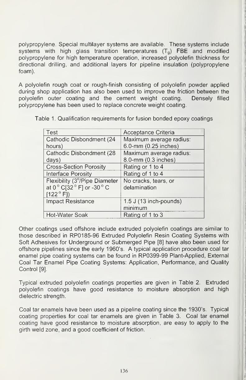
polypropylene. Special multilayer systems are available. These systems include
systems with high glass transition temperatures (Tg) FBE and modified
polypropylene for high temperature operation, increased polyolefin thickness for
directional drilling, and additional layers for pipeline insulation (polypropylene
foam).
A polyolefin rough coat or rough-finish consisting of polyolefin powder applied
during shop application has also been used to improve the friction between the
polyolefin outer coating and the cement weight coating. Densely filled
polypropylene has been used to replace concrete weight coating.
Table 1 . Qualification requirements for fusion bonded epoxy coatings
Test Acceptance Criteria
Cathodic Disbondment (24
hours)
Maximum average radius:
6.0-mm (0.25 inches)
Cathodic Disbondment (28
days)
Maximum average radius:
8.0-mm (0.3 inches)
Cross-Section Porosity Rating or 1 to 4
Interface Porosity Rating of 1 to 4
Flexibility (3°/Pipe Diameter
atO°C[32°F] or -30° C[122° F])
No cracks, tears, or
delamination
Impact Resistance 1 .5 J (13 inch-pounds)
minimumHot-Water Soak Rating of 1 to 3
Other coatings used offshore include extruded polyolefin coatings are similar to
those described in RP01 85-96 Extruded Polyolefin Resin Coating Systems with
Soft Adhesives for Underground or Submerged Pipe [8] have also been used for
offshore pipelines since the early 1960's. A typical application procedure coal tar
enamel pipe coating systems can be found in RP0399-99 Plant-Applied, External
Coal Tar Enamel Pipe Coating Systems: Application, Performance, and Quality
Control [9].
Typical extruded polyolefin coatings properties are given in Table 2. Extruded
polyolefin coatings have good resistance to moisture absorption and high
dielectric strength.
Coal tar enamels have been used as a pipeline coating since the 1930's. Typical
coating properties for coal tar enamels are given in Table 3. Coal tar enamel
coating have good resistance to moisture absorption, are easy to apply to the
girth weld zone, and a good coefficient of friction.
136
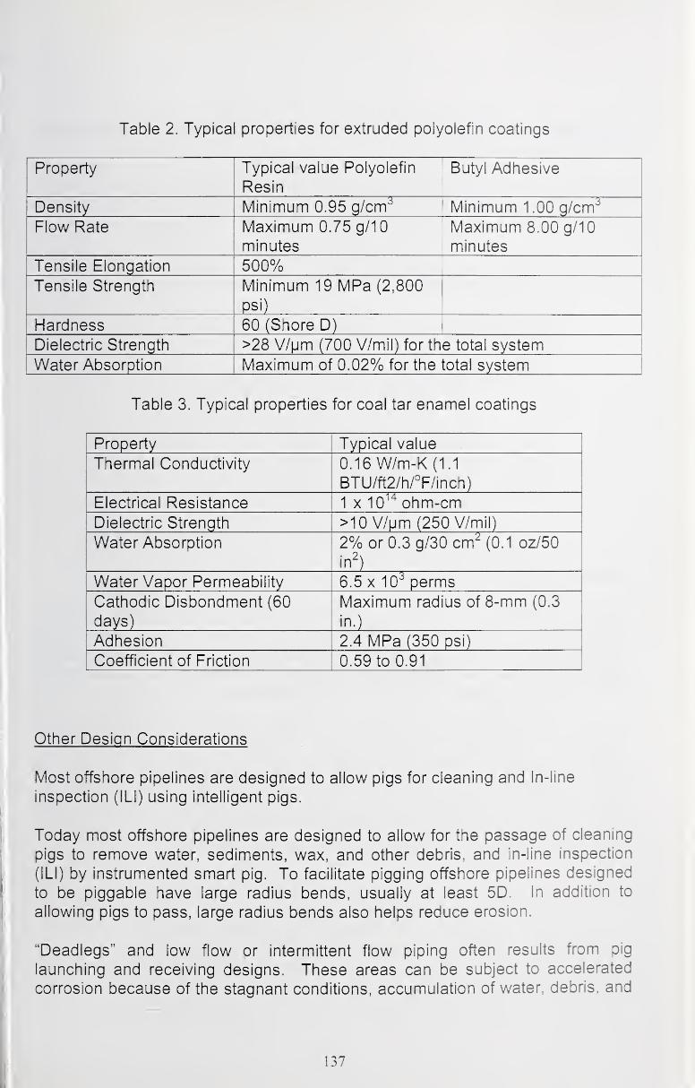
Table 2. Typical properties for extruded polyolefin coatings
Property Typical value Polyolefin
Resin
Butyl Adhesive
Density Minimum 0.95 g/cm^ Minimum 1 .00 g/cm^
Flow Rate Maximum 0.75 g/10 Maximum 8.00 g/10
minutes minutes' Tensile Elongation 500%Tensile Strength Minimum 19 MPa (2,800
psi)
Hardness 60 (Shore D)
Dielectric Strength >28 V/Mm (700 V/mil) for the total system
Water Absorption Maximum of 0.02% for the total system
Table 3. Typical properties for coal tar enamel coatings
Property Typical value
Thermal Conductivity 0.16 W/m-K (1.1
BTU/ft2/h/°F/inch)
Electrical Resistance 1 X 10^^ ohm-cmDielectric Strength >10 V/pm (250 V/mil)
Water Absorption 2% or 0.3 g/30 cm^ (0,1 oz/50
in^)
Water Vapor Permeability 6.5 X 10^ perms
Cathodic Disbondment (60
days)
Maximum radius of 8-mm (0.3
in.)
Adhesion 2.4 MPa (350 psi)
Coefficient of Friction 0.59 to 0.91
Other Design Considerations
Most offshore pipelines are designed to allov^ pigs for cleaning and In-line
inspection (ILl) using intelligent pigs.
Today most offshore pipelines are designed to allow for the passage of cleaning
pigs to remove water, sediments, wax, and other debris, and in-line inspection
(ILl) by instrumented smart pig. To facilitate pigging offshore pipelines designed
to be piggable have large radius bends, usually at least 5D. In addition to
allowing pigs to pass, large radius bends also helps reduce erosion.
"Deadlegs" and low flow or intermittent flow piping often results from pig
launching and receiving designs. These areas can be subject to accelerated
corrosion because of the stagnant conditions, accumulation of water, debris, and
137
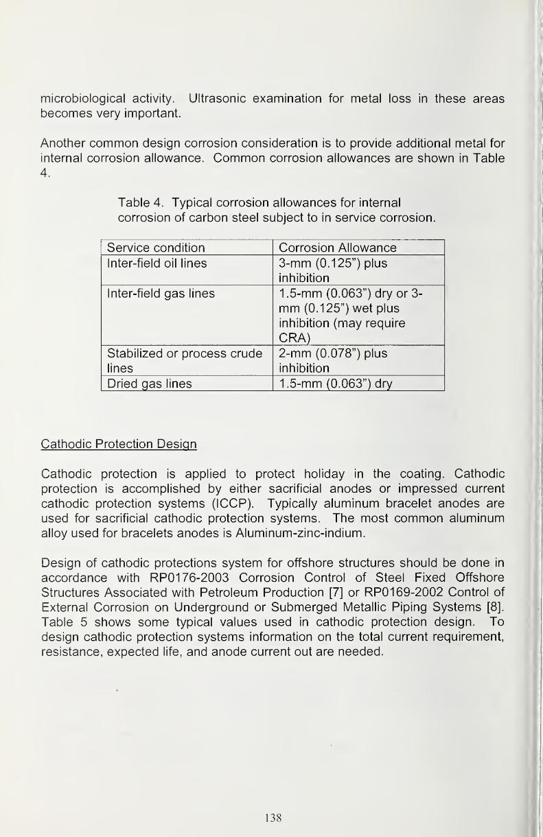
microbiological activity. Ultrasonic examination for metal loss in these areas
becomes very important.
Another common design corrosion consideration is to provide additional metal for
internal corrosion allowance. Common corrosion allowances are shown in Table
4.
Table 4. Typical corrosion allowances for internal
corrosion of carbon steel subject to in service corrosion.
Service condition Corrosion Allowance
Inter-field oil lines 3-mm (0.125") plus
inhibition
Inter-field gas lines 1.5-mm (0.063") dry or 3-
mm (0.125") wet plus
inhibition (may require
CRA)Stabilized or process crude
lines
2-mm (0.078") plus
inhibition
Dried gas lines 1.5-mm (0.063") dry
Cathodic Protection Design
Cathodic protection is applied to protect holiday in the coating. Cathodic
protection is accomplished by either sacrificial anodes or impressed current
cathodic protection systems (ICCP). Typically aluminum bracelet anodes are
used for sacrificial cathodic protection systems. The most common aluminum
alloy used for bracelets anodes is Aluminum-zinc-indium.
Design of cathodic protections system for offshore structures should be done in
accordance with RP01 76-2003 Corrosion Control of Steel Fixed Offshore
Structures Associated with Petroleum Production [7] or RP01 69-2002 Control of
External Corrosion on Underground or Submerged Metallic Piping Systems [8].
Table 5 shows some typical values used in cathodic protection design. Todesign cathodic protection systems information on the total current requirement,
resistance, expected life, and anode current out are needed.
138

Table 5. Cathodic protection design parameters and coatings design
considerations
Design parameter Typical Value
Seawater Resistivity 20 - 25 ohm-cmSaline Mud 100- 150 ohm-cmAnode open circuit
potential - buried
-1.05 V (Ag/AgCI)
Anode open circuit
potential - seawater
-0.95 V (Ag/AgCI)
Anode Consumption 1280 A hours/ pound
Anode Utilization
Factor
0.80
Coating BreakdownFactor (FBE)
0.5% to 1.0% (initial)
10% (after 30 years)
Insulation BreakdownFactor
0.5% to 1.0% (initial)
3% (after 30 years)
Neoprene Breakdownfactor
0.5% to 1.0% (initial)
5% (after 30 years)
Design current density
for bare steel in
seawater
12mA/ft^ (initial)
l\wNV? (after
polarization)
Design current density
in sand or mud2mA/ft^ (initial and after
polarization)
Normally sacrificial cathodic protection systems for pipelines consist of bracelet
anode spaced periodically along the pipeline. For design of a sacrificial cathodic
protection system, the current demand is calculated from the coating breakdown
factor, design current density, and the total surface of the pipeline as shown in
equation 1.
Ipeq "Idesign *Apipe*Fcoating/1000 (1)
where: Ueq is the total current demand
design is the design current density
Apipe is the total area of the pipeline
Fcoating is the coating breakdown factor
The total anode weight required is then:
Wanodes = (Ireq* 8760 hr/yoar * expected life) / (Consumption rate * efficiency) (2)
139
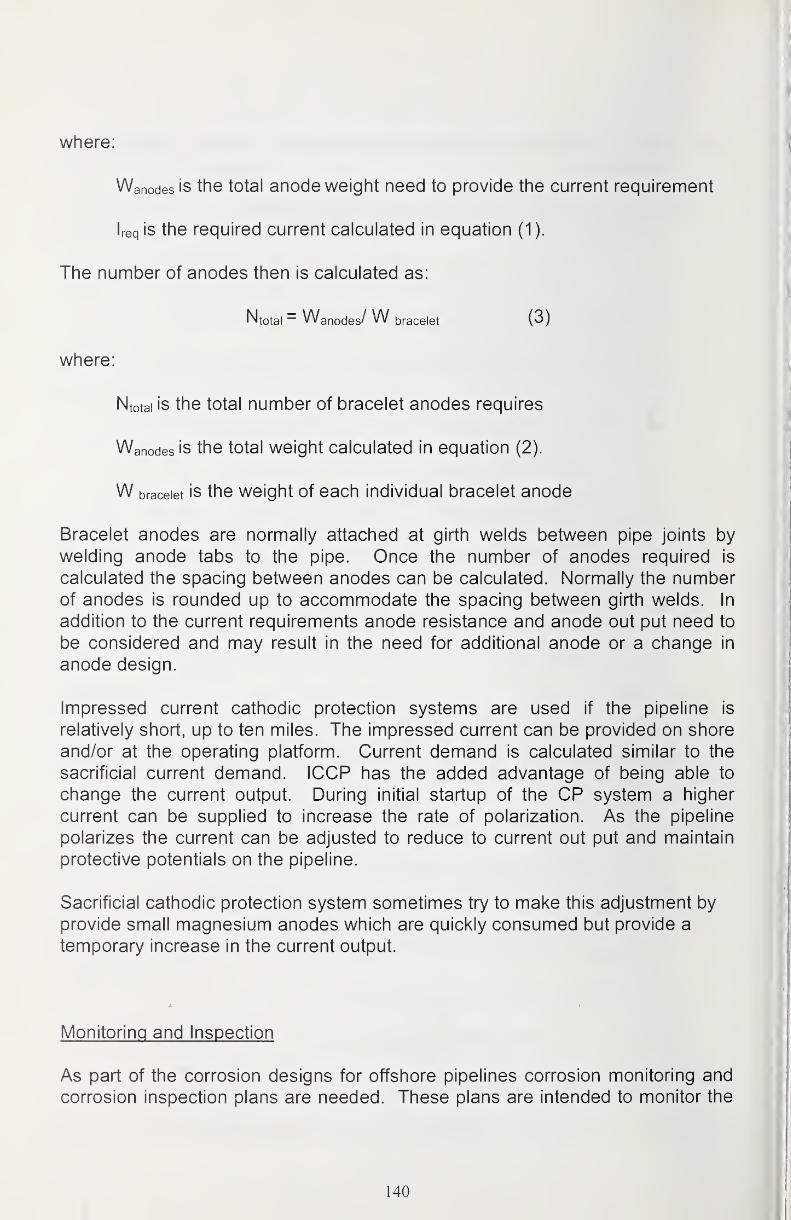
where:
Wanodes is the total anode weight need to provide the current requirement
Ireq is the required current calculated in equation (1).
The number of anodes then is calculated as:
Ntotal = Wanodes/ W bracelet (3)
where:
Ntotal is the total number of bracelet anodes requires
Wanodes is the total weight calculated in equation (2).
W bracelet is the Weight of each individual bracelet anode
Bracelet anodes are normally attached at girth welds between pipe joints by
welding anode tabs to the pipe. Once the number of anodes required is
calculated the spacing between anodes can be calculated. Normally the numberof anodes is rounded up to accommodate the spacing between girth welds. In
addition to the current requirements anode resistance and anode out put need to
be considered and may result in the need for additional anode or a change in
anode design.
Impressed current cathodic protection systems are used if the pipeline is
relatively short, up to ten miles. The impressed current can be provided on shore
and/or at the operating platform. Current demand is calculated similar to the
sacrificial current demand. ICCP has the added advantage of being able to
change the current output. During initial startup of the CP system a higher
current can be supplied to increase the rate of polarization. As the pipeline
polarizes the current can be adjusted to reduce to current out put and maintain
protective potentials on the pipeline.
Sacrificial cathodic protection system sometimes try to make this adjustment by
provide small magnesium anodes which are quickly consumed but provide a
temporary increase in the current output.
Monitoring and Inspection
As part of the corrosion designs for offshore pipelines corrosion monitoring and
corrosion inspection plans are needed. These plans are intended to monitor the
140
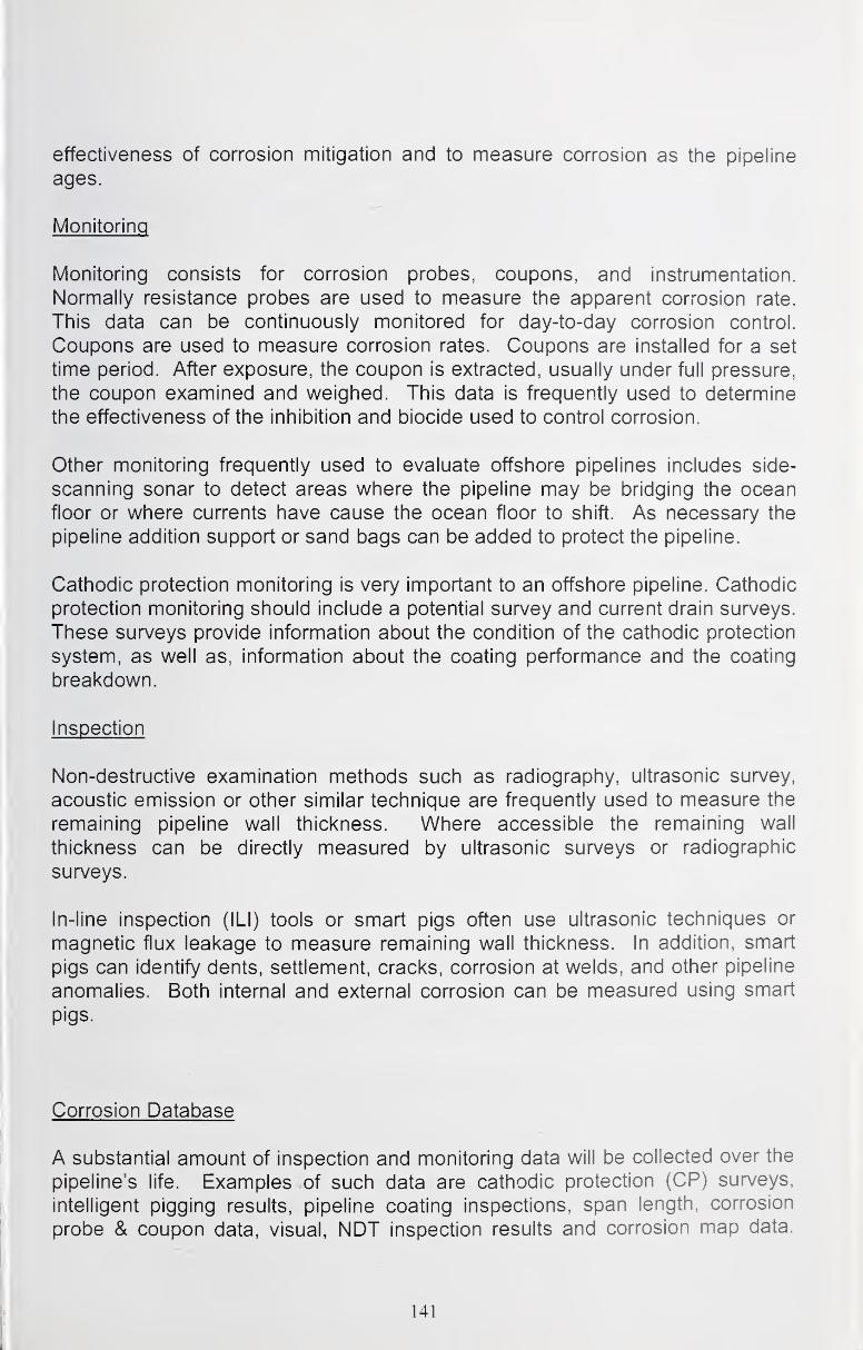
effectiveness of corrosion mitigation and to measure corrosion as the pipeline
ages.
Monitoring
Monitoring consists for corrosion probes, coupons, and instrumentation.
Normally resistance probes are used to measure the apparent corrosion rate.
This data can be continuously monitored for day-to-day corrosion control.
Coupons are used to measure corrosion rates. Coupons are installed for a set
time period. After exposure, the coupon is extracted, usually under full pressure,
the coupon examined and weighed. This data is frequently used to determine
the effectiveness of the inhibition and biocide used to control corrosion.
Other monitoring frequently used to evaluate offshore pipelines includes side-
scanning sonar to detect areas where the pipeline may be bridging the ocean
floor or where currents have cause the ocean floor to shift. As necessary the
pipeline addition support or sand bags can be added to protect the pipeline.
Cathodic protection monitoring is very important to an offshore pipeline. Cathodic
protection monitoring should include a potential survey and current drain surveys.
These surveys provide information about the condition of the cathodic protection
system, as well as, information about the coating performance and the coating
breakdown.
Inspection
Non-destructive examination methods such as radiography, ultrasonic survey,
acoustic emission or other similar technique are frequently used to measure the
remaining pipeline wall thickness. Where accessible the remaining wall
thickness can be directly measured by ultrasonic surveys or radiographic
surveys.
In-line inspection (ILI) tools or smart pigs often use ultrasonic techniques or
magnetic flux leakage to measure remaining wall thickness. In addition, smart
pigs can identify dents, settlement, cracks, corrosion at welds, and other pipeline
anomalies. Both internal and external corrosion can be measured using smart
pigs.
Corrosion Database
A substantial amount of inspection and monitoring data will be collected over the
pipeline's life. Examples of such data are cathodic protection (CP) surveys,
intelligent pigging results, pipeline coating inspections, span length, corrosion
probe & coupon data, visual, NDT inspection results and corrosion map data.
141

other examples include details of inhibition programs and levels of conformance
to plan, locations and technical operational information on CI systems,
comparison of actual wall thickness with design wall thickness of pipelines, piping
and vessels, conditions of external coatings and internal linings. These data mayreside within various departments and considerable effort may be needed to
collect, collate and arrange this data in a format that will allow ready comparison
against acceptable values.
Monitoring and inspection over the life of the pipeline will generate a great
number of data points. Today most pipelines use an electronic database to store
the pipeline inspection, monitoring data and integrity data. Electronic databases
greatly simplify the comparison of measured values against design values during
asset integrity assessments. Identification of trends in coating integrity, cathodic
protection, and internal corrosion can be correlated with asset degradation.
Conclusions about Coatings for Offshore Pipelines
The first line of defense for an offshore pipeline is the coating on the pipe. Manydifferent types of coating are used for offshore pipeline. Cathodic protection is
used to protect holidays in the coating. Coatings for offshore must have goodresistance to water absorption, cathodic disbondment, and strong adhesion to
the pipe.
Testing of coatings can provide some guidance concerning the ability of a
coating to survive the offshore environment. Coating history and performance is
very valuable information.
References
[1] J. A. Kehr, Fusion-Bonded Epoxy (FBE): A Foundation for Pipeline Corrosion
Protection, NACE International, Houston TX, 2003
[2] ASM Handbook Volume 13: Corrosion, ASM International, Metals Park, OH,1987
[3] CSA Standard Z662-03, Oil and Gas Pipeline Systems, CSA International,
June 2003
[4] NOROSK Standard, M-001 Materials selection (Rev. 3, Nov. 2002)
[5] NOROSK Standard, M-503 Cathodic protection (Rev. 2, Sept. 1997)
142
[6] M-506 C02 Corrosion Rate Calculation Model (Rev. 1, June 1998)
[7] RP0394-2002 Application, Performance, and Quality Control of Plant-Applied,
Fusion-Bonded Epoxy External Pipe Coating NACE International, 2002
[8] RP01 85-96 Extruded Polyolefin Resin Coating Systems with Soft Adhesives
for Underground or Submerged Pipe, NACE International, Houston TX, 1996
[9] RP0399-99 Plant-Applied, External Coal Tar Enamel Pipe Coating Systems:
Application, Performance, and Quality Control, NACE International, Houston TX,
1999
[7] RP01 76-2003 Corrosion Control of Steel Fixed Offshore Structures
Associated with Petroleum Production, NACE International, Houston TX, 2003
[8] RP01 69-2002 Control of External Corrosion on Underground or SubmergedMetallic Piping Systems, NACE International, Houston TX, 2002
[9] E.W. Klechka, "Dual Powder FBE Coatings Used for Directionally Drilled
Alaskan River Crossing," Materials Performance, June 2003
143
Experience with Coating for Corrosion Protection from the NorwegianContinental Shelf
Roger L. [email protected]
Helge I. Vestre
helge-i. [email protected]
Rolf H. Hinderaker
Petroleum Safety Authority NorwayStavanger, Norway
Abstract
This article will aim at highlighting various phases of Norwegian offshore field
developments, from integrated fixed jackets and GBS' to floating production
units, e.g. FPSO's, semi-submersibles, where the coating design, application andmaintenance must be such that the facilities sustain the harsh environment andweather conditions encountered offshore Norway. Also, as a regulator, the article
emphasizes on aspects of the regulatory regime e.g. experiences with
prescriptive and functional requirements, improvements achieved in protective
equipment for surface treatment, development of regulations for coatings and
coatings application and operational experience with various coating systems.
The Petroleum Safety Authority Norway
The Petroleum Safety Authority Norway (PSA) was established 1 January 2004,
as an independent governmental supervisory authority which reports to the
Ministry of Labour and Governmental Administration. It is located in Stavanger,
on the southwest coast of Norway and shares offices with the Norwegian
Petroleum Directorate (NPD). PSA employs approximately 150 persons.
PSA has responsibility for safety, emergency preparedness and working
environment in the petroleum activities. Upon establishment, enforcing
regulations relating to health, safety and working environment (HSE) in the
petroleum activities is a responsibility of PSA. Also, the areas of authority have
been extended and incorporate supervisory activity towards health, emergency
144
preparedness and working environment at onshore petroleum process facilities
and onshore transportation pipelines.
Leading principles for PSA are to provide information and counselling towards
the petroleum industry, cooperate with corresponding HSE authorities both
nationally and internationally and promote transfer of experience and knowledgeof health, safety and working environment in the society in general. With suchprinciples in mind, our ambition with this article is to contribute with experience
on development of protective equipment for operators, address operational
coatings experience and development of regulations.
Norwegian Oil and Gas Fields
As of January 2004, 44 oil and gas fields are in production on the NorwegianContinental Shelf (NCS). These are located in the southern North Sea sector (12
fields), the northern North Sea sector (27 fields) and the Norwegian Sea (five
fields). Seven fields are at the moment under development. A total of 112
platforms are installed, 94 fixed installations and 18 floating production andstorage installations.
The North Sea
Ekofisk, an oil field located in the southern North Sea, was discovered in 1969and put in production in 1971. Developments of offshore facilities at Ekofisk
make it serve as a hub for oil and gas pipelines to the UK and the Europeancontinent. Although Ekofisk has been in production for more than thirty years, the
reservoir still contains oil and gas for several decades of production.
Frigg, a gas field located in the northern North Sea at the borderline of Norwayand UK, was discovered in 1971. The first gas was piped to St. Fergus in
Scotland in 1976. Frigg is planned to cease production in 2004. Statfjord, yet
another oil field in the northern North Sea was put in production in 1979.
Statfjord, along with other fields in the Tampen area, e.g. Gullfaks, Snorre and
several minor fields, were the most important oil producing province on the
Norwegian Continental Shelf in the 1980's and 1990's.
With the Troll development, Norway moved on to take advantage of its great gas
resources and marks a development where gas export has a significant
importance in terms of overall petroleum production. Also, Troll is a major
contributor to Norway's oil production. The oil in the reservoir is trapped in a zone
so thin that the oil has to be produced through some of the worlds longest
horizontally drilled wells.
145
The Norwegian Sea
Development of oil and gas fields in the Norwegian Sea started with Draugen, an
oil field, which was put in production in 1993. Until present, five moredevelopments have been completed, where Asgard ranks as one of the largest
subsea developments worldwide.
The Barents Sea
In the Barents Sea, the development of Snohvit is ongoing. This developmentincludes offshore subsea facilities and an onshore Liquefied Natural Gas (LNG)plant. Snohvit is due for production in 2006.
Offshore Infrastructure Investments
In the past three decades since the production of oil on the Norwegian
Continental Shelf began in 1971, the total investment in offshore structures has
exceeded 660 billion Norwegian kroner ($94 billion US). It has been estimated
that the cost of procurement and application of all coatings accounts for 1.5 to 3
percent of the total cost of fabricating a platform topside. The cost of
procurement and application of coatings are then in the range of 10 - 23 billion
Norwegian kroner ($1 .4 - 3.3 billion US).
Although Norwegian offshore installations have a coating design and coatings
application in accordance with established standards and procedures, we have in
recent years seen examples of deterioration and degradation of coatings on
installations after just a few years of operation. Concerns with safety aspects like
corrosion, leaks, etc. are reasons for the authorities emphasis on applying
qualified coating products, operators, supervisors and procedures.
Norwegian Oil and Gas Production
In 2002, an average production of 3.33 million barrels of crude oil each day ranks
Norway as seventh among the oil producing nations. With an oil export of 3.12
million barrels each day, Norway ranks as the third largest oil exporter worldwide.
Oil is shipped to the market through pipelines and by offshore offloading to crude
tankers.
146
Norway is a major supplier of gas to the European market. Norwegian supplies
cover 11 percent of the European demand for gas. In 2002 the export amountedto 64.2 billion Sm^ dry gas. The export covers two percent of the consumption on
a worldwide basis.
The gas is transported to the UK and the European continent through a pipeline
grid of more than 6000 kilometres, which makes this the longest offshore
transportation grid.
Production Forecast - Prosperity or Decline?
Norwegian oil production has been at a plateau since 1996 and estimates
indicate a production rate of slightly less than three million barrels each day until
2005. From then on, the oil production will probably decrease.
Two scenarios for oil and gas production from the NCS may be foreseen; the
decline scenario and f/?e long-term scenario. The first, decline, assumes a
consensus among the petroleum industry and the authorities that what has been
achieved so far is satisfactory. It involves stagnation for the NCS and of the
Norwegian oil and gas industry over the coming ten to twenty years. Thealternative, more prosperous long-term scenario, suggests a common effort from
the petroleum industry and the authorities to extract the petroleum resources in a
cost effective manner. The government's aim is that the long-term scenario will
prevail and the Parliament (Stoning) has concurred with this objective, which puts
oil and gas production on the NCS in a century-long perspective.
Norway's oil and gas resources belong to the Norwegian community and must be
managed for the maximum benefit of present and future generations. An overall
objective of government oil and gas policy is accordingly to ensure that the
largest possible share of value creation from petroleum operations accrues to the
community.
Development of Regulations and Standards for Coatings and Coatings
Application
The Regulations concerning loadbearing structures in the petroleum activities of
February 1992, with five guidelines, gave prescriptive requirements on the
regulation level. The guideline Guidelines of corrosion protection of loadbearing
structures provided examples to how these requirements could be met.
147
The guidelines dealt with issues like pretreatment, cleaning, paint work including
control during application, film thickness, adhesion, production and test reporting
and referred to applicable national and international standards.
As part of a drive to reduce costs related to the development of Norwegianoffshore oil fields, the Norwegian government established the NORSOK (The
competitive standing of the Norwegian offshore sector) project in 1993, which
implied involvement of oil companies, suppliers and the authorities to standardize
technical specifications for offshore projects.
NORSOK Standard M-501 Surface Preparation and Protective Coating
Prior to the NORSOK project, during 1991, the coating industry decided to
produce a standardized coating specification, which would improve the quality of
work performed in the coatings industry. The specification would make it easier
for industry personnel to have one set of standards, methods and requirements.
The first revision of the standardized coating specification was made during 1991
and 1992. The standardized coating specification has been used as a basis for
the NORSOK coating specification entitled M-501 Surface Preparation andProtective Coatings.
The authorities supported the project and made reference to the standard whenissuing updates of the regulations. In the Regulations Relating to Loadbearing
Structures of February 1998, the guidelines on corrosion protection for the most
had been replaced by a reference to NORSOK Standard M-501 as a recognized
standard.
Furthermore, NPD (now PSA) in 2002 issued jointly with Norwegian Pollution
Control Authority and Norwegian Social and Health Directorate, a revised
compilation of regulations comprising the original 14 prescriptive regulations to
five functional regulations with additional guidelines, entitled Regulations Relating
Health, Environment and Safety in the Petroleum Activities of January 2002.
Requirements in these regulations are formulated as functional requirements,
whereas the guidelines recommend one way to comply with the regulatory
requirement, for example a recognized standard. For coating protection, the
functional requirements are stated in Regulations Relating to Design andOutfitting of Facilities etc. in the Petroleum Activities Section 11, while the
guidelines propose NORSOK Standard M-501 as the means to be in compliance
with the regulation.
148
Improvements of Health. Safety and Working Environment in Coatings
Application
A noise study was initiated in 1997 in order to evaluate the noise exposure for
personnel working with sandblasting and ultra-high pressure (UHP)
waterblasting.
The report issued in 1998, documented that personnel involved in surface
treatment is the group which is most exposed to noise of all the offshore workers.
This is a working environment problem, which is common to the industry, both
offshore and onshore.
At the time of conducting the study, offshore work in the Norwegian sector wasgoverned by Regulations Relating to Systematic Follow-up of the Working
Environment in the Petroleum Activities of March 1995. These regulations specify
both the maximum allowable noise exposure and requirements for personal
protective equipment. According to these regulations "no employees should be
subjected to a daily noise exposure which during the course of a work shift
exceeds a 12-hour equivalent sound level of 83 dBA or an impulsive sound level
above 130 dBC (Peak)". Personnel protective equipment shall be suitable in
relation to protection against hazards without causing increased risk in itself.
Further, the equipment shall be adapted to both the work place and the user.
The average noise exposure for personnel during sandblasting varies from 95 -
110 dBA with today's most common equipment in Norway, the Viking mask. Thenoise generated by the air supply may reach more than 105 dBA inside the
mask.
Noise from the UHP waterblasting may be even higher than the sandblasting
noise. Noise levels measured were as high as 110 - 130 dBA. Since working
gear for UHP waterblasting has lower sound attenuation, the risk of hearing
impairment is consequently even higher. Even with use of earplugs the risk of
hearing impairment is present.
Working with sandblasting and UHP waterblasting will increase the occurrence of
hearing impairment among the personnel. As no equipment providing sufficient
protection existed in the market, there was a great need for developing newtechnology within working gear and personnel protective equipment.
A project was therefore initiated to develop and design new protective
equipment. In addition to noise protection, the design project took into account
factors as safety, ergonomics, chemical exposure and user comfort.
149
Personal Protective Equipment - Silencer®
Silencer® personal protective equipment has been developed in close
cooperation with Norwegian sandblasting companies. The aim for the project wasto develop a product that satisfied the Norwegian legal requirements to noise
reduction, i.e. 12-hour equivalent sound level of 83 dBA, while still being user-
friendly and comfortable. Repeated testing has shown that both goals have beenattained.
The Silencer® personal protective gear for sandblasting and UHP waterblasting
provide noise reduction of 39 dBA and has integrated hearing protectors and
hard hat. In addition, it provides the operator with high user comfort whereas the
gear has low weight (2.2 kg). With double hearing protection, both earplugs andhearing protectors, operators will be protected against harmful noise levels in
most situations.
Field Experience with Coating Systems
NORSOK System 1- General Structure
Offshore field developments from the mid 1990's adopted the functional
regulatory regime which was introduced in the beginning of that period, i.e.
applying NORSOK standards where applicable. A common goal for both the
industry and the authorities was to pave the way for cost effective solutions in
offshore developments, which also meant speeding up the fabrication process.
By applying production friendly coatings, with rapid curing time and shorter
overcoating intervals, time and cost was saved at the yards.
In our contact with the operators, we learned that installations which had been in
production for only a few years were experiencing coating deterioration on
structures, piping and vessels. The deterioration occurred to coating system 1 Hconsisting of 60 pm zinc epoxy, 200 pm modified epoxy and 75 pm acrylic epoxy,
and applied on installations designed for 20 - 50 years operational lifetime. Werequested all operating companies to calculate and report back the extent of
application and experience with the production friendly coating.
The response identified which installations, both offshore and onshore, wherethis coating system has been applied, experience with deterioration and initiated
measures. A common response was that operators no longer were utilizing the
said coating system. Some operators had experienced severe deterioration while
other operators at that time had no such negative experience. Also, it appeared
that the coating system at the time of procurement was not adequately qualified
according to NORSOK M-501 requirements for pre-qualification of products. An
150

estimated 260 000 of structures, piping and vessels has been coated with tiiis
1 H coating system at eight offshore installations.
The characteristic deterioration is cracking and flaking, caused by internal stress,
high dry film thickness and a weak anchor pattern, indicating that the applied
coating system is not capable of withstanding operational conditions.
Corrective repair programs and maintenance have been initiated years in
advance of what was planned for in design. The repair systems have been pre-
qualified according to requirements in NORSOK M-501. Operating companies
that have commenced a repair program, experience that this is a costly and time
consuming operation with progress limited by access restrictions to certain areas,
limited bed capacity in the living quarter, extra caretaking of operators'
occupational health while using ultrahigh pressure waterblasting for paint
removal, weather conditions restricting repair work to summer months only,
among others.
One operating company has incorporated additional requirements for NORSOKSystem 1, requiring that it must consist of a minimum of three coating layers and
that corrosion creep from scribe must be less than 1.0 mm. NORSOK M-501 has
no minimum requirement related to amount of coating layers, and an allowance
of less than 3.0 mm corrosion creep, respectively.
NORSOK System 2 - Thermally Sprayed Aluminium
The example is from experience with thermally sprayed aluminium on risers.
These risers were installed offshore along with a jacket in 1998. The risers are 12
inch and the coating systems consist of 2 x 750 pm glass flake polyester in the
atmospheric zone, minimum 200 |jm thermally sprayed aluminium and 12 mmpolychloroprene (rubber coating) in the splash zone and 2 x 225 |jm epoxy
mastic below water.
After five years of service, severe corrosion was revealed on three production
risers and one gas lift riser, located from the transition above and below the
rubber lined riser and the painted riser.
In addition, O. 0. Knudsen et al. reports of examples from offshore installations
were thermally sprayed aluminium duplex coating systems have degraded
severely after only a few years of exposure.
As a suggested degradation mechanism, it is likely that a riser coating with
thermally sprayed aluminium overlaid with organic material causes aluminium to
corrode and release aluminium chlorides. This in turn generates hydrochloric
acid resulting in steel corrosion. As for the mentioned risers, corrosion both under
the rubber and in the coating system above is evident and supports the analysis.
151
When specifications for the riser coating system where settled, no benefits from
industry learning was available.
Thermally sprayed aluminium with only a thin sealer, has given very goodcorrosion resistance and little coating degradation even after very long exposure.
This is explained as the sealer is too thin to hold an aggressive electrolyte at the
metal surface. When the thermally sprayed aluminium corrodes the aluminium
ions are precipitated as aluminium oxide, which contribute to the protection of the
thermally sprayed aluminium.
Tests conducted, related to diffusion rates on chloride ions through the riser
rubber coating to the thermally sprayed aluminium underneath, shows low
transport rate of ions with high resistivity in the coating. Provided that the existing
rubber coating remains undamaged, it will sustain adequate protection of risers
for the remaining field life.
NORSOK System 3 - Applied in Tanks for Stabilized Crude
The example is from experience with coating in cargo tanks of a Floating
Production Storage and Offloading (FPSO) vessel. The coating system for the
cargo tanks was designed by the vessel designer in accordance to general
specifications in NORSOK M-501, which recommended solvent free epoxy
mastic of 3 x 150 pm thickness. However, the applied coating system at the yard
was a solvent free epoxy that was to be applied in 2 x 225 pm thickness.
The FPSO was put in operation in 1997, while inspection of cargo tanks in 1999
revealed cracking of coating at tank bottom and the lower parts of cargo tanks.
Further, the coating in these areas had loosened from the steel surface. Toprevent damage to offloading pumps and inspect for possible structural damage,the operator decided to remove all coating in two cargo tanks.
Investigation revealed coating film thickness of up to 6 mm, v\/hereas the
specification stated maximum film thickness of 0.45 mm. The applied solvent free
epoxy should normally be sprayed on by use of a two-component gun, which
allows for excess thickness without compromising the quality of the coating
system. At the yard, curing additives and base were mixed and solvents addedprior to application, using a conventional high-pressure gun, while spraying onto
ambient tropical temperature (warm) steel surfaces.
The rapid curing of the coating, before evaporation of solvents, resulted in
excess solvent inside the coating. Later, when the solvent evaporated, this
caused a material loss leading to contraction and stress inside the coating. In
addition a high coating film thickness amplified the effect. The stress may result
in cracking, or cause the coating to loosen from concave shaped surfaces.
152
Underneath the loosened coating, pitting corrosion with up to 60 percent wall
thickness reduction was observed. It is believed that the pitting was initiated by
sulphur reducing bacteria (SRB's) causing HZS corrosion.
The operating company decided to remove the coating, clean and re-coat all
cargo tanks, an operation that commenced with two cargo tanks the same year
loosening and cracking was discovered, and which will be finalized in spring
2004. Since cargo-filling restrictions are enforced, tank renovation is conducted
during the winter period.
What Will Corrosion Protection Look Like in the Future?
Striving to develop coating systems more robust, more "user-friendly" related to
applicability, more flexible related to changing environmental loads, etc., will
continue, and possibly accelerate. The industry, both petroleum, aerospace,
chemical, automobile and others are already searching for coating systems that
we will characterize as "intelligent" coating systems, encompassing the ability to
transform its abilities dependent on temperature, chemical exposure, wear,
stress or strain in the material to be protected, and also including the ability to
repair itself after being damaged - without being a threat to the environment.
Based on the market demand and the exponential increase in patents and
publications related to nanotechnology and nanocatalysis, we foresee a
development where within the next ten years we will see nanotechnology utilized
in sophisticated new coating systems encompassing several of the qualities
mentioned above.
Conclusions
Regulations for coatings and coatings application have over the last decade seen
a shift from prescriptive requirements to functional requirements, whereas the
guidelines recommend one way to comply by using NORSOK M-501 as a
recognized standard.
Personnel involved in surface treatment is the group which is most exposed to
noise of all the offshore workers. This is a working environment problem, which is
common to the industry, both offshore and onshore. Silencer® personal
protective equipment has been developed to satisfy the Norwegian legal
requirements to noise reduction while still being user-friendly and comfortable.
Application of a coating system that was not adequately qualified according to
NORSOK M-501 requirements for pre-qualification, have led to initiation of
153
corrective repair programs and maintenance years in advance of what wasplanned during design.
Thermally sprayed aluminium overlaid with an organic material (rubber) exposed
to a marine atmosphere has shown corrosion in the transition above and below
the rubber. Research has shown that aluminium chlorides are released andhydrochloric acid generated, resulting in steel corrosion.
Coating in cargo tanks has been applied in excess thickness and not in
accordance to specifications, leading to loosening and cracking of the coating in
operation mode. A renovations program has been initiated for the cargo tanks.
We foresee a development where striving to develop coating systems morerobust, more "user-friendly" related to applicability, more flexible related to
changing environmental loads, etc., will continue, and possibly accelerate.
References
[1] Two halves make a whole - http://www.ptil.no/English/Frontpage.htm
[2] Ministry of Petroleum and Energy - Facts 2003 The Norwegian petroleum
sector - http://www.dep.no/oed/engelsk/p10002017/
[3] Oljedirektoratet - Petroleumsressurser pa norsk kontinental sokkel 2001
(article in Norwegian only)
[4] A. Grieg - Developments in the Supply and Application of Coatings in Norway,
PCE April 1996
[5] Regulation concerning loadbearing structures in the petroleum activities,
February 1992. Guidelines on corrosion protection of loadbearing structures in
the petroleum activities
[6] NORSOK standard M-501 Surface preparation and protective coating -
http://www.standard.no/
[7] Regulation relating loadbearing structures in the petroleum activities,
February 1998Guidelines on corrosion protection of loadbearing structures in the petroleum
activities
[8] Regulations relating health, environment and safety in the petroleum
activities, January 2002 - http://www.npd.no/regelverk/r2002/
154

[9] Regulations relating to design and outfitting of facilities etc. in the petroleum
activities,
January 2002
[10] H. Erikstein - Noise from sandblasting and ultra-high pressure water jetting,
10.11.1998 - http://www.ptil.n0/engelsk/safety/l 815-ode.pdf
[11] Regulations relating to systematic follow-up of the working environment in
the petroleum activities of March 1995
[12] Silencer® - personal protective equipment - http://www.silencer.no
[13] Statoil - Informasjon om malingssystem, 23.10.1999 (article in Norwegian
only)
[14] Statoil - Korrosjon/Belegg DVM/R&U -
http://www.statoil.com/tek/dvm/sva01757.nsf
[15] ExxonMobil - Status cracked coating, 6.6.2001
[16] ExxonMobil - Riser corrosion, 28.7.2003
[17] 0.0. Knudsen, T. Rogne and T. Rossland - Rapid degradation of painted
TSA, NACE 2004
[18] Statoil - Informasjon om skader i lastetanker, 9.9.1999 (article in Norwegian
only)
155

156

Section 4
White Papers
157

158
us Shipyard Paint ShopsCurrent Issues and Future Needs
IViark PanoskyChair of SP-3 Technical Panel on Surface Preparation and Painting
for the National Shipbuilding Research Program (NSRP)
Introduction
The following paper was developed from discussions held during the aboveworkshop, from discussions with US paint shop management and engineering
personnel from new construction and repair shipyards that are members of the
NSRP, and from technical reports developed by the NSRP SP-3 Panel. Thediscussion group during the workshop consisted of shipyard representatives, ship
owners, coating suppliers, marine industry consultants, and research and
development personnel. The group took a global view of the issues and agreed
that while all the issues raised may not be immediately or easily solvable, it is
vital to the shipbuilding and repair industry that these issues be worked on.
The major topics discussed at the workshop were as follows:
1. Ship Design and Preservation
2. Paint Chemistry Issues
3. Shipyard Planning and Preservation
4. Surface Preparation Issues
5. Paint Application Issues
6. Quality Assurance & Training Issues
7. Environmental Issues
Ship Design and Preservation
Many of the difficulties experienced during surface preparation and painting of
ships and some of the coating failures in service can be traced back to initial
design choices. A wide variety of parameters must be resolved during design of
a ship such as performance requirements, material and labor costs, producibility,
shipyard capabilities, maintenance requirements while in service, allowance for
future changes, environmental regulations, international standards, etc. There
are also distinct differences between the requirements for commercial versus
military ships. Because no one parameter can have complete dominance over
all others, the final design of a ship is typically a compromise. There is also a
159

clear trade-off between using best practices for ship design and staying within
the allotted budgets for design, construction and repair. Even in the compromise,
some issues must have priority. For example, the performance and initial new-build cost control requirements typically have greater priority over the other
parameters. Unfortunately, it often appears that the last thing considered during
the design of ships is corrosion control and coatings.
In recent years there has been a heightened awareness of how a lack of
attention to ship design details can significantly increase the downstreamownership costs relative to preservation. It has been reported that the costs for
preservation maintenance on US Navy ships in the fleet may be as high as 25percent of total maintenance costs. A portion of that cost is believed to be due to
the lack of sufficient attention to those design factors that impact preservation
work such as:
• accessibility to perform proper surface preparation and painting during
construction and when in service
• proper specification of materials (carbon steels, corrosion resistant metals,
coatings, etc.)
• design requirements that lead to fabrication methods and sequences that
damage completed coatings
• insufficient quality assurance specified in the preservation design
Other design related issues that affect preservation efforts and costs involve:
• There are relatively few corrosion control design standards that are
sufficiently detailed to support decision making during the design of all parts
of the ship. Standards for corrosion prevention of ship's structures are
somewhat available, but design standards for corrosion prevention of ship's
machinery, piping and electrical systems are not. Specific examples of
problem areas on ships are: (1) in tanks, stiffeners that lack sufficient depth to
allow access for surface preparation and coatings, (2) designs that do not
support easy and simple setup and removal of the scaffolding needed for
preservation, (3) angle irons that are too small and too closely spaced, (4) not
enough accesses into tanks and confined spaces so that one can be used for
personnel access and one for the myriad of hoses, cables and ventilation
trunks needed to do the preservation work.
• Ship designs typically lack sufficient corrosion prevention details for each and
every part to be painted. It is relatively easy to define the preservation
requirements for major structures and components, but much more labor
intensive and costly during the design phase to define the requirements downto the individual piece or part. Large combatant ships could have tens of
thousands of individual parts that need paint details specified. For
mechanical components, masking details for surfaces not to be painted (e.g.,
alignment critical and bearing surfaces) take time and attention to create.
Failure to develop these details in depth during the initial design means more
160
time will be spent (and costs incurred) during the actual preservation work for
new construction or repair.
• The design data for the ship preservation requirements must be organized in
a way that can support bidding and estimating (surface area, gallons needed,
surface prep costs relative to similar configurations, etc.), support
development of paint procurement schedules, and help tie paint deliveries to
key event dates for painting. Ship design computer software programs are
just beginning to consider how to support the above issues.
• Ship designers need more feedback from ship owners and from operating
ships regarding the cause of the corrosion relative to the ship design or
fabrication strategy. Without such information, many corrosion problems andtheir associated costs for repair are likely to recur on later ships of the sameclass or where the same design is used on other classes. Upon evaluation,
many corrosion problems experienced on ships can often be traced back to
either faulty initial design decisions or fabrication strategies that "sow the
seeds" for coating failure later.
• Paint warrantees for ships and their effect on design decisions are starting to
be considered, but there needs to be greater education for designers in this
area. Poor design choices can result in the building yard being charged to
repair coating systems that failed prematurely.
• Before a new design is signed off, there should be a more formal review of
any ship structure, component or system that had a history of corrosion
problems on previous designs.
• There should more training in corrosion control methods for ship designers
and engineers.
Paint Chemistry Issues
The key parameters the working group desired for ship coatings were:
• Less toxic
• Solventless
• Epoxy paints with better ultraviolet light resistance
• Better tolerance to high humidity during application
• Less moisture transmission
• Need minimal surface preparation
• Won't propagate at breaks in the coating
• Better shear resistance
• Better non-copper based antifouling paints
161

Shipyards for large ships typically apply weld-through inorganic zinc "pre-
construction primers" to large steel plates and shapes prior to fabrication of the
ship sections. After hull erection, the pre-construction primer is often completely
removed by abrasive blasting and the final paint system for the area applied.
There is a need to continue to push "weld through" paint technology to allow
thicker and more durable primer coatings to be applied to the steel plates prior to
initial fabrication. The new primers must be capable of surviving the construction
period and allow for topcoating with the finish paint with a minimal amount of
surface preparation, and without complete removal, which means the newprimers should also be easier to clean. Achieving these goals could significantly
reduce the cost of coating large ships.
Another issue for paint chemistry is the need for shorter drying times.
Reformulation of paints in the 1990's to meet new environmental limits for volatile
organic compounds (VOCs) often resulted in many interior alkyd enamels having
significantly longer drying times, especially at cooler temperatures. In the
shipbuilding industry, anything that can reduce the schedule for building or
repairing the ship reduces cost. Paints that dry hard more quickly allow other
trades back into the area sooner and are less likely to suffer damage from other
construction activities, which means less re-work.
The shipyards also need paints that cure harder and are more resistant to
mechanical damage. The construction and repair periods for ships can be in
some ways more damaging to the coating systems than the service time due to
welding, grinding, burning, machining, and system testing. Coatings that can
better survive the shipbuilding and repair periods will likely also provide better
performance in service, and hence, reduce re-work and maintenance costs.
Shipyard Strategic Planning and Preservation
In order for ship preservation work to provide the service life intended by the
designers and expected by the ship owner, the efforts of the paint shops have to
be properly coordinated with the rest of the new construction and repair
requirements. The strategies for new ship construction painting are different than
those for repair shipyards. New construction ships typically have a long building
period and painting has to be inserted into the right times in that long span.
Repairs yards typically have to accomplish painting over a much shorter period,
but have mostly complete structures to coat, versus the thousands of small parts
encountered in shipyards for new ships.
The process of moving parts through the paint shops for surface preparation
preservation and on to the next shipyard trade for further work or installation
must be a smooth one. To achieve a balanced and smooth operation, proper
sequencing and planning of all construction and repair work is critical. Parts
arriving at the paint shops must be properly identified relative to surface
162

preparation requirements, areas to be protected from paint, type and thickness of
paint to be applied, etc.
For shipboard work, the paint shop is often the last group allowed in a
compartment after the other trades have completed their work and hence,
painting becomes the "rate limiting step" in the drive to complete the ship on time
and within budget. It is also known by shipyard paint shops that many of the
other shipyard trades do not fully understand the requirements for surface
preparation, coating application and curing, and hence do not appreciate the
negative impact their activities (and lack of control on whether steel work has
been completed) can have on preservation work. This issue has been expressed
as "The number of times a painter has to keep going back to the same space to
repair the new coating that every one thought we were ready for". Reworkcaused by painting areas not completely outfitted for reasons such as incomplete
hot-work, improper sequence of work, or late authorized design changes,
continues to be a cost to the paint shops.
It would be unthinkable for shipyard trades to arbitrarily reduce the thickness of
steel required by the designer or to choose to not install the full length of weld
required. Yet shipyard paint shops are regularly asked if curing times and
number of coats of paint can be reduced, or are asked to work to schedules that
are shorter than paint manufacturer's recommendations. It would be beneficial to
have more precise input to overall ship new construction and repair planning and
scheduling to account for more realistic times required for proper surface
preparation and painting, including all the activities incidental to this work, such
as clean up of spent abrasive, hook-up of dehumidification equipment, quality
assurance checks, etc.
The schedule for building or repairing the ship must also determine the best time
during the overall sequence of activities to perform the work. For every ship
structure or component, there is an optimum window of opportunity within the
fabrication schedule to perform surface preparation and painting. Costs and the
risk for less than desired paint performance are increased when surface
preparation and operations must be performed outside that optimum window of
opportunity. For example, if a structure is coated too soon in the fabrication
sequence, damage to the paint and subsequent paint re-work are inevitable. Thetouchup work may not perform as well as the initial work because abrasive
blasting may not be practical late in construction. Likewise, abrasive blasting
costs will be significantly increased when the preparation work has been delayed
until after machinery has been installed due to the increased labor time for
masking and protection of that equipment.
163
Surface Preparation Issues
Surface preparation continues to be the most important and least appreciated of
all the requirements of shipyard paint shops. The longevity of the applied coating
system is directly related to the quality of surface preparation. For ships,
surfaces that will be in immersed, wetted or damp conditions must be abrasive
blasted to a minimum of "near-white" metal prior to painting. Abrasive blasting is
still done primarily by individuals holding high-pressure air hoses while working
from scaffolding or "cherry pickers". Automated blasting has been tested on the
relatively smooth areas on the exterior hulls of ships, but is presently impractical
for most topside or interior areas of ships. The labor hours to collect and removespent abrasives and prepare the area for paint continues to be a significant cost
driver. Recyclable abrasives are used in shop blasting and are being introduced
for interior tank painting and exterior hulls as cost reduction and environmental
improvements, but the up-front capital costs for the recyclable equipment can be
intimidating even when the return on investment (ROI) appears favorable. In
addition, there is a need to standardize the test requirements to ensure that
recycled abrasives continue to be fit for use and to have methods that can
effectively clean and prepare for reuse those abrasives in a shipyard
environment
Another need is for better mechanical surface preparation tools that can be used
when abrasive blasting is impractical, but that will also provide coating bond
strengths equivalent to those achieved with blasting. Some shipyards report
being required to accomplish the Steel Structures Painting Council's (SSPC)SP10 "near-white metal" surface standard to damaged areas of any size as
opposed to a more cost-effective SSPC-SP 1 1 "power tool clean to bare metal".
This is partly because of the lack of confidence in the ability of the mechanical
tools to achieve the desired surface cleanliness and profile to support long term
good paint performance. In addition, while the SSPC-SP10 standard is most
commonly specified for immersed or wetted areas, there needs to be more study
to determine if lesser grades of surface preparation can provide the desired level
of performance when applying the latest formulations of paint. In other words, it
is possible that the level of surface preparation required may exceed the amountneeded when applying today's coatings.
Another surface preparation issue involves overcoating of aged epoxy systems.
Many times shipyards are faced with the need to use ultra high pressure (UHP)water blasting for removal of epoxy coatings and yet maintain a suitable surface
for recoating. UPH has been known to create small fractures in the existing
epoxy system due to the "mass" impact of the water on the epoxy surface. Also,
the required profile may not be left after blasting with water. For these reasons, a
combination of techniques is often needed to ensure surfaces can be
successfully re-coated.
164
The working group also expressed a desire for "hand-sized" hydroblast
equipment and better standards and equipment for "one pass" edge grinding of
steel structures. _
Paint Application Issues
Over the last eight years, shipyards have started using more plural componentspray equipment and proportional mixers for multi-component paints as
compared to standard single pump airless spray equipment. Some shipyards
report significant savings from reduced paint waste and decreased use of
solvents for cleaning spray lines when using the plural component equipment.
Guidelines for training workers on this equipment have been developed and
certification programs are being investigated. Unfortunately, too much of the
surface area on ships is still painted with brushes and rollers, which meansreduced productivity and higher costs.
Other paint application issues for shipyards are:
Capture and or elimination of overspray generated during paint application.
The use of a capture device at the spray gun versus total encapsulation of the
space to be painted should be investigated.
There is a need for coating systems, including non-skid deck systems, that
will last when applied over less than perfect surface preparations.
Increase the investment in coating application technology R&D. The cost of
surface preparation and coating application for underwater hull areas is going
up and the designs of coating technology for this area has not kept pace.
The shipyards need paints with longer windows for overcoating and that
require minimal surface preparation if the overcoating window is exceeded.
The cost of missing the overcoat window is extremely high.
Application of 100% solids coatings outside of the paint shop facilities
increases the workload due to the need for stringent environmental controls.
These coatings typically have a very narrow range of fluid temperatures that
will support successful spraying. As an example, plural component spray
equipment often must be set-up on weather decks that are unheated, so there
is an extra cost to build and heat an enclosure for the paint and the spray
pumps.
Touch up of high solids epoxy paints is more difficult due to the typically short
pot life and exothermic properties of these coatings. Some promising work is
underway to provide touch-up paint in pre-packaged kits that can be
dispensed in just the amounts needed at the jobsite. Even so, some high
165
solids epoxy coatings have short pot lives that make brush or roller
application difficult.
Obtaining proper paint thickness in tight, configured structures is a problem
when spraying high viscosity paints due to the high pressures required to
properly atomize these coatings.
For 100% solids paints, the increased thickness at which these paints are
applied, combined with their hardness after curing, makes removal of
masking very difficult.
Paint shop workers need better and longer lasting personal protective
equipment for blasting and painting, such as soundproof helmets and bodycooling devices. Some shipyards use air-conditioned "waiting rooms" to rest
personnel working in tanks and confined spaces.
Robotic equipment for paint application on the exterior hulls of ships is under
development by the US Navy and others. The potential exists that such
equipment could be more efficient and provide more uniform paint films than
humans can. The business case to support use of this type of equipment,
which is typically expensive, must be developed.
Quality Assurance and Training Issues
Education and training of paint shop and quality assurance (QA) personnel are
an essential part of reducing shipyard costs. The basic and advanced concepts
of surface preparation and painting must be taught to all new paint and blast
shop workers and continually refreshed to experienced workers. As coating
chemistry becomes more sophisticated to meet environmental regulations and as
surface preparation and coating application equipment becomes more complex
and expensive, the investment in education and training will result in reduced
costs for materials and equipment, fewer mistakes and re-work, and improved
productivity.
A key component of quality assurance is related to paint shop procedures, and in
particular to how those procedures flow down to the workers. Some large USshipyard paint shops have between 300 to 800 painters, so ensuring good quality
paint work means somehow translating the required surface preparation and
paint application information to individuals in a easy to access and clear manner.
Records for accomplishment of individual procedural steps and quality assurance
checkpoints need to be more computerized. On-the-job training for blasters and
spray painters is a must because such activities cannot be simulated on a
computer in any meaningful way. In many areas of the country, training needs to
be provided in several languages.
166
One of the biggest challenges for shipyards will be in retaining qualified
personnel to do abrasive blasting. The nature of this work is hot, dirty, noisy anddangerous. Personnel must be dressed in protective clothing for long periods
and work in very uncomfortable conditions. Because coating longevity is directly
related to the quality of the surface preparation more than any other paint shopparameter, shipyards must make special efforts to train and retain capable blast
personnel.
The introduction of plural component spray equipment into shipyards has
required increased training. Plural component proportioning equipment can
expensive, often costing up to $70,000 for a single spray rig. Some units use
computers to ensure a proper mix of the resin and catalyst components. Thecapital expended to purchase this equipment will be wasted if training is not
performed regularly. Motivating paint shop workers to embrace new technology
and procedures is often a challenge. People become comfortable with what they
know (or think they know). As an example, in one shipyard assignment for
training on plural component spray equipment was often seen by the trainees as
a significant potential risk for failure rather than an opportunity to learn a newskill. The US Navy is considering a certification program for personnel whooperate plural component spray equipment.
Another issue involves quality of work and oversight. Quality assurance
inspectors do not always have sufficient training or are not given sufficient
responsibility and authority to stop work without the fear of retaliation, which
results in a lack of true third party QA. Another issue occurs when coating
inspectors with minimal knowledge and experience are assigned to perform QAon major projects and who then over-assert their limitations. Some of this
problem can also be related in imprecise specifications that leave too much room
for interpretation. It was the consensus of the group that QA inspectors should
have previous hands-on experience as blasters and painters.
Receipt inspection of paints is vital in order to have a successful preservation
system. While paint manufacturers typically perform a series of conformance
checks on paint before shipment, it is in the shipyards' interest to verify that only
good quality paint is used for the work. The cost and time to perform receipt
inspection of paint, either on an "every batch" or "skip-lot" basis, can easily be
exceeded by just one crisis in a shipyard where poor quality paint has been
applied. One reason for this large effect is that the existence of bad paint on a
ship, and the efforts to remove it and re-apply good paint, can affect many other
shipyard trades' work and schedules. For example, installed components mayhave to be removed and system tests may have to be repeated.
The most important need for training identified in a 1999 survey of large USshipyards was for paint shop personnel involved in cost identification and control.
This attribute is seen as one of the weakest in most paint shops' capabilities. In
order to control costs, one must be able to identify, calculate, and accurately
report those costs to management. However, few yards have been given the
167
training, tools and personnel to perform this task to the degree it deserves. For
that reason it is suspected that many hidden costs and potential savings are not
being identified because of lack of sufficient training of paint shop personnel in
this area. "Lean manufacturing", "six sigma" and similar concepts are makingtheir way through the US shipyard paint shops, but these efforts will not
necessarily capture the key areas where training will make the difference.
Other key needs identified by the working group that are related to quality
assurance and training included:
• Better mockups for training blasters and painters.
• Blasting and painting procedures must be defined simply.
• Pre-job conferences for blasters and painters are vital for success of a
project.
Environmental Issues
By any measure, it can be said that the large US shipyards and the paint
companies that supply them have successfully adapted to the federal EPA's
National Emission Standards for Hazardous Air Pollutants (NESHAP) from
painting during shipbuilding and ship repair. Paints with compliant volatile
organic compound (VOC) contents are available to serve most, although not all,
the needs of the industry. There are still some specialized coatings for which
VOC-compliant versions are sometimes difficult to find (for example, varnishes
for electrical windings and components), primarily because the low volume usageof such coatings in the shipyards does not encourage development and approval
of new compliant coatings by the paint manufacturers. Any reductions in the
current limits in VOC content will cause a new round of testing and
experimentation to ensure the new products will perform as well and will support
ship construction and repair producibility parameters to at least the same degree
as the present coatings.
A continuing issue for US shipyards involves the regulatory requirements to keep
detailed records of paint usage and insure that all applicable federal and state
environmental regulations are complied with. Because federal, state and
regional environmental regulations for paint often read differently, paint shops
must be continually vigilant to ensure compliance. Some ships require more than
100 different coatings and new ships can be constructed over as long as seven
years, so paint usage databases need to be more fully computerized and
inexpensive to manage. It would be helpful to the shipyard's documentation
processes if a national uniform bar code standard was established for shipyard
paints. The bar code should contain information about the paint chemistry
relative to the percent weight of the volatile organic compounds and hazardous
air pollutants, specific gravity, batch number, container size, dates of
manufacture and expiration, date of the Material Safety Data Sheet (MSDS), etc.
168
This would allow environmental data to be accumulated electronically uponarrival of the paint at the shipyard, and that data "rolled up" to the periodic reports
required by the government agencies. The bar code would also support better
tracking of the paint while in the shipyard relative to traceability to design
requirements, shelf life, material usage and disposal.
Better methods are needed to separate waste paint, blasting grit and waste
solvents. Better methods are also needed to predict the amount of waste to be
created from the work to be done. The amount of paint and blasting grit neededmust be factored into all parts of the operation (e.g., bidding and estimating,
planning, re-work, cost, schedule, etc.).
Summary
The oceans are unforgiving relative to corrosion on ships. This paper has
identified the key preservation issues confronting the shipbuilding and ship repair
industries in their attempt to meet that challenge. In order to preserve the value
of ships and ensure the safety of their crew and cargo, ships need cost-effective
preservation systems that can perform well under a variety of harsh conditions.
Proper corrosion control designs, smart strategies for preserving ships during
new construction and repair, practical and durable surface preparation and paint
application tools, and good quality assurance and training are all necessary to
achieve that result.
169

"Rationalization and Optimization of Coatings Maintenance Programs for
Corrosion Management on Offshore Platforms"
Paul E. VersowskvFacilities Engineering Advisor
ChevronTexaco
A "white paper discussion" on the challenges of corrosion management in the
offshore environment, and the opportunities presented through cooperation[
among energy industry operators, coatings industry vendors, and governmentregulators.
Introduction
The purpose of this document is to generate discussion among interested parties
on the topic of corrosion management on offshore structures. It is intended that
this "white paper" will grow over the next week, during the workshop and beyondinto a set of recommendation for industry and regulators to use for effective
management of the practice of using coatings for corrosion management on
offshore structures.
Interest in the topic of corrosion management and funding for this workshop weresupplied by the Minerals Management Service (MMS). Recently, the MMS has
required offshore operators to report the condition of platform coating systems, a
primary tool in the corrosion management of offshore platforms Results are
reported as part of the annual topsides inspection reporting (API RP2A Section
14 - Level 1 Inspection). Significant questions arose concerning the criteria for
reporting.
Corrosion Protection: State-of-Practice
Protecting against corrosion on offshore structures generally comes down to
preventing the oxidation of steel in the humid, salt laden environment that exists
offshore. In terms of corrosion protection, platform designers in the Gulf of
Mexico divide a structure into three distinct regions: underwater (immersed
zone), waterline or splash zone (+/- 10 feet from MLW) and topsides (+10 feet
and above).
In the underwater or immersed zone good practice is characterized by the use of
anode based cathodic protection systems which, when properly designed and
170
maintained, inhibits corrosion extremely well. The integrity of these systems are
annual checked by monitored the anode driven potential between the platform
steel and the surrounding saltwater. _
In the splash zone, just above and below the water line, good corrosion
prevention practice is characterized by minimizing the amount of structure in the
water surface plane, and wrapping structural elements that pierce the water line
with barrier materials such as Monel, Tideguard, and Splashstron. Properly
applied, these materials are very effective at preventing corrosion in what is
considered the area of a platform with the highest potential for metal loss.
Nonstructural elements such as risers, sumps, well conductors, boat landings,
etc. in the splash zone may be wrapped with barrier materials or protected with
multi layered coating systems. All systems in the splash zone fall prey to the
mechanical damage of wave action and boat impact.
Above the splash zone the platform topsides consist of structure elements,
equipment and piping, wells, etc. Topsides elements are generally protected
against corrosion by coatings. This white paper and the workshop are
focused on issues and practice associated with these coating and the role
they play in Corrosion Management of Offshore Platforms.
I. - Corrosion Management (Initial Coating)
No discussion on corrosion management, and specifically on the life of coating
systems, can start without acknowledging the value of proper selection and
application of the original coating system. The offshore industry can and will
continue to focus on materials, surface preparation, proper application,
inspection and testing. Coating inspectors and coating applicators must
understand and aggressively apply good practice in the proper application of the
original paint system. As coating materials are developed with the potential for
longer life and better adhesion, the proper application of the product will be
critical in meeting project metrics for corrosion management.
Workshop Topics for Discussion (Initial Coating):
• Protection of People and Environment
• Product Selection
o Application conditions
o Service conditions
• Surface Preparation
• Application
• Inspection
• Metrics
171
II. - Corrosion Management Program (Corrosion Management and Coatings
Maintenance)
In general, corrosion management begins the day the structure is coated in the
fabrication yard. We have already stressed the importance of the attention paid
to the initial coating on the structure. However, when we consider the 20 to 40plus years of the life of an offshore facility and the problems associated with
coating repair and replacement in the offshore environment a much larger
challenge arises.
Please note that we are not focused here on coatings management, but on
corrosion management. Corrosion management is the term given to actively
observing and assessing metal loss, while assuring that the functionality of the
structure or process is maintained. An obvious example of the direct application
of corrosion management with or without coating is the "corrosion allowance."
The corrosion allowance is the additional steel the designer will add to a platform
component to account for the 8-12 mills per year of corrosion. Such practice
is/was common and fundamentally sound practice.
Topics for Discussion (Corrosion Management and Coatings Maintenance):
• Protection of People and Environment
• Corrosion Managemento Inspection
o Coating Breakdowno Steel Loss
Surface corrosion vs. Steel loss
o Corrosion Drivers
Cathodic protection
Spurious currents
Corrosion cells
• Coatings Maintenance Plan
o MMS's A, B, C descriptors
o ChevronTexaco's A, B, C, D, E, F descriptor
o Product Selection
Application Conditions
Service conditions
o Surface preparation• o Proper application
o Inspection
o Metrics
• Other considerations
172
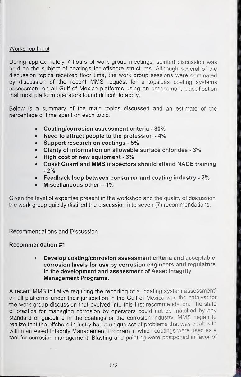
Workshop Input
During approximately 7 hours of work group meetings, spirited discussion washeld on the subject of coatings for offshore structures. Although several of the
discussion topics received floor time, the work group sessions were dominated
by discussion of the recent MMS request for a topsides coating systems
assessment on all Gulf of Mexico platforms using an assessment classification
that most platform operators found difficult to apply.
Below is a summary of the main topics discussed and an estimate of the
percentage of time spent on each topic.
• Coating/corrosion assessment criteria - 80%• Need to attract people to tlie profession 4%• Support research on coatings - 5%• Clarity of information on allowable surface chlorides - 3%• High cost of new equipment - 3%• Coast Guard and MMS inspectors should attend NACE training
-2%• Feedback loop between consumer and coating industry - 2%• Miscellaneous other - 1%
Given the level of expertise present in the workshop and the quality of discussion
the work group quickly distilled the discussion into seven (7) recommendations.
Recommendations and Discussion
Recommendation #1
• Develop coating/corrosion assessment criteria and acceptable
corrosion levels for use by corrosion engineers and regulators
in the development and assessment of Asset Integrity
Management Programs.
A recent MMS initiative requiring the reporting of a "coating system assessment"
on all platforms under their jurisdiction in the Gulf of Mexico was the catalyst for
the work group discussion that evolved into this first recommendation. The state
of practice for managing corrosion by operators could not be matched by any
standard or guideline in the coatings or the corrosion industry. MMS began to
realize that the offshore industry had a unique set of problems that was dealt with
within an Asset Integrity Management Program in which coatings were used as a
tool for corrosion management. Blasting and painting were postponed in favor of
173
sustaining production to meet contract obligations. Passive corrosion is tolerated
provided that the functionality of the resource was not impaired.
The MMS proposed a simplified A, B, C classification as follows:
A - Good Condition, no maintenance needed within 3 years
B - Fair Condition, Maintenance will be required within 3 years
C - Poor Condition, Maintenance needed within 12 months
Operators with a Corrosion Management Plan did not find it difficult to respond to
the MMS assessment request. It was a matter of extracting from the plan the list
of structures that were to be painted in the next year (C's), 3 years (B's); and all
the rest became A's.
This approach inevitably led to the question, "What are the criteria used for
determining when a structure needed coatings maintenance". The answer to this
question is wide ranging. Some used a coatings repair philosophy; while others
were based on substrate corrosion activity. Few thought the Structural Steel
Painting Council coatings deterioration guidelines applied.
It is suggested that a matrix approach defining corrosion assessment in terms of
"coatings deterioration" and "degree of substrate corrosion" was an essential part
of corrosion management. Appendix A shows an example of how such a matrix
might look. Various examples of this approach were being utilized in corrosion
assessment programs.
Other elements of the corrosion assessment program necessary for consistency
and reproducibility in the A, B, C condition assessment for offshore platforms
include:
• Component dependent corrosion assessment matrices
• Structural elements
• Wells
• Piping and equipment
• Stairs, walkways, handrails, etc.
• Location data
• Extent of corrosion by Location on the platform
Recommendation #2• Protection of People and Environment
• Need to attract people to the profession• Year round work• Certification
174
The offshore coating industry is a good place to work. Attracting andretaining quality employees has improved; given the excellent PP&Einitiatives. However, attracting good, talented employees could be further
improved by offering a steady weekly paycheck. Blame for lost pay is
often blamed on coating materials with low tolerance to environmental
conditions. In addition, both coatings contractors and clients will benefit by
attracting and holding quality personnel by offering training andcertification : both of which have a known impact on safety, employeemorale and salary.
Recommendation #3• Product Selection
• Support research on coatings:
• That can be used year round in offshore
conditions• With "inhibitor based technology"• Water Borne Epoxy
You will always hear a recommendation for higher quality coating
materials. From both the contractor and client viewpoint, research into
more durable, longer life coatings that are more tolerant of the application
environment are needed by industry. Coatings which can be applied year
round support recommendation #2.
Recommendation #4
Surface Preparation
• Improve the dissemination and clarity of information on
allowable surface chlorides.
Ongoing work in this arena was discussed and standards are being
prepared. Efforts to disseminate the information would be forth coming.
Techniques for reducing surface chlorides were also discussed.
175
Recommendation #5
Application
• Use and deployment of new coating technology is
hampered by high cost of new equipment. Look into
what can be done to utilize existing equipment; lower
the cost of new equipment; or provide the financial
incentives needed.
Although not necessarily a research topic, more an economic condition; it
was noted that some of the new coating materials required application
equipment that was state-of the art. Where ever possible coatings
developers should consider the economic impact new equipment has on a
contractor.
Recommendation #6
Inspection
• Suggest that Coast Guard and MMS inspectors shouldattend NACE training to improve knowledge andconsistency.
MMS noted this need and will consider developing a training program for
MMS inspectors.
Post-workshop note: MMS has acted quickly. An in-service inspector
training course was developed and the first training was held first week of
October 2004.
Recommendation #7
Metrics
• Feedback loop between consumer and coating industry
need to be improved. Problems are generally reported
and investigated; however, successful applications
rarely are investigated to confirm good practice.
Although this is the last recommendation from the workshop, it could
possibly be the most important. Continuous improvement in any industry
requires a feedback loop that includes performance metrics, lessons
learned, and best practice. Although examples of post project feedback
can be pointed out, especially when poor performance is involved,
effective feedback at critical mass does not exist. Given the economics
176

and competitiveness of the industry, and the fact that the consumer will
benefit most from the feed back, the consumers need to take the lead in
improving the situation.
Appendix A
Structural
Coat ng deterioration
0-5% 6-10% 11-25% 26-50% 51-100%
Degree
of
substrate
corrosion
None/ rust
staining/light
rust
A A A A A
General
light rust-
passive
A A A A A
Heavy rust -
-active A A A B B
Deep pitting
A B B B C
Significant
Metal loss B C C C C
MMS Coatings Assessment Classification
as function of
Coating Deterioration and Degree of Substrate Corrosion
Table A.1 - Example of Proposed Classification Matrix.
177
Coatings for Pipelines
Sankara Papavinasam and R.Winston Revie
CANIVIET Materials Technology Laboratory
Natural Resources Canada568 Booth Street
Ottawa, Ontario
Canada K1A0G1
Email: [email protected] and [email protected]
Abstract
Following are the main R&D issues that were identified in the area of coatings for
pipelines, listed in decreasing order of priority; i.e., item 1 is the top priority item
for R&D. Items with the same number were ranked equally in terms of relative
priority.
1. Database on Coating Performance
An unbiased third party will compile an industry-wide historical database on
coating performance and evaluate the data critically.
2. Performance of Field-Applied Coatings
Effects of environmental conditions and variations in coating procedure on
performance of field-applied coatings
Curing time compared with time to burial or immersion
Adhesion of field-applied coating and mill-applied coating
Long-term field evaluation of pipeline coatings
A national or international program.
Coated pipe samples to be installed in the field at carefully selected
locations representative of different environmental conditions.
Several monitoring methods to be used.
In addition, evaluate coating performance at constant and fluctuating
temperatures with transient and cyclic temperature fluctuations.
1-day scoping meeting to be held, most likely in the fall of 20043. Effects of stockpiling on coating performance
Temperature
UVTime
Development of practices for evaluating coatings for service under extreme
conditions
Offshore, deep-sea
Onshore Arctic
Onshore Equator
Include 3 types of coatings:
178
Anti-corrosion coatings,
Abrasion-resistant coatings, andInsulation coatings
4. Standardization of test methods for evaluating coatings
Development of coatings with anti-microbial properties
Introduction
Coating performance depends on the events taking place during the five stages
of the coating lifetime:
1 . Manufacture,
2. Application,
3. Transportation,
4. Installation, and
5. Field operation.
Objectives of R&D are to clarify the following issues^"^:
• What are the chemical and electrochemical conditions and their changes under
realistic pipeline environments?• What are the conditions that are independent of coating type?• What are the conditions that depend on coating type?• What are the failure modes of coatings on an operating pipeline?
• How are the failure modes identified?
• How accurate are the field monitoring techniques?• Do the standard tests simulate the chemical and electrochemical conditions of
the field environments?• Do the standard laboratory tests simulate the failure modes in the field?
• Are the acceleration effects (e.g., aging, extreme CP potential, and elevated
temperature) in the laboratory tests relevant to field conditions?
• What information from the laboratory data could be transferred to field
performance?• What are the assumptions to be made to transfer the data?• How is the validity of the prediction of field performance monitored and verified
in the field?
The state-of-the-art on our understanding of performance of pipeline coatings is
discussed in this white paper, along with R&D to be carried out to address the
main issues. The R&D topics were prioritized at the Workshop, and the results of
the prioritization are presented in this paper.
Manufacture of Chemical Components
Figure 1 lists the coatings used in different time periods in the twentieth century"^"
A comprehensive laboratory analysis of factors leading to coating failure^^
179
and loss of adhesion has been performed. Some of the earliest coatings
applied are still in service and are still available for application on new pipelines.
Over a decade ago, the concept of polyurea spray elastomer technology wasintroduced. This new application was based on the reaction of an iso-cyanate
component with an amine blend. Advances in both the chemistry and application
equipment for coatings have enabled continuous evolution of coatings.
Coating Chemistry
Although finger printing of the products is used for quality control (QC) purposes,
this method is not 100% reliable.
X The relationship between coating chemistry and corrosion protection is not
clear.
Previous investigations were undertaken to explore any possible effects of
cathodic protection to disbond pipeline coatings. These studies focused on the
electrochemical reactions and chemical changes that occur in the environment at
the steel surface and characterized, using Fourier Transform Infrared (FTIR),
Auger electron spectroscopy (AES) and X-ray photoelectron spectroscopy (XPS),
the surface chemistry of steel samples taken from areas where the coating wasdisbonded.
Simple test procedures have been developed to assess^^:
1 . The degree of reaction (cure) of the applied FBE (fusion bonded epoxy)
coating,
2. The adhesive bond strength of the coating to the steel pipe substrate, and
3. The void content of the coating created by bubble entrapment or gas
formation during application.
All investigations were carried out using FBE coating as the model system^^''^.
Filling the gaps in knowledge requires that the manufacturers be willing to
disclose not only the coating formulations but also the ratios in which the different
components are present in the formulations. Within the composition range of
generic coatings, the formulations change widely without any significant change
in the corrosion protection properties. Although a relationship between coating
chemistry and corrosion protection is important, any attempt to fill this gap will
involve significant R&D.
Laboratory Evaluation
Evaluation of existing coatings is the first important step in the development of
future coatings. Several methods have been used over the years to evaluate the
180
tests. Table 1 presents a list of standard tests that can be used to evaluate
coatings. The standards are the widely accepted baselines, although further
improvement and consolidation of various national standards are needed.
It is not entirely clear which laboratory tests should be used to evaluate a
particular property of a given coating and which laboratory tests are suitable for
specific coatings.
• Consolidation of laboratory methods to develop generic tests, leading to
specific test methods for specific coatings, should be considered.
Long-Term Prediction/Life-Time Cost
Current and potential distributions inside the crevice of a simulated disbonded
coating with a holiday during cathodic protection (CP) of steel were measuredexperimentally''^. Based on the comparison of experiments and numerical
simulation of a cathodically protected buried pipe with coating failures, a model
was developed. The agreement between the results demonstrates that
numerical simulations are acceptable for cathodic protection systems in high-
resistivity media'^^.
Two- and three-dimensional boundary element mathematical models have been
developed to model the performance of CP designs. The models offer a
convenient tool to quantify the performance of a CP system and allow the user to
determine the influence of relevant parameters, such as soil resistivity, coating
damage, and anode type and spacing. The model can also be used as an
educational tool to identify the factors that control CP performance under
different operating conditions''^.
A boundary element mathematical model was used to assess the influence of
cathodic protection (CP) design parameters on performance of a parallel-ribbon
sacrificial anode CP system for coated pipelines. The model accounted for
current and potential distributions associated with discrete holidays on coated
pipelines that expose bare steel to the environment. Case studies, based on the
CP system used to provide protection to the Trans-Alaska pipeline, were
selected to show conditions under which a given CP system will and will not
protect a pipe''^.
The General Electromigration Model (GEM) has been used with modifications for
electrochemical kinetics''''. The cathodic hydrogen evolution rate and anodic iron
dissolution rates were both found to affect the pH inside the crevice. The model
also predicted that formation of iron carbonate, observed extensively in somepipeline failures, occurs under a specific combination of iron dissolution rate and
hydrogen evolution rate. GEM provides a unique modeling tool because it is
flexible enough to test the effects of a variety of environmental conditions as
181
input parameters and because its predictions of solid mineral formation in
crevices can be tested against field experience. The changes in crevice pH andpotential were measured experimentally using microelectrodes.
The occurrence of corrosion and stress corrosion cracking (SCC) under a
disbonded coating on a pipeline is determined by a variety of factors including
groundwater composition, soil conditions, presence of alternating wet/dry
conditions, coating type, cathodic protection, and operating conditions. TheTransient Electrochemical Coupled Transport (TECTRAN) code predicts the time
evolution of the environment under a disbonded coating''^.
However in all the modeling work, the plurality of coatings has not beenaddressed. In one study, it was determined that for the coating thicknesses
examined and over the time period observed, coal tar enamel and polyethylene
tape acted as inert barriers, and no permeation or ionic migration through these
coatings was observed. The FBE exhibited slight ionic migration and was found
to be cation selective^^.
Electrochemical Impedance Spectroscopy (EIS) is a good tool to investigate the
deterioration of coating on a metal. Electrochemical impedance spectroscopy
provides two very important pieces of information: the change in capacitance of
the organic film that relates to water uptake and the deviation from purely
capacitive behavior of the film. For gas pipelines, the equivalent circuit
parameters in the presence of disbonded coatings have been established^^. Theparameters of the model are the coating thickness and the area under the
disbondment. A coated pipeline can be modeled as a sequence of simple
equivalent circuits, which can be handled using standard theory to yield the
observed impedance in terms of the values of the circuit elements in the line. Theproposed models have been tested to verify their applicability for predicting sites
of corrosion in buried pipelines. The effect of a few geometrical and physical
parameters has been investigated, and results have been compared with the
output of laboratory and field measurements. In some cases, the adjustment of
literature parameters has been enough to obtain good agreement of field and
laboratory data; modification of the equivalent circuit has, however, been found to
be necessary. But there is no universally accepted method of using EIS for
coating performance. Future research in this field is required before the method
can be used with confidence.
Development of pores in the coating or disbonding of an electrolyte-saturated film
causes deviation from capacitive behavior. For either case, conducting paths
develop through the coating. Research to evaluate the nature of these
conducting paths would provide valuable insight into the degradation of the
coatings. Little information exists on the relationship of EIS data to the protective
properties of organic coatings.
182
Low cost computing power is having its impact on all areas. In recent years, the
use of microprocessors in the design of instrumentation has brought computing
power into the hands of people working in quality control. These analytical
techniques are now being applied to coatings, particularly for coating thickness
assessment when continuous processing is applicable.
• A comprehensive model to predict long-term performance of coatings should
be developed based on carefully controlled laboratory experiments as well as
from field experience with older coatings, such as coal tar and asphalt, and
modern coatings, such as FBE and urethane, using the power of moderncomputers and intelligent systems, e.g., artificial neural networks.
Temperature Effect
In some applications, one of the critical properties of external organic coatings is
resistance to high temperature. It has been found that most organic coatings
have problems at temperatures higher than 80°C. There is a need for high-
temperature performance in oil and gas pipelines, especially near compressor
stations for natural gas transmission and in the transport of higher viscosity crude
oils. The operating temperatures of pipelines extend to 275°C. Applicators,
coating manufacturers, and owners are working to overcome the challenges
associated with high temperatures. Currently no industry standards exist to test
high temperature coatings. Manufacturers are developing high temperature
coatings based on in-house testing. It is recognized that conventional test
methods, such as cathodic disbondment, may not be appropriate. The primary
challenge is to obtain adequate flexibility with high temperature performance.
For this reason, design criteria for high temperature test methods and for life
prediction need to be established.
The criteria for testing coatings for higher temperature applications are not the
same as those for lower temperature application. For example, coatings with
good cathodic performance, adhesion, barrier properties, impact resistance, and
flexibility will protect the pipeline over the lifetime. At elevated temperatures,
cathodic disbondment performance may not be relevant if the coated pipe is
insulated. But good adhesion, barrier properties, flexibility, and resistance to
movement at higher temperatures are necessary.
The question is not, "How do we design the perfect high temperature coating?"
Rather, it is, "How do we know that we have designed it?"
• Based on a systematic study, the temperature limits of existing tests should be
explored, and tests to evaluate products for elevated temperature applications
should be developed.
183
Application
In general, conditions are better for application of coatings in the mill than in the
field. Most modern coatings are applied in the mill.
• Whereas many of the issues of mainline coatings are well understood andstandards for mainline coatings have been developed, there is now a need to
focus on field applied coatings, both repair and joint coatings.
Surface Preparation
Resistance of a coating to disbondment is a property affecting all forms of(
corrosion; an intact coating that prevents contact of electrolyte with the steel '
surface will mitigate all forms of corrosion. Studies show that inadequate grit
blasting can increase corrosion and stress corrosion cracking susceptibility by
creating stress raisers at embedded mill scale. Grit blasting produces anchor
patterns suitable for adherence of coatings.
A study of atmospheric exposure of cold applied coal tar enamel coatings
revealed that systems applied to wire-brushed surfaces, primed or unprimed,
failed within one year. On the other hand, the same systems on sandblasted
surfaces, both with and without primers, were in satisfactory condition after five
years' exposure in the same environment^^
Studies have concluded that visual evaluation (degree of blistering, rusting and
creep of blistering and corrosion from a scratch) is not sufficient to predict the
effect of surface condition on coating properties'^.
An investigation on the effect of surface contamination included a study of the
presence of varnish or previous coating on the pipe, phosphoric acid treatment,
water, and grit or shot quality. The presence of contaminants on the pipe surface
was identified using EDAX (X-ray energy dispersion analysis), optical and
electron microscopy analysis, grit and water conductivity, and acid wash location.j
The results indicate that all varnished pipes presented high cathodic disbonding
(above 17 mm). This high cathodic disbonding was attributed to varnish particles
located on the anchor pattern of the pipe surface. It was also found that
phosphoric acid application after blasting gives better adhesion and less cathodic
disbonding. This has been attributed to the surface active pattern provided by
the acid that gives better interaction between the pipe surface and FBE^'.
Based on R&D to evaluate the performance of FBE coatings on contaminated
and uncontaminated surfaces with and without phosphoric acid treatment, the
following conclusions were drawn'"^: Acid wash treatment greatly improves the
performance in CD tests if the surface was initially contaminated. Chloride
184
contamination is the most difficult type of contamination to remedy, because of
pitting corrosion.
Based on adhesion ratings after hot-water immersion, the maximum tolerance
levels of FBE coatings^^ applied over contaminated steel surfaces were at the
threshold limit values: chloride (5 |jg/cm^), sulphate (7 |jg/cm^), nitrate (9
|jg/cm^), and ferrous ion (24 |jg/cm^). Accelerated performance testing of FBEcoatings on ion-contaminated steel substrates revealed that the following coating
parameters are functions of contaminant ion concentration: (1) tensile bondstrength after hot-water immersion, (2) blister size and density after hot-water
immersion, and (3) degree of disbondment after accelerated cathodic disbonding.
One study of FBE coating performance was conducted using coupons removedfrom contaminated production pipe. The steel coupons with contaminations
higher than the threshold level failed in the hot-water immersion test, whereasthose with lower levels of contamination passed the test.
The use of water jetting and water cleaning has increased recently with advancesin equipment technology, the continued concerns with dusting caused by
abrasive blast cleaning, and a heightened awareness of the need for chemically
clean substrates. NACE 5/SSPC-SP 12 was introduced in 1996 (as an update to
NACE Standard RP0172) to describe levels of cleaning using water for
substrates to be painted. The NACE and SSPC abrasive blast cleaning
standards are well known in the coatings industry, and field inspectors are very
familiar with their use and interpretation. Additionally, the blast cleaning
standards clearly describe one end condition of the substrate to be painted. In
contrast, NACE 5/SSPC-SP 12 describes four end conditions of the substrate for
visible cleanliness and three conditions for non-visible cleanliness. As a result,
the specifier must make specific choices when invoking NACE 5/SSPC-SP 12.
A review paper on the surface preparation standards in various countries waspublished recently with the intention of determining whether there is a prevailing
or common standard in use. Discussions with users in Europe, United Kingdom,
Middle East, Japan, Australia and Venezuela have revealed a trend away from
national standards towards International Standards^^.
Grit blasting increased the cathodic disbonding resistance of coal-tar enamel and
FBE coatings, but did not increase the cathodic disbonding resistance of
polyethylene tape. Grit blasting also beneficially alters the corrosion potential of
the pipe^^
Whereas the effects of different surface preparation techniques are well
established, the tolerance in the variation within the surface preparation
specification is not clear. This aspect is especially important because there are
limitations on the control of surface preparation that is possible in the field.
185
• The effects of minor variations in surface preparation on long-term coatings
performance need to be established.
Temperature Effects
The intercoat adhesion of coatings cured using cross-linkers depends on both
temperature and humidity. The addition of thinner promotes intercoat adhesion
failure. The conversion of the amine to amine carbamate salts at or near the
surface, resulting in incomplete curing at the interface, is responsible for intercoat
adhesion failure.
The rate of reaction between the amine and the epoxy prepolymer, and the
humidity level, are key factors in the intercoat adhesion of epoxy coatings. At
appropriate temperatures of application, the rate of reaction between the amineand the epoxy prepolymer is rapid, causing the formation of coatings with goodintercoat adhesion. However, at lower temperatures, the rate of the cross-linking
reaction is decreased, allowing moisture to permeate the coating and solubilize
the amine. In its solubilized form, the amine reacts with carbon dioxide to form
stable carbamate salts incapable of reacting with the epoxy prepolymer. In
addition, the degree of cross-linking also depends on the RH level to determine
the degree of solubilization of the amine that can be converted to the carbamate
salt. The appropriate level of applying the coating is generally determined by the
glass transition temperature^^.
Relationship between application temperature and coating performance
needs to be established.
Installation of Pipeline
During installation, minor coating damage is bound to occur for various reasons.
It is very important to ensure that the pipe coating is adequately tested and that
all defects are repaired.
Stockpiled Coating
The breakdown of powder polyester coatings when exposed to UV radiation
(270-390 nm, peak -313 nm) has been explored by monitoring changes in their
ion transport properties using impedance spectroscopy. EIS demonstrated that
one manifestation of weathering was the development of an increased level of
porosity in the films that could be measured quantitatively. The results from
impedance spectroscopy were supported by SEM and gloss loss
measurements^^.
186
The effect of UV on stockpiled coatings is well known. The extent to which
stockpiling affects coating performance is not known.
• Influence of stockpiling on coating performance should be established.
Joint Coating
Historically, the major problems associated with field-applied coatings weredirectly related to the sensitivity of prevailing environmental conditions, such as
substrate cleanliness and preparation, and application technique (including
curing time). In addition to good "in service" performance, systems should be
easy to apply and tolerant to environmental conditions. While pipeline coating
plants have been developed to apply advanced coatings to strict specifications,
specifications for coatings applied to field joints have not received the sameemphasis.
The increase in use of high quality and expensive pipeline coatings has
heightened the need for field joint coating systems to match the quality of factory
coatings. A comparison should be made between the different field joint coating
systems in terms of technical characteristics, cost, and ease of application in the
field. Because of the lack of international standards, pre-qualification trials and
production testing in the field are important.
• A systematic study on the effects of field conditions and variations of
procedure during the application of joint coatings, including the field
performance of the coating, is recommended. This study should include the
cohesive and adhesive strength of joint coatings.
Backfilling
There are several factors relating to backfilling that influence coatings. These
are soil type, drainage, topography, temperature, and electrical conductivity. The
Canadian Energy Pipeline Association (CEPA) has classified the soils in Canadainto seven (7) types (Table 2). Even though backfilling is very important, no
systematic experimental data are currently available on the effect of backfilling on
coating performance.
Fine backfill around the pipe is used to protect the pipe from heavy and sharp
rocks or other objects. In addition, the system can include a layer of geotextile
fabric just above the fine backfill as additional protection against damaging
187
In very rocky areas, pipeline-construction operations sometimes dictate that an
external impact-resistant or barrier material be applied over the pipe to protect
the coating from damage during backfilling. The use of a specific backfill, such
as compacted sand, is often specified. As an alternate, a barrier coating of
concrete or urethane foam can be applied over the coating. Although high
resistance and resistivity are normally associated with a propensity for shielding
of cathodic protection current, the resistivity of a barrier material and the
corrosion rates and polarization characteristics of the underlying steel are
important when considering the potential for shielding and the protection
capability of the barrier material^V
The Office of Pipeline Safety (OPS) is currently conducting two projects,
"Improvements to External Corrosion Direct Assessment Methodology by
Incorporating Soils Data" and "Emerging Padding and Related Pipeline
Construction Practices". The projects are expected to produce benchmarks for!
comparison of variety of soil types, and existing as well as emerging practices, to t
provide a basis to assess improvements to current practices^^.
• Realistic backfill impact testing that includes a method to evaluate the
compaction produced by backfilling should be carried out to determine the
effect of backfilling on coating performance.
Soil Forces
Shear properties of pipeline coatings with elastomeric adhesives are frequently
measured in the laboratory. These measurements are expected to correlate with
the ability of the coating to withstand the forces of soil burial and movement. Theparameters of the laboratory methods are based on calculations of soil forces on
pipeline coatings from an analytical model and from finite element analysis^^'^^.
An apparatus was designed and built to carry out peel and sheer tests at different
temperatures. The peel test procedure allows for the measurement of shear
strength, which is directly comparable to shear stress sustained by coatings on
buried pipelines. The results have shown significant differences between the i
adhesion properties of individual products. The shear and peel strengths of the
coatings are strongly affected, as shown by an exponential drop with increasing
temperature. The results conform to an Arrhenius relationship between
temperature and the peel and shear strengths®'^.
In one project, existing test methods were examined to determine their
applicability to horizontal directional drilling (HDD) and slip boring loads. Twogenerally applicable methods were identified, Technical Inspection Services'
(TISI) Gouge Test and Taber Abraser Test (ASTM D 4060). Both these methods
are related to the soil conditions, for which the rotary abrasion tester has been
188

designed. The results can be used to predict coating wear during HDDinstallation through rock^^.
• Focused effort to understand soil forces (both physical and chemical) oncoating performance will provide useful information for developing strategies to
protect coatings.
Construction of Frontier Pipelines under Extreme Temperature Conditions
Offshore deep sea pipelines may be exposed to very low temperatures (as low
as -65°C). In the near future, the construction of northern pipelines for
transmission of natural gas will begin in North America. Construction in the
harsh northern climate, with temperatures as low as- 45°C and in remote locations will impose unique challenges for protective
coatings on pipelines. Methodologies for evaluating and selecting pipeline
coatings for use on pipelines under extreme conditions will have to be developed,
considering the extreme climatic conditions to which the coated pipe may be
subjected before it is installed and before operation begins. It is critical that the
design of coatings be adequate to protect the pipelines under long-term, severe
environmental conditions, including the extreme climatic conditions that will apply
in the North before the pipe is installed and operation begins.
• Recommended practices for evaluating coatings for northern pipelines need
to be developed and incorporated in standards
Field Testing of Coatings
Repair Coatings
A number of factors that are important in the performance of mainline coatings
are also important for repair coatings, including: cathodic disbondment,
adhesion, resistance to moisture penetration, impact resistance, penetration
resistance, performance at service temperature, abrasion resistance, soil stress,
burn-back resistance, chemical resistance, and general handling behavior. In
addition, because the repair coatings are applied in the field, the factors
discussed in joint coatings are also important. In spite of the importance of repair
coatings, no special tests or procedures have been developed to evaluate
them^^
Correct material selection can provide substantially improved coating
performance and economy. No specific method for repair coating selection
exists. The development of field-proven, reliable criteria for selecting and
evaluating repair coatings is essential in order to make the best use of available
materials and processes. The development of accelerated tests that closely
189
resemble actual field application and service conditions would be useful in the
realistic evaluation of repair coatings.
• Tests to evaluate repair coatings, including evaluation of cohesion within the
repair coating and adhesion to the mainline coating and to steel pipe, should
be developed.
Field Performance
Monitoring
Several techniques are available to detect defects in coatings on buried
pipelines. A critical review and evaluation of the Pearson survey, close interval
survey, coating conductance parameter, electromagnetic current attenuation, andDC voltage gradient methods have been provided, with the advantages anddisadvantages of each method identified^''. An instrumented pipeline pig
designed to locate disbonded external coating on operating gas pipelines has
been evaluated^^. The results from each method have been assessed in terms
of defining the need for coating refurbishment and in providing the parameters
needed to establish the most cost-effective route to control pipeline corrosion.
The Elastic Wave vehicle has the potential to detect disbonding as well as areas
where the coating has been removed^^'^°°.
The development of instrumentation for field testing and inspecting coatings has
been accelerated by the use over the last ten years of microprocessor
electronics. Such designs are now entering the fourth generation and have
included many user features that make the assessment of coatings easier and
more accurate than was previously possible. These features include storage of
data, statistical analysis, hard copy printout and high accuracy in hand-held fully
portable and rugged units, suitable for use in the most hazardous environments.
The most recent improvements have been realised by providing the transducer,
or probe, with electronic intelligence so that its characteristics can be closely
matched for optimum accuracy and flexibility. A major benefit of this approach is
that the measurement transducer can be of any type and the data output from
the electronics can be made to fit a standard format display instrument. In this
way, it is possible to make a general purpose kit with a diverse set of
measurement modules for a range of tests, such as temperature, humidity,
surface profile, and adhesion, as well as a full range of coating thickness
modules, using electromagnetic induction and eddy currents for applications that
range from thin coatings on small components up to very thick coatings on large
structures.
It is becoming more common for gas transmission pipelines to share a commoncorridor with electric power transmission lines. Electrical energy that is
190
magnetically coupled from the power line often results in an AC voltage being
developed between the pipeline steel and the earth that surrounds the
pipeline^°-.
It is important to evaluate the extent to which monitoring techniques are capable
of evaluating the shielding effect of coatings.
• Development of a remote, accurate monitoring technique to evaluate the
status of the coating (including the shielding effect) will greatly enhancepipeline integrity and decrease the number of pipeline incidents caused by
corrosion.
Feedback
In spite of the close interaction between pipeline owners and coating suppliers at
the time of installation of pipe, feedback on coating performance, whether
positive or negative, is not, in general, readily available.
• Development of an industry-wide coating database to share the experience of
older and modern coatings is an essential logical step to develop an integrity
management program. Continuous updating and sharing of such a database
will be very useful.
Operational Conditions
In general, pipeline operational conditions vary considerably. Among all the
various conditions, temperature is quite important. In spite of the well-known
transient temperature variations of pipelines and seasonal cyclic fluctuations, no
systematic study on the effect of temperature on coatings has been carried out.
• The performance of coatings should be compared at constant and fluctuating
temperatures.
Ground Effects
Although coatings are routinely evaluated for resistance to a variety of ground
factors (e.g., soil stresses), few coatings have been developed with consideration
given to their resistance to microbiologically influenced corrosion (MIC).
Increased numbers of bacteria at some corrosion sites have been observed. Amodel, for the development of a site where MIC occurs, indicates that in the first
phase, soil stresses caused disbondment of the coating, leaving adhesive/primer
exposed to the invading water on the pipe surface. Blisters, filled with water, form
in the residual coating components on the pipe surface. As the MIC community
191
forms and grows, pitting corrosion begins in local areas, effectively "fixing" the
anodes. In the final phase, periodic exposure to oxygen results in transformation
of the corrosion products (siderite and ferrous sulfides) to iron (III) oxides.
Early studies performed in the GRI MIC program demonstrated that a very high
percentage of external MIC occurred in connection with disbonded coatings andfollowed the same general pattern as classic examples of MIC associated with
disbonded coatings. The general consensus is that holidays will occur in mostcoatings by one or more mechanisms (mechanical, chemical, and biological) andthat holidays and disbonded coatings offer sites for MIC to occur^°^. Studies
have also shown that levels of bacteria are high on all types of coatings and in all
holidays regardless of the level of CP and the pH in the holidays (which ranged
from 4.5 to 11.9).
The effects of CP on MIC cannot be assessed simply by measuring the numbersof bacteria. Instead, chemical and site specific factors (e.g., corrosion potential of
the steels in the soils at specific sites) must be taken into account.
A "first-cut" MIC profile was developed to aid in determining which sites were
most likely to be susceptible to external MIC. This profile included soil, chemical,
biological, metallurgical and operational factors, such as level of CP.
Several reports in the literature have confirmed the utilization of certain pipeline
coatings by microorganisms. Microorganisms have the potential to enhancecoating disbondment rates as well as contribute to pipeline corrosion as a result
of coating biodegradation. In these studies, parameters such as coating weight
loss and enumeration of microbial cells were used to assess the biodegradation
of coatings. Uncertainties in causes of weight change occur because weight loss
can result from solubilization of coating constituents and weight gain can be
caused by water absorption. Enumeration is not a measure of activity since
microorganisms can be active without increasing their numbers. Thus,
enumeration cannot produce direct and quantitative results.
• An objective study to develop a method that monitors microbial population and
coating biodegradation will clarify the effects of microbes on coatings.
Summary
At the workshop held in Biloxi, the following R&D issues were identified as top
priorities. This prioritized list is very similar to one developed in a PRCI project,
thus validating the importance of the conclusions reached at the Workshop^°^:
1 . Database on Coating Performance
Unbiased third party will compile an industry-wide historical database on
coating performance and evaluate the data critically.
192

2. Performance of Field-Applied Coatings
Effects of environmental conditions and variations in coating procedure onperformance of field-applied coatings
Curing time compared with time to burial or immersion
Adhesion of field-applied coating and mill-applied coating
Long-term field evaluation of pipeline coatings
A national or international program.
Coated pipe samples to be installed in the field at carefully selected
locations representative of different environmental conditions.
Several monitoring methods to be used.
In addition, evaluate coating performance at constant and fluctuating
temperatures with transient and cyclic temperature fluctuations.
1-day scoping meeting to be held, most likely in the fall of 20043. Effects of stockpiling on coating performance
Temperature
UVTime
Development of practices for evaluating coatings for service under extreme
conditions
Offshore, deep-sea
Onshore Arctic
Onshore Equator
Include 3 types of coatings:
Anti-corrosion coatings.
Abrasion-resistant coatings, and
Insulation coatings
4. Standardization of test methods for evaluating coatings
Development of coatings with anti-microbial properties
The following issues are important, but are not considered as high priorities at
this time:
• Parameters that control coating performance
• Modeling of performance of all coatings (not only FBE). Modeling using
EIS is not reliable
• Evaluation of coatings at higher temperature (above 85oC) in the
laboratory
• Performance of insulation coating
• Effects of minor variations in surface preparation and effects of variation in
composition of surface contamination, including mill scale, on long-term
coatings performance
• Method to monitor simultaneously microbial population and coating
degradation
193
Acknowledgements
The authors gratefully acknowledge the support of the Pipeline Research Council
International (PRCI) in carrying out the initial review on which this white paper
was based. Numerous helpful discussions with the chair of the Ad Hoc PRCIcommittee, Howard R. Mitschke of Shell Global Solutions (US) Inc., are
acknowledged. Meetings with the Ad Hoc Committee were most beneficial in
helping to achieve the objectives of this project.
The discussions that took place at the workshop in Biloxi were most helpful in
giving the authors and the workshop participants an opportunity to update andprioritize further the R&D topics. The efforts of the Workshop participants are
gratefully acknowledged.
References
1. S. Nunez, K.E.W. Coulson, L.C. Choate, and J.L. Banach, "A Review of
Gas Industry Pipeline Coating Practices", July 1988, A.G.A. Catalog No.
L51586.
2. S.J. Lukezich, J.R. Hancock, and B.C. Yen, "State-of-the-Art for the Use of
Anti-Corrosion Coatings on Buried Pipelines in the Natural Gas Industry",
April 1992, Gas Research Institute Project # 06-3699 (GTI #2024/GRI-
92/0004) and "Prediction of the Field Performance of Anti-Corrosion
Coatings for Buried Steel Pipelines" International Gas Research
Conference 1992, p. 512 (GT9 #2024).
3. A. Andrenacci, D. Wong, and J.G. Mordarski, "New Developments in Joint
Coating and Field Repair Technology", Materials Performance (2) (1999),
p.35.
4. L.R. Aalund, Polypropylene System Scores High as Pipeline Anti-
corrosion Coating, Oil & Gas Journal, (1992) 42-45.
5. M. Alexander, High-Temperature Performance of Three-Layer
Epoxy/Polyethylene Coatings, Materials Performance, (1992) 41-45.
6. B.R. Appleman, Tape Systems for Pipeline Protection,
J. Protective.Coatings and Linings, 4 (1987) 52-60.
7. T. Arai, and M. Ohkita, Application of Polypropylene Coating System to
Pipeline for High Temperature Service. 189-201. 1989. Florence, Italy,
BHRA (Information Services), The Fluid Engineering Centre, Cranfield,
Bedford MK43 OAJ, UK, 1990. Internal and External Protection of Pipes-
Proceedings of the 8th International Conference.
8. T. Arai, M. Ohkita, T. Ohtsuka, and S. Yamauchi, Development of an
Ultraviolet Curable Primer (UVC) System for Polyethylene Coated Steel
Line Pipe, Sumitomo Search, (1987) 77-82.
194
9. J.L. Banach, Pipeline Coatings - Evaluation, Repair, and Impact on
Corrosion Protection Design and Cost. 29-1-29/13. 1987. Houstan/Texas,
NACE. Corrosion 87.
10. K. Bennett, Selecting Field Joint Coatings for Two- and Three-Layer
Extruded Pipe Coatings, Journal of Protective Coatings & Linings, 18
(2001)45-49.
11. P. Blome and G. Friberg, Multilayer Coating Systems for Buried Pipelines,
Materials Performance, 30 (1991)
12. G. Connelly, G. Gaillard, and Y. Provou, Three Layer Epoxy-Polypropylene Pipe Coatings for Use at Elevated Service Temperatures.
179-188. 1989. Florence, Italy, BHRA (Information Services), The Fluid
Engineering Centre, Cranfield, Bedford MK43 OAJ, U.K., 1990. Internal
and External Protection of Pipes-Proceedings of the 8th International
Conference.
13. G. Connelly and G. Gaillard, 3 Layer Polyolefin Pipe Coatings. U.K.
Corrosion 87(Coatings and Linings: Pipeline Protection - Multi Layer
Coating Systems), 1-14. 1987. Institute of Corrosion. Conference Archive
CD 1982-1999.
14. J.W. Cox, and K. Fogh, Dual Coating System for Pipelines in High-
Temperature Service, Materials Performance, 29 (1990) 18-21.
15. W.A. Dempster III and A.J. Doheny Jr., Heat Fused Polyolefin System For
Fusion Bonded Epoxy Coated Pipe. 564-1-564/11. 1994. Houston, Texas,
NACE, Corrosion/94, 1994.
16. J. Didas, Fusion-bonded Epoxy Coatings for Underground Pipelines,
Materials Performance, 39 (2000) 38-39.
17. N.C. Duvic, Polysiloxanes-New Coating Technology, 582-1-582/6. 1988.
Houston, Texas, NACE, Corrosion/95, 1995.
18. Y. Ikeda, The Development of Embossed Polyethylene Coated Pipe for
Offshore Pipelines. 1-10.1983. BHRA Fluid Engineering, Cranfield,
Bedford MK43 OAJ, England. 5th International Conference on the Internal
and External Protection of Pipes, Innsbruck, Austria, 25-27 Oct. 1983.
19. D. Fairhurst and D. Willis, D. Polyporpylene Coating Systems for Pipelines
Operating at Elevated Temperatures. UK Corrosion 95(Session 1: Pipe
Protection - Recent Coating Developments), 1-24. 1995. Institute of
Corrosion. Conference Archive CD 1982-1999.
20. S. Funatsu, Durability of three layer polypropylene coated steel pipe at
elevated temperatures. 9-11. 1995. Florence, Italy, Mechanical
Engineering Publications Ltd., P.O. Box 24, Northgate Avenue, Bury St.
Edmunds, Suffolk IP32 6BW, UK, 1995. Eleventh International
Conference on Pipeline Protection.
21. G. Gaillard and G. Connelly, 3 Layer Epoxy-Polyolefin Pipe Coatings.
309-1-309/13. 3-25-1988. Houston, Texas, NACE. Corrosion/88, 3-21-
1988.
22. R. Ganga, Thermoplastic Coating Used on Oman Hot Liquids System,
Pipe Line Ind., 53 (1980) 83-84.
195
23. B.C. Goff, The Coating of Pipeline Field Joints - The State of the Art and a
Look to the 1990's. UK Corrosion 89(Coatings and Linings in Field
Experience), 1-16. 1989. Institute of Corrosion. Conference Archive CD1982-1999.
24. B.C. Goff and R.F. Strobel, The Development of Fusion-Bonded EpoxyPipeline Coatings in Europe and the Middle East. 17-30. 1981. BHRAFluid Engineering, Cranfield, Bedford MK43 OAJ, England. Internal andExternal Protection of Pipes, Noordwijkerhout, Netherlands, 15-17 Sept.
1981.
25. E.E. Hankins, Development of Tapes for the External Protection of
Pipelines in High-Temperature Environment. 317-328.1981. BHRA Fluid
Engineering, Cranfield, Bedford MK43 OAJ, England. Internal and External
Protection of Pipes, Noordwijkerhout, Netherlands, 15-17 Sept. 1981.
26. E.E. Hankins, The Role of Plastics in Pipeline Protection Tapes. 1980.
Plastics and Rubber Institute, 11 Hobart Place, London SW1W OHL,England. Plastics and Paints against Corrosion, London, England, 12 Nov.
1980.
27. M.T. Harris and C.J. Argent, A Review of the Factors Influencing the
Mechanical Properties of Epoxy Powder Coatings. 127-150. 1985.
Institution of Corrosion Science and Technology, Exeter House, 48Holloway Head, Birmingham B1 1NQ, UK. UK Corrosion '85: Coating and
Preparation, Corrosion Monitoring, Materials Selection, Harrogate, UK, 4-6
Nov. 1985.
28. Y.M. Ireland and A. Lopez, Field Application of Epoxy-urethane Coatings
Using Line Travel Equipment on Pipelines. 00771-1-00771/15. 2000.
Houston, Texas, NACE International. NACE Corrosion 2000. 3-26-2000
29. J.R. Johnson, S. Henegar, and B. Roder, A New Higher Temperature Coal
Tar Enamel Pipeline Coating System. 196-1-196/12. 1996. Houston,
Texas, NACE International. NACE Corrosion 96. 3-24-1996.
30. B.R. Johnston, Polyethylene Coating of Steel Pipe Experience Gained in
the Development of a "Tight- Bonding" System, Institution of Corrosion
Science & Technology, Exeter House, 48 Holloway Head, Birmingham B1
1NQ, UK", 1987,
31. J.A. Kehr, FBE Pipeline and Rebar Corrosion Coatings. April 10, 2000.
2000. http://www.NRCan.gc.ca/picon/conference2/kehr2.htm, Natural
Resources Canada - CANMET. 2000 PICON Conference, and AFoundation for Pipeline Corrosion Coatings. 00757-1-00757/20. 2000.
Houston, Texas, NACE International. NACE Corrosion 2000. 3-26-2000.
32. J.D. Kellner, A.J. Doheny, Jr., and B.B. Patil, A New 3-layer Polyethylene
Coating for Plant Application. 557-1-557/10. 1997. Houston, Texas,
NACE International. NACE Corrosion 97. 3-14-1997.,
33. W. Klahr, Polyurethane/Tar Coating for Steel Pipes. 51-66. 1981. BHRAFluid Engineering, Cranfield, Bedford MK43 OAJ, England. Internal and
External Protection of Pipes, Noordwijkerhout, Netherlands, 15-17 Sept.
1981.
196
34. W.J. Knight, Polyurea Spray Coatings: An Introduction, Journal of
Protective Coatings & Linings, 18 (2001) 48-52.
35. R. Marchal, Protection of Buried Ductile Iron Pipelines With a Zinc-Based
Coating-Healing Power of Coating Damages. 125-137.1981. BHRAFluid Engineering, Cranfield, Bedford MK43 OAJ, England. Internal andExternal Protection of Pipes, Noordwijkerhout, Netherlands, 15-17 Sept.
1981.
36. M. Murakami, Influence of epoxy primer on polyethylene coating
properties. 139-168. 1995. Florence, Italy, Mechanical Engineering
Publications Ltd., P.O. Box 24, Northgate Avenue, Bury St. Edmunds,Suffolk IP32 6BW, UK, 1995. Eleventh International Conference on
Pipeline Protection.
37. D. Norman and R. Swinburne, Epoxy and Polyurethane Coatings for the
Rehabilitation and Repair of Pipelines. UK Corrosion 98, 08-01-08/14.
1998. Institute of Corrosion. Conference Archive CD 1982-1999.
38. D. Norman and R. Swinburne, Polyurethane and Epoxy Coatings for the
Rehabilitation and Repair of Pipelines. 00758-1-00758/7. 2000. Houston,
Texas, NACE International. NACE Corrosion 2000. 3-26-2000.
39. D. Nozahic, L. Leiden, and R. Bresser, Latest Developments in Three
Component Polyethylene Coating Systems for Gas Transmission
Pipelines. 00767-1-00767/8. 2000. Houston, Texas, NACE International.
NACE Corrosion 2000. 3-26-2000.
40. M. O'Donoghue, R. Garrett, V.J. Datta, E. Swanson, and B. Dillingham,
Fast-Cure AHC Epoxy Coatings for Tank and Pipe Applications, Materials
Performance, 39 (2000) 32-37.
41. Y. Okano, The development of an auto-sealing system using an
electrically shrinkable tube under a low-pressure condition. Materials
Performance, 36 (1997) 40-44.
42. Y. Okano, N. Shoji, T. Namioka, and M. Komura, The Development of
Auto-sealing System for Field Joints of Polyethylene Coated Pipelines.
389-1-389/11. 1997. Houston, Texas, NACE International. NACECorrosion 97. 3-14-1997.
43. T.J. Padley and H.H. Collins, The External Protection of Buried Ductile
Iron Pipes by Polyethylene Sleeving, Advances in Pipeline Protection,
(1988) 25-31.
44. S. Power, High Performance Liquid Epoxy Polymer Concrete Coatings
Used for New Construction and Rehabilitation Projects. Paper 01606,
1606-1-1606/6. 2001. Houston, Texas, NACE International. Corrosion
2001.
45. C.R. Reeves, Pipeline Rehabilitation Using Field Applied Tape Systems.
615-1-615/6. 1998. Houston, Texas, NACE International. NACE Corrosion
98.3-22-1998.
46. J.E. Rench, Review of a Fusion Bonded Pipeline Coating System, NACEPaper no 47, (1973)
47. G.L. Rigosi, R. Marzola, and G.P. Guidetti, Polypropylene thermal
insulated coating for pipelines. 9-11. 1995. Florence, Italy, Mechanical
197
Engineering Publications Ltd., P.O. Box 24, Northgate Avenue, Bury St.
Edmunds, Suffolk IP32 6BW, UK, 1995. Eleventh International
Conference on Pipeline Protection.
48. A.H. Roebuck and R.W. Foster, 100% Solids Plural Component Urethane
Coatings. 213-233. 1987. Orlando, Florida, USA, Steel Structures
Painting Council, 4400 Fifth Ave., Pittsburgh, Pennsylvania 15213, USA",
1987. Conference: Improving the Field Reliability of Protective Coatings.
49. P.J. Singh and J. Cox, Development of a Cost Effective Powder CoatedMulti-component Coating for Pipelines. 00762-1-00762/14. 2000.
Houston, Texas, NACE International. NACE Corrosion 2000. 3-26-2000.
50. R.N. Sloan and L.L. Hsu, Extruded Polyolefin Systems for Pipeline
Protection Total Corrosion Control for Industrial Gas Turbines: High
Temperature Coatings and Air, Fuel and Water Management,J.prot.coatings Linings, 32 (1987) 1-17.
5L T. Takamatsu, K. Suzuki, and M. Ishida, Polyurethane Elastomer CoatedSteel Pipe for Water Service, Nippon Steel Tech. Rep., (1985) 49-57.
52. K. Tsuchiya, F. Ohtsuki, M. Tanaka, and S. Sugimura, An ApproachToward Heat Resistant Coating Material for Line Pipes. 307-316. 1981.
BHRA Fluid Engineering, Cranfield, Bedford MK43 OAJ, England. Internal
and External Protection of Pipes, Noordwijkerhout, Netherlands, 15-17
Sept 1981.
53. J.G. Tucker, Elastomeric Polyurethanes Use as Coatings in the ArduousConditions of Severe Corrosion and Abrasion, Anti-Corrosion MethodsMater. 33 (1986) 10-13.
54. T. Ueno, Polyethylene Coated Pipe, Tube Int., 4 (1985) 101-105.
55. J.F.H. Van Eijnsbergen, External Corrosion Protection of Pipes by ModernTapes. 139-148. 1981. BHRA Fluid Engineering, Cranfield, Bedford
MK43 OAJ, England. Internal and External Protection of Pipes,
Noordwijkerhout, Netherlands, 15-17 Sept. 1981.
56. E. Vemer and A. Fletcher, An Introduction to Fusion Bonded Low Density
Polyethylene Coatings for Large Bore Steel Pipe, Corrosion and Coatings,
South Africa, 22 (1995)6-8.
57. P.A. White, The Development of Polymer Modified Glass Fibre Reinforced
Cement as a Buffer Coating for the Mechanical Protection of Thin Film
Anti-Corrosion Coatings. 97-120.1983. BHRA Fluid Engineering,
Cranfield, Bedford MK43 OAJ, England. 5th International Conference on
the Internal and External Protection of Pipes, Innsbruck, Austria, 25-27
Oct. 1983.
58. I.E. Wilberg, Glassflake Reinforced Polyester Coatings, 10-20 Years
Experience in USA, in the North Sea and Industrial Application. UKCorrosion 91 (Symposium A: Coatings and Linings - Field Experience in
Critical Areas), 1-26. 1991. Institute of Corrosion. Conference Archive CD1982-1999.
59. B. Wood, Coal Tar Epoxy Coatings: "That Old Black Magic", Journal of
Protective Coatings and Linings, 4 (1987) 32-38.
198
60. F. Zheng, Glass-Fiber Reinforced Plastics Wrap-Coating for Anti-
Corrosion of Marine Steel Pipeline. 6-9. 1988. Xiamen, China,
International Academic Publishers, Xizhimenwai Dajie, Beijing Exhibition
Centre, Beijing 100044, China, 1988. Corrosion and Corrosion Control
for Offshore and Marine Construction
61. D.P.Werner, S.J.Lukezich, "Selection and Use of Anti-Corrosion Coatings
for Corrosion Control of Buried Natural Gas Pipelines", 92-DT-63, p. 125.
62. National Energy Board Report of the Inquiry, Stress Corrosion Cracking
on Canadian Oil and Gas Pipelines, Calgary, Canada, December 1996
63. B.C. Brand, E.J.Bradbury, R.J.Dick, M.M.Epstein, J.A.Hassell,
H.N.Johnston, J.F.Kiefner, W.Mirick, J. K. Moon, L.J.Nowacki,
J.M.Spangler, and J.A.Wray, Line Pipe Coating Analysis Volume 1,
Laboratory Studies and Results, November 1978
64. B.C. Brand, E.J.Bradbury, R.J.Dick, M.M.Epstein, J.A.Hassell,
H.N.Johnston, J.F.Kiefner, W.Mirick, J. K. Moon, L.J.Nowacki,
J.M.Spangler, and J.A.Wray, Line Pipe Coating Analysis Volume 2,
Topical Report on Adhesion, November 1978.
65. MRI Report, "On-Site Assessment of Mill-Applied Fusion-Bonded Coating
Quality", February, 1985.
66. G.R.Ruschau and J.A.Beavers, "Performance of Blistered FBE Coated
Pipe", PR-1 86-9810, December 2000.
67. J. H. Payer and J.J.Perdomo, "Chemical and Electrochemical Conditions on
Steel on Disbonded Coatings", PR 75-9310, 1995
68. J. H. Payer, "Fundamental Research on Disbonding of Pipeline Coatings",
GRI-92/0166/GTI2110, 1992
69. M.Kendig, J.Lumsden, P.Stocker, and S.Jeanjaquet, "Mechanism of
Disbonding of Pipeline Coatings" GRI-93-0230
70. M.Kendig, J.Lumsden, P.Stocker, and S.Jeanjaquet, "Mechanism of
Disbonding of Pipeline Coatings", GRI-92/0173/GTI21 15
71. M.Kendig, "Mechanism of Disbonding of Pipeline Coatings", GTI
#2115/GRI-95/0459
72. D.Gervasio, I.Song, B.Trautman, and J. H. Payer, "Fundamental Research
on Disbonding of Pipeline Coatings", GRI-93/0265/GTI21 10
73. D.-T. Chin and G. Sabde, "Current Distribution and Electrochemical
Environment in a Cathodically Protected Crevice", Corrosion 55 (3), 1999,
p.229.
74. S.L.D.C. Brasil, J.C.F. Telles, and L.R.M. Miranda, "Simulation of Coating
Failures on Cathodically Protected Pipelines - Experimental and
Numerical Results", Corrosion 65 (11), 2000, p. 1180.
75. J.M. Esteban, M.E. Orazem, K.J. Kennelley,K.J., and R.M. Degerstedt,
"Mathematical Models for Cathodic Protection of an Underground Pipeline
with Coating Holidays" NACE Corrosion 95, Paper #347.
76. M.E. Orazem, "Mathematical Models for Cathodic Protection of an
Underground Pipeline with Coating Holidays. II. Case Studies of Parallel
Anode Cathodic Protection Systems" Corrosion 53 (6), 1997, p.427.
199
77. N. Sridhar, P.C. Lichtner, and D.S. Dunn, Evolution of Environment under
Disbonded Coating on Cathodically Protected Pipeline - Prelinninary
Modeling and Experimental Studies, NACE Corrosion Conference, 1998,
Paper #680.
78. N. Sridhar, D.S.Dunn, M.Seth, A.Anderko, and M.M.Lencka, "Models for
Evaluating Corrosion Under Disbonded Coating on Steel Pipelines", GRI-
02/0027, November 2001.
79. N.G. Thompson and K. Kelley, "Corrosion of Underground Pipe", GRI-81-
0125/GTI#0380
80. J.N. Murray and H.P. Hack, "Testing Organic Architectural Coatings in
ASTM Synthetic Seawater Immersion Conditions Using EIS" Corrosion
48(8), 1990, p.671
81. W.F. Fair, "Properties, Specifications, Tests and Recommendations for
Coal Tar Coatings", Part 2-Cold Applied Coatings 12(12), 1956, p605t
82. Joanna Kobus, "Estimation of the Effect of the Steel Surface Condition on
the Protective Properties of the Selected Coatings in Use for the Ship
Equipment", Eurocorrosion 2000, London U.K.
83. V. Rodriguez, L. Castaiieda, and B. Luciani, "Effect of Contaminants on
FBE Performance" NACE Corrosion 98, Paper #612, 1998, Houston,
Texas.
84. P.E. Partridge, "Effects of Phosphoric Acid Treatment on the Performance
of FBE Coatings", PR247-9511, October 1997.
85. C.C. Chappelow, G.R. Cooper, C.S. Pinzino, B. LaRue, D. Rose, and S.R.
Spurlin, "Effect of Substrate Contaminants on the Performance of Fusion-
Bonded Epoxy Pipeline Coatings", AGA Project #. Pr-1 38-907, January
1992.
86. L.D. Vincent, "Surface Preparation Standards", NACE Corrosion
conference 2001, Paper # 1659, Houston, Texas.
87. J.A. Beavers, "Assessment of the Effects of Surface Preparation and
Coatings on the Susceptibility of Line Pipe to Stress-Corrosion Cracking",
PR186-917, February 1992.
88. J.C. Graham, D.A. Gloskey, T.G. Fisher, and R.A. Garling, "Temperature
and Humidity Effects on the Intercoat Adhesion of Aliphatic Amine-Cured
Epoxy Coatings", Materials Performance 33 (3) 1994, p.33
89. R.D. Armstrong, A.T.A. Jenkins, and B.W. Johnson, "An Investigation on
the UV Breakdown of Thermoset Polyester Coatings using ImpedanceSpectroscopy", Corrosion Science, 37(10), 1995, p. 161 5.
90. T.A. Ferguson, "An Evaluation of a New Ditch Backfill Method for UseWhen Laying Pipelines in Rocky Terrain, GRI-97/0260/GTI 3850
91. T.J. Barlo, D.P. Werner, "Shielding Effects of Concrete and Foam External
Pipeline Coatings", PR-208-631,January 1 992.
92. Office of Pipeline Safety, Research and Development Program and
Projects (http://primis.rspa.dot.gov/rd ), "Improvements to External
Corrosion Direct Assessment Methodology by Incorporating Soils Data"
and "Emerging Padding and Related Pipeline Construction Practices".
200
93. J.D. Kellner, "Methodologies to Evaluate Shear Strength Evaluation",
NACE Corrosion Conference 1996, Paper # 199, Houston, Texas.
94. J.J. Baron and P.J. Singh, "The Results of an Evaluation of Pipeline
Coatings Using New Test Methods", NACE Canadian Region WesternConference 1992, p.1.
95. J.D. Hair, PRC! project PR-003-9715, "Coating Requirements for Pipeline
Installed by Horizontal Drilling and Slip Boring",
96. N.C. Saha, "Repair Coatings and Durable Paints for Gas Distribution
Piping Systems", GRI-84/0055/GTI-0522
97. R.A. Gummow and S.M. Segall, "In-Situ Evaluation of Directional
Drill/Bore Coating Quality", PR-262-9738, October 1998.
98. S. Jordan, "In-Situ" Detection of Disbonded Coating", AGA PR-1 88-606,
May, 1988.
99. D.G. Stirling, "Evaluation of Coating Condition using the Elastic WavePig", GRI-97/0073/ GTI3329
100. M.L. Lewis, "Development of Techniques for Monitoring Pipeline Coatings
with the Elastic Wave In-Line Inspection Vehicle, GTI-5016/GRI-00/0160
101. M.J. Frazier, "Induced AC Influence on Pipeline Corrosion and Coating
Disbondment, GRI-95/0004, December 1994.
102. D.H. Pope and D.C. White, "Microbiologically Influenced Corrosion in the
Natural Gas Industry, GRI 90-0237.
103. S. Papavinasam and R.W. Revie, "Coating Gap Analysis", PRCI Report #L51971.
201
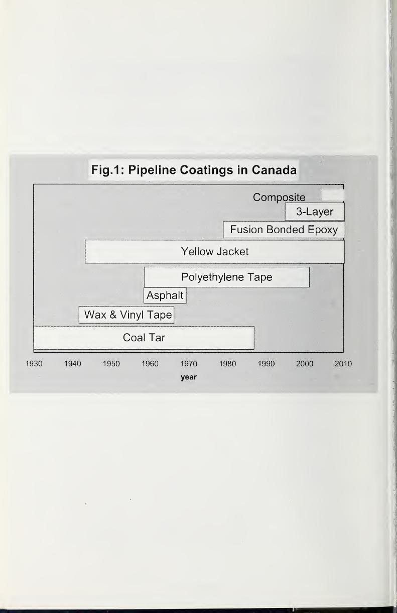
Fig.1: Pipeline Coatings in Canada
Composite
3-Layer
Fusion Bonded Epoxy
Yellow Jacket
Polyethylene Tape
Asphalt
Wax & Vinyl Tape
Coal Tar
1930 1940 1950 1960 1970 1980 1990 2000 2010
year
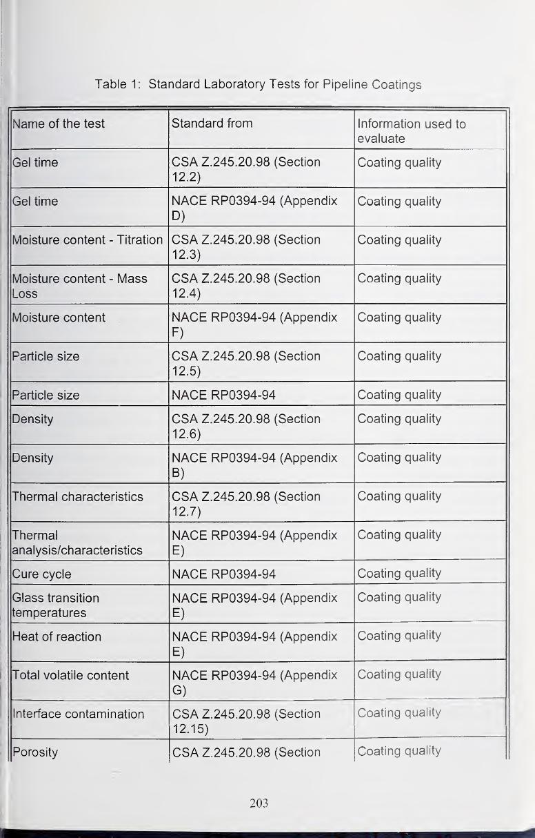
Table 1 : Standard Laboratory Tests for Pipeline Coatings
k. 1 -Cxi J. J.Name of the test Standard from Information used to
evaluate
Gel time CSA Z.245.20.98 (Section
12.2)
Coating quality
Gel time NACE RP0394-94 (Appendix
D)
Coating quality
Moisture content - Titration CSA Z.245.20.98 (Section
12.3)
Coating quality
Moisture content - MassLoss
CSA Z.245.20.98 (Section
12.4)
Coating quality
Moisture content NACE RP0394-94 (Appendix
F)
Coating quality
Particle size CSA Z.245.20.98 (Section
12.5)
Coating quality
Particle size NACE RP0394-94 Coating quality
Density CSA Z.245.20.98 (Section
12.6)
Coating quality
Density NACE RP0394-94 (Appendix
B)
Coating quality
Thermal characteristics CSA Z.245.20.98 (Section
12.7)
Coating quality
Thermal
analysis/characteristics
NACE RP0394-94 (Appendix
E)
Coating quality
Cure cycle NACE RP0394-94 Coating quality
Glass transition
temperatures
NACE RP0394-94 (Appendix
E)
Coating quality
Heat of reaction NACE RP0394-94 (Appendix
E)
Coating quality
Total volatile content NACE RP0394-94 (Appendix
G)
Coating quality
Interface contamination CSA Z.245.20.98 (Section
12.15)
Coating quality
Porosity CSA Z.245.20.98 (Section Coating quality
203

1
12 10)
Pnrn*^it\/ ANSI/AWWA C203/97 ^Section
5.3.14.4)
r^natinn niialitv
Viscosity CSA Z245.21.98 (Section 12.1) Coating quality
FInw1 1 \y V V CSA Z245 21 98 CSection 12 2) Cnatinn niialitv
Cross-section porosity NACE RP0394-94 (Appendix J) Coating quality
Interface porosity NACE RP0394-94 (Appendix
K)
Coating quality
interface contamination NACE RP0394-94 ^Aooendix
P)
Coatinn nualitv
Surface preparation SSPC-SP6/NACE No.3 Surface preparation
Surface preparation SSPC-SP10/NACE No.2 Surface preparation
Surface preparation ISO 4618-3:1999 Surface Preparation -
Terms and definitions for
rnatinn matprial<5
Slielf life NACE RP0394-94 (Appendix Handling
Outdoor weathering ASTM G 1
1
Handling
Water resistance (100%relative humidity)
ASTM D 2247 Handling
Flexibility CSA Z.245.20.98 (Section
12.11)
Testing (Hydrostatic
expansion)
Flexibility (2°/PD at-18°C
or 1.5°/PD permanentoil Clll 1 1
NACE RP0394-94 (Appendix
K)
Testing (Hydrostatic
expansion)
Bendability ASTM G 10 Installation
Bendability (ring) -
squeeze test
ASTM G 70 Installation
Cathodic disbondment CSA Z.245.20.98 (Section
12.8)
Operation
Cathodic disbondment of
strained coating
CSA Z.245.20.98 (Section
12.13)
Operation
Cathodic disbondment (24
hours or 28 days
NACE RP0394-94 (Appendix
H)
Operation
204
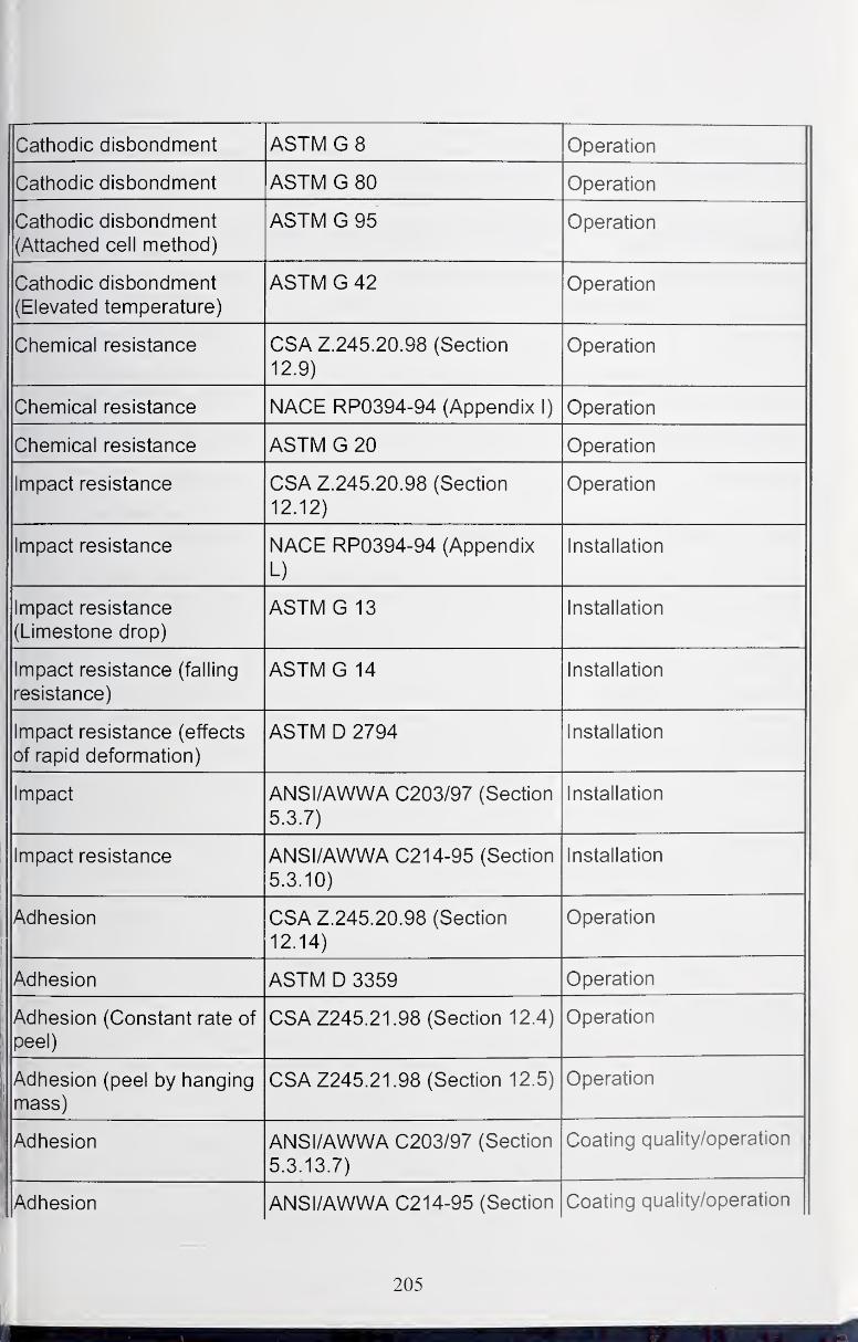
Cathodic disbondment ASTM G 8 Operation
Cathodic disbondment ASTM G 80 Operation
Cathodic disbondment
(Attached cell method)
ASTM G 95 Operation
Cathodic disbondment
(Elevated temperature)
ASTM G 42 Operation
Chemical resistance CSA Z.245.20.98 (Section
12.9)
Operation
Chemical resistance NACE RP0394-94 (Appendix 1) Operation
Chemical resistance ASTM G 20 Operation
Impact resistance CSA Z.245.20.98 (Section
12.12)
Operation
Impact resistance NACE RP0394-94 (Appendix
L)
Installation
Impact resistance
(Limestone drop)
ASTM G 13 Installation
Impact resistance (falling
resistance)
ASTM G 14 Installation
Impact resistance (effects
of rapid deformation)
ASTM D 2794 Installation
Impact ANSI/AWWA C203/97 (Section
5.3.7)
Installation
Impact resistance ANSI/AWWA C214-95 (Section
5.3.10)
Installation
Adhesion CSA Z.245.20.98 (Section
12.14)
Operation
Adhesion ASTM D 3359 Operation
Adhesion (Constant rate of
peel)
CSA Z245.21.98 (Section 12.4) Operation
Adhesion (peel by hanging
1 1 ICloo )
CSAZ245.21.98 (Section 12.5) Operation
Adhesion ANSI/AWWA C203/97 (Section
5.3.13.7)
Coating quality/operation
Adhesion ANSI/AWWA C214-95 (Section Coating quality/operation
205
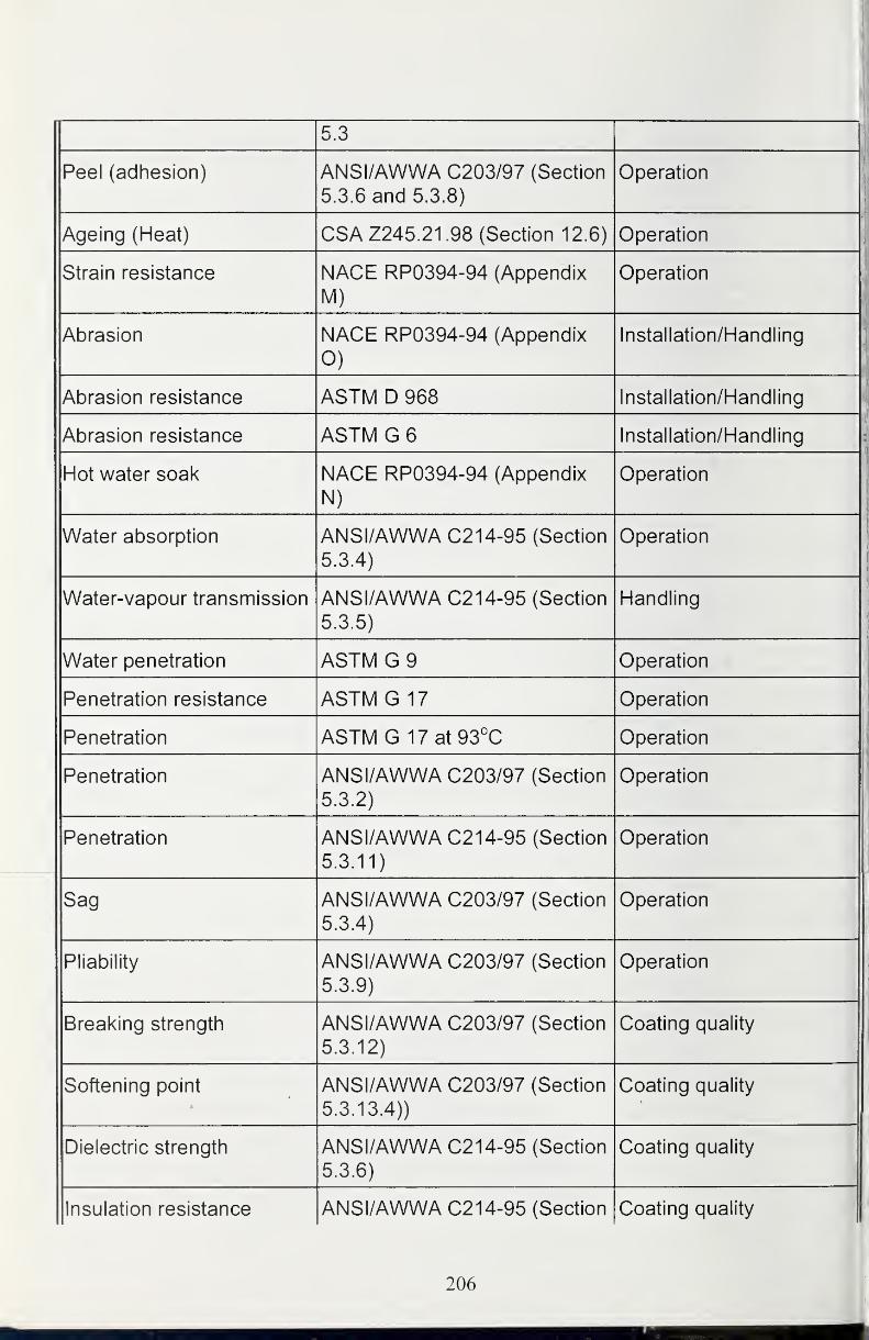
5.3
Peel (adhesion) ANSI/AWWA C203/97 (Section
5.3.6 and 5.3.8)
Operation
Ageing (Heat) CSA Z245.21.98 (Section 12.6) Operation
Strain resistance NACE RP0394-94 (Appendix
M)Operation
Abrasion NACE RP0394-94 (Appendix
0)
Installation/Handling
Abrasion resistance ASTM D 968 Installation/Handling
Abrasion resistance ASTM G 6 Installation/Handling
Hot water soak NACE RP0394-94 (Appendix
N)
Operation
Water absorption ANSI/AWWA C214-95 (SectionCO A \
5.3.4)
Operation
Water-vapour transmission ANSI/AWWA C214-95 (Section
5.3.5)
Handling
Water penetration ASTM G 9 Operation
Penetration resistance ASTM G 17 Operation
Penetration ASTM G 17at 93°C Operation
Penetration ANSI/AWWA C203/97 (Section
5.3.2)
Operation
Penetration ANSI/AWWA C214-95 (Section
5.3.11)
Operation
Sag ANSI/AWWA C203/97 (Section
5.3.4)
Operation
Pliability ANSI/AWWA C203/97 (Section
5.3.9)
Operation
Breaking strength ANSI/AWWA C203/97 (Section
5.3.12)
Coating quality
Softening point ANSI/AWWA C203/97 (Section
5.3.13.4))
Coating quality
Dielectric strength ANSI/AWWA C214-95 (Section
5.3.6)
Coating quality
Insulation resistance ANSI/AWWA C214-95 (Section Coating quality
206
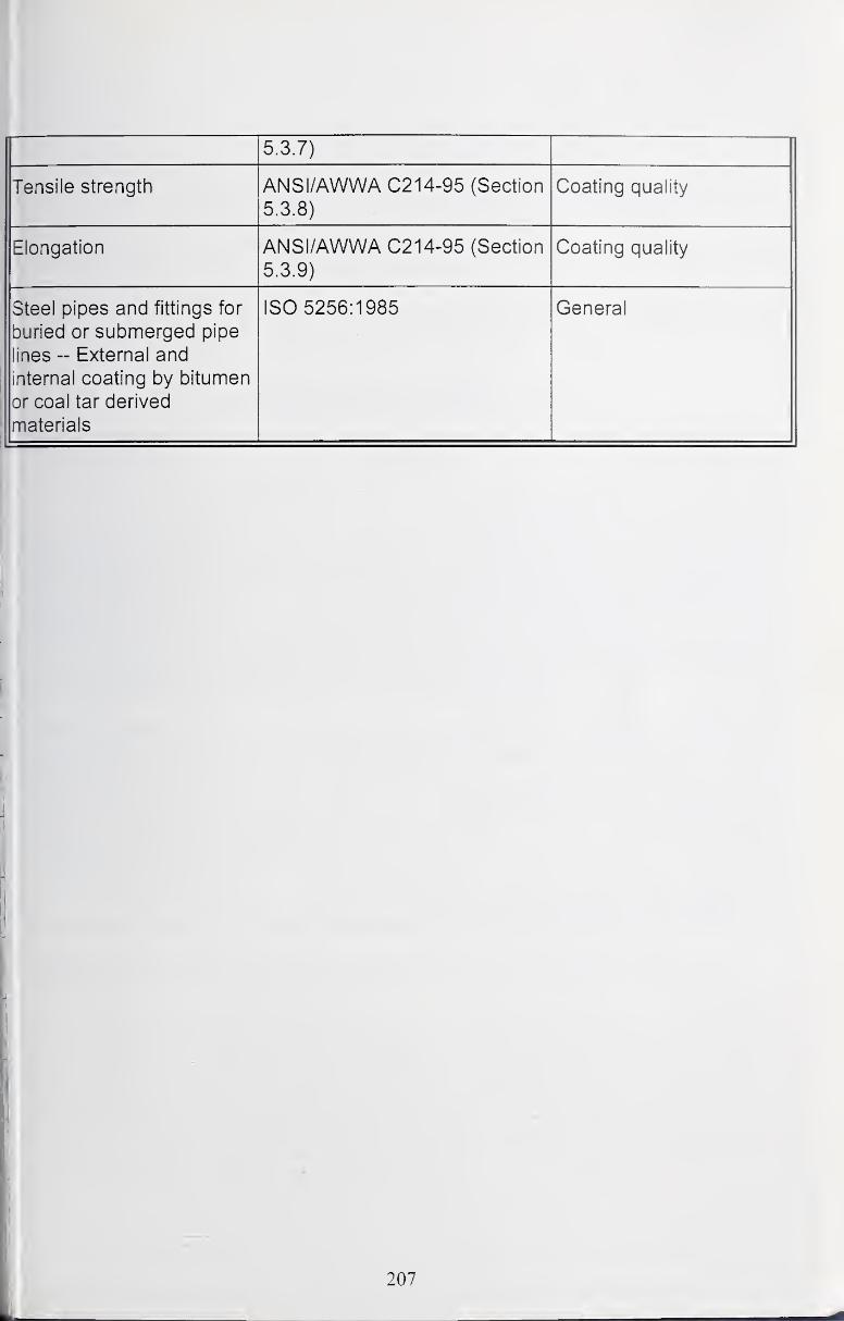
5 3 7)
Tensile strength ANSI/AWWA C214-95 (Section
5.3.8)
Coating quality
Elongation ANSI/AWWA C214-95 (Section
5.3.9)
Coating quality
Steel pipes and fittings for
buried or submerged pipe
lines -- External and
internal coating by bitumen
or coal tar derived
materials
ISO 5256:1985 General
I
I'
i
I
j
I
207
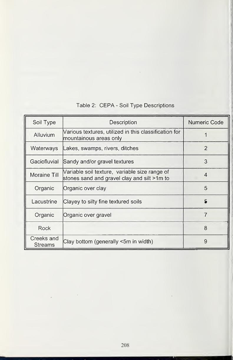
Table 2: CEPA - Soil Type Descriptions
Soil Type Description Numeric Code
MiiuviumVarious textures, utilized in this classification for
mountainous areas only1
1
Waterways Lakes, swamps, rivers, ditches 2
Gaciofluvial Sandy and/or gravel textures 3
Moraine TillVariable soil texture, variable size range of
stones sand and gravel clay and silt >1m to4
Organic Organic over clay 5
Lacustrine Clayey to silty fine textured soils 6
Organic Organic over gravel 7
Rock 8
Creeks and
StreamsClay bottom (generally <5m in width) 9
208
Coatings for Port Facilities
John H. Webb*, Daniel A. Zarate** and David L. Olson
*Mississippi State Port Authority
Guifport, Mississippi
**Naval Facilities Engineering Service CenterPort Hueneme, California
*** Colorado School of MinesGolden, Colorado
America's dependency on international commerce can be realized by the
tremendous continuous flow of very large volumes of fuel, perishables and
manufactured goods that pass through our nations port facilities. The facilities
have intense loading and unloading service requirements and schedules that are
generally inflexible and intolerant of unscheduled maintenance. These port
facilities rely on corrosion protection systems and coatings to minimize corrosion
repair and are seeking advances in coating materials and application techniques
to further extend the period between scheduled maintenance.
The workshop group on coatings for port facilities held discussions on present
and desired practices to procure coating materials and to select proper
application practices. Harbor and port facilities experience both wet and
atmospheric corrosions, which often makes situations worse being in the splash
zone or cyclic wet-dry areas. For this discussion, the type of coatings and
practices were categorized as landside facilities and structures and water- and
marine-based structures.
The Important Issues for Landside Facilities and Structures were identified as:
1. Need for better surface preparations, coating adhesion and long term
wear protection for structures of near shore marine facilities exposed to
salt spray. Ability/inability in obtaining non-conditional product installation
and warranty for new work is a concern. Qualifying contractors involved in
industry should have supported/accepted QA/QC standards such as
SSPC's QP1 program, which needs to be expanded within the industry or
established for their employees. SSPC is the Society for Protective
Coatings.
209
2. Product performance criteria needs to be established and products needto be tested for compliance to establish a standard method of specifying
quality products. By limiting choices to known quality products, this
practice will enhance a contractor's ability to compete and bid on anycoating application project, public or private. Establishing third party (non-
government) standards to quantify performance and qualify products.
Establishing methods to prevent falsifying or even "bending" the outcomeof results. Promote advances in coating tests for better selection of
coating materials
The Important Issues for Water Based Structures were identified as:
1. Steel sheet pile bulkheads and dock support structures... splash zoneprotection requirements as compared to normally submerged surfaces. Use of
coal tar epoxies as a protective coating. What advancements are available for
quick drying (setting up) coatings for application in the splash zone? Are there
coatings that can be applied underwater? What are the proper surface
preparation and coating application techniques for these conditions? Is there a
need for robotics in the application of coatings? What would drive the initiation of
robotics into the application of coatings?
2. Needs for adhesion and abrasive testing... proper methods and accuracy.
What is the range of test results (paint viscosity, hardness, adhesion shear
strength, adhesion tensile strength, coating flexibility on substrate, coating wear,
etc) that is best for marine applications in a harbor setting? Develop an index
based on tests to report the overall quality of the coating that can be used for
quality control.
3. Product performance as compared to environmental "friendliness" of
coating product needs to be established. The coating material and/or
application technique that works best is not necessarily the most environmentally
complaint. Where is the middle? What advancements are being made for better
environmentally acceptable paint removal techniques?
4. What is the best approach to ensure that the proper coating materials are
used with cathodic protection in the port facilities?
General Coating Issues Related to Port Facilities:
1. Can a port facilities user group be formed to compare performance of
coating materials and coating application technologies? (Note to others: a
marine and offshore focus group exists under SSPC and meets at the
annual meeting. Issues include discussions of port facilities coating and
corrosion control problems.)
210

2. Need to better prepare engineers during their university studies in the useof coating materials and their application technologies, specifically in
corrosion and its mitigation. Need for more preparation in economic skills
related to making engineering decisions.
3. Is the application of smart coatings with implanted sensors feasible in the
near future for corrosion protective coating service in port facilities? Cancoating integrity be assessed with a microwave (radar) gun for example,
which can be pointed gun pointed at the smart coating?
4. Use of organic systems versus metallic systems. When is it proper to hot
dip galvanize and when to paint? Is metallic coating becoming competitive
with organic based coating for corrosion protection in port facilities. Needfor a life cycle cost evaluation.
5. Promote advances in inspection methodologies of coatings on port
facilities structures. What can be developed for monitoring the condition
of coating during its service on a structure?
6. Promote advances in prediction of service life of coatings. What is the
expected service life for land based coatings? What new coating materials
and/or coating practices can make significant improvements in coating
service life?
Recommendations
The working group on coatings for port facilities offers the following
recommendations to the workshop report.
1 . The development of performance based specifications (easier on owner).
2. The development of generally accepted design standards and practices
for port authorities. This development may need to be geographically
specific; such as blue water specific or brown water specific. These
standards and practices need to beneficial to the owner.
3. Organize a working group, national or regional, to increase exchange of
information on the performance of coating products and application
methods to increase technological transfer of new coating materials and
application methodologies into practice. The working group can formulate
through user conscience new performance based specifications, design
standards and practices for port facilities. There already exists the working
structure for such a working group in the existing coating and corrosion
societies. It needs an initiator. (Note: Loosely exists at SSPC).
211
Near 100 Percent Solids Tank Linings - Panacea or Pandemonium
Benjamin S. Fultz
Bechtel Corporation
Introduction
Near 100% solids tank linings have been in existence for at least 40 years.
These products are based on low molecular weight epoxy resins, which are liquid
at room temperature. The reactants are also liquid at room temperature andrange from straight amine compounds, such as diethyltriamine, to amine
adducts. Since the resins are liquid at room temperature, less solvent is required
in the formulation of the vehicle portion of the lining. This facilitates both
manufacturing and application.
In general, lower molecular weight epoxide resins have decreased chemical
resistance and are more brittle. Chemical resistance is not a major concern for
ambient temperature salt-water exposures, albeit salt water is a highly corrosive
media. To improve performance, higher molecular weight solid epoxy resins are
added and co-reactant solvents such as benzyl alcohol compounds are added to
reduce the "as manufactured," in the can, viscosity.
One early high solid (93%) lining formulation (circa 1960) was based on a
ketamine reactant system. This material actually required atmospheric moisture
to complete the final cure. As with MDA types of reactants, ketamines weredetermined to be carcinogenic and removed from the market.
The challenge in linings formulation has always been to balance worker safety,
performance and environmental issues. Using current technology, several paint
companies have met these challenges of meeting existing worker safety
standards and environmental regulations. Performance evaluation is a work in
progress.
Advantages
The obvious advantage of high solids tank linings is reduced solvent emissions.
Reduced solvent emissions impact both worker safety and environmental
restrictions. Worker safety is improved both by reductions of direct worker
exposure to solvents during application and a reduced risk of fire or explosion
due to concentrations of flammable air solvent mixtures.
212
Reduced solvent liberation to the atmosphere also provided a mechanism for the
facility owners to meet strict environmental air quality standards. Where solvent
capture technology is used; the efficiency of the device is improved along with
reduced cost of operation.
Solvent is still required for cleanup of equipment. Waste reduction can also
result, depending on the type of application equipment used.
Disadvantages
In general, higher solids materials have reduced pot life. To facilitate application,
plural component application equipment is required. Since the "as
manufactured" viscosity is increased, higher application pressures are also
required, thus larger, more powerful high-pressure pumps. Both lead to
procurement of higher priced equipment.
Materials are required to be packaged in standard volume ratios; preferably oneto one mixes with the viscosities of each component matched as closely as
possible. Heat is sometimes used to further reduce the "as applied" viscosity.
Heating requires additional utilities. The thixotropy of the "as applied" product
also has to accommodate edge build and retention.
Film thickness control requires a higher degree of applicator skill. There is a
tendency to apply more material than is specified. Higher resultant film
thicknesses increase consumption of lining materials, in excess of estimated
quantities. Increasing the dry film thickness by an average of 2 mils for a 10 mil
specified coating increases the lining consumption by 20 percent.
Higher solids linings are, in general, more expensive than lower solids materials
on a dry mil per square foot basis, even when considering the increased solids
content. Application equipment maintenance costs are increased due to both the
increased complexity of the equipment, higher application pressures and, with
some materials, increased equipment wear to due to the abrasive nature of the
lining material on internal parts.
Because of the stiffness of high-pressure paint material supply lines, there is
difficulty in applying linings to restricted access areas, such as behind stiffening
and structure. The application equipment has a larger footprint, thus requiring
more space for setup. The weight of the equipment is greater than conventional
application equipment, which requires additional facility support.
213
Performance
Reports of performance have been mixed. The "grapevine" has reported
improved performance, comparable performance, and in some cases miserable
performance, when compared to standard, relatively low solids lining materials.
Linings applied to static structures seem to do better than linings applied to
structures subject to dynamic forces. One offshore semi submersible operator
has reported ten plus years of excellent performance. One ship operator has
reported cracking in the weld areas subject to dynamic structural flexing after a
relatively short time period. The US Navy has reported good results.
In a recent National Shipbuilding Research Program test program investigating
the retention of pre-construction primer (PGP) in ballast tanks, a lower solids tank
lining performed as well as or better than the near 100% solids lining materials.
Cause and Effect
With the adaptation of high solids lining technology, the US Navy developed a
process manual and special inspection requirements. Was this process control
the reason for increased performance or was the use of the higher solids material
the reason for improved performance? Does the formulation of so called edgeretentive linings improve performance or is the stripe coating of welds and edgesthe real reason for improved performance? In conclusion, does the additional
capital investment in material and equipment truly justify the use of higher solids
materials?
Recommendations
1 . Recommendation for investigation of developing a non destructive method
of evaluating coating systems using thermography
2. Investigate the feasibility of using microwave technology as a method of
surface preparation
3. Establish a welding procedure for welding on painted surfaces
4. Develop high solids products which meet VOC requirements that have
less tendency to embrittle over time
5. Improve application equipment to facilitate applying high solids coatings in
the field to inaccessible areas
6. Develop a mechanism to aid the painter in being able to achieve more
uniform film thicknesses with high solids coatings in the field
7. Develop a certification and training program for painters in the marine
industry
8. Help develop an engineering technologist degree / vocational training
program for coating specification
214
9. Research program to develop coating systems that respond to exposure
stresses
10. Develop a system that would be able to be used by the owner to detect
corrosion or coating localized film degradation by utilizing electrical
impedance11. Determine the feasibility of adapting magnetic flux leakage technology as
a method of determining metal loss in the shipping industry
12. Determine the feasibility of developing a hand held x-ray fluorescent
system of detecting salts on the surface
215
Evaluating the Current State of Inspection practices for Protective Coatings(In Process and Continued Evaluation) and the Exploration of
Opportunities for Improvement of these Practices
Ray Stone, CCC&IMalcolm McNeil, McNeil Coating Consultants, Inc.
D. Terry Greenfield, CorroMetrics, Inc.
Abstract
This "white paper" addresses an evaluation of the current state of inspection
practices for protective coatings and the opportunities for innprovement of these
practices as determined by a panel discussion. Inspection is attributed as a tool
to achieve the designed performance of an installed coating system through
correct installation, thereby realizing the economic benefit of asset protection with
protective coatings. Further, inspections are required to address maintenancej
and evaluate coatings performance. An evaluation of current testing methods I
and protocols, equipment and testing standards is explored with the intent of i
validation and/or improvement of these practices. The evaluation will explorei
both in-process inspection of new coating systems installation and in situj
inspection of installed systems for maintenance (repair and life-cycle extension)
and coatings system performance evaluation. The paper concludes with
identification of Research & Design (R&D) issues determined from the panel
discussion and a possible roadmap for achieving the presented opportunities for
R&D of inspection technologies, protocols, practices, and management.
Introduction
The intended life cycle of a protective coating (paint) system presents the
engineered economic value of that coating system by providing protection from
corrosion to that asset. The protection of that asset is typically a requirement of
economic, operational, environmental, and safety issues.
Inspection during protective coatings installation is employed as a tool to ensure
that the installation of the coating is within the design parameters of the
engineered and specified coating system. The emphasis of industry endeavor in
the form of practices, standards, and training has been primarily directed to this
mission.
216
Recognizing that deficiencies in the original installation do occur, further
inspections are required to initiate repair efforts, monitor coatings systenn
performance, and maximize the life cycle of the installed coatings. These in situ
inspections may present greater challenges in providing concise data to makesound engineering decisions about refurbishment issues such as maintenance
and over-coating (applying additional coatings to an already installed system for
life-cycle extension). The information gathered in the in-service inspections,
utilized with sound management practice is a valuable tool to achieve the
intended economic value of the installed coatings system.
For discussion the two most common types of inspections concerning protective
coatings can be classified as:
1. In-process inspections conducted during the initial installation of the
coatings systems and any repair efforts to that initially installed coating
before entry into service.
2. In-service inspections of the installed coatings system at regular
intervals for evaluation and scheduling of repairs to the installed
system, including evaluation of the installed coating film for repair,
refreshment (over-coating) and complete replacement.
In-Process Inspection
To evaluate only the inspection process it is assumed that the coatings materials
are properly formulated, manufactured correctly, and have been correctly
specified for the intended service. The emphasis of in-process inspection is to
ensure the correct application of that specified coatings system and the
verification that the installation is as specified.
A brief summary of the elements of typical in-process inspections for coatings
application include the following:
1. Preexisting Conditions
a. Surface Contaminates (Visible and Non-Visible)
b. Fabrication and Design Defects/Issues
2. Surface Preparation
a. Anchor Profile
b. Level of Surface Cleanliness
c. Non-Visible Contaminates
d. Environmental Condition
e. Special Substrates
i. Concrete
11. Stainless Steel
ill. Others
217
3. Coatings Application
a. Materials Verification
b. Mixing and Thinning
c. Application
d. Environmental Conditions
e. Post Application
i. Dry Film Thickness (DFT) Measurementii. Film Continuity Evaluation (visual or holiday testing)
4. Documentation and Reporting Systemsa. Hard Copy Systemsb. Computer Based Reporting
c. AuditingA/erification of Documentation
5. Other Requirements
Current industry standards address many of the described elements. However,
new surface preparation and application technologies, and continued discoveries
as to the cause of premature coatings failures require continued reevaluation of
existing standards and promulgation of new standards as required.
Evaluating the aspects of in-process inspection, opportunities for research anddevelopment emerge from the following questions.
Do the current standards adequately address the required testing? Are additional
standards required? If so, what are those standards?
Immediate industry demand for standards pertaining to visible and non-visible
levels of contamination are evident. The following ISO Standards are currently
available with regards to testing procedures:
• ISO 8502-5:1998 Preparation of Steel Substrates Before Application of Paints
and Related Products— Tests for the Assessment of Surface Cleanliness—Part 5: Measurement of Chloride on Steel Substrates Prepared for painting-
Ion Detection Tube Method
• ISO 8502-6:1998 Preparation of Steel Substrates Before Application of Paints
and Related Products— Tests for the Assessment of Surface Cleanliness—Part 6: Extraction of soluble contaminates for analysis - The Bresle method
• ISO 8502-9:1998 Preparation of Steel Substrates Before Application of Paints
and Related Products—Tests for the Assessment of Surface Cleanliness—Part 9: Field method for the conductometric determination of water soluble
salts
• ISO 8502-10:1999 Preparation of Steel Substrates Before Application of
Paints and Related Products—Tests for the Assessment of Surface
218
Cleanliness—Part 10: Field method for the titrimetric determination of water-
soluble chloride
• ISO 8502-12:2003 Preparation of Steel Substrates Before AfDplication of
Paints and Related Products—Tests for the Assessment of Surface
Cleanliness—Part 12: Field method for the titrimetric determination of water-
soluble ferrous ions
Efforts for development of standards for evaluation of non-visible surface
contamination by SSPC: The Society for Protective Coatings and NACEInternational (Task Group 259 - Salt Contaminants, Nonvisible, Soluble onCoated and Uncoated Metallic Surfaces Immediately Prior to Coating Application:
Evaluation) continue, although expected dates of any publication are not
available. Quantifying the allowable values of non-visible contamination as
determined by these described testing methods to ensure the coating application
is unaffected and no detriment to performance is experienced is the current
challenge facing industry.
Assessment of visible contaminates (dust) can be addressed with ISO Standard
ISO 8502-3:1992 Preparation of Steel Substrates Before Application of Paints
and Related Products—Tests for the Assessment of Surface Cleanliness—Part
3: Assessment of Dust on Steel Surfaces Prepared for painting (Pressure
Sensitive tape Method) using clear tape and assessing the visible residue
adhering to the tape.
Further opportunity exists for the development of Secondary Surface Preparation
Criteria/Standards (example: exceeding the recoat window of an epoxy -
Methodology for evaluation). Currently, surface preparation standards exist for
the preparation of surfaces and address the cleanliness requirements of that
substrate, typically steel. Current surface preparation standards do not address
the preparation requirements of painted surfaces to receive additional coatings
application and focus more directly on the substrate itself.
Is the current array of testing equipment adequate? What new equipment could
be developed to assist? The development of new testing equipment by
equipment manufacturers is typically driven by industry requirements with
potential market for the return of development costs and potential profit. The
potential of wide scale use is characteristically a requirement to initiate newtesting equipment development after identification of the specific need.
Currently, improvements for instrumentation used in in-process inspection maybe found in surface moisture detection, anchor profile peak densities and
improvement in the dry film thickness evaluation of coatings applied over
concrete present immediate opportunities for improvement of process and
equipment.
219
What is the measurable contribution (value) of inspection to the success
(achieving designed life-cycle) of a protective coatings installation? Research
executed to quantify the "value" of in-process coatings inspection to the
extension and/or realization of expected life cycle performance of the installed
system would provide rationale to management for the additional cost of in-
process inspection during coatings application. Although most agree that the
inclusion of inspection in coatings projects results in properly executed
application and a subsequently longer life cycle before repairs, there is little
industry data for examination to support this conclusion. Previous publication of
this subject has typically presented a comparative view of a project without in-
process inspection that failed prematurely and the costs associated with that
failure compared to the additional cost of inspection with the assumption of
project success (expected design life-cycle).
What is the required effort of inspection for it to be realized as an effective
contribution to project success? Is coating inspection performed at designated
"hold-points" an effective tool? Can "part-time" inspection be considered a
worthwhile investment in the success of a coatings project? What training and/or
certification and level of experience should be required for inspectors and firms
providing inspection?
Standards/Recommended Practices for Implementation of Inspection for
Protective Coatings Projects would provide guidance to achieve the expected
life-cycle performance of the installed coating system though in-process
inspection would ensure consistent application of in-service inspection services
determined to provide effective contribution to the coatings installation project.
Consistent practices with regards the to level of effort, inspection practices, and
project documentation should be addressed in the proposed standard.
Has the profession of Coatings Inspector evolved to a level requiring a
professional association to ensure adequate communication of new technologies
and provide a catalyst for the improvement of the profession?
In Service Inspection
Continued inspections of the installed coating systems are utilized to evaluate the
performance of those systems and to determine maintenance efforts and ensure
that the repair and/or rehabilitation course of action taken will be successful.
These inspections typically address the following:
1. Dry Film Thickness
2. Coating Adhesion
3. Substrate Condition
4. Coating Film Integrity
5. Service Environment
220
Interpretation of collected data is performed to typically provide the mosteconomically feasible course of action. Standardizing the evaluation criteria for
the three basic actions available to us: spot repair, overcoat (a decisive
evaluation of the system's ability to accept repair and overcoat is required) or
replacement should lead to consistent interpretation and economically viable
asset protection success. The following questions and opportunities emerge:
Are we presently looking at the right metrics in terms of in-service inspection andrepair? Are we looking at any metrics currently? Are industries so disparate in
requirements that common processes become impossible?
Can the equipment and protocols used for in-process inspection be used during
in-service inspection? Do we have the proper inspection tools and protocols to
efficiently evaluate condition during service and the ability to forecast remaining
service life? Life cycle expectations of coatings systems are typically predicted
from laboratory analysis prior to installation and not from an evaluation of the in
situ coating. Is there a need to develop tools focused on in-service inspection?
Possibilities include:
• Coatings age and degradation
• Ability to apply over-coatings
• Coatings deterioration and remaining service life
Except for items such as chalking, few tools exist for NDE of in-service coatings.
Identified prospects will have to eventually have some standard associated with
them. Additional opportunities may exist with:
• Electromagnetic (EM) methods-spectroscopy, use of IR, UV, color fading, etc.
• "Smart" primers (formulated to give some indication of nascent corrosion)
• Wet and dry adhesion testing (can we accomplish nondestructively?)
• Degree of cross-linking
• Detection of the products of deterioration
• Blister/blister fluid analysis
• Visual indication
• Water or other "solvent" uptake by coating film
• Exudation of high boiling volatiles?
Continued research of Electrochemical Impedance Spectroscopy (EIS) and its
use as a field measurement tool for coatings performance may provide tools for
the field measurement of remaining coatings life. The permeability of the installed
coating and evaluation of substrate corrosion not yet visually apparent may be
obtained from this testing. Currently used for laboratory evaluation of coatings,
development of field instrumentation and the associated metrics may provide
reliable tools for coatings condition assessment.
221
Do current training programs adequately address the practices required for
evaluation of in situ coatings? Current Inspector training programs focus on in-
process inspection. Although providing instruction in the use of equipment also
utilized for in-service (dry film thickness evaluation, adhesion, and etc.) the
specifics of evaluating coatings for the development of remedial and/or
maintenance planning is not addressed. The opportunity for development and
presentation of training addressing the specifics of in-service coatings evaluation
is apparent.
Do we have confidence in the various determinations of the causes of pre-mature
failure being promulgated (are there standardized methods of examination,
analysis and reporting)?
Do we have standards to evaluate condition of in-service coatings? Can our
description of condition be consistently quantified? The development of
Guidelines/Practices/Standards for evaluating In-Service Coatings could provide
industry with consistent metrics of evaluation for coatings service life through a
uniform approach to evaluation.
Is there a management system to store, manipulate, interpret, distribute, and use
the data we gather? Are there standards controlling this data collection?
Standardized Methodology for Data Collection and Management would provide:
• Consistently Quantified Condition
• Industry Shared Information
Do we have procedures available to us to make sound maintenance decisions
(i.e., successful, cost effective ones)? Can we translate the existing condition,
together with expected useful service life, into budgetary requirements? Are there
criteria for determining the most cost effective maintenance effort?
Determining analytical procedures for coating life predictions will require the
following developments and practices:
• Standard degradation models (statistically based)
• Metrics required
• NDE to gather data
• Service to laboratory correlations (atmospheric versus immersion for
example)
• New procedures to evaluate service life of new coating formulations
• In-situ evaluation
• Accelerated testing procedures
The repairs applied to new coatings and linings installations have an effect on the
system performance and its expected life-cycle and maintenance requirements.
The selection of repair methods that maintain the expected life cycle of the
222
installed systems are paramount. How are these decisions currently made?Opportunities for the research and development exist within the following:
• Quantification of the effect of "repairs" on newly installed coatings system's
life-cycle performance
• Quantification of Performance & Repair Criteria for
Summary
Although many questions regarding coatings inspection (both in-process and in-
service) have been presented, the surfacing opportunities appear to rest with the
further development of the inspection processes of in-service coatings. The panel
consensus for opportunities for the improvement of process, practices, research,
and development have focused within the following areas:
• A Study of the Measurable Economic Contribution of Inspection to Coatings
Project Success and Performance
• Standards/Recommended Practices for Implementation of Inspection for
Protective Coatings Projects
• Professional Organization of Coating Inspectors
• Secondary Surface Preparation Criteria/Standards (example: exceeding the
recoat window of an epoxy - Methodology for evaluation)
• Guidelines/Practices/Standards for evaluating In-Service Coatings and the
training of Coating Survey Inspectors, with focus on Inspection and
Evaluation of In-Service Coatings and tools for evaluation.
• Criteria for determining the most cost effective maintenance effort and tools to
quantify:
o Coatings age and degradation
o Ability to apply over-coatings
o Consistent evaluation
• Quantify the effect of "repairs" on newly installed coatings system's
performance
• Standards for Quantification of Performance & Repair Criteria
• Standardized Methodology for Data Collection and Managemento Consistently Quantified Condition
o Industry Shared Information
223

Formulation of the roadmap for research and/or development of these initiatives
will fall to industry organizations such as NACE International and SSPC: TheSociety for Protective Coatings as well as government research agencies funding
industry research.
The development of standards and recommended practices, after identification of
the specific requirements, is within the mission of industry organizations and the
framework currently exists for their development. Communication of these
requirements to the organizations is the first step to development.
Research and further study of the issues regarding predictability of in-service
coatings and linings systems and the value of in-process inspection will require
funding and sponsorship from government and industry. The economic benefit of
extended life cycle performance (from both successful application and sound
maintenance decisions) provides the initiative for funding and warrants the effort
required.
This working group has attempted to identify and clarify the current issues
regarding "Inspection & Repair" within industries using protective coatings for
asset protection to improve the inspection and repair process. The next steps
include industry and coatings organization support to fund and develop the
suggestions made within this paper. The operational, environmental, safety, and
economic benefits derived from the improvement of the process justify immediate
effort.
224
Recommendations from the Discussion Groups
ProgramsPrograms consist of numerous projects, which must be completed to achieve the
intended goal.
Research
1. Quantitative evaluation of the long-term field performance of pipeline
coatings. One project should install coated pipe samples in the field at
carefully selected locations representative of different environmental
conditions. Several monitoring methods should be used. In addition, the
coating performance evaluation should include both consistent and
fluctuating temperatures with transient and cyclic temperature fluctuations.
A one-day scoping meeting prior to this investigation should be held with
good representation of the interested parties.
2. Development of practices for evaluating pipeline coatings for service under
extreme conditions such as: Offshore-deep sea, Offshore-Arctic, Onshore-
equator is recommended. These investigations should include three types
of coatings: Anti-corrosion coatings, Abrasion-resistant coatings, and
Insulation coatings.
3. Development of a non-destructive method of evaluating the application of
coating systems. Programs need to explore the feasibility of thermography,
magnetic flux leakage, electrical impedance, and eddy current phase array.
Modeling using EIS is not reliable.
4. Development of specific advancements in coating materials. A project for
non-skid deck coating systems that will last when applied over less than
perfect surface preparations. Parameters that control coating performance.
Modeling of performance of all coatings (not only FBE). A project should
include the evaluation of coatings at higher temperature in the laboratory.
Performance of insulation coating should be investigated. Research project
to develop coating systems that respond to exposure stresses needs to be
performed.
225
Development
5. Improvement in the effective use of coatings for port facilities and the
development of the necessary performance-based specifications. Thedevelopment of generally accepted design standards and practices for port
authorities needs to be established. These standards and practices need to
be beneficial to the owner. Also the program needs to develop generally
accepted design standards and acceptances for port facilities. This
development may need to be geographically specific such as: blue water
specific or brown water specific.
6. Advanced methodologies for applications of coatings. A project needs to
address paint application issues without the use of brushes and rollers to
increase productivity, lower costs, and less personnel exposure. Theproposed investigation should include concerns of issues such as: curing
time compared to burial or immersion time and adhesion of field-applied
coatings to mill-applied coatings. An investigation to assess the effects of
stockpiling of coating products on pipeline coatings performance including
the effect of temperature, ultra-vioJet light, and time needs to be established.
Development of high solid products, which meet VOC requirements that
have less tendency to embrittle over time. Develop a mechanism to aid the
painter in being able to achieve more uniform film thicknesses with high
solid coatings in the field. The use of a capture device at the spray gun
versus total encapsulation of the space to be painted should be
investigated. Evaluate the need to increase the investment in coating
application technology R&D. Establishment of a welding procedure for
welding on painted surfaces is recommended.
7. Assessment of new technologies for surface preparation before coating.
This program should include projects on the feasibility of using microwave
technology for surface preparation, hand-held x-ray fluorescence system to
detect salts on the surface, and a project to improve the dissemination and
clarity of information on allowable surface chlorides. Improvement of
application equipment to facilitate applying high solid coatings in the field to
inaccessible areas. A project investigating the effects of minor variations in
surface preparation and effects of variation in composition of surface
contamination, including mill scale, on long-term coatings performance is
necessary. A project on secondary surface preparation critera / Standards
(example: exceeding the recoat window of an epoxy- Methodology for
evaluation) needs to be established. The cost of surface preparation and
coating application for underwater hull areas is going up and the designs of
coating technology for this area has not kept pace.
226
Administration
8. Standardized methodology for data collection and management. Anunbiased third party to compile an industry wide historical data base on
pipeline coating performance and evaluate the data critically needs to beestablished and funded. A program to establish user-friendly
standardization needs to be initiated and performed. The program wouldinclude a project on the standard/ recommended practices for
implementation of inspection for protective coatings projects.
9. Formulation of a roadmap for coatings research and/or development that
indicates the proper sequence of projects. The roadmap needs to be
periodically updated by industrial organizations as well as governmentresearch agencies and industrial users of coated structures. Such a
roadmap would be helpful in prioritizing national and international needs and
to assist in obtaining the necessary funding. The roadmap program will
need to be annually updated by NACE International and SSPC (The Society
for Protective Coatings).
10. A working group, national or regional, to increase exchange of information
on the performance of coating products and application. The working group
can formulate through user conscience new performance based
specifications, design standards, and practices for port facilities. There
already exists the working structure for such a working group in the existing
coating and corrosion societies. It needs an initiator. (Note: Loosely exists at
SSPC).
11. Evaluation of the economic issues of coating materials, their application,
and their service behavior. A specific project on the study of the
measurable economic contribution of the inspection of coatings project
successes and performance needs to be performed. A project to study
economics of coating technology to suggest and recommend the most cost
effective use of the present technology should be implemented. The issue
is that use and deployment of new coating technology is hampered by high
cost of new equipment. Look into what can be done to utilize existing
equipment; lower the cost of new equipment; or provide the financial
incentives needed. Consumer and coating industry feedback loop needs to
be improved. Problems are generally reported and investigated; however,
successful applications rarely are investigated to confirm good practice.
227
Operations
12. Advanced methods for coating repair. This program should include a
project on standards for quantification of performance and repair criteria and
a project to quantify the effect of "repairs" on newly installed coatings
system's performance.
13. Training, education, and certification of painters, corrosion engineers, andinspectors in the marine and pipeline industry. Develop a certification andtraining program for painters in the marine industry. Help develop an
engineering technologist degree / vocational training program for coating
specification. Guidelines/Practices/Standards for evaluating In-Service
Coatings and the training of Coating Survey Inspectors, with focus on
Inspection and Evaluation of In-Service Coatings and tools for evaluation
needs to be organized. A special program for educating Coast Guard and
MMS inspectors to establish consistency with the offshore industrial
standards. Development of a hiring program offering training and
certification plus weekly pay, which would have an impact on safety,
employee morale, and salary.
14. Development of coating/corrosion assessment criteria and acceptable
corrosion levels for use by corrosion engineers and regulators in the
development and assessment of Asset Integrity Management Programs.
Development of a criteria for determining the most cost effective
maintenance effort and tools to quantify: coatings age and degradation,
ability to apply over-coatings, and consistent evaluation needs to be
established.
15. Address the environmental and health and safety issues regarding paint
materials and their application. A project for the determination of the effects
of environmental conditions and variations in coating procedures on the
performance of field-applied pipeline coatings needs to be instituted. Aproject on the development and research of environment tolerant coatings
that can be used year round with increased quality. The development of
pipeline coatings with anti-microbia! properties. This development must
achieve coating acceptable ecological concerns.
228

Section 5
Special Lectures
229

I
230

COATINGS FOR U. S. NAVY SHIPSDEVELOPMENTS AND STATUS
By A.I. KAZNOFF
SEA 05M1, April 2003
Outline
I. HISTORY 1982 - 1989
II. ENVIRONMENTAL IMPACTS - FEDERAL ANDSTATE
III. POST COLD WAR EFFECTS
IV. CHANGE TO WORLD BEST PRACTICE 1994
V. RELIABILITY, ENVIRONMENT AND UNDS
VI. TECHNOLOGICAL STATUS AND NEEDS
SEA 05M1, April 2003
231
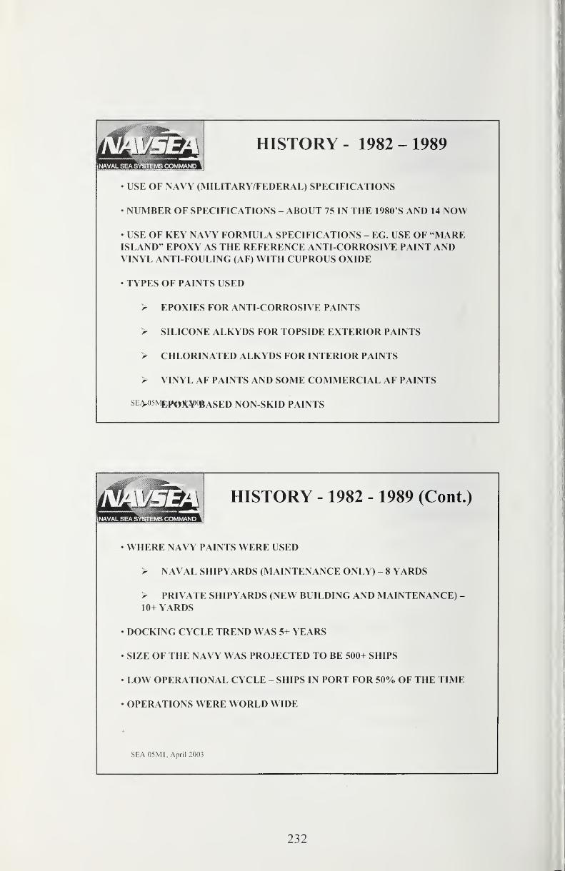
[NAVAL SEA SYSTEMS COMMAND
HISTORY - 1982-1989
• USE OF NAVY (MILITARY/FEDERAL) SPECIFICATIONS
• NUMBER OF SPECIFICATIONS - ABOUT 75 IN THE 1980'S AND 14 NOW
• USE OF KEY NAVY FORMULA SPECIFICATIONS - EG. USE OF "MAREISLAND" EPOXY AS THE REFERENCE ANTI-CORROSIVE PAINT ANDVINYL ANTI-FOULING (AF) WITH CUPROUS OXIDE
• TYPES OF PAINTS USED
> EPOXIES FOR ANTI-CORROSIVE PAINTS
> SILICONE ALKYDS FOR TOPSIDE EXTERIOR PAINTS
> CHLORINATED ALKYDS FOR INTERIOR PAINTS
> VINYL AF PAINTS AND SOME COMMERCIAL AF PAINTS
SE^5N^p»0^j|^¥qgASED NON-SKID PAINTS
HISTORY - 1982 - 1989 (Cont.)
• WHERE NAVY PAINTS WERE USED
> NAVAL SHIPYARDS (MAINTENANCE ONLY) - 8 YARDS
> PRIVATE SHIPYARDS (NEW BUILDING AND MAINTENANCE) -
10+ YARDS
• DOCKING CYCLE TREND WAS 5+ YEARS
• SIZE OF THE NAVY WAS PROJECTED TO BE 500+ SHIPS
• LOW OPERATIONAL CYCLE - SHIPS IN PORT FOR 50% OF THE TIME
• OPERATIONS WERE WORLD WIDE
SEA 05M1, April 2003
232
NAVAL SEA SY^EMS COMMAND
HISTORY - 1982 - 1989 (Cont.)
Major Changes and Developments
• DELIBERATE SHIFT TO COMMERCIAL COATINGS THROUGH THE USEOF PERFORMANCE SPECIFICATIONS AND QUALIFIED PRODUCTS LISTS(QPL)
• DELIBERATE ELIMINATION OF HAZARDOUS/TOXIC PAINTINGREDIENTS SUCH AS LEAD (DRIERS AND PIGMENTS) ASBESTOS,CRYSTALLINE SILICA AND CHROMATES
• MAJOR PROBLEMS IN ANTI-FOULING PAINT> PERFORMANCE WAS LIMITED TO 18 MONTHS WITH THEVINYL AF PAINT> MAIN ACTIVITY WAS NAVY R&D IN TRIBUTYL TIN (TBT)
PAINTS> EVALUATION OF COMMERCIAL TBT PAINTS
• PARALLEL EFFORT WAS SPENT IN QUALIFYING ALTERNATIVECUPROUS OXIDE AF PAINTS BECAUSE TBT USE WAS UNCERTAIN DUETO LACK OF ENVIRONMENTAL ASSESSMENT
DEVELOPMENT AND QUALIFICATION OF WATER-BORNE INTERIOR'
^'^^i^AINTS
ENVIRONMENTAL IMPACTS -
FEDERAL/STATE REGULATIONS
• FEDERAL (EPA) AND SOME STATE AUTHORITIES REQUIREREGISTRATION OF PAINTS USED ESPECIALLY ANTI-FOULING PAINTSBECAUSE OF THE BIOCIDE USED
• THE LATE 80'S WAS A PERIOD OF HOPE OF OBTAINING A MOREEFFECTIVE AF PAINT BASED ON TBT
• THE EPA AND THE MAJORITY OF AFFECTED STATES DID NOTACCEPT THE NAVY ENVIRONMENTAL ASSESSMENT FAVORING ITS
USE
• FEDERAL REGULATIONS SET THE LIMIT OF EMISSIONS AT 4
MICROGRAMS PER SQUARE CENTIMETER PER DAY FOR TBT
• STATE CHALLENGES TO NAVY USE OF TBT PAINTS BASED ONTIGHT LOCAL WATER QUALITY STANDARDS AND LOCAL FEARS OFTBT
SEA 05M1, April 2003
233
ENVIRONMENTAL IMPACTS -
FEDERAL/STATE REGULATIONS (Cont.)
• NAVY DECIDES NOT TO USE TBT PAINTS AND SWITCHES TO TWOCOMMERCIAL ABLATIVE PAINTS BASED ON CUPROUS OXIDE
• LOSS OF TBT OPTION FOR ALUMINUM HULLS POSES MAJORPROBLEMS (AS COPPER BASED AF PAINTS ARE UNSUITABLE) -
PROBLEM SOLVED BY THE INTRODUCTION OF "EASY RELEASE"SILICONE PAINT
• NET RESULT WAS THAT THE NAVY WAS UNAFFECTED BY THE IMOBAN ON TBT PAINTS WHICH CAME MORE THAN A DECADE AFTER THENAVY DECISION NOT TO USE TBT AF PAINTS
• NAVY CANCELLED THEIR MILITARY SPECIFCATION FORORGANOTIN PAINTS (MIL-P-24588) IN 1985
SEA 05M1, April 2003
ENVIRONMENTAL IMPACTS -
FEDERAL/STATE REGULATIONS (Cont.)
• LATE EIGHTIES WAS A PERIOD WHEN THE STATE OF CALIFORNIAPUSHED THROUGH REGULATIONS FOR LIMITING VOLATILE ORGANICCOMPOUND (VOC) CONTENT
• BY 1989 THE NAVY ESTABLISHED BY NEGOTIATION THE LIMITS FORIMPLEMENTATION BY SEPTEMBER OF 1991 THE GENERIC NEW VOCLIMIT OF 340 GRAMS OF SOLVENT PER LITER OF PAINT (g/L)
• THE NAVY MET ALL VOC REGULATIONS THROUGHREFORMULATION PROGRAMS BY THE DEADLINE DATE EXCEPT FORONE PAINT WHICH WAS COMPLETED BY JANUARY 1992
• IN 1992 THE FEDERAL"NATIONAL EMISSIONS STANDARDS FORHAZARDOUS AIR POLLUTANTS" (NESHAP) HIT THE NAVY
• RESULT WAS REGULATION IN 1997 WHICH WAS MET BY THE NAVY.IN LARGE MEASURE THE NESHAP WAS BASED ON VOC LIMITS SET BYCALIFORNIA
SEA 05M1, April 2003
234
POST COLD WAR EFFECTS ONNAVY
• REDUCTION OF FLEET SIZE TO LESS THAN 300 SHIPS CURRENTLY
• REDUCTION IN MAINTENANCE BUDGETS
• REDUCTION IN SHIPYARDS & FACILITIES (8 SHIPYARDS TO 4)
• EXTENSION OF DOCKING CYCLES TO 10+ YEARS
• REDUCTION IN PERSONNEL RESULTING IN LOSS OF EXPERIENCEDPEOPLE
• PERIODIC DIFFICULTIES IN RECRUITMENT AND RETENTION OFNAVY PERSONNEL
• FLEET MATERIAL OFFICERS DEMANDING MORE RELIABLE LONGERLASTING COATINGS IN ALL CATEGORIES - 1994 - BUT NO FUNDING TODEVELOP.
• ACCEPTANCE OF "REASONABLE RISKS "
SEA 05M1, April 2003
• BETWEEN 1994 AND 2002 13 SHIPBUILDING YARDS WERE VISITED BYNAVSEA IN EUROPE, JAPAN AND KOREA
• HIGH PERFORMANCE PAINTS AND APPLICATION REQUIREMENTSESTABLISHED BY INTERACTIONS WITH WORLD PAINT SUPPLIERS -
SIGMA, AKZO-NOBEL, HEMPEL, JOTUN, CHUGOKU
• VERIFICATION OF COATING PRACTICE WITH CLASSIFICATIONSOCIETIES SUCH AS DET NORSKE VERITAS
• EXAMINATION OF NAVY DATA SHOWED;> LIFETIME OF A BALLAST TANK COATING VARIED FROM 1 YEARTO 10 YEARS WITH THE SAME PAINT (AVERGAGE LIFE LESS THAN5 YEARS)
> QC & QA ON COATINGS SYSTEMS WAS HIGHLY VARIABLE
> LACK OF DIRECTION FOR ROUNDING CORNERS LED TOGENERIC EARLY FAILURES IN TANKS.
> TRAINING OF APPICATOR PERSONNEL WAS/IS QUESTIONABLESEA 05M1, April 2003
CHANGE TO WORLD BESTPRACTICE 1994
235
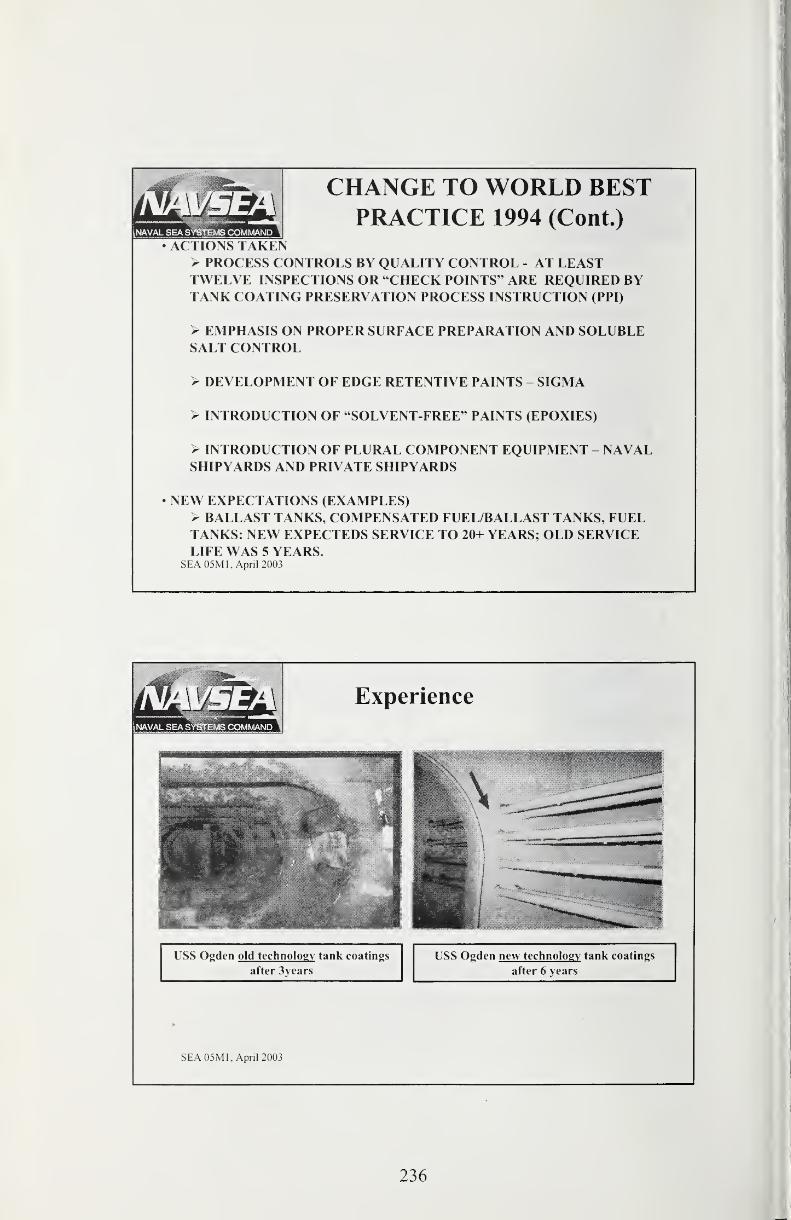
iNAVAL SEA SYSTEMS COMMAND
CHANGE TO WORLD BESTPRACTICE 1994 (Cont.)
• ACTIONS TAKEN> PROCESS CONTROLS BY QUALITY CONTROL - AT LEASTTWELVE INSPECTIONS OR "CHECK POINTS " ARE REQUIRED BYTANK COATING PRESERVATION PROCESS INSTRUCTION (PPI)
> EMPHASIS ON PROPER SURFACE PREPARATION AND SOLUBLESALT CONTROL
> DEVELOPMENT OF EDGE RETENTIVE PAINTS - SIGMA
> INTRODUCTION OF "SOLVENT-FREE " PAINTS (EPOXIES)
> INTRODUCTION OF PLURAL COMPONENT EQUIPMENT - NAVALSHIPYARDS AND PRIVATE SHIPYARDS
• NEW EXPECTATIONS (EXAMPLES)> BALLAST TANKS, COMPENSATED FUEL/BALLAST TANKS, FUELTANKS: NEW EXPECTEDS SERVICE TO 20+ YEARS; OLD SERVICELIFE WAS 5 YEARS.
SEA 05M1, April 2003
SEA 05M1, April 2003
236
RELIABILITY, ENVIRONMENT,EPA CONSTRAINTS AND UNDS
RELIABILITY
• RELIABILITY DEPENDS ON PROCESSES THAT ARE VERIFIED FOR THECONDITIONS ENCOUNTERED ACCOMPANIED BY QUALITY CONTROLWITH INDEPENDENT OVERSIGHT
• INTERNAL SPACES ON SHIPS ARE EASIER TO CONTROL FROM ANENVIRONMENTAL STANDPOINT WITH EQUIPMENT THAT MAINTAINSREQUIRED TEMPERATURE AND HUMIDITY.
• SPECIFICATIONS WITH TEMPERATURE AND HUMIDITY CONTROLSCAN HAVE VERY LOW RECORDS OF COMPLIANCE WITHOUTAUTOMATIC CONTROL DEVICES.
SEA 05M1, April 2003
RELIABILITY (Cont'd)
• EXTERIORS OF SHIPS ARE CONSIDERABLY HARDER TO PRESERVEBECAUSE NEARLY ALL EXTERIOR PAINTING IS DONE IN THEWEATHER WITHOUT THE BENEFIT OF TEMPORARY SHELTER ANDCONTROLS.
• VAGARIES OF WEATHER ALSO INTRODUCE SERIOUS RISKS IN
ACCOMPLISHMENT OF QUALITY WORK AND REQUIRE EXPENSIVEREWORK AS A RESULT OF WEATHER UPSETS.
• THE ABILITY TO DECREASE THE RISKS OF WEATHER INDUCED"FAILURES" OF PAINTING MAY BE ACCOMPLISHED BY THEFOLLOWING MEANS:
> RAPID CURE PAINT SYSTEMS TO DECREASE THE PERIOD OFSUSCEPTABILITY TO WEATHER UPSETS AND SAVE MONEY (THIS MAY BETHE BETTER OPTION IF SHELTER OPTION IS OUT)
> DEVELOPMENT OF PAINT TOLERANT TO MOISTURE (THIS IS AT BEST AMARGINAL IMPROVEMENT)
> UTILIZATION OF TEMPORARY OR PERMANENT ENCLOSURES . THIS
sa^El^IJ^lBKSINESS CASE STUDIES. (BEST CORRECTIVE OPTION FORMEETING UNIFORM SCHEDULES)
237

[NAVAL SEA SYSTEl*^ COMMAND
EPA CONSTRAINTS• TRENDS IN CALIFORNIA INDICATE THAT VOC (NESHAP) VALUES ARERAPIDLY DECREASING
1991 - 340 g/L
2004 - 250 g/L
2006 - 100-150 g/L
THE TREND IS APPROACHING ZERO VOC
• WATER QUALITY ISSUES EVIDENT IN SAN DIEGO (BAY AREA) WHEREHIGH COPPER LEVELS ARE SEEN (I.E. IN PLEASURE CRAFT HARBORS)
• FEDERAL EPA HAS RECENTLY PROPOSED MORE STRINGENT LIMITSON COPPER LEVELS. THIS HAS A MAJOR IMPACT ON COPPER USE IN
ANTI-FOULING PAINTS. SOME EUROPEAN COUNTRIES AND CANADAHAVE CONSTRAINTS ON COPPER IN THE WATER
• DUE TO ACTIONS IN THE MID-NINETIES, THE NAVY HAS EPOXIES(ANTI-CORROSIVES AND OTHER USES) THAT WILL MEET ALL KNOWNCALIFORNIA LIMITS .
• IT IS DOUBTFUL IF ALKYD LIMITS BELOW 200g/L ARE ACHIEVABLE
• A^MJ^UlEt?^?AINTS, DUE TO RESINS USED, ARE UNLIKELY TO GOBELOW 400 g/L (WITH SOME RARE EXCEPTIONS TO 340 g/L)
UNIFORM NATIONALDISCHARGE STANDARDS (UNDS)
• JOINT EPA - DOD (AND COAST GUARD) EFFORT TO DEVELOPSTANDARDS FOR DISCHARGES FROM SHIPS INTO THE WATER (WITHINTHE 12 NAUTICAL MILE LIMIT)
• APPLICABLE TO 25 SHIP DISCHARGES, BUT FOR THIS PRESENTATION,THE SPECIFIC DISCHARGE IS "SHIP HULL LEACHATE" DISCHARGEBECAUSE OF ITS CONTRIBUTION TO COPPER CONTENT IN HARBORSSUCH AS SAN DIEGO
TO DATE, NO STANDARD HAS BEEN DEVELOPED OR EXISTS
SEA 05M1, April 2003
238
TECHNOLOGICAL STATUS ANDNEEDS
• THE NEEDS AND DILEMMAS HAVE BEEN PRESENTED AND WHILESOME ARE IMPORTANT PRESENT DIFFICULTIES, THERE ARESIGNIFICANT OPTIONS AND DEVELOPMENTS FOR FUTURE SOLUTIONS.
• TOPSIDE ALKYD PAINT CAN BE REPLACED WITH SOLVENT-FREEALIPHATIC URETHANES. THE PROBLEMS WITH THIS CHANGE ARE:
> USE OF PLURAL COMPONENT APPLICATION FOR SHIPS FORCEMAINTENANCE IS UNLIKELY> PROBLEMS WITH OVERCOAT ADHESION - NEED FOR FUNCTIONALITY IN
THE RESIN TO OVERCOME LIMITATIONS
• CHANGE TO URETHANE (OR POLYUREA) FOR RAPID CURE/REPAIRSTRATEGY FOR ALL SYSTEMS. FURTHER ADVANTAGE IS WIDENINGOF THE RANGE OF APPLICATION TO LOWER TEMPERATURES (320 F)
• ANTI-FOULING PAINTS HAVE MAJOR PROBLEMS FOR MEETING THE340-400 g/L VOC LIMIT AND HIGH SOLVENT CONTENT BRINGSPROBLEMS FOR LONG SERVICE AF PAINTS DUE TO SLOW SOLVENTEVM9M,TP^o^D RESULTING LOW MECHANICAL STRENGTH OFTHE PAINT.
NAVAL SEA SYSTEMS COMMAND
TECHNOLOGICAL STATUS ANDNEEDS (Cont.)
• THE SOLUTION IS THE DEVELOPMENT OF A TWO-COMPONENT PAINTSYSTEM THAT PROVIDES THE PROPER SELF-POLISHING FOR THEBIOCIDES USED.
• WHY ARE WE OPTIMISTIC? R & D AT THE NAVAL RESEARCHLABORATORY (NRL) LED BY Dr. JEF VERBORGT HAS IDENTIFIED THENEEDED TECHNOLOGY OF:
> RAPID CURE POLYURETHANES> HIGH FUNCTIONALITY SYSTEMS THAT ALLOW HIGH ADHESION OFOVERCOAT/REPAIR> AF SELF-POLISHING SYSTEMS HAVE BEEN IDENTIFIED
• THE POSITION OF THE U. S. NAVY IS THAT THE TECHNOLOGYDEVELOPED BY NRL/ JEF VERBORGT CAN BE MADE AVAILABLE TOTHE COATINGS INDUSTRY. PATENT APPLICATION HAS BEEN MADEAND OTHERS WILL FOLLOW.
SEA 05M1, Apnl 2003
239
For More Information:
• NAVAL RESEARCH POINT OF CONTACT IS MR. KEITH LUCAS, NRL,CODE 6130, CENTER FOR CORROSION SCIENCE AND ENGINEERING,PHONE NUMBER 202-767-0833.
• FOR FURTHER REFERENCE ON THE TOPIC OF RAPID CURE RESINSYSTEMS SEE NATIONAL ASSOCIATION OF CORROSION ENGINEERS(NACE) PUBLICATION "MATERIALS PERFORMANCE" OCTOBER 2003.
SEA 05M1, April 2003
• HIGH SOLIDS EDGE RETENTIVE COATINGSTANKS AND EXTERIOR ANTI-CORROSIVE PAINTS> AMERON 133/333
> SIGMA BT> SHERWIN-WILLIAMS DURA PLATE> AKZO-NOBEL INTERGARD 143
• SOLVENTLESS COATINGSTANKS> SIGMA EDGEGUARD AND CSF> SHERWIN-WILLIAMS DURA-PLATE UHS> AKZO-NOBEL E^TERGARD 143
Backup Slides - Recent
Developments in Navy Coatings
SEA 05M1, April 2003
240
Recent Developments (Cont'd)UNAVAL SEA SYSTEMS COMMAND
• LOW SOLAR ABSORBENT/ANTLSTAIN EXTERIORTOPSIDE COATINGS
FREEBOARD AND DECKS> NCP (NILES CHEMICAL PAINT CO.) 7229C
> AKZO-NOBEL INTERLAC 1
• BIOCIDE-FREE ANTIFOULING PAINTS FOR SPECIALAPPLICATIONS
PRIMARILY FOR ALUMINUM CRAFT> AKZO-NOBEL INTERSLEEK
• SURFACE TOLERANT COATINGSBILGES, WET SPACES> EURONAVYES 301
SEA05Ml^pnl2003^LOCIT 28.15
COATINGS FOR THE FUTURE
•SINGLE COAT PRODUCTS> URETHANES> POLYUREAS> EPOXIES
•QUICK CURE PRODUCTS> SHORT POT LIFE
> COAT-TO-USE IN 30 MINUTES> LOW TEMPERATURE CURE
•ANTI-FOULING PAINTS> LOW COPPER/NO COPPER> BIOCIDEFREE> SOLVENTLESS
SEA 05M1. Anril 2003
> TWO COMPONENT
241
Single Coat & Rapid Cure
Tank: Coating Systems
Improved Tank Preservation Processes
Arthur Webb - NRL
Program Team
Program Sponsor
- Office of Naval Research
Transition Sponsor/Materials Technical Authority
- Naval Sea Systems Command 05MFleet Demonstration Partners
- COMNAVSURFLANT, COMNAVSURPAC- COMNAVAIRLANT, COMNAVAIRPACTechnical Development and Implementation Labs
- Naval Research Laboratory, Code 6130
- Naval Surface Warfare Center, Carderock Division, Code 613
Naval Research Laboratory
Arthur A. Webb(202) 404-2888, [email protected]
Paul Slebodnick
202-404-7298, [email protected]
Bill Groeninger
757-652-4838, [email protected]
Naval Surface Warfare Center
Bill Needham
301 -227-5034, [email protected]
Rich Hays
301-227-5135, ([email protected]
242
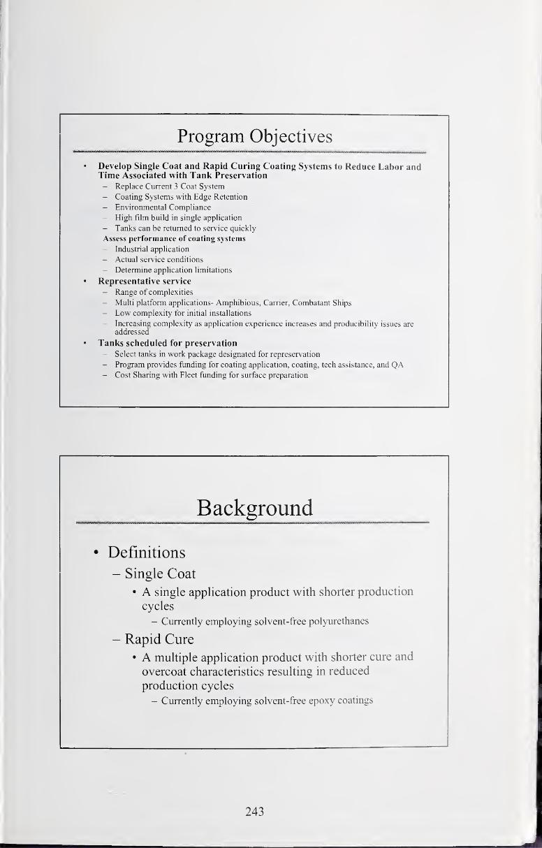
Program Objectives
Develop Single Coat and Rapid Curing Coating Systems to Reduce Labor andTime Associated with Tank Preservation
- Replace Current 3 Coat System
- Coating Systems with Edge Retention
- Environmental Compliance
- High film build in single application
- Tanks can be returned to service quickly
Assess performance of coating systems
- Industrial application
- Actual service conditions
- Determine application limitations
• Representative service
- Range of complexities
- Multi platform applications- Amphibious, Carrier, Combatant Ships
- Low complexity for initial installations
- Increasing complexity as application experience increases and producibility issues are
• Tanks scheduled for preservation
- Select tanks in work package designated for represervation
- Program provides funding for coating application, coating, tech assistance, and QA- Cost Sharing with Fleet funding for surface preparation
• Definitions
- Single Coat
• A single application product with shorter production
cycles
- Currently employing solvent-free polyurethanes
- Rapid Cure
• A multiple application product with shorter cure and
overcoat characteristics resulting in reduced
production cycles
- Currently employing solvent-free epoxy coatings
addressed
243
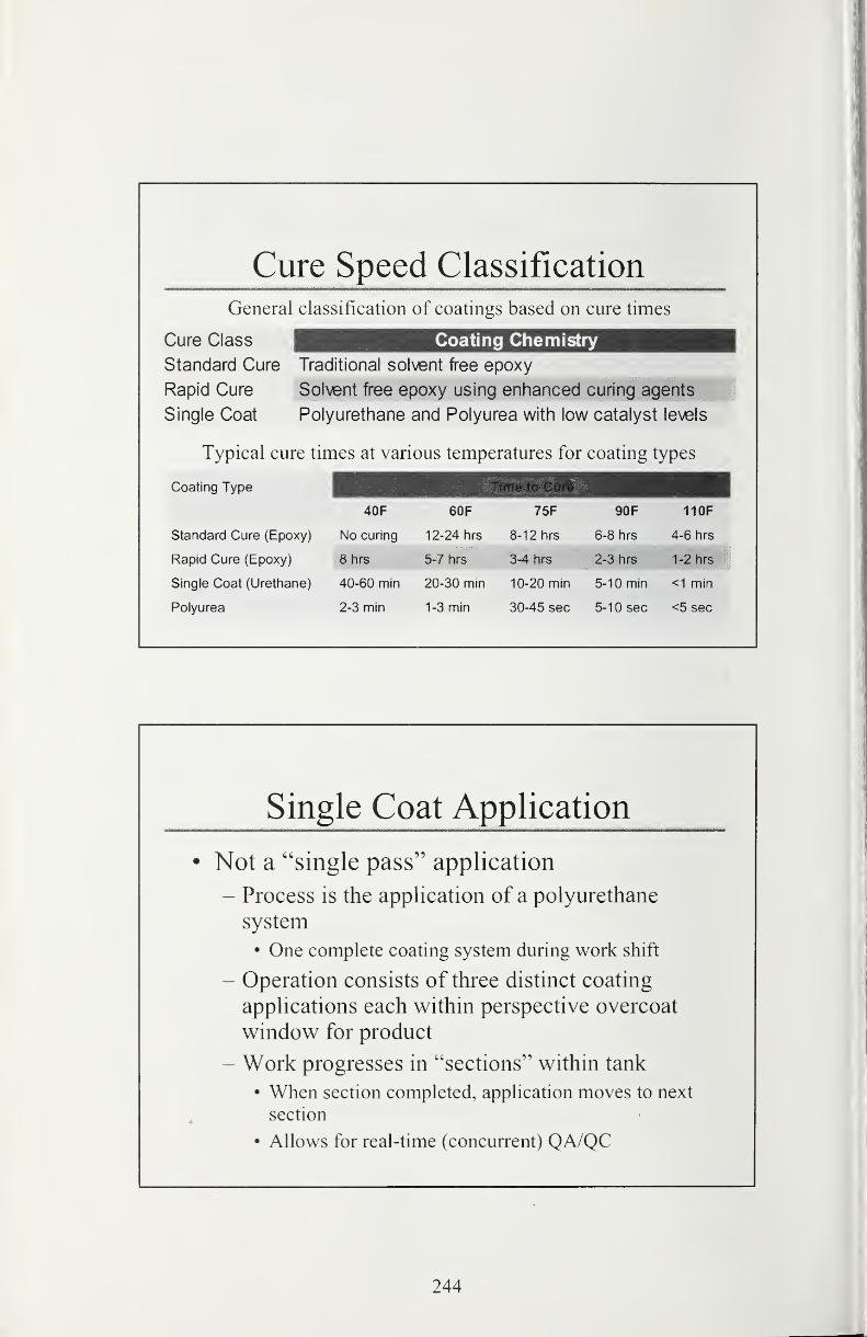
Cure Speed Classification
General classification of coatings based on cure times
Cure Class iHIHiHIIIHE!EE3BEEC33SS!3iH^HHistandard Cure Traditional solvent free epoxy
Rapid Cure Solvent free epoxy using enhanced curing agents
Single Coat Polyurethane and Polyurea with low catalyst levels
Typical cure times at various temperatures for coating types
Type ^^^^^^^^^H^^^^^^^^^^^^^^^^^^^^^H40F 60F 75F 90F 110F
Standard Cure (Epoxy) No curing 12-24 hrs 8-12 hrs 6-8 hrs 4-6 hrs
Rapid Cure (Epoxy) 8hrs 5-7 hrs 3-4 hrs 2-3 hrs 1-2 hrs
Single Coat (Urethane) 40-60 min 20-30 min 10-20 min 5-10 min <1 min
Polyurea 2-3 min 1-3 min 30-45 sec 5-10 sec <5 sec
Single Coat Application
• Not a "single pass" application
- Process is the application of a polyurethane
system
• One complete coating system during work shift
- Operation consists of three distinct coating
applications each within perspective overcoat
window for product
- Work progresses in "sections" within tank
• When section completed, application moves to next
section
• Allows for real-time (concurrent) QA/QC
244
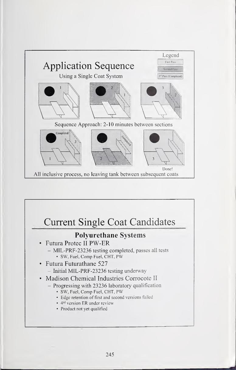
Application SequenceUsing a Single Coat System
LegendFirst Pass
Second Pass
3"' Pass (Completed)
Sequence Approach: 2-10 minutes between sections
Done!
All inclusive process, no leaving tank between subsequent coats
Current Single Coat Candidates
Polyurethane Systems• Futura Protec II PW-ER
- MIL-PRF-23236 testing completed, passes all tests
• SW, Fuel, Comp Fuel, CHT, PW• Futura Futurathane 527
- Initial MIL-PRF-23236 testing underway
• Madison Chemical Industries Corrocote II
- Progressing with 23236 laboratory qualification
• SW, Fuel, Comp Fuel, CHT, PW• Edge retention of first and second versions failed
• 4'''^ version ER under review
• Product not yet qualified
245

Current Rapid Cure Candidates
• Sherwin-Williams Fast-Clad
- Progressing with 23236 laboratory qualification
• SW, Fuel, Comp Fuel, CHT• No potable water
• Product not yet qualified
• International Intergard 783- MIL-PRF-23236 testing initiated Aug 03
• SW, Fuel, Comp Fuel
• Sigma EX 1762- Initial MIL-PRF-23236 qualification underway
• Formulated for all tank applications, except potable water
Current Rapid Cure Candidates
Curing Performance for Current Fast Cure Candidates
SIGMA SH-WMS INTERNATEX1762 FASTCLAD INTERGARD
AMINE 483/783
Properties Cure TimesSET TO TOUCH 1.3 hrs 1.6 hrs 1 .4 hrs
TACK FREE 1.9 hrs 2.3 hrs 2.3 hrs
DRY HARD 2.1 hrs 2.6 hrs 2.5 hrs
ND= no difference or change from dry hard reading coatings were cured through at
the dry hard measurement time
246
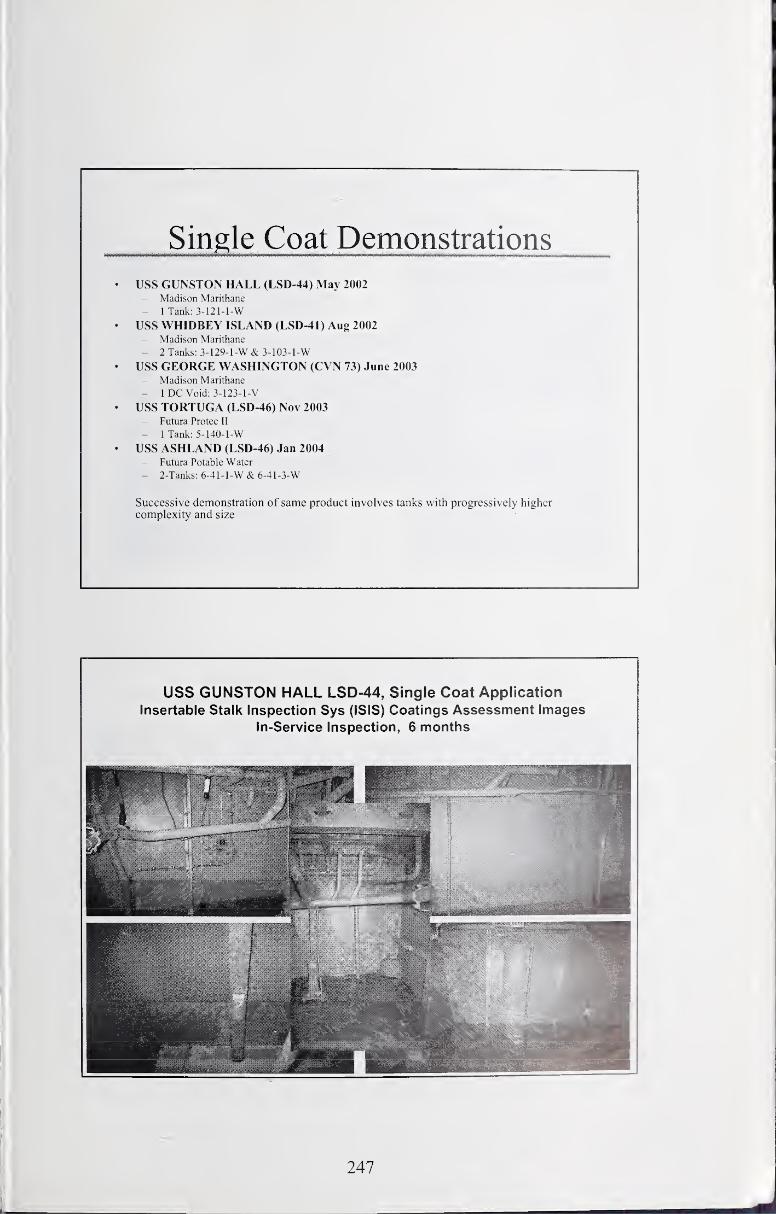
Single Coat Demonstrations
• USS GUNSTON HALL (LSD-44) May 2002- Madison Marithane
- 1 Tank: 3-121-1-W
• USS WHIDBEY ISLAND (LSD-41) Aug 2002- Madison Marithane
- 2Tanks:3-129-l-W&3-103-l-W
• USS GEORGE WASHINGTON (CVN 73) June 2003- Madison Marithane
- 1 DC Void: 3-123-1-V
• USS TORTUGA (LSD-46) Nov 2003- Futura Protec II
~ 1 Tank: 5-140-1-W
• USS ASHLAND (LSD-46) Jan 2004- Futura Potable Water
- 2-Tanks: 6-4 1 - 1-W & 6-4 1 -3-W
Successive demonstration of same product involves tanks with progressively higher
complexity and size
USS GUNSTON HALL LSD-44, Single Coat Application
Insertable Stalk Inspection Sys (ISIS) Coatings Assessment Images
In-Service Inspection, 6 months
247
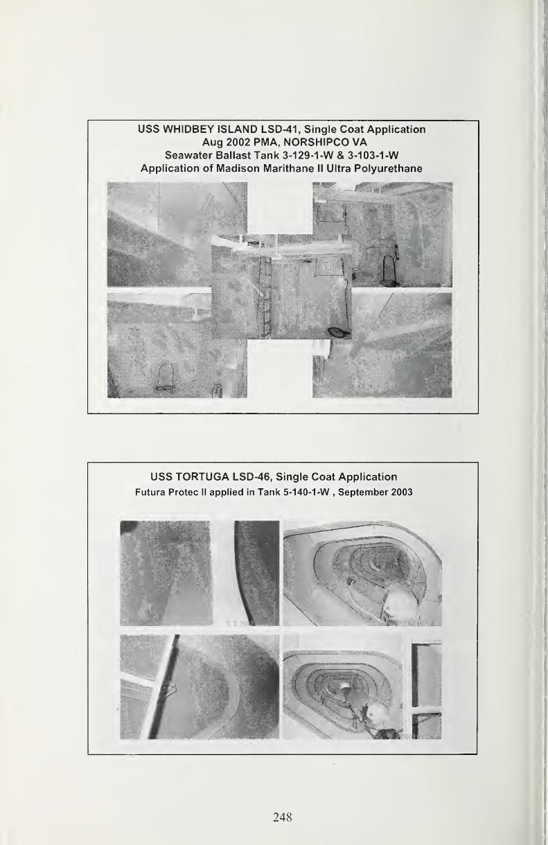
USS WHiDBEY ISLAND LSD-41, Single Coat Application
Aug 2002 PMA, NORSHIPCO VASeawater Ballast Tank 3-1 29-1 -W & 3-1 03-1 -W
Application of Madison Marithane II Ultra Polyurethane
USS TORTUGA LSD-46, Single Coat Application
Futura Protec II applied in Tank 5-140-1 -W,September 2003
248
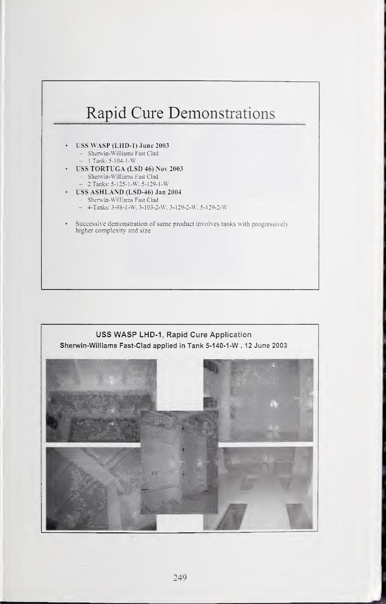
Rapid Cure Demonstrations
• USS WASP (LHD-1) June 2003- Shenvm-Williams Fast Clad
- 1 Tank: 5- 104-1 -W• USS TORTUGA (LSD 46) Nov 2003
- Sherwin-Williams Fast Clad
- : Tanks: 5-125-1-W. 5-129-l-\V
• USS ASHL.\ND (LSD-46) Jan 2004- Sherwin-Williams Fast Clad
- 4-Taiiks: 3-98-1-W. 3-103-2-W. 3-129-2-W. 5-129-2-W
Successi\ e demonstration of same product involves tanks with progressively
higher complexit\" and size
USS WASP LHD-1, Rapid Cure Application
Sherwin-Williams Fast-Clad applied in Tank 5-140-1 -W , 12 June 2003
249
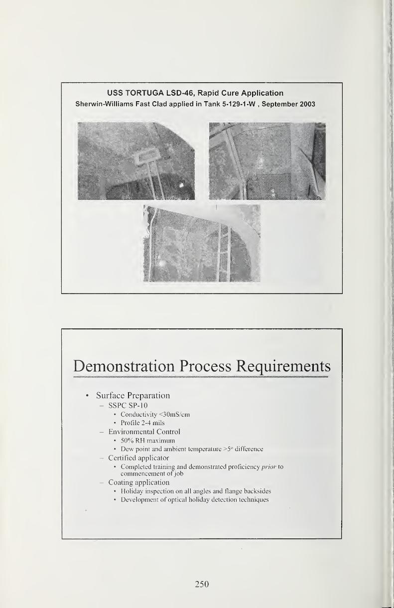
USS TORTUGA LSD-46, Rapid Cure Application
Sherwin-Williams Fast Clad applied in Tank 5-1 29-1 -W , September 2003
Demonstration Process Requirements
• Surface Preparation
- SSPCSP-10• Conductivity <30mS/cin
• Profile 2-4 mils
- Environmental Control
• 50% RH maximum• Dew point and ambient temperature >5° difference
- Certified applicator
• Completed training and demonstrated proficiency prior to
commencement ofjob
- Coating application
• Holiday inspection on all angles and flange backsides
• Development of optical holiday detection techniques
250
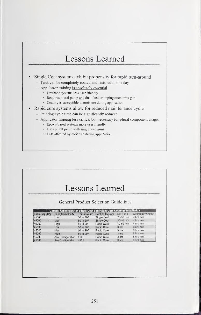
Lessons Learned
• Single Coat systems exhibit propensity for rapid turn-around
- Tank can be completely coated and finished in one day
- Applicator training is absolutely essential
• Urethane systems less user friendly
• Requires plural pump and dual feed or impingement mix gun
• Coating is susceptible to moisture during application
• Rapid cure systems allow for reduced maintenance cycle
- Painting cycle time can be significantly reduced
- Applicator training less critical but necessary for plural component usage.
• Epoxy-based systems more user friendly
• Uses plural pump with single feed guns
• Less affected by moisture during application
Lessons Learned
General Product Selection Guidelines
General Guidelines for Single Coat and Rapid Cure Coatings Installation
Tank Size fft*2) Tank CompiexEty Temperature Coating System Set Time Overcoat Window<5000 Low 50 to 90F Single Coat 20-30 min 4 hrs min
<5000 Med 50 to 90F Single Coat 30-40 min 4 hrs min
<5000 High 50 to 90F Rapid Cure 40-60 min 4 hrs min
>5000 Low 50to90F Rapid Cure Zhrs 8 hrs min
>5000 Med 50 to 90F Rapid Cure 3 iirs 8 hrs min
>5Qm High 50 to 90F Rapid Cure 3hrs 8 hrs min
<5000 Any Configuration >90F Rapid Cure 3 tirs 8 hrs min
>mm Any Configuration >90F Rapid Cure 3 hrs 8 hrs min
251
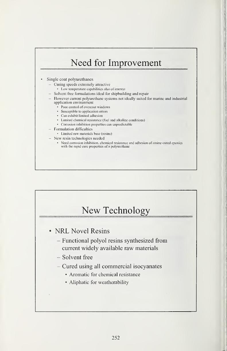
Need for Improvement
• Single coat polyurethanes
- Curing speeds extremely attractive
• Low temperature capabilities also of interest
- Solvent free formulations ideal for shipbuilding and repair
- However current polyurethane systems not ideally suited for marine and industrial
application environment• Poor control of overcoat windows• Susceptible to application errors
• Can exhibit limited adhesion
• Limited chemical resistance (fiiel and alkaline conditions)
• Corrosion inhibition properties can unpredictable
- Formulation difficulties
• Limited raw materials base (resins)
- New resin technologies needed• Need corrosion inhibition, chemical resistance and adhesion of amine-cured epoxies
with the rapid cure properties of a poljoirethane
New Technology
• NRL Novel Resins
- Functional polyol resins synthesized from
current widely available raw materials
- Solvent free
- Cured using all commercial isocyanates
• Aromatic for chemical resistance
• Ahphatic for weatherabihty
252
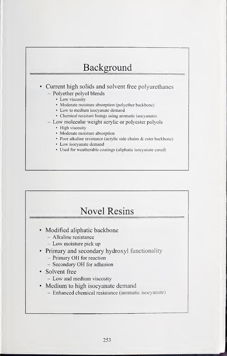
Background
• Current high solids and solvent free polyurethanes- Polyether polyol blends
• Low viscosity
• Moderate moisture absorption (polyether backbone)
• Low to medium isocyanate demand• Chemical resistant linings using aromatic isocyanates
- Low molecular weight acrylic or polyester polyols
• High viscosity
• Moderate moisture absorption
• Poor alkaline resistance (acrylic side chains & ester backbone)
• Low isocyanate demand• Used for weatherable coatings (aliphatic isocyanate cured)
Novel Resins
• Modified aliphatic backbone- Alkaline resistance
- Low moisture pick up
• Primary and secondary hydroxyl functionality
- Primary OH for reaction
- Secondary OH for adhesion
• Solvent free
- Low and medium viscosity
• Medium to high isocyanate demand- Enhanced chemical resistance (aromatic isocyanate)
253
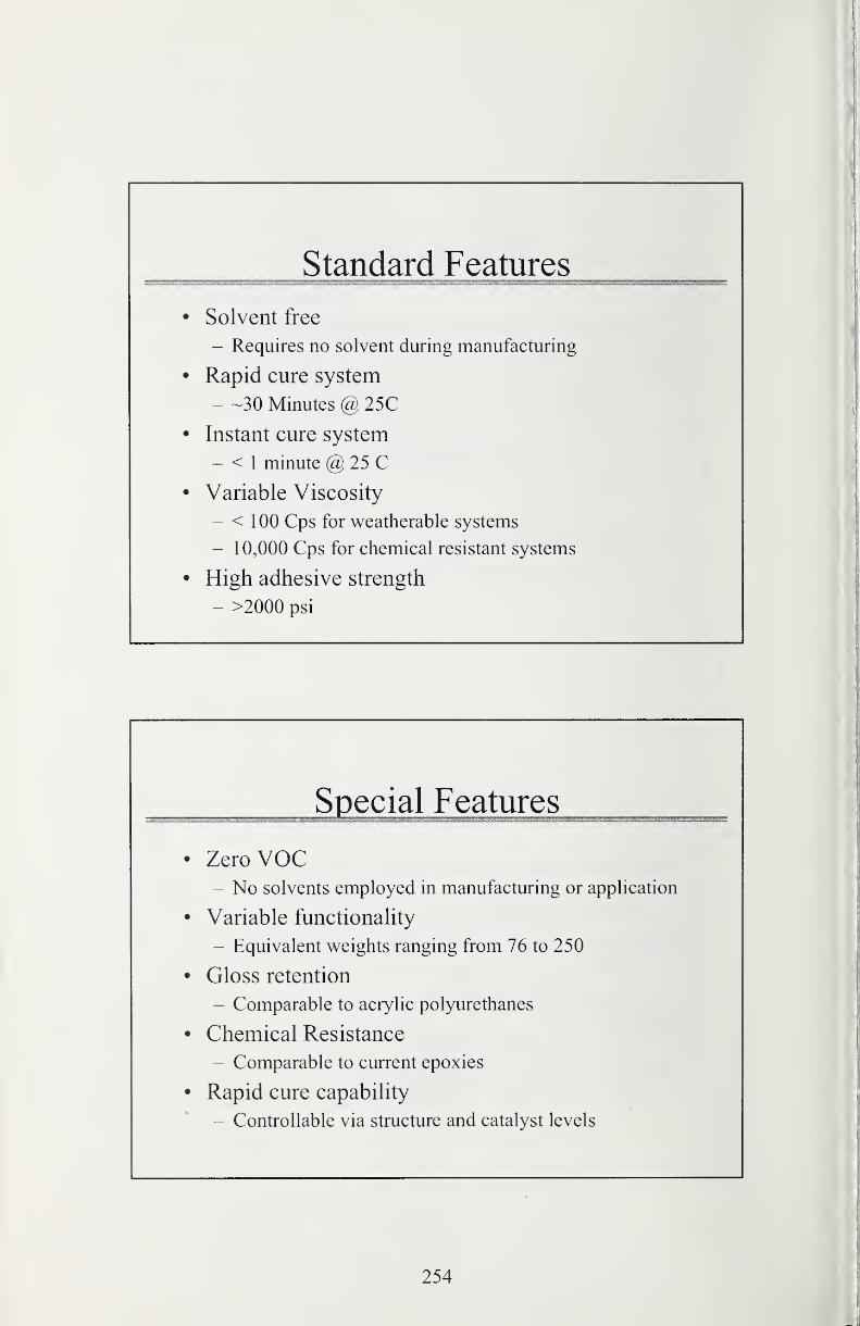
Standard Features
• Solvent free
- Requires no solvent during manufacturing
• Rapid cure system
- -30 Minutes @ 25C
• Instant cure system
- < 1 minute @ 25 C
• Variable Viscosity
- < 100 Cps for weatherable systems
- 10,000 Cps for chemical resistant systems
• High adhesive strength
- >2000 psi
Special Features
• ZeroVOC- No solvents employed in manufacturing or application
• Variable functionality
- Equivalent weights ranging from 76 to 250
• Gloss retention
- Comparable to acrylic polyurethanes
• Chemical Resistance
- Comparable to current epoxies
• Rapid cure capability
- Controllable via structure and catalyst levels
254
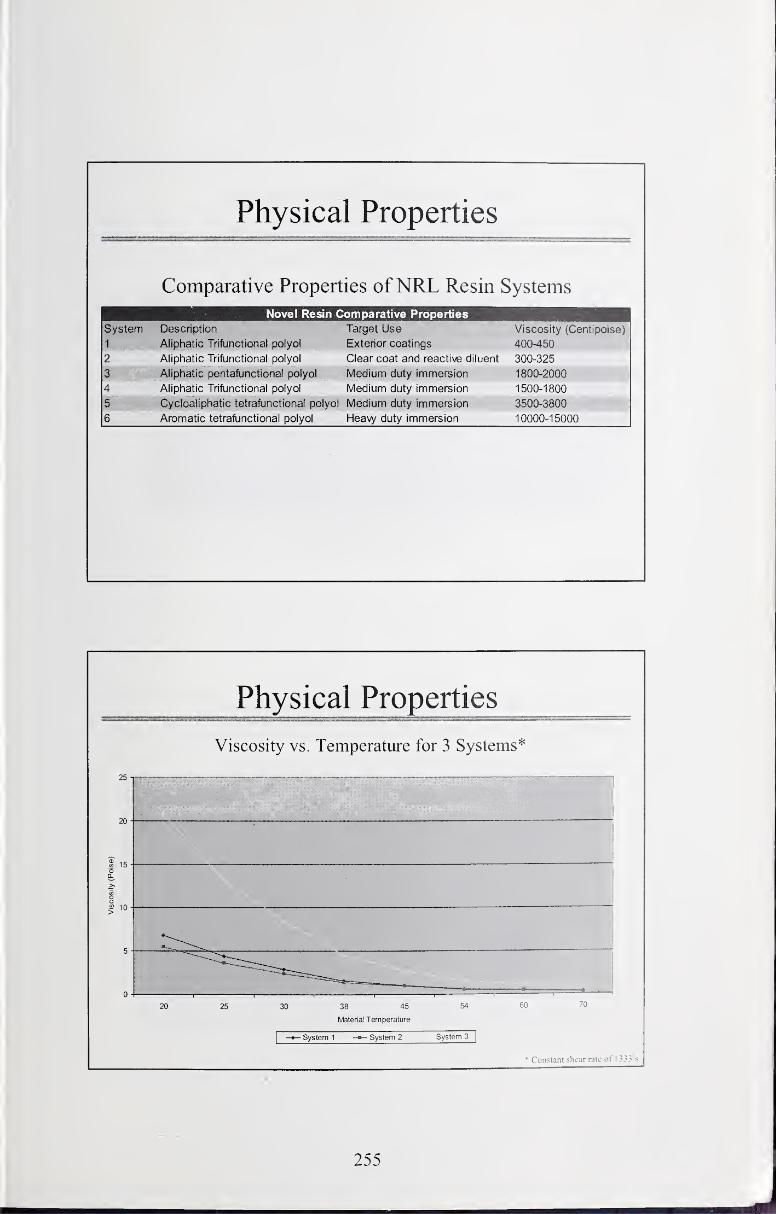
Physical Properties
Comparative Properties ofNRL Resin Systems
Novel Resin Comparative Properties
System
1
Description
Aliphatic Trifunctionat polyot
Target Use
Exterior coatings
Viscosity (Centipoise)
400-450
2 Aliphatic Trifunctiona! polyol Clear coat and reactive diluent 300-325
3 Aliphatic pentaftjnctional polyol Medium duty immersion 1800-2000
4 Aliphatic Trifunctional polyol Medium duty immersion 1500-1800
5 Cycfoafiphatic tetralincttonal polyol Medium duty immersion 3500-3800
6 Aromatic tetrafunctional polyol Heavy duty immersion 10000-15000
Physical Properties
Viscosity vs. Temperature for 3 Systems*
25 -|
20 -
scosity
(Pois
5
0 -
20 25 30 38 45 54 60"0
Material Temperature
1
-»— System 1 System 2 System 3|
• Constant shear rate of
255
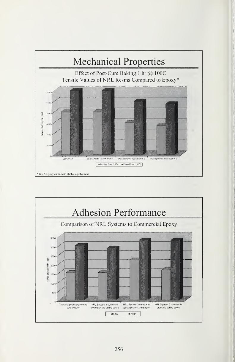
Mechanical Properties
Effect of Post-Cure Baking 1 hr @ lOOC
Tensile Values ofNRL Resins Compared to Epoxy*
Epoxy Resin Developmental Resin System 1 Developmental Resin System 2 Developmental Resin System 3
Ambient Cure (25C) - Forced Cure (100C)
* Bis-A Epoxy cured with aliphatic polyamine
Adhesion PerformanceComparison ofNRL Systems to Commercial Epoxy
cured epoxy cycloaliphatic curing agent cycloaliphatic curing agent aromatic curing agent
O Low Higti
256
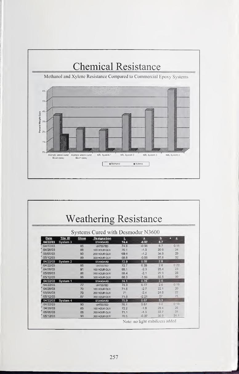
Chemical ResistanceMethanol and Xylene Resistance Compared to Commercial Epoxy Systems
Aliphatic amine cured Aliphatic amine cured NRL System 1 NRL System 2 NRL System ^ NRL System 4
Bis-A epoxy Bis-F epoxy
O Methanol Xylenes
Weathering Resistance
Systems Cured with Desmodur N3600Date Tile ID Gloss Designation L a e
04/22/03_ System 3 STANDARD 74.4 -0.97 .
04/22/03 85 74.6 -0.96 6.7 0.11
" 04/28/03 88 lOOHOLfiQUV 70.1 -1.9 30.6 24' 05/05/03 90 200HOt«QUV 69.4 -1.2 34,9 29' 05/12/03 89 sooHomouv 68.8 -0.58 37.8 32
04/22/03 System 2 STAtsffJARD 72.9 0.39 2.8
04/22/03 86 LWTESTH) 72,7 0.39 2.8 0.22
04/28/03 91 100HOLRCRJV 69.1 -2.3 25.4 23' 05/05/03 86 200H(XRQUV 68.4 -2.1 29.9 28
' 05/12/03 96 300HOtRQUV 68.3 -1.84 32.5 30
04/22/03 System 1 STANDARD 74.1 0.75 2.6
' 04/22/03 77 LWIfcSlbU 74.3 0.77 2.6 0.19
" 04/28/03 70 100 HOIK QUV 71.5 -2.7 22.1 20
' 05/05/03 73 200 HOUR QUV 71 -2.4 24.5 22
' 05/12/03 87 300HOtRQUV 71.6 -2.21 27 25
04/22/03 System 4 STANDARD .75.9 0.67 3.3
' 04/22/03 90 Lfl^TESTTO 76.1 0.67 3.2 0.13
" 04/28/03 85 100 HOLRQUV 72.2 -1.9 28.4 26
05/05/03 88 200 HOUR QUV 71.1 -1.3 33.7 31
' 05/12/03 90 300 HOUR OA' 70.5 -0.37 36.9 34.1
Note: no light stabilizers added
257
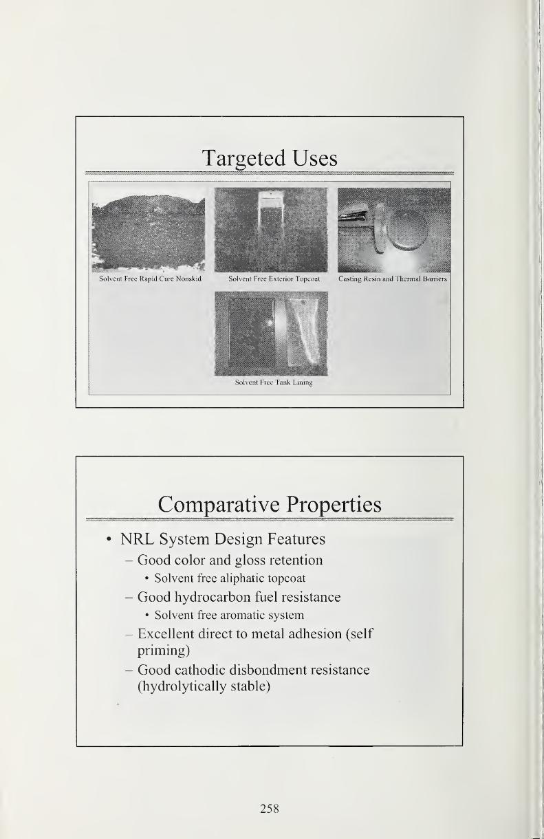
Targeted Uses
Solvent Free Rapid Cure Nonskid Solvent Free Exterior Topcoat Casting Resin and Thennal Banicrs
Solvent Free Tank Lninig
Comparative Properties
• NRL System Design Features
- Good color and gloss retention
• Solvent free aliphatic topcoat
- Good hydrocarbon fuel resistance
• Solvent free aromatic system
- Excellent direct to metal adhesion (self
priming)
- Good cathodic disbondment resistance
(hydrolytically stable)
258
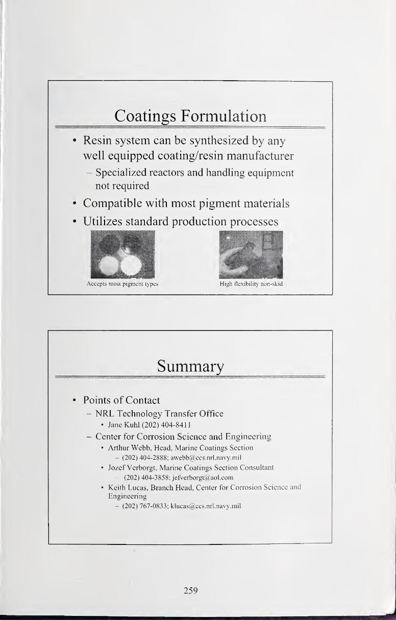
Coatings Formulation
• Resin system can be synthesized by any
well equipped coating/resin manufacturer
- Specialized reactors and handling equipment
not required
• Compatible with most pigment materials
• Utilizes standard production processes
Accepts most pigment types High flexibility non-skid
Summary
• Points of Contact
- NRL Technology Transfer Office
• Jane Kuhl (202) 404-8411
- Center for Corrosion Science and Engineering
• Arthur Webb, Head, Marine Coatings Section
- (202) 404-2888; [email protected]
• Jozef Verborgt, Marine Coatings Section Consultant
- (202) 404-3858; [email protected]
• Keith Lucas, Branch Head, Center for Corrosion Science and
Engineering
- (202) 767-0833; [email protected]
259

Technical Publications
Periodical
Journal of Research of the National Institute of Standards and Technology CReports NIST research and dev elopment
in metrology and related fields of physical science, engineering, applied mathematics, statistics, biotechnology, and
information technology. Papers cover a broad range of subjects, with major emphasis on measurement methodology and
the basic technology underlying standardization. Also included from time to time are survey articles on topics closely
related to the Institute's technical and scientific programs. Issued si.x times a year.
Nonperiodicals
MonographsCMajor contributions to the technical literature on various subjects related to the Institute's scientific and
technical activities.
HandbooksCRecommended codes of engineering and industrial practice (including safety codes) developed in
cooperation with interested industries, professional organizations, and regulatory bodies.
Special PublicationsClnclude proceedings of conferences sponsored by NIST, NIST annual reports, and other special
publications appropriate to this grouping such as wall charts, pocket cards, and bibliographies.
National Standard Reference Data SeriesCProvides quantitative data on the physical and chemical properties of
materials, compiled from the world's literature and critically evaluated. Developed under a worldwide program
coordinated by NIST under the authority of the National Standard Data Act (Public Law 90-396). NOTE: The Journal of
Physical and Chemical Reference Data (JPCRD) is published bimonthly for NIST by the American Institute of Physics
(AlP). Subscription orders and renewals are available from AIP, P.O. Box 503284, St. Louis, MO 63150-3284.
Building Science SeriesCDisseminates technical information developed at the Institute on building materials,
components, systems, and whole structures. The series presents research results, test methods, and performance criteria
related to the structural and environmental functions and the durability and safet}' characteristics of building elements and
systems.
Technical NotesCStudies or reports which are complete in themselves but restricfive in their treatment of a subject.
Analogous to monographs but not so comprehensive in scope or definitive in treatment of the subject area. Often serv e as
a vehicle for final reports of work performed at NIST under the sponsorship of other government agencies.
Voluntary Product StandardsCDeveloped under procedures published by the Department of Commerce in Part 10. Title
15, of the Code of Federal Regulations. The standards establish nationally recognized requirements for products, and
provide all concerned interests with a basis for common understanding of the characteristics of the products. NIST
administers this program in support of the efforts of private-sector standardizing organizations.
Order thefollowing NISTpublicatiomCFIPS and NISTIRsCfrom the National Technical Information Senlce. Springfield.
VA 22 1 61.
Federal Information Processing Standards Publications (FIPS PUB)CPublications in this series collecti\ ely constitute
the Federal Informafion Processing Standards Register. The Register serves as the official source of information in the
Federal Government regarding standards issued by NIST pursuant to the Federal Property and Administrati\ e Ser\ ices
Act of 1949 as amended. Public Law 89-306 (79 Stat. 1 127), and as implemented by Executive Order 1 1717 (38 FR
12315. dated May 1 1.1973) and Part 6 of Title 15 CFR (Code of Federal Regulafions).
NIST Interagency or Internal Reports (NISTIR)CThe series includes interim or final reports on work perfomied b\
NIST for outside sponsors (both government and nongovernment). In general, initial distribution is handled by the
sponsor; public distribution is handled by sales through the National Technical Information Serv ice, Springtield. \ A
22161, in hard copy, electronic media, or microfiche form. NISTIR's may also report results ofNIST projects ot
transitory or limited interest, including those that will be published subsequently in more comprehensi\ e tomi.

U.S. Department of CommerceNational Bureau of Standards and Technology
325 Broadway
Boulder, CO 80305-3328
Official Business
Penalty for Private Use $300
V