Voltage Support Control Strategies for Static Synchronous Compensators Under Unbalanced Voltage Sags
Upload
khangminh22Category
view
2download
0
Bureau ^ v ^ A> ^ u >
library, N. W . itr ^' J from the Library.
stP 1949
High-Frequency Voltage Measurement
United States Department of Commerce National Bureau of Standards
Circular 481

_

UNITED STATES DEPARTMENT OF COMMERCE • Charles Sawyer, Secretary
NATIONAL BUREAU OF STANDARDS • E. U. Condon, Director
High-Frequency Voltage Measurement
by Myron C. Selby
National Bureau of Standards Circular 481
Issued September 1, 1949
For sale by the Superintendent of Documents, U. S. Government Printing Office, Washington 25, D. C,
Price 20 cents

Contents Page
I. Introduction_ 1
1. Higli-precision methods based on d-c measurements_ 1
(a) Power substitution_'_ 1
(b) Resistor in series with current measuring device_ 3
(c) Cathode-ray beam deflection_ 3
(d) Electrostatic voltmeter_ 6
2. Moderate precision methods_ 6
(a) Vacuum-tube voltmeters_ 6
(b) Nonthermionic rectifiers_ .8
3. Pulse-peak voltage measurement_ 10
(a) Cathode-ray beam deflection_ 10
(b) Diode peak voltmeters_ 11
4. Miscellaneous methods_ 11
(a) Heterodyne method of extending the voltage range_ 11
(b) Spark-gap method___._ 12
(c) Glow-discharge voltmeter_ 12
(d) Electrometer employing miniature open-wire line_ 12
(e) Electrometer employing suspended wire_ 12
II. References__ 13
ii

High-Frequency Voltage Measurements By Myron C. Selby
The paper presents an up-to-date account of fundamental principles and techniques used for voltage measurements primarily for frequencies in the upper audio- and radio¬ frequency ranges and including part of the ultrahigh frequency range. Subject matter is limited to principles and methods that have met with some degree of success for both high and moderate precision, emphasizing those developed and applied for primary standard work in this frequency range at the National Bureau of Standards. This paper is intended to give professional workers and graduate students a more comprehensive picture of the methods employed with regard to this subject than is presently available in textbooks and handbooks.
I. Introduction
Standard procedures of r-f voltage measure¬ ments are at the present time based upon direct-voltage calibrations with the voltage of a standard cell as the primary reference. For maximum accuracy, direct substitution is made of d-c for r-f voltage having negligible harmonic components. Reliability is insured by cross¬ checking results with one or more independent calibration methods based on different principles. In the light of present-day experience at these frequencies, measurements to accuracies of approx¬ imately ±1 percent may be considered of high precision, whereas accuracies of the order of ±5 percent are of moderate precision. Direct voltage measurements are readily made to 0.1 percent so that transfer methods, employing measurements made directly in terms of direct voltage without needing corrections for frequency, may be called primary-standard methods. Reproducibility of results, as well as agreement between individual primary-standard methods, is expected to be within ± 1 percent or better. In this paper, methods that in terms of primary-standard tech¬ niques are only reproducible to ±5 percent will be referred to as “moderate” precision methods of measurement. At this point one should differen¬ tiate between accuracy and precision. An accu¬ racy of ± 1 percent implies that the value of the quantity measured is within ± 1 percent of its true or absolute value. Precision on the other hand refers primarily to sensitivity and repeata¬ bility incidental to relative measurements. Thus precise repeatable indications that can be obtained using different instruments may be extremely useful in making circuit adjustments and for experimental purposes, but they need not agree among themselves to the extent of being indi¬ vidually accurate. Accuracy implies ample sensi¬ tivity and precision of measurement to establish the extent of agreement with accepted theory or standards.
The most suitable primary-standard r-f voltage measurement methods seem to be those em¬ ploying:
(a) Power substitution. (b) Measurement of current through a known
resistance. (c) Deflection of cathode-ray beam. (d) The electrostatic voltmeter.
Not suitable for d-c calibration are methods employing:
(e) Vacuum tube voltmeters. (f) Rectifiers (nonthermionic).
1. High-Precision Methods Based on D-C Measurements
(a) Power Substitution
In this method bolometers are made use of with the assumption that the same temperature or heating effect is produced by an equal amount of power whether produced by radio frequency or by direct current, and that the resistance of the bolorimetric element is independent of frequency and is reliably dependent upon its temperature.
Thermistor and Wollaston type bolometers are in general use. A thermistor is a semiconductor, such as uranium oxide (U308), or a mixture of nickel oxide (NiO). having a large negative resistance-temperature coefficient [1,2]. A Wol¬ laston wire is a platinum wire of the order of 0.001 mm in diameter drawn inside a silver wire; this silver coat is removed over a small section by etching with a solution of nitric acid (HN03); the exposed platinum core constitutes the active section of the bolometer. Typical thermistors have a resistance versus temperature sensitivity approximately 10 times larger than Wollaston wire, will carry considerably higher overloads, are superior in mechanical ruggedness, have a larger thermal time constant [53], and seem more adapt-
l
able for voltage measurements because of their relatively small physical dimensions. Precautions must be observed in mounting the bolometer so that the voltmeter under calibration is connected directly across an r-f current-carrying circuit element having negligible series reactance, since a fundamental assumption of this method is that the r-f resistance of a particular bolometer is equal to its d-c resistance.
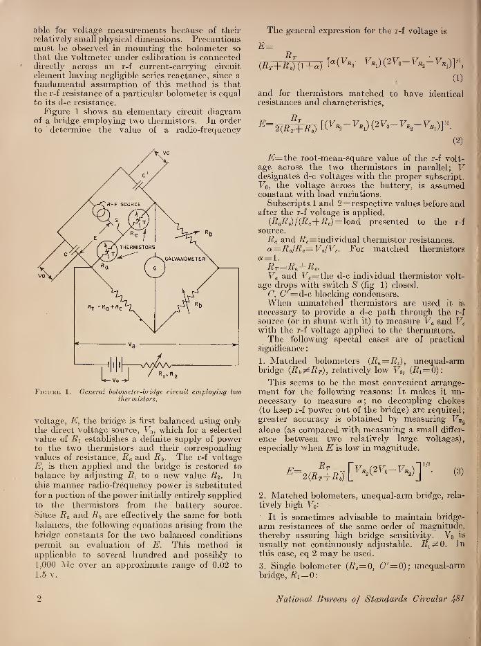
Figure 1 shows an elementary circuit diagram of a bridge employing two thermistors. In order to determine the value of a radio-frequency
Figure 1. General bolometer-bridge circuit employing, two thermistors.
voltage, E, the bridge is first balanced using only the direct voltage source, Vo, which for a selected value of Ri establishes a definite supply of power to the two thermistors and then corresponding values of resistance, Ra and Rb. The r-f voltage E, is then applied and the bridge is restored to balance by adjusting R{ to a new value R2. In this manner radio-frequency power is substituted for a portion of the power initially entirely supplied to the thermistors from the battery source. Since Ra and Rb are effectively the same for both balances, the following equations arising from the bridge constants for the two balanced conditions permit an evaluation of E. This method is applicable to several hundred and possibly to 1,000 Me over an approximate range of 0.02 to 1.5 v.
The general expression for the r-f voltage is
E=
(Br + flJu + a) KF*2~T7*i) (2F0-
(1)
and for thermistors matched to have identical resistances and characteristics,
e~2
(2)
i?=the root-mean-square value of the r-f volt¬ age across the two thermistors in parallel; V designates d-c voltages with the proper subscript Vo, the voltage across the battery, is assumed constant with load variations.
Subscripts 1 and 2 = respective values before and after the r-f voltage is applied.
(RaRc) / (Ra+R;)-load presented to the r-f source.
Ra and Rc=individual thermistor resistances. a=Ra/Rc=Va/Vc. For matched thermistors
a= 1. RT=Ra-\-Rc. Va and Vc= the d-c individual thermistor volt¬
age drops with switch S (fig 1) closed. C, C' = d-c blocking condensers. When unmatched thermistors are used it is
necessary to provide a d-c path through the r-f source (or in shunt with it) to measure Va and Vc with the r-f voltage applied to the thermistors.
The following special cases are of practical significance:
1. Matched bolometers (Ra=Rc), unequal-arm bridge (Rb^RT), relatively low V0, (Ri=0):
This seems to be the most convenient arrange¬ ment for the following reasons: It makes it un¬ necessary to measure a; no decoupling chokes (to keep r-f power out of the bridge) are required; greater accuracy is obtained by measuring Vr2
alone (as compared with measuring a small differ¬ ence between two relatively large voltages), especially when E is low in magnitude.
E= Rn
2{RT-\-Rb) ^^K2(2^0~ ^*2)J 1/2
(3)
2. Matched bolometers, unequal-arm bridge, rela¬ tively high Vo¬
lt is sometimes advisable to maintain bridge- arm resistances of the same order of magnitude, thereby assuring high bridge sensitivity. Vo is usually not continuously adjustable. R^O. In this case, eq 2 may be used.
3. Single bolometer (Rc—0, C — 0); unequal-arm bridge, Rx = 0:
National Bureau of Standards Circular Jp81 2
This arrangement eliminates the necessity of matching bolometers and removes the possibility of only one of the two carrying the entire r-f load. This could occur, for example, when operation takes place over a negative resistance portion of thermistor characteristics. Means are required, however, to keep the r-f power out of the d-c bridge.
fVS!(2F„- F%)] (4) (RT-\-Rb)
4. Single bolometer, equal-arm bridge:
E—1/2 {yr2 "^ra1)(2V’o ' ^ fli)J
1/2
(5)
The major advantage of having Rb?±RT arises when a relatively small value of (VNn — VR]), as
compared with Vr2, has to be measured, as is the
case at very low values of E. Other modifications may occasionally be desirable, such as a single¬ bolometer unequal-arm bridge with high Vo, (Rit^O), or an unmatched two-bolometer bridge when Ra and Rc are known individually and are ex¬ pected to remain stable in either equal- or unequal- arm bridges. When unmatched thermistors are used, the degree of departure of Ra from Rc may increase considerably with increasing r-f power- fed to the two in parallel as a result of their negative resistance vs. temperature coefficient [62J.
To obtain maximum accuracy, precision potenti¬ ometers and a galvanometer of proper sensitivity are desirable. Among the precautionary require¬ ments of this method, especially in measuring small voltages, are the following: Constant am¬ bient temperature, stable V0, stability of the resistances in the circuit and accurate deter¬ mination of their values, an r-f voltage source relatively free from harmonics.
(b) Resistor in series with current measuring device
In employing this method to obtain accuracies of about 1 percent, the d-c calibration of the current indicating device and the value of the series resistor must be known to 0.5 percent. Either changes in current indication or resistance depending on frequency should be negligible, or they should be small and known, so that correc¬ tions may be applied. The physical design and arrangement of components must insure that all of and only the current entering one end of the resistor passes out the other end and through the current measuring element [62], Unless the im¬ pedance of the current-measuring element is negligible, it must be taken into account and should, in any event, be preferably resistive if the voltage drop across it is part of the total voltage being measured.
Thermoelements (heater with thermocouple for current indication) may be used in series with special resistors [3, 4] up to a frequency of several megacycles to measure voltage ranging from several millivolts to approximately 50 v. Errors at high frequencies are likely to be introduced by stray capacitances associated with either the resistor or thermocouple circuit and by stray fields coupling with thermocouple circuit. Cur¬ rents induced in the thermocouple circuit whose resistance is low in comparison with that of the r-f current-carrying heater element may introduce spurious heating effects not present during cali¬ bration of the thermoelement on direct current [5] and be a large source of error. When the couple is not insulated from the heater, calibration of the thermoelement is usually made on reversed direct current to reduce error caused by the section of the conductor common to both elements.
Instead of using a thermoelement, a heater element alone may be used, depending on other means of correlating the heating effect of r-f current through the heater with a suitable indi¬ cating device. An arrangement, applicable to approximately 30 Me [4], utilizes a photoelectric calibration of the glow from the current-carrying heater element. Under conditions of use the impedance across the heater terminals must be known as a function of voltage and should be essentially resistive.
Skin effect, inductance, and power dissipation limit both the frequency and voltage ranges.
(c) Cathode-ray beam deflection
This method makes use of the deflection of an electron beam by an electric field. An elementary circuit arrangement is shown in fig. 2.
The deflection is
D=Ema!i Yy~d» (6)
where Va is the accelerating potential of the beam, l is the effective length of the deflecting field, y is the effective length of the beam between this field and screen, and d is the distance between the deflection plates.
The procedure in measuring an r-f voltage E (fig. 2) is to adjust first the zero spot position by setting Vi with U=0 and E= 0. The r-f voltage is then applied and the position of either end of the deflection trace on the screen is restored to the original position of the spot by applying the proper value of V; this value of V is then equal to E peak, provided the transit time and other fre¬ quency errors are negligible. For maximum accuracy at low voltage levels it is best to line up the edge of the spot against a fine hair-line with a low-power microscope.
As a result of transit-time effect , the voltage and
High-Frequency Voltage Measurement O

Figure 2. Essential components of r-f voltage-measuring circuit arrangement employing deflection of cathode-ray beam.
frequency ranges are limited and are interdepend¬ ent. This effect takes place when the phase of the deflecting voltage begins to reverse before the electrons in the beam have sufficient time to cross the deflecting field. The transit time thus reduces the magnitude of the deflection unless it is smaller
than a half-period of the highest frequency to be used. The error caused by this effect is usually expressed as a ratio, C, of dynamic to static sensitivity, the sensitivity being the linear deflection per volt. This ratio is expressed as [6, 7, 81
C= V 2( 1 — cos </>)+</>2—2(f sin <f> + 2(f>2 -j 1+T (1" -cos 4>)
(7)
where
u = 2irj
«0=5.97X 10⁷Vl7a = beam velocity
(8)
(9)
yo=d-c voltage accelerating the beam within the deflection field for FaX 10,000v. For higher values of Va, Einstein’s correction for the increase in mass of the electron must be applied.
Equation 7 takes into account the beam dis¬ placement parallel to the axis. This displacement is usually negligible for large ratios of the Ljl, where L is the effective distance between the screen and the deflection field as shown in figure 2. In the latter case, for sinusoidal input,
sin 4>/2
0/2 (10)
Figure 3 shows C as a function of 0/2, given by eq 10 [9, 10].
+ 1.2
i
08
0.6
O 04
0.2
0
0.2
-0.4
0.01 0.1 I 10 100
0/2 Figure 3. Effect of electron transit time on sensitivity of
cathode-ray tube [3].
4 National Bureau of Standards Circular /81

Another source of error is the effect on the deflection field of the lead inductance and deflec¬ tion plate capacity. The voltage between the plates is larger than the voltage applied to the outside terminals of the cathode-ray tube (where the voltmeter under calibration is connected), as given by the following expression [5]:
El=E 1
i-c m2’ (if)
where E?=deflecting voltage E= applied voltage /= operating frequency /r=plate and lead series resonance frequency.
The design and construction of present-day commercially available cathode-ray tubes is such that they may be used with negligible frequency error up to 75 Me for voltages ranging from 5 to several hundred volts. Their suitability and range is dependent upon electrode and lead arrangement, spacing, and insulation.
Deflection sensitivity may be increased by reducing accelerating voltage as is evident from eq 6, permitting satisfactory measurements at less than 5v radio frequency but only at the ex¬ pense of a reduction of the upper limit of frequency, and an increase in spurious effects from magnetic fields and normally minor voltage fluctuations. Similarly, the upper frequency limit of satisfac¬ tory response may be increased by increasing the accelerating voltage (within its rated limits) at the expense of a reduction in deflection sensitivity.
Modified designs of oscilloscope tubes, with proper precautions in circuit connections, may be used for frequencies above 75 Me. One modi¬ fication is the replacement of the conventional
deflecting plates of an oscillosope by a section of a two-wire transmission line (in a plane normal to the axis of the tube) extending through the tube [11]. The beam passing through the spacing between the conductors is deflected in proportion to the voltage at this point of the line. The voltmeter under calibration is placed either as close as possible to the tube or a distance A/2 away along the extended transmission line, where the voltage across the line is the same as at the cathode ray. This method is shown in figure 4. The deflection angle d is given by
/(max_^
2Va cosh~1(d/2r) (12a)
For large values of d[r
e ^ E IT
==2Va ln(d/r)’ (12b)
where d and r are the separation and wire radius, respectively.
The effective deflecting field is largely concen¬ trated within a space between the wires approxi¬ mately equal in width to the wire separation; the distance responsible for a transit time error is therefore approximately equal to the wire separa¬ tion.
A line having a 3-mm wire diameter and a 6-mm center-to-center separation results in a sensitivity of 0.3 mm/v for Vo = 1,000 v at a screen distance of 25 cm; this may be compared with a sensitivity of approximately 0.63 mm under the same conditions with deflecting plates having a transit time distance nearly five times as large.
Experimental work, now in progress at the National Bureau of Standards, with these types
Iligh-Freqvency Voltage Measurement 5

of tubes resulted in precision measurements of voltages up to 150 Me.
Another modification consists of a specially constructed cathocle-ray tube employing a short focus lens and very small deflecting plates [6, 9]. Figure 5 shows a diagram of this device referred to as a “micro” oscillograph. The initial cross section of the beam is reduced to a degree result¬ ing in a spot size of 10~2 to 10-3 mm in diameter. The beam passes through the deflecting plates and into the short-focus electrostatic lens. This oscillograph depends on optical magnification for increased initial deflection. Using a 50X optical magnifier and Va= 10,000 v, an effective deflec¬ tion sensitivity of approximately 0.5 mm/v is obtained; the plate length and separation are about 0.2 inch, and the transit time effect is negligible at 1,500 Me. These two modified applications of the cathode-ray tube seem to indicate that this method can be used for pre¬ cision wide-range voltage measurements to at least 300 Me and perhaps to much higher fre¬ quencies simply by further reduction in size of cathode-ray tube elements.
The voltage range of present-day commercial electrostatic voltmeters is approximately 20 to 50,000 v.
2. Moderate precision methods
(a) Vacuum-tube voltmeters
The first vacuum-tube (v-t) voltmeter was patented by R. A. Heising in 1917 [36], For a number of years prior to that date and up to the present time, v-t voltmeters have been universally used to measure r-f voltages of the order of one millivolt to several kilovolts. Vacuum-tube volt¬ meters are made in a variety of forms and in various voltage ranges. The useful frequency range in each basic design is limited primarily by the adapted circuit arrangement and characteris¬ tics of such components as tubes, amplifiers, voltage dividers, etc. The v-t voltmeter is not- satisfactory as a high-precision standard, because it is difficult to determine precisely the law of its voltage-current characteristic as well as to main¬ tain its operation sufficiently constant over a
SHORT-FOCUS ELECTROSTATIC
(d) Electrostatic voltmeter
Electrometers and electrostatic voltmeters make use of the force existing between charged conduc¬ tors. These instruments are essentially capacitors with the rotor, either fiber suspended or jewel- pivoted. One set of the conductors is usually fixed in position and the other one (the set cor¬ responding to the rotor of a variable capacitor) is fiber-suspended or jewel-pivoted, and so restrained by the suspension or a coiled spring that its dis¬ placement is indicative of the voltage applied. Commercial electrostatic voltmeters have a scale (usually nonlinear unless the plates are especially shaped) that is graduated to read rms values of voltage, and have a high input resistance and low power consumption at frequencies up to approxi¬ mately 5 Me [12].
The major disadvantages of this type of volt¬ meter are low sensitivity and high input capacity (a few micromicrofarads to several hundred micromicrofarads), with the capacity a function of the instrument deflection. Thus certain difficul¬ ties and limitations are introduced when the instrument is connected across a tuned circuit.
6
reasonable length of time. In addition, in the case of voltmeters employing the usual form of grid-leak-condenser diode circuits, the analytically derived output contains factors depending upon the nature of the impedance across which the voltage is being measured. Finally the input impedance of the voltmeter is a function of the voltage applied to it [13],
Tubes with more than three electrodes are seldom used for voltages above 0.5 v. Pentodes connected as triodes are desirable for some voltage and frequency ranges as a result of spacing and shielding of the electrodes. Triodes connected as diodes are used for higher voltages.
Vacuum-tube voltmeters are usually calibrated at all frequencies using one of the above standard methods. They may also be calibrated in terms of power or audio-frequency standard instruments, in which case freedom from frequency correction should be verified. For higher accuracy, cali¬ bration at the operating frequency is preferred. The major performance desiderata of a v-t volt¬ meter for freuencies up to several hundred megacycles are:
1. Low-input capacitance.
National Bureau of Standards Circular Ifil
I Diode Detection
2. Diode Rectification
(b)
PRINCIPLE OF OPERATION
In circuits (a) and (b) C charges
to E peak. R acts to discharge C.
13,15,16,17,48,49,
In circuit (b), R‘ and C' act as a
filter to keep r-f out of the d-c
measuring circuit
BASIC FORMULAE
For linear diode characteristics Vdc = KE peak. Equivalent input resistance =
R _ R IpR 2 *t\
E peak
approximately unity as R
and E increase. For square-law type diode
is a function of E. [3, !_5.
note: Numbers refer to list of refer
ences.
Rp = 0 by assumption Ip0 = 0 by assumption
RLIgve = average voltage of the
positive half cycle
43, 56, 5J, 58,59.
note: See list of nomenclature
For a sinusoidal input
APPROXIMATE
INPUT IMPEDANCE
In general it is a function of R
ond amplitude of E. There is a
value of R at which the input
impeaance is practically indepen-
aent of E The order of magni¬
tude is the equivalent of I to
25 megohms resistance shunted
with an input capacity of 3-10
M M f I05 ohms at 300 Me. is
possible. [3
OUTPUT OF
COMPLEX WAVEFORM
E peak
EFFECT OF WAVEFORM
The source impedance must
be negligible at all harmonics,
and the level of harmonics
must be low otherwise error
may be as large as the per¬
centage harmonics present. [3
Not subject to turnover. 45
(i.e. no error is coused by re¬
versing input teminals even in
the case of unsymetrical
wave-form consisting only of
fundamental and its harmonics.)
APPROXIMATE
VOLTAGE RANGE
The upper limit depends on
tube ruting. With sensitive
d-cvoltmeter or with d-c am¬
plifier the lower limit is a
fraction of a volt Range
depends on frequency, the
higher the frequency, the
narrower the range; correction may be applied.
A fraction of a volt to a
few hundred volts and high¬
er depending on the value
of R|_ and tube voltage rat¬
ings .
FREQUENCY RANGE AND ERROR
Upper limit is affected by
(I) Series resonance of in¬
put L and C anode to cath¬
ode r-f voltage -
constancy of filament voltage and emission.
May require yearly cali¬ brations
• (t,)2 2% tor a type 955 vacuum
tube at 100 Me. (2) Transit time error =
AV . K da
/ A -JE peak
3% at 100 Me with 955
"acorn" at lOv. Range is
therefore a function of vol¬
tage applied. Correction
curves may be used to ex¬
tend the range. Overall -
12% is obtainable without
correction forE>0.5v. 16,5.
Should be calibrated at
the operating frequency
when used in the neighbor¬
hood of I Me and higher.
Probable useful range up
several Me.
CALIBRATION STABILITY REMARKS
This circuit, followed by o self-biased d c ampli¬
fier seems to be the prefered type most suit¬
able for the widest frequency range
To eliminate low-frequency discrimination ,
the product of RC should equal at least 100
at the lowest value of frequency. The effect
of series resonance of the input to the tube is to:
(1) Increase the apparent input voltage at the
fundamental frequency.
(2) Emphasize harmonics more than the fun¬
damental. For high' voltages, triodes con¬
nected as diodes or power rectifiers are used.
RL may vary from 0 to I megohm. For RL
- 100,00011, error caused by slight curvature
of static tube characteristic is negligible. 51
3. Plate Detection
Full wave,square law.
L±°
Approximate parabolic lower
curved portion of Ip-Ec charac¬
teristic is used. Average plate
current is higher than the
quiescent plate current. Biased
for Lp>o throughout the cycle.
R[_ (except of current meter) is
usually omitted. 60.
Alp — k(E|2 + e| +El + • ■ .) to a
first approximation
A Mo 9m0 (rp + RL)'eEgA
+ E|+e|+--\) 40
Approximately 107 ohms resis-
five at frequencies up to a few
me. shunted by (Ggp+Cgc). May
drop to I04 or I03 at 300 Me.
depending on the tube. 5
(et+ei+e|+---.) In practice Alp will depend
to some degree upon wave
form. Theoretically there is no
turnover. Phose of harmonic
has no effect.
Fraction of a volt to top
limit within square law range
of tube (a few volts for
commercial tubes)
Ra=r 9m
f2 72 41,35,61.
With present commercial
type tubes , a low-frequency calibration will hold within
5-10% to 20 or 30 Me. At
higher frequencies calibra¬
tion at each frequency is
necessary. 39
Poor as a result of
tube ageing and vari¬
ations in the d-c volt¬
ages .
Noise output can be corrected for by subtree ting it from total output, 40
4. Plate Detection
Half wave, square law.
Same as above except tube is
biased to cutoff. For large Rl
and C =0, Ip is nearly propor-
ional to eg during positive
half cycles.
For relatively large values of
Rl and E, Ip — KEave.For small
r-f voltages and low values of RL,
iP = k(e?+e!+e!<---.)
Same as above Eave if plate current
characteristic is linear.
Erms If plate current
characteristic is parabolic.
Subject to turnover and phase
of harmonics.
Fraction of a volt to a
value of E causing grid cur
rent flow
5. Plate Detection
Peak
Tube is biased appreciably be¬
yond cutoff.
At negligible transit time ef- Not recommended. Error
might be appreciable
Subject to turnover and
phase of harmonics.
From En Vd to values
causing flow of grid currents.
Cg = (Cgp + Cgc)
6. Grid-detection Operation takes place along
the lower curved portion of the
grid-current grid-voltage charac¬
teristic and over the straight or
the curved portions of the Ip -
characteristic. XC«R.
AIP = gmRAIg over the linear
portion of the Ip-Eg character¬
istic.
Relatively low. Erms or Epeak depen¬ ding on input level and operating voltages.
Error may be appreciable Fraction of a volt to a
few volts with receiving type
tubes.
Approximately to 10 Me. Very poor. When plate rectification takes place in addi
tion to grid rectification, Alp may equal
zero at a certain level of E. 51
D-C bias adjusted to obtain
same plate current with c f. as
as obtained without r.f. (i.e
th input terminals shorted) p=lp0=a few microamperes.
34
The peak of the positive half
cycle = Emax = K(V, -V0). K ap¬
proaches unity as E increases
and as the sharpness of cutoff
increases. It may be as low as
0.2 and lower depending on the
tube characteristic and on the
magnitude of E.
V0= d-c voltoge at E=0
V| = d-c voltages ot other volues
of E.
D(Ogp »CgC)
Input resistance is approaching
leakage resistance across input
terminals. 34,61
E peak of positive half cycle.
Subject to turnover. Fraction of a volt to a few
hundred volts. Calibration is
indispensible especially for
voltages below approximately
10 volts; calibration should be
made for a given IP.
Approximately to 10 or
20 Me depending on input
capacity.
Good . Practically inde¬
pendant of ageing and
operating voltage vari
ations.
Sharp cut off is obtained with pentodes
connected as triodes with screen grid used as
the control element. 37
8. Inverted Triode Ig is reduced when an r-f
oltage is applied to the input
terminals. Vp is negative. 38
Epeak—VP required to produce the same Ig . ( Amplification factor^ •p’
Resistance of the order of
1000 megohms shunted by Subject to turnover Large voltages , de pending
on tube design.
Possibly to 10 Me.Theo¬
retically limited by the in¬
put capacity. No experimen¬
tal data available.
Probably good. No
experimental data avail¬ able
= d-c plate current without applied r-f voltage =d-c plate current =d-c grid current =d-c voltage = d-c voltage increment = increment of d-c plate current = increment of d-c grid current =ampliflcation factor = mutual conductance =plate resistance = load resistance =resistive component of grid input impe
Table 1. Elementary circuits and characteristics of vacuum-tube voltmeters
“d-c grid bias
837899 O - 49 (Face p
^0. 0 mQ, \
'-GSM' values determined at a given quiescent point corresponding to E,0 and Ip,
= amplitudes of harmonic components of a complex periodic wave. = instantaneous plate current = instantaneous grid voltage “instantaneous voltage “maximum value of r-f voltage
= rms grid voltage “average voltage over half-cycle of a periodic wave
“frequency in cycles per second “resonance frequency =o constant “distance between anode and cathode of a vacuum tube “rectification efficiency “wavelength “electron transit time.
Wherever the term "sinusoidal voltage" is used, a voltsgi of negligible harmoni content is assumed.

- __i_
0 v
;■ ^ . i-
i v.". t--9v ■ l u i
■ r-. ■
■
-
'
'
'
r. ■ • I .1
* ■ " ■ V.-70 ' •• -
>a*. juftno;, loxj; =
TO ;1 !■< i! -
'll
M

2. High-input' resistance. 3. Short-input terminals. 4. High series-resonance frequency of input-
lead inductance and capacity. 5. Freedom from transit-time correction. 6. Calibration must not be affected by ordinary
line-voltage variations, aging and temperature and humidity changes, and must have negligible zero-setting drift. Vacuum-tube voltmeters must not generate disturbing voltages and must give steady indications.
7. Calibration must hold over a reasonable length of time and shall not be affected by tube replacement.
8. Maximum voltage range with minimum auxiliary equipment like amplifiers and voltage dividers.
9. Peak voltage calibration for nonsinusoidal waves; rms for sinusoidal waves.
10. Linear scale or large number of overlapping- scales for square-law indications.
Some relative merits of triodes versus diodes for voltmeter applications are listed below.
Triodes are preferable at frequencies below approximately 20 Me.
1. For high sensitivity to small applied voltages, 2. For lower loading effect on circuit being
measured, 3. For greater reliability of calibration at a
power frequency. Their major disadvantages are: 1. Input voltage is usually limited to values low
enough to keep the grid from going positive. 2. The d-c plate current has to be stably bal¬
anced out to obtain maximum sensitivity. 3. Null point shifts as a result of supply voltage
variations, aging and warm-up period required. 4. Triodes may have a shorter life and may
require more frequent calibrations as compared with diodes.
5. The input resistance at frequencies of about 100 Me is lower than that of a diode by a factor of 10 [5],
6. It is difficult to construct a triode having the small interelectrode spacing required to keep transit time and resonance errors to a minimum [5, 15, 23].
A special diode construction was reported em¬ ploying- an indirectly heated cathode having the shape of a cylinder with a sealed-off end. A similar indirectly heated sealed-off cylinder is used as an anode. Both cylinders are lined up end-to-end in such a manner that the two sealed ends face each other, and the gap between them forms the electron transit distance from cathode to anode. The width of this gap, and consequently the transit time, is controlled and is held at a minimum by varying the heating current fed to the anode, thereby causing its expansion or contraction [54], Diodes were recently developed with an inter¬ electrode spacing and element structure permitting
their application without frequency correction for frequencies well above several hundred mega¬ cycles.
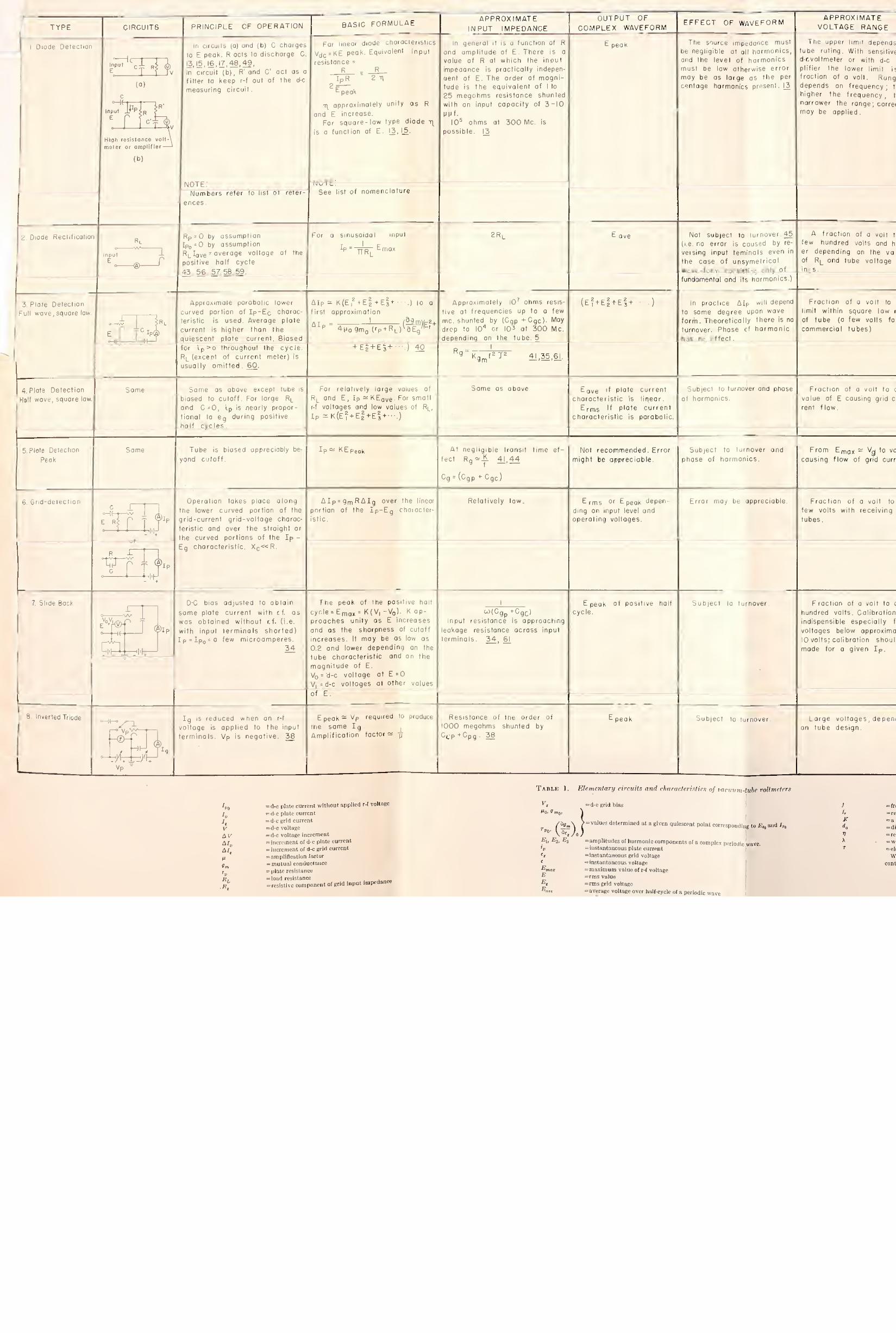
Table 1 lists fundamental detecting circuit ele¬ ments of vacuum-tube voltmeters and their major functional characteristics. Associated circuits in¬ cluding regular and feedback amplifiers, current balancing circuits, voltage dividers, voltage stab¬ ilizing elements, etc., are equally important in determining sensitivity, linearity, stability, and range of the meter [14, 16, 17, 18, 19], Voltage dividers, specially constructed to fit given mechan¬ ical and electrical requirements, may be used to measure high voltages at high frequencies. One arrangement is shown in figure 6 [20].
Figure 6. Voltage divider for high r-f voltage measure¬ ments
C is the terminal connected to a calibrated low voltage meter. The high voltage is coupled through the capacity between parts B and C. Various sizes of part C are provided to obtain different voltage ratios.
High-Frequency Voltage Measurement 7

(b) Nonthermionic rectifiers
In addition to thermionic diodes, other rectifiers are used as r-f voltmeter diode elements. These may be broadly subdivided into two classes, copper-oxide or selenium rectifiers and crystal diodes.
Copper-oxide and selenium, rectifiers have good overload characteristics and ruggedness. They are, however, affected by temperature and aging, have a relatively large shunt capacitance and high forward resistance. The approximate equiv¬ alent circuit is given in figure 7 [21, 22], The capacitance is approximately 0.02 pf/cm2 of con¬ tact surface. 2 ohms for 1 cm,2 and i?2 with polarity connections for maximum resistance (that is, backward resistance) is approximately 11,000 ohms for 1 cm 2 at applied voltages of —0.25 to — 3: this holds over a frequency range of 50 kc to 5 Me. The forward resistance is several ohms per square centimeter at 26° C and decreases slightly with increasing temperature. Backward resistance is considerably affected by temperature changes. Figure 8 shows direct-current charac¬ teristics of some of these rectifiers [22], The rectified current depends on temperature, load resistance, frequency, and current density. This type of rectifier is manufactured in all sizes down to a small fraction of an inch in cross-sectional area for currents of a few milliamperes.
Copper-oxide rectifiers are preferable to sele¬ nium types for instrument application because of their lower resistance. Selenium types may be operated up to about 10 v per element as against about 2 v for copper oxide.
-VNAAAAA-
AAAAAA-
Figube 7. Approximate equivalent circuit of copper-oxide rectifier in the 50 kc to 5 Me range.
Ri represents the resistance of the body of the oxide. Ri represents the resistance of the oxide-copper interface and is a function of applied voltage.
Copper-oxide-rectifier-type voltmeters are avail¬ able for frequencies to approximately 30 kc and can be designed up to 1 Me [22], The major fre¬ quency-limiting element is the shunt capacitance, C. The effect of the wave form of the applied voltage is appreciable; the error in the indicated output, calibrated in terms of voltage free of har¬ monics, may approach in magnitude the percent¬ age of harmonic content of the voltage measured. These rectifiers are used in series with resistors in 1,000-ohm/v instruments. They are very much higher in sensitivity and draw considerably less current from the source than the iron-vane or thermocouple type instruments. When the power
\ • '
f of the voltage source exceeds 1 w and a high im- j pedance instrument is not necessary it is prefer- \ able to employ an instrument having a higher in¬ herent order of accuracy than that of the rectifier- type voltmeter [22],
-.5 -.4 -.3 -.2 -.1 0 .1 .2 .3 .4 .5
D-C - VOLTS
Figube 8. Direct-current characteristics of copper-oxide rectifiers.
A, 0.200 disk; B, 0.130 disk; C, 0.008 disk.
Whereas copper-oxide rectifiers are applicable as voltage indicators only at the lowest frequencies considered here, modern crystal rectifiers are useful up to 300 Me and higher.
The crystals most commonly used at present are silicon and germanium.
Table 2 shows the chemical constituents of some of these crystals [26]. Other useful crystals are galena, iron-pyrites and carborundum. In meas¬ urement applications involving present-day dry rectifiers, one should recognize the following dif¬ ference in design: the contact area, and thus power-handling capacity, of crystal diodes is much smaller than for copper-oxide rectifiers.
■ ■
Table 2. Composition of crystal rectifiers
Impurities added
Bulk material High-frequency High-back voltage Low-frequency mixer crystals crystals rectifiers
Aluminum Germanium Aluminum Boron Also Boron
Ni Germanium Sn Also Bi Mo Ta Ca Zr Co
W Re Be Fe
Germanium.. Antimony Tin Antimony Also Also Tin
P Ca Pe Ni
Sr Bi N
8
I;
National Bureau of Standards Circular 1^81

Figure 9 sliows the mechanical construction of a modern crystal diode; figure 10 shows typical static characteristics for three germanium diodes, and figure 11 shows the rectification-efficiency characteristic of a germanium diode for different loads and frequencies; figure 12 shows the rectifi¬ cation efficiency of an iron-pyrites rectifier [24, 25, 26, 27]
Figure 13 shows the equivalent circuit of a crystal diode where Re and Cb are the nonlinear resistance and shunt capacity of the barrier layer, and Rs is the resistance of the body of the semi¬ conductor [27, 28].
Relative merits of crystal versus thermionic diodes for r-f voltage measurements are listed as follows.
Figure 9. Components of a 1N34 germanium crystal. The wire “whisker” points toward the small germanium block mounted
on the lower threaded terminal.
-80 -70 -60 -50 - 40 -30 -20 -10 0 I 2 3 4
VOLTS
Figure 10. Individual static characteristics of three small germanium diodes A, B, and C.
10 10 10 100 1,000 FREQUENCY IN MEGACYCLES
Figure 11. Rectification-efficiency characteristics of a germanium crystal.
Figure 12. Rectification efficiency of an iron-pyrites rectifier.
Figure 13. Equivalent circuit of a crystal rectifier.
High-Frequency Voltage Measurement 9
Relative advantages of crystal diodes: 1. Transit-time effect is negligible. For com¬
parison the rectification efficiency in acorn-type thermionic diodes as a result of transit-time effect begins to drop off at 30 Me for voltage levels of 0.5 v. This reduction is 30 percent at 500 Me.
2. The crystal has smaller physical dimensions and therefore a higher input resonant frequency. This is approximately 3,500 Me as against 1,500 Me for the smallest commercial thermionic diode and 2,800 Me claimed for the latest special type diode (Eimac type 2-01C).
3. The cathode does not have to be maintained at constant temperature, an added requirement in the case of thermionic tubes to insure constant emission.
4. Crystals are useful in rectifying lower volt¬ ages than vaccum diodes.
Relative disadvantages of crystals: 1. They have poorer stability, are less rugged,
and show greater variation in characteristics for units of the same type.
2. They are frequency-sensitive partly for the following reasons: the capacity Cb (fig. 13) (Cb ranged from 0.2 to 0.6 yyf for good commercial units) shunts the “reverse” resistance of the barrier; this produces a drop in rectification effi¬ ciency. The effective resistance and capacity of the barrier layer are functions of the voltage applied across this barrier [25, 28]; the magnitude of this voltage is in turn a function of Cb, Re, and Rs acting as a voltage divider; Rs varies between 5 to 100 ohms for different types of crystals. This effect is negligible, however, for some units at frequencies below 500 Me in circuits having relatively high crystal-load resistance. Figures 11 and 12 show typical frequency characteristics of two commercial types of crystals.
3. Reverse rectification at the contact between the crystal and its supporting electrode and the relatively large shunting capacity at this contact introduces another error. In the particular case of an iron-pyrites crystal this error amounts to a 50-percent increase in the total output at 10 Me as compared with the output at 1 Me [27], This takes place because the r-f voltage across these contacts is a function of the ratio of the contact resistance to the capacitive reactance shunting it; at 10 Me the r-f voltage rectified in the reverse direction is therefore lower than that of 1 Me; consequently the total rectified output at 10 Me is higher. Plating or fusing the crystal in place largely eliminates this effect.
4. The input impedance of crystal and probe is comparable with that of a thermionic diode and its probe at ultrahigh frequencies. At lower fre¬ quencies the v-t diode has a higher input resistance than the crystal.
5: The voltage range of commercially available crystal units designed for high back voltage and for frequencies up to ] 00 Me is limited to a maximum
10
of approximately 30 v rms. Those recommended for higher frequencies have a maximum rating of approximately 1 v rms [25, 26]. Overloading causes a change in characteristics or permanent damage to the contacts.
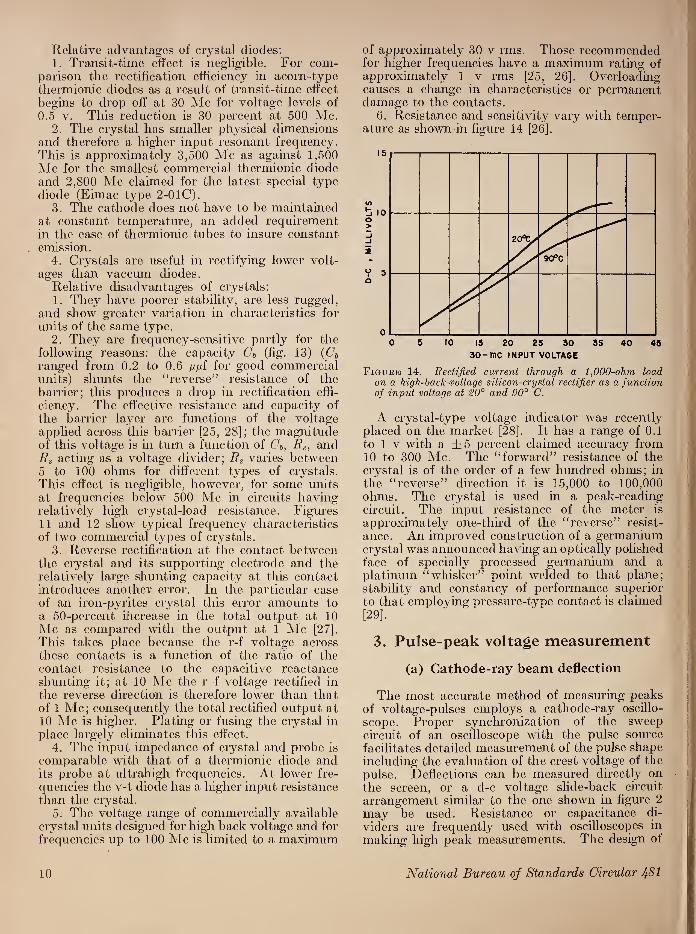
6. Resistance and sensitivity vary with temper¬ ature as shown-in figure 14 [26],
0 5 10 15 20 25 30 35 40 45
30-me INPUT VOLTAGE
Figure 14. Rectified current through a 1,000-ohm load on a high-hack-voltage silicon-crystal rectifier as a function of input voltage at 20° and 90° C.
A crystal-type voltage indicator was recently placed on the market [28]. It has a range of 0.1 to 1 v with a ±5 percent claimed accuracy from 10 to 300 Me. The “forward” resistance of the crystal is of the order of a few hundred ohms; in the “reverse” direction it is 15,000 to 100,000 ohms. The crystal is used in a peak-reading circuit. The input resistance of the meter is approximately one-third of the “reverse” resist¬ ance. An improved construction of a germanium crystal was announced having an optically polished face of specially processed germanium and a platinum “whisker” point welded to that plane; stability and constancy of performance superior to that employing pressure-type contact is claimed [29],
3. Pulse-peak voltage measurement
(a) Cathode-ray beam deflection
The most accurate method of measuring peaks of voltage-pulses employs a catliode-ray oscillo¬ scope. Proper synchronization of the sweep circuit of an oscilloscope with the pulse source facilitates detailed measurement of the pulse shape including the evaluation of the crest voltage of the pulse. Deflections can be measured directly on the screen, or a d-c voltage slide-back circuit arrangement similar to the one shown in figure 2 may be used. Resistance or capacitance di¬ viders are frequently used with oscilloscopes in making high peak measurements. The design of
National Bureau of Standards Circular 481
the divider should be such that in reducing the relative magnitude of the voltage pulse it does not alter the shape of the pulse applied to the oscilloscope.
(b) Diode peak voltmeters
Diode peak voltmeters are generally used as convenient moderate-precision indicators [30, 31]. However, the discrepancy between the voltmeter reading and true peak value may be very large. Figure 15 shows the response of a diode-type vacuum-tube voltmeter as a function of pulse- repetition frequency for a rectangular pulse shape and pulse duration of 3.5 microseconds. An approximate expression is given by Easton [30] for the rectangular pulse peak in terms of the d-c diode output as follows:
6° | + h #0’ ('13^ where
e0 = the peak voltage of a rectangular pulse -EdC=the d-c voltage across R2
7= the duration of the discharging interval h = the duration of the charging interval
i?i = the total resistance during charging JU = the total resistance during discharging.
One of the curves of figure 15 shows values computed on the basis of this expression. The effective input impedance of this type of voltmeter for pulse voltages may be very low. The direct- voltage output (measured across R2) decreases with increasing rate of pulse repetition, with in¬ creasing values of R2 and with decreasing values of Rx. Rx is a function of the combined source and diode resistances at the particular operating con¬ ditions. Improved performance may be obtained by means of auxiliary circuits like cathode follow¬ ers [30] and automatic slideback arrangements [31].
Figure 15. Response of a diode-type VTVM as a function of pulse-repetition frequency for a charging-interval dura¬ tion of 3.5 microseconds and a peak of 26 v.
4. Miscellaneous Methods
The following voltage-measuring methods are of interest as relatively independent and useful for certain applications.
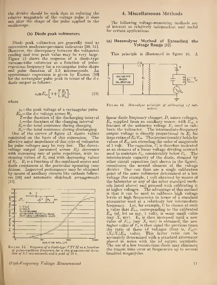
(a) Heterodyne Method of Extending the Voltage Range [32]
This principle is illustrated in figure 16. A
Figure 16. Heterodyne principle of calibrating r-f volt¬ meters.
linear diode frequency changer, D, mixes voltages, E0, supplied from an auxiliary source, with ExU a fraction of the unknown voltage Ex used to cali¬ brate the voltmeter. The intermediate-frequency output voltage is directly proportional to Ex for large ratios of EQ/ExX. This proportionality holds for values of Exl not exceeding the order of magnitude of 1 volt. The capacitor, C, is therefore indicated as an element of a linear voltage dividing network used to maintain ExX considerably below Ex. The interelectrode capacity of the diode, shunted by other circuit capacities (not shown in the figure), constitutes the second element of the voltage divider. One can thus use a single calibration point of the same voltmeter determined at a low voltage (for example, 1 volt obtained by means of the bolometer or any of the other standard meth¬ ods listed above) and proceed with calibrating it at higher voltages. The advantage of this method is that it can be used to calibrate high voltage levels at high frequencies in terms of a standard attenuator used at a relatively low intermediate frequency. Let, for example, C be chosen at such a value that Ex.t, corresponding to the calibrated ExX (of, let us say, 1 volt), is some small value (say Xx mv). Ez is then increased until a new value of Ei.£ (say X2 mv) is obtained; the new higher value of Ex is then equal the previous times the ratio of these i-f voltages (that is, Ex2— {X2/Xi)Exi volts). This latter ratio can be accurately determined with a standard attenuator placed in series with the i-f output terminals. The use of a low transit-time diode may eliminate the transit time error at frequencies up to several hundred megacycles.
High-Frequency Voltage Measurement 11
(b) Spark-gap method
Spark gaps may be used to measure peak volt¬ ages of tlie order of 1 to 30 kv at all frequencies up to about 100 kc [33]. The sphere spark gap is preferred to other electrodes because the break¬ down voltage changes little up to about 25 kc. For a symmetrical sphere-gap voltmeter the peak voltage is given approximately by
_E=V 2e~, (14) m
where
e— 19.3p[l + 0.76/-\/^D]kv/cm p = 3.92_p/T'=relative air density D=sphere diameter in centimeters 1=maximum gap-length in centimeters at
which spark-over may take place p=atmospheric pressure in centimeters of a
mercury column T— (273+iV0C) = absolute temperature in deg
K, and_ to=0.25[2Z/£>+1+ V(2//£>+l)2+8].
Actual voltages at 100 kc are 10 percent lower than corresponding power frequency voltages normally used to calibrate the gap voltmeter.
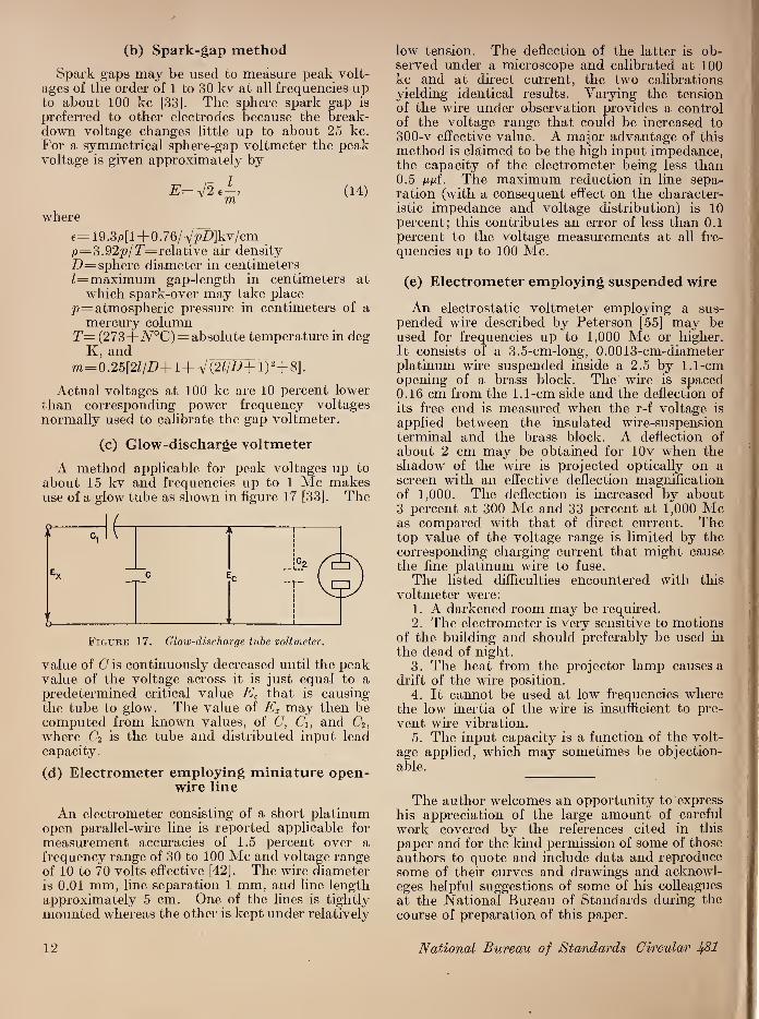
(c) Glow-discharge voltmeter
A method applicable for peak voltages up to about 15 kv and frequencies up to 1 Ale makes use of a glow tube as shown in figure 17 [33], The
value of C is continuously decreased until the peak value of the voltage across it is just equal to a predetermined critical value Ec that is causing the tube to glow. The value of Ex may then be computed from known values, of C, Ci, and C2, where C2 is the tube and distributed input lead capacity.
(d) Electrometer employing miniature open- wire line
An electrometer consisting of a short platinum open parallel-wire line is reported applicable for measurement accuracies of 1.5 percent over a frequency range of 30 to 100 Me and voltage range of 10 to 70 volts effective [42], The wire diameter is 0.01 mm, line separation 1 mm, and line length approximately 5 cm. One of the lines is tightly mounted whereas the other is kept under relatively
12
low tension. The deflection of the latter is ob¬ served under a microscope and calibrated at 100 kc and at direct current, the two calibrations yielding identical results. Varying the tension of the wire under observation provides a control of the voltage range that could be increased to 300-v effective value. A major advantage of this method is claimed to be the high input impedance, the capacity of the electrometer being less than 0.5 nni. The maximum reduction in line sepa¬ ration (with a consequent effect on the character¬ istic impedance and voltage distribution) is 10 percent; this contributes an error of less than 0.1 percent to the voltage measurements at all fre¬ quencies up to 100 Me.
(e) Electrometer employing suspended wire
An electrostatic voltmeter employing a sus¬ pended wire described by Peterson [55] may be used for frequencies up to 1,000 Me or higher. It consists of a 3.5-cm-long, 0.0013-cm-diameter platinum wire suspended inside a 2.5 by 1.1-cm opening of a brass block. The wire is spaced 0.16 cm from the 1.1-cm side and the deflection of its free end is measured when the r-f voltage is applied between the insulated wire-suspension terminal and the brass block. A deflection of about 2 cm may be obtained for lOv when the shadow of the wire is projected optically on a screen with an effective deflection magnification of 1,000. The deflection is increased by about 3 percent at 300 Me and 33 percent at 1,000 Me as compared with that of direct current. The top value of the voltage range is limited by the corresponding charging current that might cause the fine platinum wire to fuse.
The listed difficulties encountered with this voltmeter were:
1. A darkened room may be required. 2. The electrometer is very sensitive to motions
of the building and should preferably be used in the dead of night.
3. The heat from the projector lamp causes a drift of the wire position.
4. It cannot be used at low frequencies where the low inertia of the wire is insufficient to pre¬ vent wire vibration.
5. The input capacity is a function of the volt¬ age applied, which may sometimes be objection¬ able.
The author welcomes an opportunity to express his appreciation of the large amount of careful work covered by the references cited in this paper and for the kind permission of some of those authors to quote and include data and reproduce some of their curves and drawings and acknowl- eges helpful suggestions of some of his colleagues at the National Bureau of Standards during the course of preparation of this paper.
National Bureau of Standards Circular 181

II. References
[1] G. L. Pearson, Thermistors, their characteristics and uses, a pamphlet on varistors by Western Electric Co., Radio Division, WECO, T2096B, p. 22 (1945).
[2] J. A. Becker, C. B. Green, and G. L. Pearson, Proper¬ ties and uses of thermistors—thermally sensitive resistors, Trans. Am. Inst. Elect. Engrs. 65, No. 11, 711 (1946).
[3] D. B. Sinclair, The type 663 resistor, General Radio Experimenter, 13, No. 8, 6 (1939).
[4] P. M. Lamps, technical data (Sylvania Electrical Products Inc., Feb. 5, 1945).
[5] L. S. Nergaard, Electrical measurements at wave¬ lengths less than two meters, Proc. Inst. Radio Engrs. 24, 1207 (1936).
[6] H. E. Hollmann, Ultra-high-frequency oscillography, Proc. Inst. Radio Engrs. 28, No. 5, 213 (1940).
[7] F. M. Gager, Cathode-ray electron ballistics, Com¬ munications, p. 10, (1938).
[8] H. E. Hollmann, The use of the cathode-ray oscillo¬ graph at ultra-high frequencies, W. Eng. and Exp. W. 10, 430 484 (1933).
[9] G. M. Lee, A three beam oscillograph for recording at frequencies up to 10,000 Me., Proc. Inst. Radio Engrs. 34, No. 3, 121W (1946).
[10] L. K. Libbv, Cathode ravs for the uhf, Electronics 9, No. 9, 15 (1936).
[11] H. G. Rudenberg, Deflection sensitivity of parallel- wire lines in cathode-ray oscillographs, J. Applied Phys. 16, 279 (1945).
[12] Electrical measurements, 13, No. 1 (Scientific Re¬ search Instrument Corp., New York, N. Y., Jan. 1946).
[13] C. B. Aiken, Theory of the diode voltmeter, Proc. Inst. Radio Engrs. 26, 859 (1938).
[14] J. F. Rider, Vacuum tube voltmeters (J. F. Rider Publisher Inc., 404 4th Ave., New York, N. Y., 1941).
[15] E. C. S. Megaw, Voltage measurement at very high frequencies, W. Eng., 13, 65, 135, 201 (1936).
[16] C. A. Woodward, Jr., A new vacuum tube voltmeter, General Radio Experimenter, 22, No. 4 (1946).
[17] W. N. Tuttle, Type 726-A vacuum-tube voltmeter, General Radio Experimenter, 11, No. 12 (1937).
[18] I. G. Easton, Radio-frequency characteristics of the type 726-A vacuum-tube voltmeter, General Radio Experimenter, 15, No. 11 (1941).
[19] The use of the 954 as a vacuum-tube voltmeter, RCA Radiotron Division, Application note, No. 47 (Mav 20, 1935).
[20] Radio-frequency voltmeter, Bell Labs. Record 21, No. 5, 126 (1943).
[21] W. H. Brattain, The copper oxide varistor, a pamphlet on varistors by Western Electric Co., Radio Division, p. 9, WECO, T2096B (1945).
[22] J. H. Miller, Copper oxide rectifiers as used in meas¬ uring instruments, Weston Eng, notes, 1, No. 1 (1946).
[23] B. J. Thompson, G. M. Rose, Jr., Vacuum tubes of small dimensions for use at extremely high frequen¬ cies, Proc. Inst. Radio Engrs. 21, No. 12, 1707 (1933).
[24] Sylvania Electric Products Inc., bulletin on crystal diode IN34, No. EC-22, Jan. 1946.
[25] E. C. Cornelius, Germanium crystal diodes, Elec¬ tronics 19, No. 2, 118 (1946).
[26] W. E. Stephens, Crystal rectifiers, Electronics 19, No. 7, 112 (1946).
[27] A. Peterson, Vacuum tubes and crystal rectifiers as galvanometers and voltmeters at ultra-high- frequencies, General Radio Experimenter 19, No. 12 (1945).
[28] A. Peterson, A peak reading voltmeter for uhf ranges, General Radio Experimenter 21, No. 5 (1946).
[29] The new germanium crystal diode, G. E. Electronic Dept., bulletin ESD-88, Feb. 24, 1947.
[30] A. Easton, Pulse response of diode voltmeters, Electronics 19, No. 1, 146 (1946).
[31] C. J. Creveling, L. Mantner, An automatic slideback peak voltmeter for measuring pulses, Proc. Inst. Radio Engrs. 35, No. 2, 208 (1947).
[32] This method is at present under investigation at the Central Radio Propagation Laboratory of the NBS.
[33] A. Hund, High-frequency measurements, 1st ed., p. 134 to 136 (McGraw-Hill Book Co., Inc., New York, N. Y., 1933). '
[34] C. B. Aiken, L. C. Birdsall, Sharp cutoff in vacuum tubes, with applications to the slide-back voltmeter. Trans. Am. Inst. Elec. Engrs. 57, 171 (1938).
[35] I. M. Miller, Dependence of the input impedance of a three-electrode vacuum tube upon the load in the plate circuit, BS Sci. Pap. 15, (1919-20) S351.
[36] R. A. Heising, Thermionic voltmeters, Patent No. I, 232,919 (1917).
[37] H. J. Reich, G. S. Marvin, K. Stall, Vacuum tube voltmeter of high sensitivity, Electronics 3, 109 (1931).
[38] F. E. Terman, The inverted vacuum tube, a voltage- reducing power amplifier, Proc. Inst. Radio Engrs. 16, No. 4, 447 (1928).
[39] RCA Radiotron Division, Harrison, N. J., Applica¬ tion note on the use of the 954 as a vacuum tube voltmeter. Application note No. 47, May 20, (1938).
[40] F. E. Terman, Radio Eng., 2d ed., p. 269 (McGraw- Hill Book Co., Inc., New York, N. Y., 1937).
[41] W. R. Ferris, Input resistance of vacuum tubes as ultra-high frequency amplifiers, Proc. Inst. Radio Engrs. 24, 82 (1936).
[42] A. L. Chodakov, An electrometer for measuring voltages in the meter wave range, J. Tech. Phys. II, No. 8, 767 (1941). (In Russian).
[43] II. J. Reich, Theory and application of electron tubes, 2d ed., p. 597 to 612 (McGraw-Hill Book Co., Inc., New York, N. Y., 1944).
[44] J. G. Chaffee, The determination of dielectric prop¬ erties at very high frequencies, Proc. Inst. Radio Engrs. 22, No. 8, 1009 (1934).
[45] H. A. Brown, Radio-frequency electrical measure¬ ments, 2d ed., p. 274 and 28i (McGraw-Hill Book Co., Inc., New York, N. Y., 1938).
[46] A valve voltmeter for audio frequencies, W. Eng. 10, 310 (1933).
[47] L. S. Nergaard, A survey of ultra-high-frequency measurements, RCA Rev. 3, 156 (1938).
High-Frequency Voltage Measurement 13

[48] M. J. O. Strutt, K. S. Knol, Measurement of currents and voltages down to a wavelength of 20 centi¬ meters, Proc. Inst. Radio Engrs. 27, 783 (1939).
[49] R. Davis, G. W. Bowdler, W. G. Standring, The measurement of high voltages with special reference to the measurement of peak, J. Inst. Elec. Engrs. (London) 68, 1222 (1930).
[50] C. E. Kilgour, J. M. Glissner, Diode detection analysis Proc. Inst. Radio Engrs. 21, No. 7, 930 (1933).
[51] A. Hund, High-frequency measurements, 1st ed., p. 149 to 153 (McGraw-Hill Book Co., Inc., New York, N. Y., 1933).
[52] J. T. Kendall, The rectifying projrerty of carborund¬ um, Proc. Phys. Soc. 56, part 2, No. 314, 123 (1944).
[53] T. Moreno, O. C. Lundstrom, Microwave power measurement, Proc. Inst. Radio Engrs. 35, 514 (1947).
[54] Report on measurement voltage at high frequencies, Research Laboratories, Electric and.Musical Indus¬ tries, Ltd., Hayes, Middix, Dec. 28, 1940 (un¬ published).
[55] A. P. G. Peterson, The measurement of voltages at ultra-high-frequencies, Thesis, submitted to Massa¬ chusetts Institute of Technology, May 15, 1941).
14
[56] I. Wolff, Alternating-current measuring instruments as discriminators against harmonics, Proc. Inst. Radio Engrs. 19, No. 4, 647 (1931).
[57] F. E. Terman, Multirange rectifier instruments having the same scale graduation for all ranges, Proc. Inst. Radio Engrs. 23, No. 3, 234 (1935).
[58] A valve voltmeter for audio frequencies, The wireless engineer and experimental wireless 10, 310 (1933).
[59] J. Taylor, An application of the diode to the measure¬ ment of a-c voltages, J. Sci. Instruments 3, 113 (1925-26).
[60] F. E. Terman, Measurements in Radio Engineering, 1st ed., p. 18 to 30 (McGraw-Hill Book Co., Inc., New York, N. Y., 1935).
[61] H. J. Reich, Theory and applications of electron tubes, 2d ed., chapter 4 (McGraw-Hill Book Co., Inc., New York, N. Y., 1944).
[62] F. L. Hermach, A precision electrothermic voltmeter for measurements between 20 and 20,000 cycles, Trans. Am. Inst. Elec. Engrs. 67, paper 48-218 (1948).
Washington, March 2, 1949.
National Bureau of Standards Circular 481
U. S. GOVERNMENT PRINTING OFFICE: 1949


*.i:a
Copyright © 2022 FDOKUMEN