Surface & Coatings Technology - NoMorFilm
11
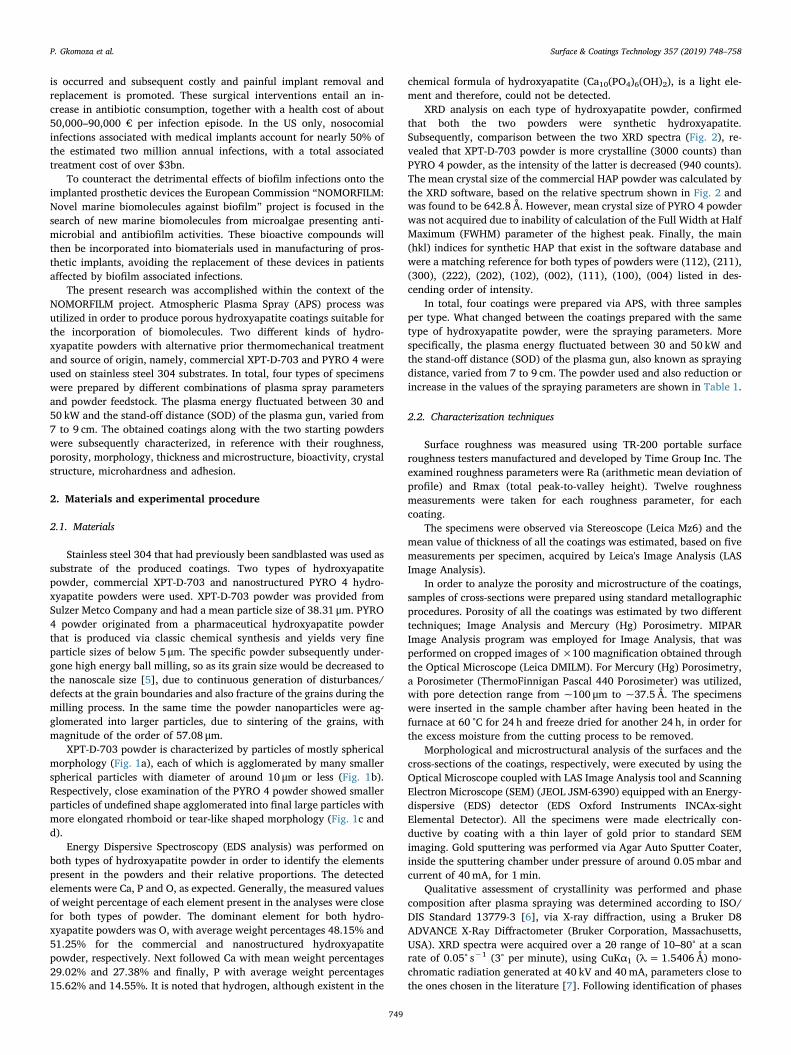
Contents lists available at ScienceDirect Surface & Coatings Technology journal homepage: www.elsevier.com/locate/surfcoat Comparative study of structure and properties of thermal spray coatings using conventional and nanostructured hydroxyapatite powder, for applications in medical implants P. Gkomoza a, ⁎ , M. Vardavoulias a , D.I. Pantelis b , Ch. Sarafoglou b a PyroGenesis SA, Technological Park of Lavrion, 195 00 Lavrion, Greece b Shipbuilding Technology Laboratory, School of Naval Architecture and Marine Engineering, National Technical University of Athens, 9 Heroon, Polytechniou Ave., Zografos, Athens GR-157 80, Greece ARTICLE INFO Keywords: Biomedical coatings Thermal spray Hydroxyapatite (HAP) Nanostructured Properties ABSTRACT The objective of this paper is to study and compare the structure and properties of thermal spray coatings prepared with conventional and nanostructured hydroxyapatite powder, in order to assess their suitability for future use in medical implants. Four coatings were prepared via Atmospheric Plasma Spray process (APS). Two kinds of feedstock material were employed for the spray process, namely, commercial XPT-D-703 hydroxyapatite powder for half the samples and novel nanostructured PYRO 4 hydroxyapatite powder, which had previously been mechanically treated, for the remaining samples. The substrate of all the samples was stainless steel 304. Finally, the plasma spray parameters were altered for two out of the four coatings, each produced with a dif- ferent type of powder, in order for a sufficient amount of porosity to be achieved for future incorporation of biomolecules. The coatings were also examined in terms of bioactivity in vitro. It was concluded that the coating produced with the nanostructured powder, under lower plasma energy and at greater spraying distance pre- sented the best results regarding its roughness, bioactive response, crystallinity, adherence and porosity content. 1. Introduction The positive response and long-term functions of osteoblasts on nanoceramics with grain sizes < 100 nm, have been confirmed by a novel (at the time) in vitro study [1], that has led researches [2] to claim that nanostructured biomaterials promote osteoblast adhesion and proliferation, osseointegration, and the deposition of calcium containing minerals on the surface of these materials. More specifically, nanosized HAP particles are characterized by greater specific surface area compared to that of larger sized particle counterparts. Greater surface area allows greater degree of interaction with the surrounding environment and taking into consideration that “the first and im- mediate biologic reaction to a foreign body is its coating with proteins” [3], the absorbed quantity amongst the available proteins of the sur- rounding physiological environment is increased [2,4]. As a result, both cell adhesion and proliferation are enhanced. Therefore, production of nanostructured HAP powders and composites for construction of med- ical implants is a logical step for desirable development in the field of orthopaedics. Plasma spraying has been used as a major technique in applying hydroxyapatite (Ca 10 (PO 4 ) 6 (OH) 2 ) coatings onto metal implants to improve implant fixation and bone growth. Variations in process parameters such as plasma energy, spraying distance and powder morphology can induce microstructural and mechanical inconsistencies that have an effect on the service performance of the coating. Due to all the limitations, strict plasma spray process control is required to achieve the desired properties of the final coatings. Discovering corre- lations between spraying conditions and final coating characteristics and at the same time elimination of the consequent spraying defects, such as micro-cracks, poor adhesion between the coating and the sub- strate and phase changes due to high-temperature exposure, is a priority. In the last decades, an increasing number of antibiotic resistant bacterial pathogens, amongst which, biofilm-associated pathogens, have become an important problem worldwide. It is estimated that, > 60% of the human infections are caused by microorganisms able to form biofilms and therefore, avoid the antibiotic and immune system actions. Although some of these colonizing microorganisms do not cause infection, they can promote an immune reaction giving rise to inflammation at the underlying tissue. As a result, release of the implant https://doi.org/10.1016/j.surfcoat.2018.10.044 Received 24 July 2018; Received in revised form 15 October 2018; Accepted 16 October 2018 ⁎ Corresponding author. E-mail addresses: [email protected], [email protected] (P. Gkomoza). Surface & Coatings Technology 357 (2019) 748–758 Available online 18 October 2018 0257-8972/ © 2018 Elsevier B.V. All rights reserved. T
-
Upload
khangminh22 -
Category
Documents
-
view
0 -
download
0
Transcript of Surface & Coatings Technology - NoMorFilm
Contents lists available at ScienceDirect
Surface & Coatings Technology
journal homepage: www.elsevier.com/locate/surfcoat
Comparative study of structure and properties of thermal spray coatingsusing conventional and nanostructured hydroxyapatite powder, forapplications in medical implants
P. Gkomozaa,⁎, M. Vardavouliasa, D.I. Pantelisb, Ch. Sarafogloub
a PyroGenesis SA, Technological Park of Lavrion, 195 00 Lavrion, Greeceb Shipbuilding Technology Laboratory, School of Naval Architecture and Marine Engineering, National Technical University of Athens, 9 Heroon, Polytechniou Ave.,Zografos, Athens GR-157 80, Greece
A R T I C L E I N F O
Keywords:Biomedical coatingsThermal sprayHydroxyapatite (HAP)NanostructuredProperties
A B S T R A C T
The objective of this paper is to study and compare the structure and properties of thermal spray coatingsprepared with conventional and nanostructured hydroxyapatite powder, in order to assess their suitability forfuture use in medical implants. Four coatings were prepared via Atmospheric Plasma Spray process (APS). Twokinds of feedstock material were employed for the spray process, namely, commercial XPT-D-703 hydroxyapatitepowder for half the samples and novel nanostructured PYRO 4 hydroxyapatite powder, which had previouslybeen mechanically treated, for the remaining samples. The substrate of all the samples was stainless steel 304.Finally, the plasma spray parameters were altered for two out of the four coatings, each produced with a dif-ferent type of powder, in order for a sufficient amount of porosity to be achieved for future incorporation ofbiomolecules. The coatings were also examined in terms of bioactivity in vitro. It was concluded that the coatingproduced with the nanostructured powder, under lower plasma energy and at greater spraying distance pre-sented the best results regarding its roughness, bioactive response, crystallinity, adherence and porosity content.
1. Introduction
The positive response and long-term functions of osteoblasts onnanoceramics with grain sizes< 100 nm, have been confirmed by anovel (at the time) in vitro study [1], that has led researches [2] toclaim that nanostructured biomaterials promote osteoblast adhesionand proliferation, osseointegration, and the deposition of calciumcontaining minerals on the surface of these materials. More specifically,nanosized HAP particles are characterized by greater specific surfacearea compared to that of larger sized particle counterparts. Greatersurface area allows greater degree of interaction with the surroundingenvironment and taking into consideration that “the first and im-mediate biologic reaction to a foreign body is its coating with proteins”[3], the absorbed quantity amongst the available proteins of the sur-rounding physiological environment is increased [2,4]. As a result, bothcell adhesion and proliferation are enhanced. Therefore, production ofnanostructured HAP powders and composites for construction of med-ical implants is a logical step for desirable development in the field oforthopaedics.
Plasma spraying has been used as a major technique in applying
hydroxyapatite (Ca10(PO4)6(OH)2) coatings onto metal implants toimprove implant fixation and bone growth. Variations in processparameters such as plasma energy, spraying distance and powdermorphology can induce microstructural and mechanical inconsistenciesthat have an effect on the service performance of the coating. Due to allthe limitations, strict plasma spray process control is required toachieve the desired properties of the final coatings. Discovering corre-lations between spraying conditions and final coating characteristicsand at the same time elimination of the consequent spraying defects,such as micro-cracks, poor adhesion between the coating and the sub-strate and phase changes due to high-temperature exposure, is apriority.
In the last decades, an increasing number of antibiotic resistantbacterial pathogens, amongst which, biofilm-associated pathogens,have become an important problem worldwide. It is estimatedthat,> 60% of the human infections are caused by microorganismsable to form biofilms and therefore, avoid the antibiotic and immunesystem actions. Although some of these colonizing microorganisms donot cause infection, they can promote an immune reaction giving rise toinflammation at the underlying tissue. As a result, release of the implant
https://doi.org/10.1016/j.surfcoat.2018.10.044Received 24 July 2018; Received in revised form 15 October 2018; Accepted 16 October 2018
⁎ Corresponding author.E-mail addresses: [email protected], [email protected] (P. Gkomoza).
Surface & Coatings Technology 357 (2019) 748–758
Available online 18 October 20180257-8972/ © 2018 Elsevier B.V. All rights reserved.
T
is occurred and subsequent costly and painful implant removal andreplacement is promoted. These surgical interventions entail an in-crease in antibiotic consumption, together with a health cost of about50,000–90,000 € per infection episode. In the US only, nosocomialinfections associated with medical implants account for nearly 50% ofthe estimated two million annual infections, with a total associatedtreatment cost of over $3bn.
To counteract the detrimental effects of biofilm infections onto theimplanted prosthetic devices the European Commission “NOMORFILM:Novel marine biomolecules against biofilm” project is focused in thesearch of new marine biomolecules from microalgae presenting anti-microbial and antibiofilm activities. These bioactive compounds willthen be incorporated into biomaterials used in manufacturing of pros-thetic implants, avoiding the replacement of these devices in patientsaffected by biofilm associated infections.
The present research was accomplished within the context of theNOMORFILM project. Atmospheric Plasma Spray (APS) process wasutilized in order to produce porous hydroxyapatite coatings suitable forthe incorporation of biomolecules. Two different kinds of hydro-xyapatite powders with alternative prior thermomechanical treatmentand source of origin, namely, commercial XPT-D-703 and PYRO 4 wereused on stainless steel 304 substrates. In total, four types of specimenswere prepared by different combinations of plasma spray parametersand powder feedstock. The plasma energy fluctuated between 30 and50 kW and the stand-off distance (SOD) of the plasma gun, varied from7 to 9 cm. The obtained coatings along with the two starting powderswere subsequently characterized, in reference with their roughness,porosity, morphology, thickness and microstructure, bioactivity, crystalstructure, microhardness and adhesion.
2. Materials and experimental procedure
2.1. Materials
Stainless steel 304 that had previously been sandblasted was used assubstrate of the produced coatings. Two types of hydroxyapatitepowder, commercial XPT-D-703 and nanostructured PYRO 4 hydro-xyapatite powders were used. XPT-D-703 powder was provided fromSulzer Metco Company and had a mean particle size of 38.31 μm. PYRO4 powder originated from a pharmaceutical hydroxyapatite powderthat is produced via classic chemical synthesis and yields very fineparticle sizes of below 5 μm. The specific powder subsequently under-gone high energy ball milling, so as its grain size would be decreased tothe nanoscale size [5], due to continuous generation of disturbances/defects at the grain boundaries and also fracture of the grains during themilling process. In the same time the powder nanoparticles were ag-glomerated into larger particles, due to sintering of the grains, withmagnitude of the order of 57.08 μm.
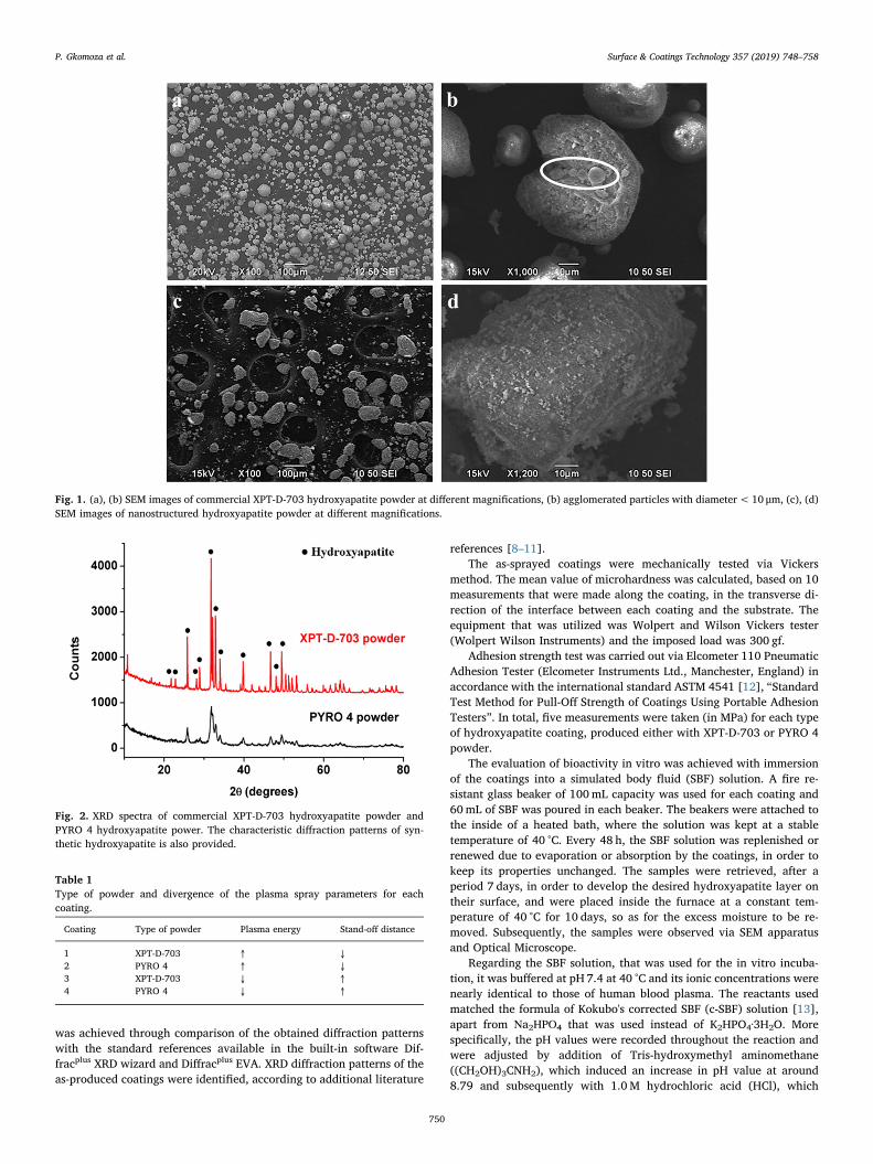
XPT-D-703 powder is characterized by particles of mostly sphericalmorphology (Fig. 1a), each of which is agglomerated by many smallerspherical particles with diameter of around 10 μm or less (Fig. 1b).Respectively, close examination of the PYRO 4 powder showed smallerparticles of undefined shape agglomerated into final large particles withmore elongated rhomboid or tear-like shaped morphology (Fig. 1c andd).
Energy Dispersive Spectroscopy (EDS analysis) was performed onboth types of hydroxyapatite powder in order to identify the elementspresent in the powders and their relative proportions. The detectedelements were Ca, P and O, as expected. Generally, the measured valuesof weight percentage of each element present in the analyses were closefor both types of powder. The dominant element for both hydro-xyapatite powders was O, with average weight percentages 48.15% and51.25% for the commercial and nanostructured hydroxyapatitepowder, respectively. Next followed Ca with mean weight percentages29.02% and 27.38% and finally, P with average weight percentages15.62% and 14.55%. It is noted that hydrogen, although existent in the
chemical formula of hydroxyapatite (Ca10(PO4)6(OH)2), is a light ele-ment and therefore, could not be detected.
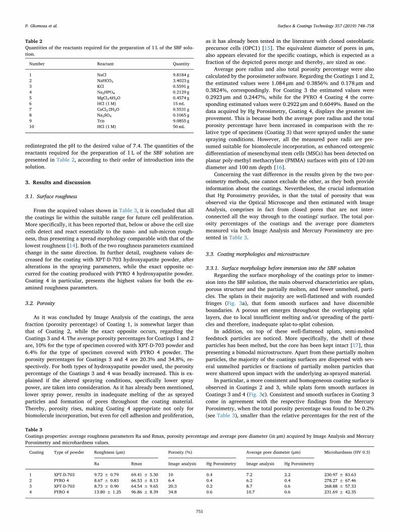
XRD analysis on each type of hydroxyapatite powder, confirmedthat both the two powders were synthetic hydroxyapatite.Subsequently, comparison between the two XRD spectra (Fig. 2), re-vealed that XPT-D-703 powder is more crystalline (3000 counts) thanPYRO 4 powder, as the intensity of the latter is decreased (940 counts).The mean crystal size of the commercial HAP powder was calculated bythe XRD software, based on the relative spectrum shown in Fig. 2 andwas found to be 642.8 Å. However, mean crystal size of PYRO 4 powderwas not acquired due to inability of calculation of the Full Width at HalfMaximum (FWHM) parameter of the highest peak. Finally, the main(hkl) indices for synthetic HAP that exist in the software database andwere a matching reference for both types of powders were (112), (211),(300), (222), (202), (102), (002), (111), (100), (004) listed in des-cending order of intensity.
In total, four coatings were prepared via APS, with three samplesper type. What changed between the coatings prepared with the sametype of hydroxyapatite powder, were the spraying parameters. Morespecifically, the plasma energy fluctuated between 30 and 50 kW andthe stand-off distance (SOD) of the plasma gun, also known as sprayingdistance, varied from 7 to 9 cm. The powder used and also reduction orincrease in the values of the spraying parameters are shown in Table 1.
2.2. Characterization techniques
Surface roughness was measured using TR-200 portable surfaceroughness testers manufactured and developed by Time Group Inc. Theexamined roughness parameters were Ra (arithmetic mean deviation ofprofile) and Rmax (total peak-to-valley height). Twelve roughnessmeasurements were taken for each roughness parameter, for eachcoating.
The specimens were observed via Stereoscope (Leica Mz6) and themean value of thickness of all the coatings was estimated, based on fivemeasurements per specimen, acquired by Leica's Image Analysis (LASImage Analysis).
In order to analyze the porosity and microstructure of the coatings,samples of cross-sections were prepared using standard metallographicprocedures. Porosity of all the coatings was estimated by two differenttechniques; Image Analysis and Mercury (Hg) Porosimetry. MIPARImage Analysis program was employed for Image Analysis, that wasperformed on cropped images of ×100 magnification obtained throughthe Optical Microscope (Leica DMILM). For Mercury (Hg) Porosimetry,a Porosimeter (ThermoFinnigan Pascal 440 Porosimeter) was utilized,with pore detection range from ~100 μm to ~37.5 Å. The specimenswere inserted in the sample chamber after having been heated in thefurnace at 60 °C for 24 h and freeze dried for another 24 h, in order forthe excess moisture from the cutting process to be removed.
Morphological and microstructural analysis of the surfaces and thecross-sections of the coatings, respectively, were executed by using theOptical Microscope coupled with LAS Image Analysis tool and ScanningElectron Microscope (SEM) (JEOL JSM-6390) equipped with an Energy-dispersive (EDS) detector (EDS Oxford Instruments INCAx-sightElemental Detector). All the specimens were made electrically con-ductive by coating with a thin layer of gold prior to standard SEMimaging. Gold sputtering was performed via Agar Auto Sputter Coater,inside the sputtering chamber under pressure of around 0.05mbar andcurrent of 40mA, for 1min.
Qualitative assessment of crystallinity was performed and phasecomposition after plasma spraying was determined according to ISO/DIS Standard 13779-3 [6], via X-ray diffraction, using a Bruker D8ADVANCE X-Ray Diffractometer (Bruker Corporation, Massachusetts,USA). XRD spectra were acquired over a 2θ range of 10–80° at a scanrate of 0.05° s−1 (3° per minute), using CuKα1 (λ=1.5406 Å) mono-chromatic radiation generated at 40 kV and 40mA, parameters close tothe ones chosen in the literature [7]. Following identification of phases
P. Gkomoza et al. Surface & Coatings Technology 357 (2019) 748–758
749
was achieved through comparison of the obtained diffraction patternswith the standard references available in the built-in software Dif-fracplus XRD wizard and Diffracplus EVA. XRD diffraction patterns of theas-produced coatings were identified, according to additional literature
references [8–11].The as-sprayed coatings were mechanically tested via Vickers
method. The mean value of microhardness was calculated, based on 10measurements that were made along the coating, in the transverse di-rection of the interface between each coating and the substrate. Theequipment that was utilized was Wolpert and Wilson Vickers tester(Wolpert Wilson Instruments) and the imposed load was 300 gf.
Adhesion strength test was carried out via Elcometer 110 PneumaticAdhesion Tester (Elcometer Instruments Ltd., Manchester, England) inaccordance with the international standard ASTM 4541 [12], “StandardTest Method for Pull-Off Strength of Coatings Using Portable AdhesionTesters”. In total, five measurements were taken (in MPa) for each typeof hydroxyapatite coating, produced either with XPT-D-703 or PYRO 4powder.
The evaluation of bioactivity in vitro was achieved with immersionof the coatings into a simulated body fluid (SBF) solution. A fire re-sistant glass beaker of 100mL capacity was used for each coating and60mL of SBF was poured in each beaker. The beakers were attached tothe inside of a heated bath, where the solution was kept at a stabletemperature of 40 °C. Every 48 h, the SBF solution was replenished orrenewed due to evaporation or absorption by the coatings, in order tokeep its properties unchanged. The samples were retrieved, after aperiod 7 days, in order to develop the desired hydroxyapatite layer ontheir surface, and were placed inside the furnace at a constant tem-perature of 40 °C for 10 days, so as for the excess moisture to be re-moved. Subsequently, the samples were observed via SEM apparatusand Optical Microscope.
Regarding the SBF solution, that was used for the in vitro incuba-tion, it was buffered at pH 7.4 at 40 °C and its ionic concentrations werenearly identical to those of human blood plasma. Τhe reactants usedmatched the formula of Kokubo's corrected SBF (c-SBF) solution [13],apart from Νa2ΗΡΟ4 that was used instead of K2HPO4·3H2O. Morespecifically, the pH values were recorded throughout the reaction andwere adjusted by addition of Tris-hydroxymethyl aminomethane((CH2OH)3CNH2), which induced an increase in pH value at around8.79 and subsequently with 1.0M hydrochloric acid (HCl), which
Fig. 1. (a), (b) SEM images of commercial XPT-D-703 hydroxyapatite powder at different magnifications, (b) agglomerated particles with diameter< 10 μm, (c), (d)SEM images of nanostructured hydroxyapatite powder at different magnifications.
Fig. 2. XRD spectra of commercial XPT-D-703 hydroxyapatite powder andPYRO 4 hydroxyapatite power. The characteristic diffraction patterns of syn-thetic hydroxyapatite is also provided.
Table 1Type of powder and divergence of the plasma spray parameters for eachcoating.
Coating Type of powder Plasma energy Stand-off distance
1 XPT-D-703 ↑ ↓2 PYRO 4 ↑ ↓3 XPT-D-703 ↓ ↑4 PYRO 4 ↓ ↑
P. Gkomoza et al. Surface & Coatings Technology 357 (2019) 748–758
750
redintegrated the pH to the desired value of 7.4. The quantities of thereactants required for the preparation of 1 L of the SBF solution arepresented in Table 2, according to their order of introduction into thesolution.
3. Results and discussion
3.1. Surface roughness
From the acquired values shown in Table 3, it is concluded that allthe coatings lie within the suitable range for future cell proliferation.More specifically, it has been reported that, below or above the cell sizecells detect and react essentially to the nano- and sub-micron rough-ness, thus presenting a spread morphology comparable with that of thelowest roughness [14]. Both of the two roughness parameters examinedchange in the same direction. In further detail, roughness values de-creased for the coating with XPT-D-703 hydroxyapatite powder, afteralterations in the spraying parameters, while the exact opposite oc-curred for the coating produced with PYRO 4 hydroxyapatite powder.Coating 4 in particular, presents the highest values for both the ex-amined roughness parameters.
3.2. Porosity
As it was concluded by Image Analysis of the coatings, the areafraction (porosity percentage) of Coating 1, is somewhat larger thanthat of Coating 2, while the exact opposite occurs, regarding theCoatings 3 and 4. The average porosity percentages for Coatings 1 and 2are, 10% for the type of specimen covered with XPT-D-703 powder and6.4% for the type of specimen covered with PYRO 4 powder. Theporosity percentages for Coatings 3 and 4 are 20.3% and 34.8%, re-spectively. For both types of hydroxyapatite powder used, the porositypercentage of the Coatings 3 and 4 was broadly increased. This is ex-plained if the altered spraying conditions, specifically lower spraypower, are taken into consideration. As it has already been mentioned,lower spray power, results in inadequate melting of the as sprayedparticles and formation of pores throughout the coating material.Thereby, porosity rises, making Coating 4 appropriate not only forbiomolecule incorporation, but even for cell adhesion and proliferation,
as it has already been tested in the literature with cloned osteoblasticprecursor cells (OPC1) [15]. The equivalent diameter of pores in μm,also appears elevated for the specific coatings, which is expected as afraction of the depicted pores merge and thereby, are sized as one.
Average pore radius and also total porosity percentage were alsocalculated by the porosimeter software. Regarding the Coatings 1 and 2,the estimated values were 1.084 μm and 0.3856% and 0.178 μm and0.3824%, correspondingly. For Coating 3 the estimated values were0.2923 μm and 0.2447%, while for the PYRO 4 Coating 4 the corre-sponding estimated values were 0.2922 μm and 0.6049%. Based on thedata acquired by Hg Porosimetry, Coating 4, displays the greatest im-provement. This is because both the average pore radius and the totalporosity percentage have been increased in comparison with the re-lative type of specimens (Coating 3) that were sprayed under the samespraying conditions. However, all the measured pore radii are pre-sumed suitable for biomolecule incorporation, as enhanced osteogenicdifferentiation of mesenchymal stem cells (MSCs) has been detected onplanar poly-methyl methacrylate (PMMA) surfaces with pits of 120 nmdiameter and 100 nm depth [16].
Concerning the vast difference in the results given by the two por-osimetry methods, one cannot exclude the other, as they both provideinformation about the coatings. Nevertheless, the crucial informationthat Hg Porosimetry provides, is that the total of porosity that wasobserved via the Optical Microscope and then estimated with ImageAnalysis, comprises in fact from closed pores that are not inter-connected all the way through to the coatings' surface. The total por-osity percentages of the coatings and the average pore diametersmeasured via both Image Analysis and Mercury Porosimetry are pre-sented in Table 3.
3.3. Coating morphologies and microstructure
3.3.1. Surface morphology before immersion into the SBF solutionRegarding the surface morphology of the coatings prior to immer-
sion into the SBF solution, the main observed characteristics are splats,porous structure and the partially molten, and fewer unmelted, parti-cles. The splats in their majority are well-flattened and with roundedfringes (Fig. 3a), that form smooth surfaces and have discernibleboundaries. A porous net emerges throughout the overlapping splatlayers, due to local insufficient melting and/or spreading of the parti-cles and therefore, inadequate splat-to-splat cohesion.
In addition, on top of these well-flattened splats, semi-moltedfeedstock particles are noticed. More specifically, the shell of theseparticles has been melted, but the core has been kept intact [17], thuspresenting a bimodal microstructure. Apart from these partially moltenparticles, the majority of the coatings surfaces are dispersed with sev-eral unmelted particles or fractions of partially molten particles thatwere shattered upon impact with the underlying as-sprayed material.
In particular, a more consistent and homogeneous coating surface isobserved in Coatings 2 and 3, while splats form smooth surfaces inCoatings 3 and 4 (Fig. 3c). Consistent and smooth surfaces in Coating 3come in agreement with the respective findings from the MercuryPorosimetry, when the total porosity percentage was found to be 0.2%(see Table 3), smaller than the relative percentages for the rest of the
Table 2Quantities of the reactants required for the preparation of 1 L of the SBF solu-tion.
Number Reactant Quantity
1 NaCl 9.8184 g2 NaHCO3 3.4023 g3 KCl 0.5591 g4 Νa2ΗΡΟ4 0.2129 g5 MgCl2·6H2O 0.4574 g6 HCl (1M) 15mL7 CaCl2·2H2O 0.5531 g8 Na2SO4 0.1065 g9 Tris 9.0855 g10 HCl (1M) 50mL
Table 3Coatings properties: average roughness parameters Ra and Rmax, porosity percentage and average pore diameter (in μm) acquired by Image Analysis and MercuryPorosimetry and microhardness values.
Coating Type of powder Roughness (μm) Porosity (%) Average pore diameter (μm) Microhardness (HV 0.3)
Ra Rmax Image analysis Hg Porosimetry Image analysis Hg Porosimetry
1 XPT-D-703 9.72 ± 0.79 69.41 ± 5.30 10 0.4 7.2 2.2 230.97 ± 83.632 PYRO 4 8.67 ± 0.83 66.53 ± 8.13 6.4 0.4 6.2 0.4 278.27 ± 67.463 XPT-D-703 8.73 ± 0.90 64.54 ± 9.65 20.3 0.2 8.7 0.6 268.88 ± 57.334 PYRO 4 13.80 ± 1.25 96.86 ± 8.39 34.8 0.6 10.7 0.6 231.69 ± 42.35
P. Gkomoza et al. Surface & Coatings Technology 357 (2019) 748–758
751
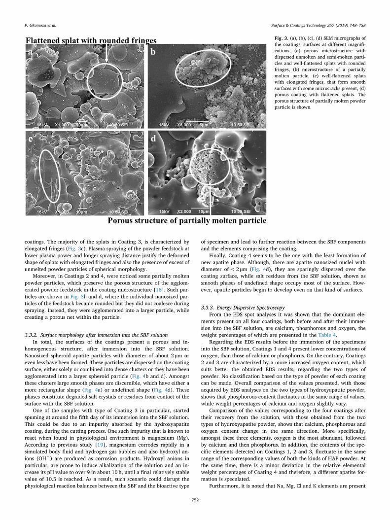
coatings. The majority of the splats in Coating 3, is characterized byelongated fringes (Fig. 3c). Plasma spraying of the powder feedstock atlower plasma power and longer spraying distance justify the deformedshape of splats with elongated fringes and also the presence of excess ofunmelted powder particles of spherical morphology.
Moreover, in Coatings 2 and 4, were noticed some partially moltenpowder particles, which preserve the porous structure of the agglom-erated powder feedstock in the coating microstructure [18]. Such par-ticles are shown in Fig. 3b and d, where the individual nanosized par-ticles of the feedstock became rounded but they did not coalesce duringspraying. Instead, they were agglomerated into a larger particle, whilecreating a porous net within the particle.
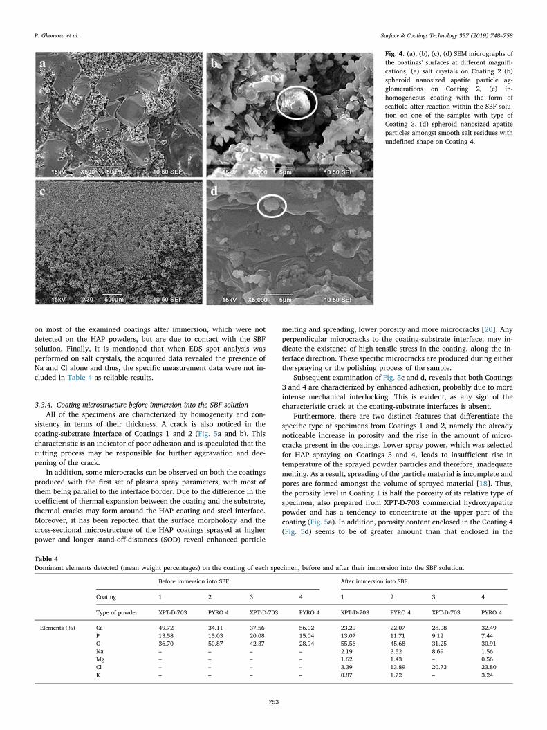
3.3.2. Surface morphology after immersion into the SBF solutionIn total, the surfaces of the coatings present a porous and in-
homogeneous structure, after immersion into the SBF solution.Nanosized spheroid apatite particles with diameter of about 2 μm oreven less have been formed. These particles are dispersed on the coatingsurface, either solely or combined into dense clusters or they have beenagglomerated into a larger spheroid particle (Fig. 4b and d). Amongstthese clusters large smooth phases are discernible, which have either amore rectangular shape (Fig. 4a) or undefined shape (Fig. 4d). Thesephases constitute degraded salt crystals or residues from contact of thesurface with the SBF solution.
One of the samples with type of Coating 3 in particular, startedspuming at around the fifth day of its immersion into the SBF solution.This could be due to an impurity absorbed by the hydroxyapatitecoating, during the cutting process. One such impurity that is known toreact when found in physiological environment is magnesium (Mg).According to previous study [19], magnesium corrodes rapidly in asimulated body fluid and hydrogen gas bubbles and also hydroxyl an-ions (OH−) are produced as corrosion products. Hydroxyl anions inparticular, are prone to induce alkalization of the solution and an in-crease its pH value to over 9 in about 10 h, until a final relatively stablevalue of 10.5 is reached. As a result, such scenario could disrupt thephysiological reaction balances between the SBF and the bioactive type
of specimen and lead to further reaction between the SBF componentsand the elements comprising the coating.
Finally, Coating 4 seems to be the one with the least formation ofnew apatite phase. Although, there are apatite nanosized nuclei withdiameter of< 2 μm (Fig. 4d), they are sparingly dispersed over thecoating surface, while salt residues from the SBF solution, shown assmooth phases of undefined shape occupy most of the surface. How-ever, apatite particles begin to develop even on that kind of surfaces.
3.3.3. Energy Dispersive SpectroscopyFrom the EDS spot analyses it was shown that the dominant ele-
ments present on all four coatings, both before and after their immer-sion into the SBF solution, are calcium, phosphorous and oxygen, theweight percentages of which are presented in the Table 4.
Regarding the EDS results before the immersion of the specimensinto the SBF solution, Coatings 1 and 4 present lower concentrations ofoxygen, than those of calcium or phosphorus. On the contrary, Coatings2 and 3 are characterized by a more increased oxygen content, whichsuits better the obtained EDS results, regarding the two types ofpowder. No classification based on the type of powder of each coatingcan be made. Overall comparison of the values presented, with thoseacquired by EDS analyses on the two types of hydroxyapatite powder,shows that phosphorous content fluctuates in the same range of values,while weight percentages of calcium and oxygen slightly vary.
Comparison of the values corresponding to the four coatings aftertheir recovery from the solution, with those obtained from the twotypes of hydroxyapatite powder, shows that calcium, phosphorous andoxygen content change in the same direction. More specifically,amongst these three elements, oxygen is the most abundant, followedby calcium and then phosphorus. In addition, the contents of the spe-cific elements detected on Coatings 1, 2 and 3, fluctuate in the samerange of the corresponding values of both the kinds of HAP powder. Atthe same time, there is a minor deviation in the relative elementalweight percentages of Coating 4 and therefore, a different apatite for-mation is speculated.
Furthermore, it is noted that Na, Mg, Cl and K elements are present
Fig. 3. (a), (b), (c), (d) SEM micrographs ofthe coatings' surfaces at different magnifi-cations, (a) porous microstructure withdispersed unmolten and semi-molten parti-cles and well-flattened splats with roundedfringes, (b) microstructure of a partiallymolten particle, (c) well-flattened splatswith elongated fringes, that form smoothsurfaces with some microcracks present, (d)porous coating with flattened splats. Theporous structure of partially molten powderparticle is shown.
P. Gkomoza et al. Surface & Coatings Technology 357 (2019) 748–758
752
on most of the examined coatings after immersion, which were notdetected on the HAP powders, but are due to contact with the SBFsolution. Finally, it is mentioned that when EDS spot analysis wasperformed on salt crystals, the acquired data revealed the presence ofNa and Cl alone and thus, the specific measurement data were not in-cluded in Table 4 as reliable results.
3.3.4. Coating microstructure before immersion into the SBF solutionAll of the specimens are characterized by homogeneity and con-
sistency in terms of their thickness. A crack is also noticed in thecoating-substrate interface of Coatings 1 and 2 (Fig. 5a and b). Thischaracteristic is an indicator of poor adhesion and is speculated that thecutting process may be responsible for further aggravation and dee-pening of the crack.
In addition, some microcracks can be observed on both the coatingsproduced with the first set of plasma spray parameters, with most ofthem being parallel to the interface border. Due to the difference in thecoefficient of thermal expansion between the coating and the substrate,thermal cracks may form around the HAP coating and steel interface.Moreover, it has been reported that the surface morphology and thecross-sectional microstructure of the HAP coatings sprayed at higherpower and longer stand-off-distances (SOD) reveal enhanced particle
melting and spreading, lower porosity and more microcracks [20]. Anyperpendicular microcracks to the coating-substrate interface, may in-dicate the existence of high tensile stress in the coating, along the in-terface direction. These specific microcracks are produced during eitherthe spraying or the polishing process of the sample.
Subsequent examination of Fig. 5c and d, reveals that both Coatings3 and 4 are characterized by enhanced adhesion, probably due to moreintense mechanical interlocking. This is evident, as any sign of thecharacteristic crack at the coating-substrate interfaces is absent.
Furthermore, there are two distinct features that differentiate thespecific type of specimens from Coatings 1 and 2, namely the alreadynoticeable increase in porosity and the rise in the amount of micro-cracks present in the coatings. Lower spray power, which was selectedfor HAP spraying on Coatings 3 and 4, leads to insufficient rise intemperature of the sprayed powder particles and therefore, inadequatemelting. As a result, spreading of the particle material is incomplete andpores are formed amongst the volume of sprayed material [18]. Thus,the porosity level in Coating 1 is half the porosity of its relative type ofspecimen, also prepared from XPT-D-703 commercial hydroxyapatitepowder and has a tendency to concentrate at the upper part of thecoating (Fig. 5a). In addition, porosity content enclosed in the Coating 4(Fig. 5d) seems to be of greater amount than that enclosed in the
Fig. 4. (a), (b), (c), (d) SEM micrographs ofthe coatings' surfaces at different magnifi-cations, (a) salt crystals on Coating 2 (b)spheroid nanosized apatite particle ag-glomerations on Coating 2, (c) in-homogeneous coating with the form ofscaffold after reaction within the SBF solu-tion on one of the samples with type ofCoating 3, (d) spheroid nanosized apatiteparticles amongst smooth salt residues withundefined shape on Coating 4.
Table 4Dominant elements detected (mean weight percentages) on the coating of each specimen, before and after their immersion into the SBF solution.
Before immersion into SBF After immersion into SBF
Coating 1 2 3 4 1 2 3 4
Type of powder XPT-D-703 PYRO 4 XPT-D-703 PYRO 4 XPT-D-703 PYRO 4 XPT-D-703 PYRO 4
Elements (%) Ca 49.72 34.11 37.56 56.02 23.20 22.07 28.08 32.49P 13.58 15.03 20.08 15.04 13.07 11.71 9.12 7.44O 36.70 50.87 42.37 28.94 55.56 45.68 31.25 30.91Na – – – – 2.19 3.52 8.69 1.56Mg – – – – 1.62 1.43 – 0.56Cl – – – – 3.39 13.89 20.73 23.80K – – – – 0.87 1.72 – 3.24
P. Gkomoza et al. Surface & Coatings Technology 357 (2019) 748–758
753
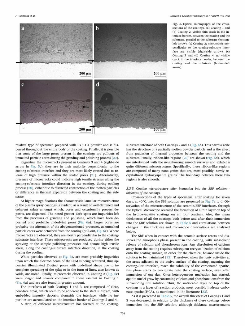
relative type of specimen prepared with PYRO 4 powder and is dis-persed throughout the entire body of the coating. Finally, it is possiblethat some of the large pores present in the coatings are pullouts ofunmelted particle cores during the grinding and polishing process [20].
Regarding the microcracks present in Coatings 3 and 4 (right-sidearrow in Fig. 5c), they are in their majority perpendicular to thecoating-substrate interface and they are most likely caused due to re-lease of high pressure within the sealed pores [21]. Alternatively,presence of microcracks could indicate high tensile stresses along thecoating-substrate interface direction in the coating, during coolingprocess [20], either due to restricted contraction of the molten particlesor difference in thermal expansion between the coating and the sub-strate.
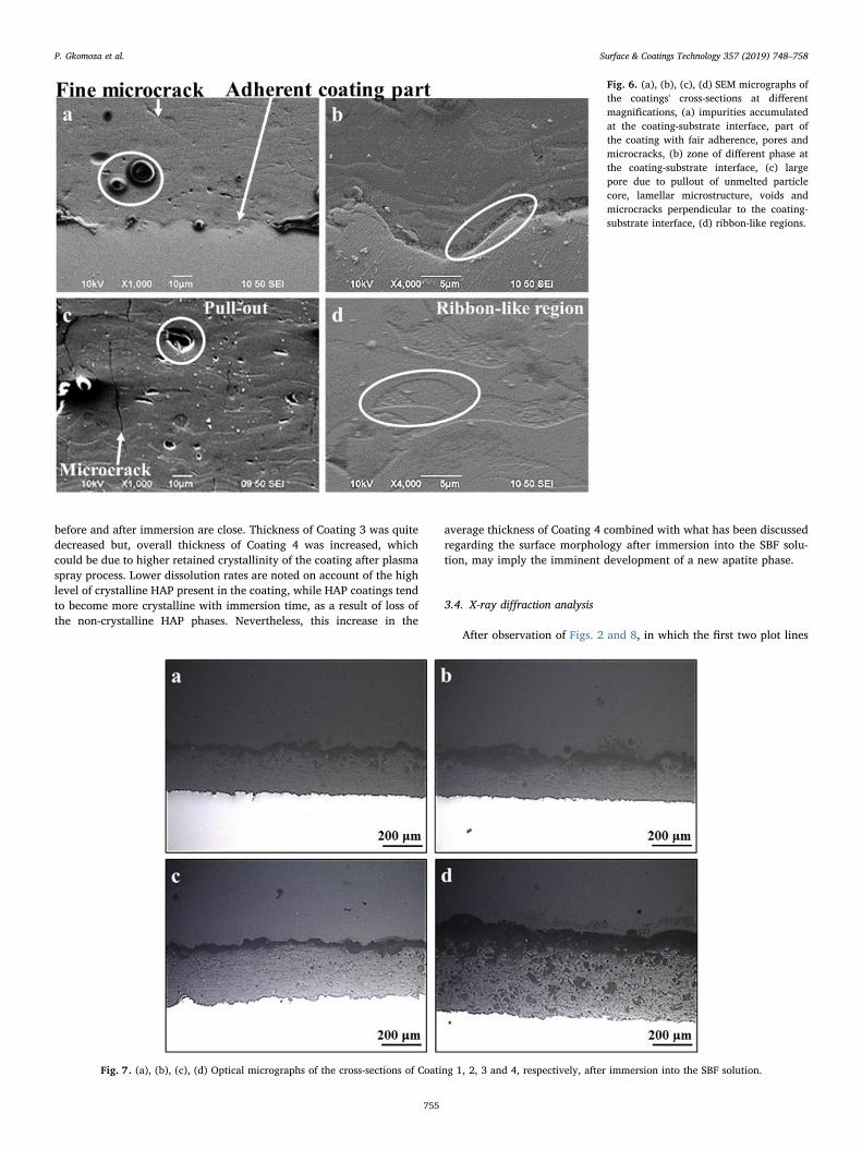
At higher magnifications the characteristic lamellar microstructureof the plasma spray coatings is evident, as a result of well-flattened andcoherent splats amongst which, pores and occasionally process de-posits, are dispersed. The noted greater dark spots are impurities leftfrom the processes of grinding and polishing, which have been de-posited onto probable underlying pores (Fig. 6a). Larger pores areprobably the aftermath of the abovementioned processes, as unmeltedparticle cores were detached from the coating (pull-out, Fig. 6c). Wheremicrocracks are observed, they are mostly perpendicular to the coating-substrate interface. These microcracks are produced during either thespraying or the sample polishing processes and denote high tensilestress, along the coating-substrate interface direction, in the coatingduring the cooling.
White particles observed at Fig. 6c, are most probably impuritiesupon which the electron beam of the SEM is being scattered, thus ap-pearing illuminated. Distinct pores with undefined shape due to in-complete spreading of the splat or in the form of lines, also known asvoids, are noted. Finally, microcracks observed in Coating 3 (Fig. 6c)were longer and coarser compared to those existent in Coating 1(Fig. 6a) and are also found in greater amount.
The interfaces of both Coatings 1 and 3, are comprised of clear,pore-free areas, which seem to be adherent to the steel substrate, withembedded impurity deposits alongside the interface, while no im-purities are accumulated on the interface border of Coatings 2 and 4.
A strip of different microstructure has formed at the coating-
substrate interface of both Coatings 2 and 4 (Fig. 6b). This narrow zonehas the structure of a partially molten powder particle and is the effectfrom gradation of thermal properties between the coating and thesubstrate. Finally, ribbon-like regions [20] are shown (Fig. 6d), whichare intertwined with the neighbouring smooth surfaces and exhibit aquite different microstructure. Specifically, these ribbon-like regionsare composed of many nano-grains that are, most possibly, newly re-crystallized hydroxyapatite grains. The boundary between these tworegions is also smooth.
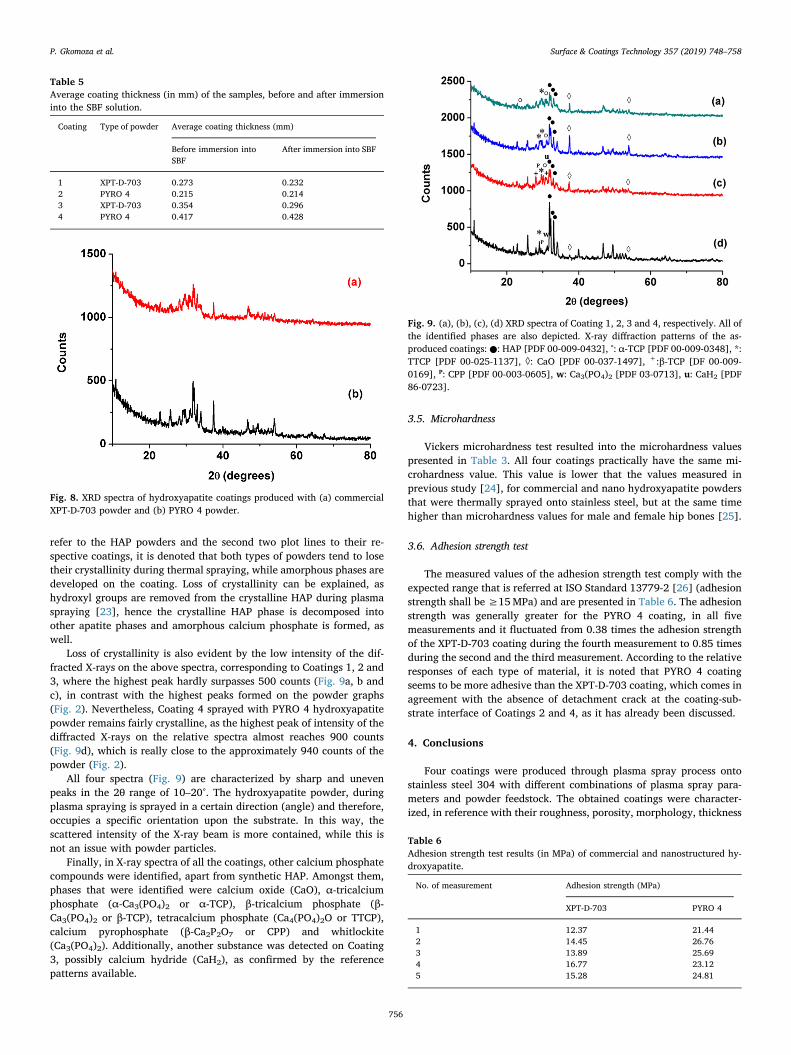
3.3.5. Coating microstructure after immersion into the SBF solution -thickness of the coatings
Cross-sections of the types of specimens, after soaking for sevendays, at 40 °C, into the SBF solution are presented in Fig. 7a to d. Ob-servation of the microstructure of the ceramic/SBF interfaces, throughthe Optical Microscope revealed the formation of a thin layer on top ofthe hydroxyapatite coatings on all four coatings. Also, the meanthicknesses of all the coatings both before and after their immersioninto the SBF solution are shown in Table 5 and correlations betweenchanges in the thickness and microscope observations are analyzedbelow.
The SBF when in contact with the ceramic surface reacts and dis-solves the amorphous phase present in the coating, with subsequentrelease of calcium and phosphorous ions. Any dissolution of calciumaway from the coating requires subsequent recrystallization of calciumonto the coating surface, in order for the chemical balance inside thesolution to be maintained [22]. Therefore, when the ionic activities atthe areas adjacent to the active surface of the coating, meaning thecoating/SBF interface, reach the solubility of the carbonated apatite,this phase starts to precipitate onto the coating surface, even afterimmersion of one day. Once heterogeneous nucleation has started,apatite nuclei grow by consuming calcium and phosphate ions from thesurrounding SBF solution. Thus, the noticeable layer on top of thecoatings is a layer of reaction products, most possibly hydroxy-carbo-nate apatite (HCA), as mentioned in the literature [23].
As it is presented in Table 5, the overall thickness of Coatings 1 and2 was decreased, in relation to the thickness of these coatings beforeimmersion into the SBF solution, although thickness measurements
Fig. 5. Optical micrographs of the cross-sections of the coatings. (a) Coating 1 and(b) Coating 2; visible thin crack in the in-terface border, between the coating and thesubstrate, parallel to the substrate (bottom-left arrow). (c) Coating 3; microcracks per-pendicular to the coating-substrate inter-face are visible (right-side arrow). (c)Coating 3 and (d) Coating 4; no visiblecrack in the interface border, between thecoating and the substrate (bottom-leftarrow).
P. Gkomoza et al. Surface & Coatings Technology 357 (2019) 748–758
754
before and after immersion are close. Thickness of Coating 3 was quitedecreased but, overall thickness of Coating 4 was increased, whichcould be due to higher retained crystallinity of the coating after plasmaspray process. Lower dissolution rates are noted on account of the highlevel of crystalline HAP present in the coating, while HAP coatings tendto become more crystalline with immersion time, as a result of loss ofthe non-crystalline HAP phases. Nevertheless, this increase in the
average thickness of Coating 4 combined with what has been discussedregarding the surface morphology after immersion into the SBF solu-tion, may imply the imminent development of a new apatite phase.
3.4. X-ray diffraction analysis
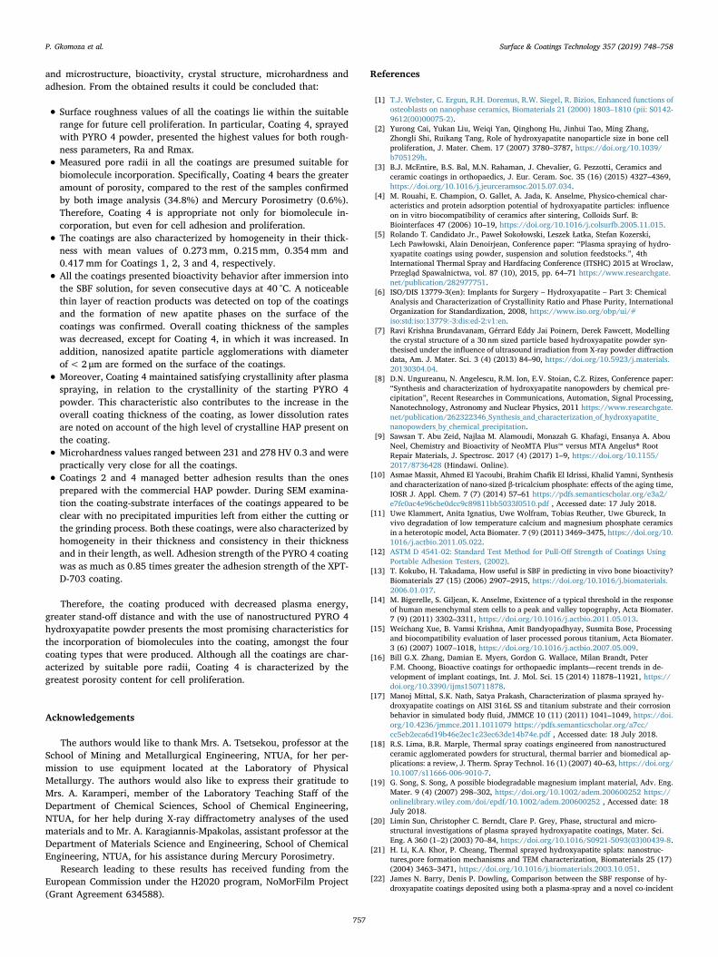
After observation of Figs. 2 and 8, in which the first two plot lines
Fig. 6. (a), (b), (c), (d) SEM micrographs ofthe coatings' cross-sections at differentmagnifications, (a) impurities accumulatedat the coating-substrate interface, part ofthe coating with fair adherence, pores andmicrocracks, (b) zone of different phase atthe coating-substrate interface, (c) largepore due to pullout of unmelted particlecore, lamellar microstructure, voids andmicrocracks perpendicular to the coating-substrate interface, (d) ribbon-like regions.
Fig. 7. (a), (b), (c), (d) Optical micrographs of the cross-sections of Coating 1, 2, 3 and 4, respectively, after immersion into the SBF solution.
P. Gkomoza et al. Surface & Coatings Technology 357 (2019) 748–758
755
refer to the HAP powders and the second two plot lines to their re-spective coatings, it is denoted that both types of powders tend to losetheir crystallinity during thermal spraying, while amorphous phases aredeveloped on the coating. Loss of crystallinity can be explained, ashydroxyl groups are removed from the crystalline HAP during plasmaspraying [23], hence the crystalline HAP phase is decomposed intoother apatite phases and amorphous calcium phosphate is formed, aswell.
Loss of crystallinity is also evident by the low intensity of the dif-fracted X-rays on the above spectra, corresponding to Coatings 1, 2 and3, where the highest peak hardly surpasses 500 counts (Fig. 9a, b andc), in contrast with the highest peaks formed on the powder graphs(Fig. 2). Nevertheless, Coating 4 sprayed with PYRO 4 hydroxyapatitepowder remains fairly crystalline, as the highest peak of intensity of thediffracted X-rays on the relative spectra almost reaches 900 counts(Fig. 9d), which is really close to the approximately 940 counts of thepowder (Fig. 2).
All four spectra (Fig. 9) are characterized by sharp and unevenpeaks in the 2θ range of 10–20°. The hydroxyapatite powder, duringplasma spraying is sprayed in a certain direction (angle) and therefore,occupies a specific orientation upon the substrate. In this way, thescattered intensity of the X-ray beam is more contained, while this isnot an issue with powder particles.
Finally, in X-ray spectra of all the coatings, other calcium phosphatecompounds were identified, apart from synthetic HAP. Amongst them,phases that were identified were calcium oxide (CaO), α-tricalciumphosphate (α-Ca3(PO4)2 or α-TCP), β-tricalcium phosphate (β-Ca3(PO4)2 or β-TCP), tetracalcium phosphate (Ca4(PO4)2O or TTCP),calcium pyrophosphate (β-Ca2P2O7 or CPP) and whitlockite(Ca3(PO4)2). Additionally, another substance was detected on Coating3, possibly calcium hydride (CaH2), as confirmed by the referencepatterns available.
3.5. Microhardness
Vickers microhardness test resulted into the microhardness valuespresented in Table 3. All four coatings practically have the same mi-crohardness value. This value is lower that the values measured inprevious study [24], for commercial and nano hydroxyapatite powdersthat were thermally sprayed onto stainless steel, but at the same timehigher than microhardness values for male and female hip bones [25].
3.6. Adhesion strength test
The measured values of the adhesion strength test comply with theexpected range that is referred at ISO Standard 13779-2 [26] (adhesionstrength shall be ≥15MPa) and are presented in Table 6. The adhesionstrength was generally greater for the PYRO 4 coating, in all fivemeasurements and it fluctuated from 0.38 times the adhesion strengthof the XPT-D-703 coating during the fourth measurement to 0.85 timesduring the second and the third measurement. According to the relativeresponses of each type of material, it is noted that PYRO 4 coatingseems to be more adhesive than the XPT-D-703 coating, which comes inagreement with the absence of detachment crack at the coating-sub-strate interface of Coatings 2 and 4, as it has already been discussed.
4. Conclusions
Four coatings were produced through plasma spray process ontostainless steel 304 with different combinations of plasma spray para-meters and powder feedstock. The obtained coatings were character-ized, in reference with their roughness, porosity, morphology, thickness
Table 5Average coating thickness (in mm) of the samples, before and after immersioninto the SBF solution.
Coating Type of powder Average coating thickness (mm)
Before immersion intoSBF
After immersion into SBF
1 XPT-D-703 0.273 0.2322 PYRO 4 0.215 0.2143 XPT-D-703 0.354 0.2964 PYRO 4 0.417 0.428
Fig. 8. XRD spectra of hydroxyapatite coatings produced with (a) commercialXPT-D-703 powder and (b) PYRO 4 powder.
Fig. 9. (a), (b), (c), (d) XRD spectra of Coating 1, 2, 3 and 4, respectively. All ofthe identified phases are also depicted. X-ray diffraction patterns of the as-produced coatings:●: HAP [PDF 00-009-0432], °: α-TCP [PDF 00-009-0348], *:TTCP [PDF 00-025-1137], ◊: CaO [PDF 00-037-1497], +:β-TCP [DF 00-009-0169], ᴾ: CPP [PDF 00-003-0605], w: Ca3(PO4)2 [PDF 03-0713], u: CaH2 [PDF86-0723].
Table 6Adhesion strength test results (in MPa) of commercial and nanostructured hy-droxyapatite.
No. of measurement Adhesion strength (MPa)
XPT-D-703 PYRO 4
1 12.37 21.442 14.45 26.763 13.89 25.694 16.77 23.125 15.28 24.81
P. Gkomoza et al. Surface & Coatings Technology 357 (2019) 748–758
756
and microstructure, bioactivity, crystal structure, microhardness andadhesion. From the obtained results it could be concluded that:
• Surface roughness values of all the coatings lie within the suitablerange for future cell proliferation. In particular, Coating 4, sprayedwith PYRO 4 powder, presented the highest values for both rough-ness parameters, Ra and Rmax.
• Measured pore radii in all the coatings are presumed suitable forbiomolecule incorporation. Specifically, Coating 4 bears the greateramount of porosity, compared to the rest of the samples confirmedby both image analysis (34.8%) and Mercury Porosimetry (0.6%).Therefore, Coating 4 is appropriate not only for biomolecule in-corporation, but even for cell adhesion and proliferation.
• The coatings are also characterized by homogeneity in their thick-ness with mean values of 0.273mm, 0.215mm, 0.354mm and0.417mm for Coatings 1, 2, 3 and 4, respectively.
• All the coatings presented bioactivity behavior after immersion intothe SBF solution, for seven consecutive days at 40 °C. A noticeablethin layer of reaction products was detected on top of the coatingsand the formation of new apatite phases on the surface of thecoatings was confirmed. Overall coating thickness of the sampleswas decreased, except for Coating 4, in which it was increased. Inaddition, nanosized apatite particle agglomerations with diameterof< 2 μm are formed on the surface of the coatings.
• Moreover, Coating 4 maintained satisfying crystallinity after plasmaspraying, in relation to the crystallinity of the starting PYRO 4powder. This characteristic also contributes to the increase in theoverall coating thickness of the coating, as lower dissolution ratesare noted on account of the high level of crystalline HAP present onthe coating.
• Microhardness values ranged between 231 and 278 HV 0.3 and werepractically very close for all the coatings.
• Coatings 2 and 4 managed better adhesion results than the onesprepared with the commercial HAP powder. During SEM examina-tion the coating-substrate interfaces of the coatings appeared to beclear with no precipitated impurities left from either the cutting orthe grinding process. Both these coatings, were also characterized byhomogeneity in their thickness and consistency in their thicknessand in their length, as well. Adhesion strength of the PYRO 4 coatingwas as much as 0.85 times greater the adhesion strength of the XPT-D-703 coating.
Therefore, the coating produced with decreased plasma energy,greater stand-off distance and with the use of nanostructured PYRO 4hydroxyapatite powder presents the most promising characteristics forthe incorporation of biomolecules into the coating, amongst the fourcoating types that were produced. Although all the coatings are char-acterized by suitable pore radii, Coating 4 is characterized by thegreatest porosity content for cell proliferation.
Acknowledgements
The authors would like to thank Mrs. A. Tsetsekou, professor at theSchool of Mining and Metallurgical Engineering, NTUA, for her per-mission to use equipment located at the Laboratory of PhysicalMetallurgy. The authors would also like to express their gratitude toMrs. A. Karamperi, member of the Laboratory Teaching Staff of theDepartment of Chemical Sciences, School of Chemical Engineering,NTUA, for her help during X-ray diffractometry analyses of the usedmaterials and to Mr. A. Karagiannis-Mpakolas, assistant professor at theDepartment of Materials Science and Engineering, School of ChemicalEngineering, NTUA, for his assistance during Mercury Porosimetry.
Research leading to these results has received funding from theEuropean Commission under the H2020 program, NoMorFilm Project(Grant Agreement 634588).
References
[1] T.J. Webster, C. Ergun, R.H. Doremus, R.W. Siegel, R. Bizios, Enhanced functions ofosteoblasts on nanophase ceramics, Biomaterials 21 (2000) 1803–1810 (pii: S0142-9612(00)00075-2).
[2] Yurong Cai, Yukan Liu, Weiqi Yan, Qinghong Hu, Jinhui Tao, Ming Zhang,Zhongli Shi, Ruikang Tang, Role of hydroxyapatite nanoparticle size in bone cellproliferation, J. Mater. Chem. 17 (2007) 3780–3787, https://doi.org/10.1039/b705129h.
[3] B.J. McEntire, B.S. Bal, M.N. Rahaman, J. Chevalier, G. Pezzotti, Ceramics andceramic coatings in orthopaedics, J. Eur. Ceram. Soc. 35 (16) (2015) 4327–4369,https://doi.org/10.1016/j.jeurceramsoc.2015.07.034.
[4] M. Rouahi, E. Champion, O. Gallet, A. Jada, K. Anselme, Physico-chemical char-acteristics and protein adsorption potential of hydroxyapatite particles: influenceon in vitro biocompatibility of ceramics after sintering, Colloids Surf. B:Biointerfaces 47 (2006) 10–19, https://doi.org/10.1016/j.colsurfb.2005.11.015.
[5] Rolando T. Candidato Jr., Paweł Sokołowski, Leszek Łatka, Stefan Kozerski,Lech Pawłowski, Alain Denoirjean, Conference paper: “Plasma spraying of hydro-xyapatite coatings using powder, suspension and solution feedstocks.”, 4thInternational Thermal Spray and Hardfacing Conference (ITSHC) 2015 at Wroclaw,Przegląd Spawalnictwa, vol. 87 (10), 2015, pp. 64–71 https://www.researchgate.net/publication/282977751.
[6] ISO/DIS 13779-3(en): Implants for Surgery – Hydroxyapatite – Part 3: ChemicalAnalysis and Characterization of Crystallinity Ratio and Phase Purity, InternationalOrganization for Standardization, 2008, https://www.iso.org/obp/ui/#iso:std:iso:13779:-3:dis:ed-2:v1:en.
[7] Ravi Krishna Brundavanam, Gérrard Eddy Jai Poinern, Derek Fawcett, Modellingthe crystal structure of a 30 nm sized particle based hydroxyapatite powder syn-thesised under the influence of ultrasound irradiation from X-ray powder diffractiondata, Am. J. Mater. Sci. 3 (4) (2013) 84–90, https://doi.org/10.5923/j.materials.20130304.04.
[8] D.N. Ungureanu, N. Angelescu, R.M. Ion, E.V. Stoian, C.Z. Rizes, Conference paper:“Synthesis and characterization of hydroxyapatite nanopowders by chemical pre-cipitation”, Recent Researches in Communications, Automation, Signal Processing,Nanotechnology, Astronomy and Nuclear Physics, 2011 https://www.researchgate.net/publication/262322346_Synthesis_and_characterization_of_hydroxyapatite_nanopowders_by_chemical_precipitation.
[9] Sawsan T. Abu Zeid, Najlaa M. Alamoudi, Monazah G. Khafagi, Ensanya A. AbouNeel, Chemistry and Bioactivity of NeoMTA Plus™ versus MTA Angelus® RootRepair Materials, J. Spectrosc. 2017 (4) (2017) 1–9, https://doi.org/10.1155/2017/8736428 (Hindawi. Online).
[10] Asmae Massit, Ahmed El Yacoubi, Brahim Chafik El Idrissi, Khalid Yamni, Synthesisand characterization of nano-sized β-tricalcium phosphate: effects of the aging time,IOSR J. Appl. Chem. 7 (7) (2014) 57–61 https://pdfs.semanticscholar.org/e3a2/e7fc0ac4e96cbe0dcc9c89811bb5033f0510.pdf , Accessed date: 17 July 2018.
[11] Uwe Klammert, Anita Ignatius, Uwe Wolfram, Tobias Reuther, Uwe Gbureck, Invivo degradation of low temperature calcium and magnesium phosphate ceramicsin a heterotopic model, Acta Biomater. 7 (9) (2011) 3469–3475, https://doi.org/10.1016/j.actbio.2011.05.022.
[12] ASTM D 4541-02: Standard Test Method for Pull-Off Strength of Coatings UsingPortable Adhesion Testers, (2002).
[13] T. Kokubo, H. Takadama, How useful is SBF in predicting in vivo bone bioactivity?Biomaterials 27 (15) (2006) 2907–2915, https://doi.org/10.1016/j.biomaterials.2006.01.017.
[14] M. Bigerelle, S. Giljean, K. Anselme, Existence of a typical threshold in the responseof human mesenchymal stem cells to a peak and valley topography, Acta Biomater.7 (9) (2011) 3302–3311, https://doi.org/10.1016/j.actbio.2011.05.013.
[15] Weichang Xue, B. Vamsi Krishna, Amit Bandyopadhyay, Susmita Bose, Processingand biocompatibility evaluation of laser processed porous titanium, Acta Biomater.3 (6) (2007) 1007–1018, https://doi.org/10.1016/j.actbio.2007.05.009.
[16] Bill G.X. Zhang, Damian E. Myers, Gordon G. Wallace, Milan Brandt, PeterF.M. Choong, Bioactive coatings for orthopaedic implants—recent trends in de-velopment of implant coatings, Int. J. Mol. Sci. 15 (2014) 11878–11921, https://doi.org/10.3390/ijms150711878.
[17] Manoj Mittal, S.K. Nath, Satya Prakash, Characterization of plasma sprayed hy-droxyapatite coatings on AISI 316L SS and titanium substrate and their corrosionbehavior in simulated body fluid, JMMCE 10 (11) (2011) 1041–1049, https://doi.org/10.4236/jmmce.2011.1011079 https://pdfs.semanticscholar.org/a7cc/cc5eb2eca6d19b46e2ec1c23ec63de14b74e.pdf , Accessed date: 18 July 2018.
[18] R.S. Lima, B.R. Marple, Thermal spray coatings engineered from nanostructuredceramic agglomerated powders for structural, thermal barrier and biomedical ap-plications: a review, J. Therm. Spray Technol. 16 (1) (2007) 40–63, https://doi.org/10.1007/s11666-006-9010-7.
[19] G. Song, S. Song, A possible biodegradable magnesium implant material, Adv. Eng.Mater. 9 (4) (2007) 298–302, https://doi.org/10.1002/adem.200600252 https://onlinelibrary.wiley.com/doi/epdf/10.1002/adem.200600252 , Accessed date: 18July 2018.
[20] Limin Sun, Christopher C. Berndt, Clare P. Grey, Phase, structural and micro-structural investigations of plasma sprayed hydroxyapatite coatings, Mater. Sci.Eng. A 360 (1–2) (2003) 70–84, https://doi.org/10.1016/S0921-5093(03)00439-8.
[21] H. Li, K.A. Khor, P. Cheang, Thermal sprayed hydroxyapatite splats: nanostruc-tures,pore formation mechanisms and TEM characterization, Biomaterials 25 (17)(2004) 3463–3471, https://doi.org/10.1016/j.biomaterials.2003.10.051.
[22] James N. Barry, Denis P. Dowling, Comparison between the SBF response of hy-droxyapatite coatings deposited using both a plasma-spray and a novel co-incident
P. Gkomoza et al. Surface & Coatings Technology 357 (2019) 748–758
757
microblasting technique, Key Eng. Mater. 493–494 (2012) 483–488, https://doi.org/10.4028/www.scientific.net/KEM.493-494.483 http://irserver.ucd.ie/bitstream/handle/10197/4693/SBF%20response%20of%20hydroxyapatite%20coatings%20deposited%20using%20both%20a%20plasma-spray%20and%20a%20novel%20co-incident%20DONE.pdf?sequence=2 , Accessed date: 18 July2018.
[23] Andrea Cattini, Devis Bellucci, Antonella Sola, Lech Pawłowski, Valeria Cannillo,Functional bioactive glass topcoats on hydroxyapatite coatings: analysis of micro-structure and in-vitro bioactivity, Surf. Coat. Technol. 240 (2014) 110–117, https://doi.org/10.1016/j.surfcoat.2013.12.023.
[24] Krai Kulpetchdara, Apichart Limpichaipanit, Gobwute Rujijanagul,Chamnan Randorn, Komsanti Chokethawai, Influence of the nano hydroxyapatitepowder on thermally sprayed HA coatings onto stainless steel, Surf. Coat. Technol.306 (2016) 181–186, https://doi.org/10.1016/j.surfcoat.2016.05.069.
[25] Meera Ramrakhiani, Deepti Pal, T.S. Murty, Micro-indentation hardness studies onhuman bones, Acta Anat. 103 (3) (1979) 358–362, https://doi.org/10.1159/000145035.
[26] ISO 13779-2: Implants for Surgery – Hydroxyapatite – Part 2: Coatings ofHydroxyapatite, International Organization for Standardization, 2008.
P. Gkomoza et al. Surface & Coatings Technology 357 (2019) 748–758
758