PROCESS MODELING FOR SIMULATION - AnyLogic
12
Proceedings of the 2016 Winter Simulation Conference T. M. K. Roeder, P. I. Frazier, R. Szechtman, E. Zhou, T. Huschka, and S. E. Chick, eds. PROCESS MODELING FOR SIMULATION: OBSERVATIONS AND OPEN ISSUES Gerd Wagner Mamadou Seck Department of Informatics Brandenburg University of Technology P. O. Box 101344 03013 Cottbus, GERMANY Engineering Management & Systems Engineering Old Dominion University 241 Kaufman Hall Norfolk, VA 23529, USA Frederic McKenzie Modeling, Simulation & Visualization Engineering Dept. Old Dominion University 1307 ECSB, 4700 Elkhorn Avenue Norfolk, VA 23529, USA ABSTRACT We review the state of the art of process modeling for discrete event simulation, make a number of observations and identify a number of issues that have to be tackled for promoting the use of process modeling in simulation. Process models are of particular interest in model-based simulation engineering approaches where the executable simulation model (code) is obtained with the help of textual or visual models. We present an illustrative example of model-based simulation development. 1 INTRODUCTION Traditionally, in the field of Modeling and Simulation (M&S), the term ‘model’ often refers to a compu- tational model in the form of a computer program and not to a model expressed in a higher-level diagrammatic modeling language, as in the areas of Information Systems and Software Engineering (IS/SE). In an M&S project, often no model in the sense of a conceptual model or a design model is made, or it is made in a sketchy manner, only, not using any well-defined modeling language, but rather the simulation developer jumps from her mental model, or sketches, to an implementation in some target technology platform. Clearly, in M&S, as in IS/SE, making conceptual models and design models would be important for several reasons: as opposed to a model as code, a high-level (visual) model would be more comprehensible and easier to communicate, share, reuse, maintain and evolve, while it could still be used for obtaining platform-specific implementation code with the help of model transformations and code generation, as proposed in model-driven engineering. 2 DISCRETE EVENT SIMULATION The term Discrete Event Simulation (DES) has been established as an umbrella term subsuming various kinds of computer simulation approaches, all based on the general idea of modeling a discrete dynamic system by modeling its state as being composed of ‘state variables’ provided by the attributes of ‘entities’, which are computational representations of real-world objects, and modeling its dynamics by modeling 978-1-5090-4486-3/16/$31.00 ©2016 IEEE 1072
-
Upload
khangminh22 -
Category
Documents
-
view
0 -
download
0
Transcript of PROCESS MODELING FOR SIMULATION - AnyLogic
Proceedings of the 2016 Winter Simulation Conference
T. M. K. Roeder, P. I. Frazier, R. Szechtman, E. Zhou, T. Huschka, and S. E. Chick, eds.
PROCESS MODELING FOR SIMULATION: OBSERVATIONS AND OPEN ISSUES
Gerd Wagner Mamadou Seck
Department of Informatics
Brandenburg University of Technology
P. O. Box 101344
03013 Cottbus, GERMANY
Engineering Management
& Systems Engineering
Old Dominion University
241 Kaufman Hall
Norfolk, VA 23529, USA
Frederic McKenzie
Modeling, Simulation & Visualization Engineering Dept.
Old Dominion University
1307 ECSB, 4700 Elkhorn Avenue
Norfolk, VA 23529, USA
ABSTRACT
We review the state of the art of process modeling for discrete event simulation, make a number of
observations and identify a number of issues that have to be tackled for promoting the use of process
modeling in simulation. Process models are of particular interest in model-based simulation engineering
approaches where the executable simulation model (code) is obtained with the help of textual or visual
models. We present an illustrative example of model-based simulation development.
1 INTRODUCTION
Traditionally, in the field of Modeling and Simulation (M&S), the term ‘model’ often refers to a compu-
tational model in the form of a computer program and not to a model expressed in a higher-level
diagrammatic modeling language, as in the areas of Information Systems and Software Engineering
(IS/SE). In an M&S project, often no model in the sense of a conceptual model or a design model is made,
or it is made in a sketchy manner, only, not using any well-defined modeling language, but rather the
simulation developer jumps from her mental model, or sketches, to an implementation in some target
technology platform.
Clearly, in M&S, as in IS/SE, making conceptual models and design models would be important for
several reasons: as opposed to a model as code, a high-level (visual) model would be more
comprehensible and easier to communicate, share, reuse, maintain and evolve, while it could still be used
for obtaining platform-specific implementation code with the help of model transformations and code
generation, as proposed in model-driven engineering.
2 DISCRETE EVENT SIMULATION
The term Discrete Event Simulation (DES) has been established as an umbrella term subsuming various
kinds of computer simulation approaches, all based on the general idea of modeling a discrete dynamic
system by modeling its state as being composed of ‘state variables’ provided by the attributes of ‘entities’,
which are computational representations of real-world objects, and modeling its dynamics by modeling
978-1-5090-4486-3/16/$31.00 ©2016 IEEE 1072
Wagner, Seck, and McKenzie
the events that are responsible for its state changes. There is, however, no generally accepted definition of
DES. Simulation textbooks and tutorials avoid defining the term “DES” in a precise way.
Two widely used characterizations of DES are given in terms of the simulation implementation
paradigms of activity scanning, event scheduling and process-orientation (Pidd 2004), and in terms of
simulation modeling worldviews (Pegden 2010), which are defined as follows.
Event worldview: The system is viewed as a series of instantaneous events that change the state of the
system over time. The modeler defines the events in the system and models the state changes that take
place when those events occur. According to Pegden, all DES platforms implement their internal logic
using the event worldview, regardless of the worldview they present to the user.
Processing network worldview: The system is described as a processing network where passive
entities (or work items) flow through the system and are subject to a series of processing steps performed
through activities, possibly requiring resources and inducing queues. This approach, pioneered by the
SIMAN/Arena framework, is still widely used today. Simulation platforms based on this paradigm may or
may not support object-oriented modeling and programming. Notice that this worldview has been called
‘process worldview‘ in (Pegden 2010), but we prefer to use a more specific term since it is not based on a
general concept of process and since it may lead to confusion with the term ‘process-oriented’ paradigm
suggested by Pidd (2004).
Object worldview: The system is modeled by describing the objects that make up the system. The
system behavior emerges from the interaction of these objects. This paradigm has been pioneered by
SIMULA, which triggered the development of object-oriented modeling and programming in computer
science in the 1980’s and 90’s. This worldview applies to all object-oriented DES approaches, including
the DES frameworks Simio and AnyLogic. It does not, however, include a general concept of events,
although it is compatible with one. For instance, the event concept of Simio is restricted to an object
context, while in the event worldview, events are first-class citizens: they may be defined independently
of specific objects and they may affect several objects at the same time. Agent-based simulation
approaches are often based on the object world view.
The event worldview and the object worldview can be combined in approaches that support both
objects and events as first-class citizens. Such an approach seems highly desirable because (1) objects
(and classes) are a must-have in today’s state-of-the-art modeling and programming, and (2) a general
concept of events is fundamental in DES, as demonstrated by the classical event worldview. We use the
term object-event worldview for any DES approach combining OO modeling and programming with a
general concept of events. Notice that it’s a natural option to extend the object-event worldview by adding
further concepts like activities, agents, actions, etc.
Worldviews concern the simulation models, while implementation paradigms concern the simulation
engine used to execute the models. The event worldview is most naturally combined with the event
scheduling paradigm.
Observation 1: The event worldview is the most fundamental worldview since it corresponds directly to
the concept of a discrete dynamic system. The object-event worldview is the basis of any general-purpose
DES approach that can be used for modeling any kind of discrete dynamic system and implement the
model with OO programming in a viable way. The processing network worldview is a special-purpose
approach that is convenient for all simulation problems allowing a processing network model.
3 PROCESS MODELING
Process modeling is concerned with modeling discrete processes, based on events (including actions and
activities). As explained in (Guizzardi and Wagner 2013), the ontologically fundamental categories are
objects and events, while actions and activities are special types of events.
Process modeling started with Gantt charts, which allow to model actors and their activity sequences.
Flowchart languages combine conditional branching (“decisions”) with activity sequences. UML Activity
Diagrams (ADs) extend flowcharts by adding parallel branching, actors (“swim lanes”), and a limited
1073
Wagner, Seck, and McKenzie
concept of events, while the Business Process Modeling Notation (BPMN) extends ADs by supporting a
more general concept of events (including asynchronous message events and event-based branching).
In addition to this group of activity-based process modeling languages, there are a number of diagram
languages that do not support activities as first-class citizens, such as Petri Nets, UML State Charts, and
UML Sequence Diagrams.
Observation 2: While general-purpose process modeling languages that support events, such as BPMN,
are required in DES approaches based on the event (or object-event) worldview, the processing network
worldview allows using tailored modeling languages, called domain-specific languages (DSL) in
software engineering. For instance, Arena, Simio and AnyLogic are using DSLs for creating their
processing network diagrams.
4 MODEL-DRIVEN ENGINEERING
Model-driven engineering (MDE) is a general approach that is applicable in all areas of engineering. It is
based on the principle that models are the primary engineering artifacts for capturing concepts, logical
designs and implementation designs for technical products.
With the success of the Unified Modeling Language (UML) in IS/SE, UML-based MDE has become
an established approach in these fields, where information modeling is the main modeling concern
(Whittle et al 2014). However, in simulation engineering, like in workflow engineering, information
models have to be complemented by process models for obtaining complete models as a basis for code
generation.
While MDE with UML class models is already an established engineering practice in the software
industry, the use of process modeling in MDE is still a research issue that has been investigated mainly in
the areas of workflow management and service engineering. In simulation engineering, MDE has not yet
found much attention, due to several reasons, including a lack of established foundations and standards.
4.1 Model-Driven Software Engineering
In MDE, there is a clear distinction between three kinds of models as engineering artifacts resulting from
corresponding modeling activities in the analysis, design and implementation phases:
1. solution-independent domain models (also called conceptual models),
2. platform-independent design models,
3. platform-specific implementation models.
Domain models are solution-independent descriptions of a problem domain, or of a system under
investigation, produced in the analysis phase of a software engineering project. A domain model may
include both descriptions of the domain’s state structure (in conceptual information models) and
descriptions of its processes (in conceptual process models). They are solution-independent, or
‘computation-independent’, in the sense that they are not concerned with making any system design
choices or with other computational issues. Rather, they focus on the perspective and language of the
subject matter experts for the domain under consideration.
In the design phase, a platform-independent design model, as a general computational solution (for a
software application system or for a simulation system), is developed on the basis of the domain model.
The same domain model can potentially be used to produce a number of different design models.
Then, by choosing one or more target technology platforms and by taking into consideration
implementation issues such as architectural styles and nonfunctional quality criteria to be maximized
(e.g., performance, adaptability), one or more platform-specific implementation models are derived from
the design model. These models can be directly mapped to code.
It is an option to group different technology platforms sharing common principles, such as object-
oriented (OO) programming, and consider them to form a platform class, for which a “class of platforms“
model, such as an OO model, can be made as an intermediate step between a design model and the
implementation models based on it.
1074
Wagner, Seck, and McKenzie
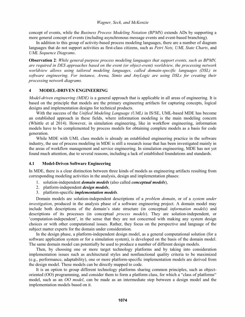
These one-to-many relationships between a conceptual model and corresponding design models, as
well as between a design model and corresponding implementation models, are illustrated in Figure 1.
Different Platforms
Different Solutions
Conceptual Model
Implementation Model 1-1
Design Model 1
Design Model 2
Implementation Model 1-2
Implementation Model 1-3
Implementation Model 2-1
Figure 1: From a conceptual model via design models to implementation models.
In the implementation phase, an implementation model is coded in the programming language of the
target platform, either manually or by means of an automated model-to-code transformation. Finally, after
testing and debugging, the implemented solution is then deployed in a target environment.
A model for a (software) system, which may be called a ‘(software) system model’, does not consist
of just one model diagram including all viewpoints or aspects of the system to be developed (or to be
described). Rather it consists of a set of models, one (or more) for each different viewpoint. The two most
important viewpoints, crosscutting all three modeling levels: conceptualization, design and implemen-
tation, are
1. information modeling, which is concerned with the state structure of the domain or the system
under investigation (SUI);
2. process modeling, which is concerned with the dynamics of the domain or SUI.
Examples of widely used languages for information modeling are Entity Relationship (ER) Diagrams
and UML Class Diagrams. Since the latter subsume the former, UML class diagrams can be used for
making all kinds of information models, including SQL database models. Examples of widely used
languages for process modeling are Petri Nets, UML State Charts, UML Activity Diagrams and the
Business Process Modeling Notation (BPMN).
Notice that there is more agreement on the right concepts for information modeling than for process
modeling, as indicated by the much larger number of different process modeling languages. This seems to
indicate that there is a lower degree of understanding the nature of events and processes compared to
understanding objects and their relationships.
Some modeling languages, such as UML Class Diagrams and BPMN, can be used on all three
modeling levels in the form of tailored variants. Other languages have been designed for being used on
one or two of these three levels only. E.g., Petri Nets cannot be used for conceptual process modeling,
since they lack the required expressivity.
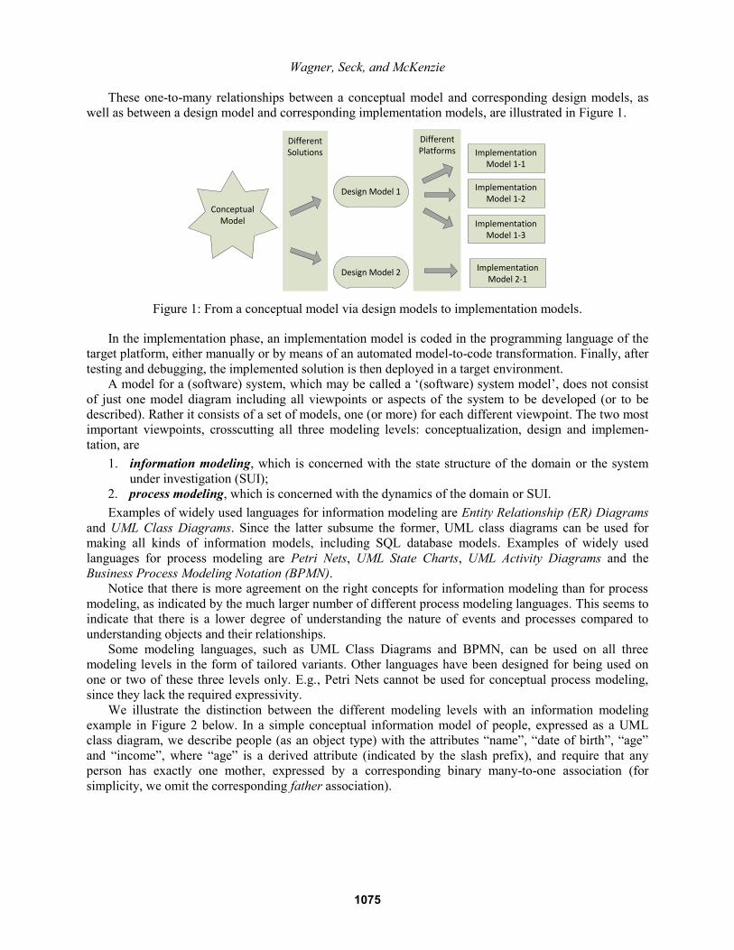
We illustrate the distinction between the different modeling levels with an information modeling
example in Figure 2 below. In a simple conceptual information model of people, expressed as a UML
class diagram, we describe people (as an object type) with the attributes “name”, “date of birth”, “age”
and “income”, where “age” is a derived attribute (indicated by the slash prefix), and require that any
person has exactly one mother, expressed by a corresponding binary many-to-one association (for
simplicity, we omit the corresponding father association).
1075
Wagner, Seck, and McKenzie
namedate of birth/ageincome
people1..*
mother 1
+getSSN() : Integer+setSSN(in ssn : Integer)+getName() : String+setName(in n : String)+get...()+set...()+getAge() : Integer
-ssn : Integer {id}-name : String-dateOfBirth : Date-income : Decimal-mother : Person
Person
Conceptual Information Model
OO Class Model
getAge() : Integer
ssn : Integer {id}name : StringdateOfBirth : Dateincome : Decimal
Person
1..*
mother 1
Information Design Model
+getSsn() : int+setSsn(in ssn : int)+getName() : string+setName(in name : string)+get...()+set...()+getAge() : int
-ssn : int {id}-name : string-dateOfBirth : date-income : double-mother : Person*
Person
C++ Class Model
Figure 2: From a conceptual information model via a design model to OO and C++ class models.
In the design and implementation models of Figure 2, we follow standard naming conventions for class
and attribute names (e.g., a class name is a singular capitalized noun, such as Person). In the design
model, we define a range for all attributes (using platform-independent datatype names) and map the
derived attribute “age” to a “getAge” operation that computes the age of a person on demand from their
date of birth. In the OO class model, we make all attributes private, add public get and set methods for
them, and map the mother association to a corresponding reference property. In the C++ class model, we
map platform-independent datatypes (such as Integer and Decimal) to C++-specific datatypes (such as
int and double), and use pointer types (such as Person*) for reference properties.
4.2 Model-Driven Simulation Engineering
Since simulation engineering can be viewed as a special case of software engineering, it is natural to
apply the ideas of MDE also to simulation engineering. There have been several proposals of using an
MDE approach in M&S, see, e.g., the overview in Cetinkaya and Verbraeck (2011).
Model-driven simulation engineering is based on the same types of models as model-driven software
engineering: going from a domain model via a simulation design model to a simulation implementation
model for the simulation platform of choice (or to several implementation models if there are several
target simulation platforms). The specific concerns of simulation engineering, like, e.g., the concern to
model random variations in the form of random variables, do not affect the applicability of the MDE
approach, but the modeling languages to be used.
We list a number of simulation-specific modeling concerns:
1. In simulation, we need to model event types (including activity types), in addition to object types.
Both can be modeled in the form of corresponding classes in UML class models, while the
dynamics implied by events is modeled with the help of process models.
2. When making a simulation design model, the choices to be made include specifying random
variables for modeling random variations and suitable output statistics.
We follow the IS/SE usage of the term ‘conceptual model’ as a synonym of ‘domain model’. However, in
the M&S literature there are diverging proposals how to define the term ‘conceptual model’, see, e.g.,
(Robinson et al 2015).
Unlike a conceptual domain model, a design model depends on the purpose of the simulation project.
If the purpose is answering certain research questions, then the design is being tailored such that these
questions can be answered with the help of simulation output statistics. If the purpose is education or
entertainment, the design needs to support suitable user interfaces for runtime statistics, visualization and
user interaction.
1076
Wagner, Seck, and McKenzie
5 A PROCESS MODELING EXAMPLE
As an illustrative example for using process modeling in model-based simulation engineering, we
consider the case of a toll collection system called “Easy Pass”. The system narrative, based on Chapter 6
of (Sokolowski and Banks 2010), is as follows:
The “Easy Pass” toll collection system will be placed on a two-lane highway with sufficient space to
add double bypass lanes with a two-lane toll booth area. The toll booths will provide cash and credit
toll payment on a 24 h basis. The lanes of the main highway will be equipped with the new Easy Pass
electronic toll collection system. Cars signed up for Easy Pass will remain on the main highway lanes
and maintain the posted speed limit. Their Easy Pass accounts will be automatically credited as the
cars pass by identifying them with the help of sensors.
Since conceptually events depend on the objects that participate in them, a process model depends on an
underlying information model, which associates event types with those types of objects that participate in
them. Consequently, process models need to be combined with information models.
5.1 Making a Conceptual Simulation Model
We follow the approach proposed in (Wagner 2014), which is based on the concept of event rules for
modeling the causal regularities of a discrete dynamic system. An event rule corresponds to the notion of
an event routine in the event scheduling approach. It defines what happens when an event (of a certain
type) occurs, or, more specifically, which state changes and which follow-up events are caused by an
event of that type by triggering dispositions of affected real-world objects, as discussed in (Guizzardi and
Wagner 2013).
We start the modeling effort by making a conceptual information model describing all relevant object
types and event types implied by the system narrative and other available requirements documents. Notice
that such a conceptual model is a (solution-independent) description of the real-world system under
investigation, and not a software design model.
As a first step, we make a textual model in the form of two lists: one describing the relevant types of
objects, and the other one describing the relevant types of events, together with the types of objects that
participate in them. For simplicity, we ignore the sensor-controlled main highway lanes and focus on the
toll booth area. This leaves us with the following types of objects and events:
Object types: cars, toll booth lanes, toll booths, toll booth clerks.
Event types: car arrivals at the toll booth area (involving cars), car arrivals at a toll booth lane
(involving cars and toll booth lanes), toll payments (involving cars and toll booth clerks), car
departures (involving cars and toll booths).
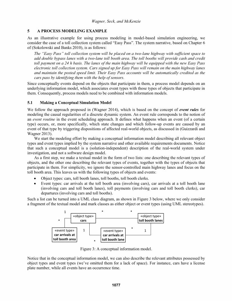
Such a list can be turned into a UML class diagram, as shown in Figure 3 below, where we only consider
a fragment of the textual model and mark classes as either object or event types (using UML stereotypes).
«object type»cars
«object type»toll booth lanes
**
«event type»car arrivals at
toll booth area
1
*
«event type»car arrivals at
toll booth lane
1*1
*
Figure 3: A conceptual information model.
Notice that in the conceptual information model, we can also describe the relevant attributes possessed by
object types and event types (we’ve omitted them for a lack of space). For instance, cars have a license
plate number, while all events have an occurrence time.
1077
Wagner, Seck, and McKenzie
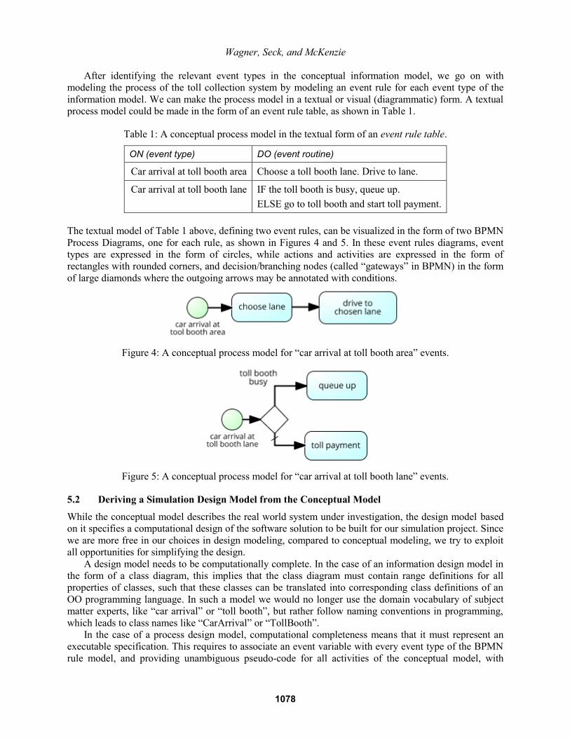
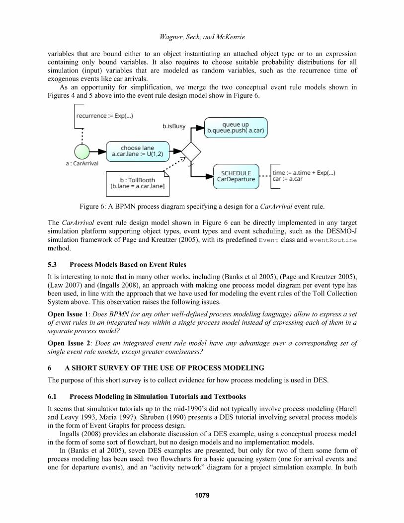
After identifying the relevant event types in the conceptual information model, we go on with
modeling the process of the toll collection system by modeling an event rule for each event type of the
information model. We can make the process model in a textual or visual (diagrammatic) form. A textual
process model could be made in the form of an event rule table, as shown in Table 1.
Table 1: A conceptual process model in the textual form of an event rule table.
ON (event type) DO (event routine)
Car arrival at toll booth area Choose a toll booth lane. Drive to lane.
Car arrival at toll booth lane IF the toll booth is busy, queue up.
ELSE go to toll booth and start toll payment.
The textual model of Table 1 above, defining two event rules, can be visualized in the form of two BPMN
Process Diagrams, one for each rule, as shown in Figures 4 and 5. In these event rules diagrams, event
types are expressed in the form of circles, while actions and activities are expressed in the form of
rectangles with rounded corners, and decision/branching nodes (called “gateways” in BPMN) in the form
of large diamonds where the outgoing arrows may be annotated with conditions.
Figure 4: A conceptual process model for “car arrival at toll booth area” events.
Figure 5: A conceptual process model for “car arrival at toll booth lane” events.
5.2 Deriving a Simulation Design Model from the Conceptual Model
While the conceptual model describes the real world system under investigation, the design model based
on it specifies a computational design of the software solution to be built for our simulation project. Since
we are more free in our choices in design modeling, compared to conceptual modeling, we try to exploit
all opportunities for simplifying the design.
A design model needs to be computationally complete. In the case of an information design model in
the form of a class diagram, this implies that the class diagram must contain range definitions for all
properties of classes, such that these classes can be translated into corresponding class definitions of an
OO programming language. In such a model we would no longer use the domain vocabulary of subject
matter experts, like “car arrival” or “toll booth”, but rather follow naming conventions in programming,
which leads to class names like “CarArrival” or “TollBooth”.
In the case of a process design model, computational completeness means that it must represent an
executable specification. This requires to associate an event variable with every event type of the BPMN
rule model, and providing unambiguous pseudo-code for all activities of the conceptual model, with
1078
Wagner, Seck, and McKenzie
variables that are bound either to an object instantiating an attached object type or to an expression
containing only bound variables. It also requires to choose suitable probability distributions for all
simulation (input) variables that are modeled as random variables, such as the recurrence time of
exogenous events like car arrivals.
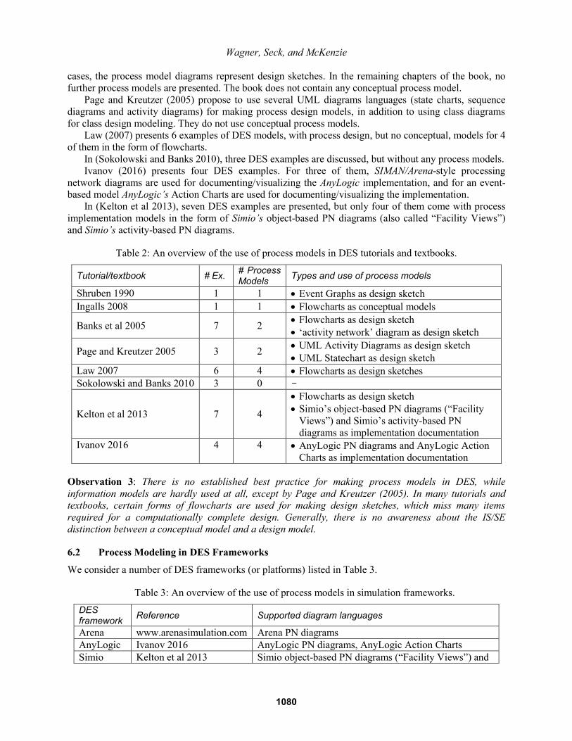
As an opportunity for simplification, we merge the two conceptual event rule models shown in
Figures 4 and 5 above into the event rule design model show in Figure 6.
Figure 6: A BPMN process diagram specifying a design for a CarArrival event rule.
The CarArrival event rule design model shown in Figure 6 can be directly implemented in any target
simulation platform supporting object types, event types and event scheduling, such as the DESMO-J
simulation framework of Page and Kreutzer (2005), with its predefined Event class and eventRoutine
method.
5.3 Process Models Based on Event Rules
It is interesting to note that in many other works, including (Banks et al 2005), (Page and Kreutzer 2005),
(Law 2007) and (Ingalls 2008), an approach with making one process model diagram per event type has
been used, in line with the approach that we have used for modeling the event rules of the Toll Collection
System above. This observation raises the following issues.
Open Issue 1: Does BPMN (or any other well-defined process modeling language) allow to express a set
of event rules in an integrated way within a single process model instead of expressing each of them in a
separate process model?
Open Issue 2: Does an integrated event rule model have any advantage over a corresponding set of
single event rule models, except greater conciseness?
6 A SHORT SURVEY OF THE USE OF PROCESS MODELING
The purpose of this short survey is to collect evidence for how process modeling is used in DES.
6.1 Process Modeling in Simulation Tutorials and Textbooks
It seems that simulation tutorials up to the mid-1990’s did not typically involve process modeling (Harell
and Leavy 1993, Maria 1997). Shruben (1990) presents a DES tutorial involving several process models
in the form of Event Graphs for process design.
Ingalls (2008) provides an elaborate discussion of a DES example, using a conceptual process model
in the form of some sort of flowchart, but no design models and no implementation models.
In (Banks et al 2005), seven DES examples are presented, but only for two of them some form of
process modeling has been used: two flowcharts for a basic queueing system (one for arrival events and
one for departure events), and an “activity network” diagram for a project simulation example. In both
1079
Wagner, Seck, and McKenzie
cases, the process model diagrams represent design sketches. In the remaining chapters of the book, no
further process models are presented. The book does not contain any conceptual process model.
Page and Kreutzer (2005) propose to use several UML diagrams languages (state charts, sequence
diagrams and activity diagrams) for making process design models, in addition to using class diagrams
for class design modeling. They do not use conceptual process models.
Law (2007) presents 6 examples of DES models, with process design, but no conceptual, models for 4
of them in the form of flowcharts.
In (Sokolowski and Banks 2010), three DES examples are discussed, but without any process models.
Ivanov (2016) presents four DES examples. For three of them, SIMAN/Arena-style processing
network diagrams are used for documenting/visualizing the AnyLogic implementation, and for an event-
based model AnyLogic’s Action Charts are used for documenting/visualizing the implementation.
In (Kelton et al 2013), seven DES examples are presented, but only four of them come with process
implementation models in the form of Simio’s object-based PN diagrams (also called “Facility Views”)
and Simio’s activity-based PN diagrams.
Table 2: An overview of the use of process models in DES tutorials and textbooks.
Tutorial/textbook # Ex. # Process Models
Types and use of process models
Shruben 1990 1 1 Event Graphs as design sketch
Ingalls 2008 1 1 Flowcharts as conceptual models
Banks et al 2005 7 2 Flowcharts as design sketch
‘activity network’ diagram as design sketch
Page and Kreutzer 2005 3 2 UML Activity Diagrams as design sketch
UML Statechart as design sketch
Law 2007 6 4 Flowcharts as design sketches
Sokolowski and Banks 2010 3 0 -
Kelton et al 2013 7 4
Flowcharts as design sketch
Simio’s object-based PN diagrams (“Facility
Views”) and Simio’s activity-based PN
diagrams as implementation documentation
Ivanov 2016 4 4 AnyLogic PN diagrams and AnyLogic Action
Charts as implementation documentation
Observation 3: There is no established best practice for making process models in DES, while
information models are hardly used at all, except by Page and Kreutzer (2005). In many tutorials and
textbooks, certain forms of flowcharts are used for making design sketches, which miss many items
required for a computationally complete design. Generally, there is no awareness about the IS/SE
distinction between a conceptual model and a design model.
6.2 Process Modeling in DES Frameworks
We consider a number of DES frameworks (or platforms) listed in Table 3.
Table 3: An overview of the use of process models in simulation frameworks.
DES framework
Reference Supported diagram languages
Arena www.arenasimulation.com Arena PN diagrams
AnyLogic Ivanov 2016 AnyLogic PN diagrams, AnyLogic Action Charts
Simio Kelton et al 2013 Simio object-based PN diagrams (“Facility Views”) and
1080
Wagner, Seck, and McKenzie
activity-based PN diagrams
Simul8 www.simul8.com Simul8 PN diagrams, BPMN process diagrams
Observation 4: DES frameworks use their own (DSL-based) process diagram language for visualizing
and documenting their simulation programs. Typically, they use some form of Processing Network (PN)
diagrams based on the processing network worldview. Some platforms also support business process
simulation with BPMN. The relationship between PN diagrams and BPMN diagrams is not clear.
6.3 Process Modeling in DES Methodology Research
Explicit process modeling construed as an analysis or design activity in preparation for making an
executable model is more common in DES research than it is in the general practice of DES. Several
authors have underlined the importance of conceptual modeling, often by means of process models in the
development of DES models. In (Cetinkaya et al 2015), a survey of simulation methodology publications
(e.g., Fishwick 1995; Robinson 2004; Sargent 2010; Balci 2012) shows that the overwhelming majority
of authors advocate the use of process models. However, there is no agreement on the choice of a
modeling language in the proposed methodologies. As a consequence of these limitations, it is shown that
achieving model continuity throughout the steps of a simulation methodology is a challenge.
Ryan and Heavey (2006) point out that the issue of using process models for requirements gathering
during the analysis phase of a simulation project has been neglected in M&S. Based on a certain set of
requirements for process models, they argue that none of the process formalisms Petri Nets, DEVS, State
Charts, and Activity Cycle Diagrams, and none of a number of business process modeling languages
considered (including IDEF0/IDEF3, CIMOSA, and UML Activity Diagrams) are sufficiently expressive
for requirements gathering, or conceptual modeling (notice that they did not consider BPMN). As a
consequence, they propose their own modeling language, called Simulation Activity Diagrams, for which
they do not provide a well-defined syntax and semantics, though.
Birta and Arbez (2013) propose an Activity-Based Conceptual modelling framework, called ABCmod,
for modeling discrete dynamic systems in the form of “interaction amongst some collection of objects”
that populate a system. ABCmod is not built upon an established modelling language, but rather comes
with its own (peculiar) language, based on “entity categories” for information (or state structure)
modeling and on activities and actions for process modeling.
Furian et al (2015) presents a conceptual modeling framework for discrete event simulation. The
paper laments the inadequacy of existing conceptual modeling approaches and proposes a hierarchical
conceptual model that involves a structural and control and behavioral part. The proposed conceptual
approach does not impose a specific process modeling language, but cites UML/SysML activity
diagrams, as well as state charts or sequence diagrams, business process diagrams, flow charts, or event
graphs, as potential candidates. The paper does not provide a criterion upon which to base this choice.
There is a special class of DES projects where BPMN process models are used as the starting point:
for business process (BP) simulation. This approach is supported by the BPSim standard (WFMC 2013),
which facilitates the interoperation between BP modeling tools and simulation tools (e.g., Simul8 is able
to import a BPMN/BPSim process specification and run corresponding simulations).
In (García et al 2014), a DES metamodel and a set of rules for generating DES design models from
BPMN process models enriched with certain annotations, and for generating simulation programs (coded,
e.g., in AnyLogic ) from such a DES design model, are proposed for supporting business process
simulation. However, the restrictions on BPMN necessary to allow a model transformation based on the
proposed DES metamodel are not discussed.
In (Bisogno et al. 2016), a BPMN modeling tool with BPSim support is used for modeling a pre-
operative patient flow in a healthcare simulation project. It is argued that the use of BPMN has facilitated
stakeholder participation. However, the authors do not discuss the limitations of BPMN with respect to
simulation modeling.
1081
Wagner, Seck, and McKenzie
Observation 5: There is not much DES methodology research on conceptual and design modeling, and it
mostly ignores the results achieved in IS/SE.
Observation 6: The standard semantics of BPMN, based on token flows, only supports case-handling
business processes, but not business system processes, consisting of a multitude of business processes
performed in parallel and interacting with each other (e.g., via competition for resources), as needed in
DES. Also BPMN’s event syntax, with the fixed event roles start/intermediate/end, seems to be a problem
for integrated business system models.
Open Issue 3: In which way can BPMN be modified, such that it does not only support business process
simulation, but all kinds of discrete event simulations?
7 CONCLUSIONS
We have made 6 observations and identified 3 open issues. Compared to the limited attention it gets in
today’s simulation engineering practice, process modeling could play a much more prominent role and
promote model-based simulation development. We have shown one promising way of using BPMN
diagrams for modeling event rules in DES approaches based on the object-event worldview. But there
may be many other opportunities how to benefit from using an expressive process modeling language like
BPMN in simulation engineering.
REFERENCES
Banks, J., J.S. Carson, B.L. Nelson and D.M Nicol. 2005. Discrete-Event System Simulation. Pearson
Prentice Hall.
Birta, L.G. and G. Arbez. 2013. Modelling and Simulation: Exploring Dynamic System Behaviour. 2nd
ed., Springer, London, England.
Bisogno S., N.C. Proudlove, A. Calabrese, N. Levialdi Ghiron and B.S.S. Onggo. 2016. “Towards fully-
facilitated DES modelling: A successful project”. Lancaster University Management School Working
Paper 2016:02. Lancaster University, Department of Management Science. Available from
http://eprints.lancs.ac.uk/80114/1/Fare_Italy_WP_1.2.pdf
Cetinkaya, D. and A. Verbraeck. 2011. “Metamodeling and Model Transformations in Modeling and
Simulation”. In Proceedings of the 2011 Winter Simulation Conference, edited by S. Jain, R.R.
Creasey J. Himmelspach, K. P. White, and M. Fu. Piscataway, New Jersey: Institute of Electrical and
Electronics Engineers, Inc.
Çetinkaya, D., A. Verbraeck, and M. Seck. 2015. “Model Continuity in Discrete Event Simulation: A
Framework for Model-Driven Development of Simulation Models”. ACM Trans. Model. Comput.
Simul. 25:3.
Fishwick, P. 1995. Simulation Model Design and Execution: Building Digital Worlds (1st ed.). Prentice
Hall PTR, Upper Saddle River, NJ, USA.
Furian N., M. O’Sullivan, C. Walker, S. Vössner, D. Neubacher. 2015. “A conceptual modeling
framework for discrete event simulation using hierarchical control structures”. Simulation Modelling
Practice and Theory 56:82–96.
García, M.T., M.A. Barcelona, M. Ruiz, L. García-Borgonón and I. Ramos. 2014. “A Discrete-Event
Simulation Metamodel for Obtaining Simulation Models from Business Process Models”.
Information System Development, 307–317.
Guizzardi, G. and G. Wagner. 2013. “Dispositions and Causal Laws as the Ontological Foundation of
Transition Rules in Simulation Models”. In Proceedings of the 2013 Winter Simulation Conference,
edited by R. Pasupathy, S.-H. Kim, A. Tolk, R. Hill, and M. E. Kuhl. 1335–1346. Piscataway, New
Jersey: Institute of Electrical and Electronics Engineers, Inc. Available from http://informs-
sim.org/wsc13papers/includes/files/117.pdf
1082
Wagner, Seck, and McKenzie
Harrell C. and J. Leavy. 1993. “ProModel Tutorial”. In Proceedings of the 1993 Winter Simulation
Conference, edited by G.W. Evans et al, 184–189. Piscataway, New Jersey: Institute of Electrical and
Electronics Engineers, Inc.
Ingalls, R.G. 2008. “Introduction to Simulation”. In Proceedings of the 2008 Winter Simulation
Conference, edited by S.J. Mason et al. 17–26. Piscataway, New Jersey: Institute of Electrical and
Electronics Engineers, Inc.
Ivanov, D. 2016. Operations and Supply Chain Simulation with AnyLogic 7.2. E-textbook, Berlin School
of Economics and Law. Available from http://www.anylogic.com/upload/pdf/operations-and-supply-
chain-simulation-with-anylogic72.pdf
Law, A.M. 2007. Simulation Modeling and Analysis. 4th edition. McGraw-Hill.
Page, B. and W. Kreutzer. 2005. The Java Simulation Handbook. Shaker Verlag, Aachen, Germany.
Pegden, C.D. 2010. “Advanced Tutorial: Overview of Simulation World Views.” In Proceedings of the
2010 Winter Simulation Conference, edited by B. Johansson et al, 643−651. Piscataway, New Jersey:
Institute of Electrical and Electronics Engineers, Inc.
Robinson, S. 2004. Simulation: The Practice of Model Development and Use. John Wiley & Sons.
Ryan, J. and C. Heavey. 2006. “Process modeling for simulation”. Computers in Industry 57, 437–450.
Sargent, R.G. 2007. “Verification and validation of simulation models”. In Proceedings of the 2007
Winter Simulation Conference, edited by S. G. Henderson, 124−137. Piscataway, New Jersey:
Institute of Electrical and Electronics Engineers, Inc.
Sokolowski, J.A. and C.M. Banks (eds.). 2010. Modeling and Simulation Fundamentals. Hoboken, New
Jersey: John Wiley & Sons, Inc.
Wagner, G. 2014. “Tutorial: Information and Process Modeling for Simulation”. In Proceedings of the
2014 Winter Simulation Conference, edited by A. Tolk et al, 103–117. Piscataway, New Jersey:
Institute of Electrical and Electronics Engineers, Inc. Available from http://informs-
sim.org/wsc14papers/includes/files/012.pdf
WFMC (Workflow Modeling Coalition). 2013. “Business Process Simulation Specification”. Document
Number WFMC -BPSWG-2012-1
Whittle, J., J. Hutchinson and M. Rouncefield. 2014. “The State of Practice in Model-Driven
Engineering”. IEEE Software, 31:3, 79−85.
AUTHOR BIOGRAPHIES
GERD WAGNER is Professor of Internet Technology in the Dept. of Informatics, Brandenburg Univer-
sity of Technology, Germany, and Adjunct Associate Professor in the Dep. of Modeling, Simulation and
Visualization Engineering, Old Dominion University, Norfolk, VA, USA. His research interests include
modeling and simulation, foundational ontologies, knowledge representation and web engineering. His
email address is [email protected].
MAMADOU D. SECK is an Assistant Professor in the Dept. Engineering Management & Systems
Engineering, Old Dominion University, Norfolk, VA, USA. His research interests include modeling and
simulation formalisms, dynamic data-driven simulation, human behavior simulation, and agent directed
simulation. His email address is [email protected].
FREDERIC D. MCKENZIE is Professor and Chair in the Dept. of Modeling, Simulation and
Visualization Engineering and Co-Director of the Medical Imaging, Diagnosis, and Analysis (MIDA)
Laboratory, Old Dominion University, Norfolk, VA, USA. He conducts research in medical modeling
and simulation, human behavior representation, and simulation architectures. His email address is
1083