Numerical Process Simulation for Tool and Process Design in Bulk Metal Forming
17
Keynote Papers Keynote Papers Presented at the Scientific Technical Committee Paper Discussion Sessions Numerical Process Simulation for Tool and Process Design in Bulk Metal Forming Taylan Altan (1). Victor Vazquez, Engineering Research Center for Net Shape Manufacturing, Ohio State University, Columbus, OH, USA ABSTRACT Global competition requires that manufacturing industry utilizes practical and proven CAD, CAM and CAE techniques for rapid and cost effective process design and die manufacture. Thus, numerical simulation of bulk metal forming processes is increasingly applied to eliminate forming defects, predict and optimize process variables. and to predict stresses in dies for preventing premature die failure. This paper reviews the latest state of technology and describes several successful applications. Ongoing developments and future trends are also discussed. KevwordS; Process Simulation, Metal Forming, Forging, Tooling INTRODUCTION In bulk metal forming. a given material of a simple geometry such as a billet or bar. is transformed under controlled application of energy into a useful component for further processing or final machining prior to assembly. This component usually has a complex geometry with well-defined (a) shape, (b) size, (c) accuracy and tolerances, (d) appearance, and (e) properties. In general. bulk forming entails sequential deformation of the workpiece material through a number of different processes ( A h . et al., 1983). In manufacturing of discrete parts via bulk metal forming, the part geometry is "stored" in the dies or tools and imparted on the product through the diehaterial interface in a relatively short time. usually with a single stroke or cycle of a given machine. Thus, die or tool design and manufacturing, and interactions between the workpiece material and the dies are the key issues, while the dimensional tolerances, surface finish and the structural integrity of the final part are the key goals throughout the forming cycle, regardless of the specific material and the process. A forming process comprises all the input variables such as workpiece material, dies, the conditions at the die-workpiece interface, the mechanics of shape change in the workzone. and the characteristics of the processing equipment, as illustrated in Figure 1 (NRC 1995) Thus, in designing and developing bulk metal forming processes, key technical problem areas that must be addressed include: 9- . I-shape and size, chemical composition and microstructure, flow properties under processing conditions (flow stress in function of strain, strain rate and temperature), thermal and physical properties dies or tools-geometry, surface conditions. material and hardness, surface coating, temperature, stiffness and accuracy w r f a c e --surface finish, lubrication, friction, heat transfer *workzone mechanics of plastic deformation, material flow, stresses, velocities, temperatures) --speed, production rate, force and energy capabilities, rigidity and accuracy The understanding of these variables allow the prediction of the characteristics of the formed product. ix.. geometry and tolerances, surface finish. microstructure and properties. PROCESS AND TOOL DESIGN Numerical simulation and modeling of bulk metal forming processes, based on knowledge of underlying process physics and validated by experimental results, is a powerful tool for optimizing process parameters. In many process development and design situations, simulations have replaced full-scale process trials, reducing development time and cost compared with Annals of the ClRP Vol. 45/2/1996 599
Transcript of Numerical Process Simulation for Tool and Process Design in Bulk Metal Forming
Keynote Papers
Keynote Papers
Presented at the Scientific Technical Committee Paper Discussion Sessions
Numerical Process Simulation for Tool and Process Design in Bulk Metal Forming
Taylan Altan (1). Victor Vazquez, Engineering Research Center for Net Shape Manufacturing, Ohio State University, Columbus, OH, USA
ABSTRACT
Global competition requires that manufacturing industry utilizes practical and proven CAD, CAM and CAE techniques for rapid and cost effective process design and die manufacture. Thus, numerical simulation of bulk metal forming processes is increasingly applied to eliminate forming defects, predict and optimize process variables. and to predict stresses in dies for preventing premature die failure. This paper reviews the latest state of technology and describes several successful applications. Ongoing developments and future trends are also discussed.
KevwordS; Process Simulation, Metal Forming, Forging, Tooling
INTRODUCTION
In bulk metal forming. a given material of a simple geometry such as a billet or bar. is transformed under controlled application of energy into a useful component for further processing or final machining prior to assembly. This component usually has a complex geometry with well-defined (a) shape, (b) size, (c) accuracy and tolerances, (d) appearance, and (e) properties. In general. bulk forming entails sequential deformation of the workpiece material through a number of different processes ( A h . et al., 1983).
In manufacturing of discrete parts via bulk metal forming, the part geometry is "stored" in the dies or tools and imparted on the product through the diehaterial interface in a relatively short time. usually with a single stroke or cycle of a given machine. Thus, die or tool design and manufacturing, and interactions between the workpiece material and the dies are the key issues, while the dimensional tolerances, surface finish and the structural integrity of the final part are the key goals throughout the forming cycle, regardless of the specific material and the process.
A forming process comprises all the input variables such as workpiece material, dies, the conditions at the die-workpiece interface, the mechanics of shape change in the workzone. and the characteristics of the processing equipment, as illustrated in Figure 1 (NRC 1995)
Thus, in designing and developing bulk metal forming processes, key technical problem areas that must be addressed include:
9- . I-shape and size, chemical composition and microstructure, flow properties under processing conditions (flow
stress in function of strain, strain rate and temperature), thermal and physical properties
dies or tools-geometry, surface conditions. material and hardness, surface coating, temperature, stiffness and accuracy
w r f a c e --surface finish, lubrication, friction, heat transfer
*workzone mechanics of plastic deformation, material flow, stresses, velocities, temperatures)
--speed, production rate, force and energy capabilities, rigidity and accuracy
The understanding of these variables allow the prediction of the characteristics of the formed product. ix.. geometry and tolerances, surface finish. microstructure and properties.
PROCESS AND TOOL DESIGN
Numerical simulation and modeling of bulk metal forming processes, based on knowledge of underlying process physics and validated by experimental results, i s a powerful tool for optimizing process parameters. In many process development and design situations, simulations have replaced full-scale process trials, reducing development time and cost compared with
Annals of the ClRP Vol. 45/2/1996 599

conventional experimental iterative methods ( N R C 1995).
In metal forming, process modeling is used to predict metal flow, stress and temperature distributions. stresses and forces exerted on tools, and potential sources of defects and failures. In some cases, it is even possible to predict product microstructure and properties as well as elastic recovery and residual stresses.
Numerical simulation is routinely applied in research as well as in industrial practice. Simulation of 2D problems, e.g., axisymmetric and plane or near-plane strain, is truly state of the art. The application for 3D problems is still not widely used in industrial practice because i t is not always cost effective and requires considerable engineering and computation time. In such cases, physical modeling, e.g., simulation of a process using a soft material and low strength tooling, is still more cost effective (Bay, et al., 1995. Bay, et al.. 1994).
The main objectives of the numerical process design in metal forming are to:
a) develop adequate die design and establish process parameters. by
process simulation to assure die fill
9 preventing tlow induced defects such as laps and cold shuts
predicting processing limits that should not be exceeded so that internal and surface defects are avoided,
predicting temperatures so that part properties. friction conditions and die life can be controlled
b) improve part quality and complexity while reducing manufacturing costs by
= predicting and improving grain flow and microstructure
- reducing die try-out and lead times
reducing rejects and improving material yield
The steps involved in integrated product and process design for metal forming are schematically illustrated in Figure 2. Based on functional requirements, the geometry (shape, size, surface finish, tolerances) and the material are selected for a part at the design stage. I t is well known that the design activity represents only a small portion, 5 to 15 percent, of the total production costs of a part. However, decisions made at the design stage determine the overall manufacturing, maintenance and support costs associated with the specific product. Once the part is designed for a specific process, Figure 2. the following steps lead to a rational process design:
I .
2.
3.
4.
5.
6.
establish a preliminary die design and selection of process parameters by using experience based knowledge
verify initial design and process conditions using process modeling. For this purpose i t is appropriate to use well established commercially available computer codes
modify die design and initial selection of process variables, as needed, based on the results of process simulation
complete die design and manufacture the dies
conduct die try-outs on production equipment
modify die design and process conditions, if necessary, to produce good quality parts. Hopefully, at this stage little or no modifications will be necessary since process modeling is expected to be accurate and sufficient to make all necessary changes before manufacturing the dies.
Practical and proven applications of numerical process simulation in bulk metal forming include:
design of forging sequences in cold, warm and hot forging, including the prediction of forming forces, die stresses and preform shapes
prediction and optimization of flash dimensions in hot forging from billet or P/M preforms
prediction OF die stresses, fracture and die wear; improvement in process variables and die design to reduce die failure - prediction and elimination of failures, surface folds or fractures as well as internal fractures,
investigation of the effect of friction upon metal flow
investigation of metal flow in multiple action forging and selection of various tool motions and sequences
prediction of microstructure and properties, elastic recoveries and residual stresses
APPLICATION OF NUMERICAL PROCESS MODELING
Several issues, such as material properties, geometry representation, computing time, and remeshing capability, must be considered in cost effective and reliable application of numerical process modeling.
Geometry
Depending on its geometrical complexity, a bulk forming process can be simulated either as a two dimensional, axisymmetric or plane strain. or a three dimensional problem.
In 2D problems the geometry of work-piece and dies is represented as an arbitrary planar geometry formed
600

Keynote Papers
by the combination of lines. arcs or splines. Since a meshed workpiece is needed for the process simulations the workpiece geometry always forms a closed boundary. On the other hand, the geometry of the dies can be either an open or a closed boundary. An open boundary is used when only the metal flow of the work-piece is of interest and other variables, i.e., temperature, elastic die deflection, can be neglected. A closed boundary would be used for the dies if the effects of die temperature or deflection would significantly affect the metal flow of the workpiece. In 3D problems the geometry representation is made possible using surfaces instead of lines and arcs.
In general, in order to have an efficient simulation it is necessary to remove all minor geometrical features, like small radii in the dies (Altan and Oh, 1990). These features do not have a significant effect on the metal flow. However, in some specific applications like microforming processes the size effects should be taken into account in the simulation (Messner, et al.. 1994). These effects might be due to the microstructure of the billet. and the surface roughness and process conditions at the billetdie interface.
Mesh and Remesh
In bulk forming processes the workpiece generally undergoes large plastic deformation, and the relative motion between the deforming material and the die surface is significant. In the simulation of such processes the starting mesh is well defined and can have the desired mesh density distribution. As the simulation continues, the distortion of the workpiece mesh is significant. Hence, it is necessary to generate a new mesh and interpolate the data from the old mesh to the new mesh in order to obtain accurate results. Mesh generation is a time consuming and error prone process. An automated mesh generation (AMG) scheme was proposed by Wu. Oh, Altan and Miller (1990). AMG is currently implemented in the softwares DEFORM 2D and DEFORM 3D as well as in other commercially available codes. In AMG two tasks are required: ( I ) determine optimal mesh density distribution and (2) generate the FEM mesh based on a given density.
The mesh density should conform with the geometrical features of the workpiece at each step of deformation (Wu, et al., 1992). In order to maximize the geometric conformity mesh densities that take into account the boundary curvature and local thickness are considered. The importance of the density distributions is problem dependent. To obtain the final mesh density the user should provide the maximum number of elements and the weights associated with each of the density distributions. Figure 3 shows how the final mesh varies depending on the weights associated with each variable.
Once the mesh density has been defined, the mesh generation procedure considers the following factors:
I . Geometry representation
2. Density representation: the density specification is accommodated in the geometry
3. Identification of critical points (like sharp corner points) for the accurate representation of the geometry
Node generation: the number of nodes in between critical points are generated and repositioned based on the density distribution.
Splitting: the geometry is sequentially divided in subdomains
Pattern Matching: depending on the arrangement of nodes on the boundary of each subdomain, a complex pattern formed by quadrilateral elements is matched to either one of three basic subpatterns
Shape Improvement and Bandwidth Minimization: the shape of the elements after the mesh generation procedure have to be smoothed to obtain a usable mesh. Also, the bandwidth of the stiffness matrix must be improved to obtain a computationally efficient mesh.
The mesh generation and remeshing has a higher degree of complexity in the case of 3D FEM process simulations. Early attempts to perform 3D FEM simulations of different processes were made using a mesh with brick elements (Wu. et al.. 1994 and Kim. et al.. 1994). However, 'when the mesh was too distorted to continue the simulation i t was necessary to remesh manually the deformed billet. This procedure is time consuming and error prone. A new approach using tetrahedral elements to mesh and automatically remesh the workpiece during 3D FEM simulations has been implemented in DEFORM 3D by Wu. Li, Arvin and Tang ( I 996). In this approach the boundary of the deformed mesh is extracted as a collection of surfaces, then a triangular surface mesh is generated. The solid mesh is generated inward based on the triangular faces on the surface. With this new capability it is possible to set-up a simulation model and run it to the end with very little interaction with the user.
Workpiece and Tool Material Properties
The flow stress of the billet material may be significantly affected by changes in the strain rate, temperature. and microstructure during the forming process. Therefore, in order to accurately predict the metal flow and the forming loads i t is necessary to use reliable input data. The stress strain relation or flow curve is generally obtained from a compression test. However, these tests have the following limitations:
(a) the amount of strain that can be obtained is limited, and well below that observed in common bulk forming operations
(b) there might be some differences between the flow behavior of the same material obtained under isothermal versus non-isothermal conditions
(c) for some alloys the flow stress may be affected by changes in the microstructure during the forming process
To handle the first problem Knoerr. Graeber and Poehlandt (1990) described the use of a new test geometry to obtain flow stress data at high strains and strain rates using the torsion test.
The last two problems were addressed by Shen. Semiatin. Kropp and Altan (1992). and by Shen.
60 1

Semiatin. and Altan (1993). These authors developed an empirical method to correct isothermal flow curves to account for thermal, and microstructure history effects in non-isothermal simulations. The method is based on an iterative procedure that uses an FEM code and the results of non-isothermal forging experiments to adjust the isothermal flow stress data.
In most simulations the tools are considered rigid. Therefore. the deformation and stresses induced in the dies during the forming process are neglected. However. in hot and warm forming operations. the relatively small elastic deformations of the dies may influence the thermal and mechanical loading conditions and the contact stress distribution at the die- workpiece interface. Knoerr. Lange and Altan (1994) presented a concept in which the data generated from the process simulation is used to perform the stress and fatigue analysis of an arbitrary die. This concept uses the elastic-plastic properties of the die material (for a certain heat treatment and at the typical forming process temperature). and the strain- life curve to perform the stress and low cycle fatigue analysis. respectively.
While the elastic plastic properties are available or can be easily generated with standard tests, the strain life data is scarce and expensive to generate. Vazquez, Knoerr, Shivpuri and Altan ( I 996) proposed a fatigue test to generate the strain life data for hot forging die materials. Once this data is generated i t is possible to predict die life in forging. The analysis proposed by Knoerr, et al ... (19941 only gives one value for the expected die life, neglecting the high degree of uncertainty that characterizes the life of a die. Engel ( 1 994) proposed the combination of statistical data with FEM analysis in order to increase the level of confidence in the estimation of the die life.
Interface Conditions (Friction and Heat Transfer)
The friction and heat transfer conditions at the interface between the die and the billet has a significant effect on the metal flow and the loads required to produce the part.
The most common way of determining the friction factor for bulk forming is to perform ring compression tests. Burte. Semiatin and Altan (1990) used a special tooling with fast response thermocouples located at various depths from the die surface to perform ring and cylinder compression tests under various temperature and lubrications conditions. Temperature fields in dies as well as forming loads were measured. From these experiments i t was possible to estimate the heat transfer coefficient. flow stress and friction as a function of temperature, strain rate, strain, and forming pressure.
However, the friction factors measured with the ring compression are not applicable to precision forging (hot warm and cold), and cold forging, where the interface pressure is very high and the surface generation is large. The friction conditions change during the process due to changes in the lubricant and temperature at the die workpiece interface. Several authors (Shen, et al.. 1992; Bay, et al., 1995; and Buschhausen, et al.. 1992). have proposed backward extrusion type tests to measure the friction factor for practical cold and warm forming processes. In the tests
developed by Shen. et al., (1992) and Buschhausen, et al.. (1992) FEM simulations were used to generate calibration curves for different friction factors. Bennani and Bay (1994) have evaluated the limits for lubrication i n backward can extrusion.
In bulk metal forming simulation, due to the high contact stresses at the interface between workpiece and die, the constant shear friction factor gives better results than the Coulomb friction coefficient. However. for processes like open die plane strain upsetting, Antonelli and Kessels (1995) found good agreement between experimental results and FEM simulation with a modified friction model that combines Coulomb and the constant shear friction factors.
Characteristics of the Simulation Code (Reliability and Compute Time Requirements)
Several commercial codes are available for numerical simulation of bulk forming processes. Some of those like DEFORM 2D. DEFORM 3D, FINEL, FORGE 2 and FORGE 3, are focused on bulk forming deformation problems and are widely used in industry. On the other hand, general purpose FEM codes, like ABAQUS and MARCIMENTAT. have also been applied to the solution of bulk forming problems. The accurate and efficient use of metal flow simulations as a process design tool, it is not only necessary to have reliable FE solver (Knoerr, et al., 1992), but also:
(9
(ii)
(iii)
software packages for (a) interactive pre- processing to provide the user with control over the initial geometry, mesh generation and the input data; (b) automated remeshing to allow the simulation to continue by generating a new mesh when the distortion of the old mesh is excessive; and (c) interactive post-processing that provide more advanced data analysis, such as point tracking and flow line calculation.
appropriate input data describing (a) thermal and physical properties of die and billet material; (b) heat transfer and Friction at the die-workpiece interface under the processing conditions being investigated; and (c) flow behavior of the deforming material at the relatively large strains that occur in practical metal forming operations.
analysis capabilities that are able to (a) perform the process simulation with rigid dies to reduce calculation time; and (b) use contact stresses and temperature distribution from the process simulation with rigid dies to perform elastic plastic die stress analysis
The time required to run a simulation varies depending on the computer used and the amount of memory, and the work load such a computer has. However, with today computers i t is possible to run a simple 2D forging simulation in a couple of hours, while a 3D sirnulation would take days or weeks to be completed (Wu. et al., 1996).
APPLICATIONS IN 2D
Most practical applications of numerical simulation in bulk forming have been carried out to investigate ZD
602

Keynote Papers
metal flow problems. using commercially available codes. Several examples are discussed below to illustrate past and present capabilities of numerical process simulation.
Die and Process Sequence Design in Forging
In 1989. the code DEFORM that had only limited remeshing capability at that time, was used to investigate a three station process for hot forging of ring gear blanks. The metal tlow pattern, which led to the formation of a lap defect in the finishing operation, was simulated non-isothermally and the blocker design was modified to obtain a sound forging. This investigation illustrated that it was possible to reduce the required engineering and computational efforts by neglecting small radii on the die and by assuming isothermal forging conditions even though the process was non-isothermal The heat transfer during forging, however, was relatively small so that the latter assumption did not cause a significant error. (Knoerr, et al., 1992).
In establishing cold forging sequences. i t is often appropriate to use a knowledge-based approach at early stages of the design process (Bariani, et al.. 1993). However, during the detailed design of the tooling stages, i t is necessary to predict the forging load. the stresses acting on the tools, and the metal flow to assure that no flow induced defects occur at any of the forging stations. Process modeling is used routinely for this purpose by the industry and by researchers (Osakada, et al.. 1990). For reasons of contidentiality, however, there are very few published industrial results (Kim, et al.. 1996. Altan and Knoerr 1992).
Through appropriate experiments i t is possible to determine how process variables, i.e., strains, temperatures and strain rates influence the microstructure development and properties. Once these relationships are known for a given material. i t is possible to predict the properties of the formed part using the results of process simulation. Examples of such applications are available for forging microalloyed steels (Deshpande, et al.. 1995). cold forging (Kim, Lee and Altan 1996) and hot forging connecting rods (Karhausen and Kopp 1995).
Metal Flow in Semi-Solid or Mashy-State Forging
In the past ten years, mashy-state or semi-solid forming (SSF) technology made significant advances. Since SSF is a relatively new process. numerical modeling of this process and the development of adequate description of the flow behavior are essential for further development. Mori, et al.. (1991) conducted one of the early studies on this subject.
A mathematical model. developed for the simulation of flow and deformation of mashy alloys (Toyoshima 1991) was extended and applied to uniaxial upsetting and extrusion (Kiuchi and Fukushima 1995). The results indicated that while the model was useful for analyzing the general features of flow and deformation of mashy alloys, better constitutive equations and experimental verification were needed.
Forging of a flanged disk, 200mm diameter and 3.6mm thick, from semi-solid aluminum alloy A356 was simulated using FEA. Although approximate flow stress curves were used. deformation characteristics were found to be i n good agreement with the experiments (Koc. et al.. 1996). In particular, forming forces and folding defects and their "rewelding" were predicted with sufficient accuracy. Figure 4.
Prediction of Defects in Formed Parts
With the FEM codes available today. i t is relatively easy to predict flow induced defects that are usually due to folds or laps. Such defects are usually due to either non-homogenous tlow stress distribution in the workpiece or to the detlection of metal tlow from the wall of the tooling. For example, a suck-in defect i n forward extrusion of an aluminum part was predicted and experimentally verified in early studies. Figure 5 (Oh, et al.. 1990).
Defects that may form i n forging of an H-shaped profile were investigated by numerical and physical modeling (Arentoft. et al.. 1994). In this study the effects of geometry, billet volume and friction at tool/workpiece interface upon metal flow and defect formation were determined. I t was seen that the agreement between numerical modeling and physical modeling using paraffin wax was quite good. Thus, numerical modeling could be used to establish a "formability" diagram for forging H-shaped parts.
An instructional computer program, called FORDIA (FORging defect DlAgnostic system), was developed (Fujikawa. et al., 1993). This program takes the part defect symptoms, uses conditional probability theory to identify causes and suggests remedies. FEM simulations were used to illustrate graphically the influence of process variables upon the formation of flow induced defects in hot forging various automotive products such as crank shafts, connecting rods. and gear blanks. This program runs on Hypercard and uses extensively graphical displays for illustrating how defects form and could be eliminated.
In a recent study, the concept of a critical damage value was introduced by evaluating several ductile fracture criteria with a FE code. Experiments and numerical simulations showed that three of the seven criteria investigated in this study could predict ductile fracture i n cold forging with reasonable accuracy (Kim, et al., 1995). Thus, the "critical damage value" is now incorporated into the commercial FEM code DEFORM and used for predicting and eliminating the probability of internal fracture in cold forging operations.
Forging of Gears
Numerical simulation has been used successfully to predict metal flow and die f i l l in cold and warm forging of bevel gears by various investigators. At IFUM of the Technical University Hannover. a precision forging technology has been developed which eliminates the need for a cold calibration operation for obtaining the desired surface quality and part tolerances (Doege and Naegele 1994). Using a
603

commercial FEM code for the simulation of the complex forming process, the amount of experimental trial and error was reduced during tool layout. Using these. results the geometry of the tool dimensions could be corrected and considerable savings could be achieved.
In another study, certain simplifying assumptions were made to simulate in 2D different motions of a triple action tool for cold forging bevel gears. Comparison with physical modeling experiments and with production results illustrated that numerical simulations, even in simplified form, are extremely useful in predicting the correct tool motions in process development (Meidert, et al.. 1992).
At WZL Aachen, a cold forging process has been developed for manufacturing straight and helical gear shafts using forward extrusion as well as combined backward and radial extrusion (Koenig and Lennartz). Numerical simulations and experimental studies have been conducted and has been used to predict metal flow and tool stresses. As a result the limitations of alternative processes could be determined in achieving complete tooth profile and tolerances. This investigation also iHustnted that with appropriate flow stress and friction data even 2D simulations provide useful information for process development and tool design. especially in evaluation of various tool design alternatives (Lennartz 1995).
Tool Life and Fracture
Numerical process simulation and a subsequent set of stress analyses were used to determine the amount of cyclic plastic straining in the fillet radius of a large die used in hot forging titanium alloy aircraft parts (Knoerr, Lee. and Altan 1992). The concept used for this purpose is shown in Figure 6. The distributions of temperature in the workpiece and the die and the stresses at the workpiece-die interface were obtained from the process sirnulation. The die temperatures were used to calculate the thermally induced stresses. Consequently. i t was possible to estimate the combined die stresses and deflections due to mechanical and thermal loading. This investigation showed that the die material in the fillet area was deforming plastically during each forging cycle. Thus it was possible to estimate the low cycle fatigue life of the forging die.
The concept described above was further expanded to perform the stress and fatigue analysis of an arbitrary die in cold forging (Knoerr. et al.. 1994).
The capability of process modeling in predicting the pressure distribution at the material-die interface was used for improving the design and service life of a punch i n cold forging (Meidert, et al., 1992). The geometry of the highly stressed punch is seen in Figure 7. Using the interface pressures as input, the ABAQUS code was used for the elastic plastic analysis of the punch stresses. Very high pressures were calculated at the lower punch corner and in the upper fillet radius. By varying the punch geometry, Figure 7, after a few iterations. i t was possible to reduce the peak stresses and distribute the punch load
more evenly. As a result the punch life could be increased 6 to 8 fold.
Process simulation and fatigue analysis techniques were also used by Nagao, Knoerr and Altan (1994) to investigate the tool life in cold forging of CV joint outer races. The study showed that the major causes of the fatigue failure were: a) the formation of a plastic zone at the transition radii that led to fatigue cracks, Figure 8, and b) the tensile maximum principle stresses that develop at the radii under the forging load; these stresses were responsible for the propagation of the cracks. By appropriate redesign of the production tooling, it was possible to increase tool life dramatically.
Geiger, Haensel and Rebhan (1992) developed a method for improving the fatigue resistance of cold forging tools by numerical process simulation and computer aided die shape optimization. With this method they were able to optimize tool design to enhance service life and process reliability.
Haensel (1992). conducted intensive studies on the FEM simulation of mixed-mode fatigue crack growth in metal forming tools. He created a new concept of cumulative fatigue damage, based on strain energy density. In combination with FE analysis the proposed fatigue life concept becomes a powerful tool for simulation of fracture behavior of complex components (Geiger and Haensel 1993).
The stochastic character of the tool life problem was addressed by Engel (1995). He introduced the reliability analysis and failure probability concepts for estimating tool failure. His approach uses process simulation for calculating the forming load and the tool’s capacity to withstand that load. The kernel of this concept is represented by the statistical interference of load and strength. which can be solved numerically yielding the distribution of tool life and probability of die failure.
Adhesive and abrasive wear have been investigated for the hot extrusion operation used in forging engine valves (Painter, et al., 1996). In this process die life is relatively short because of high pressures, temperatures and interface velocities involved. The abrasive wear model. used in this study, could predict a wear profile similar to that measured in experiments. It is expected that the ability to predict die wear will (a) allow scheduled tool changes, (b) help to optimize die shapes and materials, and (c) reduce operating expenses in extrusion type processes.
Special Applications of 2D Simulations
In addition to the selected examples, discussed above, the application of 2D numerical process simulation is being expanded to other manufacturing applications.
To investigate the friction conditions in cold and precision forging, where new surface generation and tool pressures are large, simulation has been applied to develop the double cup extrusion test (Buschhausen. et al.. 1992). Recently, techniques developed for numerical simulation of bulk metal forming operations have been also applied to machining Figure
604

Keynote Papers
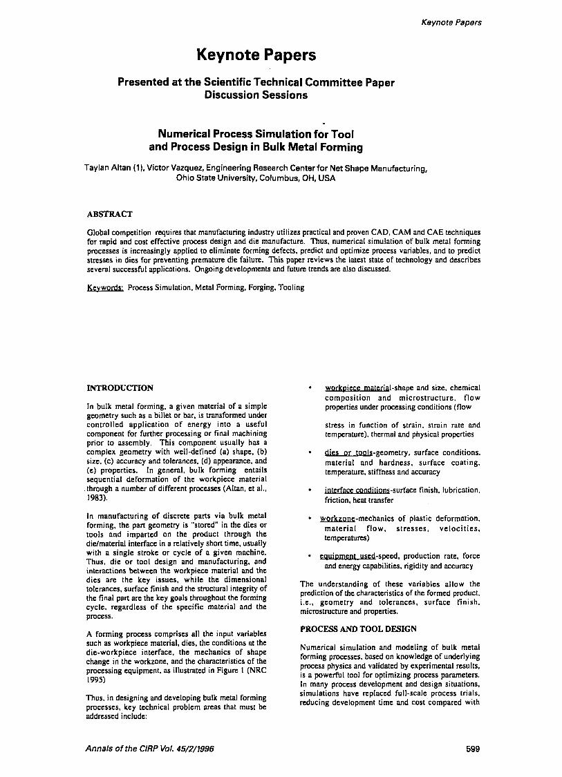
9 (Ceretti, et al.. 1996) and blanking Figure 10 (Taupin. et a1 ., 1996). In these latter applications. research is in progress to predict material separation and the influence of tool geometry upon part quality and tool wear.
APPLICATIONS IN 3D
Coining of Surgical Blades
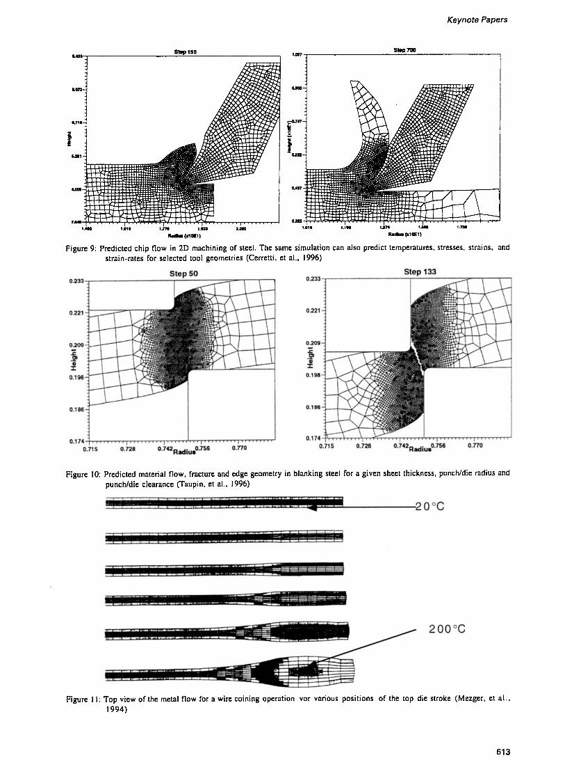
3D simulations of simple upsetting operations have been reported by several authors (Wu. et al. 1994. and Kim. et al, 1994). The buckling during upsetting and heading was investigated by Mori, et al., (1993). In the fabrication of surgical blades one end of a piece of wire, with approximately 0.04 in diameter, is cold upset or coined (Mezger, et al., 1994). 3D simulation was needed to estimate the elongation and the nonuniform deformation of the workpiece during upsetting. Since no remeshing was required, total processing time was very short (3 hrs). Figure I 1 shows the temperature development and metal flow in the deformed workpiece.
Extrusion and Drawing of Shapes
The simulation of processes like extrusion or drawing are time consuming since the simulation can not be stopped before reaching steady state conditions i n the deformation zone. Mori, et al., (1993) investigated 3D extrusion of non-circular sections to predict the curvature of an extruded bar. Later. Yang and Kang (1996) simulated the extrusion of a complex profile with squared dies to generate the loading data necessary to predict the wear of the die land.
Jia and Cunasekera (1995) simulated the drawing and extrusion of a hollow preform to form a squared hollow tube with P stream-lined die. A similar study, using a mandrel, was conducted by Sterzl. et al.. (1995). Figure 12. Initially, drawing with a single pass was simulated. In this case substantial undertilling was observed at the comer of the die. To achieve complete till at the die corner, the overall area reduction of about 25% was divided between two passes. In addition the outer radius of the preform was increased from 3 in to 3.2 in.
Tiesler. et al.. (1996) simulated, using 3D FEM, cold drawing of a copper bar with relatively complex section, Figure 13. The objective was to study the influence of different die designs on the corner filling. The automatic remeshing routine used in this simulation requires the use of tetrahedral elements and produces a mesh with a uniform element size. Thus, complex parts require a large number of elements if uniform sized tetrahedral elements were used. Therefore. the investigated shape was meshed with brick elements of a varying (user defined) size. Large elements were used to f i l l the body of the shape, whereas the comer of interest was meshed with small elements to obtain more accurate results on the filling behavior. Since remeshing is not possible with brick elements, the minimum mesh size was limited to a certain extent. To mesh half of the billet (due to symmetry reasons) 901 elements with 1260 nodes were needed. It took 4 days of calculation time to reach steady-state metal flow. This investigation
illustrated that 3D simulation has limitations and can not be used cost effectively in every application.
Cold Forging of a Cross Groove Inner Race
Automotive transmission and drive train components like gears and constant velocity joints are produced by bulk forming processes in tooling with complex configurations. Wu. et al.. (1996) reported computing times of one day and two days for the 3D FEM simulation of an outer race of a constant velocity joint (CVJ) and cross piece for a universal joint. respectively. Other investigators (Koenig, Fan and Seibert 1993; Lange and Szentmih5lyi 1995) have successfully performed metal tlow simulations for forming helical gears either by extrusion or forging.
Figure 14 illustrates a cross groove inner race o f a CVJ which consists of inner and outer races, six balls. and a cage between the inner and outer races.
The common manufacturing steps for the inner race are: ( I ) peeling of the incoming bar, (2) sawing of billets, (3) cold forging. (4) broaching of the grooves, ( 5 ) heat treating and grinding (Wolff. Vazquez. and Altan. 1995). The inner races for other types of CV ball joints are almost entirely made by cold forging (Wagner, 1979; Onodera. 1992; and Onodera. 1994). which is a very cost effective process.
A small number of companies with advanced cold forging technology, including Toyota [Kudo. et al., 19901 and more recently, Aikoku Alpha [Onodera, 19941. have begun to produce the cross groove inner race by cold forging with multiple-action tooling. To eject the part after forging the die must be split into several segments, Figure 15.
In order to obtain detailed information on metal tlow and die stresses 3D FEM simulations were performed at the ERC/NSM for different variations of the punch motion. DEFORM 3D was used for these investigation (Vazquez, et al.. 1996). Due to the symmetry of the cross groove only one sixth of the billet had to be analyzed. The FEM model used is shown in Figure 16. The tools were assumed to have rigid surfaces and tool deflection was neglected.
The calculations showed that at the end of the stroke the die cavity pressure increases considerably. Since the maximum pressure should not exceed a certain limit i t is necessary to control the motion and pressures of the inner punches. Figure 15.
This study clearly illustrated that in the multi-action forming of the cross grooved inner race a compromise between cavity f i l l and pressure must be achieved. 3D FEM simulation of the different concepts for the punch motion helps to select the best tool design before the actual tooling is designed and built (Vazquez. et al., 1996).
Closed Die Forging of a Connecting Rod Without Flash In conventional hot forging of con rods from billet a large part of the material is lost into flash. In addition, with the conventional forging techniques it is difficult to maintain close tolerances to reduce machining. As a result, P/M forged con rods continue to gain market share.
605

Process simulation was used to develop the tool and preform design for precision tlashless forging of con rods since this option represents an improvement in the state of the art. The preform shape and volume, and forging pressures were predicted (Takemasu. et al . , 1996). 3D simulations and physical modeling experiments (Barcellona. et al.. 1994) showed that the volume distribution and control in the preform must be very accurate in order to avoid flash formation entirely, Figures 17 and 18. Therefore, the preparation of preforms with close tolerances, required for tlashless forging, was found to be not practical. Consequently, this study is now redirected to design a process where a minimum amount of flashing is allowed (Couturier, et al.. 1996).
Roll Pass Design
In shape rolling the metal tlow is three dimensional since the billet elongates while its cross section changes. Several authors (Tiesler. et al., 1996; and Park, et al, 1990) have applied the 3D FEM to simulate shape rolling. The results correlate well with experimental data, but the simulation requires an excessive amount of CPU time. In order to reduce the computation time K i m , et al., (1991) proposed a simplified approach that combines the 2D finite element method and the slab method to simulate the shape rolling process without losing accuracy. This approach has been implemented in the software TASKS. This code has been successfully used for the optimization of roll pass design (Shin, et al.. 1992) , and for the improvement of the surface quality of rolled bars (Sawamiphakdi. et al.. 1994).
SUMMARY AND CONCLUSIONS
The numerical simulation of bulk metal forming processes with a finite element method based code assists the forming engineer i n establishing and optimizing process variables and die design. As a result, process development effort and costs can be reduced. However, i n conducting such simulations, the required engineering effort must be reasonable and must not be so large as to offset the advantages gained in process development. Today, robust codes with appropriate pre-/post-processing modules as well as very fast and cost-effective workstations, have reduced this effort considerably.
The main objectives of the numerical process modeling in bulk metal forming are to:
optimize die and process design
assure die till and prevent defects
predict and control die life and die failure
=
predict and control microstructure and properties of the formed part
reduce the number of operations needed , die try-out, and lead times
9 reduce scrap and material loss
When complicated processes are being modeled. finite element simulations can still consume so much effort and computing time that their use may not be considered economical. By making simplifying assumptions about a process, simulations can be performed to provide the designed information in a fraction of the time detailed simulations would have required.
The review of the literature and communication with the industry indicated that:
(a) in bulk metal forming 2D process simulation is well accepted by researchers as well as industry
(b) the application of 3D simulations continues to increase. However, due to present hardware limitations, these applications are still relatively rare and limited to relatively simple geometries. When a part does not have features with small radii and protrusions, 3D simulations work quite well and are cost effecti ve
(c) numerical process simulation is capable of predicting microstructures and properties of the formed product. These applications are expected to increase in the future.
ACKNOWLEDGEMENTS
This review paper was prepared with input from various CIRP colleagues. The authors would like to acknowledge these contributions and thank Professors:
P. Bariani. University of Padova, Italy N. Bay. Technical University of
A. Bramley, University of Bath, U.K. M. Geiger, University of Erlangen. Germany J. Gunasekera. Ohio University, USA B. Kaftanoglu, Middle East Technical University,
M. Kiuchi. University of Tokyo. Japan F. Klocke, Technical University, Aachen. Germany G. Lahoti, Timken Corporation, USA K. Lange, Technical University, Stuttgart Germany K. Osakada. Osaka University, Japan G. Perotti, Technical University of Torino, Italy
Denmark, Denmark
Turkey
REFERENCES
( I ) Altan, T.. Oh, S.1.. and Gegel, H. (1983) " Met a I and Applications". book published by American Society of Metals (ASM)
Altan, T., Oh, S.I. (1990) "Application of FEM to 2-D Metal Flow Simulation: Practical Examples". Advanced Technology of Plasticity, vol. 4, p. 1779
Altan. A.. and Knoerr, M. (1992) "Application of 2D Finite Element Method to Simulation of Cold Forging Process", Journal of Materials Processing Technology, vol. 35. p. 275
Form i n g - Fu n d a m e n t a I s
(2)
(3)
606

Keynote Papers
Antonelli, D., Kessels. M. (1995), "The Implementation of a Friction Model Suited for the Simulation of Upsetting in Plane Strain Conditions", Proceedings AITEM, Padova, Italy
Arentoft. M.. Henningsen, M.. Bay, N., and Wanheim. T. (1994). "Simulation of Defects in Metal Forming - An Example". Journal of Materials Processing Technology. vol. 45, p. 5 27
Barcellona, A., Long, K., and Altan, T. (1994). "Flashless Forging of a Connecting Rod of an Aluminum Alloy and a Metal Matrix Composite (MMC) Material". ERCINSM-B- 94-32 Engineering Research Center for Net Shape Manufacturing, The Ohio State University, Columbus. Ohio
Bariani. P.F., Berti, G., and D'Angelo, L. (1993). "Tool Cost Estimating at the Early Stages of Cold Forging Process Design. Annals of CIRP. vol. 4WI. p. 279
Bay, N., Wanheim, T.. Arentoft. M., Andenen, C.B.. and Bennani, B. (1995). "An Appraisal of Numerical and Physical Modelling for Prediction of Metal Forming Processes". Proceedings of the 4th International Conference on Computational Plasticity, p. 1343. Barcelona, Spain,
Bay. N.. Wanheim. T.. Danckert, J., and Nielsen. K.B. (1994) "Modelling and Prediction of Metal Forming". Proceedings of the Riso Int. Symposium on Materials Science; Numerical Predictions of Deformation Processes and Behaviour of Real Materials, p. I
Bay, N.. Wibom. 0.. and Nielsen, J.A. (1995). "A New Friction and Lubrication Test for Cold Forging", Annals of CIRP, vol. 44, p. 217
Bennani, B.. and Bay, N. (1994), "Limits of Lubrication in Backward Can Extrusion: Analysis by the Finite Element Method and Physical Modeling Experiments", Proceedings of the 27th ICFG Plenary Meeting, p. 7.1, Padova. Italy
Burte. P.. Semiatin. S.L. and AItan. T. (1990). "An Investigation of the Heat Transfer and Friction in Hot Forging of 3304SS and Ti-6A 1- 4V. Transactions of North American Manufacturing Research Institution of SME. p. 59, Dearbom. Michigan
Buschhausen. A,. Weinmann, K.. Lee. J.Y., and Altan, T. (1992). "Evaluation of Lubrication and Friction in Cold Forging Using Double Backward-extrusion Process", Journal of Materials and Processing Technology, vol. 33, p. 95
Ceretti, E.. Fallbfihmer, P., and Altan. T.. (1996), "Application of 2D FEM to Chip
Formation in Orthogonal Cutting". Journal of Materials Processing Technology. vol. 59. nos. 102. p. 169
(15) Couturier. B.. Vazquez. V.. and Altan. T. (1996). "Development of a Tooling Concept to Forge Connecting Rods with a Controlled Amount of Flash", ERC/NSM-B-96-22, Engineering Research Center for Net Shape Manufacturing, The Ohio State University. Columbus. Ohio
(16) Deshpande. A.. Shivpuri, R.. and Ishikawa, T. (1995), "Process Structure Relationships in Warm Forging of Microalloyed Steels". Proceedings of NAMRC XXIII, NAMRIISME. p. 57
(17) Doege, E., and Naegele, H. (1994). "FE Simulation of the Precision Forging Process of Bevel Gears". Annals of CIRP. vol. 43/1. p. 24 I
(18) Engel. U. (1994). "Prediction of Tool Failure from a Probabilistic Point of View". Journal of Materials and Processing Technology, vol. 42. P- I
(19) Engel, U. (1995). "Reliability Analysis of Cold Forging Tools", Proceedings of the 9th International Cold Forging Congress, p. I , Solihull. U.K.
(20) Fujikawa. S.. Ishii. K.. and Altan. T. (1992). "A Diagnostic Expert System for Defects in Forged Parts", Proceedings of AIENG. France
(21) Geiger, M. and Haensel, M. (1993), "An Energy Based Approach to the Simulation of Fatigue Crack Limitation in Metal Forming Tools". WIRE, v. 43, p. I
Geiger, M.. Haensel. M.. and Rebhan. T. ( 1992). "Improving the Fatigue Resistance of Cold Forging Tools by FE Simulation and Computer Aided Die Shape Optimization", Proceedings of Institute of Mechanical Engineers, vol. 206, part 8, Journal of Engineering Manufacture. p. 143
(22)
(23) Haensel. M. (1992). "Contribution to the Simulation of Surface Fatigue in Metal Forming Tools (in German), PhD dissertation, University of Erlangen
(24) Jia. 2.. and Gunasekera. 1.S. (1995). "Computer Simulation of Hollow Cold Extrusion and Drawing Using 3-D FEM". Proceedings of the NAMRC XXIIl Conference. Unpublished reprint, ISSN 019 I - 085X, p. I
(25) Karhausen, K. and Kopp, R. (1995). "Improvement of Microstructure in Forging of a Connecting Rod by Means of Finite Element Simulations". Steel Research, vol. 66. no. I , p. 20
607

(26)
(27)
(30)
(36)
Kim. H., and Altan, T. (1996), "Cold Forging of Steel - Practical Examples of Computerized PartslProcess Design", Journal of Materials Processing Technology, vol. 59. no. 1-2. p. 122
Kim. H.. Yamanaka. M., and Altan. T. (1995). "Prediction and Elimination of Ductile Fracture in Cold Forging Using FEM Simulations", Proceedings of NAMRC. p. 63. Society of Manufacturing Engineers, Houghton. Michigan
Kim, H., Sweeney, K., and Altan, T. (1994), "Application of Computer Aided Simulation to Investigate Metal Flow in Selected Forging Operations", Journal of Materials and Processing Technology, vol. 46. p. I27
Kim, H., Lee, S.M., and Altan. T. (1996), "Prediction of Hardness Distribution in Cold Backward Extruded Cups", Journal of Materials Processing Technology, vol. 59, nos. 1-2, p. 1 I3
Kim. N., Kobayashi, S.. and Altan. T. (1991). "Three-Dimensional Analysis and Computer Simulation of Shape Rolling by the Finite and Slab Element Method", International Journal of Machine Tools Manufacturing, vol. 3 I , p. 553
Kiuchi. M.. and Fukushima, S. (1995). "Numerical Simulation of Flow of MushylSemi-solid Alloy, Simulations of Materials Processing: Theory. Methods and Applications", p. I147 NUMIFORM '95, Shen & Dawson editors.
Knoerr. M., Lee. J.. and Altan, T. (1992). "Application of the 2D Finite Element Method to Simulation of Various Forming Processes". Journal of Materials Processing Technology, vol. 33. no. 1-2. p. 3 1
Knoerr, M., Lange. K.. and Altan. T. (1994). "Fatigue Failure of Cold Forging Tooling: Causes and Possible Solutions Through Fatigue Analysis". Journal of Materials Processing Technology, vol. 46. no. 1-2. p. 57
Knoerr, M., Lange, K., and Altan. T. (1992). " A n Integrated Approach to Process Simulation and Die Stress Analysis i n Forging". Transactions of NAMRC. vol. XX. p. 53. Society of Manufacturing Engineers
Knoerr. M.. Graeber. A., and Poehlandt, K. ( I 990). "A New Approach to the Evaluation of High Strain Flow Curve Data using the Torsion Test". Transactions of North American Manufacturing Research Institution of SME. p. 52. SME, Dearborn, Michigan
Koc, M., Vazquez, V., Witulski. T., and Altan, T. (1996). "Application of the Finite Element Method to Predict Material Flow and Defects in the Semi-Solid Forging of 356 Aluminum Alloys", Journal of Materials Processing Technology, vol. 59. no. 1-2. p. 106
(37)
(43)
(45)
(47)
Koenig, W.. Fan, J.A.. and Seibert. D. (1993). "Recent Developments in the Extrusion of Helical Gears", International Journal of Machine Tools Manufacturing, vol. 33, no. 4. p. 599
Konig, W., and Lennartz. J. (1993). "Cold Impact Extrusion of Toothed Gear Shafts", Production Engineering, vol. I l l . p. 63
Kudo, H. and Takahashi, A. (l990), "Extrusion Technology in the Japanese Automotive Industry". VDI Berichte, 810. p. 19
Lange. K., and Szentmihalyi, V. (1995). "Optimized Cold Forging of Helical Gears by FEM Simulation", Proceedings of 9th International Cold Forging Congress, Solihull. U.K.
Lennartz, J. (1995). "Cold Extrusion of Spur and Helical Toothed Drive Shafts" (in German) Dissertation, Technical University Aachen, WZL
Meidert. M.. Knoerr, M.. Westphal, K.. and Altan, T. (l992), "Numerical and Physical Modeling of Cold Forging of Bevel Gears", Journal of Materials Processing Technology, vol. 33, no. 1-2. p. 75
Messner, A., Engel, U., Kals. R.. and Vollertsen. F. (1994). "Size Effect in the FE Simulation of Microforming Processes", Journal of Materials and Processing Technology, vol. 45. p. 374
Mezger. J., Sweeney, K.. and Altan. T. (1994). "Investigation of the DEFORM 3D code: Flashless Forging of a Connecting Rod" ERCINSM-B-94-3 1, Engineering Research Center for Net Shape Manufacturing, The Ohio State University, Columbus, Ohio
Mori, K.. Osakada, K.. and Kadohata, S. (1993). "Finite Element Simulation of Three- Dimensional Buckling in Upsetting and Heading of Cylindrical Billet", Proceedings of 4th International Conference on Technology of Plasticity. 1047
Mori, K., Osakada. K.. and Shiomi. M. (1991). "Finite Element Modelling of Forming Process of Solid Metal with Liquid Phase", Journal of Materials Processing Technology, vol. 27. p. I l l
Mori, K.. Osakada. K.. and Yamaguchi. H. (1993), "Prediction of Curvature of an Extended Bar with Non-circular Cross-section by a 3-D Rigid-plastic Finite Element Method", International Journal of Mechanical Science, vol. 35, p. 879
Nagao. Y., Knoerr. M.. and Altan. T. (l994), "Improvement of Tool Life in Cold Forging of Complex Automotive Parts", Journal of
608

Keynote Papers
(49)
(50)
(56)
(59)
Materials Processing Technology, vol. 46. no 1-2. p. 73
National Research Council ( I 995) "Uni t Manufacturing Processes - Issues and Opportunities i n Research" prepared by the Manufacturing Process Research Committee, 1. Finnie. Chair, National Academy Press
Oh, S.I. , Wu, W.T., Tang, J. P. , and Vedhanayagam. A. ( I 990), "Capabilities and Application of FEM code DEFORM: The Perspectives of the Developer". Journal of Materials Processing Technology, vol. 27, p. 25
Onodera. S. (1992). "Concurrent Cold Forging Techniques for the Manufacture of Complex Precision Near Net Shapes", Journal of Material Processing Technology, vol. 35
Onodera. S. (1994). "Modern Cold Forging Applications for the Manufacture of Complex Automotive Parts", Journal of Material . Processing Technology, vol. 46
Osakada. K., Yang, G.. Nakamura, T.. and Mori. K. (1990). "Expert System for Cold Forging Process Based on FEM Simulation", Annals of the CIRP. Vol. 39. p. 249
Painter, B., Shivpuri, R., and Altan, T. (1996). "Prediction of Die Wear During Hot Extrusion of Engine Valves", Journal of Materials Processing Technology, vol. 59. no 1-2. p. I32
Park, J.J. and Oh, S.I. (1990), "Application of Three Dimensional Finite Element Analysis to Shape Rolling Processes". Transactions of ASME, Journal Engineering Industry, vol. 112. Pg. 36
Roy, S.. Ghosh. S., Shivpuri. R., and Altan, T. (1994), "Design Optimization of Multipass Cold Drawing of Arbitrary Profiles". Internal Report Engineering Research Center for Net Shape Manufacturing, The Ohio State University, Columbus, Ohio
Sawamiphkdi. K., and Lahoti. G.D. (1994). "Application of the Slab-Finite Element Method for Improvement of Rolled Bar Surface Quality", Annals of CIRP. 143/V1994
Shen, G.. Vedhanayagam. A,. Kropp, E., and Altan. T. (1992). "A Method for Evaluating Friction Using Backward Extrusion Type Forging". Journal of Materials and Processing Technology. vol. 33, p. 109
Shen. G.. Semiatin. S.L.. and Altan, T. (1993). "Investigation of Flow Stress and Microstructure Development i n Non- isothermal Forging of Ti-6242". Journal of Materials Processing Technology, vol. 36, p. 303
(67)
Shen. G.. Semiatin. S.L., Kropp. E.. and Altan. T. (1992). " A technique to Compensate for Temperature History Effects in the Simulation of Non-isothermal Forging Processes". Journal of Materials Processing Technology, vol. 33, no. 1-2. p. 125
Shin, W., Lee. S.M., Shivpuri, R.. and Altan. T. ( 1 992). "Finite-slab Element Investigation of Square-to-Round Multi-pass Shape Rolling", Journal of Materials Processing Technology. vol. 33. p. 141
Sterzl, W.. Vazquez. V.. and Altan. T. (1995) "Cold Drawing of Precision Shapes, FEM Analysis of the Metal Flow Concerning the Optimization of the Corner Filling for Rectangular Cross Sections". Report No. ERCINSM-B-95-38, Engineering Research Center for Net Shape Manufacturing, The Ohio State University, Columbus, Ohio
Takemasu. T.. Vazquez. V., Painter, B., and A h . T. (1996) , "Investigation of Metal Flow and Preform Optimization in Flashless Forging of a Connecting Rod. Journal of Materials and Processing Technology, vol. 59. no 1-2. p. 95
Taupin. E., Breitling, J.. Wu. W.T.. and Altan. T. (1996). "Material Fracture and B u r r Formation in Blanking Results of FEM Simulations and Comparison with Experiments". Journal of Materials Processing Technology, vol 59. nos 1-2. p. 68
Tiesler. N.. Vazquez. V.. and Altan. T. ( 1996). "Process and Die Design in Shape Drawing: Application of 3D Finite Element Analysis'' - in preparation
Toyoshima. S. ( I 99 1 ) "A Numerical Simulation of Forming Processes for Semi- Solid Materials", ISlJ International. vol. 31, no. 6. p. 577
Vazquez. V.. M. Knoerr. R. Shivpuri. T. Altan. (1996) Determination of Fatigue Properties of Die Steels for Hot Forging, Trans. North American Manufacturing Research Institution
Vazquez, V., Sweeney, K., Wallace. D., Wolff. C., Ober. M.. and Altan, T., (1996) Tooling and Process Design to Cold Forge a Cross Groove Inner Race For a Constant Velocity Joint - Physical Modeling and FEM Process Simulation, Journal of Materials and Processing Technology, Vol. 59, No. 1-2. pp.
Wagner, E. (1979) Cross Groove Universal Joint. Universal Joint and Driveshaft Manual. Advances in Engineering Series. No. 7. Society of Automotive Engineers, Inc.
Wolff, C., Vazquez. V., and Altan. T. (1995) Material Flow Simulation for Cold Forging a Crossed Groove Inner Race. ERUNSM-Report
of SME, pp. 155- I60
144-157
609

B-95-25. ERC for Net Shape Manufacturing. The Ohio State University
Wu, W. T., Li. G. J.. and G.P. Tang, (1994). Finite Element Analysis of Three Dimensional Metal Flow i n Cold and Hot Forming Processes, Annals of CIRP, Vol. 43. pp. 235- 239
Wu. W. T.. Li, G. J., Arvind. A., and G.P. Tang, (1996). Development of a Three Dimensional Finite Element Method Based Process Simulation Tool for the Metal Forming Industry. Proceedings of the Third Biennial Joint Conference on Engineering Systems Design & Analysis, Montpellier. France
Wu. W.T.. S.I. Oh, T. Altan. R. A. Miller, ( I99 1 ) Automated Mesh Generation for Forming Simulation-I", Proceedings of ASME International Computers in Engineering, vol. I , p. 507, Boston, MA.
Wu, W.T., Oh, S.I.. Altan. T., and Miller, R.A. (1992) Optimal Mesh Density Determination for the FEM Simulation of Forming Processes, NUMIFORM '92, September 14-18, 1992, France
Yang. D.S.. Kang. Y. S. , (1996) Analysis and Design of Industrial Hot Extrusion Process Through Squared Dies for Manufacturing of Complicated Al Alloy Profiles. Annals of
(71)
(72)
(73)
(74)
(75)
CIRP. VOI. 45- I , pp. 239-243.
610

Keynote Papers
FUNCl lONAL KEQUlKEMENl3
(BASU)ON E X I T K l E N C E / K U W
'KCUMINAKY DIE DESIGN 4 (BASKION CXPCKIEhCE/KUUSl I DIE/ I'AKT
D E I G N
L
FOKMINC VAKIABLEWSIMULATE MCTAL FLOW
DlC DWCN A N D JATABASE WITH I'KOCISS VAKIABLE DIE/MATEKIAL < 4CCEITABLE yls > 7 ROI'EKTIES I
Figure 2 : Product and process design for net shape manufacturing
Figure 3: FEM meshes generated automatically at the start and at the various steps of deformation during the simulation. (Oh. et al.. 1990)
Figure 4: Beginning and end of the rewelding of the folds formed during the SSF of the disk shape. At 99.9% stroke two surfaces of a fold have just contacted to each other and at 100% stroke surfaces of the fold are rewelded to each other (Koc. et al.. 1996)
61 1

Figure 5 : Calculated displacement of 2 points selected from the upper billet surface, illustrates the formation of suck-in defect (Oh. et al.. 1990)
1 I-DEAS I MODEL FILE I
FE-Mesh of Dies
1 - NOdll Tamparalures
1 Conlac! Slressas or Forcns
I
Rigid-Plasli c Sirnulalion of Malarial Flow wilh Transienl Heal Transler
Analysis
NASTRAN ANSYS
I 1 I 1
original modified Figure 7: Original and modified punch desing for
increasing tool life in cold forging of bevel gears (Meidert. et al.. 1992)
0, = 1700 MPa crack initiation point a,,, P 1726 MPa
I Figure 8: Plastic zone at the initiation site of the flange
crack in cold forging of outer race of a CV joint (Nagao. et al., 1994)
Figure 6: Proposed concept for integration of stress analysis into the CAE of forging dies (Knoerr, et al.. 1992)
61 2
Keynote Papers
smp 110 P *-- I
1 .m I . . . . . . . . I . . . . . .
111a 1 . 1 1 u r n 1-
R.du @lam)
Figure 9: Predicted chip flow in 2D machining of steel. The same simulation can also predict temperatures. stresses, strains, and strain-rates For selected tool geometries (Cerretti, et al., 1996)
Figure 10: Predicted material flow, fracture and edge geometry in blanking steel for a given sheet thickness, punchldie radius and punchldie clearance (Taupin, et al., 1996)
Figure 11: Top view of the metal flow for a wire coining operation vor various positions of the top die stroke (Mezger, et a l . . 1994)
613

Figure 12: 3D simulation of a tube drawing operation with mandrel, (initial tube OD=] 52.4mm, ID=120.6mm; final rectangular shape: a) outer dimension is 85.54mm x 120.65mrn. b) minor dimensions 61.6mm x 92.7mm) (Sterzl. 1995)
A - A
a) b) Figure 13: Preform (a) , and final shape (b) used in drawing
of a Copper profile (Tiesler. et al., 1996)
conical
U H-
7 I l l
I f b i l let
4 I
Figure 15: Conceptual design for the forging of a. cross groove CV joint inner race, using retractable die segments (Vazquez, et al., 1996)
Figure 14: An example of a cross groove universal joint (Vazquez, et al.. 1996)
614

Keynote Papers
s l 3.96 s8 4.70
Ring Punch TOP
Inner Punch
TOP
Outer
s2 93 s4 s5 s6 s7 26.77 12.04 17.23 11.61 6.58 7.90 dl d2 d3 d4 d5 9.65 16.76 7.01 16.26 7.06
Figure 17: Sketch of preform-I used for tlashless forging of a connecting rod (Takemasu. et al.. 1996)
Figure 16: initial mesh of billet and tools used in the simulation of cold forging a cross groove inner race (Vazquez, et al.. 1996)
Punch movement
Figure 18: Simulation model and material flow in tlashless precision forging of a connecting rod (Takemasu. et al.. 1996)
615