
PowerLogic™ - Home
246
PowerLogic ™ Energy management, revenue metering and power quality monitoring Electrical network management www.schneider-electric.com
-
Upload
khangminh22 -
Category
Documents
-
view
2 -
download
0
Transcript of PowerLogic™ - Home

PowerLogic™
Energy management, revenue meteringand power quality monitoring
Electrical network management
www.schneider-electric.com

Contents Introduction to PowerLogic 3
Product panorama 7
Current transformers 15
Panel instruments 32
Basic energy metering IEM2000 series and IEM3000 series 43
Basic multi-function metering ION6200, PM3000 series, PM5350 and PM5000 series
58
Advanced metering PM8000 series and ION9000 series
106
Advanced utility metering ION7400, ION8650 and ION8800
129
Multi-circuit metering BCPM, EM4000 series, EM4800, and EM4900
159
Retrofit products EM3500 and EM4200
195
Communications and gateways Link150, Com’X 210, Com’X 510 and ION7550 RTU
209
Insulation monitoring devices Vigilohm insulation monitoring devices
236
Commercial reference numbers 241Clicking on a
Commercial Reference Number
or scanning the product’s QR Code
links you to further product information on
www.schneider-electric.com
POWERLOGIC CATALOG INTRODUCTION
Version: 1.0 - 22/01/2020PLSED309005EN_01a
2

Schneider Electric believes every business can increase productivity while
consuming less and achieving energy savings of 10% to 30%.
Saving energy reduces costs and pollution, but you need the tools to uncover all opportunities, avoid risks, track progress against goals, and verify success. Schneider Electric provides these tools via the world’s most advanced energy intelligence technology: PowerLogic.
A PowerLogic system of meters, software and power quality solutions help manage all energy assets, every second of the day. A PowerLogic system enables all stakeholders, from CEO to facility and engineering managers, to respond quickly to potential problems and manage energy in financial and environmental terms.
PowerLogic technology delivers the key performance indicators and analytics that you need to strategically balance emissions, efficiency, reliability and cost.
PowerLogic technology
forms one part of your
total energy management
solution from Schneider
Electric. As the global
energy management
specialist, we offer end-
to-end power, building
and process management
solutions that help you
optimize energy use and
costs, improve performance,
enhance comfort and safety,
and deliver uninterrupted
service while taking
responsible care of our
planet.
Our expert services can
help you audit your energy
use and build your energy
action plan. From power
factor correction systems,
harmonic filtering and
variable speed drives to
HVAC and lighting controls,
we offer a complete
range of energy efficient
technologies.
PowerLogic™ System is…
POWERLOGIC CATALOG INTRODUCTION
3Version: 1.0 - 22/01/2020PLSED309005EN_01aVersion: 1.0 - 22/01/2020PLSED309005EN_01a
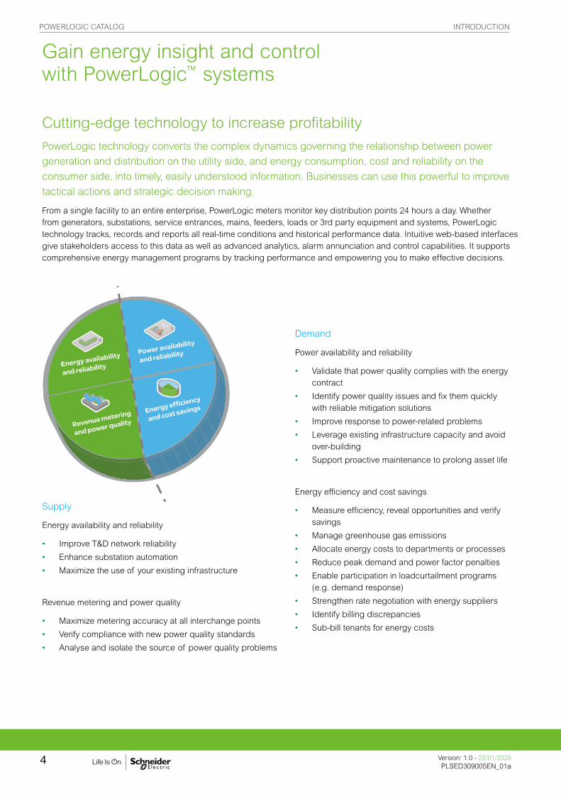
Cutting-edge technology to increase profitabilityPowerLogic technology converts the complex dynamics governing the relationship between power
generation and distribution on the utility side, and energy consumption, cost and reliability on the
consumer side, into timely, easily understood information. Businesses can use this powerful to improve
tactical actions and strategic decision making.
From a single facility to an entire enterprise, PowerLogic meters monitor key distribution points 24 hours a day. Whether from generators, substations, service entrances, mains, feeders, loads or 3rd party equipment and systems, PowerLogic technology tracks, records and reports all real-time conditions and historical performance data. Intuitive web-based interfaces give stakeholders access to this data as well as advanced analytics, alarm annunciation and control capabilities. It supports comprehensive energy management programs by tracking performance and empowering you to make effective decisions.
Supply
Energy availability and reliability
• Improve T&D network reliability
• Enhance substation automation
• Maximize the use of your existing infrastructure
Revenue metering and power quality
• Maximize metering accuracy at all interchange points
• Verify compliance with new power quality standards
• Analyse and isolate the source of power quality problems
Demand
Power availability and reliability
• Validate that power quality complies with the energy contract
• Identify power quality issues and fix them quickly with reliable mitigation solutions
• Improve response to power-related problems
• Leverage existing infrastructure capacity and avoid over-building
• Support proactive maintenance to prolong asset life
Energy efficiency and cost savings
• Measure efficiency, reveal opportunities and verify savings
• Manage greenhouse gas emissions
• Allocate energy costs to departments or processes
• Reduce peak demand and power factor penalties
• Enable participation in loadcurtailment programs (e.g. demand response)
• Strengthen rate negotiation with energy suppliers
• Identify billing discrepancies
• Sub-bill tenants for energy costs
Gain energy insight and control with PowerLogic™ systems
POWERLOGIC CATALOG INTRODUCTION
Version: 1.0 - 22/01/2020PLSED309005EN_01a
4

Buildings
Building managers through operations staff can cut energy and maintenance costs without effecting the comfort or productivity of their tenants, employees, students, patients or customers. A PowerLogic system will track all utilities and equipment conditions, and enterprise-level software will help you analyse and improve electrical reliability.
You can forecast energy requirements, optimize multi-site contracts and accurately allocate or sub-bill costs. Key performance indicators help you find and sustain energy savings, reduce emissions and meet “green” building standards in order to increase asset value and attract or retain tenants..
• Tenant sub-billing
• Cost allocation
• Energy efficiency &
benchmarking
• Procurement optimization
• Power availability
• Demand response / load
curtailment
Market segments
Industry
From finance to engineering, PowerLogic technology gives industry professionals the energy intelligence and control they need to support strategic decisions and establish best energy practices. It will help you reduce operational costs and meet new emissions standards without compromising production schedules or product quality.
Key points are monitored throughout your power distribution, building and backup systems. Enterprise-level software helps you maximize the use of your existing energy assets, increase energy efficiency and avoid demand or power factor penalties. Use it to uncover and solve hidden power problems that can shorten equipment life or cause costly downtime.
• Cost allocation
• Procurement optimization
• Power factor correction
• Continuity of service even in case
of an earth fault
POWERLOGIC CATALOG INTRODUCTION
5Version: 1.0 - 22/01/2020PLSED309005EN_01aVersion: 1.0 - 22/01/2020PLSED309005EN_01a

Critical infrastructure
PowerLogic technology helps keep your systems operating continuously and securely with an economical supply of energy. Whether you manage data, communication, transportation or environmental services, minimising the risk of power-related downtime and keeping costs under control is a priority.
A PowerLogic system monitors all power and cooling systems, accurately tracks their energy consumption, and allows you to identify and fix power quality issues as soon as they arise. Enterprise-level software delivers insightful diagnostics and metrics to help verify the reliability of your backup systems and maximize the use of existing capacity to defer new capital investments. You can also reveal energy inefficiencies and strengthen energy procurement across multiple sites.
Utilities
Today’s energy market is more complex than ever before. Whether you generate, transmit or distribute electricity, more stakeholders need shared access to timely, accurate energy data from more exchange points and you need to maintain power availability and reduce price volatility in the face of rising demand and transmission congestion. A PowerLogic energy information system helps you meet all of these challenges by:
• Metering all key interchange points with the highest possible accuracy
• Improving the quality of power delivered to your customers
• Ensuring the reliability and efficiency of your network and equipment
From advanced energy and power quality metering systems to enterprise-level analytic software and power quality mitigation solutions, PowerLogic systems deliver business-critical information that conventional metering, SCADA and billing systems cannot. It gives you the energy intelligence and control needed to track performance, stay informed of critical conditions and empower you to make strategic decisions. It will help you increase reliability, maximize the use of resources and improve service.
• Revenue metering
• Power quality monitoring
• Power availability and reliability
• Insulation monitoring
• Infrastructure optimization
• Power quality analysis compliance
• Alarming and event notification
• Energy efficiency
• Cost allocation
• Procurement optimization
POWERLOGIC CATALOG INTRODUCTION
Version: 1.0 - 22/01/2020PLSED309005EN_01a
6
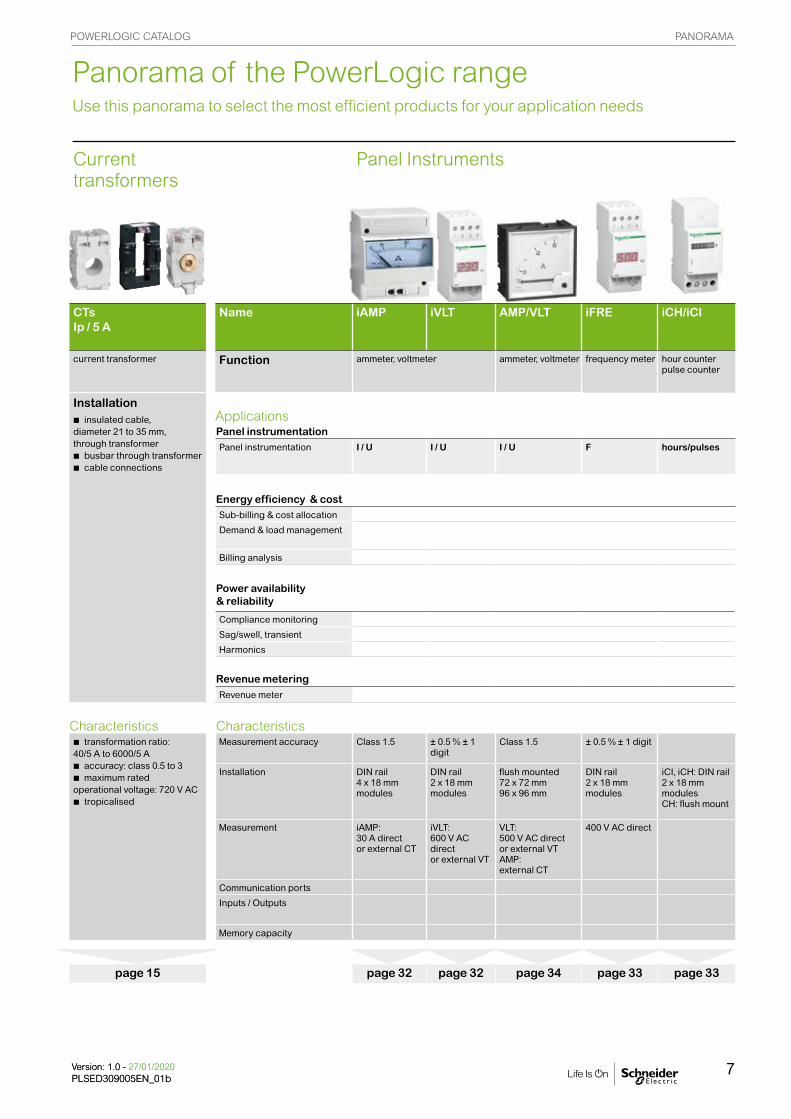
Current transformers
Panel Instruments
CTsIp / 5 A
Name iAMP iVLT AMP/VLT iFRE iCH/iCI
current transformer Function ammeter, voltmeter ammeter, voltmeter frequency meter hour counterpulse counter
Installationbinsulated cable, diameter 21 to 35 mm, through transformerbbusbar through transformerbcable connections
ApplicationsPanel instrumentationPanel instrumentation I / U I / U I / U F hours/pulses
Energy efficiency & costSub-billing & cost allocation
Demand & load management
Billing analysis
Power availability & reliability
Compliance monitoring
Sag/swell, transient
Harmonics
Revenue metering
Revenue meter
Characteristics Characteristicsbtransformation ratio: 40/5 A to 6000/5 Abaccuracy: class 0.5 to 3bmaximum rated operational voltage: 720 V ACbtropicalised
Measurement accuracy Class 1.5 ± 0.5 % ± 1 digit
Class 1.5 ± 0.5 % ± 1 digit
Installation
DIN rail4 x 18 mm modules
DIN rail2 x 18 mm modules
flush mounted72 x 72 mm 96 x 96 mm
DIN rail2 x 18 mm modules
iCI, iCH: DIN rail2 x 18 mm modules CH: flush mount
Measurement iAMP: 30 A director external CT
iVLT:600 V AC direct or external VT
VLT: 500 V AC direct or external VTAMP: external CT
400 V AC direct
Communication ports
Inputs / Outputs
Memory capacity
page 15 page 32 page 32 page 34 page 33 page 33
Panorama of the PowerLogic range Use this panorama to select the most efficient products for your application needs
POWERLOGIC CATALOG PANORAMA
7Version: 1.0 - 27/01/2020PLSED309005EN_01bVersion: 1.0 - 27/01/2020PLSED309005EN_01b
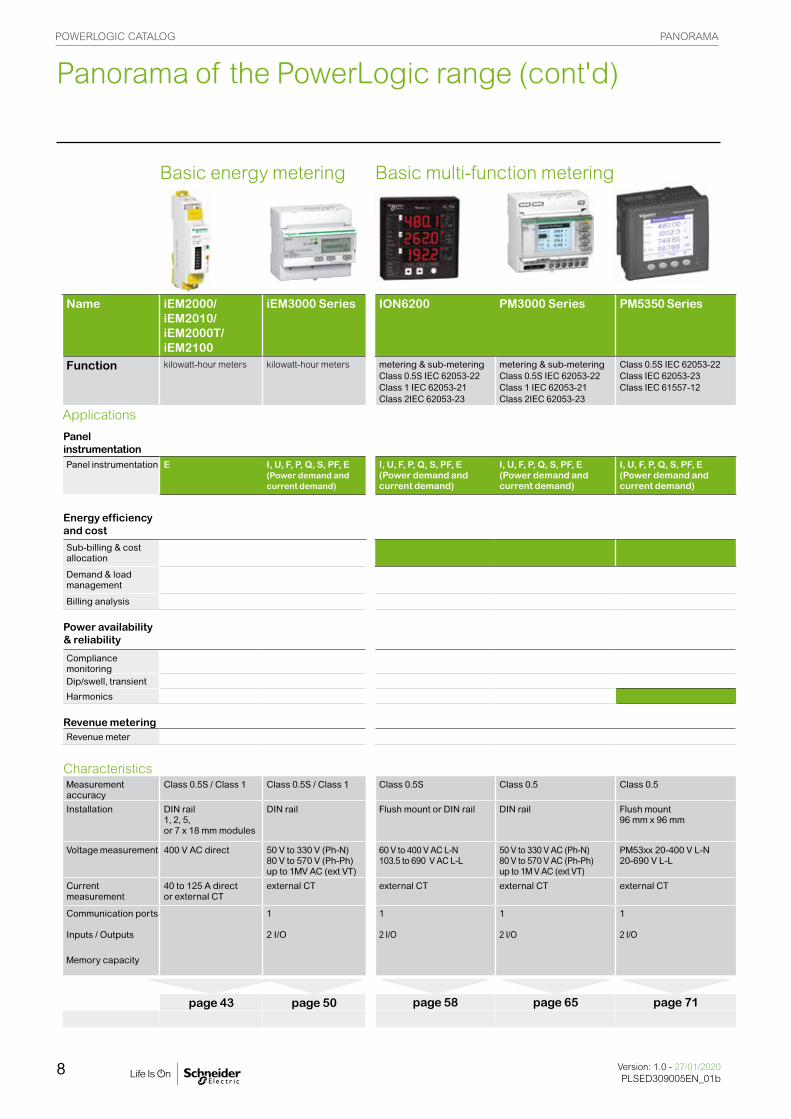
Panorama of the PowerLogic range (cont'd)
Basic energy metering Basic multi-function metering
Name iEM2000/iEM2010/ iEM2000T/iEM2100
iEM3000 Series ION6200 PM3000 Series PM5350 Series
Function kilowatt-hour meters kilowatt-hour meters metering & sub-meteringClass 0.5S IEC 62053-22Class 1 IEC 62053-21Class 2IEC 62053-23
metering & sub-meteringClass 0.5S IEC 62053-22Class 1 IEC 62053-21Class 2IEC 62053-23
Class 0.5S IEC 62053-22Class IEC 62053-23Class IEC 61557-12
Applications
Panel instrumentationPanel instrumentation E I, U, F, P, Q, S, PF, E
(Power demand andcurrent demand)
I, U, F, P, Q, S, PF, E(Power demand andcurrent demand)
I, U, F, P, Q, S, PF, E(Power demand andcurrent demand)
I, U, F, P, Q, S, PF, E(Power demand andcurrent demand)
Energy efficiency and cost
Sub-billing & cost allocation
Demand & load management
Billing analysis
Power availability & reliability
Compliance monitoringDip/swell, transient
Harmonics
Revenue meteringRevenue meter
CharacteristicsMeasurement accuracy
Class 0.5S / Class 1 Class 0.5S / Class 1 Class 0.5S Class 0.5 Class 0.5
Installation
DIN rail1, 2, 5, or 7 x 18 mm modules
DIN rail Flush mount or DIN rail DIN rail Flush mount96 mm x 96 mm
Voltage measurement 400 V AC direct 50 V to 330 V (Ph-N)80 V to 570 V (Ph-Ph) up to 1MV AC (ext VT)
60 V to 400 V AC L-N 103.5 to 690 V AC L-L
50 V to 330 V AC (Ph-N) 80 V to 570 V AC (Ph-Ph)up to 1M V AC (ext VT)
PM53xx 20-400 V L-N 20-690 V L-L
Current measurement
40 to 125 A direct or external CT
external CT external CT external CT external CT
Communication ports 1 1 1 1
Inputs / Outputs 2 I/O 2 I/O 2 I/O 2 I/O
Memory capacity
page 43 page 50 page 58 page 65 page 71
POWERLOGIC CATALOG PANORAMA
Version: 1.0 - 27/01/2020PLSED309005EN_01b
8
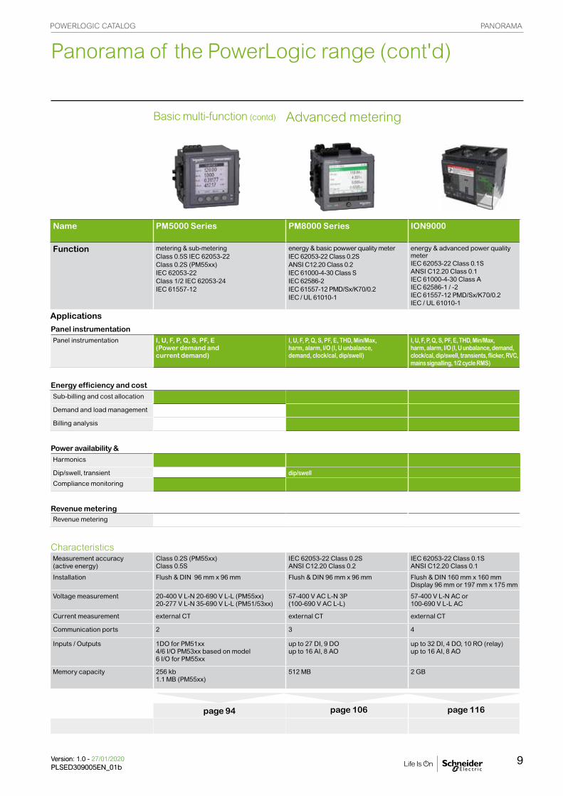
Basic multi-function (contd) Advanced metering
Name PM5000 Series PM8000 Series ION9000
Function metering & sub-meteringClass 0.5S IEC 62053-22Class 0.2S (PM55xx)IEC 62053-22Class 1/2 IEC 62053-24IEC 61557-12
energy & basic powwer quality meterIEC 62053-22 Class 0.2SANSI C12.20 Class 0.2IEC 61000-4-30 Class SIEC 62586-2IEC 61557-12 PMD/Sx/K70/0.2IEC / UL 61010-1
energy & advanced power quality meterIEC 62053-22 Class 0.1SANSI C12.20 Class 0.1IEC 61000-4-30 Class AIEC 62586-1 / -2IEC 61557-12 PMD/Sx/K70/0.2IEC / UL 61010-1
Applications
Panel instrumentationPanel instrumentation I, U, F, P, Q, S, PF, E
(Power demand andcurrent demand)
I, U, F, P, Q, S, PF, E, THD, Min/Max,harm, alarm, I/O (I, U unbalance,demand, clock/cal, dip/swell)
I, U, F, P, Q, S, PF, E, THD, Min/Max,harm, alarm, I/O (I, U unbalance, demand, clock/cal, dip/swell, transients, flicker, RVC, mains signalling, 1/2 cycle RMS)
Energy efficiency and costSub-billing and cost allocation
Demand and load management
Billing analysis
Power availability & Harmonics
Dip/swell, transient dip/swell
Compliance monitoring
Revenue meteringRevenue metering
CharacteristicsMeasurement accuracy(active energy)
Class 0.2S (PM55xx)Class 0.5S
IEC 62053-22 Class 0.2SANSI C12.20 Class 0.2
IEC 62053-22 Class 0.1SANSI C12.20 Class 0.1
Installation
Flush & DIN 96 mm x 96 mm Flush & DIN 96 mm x 96 mm Flush & DIN 160 mm x 160 mm Display 96 mm or 197 mm x 175 mm
Voltage measurement 20-400 V L-N 20-690 V L-L (PM55xx)20-277 V L-N 35-690 V L-L (PM51/53xx)
57-400 V AC L-N 3P (100-690 V AC L-L)
57-400 V L-N AC or 100-690 V L-L AC
Current measurement external CT external CT external CT
Communication ports 2 3 4
Inputs / Outputs 1DO for PM51xx4/6 I/O PM53xx based on model6 I/O for PM55xx
up to 27 DI, 9 DOup to 16 AI, 8 AO
up to 32 DI, 4 DO, 10 RO (relay) up to 16 AI, 8 AO
Memory capacity 256 kb1.1 MB (PM55xx)
512 MB 2 GB
page 94 page 106 page 116
Panorama of the PowerLogic range (cont'd)
Basic energy metering Basic multi-function metering
Name iEM2000/iEM2010/ iEM2000T/iEM2100
iEM3000 Series ION6200 PM3000 Series PM5350 Series
Function kilowatt-hour meters kilowatt-hour meters metering & sub-meteringClass 0.5S IEC 62053-22Class 1 IEC 62053-21Class 2IEC 62053-23
metering & sub-meteringClass 0.5S IEC 62053-22Class 1 IEC 62053-21Class 2IEC 62053-23
Class 0.5S IEC 62053-22Class IEC 62053-23Class IEC 61557-12
Applications
Panel instrumentationPanel instrumentation E I, U, F, P, Q, S, PF, E
(Power demand andcurrent demand)
I, U, F, P, Q, S, PF, E(Power demand andcurrent demand)
I, U, F, P, Q, S, PF, E(Power demand andcurrent demand)
I, U, F, P, Q, S, PF, E(Power demand andcurrent demand)
Energy efficiency and cost
Sub-billing & cost allocation
Demand & load management
Billing analysis
Power availability & reliability
Compliance monitoringDip/swell, transient
Harmonics
Revenue meteringRevenue meter
CharacteristicsMeasurement accuracy
Class 0.5S / Class 1 Class 0.5S / Class 1 Class 0.5S Class 0.5 Class 0.5
Installation
DIN rail1, 2, 5, or 7 x 18 mm modules
DIN rail Flush mount or DIN rail DIN rail Flush mount96 mm x 96 mm
Voltage measurement 400 V AC direct 50 V to 330 V (Ph-N)80 V to 570 V (Ph-Ph) up to 1MV AC (ext VT)
60 V to 400 V AC L-N 103.5 to 690 V AC L-L
50 V to 330 V AC (Ph-N) 80 V to 570 V AC (Ph-Ph)up to 1M V AC (ext VT)
PM53xx 20-400 V L-N 20-690 V L-L
Current measurement
40 to 125 A direct or external CT
external CT external CT external CT external CT
Communication ports 1 1 1 1
Inputs / Outputs 2 I/O 2 I/O 2 I/O 2 I/O
Memory capacity
page 43 page 50 page 58 page 65 page 71
POWERLOGIC CATALOG PANORAMA
9Version: 1.0 - 27/01/2020PLSED309005EN_01bVersion: 1.0 - 27/01/2020PLSED309005EN_01b
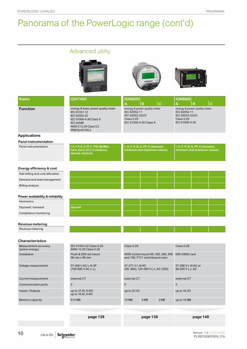
Advanced utility
Name ION7400 ION8650 ION8800A B C A B C
Function energy & basic power quality meterIEC 61557-12IEC 62053-22IEC 61000-4-30 Class SIEC 62586ANSI C12.20 Class 0.2PMD/Sx/K70/0.2
energy & power quality meterIEC 62052-11IEC 62053-22/23Class 0.2SIEC 61000-4-30 Class A
energy & power quality meterIEC 62052-11IEC 62053-22/23Class 0.2SIEC 61000-4-30
Applications
Panel instrumentationPanel instrumentation I, U, F, P, Q, S, PF, E, THD, Min/Max,
harm, alarm, I/O (I, U unbalance,demand, clock/cal)
I, U, F, P, Q, S, PF, E (demand, minimum and maximum values)
I, U, F, P, Q, S, PF, E (demand, minimum and maximum values)
Energy efficiency & cost
Sub-billing and cost allocation
Demand and load management
Billing analysis
Power availability & reliabilityHarmonics
Dip/swell, transient dip/swell
Compliance monitoring
Revenue meteringRevenue metering
CharacteristicsMeasurement accuracy(active energy)
IEC 61053-22 Class 0.2SANSI 12.20 Class 0.2S
Class 0.2S Class 0.2S
Installation
Flush & DIN rail mount96 mm x 96 mm
ANSI socket mount 9S, 35S, 36S, 39S and 76S; FT21 switchboard case
DIN 43862 rack
Voltage measurement 57-400 V AC L-N 3P (100-690 V AC L-L)
57-277 V L-N AC(9S, 36S); 120-480 V L-L AC (35S)
57-288 V L-N AC or 99-500 V L-L AC
Current measurement external CT external CT external CT
Communication ports 2 5 5
Inputs / Outputs up to 27 DI, 9 DOup to 16 AI, 8 AO
up to 22 I/O up to 16 I/O
Memory capacity 512 MB 10 MB 4 MB 2 MB up to 10 MB
page 128 page 138 page 148
Panorama of the PowerLogic range (cont'd)
POWERLOGIC CATALOG PANORAMA
Version: 1.0 - 27/01/2020PLSED309005EN_01b
10

Multi-circuit metering
Name BCPM EM4000 EM4800 EM4900
Function branch circuit monitorIEC 61036 Class 1
multi-circuit energy meterClass 0.5 ANSI C12.1, C12.20Class 0.5S IEC 62053-22
multi-circuit energy meterClass 0.5 ANSI C12.1, C12.20Class 0.5S IEC 62053-22
multi-circuit energy meterClass 0.5 ANSIC12.1, C12.20Class 0.5S IEC 62
ApplicationsPanel instrumentationPanel instrumentation I, U, F, P, Q, S,
PF, E(Power demand and current demand)
I, U, F, P, Q, S,PF, E(Power demandand current demand)
I, U, F, P, Q, S,PF, E(Power demandand current demand)
I, U, F, P, Q, S,PF, E(Power demandand current demand)
Energy efficiency and costSub-billing and cost allocation
Demand and load management
Billing analysis
Power availability and reliability
Compliance monitoring
Sag/swell, transient
Harmonics
Revenue meteringRevenue meter
CharacteristicsMeasurement accuracy Class 1 (mains active
energy)Class 0.5S Class 0.5S Class 0.5S
Installation
Panel or enclosure Panel or enclosure Panel or enclosure Panel or enclosure
Voltage measurement 90 – 277 V L-N voltage Inputs
80 - 480 V AC L-L without PTs, Up to 999 kV with external PTs
80 - 480 V AC L-L without PTs, Up to 999 kV with external PTs
150 – 480 V AC L-L without PTsUp to 999 kV with external PTs
Current measurement CT strips for branch circuits and external CTs for mains
Split- or solid-core CTs Split- or solid-core CTs Split- or solid-core CTs
Communication ports 1 for main 2 2 2
Inputs / Outputs 2 2 2
Memory capacity
page 158 page 172 page 181 page 186
Panorama of the PowerLogic range (cont'd)
POWERLOGIC CATALOG PANORAMA
11Version: 1.0 - 27/01/2020PLSED309005EN_01bVersion: 1.0 - 27/01/2020PLSED309005EN_01b

Retrofit products
Name EM3500 EM4200
Function DIN rail power & energy meterANSI 12.20 0.2% accuracy, IEC 62053-22 Class 0.2S for EM35xx models, ANSI C12.20 0.5% accuracy, IEC 62053-22 Class 0.2S for EM35xxA models
power & energy meterANSI C12.20 0.2% IEC 62053-22 Class 0.2S
ApplicationsPanel instrumentationPanel instrumentation I, U, F, P, Q, S,
PF, E(Power demand and current demand)
I, U, F, P, Q, S, PF, E(Power demand and current demand)
Energy efficiency and costSub-billing and cost allocation
Demand and load management
Billing analysis
Power availability and reliability
Compliance monitoring
Sag/swell, transient
Harmonics
Revenue meteringRevenue meter
CharacteristicsMeasurement accuracy Class 1 (mains active
energy)ANSI C12.20 Class 0.2SIEC 62053-22 Class 0.2S
Installation
Panel or enclosure DIN or screw, clip-on or hook
Voltage measurement UL: 90 V L-N to 600 V L-L;CE: 90 V L-N to 300 V L
890 - 480 V AC L-L
Current measurement EM35xxA models work exclusively with Rogowski coil CTs.
5 A to 5000 A
Communication ports 1 for main 2
Inputs/Outputs (see Datasheet)
Memory capacity
page 196 page 202
Panorama of the PowerLogic range (cont'd)
POWERLOGIC CATALOG PANORAMA
Version: 1.0 - 27/01/2020PLSED309005EN_01b
12
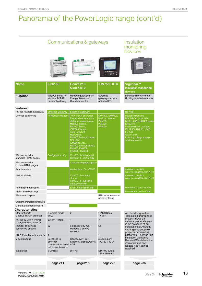
Communications & gateways Insulation monitoring Devices
Name Link150 Com'X 210Com'X 510
ION7550 RTU Vigilohm™ Insulation monitoring devices
Function Modbus Serial to Modbus TCP/IP protocol gateway
Modbus gateway plus Energy Server and Cloud connector
Ethernet gateway-server + onboard I/O
Insulation monitoring for IT / Ungrounded networks
FeaturesRS-485 / Ethernet gateway Ethernet Gateway Ethernet Gateway RS-485
Devices supported All Modbus devices 100+ known Schneider Electric devices and the ability to create custom Modbus models. EM3000 Series, iEM3000 Series, Acti9 Smartlink Masterpact,PM5000 Series, CompactNSX, iEM1,iEM2000 series,PM3000 Series, PM5350, PM5000, PM8000,ION9000, CM4000
ION8800, ION9000, Modbus devicesPM5350PM5000PM8000
Insulation Monitors: IM9, IM9-OL, IM10, IM20IM10-H, IM20-H, IM400 seriesIM400THRInsulation Fault Locators: IFL 12, IFL 12C, IFL 12MC, IFL 12H Accessories: Including voltage adaptors, cardews, toroids
Web server with standard HTML pages
Configuration only Com'X 510 - full supportCom'X 210 - config. only
Web server with custom HTML pages
Custom web page support
Real time data Available on Com'X 510 Available on product supervision e.g.PME, Com'X 510
Historical data Com'X 510 onboard storageCom'X 210 - publish to database server
Available on product supervision e.g.PME, Com'X 510
Automatic notification Event Notification to FI Available in supervision PME
Alarm and event logs Available in supervision PME
Waveform display RTU includes alarm and event logs
Custom animated graphics
Manual/automatic reports
CharacteristicsEthernet portsModbus TCP/IP protocol
2 (switch mode only)
2 10/100 Base TX port
An IT earthing system -also called ungrounded system- allows the network to operate even in the presence of an insulation fault, without endangering people or property. Required as part of the IT network, an Insulation Monitoring Device (IMD) detects the insulation fault and locates it so it can be repaired.
RS-485 (2-wire / 4-wire) ports, Modbus protocol
2w/4w - 1 (rj45) 1 3
Number of devices connected directly
32 64 devices/32 max Modbus, 2 analog sensors
64
RS-232 configuration ports 1 1
Miscellaneous Serial line to Ethernet connectivity - serial or Ethernet master
Connectivity: WiFi, Ethernet, Zigbee, GPRS, + 3G
modem port I/O (20 I/ 12 O)
Installation 9 DIN rail DIN rail DIN 192 cutout 186 x 186 mm
page 211 page 215 page 225 page 235
Panorama of the PowerLogic range (cont'd)POWERLOGIC CATALOG PANORAMA
13Version: 1.0 - 27/01/2020PLSED309005EN_01bVersion: 1.0 - 27/01/2020PLSED309005EN_01b

CURREBT TRANSFORMERS FUNCTIONS AND CHARACTERISTICS
Version: 1.0 - 24/01/2020PLSED309005EN_02
14
Current transformers Schneider Electric is the global specialist in energy management with the most complete power
monitoring product line. Current Transformers are essential components designed to be used with
Schneider Electric's extensive power monitoring product portfolio. From simple energy meters to world
class power quality meters, these proven products satisfy any requirement.
0568
54N
MD
-205
6852
NM
D-2
PB
1003
16-3
5
METSECT5CC04 METSECT5MB025 METSECT5CYL1 METSECT5GD025 METSECT5HA025
PB
1198
64P
B11
9870

CURRENT TRANSFORMERS FUNCTIONS AND CHARACTERISTICS
15Version: 1.0 - 24/01/2020PLSED309005EN_02Version: 1.0 - 24/01/2020PLSED309005EN_02
CT with let-through primaryConductor type
Cable Mixed, bars or cables Vertical or horizontal bars Vertical bars
Suggested Current Transformer and mounting D
B41
5986
DB
4159
20
DB
4159
88
DB
4159
89
DB
4159
21
DB
4159
87
Ratings (A) 40 to 250 150 to 800 200 to 4000 5000 to 6000
CT internal profile
Type C Type M Type D (1) Type V
MA
MB
MC
MD
(1) Two secondary connectors (parallel internal wiring - only one secondary winding) for easier cable access. 1 lateral + 1 on one extremity. Warning: only one must be used at a time.
Specific mounting: use of cylinderA cylindrical metallic spacer ensures a proper CT positioning when the conductor or the CT cannot be positioned perpendicular. Secured by bolt + nut.
CT with primary connection by screw and nut (example: use of cylinder with bar or cable)
DB
4160
05
METSECT5CYL1 (aluminium) 16550 (brass)
DB
4161
86
Application diagram of a CT.
VV
The Ip/5 A ratio current transformer delivers at the secondary a current (Is) of 0 to 5 A that is proportional to the current measured at the primary (Ip). This allows them to be used in combination with measurement equipment:
• Ammeters.
• Kilowatt-hour meters.
• Measurement units.
• Control relays.
• etc.
When the primary is energized, the measurement equipment nearly acts as a short circuit which keeps the secondary voltage very low. This voltage will increases significantly if the short circuit is removed.
CT selection - conductor rating aspectsThe choice depends on the conductor profile and the maximum intensity of the primary circuit.
Ip/5 A ratio
DB
4160
06
NOTE: This document is not intended to be used as an installation guide.
FF C
FF M
AFF
MD
FF D
FF V
2

CURREBT TRANSFORMERS FUNCTIONS AND CHARACTERISTICS
Version: 1.0 - 24/01/2020PLSED309005EN_02
16
CT selection - Electrical aspect Ip/5 A• We recommend that you choose the ratio immediately higher than the maximum measured current (In).
Example: In = 1103 A; ratio chosen = 1250/5.
• For small ratings: From 40/5 to 75/5 and for an application with digital devices, we recommend that you choose a higher rating, for example 100/5. This is because small ratings are less accurate and the 40 A measurement, for example, will be more accurate with a 100/5 CT than with a 40/5 CT.
• Specific case of the motor starter: to measure motor starter current, you must choose a CT with primary current Ip = Id/2 (Id = motor starting current).
Validation of measurement solution according to accuracy classIt consists in controlling the right adaptation of the CT on the accuracy class aspect. The accuracy class is specified in the project. The total dissipated power of the measurement circuit (meter + cables) should not be superior to the specified limit of the CT. This limit is for different standard classes. If necessary, the choice of the cable section, the CT or meter should be modified to fit the requirement.
Copper cable cross-section (mm2)
Power per doubled meter at 20 °C (VA)
Schneider Electric device
Consumption of the current input (VA)
Ammeter 72 x 72 / 96 x 96
1.1
Analog ammeter 1.1Digital ammeter 0.3PM8000 0.15PM3000 0.3PM5000iEM3000
1 1
1.5 0.685
2.5 0.41
4 0.254
6 0.169
10 0.0975
16 0.062
Application exampleProject specification: 200 A, in Ø27 mm cable, accuracy class 1.Our choice is METSECT5MA020.
For this CT selected on the chart (next page), the max acceptable power is 7 VA (for "Accuracy class 1" which is specified in the project).
Control of the conformity of the measurement chain:
b PM3000 multi-meter: 0.3 VA. b 4 meters of 2.5 mm2, doubled wires: 0.41 x 4 = 1.64 VA.
Total: 0.3 + 1.64 = 1.94 VA (< 7 VA)Conclusion: this CT is well adapted as the accuracy class will be even better than 1.
For each temperature variation per 10 °C bracket, the power drawn up by the cables increases by 4 %.
Internal profile type
Cables (mm)
Bars (mm)
Rating Ip/5 A (A)
Commercial reference number
Accuracy class0.5 1 3Max. power (VA)
MAØ27 10 x 32
15 x 25
150 METSECT5MA015 3 4 -200 METSECT5MA020 4 7 -250 METSECT5MA025 6 8 -300 METSECT5MA030 8 10 -400 METSECT5MA040 10 12 -
FF M
EH
azar
d L
abel

CURRENT TRANSFORMERS FUNCTIONS AND CHARACTERISTICS
17Version: 1.0 - 24/01/2020PLSED309005EN_02Version: 1.0 - 24/01/2020PLSED309005EN_02
Type C - solid core current transformer (cable profile)Internal profile type
Cables (mm)
Bars (mm)
Rating Ip/5 A (A)
Commercial ref number
CC Ø21 - 40 METSECT5CC004
50 METSECT5CC00560 METSECT5CC00675 METSECT5CC008100 METSECT5CC010125 METSECT5CC013150 METSECT5CC015200 METSECT5CC020250 METSECT5CC025
Type M - current transformers (mixed: cable/bar profile)MB
Ø26 12 x 40 15 x 32
250 METSECT5MB025300 METSECT5MB030400 METSECT5MB040
MAØ27 10 x 32
15 x 25150 METSECT5MA015200 METSECT5MA020250 METSECT5MA025300 METSECT5MA030400 METSECT5MA040
MCØ32 10 x 40
20 x 32 25 x 25
250 METSECT5MC025300 METSECT5MC030400 METSECT5MC040500 METSECT5MC050600 METSECT5MC060800 METSECT5MC080
MDØ40 12 x 50
20 x 40500 METSECT5MD050600 METSECT5MD060800 METSECT5MD080
PB
1124
46
METSECT5CCppp
METSECT5MBppp
PB
1124
60
PB
1124
62
METSECT5MAppp METSECT5MCppp
METSECT5MDppp
PB
1124
61P
B11
2463
See your Schneider Electric representative for complete ordering information.
FF M
CFF
MD
FF M
BFF
MA
FF C
C
PB
1180
85

CURREBT TRANSFORMERS FUNCTIONS AND CHARACTERISTICS
Version: 1.0 - 24/01/2020PLSED309005EN_02
18
Type C - solid core current transformer (cable profile)Internal profile type
Accuracy class Overall dimensions (refer to drawing pages for details) W x H x D (mm)
Fastening mode Accessories0.5 1 3 Cylinder
Max. power (VA)
CC Dimension (mm) Commercial ref no.
- - 1 44 x 66 x 37 b Adapter for DIN rails. b Mounting plate.
16550
METSECT5CYL1
Included- 1.25 1.5- 1.25 2- 1.5 2.52 2.5 3.52.5 3.5 43 4 54 5.5 65 6 7
MB3 5 - 60 x 85 x 63 b Adapter for DIN rails.
b Mounting plate.- METSECT5COVER
4 6 -6 8 -
MA3 4 - 56 x 80 x 63 b Adapter for DIN rails.
b Mounting plate.METSECT5CYL2 METSECT5COVER
4 7 -6 8 -8 10 -10 12 -
MC3 5 - 70 x 95 x 65 b Adapter for DIN rails.
b Mounting plate.- METSECT5COVER
5 8 -8 10 -10 12 -12 15 -10 12 -
MD4 6 - 70 x 95 x 65 b Adapter for DIN rails.
b Mounting plate.- METSECT5COVER
6 8 -8 12 -
Common characteristicsSecondary current Is (A) 5 AMaximum voltage rating Ue (V) 720 VFrequency (Hz) 50/60 HzSafety factor (sf) 40 to 4000 A: sf y 5
5000 to 6000 A: sf y 10Degree of protection IP20Operating temperature tropicalised range
-25°C to +60°C (1)
relative humidity > 95 %Storage temperature -40°C to +85°CCompliance with standards IEC 61869-2
VDE 0414Secondary connection (as per model) by terminals for lug
by tunnel terminalsby screws
(1) Warning: some products are limited to +50°C.DIN rail mounting.
DB
4159
27D
B41
5926
Mounting plate installation.
See your Schneider Electric representative for complete ordering information.
NOTE: This document is not intended to be used as an installation guide.
FF C
CFF
MB
FF M
AFF
MC
FF M
D
PB
1124
51
PB
1124
52

CURRENT TRANSFORMERS FUNCTIONS AND CHARACTERISTICS
19Version: 1.0 - 24/01/2020PLSED309005EN_02Version: 1.0 - 24/01/2020PLSED309005EN_02
METSECT5VVppp
PB
1124
54
PB
1124
55
METSECT5DAppp METSECT5DBppp
PB
1124
56
PB
1124
57
METSECT5DCppp METSECT5DDppp
PB
1124
59
METSECT5DEppp METSECT5DHppp
Type V - current transformers (vertical bar profile)Internal profile type
Cables (mm)
Bars (mm)
Rating Ip/5 A (A)
Commercial reference number
VV- 55 x 165 5000 METSECT5VV500 g
6000 METSECT5VV600 g
Type D - current transformers (vertical or horizontal bar - dual secondary terminals)DA
32 x 65 400 METSECT5DA040500 METSECT5DA050600 METSECT5DA060800 METSECT5DA0801000 METSECT5DA1001250 METSECT5DA125 g1500 METSECT5DA150 g
DB- 38 x 127 1000 METSECT5DB100
1250 METSECT5DB125 g1500 METSECT5DB150 g2000 METSECT5DB200 g2500 METSECT5DB250 g3000 METSECT5DB300 g
DC- 52 x 127 2000 METSECT5DC200 g
2500 METSECT5DC250 g3000 METSECT5DC300 g4000 METSECT5DC400 g
DD- 34 x 84 1000 METSECT5DD100
1250 METSECT5DD125 g1500 METSECT5DD150 g
DE- 54 x 102 1000 METSECT5DE100
1250 METSECT5DE125 g1500 METSECT5DE150 g2000 METSECT5DE200 g
DH- 38 x 102 1250 METSECT5DH125 g
1500 METSECT5DH150 g2000 METSECT5DH200 g
g Operating temperature: -25 °C to 50 °C
PB
1124
67
See your Schneider Electric representative for complete ordering information.
FF V
2
PB
1124
58

CURREBT TRANSFORMERS FUNCTIONS AND CHARACTERISTICS
Version: 1.0 - 24/01/2020PLSED309005EN_02
20
Type V - solid core current transformers (vertical bar profile)Internal profile type
Accuracy class Overall dimensions (refer to drawing pages for details) W x H x D (mm)
Fastening mode Accessories
0.5 1 3 Cylinder Sealable cover
Max. power (VA)
VV Dimension (mm) .
60 - - 175 x 273.5 x 110 b Insulated locking screw. - Included70 - -
Type D - solid core current transformers (vertical or horizontal bar - dual secondary terminals)DA Dimension (mm)
4 8 - 90 x 94 x 90 b Insulated locking screw. Included
8 10 -8 12 -12 15 -15 20 -15 20 -20 25 -
DB6 10 - 99 x 160 x 87 b Insulated locking screw. - Included8 12 -10 15 -15 20 -20 25 -25 30 -
DC25 30 - 125 x 160 x 87 b Insulated locking screw. - Included30 50 -30 50 -30 50 -
DD10 15 - 96 x 116 x 87 b Insulated locking screw. - Included12 15 -15 20 -
DE12 15 - 135 x 129 x 85 b Insulated locking screw. - Included15 20 -20 25 -20 25 -
DH12 15 - 98 x 129 x 75 b Insulated locking screw. - Included12 15 -20 25 -
g Operating temperature: -25 °C to 50 °C See your Schneider Electric representative for complete ordering information.
FF V
2
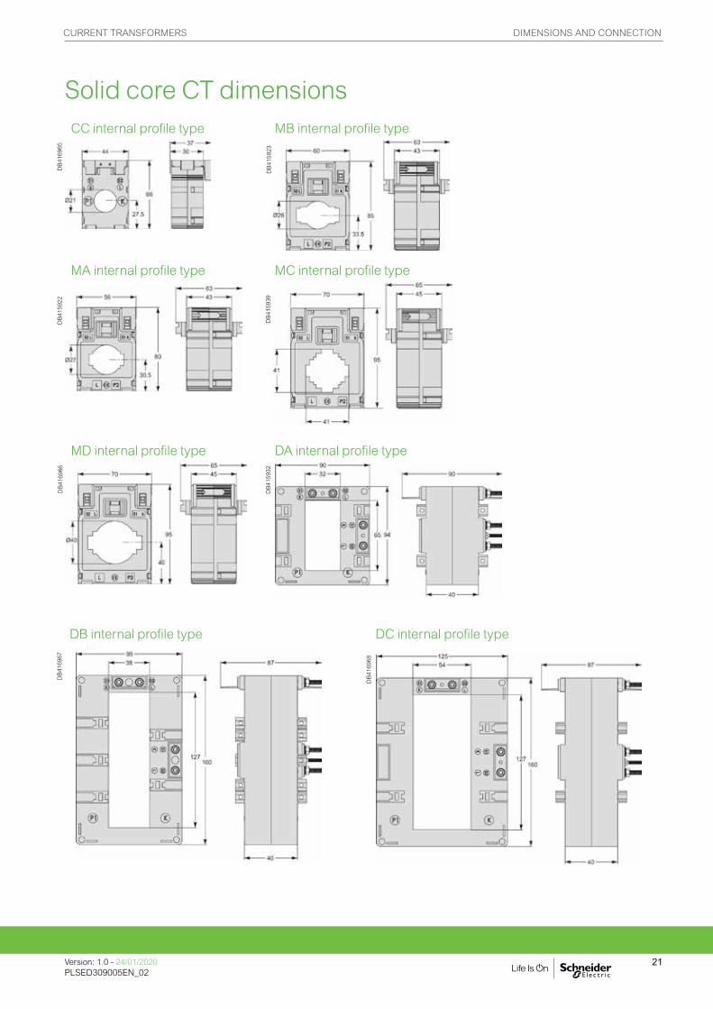
CURRENT TRANSFORMERS DIMENSIONS AND CONNECTION
Version: 1.0 - 24/01/2020PLSED309005EN_02
21
CC internal profile type MB internal profile type
DB
4169
65
MA internal profile type MC internal profile type
DB
4159
22
DB
4159
39
MD internal profile type DA internal profile type
DB
4169
66
DB
4159
32
DB internal profile type DC internal profile type
DB
4169
67
DB
4169
68
DB
4159
23
Solid core CT dimensions

CURRENT TRANSFORMERS DIMENSIONS AND CONNECTION
Version: 1.0 - 24/01/2020PLSED309005EN_02
22
DD internal profile type DE internal profile type
DB
4169
69
DB
4169
70
DH internal profile type
DB
4169
71
VV internal profile type
DB
4169
72
Solid core CT dimensions contd.
NOTE: This document is not intended to be used as an installation guide.

CURRENT TRANSFORMERS DIMENSIONS AND CONNECTION
Version: 1.0 - 24/01/2020PLSED309005EN_02
23
Solid core cylinders dimensions
CylindersMETSECT5CYL1 METSECT5CYL2
DB4
1600
4
DB4
1600
2
Aluminium Aluminium
16550 16551
DB4
1608
2
DB4
1600
0
Brass Brass
CoversMETSECT5COVER
DB4
1600
8

CURREBT TRANSFORMERS FUNCTIONS AND CHARACTERISTICS
Version: 1.0 - 24/01/2020PLSED309005EN_02
24
Split core CTCT internal profile
Type H Type G
HA HD HG HJ HP
GA GD GG GJ
HM
Split core CTs
Haz
ard
Lab
el
FF C
FF H
M
FF V
2
Common characteristics Cable CT Bus Bar CTSecondary current Is (A) 5 A 5 AMaximum voltage rating Ue (V) 720 V 720 VFrequency (Hz) 50/60 Hz 50/60 HzSafety factor (sf) up to 1000 A: sf y 5
greater than 1000 A: sf y 10
up to 1500 A: sf y 5greater than 1500 A: sf y 10
Degree of protection IP20 IP20Operating temperature -5°C to +50°C
relative humidity 5-85 %-5°C to +40°Crelative humidity 5-85 %
Storage temperature -25°C to +70°C -25°C to +70°CCompliance with standards IEC 61869-1
IEC 61869-2IEC 61869-1IEC 61869-2
Secondary connection (as per model) by terminals for lugby tunnel terminalsby screws
by terminals for lugby tunnel terminalsby screws

CURRENT TRANSFORMERS FUNCTIONS AND CHARACTERISTICS
25Version: 1.0 - 24/01/2020PLSED309005EN_02Version: 1.0 - 24/01/2020PLSED309005EN_02
Type G - split core current transformers (bus bar)Accuracy classMax power (VA)
CT window dimension (mm)
Rating Ip/5A (A)
Commercial Reference no.
0.5 1 3
GA
- - 1.25 23 x 33 100 METSECT5GA010- - 1.5 150 METSECT5GA015- - 2.5 200 METSECT5GA020- 1.5 - 250 METSECT5GA025- 3.75 - 300 METSECT5GA0301 - - 400 METSECT5GA040
GD
- 1.5 - 55 x 85 250 METSECT5GD025- 2.5 - 300 METSECT5GD0301 - - 400 METSECT5GD040
2.5 - - 500 METSECT5GD0502.5 - - 600 METSECT5GD0602.5 - - 750 METSECT5GD0752.5 - - 800 METSECT5GD0805 - - 1000 METSECT5GD100
GG- 1.5 - 85 x 125 250 METSECT5GG025- 2.5 - 300 METSECT5GG030- 2.5 - 400 METSECT5GG040
2.5 - - 500 METSECT5GG0502.5 - - 600 METSECT5GG0602.5 - - 750 METSECT5GG0752.5 - - 800 METSECT5GG0805 - - 1000 METSECT5GG1005 - - 1200 METSECT5GG120
7.5 - - 1250 METSECT5GG1257.5 - - 1500 METSECT5GG150
GJ10 - - 85 x 165 1000 METSECT5GJ10010 - - 1200 METSECT5GJ120
10 - - 1500 METSECT5GJ15010 - - 1600 METSECT5GJ16010 - - 2000 METSECT5GJ20010 - - 2500 METSECT5GJ25015 - - 3000 METSECT5GJ30015 - - 4000 METSECT5GJ400
See your Schneider Electric representative for complete ordering information.
Split core CTsP
B11
9862
PB
1198
64P
B11
9866
PB
1198
68
METSECT5GAppp
METSECT5GDppp
METSECT5GGppp
METSECT5GJppp

CURREBT TRANSFORMERS FUNCTIONS AND CHARACTERISTICS
Version: 1.0 - 24/01/2020PLSED309005EN_02
26
Type H - split core current transformers (cable)
Accuracy classMax power (VA)
CT window dimension (mm)
Rating Ip/5A (A)
Commercial Reference no.
0.5 1 3
HA- 1 - 18.4 x 19 150 METSECT5HA015- 1.5 - 150 METSECT5HA0201 - - 250 METSECT5HA025
HD- 1 - 27.9 x 27 250 METSECT5HD025- 1.5 - 300 METSECT5HD030- 2.5 - 400 METSECT5HD0401 - - 500 METSECT5HD050
HG - - 1.5 Ø32.5 100 METSECT5HG010- - 2.5 125 METSECT5HG013- - 3 150 METSECT5HG015- - 3 200 METSECT5HG020- - 3 250 METSECT5HG025- 2.5 - 300 METSECT5HG030- 5 - 400 METSECT5HG040- 5 - 500 METSECT5HG050- 5 - 600 METSECT5HG060
HJ- 2.5 - 42.4 x 43 300 METSECT5HJ030- 5 - 400 METSECT5HJ040- 5 - 500 METSECT5HJ050
2.5 - - 600 METSECT5HJ0602.5 - - 750 METSECT5HJ0752.5 - - 800 METSECT5HJ080
HM- 2.5 - 42.4 x 85 300 METSECT5HM030- 5 - 400 METSECT5HM040- 5 - 500 METSECT5HM050
2.5 - - 600 METSECT5HM0602.5 - - 750 METSECT5HM0752.5 - - 800 METSECT5HM080
HP- 1.5 - Ø44 250 METSECT5HP025- 2.5 - 300 METSECT5HP030- 5 - 400 METSECT5HP040- 5 - 500 METSECT5HP050- 5 - 600 METSECT5HP060- 5 - 750 METSECT5HP075- 5 - 800 METSECT5HP080- 5 - 1000 METSECT5HP100
See your Schneider Electric representative for complete ordering information.
Split core CTs contd.
PB
1198
70P
B11
9872
PB
1198
74P
B11
9876
METSECT5HAppp
METSECT5HDppp
METSECT5HGppp
METSECT5HJppp METSECT5HMppp METSECT5HPppp
PB
1198
78
PB
1198
80

CURRENT TRANSFORMERS DIMENSIONS AND CONNECTION
Version: 1.0 - 24/01/2020PLSED309005EN_02
27
Split core CT dimensions
GA Dimensions
GG Dimensions
GD Dimensions
GJ Dimensions
PB
1198
67P
B11
9863
PB
1198
65P
B11
9869
Gx products

CURRENT TRANSFORMERS DIMENSIONS AND CONNECTION
Version: 1.0 - 24/01/2020PLSED309005EN_02
28
HA Dimensions HD Dimensions
HG Dimensions HJ Dimensions
Split core CT dimensions contd.Hx products
PB
1198
77
PB
1198
75
PB
1198
73
PB
1198
71

CURRENT TRANSFORMERS DIMENSIONS AND CONNECTION
Version: 1.0 - 24/01/2020PLSED309005EN_02
29
HM Dimensions HP Dimensions
PB
1198
81
PB
1198
79
Split core CT dimensions contd.
CURREBT TRANSFORMERS FUNCTIONS AND CHARACTERISTICS
Version: 1.0 - 24/01/2020PLSED309005EN_02
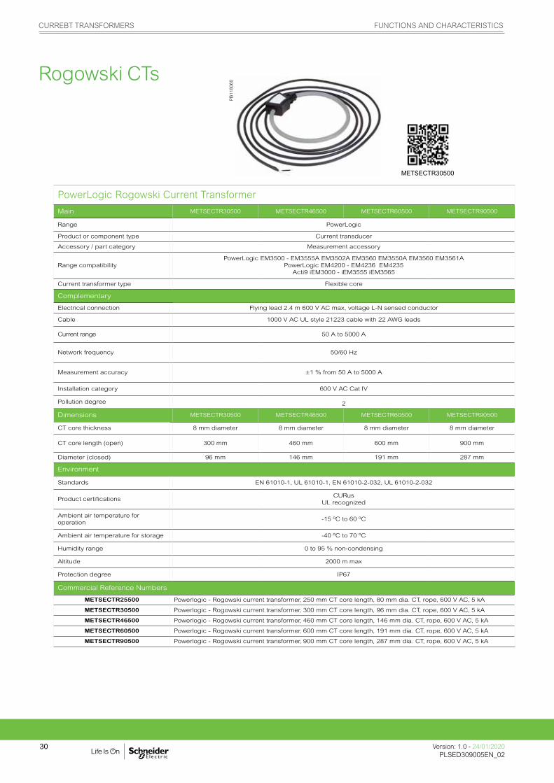
30
PowerLogic Rogowski Current Transformer
Main METSECTR30500 METSECTR46500 METSECTR60500 METSECTR90500
Range PowerLogic
Product or component type Current transducer
Accessory / part category Measurement accessory
Range compatibilityPowerLogic EM3500 - EM3555A EM3502A EM3560 EM3550A EM3560 EM3561A
PowerLogic EM4200 - EM4236 EM4235 Acti9 iEM3000 - iEM3555 iEM3565
Current transformer type Flexible core
Complementary
Electrical connection Flying lead 2.4 m 600 V AC max, voltage L-N sensed conductor
Cable 1000 V AC UL style 21223 cable with 22 AWG leads
Current range 50 A to 5000 A
Network frequency 50/60 Hz
Measurement accuracy ±1 % from 50 A to 5000 A
Installation category 600 V AC Cat IV
Pollution degree 2
Dimensions METSECTR30500 METSECTR46500 METSECTR60500 METSECTR90500
CT core thickness 8 mm diameter 8 mm diameter 8 mm diameter 8 mm diameter
CT core length (open) 300 mm 460 mm 600 mm 900 mm
Diameter (closed) 96 mm 146 mm 191 mm 287 mm
Environment
Standards EN 61010-1, UL 61010-1, EN 61010-2-032, UL 61010-2-032
Product certificationsCURus
UL recognized
Ambient air temperature for operation
-15 ºC to 60 ºC
Ambient air temperature for storage -40 ºC to 70 ºC
Humidity range 0 to 95 % non-condensing
Altitude 2000 m max
Protection degree IP67
Commercial Reference Numbers
METSECTR25500 Powerlogic - Rogowski current transformer, 250 mm CT core length, 80 mm dia. CT, rope, 600 V AC, 5 kA
METSECTR30500 Powerlogic - Rogowski current transformer, 300 mm CT core length, 96 mm dia. CT, rope, 600 V AC, 5 kA
METSECTR46500 Powerlogic - Rogowski current transformer, 460 mm CT core length, 146 mm dia. CT, rope, 600 V AC, 5 kA
METSECTR60500 Powerlogic - Rogowski current transformer, 600 mm CT core length, 191 mm dia. CT, rope, 600 V AC, 5 kA
METSECTR90500 Powerlogic - Rogowski current transformer, 900 mm CT core length, 287 mm dia. CT, rope, 600 V AC, 5 kA
PB
1180
60
METSECTR30500
Rogowski CTs

PANEL INSTRUMENTS FUNCTIONS AND CHARACTERISTICS
31Version: 1.0 - 24/01/2020PLSED309005EN_03Version: 1.0 - 24/01/2020PLSED309005EN_03
Panel instrumentsSchneider Electric panel instruments reliably comply with the most stringent standards, including IEC,
MID, UL, etc., and we thoroughly test all products with recognized, third-party laboratories.
Our products are simple to install, configure, and use. This saves our partners time and
money and lets them deliver the best solutions in a timely and cost-effective manner.
Whatever the size or type of application, the PowerLogic™ product line is an integral
part of smart panels.
DB
1190
06P
B11
2024
PB
1011
18
16029 15202 16003

PANEL INSTRUMENTS FUNCTIONS AND CHARACTERISTICS
Version: 1.0 - 24/01/2020PLSED309005EN_03
32
FunctioniAMPAmmeters measure the current flowing through an electric circuit in amps.
iVLTVoltmeters measure the potential (voltage) difference of an electric circuit in volts.
Common technical data
• Accuracy: Class 1.5.• Complies with standards IEC 60051-1, IEC 61010-1 and IEC 61000-4.• Ferromagnetic device.• Pseudo-linear scale over 90°.• Ammeters (except catalog number 16029): – connection on CT, ratio In/5, to be ordered separately interchangeable dials.
• Temperature: – operating temperature: -25 °C to 55 °C – reference temperature: 23 °C
• Influence of temperature on accuracy: ±0.03 %/°C.
• Utilisation frequency: 50 Hz to 60 Hz.
• Consumption: – AMP: 1.1 VA – VLT catalog number 15060: 2.5 VA – VLT catalog number 16061: 3.5 VA.
• Permanent overload: – AMP: 1.2 In – VLT: 1.2 Un.
• Maximum overload for 5 s: – AMP: 10 In – VLT: 2 Un.
• Connection: tunnel terminals for 1.5 to 6 mm2 rigid cables.
Commercial reference numbersType Scale Connection
with CTWidth in mod. of 9 mm
Comm. ref. no.
iAMP with direct connection
0-30 A no 8 16029
iAMP with connection on CT
Basic device (delivered without dial)
X/5 8 16030
Dial 0-5 A0-50 A 50/5 160320-75 A 75/5 160330-100 A 100/5 160340-150 A 150/5 160350-200 A 200/5 160360-250 A 250/5 160370-300 A 300/5 160380-400 A 400/5 160390-500 A 500/5 160400-600 A 600/5 160410-800 A 800/5 160420-1000 A 1000/5 160430-1500 A 1500/5 160440-2000 A 2000/5 16045
iVLT0-300 V 8 160600-500 V 8 16061
DB
1190
06
iAMP.
DB
1190
05
iVLT.
See your Schneider Electric representative for complete ordering information.
16029
16061

PANEL INSTRUMENTS FUNCTIONS AND CHARACTERISTICS
33Version: 1.0 - 24/01/2020PLSED309005EN_03Version: 1.0 - 24/01/2020PLSED309005EN_03
FunctioniAMPAmmeters measure in amps the current flowing through an electric circuit.
iVLTVoltmeters measure in volts the potential (voltage) difference of an electric circuit.
iFREFrequency meters measure in hertz the frequency of an electric circuit from 20 to 600 V AC.
Common technical data• Supply voltage: 230 V AC• Operating frequency: 50 Hz to 60 Hz.• Display by red LED: 3 digits, h = 8 mm (0.31 in).• Accuracy at full-scale : 0.5 % ±1 digit.• Consumption: max. 5 VA or rated 2.5 VA.• Degree of protection: – IP40 on front face. – IP20 at terminal level.• Connection: tunnel terminals for 2.5 mm2 cables.
Specific data10 A direct reading ammeter• Minimum value measured: 4 % of rating.
• Measurement input consumption: 1 VA.
Multi-rating ammeter• Ratings: – in direct reading: 5 A. – by CT (not supplied) configurable on the front face of the ammeter: 10, 15, 20, 25, 40, 50, 60, 100, 150, 200, 250, 400, 500, 600, 800, 1000, 1500, 2000, 2500, 4000, 5000 A.• Minimum value measured: 4 % of rating.• Measurement input consumption: 0.55 VA.
Voltmeter• Direct measurement: 0...600 V AC• Input impedance: 2 MW.• Minimum value measured: 4 % of rating.
Frequency meter• Minimum value measured: 20 Hz.• Maximum value measured: 100 Hz.• Full-scale display: 99.9 Hz.
Compliance with standards• Safety: IEC/EN 61010-1.• EMC electromagnetic compatibility: IEC/EN 65081-1 and IEC/EN 65082-2.
Commercial reference numbersType Scale Connection
with CTWidth in mod. of 9 mm
Comm. ref. no.
Direct reading iAMP0-10 A No 4 15202
Multi-rating iAMP0-5000 A As per rating 4 15209
iVLT0-600 V 4 15201
iFRE20-100 Hz 4 15208
PB
1120
24
iAMP.
PB
1120
23
iVLT.
PB
1120
25
iFRE.
See your Schneider Electric representative for complete ordering information.
15202
15201
15208
PANEL INSTRUMENTS FUNCTIONS AND CHARACTERISTICS
Version: 1.0 - 24/01/2020PLSED309005EN_03
34
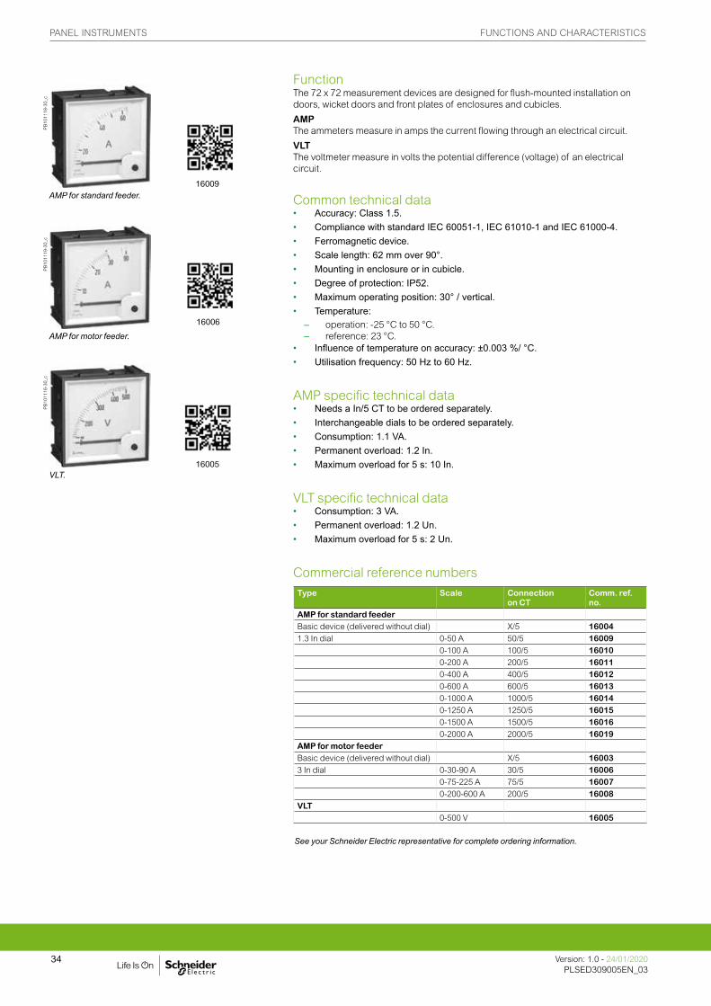
FunctionThe 72 x 72 measurement devices are designed for flush-mounted installation on doors, wicket doors and front plates of enclosures and cubicles.
AMPThe ammeters measure in amps the current flowing through an electrical circuit.
VLTThe voltmeter measure in volts the potential difference (voltage) of an electrical circuit.
Common technical data• Accuracy: Class 1.5.• Compliance with standard IEC 60051-1, IEC 61010-1 and IEC 61000-4.• Ferromagnetic device.• Scale length: 62 mm over 90°.• Mounting in enclosure or in cubicle.• Degree of protection: IP52.• Maximum operating position: 30° / vertical.• Temperature: – operation: -25 °C to 50 °C. – reference: 23 °C.• Influence of temperature on accuracy: ±0.003 %/ °C.• Utilisation frequency: 50 Hz to 60 Hz.
AMP specific technical data• Needs a In/5 CT to be ordered separately.• Interchangeable dials to be ordered separately.• Consumption: 1.1 VA.• Permanent overload: 1.2 In.• Maximum overload for 5 s: 10 In.
VLT specific technical data• Consumption: 3 VA.• Permanent overload: 1.2 Un.• Maximum overload for 5 s: 2 Un.
Commercial reference numbersType Scale Connection
on CTComm. ref. no.
AMP for standard feederBasic device (delivered without dial) X/5 160041.3 In dial 0-50 A 50/5 16009
0-100 A 100/5 160100-200 A 200/5 160110-400 A 400/5 160120-600 A 600/5 160130-1000 A 1000/5 160140-1250 A 1250/5 160150-1500 A 1500/5 160160-2000 A 2000/5 16019
AMP for motor feederBasic device (delivered without dial) X/5 160033 In dial 0-30-90 A 30/5 16006
0-75-225 A 75/5 160070-200-600 A 200/5 16008
VLT0-500 V 16005
PB
1011
18-3
0_c
AMP for standard feeder.
PB
1011
19-3
0_c
AMP for motor feeder.
PB
1011
16-3
0_c
VLT.
See your Schneider Electric representative for complete ordering information.
16009
16006
16005

PANEL INSTRUMENTS FUNCTIONS AND CHARACTERISTICS
35Version: 1.0 - 24/01/2020PLSED309005EN_03Version: 1.0 - 24/01/2020PLSED309005EN_03
FunctionThe 96 x 96 measurement devices are designed for flush-mounted installation on doors, wicket doors and front plates of enclosures and cubicles.
AMPThe ammeters measure in amps the current flowing through an electrical circuit.
VLTThe voltmeter measure in volts the potential difference (voltage) of an electrical circuit.
Common technical data• Accuracy: class 1.5.• Compliance with standard IEC 60051-1, IEC 61010-1 and IEC 61000-4.• Ferromagnetic device.• Scale length: 80 mm over 90°.• Mounting in enclosure or in cubicle.• Degree of protection: IP52.• Maximum operating position: 30° / vertical.• Temperature: – operation: -25 °C to 50 °C. – reference: 23 °C.• Influence of temperature on accuracy: ±0.003 % / °C.• Utilisation frequency: 50 Hz to 60 Hz.
AMP specific technical data• Needs a In/5 CT to be ordered separately.• Interchangeable dials to be ordered separately.• Consumption: 1.1 VA.• Permanent overload: 1.2 In.• Maximum overload for 5S: 10 In.
VLT specific technical data• Consumption: 3 VA.• Permanent overload: 1.2 Un.• Maximum overload for 5S: 2 Un.
Commercial reference numbersType Scale Connection
on CTComm. ref. no.
AMP for standard feederBasic device (delivered without dial) X/5 160741.3 In dial 0-50 A 50/5 16079
0-100 A 100/5 160800-200 A 200/5 160810-400 A 400/5 160820-600 A 600/5 160830-1000 A 1000/5 160840-1250 A 1250/5 160850-1500 A 1500/5 160860-2000 A 2000/5 160870-2500 A 2500/5 160880-3000 A 3000/5 160890-4000 A 4000/5 160900-5000 A 5000/5 160910-6000 A 6000/5 16092
AMP for motor feederBasic device (delivered without dial) X/5 160733 In dial 0-30-90 A 30/5 16076
0-75-225 A 75/5 160770-200-600 A 200/5 16078
VLT0-500 V 16075
PB
1011
18-4
0_c
AMP for standard feeder.
PB
1011
19-4
0_c
AMP for motor feeder.
PB
1011
16-4
0_c
VLT.
See your Schneider Electric representative for complete ordering information.
16079
16076
16075

PANEL INSTRUMENTS FUNCTIONS AND CHARACTERISTICS
Version: 1.0 - 24/01/2020PLSED309005EN_03
36
Common technical data• Durability: – electrical: 100,000 operations. – mechanical: 2,000,000 operations.• AgNi contact.• Operating temperature: -25 °C to 50 °C.• Compliance with standards IEC/EN 60947-3.• Degree of protection: – IP65 on front face. – IP20 at terminal level.
Commercial reference numbersType Rating
(A)Voltage(V)
Number of positions
Comm. ref. no.
CMA 20 4 16017CMV 500 7 16018
Connection
DB
1172
74
CMA.
DB
1142
75
CMV.
Reading 3 phase-to-earth voltages + 3 phase-to-phase voltages.Note: when connecting do not remove the pre-cabling.See appropriate Installation Guide for this product.
See your Schneider Electric representative for complete ordering information.
FunctionThe 48 x 48 selector switches are designed for flush-mounted installation on doors, wicket doors and front plates of enclosures and cubicles.
CMAThe ammeter selector switch uses a single ammeter (by means of current transformers) for successive measurement of the currents of a three-phase circuit.
CMVThe voltmeter selector switch uses a single voltmeter for successive measurement of the voltages (phase-to-phase and phase-to-neutral) of a three-phase circuit.
PANEL INSTRUMENTS FUNCTIONS AND CHARACTERISTICS
37Version: 1.0 - 24/01/2020PLSED309005EN_03Version: 1.0 - 24/01/2020PLSED309005EN_03
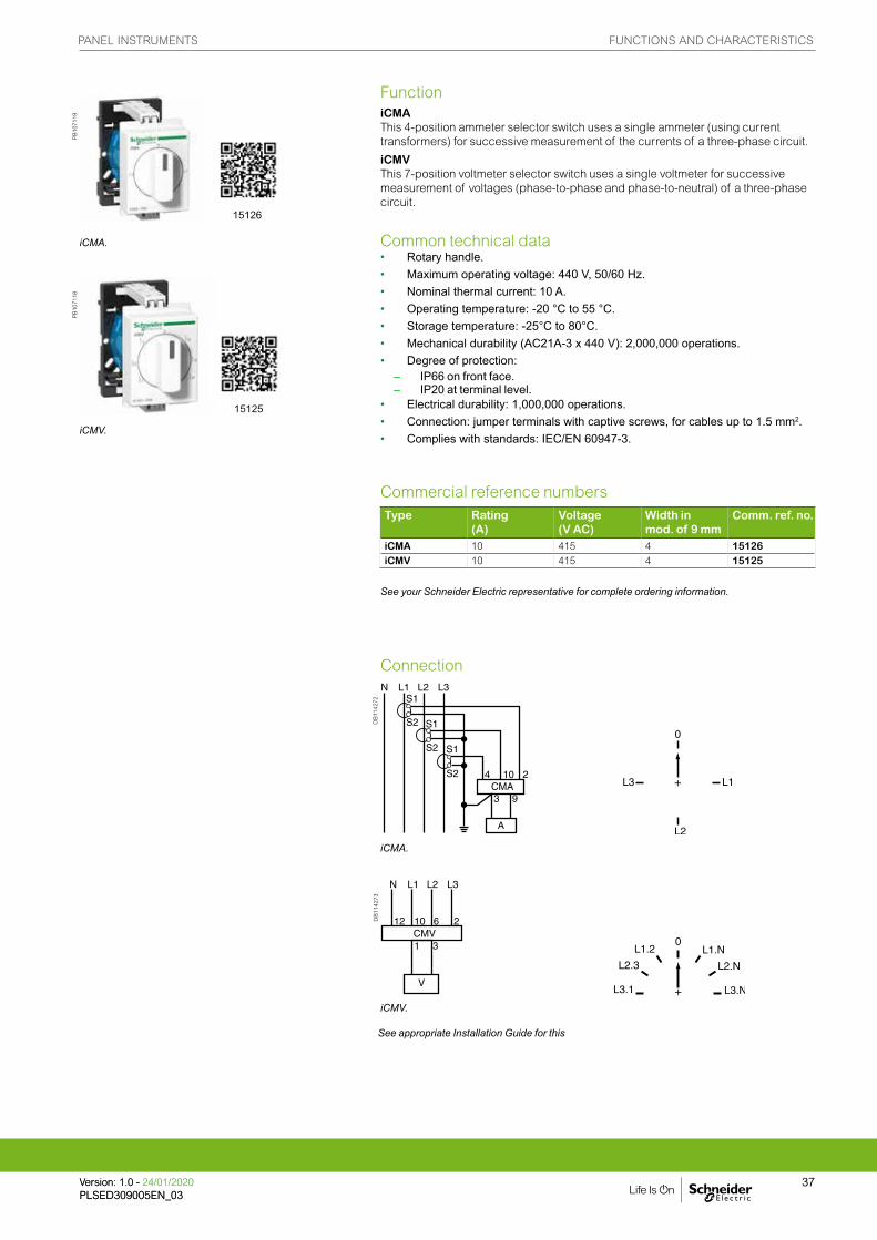
FunctioniCMAThis 4-position ammeter selector switch uses a single ammeter (using current transformers) for successive measurement of the currents of a three-phase circuit.
iCMVThis 7-position voltmeter selector switch uses a single voltmeter for successive measurement of voltages (phase-to-phase and phase-to-neutral) of a three-phase circuit.
Common technical data• Rotary handle.• Maximum operating voltage: 440 V, 50/60 Hz.• Nominal thermal current: 10 A.• Operating temperature: -20 °C to 55 °C.• Storage temperature: -25°C to 80°C.• Mechanical durability (AC21A-3 x 440 V): 2,000,000 operations.• Degree of protection: – IP66 on front face. – IP20 at terminal level.• Electrical durability: 1,000,000 operations.• Connection: jumper terminals with captive screws, for cables up to 1.5 mm2.• Complies with standards: IEC/EN 60947-3.
Commercial reference numbersType Rating
(A)Voltage (V AC)
Width in mod. of 9 mm
Comm. ref. no.
iCMA 10 415 4 15126iCMV 10 415 4 15125
Connection
DB
1142
72
iCMA.
DB
1142
73
iCMV.
PB
1071
19
iCMA.
PB
1071
18
iCMV.
See appropriate Installation Guide for this
See your Schneider Electric representative for complete ordering information.
15126
15125
PANEL INSTRUMENTS FUNCTIONS AND CHARACTERISTICS
Version: 1.0 - 24/01/2020PLSED309005EN_03
38
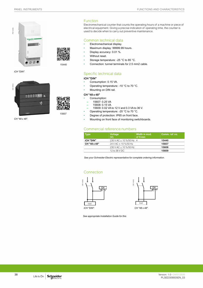
FunctionElectromechanical counter that counts the operating hours of a machine or piece of electrical equipment. Giving a precise indication of operating time, the counter is used to decide when to carry out preventive maintenance.
Common technical data• Electromechanical display.• Maximum display: 99999.99 hours.• Display accuracy: 0.01 %.• Without reset.• Storage temperature: -25 °C to 85 °C.• Connection: tunnel terminals for 2.5 mm2 cable.
Specific technical dataiCH "DIN"• Consumption: 0.15 VA.• Operating temperature: -10 °C to 70 °C.• Mounting on DIN rail.
CH "48 x 48"• Consumption: – 15607: 0.25 VA – 15608: 0.15 VA – 15609: 0.02 VA to 12 V and 0.3 VA to 36 V.• Operating temperature: -20 °C to 70 °C.• Degree of protection: IP65 on front face.• Mounting on front face of monitoring switchboards.
Commercial reference numbersType Voltage
(V)Width in mod.of 9 mm
Comm. ref. no.
iCH "DIN" 230 V AC ± 10 %/50 Hz 4 15440CH "48 x 48" 24 V AC ± 10 %/50 Hz 15607
230 V AC ± 10 %/50 Hz 1560812 to 36 V DC 15609
Connection
DB
1142
62
DB
1142
63
iCH "DIN". CH "48 x 48".
PB
1120
26
iCH "DIN".
DB
1190
03
CH "48 x 48".
load load
See appropriate Installation Guide for this
See your Schneider Electric representative for complete ordering information.
15440
15607
PANEL INSTRUMENTS FUNCTIONS AND CHARACTERISTICS
39Version: 1.0 - 24/01/2020PLSED309005EN_03Version: 1.0 - 24/01/2020PLSED309005EN_03
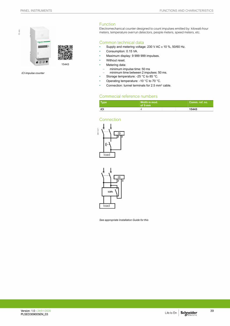
FunctionElectromechanical counter designed to count impulses emitted by: kilowatt-hour meters, temperature overrun detectors, people meters, speed meters, etc.
Common technical data• Supply and metering voltage: 230 V AC ± 10 %, 50/60 Hz.• Consumption: 0.15 VA.• Maximum display: 9 999 999 impulses.• Without reset.• Metering data: – minimum impulse time: 50 ms – minimum time between 2 impulses: 50 ms.• Storage temperature: -25 °C to 85 °C.• Operating temperature: -10 °C to 70 °C.• Connection: tunnel terminals for 2.5 mm2 cable.
Commecial reference numbersType Width in mod.
of 9 mmComm. ref. no.
iCI 4 15443
Connection
DB
1142
71
iCL.
eps
iCI impulse counter
load
load
See appropriate Installation Guide for this
15443

PANEL INSTRUMENTS DIMENSIONS AND CONNECTION
Version: 1.0 - 24/01/2020PLSED309005EN_03
40
Analog ammeters and voltmeters iAMP, iVLT
DB
1034
73
Digital ammeters, voltmeter and frequency meter iAMP, iVLT
DB
1034
74
iCMA and iCMV selector switches
DB
1034
75
72 x 72 analog ammeters and voltmeter
DB
1034
76
96 x 96 analog ammeters and voltmeter
DB
1034
81
Protection cover
Capot de protection
TerminalM4
Protection cover
Capot de protection
TerminalM4
See the appropriate Installation Guide for this product.
PANEL INSTRUMENTS DIMENSIONS AND CONNECTION
Version: 1.0 - 24/01/2020PLSED309005EN_03
41
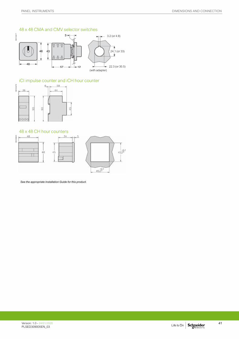
48 x 48 CMA and CMV selector switches
DB
1034
77
iCI impulse counter and iCH hour counter
DB
1034
79
48 x 48 CH hour counters
DB
1098
25
3.2 (or 4.8)
24.1 (or 33)
22.3 (or 30.5)(with adapter)
See the appropriate Installation Guide for this product.
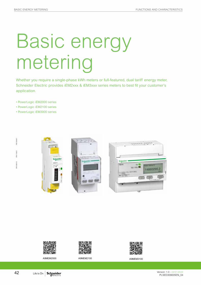
Basic energy metering Whether you require a single-phase kWh meters or full-featured, dual tariff energy meter, Schneider Electric provides iEM2xxx & iEM3xxx series meters to best fit your customer’s application.
• PowerLogic iEM2000 series
• PowerLogic iEM2100 series
• PowerLogic iEM3000 series
PB
108401
PB
115001
PB
108410
A9MEM2000 A9MEM2100 A9MEM3100
BASIC ENERGY METERING FUNCTIONS AND CHARACTERISTICS
Version: 1.0 - 24/01/2020PLSED309005EN_04
42
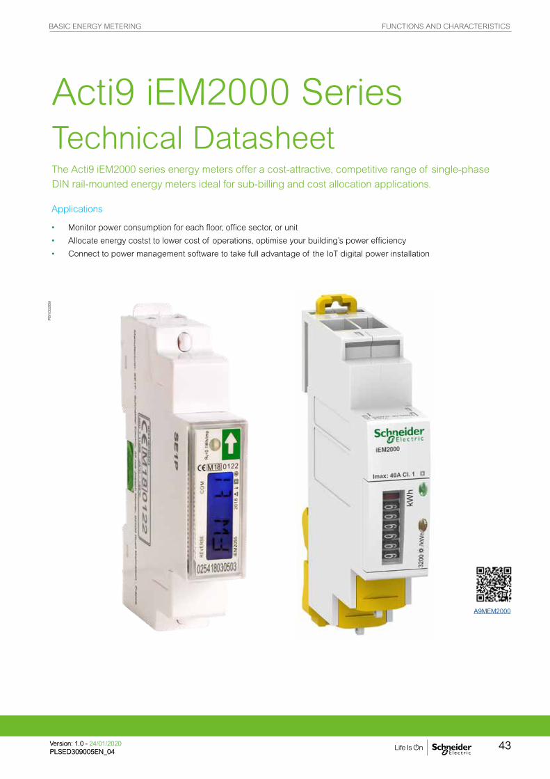
The Acti9 iEM2000 series energy meters offer a cost-attractive, competitive range of single-phase
DIN rail-mounted energy meters ideal for sub-billing and cost allocation applications.
Acti9 iEM2000 Series Technical Datasheet
Applications
• Monitor power consumption for each floor, office sector, or unit
• Allocate energy costst to lower cost of operations, optimise your building’s power efficiency
• Connect to power management software to take full advantage of the IoT digital power installation
PB
105289
A9MEM2000
BASIC ENERGY METERING FUNCTIONS AND CHARACTERISTICS
43Version: 1.0 - 24/01/2020PLSED309005EN_04Version: 1.0 - 24/01/2020PLSED309005EN_04
The solution for:
All markets that can benefit from a solution that includes PowerLogic iEM2000 series meters:
• Buildings
• Industry
• Data Centre & networks
• Infrastructures (airport, road tunnels, telecom).
Advantages
• Active energy Class 1 accuracy, with LCD display
• Modbus RS-485 and pulse output
• Direct connect, self-powered
• MID approved
• Two tariffs
Benefits
The Acti9 iEM2000 series meters are economical and easy to install in panelboards and switchboards:
• DIN rail mounted, compact size
• Accurate data measurement with Class 1 accuracy
Energy management system:
To get the most effective use from your Schneider Electric measurement and metering devices, we offer a range of dedicated data loggers and gateways for your building energy management.
Conformity of standards
• IEC 62053-21
• EN 50470-3
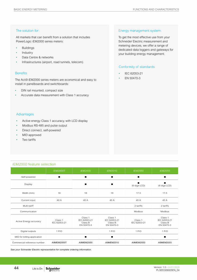
iEM2000 feature selection
iEM2000T iEM2000 iEM2010 iEM2050 iEM2055
Self-powered n n n n n
Display n n n (6 digit LCD)
n (6 digit LCD)
Width (mm) 18 18 18 17.5 17.5
Current input 40 A 40 A 40 A 45 A 45 A
Multi-tariff 2 tariffs 2 tariffs
Communication Modbus Modbus
Active Energy accuracyClass 1
IEC 62053-21
Class 1IEC 62053-21
Class BEN 50470-3
Class 1IEC 62053-21
Class BEN 50470-3
Class 1IEC 62053-21
Class 1IEC 62053-21
Class BEN 50470-3
Digital outputs 1 P/O 1 P/O 1 P/O 1 P/O
MID for billing application n n n
Commercial reference number A9MEM2000T A9MEM2000 A9MEM2010 A9MEM2050 A9MEM2055
See your Schneider Electric representative for complete ordering information.
BASIC ENERGY METERING FUNCTIONS AND CHARACTERISTICS
Version: 1.0 - 24/01/2020PLSED309005EN_04
44
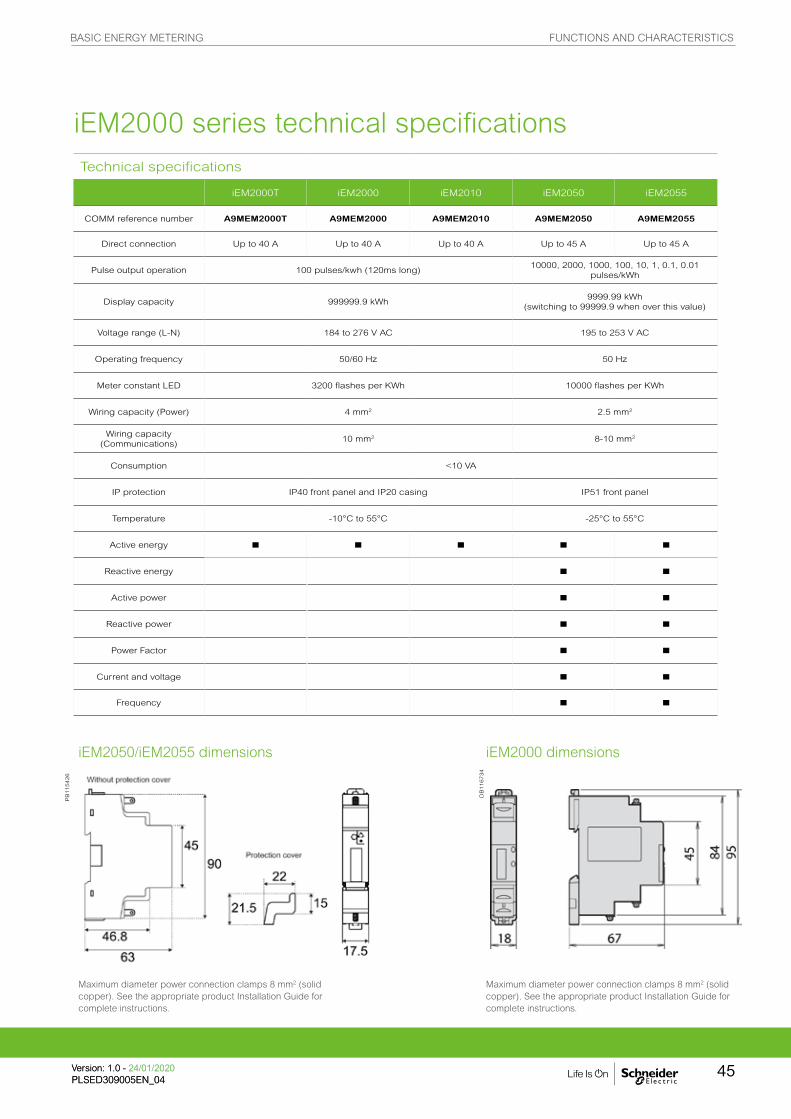
iEM2000 dimensionsiEM2050/iEM2055 dimensions
Maximum diameter power connection clamps 8 mm2 (solid copper). See the appropriate product Installation Guide for complete instructions.
Maximum diameter power connection clamps 8 mm2 (solid copper). See the appropriate product Installation Guide for complete instructions.
Technical specifications
iEM2000T iEM2000 iEM2010 iEM2050 iEM2055
COMM reference number A9MEM2000T A9MEM2000 A9MEM2010 A9MEM2050 A9MEM2055
Direct connection Up to 40 A Up to 40 A Up to 40 A Up to 45 A Up to 45 A
Pulse output operation 100 pulses/kwh (120ms long)10000, 2000, 1000, 100, 10, 1, 0.1, 0.01
pulses/kWh
Display capacity 999999.9 kWh9999.99 kWh
(switching to 99999.9 when over this value)
Voltage range (L-N) 184 to 276 V AC 195 to 253 V AC
Operating frequency 50/60 Hz 50 Hz
Meter constant LED 3200 flashes per KWh 10000 flashes per KWh
Wiring capacity (Power) 4 mm2 2.5 mm2
Wiring capacity (Communications)
10 mm2 8-10 mm2
Consumption <10 VA
IP protection IP40 front panel and IP20 casing IP51 front panel
Temperature -10°C to 55°C -25°C to 55°C
Active energy n n n n n
Reactive energy n n
Active power n n
Reactive power n n
Power Factor n n
Current and voltage n n
Frequency n n
iEM2000 series technical specifications
DB
116734
PB
115426
BASIC ENERGY METERING FUNCTIONS AND CHARACTERISTICS
45Version: 1.0 - 24/01/2020PLSED309005EN_04Version: 1.0 - 24/01/2020PLSED309005EN_04
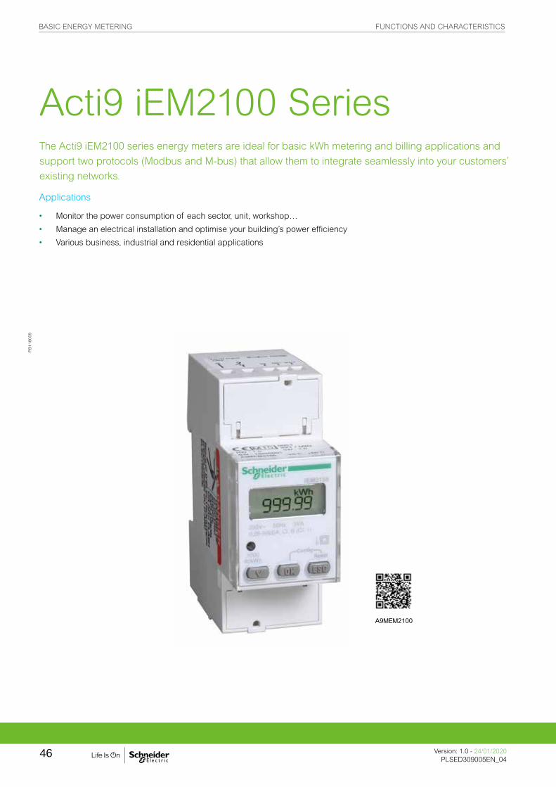
The Acti9 iEM2100 series energy meters are ideal for basic kWh metering and billing applications and
support two protocols (Modbus and M-bus) that allow them to integrate seamlessly into your customers’
existing networks.
Acti9 iEM2100 Series
Applications
• Monitor the power consumption of each sector, unit, workshop…
• Manage an electrical installation and optimise your building’s power efficiency
• Various business, industrial and residential applications
PB
118059
A9MEM2100
BASIC ENERGY METERING FUNCTIONS AND CHARACTERISTICS
Version: 1.0 - 24/01/2020PLSED309005EN_04
46

The solution for
All markets that can benefit from a solution that includes PowerLogic iEM2100 series meters:
• Buildings
• Industry
• Data Centre & networks
• Infrastructures (airport, road tunnels, telecom).
Energy management system:
To get the most effective use from your Schneider Electric measurement and metering devices, we offer a range of dedicated data loggers and gateways for your building energy management.
Competitive advantages
• Compact size
• MID compliant (selected models) providing certified accuracy and data security
• Four quadrant measurement
• Electrical parameter measurement eg. V, I, P, PF
• Onboard Modbus or M-bus communication
• A complete range of energy meters
• Compatible with Acti9 range
iEM2100 feature selection
iEM2100 iEM2105 iEM2110 iEM2135 IEM2150 iEM2155
Self-powered n n n n n n
Display n n n n n n
Width (mm) 36 36 36 36 36 36
Current input 63 A 63 A 63 A 63 A 63 A 63 A
Active Energy accuracy
Class 1 Class 1 Class 1 Class 1 Class 1 Class 1
Reactive Energy accuracy
Class 2 Class 2 Class 2 Class 2 Class 2 Class 2
Four quadrant Energy
measurementn n n n
Multi-tariff 2 2 2
Digital inputs 1 (tariff switching) 1 (tariff switching) 1 (tariff switching)
Digital outputs 1 P/O 2 P/O's
Communication protocol
M-bus Modbus RS-485 Modbus RS-485
MID for billing application n n n
Commercial reference number
A9MEM2100 A9MEM2105 A9MEM2110 A9MEM2135 A9MEM2150 A9MEM2155
Conformity of standards
• IEC 62052-11
• IEC 62053-21
• IEC 62053-23
• EN 50470-1
• EN 50470-3
Benefits
The Acti9 iME kilowatt-hour meters are specially economic and easy to install in all switchboards.
47
BASIC ENERGY METERING FUNCTIONS AND CHARACTERISTICS
47Version: 1.0 - 24/01/2020PLSED309005EN_04Version: 1.0 - 24/01/2020PLSED309005EN_04

iEM2100/iEM2105 dimensions iEM2110/iEM2135/iEM2150/iEM2155 dimensions
See the appropriate product
Installation Guide for
complete instructions.
Technical specifications
iEM2100 iEM2105 iEM2110 iEM2135 IEM2150 iEM2155
Direct connection 63 A 63 A 63 A 63 A 63 A 63 A
Pulse output operation
1 pulse/kwh (200ms long)
1 to 1000 pulses / kwh or kvarh (30 to
100ms long)
Display capacity 99999 KWh or 999.99 MWh 999999.99KWh
Voltage range (L-N) 184 to 276 V AC 92 to 276 V AC
Operating frequency
50/60 Hz
Meter constant LED 1000 flashes per KWh
Wiring capacity (Top)
6 mm2 4 mm2
Wiring capacity (Bottom)
32 mm2 (16 mm2 iEM2100/iEM2105)
Consumption 2.5 VA 3 VA
IP protection IP40 front panel and IP20 casing
Temperature -25°C to 55°C
Active energy n n n n n n
Reactive energy n n n n
Active power n n n n
Reactive power n n n n
Power Factor n n n n
Current and voltage n n n n
Frequency n n n n
DB1
0348
3
PB11
5003
Acti9 iEM2100 series technical specifications
BASIC ENERGY METERING FUNCTIONS AND CHARACTERISTICS
Version: 1.0 - 24/01/2020PLSED309005EN_04
48

Comm. reference number Product
A9MEM2000T iEM2000T basic energy meter, no display
A9MEM2000 iEM2000 basic energy meter
A9MEM2010 iEM2010 energy meter, kWh pulse output
A9MEM2100 iEM2100 basic energy meter
A9MEM2050 iEM2050 modular single phase power meter 230 V - 45 A with Modbus
A9MEM2055 iEM2055 modular single phase power meter 230 V - 45 A with Modbus, MID
A9MEM2105 iEM2105 energy meter, kWh pulse output with partial meter
A9MEM2110 iEM2110 energy meter, kWh and kvarh pulse outputs with two tariffs, four quadrant energy measurement, MID certified
A9MEM2135 iEM2135 energy meter, M-Bus communication, four quadrant energy measurement, two tariffs, MID certified
A9MEM2150 iEM2150 energy meter, Modbus communication, four quadrant energy measurement
A9MEM2155 iEM2155 energy meter, Modbus communication, four quadrant energy measurement, two tariffs, MID certified
iEM2000 and iEM2100 series commercial reference numbers
See your Schneider Electric representative for complete ordering information.
BASIC ENERGY METERING FUNCTIONS AND CHARACTERISTICS
49Version: 1.0 - 24/01/2020PLSED309005EN_04Version: 1.0 - 24/01/2020PLSED309005EN_04
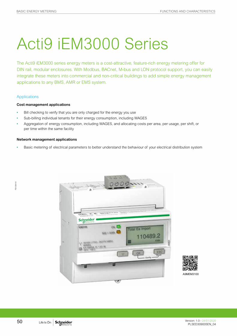
Applications
Cost management applications
• Bill checking to verify that you are only charged for the energy you use
• Sub-billing individual tenants for their energy consumption, including WAGES
• Aggregation of energy consumption, including WAGES, and allocating costs per area, per usage, per shift, or per time within the same facility
Network management applications
• Basic metering of electrical parameters to better understand the behaviour of your electrical distribution system
Acti9 iEM3000 Series The Acti9 iEM3000 series energy meters is a cost-attractive, feature-rich energy metering offer for
DIN rail, modular enclosures. With Modbus, BACnet, M-bus and LON protocol support, you can easily
integrate these meters into commercial and non-critical buildings to add simple energy management
applications to any BMS, AMR or EMS system.
PB
108418
A9MEM3100
BASIC ENERGY METERING FUNCTIONS AND CHARACTERISTICS
Version: 1.0 - 24/01/2020PLSED309005EN_04
50

The solution for
All markets that can benefit from a solution that includes PowerLogic iEM3000 series meters:
• Buildings & industry
• Data centres and networks
• Infrastructure (airports, road tunnels, telecom)
Conformity of standards
• IEC 61557-12
• IEC 62053-21/22
• IEC 62053-23
• EN 50470-3
• EN 50470-1
• IEC 61036
• IEC 61010
Benefits
Optimise your energy consumption & enable energy efficiency practices
• Collect and analyse energy consumption data from each area for each type of load or circuit
• Gain an accurate understanding of business expenses by allocating the energy-related costs
• Use information to implement actions designed to reduce energy consumption
Monitor the energy consumption of your tenants or customers and establish accurate invoices
• Drive energy-efficient behaviour
• Allow building owners to bill tenants for individual measured utility usage
• Give accurate and achievable objectives for energy savings
More than just kWh meters, the Acti9 iEM3000 series meters provide a full view of both energy consumption and on-site generation with full four-quadrant measurement of active and reactive energy delivered and received. Additionally, extensive real-time measurements (V, I, P, PF) give customers greater detail on their energy usage, and multiple tariffs give customers the flexibility to match the billing structure of their utility.
Energy management system:
To get the most effective use from your Schneider Electric measurement and metering devices, we offer a range of dedicated data loggers and gateways for your building energy management.
Competitive advantages
• Compact size
• MID compliant (selected models) providing certified accuracy and data security
• Programmable digital inputs/ouputs
• Multi-tariff capability
• Onboard Modbus, LON, M-bus or BACnet communication
• A complete range of energy meters
• Compatible with Acti9 range
BASIC ENERGY METERING FUNCTIONS AND CHARACTERISTICS
51Version: 1.0 - 24/01/2020PLSED309005EN_04Version: 1.0 - 24/01/2020PLSED309005EN_04
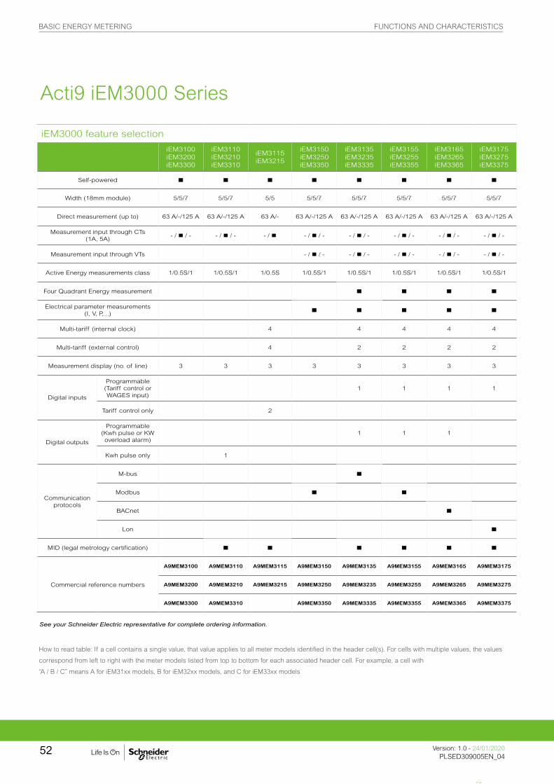
iEM3000 feature selection
iEM3100iEM3200iEM3300
iEM3110iEM3210iEM3310
iEM3115iEM3215
iEM3150iEM3250iEM3350
iEM3135iEM3235iEM3335
iEM3155iEM3255iEM3355
iEM3165iEM3265iEM3365
iEM3175iEM3275iEM3375
Self-powered n n n n n n n n
Width (18mm module) 5/5/7 5/5/7 5/5 5/5/7 5/5/7 5/5/7 5/5/7 5/5/7
Direct measurement (up to) 63 A/-/125 A 63 A/-/125 A 63 A/- 63 A/-/125 A 63 A/-/125 A 63 A/-/125 A 63 A/-/125 A 63 A/-/125 A
Measurement input through CTs (1A, 5A)
- / n / - - / n / - - / n - / n / - - / n / - - / n / - - / n / - - / n / -
Measurement input through VTs - / n / - - / n / - - / n / - - / n / - - / n / -
Active Energy measurements class 1/0.5S/1 1/0.5S/1 1/0.5S 1/0.5S/1 1/0.5S/1 1/0.5S/1 1/0.5S/1 1/0.5S/1
Four Quadrant Energy measurement n n n n
Electrical parameter measurements (I, V, P,...) n n n n n
Multi-tariff (internal clock) 4 4 4 4 4
Multi-tariff (external control) 4 2 2 2 2
Measurement display (no. of line) 3 3 3 3 3 3 3 3
Digital inputs
Programmable (Tariff control or WAGES input)
1 1 1 1
Tariff control only 2
Digital outputs
Programmable (Kwh pulse or KW overload alarm)
1 1 1
Kwh pulse only 1
Communication protocols
M-bus n
Modbus n n
BACnet n
Lon n
MID (legal metrology certification) n n n n n n
Commercial reference numbers
A9MEM3100 A9MEM3110 A9MEM3115 A9MEM3150 A9MEM3135 A9MEM3155 A9MEM3165 A9MEM3175
A9MEM3200 A9MEM3210 A9MEM3215 A9MEM3250 A9MEM3235 A9MEM3255 A9MEM3265 A9MEM3275
A9MEM3300 A9MEM3310 A9MEM3350 A9MEM3335 A9MEM3355 A9MEM3365 A9MEM3375
How to read table: If a cell contains a single value, that value applies to all meter models identified in the header cell(s). For cells with multiple values, the values
correspond from left to right with the meter models listed from top to bottom for each associated header cell. For example, a cell with
“A / B / C” means A for iEM31xx models, B for iEM32xx models, and C for iEM33xx models
Acti9 iEM3000 Series
52
See your Schneider Electric representative for complete ordering information.
BASIC ENERGY METERING FUNCTIONS AND CHARACTERISTICS
Version: 1.0 - 24/01/2020PLSED309005EN_04
52

EM3400/iEM3500 technical specifications
iEM3455 iEM3465 iEM33555 iEM3565
Max current 0.333V-1.0V LVCTs 0.333V-1.0V LVCTs Rogowski coils Rogowski coils
Meter constant LED 5000/kWh
Pulse output frequency Up to 500p/kWh
Multi-tariff 4 tariffs
Communication Modbus BACnet Modbus BACnet
DI/DO 1/1
Network1P+N, 3P, 3P+N
support LVCTs, Rogowski coils, and VTs
Wiring capacity 6 mm² for currents and 4 mm² for voltages
Display max LCD 99999999.9kWh or 99999999.9MWh
Voltage (L-L) 3 x 100/173 V AC to 3 x 277/480 V AC (50/60 Hz)
IP protection IP40 front panel and IP20 casing
Temperature -25°C to 70°C (K55)
Product size 5 steps of 18 mm
Overvoltage & measurement Category III, Degree of pollution 2
kWh n
kVARh n
Active power n
Reactive power n
Currents & voltages n
Overload alarm n
Hour counter n
Acti9 iEM3000 Series
53
See your Schneider Electric representative for complete ordering information.
BASIC ENERGY METERING FUNCTIONS AND CHARACTERISTICS
53Version: 1.0 - 24/01/2020PLSED309005EN_04Version: 1.0 - 24/01/2020PLSED309005EN_04

Acti9 iEM3100/iEM3300 series technical specifications
Technical specifications
iEM3100 iEM3300
iEM3110iEM3310
iEM3115iEM3150iEM3350
iEM3135 iEM3335
iEM3155iEM3355
iEM3165iEM3365
iEM3175iEM3375
Max current (direct connection) 63 A for iEM3100 models, 125 A for iEM3300 models
Meter constant LED 500/kWh
Pulse outputUp to
1000 p/kWhUp to
1000 p/kWhUp to
1000 p/kWh
Multi-tariff 4 tariffs 4 tariffs 4 tariffs
Communication Modbus Modbus Modbus BACnet LON
DI/DO 0/1 2/0 1/1 1/1 1/1 1/0
MID (EN50470-3) n n n n n
Network 1P+N, 3P, 3P+N
Accuracy class Class 1 (IEC 62053-21 and IEC 61557-12) Class B (EN 50470-3)
Wiring capacity 16 mm² for iEM3100 models, 50 mm2 for iEM3300 models
Display max. LCD 99999999.9kWh
Voltage (L-L) 3 x 100/173 V AC to 3 x 277/480 V AC (50/60 Hz)
IP protection IP40 front panel and IP20 casing
Temperature -25°C to 55°C (K55)
Product size 5 x 18 mm for iEM3100 models, 7 x 18 mm for iEM3300 models
Overvoltage and measurement Category III, Degree of pollution 2
kWh n n n n n n n n
kVARh n n n n
Active power n n n n n
Reactive power n n n n
Currents and voltages n n n n n
Overload alarm n n n n
Hour counter n n n n
BASIC ENERGY METERING FUNCTIONS AND CHARACTERISTICS
Version: 1.0 - 24/01/2020PLSED309005EN_04
54

Acti9 IEM3200 series technical specifications
Technical specifications
iEM3200 iEM3210 iEM3215 iEM3250 iEM3235 iEM3255 iEM3265 iEM3275
Max current (1A/5A CT connected)
6 A
Meter constant LED 5000/kWh
Pulse output frequencyUp to
500p/kWhUp to
500p/kWhUp to 500p/kWh
Multi-tariff 4 tariff 4 tariffs 4 tariffs
Communication Modbus Modbus Modbus BACnet LON
DI/DO 0/1 2/0 1/1 1/1 1/1 1/0
MID (EN50470-3)(1) n n n n n n
Network1P+N, 3P, 3P+N
support CTs1P+N, 3P, 3P+N
support CTs &VTs
Accuracy class Class 0.5S (IEC 62053-22 and IEC61557-12) Class C (EN50470-3)(1)
Wiring capacity 6 mm² for currents and 4 mm² for voltages
Display max. LCD 99999999.9kWh or 99999999.9MWh
Voltage (L-L) 3 x 100/173 V AC to 3 x 277/480 V AC (50/60 Hz)
IP protection IP40 front panel and IP20 casing
Temperature -25°C to 55°C (K55)
Product size 5 steps of 18 mm
Overvoltage & measurement Category III, Degree of pollution 2
kWh n n n n n n n n
kVARh n n n n
Active power n n n n n
Reactive power n n n n
Currents and voltages n n n n n
Overload alarm n n n n
Hour counter n n n n
(1) If used for MID purposes, iEM32xx must use CT secondary set to 5 A.
BASIC ENERGY METERING FUNCTIONS AND CHARACTERISTICS
55Version: 1.0 - 24/01/2020PLSED309005EN_04Version: 1.0 - 24/01/2020PLSED309005EN_04

PB10
5302
PB10
5303
PB10
5305
PB10
5306
iEM3000/iEM3200 series dimensions
Acti9 iEM3100/iEM3200 Series front flaps open and closed
iEM3300 series dimensions
Acti9 iEM3000 Series parts1. Digital inputs for tariff control (iEM3115 / iEM3215)2. Display for measurement and configuration3. Pulse out for remote transfer (iEM3110 / iEM3210)4. Cancellation5. Confirmation6. Selection7. Flashing yellow meter indicator to check accuracy8. Green indicator: on/off, error
Acti9 iEM3000 Series parts1. Digital inputs for tariff control (iEM3115 / iEM3215)2. Display for measurement and configuration3. Pulse out for remote transfer (iEM3110 / iEM3210)4. Cancellation5. Confirmation6. Selection7. Flashing yellow meter indicator to check accuracy8. Green indicator: on/off, error
PB10
5313
PB11
3599
_mPB
1135
98_m
PB10
5324
1
Please see the appropriate Installation Guide for accurate and complete information on the installation of this product.
BASIC ENERGY METERING DIMENSIONS AND CONNECTION
Version: 1.0 - 24/01/2020PLSED309005EN_04
56

A range of meters designed for cost management and simple network management. Affordable
to buy and easy to choose, the highly-capable PowerLogic PM5000 series meters are designed to
provide the best combination of features to match all your energy cost management needs.
As well as pin-point energy savings, optimal equipment efficiency and utilisation, basic multi-function
meters perform a high level assessment of the power quality in an electrical network.
• • PowerLogic ION6200
• • PowerLogic PM3000
• • PowerLogic PM5350
• • PowerLogic PM5000
Basic multi-function metering
PE
86127
PB
117510
M6200
PB
108447
PB
111770
A9MEM2000 A9MEM2000 A9MEM2000
BASIC MULTI-FUNCTION METERING FUNCTIONS AND CHARACTERISTICS
57Version: 1.0 - 24/01/2020PLSED309005EN_05Version: 1.0 - 24/01/2020PLSED309005EN_05

The PowerLogic ION6200 is a multi-function, cost-attractive, feature-rich flush or DIN rail-mounted multi-
function meter that offers all the measurement capabilities required to monitor an electrical installation.
Complete with four-quadrant power, demand, energy, power factor, and frequency measurements, this versatile unit is easy to wire and mount. It offers an excellent upgrade path that lets you start with a low-cost base model and add enhanced functionality over the long term.
ION6200 series
Applications
Cost management applications
• Basic metering
• Class 0.5S metering and sub-metering
• Replace multiple analog meters
• Cost allocation
• Substation monitoring
PE
86127
M6200
BASIC MULTI-FUNCTION METERING FUNCTIONS AND CHARACTERISTICS
Version: 1.0 - 24/01/2020PLSED309005EN_05
58
The solution for
All markets that can benefit from a solution that includes PowerLogic ION6200 series meters:
• Buildings• Industry• Data centres and networks• Infrastructure (e.g. airports, road tunnels, telecom)
Power management solutions
Schneider Electric provides innovative power management solutions to increase your energy efficiency and cost savings, maximise electrical network reliability and availability, and optimise electrical asset performance.
Competitive advantages
Connectivity advantages
• High visibility front display panel
• Megawatt option for all power and energy values
• Complete communications - optional RS-485 port, standard Modbus RTU, data rates 1200-19200 baud
• Modular construction allows for easy retrofit and planned upgrades
• Fast, easy setup via display or software
• IEC 60687 Class 0.5s accuracy for tariff metering
• Certified for revenue metering
• Multiple installation options - direct 4-wire Wye, 3-wire Wye, 3-wire
Delta, Direct Delta, and single phase
Benefits
Optimise your energy consumption & enable energy efficiency practices
• Collect and analyse energy consumption data from each area for each type of load or circuit
• Gain an accurate understanding of business expenses by allocating the energy-related costs
• Identify savings opportunities
• Use information to implement actions designed to reduce energy consumption
Conformity of standards
• EN 61000-4-2
• EN 61000-4-3
• EN 61000-4-4
• EN 61000-4-5
• EN 61000-4-6
• EN 61010-1
• IEC 61010-1
• IEC 61000-4-2
• IEC 61000-4-3
• IEC 61000-4-4
• IEC 61000-4-5
• IEC 61000-4-6
• IEC 61000-6-2
BASIC MULTI-FUNCTION METERING FUNCTIONS AND CHARACTERISTICS
59Version: 1.0 - 24/01/2020PLSED309005EN_05Version: 1.0 - 24/01/2020PLSED309005EN_05

ION6200 feature selection
ION6200Standard
ION6200 EP1
ION6200 EP2
Performance standard
IEC61557-12 PMD/Sx/K55/0.5 n n n
General
Use on LV and HV systems n n n
Current and voltage accuracy 0.3% 0.3% 0.3%
Energy and power accuracy 0.5% 0.5% 0.5%
Number of samples per cycle 64 64 64
Instantaneous rms values
Current and voltage n n n
Frequency n n
Active, powerTotal n n
Per phase n
Reactive and apparent power
Total n
Per phase n
Power factor Total n n
Per phase n
Energy value
Active energy n n
Reactive, apparent energy n
Demand value
Current Present and max n n
Active powerPresent n
Max n n
Reactive and apparent power Present and max n
Power quality measurements
Harmonic distortion Current, voltage n
Display and I/O
LED display n n n
Pulse output n n n
Direct voltage connection (V AC) 400/690 400/690 400/690
Communication
RS-485 port n n n
ION compatibility n n n
Modbus RTU protocol n n n
ION6200
See your Schneider Electric representative for complete ordering information.
BASIC MULTI-FUNCTION METERING FUNCTIONS AND CHARACTERISTICS
Version: 1.0 - 24/01/2020PLSED309005EN_05
60

ION6200 feature selection
Electrical characteristics
Type of measurementTrue rms electrical parameters Up to 64 samples per cycle
Measurement accuracy
Current ≥5 % of full scale 0.3 % reading
<5 % of full scale 0.3 % reading + 0.5 % full scale
I4 derivation 0.6 % reading + 0.5 % full scale
Voltage L-N 0.3 % reading, L-L 0.5 % reading
Power IEC 60687 Class 0.5, ANSI 12.20 Class 0.5
Frequency 0.1 % reading
Power factor 1.0 % reading
Energy IEC 60687 Class 0.5, ANSI 12.20 Class 0.5
Harmonic distortion Total harmonic distortion + 1.0 %
Input-voltage characteristics
Measurement range60-400 L-N (103.5-690 L-L) V AC RMS (3 phase) 60-400 L-N V AC (single phase)
Impedance 2 MW /phase
Inputs V1, V2, V3, Vref
Overload 1500 V AC RMS continuous
Dielectric withstand >3250 V AC RMS; 60 Hz for 1 minute
Input-current characteristics
Rated inputs5 A nominal /10 A full scale RMS (+20% overrange with full accuracy, 300 V RMS to ground)
Permissible overload 120 A RMS for 1 second, non-recurring
Starting current 0.005 A RMS
Burden 0.05 VA (typical) @ 5 A RMS
Inputs I1, I2, I3
Dielectric withstand 3000 V RMS for 1 minute
Power supplyAC Standard: 100-240 V AC, 50-60 Hz
DC Standard: 110-300 V DC, Low Voltage DC: 20-60 V DC
Inputs/outputsDigital outputs
2 optically isolated digital outputs for KY pulsing or control Max forward current: 150 mA Max voltage: 200 V Max current: 150 mA
RS-485 port Optically isolated
Mechanical characteristics
Weight 0.68 kg
IP degree of protection (IEC 60529)Meter with display: front IP 65, back IP 30;Transducer unit (no integrated display): IP 30Remote display unit: front IP 65; back IP 30
DimensionsBasic unit installed depth: 106.7x106.7x40.6 mm Remote display: 106.7x106.7x22.9 mm
Environmental conditions
Operating temperature -20° C to 70° C ambient air
Storage temperature -40° C to 85° C
Humidity rating 5 % to 95 % non-condensing
Pollution degree 2
Installation category III (Distribution)
Electromagnetic compatibilty industrial environments
ION6200
BASIC MULTI-FUNCTION METERING FUNCTIONS AND CHARACTERISTICS
61Version: 1.0 - 24/01/2020PLSED309005EN_05Version: 1.0 - 24/01/2020PLSED309005EN_05

ION6200 feature selection
Electromagnetic compatibility
Electrostatic discharge IEC 61000-4-2 (EN61000-4-2/IEC801-2)
Immunity to radiated fields IEC 61000-4-3 (EN61000-4-3/IEC801-3)
Immunity to fast transients IEC 61000-4-4 (EN61000-4-4/IEC801-4)
Surge immunity IEC 61000-4-5 (EN61000-4-5/IEC801-5)
Conducted immunity IEC 61000-4-6 (EN61000-4-6/IEC801-6)
Electromagnetic compatibilty for industrial environments IEC 61000-6-2
Safety
Standards
cUL compliant to CSA C22.2 No. 1010-1
IEC1010-1 (EN61010-1)
UL 3111-1
Communications
RS-485 port Up to 19 200 bps, Modbus RTU, ION compatible protocol
Display
Bright LED display
19 mm high digits
Displays all basic power parameters
Easy setup for common configuration parameters
Password protection on setup parameters
Password protection for demand reset
Megawatt options
MegaWatt option on meter base with integrated display. Not available for RMICAN or RMICAN-sealed meters MO
MegaWatt option on Transducer model with DIN rail mount, Remote Display and 4.2 m cable (RJ11, 6 conductor, 26 gauge). Not available with Security options RMICAN or RMICAN-SEAL.
N1
MegaWatt option on Transducer model with DIN rail mount, Remote Display and 2 m cable (RJ11, 6 conductor, 26 gauge). Not available with Security options RMICAN or RMICAN-SEAL.
N2
MegaWatt option on Transducer model with DIN rail mount, Remote Display and 9 m cable (RJ11, 6 conductor, 26 gauge). Not available with Security options RMICAN or RMICAN-SEAL.
N3
Options card
1 Standard Measurements Z0A0N
2 Enhanced Package #1 Z0A0P
3 Enhanced Package #2 Z0A0R
4 Standard Measurements, two pulse outputs Z0B0N
5 Enhanced Package #1, two pulse outputs Z0B0P
6 Enhanced Package #2, two pulse outputs Z0B0R
7 Standard Measurements, RS-485 A0A0N
8 Enhanced Package #1, RS-485 A0A0P
9 Enhanced Package #2, RS-485 A0A0R
10 Standard Measurements, two pulse outputs, RS-485 A0B0N
11 Enhanced Package #1, two pulse outputs, RS-485 A0B0P
12 Enhanced Package #2, two pulse outputs, RS-485 A0B0R
Remote modular display (RMD)
Model M620D
Display typeStandard display R
For use with Transducer meter base with MegaWatt option N
Cable length
No Cable 0
4.2 m cable connecting RMD to Transducer meter base 1
2 m cable connecting RMD to Transducer meter base 2
9 m cable connecting RMD to Transducer meter base 3
ION6200
BASIC MULTI-FUNCTION METERING FUNCTIONS AND CHARACTERISTICS
Version: 1.0 - 24/01/2020PLSED309005EN_05
62

ION6200 feature selection
Part numbers
Part Code Description
1 Model M6200 A
2 Form factor
A0 Integrated display model
R1Transducer model with DIN rail mount, Remote Display and 4.2 m cable (RJ11, 6 conductor, 26 gauge)
R2 Transducer model with DIN rail mount, Remote Display and 2 m cable (RJ11, 6 conductor, 26 gauge)
R3 Transducer model DIN rail mount, Remote Display and 9 m cable (RJ11, 6 conductor, 26 gauge)
T1 Transducer model with DIN rail mount (requires Comms or pulse outputs)
3 Current inputs A 10 Amp current inputs (12 A max)
4 Voltage inputs 0 Autoranging (57-400 V AC L-N / 99-690 V AC L-L)
5 Power supplyA AC Standard: 100-240 V AC, 50-60 Hz
B DC Standard: 110-300 V DC, Low Voltage DC: 20-60 V DC
6 System frequency 0 Calibrated for use with 50 Hz or 60 Hz systems
7 Communications
Z0 No communications
A0 Single RS-485 port (supports Modbus RTU protocol and ION-compatible PML protocol)
8 I/O
A No I/O
B This option activates the two Form A digital outputs for kWh, kvarh energy pulsing
9 Security
0 No hardware lock (setup is password protected)
2RMANSI: Revenue Meter approved for use in the United States (ANSI C12.16 approved; meets ANSI C12.20 class 0.5 accuracy at 23° C; 10 A current inputs only)
3 RMICAN: Measurement Canada approved revenue meter for use in Canada (10A current inputs only)
4 RMICAN-SEAL: Factory-sealed and Measurement Canada approved revenue meter
10 Measurement package N Standard Measurements (Volts/Amps per phase and avg)
PEnhanced Package #1 (Standard Measurements plus Energy/Power total, Frequency, Power Factor total, Neutral Current
R Enhanced Package #2 (all measurements)
Power supplyP620PB Standard plug-in power supply (100-240 V AC / 50-60 Hz or 110-300 V DC)
P620PC Low voltage DC plug-in power supply (20-60 V DC)
BASIC MULTI-FUNCTION METERING FUNCTIONS AND CHARACTERISTICS
63Version: 1.0 - 24/01/2020PLSED309005EN_05Version: 1.0 - 24/01/2020PLSED309005EN_05
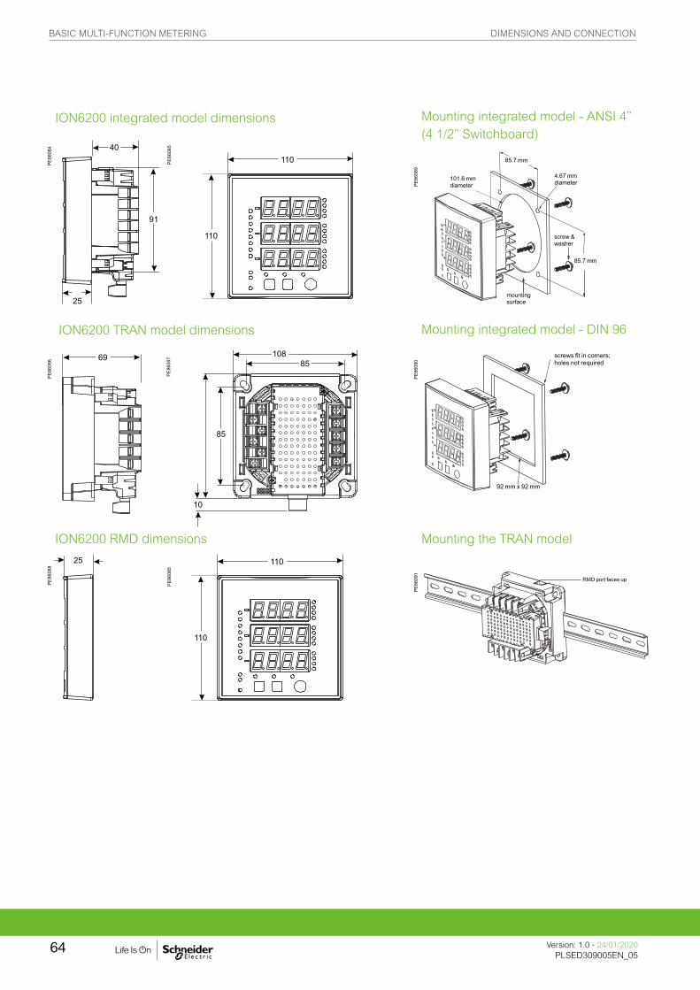
ION6200 integrated model dimensions
PE86
084
ION6200 TRAN model dimensions
PE86
086
ION6200 RMD dimensions
PE86
088
Mounting integrated model - ANSI 4” (4 1/2” Switchboard)
PE86
089
Mounting integrated model - DIN 96
PE86
090
Mounting the TRAN model
PE86
091
85.7 mm
4.67 mm diameter
screw & washer
85.7 mm
mounting surface
101.6 mm diameter
screws fit in corners; holes not required
92 mm x 92 mm
RMD port faces up
PE86
085
PE86
087
PE86
085
BASIC MULTI-FUNCTION METERING DIMENSIONS AND CONNECTION
Version: 1.0 - 24/01/2020PLSED309005EN_05
64
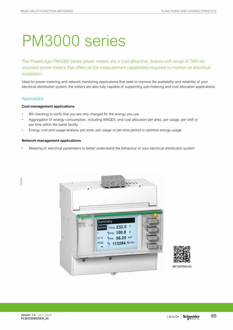
The PowerLogic PM3000 series power meters are a cost-attractive, feature-rich range of DIN rail-
mounted power meters that offers all the measurement capabilities required to monitor an electrical
installation.
Ideal for power metering and network monitoring applications that seek to improve the availability and reliability of your electrical distribution system, the meters are also fully capable of supporting sub-metering and cost allocation applications.
PM3000 series
Applications
Cost management applications
• Bill checking to verify that you are only charged for the energy you use
• Aggregation of energy consumption, including WAGES, and cost allocation per area, per usage, per shift or per time within the same facility
• Energy cost and usage analysis per zone, per usage or per time period to optimise energy usage
Network management applications
• Metering of electrical parameters to better understand the behaviour of your electrical distribution system
PB
108447
METSEPM3250
Mounting integrated model - ANSI 4” (4 1/2” Switchboard)
PE86
089
Mounting integrated model - DIN 96
PE86
090
Mounting the TRAN model
PE86
091
85.7 mm
4.67 mm diameter
screw & washer
85.7 mm
mounting surface
101.6 mm diameter
screws fit in corners; holes not required
92 mm x 92 mm
RMD port faces up
BASIC MULTI-FUNCTION METERING FUNCTIONS AND CHARACTERISTICS
65Version: 1.0 - 24/01/2020PLSED309005EN_05Version: 1.0 - 24/01/2020PLSED309005EN_05

The solution for
All markets that can benefit from a solution that includes PowerLogic PM3000 series meters:
• Buildings• Industry• Data centres and networks• Infrastructure (e.g. airports, road tunnels, telecom)
Power management solutions
Schneider Electric provides innovative power management solutions to increase your energy efficiency and cost savings, maximise electrical network reliability and availability, and optimise electrical asset performance.
Competitive advantages
Connectivity advantages
• Programmable digital input
– External tariff control signal (4 tariff)
– Remote reset partial counter
– External status like breaker status
– Collect WAGES pulses
• Programmable digital output
– Alarm (PM3255)
– KWh pulses
• Graphic LCD display
• Modbus RS-485 with screw terminals Multi-tariff capability The PM3000 series allows users to arrange KWh consumption in four different registers. This can be controlled by:
• Digital inputs. Signal can be provided by PLC or utilities
• Internal clock programmable by HMI
• Through communication
This function allows users to:
• Make tenant metering for dual source applications to differentiate backup source or utility source
• Understand well the consumption during peak time and off-peak time, weekdays and weekends, holiday and working days etc.
• Follow up feeders consumption in line with utility tariff rates
Benefits
Optimise your energy consumption & enable energy efficiency practices
• Collect and analyse energy consumption data from each area for each type of load or circuit
• Gain an accurate understanding of business expenses by allocating the energy-related costs
• Identify savings opportunities
• Use information to implement actions designed to reduce energy consumption
Conformity of standards
• IEC 61557-12
• IEC 61326-1
• IEC 62052-11
• IEC 62053-21
• IEC 62053-22
• IEC 62053-23
• EN 50470-1
• EN 50470-3
• IEC 61010-1
• EN 55022
BASIC MULTI-FUNCTION METERING FUNCTIONS AND CHARACTERISTICS
Version: 1.0 - 24/01/2020PLSED309005EN_05
66

PM3000 series feature selection
PM3200 PM3210 PM3250 PM3255
Performance standard
IEC61557-12 PMD/Sx/K55/0.5 n n n n
General
Use on LV and HV systems n n n n
Number of samples per cycle 32 32 32 32
CT input 1A/5A n n n n
VT input n n n n
Multi-tariff 4 4 4 4
Multi-lingual backlit display n n n n
Instantaneous rms values
Current, voltage Per phase and average n n n n
Active, reactive, apparent power Total and per phase n n n n
Power factor Total and per phase n n n n
Energy values
Active, reactive and apparent energy; import and export n n n n
Demand value
Current, power (active, reactive, apparent) demand; present n n n n
Current, power (active, reactive, apparent) demand; peak n n n
Power quality measurements
THD Current and voltage n n n
Data recording
Min/max of the instantaneous values n n n n
Power demand logs n
Energy consumption log (day, week, month) n
Alarms with timestamping 5 5 15
Digital inputs/digital outputs 0/1 2/2
Communication
RS-485 port n n
Modbus protocol n n
Commercial reference number METSEPM3200 METSEPM3210 METSEPM3250 METSEPM3255
PM3000 series
See your Schneider Electric representative for complete ordering information.
BASIC MULTI-FUNCTION METERING FUNCTIONS AND CHARACTERISTICS
67Version: 1.0 - 24/01/2020PLSED309005EN_05Version: 1.0 - 24/01/2020PLSED309005EN_05

PM3000 technical specifications
Type of measurementTrue rms up to the 15th harmonic on three-phase (3P,3P+N) and single-phase AC systems. 32 samples per cycle
Measurement accuracy
Current with x/5A CTs 0.3 % from 0.5 A to 6 A
Current with x/1A CTs 0.5 % from 0.1 A to 1.2 A
Voltage 0.3 % from 50 V to 330 V (Ph-N), from 80 V to 570 V (Ph-Ph)
Power factor ±0.005 from 0.5 A to 6 A with x/5 A CTs; from 0.1A to 1.2 A with x/1 A CTs and from 0.5 L to 0.8 C
Active/Apparent Power with x/5A CTs Class 0.5
Active/Apparent Power with x/1A CTs Class 1
Reactive power Class 2
Frequency 0.05 % from 45 to 65 Hz
Active energy with x/5A CTs IEC 62053-22 Class 0.5s
Active energy with x/1A CTs IEC 62053-21 Class 1
Reactive energy IEC 62053-23 Class 2
Data update rate
Update rate 1s
Input-voltage characteristics
Measured voltage50 V to 330 V AC (direct / VT secondary Ph-N)80 V to 570 V AC (direct / VT secondary Ph-Ph)up to 1 MV AC (with external VT)
Frequency range 45 Hz to 65 Hz
Input-current characteristics
CT primaryAdjustable from 1 A to 32767 A
CT secondary 1 A or 5 A
Measurement input range with x/5A CTs 0.05 A to 6 A
Measurement input range with x/1A CTs 0.02 A to 1.2 A
Permissible overload 10 A continuous, 20 A for 10s/hour
Control Power
AC 100/173 to 277/480 V AC (+/-20%), 3 W/5 VA; 45 Hz to 65 Hz
DC 100 to 300 V DC, 3 W
Input
Digital inputs (PM3255) 11 to 40 V DC, 24 V DC nominal, <=4mA maximum burden, 3.5kVrms insulation
Output
Digital output (PM3210) Optocoupler, polarity sensitive, 5 to 30 V, 15 mA max, 3.5kVrms insulation
Digital outputs (PM3255)Solid state relay, polarity insensitive, 5 to 40 V, 50 mA max, 50 Ω max, 3.5kVrms insulation
PM3000 series
BASIC MULTI-FUNCTION METERING FUNCTIONS AND CHARACTERISTICS
Version: 1.0 - 24/01/2020PLSED309005EN_05
68

g Protected throughout by double insulation
PM3000 seriesPM3000 technical specifications
Mechanical characteristics
Weight 0.26 kg
IP degree of protection (IEC 60529) IP40 front panel, IP20 meter body
Dimension 90 x 95 x 70 mm
Environmental conditions
Operating temperature -25 ºC to 55 ºC
Storage temperature -40 ºC to 85 ºC
Humidity rating 5 to 95% RH at 50 ºC (non-condensing)
Pollution degree 2
Metering category III, for distribution systems up to 277/480 V AC
Dielectric withstand As per IEC61010-1, Doubled insulated front panel display
Altitude 3000 m max
Electromagnetic compatibility
Electrostatic dischargeLevel IV (IEC 61000-4-2)
Immunity to radiated fields Level III (IEC 61000-4-3)
Immunity to fast transientsLevel IV (IEC 61000-4-4)
Immunity to surge Level IV (IEC 61000-4-5)
Conducted immunity Level III (IEC 61000-4-6)
Immunity to power frequency magnetic fields
0.5mT (IEC 61000-4-8)
Conducted and radiated emissions Class B (EN 55022)
Safety
CE as per IEC 61010-1g
Communication
RS-485 port Half duplex, from 9600 up to 38400 baud, Modbus RTU (double insulation)
Display characteristics
Dimensions (VA) 43 mm x 34.6 mm
Display resolution 128 x 96 dots
Standard compliance
IEC 61557-12, EN 61557-12IEC 61010-1, UL 61010-1
IEC 62052-11, IEC 62053-21, IEC 62053-22, IEC 62053-23EN 50470-1, EN 50470-3
BASIC MULTI-FUNCTION METERING FUNCTIONS AND CHARACTERISTICS
69Version: 1.0 - 24/01/2020PLSED309005EN_05Version: 1.0 - 24/01/2020PLSED309005EN_05
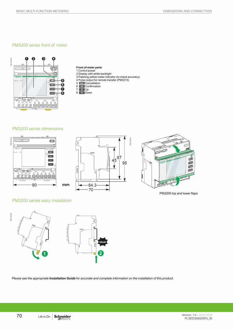
PB
105446
PM3200 series front of meter
PM3200 series dimensions
PM3200 series easy installation
Front of meter parts1 Control power2 Display with white backlight3 Flashing yellow meter indicator (to check accuracy)4 Pulse output for remote transfer (PM3210)5 Cancellation6 Confirmation7 Up8 Down
PM3200 top and lower flaps
PB
105440
PB
105302
PB
105447
Please see the appropriate Installation Guide for accurate and complete information on the installation of this product.
BASIC MULTI-FUNCTION METERING DIMENSIONS AND CONNECTION
Version: 1.0 - 24/01/2020PLSED309005EN_05
70

PE
86278
The PowerLogic PM5350 series power meters are the new benchmark in affordable, precision metering.
The PowerLogic PM5350 power meter offers all the measurement capabilities required to monitor an electrical installation in a space-efficient, single 96 x 96 mm unit with small depth. DNC certifies for marine applications.
PM5350 series
Applications
• Panel instrumentation.
• Cost allocation or energy management
• Electrical installation remote monitoring
• Sophisticated alarming
• Circuit beaker monitoring and control
METSEPM5350
BASIC MULTI-FUNCTION METERING FUNCTIONS AND CHARACTERISTICS
71Version: 1.0 - 24/01/2020PLSED309005EN_05Version: 1.0 - 24/01/2020PLSED309005EN_05
The solution for
Markets that can benefit from a solution that includes PowerLogic PM5350 series meters:
• Buildings
• Industry
• Healthcare
• Data Centre and networks
• Infrastructure
Power management solutions
Schneider Electric provides innovative power management solutions to increase your energy efficiency and cost savings, maximise electrical network reliability and availability, and optimise electrical asset performance.
Competitive advantages
• Easy to install and operate
• Easy for circuit breaker monitoring and control
• Power quality analysis
• Load management combined with alarm and timestamping
• High performance and accuracy
Conformity of standards
• IEC 62053-22
• IEC 61557-12
• IEC 62053-23
• IEC 61010-1
• UL 61010-1
• IEC 61326-1
• FCC part 15 Class A
• DNV certified
Benefits
System integrators’ benefit
• Ease of integration
• Ease of setup
• Cost effectiveness
Panel builders’ benefit
• Ease of installation
• Cost effectiveness
• Aesthetically pleasing
• Simplified ordering
End users’ benefit
• Ease of use
• Precision metering & sub-billing
• Billing flexibility
• Comprehensive, consistent and superior performance
BASIC MULTI-FUNCTION METERING FUNCTIONS AND CHARACTERISTICS
Version: 1.0 - 24/01/2020PLSED309005EN_05
72
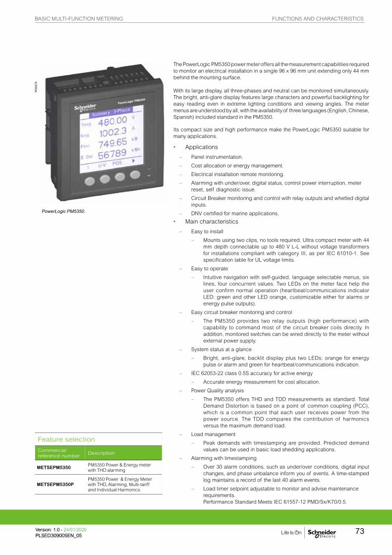
PE86
278
The PowerLogic PM5350 power meter offers all the measurement capabilities required to monitor an electrical installation in a single 96 x 96 mm unit extending only 44 mm behind the mounting surface.
With its large display, all three-phases and neutral can be monitored simultaneously. The bright, anti-glare display features large characters and powerful backlighting for easy reading even in extreme lighting conditions and viewing angles. The meter menus are understood by all, with the availability of three languages (English, Chinese, Spanish) included standard in the PM5350.
Its compact size and high performance make the PowerLogic PM5350 suitable for many applications.
• Applications
– Panel instrumentation.
– Cost allocation or energy management.
– Electrical installation remote monitoring.
– Alarming with under/over, digital status, control power interruption, meter reset, self diagnostic issue.
– Circuit Breaker monitoring and control with relay outputs and whetted digital inputs.
– DNV certified for marine applications.
• Main characteristics
– Easy to install
– Mounts using two clips, no tools required. Ultra compact meter with 44 mm depth connectable up to 480 V L-L without voltage transformers for installations compliant with category III, as per IEC 61010-1. See specification table for UL voltage limits.
– Easy to operate
– Intuitive navigation with self-guided, language selectable menus, six lines, four concurrent values. Two LEDs on the meter face help the user confirm normal operation (heartbeat/communications indicator LED: green and other LED orange, customizable either for alarms or energy pulse outputs).
– Easy circuit breaker monitoring and control
– The PM5350 provides two relay outputs (high performance) with capability to command most of the circuit breaker coils directly. In addition, monitored switches can be wired directly to the meter without external power supply.
– System status at a glance
– Bright, anti-glare, backlit display plus two LEDs; orange for energy pulse or alarm and green for heartbeat/communications indication.
– IEC 62053-22 class 0.5S accuracy for active energy
– Accurate energy measurement for cost allocation.
– Power Quality analysis
– The PM5350 offers THD and TDD measurements as standard. Total Demand Distortion is based on a point of common coupling (PCC), which is a common point that each user receives power from the power source. The TDD compares the contribution of harmonics versus the maximum demand load.
– Load management
– Peak demands with timestamping are provided. Predicted demand values can be used in basic load shedding applications.
– Alarming with timestamping
– Over 30 alarm conditions, such as under/over conditions, digital input changes, and phase unbalance inform you of events. A time-stamped log maintains a record of the last 40 alarm events.
– Load timer setpoint adjustable to monitor and advise maintenance requirements. Performance Standard Meets IEC 61557-12 PMD/Sx/K70/0.5.
PowerLogic PM5350.
Feature selection
Commercial reference number
Description
METSEPM5350 PM5350 Power & Energy meter with THD alarming
METSEPM5350PPM5350 Power & Energy Meter with THD, Alarming, Multi-tariff and Individual Harmonics
BASIC MULTI-FUNCTION METERING FUNCTIONS AND CHARACTERISTICS
73Version: 1.0 - 24/01/2020PLSED309005EN_05Version: 1.0 - 24/01/2020PLSED309005EN_05

PM5350 technical specifications
PE86
323_
m
General
Use on LV and MV systems b
Basic metering with THD and min/max readings b
Instantaneous rms values
Current Total, Phases and neutral b
Voltage Total, Ph-Ph and Ph-N b
Frequency b
Real, reactive, and apparent power Total and per phase Signed
True Power Factor Total and per phase Signed, Four Quadrant
Displacement PF Total and per phase Signed, Four Quadrant
Unbalanced I, VL-N, VL-L b
PE86
324
Energy values Stored in non-volatile
memory
Accumulated Active, Reactive and Apparent Energy Received/Delivered; Net and absolute; b
Demand values
Current average Present, Last, Predicted, Peak, & Peak Date Time b
Active power Present, Last, Predicted, Peak, & Peak Date Time b
Reactive power Present, Last, Predicted, Peak, & Peak Date Time b
Apparent power Present, Last, Predicted, Peak, & Peak Date Time b
Peak demand with timestamping D/T for current & powers b b
Demand calculation Sliding, fixed and rolling block, thermal b b
Synchronization of the measurement window b b
Other measurements
I/O timer b b
Operating timer b b
Active load timer b b
Alarm counters b b
Power quality measurements
THD, thd (Total Harmonic Distortion) I, V L-N, V L-L
TDD, thd (Total Demand Distortion) b
Data recording
Min/max of instantaneous values, plus phase identification b b
Alarms with 1s timestamping Standard 29; Unary 4; Digital 4
Alarms stored in non-volatile memory 40 events b
Inputs/Outputs
Digital inputs 4 (DI1, DI2, DI3, DI4)
Digital outputs 2 relay outputs (DO1, DO2)
Display
White backlit LCD display, 6 lines, 4 concurrent values b
IEC or IEEE visualization mode b
Communication
Modbus RTU, Modbus ASCII, Jbus Protocol b
Firmware update via RS-485 serial port (DLF3000 via the Schneider Electric website: www.schneider-electric.com)
b
PM5350 meter parts
A Retainer clips.
B Control power supply connector.
C Voltage inputs.
D Digital outputs.
E RS-485 port (COM1).
F Digital input.
G Optical revenue switch.
H Current inputs.
PM5350 series
BASIC MULTI-FUNCTION METERING FUNCTIONS AND CHARACTERISTICS
Version: 1.0 - 24/01/2020PLSED309005EN_05
74

Electrical characteristics
PE86
292
Type of measurement True rms up to the 15th harmonic on three-phase (3P, 3P + N) 32 samples per cycle, zero blind
Measurement accuracy
Current, Phase g ±0.30 %
Voltage, L-N g ±0.30 %
Power Factor g ±0.005
Power, Phase IEC 61557-12 Class 0.5; For 5 A nominal CT (for 1 A nominal CT when I > 0.15 A) ±0.5 % from 0.25 A to 9.0 A at COS φ = 1±0.6 % from 0.50 A to 9.0 A at COS φ = 0.5 (ind or cap)
Frequencyg ±0.05 %
Real Energy IEC 62053-22 Class 0.5 S; IEC 61557-12 Class 0.5; For 5 A nominal CT (for 1 A nominal CT when I > 0.15 A) ±0.5 % from 0.25 A to 9.0 A at COS φ = 1±0.6 % from 0.50 A to 9.0 A at COS φ = 0.5 (ind or cap) IEC 61557-12 Class 0.5
Reactive Energy IEC 62053-23 Class 3, IEC 61557-12 Class 2 For 5 A nominal CT (for 1 A nominal CT when I > 0.15 A) ±2.0 % from 0.25 A to 9.0 A at SIN φ = 1±2.5 % from 0.50 A to 9.0 A at SIN φ = 0.5 (ind or cap)
Data update rate 1 second nominal (50/60 cycles)
Input-voltage VT primary 1.0 MV AC max, starting voltage depends on VT ratio.
U nom 277 V L-N
Measured voltage with overrange & Crest Factor
IEC: 20 to 480 V AC L-L; 20 to 277 V AC L-N, CAT IIIIEC: 20 to 690 V AC L-L; 20 to 400 V AC L-N, CAT IIUL: 20 to 300 V AC L-L, CAT III
Permanent overload 700 V AC L-L, 404 V AC L-N
Impedance 10 MWFrequency range 45 to 70 Hz
Input-current CT ratings Secondary 1A, 5 A nominal
Measured voltage with overrange & crest factor
5 mA to 9 A
Withstand Continuous 20 A,10 sec/hr 50 A,1 sec/hr 500 A
Impedance < 0.3 mW
Frequency range 45 to 70 Hz
Burden < 0.024 VA at 9 A
AC control power
Operating range 85 - 265 V AC
Burden 4.1 VA / 1.5 W typical, 6.7 VA / 2.7 W max at 120 V AC6.3 VA / 2.0 W typical, 8.6 VA / 2.9 W max at 230 V AC 9.6 VA / 3.5 W maximum at 265 V AC
Frequency 45 to 65 Hz
Ride-through time 100 mS typical at 120 V AC and maximum burden 400 mS typical at 230 V AC and maximum burden
DC control power
Operating range 100 to 300 V DC
Burden 1.4 W typical, 2.6 W maximum at 125 V DC1.8 W typical, 2.7 W maximum at 250 V DC3.2 W maximum at 300 V DC
Ride-through time 50 mS typical at 125 V DC and maximum burden
Real time clock
Ride-through time 30 seconds
Digital output Number/Type 2 - Mechanical Relays
Output frequency 0.5 Hz maximum (1 second ON / 1 second OFF - minimum times)
Switching Current 250 V AC at 2.0 Amps, 200 k cycles, resistive250 V AC at 8.0 Amps, 25 k cycles, resistive250 V AC at 2.0 Amps, 100 k cycles, COS φ=0.4250 V AC at 6.0 Amps, 25 k cycles, COS φ=0.430 V DC at 2.0 Amps, 75 k cycles, resistive30 V DC at 5.0 Amps, 12.5 k cycles, resistive
Isolation 2.5 kVrms
Status Digital Inputs
Voltage ratings ON 18.5 to 36 V DC, OFF 0 to 4 V DC
Input Resistance 110 k WMaximum Frequency 2 Hz (T ON min = T OFF min = 250 ms)
Response Time 10 ms
Isolation 2.5 kVrms
Whetting output
Nominal voltage 24 V DC
Allowable load 4 mA
Isolation 2.5 kVrms
g Measurements taken from 45 Hz to 65 Hz, 0.5 A to 9 A, 57 V to 347 V & 0.5 ind to 0.5 cap power factor with a sinusoidal wave.
Front screen view of PM5350.
PM5350 series
BASIC MULTI-FUNCTION METERING FUNCTIONS AND CHARACTERISTICS
75Version: 1.0 - 24/01/2020PLSED309005EN_05Version: 1.0 - 24/01/2020PLSED309005EN_05

PM5350 technical specifications
Mechanical characteristics
Weight 250 g
IP degree of protection (IEC 60529) IP51 front display, IP30 meter body (excluding connectors)
Dimensions W x H x D 96 x 96 x 44 mm (depth of meter from housing mounting flange)96 x 96 x 13 mm (protrusion of meter from housing flange)
Mounting position Vertical
Panel thickness 6.35 mm max
Environmental characteristics
Operating temperature Meter -25 °C to 70 °C
Display -20 °C to 70 °C(Display functions to -25 °C with reduced performance)
Storage temp. Meter + display -40 °C to 85 °C
Humidity rating 5 % to 95 % RH at 50 °C (non-condensing)
Pollution degree 2
Altitude 3000 m max
Indoor use only Not suitable for wet locations
Electromagnetic compatibility
Electrostatic discharge IEC 61000-4-2gImmunity to radiated fields IEC 61000-4-3g
Immunity to fast transients IEC 61000-4-4g
Immunity to impulse waves IEC 61000-4-5g
Conducted immunity IEC 61000-4-6g
Immunity to magnetic fields IEC 61000-4-8g
Immunity to voltage dips IEC 61000-4-11g
Radiated emissions FCC part 15 class A, EN 55011 Class A
Conducted emissions FCC part 15 class A, EN 55011 Class A
Harmonics IEC 61000-3-2g
Flicker emissions IEC 61000-3-3g
Safety
Europe e, as per IEC 61010-1
U.S. and Canada cULus as per UL 61010-1, IEC 61010-1 (3rd Edition)
Measurement category (Voltage and current inputs) Per IEC 61010-1: CAT III, 277 V L-N / 480 V L-L nominal; CAT II 400 V L-N / 690 V L-L nominalPer UL 61010-1 and CSA C22.2 No. 61010-1: CAT III, 300 V L-L
Overvoltage Category (Control power) CAT III
Dielectric As per IEC 61010-1Double insulated front panel display
Protective Class Class II
Communication
RS-485 port 2-Wire, 9600,19200 or 38400 baud, Parity - Even, Odd, None, 1 stop bit if parity Odd or Even, 2 stop bits if None; Modbus RTU, Modbus ASCII (7 or 8 bit), JBUS
Firmware and language file update Update via communication port using DLF3000 software
Isolation 2.5 kVrms, double insulated
Human machine interface
Display type Monochrome Graphics LCD
Resolution 128 x 128
Backlight White LED
Viewable area (W x H) 67 x 62.5 mm
Keypad 4-button
Indicator Heartbeat / Comm activity Green LED
Energy pulse output / Active alarm indication (configurable)
Type Optical, amber LED
Wavelength 590 to 635 nm
Maximum pulse rate 2.5 kHz
g As per IEC 61557-12
PM5350 series
BASIC MULTI-FUNCTION METERING FUNCTIONS AND CHARACTERISTICS
Version: 1.0 - 24/01/2020PLSED309005EN_05
76
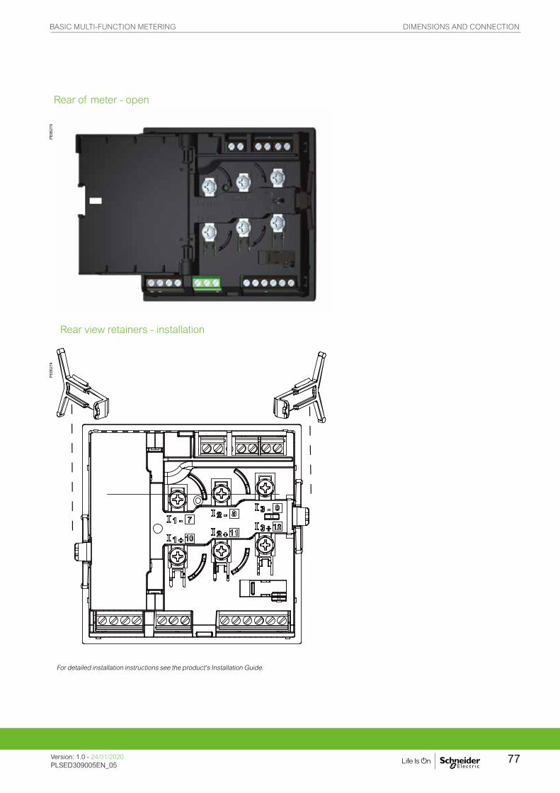
PE86
279
PE86
274
For detailed installation instructions see the product's Installation Guide.
Rear of meter - open
Rear view retainers - installation
BASIC MULTI-FUNCTION METERING DIMENSIONS AND CONNECTION
Version: 1.0 - 24/01/2020PLSED309005EN_05
77

PE86
275
For detailed installation instructions see the product's Installation Guide.
Rear view retainers - users
BASIC MULTI-FUNCTION METERING DIMENSIONS AND CONNECTION
Version: 1.0 - 24/01/2020PLSED309005EN_05
78

PE
86278
The PowerLogic PM5350IB and PM5350PB series power meters are the new benchmark in affordable,
precision metering.
The PowerLogic PM5350P power meter offers all the measurement capabilities required to monitor an electrical installation in a space-efficient, single 96 x 96 mm unit.
PM5350IB and PM5350PB series
Applications
• Panel instrumentation.
• Cost allocation or energy management
• Electrical installation remote monitoring.
• Sophisticated alarming
• Circuit Breaker monitoring and control
METSEPM5350IB
BASIC MULTI-FUNCTION METERING FUNCTIONS AND CHARACTERISTICS
79Version: 1.0 - 24/01/2020PLSED309005EN_05Version: 1.0 - 24/01/2020PLSED309005EN_05

The solution for
Markets that can benefit from a solution that includes PowerLogic PM5350IB and PM5350PB series meters:
• Buildings
• Industry
• Healthcare
• Data Centre and networks
• Infrastructure
Power management solutions
Schneider Electric provides innovative power management solutions to increase your energy efficiency and cost savings, maximise electrical network reliability and availability, and optimise electrical asset performance.
Competitive advantages
• Easy to install and operate
• Easy for circuit breaker monitoring and control
• Power quality analysis
• Load management combined with alarm and timestamping
• High performance and accuracy
Conformity of standards
• IEC 62053-22
• IEC 61557-12
• IEC 62053-23
• IEC 61326-1
• IEC 61010-1
• UL 61010-1
• IEC 61000-4-2
• IEC 61000-4-3
Benefits
System integrators’ benefit
• Ease of integration
• Ease of setup
• Cost effectiveness
Panel builders’ benefit
• Ease of installation
• Cost effectiveness
• Aesthetically pleasing
• Simplified ordering
End users’ benefit
• Ease of use
• Precision metering & sub-billing
• Billing flexibility
• Comprehensive, consistent and superior performance
BASIC MULTI-FUNCTION METERING FUNCTIONS AND CHARACTERISTICS
Version: 1.0 - 24/01/2020PLSED309005EN_05
80

PE86
278
PowerLogic PM5350IB
The PM5350IB and PM5350PB are compact multi-circuit power meters specially designed to monitor Busway power distribution systems. They provide consumption and alarm data by circuit, for up to three single-phase circuits and can also be installed in different electrical configurations, monitoring 1-, 2-, and 3-phase circuits. These meters are an ideal solution for cost management and sub-billing in data centres.
With its large display, all individual circuits can be monitored simultaneously. The bright, anti-glare display features large characters and powerful backlighting for easy reading even in extreme lighting conditions and viewing angles.
• Main characteristics
– Easy to install
– Mounts using two clips, no tools required. Ultra compact meter with 44 mm depth connectable up to 480 V L-L without voltage transformers. See specification table for voltage inputs details.
– Easy to operate
– Intuitive navigation with self-guided, language selectable menus, six lines, four concurrent values.
– System status at a glance
– Bright, anti-glare, backlit display plus two LEDs; orange for energy pulse or alarm and green for heartbeat/communications indication.
– IEC 62053-22 class 0.5S accuracy for active energy
Accurate energy measurement for cost allocation and sub-billing.g
• Circuit breaker monitoring
– Four digital inputs provide an easy way to monitor status, alarm and report on circuit breaker trips.
• Multi-level alarming
– Five different alarm levels (high, high-high, low, low-low, tripped) optimized network management and downtime prevention.
• Performance Standard Meets IEC 61557-12 PMD/Sx/K70/0.5.
gSub-billing might be subject to local regulation.
Feature selection
Commercial reference number
Description
METSEPM5350IB PowerLogic PM5350IB
METSEPM5350PB PowerLogic PM5350PB
BASIC MULTI-FUNCTION METERING FUNCTIONS AND CHARACTERISTICS
81Version: 1.0 - 24/01/2020PLSED309005EN_05Version: 1.0 - 24/01/2020PLSED309005EN_05
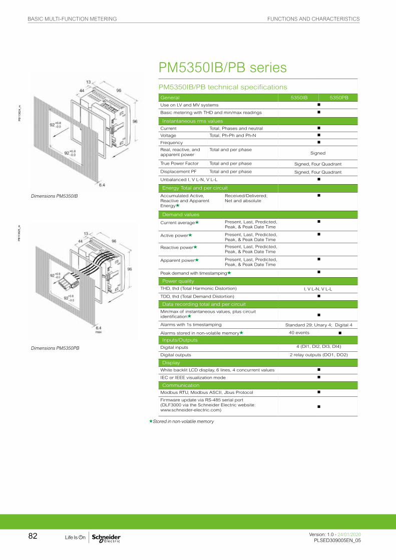
PM5350IB/PB technical specifications
PB11
3624
_m
General 5350IB 5350PB
Use on LV and MV systems b
Basic metering with THD and min/max readings b
Instantaneous rms values
Current Total, Phases and neutral b
Voltage Total, Ph-Ph and Ph-N b
Frequency b
Real, reactive, and apparent power
Total and per phaseSigned
True Power Factor Total and per phase Signed, Four Quadrant
Displacement PF Total and per phase Signed, Four Quadrant
Unbalanced I, V L-N, V L-L b
Energy Total and per circuit
Accumulated Active, Reactive and Apparent Energyg
Received/Delivered; Net and absolute
b
Demand values
Current averageg Present, Last, Predicted, Peak, & Peak Date Time
b
Active powerg Present, Last, Predicted, Peak, & Peak Date Time
b
Reactive powerg Present, Last, Predicted, Peak, & Peak Date Time
Apparent powerg Present, Last, Predicted, Peak, & Peak Date Time
b
Peak demand with timestampingg b
Power quality
THD, thd (Total Harmonic Distortion) I, V L-N, V L-L
TDD, thd (Total Demand Distortion) b
Data recording total and per circuit
Min/max of instantaneous values, plus circuit identificationg b
Alarms with 1s timestamping Standard 29; Unary 4; Digital 4
Alarms stored in non-volatile memoryg 40 events b
Inputs/Outputs
Digital inputs 4 (DI1, DI2, DI3, DI4)
Digital outputs 2 relay outputs (DO1, DO2)
Display
White backlit LCD display, 6 lines, 4 concurrent values b
IEC or IEEE visualization mode b
Communication
Modbus RTU, Modbus ASCII, Jbus Protocol b
Firmware update via RS-485 serial port (DLF3000 via the Schneider Electric website: www.schneider-electric.com)
b
Dimensions PM5350IB
Dimensions PM5350PB
PB11
3625
_m
gStored in non-volatile memory
PM5350IB/PB series
BASIC MULTI-FUNCTION METERING FUNCTIONS AND CHARACTERISTICS
Version: 1.0 - 24/01/2020PLSED309005EN_05
82

Front screen view of PM5350.
Electrical characteristics 5350IB 5350PB
PE86
292
Type of measurement True rms up to the 15th harmonic 32 samples per cycle, zero blind
Measurement accuracy
Current, Circuit g ±0.30 % Voltage, L-N g ±0.30 % Power Factor g ±0.005 Power, Circuit IEC 61557-12 Class 0.5; For 5 A nominal CT (for 1
A nominal CT when I > 0.15 A) ±0.5 % from 0.25 A to 9.0 A at COS φ = 1±0.6 % from 0.50 A to 9.0 A at COS φ = 0.5 (ind or cap)
Frequency g ±0.05 %
Real Energy IEC 62053-22 Class 0.5 S; IEC 61557-12 Class 0.5; For 5 A nominal CT (for 1 A nominal CT when I > 0.15A) ±0.5 % from 0.25 A to 9.0 A at COS φ = 1±0.6 % from 0.50 A to 9.0 A at COS φ = 0.5 (ind or cap)IEC 61557-12 Class 0.5
Reactive Energy IEC 62053-23 Class 3, IEC 61557-12 Class 2 For 5 A nominal CT (for 1 A nominal CT when I > 0.15A) ±2.0 % from 0.25 A to 9.0 A at SIN φ = 1±2.5 % from 0.50 A to 9.0 A at SIN φ = 0.5 (ind or cap)
Data update rate 1 second nominal (50/60 cycles)
Input-voltage VT primary 1.0 MV AC max, starting voltage depends on VT ratio.
U nom 277 V L-N
Measured voltage with overrange & Crest Factor
UL: 20 to 300 V AC L-LIEC: 20 to 690 V V AC L-L; 20 to 400 V AC L-N
UL: 20 to 480 V AC L-LIEC: 20 to 690 V V AC L-L; 20 to 400 V AC L-N
Permanent overload 700 V AC L-L, 404 V AC L-N
Impedance 10 M W
Frequency range 45 to 70 Hz
Input-current CT ratings Primary Adjustable 1 A to 32767 A
Secondary 1 A, 5 A nominal
Measured voltage with overrange & Crest Factor
5 mA to 9 A
Withstand Continuous 20 A,10 sec/hr 50 A,1 sec/hr 500 A
Impedance < 0.3 mW
Frequency range 45 to 70 Hz
Burden < 0.024 VA at 9 A
AC control power
Operating range 85 to 277 V AC
Burden 4.1 VA / 1.5 W typical, 6.7 VA / 2.7 W max at 120 V AC6.3 VA / 2.0 W typical, 8.6 VA / 2.9 W max at 230 V AC 9.6 VA / 3.5 W maximum at 265 V AC
Frequency 45 to 65 Hz
Ride-through time 100 mS typical at 120 V AC and maximum burden 400 mS typical at 230 V AC and maximum burden
DC control power
Operating range 100 to 300 V DC
Burden 1.4 W typical, 2.6 W maximum at 125 V DC1.8 W typical, 2.7 W maximum at 250 V DC3.2 W maximum at 300 V DC
Ride-through time 50 mS typical at 125 V DC and maximum burden
Real time clock
Ride-through time 30 seconds
Digital output Number/Type 2 - Mechanical Relays
Output frequency 0.5 Hz maximum (1 second ON / 1 second OFF - minimum times)
Switching Current 250 V AC at 2.0 Amps, 200 k cycles, resistive250 V AC at 8.0 Amps, 25 k cycles, resistive250 V AC at 2.0 Amps, 100 k cycles, COS φ = 0.4250 V AC at 6.0 Amps, 25 k cycles, COS φ = 0.430 V DC at 2.0 Amps, 75 k cycles, resistive30 V DC at 5.0 Amps, 12.5 k cycles, resistive
Isolation 2.5 kVrms
Status Digital Inputs
Voltage ratings ON 18.5 to 36 V DC, OFF 0 to 4 V DC
Input Resistance 110 k WMaximum Frequency 2 Hz (T ON min = T OFF min = 250 ms)
Response Time 10 ms
Isolation 2.5 kVrms
Whetting output
Nominal voltage 24 V DC
Allowable load 4 mA
Isolation 2.5 kVrms
g Measurements taken from 45 Hz to 65 Hz, 0.5 A to 9 A, 57 V to 347 V & 0.5 ind to 0.5 cap power factor with a sinusoidal wave.
PM5350IB/PB series
BASIC MULTI-FUNCTION METERING FUNCTIONS AND CHARACTERISTICS
83Version: 1.0 - 24/01/2020PLSED309005EN_05Version: 1.0 - 24/01/2020PLSED309005EN_05

PM5350IB/PB technical specifications
Mechanical characteristics 5350IB 5350PB
Weight 250 g
IP degree of protection (IEC 60529) IP51 front display, IP30 meter body
Dimensions W x H x D 96 x 96 x 44 mm (depth of meter from housing mounting flange)96 x 96 x 13 mm (protrusion of meter from housing flange)
Mounting position Vertical
Panel thickness 6.35 mm max
Environmental characteristics (for indoor use only)
Operating temperature Meter -25 °C to 70 °C
Display -20 °C to 70 °C(Display functions to -25°C with reduced performance)
Storage temp. Meter + display -40 °C to 85 °C
Humidity rating 5 to 95 % RH at 50 °C (non-condensing)
Pollution degree 2
Altitude 3000 m max.
Indoor use only Not suitable for wet locations
Electromagnetic compatibility (for indoor use only)
Electrostatic discharge IEC 61000-4-2g
Immunity to radiated fields IEC 61000-4-3g
Immunity to fast transients IEC 61000-4-4g
Immunity to impulse waves IEC 61000-4-5g
Conducted immunity IEC 61000-4-6g
Immunity to magnetic fields IEC 61000-4-8g
Immunity to voltage dips IEC 61000-4-11g
Radiated emissions FCC part 15 class A, EN 55011 Class A
Conducted emissions FCC part 15 class A, EN 55011 Class A
Harmonics IEC 61000-3-2g
Flicker emissions IEC 61000-3-3g
Safety
Europe e, as per IEC 61010-1
U.S. and Canada cULus as per UL61010-1, IEC 61010-1 (2nd Edition)
Measurement category (Voltage and current inputs) UL: 20 to 300 V AC L-L, CATIIIIEC: 20 to 480V V AC L-L; 20 to 277 V AC L-N, CATIII20 to 690V V AC L-L; 20 to 400 V AC L-N, CATII
UL: 20 to 480 V AC L-L, CATIIIIEC: 20 to 480V V AC L-L; 20 to 277 V AC L-N, CATIII20 to 690V V AC L-L; 20 to 400 V AC L-N, CATII
Overvoltage Category (Control power) CAT III
Dielectric As per IEC 61010-1Double insulated front panel display
Protective Class Class II
Communication
RS-485 port 2-Wire, 9600,19200 or 38400 baud, Parity - Even, Odd, None, 1 stop bit if parity Odd or Even, 2 stop bits if None; Modbus RTU, Modbus ASCII (7 or 8 bit), JBUS
Firmware and language file update Update via comunication port using DLF3000 software
Isolation 2.5 kVrms, double insulated
Human machine interface
Display type Monochrome Graphics LCD
Resolution 128 x 128
Backlight White LED
Viewable area (W x H) 67 x 62.5 mm
Keypad 4-button
Indicator Heartbeat / Comm activity Green LED
Energy pulse output / Active alarm indication (configurable)
Type Optical, amber LED
Wavelength 590 to 635 nm
Maximum pulse rate 2.5 kHz
g V L-L is limited to 700 V AC (2) As per IEC 61557-12
PM5350IB/PB series
BASIC MULTI-FUNCTION METERING FUNCTIONS AND CHARACTERISTICS
Version: 1.0 - 24/01/2020PLSED309005EN_05
84
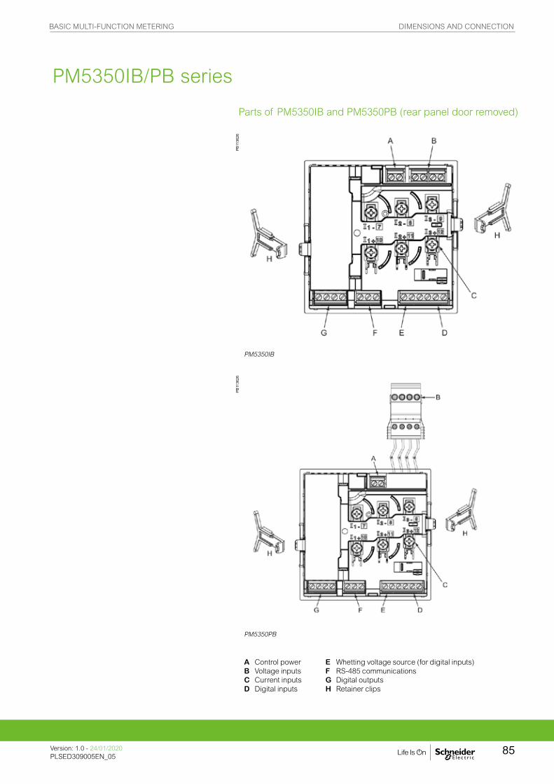
PM5350PB
PM5350IB
PB11
3626
PB11
3626
For detailed installation instructions see the product's Installation guide.
A Control powerB Voltage inputsC Current inputsD Digital inputs
E Whetting voltage source (for digital inputs)F RS-485 communicationsG Digital outputsH Retainer clips
Parts of PM5350IB and PM5350PB (rear panel door removed)
PM5350IB/PB series
BASIC MULTI-FUNCTION METERING DIMENSIONS AND CONNECTION
Version: 1.0 - 24/01/2020PLSED309005EN_05
85
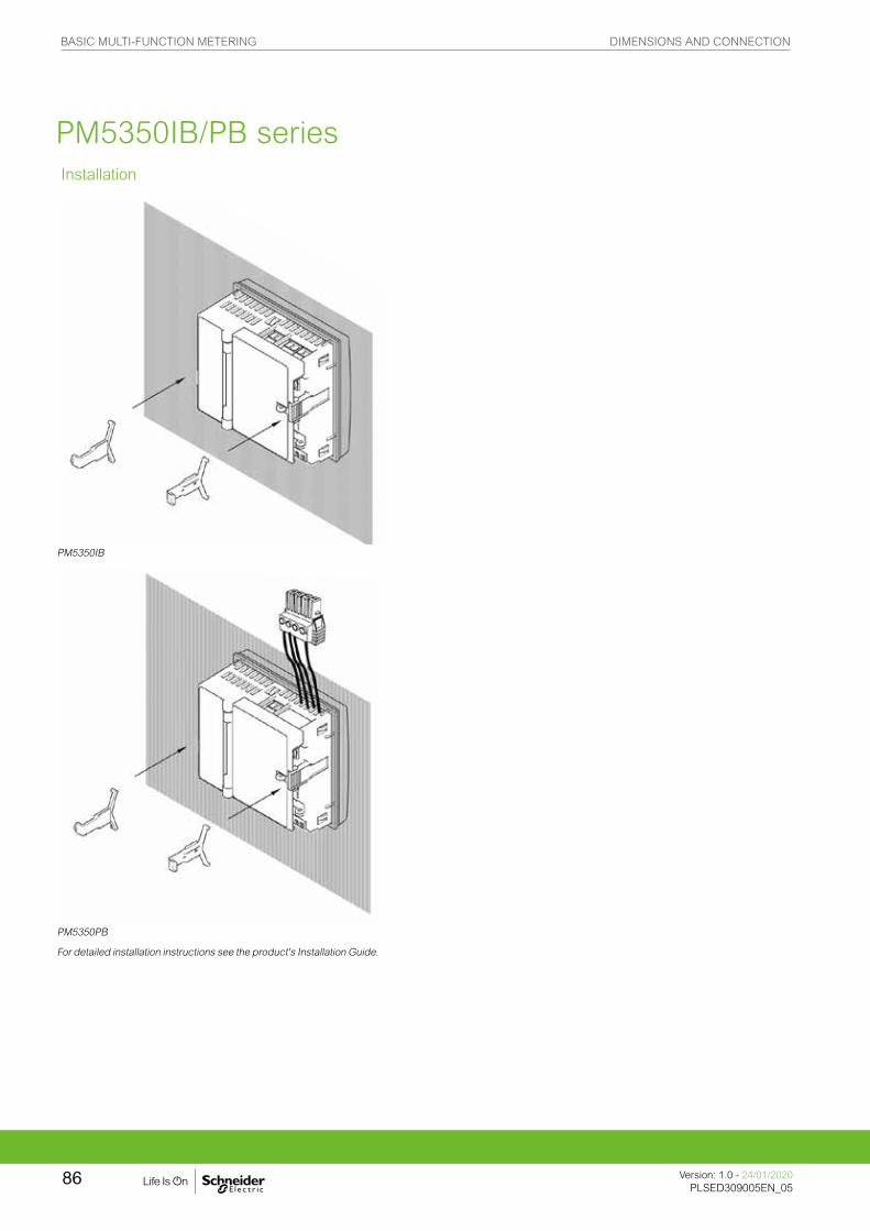
PM5350PB
For detailed installation instructions see the product's Installation Guide.
PM5350IB
Installation
PM5350IB/PB series
BASIC MULTI-FUNCTION METERING DIMENSIONS AND CONNECTION
Version: 1.0 - 24/01/2020PLSED309005EN_05
86

PB
117510
The PowerLogic PM5350P series power meters are the new benchmark in affordable, precision metering.
The PowerLogic PM5350P power meter offers all the measurement capabilities required to monitor an electrical installation in a space-efficient, single 96 x 96 mm unit.
PM5350P series
Applications
• Panel instrumentation
• Cost allocation or energy management
• Electrical installation remote monitoring
• Sophisticated alarming
• Circuit Breaker monitoring and control
METSEPM5350P
BASIC MULTI-FUNCTION METERING FUNCTIONS AND CHARACTERISTICS
87Version: 1.0 - 24/01/2020PLSED309005EN_05Version: 1.0 - 24/01/2020PLSED309005EN_05
The solution for
Markets that can benefit from a solution that includes PowerLogic PM5350P series meters:
• Buildings
• Industry
• Healthcare
• Data Centre and networks
• Infrastructure
Power management solutions
Schneider Electric provides innovative power management solutions to increase your energy efficiency and cost savings, maximise electrical network reliability and availability, and optimise electrical asset performance.
Competitive advantages
• Easy to install and operate
• Easy for circuit breaker monitoring and control
• Power quality analysis
• Load management combined with alarm and timestamping
• High performance and accuracy
• Multi-tariff capabilities
• Individual harmonics up to 31st
Conformity of standards
• IEC 62053-22
• IEC 61557-12
• IEC 62053-23
• IEC 61010-1
• IEC 61326-1
• UL 61010-1
• IEC 61000-3-3
Benefits
System integrators’ benefit
• Ease of integration
• Ease of setup
• Cost effectiveness
Panel builders’ benefit
• Ease of installation
• Cost effectiveness
• Aesthetically pleasing
• Simplified ordering
End users’ benefit
• Ease of use
• Precision metering & sub-billing
• Billing flexibility
• Comprehensive, consistent and superior performance
BASIC MULTI-FUNCTION METERING FUNCTIONS AND CHARACTERISTICS
Version: 1.0 - 24/01/2020PLSED309005EN_05
88

PowerLogic PM5350P
The PowerLogic PM5350P power meter offers electrical installation measurement capabilities in a single 96 x 96 mm unit. Three-phases and neutral can be monitored simultaneously using a bright, anti-glare display with large characters and backlighting. Menus are intuitive and the meter supports English, Chinese, Hebrew, and Spanish. Its compact size and high performance make the PowerLogic PM5350P suitable for many applications.
• Applications
– Panel instrumentation.
– Cost allocation or energy management.
– Electrical installation remote monitoring.
– Alarming with under/over, digital status, control power interruption, meter reset, self diagnostic issue.
– Circuit Breaker monitoring and control with relay outputs and whetted digital inputs.
• Main characteristics
– Easy to install
– Mounts using two clips, no tools required. Ultra compact meter with 44 mm depth connectable up to 480 V L-L without voltage transformers for installations compliant with category III, as per IEC 61010-1. See specification table for UL voltage limits.
– Easy to operate
– Intuitive navigation with self-guided, language selectable menus, six lines, four concurrent values. Two LEDs help confirm normal operation.
– Easy circuit breaker monitoring and control
– Two relay outputs (high performance) to command most circuit breaker coils directly. Monitored switches can be wired directly without external power supply.
– System status at a glance
– Bright, anti-glare, backlit display plus two LEDs; orange for energy pulse or alarm and green for heartbeat/communications indication.
– IEC 62053-22 class 0.5S accuracy for active energy
– Accurate energy measurement for cost allocation.
– Power Quality analysis
– The PM5350P offers THD and TDD measurements as standard. Total Demand Distortion is based on a point of common coupling (PCC), which is a common point that each user receives power from the power source. The TDD compares the contribution of harmonics versus the maximum demand load. In addition, it has individual harmonics (odd) measurement up to 31st harmonics. These types of power quality parameters help to identify the source of harmonics that can harm transformers, capacitors, generators, motors and electronic equipment.
• Load management
– Peak demands with Timestamping are provided. Predicted demand values can be used in basic load shedding applications. Alarming with timestamping
– Over 30 alarm conditions, such as under/over conditions, digital input changes, and phase unbalance inform you of events. A time-stamped log maintains a record of the last 40 alarm events.
– Load timer setpoint adjustable to monitor and advise maintenance requirements.
– Performance Standard Meets IEC 61557-12 PMD/Sx/K70/0.5.
PB11
7510
BASIC MULTI-FUNCTION METERING FUNCTIONS AND CHARACTERISTICS
89Version: 1.0 - 24/01/2020PLSED309005EN_05Version: 1.0 - 24/01/2020PLSED309005EN_05

Feature guide PM5350P
PE86
323_
m
General
Use on LV and MV systems b
Basic metering with THD and min/max readings b
Instantaneous rms values
Current Total, Phases and neutral b
Voltage Total, Ph-Ph and Ph-N b
Frequency b
Real, reactive, and apparent power Total and per phase Signed
True Power Factor Total and per phase Signed, Four Quadrant
Displacement PF Total and per phase Signed, Four Quadrant
Unbalanced I, VL-N, VL-L b
PE86
324
Energy values Stored in non-volatile memory
Accumulated Active, Reactive and Apparent Energy Received/Delivered; Net and absolute; b
Demand values
Current average Present, Last, Predicted, Peak, & Peak Date Time b
Active power Present, Last, Predicted, Peak, & Peak Date Time b
Reactive power Present, Last, Predicted, Peak, & Peak Date Time b
Apparent power Present, Last, Predicted, Peak, & Peak Date Time b
Multi-tariff 4 tariffs b
Peak demand with timestamping D/T for current & powers b b
Demand calculation Sliding, fixed and rolling block, thermal b b
Synchronization of the measurement window b b
Other measurements
I/O timer b b
Operating timer b b
Active load timer b b
Alarm counters b b
Power quality measurements
THD, thd (Total Harmonic Distortion) I, V L-N, V L-L
TDD, thd (Total Demand Distortion) b
Harmonics Individual (Odd) 31st
Data recording
Min/max of instantaneous values, plus phase identification b b
Alarms with 1s timestamping Standard 29; Unary 4; Digital 4
Alarms stored in non-volatile memory 40 events b
Inputs/Outputs
Digital inputs 4 (DI1, DI2, DI3, DI4)
Digital outputs 2 relay outputs (DO1, DO2)
Display
White backlit LCD display, 6 lines, 4 concurrent values b
IEC or IEEE visualization mode b
Communication
Modbus RTU, Modbus ASCII, Jbus Protocol b
Firmware update via RS-485 serial port (DLF3000 via the Schneider Electric website: www.schneider-electric.com)
b
PM5350P meter parts
A Retainer clips.B Control power supply connector.C Voltage inputs.D Digital outputs.E RS-485 port (COM1).F Digital inputs.G Optical revenue switch.H Current inputs.
BASIC MULTI-FUNCTION METERING FUNCTIONS AND CHARACTERISTICS
Version: 1.0 - 24/01/2020PLSED309005EN_05
90

Electrical characteristics
PB11
7511
Type of measurement RMS including harmonics upto 31st on three-phase AC system (3P, 3P + N)64 samples per cycle, zero blind
Measurement accuracy
Active Energy Class 0.5S as per IEC 62053-22 up to 9AClass 0.5 as per IEC 61557-12 up to 9AFor 5 A nominal CT (for 1 A nominal CT when I > 0.15 A)
Reactive Energy Class 2 as per IEC 62053-23 up to 9 AClass 2 as per IEC 61557-12 up to 9 AFor 5 A nominal CT (for 1 A nominal CT when I > 0.15 A)
Active Power Class 0.5 as per IEC 61557-12 upto 9AFor 5 A nominal CT (for 1 A nominal CT when I > 0.15 A)
Frequencyg ±0.05 %
Current, Phaseg ±0.5 %
Voltage, L-Ng ±0.50 %
Power Factorg ±0.01 Count
Voltage Harmonics Class 5 as per 61557-12 g g
Voltage THD/thd Class 5 as per 61557-12 g g
Current Harmonics Class 5 as per 61557-12 g g
Current THD/ thd Class 5 as per 61557-12 g g
g Measurement applicable from 45 Hz to 65 Hz ,0.5 A to 9 A , 57 V to 347V and 0.5 Inductive , 0.5 capacitive power factor With a sinusoidal waveg g Accuracy applicable up to 15th Harmonics measured up to 31st Harmonics
Data update rate 1 second nominal (50/60 cycles)
Input voltage U nom 277 V L-N
Measured voltage with overrange & Crest Factor
Per IEC 61010-1CAT III, 20-277 V L-N / 20-480 V L-LCAT II, 20-400 V L-N / 20-690 V L-LPer UL 61010-1 and CSA C22.2 NO. 61010-1CAT III, 20-300 V L-L AC
Permanent overload 700 V AC L-L, 404 V AC L-N
Impedance 5 MW
Frequency range 45 to 65 Hz
Input-current CT ratings Secondary 1 A, 5 A nominal
Measured voltage with overrange & Crest Factor
5 mA to 9 A
Withstand Continuous 20 A,10 sec/hr 50 A,1 sec/hr 500 A
Impedance < 0.3 MW
Frequency range 45 to 65 Hz
Burden < 0.024 V A at 9 A
AC control power
Operating range 85 - 265 V AC
Burden 7 VA / 4W maximum at 120 V AC, 9 VA / 5W maximum at 230 V AC, 11.9 VA /5W maximum at 265 V AC
Frequency 45 to 65 Hz
Ride-through time 40 mS typical at 120 V AC and maximum burden250 mS typical at 230 V AC and maximum burden
DC control power
Operating range 100 to 300 V DC
Burden 4 W maximum at 125 V DC, 5 W maximum at 250 V DC, 5 W maximum at 300 V DC
Ride-through time 30 mS typical at 125 V DC and maximum burden
Real time clock
Clock drift ~0.5 seconds per day
Battery Backup time 3 years without control power
Digital output Number/Type 2 - Mechanical Relays
Output frequency 0.5 Hz maximum (1 second ON / 1 second OFF - minimum times)
Switching Current 250 V AC at 2.0 Amps, 200k cycles, resistive250 V AC at 8.0 Amps, 25k cycles, resistive250 V AC at 2.0 Amps, 50k cycles, COSΦ=0.430 V DC at 2.0 Amps, 75k cycles, resistive30 V DC at 5.0 Amps, 12.5k cycles, resistiveNOTE: The COSΦ ratings are not evaluated for UL
Isolation 2.5 kVrms
Status Digital Inputs
Voltage ratings ON 18.5 to 36 V DC, OFF 0 to 4 V DC
Input Resistance 110 k W
Maximum Frequency 2 Hz (T ON min = T OFF min = 250 ms)
Response Time 10 msIsolation 2.5 kVrms
Whetting output
Nominal voltage 24 V DCAllowable load 4 mAIsolation 2.5 kVrms
PowerLogic PM5350P front display
BASIC MULTI-FUNCTION METERING FUNCTIONS AND CHARACTERISTICS
91Version: 1.0 - 24/01/2020PLSED309005EN_05Version: 1.0 - 24/01/2020PLSED309005EN_05

Mechanical characteristics
Weight 250 g
IP degree of protection (IEC 60529) Designed to IP51 front display, IP30 meter body (Excluding connectors)
Dimensions W x H x D 96 x 96 x 44 mm (depth of meter from housing mounting flange)96 x 96 x 13 mm (protrusion of meter from housing flange)
Mounting position Vertical
Panel thickness 6.35 mm max
Environmental characteristics
Operating temperature
Meter -25 °C to 70 °C
Display -20 °C to 70 °C(Display functions to -25 °C with reduced performance)
Storage temp. Meter + display -40 °C to 85 °C
Humidity rating 5 % to 95 % RH at 50 °C (non-condensing)
Pollution degree 2
Altitude < 3000 m max
Indoor use only Not suitable for wet locations
Electromagnetic compatibility
Electrostatic discharge IEC 61000-4-2g
Immunity to radiated fields IEC 61000-4-3g
Immunity to fast transients IEC 61000-4-4g
Immunity to impulse waves IEC 61000-4-5g
Conducted immunity IEC 61000-4-6g
Immunity to magnetic fields IEC 61000-4-8g
Immunity to voltage dips IEC 61000-4-11g
Radiated emissions FCC part 15 class A, EN 55011 class A
Conducted emissions FCC part 15 class A, EN 55011 class A
Harmonics IEC 61000-3-2g
Flicker emissions IEC 61000-3-3g
Safety
Europe e, as per IEC 61010-1 3rd Edition
U.S. and Canada UL 61010-1 and CAN/CSA-C22.2 No. 61010, 3rd Edition
Measurement category (Voltage inputs) Per IEC 61010-1CAT III, 20-277 V L-N / 20-480 V L-LCAT II, 20-400 V L-N / 20-690 V L-LPer UL 61010-1 and CSA C22.2 NO. 61010-1CAT III, 20-300 V L-L
Current Inputs (sensor connected) Require external Current Transformer for Insulation
Overvoltage Category (Control power) CAT III
Overvoltage Category (Relay) CAT II
Dielectric withstand As per IEC 61010-1Double insulated front panel display
Protective Class Class II
Double insulation at user-accessible area Included
Communication
RS-485 port 2-Wire, 9600,19200 or 38400 baud, Parity - Even, Odd, None, 1 stop bit if parity Odd or Even, 2 stop bits if None; Modbus RTU, Modbus ASCII (7 or 8 bit), JBUS
Firmware and language file update Update via communication port using DLF3000 software
Isolation 2.5 kVrms
Human machine interface
Display type Monochrome Graphics LCD
Resolution 128 x 128
Backlight White LED
Viewable area (W x H) 67 x 62.5 mm
Keypad type 4-button
Indicator Heartbeat / Comm activity Green LED
Energy pulse output / Active alarm indication (configurable)
Type Optical, amber LED
Wavelength 590 to 635 nm
Maximum pulse rate 2.5 kHz
Rear view of PowerLogic PM5350P
PB11
7512
Feature selection
Commercial reference number
Description
METSEPM5350 RS-485 Modbus, THD, 4DI, 2Relay
METSEPM5350IB RS-485, 4DI/2Relay, Multi-level alarm, UL480V, 4DI/2Relay
METSEPM5350PB RS-485, 4DI/2Relay, Multi-level alarm, UL300V, 4DI/2Relay
METSEPM5350P RS-485 Modbus, THD, Multi-tariff and individual harmonics 4DI/2relay
METSEPM5100 No commnication, 1DO
METSEPM5110 RS-485 Modbus, 1DO
METSEPM5111 RS-485 ModBus, 1DO, MID certified
METSEPM5310 RS-485 Modbus, 2DI/2DO
METSEPM5320 Ethernet 2DI/2DO
METSEPM5330 RS-485 Modbus, 2DI/2DO, 2Relay
METSEPM5331 RS-485 Modbus, 2DI/2DO, 2Relay, MID certified
METSEPM5340 Ethernet 2DI/2DO, 2Relay
METSEPM5341 Ethernet 2DI/2DO, 2Relay, MID certified
METSEPM5560 Modbus and Ethernet, 4DI/2DO
METSEPM5561 Modbus and Ethernet, MID certified
METSEPM5562 RMICAN approved, HW lockable, 4DI/2DO
METSEPM5562MC RMICAN approved, factory sealed, 4DI/2DO
METSEPM5563 DIN mount , no display Power meter, 4DI/2DO
METSEPM5563RD Remote Display for PM5563
BASIC MULTI-FUNCTION METERING FUNCTIONS AND CHARACTERISTICS
Version: 1.0 - 24/01/2020PLSED309005EN_05
92

Rear of meter - open
Rear view retainers - installation Rear view retainers - users
PE86
279
For detailed installation instructions see the product’s Installation Guide.
PE86
274
BASIC MULTI-FUNCTION METERING DIMENSIONS AND CONNECTION
Version: 1.0 - 24/01/2020PLSED309005EN_05
93

The PowerLogic PM5000 series power meters are the new benchmark in affordable, precision metering.
The value you want, the precision you need. Compact, affordable power meters with high-end cost capabilities and basic mobile energy management.
PM5000 series
Applications
Capable of essential cost management:
• Sub-billing/tenant metering
• Equipment sub-billing
• Energy cost allocation
Also ideal for electrical network management:
• Track real-time power conditions
• Monitor control functions
• Provide basic power quality values
• Detect and capture voltage sag and swell events
• Monitor residual current
• Analyze equipment and network status
• BACnet/IP, Ethernet/IP, and DNP3.0 protocol support
PB
118061
METSEPM5760
BASIC MULTI-FUNCTION METERING FUNCTIONS AND CHARACTERISTICS
Version: 1.0 - 24/01/2020PLSED309005EN_05
94

The solution for
Markets that can benefit from a solution that includes PowerLogic PM5000 series meters:
• Buildings
• Industry
• Healthcare
• Data Center and networks
• Infrastructure
Power management solutions
Schneider Electric provides innovative power management solutions to increase your energy efficiency and cost savings, maximize electrical network reliability and availability, and optimize electrical asset performance.
Competitive advantages
• Easy to install and operate
• Easy for circuit breaker monitoring and control
• Power quality analysis
• Load management combined with alarm and timestamping
• High performance and accuracy
• Residual Current Monitoring
• Voltage sag and swell detection with waveform capture
• MID ready compliance for legal billing application
• BACnet/IP, Ethernet/IP, and DNP3.0 protocol support
Conformity of standards
• IEC 61557-12
• IEC 62053-22
• IEC 62053-24
• IEEE 802.3
• EN 50470-1
• EN 50470-3
• IEC 61010-1
• IEC 61326-1
• CISPR22 Class B
• ODVA certification
• ANSI C12.1-2008 (PM55xx)
• ANSI C12.20 Class 0.2 & 0.5
Benefits
System integrators’ benefit
• Ease of integration
• Ease of setup
• Cost effectiveness
Panel builders’ benefit
• Ease of installation
• Cost effectiveness
• Aesthetically pleasing
• Simplified ordering
End users’ benefit
• Ease of use
• Precision metering & sub-billing
• Billing flexibility
• Comprehensive, consistent and superior performance
• Maximize uptime, eliminate faults, and enhance safety
BASIC MULTI-FUNCTION METERING FUNCTIONS AND CHARACTERISTICS
95Version: 1.0 - 24/01/2020PLSED309005EN_05Version: 1.0 - 24/01/2020PLSED309005EN_05

PM5000 series feature selection
PM5100 PM5300
PM5100 PM5110 PM5310 PM5310R PM5320 PM5320R PM5330 PM5340
Installation
Fast installation, panel mount with integrated display
b b b b b b b b
Fast installation, DIN rail mountable
– – – – – – – –
Accuracy CL 0.5S CL 0.5S CL 0.5S CL 0.5S CL 0.5S CL 0.5S CL 0.5S CL 0.5S
Display
Backlit LCD, multilingual, bar graphs, 6 lines, 4 concurrent values
b b b b b b b b
Power and energy metering
3-ph voltage, current, power, demand, energy, frequency, power factor
b b b b b b b b
Multi-tariff – – 4 4 4 4 4 4
MID ready compliance, EN50470-1/3, Annex B & Annex D Class C
– PM5111 – – – – PM5331 PM5341
Power quality analysis
THD, thd, TDD b b b b b b b b
Harmonics, individual (odd) up to
15th 15th 31st 31st 31st 31st 31st 31st
Waveform capture & sag/swell detection
– – – – – – – –
I/Os and relays
I/Os 1DO 1DO 2DI/2DO 2DI/2DO 2DI/2DO 2DI/2DO 2DI/2DO 2DI/2DO
Relays 0 0 0 0 0 0 2 2
Analog inputs – – – – – – – –
Residual Current inputs – – – – – – – –
Alarms and control
Alarms 33 33 35 35 35 35 35 35
Set point response time, seconds
1 1 1 1 1 1 1 1
Single and multi-condition alarms
– – b b b b b b
Boolean alarm logic – – – – – – – –
Memory for data logging – – 256KB 256KB 256KB 256KB 256KB 256KB
Communications
Serial ports with modbus protocol
– 1 1 1 – – 1 –
Ethernet port with Modbus TCP protocol
– – – – 1 1 – 1
BACnet/IP protocol – – – – b b – b
Ethernet/IP protocol – – – – – – – –
DNP3.0 over Ethernet – – – – – – – –
Onboard web server with web pages
– – – – – – – –
Serial to Ethernet gateway – – – – – – – –
Short ref. numbers PM5100 PM5110 PM5310 PM5310R PM5320 PM5320R PM5330 PM5340
(See table below for complete commercial reference numbers)
g 2 Ethernet ports for daisy chain, one IP address. NOTE: PM5310R and PM5320R must be used with Schneider Electric’s “Quick Click” 3-in-1 LVCTs
PM5000 series
BASIC MULTI-FUNCTION METERING FUNCTIONS AND CHARACTERISTICS
Version: 1.0 - 24/01/2020PLSED309005EN_05
96
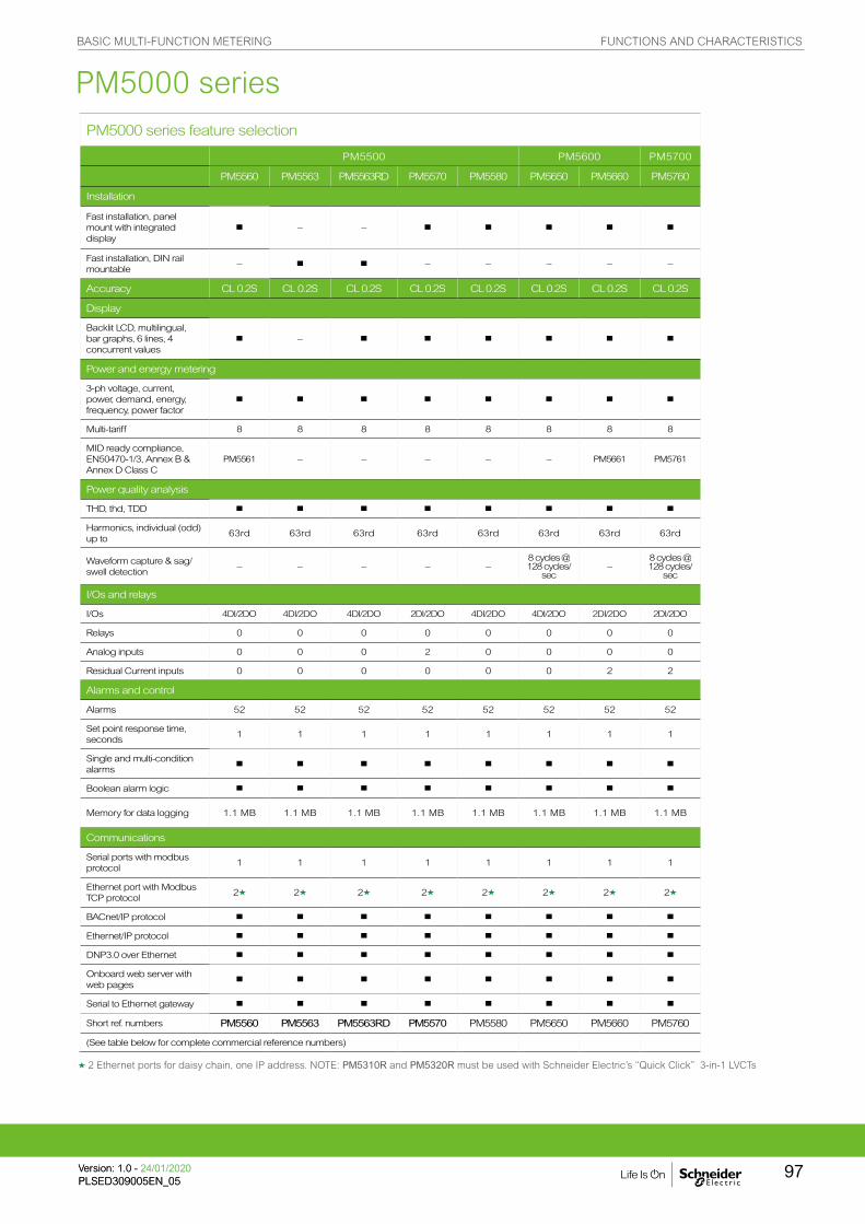
PM5000 series
g 2 Ethernet ports for daisy chain, one IP address. NOTE: PM5310R and PM5320R must be used with Schneider Electric’s “Quick Click” 3-in-1 LVCTs
PM5000 series feature selection
PM5500 PM5600 PM5700
PM5560 PM5563 PM5563RD PM5570 PM5580 PM5650 PM5660 PM5760
Installation
Fast installation, panel mount with integrated display
b – – b b b b b
Fast installation, DIN rail mountable
– b b – – – – –
Accuracy CL 0.2S CL 0.2S CL 0.2S CL 0.2S CL 0.2S CL 0.2S CL 0.2S CL 0.2S
Display
Backlit LCD, multilingual, bar graphs, 6 lines, 4 concurrent values
b – b b b b b b
Power and energy metering
3-ph voltage, current, power, demand, energy, frequency, power factor
b b b b b b b b
Multi-tariff 8 8 8 8 8 8 8 8
MID ready compliance, EN50470-1/3, Annex B & Annex D Class C
PM5561 – – – – – PM5661 PM5761
Power quality analysis
THD, thd, TDD b b b b b b b b
Harmonics, individual (odd) up to
63rd 63rd 63rd 63rd 63rd 63rd 63rd 63rd
Waveform capture & sag/swell detection
– – – – –8 cycles @ 128 cycles/
sec–
8 cycles @ 128 cycles/
sec
I/Os and relays
I/Os 4DI/2DO 4DI/2DO 4DI/2DO 2DI/2DO 4DI/2DO 4DI/2DO 2DI/2DO 2DI/2DO
Relays 0 0 0 0 0 0 0 0
Analog inputs 0 0 0 2 0 0 0 0
Residual Current inputs 0 0 0 0 0 0 2 2
Alarms and control
Alarms 52 52 52 52 52 52 52 52
Set point response time, seconds
1 1 1 1 1 1 1 1
Single and multi-condition alarms
b b b b b b b b
Boolean alarm logic b b b b b b b b
Memory for data logging 1.1 MB 1.1 MB 1.1 MB 1.1 MB 1.1 MB 1.1 MB 1.1 MB 1.1 MB
Communications
Serial ports with modbus protocol
1 1 1 1 1 1 1 1
Ethernet port with Modbus TCP protocol
2g 2g 2g 2g 2g 2g 2g 2g
BACnet/IP protocol b b b b b b b b
Ethernet/IP protocol b b b b b b b b
DNP3.0 over Ethernet b b b b b b b b
Onboard web server with web pages
b b b b b b b b
Serial to Ethernet gateway b b b b b b b b
Short ref. numbers PM5560 PM5563 PM5563RD PM5570 PM5580 PM5650 PM5660 PM5760
(See table below for complete commercial reference numbers)
BASIC MULTI-FUNCTION METERING FUNCTIONS AND CHARACTERISTICS
97Version: 1.0 - 24/01/2020PLSED309005EN_05Version: 1.0 - 24/01/2020PLSED309005EN_05

PM5000 technical specifications
PM5100 PM5300 PM5500 PM5600 PM5700
Use on LV and MV systems b
Basic metering with THD and min/max readings b
Instantaneous rms values
Currentper phase, neutral and ground (PM5500)
b
Voltage Total, per phase L-L and L-N b
Frequency b
Real, reactive, and apparent power
Total and per phase Signed, Four Quadrant
True Power Factor Total and per phase Signed, Four Quadrant
Displacement PF Total and per phase Signed, Four Quadrant
% Unbalanced I, V L-N, V L-L b
Direct monitoring of neutral current b
Energy values
Accumulated Active, Reactive and Apparent Energy Received/Delivered; Net and absolute; Time Counters
Demand value
Current average Present, Last, Predicted, Peak, and Peak Date Time
Active power Present, Last, Predicted, Peak, and Peak Date Time
Reactive power Present, Last, Predicted, Peak, and Peak Date Time
Apparent power Present, Last, Predicted, Peak, and Peak Date Time
Peak demand with timestamping D/T for current and powers
b
Demand calculationSliding, fixed and rolling block, thermal methods
b
Synchronisation of the measurement window to input, communication command or internal clock
b
Settable Demand intervals b
Demand calculation for Pulse input (WAGES) b
Other measurements
I/O timer b
Operating timer b
Load timer b
Alarm counters and alarm logs b
Power quality measurements
THD, thd (Total Harmonic Distortion) I, VLN, VLL I,VLN, VLL
TDD (Total Demand Distortion) b
Individual harmonics (odds) 15th 31st 63rd
Neutral Current metering with ground current calculation
b
Waveform capture and sag/swell detection8 cycles @ 128
cycles/sec
Data recording
Min/max of instantaneous values, plus phase
identificationgb
Alarms with 1s timestampingg b
Data logging
2 fixed parameters kWh and kVAh with configurable interval
& duration (e.g. 2 parameters for 60 days at 15-minute intervals)
256 KB
Up to 14 selectable parameters with configurable interval and duration (e.g. 6 parameters for 90 days at 15-minute intervals)
Memory capacity 256 kB 1.1 MB
Min/max log b b b
Maintenance, alarm and event logs b b
Customisable data logs b
PM5000 series
gStored in non-volatile memory
BASIC MULTI-FUNCTION METERING FUNCTIONS AND CHARACTERISTICS
Version: 1.0 - 24/01/2020PLSED309005EN_05
98
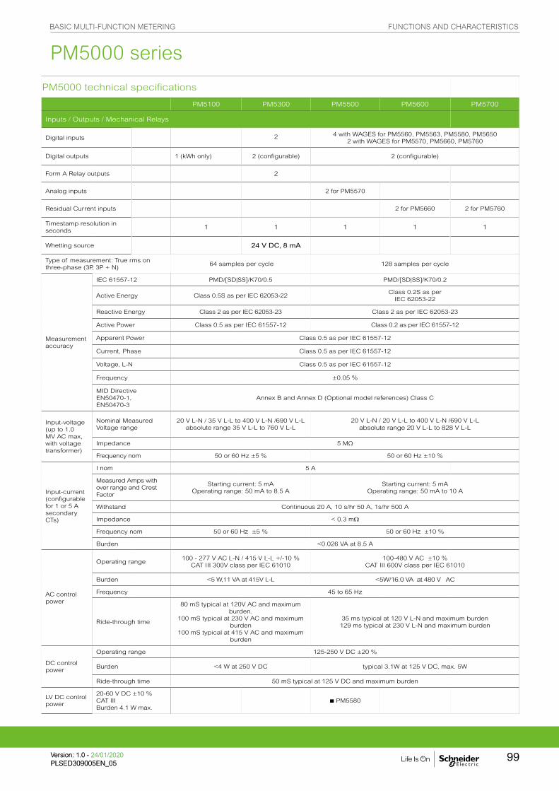
PM5000 technical specifications
PM5100 PM5300 PM5500 PM5600 PM5700
Inputs / Outputs / Mechanical Relays
Digital inputs 2 4 with WAGES for PM5560, PM5563, PM5580, PM56502 with WAGES for PM5570, PM5660, PM5760
Digital outputs 1 (kWh only) 2 (configurable) 2 (configurable)
Form A Relay outputs 2
Analog inputs 2 for PM5570
Residual Current inputs 2 for PM5660 2 for PM5760
Timestamp resolution in seconds
1 1 1 1 1
Whetting source 24 V DC, 8 mA
Type of measurement: True rms on three-phase (3P, 3P + N)
64 samples per cycle 128 samples per cycle
Measurement accuracy
IEC 61557-12 PMD/[SD|SS]/K70/0.5 PMD/[SD|SS]/K70/0.2
Active Energy Class 0.5S as per IEC 62053-22Class 0.2S as per
IEC 62053-22
Reactive Energy Class 2 as per IEC 62053-23 Class 2 as per IEC 62053-23
Active Power Class 0.5 as per IEC 61557-12 Class 0.2 as per IEC 61557-12
Apparent Power Class 0.5 as per IEC 61557-12
Current, Phase Class 0.5 as per IEC 61557-12
Voltage, L-N Class 0.5 as per IEC 61557-12
Frequency ±0.05 %
MID Directive EN50470-1, EN50470-3
Annex B and Annex D (Optional model references) Class C
Input-voltage(up to 1.0 MV AC max, with voltage transformer)
Nominal Measured Voltage range
20 V L-N / 35 V L-L to 400 V L-N /690 V L-Labsolute range 35 V L-L to 760 V L-L
20 V L-N / 20 V L-L to 400 V L-N /690 V L-Labsolute range 20 V L-L to 828 V L-L
Impedance 5 MΩ
Frequency nom 50 or 60 Hz ±5 % 50 or 60 Hz ±10 %
Input-current(configurable for 1 or 5 A secondary CTs)
I nom 5 A
Measured Amps with over range and Crest Factor
Starting current: 5 mAOperating range: 50 mA to 8.5 A
Starting current: 5 mA Operating range: 50 mA to 10 A
Withstand Continuous 20 A, 10 s/hr 50 A, 1s/hr 500 A
Impedance < 0.3 mW
Frequency nom 50 or 60 Hz ±5 % 50 or 60 Hz ±10 %
Burden <0.026 VA at 8.5 A
AC control power
Operating range100 - 277 V AC L-N / 415 V L-L +/-10 %
CAT III 300V class per IEC 61010100-480 V AC ±10 %
CAT III 600V class per IEC 61010
Burden <5 W,11 VA at 415V L-L <5W/16.0 VA at 480 V AC
Frequency 45 to 65 Hz
Ride-through time
80 mS typical at 120V AC and maximum burden.
100 mS typical at 230 V AC and maximum burden
100 mS typical at 415 V AC and maximum burden
35 ms typical at 120 V L-N and maximum burden129 ms typical at 230 V L-N and maximum burden
DC control power
Operating range 125-250 V DC ±20 %
Burden <4 W at 250 V DC typical 3.1W at 125 V DC, max. 5W
Ride-through time 50 mS typical at 125 V DC and maximum burden
LV DC control power
20-60 V DC ±10 %CAT III Burden 4.1 W max.
b PM5580
PM5000 series
BASIC MULTI-FUNCTION METERING FUNCTIONS AND CHARACTERISTICS
99Version: 1.0 - 24/01/2020PLSED309005EN_05Version: 1.0 - 24/01/2020PLSED309005EN_05
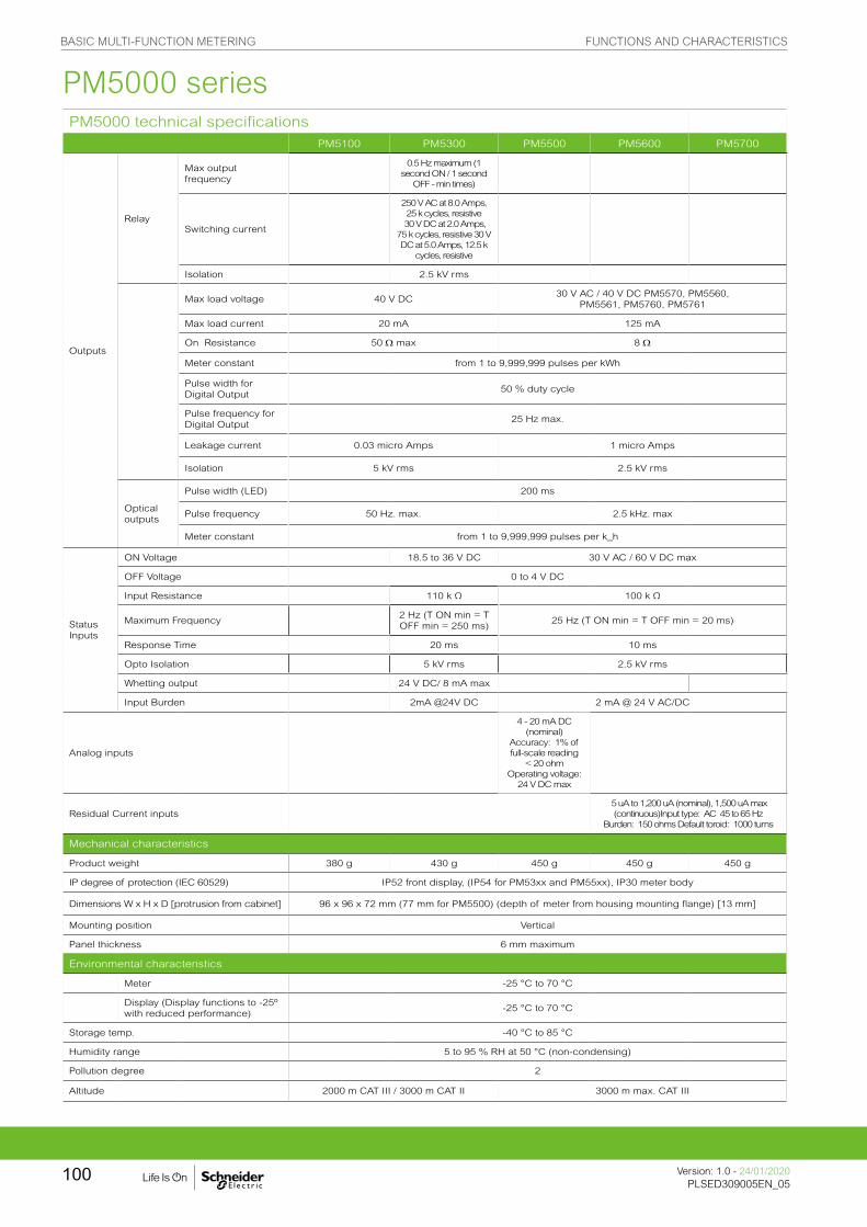
PM5000 technical specificationsPM5100 PM5300 PM5500 PM5600 PM5700
Outputs
Relay
Max output frequency
0.5 Hz maximum (1 second ON / 1 second
OFF - min times)
Switching current
250 V AC at 8.0 Amps, 25 k cycles, resistive
30 V DC at 2.0 Amps, 75 k cycles, resistive 30 V DC at 5.0 Amps, 12.5 k
cycles, resistive
Isolation 2.5 kV rms
Max load voltage 40 V DC30 V AC / 40 V DC PM5570, PM5560,
PM5561, PM5760, PM5761
Max load current 20 mA 125 mA
On Resistance 50 W max 8 W
Meter constant from 1 to 9,999,999 pulses per kWh
Pulse width for Digital Output
50 % duty cycle
Pulse frequency for Digital Output
25 Hz max.
Leakage current 0.03 micro Amps 1 micro Amps
Isolation 5 kV rms 2.5 kV rms
Optical outputs
Pulse width (LED) 200 ms
Pulse frequency 50 Hz. max. 2.5 kHz. max
Meter constant from 1 to 9,999,999 pulses per k_h
Status Inputs
ON Voltage 18.5 to 36 V DC 30 V AC / 60 V DC max
OFF Voltage 0 to 4 V DC
Input Resistance 110 k Ω 100 k Ω
Maximum Frequency 2 Hz (T ON min = T OFF min = 250 ms)
25 Hz (T ON min = T OFF min = 20 ms)
Response Time 20 ms 10 ms
Opto Isolation 5 kV rms 2.5 kV rms
Whetting output 24 V DC/ 8 mA max
Input Burden 2mA @24V DC 2 mA @ 24 V AC/DC
Analog inputs
4 - 20 mA DC (nominal)
Accuracy: 1% of full-scale reading
< 20 ohmOperating voltage:
24 V DC max
Residual Current inputs 5 uA to 1,200 uA (nominal), 1,500 uA max (continuous)Input type: AC 45 to 65 Hz
Burden: 150 ohms Default toroid: 1000 turns
Mechanical characteristics
Product weight 380 g 430 g 450 g 450 g 450 g
IP degree of protection (IEC 60529) IP52 front display, (IP54 for PM53xx and PM55xx), IP30 meter body
Dimensions W x H x D [protrusion from cabinet] 96 x 96 x 72 mm (77 mm for PM5500) (depth of meter from housing mounting flange) [13 mm]
Mounting position Vertical
Panel thickness 6 mm maximum
Environmental characteristics
Meter -25 °C to 70 °C
Display (Display functions to -25º with reduced performance)
-25 °C to 70 °C
Storage temp. -40 °C to 85 °C
Humidity range 5 to 95 % RH at 50 °C (non-condensing)
Pollution degree 2
Altitude 2000 m CAT III / 3000 m CAT II 3000 m max. CAT III
PM5000 series
BASIC MULTI-FUNCTION METERING FUNCTIONS AND CHARACTERISTICS
Version: 1.0 - 24/01/2020PLSED309005EN_05
100
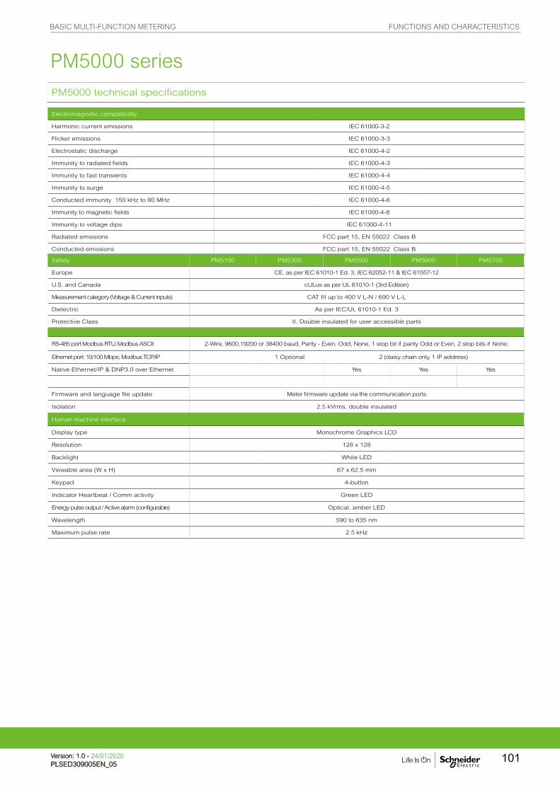
PM5000 technical specifications
Electromagnetic compatibility
Harmonic current emissions IEC 61000-3-2
Flicker emissions IEC 61000-3-3
Electrostatic discharge IEC 61000-4-2
Immunity to radiated fields IEC 61000-4-3
Immunity to fast transients IEC 61000-4-4
Immunity to surge IEC 61000-4-5
Conducted immunity 150 kHz to 80 MHz IEC 61000-4-6
Immunity to magnetic fields IEC 61000-4-8
Immunity to voltage dips IEC 61000-4-11
Radiated emissions FCC part 15, EN 55022 Class B
Conducted emissions FCC part 15, EN 55022 Class B
Safety PM5100 PM5300 PM5500 PM5600 PM5700
Europe CE, as per IEC 61010-1 Ed. 3, IEC 62052-11 & IEC 61557-12
U.S. and Canada cULus as per UL 61010-1 (3rd Edition)
Measurement category (Voltage & Current inputs) CAT III up to 400 V L-N / 690 V L-L
Dielectric As per IEC/UL 61010-1 Ed. 3
Protective Class II, Double insulated for user accessible parts
RS-485 port Modbus RTU, Modbus ASCII 2-Wire, 9600,19200 or 38400 baud, Parity - Even, Odd, None, 1 stop bit if parity Odd or Even, 2 stop bits if None;
Ethernet port: 10/100 Mbps; Modbus TCP/IP 1 Optional 2 (daisy chain only, 1 IP address)
Native Ethernet/IP & DNP3.0 over Ethernet Yes Yes Yes
Firmware and language file update Meter firmware update via the communication ports
Isolation 2.5 kVrms, double insulated
Human machine interface
Display type Monochrome Graphics LCD
Resolution 128 x 128
Backlight White LED
Viewable area (W x H) 67 x 62.5 mm
Keypad 4-button
Indicator Heartbeat / Comm activity Green LED
Energy pulse output / Active alarm (configurable) Optical, amber LED
Wavelength 590 to 635 nm
Maximum pulse rate 2.5 kHz
PM5000 series
BASIC MULTI-FUNCTION METERING FUNCTIONS AND CHARACTERISTICS
101Version: 1.0 - 24/01/2020PLSED309005EN_05Version: 1.0 - 24/01/2020PLSED309005EN_05

Comm ref numbers
Description
METSEPM5100 Power Meter range 72 mm depth, control power to 415 V AC, Cl 0.5S, 15th harmonic, no communication, 1DO
METSEPM5110 Power Meter range 72 mm depth, control power to 415 V AC, Cl 0.5S, 15th harmonic, RS-485 Modbus, 1DO
METSEPM5111 Power Meter range 72 mm depth, control power to 415 V AC, Cl 0.5S, 15th harmonic, RS-485 Modbus, 1DO, MID cert.
METSEPM5310 Power Meter range 72 mm depth, control power to 415 V AC, Cl 0.5S, 31st harmonic, 256 kB, RS-485 Modbus, 2DI/2DO
METSEPM5310R Power Meter range 72 mm depth, control power to 415 V AC, Cl 0.5S, 31st harmonic, 256 kB, RJ45 LVCT, RS-485 Modbus, 2DI/2DO
METSEPM5320 Power Meter range 72 mm depth, control power to 415 V AC, Cl 0.5S, 31st harmonic, 256 kB, Ethernet, 2DI/2DO
METSEPM5320R Power Meter range 72 mm depth, control power to 415 V AC, Cl 0.5S, 31st harmonic, 256 kB, RJ45 LVCT, Ethernet, 2DI/2DO
METSEPM5330 Power Meter range 72 mm depth, control power to 415 V AC, Cl 0.5S, 31st harmonic, 256 kB, RS-485 Modbus, 2DI/2DO, 2Relay
METSEPM5331 Power Meter range 72 mm depth, control power to 415 V AC, Cl 0.5S, 31st harmonic, 256 kB, RS-485 Modbus, 2DI/2DO, 2Relay, MID cert.
METSEPM5340 Power Meter range 72 mm depth, control power to 415 V AC, Cl 0.5S, 31st harmonic, 256 kB, Ethernet, 2DI/2DO, 2Relay
METSEPM5341 Power Meter range 72 mm depth, control power to 415 V AC, Cl 0.5S, 31st harmonic, 256 kB, Ethernet, 2DI/2DO, 2Relay, MID cert.
METSEPM5560 Power Meter range 77 mm depth, control power to 480 V AC, Cl 0.2S, 63rd harmonic, 1.1 MB, Modbus and Ethernet, 4DI/2DO
METSEPM5561 Power Meter range 77 mm depth, control power to 480 V AC, Cl 0.2S, 63rd harmonic, 1.1 MB, Modbus and Ethernet, MID cert.
METSEPM5562 Power Meter range 77 mm depth, control power to 480 V AC, Cl 0.2S, 63rd harmonic, 1.1 MB, RMICAN approved, HW lockable, 4DI/2DO
METSEPM5562MC Power Meter range 77 mm depth, control power to 480 V AC, Cl 0.2S, 63rd harmonic, 1.1 MB, RMICAN approved, factory sealed, 4DI/2DO
METSEPM5563 Power Meter range 77 mm depth, control power to 480 V AC, Cl 0.2S, 63rd harmonic, 1.1 MB, DIN mount, no display, 4DI/2DO
METSEPM5563RD Power Meter range 77 mm depth, control power to 480 V AC, Cl 0.2S, 63rd harmonic, 1.1 MB, DIN mount, remote display, 4DI/2DO
METSEPM5570 Power Meter range 77 mm depth, control power to 480 V AC, Cl 0.2S, 63rd harmonic, 1.1 MB, Modbus and Ethernet, 2DI/2DO/2AI
METSEPM5580 Power Meter range 77 mm depth, control power 24-60 VDC, Cl 0.2S, 63rd harmonic, 1.1 MB, Modbus and Ethernet, 4DI/2DO
METSEPM5650 Power Meter range 77 mm depth, control power to 480 V AC, Cl 0.2S, 63rd harmonic, waveform capture and sag/swell, 1.1 MB, Modbus and Ethernet, 2DI/2DO
METSEPM5660 Power Meter range 77 mm depth, control power to 480 V AC, Cl 0.2S, 63rd harmonic, 1.1 MB, Modbus and Ethernet, 2DI/2DO, RCM
METSEPM5661 Power Meter range 77 mm depth, control power to 480 V AC, Cl 0.2S, 63rd harmonic, 1.1 MB, Modbus and Ethernet, 2DI/2DO, RCM, MID
METSEPM5760 Power Meter range 77 mm depth, control power to 480 V AC, Cl 0.2S, 63rd harmonic, waveform capture and sag/swell, 1.1 MB, Modbus and Ethernet, 2DI/2DO, RCM
METSEPM5761 Power Meter range 77 mm depth, control power to 480 V AC, Cl 0.2S, 63rd harmonic, waveform capture and sag/swell, 1.1 MB, Modbus and Ethernet, 2DI/2DO, RCM, MID cert.
Residual Current Monitoring Toroids (Vigirex)
Closed Toroids, A Type
50437 TA30 - 30 mm inside diameter, Ie (A) 65, 1000 turns
50438 PA50 - 50 mm inside diameter, Ie (A) 85, 1000 turns
50439 IA80 - 80 mm inside diameter, Ie (A) 160, 1000 turns
50440 MA120 - 120 mm inside diameter, Ie (A) 250, 1000 turns
50441 SA200 - 200 mm inside diameter, Ie (A) 400, 1000 turns
50442 GA300 - 300 mm inside diameter, Ie (A) 630, 1000 turns
Accessories for Closed Toroids
56055 Magnetic ring for TA30 toroid
56056 Magnetic ring for PA50 toroid
56057 Magnetic ring for IA80 toroid
56058 Magnetic ring for MA120 toroid
Split Toroids, OA Type
50420 TOA80 - 80 mm inside diameter, Ie (A) 160, 1000 turns
50421 TOA120 - 120 mm inside diameter, Ie (A) 250, 1000 turns
56053 L1 - 280 x 115 mm inside diameter, Ie (A) 1600, 1000 turns
56054 L2 - 470 x 160 mm inside diameter, Ie (A) 3200, 1000 turns
PM5xxx series commercial reference numbers
BASIC MULTI-FUNCTION METERING FUNCTIONS AND CHARACTERISTICS
Version: 1.0 - 24/01/2020PLSED309005EN_05
102

See your Schneider Electric representative for complete ordering information.
Comm. ref numbers Description
0.333V 3-in-1 CTs with RJ45 for PM53x0R
METSECTV25006 LVCT SolidC 3in1 RJ45 25mmCtr 60A:1/3V
METSECTV25010 LVCT SolidC 3in1 RJ45 25mmCtr 100A:1/3V
METSECTV25013 LVCT SolidC 3in1 RJ45 25mmCtr 125A:1/3V
METSECTV25016 LVCT SolidC 3in1 RJ45 25mmCtr 160A:1/3V
METSECTV35006 LVCT SolidC 3in1 RJ45 35mmCtr 60A:1/3V
METSECTV35010 LVCT SolidC 3in1 RJ45 35mmCtr 100A:1/3V
METSECTV35012 LVCT SolidC 3in1 RJ45 35mmCtr 120A:1/3V
METSECTV35013 LVCT SolidC 3in1 RJ45 35mmCtr 125A:1/3V
METSECTV35015 LVCT SolidC 3in1 RJ45 35mmCtr 150A:1/3V
METSECTV35016 LVCT SolidC 3in1 RJ45 35mmCtr 160A:1/3V
METSECTV35020 LVCT SolidC 3in1 RJ45 35mmCtr 200A:1/3V
METSECTV35025 LVCT SolidC 3in1 RJ45 35mmCtr 250A:1/3V
METSECTV45025 LVCT SolidC 3in1 RJ45 45mmCtr 250A:1/3V
METSECTV45030 LVCT SolidC 3in1 RJ45 45mmCtr 300A:1/3V
METSECTV45040 LVCT SolidC 3in1 RJ45 45mmCtr 400A:1/3V
METSECTV45050 LVCT SolidC 3in1 RJ45 45mmCtr 500A:1/3V
METSECTV45060 LVCT SolidC 3in1 RJ45 45mmCtr 600A:1/3V
METSECTV45063 LVCT SolidC 3in1 RJ45 45mmCtr 630A:1/3VMETSECTV29006 LVCT SolidC 3in1 RJ45 29mmCtr 60A:1/3V
METSECTV29010 LVCT SolidC 3in1 RJ45 29mmCtr 100A:1/3V
METSECTV29012 LVCT SolidC 3in1 RJ45 29mmCtr 120A:1/3V
METSECTV29013 LVCT SolidC 3in1 RJ45 29mmCtr 125A:1/3V
METSECTV29015 LVCT SolidC 3in1 RJ45 29mmCtr 150A:1/3V
METSECTV29016 LVCT SolidC 3in1 RJ45 29mmCtr 160A:1/3V
METSECTV29020 LVCT SolidC 3in1 RJ45 29mmCtr 200A:1/3V
METSECTV70080 LVCT SolidC 3in1 RJ45 70mmCtr 800A:1/3V
METSECTV70100 LVCT SolidC 3in1 RJ45 70mmCtr 1000A:1/3V
METSECTV70125 LVCT SolidC 3in1 RJ45 70mmCtr 1250A:1/3V
Cables
DCEPCURJX5GYM Category 5e, Patch Cord, UTP, 0.5 M, GreyDCEPCURJ01GYM Category 5e, Patch Cord, UTP, 1 M, GreyDCEPCURJ02GYM Category 5e, Patch Cord, UTP, 2 M, GreyDCEPCURJ03GYM Category 5e, Patch Cord, UTP, 3 M, GreyDCEPCURJ05GYM Category 5e, Patch Cord, UTP, 5 M, Grey
DCEPCURJ10GYM Category 5e, Patch Cord, UTP, 10 M, Grey
Other related products
METSEPM5RD Remote display for PM5563
METSEPM51HK Hardware kit for PM51xx
METSEPM53HK Hardware kit for PM53xx
METSEPM51_3RSK Revenue sealing kit for PM51XX & PM53XX
METSEPM55RSK Revenue sealing kit for PM55XX
METSEPM55HK Hardware kit for PM55xx
METSEPM5CAB3 Remote Display cable
PM5xxR series commercial reference numbers
BASIC MULTI-FUNCTION METERING FUNCTIONS AND CHARACTERISTICS
103Version: 1.0 - 24/01/2020PLSED309005EN_05Version: 1.0 - 24/01/2020PLSED309005EN_05

PM5000 meter parts A Menu selection buttons B LED indicators C Navigation or menu selections D Maintenance and alarm
notification area
Please see the appropriate Installation Guide for accurate and complete information on the installation of this product.
PM5100 / PM5300 meter parts E Relay output (PM5300 only) F Voltage inputs G Control power H Current inputs I Status inputs/digital outputs J Communications port: Ethernet
(PM5300 only) or RS-485)
PM5100 / PM5300 PM5500 / PM5600
PM5500 / PM5600 meter parts E Voltage inputs F RS-485 comms G Digital inputs H Current inputs I Digital outputs J Ethernet ports K Control power
PM5500
PM5000 Series meter flush mounting
PM5000 series meter dimensions
PB
111276m
PB
111279_m
PB
111278
PB
111277
PB
111291
PB
111289
PB
111279A
PM5000
PM5000 series
BASIC MULTI-FUNCTION METERING DIMENSIONS AND CONNECTION
Version: 1.0 - 24/01/2020PLSED309005EN_05
104

METSEPM8240 M7650
Advanced high performance meters are designed for mains or critical loads on MV/LV networks. They
provide analysis of efficiency, losses and capacity, bill verification, power quality compliance monitoring,
problem notification and diagnosis and control of loads, etc. Power quality meters are classified as
advanced meters designed to monitor service entrances and critical network locations to maximize
power availability and reliability by providing a comprehensive system load profile, power quality and
root cause analyses.
• • PowerLogic™ PM8000
• • PowerLogic™ ION9000
Advanced metering
P115
913
PB11
3687
ADVANCED METERING FUNCTIONS AND CHARACTERISTICS
105Version: 1.0 - 06/11/2020PLSED309005EN_06Version: 1.0 - 06/11/2020PLSED309005EN_06

The PowerLogic™ PM8000 series meters are compact, cost-effective multifunction power meters that
will help you ensure reliability and efficiency of your power-critical facility.
Reveal and understand complex power quality conditions. Measure, understand and act on insightful data gathered from your entire power system. Designed for key metering points throughout your energy infrastructure, the PowerLogic PM8000 series meter has the versatility to perform nearly any job you need a meter to do, wherever you need it!
Applications
Ideal for low to high voltage applications in industrial facilities, data centers, infrastructure and other critical power environments.
PM8000 Series
PB
113687
METSEPM8240
ADVANCED METERING FUNCTIONS AND CHARACTERISTICS
Version: 1.0 - 06/11/2020PLSED309005EN_06
106

The solution for
Markets that can benefit from a solution that includes PowerLogic PM8000 series meters:
• Industry
• Data centers
• Infrastructure
• Healthcare
• Buildings
Power management solutions
Schneider Electric provides innovative power management solutions to increase your energy efficiency and cost savings, maximize electrical network reliability and availability, and optimise electrical asset performance.
Competitive advantages
• Modular, flexible patented ION technology architecture enables a simple building block approach.
• Disturbance direction detection, modularity and compliance with latest power quality standards.
• Color screen.
• Multiple communication options.
• Excellent accuracy.
Benefits
• Makes understanding power quality simple to help operations personnel avoid downtime and helps ensure increased productivity and equipment life.
• Makes energy and power quality immediately relevant and actionable to support your operational and sustainability goals.
Conformity of standards
• EN 50160
• EN 50470
• IEC 61000-4-30
• IEC 61010-1
• IEC 61326-1
• IEC 61557-12
• IEC 62052-11
• IEC 62053-11
• IEC 62053-22
• IEC 62053-23
• IEC 62053-24
• IEC 62586-2
• IEEE 519
• UL 61010-1
PM8000 series
ADVANCED METERING FUNCTIONS AND CHARACTERISTICS
107Version: 1.0 - 06/11/2020PLSED309005EN_06Version: 1.0 - 06/11/2020PLSED309005EN_06
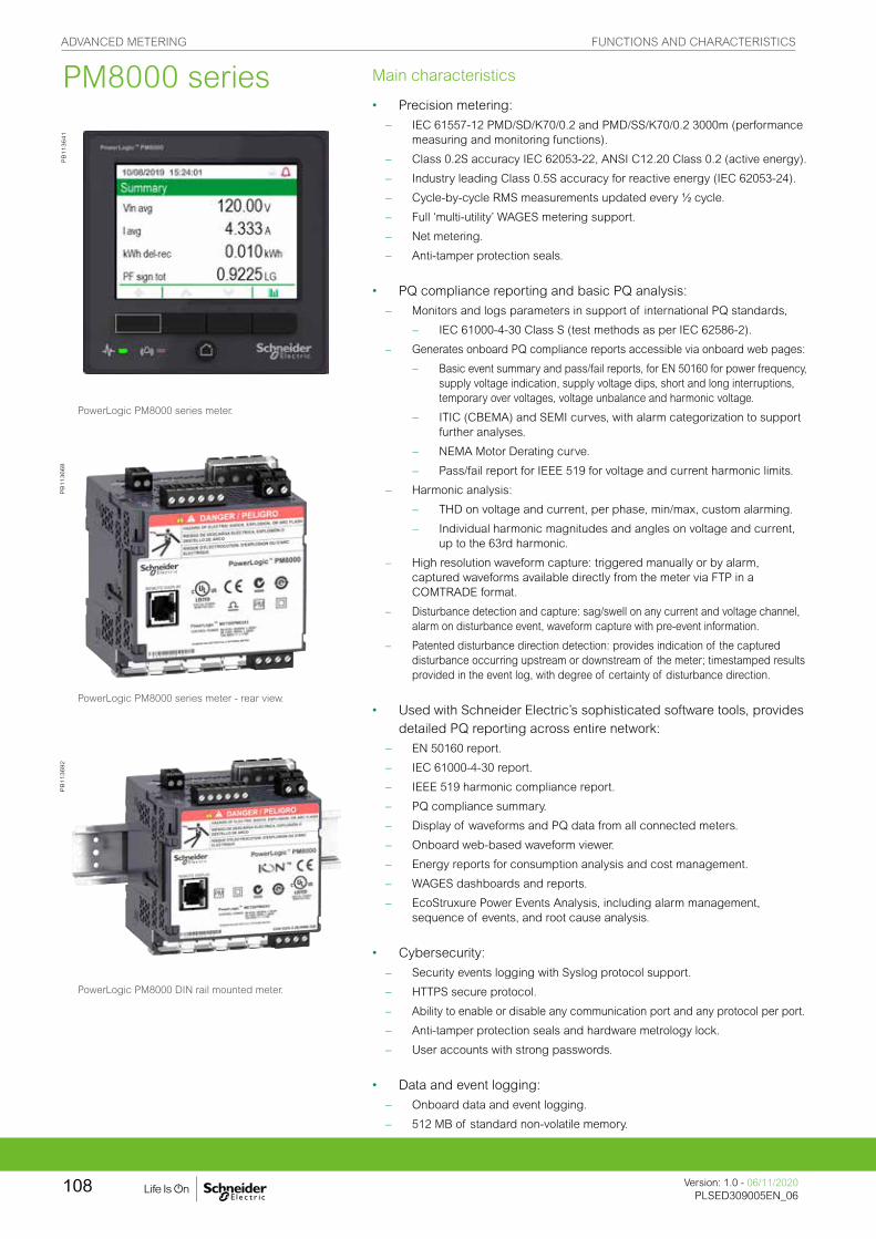
Main characteristics
• Precision metering:
– IEC 61557-12 PMD/SD/K70/0.2 and PMD/SS/K70/0.2 3000m (performance measuring and monitoring functions).
– Class 0.2S accuracy IEC 62053-22, ANSI C12.20 Class 0.2 (active energy).
– Industry leading Class 0.5S accuracy for reactive energy (IEC 62053-24).
– Cycle-by-cycle RMS measurements updated every ½ cycle.
– Full ‘multi-utility’ WAGES metering support.
– Net metering.
– Anti-tamper protection seals.
• PQ compliance reporting and basic PQ analysis:
– Monitors and logs parameters in support of international PQ standards,
– IEC 61000-4-30 Class S (test methods as per IEC 62586-2).
– Generates onboard PQ compliance reports accessible via onboard web pages:
– Basic event summary and pass/fail reports, for EN 50160 for power frequency, supply voltage indication, supply voltage dips, short and long interruptions, temporary over voltages, voltage unbalance and harmonic voltage.
– ITIC (CBEMA) and SEMI curves, with alarm categorization to support further analyses.
– NEMA Motor Derating curve.
– Pass/fail report for IEEE 519 for voltage and current harmonic limits.
– Harmonic analysis:
– THD on voltage and current, per phase, min/max, custom alarming.
– Individual harmonic magnitudes and angles on voltage and current, up to the 63rd harmonic.
– High resolution waveform capture: triggered manually or by alarm, captured waveforms available directly from the meter via FTP in a COMTRADE format.
– Disturbance detection and capture: sag/swell on any current and voltage channel, alarm on disturbance event, waveform capture with pre-event information.
– Patented disturbance direction detection: provides indication of the captured disturbance occurring upstream or downstream of the meter; timestamped results provided in the event log, with degree of certainty of disturbance direction.
• Used with Schneider Electric’s sophisticated software tools, provides detailed PQ reporting across entire network:
– EN 50160 report.
– IEC 61000-4-30 report.
– IEEE 519 harmonic compliance report.
– PQ compliance summary.
– Display of waveforms and PQ data from all connected meters.
– Onboard web-based waveform viewer.
– Energy reports for consumption analysis and cost management.
– WAGES dashboards and reports.
– EcoStruxure Power Events Analysis, including alarm management, sequence of events, and root cause analysis.
• Cybersecurity:
– Security events logging with Syslog protocol support.
– HTTPS secure protocol.
– Ability to enable or disable any communication port and any protocol per port.
– Anti-tamper protection seals and hardware metrology lock.
– User accounts with strong passwords.
• Data and event logging:
– Onboard data and event logging.
– 512 MB of standard non-volatile memory.
PowerLogic PM8000 series meter.
PowerLogic PM8000 series meter - rear view.
PowerLogic PM8000 DIN rail mounted meter.
PB
113641
PB
113668
PB
113692
PM8000 seriesADVANCED METERING FUNCTIONS AND CHARACTERISTICS
Version: 1.0 - 06/11/2020PLSED309005EN_06
108
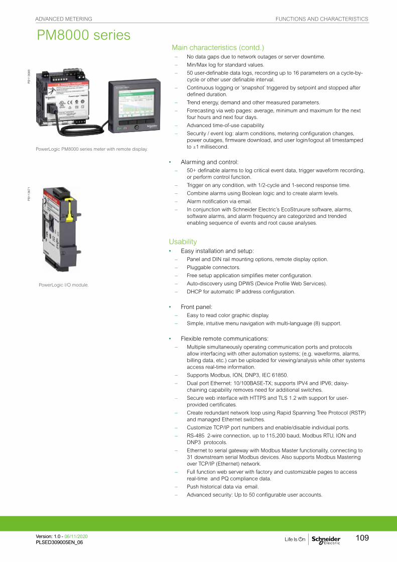
– No data gaps due to network outages or server downtime.
– Min/Max log for standard values.
– 50 user-definable data logs, recording up to 16 parameters on a cycle-by-cycle or other user definable interval.
– Continuous logging or ‘snapshot’ triggered by setpoint and stopped after defined duration.
– Trend energy, demand and other measured parameters.
– Forecasting via web pages: average, minimum and maximum for the next four hours and next four days.
– Advanced time-of-use capability.
– Security / event log: alarm conditions, metering configuration changes, power outages, firmware download, and user login/logout all timestamped to ±1 millisecond.
• Alarming and control: – 50+ definable alarms to log critical event data, trigger waveform recording,
or perform control function.
– Trigger on any condition, with 1/2-cycle and 1-second response time.
– Combine alarms using Boolean logic and to create alarm levels.
– Alarm notification via email.
– In conjunction with Schneider Electric’s EcoStruxure software, alarms, software alarms, and alarm frequency are categorized and trended enabling sequence of events and root cause analyses.
Usability• Easy installation and setup:
– Panel and DIN rail mounting options, remote display option.
– Pluggable connectors.
– Free setup application simplifies meter configuration.
– Auto-discovery using DPWS (Device Profile Web Services).
– DHCP for automatic IP address configuration.
• Front panel: – Easy to read color graphic display.
– Simple, intuitive menu navigation with multi-language (8) support.
• Flexible remote communications: – Multiple simultaneously operating communication ports and protocols
allow interfacing with other automation systems; (e.g. waveforms, alarms, billing data, etc.) can be uploaded for viewing/analysis while other systems access real-time information.
– Supports Modbus, ION, DNP3, IEC 61850.
– Dual port Ethernet: 10/100BASE-TX; supports IPV4 and IPV6; daisy-chaining capability removes need for additional switches.
– Secure web interface with HTTPS and TLS 1.2 with support for user-provided certificates.
– Create redundant network loop using Rapid Spanning Tree Protocol (RSTP) and managed Ethernet switches.
– Customize TCP/IP port numbers and enable/disable individual ports.
– RS-485 2-wire connection, up to 115,200 baud, Modbus RTU, ION and DNP3 protocols.
– Ethernet to serial gateway with Modbus Master functionality, connecting to 31 downstream serial Modbus devices. Also supports Modbus Mastering over TCP/IP (Ethernet) network.
– Full function web server with factory and customizable pages to access real-time and PQ compliance data.
– Push historical data via email.
– Advanced security: Up to 50 configurable user accounts.
PowerLogic I/O module.
PowerLogic PM8000 series meter with remote display.
PB
113669
PB
113671
M Main characteristics
Main characteristics (contd.)PM8000 seriesADVANCED METERING FUNCTIONS AND CHARACTERISTICS
109Version: 1.0 - 06/11/2020PLSED309005EN_06Version: 1.0 - 06/11/2020PLSED309005EN_06

• Time synchronization via: – GPS clock (RS-485) or IRIG-B (digital input) to ±1 millisecond.
– Network Time Protocol (NTP/SNTP).
– Precision Time Protocol (PTP - IEEE 1588 / IEC 61588).
– Time set function from Schneider Electric software server.
Adaptability – ION™ frameworks allow customisable, scalable applications, object-oriented
programming, compartmentalizes functions, and increases flexibility and
adaptability.
– Applications include: access and aggregate data from Modbus devices on serial port or across the network (Modbus TCP/IP), logging and/or processing data by totaling, unit conversion or other calculations, applying complex logic for alarming or control operations, data visualization via web pages.
Standard meter I/O
• 3 digital status/counter inputs.• 1 KY (form A) energy pulse output for interfacing with other systems.
Modular I/O options
• Optional expansion modules.• Up to 4 modules per meter.
Option modules include:
• Digital module:
– 6 digital status/counter inputs.
– 2 Form C relay outputs, 250 V, 8 A.• Analog module:
– 4 analog inputs (4-20 mA; 0-20 mA; 0-30 V).
– 2 analog outputs (4-20 mA; 0-20 mA; 0-10 V) for interfacing with building management sensors and systems.
PowerLogic PM8000 series meter with I/O modules.
PB
113686
PowerLogic PM8000 series waveform web page sample
PB
119094
PowerLogic PM8000 series CBEMA web page sample
PB
119093
PowerLogic PM8000 series PQ harmonics web page sample
PB
119095
PM8000 seriesADVANCED METERING FUNCTIONS AND CHARACTERISTICS
Version: 1.0 - 06/11/2020PLSED309005EN_06
110
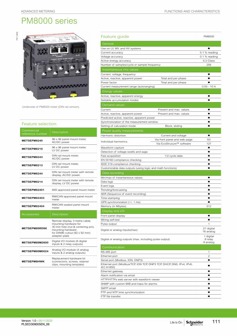
Feature selection
Commercial reference number
Description
METSEPM824096 x 96 panel mount meter, AC/DC power.
METSEPM821096 x 96 panel mount meter, LV DC power.
METSEPM8243DIN rail mount meter, AC/DC power.
METSEPM8213DIN rail mount meter, LV DC power.
METSEPM8244DIN rail mount meter with remote display, AC/DC power.
METSEPM8214DIN rail mount meter with remote display, LV DC power.
METSEPM82401 MID approved panel mount meter.
METSEPM82403RMICAN approved panel mount meter.
METSEPM82404RMICAN sealed panel mount meter.
Accessories Description
METSEPM89RD96
Remote display, 3 metre cable, mounting hardware for30 mm hole (nut & centering pin), mounting hardwarefor DIN96 cutout (92 x 92 mm) adapter plate
METSEPM89M2600Digital I/O module (6 digital inputs & 2 relay outputs)
METSEPM89M0024Analog I/O module (4 analog inputs & 2 analog outputs)
METSEPM8HWKReplacement hardware kit (connectors, screws, retainer clips, mounting template)
Feature guide PM8000
General
Use on LV, MV, and HV systems b
Current accuracy 0.1 % reading
Voltage accuracy 0.1 % reading
Active energy accuracy 0.2 Class
Number of samples/cycle or sample frequency 256
Instantaneous rms values
Current, voltage, frequency b
Active, reactive, apparent power Total and per phase b
Power factor Total and per phase b
Current measurement range (autoranging) 0.05 - 10 A
Energy values
Active, reactive, apparent energy b
Settable accumulation modes b
Demand values
Current Present and max. values b
Active, reactive, apparent power Present and max. values b
Predicted active, reactive, apparent power b
Synchronization of the measurement window b
Setting of calculation mode Block, sliding b
Power quality measurements
Harmonic distortion Current and voltage b
Individual harmonicsVia front panel and web page 63
Via EcoStruxure™ software 127
Waveform capture b
Detection of voltage swells and sags b
Fast acquisition 1/2 cycle data b
EN 50160 compliance checking b
IEEE 519 compliance checking b
Customizable data outputs (using logic and math functions) b
Data recording
Min/max of instantaneous values b
Data logs b
Event logs b
Trending/forecasting b
SER (Sequence of event recording) b
Time stamping b
GPS synchronization (+/- 1 ms) b
Memory (in Mbytes) 512
Display and I/O
Front panel display b
Wiring self-test b
Pulse output 1
Digital or analog inputs(max)27 digital16 analog
Digital or analog outputs (max, including pulse output)1 digital8 relay
8 analog
Communication
RS-485 port 1
Ethernet port 2
Serial port (Modbus, ION, DNP3) b
Ethernet port (Modbus/TCP, ION TCP, DNP3 TCP, DHCP, DNS, IPv4, IPv6, IEC 61850)
b
Ethernet gateway b
Alarm notification via email b
HTTP/HTTPs web server with waveform viewer b
SNMP with custom MIB and traps for alarms b
SMTP email b
PTP and NTP time synchronization b
FTP file transfer b
PB
113696
Underside of PM8000 meter (DIN rail version).
PM8000 seriesADVANCED METERING FUNCTIONS AND CHARACTERISTICS
111Version: 1.0 - 06/11/2020PLSED309005EN_06Version: 1.0 - 06/11/2020PLSED309005EN_06

Technical specifications
Electrical characteristics
Type of measurement True rms to 256 samples per cycle
Measurement accuracy
Current & voltage Class 0.2 as per IEC 61557-12
Active Power Class 0.2 as per IEC 61557-12
Power factor Class 0.5 as per IEC 61557-12
Frequency Class 0.02 as per IEC 61557-12
Active energyClass 0.2S IEC 62053-22Class 0.2 IEC 61557-12, ANSI C12.20 Class 0.2
Reactive Energy Class 0.5S IEC 62053-24*
MID Directive EN 50470-1, EN 50470-1, AnnexB & AnnexD (optional model)
Display refresh rate 1/2 cycle or 1 second
Input-voltage characteristics
Specified accuracy voltage 57 - 400 V L-N / 100 - 690 V L-L
Impedance 5 MW per phase
Specified accuracyfrequency - Frequency
42 to 69 Hz(50/60 Hz nominal)
Limit range of operation - frequency
20 to 450 Hz
Input-current characteristics
Rated nominal current 1 A (0.2S), 5 A (0.2S) , 10 A (0.2 ANSI)
Specified accuracycurrent range
Starting Current: 5 mAAccurate Range: 50 mA - 10 A
Permissible overload 200 A rms for 0.5s, non-recurring
Impedance 0.0003 W per phase
Burden 0.01 VA max at 5 A
Power supplyAC/DC
AC 90-415 V AC ±10 % (50/60 Hz ±10 %) 90-120 V AC +/- 10% (400 Hz)
DC 110-415 V DC ±15 % (20-60 V DC ±10 % for PM8210
Ride-through time100 ms (6 cycles at 60 Hz) min., any condition200 ms (12 cycles at 60 Hz) typ., 120 V AC500 ms (30 cycles at 60 Hz) typ., 415 V AC
BurdenTypical: 7.7 W / 16 VA at 230 V (50/60 Hz)Fully optioned: max. 18 W / 40 VA at 415 V (50/60 Hz).
Power supplyLV DC
DC 20 to 60 V DC ±10 %
Burden Fully optioned: max. 18 W at 18 to 60 V DC
Input/outputs
Meter Base Only3 digital inputs (30 V AC/60 V DC)1 form A (KY) solid state digital output (30 V AC/60 V DC, 75 mA).
OptionalDigital - 6 digital inputs (30 V AC / 60 V DC) wetted + 2 form C relay outputs (250 V AC, 8 A)
Analog - 4 analog inputs (4-20 mA, 0-30 V DC) + 2 analog outputs (4-20 mA, 0-10 V DC).
Mechanical characteristics
Weight
Integrated Display Model 0.581 kgDIN rail mounted Model 0.528 kgIO modules 0.140 kgRemote display 0.300 kg
IP degree of protectionIP 54, UL type 12: Panel mount and Remote display, front.IP 30: Panel mount rear, DIN rail mount, I/O modules.
Excellent quality ISO 9001 and ISO 14000 certified manufacturing.
Dimensions
Panel mount model 96 x 96 x 77.5 mm
DIN model 90.5 x 90.5 x 90.8 mm
Remote display 96 x 96 x 27 mm
IO modules 90.5 x 90.5 x 22 mm
PM8000 series
ADVANCED METERING FUNCTIONS AND CHARACTERISTICS
Version: 1.0 - 06/11/2020PLSED309005EN_06
112

Environmental conditions
Operating temperature -25 ºC to 70 ºC
Remote Display Unit -25 ºC to 60 ºC
Storage temperature -40 ºC to 85 ºC
Humidity rating 5 % to 95 % non-condensing
Installation category III
Operating altitude (maximum) 3000 m above sea-level
Electromagnetic compatibility
EMC standards IEC 62052-11 and IEC 61326-1
Immunity to electrostatic discharge IEC 61000-4-2
Immunity to radiated fields IEC 61000-4-3
Immunity to fast transients IEC 61000-4-4
Immunity to surges IEC 61000-4-5
Immunity to conducted disturbances IEC 61000-4-6
Immunity to power frequency magnetic fields
IEC 61000-4-8
Immunity to conducted disturbances, 2-150kHz
CLC/TR 50579
Immunity to voltage dips & interruptions
IEC 61000-4-11
Immunity to ring waves IEC 61000-4-12
Conducted and radiated emissions EN 55022, EN 55011, FCC part 15 Class B, EN55011, EN55022 Class B, ICES-003 Class B
Surge withstand Capability (SWC) IEEE / ANSI C37.90.1
Safety
Safety ConstructionIEC/EN 61010-1 ed.3, CAT III, 400 V L-N / 690 V L-LUL 61010-1 ed.3 and CSA-C22.2 No. 61010-1 ed.3, CAT III, 347 V L-N / 600 V L-L IEC/EN 62052-11, protective class II.
Communication
Ethernet to serial line gateway Communicates directly with up to 31 unit load devices.
Web server Customisable pages, new page creation capabilities, HTML/XML compatible.
Serial port RS-485 Baud rates of 2400 to 115200, pluggable screw terminal connector.
Ethernet port(s) 2x 10/100BASE-TX, RJ45 connector (UTP).
Protocol Modbus, ION, DNP3, IEC 61850, HTTPS, FTP, SNMP, SMTP, DPWS, RSTP, NTP, PTP, NTP/SNTP, GPS, IPv4 /IPv6, DHCP, Syslog protocols.
Firmware characteristics
High-speed data recordingDown to 1/2 cycle interval burst recording, stores detailed characteristics of disturbances or outages. Trigger recording by a user-defined setpoint, or from external equipment.
Harmonic distortion Up to 63rd harmonic (127th via Schneider Electric software) for all voltage and current inputs.
Sag/swell detectionAnalyse severity/potential impact of sags and swells: magnitude and duration data suitable for plotting on voltage tolerance curves per phase triggers for waveform recording, control.
Disturbance direction detectionDetermine the location of a disturbance more quickly and accurately by determining the direction of the disturbance relative to the meter. Analysis results are captured in the event log, along with a timestamp and confidence level indicating level of certainty.
InstantaneousHigh accuracy of standard speed (1s) and high-speed (1/2 cycle) measurements, including true rms per phase and total for: voltage, current, active power (kW),reactive power (kvar), apparent power (kVA), power factor, frequency, voltage and current unbalance, phase reversal.
Load profilingChannel assignments (800 channels via 50 data recorders) configurable for any measurable parameter, including historical trend recording of energy, demand, voltage, current, power quality, or any measured parameter. Trigger recorders based on time interval, calendar schedule, alarm/event condition, or manually.
Trend curvesHistorical trends and future forecasts to better manage demand, circuit loading, and other parameters. Provides average, min, max and standard deviation every hour for last 24 hours, every day for last month, every week for last 8 weeks and every month for last 12 months.
Waveform capturesSimultaneous capture of all voltage and current channels, sub-cycle disturbance capture, ability to record from 210 cycles at 256 sample per cycle to over 2880 cycles at 16 points per cycle with user selectable sampling speed as well as pre- and post-trigger length.
AlarmsThreshold alarms: adjustable pickup and dropout setpoints and time delays, numerous activation levels possible for a given type of alarm, user-defined or automatic alarm threshold settings, user-defined priority levels (optional automatic alarm setting).
Advanced Time of Use (TOU) 6 seasons; 3 different day types: weekend, weekday, and holiday; up to 8 tariffs per day type.
PM8000 series
ADVANCED METERING FUNCTIONS AND CHARACTERISTICS
113Version: 1.0 - 06/11/2020PLSED309005EN_06Version: 1.0 - 06/11/2020PLSED309005EN_06

Firmware characteristics (cont.)
Advanced security Up to 50 users with unique access rights. Perform resets, time sync, or meter configurations based on user privileges.
Memory 512 MB.
Firmware update Update via the communication ports.
Display characteristics
Integrated or Remote display 320 x 240 (1/4 VGA) Color LCD, configurable screens , 5 buttons and 2 LED indicators (alarm and meter status).
Languages English, French, Spanish, Russian, Portugese, German, Italian, Chinese.
Notations IEC, IEEE.
The HMI menu includes
Alarms Active alarms, historic alarms (50+ alarms).
Basic Reading Voltage, current, frequency, power summary.
Power Power summary, demand, power factor.
Energy Energy total, delivered, received.
Events Timestamped verbose event log.
Power Quality EN 50160, IEEE 519, harmonics, phasor diagrams.
Inputs/Outputs Digital inputs, digital outputs, analog inputs, analog outputs.
Nameplate Model, serial and FW version.
Custom Screens Build your own metrics.
Setup MenuMeter setup, communications setup, display setup, date/time/clock setup, alarm setup, language setup, time of use setup, resets, password setup.
PM8000 series
PM8000 series parts
PB
119092
A Voltage inputsB Control powerC Digital inputsD Revenue lock LED (green)E Status LED (green/red)F Revenue lock switchG Digital outputH Sealing gasketI Infrared energy pulsing LEDJ Energy pulsing LEDK RS-485L Current inputsM Ethernet (2)N Date/timeO Revenue lock icon
P Alarm iconQ DisplayR Navigation icons Up Down Select Cancel Edit More
S Navigation buttonsT Home buttonU Alarm LED (red)V Bar graph
PB
113642
ADVANCED METERING FUNCTIONS AND CHARACTERISTICS
Version: 1.0 - 06/11/2020PLSED309005EN_06
114

PM8000 panel mount meter dimensions
PM8000 DIN rail mount meter dimensions
PM8000 remote display dimensions
PM8000 with I/O modules dimensions
Please see the appropriate Installation Guide for accurate and complete information on the installation of this product.
PB
119087
PB
119088
PB
119089
PB
119090
PB
119086
PM8000 series
ADVANCED METERING DIMENSIONS AND CONNECTION
Version: 1.0 - 06/11/2020PLSED309005EN_06
115

The PowerLogic™ ION9000 is your 24/7 power quality expert, providing information, not just data.
With a comprehensive, industry-leading Power Quality Instrument (PQI) performance designation according to IEC 62586-1/-2, the PowerLogic ION9000 is third-party certified ANSI C12.20 Class 0.1 and IEC 62053-22 Class 0.1S accurate, the most accurate power meter available today. Lab-verified power quality and safety ensure reliable, precision performance that is perfect for supply- or demand-side applications. Its patented Disturbance Direction Detection also helps you pinpoint the source of power quality issues faster. Capable of sampling at 10 MHz, the ION9000T captures extremely fast voltage events that are missed by most other power meters, enabling advanced diagnostics and high-resolution event associations for fast, conclusive diagnosis and resolution to transient voltages.
Highly customizable and modular, the ION9000’s field programmability can adapt to satisfy any solution, protecting your investment now and in the future. All designed to align with your comprehensive grid cybersecurity policies and backed by Schneider Electric’s global services and support.
Applications
Ideal for critical power and large energy users who cannot afford to be shut down, the ION9000T has High-Speed Transient Capture (HSTC) to detect and record transient events that exceed the voltage withstand of sensitive equipment.
ION9000 Series
PB
115917
METSEION92040
ADVANCED METERING FUNCTIONS AND CHARACTERISTICS
Version: 1.0 - 06/11/2020PLSED309005EN_06
116

The market solution for
Markets that benefit from a solution that includes PowerLogic ION9000 series meters:
• Data centers
• Healthcare facilities
• Semiconductor
• Pharmaceutical & chemical
• Energy industries
• Mining, Minerals, & Metals
• Renewable energy interconnects
• Medium voltage distribution & energy automation
Power management solutions
Schneider Electric provides innovative power management solutions to increase your energy efficiency and cost savings. Maximize electrical network reliability and availability, and optimize electrical asset performance.
Competitive advantages
• Modular, flexible, patented ION™ programmable technology
• Utility grade energy accuracy
• Patented Disturbance Direction Detection
• Third-party, lab-verified compliance with latest PQ standards
• Onboard pass/fail PQ characterization and assessment according to EN50160 and IEEE519
• Cybersecurity event logging, Syslog protocol, HTTPS, SFTP, and full control of each communication port
• High-speed impulsive and oscillatory transient detection
Benefits
• Makes understanding power quality simple which helps operations personnel avoid downtime and increase productivity and equipment life
• Makes energy and power quality data immediately actionable and relevant to operational and sustainability goals
Conformity of standards
• ANSI C12.20
• ANSI C37.90.1
• IEC 61000-4-15
• IEC 61000-4-30
• IEC 61010-1
• IEC 61326-1
• IEC 61557-12
• IEC 61850
• IEC 62052-11
• IEC 62052-31
• IEC 62053-22
• IEC 62053-23
• IEC 62053-24
• IEC 62586
• UL 61010-1
ADVANCED METERING FUNCTIONS AND CHARACTERISTICS
117Version: 1.0 - 06/11/2020PLSED309005EN_06Version: 1.0 - 06/11/2020PLSED309005EN_06
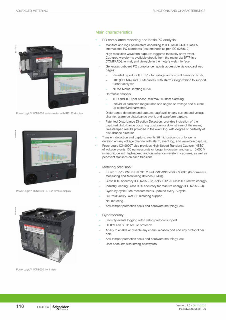
Main characteristics
• PQ compliance reporting and basic PQ analysis:
– Monitors and logs parameters according to IEC 61000-4-30 Class A international PQ standards (test methods as per IEC 62586-2).
– High resolution waveform capture: triggered manually or by event. Captured waveforms available directly from the meter via SFTP in a COMTRADE format, and viewable in the meter’s web interface.
– Generates onboard PQ compliance reports accessible via onboard web pages:
– Pass/fail report for IEEE 519 for voltage and current harmonic limits.
– ITIC (CBEMA) and SEMI curves, with alarm categorization to support further analyses.
– NEMA Motor Derating curve.
– Harmonic analysis:
– THD and TDD per phase, min/max, custom alarming.
– Individual harmonic magnitudes and angles on voltage and current, up to the 63rd harmonic.
– Disturbance detection and capture: sag/swell on any current and voltage channel, alarm on disturbance event, and waveform capture.
– Patented Disturbance Direction Detection: provides indication of the captured disturbance occurring upstream or downstream of the meter; timestamped results provided in the event log, with degree of certainty of disturbance direction.
• Transient detection and capture: events 20 microseconds or longer in duration on any voltage channel with alarm, event log, and waveform capture.
• PowerLogic ION9000T also provides High-Speed Transient Capture (HSTC) of voltage events 100 nanoseconds or longer in duration and up to 10,000 V in magnitude with high-speed and disturbance waveform captures, as well as per-event statistics on each transient.
• Metering precision:
– IEC 61557-12 PMD/SD/K70/0.2 and PMD/SS/K70/0.2 3000m (Performance Measuring and Monitoring devices (PMD)).
– Class 0.1S accuracy IEC 62053-22, ANSI C12.20 Class 0.1 (active energy).
– Industry leading Class 0.5S accuracy for reactive energy (IEC 62053-24).
– Cycle-by-cycle RMS measurements updated every ½ cycle.
– Full ‘multi-utility’ WAGES metering support.
– Net metering.
– Anti-tamper protection seals and hardware metrology lock.
• Cybersecurity:
– Security events logging with Syslog protocol support.
– HTTPS and SFTP secure protocols.
– Ability to enable or disable any communication port and any protocol per port.
– Anti-tamper protection seals and hardware metrology lock.
– User accounts with strong passwords.
PowerLogic™ ION9000 series meter with RD192 display
PowerLogic™ ION9000 RD192 remote display
PowerLogic™ ION9000 front view
PB
115917
PB
115914
PB
115918
ADVANCED METERING FUNCTIONS AND CHARACTERISTICS
Version: 1.0 - 06/11/2020PLSED309005EN_06
118

(1) For 50 Hz line frequency; 17µs for 60 Hz line frequency.
• Used with Schneider Electric’s advanced software tools, provides detailed PQ reporting across entire network:
– EN 50160 compliance report.
– IEEE 519 harmonic compliance report.
– IEC 61000-4-30 report.
– Power quality compliance summary.
– Energy reports for consumption analysis and cost management.
– WAGES dashboards and reports.
– Display of waveforms and PQ data from all connected meters.
– Onboard web-based waveform viewer.
– EcoStruxure Power Events Analysis, including alarm management, sequence of events, and root cause analysis.
• Data and event logging:
– Onboard data and event logging.
– 2 GB of standard non-volatile memory.
– No data gaps due to network outages or server downtime.
– Min/max log for standard values.
– 100 user-definable data logs, recording up to 16 parameters at a 1/2 cycle or other user definable interval.
– Continuous logging or snapshot, triggered by setpoint and stopped after defined duration.
– Trend energy, demand and other measured parameters.
– Forecasting via web pages: average, minimum and maximum for the next four hours and next four days.
– Advanced time-of-use capability.
– Security/event log: alarm conditions, metering configuration changes, power outages, firmware download, and user login/logout with timestamp.
• Alarming and control: – 50+ definable alarms to log critical event data, trigger waveform recording,
or perform control function.
– Trigger on any condition, with 1/2-cycle and 1-second response time.
– Combine alarms using Boolean logic enabling customization of alarms.
– Alarm notification via email.
– In conjunction with Schneider Electric’s EcoStruxure software, alarms, software alarms, and alarm frequency are categorized and trended enabling sequence of events and root cause analyses.
Usability• Auto-discovery using DPWS (Device Profile Web Services).
• DHCP for automatic IP address configuration.
• Full function web server enables simple web commissioning.
• Free setup wizard simplifies meter configuration.
• Front panel: – Easy to read color graphic display. – Simple and intuitive menu navigation with multiple language
interface and support.
• DIN rail mounting options.
• Remote display option.
• Pluggable connectors.
• Low Voltage Current Sensors Input option.
PowerLogic ION9000 front with two option modules
PowerLogic ION9000 with panel mounting adapter
PB
115916
PB
115919
PB
115920
PowerLogic ION9000 bottom with two option modules
ADVANCED METERING FUNCTIONS AND CHARACTERISTICS
119Version: 1.0 - 06/11/2020PLSED309005EN_06Version: 1.0 - 06/11/2020PLSED309005EN_06

• Flexible remote communications: – Multiple simultaneously operating communication ports and protocols allow
interfacing with other automation systems, e.g. waveforms, alarms, billing data, etc. Data can be uploaded for viewing/analysis while other systems access real-time information.
– Supports: Modbus, ION, DNP3, DLMS/COSEM, SNMP, and IEC 61850.
– Dual port Ethernet: 2x 10/100BASE-TX; supports IPV4 and IPV6; daisy-chaining capability removes need for additional switches.
– Create redundant network loop using Rapid Spanning Tree Protocol (RSTP) and managed Ethernet switches.
– Secure web interface with HTTPS and TLS 1.2 with support for user-provided certificates.
– Customize TCP/IP port numbers and enable/disable individual ports.
– RS-485 2-wire connection, up to 115,200 baud, Modbus RTU, ION and DNP3 protocols.
– Ethernet to serial gateway with Modbus Master functionality, connecting to 31 unit loads of downstream serial Modbus devices. Also supports Modbus Mastering over TCP/IP (Ethernet) network.
– Full function web server with factory and customizable pages to access real-time and PQ compliance data.
– Push historical data via email.
– Advanced network security: Up to 50 configurable user accounts.
• Time synchronization via: – Precision network time protocol (PTP) based on IEEE 1588 / IEC 61588.
– GPS clock (RS-485) or IRIG-B (digital input) to ±1 millisecond.
– Network Time Protocol (NTP/SNTP).
– Automatic time synchronization available through Schneider Electric software server.
Adaptability
• ION™ frameworks are customizable, scalable applications with object-oriented programming that compartmentalizes functions, and increases flexibility and adaptability.
• Applications include: access and aggregate data from Modbus devices on serial port or across the network (Modbus TCP/IP), logging and/or processing data by totaling, unit conversion or other calculations, applying complex logic for alarming or control operations, data visualization via web pages.
Standard meter I/O
• 8 digital status/counter inputs with ±1 millisecond timestamp.• 4 solid state digital outputs (Form A) for energy pulsing, interfacing with other
systems or control.• 2 Form C relay outputs for control applications.
Modular I/O options
• Optional expansion modules.• Up to 4 modules per meter.
Option modules include:
• Digital module:
– 6 digital status/counter inputs.
– 2 Form C relay outputs, 250 V AC, 8 A.• Analog module:
– 4 analog inputs (0-20 mA, 4-20 mA; 0-30 V).
– 2 analog outputs (0-20 mA, 4-20 mA; 0-10 V) for interfacing with building management sensors and systems.
PowerLogic ION9000 Harmonics display
PB
115915
ADVANCED METERING FUNCTIONS AND CHARACTERISTICS
Version: 1.0 - 06/11/2020PLSED309005EN_06
120
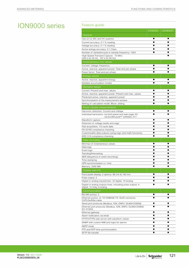
Feature guide
ION9000 ION9000T
General
Use on LV, MV, and HV systems b b
Current accuracy: 0.1 % reading b b
Voltage accuracy: 0.1 % reading b b
Active energy accuracy: 0.1 Class b b
Number of samples/cycle or sample frequency: 1024 b b
High-Speed Transient Capture: 10 MHz (200 k for 50 Hz, 167 k for 60 Hz)
b
Instantaneous rms values
Current, voltage, frequency b b
Active, reactive, apparent power: Total and per phase b b
Power factor: Total and per phase b b
Energy values
Active, reactive, apparent energy b b
Settable accumulation modes b b
Demand values
Current: Present and max. values b b
Active, reactive, apparent power: Present and max. values b b
Predicted active, reactive, apparent power b b
Synchronization of the measurement window b b
Setting of calculation mode: Block, sliding b b
Power Quality measurements
Harmonic distortion: Current and voltage b b
Individual harmonics: via front panel and web page: 63 via EcoStruxure™ software: 511
b b
Waveform capture b b
Detection of voltage swells and sags b b
Fast acquisition: 1/2 cycle data b b
EN 50160 compliance checking b b
Customizable data outputs (using logic and math functions) b b
IEEE 519 compliance checking b b
Data recording
Min/max of instantaneous values b b
Data logs b b
Event logs b b
Trending/forecasting b b
SER (Sequence of event recording) b b
Time stamping b b
GPS synchronization (± 1ms) b b
Memory: 2000 MB b b
Display and I/O
Front panel display, 2 options: 96 mm & 192 mm b b
Pulse output: 2 b b
Digital or analog inputs(max): 32 digital, 16 analog b b
Digital or analog outputs (max, including pulse output): 4 digital, 10 relay, 8 analog
b b
Communication
RS-485 port(s): 2 b b
Ethernet port(s): 2x 10/100BASE-TX, RJ45 connector, CAT5/5e/6/6a cable
b b
Serial port protocols (Modbus, ION, DNP3, DLMS/COSEM) b b
Ethernet port protocols (Modbus, ION, DNP3, DLMS/COSEM, IEC 61850)
b b
Ethernet gateway b b
Alarm notification via email b b
HTTP/HTTPS web server with waveform viewer b b
SNMP with custom MIB and traps for alarms b b
SMTP email b b
PTP and NTP time synchronization b b
SFTP file transfer b b
ION9000 series
ADVANCED METERING FUNCTIONS AND CHARACTERISTICS
121Version: 1.0 - 06/11/2020PLSED309005EN_06Version: 1.0 - 06/11/2020PLSED309005EN_06

(1) Consult the ION7550 / ION7650 installation guide for complete specifications. (2) IEC 62051-22B with serial ports only.
Technical specifications
ION9000 ION9000T
Electrical characteristics
Type of measurement True rms to 1,024 samples per cycle b b
High-speed transient detection, 10 MHz, 10 kV b
Measurement accuracy Current & voltage Class 0.1 as per IEC 61557-12 b b
Active Power Class 0.1 as per IEC 61557-12 b b
Power factor Class 0.5 as per IEC 61557-12 b b
Frequency Class 0.02 as per IEC 61557-12 b b
Active energy Class 0.1S IEC 62053-22Class 0.1 IEC 61557-12Class 0.1 ANSI C12.20
b b
Reactive Energy Class 0.5S IEC 62053-24 b b
Display refresh rate HMI display updated once per second; data refresh rate 1/2 cycle or 1 second
b b
Input-voltage characteristics
Specified accuracy voltage
57 - 400 V L-N / 100 - 690 V L-L b b
Impedance 5 MW per phase b b
Specified accuracyfrequency
42 to 69 Hz(50/60 Hz nominal)
b b
Limit range of operation - frequency
20 to 450 Hz b b
Input-current characteristics
Rated nominal current 1 A (0.1S), 5 A (0.1S); current class 2, 10, 20 A (0.1 ANSI) b b
Specified accuracycurrent range
Starting Current: 1 mA (no accuracy)Accurate Range: 10 mA - 20 A
b b
Permissible overload 500 A rms for 1.0s b b
Impedance 0.0003 W per phase b b
Burden 0.01 VA max at 5 A b b
LV Input-currentcharacteristics
Input voltage range ±5.5 V pk b 1 -
Minimum signal 1 mV b 1 -
Withstand 30 V pk continuous b 1 -
Input impedance 200 k W b 1 -
Safety For use with listed Energy Monitoring current transformers b 1 -
Power supplyAC/DC
AC 90-480 V AC ±10 % (50/60 Hz ±10 %) 90-120 V AC ±10% (400 Hz) b b
DC 110-480 V DC ±15 % b b
Ride-through time (Values for meters with no optional accessories)
100 ms (5 cycles at 50/60 Hz) typ., 120 V AC400 ms (20 cycles at 50/60 Hz) typ., 240 V AC1,200 ms (60 cycles at 50/60 Hz) typ., 480 V AC
b b
Burden Typical: 16.5 W / 38 VA at 480 V (50/60 Hz)Fully optioned: max. 40 W / 80 VA at 480 V (50/60 Hz).
b b
Input/outputs Meter base Only 8 digital inputs (30 V AC/60 V DC)4 Form A (KY) solid state digital output (30 V AC/60 V DC, 75 mA)2 Form C relays (8 A at 250 V AC, 5 A at 24 V DC)
b b
Optional Digital - 6 digital inputs (30 V AC / 60 V DC) wetted + 2 Form C relay outputs (250 V AC, 8 A)
b b
Analog - 4 analog inputs (0-20 mA, 4-20 mA, 0-30 V DC) + 2 analog outputs (0-20 mA, 4-20 mA, 0-10 V DC).
b b
ION9000 series
1 The LV Input-current option replaces standard CT inputs
ADVANCED METERING FUNCTIONS AND CHARACTERISTICS
Version: 1.0 - 06/11/2020PLSED309005EN_06
122
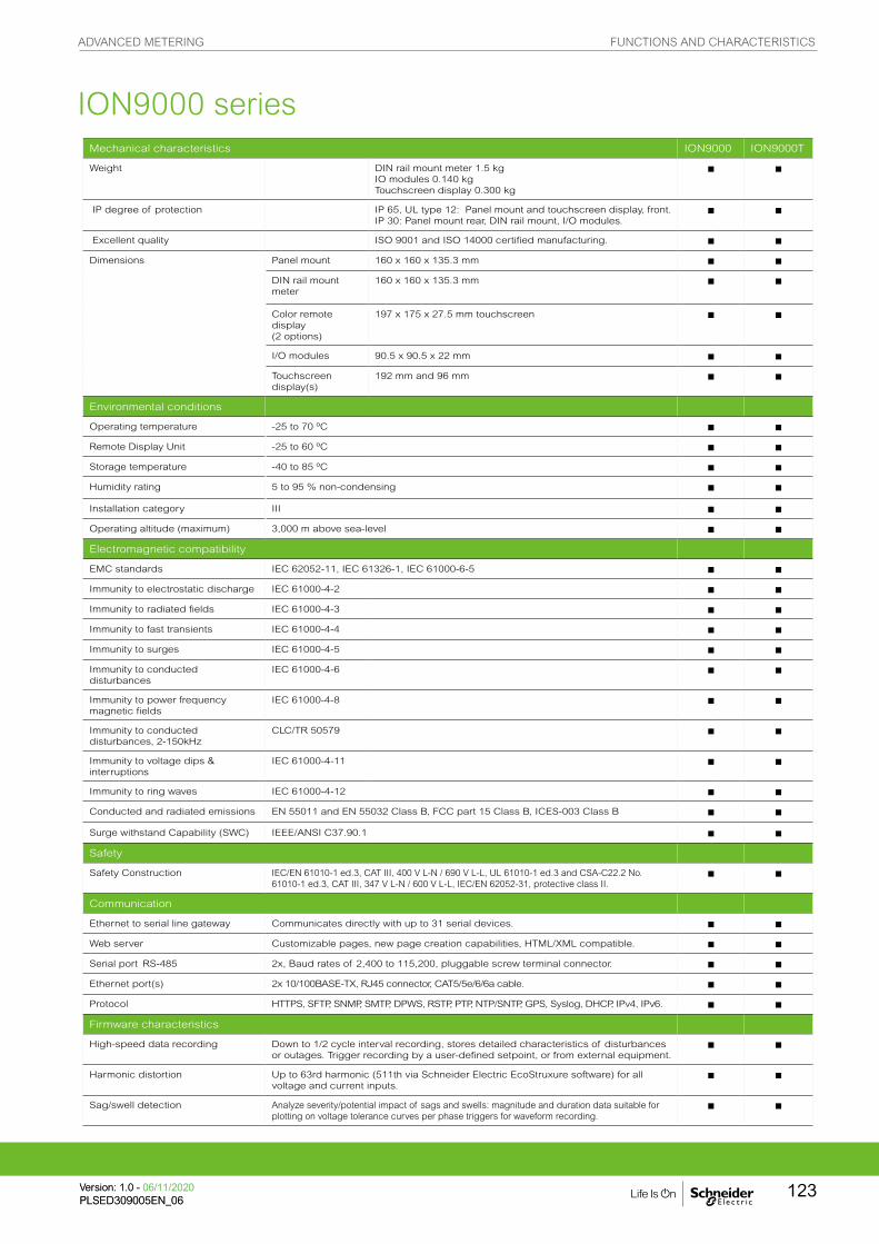
Mechanical characteristics ION9000 ION9000T
Weight DIN rail mount meter 1.5 kgIO modules 0.140 kgTouchscreen display 0.300 kg
b b
IP degree of protection IP 65, UL type 12: Panel mount and touchscreen display, front.IP 30: Panel mount rear, DIN rail mount, I/O modules.
b b
Excellent quality ISO 9001 and ISO 14000 certified manufacturing. b b
Dimensions Panel mount 160 x 160 x 135.3 mm b b
DIN rail mount meter
160 x 160 x 135.3 mm b b
Color remote display (2 options)
197 x 175 x 27.5 mm touchscreen b b
I/O modules 90.5 x 90.5 x 22 mm b b
Touchscreen display(s)
192 mm and 96 mm b b
Environmental conditions
Operating temperature -25 to 70 ºC b b
Remote Display Unit -25 to 60 ºC b b
Storage temperature -40 to 85 ºC b b
Humidity rating 5 to 95 % non-condensing b b
Installation category III b b
Operating altitude (maximum) 3,000 m above sea-level b b
Electromagnetic compatibility
EMC standards IEC 62052-11, IEC 61326-1, IEC 61000-6-5 b b
Immunity to electrostatic discharge IEC 61000-4-2 b b
Immunity to radiated fields IEC 61000-4-3 b b
Immunity to fast transients IEC 61000-4-4 b b
Immunity to surges IEC 61000-4-5 b b
Immunity to conducted disturbances
IEC 61000-4-6 b b
Immunity to power frequency magnetic fields
IEC 61000-4-8 b b
Immunity to conducted disturbances, 2-150kHz
CLC/TR 50579 b b
Immunity to voltage dips & interruptions
IEC 61000-4-11 b b
Immunity to ring waves IEC 61000-4-12 b b
Conducted and radiated emissions EN 55011 and EN 55032 Class B, FCC part 15 Class B, ICES-003 Class B b b
Surge withstand Capability (SWC) IEEE/ANSI C37.90.1 b b
Safety
Safety Construction IEC/EN 61010-1 ed.3, CAT III, 400 V L-N / 690 V L-L, UL 61010-1 ed.3 and CSA-C22.2 No. 61010-1 ed.3, CAT III, 347 V L-N / 600 V L-L, IEC/EN 62052-31, protective class II.
b b
Communication
Ethernet to serial line gateway Communicates directly with up to 31 serial devices. b b
Web server Customizable pages, new page creation capabilities, HTML/XML compatible. b b
Serial port RS-485 2x, Baud rates of 2,400 to 115,200, pluggable screw terminal connector. b b
Ethernet port(s) 2x 10/100BASE-TX, RJ45 connector, CAT5/5e/6/6a cable. b b
Protocol HTTPS, SFTP, SNMP, SMTP, DPWS, RSTP, PTP, NTP/SNTP, GPS, Syslog, DHCP, IPv4, IPv6. b b
Firmware characteristics
High-speed data recording Down to 1/2 cycle interval recording, stores detailed characteristics of disturbances or outages. Trigger recording by a user-defined setpoint, or from external equipment.
b b
Harmonic distortion Up to 63rd harmonic (511th via Schneider Electric EcoStruxure software) for all voltage and current inputs.
b b
Sag/swell detection Analyze severity/potential impact of sags and swells: magnitude and duration data suitable for plotting on voltage tolerance curves per phase triggers for waveform recording.
b b
ION9000 series
ADVANCED METERING FUNCTIONS AND CHARACTERISTICS
123Version: 1.0 - 06/11/2020PLSED309005EN_06Version: 1.0 - 06/11/2020PLSED309005EN_06

Firmware characteristics (cont.) ION9000 ION9000T
Disturbance direction detection Determine the location of a disturbance more quickly and accurately by determining the direction of the disturbance relative to the meter. Results are captured in the event log, along with a timestamp and confidence level indicating level of certainty.
b b
Detection & capture of transients As short as 20 μs at 50 Hz (17 μs at 60 Hz) b b
High-speed transient capture Detection and capture of high-speed impulsive and oscillatory transients as short as 100 ns in duration and up to 10 kV in magnitude. (PowerLogic ION9000T).
b b
Instantaneous High accuracy of standard speed (1s) and high-speed (1/2 cycle) measurements, including true rms per phase and total for: voltage, current, active power (kW),reactive power (kvar), apparent power (kVA), power factor, frequency, voltage and current unbalance, phase reversal.
b b
Load profiling Channel assignments (1600 channels via 100 recorders) configurable for any measurable parameter, including historical trend recording of energy, demand, voltage, current, power quality, or any measured parameter. Trigger recorders based on time interval, calendar schedule, alarm/event condition, or manually.
b b
Trend curves Historical trends and future forecasts to better manage demand, circuit loading, and other parameters. Provides average, min, max, and standard deviation every hour for last 24 hours, every day for last month, every week for last 8 weeks and every month for last 12 months.
b b
Waveform captures Simultaneous capture of voltage and current channels, sub-cycle disturbance captures of 180-cycles @ 1,024 samples/cycle to 7,200-cycles @ 16 sample/cycle, retriggerable.
b b
High-speed transient waveform captures
Simultaneous capture of voltage channels, impulsive and oscillatory transient capture of up to 1-cycle @ 200 k samples per cycle (50 Hz) along with coincidence disturbance waveform capture (PowerLogic ION9000T).
b
Alarms Threshold alarms: adjustable pickup and dropout setpoints and time delays, numerous activation levels possible for a given type of alarm, user-defined or automatic alarm threshold settings, user-defined priority levels (optional automatic alarm setting).
b b
Advanced Time of Use (TOU) 4 seasons; 5 different day types: weekend, weekday, and holiday; up to 4 tariffs per day type. b b
Advanced network security Up to 50 users with unique access rights. Perform resets, time sync, or meter configurations based on user privileges.
b b
Memory 2,000 MB. b b
Firmware update Update via the communication ports. b b
Display characteristics
96 mm pushbutton display 320 x 240 (1/4 VGA) color LCD, configurable screens, 5 buttons and 2 LED indicators (alarm and meter status).
b b
192 mm touchscreen display 800 x 480 pixels, 177.8 mm (7”) Color LCD, +/- 85 degree view angle, sunlight readable, dual capacitive touch, usable when wet or through Class 0 lineman gloves, impact resistant to 5 joules, IP65 rating.
b b
Languages English, French, Spanish, Russian, Portugese, German, Italian, Chinese. b b
Notations IEC, IEEE. b b
ION9000 series
ION9000 Commercial reference numbers
Comm ref number Description
METSEION92030 ION9000 meter, DIN mount, no display, hardware kit
METSEION92040 ION9000 meter, DIN mount, 192 mm display, B2B adapter, hardware kit
METSEION92043 ION9000 meter, DIN mount, 192 mm display, B2B adapter, hardware kit, Measurement Canada Ready (Canada only)
METSEION92044 ION9000 meter, DIN mount, 192 mm display, B2B adapter, hardware kit, Measurement Canada Sealed (Canada only)
METSEION93030 ION9000 meter, LVCS, DIN mount, no display, hardware kit
METSEION93040 ION9000 meter, LVCS, DIN mount, 192 mm display, B2B adapter, hardware kit
METSEION95030 ION9000T meter, HSTC, DIN mount, no display, hardware kit
METSEION95040 ION9000T meter, HSTC, DIN mount, 192 mm display, B2B adapter, hardware kit
METSEPM89RD96 Remote display, color LCD, 96 x 96 mm
METSERD192 Remote display, color touchscreen, 192 x 192 mm
METSEPM89M2600 I/O module, 2 relay outputs, 6 digital inputs
METSEPM89M0024 I/O module, 2 analog outputs, 4 analog inputs
METSE9HWK ION9000 meter hardware kit – plugs, terminal guards, spare grounding screw, DIN clips
METSE9CTHWK ION9000 Current Input hardware kit - terminal screws, CT covers
METSERD192HWK RD192 remote display hardware kit
METSE9B2BMA ION9000 B2B (back to back) mounting adapter
METSE9HWKLVCS ION9000 hardware kit for LVCS
METSE9USBK ION9000 USB cover hardware kit
METSE7X4MAK ION7X50 mounting adapter kit
Contact your Schneider Electric representative for complete ordering information.
ADVANCED METERING FUNCTIONS AND CHARACTERISTICS
Version: 1.0 - 06/11/2020PLSED309005EN_06
124

ION9000 96 mm display dimensions
ION9000 seriesP
B119713_m
ION9000 192 mm display dimensions
PB
119712_m
ION9000 meter dimensions
PB
119707
ION9000 mounting template
ION9000 back-to-back (B2B) dimensions
PB
119705
PB
119714_m
Please refer to ION9000 Series Meter Installation Sheet for accurate and complete information on the installation of this product.
PB
120537
LVCS Input-current option
ADVANCED METERING DIMENSIONS AND CONNECTION
Version: 1.0 - 06/11/2020PLSED309005EN_06
125

ION9000 series
PB
119706
ION9000 meter DIN rail dimensions ION7x50 mounting adapter dimensions
PB
119714
ION9000 LV Current Input wiring options
PB
120533
ADVANCED METERING FUNCTIONS AND CHARACTERISTICS
Version: 1.0 - 06/11/2020PLSED309005EN_06
126

Power quality and revenue meters are designed for utility network monitoring, e.g. transmission and
distribution network monitoring.
Revenue and power quality meters designed for precision metering at key transmission network
inter-ties, distribution substations and service entrances to optimise power reliability and energy
efficiency in utility smart grids.
• • PowerLogic ION7400
• • PowerLogic ION8650
• • PowerLogic ION8800
Advanced utility metering
PB
1151
52P
B10
7500
PE
8617
6
METSEION7400 M8650A P880CA0A
ADVANCED UTILITY METERING FUNCTIONS AND CHARACTERISTICS
127Version: 1.0 - 24/01/2020PLSED309005EN_07Version: 1.0 - 24/01/2020PLSED309005EN_07
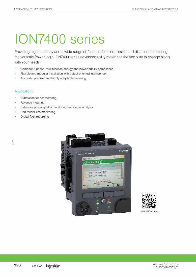
PB
1151
52
METSEION7400
Providing high accuracy and a wide range of features for transmission and distribution metering,
the versatile PowerLogic ION7400 series advanced utility meter has the flexibility to change along
with your needs.
• Compact 3-phase, multifunction energy and power quality compliance
• Flexible and modular installation with object-oriented intelligence
• Accurate, precise, and highly adaptable metering
ION7400 series
Applications
• Substation feeder metering
• Revenue metering
• Extensive power quality monitoring and cause analysis
• End feeder line monitoring
• Digital fault recording
ADVANCED UTILITY METERING FUNCTIONS AND CHARACTERISTICS
Version: 1.0 - 21/07/2020PLSED309005EN_07
128
The solution for
Markets that can benefit from a solution that includes PowerLogic ION7400 series meters:
• Transmission networks
• Distribution network
Competitive advantages
• Be able to use Power Monitoring Expert software for data analysis or share operation data with SCADA systems through multiple communication channels and protocols
• Transformer/line loss compensation
• Instrument transformer correction
• Utilize disturbance direction detection to help locate fault
Benefits
• Reduce operations costs
• Improve power quality
• Improve continuity of service
Conformity of standards
• ANSI C12.20
• CLC/TTR50579
• EN 50160
• IEC 61000-4-7
• IEC 61000-4-15
• IEC 61000-4-30
• IEC 61010-1
• IEC 61326
• IEC 61557-12
• IEC 61850
• IEC 62052-11
• IEC 62053-22
• IEC 62053-23
• IEC 62586
• IEEE 519
Power management solutions
Schneider Electric provides innovative power management solutions to increase your energy efficiency and cost savings, maximise electrical network reliability and availability, and optimise electrical asset performance.
ADVANCED UTILITY METERING FUNCTIONS AND CHARACTERISTICS
129Version: 1.0 - 21/07/2020PLSED309005EN_07Version: 1.0 - 21/07/2020PLSED309005EN_07

PowerLogic ION7400 meter showing active alarms.
Applications and benefits
• Maximize profits by providing the highest output possible with the least amount of risk to availability
• Optimize availability and reliability of electrical systems and equipment• Monitor power quality (PQ) for compliance and to prevent problems• Meters fully supported by EcoStruxure™ Power Monitoring Expert and
EcoStruxure™ Power SCADA Operation software
Main characteristics
• Precision metering:
– IEC 61557-12 PMD/Sx/K70/0.2 3000m (performance measuring and monitoring functions)
– IEC 62053-22 for active energy Class 0.2s accuracy and 0.5s accuracy, ANSI C12.20 Class 0.2 for active energy
– IEC 62053-23 for reactive energy Class 2 accuracy and Class 3
– Cycle-by-cycle RMS measurements updated every ½ cycle
– Full ‘multi-utility’ WAGES metering support
– Net metering
– Anti-tamper protection seals
– Test mode
• PQ Compliance and basic PQ analysis. – Monitors and logs parameters in support of international PQ standards,
– IEC 61000-4-30 Class S
– IEC 61000-4-15 Flicker
– IEC 62586
– EN 50160
– Generates onboard PQ compliance reports accessible via onboard web pages:
– Basic event summary and pass/fail reports, such as EN 50160 for power
– Frequency, supply voltage magnitude, supply voltage dips, short and long interruptions, temporary over voltages, voltage unbalance and harmonic voltage
– ITIC (CBEMA) and SEMI curves, with alarm categorization to support further analyses
– Basic meter provides EN 50160 but can be configured to provide IEEE 519
– Harmonic analysis:
– THD on voltage and current, per phase, min/max, custom alarming
– Individual harmonic magnitudes and angles on voltage and current, up to the 63rd harmonic (up to 127th via EcoStruxure™ software).
– High resolution waveform capture: triggered manually or by alarm, captured waveforms available directly from the meter via FTP in a COMTRADE format or can be viewed via onboard webpages
– Disturbance detection and capture: sag/swell on any current and voltage channel, alarm on disturbance event, waveform capture with pre-event information
– Patented disturbance direction detection: provides indication of the captured disturbance occurring upstream or downstream of the meter; timestamped results provided in the event log, with degree of certainty of disturbance direction
• Used with EcoStruxure™ Power Monitoring Expert software, provides detailed PQ reporting across entire network:
– EN 50160 report
– IEC 61000-4-30 report
– PQ compliance summary
– Display of waveforms and PQ data from all connected meters.
PB1
1515
2PB
1151
61PB
1151
62_1
PowerLogic ION7400 meter - rear view.
PowerLogic ION7403 DIN rail mounted meter.
ADVANCED UTILITY METERING FUNCTIONS AND CHARACTERISTICS
Version: 1.0 - 21/07/2020PLSED309005EN_07
130

PowerLogic remote display.
PowerLogic ION7400 meter with remote display.
PB11
3671
PB11
7739
PB11
7743
• Onboard data and event logging
– 512 MB of standard non-volatile memory
– No data gaps due to network outages or server downtime
– Min/Max log for standard values
– 50 user-definable data logs, recording up to 16 parameters on a cycle-by-cycle or other user definable interval
– Continuous logging or ‘snapshot’ triggered by setpoint and stopped after defined duration
– Trend energy, demand and other measured parameters
– Forecasting via web pages: average, minimum and maximum for the next four hours and next four days
– Time-of-use in conjunction with EcoStruxure™ software
– Event log: alarm conditions, metering configuration changes, and power outages, timestamped to 1 millisecond
• Alarming and control.
– 50+ definable alarms to log critical event data, trigger waveform recording, or perform control function
– Trigger on any condition, with cycle-by-cycle and 1-second response time
– Combine alarms using Boolean logic and to create alarm levels
– Alarm notification via email text message
– In conjunction with EcoStruxure™ Power Monitoring Expert, software alarms and alarm frequency are categorized and trended for easy evaluation of worsening/improving conditions
• Excellent quality: ISO 9001 and ISO 14000 certified manufacturing
Usability
• Easy installation and setup
– Panel and DIN rail mounting options, remote display option
– Pluggable connectors
– Free setup application simplifies meter configuration
• Front panel
– Easy to read color graphic display
– Simple, intuitive menu navigation with multi-language (8) support
– Optical port
– 2 energy pulsing LEDs
– Alt/Norm screens.
• Flexible remote communications
– Multiple simultaneously operating communication ports and protocols allow interfacing with other automation systems; (e.g. waveforms, alarms, billing data, etc.) can be uploaded for viewing/analysis while other systems access real-time information
– Supports Modbus, ION, DNP3, IEC 61850, MV-90
– Dual port Ethernet: 10/100BASE-TX; daisy-chaining capability removes need for additional switches
– Create redundant network loop using Rapid Spanning Tree Protocol (RSTP) and managed Ethernet switches
– Customize TCP/IP port numbers enable/disable individual ports
– RS-485 2-wire connection, up to 115200 baud, Modbus RTU and ION protocols, DNP3 is also supported via RS-485.
PB11
5153
PowerLogic ION7400 with Harmonics display.
PowerLogic I/O module.
ADVANCED UTILITY METERING FUNCTIONS AND CHARACTERISTICS
131Version: 1.0 - 21/07/2020PLSED309005EN_07Version: 1.0 - 21/07/2020PLSED309005EN_07

PB11
5159
• Flexible remote communications (cont’d)
– Ethernet to serial gateway with Modbus Master functionality, connecting to 31 downstream serial Modbus devices. Also supports Modbus Mastering over TCP/IP (Ethernet) network.
– Full function web server with factory and customizable pages to access real-time and PQ compliance data.
– Push historical data via email.
– Advanced security: Up to 16 configurable user accounts.
• Time synchronization via:
– GPS clock (RS-485) or IRIG-B (digital input) to +/- 1 millisecond.
Also supports Network Time Protocol (NTP/SNTP) and time set function from EcoStruxure software server.
Adaptability
• ION™ frameworks allow customizable, scalable applications, object-oriented programming, compartmentalizes functions, and increases flexibility and adaptability.
• Applications include: access and aggregate data from Modbus devices on serial port or across the network (Modbus TCP/IP), logging and/or processing data by totalizing, unit conversion or other calculations, applying complex logic for alarming or control operations, data visualization via web pages.
Standard meter I/O
• 3 digital status/counter inputs.
• 1 KY (form A) energy pulse output for interfacing with other systems.
Modular I/O options
• Optional expansion modules (up to 4 per meter) add digital/analog I/O.
Option modules include:
• Digital module
– 6 digital status/counter inputs.
– 2 Form C relay outputs, 250 V, 8 A
• Analog module.
– 4 analog inputs (4-20 mA; 0-30 V)
– 2 analog outputs (4-20 mA; 0-10 V) for interfacing with building management sensors and systems
Standards
• IEC 61000-4-30
• IEC 61000-4-7
• IEC 61000-4-15
• IEC 61326-1
• ANSI C12.20
• IEC 62052-11
• IEC 62053-22
• IEC 62053-23
• CLC/TR50579
Languages supported
• English, French, Spanish, Chinese, Italian, German, Russian, Portuguese
PowerLogic ION7400 series meter with phasor display.
Feature selection
Commercial reference number
Description
METSEION7400ION7400 Panel mount meter (integrated display with optical port and 2 energy pulse LEDs)
METSEION7410
ION7400 Panel mount meter (integrated display with optical port and 2 energy pulse LEDs) 20-60 V DC control power
METSEION7403 DIN rail mount - utility meter base
METSEION7413DIN rail mount - utility meter base20-60 V DC control power
Accessories Description
METSEPM89RD96
Remote display, 3 metre cable, mounting hardware for30 mm hole (nut & centering pin), mounting hardware for DIN96 cutout (92 x 92 mm) adapter plate
METSEPM89M2600Digital I/O module (6 digital inputs & 2 relay outputs)
METSEPM89M0024Analog I/O module (4 analog inputs & 2 analogoutputs)
METSECAB10 Display Cable, 10 m
METSEPM8000SK Sealing kit
ADVANCED UTILITY METERING FUNCTIONS AND CHARACTERISTICS
Version: 1.0 - 21/07/2020PLSED309005EN_07
132
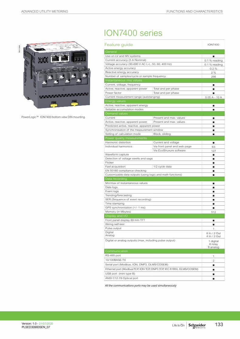
PB11
3696 Feature guide ION7400
General
Use on LV and MV systems bCurrent accuracy (5 A Nominal) 0.1 % readingVoltage accuracy (90-690 V AC L-L, 50, 60, 400 Hz) 0.1 % readingActive energy accuracy 0.2 %Reactive energy accuracy 2 %Number of samples/cycle or sample frequency 256
Instantaneous rms values
Current, voltage, frequency bActive, reactive, apparent power Total and per phase bPower factor Total and per phase bCurrent measurement range (autoranging) 0.05 A - 10 A
Energy values
Active, reactive, apparent energy bSettable accumulation modes bDemand values
Current Present and max. values bActive, reactive, apparent power Present and max. values bPredicted active, reactive, apparent power bSynchronisation of the measurement window bSetting of calculation mode Block, sliding bPower quality measurements
Harmonic distortion Current and voltage bIndividual harmonics Via front panel and web page 63
Via EcoStruxure software 127Waveform capture bDetection of voltage swells and sags bFlicker bFast acquisition 1/2 cycle data bEN 50160 compliance checking bCustomizable data outputs (using logic and math functions) bData recording
Min/max of instantaneous values bData logs bEvent logs bTrending/forecasting bSER (Sequence of event recording) bTime stamping bGPS synchronisation (+/- 1 ms) bMemory (in Mbytes) 512
Display and I/O
Front panel display 89 mm TFT bWiring self-test bPulse output 1Digital Analog
6 In / 2 Out4 In / 2 Out
Digital or analog outputs (max, including pulse output) 1 digital8 relay
8 analog
Communication
RS-485 port 1
10/100BASE-TX 2
Serial port (Modbus, ION, DNP3, DLMS/COSEM) bEthernet port (Modbus/TCP, ION TCP, DNP3 TCP, IEC 61850, DLMS/COSEM) bUSB port (mini type B) bANSI C12.19 Optical port b
All the communications ports may be used simultaneously
PowerLogic™ ION7400 bottom view DIN mounting.
ION7400 series
ADVANCED UTILITY METERING FUNCTIONS AND CHARACTERISTICS
133Version: 1.0 - 21/07/2020PLSED309005EN_07Version: 1.0 - 21/07/2020PLSED309005EN_07

Electrical characteristics ION7400
Type of measurement True rms to 256 samples per cycle
Measurement accuracy
Current & voltage Class 0.2 as per IEC 61557-12
Active Power Class 0.2 as per IEC 61557-12
Power factor Class 0.5 as per IEC 61557-12
Frequency Class 0.2 as per IEC 61557-12
Active energyClass 0.2S IEC 62053-22 (In=5A)Class 0.2 IEC 61557-12, ANSI C12.20 Class 0.2
Reactive Energy Class 2 IEC 62053-23
Data update rate 1/2 cycle or 1 second
Input-voltage characteristics
Specified accuracy voltage 57 V L-N/100 V L-L to 400 V L-N/690 V L-L
Impedance 5 MW per phaseSpecified accuracyfrequency - Frequency
42 to 69 Hz(50/60 Hz nominal)
Limit range of operation - frequency
20 Hz to 450 Hz
Input-current characteristics
Rated nominal current 1 A (0.2S), 5 A (0.2S) , 10 A (0.2 ANSI)
Specified accuracycurrent range
Starting Current: 5 mAAccurate Range: 50 mA - 10 A
Permissible overload200 A rms for 0.5s, non-recurring
Impedance 0.0003 W per phase
Burden 0.024 VA at 10 A
Power supply AC/DC 90-415 V AC ±10 % 16 VA at 230 V (50/60 Hz ±10%), 110-300 V DC ±10% 18 W (max)
LV DC 20–60 V DC, ±10 %,18 W (max)
Ride-through time
100 ms (6 cycles at 60 Hz) min., any condition200 ms (12 cycles at 60 Hz) typ., 120 V AC, 110-415 V DC500 ms (30 cycles at 60 Hz) typ., 415 V AC
BurdenMeter Only: 18 VA max at 415 V AC, 6W at 300 V DCFully optioned meter: 36 VA max at 415 V AC, 17 W at 300 V DC.
Input/outputs Meter Base Only3 form A digital inputs (30 V AC/60 V DC)1 form A (KY) solid state digital output (30 V AC/60 V DC, 75 mA).
Optional
Digital - 6 form A digital inputs (30 V AC / 60 V DC) wetted + 2 form C relay outputs (250 V AC / 30 V DC, 8 A at 250 V AC or 5 A at 24 V DC)
Analog - 4 analog inputs (4-20 mA, 0-30 V DC) + 2 analog outputs (4-20 mA, 0-10 V DC).
Mechanical characteristics
Weight
Integrated Display Model 0.710 kg (without option modules)DIN rail mounted Model 0.530 kg (without remore display or option modules)IO modules 0.140 kgRemote display 0.300 kg
IP degree of protectionIP 54, UL type 12: Panel mount and Remote display, front.IP 30: Panel mount rear, DIN rail mount, I/O modules.
Dimensions
Panel mount model 98 x 112 x 78.5 mm
DIN model 90.5 x 90.5 x 90.8 mm
Remote display 96 x 96 x 27 mm
IO modules 90.5 x 90.5 x 22 mm
Environmental conditions
Operating temperature -25 ºC to 70 ºC
Remote Display Unit -25 ºC to 60 ºC
Storage temperature -40 ºC to 85 ºC
Humidity rating 5 % to 95 % non-condensing
Installation category III
Operating altitude (maximum) 3000 m above sea level
ION7400 series
ADVANCED UTILITY METERING FUNCTIONS AND CHARACTERISTICS
Version: 1.0 - 21/07/2020PLSED309005EN_07
134

Electromagnetic compatibility
Product standards IEC 62052-11 and IEC 61326-1
Immunity to electrostatic discharge IEC 61000-4-2
Immunity to radiated fields IEC 61000-4-3
Immunity to fast transients IEC 61000-4-4
Immunity to surges IEC 61000-4-5
Immunity to conducted disturbances IEC 61000-4-6
Immunity to power frequency magnetic fields IEC 61000-4-8
Immunity to conducted disturbances, 2-150kHz CLC/TR 50579
Immunity to voltage dips & interruptions IEC 61000-4-11
Immunity to ring waves IEC 61000-4-12
Conducted and radiated emissions EN 55022, EN 55011, FCC part 15, ICES-003
Surge withstand Capability (SWC) IEEE C37.90.1
Safety
Safety Construction IEC/EN 61010-1 ed.3, CAT III, 400 V L-N / 690 V L-LUL 61010-1 ed.3 and CSA-C22.2 No. 61010-1 ed.3, CAT III, 347 V L-N / 600 V L-L IEC/EN 62052-11, protective class II
Communication
Ethernet to serial line gateway Communicates directly with up to 32 unit load ION slave devices.
Web server Customisable pages, new page creation capabilities, HTML/XML compatible.
Serial port RS 485 Baud rates of 2400 to 115200, pluggable screw terminal connector.
Ethernet port(s) 2 x 10/100BASE-TX, RJ45 connector (UTP).
USB port Virtual serial port supports USB 3.0, 2.0, 1.1 using ION protocol.
Protocol Modbus, ION, DNP3, IEC 61850, MV-90, DLMS/COSEM, HTTP, FTP, SNMP, SMTP, DPWS, RSTP, NTP, SNTP, GPS protocols.
Firmware characteristics
High-speed data recording Down to 1/2 cycle interval burst recording, stores detailed characteristics of disturbances or outages. Trigger recording by a user-defined setpoint, or from external equipment.
Harmonic distortion Up to 63rd harmonic (via EcoStruxure™ software) for all voltage and current inputs.
Sag/swell detection Analyse severity/potential impact of sags and swells: magnitude and duration data suitable for plotting on voltage tolerance curves per phase triggers for waveform recording, control.
Disturbance direction detection Determine the location of a disturbance more quickly and accurately by determining the direction of the disturbance relative to the meter. Analysis results are captured in the event log, along with a timestamp and confidence level indicating level of certainty.
Instantaneous High accuracy of standard speed (1s) and high-speed (1/2 cycle) measurements, including true rms per phase and total for:voltage, current, active power (kW),reactive power (kvar), apparent power (kVA), power factor, frequency, voltage and current unbalance, phase reversal.
Load profiling Channel assignments (800 channels via 50 data recorders) configurable for any measurable parameter, including historical trend recording of energy, demand, voltage, current, power quality, or any measured parameter. Trigger recorders based on time interval, calendar schedule, alarm/event condition, or manually.
Trend curves Historical trends and future forecasts to better manage demand, circuit loading, and other parameters. Provides average, min, max and standard deviation every hour for last 24 hours, every day for last month, every week for last 8 weeks and every month for last 12 months.
Waveform captures Simultaneous capture of all voltage and current channelssub-cycle disturbance capture, maximum cycles is 100,000 (16 samples/cycle x 96 cycles, 10 MB memory), max 256 samples/cycle.
Alarms Threshold alarms: adjustable pickup and dropout setpoints and time delays, numerous activation levels possible for a given type of alarm, user-defined or automatic alarm threshold settings, user-defined priority levels (optional automatic alarm setting).
ION7400 series
All the communication ports may be used simultaneously.
ADVANCED UTILITY METERING FUNCTIONS AND CHARACTERISTICS
135Version: 1.0 - 21/07/2020PLSED309005EN_07Version: 1.0 - 21/07/2020PLSED309005EN_07

PB11
5154
PB11
5155
PB11
5156
A Voltage inputs
B Control power
C Digital inputs
D Revenue lock LED
E Status LED (2 green/red)
F Revenue lock switch
G Digital output
H Sealing gasket
I Infrared energy pulsing LED
J Energy pulsing LED
K RS-485
L Current inputs
M Ethernet (2)
N Date/time
O Indicator icons
P Display
Q Navigation icons
R Navigation buttons
S Home button
T Alarm LED (red)
U USB ports cover
V Watt energy pulsing LED
W Watt infrared energy pulsing LED
X VAR infrared energy pulsing LED
Y VAR energy pulsing LED
Z Optical port
ION7400 meter parts descriptions
ADVANCED UTILITY METERING DIMENSIONS AND CONNECTION
Version: 1.0 - 21/07/2020PLSED309005EN_07
136
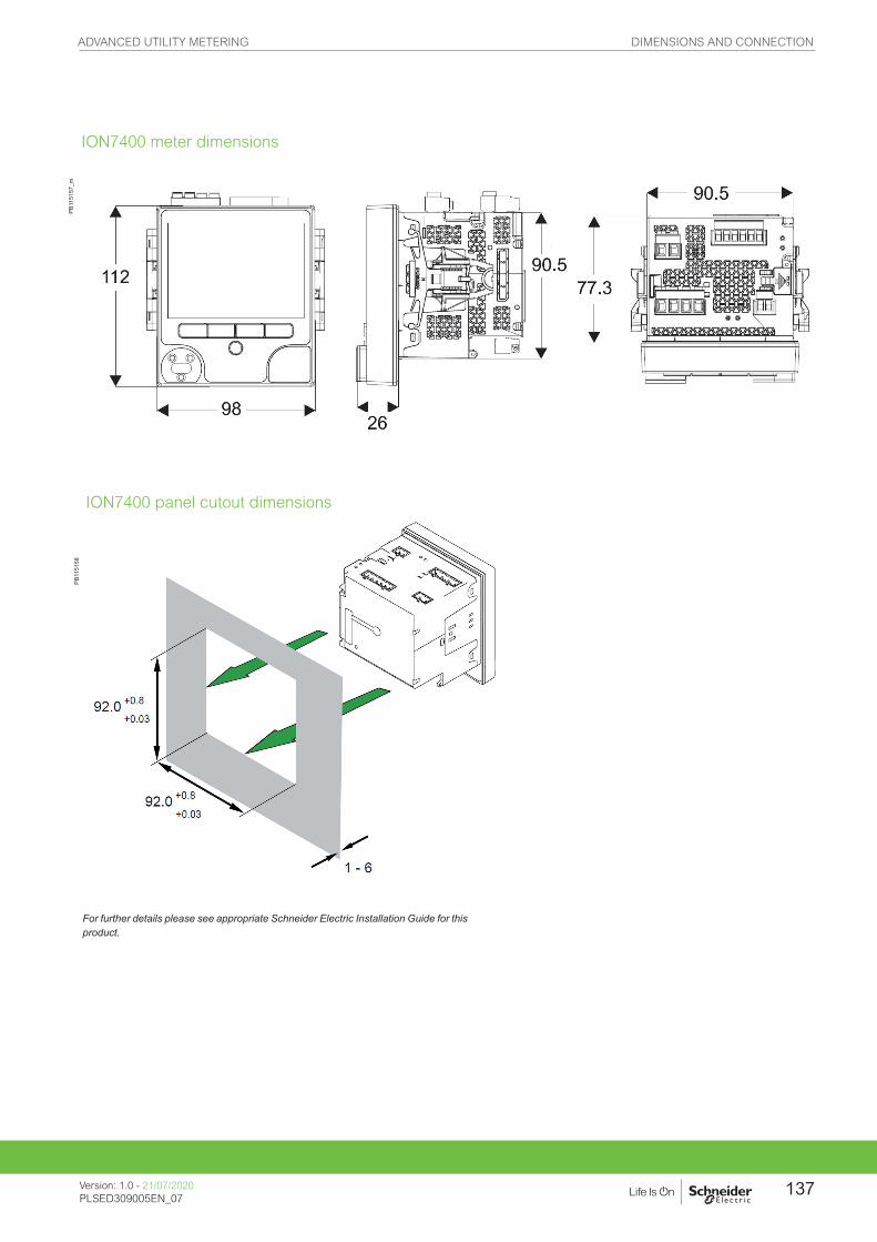
PB11
5157
_m
For further details please see appropriate Schneider Electric Installation Guide for this product.
ION7400 meter dimensions
ION7400 panel cutout dimensions
PB11
5158
ADVANCED UTILITY METERING DIMENSIONS AND CONNECTION
Version: 1.0 - 21/07/2020PLSED309005EN_07
137

M8650A
Providing high accuracy and a wide range of features for transmission and distribution metering,
the PowerLogic ION8650 advanced revenue and power quality meter has the flexibility to change
along with your needs. The meter provides the tools necessary to:
• Manage energy procurement and supply contracts
• Perform network capacity planning and stability analysis
• Monitor power quality compliance, supply agreements, and regulatory requirements
ION8650 series
Applications
• Transmission and distribution metering
• Revenue metering
• Extensive power quality monitoring and analysis
• Power quality compliance monitoring
• Digital fault recording
• Instrument transformer correction
PB10
7500
ADVANCED UTILITY METERING FUNCTIONS AND CHARACTERISTICS
Version: 1.0 - 24/01/2020PLSED309005EN_07
138

The solution for
Markets that can benefit from a solution that includes PowerLogic ION8650 series meters:
• Transmission networks
• Distribution network
Competitive advantages
• Be integrated into existing wholesale settlement system
• Be able to use Power Monitoring Expert software for data analysis or share operation data with SCADA systems through multiple communication channels and protocols
• Transformer/line loss compensation
• Instrument transformer correction
Benefits
• Reduce operations costs
• Improve power quality
• Improve continuity of service
Conformity of standards
• IEC 62053-22/23
• IEC 61000-4-30
• EN 50160
• IEC 61000-4-7
• IEC 61000-4-15
• IEEE 1159
• IEEE 519
• IEC 61000-4-2
• IEC 61000-4-3
• IEC 61000-4-4
• IEC 61000-4-5
• IEC 61000-4-6
• IEC 61000-4-12
• CISPR 22
• IEC 62052-11
• IEC 60950
• ANSI C12.20
Power management solutions
Schneider Electric provides innovative power management solutions to increase your energy efficiency and cost savings, maximise electrical network reliability and availability, and optimise electrical asset performance.
ADVANCED UTILITY METERING FUNCTIONS AND CHARACTERISTICS
139Version: 1.0 - 24/01/2020PLSED309005EN_07Version: 1.0 - 24/01/2020PLSED309005EN_07

PB10
7500
PowerLogic ION8650 socket meter
Main characteristics
Used to monitor electric energy provider networks, service entrances and substations, PowerLogic ION8650 meters are ideal for independent power producers and cogeneration applications that need to accurately measure energy bi-directionally in both generation and stand-by modes. These meters give utilities the tools to manage complex energy supply contracts that include commitments to power quality. Integrate them with our EcoStruxure™ Power Monitoring operations software or other energy management and SCADA systems through multiple communication channels and protocols, including Itron MV-90, Modbus, DNP, DLMS, IEC 61850 Ed. 3.
Applications• Revenue metering.• Cogeneration and IPP monitoring.• Compliance monitoring.• Power quality analysis.• Demand and power factor control.• Load curtailment.• Equipment monitoring and control.• Energy pulsing and totalisation.• Instrument transformer correction.• Outage Notification
Main characteristics• ANSI Class 0.1 and IEC 62053-22/23 Class 0.2 S metering
– For interconnection points on medium, high, and ultra-high voltage networks; twice as accurate as current IEC and meets ANSI Class standards over all conditions and including single wide range current measurement.
• Power quality compliance monitoring – Monitor compliance with international quality-of-supply standards (IEC
61000-4-30 Ed. 3 Class A/S, EN 50160 Ed. 4, IEC 61000-4-7, IEC 61000-4-15, IEEE 1159, IEEE 519). Also detects disturbance direction.
• Digital fault recording – Simultaneous capture of voltage and current channels for sub-cycle
disturbance.
• Complete communications – Multi-port, multi-protocol ports including serial, infrared, modem and
ethernet. Simultaneously supports multiple industry standard protocols including: Itron MV-90, Modbus, Modbus Master, DLMS, DNP 3.0 and IEC 61850 Ed. 2. Cell modem option using CDMA or LTE.
• Multiple tariffs and time-of-use – Apply tariffs, seasonal rate schedules to measure energy and demand
values for time periods with specific billing requirements.
• Multiple setpoints for alarm and functions – Use up to 65 setpoints for single/multi-condition alarms and I/O functions
with response times down to 1/2 cycle.
• Multiple setpoints for alarm and functions – Use up to 65 setpoints.
• Instrument transformer correction – Save money and improve accuracy by correcting for less accurate
transformers.
• Alarm notification via email – High-priority alarms, data logs sent directly to the user’s PC. Instant
notification of power quality events by email.
• Cyber security enhancements – Assign communication admin rights to selected user; prevention measures
ensure no loss of security logs; support syslog for external security.
Feature selection
Commercial reference number
ION8650 meters
S8650A ION8650A
S8650B ION8650B
S8650C ION8650C
ADVANCED UTILITY METERING FUNCTIONS AND CHARACTERISTICS
Version: 1.0 - 24/01/2020PLSED309005EN_07
140

PE86
302-
95
PowerLogic ION8650 switchboard meter.
1 Terminals2 Optical port3 Main display status bar4 Watt LED5 Navigation, ALT/Enter buttons6 VAR LED7 Nameplate label8 Demand reset switch
Selection guide ION8650 A
ION8650 B
ION8650 C
General
Use on LV, MV and HV systems b b bCurrent accuracy 0.1 % 0.1 % 0.1 % Voltage accuracy 0.1 % 0.1 % 0.1 % Power accuracy 0.1 % 0.1 % 0.1 % Samples/cycle 1024 1024 1024
Instantaneous values
Current, voltage, frequency b b bActive, reactive, apparent power Total & per phase b b bPower factor Total & per phase b b bCurrent measurement range 0 A - 20 A 0 A - 20 A 0 A - 20 A
Energy values
Active, reactive, apparent energy b b bSettable accumulation modes b b bDemand values
Current Present & max values b b bActive, reactive, apparent power Present & max values b b bPredicted active, reactive, apparent power b b bSynchronisation of the measurement window b b bDemand modes: Block (sliding), thermal (exponential) b b bPower quality measurements
Harmonic distortion Current & voltage b b bIndividual harmonics Via front panel 63 63 31Waveform / transient capture b / b - / b - / -Harmonics: magnitude, phase, and interharmonics 50 40 -Detection of voltage sags and swells b b bIEC 61000-4-30 class A / S A S -IEC 61000-4-15 (Flicker) b b -High speed data recording (down to 10 ms) b b -EN 50160 compliance reporting b b -Programmable (logic and math functions) b b bData recording
PE86
002
Disturbance waveform capture and power quality report
Onboard Memory (in Mbytes) 128 64 32Revenue logs b b bEvent logs b b bHistorical logs b b bHarmonics logs b b bSag/swell logs b b bTransient logs b - -Time stamping to 1 ms b b bGPS synchronisation (IRIG-B standard) b b bDisplay and I/O
Front panel display b b bWiring self-test (requires PowerLogic ION Setup) b b bPulse output (front panel LED) 2 2 2Digital or analog inputsg (max) 11 11 11Digital or analog outputsg (max, including pulse output) 16 16 16
Communication
Infrared port 1 1 1RS-485 / RS-232 port 1 1 1ggg
RS-485 port 1 1 1ggg
Ethernet port (Modbus/TCP/IP protocol) with gateway 1 1 1ggg
Internal modem with gateway (ModemGate) 1 1 1ggg
HTML web page server b b bIRIG-B port (unmodulated IRIG B00x time format) 1 1 1Modbus TCP Master / Slave (Ethernet port) b / b b / b - / bModbus RTU Master / Slave (Serial ports) b / b b / b - / bDNP 3.0 through serial, modem, and I/R ports b b bCell modem option (CDMA/LTE) b b bDLMS COSEM through serial, Ethernet and optical ports for all variants b b b
g With optional I/O Expander.gg For 9S, and 36S only. For 35S system up to 480 V L-L.ggg C model limited to IR + 2 other ports at one time. Ports can be enabled/disabled by user.
ADVANCED UTILITY METERING FUNCTIONS AND CHARACTERISTICS
141Version: 1.0 - 24/01/2020PLSED309005EN_07Version: 1.0 - 24/01/2020PLSED309005EN_07
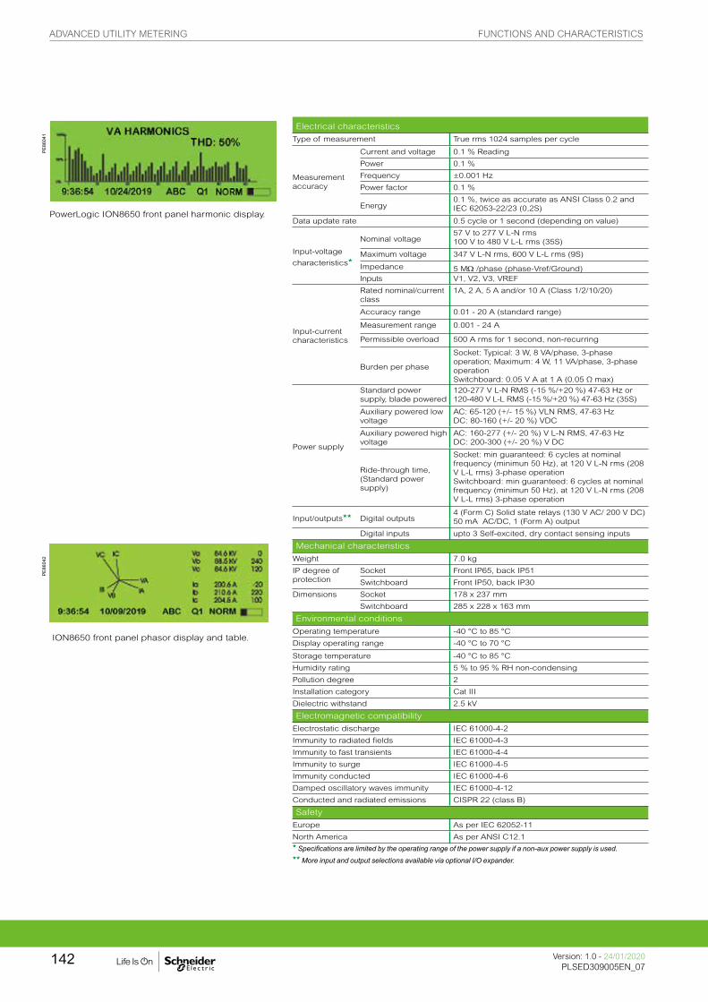
PE86
041
PowerLogic ION8650 front panel harmonic display.
Electrical characteristics
Type of measurement True rms 1024 samples per cycle
Measurement accuracy
Current and voltage 0.1 % Reading
Power 0.1 %
Frequency ±0.001 Hz
Power factor 0.1 %
Energy0.1 %, twice as accurate as ANSI Class 0.2 and IEC 62053-22/23 (0,2S)
Data update rate 0.5 cycle or 1 second (depending on value)
Input-voltage
characteristicsg
Nominal voltage57 V to 277 V L-N rms100 V to 480 V L-L rms (35S)
Maximum voltage 347 V L-N rms, 600 V L-L rms (9S)
Impedance 5 MW /phase (phase-Vref/Ground)Inputs V1, V2, V3, VREF
Input-current characteristics
Rated nominal/current class
1A, 2 A, 5 A and/or 10 A (Class 1/2/10/20)
Accuracy range 0.01 - 20 A (standard range)
Measurement range 0.001 - 24 A
Permissible overload 500 A rms for 1 second, non-recurring
Burden per phase
Socket: Typical: 3 W, 8 VA/phase, 3-phase operation; Maximum: 4 W, 11 VA/phase, 3-phase operationSwitchboard: 0.05 V A at 1 A (0.05 Ω max)
Power supply
Standard power supply, blade powered
120-277 V L-N RMS (-15 %/+20 %) 47-63 Hz or120-480 V L-L RMS (-15 %/+20 %) 47-63 Hz (35S)
Auxiliary powered low voltage
AC: 65-120 (+/- 15 %) VLN RMS, 47-63 HzDC: 80-160 (+/- 20 %) VDC
Auxiliary powered high voltage
AC: 160-277 (+/- 20 %) V L-N RMS, 47-63 HzDC: 200-300 (+/- 20 %) V DC
Ride-through time, (Standard power supply)
Socket: min guaranteed: 6 cycles at nominal frequency (minimun 50 Hz), at 120 V L-N rms (208 V L-L rms) 3-phase operationSwitchboard: min guaranteed: 6 cycles at nominal frequency (minimun 50 Hz), at 120 V L-N rms (208 V L-L rms) 3-phase operation
Input/outputsgg Digital outputs 4 (Form C) Solid state relays (130 V AC/ 200 V DC) 50 mA AC/DC, 1 (Form A) output
Digital inputs upto 3 Self-excited, dry contact sensing inputs
PE86
042
ION8650 front panel phasor display and table.
Mechanical characteristics
Weight 7.0 kg
IP degree of protection
Socket Front IP65, back IP51
Switchboard Front IP50, back IP30
Dimensions Socket 178 x 237 mm
Switchboard 285 x 228 x 163 mm
Environmental conditions
Operating temperature -40 °C to 85 °C
Display operating range -40 °C to 70 °C
Storage temperature -40 °C to 85 °C
Humidity rating 5 % to 95 % RH non-condensing
Pollution degree 2
Installation category Cat III
Dielectric withstand 2.5 kV
Electromagnetic compatibility
Electrostatic discharge IEC 61000-4-2
Immunity to radiated fields IEC 61000-4-3
Immunity to fast transients IEC 61000-4-4
Immunity to surge IEC 61000-4-5
Immunity conducted IEC 61000-4-6
Damped oscillatory waves immunity IEC 61000-4-12
Conducted and radiated emissions CISPR 22 (class B)
Safety
Europe As per IEC 62052-11
North America As per ANSI C12.1g Specifications are limited by the operating range of the power supply if a non-aux power supply is used.gg More input and output selections available via optional I/O expander.
ADVANCED UTILITY METERING FUNCTIONS AND CHARACTERISTICS
Version: 1.0 - 24/01/2020PLSED309005EN_07
142
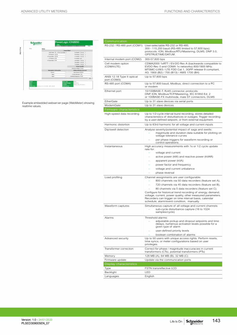
Example embedded webserver page (WebMeter) showing realtime values.
Communication
RS-232 / RS-485 port (COM1) User-selectable RS-232 or RS-485. 300 - 115,200 baud (RS-485 limited to 57,600 bps); protocols: ION, Modbus/RTU/Mastering, DLMS, DNP 3.0, GPSTRUETIME/DATUM.
Internal modem port (COM2) 300-57,600 bps
Cell modem option (CDMA/LTE)
CDMA2000 1xRTT / EV-DO Rev A (backwards compatible to EVDO Rev. 0 and CDMA 1x networks) 800/1900 MHz. MTSMC-LVW3 / LTE FDD Cat 1, 3GPP release 9 compliant, 4G: 1900 (B2) / 700 (B13) / AWS 1700 (B4)
ANSI 12.18 Type II optical port (COM3)
Up to 57,600 bps
RS-485 port (COM4) Up to 57,600 baud, Modbus, direct connection to a PC or modem
Ethernet port 10/100BASE-T, RJ45 connector, protocols: DNP, ION, Modbus/TCP/Mastering, IEC 61850 Ed. 2or 100BASE-FX multimode, male ST connectors, DLMS
EtherGate Up to 31 slave devices via serial ports
ModemGate Up to 31 slave devices
Firmware characteristics
High-speed data recording Up to 1/2-cycle interval burst recording, stores detailed characteristics of disturbances or outages. Trigger recording by a user-defined setpoint, or from external equipment.
Harmonic distortion Up to 63rd harmonic for all voltage and current inputs
Dip/swell detection Analyse severity/potential impact of sags and swells: – magnitude and duration data suitable for plotting on
voltage tolerance curves
– per phase triggers for waveform recording or control operations
Instantaneous High accuracy measurements with 1s or 1/2 cycle update rate for:
– voltage and current
– active power (kW) and reactive power (kVAR)
– apparent power (kVA)
– power factor and frequency
– voltage and current unbalance
– phase reversal
Load profiling Channel assignments are user configurable: – 800 channels via 50 data recorders (feature set A),
– 720 channels via 45 data recorders (feature set B),
– 80 channels via 5 data recorders (feature set C).
Configure for historical trend recording of energy, demand, voltage, current, power quality, other measured parameters. Recorders can trigger on time interval basis, calendar schedule, alarm/event condition, manually.
Waveform captures Simultaneous capture of all voltage and current channels – sub-cycle disturbance capture (16 to 1024
samples/cycle)
Alarms Threshold alarms: – adjustable pickup and dropout setpoints and time
delays, numerous activation levels possible for a given type of alarm
– user-defined priority levels
– boolean combination of alarms
Advanced security Up to 50 users with unique access rights. Perform resets, time syncs, or meter configurations based on user privileges.
Transformer correction Correct for phase / magnitude inaccuracies in current transformers (CTs), potential transformers (PTs)
Memory 128 MB (A), 64 MB (B), 32 MB (C)
Firmware update Update via the communication ports
Display characteristics
Type FSTN transreflective LCD
Backlight LED
Languages English
PB11
7744
ADVANCED UTILITY METERING FUNCTIONS AND CHARACTERISTICS
143Version: 1.0 - 24/01/2020PLSED309005EN_07Version: 1.0 - 24/01/2020PLSED309005EN_07
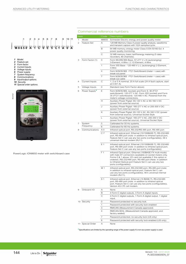
Commercial reference numbers
Item Code Description
PE86
043-
C
1 Model M8650 Schneider Electric energy and power quality meter.
2 Feature Set A 128 MB Memory Class A power quality analysis, waveforms and transient capture with 1024 samples/cycle.
B 64 MB memory, energy meter Class S EN 50160 Ed. 4 power quality monitoring.
1 Model.2 Feature set.3 Form factor.4 Current Inputs.5 Voltage inputs.6 Power supply.7 System frequency.8 Communications.9 Input/output options.10 Security.11 Special order options.
C 32 MB memory, basic tariff/energy metering (5 data recorders, 80 channels).
3 Form Factor (1) 0 Form 9S/29S/36S Base, 57-277 V L-N (autoranging) 3-Element, 4-Wire / 2 1/2-Element, 4-Wire
1 Form 35S Base - 120-480 V L-L (autoranging) 2-Element, 3-Wire
4 Form 9/29/35/36S FT21 Switchboard (meter + case) with break out panel
7 Form 9/29/35/36S FT21 Switchboard (meter + case) with break out cable
4 Current Inputs C 1, 2 or 5 A nominal, 20 A full scale (24 A fault capture, start at 0.001 A)
5 Voltage Inputs 0 Standard (see Form Factor above)
6 Power Supplyg E Form 9/29/35/36S, (socket) and Form 9, 36 (FT21 switchboard): 120-277 V AC. Form 35S (socket) and Form 35 (FT21 switchboard): 120-480 V AC. Powered from the meter’s voltage connections.
H Auxiliary Power Pigtail: 65-120 V AC or 80-160 V DC (power from external source)
J Auxiliary Power Pigtail: 160-277 V AC or 200-300 V DC (power from external source)
K Auxiliary Power Pigtail: 65-120 V AC, 80-160 V DC (power from external source), Universal Socket Style
L Auxiliary Power Pigtail: 160-277 V AC, 200-350 V DC (power from external source), Universal Socket Style
7 System Frequency
5 Calibrated for 50 Hz systems.
6 Calibrated for 60 Hz systems.
8 Communications A 0 Infrared optical port, RS-232/RS-485 port, RS-485 port
PowerLogic ION8650 meter with switchboard case
C 7 Infrared optical port, Ethernet (10/100BASE-T), RS-232/485 port, RS-485 port (note: in addition to infrared optical port, Feature Set C can use any two ports (configurable)), 56 k universal internal modem (RJ11)
E 1 Infrared optical port, Ethernet (10/100BASE-T), RS 232/485 port, RS-485 port (note: in addition to infrared optical port, Feature Set C can use any two ports (configurable))
F 1 Infrared Optical port, Ethernet (100BASE-FX multi-mode) with male ST connectors (available on socket meters only, Forms 0 & 1 above. I/O card not available if this option is ordered.) RS-232/485 port, RS-485 port (Note: in addition to Infrared Optical port Feature Set C can use any two ports (configurable))
M 1 Infrared optical port, RS-232/485 port, RS-485 port (note: in addition to infrared optical port, Feature Set C can use any two ports (configurable)), 56 k universal internal modem (RJ11).
S 1 Infrared optical port, Ethernet (10 BASE-T), RS-232/485 port, RS-485 port (note: in addition to infrared optical port, Feature Set C can use any two ports (configurable)), Verizon 4G LTE cell modem.
9 Onboard I/O A None.
B 4 Form C digital outputs, 3 Form A digital inputs.
C 4 Form C digital outputs, 1 Form A digital output, 1 digital input.
10 Security 0 Password protected no security lock.
1 Password protected with security lock enabled
3 RMICAN (Measurement Canada approved)
4 RMICAN-SEAL (Measurement Canada approved, and factory sealed)
7 Password protected, no security lock (US only)
8 Password protected with security lock enabled (US only)
11 Special Order A None
gSpecifications are limited by the operating range of the power supply if a non-aux power supply is used.
PB10
7507
ADVANCED UTILITY METERING FUNCTIONS AND CHARACTERISTICS
Version: 1.0 - 24/01/2020PLSED309005EN_07
144

Commercial reference numbers (cont.)
PE86
044_
1
I/O Expander
Digital/Analog I/O P850E Schneider Electric I/O Expander for ION8600 meters: Inputs and Outputs for energy pulsing, control, energy counting, status monitoring, and analog interface to SCADA.
Example order code. Use this group of codes when ordering the I/O Expander.
I/O option A External I/O box with 8 digital inputs and 8 digital outputs (4 Form A, 4 Form C)
1 Digital / Analog I/O.2 I/O option.3 Cable option.
B External I/O box with 8 digital inputs and 4 digital outputs (4 Form C) and 4 analog outputs (0 to 20 mA)
C External I/O box with 8 digital inputs and 4 digital outputs (4 Form C) and 4 analog outputs (-1 mA to 1 mA)
PE86
131
D External I/O box with 8 digital inputs and 4 digital outputs (4 Form C) and 4 analog outputs (two -1 to 1 mA, and two 0 to 20 mA outputs)
Cable 0 No cable - cables for the I/O box are no ordered as a separate part number. Refer to commercial reference numbers: CBL-8X00IOE5FT, CBL-8X00IOE15FT and CBL-8XX0-BOP-IOBOX under Connector cables, below.
Comm. ref. no. A-base adapters
A-BASE-ADAPTER-9 Form 9S to Form 9A adapter
A-BASE-ADAPTER-35 Form 35S to Form 35A adapter
Optical communication interface
OPTICAL-PROBE Optical communication interface
Connector cables
CBL-8X00BRKOUT 1.5 m extension cable, mates with 24-pin male Molex connector from the meter to the 24-pin Molex connector on the I/O expander box (not for use with breakout panel E8, F8 & G8 form factors)
CBL-8X00IOE5FT 44.57 m extension cable, mates with 24-pin male Molex connector from the meter to the 24-pin Molex connector on the I/O expander box (not for use with breakout panel E8, F8 & G8 form factors)
CBL-8X00IOE15FT 44.57 m extension cable, mates with 24-pin male Molex connector from the meter to the 24-pin female Molex connector on the I/O Expander box (not for use with breakout panel E8, F8 & G8 form factors)
CBL-8XX0-BOP-IOBOX 1.8 m connector cable, 24-pin male to 14-pin male Molex connector for connecting an ION8000 Series meter with breakout panel to an I/O Expander Box
ADVANCED UTILITY METERING FUNCTIONS AND CHARACTERISTICS
145Version: 1.0 - 24/01/2020PLSED309005EN_07Version: 1.0 - 24/01/2020PLSED309005EN_07

PE86
052
PE86
309
PE86
303_
m
PE86
304_
m
PE86
305_
m
PE86
306_
m
PE86
307
PE86
308
ION8650 socket dimensions
ION8650 switchboard dimensions
I/O Expander dimensions
ADVANCED UTILITY METERING DIMENSIONS AND CONNECTION
Version: 1.0 - 24/01/2020PLSED309005EN_07
146

PE86
052
PE86
309
Please see appropriate Installation Guide for these products for further details.
PE86
310
ION8650 suggested switchboard mounting dimensions
ION8650 switchboard mounting
ADVANCED UTILITY METERING DIMENSIONS AND CONNECTION
Version: 1.0 - 24/01/2020PLSED309005EN_07
147

Providing high accuracy and a wide range of features for transmission and distribution metering,
the PowerLogic ION8800 advanced revenue and power quality meter has the flexibility to change
along with your needs. The meter provides the tools necessary to:
• Manage energy procurement and supply contracts
• Perform network capacity planning and stability analysis
• Monitor power quality compliance, supply agreements, and regulatory requirements
ION8800 series
Applications
• Transmission and distribution metering
• Revenue metering
• Extensive power quality monitoring and analysis
• Power quality compliance monitoring
• Digital fault recording
• Instrument transformer correction
PE
8617
6
P880CA0A
ADVANCED UTILITY METERING FUNCTIONS AND CHARACTERISTICS
Version: 1.0 - 24/01/2020PLSED309005EN_07
148

The solution for
Markets that can benefit from a solution that includes PowerLogic ION8800 series meters:
• Transmission networks
• Distribution network
Competitive advantages
• Integrated into existing wholesale settlement system
• Able to use EcoStruxure™ software for data analysis or share operation data with SCADA systems through multiple communication channels and protocols
• Transformer/line loss compensation
• Instrument transformer correction
Benefits
• Reduce operations costs
• Improve power quality
• Improve continuity of service
Conformity of standards
• IEC 62053-22/23
• IEC 61000-4-30
• EN 50160
• IEC 61000-4-7
• IEC 61000-4-15
• IEEE 1159
• IEEE 519
• IEC 61000-4-2
• IEC 61000-4-3
• IEC 61000-4-4
• IEC 61000-4-5
• IEC 61000-4-6
• IEC 61000-4-12
• CISPR 22
• IEC 62052-11
• IEC 60950
Power management solutions
Schneider Electric provides innovative power management solutions to increase your energy efficiency and cost savings, maximise electrical network reliability and availability, and optimise electrical asset performance.
ADVANCED UTILITY METERING FUNCTIONS AND CHARACTERISTICS
149Version: 1.0 - 24/01/2020PLSED309005EN_07Version: 1.0 - 24/01/2020PLSED309005EN_07

Main characteristics
• IEC 19-inch rack mount design to DIN 43862 standard
– Use Essailec connectors with common measurement and energy pulsing pin-out to easily retrofit into existing systems.
• Accurate metering
– Interconnection points on medium, high, and ultra-high voltage networks are in compliance with IEC 62053-22/23 Class 0,2S.
• Power quality compliance monitoring
– Monitor compliance with international quality-of-supply standards (IEC 61000-4-30 Class A/S, EN50160, IEC 61000-4-7, IEC 61000-4-15, IEEE 1159, IEEE 519).
• Power quality summary
– Consolidate power quality characteristics into easily viewable reports indices.
• Digital fault recording
– Capture voltage and current channels simultaneously for sub-cycle disturbances.
• Complete communications
– Use the IEC1107 optical port or the optional communications module that supports concurrent Ethernet, serial, and modem communications.
• Multiple tariffs and time-of-use
– Apply tariffs and seasonal rate schedules to measure energy and demand values for time periods with specific billing requirements.
• Alarms and I/O functions
– Use up to 65 setpoints for single/multi-condition alarms and I/O functions with response times down to 1/2 cycle.
• Alarm notification via email
– High-priority alarms, data logs sent directly to the user’s PC. Instant notification of power quality events by email.
• Software integration
– Easily integrate the meter with EcoStruxure™ Power Monitoring Expert, EcoStruxure™ Power SCADA Operation, or other utility software; MV-90, Pacis and third-party SCADA packages.
• Transformer/line loss compensation
– Compensate for system losses in real time directly in the meter.
• Instrument transformer correction
– Save money and improve accuracy by correcting for less accurate transformers.
150 PLSED309005EN150
ADVANCED UTILITY METERING FUNCTIONS AND CHARACTERISTICS
Version: 1.0 - 24/01/2020PLSED309005EN_07
150
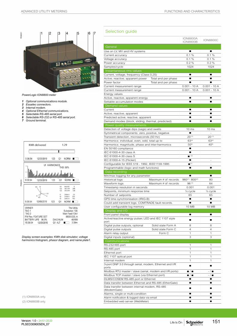
PE86
001
PowerLogic ION8800 meter
1 Optional communications module.2 Essailec connectors.3 Internal modem.4 Optional Ethernet communications.5 Selectable RS-485 serial port.6 Selectable RS-232 or RS-485 serial port.7 Ground terminal.
PE86
235
Display screen examples: KWh disk simulator, voltage harmonics histogram, phasor diagram, and name plate1.
Selection guide
ION8800AION8800B
ION8800C
General
Use on LV, MV and HV systems b b
Current accuracy 0.1 % 0.1 %
Voltage accuracy 0.1 % 0.1 %
Power accuracy 0.2 % 0.2 %
Samples/cycle 1024 1024
Instantaneous rms valuesCurrent, voltage, frequency (Class 0,2S) b b
Active, reactive, apparent power Total and per phase b b
Power factor Total and per phase b b
Current measurement range 0.001 - 10 A 0.001 - 10 A
Current measurement range 0.001 - 10 A 0.001 - 10 A
Energy values
Active, reactive, apparent energy b b
Settable accumulation modes b b
Demand valuesCurrent b b
Active, reactive, apparent b b
Predicted active, reactive, apparent b b
Demand modes (block, sliding, thermal, predicted) b b
Power quality measurementsDetection of voltage dips (sags) and swells 10 ms 10 ms
Symmetrical components: zero, positive, negative b -
Transient detection, microseconds (50 Hz) 20 (1) 20 (1)
Harmonics: individual, even, odd, total up to 63rd 63rd
Harmonics: magnitude, phase and inter-harmonics 50th 40th
EN 50160 compliance b
IEC 61000-4-30 class A b
IEC 61000-4-30 class S b (2)
IEC 61000-4-15 (Flicker) b -
Configurable for IEEE 519 - 1992, IEEE1159-1995 b(1) -
Programmable (logic and math functions) b b
Data recordingMin/max logging for any parameter b b
Historical logs Maximum # of records 960(1) 800(2) 80
Waveform logs Maximum # of records 96 (1) 64
Timestamp resolution in seconds 0.001 0.001
Setpoints, minimum response time ½ cycle ½ cycle
Number of setpoints 65 65
GPS time synchronisation (IRIG-B) b b
Could add transient logs. COMTRADE fault records. b b
User configurable log memory 10 MB 10 MB
Display and I/OFront panel display b b
Active/reactive energy pulser, LED and IEC 1107 style port
b b
Digital pulse outputs, optional Solid state Form A 8 8
Digital pulse outputs Solid state Form C 4 4
Alarm relay output Form C 1 1
Digital inputs (optional) 3 3
CommunicationsRS-232/485 port 1 1
RS-485 port 1 1
Ethernet port 1 1
IEC 1107 optical port 1 1
Internal modem 1 1
3-port DNP 3.0 through serial, modem, Ethernet and I/R ports
b b
Modbus RTU master / slave (serial, modem and I/R ports) b / b - / b
Modbus TCP master / slave (via Ethernet port) b / b - / b
DLMS/COSEM RS-485 port or Ethernet b b
Data transfer between Ethernet and RS-485 (EtherGate) b b
Data transfer between internal modem, RS-485 (ModemGate)
b b
Alarms, single or multi-condition b b
Alarm notification & logged data via email b b
Embedded web server (WebMeter) b b
(1) ION8800A only.
(2) ION8800B only.
ADVANCED UTILITY METERING FUNCTIONS AND CHARACTERISTICS
151Version: 1.0 - 24/01/2020PLSED309005EN_07Version: 1.0 - 24/01/2020PLSED309005EN_07

(1) Channel COM2 is available on the port at the back of the meter OR on the Comm Module (if installed). You must select which connectors your communications wiring is connected to during meter setup.(2) All Onboard I/O and Comms (Base Option) options include: 4 Form C solid-state digital outputs, 1 Form C mechanical relay output, one IEC 1107 optical communications port, two IEC 1107 style optical pulsing ports.
Example product part number.
1 Model.2 Feature set.3 Memory / form factor.4 Current Inputs.5 Voltage inputs.6 Power supply.7 System frequency.8 Communications.9 Onboard inputs/outputs.10 Security.11 Special order.
Part numbersItem Code Description
1 Model M8800 ION8800 IEC/DIN 43862 19” rack mount energy and power quality meter.
2 Feature Set
A Class A power quality analysis, waveforms and transient capture with 1024 samples/cycle.
B Energy meter Class S EN50160 power quality monitoring.
C Basic tariff/energy revenue meter with sag/swell monitoring.
3Memory/Form
Factor
1 10 MB logging memory, Essailec connectors.
2 5 MB logging memory, Essailec connectors, with IEC61850 protocol
4 Current InputsC (I1-I3): Configured for 5 A nominal, 10 A full scale, 14 A fault capture, 0.001 A starting current.
E (I1-I3): Configured for 1 A nominal, 10 A full scale, 14 A fault capture, 0.001 A starting current.
5 Voltage Inputs 0 (V1-V3): Autoranging (57-288 VAC L-N or 99-500 VAC L-L)
6 Power Supply B Single phase power supply: 85-240 VAC ±10% (47-63 Hz) or 110-270 VDC.
7System
Frequency
5 Calibrated for 50 Hz systems.
6 Calibrated for 60 Hz systems.
8Communications
module (field serviceable)
Z0 No communications module - meter includes Base Onboard I/O and comms (see below for details).
A0 Standard communications: 1 RS 232/RS-485 port, 1 RS-485 port (COM2) (1).
C1 Standard communications plus 10BASE-T Ethernet (RJ45), 56 k universal internal modem (RJ11).
D1Standard communications plus 10BASE-T/100BASE-TX Ethernet (RJ45) / 10Base-FL/100BASE-FX Ethernet Fiber, 56 k universal internal modem (RJ11)
E0 Standard communications plus 10BASE-T/100BASE-TX Ethernet (RJ45).
F0Standard communications plus 10BASE-T/100BASE-TX Ethernet (RJ45) / 10Base-FL/100BASE-FX (ST male Fiber Optic connection).
M1 Standard communications plus 56k universal internal modem (RJ11).
9
Onboard I/O and
communications (not field
serviceable, part of base unit)
A Base option AND 8 Form A digital outputs (2), 1 RS-485 (COM2) port (1).
B Base Option AND 8 Form A digital outputs (2), 3 digital inputs (20-56 VDC/AC).
C Base Option AND 8 Form A digital outputs (2), 3 digital inputs (80-280 VDC/AC).
D Base Option AND 1 IRIG-B time sync port (2), 1 RS-485 port (COM2), 3 digital inputs (20-56 V DC/AC) (1).
E Base Option AND 1 IRIG-B time sync port (2), 1 RS-485 port (COM2), 3 digital inputs (80-280 V DC/AC) (1).
10 Security0 Password protected, no security lock.
1 Password protected with security lock enabled.
11 Special OrderA None.
C Tropicalisation treatment applied.
PE
8600
6
ADVANCED UTILITY METERING FUNCTIONS AND CHARACTERISTICS
Version: 1.0 - 24/01/2020PLSED309005EN_07
152

Optional ION8800 communications module
ION8800 Accessories
Ordering reference Communication Card for ION8800
P880CA0A Std. comms: 1 RS-232/RS-485 port, **1 RS-485 port (COM2)
P880CA0C Std. comms: 1 RS-232/RS-485 port, **1 RS-485 port (COM2), tropicalisation treatment applied
P880CC1A Std. comms AND 10/1000BASE-TX Ethernet (RJ45), 56k universal internal modem (RJ11)
P880CC1C Std. comms AND 10/1000BASE-TX Ethernet (RJ45), 56k universal internal modem (RJ11), tropicalisation treatment applied
P880CD1A Std. comms AND 10/1000BASE-TX Ethernet (RJ45) / 10/100BASE-FX Ethernet Fiber, 56k universal internal modem (RJ11)
P880CD1CStd. comms AND 10/1000BASE-TX Ethernet (RJ45) / 10/100BASE-FX Ethernet Fiber, 56k universal internal modem (RJ11), tropicalisation treatment applied
P880CE0A Std. comms AND 10/1000BASE-TX Ethernet (RJ45)
P880CE0C Std. comms AND 10/1000BASE-TX Ethernet (RJ45), tropicalisation treatment applied
P880CF0A Std. comms AND 10/1000BASE-TX Ethernet (RJ45) / 10/100BASE-FX (ST Fiber Optic connection)
P880CF0CStd. comms AND 10/1000BASE-TX Ethernet (RJ45) / 10/100BASE-FX (ST Fiber Optic connection), tropicalisation treatment applied
P880CM1A Std. comms AND 56k universal internal modem (RJ11)
P880CM1C Std. comms AND 56k universal internal modem (RJ11), tropicalisation treatment applied
Ordering reference ION8800 related items
BATT-REPLACE-8XXX Replacement batteries for the ION8600 or ION8800, quantity 10
RACK-8800-RAW IEC/DIN 34862 19” Rack with female mating voltage/current and I/O blocks unassembled.
IEC-OPTICAL-PROBE IEC 61107 compliant Optical Probe (DB-9) for use with ION8800 meters
PE
8600
7_C
ADVANCED UTILITY METERING FUNCTIONS AND CHARACTERISTICS
153Version: 1.0 - 24/01/2020PLSED309005EN_07Version: 1.0 - 24/01/2020PLSED309005EN_07

ION8800 seriesTechnical Specification Technical Specification
Electrical characteristics
Type of measurementTrue rms1024 samples per cycle
Measurement accuracy
Current and voltage 0.1 %
Power 0.2 %
Frequency ±0.005 Hz
Power factor 0.1%
Energy IEC 62053-22/23 Class 0.2 S
Data update rate ½ cycle or 1 second
Input-voltage characteristics
Inputs U1, U2, U3, Uref
Measurement range 57-288 L-N V AC rms (99-500 L-L V AC rms)
Dielectic withstand 3320 V AC rms
Impedance 5 MW /phase (phase-Uref/Ground)
Input-current characteristics
Rated nominals 5 A, 1 A, 2 A
Permissible overload 200A rms for 0.5s, non-recurring (IEC 62053-22)
Impedance 10 mW /phase
Burden 0.01 VA per phase (1A), 0.25 VA per phase (5 A)
Power supply
AC 85 - 240 V AC (+/- 10 %), 47-63 Hz
DC 110 - 270 V DC (+/- 10 %)
BurdenTypical (without comm module): 13 VA, 8 W Typical (with comm module): 19 VA, 12 WMax (without comm module): 24 VA, 10 W Max (with comm module): 32 VA, 14 W
Ride-through timeTypical: 0.5 s to 5 s depending on configurationMin: 120 ms (6 cycles @ 50 Hz)
Dielectric withstand 2000 V AC
Input/outputs
Mechanical alarm relay 1 Form C digital output (250 V AC / 125 V DC, 1 A AC / 0.1 A DC max)
Digital outputs (Form C)4 Solid state relay outputs (210 V AC / 250 V DC) 100 mA AC/DC
Digital outputs (Form A)8 Solid state relay outputs (210 V AC / 250 V DC) 100 mA AC/DC
Digital inputs3 Solid state digital inputs (low-voltage inputs 15 to 75 V AC/DC; high-voltage inputs 75 to 280 V AC/DC; 3 mA max.)
Pulse rate 20 Hz maximum
Mechanical characteristics
Weight6.0 kg(6.5 kg with optional communications module)
IP degree of protection (IEC 60529) IP51
Dimensions 202.1 x 261.51 x 132.2 mm
Environmental conditions
Mounting location Indoor
Maximum altitude 2000 metres above sea-level
Limit range of operation -25 °C to 70 °C
Specified operating temperature -10 °C to 45 °C (as per 62052-11)
Display operating range -10 °C to 60 °C
Storage temperature -25 °C to 70 °C
Humidity rating 5 to 95 % RH non-condensing
Pollution degree 2
Installation category Power supply (II) Metering inputs (III)
Electromagnetic compatibility
Electrostatic discharge IEC 61000-4-2
Immunity to radiated fields IEC 61000-4-3
Immunity to fast transients IEC 61000-4-4
Immunity to surge waves IEC 61000-4-5
Conducted immunity IEC 61000-4-6
Damped oscillatory waves immunity IEC 61000-4-12
Conducted and radiated emissions CISPR 22 (class B)
Safety
Europe As per IEC 62052-11
International As per IEC 60950
ADVANCED UTILITY METERING FUNCTIONS AND CHARACTERISTICS
Version: 1.0 - 24/01/2020PLSED309005EN_07
154

Technical Specification
Communication
IEC 1107 optical port 2/4 wires, up to 19200 baud
RS-485 portUp to 57600 baud, direct connection to a PC or modem, protocols: ION, Modbus RTU, Modbus Master, DNP 3.0, GPSTRUETIME/DATUM, DLMS/COSEM
Communications module (optional)
RS-232/485 port300 - 115,200 baud (RS-485 limited to 57,600 baud); protocols: same as RS-485 port
Internal modem port 300 baud - 56000 baud, RJ11 connector
Ethernet port10/100BASE-TX, RJ45 connector, 100 m link; protocols: DNP TCP, ION, Modbus TCP, Modbus Master, DLMS/COSEM, IEC 61850
Fiber-optic Ethernet link10/100BASE-FX, ST connector, 1300 nm, FO multimode with gradient index 62.5/125 µm or 50/125 µm, 2000 m link; protocols: same as Ethernet port
EtherGateCommunicates directly with up to 62 slave devices via available serial ports
ModemGate Communicates directly with up to 31 slave devices
Firmware characteristics
High-speed data recording
Up to ½-cycle interval burst recording, stores detailed characteristics of disturbances or outages Trigger recording by a user-defined setpoint, or from external equipment.
Harmonic distortion Up to 63rd harmonic for all voltage and current inputs
Dip/swell detection
Analyse severity/potential impact of sags and swells:magnitude and duration data suitable for plotting on voltage tolerance curves per phase triggers for waveform recording or control operations
Instantaneous
High accuracy measurements with 1s or 1/2 cycle update rate for:voltage and currentactive power (kW) and reactive power (kvar)apparent power (kVA)power factor and frequencyvoltage and current unbalancephase reversal
Load profiling
Channel assignments (800 channels via 50 datarecorders) are configurable for any measureableparameter, including historical trend recording ofenergy, demand, voltage, current, power quality, or anymeasured parameterTrigger recorders based on time interval, calendarschedule, alarm/event condition, or manually.
Modbus Master
Master up to 32 slave devices per serial channel and store their data at programmable intervals. Use this data to aggregate and sum energy values and perform complex totaling.
Waveform captures
Simultaneous capture of all voltage and current channelssub-cycle disturbance capturemaximum cycles is 214,000 (16 samples/cycle x 96 cycles, 10 MB memory)1024 samples/cycle
Alarms
Threshold alarms:adjustable pickup and dropout setpoints and time delays, numerous activation levels possible for a given type of alarmuser-defined priority levelsboolean combination of alarms possible
Advanced securityUp to 50 users with unique access rights. Perform resets, time syncs, or meter configurations based on user privileges.
Transformer correctionCorrect for phase / magnitude inaccuracies in current transformers (CTs), potential transformers (PTs)
Memory 5 -10 MB(specified at time of order)
Firmware update Update via the communication ports
Display characteristics
Type FSTN transreflective LCD
Backlight LED
Languages English
Example embedded page showing realtime values.
Ports on the optional communications module.
PE
8623
4P
E86
233
PE
8600
2
ADVANCED UTILITY METERING FUNCTIONS AND CHARACTERISTICS
155Version: 1.0 - 24/01/2020PLSED309005EN_07Version: 1.0 - 24/01/2020PLSED309005EN_07

ION8800 dimensions
ION8800 Essailec rack dimensions
ION8800 communication module dimensions
Rack mounting the ION8800
PE
8600
8P
E86
010
PE
8601
1P
E86
012
PE
8600
9
Please see the appropriate Installation Guide for accurate and complete information on the installation of this product.
ADVANCED UTILITY METERING DIMENSIONS AND CONNECTION
Version: 1.0 - 24/01/2020PLSED309005EN_07
156
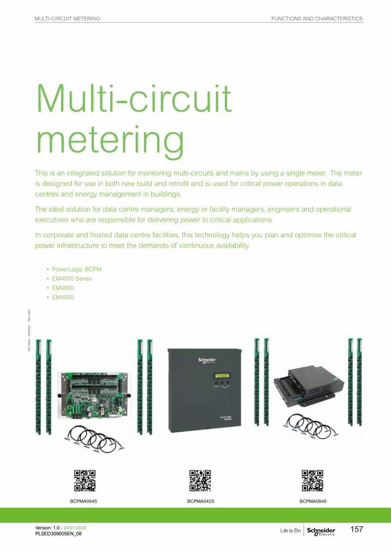
This is an integrated solution for monitoring multi-circuits and mains by using a single meter. The meter
is designed for use in both new build and retrofit and is used for critical power operations in data
centres and energy management in buildings.
The ideal solution for data centre managers, energy or facility managers, engineers and operational
executives who are responsible for delivering power to critical applications.
In corporate and hosted data centre facilities, this technology helps you plan and optimise the critical
power infrastructure to meet the demands of continuous availability.
• • PowerLogic BCPM
• • EM4000 Series
• • EM4800
• • EM4900
PB11
3664
PB11
3665
Multi-circuit metering
PE86
325
BCPMA084S BCPMA042S BCPMA084S
MULTI-CIRCUIT METERING FUNCTIONS AND CHARACTERISTICS
157Version: 1.0 - 24/01/2020PLSED309005EN_08Version: 1.0 - 24/01/2020PLSED309005EN_08

PB11
3665
The PowerLogic BCPM is a highly accurate, full-featured metering product designed for the unique,
multi-circuit and minimal space requirements of a high performance power distribution unit (PDU) or
remote power panel (RPP).
It offers class 1 (1 %) power and energy system accuracy (including 50 A or 100 A CTs) on all branch channels. The BCPM monitors up to 84 branch circuits and the incoming power mains to provide information on a complete PDU. Full alarming capabilities ensure that potential issues are dealt with before they become problems.
PowerLogic BCPM
Applications
• Maximise uptime and avoid outages
• Optimise existing infrastructure
• Improve power distribution efficiency
• Track usage and allocate energy costs
• Enable accurate sub-metering
BCPMA084S
MULTI-CIRCUIT METERING FUNCTIONS AND CHARACTERISTICS
Version: 1.0 - 24/01/2020PLSED309005EN_08
158
The solution for
Markets that can benefit from a solution that includes PowerLogic BCPM series meters:
• Data centres
• Buildings
Power management solutions
Schneider Electric provides innovative power management solutions to increase your energy efficiency and cost savings, maximise electrical network reliability and availability, and optimise electrical asset performance.
Benefits
The flexible BCPM fits any PDU or RPP design and supports both new and retrofit installations. It has exceptional dynamic range and accuracy, and optional feature sets to meet the energy challenges of mission critical data centres.
Conformity of standards
• ANSI C12.1
• IEC 61010-1
• IEC 62053-21 Class 1
• UL508Competitive advantages
• Fit any PDU or RPP design for both new and retrofit projects
• Class 1.0 system accuracy
• Ethernet communication
MULTI-CIRCUIT METERING FUNCTIONS AND CHARACTERISTICS
159Version: 1.0 - 24/01/2020PLSED309005EN_08Version: 1.0 - 24/01/2020PLSED309005EN_08
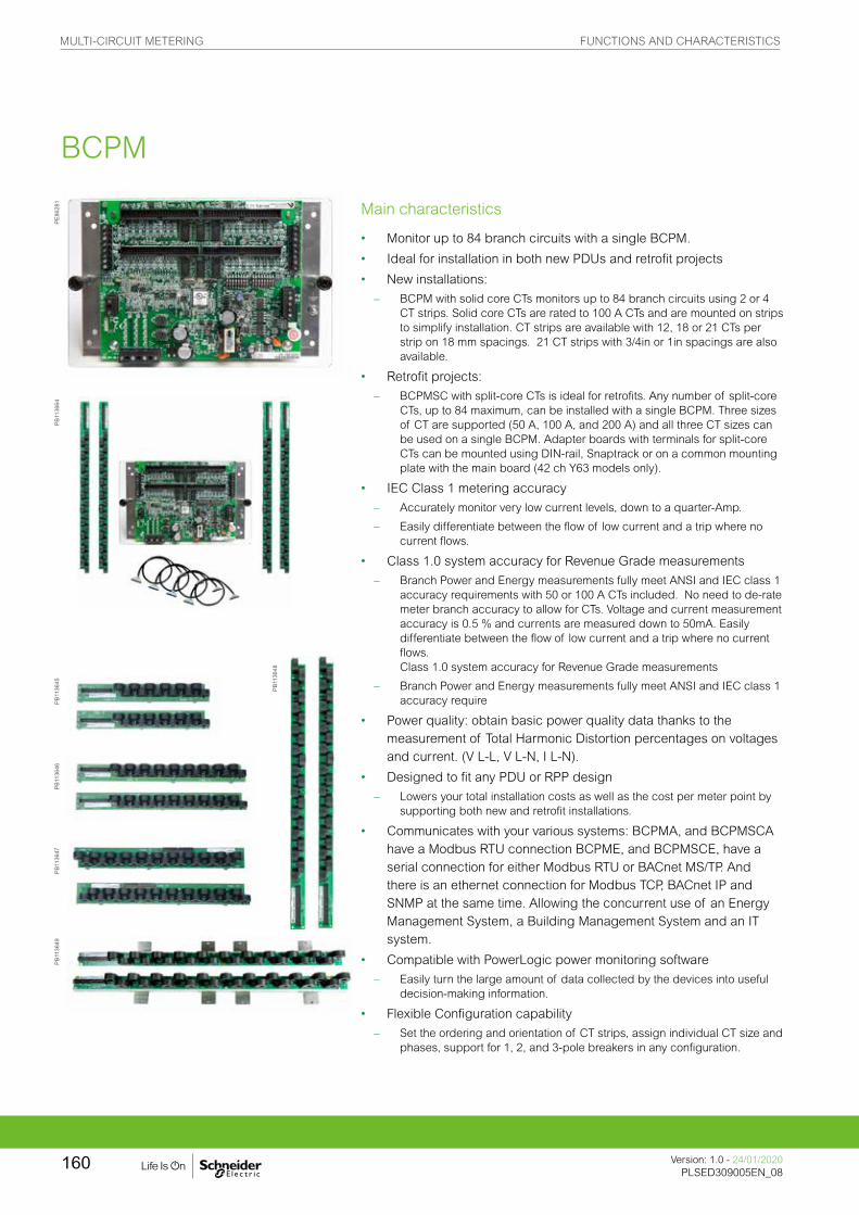
Main characteristics
• Monitor up to 84 branch circuits with a single BCPM.
• Ideal for installation in both new PDUs and retrofit projects
• New installations:
– BCPM with solid core CTs monitors up to 84 branch circuits using 2 or 4 CT strips. Solid core CTs are rated to 100 A CTs and are mounted on strips to simplify installation. CT strips are available with 12, 18 or 21 CTs per strip on 18 mm spacings. 21 CT strips with 3/4in or 1in spacings are also available.
• Retrofit projects:
– BCPMSC with split-core CTs is ideal for retrofits. Any number of split-core CTs, up to 84 maximum, can be installed with a single BCPM. Three sizes of CT are supported (50 A, 100 A, and 200 A) and all three CT sizes can be used on a single BCPM. Adapter boards with terminals for split-core CTs can be mounted using DIN-rail, Snaptrack or on a common mounting plate with the main board (42 ch Y63 models only).
• IEC Class 1 metering accuracy
– Accurately monitor very low current levels, down to a quarter-Amp.
– Easily differentiate between the flow of low current and a trip where no current flows.
• Class 1.0 system accuracy for Revenue Grade measurements
– Branch Power and Energy measurements fully meet ANSI and IEC class 1 accuracy requirements with 50 or 100 A CTs included. No need to de-rate meter branch accuracy to allow for CTs. Voltage and current measurement accuracy is 0.5 % and currents are measured down to 50mA. Easily differentiate between the flow of low current and a trip where no current flows. Class 1.0 system accuracy for Revenue Grade measurements
– Branch Power and Energy measurements fully meet ANSI and IEC class 1 accuracy require
• Power quality: obtain basic power quality data thanks to the measurement of Total Harmonic Distortion percentages on voltages and current. (V L-L, V L-N, I L-N).
• Designed to fit any PDU or RPP design
– Lowers your total installation costs as well as the cost per meter point by supporting both new and retrofit installations.
• Communicates with your various systems: BCPMA, and BCPMSCA have a Modbus RTU connection BCPME, and BCPMSCE, have a serial connection for either Modbus RTU or BACnet MS/TP. And there is an ethernet connection for Modbus TCP, BACnet IP and SNMP at the same time. Allowing the concurrent use of an Energy Management System, a Building Management System and an IT system.
• Compatible with PowerLogic power monitoring software
– Easily turn the large amount of data collected by the devices into useful decision-making information.
• Flexible Configuration capability
– Set the ordering and orientation of CT strips, assign individual CT size and phases, support for 1, 2, and 3-pole breakers in any configuration.
PE86
281
PB11
3664
PB11
3645
PB11
3646
PB11
3647
PB11
3649
PB11
3648
BCPM
MULTI-CIRCUIT METERING FUNCTIONS AND CHARACTERISTICS
Version: 1.0 - 24/01/2020PLSED309005EN_08
160
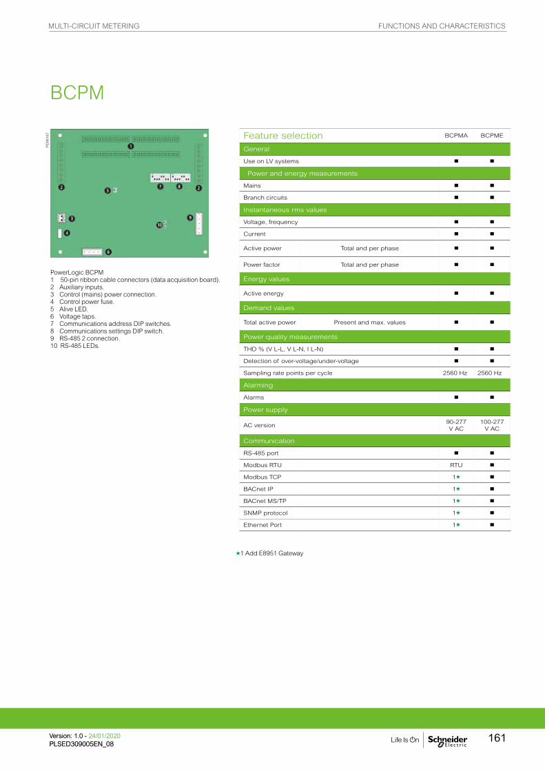
Feature selection BCPMA BCPME
General
Use on LV systems b b
Power and energy measurements
Mains b b
Branch circuits b b
Instantaneous rms values
Voltage, frequency b b
Current b b
Active power Total and per phase b b
Power factor Total and per phase b b
Energy values
Active energy b b
Demand values
Total active power Present and max. values b b
Power quality measurements
THD % (V L-L, V L-N, I L-N) b b
Detection of over-voltage/under-voltage b b
Sampling rate points per cycle 2560 Hz 2560 Hz
Alarming
Alarms b b
Power supply
AC version90-277 V AC
100-277 V AC
Communication
RS-485 port b b
Modbus RTU RTU b
Modbus TCP 1g b
BACnet IP 1g b
BACnet MS/TP 1g b
SNMP protocol 1g b
Ethernet Port 1g b
PE86
167
g1 Add E8951 Gateway
PowerLogic BCPM 1 50-pin ribbon cable connectors (data acquisition board).2 Auxiliary inputs.3 Control (mains) power connection.4 Control power fuse.5 Alive LED.6 Voltage taps.7 Communications address DIP switches.8 Communications settings DIP switch.9 RS-485 2 connection.10 RS-485 LEDs.
BCPM
MULTI-CIRCUIT METERING FUNCTIONS AND CHARACTERISTICS
161Version: 1.0 - 24/01/2020PLSED309005EN_08Version: 1.0 - 24/01/2020PLSED309005EN_08

BCPM part numbers BCPM with solid core CTs
Item Code Description
1 Model BCPM
BCPM with solid core CTs. Highly accurate meter that monitors branch circuits and the incoming power mains and includes full alarming capabilities
2 Feature set
A
Advanced - Monitors power & energy per circuit & mains, Modbus RTU only (add E8951 for other protocols), Meter Main Board comes on an aluminum mounting plate
EAdvanced, with Ethernet - Monitors power & energy per circuit & mains, Meter Main Board is partially enclosed in a metal housing
3 CT spacing
0 3/4in (19 mm) CT spacing
1 1in (26 mm) CT spacing
2 18 mm CT spacing
4Number of
circuits
2424 circuits, (2) 12-CT strips (18 mm spacing only)
3636 circuits, (2) 18-CT strips (18 mm spacing only)
42 42 circuits, (2) 21-CT strips
4848 circuits, (4) 12-CT strips (18 mm spacing only)
7272 circuits, (4) 18-CT strips (18 mm spacing only)
84 84 circuits, (4) 21-CT strips
5 Brand S Schneider Electric
The PowerLogic BCPM uses .333 V AC output split-core CTs for the auxiliary inputs. These CTs are ordered separately from the BCPM.
* Quantity and style of CT strips and cables included varies by model
PE86
168
PB11
3664
PB11
3665
Example BCPM with solid core CTs part number1. Model2. Feature set3. CT spacing (solid core models only)4. Number of circuits5. Brand
BCPM
MULTI-CIRCUIT METERING FUNCTIONS AND CHARACTERISTICS
Version: 1.0 - 24/01/2020PLSED309005EN_08
162
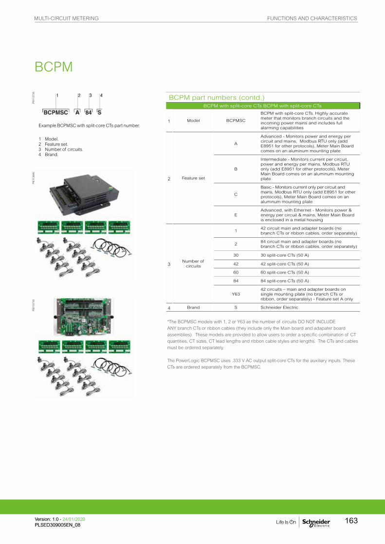
BCPM part numbers (contd.)BCPM with split-core CTs BCPM with split-core CTs
1 Model BCPMSC
BCPM with split-core CTs. Highly accurate meter that monitors branch circuits and the incoming power mains and includes full alarming capabilities
2 Feature set
A
Advanced - Monitors power and energy per circuit and mains, Modbus RTU only (add E8951 for other protocols), Meter Main Board comes on an aluminum mounting plate
B
Intermediate - Monitors current per circuit, power and energy per mains, Modbus RTU only (add E8951 for other protocols), Meter Main Board comes on an aluminum mounting plate
C
Basic - Monitors current only per circuit and mains, Modbus RTU only (add E8951 for other protocols), Meter Main Board comes on an aluminum mounting plate
EAdvanced, with Ethernet - Monitors power & energy per circuit & mains, Meter Main Board is enclosed in a metal housing
3Number of
circuits
142 circuit main and adapter boards (no branch CTs or ribbon cables, order separately)
284 circuit main and adapter boards (no branch CTs or ribbon cables, order separately)
30 30 split-core CTs (50 A)
42 42 split-core CTs (50 A)
60 60 split-core CTs (50 A)
84 84 split-core CTs (50 A)
Y6342 circuits – main and adapter boards on single mounting plate (no branch CTs or ribbon, order separately) - Feature set A only
4 Brand S Schneider Electric
1 Model.2 Feature set.3 Number of circuits.4 Brand.
Example BCPMSC with split-core CTs part number.
*The BCPMSC models with 1, 2 or Y63 as the number of circuits DO NOT INCLUDE ANY branch CTs or ribbon cables (they include only the Main board and adapater board assemblies). These models are provided to allow users to order a specific combination of CT quantities, CT sizes, CT lead lengths and ribbon cable styles and lengths. The CTs and cables must be ordered separately.
The PowerLogic BCPMSC uses .333 V AC output split-core CTs for the auxiliary inputs. These CTs are ordered separately from the BCPMSC.
PB11
3735
PB11
3666
PB11
3730
BCPM
MULTI-CIRCUIT METERING FUNCTIONS AND CHARACTERISTICS
163Version: 1.0 - 24/01/2020PLSED309005EN_08Version: 1.0 - 24/01/2020PLSED309005EN_08

Flat ribbon cable
Round ribbon cable
Cabling and connection
Flat ribbon cables are recommended for use when the BCPM printed circuit board will be mounted inside of the PDU that is being monitored. Round ribbon cables are the prefered choice when the ribbon cable will be threaded through conduit.
BCPM part numbers for solid and split-core CTs (contd.)BCPM with split-core CTs
Commercial ref. no.
Description
BCPMA042S42-circuit solid core power & energy meter, 100 A CTs (2 strips), 19 mm spacing
BCPMA084S84-circuit solid core power & energy meter, 100 A CTs (4 strips), 19 mm spacing
BCPMA142S42-circuit solid core power & energy meter, 100 A CTs (2 strips), 25 mm spacing
BCPMA184S84-circuit solid core power & energy meter, 100 A CTs (4 strips), 25 mm spacing
BCPMA224S24-circuit solid core power & energy meter, 100 A CTs (2 strips), 18 mm spacing
BCPMA236S36-circuit solid core power & energy meter, 100 A CTs (2 strips), 18 mm spacing
BCPMA242S42-circuit solid core power & energy meter, 100 A CTs (2 strips), 18 mm spacing
BCPMA248S48-circuit solid core power & energy meter, 100 A CTs (4 strips), 18 mm spacing
BCPMA272S72-circuit solid core power & energy meter, 100 A CTs (4 strips), 18 mm spacing
BCPMA284S84-circuit solid core power & energy meter, 100 A CTs (4 strips), 18 mm spacing
BCPME042S42-circuit solid core power & energy meter w/Ethernet, 100 A CTs (2 strips), 19 mm spacing
BCPME084S84-circuit solid core power & energy meter w/Ethernet, 100 A CTs (4 strips), 19 mm spacing
BCPME142S42-circuit solid core power & energy meter w/Ethernet, 100 A CTs (2 strips), 25 mm spacing
BCPME184S84-circuit solid core power & energy meter w/Ethernet, 100 A CTs (4 strips), 25 mm spacing
BCPME224S24-circuit solid core power & energy meter w/Ethernet, 100 A CTs (2 strips), 18 mm spacing
BCPME236S36-circuit solid core power & energy meter w/Ethernet, 100 A CTs (2 strips), 18 mm spacing
BCPME242S42-circuit solid core power & energy meter w/Ethernet, 100 A CTs (2 strips), 18 mm spacing
BCPME248S48-circuit solid core power & energy meter w/Ethernet, 100 A CTs (4 strips), 18 mm spacing
BCPME272S72-circuit solid core power & energy meter w/Ethernet, 100 A CTs (4 strips), 18 mm spacing
BCPME284S84-circuit solid core power & energy meter w/Ethernet, 100 A CTs (4 strips), 18 mm spacing
PE86
284
PB11
3650
BCPM
CBL016
CBL022
MULTI-CIRCUIT METERING FUNCTIONS AND CHARACTERISTICS
Version: 1.0 - 24/01/2020PLSED309005EN_08
164
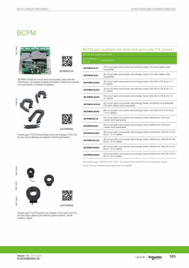
PE
8618
3P
B11
3651
PB
1136
58
PowerLogicTM LVCT0xxxxS Split-core Low-voltage (1/3V) CTs for Aux inputs (Mains) are ideal for retrofit applications
BCPMSCxY63S 42-circuit split-core models come with the main board, (2) adapter boards and ribbon cables all mounted on a backplate, to simplify installation.
PowerLogicTM LVCT2xxxxS Low-voltage (1/3V) solid core CTs for Aux inputs (Mains) are ideal for panel builders (small, medium, large)
PB
1136
52P
B11
3657
The PowerLogicTM BCPM uses .333 V AC output split-core CTs for the auxiliary inputs.
These CTs are ordered separately from the BCPM.
BCPMSCA1S42-circuit split-core power and energy meter, CTs and cables sold separately
BCPMSCA2S84-circuit split-core power and energy meter, CTs and cables sold separately
BCPMSCA30S30-circuit split-core power and energy meter, (30) 50 A CTs & (2) 1.2 m cables
BCPMSCA42S42-circuit split-core power and energy meter, (42) 50 A CTs & (2) 1.2 m cables
BCPMSCA60S60-circuit split-core power and energy meter, (60) 50 A CTs & (4) 1.2 m cables
BCPMSCAY63S42-circuit split-core power and energy meter, all boards on backplate, CTs and cables sold separately
BCPMSCA84S84-circuit split-core power and energy meter, with (84) 50 A CTs & (4) 1.2 m cables
BCPMSCE1S42-circuit split-core power and energy meter w/Ethernet, CTs and cables sold separately
BCPMSCE2S84-circuit split-core power and energy meter w/Ethernet, CTs and cables sold separately
BCPMSCE30S30-circuit split-core power and energy meter w/Ethernet, (30) 50 A CTs & (2) 1.2 m cables
BCPMSCE42S42-circuit split-core power and energy meter w/Ethernet, (42) 50 A CTs & (2) 1.2 m cables
BCPMSCE60S60-circuit split-core power and energy meter w/Ethernet, (60) 50 A CTs & (4) 1.2 m cables
BCPMSCE84S84-circuit split-core power and energy meter w/Ethernet, (84) 50 A CTs & (4) 1.2 m cables
BCPM part numbers for solid and split-core CTs (contd.)
BCPM with split-core CTs
Commercial ref. no.
Description
BCPM
LVCT20050S
LVCT00050S
BCPMSCA1S
MULTI-CIRCUIT METERING FUNCTIONS AND CHARACTERISTICS
165Version: 1.0 - 24/01/2020PLSED309005EN_08Version: 1.0 - 24/01/2020PLSED309005EN_08
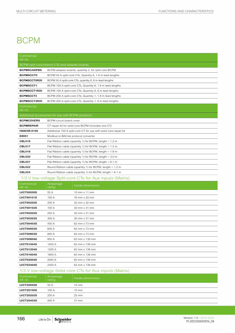
Commercial ref. no.
BCPM split-core branch CTs and adapter boards
BCPMSCADPBS BCPM adapter boards, quantity 2, for split-core BCPM
BCPMSCCT0 BCPM 50 A split-core CTs, Quantity 6, 1.8 m lead lengths
BCPMSCCT0R20 BCPM 50 A split-core CTs, quantity 6, 6 m lead lengths
BCPMSCCT1 BCPM 100 A split-core CTs, Quantity 6, 1.8 m lead lengths
BCPMSCCT1R20 BCPM 100 A split-core CTs, Quantity 6, 6 m lead lengths
BCPMSCCT3 BCPM 200 A split-core CTs, Quantity 1, 1.8 m lead lengths
BCPMSCCT3R20 BCPM 200 A split-core CTs, Quantity 1, 6 m lead lengths
Commercial ref. no.
Additional accessories for use with BCPM products
BCPMCOVERS BCPM circuit board cover
BCPMREPAIR CT repair kit for solid core BCPM (includes one CT)
H6803R-0100 Additional 100 A split-core CT for use with solid core repair kit
E8951 Modbus to BACnet protocol converter
CBL016 Flat Ribbon cable (quantity 1) for BCPM, length = 1.2 m
CBL017 Flat Ribbon cable (quantity 1) for BCPM, length = 1.5 m
CBL018 Flat Ribbon cable (quantity 1) for BCPM, length = 1.8 m
CBL020 Flat Ribbon cable (quantity 1) for BCPM, length = 3.0 m
CBL021 Flat Ribbon cable (quantity 1) for BCPM, length = 6.1 m
CBL022 Round Ribbon cable (quantity 1) for BCPM, length = 1.2 m
CBL024 Round Ribbon cable (quantity 1) for BCPM, length = 6.1 m
1/3 V low-voltage Split-core CTs for Aux inputs (Mains)Commercial ref. no.
Amperage rating
Inside dimensions
LVCT00050S 50 A 10 mm x 11 mm
LVCT00101S 100 A 16 mm x 20 mm
LVCT00202S 200 A 32 mm x 32 mm
LVCT00102S 100 A 30 mm x 31 mm
LVCT00202S 200 A 30 mm x 31 mm
LVCT00302S 300 A 30 mm x 31 mm
LVCT00403S 400 A 62 mm x 73 mm
LVCT00603S 600 A 62 mm x 73 mm
LVCT00803S 800 A 62 mm x 73 mm
LVCT00804S 800 A 62 mm x 139 mm
LVCT01004S 1000 A 62 mm x 139 mm
LVCT01204S 1200 A 62 mm x 139 mm
LVCT01604S 1600 A 62 mm x 139 mm
LVCT02004S 2000 A 62 mm x 139 mm
LVCT02404S 2400 A 62 mm x 139 mm
1/3 V low-voltage Solid core CTs for Aux inputs (Mains)Commercial ref. no.
Amperage rating
Inside dimensions
LVCT20050S 50 A 10 mm
LVCT20100S 100 A 10 mm
LVCT20202S 200 A 25 mm
LVCT20403S 400 A 31 mm
BCPM
MULTI-CIRCUIT METERING FUNCTIONS AND CHARACTERISTICS
Version: 1.0 - 24/01/2020PLSED309005EN_08
166

Technical specifications
Electrical characteristics
Type of measurement
Accuracy
Power/energy 1 % system accuracy (including 50A or 100A branch CTs)
Voltage±0.5 % of reading
Current ±0.5 % of reading
Minimum “ON” current 50mA
Sampling rate Points per cycle 2560 Hz
Data update rate 1.8 seconds (Modbus), 14 seconds (BACnet) 20 sec (SNMP)
Input-voltage characteristics
Measured voltage150 – 480 V AC L-L (1) 90 – 277 V AC L-N (1)
Measurement range150 – 480 V AC L-L (1) 90 – 277 V AC L-N (1)
Power supply AC 100 – 277 V AC (50/60 Hz)
Auxiliary CT Current Input Range 0-0.333V; CTs must be rated for use with Class 1 voltage inputs
Mechanical characteristics
Weight 1.5 kg
Dimensions A/B/C model Circuit board 288 x 146 mm
E model housing (w/brackets on long sides) 253 mm W x 307 mm H x 71 mm D
E model housing (w/brackets on short ends) 210 mm W x 353 mm H x 71 mm D
Environmental conditions
Operating temperature 0 to 60 ºC
Storage temperature -40 ºC to 70 ºC
Installation category CAT III, pollution degree 2
Safety
Europe IEC 61010
U.S. and Canada UL 508 Open type device
Communication
RS-485 (A/B/C models)Baud rate: DIP-switch selectable 9600, 19200, 38400DIP-switch selectable 2-wire or 4-wire RS-485. Parity selectable: Even, Odd or None.
RS-485 (A models)Baud rate: configured via Web-server. Baud selectable: 9600, 19200, 38400. Parity selectable: Even, Odd or None. 2-wire RS-485.
Ethernet (E models) 10/100 Mbit Ethernet. RJ-45 connection. Static IP or DHCP.
Protocols Modbus RTU on all models, BCPME models also support Modbus TCP, SNMP, BACnet IP & BACnet MS/TP
Firmware characteristics
Detection of over-voltage/under-voltage
User-defined alarm thresholds for over-voltage and under-voltage detection
AlarmsFour alarm levels: high-high, high, low and low-low (users define the setpoints for each). Each alarm has a latching status to alert the operator that an alarm has previously occurred. High and Low alarms have instantaneous status to let the operator know if the alarm state is still occurring.
Firmware update Update via Modbus
BCPM
MULTI-CIRCUIT METERING FUNCTIONS AND CHARACTERISTICS
167Version: 1.0 - 24/01/2020PLSED309005EN_08Version: 1.0 - 24/01/2020PLSED309005EN_08

1/3 V low-voltage CT (LVCT) for Mains - Technical specifications
Electrical characteristics
Accuracy1 % from 10 % to 100 % of rated current(LVCT0xxxx0S/1S/2S/3S/4S [split-core])0.5 % from 5 % to 100 % of rated current (LVCT2xxxx0S/2S/3S [solid core])
Frequency range 50/60 Hz
Leads 18 AWG, 600 V AC, 1.8m standard length
Max. voltage L-N sensed conductor
300 V AC (LVCT0xxxx0S)600 V AC (LVCT0xxxx1S/2S/3S/4S, LVCT2xxxxxS)
Environmental conditions
Operating temperature
0 ºC to 70 ºC (LVCT0xxxx0S/1S)-15 ºC to 60 ºC (LVCT0xxxx2S/3S/4S less than 2400A)-15 ºC to 60 ºC (LVCT02404S [2400A])-40 ºC to 85 ºC (LVCT2xxxx0S/2S/3S [solid core])
Storage temperature-40 ºC to 105 ºC (LVCT0xxxx0S/1S)-40 ºC to 70 ºC (LVCT0xxxx2S/3S/4S)-50 ºC to 105 ºC (LVCT2xxxx0S/2S/3S [solid core])
Humidity range 0 to 95 % non-condensing
BCPM
MULTI-CIRCUIT METERING FUNCTIONS AND CHARACTERISTICS
Version: 1.0 - 24/01/2020PLSED309005EN_08
168

PowerLogic BCPM adapter board (one board per 21 split-core branch CTs)
PowerLogic BCPM dimensions
PE
8628
6_m
PB
1136
62
PB
1136
61
PE
8616
9
BCPM
MULTI-CIRCUIT METERING DIMENSIONS AND CONNECTION
Version: 1.0 - 24/01/2020PLSED309005EN_08
169

Small form factor100/200/300 Amp A = 96 mm B = 30 mm C = 31 mm D = 30 mm E = 100 mm F = 121 mm
Large form factor800/1000/1200/1600/2000/2400 Amp A = 125 mm B = 139 mm C = 62 mm D = 30 mm E = 201 mm F = 151 mm
Medium form factor400/600/800 Amp A = 125 mm B = 73 mm C = 62 mm D = 30 mm E = 132 mm F = 151 mm
These dimensions apply to both BCPMSCCTxx (branch CTs) and LVCT0xxxx0S/1S (for Mains) 50 A-200 A CT families.
Solid core CT dimensions
1/3 V low-voltage CT form factor
50 A-200 A Split-core CT dimensions
PB
1136
59P
B11
3660
_mP
B11
3663
PB
1136
59
PB
1136
59
Model L A B C D ELVCT20050S
1.8 m 33 mm 38 mm 18 mm 21 mm 10 mmLVCT20100S
LVCT20202S 1.8 m 59 mm 66 mm 18 mm 31 mm 25 mm
LVCT20403S 1.8 m 70 mm 82 mm 25 mm 36 mm 31 mm
BCPM
MULTI-CIRCUIT METERING DIMENSIONS AND CONNECTION
Version: 1.0 - 24/01/2020PLSED309005EN_08
170

PowerLogic BCPM with solid core CT strips installation details
PowerLogic BCPM with split-core CTs installation details
Mains monitoring(CTs ordered separately)
BCPM PCB
Transducers (1/3 Vac)
Circuit monitoring 4 CT strips monitor up to 84 circuits
PE
8617
1P
E86
287
BCPM
MULTI-CIRCUIT METERING DIMENSIONS AND CONNECTION
Version: 1.0 - 24/01/2020PLSED309005EN_08
171
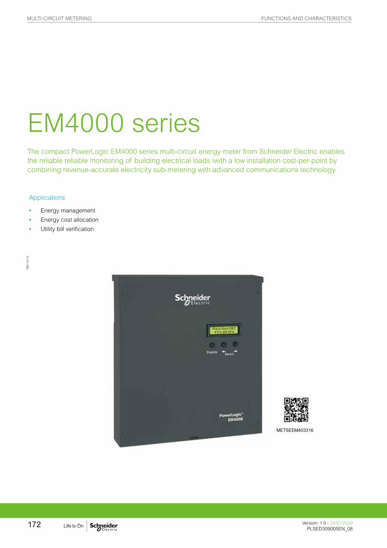
The compact PowerLogic EM4000 series multi-circuit energy meter from Schneider Electric enables the reliable reliable monitoring of building electrical loads iwith a low installation cost-per-point by combining revenue-accurate electricity sub-metering with advanced communications technology.
EM4000 series
Applications
• Energy management
• Energy cost allocation
• Utility bill verification
PB
113714
METSEEM403316
MULTI-CIRCUIT METERING FUNCTIONS AND CHARACTERISTICS
Version: 1.0 - 24/01/2020PLSED309005EN_08
172

The solution for
Markets that can benefit from a solution that includes PowerLogic EM4000 series meters:
• Buildings
• Industry
• Healthcare
• Data Centre and networks
• Infrastructure
Power management solutions
Schneider Electric provides innovative power management solutions to increase your energy efficiency and cost savings, maximise electrical network reliability and availability, and optimise electrical asset performance.
Competitive advantages
• Compact, maintenance-free design
• Hi-density, flexible connection
• Direct connection
• Multiple CT types
• No rewiring required
• Integrated communications networks.
Conformity of standards
• IEC 61557-12
• IEC 62053-22
• IEC 62053-24
• IEC 61010-1
• IEC 61000-4-2
• IEC 61000-4-3
• IEC 61000-4-4
• IEC 61000-4-5
• IEC 61000-4-6
• IEC 61000-4-8
• Etc.
Benefits
System integrators’ benefit
• Ease of integration
• Ease of setup
• Cost effectiveness
Panel builders’ benefit
• Ease of installation
• Cost effectiveness
• Aesthetically pleasing
• Simplified ordering
End users’ benefit
• Ease of use
• Precision metering & sub-billing
• Billing flexibility
• Comprehensive, consistent and superior performance
MULTI-CIRCUIT METERING FUNCTIONS AND CHARACTERISTICS
173Version: 1.0 - 24/01/2020PLSED309005EN_08Version: 1.0 - 24/01/2020PLSED309005EN_08

PB
1137
14
The compact PowerLogic EM4000 series multi-circuit energy meter from Schneider Electric enables the reliable monitoring of building electrical loads iwith a low installation cost-per-point by combining revenue-accurate electricity sub-metering with advanced communications technology.
The EM4000 is ideal for departmental metering applications and M&V within office towers, condominiums, apartment buildings, shopping centres and other multi-user environments, or small-footprint retail.
The PowerLogic EM4000 series meters monitor up to 24 meter points with a single device. Multiple meters can be combined to support an unlimited number of points.
Two meter models offer a choice of CTs and installation options:
• PowerLogic EM4033: 333 mV, split-core CTs
• PowerLogic EM4080: 80 mA solid core CTs
Main characteristics
• Compact, maintenance-free design
– Requires no floor space
• Hi-density, flexible connection
– From single-pole to single- or three-phase metering, supports up to 24 circuits.
– Select the connection type using an intuitive configuration tool.
• Direct connection
– For 100 - 300 V AC L-N electrical distribution systems: 120/240 V, 120/208 V, 277/480 V
• Multiple CT types
– Support a variety of needs in both new and retrofit installations.
– 1/3 V output CT option does not require shorting blocks, making it the ideal choice for retrofit installations.
• No rewiring required
– Use existing wiring to connect to existing panels.
• Integrated communications networks.
– Onboard Ethernet or RS-485 allows for easy integration into existing communications networks.
Feature selection
Commercial ref. no.
Model Description
METSEEM403316EM4033
PM5310 Cl 0.5, RS-485 Modbus, 2DI/2DO
METSEEM403336 PM5330 Cl 0.5, RS-485 Modbus, 2DI/2DO, Relay
METSEEM408016EM4080
PM5331 Power & Energy meter
METSEEM408036 PM5320 Power & Energy meter
EM4000 series multi-circuit energy meter
EM4000 series
MULTI-CIRCUIT METERING FUNCTIONS AND CHARACTERISTICS
Version: 1.0 - 24/01/2020PLSED309005EN_08
174

Selection guide
EM4033 EM4080
General
Use on LV systems b bAccuracy +/- 0.5 % b bAccuracy compliance ANSI C12.1 and C12.20 Class 0.5;
IEC 62053-22, Class 0.5S b b
Maximum circuits: single-pole / single-phase / three-phase
24 / 12 / 8
b b
Instantaneous rms values
Energy real, kWh received/delivered b breactive, kvarh received/delivered b bapparent, VAh b b
Voltage b bPulse counts b bVoltage and current V rms, I rms per phase b bPower real, reactive, apparent b bPower factor b bMeasurements available for data loggingEnergy real, kWh received/delivered b b
reactive, kvarh received/delivered b bapparent, VAh b b
Voltage b bDisplayBacklit LCD display 2 lines of 16 characters b bOptional remote modular display available b bCommunicationEthernet port b bMODBUS-RTU over RS-485 b bPulse inputs 2 b bProtocols: Modbus TCP/IP, HTTP, BACnet/IP, FTP, and SNTP b b Installation options0.333 V CTs b80 mA CTs bSplit-core CT bSolid core CT b b
Legend:1 Cover screw location2 Meter point input connector3 Cable connector4 Mounting keyhole5 Ingress punch-outs6 Earth stud6 Sense voltage terminal block8 Control voltage terminal block9 Fuse10 Control voltage jumper11 RTU interface12 Display13 Remote display connector14 Serial RS-23215 Ethernet port16 Pulse in terminal blocks17 Pulse out connector
PowerLogic EM4000 meter 480Y/277V three-phase wye service connection
PB
1137
18P
B11
3716
EM4000 series
MULTI-CIRCUIT METERING FUNCTIONS AND CHARACTERISTICS
175Version: 1.0 - 24/01/2020PLSED309005EN_08Version: 1.0 - 24/01/2020PLSED309005EN_08

EM4000 technical specifications
Electrical characteristicsInput-voltage characteristics Inputs V1, V2, V3, Vn
Measured voltage 80 - 480 V AC L-L without PTsUp to 999 kV with external PTs
Frequency range 60 Hz
Mechanical characteristics
Weight EM4033/EM4080 approx. 4.0 kgDimensions EM4033/EM4080 335 x 305 x 55 mm
Environmental conditions
Operating temperature -40 °C to 70 °C
Storage temperature -40 °C to 70 °CHumidity rating 0 % to 90 % RH non-condensingEnclosure Type 1 (indoor or enclosed outdoor use)Altitude 3000 mPollution degree 2Safety and standards
UL Certified to IEC/EA/CSA 61010-1CSA-C22.2 No 61010-1-04FCC Part 15 Class BICES-003 EN 55022, IEC 6100-4-5ANSI/TIA968-A: 2002Communication
Ports Ethernet
MODBUS-RTU over RS-485
Pulse inputs 2
Protocols: Modbus TCP/IP, HTTP, BACnet/IP, FTP, and SNTP
Display characteristics
Integrated backlit LCD display 2 lines, 16 digits per line display; R / L arrow buttons select metering point; Display button cycles through measurements per point.
EM4000 series
MULTI-CIRCUIT METERING FUNCTIONS AND CHARACTERISTICS
Version: 1.0 - 24/01/2020PLSED309005EN_08
176
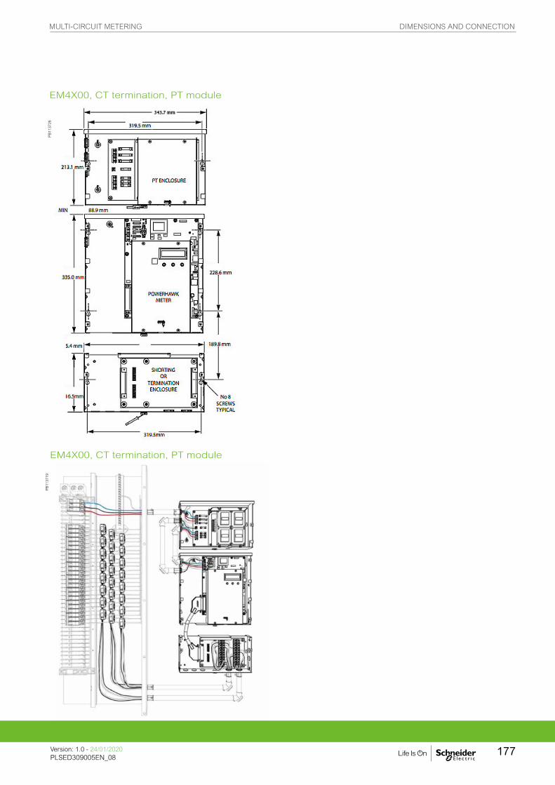
PB
1137
26P
B11
3719
EM4X00, CT termination, PT module
EM4X00, CT termination, PT module
MULTI-CIRCUIT METERING DIMENSIONS AND CONNECTION
Version: 1.0 - 24/01/2020PLSED309005EN_08
177
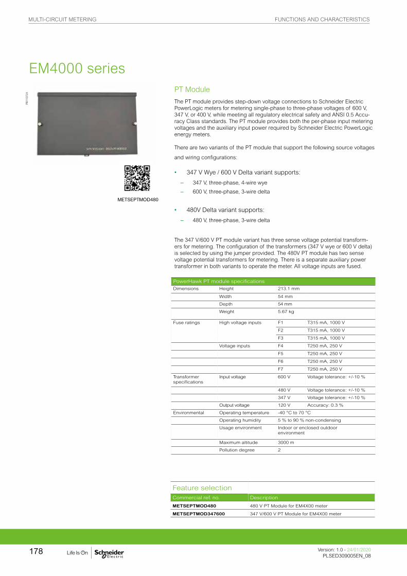
PT Module
The PT module provides step-down voltage connections to Schneider Electric PowerLogic meters for metering single-phase to three-phase voltages of 600 V, 347 V, or 400 V, while meeting all regulatory electrical safety and ANSI 0.5 Accu-racy Class standards. The PT module provides both the per-phase input metering voltages and the auxiliary input power required by Schneider Electric PowerLogic energy meters.
There are two variants of the PT module that support the following source voltages
and wiring configurations:
• 347 V Wye / 600 V Delta variant supports:
– 347 V, three-phase, 4-wire wye
– 600 V, three-phase, 3-wire delta
• 480V Delta variant supports:
– 480 V, three-phase, 3-wire delta
The 347 V/600 V PT module variant has three sense voltage potential transform-ers for metering. The configuration of the transformers (347 V wye or 600 V delta) is selected by using the jumper provided. The 480V PT module has two sense voltage potential transformers for metering. There is a separate auxiliary power transformer in both variants to operate the meter. All voltage inputs are fused.
PowerHawk PT module specifications
Dimensions Height 213.1 mm
Width 54 mm
Depth 54 mm
Weight 5.67 kg
Fuse ratings High voltage inputs F1 T315 mA, 1000 V
F2 T315 mA, 1000 V
F3 T315 mA, 1000 V
Voltage inputs F4 T250 mA, 250 V
F5 T250 mA, 250 V
F6 T250 mA, 250 V
F7 T250 mA, 250 V
Transformer specifications
Input voltage 600 V Voltage tolerance: +/-10 %
480 V Voltage tolerance: +/-10 %
347 V Voltage tolerance: +/-10 %
Output voltage 120 V Accuracy: 0.3 %
Environmental Operating temperature -40 °C to 70 °C
Operating humidity 5 % to 90 % non-condensing
Usage environment Indoor or enclosed outdoor environment
Maximum altitude 3000 m
Pollution degree 2
PB
1137
24
Feature selectionCommercial ref. no. Description
METSEPTMOD480 480 V PT Module for EM4X00 meter
METSEPTMOD347600 347 V/600 V PT Module for EM4X00 meter
EM4000 series
METSEPTMOD480
MULTI-CIRCUIT METERING FUNCTIONS AND CHARACTERISTICS
Version: 1.0 - 24/01/2020PLSED309005EN_08
178

PB
1137
25
CT Module
PowerLogic 4080 meters have two shorting options that provide a seamless and sealable mechanical package. The CT Shorting Module provides CT connections via the color coded 25 pair cable routed into the breaker panel. All CTs are shorted at the same time for safe removal of the meter for maintenance when the electrical circuits are still live.
The CT Termination Module has the same shorting ability, but provides CT con-nections via 24 2-position screw-down terminal blocks. Individual pairs are then routed from the CT Termination Module to 1 or more breaker panels via conduit knock outs provided on the module. Thus eliminating the need for a splitter box to route CT cables to multiple panels.
Commercial ref. no. Description
METSECTTERM CT Termination Module for EM4X00 meter
METSECTSHORT CT Shorting Module for EM4X00 meter
Commercial ref. no. Description
METSECONV580 5 A : 80 mA converter for EM4X00 meter
Converter
The 5 A:80 mA converter is useful in applications where there are existing 5 A CT’s integrated into large motors or switch gear. The 5 A:80 mA converter matches the 5 A secondary of the load to the 80 mA input of the meter. In Billing Grade applications, the 5 A:80 mA converter is also used to connect regulatory grade large aperture, large amperage CT’s with 5 A secondaries to the 80 mA of PowerLogic 4 X 80 meters.
PB
1137
29
PB
1110
56
The 5 A to 80 mA converter dimensions
See appropriate Installation Guide for this product.
EM4000 series
METSECONV580
PowerHawk PT module specifications
Dimensions Height 213.1 mm
Width 54 mm
Depth 54 mm
Weight 5.67 kg
Fuse ratings High voltage inputs F1 T315 mA, 1000 V
F2 T315 mA, 1000 V
F3 T315 mA, 1000 V
Voltage inputs F4 T250 mA, 250 V
F5 T250 mA, 250 V
F6 T250 mA, 250 V
F7 T250 mA, 250 V
Transformer specifications
Input voltage 600 V Voltage tolerance: +/-10 %
480 V Voltage tolerance: +/-10 %
347 V Voltage tolerance: +/-10 %
Output voltage 120 V Accuracy: 0.3 %
Environmental Operating temperature -40 °C to 70 °C
Operating humidity 5 % to 90 % non-condensing
Usage environment Indoor or enclosed outdoor environment
Maximum altitude 3000 m
Pollution degree 2
MULTI-CIRCUIT METERING FUNCTIONS AND CHARACTERISTICS
179Version: 1.0 - 24/01/2020PLSED309005EN_08Version: 1.0 - 24/01/2020PLSED309005EN_08

Legend:1 Source2 Energy flow3 Load4 X15 X2
CTs• Model 8 (80/100 mA Secondary)
• Window Size: 82.5 mm Diameters
• Application: Metering
• Frequency: 50- 400 Hz
• Insulation Level: 600 Volts, 10 Kv BIL Full Wave
• Flexible leads available for all case configurations. Flexible leads are UL 1015 105 ˚C, CSA approved #16 AWG, 609.6 mm long standard length. Non- standard lengths are available upon request.
• Terminals are brass studs No. 8-32 UNC with one flat washer, one lock washer and one nut each. Terminals are only available on the square case configuration.
• Mounting brackets kits for the Model 8SHT are available when required.
• Approximate weight: 1.36 kg
PB
1110
60
200 A CT dimensions
METSECT80600 600 A 80 mA CT
200 A CT
PB
1110
61
600 A 80 mA CT dimensions
PB
1110
59P
B11
1057
PB
1110
58
400 A CT 400 A CT dimensions
PB
1139
71
PB
1139
72
Feature selections
Commercial reference number
Description
METSECT80200
CT, solid core, 200 A primary, 80 mA secondary, for use with EM4X80 multi-circuit meter
METSECT80400
CT, solid core, 400 A primary, 80 mA secondary, for use with EM4X80 multi-circuit meter
METSECT80600
CT, solid core, 600 A primary, 80 mA secondary, for use with EM4X80 multi-circuit meter
EM4000 series
PB
1110
57
MULTI-CIRCUIT METERING DIMENSIONS AND CONNECTION
Version: 1.0 - 24/01/2020PLSED309005EN_08
180

The compact PowerLogic EM4800 series multi-circuit energy meter from Schneider Electric enables reliable metering of individual tenants with a low installation cost-per-point by combining revenue-accurate electricity sub-metering with advanced communications technology.The ideal fit for high-end cost management applications, providing the measurement capabilities needed to allocate energy usage, perform tenant metering and sub-billing, pin-point energy savings, optimise equipment efficiency and utilisation, and perform a high level assessment of the power quality in an electrical network.
EM4800 series
Applications
Capable of essential cost management:
• Multi-tenant metering
• Energy management
• Energy cost allocation
• Utility bill verification
PE
86325
METSEEM480525
MULTI-CIRCUIT METERING DIMENSIONS AND CONNECTION
Version: 1.0 - 24/01/2020PLSED309005EN_08
181

The solution for
Markets that can benefit from a solution that includes PowerLogic EM4800 series meters:
• Buildings
• Industry
• Healthcare
• Data Centre and networks
• Infrastructure
Power management solutions
Schneider Electric provides innovative power management solutions to increase your energy efficiency and cost savings, maximise electrical network reliability and availability, and optimise electrical asset performance.
Competitive advantages
• Compact, maintenance-free design
• Hi-density, flexible connection
• Direct connection
• Multiple CT types
• No rewiring required
• Integrated communications
Conformity of standards
• IEC61557-12
• IEC62053-22
• IEC62053-24
• IEC 61010-1
• IEC 61000-4-2
• IEC 61000-4-3
• IEC 61000-4-4
• IEC 61000-4-5
• IEC 61000-4-6
• IEC 61000-4-8
• Etc.
Benefits
System integrators’ benefit
• Ease of integration
• Ease of setup
• Cost effectiveness
Panel builders’ benefit
• Ease of installation
• Cost effectiveness
• Aesthetically pleasing
• Simplified ordering
End users’ benefit
• Ease of use
• Precision metering & sub-billing
• Billing flexibility
• Comprehensive, consistent and superior performance
MULTI-CIRCUIT METERING FUNCTIONS AND CHARACTERISTICS
Version: 1.0 - 24/01/2020PLSED309005EN_08
182
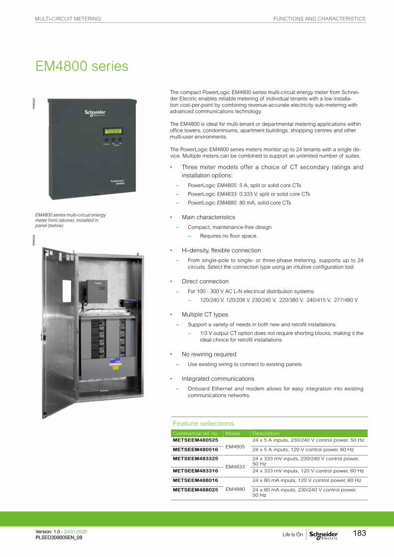
PE86
326
P
E863
25
EM4800 series multi-circuit energy meter front (above), installed in panel (below)
The compact PowerLogic EM4800 series multi-circuit energy meter from Schnei-der Electric enables reliable metering of individual tenants with a low installa-tion cost-per-point by combining revenue-accurate electricity sub-metering with advanced communications technology.
The EM4800 is ideal for multi-tenant or departmental metering applications within office towers, condominiums, apartment buildings, shopping centres and other multi-user environments.
The PowerLogic EM4800 series meters monitor up to 24 tenants with a single de-vice. Multiple meters can be combined to support an unlimited number of suites.
• Three meter models offer a choice of CT secondary ratings and installation options:
– PowerLogic EM4805: 5 A, split or solid core CTs
– PowerLogic EM4833: 0.333 V, split or solid core CTs
– PowerLogic EM4880: 80 mA, solid core CTs
• Main characteristics
– Compact, maintenance-free design
– Requires no floor space.
• Hi-density, flexible connection
– From single-pole to single- or three-phase metering, supports up to 24 circuits. Select the connection type using an intuitive configuration tool.
• Direct connection
– For 100 - 300 V AC L-N electrical distribution systems:
– 120/240 V, 120/208 V, 230/240 V, 220/380 V, 240/415 V, 277/480 V
• Multiple CT types
– Support a variety of needs in both new and retrofit installations.
– 1/3 V output CT option does not require shorting blocks, making it the ideal choice for retrofit installations.
• No rewiring required
– Use existing wiring to connect to existing panels.
• Integrated communications
– Onboard Ethernet and modem allows for easy integration into existing communications networks.
Feature selectionsCommercial ref. no. Model DescriptionMETSEEM480525
EM480524 x 5 A inputs, 230/240 V control power, 50 Hz
METSEEM480516 24 x 5 A inputs, 120 V control power, 60 Hz
METSEEM483325
EM4833
24 x 333 mV inputs, 230/240 V control power, 50 Hz
METSEEM483316 24 x 333 mV inputs, 120 V control power, 60 Hz
METSEEM488016
EM4880
24 x 80 mA inputs, 120 V control power, 60 Hz
METSEEM488025 24 x 80 mA inputs, 230/240 V control power, 50 Hz
EM4800 series
MULTI-CIRCUIT METERING FUNCTIONS AND CHARACTERISTICS
183Version: 1.0 - 24/01/2020PLSED309005EN_08Version: 1.0 - 24/01/2020PLSED309005EN_08

Selection guide
PE86
327A
PowerLogic EM4800 series digital panel meter.
EM4805 EM4833 EM4880
General
Use on LV systems b b bAccuracy +/- 0.5 % b b bAccuracy compliance ANSI C12.1 and C12.20 Class
0.5; IEC 62053-22, Class 0.5S
b b b
Maximum circuits: single-pole / single phase / three-phase
24 / 12 / 8
b b b
Instantaneous rms values
Energy Real, kWh received/delivered b b bReactive, kvarh received/delivered b b b
Apparent, VAh b b bVoltage b b bPulse counts b b bVoltage and current V rms, I rms per phase b b bPower Real, reactive, apparent b b bPower factor b b bMeasurements available for data logging
Energy Real, kWh received/delivered b b bReactive, kvarh received/delivered b b b
Apparent, VAh b b bVoltage b b bDisplayBacklit LCD display 2 lines of 16 characters b b bOptional remote modular display available b b bCommunicationEthernet port b b bV.90 modem port b b bPulse inputs 2 b b bProtocols: Modbus TCP/IP, HTTP, BACnet/IP, FTP, and SNTP b b b Installation options5 A CTs b0.333 V CTs b80 mA CTs bSplit-core CT b bSolid core CT b b bRemote modular display b b b
EM4800 series
MULTI-CIRCUIT METERING FUNCTIONS AND CHARACTERISTICS
Version: 1.0 - 24/01/2020PLSED309005EN_08
184

Electrical characteristicsInput-voltage characteristics
Inputs V1, V2, V3, Vn
Measured voltage 80 - 480 V AC L-L without PTsUp to 999 kV with external PTs
Frequency range 50/60 Hz
Mechanical characteristics
Weight EM4805 approx. 5.4 kg
EM4833/EM4880 approx. 4.0 kg
Dimensions EM4805 335 x 44 x 55 mm
EM4833 / EM4880 335 x 305 x 55 mm
Environmental conditions
Operating temperature -40 °C to 70 °C
Storage temperature -40 °C to 70 °C
Humidity rating 0 % to 90 % RH non-condensing
Enclosure Type 1 (indoor or enclosed outdoor use)
Altitude 3000 m
Pollution degree 2
Safety and standards
UL Certified to IEC/EA/CSA 61010-1
CSA-C22.2 No 61010-1-04
FCC Part 15 Class B
ICES-003 EN55022, IEC 6100-4-5
ANSI/TIA968-A: 2002
Communication
Ports Ethernet
V.90 modem
Pulse inputs 2
Protocols: Modbus TCP/IP, HTTP, BACnet/IP, FTP, and SNTP
Display characteristics
Integrated backlit LCD display 2 ines, 16 digits per line display; R / L arrow buttons select metering point; Display button cycles through measurements per point.
EM4800 series
MULTI-CIRCUIT METERING FUNCTIONS AND CHARACTERISTICS
185Version: 1.0 - 24/01/2020PLSED309005EN_08Version: 1.0 - 24/01/2020PLSED309005EN_08
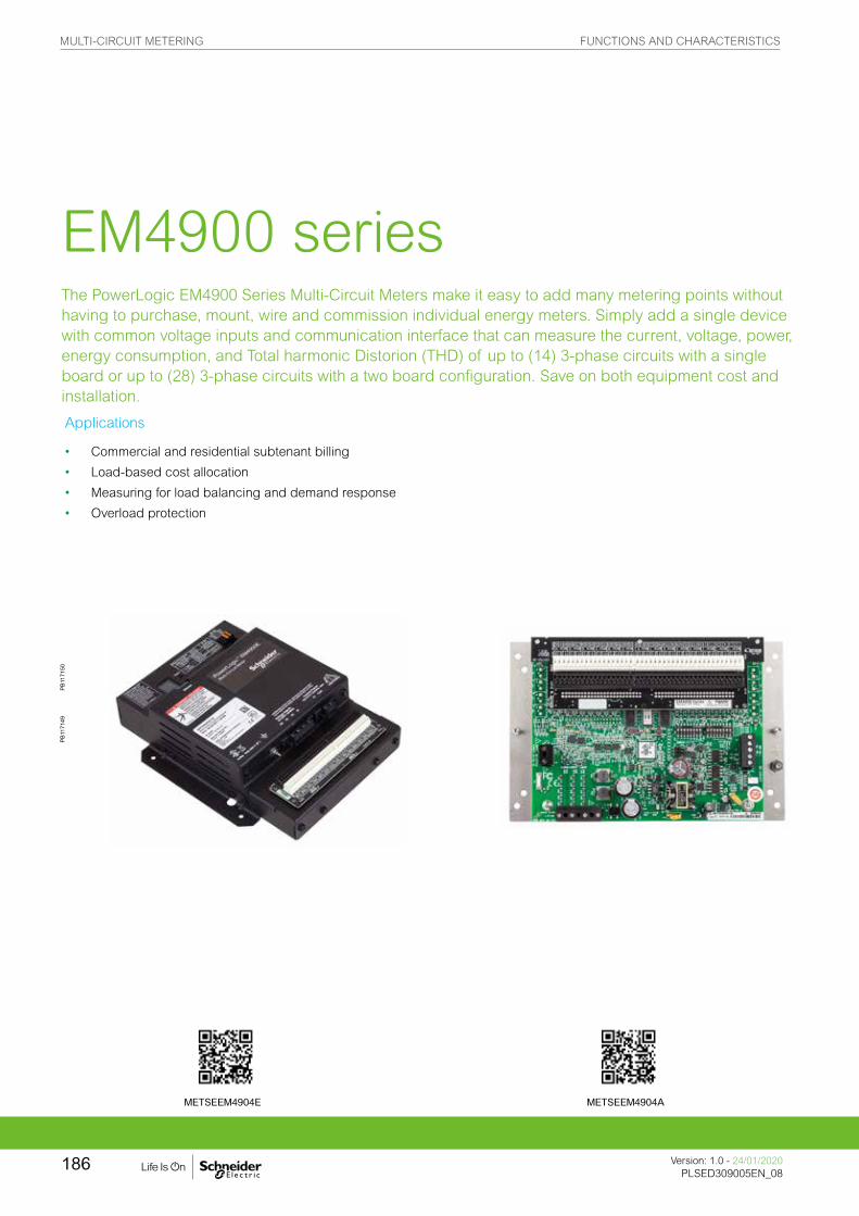
The PowerLogic EM4900 Series Multi-Circuit Meters make it easy to add many metering points without having to purchase, mount, wire and commission individual energy meters. Simply add a single device with common voltage inputs and communication interface that can measure the current, voltage, power, energy consumption, and Total harmonic Distorion (THD) of up to (14) 3-phase circuits with a single board or up to (28) 3-phase circuits with a two board configuration. Save on both equipment cost and installation.
EM4900 series
Applications
• Commercial and residential subtenant billing
• Load-based cost allocation
• Measuring for load balancing and demand response
• Overload protection
PB11
7150
PB11
7149
METSEEM4904E METSEEM4904A
MULTI-CIRCUIT METERING FUNCTIONS AND CHARACTERISTICS
Version: 1.0 - 24/01/2020PLSED309005EN_08
186

The solution for
Markets that can benefit from a solution that includes PowerLogic EM4900 series meters:
• Buildings
• Industry
• Healthcare
• Hotels, Multi-Dweller Units (condos)
Power management solutions
Schneider Electric provides innovative power management solutions to increase your energy efficiency and cost savings, maximise electrical network reliability and availability, and optimise electrical asset performance.
Competitive advantages
• Lower cost and space per metering point
• Adapts to any mix of metering needs (1ph, 2ph, 3ph with or without Neutral wire)
• Class 0.5 accuracy for Revenue Grade measurement
• THD monitoring to help identify problem loads and early wear and tear
• Capable of concurrent communication to software packages, including PowerLogic software packages and third party systems
Conformity of standardsBenefits
System integrators’ benefit
• Ease of integration
• Ease of setup
• Cost effectiveness
Panel builders’ benefit
• Ease of installation
• Cost effectiveness
• Aesthetically pleasing
• Simplified ordering
End users’ benefit
• Ease of use
• Precision metering & sub-billing
• Billing flexibility
• Comprehensive, consistent and superior performance
• EN 61000-6-3 Class B - Part 6-3
• EN 61000-6-3 Class B - Part 6-3
• EN 61000-6-4 Class A - Part 6
• EN 61010-1 - Part 1
• EN 61326-1 Class A - Part 1
• EN 61326-1 Class B - Part 1
• IEC 62053-22 Class 0.5 - Part 21
• FCC 47 CFR Part 15 Class A & Class B
• UL 508 Open Device Type
• IEC 61010-1 - Part 1
MULTI-CIRCUIT METERING FUNCTIONS AND CHARACTERISTICS
187Version: 1.0 - 24/01/2020PLSED309005EN_08Version: 1.0 - 24/01/2020PLSED309005EN_08

28 Meter adapter board (EM4928A and EM4928E)
PowerLogic™ EM4914E
PB11
7151
To aid in commissioning, a configuration software tool, an Ethernet discovery tool (for the EM49xxE) and a User Guide are available online at www.schneider-electric.com.
• Main characteristics
– Add lots of metering points without lots of cost
– Add up to 28 3-phase meters by installing a single product small enough to fit inside many distribution panels. Save on both equipment cost and installation cost. Common voltage and communication connections and color-coded push-in CT connections save installation time and effort.
– Class 0.5 accuracy for Revenue Grade measurements
– Power and Energy measurements with ANSI and IEC class 0.5 accuracy provide the accuracy needed for tenant billing applications. Voltage and current measurement accuracy is 0.5 % and currents are measured down to 0.1% of the CT range. Easily differentiate between the flow of low current and a trip or load disconnect where no current flows.
– Total Harmonics Distorion measurements
– Helps assess basic power quality to reduce risks to the load and provide indication of potential early wear and tear of the electrical network and its load.
– Common CTs, 1/3V outputs
– CTs with low-voltage outputs eliminate the need for shorting blocks that add cost and labor to the installation. They also allow long CT lead extensions without compromising accuracy. Choose from a range of our CT styles and sizes or use any CTs with industry-standard 0.333V outputs.
– Models with integrated Ethernet offer broad protocol support
– All models integrate easily into existing networks using Modbus RTU communications over an RS-485 serial link. EM49xxE models offer integrated Ethernet and add support for Modbus TCP, BACnet IP, BACnet MS/TP and SNMP. Those Ethernet protocols can be run in parallel allowing multiple software to access the device (Building Management System, Energy Management System, etc.) An optional external gateway can be added to EM49xxA models to offer the same capability.
– Compatible with PowerLogic power monitoring software
– Easily turn the large amount of data collected by the devices into useful decision making information.
– Configure the meters you want
– Choose 4, 8, 14 or 28 3-phase meters. User-configurable to any combination of 1-, 2-, 3-phase meters. Reconfigure channels as needed to monitor neutral current.
PowerLogic™ EM4914A
PB11
7153
PB11
7149
EM4900 series
MULTI-CIRCUIT METERING FUNCTIONS AND CHARACTERISTICS
Version: 1.0 - 24/01/2020PLSED309005EN_08
188

Measurements
Measurement voltage 90 t0 300 V AC L-N, 50/60 Hz
Total Harmonic Distortion (THD) THD % voltage L-L, L-N and THD % on current
Control power
EM49xxA 90 to 277 V AC L-N, 50/60 Hz
EM49xxE 100 to 277 V AC L-N, 50/60 Hz
Accuracy
Power/Energy IEC 62053-21 Class 0.5, ANSI C12.20 class 0.5
Voltage ±0.5% of reading 90 to 277 V L-N
Current ±0.5% of reading from 2% to 100% of full-scale
Operation
Sampling frequency 2560 Hz
Update rate 1.8 seconds (both panels)
Overload capability 22 kAIC
EM49xxA serial communication
Type Modbus RTU
Connection DIP switch-selectable 2-wire or 4-wire, RS-485
Address DIP switch-selectable address 1 to 247 (in pairs of 2) (See Installation Guide)
Baud rate DIP switch-selectable 9600, 19200, 38400
Parity DIP switch-selectable NONE, ODD, EVEN
Communication format 8 data bits, 1 start bit, 1 stop bit
Termination 5-position plug-in connector (TX+ TX- SHIELD TX+/RX+ TX-/RX-)
EM49xxE serial communication
Physical Interface 2-wire RS-485
Serial protocols supported Modbus RTU or BACnet MS/TP
Address range 1 to 247 for Modbus RTU; 0 to 127 for BACnet MS/TP
Baud rate 9600, 19200, 38400
Parity Modbus RTU: NONE, ODD, EVEN BACnet MS/TP: NONE (fixed)
Communication format 8 data bits, 1 start bit, 1 stop bit
Termination 2x3 position connector
EM49xxE Ethernet communication
Physical interface Protocols Supported
Protocols supported Modbus TCP, BACnet IP, SNMP V2c
Wire size range
Removable connectors on main board 24 to 12 AWG
CT Terminals and EM49xxE serial connector terminals 26 to 16 AWG
Terminal block torque
Removable connectors 0.5 to 0.6 N-m
Mechanical
Ribbon cable support (28-meter models only) 0.9 m round ribbon cable ships standard; up to 6 m flat or round available
Operating conditions
Operating temperature range 0 to 60 °C (<95% RH non-condensing)
Storage temperature range -40 to 70 °C
Altitude of operation 3000 m
Mounting location Not suitable for wet locations. For indoor use only.
Compliance information
Agency approvals UL 508 open type device+1, IEC/EN 61010-1
Installation category Cat III, pollution degree 2+2
Conducted emissions EM49xxA Models: FCC part 15 Class B, EN 61000-6-3, EN 61326-1 Class B (residential & light
Radiated emissions EM49xxE Models: FCC part 15 Class A, EN 6100-6-4, EN 61326-1 Class A
Conducted and radiated immunity EN 61000-6-2 and EN 61326-1
EM4900 series specifications
+1Install EM49xx in apprpropriate fire enclosure; if used with circuits higher than product ratings, circuits must be segregated per UL 508A Sec 17.5 (EM49xx internal circuitry are not circuits as defined by UL 508A).+2 A Pollution Degree 2 environment must control conductive pollution and the possibility of condensation or high humidity. Consideration must be given to the enclosure, the correct use of ventilation, thermal properties of the equipment and the relationship with the environment.
MULTI-CIRCUIT METERING FUNCTIONS AND CHARACTERISTICS
189Version: 1.0 - 24/01/2020PLSED309005EN_08Version: 1.0 - 24/01/2020PLSED309005EN_08
1/3 V low-voltage CT (LVCT) Electrical characteristics
Accuracy 1 % from 10 % to 100 % of rated current(LVCT0xxxx0S/1S/2S/3S/4S [split-core])0.5 % from 5 % to 100 % of rated current (LVCT2xxxx0S/2S/3S [solid core])
Frequency range 50/60 Hz
Leads 18 AWG, 600 V AC, 1.8 m standard length
Max. voltage L-N sensed conductor 300 V AC (LVCT0xxxx0S)600 V AC (LVCT0xxxx1S/2S/3S/4S, LVCT2xxxxxS)
Measurements
Real time measurements Current: multi-phase average and per phaseCurrent phase angle per branchReal power (kW): multi-phase total and per phaseApparent power (kVA): multi-phase total and per phasePower factor: multi-phase average and per phase
Demand measurements Current present demand: multi-phase average and per phaseReal power (kW) present demand: multi-phase average and per phase
Historic maximums Maximum instantaneous current: multi-phase average and per phaseMaximum current demand: multi-phase average and per phaseMaximum real power demand: multi-phase total and per phase
Accumulate energy Energy (kWh): multi-phase total and per phase
Energy snapshots Energy (kWh): multi-phase total and per phase
EM4900 series
MULTI-CIRCUIT METERING FUNCTIONS AND CHARACTERISTICS
Version: 1.0 - 24/01/2020PLSED309005EN_08
190

EM4900 series part numbers - BCPM with solid core CTs
Item Code Description
1 Model METSEEM49 Multi-Circuit Meter
2 Number of 3-phase Meters
04 Up to (4) 3-phase Meters (see table for variations)
08 Up to (8) 3-phase Meters (see table for variations)
14 Up to (14) 3-phase Meters (see table for variations)
28 Up to (28) 3-phase Meters (see table for variations)
3 Communication Interfaces & Protocols
A RS-485 Serial with Modbus RTU (add E8951 for other protocols)
E Ethernet with Modbus TCP, BACnet IP and SNMP protocols and RS-485 Serial with Modbus RTU or BACnet IP
PB11
7150
PB11
7149
PB11
7151
1 2 3
METSEEM49 14 E
1 Model.2 Number of 3-phase meters (without neutral current)3 Communication interfaces & protocols.
EM49xxA Main Board
EM49xxE Main Unit
CT Adapter Assembly (28-Meter models only)
Number of meters supported:EM4900 models are all factory-configured as all 3-phase meters (w/o neutral). They can be easily re-configured to any combination of 1-ph, 2-ph or 3-ph meters (with ION Setup). Any unused channels can be used to measure neutral current. Label overlays (to re-number CT connections) are provided for 1-ph/2-ph applications.
Number of metersCommercial ref. no. “E” - Integrated
Ethernet3-phase 2-phase 1-phase
METSEEM4904A METSEEM4904E 4 6 12
METSEEM4908A METSEEM4908E 8 12 24
METSEEM4914A METSEEM4914E 14 21 42
METSEEM4928A METSEEM4928E 28 42 84
Commercial ref. no. EM4900 multi-circuit meters
METSEEM4904A Multi-Circuit Meter – (4) 3-phase meters - Modbus RTU only
METSEEM4908A Multi-Circuit Meter – (8) 3-phase meters - Modbus RTU only
METSEEM4914A Multi-Circuit Meter – (14) 3-phase meters - Modbus RTU only
METSEEM4928A Multi-Circuit Meter – (28) 3-phase meters - Modbus RTU only
METSEEM4904E Multi-Circuit Meter – (4) 3-phase meters - Ethernet and Serial (Modbus, BACnet & SNMP)
METSEEM4908E Multi-Circuit Meter – (8) 3-phase meters - Ethernet and Serial (Modbus, BACnet & SNMP)
METSEEM4914E Multi-Circuit Meter – (14) 3-phase meters - Ethernet and Serial (Modbus, BACnet & SNMP)
METSEEM4928E Multi-Circuit Meter – (28) 3-phase meters - Ethernet and Serial (Modbus, BACnet & SNMP)
EM4900 series
MULTI-CIRCUIT METERING FUNCTIONS AND CHARACTERISTICS
191Version: 1.0 - 24/01/2020PLSED309005EN_08Version: 1.0 - 24/01/2020PLSED309005EN_08

PE86
284
PB11
7152
PE86
183
PB11
3652
PB11
3657
PB11
3658
Flat ribbon cable
Round ribbon cable
PowerLogic™ LVCT0xxxxS split-core Low-voltage (1/3V) CTs are ideal for retrofit applications
PowerLogic™ LVCT2xxxxS Low-voltage (1/3V) solid core CTs are ideal for panel builders (small, medium, large)
EM4900 series accessoriesCommercial reference number
Description
BCPMCOVERS EM4900 circuit board cover
E8951 Modbus to BACnet protocol converter
Ribbon cables for 28-meter models
1.22 m cables are standard – others must be ordered separately
CBL008 Flat Ribbon cable (quantity 1) for BCPM, length = 0.45 m
CBL016 Flat Ribbon cable (quantity 1) for BCPM, length = 1.2 m
CBL017 Flat Ribbon cable (quantity 1) for BCPM, length = 1.5 m
CBL018 Flat Ribbon cable (quantity 1) for BCPM, length = 1.8 m
CBL019 Flat Ribbon cable (quantity 1) for BCPM, length = 2.4 m
CBL020 Flat Ribbon cable (quantity 1) for BCPM, length = 3.0 m
CBL021 Flat Ribbon cable (quantity 1) for BCPM, length = 6.1 m
CBL022 Round Ribbon cable (quantity 1) for BCPM, length = 1.2 m
CBL023 Round Ribbon cable (quantity 1) for BCPM, length = 3 m
CBL024 Round Ribbon cable (quantity 1) for BCPM, length = 6.1 m
CBL031 Round Ribbon cable (quantity 1) for BCPM, length = 0.5 m
CBL033 Round Ribbon cable (quantity 1) for BCPM, length = 0.8 m
1/3 V low-voltage Split-core CTsCommercial reference number
Amperage rating Inside dimensions
LVCT00050S 50 A 10 x 11 mm
LVCT00101S 100 A 16 x 20 mm
LVCT00201S 200 A 32 x 32 mm
LVCT00102S 100 A 30 x 31 mm
LVCT00202S 200 A 30 x 31 mm
LVCT00302S 300 A 30 x 31 mm
LVCT00403S 400 A 62 x 73 mm
LVCT00603S 600 A 62 x 73 mm
LVCT00803S 800 A 62 x 73 mm
LVCT00804S 800 A 62 x 139 mm
LVCT01004S 1000 A 62 x 139 mm
LVCT01204S 1200 A 62 x 139 mm
LVCT01604S 1600 A 62 x 139 mm
LVCT02004S 2000 A 62 x 139 mm
LVCT02404S 2400 A 62 x 139 mm
1/3 V low-voltage Solid core CTsCommercial reference number
Amperage rating Inside dimensions
LVCT20050S 50 A 10 mm
LVCT20100S 100 A 10 mm
LVCT20202S 200 A 25 mm
LVCT20403S 400 A 31 mm
EM4900 series
LVCT20050S
LVCT00050S
CBL022
CBL008
MULTI-CIRCUIT METERING FUNCTIONS AND CHARACTERISTICS
Version: 1.0 - 24/01/2020PLSED309005EN_08
192

PB11
7144
_m
mm
EM49xxA main board dimensions
28-Meter CT adapter assembly dimensions
EM4900 series
PB11
9356
_m
PE86
169_
m
MULTI-CIRCUIT METERING DIMENSIONS AND CONNECTION
Version: 1.0 - 24/01/2020PLSED309005EN_08
193

PB11
3660
PB11
3659
50 A-200 A Split-core CT dimensions
Solid core CT dimensions
1/3 V low-voltage CT form factor
Small form factor100/200/300 A
Medium form factor400/600/800 A
Large form factor800/1000/1200/
1600/2000/2400 A
A = 96 mm A = 125 mm A = 125 mm
B = 30 mm B = 73 mm B = 139 mm
C = 31 mm C = 62 mm C = 62 mm
D = 30 mm D = 30 mm D = 30 mm
E = 100 mm E = 132 mm E = 201 mm
F = 121 mm F = 151 mm F = 151 mm
Split-core CT dimensions - see table.
PB11
3663
Model L A B C D ELVCT20050S
1.8 m 33 mm 38 mm 18 mm 21 mm 10 mmLVCT20100S
LVCT20202S 1.8 m 59 mm 66 mm 18 mm 31 mm 25 mm
LVCT20403S 1.8 m 70 mm 82 mm 25 mm 36 mm 31 mm
EM4900 series
CT rating A B C D E
50 A 26 mm 11 mm 10 mm 23 mm 40 mm
100 A 28 mm 16 mm 16 mm 40 mm 52 mm
200 A 37 mm 32 mm 32 mm 62 mm 69 mm
MULTI-CIRCUIT METERING DIMENSIONS AND CONNECTION
Version: 1.0 - 24/01/2020PLSED309005EN_08
194

The advantages of using retrofit products throughout your power monitoring
system are numerous and proven. Whether you install these products as part of
an upgrade or as add-on modules in a new build environment, ease of installation
and commissioning will reap huge economic benefits. The PowerLogic range is
designed to retrofit existing switchboards and enhance the energy efficiency of
buildings for many years.
These products are:
• • Easy and cost-effective to install
• • Able to collect a broad scop of electrical data
• • Able to utilize a variety of meters to measure WAGES (Water, Air, Gas, Electricity, Steam) usage
• • Transmit all data to a centralized data concentrator for detailed analysis
Retrofit Products
PB
1054
31P
B11
5451
METSEEM4235METSEEM3502
RETROFIT PRODUCTS FUNCTIONS AND CHARACTERISTICS
195Version: 1.0 - 24/01/2020PLSED309005EN_09Version: 1.0 - 24/01/2020PLSED309005EN_09
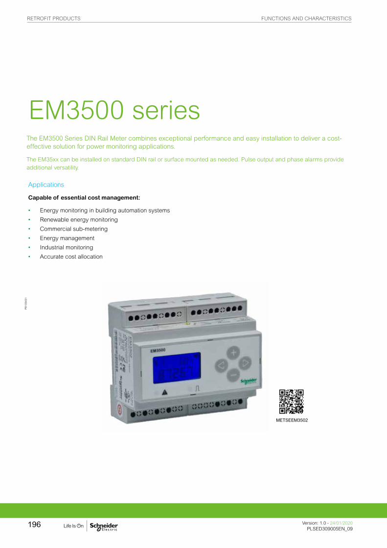
PB
1054
31
The EM3500 Series DIN Rail Meter combines exceptional performance and easy installation to deliver a cost-effective solution for power monitoring applications.
The EM35xx can be installed on standard DIN rail or surface mounted as needed. Pulse output and phase alarms provide additional versatility.
EM3500 series
Applications
Capable of essential cost management:
• Energy monitoring in building automation systems
• Renewable energy monitoring
• Commercial sub-metering
• Energy management
• Industrial monitoring
• Accurate cost allocation
METSEEM3502
RETROFIT PRODUCTS FUNCTIONS AND CHARACTERISTICS
Version: 1.0 - 24/01/2020PLSED309005EN_09
196

The solution for
Markets that can benefit from a solution that includes PowerLogic EM3500 series meters:
• Buildings
• Industry
• Healthcare
• Data Centre and networks
• Infrastructure
Power management solutions
Schneider Electric provides innovative power management solutions to increase your energy efficiency and cost savings, maximise electrical network reliability and availability, and optimise electrical asset performance.
Competitive advantages
• DIN rail mounting option; easy installation
• Real energy output and phase loss alarm output
• 90-600 V AC; application versatility with fewer models to stock
• Bright backlit LCD; easy visibility in dark enclosures
• Data logging capability safeguard during power failures
• EM35xx models compatible with LVCTs from 5 A to 32000 A
• User-enabled password protection prevents tampering
• Native BACnet MS/TP support (no gateway)
Conformity of standards
• IEC 61557-12
• IEC 62053-22
• IEC 62053-24
• IEC 61010-1
• IEC 61000-4-2
• IEC 61000-4-3
• IEC 61000-4-4
• IEC 61000-4-5
• IEC 61000-4-6
• IEC 61000-4-8
• Etc.
Benefits
System integrators’ benefit
• Ease of integration
• Ease of setup
• Cost effectiveness
Panel builders’ benefit
• Ease of installation
• Cost effectiveness
• Aesthetically pleasing
• Simplified ordering
End users’ benefit
• Ease of use
• Precision metering & sub-billing
• Billing flexibility
• Comprehensive, consistent and superior performance
RETROFIT PRODUCTS FUNCTIONS AND CHARACTERISTICS
197Version: 1.0 - 24/01/2020PLSED309005EN_09Version: 1.0 - 24/01/2020PLSED309005EN_09

PB
1054
31
PowerLogic™ EM3500
PB
1137
27P
B11
3728
EM3500 parts and connection terminals
EM3502/EM355x parts and connection terminals
The data logging capability (EM3555 and EM3560) protects data in the event of a power failure. Modbus, pulse output, and phase alarms are all provided to suit a wide variety of applications. Additional pulse inputs on EM3560 provide an easy way to incorporate simple flow sensors to track gas, water, steam, or other energy forms us-ing a BACnet system in addition to full monitoring of electrical energy.
EM35xxA (Pulse, Modbus, BACnet) models designed for use exclusively with Rogowski coil CTs where integrator and power supply for the CTs are built into the meter, resulting in fewer devices to purchase and faster to install. (Not recommended for high harmonic applications.)
The EM3555 models adds a bi-directional monitoring feature designed expressly for renewable energy applications, allowing measurement of power imported from the utility grid as well as power exported from the renewable energy source (e.g. solar panels). In this way, a facility administrator track all energy data, ensuring accuracy in billing and crediting.
• Features
– All Models: A compact solution for panelboard monitoring
– DIN rail mounting option; easy installation
– ANSI 12.20 0.2% accuracy, IEC 62053-22 Class 0.2S for all 35xx models; great for cost allocation
– ANSI C12.20 0.5% accuracy, IEC 62053-22 Class 0.5S for EM35xxA models
– Real energy output and phase loss alarm output on EM3502(A), EM3550(A), and EM3555 models; one device serves multiple applications
– 90-600 VAC; application versatility with fewer models to stock
– Bright backlit LCD; easy visibility in dark enclosures
– Data logging capability EM3555 & EM3560(A); safeguard during power failures
– EM35xx models compatible with LVCTs from 5 A to 32000 A; wide range of service types
– User-enabled password protection; prevents tampering
– EM35xxA models are designed to work exclusively with Rogowski coil CTs 20-5000 A range. Eliminate site walks, save time and money. (Not recommended in high harmonic applications.)
– System integration via Modbus EM355xx(A) or BACnet MS/TP EM356xx(A); convenient compatibility with existing systems
– Native BACnet MS/TP support (no gateway) with serial rates up to 115.2 kbaud EM3560, EM3561, EM3560A, & EM3561A
– EM3555 Models: An essential solution for Solar and other renewable energy applications
– Bi-directional metering (4-quadrant); allows net metering
– Data logging capability; ensures long term data retrieval
– CSI approved
EM3500 series
RETROFIT PRODUCTS FUNCTIONS AND CHARACTERISTICS
Version: 1.0 - 24/01/2020PLSED309005EN_09
198
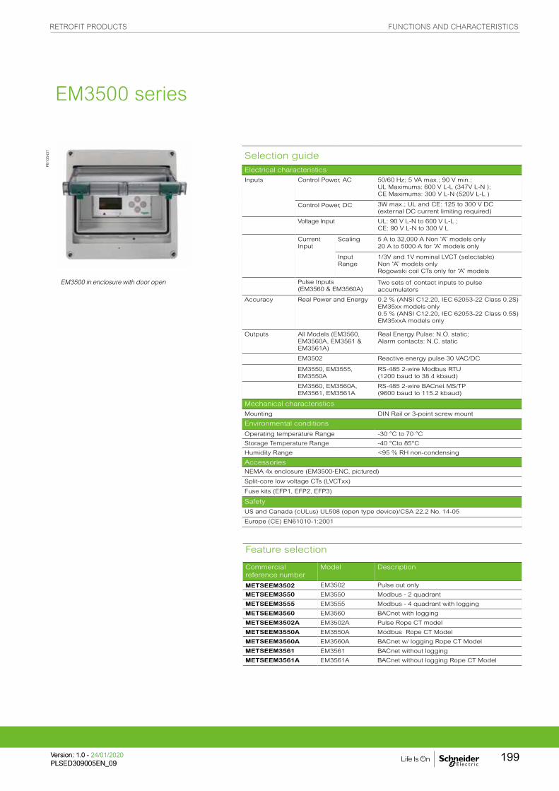
Feature selection
Commercial reference number
Model Description
METSEEM3502 EM3502 Pulse out only
METSEEM3550 EM3550 Modbus - 2 quadrant
METSEEM3555 EM3555 Modbus - 4 quadrant with logging
METSEEM3560 EM3560 BACnet with logging
METSEEM3502A EM3502A Pulse Rope CT model
METSEEM3550A EM3550A Modbus Rope CT Model
METSEEM3560A EM3560A BACnet w/ logging Rope CT Model
METSEEM3561 EM3561 BACnet without logging
METSEEM3561A EM3561A BACnet without logging Rope CT Model
Selection guideElectrical characteristics
Inputs Control Power, AC 50/60 Hz; 5 VA max.; 90 V min.; UL Maximums: 600 V L-L (347V L-N ); CE Maximums: 300 V L-N (520V L-L )
Control Power, DC 3W max.; UL and CE: 125 to 300 V DC (external DC current limiting required)
Voltage Input UL: 90 V L-N to 600 V L-L ; CE: 90 V L-N to 300 V L
Current Input
Scaling 5 A to 32,000 A Non “A” models only20 A to 5000 A for “A” models only
Input Range
1/3V and 1V nominal LVCT (selectable)Non “A” models onlyRogowski coil CTs only for “A” models
Pulse Inputs (EM3560 & EM3560A)
Two sets of contact inputs to pulse accumulators
Accuracy Real Power and Energy 0.2 % (ANSI C12.20, IEC 62053-22 Class 0.2S) EM35xx models only0.5 % (ANSI C12.20, IEC 62053-22 Class 0.5S)EM35xxA models only
Outputs All Models (EM3560, EM3560A, EM3561 & EM3561A)
Real Energy Pulse: N.O. static; Alarm contacts: N.C. static
EM3502 Reactive energy pulse 30 VAC/DC
EM3550, EM3555, EM3550A
RS-485 2-wire Modbus RTU (1200 baud to 38.4 kbaud)
EM3560, EM3560A, EM3561, EM3561A
RS-485 2-wire BACnet MS/TP (9600 baud to 115.2 kbaud)
Mechanical characteristics
Mounting DIN Rail or 3-point screw mount
Environmental conditions
Operating temperature Range -30 °C to 70 °C
Storage Temperature Range -40 °Cto 85°C
Humidity Range <95 % RH non-condensing
Accessories NEMA 4x enclosure (EM3500-ENC, pictured)
Split-core low voltage CTs (LVCTxx)
Fuse kits (EFP1, EFP2, EFP3)
Safety
US and Canada (cULus) UL508 (open type device)/CSA 22.2 No. 14-05
Europe (CE) EN61010-1:2001
PB
1054
37
EM3500 in enclosure with door open
EM3500 series
RETROFIT PRODUCTS FUNCTIONS AND CHARACTERISTICS
199Version: 1.0 - 24/01/2020PLSED309005EN_09Version: 1.0 - 24/01/2020PLSED309005EN_09

EM3500 dimensions
PB
1054
20
EM3500 connections
PB
1054
17
Screen Name or Units
Diagnostic Alert
Numeric Data
Alive Indicator
Export
Import
Transmit Data
Receive Data
Receive Data Error
PB
1054
36
EM3500 series
EM
35
02
EM
35
50
EM
35
60
EM
35
61
EM
35
55
EM
35
02
A
EM
35
50
A
EM
35
60
A
EM
35
61
A
Measurement Capability, Full Data Set
Bi-directional Energy Measurements b
Power (3-phase total and per phase): Real (kW) Reactive (kVAR), and Apparent (kVA) b b b b b b b b b
Power Factor: 3-phase average & per phase b b b b b b b b b
Present Power Demand: Real (kW), Reactive (kVAR), and Apparent (kVA) b b b b b b b b b
Import and Export totals of Present Power Demand: Real (kW), Reactive (kVAR), & Apparent (kVA) b
Peak Power Demand: Real (kW), Reactive (kVAR), and Apparent (kVA) b b b b b b b b b
Current (3-phase average and per phase) b b b b b b b b b
Voltage: Line-Line and Line-Neutral (3-phase average and per phase) b b b b b b b b b
Frequency b b b b b b b b b
ANSI C12.20 0.5 % accuracy, IEC 62053-22 Class 0.5S b b b b
ANSI C12.20 0.2 % accuracy, IEC 62053-22 Class 0.2S b b b b b
Accumulated Net Energy: Real (kWh), Reactive (kVARh), and Apparent (kVAh) b b b b b b b b b
Accumulated Real Energy by phase (kWh) b b b b b b b b b
Import and Export Accumulators of Real and Apparent Energy b
Reactive Energy Accumulators by Quadrant (3-phase total & per phase) b
Demand Interval Configuration: Fixed or Rolling Block b b b b b b b b b
Demand Interval Configuration: External Sync to Comms b b b b b b b
Data Logging (Store up to 60 days at 15-minute interval)
Data Logging: 10 16-Bit Configurable (can include Date/Time) Data Buffers b
Data Logging: 3 Timestamped 32-Bit Configurable Data Buffers b b
Outputs
Alarm Output (N.C.) b b b b b b b
1 Pulse Output (N.O.) b b b
2 Pulse Outputs (N.O.) b b
RS-485 Serial (Modbus RTU Protocol) b b b
RS-485 Serial (BACnet MS/TP Protocol) b b b b
LON FT Serial (LonTalk Protocol)
Inputs
2 Pulse Contact Accumulator Inputs b b
1 Pulse Contact Accumulator Input b b
Display Screen Diagram
EM3500 series
RETROFIT PRODUCTS FUNCTIONS AND CHARACTERISTICS
Version: 1.0 - 24/01/2020PLSED309005EN_09
200

EM3500 dimensions
PB
1054
20
EM3500 connections
PB
1054
17
Two 5-character rows of display text.Top row alphanumeric;Bottom row numeric only
The red Alarm LED lights when any of the 3 phase voltages drop below the selected threshold.
The green Energy LED lights momentarily each time the Energy output pulse is active.
Please see EM3500 User Guide and EM3500 Installation Guide for safe and correct wiring and connection information.
Bottom View (DIN Mount Option)
PB
1054
39
PB
1054
21
EM3500 series
RETROFIT PRODUCTS DIMENSIONS AND CONNECTION
Version: 1.0 - 24/01/2020PLSED309005EN_09
201

PB
1208
08
The PowerLogic EM4200 Series Enercept power and energy meters provide a unique solution for measuring energy data.
Designed for simplicity, the range includes two main offers: System Calibrated and Flex. The EM4200 System Calibrated offers system accuracy, pre-mounted Current Transducers, with a simple to quote and order single part number.
The EM4200 Flex offers the flexibility of a wide range of Current Transducers to match most applications, no matter how varied.
EM4200 series
Applications
Capable of essential cost management:
• Energy monitoring in building automation systems
• Renewable energy monitoring
• Energy management
• Commercial sub-metering
• Industrial monitoring
• Accurate cost allocation
METSEEM4235
RETROFIT PRODUCTS FUNCTIONS AND CHARACTERISTICS
Version: 1.0 - 24/01/2020PLSED309005EN_09
202

The solution for
Markets that can benefit from a solution that includes PowerLogic EM4200 series:
• Buildings
• Industry
• Healthcare
• Data centre and networks
• Infrastructure
Power management solutions
Schneider Electric provides innovative power management solutions to increase your energy efficiency and cost savings, maximise electrical network reliability and availability, and optimise electrical asset performance.
Competitive advantages
• High reliability with high system, or meter accuracy.
• Single part to order a metering chain (System Calibrated).
• Supports a large range of Sensor options. Flex can adapt to CTs from 50 to 5000 A, or different Rogowski coil sizes rated for up to 5000 A.
• Modbus and BACnet protocols along with uni-directional and bi-directional feature sets.
• Wide 90 to 480 V AC input range.
• DIN rail or screw-mount options, including mounting bracket for easy installation.
• Seamless integration with EcoStruxure™ Power Management software products.
Conformity of standards
• CAN/CSA-C22.2
• EN 61000-6-2
• EN 61000-6-4 Class A
• EN 61010-1
• EN 61326-1 Class A
• FCC 47 CFR Part 15 Class A
• UL 61010-1
Benefits
System integrators’ benefit
• Ease of integration
• Ease of setup
• Cost effectiveness
Panel builders’ benefit
• Ease of installation
• Cost effectiveness
• Aesthetically pleasing
• Simplified ordering
End users’ benefit
• Ease of use
• Precision metering & sub-billing
• Billing flexibility
• Comprehensive, consistent and superior performance
Accuracy standards
Flex models
• ANSI C12.20-2015 Class 0.2
• IEC 62053-24 Class 1S When used with 1/3 V CT (Meter accuracy)
• IEC 62053-22 Class 0.2S 0.2% When used with Rogowskil Coils (Meter accuracy)
• IEC 62053-22 Class 0.5S
System calibrated
• ANSI C12.1, 1%
• IEC 62053-22 Class 1S 1%
RETROFIT PRODUCTS FUNCTIONS AND CHARACTERISTICS
203Version: 1.0 - 24/01/2020PLSED309005EN_09Version: 1.0 - 24/01/2020PLSED309005EN_09

The EM4200 meter series provides a highly flexible retrofit option ideal when add-ing metering to an existing building, or to integrate in an OEM solution. Designed to simplify the ordering process, the meter is declined in 2 major options:
System Calibrated offers the simplest way to order, deploy and meet requirements. The meter comes with pre-mounted Current Transducers (CT), or Rogowski Coils. A single reference provides a System calibrated accuracy meter with a 100, 200, 400A CT, or 5,000A Rogowski coil.
Flex offers the flexibility required when the CT, or Rogowksi coil, rating or size needs to further adapt to the site. CTs can range from 50 to 5,000A and Rogowski coils can be
different sizes with a 5,000 A rating.
• General features
– Uni and Bi-Directional metering to support to power generation application.
– Data logging.
– Modbus and BACnet serial communication with auto-protocol and baud rate detection.
– Configurable with or without power.
– DIN rail or screw-mount options, including mounting brackets for easy installation.
– Seamless integration in Power Monitoring Operations and Power SCADA Operations.
– Wide input range of 90 to 480 V AC.
– Approvals: UL 61010-1, IEC/EN 61010-1
• System calibrated features
– Three factory mounted and calibrated Current Transducers (100, 200 or 400 A), or Rogowski coils (5,000 A, 12” or 18” (304.8 mm or 457.2 mm)). Simplifies ordering and commissioning.
– ANSI version only: Fuse packs factory mounted.
– System Accuracy from 1% to 100% load:
– Real Power and Energy: ANSI C12.1 1%, IEC 62053-22 Class 1S, 1%.
– Reactive Power and Energy: IEC 62053-24 Class 1, 1%
• Flex features
– Supports generic 1/3 V CTs from 50 to 5,000 A. Or 1/3 V 5,000 A Rogowski coils.
– ANSI: Optional fuse packs available.
– Meter Accuracy from 1% to 100% of load (CT mode):
– Real Power and Energy: ANSI C12.20 0.2%, IEC 62053-22 Class 0.2S, 0.2%.
– Reactive Power and Energy: IEC 62053-24 Class 1, 1%.
PB
12
08
09
EM4200 series
PB
11
93
61
EM4200 Flex Power Meter
EM4200 System Calibrated with calibrated Rogowski coils
RETROFIT PRODUCTS FUNCTIONS AND CHARACTERISTICS
Version: 1.0 - 24/01/2020PLSED309005EN_09
204

EM4200 series selection guide
Advantage EM4200 Flex EM4200 System CalibratedMETSEEM4235 METSEEM4236 METSEEM4235Axx METSEEM4236Axx METSEEM4235Bxx METSEEM4236Bxx
GeneralMarket IEC ANSI IEC ANSI IEC ANSI
Single part to order Yes Yes Yes Yes
Factory mounted CTs/Rogowski coil Yes Yes Yes Yes
CTRating 50 to 5000 A
user choice50 to 5000 A user choice
Three Three 100, 200 or
400 A supplied
Three 100, 200 or
400 A supplied
Type 1/3 V Solid or Split Core
1/3 V Solid or Split Core
Split Core Split Core
Rogowski CoilRating 5000 A 5000 A 5000 A supplied Three 5000 A
supplied
Type
Size User choice User choice 12” or 18” 12” or 18”
AccuracyMeter 0.2% with CTs
0.5% with Rogowski Coil
0.2% with CTs0.5% with Rogowski Coil
System 1% 1% 1% 1%
Fuse packOption sold separately
Option sold separately
Factory mounted Factory mounted
Communication
EM4200 parts descriptions and advantages
PB
1208
11
EM4200 series
EM4200 Flex meter EM4200 System calibrated
PB
1208
12
RETROFIT PRODUCTS FUNCTIONS AND CHARACTERISTICS
205Version: 1.0 - 24/01/2020PLSED309005EN_09Version: 1.0 - 24/01/2020PLSED309005EN_09

EM4200 dimensionsElectrical characteristics EM4200 Flex EM4200 System calibratedInput-voltage characteristics
Inputs V1, V2, V3, Vn V1, V2, V3, Vn
Measured voltage 90 - 277 V AC L-NUL max 480 V L-LCE max 300 V L-N
90 - 277 V AC L-NUL max 480 V L-LCE max 300 V L-N
Frequency range 50/60 Hz 50/60 Hz
Mechanical characteristics
Weight Approx 1/0 kg (2.2 lb) 1.4 to 2.2 Kg (3.10 to 4.85 lb) (model dependent)
Dimensions 46.63 x 35.81 x 152.36 mm (1.84 x 1.41 x 6.0 in)
46.63 x 35.81 x 152.36 mm (1.84 x 1.41 x 6.0 in) (Meter alone), CT/Rogowski size varies with model
Environmental conditions
Operating temperature -30 °C to 70 °C (-22 to 158 °F) 0 to 70 °C (32 to 158 °F)
Storage temperature -40 °C to 85 °C (-40 to 185 °F) With Split Core CTs: -40 to 85 °C (-40 to 185 °F)With Rogowski Coils: -40 to 70 °C (-40 to 158 °F))
Humidity rating <95 % RH non-condensing <95 % RH non-condensing
Enclosure Indoor use only - not suitable for wet locations
Indoor use only - not suitable for wet locations
Altitude 3000 m (10,000 ft) 3000 m (10,000 ft)
Pollution degree 2 2
Electromagnetic compatibility
Compliance
CAN/CSA-C22.2 CAN/CSA-C22.2
EN 61000-6-2 EN 61000-6-2
EN 61000-6-4 Class A EN 61000-6-4 Class A
EN 61010-1 EN 61010-1
EN 61326-1 Class A EN 61326-1 Class A
FCC 47 CFR Part 15 Class A FCC 47 CFR Part 15 Class A
UL 61010-1 UL 61010-1
Accuracy
ANSI C12.20-2015 Class 0.2 ANSI C12.20-2015 Class 0.2
IEC 62053-24 Class 1S IEC 62053-24 Class 1S
ANSI C12.20 2015 Class 0.2IEC 62053-24 Class 1SWhen used with 1/3 V CT (Meter accuracy) IEC 62053-22 Class 0.2S 0.2%When used with Rogowski coils (Meter accuracy) IEC 62053-22 Class 0.5S
ANSI C12.1 1%IEC 62053-21 Class 1S 1%IEC 62053-24 Class 1 1%
EM4200 series
Market Commercial Reference Rating CTR type CT size Fuse pack
CT lead length System calibrated
IEC METSEEM4235 User choice
IEC METSEEM4235A12 Up to 5000 A (3 coils supplied) Rogowski 12” (304.8 mm) 6 ft (1828.8 mm) Yes
IEC METSEEM4235A18 Up to 5000 A (3 coils supplied) Rogowski 18” (457.2 mm) 6 ft (1828.8 mm) Yes
IEC METSEEM4235B101 100 A (3 CTs supplied) Split core 6 ft (1828.8 mm) Yes
IEC METSEEM4235B201 200 A (3 CTs supplied) Split core 6 ft (1828.8 mm) Yes
IEC METSEEM4235B401 400 A (3 CTs supplied) Split core 6 ft (1828.8 mm) Yes
ANSI METSEEM4236 User choice Option
ANSI METSEEM4236A12 Up to 5000 A (3 coils supplied) Rogowski 12” (304.8 mm) Yes 6 ft (1828.8 mm) Yes
ANSI METSEEM4236A18 Up to 5000 A (3 coils supplied) Rogowski 18” (457.2 mm) Yes 6 ft (1828.8 mm) Yes
ANSI METSEEM4236B101 100 A (3 CTs supplied) Split core Yes 6 ft (1828.8 mm) Yes
ANSI METSEEM4236B201 200 A (3 CTs supplied) Split core Yes 6 ft (1828.8 mm) Yes
ANSI METSEEM4236B401 400 A (3 CTs supplied) Split core Yes 6 ft (1828.8 mm) Yes
Commercial Reference Numbers
RETROFIT PRODUCTS FUNCTIONS AND CHARACTERISTICS
Version: 1.0 - 24/01/2020PLSED309005EN_09
206

EM4200 dimensions
PB
1154
54
PB
1154
53P
B11
5452
EM4200 series
RETROFIT PRODUCTS DIMENSIONS AND CONNECTION
Version: 1.0 - 24/01/2020PLSED309005EN_09
207

This is a part of your metering solution which provides an interface between energy
monitoring software and your metering points via GPRS, wired connection and Wi-Fi.
We also offer the option of an integrated gateway-server which provides an all-in-one
energy management solution. They are fully capable of supporting EcoStruxure™ Power
Management software. Data loggers, gateways and remote terminal units help measured
data reach the power monitoring software for analyses.
They are fundamental components in most power and energy management system
architectures.
• • Link150 Ethernet gateway
• • Data logger Com’X 210
• • Data logger Com’X 510
• • ION7550 RTU
Communications& Gateways
PB
1154
27P
B11
2041
PE
8611
7
EGX150 EBX210 P765CA0A
COMMUNICATIONS & GATEWAYS FUNCTIONS AND CHARACTERISTICS
Version: 1.0 - 24/01/2020PLSED309005EN_10
208

With Schneider Electric’s advanced communication technology, all forms of power monitoring
data can be accessed remotely, quickly and easily.
In all architectures, the communication interface serves as the link between the installation devices and the PC running the operating software. It provides the physical link and protocol adaptation. Adaptation is required because the communication systems used by the PC (Modbus via RS-232 and/or Ethernet) are generally not those used by the installation devices (e.g. the Modbus protocol via RS-485).
Dedicated application software prepares the information for analysis under the best possible conditions.
In addition, an Modbus-Ethernet gateway in serial port slave mode allows a serial Modbus master device to access information from other devices across a Modbus TCP/IP network.
Serial link
Switchboard-data acquisition and monitoring make it possible to anticipate events.
In this way, they reduce customer costs in terms of operation, maintenance and
investment.
RS-232 - RS-485interface
Modbus communication architecture.
Modbus communication across Ethernet network
Link150serial slave mode
Modbus master device
DB
1113
16
DB
1113
17
COMMUNICATIONS & GATEWAYS FUNCTIONS AND CHARACTERISTICS
209Version: 1.0 - 24/01/2020PLSED309005EN_10Version: 1.0 - 24/01/2020PLSED309005EN_10

Using modern web technologies, the operator can access information from monitoring and
protection devices using any PC connected to the network, with all the required security.
The Ethernet Modbus-Ethernet gateway* or the integrated gateway-servers* provide connectivity between Modbus RS-485 and Ethernet Modbus TCP/IP.
The services available with these technologies considerably simplify the creation, maintenance and operation of these supervision systems.
The application software is now standardised: the web interface into the system does not require custom web pages to be created. It is personalised by simply identifying the components in your installation and can be used as easily as any internet application.
The first step in this approach is the integrated gateway-server with HTTP pages. Power management software (EcoStruxure™ Power Monitoring Expert and EcoStruxure™ Power SCADA Operation), running on a PC, provide broader coverage for more specific need
Ethernet link
Link150 Com'X 510
Ethernet communication architecture.
PB
1113
3a
COMMUNICATIONS & GATEWAYS FUNCTIONS AND CHARACTERISTICS
Version: 1.0 - 24/01/2020PLSED309005EN_10
210

The Link150 gateway provides fast, reliable Ethernet connectivity in the most demanding
applications, from a single building to a multi-site enterprise. This gateway supports meters,
monitors, protective relays, trip units, motor controls and other devices that need to communicate
data quickly and efficiently. It is your simple, cost-effective serial line to full Ethernet connectivity.
Link150 Ethernet gateway
Applications
• Energy management
• Power distribution
• Building automation
• Factory automation
PB
1154
27
EGX150
COMMUNICATIONS & GATEWAYS FUNCTIONS AND CHARACTERISTICS
211Version: 1.0 - 24/01/2020PLSED309005EN_10Version: 1.0 - 24/01/2020PLSED309005EN_10
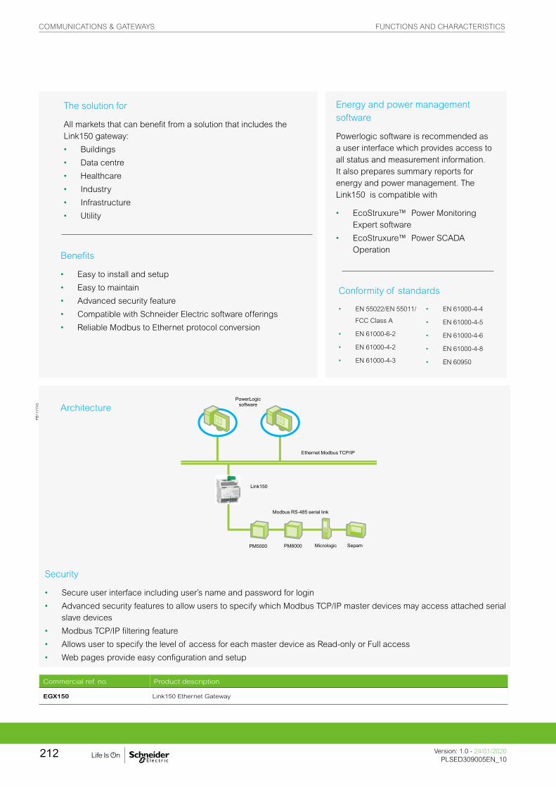
Architecture
The solution for
All markets that can benefit from a solution that includes the Link150 gateway:
• Buildings
• Data centre
• Healthcare
• Industry
• Infrastructure
• Utility
Benefits
• Easy to install and setup
• Easy to maintain
• Advanced security feature
• Compatible with Schneider Electric software offerings
• Reliable Modbus to Ethernet protocol conversion
Security
• Secure user interface including user’s name and password for login
• Advanced security features to allow users to specify which Modbus TCP/IP master devices may access attached serial slave devices
• Modbus TCP/IP filtering feature
• Allows user to specify the level of access for each master device as Read-only or Full access
• Web pages provide easy configuration and setup
PowerLogicsoftware
Ethernet Modbus TCP/IP
Link150
Modbus RS-485 serial link
PM5000 PM8000 Micrologic Sepam
Commercial ref. no. Product description
EGX150 Link150 Ethernet Gateway
Energy and power management software
Powerlogic software is recommended as a user interface which provides access to all status and measurement information. It also prepares summary reports for energy and power management. The Link150 is compatible with
• EcoStruxure™ Power Monitoring Expert software
• EcoStruxure™ Power SCADA Operation
Conformity of standards
• EN 55022/EN 55011/
FCC Class A
• EN 61000-6-2
• EN 61000-4-2
• EN 61000-4-3
• EN 61000-4-4
• EN 61000-4-5
• EN 61000-4-6
• EN 61000-4-8
• EN 60950
PB
1177
45
COMMUNICATIONS & GATEWAYS FUNCTIONS AND CHARACTERISTICS
Version: 1.0 - 24/01/2020PLSED309005EN_10
212
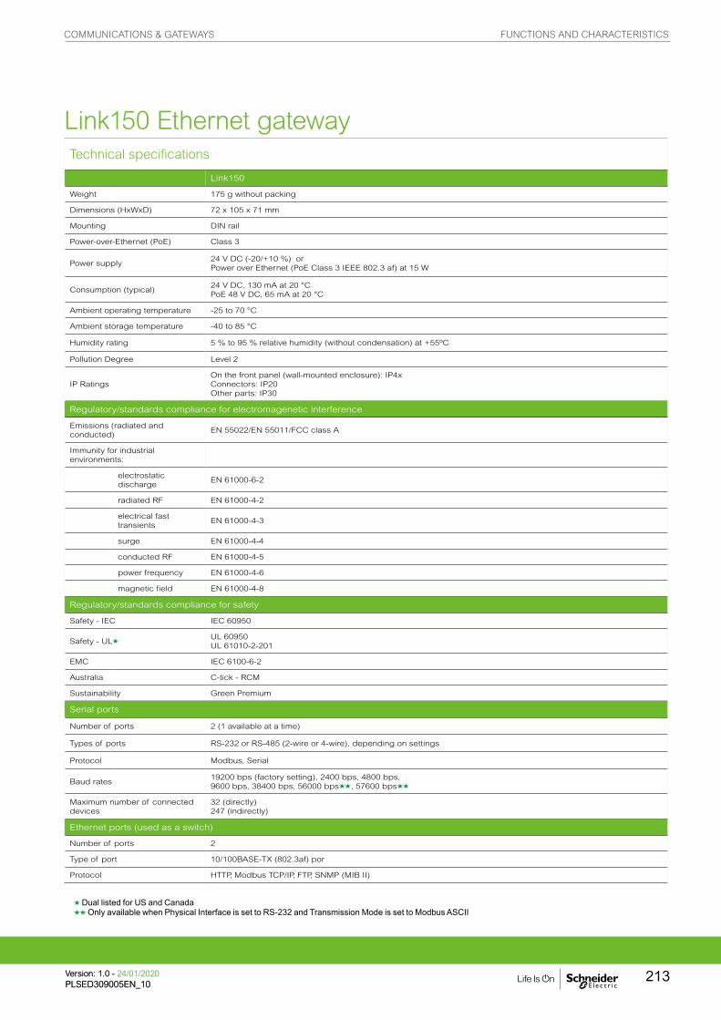
Technical specifications
Link150
Weight 175 g without packing
Dimensions (HxWxD) 72 x 105 x 71 mm
Mounting DIN rail
Power-over-Ethernet (PoE) Class 3
Power supply24 V DC (-20/+10 %) orPower over Ethernet (PoE Class 3 IEEE 802.3 af) at 15 W
Consumption (typical)24 V DC, 130 mA at 20 °CPoE 48 V DC, 65 mA at 20 °C
Ambient operating temperature -25 to 70 °C
Ambient storage temperature -40 to 85 °C
Humidity rating 5 % to 95 % relative humidity (without condensation) at +55ºC
Pollution Degree Level 2
IP RatingsOn the front panel (wall-mounted enclosure): IP4xConnectors: IP20Other parts: IP30
Regulatory/standards compliance for electromagenetic interference
Emissions (radiated and conducted)
EN 55022/EN 55011/FCC class A
Immunity for industrial environments:
electrostatic discharge
EN 61000-6-2
radiated RF EN 61000-4-2
electrical fast transients
EN 61000-4-3
surge EN 61000-4-4
conducted RF EN 61000-4-5
power frequency EN 61000-4-6
magnetic field EN 61000-4-8
Regulatory/standards compliance for safety
Safety - IEC IEC 60950
Safety - ULgUL 60950UL 61010-2-201
EMC IEC 6100-6-2
Australia C-tick - RCM
Sustainability Green Premium
Serial ports
Number of ports 2 (1 available at a time)
Types of ports RS-232 or RS-485 (2-wire or 4-wire), depending on settings
Protocol Modbus, Serial
Baud rates19200 bps (factory setting), 2400 bps, 4800 bps, 9600 bps, 38400 bps, 56000 bpsgg, 57600 bpsgg
Maximum number of connected devices
32 (directly)247 (indirectly)
Ethernet ports (used as a switch)
Number of ports 2
Type of port 10/100BASE-TX (802.3af) por
Protocol HTTP, Modbus TCP/IP, FTP, SNMP (MIB II)
g Dual listed for US and Canadagg Only available when Physical Interface is set to RS-232 and Transmission Mode is set to Modbus ASCII
Link150 Ethernet gateway
COMMUNICATIONS & GATEWAYS FUNCTIONS AND CHARACTERISTICS
213Version: 1.0 - 24/01/2020PLSED309005EN_10Version: 1.0 - 24/01/2020PLSED309005EN_10

Link150 Ethernet gateway
A Ethernet 1 communication port
B Ethernet 2 (PoE) communication port
C Midspan PoE injector
D Ethernet communication LEDs
E Module status LED
F Network status LED
G Sealable transparent cover
H IP reset pin
I RS-485 traffic status LED
J Device soft restart button (Accesible through closed cover)
K RS-232 traffic status LED
L Device name label
M RS-232 port
N RS-485 port
Parts
Dimensions DIN rail mounting
Fast and easy DIN rail installation
PB
1154
31
PB
1154
32
PB
1154
33P
B11
5429
PB
1154
30
PB
1154
36
See appropriate Installation Guide for this product.
COMMUNICATIONS & GATEWAYS DIMENSIONS AND CONNECTION
Version: 1.0 - 24/01/2020PLSED309005EN_10
214

D Ethernet communication LEDs
E Module status LED
F Network status LED
G Sealable transparent cover
H IP reset pin
I RS-485 traffic status LED
J Device soft restart button (Accesible through closed cover)
K RS-232 traffic status LED
L Device name label
A highly flexible plug-and-play Energy Server Com’X 210 collects and stores WAGES consumptions
and environmental parameters such as temperatures, humidity and CO2 levels in a building. Data is
periodically transmitted as a report to an internet database server for further processing. The Energy
Server Com’X 210 not only reduces your technical complexity, but helps to manage your energy.
Com’X 210
Applications
The quickest path to multi-site energy management and on-line services
• Delivers batches of data ready to process by EcoStruxure™ Power Management solutions and services
• Publishes logged data to the Schneider Electric cloud or another hosted platform
PB
1120
41
EBX210
COMMUNICATIONS & GATEWAYS FUNCTIONS AND CHARACTERISTICS
215Version: 1.0 - 24/01/2020PLSED309005EN_10Version: 1.0 - 24/01/2020PLSED309005EN_10

The solution for
All markets that can benefit from a solution that includes data logger Com’X 210:
• Buildings
• Industry
Energy management solutions
The data collected and stored by Com’X 210 can be processed and displayed as webpages through web services provided by Schneider Electric, such as EcoStruxure™ Power Management software products, or by any private energy platform.
The Com’X 210 also provides a transparent interface between Ethernet-based networks and field devices. This gateway function supports the use of monitoring software, such as EcoStruxure™ Power Monitoring Expert (PME) for data collection, trending, event management, analysis and further processing.
Architecture
Conformity of standards• EN 60950
Benefits
• Data collection from up to 64 field devices
• Data publishing leveraging existing infrastructures, Ethernet or Wi-Fi, GPRS-ready
• Quick fitting into electrical switchboards thanks to DIN rail clipping and profile
• Quick setup and configuration thanks to intuitive HMI
PB
1148
56-2
00
COMMUNICATIONS & GATEWAYS FUNCTIONS AND CHARACTERISTICS
Version: 1.0 - 24/01/2020PLSED309005EN_10
216

Data collector
Collects and stores energy data from up to 64 field devices, connected to either:
• Ethernet TCP/IP field network.
• Modbus Serial line network (up to 32 devices).
• Embedded digital and analogue inputs.
“Field devices” consist of :
• PowerLogic devices for power and energy monitoring.
• Masterpact or Compact circuit-breakers for protection and monitoring.
• Acti9 protection devices, meters, remote controlled switches, etc.
• Water, Air, Gas, Electricity, and Steam (WAGES) consumption meters, from specialised manufacturers, delivering pulses as per standard (see table next page).
• Environmental sensors such as temperatures, humidity, and CO2 levels in a building, providing analogue information.
Data logging and storage capabilities include:
• Configurable logging interval, from every minute to once a week.
• Data storage duration of several weeks, depending on quantity of collected data.
Data publisher
Batches of collected data periodically transmitted to an Internet server, as:
• XML files, for processing by EcoStruxure™ Power Management software products.
• CSV files for viewing in Excel or transformed for upload into programs such as EcoStruxure™ Power Monitoring Expert or any compatible software.
Data publishing function supports 4 transfer protocols over Ethernet or Wi-Fi:
• HTTP
• HTTPS
• FTP
• SMTP
Additional functions
Gateway
If selected by the user, the Com’X 210 can also make all data from connected devices available in real-time:
• In Modbus TCP/IP format over Ethernet or Wi-Fi.
• For requests by an energy management software.
Modbus packets can be sent from managing software to field devices through Modbus serial line or Modbus TCP/IP over Ethernet.
Commercial ref. no. Product description
EBX210 Com’X 210 data logger 24 V DC or 230 V AC power supplied
EBXA-ANT-5M Com’X External GPRS antenna
COMMUNICATIONS & GATEWAYS FUNCTIONS AND CHARACTERISTICS
217Version: 1.0 - 24/01/2020PLSED309005EN_10Version: 1.0 - 24/01/2020PLSED309005EN_10

A highly flexible plug-and-play Energy Server Com’X 510 collects and stores WAGES consumptions
and environmental parameters such as temperatures, humidity and CO2 levels in a building. The Com’X
510 has up to 2 year data storage and embedded webpages which means all your energy data can be
viewed and managed on-site.
Com’X 510
Applications
• All-in-one-box energy management solution especially suitable for buildings up to 10,000 sq. metres
PB
1145
82
EBX510
COMMUNICATIONS & GATEWAYS FUNCTIONS AND CHARACTERISTICS
Version: 1.0 - 24/01/2020PLSED309005EN_10
218

Architecture
The solution for
All markets that can benefit from a solution that includes data logger Com’X 510:
• Buildings
• Industry
Benefits
• Data collection from up to 64 field devices
• Data publishing leveraging existing infrastructures : Ethernet or Wi-Fi, GPRS-ready
• Quick fitting into electrical switchboards thanks to DIN rail clipping and profile.
• Quick setup and configuration thanks to intuitive HMI
Conformity of standards
• EN 60950
Competitive advantages
• Fit any PDU or RPP design for both new and retrofit projects
• Class 1.0 system accuracy
• Ethernet communication
Energy management solution
The data collected and stored by Com’X 510 can be processed and displayed through its own onboard webpage.
The Com’X 510 also provides a transparent interface between Ethernet-based networks and field devices. This gateway function supports the use of monitoring software, such as EcoStruxure™Power Monitoring Expert for data collection, trending, event management, analysis and further processing.
PB
1148
56
COMMUNICATIONS & GATEWAYS FUNCTIONS AND CHARACTERISTICS
219Version: 1.0 - 24/01/2020PLSED309005EN_10Version: 1.0 - 24/01/2020PLSED309005EN_10
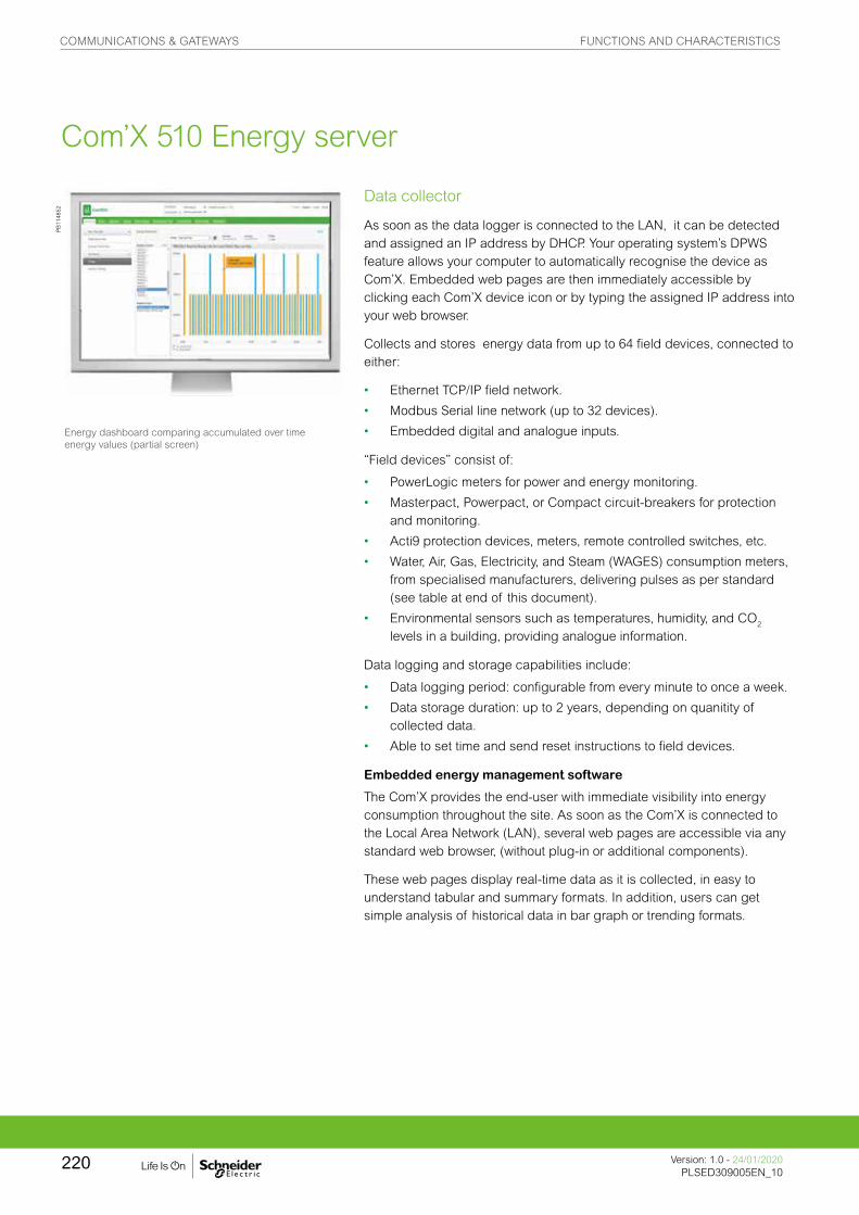
Data collector
As soon as the data logger is connected to the LAN, it can be detected and assigned an IP address by DHCP. Your operating system’s DPWS feature allows your computer to automatically recognise the device as Com’X. Embedded web pages are then immediately accessible by clicking each Com’X device icon or by typing the assigned IP address into your web browser.
Collects and stores energy data from up to 64 field devices, connected to either:
• Ethernet TCP/IP field network.
• Modbus Serial line network (up to 32 devices).
• Embedded digital and analogue inputs.
“Field devices” consist of:
• PowerLogic meters for power and energy monitoring.
• Masterpact, Powerpact, or Compact circuit-breakers for protection and monitoring.
• Acti9 protection devices, meters, remote controlled switches, etc.
• Water, Air, Gas, Electricity, and Steam (WAGES) consumption meters, from specialised manufacturers, delivering pulses as per standard (see table at end of this document).
• Environmental sensors such as temperatures, humidity, and CO2 levels in a building, providing analogue information.
Data logging and storage capabilities include:
• Data logging period: configurable from every minute to once a week.
• Data storage duration: up to 2 years, depending on quanitity of collected data.
• Able to set time and send reset instructions to field devices.
Embedded energy management software
The Com’X provides the end-user with immediate visibility into energy consumption throughout the site. As soon as the Com’X is connected to the Local Area Network (LAN), several web pages are accessible via any standard web browser, (without plug-in or additional components).
These web pages display real-time data as it is collected, in easy to understand tabular and summary formats. In addition, users can get simple analysis of historical data in bar graph or trending formats.
Energy dashboard comparing accumulated over time energy values (partial screen)
PB
1148
52
Com’X 510 Energy server
COMMUNICATIONS & GATEWAYS FUNCTIONS AND CHARACTERISTICS
Version: 1.0 - 24/01/2020PLSED309005EN_10
220

Energy Server Com'X 510 data logger
Additional functions
Data publisherBatches of collected data can also be periodically transmitted to an Internet server, as:• XML files, for processing by EcoStruxure™ Power Management
software products
• CSV files for viewing in Excel or transformed for uploading to programs such as EcoStruxure™ Power Monitoring Expert or any compatible software
Data publishing function supports 4 transfer protocols over Ethernet or Wi-Fi:
• HTTP
• HTTPS
• FTP
• SMTP
Gateway• If selected by the user, the Com’X 510 can make data from
connected devices available in real time
• In Modbus TCP/IP format over Ethernet or Wi-Fi
• For requests by energy management software
Modbus packets can be sent from managing software to field devices through Modbus serial line or Modbus TCP/IP over Ethernet.
Raw data and measurements from one field device (partial screen)
Historical trending comparing multiple devices or multiple topics (partial screen)
Commercial reference numbers Description
EBX510Com'X 510 energy server 24 V DC power supplied UL rated
EBXA-ANT-5M Com’X External GPRS antenna
EBXA-USB-Zigbee Com’X Zigbee USB interface
PB
1143
27P
B11
4854
PB
1148
53
Com’X 510 Energy server
COMMUNICATIONS & GATEWAYS FUNCTIONS AND CHARACTERISTICS
221Version: 1.0 - 24/01/2020PLSED309005EN_10Version: 1.0 - 24/01/2020PLSED309005EN_10
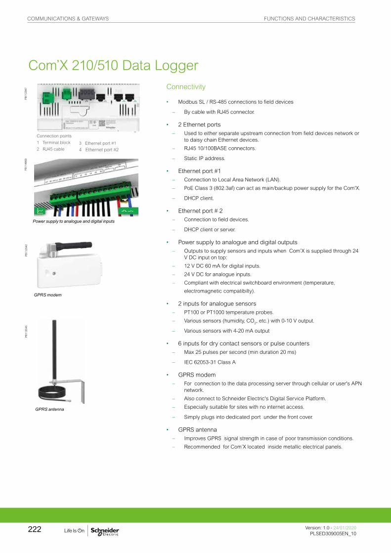
Com’X 210/510 Data LoggerConnectivity
• Modbus SL / RS-485 connections to field devices
– By cable with RJ45 connector.
• 2 Ethernet ports – Used to either separate upstream connection from field devices network or
to daisy chain Ethernet devices.
– RJ45 10/100BASE connectors.
– Static IP address.
• Ethernet port #1 – Connection to Local Area Network (LAN).
– PoE Class 3 (802.3af) can act as main/backup power supply for the Com'X.
– DHCP client.
• Ethernet port # 2 – Connection to field devices.
– DHCP client or server.
• Power supply to analogue and digital outputs – Outputs to supply sensors and inputs when Com’X is supplied through 24
V DC input on top:
– 12 V DC 60 mA for digital inputs.
– 24 V DC for analogue inputs.
– Compliant with electrical switchboard environment (temperature,
electromagnetic compatibilty).
• 2 inputs for analogue sensors – PT100 or PT1000 temperature probes.
– Various sensors (humidity, CO2, etc.) with 0-10 V output.
– Various sensors with 4-20 mA output
• 6 inputs for dry contact sensors or pulse counters – Max 25 pulses per second (min duration 20 ms)
– IEC 62053-31 Class A
• GPRS modem – For connection to the data processing server through cellular or user's APN
network.
– Also connect to Schneider Electric's Digital Service Platform.
– Especially suitable for sites with no internet access.
– Simply plugs into dedicated port under the front cover.
• GPRS antenna – Improves GPRS signal strength in case of poor transmission conditions.
– Recommended for Com’X located inside metallic electrical panels.
GPRS antenna
GPRS modem
Connection points
1 Terminal block
2 RJ45 cable3 Ethernet port #1
4 Ethernet port #2
Power supply to analogue and digital inputs
PB
1120
47P
B11
4859
PB
1120
42P
B11
2045
COMMUNICATIONS & GATEWAYS FUNCTIONS AND CHARACTERISTICS
Version: 1.0 - 24/01/2020PLSED309005EN_10
222

Setup and configuration
Connection to LAN
As soon as they are connected to the LAN, Com’X devices can be detected and assigned an IP address by DHCP. Your operating system’s DPWS feature allows your computer to automatically recognise the device as Com’X. Embedded web pages are then immediately accessible by clicking each Com’X device icon or by typing the assigned IP address into your web browser.
Com’X 210/510 setup and configuration
Additional features and benefits
• Cybersecurity - works well with your cyber security architecture.
• 2 Ethernet ports to separate upstream cloud connection, or to daisy chain with other Ethernet devices, from field device network.
• Data storage in case of communications failure.
• Local backup of configuration parameters - back up your system to a USB storage device and have it available for system restore or to duplicate the configuration on another box.
Field device auto-discovery
The user-activated device discovery function automatically identifies all field devices connected to Modbus SL, Ethernet port.
• Schneider Electric devices display with the product image.
• Other devices appear as “unknown,” allowing the user to manually assign a device type.
• User can assign their own device types.
• Users can complete additional device identification fields, such as circuit ID or building zone.
Data selection for logging and publication
Web page configuration tabs allow you to configure, in just a few clicks, which connected field devices collect and publish data.
• Advanced diagnostics and troubleshooting features
• Modbus serial and TCP/IP device statistics.
• Ethernet network statistics.
• Communications check wizard.
• Direct reading of register values from local and remote devices.
Device settings page (partial), as displayed after auto-discovery, enabling user to assign circuit identifications and select data for logging and publication.
DIN rail fitting (Front face IP40, terminals IP20).
Com’X 210/510 installation
PB
1148
57
PB
1180
56
PB
1180
57
COMMUNICATIONS & GATEWAYS FUNCTIONS AND CHARACTERISTICS
223Version: 1.0 - 24/01/2020PLSED309005EN_10Version: 1.0 - 24/01/2020PLSED309005EN_10

Technical specifications
Com’X 210/510 Environment
Operating temperature-25º to 60°C Com’X 210-25º to 70°C Com’X 510
Storage temperature -40º to 85°C
GPRS dongleOperating temperature
-20º to 60°C
GPRS dongleStorage temperature
-40º to 85°C
Wif-Fi dongleOperating temperature
0º to 50°C
Wi-Fi dongleStorage temperature
-20º to 80°C
Humidity 5 to 95 % relative humidity (without condensation) at 55ºC
Pollution Class III
Safety standards / regulation
International (CB scheme) IEC 60950
USA UL 508
USA UL 60950 (Com’X 510 only)
Canada cUL 60950 (Com’X 510 only)
Canada cULus 508
Europe EN 60950
Quality Brands
CE, UL
Power Supply Com’X 210 Com’X 510
AC 100-230 V (+/- 15%)(50-60 Hz) b
DC 24 V (+/- 10%) b b
Power over Ethernet 15.4 W DC b b
Max power 26 W max b b
Mechanical Com’X 210 Com’X 510
IP Front face IP40, terminals IP20 b b
Dimensions (HxWxD) 91 x 144 x 65.8 mm b b
Weight 450 g b b
Com’X 210/510 Data Logger
COMMUNICATIONS & GATEWAYS FUNCTIONS AND CHARACTERISTICS
Version: 1.0 - 24/01/2020PLSED309005EN_10
224
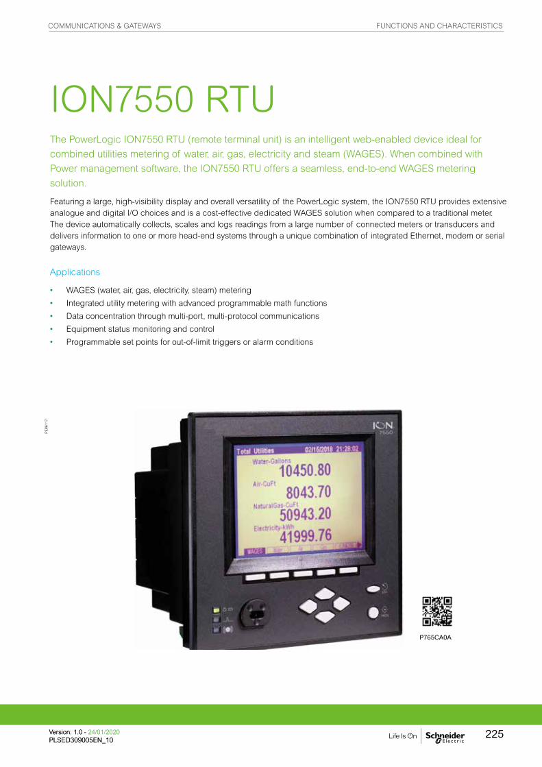
The PowerLogic ION7550 RTU (remote terminal unit) is an intelligent web-enabled device ideal for
combined utilities metering of water, air, gas, electricity and steam (WAGES). When combined with
Power management software, the ION7550 RTU offers a seamless, end-to-end WAGES metering
solution.
Featuring a large, high-visibility display and overall versatility of the PowerLogic system, the ION7550 RTU provides extensive analogue and digital I/O choices and is a cost-effective dedicated WAGES solution when compared to a traditional meter. The device automatically collects, scales and logs readings from a large number of connected meters or transducers and delivers information to one or more head-end systems through a unique combination of integrated Ethernet, modem or serial gateways.
ION7550 RTU
Applications
• WAGES (water, air, gas, electricity, steam) metering
• Integrated utility metering with advanced programmable math functions
• Data concentration through multi-port, multi-protocol communications
• Equipment status monitoring and control
• Programmable set points for out-of-limit triggers or alarm conditions
PE
8611
7
P765CA0A
COMMUNICATIONS & GATEWAYS FUNCTIONS AND CHARACTERISTICS
225Version: 1.0 - 24/01/2020PLSED309005EN_10Version: 1.0 - 24/01/2020PLSED309005EN_10

The solution for
All markets that can benefit from a solution that includes PowerLogic ION7550 RTU series meters:
• Buildings
• Industry
• Healthcare
• Education
• Etc.
Competitive advantages
• Data concentration through multi-port, multi-protocol communications
• Integrated utility metering with advanced programmable function
Benefits
• Help reduce waste and optimise equipment operation to increase energy efficiency
• A large, intuitive display
• Extensive digital and analogue I/O
• Dedicated WAGES solution when compared to a traditional meter
Conformity of standards
• EN 61010-1
• IEC 61000-4-2
• IEC 61000-4-3
• IEC 61000-4-4
• IEC 61000-4-5
• CISPR 22
Main characteristics
• Increase efficiency
– Reduce waste and optimise equipment operation to increase efficiency.
• Easy to operate
– Screen-based menu system to configure meter settings. Bright LCD display with adjustable contrast.
• Integrate with software
– Easily integrated with PowerLogic or other energy management enterprises, including SCADA systems.
• Transducer and equipment condition monitoring
– Versatile communications, extensive I/O points, clock synchronisation, event logging and sequence of events recording capabilities for transducer and equipment condition and status monitoring at utility substations.
• Set automatic alarms
– Alarm setpoint learning feature for optimum threshold settings.
• Up to 10 Mbytes of memory
– For archiving of data and waveforms.
• Notify alarms via email
– High-priority alarms sent directly to the user’s PC. Instant notification of power quality events by email.
• Modbus Master functionality
– Aggregate and store data from downstream Modbus devices using serial or Ethernet connections
Power management solutions
As part of a complete enterprise energy management solution, the ION7550 RTU can be integrated with EcoStruxure™ Power Monitoring Expert, or other SCADA, information and automation systems.
COMMUNICATIONS & GATEWAYS FUNCTIONS AND CHARACTERISTICS
Version: 1.0 - 24/01/2020PLSED309005EN_10
226

5 N 9M
4Part numbers
Item Code Description
1 Model 7550 ION7550 device
2 Form Factor
A0Integrated display with front optical port, 5 MB logging memory, and 512 samples/cycle resolution.
B0Integrated display with front optical port, 10 MB logging memory, and 512 samples/cycle resolution.
T0Transducer (no display) version, with 5 MB logging memory.
U0Transducer (no display) version, with 10 MB logging memory.
3 RTU option N9 RTU option
4 Power SupplyB
Standard power supply (85-240 VAC, ±10%/47-63 Hz / 110-330 VDC, ±10%)
C Low voltage DC power supply (20-60 VDC)
5 Internal use 9 This field for internal use only
6 Communications
A0
Standard communications (1 RS-232/RS-485 port, 1 RS-485 port). Integrated display models also include 1 ANSI Type 2 optical communications port.
C1
Standard communications plus 10BASE-T/100BASE-TX Ethernet (RJ-45), 56k universal internal modem (RJ-11). Ethernet, modem gateway functions each use a serial port.
D7
Standard comms plus 10BASE-T/100BASE-TX Ethernet (RJ-45) and 100BASE-FX Ethernet Fiber, 56k universal internal modem (RJ-11). Ethernet and modem gateway functions each use a serial communications port.
E0Standard communications plus 10BASE-T/100BASE-TX Ethernet (RJ-45). Ethernet gateway function uses serial port.
F1Standard communications plus 10BASE-T/100BASE-TX Ethernet (RJ-45) and 100BASE-FX (SC fiber optic connection). Ethernet gateway uses a serial port.
M1Standard communications plus 56k universal internal modem (RJ-11). Modem gateway uses serial communications port.
7 I/O
AStandard I/O (8 digital inputs, 3 Form C relays, 4 Form A solid-state outputs)
EStandard I/O plus Expansion I/O card (8 additional digital inputs & four 0 to 20 mA analogue inputs)
KStandard I/O plus Expansion I/O card (8 additional digital inputs & four 0 to 20 mA analogue outputs)
NStandard I/O plus Expansion I/O card (8 additional digital inputs & four 0 to 20 mA analogue inputs and four 0 to 20 mA outputs)
PStandard I/O plus Expansion I/O card (8 additional digital inputs & four 0 to 1 analogue inputs and four -1 to 1 mA analogue outputs)
8 Security 0 Password protected, no hardware lock
9 Special OrderA None
C Tropicalisation treatment applied
PowerLogic® ION7550 RTU.
1 I/O expansion card.2 Digital inputs.3 Analogue inputs.4 Analogue outputs.5 Communications card.6 Power supply.7 Form C digital outputs.8 Digital inputs.9 Form A digital outputs.
PE
8612
4
ION7550 RTU
COMMUNICATIONS & GATEWAYS FUNCTIONS AND CHARACTERISTICS
227Version: 1.0 - 24/01/2020PLSED309005EN_10Version: 1.0 - 24/01/2020PLSED309005EN_10

Commercial ref. no. Communication Card for ION7550RTU
P765CA0A Standard Comms: 1 RS-232/RS-485 port (COM1), 1 RS-485 port (COM2), Front optical port (COM3)
P765CA0CStandard Comms: 1 RS-232/RS-485 port (COM1), 1 RS-485 port (COM2), Front optical port (COM3), tropicalisation treatment applied
P765CC1A Standard plus Ethernet (10/100BASE-T), 56k universal internal modem (RJ11; shares COM3)
P765CC1C Standard plus Ethernet (10/100BASE-T), 56k universal internal modem (RJ11; shares COM3), tropicalisation treatment applied
P765CD7A Standard plus Ethernet (10/100BASE-T, 100BASE-FX), 56k internal modem (RJ11)
P765CD7C Standard plus Ethernet (10/100BASE-T, 100BASE-FX), 56k internal modem (RJ11), tropicalisation treatment applied
P765CE0A Standard plus Ethernet (10/100BASE-T)
P765CE0C Standard plus Ethernet (10/100BASE-T), tropicalisation treatment applied
P765CF1A Standard plus Ethernet (10/100BASE-T, 100BASE-FX)
P765CF1C Standard plus Ethernet (10/100BASE-T, 100BASE-FX), tropicalisation treatment applied
P765CM1A Standard plus 56k universal internal modem (RJ11; shares COM3)
P765CM1C Standard plus 56k universal internal modem (RJ11; shares COM3),tropicalisation treatment applied
Commercial ref. no. Analogue I/O cards
P760AEA four 0 to 20 mA analogue inputs & 8 digital inputs
P760AEC four 0 to 20 mA analogue inputs & 8 digital inputs,tropicalisation treatment applied
P760AKA four 0 to 20 mA analogue outputs & 8 digital inputs
P760AKC four 0 to 20 mA analogue outputs & 8 digital inputs,tropicalisation treatment applied
P760ANA four 0 to 20 mA analogue inputs, four 0 to 20 mA analogue outputs & 8 digital inputs
P760ANC four 0 to 20 mA analogue inputs, four 0 to 20 mA analogue outputs & 8 digital inputs,tropicalisation treatment applied
P760APA four 0 to 1 analogue inputs, four -1 to 1 mA analogue outputs & 8 digital inputs.
P760APC four 0 to 1 analogue inputs, four -1 to 1 mA analogue outputs & 8 digital inputs,tropicalisation treatment applied
ION7550 RTU
COMMUNICATIONS & GATEWAYS FUNCTIONS AND CHARACTERISTICS
Version: 1.0 - 24/01/2020PLSED309005EN_10
228

Commercial ref. no. OpenDAC rack, controllers, power supply
70LRCK16-48 OpenDAC rack. Holds up to 8 OpenLine modules to provide up to 16 I/O points. Requires communications controller
72-MOD-4000OpenDAC OpenDAC RS-485 serial module. Communications controller for use in a Modbus RTU network. Supports up to 2 70LRCK16-48 OpenDAC racks
72-ETH-T000 OpenDAC Ethernet network module for use on an Modbus/TCP Ethernet network. Supports up to 2 OpenDAC racks
PS-240-15W 85-264 V AC/110-370 V DC 15 W power supply. Required for applying power to the racks and controllers
Commercial ref. no. OpenLine digital I/O modules
70L-IAC digital input, 120 V AC
70L-IACA digital input, 220 V AC
70L-IDC digital input, 3-32 V DC
70L-IDCB digital input, fast switching
70L-IDCNP digital input, 15-32 V AC/10-32 V DC
70L-IDC5S dry contact closure-sensing DC input
70L-ISW input test module
70L-OAC digital output, 120 V AC
70L-OACL digital output, 120 V AC inductive loads
70L-OACA digital output, 220 V AC
70L-OACAL digital output, 220 V AC inductive loads
70L-ODC digital output, 3-60 V DC fast
70L-ODCA digital output, 4-200 V DC
70L-ODCB digital output, fast switching
70L-ODC5R digital output, dry contact
Ordering reference OpenLine analogue I/O modules
73L-II020 analogue input, current, 0-20 mA
73L-II420 analogue input, current, 4-20 mA
73L-ITCJ analogue input, temperature, J-type TC
73L-ITCK analogue input, temperature, K-type TC
73L-ITCT analogue input, temperature, T-type TC
73L-ITR100 analogue input, temperature, RTD
73L-ITR3100 analogue input, temperature, 3wire RTD
73L-ITR4100 analogue input, temperature, 4wire RTD
73L-IV1 analogue input, voltage, 0-1 V DC
73L-IV10 analogue input, voltage, 0-10 V DC
73L-IV10B analogue input, voltage, -10 to 10 V DC
73L-IV100M analogue input, voltage, 0-100 V DC
73L-IV5 analogue input, voltage, 0-5 V DC
73L-IV5B analogue input, voltage, -5 to 5 V DC
73L-IV50M analogue input, voltage, 0-50 mV
73L-OI020 analogue output, current, 0-20 mA
73L-OI420 analogue output, current, 4-20 mA
73L-OV10 analogue output, voltage, 0-10 V DC
73L-OV10B analogue output, voltage, -10 to 10 V DC
73L-OV5 analogue output, voltage, 0-5 V DC
73L-OV5B analogue output, voltage, -5 to 5 V DC
ION7550 RTU
COMMUNICATIONS & GATEWAYS FUNCTIONS AND CHARACTERISTICS
229Version: 1.0 - 24/01/2020PLSED309005EN_10Version: 1.0 - 24/01/2020PLSED309005EN_10

Features
ION7550 RTU
Data recording
Min/max of instantaneous values b
Data logs b
Event logs b
Trending b
SER (Sequence of event recording) b
Time stamping b
GPS synchronisation (1 ms) b
Memory (in Mbytes) 10
Display and I/O
Front panel display b
Pulse output 1
Digital or analogue inputs(max) 24
Digital or analogue outputs (max, including pulse output) 30
Communication
RS-485 port 1
RS-485 / RS-232 port 1
Optical port 1
Modbus TCP Master / Slave (Ethernet port) b / b
Modbus RTU Master / Slave (Serial port) b / b
Ethernet port (Modbus/TCP/IP protocol) 1
Ethernet gateway (EtherGate) 1
Alarms (optional automatic alarm setting b
Alarm notification via email (Meterm@il) b
HTML web page server (WebMeter) b
Internal modem 1
Modem gateway (ModemGate) b
DNP 3.0 through serial, modem, and I/R ports b
ION7550 RTU
COMMUNICATIONS & GATEWAYS FUNCTIONS AND CHARACTERISTICS
Version: 1.0 - 24/01/2020PLSED309005EN_10
230
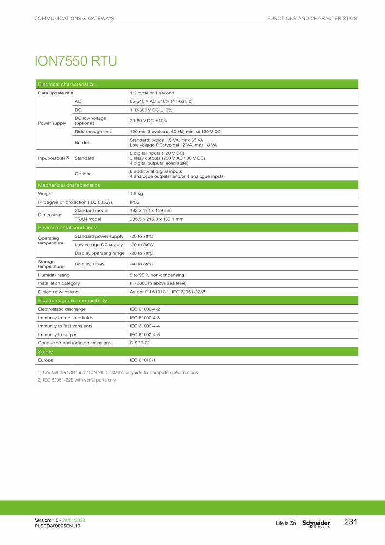
Electrical characteristics
Data update rate 1/2 cycle or 1 second
Power supply
AC 85-240 V AC ±10% (47-63 Hz)
DC 110-300 V DC ±10%
DC low voltage (optional)
20-60 V DC ±10%
Ride-through time 100 ms (6 cycles at 60 Hz) min. at 120 V DC
BurdenStandard: typical 15 VA, max 35 VALow voltage DC: typical 12 VA, max 18 VA
Input/outputs(1) Standard8 digital inputs (120 V DC)3 relay outputs (250 V AC / 30 V DC) 4 digital outputs (solid state)
Optional8 additional digital inputs4 analogue outputs, and/or 4 analogue inputs
Mechanical characteristics
Weight 1.9 kg
IP degree of protection (IEC 60529) IP52
DimensionsStandard model 192 x 192 x 159 mm
TRAN model 235.5 x 216.3 x 133.1 mm
Environmental conditions
Operating temperature
Standard power supply -20 to 70ºC
Low voltage DC supply -20 to 50ºC
Display operating range -20 to 70ºC
Storage temperature
Display, TRAN -40 to 85ºC
Humidity rating 5 to 95 % non-condensing
Installation category III (2000 m above sea level)
Dielectric withstand As per EN 61010-1, IEC 62051-22A(2)
Electromagnetic compatibility
Electrostatic discharge IEC 61000-4-2
Immunity to radiated fields IEC 61000-4-3
Immunity to fast transients IEC 61000-4-4
Immunity to surges IEC 61000-4-5
Conducted and radiated emissions CISPR 22
Safety
Europe IEC 61010-1
(1) Consult the ION7550 / ION7650 installation guide for complete specifications.
(2) IEC 62051-22B with serial ports only.
ION7550 RTU
COMMUNICATIONS & GATEWAYS FUNCTIONS AND CHARACTERISTICS
231Version: 1.0 - 24/01/2020PLSED309005EN_10Version: 1.0 - 24/01/2020PLSED309005EN_10

(1) All the communication ports may be used simultaneously.
Communication
RS-232/RS-485 port (1) Up to 115,200 bauds (57,600 bauds for RS-485), ION, DNP 3.0, Modbus, GPS, EtherGate, ModemGate, Modbus Master
RS-485 port (1) Up to 115,200 bauds, ION, DNP 3.0, Modbus, GPS, EtherGate, ModemGate, Modbus Master
Infrared port(1) ANSI type 2, up to 19,200 bauds, ION, Modbus, DNP 3.0
Ethernet port 10BASET, 100BASETX. RJ45 connector, 10/100 m link
Fibre-optic Ethernet link 100BASE FX, SC duplex connector, 1300 nm, FO multimode with gradient index 62.5/125 µm or 50/125 µm, 2000 m link
Protocol ION, Modbus, Modbus Master, TCP/IP, DNP 3.0, Telnet
EtherGate Communicates directly with up to 62 slave devices via available serial ports
ModemGate Communicates directly with up to 31 slave devices
WebMeter 5 customisable pages, new page creation capabilities, HTML/XML compatible
Firmware characteristics
High-speed data recordingDown to 5 ms interval burst recording, stores detailed characteristics of disturbances or outages. Trigger recording by a user-defined setpoint, or from external equipment.
Load profilingChannel assignments (800 channels via 50 data recorders) are configurable for any measurable parameter. Trigger recorders based on time interval, calendar schedule, alarm/event condition, or manually.
Trend curvesAccess historical data at the front panel. Display, trend and continuously update historical data with date andtimestamps for up to four parameters simultaneously.
Alarms
Threshold alarms:adjustable pickup and dropout setpoints and time delays, numerous activation levels possible for a given type of alarmuser-defined priority levelsboolean combination of alarms is possible using the operators NAND, OR, NOR and XOR
Advanced security Up to 16 users with unique access rights. Perform resets, time syncs, or meter configurations based on user privileges
Memory 5 to 10 MB (specified at time of order)
Firmware update Update via the communication ports
Display characteristics
Integrated display Backlit LCD, configurable screens
Languages English
ION7550 RTU
COMMUNICATIONS & GATEWAYS FUNCTIONS AND CHARACTERISTICS
Version: 1.0 - 24/01/2020PLSED309005EN_10
232

Protection(3A)
L/+ N/-
Power supply
Fuse for N/- required if neutral is ungrounded
Connect G terminalto ground for AC power source
Note: the current and voltage terminal strip (I52, I51, I42, I41, I32, I31, I22,
I21, I12, I11, V4, V3, V2, V1, Vref) is not present on the RTU.
ION7550 RTU dimensions
Front-panel mounting Power supply
PE
8602
2P
E86
027
PE
8612
3P
E86
023
ION7550 RTU
COMMUNICATIONS & GATEWAYS DIMENSIONS AND CONNECTION
Version: 1.0 - 24/01/2020PLSED309005EN_10
233

Insulation monitoringdevicesAn IT earthing system allows your electrical distribution system to continually operate, even in the
presence of an insulation fault, without endangering people or property. Required as part of an IT
earthing system, an insulation monitoring device (IMD) detects the initial fault so you can make repairs
before a second fault occurs, which could trigger protective devices and halt operations.
PB11
8026
PB11
8027
PB11
8026
INSULATION MONITORING DEVICES FUNCTIONS AND CHARACTERISTICS
Version: 1.0 - 24/01/2020PLSED309005EN_11
234

Insulation Monitoring of IT / Ungrounded Networks
230 V TT
110 mA
230 V IT
< 1 mA
110 V
0.7 V
The main interest of IT systems is that in case of one insulation fault, no trip of protective device is required as the faulty current remains low.
– Advantages of IT networks include:
– Enhanced continuity of service of the network (no trip if there is one insulation fault on the network).
– Reduced risk of electric shock.
– Reduced risk of fire or explosion (low faulty current in case of insulation fault).
– Reduced stress on the network and increased equipment life (low faulty current in case of insulation fault).
– In a situation with several insulation faults, the faulty current is no longer negligible and will cause trip of the protections.
– For this reason, Insulation Monitoring Devices are used on IT networks in order to detect a first insulation fault and indicate its location so that the fault can be repaired; hence avoiding situations with several insulation faults and maintaining the continuity of service on the network.
Unlike the TT or TN earthing systems, the neutral of the transformer is isolated from the ground for an IT earthing system (also called Ungrounded system).
Example of simple insulation monitoring system
PB118030PB118031
PB118029
INSULATION MONITORING DEVICES FUNCTIONS AND CHARACTERISTICS
235Version: 1.0 - 24/01/2020PLSED309005EN_11Version: 1.0 - 24/01/2020PLSED309005EN_11

PB11
8032
Insulation Monitoring of IT / Ungrounded Networks
IT earthing systems are used for applications requiring continuity of service, such as:
– Healthcare: critical rooms in medical premises such as operating theaters, intensive care units, recovery rooms.
– Industry: critical processes in cement, steel, chemical factories, food processing, car manufacturing, water, and waste water.
– Infrastructure: control tower and take-off path in airports, lighting, and signaling networks in rail.
– Utilities: power plants and control command systems.
– Photovoltaic: solar farms.
– Marine: electrical distribution of any type of ship.
– DC applications such as electrical vehicle charging stations.
The Vigilohm catalog offers a range of products suitable for these various applications, from the simplest insulation monitoring systems to the most advanced ones, including individual insulation monitoring per feeder and communication with supervision.
Maintenance Room
IFL12H
IM20H
Link150
OTD OTD
PME
IFL12H
IM20H
Mod
bus
RS4
85
Mod
bus
RS4
85
Modbus TCP/IP
Operating Theater 1 Operating Theater 2
SmartlinkEthernet
SmartlinkModbus
Example of Healthcare network monitored by Vigilohm Insulation Monitoring Devices in compliance with IEC 60364-7-710.
Medical staff is informed of electrical faults in the operating theater room through the local HMI (Operating Theater Display - OTD)
Technical staff is informed of any fault in the various operating theaters via a supervision system such as EcoStruxure Power Monitoring Expert.
INSULATION MONITORING DEVICES FUNCTIONS AND CHARACTERISTICS
Version: 1.0 - 24/01/2020PLSED309005EN_11
236
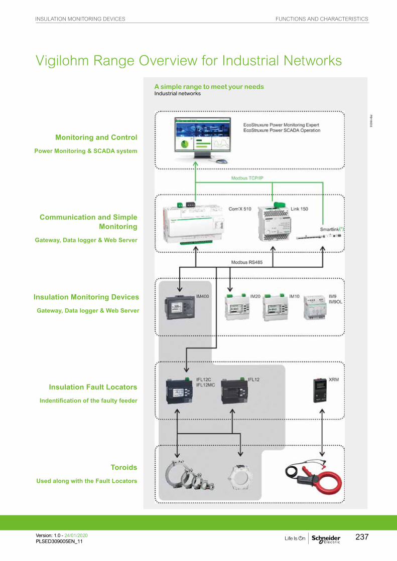
Vigilohm Range Overview for Industrial Networks
PB118033
A simple range to meet your needsIndustrial networks
Monitoring and ControlPower Monitoring & SCADA system
Communication and Simple Monitoring
Gateway, Data logger & Web Server
Insulation Monitoring DevicesGateway, Data logger & Web Server
Insulation Fault LocatorsIndentification of the faulty feeder
ToroidsUsed along with the Fault Locators
INSULATION MONITORING DEVICES FUNCTIONS AND CHARACTERISTICS
237Version: 1.0 - 24/01/2020PLSED309005EN_11Version: 1.0 - 24/01/2020PLSED309005EN_11

Dedicated offers for critical rooms compliantwith IEC60364-7-7 10
Vigilohm Range Overview for Healthcare
PB11
8034
Monitoring and ControlPower Monitoring & SCADA system
CommunicationGateway
Local DisplaysHMI in the medical room
Local DisplaysHMI in the medical room
Insulation Fault LocatorsIdentification of the fault
ToroidsUsed along with the Fault Locators
INSULATION MONITORING DEVICES FUNCTIONS AND CHARACTERISTICS
Version: 1.0 - 24/01/2020PLSED309005EN_11
238
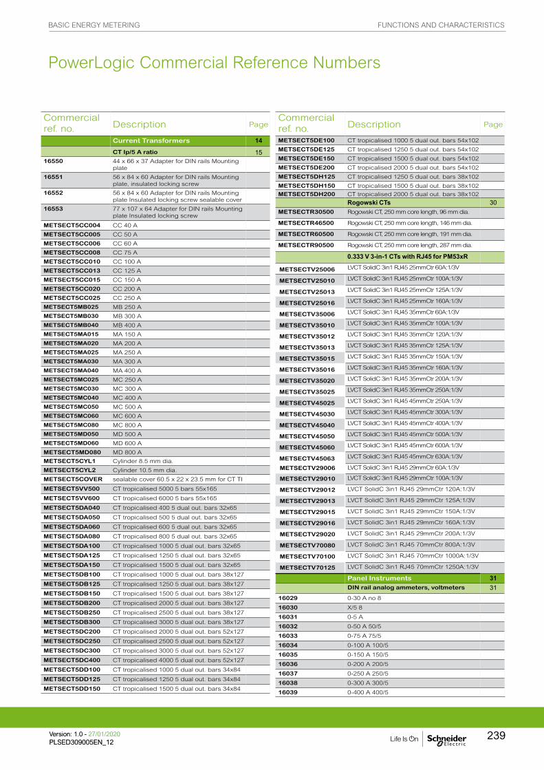
Commercial ref. no. Description Page
Current Transformers 14CT Ip/5 A ratio 15
16550 44 x 66 x 37 Adapter for DIN rails Mounting plate
16551 56 x 84 x 60 Adapter for DIN rails Mounting plate, insulated locking screw
16552 56 x 84 x 60 Adapter for DIN rails Mounting plate Insulated locking screw sealable cover
16553 77 x 107 x 64 Adapter for DIN rails Mounting plate Insulated locking screw
METSECT5CC004 CC 40 A
METSECT5CC005 CC 50 A
METSECT5CC006 CC 60 A
METSECT5CC008 CC 75 A
METSECT5CC010 CC 100 A
METSECT5CC013 CC 125 A
METSECT5CC015 CC 150 A
METSECT5CC020 CC 200 A
METSECT5CC025 CC 250 A
METSECT5MB025 MB 250 A
METSECT5MB030 MB 300 A
METSECT5MB040 MB 400 A
METSECT5MA015 MA 150 A
METSECT5MA020 MA 200 A
METSECT5MA025 MA 250 A
METSECT5MA030 MA 300 A
METSECT5MA040 MA 400 A
METSECT5MC025 MC 250 A
METSECT5MC030 MC 300 A
METSECT5MC040 MC 400 A
METSECT5MC050 MC 500 A
METSECT5MC060 MC 600 A
METSECT5MC080 MC 800 A
METSECT5MD050 MD 500 A
METSECT5MD060 MD 600 A
METSECT5MD080 MD 800 A
METSECT5CYL1 Cylinder 8.5 mm dia.
METSECT5CYL2 Cylinder 10.5 mm dia.
METSECT5COVER sealable cover 60.5 x 22 x 23.5 mm for CT TI
METSECT5VV500 CT tropicalised 5000 5 bars 55x165
METSECT5VV600 CT tropicalised 6000 5 bars 55x165
METSECT5DA040 CT tropicalised 400 5 dual out. bars 32x65
METSECT5DA050 CT tropicalised 500 5 dual out. bars 32x65
METSECT5DA060 CT tropicalised 600 5 dual out. bars 32x65
METSECT5DA080 CT tropicalised 800 5 dual out. bars 32x65
METSECT5DA100 CT tropicalised 1000 5 dual out. bars 32x65
METSECT5DA125 CT tropicalised 1250 5 dual out. bars 32x65
METSECT5DA150 CT tropicalised 1500 5 dual out. bars 32x65
METSECT5DB100 CT tropicalised 1000 5 dual out. bars 38x127
METSECT5DB125 CT tropicalised 1250 5 dual out. bars 38x127
METSECT5DB150 CT tropicalised 1500 5 dual out. bars 38x127
METSECT5DB200 CT tropicalised 2000 5 dual out. bars 38x127
METSECT5DB250 CT tropicalised 2500 5 dual out. bars 38x127
METSECT5DB300 CT tropicalised 3000 5 dual out. bars 38x127
METSECT5DC200 CT tropicalised 2000 5 dual out. bars 52x127
METSECT5DC250 CT tropicalised 2500 5 dual out. bars 52x127
METSECT5DC300 CT tropicalised 3000 5 dual out. bars 52x127
METSECT5DC400 CT tropicalised 4000 5 dual out. bars 52x127
METSECT5DD100 CT tropicalised 1000 5 dual out. bars 34x84
METSECT5DD125 CT tropicalised 1250 5 dual out. bars 34x84
METSECT5DD150 CT tropicalised 1500 5 dual out. bars 34x84
Commercial ref. no. Description Page
METSECT5DE100 CT tropicalised 1000 5 dual out. bars 54x102
METSECT5DE125 CT tropicalised 1250 5 dual out. bars 54x102
METSECT5DE150 CT tropicalised 1500 5 dual out. bars 54x102
METSECT5DE200 CT tropicalised 2000 5 dual out. bars 54x102
METSECT5DH125 CT tropicalised 1250 5 dual out. bars 38x102
METSECT5DH150 CT tropicalised 1500 5 dual out. bars 38x102
METSECT5DH200 CT tropicalised 2000 5 dual out. bars 38x102
Rogowski CTs 30METSECTR30500 Rogowski CT, 250 mm core length, 96 mm dia.
METSECTR46500 Rogowski CT, 250 mm core length, 146 mm dia.
METSECTR60500 Rogowski CT, 250 mm core length, 191 mm dia.
METSECTR90500 Rogowski CT, 250 mm core length, 287 mm dia.
0.333 V 3-in-1 CTs with RJ45 for PM53xR
METSECTV25006 LVCT SolidC 3in1 RJ45 25mmCtr 60A:1/3V
METSECTV25010 LVCT SolidC 3in1 RJ45 25mmCtr 100A:1/3V
METSECTV25013 LVCT SolidC 3in1 RJ45 25mmCtr 125A:1/3V
METSECTV25016 LVCT SolidC 3in1 RJ45 25mmCtr 160A:1/3V
METSECTV35006 LVCT SolidC 3in1 RJ45 35mmCtr 60A:1/3V
METSECTV35010 LVCT SolidC 3in1 RJ45 35mmCtr 100A:1/3V
METSECTV35012 LVCT SolidC 3in1 RJ45 35mmCtr 120A:1/3V
METSECTV35013 LVCT SolidC 3in1 RJ45 35mmCtr 125A:1/3V
METSECTV35015 LVCT SolidC 3in1 RJ45 35mmCtr 150A:1/3V
METSECTV35016 LVCT SolidC 3in1 RJ45 35mmCtr 160A:1/3V
METSECTV35020 LVCT SolidC 3in1 RJ45 35mmCtr 200A:1/3V
METSECTV35025 LVCT SolidC 3in1 RJ45 35mmCtr 250A:1/3V
METSECTV45025 LVCT SolidC 3in1 RJ45 45mmCtr 250A:1/3V
METSECTV45030 LVCT SolidC 3in1 RJ45 45mmCtr 300A:1/3V
METSECTV45040 LVCT SolidC 3in1 RJ45 45mmCtr 400A:1/3V
METSECTV45050 LVCT SolidC 3in1 RJ45 45mmCtr 500A:1/3V
METSECTV45060 LVCT SolidC 3in1 RJ45 45mmCtr 600A:1/3V
METSECTV45063 LVCT SolidC 3in1 RJ45 45mmCtr 630A:1/3V
METSECTV29006 LVCT SolidC 3in1 RJ45 29mmCtr 60A:1/3V
METSECTV29010 LVCT SolidC 3in1 RJ45 29mmCtr 100A:1/3V
METSECTV29012 LVCT SolidC 3in1 RJ45 29mmCtr 120A:1/3V
METSECTV29013 LVCT SolidC 3in1 RJ45 29mmCtr 125A:1/3V
METSECTV29015 LVCT SolidC 3in1 RJ45 29mmCtr 150A:1/3V
METSECTV29016 LVCT SolidC 3in1 RJ45 29mmCtr 160A:1/3V
METSECTV29020 LVCT SolidC 3in1 RJ45 29mmCtr 200A:1/3V
METSECTV70080 LVCT SolidC 3in1 RJ45 70mmCtr 800A:1/3V
METSECTV70100 LVCT SolidC 3in1 RJ45 70mmCtr 1000A:1/3V
METSECTV70125 LVCT SolidC 3in1 RJ45 70mmCtr 1250A:1/3V
Panel Instruments 31DIN rail analog ammeters, voltmeters 31
16029 0-30 A no 8
16030 X/5 8
16031 0-5 A
16032 0-50 A 50/5
16033 0-75 A 75/5
16034 0-100 A 100/5
16035 0-150 A 150/5
16036 0-200 A 200/5
16037 0-250 A 250/5
16038 0-300 A 300/5
16039 0-400 A 400/5
PowerLogic Commercial Reference Numbers
BASIC ENERGY METERING FUNCTIONS AND CHARACTERISTICS
239Version: 1.0 - 27/01/2020PLSED309005EN_12Version: 1.0 - 27/01/2020PLSED309005EN_12

Commercial ref. no. Description Page
iCI impulse counter 3915443 iCI 4mm impulse counter DIN
Basic Energy Metering 42iEM2000 43
A9MEM2000T iEM2000T basic energy meter, no display
A9MEM2000 iEM2000 basic energy meter
A9MEM2010 iEM2010 energy meter, kWh pulse output
A9MEM2100 iEM2100 basic energy meter
A9MEM2050 iEM2050 modular single phase power meter 230 V - 45 A with Modbus
A9MEM2055 iEM2055 modular single phase power meter 230 V - 45 A with Modbus, MID
A9MEM2105 iEM2105 energy meter, kWh pulse output with partial meter
A9MEM2110 iEM2110 energy meter, kWh and kvarh pulse outputs with two tariffs, four quadrant energy measurement, MID certified
A9MEM2135 iEM2135 energy meter, M-Bus communication, four quadrant energy measurement, two tariffs, MID certified
A9MEM2150 iEM2150 energy meter, Modbus communication, four quadrant energy measurement
A9MEM2155 iEM2155 energy meter, Modbus communication, four quadrant energy measurement, two tariffs, MID certified
iEM3000 50A9MEM3100 iEM3100 basic energy meter
A9MEM3110 iEM3110 energy meter with pulse output
A9MEM3115 iEM3115 multi-tariff energy meter
A9MEM3135 iEM3135 advanced multi-tariff energy meter & electrical parameter plus M-Bus comm port
A9MEM3150 iEM3150 energy meter & electrical parameter plus Modbus RS-485 comm port
A9MEM3155 iEM3155 advanced multi-tariff energy meter & electrical parameter plus Modbus RS-485 comm port
A9MEM3165 iEM3165 advanced multi-tariff energy meter & electrical parameter plus BACnet MS/TP comm port
A9MEM3175 iEM3175 advanced multi-tariff energy meter & electrical parameter plus LON TP/FT-10 comm port
A9MEM3200 iEM3200 basic energy meter
A9MEM3210 iEM3210 energy meter with pulse output
A9MEM3215 iEM3215 multi-tariff energy meter
A9MEM3235 iEM3235 advanced multi-tariff energy meter & electrical parameter plus M-Bus comm port
A9MEM3250 iEM3250 energy meter & electrical parameter plus Modbus RS-485 comm port
A9MEM3255 iEM3255 advanced multi-tariff energy meter & electrical parameter plus Modbus RS485 comm port
A9MEM3265 iEM3265 advanced multi-tariff energy meter & electrical parameter plus BACnet MS/TP comm port
A9MEM3275 iEM3275 advanced multi-tariff energy meter & electrical parameter plus LON TP/FT-10 comm port
A9MEM3300 iEM3300 basic energy meter
A9MEM3310 iEM3310 energy meter with pulse output
A9MEM3335 iEM3335 advanced multi-tariff energy meter & electrical parameter plus M-Bus comm port
A9MEM3350 iEM3350 energy meter & electrical parameter plus Modbus RS-485 comm port
A9MEM3355 iEM3355 advanced multi-tariff energy meter & electrical parameter plus Modbus RS485 comm port
Commercial ref. no. Description Page
16040 0-500 A 500/5
16041 0-600 A 600/5
16042 0-800 A 800/5
16043 0-1000 A 1000/5
16044 0-1500 A 1500/5
16045 0-2000 A 2000/5
16060 0-300 V 8
16061 0-500 V 8
DIN rail digital ammeters, voltmeter, freq meter 33
15202 Direct reading iAMP 0-10 A No 4
15209 Multi-rating iAMP 0-5000 A As per rating 4
15201 iVLT 0-600 V 4
15208 iFRE 20-100 Hz 4
72x72 analog ammeter, voltmeter 3416003 AMP for motor feeder
16004 AMP for standard feeder X/5
16009 AMP for standard feeder 0-50 A 50/5
16010 AMP for standard feeder 0-100 A 100/5
16011 AMP for standard feeder 0-200 A 200/5
16012 AMP for standard feeder 0-400 A 400/5
16013 AMP for standard feeder 0-600 A 600/5
16014 AMP for standard feeder 0-1000 A 1000/5
16015 AMP for standard feeder 0-1250 A 1250/5
16016 AMP for standard feeder 0-1500 A 1500/5
16019 AMP for standard feeder 0-2000 A 2000/5
16003 AMP for motor feeder X/5
16006 AMP for motor feeder 0-30-90 A 30/5
16007 AMP for motor feeder 0-75-225 A 75/5
16008 AMP for motor feeder 0-200-600 A 200/5
16005 VLT 0-500 V
96x96 analog ammeter, voltmeter 3516074 AMP for standard feeder X/5
16079 AMP for standard feeder 0-50 A 50/5
16080 AMP for standard feeder 0-100 A 100/5
16081 AMP for standard feeder 0-200 A 200/5
16082 AMP for standard feeder 0-400 A 400/5
16083 AMP for standard feeder 0-600 A 600/5
16084 AMP for standard feeder 0-1000 A 1000/5
16085 AMP for standard feeder 0-1250 A 1250/5
16086 AMP for standard feeder 0-1500 A 1500/5
16087 AMP for standard feeder 0-2000 A 2000/5
16088 AMP for standard feeder 0-2500 A 2500/5
16089 AMP for standard feeder 0-3000 A 3000/5
16090 AMP for standard feeder 0-4000 A 4000/5
16091 AMP for standard feeder 0-5000 A 5000/5
16092 AMP for standard feeder 0-6000 A 6000/5
16073 AMP for motor feeder X/5
16076 AMP for motor feeder 0-30-90 A 30/5
16077 AMP for motor feeder 0-75-225 A 75/5
16078 AMP for motor feeder 0-200-600 A 200/5
16075 VLT 0-500 V
48x48 CMA, CMV selector switches 3616017 CMA 20 4
16018 CMV 500 7
DIN rail iCMA, iCMV selector switches 3715126 iCMA 10 415 4
15125 iCMV 10 415 4
iCH hour counter 3815440 iCH "DIN" 230 V AC ± 10 %/50 Hz 4mm
15607 CH "48 x 48" 24 V AC ± 10 %/50 Hz
15608 CH "48 x 48" 230 V AC ± 10 %/50 Hz
15609 CH "48 x 48" 12 to 36 V DC
PowerLogic Commercial Reference Numbers
BASIC ENERGY METERING FUNCTIONS AND CHARACTERISTICS
Version: 1.0 - 27/01/2020PLSED309005EN_12
240
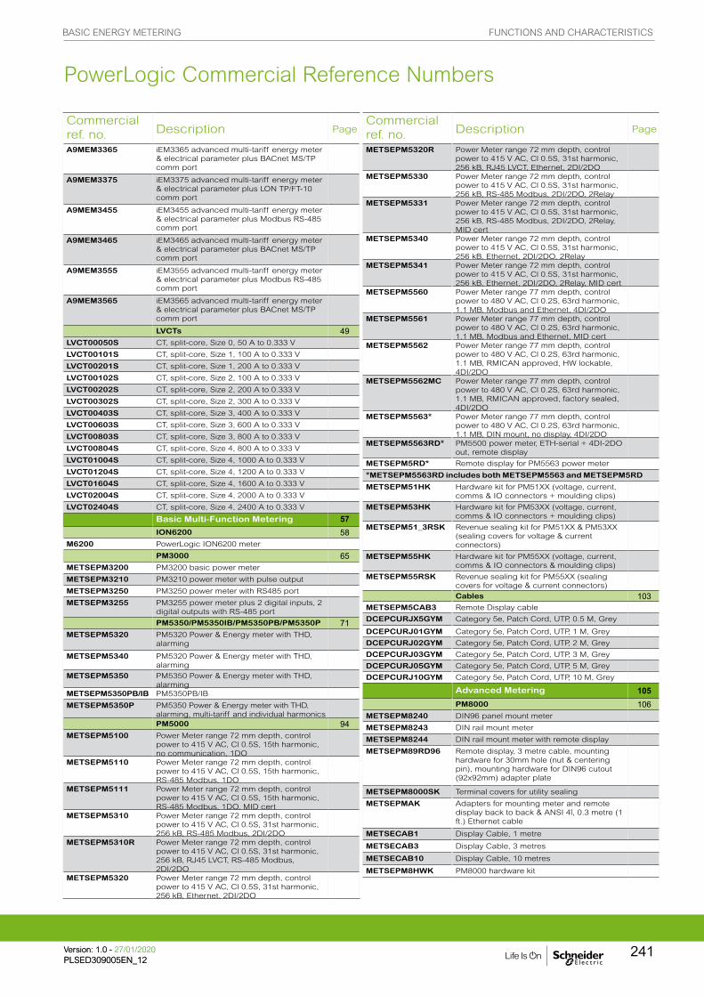
Commercial ref. no. Description Page
A9MEM3365 iEM3365 advanced multi-tariff energy meter & electrical parameter plus BACnet MS/TP comm port
A9MEM3375 iEM3375 advanced multi-tariff energy meter & electrical parameter plus LON TP/FT-10 comm port
A9MEM3455 iEM3455 advanced multi-tariff energy meter & electrical parameter plus Modbus RS-485 comm port
A9MEM3465 iEM3465 advanced multi-tariff energy meter & electrical parameter plus BACnet MS/TP comm port
A9MEM3555 iEM3555 advanced multi-tariff energy meter & electrical parameter plus Modbus RS-485 comm port
A9MEM3565 iEM3565 advanced multi-tariff energy meter & electrical parameter plus BACnet MS/TP comm port
LVCTs 49LVCT00050S CT, split-core, Size 0, 50 A to 0.333 V
LVCT00101S CT, split-core, Size 1, 100 A to 0.333 V
LVCT00201S CT, split-core, Size 1, 200 A to 0.333 V
LVCT00102S CT, split-core, Size 2, 100 A to 0.333 V
LVCT00202S CT, split-core, Size 2, 200 A to 0.333 V
LVCT00302S CT, split-core, Size 2, 300 A to 0.333 V
LVCT00403S CT, split-core, Size 3, 400 A to 0.333 V
LVCT00603S CT, split-core, Size 3, 600 A to 0.333 V
LVCT00803S CT, split-core, Size 3, 800 A to 0.333 V
LVCT00804S CT, split-core, Size 4, 800 A to 0.333 V
LVCT01004S CT, split-core, Size 4, 1000 A to 0.333 V
LVCT01204S CT, split-core, Size 4, 1200 A to 0.333 V
LVCT01604S CT, split-core, Size 4, 1600 A to 0.333 V
LVCT02004S CT, split-core, Size 4, 2000 A to 0.333 V
LVCT02404S CT, split-core, Size 4, 2400 A to 0.333 V
Basic Multi-Function Metering 57ION6200 58
M6200 PowerLogic ION6200 meter
PM3000 65METSEPM3200 PM3200 basic power meter
METSEPM3210 PM3210 power meter with pulse output
METSEPM3250 PM3250 power meter with RS485 port
METSEPM3255 PM3255 power meter plus 2 digital inputs, 2 digital outputs with RS-485 port
PM5350/PM5350IB/PM5350PB/PM5350P 71METSEPM5320 PM5320 Power & Energy meter with THD,
alarming
METSEPM5340 PM5320 Power & Energy meter with THD, alarming
METSEPM5350 PM5350 Power & Energy meter with THD, alarming
METSEPM5350PB/IB PM5350PB/IB
METSEPM5350P PM5350 Power & Energy meter with THD, alarming, multi-tariff and individual harmonicsPM5000 94
METSEPM5100 Power Meter range 72 mm depth, control power to 415 V AC, Cl 0.5S, 15th harmonic, no communication, 1DO
METSEPM5110 Power Meter range 72 mm depth, control power to 415 V AC, Cl 0.5S, 15th harmonic, RS-485 Modbus, 1DO
METSEPM5111 Power Meter range 72 mm depth, control power to 415 V AC, Cl 0.5S, 15th harmonic, RS-485 Modbus, 1DO, MID cert
METSEPM5310 Power Meter range 72 mm depth, control power to 415 V AC, Cl 0.5S, 31st harmonic, 256 kB, RS-485 Modbus, 2DI/2DO
METSEPM5310R Power Meter range 72 mm depth, control power to 415 V AC, Cl 0.5S, 31st harmonic, 256 kB, RJ45 LVCT, RS-485 Modbus, 2DI/2DO
METSEPM5320 Power Meter range 72 mm depth, control power to 415 V AC, Cl 0.5S, 31st harmonic, 256 kB, Ethernet, 2DI/2DO
Commercial ref. no. Description Page
METSEPM5320R Power Meter range 72 mm depth, control power to 415 V AC, Cl 0.5S, 31st harmonic, 256 kB, RJ45 LVCT, Ethernet, 2DI/2DO
METSEPM5330 Power Meter range 72 mm depth, control power to 415 V AC, Cl 0.5S, 31st harmonic, 256 kB, RS-485 Modbus, 2DI/2DO, 2Relay
METSEPM5331 Power Meter range 72 mm depth, control power to 415 V AC, Cl 0.5S, 31st harmonic, 256 kB, RS-485 Modbus, 2DI/2DO, 2Relay, MID cert
METSEPM5340 Power Meter range 72 mm depth, control power to 415 V AC, Cl 0.5S, 31st harmonic, 256 kB, Ethernet, 2DI/2DO, 2Relay
METSEPM5341 Power Meter range 72 mm depth, control power to 415 V AC, Cl 0.5S, 31st harmonic, 256 kB, Ethernet, 2DI/2DO, 2Relay, MID cert
METSEPM5560 Power Meter range 77 mm depth, control power to 480 V AC, Cl 0.2S, 63rd harmonic, 1.1 MB, Modbus and Ethernet, 4DI/2DO
METSEPM5561 Power Meter range 77 mm depth, control power to 480 V AC, Cl 0.2S, 63rd harmonic, 1.1 MB, Modbus and Ethernet, MID cert
METSEPM5562 Power Meter range 77 mm depth, control power to 480 V AC, Cl 0.2S, 63rd harmonic, 1.1 MB, RMICAN approved, HW lockable, 4DI/2DO
METSEPM5562MC Power Meter range 77 mm depth, control power to 480 V AC, Cl 0.2S, 63rd harmonic, 1.1 MB, RMICAN approved, factory sealed, 4DI/2DO
METSEPM5563* Power Meter range 77 mm depth, control power to 480 V AC, Cl 0.2S, 63rd harmonic, 1.1 MB, DIN mount, no display, 4DI/2DO
METSEPM5563RD* PM5500 power meter, ETH-serial + 4DI-2DO out, remote display
METSEPM5RD* Remote display for PM5563 power meter
*METSEPM5563RD includes both METSEPM5563 and METSEPM5RD
METSEPM51HK Hardware kit for PM51XX (voltage, current, comms & IO connectors + moulding clips)
METSEPM53HK Hardware kit for PM53XX (voltage, current, comms & IO connectors + moulding clips)
METSEPM51_3RSK Revenue sealing kit for PM51XX & PM53XX (sealing covers for voltage & current connectors)
METSEPM55HK Hardware kit for PM55XX (voltage, current, comms & IO connectors & moulding clips)
METSEPM55RSK Revenue sealing kit for PM55XX (sealing covers for voltage & current connectors)Cables 103
METSEPM5CAB3 Remote Display cable
DCEPCURJX5GYM Category 5e, Patch Cord, UTP, 0.5 M, Grey
DCEPCURJ01GYM Category 5e, Patch Cord, UTP, 1 M, Grey
DCEPCURJ02GYM Category 5e, Patch Cord, UTP, 2 M, Grey
DCEPCURJ03GYM Category 5e, Patch Cord, UTP, 3 M, Grey
DCEPCURJ05GYM Category 5e, Patch Cord, UTP, 5 M, Grey
DCEPCURJ10GYM Category 5e, Patch Cord, UTP, 10 M, Grey
Advanced Metering 105PM8000 106
METSEPM8240 DIN96 panel mount meter
METSEPM8243 DIN rail mount meter
METSEPM8244 DIN rail mount meter with remote display
METSEPM89RD96 Remote display, 3 metre cable, mounting hardware for 30mm hole (nut & centering pin), mounting hardware for DIN96 cutout (92x92mm) adapter plate
METSEPM8000SK Terminal covers for utility sealing
METSEPMAK Adapters for mounting meter and remote display back to back & ANSI 4î, 0.3 metre (1 ft.) Ethernet cable
METSECAB1 Display Cable, 1 metre
METSECAB3 Display Cable, 3 metres
METSECAB10 Display Cable, 10 metres
METSEPM8HWK PM8000 hardware kit
PowerLogic Commercial Reference Numbers
BASIC ENERGY METERING FUNCTIONS AND CHARACTERISTICS
241Version: 1.0 - 27/01/2020PLSED309005EN_12Version: 1.0 - 27/01/2020PLSED309005EN_12

Commercial ref. no. Description Page
METSEPM8RDHWK PM8000 remote display hardware kit
METSEPM89M2600 Digital I/O module (6 digital inputs & 2 relay outputs)
METSEPM89M0024 Analog I/O module (4 analog inputs & 2 analog outputs)
ION9000 116METSEION92030 ION9200 meter, DIN mount, no display, HW kit
METSEION92040 ION9200 meter, DIN mount, 192 mm display, B2B adapter, HW kit
METSEION95030 ION9000T HSTC meter, DIN mount, no display, hardware kit
METSEION95040 ION9000T HSTC meter, DIN mount, 192 mm display, B2B adapter, hardware kit
METSEPM89RD96 Remote display, color LCD, 96 x 96 mm
METSERD192 Remote display, color touchscreen, 192 x 192 mm
METSEPM89M2600 I/O module, 2 relay outputs, 6 digital inputs
METSEPM89M0024 I/O module, 2 analog outputs, 4 analog inputs
METSE9HWK ION9000 meter hardware kit – plugs, terminal guards, spare grounding screw, DIN clips
METSERD192HWK RD192 remote display hardware kitMETSE9B2BMA ION9000 B2B adapter
METSE92040DEMOK ION9000 Demo Kit
METSE9USBK ION9000 USB cover hardware kit
METSE9CTHWK ION9000 Current Input hardware kit – terminal screws, CT covers
METSEPMBATK Battery replacement kit – ION7400/ION9000/PM8000
METSE7X4MAK ION7x50 Mounting Adapter Kit
Advanced Utility Metering 127ION7400 128
METSEION7400 ION7400 Panel mount meter (integrated display with optical port and 2 energy pulse LEDs)
METSEION7403 DIN rail mount - utility meter base
METSEPM89RD96 Remote display, 3 m cable, mounting hardware for 30 mm hole and DIN96 cutout (92 x 92 mm) adapter plate
METSEPM89M2600 Digital I/O module (6 digital inputs (wetted) & 2 relay outputs)
METSEPM89M0024 Analog I/O module (4 analog inputs & 2 analog outputs)
METSEPM8000SK Revenue sealing kit
METSECAB10 Display Cable, 10 m
ION8650 138M8650A ION8650A meter
M8650B ION8650B meter
M8650C ION8650C meter
A-BASE-ADAPTER-9 Form 9S to Form 9A adapter
A-BASE-ADAPTER-35
Form 35S to Form 35A adapter
CBL-8X00BRKOUT Break out cable 1.5 m
CBL-8X00IOE5FT Cable para I/O expander 1.5 m
CBL-8X00IOE15FT I/O extension cable 4.6 m
CBL-8XX0-BOP-IOBOX
Cat.3 25PR UTP cable 205 m reel
ION8800 148M8800A ION8800A meter
M8800B ION8800B meter
M8800C ION8800C meter
OPTICAL-PROBE ION8800 optical probe with DB9 connector
OPTICAL-PROBE-USB
ION8800 optical probe with USB connector
Multi-Circuit Metering 157BCPM (Branch Circuit Power Meter) 158
BCPMA084S 84-circuit solid-core power & energy meter, 100A CTs (4 strips), 19.05 mm spacing
BCPMA184S 84-circuit solid-core power & energy meter, 100A CTs (4 strips), 25.4 mm spacing
Commercial ref. no. Description Page
BCPMA042S 42-circuit solid-core power & energy meter, 100A CTs (2 strips), 19.05 mm spacing
BCPMA142S 42-circuit solid-core power & energy meter, 100A CTs (2 strips), 25.4 mm spacing
BCPMA224S 24-circuit solid-core power & energy meter, 100A CTs (2 strips), 18 mm spacing
BCPMA236S 36-circuit solid-core power & energy meter, 100A CTs (2 strips), 18 mm spacing
BCPMA242S 42-circuit solid-iEM2000core power & energy meter, 100 A CTs (2 strips), 18 mm spacing
BCPMA248S 48-circuit solid-core power & energy meter, 100 A CTs (4 strips), 18 mm spacing
BCPMA272S 72-circuit solid-core power & energy meter, 100 A CTs (4 strips), 18 mm spacing
BCPMA284S 84-circuit solid-core power & energy meter, 100 A CTs (4 strips), 18 mm spacing
BCPMB084S 84-circuit solid-core branch current, mains power meter, 100 A CTs (4 strips), 19.05 mm spacing
BCPMB184S 84-circuit solid-core branch current, mains power meter, 100 A CTs (4 strips), 25.4 mm spacing
BCPMB042S 42-circuit solid-core branch current, mains power meter, 100 A CTs (2 strips), 19.05 mm spacing
BCPMB142S 42-circuit solid-core branch current, mains power meter, 100 A CTs (2 strips), 25.4 mm spacing
BCPMB224S 24-circuit solid-core branch current, mains power meter, 100 A CTs (2 strips), 18 mm spacing
BCPMB236S 36-circuit solid-core branch current, mains power meter, 100 A CTs (2 strips), 18 mm spacing
BCPMB242S 42-circuit solid-core branch current, mains power meter, 100 A CTs (2 strips), 18 mm spacing
BCPMB248S 48-circuit solid-core branch current, mains power meter, 100 A CTs (4 strips), 18 mm spacing
BCPMB272S 72-circuit solid-core branch current, mains power meter, 100 A CTs (4 strips), 18 mm spacing
BCPMB284S 84-circuit solid-core branch current, mains power meter, 100 A CTs (4 strips), 18 mm spacing
BCPMC084S 84-circuit solid-core branch current meter, 100 A CTs (4 strips), 19.05 mm spacing
BCPMC184S 84-circuit solid-core branch current meter, 100 A CTs (4 strips), 25.4 mm spacing
BCPMC042S 42-circuit solid-core branch current meter, 100 A CTs (2 strips), 19.05 mm spacing
BCPMC142S 42-circuit solid-core branch current meter, 100 A CTs (2 strips), 25.4 mm spacing
BCPMC224S 24-circuit solid-core branch current meter, 100 A CTs (2 strips), 18 mm spacing
BCPMC236S 36-circuit solid-core branch current meter, 100 A CTs (2 strips), 18 mm spacing
BCPMC242S 42-circuit solid-core branch current meter, 100 A CTs (2 strips), 18 mm spacing
BCPMC248S 48-circuit solid-core branch current meter, 100 A CTs (4 strips), 18 mm spacing
BCPMC272S 72-circuit solid-core branch current meter, 100 A CTs (4 strips), 18 mm spacing
BCPMC284S 84-circuit solid-core branch current meter, 100 A CTs (4 strips), 18 mm spacing
BCPME042S 42-circuit solid-core power & energy meter w/Ethernet, 100 A CTs (2 strips), 19.05 mm spacing
BCPME084S 84-circuit solid-core power & energy meter w/Ethernet, 100 A CTs (4 strips), 19.05 mm spacing
BCPME142S 42-circuit solid-core power & energy meter w/Ethernet, 100 A CTs (2 strips), 25.4 mm spacing
BCPME184S 84-circuit solid-core power & energy meter w/Ethernet, 100 A CTs (4 strips), 25.4 mm spacing
PowerLogic Commercial Reference Numbers
BASIC ENERGY METERING FUNCTIONS AND CHARACTERISTICS
Version: 1.0 - 27/01/2020PLSED309005EN_12
242

Commercial ref. no. Description Page
BCPME224S 24-circuit solid-core power & energy meter w/Ethernet, 100 A CTs (2 strips), 18 mm spacing
BCPME236S 36-circuit solid-core power & energy meter w/Ethernet, 100 A CTs (2 strips), 18 mm spacing
BCPME242S 42-circuit solid-core power & energy meter w/Ethernet, 100 A CTs (2 strips), 18 mm spacing
BCPME248S 48-circuit solid-core power & energy meter w/Ethernet, 100 A CTs (4 strips), 18 mm spacing
BCPME272S 72-circuit solid-core power & energy meter w/Ethernet, 100 A CTs (4 strips), 18 mm spacing
BCPME284S 84-circuit solid-core power & energy meter w/Ethernet, 100 A CTs (4 strips), 18 mm spacing
BCPMSCA1S 42-circuit split-core power and energy meter, CTs and cables sold separately
BCPMSCA2S 84-circuit split-core power and energy meter, CTs and cables sold separately
BCPMSCA30S 30-circuit split-core power and energy meter, (30) 50 A CTs & (2) 1.21 m cables
BCPMSCA42S 42-circuit split-core power and energy meter, (42) 50 A CTs & (2) 1.21 m cables
BCPMSCA60S 60-circuit split-core power and energy meter, (60) 50 A CTs & (4) 1.21 m cables
BCPMSCA84S 84-circuit split-core power and energy meter, with (84) 50 A CTs & (4) 1.21 m cables
BCPMSCB1S 42-circuit split-core branch current, mains power meter, CTs and cables sold separately
BCPMSCB2S 84-circuit split-core branch current, mains power meter, CTs and cables sold separately
BCPMSCB30S 30-circuit split-core branch current, mains power meter, (30) 50 A CTs & (2) 1.21 m cables
BCPMSCB42S 42-circuit split-core branch current, mains power meter, (42) 50 A CTs & (2) 1.21 m cables
BCPMSCB60S 60-circuit split-core branch current, mains power meter, (60) 50 A CTs & (4) 1.21 m cables
BCPMSCBY63S 42-circuit split-core branch current, mains, all boards on backplate, CTs and cables sold separately
BCPMSCB84S 84-circuit split-core branch current, mains power meter, (84) 50 A CTs & (4) 1.21 m cables
BCPMSCC1S 42-circuit split-core current meter, CTs and cables sold separately
BCPMSCC2S 84-circuit split-core current meter, CTs and cables sold separately
BCPMSCC30S 30-circuit split-core current meter, (30) 50 A CTs & (2) 1.21 m cables
BCPMSCC42S 42 circuit split-core current meter, (42) 50 A CTs & (2) 1.21 m cables
BCPMSCC60S 60-circuit split-core current meter, (60) 50 A CTs & (4) 1.21 m cables
BCPMSCCY63S 42-circuit split-core current meter, all boards on backplate, CTs and cables sold separately
BCPMSCC84S 84-circuit split-core current meter, (84) 50 A CTs & (4) 1.21 m cables
BCPMSCE1S 42-circuit split-core power and energy meter w/Ethernet, CTs and cables sold separately
BCPMSCE2S 84-circuit split-core power and energy meter w/Ethernet, CTs and cables sold separately
BCPMSCE30S 30-circuit split-core power and energy meter w/Ethernet, (30) 50A CTs & (2) 1.21 m cables
BCPMSCE42S 42-circuit split-core power and energy meter w/Ethernet, (42) 50 A CTs & (2) 1.21 m cables
BCPMSCE60S 60-circuit split-core power and energy meter w/Ethernet, (60) 50 A CTs & (4) 1.21 m cables
BCPMSCE84S 84-circuit split-core power and energy meter w/Ethernet, (84) 50 A CTs & (4) 1.21 m cables
Commercial ref. no. Description Page
BCPMSCADPBS BCPM adapter boards, quantity 2, for split core BCPM
BCPMSCCT0 BCPM 50 A split core CTs, Quantity 6, 1.8 m lead lengths
BCPMSCCT0R20 BCPM 50 A split core CTs, quantity 6, 6 m lead lengths
BCPMSCCT1 BCPM 100 A split core CTs, Quantity 6, 1.8 m lead lengths
BCPMSCCT1R20 BCPM 100 A split core CTs, Quantity 6, 6 m lead lengths
BCPMSCCT3 BCPM 200 A split core CTs, Quantity 1, 1.8 m lead lengths
BCPMSCCT3R20 BCPM 200 A split core CTs, Quantity 1, 6 m lead lengths
BCPMCOVERS BCPM circuit board cover
BCPMREPAIR CT repair kit for solid core BCPM (includes one CT)
H6803R-0100 H6803R-0100 Additional 100A split core CT for use with solid core repair kit
E8951 Modbus to BACnet protocol converter
CBL008 Flat Ribbon cable for BCPM, length = 0.45 m
CBL016 Flat Ribbon cable for BCPM, length = 1.2 m
CBL017 Flat Ribbon cable for BCPM, length = 1.5 m
CBL018 Flat Ribbon cable for BCPM, length = 1.8 m
CBL019 Flat Ribbon cable for BCPM, length = 2.4 m
CBL020 Flat Ribbon cable for BCPM, length = 3.0 m
CBL021 Flat Ribbon cable for BCPM, length = 6.1 m
CBL022 Round Ribbon cable for BCPM, length = 1.2 m
CBL023 Round Ribbon cable for BCPM, length = 3 m
CBL024 Round Ribbon cable for BCPM, length = 6.1 m
CBL031 Round Ribbon cable for BCPM, length = 0.5 m
CBL033 Round Ribbon cable for BCPM, length = 0.8 m
LVCT00050S 50 A 10 mm x 11 mm
LVCT00101S 100 A 16 mm x 20 mm
LVCT00102S 100 A 30 mm x 31 mm
LVCT00202S 200 A 30 mm x 31 mm
LVCT00302S 300 A 30 mm x 31 mm
LVCT00403S 400 A 62 mm x 73 mm
LVCT00603S 600 A 62 mm x 73 mm
LVCT00803S 800 A 62 mm x 73 mm
LVCT00804S 800 A 62 mm x 139 mm
LVCT01004S 1000 A 62 mm x 139 mm
LVCT01204S 1200 A 62 mm x 139 mm
LVCT01604S 1600 A 62 mm x 139 mm
LVCT02004S 2000 A 62 mm x 139 mm
LVCT02404S 2400 A 62 mm x 139 mm
LVCT20050S 50 A 10 mm
LVCT20100S 100 A 10 mm
LVCT20202S 200 A 25 mm
EM4000 172METSEEM403316 24 x 333 mV inputs, 120V control power 60 Hz
METSEEM403336 24 x 333 mV inputs, 277V control power 60 Hz
METSEEM408016 24 x 80 mA inputs, 120V control power 60 Hz
METSEEM408036 24 x 80 mA inputs, 277V control power 60 Hz
METSECONV580 EM4000 5 A : 80 mA converter
METSEPTMOD480 480 V PT Module for EM4X00 meter
METSEPTMOD347600 347 V/600 V PT Module for EM4X00 meter
METSECTTERM EM4000 CT termination module
METSECTSHORT EM4000 CT shorting module
METSECT80200 EM4000 solid-core CT 200 A / 80 mA secondary
METSECT80400 EM4000 solid-core CT 400 A / 80 mA secondary
METSECT80600 EM4000 solid-core CT 600 A / 80 mA secondary
PowerLogic Commercial Reference Numbers
BASIC ENERGY METERING FUNCTIONS AND CHARACTERISTICS
243Version: 1.0 - 27/01/2020PLSED309005EN_12Version: 1.0 - 27/01/2020PLSED309005EN_12

Commercial ref. no. Description Page
EM4800 181METSEEM480525 24 x 5 A inputs, 230/240 V control power, 50 Hz
METSEEM480516 24 x 5 A inputs, 120 V control power, 60 Hz
METSEEM483325 24 x 333 mV inputs, 230/240 V control power, 50 Hz
METSEEM483316 24 x 333 mV inputs, 120 V control power, 60 Hz
METSEEM488016 24 x 80 mA inputs, 120 V control power, 60 Hz
METSEEM488026 24 x 80 mA inputs, 230/240 V control power, 50 Hz
METSECONV580 EM4000 5 A : 80 mA converter
METSEPTMOD480 480 V PT Module for EM4X00 meter
METSEPTMOD347600 347 V/600 V PT Module for EM4X00 meter
METSECTTERM EM4000 CT termination module
METSECTSHORT EM4000 CT shorting module
METSECT80200 EM4000 solid-core CT 200 A / 80 mA secondary
METSECT80400 EM4000 solid-core CT 400 A / 80 mA secondary
METSECT80600 EM4000 solid-core CT 600 A / 80 mA secondary
EM4900 186METSEEM4904A EM4900 (4) 3-phase meters - Modbus RTU only
METSEEM4908A EM4900 (8) 3-phase meters - Modbus RTU only
METSEEM4914A EM4900 (14) 3-phase meters - Modbus RTU only
METSEEM4928A EM4900 (28) 3-phase meters - Modbus RTU only
METSEEM4904E EM4900 (4) 3-phase meters - Ethernet and Serial (Modbus, BACnet & SNMP)
METSEEM4908E EM4900 (8) 3-phase meters - Ethernet and Serial (Modbus, BACnet & SNMP)
METSEEM4914E EM4900 (14) 3-phase meters - Ethernet and Serial (Modbus, BACnet & SNMP)
METSEEM4928E EM4900 (28) 3-phase meters - Ethernet and Serial (Modbus, BACnet & SNMP)
Retrofit Products 195EM3500 196
METSEEM3502 EM3502 Pulse out only
METSEEM3550 EM3550 Modbus - 2 quadrant
METSEEM3555 EM3555 Modbus - 4 quadrant with logging
METSEEM3560 EM3560 BACnet with logging
METSEEM3502A EM3502A Pulse Rope CT model
METSEEM3550A EM3550A Modbus Rope CT Model
METSEEM3560A EM3560A BACnet w/ logging Rope CT Model
METSEEM3561 EM3561 BACnet without logging
METSEEM3561A EM3561A BACnet without loggingRope CT ModelEM4200 202
METSEEM4235 Enercept, Class 0.2S meter, Modbus/BACnet communication, Uni-Directional/Bi-Directional, RS-485, IEC wire code, single circuit, Modbus/BACnet
METSEEM4236 Enercept, Class 0.2S meter, Modbus/BACnet communication, Uni-Directional/Bi-Directional, RS-485, ANSI wire code, single circuit, Modbus/BACnet
Communications & Gateways 208Link150 Ethernet gateway 211
EGX150 Link150 Ethernet gateway
Com'X 200/210/510 215EBX200 Com'X 200 data logger 24 V DC or 230 V AC
power supplied
EBX210 Com'X 210 data logger 24 V DC power supplied UL rated
EBX510 Com'X 510 energy server 24 V DC power supplied UL rated
EBXA-GPRS-SIM Com'X GPRS interface SIM card
EBXA-ANT-5M Com'X External GPRS antenna
EBXA-USB-Zigbee Com'X Zigbee USB interface
Commercial ref. no. Description Page
ION7550 RTU 225M7550 ION7550 RTU
M7550A0N9B9A0A0A 7550-I/5M/512S-RTU-P240-SCOM PML 7550 PO
M7550A0N9B9E0A0A SE-7550-I/5M/512S-RTU-P240-ETH PML 7550
M7550A0N9B9E0E0A SE-7550-I/5M/512S-RTU-P240-ETH-20MAI PML
Insulation Monitoring 234Vigilohm Insulation Monitoring 235
50310 Case XGR(230 V CA) +XRM+3Clamp-on CTs
50281 XGR 115-127 V CA
50282 XGR 220-240 V CA
50283 XGR 380-415 V CA
50278 XRM
50494 XP15 Clamp-on toroid for XRM
50498 XP50 Clamp-on toroid for XRM
50499 XP100 Clamp-on toroid for XRM
50285 Empty case
50170 Surge arrestor CARDEW 250 V CA
50171 Surge arrestor CARDEW 440 V CA
50172 Surge arrestor CARDEW 660 V CA
50183 Surge arrestor CARDEW 1000 V CA
50169 Base CARDEW
50248 PHT1000
50159 ZX resistance grounded
IMD-IM20-1700 Voltage Adaptor for IM20
IMD-IM400-1700 Voltage Adaptor for IM400
IMD-IM400-1700C Voltage Adaptor for IM400C
IMD-IM400VA2 Voltage adaptor for PV application_Coated
50168 HOSPITAL REMOTE PANEL
50540 XM300C 115-127 V CA
50541 XM300C 200-240 V CA
50542 XM300C 380-415 V CA
IMD-IM10 IM10
IMD-IM10-H IM10 H
IMD-IM20 IM20
IMD-IM20-H IM20 H
IMD-IM9 IM9
IMD-IM9-OL IM9Off-Line
IMD-IM400 IM400
IMD-IM400C IM400C
50490 XML308 115-127 V CA
50491 XML308 220-240 V CA
50492 XML308 380-415 V CA
50322 XML316 115-127
50323 XML316 220-240 V CA
50324 XML316 380-415 V CA
50606 XL308 115/127 V CA
50607 XL308 220-240 V CA
50608 XL308 380-415 V CA
50615 XL316 115/127 V CA
50616 XL316 220-240 V CA
50617 XL316 380-415 V CA
50723 XD308C 115-127 V CA
50724 XD308C 220-240 V CA
50725 XD308C 380-415 V CA
50506 XD301 115-127 V CA
50507 XD301 220-240 V CA
50508 XD301 380-415 V CA
50535 XD312 115-127 V CA
PowerLogic Commercial Reference Numbers
BASIC ENERGY METERING FUNCTIONS AND CHARACTERISTICS
Version: 1.0 - 27/01/2020PLSED309005EN_12
244

Commercial ref. no. Description Page
50536 XD312 220-240 V CA
50537 XD312 380-415 V CA
50536-H XD312 220-240 V CA FOR HOSPITAL
50515 XLI300 115/127 V CA
50516 XLI300 220/240 V CA
50517 XLI300 380/415 V CA
50545 XTU300115/127 V CA
50546 XTU300 220/240 V CA
50547 XTU300 380/415 V CA
50437 Toroid TA30
50438 Toroid PA50
50439 Toroid IA80
50440 Toroid MA120
50441 Toroid SA200
50442 Toroid GA300
50485 Toroid Ouvert POA
50486 Toroid Ouvert GOA
50420 Toroid ouvert TOA80
50421 Toroid ouvert TOA120
Please see your Schneider Electric Representative for complete ordering information.
PowerLogic Commercial Reference Numbers
BASIC ENERGY METERING FUNCTIONS AND CHARACTERISTICS
245Version: 1.0 - 27/01/2020PLSED309005EN_12Version: 1.0 - 27/01/2020PLSED309005EN_12

Schneider Electric Industries SAS
35, Rue Joseph Monier
CS 30323
92506 Rueil Malmaison Cedex
RCS Nanterre 954 503 439
Capital social 928 298 512 €
www.se.com
September 2020
PowerLogic™ Catalog
PLSED309005EN
© 2020 - Schneider Electric. All rights reserved.
All trademarks are owned by Schneider Electric
Industries SAS or its affiliated companies.
As standards, specifications and designs develop from time to time, please
ask for confirmation of the information given in this document.
Over 75 % of Schneider Electric products
have been awarded the Green Premium ecolabel.
www.se.com