L25 - SLC™ to CompactLogix™ Migration - infoPLC
72
L25 - SLC™ to CompactLogix™ Migration
-
Upload
khangminh22 -
Category
Documents
-
view
0 -
download
0
Transcript of L25 - SLC™ to CompactLogix™ Migration - infoPLC

L25 - SLC™ to CompactLogix™ Migration


L25 - SLC™ to CompactLogix™ Migration Lab 1/9/2013 Page 5 of 72
SLC-PLC MIGRATION TOOLS ____________________________________________________ 7
ABOUT THIS HANDS-ON LAB __________________________________________________ 7
LAB MATERIALS ___________________________________________________________ 7
LAB 1: USING IAB TO PLAN HARDWARE MIGRATION (30 MIN) ____________________________ 9
ABOUT THIS LAB ___________________________________________________________ 9
ADD SLC MODULES (RETAIN SLC I/O) _________________________________________ 12
REPLACE THE LOCAL SLC SYSTEM WITH COMPACTLOGIX ___________________________ 20
CONNECTION OPTIONS FOR THE REMOTE (SLC SYSTEM) I/O CHASSIS __________________ 24
LAB 2: CONVERTING SLC CODE TO LOGIX (45 MIN) ___________________________________ 31
EXAMINING THE EXISTING SLC500 PROJECT _____________________________________ 31
EXPORTING THE EXISTING SLC PROJECT________________________________________ 37
TRANSLATING THE EXPORTED SLC500 PROGRAM CODE ____________________________ 41
RESOLVING DIFFERENCES IN THE NEW LOGIX PROGRAM ____________________________ 47
RESOLVING ISSUES WITH PHYSICAL I/O _________________________________________ 57
APPENDIX A: ALIAS TAG CREATION OUTPUT _______________________________________ 69
APPENDIX B: PCE INSTRUCTION ERROR CODES _____________________________________ 71


L25 - SLC™ to CompactLogix™ Migration Lab 1/9/2013 Page 7 of 72
L25 - SLC™ to CompactLogix™ Migration Tools
About This Hands-On Lab
Rockwell Automation stands behind our products and supports them for decades. In fact, we still have some PLC-3 systems out there today! Furthermore, we offer repair services and spares for many of our legacy control platforms. While this is true, customers need to proactively plan a life cycle plan for their systems and choose a platform that will take them into the next decade.
This Hand-On-Lab will introduce you to the new PLC5 / SLC500 2.0 conversion utility. In this lab you‟ll gain an understanding of what files are required for conversion, the process for importing, identification of what didn‟t convert and conversion options.
What You Will Accomplish In This Lab
As you complete the exercises in this hands-on session, you will:
Use Integrated Architecture Builder to assist in laying out hardware options
Export a basic SLC500 program to an ASCII text format and import it into Logix
Resolve conversion issues associated with the code conversion process
Who Should Complete This Lab
This hands-on lab is intended for individuals who:
Are interested in the considerations involved in converting existing SLC500 or PLC-5 systems to the Logix platform.
Lab Materials
For this Hands-On lab, we have provided you with the following materials that will allow you to complete the labs in this workbook.
Hardware
This hands-on lab uses no hardware
Software
This hands-on lab uses the following software:
RSLogix 500 v8.0 or later
RSLogix 5000 v20 w/ PLC/SLC Translation Tool v2.0
Integrated Architecture Builder v8.9.0.2 or later
Lab Files
This hands-on lab uses the following files:
SLC_MIG.RSS
IO_Tree.ACD
DII_Trigger_Rungs.L5X

L25 - SLC™ to CompactLogix™ Migration Lab 1/9/2013 Page 8 of 72
Document Conventions
Throughout this lab manual, we have used the following conventions to help guide you through the lab materials.
This style or symbol: Indicates:
Words shown in bold italics (e.g., RSLogix 5000 or OK)
An item or button that you must click on, or a menu name from which you must choose an option or command. This will be an actual name of an item that you see on your screen or in an example.
Words shown in italics, enclosed in single quotes (e.g., 'Controller1')
An item that you must type in the specified field. This is information that you must supply based on your application (e.g., a variable).
Note: When you type the text in the field, remember that you do not need to type the quotes; simply type the words that are contained within them (e.g., Controller1).
Text in a gray box.
Text that appears in a gray box is supplemental information. Although it is not required in order to complete the lab exercises, it may help you understand better how IAB works or how to use IAB more efficiently.
Note: If the mouse button is not specified in the text, you should click on the left mouse button.

L25 - SLC™ to CompactLogix™ Migration Lab 1/9/2013 Page 9 of 72
Lab 1: Using IAB to Plan Hardware Migration (30 Min)
About This Lab
As users investigate the prospect of upgrading current control systems to newer technology, it is important to factor in all aspects of the migration. Deciding how to “phase in” the new system can be challenging due to conversion time as well as physical considerations. Rockwell Automation has tools to assist with the conversion of the program code itself to minimize the engineering design time. But, what about the physical layout of the new system? Would it make more sense to leave the existing legacy I/O and wiring in place and save the I/O conversion for a later date? Or should the entire system be upgraded all at once? How might the hardware costs for each of these scenarios be affected?
Integrated Architecture Builder (IAB) provides users with the ability to weigh each of the options to make an informed decision. In this lab, we will use the new SLC/PLC Migration Wizard within Integrated Architecture Builder (IAB) to assist with the conversion of the existing SLC hardware to a CompactLogix system. In the first scenario, we‟ll simply replace the local SLC controller only and leave all of the existing I/O in place. In the second scenario, we‟ll explore some of the considerations involved in a full hardware replacement.
1. From the Windows Quick Start menu, launch Integrated Architecture Builder.
2. The IAB opening dialog appears. Click New Project.

L25 - SLC™ to CompactLogix™ Migration Lab 1/9/2013 Page 10 of 72
3. In the Create a New Workspace dialog, under Migration Workspaces, click SLC 500 Migration Wizard. Type the name „SLC Migration Wizard’ in the Workspace Name text box and click OK.
4. In the SLC Migration Chassis Selection dialog, click the button. IAB opens the Add Chassis dialog.
5. Click OK in the Add Chassis dialog to accept the default name for the new chassis (SLC001).

L25 - SLC™ to CompactLogix™ Migration Lab 1/9/2013 Page 11 of 72
IAB opens the SLC Migration Module Selection dialog, in which you will make the conversion selections for this chassis. Notice the different areas of this window.
In our example, the original SLC500 system consists of the modules shown below.
1747-L553 IB16 OB16 NIO4V OB16 NT4 SN ASB <empty> OB16 NIO4V
Conversion options
Original SLC Chassis
List of SLC modules
Replacement CompactLogix
chassis and remote SLC I/O chassis

L25 - SLC™ to CompactLogix™ Migration Lab 1/9/2013 Page 12 of 72
Add SLC Modules (Retain SLC I/O)
In this first exercise, we‟ll demonstrate how to configure the Bill of Material required to convert the SLC500 system to a CompactLogix system while maintaining the existing SLC500 I/O modules and wiring.
6. Select the 1746-A7 chassis in the Chassis Size dropdown list and choose the 1746-P3 Power Supply. We will choose to Retain the SLC I/O in this example.
7. From the Processor module list, expand the Processor heading and drag a 1747-L553 processor module to slot 0 of the SLC chassis as shown.

L25 - SLC™ to CompactLogix™ Migration Lab 1/9/2013 Page 13 of 72
Because IAB has found more than one possible CompactLogix controller migration option, the SLC Migration Conflict Resolution Dialog appears.
Conflict resolution dialogs appear when you must make a decision about the conversion. The information in the dialog is specific to the action you are performing. In this case, we must select the CompactLogix processor that we wish to use.
8. Select the 1769-L36ERM processor in the list and click OK.

L25 - SLC™ to CompactLogix™ Migration Lab 1/9/2013 Page 14 of 72
IAB adds processors to both the SLC chassis and the replacement CompactLogix chassis. Additionally, IAB also adds a 1747-AENTR Ethernet adapter module to the retained I/O SLC chassis at the bottom of the display.
9. Using the same procedure, expand the I/O Module heading, select the 1746-IB16 module and drag it over to the next slot in the SLC chassis.
Once again, IAB retains the 1746-IB16 module in the lower SLC I/O chassis. This is fun, and it hasn‟t cost me a penny!

L25 - SLC™ to CompactLogix™ Migration Lab 1/9/2013 Page 15 of 72
10. In the same manner, complete the local SLC 553 controller chassis I/O module layout using the list below as a guide. (If you incorrectly place a module, simply right-click on the module and
click to try again)
Module Name Slot #
1746-OB16 (2) 1746-NIO4V (3) 1746-OB16 (4) 1746-NT4 (5)
You should have the following:
11. The final slot contains a 1747-SN Remote I/O scanner module. To add this module, simply expand the Scanner heading and drag the 1747-SN over to the last slot in the SLC chassis.
The following warning occurs.
12. The 1747-SN is not supported as part of a retained I/O solution when connected to a Logix controller. Therefore, no module will be placed into the lower chassis. Click OK.

L25 - SLC™ to CompactLogix™ Migration Lab 1/9/2013 Page 16 of 72
13. The local SLC chassis is now complete. Click OK.
14. Our original system, however, does contain a 2nd chassis. Let‟s capture this next. On the SLC
Migration Chassis Selection dialog click the button.
This chassis will replace the remote SLC I/O chassis in our system: a 1746-A4 with a 1746-P3 power supply, a 1747-ASB RIO adapter, a 1746-OB16 and a 1746-NIO4V.
15. Name this chassis „SLC002_Remote‟ and click OK.
16. Select the 1746-A4 chassis and 1746-P3 power supply. As we did before, we will choose to retain the SLC I/O for this chassis.
17. In our original system this chassis has a Remote IO adapter in the first slot. Drag a 1747-ASB module to slot 0 of the SLC chassis.
Note that IAB replaces the 1747-ASB adapter with a 1747-AENTR Ethernet adapter in the replacement SLC remote I/O chassis.

L25 - SLC™ to CompactLogix™ Migration Lab 1/9/2013 Page 17 of 72
18. The next slot is unused in our system. Generally, it‟s a good practice to fill unused slots with blank “filler” modules. From the module list, expand the Specialty Module heading and drag the 1746-N2 module into the next slot.
19. To complete the remote chassis configuration, drag a 1746-OB16 module into slot 2 and a 1746-NIO4V into the final slot.
You should have the following:
20. Click OK.
21. In the SLC Migration Chassis Selection dialog, click the button to create the wizard-defined CompactLogix configuration in IAB.

L25 - SLC™ to CompactLogix™ Migration Lab 1/9/2013 Page 18 of 72
22. Click on the Hardware tab in the lower left hand corner of the IAB window and click on the SLC_Migration.1_SLC001 chassis to see the hardware.
This chassis contains all the SLC I/O from the local rack that we replaced. A 1747-AENTR module has been added to connect this I/O remotely over Ethernet to the CompactLogix controller that is replacing our SLC processor.
23. Before we move on, let‟s save our project so far. From the Menu Bar, click on the icon.
24. At this point, we may want to get a rough idea of how much this conversion is going to cost. From the Menu Bar, click on the Project Bill of Material (BOM) icon.

L25 - SLC™ to CompactLogix™ Migration Lab 1/9/2013 Page 19 of 72
From this screen, we can get a clear view of the material necessary to make the conversion based on the chassis layouts.
In addition, the radio buttons along the bottom of the dialog allow users to manipulate the information either as a consolidated spreadsheet or by slot location. All of these arrangements incorporate pricing either with List or Custom pricing models.
25. Click to close the BOM window.
That wasn‟t very painful at all! In the next section, we‟ll examine another possible conversion scenario.

L25 - SLC™ to CompactLogix™ Migration Lab 1/9/2013 Page 20 of 72
Replace the Local SLC System with CompactLogix
Although retaining the SLC I/O when converting to a Logix system can save on re-wiring costs, adding a controller and a power supply to an existing control panel might prove to be impossible due to physical space limitations. In such cases, the best SLC conversion solution may actually involve converting the I/O to the 1769 or Point I/O platforms in addition to converting to a Logix controller.
Let‟s consider the hardware layout and bill of material associated with replacing the SLC I/O in the local SLC processor chassis with Compact I/O instead.
26. Close the Hardware View window (lower “X”) to reveal the System View.
27. Double click on your SLC_Migration.1 subsystem to reopen the SLC Migration wizard.

L25 - SLC™ to CompactLogix™ Migration Lab 1/9/2013 Page 21 of 72
28. Select SLC001 and click the button.
29. In the SLC Migration Module Selection dialog, use the drop down list to select Replace the SLC I/O.
30. In the Conflict Resolution dialog, choose the 1769-L36ERM processor again and click OK.

L25 - SLC™ to CompactLogix™ Migration Lab 1/9/2013 Page 22 of 72
Not all SLC modules have an exact match in Compact I/O. When a module that is not supported in Compact I/O is added to a SLC chassis, a message will appear indicating that there is no replacement to the user.
31. This dialog indicates that the 1747-SN scanner is not supported in the CompactLogix system. Since our intent is to replace any remote chassis with additional I/O on Ethernet anyway, click OK to acknowledge the warning.
Now all the replacement I/O should be in the CompactLogix chassis and not the SLC chassis.
Let‟s examine the conversion for the 2nd chassis. We have a few options with this remote chassis. First, if we were primarily interested in just converting the local SLC I/O, we could choose to simply leave the remote SLC chassis in place, add in the Ethernet wiring and rebuild our BOM. Or perhaps, we may wish to add the I/O modules from the 2nd SLC chassis into the new local CompactLogix system. As a third option, we may want to swap out the remote SLC I/O chassis with a more cost effective Flex or Point I/O system.
In either case, this is best done outside the wizard, so we‟ll first need to remove the remote SLC chassis from the system.

L25 - SLC™ to CompactLogix™ Migration Lab 1/9/2013 Page 23 of 72
32. Click OK to close the SLC Migration Module Selection dialog.
33. Highlight the SLC002_Remote and click the button.
34. Next, click the button to generate a new set of local chassis hardware.
35. Choose Yes to the question about regenerating your subsystem and deleting the previous subsystem.
36. Click the Hardware tab to view the new CompactLogix system SLC_Migration.1_SLC001.CpLX.

L25 - SLC™ to CompactLogix™ Migration Lab 1/9/2013 Page 24 of 72
Connection Options for the Remote (SLC System) I/O chassis
Connecting I/O systems to a controller is best accomplished by first creating a network connection on the controller itself. Since the remote SLC I/O chassis is configured with a 1747-AENTR Ethernet adapter we can quickly connect it to the CompactLogix chassis using an Ethernet network.
37. In the Hardware View for the SLC_Migration_SLC001.CpLX chassis, right click on the 1769-L36ERM controller and select Connect Connect „Port 1‟ to a new EtherNet/IP Network Standalone Device Level Linear.
38. Click OK to accept the default network name.
39. Click OK to select default Copper media for the linear topology.

L25 - SLC™ to CompactLogix™ Migration Lab 1/9/2013 Page 25 of 72
40. Set the IP address (reference only) of the CompactLogix controller as shown and click OK.
41. IAB indicates that new connections on this Ethernet network will be connected to the CompactLogix controller. Click OK.
42. Select the Network tab.
43. In the Network View, select the Linear001 tab.
You now see an icon representing the CompactLogix. To this picture, we are going to add our remote I/O devices.

L25 - SLC™ to CompactLogix™ Migration Lab 1/9/2013 Page 26 of 72
44. We‟ll start with the I/O adapter. On the Ethernet device list tab, select the 1794-AENTR adapter as shown and drag it into the Network View window.
The new Flex adapter module is added to the Network View. At this point, we can modify the characteristics of the adapter such as its IP address.
45. Right-click on the Flex001 adapter and select Channel properties…
46. Configure the IP address of the Flex001 adapter as shown below and click OK.

L25 - SLC™ to CompactLogix™ Migration Lab 1/9/2013 Page 27 of 72
Next, we‟ll need to add the I/O modules to this Flex chassis. In order to do this, we‟ll need to first expand the chassis size to accommodate our needs.
47. Right-click on the Flex001 adapter once again and select Goto Chassis to reveal the Flex adapter in the Hardware View.
48. Right-click on the Flex adapter and select Configure Chassis.
49. Set the value for the Number of Slots to “3” and click OK.

L25 - SLC™ to CompactLogix™ Migration Lab 1/9/2013 Page 28 of 72
50. We‟re ready to add the two Flex I/O modules. From the Flex device list tab, expand the I/O Module and Digital headings and drag the 1794-OB16 into slot 2.
Easy enough. For the remaining analog module, since there is no direct Flex I/O replacement for the 1746-NIO4V, we‟ll have to select the most comparable option.
51. In the same Flex device list tab, expand the I/O Module and Analog headings as shown below and drag the 1794-IE4XOE2 into slot 3.

L25 - SLC™ to CompactLogix™ Migration Lab 1/9/2013 Page 29 of 72
You should have the following layout in your Flex I/O platform.
52. Save your project.
53. Let‟s see what the new BOM looks like. From the Menu Bar, click the Project BOM button.

L25 - SLC™ to CompactLogix™ Migration Lab 1/9/2013 Page 30 of 72
54. Click and exit Integrated Architecture Builder.
You have completed the IAB Conversion Wizard lab.

L25 - SLC™ to CompactLogix™ Migration Lab 1/9/2013 Page 31 of 72
Lab 2: Converting SLC Code to Logix (35 Min)
SLC500 and PLC-5 systems have been deployed worldwide. Whether you are a plant engineer responsible for maintaining control systems at an end user manufacturing facility, or an engineering manager at an OEM driving the next generation machine design, the decision to move to Logix is essential to growth for your operation. Fortunately, your Rockwell Sales Engineer has already realized this and has approached you with the perfect tool to assist you with your code conversion.
We will be converting a relatively basic, but typical SLC500 program into a CompactLogix 5370 platform. Before we perform the conversion, let‟s become a little more familiar with this existing system.
Examining the Existing SLC500 Project
1. From the Windows Quick Start menu, open the RSLogix500 programming software.
2. From the Menu bar, select FileOpen.
3. Browse to the “C:\Lab Files\SLC Migration” folder, select the SLC_MIG.RSS file and click
.
Before we execute the conversion of this project, let‟s take a close look at how it‟s set up and what it contains.

L25 - SLC™ to CompactLogix™ Migration Lab 1/9/2013 Page 32 of 72
4. We‟ll start with the I/O Configuration. From the Project Tree at the left, double click on the IO Configuration heading.
In the I/O Configuration dialog, compare the modules in the local SLC500 chassis to the graphic below.
These modules represent some of the most common digital and analog I/O modules used in SLC500 systems today. In addition, this project also utilizes a 2nd chassis on Remote I/O (RIO). This remote chassis also contains a couple of the most often deployed 1746 modules.

L25 - SLC™ to CompactLogix™ Migration Lab 1/9/2013 Page 33 of 72
5. The configuration of the digital modules is fairly straight forward, so let‟s focus on the specialty modules and the RIO scanner. In the module configuration list, double click on the 1746-NT4 to open its Advanced I/O Configuration details.
This module is currently set up to provide 8 words of input data. 4 Words are used for the actual thermocouple values and the remaining 4 words contain status information. The 8 Output words are reserved for module configuration. Let‟s see how this module is set up.
6. Click the button.
We‟ve only configured Channel 1 for this example. This channel is providing a temperature in °F for a Type J thermocouple connection.

L25 - SLC™ to CompactLogix™ Migration Lab 1/9/2013 Page 34 of 72
This dialog writes information to a file in the controller. This configuration must then be written directly to the Output file for the NT4 module. This is done through code in the controller. The rung below simply takes the stored configuration and moves it to the NT4 output image when the controller first enters Run mode. This rung can be found in the MAIN routine of the program. We will be modifying this rung after our conversion is complete.
7. Click OK as necessary to close any open Configuration Detail dialogs and return to the I/O Configuration list. We have completed our examination of the I/O Configuration. Close the dialog.
Certain applications may require the use of specialized coding. For example, it might be critical to always run a particular routine at a preset interval. Likewise, perhaps a larger program might need special interrupts in order to eliminate missed inputs in high speed applications. Let‟s configure this controller to meet both of these needs.
8. From the Project Tree at the left, double click on the Process Status heading.
In the SLC500, the Selectable Timed Interrupt (STI) feature is used to specify details for a routine which must be executed at consistent intervals. Reliable time-based execution of code is essential in the regulation of variables typically used in process applications. For this example, let‟s set the “STI” Program File to run every 2 seconds.

L25 - SLC™ to CompactLogix™ Migration Lab 1/9/2013 Page 35 of 72
9. On the STI tab, the Setpoint (rate) is “200” and the File Number is “12”.
Here is a sample of the code contained in the “STI” routine.
That was fairly easy! Next, let‟s configure a routine which could be used to execute specific ladder logic based on a high speed input. In the SLC500, the Discrete Input Interrupt (DII) is used to perform this function.
10. On the DII tab, view the values as highlighted below.

L25 - SLC™ to CompactLogix™ Migration Lab 1/9/2013 Page 36 of 72
With the settings above, the DII is configured to execute the logic contained in Program File 13 (“DII”) when the 2nd input in slot 1 has been triggered five times. The rung below, from the DII routine, will simply move the value from N13:0 into N7:15 when the DII condition above is satisfied.
11. Close the Processor Status dialog when finished.
Finally, the screenshot below provides some background information on each of the remaining Program files in the SLC_MIG project. Feel free to browse each of these routines if you wish.
12. From the Menu Bar, click the icon to save your changes to this project.
IC500DMO/LOCAL IO – Contain code primarily to control digital I/O in the local SLC500 chassis
SEQUENCER 1,2,3 – Contain additional code to uniquely control digital I/O in both the local and remote chassis
THERMO – Contains code related to manipulation of data associated with the SLC500 thermocouple module
ANALOG RIO – Manipulates data to/from the analog module in the remote SLC500 chassis
STI/DII – Contain code designed to execute under special conditions (ie. Time-based or high-speed interrupt)
MAIN – Contains initialization code and controls execution of subroutines

L25 - SLC™ to CompactLogix™ Migration Lab 1/9/2013 Page 37 of 72
Exporting the Existing SLC Project
Now that we have a better understanding of the current SLC500 project, let‟s begin the conversion process. The first step in a procedure of this type is to export the current SLC (or PLC5) project into an ASCII text format.
13. From the Menu Bar, select FileSave As…
14. Browse to the “C:\Lab Files\SLC Migration” folder and set the file type to “.SLC”.
The translation tool we will be using to convert the program into a Logix project accepts projects that have been exported to one of two formats. For PLC-5 Projects, this exported format would be a .PC5 file type. For SLC500 projects, the format is a .SLC. Additionally, the database for these projects must also be exported for proper import into the RSLogix5000 translation tool. With this release of the translation tool, rung comments, address comments, and symbols must be exposed using the Advanced Programming Software (APS) text format.
15. Check the Export Database checkbox and enable the A.P.S. radio button to select this format.
You should have the following settings so far.

L25 - SLC™ to CompactLogix™ Migration Lab 1/9/2013 Page 38 of 72
16. Before we move on, let‟s make a note of the additional files that will be exported with these
options. Click the button.
With the current settings, the export will create three additional files for the documentation. Most applications contain primarily Address and Symbol Descriptions, but seldom make reference to Instruction or Rung Comments.
Address Descriptions in RSLogix500 can be as long as 5 lines of 20 characters each. The export tool provides the user with the option of treating these comments either as five separate lines of text or as one single line comment. In either case, the exported descriptions will be truncated to include only the first 10 characters.
Tip: Other database export options such as the AI or RSLogix500 choices permit the user to include up to 15 or 20 characters per line, respectively. Using either of these other options will certainly preserve the integrity of the exported descriptions. However, the user will be forced to perform an additional file conversion (manually) in order to allow the translation tool to import the longer comments.
17. Click OK to return to the Save As dialog.
18. Click the button to continue.

L25 - SLC™ to CompactLogix™ Migration Lab 1/9/2013 Page 39 of 72
Additional file export options are presented to the user. For this example, we want to export the entire project, so the default settings here are fine.
19. Click OK.
20. The following warning appears to indicate that some comments and symbols may be truncated, which might lead to some duplication of database information. This is worth noting, especially if we want to edit the resulting text file(s) before executing the translation, but for now, just click OK.
When the export has completed, the Export Results dialog appears.
L25 - SLC™ to CompactLogix™ Migration Lab 1/9/2013 Page 40 of 72
Feel free to scroll through the list of warnings that have been provided for this exmaple. If desired, users may also choose to save the results to a file for reference when finalizing the code translation later.
21. Click OK.
22. Close the RSLogix500 software.
We have now completed the steps required to export the current SLC500 project. In the next section, we‟ll begin the translation portion of the SLC500 conversion to Logix.

L25 - SLC™ to CompactLogix™ Migration Lab 1/9/2013 Page 41 of 72
Translating the Exported SLC500 Program Code
The process of translating the exported SLC500 project begins with the RSLogix5000 Translation Tool. This tool is installed by default as part of the RSLogix5000 installation procedure. It can be launched from a variety of locations:
1) From the Windows Start Menu: StartProgramsRockwell SoftwareRSLogix5000 ToolsTranslate PLC-5_SLC 2.0
2) From within RSLogix5000: Tools Translate PLC-5_SLC 2.0
The initial dialog for the Translation Wizard appears.
23. Since we‟re interested in converting the SLC500 project we just exported, select the SLC500 radio button option.

L25 - SLC™ to CompactLogix™ Migration Lab 1/9/2013 Page 42 of 72
24. Next, click the button and locate the “SLC_MIG.SLC” file in the “C:\Lab Files\SLC Migration” folder.
25. Click .
By default, the wizard expects to use the default documentation file names that we exported earlier.
26. Click .
In Step 2, we can set the options for the new project which will be created. The output file will be a text-based .L5K project which can be edited in any text editor if necessary and ultimately opened in RSLogix5000. The output filename is satisfactory, but we‟ll need to select the controller type and version.
27. Using the drop down lists, select the 1769-L35E controller and choose v18 as the version number as shown below.

L25 - SLC™ to CompactLogix™ Migration Lab 1/9/2013 Page 43 of 72
These are just settings which will be used to provide a starting point for the new project file attributes. Ultimately, we‟ll be converting this project to a CompactLogix 1769-L36ERM controller, which requires RSLogix5000 version 20.
28. Click .
Step 3 in the Translation wizard provides the user with selections for the creation of I/O and Symbol aliases. The resulting controller alias tags may be useful to users who would otherwise have to modify tag names in the program code.
TIP: Details on how each of these settings affects the output project can be found by
clicking the button and scrolling down to the “Translation Options” section.

L25 - SLC™ to CompactLogix™ Migration Lab 1/9/2013 Page 44 of 72
29. For this exercise, we‟ll keep the default settings and allow the tool to create aliases for only the physical I/O addresses.
NOTE: Refer to Appendix A for example output controller tag projects for the other settings.
30. Click the button.
Depending on the configuration and a number of other settings within the SLC500 or PLC-5 controllers themselves, syntax error dialogs may appear during the translation. Although you may choose to modify the file to alleviate the problems as they arise here, in most instances, it may be best just as easy to remove the incompatibility by deleting the entire offending line and move on. In this instance, the tool indicates there is a problem with the first line of the I/O Configuration.

L25 - SLC™ to CompactLogix™ Migration Lab 1/9/2013 Page 45 of 72
31. To eliminate the problem, which will likely include ALL of the I/O Configuration anyway, select all of the I/O Config lines as shown and delete them.
32. Once these lines have been removed, click .
The translation should complete as shown below.
33. Let‟s open the new project. Click the button in the lower right corner of the dialog.

L25 - SLC™ to CompactLogix™ Migration Lab 1/9/2013 Page 46 of 72
34. The default SLC_MIG name for the new .ACD file is fine. Browse to the “C:\Lab_Files\SLC
Migration” folder and simply click .
The V18 L5K file is being imported into RSLogix5000 version 20 automatically.
We have now completed SLC500 program import. In the next section, we will rectify some of the program code incompatibilities, tag alias references, and data type differences as an example of what needs to be done to complete the conversion.

L25 - SLC™ to CompactLogix™ Migration Lab 1/9/2013 Page 47 of 72
Resolving Differences in the New Logix Program
Now that the SLC500 program has been initially converted to Logix, we‟ll take a closer look at some of the most common elements that must be addressed to ensure the CompactLogix project will properly control the installed 1746 I/O.
TIP: KnowledgeBase contains a wealth of information related to conversion considerations ranging from supported and unsupported I/O modules to managing the fundamental data differences between SLC500 and Logix data tables.
In this section of the lab, we‟ll examine instruction compatibility, aliasing, and data type conversion considerations.
35. First, let‟s set the correct controller. From the Online Toolbar, click on the Properties icon.
36. Next, click the button and use the drop down list to select the 1769-L36ERM as shown.
L25 - SLC™ to CompactLogix™ Migration Lab 1/9/2013 Page 48 of 72
37. Click OK and Yes to complete the change.
38. Click OK once again to close the Controller Properties dialog.
Let‟s look at the program code itself and try to resolve any issues. We‟ll begin with the organization of code in the new project.
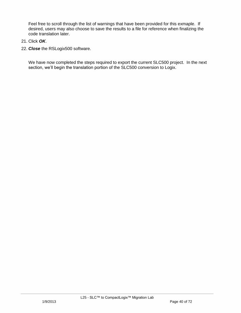
In the Controller Organizer, note that the new project now consists of a Continuous Task called MainTask, a Periodic Task call “_12_STI”, and an Event Task called “_2_MAIN”.
All of the standard SLC500 routines have been placed into the “_2_MAIN” event task.
The code for the DII routine in the SLC500 has been placed into the “MainTask”.
The STI code has been placed into the “12_STI” periodic task.
39. Let‟s open each of these tasks. Expand the MainTask and then the MainProgram.
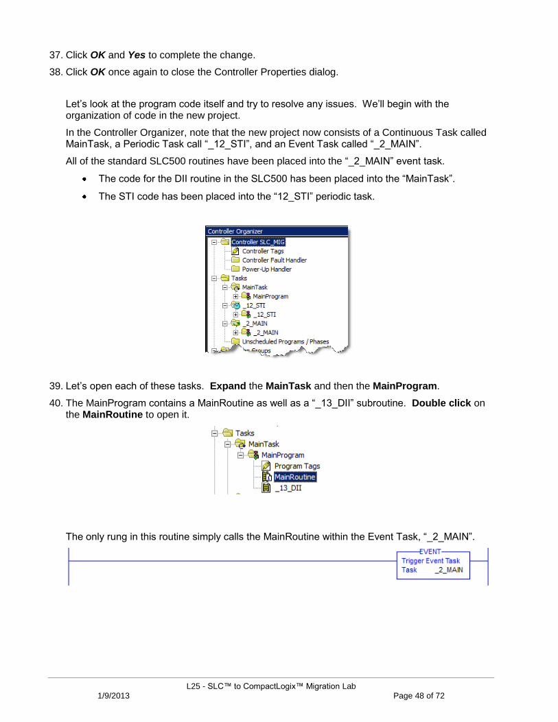
40. The MainProgram contains a MainRoutine as well as a “_13_DII” subroutine. Double click on the MainRoutine to open it.
The only rung in this routine simply calls the MainRoutine within the Event Task, “_2_MAIN”.
L25 - SLC™ to CompactLogix™ Migration Lab 1/9/2013 Page 49 of 72
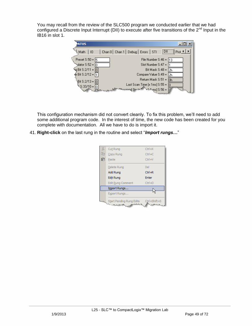
You may recall from the review of the SLC500 program we conducted earlier that we had configured a Discrete Input Interrupt (DII) to execute after five transitions of the 2nd Input in the IB16 in slot 1.
This configuration mechanism did not convert cleanly. To fix this problem, we‟ll need to add some additional program code. In the interest of time, the new code has been created for you complete with documentation. All we have to do is import it.
41. Right-click on the last rung in the routine and select “Import rungs…”
L25 - SLC™ to CompactLogix™ Migration Lab 1/9/2013 Page 50 of 72
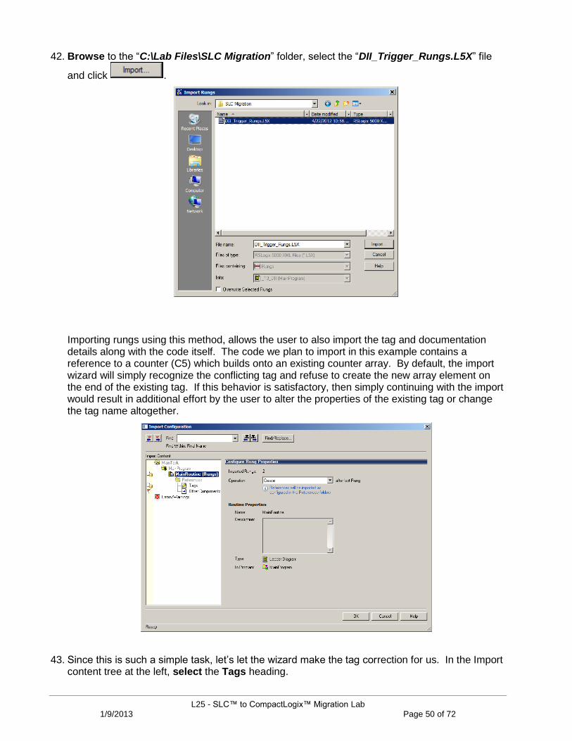
42. Browse to the “C:\Lab Files\SLC Migration” folder, select the “DII_Trigger_Rungs.L5X” file
and click .
Importing rungs using this method, allows the user to also import the tag and documentation details along with the code itself. The code we plan to import in this example contains a reference to a counter (C5) which builds onto an existing counter array. By default, the import wizard will simply recognize the conflicting tag and refuse to create the new array element on the end of the existing tag. If this behavior is satisfactory, then simply continuing with the import would result in additional effort by the user to alter the properties of the existing tag or change the tag name altogether.
43. Since this is such a simple task, let‟s let the wizard make the tag correction for us. In the Import content tree at the left, select the Tags heading.

L25 - SLC™ to CompactLogix™ Migration Lab 1/9/2013 Page 51 of 72
44. Use the Operation dropdown list to select “Overwrite” for the C5 tag name. The I1 input tag is fine.
You should have the following:
45. Click OK to complete the import.
You should now have the additional rungs shown below in your MainRoutine.
Each time the I1[0].1 input goes true, the counter, C5[13], increments by 1. When the Accumulator reaches “5”, the DN bit is enabled and the “_13_DII” routine is called and the counter is reset.
46. To view the code within the “_13_DII” routine, from the Controller Organizer, double click on the “_13_DII” routine to open it.

L25 - SLC™ to CompactLogix™ Migration Lab 1/9/2013 Page 52 of 72
This routine also contains a new rung inserted by the Translation Tool.
We‟ll see a few more of these rungs as we scan through the translated code. The Tool inserts special Program Conversion Error (or PCE) instructions anywhere there may be a conversion issue.
The code within the instruction indicates what type of issue should be addressed. This is a warning to the user that the instruction should be examined to determine if a modification is required. In many cases, the instruction, or in this case, the entire rung, may be deleted with no code adjustment at all.
NOTE: For a complete list of the PCE instruction Message IDs and their descriptions, please refer to Appendix B at the end of this lab.
47. For now, let‟s delete this rung. Highlight the rung number “0” at the left and press Delete or right-click on the rung number and choose “Delete Rung”.
48. The remaining rung is fine as is. Let‟s save our changes so far. From the Menu Bar, click the
Save icon.
Next, let‟s look at our Selectable Timed Interrupt routine. Remember, this routine is part of the STI task, a periodic task in the controller.
49. Right-click on the “_12_STI” periodic task and choose Properties…

L25 - SLC™ to CompactLogix™ Migration Lab 1/9/2013 Page 53 of 72
50. On the Configuration tab, note the Period is set to 2000ms. (2 seconds).
51. No changes required here, so just click OK to close the dialog.
52. As for the STI code, double click on the “_12_STI” routine as shown below to open it.
Just a single rung in this routine which will move the value in N13[0] to N7[14].
53. Continuing on, let‟s see what changes need to be made in the basic control code, that is, the code in the “_2_MAIN” task. From the Controller Organizer, drill down through the _2_MAIN task and _2_MAIN Program and open the “_2_MAIN” Routine.

L25 - SLC™ to CompactLogix™ Migration Lab 1/9/2013 Page 54 of 72
This routine contains a few common conversion errors that we need to address. The first rung in this routine contains a reference to data that is being manipulated directly to I/O. Since we have not yet added I/O to the Config Tree yet, let‟s come back to this later. Scroll down to the 2nd rung which looks like the screenshot below.
This rung references a timer. The timer instruction and its associated elements are compatible between the SLC500 (or PLC-5) and the Logix platform. However, the SLC500 only supports either a .01 or 1 second time base for timers. Logix supports a 1ms time base. The code conversion resulted in an increase of the timer Preset value by an order of magnitude. That is, the original Preset in the SLC500 for this timer was “32767” and now it has been changed to “327670”. All related references to this timer have been adjusted automatically, except those which may reference a specific bit within the Accum or Preset itself. We do have one instance of this which we‟ll address in a moment.
54. For now, this rung is acceptable, so simply highlight the PCE instruction and press Delete to remove it.
55. Continue to scroll down to the end of the routine to locate the next PCE instruction.

L25 - SLC™ to CompactLogix™ Migration Lab 1/9/2013 Page 55 of 72
The last rung contains an STE instruction which is used to enable the Selectable Timed Interrupt. If we truly wished to enable or disable the STI, we would simply add permissives to program control instructions such as a JSR to perform this function. In this instance, we did not plan to disable the function anyway, so this instruction, and hence, the entire rung is not needed.
56. Highlight the rung number at the left and press Delete to remove it.
57. Let‟s save our changes so far. From the Menu Bar, click the Save icon.
58. Let‟s continue on. From the Controller Organizer, open the “_3_IC500DMO” routine.
59. This routine is somewhat longer, so perhaps we can use the software to help us locate the issues. From the Menu Bar, select the Verify Routine icon.
The Results window at the bottom of the screen now contains an updated list of Errors and Warnings. You may expand the Errors window to see more of the list.
TIP: Many of the Warnings reference bits that are used as outputs in more than one rung, Duplicate Destructive Bits. While using this type of coding is generally not recommended, with careful programming, using the same outputs on several different rungs can be done.
60. Scroll back up the Results window to locate the Errors.

L25 - SLC™ to CompactLogix™ Migration Lab 1/9/2013 Page 56 of 72
61. Double click on the first error located on Rung 3 to highlight it in the ladder window.
This rung contains one of those Accumulator bit references discussed earlier. Using the previous rung just above this one, you‟ll notice the original T4:9 timer had a Preset =100. With the new 1ms time base in Logix, the new Preset has been converted to “1000”.
RSLogix 500 RSLogix 5000
62. Subsequently, any instructions using intermediate values within this timer MUST also be adjusted. To make the change, double click on the High Limit value in the LIM instruction and change the value to “400”.
63. With the change complete, highlight the PCE instruction just to the left of the LIM and press Delete to remove it.
64. The same procedure could be done to modify the High Limit values on the LIM instructions in rungs 24-27, 84, and 88 in the same manner. For this lab let‟s leave the rest and move on.
65. From the Menu Bar, click the Save icon.

L25 - SLC™ to CompactLogix™ Migration Lab 1/9/2013 Page 57 of 72
Resolving Issues with Physical I/O
We are making good progress. The remaining issues are all related to instructions that ultimately refer to physical I/O addresses. Let‟s make sure we have all of the necessary corresponding tags in order to complete the I/O mapping.
Most of the I/O conversion errors related to mismatched data types and improper aliasing of the tags to their I/O module data. Our project currently has no I/O Configuration associated with it. We‟ll begin this section by adding the various 1746 I/O to the new CompactLogix system.
In the interest of time, we are going to simply use a module library and import the I/O Configuration rather than create each 1746 module in the tree individually. The library has been stored in an alternate ACD file for you.
66. In the SLC_MIG project, click the Restore Down button in the upper right corner of the window. (This will allow you to re-position the RSLogix 5000 project window)
67. From your Desktop, open the “Lab FilesSLC Migration” folder and open the “IO_ Tree.ACD” project.
68. The IO_Tree project window is already movable. Position the two project windows side-by-side as shown below.
L25 - SLC™ to CompactLogix™ Migration Lab 1/9/2013 Page 58 of 72
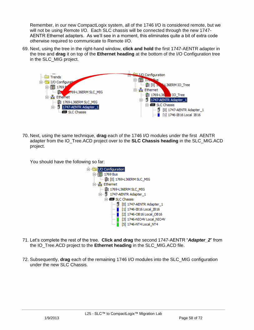
Remember, in our new CompactLogix system, all of the 1746 I/O is considered remote, but we will not be using Remote I/O. Each SLC chassis will be connected through the new 1747-AENTR Ethernet adapters. As we‟ll see in a moment, this eliminates quite a bit of extra code otherwise required to communicate to Remote I/O.
69. Next, using the tree in the right-hand window, click and hold the first 1747-AENTR adapter in the tree and drag it on top of the Ethernet heading at the bottom of the I/O Configuration tree in the SLC_MIG project.
70. Next, using the same technique, drag each of the 1746 I/O modules under the first AENTR adapter from the IO_Tree.ACD project over to the SLC Chassis heading in the SLC_MIG.ACD project.
You should have the following so far:
71. Let‟s complete the rest of the tree. Click and drag the second 1747-AENTR “Adapter_2” from the IO_Tree.ACD project to the Ethernet heading in the SLC_MIG.ACD file.
72. Subsequently, drag each of the remaining 1746 I/O modules into the SLC_MIG configuration under the new SLC Chassis.

L25 - SLC™ to CompactLogix™ Migration Lab 1/9/2013 Page 59 of 72
You should now have the completed I/O tree shown below.
Feel free to open any of the module properties to view the configuration details.
73. From the Menu Bar, click the Save icon.
74. Close the IO_Tree.ACD project.
75. You may maximize the SLC_MIG.ACD project once again.
76. With our new I/O in the tree, open the Controller Tags database (at the top of the Controller Organizer) and verify that you now have a plethora of newly created I/O tags. We‟ll use these tags in a moment to map certain Input and Output aliases.
77. Let‟s complete the rest of the raw code conversion process. From the Controller Organizer, open the “_2_MAIN” routine.

L25 - SLC™ to CompactLogix™ Migration Lab 1/9/2013 Page 60 of 72
This first rung is used to initialize the configuration for the 1746-NT4 in slot 5 of the local SLC500 chassis.
Since this instruction references an entire output word, rather than each of the output bits individually, we have 3 possible ways to resolve this type of issue.
1) We can choose to simply modify the COP instruction to directly write to the physical output locations. 2) We can add multiple MOV instructions to directly write to each physical output word. 3) We can choose to leave the logic code alone and map, or “alias”, the O5[0] tag to the physical output
locations in the tag database.
The main concern with option 1 above is that the Dest data location represents an integer array of at least 4 elements. However, in order to successfully configure multiple channels, the normally consecutive array elements must be transferred into non-consecutive structures built by the 1746-NT4 module data type. An example of the data type is shown below. Notice how the Channel_0_Config and Channel_1_Config words are separated by additional configuration words, thereby eliminating the ability to correctly map 4 contiguous array elements.
L25 - SLC™ to CompactLogix™ Migration Lab 1/9/2013 Page 61 of 72
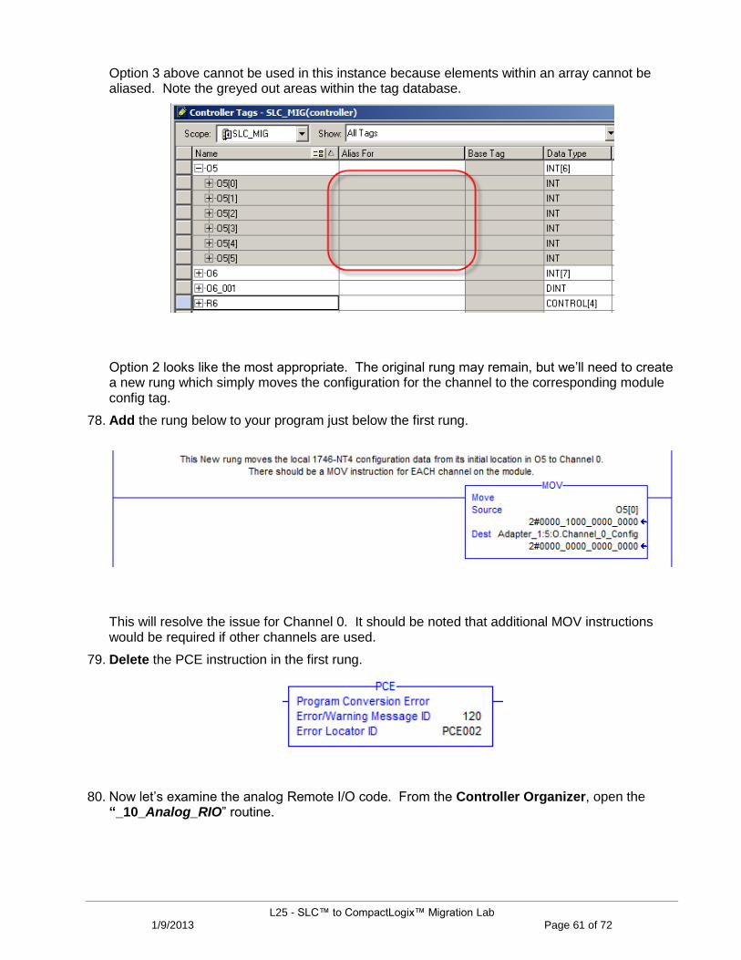
Option 3 above cannot be used in this instance because elements within an array cannot be aliased. Note the greyed out areas within the tag database.
Option 2 looks like the most appropriate. The original rung may remain, but we‟ll need to create a new rung which simply moves the configuration for the channel to the corresponding module config tag.
78. Add the rung below to your program just below the first rung.
This will resolve the issue for Channel 0. It should be noted that additional MOV instructions would be required if other channels are used.
79. Delete the PCE instruction in the first rung.
80. Now let‟s examine the analog Remote I/O code. From the Controller Organizer, open the “_10_Analog_RIO” routine.

L25 - SLC™ to CompactLogix™ Migration Lab 1/9/2013 Page 62 of 72
In order for many specialty modules to transfer data over RIO, sophisticated instructions called Block Transfers were used. In the conversion they were replaced with the MSG instructions shown below.
The need for messaging to/from these modules is no longer needed since we will be communicating with them directly through the new 1747-AENTR module.
Data to be written to the remote NIO4V module in our example, was entered into N11:0 (2 words).
Data to be read from the NIO4V into the controller was placed into N13:0 (2 words).
This is the only information we need to create the instructions necessary to replicate the original program functionality.
L25 - SLC™ to CompactLogix™ Migration Lab 1/9/2013 Page 63 of 72
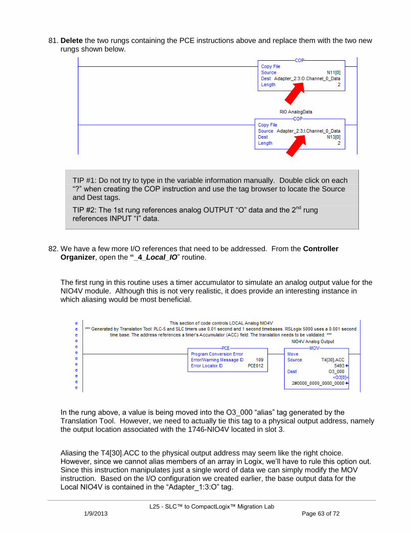
81. Delete the two rungs containing the PCE instructions above and replace them with the two new rungs shown below.
TIP #1: Do not try to type in the variable information manually. Double click on each “?” when creating the COP instruction and use the tag browser to locate the Source and Dest tags.
TIP #2: The 1st rung references analog OUTPUT “O” data and the 2nd rung references INPUT “I” data.
82. We have a few more I/O references that need to be addressed. From the Controller Organizer, open the “_4_Local_IO” routine.
The first rung in this routine uses a timer accumulator to simulate an analog output value for the NIO4V module. Although this is not very realistic, it does provide an interesting instance in which aliasing would be most beneficial.
In the rung above, a value is being moved into the O3_000 “alias” tag generated by the Translation Tool. However, we need to actually tie this tag to a physical output address, namely the output location associated with the 1746-NIO4V located in slot 3.
Aliasing the T4[30].ACC to the physical output address may seem like the right choice. However, since we cannot alias members of an array in Logix, we‟ll have to rule this option out. Since this instruction manipulates just a single word of data we can simply modify the MOV instruction. Based on the I/O configuration we created earlier, the base output data for the Local NIO4V is contained in the “Adapter_1:3:O” tag.

L25 - SLC™ to CompactLogix™ Migration Lab 1/9/2013 Page 64 of 72
83. In the first rung, modify the Dest element of the MOV instruction and delete the PCE instruction as shown below.
84. Let‟s look at another I/O issue. From the Controller Organizer, open the “_5_Sequencer1” routine.
The only rung in this routine is used to pulse various output patterns to the 1746-OB16 module in the 2nd I/O chassis. The trigger mechanism is the 4th bit of the T4[30] timer, which flagged the PCE instruction on the rung.
As the T4:30 timer executed in the SLC500, bit 4 was enabled approximately four times per second. Because the time base has changed from .01 seconds to .001 seconds, this 4th bit now pulses at a much faster rate. In order to compensate for this, we‟ll need to adjust the timer address.
85. Modify the input instruction shown below to use the 7th bit in the T4[30].ACC word.
86. With the timer adjusted, we can remove the PCE instruction. Highlight the PCE instruction and press Delete.
However, we have one more item to address on this rung. The Dest element of the Sequencer Output (SQO) instruction needs to be linked to the physical outputs on the 1746-OB16 in the 2nd adapter. While this might seem trivial, the Array, Dest and actual I/O address data types are not the same so they cannot be linked within the SQO instruction. The Array and Dest tags are double integer (DINT) data types and the output address is an integer (INT).
87. To eliminate the data mismatch, we need to remove the alias reference which is forcing this tag to assume the integer data type. Right-click on the “O6_001” tag in the SQO instruction and select “Edit ‘O6_001’ Properties”.
L25 - SLC™ to CompactLogix™ Migration Lab 1/9/2013 Page 65 of 72
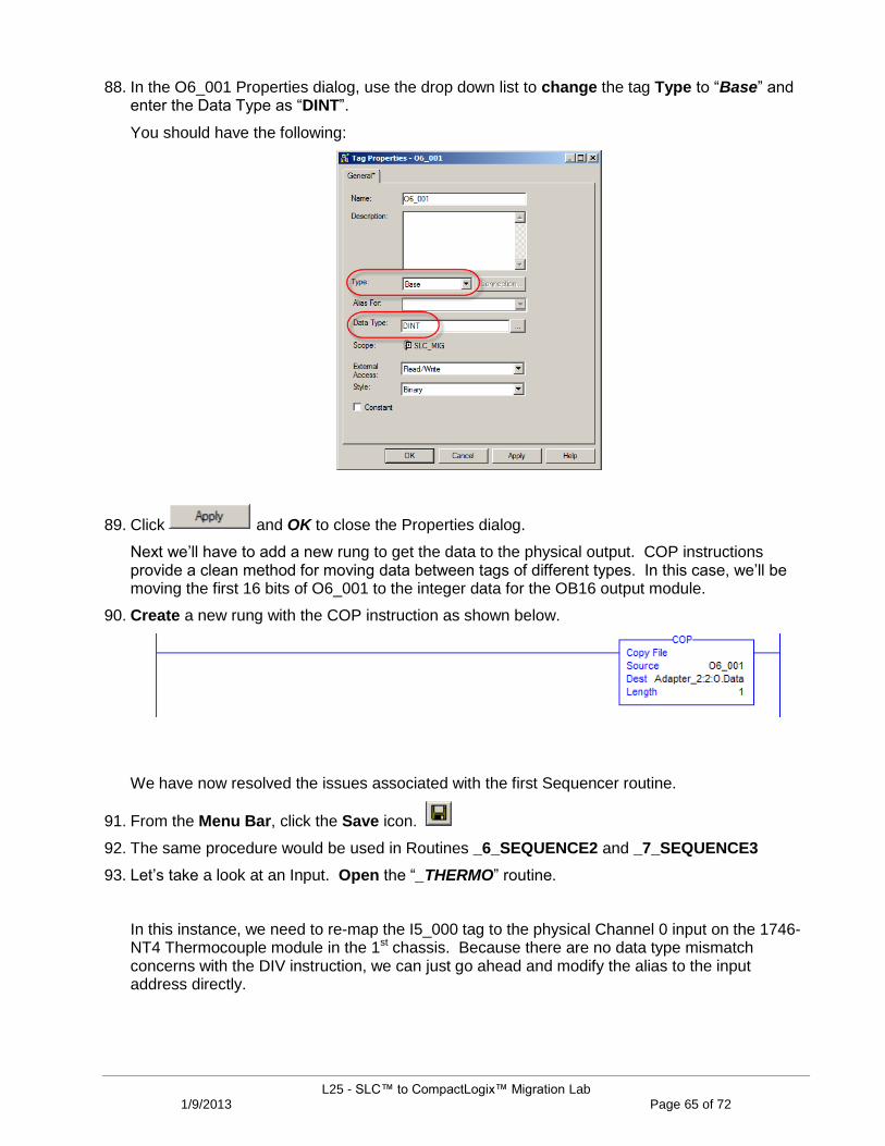
88. In the O6_001 Properties dialog, use the drop down list to change the tag Type to “Base” and enter the Data Type as “DINT”.
You should have the following:
89. Click and OK to close the Properties dialog.
Next we‟ll have to add a new rung to get the data to the physical output. COP instructions provide a clean method for moving data between tags of different types. In this case, we‟ll be moving the first 16 bits of O6_001 to the integer data for the OB16 output module.
90. Create a new rung with the COP instruction as shown below.
We have now resolved the issues associated with the first Sequencer routine.
91. From the Menu Bar, click the Save icon.
92. The same procedure would be used in Routines _6_SEQUENCE2 and _7_SEQUENCE3
93. Let‟s take a look at an Input. Open the “_THERMO” routine.
In this instance, we need to re-map the I5_000 tag to the physical Channel 0 input on the 1746-NT4 Thermocouple module in the 1st chassis. Because there are no data type mismatch concerns with the DIV instruction, we can just go ahead and modify the alias to the input address directly.

L25 - SLC™ to CompactLogix™ Migration Lab 1/9/2013 Page 66 of 72
94. Right-click on the Source A “I5_000” tag in the DIV instruction and select “Edit ‘I5_000’ Properties”.
95. Using the drop down list, browse to the Channel_0_Data tag for the Thermocouple module as shown below.
96. Click and OK.
Your rung should now appear shown below.

L25 - SLC™ to CompactLogix™ Migration Lab 1/9/2013 Page 67 of 72
As we have shown in this section, there are a number of ways to resolve the issues associated with the mapping of physical I/O address words after the conversion. The MOV or COP instructions we added earlier provide excellent methods for manipulating 16 bits all at once. Similarly, in the last case, we were able to quickly re-assign the thermocouple data with a simple alias to the entire word.
However, input and output addresses, especially those tied to digital I/O modules, are typically addressed as bits rather than whole words. The _3_IC500DMO routine in our SLC_MIG program contains a large quantity of these bit references in rungs like the one shown below.
The data table below is an example of the bit aliases for one Input and one Output module. Although we will not do so in this lab, when converting an actual project, each of these I1 and O2 tags would need to be re-mapped to the physical address of its corresponding I/O.

L25 - SLC™ to CompactLogix™ Migration Lab 1/9/2013 Page 68 of 72
Oftentimes, when dealing with digital I/O modules, the best remedy for I/O mapping is simply to eliminate the aliasing altogether and just directly reference the physical data points as shown below.
97. From the Menu Bar, click the Save icon.
Congratulations! You have completed the conversion of this project into Logix.
L25 - SLC™ to CompactLogix™ Migration Lab 1/9/2013 Page 69 of 72
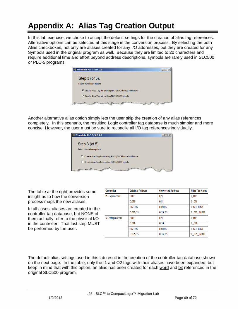
Appendix A: Alias Tag Creation Output
In this lab exercise, we chose to accept the default settings for the creation of alias tag references. Alternative options can be selected at this stage in the conversion process. By selecting the both Alias checkboxes, not only are aliases created for any I/O addresses, but they are created for any Symbols used in the original program as well. Because they are limited to 20 characters and require additional time and effort beyond address descriptions, symbols are rarely used in SLC500 or PLC-5 programs.
Another alternative alias option simply lets the user skip the creation of any alias references completely. In this scenario, the resulting Logix controller tag database is much simpler and more concise. However, the user must be sure to reconcile all I/O tag references individually.
The table at the right provides some insight as to how the conversion process maps the new aliases.
In all cases, aliases are created in the controller tag database, but NONE of them actually refer to the physical I/O in the controller. That last step MUST be performed by the user.
The default alias settings used in this lab result in the creation of the controller tag database shown on the next page. In the table, only the I1 and O2 tags with their aliases have been expanded, but keep in mind that with this option, an alias has been created for each word and bit referenced in the original SLC500 program.

L25 - SLC™ to CompactLogix™ Migration Lab 1/9/2013 Page 70 of 72

L25 - SLC™ to CompactLogix™ Migration Lab 1/9/2013 Page 71 of 72
Appendix B: PCE Instruction Error Codes
Program Conversion Error (or PCE) instructions are special instructions inserted into Logix routines when converting application code from legacy control systems such as SLC500 or PLC-5. The instructions themselves flag the engineer that there may be an issue with a legacy instruction, referenced I/O or perhaps scaling.
In many cases, the code flagged by a PCE instruction be may fine without making any changes at all. The table below provides detailed descriptions of the various Message IDs contained in PCE instructions.

L25 - SLC™ to CompactLogix™ Migration Lab 1/9/2013 Page 72 of 72