HYDRA M™ HYDRA PRO SUPER™ - Titan Tool
40
Model Numbers: Hydra M 2000™ 433-860 433-861 (55 gal.) Hydra M 4000™ 433-800 (roofer model) 433-801 (painter model) 433-802 (55 gal.) Hydra Pro Super™ 433-810 HYDRA M ™ HYDRA PRO SUPER ™ 1120 • Form No. 0528925N GAS POWERED AIRLESS SPRAYER OPERATING MANUAL - EN - OPERATING MANUAL 2
-
Upload
khangminh22 -
Category
Documents
-
view
1 -
download
0
Transcript of HYDRA M™ HYDRA PRO SUPER™ - Titan Tool

Model Numbers: Hydra M 2000™ 433-860 433-861 (55 gal.)Hydra M 4000™ 433-800 (roofer model) 433-801 (painter model) 433-802 (55 gal.)Hydra Pro Super™ 433-810
HYDRA M™
HYDRA PRO SUPER™
1120 • Form No. 0528925N
GAS POWERED AIRLESS SPRAYER
OPERATING MANUAL
- EN - OPERATING MANUAL 2

2 © Titan Tool Inc. All rights reserved.
Important Safety InformationRead all safety information before operating the equipment. Save these instructions.
Indicates a hazardous situation which, if not avoided, could result in death or serious injury.To reduce the risks of fire or explosion, electrical shock and the injury to persons, read and understand all instructions included in this manual. Be familiar with the controls and proper usage of the equipment.
WARNING: EXPLOSION OR FIRE Flammable vapors, such as solvent and paint vapors, in work area can ignite or explode.
PREVENTION: 1. Use equipment only in well ventilated area. Keep a good
supply of fresh air moving through the area to keep the air within the spray area free from accumulation of flammable vapors. Keep pump assembly in well ventilated area. Do not spray pump assembly.
2. Do not fill fuel tank while engine is running or hot; shut off engine and allow to cool. Fuel is flammable and can ignite or explode if spilled on a hot surface.
3. Eliminate all ignition sources, such as pilot lights, cigarettes, portable electric lamps and plastic drop cloths (potential static arc).
4. Keep work area free of debris, including solvent, rags and gasoline.
5. Do not plug or unplug power cords, or turn power or light switches on or off when flammable vapors are present.
6. Ground equipment and conductive objects in work area. Make sure the grounding cable (not equipped) is connected from the grounding lug to a true earth ground.
7. Use only grounded hoses. 8. Hold spray gun firmly to the side of a grounded pail when
triggering into pail. 9. If there is static sparking or if you feel a shock, stop operation
immediately. 10. Know the contents of the paint and solvents being sprayed.
Read all Safety Data Sheets (SDS) and container labels provided with the paints and solvents. Follow the paint and solvent manufacturer’s safety instructions.
11. Do not use a paint or solvent containing halogenated hydrocarbons. Such as chlorine, bleach, mildewcide, methylene chloride and trichloroethane. They are not compatible with aluminum. Contact the coating supplier about compatibility of material with aluminum.
12. Keep a fire extinguisher in work area.
WARNING: INJECTION INJURYA high pressure paint stream produced by this equipment can pierce the skin and underlying tissues, leading to serious injury and possible amputation. See a physician immediately.
PREVENTION: 1. Do not aim the gun at, or spray any person or animal. 2. Keep hands and other body parts away from the discharge.
For example, do not try to stop leaks with any part of the body.
3. Always use the nozzle tip guard. Do not spray without the nozzle tip guard in place.
4. Only use a nozzle tip specified by the manufacturer. 5. Use caution when cleaning and changing nozzle tips. In the
case where the nozzle tip clogs while spraying, ALWAYS lock gun trigger, shut pump off, and release all
pressure before servicing, cleaning tip or guard, or changing tip. Pressure will not be released by turning off the motor. The PRIME/SPRAY valve or pressure bleed valve must be turned to their appropriate positions to relieve system pressure. Refer to PRESSURE RELIEF PROCEDURE described in the pump manual.
6. Do not leave the unit energized or under pressure while unattended. When the unit is not in use, turn off the unit and relieve the pressure in accordance with the manufacturer’s instructions.
7. High-pressure spray is able to inject toxins into the body and cause serious bodily injury. In the event that injection occurs, seek medical attention immediately.
8. Check hoses and parts for signs of damage, a leak can inject material into the skin. Inspect hose before each use. Replace any damaged hoses or parts.
9. This system is capable of producing 3300 PSI / 22.8 MPa. Only use replacement parts or accessories that are specified by the manufacturer and that are rated a minimum of 3300 PSI. This includes spray tips, nozzle guards, guns, extensions, fittings, and hose.
10. Always engage the trigger lock when not spraying. Verify the trigger lock is functioning properly.
11. Verify that all connections are secure before operating the unit.
12. Know how to stop the unit and bleed pressure quickly. Be thoroughly familiar with the controls. Pressure will not be released by turning off the motor. The PRIME/SPRAY valve or pressure bleed valve must be turned to their appropriate positions to relieve system pressure. Refer to PRESSURE RELIEF PROCEDURE described in the pump manual.
13. Always remove the spray tip before flushing or cleaning the system.
NOTE TO PHYSICIAN: Injection into the skin is a traumatic injury which can lead to possible amputation. It is important to treat the injury as soon as possible. DO NOT delay treatment to research toxicity. Toxicity is a concern with some coatings injected directly into the blood stream. Consultation with a plastic surgeon or reconstructive hand surgeon may be advisable.
WARNING: GENERAL Can cause severe injury or property damage.
PREVENTION: 1. Always wear appropriate gloves, eye protection, clothing
and a respirator or mask when painting. Hazardous vapors – Paints, solvents, insecticides, and other materials can be harmful if inhaled or come in contact with body. Vapors can cause severe nausea, fainting or poisoning.
2. Do not operate or spray near children. Keep children away from equipment at all times.
3. Do not overreach or stand on an unstable support. Keep effective footing and balance at all times.
4. Stay alert and watch what you are doing. 5. Do not operate the unit when fatigued or under the influence
of drugs or alcohol. 6. Do not kink or over-bend the hose. Airless hose can develop
leaks from wear, kinking and abuse. A leak can inject material into the skin.

© Titan Tool Inc. All rights reserved. 3
Important Safety Information 7. Do not expose the hose to temperatures or pressures in excess
of those specified by manufacturer. 8. Do not use the hose as a strength member to pull or lift the
equipment. 9. Use lowest possible pressure to flush equipment. 10. Follow all appropriate local, state and national codes
governing ventilation, fire prevention and operation. 11. The United States Government Safety Standards have been
adopted under the Occupational Safety and Health Act (OSHA). These standards, particularly part 1910 of the General Standards and part 1926 of the Construction Standards should be consulted.
12. Before each use, check all hoses for cuts, leaks, abrasion or bulging of cover. Check for damage or movement of couplings. Immediately replace hose if any of those conditions exist. Never repair a paint hose. Replace with a conductive high-pressure hose.
13. Do not spray outdoors on windy days. 14. Always unplug cord from outlet before working on equipment
(electric models only).IMPORTANT: Do not lift cart handle when loading or unloading.
Gasoline Engine Safety
The engine exhaust from this unit contains chemicals known to the State of California to cause cancer, birth defects, or other reproductive harm.
1. Gas engines are designed to give safe and dependable service if operated according to instructions. Read and understand the engine Owner’s Manual before operating the engine. Failure to do so could result in personal injury or equipment damage.
2. To prevent fire hazards and to provide adequate ventilation, keep the engine at least 1 meter (3 feet) away from buildings and other equipment during operation. Do not place flammable objects close to the engine.
3. Children and pets must be kept away from the area of operation due to a possibility of burns from hot engine components or injury from any equipment the engine may be used to operate.
4. Know how to stop the engine quickly, and understand the operation of all controls. Never permit anyone to operate the engine without proper instructions.
5. Gasoline is extremely flammable and is explosive under certain conditions.
6. Refuel in a well-ventilated area with the engine stopped. Do not smoke or allow flames or sparks in the refueling area or where gasoline is stored.
7. Do not overfill the fuel tank. After refueling, make sure the tank cap is closed properly and securely.
8. Be careful not to spill fuel when refueling. Fuel vapor or spilled fuel may ignite. If any fuel is spilled, make sure the area is dry before starting the engine.
9. Never run the engine in an enclosed or confined area. Exhaust contains poisonous carbon monoxide gas; exposure may cause loss of consciousness and may lead to death.
10. The muffler becomes very hot during operation and remains hot for a while after stopping the engine. Be careful not to touch the muffler while it is hot. To avoid severe burns or fire hazards, let the engine cool before transporting it or storing it indoors.
11. Never ship/transport unit with gasoline in the tank.
Part # Language
745-089745-104
English
745-106745-107
Spanish
745-108745-109
French
745-110745-111
German
Warning LabelsYour sprayer has the English language warning labels. If you require these labels in French, German, or Spanish, or require additional English labels, order directly from Titan free of charge.
Table of ContentsSafety Precautions ........................................................................... 2Specifications ................................................................................... 4Introduction ..................................................................................... 5 Hydra M 2000™ ..............................................................................................5 Hydra M 4000™ ..............................................................................................6Setup ................................................................................................ 7 Fueling (gas engine) ....................................................................................7 Battery Connections ....................................................................................8Operation ......................................................................................... 7 Startup ..............................................................................................................9 Pressure Relief Procedure ..........................................................................9 Cleaning a Clogged Tip ............................................................................10 Color Change / Clean Out ........................................................................10Maintenance .................................................................................. 10 Hydraulic System ........................................................................................10 General Fluid Pump Maintenance ........................................................10 Basic Engine Maintenance ......................................................................11Troubleshooting ............................................................................ 12 Airless Spraying ...........................................................................................12 Spray Patterns ..............................................................................................13 Hydraulic Motors ........................................................................................14 Fluid Sections ...............................................................................................15Parts Lists and Service Instructions ............................................. 16 Hydra M 2000™ Major Components ....................................................16 Hydra M 4000™ Major Components ....................................................18 Engine Drive & Hydraulic System .........................................................20 Tank Assembly and Mobil Kit .................................................................22 Hydraulic motor, 441-575 & 441-576 ..................................................24 Fluid Pump, Hydra M 2000™. 315-555.................................................28 Fluid Pump, Hydra M 4000™, 245-555.................................................30 Fluid Pump, Hydra Pro Super™, 185-551 ............................................32 Fluid Accessories .........................................................................................34 Outlet Accessories ......................................................................................37Accessories and Service Kits ......................................................... 39Warranty ........................................................................................ 40

4 © Titan Tool Inc. All rights reserved.
SpecificationsHydra M 4000™Gallons per minute (GPM) ...................... 3.3Cycle rate per gallon ................................ 13Cycles per minute (max) ......................... 43Maximum tip size: 1-Gun ................................................. .060” 2-Gun ................................................. .040” 3-Gun ................................................. .035”Pressure range ............................................ 500-4000 psiPower ............................................................. 11 HP Honda engine, electric
startFuel capacity ............................................... 1.6 gallonsWeight ........................................................... 361 lbsInlet paint filter ........................................... 1 1/4” rock catcherOutlet paint filter ....................................... 50 mesh, 18in2
Pump inlet.................................................... 1 1/4” Pump outlet ................................................ 1/2” NPT(F)Paint filter hose connections ................ (1) - 1/4” NPSM(M) (1) 3/8” NPT(F) PluggedDimensions .................................................. 38” H x 52” L w/handle (32” w/o
handle) x 24 1/2” WFluid Pump Wetted Parts:Electroless nickel plated ductile iron, electroless nickel plated carbon steel, propietary hard chrome anti-wear surface, stainless steel, tungsten carbide, PTFE, thiokol impregnated leather, ultra high molecular weight polyethylene.
Hydra M 2000™Gallons per minute (GPM) ...................... 6.0Cycle rate per gallon ................................ 7Cycles per minute (max) ......................... 42Maximum tip size: 1-Gun ................................................. .075” 2-Gun ................................................. .053”Pressure range ............................................ 500-2000 psiPower ............................................................. 11 HP Honda engine, electric
startFuel capacity ............................................... 1.6 gallonsWeight ........................................................... 421 lbsInlet paint filter ........................................... N/AOutlet paint filter ....................................... N/APump inlet.................................................... 1 1/2” Pump outlet ................................................ 1” NPT(F)Paint filter hose connections ................ N/ADimensions .................................................. 40” H x 52” L w/handle (32” w/o
handle) x 24 1/2” WFluid Pump Wetted Parts:Electroless nickel plated ductile iron, electroless nickel plated carbon steel, propietary hard chrome anti-wear surface, stainless steel, tungsten carbide, PTFE, thiokol impregnated leather, ultra high molecular weight polyethylene.
Hydra M Pro Super™Gallons per minute (GPM) ...................... 2.5Cycle rate per gallon ................................ 24Cycles per minute (max) ......................... 60Maximum tip size: 1-Gun ................................................. .050” 2-Gun ................................................. .035” 3-Gun ................................................. .029”Pressure range ............................................ 500-4500 psiPower ............................................................. 11 HP Honda engine, electric
startFuel capacity ............................................... 1.6 gallonsWeight ........................................................... 354 lbsInlet paint filter ........................................... 1” rock catcherOutlet paint filter ....................................... 50 mesh, 18in2
Pump inlet.................................................... 1” Pump outlet ................................................ 1/2” NPT(F)Paint filter hose connections ................ (1) - 1/4” NPSM(M) (1) 3/8” NPT(F) PluggedDimensions .................................................. 38” H x 52” L w/handle (32” w/o
handle) x 24 1/2” WFluid Pump Wetted Parts:Electroless nickel plated ductile iron, electroless nickel plated carbon steel, propietary hard chrome anti-wear surface, stainless steel, tungsten carbide, PTFE, thiokol impregnated leather, ultra high molecular weight polyethylene.

© Titan Tool Inc. All rights reserved. 5
IntroductionCongratulations on having selected the finest airless sprayer available in the world. Titan piston pumps are tireless workhorses - so tough they are virtually indestructable, even under the most severe service. Titan designs and builds equipment with superior quality and reliability. Equipment that will last for years with minimal maintenance and downtime. This equipment will make you money year after year. We thank you for your purchase and welcome you to our large and growing family of Titan users.Hydraulic drive makes possible the longest stroke and slowest cycling pumps in the industry which translates into low maintenance and longer life.
The Hydra M 2000 and 4000™ offer other cost saving features: • Variable pressure control • Very large tungsten carbide valve seats with hardened
stainless steel balls • Self-adjusting packings • Exclusive hand-tight swivel foot valve • Large capacity inline paint filter • “Floating ball” pressure bleed valve • 5 gallon siphon hose and bleed line assemblies are standardYou have made an excellent choice. We know you will be pleased with your new Hydra M™ airless sprayer. We appreciate your business.
High pressurehydraulic hose
Hydraulicmotor
Hydraulic systemshuto� valve
Wet cup (useLubrisolv only)
Pressure bleedvalve
Outlet assembly
Bleed line
Siphon hose
Ground lugFluid pumpHydraulic �uid�ll & dipstick(use Cool�o only)
Pressure adjustment knobIncrease = clockwise
Decrase = counterclockwise
Start PositionWhen the handle is in this position,the system is not under pressure
Run PositionWhen the handle is in this position, the system ispressurized. Use extreme caution. Follow all warningsand instructions regarding pressure relief procedure
Data plate
Hydra M 2000™

6 © Titan Tool Inc. All rights reserved.
High pressurehydraulic hose
Hydraulicmotor
Hydraulic systemshuto� valve
Wet cup (useLubrisolv only)
Pressure bleedvalve
Paint �lter
Fluid pump
Siphon hose Bleed lineGround lug
Hydraulic �uid�ll & dipstick(use Cool�o only)
Pressure adjustment knobIncrease = clockwise
Decrase = counterclockwise
Start PositionWhen the handle is in this position,the system is not under pressure
Run PositionWhen the handle is in this position, the system ispressurized. Use extreme caution. Follow all warningsand instructions regarding pressure relief procedure
Data plate
Hydra M 4000™

© Titan Tool Inc. All rights reserved. 7
Setup
Read, understand, and follow all warnings before starting or operating this sprayer.
Required tools: Adjustable wrench
1. Connecting the hoses: The siphon hose and bleed line hose have factory installed
PTFE tape on the male end o the hoses. Tighten the siphon hose and bleed line wrench tight.
2. One gun operation: Attach the gun and hose. Always use a spray hose at least 50
feet long. Do not use PTFE or thread sealant on this assembly. Do not install the spray tip at this time.
3. Two gun operation: Remove the plug from the second gun outlet. Replace with
nipple, part # 812-003 for 1/4” hose or nipple; use part # 808-555 for 3/8” hose. Connect a hose and a gun to the outlet.
4. Multiple gun operation: The Hydra M 4000™ is engineerd to handle up to 4 guns.
When using more than two guns, make sure the second gun hookup outlet is plugged. Connect the multiple gun manifold to the single gun outlet. These manifolds are for either 2, 3, or 4 guns and have shutoff valves. Connect a hose and gun to each outlet.
5. Fill the wet-cup 1/2 full with Titan’s Lubrisolv, part # 310-203 supplied by the factory. This extends packing life.
6. Be sure the Hydra M 4000 / 2000™ system is grounded. All Titan units are equipped with a grounding lug. A grounding cable (not supplied) should be used to connect the unit to a true earth ground. Check your loack electrical regulations for detailed grounding instructions.
Proper grounding is important. This applies to both gas and electric powered models. The passage of some materials through the nylon fluid hose will build up a static electric charge, which if discharged, could ignite solvent vaports present and create an explosion.
7. Strain all paints to assure trouble-free operation and freedom from frequent cleaning of inlet screen and gun strainer.
OperationFueling (gas engine)
Gasoline is extremely flammable and is explosive under certain conditions.
• ALWAYS turn the engine off before refueling. • Refuel in a well-ventilated area. • Do not smoke or allow flames or sparks in the refueling area or
where gasoline is stored. • Do not overfill the fuel tank. After refueling, make sure the
tank cap is closed properly and securely. • Be careful not to spill fuel when refueling. Spilled fuel or fuel
vapor may ignite. If any fuel is spilled, make sure the area is dry before starting the engine.
• Avoid repeated or prolonged contact with skin or breathing of vapor.
• Keep out of the reach of children.
Fuel Specifications • Use automotive gasoline that has a pump octane number of
86 or higher, or that has a research octane number of 91 or higher. Use of a lower octane gasoline can cause persistent “pinging” or heavy “spark knock” (a metallic rapping noise) which, if severe, can lead to engine damage.
NOTE: If “spark knock” or “pinging” occurs at a steady engine speed under normal load, change brands of gasoline. If spark knock or pinging persists, consult an authorized dealer of the engine manufacturer. Failure to do so is considered misuse, and damage caused by misuse is not covered by the engine manufacturer’s limited warranty.
Occasionally you may experience light spark knock while operating under heavy loads. This is no cause for concern, it simply means your engine is operating efficiently.
• Unleaded fuel produces fewer engine and spark plug deposits and extends the life of the exhaust system components.
• Never use stale or contaminated gasoline or an oil/gasoline mixture. Avoid getting dirt, dust, or water in the fuel tank.

8 © Titan Tool Inc. All rights reserved.
Battery Connections 1. Use a 12 volt battery with an ampere-hour rating of at least
18AH. 2. Connect the battery positive (+) cable to the starter solenoid
terminal as shown. 3. Connect battery negative (-) cable to an engine mounting
bolt, frame bolt, or other good engine ground connection. 4. Check the battery cable connections to be sure the cables are
tightened and free of corrosion. Remove any corrosion and coat the terminals and cable ends with grease.
Negative (-)battery cable
Positive (+)battery cable
Startersolenoid
The battery gives off explosive gases; keep sparks, flames and cigarettes away. Provide adequate ventilation when charging or using batteries in an enclosed space.
The battery contains sulphuric acid (electrolyte). Contact with skin or eyes may cause severe burns. Wear protective clothing and a face shield.
• If electrolyte gets on your skin, flush with water. • If electrolyte gets in your eyes, flush with water for at least
15 minutes and call a physician. • Electrolyte is poisonous. If swallowed, drink large
quantities of water or milk and follow with milk of magnesia or vegetable oil and call a physician.
• Keep out of reach of children.
Filling the BatteryDue to shipping regulations, the battery in your Hydra has been shipped to you empty. Before using the Hydra, the battery must be filled with electrolyte (acid) and then charged. Follow the instructions below.
NOTE: Battery electrolyte can be purchased at your local hardware or auto parts retailer.
Battery electrolyte is very hazardous. Make sure to follow all precautions and warnings on the electrolyte container.
Electrolyte specificationsIn cool or temperate climates, purchase electrolyte with a specific gravity of 1.270 - 1.280.In tropical climantes, purchase electrolyte with a specific gravity of 1.250 - 1.260.
Fill the battery 1. Remove the battery from the holder. 2. Remove rubber sealing cap from the exhaust opening on the
side of the battery. 3. Replace the rubber sealing cap with the exhaust tube
provided (this can be found in the plastic bag containing the instruction manual and other literature).
4. Remove the six (6) yellow filling caps on top of the battery. 5. Fill the battery with electrolyte in each of the filling ports (see
“Electrolyte specifications”, above). Fill the battery to the upper level as indicated on the battery case.
IMPORTANT: The electrolyte temperature must not be lower than 60º F (15º C) or higher than 86º F (30º C). 6. Allow the battery to stand for at least 30 minutes after filling. 7. After 30 minutes, check electrolyte level. If the level has fallen,
refill to the upper level prior to charging. 8. Replace the yellow filling caps. 9. Replace the battery onto the holder.
Positive (+)battery cable
Negative (-)battery cable

© Titan Tool Inc. All rights reserved. 9
Charge the battery 1. Place the battery on a charge for 3 to 5 hours at the
approximate current equivalent to 1/10th of its rated capacity. a. If electrolyte level falls after charging, fill with distilled water to
upper level. b. After water is added, continue charging for 1 to 2 hours in order to
mix the water with the electrolyte. 2. After charging, check the battery voltage three times at 30
minute intervals. Make sure the voltage is constant over the three readings.
3. Replace the filler plugs (if needed) and wash off any electrolyte spillage with clean water.
Startup 1. Areas must be well-ventilated to prevent hazardous operation
with volatile solvents or exhaust fumes.
If lacquer or other flammable materials are to be sprayed, ALWAYS locate the unit outside the immediate spraying area. Failure to do so may cause an explosion.
2. Locate the unit outside the immediate spraying area to avoid clogged air intake of the engine or electric motor with overspray.
3. Before starting the unit, check oil levels: a. The hydraulic fluid level should read “Full” on the dipstick. Check
it daily. See the hydraulic system maintenance instructions for changing or adding hydraulic fluid. Do not overfill. Use only Titan Coolflo™, part no. 430-361.
b. The gasoline engine oil level is determined by the manufacturer. Check the manufacturer’s service manual supplied.
4. Open the orange handle shut-off valve located on the hydraulic return hose. Handle should be in line with hose. The figure below shows the handle in the open position.
Start
5. Turn the pressure adjustment knob counterclockwise to lowest pressure setting. See figure above.
6. Open the pressure bleed valve by turning it counterclockwise. This relieves pressure. See figure below.
a. Your new sprayer was tested at the factory with water soluble oil. You must clean the system before spraying to avoid contamination of the sprayed material.
If you are spraying a water-based latex, flush with warm, soapy water followed by a clean water rinse.
If you are using any other coating, flush with warm, soapy water followed by a solvent. Check with the material manufacturer for a compatible solvent.
Place siphon tube assembly into proper solvent or water. b. Place waste container below bleed line.
c. Start engine. Turn pressure control adjustment knob clockwise (increasing pressure) until pump cycles evenly and solvent flows freely from bleed line.
d. Close pressure bleed valve by turning it clockwise. This allows the system to pressurize. Hold gun trigger open, without spray tip attached, until the fluid flows smoothly. See figure below.
Run
7. Repeat above starting procedure with paint material. Lock gun trigger and attach spray tip. See the Technical Data Sheet or Operator’s Manual on the gun provided for installation and selection of the proper tip sizes.
8. Test spray pattern. Operate the pump at the lowest hydraulic pressure which provides good atomization. See the Troubleshooting Guide if you are not getting the proper pattern.
9. Operating pressure is adjustable from 500 to 2000 psi for the Hydra M 2000™, from 500 to 4000 psi for the Hydra M 4000™ and from 500 to 4500 psi for the Hydra Pro Super™. Turn the pressure adjustment knob clockwise to increase pressure. Do not turn the knob clockwise more than necessary to provide satisfactory atomization. Excess pressure wears out spray tips.
10. When restarting the unit, reduce the pressure at pressure control adjustment knob and pressure bleed valve.
Pressure Relief ProcedureIMPORTANT: Always reduce pressure when you are cleaning a clogged tip, changing a tip, servicing any part of the system, or shutting down. Follow the steps below. 1. Engage the gun trigger lock. 2. Shut off the power source. 3. Close the orange handle shut-off ball valve on the hydraulic
hose. 4. Open the pressure bleed valve by turning it counterclockwise
at least three full turns. 5. Disengage the gun trigger lock and hold trigger open until
flow of material stops. 6. Be certain to hold a metal part of the gun firmly to the side of
a grounded metal container.
10 © Titan Tool Inc. All rights reserved.
Cleaning a Clogged Tip 1. Follow the Pressure Relief Procedure, page 9. 2. Lock the gun trigger. 3. Unthread the safety tip guard and remove the spray tip. Wash
the tip in solvent and use a tip probe to remove any clogged material.
4. Release the gun trigger lock and spray briefly into a waste container to blow out any clogged particles.
5. Reset the trigger lock in the “Trigger Locked” position. Release the trigger lock and resume spraying.
The flow from the spray tip is at very high pressure. Contact with any body part may be dangerous. Do not place finger on gun outlet. Do not point the gun at any person. Never operate the spray gun without the proper tip guard.
Color Change / Clean OutIMPORTANT: Use only compatible solvents when cleaning out oil based enamels, lacquers, coal tar, and epoxies. Check with the fluid manufacturer for a recommended solvent. 1. Reduce pressure by turning the pressure adjustment knob and
the pressure bleed valve on the bleed line counterclockwise. Follow the Pressure Relief Procedure, page 9.
The pressure bleed valve should be turned counter-clockwise three full turns.
2. Pull the siphon tube out of the material container. 3. Remove the spray tip from the gun. Hold the gun trigger
open until material flow stops. 4. Put siphon tube into wash solvent or water as applicable, and
operate pump slowly at low pressure until solvent flows freely from pressure bleed valve line.
5. Close pressure bleed valve and hold gun trigger open until solvent flows freely from gun. If solvent is not too dirty, recirculate it by flowing gun stream back into solvent container. Use additional clean solvent and repeat procedure if necessary.
6. Check gun strainer screen and pump outlet filter screen daily. Use 50 mesh screens with spray tip size .017 and larger. Use 100 or 200 mesh screens with spray tip sizes .015 and smaller.
7. Replace paint filter cap to maximize clockwise rotation. The filter cover should be hand removable after the first or second use with new Telfon O-ring.
IMPORTANT: O-ring must have PTFE backup washer to seal properly. 8. If unit has been spraying a water soluble material, flush with
water and then repeat procedure with mineral spirits or Varsol solvent.
9. Wash spray tip in solvent. Blow tip clean with air pressure directed through the tip in the reverse direction.
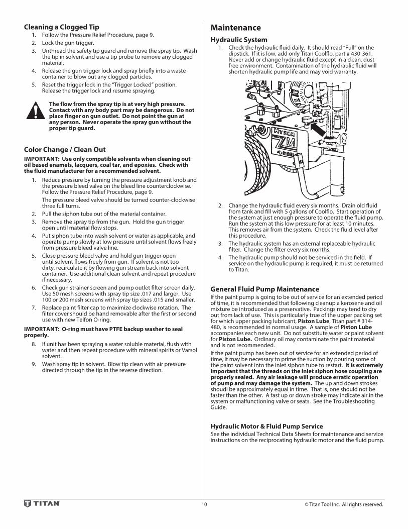
MaintenanceHydraulic System 1. Check the hydraulic fluid daily. It should read “Full” on the
dipstick. If it is low, add only Titan Coolflo, part # 430-361. Never add or change hydraulic fluid except in a clean, dust-free environment. Contamination of the hydraulic fluid will shorten hydraulic pump life and may void warranty.
2. Change the hydraulic fluid every six months. Drain old fluid from tank and fill with 5 gallons of Coolflo. Start operation of the system at just enough pressure to operate the fluid pump. Run the system at this low pressure for at least 10 minutes. This removes air from the system. Check the fluid level after this procedure.
3. The hydraulic system has an external replaceable hydraulic filter. Change the filter every six months.
4. The hydraulic pump should not be serviced in the field. If service on the hydraulic pump is required, it must be returned to Titan.
General Fluid Pump MaintenanceIf the paint pump is going to be out of service for an extended period of time, it is recommended that following cleanup a kerosene and oil mixture be introduced as a preservative. Packings may tend to dry out from lack of use. This is particularly true of the upper packing set for which upper packing lubricant, Piston Lube, Titan part # 314-480, is recommended in normal usage. A sample of Piston Lube accompanies each new unit. Do not substitute water or paint solvent for Piston Lube. Ordinary oil may contaminate the paint material and is not recommended.If the paint pump has been out of service for an extended period of time, it may be necessary to prime the suction by pouring some of the paint solvent into the inlet siphon tube to restart. It is extremely important that the threads on the inlet siphon hose coupling are properly sealed. Any air leakage will produce erratic operation of pump and may damage the system. The up and down strokes shoudl be approximately equal in time. That is, one should not be faster than the other. A fast up or down stroke may indicate air in the system or malfunctioning valve or seats. See the Troubleshooting Guide.
Hydraulic Motor & Fluid Pump ServiceSee the individual Technical Data Sheets for maintenance and service instructions on the reciprocating hydraulic motor and the fluid pump.

© Titan Tool Inc. All rights reserved. 11
Basic Engine Maintenance • For detailed engine maintenance and technical specifications
refer to the separate gasoline engine manual. • All service to the engine should be performed by a dealer
authorized by the engine manufacturer. To locate a dealer in your area, look in the Yellow Pages of your telephone directory under Gasoline Engines, Garden & Lawn Equipment & Supplies, Lawn Mowers, etc.
• The gas engine is warranted exclusively by the engine manufacturer.
• Use a premium quality motor oil certified to meet or exceed U.S. Automotive requirement SG.or SF. SAE 10W30 is recommended for general all temperature use. Other viscosities may be required in other climates.
• Use only a (NGK) BP6ES or BPR6E spark plug. Gap the plug to 0.028 to 0.031 In. (0.7 to 0.8 mm) Always use a spark plug wrench.
Daily 1. Check engine oil level, and fill as necessary. 2. Check gasoline level, and fill as necessary.
Always follow the fueling procedure outlined earlier in this manual.
First 20 Hours 1. Change engine oil.
Every 100 Hours 1. Change engine oil. 2. Clean the sediment cup. 3. Clean and re-gap the spark plug. 4. Clean the spark arrestor.
Weekly 1. Remove the air filter cover and clean the element. In very
dusty environments, check the filter daily. Replace the element as needed. Replacement elements can be purchased from your local engine dealer.
Engine Operation and Service 1. Clean and oil air filter pad on gasoline engine every 25 hours
or once weekly. Do not permit the air intake screen around the fly wheel of the gas engine to load up with paint or trash. Clean it regularly. The service life and efficiency of the gas engine model depends upon keeping the gasoline engine running properly. Change the oil in the engine every 100 hours. Failure to observe this may result in engine overheating. Consult the engine manufacturer’s service manual provided.
2. To conserve fuel, service life, and efficiency of the sprayer, always operate the gasoline engine at the lowest RPM at which it runs smoothly without laboring and delivers the amount required for the particular painting operation. Higher RPM does not produce higher working pressure. The gasoline engine is connected to the hydraulic pump by a pulley combination designed to produce full paint delivery at maximum RPM.
3. The warranty on gasoline engines or electric motors is limited to the original manufacturer.
12 © Titan Tool Inc. All rights reserved.
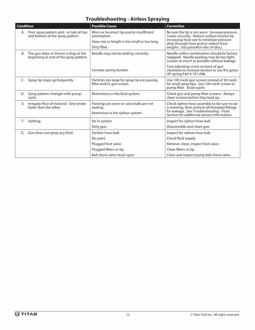
Troubleshooting - Airless SprayingCondition Possible Cause Correction
A. Poor spray pattern and / or tails at top and bottom of the spray pattern.
Worn or incorrect tip and/or insufficient atomization.Hose size or length is too small or too long.Dirty filter.
Be sure the tip is not worn. Increase pressure. Lower viscosity. Reduce surface tension by increasing hose size to minimize pressure drop through hose and/or reduce hose lengths. Use preorifice disc (H disc).
B. The gun drips or throws a drop at the beginning or end of the spray pattern.
Needle may not be seating correctly.
Increase spring tension.
Needle-orifice combination should be factory relapped. Needle packing may be too tight. Loosen as much as possible without leakage.Turn adjusting screw on back of gun clockwise to increase tension or use the green HP spring Part # 701-098.
C. Spray tip stops up frequently. Particles too large for spray tip are passing filter and/or gun screen.
Use 100 mesh gun screen instead of 50 mesh for small spray tips. Use 100 mesh screen in pump filter. Strain paint.
D. Spray pattern changes with pump cycle.
Restrictions in the fluid system. Check gun and pump filter screens. Always clean screens before they load up.
E. Irregular flow of material. One stroke faster than the other.
Packings are worn or valve balls are not seating.Restriction in the siphon system.
Check siphon hose assembly to be sure no air is entering, then recheck all threaded fittings for leakage. See Troubleshooting - Fluid Section for additional service information.
F. Spitting. Air in system.Dirty gun.
Inspect for siphon hose leak.Disassemble and clean gun.
G. Gun does not spray any fluid. Suction hose leak.No paint.Plugged foot valve.Plugged filters or tip.Ball check valve stuck open.
Inspect for siphon hose leak.Check fluid supply.Remove, clean, inspect foot valve.Clean filters or tip.Clean and inspect pump ball check valve.

Troubleshooting - Spray PatternsCondition Possible Cause Correction
A. Tails Inadequate fluid delivery.
Fluid not atomizing correctly.
Increase fluid pressure. Change to small tip orifice size. Reduce fluid viscosity. Reduce hose length.Clean gun and filter(s). Reduce number of guns using pump.
B. Hour glass Inadequate fluid delivery. Same as above.
C. Distorted Plugged or worn nozzle tip. Clean or replace nozzle tip.
D. Pattern expanding and contracting (surge)
Suction leak.Pulsating fluid delivery.
Inspect for siphon hose leak.Change to a smaller tip orifice size.Install pulsation dampener in system or drain existing one. Reduce number of guns using pump.Remove restrictions in system, clean tip screen if filter is used.
E. Round pattern. Worn tip.Fluid too heavy for tip.
Replace tip.Increase pressure. Thin material. Change nozzle tip.
© Titan Tool Inc. All rights reserved. 13

14 © Titan Tool Inc. All rights reserved.
Troubleshooting - Hydraulic MotorsCondition Possible Cause Correction
A. Oil motor stalls at bottom (no unusual heat problems).
Fluid pump seat unthreaded.
Valve sticking or oil motor trip rod shifter assembly separated.
If connecting rod is okay, remove cylinder head plug and pop valve down. Replace plug and start machine. If machine cycles up and stops at bottom again, then problem is piston seat on fluid pump. Check piston seat. Repair or replace as necessary. If piston seat is okay and problem does not change, check oil motor.Remove valve and check for scratches and rough movement when sliding it up and down. Replace valve and spool in this condition. Check trip rod for possible separation.
B. Oil motor stops at top (no unusual heat problems).
Valve sticking
Broken spring retainer (valve rod assembly)Broken spring or valve rodAir in hydraulic motor
Air in fluid pump
Remove valve and check for scratches and rough movement when sliding it up and down. Replace valve and spool in this condition.Replace valve rod assembly.
Replace valve rod assembly.Reset valve. Purge Air, generally accomplished by low pressure cycling of motor/pump assembly for 5–10 minutes. Check for causes of air introduction: • Loose fittings in tank. • Loose fittings on hydraulic pump. • Loose hose connections. • Low oil in reservoir.Stall at top can occur randomly when fluid pump picks up air. Reset valve. Avoid air in the fluid pump.
C. Low pressure (okay on down stroke, sluggish on up stroke - high heat)
NOTE: Engine labors on upstroke, idles back at stall on the down stroke.
Blown piston seal
Cracked piston
Before dismantling oil motor, start machine. With pump cycling under pressure, touch the hydraulic cylinder and the head to see if cylinder or head gets hotter. This will help determine if piston seal is blown or piston nut is broken. If heat is on the head, check the o-rings on spool valve.Dismantle oil motor and check piston seals cylinder bore and piston nut. Pay special attention to piston nut. It can be cracked and not show externally.
D. Low pressure (both strokes - high heat)
NOTE: Engine labors at stall on both strokes.
Blown center o-rings on spool valve
Bad hydraulic pump
Before dismantling oil motor, start machine. With pump cycling under pressure, touch the head to see if the head becomes hotter. This will help determine if center o-ring is blown on spool valve. If hot, remove and replace o-ring.Replace hydraulic pump.

© Titan Tool Inc. All rights reserved. 15
Troubleshooting - Fluid SectionsCondition Possible Cause Correction
A. Pump delivers on upstroke only or goes up slowly and down fast (commonly called downstroke dive).
Lower foot valve ball is not seating due to trash or wear.
Material to viscous to siphon.
Air leaking in on siphon side or damaged siphon hose. Siphon may be too small for heavy material.
Remove foot valve assembly. Clean and inspect. Test foot valve by filling with water. If ball fails to seal the seat, replace ball.Thin material - contact manufacturer for proper thinning procedures.Tighten all connections between pump and paint container. If damaged, replace. Switch to bigger siphon set.
B. Pump delivers on down stroke only or goes up fast and down slowly.
Upper ball is not seating due to trash or wear.
Lower packing set is worn.
Check upper seat and ball with water. If ball fails to seal seat, replace.Replace packing set is worn.
C. Pump moves up and down fast, not delivering material.
Material container is empty or material is too thick to flow through the siphon hose.
Bottom ball stuck to foot valve seat.Siphon hose is kinked or loose.
Refill with new material. If too thick, remove siphon hose and immerse pump or add thinner to material. Change to bigger siphon set. Open bleed valve to remove air and restart pump.Remove foot valve. Clean ball and seat.Straighten.
D. Pump moves up and down slowly when spray gun is shut off.
Loose connections. Bleed valve is open partially or bleed valve is worn. Lower packing set is worn.
Upper and/or lower ball not seating.
Check all connections between pump and gun. Tighten as necessary. If material is flowing from bleed hose, close bleed valve or replace if necessary. Should none of above be evident, replace lower packing.Reset balls by cleaning.
E. Not enough fluid pressure at gun. Spray tip is worn. Outlet filter or gun filter is clogged.Low voltage and/or inadequate amperage.Hose size or length is too small or too long.
Replace.Clean or replace filter.Check electrical service. Correct as required.Increase hose size to minimize pressure drop through hose and/or reduce hose lengths.
F. Pump chatters on up or down stroke Solvent has caused upper packing to swell. Replace packings.

16 © Titan Tool Inc. All rights reserved.
Hydra M 2000™ Major Components
12
14
5
12
1817
11
11
10
8
9
7
6
10
13
2
15
15
16
19
1
3
4

© Titan Tool Inc. All rights reserved. 17
13 HP Honda w/outlet
13 HP Honda 55 Gal
ITEM NO. PART NO. DESCRIPTION 433-860 433-861
1 441-315 Motor pump assembly 1
2 441-576 Motor assembly (1)
3 441-105 Assembly set (1)
4 315-555 Pump assembly (1)
5 441-316 Motor pump assembly 1
6 441-576 Motor assembly (1)
7 441-106 Assembly set (1)
8 315-555 Pump assembly (1)
9 840-202 Riser pipe assembly (1)
10 433-601 Engine drive assembly, electric start 1 1
11 433-702 Hydraulic tank assembly 1 1
12 590-312 Mobil kit 1 1
13 432-680 Hose set, hydraulic 1
14 432-684 Hose set, hydraulic, 55 gal. 1
15 840-207 Outlet assembly, 1” 1 1
16 103-106 Bleed line assembly (1)
17 945-600 Bleed valve (1)
18 103-818 Siphon hose assembly 1 1/2” x 6’ 1
19 219-650 Adj. drum mount assembly 1
All models are equipped with electric starter.
Hydra M 2000™ Major Components
18 © Titan Tool Inc. All rights reserved.
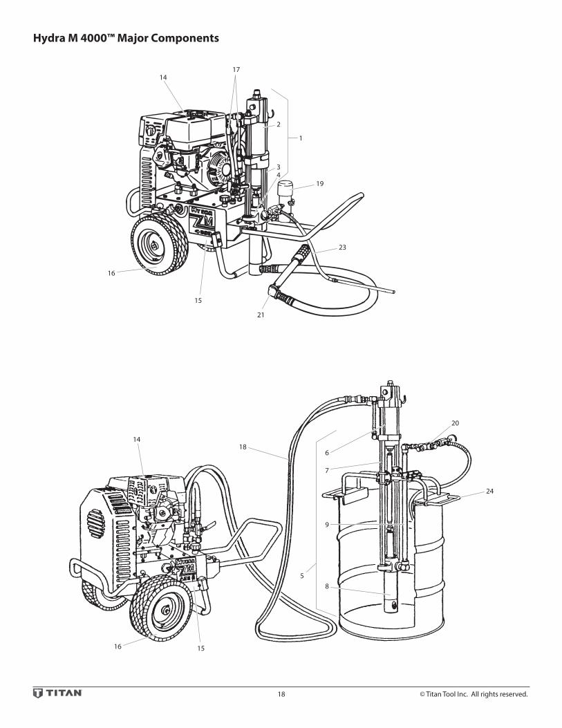
Hydra M 4000™ Major Components
16
18
5
16
21
15
15
14
8
9
7
6
14
17
2
19
20
23
24
1
34

© Titan Tool Inc. All rights reserved. 19
Hydra M 4000™ Major Components
Hydra M 4000™ Hydra Pro Super™
13 HP Honda w/outlet
13 HP Honda w/filter
13 HP Honda 55 Gal
13 HP Honda w/filter
ITEM NO.
PART NO.
DESCRIPTION 433-800 433-801 433-802 433-810
1 441-246 Motor pump assembly 1 1
2 441-576 Motor assembly (1)
3 441-107 Assembly set (1)
4 245-555 Pump assembly (1)
5 441-247 Motor pump assembly 1
6 441-576 Motor assembly (1)
7 441-108 Assembly set (1)
8 245-555 Pump assembly (1)
9 840-202 Riser pipe assembly (1)
10 441-182 Motor pump assembly 1
11 441-575 Motor assembly (1)
12 441-101 Assembly set (1)
13 185-551 Pump assembly (1)
14 433-601 Engine drive assembly, electric start 1 1 1 1
15 433-701 Hydraulic tank assembly 1 1 1 1
16 590-312 Mobil kit 1 1 1 1
17 432-681 Hose set, hydraulic 1 1 1
18 432-684 Hose set, hydraulic, 55 gal. 1
19 920-559 Filter assembly, 50 mesh 1 1
20 840-208 Outlet assembly, 3/4” 1 1
21 103-812 Siphon hose, 1 1/4” x 4’ 1 1
22 103-807 Siphon hose, 1” x 4’ 1
23 840-209 Relief valve w/bleed line 1 1
24 219-650 Adj. drum mount assembly 1
Hydra Pro Super™ is not illustratred.
All models are equipped with electric starter.

20 © Titan Tool Inc. All rights reserved.
Hydra M™ and Hydra Pro Super™ Engine Drive & Hydraulic System
d
h
gf
e
c b a
26a
2224
23
25
26b
b a
11
61/62
1213
56
55545352515049484746
45
4440
42
43
57
5859
60
63
1
23 4 5 6
7
8
19
20 31
30
29
2728
17
1661 14
15
33 3435 36 37 38 39 4132
9
18
10
21
© Titan Tool Inc. All rights reserved. 21
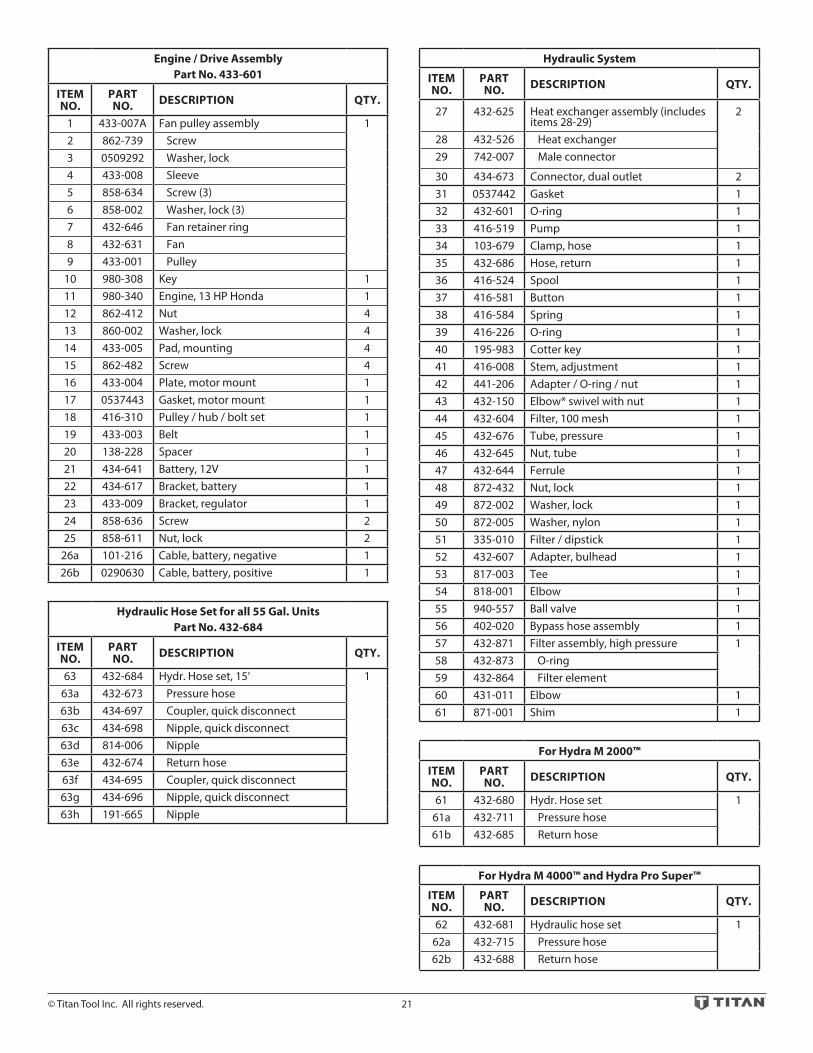
Engine / Drive Assembly Part No. 433-601
ITEM NO.
PART NO. DESCRIPTION QTY.
1 433-007A Fan pulley assembly 12 862-739 Screw 3 0509292 Washer, lock 4 433-008 Sleeve 5 858-634 Screw (3)6 858-002 Washer, lock (3)7 432-646 Fan retainer ring 8 432-631 Fan 9 433-001 Pulley
10 980-308 Key 111 980-340 Engine, 13 HP Honda 112 862-412 Nut 413 860-002 Washer, lock 414 433-005 Pad, mounting 415 862-482 Screw 416 433-004 Plate, motor mount 117 0537443 Gasket, motor mount 118 416-310 Pulley / hub / bolt set 119 433-003 Belt 120 138-228 Spacer 121 434-641 Battery, 12V 122 434-617 Bracket, battery 123 433-009 Bracket, regulator 124 858-636 Screw 225 858-611 Nut, lock 2
26a 101-216 Cable, battery, negative 126b 0290630 Cable, battery, positive 1
Hydraulic Hose Set for all 55 Gal. UnitsPart No. 432-684
ITEM NO.
PART NO. DESCRIPTION QTY.
63 432-684 Hydr. Hose set, 15’ 163a 432-673 Pressure hose 63b 434-697 Coupler, quick disconnect 63c 434-698 Nipple, quick disconnect 63d 814-006 Nipple 63e 432-674 Return hose 63f 434-695 Coupler, quick disconnect 63g 434-696 Nipple, quick disconnect 63h 191-665 Nipple
Hydraulic System
ITEM NO.
PART NO. DESCRIPTION QTY.
27 432-625 Heat exchanger assembly (includes items 28-29)
2
28 432-526 Heat exchanger29 742-007 Male connector
30 434-673 Connector, dual outlet 231 0537442 Gasket 132 432-601 O-ring 133 416-519 Pump 134 103-679 Clamp, hose 135 432-686 Hose, return 136 416-524 Spool 137 416-581 Button 138 416-584 Spring 139 416-226 O-ring 140 195-983 Cotter key 141 416-008 Stem, adjustment 142 441-206 Adapter / O-ring / nut 143 432-150 Elbow* swivel with nut 144 432-604 Filter, 100 mesh 145 432-676 Tube, pressure 146 432-645 Nut, tube 147 432-644 Ferrule 148 872-432 Nut, lock 149 872-002 Washer, lock 150 872-005 Washer, nylon 151 335-010 Filter / dipstick 152 432-607 Adapter, bulhead 153 817-003 Tee 154 818-001 Elbow 155 940-557 Ball valve 156 402-020 Bypass hose assembly 157 432-871 Filter assembly, high pressure 158 432-873 O-ring59 432-864 Filter element60 431-011 Elbow 161 871-001 Shim 1
For Hydra M 2000™
ITEM NO.
PART NO. DESCRIPTION QTY.
61 432-680 Hydr. Hose set 161a 432-711 Pressure hose 61b 432-685 Return hose
For Hydra M 4000™ and Hydra Pro Super™
ITEM NO.
PART NO. DESCRIPTION QTY.
62 432-681 Hydraulic hose set 162a 432-715 Pressure hose 62b 432-688 Return hose

22 © Titan Tool Inc. All rights reserved.
Hydra M™ & Hydra Pro Super™ Tank Assembly and Mobil Kit
12
34
5
78
910
11
19
14
16
20
3738
42
2324
2526
4344
45
46
21
36
22
15
17
18
394041
15
6
12
2728
2930
31
3233
3435
13
© Titan Tool Inc. All rights reserved. 23
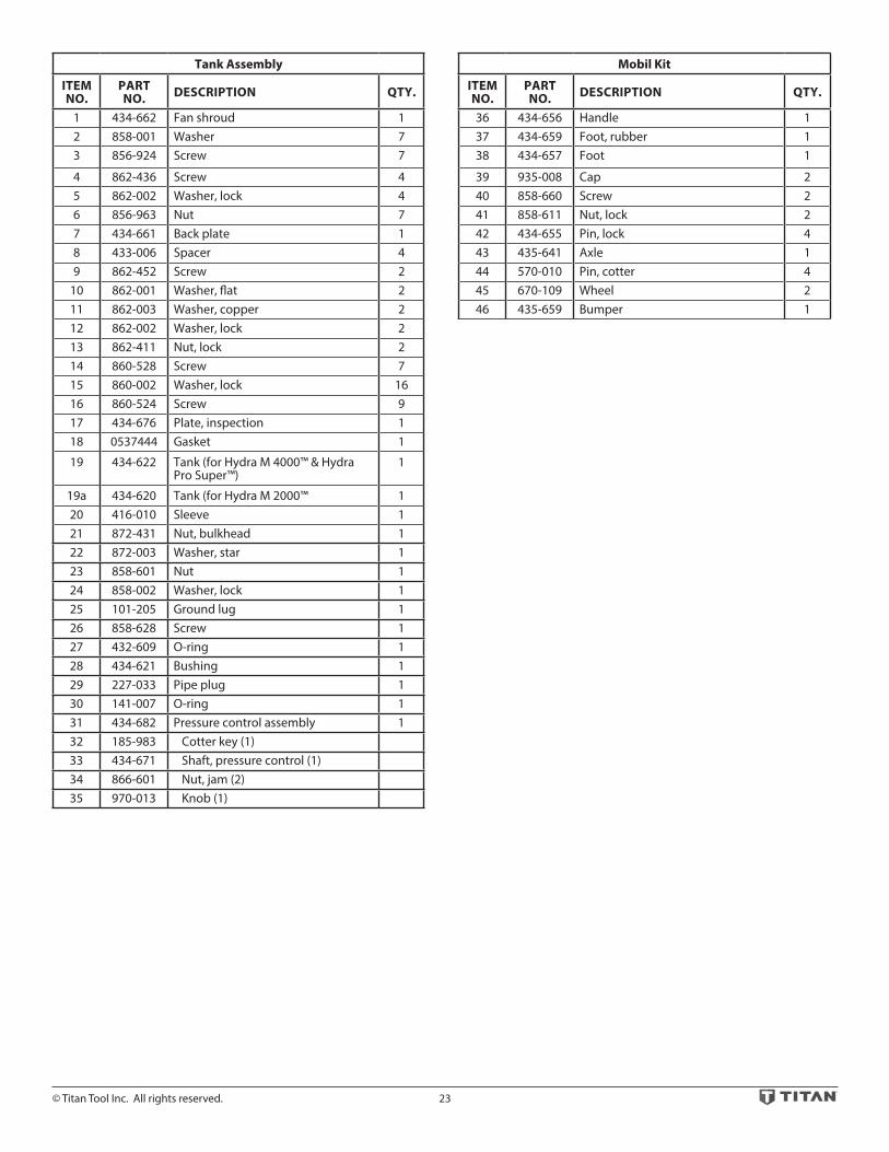
Tank Assembly
ITEM NO.
PART NO. DESCRIPTION QTY.
1 434-662 Fan shroud 12 858-001 Washer 73 856-924 Screw 7
4 862-436 Screw 45 862-002 Washer, lock 46 856-963 Nut 77 434-661 Back plate 18 433-006 Spacer 49 862-452 Screw 2
10 862-001 Washer, flat 211 862-003 Washer, copper 212 862-002 Washer, lock 213 862-411 Nut, lock 214 860-528 Screw 715 860-002 Washer, lock 1616 860-524 Screw 917 434-676 Plate, inspection 118 0537444 Gasket 1
19 434-622 Tank (for Hydra M 4000™ & Hydra Pro Super™)
1
19a 434-620 Tank (for Hydra M 2000™ 120 416-010 Sleeve 121 872-431 Nut, bulkhead 122 872-003 Washer, star 123 858-601 Nut 124 858-002 Washer, lock 125 101-205 Ground lug 126 858-628 Screw 127 432-609 O-ring 128 434-621 Bushing 129 227-033 Pipe plug 130 141-007 O-ring 131 434-682 Pressure control assembly 132 185-983 Cotter key (1)33 434-671 Shaft, pressure control (1)34 866-601 Nut, jam (2)35 970-013 Knob (1)
Mobil Kit
ITEM NO.
PART NO. DESCRIPTION QTY.
36 434-656 Handle 137 434-659 Foot, rubber 138 434-657 Foot 1
39 935-008 Cap 240 858-660 Screw 241 858-611 Nut, lock 242 434-655 Pin, lock 443 435-641 Axle 144 570-010 Pin, cotter 445 670-109 Wheel 246 435-659 Bumper 1

24 © Titan Tool Inc. All rights reserved.
Hydra M™ 2000 and Hydra M™ 4000 441-576 Hydraulic Motor
a
23
45
67
8
1011
12
13
9
16
9
14
b
c
d
17
31
32
33
20
28
11
10
9
8
34
36
37
9
9
a
a
35
30
29
21
22
23
24
25
27
26
18
19
e
15
a
a
f
1

© Titan Tool Inc. All rights reserved. 25
ITEM NO.
PART NO. DESCRIPTION
441-575
441-576
QTY. QTY.1 441-032 Reset assembly 1 1
1a 441-031 Cap1b 441-041 Button, reset 1c 441-029 Spring, reset 1d 441-027 Body 1e 441-030 O-ring 1f 441-028 Pin, reset2 441-217 O-ring 1 13 858-811 Nut 1 14 569-016 Ball 2 25 441-005 Spring, trip 2 26 141-007 O-ring 2 27 441-979 Retainer 2 28 870-401 Nut, stanchion 2 29 870-004 Washer, stanchion 6 6
10 441-149 Ring, back-up 2 211 441-148 O-ring 2 212 441-908 Valve spool/sleeve 1 1
13 441-152 O-ring 3 3
14 441-015 Stanchion 2 215 441-916 Head, cylinder 1 116 191-668 Adapter 1 1
16a 194-114 O-ring16b 194-113 O-ring
ITEM NO.
PART NO. DESCRIPTION
441-575
441-576
QTY. QTY.17 441-211 Spacer 1 118 314-072 Ring, snap 1 119 441-377 Shifter actuator 1 120 441-238 Ring, wear 1 121 442-978 Piston 1 122 441-249 Seal, piston 1 123 441-026 O-ring 1 124 441-024 Ring, back-up 1 125 441-932 Piston tube 1
25a 441-931 Piston tube 126 441-937 Set screw 1 127 431-007 Nut, coupling 1
27a 441-007 Nut, coupling 128 441-312 Cylinder 1 129 441-151 Gasket, cushion 1 130 441-945 Base, motor 1 131 441-234 Seal, piston tube 1 132 445-237 Ring, wear 1 133 441-025 Wiper, piston tube 1 134 432-640 Elbow 1 135 441-017 Tee 1 1
35a 432-611 O-ring set 36 441-789 Tube 1 137 432-729 Elbow 1 1
37a 632-611 O-ring set

26 © Titan Tool Inc. All rights reserved.
Hydra M™ & Hydra Pro Super™ 441-575 Hydraulic MotorService Instructions
a
23
45
67
8
1011
12
13
9
16
9
14
b
c
d
17
31
32
33
20
28
11
10
9
8
34
36
37
9
9
a
a
35
30
29
21
22
23
24
25
27
26
18
19
e
15
a
a
f
1
© Titan Tool Inc. All rights reserved. 27
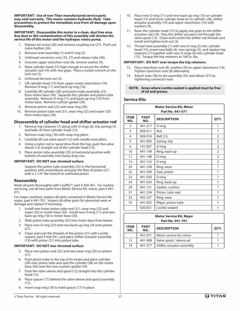
IMPORTANT: Use of non-Titan manufactured service parts may void warranty. This motor contains hydraulic fluid. Take precautions to protect the immediate area from oil damage upon disassembly.
IMPORTANT: Disassemble this motor in a clean, dust free area. Any dust or dirt contamination of this assembly will shorten the service life of this motor and the hydrapac rotary pump. 1. Release set screw (26) and remove coupling nut (27). Push out
nylon button (26). 2. Remove reset assembly (1) and O-ring (2). 3. Unthread connector nuts (35, 37) and release tube (36). 4. Unscrew upper stanchion nuts (8), remove washer (9). 5. Raise cylinder head (15) high enough to secure the shifter
actuator rod (19) with vise grips. Place a socket wrench on the lock nut (3).
6. Unthread the lock nut (3). 7. Lift cylinder head (15) from upper motor stanchions (14).
Remove O-ring (11) and back-up ring (10). 8. Carefully lift cylinder (28) and piston tube assembly (25)
from motor base (30). Separate the cylinder and piston tube assembly. Remove O-ring (11) and back-up ring (10) from motor base. Remove cushion gasket (29).
9. Remove piston seal (22) and wear ring (20). 10. Remove piston tube seal (31), wear ring (32) and wiper (33)
from motor base (30).
Disassembly of cylinder head and shifter actuator rod 1. Remove trip retainers (7) along with O-rings (6), trip springs (5)
and balls (4) from cylinder head (15). 2. Remove snap ring (18) with snap ring pliers. 3. Carefully lift out valve spool (12) with needle nose pliers. 4. Using a nylon rod or spool drive from the top, push the valve
sleeve (12) straight out of the cylinder head (15). 5. Place piston tube assembly (25) in horizontal position with
bottom of assembly into heavy-duty vise.
IMPORTANT: DO NOT mar chromed surface. Support the piston tube assembly (25) in the horizontal
position with wood blocks and grip the flats of piston (21) with a 2 1/4” flat wrench to unthread piston.
ReassemblyWash all parts thoroughly with Coolflo™, part # 430-361. For routine servicing, use all new parts from Motor Service Kit, minor, part # 441-071. For major overhaul, replace all parts contained in Motor Service Kit, major, part # 441-701. Inspect all other parts for abnormal wear or damage and replace if necessary. 1. Install new lower piston tube seal (31), wear ring (32) and
wiper (33) in motor base (30). Install new O-ring (11) and new back-up ring (10) in motor base (30).
2. Slide piston tube assembly (25) into motor base from below. 3. Place new O-ring (23) and new back-up ring (24 onto piston
(21). 4. Clean and coat the threads of the piston (21) with Loctite
sealant, part # 426-051, and place shifter actuator assembly (19) with piston (21) into piston tube.
IMPORTANT: DO NOT mar chromed surface. 5. Place new piston seal (22) and new wear ring (20) on piston
(21). 6. Push piston tube to the top of its stroke and place cylinder
(28) over piston tube and seat the cylinder (28) on the motor base (30) over the new cushion gasket (29).
7. Push the valve sleeve and spool (12) straight into the cylinder head (15).
8. Place spacer (17) behind the valve sleeve and spool assembly (12).
9. Insert snap ring (18) to hold spacer (17) in place.
10. Place new O-ring (11) and new back-up ring (10) on cylinder head (15) and lower cylinder head on to cylinder (28), shifter actuator assembly (19) and upper stanchions (14) with washers (9).
11. Raise the cylinder head (15) to apply vise grips to the shifter actuator rod (19). Pass the shifter actuator rod through the valve spool (12). Clean and Loctite the shifter rod threads and install and tighten lock nut (3).
12. Thread reset assembly (1) with new O-ring (2) into cylinder head (15), insert new balls (4), new springs (5), and replace trip retainers (7) together with new O-rings (6) into cylinder head (15). Torque the trip retainers to 180 in.-lbs.
IMPORTANT: DO NOT over torque the trip retainers. 13. Place stanchion nuts (8), washers (9) on upper stanchions (14).
Tighten stanchion nuts (8) alternately. 14. Attach tube (36) to tee assembly (35) and elbow (37) by
tightening connector nuts.
NOTE: Areas where Loctite sealant is applied must be free of oil and grease.
Service Kits
Motor Service Kit, MinorPart No. 441-071
ITEM NO.
PART NO. DESCRIPTION QTY.
2 441-217 O-ring 13 858-811 Nut 14 569-016 Ball, S.S. 25 441-005 Spring, trip 26 141-007 O-ring 2
10 441-149 Ring, back-up 211 441-148 O-ring 213 441-152 O-ring 320 441-238 Ring, wear 122 441-249 Seal, piston 123 441-026 O-ring 124 441-024 Ring, back-up 129 441-151 Gasket, cushion 131 441-234 Piston, tube seal 132 445-237 Ring, wear 133 441-025 Wiper, piston tube 1
426-051 Loctite sealant 1
Motor Service Kit, MajorPart No. 441-701
ITEM NO.
PART NO. DESCRIPTION QTY.
441-071 Motor service kit, minor 112 441-908 Valve spool / sleeve set 119 441-377 Shifter actuator assembly 1
28 © Titan Tool Inc. All rights reserved.
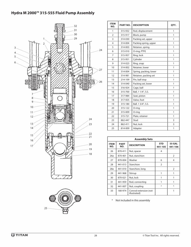
Hydra M 2000™ 315-555 Fluid Pump Assembly
ITEM NO. PART NO. DESCRIPTION QTY.
1 315-932 Rod, displacement 1
2 315-917 Block, pump 1
3 314-030 Packing set, upper 1
4 314-004 Packing spring, upper 1
5 314-003 Retainer, spring 1
6 315-010 O-ring, PTFE 1
7 315-957 Ring, lock 1
8 315-951 Cylinder 1
9 314-023 Ring, snap 1
10 314-002 Retainer, lower 1
11 314-004 Spring, packing, lower 1
12 314-981 Retainer, packing set 1
13 214-109 Pin, ball stop 1
14 314-040 Packing set, lower 1
15 316-924 Cage, ball 1
16 315-700 Ball, 1 1/4”, S.S. 1
17 317-984 Seat, piston 1
18 317-925 Valve, foot 1
19 315-180 Ball. 1 3/4”, S.S. 1
20 315-122 O-ring 1
21 315-009 O-ring 1
22 315-721 Plate, retainer 1
23 862-447 Stud 3
24 862-411 Nut, lock 3
25 814-009 Adapter 1
Assembly Sets
ITEM NO.
PART NO. DESCRIPTION
STD441-105
55 GAL 441-106
26 870-411 Nut, spacer 4
26a 870-401 Nut, stanchion 2
27 870-004 Washer 6 4
28 441-013 Stanchion 2
28a 441-010 Stanchion, long 2
29 441-968 Stirrup 1 1
30 870-021 Nut, lock 1 1
31 441-959 Rod, connecting 1 1
32 441-007 Nut, coupling * *
33 180-974 Conrod extension (not illustrated)
1
* Not included in this assembly
1
3
789
10
11
12
1314
15
16
17
18
19
20
2122
23
24
24
29303132
26
27
45
6
2
25

© Titan Tool Inc. All rights reserved. 29
Displacement Rod Area
Stroke Length Displacement Volume / Stroke
Displacement Volume / 40 Cycles / 80 Strokes
Motor Motor Pump ratio
IN2 CM2 IN CM IN3 CM3 LITER IN3 GAL. CM3 LITER 441-576 1:1
4 25.8 4 10.2 16.0 262 .262 1920 8.3 31,400 31.4
315-555 Fluid Pump Service InformationThe 315 Series Pump should receive a routine servicing after approximately 1000 hours of use. The appropriate Minor Service Kit should be installed at this time. It is recommended that one Major Service Kit be kept on hand of normal maintenance and emergency repairs. Packing life will be extended by the use of Piston Lube, Titan part # 314-480 permanent solvent. Fill to 1/4” level in pump block (2). Do not use oil or thinners as lubricant. Use Piston Lube for upper packings only - DO NOT USE IN MOTOR OR HYDRAULIC SYSTEM.
Disassembly Procedure 1. Disconnect coupling nut (32). 2. Remove the stanchion nuts (26) for disassembly from tank
only. 3. Unthread foot valve (18), lock ring (7) and cylinder (8). 4. Drop spring retainer (5). 5. Remove displacement rod (1) by sliding it downward. 6. Remove packing spring (4) and packing set (3). 7. To loosen piston seat (17) and displacement rod: a. Hold piston seat in vise. b. Insert 1/2” bar into fluid holes in displacement rod (1) and turn. 8. Remove packing set (12) and spring retainer (10). 9. Remove lock nuts (24) to diassemble foot valve and remove
plate (22) and ball (19).
Reassembly Procedure 1. Replace new packing set (3) into pump block (2). Peak of
packings should point toward motor as illustrated. 2. Replace packing spring retainer (5). Replace new O-ring (6)
into pump block (2). 3. Replace new ball (16) in piston seat (17) and replace spring
retainer (10), spring (11), retainer (12) and new packing set (3). 4. Tighten displacement rod (1) on to piston seat. 5. Insert displacement rod (1) through pump block (2) slowly to
avoid damaging packing set (3). 6. Replace new O-ring (6) in pump block (2). 7. Replace new ball (19) and new O-rings (20 & 21) in foot valve
(18). 8. Thread cylinder (8) into pump block (2) locking in spring
retainer (5). 9. Tighten lock ring (7). 10. Replace foot valve (18) in cylinder. 11. Connect upper connecting rod (31) to motor by threading
coupling nut (32) into piston rod of hydraulic motor.
IMPORTANT: It is necessary to grease the surface of all O-rings to avoid the possibility of cutting them on reassembly.
Service Kits
Pump Service Kits, MinorPart No. 315-050
ITEM NO.
PART NO. DESCRIPTION QTY.
3 314-030 Packing set, upper 16 315-010 O-ring, PTFE 1
14 314-040 Packing set, lower 116 315-700 Ball, 1 1/4”, SS 119 315-180 Ball, 1 3/4”, SS 120 315-122 O-ring 121 315-009 O-ring 1
753-024 Sealant tape, PTFE 1
Pump Service Kits, MinorPart No. 315-500
ITEM NO.
PART NO. DESCRIPTION QTY.
315-050 Service kit, minor 11 315-932 Rod, displacement 18 315-951 Cylinder 1

30 © Titan Tool Inc. All rights reserved.
Hydra M 4000™ 245-555 Fluid Pump Assembly
ITEM NO. PART NO. DESCRIPTION QTY.
1 245-907 Block, pump 1
2 240-001 Packing set, Poly/Lthr. 1
3 245-005 Packing spring, upper 1
4 245-013 Retainer, spring 1
5 892-323 O-ring, PTFE 1
6 245-012 Cylinder 1
7 920-103 Ball, S.S. 1
8 245-020 Retainer, spring 1
9 245-014 Spring, packing 1
10 240-001 Packing set, Poly/Lthr. 1
11 241-007 Seat, piston 1
12 240-022 Cage, ball 1
12a 241-109 Pin, ball stop (1)
13 891-403 O-ring, PTFE 1
14 892-281 O-ring 1
15 245-018 Valve, foot 1
16 314-180 Ball, S.S. 1
17 245-021 Retainer, cage 1
18 245-009 Rod, displacement 1
Assembly Sets
ITEM NO.
PART NO. DESCRIPTION
STD441-107
55 GAL 441-108
19 870-441 Nut 4
19a 870-401 Nut 2
20 870-004 Washer 4 6
21 870-006 Spacer 2
22 140-016 Stanchion 2
22a 441-010 Stanchion, 55 gal 2
23 245-109 Roll pin 1
24 442-959 Rod, connecting 1
24a 441-959 Rod, connecting 1
25 441-007 Nut, coupling * *
26 180-972 Ext., connecting rod 1
27 441-968 Stirrup 1
28 870-021 Nut 1
* Not included in this assembly
151182728
26
2824a25
(For 55Gallon)
17
18
19
1920
21
22
23
24
25, 25a
16
122a
19a
20
4
5
6
7
8
9
10
11
1212a
13
14
23

© Titan Tool Inc. All rights reserved. 31
245-555 Fluid Pump Service InformationIMPORTANT: Use of non-Titan manufactured service parts may void warranty.The 245 Series Pumps should receive routine servicing after approximately 1000 hours of use or earlier if there is excessive leakage from the top packing, or if the pump strokes become faster on one stroke or the other. The use of Titan Piston Lube, part # 314-480 is recommended as an upper packing lubricant. DO NOT SUBSTITUTE OIL, WATER OR SOLVENT for an upper packing lubricant.
Disassembly Procedure 1. Test pump before disassembly. Follow test procedure in
Troubleshooting Guide - Fluid Section. 2. Remove siphon hose assembly. 3. Remove stanchion nuts (19) and washers (20). 4. Remove set screw between the two flats on hydraulic motor
rod. Hold the hydraulic motor rod at the wrench flats and unthread coupling nut (25) to separate pump from hydraulic motor.
IMPORTANT: Never use a pipe wrench, pliers, etc. on the chrome part of hydraulic or fluid section rod. 5. Remove roll pin (23) or jam nut on connecting rod (24).
Remove connecting rod (24) from displacement rod (18). 6. Unthread and remove foot valve (15). 7. Remove PTFE O-ring (13), O-ring (14), ball cage retainer (17),
ball cage (12) and ball (16). 8. Remove cylinder (6). 9. Remove displacement rod (18). 10. Place piston seat (11) in a vise and use a wrench on the flats to
remove the displacement rod (18) from the piston seat (11). 11. Remove lower packing set (10), spring (9), spring retainer (8)
and ball (7). 12. Remove upper spring retainer (4), spring (3), PTFE O-ring (5)
and packing set (2). 13. Clean and inspect all parts. Inspect rod’s and cylinder’s hard
chrome for grooves, dents or worn areas. Replace if hard chrome is damaged. Inspect valve seats and replace if cracked or worn.
Reassembly Procedure 1. Insert new upper packing set (2) into pump block (1)
IMPORTANT: Peak of “V” packings must point upwards on reassembly. 2. Insert upper spring (3); small end of spring must go toward
the packing set. 3. Insert upper spring retainer (4) and new O-ring (5) into pump
block (1).
IMPORTANT: Lubricate all O-rings before assembly. 4. Place new lower packing set (2) over piston seat (11).
IMPORTANT: Peak of “V” must point downward on reassembly. 5. Replace spring (9), spring retainer (8) and new ball (7) on
piston seat (11). 6. Thread piston seat back onto displacement rod (18).
IMPORTANT: Use Loctite on clean threads. 7. Insert displacement rod assembly through upper packing set
(2) in pump block (1). 8. Thread cylinder (6) back into into pump block (1). 9. Insert new ball (16), ball cage (12), ball cage retainer (17) new
O-ring (14) and new PTFE O-ring (13).
IMPORTANT: Lubricate all O-rings into foot valve (15).
NOTE: Ball cage pin (12a) to be in lower position unless pump is to be used for heavy block filler or roofing materials.
10. Thread foot valve (15) back into cylinder (6). 11. Place connecting rod (23) through coupling nut (24) and
thread connecting rod (23) into displacement rod (18). 12. Replace roll pin (23) into displacement rod (18).
NOTE: It is not necessary to overtighten foot valve and cylinder into pump block. O-ring seals perform sealing function without excessive tightening. Full thread engagement is sufficient. The foot valve (15) may be rotated back up to 1/2 turn from full engagement for convenient hose position.
For siphon hose attachment, it is critically important that the thread of the siphon hose fit snugly into the foot valve with the hose assembly couplings PTFE-taped and sealed to prevent air inlet leakage.
Service Kits
Pump Service Kits, Minor
ITEM NO.
PART NO. DESCRIPTION 245-
050245-051
245-052
2 240-001 Packing set, upper, Poly/Lthr 1
2 240-101 Packing set, upper, Leather 1
2 240-201 Packing set, upper, PTFE 1
5 892-323 O-ring, PTFE 1 1 1
7 920-103 Ball 1 1 1
10 240-001 Packing set, lower, Poly/Lthr 1
10 240-101 Packing set, lower, leather 1
10 240-201 Packing set, lower, PTFE 1
13 891-403 O-ring, PTFE 1 1 1
14 892-281 O-ring 1 1 1
16 314-180 Ball 1 1 1
426-051 Loctite Sealant 1 1 1
Pump Service Kits, Major
ITEM NO.
PART NO. DESCRIPTION 245-
500245-501
245-502
245-050 Minor kit 1
245-051 Minor kit 1
245-052 Minor kit 1
6 245-012 Cylinder 1 1 1
9 245-014 Spring, packing 1 1 1
18 245-009 Displacement rod 1 1 1

32 © Titan Tool Inc. All rights reserved.
Hydra Pro Super™ 185-551 Fluid Pump Assembly
ITEM NO. PART NO. DESCRIPTION QTY.
1 185-981 Pin, roll 1
2 185-984 Rod, displacement 1
3 181-906 Block, pump 1
4 178-001 Packing set, upper 1
5 228-002 Nipple, hex 1
6 182-906 Spring, packing 1
7 182-007 O-ring, PTFE 1
8 183-930 Cylinder 1
9 185-011 Retainer, spring 1
10 185-010 Spring, packing 1
11 180-001 Packing set, lower 1
12 920-103 Ball 1
13 182-921 Seat, piston 1
14 183-230 O-ring 1
15 182-007 O-ring, PTFE 1
16 183-992 Valve, foot 1
17 314-180 Ball 1
18 240-022 Cage, ball 1
18a 241-109 Pin 1
Assembly Set - Part No. 441-101
ITEM NO.
PART NO. DESCRIPTION QTY.
19 870-441 Nut 420 870-004 Washer 621 441-016 Stanchion 222 442-956 Rod, connecting 1
Displacement Rod Area
Stroke Length Displacement Volume / Stroke
Displacement Volume / 40 Cycles / 80 Strokes
Motor Selection
Motor Pump ratio
IN2 CM2 IN CM IN3 CM3 LITER IN3 GAL. CM3 LITER
441 Series 3:11.38 8.90 4 10.2 5.55 90.9 0.091 444 1.92 7272 7.27
1
22
2
7
8
9
10
11
12
13
14
15
1617
3
4
56
21
23
20

© Titan Tool Inc. All rights reserved. 33
185-551 Fluid Pump Service InformationIMPORTANT: Use of non-Titan manufactured service parts may void warranty.The 185 Series Pump should receive a routine servicing after approximately 1000 hours of use or earlier if there is excessive leakage from the top packing, or if pump strokes become faster on one stroke or another. The use of Titan Piston Lube Part # 314-480 is recommended as an upper packing lubricant. DO NOT SUBSTITUTE OIL, WATER OR SOLVENT for an upper packing lubricant.
Disassembly Procedure 1. Test pump before disassembly. Follow test procedure in
Troubleshooting Guide - Fluid Section. 2. Remove siphon hose assembly. 3. Remove stanchion nuts (19) and washers (20). 4. Hold the air motor piston rod at the wrench flats and unthread
coupling nut to separate pump from motor.
IMPORTANT: Never use a pipe wrench, pliers, etc. on the chrome part of hydraulic, air or fluid section rod. 5. Remove roll pin (1) or jam nut on connecting rod (22).
Remove connecting rod (22) from displacement rod (2). 6. Unthread and remove foot valve (16). 7. Remove PTFE O-ring (15), O-ring (14), ball cage assembly (18)
and ball (17). 8. Remove cylinder (8). 9. Remove displacement rod (2). 10. Place piston seat (13) in a vise and use a wrench on the flats to
remove the displacement rod (2) from the piston seat (13). 11. Remove lower packing set (11), spring (10), spring retainer (9)
and ball (12). 12. Remove upper packing spring (6), packing set (4) and O-ring
(7). 13. Clean and inspect all parts. Inspect displacement rod’s (2)
and cylinder’s (8) chrome for grooves, dents or worn areas. Replace if hard chrome is damaged. Inspect valve seats and replace if cracked or worn.
Reassembly Procedure 1. Insert upper packing set (4) into pump block (3)
IMPORTANT: Peak of “V” packings must point upwards on reassembly. 2. Insert upper spring (6); small end of spring must go toward
the packing set. 3. Insert spring retainer (9). 4. Place new lower packing set (11) over piston seat (13).
IMPORTANT: Peak of “V” must point downward on reassembly. 5. Replace spring (10), spring retainer (9) and new ball (12) on
piston seat (13). 6. Thread piston seat (13) back onto displacement rod (2).
IMPORTANT: Use Loctite on clean threads. 7. Insert displacement rod (2) assembly through upper packing
set (4) in pump block (3). 8. Place new O-ring (7) on end of cylinder (8) and thread back
into pump block (3).
IMPORTANT: Lubricate all O-rings before assembly. 9. Insert new ball (17), ball cage (18), and new O-ring (14) into
foot valve.
NOTE: Ball cage pin (18a) to be in lower position unless pump is to be used for heavy block filler or roofing materials.
10. Place new PTFE O-ring (15) on cylinder (8) and then install foot valve assembly (16)
NOTE: It is not necessary to overtighten foot valve and cylinder into pump block. O-ring seals perform sealing function without excessive tightening. Full thread engagement is sufficient. The foot valve (16) may be rotated back up to 3/4 turn from full engagement for convenient hose position.
11. Insert connecting rod (22) through coupling nut and thread connecting rod (22) into displacement rod (2).
12. Insert roll pin (1) into connecting rod (22). For siphon hose attachment, it is critically important that
the thread of the siphon hose fit snugly into the foot valve with the hose assembly couplings PTFE-taped and sealed to prevent air inlet leakage.
Service Kits
NOTE: Minor service kit # 185-050 has polyethylene/leather packings.
Minor service kit # 180-051 has leather packings. Minor service kit # 185-052 has PTFE packings.
Pump service kit, minor CTR IND PTFE
ITEM NO.
PART NO. DESCRIPTION 185-
050185-051
185-052
4 175-001 Packing set, upper 1
4 178-001 Packing set, upper 1
4 178-320 Packing set, upper 1
7 182-007 O-ring, PTFE 1 1 1
11 180-002 Packing set, lower 1
11 180-322 Packing set, lower 1
11 183-001 Packing set, lower 1
12 920-103 Ball 1 1 1
14 183-230 O-ring 1 1 1
15 182-007 O-ring, PTFE 1 1 1
17 314-180 Ball 1 1 1
426-051 Loctite Sealant 1 1 1
Pump service kit, major CTR IND PTFE
ITEM NO.
PART NO. DESCRIPTION 185-
500185-501
185-502
185-050 Minor kit 1
185-051 Minor kit 1
185-052 Minor kit 1
2 185-984 Displacement rod 1 1 1
6 182-906 Spring, packing 1 1 1
8 183-930 Cylinder 1 1 1

34 © Titan Tool Inc. All rights reserved.
Hydra M™ 2000 / 4000 Fluid Accessories
Siphon Hose AssemblyPart # 103-818 (Hydra M™ 2000)
ITEM NO. PART NO. DESCRIPTION QTY.
1 103-612 Tube 1
2 192-991 Elbow 1
3 194-991 Nipple 1
4 103-684 Clamp 2
5 421-202 Hose 1
6 194-201 CamLock assembly 1
Siphon Hose AssemblyPart # 103-812 (5 gal., Hydra M™ 4000)
ITEM NO. PART NO. DESCRIPTION QTY.
1 103-629 Rock catcher assembly 1
2 103-641 Tube 1
3 205-559 Elbow 1
4 604-125 Hose assembly 1
Siphon Hose AssemblyPart # 103-814 (55 gal., Hydra M™ 4000)
ITEM NO. PART NO. DESCRIPTION QTY.
1 103-629 Rock catcher assembly 1
2 103-642 Tube 1
3 205-559 Elbow 1
4 606-126 Hose assembly 1
Outlet Assemblies With Pressure Bleed Valve
ITEM NO. PART NO. DESCRIPTION 840-
207840-208
1 200-556 Swivel adapter, 1” 1
1a 138-037 Swivel adapter, 3/4” 1
2 813-009 Cross 1
2a 817-004 Tee 1
3 929-063 Bushing 1
3a 929-075 Bushing 1
3b 929-076 Bushing 1
4 945-600 Valve, bleed 1 1
5 103-106 Bleed line assembly 1 1
6 210-039 Plug, pipe 1
4 3 2
5
4
6
1
1
2
3
4
12
5 3
4

© Titan Tool Inc. All rights reserved. 35
Hydra M™ & Hydra Pro Super™ Fluid Accessories
840-209 Bleed Line Assembly
ITEM NO. PART NO. DESCRIPTION QTY.
1 944-028 Valve, bleed 1
2 103-101 Bleed line assembly 1
3 0509764 Tube (1)
4 538-030 Hose assembly (1)
103-106 Bleed Line Assembly
ITEM NO. PART NO. DESCRIPTION QTY.
1 103-317 Tube 1
2 201-555 Elbow 1
3 538-031 Hose assembly 1
4
3
2
1
2
1
3
944-620 Bleed Valve Assembly, 1/8” NPT
ITEM NO. PART NO. DESCRIPTION QTY.
1 944-024 Knob assembly 1
2 944-020 Valve body 1
3 944-004 O-ring 1
4 944-026 Valve stem stop 1
5 761-715 Ball, T.C. 1
6 945-003 Gasket, copper 1
7 944-904 Valve seat 1
945-600 Bleed Valve Assembly, 1/2” NPT
ITEM NO. PART NO. DESCRIPTION QTY.
1 945-005 Knob 1
2 970-011 Nut 1
3 944-023 Valve stem 1
4 945-022 Valve body 1
5 891-073 O-ring, PTFE 1
6 944-026 Valve stem stop 1
7 138-226 Ball 1
8 891-183 O-ring, PTFE 1
9 945-906 Valve seat 1
1 2 3 4 5 6 7
1 2 3 4 5 6 7 8 9
Service InstructionsThe 944 / 945 Series Relief Valve has a tungsten carbide seat (9) and should not require frequent replacement. The tungsten carbide ball (7), in normal service, will last a long time because it rotates and wears evenly. If there is leakage, replace the ball.
IMPORTANT: Open the adjustment knob (1) to full counterclockwise position before unthreading valve seat (9) from valve body (4).If the valve stem (3) is rotated inwardly with the ball removed, the PTFE O-ring (5) may require replacement. If there has been leakage from the valve stem, the PTFE O-ring should be replaced.
IMPORTANT: The valve stem stop (6) must be unthreaded from the valve stem (3) with a socket screwdriver, then the valve stem can be threaded out of the valve body.
IMPORTANT: All non-moving threads must be assembled with Loctite sealant, Titan part # 426-051.
Part No. 944-620
Part No. 944-600

36 © Titan Tool Inc. All rights reserved.
Hydra Pro Super™ Fluid Accessories
103-807 Siphon Valve Assembly103-808 55 Gallon Siphon Assembly
ITEM NO. PART NO. DESCRIPTION QTY.
1 0509762A Rock catcher 1
2 103-575 Tube 1
103-585 Tube (55 gal. siphon ass’y) 1
3 103-679 Hose clamp 2
4 420-070 Hose 5’
5 103-125 Spring 1
6 103-119 Clip 1
7 0509760A Adapter 1
1
2
34 5 6
73
Service InstructionsThe 944 Series Relief Valve has a tungsten carbide seat (9) and should not require frequent replacement. The tungsten carbide ball (7), in normal service, will last a long time because it rotates and wears evenly. If there is leakage, replace the ball.
IMPORTANT: Open the adjustment knob (1) to full counterclockwise position before unthreading valve seat (9) from valve body (4).If the valve stem (3) is rotated inwardly with the ball removed, the PTFE O-ring (5) may require replacement. If there has been leakage from the valve stem, the PTFE O-ring should be replaced.
IMPORTANT: The valve stem stop (6) must be unthreaded from the valve stem (3) with a socket screwdriver, then the valve stem can be threaded out of the valve body.
IMPORTANT: All non-moving threads must be assembled with Loctite sealant, Titan part # 426-051.

© Titan Tool Inc. All rights reserved. 37
Hydra M™ & Hydra Pro Super™ Outlet Accessories
Outlet Manifold Filter Assembly
ITEM NO.
PART NO. DESCRIPTION QTY
1 920-917 Filter cap assembly 1
2 920-103 Ball, S.S. 1
3 920-004 Screen, filter, 50 mesh 1
4 920-006 Gasket, PTFE (thick) 1
5 920-070 Gasket, PTFE (thin) 1
6 920-927 Body, filter (5000 psi) 1
7 812-003 Nipple, hex 1
8 227-027 Plug, pipe 1
9 227-033 Plug, pipe 1
10 703-137 Swivel fitting 1
Part No. 920-050 Filter Service Kit
ITEM NO. PART NO. DESCRIPTION QTY.
2 920-103 Ball 1
4 920-006 Gasket, PTFE 1
5 920-070 Gasket, PTFE 1
1
2
3
4
5
6
10
98
7
CleaningClean filter regularly. Dirty or clogged filters can greatly reduce filtering ability and cause a number of system problems including poor spray patterns, clogged spray tips, etc.
To clean the filter, shutoff system and relieve all system pressure. See the Pressure Relief Procedure on page 9.
1. Remove filter cap (1). 2. Pull filter element with check ball (3) straight out of the filter
body (6). 3. Thoroughly clean inside filter body (6), filter element with
check ball (3) and filter cap (1) with appropriate solvent. Use care in handling parts as dirt, debris, scratches or nicks may prevent O-rings or gaskets from sealing.
The 920 Series Filter Elements filter from the inside out. Be certain to clean the screen element thoroughly on the inside. Soak in solvent to loosen hardened paint, etc. or replace.
Specifications
Max. Working Pressure 5000 psi (345 bar)
Filter Area 18in2 (116 cm2)
Outlet Ports (1) 1/4” NPT (F) for bleed valve(1) 3/8” NPT (F) with 1/4 NPSM (M) hose connection(1) 3/8” NPT (F) plug for additional gun hookup.
Wetted parts Carbon steel with electroless nickel and cadmium plating, stainless steel, PTFE

38 © Titan Tool Inc. All rights reserved.
Hydra M™ & Hydra Pro Super™ Outlet Accessories - Gun Manifold Assemblies
2-Gun
52
3 7
3
41
2
5
4-Gun
2
2
2
3 17
3
2
5
54
4
13
1 Gun Add-On
32
5
Gun Manifold Assemblies
ITEM NO.
PART NO. DESCRIPTION
975-212 975-214 975-111 975-302 975-304 975-311
2 - GUN 1/4” 4 - GUN 1/4” 1 - GUN ADD-ON
1/4”
2 - GUN 3/8” 4 - GUN 3/8” 1 - GUN ADD-ON
3/8”
1 970-100 Manifold 1 2 1 2
2 940-553 Valve, ball 2 4 1
2a 941-555 Valve, ball 2 4 1
3 814-002 Nipple, hex 2 4 1
4 814-004 Nipple, hex 1 2 3 6 1
5 227-006 Nipple, hex 2 4 1
6 808-555 Nipple, hex 2 4 1
7 227-033 Plug, pipe 1 1 1 1
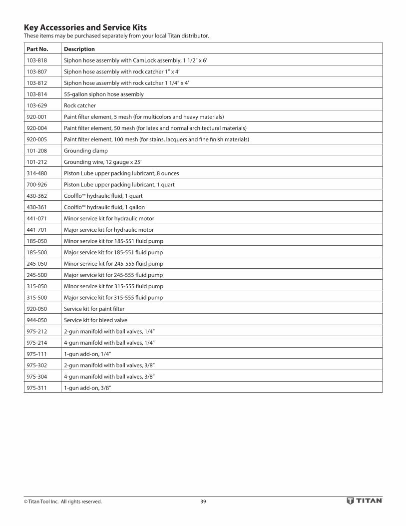
© Titan Tool Inc. All rights reserved. 39
Key Accessories and Service KitsThese items may be purchased separately from your local Titan distributor.
Part No. Description
103-818 Siphon hose assembly with CamLock assembly, 1 1/2” x 6’
103-807 Siphon hose assembly with rock catcher 1” x 4’
103-812 Siphon hose assembly with rock catcher 1 1/4” x 4’
103-814 55-gallon siphon hose assembly
103-629 Rock catcher
920-001 Paint filter element, 5 mesh (for multicolors and heavy materials)
920-004 Paint filter element, 50 mesh (for latex and normal architectural materials)
920-005 Paint filter element, 100 mesh (for stains, lacquers and fine finish materials)
101-208 Grounding clamp
101-212 Grounding wire, 12 gauge x 25’
314-480 Piston Lube upper packing lubricant, 8 ounces
700-926 Piston Lube upper packing lubricant, 1 quart
430-362 Coolflo™ hydraulic fluid, 1 quart
430-361 Coolflo™ hydraulic fluid, 1 gallon
441-071 Minor service kit for hydraulic motor
441-701 Major service kit for hydraulic motor
185-050 Minor service kit for 185-551 fluid pump
185-500 Major service kit for 185-551 fluid pump
245-050 Minor service kit for 245-555 fluid pump
245-500 Major service kit for 245-555 fluid pump
315-050 Minor service kit for 315-555 fluid pump
315-500 Major service kit for 315-555 fluid pump
920-050 Service kit for paint filter
944-050 Service kit for bleed valve
975-212 2-gun manifold with ball valves, 1/4”
975-214 4-gun manifold with ball valves, 1/4”
975-111 1-gun add-on, 1/4”
975-302 2-gun manifold with ball valves, 3/8”
975-304 4-gun manifold with ball valves, 3/8”
975-311 1-gun add-on, 3/8”

40 © Titan Tool Inc. All rights reserved.
WarrantyTitan Tool, Inc., (“Titan”) warrants that at the time of delivery to the original purchaser for use (“End User”), the equipment covered by this warranty is free from defects in material and workmanship. With the exception of any special, limited, or extended warranty published by Titan, Titan’s obligation under this warranty is limited to replacing or repairing without charge those parts which, to Titan’s reasonable satisfaction, are shown to be defective within twelve (12) months after sale to the End User. This warranty applies only when the unit is installed and operated in accordance with the recommendations and instructions of Titan.This warranty does not apply in the case of damage or wear caused by abrasion, corrosion or misuse, negligence, accident, faulty installation, substitution of non-Titan component parts, or tampering with the unit in a manner to impair normal operation.Defective parts are to be returned to an authorized Titan sales/service outlet. All transportation charges, including return to the factory, if necessary, are to be borne and prepaid by the End User. Repaired or replaced equipment will be returned to the End User transportation prepaid.THERE IS NO OTHER EXPRESS WARRANTY. TITAN HEREBY DISCLAIMS ANY AND ALL IMPLIED WARRANTIES INCLUDING, BUT NOT LIMITED TO, THOSE OF MERCHANTABILITY AND FITNESS FOR A PARTICULAR PURPOSE, TO THE EXTENT PERMITTED BY LAW. THE DURATION OF ANY IMPLIED WARRANTIES WHICH CANNOT BE DISCLAIMED IS LIMITED TO THE TIME PERIOD SPECIFIED IN THE EXPRESS WARRANTY. IN NO CASE SHALL TITAN LIABILITY EXCEED THE AMOUNT OF THE PURCHASE PRICE. LIABILITY FOR CONSEQUENTIAL, INCIDENTAL OR SPECIAL DAMAGES UNDER ANY AND ALL WARRANTIES IS EXCLUDED TO THE EXTENT PERMITTED BY LAW.TITAN MAKES NO WARRANTY AND DISCLAIMS ALL IMPLIED WARRANTIES OF MERCHANTABILITY AND FITNESS FOR A PARTICULAR PURPOSE WITH RESPECT TO ACCESSORIES, EQUIPMENT, MATERIALS OR COMPONENTS SOLD BUT NOT MANUFACTURED BY TITAN. THOSE ITEMS SOLD, BUT NOT MANUFACTURED BY TITAN (SUCH AS GAS ENGINES, SWITCHES, HOSES, ETC.) ARE SUBJECT TO THE WARRANTY, IF ANY, OF THEIR MANUFACTURER. TITAN WILL PROVIDE THE PURCHASER WITH REASONABLE ASSISTANCE IN MAKING ANY CLAIM FOR BREACH OF THESE WARRANTIES.
Safety Data Sheets (SDS) are available on Titan’s website or by calling Customer Service.
Register your product online at:
www.titantool.com
Serial Number _ _ _ _ _ _ _ _ _ _
UNITED STATES SALES & SERVICE INTERNATIONAL
WEB: www.titantool.comPHONE: 1-800-526-53621770 Fernbrook Lane
Minneapolis, MN 55447
WEB: www.titantool-international.com