Titan ControlFireTM User Manual - Hunting Energy Services
60
-
Upload
khangminh22 -
Category
Documents
-
view
0 -
download
0
Transcript of Titan ControlFireTM User Manual - Hunting Energy Services

Hunting ControlFire® User Manual
Copyright ©2020 Hunting
Doc Number: 10002 Page 2 of 60 Last Modified: March 2020 Rev: 2.6
Table of Contents
1.0 ControlFire® Perforating Command & Control Panel ........................................................................ 5
1.1 Equipment Overview .......................................................................................................................... 5
1.2 Perforating Panel Overview .............................................................................................................. 5
1.3 Cable Kit .............................................................................................................................................. 6
1.4 Perforating Panel Specifications ...................................................................................................... 7
2.0 ControlFire® Shooting Power Supply Panel ...................................................................................... 8
2.1 Equipment Overview .......................................................................................................................... 8
2.2 Shooting Panel Overview .................................................................................................................. 8
2.3 Cable Kit .............................................................................................................................................. 9
2.4 Shooting Panel Specifications .......................................................................................................... 9
2.5 Log, Aux and CCL Operation ......................................................................................................... 10
2.6 ARM Mode Operation ...................................................................................................................... 10
2.7 Select Fire Instructions (Positive / Negative) ............................................................................... 10
2.8 Dump Fire Instructions (Positive / Negative) ................................................................................ 10
3.0 Perf Switch and Wireline Simulator Panel ........................................................................................ 11
3.1 Wireline Switch Simulator Panel External Test Block ................................................................. 11
3.2 ControlFire® Perf Switch Rev 1.8 .................................................................................................. 12
3.3 ControlFire® Perf Switch Specifications ....................................................................................... 13
4.0 Installing the ControlFire® Software ................................................................................................... 13
4.1 Installing GUI Program .................................................................................................................... 13
4.2 Installing USB Virtual COM Port Driver ......................................................................................... 17
5.0 Installing ControlFire® Perforating Command & Control Panel on Logging Truck ..................... 17
6.0 ControlFire® Operation ........................................................................................................................ 18
6.1 Starting the ControlFire® Software ................................................................................................ 18
6.2 Setup for ControlFire® Operations ................................................................................................. 23
Hunting ControlFire® User Manual
Copyright ©2020 Hunting
Doc Number: 10002 Page 3 of 60 Last Modified: March 2020 Rev: 2.6
6.2.1 Create New Job Folder ................................................................................................................ 23
6.2.2 W/L Power Supply Settings ........................................................................................................ 24
6.2.3 Create a New Tool String ............................................................................................................ 25
6.2.4 Verify a Tool String ....................................................................................................................... 29
6.3 Gun Check, Arming and Firing ....................................................................................................... 32
6.3.1 Gun Check ..................................................................................................................................... 34
6.3.2 Arm and Fire Sequence ............................................................................................................... 36
6.4 Gun Skipping Operations ................................................................................................................ 38
6.4.1 Gun Skip using Switch Skip button in Gun Control Window .................................................. 38
6.4.2 Gun Skip using Verify Tool String Window ............................................................................... 40
6.4.3 Gun Skip using right click in Gun Control Menu ...................................................................... 43
7.0 Hunting Release Tool - Electronic ..................................................................................................... 45
7.1 Releasing the Tool ........................................................................................................................... 46
7.2 Attaching the Fishing Neck ............................................................................................................. 48
8.0 Shooting PS Board Display................................................................................................................. 49
9.0 Cleaning Instructions ........................................................................................................................... 52
10.0 VeriFire® ................................................................................................................................................ 52
11.0 ControlFire® Part Numbers ................................................................................................................ 53
12.0 User Agreement .................................................................................................................................... 54
Appendix ............................................................................................................................................................ 55
A. EBS Down Hole Pin Wire Attachment ......................................................................................................... 55
B. Software License ......................................................................................................................................... 56
Hunting ControlFire® User Manual
Copyright ©2020 Hunting
Doc Number: 10002 Page 4 of 60 Last Modified: March 2020 Rev: 2.6
Safety Precautions When Using ControlFire® Perf Unit
The following precautions must be followed when using the ControlFire® Perf Unit.
1. Do NOT open the unit and try and service. If any service or repair is
required the unit must be returned to the manufacturer, Hunting Titan.
2. Always use the recommended AC power cord that includes a 3rd wire safety
ground that connects equipment to a grounded single phase outlet.
3. When installing into a wireline truck always position the ControlFire® Perf
Unit so that the AC cord can be accessible for rapid disconnect.
4. When replacing either the AC fuse or W/L fuse always use the exact
replacement P/N.
5. If equipment is not used in a manner specified by the manufacturer, safety
protection may become impaired
Safety Symbol Explanation
Caution: Risk of danger, refer to user guide.
Warning: Electrical shock hazard.

Hunting ControlFire® User Manual
Copyright ©2020 Hunting
Doc Number: 10002 Page 5 of 60 Last Modified: March 2020 Rev: 2.6
1.0 ControlFire® Perforating Command & Control Panel
1.1 Equipment Overview
The minimum equipment required for running a switch system with the ControlFire® Perforating Command and Control Portable Panel is listed below.
Item Equipment Description P/N
1 ControlFire® Command & Control Panel 9002-013-510
2 Cable Kit 9002-013-017
13 Wireline Switch Simulator Panel 9002-013-610
4 ControlFire® Perforating Switch Rev 1.8 PCB 1.0D 9002-013-120-1.8
15 Wireline Switch Simulator Panel External Test Block 9002-013-320
1Items 3 and 5 can be used for system verification at the shop or on a job location
1.2 Perforating Command & Control Portable Panel Overview
Shown in Figure 1 is a surface perforating command & control portable panel that provides communication and control to the downhole ControlFire® switch string. This control panel interfaces with a PC or Laptop via a “USB connector”, connects to a Shooting Power Supply through the “Shooting PWR IN” connector and to a wireline cable via the “Wire Line Output” connector. The Perforating Command and Control Panel is available as a portable panel, rack mount panel (BOD) or integrated into a shooting power supply as a combination rack mount panel. See Section 11 for part numbers.
Figure 1
Hunting ControlFire® User Manual
Copyright ©2020 Hunting
Doc Number: 10002 Page 6 of 60 Last Modified: March 2020 Rev: 2.6
1.3 Cable Kit
Shown in Figure 2 are the normally required cables and connectors. An itemized listing is given:
Figure 2
1. AC Input Power Cord – (PN. E6000-312011-01). Three wire power cord for
connecting the Command & Control Panel to an AC power source (hot, neutral and safety ground). The safety ground (3rd wire) within the AC receptacle must be connected to earth ground. Ground wire must be Green/Yellow.
Cord should be: 3-Conductor, 18AWG, 10A, 60ºC minimum, 3m length maximum
2. Shooting PWR In Cable – (PN. 9002-013-015) RG8 Coaxial Cable, 10 feet long, with Cannon Female Plug and Male UHF PL-259 connectors
3. Wire Line Output Cable – (PN. 9002-013-014) RG8 Coaxial Cable, 10 feet long, with Cannon Male Plug and Male UHF PL-259 connectors
4. Double Female UHF adaptor – (PN. E2100-83-1J) Used to convert the Male UHF of the Wire cable to a female gender
5. USB cable – (PN. E6000-USBAA-6) Male to Male cable used to interface a PC or Laptop to the Control Panel
6. BNC JACK TO DBL BANANA PLUG ADAPTER (PN: E2100-1270) – BNC to Double banana plug used to connect to the W/L Simulator (9002-013-610)
7. BNC JACK TO UHF PLUG ADAPTER (PN: E2100-27-8120) – BNC to UHF
adapter.
Hunting ControlFire® User Manual
Copyright ©2020 Hunting
Doc Number: 10002 Page 7 of 60 Last Modified: March 2020 Rev: 2.6
1.4 Perforating Command & Control Portable Panel Specifications
Table 1 gives the specifications for the ControlFire® Perforating Command and Control Portable Panel.
Specification Rating/Description Conditions
Temperature
(-10 to +55) C (+14 to +131)F Operating
(-10 to +55) C (+14 to +131)F Start Up
(-30 to +75) C (-22 to +167)F Storage
Humidity, RH%, Operating & Storage
10 to 95% RH Non-Condensing
Altitude 0 – 10,000ft Operating
0 - 45,000ft Storage
IEC60529 Rating IP67 (1-meter submersion for 30
minutes)
AC Input Voltage 120-220 VAC 0~100% load
Frequency, Range 50 – 60 Hz 0~100% load
Input Power 150W Max
AC Power Cord 3 conductor,18AWG, 10A, 60ºC minimum, 3m length maximum
Operating
AC Entry Fuse 250V, 1.6A, 5mm X 20mm slow blow. Part# BK/GDC-1.6A
Operating
Wire Line Fuse 250V, 0.63A, 5mm X 20mm Slow blow. Part# BK/GDC-630MA
Operating
Table 1
Hunting ControlFire® User Manual
Copyright ©2020 Hunting
Doc Number: 10002 Page 8 of 60 Last Modified: March 2020 Rev: 2.6
2.0 ControlFire® Shooting Power Supply Panel
2.1 Equipment Overview
The minimum equipment required for running a switch system with a ControlFire®
Shooting Power Supply is listed below.
Item Equipment Description Titan P/N
1 ControlFire® Shooting Power Supply 9002-013-810-1 12 Wireline Switch Simulator Panel 9002-013-610
3 ControlFire® Perforating Switch Rev 1.8 PCB 1.0D 9002-013-120-1.8 14 Wireline Switch Simulator Panel External Test Block 9002-013-320
1Items 2 and 4 can be used for system verification at the shop or on a job location
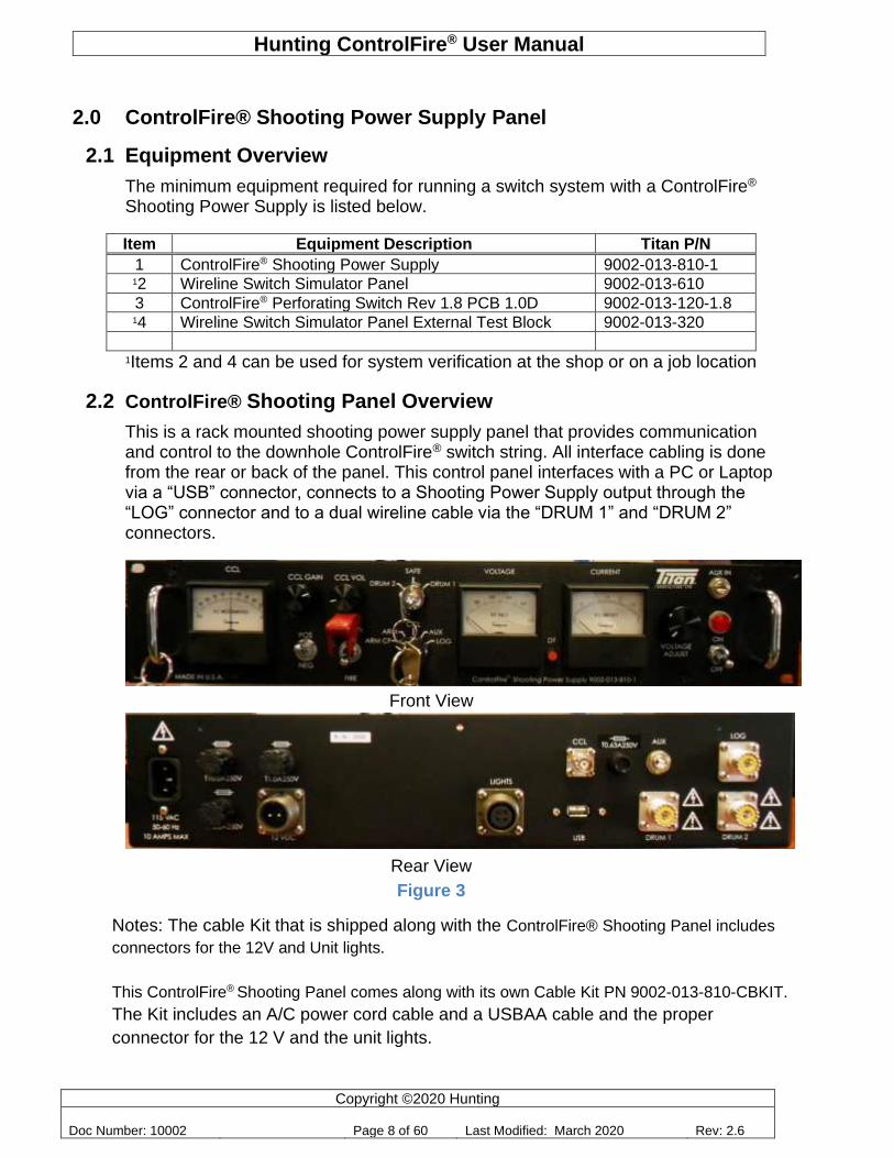
2.2 ControlFire® Shooting Panel Overview
This is a rack mounted shooting power supply panel that provides communication and control to the downhole ControlFire® switch string. All interface cabling is done from the rear or back of the panel. This control panel interfaces with a PC or Laptop via a “USB” connector, connects to a Shooting Power Supply output through the “LOG” connector and to a dual wireline cable via the “DRUM 1” and “DRUM 2” connectors.
Front View
Rear View
Figure 3
Notes: The cable Kit that is shipped along with the ControlFire® Shooting Panel includes
connectors for the 12V and Unit lights.
This ControlFire® Shooting Panel comes along with its own Cable Kit PN 9002-013-810-CBKIT.
The Kit includes an A/C power cord cable and a USBAA cable and the proper
connector for the 12 V and the unit lights.
Hunting ControlFire® User Manual
Copyright ©2020 Hunting
Doc Number: 10002 Page 9 of 60 Last Modified: March 2020 Rev: 2.6
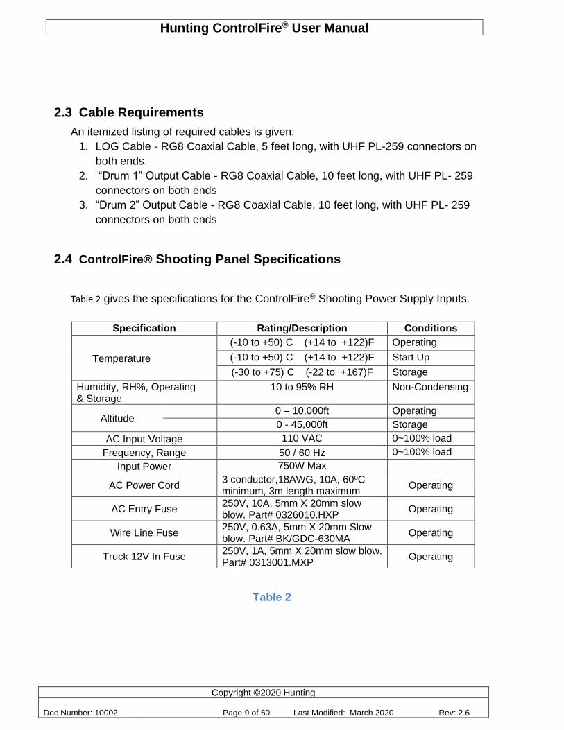
2.3 Cable Requirements
An itemized listing of required cables is given:
1. LOG Cable - RG8 Coaxial Cable, 5 feet long, with UHF PL-259 connectors on
both ends.
2. “Drum 1” Output Cable - RG8 Coaxial Cable, 10 feet long, with UHF PL- 259
connectors on both ends
3. “Drum 2” Output Cable - RG8 Coaxial Cable, 10 feet long, with UHF PL- 259
connectors on both ends
2.4 ControlFire® Shooting Panel Specifications
Table 2 gives the specifications for the ControlFire® Shooting Power Supply Inputs.
Specification Rating/Description Conditions
Temperature
(-10 to +50) C (+14 to +122)F Operating
(-10 to +50) C (+14 to +122)F Start Up
(-30 to +75) C (-22 to +167)F Storage
Humidity, RH%, Operating & Storage
10 to 95% RH Non-Condensing
Altitude 0 – 10,000ft Operating
0 - 45,000ft Storage
AC Input Voltage 110 VAC 0~100% load
Frequency, Range 50 / 60 Hz 0~100% load
Input Power 750W Max
AC Power Cord 3 conductor,18AWG, 10A, 60ºC minimum, 3m length maximum
Operating
AC Entry Fuse 250V, 10A, 5mm X 20mm slow blow. Part# 0326010.HXP
Operating
Wire Line Fuse 250V, 0.63A, 5mm X 20mm Slow blow. Part# BK/GDC-630MA
Operating
Truck 12V In Fuse 250V, 1A, 5mm X 20mm slow blow. Part# 0313001.MXP
Operating
Table 2
Hunting ControlFire® User Manual
Copyright ©2020 Hunting
Doc Number: 10002 Page 10 of 60 Last Modified: March 2020 Rev: 2.6
2.5 Log, Aux and CCL Operation
When the user selects Log from the front panel knob the selected Drum connector will connect to the Log connector on the back of the panel.
When the user selects Aux from the front panel knob the selected Drum connector will connect to the Aux connector on the front and back of the panel.
When the user selects CCL from the front panel the device will display the CCL signal changes on the front panel micro ammeter. The CCL Gain knob controls the gain of the CCL circuit, and the volume control knob controls the volume of the CCL signal kicks. The rear panel CCL connector is not affected by the CCL Gain knob as it has a fixed gain.
2.6 ARM Mode Operation
When the user selects ARM from the front panel, the user is able to send shooting power in either polarity down the wireline. The Dump Fire button enables the operator to Dump fire a preselected voltage.
When in Dump Fire mode the Dump Fire button LED will flash once every second.
If an over current condition occurs, then the output is disconnected and the Dump Fire LED will flash 4 times a second. Turning the knob all the way to zero or changing the mode will enable the operator to use the shooting supply again.
2.7 Select Fire Instructions (Positive / Negative)
• Turn the Voltage knob fully counter clockwise.
• Select the Polarity of voltage required by selecting Positive “POS” or Negative “NEG”.
• Press the Red colored Fire Switch (spring loaded) and turn the Voltage knob
clockwise till you arrive at the desired voltage.
• Once the required operation is completed release the Fire Switch and turn the
voltage knob fully counter clockwise.
2.8 Dump Fire Instructions (Positive / Negative)
• Pressing the Dump Fire Switch once places the unit in Dump Fire Mode. This is
indicated by a LED flashing once every second
• Turn the Voltage knob fully counter clockwise.
• Select the Polarity of voltage required by selecting Positive “POS” or Negative “NEG”.
• Press the Red colored Fire Switch (spring loaded) and turn the Voltage knob
clockwise till you arrive at the desired voltage.
• Press the Dump Fire switch again to dump the voltage into the connected output.
• Once the required operation is completed release the Fire Switch and turn the
voltage knob fully counter clockwise.
Hunting ControlFire® User Manual
Copyright ©2020 Hunting
Doc Number: 10002 Page 11 of 60 Last Modified: March 2020 Rev: 2.6
• This removes the panel out of Dump Fire mode and places it in regular Select Fire
Mode
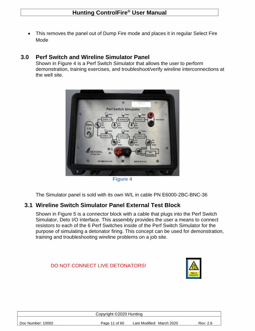
3.0 Perf Switch and Wireline Simulator Panel Shown in Figure 4 is a Perf Switch Simulator that allows the user to perform demonstration, training exercises, and troubleshoot/verify wireline interconnections at the well site.
The Simulator panel is sold with its own W/L in cable PN E6000-2BC-BNC-36
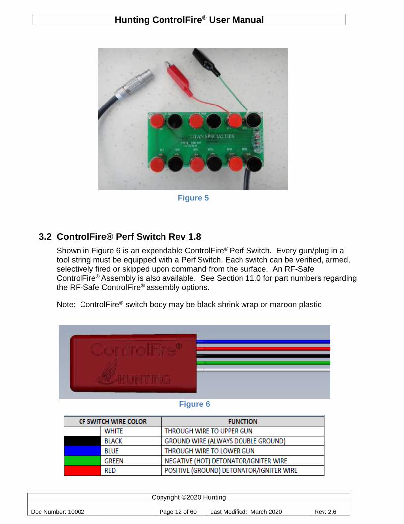
3.1 Wireline Switch Simulator Panel External Test Block
Shown in Figure 5 is a connector block with a cable that plugs into the Perf Switch Simulator, Deto I/O interface. This assembly provides the user a means to connect resistors to each of the 6 Perf Switches inside of the Perf Switch Simulator for the purpose of simulating a detonator firing. This concept can be used for demonstration, training and troubleshooting wireline problems on a job site.
DO NOT CONNECT LIVE DETONATORS!
Figure 4
Hunting ControlFire® User Manual
Copyright ©2020 Hunting
Doc Number: 10002 Page 12 of 60 Last Modified: March 2020 Rev: 2.6
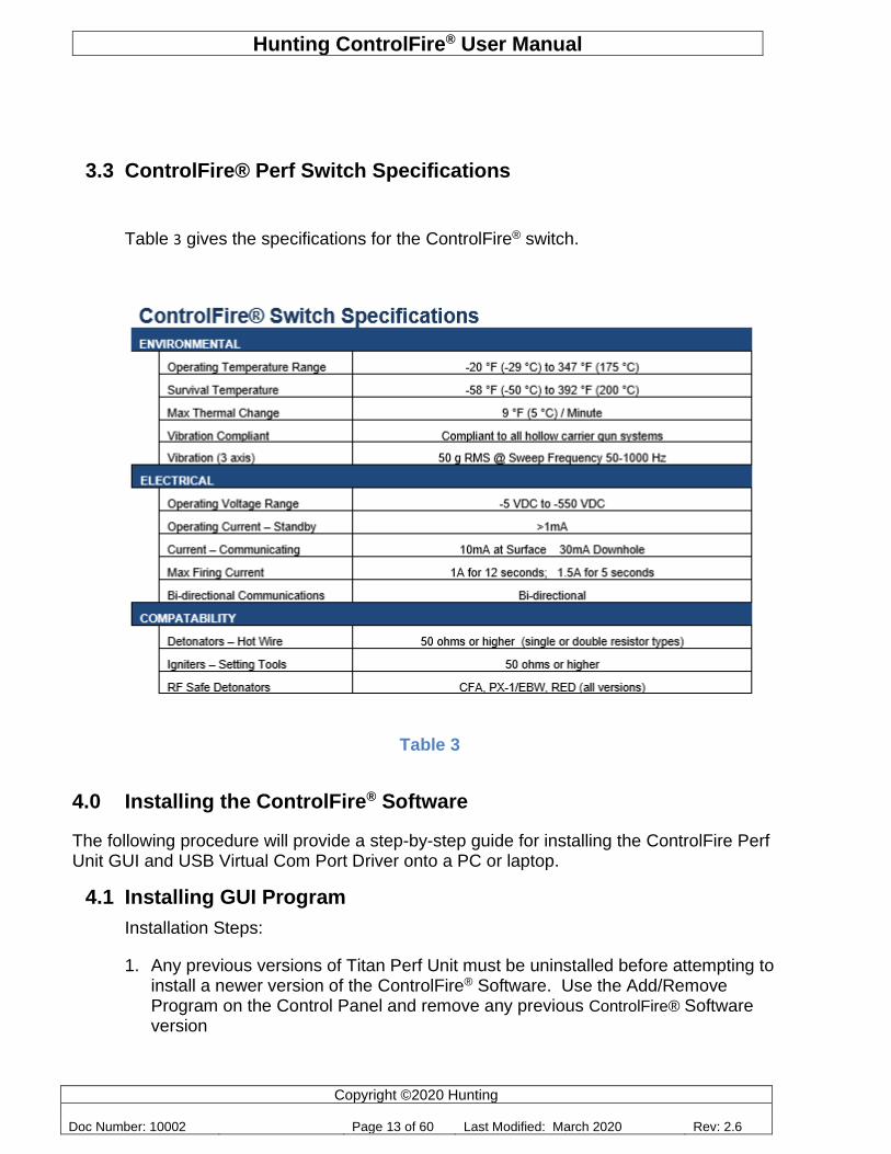
3.2 ControlFire® Perf Switch Rev 1.8
Shown in Figure 6 is an expendable ControlFire® Perf Switch. Every gun/plug in a tool string must be equipped with a Perf Switch. Each switch can be verified, armed, selectively fired or skipped upon command from the surface. An RF-Safe ControlFire® Assembly is also available. See Section 11.0 for part numbers regarding the RF-Safe ControlFire® assembly options.
Note: ControlFire® switch body may be black shrink wrap or maroon plastic
Figure 6
DET (-)
W/L OUT
DET (GRND)
GRND
W/L IN (-)
Figure 5
Hunting ControlFire® User Manual
Copyright ©2020 Hunting
Doc Number: 10002 Page 13 of 60 Last Modified: March 2020 Rev: 2.6
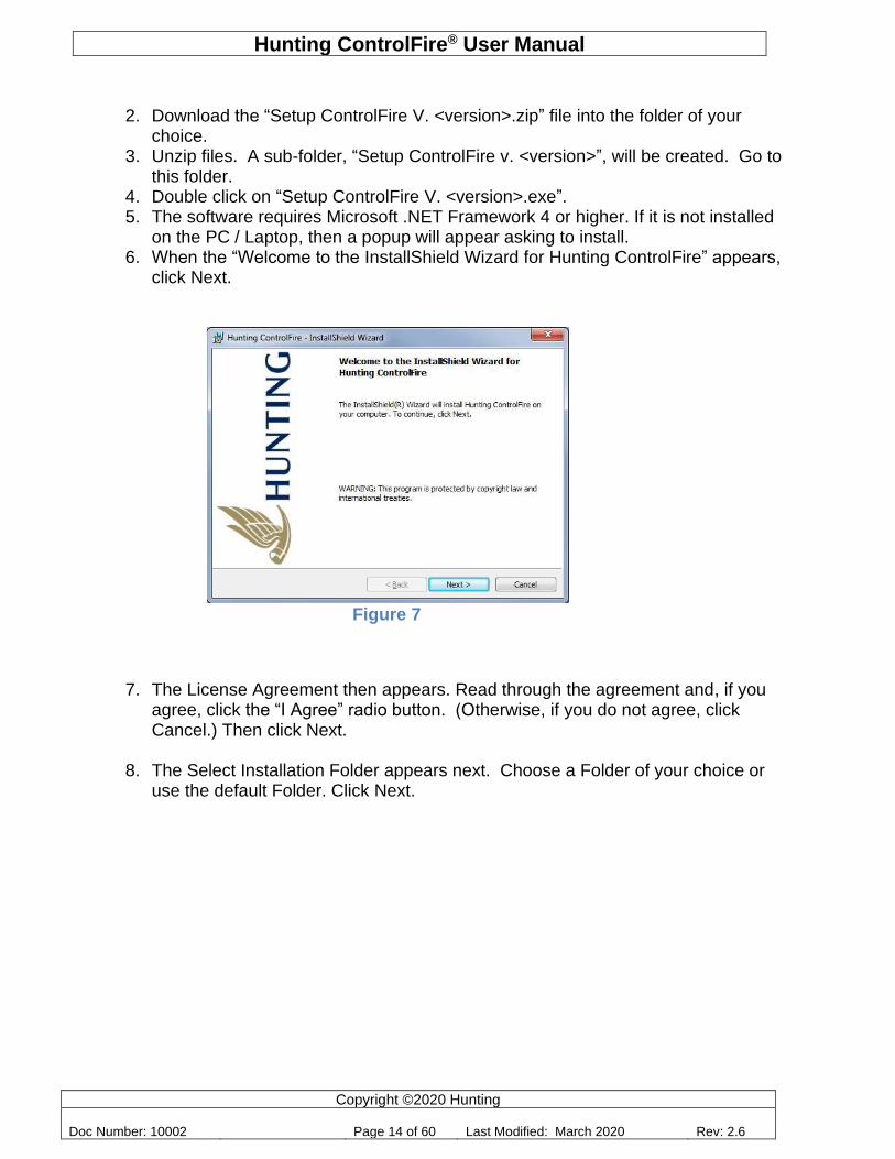
3.3 ControlFire® Perf Switch Specifications
Table 3 gives the specifications for the ControlFire® switch.
Table 3
4.0 Installing the ControlFire® Software
The following procedure will provide a step-by-step guide for installing the ControlFire Perf Unit GUI and USB Virtual Com Port Driver onto a PC or laptop.
4.1 Installing GUI Program
Installation Steps:
1. Any previous versions of Titan Perf Unit must be uninstalled before attempting to install a newer version of the ControlFire® Software. Use the Add/Remove Program on the Control Panel and remove any previous ControlFire® Software version
ControlFire® Switch Specifications ENVIRONMENTAL
Operating Temperature Range -20 °F (-29 °C) to 347 °F (175 °C)
Survival Temperature -58 °F (-50 °C) to 392 °F (200 °C)
Max Thermal Change 9 °F (5 °C) / Minute
Vibration Compliant Compliant to all hollow carrier gun systems
Vibration (3 axis) 50 g RMS @ Sweep Frequency 50-1000 Hz
ELECTRICAL
Operating Voltage Range -5 VDC to -550 VDC
Operating Current – Standby >1mA
Current – Communicating 10mA at Surface 30mA Downhole
Max Firing Current 1A for 12 seconds; 1.5A for 5 seconds
Bi-directional Communications Bi-directional
COMPATABILITY
Detonators – Hot Wire 50 ohms or higher (single or double resistor types)
Igniters – Setting Tools 50 ohms or higher
RF Safe Detonators CFA, PX-1/EBW, RED (all versions)
Hunting ControlFire® User Manual
Copyright ©2020 Hunting
Doc Number: 10002 Page 14 of 60 Last Modified: March 2020 Rev: 2.6
2. Download the “Setup ControlFire V. <version>.zip” file into the folder of your choice.
3. Unzip files. A sub-folder, “Setup ControlFire v. <version>”, will be created. Go to this folder.
4. Double click on “Setup ControlFire V. <version>.exe”. 5. The software requires Microsoft .NET Framework 4 or higher. If it is not installed
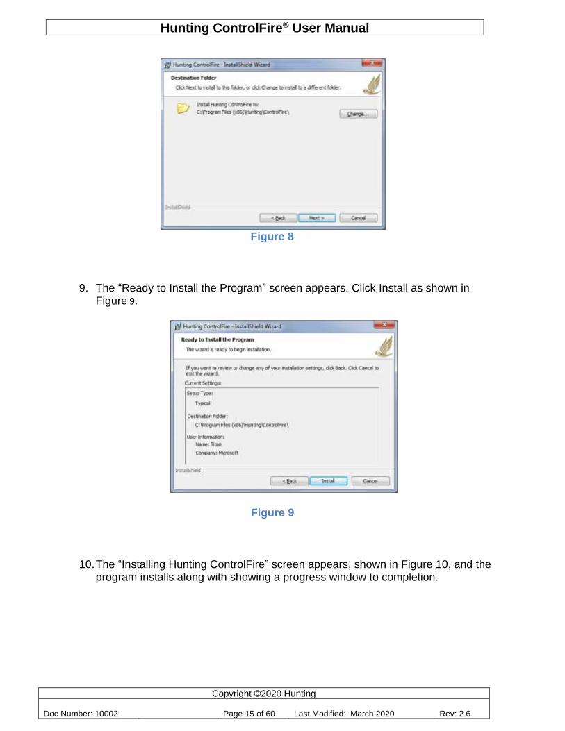
on the PC / Laptop, then a popup will appear asking to install. 6. When the “Welcome to the InstallShield Wizard for Hunting ControlFire” appears,
click Next.
Figure 7
7. The License Agreement then appears. Read through the agreement and, if you agree, click the “I Agree” radio button. (Otherwise, if you do not agree, click Cancel.) Then click Next.
8. The Select Installation Folder appears next. Choose a Folder of your choice or
use the default Folder. Click Next.
Hunting ControlFire® User Manual
Copyright ©2020 Hunting
Doc Number: 10002 Page 15 of 60 Last Modified: March 2020 Rev: 2.6
9. The “Ready to Install the Program” screen appears. Click Install as shown in Figure 9.
Figure 9
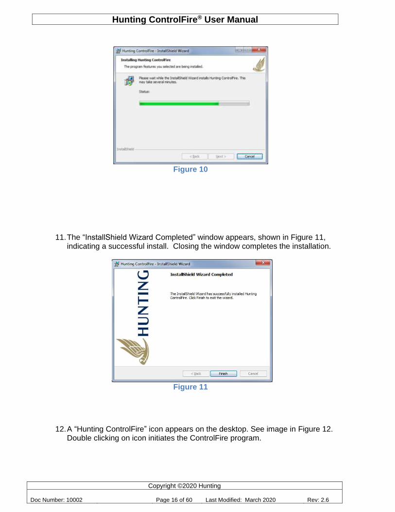
10. The “Installing Hunting ControlFire” screen appears, shown in Figure 10, and the
program installs along with showing a progress window to completion.
Figure 8
Hunting ControlFire® User Manual
Copyright ©2020 Hunting
Doc Number: 10002 Page 16 of 60 Last Modified: March 2020 Rev: 2.6
Figure 10
11. The “InstallShield Wizard Completed” window appears, shown in Figure 11, indicating a successful install. Closing the window completes the installation.
Figure 11
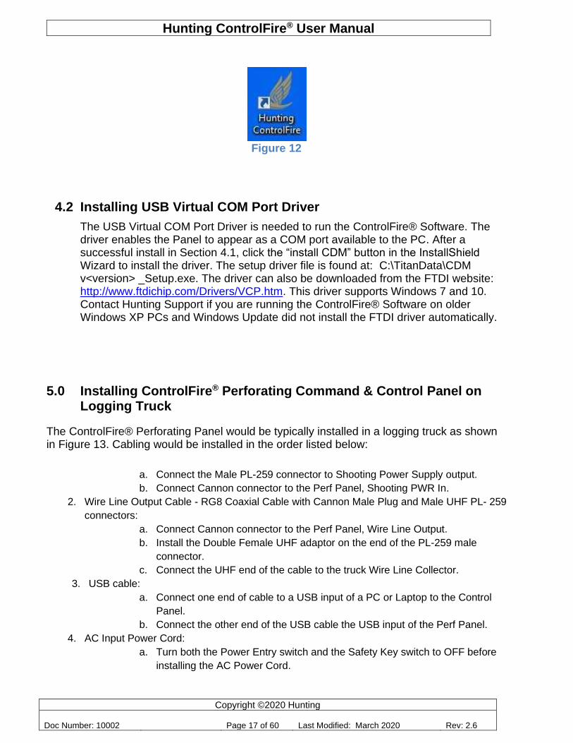
12. A “Hunting ControlFire” icon appears on the desktop. See image in Figure 12. Double clicking on icon initiates the ControlFire program.
Hunting ControlFire® User Manual
Copyright ©2020 Hunting
Doc Number: 10002 Page 17 of 60 Last Modified: March 2020 Rev: 2.6
Figure 12
4.2 Installing USB Virtual COM Port Driver
The USB Virtual COM Port Driver is needed to run the ControlFire® Software. The driver enables the Panel to appear as a COM port available to the PC. After a successful install in Section 4.1, click the “install CDM” button in the InstallShield Wizard to install the driver. The setup driver file is found at: C:\TitanData\CDM v<version> _Setup.exe. The driver can also be downloaded from the FTDI website: http://www.ftdichip.com/Drivers/VCP.htm. This driver supports Windows 7 and 10. Contact Hunting Support if you are running the ControlFire® Software on older Windows XP PCs and Windows Update did not install the FTDI driver automatically.
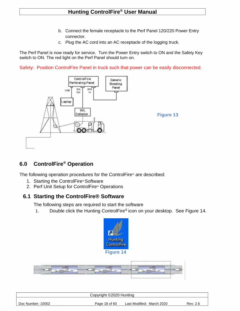
5.0 Installing ControlFire® Perforating Command & Control Panel on Logging Truck
The ControlFire® Perforating Panel would be typically installed in a logging truck as shown in Figure 13. Cabling would be installed in the order listed below:
a. Connect the Male PL-259 connector to Shooting Power Supply output.
b. Connect Cannon connector to the Perf Panel, Shooting PWR In.
2. Wire Line Output Cable - RG8 Coaxial Cable with Cannon Male Plug and Male UHF PL- 259
connectors:
a. Connect Cannon connector to the Perf Panel, Wire Line Output.
b. Install the Double Female UHF adaptor on the end of the PL-259 male
connector.
c. Connect the UHF end of the cable to the truck Wire Line Collector.
3. USB cable:
a. Connect one end of cable to a USB input of a PC or Laptop to the Control
Panel.
b. Connect the other end of the USB cable the USB input of the Perf Panel.
4. AC Input Power Cord:
a. Turn both the Power Entry switch and the Safety Key switch to OFF before
installing the AC Power Cord.
Hunting ControlFire® User Manual
Copyright ©2020 Hunting
Doc Number: 10002 Page 18 of 60 Last Modified: March 2020 Rev: 2.6
b. Connect the female receptacle to the Perf Panel 120/220 Power Entry
connector.
c. Plug the AC cord into an AC receptacle of the logging truck.
The Perf Panel is now ready for service. Turn the Power Entry switch to ON and the Safety Key switch to ON. The red light on the Perf Panel should turn on.
Safety: Position ControlFire Panel in truck such that power can be easily disconnected.
6.0 ControlFire® Operation
The following operation procedures for the ControlFire® are described:
1. Starting the ControlFire® Software 2. Perf Unit Setup for ControlFire® Operations
6.1 Starting the ControlFire® Software
The following steps are required to start the software
1. Double click the Hunting ControlFire® icon on your desktop. See Figure 14.
Figure 14
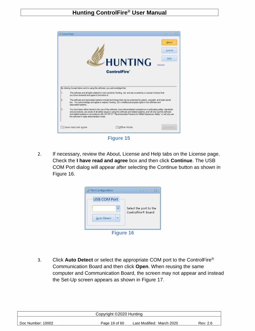
The License Agreement screen appears as shown in Figure 15.
Figure 13
Hunting ControlFire® User Manual
Copyright ©2020 Hunting
Doc Number: 10002 Page 19 of 60 Last Modified: March 2020 Rev: 2.6
2. If necessary, review the About, License and Help tabs on the License page.
Check the I have read and agree box and then click Continue. The USB
COM Port dialog will appear after selecting the Continue button as shown in
Figure 16.
3. Click Auto Detect or select the appropriate COM port to the ControlFire®
Communication Board and then click Open. When reusing the same
computer and Communication Board, the screen may not appear and instead
the Set-Up screen appears as shown in Figure 17.
Figure 16
Figure 15
Hunting ControlFire® User Manual
Copyright ©2020 Hunting
Doc Number: 10002 Page 20 of 60 Last Modified: March 2020 Rev: 2.6
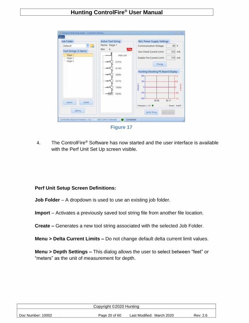
4. The ControlFire® Software has now started and the user interface is available
with the Perf Unit Set Up screen visible.
Perf Unit Setup Screen Definitions:
Job Folder – A dropdown is used to use an existing job folder.
Import – Activates a previously saved tool string file from another file location.
Create – Generates a new tool string associated with the selected Job Folder.
Menu > Delta Current Limits – Do not change default delta current limit values.
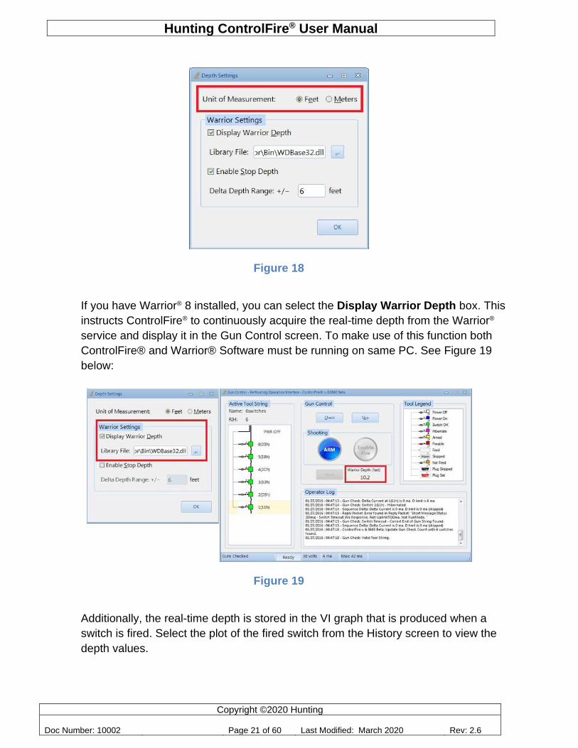
Menu > Depth Settings – This dialog allows the user to select between “feet” or
“meters” as the unit of measurement for depth.
Figure 17
Hunting ControlFire® User Manual
Copyright ©2020 Hunting
Doc Number: 10002 Page 21 of 60 Last Modified: March 2020 Rev: 2.6
Figure 18
If you have Warrior® 8 installed, you can select the Display Warrior Depth box. This
instructs ControlFire® to continuously acquire the real-time depth from the Warrior®
service and display it in the Gun Control screen. To make use of this function both
ControlFire® and Warrior® Software must be running on same PC. See Figure 19
below:
Figure 19
Additionally, the real-time depth is stored in the VI graph that is produced when a
switch is fired. Select the plot of the fired switch from the History screen to view the
depth values.
Hunting ControlFire® User Manual
Copyright ©2020 Hunting
Doc Number: 10002 Page 22 of 60 Last Modified: March 2020 Rev: 2.6
The Enable Stop Depth feature works with the Warrior® software to ensure that
guns are fired within the allowed depth range. ControlFire® accomplishes this by
making the Enable Fire button in Gun Control clickable only at the correct depths. A
gun becomes “fireable” when the current Warrior® depth in Gun Control is within
range of the gun’s Stop Depth. Note that a switch can be checked and armed at any
depth. Additionally, once the user has clicked Enable Fire, the user will have the
ability to send voltage even if the depth of the switch goes out of range. For this
reason, we recommend using the Stop Depth feature only when shooting in a
stationary position. The Stop Depths are entered in the Gun Sheet as outlined in
Section 6.2.4 steps 2-4. As an added safety measure, when ControlFire® detects a
Shooting Power Supply (SPS) from Hunting, it disables that panel’s Fire relay switch
as soon as the Gun Control screen becomes active. The SPS Fire relay switch is
enabled only after a gun is armed and within the tolerance range.
Menu > Downhole Temperature – This option allows the user to select the
temperature unit. It is useful when the Tool String includes a temperature sensor,
such as the one found in the Hunting Safety Sub.
Menu > Decrease the Armed Timer to 15 seconds – When enabled, this option
decreases the time available to click the Enable Fire button once the switch is armed.
The default timer is 5 minutes.
Menu > Hunting Release Tool – Electronic – This option modifies the voltage used
to operate the tool.
Menu > Update ControlFire Board Firmware – When selected, the Bootloader
dialog is opened for updating the Communication Board firmware.
Menu > Update Shooting PS Board Firmware – When selected, the SPS
Bootloader dialog is opened for updating the Hunting Shooting Power Supply Board
firmware.
Menu > Help – When selected, a ControlFire® User’s Manual is opened for viewing.
Menu > Troubleshooting Guide – When selected, a ControlFire® Troubleshooting
guide is opened for viewing.
History – Opens a screen to view the history of each run within the job folder. It also
enables the user to export specific V/I plots within the job folder.
Hunting ControlFire® User Manual
Copyright ©2020 Hunting
Doc Number: 10002 Page 23 of 60 Last Modified: March 2020 Rev: 2.6
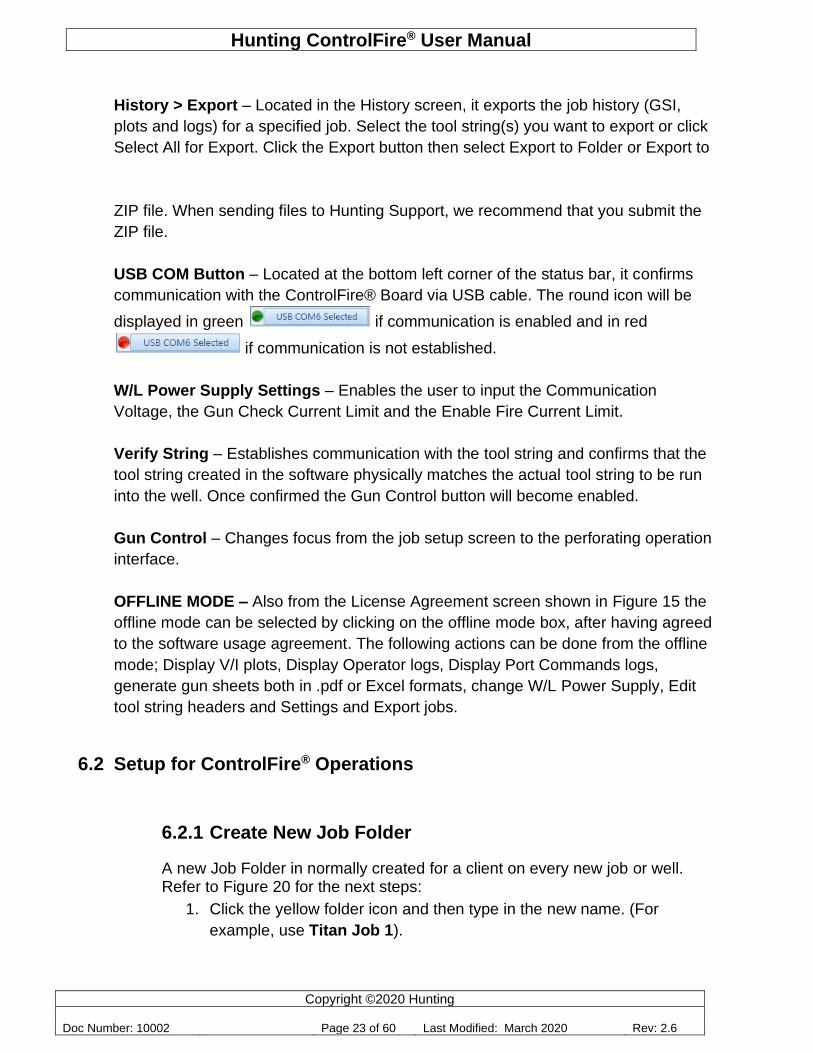
History > Export – Located in the History screen, it exports the job history (GSI,
plots and logs) for a specified job. Select the tool string(s) you want to export or click
Select All for Export. Click the Export button then select Export to Folder or Export to
ZIP file. When sending files to Hunting Support, we recommend that you submit the
ZIP file.
USB COM Button – Located at the bottom left corner of the status bar, it confirms
communication with the ControlFire® Board via USB cable. The round icon will be
displayed in green if communication is enabled and in red
if communication is not established.
W/L Power Supply Settings – Enables the user to input the Communication
Voltage, the Gun Check Current Limit and the Enable Fire Current Limit.
Verify String – Establishes communication with the tool string and confirms that the
tool string created in the software physically matches the actual tool string to be run
into the well. Once confirmed the Gun Control button will become enabled.
Gun Control – Changes focus from the job setup screen to the perforating operation
interface.
OFFLINE MODE – Also from the License Agreement screen shown in Figure 15 the
offline mode can be selected by clicking on the offline mode box, after having agreed
to the software usage agreement. The following actions can be done from the offline
mode; Display V/I plots, Display Operator logs, Display Port Commands logs,
generate gun sheets both in .pdf or Excel formats, change W/L Power Supply, Edit
tool string headers and Settings and Export jobs.
6.2 Setup for ControlFire® Operations
6.2.1 Create New Job Folder
A new Job Folder in normally created for a client on every new job or well. Refer to Figure 20 for the next steps:
1. Click the yellow folder icon and then type in the new name. (For
example, use Titan Job 1).
Hunting ControlFire® User Manual
Copyright ©2020 Hunting
Doc Number: 10002 Page 24 of 60 Last Modified: March 2020 Rev: 2.6
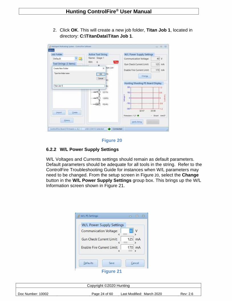
2. Click OK. This will create a new job folder, Titan Job 1, located in
directory: C:\TitanData\Titan Job 1.
Figure 20
6.2.2 W/L Power Supply Settings
W/L Voltages and Currents settings should remain as default parameters. Default parameters should be adequate for all tools in the string. Refer to the ControlFire Troubleshooting Guide for instances when W/L parameters may need to be changed. From the setup screen in Figure 20, select the Change
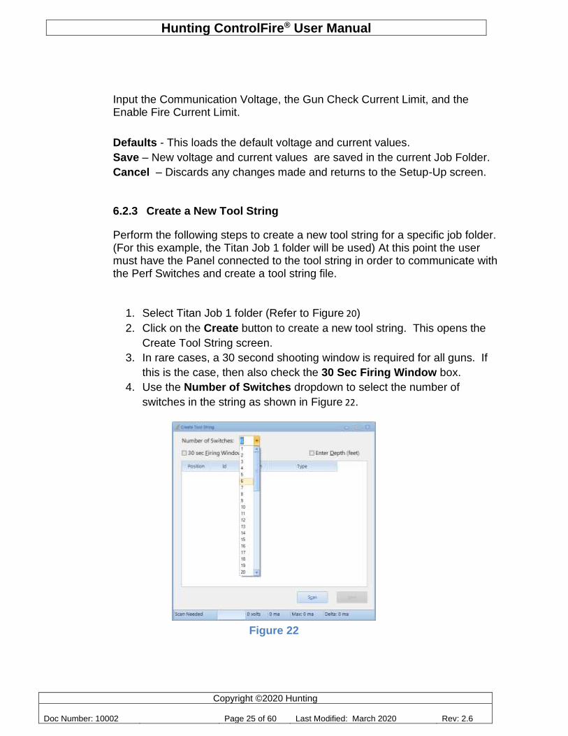
button in the W/L Power Supply Settings group box. This brings up the W/L Information screen shown in Figure 21.
Figure 21
Hunting ControlFire® User Manual
Copyright ©2020 Hunting
Doc Number: 10002 Page 25 of 60 Last Modified: March 2020 Rev: 2.6
Input the Communication Voltage, the Gun Check Current Limit, and the Enable Fire Current Limit.
Defaults - This loads the default voltage and current values.
Save – New voltage and current values are saved in the current Job Folder.
Cancel – Discards any changes made and returns to the Setup-Up screen.
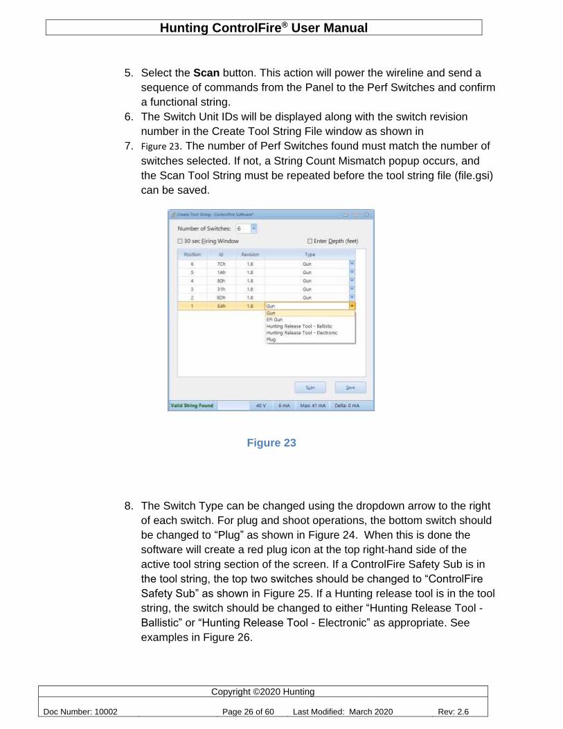
6.2.3 Create a New Tool String
Perform the following steps to create a new tool string for a specific job folder. (For this example, the Titan Job 1 folder will be used) At this point the user must have the Panel connected to the tool string in order to communicate with the Perf Switches and create a tool string file.
1. Select Titan Job 1 folder (Refer to Figure 20)
2. Click on the Create button to create a new tool string. This opens the
Create Tool String screen.
3. In rare cases, a 30 second shooting window is required for all guns. If
this is the case, then also check the 30 Sec Firing Window box.
4. Use the Number of Switches dropdown to select the number of
switches in the string as shown in Figure 22.
Figure 22
Hunting ControlFire® User Manual
Copyright ©2020 Hunting
Doc Number: 10002 Page 26 of 60 Last Modified: March 2020 Rev: 2.6
5. Select the Scan button. This action will power the wireline and send a
sequence of commands from the Panel to the Perf Switches and confirm
a functional string.
6. The Switch Unit IDs will be displayed along with the switch revision
number in the Create Tool String File window as shown in
7. Figure 23. The number of Perf Switches found must match the number of
switches selected. If not, a String Count Mismatch popup occurs, and
the Scan Tool String must be repeated before the tool string file (file.gsi)
can be saved.
Figure 23
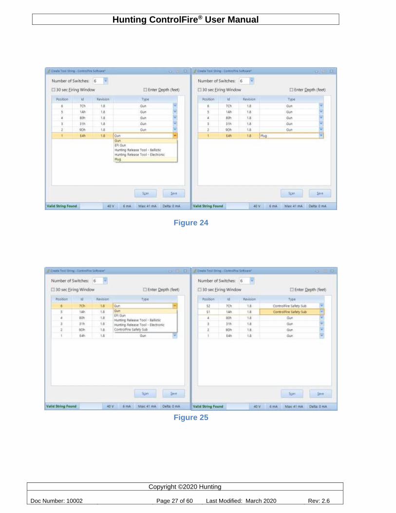
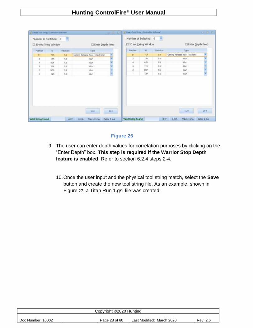
8. The Switch Type can be changed using the dropdown arrow to the right
of each switch. For plug and shoot operations, the bottom switch should
be changed to “Plug” as shown in Figure 24. When this is done the
software will create a red plug icon at the top right-hand side of the
active tool string section of the screen. If a ControlFire Safety Sub is in
the tool string, the top two switches should be changed to “ControlFire
Safety Sub” as shown in Figure 25. If a Hunting release tool is in the tool
string, the switch should be changed to either “Hunting Release Tool -
Ballistic” or “Hunting Release Tool - Electronic” as appropriate. See
examples in Figure 26.
Hunting ControlFire® User Manual
Copyright ©2020 Hunting
Doc Number: 10002 Page 27 of 60 Last Modified: March 2020 Rev: 2.6
Figure 24
Figure 25
Hunting ControlFire® User Manual
Copyright ©2020 Hunting
Doc Number: 10002 Page 28 of 60 Last Modified: March 2020 Rev: 2.6
Figure 26
9. The user can enter depth values for correlation purposes by clicking on the
“Enter Depth” box. This step is required if the Warrior Stop Depth
feature is enabled. Refer to section 6.2.4 steps 2-4.
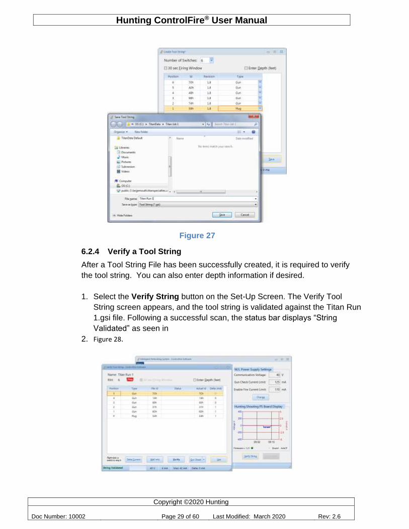
10. Once the user input and the physical tool string match, select the Save
button and create the new tool string file. As an example, shown in
Figure 27, a Titan Run 1.gsi file was created.
Hunting ControlFire® User Manual
Copyright ©2020 Hunting
Doc Number: 10002 Page 29 of 60 Last Modified: March 2020 Rev: 2.6
Figure 27
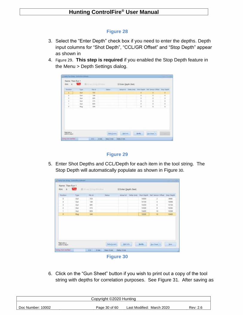
6.2.4 Verify a Tool String
After a Tool String File has been successfully created, it is required to verify
the tool string. You can also enter depth information if desired.
1. Select the Verify String button on the Set-Up Screen. The Verify Tool
String screen appears, and the tool string is validated against the Titan Run
1.gsi file. Following a successful scan, the status bar displays “String
Validated” as seen in
2. Figure 28.
Hunting ControlFire® User Manual
Copyright ©2020 Hunting
Doc Number: 10002 Page 30 of 60 Last Modified: March 2020 Rev: 2.6
Figure 28
3. Select the “Enter Depth” check box if you need to enter the depths. Depth
input columns for “Shot Depth”, “CCL/GR Offset” and “Stop Depth” appear
as shown in
4. Figure 29. This step is required if you enabled the Stop Depth feature in
the Menu > Depth Settings dialog.
Figure 29
5. Enter Shot Depths and CCL/Depth for each item in the tool string. The
Stop Depth will automatically populate as shown in Figure 30.
Figure 30
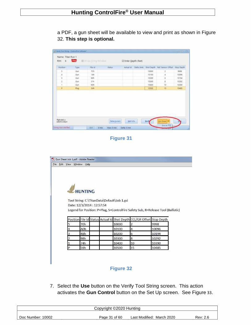
6. Click on the “Gun Sheet” button if you wish to print out a copy of the tool
string with depths for correlation purposes. See Figure 31. After saving as
Hunting ControlFire® User Manual
Copyright ©2020 Hunting
Doc Number: 10002 Page 31 of 60 Last Modified: March 2020 Rev: 2.6
a PDF, a gun sheet will be available to view and print as shown in Figure
32. This step is optional.
Figure 31
Figure 32
7. Select the Use button on the Verify Tool String screen. This action
activates the Gun Control button on the Set Up screen. See Figure 33.
Hunting ControlFire® User Manual
Copyright ©2020 Hunting
Doc Number: 10002 Page 32 of 60 Last Modified: March 2020 Rev: 2.6
Figure 33
This completes the setup process and a given tool string is ready. The Gun Control screen is now ready for use.
6.3 Gun Check, Arming and Firing
Following a successful Verify, the tool string is ready to begin a Gun Check, Arming and Firing sequence. To start these sequences, select the Gun Control button on the Set Up screen in Figure 17. This activates the Gun Control Screen in
Figure 34.
Hunting ControlFire® User Manual
Copyright ©2020 Hunting
Doc Number: 10002 Page 33 of 60 Last Modified: March 2020 Rev: 2.6
Figure 34
Gun Control Window Definitions:
Warning: All Gun Control commands must be performed in a wellbore at a depth of greater
than 200 feet or according to the operator’s standards.
Gun Check –The Check button requests the ControlFire® Board to send a set of commands to the Perf Switches and read the status of all the switches in the string. An
Hunting ControlFire® User Manual
Copyright ©2020 Hunting
Doc Number: 10002 Page 34 of 60 Last Modified: March 2020 Rev: 2.6
unlimited number of Gun Check requests can be performed on the tool string. Once the Gun Check is successfully completed, the Arm button is accessible to the user.
Arm – Selecting the Arm button sends an ARM command to the bottom most active switch. Once the selected gun is armed, the Enable Fire button is accessible to the user for 15 seconds or 5 minutes if the user enabled the option under Menu > Decrease Armed Timer to 15 Seconds. If an enable fire is not sent within the specified time window, the Perforating Command and Control Panel will revert back to a pre-initialized gun check screen.
Enable Fire - The Enable Fire button commands starts the following sequences:
1. The V/I plot appears and immediately starts recording wire line current and
voltage. This Plot is used for shot detection.
2. The Enable Fire button becomes clickable, and the status bar displays “Gun
Armed”.
Note: If Stop Depth is enabled, a switch can be Armed at any depth. However, the Enable Fire button becomes clickable only when the gun is within the correct depth range. The Stop Depth feature is enabled in the Menu > Depth Settings dialog. The depths must be typed in the Verify Tool String screen.
Switch Skip – The Skip button provides a method to skip over malfunctioned guns. A switch skip command skips the bottom most detected gun in a string. Each additional switch skip command initiated propagates upward one gun.
Abort – The abort button stops the current operation.
Tool Legend – This legend (Figure 35) indicates the state of the switch in the string.
6.3.1 Gun Check
A Gun Check is initiated by selecting the Gun Check button on the Gun Control Screen. The screen shown in
Power Off – No power/communication to switch Power On – Power applied to switch Gun OK – Switch verified and operational Hibernate – Switch is OFF and W/L Switch is ON Armed – Switch is ready for detonator connection Fireable – Switch is armed and ready for power to be applied to detonator/igniter Fired – Enable Fire function has been performed Skipped – Switch has been skipped and unable to be armed Not Fired – Enable fire function has been performed but switch remains functional
Figure 35
Hunting ControlFire® User Manual
Copyright ©2020 Hunting
Doc Number: 10002 Page 35 of 60 Last Modified: March 2020 Rev: 2.6
Figure 36 results from a successful gun check.
Figure 36
The following indicate a valid gun check:
1. All switch icons are green in color
2. Operator Log does not indicate any errors
3. The status bar displays “Guns Checked”
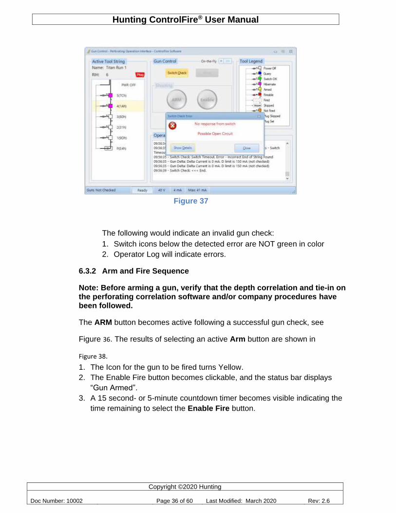
Shown in Figure 37 is the result of an invalid gun check. For this example, the wire line was not connected between switch 4(1Ah) and switch 3(80h).
Hunting ControlFire® User Manual
Copyright ©2020 Hunting
Doc Number: 10002 Page 36 of 60 Last Modified: March 2020 Rev: 2.6
Figure 37
The following would indicate an invalid gun check:
1. Switch icons below the detected error are NOT green in color
2. Operator Log will indicate errors.
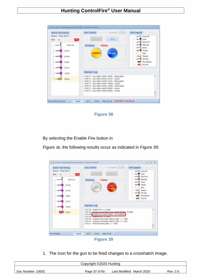
6.3.2 Arm and Fire Sequence
Note: Before arming a gun, verify that the depth correlation and tie-in on the perforating correlation software and/or company procedures have been followed.
The ARM button becomes active following a successful gun check, see
Figure 36. The results of selecting an active Arm button are shown in
Figure 38.
1. The Icon for the gun to be fired turns Yellow.
2. The Enable Fire button becomes clickable, and the status bar displays
“Gun Armed”.
3. A 15 second- or 5-minute countdown timer becomes visible indicating the
time remaining to select the Enable Fire button.
Hunting ControlFire® User Manual
Copyright ©2020 Hunting
Doc Number: 10002 Page 37 of 60 Last Modified: March 2020 Rev: 2.6
Figure 38
By selecting the Enable Fire button in
Figure 38, the following results occur as indicated in Figure 39:
Figure 39
1. The Icon for the gun to be fired changes to a crosshatch image.
Hunting ControlFire® User Manual
Copyright ©2020 Hunting
Doc Number: 10002 Page 38 of 60 Last Modified: March 2020 Rev: 2.6
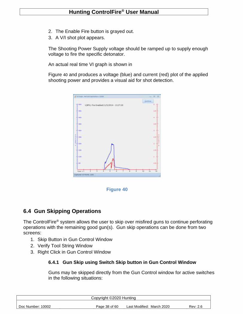
2. The Enable Fire button is grayed out.
3. A V/I shot plot appears.
The Shooting Power Supply voltage should be ramped up to supply enough voltage to fire the specific detonator.
An actual real time VI graph is shown in
Figure 40 and produces a voltage (blue) and current (red) plot of the applied
shooting power and provides a visual aid for shot detection.
6.4 Gun Skipping Operations
The ControlFire® system allows the user to skip over misfired guns to continue perforating operations with the remaining good gun(s). Gun skip operations can be done from two screens:
1. Skip Button in Gun Control Window
2. Verify Tool String Window
3. Right Click in Gun Control Window
6.4.1 Gun Skip using Switch Skip button in Gun Control Window
Guns may be skipped directly from the Gun Control window for active switches in the following situations:
Figure 40
Hunting ControlFire® User Manual
Copyright ©2020 Hunting
Doc Number: 10002 Page 39 of 60 Last Modified: March 2020 Rev: 2.6
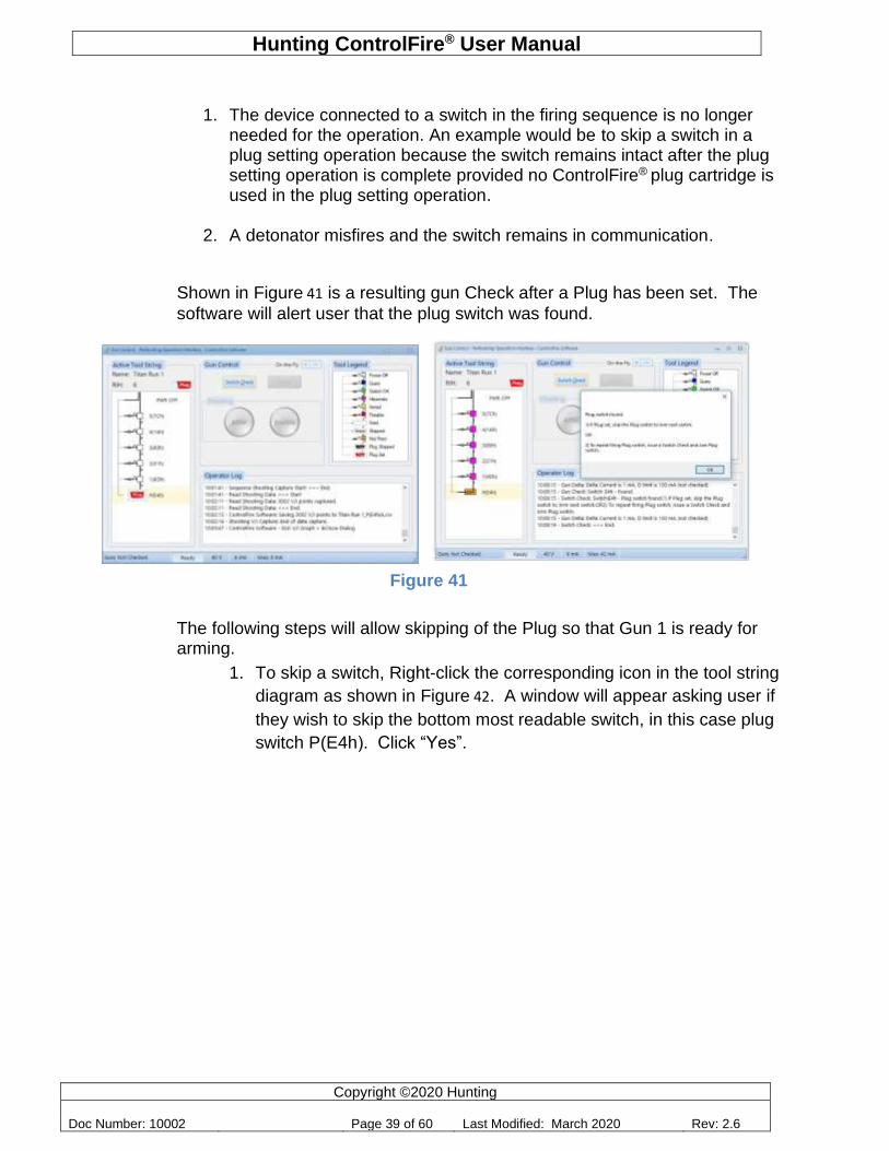
1. The device connected to a switch in the firing sequence is no longer needed for the operation. An example would be to skip a switch in a plug setting operation because the switch remains intact after the plug setting operation is complete provided no ControlFire® plug cartridge is used in the plug setting operation.
2. A detonator misfires and the switch remains in communication.
Shown in Figure 41 is a resulting gun Check after a Plug has been set. The
software will alert user that the plug switch was found.
The following steps will allow skipping of the Plug so that Gun 1 is ready for arming.
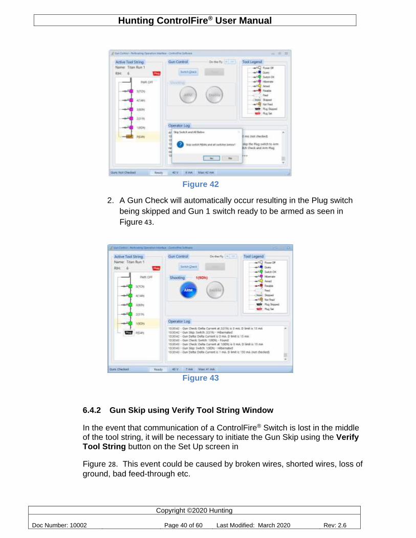
1. To skip a switch, Right-click the corresponding icon in the tool string
diagram as shown in Figure 42. A window will appear asking user if
they wish to skip the bottom most readable switch, in this case plug
switch P(E4h). Click “Yes”.
Figure 41
Hunting ControlFire® User Manual
Copyright ©2020 Hunting
Doc Number: 10002 Page 40 of 60 Last Modified: March 2020 Rev: 2.6
Figure 42
2. A Gun Check will automatically occur resulting in the Plug switch
being skipped and Gun 1 switch ready to be armed as seen in
Figure 43.
Figure 43
6.4.2 Gun Skip using Verify Tool String Window
In the event that communication of a ControlFire® Switch is lost in the middle of the tool string, it will be necessary to initiate the Gun Skip using the Verify Tool String button on the Set Up screen in
Figure 28. This event could be caused by broken wires, shorted wires, loss of
ground, bad feed-through etc.
Hunting ControlFire® User Manual
Copyright ©2020 Hunting
Doc Number: 10002 Page 41 of 60 Last Modified: March 2020 Rev: 2.6
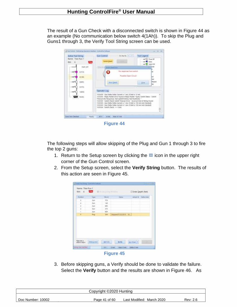
The result of a Gun Check with a disconnected switch is shown in Figure 44 as an example (No communication below switch 4(1Ah)). To skip the Plug and Guns1 through 3, the Verify Tool String screen can be used.
Figure 44
The following steps will allow skipping of the Plug and Gun 1 through 3 to fire the top 2 guns:
1. Return to the Setup screen by clicking the icon in the upper right
corner of the Gun Control screen.
2. From the Setup screen, select the Verify String button. The results of
this action are seen in Figure 45.
Figure 45
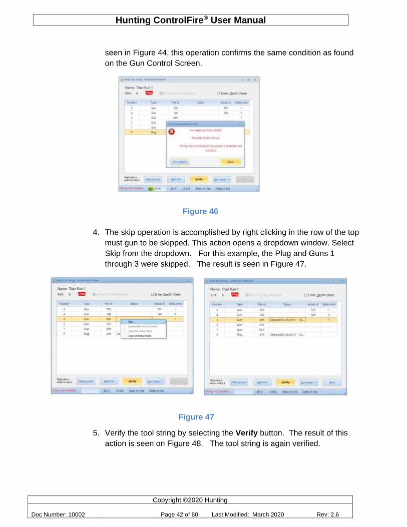
3. Before skipping guns, a Verify should be done to validate the failure.
Select the Verify button and the results are shown in Figure 46. As
Hunting ControlFire® User Manual
Copyright ©2020 Hunting
Doc Number: 10002 Page 42 of 60 Last Modified: March 2020 Rev: 2.6
seen in Figure 44, this operation confirms the same condition as found
on the Gun Control Screen.
4. The skip operation is accomplished by right clicking in the row of the top
must gun to be skipped. This action opens a dropdown window. Select
Skip from the dropdown. For this example, the Plug and Guns 1
through 3 were skipped. The result is seen in Figure 47.
Figure 47
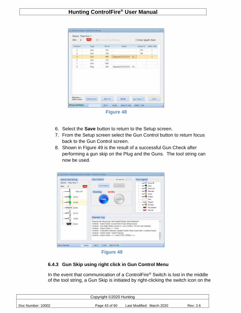
5. Verify the tool string by selecting the Verify button. The result of this
action is seen on Figure 48. The tool string is again verified.
Figure 46
Hunting ControlFire® User Manual
Copyright ©2020 Hunting
Doc Number: 10002 Page 43 of 60 Last Modified: March 2020 Rev: 2.6
Figure 48
6. Select the Save button to return to the Setup screen.
7. From the Setup screen select the Gun Control button to return focus
back to the Gun Control screen.
8. Shown in Figure 49 is the result of a successful Gun Check after
performing a gun skip on the Plug and the Guns. The tool string can
now be used.
6.4.3 Gun Skip using right click in Gun Control Menu
In the event that communication of a ControlFire® Switch is lost in the middle of the tool string, a Gun Skip is initiated by right-clicking the switch icon on the
Figure 49
Hunting ControlFire® User Manual
Copyright ©2020 Hunting
Doc Number: 10002 Page 44 of 60 Last Modified: March 2020 Rev: 2.6
tool string. This event could be caused by broken wires, shorted wires, loss of ground, bad feed-through etc.
The result of a Gun Check with a disconnected switch 2(31h) after Gun 1 was successfully fired is shown in Figure 50 as an example. User can skip the Open switch following indications given below.
Figure 50
The following steps will allow skipping of Gun 2 such that Guns 3 is ready to arm:
1. Right-click on the disconnected switch 2(31h)) in the tool diagram
and click “Yes” when the Skip Switch and All Below window appears
as shown in Figure 51.
Figure 51
2. A Gun Check will automatically occur, resulting in switch 2(31h)
skipped and Gun 3 ready to arm as seen in Figure 52.
Hunting ControlFire® User Manual
Copyright ©2020 Hunting
Doc Number: 10002 Page 45 of 60 Last Modified: March 2020 Rev: 2.6
Figure 52
7.0 Hunting Release Tool - Electronic
When creating a new string with this tool, change the switch type of the tool from “Gun” (the default type) to “Hunting Release Tool - Electronic”. The software will automatically adjust the Position to RM1. See Figure 53 below.
Figure 53
The power supply voltage to run the motor can be modified from the Set-Up screen by clicking Menu > Hunting Release Tool - Electronic …
Hunting ControlFire® User Manual
Copyright ©2020 Hunting
Doc Number: 10002 Page 46 of 60 Last Modified: March 2020 Rev: 2.6
:
Figure 54
To operate the tool, you must verify the string and then open the Gun Control screen.
7.1 Releasing the Tool
Figure 55 shows a sample string where the top tool is a Hunting Release Tool - Electronic. To release this tool, right click the switch just below it; i.e., switch 5 (7Ch) and skip it. Perform a Gun Check then Arm the tool as you would arm a regular switch. Click Yes when you see the ARM Tool dialog shown in Figure 55.
Hunting ControlFire® User Manual
Copyright ©2020 Hunting
Doc Number: 10002 Page 47 of 60 Last Modified: March 2020 Rev: 2.6
Figure 55
Following a successful Arm sequence, the Enable Release button in Gun Control becomes active. Click Enable Release then click Yes to proceed. See Figure 56.
Figure 56
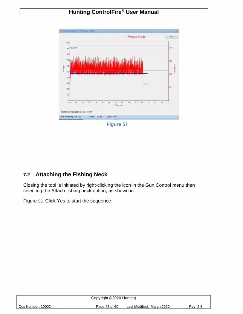
A new window appears showing a real time V/I graph that lets you monitor the operation.
Hunting ControlFire® User Manual
Copyright ©2020 Hunting
Doc Number: 10002 Page 48 of 60 Last Modified: March 2020 Rev: 2.6
Figure 57
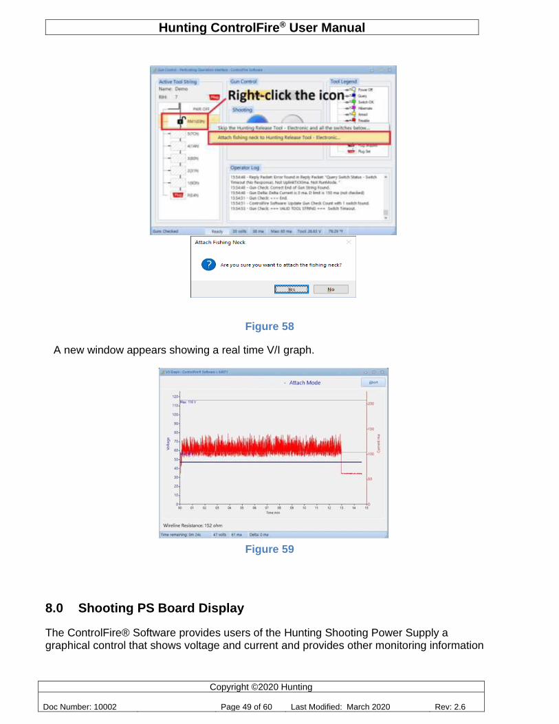
7.2 Attaching the Fishing Neck
Closing the tool is initiated by right-clicking the icon in the Gun Control menu then selecting the Attach fishing neck option, as shown in
Figure 58. Click Yes to start the sequence.
Hunting ControlFire® User Manual
Copyright ©2020 Hunting
Doc Number: 10002 Page 49 of 60 Last Modified: March 2020 Rev: 2.6
Figure 58
A new window appears showing a real time V/I graph.
Figure 59
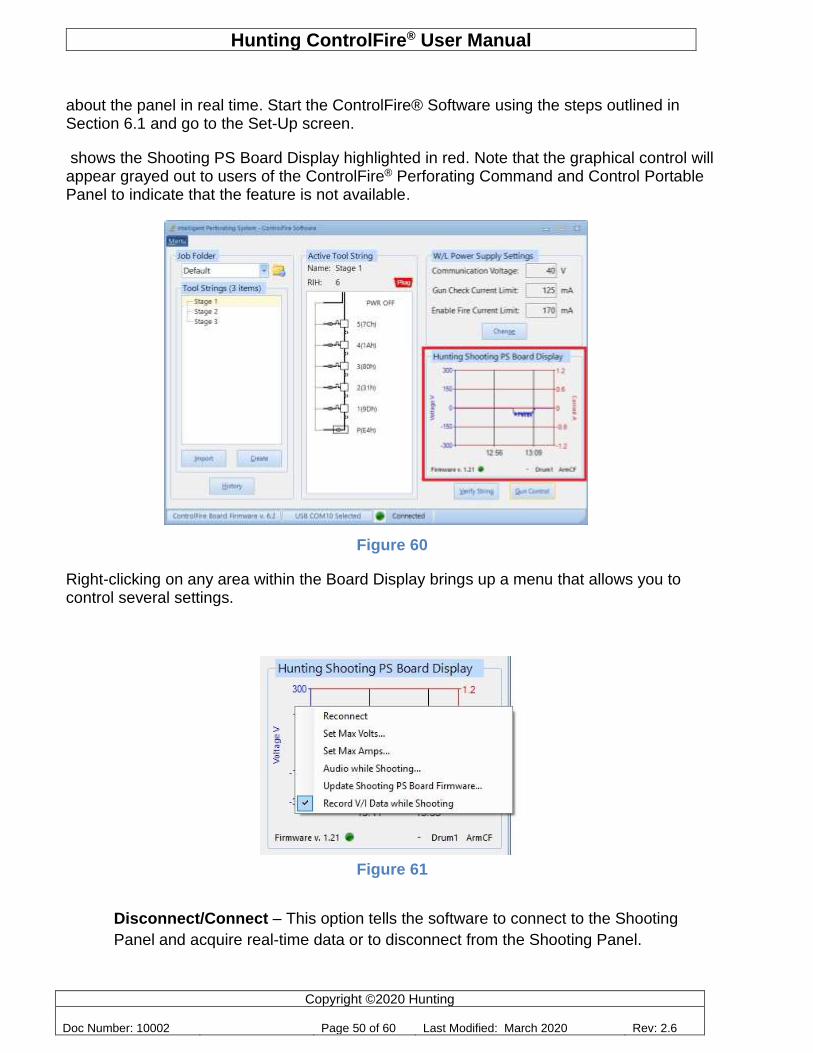
8.0 Shooting PS Board Display
The ControlFire® Software provides users of the Hunting Shooting Power Supply a graphical control that shows voltage and current and provides other monitoring information
Hunting ControlFire® User Manual
Copyright ©2020 Hunting
Doc Number: 10002 Page 50 of 60 Last Modified: March 2020 Rev: 2.6
about the panel in real time. Start the ControlFire® Software using the steps outlined in Section 6.1 and go to the Set-Up screen.
shows the Shooting PS Board Display highlighted in red. Note that the graphical control will appear grayed out to users of the ControlFire® Perforating Command and Control Portable Panel to indicate that the feature is not available.
Figure 60
Right-clicking on any area within the Board Display brings up a menu that allows you to control several settings.
Figure 61
Disconnect/Connect – This option tells the software to connect to the Shooting
Panel and acquire real-time data or to disconnect from the Shooting Panel.
Hunting ControlFire® User Manual
Copyright ©2020 Hunting
Doc Number: 10002 Page 51 of 60 Last Modified: March 2020 Rev: 2.6
Set Max Volts… – Sets the maximum voltage value in the plot.
Set Max Amps… – Sets the maximum current value in the plot.
Audio while Shooting… – This option turns the Audio while Shooting feature on or
off.
Update Shooting PS Board Firmware … – When selected, the SPS Bootloader
dialog is opened for updating the Hunting Shooting Power Supply Board firmware.
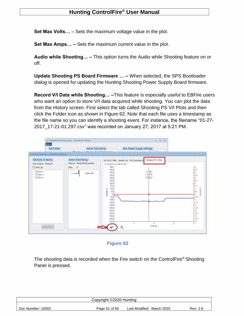
Record V/I Data while Shooting… –This feature is especially useful to EBFire users
who want an option to store V/I data acquired while shooting. You can plot the data
from the History screen. First select the tab called Shooting PS V/I Plots and then
click the Folder icon as shown in Figure 62. Note that each file uses a timestamp as
the file name so you can identify a shooting event. For instance, the filename “01-27-
2017_17-21-01.297.csv” was recorded on January 27, 2017 at 5:21 PM.
Figure 62
The shooting data is recorded when the Fire switch on the ControlFire® Shooting
Panel is pressed.
Hunting ControlFire® User Manual
Copyright ©2020 Hunting
Doc Number: 10002 Page 52 of 60 Last Modified: March 2020 Rev: 2.6
9.0 Cleaning Instructions
There are no user serviceable parts inside the box and the unit does not require any preventive maintenance.
If the unit requires service, it must be returned to Hunting Titan.
The unit may be cleaned using a damp cloth to remove and dust and dirt form the case and the metallic faceplate on the inside.
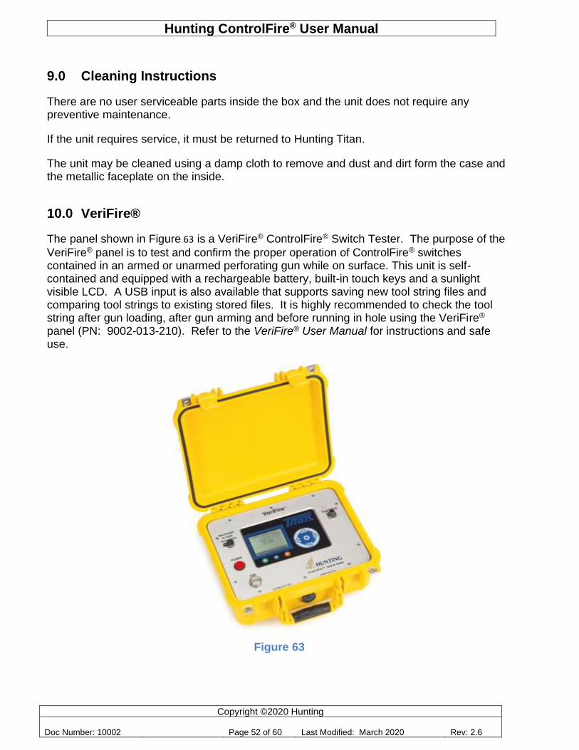
10.0 VeriFire®
The panel shown in Figure 63 is a VeriFire® ControlFire® Switch Tester. The purpose of the
VeriFire® panel is to test and confirm the proper operation of ControlFire® switches contained in an armed or unarmed perforating gun while on surface. This unit is self-contained and equipped with a rechargeable battery, built-in touch keys and a sunlight visible LCD. A USB input is also available that supports saving new tool string files and comparing tool strings to existing stored files. It is highly recommended to check the tool string after gun loading, after gun arming and before running in hole using the VeriFire® panel (PN: 9002-013-210). Refer to the VeriFire® User Manual for instructions and safe use.
Figure 63
Hunting ControlFire® User Manual
Copyright ©2020 Hunting
Doc Number: 10002 Page 53 of 60 Last Modified: March 2020 Rev: 2.6
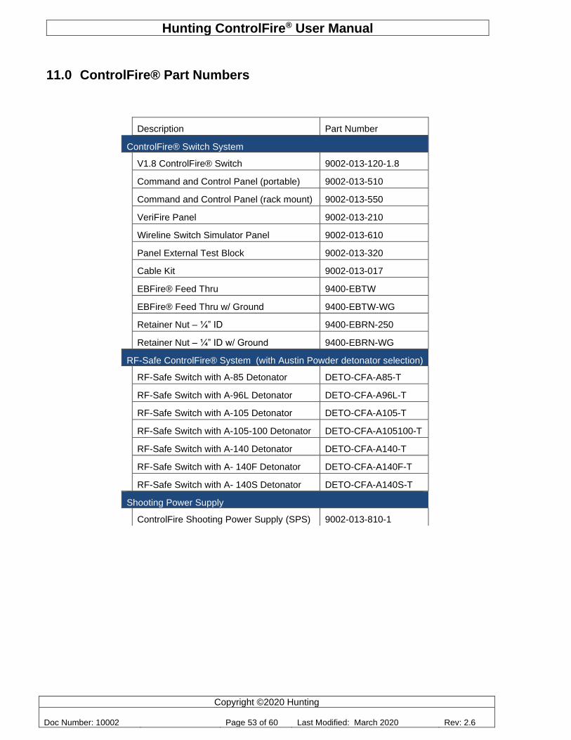
11.0 ControlFire® Part Numbers
Description Part Number
ControlFire® Switch System
V1.8 ControlFire® Switch 9002-013-120-1.8
Command and Control Panel (portable) 9002-013-510
Command and Control Panel (rack mount) 9002-013-550
VeriFire Panel 9002-013-210
Wireline Switch Simulator Panel 9002-013-610
Panel External Test Block 9002-013-320
Cable Kit 9002-013-017
EBFire® Feed Thru 9400-EBTW
EBFire® Feed Thru w/ Ground 9400-EBTW-WG
Retainer Nut – ¼” ID 9400-EBRN-250
Retainer Nut – ¼” ID w/ Ground 9400-EBRN-WG
RF-Safe ControlFire® System (with Austin Powder detonator selection)
RF-Safe Switch with A-85 Detonator DETO-CFA-A85-T
RF-Safe Switch with A-96L Detonator DETO-CFA-A96L-T
RF-Safe Switch with A-105 Detonator DETO-CFA-A105-T
RF-Safe Switch with A-105-100 Detonator DETO-CFA-A105100-T
RF-Safe Switch with A-140 Detonator DETO-CFA-A140-T
RF-Safe Switch with A- 140F Detonator DETO-CFA-A140F-T
RF-Safe Switch with A- 140S Detonator DETO-CFA-A140S-T
Shooting Power Supply
ControlFire Shooting Power Supply (SPS) 9002-013-810-1
Hunting ControlFire® User Manual
Copyright ©2020 Hunting
Doc Number: 10002 Page 54 of 60 Last Modified: March 2020 Rev: 2.6
12.0 User Agreement
All rights to the software and systems described in this user manual are owned by Hunting Titan. The software and systems described in this user manual include technology that may be protected by patent, copyright, and trade secret law. Use of the software and systems described in this user manual is authorized only under a License Contract with Hunting Titan. You may only use the software and systems described in this user manual if you have been trained in the use of the software and systems, have demonstrated competence in perforating safety, standards, and procedures, are aware of all safety issues in using the software and systems, and will only use this software and systems in accordance with API RP 67 “Recommended Practice for Oilfield Explosives Safety.”
Hunting ControlFire® User Manual
Copyright ©2020 Hunting
Doc Number: 10002 Page 55 of 60 Last Modified: March 2020 Rev: 2.6
Appendix
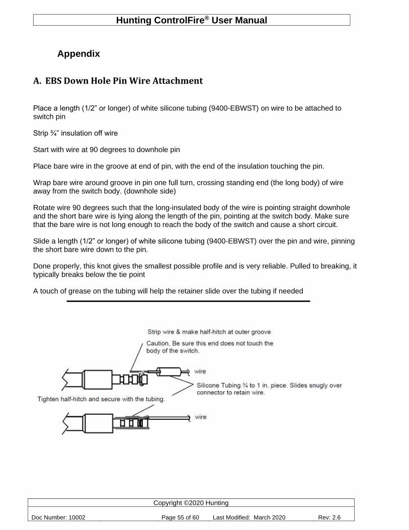
A. EBS Down Hole Pin Wire Attachment
Place a length (1/2” or longer) of white silicone tubing (9400-EBWST) on wire to be attached to switch pin
Strip ¾” insulation off wire
Start with wire at 90 degrees to downhole pin
Place bare wire in the groove at end of pin, with the end of the insulation touching the pin.
Wrap bare wire around groove in pin one full turn, crossing standing end (the long body) of wire away from the switch body. (downhole side)
Rotate wire 90 degrees such that the long-insulated body of the wire is pointing straight downhole and the short bare wire is lying along the length of the pin, pointing at the switch body. Make sure that the bare wire is not long enough to reach the body of the switch and cause a short circuit.
Slide a length (1/2” or longer) of white silicone tubing (9400-EBWST) over the pin and wire, pinning the short bare wire down to the pin.
Done properly, this knot gives the smallest possible profile and is very reliable. Pulled to breaking, it typically breaks below the tie point
A touch of grease on the tubing will help the retainer slide over the tubing if needed
Hunting ControlFire® User Manual
Copyright ©2020 Hunting
Doc Number: 10002 Page 56 of 60 Last Modified: March 2020 Rev: 2.6
B. Software License
Upon clicking “I Agree” below, you will be given access to Hunting Titan, Ltd’s ControlFire® software (“the Software”) AND you will be agreeing to the terms and conditions of this limited License Contract, AND you will be acknowledging, , that you have read and understood all the following terms and conditions of this License Contract:
1. You have a limited and non-exclusive license, terminable at any time by Hunting Titan to use the software, display the Software and its functionality to anyone, and you may distribute the software to anyone, provided that:
a. you require any recipient or viewer of the software to agree to the terms of this License Contract
b. you do not decompile, decode, flowchart, or otherwise reverse engineer the Software,
c. you charge no fee in association with display, use, or distribution of the Software, unless the Software is used to control only equipment or tools manufactured or sold by Hunting Titan (“Hunting Titan equipment or tools”),
d. you do not modify the software in any way, including: to operate on any equipment or tool , including control boxes or down-hole hardware, other than the Hunting Titan equipment and tools that the Software was designed to operate, to add, remove, or modify any logo, brand, or other trade or service mark associated with the software or Hunting Titan equipment or tools, to allow access without agreement to the terms and conditions of this License Contract, to remove any digital rights management attributes of the Software, or to make any other modification or derivation that is not explicitly authorized by this License Contract.
2. No implied license to any intellectual property is granted by this License Contract.
3. In addition to any other action that is held to be a material breach of this License Contract, it is a material breach of this License Contract, and the license granted under this License Contract shall terminate immediately, without any action by Hunting Titan, if you do any of the following:
a. offer to facilitate a display or distribution of the Software to anyone without requiring them to agree to the terms of this License Contract before viewing or distributing the Software,
b. decompile, decode, flowchart, or otherwise reverse engineer the software,
c. modify the software in any way, including: to operate on any equipment or tool other than Hunting Titan equipment or tools, to add, remove, or modify any logo,
brand, or other trade or service mark, to allow access without agreement to the terms and conditions of this License Contract, to remove any digital rights management
attributes of the Software, or to make any other modification or derivation that is not explicitly authorized by this License Contract,
Hunting ControlFire® User Manual
Copyright ©2020 Hunting
Doc Number: 10002 Page 57 of 60 Last Modified: March 2020 Rev: 2.6
d. use the Software with any equipment or tool, including control boxes or down-hole hardware, other than the Hunting Titan equipment and tools that the Software was designed to operate, or
e. violate any export control law of the United States.
4. You acknowledge that:
a. Hunting Titan owns and shall continue to own any and all intellectual property relating to the Software and the equipment and tools that the Software was designed to operate, including rights granted or protected by any nation or international organization, under any law or treaty, relating to patents, patent applications, inventor certificates, trade secrets, confidential information, copyrights, rights of attribution, trade mark rights in the marks used or associated with the Software, the Hunting Titan equipment and tools with which the software is designed to be used, Hunting Titan, and any and all other intellectual property rights of any nature or country that may be associated with the Software. All intellectual property rights in any improvements, and or derivative works, relating to the Software not already owned by Hunting Titan are hereby assigned to Hunting Titan, and you shall perform all acts and execute all documents reasonably requested by Hunting Titan to effectuate the purpose of this clause.
b. Patent Cooperation Treaty Applications PCT App No. PCT/US08/00200, entitled “Tractor Communication/Control and Select File Perforating Switch,” filed January 7, 2008, published August 21, 2008, Pub. No. WO2008/100362 A3 and PCT App. No. PCT/US09/04477, entitled “Apparatus and Methods for Controlling and Communicating with Downhole Devices,” filed August 5, 2009, published February 11, 2010, Pub. No. WO 2010/01689 (“the Applications”) relate to the Software; and, should the claims of the Applications issue, the actions listed in Section 271 of Title 35 of the United States Code or actions deemed to be acts of infringement in other countries would be covered by at least some claims of the Applications, and performing those actions in any country without authorization from Hunting Titan to perform those actions in that particular country would constitute infringement of patent claims issued in that country.
c. the source code and logic flow of the Software, to the extent not readily discernable from the use or display of the software, or publicly available information, is a trade secret of Hunting Titan.
d. you either have all appropriate training in the applicable safety procedures related to the Software and have demonstrated competence in perforating operation safety, standards, and procedures, including API RP 67 “Recommended Practice for Oilfield Explosives Safety,” and you will only operate the Software and any equipment or tools associated with the software in accordance with API RP 67 or will only use the software in the sales demonstration mode.
e. the Software is not designed or intended for use in hazardous environments requiring fail-safe performance; for example, the Software is not intended for use where Software failure could lead to death, personal injury, or severe physical or property damage, unless expressly agreed otherwise.
Hunting ControlFire® User Manual
Copyright ©2020 Hunting
Doc Number: 10002 Page 58 of 60 Last Modified: March 2020 Rev: 2.6
f. software and computer technology are too complex for Hunting Titan to warrant that software operations will be uninterrupted or error-free, and no such warranty is made in this License Contract.
5. Export Control. You will comply with any export control law of any country. At a minimum, you will not export or re-export, directly or indirectly, the Software from the United States except in compliance with law, including obtaining any necessary licenses.
6. Warranty. The Software will operate in accordance with any specifications published by Hunting Titan regarding the minimum requirements for any computer to run the Software. THE SOFTWARE IS PROVIDED “AS IS,” AND HUNTING TITAN HEREBY DISCLAIMS ANY AND ALL WARRANTIES NOT EXPRESSED IN THIS LICENSE CONTRACT INCLUDING, LACK OF VIRUS OR OTHER HARMFUL CODE, SECURITY, ABSENCE OF OPEN SOURCE CODE, FITNESS FOR PARTICULAR PURPOSE, TITLE, MERCHANTABILITY, AND NON-INFRINGEMENT OF THIRD PARTIES’ INTELLECTUAL PROPERTY.
7. Sole Remedy. Should any warranty, express (or implied by a court regardless of the wording of this License Contract) be breached, your sole remedy is repair or replacement of the Software.
8. Indemnification and Release. You hereby release, indemnify, will defend, and hold harmless, Hunting Titan, for and against any claim, including claims relating to personal injury, injury to personal or real property, infringement of intellectual property arising out of, relating to, or proximately caused by your use, display, or distribution of the Software in combination with any equipment or tool other than Hunting Titan equipment and tools.
9. Limitation of Damages. Hunting Titan shall not be responsible to you or any third party for any damages, (including but not limited to direct, indirect, special, punitive, exemplary, compensatory, incidental, or consequential damages) arising from or relating to the distribution, display, or use, of the Software. In the event any particular limited remedy fails of its essential purpose, the limitations of liability in this section shall still apply; you have specifically agreed to this allocation of economic risk. The limitations of liability in this section are without prejudice to any other limitations of liability that may be stated in other clauses of this License Contract.
10. Severability. If any clause in this License Contract is held void, voidable, invalid, unenforceable, or otherwise defective, this License Contract shall be considered modified to exclude such clause, and all other provisions shall remain valid.
11. Interpretation. This License Contract shall be interpreted as if drafted jointly by both parties; no ambiguity is to automatically be resolved as against either party.
12. Waiver. No failure to enforce any provision of this License Contract shall be considered a waiver of the right to enforce that provision in the future or to enforce any other provision of this License Contract.
13. Choice of Law. This License Agreement shall be interpreted under the laws of the State of Texas without regard to Texas law regarding conflicts of laws.
14. Integration. This License Contract is the sole agreement between the parties regarding the Software; all other agreements, whether written or oral, are hereby void. There are no other
Hunting ControlFire® User Manual
Copyright ©2020 Hunting
Doc Number: 10002 Page 59 of 60 Last Modified: March 2020 Rev: 2.6
terms or conditions to this License Contract, of any kind between the parties. This License Contract may not be amended except in writing that expressly states that this License Contract is being amended and sets out the amendment's terms.
15. Arbitration. If a dispute of any kind arises under this License Contract or related to the use of the Software, that dispute will be resolved by binding arbitration before the American Arbitration Association. This arbitration provision limits your ability to litigate claims in court and your right to a jury trial.

Hunting ControlFire® User Manual
Copyright ©2020 Hunting
Doc Number: 10002 Page 60 of 60 Last Modified: March 2020 Rev: 2.6