TITAN - Instrument User Manual V1.3R - Euro Index
66
Register your instrument online to receive your extended Warranty. TITAN Instrument User Manual V1.3R Unrivalled Gas Detection. ionscience.com
-
Upload
khangminh22 -
Category
Documents
-
view
3 -
download
0
Transcript of TITAN - Instrument User Manual V1.3R - Euro Index

Register your instrument
online to receive your extended Warranty.
TITAN Instrument User Manual V1.3R
Unrivalled Gas Detection. ionscience.com

TITAN Instrument User Manual V1.3R
Unrivalled Gas Detection. Page 2 of 66 ionscience.com
THIS PAGE IS LEFT INTENTIONALLY BLANK

TITAN Instrument User Manual V1.3R
Unrivalled Gas Detection. Page 3 of 66 ionscience.com
Thank you for purchasing your ION Science instrument.
Register your instrument online for extended warranty
The standard warranty of your TITAN 875 Benzene Monitor can be extended up to two years.
To receive your extended warranty, you must register your instrument online within one month of purchase (terms and conditions apply).
Visit www.ionscience.com

TITAN Instrument User Manual V1.3R
Unrivalled Gas Detection. Page 4 of 66 ionscience.com
Content
EU Declaration of conformity .......................................................................................................... 7
Statements..................................................................................................................................... 7
Validity of this Manual ......................................................................................................................................... 8
Responsibility for Correct Use ............................................................................................................................. 8
Quality Assurance ................................................................................................................................................ 8
Disposal ................................................................................................................................................................ 8
Legal Notice .......................................................................................................................................................... 8
Warranty .............................................................................................................................................................. 8
Service .................................................................................................................................................................. 9
Introduction to TITAN ................................................................................................................... 10
Technical Specification ................................................................................................................. 11
Environmental Conditions ............................................................................................................ 11
Un-Packing ................................................................................................................................... 12
Titan Benzene Monitor and Accessories Kit ................................................................................... 12
System Description ....................................................................................................................... 14
The Gas Detector ............................................................................................................................................... 14
Pneumatic Connections ..................................................................................................................................... 14
Pneumatics ......................................................................................................................................................... 14
Running Flow ...................................................................................................................................................... 15
Sampling Flow .................................................................................................................................................... 16
Heaters ............................................................................................................................................................... 17
Outputs and Communications ........................................................................................................................... 18
RS485 Modbus Interface ............................................................................................................... 19
Function Codes ................................................................................................................................................... 19
Bytes and Words ................................................................................................................................................ 19
Input Registers Address Map ............................................................................................................................. 19
Holding Registers Address Map ......................................................................................................................... 21
System Files ........................................................................................................................................................ 23
Modbus Error Flags ............................................................................................................................................ 23
Installation Requirements ............................................................................................................ 23
Location Requirements ...................................................................................................................................... 23
Power Requirements ......................................................................................................................................... 24
Cable and Gland Requirements ......................................................................................................................... 24
RS485 Connections ....................................................................................................................... 24
Installation ................................................................................................................................... 25

TITAN Instrument User Manual V1.3R
Unrivalled Gas Detection. Page 5 of 66 ionscience.com
Preparation for Installation ................................................................................................................................ 25
Dimensions for Installation ................................................................................................................................ 25
To Install the Housing Module ........................................................................................................................... 26
After-Installation Test ........................................................................................................................................ 26
Electrical Connections................................................................................................................... 27
Terminal Block-2 (Communications) .................................................................................................................. 28
Circuit diagrams for 4-20 mA monitoring .......................................................................................................... 29
Removal and Installation of the Detection Module ....................................................................... 30
To Remove the Detection Module ..................................................................................................................... 30
To Install the Detection Module ........................................................................................................................ 32
Operating the Titan ...................................................................................................................... 36
Switches and Display .......................................................................................................................................... 36
Power on ............................................................................................................................................................ 36
Main screens and main menu ............................................................................................................................ 36
Menu Icons ......................................................................................................................................................... 37
Navigation .......................................................................................................................................................... 37
Calibration .......................................................................................................................................................... 38
Benzene Calibration ........................................................................................................................................... 38
Flow Calibration ................................................................................................................................................. 39
Removal of the Memory Card ....................................................................................................... 40
Password Lock .................................................................................................................................................... 40
Lock the Calibration ........................................................................................................................................... 41
Lock the STEL and LIVE Displays ......................................................................................................................... 42
Alarms and Relays .............................................................................................................................................. 42
Alarm or Relay Selection .................................................................................................................................... 43
Alarm Configuration ........................................................................................................................................... 43
Relay Configuration ............................................................................................................................................ 43
Relays and 4-20mA Test ..................................................................................................................................... 44
Information Pages .............................................................................................................................................. 44
Fault Indications ................................................................................................................................................. 45
Alarm Indications ............................................................................................................................................... 46
Service Period Reminder .................................................................................................................................... 46
TitanPC Software .......................................................................................................................... 47
Minimum requirements ..................................................................................................................................... 47
Connect the Titan to the PC ............................................................................................................................... 47
Starting the Software ......................................................................................................................................... 48

TITAN Instrument User Manual V1.3R
Unrivalled Gas Detection. Page 6 of 66 ionscience.com
Data Connection................................................................................................................................................. 49
Settings ............................................................................................................................................................... 50
Data Download................................................................................................................................................... 51
Data View ........................................................................................................................................................... 52
Upgrade .............................................................................................................................................................. 54
Flow Calibration ................................................................................................................................................. 55
Benzene Calibration ........................................................................................................................................... 56
Recorded Faults.................................................................................................................................................. 57
Alarm Set ............................................................................................................................................................ 58
Virtual Screen ..................................................................................................................................................... 58
Bump Test .................................................................................................................................... 59
Use of the Test ................................................................................................................................................... 59
Test Procedure ................................................................................................................................................... 59
Fault Diagnostics .......................................................................................................................... 60
Fault and Alarm indications ............................................................................................................................... 60
Fault Conditions ................................................................................................................................................. 60
Abbreviations: .................................................................................................................................................... 60
TitanPC Fault Groups ......................................................................................................................................... 63
Parts List ...................................................................................................................................... 63
ION Science Contact Details .......................................................................................................... 65
Manual Log .................................................................................................................................. 66

TITAN Instrument User Manual V1.3R
Unrivalled Gas Detection. Page 7 of 66 ionscience.com
EU Declaration of conformity

TITAN Instrument User Manual V1.3R
Unrivalled Gas Detection. Page 8 of 66 ionscience.com
Statements
Validity of this Manual
This user manual gives information and procedures for the firmware and software versions shown on the front page of this manual.
If you have different versions of firmware or software, please obtain the correct user manual.
Responsibility for Correct Use
Ion Science Ltd accepts no responsibility for incorrect adjustments that cause harm or damage to persons or property. The users are responsible to respond appropriately to the readings and alarms given by Titan.
Use the equipment in accordance with this manual, and in compliance with local safety standards. Use of external circuit breakers and/or fuse protection is recommended for safe operation in the case of rare malfunction.
Reduced performance of gas detection might not be obvious, so equipment must be inspected and maintained regularly. Ion Science recommends:
• you use a schedule of regular checks to ensure it performs within calibration limits, and
• you keep a record of calibration check data.
WARNINGS:
1. Substitution of components can result in unsafe conditions.
2. For safety, Titan must only be operated and maintained by qualified personnel.
3. Read and understand this Manual fully before you install, operate or maintain Titan.
4. ! DO NOT OPEN WHILE ENERGIZED !
5. ! DO NOT OPEN WHILE A HAZARDOUS ATMOSPHERE MAY BE PRESENT !
6. When performing any kind of servicing on Titan, precautions must be taken to prevent damage caused by ESD (Electrostatic Discharge). Measures, including ESD wrist straps and work mats must be employed.
Quality Assurance
Titan is manufactured in a ISO9001:2015 complient Quality management system. That ensures that the equipment is:
• designed and assembled reproducibly, from traceable components,
• calibrated to the stated standards before it leaves our factory.
Disposal
Dispose of Titan and its components in accordance with all local and national safety and environmental requirements. This includes the European WEEE (Waste Electrical and Electronic Equipment) directive. Ion Science Ltd offers a take-back service. Please contact us for more information.
Legal Notice
Whilst every attempt is made to ensure the accuracy of the information contained in this manual, Ion Science accepts no liability for errors or omissions, or any consequences deriving from the use of information contained herein. It is provided "as is" and without any representation, term, condition or warranty of any kind, either expressed or implied. To the extent permitted by law, Ion Science shall not be liable to any person or entity for any loss or damage which may arise from the use of this manual. We reserve the right at any time and without any notice to remove, amend or vary any of the content which appears herein.
Warranty
You can extend the Standard Warranty up to 2 years when you register your Titan instrument via our website: ionscience.com/instrument-registration
To receive your Extended Warranty, you must register within one month of purchase (Terms and Conditions apply). You will then receive a confirmation email that your Extended Warranty Period has been activated and processed.
Full details, along with a copy of our Warranty Statement can be found by visiting: www.ionscience.com

TITAN Instrument User Manual V1.3R
Unrivalled Gas Detection. Page 9 of 66 ionscience.com
Service
Ion Science recommends two levels of service for the Titan.
The six-month service includes the internal (carbon) filter, the external (hydrophobic) filter; and calibration.
The twelve-month service includes: replacement of all items listed in the six-month service, as well as replacement of the AirSep Filter, replacement of the PID lamp and electrode stack and replacement of the outer loop pump; and calibration.
Contact Ion Science or your local distributor for service options in your area.

TITAN Instrument User Manual V1.3R
Unrivalled Gas Detection. Page 10 of 66 ionscience.com
Introduction to TITAN
The TITAN 875 Benzene Monitor is a fixed benzene monitor certified for Zone 1 hazardous areas. It detects 0-20ppm concentrations in ambient air, taking one sample per minute.
It monitors both the current benzene concentration and the STEL (Short-Term Exposure Limit, calculated over the previous 15 minutes).
Real-time display of the measurement is on the LCD and transmitted on a 4-20mA channel. Historic data stored in Titan can be viewed and stored externally either over the RS485 or the USB connection.
Alarms and warnings are transmitted by the 4-20mA channel and by two relays programmable to be Normally Open or Normally Closed.
It is powered by a single power supply in the range of range of 19VDC @ 4A to 32VDC @ 2.4A.
The Titan has two modules:
• The Housing Module that is installed permanently.
• The Detection Module that can be removed for servicing and calibration.
All the operational and calibration data is stored within the Detection Module. After the Detection Module has been calibrated, it will function correctly when installed in any Housing Module.
A Detection Module can be calibrated and tested off-site, then taken to the installation site and installed in place of an existing module. The removed module can then be serviced ready for installation later or in another Housing Module.

TITAN Instrument User Manual V1.3R
Unrivalled Gas Detection. Page 11 of 66 ionscience.com
Technical Specification
Measurement Frequency Every 1 minute
Response time: T90 < 1 minute
Detectable Range: 0-20ppm Benzene
Resolution: ± 0.1ppm
Accuracy: ± 0.1ppm or ±10%, whichever is greater
Data log: To internal memory (Up to 2 Years)
Outputs: 4-20mA, RS485, USB, Two programmable relays (24VDC @1.5A maximum load)
Alarms/Alerts Visual: Red, Yellow, Green, LEDs
Flow Rate: ≥ 160 ml/min in Ambient conditions
Temperature: Operating: -20 to 55degC (-4 to 130degF)
Power Requirement Nominal 24VDC at 3.2A
Weight: 15kg
Environmental Conditions
Location: Outdoor use
Wet conditions
Pollution degree 4
Altitude: Maximum 3000m
Relative humidity: 0 – 99RH%( Non Condensing)
Ingress protection: IP65
TITAN Instrument User Manual V1.3R
Unrivalled Gas Detection. Page 12 of 66 ionscience.com
Un-Packing
All equipment shipped by Ion Science Ltd is packed in containers with shock absorbing filling to protect them against physical damage.
Remove the contents carefully and check them against the packing list. Report discrepancies between the contents and the packing list to Ion Science Ltd. Ion Science will not be responsible for discrepancies not reported within ten days of your receipt of the shipment.
Every Titan (new units and those returned from a Service Centre) must have a Certificate of Calibration before you install it.
Titan Benzene Monitor and Accessories Kit
Part number Description Qty.
TNXSXBXX-X Titan 875 Benzene Monitor and Accessories Kit Comprising:
Kit
A-875281 Housing Module 1
A-875245 Detector Module 1
875413 Front Cover Removal Tool 2
875400 Transit Strap 1
2/SH10-16 Transit Strap Screws (M10x16) 2
A-875265 Switch Actuation Magnet 1
A-875417 External (Hydrophobic) Filter 1
4/PB-05 Gland Port Plug (for transportation) 2
4/TA-06 Allen Key 2mm 1
4/TA-08 Allen Key 3mm 1
875431 Mounting Template 1
875263 Titan User Manual 1
– Certificate of Calibration 1
TITAN Instrument User Manual V1.3R
Unrivalled Gas Detection. Page 13 of 66 ionscience.com
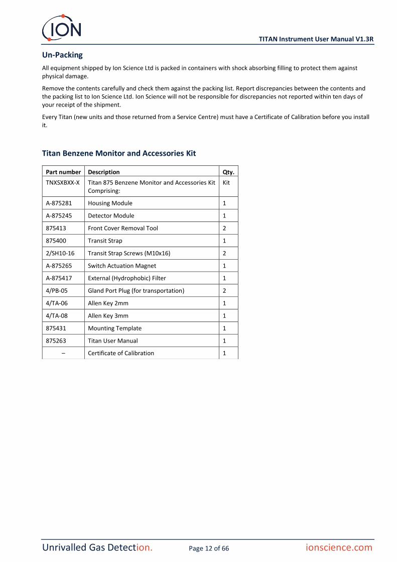
Titan Detector Module and Accessories Kit
Part number Description Qty.
TSMXSXXXX-X Titan Detector Module and Accessories Kit Comprising:
Kit
A-875245 Titan Detector Module 1
875405 Transit and Storage Case 1
875413 Front Cover Removal Tool 2
4/TA-06 Allen Key 2mm 1
4/TA-08 Allen Key 3mm 1
– Certificate of Calibration 1
Titan Label Information: Ensure Warning Label is attached to Titan.
WARNING: DO NOT OPEN WHILE ENERGIZED!
WARNING: DO NOT OPEN WHILE A HAZARDOUS ATMOSPHERE MAY BE PRESENT!
Refer to instruction manual/booklet
Separate collection for WEEE-Waste of electrical and electronic equipment
IP65 Dust-tight and protected against water jets

TITAN Instrument User Manual V1.3R
Unrivalled Gas Detection. Page 14 of 66 ionscience.com
System Description
The Gas Detector
The Titan samples the ambient air once every 60 seconds and passes the sample through a Photo-Ionisation Detector (PID).
The PID works by illuminating sample gases with high energy ultra-violet (UV) light. Benzene is one of the volatile organic compounds (VOCs) ionised by the UV photons. In a high voltage electric field, these ions create a current that can be amplified and measured to quantify the concentration of gases present. To make the measurements specific to benzene, it must be separated out from the other gasses before the PID measurement.
The sample passes through the AirSep filter which retards some gas components more than others. Under controlled conditions the filtration ensures the benzene will pass through the filter at a known and well defined time as a separated component. The benzene level is measured by analysis of the signal profile of the PID as the gasses from the AirSep filter pass through it.
For optimum performance it is important that the filter temperature and sample flow are tightly controlled. To achieve temperature stability, the AirSep filter is controlled to 50degC and the internal air temperature of the Titan is controlled to a maximum of 50degC by separate heating systems.
There is no forced cooling mechanism so if the ambient temperature exceeds 55degC the measurement of benzene will be lower than the actual concentration.
Make sure to install the Titan where the ambient temperature does not rise above 55degC.
Pneumatic Connections
The Titan has three flame-arrestor connectors: one inlet and one outlet for the sampled air, and one breather. The breather keeps pressure equilibrium between inside and outside of the housing.
The outlet flame-arrestor can have an exhaust tube attached, to remove the processed air away from the inlet.
Internally, there is also an inlet through the carbon filter and an outlet into the interior space.
Pneumatics
In running flow:
• Pump P2 (outer loop) runs for 40 seconds out of every one minute cycle. The pump is stopped for twenty seconds to allow accurate sampling by Valve V1. When the Valve V1 is in its normal "running" position, the air bypasses the Photo-Ionization Detector (PID).
• Pump P1 (inner loop) keeps a constant flow of clean air from the internal (carbon) filter through the PID. Pump P1 (inner loop) outlet is inside the housing. Thus the clean air recycles through the internal (carbon) filter.
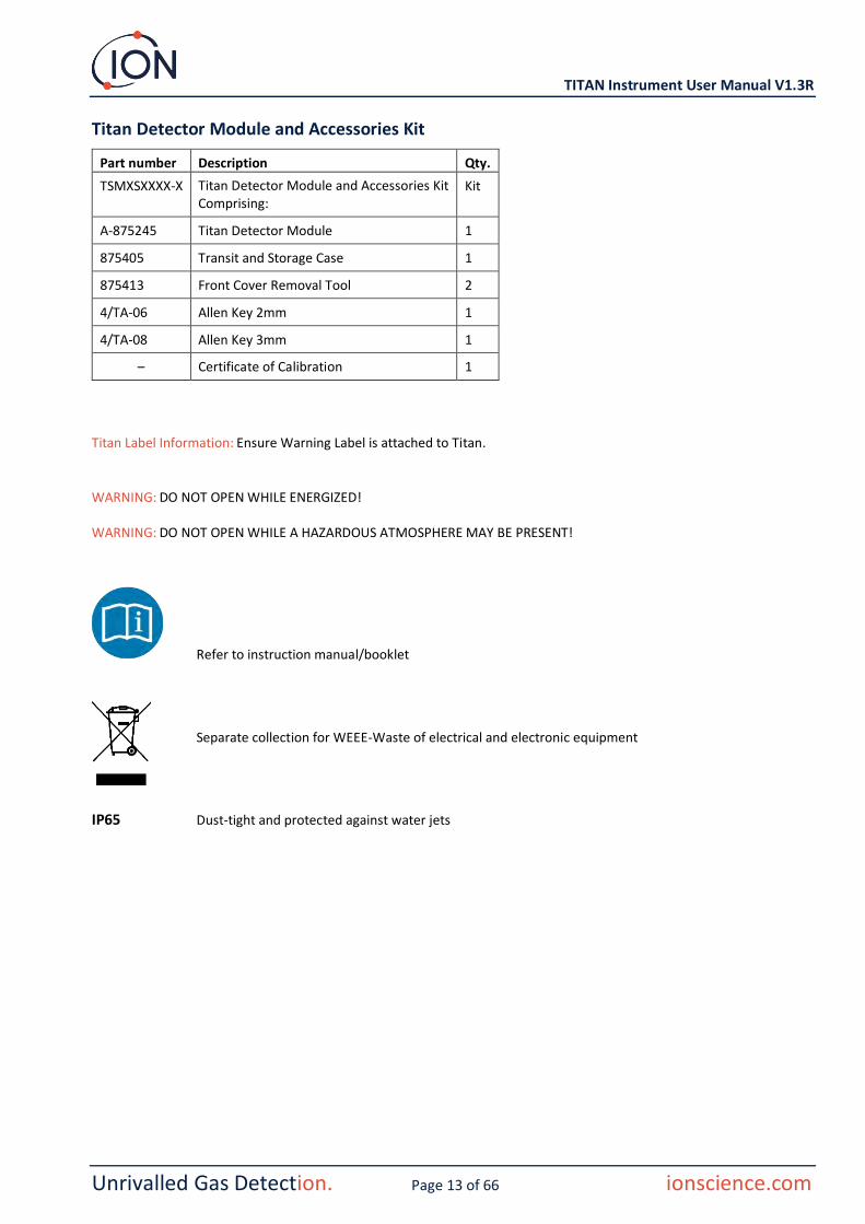
In sampling flow:
• At 60 second intervals, Valve V1 moves to its "sampling" position for 0.5 seconds.
Inlet
Outlet
Breather
PneumaticConnection 1 and 2
PneumaticConnection 4

TITAN Instrument User Manual V1.3R
Unrivalled Gas Detection. Page 15 of 66 ionscience.com
• Pump P1 (inner loop) then draws a sample of air from the Pump P2 (outer loop) flow. Through the AirSep filter and the PID.
• Analysis of the PID signal profile gives the benzene concentration.
Pump P1 (inner loop) flow is approximately 8mL per min.
Pump P2 (outer loop) flow is approximately 200mL per min.
The pressure sensors monitor the correct functioning of the pneumatic systems.
The external (hydrophobic) filter removes particles and moisture from the inlet Flow. Every three hours by the clock (00:00, 03:00, 06:00…) the Titan will stop to measure the ambient pressure conditions to correctly adjust for flow control. Important note: bump testing is inadvisable at these times as external pressure sources will affect the pressure calibration process
Running Flow
TITAN Instrument User Manual V1.3R
Unrivalled Gas Detection. Page 16 of 66 ionscience.com
Sampling Flow
TITAN Instrument User Manual V1.3R
Unrivalled Gas Detection. Page 17 of 66 ionscience.com
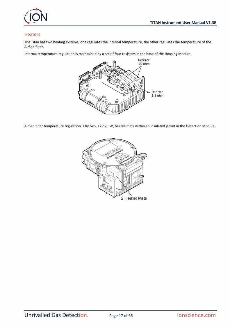
Heaters
The Titan has two heating systems, one regulates the internal temperature, the other regulates the temperature of the AirSep filter.
Internal temperature regulation is maintained by a set of four resistors in the base of the Housing Module.
AirSep filter temperature regulation is by two, 12V 2.5W, heater-mats within an insulated jacket in the Detection Module.
Resistor20 ohm
Resistor3.3 ohm
2 Heater Mats

TITAN Instrument User Manual V1.3R
Unrivalled Gas Detection. Page 18 of 66 ionscience.com
Outputs and Communications
Titan has five communication outputs:
• The on-board LCD and LEDs on the faceplate.
• 4-20mA Current Loop.
• RS485 Modbus (simplex/half-duplex or fully-duplex),
• USB (Accessible on the Detector Module).
• Two programmable relays.
Titan monitors, in real-time, the current (Live) and the Short-Term Exposure Limit (STEL) benzene concentration. The STEL is calculated over the previous 15 minutes.
This real-time information is displayed on the LCD and transmitted on the 4-20mA and RS485 channels.
You can program two alarms to operate at a chosen concentration of benzene and/or a chosen STEL limit. The alarms will display a message on the LCD and LEDs; energize the relays: and transmit a signal on the 4-20mA channel.
The alarms and relays are individually programmable to the settings required by the site policy. You can choose either alarm to energize either relay. The default settings would be:
• Alarm 1: 5.0ppm live
• Alarm 2: 0.5ppm STEL
• Relay 1: Alarm 1, N/O
• Relay 2: Alarm 2, N/O
Both relays can be programed to be Normally Open or Normally Closed. They can switch 24VDC at 1.5A maximum load. When the Titan is not powered the default state of relay 1 is N/C, the default state of relay 2 is N/O
Data is stored internally for a minimum of two years and can be downloaded with TitanPC software via USB or RS485 for analysis and archive storage.
You can configure the RS485 connection for half-duplex, 2-wire, or full-duplex, 4-wire, communication. Refer to Installation, Terminal Block-2.
The 4-20mA output fault indications are given by discrete current signals between 2.0 and 3.5mA. Refer to the table in Fault Diagnostics, Fault Conditions.

TITAN Instrument User Manual V1.3R
Unrivalled Gas Detection. Page 19 of 66 ionscience.com
RS485 Modbus Interface
The Titan Modbus interface uses Serial ASCII format Modbus, at:
• 38400 baud 8 data bits, no parity, 2 stop bits.
Function Codes
Titan supports these function codes:
• 0x03 – Read Holding Registers
• 0x04 – Read Input Registers
• 0x10 – Write Multiple Registers
The address map for Read Holding Registers and Write Multiple Registers is the same – but not all addresses are writeable.
Bytes and Words
Modbus registers are generally 16 bits in length. For example if you send the command to Read Input Registers with a register quantity of 1 you will receive 2 bytes (1 word) of data. In the tables of addresses, we specify the length in bytes. This is the number of bytes of data associated with the read/write at that address.
Thus your Modbus request will be for half that number of registers.
Input Registers Address Map
Use the function code 0x04 to Read Input Registers in the address range given in the table. If you read more than the number of bytes indicated for the length at each address, any bytes beyond the length are undefined.
For example, if you read 32 bytes at address 1000, only the first 16 bytes returned are valid.
Address (hex)
Data Length (bytes)
Content
0 60 Returns block of 15 integers for latest result
Integer Meaning
1 Benzene value in ppm x 10
2 Sensor temperature in degC x 100
3 Ambient temperature in degC x 10
4 Flow in ml/min x 100
5 PS1 diagnostic
6 PS2 diagnostic
7 PS3 diagnostic
8 Slope diagnostic
9 Flags
10 Sensor fence signal
11 Raw signal
12 STEL value
13 Pump drive signal
14 Pump drive volts
15 Fault record

TITAN Instrument User Manual V1.3R
Unrivalled Gas Detection. Page 20 of 66 ionscience.com
80 24 Returns block of data indicating the state of the sensor temperature controller. Six 32-bit integers are returned. e.g.
00000000 84 13 00 00 22 02 00 00 AD 08 00 00 A0 0F 00 00 „···"······ ··· 00000010 01 00 00 00 01 00 00 00 ········
These can be decoded as follows:
84 12 00 00 = 0x00001284 = 4740
The values have the following meaning
Integer Meaning
1 Temperature in degrees Celsius x 100
2 Ambient temperature in degC x 16
3 Heater drive power in % x 100
4 Heater driver voltage
5 1 if required temperature has been reached
6 Time in seconds taken to reach target from switch on
100 24 Returns block of data indicating state of background temperature controller. Six 32-bit integers are returned. e.g.
00000000 FC 44 00 00 21 02 00 00 00 00 00 00 01 00 00 00 üD··!··········· 00000010 EF 00 00 00 02 00 00 00 ï·······
Integer Meaning
1 Heater Temperature in degC x 100
2 Ambient temperature in degC x 16
3 Heater drive power in % x 100
4 Heater driver voltage
5 Power supply level x 10
6 Heater level
1000 16 Unique ID of Titan – a string of 16 ASCII characters unique to each Titan
1100 32 Firmware versions of Titan and Flow Controller. Two null terminated strings are returned. e.g.
00000000 56 30 2E 31 2E 33 33 00 56 30 2E 31 2E 31 31 00 V0.1.33·V0.1.11· 00000010 00 00 00 00 00 00 00 00 00 00 00 00 00 00 00 00 ················
1200 36 Returns a block of data indicating the state of the flow.
This block contains 9 32-bit integers. e.g.
00000000 21 03 00 00 DA 0D 00 00 20 2F 00 00 88 00 00 00 !···Ú··· /··ˆ···
00000010 01 00 00 00 00 00 00 00 ········
These can be decoded as follows:
21 03 00 00 = 0x00000321 = 801
The values have the following meaning:
Integer Meaning
1 Current flow x 100
2 Flow Differential pressure sensor reading
3 Absolute pressure sensor reading
4 Pump power output

TITAN Instrument User Manual V1.3R
Unrivalled Gas Detection. Page 21 of 66 ionscience.com
5 1 if pump power OK, 0 if pump power problem
6 1 if outer loop pump running, 0 if outer loop pump not running
7 Pump drive output voltage
8 Absolute pressure when pump not running
9 Valve state
1300 12 Returns information on the internal memory storage. Three 32-bit integers are returned.
Integer Meaning
1 Number of free clusters.
2 Total available clusters
3 Reserved clusters.
1400 96 Returns an array of 27 32-bit integers indicating internal fault state of Titan. If there are no faults all values are zero.
1500 20 Returns five 32-bit integers indicating state of the lamp sensor.
Integer Meaning
1 Last signal reading in μV
2 1 is lamp is on, 0 if not
3 0 if lamp drive is off, non-zero if lamp drive is on
4 Lamp sensor signal when lamp off, in μV
5 Last Lamp sensor signal reading in μV
1600 6 Returns three 16-bit values containing diagnostic data for pressure sensor
Holding Registers Address Map
Read Holding Registers – use function code 0x03. Write Holding Registers – use function code 0x01 (Write Multiple Registers).
If you read or write more than the number of bytes specified for the length at each address, any bytes beyond the length are undefined.
Titan can malfunction if you write more data than the specified length.
For example if you read 32 bytes at address 1000, only the first 16 bytes returned are valid.
Address (hex)
Data Length (bytes)
Content
1100 32 ASCII name allocated to the Titan. This may be written or read. e.g
00000000 53 65 72 76 69 63 65 20 54 69 74 61 6E 00 00 00 Service Titan··· 00000010 00 00 00 00 00 00 00 00 00 00 00 00 00 00 00 00 ················
1200 32 Internal real time clock. This may be written or read. e.g.
00000000 DF 07 00 00 02 00 00 00 0A 00 00 00 10 00 00 00 ß··············· 00000010 11 00 00 00 29 00 00 00 02 00 00 00 00 00 00 00 ····)···········
TITAN Instrument User Manual V1.3R
Unrivalled Gas Detection. Page 22 of 66 ionscience.com
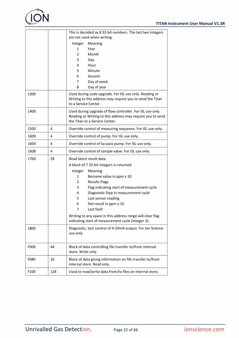
This is decoded as 8 32-bit numbers. The last two integers are not used when writing.
Integer Meaning
1 Year
2 Month
3 Day
4 Hour
5 Minute
6 Second
7 Day of week
8 Day of year
1300 Used during code upgrade. For ISL use only. Reading or Writing to this address may require you to send the Titan to a Service Center.
1400 Used during upgrade of flow controller. For ISL use only. Reading or Writing to this address may require you to send the Titan to a Service Center.
1500 4 Override control of measuring sequence. For ISL use only.
1600 4 Override control of pump. For ISL use only.
1604 4 Override control of by-pass pump. For ISL use only.
1608 4 Override control of sample valve. For ISL use only.
1700 28 Read latest result data.
A block of 7 32-bit integers is returned
Integer Meaning
1 Benzene value in ppm x 10
2 Results Flags
3 Flag indicating start of measurement cycle
4 Diagnostic Step in measurement cycle
5 Last sensor reading
6 Stel result in ppm x 10
7 Last fault
Writing to any space in this address range will clear flag indicating start of measurement cycle (integer 3).
1800 Diagnostic, test control of 4-20mA output. For Ion Science use only.
F000 44 Block of data controlling file transfer to/from internal store. Write only.
F080 16 Block of data giving information on file transfer to/from internal store. Read only.
F100 128 Used to read/write data from/to files on internal store.

TITAN Instrument User Manual V1.3R
Unrivalled Gas Detection. Page 23 of 66 ionscience.com
System Files
Titan stores configuration parameters in *.CFG files in the file store.
Titan can malfunction if you delete or modify these files.
Modbus Error Flags
1 Temp error 18 Pump fault
2 Temp fault 19 Pump power fail
3 Temp fault 20 Step error
4 Temp error 21 Inlet blocked
5 Leak 22 Temp error
6 Sensor flow low 23 Memory full
7 Sensor flow high 24 Pump drive high
8 Outlet Blocked 25 Alarm1
9 Tube off 26 Alarm2
10 Lamp Out 27 Temp fault
11 Memory fault 28 Pump power fail
12 Temp Error 29 Service Required
13 PID ADC Fail 30 Pump reset
14 Step overrun 31 ADS1000 fault
15 Watchdog 32 P3 Sensor fail
16 ADC Fault 33 Abs Pres Sensor fail
17 MMC Fault 34 Diff Pres sensor fail
Installation Requirements
Please make sure you understand all the installation requirements before you install Titan.
Location Requirements
There are many variables involved in defining the optimum location for a gas detector. Mount the Titan:
• in a location where it (or its inlet probe) is most likely to detect the gas
• in an area that has good air circulation. Restricting natural air current can result in delayed detection
• on a solid, stable support, where it is accessible for servicing
• vertically, with the flame arresters underneath the housing
• not in direct sunlight or over a heat source (This can cause the Titan to exceed its certified internal working temperature of 50degC)
• not in areas likely to flood.
An exhaust line can be attached to the outlet flame-arrestor to remove the processed air away from the Titan.
An inlet line (inlet probe), with hydrophobic filter can be attached to the inlet flame-arrestor to detect benzene in areas remote from the Titan.
These lines can be
• Maximum of 10 meters long.
• Recommended cross-section: 6mm OD x 4mm ID PTFE tube.
NOTE: Whether the gas inputs to the unit are from the area where the flame proof box is installed or whether it inputs from another source. The gas which is pumped inside the flame proof box must be from the area where the flame proof box is installed.

TITAN Instrument User Manual V1.3R
Unrivalled Gas Detection. Page 24 of 66 ionscience.com
Power Requirements
Nominal Voltage 24VDC @ 3.2A
Minimum Voltage 19VDC @ 4A
Maximum Voltage 32VDC @ 2.4A
We recommend an industrial grade power supply unit of 24VDC at 4.5A.
Power consumption depends on the heaters in the temperature control systems. Running in ambient temperatures below 5degC will use maximum power. Higher temperatures will reduce power consumption.
The 4-20mA output requires its own power supply at 24 (minimum) to 32VDC (maximum). It can share the instrument's 24 to 32VDC, 4.5A, power supply if:
• the 4-20mA output goes to the same location as the instrument power supply and
• their Grounds will be connected together.
Refer to Electrical Connections, Terminal Block-1.
Cable and Gland Requirements
We recommend you use screened cables e.g., multicore cable with SWA armour, or Braid Armour to protect against EMI.
The manufacture and build of the cable glands is the responsibility of the installer. The cable glands must conform to the certification standards required for the installation site. Install blanking plugs with the appropriate certification standards to unused cable gland ports.
For general advice on selection of cable glands please visit https://www.cmp-products.com/cable-glands/products/explosive-atmosphere/
DC power 2 core (positive and negative) 1.5mm²
4-20mA Comms 2 core 1.5mm² max
RS485 half-duplex 3 cores (including ground) 1.5mm² max
Relays (2 Outputs) 4 cores 1.5mm² max
Cable Gland ¾" NPT - Explosive Atmosphere Certified
Blanking Plug ¾" NPT - Explosive Atmosphere Certified
RS485 Connections
You can use Titan for half-duplex, 2-wire communication. You can also configure it to use a built-in 120R termination resistor.
Pin references are to Terminal Block-2 (Refer to Installation, Terminal Block-2)
Rx
Tx
A (Pin5)
B (Pin4)
0 (Pin3)
TITAN Instrument User Manual V1.3R
Unrivalled Gas Detection. Page 25 of 66 ionscience.com
To connect a 120R termination resistor across 'A' and 'B': connect a jumper on L1 between the middle pin and 120R pin. (Refer to Note 1 of Terminal Block-2, Installation).
This enables 2-wire communications and a 3rd wire ('0') as a Ground.
• 'A' is connected to 'Y'
• 'B' is connected to 'Z'
• '0' is Ground
Installation
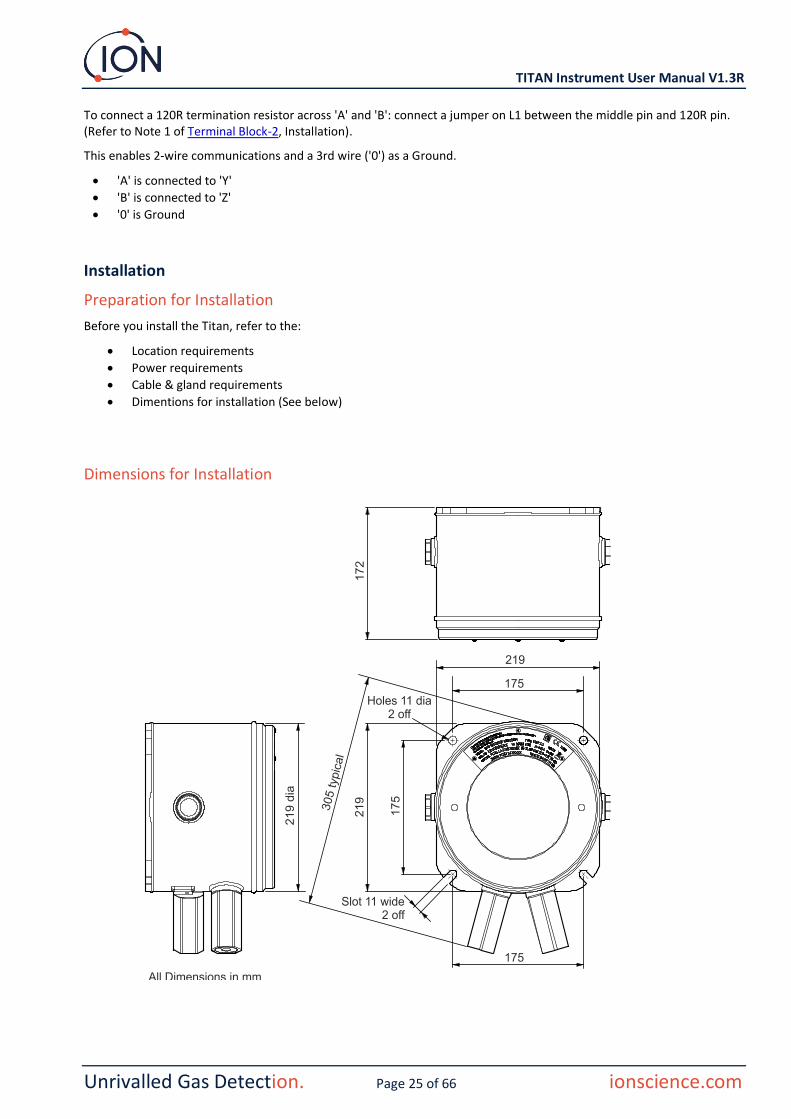
Preparation for Installation
Before you install the Titan, refer to the:
• Location requirements
• Power requirements
• Cable & gland requirements
• Dimentions for installation (See below)
Dimensions for Installation
TITAN Instrument User Manual V1.3R
Unrivalled Gas Detection. Page 26 of 66 ionscience.com
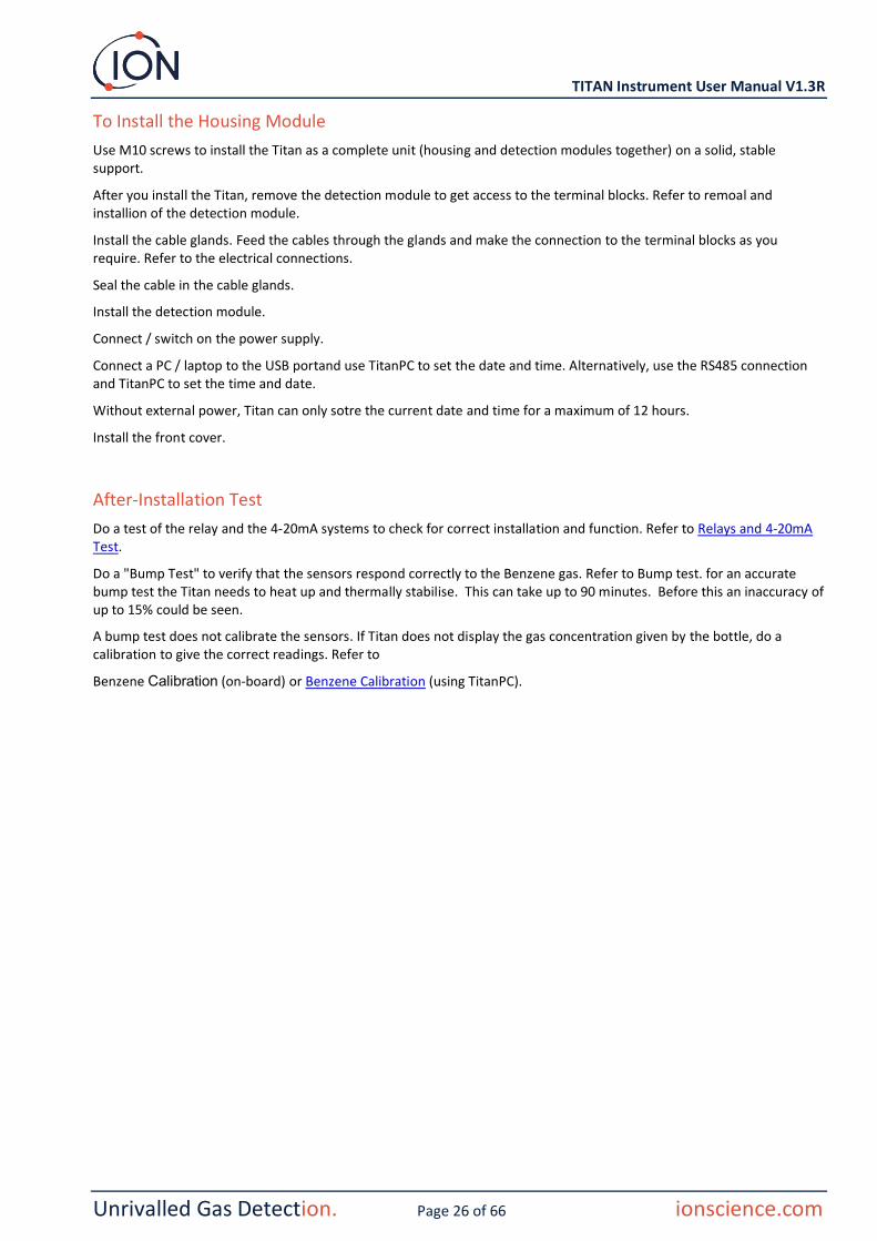
To Install the Housing Module
Use M10 screws to install the Titan as a complete unit (housing and detection modules together) on a solid, stable support.
After you install the Titan, remove the detection module to get access to the terminal blocks. Refer to remoal and installion of the detection module.
Install the cable glands. Feed the cables through the glands and make the connection to the terminal blocks as you require. Refer to the electrical connections.
Seal the cable in the cable glands.
Install the detection module.
Connect / switch on the power supply.
Connect a PC / laptop to the USB portand use TitanPC to set the date and time. Alternatively, use the RS485 connection and TitanPC to set the time and date.
Without external power, Titan can only sotre the current date and time for a maximum of 12 hours.
Install the front cover.
After-Installation Test
Do a test of the relay and the 4-20mA systems to check for correct installation and function. Refer to Relays and 4-20mA Test.
Do a "Bump Test" to verify that the sensors respond correctly to the Benzene gas. Refer to Bump test. for an accurate bump test the Titan needs to heat up and thermally stabilise. This can take up to 90 minutes. Before this an inaccuracy of up to 15% could be seen.
A bump test does not calibrate the sensors. If Titan does not display the gas concentration given by the bottle, do a calibration to give the correct readings. Refer to
Benzene Calibration (on-board) or Benzene Calibration (using TitanPC).

TITAN Instrument User Manual V1.3R
Unrivalled Gas Detection. Page 27 of 66 ionscience.com
Electrical Connections
Terminal Block-1 (Power)
Pin Label Function
1 0V DC Power input (Negative)
2 0V DC Power additional input (Negative) (Connected to above Pin1 on-board) (See Note 1)
3 24 DC Power Input (Positive) +24VDC
4 24 DC Power additional input (Positive) (Connected to above Pin3 on-board) (See Note 1)
5 R1 Relay 1 output (Terminal-1)
6 R1 Relay 1 output (Terminal-2)
7 R2 Relay 2 output (Terminal-1)
8 R2 Relay 2 output (Terminal-2)
9 Is DC Power Output (Positive) (Connected to Pin3 & 4 on-board) (See Note 2)
NOTES:
1. Pin 2 '0V' and pin 4 '24V' on Terminal Block-1 allow two wires to share the current of the Power Supply Input. Pin 1 and Pin 2 are connected together on-board. Pin 3 and Pin 4 are connected together on-board.
2. The 4-20mA output is NOT powered on-board. It is an isolated output that requires its own Power Supply at 24VDC (nominal) and 32VDC (maximum).
The 4-20mA output can share the instrument Power Supply if:
• the 4-20mA output goes to the same location as the instrument power supply and
• their Grounds will be connected together.
If that is so, connect a jumper from Pin 9 of Terminal Block-1 to Pin-1 of Terminal
Block-2

TITAN Instrument User Manual V1.3R
Unrivalled Gas Detection. Page 28 of 66 ionscience.com
Terminal Block-2 (Communications)
Pin Label Function
1 I+ 4-20mA transmitter DC Power Input (Positive) 24VDC (max= 32VDC)
2 I - 4-20mA output return
3 0 RS485 Ground (0V) (See Note 4)
4 B RS485 interface D (-)
5 A RS485 interface D (+)
NOTES:
1. For RS485 termination resistor, put a jumper link on the L1 header between the middle pin and the pin labelled 120R. This puts a 120R termination resistor across 'A' and 'B' of Terminal Block-2 (See RS485 Connections diagram for more details). To disconnect the resistor remove the jumper completely.
2. The 4-20mA output has an inline fuse, for protection against accidental short circuit, see F2 on the above diagram.

TITAN Instrument User Manual V1.3R
Unrivalled Gas Detection. Page 29 of 66 ionscience.com
Circuit diagrams for 4-20 mA monitoring
I+
I-
Ammeter for current
measurement 4-20mA
On-board-Fuse (375mA / F2)
+24V
0V
Power Supply
I+
I-
On-board-Fuse (375mA / F2)
+24V
0V
Current Sense Resistor 4-20mA
Power Supply
To Measurement
Circuitry

TITAN Instrument User Manual V1.3R
Unrivalled Gas Detection. Page 30 of 66 ionscience.com
Removal and Installation of the Detection Module
To Remove the Detection Module
Switch off or remove the power to the Titan.
WARNING:
1. Ensure the electrical power is switched off or disconnected.
2. Do not open when an explosive atmosphere might be present.
Insert the threaded Cover Removal Tools into the holes in the Titan front cover.
Turn counter-clockwise to unscrew the front cover.
Use a 2mm allen-key to remove the four faceplate screws.
Remove the faceplate.
Press the 'wings' down to release the ribbon cable at the top of the Detection Module.

TITAN Instrument User Manual V1.3R
Unrivalled Gas Detection. Page 31 of 66 ionscience.com
Two captive, hex-socket screws hold the Detection Module in the Housing Module, as shown.
Two holes in the front of the Detection Module give access to the screws.
Use a 3mm allen-key to reach the screws directly behind the holes.
Turn each screw counter-clockwise until it is completely loose.
Grips
When the captive screws are completely loose, grip the sides of the frame of the Detection Module, as shown, to remove it from the Housing Module.
Be careful not to cause damage the PCBs.
Be careful to remove it only far enough to disconnect the Luer connectors of the 3 pneumatic tubes.

TITAN Instrument User Manual V1.3R
Unrivalled Gas Detection. Page 32 of 66 ionscience.com
Ensure the pneumatic tubes are properly identified for later connection to the correct connectors.
Disconnect the tubes only from the Detection Module, not from the Housing Module. The tubes must remain connected at all times to the barbs on the interior face of the flame-arrestors.
For complete removal of the Detection Module: a half-turn, counter-clockwise, of the Luer connectors will remove the pneumatic tubes:
• two on the left
• one on the right.
You can now remove the Detection Module completely.
To Install the Detection Module
Check the identification of the pneumatic tubes and connectors.
Connect the tubes to the connectors: a half-turn, clockwise, of the Luer connectors will secure the pneumatic tubes:
• two on the left
• one on the right.
Ensure the tubes have no twists or kinks.
Half Turn
Half Turn

TITAN Instrument User Manual V1.3R
Unrivalled Gas Detection. Page 33 of 66 ionscience.com
Hold the ribbon cable out of your way while you insert the Detection Module.
There are locating pins to ensure correct positioning of the Detection Module on the base-plate.
Move the module from side to side until it locks into place.
Use the allen-key to engage the captive screw at each side of the Detection Module.
If the module is in its correct position, the screws will engage in the threads and turn freely.
If they do not engage the threads easily, check the positon of the Detection Module.
Move the module from side to side until it locks into place.
Tighten them hand-tight.
Check the Detection Module is held firmly.
Attach the ribbon cable.
When you push it into its socket, it should clip in automatically.
Gently pull the cable to check it is securely connected.

TITAN Instrument User Manual V1.3R
Unrivalled Gas Detection. Page 34 of 66 ionscience.com
Use the four screws to attach the face plate. Tighten them firmly hand-tight.
Connect a PC to the USB or RS485 connection and use TitanPC software to set the date and time. Refer to Settings.
The date and time is used to "Date-stamp" all data files and calibration history.
Without external power, Titan can only store the current date and time for a maximum of 12 hours.
Install the front cover. Turn it clock-wise until it is hand-tight.
CAUTION: Be careful to ensure the front cover engages easily with the screw thread. If there is resistance, remove it, examine it, and try again. Do not use force. Force can cause damage to the threads.
TITAN Instrument User Manual V1.3R
Unrivalled Gas Detection. Page 35 of 66 ionscience.com
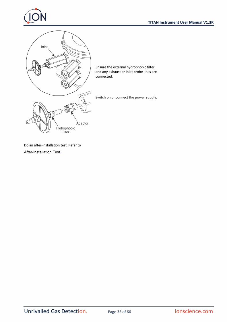
Ensure the external hydrophobic filter and any exhaust or inlet probe lines are connected.
Switch on or connect the power supply.
Do an after-installation test. Refer to
After-Installation Test.

TITAN Instrument User Manual V1.3R
Unrivalled Gas Detection. Page 36 of 66 ionscience.com
Operating the Titan
Switches and Display
The Titan front face has:
• An LCD display,
• two switches, magnetically operated,
• three LEDs.
All three LEDs work together and display the same colour.
LEDs Green Titan is operating correctly.
LEDs Yellow Titan has an operational fault. An alert signal and the name of the fault is on the screen.
LEDs Red The measured level of benzene is above the alarm threshold.
Power on
When power is turned on, the Titan displays the 'Ion Science' logo followed by the firmware version.
The Titan then starts to heat the AirSep filter. Normal operation cannot start until it reaches the target temperature. This will usually take a few minutes.
Normal operation starts when it is stable at the target temperature. The Titan then displays the ambient benzene level in parts per million (ppm). This updates once per minute.
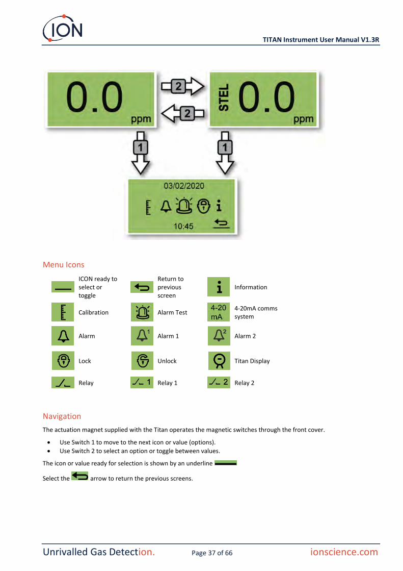
Main screens and main menu
The actuation magnet supplied with the Titan operates the magnetic switches through the front cover.
On the main operation screen:
• Select Switch 2 to toggle between the current reading and the calculated STEL (Short-Term Exposure Limit) over the previous 15 minutes.
• Select Switch 1 to go to the main menu.
TITAN Instrument User Manual V1.3R
Unrivalled Gas Detection. Page 37 of 66 ionscience.com
Menu Icons
ICON ready to select or toggle
Return to previous screen
Information
Calibration
Alarm Test
4-20mA comms system
Alarm
Alarm 1
Alarm 2
Lock
Unlock
Titan Display
Relay
Relay 1
Relay 2
Navigation
The actuation magnet supplied with the Titan operates the magnetic switches through the front cover.
• Use Switch 1 to move to the next icon or value (options).
• Use Switch 2 to select an option or toggle between values.
The icon or value ready for selection is shown by an underline
Select the arrow to return the previous screens.

TITAN Instrument User Manual V1.3R
Unrivalled Gas Detection. Page 38 of 66 ionscience.com
Calibration
Select the Calibration icon to go the calibration menu.
Select the bottle icon to go to the Benzene calibration screen.
Benzene Calibration
For accuracy over the full range; Ion recommends a bottle of 5ppm benzene. The software allows you to use any benzene concentration from 0.1 to 20.0ppm, if your application has different requirements.
Attach the bottle before you start calibration. This ensures the benzene is flowing through the Titan system before the start of the calibration.
Connect the bottle to the hydrophobic filter on the inlet flame-arrestor of the Titan. Use a fixed-flow regulator that delivers more than 300mL/min. A demand-flow regulator will not perform correctly and can damage the Titan. You will need to use a flood-leak with a carbon filter on the leak. This is to prevent gas pressure irregularities from affecting the instrument.
Move the cursor to the ppm value. Use Switch 2 to cycle through the values to the benzene concentration of the bottle.
Select to start the calibration process.
Titan analyses the gas for a default time of 10 minutes.
You can select the return arrow icon to stop the calibration process at any time.
Once the timer has finished the new calibration will replace the previous calibration in the Detector Module.
Do a Bump Test to check the calibration. Refer to Bump Test.

TITAN Instrument User Manual V1.3R
Unrivalled Gas Detection. Page 39 of 66 ionscience.com
Flow Calibration
Ion recommends a bottle of between 5 and 10ppm benzene.
Select the flow arrow to go to the Flow calibration screen.
Attach the bottle before you start calibration. This ensures the benzene is flowing through the Titan system before the start of the calibration.
Connect the bottle to the hydrophobic filter on the inlet flame-arrestor. Use a fixed-flow regulator that delivers more than 300mL/min with a flood-leak. A demand-flow regulator will not perform correctly and can damage the Titan.
Select to start the calibration process.
The calibration process lasts between 5 and 10 minutes.
You can select the return arrow icon to stop the calibration process at any time.
Calibration is complete and successful.
Select to save and return to the main menu. The new calibration will replace the previous calibration in the Detector Module.
Select X to not save and return to main menu.
Calibration has failed for the reason shown on the screen.
Select the return arrow to return to the main menu.
If you can correct the fault, you can start the calibration again.
Do a Bump Test to check the calibration. Refer to Bump Test.

TITAN Instrument User Manual V1.3R
Unrivalled Gas Detection. Page 40 of 66 ionscience.com
Removal of the Memory Card
You can remove the memory card from the Titan. You can then connect the card to a PC and use TitanPC software to download and read the data.
While the Memory card is removed, the Titan cannot log data.
For safe removal of the memory card, use the magnet to actuate switch 1 for 5 seconds.
The Titan goes into safe mode. The Memory card removal screen shows when it is safe to remove the card.
When you remove the memory card, the arrows change direction to show that you must insert a card. Use the magnet to actuate switch 1 for 5 seconds to exit menu.
IMPORTANT: Fit the memory card before the service module is fitted into the EXD enclosure. The memory card is push to connect and push to release so may be pressed inadvertently during servicing. Always check the memory card is inserted correctly after servicing.
Password Lock
The password lock lets you:
• Prevent access to the calibration: so that selecting the calibration icon on the main menu will not access calibration menu.
• Prevent viewing of measured benzene levels: so the STEL and LIVE benzene displays will be blank.
You will use a 4-digit pin to turn the lock function on or off.
Titan is supplied with a default PIN of 0000 and with calibration and viewing unlocked.
Select the lock icon on the main menu.
Memory card

TITAN Instrument User Manual V1.3R
Unrivalled Gas Detection. Page 41 of 66 ionscience.com
Lock the Calibration
On the "Lock Select" menu, select the calibration icon to lock or unlock the calibration screens.
On the "Enter PIN" screen, use Switch 2 to cycle through the values to set the first digit. Use Switch 1 to move to the next digit.
The factory-set default is 0000.
When all the digits are set, Select to go to the "Lock/Unlock" screen.
On the "Lock/Unlock" screen use Switch 2 to toggle between locking and unlocking the calibration.
Then select return to go to the "Lock Select" screen.
To change the PIN, use Switch 1 to navigate to the PIN number icon then use Switch 2 to select it.
This will take you to the "Enter new PIN" screen.
On the "Enter new PIN" screen, use Switch 2 to cycle through the values to set the first digit. Use Switch 1 to move to the next digit.
When all the digits are set:
• Select to save the PIN and return to the "Lock screen
• Select to return to the lock screen without saving the PIN.

TITAN Instrument User Manual V1.3R
Unrivalled Gas Detection. Page 42 of 66 ionscience.com
Lock the STEL and LIVE Displays
On the "Lock Select" menu, select the Titan Display icon to prevent or allow viewing the STEL and LIVE values on the screen.
On the "Enter PIN" screen, use Switch 2 to cycle through the values to set the first digit. Use Switch 1 to move to the next digit.
The factory-set default is 0000.
When all the digits are set, Select to go to the "Lock/Unlock" screen.
On the "Lock/Unlock" screen use Switch 2 to toggle between locking and unlocking the display.
Then select return to go to the "Lock Select" screen.
To change the PIN, use Switch 1 to navigate to the PIN number icon then use Switch 2 to select it.
This will take you to the "Enter new PIN" screen.
On the "Enter new PIN" screen, use Switch 2 to cycle through the values to set the first digit. Use Switch 1 to move to the next digit.
When all the digits are set:
• Select to save the PIN and return to the "Lock screen
Select to return to the lock screen without saving the PIN.
Alarms and Relays
The alarms and relays are individually programmable to the settings required by the site policy. You can choose either alarm to energize either relay. The default settings would be. When the Titan is not powered the default state of relay 1 is N/C, the default state of relay 2 is N/O.
• Alarm 1: 5.0ppm live
• Alarm 2: 0.5ppm STEL
• Relay 1: Alarm 1, N/O
• Relay 2: Alarm 2, N/O
Both relays can be programed to be Normally Open or Normally Closed.
TITAN Instrument User Manual V1.3R
Unrivalled Gas Detection. Page 43 of 66 ionscience.com
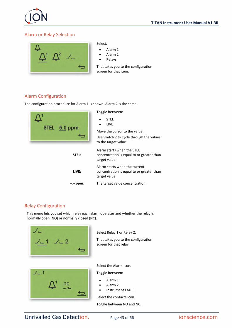
Alarm or Relay Selection
Select:
• Alarm 1 • Alarm 2
• Relays
That takes you to the configuration screen for that item.
Alarm Configuration
The configuration procedure for Alarm 1 is shown. Alarm 2 is the same.
Toggle between:
• STEL
• LIVE
Move the cursor to the value.
Use Switch 2 to cycle through the values to the target value.
STEL: Alarm starts when the STEL concentration is equal to or greater than target value.
LIVE: Alarm starts when the current concentration is equal to or greater than target value.
–.– ppm: The target value concentration.
Relay Configuration
This menu lets you set which relay each alarm operates and whether the relay is normally open (NO) or normally closed (NC).
Select Relay 1 or Relay 2.
That takes you to the configuration screen for that relay.
Select the Alarm Icon.
Toggle between:
• Alarm 1 • Alarm 2
• Instrument FAULT.
Select the contacts Icon.
Toggle between NO and NC.
TITAN Instrument User Manual V1.3R
Unrivalled Gas Detection. Page 44 of 66 ionscience.com
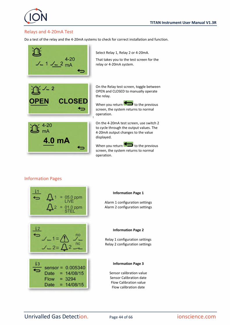
Relays and 4-20mA Test
Do a test of the relay and the 4-20mA systems to check for correct installation and function.
Select Relay 1, Relay 2 or 4-20mA.
That takes you to the test screen for the relay or 4-20mA system.
On the Relay test screen, toggle between OPEN and CLOSED to manually operate the relay.
When you return to the previous screen, the system returns to normal operation.
On the 4-20mA test screen, use switch 2 to cycle through the output values. The 4-20mA output changes to the value displayed.
When you return to the previous screen, the system returns to normal operation.
Information Pages
Information Page 1
Alarm 1 configuration settings Alarm 2 configuration settings
Information Page 2
Relay 1 configuration settings Relay 2 configuration settings
Information Page 3
Sensor calibration value Sensor Calibration date Flow Calibration value Flow calibration date

TITAN Instrument User Manual V1.3R
Unrivalled Gas Detection. Page 45 of 66 ionscience.com
Information Page 4
Titan internal temperature AirSep temperature
Fault Indications
If there is a fault:
• The three LEDs show Yellow
• The main screen changes to a -Warning Screen and gives the name of the fault at the bottom. Use the Fault Name to find information from the Fault Diagnostics section of this manual.
Information Page 5 Firmware version number
Pump Driver Board Version Number
Information Page 6 Instrument serial number
User settable location Processor serial number
Information Page 7 Baud rate
Modbus address

TITAN Instrument User Manual V1.3R
Unrivalled Gas Detection. Page 46 of 66 ionscience.com
Alarm Indications
If the benzene level exceeds one of the two target concentration values selected during Alarm Configuration:
• The three LEDs on the front panel show red.
• An alarm symbol and the alarm number, is displayed in the top right of the screen.
• If a relay is associated with the alarm, it is energized.
• Benzene detection continues.
• The alarm is only raised if the current cycle is above the alarm thresholds.
Service Period Reminder
Titan counts continuous days of operation. When it reaches 180 days:
• The screen changes to "Service Required"
• The three LEDs on the front panel show yellow.
Only a Service Centre can reset it.

TITAN Instrument User Manual V1.3R
Unrivalled Gas Detection. Page 47 of 66 ionscience.com
TitanPC Software
The TitanPC software lets you connect to the Detection Module to:
• Calibrate the module • View and download the detection and fault histories stored in the module
• Set the operating thresholds of the alarms and relays
• Adjust the time and date settings in the module clock
• Give the module an identification appropriate to its installation
• Upgrade the operating firmware on the module.
Minimum requirements
TitanPC Software works on PCs or laptops with operating systems:
• Windows XP (no longer supported),
• Windows Vista
• Windows 7
• Windows 8 / 8.1
Connect the Titan to the PC
1. Install the Detector Module into the Test Housing Module.
2. Connect the USB or RS485 output to the PC.
3. Connect or switch on the power supply.
4. Start TitanPC.
TITAN Instrument User Manual V1.3R
Unrivalled Gas Detection. Page 48 of 66 ionscience.com
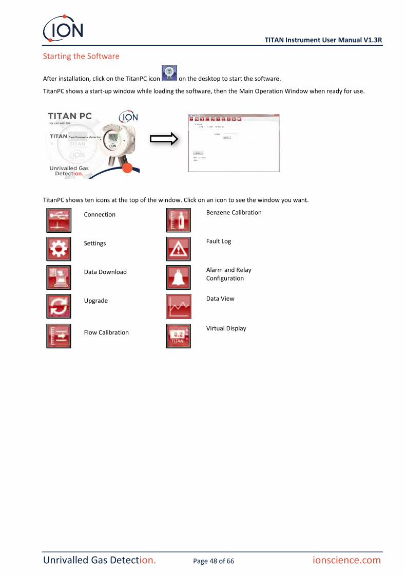
Starting the Software
After installation, click on the TitanPC icon on the desktop to start the software.
TitanPC shows a start-up window while loading the software, then the Main Operation Window when ready for use.
TitanPC shows ten icons at the top of the window. Click on an icon to see the window you want.
Connection
Benzene Calibration
Settings
Fault Log
Data Download
Alarm and Relay Configuration
Upgrade
Data View
Flow Calibration
Virtual Display

TITAN Instrument User Manual V1.3R
Unrivalled Gas Detection. Page 49 of 66 ionscience.com
Data Connection
Click the icon for the Connection window.
Click on the radio button for USB or RS485, to select the connection type.
• RS485 is normally used when the Test Housing Module is a permanent installation The default address of the Titan is 10
• USB is normally used for a bench-top set-up or connect a PC/Laptop to a Detector Module in its normal, installed position.
Click on the "Connect" button to manually connect to the Titan.
If connection is successful, it will show the status and ID of the Titan.
Or you can remove the memory card from the Titan (Refer to
Removal of the Memory Card) and insert it into the pc. Then select Memory Card and click Browse to find the card location. After connection, you can download and view the data on the card.
If Titan is connected via USB, and the PC is connected to the internet, you can tick the check-box to allow Ion Service Support to remotely connect to the Titan to view factory level data and configuration values.

TITAN Instrument User Manual V1.3R
Unrivalled Gas Detection. Page 50 of 66 ionscience.com
Settings
Click the icon for the Settings window.
The software should automatically scan for data when started. The "Read from Titan" button lets you manually scan for data, if necessary.
When the software has successfully connected to the Titan, the serial number, instrument name and instrument date and time are displayed.
You can change the instrument name to something more meaningful (for example, 'Area 1 Monitor').
You can change the Titan date and time to the same as the PC clock.
Modbus: Change address and baud rate
Service period: Displayed in days since last service
Calibration value: Test gas concentration, sensor calibration factor and flow calibration factor
NOTE:
1. The Titan internal clock is automatically set during calibration using TitanPC. Without external power, Titan can only store the current date and time for a maximum of 12 hours.

TITAN Instrument User Manual V1.3R
Unrivalled Gas Detection. Page 51 of 66 ionscience.com
Data Download
Click on the icon for the Data Download window.
When data is available to download, a list of the available dates is displayed under "File Date" on the left.
If necessary, click "Refresh" to scan the instrument for fresh data.
Click on the available dates to select the data you want.
Use standard windows functions to select groups of dates, e.g.:
• For consecutive files click the first one, hold down the Shift Key [Shift] and click on the last file you want.
• For non-consecutive files, hold down the Control Key [Ctrl] and click on each file you want.
Or click the "Select All" button if you want all the files.
After selecting the files:
Click "Read Selected" to download the files to the PC
Click "Delete Selected" to delete the files.
The bar at the bottom of the screen indicates how much memory is used/unused in the Titan.

TITAN Instrument User Manual V1.3R
Unrivalled Gas Detection. Page 52 of 66 ionscience.com
Data View
Click on the icon for the Data Download window.
Data View allows you to view, print or save pictures of graphs of the data in files downloaded from Titan using Data Download. You can change the presentation to how you want to see it.
Click the 'Open File' button and select a file from the list.
TitanPC shows the data as a graph, or graphs superimposed on each other using the same time-axis. Each data-set has its own, colour-coded, axis on the left. Fault groups (refer to
TitanPC Fault Groups) are shown in a bar-graph at the top of the screen.
The tick-boxes at the top let you choose which graphs you see.
Hold down the left mouse button to grab and drag the graph around the screen. Use the mouse wheel to zoom in and out.
There are 5 control buttons at the top right of the screen:
Scales – adjustment of data-axis scales.
Click on this to manually adjust the axis of each data-set.
In the pop-up window, click on the arrows, or type-in numbers to change the maximum and minimum values of the scale. Click the 'Auto Scale' button to revert to the default values.

TITAN Instrument User Manual V1.3R
Unrivalled Gas Detection. Page 53 of 66 ionscience.com
Zoom to fit (Auto-scale).
Click this to reset the graph to make all data visible (Auto-scale).
Zoom.
Click this to zoom-in on an area of the graph. The cursor changes to a magnifying glass when over the graph. Hold down the left mouse button to draw a rectangle around the area you want to enlarge. Click the Zoom button again to leave zoom mode.
Print.
Click this to print the view you have on the screen.
Save as a Picture.
Click this to save the view you have on the screen, as a picture. You can save in jpg, emf, bmp, tif, png, or gif format.

TITAN Instrument User Manual V1.3R
Unrivalled Gas Detection. Page 54 of 66 ionscience.com
Upgrade
Click on the icon for the Upgrade window.
If the PC is connected to the internet TitanPC will automatically detect if a new version of firmware or software is available.
If new firmware or software is available, you can view the release notes or do an upgrade.

TITAN Instrument User Manual V1.3R
Unrivalled Gas Detection. Page 55 of 66 ionscience.com
Flow Calibration
Click on the icon for the Flow Calibration window.
Attach a bottle of between 5 and 10ppm Benzene to the inlet flame-arrestor before you start calibration. This ensures the benzene is flowing through the Titan system before the start of the calibration.
Click the "Start Calibration" button. The text on the button will change to “Abort Calibration.” You can click the button again to any time to stop the calibration and reset the screen to its original state.
"Last Cycle" shows the pump power and AirSep Performance value for the previous cycle.
If the AirSep Performance value is larger than the specified configuration value then the calibration will fail.
"Live Status" shows the applied pump power and measured differential pressure of the current cycle. If the pump cannot run between the limits of ‘Minimum Pump Power’ and ‘Maximum Pump Power’ then the calibration will fail.
"Sensor Calibration" If you tick "Enable Sensor Calibration" and type-in the Benzene concentration of the bottle, TitanPC will calibrate the sensor after the Flow Calibration.
The "Save Calibration" button is not active until the calibration is complete and successful. The new calibrated flow will not replace the old setting in the Detector Module until you click the button. The text "Calibration Saved" will then appear next to the button.
The Status, Pump power and Differential pressure stay on the screen until you start a new calibration.
Do a Bump Test to check the calibration. Refer to Bump Test.
During the procedure the "Status" message shows:
“Instrument ready” When there is a Detector Module connected to TitanPC.
“Stabilising flow” When the pump power has been adjusted and the software is waiting for stable flow conditions.
“Running measurement cycle” When the software is doing a measurement cycle.
“Calibration successful” When the calibration is complete and successful.
“Calibration failed: AirSep fault” When the calibration diagnoses a failure of the AirSep.

TITAN Instrument User Manual V1.3R
Unrivalled Gas Detection. Page 56 of 66 ionscience.com
“Calibration failed: pump power high” When calibration diagnoses that the pump power required for a working flow is too high.
“Calibration failed: pump power low” When calibration diagnoses that the pump power required for a working flow is too low
Benzene Calibration
Click on the icon for the Benzene Calibration window.
Ensure the Detector Module clock is set to the correct date and time.
Ensure the flow is successfully calibrated before you do Benzene Calibration.
For accuracy over the full range; Ion recommends a bottle of 5ppm benzene. The software allows you to use any benzene concentration from 0.1 to 20.0ppm, if your application has different requirements. Titan analyses the gas for a default of 5 cycles (10 minutes). If the tube or inlet probe between bottle and Titan is long, you can increase the cycles to ensure a stable gas flow. (Contact Ion Science or your Service Center)
Attach the bottle before you start calibration. This ensures the benzene is flowing through the Titan system before the start of the calibration.
Connect the bottle to the hydrophobic filter on the inlet flame-arrestor of the Titan. Gas bottles should be fitted with a fixed-flow regulator that delivers more than 300mL/min with a flood-leak. A demand-flow regulator will not perform correctly and can damage the Titan.
Type-in the benzene concentration of the bottle and the cycles required.
Click on the "Start Calibration" button.
The screen shows the "Time Left" and the progress bar at the bottom.
At the end of the calibration the option to "Save" will show on the screen. The new calibration will not replace the previous calibration in the Detector Module if you do not click the Save button.
Do a Bump Test to check the calibration. Refer to Bump Test.

TITAN Instrument User Manual V1.3R
Unrivalled Gas Detection. Page 57 of 66 ionscience.com
Recorded Faults
Click on the icon for the Recorded Faults window.
This screen shows the last date a fault occurred and how many times it has occurred.
Click "Refresh" to scan for the latest fault data.
Click "Reset" to clear all the fault reports to zero.
For more details of the fault conditions, refer to the
Fault Diagnostics section of this manual.
Pressing the ‘Read Diagnostic Log’ button opens the following screen. The diagnostic file and comments can be sent to Ion Science or to an e-mail of the user’s choice.

TITAN Instrument User Manual V1.3R
Unrivalled Gas Detection. Page 58 of 66 ionscience.com
Alarm Set
Click on the icon for the Alarm Set window.
You can set each alarm to operate when the STEL or Current level of Benzene reaches a set value in ppm.
• In the window, type the value to trigger the alarm.
• Click on the radio button to choose STEL or Current value as the trigger.
You can select which alarm or fault will operate each relay and whether it is normally open NO or normally closed NC.
For each relay select between:
• Alarm 1
• Alarm 2
• Instrument FAULT.
Select the contacts as NO or NC.
Click "Refresh" to reset the screen to the values in the Titan.
Click "Save" to set the Titan to the values on the screen.
Virtual Screen
Click on the icon for the Virtual Screen window.
This tab displays in real time what is displayed on the Titan screen. A radio button allows the user to switch between the current cycle reading and the calculated STEL.
TITAN Instrument User Manual V1.3R
Unrivalled Gas Detection. Page 59 of 66 ionscience.com
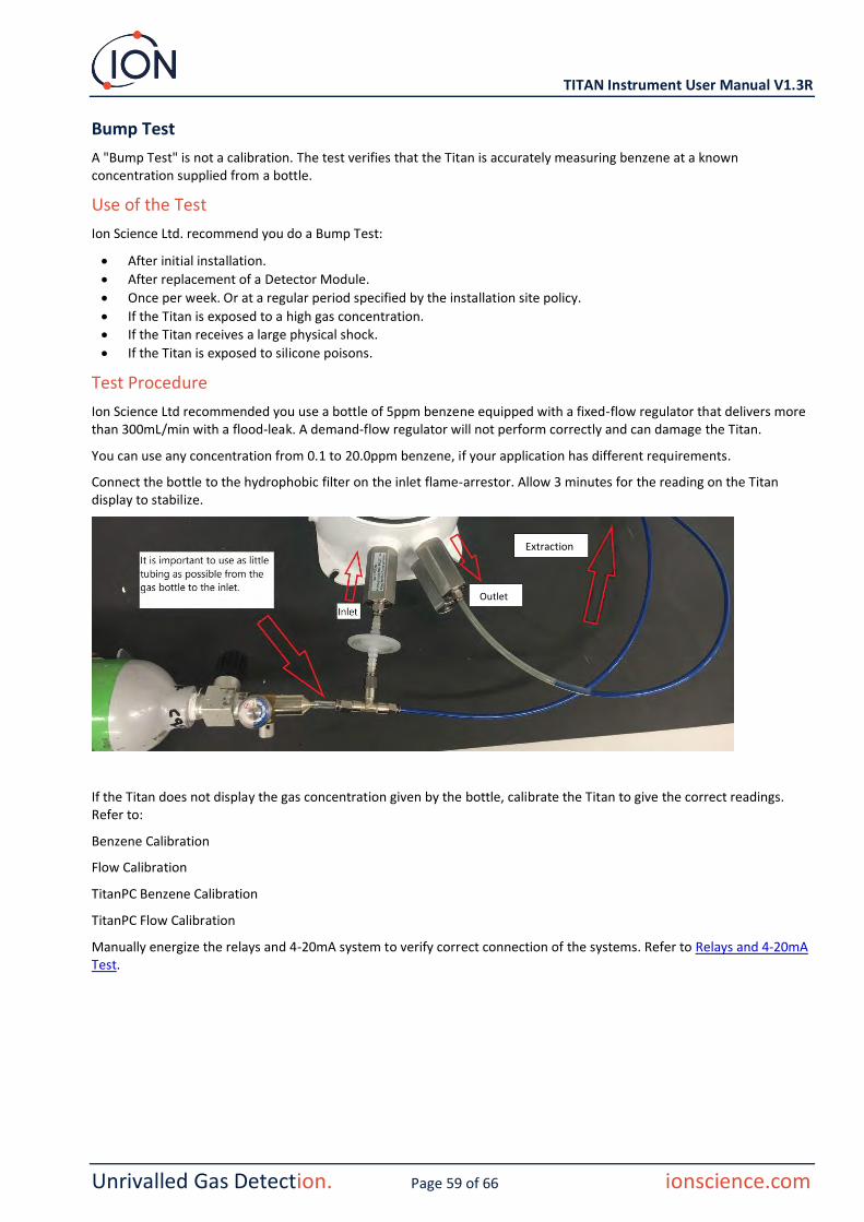
Bump Test
A "Bump Test" is not a calibration. The test verifies that the Titan is accurately measuring benzene at a known concentration supplied from a bottle.
Use of the Test
Ion Science Ltd. recommend you do a Bump Test:
• After initial installation.
• After replacement of a Detector Module.
• Once per week. Or at a regular period specified by the installation site policy.
• If the Titan is exposed to a high gas concentration. • If the Titan receives a large physical shock.
• If the Titan is exposed to silicone poisons.
Test Procedure
Ion Science Ltd recommended you use a bottle of 5ppm benzene equipped with a fixed-flow regulator that delivers more than 300mL/min with a flood-leak. A demand-flow regulator will not perform correctly and can damage the Titan.
You can use any concentration from 0.1 to 20.0ppm benzene, if your application has different requirements.
Connect the bottle to the hydrophobic filter on the inlet flame-arrestor. Allow 3 minutes for the reading on the Titan display to stabilize.
If the Titan does not display the gas concentration given by the bottle, calibrate the Titan to give the correct readings. Refer to:
Benzene Calibration
Flow Calibration
TitanPC Benzene Calibration
TitanPC Flow Calibration
Manually energize the relays and 4-20mA system to verify correct connection of the systems. Refer to Relays and 4-20mA Test.
Outlet
Extraction

TITAN Instrument User Manual V1.3R
Unrivalled Gas Detection. Page 60 of 66 ionscience.com
Fault Diagnostics
Fault and Alarm indications
If there is a fault, the main screen changes to a Warning Screen and gives the name of the fault under the warning icon. Use the Fault Name in the table below to find the possible conditions causing the fault.
Fault Conditions
The Titan is equipped with a number of diagnostics to ensure instrument faults are detected and communicated. The table gives a fuller description of each fault and list some possible causes and corrective actions you can try.
If the fault continues, or is repeated, contact your Service Centre.
Abbreviations:
CTO = Continues to Operate. (Titan continues to operate but results might not be correct.) Norm = Normal Operation
Fault Name and Description
Possible Causes and Corrective Actions
4-20mA signal
LED colour CTO
Service Required:
Yellow
Yes
The Titan requires its 6-month service check.
Titan has recorded 180 days of continuous operation without a service.
This can only be reset by an Ion Science Service Centre.
Temp error:
2.000
Yellow
Yes
Ambient temperature too high. or
AirSep temperature out of limits.
Ambient temp >50, Try cooling or shading the Titan to prevent overheating.
AirSep temp <45 or >80 Or failed to reach temp within 180 mins, Possible thermocouple fault. Contact the Service Centre.
Temp fault:
2.125
Yellow
Yes
Instrument temperature too high for extended period.
Ambient T >50 for 1 hour
Try cooling or shading the Titan to prevent overheating.

TITAN Instrument User Manual V1.3R
Unrivalled Gas Detection. Page 61 of 66 ionscience.com
Sensor flow low:
2.250
Yellow
Yes
AirSep flow too low. Check for kinks or pinches in the tube between port 3 and the inlet flame-arrester.
Sensor flow high:
2.375
Yellow
Yes
AirSep flow too high. Check that AirSep filter is pushed in firmly and internal tube connections are not loose.
Recalibrate the flow.
Outlet Blocked:
2.500
Yellow
Yes
Reduced flow through the outlet flame-arrester.
P3 values not correct.
Check for kinks or pinches in the tube between port 4 and the outlet flame-arrester.
Tube off:
2.625
Yellow
Yes
Increased flow through the inlet flame-arrester.
P3 values not correct.
Check for leaks between the external (Hydrophobic) filter and the inlet flame-arrester.
Check for leaks between the external (Hydrophobic) filter and the extended probe line, if installed.
Check for any disconnected tubes within the Detector Module.
Inlet Blocked:
2.750
Yellow
Yes
Reduced flow through the inlet flame-arrester.
P3 values not correct.
Check the external (Hydrophobic) filter is not blocked.
Check the extended probe line, if installed, is not blocked or kinked.
Check the inlet flame-arrester for damage or blockage.
Check for kinks or pinches in the tubes within the Detector Module.

TITAN Instrument User Manual V1.3R
Unrivalled Gas Detection. Page 62 of 66 ionscience.com
Lamp Out:
2.875
Yellow
Yes
No signal from PID Light sensor.
PID Lamp not illuminated.
Sensor failure.
During Titan start-up, wait at least 5 cycles for the lamp to illuminate.
Memory full:
Norm
Red
Yes
Not enough memory space to store history.
Memory full.
Use TitanPC to download or delete History Record Files.
PID ADC Fail:
3.000
Yellow
Yes
Communication failure Internal hardware fault.
Remove the Detector Module to check that the black wiring loom is connected and not damaged.
Step overrun:
Norm
Red
Yes
Internal hardware fault Program code step took more than 0.5s to execute.
Contact the Service Centre.
Step error:
Norm
Red
Yes Software fault. Invalid sequence step.
Contact the Service Centre.
Watchdog:
3.125
Red
Yes Software fault. Software fault.
Contact the Service Centre.
Pump fault:
3.250
Yellow
Yes Failed communication with pump board.
Internal hardware fault.
Contact the Service Centre.
Pump power fail:
3.375
Yellow
No Pump power fault. Pump board power failure.
Contact the Service Centre.

TITAN Instrument User Manual V1.3R
Unrivalled Gas Detection. Page 63 of 66 ionscience.com
TitanPC Fault Groups
To reduce file size and memory usage, fault records are grouped together in the files stored on the Titan and downloaded to the TitanPC.
TitanPC Group Name Faults in the Group
PID failure Lamp out, PID ADC fail
Power failure Pump power fail
General Operational failure Step overrun, Watchdog, Pump fault, Step error
Memory full Memory full
Separator flow fault Sensor flow high, Sensor flow low
Instrument flow fault Outlet blocked, Inlet blocked, Tube off
Separator temperature fault Temp error
Internal Temperature fault Temp fault
Parts List
Part Description Part number Qty
Titan 875 Benzene Monitor and Accessories Kit
Installation Kit, Comprising:
TNXSXBXX-X
Housing Module A-875281 1
Detector Module A-875245 1
Front Cover Removal Tool 875413 2
Transit Strap 875400 1
Transit Strap Screws (M10x16)
2/SH10-16 2
Switch Actuation Magnet A-875265 1
External (Hydrophobic) Filter
A-875417 1
Gland Port Plug (for transportation)
4/PB-05 2
Allen Key 2mm 4/TA-06 1
Allen Key 3mm 4/TA-08 1
Mounting Template 875431
Titan User Manual 875263 1

TITAN Instrument User Manual V1.3R
Unrivalled Gas Detection. Page 64 of 66 ionscience.com
Titan Detector Module and Accessories Kit
Detector Module as spare, or for off-site service or calibration Comprising:
TSMXSXXXX-X
Titan Detector Module A-875245 1
Transit Case 875405 1
Front Cover Removal Tool 875413 2
Allen Key 2mm 4/TA-06 1
Allen Key 3mm 4/TA-08 1
Titan Calibration Gas Kit
Comprising:
861517
Bottle of 5ppm Benzene 1
Carry case 1
Tubing 1
Fixed-flow Regulator Flood-leak with carbon scrubber
1
Faceplate (Enhanced EMI protection)
Alternative Faceplate with increased protection against Electromagnetic Interference
875294
Transit Case For transporting the Detector Module without the Housing Module
875405 1
Cover Removal Tool Tools to remove the front cover
875413 2
Actuation Magnet Tool to operate the magnetic switches through the front cover
A-875265 1
External (Hydrophobic) Filter
Replacement External Filter
A-875417 1
Allen Key 2mm Ball-ended Hex Wrench To remove Detector Module
4/TA-06 1
Allen Key 3mm Ball-ended Hex Wrench To remove Detector Module
4/TA-08 1
TitanPC Software To use a PC to calibrate and download detection and fault history (on USB stick or Ion website)
Titan User Manual Installation, Operating, Servicing and Fault Diagnosis Instructions
875632 1

TITAN Instrument User Manual V1.3R
Unrivalled Gas Detection. Page 65 of 66 ionscience.com
ION Science Contact Details
UK and Head Office
ION Science Ltd The Hive, Butts Lane,
Fowlmere, Cambridgeshire SG8 7SL UK
Tel: +44 (0)1763 208503
Fax: +44 (0) 1763 290477
Web: www.ionscience.com
Email: [email protected]
USA Office
ION Science Inc 4153 Bluebonnet Drive Stafford TX 77477 USA
Tel: +1 877 864 7710
Web: www.ionscience.com/usa
Email: [email protected]
German Office
ISM ION Science Messtechnik Laubach 30 Metmann-Neandertal D-40822 GERMANY
Tel: +49 2104 14480
Fax: +49 2104 144825
Web: www.ism-d.de
Email: [email protected]
French Office
ION Science France 41 Rue de Etoiles, 83240 Cavalaire-sur-Mer, FRANCE
Tel: +33 6 13 50 55 35
Web: www.ionscience.com/fr
Email: [email protected]
India Office
ION Science India #1-90/B/B/3/1, Charmy Vittal Rao Nagar
Image Hospital Lane, Madhapur, Hyderabad – 500 081
Telangana State - India
Tel: +91 40 4853 6129
Web: www.ionscience.com/in
Chinese Office
ION Science China Ltd 1101 Bldg B, Far East International Plaza No. 317, Xianxia Road, Shanghai P.R. CHINA
Tel: +86 21 52545988
Fax: +86 21 52545986
Web: www.ionscience.com/cn
Email: [email protected]
Italian Office
ION Science Italia Via delle Querce 1/g
40011 Anzola dell’Emilia (Bologna) ITALY
Tel: +39 051 0561850
Fax: +39 051 0561851
Web: www.ionscience.com/it
Email: [email protected]

TITAN Instrument User Manual V1.3R
Unrivalled Gas Detection. Page 66 of 66 ionscience.com
Manual Log
Manual Version
Amendment Issue Date Instrument Firmware
PC software
1.0 First Issue 01/01/2016 0.1.70 1.0.1.54
1.1
Cover - Titan image
Page 6 - Declaration of conformity
Page 7 - Statements
Page 8 - US office address
Page 12 - Warning notice
Page 29 - Added graphic page 29
Page 36, 38 - Modified graphics
Page 39 - Added memory location image
Page 40,43, 44 - Modified / added graphics
Page 47 to 59 - Replaced screen graphics
1.1R Logo only 01/08/2017
1.2
Page 6 – Declaration of conformity, Page 7 – Warnings and Quality Assurance, Page 8 – Service info, Page 9 and 10 – Technical Specifcation & Environmental conditions table, Page 23 – Modbus Error Flags table, P26 – RS485 Connections and EMC Requirements, P29 and 30 – Electrical Connections, Page 39 – Benzene and Flow Calibration. Page 56 – Benzene Calibration, Page 59 – Test Procedure, Page 63 – Contents of Titan Calibration Gas Kit contents
03/06/2019
0.1.96
1.0.1.73
1.3 Updated into new format, updated TitanPC load up
screen image and Ion logo screen, certification update 24/01/2020 0.1.96 1.0.1.76
1.3R Updated to include the Titan recertification and New
EU Decleration of conformity 09/12/2020 0.1.96 1.0.1.76