LabVIEW TM Getting Started with LabVIEW Getting Started with LabVIEW
Upload
khangminh22Category
view
5download
0
www.euromoulders.org
EUROMOULDERS
EUROMOULDERS
GETTING TO UNDERSTANDMOULDED POLYURETHANE FOAM FOR AUTOMOTIVE SEATING
EURO MOULDERSAvenue de Cortenbergh 71 B-1000 Brussels Belgium
www.euromoulders.org


3
IntroductionEuro-Moulders is the European Association of Manufacturers of Moulded Polyurethane Parts for the Automotive Industry. Our members produce moulded polyurethane foams for seat cushions in 28 plants in 13 countries. They collectively employ over 10,000 people. The EU’s total production of moulded foam for the automotive sector is around 150,000 tonnes per year.
Moulded polyurethane (PU) foam, thanks to its unique properties, is today by far the preferred cushioning material for automotive seating, with a market share of well over 90%.
We have created this guide to explain:
• How our product came to this overwhelming market share in seat cushioning
• How PU foam is produced and processed
• What its properties are
• How our plants are organized
• Which complex parameters influence the properties of foam
• Frequently asked question on foam and of course ways to answer them
The aim of this document is to enlighten customers of moulded polyurethane foam cushion producers in the automotive supply chain about the specificities linked to the production of such cushions.
The intention is not to develop an exhaustive guide on moulded polyurethane foam technology or on polyurethane foam chemistry but to give an overview of the essentials to know about our industry. We hope this document will help giving our customers useful documentation to serve as a basis for a fruitful and positive dialogue for mutual benefit.
We hope you will enjoy your reading and agree with us that PU foam is a fascinating material that has not only been the preferred padding material for automotive seating for several decades already but will remain so for the foreseeable future too.
Disclaimer
EURO-MOULDERS has in good faith made every effort to present accurate and reliable information in this document. Neither EURO-MOULDERS nor its members can however be held responsible for any inaccuracies or omissions present in this document.
Acknowledgments
This document has been drafted by Mr Jean Roux, with the kind support of all the members of the Technical Committee of EURO-MOULDERS. We wish in particular to warmly thank Ms Roberta Stacey (Pro-Seat) and Esther Quintanilla (Dow Automotive), as well as Mess. Dirk-Endres Hein (F.S. Fehrer Automotive), Sébastien Gentil (Johnson Controls International), Renato Ravicino (Toscana Gomma), Massimo Gilardi (Toscana Gomma), Eric Van Lancker (Pro-Seat), Marc Lauth (Faurecia), Arturo Gonzalez (Grupo Copo), Christophe Ponce (Huntsman), John Hobdell (Huntsman), Roger Van Maris (Tosoh) and Michel Baumgartner (Euro-Moulders) for their valuable input and comments. Pictures and sketches were used with the kind permission of the companies Pro-Seat, F.S. Fehrer Automotive, Johnson Controls International and Dow Chemical.
Copyright
This document is the property of EURO-MOULDERS aisbl, Avenue de Cortenbergh 71, B-1000 Brussels. It may not be used or reproduced, in full or in part, without the authorisation of the association.
INTR
OD
UC
TIO
N

4
CO
NTE
NTS
Contents
Introduction 3
Chapter 1: A brief history of car seats 6
Chapter 2: A brief history of polyurethanes 8
Chapter 3: The principles of polyurethane chemistry 10
3.1: Thermoplastics versus thermosets 10
3.1.1: Thermoplastics 10
3.1.2: Thermosets 10
3.2: What defined polyurethane foam? 11
3.2.1: A cellular structure 11
3.2.2: Its chemistry 13
3.3: Different types of polyurethane (foams) 13
3.4: The chemical reactions that lead to polyurethane foam 14
3.4.1: Polymerisation 14
3.4.2: Gaseous Expansion 16
3.4.3: For further understanding 16
Chapter 4: Polyurethane Foam Processing 19
4.1: Flexible slabstock foam process description 19
4.2: Flexible moulded foam process description 21
4.2.1: Moulded foam production lines 22
4.2.1.1: The Wet-Side 22
4.2.1.2: The Dry-Side 24
4.2.2: Hot cure foam 26
4.2.3: Cold cure foam 27
4.2.4: Pour-in-place 28

CO
NTE
NTS
5
Chapter 5: Flexible Moulded Polyurethane Foam Properties 31
5.1 Mechanical Properties 32
5.1.1 Foam density 32
5.1.2 Hardness and support factor 32
5.1.3 Tensile strength, elongation, tear strength 35
5.1.4 Long term tests using a static load 36
5.1.5 Long term tests using a dynamic load 36
5.1.6 Flex fatigue 37
5.1.7 Vibration dampening 37
5.1.8 Ageing 38
5.1.9 Interactions between different mechanical properties 38
5.2 Emissions 39
5.3 Flammability 41
5.4 Further considerations 41
5.4.1 Hot cure vs cold cure 41
5.4.2 Dual hardness cushions 42
Chapter 6: The organisation of a flexible moulded polyurethane
foam production plant 44
List of figures and pictures 49
Glossary 50

6
Car seats have been produced with different materials over time. The first reference for automotive seating for a “horseless carriage” was a padded leather bench on springs mounted directly to the frame of the car. Since then, different materials have been used, depending on cost, ease of manufacture, durability, safety, legislation… but first and foremost on the comfort of the occupant.
This evolution in technological changes is represented on the following diagram1.
HR Foam
Hot Cure Foam
Slabstock Foam
Rubberized Hair
Latex Foam
Sprung Seats
18851900 1930 1960 1990
1915 1945 1975 2008
CHAPTER 1: A BRIEF HISTORY OF CAR SEATS
Figure 1. Source: Automotive Cushioning Through the Ages, The Molded Polyurethanes Foam Industry Panel, September 2008

BRIE
F H
ISTO
RY O
F C
AR S
EATS
7
SpringsIn spring seats, springs are used as shock absorbers to support the comfort of vehicle occupants, in combination with other materials such as hair, cotton or other resilient materials. This “historical” type of seats was produced in Europe until the 1960s and in Eastern Europe until the 1990s.
Rubberized Hair and LatexThe seats of the Ford Model T were stuffed with hair. But, with mass production, it soon became clear that hair fibres required treatment to avoid disintegration or loosening. For that purpose, animal fibres were impregnated and bonded with natural or synthetic rubber latex. More recently coconut fibres have been used, along or in combination with animal fibres. Today, small volumes with coconut fibres agglomerated with a latex mixture are still produced in Europe.
Latex FoamLatex foam cushions were installed in London’s buses as early as 1932. Progressively the technology was adapted to passenger cars, for which it remained the mainstream technology until the 1960s. Latex was replaced by polyurethane foam for two main reasons: the production process of polyurethane foam is easier to master and provides a more consistent product, and its cost is lower than that of the latex foam production process. This is why the technology was relatively quickly replaced by polyurethane foam when it came onto the market.
Polyurethane FoamPolyurethane foam started being integrated into car seats as early as 1958, when General Motors started using PU foam topper pads from slabstock foam in the seats of some of its vehicles equipped with sprung seats. But soon the use of slabstock foam for car seats had to give way to moulded foam.
Indeed, in 1961, the first flexible moulded polyurethane foam production line came on stream, using black steel sheet moulds heated in a hot air oven. This “hot cure foam” production was the start of a rapid growth and takeover of the seating market. Compared to slabstock foam, moulded foam can be produced directly in the shape needed and is therefore better suited for the production of car seats than slabstock foam, which required complex cutting and gluing (and hence loss of material) to achieve the desired result.
“Cold cure foam” was developed in the 1970s. Contrary to hot cure foam it can be produced at low or even ambient temperatures. This foam has a latex/rubber-like feel, higher support factor, improved inherent flammability resistance and – most importantly – better maintains its resilience over the long term. And, of course, the lower production temperature means less energy consumption.
8
Polyurethane was first made in Leverkusen (Germany) as early as 1937 by Mr Otto Bayer and his colleagues. Their early work focused on the production of synthetic fibres and flexible foams. The first (limited) industrial application of polyurethanes was as an aircraft coating during World War II.
After WWII, the history of polyurethanes really started. Polyisocyanates became commercially available in 1952 and production of flexible polyurethane foam began in 1954 using toluene diisocyanate (TDI) and polyester polyols. These materials were also used to produce rigid foams, gum rubber, and elastomers. The same year polyurethanes crossed the Atlantic and production started soon with well-known brands such as Dunlop, Continental, and Bridgestone
During the 1960s, automotive interior safety components such as instrument and door panels were produced by back-filling thermoplastic skins with semi-rigid foam. In the same decade, the moulded foam industry developed, mainly for automotive seating but also for furniture applications.
CHAPTER 2: A BRIEF HISTORY OF POLYURETHANES

A BR
IEF
HIS
TORY
OF
POLY
UR
ETH
ANES
9
Since then growth has been exponential. An average car contains between 24 and 45 kg of polyurethanes. This is not by accident, but because polyurethanes:
• Are lightweight. Over time the density of polyurethanes has been reduced by 30 to 40% while still maintaining the outstanding mechanical properties. Seating foam for instance has one of the lowest densities of any plastic used in a car: 30 to 90 kg/m3. Polyurethane foam used in headliners is another good example with a density of 20 to 40 kg/m3.
• Are key for passenger comfort, notably thanks to their ability to dampen vibrations and distribute body pressure when used in seats. But also generally in terms of helping to reduce noise levels in many different parts of the car.
• Are durable: Polyurethane is not prone to corrosion, throughout their life they ensure stability even under severe conditions.
• Are versatile and offer freedom of design: Car seats have widely evolved over time together with a greater knowledge of ergonomics. And they keep doing so, because polyurethanes offer a wide choice of performance and processing characteristics, allowing applications to be tailored for advanced shapes and forms from a versatile urethane chemistry toolkit.
• Are easy to deal with at the end of their life, through a range of approved technologies and they offer the potential for monomaterial solutions, which facilitate dismantling and recycling.

10
3.1 Thermoplastics versus ThermosetsPolyurethane (PU) is a leading member of the wide-ranging and highly diverse family of polymers or plastics. There are two main families of polymers: thermoplastics and thermosets. Polyurethane foam is a thermoset. The production process for thermoplastics and polyurethane foam are fundamentally different.
3.1.1 ThermosplasticsFor the production of thermoplastics, the characteristics of the material are set by the polymeric raw material used. The production operation is the conversion of an already formed polymer. It consists in a melting operation followed by a forming operation, filing a mould or extruding a part at constant viscosity. The material’s structure is not modified during the operation and the viscosity of the material is only a function of the temperature (η= f(T)). The main parameter to be taken into account for the production of thermoplastics is thus the temperature needed to obtain the right “production” viscosity. It has no influence on the material characteristics obtained.
3.1.2 ThermosetsA thermoset material is for its part cured by temperature and decomposes rather than melts upon application of elevated temperatures. This means that thermosets cannot at the end of their life be merely melted for recycling.
Polyurethane foam being a thermoset, its manufacturing process is completely different from thermoplastics and more complex. Not only is the polymer itself created “in-situ” but also the cellular structure of the material is being established by chemical reaction and not just by mere heating/melting and addition of a blowing agent. This chapter therefore seeks to explain the general principles of PU chemistry.
CHAPTER 3: THE PRINCIPLES OF POLYURETHANE CHEMISTRY

11
During polyurethane foam production, two processes take place in parallel: 1° production of the polymeric material by chemical reaction and 2° production of a part with its own specification in terms of design and material characteristics distribution through the part. In this case the viscosity of the product is not only function of the temperature T, but primarily a function of the chemical conversion x (η= f(x,T)). In other words, polyurethane production is taking place by polymer formation, so-called gelation, and in situ formation of a cellular structure through the generation of CO2 as cell gas. And for moulded polyurethane parts, at the same time, the geometry of the part is determined bythe mould. In contrast to the production of thermoplastics, the mould therefore acts as both the reactor and the part geometry determination factor at the same time.
Figure 2: Formation of polyurethane in moulds (reactor).
3.2 What defines polyurethane foam?
3.2.1 A cellular structurePolyurethane foam is a plastic product, which through a gaseous reaction, is blown up into a cellular product, the gas cells can be considered as being ideally dodecahedrons (e.g., geometrical bodies made of 12 pentagons and 30 edges). Since in a real foam the cells need to stack together to fill space, in practise a variety of cell geometries will be observed with, on average, 14 faces
PRIN
CIP
LES
OF
POLY
UR
ETH
ANE
CH
EMIS
TRY
Viscosity and Temperature are continuously changing during foaming process
Reactor (mould)
η (x; T) - x conversion- T temperature
rawmaterial
part forming andchemical exothermic reaction
starting from liquidto solid polymer material
Polyol
ISO
Additives
PU foam part

12
Figure 3: An Idealized Polyurethane Foam Cell
The edges and, the “walls” in between the edges are forming the structure of the so-called polymeric product.
Due to its cellular structure, foam is initially filled with cell gas. The apparent density of foam is therefore up to 20 times lower than the polymer density which is composing the foam.
For example, for a part at given density of 50 kg/m3 and compared with a non-cellular PU material with a density around 1200 kg/m3, the quantity of plastic material is only 5% in a given volume. This 5% of material provides the total mechanical properties of 100% of this cellular product.
Our example is not just a math exercise for schoolkids. The apparent density of a cellular plastic product is one of the predominant parameters of foam. It has a direct influence on:
• Physical properties of the foam (such as hardness, elasticity or mechanical strength). These properties tend to improve with higher apparent density. So when looking for the lowest apparent density possible in some applications, there is a need for balance in order to ensure the physical specifications remain satisfying.
• Cost: For standard formulations, the higher the apparent density for a given volume, the higher the cost (because the higher the amount of material used).
PRIN
CIP
LES
OF
POLY
UR
ETH
ANE
CH
EMIS
TRY
Dodecaedron cell
Edge
Cell windowor cell membrane
Gas trapped inside
polymer
Picture 1: Micro-Photo of PU-Flexible Foam Cells (polarized light). Picture credit: F.S. Fehrer Automotive

13
3.2.2 Its chemistryPolyurethane is a polymer in which the basic chemical structural element is called “Urethane”.
The urethane link is formed through the reaction of an isocyanate with an alcohol. This reaction is called the ‘gelling’ reaction since it contributes to forming the polymer network, or gel.
The ‘blowing’ reaction comes from the reaction of isocyanate with water which results in a urea link and also liberates CO2 gas which expands to ‘blow’ the foam.
Figure 4: Simplified basic reactions of polyurethane formation. Source: F.S. Fehrer Automotive.
3.3 Different types of polyurethane (foams)
Amongst the variety of polymers existing today, polyurethanes are probably the most fascinating ones through their versatility and ability to continuously evolve over time. There are different ways of classifying them.
Cellulard: ~10-100 kg/m3
Microcellulard: ~200-1000 kg/m3
Non-Cellulard: ~1200 kg/m3
Slabstock Moulded Moulded (RIM etc) Moulded, Spray
FlexiblePolyether
PolyesterPolyether Polyether Polyether
Polyester
ElastomersSemi-RigidPolyether
PolyesterPolyether
Polyether
(Polyester)
Rigid Polyether (+PIR)Polyether (+PIR)
panelsPolyether
Polyether
Polyester
Table 1: Classification of polyurethanes – The blue box represents where moulded polyurethane foam for automotive seating is classified.
PRIN
CIP
LES
OF
POLY
UR
ETH
ANE
CH
EMIS
TRY
UreaCarbon Dioxide
Isocyanate Polyol
Urethane
+
Gel-Reaction (Polymer Formation):
Gas-Reaction (Cell Gas)and Formationof Urea:
Basic Reactions of Polyurethane Formation (simplified)
Isocyanate IsocyanateWater

14
A first classification can be made by differentiating non cellular (pure polymer without foam (d ~ 1200 kg/m3) and cellular polyurethanes (foam with a density d ~ 10-100 kg/m3). In between, micro-cellular polyurethanes have a cellular core and a non-cellular skin (d ~200-1000 kg/m3).
A second classification can be made according the hardness of the product (force needed to obtain a deformation of the product): flexible foams, semi-rigid or rigid. It is not easy to give a clear boundary in between these different categories.
A third classification can be done according to the chemical basis of the raw-materials which are used: the base polyol being a polyether–polyol or polyester-polyol.
A fourth classification can be finally made according to the production process:
• Continuous block foaming (slabstock);
• Continuous foaming in between two layers (double conveyor);
• Discontinuous foaming in moulds (moulding and casting);
• Spraying
In the automotive seating industry, the main production technology used for producing seat cushions is moulding. Foams produced are flexible cellular foams of the polyether type.
3.4 The chemicals reactions that lead to polyurethane foam:
Polyurethane foam formulations are based on two main chemical reactions: polymerization and gaseous expansion which take place simultaneously and have to be perfectly balanced
3.4.1 PolymerisationThe polymerization reaction is the reaction whereby a blend of reactive liquids is transformed into a solid polymer (via an intermediate gel state).
Polymerisation takes place by reacting isocyanates with polyols. Isocyanates contain two or more isocyanate groups per molecule (R-(N=C=O)n≥2). When reacting with polyols containing two or more hydroxyl groups per molecule (R’-(OH) n≥2) they form polyurethane.
The chemical reaction takes place as follows:
PRIN
CIP
LES
OF
POLY
UR
ETH
ANE
CH
EMIS
TRY
Figure 5: Polyurethane Formation, Source: F.S. Fehrer Automotive

15
There are two types of isocyanates with the appropriate molecular structure to produce moulded polyurethane foam: Toluene Diisocyanate (TDI) and Methylene Diphenyl Diisocyanate (MDI).
Diisocyanate (TDI)
TDI is an aromatic diisocyanate that consists of a mixture of two isomers: 2,4-TDI and 2,6 –TDI. TDI is often marketed as 80/20 mixture of 2,4 and 2,6 isomers respectively (65/35 mixture is also existing but rarely used in PU moulded foam).
Figure 6: Toluene Diisocyanate – Source: F.S Fehrer Automotive
Methylene Diphenyl Diisocyanate (MDI)
MDI is an aromatic diisocyanate. It is produced as a mixture of monomeric and different types of polymeric MDI. A defined mixture of oligomeric, polymeric and monomeric MDIs is used in flexible foam production.
Figure 7: Methylene Diphenyl Diisocyanate – Source: F.S. Fehrer Automotive
PRIN
CIP
LES
OF
POLY
UR
ETH
ANE
CH
EMIS
TRY

16
3.4.2 Gaseous Expansion
The second essential chemical reaction for the production of polyurethane foam is the reaction between the isocyanate(s) used and water.
When reacting, isocyanates and water form primary amines and gaseous CO2 in the first step.
The primary amines then react again with another isocyanate molecule and are forming a substituted urea (please refer to equation 2). This reaction is complete and explains why there are no free diisocyanates left in cured polyurethane foam.
The CO2 produced during the reaction acts as a blowing agent expanding the polymer into cellular foam.
The following equations show the chemical reactions taking place in more detail:
Figure 8: Reaction between Isocyanates and water forming primary amines, CO2 and urea
3.4.3 For further understandingIt is important to note that the urea links produced from diisocyanates also become part of the polymer structure. Indeed, isocyanates keep reacting either with hydroxyl groups (producing urethane links) or with new water molecules (producing CO2 gas and urea links).
The product of the full reaction is a cellular polymer structure composed of urethane and urea, according to a statistical distribution based on the input of raw materials. Polyurethane is thus a three-dimensional network made of urethane and urea.
PRIN
CIP
LES
OF
POLY
UR
ETH
ANE
CH
EMIS
TRY

17
Figure 9: Polyurethane structure - simplified
As we can see on the diagram the flexibility will be obtained by the ratio of the ISO molecule concentration vs. the polymer total. The ratio ISO to polyol is defined as the index. The index 100 is calculated with the theoretical value necessary to complete all reactions.
PRIN
CIP
LES
OF
POLY
UR
ETH
ANE
CH
EMIS
TRY
Scematic and simplified Polymer-build-up:
Polymer-Structure (simplified)
Di-IsocyanatePolyol Urethane-Link Urea-Link
flexible rigid flexible rigid
softsegment hard segment flexible hard segment
Introducing more Water leeds to higher amount of Urea(hard segment):
Scematic and simplified Polymer-build-up:
Polymer-Structure (simplified)
Di-IsocyanatePolyol Urethane-Link Urea-Link
flexible rigid flexible rigid
softsegment hard segment flexible hard segment
Introducing more Water leeds to higher amount of Urea(hard segment):

18
Important to know/remember • PU foaming process is a complex process where expansion and polymerization take
place directly in the mould. A balance between both reactions must be achieved, which will depend on the composition of the formulation.
• The art of the foamer is to master the kinetics of the two reactions that take place in the reactor (polymerization and gaseous expansion). If too much gas is produced, the foam will inflate and collapse. If not enough gas is produced, there will be no foam. Additives are used to help controlling these kinetics: activators, catalysers and blowing agents.
• Expansion is linked with CO2 (which is linked to water content in the formulation).
• Full range of densities, hardness and requested properties cannot be covered with one foam system but need formulation adaptation (different raw materials for example).
• Density and hardness are 2 different properties, which do not correlate directly
• The index 100 is calculated with the theoretical value necessary to complete all reactions.
PRIN
CIP
LES
OF
POLY
UR
ETH
ANE
CH
EMIS
TRY

19
Depending on the processing method and the field of application (in our case automotive seating), a distinction can be made between moulded and slabstock foam.
4.1 Flexible slabstock foam process description
Flexible slabstock polyurethane foams are produced as large blocks using a semi-continuous process with minimal human handling. Although the raw materials are the same, there are different types of machinery being used for producing foam blocks:
• Commercial box foaming: This process is hardly used in Europe today. The foam mixture is simply poured into a wood or metal box, which deliver foam blocks of the size of the box once the foam has solidified (polymerized).
• Continuous foam machines are the standard in Europe today. While the machinery may be different from one manufacturer to the other, the general principle is always the same: the raw materials are delivered into a mixing head, which pours the foam mixture onto a pour plate, which delivers the rising foam onto a moving conveyor (usually horizontal, sometimes vertical). The figures below provide some examples of typical production processes used for slabstock foam production.
CHAPTER 4: PU FOAM PROCESSING

20
Figure 10: 3-D representation of a system – without metering device and cut-off saw – for continuous production of flexible rectangular foam blocks by means of the QFM process (source: Hennecke Gmbh)
Figure 11: The Maxfoam production process (source: Laader Berg)
Slabstock foam is mostly produced via a continuous processes so the foam block produced can in theory be endless. In practise, the foam is cut into blocks of up to 120m for curing, storage and further processing.
Slabstock foam has been used historically to produce seat cushions or elements of seat cushions that were assembled together to realize a full seat cushion. The main advantage of this process is to offer a wide range of different possibilities to obtain perfect hardness separation by selecting different grade of foams.
Agitator
Rising Section(fall plate section)
Rectangular calibration
Paper pull-off
Conveyor
Pouring Plate
PU F
OAM
PR
OC
ESSI
NG

21
Together with this advantage come two inherent disadvantages: a limitation to simple seat design and a high loss of material. Indeed, when used for producing seat cushions or complex small parts gluing different cut elements together, a significant percentage of production scrap is generated.
This is why slabstock foam is no longer used at an industrial scale today to produce seat cushions as such. Its application is limited to making samples or pre-series for new production or to supply end of life or replacement elements. Of course, this statement only applies for seat cushions, slabstock foam is widely used in other parts of a vehicle.
Picture 2: Seat cushion assembly with slabstock foam, credit: Johnson Controls International
4.2 Flexible Moulded Foam Process Description
Contrary to slabstock foam, moulded foam production is a discontinuous process.
Moulded foam articles are made one at a time by injecting the foam mixture into moulds. When the foam rises and expands, it occupies the whole space in the mould, solidifies and the produced part can then be removed from the mould, either mechanically or manually.
This makes it the preferred process for the production of parts with complex shapes. It also allows for placing inserts into the moulds for further easier assembly. This is why moulded foam technology is widely used in the automotive industry for producing seat cushions, seat backs, armrests, headrests, and knee cushions. This industry, generally, with its need for high volumes of identical parts, is an especially important market for moulded flexible foam.
There is not just one type of moulded foam technology:
• There are two main processes for producing moulded flexible foam, hot and cold cure, which are both used for similar purposes. Hot cure foam used to be the generic production process for moulded foam, but innovation in raw materials and formulations have led over time to the development cold cure foam, which is also known as HR (high-resilience) foam. Cold cure foam is today the dominant production process worldwide. The difference between hot and cold cure foam is explained later in this section.
• A special processing technology called ‘pour in place’ has been developed in order to directly produce parts ready for use. This technology is for example used to produce headrests. The reactive blend is directly injected within a pre-sewn cover to produce the finished part. This saves time, trimming and allows concave shapes to be realised which is challenging with traditional trimming.
For the purpose of this document, we will look mainly at production processes: hot and cold cure. Pour in place is dealt with briefly under point 4.2.1.2.3
PU F
OAM
PR
OC
ESSI
NG

22
4.2.1 Moulded Foam Production Lines
A moulded foam production line is divided into the “wet side” and the “dry side”. The “wet side” is the part of the line where fluids are handled, from raw material storage to the mixing head. The “dry side” is the part of the line where the solid product (polyurethane foam) is being handled. This includes the moulds (in which the foam is produced) to the packing of the finished product.
The following process description follows the production line from raw material storage until the packing of the finished product.
4.2.1.1 The Wet Side
Raw materials are stored in so called “tank farms”. These are designed to hold the various chemicals used in foam production safely to avoid spills, vapour release, moisture and any form of contamination of the chemicals.
Premix/Preblend:
To obtain the expected mechanical specification of the finished product (seat cushion), it is necessary to make a premix of polyol with the different components (activators, catalysts, stabilizer, and others additives necessary) needed for foam production. The premix is made in so-called “blending rooms” and then transferred to “day-tanks” (production tanks).
Metering / Pumping:
For the foam produced to have the desired properties, the amounts of components used in production must be accurately and reproducibly metered in the calculated ratio. For that purpose, high pressure precision pumps are used, which operate at pressure levels of up to 250 bars.
Different pump models are used, depending on the viscosity of the components, from low viscosity (isocyanates) to high viscosity (polyols or premix).
Day Tanks:
The day tanks usually have a capacity of 100 to 250 litres, over which a low air pressure is applied in order to help feeding the high pressure pumps connected to the pouring heads.
Mixing Head:
The mixing head is an essential part of the foaming process. Isocyanates and the premix are mixed together at high pressure before injection into the mould.
PU F
OAM
PR
OC
ESSI
NG

23
Figure 12: Scheme of flexible moulded foam production line, source: Flexible Polyurethane Foams, Dow Polyurethanes, 1997
Contrary to slabstock foam production where the mixing head is usually fixed or needs very limited movement, a mixing head for moulded foam production needs to be lightweight and very mobile in order to pour materials exactly where required into moulds, according to a pre-determined pouring pattern set by computer and linked with part design.
This constraint explains why there are not more than six different components arriving at a mixing head for moulded foam production (isocyanates on one end and “premixes” of polyols and additives on the other end). This is why a premix of materials is required to obtain the proper reaction mixture and why the number of different types of foam that can be produced on a production line at any given time is limited.
Polyol
Isocyanate
Pumps
5 Axes RobotMixHead
Mold
PU F
OAM
PR
OC
ESSI
NG

24
A typical “wet side” of a moulded foam production plant is designed as follows:
Figure 13: Typical wet-side of a moulded foam production plant
4.2.1.2 The “Dry side”
During the moulding operation, a pre-determined amount of reactant blend (isocyanate and premix) is poured into a pre-heated mould coated with a release agent. The lid of the mould is then closed and locked. The chemical reactions leading to polyurethane foam take place, and as the foam expands, it occupies the volume available in the mould and takes the shape of the mould. Excessive amount of air and CO2 escapes via special venting systems on the top of the mould. This causes some design limitations and can contribute to lower B side surface quality. For this reason, the B-side of a part cannot be of similar quality to the A-side.
At the end of the production line, the mould opens and the moulded foam part may be removed from the mould (‘demoulded’). After that the mould is cleaned, release agents are applied and the process can start anew.
It is at the moulding stage that the hot and cold cure processes are different. Hot cure foam needs to be externally heated in order to achieve adequate curing within an economically optimal timespan. Cold cure foam does not need such heating.
Polyol
DayTanks
Transfer Pump
Valve
Weighted Tank
additives
Weighting unit 1(low weight)
Weighting unit 2(heavy weight)
watercatalistactivator stabilizer ...
agitator
PU F
OAM
PR
OC
ESSI
NG

25
The table below outlines the main differences between hot and cold cure foam.
Hot Cure Cold Cure
Isocyanate 80/20 TDI 80/20 TDI
Blends of TDI/MDI
Polymeric MDI
MDI prepolymers
PolyolMolecular weightEO-cappedCopolymer polyol
2800-3500
Yes
Optional
4500-6500
Yes
Optional
Cure oven temperature 180-300°C no oven
Postcuring No Yes
Mould temperature at pour 25-45°C 50-70°C
Cycle-time (start to end) depending on foam production depending on foam production
Line Speed depending on foam production depending on foam production
Number of mould carriers 40-90 10-50 (exceptionally 80)
The shape of moulding lines can vary according to different constraints, notably the space available in pre-existing buildings or the choice of machinery manufacturer.
Important to know / Remember:• The technical / design limitations of a plant’s wet side limit the variety of foams
that can be produced at any given moment in time.
• Whatever the number of moulds or the speed of the line, the productivity of a foam production line is essentially dictated by the time taken to inject liquid foam accurately into a mould with a complex pour pattern.
PU F
OAM
PR
OC
ESSI
NG

26
4.2.2 Hot Cure FoamThe Hot Cure process is a “pressureless foaming process”, comparable to slabstock, which needs no crushing. The foam is rising until reaching mould lid and filling all cavities. Vents in the mould lids help foam to fill all cavities. Foam is rising through vents and creates so called mushrooms.
Picture 3: Hot cure mould with “mushrooms” coming out of vents. Credit: Johnson Controls International
The typical production sequence for hot moulded foam is as follows:
1° A cast aluminium or black sheet steel mould is filled with a reactive blend at a temperature of 35 to 40°C. Usually no venting system is needed, only “holes” to ensure ambient pressure in mould;
2° The foam is cured for 10 to 14 minutes through an oven at 180-300°C; Moulds/product temperature is then around 100°C;
3° A large number of flash buttons (mushrooms) on the top of the mould are generated during the process. Mushrooms are part of the total quantity of materials requested to foam the part and are therefore usually taken in consideration during costing phase. Material loss is much lower in the cold cure process. At the end these mushrooms must be removed by brushing or with pressurized air before mould opening.
4° The mould is opened and the part demoulded;
5° The mould cavity is cleaned and release agent applied;
6° The mould is cooled down to pouring temperature (35 – 40°C) in a cold air oven;
7° Inserts can be distributed and fixed in the mould for the next cycle;
The cycle is repeated this way and each mould is producing one part each cycle. These processing steps result in a total cycle time which depends on the line design
PU F
OAM
PR
OC
ESSI
NG
27
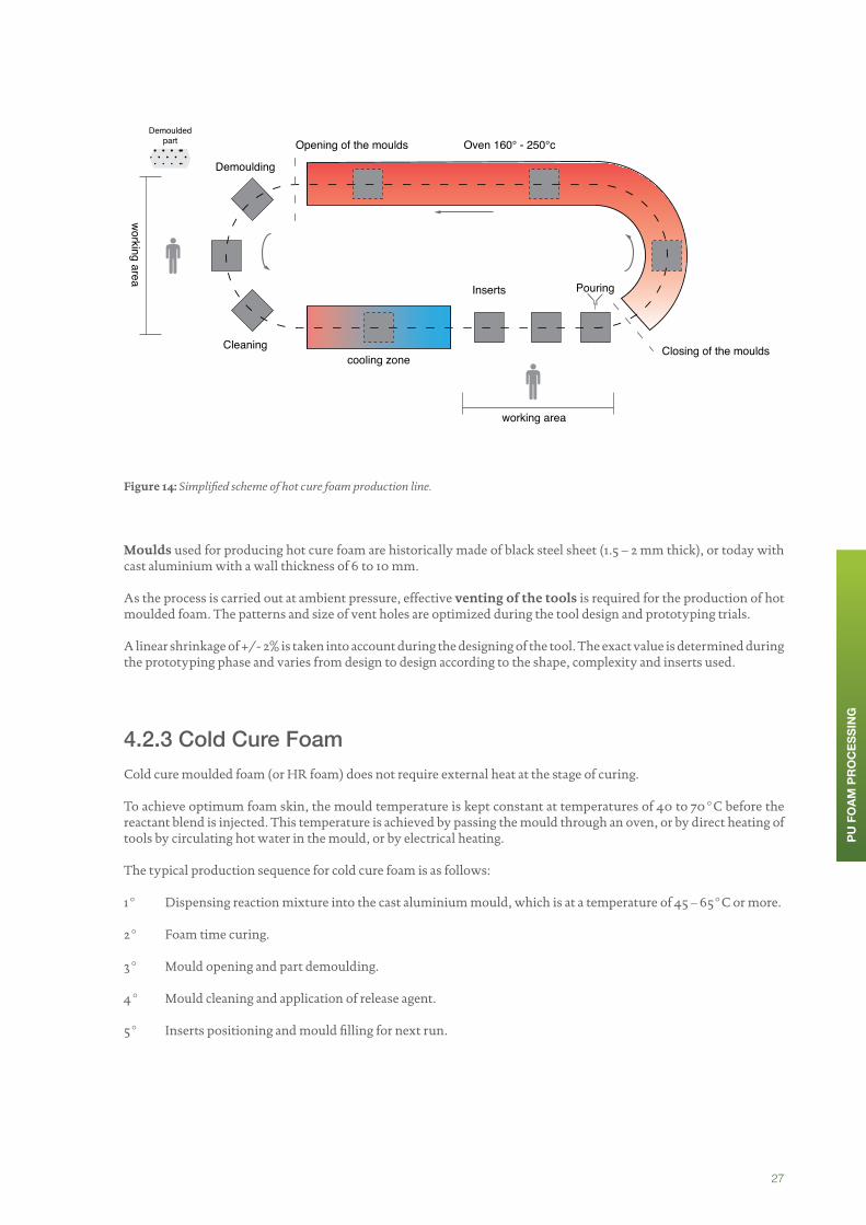
Figure 14: Simplified scheme of hot cure foam production line.
Moulds used for producing hot cure foam are historically made of black steel sheet (1.5 – 2 mm thick), or today with cast aluminium with a wall thickness of 6 to 10 mm.
As the process is carried out at ambient pressure, effective venting of the tools is required for the production of hot moulded foam. The patterns and size of vent holes are optimized during the tool design and prototyping trials.
A linear shrinkage of +/- 2% is taken into account during the designing of the tool. The exact value is determined during the prototyping phase and varies from design to design according to the shape, complexity and inserts used.
4.2.3 Cold Cure FoamCold cure moulded foam (or HR foam) does not require external heat at the stage of curing.
To achieve optimum foam skin, the mould temperature is kept constant at temperatures of 40 to 70°C before the reactant blend is injected. This temperature is achieved by passing the mould through an oven, or by direct heating of tools by circulating hot water in the mould, or by electrical heating.
The typical production sequence for cold cure foam is as follows:
1° Dispensing reaction mixture into the cast aluminium mould, which is at a temperature of 45 – 65°C or more.
2° Foam time curing.
3° Mould opening and part demoulding.
4° Mould cleaning and application of release agent.
5° Inserts positioning and mould filling for next run.
working area
Oven 160° - 250°cOpening of the moulds
Demoulding
Demouldedpart
Cleaning Closing of the moulds
Inserts
working area
cooling zone
Pouring
PU F
OAM
PR
OC
ESSI
NG

28
In contrast to hot foam, cold-cure foam contains some closed-cells that must be “crushed” after demoulding in order for the cellular structure to open in order to avoid shrinkage and to achieve the final physical properties of the foam. This operation can be done on a mechanical crusher (rollers, press, and air injection) or in case the foam contains rigid components such as metal inserts, with a vacuum crushing installation.
Figure 15: Simplified scheme of cold cure foam production line.
Contrary to hot cure foam, moulds used for cold cure foam must be able to sustain a moulding pressure of 1.3 to 2.5 bars. For the stability of the process, the lid of the moulds must resist to pressure and the moulds must be locked mechanically or pneumatically. This does of course have consequences on the cost of such moulds. This is however compensated by the fact that – due to the shorter curing time - cold cure foam requires fewer moulds than hot cure foam for a similar production volume.
4.2.4 Pour in PlaceIn terms of automotive assembly, the trimming operation (consisting of the upholstery of a textile, leather or artificial leather cover with foam) remains a manual or half manual operation. In order to limit manual handling, the “pour in place foaming” technology has been derived from cold cure foaming. Under this production process the foam is injected directly inside a sewn cover, allowing for almost immediate further processing.
A few foaming companies successfully put in place industrial processes to economically master such productions. The most important operation in this process is the adequate placing of the cover within the mould in order to obtain a perfect part. This requires a complete reorganisation of the traditional moulding race-track, and smart mould conception.
T°T°
T°
working area
T° = heating unit (hot water or electrical)
Opening demoulding PouringCleaningInserts Closing
polymerization zone
PU F
OAM
PR
OC
ESSI
NG

29
The figure below provides for a general example of such production.
Figure 16: The pour in place production process.
#14 General layout of a foam in place production
Cover Preparation
Textile boundingwith foam barrier
Elementscutting
Cover sewing
Cleaning, finishingoperations
Eventual postcuring
Packing
PU injectionin the mould
Curing
Mould Closing
Demoulding Vacuum Crushingof parts
Cover positioningon or in the mould
Cover Positioning
Foaming Operation
Finishing
Inserting
metal insert
PU F
OAM
PR
OC
ESSI
NG

30
Critical points for “pour in place” foaming are:
• The covers, which will be filled-up with the reacting blend. They need a special preparation as they must be bounded with a medium which has to be either both permeable to gas and impermeable to the reacting liquid or totally impermeable depending on the technology used.
• The limitations of the process. It is well adapted for closed-cover parts such as headrests or armrests, but is much more difficult to master for half closed-parts (having a face covered and another one not covered). Indeed it is very difficult to combine in the same mould foam production that requires products such as wax for demoulding (for the face not covered) and cover that need to remain spotlessly clean (such as the cover).
• Little room for error. Covers and bounded materials are expensive. There is not much room for error to avoid loss of production. This means that the cover preparation as well its positioning on the mould is critical and requires a lot of attention in order to prevent any wrinkling or other visual defect on the final product and hence loss of production.
PU F
OAM
PR
OC
ESSI
NG

31
The moulded foam production process is perfectly suited to the design requirements of automotive seats. It allows for a high level of freedom in geometric design and provides for flexibility in using different foam qualities and properties to achieve the level of comfort targeted.
“Comfort” is by definition a subjective concept that varies from one individual to the other. It is often defined a contrario by the “absence of discomfort”, which is a definition that is not very helpful when there is a need for making a standardized product in an industrial setting.
Nevertheless, as providing comfort is one of the key features of a car seat, some typical mechanical properties are expected from the foam parts. Mechanical properties to be fulfilled are listed in the specifications of each car manufacturer. They can be requested on complete parts (full design) or on samples cut from foam parts.
Even if the test ‘families’ or types are similar between car manufacturers, each uses a different standard with different testing conditions, sample size, test definition and targets. One foam formulation can then fulfil all the requirements for one seat for one car manufacturer but may not be accepted by others because of testing and target differences.
As for all organic polymeric materials, the properties of PU foam depend on the temperature at the time of measurement, the duration and load of the test and the rate of deformation during the test.
All these parameters are therefore defined in each testing specification. Temperature and humidity are two parameters which must be carefully controlled in the testing laboratories. Testing conditions are usually 23°C +/-2°C and 50% +/- 5% relative humidity.
As for all measured data, all properties which are described in the following pages have tolerances. Several parameters associated with the full foaming process can play a role in the variation of results for a given property. The most important properties where very narrow tolerances are requested are density and hardness. Despite a very careful control of all process parameters, narrowing of product tolerances is sometimes not possible to achieve. Euro-Moulders published a few years ago a full study on hardness tolerance. This study is available upon request.
CHAPTER 5: MOULDED POLYURETHANE FOAM PROPERTIES

32
5.1 Mechanical Foam Properties
5.1.1 Foam densityDensity and apparent density – Core density/global density
Density is a property which is particularly suitable for the characterization of a material, because it is neither dependent on the shape of the part tested, nor on the test method used.
With expanded materials, the term “apparent density” refers to the fact that the entire volume of the test piece is taken into account, and not only the much smaller volume actually taken up by the mass of the polymer.
Density ranges are different depending on the technology which is used for producing the foam part (see below).
Figure 17: Typical density ranges according to production technology used.
Density range for a given formulation and a given technology depends on the water level of the formulation (water is changed into CO2 which expands PU material). The choice of density will then have an impact on the choice of formulation and on all other mechanical properties
Core density is measured on a cut sample and global density is basically the total foam weight divided by the mould/part volume. Core density values are lower than global density values.
5.1.2 Hardness and support factorThere are two options for testing PU parts: destructive and non-destructive tests.
Material parameters which are not affected by part geometry such as Core Density and Compression Load Deflection Test (CLD) are destructive tests. Testing, which depends on part geometry such as Indentation Load Deflection (ILD) and height loss in durability testing are non-destructive tests. This means that tests relevant to the polymer material alone can only be provided by destructive testing.
Compression Load Deflection test:
This test is made on cut samples and provides an indication of material hardness. Under this test, the test specimen is held in between two parallel plates with a larger area than the specimen, and the force necessary to compress it at a constant deformation rate is determined. Diagrams of test results (in the form of compression hardness curves) provide reliable information on the behaviour of the foam during load application and removal. They allow for making a very clear distinction between different types of foam.
Density g/l (grammes/litre)
Hot Cure
TDI Cold Cure
MDI Cold Cure
25 30 35 40 45 50 55 60 65 70 75 80 85
MO
ULD
ED P
OLY
UR
ETH
ANE
FOAM
PR
OPE
RTIE
S

33
Picture 4: Compression load deflection test. Credit: Johnson Controls International.
Figure 18: Example of compression hardness curves.
loading
return(unloading)
return25% value
original25% value
σ 40%
100%65%50%
Compression Strain ε
40%25%
CompressionStress σ
MO
ULD
ED P
OLY
UR
ETH
ANE
FOAM
PR
OPE
RTIE
S

34
The CFD (Compression Force Deflection) is the load-bearing ability of the foam tested under values of 25%, 40%, 50% and / or 65% of deformation at a given cycle (can be 2nd, 3rd, 4th or 5th cycle depending on the testing specification).
Indentation Load Deflection test
This test is performed directly on the pads and usually part of the production quality control. The indentation test is quite different from the compression test, because the test specimen is compressed by an indentor (generally 323 cm2) only over a portion of its surface. The forces necessary to produce indentations to certain distances are represented by force-deformation diagrams, as for CFD.
The foam surface is usually perpendicular to the testing axis and a special hardness jig must be used to support the part under the testing area. As each foam pad has a different design, hardness jigs must be built for all parts. The test cannot be performed without them.
ILD values cannot be compared between each other. They are not only linked with PU material hardness, but also to part thickness, design under the testing area and testing specification.
The IFD (Indentation Force Deflection) is the load leading to a particular degree of deformation (25%, 40%, 65%) at a given cycle and taken as characteristic values. IFD was formally known as ILD (Indentation Load Deflection).
Sag factor
The sag factor is the ratio of 65% IFD to 25% IFD and gives an indication of cushioning quality. A high value indicates resistance to bottoming out. Foams with low sag factors will often “bottom out” and give inferior performance over time.
Hysteresis
Hysteresis is the measure of the energy lost or absorbed by a foam when subjected to deflection. It is quantified as the difference between the area under the stress-strain curve as a load is applied and when it is released.
Hysteresis can be calculated from stress/strain curves on samples (CLD) or on pads (ILD). Values can only be compared if same testing method is used. The value of Hysteresis is given as the percentage difference between the area below the stress and strain curve on loading and unloading.
Resilience (or ball rebound) test
In this test, a steel ball of a specified mass is dropped from a fixed height onto the foam sample and the ball rebound is recorded. The rebound height is divided by the original height and expressed as “percent resilience”.
MO
ULD
ED P
OLY
UR
ETH
ANE
FOAM
PR
OPE
RTIE
S
Picture 5: Indentation load deflection test. Credit: Johnson Controls International.
Picture 6: Ball rebound test. Credit: Johnson Controls International.

35
5.1.3 Tensile strength, Elongation, Tear strength
Tensile tests:
Using a predominantly uniaxial load, and a constant rate of deformation, the relationship between force and deformation is determined until failure occurs. The force-deformation diagram obtained is converted into a stress-stain diagram in order to make comparisons between test specimens of different cross selections. In each case the tensile force is related to the initial cross section of the specimen, in order to obtain the tensile stresses. The elongation is obtained from the change in length in relation to the original length. The rupture stress and associated elongation at break are derived as characteristic values from the stress-strain diagrams.
Figure 19: Example of stress-strain diagramme.
MO
ULD
ED P
OLY
UR
ETH
ANE
FOAM
PR
OPE
RTIE
S
Picture 7: PU foam part for tensile test.

36
Tear resistance:
In addition to the tensile test; flexible PU foam can also be subject to a test that determines the resistance to tear propagation of a cut specimen. Specially shaped test specimens are used for this purpose.
Tear Strength results obtained from TDI foams or MDI foams are not in the same range. MDI foams are known to give lower tear strength values.
This property is usually linked with the metal wire pull out force property (force to pull out a metal insert from the foam part) which is of importance when trimming the seats. Metal wires design must be adapted to the part design to avoid any part deterioration during trimming. High or low foam tear strength values are not directly linked with such trimming performances.
Tear strength property is also sometimes linked with complete seat ingress / egress test. There is nevertheless no clear correlation between this property and ingress / egress results (linked with complete seat design)
Picture 8: Tear resistance test. Credit: Johnson Controls International.
5.1.4 Long term tests using a static loadCompression Set:
With flexible PU foams, the permanent deformation after constant deformation at a constant temperature (normally 70°C) and during a defined time (normally 22 hours) is determine as the compression set. Compression set is most commonly expressed as a percentage of initial compression.
Creep tests:
Some properties of polymers may alter over time. The creep tests allows the measurement of the degree of compression or height loss that occurs when a flexible foam cushioning material is subjected to a static load over a defined time period at constant atmospheric conditions (in particular temperature).
5.1.5 Long term tests with dynamic load
Foam parts or samples are subjected to some fatigue tests.
Foam samples are compressed between 2 metal plates at a given frequency (generally between 1 and 3 Hz) for a given number of cycles. Material properties are measured on the samples before and after the fatigue test and compared. Car manufacturer specifications provide targets for property loss after fatigue.
Fatigue tests can also be performed on a complete part (on the corresponding hardness fixture) or on square foam blocks. In that case, one indenter is used to compress the foam surface to a given compression depth (or load value) and at a given frequency.
This test can be performed under a normal climate atmosphere (23°C, 50% relative humidity) but some specifications require fatigue test to be conducted under tropical climate conditions (40°C; 80% relative humidity)
MO
ULD
ED P
OLY
UR
ETH
ANE
FOAM
PR
OPE
RTIE
S

37
5.1.6 Flex fatigueFlex fatigue is the loss of physical properties of a foam undergoing continuous flexing of a specified magnitude, duration and rate. The most noticeable problem which can occur is the softening of cushions.
5.1.7 Vibration dampeningAs comfort improvement is one of the key reasons for selecting a foam type, some tests have also been developed in order to check the dampening properties of PU materials. Such tests can help to predict in-vehicle vibration performance.
Foam blocks or parts (on top of corresponding gage) sit on a base plate mounted to a unidirectional shaker and a mass is placed on top of the foam. Accelerometers monitor movements of both mass and base plate. Input and response acceleration are analyzed over a given range of frequency and data are reported as a transmissibility curve.
Figure 20: Scheme of vibration dampening test. Source: Johnson Controls International.
Figure 21: Example of transmissibility curve
Outputaccelerationmeasured byaccelerometer (A)
Vibrate atknownfrequency
Foam
Input acceleration(AD)
MO
ULD
ED P
OLY
UR
ETH
ANE
FOAM
PR
OPE
RTIE
SAmplitude of resonance frequency
Resonance Frequency
Damping Frequency

38
5.1.8 AgeingIn order to simulate the ageing process of plastic materials, a time/temperature superposition principle is usually used. According to this principle, the degradation processes which may occur over a long period of time at a low temperature may be simulated at a higher temperature over a shorter period of time.
Car manufacturer try to simulate the possible ageing of PU foam material over the full life of the vehicle with the use of special ageing tests which are performed on the foam after production. Different ageing conditions are requested; from average to high temperature. Some ageing is also performed in a humid atmosphere. An extensive work was also published by Euro-Moulders on the PU foam time/temperature superposition principle. A summary of this study can be found in [Kunstoffe in 8/2012] and some information can be given by the association upon request.
As already discussed for fatigue tests on samples, limits are generally given by car manufacturers for some mechanical property losses. These limits (targets) have been defined some years ago and might not be aligned to the technology evolutions of recent years.
The introduction of low emission requirements is one of the typical examples of the contradiction between new requirements and material technical limitations. The use of dedicated catalysts to be able to fulfil low emission requirements is strongly impacting the results of mechanical properties after ageing, making it impossible in some cases to fulfil historical specifications.
5.1.9 Interactions between different mechanical propertiesIt is very important to take in to consideration that all mechanical properties are linked together. The change of one property in one given direction will likely have an impact (favourable or unfavourable) on the rest of the foam properties.
Compromises need to be made by foam producers in order to fulfil all the requested properties.
Figure 22: Variation of properties after ageing with water level.
When a dedicated formulation is used to improve a given property, it could have a side effect on another property also requested by the same specification.
For example, Compression Set after humid ageing can generally be improved with formulations with a lower water level. This new lower water level is likely to have a negative impact on the CLD hardness loss result after humid ageing.
Variation of properties after aging with water level
Compression Set
CLD loss
Low Water High WaterMO
ULD
ED P
OLY
UR
ETH
ANE
FOAM
PR
OPE
RTIE
S
39
5.2 Emissions
Growing concerns about emanations from plastics were the reasons for many changes over the last 10 years. Legal requirements, health concerns, customer expectations and wishes from the global automotive industry to provide ever safer products drove the development of new analytical methods and the introduction of emission standards by automotive manufacturers.
A lot of different standards have been implemented in the last 10 years with, as for mechanical properties, tests based on material samples and on full parts. Targets defined by each car manufacturer based on its expectations and model calculation for the total car cell emission have slowly evolved into very stringent specifications.
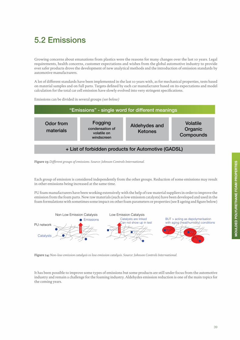
Emissions can be divided in several groups (see below)
Figure 23: Different groups of emissions. Source: Johnson Controls International.
Each group of emission is considered independently from the other groups. Reduction of some emissions may result in other emissions being increased at the same time.
PU foam manufacturers have been working extensively with the help of raw material suppliers in order to improve the emission from the foam parts. New raw materials (such as low emission catalysts) have been developed and used in the foam formulations with sometimes some impact on other foam parameters or properties (see $ ageing and figure below)
Figure 24: Non-low emission catalysis vs low emission catalysis. Source: Johnson Controls International.
It has been possible to improve some types of emissions but some products are still under focus from the automotive industry and remain a challenge for the foaming industry. Aldehydes emission reduction is one of the main topics for the coming years.
PU network
Catalysts
Non Low Emission CatalysisEmissions
Hea
t
Low Emission CatalysisCatalysts are linkedCan not show up in test
Hea
t
BUT > acting as depolymerisationwith aging (heat/humidity) conditions
MO
ULD
ED P
OLY
UR
ETH
ANE
FOAM
PR
OPE
RTIE
S
“Emissions” - single word for different meanings
Odor frommaterials
+ List of forbidden products for Automotive (GADSL)
Aldehydes and Ketones
Volatile Organic
Compounds
Foggingcondensation of
volatile on windscreen

40
Challenges of Emission Reduction in Polyurethane Foams
emissive low-emissive
Mechanical properties ++ +/0
Ageing properties + 0/-
Humid ageing properties + 0/-
Productivity/Cycle Times ++ +/0
Cost of formulation + 0
Emission (VOC) 0 +
Figure 25: Challenges of emission reduction in flexible polyurethane foams. Non-low emission vs low emission.
Fogging
Every driver has experienced the fogging phenomenon and the car manufacturers have become very concerned about its effect on driver visibility.
Fogging is defined as the undesirable deposit of a light-scattering film on the wind-screen interior surface of the vehicle. The mechanism of this film formation involves continuous condensation of volatile compounds contained in many of the components inside the vehicle. High temperature in the vehicle interior drives and accelerates this phenomenon.
Sampling and analyses of this film have shown that some of its constituting molecules can be originating from PU foam, notably:
• Surfactants;
• Catalysts;
• Flame retardants;
• Antioxidants;
• Pigment carriers;
• Etc...
MO
ULD
ED P
OLY
UR
ETH
ANE
FOAM
PR
OPE
RTIE
S
41
5.3 Flammability
Low flammability is one of the properties requested in all foam specifications. This property is linked with country regulations. The usual limit requested for foam flammability is 100 mm/min but some customers request even lower limits.
PU foam burning behaviour is strongly linked with foam densities. At lower density, burning speed will generally be higher than for foams with higher density. Additives such as fire-retardant can be added to the formulations to reduce flammability speed. Such substances must be carefully chosen as they are may contribute to some types of emission.
5.4 Further Considerations
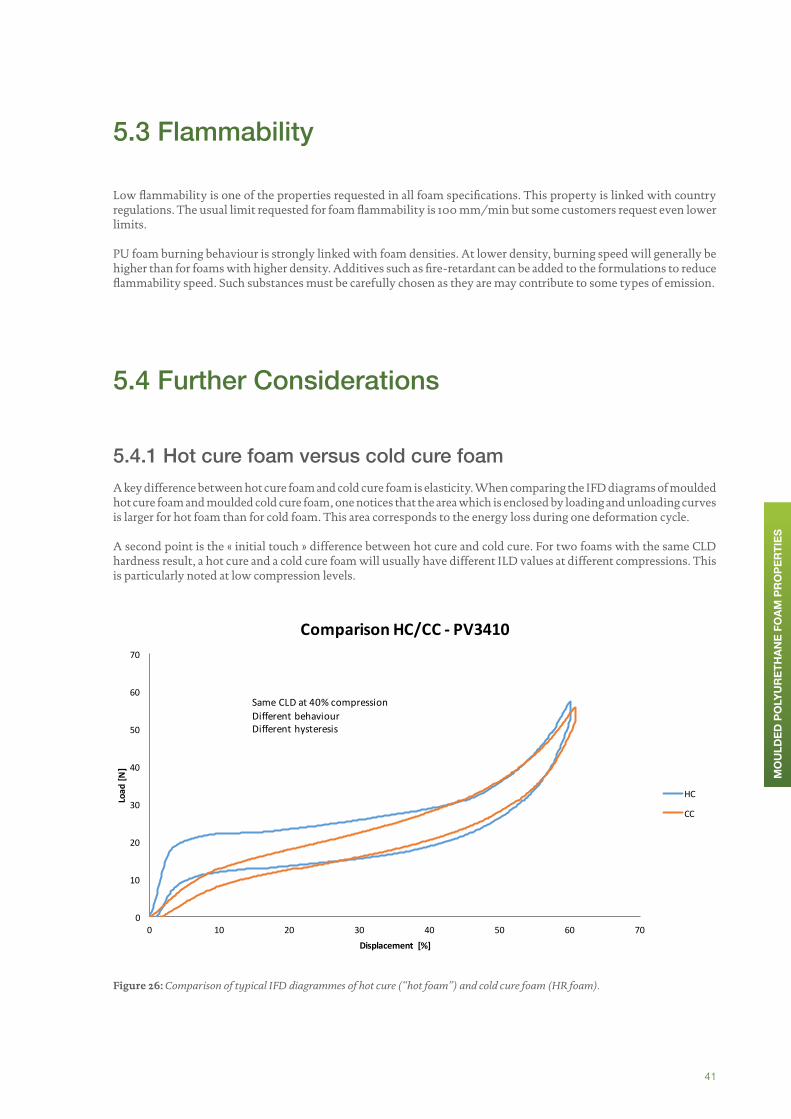
5.4.1 Hot cure foam versus cold cure foamA key difference between hot cure foam and cold cure foam is elasticity. When comparing the IFD diagrams of moulded hot cure foam and moulded cold cure foam, one notices that the area which is enclosed by loading and unloading curves is larger for hot foam than for cold foam. This area corresponds to the energy loss during one deformation cycle.
A second point is the « initial touch » difference between hot cure and cold cure. For two foams with the same CLD hardness result, a hot cure and a cold cure foam will usually have different ILD values at different compressions. This is particularly noted at low compression levels.
Figure 26: Comparison of typical IFD diagrammes of hot cure (“hot foam”) and cold cure foam (HR foam).
MO
ULD
ED P
OLY
UR
ETH
ANE
FOAM
PR
OPE
RTIE
S
0
10
20
30
40
50
60
70
0 10 20 30 40 50 60 70
Load[N]
Displacement [%]
ComparisonHC/CC- PV3410
HC
CC
SameCLDat40%compressionDifferentbehaviourDifferenthysteresis

42
5.4.2 Dual hardness cushionsIn order to increase the comfort performance of seat cushions, dual or multi-hardness foams have been developed both in hot foam and in cold cure foam.
Sitting pressures vary across the surface of a seat, and ergonomic specialists have found that dual or multi-hardness foam technology gives them a way to tailor the load-bearing strength in areas needing more or less support and an ideal body pressure mapping (ergonomics, blood pressure, etc.). In addition, a large degree of side support or bolster, holds the driver and passengers in place while the car is turning.
Traditionally, localized support was accomplished by embedding a heavy wire frame in the seat cushion. This technique involved the manual placement of a wire prior to foaming and a host of hidden costs associated with producing, shipping, storing and handling a wide variety of wire-insert designs. Hard PU inserts can also be added to the foam parts to increase rigidity in bolster areas.
Figure 27 and 28: Dual hardness cushions
In the dual hardness technology, both hard and soft foam are dispensed into the mould in such a way that a layer of soft foam is bordered on its sides by hard foam.
Dual-hardness technology is in production today globally and is expected to grow as requirements on design, cost and processing become more stringent. That means that foaming equipment will need to be properly designed and engineered to offer the capability of producing dual or multi-hardness pads under suitable conditions.
Picture 9: CAD visualisation of Front Seat Cushion dual Hardness, rigid side bolster Area (Blue). Credit: F.S Fehrer Automotive.
MO
ULD
ED P
OLY
UR
ETH
ANE
FOAM
PR
OPE
RTIE
S
MonoHardness Foam
HeavyWire insert
softerFoam
harder Foam
Unpredictable areas of hardness,dueto lackof physical separation

43
From the chemical side, it is possible to produce very soft and very hard foam. The gap soft/hard inside a part is nevertheless limited by several parameters such as notably density, part design and bolster/main panel physical separation.
When the part is not properly designed for dual hardness, the risk of penetration of one foam type (hard for example) into other foam type (soft) is increased. Areas of overlapping hardness are usually described on the part drawings and must be studied case by case because of the design. A completely separated situation between Hard and Soft area can only be achieved by combining separate parts.
As the dual hardness foams are produced by pouring pattern with several distinct injections, formulations must be carefully selected to avoid collapse between hard and soft areas when foam types are entering in to contact.
Picture 10: Slice of complex front seat back, rigid zone coloured for visualization purposes only. Credit: F.S. Fehrer Automotive
MO
ULD
ED P
OLY
UR
ETH
ANE
FOAM
PR
OPE
RTIE
S

44
The layout of PU foam production plants can be determined by pre-existing factors such as existing buildings or the property on which it is built. In this example, we describe a plant build under the best conditions, meaning in a building especially designed for hosting the plant, without limiting external factors.
As outlined in preceding chapters, a PU foam plant is composed of a wet-side, with requirements similar to those seen in process-based industries handling raw materials, and a dry-side more resembling a manufacturing industry producing semi-finished or finished products. This cohabitation on the same site requires a specific organization.
CHAPTER 6: THE ORGANISATION OF A MOULDED PU FOAM PRODUCTION PLANT

45
Production Line
Figure 29: Typical wet-side of a flexible moulded polyurethane foam plant
1. The delivery of raw materials takes place with tank trucks in a special unloading area equipped with a retaining a sump to contain any spill of material during the discharging operation. Raw materials are transferred to the raw material storage by volumetric pumps in a closed system.
2. Raw materials are stored in a tank farm properly isolated from the exterior as well as from the production area. All the tanks are equipped with recirculation pipes, temperature control and eventually liquid stirring equipment. Each tank is installed on a retention bay to collect material in case of tank leakage.
12
3 4
5
6
7 8
11
910
demoulding
Tank truck
Poly I Poly II ISO
ISODayTanksblender
Premix 1
Premix 2
exhaust
reactive blend
inserts
loadsensor
loadsensor
pouring
Transfer Pump
Hight Pressure Metering Pump
Metering Pump
moulds
foaming line
mixing head
additives
activatorwater
catalist stabilizer ...
foam parts
OR
GAN
ISAT
ION
OF
MO
ULD
ED P
U P
LAN
T

46
3. The other liquid raw material such as activators, catalysts and pigments are delivered in drums stored in an adapted warehouse.
4. Water is generally supplied from the local water network with filtering where necessary.
5. Transfer pumps convey raw materials to the batch mixer where they are pre-mixed as needed for the production of the parts fulfilling the customers’ specifications, then they are transferred to “day tanks” generally in the production area. All these day tanks are equipped with temperature monitoring and stirring systems to prevent any stratification of the preparation. These “day tanks” are generally located close to the production line to prevent long distance transfer to the production line.
6. High pressure metering pumps feeding the mixing head are fed from the day tanks. These pumps are frequently installed on a platform just above the robots holding the mixing head. Heat exchangers assuring control and adjustment of temperature are also located on the same platform, close to these pumps. The hydraulic groups commanding the mixing head valves opening and closing are also located on the same platform.
7. The mixing head on which high pressure hoses are fixed is placed on the head of a multi-axes (generally 6) robot. This robot transfers the reactive mixture into the mould via the mixing head according to a predefined pouring pattern. In between two pouring operations the mixing head is moved away from the pouring area.
8. After pouring, the mould is closed and maintained as such during the time required for polymerization. When the process is complete and the foam cured, the mould can be opened and the part demoulded (extracted from the mould).
9. After the foam has been removed, the mould is cleaned of remaining residues. Before the next filling operation the mould is coated with release agent sprayed from a multi-axes robot.
10. Before a new injection, the inserts required for the next cushion to be produced are placed into the mould (usually manually).
11. In the working area, special extraction systems ensure a safe working environment for workers.
Quality control laboratories and a tool workshop are usually located close to the production line.
Post Operation
Demoulding is not the end of moulded foam production but just the start of a new process. This part of a plant is very much depending on the type of parts being produced and on logistics offered or required by the customer.
Some parts only need small rework to remove remaining flashes from foam production. Other parts require more reworking (notably complex shapes), post-treatment (for example for surface treatment), or completion / assembly in the case of parts that need to be assembled together or that need to be added to other components.
12. After demoulding the parts are placed on conveyors and sent to crushing systems. Mechanical systems are used for parts that are not too fragile and do not have heavy inserts and vacuum systems are used for other parts.
13. The quality and aspect of parts is controlled immediately after demoulding and crushing. The quality control determines the further flow of the parts: continuation in the process for parts that pass the control, repair for parts that require small intervention or scrap for parts that cannot be repaired.
14. Parts that are in line with requirements can be directly sent to the packing and storage area.
15. Scraps are sent to a waste area for recycling.
OR
GAN
ISAT
ION
OF
MO
ULD
ED P
U P
LAN
T

47
Figure 30: Typical dry-side of a flexible moulded polyurethane foam plant
16. Depending on whether complex or simple parts are being produced two flows and two rework systems can be installed.
A. For simple parts, the repairs can be done on stream on a conveyor belt with light pneumatic or electric scissors for flashes cutting or gluing pistols to repair small tears.
B. For complex parts - it is necessary to rework them in a specially equipped station with suitable cutting tools and gluing equipment or even small foaming systems.
C. In case of surface treatment like anti-noise coating it is necessary to organize a special station dedicated to this operation.
12 13
14
15
16
17
14A
14B
14C
Parts post treatmentglueing ●
assembly ●surface treatment ●
#20,2 Moulded Foam production LayoutDry end
Crushing %
Reworks and repairs
Scraps
RepairsStations
Repairs
Packing
Trimming and Rework
Repair
Warehousestorage
Truck loading
Delivery
Rework
On beltrepairing Parts first time
OK
Complex PartsSimple Parts
Inspectionand display
FinalControl
OR
GAN
ISAT
ION
OF
MO
ULD
ED P
U P
LAN
T

48
We have to note that all these operations represent a break in the production flow so have a negative effect on productivity.
17. In order to control the result of these operations it is necessary to perform a new quality control check to validate any modifications.
18. Subsequently the parts can be packed according to customer specifications and stored in the warehouse.
19. Depending on the planning of delivery to the customer the parts are shipped from the warehouse.
Figure 31: Control parameters in flexible moulded polyurethane foam production
#24
Control Parameters in PU foam production
Machine
Mixing head
Product
Environment
MouldDispensed product
Raw Materials
Isocyanate Polyol Additive
Atmosphericpressure
HumidityTemperature
Manufactoring
Thickness Design
material
position
pouring pattern
temperature
sealing
venting
position
foam expantion
pressure flowtemperaturepressure flowtemperature
Blenol
OR
GAN
ISAT
ION
OF
MO
ULD
ED P
U P
LAN
T

49
List of Figures and Pictures
Figures
1. Automotive Cushioning Through the Ages 6
2. Formation of Polyurethane in moulds (reactor) 11
3. An idealized polyurethane foam cell 12
4. Simplified basic reactions of polyurethane formation 13
5. Polyurethane formation 14
6. Toluene Diisocyanate 15
7. Methylene Dyphenyl Diisocyanate 15
8. Reaction between isocyanates and water forming primary amines, CO2 and urea 16
9. Polyurethane structure, simplified 17
10. 3-D presentation of a system for continuous production of flexible rectangular foam 20 blocks by means of the QFM process
11. The Maxfoam production process 20
12. Scheme of flexible moulded foam production line 23
13. Typical wet-site of a moulded foam production plant 24
14. Simplified scheme of hot cure foam production line 27
15. Simplified scheme of cold cure foam production line 28
16. The pour-in-place production process 29
17. Typical density ranges according to production technology used 32
18. Example of compression hardness curves 33
19. Example of stress-strain diagramme 35
20. Scheme of vibration dampening test 37
21. Example of transmissibility curve 37
22. Variation of properties after ageing with water level 38
23. Different groups of emissions 39
24. Non-low emission catalysis vs low emission catalysis 39
25. Challenges of emission reduction in flexible polyurethane foams 40
26. Comparison of typical IFD diagrammes of hot cure and cold cure foam 41
27. Dual hardness cushion 42
LIST
OF
FIG
UR
ES A
ND
PIC
TUR
ES

50
28. Dual hardness cushion 42
29. Typical wet-side of a flexible moulded polyurethane foam plant 45
30. Typical dry-side of a flexible moulded polyurethane foam plant 47
31. Control parameters in flexible moulded polyurethane foam production 48
Pictures
1. Micro-photo of PU flexible foam cells 12
2. Seat cushion assembly with slabstock foam 21
3. Hot cure mould with “mushrooms” coming out of vents 26
4. Compression load deflection test 33
5. Indentation load deflection test 34
6. Ball rebound test 34
7. PU foam part for tensile test 35
8. Tear resistence test 36
9. CAD visualization of front seat dual hardness cushion, rigid side bolster area 42
10. Slice of complex front seat back, rigid zone coloured for visualization purposes only 43
Glossary
A-side (or A-surface):
For parts used for automotive seating this is the side that will be facing the user. More generally, it is the surface of a moulded polyurethane foam part that was in contact with the mould bottom or the lower mould during production. The surface of this part can be of better visual quality, compared to the “B-side” due to process requirements. Not to be misunderstood with the North American meaning of the term, where “A-side” means “isocyanate containing material” in PU foam production.
Apparent density:
The ratio of mass per unit volume (or the weight per unit volume) of a material, including the voids which are inherent in the material and also included the densification in surface areas.
LIST
OF
FIG
UR
ES A
ND
PIC
TUR
ES

51
B-side:
The surface of a moulded polyurethane foam part that was in contact with the mould top or the upper mould during production. For parts means for automotive seating this is the side that will be facing the seat structure. Not to be misunderstood with the North American meaning of the term, where “B-side” means “polyol containing material” in PU foam production
Blowing agent:
A substance which is capable of producing a cellular structure via a foaming process in a variety of materials that undergo hardening or phase transition, such as polymers, plastics, and metals. Flexible PU foam is expanded by CO2 resulting from the reaction between the isocyanate used and water.
Cold cure foam:
The phrase Cold Cure Foam is used as a synonym to “high resilient Foam” (HR-Foam). The usage of high reactive polyols leads to the processing option of significantly reduced mould temperatures (approx.. 50-70°C). The phrase „cold cure foam“ indicates a direct link to the quality of used raw materials and technology of processing. Cold cure foam is the dominant production process in moulded foaming worldwide today.
Crushing:
The production process of cold cure foam results in foams with closed cell walls. To achieve the excellent elasticity and the final physical properties of the foam these cell walls must be broken in order to allow air to enter and exit the foam easily. This is also essential to avoid shrinkage of the foam after demoulding. This operation can be done on a mechanical crusher (rollers, press, and air injection) or in case the foam contains rigid components such as metal inserts, with a vacuum crushing installation.
Dry-side:
The side of a polyurethane foam production plant which handles the (semi) finished foam parts after demoulding, after the chemical reactions have taken place.
Elasticity:
The property of polyurethane foam (or any solid material) to return to its original shape and size after the forces deforming it have been removed.
Extruding / Extrusion:
Manufacturing process in which a softened blank of a metal or plastic material is forced through a shaped metal piece or die to produce a continuous ribbon of the formed product.
Flammability resistance:
Low flammability is one of the properties requested in all foam specifications. This property is linked with country regulations and with the intended use of the materials. The common limit requested for foam flammability in passenger cars is 100 mm/min under specified test conditions, but some customers request even lower limits.
GLO
SSAR
Y

52
Hardness:
The hardness of polyurethane foam is the ability of a foam to push back against a given load. The ideal cushion hardness allows the user to immerse into the cushion, allowing pressure to be redistributed over a greater surface area, without ‘bottoming out’ (squashing the foam flat).
High Resilience Foam (HR-Foam):
see cold cure foam.
Hot cure foam:
Also simply called “hot foam”. The raw materials used for hot cure foam production are low to medium reactive and require elevated temperatures to finalise the polymer-reaction. In contrast to the cold cure process, the cell opening of the foam is conducted during the reaction phase itself, so no external crushing is needed. The hot cure process is a pressureless foaming process. The foam is rising until reaching mould lid and filling all cavities. It is produced at much higher temperatures than cold cure foam.
MDI:
Methylene Diphenyl Diisocyanate. See section 3.4.1 for details.
Moulded Foam:
Flexible polyurethane foam produced in moulds for (complex) parts. Please see 4.2 for details.
Mechanical strength:
The ability to withstand the stress of physical forces without deformation or breaking.
Polyisocyanate:
Compound containing multiple isocyanate functional groups (NCO).
Polyol:
Compounds with multiple hydroxyl functional groups available for chemical reactions. Polyols used for flexible polyurethane foam production for automotive seating are usually polyether polyols.
Polymer:
A chemical compound that is made of small molecules that are arranged in a simple repeating structure to form a larger molecule.
GLO
SSAR
Y
53
Release agent:
Chemical used to prevent other materials from bonding to surfaces. In moulded PU foam production release agents are used to prevent the foam from sticking to the surface of the mould.
Resilience:
Ability of a material to absorb energy when it is deformed elastically, and release that energy upon unloading.
Slabstock Foam:
Flexible polyurethane foam produced in a continuous or semi-continuous process. Foam blocks produced according to this process can be of up to 120m long and pieces required need to be cut to shape. Please see 4.1 for details.
Shrinkage:
Flexible polyurethane foam will shrink as it cools. This is why a linear shrinkage of +/- 2% is taken into account during tool design. It is specific to hot cure and cold cure and it is influenced by part and insert geometry. The shrinkage must be fixed individually for each designed part.
TDI:
Toluene Diisocyanate. Please see 3.4.1 for details.
Thermoplastic:
Plastic material (polymer), that becomes pliable or moldable above a specific temperature and solidifies upon cooling without any change to inherent properties.
Thermoset:
Thermoset plastics contain polymers that cross-link together during the curing process to form an irreversible chemical bond. Thermosets cannot be transformed by heating or melting without destroying the polymer matrix. As a consequence they can only be moulded insitu.
Vents:
An opening permitting the escape of fumes, gas or steam.
Wet-side:
The wet-side of a polyurethane foam production plant is the part of the line where chemicals are handled, from raw material storage to the mixing head. In this part of the plant specific precautions linked to the properties of the raw materials used apply.
GLO
SSAR
Y


www.euromoulders.org
EUROMOULDERS
EUROMOULDERS
GETTING TO UNDERSTANDMOULDED POLYURETHANE FOAM FOR AUTOMOTIVE SEATING
EURO MOULDERSAvenue de Cortenbergh 71 B-1000 Brussels Belgium
www.euromoulders.org
Copyright © 2022 FDOKUMEN