MVP & MVP HYDRA
50
1 5610 4th Ave S. / Seale, WA 98108—USA Tel: +1 206 764 0600 / Fax: +1 206 764 0601 Ordering Parts: [email protected] Informaon: [email protected] www.synesso.com MVP & MVP HYDRA OWNER’S MANUAL VERSION 2020.1 3 Group MVP Last update: September 2020
-
Upload
khangminh22 -
Category
Documents
-
view
1 -
download
0
Transcript of MVP & MVP HYDRA

1
5610 4th Ave S. / Seattle, WA 98108—USA
Tel: +1 206 764 0600 / Fax: +1 206 764 0601
Ordering Parts: [email protected]
Information: [email protected]
www.synesso.com
MVP & MVP HYDRA
OWNER’S MANUAL VERSION 2020.1
3 Group MVP
Last update: September 2020

2
TABLE OF CONTENTS
Introduction 3
Safety Warnings 4 -5
Start Up Screen, Serial #, Software Ver. 6
List of Tools and Supplies 6
Warranty & Water Standards 7-8
Plumbing Requirements 9
Electrical Requirements 10
Installation 11-12
Model Specific Installation 13-15
Side Panel Removal 16
Start Up 17-18
4 Stage Pressure Ramping Setup 19
Operation 20-24
Programming - Handheld Controller 25-38
Menu Level 1 - Operations 25-29
Factory Settings 26
Brew Temperature & Brew Settings 26-27
Steam Temperature Control 27
Hot Water Tap 28
Auto Backflushing Machine 28
Error Codes 29
Menu Level 2 - Settings 30-37
Access Menu Level 2 30
Save Lockout 30
Programs, Activate/Deactivate 30
Temperature, Fahrenheit & Celsius 31
Line Pressure Boost System 31-32
Brew & Steam Offsets 32-33
Flowmeter Calibration 33
System Clock 34
Heating Elements, Activate/Deactivate 34
Power Save Mode 35
Error Log 36-37
Return to Operations (Level 1 Menu) 37
Firmware Updates 38
Maintenance 39-42
Daily Cleaning 39
Maintenance Schedule 40
Quarterly Preventative Maintenance 41
Annual Preventative Maintenance Sheet 42
Flowmeter Calibration Instructions 43
Troubleshooting Guide 44-50
3
Please WRITE your Serial Number & Offset Infor-mation here. This can be found on the 2nd & 3rd Menu Levels of the Display Controller. Have this available BEFORE calling for service or technical support.
S/N: ________________________________
The offsets for this machine are:
BG1: _____°F / BG2:_____°F / BG3:_____°F
Steam Tank:_____°F
Factory Contract Information:
Synesso™ Inc.
5610 4th Ave South
Seattle, WA 98108 - USA
Tel: +1.206.764.0600 / Fax: +1.206.764.0601
E-mail: [email protected]
Web: www.synesso.com
Twitter: @SynessoFactory
Instagram: Synesso_factory
INTRODUCTION
Congratulations on the purchase of your Synesso™ espresso machine. Please read this Owner’s Manual and
retain it in a safe location for future reference. If you have any questions about your machine, please con-
tact Synesso™ and our knowledgeable staff will assist you
Included in the package with this machine you will find the following:
• Thumb Drive containing the Owner’s Manual, MVP Series Video and other technical documents
• Pump/Motor Combination + hoses (3/8” compression fittings on all hoses)
• 8’ Flexible ¾” ID drain hose + hose clamp (attached)
• Fitting, 1/4” male NPT x 90° x 3/8” Compression (if not CE)
• Accessory Package: Portafilters (per customer specification), blind basket, Synesso™ 3 oz. (90ml) shot
glass, 4oz jar cleaning detergent, 58.4mm tamper, 4 rubber leg pads
• Electrical plugs are ONLY included on CSA Certified machines (Canada). For all other machines, the
owner of the machine must purchase an appropriate plug end for their machine. Please see the elec-
trical requirements starting on page 10 for more information.
Serial Number
Your espresso machine has a unique serial number, located on the left inner frame of the machine, just
under the drain tray on a serial plate. The number can also be read on the display during start-up. Please
have this serial number available for reference when contacting the factory.
This manual applies to Synesso™ models: MVP and MVP Hydra machines. The MVP machines can be con-
figured to operate any group head as manual, manual with a program and full volumetric with a program
that includes adjustable total water volume. The MVP Hydra machines have an individual pump and mo-
tor per group head and come standard with bypass hardware and a pressure regulator to create 4 stage
pressure ramping.

4
The conductors of the power supply cord are
marked “L1”, “L2” for the ungrounded (“hot”)
supply conductors and “G” for an equipment
grounding lead.
Warning: Risk of Fire. Use UL Listed Grounding
Type Plug rate for 220 Volts, ______ Amperes,
_______ Phase, #______ Wire. Plug to be Selected
and Installed only by Qualified Service Personnel.
Electrical
WARNING: Disconnect from power supply before servicing
AVERTISSEMENT: Couper
l’alimentation avant l’entretien et le depannage.
California
only:
WARNING
This product can expose you to chemicals including lead, which is known to the State of California to cause cancer, birth defects, or other reproductive harm. For more information, go to www.P65Warnings.ca.gov.
Electrical
Box:
This equipment is to be installed to
comply with the applicable federal,
state or local plumbing codes.
Under drain tray
Materials information for Synesso™ machines:
• All stainless steel coming into contact with the water supply is 300 series
• All brass fittings are low lead per the CA360 specifications or better
• All electronic devices are lead free
• All gaskets are made from food-contact safe material
Test Information:
• Brew (coffee) tanks are hydrostatically tested to 375 psi
• Steam tanks are pressure tested to 75 psi
• The electrical system is subject to an electrical withstand test of: 1.20 kV AC for 1 sec-ond, with a 7 mA limit.
IMPORTANT Information for Synesso™ Espresso Machines: DISCONNECT FROM POWER BEFORE SERVICING.
• Read the entire manual before operating this machine.
• Steam and condensation from the steam wand discharge are very hot and may cause burns.
• The steam wand tips and bases become hot during use: do not touch these surfaces.
• Cover the steam wand tip or submerge in a filled pitcher to safely divert the steam before opening the steam valve.
• Never remove the steam wand from the product that is being heated when the valve is open.
• Never remove the portafilter from the machine during the active brewing process.
• Keep water and moisture away from any electrical device or live power.
• Steam tank water is heated to 260°F (126°C) or more; Use caution near steam tank.
• The brew groups deliver water as hot as 210°F (99°C). Avoid exposure to this water.
• The hot water mix valve can be adjusted to deliver water as hot as 212°F (100°C), which can cause severe burns: please use caution when activating this water source.
Safety Label Locations:
Synesso™ complies with UL regulations by posting the following labels on its machines:
SAFETY WARNINGS

5
BREW & STEAM TANK SAFETY
Safety Precautions:
Espresso machines have numerous potential hazards, and it is of paramount importance to Synesso™ that
people servicing our machines take all necessary precautions to ensure their personal safety. When work-
ing on the machine’s boilers (unless otherwise instructed in the directions):
• Turn the machine off and shut off the incoming water supply.
• Depressurize the boilers as shown below.
When working on any electrical wiring (unless checking voltage or amperage readings or otherwise in-
structed in the directions) ensure that the machine is switched off at the electrical box and the machine is
unplugged.
Depressurizing the Steam Tank:
1. Turn off the element circuit
breaker located under the machine.
2. Open the steam valve by moving
the steam actuator lever forward.
3. The steam tank is depres-
surized when the steam gauge
reads zero. Note: the steam
gauge is rated @ 0-60 psi.
Depressurizing the Brew Tanks:
1. Turn off the element circuit
breaker located under the machine.
2. Also turn off the water supply to
the machine.
4. The brew tanks are depressur-
ized once the pressure gauge
reads zero. Note – the brew
gauges are rated at 0-300 psi.
3. In the second level menu,
change the brew valves from
“Normal” to “ON” this will
bleed the pressure.
Normal to On

6
RECOMMENDED TOOLS & SUPPLIES
• Multi Meter – reads volts, amps and ohms (The Fluke T5-600 is recommended)
• Heat Shrink Gun or Torch
• Vacuum with a Hose
• Compressed Air
• Descaler – Citric Acid
• Flashlight
• Box Knife
• Thread Sealant – Red and Blue Loctite
• Food Grade Grease (Super Lube) 1.8600
• Tube Bender for 1/4”, 5/16”, and 3/8” Tube
• Flare Tool - 45°
• Tube Cutter
• Brass Bristle Wire Brush
• 3/8” Drive Socket Wrench with 7/16”, 1/2” and 9/16” “Deep Sockets”
• Hammer Medium Size Ball Peen
• Wire Stripper / Crimper
• Small Punch and Chisel
• Small Files – Round and Triangular
• Picks – Straight and Curved, an Ice Pick is great for replacing portafilter gaskets
• Dies: 1/8” NPT, 1/4” NPT, and 1/8” BSPP
• Taps: 8-32, 10 - 32, 3/8 – 16, and M6 x 1 bottoming Tap
• Allen Wrenches: 3/32”, 1/8”, 9/64”, 5/32, 3/16”, 1/4” (steam valve seat)
• Wrenches: 2x11/32, 1/4, 5/16, 3/8, 2x7/16, 1/2, 2x9/16 , 5/8, 11/16, 3/4, 12mm & 17mm
• Adjustable wrenches: Medium size 1 1/4” opening and Small for tight spots
• Pliers: Channel Lock, Standard pliers and Side Cutters
• Philips Head Screwdrivers: #2 short, #2 long and #1
• Flat Head Screwdrivers: #2 short, #2 medium length, #1 medium, #0 medium
• A large flat head screwdriver (or small flat nail puller) to use as a pry bar or wedge.
• Pen and paper
Tools and recommended items required to fully diagnose, service and maintain
Synesso™ espresso machines.
START UP SCREEN
Understanding the information displayed in the serial number i.e.: 301142030
3 - is the number of groups on this machine (this is a 3 group machine)
01 - is the month the machine was built (Jan is 01)
14- is the year it was built (14 is the year 2014) & 2030 is the machine sequence number
When cycling the power on,
this screen is shown momen-
tarily . It displays your software
version and your serial number.

7
Limited 2 Year Plus Warranty
Synesso Inc. and/or your Distributor warrants to the original purchaser that Synesso™ espresso machines
are free from defects in materials and workmanship under normal use and service for the period commenc-
ing upon the date of shipping and continuing for 24 months from the original date of shipment. Synesso will
make a good faith effort for prompt correction or other adjustment with respect to any non-wearing part
that proves to be defective within the limited warranty period. The limited warranty is conditional upon
proper use of the machine by the purchaser.
The limited warranty does not cover defects or damage resulting from: accident, misuse, abuse, shipping
damage, neglect, unusual physical, electrical or electromechanical stress, unauthorized customer modifica-
tions or improper water filtration.
WARRANTY & WATER STANDARDS
• Universal Brew Tank
• Steam Tank
• Marathon Motor
• Fluid-o-Tech Pump
• Pressure Relief Valve
• 1/4” Check Valves
• Thermal Overload Switch with Manual Reset
• Brew and Water Control Valves
In addition to the standard 2 Year Plus Warranty*, Synesso will cover the following items
under a Limited 5 year Warranty:
• Steam Valve Actuator
• Machine Body
• Machine Frame
• Sight Glass
• Heating Elements
• Wire Harness
• Flow Meters
• Copper Tubes
• Brass Fittings
• Temperature Probes
• Lifetime Warranty on Group Head Actuator Assemblies
Wearing parts not included in the 2 Year Plus Warranty* are:
• Portafilter Gaskets
• Portafilter Baskets
• Portafilter Springs
• Group Diffuser Screens
• Steam Valve Seals
• O-Rings or Seals
• Gauges
• Vacuum Breaker
*To obtain the 2 Year &/or 5 Year Plus Warranty, the annual Preventative Maintenance
Guide and checklist must be completed by a qualified Synesso™ Technician. After twelve
months from the original date of shipment, the completed checklist must be emailed to
the Synesso™ Technical Support Department. [ [email protected] ] Checklists must be re-
ceived before the thirteenth month from the original date of shipment in order to be valid.
See page 42 for the Annual Preventative Maintenance Checklist.
The 2 Year Plus Warranty* will cover all non-wearing parts including:

8
Total Dissolved Solids (TDS) 30 to 200 ppm (parts per million)
Total Hardness - in ppm 50 to 85 ppm
Total Hardness – in grains 3 to 5 grains (divide ppm by 17.1 to get grains)
pH 6.5 pH to 8 pH
Chloride 5-15 ppm – any Chlorides can be corrosive and harmful
Total Alkalinity Less than 100 ppm
Chlorine 0 ppm
Iron 0 ppm
Water Standards to keep your warranty valid:
In Synesso’s experience, Everpure Claris and Cirqua formulator systems can produce a result that can damage the Synesso™ stainless steel tanks. Use of either system is high-ly discouraged and will void the water related parts of the machine warranty. Any part which is determined to be defective in materials or workmanship should be returned to Synesso™ or to an authorized service location, shipping costs prepaid, as Synesso™ designates. Synesso™ may repair or replace the product or part with new or factory refurbished equipment at Synesso’s sole discretion. If the product or part is determined to be defective and in compliance with the Limited Warranty conditions, the replacement part or product will be returned to the purchaser with shipping prepaid **. Many jurisdictions have codes and regulations governing sales, construction, installation, and/or use of products for certain purposes, which may vary from area to area. While Synesso™ attempts to assure that its products comply with such codes, it cannot guarantee compliance and cannot be responsible for how the product is used or installed. Synesso’s liability is limited to the purchase price of the product and shall not be held liable for damages that extend beyond the product itself. Synesso’s liability of consequential, incidental damages, indirect or direct damages for personal injury, inability to properly use this product, loss of business profits or interruption to business is expressly disclaimed. ** Regarding equipment sold or residing outside the United States: purchaser maybe required to pay for the shipping and associated costs for warranty parts, repairs and services. Please contact your local dis-tributor to resolve the issue regionally, if possible.
Proper water filtration and regular filter changes are a requirement to keep your factory warranty
valid and your machine functioning properly. It is highly recommended that you contact a profession-
al water filtration specialist in your area and have your water tested to determine the proper filtra-
tion system. It is important to note that many municipalities change their water sources throughout
the year, so additional water tests may become necessary.
WARRANTY & WATER STANDARDS

9
PLUMBING REQUIREMENTS
This equipment must be installed to comply with the applicable federal, state or local plumbing codes.
WATER TREATMENT IS REQUIRED TO PRESERVE THE FULL MACHINE WARRANTY. Please ensure that the
incoming water complies with the warranty requirements listed on page 8.
Using the provided stainless steel braided hose, connect the pump to the shutoff valve on the filtered cold
water line. Fittings on the hoses and pumps are 3/8” tube compression. Thread sealant or Teflon tape is
not necessary. Make connections snug, but do not over tighten.
Turn incoming water ON and check for leaks.
Synesso™ machines require a minimum of 50 PSI (3.5 bar) of line pressure at 30gal (120L) per hour to have
the auto-fill system for the steam tank functioning properly. Please ensure that the incoming water meets
this requirement or contact Synesso™ for alternative methods of boosting water pressure.
NOTE: Synesso™ sells a “Euro-hose” adapter hose and fitting (part number is 1.5020) which converts from
a 3/8” tube fitting to a pipe fitting, suitable for most non-US plumbing. Please refer to the picture below to
identify the differences between the standard and Euro-style fittings and hoses.
1/4” NPT
3/8” Tube Compression
3/8” BSP Pipe
Standard Fitting
Standard Hoses (48” or 84”)
Euro Hose
Euro Fitting
(Euro Assembly - hose +
fitting)

10
ELECTRICAL REQUIREMENTS
All Synesso™ machines are rated to operate on 220 VAC with a 50 or 60 Hz frequency, single phase. Ma-
chines will operate between 208 V and 240 V.
Listed amp ratings are all measured at 220 V. Incorrect voltage can cause malfunction or damage to the ma-
chine.
An electrical socket and matching plug, rated at the proper voltage and amperage are required within three
feet of the machine. Plug ends are NOT included with the machine unless required by CSA or other certifica-
tion.
Attach the plug end per manufacturer’s instructions.
Make sure that the red electronics switch and the heating element breaker on the front of the electrical box
are in the OFF position, then plug the power cord into the receptacle.
OPTIONAL: If recovery time is slow, install an In-Line Buck-Boost transformer to increase voltage below 208v
to optimize machine recovery time. Buck-boost transformers come in different sizes. Please choose the ap-
propriate one for your machine if required. 1 and 2 Group Machines require a 1.0 KVA transformer, 3 Group
Machines require a 1.5 KVA transformer.
SPECIAL ELECTRICAL INFORMATION FOR EMC-COMPLIANT MACHINES
(CE FOR EUROPE AND OTHER LOCATIONS)
To comply with EMC (Electromagnetic Compatibility) regulations, machines built prior to May 2019 included
a capacitor in the electronics box across the main power IN. To avoid an electric shock from the charge held
in the capacitor, unplug or isolate the machine with the electronics ON/OFF red rocker switch in the ON
position.
North American Wire Color Worldwide Wire Color
Green Ground Green and Yellow Ground (Earth)
White 110 V Line 1 Brown 220 V
Black 110 V Line 2 Blue Neutral
Model Cord Plug Rating (UL Listed) Machine Max Amp Draw
2 Group MVP 30 amp 28 amp
3 Group MVP 50 amp 36 amp
1 Group MVP Hydra 20 amp 16 amp
2 Group MVP Hydra 30 amp 30 amp
3 Group MVP Hydra 50 amp 40 amp
11
INSTALLATION & WORK STATION To obtain the 2 Year Plus Warranty, an authorized or certified espresso service representa-
tive must perform the installation of this espresso machine.
Site Preparation - See Diagram on page 12
The machine must be placed on a level horizontal surface that can be easily cleaned and is capable of sus-
taining a minimum of 300 lbs.
The counter top requires a depth of 28”, which provides a minimum clearance of 1” behind and 3” in front
of the machine.
Make a 2 ½” minimum diameter hole through the counter top located 4” from the rear and 7” from the right
side of the machine. The hoses, drain tube, and electrical lines will all pass through this hole.
A 3/8” min. diameter cold water supply line from the filter with a shut off valve is required within 5’ of the
machine. The valve should be easily accessed for machine service.
The machine supply hose and pump fittings are 3/8” tube compression fittings.
A proper water filtration or softening system must be installed on the incoming water supply. Water treat-
ment requirements will vary, and it is important to use a system designed to match the needs of your spe-
cific area. Water filtration systems require periodic maintenance, including cartridge or filter replacement.
Proper filtration and service is vital to the function of the machine and the quality of the espresso served.
Follow the instructions provided by your water treatment system for proper installation.
Note: Improper water filtration can result in severe damage to the machine including scale deposits and cor-
rosion. DAMAGE CAUSED BY IMPROPER WATER TREATMENT WILL NOT BE COVERED BY THE MACHINE
WARRANTY. See page 8.
There must be adequate room under the counter to locate each motor and pump. The pumps must be easily
accessible for adjustment and motors must have a minimum of 3” clearance on all sides for air flow.
A floor drain or sink must be available. The best location is directly under the machine. The 3/4” drain hose
should descend as vertically as possible for optimal drainage. An air gap is required between the end of the
drain hose and the highest water position of a clogged drain. This is to prevent the possibility of drain water
backing up into the machine.

12
INSTALLATION DIMENSIONS

13
MODEL SPECIFIC REQUIREMENTS & INSTALLATION
MVP Hydra Vs. MVP:
The MVP Hydra and MVP models differ based on the how many pumps and motors per group head they have, as well as the functionality that the pump assemblies provide. The MVP Hydra model machine comes with a pump and motor for each group head, with each pump having a bypass assembly. The MVP has a sin-gle pump and motor for the entire machine and does not come with a bypass assembly.
In addition, the MVP Hydra has internal plumbing and wiring to accommodate separate and distinct pres-sures in each brew group. Having individual pumps and motors allows the operator to control brewing pres-sure at each group head. Each brew group also functions independently without affecting the pressure at the other groups.
Because of these differences the two models have slightly different installation processes and require-ments. Please read below for details.
Model Specific Color Coding:
Depending on the MVP Series model and number of groups, color-coded zip ties will be present on the wa-ter lines, electrical cords, and pump/motors.
The colors are as follows:
• Group 1: Grey
• Group 2: Purple
• Group 3: Brown
• Water inlet for the steam tank: Pink
• Optional Line Boost System: Red
Wherever these colors are seen, it is critical for proper machine function that they are matched up correctly (grey to grey, etc.) for both electrical and plumbing systems.
Model Specific Electrical Requirements:
The multiple pump, MVP Hydra machines have a slightly greater amp draw than the single pump, MVP ma-chines; please note the max amp draws and plan your electrical installation accordingly. See table on page 10.
For the MVP Hydra package, the pump/motor cords should be matched to the appropriate pump/motor by the color of zip tie. See above for details regarding the different colors.
MVP Pump Assembly MVP Hydra Pump
Assembly with Bypass
14
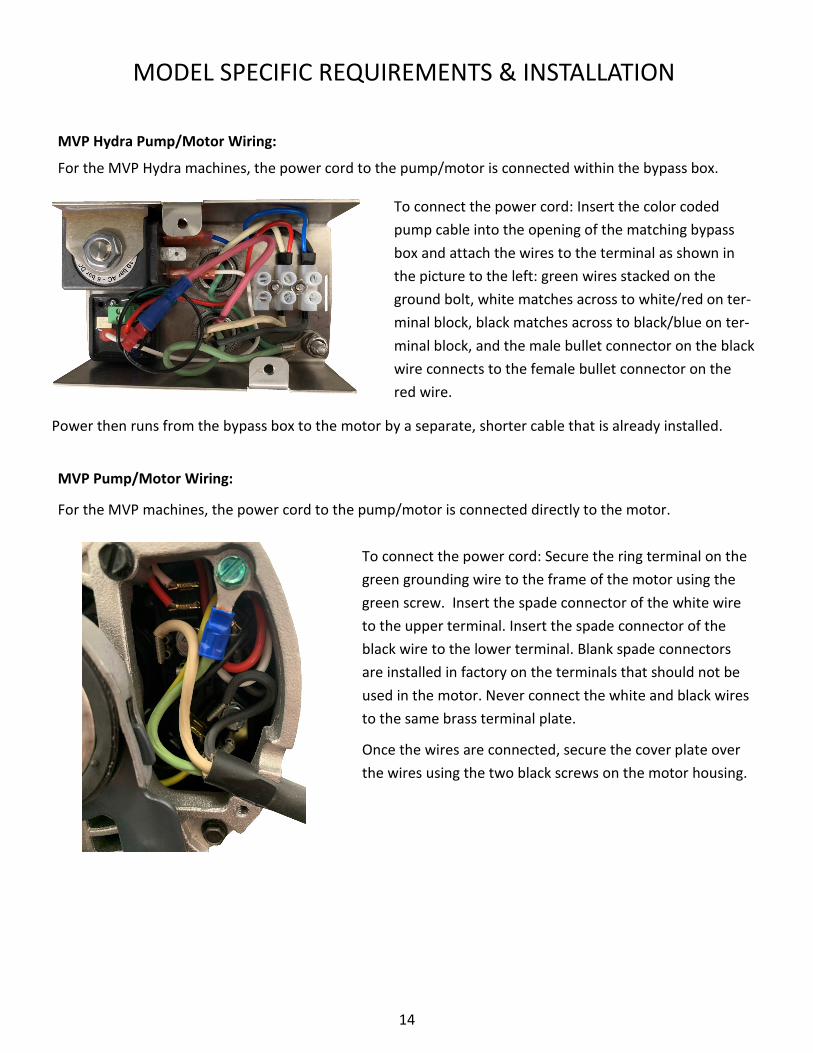
MVP Hydra Pump/Motor Wiring:
For the MVP Hydra machines, the power cord to the pump/motor is connected within the bypass box.
To connect the power cord: Insert the color coded
pump cable into the opening of the matching bypass
box and attach the wires to the terminal as shown in
the picture to the left: green wires stacked on the
ground bolt, white matches across to white/red on ter-
minal block, black matches across to black/blue on ter-
minal block, and the male bullet connector on the black
wire connects to the female bullet connector on the
red wire.
MODEL SPECIFIC REQUIREMENTS & INSTALLATION
MVP Pump/Motor Wiring:
For the MVP machines, the power cord to the pump/motor is connected directly to the motor.
To connect the power cord: Secure the ring terminal on the
green grounding wire to the frame of the motor using the
green screw. Insert the spade connector of the white wire
to the upper terminal. Insert the spade connector of the
black wire to the lower terminal. Blank spade connectors
are installed in factory on the terminals that should not be
used in the motor. Never connect the white and black wires
to the same brass terminal plate.
Once the wires are connected, secure the cover plate over
the wires using the two black screws on the motor housing.
Power then runs from the bypass box to the motor by a separate, shorter cable that is already installed.

15
MODEL SPECIFIC REQUIREMENTS & INSTALLATION
Model Specific Plumbing Requirements:
Both the MVP Hydra and MVP machines require one incoming water source. For the MVP Hydra machines,
the incoming water passes through a manifold (this was part of the line pressure regulator) from xx-xx-
3854 each pump has a regulator. Once again, follow the color coding for proper installation of the hoses
from the output of each pump to the machine. See the pictures below for MVP Hydra compression line
color matching. For the MVP machines, the incoming water routes directly to the single pump assembly.
MVP Hydra Manifold
Steam Tank Line (Pink Zip
Tie) is Matched.
Group 1 Pump - Grey Zip
Tie is Matched
Group 2 Pump - Purple
Zip Tie is Matched
Group 3 Pump - Brown
Zip Tie is Matched
Pressure Regulators:
MVP Hydras come with line pressure regulators built into the bypass pump assemblies. MVP machines do
not come standard with a line pressure regulator but it can be installed along with a manifold as an acces-
sory to the machine. The pressure regulator is used to control the stage 1 preinfusion pressure. It comes
factory set to the maximum setting of 50 psi. For more on setting up the different pressure stages please
refer to page 19.
Mini Pressure Regulator
Discontinued Watts
Pressure Regulator

16
MVP & MVP HYDRA - 2 PIECE SIDE PANELS
This side panel is shown with the trim plates removed, to display the way the lower panel interlocks with
the upper panel.
When removing the Lower Side Panel from the espresso machine:
• Loosen the 2 side panel mounting bolts , but do not remove.
• Remove the thumb screw from the drain tray
• Push the panel to the back of the machine while lifting slightly up
This allows the user easy access to the drain box & allows the technician easy access to all water control
valves on the water inlet (right) side and to the level probes and thermal switches on the left side.
For the technician to access the steam valve, the Upper Side Panel must be removed.
When removing the Upper Side Panel from the espresso machine:
• Remove the 2 side panel mounting bolts completely.
• Each bolt is threaded into a plate fastener inside the frame. Be careful not to lose the fasteners.
• The safari rack is suspended by, but not threaded onto, short bolts on each side panel. *The safari rack
needs to be supported while removing the Upper Side Panel.
17
START UP
Start-Up Instructions
1. Connect the water lines and the drain hose. Turn the water ON. Water will begin to flow into the brew groups.
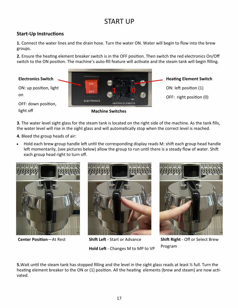
2. Ensure the heating element breaker switch is in the OFF position. Then switch the red electronics On/Off switch to the ON position. The machine’s auto-fill feature will activate and the steam tank will begin filling.
3. The water level sight glass for the steam tank is located on the right side of the machine. As the tank fills, the water level will rise in the sight glass and will automatically stop when the correct level is reached.
4. Bleed the group heads of air:
• Hold each brew group handle left until the corresponding display reads M: shift each group head handle left momentarily, (see pictures below) allow the group to run until there is a steady flow of water. Shift each group head right to turn off.
5.Wait until the steam tank has stopped filling and the level in the sight glass reads at least ½ full. Turn the heating element breaker to the ON or (1) position. All the heating elements (brew and steam) are now acti-vated.
Electronics Switch
ON: up position, light
on
OFF: down position,
light off
Heating Element Switch
ON: left position (1)
OFF: right position (0) 1 0
Machine Switches
Center Position—At Rest Shift Left - Start or Advance
Hold Left - Changes M to MP to VP
Shift Right - Off or Select Brew
Program
18
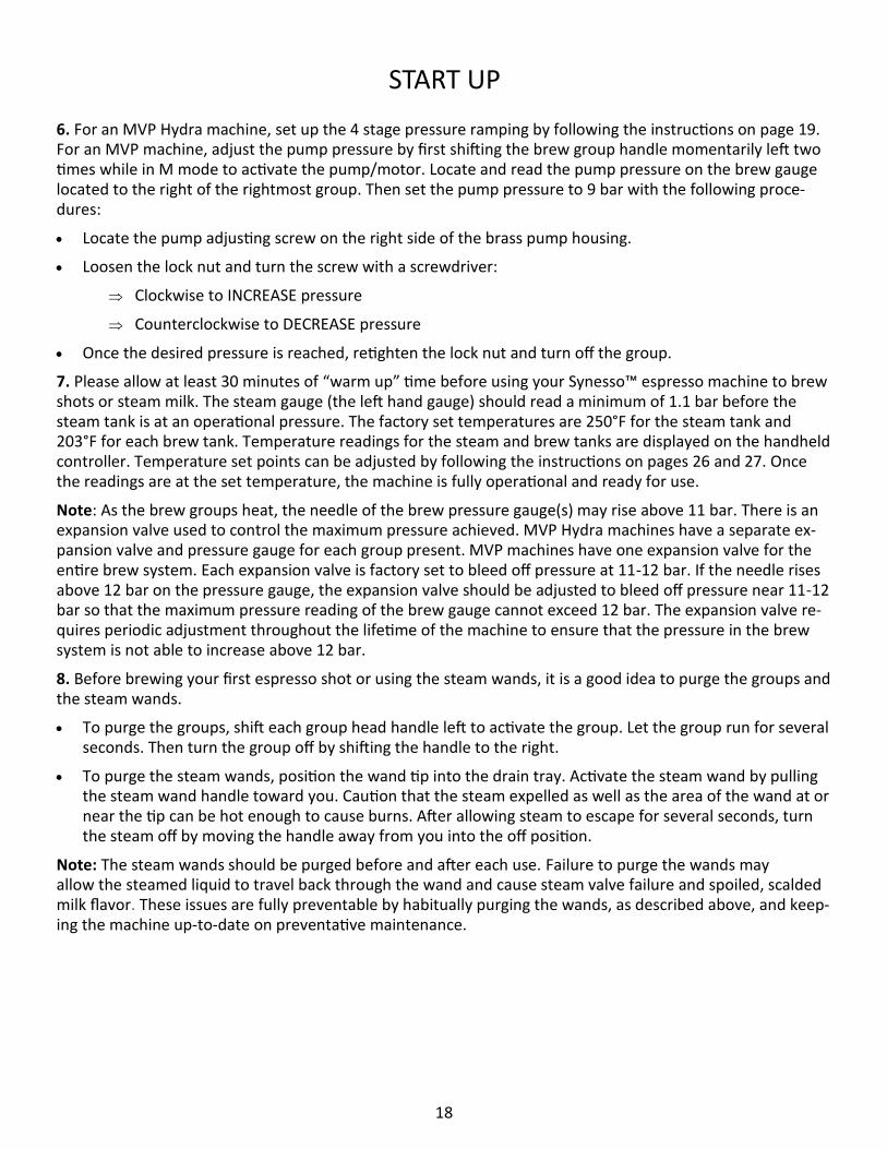
6. For an MVP Hydra machine, set up the 4 stage pressure ramping by following the instructions on page 19. For an MVP machine, adjust the pump pressure by first shifting the brew group handle momentarily left two times while in M mode to activate the pump/motor. Locate and read the pump pressure on the brew gauge located to the right of the rightmost group. Then set the pump pressure to 9 bar with the following proce-dures:
• Locate the pump adjusting screw on the right side of the brass pump housing.
• Loosen the lock nut and turn the screw with a screwdriver:
Clockwise to INCREASE pressure
Counterclockwise to DECREASE pressure
• Once the desired pressure is reached, retighten the lock nut and turn off the group.
7. Please allow at least 30 minutes of “warm up” time before using your Synesso™ espresso machine to brew shots or steam milk. The steam gauge (the left hand gauge) should read a minimum of 1.1 bar before the steam tank is at an operational pressure. The factory set temperatures are 250°F for the steam tank and 203°F for each brew tank. Temperature readings for the steam and brew tanks are displayed on the handheld controller. Temperature set points can be adjusted by following the instructions on pages 26 and 27. Once the readings are at the set temperature, the machine is fully operational and ready for use.
Note: As the brew groups heat, the needle of the brew pressure gauge(s) may rise above 11 bar. There is an expansion valve used to control the maximum pressure achieved. MVP Hydra machines have a separate ex-pansion valve and pressure gauge for each group present. MVP machines have one expansion valve for the entire brew system. Each expansion valve is factory set to bleed off pressure at 11-12 bar. If the needle rises above 12 bar on the pressure gauge, the expansion valve should be adjusted to bleed off pressure near 11-12 bar so that the maximum pressure reading of the brew gauge cannot exceed 12 bar. The expansion valve re-quires periodic adjustment throughout the lifetime of the machine to ensure that the pressure in the brew system is not able to increase above 12 bar.
8. Before brewing your first espresso shot or using the steam wands, it is a good idea to purge the groups and the steam wands.
• To purge the groups, shift each group head handle left to activate the group. Let the group run for several seconds. Then turn the group off by shifting the handle to the right.
• To purge the steam wands, position the wand tip into the drain tray. Activate the steam wand by pulling the steam wand handle toward you. Caution that the steam expelled as well as the area of the wand at or near the tip can be hot enough to cause burns. After allowing steam to escape for several seconds, turn the steam off by moving the handle away from you into the off position.
Note: The steam wands should be purged before and after each use. Failure to purge the wands may allow the steamed liquid to travel back through the wand and cause steam valve failure and spoiled, scalded milk flavor. These issues are fully preventable by habitually purging the wands, as described above, and keep-ing the machine up-to-date on preventative maintenance.
START UP

19
4 STAGE PRESSURE RAMPING SETUP - MVP HYDRA
Pin Valve for Bypass
Pressure (Ramp Up
and Ramp Down) Pump Pressure
Adjustment Screw
MVP Hydra Bypass Pump and Motor Assembly
Pressure Regulator for
Preinfusion Pressure
MVP Hydras come with a bypass pump and mo-
tor assembly that allow for four-stage pressure
ramping. The shot begins with preinfusion. Low
pressure water saturates the puck, swelling it to
reduce channeling. After the pre-infuse time has
elapsed, ramp up (bypass) begins. The bypass sys-
tem creates a slow rise in water pressure by par-
tially diverting water away from the brew group.
After the ramp up time ends, the bypass closes
and the full brew pressure (typically 9 bar) stage
begins. To complete the extraction, the shot is
then returned to bypass pressure in the ramp
down stage. The pump then shuts off to end the
extraction, returning the machine to idle pres-
sure.
To set up the four-stage pressure ramping:
1. Begin from “M” mode. Shift the group handle to the left to begin preinfusion.
2. While observing the brew pressure gauge, adjust the pressure regulator. To adjust, pull outwards on the
black knob. Turn the knob clockwise to raise pressure and counterclockwise to lower pressure. Press the
cap back in when done. Recommended preinfusion pressure is 3.5 bar.
3. Shift the group handle to the left twice more to reach the third (full pressure) stage.
4. While observing the brew pressure gauge, adjust the pump adjustment screw. To adjust, loosen the lock
nut on the screw. Using a flat head screw driver, engage the screw, turning clockwise to raise the pres-
sure and counter-clockwise to lower the pressure. When finished, tighten the lock nut to secure the ad-
justment screw. Recommended full pressure is 9 bar.
5. Shift the group handle to the left once more to reach the fourth (ramp down) stage.
6. While observing the brew pressure gauge, adjust the pin valve. Turn the handle of the valve clockwise to
raise the pressure and counter-clockwise to lower the pressure. Recommended bypass pressure is 7 bar.
*Note that if the pump or regulator pressures are adjusted, they will affect the bypass pressure.
7. To complete the setup for operation in MP or VP modes, access the machine programming via the
handheld controller to set the preinfusion time, ramp up time, and ramp down percentage (VP mode on-
ly). See pages 26 and 27 for more information on how to adjust the settings.

20
OPERATION
Preparing to Brew Espresso
1. Select the desired spout and basket configuration. Single, double and bottomless portafilters are available through Synesso™. The single spout portafilter is used with a single (7g) basket to brew a single shot. The double spouted and bottomless portafilters can be used with double (14g) or triple (18g or 21g) baskets to brew double or triple shots. The double spouted portafilter can separate a double shot into 2 single shots of espresso.
2. Fill the portafilter basket with coffee grounds to just above level and wipe off the excess.
Note: For best results, use fresh coffee. Ground coffee should be brewed as soon as possible after grinding.
3. Press straight down evenly on top of the grounds with the tamper. (A tamper is supplied with the ma-chine).
4. Engage the portafilter into the brew group and pull firmly to the right to set the seal.
5. Proceed to the instructions for the program (M, MP, or VP) that you wish to brew with. See below on how to change from program to program.
Hold handle LEFT to change the Operation Mode from M (Manual) to MP (Manual Program) to VP (Volumetric Program).
MVP vs MVP Hydra Brewing:
MVP machines allow for two different brew pressures, line pressure preinfusion and full pump pressure, with only the pump pressure being adjustable. Brewing on an MVP is profiled first as stage 1 low pressure preinfu-sion, then stage 2 full pump pressure brewing, and lastly stage 3 low pressure ramp down.
MVP Hydras allow for three different brew pressures—preinfusion, bypass, and pump pressure—all of which are adjustable. Brewing on an MVP Hydra is profiled as stage 1 low pressure preinfusion, followed by stage 2 ramp up (bypass) pressure, to stage 3 full pump pressure brewing, and finally stage 4 ramp down (bypass) pressure.
The difference between the machine’s available pressure modes is observable by the pressure bars shown on the shot timers as can be seen in the pictures below.
MVP Hydra
4 Stage Pressure
Ramping
MVP
3 Stage Pressure
Ramping
21
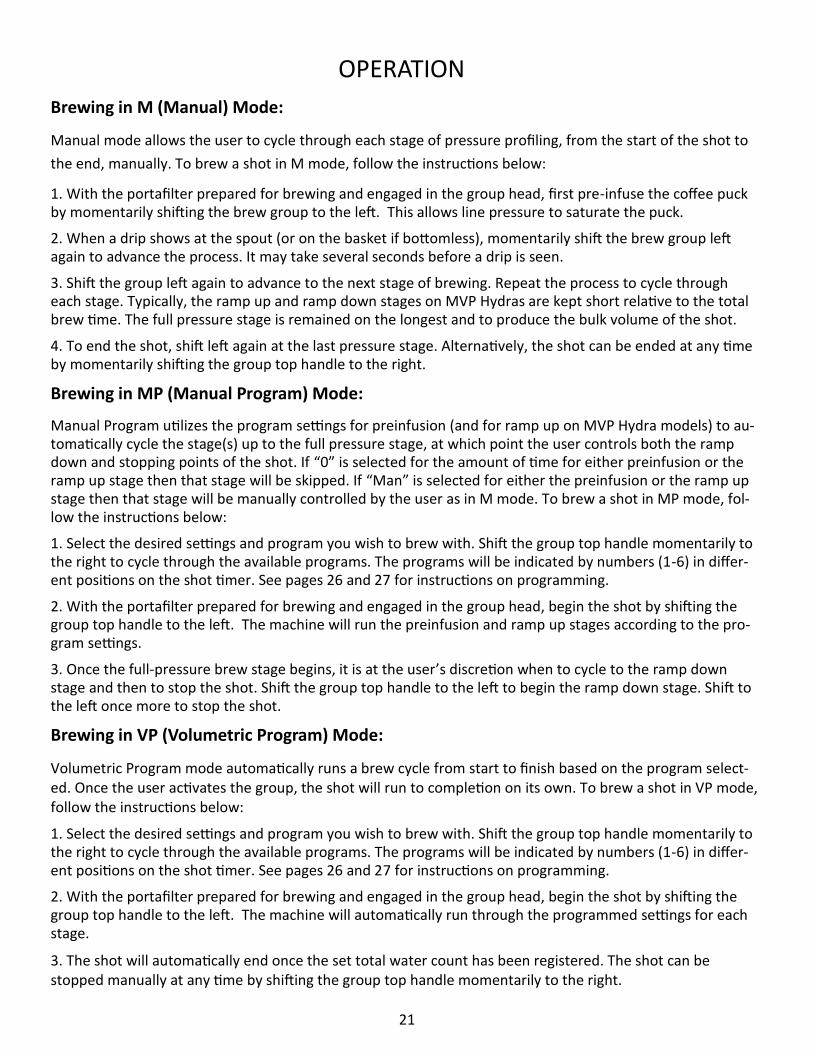
Brewing in M (Manual) Mode:
Manual mode allows the user to cycle through each stage of pressure profiling, from the start of the shot to
the end, manually. To brew a shot in M mode, follow the instructions below:
1. With the portafilter prepared for brewing and engaged in the group head, first pre-infuse the coffee puck by momentarily shifting the brew group to the left. This allows line pressure to saturate the puck.
2. When a drip shows at the spout (or on the basket if bottomless), momentarily shift the brew group left again to advance the process. It may take several seconds before a drip is seen.
3. Shift the group left again to advance to the next stage of brewing. Repeat the process to cycle through each stage. Typically, the ramp up and ramp down stages on MVP Hydras are kept short relative to the total brew time. The full pressure stage is remained on the longest and to produce the bulk volume of the shot.
4. To end the shot, shift left again at the last pressure stage. Alternatively, the shot can be ended at any time by momentarily shifting the group top handle to the right.
Brewing in MP (Manual Program) Mode:
Manual Program utilizes the program settings for preinfusion (and for ramp up on MVP Hydra models) to au-tomatically cycle the stage(s) up to the full pressure stage, at which point the user controls both the ramp down and stopping points of the shot. If “0” is selected for the amount of time for either preinfusion or the ramp up stage then that stage will be skipped. If “Man” is selected for either the preinfusion or the ramp up stage then that stage will be manually controlled by the user as in M mode. To brew a shot in MP mode, fol-low the instructions below:
1. Select the desired settings and program you wish to brew with. Shift the group top handle momentarily to the right to cycle through the available programs. The programs will be indicated by numbers (1-6) in differ-ent positions on the shot timer. See pages 26 and 27 for instructions on programming.
2. With the portafilter prepared for brewing and engaged in the group head, begin the shot by shifting the group top handle to the left. The machine will run the preinfusion and ramp up stages according to the pro-gram settings.
3. Once the full-pressure brew stage begins, it is at the user’s discretion when to cycle to the ramp down stage and then to stop the shot. Shift the group top handle to the left to begin the ramp down stage. Shift to the left once more to stop the shot.
Brewing in VP (Volumetric Program) Mode:
Volumetric Program mode automatically runs a brew cycle from start to finish based on the program select-ed. Once the user activates the group, the shot will run to completion on its own. To brew a shot in VP mode, follow the instructions below:
1. Select the desired settings and program you wish to brew with. Shift the group top handle momentarily to the right to cycle through the available programs. The programs will be indicated by numbers (1-6) in differ-ent positions on the shot timer. See pages 26 and 27 for instructions on programming.
2. With the portafilter prepared for brewing and engaged in the group head, begin the shot by shifting the group top handle to the left. The machine will automatically run through the programmed settings for each stage.
3. The shot will automatically end once the set total water count has been registered. The shot can be stopped manually at any time by shifting the group top handle momentarily to the right.
OPERATION

22
OPERATION
Brew Pressure Graph
1 Bar: Low Pressure
Preinfusion
2 Bars: Bypass Pressure
Ramp Up
3 Bars: Pump Pressure
Full Pressure Brew (9 bar)
2 Bars: Bypass Pressure
Ramp Down
Using the Save Function:
The MVP and MVP Hydra are able to store the last brewing function performed to a temporary memory. The save function can then be utilized to save the last brewing function performed as a recipe to any of the 6 programs on any or all of the groups. To save the last brewing function as a recipe follow the instructions below:
1. Hold the group top handle to the right for 2.5 seconds until the shot timer display changes to save mode. All groups will enter this mode as displayed on each shot timer.
2. Shift the group top handle momentarily right to cycle to the program you wish to save to.
3. Once the program number (or position) you wish to save to is displayed, shift the group top handle mo-mentarily to the left to save. The shot timer display will flash three times to indicate it has been saved. Repeat steps 2 and 3 on each group and for each program you wish to save to.
4. To exit save mode hold the group top handle to the right until the shot timer display returns to opera-tion mode.
5. The newly saved recipe can be viewed and edited by accessing the program using the handheld control-ler. See pages 26 and 27.
Save Mode
Shift left to save to the program indicated
6 Program Locations Shown.
Only the selected program dis-
plays when in use.
Machines after Serial Number
xxxxx3176 display programs as
numbers 1-6 instead of as squares.
23
Milk Steaming
1. Fill the pitcher halfway with fresh, cold milk. Smaller pitchers are recommended for drink sizes less than 10 oz.
Note: Steamed, unused milk should be discarded and the pitcher rinsed before reusing.
Note: Whole Milk, 2%, 1%, Non-Fat, Soy Milk, Rice Milk and other milk type products may require different techniques to foam properly. In general, the higher the fat content, the easier it is to steam.
OPERATION
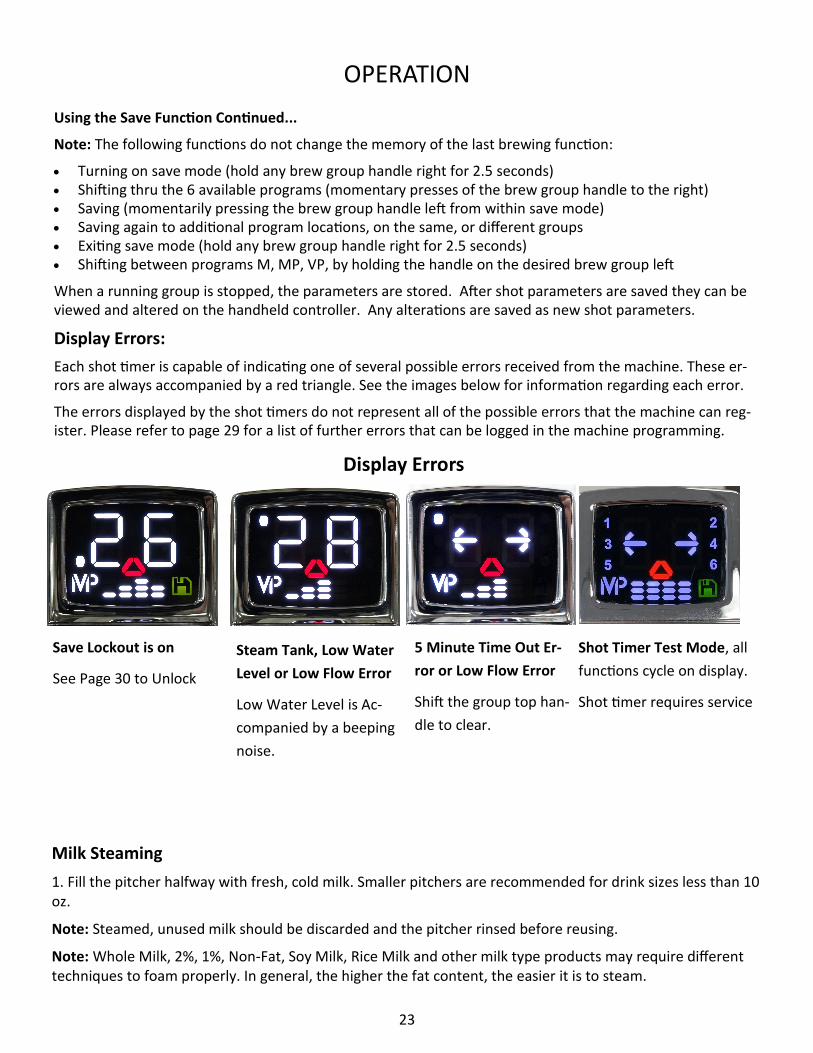
Display Errors
Save Lockout is on
See Page 30 to Unlock
Steam Tank, Low Water
Level or Low Flow Error
Low Water Level is Ac-
companied by a beeping
noise.
5 Minute Time Out Er-
ror or Low Flow Error
Shift the group top han-
dle to clear.
Shot Timer Test Mode, all
functions cycle on display.
Shot timer requires service
Using the Save Function Continued...
Note: The following functions do not change the memory of the last brewing function:
• Turning on save mode (hold any brew group handle right for 2.5 seconds) • Shifting thru the 6 available programs (momentary presses of the brew group handle to the right) • Saving (momentarily pressing the brew group handle left from within save mode) • Saving again to additional program locations, on the same, or different groups • Exiting save mode (hold any brew group handle right for 2.5 seconds) • Shifting between programs M, MP, VP, by holding the handle on the desired brew group left
When a running group is stopped, the parameters are stored. After shot parameters are saved they can be viewed and altered on the handheld controller. Any alterations are saved as new shot parameters.
Display Errors:
Each shot timer is capable of indicating one of several possible errors received from the machine. These er-rors are always accompanied by a red triangle. See the images below for information regarding each error.
The errors displayed by the shot timers do not represent all of the possible errors that the machine can reg-ister. Please refer to page 29 for a list of further errors that can be logged in the machine programming.

24
2. Purge the steam wand by activating it momentarily. This will expel any water in the wand that has collect-ed due to condensation between uses.
3. Insert the tip of the steam wand deep into the milk pitcher. This will prevent milk from splashing once the steam is turned on.
Milk Steaming Continued...
4. Activate the steam wand while holding the pitcher steady. Place one hand on the side of the pitcher to feel for the rising temperature of the milk.
5. While the milk is still cold, lower the pitcher until the tip of the steam wand is near to the surface. Allow the steam jets to push some air beneath the surface, then raise the pitcher to lower the tip of the wand deeper into the milk.
Note: The more air pushed into the milk, the more foamy the texture will be. Generally not more than a sec-ond of aeration is needed for latte foam or several seconds for cappuccino foam.
5. Continue steaming the milk while the wand is submerged. This will continue the heating process and mini-mize further foaming. Do not touch the steam wand to the bottom of the milk pitcher; this can create an in-accurate temperature measurement.
7. Heat the milk to approximately 150°F to 170°F (65°C to 76°C) then deactivate the steam wand. If you are using your hand to help determine the temperature, it will feel about as hot as you can stand without burn-ing yourself. Milk thermometers are also an excellent way to determine the temperature of the milk.
Caution: Do not overheat the milk and scald it. Scalded milk should not be used.
8. Remove the wand from the milk, purge with steam, and wipe clean immediately after each use.
Note: The steam wands should be purged before and after each use. Failure to purge the wands may allow the steamed liquid to travel back through the wand and cause steam valve failure and spoiled, scalded milk flavor. These issues are fully preventable by habitually purging the wands, as described above, and keep-ing the machine up-to-date on preventative maintenance.
Note: Although Synesso™ steam wands are made with a proprietary double-walled process that helps to keep the outer wall cooler, the tip and base can become very hot and caution must be used.
Cleaning and Maintenance:
Machine upkeep is essential to ensuring a long lifetime of the machine and proper functioning of all compo-nents. Users should perform routine cleaning and schedule routine preventative maintenance to keep the machine at optimal performance.
For more on Synesso™ recommended cleaning and maintenance procedures, please refer to pages 39-42 of this manual.
OPERATION

25
PROGRAMMING Overview:
This programming section applies to all MVP Series Synesso™ machines. MVP Series machines have a wired
handheld controller (pictured below) that allows the user to easily view and change the machine settings.
To change settings on these screens, first press the line button on the left side of the display associated
with the setting you wish to change. The value will flash once selected. Press the up or down buttons until
the desired value is displayed. Press the line button again to confirm the change. The value will stop flash-
ing. Use this procedure to change any variables in the controller menus.
The top line of every screen indicates the title. In this case, Temperature Overview.
You can return to this screen at any time by pressing the home button at the top right of the controller. The machine will also return to this screen automatically after a short time.
Lines 2, 3, and 4 may contain information or settings, many of which can be changed by the operator. This screen provides the current temperatures for each brew group along with the steam tank. The most recent error will also be shown in the lower right corner. No settings can be changed on this screen.
In some circumstances, numeric temperatures will not be shown. If a tank is reading ‘LOW’, this indicates that the tank is below the temperature probe’s effective range of measurement (170°F-270°F / 76.6°C-132.2°C). Readings above the effective range will show as ‘HIGH’.
The programmable temperature range for a brew group is from 180°F (82.2°C) up to 220°F (104.4°C). The factory set temperature is 203°F (95°C). To change brew group set temperatures, refer to page 26.
The steam tank is set in factory to a default setting of 250°F (121.1°C). To change this temperature setting, see page 27.
The [OK] on the right hand side of line 4 is indicating that there have been no errors detected by the control system. If, in place of the [OK] you find an error code (Ex: STLW01), refer to the Error Log codes on page 29.
To cycle to the next display screen, press the down arrow button. (You may press the up arrow instead to travel back to the previous screen.)
Line 2 Button
Line 3 Button
Line 4 Button
Home
Up
Down
Line 1 Title
Menu Level 1: Temperature Overview; Home Screen

26
PROGRAMMING
Line 1 of the first brew group control screen indicates the current temperature of the brew tank as measured by its probe. Once this temperature reaches the set point, it will continuously cycle up and down by small increments as the electronics balance the temperature. This line also indicates the active program (PRG1 in this case). Changing the active program will update the settings on the lines below.
Line 2 is indicating the set point of 202.0°F (94.4°C).
Line 3 indicates the length of time preinfusion is set for in the current program. When starting a shot in MP or VP mode, preinfusion will allow line pressure water to soak the puck for as long as indicated before moving on to the next brew phase. Setting the preinfusion time down to 0.0 seconds will skip the preinfusion phase in MP and VP modes. One step lower than 0.0 is the “MAN” setting, which will require the operator to exit the preinfusion phase manually in MP mode, and will skip preinfusion in VP mode.
Line 4 indicates the length time set for the ramp-up phase in the current program. This option will ONLY be visible on MVP Hydra models. Ramp-up time begins once the preinfusion stage has finished.
To cycle to the next display screen, press the down button.
Menu Level 1: Group 1, Program 1
Factory Settings:
The factory settings for MVP Series machines are as follows: Brew Group Temperature 203°F Steam Tank Temperature 250°F Brew Mode M (Manual) Right-Hold Save Lockout Locked (To Unlock refer to page 30) Enabled Programs 1 & 2 Enabled (3-6 Disabled) Temperature Units Fahrenheit Program 1: Program 2: Preinfusion 4 seconds Preinfusion 4 seconds Ramp Up 2 seconds Ramp Up 2 seconds Ramp Down 92% Ramp Down 92% Total Water Count 280 Total Water Count 380
27
PROGRAMMING
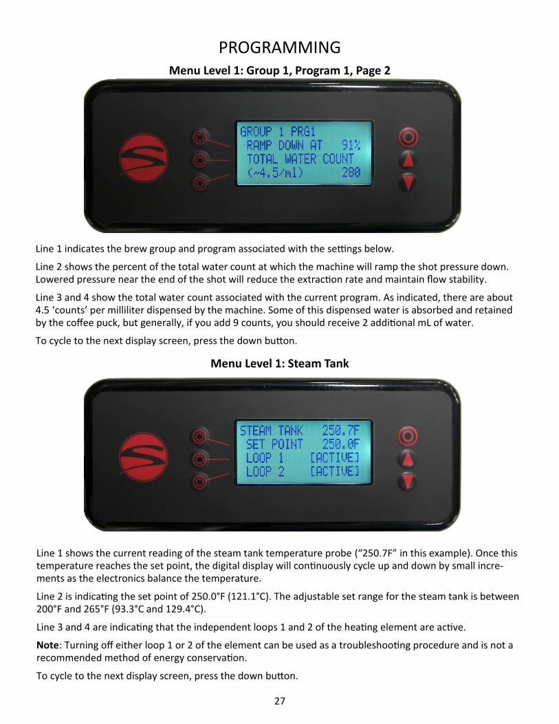
Line 1 indicates the brew group and program associated with the settings below.
Line 2 shows the percent of the total water count at which the machine will ramp the shot pressure down. Lowered pressure near the end of the shot will reduce the extraction rate and maintain flow stability.
Line 3 and 4 show the total water count associated with the current program. As indicated, there are about 4.5 ‘counts’ per milliliter dispensed by the machine. Some of this dispensed water is absorbed and retained by the coffee puck, but generally, if you add 9 counts, you should receive 2 additional mL of water.
To cycle to the next display screen, press the down button.
Line 1 shows the current reading of the steam tank temperature probe (“250.7F” in this example). Once this temperature reaches the set point, the digital display will continuously cycle up and down by small incre-ments as the electronics balance the temperature.
Line 2 is indicating the set point of 250.0°F (121.1°C). The adjustable set range for the steam tank is between 200°F and 265°F (93.3°C and 129.4°C).
Line 3 and 4 are indicating that the independent loops 1 and 2 of the heating element are active.
Note: Turning off either loop 1 or 2 of the element can be used as a troubleshooting procedure and is not a recommended method of energy conservation.
To cycle to the next display screen, press the down button.
Menu Level 1: Steam Tank
Menu Level 1: Group 1, Program 1, Page 2

28
PROGRAMMING
Auto backflush can be activated by pressing the line button associated with the group you want to flush. Set the value to “ready”, then place a portafilter equipped with a blind basket into the selected brew group. Shift left on the group head. The selected group will run the brew valve and motor for 10 seconds, followed by 10 seconds off. This will repeat 5 times. The shot timer will count up to 10 to let you know when it is running. Upon completion, the timer will read 10. Remove the portafilter and thoroughly clean the diffuser screen.
If you have used soap or other cleanser during the backflush, run the backflush process a second time with no soap or chemicals to rinse the internal tubing and brew valve. Failure to rinse after a soap backflush can leave soap residue in the brew valve affecting taste and/or machine behavior.
Any number of brew groups can use the auto backflush feature at the same time. The auto backflush can be interrupted mid-cycle by shifting to the left, or right, or by turning the setting on the controller back to “off”.
To cycle back to the temperature overview screen, press the down button.
Line 1 indicates that you are on the hot water tap control screen.
Line 2 indicates the adjustable amount of time that the hot water tap will run before shutting off.
Line 3 gives the option of setting the hot water time on line 2 by activating the tap and letting the water flow, then shutting it off. The machine will store the duration of this pour as the new dispense time.
To cycle to the next display screen, press the down button.
Menu Level 1: Hot Water Tap
Menu Level 1: Auto Backflush

29
PROGRAMMING
In an effort to prevent damage to machines and to help operators troubleshoot issues, Synesso™ has engi-
neered several safeguards into the programming. By understanding these codes, operators can remedy is-
sues more quickly. The most recent error can be found on the temperature overview screen at the lower
right corner.
BR - Brew System Codes
GROUP 1
GROUP 2
GROUP 3 CODE DESCRIPTION
BV - Brew valve BRBV01 BRBV02 BRBV03 Brew Valve has been on for 5 consecutive minutes
OT - Over Temp BROT01 BROT02 BROT03 Over Temperature (220°F)
UT - Under Temp BRUT01 BRUT02 BRUT03 Group reads < 180°F for 1 minute while reheating
BP - Bypass Valve BRBP01 BRBP02 BRBP03 Bypass Valve has been held on for 5 consecutive minutes
ST - Steam System Codes
LOW H2O Low level probe not in contact with water (audible alarm)
LW - Low Water Probe STLW00 N/A N/A Indicates past LOW H2O warning
FP - Fill Probe STFP00 N/A N/A Fill Probe is not in contact with water for 1 minute
FV - Fill Valve STFV00 N/A N/A Fill Valve has been on for 5 consecutive minutes.
OT - Over Temp STOT00 N/A N/A Over Temperature (270°F)
VM - Volumetric System Codes
UF - Unexpected Flow VMUF01 VMUF02 VMUF03 Unexpected flow detected while group is off
Menu Level 1: Brew System Error Codes
30
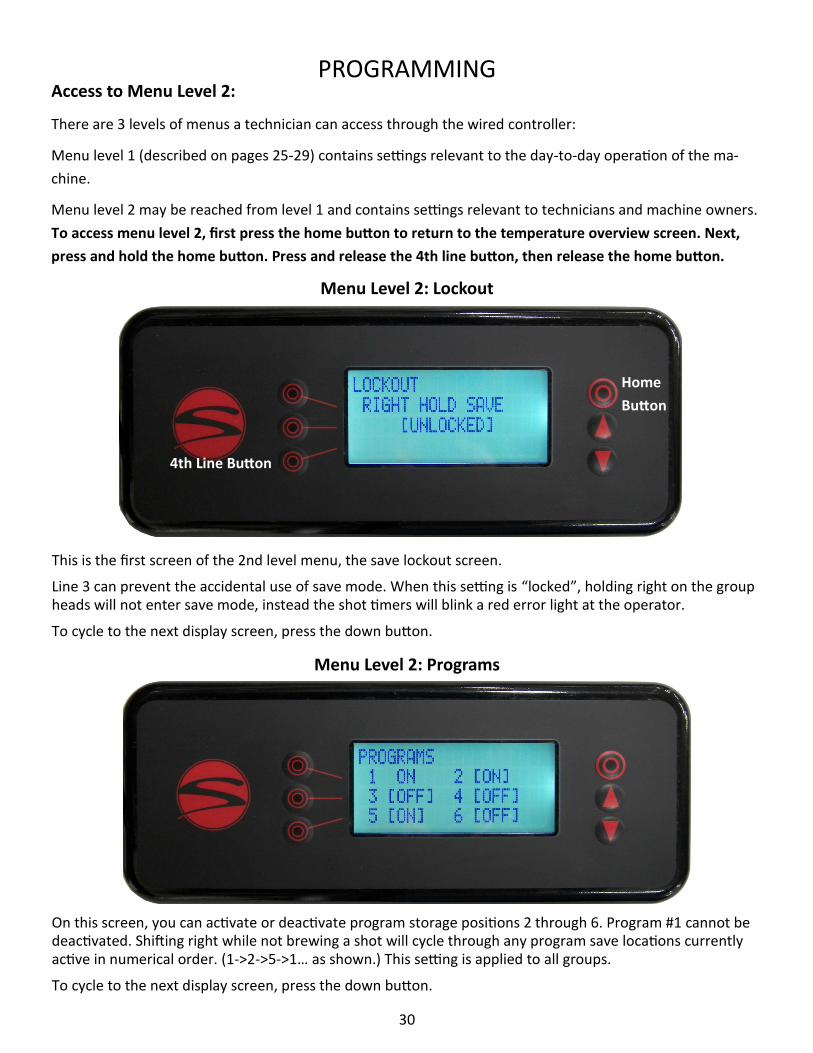
This is the first screen of the 2nd level menu, the save lockout screen.
Line 3 can prevent the accidental use of save mode. When this setting is “locked”, holding right on the group heads will not enter save mode, instead the shot timers will blink a red error light at the operator.
To cycle to the next display screen, press the down button.
On this screen, you can activate or deactivate program storage positions 2 through 6. Program #1 cannot be deactivated. Shifting right while not brewing a shot will cycle through any program save locations currently active in numerical order. (1->2->5->1… as shown.) This setting is applied to all groups.
To cycle to the next display screen, press the down button.
PROGRAMMING
Menu Level 2: Lockout
Menu Level 2: Programs
Home
Button
4th Line Button
Access to Menu Level 2:
There are 3 levels of menus a technician can access through the wired controller:
Menu level 1 (described on pages 25-29) contains settings relevant to the day-to-day operation of the ma-
chine.
Menu level 2 may be reached from level 1 and contains settings relevant to technicians and machine owners.
To access menu level 2, first press the home button to return to the temperature overview screen. Next,
press and hold the home button. Press and release the 4th line button, then release the home button.

31
PROGRAMMING
This is the temperature display screen.
Line 2 indicates the temperature scale that you are currently in (Fahrenheit or Celsius).
Line 4 indicates the operation status of the machine’s brew valves.
Setting the brew valve function to [ON] will activate the brew valves, allowing the pressure to be bled from the brew tanks. Once the pressure has dropped, turn the brew valve setting back to [NORMAL] and attach the appropriate drain hose to the brew group’s drain tube. Turn the brew valve setting back [ON] once the drain hoses are securely attached. This will allow the water in the brew groups to fully drain in approximately 5 minutes. When the brew groups are finished draining, set the brew valve indicator back to the [NORMAL] setting. If the draining process takes longer than 5 minutes, the machine’s safety programming will automati-cally turn the brew valve indicator to the [NORMAL] setting while exiting back to the temperature overview screen. If more time is needed, return to the Temperature Display screen and set the brew valve function back to [ON] to finish the procedure. Once finished with the draining procedure, make sure the brew valve function is set back to [NORMAL]. To cycle to the next display screen, press the down button.
Menu Level 2: Temperature
Menu Level 2: Line Pressure Boost
If the machine has an optional line pressure boost pump installed, you will see this menu screen, otherwise it will not be shown.
Please continue to the next page for more details.

32
PROGRAMMING
Line Pressure Boost Continued...
From the picture on the previous page, “AUTO” is the setting on line 2 for normal operation. In “AUTO” mode, whenever a brew valve or water control valve is activated, the power board will also trigger a pump relay to run a line pressure generating pump and motor package. If this is set to “OFF”, the line boost motor will not activate. The “ON” setting will run the boost motor constantly. This is factory set to “OFF” to protect the boost pump from running without water.
To cycle to the next display screen, press the down arrow
Line 2 indicates the measured water temperature at the selected brew group’s temperature probe.
Line 3 indicates the temperature adjustment made at the Synesso™ factory, in order to match the measured temperature with the temperature desired inside the puck.
The Synesso™ testing method is as follows:
Using a bottomless portafilter, dose out 16-18 grams of coffee into a 14 gram basket with a thermal probe inserted 1/8th of an inch from the surface and in the middle of the puck, packing and tamping the grounds in the basket as usual.
The thermal probe is then wired to a FLUKE thermometer to relay the actual temperature of the water flow-ing through the puck while pouring a 25 second, 2 ounce shot. This process is repeated a minimum of 3 times per brew group in order to get the most accurate readings. The difference between the measured puck temperature and the raw tank temperature becomes the brew offset
This offset should not be altered without thoroughly testing the puck temperature, as mentioned above.
Synesso™ keeps a log of the factory offsets for each machine. Contact Synesso™ Technical Support if you need to obtain the original factory-determined offset values.
To cycle to the next display screen, press the down button.
Menu Level 2: Brew Offsets

33
PROGRAMMING
Menu Level 2: Steam Offset
Menu Level 2: Calibrate Flowmeters
The flowmeter calibration feature is made available with firmware 2.64v.
The feature allows for technicians and advanced users to calibrate the flowmeters in order to achieve ex-treme accuracy in their output volumes or to recalibrate flowmeters that have become less accurate over time due to mineral buildup.
Line 3 allows the operator to begin the calibration. Before performing the calibration please read the in-structions on page 43. Instructions should be carefully followed in order to ensure proper volumetric func-tioning of the machine.
To cycle to the next display screen, press the down button.
Line 2 indicates the measured steam temperature at the steam tank temperature probe.
Line 3 is the offset used to calibrate the steam tank temperature and pressure so that when the steam tank is set at 250°F, there is 1.3 bar pressure on the gauge.
Line 4 of this display screen is showing a 5 second delay. The fill probe will wait this long before turning the steam tank fill valve on or off. Add time here if the machine is in an unstable installation such as a food truck or catering cart. There is no need to drop this time below 5 seconds.
Contact Synesso Technical Support if you need to obtain the original, factory-determined offset values.
To cycle to the next display screen, press the down button.

34
This is the system clock screen.
Line 2 allows the operator to set the local time in a 24 hour format.
Line 3 and 4 allow the operator to set the current date.
The date and time are used for both the error log and the power saving mode. A small battery on the power board should keep the clock and calendar running if the machine loses power, but it will need to be re-placed eventually. Refer to the markings on the battery for replacement info.
To cycle to the next display screen, press the down button.
Menu Level 2: System Clock
PROGRAMMING
Menu Level 2: Heating Elements
During certain maintenance procedures or technical troubleshooting, it may be necessary to disable sec-tions of the machine’s heating system. For proper performance of the machine, all elements should be left active during normal operation.
Line 2 allows the user to deactivate loop 1 of the steam tank heating element.
Line 3 allows the user to deactivate loop 2 of the steam tank heating element.
Line 4 allows the user to deactivate all of the brew tank heating elements.
To cycle to the next display screen, press the down button.

35
PROGRAMMING
Line 2 of the Power Save Mode in this example is indicating the timers are [ENABLED], making adjustments to lines 3 and 4 available. If line 2 reads [DISABLED], no further settings will be available on this screen.
Line 3 indicates the settable time at which your power save mode will start, cooling the machine to lower heat levels overnight.
Line 4 indicates the settable time at which your power save mode will end, heating the machine back up to the set points.
Enabling the power save mode will drop the temperature in the brew groups to 180°F (82.2°C) and the steam
tank to 220°F (104.4°C) when it is active. This will help conserve energy while preventing maintenance issues
that occur when machines are turned off and on repeatedly.
While power save mode is active, there is a note on the display which states that the operator can exit power
save mode at any time by pressing any button on the wired controller.
To cycle to the next display screen, press the down button.
Menu Level 2: Power Save Mode - Enabled
Menu Level 2: Power Save Mode - Disabled

36
PROGRAMMING
Line 1 of the error log screen shows how many errors the machine has recorded, up to the 35 most recent errors, and which of these you are currently viewing. This example is showing “2/2”, indicating the second of two errors is displayed.
Line 2 indicates the error code. If the error log is clear, this line will simply read “NO ERRORS” as shown be-low.
Line 3 indicates the date and time that the last error has occurred. If no error has occurred, this line will be blank.
Line 4 gives the option to scroll through or clear the error log. To view older errors, press the 4th line button once, which will make [SCROLL] flash. Use the up and down buttons to change the viewed error. Press the 4th line button again and [CLEAR] will begin flashing instead of [SCROLL]. Press the 4th line button again to deselect both options.
Please see the following page for instructions on clearing the error log.
Menu Level 2: Error Log
37
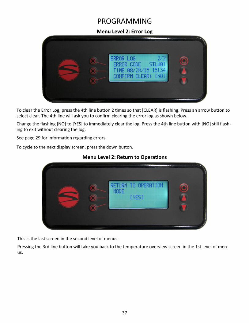
To clear the Error Log, press the 4th line button 2 times so that [CLEAR] is flashing. Press an arrow button to select clear. The 4th line will ask you to confirm clearing the error log as shown below.
Change the flashing [NO] to [YES] to immediately clear the log. Press the 4th line button with [NO] still flash-ing to exit without clearing the log.
See page 29 for information regarding errors.
To cycle to the next display screen, press the down button.
Menu Level 2: Error Log
This is the last screen in the second level of menus.
Pressing the 3rd line button will take you back to the temperature overview screen in the 1st level of men-us.
Menu Level 2: Return to Operations
PROGRAMMING

38
PROGRAMMING Firmware Updates:
The machine’s firmware is the basis for all of its programming features as made available by the handheld
controller. Synesso™ provides updates to the firmware as needed in order to make improvements to the
functionality of the machine. Firmware updates require access to the electrical box and main electronics
board of the machine and must be performed by a qualified technician.
MVP Series machines run off of firmware versions 2.xx, starting with version 2.4 and proceeding up until the
current version 2.64 (as of 2020). If the machine is running off of an older firmware version and you would
like to update to the current version—so as to make certain features available and receive the most improved
machine functionalities—please have a qualified technician reach out to Synesso™ Technical Support. One of
our technicians can provide the latest firmware and instructions needed to perform the update.
The firmware that is currently installed on the machine can be viewed on the start-up screen of the handheld
controller when powering the machine on (see picture below).
The start-up screen appears momentarily when the machine power is cycled on. The firmware can be
viewed in the upper right corner of the screen, in this case v2.5.
39
MAINTENANCE
DAILY MAINTENANCE
Daily cleaning and maintenance procedures are essential for maintaining optimum performance of your es-
presso machine. The following are procedures to be carried out on a daily basis:
Backflushing:
This process forces water through the inlet tube and drain system. This should be performed on EACH brew
group daily.
1. Replace the filter basket with the ‘blind’ basket, which has no filter holes.
2. Engage the portafilter, then follow the instructions on page 28 to use the auto backflush function.
3. When using an approved espresso industry detergent during backflushing, follow the manufacturer’s in-
structions. It is extremely important to thoroughly rinse the blind filter basket and repeat backflushing sever-
al times with clean water to clear the system of any detergent residue. Failure to rinse after using detergent
can cause valve problems and bad flavor.
Note: NEVER remove the diffuser screen and screw when backflushing. Backflushing without the screen can
cause detergent and other unwanted particles to enter the brew system and can lead to valve and flow prob-
lems. Remove and clean the screen and screw after backflushing is complete. Do not forget to reinstall.
General Machine Cleaning:
1. Clean the surface of the machine using a soft damp cloth. Avoid using abrasive cleaners or cleansing pads.
Take extra care on the mirror finish stainless steel surfaces. A “micro-fiber” towel is recommended to avoid
scratches.
2. Make sure the steam wands and tips are free of milk build-up. It is always best to clean the steam wand
and tip after each use by purging and wiping with a damp cloth. Approved espresso industry cleaners can be
used to dissolve milk build-up. Tips can be removed to soak. Deep cleaning of the wands and tips should be
carried out periodically.
3. The drip tray, drip tray grates, and portafilters should be removed and cleaned every day. If you clean the
portafilters in the dishwasher, first remove the filter baskets and springs before washing. Do not place wood-
en handled portafilters in the dishwasher. Wood should be cleaned using wood-safe cleaning procedures.

40
MAINTENANCE MAINTENANCE SCHEDULE
Proper and regularly scheduled cleaning and maintenance procedures are CRITICAL for optimum perfor-
mance of your espresso machine.
Daily
1.Backflush each brew group without detergent throughout the day. Backflush with an espresso industry approved detergent during the final cleaning of the night (or after a busy period) and then again without detergent to rinse.
2. Purge wands before and after each use. Wipe wands and steam tips with a damp cloth after each use. Clean the wands and steam tips with approved espresso industry milk cleaner during the final cleaning of the night.
3. Wipe down the entire machine with a soft cloth.
4.Remove portafilters, baskets and springs, drip tray and grates and clean all thoroughly. These items are all dishwasher safe (with the exception of wooden handled portafilters).
5. Slowly pour a pitcher of hot water down the drain to clear grounds debris and prevent blockage.
Weekly
1. Soak portafilters and the removed filter baskets in an approved espresso industry detergent and water solution. Rinse thoroughly before reassembling and using your portafilters.
2. Carefully remove screens and screws from each brew group using a short handled screwdriver and soak them overnight in a similar solution as the portafilters.
Note: Rinse screens and screws thoroughly before installing and using. Make sure you install the screens before brewing any shots of espresso. Failure to do so may plug the drain lines with coffee grounds. DO NOT overtighten the screw during reassembly.
Monthly
1. Check your water filtration system and make sure the cartridges and filters are changed as needed. In ar-eas of high mineral content, hard water, high particulate count or in very busy locations, the filtration sys-tems will need to be checked more often.
Quarterly - See Page 41 for Recommended 90 Day PM List
1. Change portafilter gaskets and closely inspect diffuser screens and filter baskets, If these items are show-ing wear, please replace them as soon as possible. Change these items if they show damage or overuse.
2. Briefly inspect the machine for leaks or potential issues. Contact Synesso™ or your local distributor or ser-vice agent to order parts and/or request service.
Annual - Please Refer to Annual PM Checklist on Page 42
Synesso™ recommends that you contact your distributor or service agent for periodic maintenance. The fre-
quency of maintenance visits will depend on a variety of factors including how much use the machine re-
ceives, but at least one preventative maintenance visit per year is required. During this yearly service, all
body panels must be removed and all connections both electrical and hydraulic must be inspected. Small
problems can become large if not caught early.

41
Quarterly Preventative Maintenance Guide • Replace portafilter gaskets
8.5mm - 1.3441 (standard size)
9.0mm - 1.3430 (for older handles with worn ears)
Inspect and replace group diffuser screens if worn or damaged
Synesso™ reinforced screen - 1.3292
• Inspect portafilter baskets for wear or damage. Replace if necessary
14 gram basket - 1.7000
18 gram basket - 1.7090
21 gram basket - 1.7170
• Inspect and/or rebuild steam valves if signs of leaking. Clean and lubricate wand pivot ball and pusher
face
Steam valve rebuild kit - 1.7320
Complete steam valve - 1.4501
• Remove and clean steam tips
• Check flow rate at each brew group. Minimum 2oz in 6-8 seconds
• Check that expansion valve does not leak at 9 bar. 11-12 bar is the factory standard setting
Expansion valve - 1.4070
• Check line, bypass, and pump pressures
• Inspect steam tank vacuum breaker. Replace if signs of leaking
Vacuum breaker - 1.4265
• Inspect steam tank pressure relief valve (dark spots may indicate leaking). Replace if signs of leaking
Pressure relief valve - 1.4100
• Depressurize steam and brew systems, check that gauges return to zero. Replace if not accurate
0-60psi steam gauge - 1.4083
0-300psi brew gauge - 1.3373
• Remove and inspect level probes. Clean scale if necessary
Upper level probe (fill probe) - 1.4111
Lower (safety) probe - 1.4112
• Inspect drain hose for clogs or leaks
• Check steam handles for grit, friction, or contacts. Lubricate and adjust as needed
• Test handheld controller for proper operation. All buttons react as normal

42
SYNESSO Annual Warranty Checklist
Replace portafilter gaskets
o 8.5mm = 1.3441 (standard size)
o 9.0mm = 1.3430 (for older handles with worn ears)
Replace group diffuser screens
o Synesso™ reinforced screen 1.3292
Inspect portafilter baskets for wear or damage. Replace if necessary o 14 gram basket=1.7000
o 18 gram basket=1.7090
o 21 gram basket=1.7170
Rebuild or replace steam valves. Clean and lubricate wand pivot ball and pusher face
o Rebuild kit = 1.7320
o Complete valve = 1.4501
Remove and clean steam tips
Remove side and splash panels, inspect tanks, copper tubes, and all fittings for leaks
Inspect and clean all ruby flow restrictors and brew valves
o Ruby jet replacement kit = 1.3191
o Brew valve = 1.2460
Inspect brew valve drain manifold. Replace worn or cracked drain hose
o Drain manifold black hose= 1.3261
Check flow rate at each brew group. 2 oz water in 6-8 seconds ☒
Test consistency and accuracy of volumetrics across all groups
Check that expansion valve does not leak at 9bar. 11-12 bar is the factory standard setting
o Expansion valve = 1.4070
Check line, bypass, and pump pressures
Replace steam tank vacuum breaker
o Vacuum breaker = 1.4265
Inspect steam tank pressure relief valve (dark spots may indicate leaking). Replace if signs of leaking.
o Pressure relief valve = 1.4102
Depressurize steam and brew systems, check that gauges return to zero. Replace if not accurate.
o 0-60psi steam gauge = 1.4083
o 0-300psi brew gauge = 1.3373
Remove and inspect level probes. Clean scale build up if necessary
o Upper level probe (fill probe) = 1.4111
o Lower (safety) probe = 1.4112
Inspect sight glass and drain valve for leaks. Rebuild if signs of leaking
o Sight glass repair kit= 1.7337
Inspect drain hose for clogs or leaks
Check element gaskets for signs of leaking, tighten if needed
Test handheld controller for proper operation. All buttons react as normal
Authorized Technician Signature and Date _________________________________
Customer Name: _____________
Machine Model: ______________
Serial Number: _______________

43
FLOWMETER CALIBRATION INSTRUCTIONS
These instructions are to be performed using the flowmeter calibration feature made available with firmware version 2.64. See page 33 for information on accessing this feature in the programming. WARNING: It is recommended that this calibration be performed while the machine is cool and the heating elements are off. Performing the calibration while the machine is hot can lead to errors in desired accuracy.
Materials Needed: • Cup (or pitcher, etc.) with at least 250ml capacity and a wide enough mouth to capture water
dispensed from brew group • Slotted screwdriver short enough to fit under group head (might need “stubby” one) • Graduated cylinder with 250ml capacity and 2ml resolution or better. WARNING: Some users may prefer to use a scale instead of a graduated cylinder. Note that the density of wa-ter varies as a function of temperature. Grams and milliliters are equivalent for water at 4°C (just above freez-ing.) However, at brew temperatures water density is closer to 0.97g / ml. Therefore, if you weigh some wa-ter (in grams) out of a hot brew group and want to calculate its volume (in ml,) you must divide by roughly 0.97.
Calibration Instructions:
1. Clean and backflush the brew groups. 2. Remove the diffuser screens and screws. 3. Ensure the heating element breaker is off. 4. In order to make the starting brew pressures more consistent, run each group briefly without the pump
on. This can be done using the BREW VALVES function on the TEMPERATURE DISPLAY screen found in the 2nd level menu (see page 31).
5. In the 2nd level menu, cycle to the FLOWMETER CALIBRATION screen. (see page 33) 6. Position the cup under the 1st brew group 7. Follow the on screen prompts to dispense a test volume of water into the cup. The machine will automati-
cally stop when the test volume of water has been dispensed (approximately 250 ml). 8. Carefully transfer the water from the cup into the graduated cylinder and measure the volume. 9. Enter the measured volume on the screen. 10. Proceed to the next brew group, repeating steps 6-9 until all groups are calibrated.
11. Return to the TEMPERATURE OVERVIEW home screen.
Optional Verification: Note: the verification step does not utilize the calibration program, but is intended to verify that the calibra-tion was successful. 1. In the first level menu, adjust the volume for program 1 on each group up to 444 TOTAL WATER COUNT. 2. Run program 1 on all of the brew groups for a few seconds to get each group up to pump pressure. 3. Position the cup under the 1st brew group. 4. Run program 1 to dispense 444 ticks worth of water into the cup. 5. Verify with the graduated cylinder that the group has dispensed 100ml of water. 6. Proceed to the next brew group, repeating steps 3-6 until all of the groups are verified. 7. Turn the heating elements back on and reinstall the diffuser screens and screws.

44
TROUBLESHOOTING GUIDE
This is a basic troubleshooting guide for some of the common issues that operators might encounter when using their machine. For more detailed assistance with technical issues, contact your distributor, local service agent, or Synesso Technical Support.
The machine may be reset by powering off for 10 seconds.
Brewing problems:
The Shot is Pouring Too Slowly:
• Tamp pressure was too firm
• Too much coffee is in the basket
• The grind is too fine
• Diffusion screens are clogged; clean or replace
• Pump pressure is too low. Ensure that it is set between 8-9.5 bar
• Brew jet is clogged; when operating properly, 60ml water should flow out within 8 seconds
The Shot is Pouring Too Quickly:
• Tamp pressure is too light
• Not enough coffee in the basket
• Grind is too coarse
• Portafilter baskets are worn or cracked; replace
• Brew temperature is too cold
Crema is Thin with Large Bubbles and Tastes Astringent:
• Coffee is old
• Grinder burrs are dull
• Brew temperature may be set too low
Diffuser Screen is Loose:
• This is most likely caused by over filling the portafilter basket with coffee. This causes the expanding coffee puck to push against the diffuser and bend the screen-to-screw contact point away from the screw.
No Pump Pressure When Water Flows from the Group:
• Check which brew stage the group is in (shot timer pressure graph shows three bars for pump pressure.)
• In M mode, it takes several shifts left to reach full pump pressure (2 for MVP, 3 for MVP Hydra.)
• In MP or VP mode, pre infusion and/or ramp up time may be set to run too long.
• Pump relay may have failed. Have a technician perform further diagnostics.
The Pump Comes On, Gauge Reads Full Pressure, but No Water Comes Out:
• Diffuser screen/screw, or jet is clogged
• Soap residue not fully flushed after cleaning has glued the valve closed (tap the valve body gently).
• Brew solenoid has been sealed shut by dried soap or has failed.

45
Brew Gauge
Brew Pressure Gauge Needle Value Changes Often:
• This is normal. The lowest number (usually 3-5 bar) reflects the incoming line pressure. When brewing
the needle reflects brew pressure (8.5-9 bar). When the brew tanks heat, the water expands and the ex-
pansion valve relieves the pressure at 11 or 12 Bar.
Brew Gauge Needle Flutters or Vibrates:
• Water is in the gauge or tube.
• Pump is failing
• Gauge is failing
Brew Pressure is Low:
• SINGLE PUMP MACHINES ONLY: When brewing on one group and another group is activated, some wa-
ter will be diverted to the second (or third) group. This will slightly reduce available brew pressure.
• Expansion valve may be set too loose. Check that the pressure in the brew system reaches 10-12 bar
while heating from a cold state. If the pressure does not exceed brew pressure, the expansion valve will
need to be tightened.
• Check pump to make sure pressure is properly set.
• Water supply hose to the pump is kinked.
• Water filter is plugged. Check and replace if necessary.
• Brew valves are worn and water is being diverted to the discharge (drain). Look for error VMUF0#.
Brew Pressure is High (above 12 bar) While Machine is Idle:
• The expansion valve needs to be adjusted. The valve should be set so that maximum pressure is 11-12 bar.
• The gauge has lost calibration.
No Brew Pressure; Pump/Motor Runs:
• Brew Solenoid is stuck (can be caused by soap residue not fully flushed after cleaning).
• Brew Solenoid has failed.
• The line between the pump and the water supply has collapsed or is kinked.
• The line to the pump is kinked.
• Water filter is plugged. Check and replace if necessary.
• Water supply is inadequate.
• Failed pump, needs to be replaced.
• Brew valve may have timed out (error BRBV0#). Turn brew group off to reset.
TROUBLESHOOTING

46
No Brew Pressure; Pump/Motor is NOT Running
• Pump relay failure. Inspect the relay.
• Pump is locked or has failed.
• Motor has failed.
Brew Temperature
Readout for Brew Water Temperature Varies by a Few Degrees:
• The control must detect a temperature one increment (0.5°F on original machines, or 0.1°F on current machines) above the set point before it sends a signal to turn off the heating element. This will allow the electronics to show a reading just above the set point. The energy from the heating element and the tube for the preheated incoming water are within 1” (25mm) from the location of the temperature probe in the brew tank. The pick up tube for brew water is at the top of the brew group and is in the most temper-ature stable water in the tank. The readout can show a temperature of a few degrees above your set point, but your brew water is actually at the set point.
Brew Temperature Reads Low (error BRUT0#):
• Be sure to allow 20-40 minutes from the time the machine is powered up as the temperatures need to stabilize. Ambient temperature and airflow can change how quickly the machine reaches stability.
• Make sure the set point has not been changed.
• Check the programming in the handheld controller to ensure the brew elements are ACTIVE.
• Have a technician perform further diagnostics.
Brew Temperature Reads High (error BROT0#):
• Display temperature will climb during brewing as hot water from the steam tank heat exchanger enters the brew tank. This is normal and the water dispensed will be at your set point, not the displayed tem-perature.
• Make sure the set point has not been changed.
• Have a technician perform further diagnostics.
Electronics
All Tanks Read LOW:
• Check to make sure the element breaker is ON (element switch is to the left). Tanks will read low until
the temperature in them reaches 175° F. Please allow 20-30 minutes to heat up initially.
• Have a technician perform further diagnostics.
An Individual Tank Reads LOW:
• Have a technician perform further diagnostics.
An Individual Tank Reads Above the Set Point:
• Have a technician perform further diagnostics.
TROUBLESHOOTING

47
Handheld Controller Display is Blank:
• If the red power switch is in the ON position and is NOT lit, there is a lack of power to the machine. Check
the wall plug and circuit breaker.
• If the red power switch is in the ON position and is lit, check that the lid of the electronics box is tightly
secured to the box. There is a safety interlock switch inside the box which interrupts power to the elec-
tronics when the lid of the electronics box is loose or removed.
• Have a technician perform further diagnostics.
Shot Timers are Blank; Machine is Powered:
• Have a technician perform further diagnostics.
Shot Timers are Cycling Through All Possible Indicators:
• Shot timer is stuck in test mode. Have a technician inspect the timer board.
Steam Wand
Drip at the Steam Wand Tip:
• A small amount of water will naturally drip as water condenses and accumulates in the wand between
uses. Make a habit of purging the steam wand of all accumulated liquids before and directly after steam-
ing a pitcher of milk.
• Steam valve seal is worn. Have a technician perform a steam valve rebuild.
• Steam valve is filled with milk residue. Have a technician inspect and clean the valve.
• Steam actuator is engaging valve in off position. Actuator needs to be adjusted.
Wand is Hard to Move or Sticky:
• Remove wand at the nut, clean and lubricate moving parts with food grade grease
Water Bubbles Out Around Wand Ball Pivot:
• Wand ball o-ring is worn, replace with new Teflon o-ring from steam valve rebuild kit.
Weak Steam Pressure from Wand:
• Steam valve not fully opening, steam handle needs to be adjusted
• Upper side panel is not installed correctly. Reinstall side panel, making sure it seats properly and bolts are
tightened evenly.
• Steam tip is clogged. Clear steam tip of residue.
• Steam valve is clogged. Have a technician inspect the valve.
• Have a technician perform further diagnostics.
Steam Pressure
Sudden Loss of Steam Pressure:
TROUBLESHOOTING

48
TROUBLESHOOTING
• Commonly caused from drawing large amounts of hot water while steaming milk or using the tea tap. Allow the machine time to recover pressure. Check steam temperature set point to make sure it’s high enough for your application. Watch the steam gauge when the pressure drops; allow the heating ele-ments to heat the incoming cold water. When it reads above 1.1 bar, hot water and steam may be dis-pensed again.
• Check the wired controller to make sure all temperatures, especially in the steam tank, are close to their set points.
• Check the element breaker on the electronics box to make sure the heating elements are ON (element switch is to the left).
Steam Pressure is Set for 1.8 bar or Higher:
• The machine can be set for steam pressure at over 2.0 bar but there can be side effects in the brewing process. A small amount of water is preheated in the steam tank for brewing. If the temperature in the steam tank is set very high then this could allow for the preheated brew water to be too hot and cause some erratic brew temperature spikes. There are ways to make this work if it is absolutely necessary to
have a very hot steam tank. Contact Synesso Technical Support for more details.
Steam Tank
Steam Tank is Not Filling:
• Check for STFV00, STFP00, and/or LOW H20 errors. Power cycle the machine.
• Check inlet hoses for kinks/pinches. Check filter is not clogged, change if needed.
• Have a technician perform further diagnostics.
Steam Tank is Overfilling:
• Water quality is not in spec. The water level probe requires a low level mineral content in order to detect the water and relay information to the CPU. Do not use deionized water in the machine.
• Debris caught in fill valve. Have a technician inspect the valve.
• Level probes require inspection. Have a technician inspect the level probes.
The Sight Glass Shows Over or Under Filled Steam Tank:
• Machine is not level. Check to make sure the surface that holds the machine is level. Slightly adjust leg height to level the machine.
• Water level is too high; use the hot water spout to drain water from the steam tank. Continue releasing hot water until the autofill system activates. Once autofill stops, recheck the water level.
• Debris caught in fill valve. Have a technician inspect the valve.
• Level probes require inspection. Have a technician inspect the level probes.
Steam Has Undesirable Smell; Water from Tank is Discolored and/or Has Debris:
• The tank is contaminated. Have a technician perform a cleaning of the tank.
Steam Valve Stem Seal Leaks:
• Have a technician perform a steam valve rebuild.

49
TROUBLESHOOTING Hot Water Tap
No Water Flows When the Switch is Pressed:
• Have a technician perform further diagnostics.
Only Cold Water Flows when Switch is On:
• Turn the mix valve clockwise until it stops. This will cut off all cold water flow. If no water flows with the mix valve off, the hot water valve has failed.
• Check the steam pressure gauge reads 1.1 bar or higher. Hot water will not flow without pressure from the tank.
Only Hot Water Flows when Switch is On:
• Check that the cold water mix valve is not fully closed. A fully closed mix valve will only allow steaming water out to the hot water tap. Turn counter-clockwise to open and allow cold water to mix with the hot water.
• Turn the cold water mix valve a full turn and a half counter-clockwise. If the water at the tap is still steaming/sputtering, the cold water valve has failed.
Leaks
Hot Water Tap:
• If the drip is cold water, the water control valve on the cold side of the mix valve is leaking. Have a tech-nician replace the valve.
• If the drip is warm or hot water, the water control valve on the hot side of the mix valve is leaking. Have
a technician replace the valve.
Steam Wand:
• See troubleshooting related to steam wand starting on page 47.
Brew Groups:
• A leaking diffuser indicates the brew valve is not sealing properly. Have a technician inspect the valve.
• If water leaks out around the sides of the portafilter when properly engaged and brewing, the portafilter gasket should be cleaned. If the leak continues once the gasket is clean, the gasket should be replaced.
Other Leaks:
• Dirty / brown water under the machine indicates the drain box is clogged or overloaded. Remove the right side panel and clear any obstructions in the drain box. Be sure the drain hose has an even, steady slope towards the floor drain. Kinks, dips, or flat runs will slow or stop the flow of waste water from the machine drain.
• A small amount of water may splash between frame panels during a steam wand purge or when rinsing the drip pan. The water will then drip onto the countertop or frame of the machine. This is normal.
• Clean water under the machine or on top of the electrical box indicates and internal leak. Have a techni-cian perform further diagnostics.
• In the case of large leak in which water is collecting in the machine frame or pooling significantly below

50
TROUBLESHOOTING
the machine, power down and unplug the machine and shut off the main water supply until a technician has repaired the leak.
Vacuum Breaker:
• When the machine is heating from cool and begins to build pressure from zero, it is normal for the vacu-um breaker to sputter until the steam tank is near full pressure.
• If sputtering occurs when the steam tank is near or at the set pressure, have a technician replace the vac-uum breaker.
Sight Glass:
• Steam or water leaking from around the glass tube of the sight glass indicates that the internal O-rings are worn. Have a technician perform a rebuild of the sight glass.
General Issues
Beeping Machine:
• Low level alarm probe is not grounding out. Power cycle the machine. Ensure the tank is filling. Check for adequate water flow to the machine. Have a technician perform further diagnostics.
Portafilter Stopping Point is Off
• Under normal circumstances, when the portafilters are fully engaged the handle will face the barista. If the portafilter stopping point is occuring before this point (handle points to the left), check that the standard size 8.5 mm gaskets are being used and that the gasket is seated fully around the diffuser block.
• If the portafilter stopping point is occurring after the normal point (handle points to the right), inspect the “ears” of the portafilter for wear. If brass is showing on the ears, try using the taller 9mm gaskets. Alter-nately, you can replace the portafilter head.
Pump/Motor is Making an Unusual Sound:
• Make sure the water to the pump is fully on. Check the filters for clogs, change if needed. Check the wa-ter lines for kinks.
• Pump may be worn and in need of replacement.
High-Pitched Whistling Noise When Groups are Active:
• Water is leaking out from the brew system. Check for VMUF0# error. Have a technician inspect the ex-pansion valve and brew valve discharge for unusual flow.