Trend Micro™ Network VirusWall™ Enforcer 3600i (R420 ...
104
-
Upload
khangminh22 -
Category
Documents
-
view
1 -
download
0
Transcript of Trend Micro™ Network VirusWall™ Enforcer 3600i (R420 ...


Trend Micro Incorporated reserves the right to make changes to this document and to the products described herein without notice. Before installing and using the product, please review the readme files, release notes, and the latest version of the applicable user documentation, which are available from the Trend Micro website at:
docs.trendmicro.com
Trend Micro, the Trend Micro t-ball logo, ActiveUpdate, OfficeScan, Control Manager, and Network VirusWall are trademarks or registered trademarks of Trend Micro, Incorporated. All other product or company names may be trademarks or registered trademarks of their owners.
Copyright © 2003-2013. Trend Micro Incorporated. All rights reserved.
Document part no. NVEM05901/130315
Release date: April 2013
Product name: Trend Micro™ Network VirusWall™ Enforcer 3600i
Software version: 3.5
Protected by US patent no. 5,623,600

The user documentation for Network VirusWall Enforcer is intended to introduce the main features of the product and installation instructions for your production environment. Read through it prior to installing or using the product.
Detailed information about how to use specific features within the product are available in the Online Help and the Knowledge Base at the Trend Micro website.
Trend Micro is always seeking to improve its documentation. Your feedback is always welcome. Please evaluate this documentation on the following site:
http://www.trendmicro.com/download/documentation/rating.asp

Contents
PrefaceAbout this Installment and Deployment Guide .........................................viii
Content Overview .......................................................................................viii
Document Set ..................................................................................................... ixDocumentation and Software Updates ..................................................... ix
Audience ............................................................................................................... xDevice and Software Version ....................................................................... x
Document Conventions ..................................................................................... x
Chapter 1: Introducing Network VirusWall EnforcerNetwork VirusWall Enforcer Overview ..................................................... 1-2
Key Concepts .................................................................................................. 1-3
Technical and Environmental Specifications ............................................. 1-5
Chapter 2: Getting StartedPackage Contents ............................................................................................ 2-2
Front Panel ...................................................................................................... 2-4Installing the Bezel ..................................................................................... 2-7
Back Panel ...................................................................................................... 2-10
Device Ports .................................................................................................. 2-11Port Functions .......................................................................................... 2-12Data Port Adapter .................................................................................... 2-14
iii

Trend Micro™ Network VirusWall™ Enforcer 3600i Installment and Deployment Guide
Network Port Indicators .........................................................................2-14Indicators on Onboard Ports ............................................................2-15Indicators on the Copper Expansion Cards ....................................2-15Indicators on the Fiber Expansion Cards ........................................2-15
Fiber-Optic Networks ..................................................................................2-16Choosing a Fiber Media Connector ......................................................2-16
Installing an Expansion Card ......................................................................2-17
Installing the Device .....................................................................................2-19
Chapter 3: Deploying Network VirusWall EnforcerPlanning for Deployment ...............................................................................3-2
Deployment Overview ..............................................................................3-2Phase 1: Plan the Deployment ............................................................3-3Phase 2: Perform Preconfiguration ....................................................3-3Phase 3: Manage Devices .....................................................................3-3
Deployment Notes .....................................................................................3-4
Identifying What to Protect ...........................................................................3-5Remote Access Endpoints ........................................................................3-5Guest Endpoints ........................................................................................3-9Key Segments and Critical Assets ..........................................................3-10Dual-Switch VLAN Environment .........................................................3-11Single-Switch VLAN Environment .......................................................3-13Networks with IPv6 Addresses ..............................................................3-14
IPv6 Limitations ..................................................................................3-14Pure IPv6 Environments ....................................................................3-15Dual-Stack and Mixed Environments ..............................................3-15
Planning for Network Traffic ......................................................................3-16Determining the Number of Devices to Deploy ................................3-16Port Grouping ...........................................................................................3-16
Avoiding MAC Flapping Errors .......................................................3-17
High Availability and Fault Tolerance ........................................................3-17Redundant Ports and Devices ................................................................3-18
Port Redundancy Considerations ......................................................3-18Failover ......................................................................................................3-18
iv

Contents
Failover Considerations ..................................................................... 3-19Failopen ..................................................................................................... 3-19
Failopen Considerations .................................................................... 3-19
Conducting a Pilot Deployment ................................................................. 3-21Choosing a Pilot Site ............................................................................... 3-22Creating a Contingency Plan .................................................................. 3-22Deploying and Evaluating your Pilot .................................................... 3-22
Redefining Your Deployment Strategy ..................................................... 3-22
Deployment Scenarios ................................................................................. 3-22Basic Deployment Scenario .................................................................... 3-23
Multi-Protection Zone Configuration without Failover ............... 3-24Port Grouping with Failover Deployment .......................................... 3-25
Deployment Scenario I: Single Pair Configuration with or without 802.1q VLAN ....................................................................... 3-28
Deployment Scenario II: Point-to-Point Links with Dual-Port Multi-Mode Fiber-Optic Server Adapter .......................... 3-30
Port Redundancy Deployment with Failover ...................................... 3-31
Chapter 4: Preconfiguring Network VirusWall EnforcerBefore Preconfiguration ................................................................................. 4-2
Verifying Network Support ...................................................................... 4-2Preparing for Preconfiguration ................................................................ 4-2
Understanding Preconfiguration .................................................................. 4-3
The Preconfiguration Console ...................................................................... 4-3
Performing Preconfiguration ........................................................................ 4-4Logging on the Preconfiguration Console ............................................. 4-4Configuring Device Settings ..................................................................... 4-6Enabling Ports and Selecting Port Functions ........................................ 4-7Setting the Interface Speed and Duplex Mode ..................................... 4-9Defining Port Groups ............................................................................. 4-11
Connecting to the Network ........................................................................ 4-12
Configuring Network VirusWall Enforcer ............................................... 4-13
v

Trend Micro™ Network VirusWall™ Enforcer 3600i Installment and Deployment Guide
Chapter 5: Troubleshooting and Technical SupportDevice Issues ....................................................................................................5-2
Getting Technical Support .............................................................................5-3Before Contacting Technical Support .....................................................5-3Contacting Technical Support ..................................................................5-3
Index
vi

Preface
Preface
Welcome to the Trend Micro™ Network VirusWall™ Enforcer Installment and Deployment Guide. This book contains basic information about the tasks you need to perform to deploy the device. It is intended for novice and advanced users of who want to plan, deploy, and preconfigure Network VirusWall Enforcer.
This preface discusses the following topics: • About this Installment and Deployment Guide on page viii• Document Set on page ix• Audience on page x• Document Conventions on page x
vii

Trend Micro™ Network VirusWall™ Enforcer 3600i Installment and Deployment Guide
About this Installment and Deployment GuideThis document contains detailed information about getting started with Network VirusWall Enforcer. It provides an overview of the device and how to install it. It also covers initial configuration and deployment to help you prepare the device for use in protecting your network.
Content OverviewThe Installment and Deployment Guide provides the following information.
TABLE P-1. Document contents
Introducing Network VirusWall Enforcer on page 1-1
An overview of the device, its components, and its technical specifications
Getting Started on page 2-1
Details of the actual device and its specifications, including instructions for mounting and powering on the device
Deploying Network VirusWall Enforcer on page 3-1
Recommendations to help you plan for the deploy-ment of one or more devices
Preconfiguring Network VirusWall Enforcer on page 4-1
Considerations and procedures on how to perform initial configuration (or preconfiguration)
Troubleshooting and Tech-nical Support on page 5-1
Troubleshooting tips for issues encountered during preconfiguration
viii
Preface
Document SetThe following documents are provided with your product.
Documentation and Software UpdatesFor the latest documentation and software updates, visit the Trend Micro Download Center at:
http://downloadcenter.trendmicro.com/
TABLE P-2. Product documentation
DOCUMENT FORMAT LOCATION COVERAGE
Installation and Deployment Guide
PDF • DVD• Trend Micro
Download Center
Guides you through device installation, deployment, and initial configuration
Administra-tor’s Guide
PDF • DVD• Trend Micro
Download Center
Explains features and guides your through man-aging policies, administra-tive tasks, and troubleshooting
Quick Start Guide
PDF and print
• DVD• Trend Micro
Download Center
• Product package
Provides an overview of the device and initial tasks
Online Help Web pages
• Web console Explains options on the web console and relevant tasks
Readme Text • DVD• Trend Micro
Download Center
Provides late-breaking news and software build information
ix

Trend Micro™ Network VirusWall™ Enforcer 3600i Installment and Deployment Guide
AudienceThis Installment and Deployment Guide is targeted at network administrators who will deploy the device. Network VirusWall Enforcer documentation assumes that readers have networking knowledge and understand antivirus and content security concepts.
Device and Software VersionThis Installment and Deployment Guide is released for administrators that are using the following device and software version.
Document ConventionsNetwork VirusWall Enforcer documentation uses the following conventions.
TABLE P-3. Target device and software
PRODUCT INFORMATION TARGET
Device Network VirusWall Enforcer 3600i
Hardware series R420 Series
Software version 3.5
TABLE P-4. Conventions used in the documentation
CONVENTION DESCRIPTION
ALL CAPITALS Acronyms, abbreviations, and names of certain commands and keys on the keyboard
Bold References to user interface items, including menus, buttons, tabs, and other labels
Italics References to other documentation
x

Preface
Monospace Actual text, typed commands, file names, and pro-gram output
Note:Important information
Tip: Recommendations
WARNING! Critical information
TABLE P-4. Conventions used in the documentation (Continued)
CONVENTION DESCRIPTION
xi

Trend Micro™ Network VirusWall™ Enforcer 3600i Installment and Deployment Guide
xii

Chapter 1
Introducing Network VirusWall Enforcer
This chapter introduces Trend Micro™ Network VirusWall™ Enforcer and provides an overview of important concepts and features.
This chapter discusses the following topics:• Network VirusWall Enforcer Overview on page 1-2• Key Concepts on page 1-3• Technical and Environmental Specifications on page 1-5
1-1
Trend Micro™ Network VirusWall™ Enforcer 3600i Installment and Deployment Guide
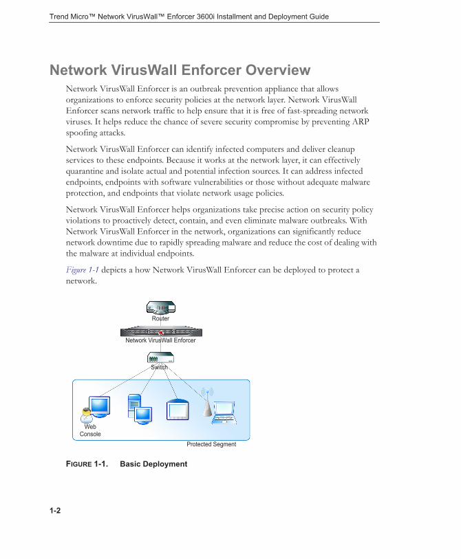
Network VirusWall Enforcer OverviewNetwork VirusWall Enforcer is an outbreak prevention appliance that allows organizations to enforce security policies at the network layer. Network VirusWall Enforcer scans network traffic to help ensure that it is free of fast-spreading network viruses. It helps reduce the chance of severe security compromise by preventing ARP spoofing attacks.
Network VirusWall Enforcer can identify infected computers and deliver cleanup services to these endpoints. Because it works at the network layer, it can effectively quarantine and isolate actual and potential infection sources. It can address infected endpoints, endpoints with software vulnerabilities or those without adequate malware protection, and endpoints that violate network usage policies.
Network VirusWall Enforcer helps organizations take precise action on security policy violations to proactively detect, contain, and even eliminate malware outbreaks. With Network VirusWall Enforcer in the network, organizations can significantly reduce network downtime due to rapidly spreading malware and reduce the cost of dealing with the malware at individual endpoints.
Figure 1-1 depicts a how Network VirusWall Enforcer can be deployed to protect a network.
FIGURE 1-1. Basic Deployment
Web Console
Protected Segment
Switch
Network VirusWall Enforcer
Router
1-2
Introducing Network VirusWall Enforcer
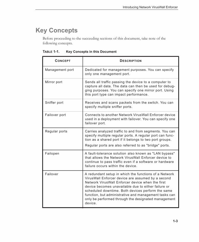
Key ConceptsBefore proceeding to the succeeding sections of this document, take note of the following concepts.
TABLE 1-1. Key Concepts in this Document
CONCEPT DESCRIPTION
Management port Dedicated for management purposes. You can specify only one management port.
Mirror port Sends all traffic passing the device to a computer to capture all data. The data can then be used for debug-ging purposes. You can specify one mirror port. Using this port type can impact performance.
Sniffer port Receives and scans packets from the switch. You can specify multiple sniffer ports.
Failover port Connects to another Network VirusWall Enforcer device used in a deployment with failover. You can specify one failover port.
Regular ports Carries analyzed traffic to and from segments. You can specify multiple regular ports. A regular port can func-tion as a shared port if it belongs to two port groups.
Regular ports are also referred to as "bridge" ports.
Failopen A fault-tolerance solution also known as "LAN bypass" that allows the Network VirusWall Enforcer device to continue to pass traffic even if a software or hardware failure occurs within the device.
Failover A redundant setup in which the functions of a Network VirusWall Enforcer device are assumed by a second Network VirusWall Enforcer device when the first device becomes unavailable due to either failure or scheduled downtime. Both devices perform the same function, but administrative and management tasks can only be performed through the designated management device.
1-3

Trend Micro™ Network VirusWall™ Enforcer 3600i Installment and Deployment Guide
Management device A Network VirusWall Enforcer device that is used to manage devices in a failover pair. All configurations from this device are replicated to the other device in the pair. You can select either the primary or secondary device to be the management device in a failover pair.
Primary device A device in a failover pair. This primary device is the default management device in a failover pair.
Secondary device The device that, by default, obtains all settings from the primary device in a failover pair.
Port groups A port group is typically a pair of regular ports, but it can comprise more ports. Unless the piece of traffic passes a shared port, any given traffic that enters and leaves the device is received and transmitted by ports belonging to the same port group.
Link-state failover A port group setting that turns off the working port if only one port in a port group is left connected. This ensures that switches immediately recognize the port group failure and can channel traffic to another route, such as another port group on the same device. This feature cannot be enabled if there is a shared port in the port group.
Preconfiguration console
The console used to preconfigure a Network VirusWall Enforcer device.
The preconfiguration process involves port configura-tion and setup of the management IP address to enable access to the web console.
Web console The browser-based administrative console for defining policies and managing the device.
TABLE 1-1. Key Concepts in this Document
CONCEPT DESCRIPTION
1-4
Introducing Network VirusWall Enforcer
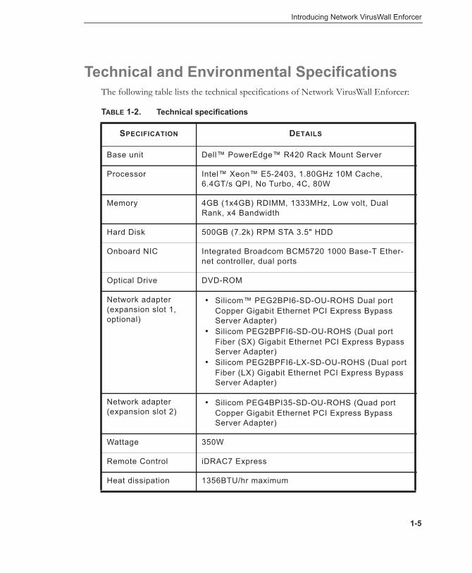
Technical and Environmental SpecificationsThe following table lists the technical specifications of Network VirusWall Enforcer:
TABLE 1-2. Technical specifications
SPECIFICATION DETAILS
Base unit Dell™ PowerEdge™ R420 Rack Mount Server
Processor Intel™ Xeon™ E5-2403, 1.80GHz 10M Cache, 6.4GT/s QPI, No Turbo, 4C, 80W
Memory 4GB (1x4GB) RDIMM, 1333MHz, Low volt, Dual Rank, x4 Bandwidth
Hard Disk 500GB (7.2k) RPM STA 3.5" HDD
Onboard NIC Integrated Broadcom BCM5720 1000 Base-T Ether-net controller, dual ports
Optical Drive DVD-ROM
Network adapter (expansion slot 1, optional)
• Silicom™ PEG2BPI6-SD-OU-ROHS Dual port Copper Gigabit Ethernet PCI Express Bypass Server Adapter)
• Silicom PEG2BPFI6-SD-OU-ROHS (Dual port Fiber (SX) Gigabit Ethernet PCI Express Bypass Server Adapter)
• Silicom PEG2BPFI6-LX-SD-OU-ROHS (Dual port Fiber (LX) Gigabit Ethernet PCI Express Bypass Server Adapter)
Network adapter (expansion slot 2)
• Silicom PEG4BPI35-SD-OU-ROHS (Quad port Copper Gigabit Ethernet PCI Express Bypass Server Adapter)
Wattage 350W
Remote Control iDRAC7 Express
Heat dissipation 1356BTU/hr maximum
1-5

Trend Micro™ Network VirusWall™ Enforcer 3600i Installment and Deployment Guide
The following table lists the environmental specifications of Network VirusWall Enforcer:
TABLE 1-3. Environmental specifications
SPECIFICATION DETAILS
Temperature (operating)
10° to 35°C (50° to 95°F) with a maximum temperature gradation of 10°C per hour
For altitudes above 2950 feet, the maximum operating temperature is de-rated 1°F/550ft.
Temperature (storage)
-40° to 65°C (-40° to 149°F) with a maximum temperature gradation of 20°C per hour
Relative humidity (operating)
20% to 80% (non-condensing) with a maximum humidity gradation of 10% per hour
Relative humidity (storage)
5% to 95% (non-condensing) with a maximum humidity gradation of 10% per hour
Maximum vibra-tion (operating)
0.26Gms from 5–350Hz for 5 minutes in operational orien-tations
Maximum vibra-tion (storage)
1.54Gms from 10–250Hz for 10 minutes in all orientations
Maximum shock (operating)
Half sine shock in all operational orientations of 31G plus or minus 5% with a pulse duration of 2.6ms plus or minus 10%
Maximum shock (storage)
Half sine shock on all six sides of 71G plus or minus 5% with a pulse duration of 2ms plus or minus 10%
Square wave shock on all six sides of 27G with a velocity change at 235in/sec or greater
Altitude (operat-ing)
-16 to 3048 m (-50 to 10,000 ft)
For altitudes above 2950ft, the maximum operating tem-perature is derated 1ºF/550ft.
Altitude (storage) -16 to 10,600 m (-50 to 35,000 ft)
1-6

Introducing Network VirusWall Enforcer
1-7

Trend Micro™ Network VirusWall™ Enforcer 3600i Installment and Deployment Guide
1-8

Chapter 2
Getting Started
This chapter guides you through setting up and powering on a Trend Micro™ Network VirusWall™ Enforcer device.
This chapter discusses the following topics:• Package Contents on page 2-2• Front Panel on page 2-4• Back Panel on page 2-10• Device Ports on page 2-11• Fiber-Optic Networks on page 2-16• Installing an Expansion Card on page 2-17• Installing the Device on page 2-19
2-1

Trend Micro™ Network VirusWall™ Enforcer 3600i Installment and Deployment Guide
Package ContentsFigure 2-1 illustrates the package contents.
FIGURE 2-1. Package contents
Note: The actual items in your package may appear slightly different from those shown in this document.
Refer to Table 2-1 to check whether the package is complete. If any of the items is missing, please contact Trend Micro support (see Getting Technical Support on page 5-3).
2-2

Getting Started
TABLE 2-1. Network VirusWall Enforcer package contents
QUANTITY ITEM DESCRIPTION
1 unit Network VirusWall Enforcer device
The device and the lockable bezel
1 piece Power cord Supplies power to the device
1 set Rack kit Mounts the device to a standard 19-inch rack cabinet
1 unit Network VirusWall Enforcer DVD
Bootable DVD that can be used to restore the device operating system and software. This DVD also includes tools and device documentation, specifically:
• Image file for the Network VirusWall Enforcer operating system
• Security Appliance License Agreement
• Third-party License Attributions• Administrator’s Guide• Installation and Deployment Guide• Quick Start Guide• Readme• Trend Micro™ Control Manager™
patches• Syslog and TFTP tools
Note: Refer to the troubleshooting section in the Administrator’s Guide for instructions on how to use the provided tools.
2-3

Trend Micro™ Network VirusWall™ Enforcer 3600i Installment and Deployment Guide
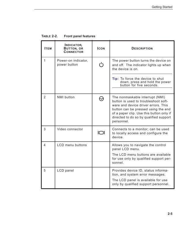
Front Panel
Figure 2-2 shows the controls, indicators, connectors, and features on the front panel behind the removable bezel. Table 2-2 provides component descriptions.
FIGURE 2-2. Front panel
3 printed documents
• Security Appliance License Agreement
• Quick Start Guide
• Dell™Product Information Guide
Printed documents that provide safety, licensing, and getting started informa-tion. Consult these documents before using Network VirusWall Enforcer.
TABLE 2-1. Network VirusWall Enforcer package contents (Continued)
QUANTITY ITEM DESCRIPTION
2-4
Getting Started
TABLE 2-2. Front panel features
ITEMINDICATOR, BUTTON, OR CONNECTOR
ICON DESCRIPTION
1 Power-on indicator, power button
The power button turns the device on and off. The indicator lights up when the device is on.
Tip: To force the device to shut down, press and hold the power button for five seconds.
2 NMI button The nonmaskable interrupt (NMI) button is used to troubleshoot soft-ware and device driver errors. This button can be pressed using the end of a paper clip. Use this button only if directed to do so by qualified support personnel.
3 Video connector Connects to a monitor; can be used to locally access and configure the device.
4 LCD menu buttons Allows you to navigate the control panel LCD menu.
The LCD menu buttons are available for use only by qualified support per-sonnel.
5 LCD panel Provides device ID, status informa-tion, and system error messages.
The LCD panel is available for use only by qualified support personnel.
2-5
Trend Micro™ Network VirusWall™ Enforcer 3600i Installment and Deployment Guide
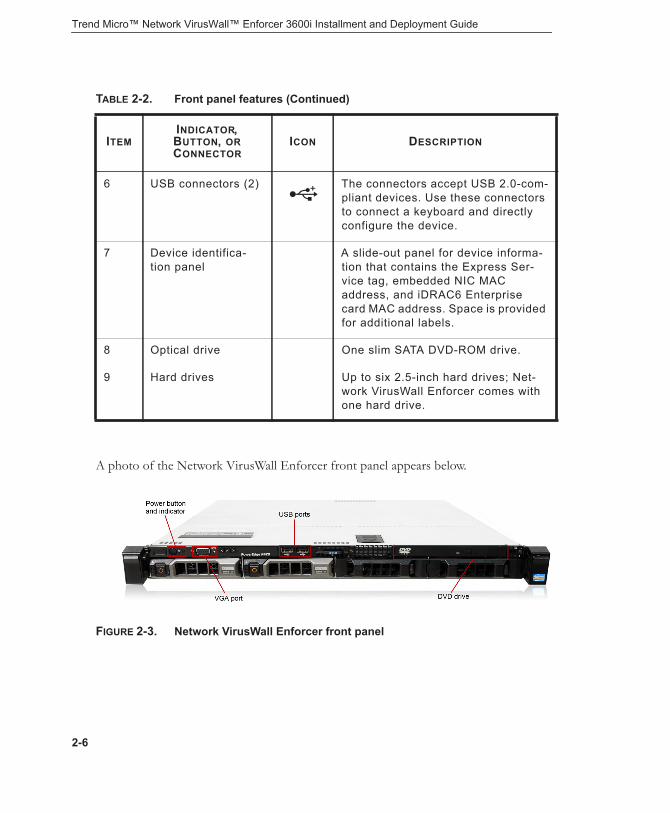
A photo of the Network VirusWall Enforcer front panel appears below.
FIGURE 2-3. Network VirusWall Enforcer front panel
6 USB connectors (2) The connectors accept USB 2.0-com-pliant devices. Use these connectors to connect a keyboard and directly configure the device.
7 Device identifica-tion panel
A slide-out panel for device informa-tion that contains the Express Ser-vice tag, embedded NIC MAC address, and iDRAC6 Enterprise card MAC address. Space is provided for additional labels.
8 Optical drive One slim SATA DVD-ROM drive.
9 Hard drives Up to six 2.5-inch hard drives; Net-work VirusWall Enforcer comes with one hard drive.
TABLE 2-2. Front panel features (Continued)
ITEMINDICATOR, BUTTON, OR CONNECTOR
ICON DESCRIPTION
2-6

Getting Started
Installing the BezelThe device is supplied with a removable bezel as shown in Figure 2-4.
FIGURE 2-4. Network VirusWall Enforcer with the bezel
2-7

Trend Micro™ Network VirusWall™ Enforcer 3600i Installment and Deployment Guide
To replace the bezel, hook the right end of the bezel onto the chassis, and then fit the free end of the bezel onto the device. Secure the bezel with the keylock.
FIGURE 2-5. Installing and removing the bezel
1 Release latch 2 Keylock
3 Bezel 4 Hinge tab
3
2
1
4
4 3
2
1
2-8

Getting Started
To remove the bezel:
1. Unlock the keylock at the left end of the bezel.2. Lift up the release latch next to the keylock.3. Rotate the left end of the bezel away from the front panel.4. Unhook the right end of the bezel and pull the bezel away from the device.
2-9

Trend Micro™ Network VirusWall™ Enforcer 3600i Installment and Deployment Guide
Back PanelFigure 2-6 shows the controls, indicators, and connectors located on the device's back panel.
FIGURE 2-6. Back panel
The number of network ports available through the NIC expansion slot varies depending on your device model. The base model uses only one expansion slot to add four ports—ports 3 to 6—as shown in the following image, for a total of six network ports.
FIGURE 2-7. Standard six-port configuration
2-10

Getting Started
Device PortsNetwork VirusWall Enforcer supports up to 8 network ports, with the first two ports (port 1 to 2) providing management functionality. More specifically, these ports can be configured as management (MGMT), mirror (MIRR), sniffer (SNIF), and failover (FOV) ports. The rest of the ports (ports 3 onwards) are regular (REG) data ports that connect to the network and provide security functionality. The device applies its protection features to packets that pass through these data ports.
FIGURE 2-8. Standard six-port configuration
Note: The failover port is for connection to another identical device. When connected though this port type, devices form a failover pair—a high-availability setup where one device is active while the other device serves as a backup device in case the active one goes offline.
2-11

Trend Micro™ Network VirusWall™ Enforcer 3600i Installment and Deployment Guide
Port FunctionsNetwork VirusWall Enforcer ports can be classified based on their function. As described earlier, there are regular data ports and management ports. Management ports can be assigned different functions as shown in the table below.
TABLE 2-3. Port types
TYPE (INTERFACE TYPE; PORT
NUMBER)
FUNCTION (CODE)
DEFAULT STATE DESCRIPTION
Data (Copper or Fiber; ports 3 onwards)
Regular (REG)
Only ports 3 and 4 are enabled
These are the standard ports used for policy enforcement. Network VirusWall Enforcer can assess endpoints con-nected to this port through L2 or L3 switches.
2-12

Getting Started
Management (Copper; ports 1 to 2)
Manage-ment (MGMT)
Disabled You can access the web con-sole through all regular ports, but you can also dedicate a single port for accessing the web console and managing the device.
Mirror (MIRR)
Assign this function to send all traffic through this port. You can use this port to capture all scanning data, which can be used for debugging. Note that having a mirror port can impact performance.
Sniffer (SNIF)
Like regular ports, sniffer ports can receive and scan packets. The sniffer port cannot be used to block or quarantine end-points for policy enforcement. You can assign multiple sniffer ports.
Failover (FOV)
To form a failover pair, connect two Network VirusWall Enforcer devices through their failover ports.
TABLE 2-3. Port types (Continued)
TYPE (INTERFACE TYPE; PORT
NUMBER)
FUNCTION (CODE)
DEFAULT STATE DESCRIPTION
2-13

Trend Micro™ Network VirusWall™ Enforcer 3600i Installment and Deployment Guide
By using bypass server adapters, Network VirusWall Enforcer data ports provide a fault-tolerance solution known as "failopen" or "LAN bypass". This solution allows the Network VirusWall Enforcer to continue passing network traffic even if other device components fail or when the device loses power.
Note: Management ports do not support failopen.
Data Port AdapterWhile the management ports are onboard ports, Network VirusWall Enforcer data ports are provided using any of the following server adapters. These adapters provide maximum network uptime with fiber or copper bypass circuitry.• Silicom PEG4BPi-SD-RoHS (Quad Port Copper Gigabit Ethernet PCI Express
Bypass Server Adapter)• Silicom PE2G4BPI35-SD-OU-ROHS (Quad port Copper Gigabit Ethernet PCI
Express Bypass Server Adapter)• Silicom PEG2BPI6-SD-OU-ROHS (Dual port Copper Gigabit Ethernet PCI
Express Bypass Server Adapter)• Silicom PEG2BPFI6-SD-OU-ROHS (Dual port Fiber (SX) Gigabit Ethernet PCI
Express Bypass Server Adapter)• Silicom PEG2BPFI6-LX-SD-OU-ROHS (Dual port Fiber (LX) Gigabit Ethernet
PCI Express Bypass Server Adapter)
By using bypass server adapters, Network VirusWall Enforcer data ports provide a fault-tolerance solution known as "failopen" or "LAN bypass". This solution allows Network VirusWall Enforcer to continue passing network traffic even when other device components fail or when the device loses power.
Note: Ports in the management interface do not support failopen.
Network Port IndicatorsEach Network VirusWall Enforcer port has an indicator that allows you to determine the port’s current state.
2-14

Getting Started
Indicators on Onboard PortsEach onboard port (ports 1-4) on the back panel has an indicator that provides information on network activity and link status. The following figures and tables describe the indicators on the onboard ports.
FIGURE 2-9. Onboard port indicators
Indicators on the Copper Expansion CardsNetwork VirusWall Enforcer can come with copper server adapters installed in its expansion slots. Each port in these cards corresponds to three LED indicators that provide the following information:• Link/Activity (top LED, green)—lit at any speed and blinks with activity• 100 (middle LED, green)—lit when connected at 100Mbit/s• 1000 (middle LED, green)—lit when connected at 1000Mbit/s
Indicators on the Fiber Expansion CardsNetwork VirusWall Enforcer can come in configurations with fiber server adapter cards. Each port in these cards corresponds to two LED indicators that provide the following information:• Link/Activity—lit when connected (yellow); blinks on activity (green)• Bypass—lit when bypass/failopen is active (green)
1 Link indicator 2 Activity indicator
1 2
2-15

Trend Micro™ Network VirusWall™ Enforcer 3600i Installment and Deployment Guide
Fiber-Optic NetworksNetwork VirusWall Enforcer can have an additional copper (Silicom PEG4BPi) or fiber-optic expansion card. Network VirusWall Enforcer offers the following fiber-optic server adapter options for the first expansion slot:• Silicom™ PEG2BPFI6-SD-OU-ROHS (Dual port Fiber (SX) Gigabit Ethernet
PCI Express Bypass Server Adapter)• Silicom PEG2BPFI6-LX-SD-OU-ROHS (Dual port Fiber (LX) Gigabit Ethernet
PCI Express Bypass Server Adapter)
Choosing a Fiber Media ConnectorNetwork VirusWall Enforcer fiber-optic server adapter options have LC connectors. If your network switches use SC connectors, you must choose the correct patch cord (optical fiber wiring) to ensure connectivity. You will also need an SC-to-LC fiber adapter.
FIGURE 2-10. The two ends of an SC-LC fiber media patch cord
The SC end The LC end
2-16

Getting Started
Table 2-4 lists the connector types for single or multi-mode fiber-optic cables.
Installing an Expansion Card
WARNING! Only trained service technicians should remove the device cover and access any of the components inside the device. Before you begin this procedure, review the safety instructions that came with the device.
1. Unpack the expansion card and prepare it for installation. For instructions, see the documentation accompanying the card.
2. Turn off the device, including any attached peripherals, and disconnect the device from the electrical outlet.
3. Open the device.4. Open the expansion card latch and remove the filler bracket.5. Install the expansion card:
a. Holding the card by its edges, position the card so that the card-edge connector aligns with the expansion card connector on the expansion card riser.
b. Insert the card-edge connector firmly into the expansion card connector until the card is fully seated.
c. Close the expansion card latch.
TABLE 2-4. Fiber media patch cords and connectors
PATCH CORD SWITCH MODE
Multi-mode duplex LC-LC connectors with fiber
GBIC, LC Multi-mode, LC
Multi-mode duplex SC-LC connectors with fiber
GBIC, SC Multi-mode, LC
Single-mode duplex SC-LC connectors with fiber
GBIC, SC Single-mode, LC
2-17
Trend Micro™ Network VirusWall™ Enforcer 3600i Installment and Deployment Guide
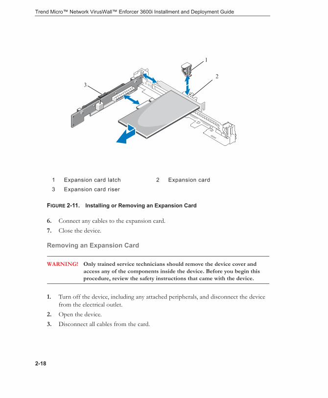
FIGURE 2-11. Installing or Removing an Expansion Card
6. Connect any cables to the expansion card.7. Close the device.
Removing an Expansion Card
WARNING! Only trained service technicians should remove the device cover and access any of the components inside the device. Before you begin this procedure, review the safety instructions that came with the device.
1. Turn off the device, including any attached peripherals, and disconnect the device from the electrical outlet.
2. Open the device. 3. Disconnect all cables from the card.
1 Expansion card latch 2 Expansion card
3 Expansion card riser
32
1
2-18
Getting Started
4. Remove the expansion card:a. Open the expansion card latch.
b. Grasp the expansion card by its edges, and carefully remove it from the expansion card connector.
5. If you are removing the card permanently, install a metal filler bracket over the empty expansion slot opening and close the expansion card latch.
Note: You must install a filler bracket over an empty expansion slot to maintain Federal Communications Commission (FCC) certification of the device. The brackets also keep dust and dirt out of the device and aid in proper cooling and airflow inside the device.
6. Close the device.
Installing the DeviceTo use Network VirusWall Enforcer:• Mounted to a standard 19-inch four-post rack cabinet
The device requires 1 rack unit (RU) of vertical space in the rack.
Tip: If mounting more than one device, position and mount the devices in close proximity. Doing so allows you to easily maintain the devices.
• On any stable surface as a freestanding deviceFor freestanding installation, ensure that the device has at least 2in (5.08 cm) of clearance on each side to allow for adequate airflow and cooling.
WARNING! Ensure that the fan vent is not blocked.
2-19

Trend Micro™ Network VirusWall™ Enforcer 3600i Installment and Deployment Guide
Installing the device involves performing the following tasks.
WARNING! Before performing the following tasks, review the safety instructions in the Product Information Guide that came with the device.
Step 1: Unpack the deviceUnpack your device. The Network VirusWall Enforcer rack kit does not require screws and is very simple to use. The kit contains two rail assemblies and two Velcro straps.
Step 2: Install the rails and device in a rackAssemble the rails and install the device in the rack.
Note: For detailed information about hardware components and instructions on how to assemble the rack kit, visit the Dell™ PowerEdge™ R420 document repository http://www.dell.com/support/Manuals/us/en/19/product/poweredge-r420.
Step 3: Connect the keyboard and monitor (optional)
FIGURE 2-12. Connecting the keyboard and the monitor
2-20

Getting Started
Connect the keyboard and monitor. The connectors on the back of your device have icons indicating which cable to plug into each connector. Be sure to tighten the screws (if any) on the monitor's cable connector.
Step 4: Connect the power cables
FIGURE 2-13. Connecting the power cables
Connect the power cable(s) to the device and, if using a monitor, connect the monitor’s power cable to the monitor.
2-21

Trend Micro™ Network VirusWall™ Enforcer 3600i Installment and Deployment Guide
Step 5: Secure the power cables
FIGURE 2-14. Securing the power cables
Bend the power cable(s) of the device into a loop as shown in the illustration and secure the cable to the bracket using the provided strap.
Plug the other end of the power cables into a grounded electrical outlet or a separate power source, such as an uninterruptible power supply (UPS) or a power distribution unit (PDU).
2-22
Getting Started
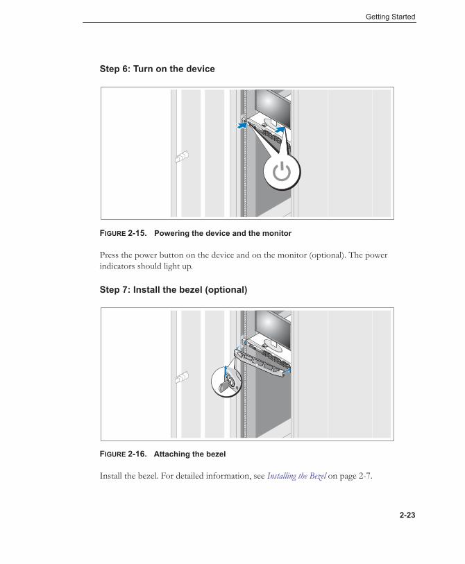
Step 6: Turn on the device
FIGURE 2-15. Powering the device and the monitor
Press the power button on the device and on the monitor (optional). The power indicators should light up.
Step 7: Install the bezel (optional)
FIGURE 2-16. Attaching the bezel
Install the bezel. For detailed information, see Installing the Bezel on page 2-7.
2-23

Trend Micro™ Network VirusWall™ Enforcer 3600i Installment and Deployment Guide
2-24

Chapter 3
Deploying Network VirusWall Enforcer
Before configuring a Network VirusWall Enforcer device, plan how to integrate the device into your network. Determine the topology it will support.
This chapter explains how to plan for the deployment. It also provides deployment scenarios to help you understand the various ways the device can protect your network.
This chapter discusses the following topics:• Planning for Deployment on page 3-2• Identifying What to Protect on page 3-5• Planning for Network Traffic on page 3-16• High Availability and Fault Tolerance on page 3-17• Conducting a Pilot Deployment on page 3-21• Redefining Your Deployment Strategy on page 3-22• Deployment Scenarios on page 3-22
3-1

Trend Micro™ Network VirusWall™ Enforcer 3600i Installment and Deployment Guide
Planning for DeploymentTo take advantage of the benefits Network VirusWall Enforcer can bring to your organization, you will need to understand the possible ways to deploy one or more devices. This section provides a deployment overview and introduces important considerations.
Note: This version only supports EtherChannel in a single device environment with two port groups.
Deployment OverviewFollow three stages of deployment to successfully install the device(s).
Tip: This Installment and Deployment Guide discusses phases 1 and 2. Refer to the Administrator’s Guide for information related to phase 3.
PHASE 1: PLAN DEPLOYMENT
PHASE 2: PERFORM PRECONFIGURATION
Gather network informationIdentify your deployment strategyConduct a pilot deploymentRedesign your deployment strategy
Perform initial preconfiguration tasksPerform preconfigurationConnect the device to your network
Deploy componentsConfigure basic settings
PHASE 3: MANAGE DEVICES
3-2
Deploying Network VirusWall Enforcer
Phase 1: Plan the DeploymentDuring phase 1, plan how to best deploy the device(s) by completing these tasks:
• Identify the segments of your network that are in the greatest need of protection.
• Plan for network traffic, considering the location of critical computers, such as email, web, and application servers.
• Determine the number of devices needed to meet your security needs and their locations on the network.
• Conduct a pilot deployment on a test segment of your network.• Redefine your deployment strategy based on the results of the pilot
deployment.
Phase 2: Perform PreconfigurationIn phase 2, begin implementing the plan you created in phase 1 by performing the following tasks:
• Perform the initial preconfiguration tasks (see Before Preconfiguration on page 4-2).
• Perform preconfiguration on the device(s) (see Performing Preconfiguration on page 4-4).
• Connect the device(s) to your network (see Connecting to the Network on page 4-12).
Phase 3: Manage DevicesDuring phase 3, manage Network VirusWall Enforcer devices from the web console. For this phase, consult the following sections of the Administrator’s Guide:• Understanding Network VirusWall Enforcer provides details about relevant concepts,
including management options, endpoints, security risks, policy enforcement, device ports, high availability and fault tolerance, updatable components, SNMP support, and VLAN support.
• Preparing for Policy Enforcement discusses the tasks you need to perform before creating policies and deploying them to your network.
• Policy Creation and Deployment covers actual policy creation, providing sample scenarios and instructions.
3-3

Trend Micro™ Network VirusWall™ Enforcer 3600i Installment and Deployment Guide
Deployment NotesConsider the following when planning for a deployment:• All traffic to and from a network segment must go through the device.
To protect an organization from network threats, position the device in a key place on your network segment. The device should be able to scan all network traffic to prevent, detect, or contain threats.
• Each of the interfaces supports the following port speed and duplex mode settings:
Note: Both the connected L2/L3 and Network VirusWall Enforcer devices should have the same port speed and duplex mode. Otherwise, the Network VirusWall Enforcer port will operate in half-duplex mode. To simplify configuration, you can set Network VirusWall Enforcer to auto-select the optimum port speed and duplex mode. Likewise, allow your switch to auto-select the port speed and duplex mode.
• For IPv4 addresses, the device supports addresses belonging to any class (class A, B, or C). For IPv6 addresses, it supports global unicast and link-local addresses.
Tip: Although each range is in a different class, you are not required to use any particular range for your internal network. However, selecting a fixed range greatly diminishes the chance of IP addressing conflicts.
• Policy enforcement and network virus scan support various actions for noncompliant or infected endpoints.
• 10Mbps x half-duplex
• 10Mbps x full-duplex
• 100Mbps x half-duplex
• 100Mbps x full-duplex
• 1000Mbps x full-duplex
3-4

Deploying Network VirusWall Enforcer
Identifying What to ProtectPosition Network VirusWall Enforcer between layer 2 (L2) or layer 3 (L3) devices. This way, the device can apply its protection to packets coming in or out of your network.
Identify segments of your network to protect by considering which kinds of endpoints may introduce security risks or violate security policies. Also, consider the location of resources that are critical to your organization, such as: • Remote endpoints that access your internal network resources • Guest endpoints that temporarily connect to your network • Key network segments/important network assets, such as places on the network
that contain email, web, or application servers
Remote Access EndpointsRemote endpoints access internal network resources in the same manner as the endpoints already on your network and comprise essentially another internal network segment. You must consider whether to protect remote endpoints as you do internal endpoints.
You can consider two types of remote endpoints: • Dialup/VPN users—telecommuters who typically dial up or use VPN to connect
to your network• External business units—offices located outside the main network site that need
access to resources on the main network
A home user could establish a dialup connection or a VPN connection to access a company’s internal network resources. Most likely, business units would establish a VPN connection.
3-5

Trend Micro™ Network VirusWall™ Enforcer 3600i Installment and Deployment Guide
FIGURE 3-1. Dialup service deployment scenario
Figure 3-1 illustrates a dialup connection between a home user and an organization’s internal network. A RAS server, the point where the dialup connection terminates, is connected to a regular port (see Key Concepts on page 1-3 for information about different types of ports). This means that all packets going between the RAS server and the LAN pass through the device. Once the home user establishes a connection with the RAS server, it essentially becomes part of the internal network, as illustrated in the basic deployment scenario (see Basic Deployment on page 3-23). The home user accesses both network resources and the Internet in the same way that internal endpoints access them.
RAS server Dialup endpoint
Public switched telephone network
To the LAN
3-6
Deploying Network VirusWall Enforcer
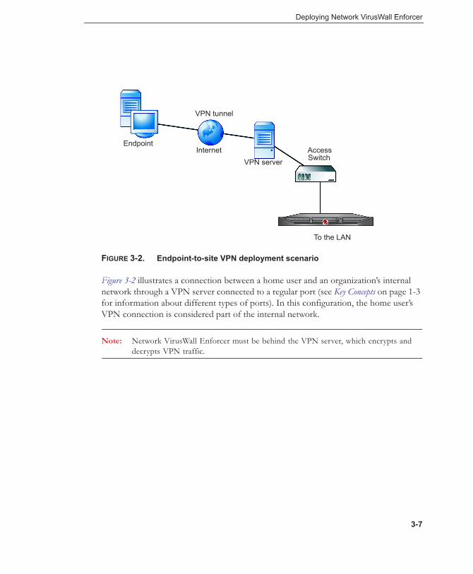
FIGURE 3-2. Endpoint-to-site VPN deployment scenario
Figure 3-2 illustrates a connection between a home user and an organization’s internal network through a VPN server connected to a regular port (see Key Concepts on page 1-3 for information about different types of ports). In this configuration, the home user’s VPN connection is considered part of the internal network.
Note: Network VirusWall Enforcer must be behind the VPN server, which encrypts and decrypts VPN traffic.
EndpointInternet Access
SwitchVPN server
VPN tunnel
To the LAN
3-7

Trend Micro™ Network VirusWall™ Enforcer 3600i Installment and Deployment Guide
The recommended settings for this scenario are the same as the settings for the dialup user scenario (see Figure 3-1).
FIGURE 3-3. Site-to-site VPN deployment scenario
Figure 3-3 illustrates a VPN connection between two business units. As in the home user scenario, a VPN server is connected to a regular port on each device (see Key Concepts on page 1-3 for information about different types of ports).
Business unit A Business unit BVPN tunnel
Network A Network B
3-8
Deploying Network VirusWall Enforcer
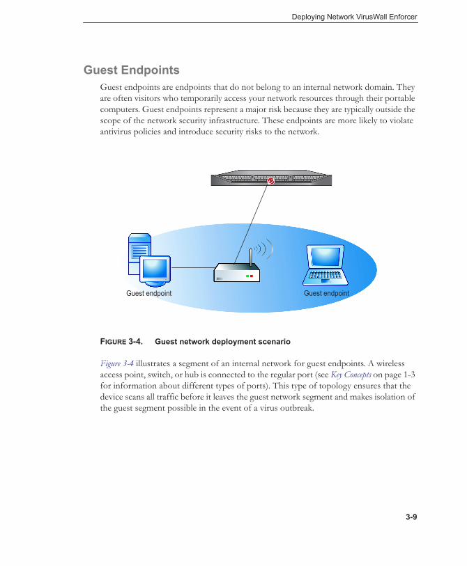
Guest EndpointsGuest endpoints are endpoints that do not belong to an internal network domain. They are often visitors who temporarily access your network resources through their portable computers. Guest endpoints represent a major risk because they are typically outside the scope of the network security infrastructure. These endpoints are more likely to violate antivirus policies and introduce security risks to the network.
FIGURE 3-4. Guest network deployment scenario
Figure 3-4 illustrates a segment of an internal network for guest endpoints. A wireless access point, switch, or hub is connected to the regular port (see Key Concepts on page 1-3 for information about different types of ports). This type of topology ensures that the device scans all traffic before it leaves the guest network segment and makes isolation of the guest segment possible in the event of a virus outbreak.
Guest endpoint Guest endpoint
3-9

Trend Micro™ Network VirusWall™ Enforcer 3600i Installment and Deployment Guide
Key Segments and Critical AssetsKey network segments need to be protected from network-based threats. This may include a group of endpoint computers or network resources critical to your organization, such as email, web, or application servers.
FIGURE 3-5. Key network segments scenario
The diagram above illustrates a segment of an internal network containing email and web servers, including endpoints. An internal switch or hub is connected to a regular port (see Key Concepts on page 1-3 for information about different types of ports), creating a segment where all packets going in and out of the segment can be scanned. Installing the device in this position adds the benefits of virus scanning and segment isolation in the event of a virus outbreak.
Critical hosts
L2 switch
L3 switch
3-10

Deploying Network VirusWall Enforcer
The device can also guard against attacks that not only originate on the Internet, but also attacks that may originate from within your network. Since traffic first passes through the device before reaching email and web servers, the device can scan and detect infected packets that come from endpoints on the LAN.
Dual-Switch VLAN EnvironmentNetwork VirusWall Enforcer must be placed in line on the physical network to provide security. In most situations, this means placing it between an upstream switch and one or more downstream switches.
Most VLAN configurations will utilize two switches. Single-switch VLAN configurations are possible; for more information, refer to Single-Switch VLAN Environment on page 3-13. The figures in this section illustrate multiple downstream switches in a flat topology; however, a single in line configuration is also possible.
In Figure 3-6, the devices are installed between an upstream switch and downstream switches. This configuration is appropriate when multiple VLANs carry moderate network traffic, and the upstream switch carries high-bandwidth traffic.
Note: Ensure that Spanning Tree Protocol (STP) is enabled. If STP is not enabled, packets may loop for an indefinite period.
3-11

Trend Micro™ Network VirusWall™ Enforcer 3600i Installment and Deployment Guide
FIGURE 3-6. Multiple VLAN segments with each device protecting one segment
In Figure 3-6, the devices are installed on an 802.1Q trunk line between two switches.
802.1Q Trunk
VLAN 10 VLAN 20 VLAN 30
3-12
Deploying Network VirusWall Enforcer
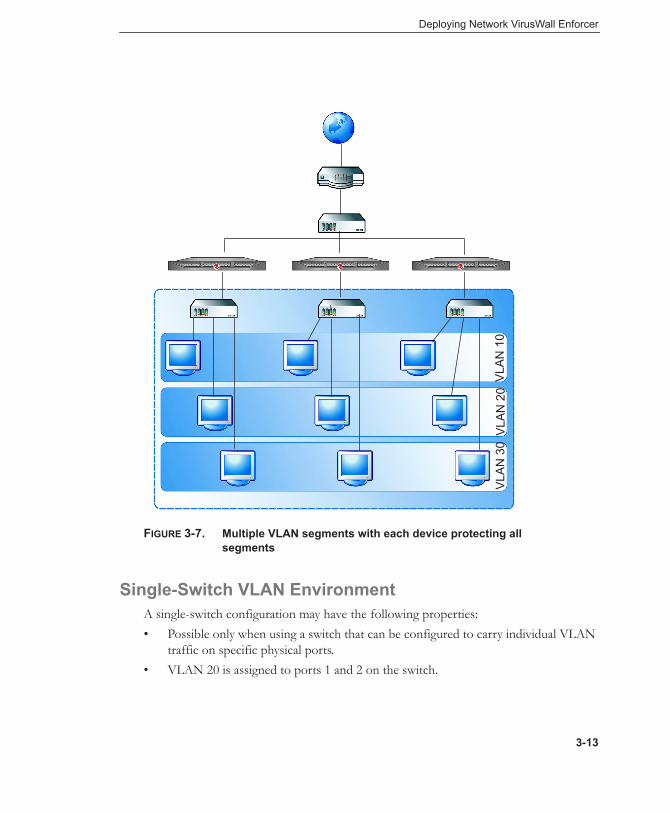
FIGURE 3-7. Multiple VLAN segments with each device protecting all segments
Single-Switch VLAN EnvironmentA single-switch configuration may have the following properties:• Possible only when using a switch that can be configured to carry individual VLAN
traffic on specific physical ports.• VLAN 20 is assigned to ports 1 and 2 on the switch.
VLA
N 1
0V
LAN
20
VLA
N 3
0
3-13

Trend Micro™ Network VirusWall™ Enforcer 3600i Installment and Deployment Guide
• The upstream network is connected to port 2 on the switch.• The regular port on Network VirusWall Enforcer is connected to port 1 on the
switch.• Endpoints are connected to other regular ports on Network VirusWall Enforcer.
FIGURE 3-8. Single-switch VLAN environment
Networks with IPv6 AddressesAdministrators deploying Network VirusWall Enforcer in an environment with IPv6 addresses must plan carefully to ensure that the device can provide protection and does not interfere with network connectivity.
IPv6 LimitationsThe following features are not supported on IPv6 networks:• Threat mitigation with Threat Discovery Appliance• Policies that require user authentication using Kerberos• Program rescue• Enforcement of network application policies (port activity, instant messengers, file
transfers, and Outbreak Prevention Policy)• Remote detection of endpoint operating systems for policy enforcement• ActiveUpdate through Network Address Translation/Protocol Translation
(NAT-PT)• Addressing:
• Dynamic addressing from a Windows DHCPv6 server
3-14
Deploying Network VirusWall Enforcer
• Limited Linux DHCPv6 support; the device can obtain an IP address, a prefix, and a DNS from a Linux DHCPv6 server, but it will not be able to obtain gateway settings.
• Specifying a link-local IP address as the update source
Pure IPv6 EnvironmentsIn environments with purely IPv6 hosts, administrators do not need to perform special deployment tasks. As long as Network VirusWall Enforcer is supplied with a valid IPv6 address, it can function normally. Note, however, that certain device features are not available in pure IPv6 environments as described in IPv6 Limitations on page 3-14.
Note: Many resources on the Internet, including the Trend Micro™ ActiveUpdate™ and product registration servers, are accessible only through IPv4 traffic. When configured as an IPv6-only host, Network VirusWall Enforcer traffic to and from the Internet can be translated using a dual-stack proxy.
Dual-Stack and Mixed EnvironmentsEnvironments with dual-stack hosts or those with both IPv6 and IPv4 hosts require relatively complex deployment planning. Consider the following key points during planning:• Ensure that you configure both an IPv4 and IPv6 address for Network VirusWall
Enforcer if it will be processing both kinds of traffic.• Network VirusWall Enforcer cannot perform traffic translation when in dual-stack
mode. It will treat IPv6 and IPv4 traffic independently.• Note the limitations of the device on IPv6 networks as discussed in IPv6 Limitations
on page 3-14.
3-15

Trend Micro™ Network VirusWall™ Enforcer 3600i Installment and Deployment Guide
Planning for Network TrafficThe scenario presented in Key Segments and Critical Assets on page 3-10 is a good example of how to plan for network traffic. There is a strategic advantage to positioning the device in front of resources that endpoints access regularly, such as an email server or an Internet gateway. Because many viruses make their way into networks through email attachments and web browsers, forcing traffic to pass through the device significantly reduces the risk of virus infection. Identify other places on your network through which large amounts of traffic pass and consider placing the device where it can scan the most traffic.
Determining the Number of Devices to DeployDetermine how many devices would best meet your security requirements. Consider the following factors:• Existing network topology—based on your network topology, identify the
segments that you want the device to protect (see Identifying What to Protect on page 3-5)
• Existing network device interfaces—because a device handles 10/100Mbps or 1Gbps Fast Ethernet traffic, identify the network device interfaces that handle the same type of traffic and can therefore connect to Network VirusWall Enforcer devices
• Desired effectiveness of protection—to lower the risk of a virus outbreak spreading, segment several sections of your network with Network VirusWall Enforcer devices
• Desired degree of performance—consider the number of endpoints and the amount of traffic that a device can handle
Port GroupingPort grouping allows a single Network VirusWall Enforcer device to handle multiple sets of independent physical links. You can use these independent links to provide redundant connections and increase availability.
3-16

Deploying Network VirusWall Enforcer
Avoiding MAC Flapping ErrorsA switch may return MAC flapping errors if it is connected to a Network VirusWall Enforcer device on multiple ports, particularly if the Network VirusWall Enforcer ports are in different port groups and if these port groups are not in distinct VLANs. This happens because Network VirusWall Enforcer ports use the same bridge MAC address, causing all packets from the device to carry the same MAC address.
In Figure 3-9, the multiple connections to switch 3 can cause MAC flapping errors on this switch. However, these errors will not occur if port groups 1 and 2 on the Network VirusWall Enforcer device are in separate VLANs.
FIGURE 3-9. Deployment prone to MAC flapping errors
High Availability and Fault ToleranceNetwork VirusWall Enforcer achieves high availability (HA) and fault tolerance using the following solutions:
• Redundant Ports and Devices on page 3-18• Failover on page 3-18• Failopen on page 3-19
Switch 3
Switch 1 Switch 2
Network VirusWall Enforcer
Port 1
Port 2
Port 3
Port 4
Port Group 1
Port Group 2
3-17

Trend Micro™ Network VirusWall™ Enforcer 3600i Installment and Deployment Guide
Redundant Ports and DevicesPort redundancy uses redundant physical links for maximum network uptime and reliability. A mesh network is typically the target topology for a port redundant deployment.
In a port redundant deployment, Network VirusWall Enforcer provides two ports each for the uplink and downlink connections. A port redundant deployment requires the completion of the following tasks:1. Allocate regular ports to define two distinct port groups.2. Attach redundant physical links to the two port groups.
To enable the failover fault-tolerance solution, redundant devices usually accompany the port redundant deployment. Multiple connection paths can exist, each with a redundant device, helping ensure that the connection is still viable even if one (or more) paths fail. The capacity for automatic failover means that the device can maintain normal functions despite the interruptions caused by problems with equipment. In a failover deployment, if one of the devices in a failover pair fails, the other Network VirusWall Enforcer device maintains all settings, connections, and sessions.
Port Redundancy ConsiderationsConsider the following points when implementing a port redundancy deployment:• A redundant deployment involves two port groups with different ports • Each port group can possess configurable attributes—you can choose whether or
not to configure settings for a port group• Packets cannot be routed into different port groups
FailoverA failover deployment involves two identical Network VirusWall Enforcer devices—the primary and the secondary device. With failover, if a Network VirusWall Enforcer device fails or is temporarily shut down for servicing, switches can seamlessly route packets to another device. You can configure failover settings only from the Preconfiguration console.
3-18

Deploying Network VirusWall Enforcer
A failover deployment requires the completion of the following tasks:1. Specify a failover port for each device. The failover port should be the same port
number for both devices.2. Establish the failover link between the two devices.3. Specify the Management device.4. Establish a Network VirusWall Enforcer connection to other network devices.
Failover ConsiderationsConsider the following points when implementing a failover deployment:• A Network VirusWall Enforcer failover pair must consist of identical
devices—same model and running the same program file version. Otherwise, the failover cannot work.
• Check whether the switches connected to the devices have Spanning Tree Protocol (STP) enabled. If STP is not enabled and a failover pair is deployed in the network, packets will loop for an indefinite period in networks with physically redundant links.
• Do not automatically update the program file for the devices in a failover pair. Doing so alters the settings for the failover devices, which can result in differences in settings and subsequently the disconnection of the failover link. Exclude the program file from automatic updates.
• Network VirusWall Enforcer disables failopen (LAN bypass) in a failover environment.
FailopenFailopen or LAN bypass involves one Network VirusWall Enforcer device. Failopen is a fault-tolerance solution that allows a Network VirusWall Enforcer to continue passing network traffic even when other device components fail or when the device loses power.
Any port group can be configured for failopen simply by enabling failopen for the port group through the Preconfiguration console.
Failopen ConsiderationsConsider the following important points about failopen:
3-19

Trend Micro™ Network VirusWall™ Enforcer 3600i Installment and Deployment Guide
• If the switches on your network do not support auto MDI/MDI-X, use a crossover and non-crossover cable combination to enable failopen. Invalid cable combinations prevent Network VirusWall Enforcer from using failopen and can result in network issues. Refer to device documentation to determine whether your L2 switches support auto MDI/MDI-X.
• All regular ports on the device support LAN bypass and will allow traffic bypass even when the device is powered off.
• To help ensure that failopen works, keep the total length of the network cable connecting regular copperports to other devices within 100 meters (~328 feet). For SX fiber-optic ports, the length should not be longer than 500 meters (~1640 feet). For LX fiber-optic ports, the length should not be longer than 3000 meters (~9842 feet).
• If you implemented port grouping with failover or port redundancy with failover, the device automatically disables failopen.
• Failopen must be enabled through the following pairs:• Ports 3 and 4• Ports 5 and 6• Ports 7 and 8You cannot split these pairs by, for example, grouping port 5 and port 8 and then enabling failopen in this port group.
• Resetting a Network VirusWall Enforcer device with failopen enabled temporarily blocks network connection for about 30 seconds.
3-20

Deploying Network VirusWall Enforcer
• Table 3-1 describes the connection status of ports with and without failopen when certain procedures are performed.
Conducting a Pilot DeploymentTrend Micro recommends conducting a pilot deployment in a controlled environment to help you understand how the device features work. A pilot deployment also helps you determine how the device can be used to accomplish your security goals and the level of support you will likely need after a full deployment.
Perform the following tasks to conduct a pilot deployment:
TABLE 3-1. Port status
TIME(SECONDS) PROCEDURE REGULAR PORTS
WITH FAILOPEN
REGULAR PORTS WITHOUT FAILOPEN
2 Restarting the device
Disconnected Disconnected
102 Configuring mem-ory
Connected Disconnected
Initializing Connected Disconnected
Loading Grand Uni-fied Bootloader (GRUB)
Connected Disconnected
Booting Network VirusWall Enforcer mini kernel
Connected Disconnected
Starting kernel Connected Disconnected
17 Disabling failopen and bridge learning
Disconnected Disconnected
n/a Preconfiguring the device
Connected Connected
3-21

Trend Micro™ Network VirusWall™ Enforcer 3600i Installment and Deployment Guide
• Choose a pilot site.• Create a contingency plan.• Deploy and evaluate your pilot.
Choosing a Pilot SiteChoose a pilot site that matches your planned deployment. Look at other devices on your network, such as switches or firewalls, and other software installations, such as OfficeScan™ and Control Manager™. Try to simulate the type of topology that would serve as an adequate representation of your production environment.
Creating a Contingency PlanTrend Micro recommends creating a contingency plan in case there are issues with the installation, operation, or upgrade of the device. Consider your network’s vulnerabilities and how you can retain a minimum level of security if issues arise.
Deploying and Evaluating your PilotDeploy and evaluate the pilot based on expectations regarding both security enforcement and network performance. Create a list of items that meet or do not meet the expected results during the pilot process.
Redefining Your Deployment StrategyIdentify the potential pitfalls and plan accordingly for a successful deployment. Consider especially how the device performed with the security installations on your network. This pilot evaluation can be rolled into the overall production and deployment plan.
Deployment ScenariosA deployment plan is dependent upon the options you select. This section provides examples of a basic deployment scenario.
A deployment plan is dependent upon the options you select. This section provides examples of a few basic deployment strategies:
3-22

Deploying Network VirusWall Enforcer
• Basic Deployment Scenario on page 3-23• Port Grouping with Failover Deployment on page 3-25• Port Redundancy Deployment with Failover on page 3-31
Tip: See Performing Preconfiguration on page 4-4 and Verifying Network Support on page 4-2 for checklists on how to prepare a device for deployment.
Basic Deployment ScenarioThe device can be installed on a network that contains Ethernet devices such as hubs, switches, and routers. Deploy Network VirusWall Enforcer between a switch that leads to the public network and a switch that protects a segment of the local area network (LAN). It can also be installed between an edge switch and a hub.
Figure 3-10 illustrates a basic deployment scenario. A switch or a router is connected to a regular port.
FIGURE 3-10. Basic Deployment
Network VirusWall Enforcer protects your network as follows:• Scans traffic to and from endpoints
Web Console
Protected Segment
Switch
Network VirusWall Enforcer
Router
3-23

Trend Micro™ Network VirusWall™ Enforcer 3600i Installment and Deployment Guide
• Prevents endpoints that violate your security policies from gaining access to resources
• Isolates endpoints in the event of a virus infection
In this deployment setup, you may opt to enable failopen. With failopen enabled, traffic can still pass through the device if the device encounters a hardware or system error that prevents it from filtering network packets.
Multi-Protection Zone Configuration without FailoverIn this sample deployment scenario, internal ports connect to four different L2 switches (or port segments) to create a protection zone. A fiber-optic port connects to an external L2 or L3 switch as the external port. Figure 3-11 illustrates this deployment scenario.
.FIGURE 3-11. Port grouping without failover, multi-protection zone
configuration, and 1 fiber port
Fiber port
3-24
Deploying Network VirusWall Enforcer
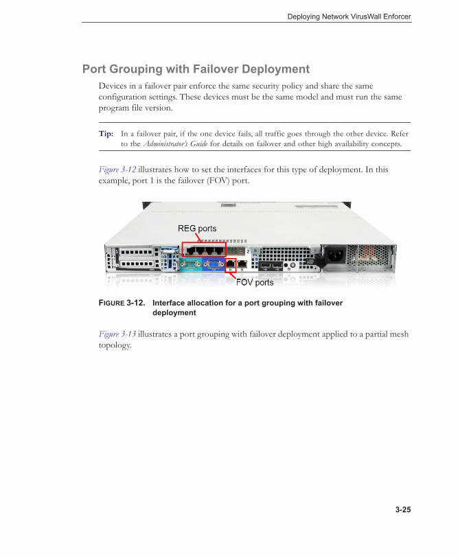
Port Grouping with Failover DeploymentDevices in a failover pair enforce the same security policy and share the same configuration settings. These devices must be the same model and must run the same program file version.
Tip: In a failover pair, if the one device fails, all traffic goes through the other device. Refer to the Administrator’s Guide for details on failover and other high availability concepts.
Figure 3-12 illustrates how to set the interfaces for this type of deployment. In this example, port 1 is the failover (FOV) port.
FIGURE 3-12. Interface allocation for a port grouping with failover deployment
Figure 3-13 illustrates a port grouping with failover deployment applied to a partial mesh topology.
3-25

Trend Micro™ Network VirusWall™ Enforcer 3600i Installment and Deployment Guide
FIGURE 3-13. Port grouping with failover deployment, partial mesh
The following points apply to a port grouping with failover deployment:• One failover port exists, which connects to the other device in a failover pair
through an RJ-45 crossover or straight through cable.• The failover pair has one primary device and one secondary device.• Both devices filter network packets.• If the primary device is the management device and it fails, the secondary device
becomes the device that filters all traffic.• A device that is not the management device cannot be configured through the
Preconfiguration or the web console. The management device replicates the configuration settings and updates the antivirus components (except the Program file) to the other device.
• The failover link allows both devices to have identical configuration settings.
Note: Stateful failover does not apply to the Network Virus Engine component. For details about Network VirusWall Enforcer components, see the Administrator’s Guide.
• The device disables failopen (LAN bypass) in a failover environment. However, as soon as one device in the failover pair is down, failopen is automatically enabled on the active device if the feature has been turned on.
Primary Secondary
3-26

Deploying Network VirusWall Enforcer
In a partial mesh deployment, only the connection between the access L2 and distribution L3 switches has redundant links (Figure 3-14). The connection between distribution L3 and L3 access switches has only a single link.
You can install two Network VirusWall Enforcer devices between L2 and L3 switches or distribution L3 switches and L3 access switches by linking them together using a failover link. In this deployment scenario, the two devices start to synchronize the information and you manage the management device through the web console.
3-27
Trend Micro™ Network VirusWall™ Enforcer 3600i Installment and Deployment Guide
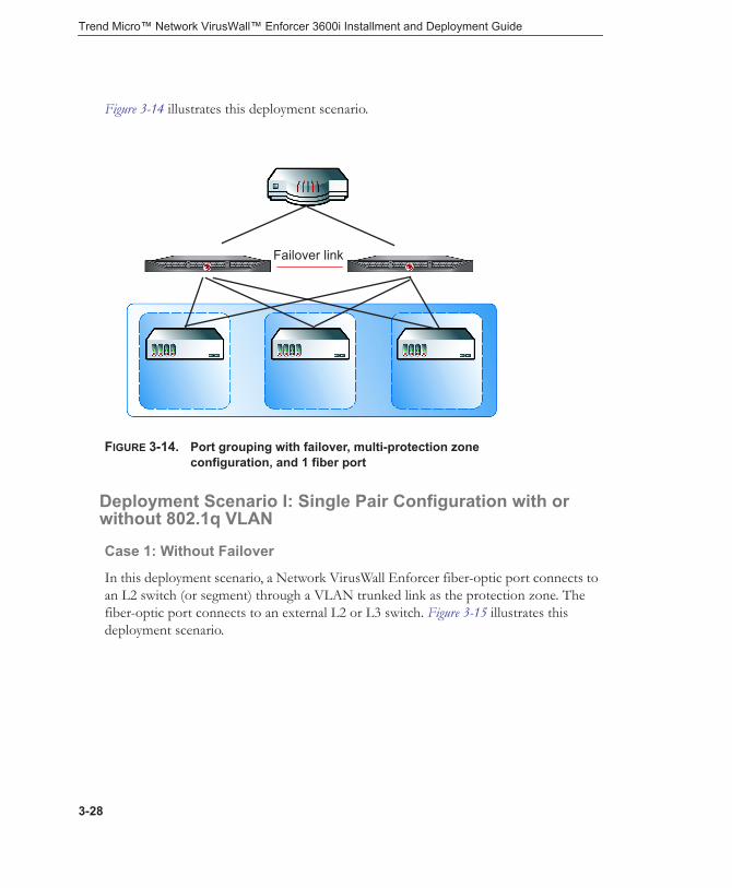
Figure 3-14 illustrates this deployment scenario.
FIGURE 3-14. Port grouping with failover, multi-protection zone configuration, and 1 fiber port
Deployment Scenario I: Single Pair Configuration with or without 802.1q VLAN
Case 1: Without Failover
In this deployment scenario, a Network VirusWall Enforcer fiber-optic port connects to an L2 switch (or segment) through a VLAN trunked link as the protection zone. The fiber-optic port connects to an external L2 or L3 switch. Figure 3-15 illustrates this deployment scenario.
Failover link
3-28

Deploying Network VirusWall Enforcer
FIGURE 3-15. Single pair configuration with or without 802.1q VLAN
Case 2: With Failover
In this scenario, two L2 or L3 switches are configured as a port-to-port channel. The redundant uplinks of the L2 switch connect to two individual Network VirusWall Enforcer devices joined by a failover link. Figure 3-16 illustrates this deployment scenario.
Fiber connection
3-29

Trend Micro™ Network VirusWall™ Enforcer 3600i Installment and Deployment Guide
FIGURE 3-16. Case 2: Failover pair with single-switch dual-port multi-mode fiber
Deployment Scenario II: Point-to-Point Links with Dual-Port Multi-Mode Fiber-Optic Server Adapter
Two Pairs of Fiber-Copper Port without Failover
In this deployment scenario, two fiber ports replace the on-board copper external ports. External and internal ports connect to the uplink and downlink switches through two individual links.
Figure 3-17 illustrates this deployment scenario.
Failover link
Fiber connectionFiber connection
Fiber connectionFiber connection
3-30

Deploying Network VirusWall Enforcer
FIGURE 3-17. Point-to-point links using two pairs of fiber-copper ports
Port Redundancy Deployment with FailoverTo maximize the benefit of port redundancy, configure high availability along with the port groups. If one device fails, all functions of the matching devices continue to operate, helping prevent interruptions in packet filtering.
Fiber connections
3-31

Trend Micro™ Network VirusWall™ Enforcer 3600i Installment and Deployment Guide
Port redundancy with failover deployment requires two port groups and a failover port. The following figure illustrates the interface allocation. Note that only an onboard port (ports 1 to 4) can be configured as a failover port.
FIGURE 3-18. Interface allocation for a port redundancy deployment with failover
Trend Micro recommends implementing a port redundant deployment with failover in a full mesh topology. Figure 3-19 illustrates this strategy.
FIGURE 3-19. Port redundant deployment with failover in a full mesh topology (example 1)
REG REG REG REG
Port group 2Port group 1
3-32

Deploying Network VirusWall Enforcer
Figure 3-20 illustrates another strategy for a port redundant deployment with failover in a full mesh topology.
FIGURE 3-20. Port redundant deployment with failover in a full mesh topology (example 2)
Note the following characteristics of a port redundant deployment with failover:• Two port groups and a failover port are available—port group 1, port group 2, and
the failover port.• The two devices in a failover pair must be the same model and running the same
program file.• If one device in the failover pair fails, the L2 or L3 device blocks the port connected
to the failed device and redirects traffic to the other device.• Both devices can filter network packets.• You can configure only the management device, which replicates settings to the
other device.
3-33

Trend Micro™ Network VirusWall™ Enforcer 3600i Installment and Deployment Guide
• To view the status of the non-management device, log on to the web console for that device.
• To determine the failover status of both devices, each device polls the other every second.
Tip: See Failover Considerations on page 3-19 for more information about failover deployments.
3-34
Chapter 4
Preconfiguring Network VirusWall Enforcer
This chapter discusses the following topics:• Before Preconfiguration on page 4-2• Understanding Preconfiguration on page 4-3• The Preconfiguration Console on page 4-3• Performing Preconfiguration on page 4-4• Connecting to the Network on page 4-12• Configuring Network VirusWall Enforcer on page 4-13
4-1

Trend Micro™ Network VirusWall™ Enforcer 3600i Installment and Deployment Guide
Before PreconfigurationComplete the following tasks before you preconfigure Network VirusWall Enforcer:• Test the failopen functionality. Network traffic should still pass through the device
after a hardware or system error or if the device loses power.• Determine the password for the admin account.
Tip: There are three default accounts: Admin, PowerUser, and Operator. These accounts use admin, poweruser, and operator, respectively, as their default passwords.
• Determine the host name for the device or devices in a failover pair.
Verifying Network SupportUse the following list to verify if your environment can support Network VirusWall Enforcer:• Enable Spanning Tree Protocol (STP) for switches deployed in the network if you
will configure port grouping. When one of the links fails, the device can determine which path to take through the STP. Refer to the documentation that comes with your STP device for details on how to enable STP.
• In a failopen deployment, the total length of the network cable connecting regular copper ports to other devices must not exceed 100 meters (~328 feet). For SX fiber-optic ports, the length should not exceed 500 meters (~1640 feet). For LX fiber-optic ports, the length should not exceed 3000 meters (~9842 feet).
A cable longer than the maximum length will prevent failopen from working. See Failopen Considerations on page 3-19 for more information.
Preparing for PreconfigurationTo prepare for preconfiguration, check if you have completed the instructions in Before Preconfiguration on page 4-2 before starting with the succeeding steps.
Also, ensure that you can access Network VirusWall Enforcer directly. Before powering on the device, attach the following peripherals:
4-2

Preconfiguring Network VirusWall Enforcer
• VGA monitor• Keyboard
Tip: For instructions on how to connect peripherals and power on the device, see Installing the Device on page 2-19.
Understanding PreconfigurationEnsure that the tasks in Preparing for Preconfiguration on page 4-2 have been completed before starting preconfiguration.
To perform preconfiguration:
1. Plan and determine the deployment strategy (see Deploying Network VirusWall Enforcer on page 3-1).
2. Perform preconfiguration (see instructions in The Preconfiguration Console on page 4-3).
3. Perform configuration tasks (see Configuring Policy Enforcement and Device Settings in the Administrator’s Guide).
After completing the initial configuration tasks (see Preparing for Preconfiguration on page 4-2), use the Preconfiguration console to proceed.
The Preconfiguration ConsoleThe Preconfiguration console lets you configure basic device settings directly using a keyboard and a monitor. All initial configuration tasks, like specifying port functions and the device IP address must be done through the Preconfiguration console.
The Preconfiguration console can also be accessed using an SSH client such as PuTTY. However, before this can be done, you must configure the device IP address and ensure that the device can connect to the network. For more information on accessing the Preconfiguration console remotely, see the Administrator’s Guide.
4-3
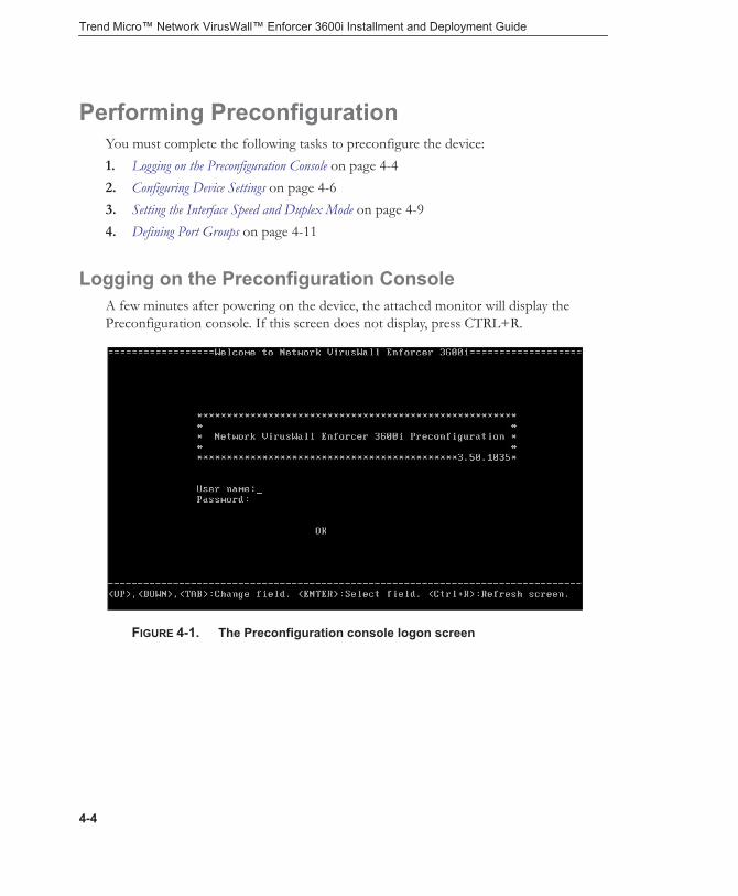
Trend Micro™ Network VirusWall™ Enforcer 3600i Installment and Deployment Guide
Performing PreconfigurationYou must complete the following tasks to preconfigure the device:1. Logging on the Preconfiguration Console on page 4-42. Configuring Device Settings on page 4-63. Setting the Interface Speed and Duplex Mode on page 4-94. Defining Port Groups on page 4-11
Logging on the Preconfiguration ConsoleA few minutes after powering on the device, the attached monitor will display the Preconfiguration console. If this screen does not display, press CTRL+R.
FIGURE 4-1. The Preconfiguration console logon screen
4-4
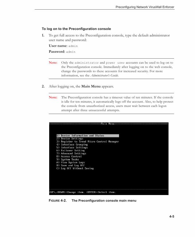
Preconfiguring Network VirusWall Enforcer
To log on to the Preconfiguration console
1. To get full access to the Preconfiguration console, type the default administrator user name and password: User name: adminPassword: admin
Note: Only the administrator and power user accounts can be used to log on to the Preconfiguration console. Immediately after logging on to the web console, change the passwords to these accounts for increased security. For more information, see the Administrator’s Guide.
2. After logging on, the Main Menu appears.
Note: The Preconfiguration console has a timeout value of ten minutes. If the console is idle for ten minutes, it automatically logs off the account. Also, to help protect the console from unauthorized access, users must wait between each logon attempt after three unsuccessful attempts.
FIGURE 4-2. The Preconfiguration console main menu
4-5

Trend Micro™ Network VirusWall™ Enforcer 3600i Installment and Deployment Guide
Configuring Device SettingsImmediately after logging on to the Preconfiguration console for the first time, configure the device host name and network settings.
To configure the device settings:
1. On the Main Menu of the Preconfiguration console, type 2 to select Device Settings. The Device Settings screen appears.
FIGURE 4-3. Device Settings screen
Note: When configuring the device for the first time, factory default settings appear.
2. Type a host name that properly represents the device in the network.Each device on your network must have a unique host name. Control Manager™ uses this unique host name during registration and as the managed product name.
4-6
Preconfiguring Network VirusWall Enforcer
Host names may contain up to 30 alphanumeric characters without spaces. Trend Micro recommends a unique descriptive host name to represent and identify the device or devices in a failover pair as seen through the management console. For example, designate NVWE-NY-main as the host name for a device protecting a New York main office.
3. Type or select the management IP address settings under Management IP settings. Specify either the IPv4 or the IPv6 settings as necessary. When using Network VirusWall Enforcer as a dual-stack host, provide both IPv4 and IPv6 settings.
WARNING! If there is a NAT device in your environment, Trend Micro recom-mends assigning a static IP address to the device. Because different port settings are assigned from your NAT, your device may not work properly if dynamic IP addresses are used.
4. After specifying the network settings, press ENTER.
Enabling Ports and Selecting Port FunctionsDepending on your desired deployment, you may need to enable certain ports and specify their function. By default, only two regular ports are enabled. So, if you need to use management, mirror, sniffer, or failover port functionality, you need to enable the management ports, which are ports 1 and 2.
4-7

Trend Micro™ Network VirusWall™ Enforcer 3600i Installment and Deployment Guide
To enable non-regular ports and modify their function:
1. On the Main Menu of the Preconfiguration console, type 5 to open the Interface Settings screen.
FIGURE 4-4. Interface Settings screen
2. Type 2 to select Interface setting.The Interface Settings screen changes so that the function of each port can be selected and modified.
3. Select a port by using the up and down arrows. Each port number corresponds to the physical ports as shown below.
4-8

Preconfiguring Network VirusWall Enforcer
FIGURE 4-5. Network VirusWall Enforcer ports
4. To modify the function of the selected port depending on your deployment strategy, press the SPACEBAR. Disabled management interface (onboard) ports can be assigned the following functions:• DIS—the port is disabled; this is the default setting• MGMT—the port is specifically used to manage the device• MIRR—the port is used to mirror network traffic to another computer; this is
typically used for debugging• SNIF—the port is used to receive and merely scan network traffic; Sniffer
ports are unable to regulate endpoints and enforce policies• FOV—the port is a failover port
Tip: For more information about different port functions, see Port Functions on page 2-12.
5. Select Return to the previous menu and press ENTER.
Setting the Interface Speed and Duplex ModeBoth the connected L2/L3 and Network VirusWall Enforcer devices should have the same port speed and duplex mode. Otherwise, the Network VirusWall Enforcer port will operate in half-duplex mode. To simplify configuration, you can set Network VirusWall Enforcer to auto-select the optimum port speed and duplex mode. However,
4-9

Trend Micro™ Network VirusWall™ Enforcer 3600i Installment and Deployment Guide
manual selection of the correct port speed and duplex mode can help ensure optimal network performance. Use the Preconfiguration console to configure the interface speed and duplex mode.
To set the interface speed and duplex mode:
1. On the Interface Settings screen, type 1 to open the Interface speed & duplex mode setting screen, which displays the current interface speeds and duplex settings of all ports.
2. Select a port by using the up and down arrows.3. Select the speed, using the SPACEBAR to scroll through the speed and duplex
mode options. For more information on the supported speed and duplex modes, see Deployment Notes on page 3-4.
4. After configuring all port speeds and duplex modes, select Return to the previous menu to go back to the Interface Settings screen.
4-10

Preconfiguring Network VirusWall Enforcer
5. Type 3 to select Return to Main menu. The Main Menu displays.6. Select Save and Log Off to make changes take effect.
Note: In order to apply the configuration changes made in the Preconfiguration console, you must save and log off.
Defining Port GroupsA port group is typically a pair of regular ports, but it can comprise more ports. Unless the piece of traffic passes a shared port, any given traffic that enters and leaves the device is received and transmitted by ports belonging to the same port group.
By default, only ports 3 and 4are set as a port group. Depending on your desired deployment, you may need to modify this port group or define other port groups.
To define an additional port group:
1. On the Main Menu of the Preconfiguration console, select Interface Grouping and then press ENTER.
2. Select Create a new interface group and press ENTER.3. Type a name for the new group.4. Identify available (DIS/REG/SHD) ports in the same row. For each port:
a. Press TAB until the cursor is under the port.
b. Press the SPACEBAR until the port is marked REG or SHD.
Note: To share a port across multiple port groups, you must set the port as shared (SHD) in each of these groups. Groups with shared ports cannot enable link-state failover.
4-11

Trend Micro™ Network VirusWall™ Enforcer 3600i Installment and Deployment Guide
5. Press TAB to move the cursor and configure the following settings:• Failopen—allow traffic to pass even when the device is powered off or is
encountering problems
Note: Failopen can be enabled only for port groups made up of specific port pairs. See Failopen Considerations on page 3-19.
• Link-state—also known as "link-state failover", disables the entire port group if only one port in the group is up
• Native VLAN ID—specify a native VLAN ID if the port group is placed between a trunk connection
6. Press TAB to select Return to previous menu and then press ENTER.
Connecting to the NetworkMake sure you preconfigure the device before attempting to connect the device or devices in a failover pair to the network. After preconfiguration, switch off the device before connecting it to the network.
To connect the device to your network:
1. Connect one end of the cable to a regular port and the other to a segment of your network.
2. In a failover deployment, establish the failover pair by connecting the provided Ethernet cable (RJ-45 crossover or a regular LAN cable) to the designated failover port of both devices.
3. Power on the device.
Note: Network VirusWall Enforcer can handle various interface speed and duplex mode network traffic. See Setting the Interface Speed and Duplex Mode on page 4-9.
4-12

Preconfiguring Network VirusWall Enforcer
Configuring Network VirusWall EnforcerAfter preconfiguring Network VirusWall Enforcer, you can configure the device and start protecting your network.
Trend Micro recommends performing the following tasks after preconfiguring a device:• Change the password for the default accounts• Activate the device• Update components• Configure policy enforcement
For more information, refer to the Online Help and the Administrator’s Guide. See Document Set on page ix.
4-13

Trend Micro™ Network VirusWall™ Enforcer 3600i Installment and Deployment Guide
4-14

Chapter 5
Troubleshooting and Technical Support
This chapter provides troubleshooting information for issues that may arise during the preconfiguration.
Tip: Refer to the Administrator’s Guide for answers to frequently asked questions and other troubleshooting tips.
This chapter discusses the following topics:• Device Issues on page 5-2• Getting Technical Support on page 5-3
5-1

Trend Micro™ Network VirusWall™ Enforcer 3600i Installment and Deployment Guide
Device Issues
# ISSUE CORRECTIVE ACTION/EXPLANATION
1 admin pass-word misplaced or forgotten
You have two options:
1. If the device has registered to Control Manager, you can access the web console and change the password through the Control Manager console using a Control Manager account.
2. You can reload the device image from the provided DVD. Note that this will remove any settings and poli-cies stored on the device.
Note: Reloading the Network VirusWall Enforcer image will restore the default settings. You can only recover device settings if you exported them to a file earlier.
2 Unable to access the Pre-configuration console remotely
Verify secure console port connections and SSH client software settings.
See the Administrator's Guide for more information on accessing the Preconfiguration console remotely.
3 Network packet delivery is too slow and seems to be blocked
Network VirusWall Enforcer does not refresh its MAC address table if one of the links fails. The result is a temporary delay in packet delivery.
5-2

Troubleshooting and Technical Support
Getting Technical SupportTrend Micro is committed to providing service and support that exceeds your expectations. You must register your product to qualify for support.
Before Contacting Technical SupportBefore contacting technical support, see if these resources can help you address your problem:• Product documentation—the Administrator’s Guide, Installation and Deployment
Guide, and Online Help provide comprehensive information about Network VirusWall Enforcer. Search these documents for helpful information.
• Knowledge Base—a key part of our technical support website, the Trend Micro Knowledge Base contains the latest information about Trend Micro products. To search the Knowledge Base, visit:
http://esupport.trendmicro.com
Contacting Technical SupportIn addition to phone support, Trend Micro provides the following resources:• Email support
[email protected]• Online Help—configuring the product and parameter-specific tips• Readme—late-breaking product news, installation instructions, known issues, and
version specific information• Knowledge Base—technical information procedures provided by the Support team:
http://esupport.trendmicro.com• Product updates and patches
http://www.trendmicro.com/download/
To locate the Trend Micro office nearest you, visit:
http://www.trendmicro.com/en/about/contact/overview.htm
5-3

Trend Micro™ Network VirusWall™ Enforcer 3600i Installment and Deployment Guide
Having the following information ready before you contact our support staff can help them resolve problems faster:• Device model and image (firmware) version• Deployment setup• Interface speed and duplex mode settings• Exact text of any error messages• Steps to reproduce the problem
5-4

Index
Aactivation 4-13ActiveUpdate 3-14activity indicator 2-15Administrator’s Guide ix, 2-3airflow and cooling 2-19altitude 1-6application policy 3-14audience xauto MDI/MDI-X 3-20
Bback panel 2-10basic deployment 3-23bezel 2-3, 2-7, 2-23
installation 2-8removal 2-9
Ccables 3-20concepts 1-3configuration 4-6, 4-13Control Manager 2-3, 5-2conventions xcritical hosts 3-10crossover cables 3-20
Ddata interface 2-12data ports 2-11
delayed packets 5-2Dell PowerEdge R610 1-5deployment
identifying what to protect 3-5number of devices 3-16overview 3-2planning 3-2
deployment planning 3-2deployment scenarios
basic deployment 3-23dual-port fiber-optic adapter 3-30multi-protection zone 3-24point-to-point links 3-30single pair 3-28without failover 3-24
deployment stages 3-2deployment strategy 3-22device identification panel 2-6device image 5-2device ports 2-11device settings 4-6dialup 3-5–3-6DIS 4-9document
conventions xdocument set ixdocumentation
audience xDual 3-11dual-stack 4-7
IX-1

Trend Micro™ Network VirusWall™ Enforcer 3600i Installment and Deployment Guide
dual-switch VLAN 3-11duplex mode 4-9
Eendpoint notifications 3-14environmental specifications 1-5–1-6expansion cards 2-14
installing 2-17removing 2-18
Express Service tag 2-6
Ffailopen 1-3, 2-14, 3-19, 3-26
and port status 3-21cable length 3-20considerations 3-19effect of a reset 3-20port groups 3-20without power 3-20
failover 1-3, 3-19, 3-31–3-32considerations 3-19
Spanning Tree Protocol (STP) 3-19partial mesh deployment 3-26port grouping 3-25requirements 3-19stateful 3-26
failover deployment 3-25failover pair 1-4, 3-25–3-26, 4-7failover port 1-3, 2-11, 2-13fault-tolerance 1-3, 2-14, 3-17, 3-19Federal Communications Commission 2-19fiber media connector 2-16fiber-optic 2-16, 4-2file transfers 3-14filler bracket 2-19FOV 2-11, 2-13, 4-9freestanding installation 2-19frequently asked questions (FAQs) 5-1
front panel 2-4, 2-6full mesh deployment 3-32
GGrand Unified Bootloader 3-21GRUB 3-21guest endpoints 3-5, 3-9
Hhard drives 2-6heat dissipation 1-5high-availability 2-11, 3-17host names 4-7humidity 1-6
Iimage file 2-3installation 2-19
connecting the power cable 2-21installing the bezel 2-23keyboard and monitor 2-20rack mounting 2-20rail assembly 2-20securing the power cable 2-22turning on the device 2-23
Installation and Deployment Guide ix, 2-3installing expansion cards 2-17instant messengers 3-14Intel Xeon 1-5interface speed 4-9introduction 1-1IPv4 addresses 3-4IPv6 addresses 3-4IPv6 networks
dual-stack and mixed environments 3-15limitations 3-14pure environments 3-15
issues 5-2
IX-2
Index
KKerberos 3-14key network segments 3-10key network segments and assets 3-5, 3-10keyboard 4-3
LLAN bypass 1-3, 2-14, 3-19, 3-26LC connectors 2-16LCD menu buttons 2-5LCD panel 2-5LED indicators 2-15link indicator 2-15link-local 3-15link-state failover 1-4, 4-11–4-12Linux DHCPv6 3-15LX ports 4-2
Mmail servers 3-10management device 1-3–1-4, 3-26management interface 2-13, 4-8management IP address 4-7management port 2-11, 2-13MDI/MDI-X 3-20memory 1-5mesh network 3-18MGMT 2-11, 2-13, 4-9MIRR 2-11, 2-13, 4-9mirror port 1-3, 2-11, 2-13monitor 2-5, 4-3mounting the device 2-19
NNAT devices 4-7NAT-PT 3-14Network Address Translation/Protocol Translation
3-14network cables 4-2
network traffic, planning for 3-16network virus scan 3-4NIC expansion slot 2-10nonmaskable interrupt (NMI) button 2-5non-regular ports 4-8notifications 3-14
Oonboard NIC 1-5Online Help ixOutbreak Prevention Policy 3-14overview 1-2
Ppackage contents 2-2–2-3packet delivery 5-2passwords 4-13
default 4-5lost passwords 5-2
pilot deployment 3-21contingency plan 3-22evaluation 3-22site 3-22
policy enforcement 3-4, 4-13port activity 3-14port functions 2-12, 4-7port groups 1-4, 4-11port indicators
copper expansion cards 2-15fiber expansion cards 2-15onboard ports 2-15
port redundancy 3-18, 3-31with failover 3-31
ports 2-11default state 2-12expansion card 2-14
power button 2-5power cord 2-3power-on indicator 2-5
IX-3
Trend Micro™ Network VirusWall™ Enforcer 3600i Installment and Deployment Guide
preconfiguration 4-1network verification 4-2performing 4-4preparations 4-2troubleshooting 5-1understanding 4-3
Preconfiguration console 1-4, 4-3, 4-11access issues 5-2logon 4-4password 4-5remote access 4-3, 5-2saving changes 4-11timeout 4-5
preface viiprimary device 1-4, 3-26printed documents 2-4processor 1-5Product Information Guide 2-4program rescue 3-14PuTTY 4-3
QQuick Start Guide ix, 2-3–2-4
Rrack cabinet 2-19rack kit 2-3, 2-20RAS server 3-6Readme ix, 2-3REG 2-11–2-12, 4-11regular port 1-3, 2-11–2-12relative humidity 1-6remote access service 3-5remote clients 3-5remote detection 3-14remote endpoints 3-5removing expansion card 2-18
Ssafety instructions 2-20SC connectors 2-16secondary device 1-4Security Appliance License Agreement 2-3–2-4server adapter 1-5, 2-14
copper 2-15–2-16fiber 2-15–2-16
shared port 4-11shock 1-6Silicom 1-5, 2-14, 2-16single-switch VLAN 3-11, 3-13SNIF 2-11, 2-13, 4-9sniffer port 1-3, 2-11, 2-13Spanning Tree Protocol (STP) 3-19, 4-2specifications 1-5SSH client 4-3stateful failover 3-26static IP address 4-7SX ports 4-2syslog 2-3
Ttemperature 1-6TFTP tool 2-3Third-party License Attributions 2-3threat mitigation 3-14troubleshooting 5-1
Uunpacking 2-20update source 3-15updates 4-13USB connectors 2-6USB flash drive 2-3, 5-2user authentication 3-14
VVGA 4-3
IX-4

Index
vibration 1-6video connector 2-5VLAN 3-13VPN 3-5VPN tunnel 3-8
Wweb console 1-4web servers 3-10Windows DHCPv6 3-14
IX-5

Trend Micro™ Network VirusWall™ Enforcer 3600i Installment and Deployment Guide
IX-6