Performance comparison of Wavelet based OFDM (WOFDM) V-BLAST MIMO system with different detection...
6
Performance Comparison of Wavelet based OFDM (WOFDM) V-BLAST MIMO System with different Detection Algorithms Muhammad Yasir*, M. J. Mughal*, N.D. Gohar*, S. A. Moiz** *GIK Institute of Engineering Sciences and Technology, Topi, N. w.P.P, Pakistan **Department of Electronic Engineering, M. A. Jinnah University, Jinnah Avenue, 44000, Islamabad, Pakistan Abstract In this article, design, performance and simulation of Wavelet based OFDM V-BLAST MIMO system has been discussed. Wavelet based OFDM technique is based upon orthonormal wavelets bases generated from Haar Quadrature Mirror Filter (QMF) bank. The BER performance of this system has been observed with three different V-BLAST detection algorithms. The three V-BLAST detection algorithms implemented in this article are: Zero Forcing (ZF), Minimum Mean Squared Error (MMSE) and QR- decomposition based V-BLAST detection algorithms. 1. Introduction The main goals in developing new wireless communication systems are increasing the transmission capacity and improving the spectrum efficiency [7].Growing market demand for broadband multimedia services, ubiquitous networking and internet access via portable devices demand wireless communication systems with high spectrum efficiency [2] .Exploitation of multipath, rather than mitigate it ,considering the multipath itself as a source of diversity [2],is a promising solution for efficient utilization of frequency spectrum for high data rate wireless communication. In this regard, V-BLAST MIMO system is a strong candidate for putting multipath propagation to work for spectrally efficient and high data rate wireless communication. BLAST stands for Bell Laboratories Layered Space Time and V stands for Vertical which relates to the blocking structure [ll].In (M, N) V-BLAST [1,6] multi-input multi-output (MIMO) system, equipped with M transmit antennas and N receive antennas, M signals are simultaneously transmitted using the same bandwidth. These different data streams get mixed up in the air and can be recovered by deploying multiple antennas and efficient signal processing techniques at the receiver end [2]. If the antennas are spaced sufficiently apart (Le., at least half a wavelength [9]), then richly scattered mutipath environment creates more or less independent paths between the different transmit and receive antennas [7]. At the receiver, with a priory knowledge of the channel impulse response, V-BLAST detection algorithm utilizes the spatial nulling process combined with symbol cancellation to successively detect the symbols from each transmit antenna [10].Such a bandwidth efficient system can greatly increase the single user data rate or the number of users in a multi-user wireless communication system[6,2].Wide band wireless communication systems do not satisfy the flat fading channel assumption [2, 6] upon which MIMO techniques are actually based. The flat fading channel requirement for MIMO systems is fulfilled by each of the OFDM sub-bands [2, 6]. In OFDM modulation technique, the transmission is carried out in parallel at different frequencies [6] . This is a muti-carrier modulation (Me) technique used for high data rate communication and it is less sensitive to delay spread of the channel [3, 6]. Wavelet based OFDM technique, due to its time frequency localization property [4, 6], is better capable of reducing lSI ,caused by multipath wireless channel as compared with conventional Fourier based OFDM technique which is caused by loss in orthogonality due to multipath wireless channel [4,6]. The core design issue in V-BLAST MIMO system is its detection algorithm, which is a computationally extensive task [12]. In this article, the performance of Wavelet based OFDM technique is investigated using V-BLAST system with three detection algorithms Le., Zero-Forcing (ZF), Minimum Mean Squared (MMSE) and QR-decomposition based V-BLAST detection algorithms and it is shown that among the three the Minimum Mean Squared (MMSE) V-BLAST detection algorithm shows the best performance. This article is organized as follows: Section I comprises introduction. In Section II construction of orthonormal wavelets is described. The system model is discussed in Section lILA brief description of three detection algorithms is given in section IV. Results are shown in Section V followed by concluding remarks in Section VI. II. Construction of Orthonormal Wavelets
Transcript of Performance comparison of Wavelet based OFDM (WOFDM) V-BLAST MIMO system with different detection...
Performance Comparison ofWavelet based OFDM (WOFDM)
V-BLAST MIMO System with different Detection Algorithms
Muhammad Yasir*, M. J. Mughal*, N.D. Gohar*, S. A. Moiz**
*GIK Institute ofEngineering Sciences and Technology, Topi, N. w.P.P, Pakistan**Department ofElectronic Engineering, M. A. Jinnah University, Jinnah Avenue, 44000, Islamabad, Pakistan
Abstract
In this article, design, performance and simulation ofWavelet based OFDM V-BLAST MIMO system hasbeen discussed. Wavelet based OFDM technique isbased upon orthonormal wavelets bases generatedfrom Haar Quadrature Mirror Filter (QMF) bank. TheBER performance of this system has been observedwith three different V-BLAST detection algorithms.The three V-BLAST detection algorithmsimplemented in this article are: Zero Forcing (ZF),Minimum Mean Squared Error (MMSE) and QRdecomposition based V-BLAST detection algorithms.
1. Introduction
The main goals in developing new wirelesscommunication systems are increasing thetransmission capacity and improving the spectrumefficiency [7].Growing market demand for broadbandmultimedia services, ubiquitous networking andinternet access via portable devices demand wirelesscommunication systems with high spectrum efficiency[2] .Exploitation of multipath, rather than mitigateit ,considering the multipath itself as a source ofdiversity [2],is a promising solution for efficientutilization of frequency spectrum for high data ratewireless communication. In this regard, V-BLASTMIMO system is a strong candidate for puttingmultipath propagation to work for spectrally efficientand high data rate wireless communication.BLAST stands for Bell Laboratories Layered SpaceTime and V stands for Vertical which relates to theblocking structure [ll].In (M, N) V-BLAST [1,6]multi-input multi-output (MIMO) system, equippedwith M transmit antennas and N receive antennas, Msignals are simultaneously transmitted using the samebandwidth. These different data streams get mixed upin the air and can be recovered by deploying multipleantennas and efficient signal processing techniques atthe receiver end [2]. If the antennas are spacedsufficiently apart (Le., at least half a wavelength [9]),then richly scattered mutipath environment createsmore or less independent paths between the differenttransmit and receive antennas [7]. At the receiver,with a priory knowledge of the channel impulse
response, V-BLAST detection algorithm utilizes thespatial nulling process combined with symbolcancellation to successively detect the symbols fromeach transmit antenna [10].Such a bandwidth efficientsystem can greatly increase the single user data rate orthe number of users in a multi-user wirelesscommunication system[6,2].Wide band wirelesscommunication systems do not satisfy the flat fadingchannel assumption [2, 6] upon which MIMOtechniques are actually based. The flat fading channelrequirement for MIMO systems is fulfilled by each ofthe OFDM sub-bands [2, 6]. In OFDM modulationtechnique, the transmission is carried out in parallel atdifferent frequencies [6] . This is a muti-carriermodulation (Me) technique used for high data ratecommunication and it is less sensitive to delay spreadof the channel [3, 6]. Wavelet based OFDM technique,due to its time frequency localization property [4, 6],is better capable of reducing lSI ,caused by multipathwireless channel as compared with conventionalFourier based OFDM technique which is caused byloss in orthogonality due to multipath wireless channel[4,6].The core design issue in V-BLAST MIMO system isits detection algorithm, which is a computationallyextensive task [12]. In this article, the performance ofWavelet based OFDM technique is investigated usingV-BLAST system with three detection algorithms Le.,Zero-Forcing (ZF), Minimum Mean Squared (MMSE)and QR-decomposition based V-BLAST detectionalgorithms and it is shown that among the three theMinimum Mean Squared (MMSE) V-BLASTdetection algorithm shows the best performance. Thisarticle is organized as follows: Section I comprisesintroduction. In Section II construction of orthonormalwavelets is described. The system model is discussedin Section lILA brief description of three detectionalgorithms is given in section IV. Results are shown inSection V followed by concluding remarks in SectionVI.
II. Construction of OrthonormalWavelets
Symmetric or asymmetric multi-stage tree structuredQuadrature Mirror Filter (QMF) Bank [4, 6] can beutilized for generating orthonormal wavelets. Theorthonormal wavelets generated, using symmetric treestructure multistage QMF bank, can be expressed bythe following equations [6]:
h(n) =th(n/ 2P-
1) *th(n/ 2P
-2
) *.. .th(n / 2P- J) *
.. ·th(n),
h (n) = th (n / 2P-1) *th (n / 2P
-2
) *... th (n / 2P- J) *
···th(n),
f2
P-l+1(n) =fh(n/ 2P
-1) *fh(nl 2P
-2
) *.. .fh(nl 2P- J) *
···fh(n),
Transmitter
(a)
Receiver
I5JPl 52 rwoFDMl Y
f2p(n) =h(nI2P
-1)* h(nI2P
-2 )* .. ·h(nI2P
- J)*
.. ·h(n),(1)
DeMuxl~M
Where P stands for the number of levels of this multistage tree structure and j E {O,I,2,...,P} ,K = 2P
stands for the number of sub-carriers. Where 1; (n) ,
fh (n) are the impulse responses of the low and the
high pass filters respectively for the perfectreconstruction QMF bank [6]. The high pass filter canbe derived from the low pass filter by the relation,
fh(n) =(_I)n h(U -I-In), where U is the
length of the filter [6]. Symmetric tree-structuredQMF bank is used for generation of the orthonormalwavelets involved in WODM demodulation process.
Sub-channel impulse responses are hK ( n)
f K ( -n), which are time reversal of sub-channelimpulse responses ofWOFDM modulator [6]. L WOFDM TN
DeMod
(b)
V-BLASTSignal
processing
III. Signal Model
The transmitter and receiver of WOFDM V-BLASTsystem are shown in Fig. I.At the transmitter side, theraw data bit stream is first Q-ary modulated (bit tosymbol mapping) and then demultiplexed to M (No oftransmit antennas) data sub-streams [1, 6]. In thissystem the demultiplexer plays the role of spaceencoder and performs symbol mapping on the M spacechannels, which are sub-streams of the same user [6].
(c)
Fig1: (a) WOFDM V-BLAST Transceiver (b)
Transmitter(c) Receiver [6]
16-QAM has been used for mapping bits to symbols.For each space channel, a serial to parallel convertertakes K of these symbols and thus generates the inputfor WODM modulator [6]. Where K represents thenumber of frequency channels and is equal to thenumber ofWOFDM sub-carriers [6].In WOFDM modulator, the branch data of each substream is first up-sampled by a factor of K and thenfiltered by the sub-channel impulse responses
fK (-n) , where k= {I, 2, 3... 2P
}[6]. In this article
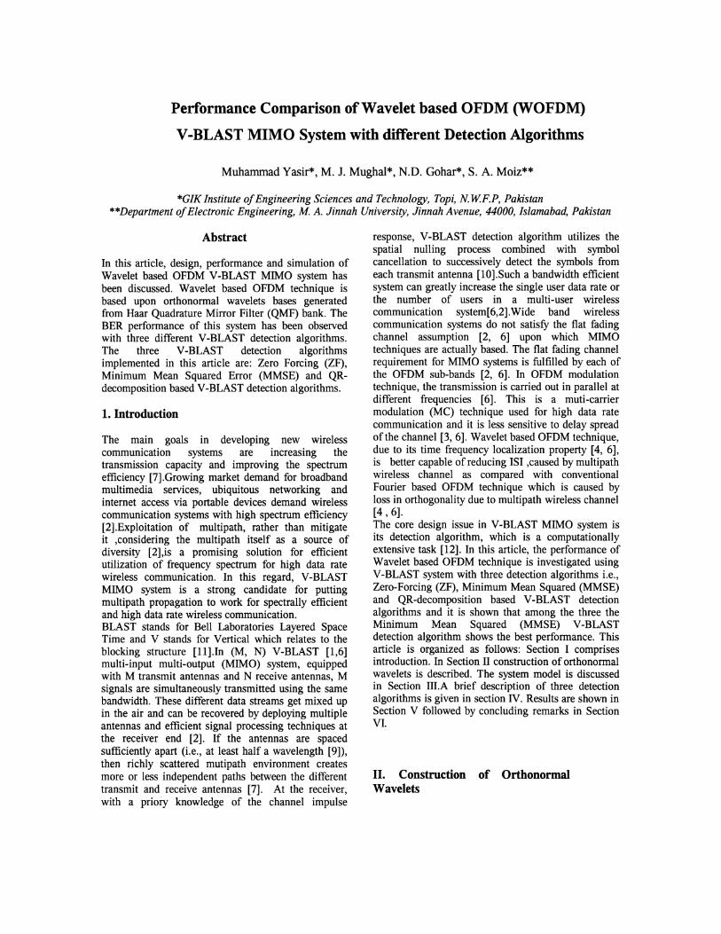
we have implemented a two-ray MIMO wirelesschannel [13]. This channel model is based upongeometrical optics [13] and is shown in fig.2.According to two-ray channel model, each of the Nreceiving antennas receives two propagating wavesfrom each of the M transmitting antennas, one directwave and other ground reflected wave[6,13]. In thissystem the number of receiving antennas is assumed to
f l H ll H 12 H n
f 2 H 21 H 22 H 23
f 3 H 31 H 32 H 33
HIM SI VI
H 2M S2 V2
H 3M S3 V3
+ (2)
H NM SN VN
?No.ofTx=M
No.ofRx=NN~M
Fig.2: A MIMO Two-Ray Ground Reflection [14]
be either equal to or greater than the number oftransmitting antennas, Le. (N~M) [5, 6].At thereceiver end each of the N antennas receives adifferent noisy superposition of the faded versions ofthe M transmitted signals [6]. The overall systemmodel can be described in matrix notations, as givenin equations (2) and (3)[5, 6], where r represents thereceived signals matrix, H represents the channelfrequency response matrix, s stands for transmittedsignals matrix and v represents channel noise matrix.The elements of channel noise matrix are complexGaussian random variable with zero mean and
variance No [6, 8].In WOFDM demodulation process
at the receiver end, at each receiving antenna, eachsub-stream is first filtered by the sub-channel impulse
response fK (-n) and then down sampled by a factor
K [6]. If the channel response is known at thereceiver, V-BLAST detection algorithm [5, 6] is ableto detect the M transmitted signals.
IV. V-BLAST Detection Algorithms
V-BLAST detection algorithm is the heart of thissystem and is implemented on the receiver side usingadvanced digital signal processing techniques [10, 5].
r =Hs +v (3)The signal detection algorithm of a VBLAST systemiscomputationally very intensive [12]. If the number oftransmitters is M and is equal to the number ofreceivers, this complexity is proportional to M 4 ateach sample time [12]. In this article we assume thatthe antennas are spaced sufficiently apart (at least halfwavelength), and the wireless channel environmentprovides rich scattering to the transmitted signal [2].As a result of which the transmitted signals arriving atdifferent receiving antennas undergo independentfading [2].For rich scattering channels, the elementsof channel matrix H are independent of one another[12]. More over, the wireless channel frequencyresponse, required in signal detection process, isassumed to perfectly known at the receiver side [10].V-BLAST detection algorithm, with a beforehandknowledge of channel impulse response and efficientsignal processing techniques, is able to detect all thesignals transmitted from M antennas. V-BLASTsystem uses a non-linear detection algorithm basedupon successive interference cancellation combinedwith spatial nulling process [2, 10]. The spatialnulling process based upon Zero-Forcing (ZF) orMinimum Mean Squared Error (MMSE) criteria, isused to separate individual sub-streams [2, 5]. In VBLAST detection process, the signals at the receiverend are detected in descending order of their postdetection SNRs The signal with the highest postdetection SNR is detected first and the signal with thelowest post detection SNR is detected at the end [5,10]. Conceptually each sub-stream to be detected issupposed to be the desired sub-stream and theremainders as interferers to be suppressed by thespatial nulling process [2, 15]. After the strongest substream has been detected, the contribution of this substream is then subtracted from the received signals[2,15].Thus, the remaining weaker sub-streams areeasier to recover since the strongest sub-stream hasbeen removed as a source of interference[2].Thisprocess is reiterated until all the sub-streams havebeen fully detected [2]. Altogether, M.K Q-arysymbols are thus obtained at the output of the VBLAST signal processor, and are serialized by serialto parallel-to-serial converter to complete theprocessing at the receiver side [15]. The three
H new =QR
This is a non-linear detection algorithm that uses anorthogonal triangularization method to reduce thecomputational complexity of the detection process andis discussed with detail in [8]. This V-BLASTalgorithm may be divided into two separate stages.First the optimal symbol detection order is obtainedbased on post-detection SNR, using criteria such asZero-forcing or minimum mean squared error [8].Inthis article we have used Zero-forcing criterion. Thisorder is then used to rearrange the columns of channelmatrix [8]. The rearranged channel matrix is thensubjected to QR-decomposition. The resultingtriangular properties then allow the sequence ofsymbols to be recovered by simple backwardsubstitution with symbol cancellation [8].
The QR decomposition of an NxM channel matrix
H new ' obtained by rearranging the columns of the
original channel matrix H, is given by the followingexpression [8]:
channel coefficients but also a priori knowledge of theSNRs of the received signals being detected. ThusMMSE V-BLAST receiver yields superiorperformance to the ZF V-BLAST receiver in presenceof noise [14].Also, MMSE filter is more advantageousthan the ZF algorithm from a performance point ofview [12], as it also takes noise term into account.In MMSE V-BLAST detection algorithm, a randomvector s is estimated on the basis of observations r tochoose a matrix D, which minimizes the mean
squared error e2 [7].
e 2 =E[(s - s) *(s - s)]=E[(s - Dr) *(s - Dr)] (5)
Where * stands for transposition and conjugation andS stands for the estimate of the signal s. The solutionofMMSE is given by [7]:s=D.r
= (_1_1 +HHH)-l HH.r (6)SNR N
Where the superscript H denotes complex transposeand conjugate. The ZF receiver perfectly separates theco-channel signal at the cost of noise enhancement[14].On the other hand, the MMSE receiver canminimize the over all error caused by noiseinterference between the co-channel signals, which isalso reduced at the cost of signal separationquality[14].
(4)
detection algorithms, implemented in this article, arebriefly discussed as below:
i). Zero-Forcing (ZF) V-BLAST DetectionAlgorithm:
.It is a low complexity detection algorithm discussedin detail in [5].It is recursive process which involvesdetermination of optimal ordering [5], based upon thepost detection SNR of the received signals. ZF VBLAST detection algorithm is based upon matrixinversion. Under the assumption that channel matrixis invertible, a transmitted data symbol can beestimated as [5, 7]:
S= (H* H)-l Hs
=H+s
=GsWhere '+' stands for Pseudo-inverse and * stands fortransposition and conjugation. Note that inverse existsonly if the columns of H are independent, which is thecase since it is assumed that the elements of Hareindependent identically distributed (i.i.d) randomvariables [5, 6, 7]. From the above eq.(4) we can seethat the if channel impulse response H is known at thereceiver, ZF V-BLAST detection algorithm canaccurately detect M co-channel signals
Sk E {Sl' S2 , ... , SM } [5,15].It is to be noted that the
signal with the highest post detection SNRcorresponds to the index of the row of the pseudoinverse of the channel matrix (G) with minimumEuclidean Norm while the signal with the lowest postdetection SNR corresponds to the signal with thehighest Euclidean Norm of the pseudo inverse of thechannel matrix (G) [16,5].The ZF receiver results in apoor performance in the low SNR regime when Hbecomes very ill-conditioned in certain fadingenvironments[14].
ii). MMSE V-BLAST Detection Algorithm:
MMSE V-BLAST detection algorithm is discussedwith detail in [12].Comparing equations (4) and (6),itmay be noted that unlike ZF V-BLAST detectionalgorithm, which removes only interferencecomponent, MMSE V-BLAST detection algorithmsuppresses both the interference and noisecomponents[14]. In MMSE V-BLAST detectionalgorithm, the mean squared error between thetransmitted symbol and estimate of the receiver isminimized [12, 7].The signal detection steps inMMSE V-BLAST detection process are almostidentical to the ZF V-BLAST detection process withonly difference being that unlike ZF, MMSE requiresnot only a beforehand knowledge of the wireless
iii). QR-decompositiondetection Algorithm:
based V-BLAST
gn gI2 glM fn f12 flM
gI2 g22 g2M 0 f22 f2M
0 0 0 (7)
0
gNI 0 0 gNM 0 0 f NM
Where Q is a unitary and orthogonal matrix, while Ris the upper triangular matrix. A property of
orthogonal matrix is that QT = Q-l and QTQ = 1[8].
The receive vector r is multiplied with the matrix QT
,to get the orthogonalized receive vector x,which is given by[8]:
(8)
For signal detection process, this orthognalizedreceive vector x is then subjected to backwardsubstitution into R and symbol cancellation [8].Theproposed method equals the performance of ZF VBLAST detection algorithm with a significantreduction in computational complexity as comparedwith ZF V-BLAST and MMSE V-BLAST detectionalgorithms [8].
v. Simulation Results
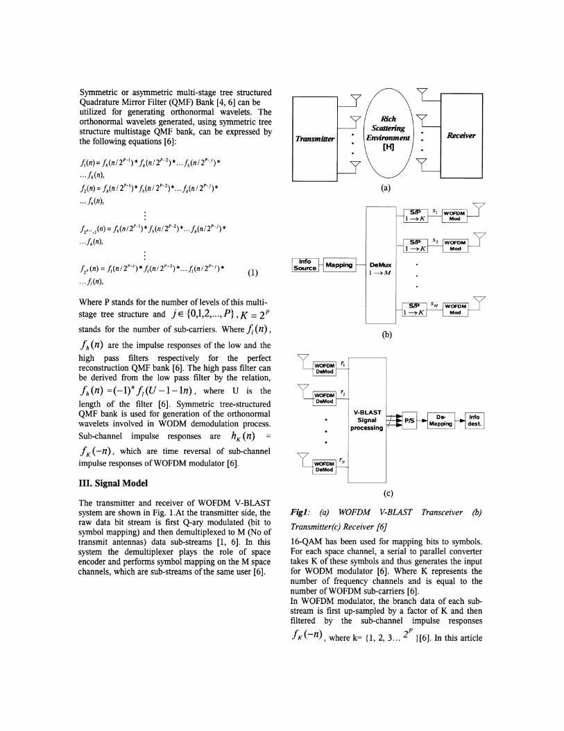
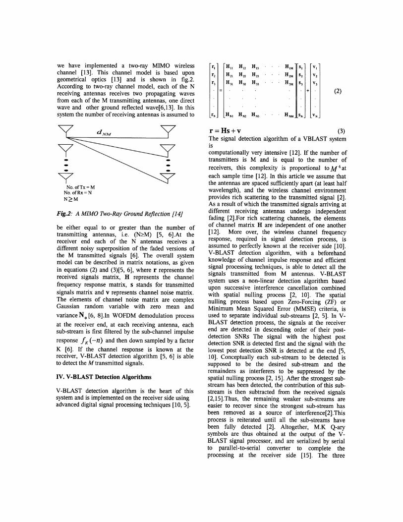
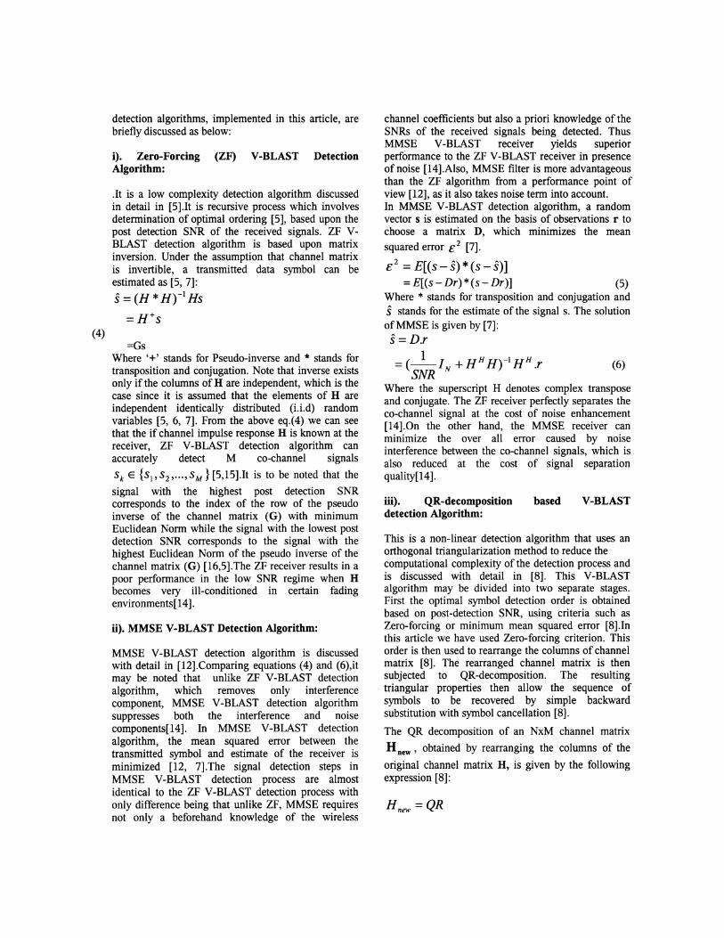
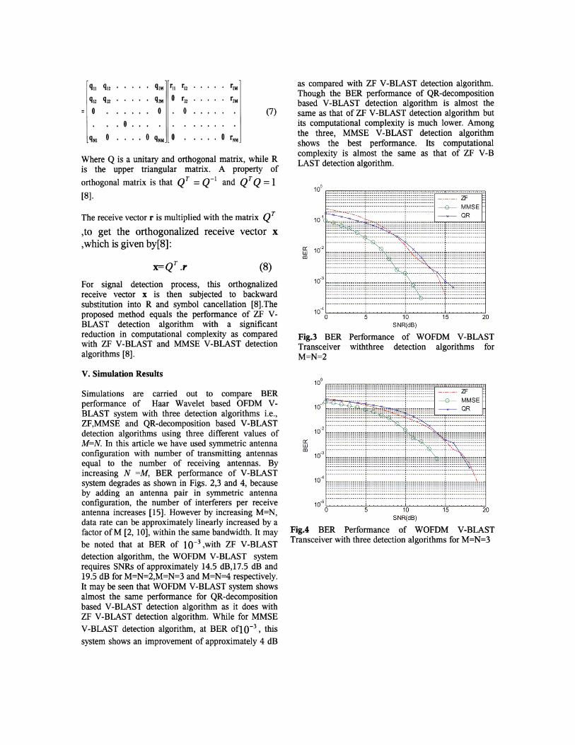
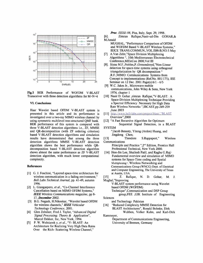
Simulations are carried out to compare BERperformance of Haar Wavelet based OFDM VBLAST system with three detection algorithms Le.,ZF,MMSE and QR-decomposition based V-BLASTdetection algorithms using three different values ofM=N. In this article we have used symmetric antennaconfiguration with number of transmitting antennasequal to the number of receiving antennas. Byincreasing N =M, BER performance of V-BLASTsystem degrades as shown in Figs. 2,3 and 4, becauseby adding an antenna pair in symmetric antennaconfiguration, the number of interferers per receiveantenna increases [15]. However by increasing M=N,data rate can be approximately linearly increased by afactor ofM [2, 10], within the same bandwidth. It maybe noted that at BER of 10-3 ,with ZF V-BLASTdetection algorithm, the WOFDM V-BLAST systemrequires SNRs of approximately 14.5 dB,17.5 dB and19.5 dB for M=N=2,M=N=3 and M=N=4 respectively.It may be seen that WOFDM V-BLAST system showsalmost the same performance for QR-decompositionbased V-BLAST detection algorithm as it does withZF V-BLAST detection algorithm. While for MMSEV-BLAST detection algorithm, at BER of10-3 , this
system shows an improvement of approximately 4 dB
as compared with ZF V-BLAST detection algorithm.Though the BER performance of QR-decompositionbased V-BLAST detection algorithm is almost thesame as that of ZF V-BLAST detection algorithm butits computational complexity is much lower. Amongthe three, MMSE V-BLAST detection algorithmshows the best performance. Its computationalcomplexity is almost the same as that of ZF V-BLAST detection algorithm.
10° __.__ . _ _. __.. _. _~~ ~ ~ ~~~~~~~~~~ ~ ~ ~~ ~ ~~~~~~~ ~ ~ ~~ ~ ~ ~~~~~~~~~~~~~~~~~~ ~ ~ ~~ ~ _._. _. ZF
10-
1 ::~'~:~';~!~:!'~'~~~""";1'.1..' ' ~~~~~~~~s~';~~~ 10-
2 ;;;;;;;;;;;;;;;;;;;L~~;;;;:;;;;;;;~;~;~~;:;;;;;;;;;;;;;1;;;;;;;;;;;;;;;;;;;
10-3 ~•• ,.:, ••~., ; •••:~ ,I~~·,~.,..~: ~;....;..:. ~: ~~~;, :.,:~~!:' ~~. ,~~,:.~ ,.~~.~-
:::::::::::::::::::~::::::::::::::::::::~::::: .. ::::::::::::~::::::::::::::::::::·········_··_-··---i--··--·· __ ·· __ ··_-_·~_··_·· ··········i···················--------------------1--------------------;---------··--··--··1-----··-------------
10-4 -'--'-- -'--'-- ...............o 5 10 15 20
SNR(dB)
Fig.3 BER Performance of WOFDM V-BLASTTransceiver withthree detection algorithms forM=N=2
10° .. _...•..•..... _ ...•.•....•.•..•..~ ~~ ~~~~~~~~~ ~~~~~~~~~ ~~~ ~~~~ ~ ~~~ ~~~~~~~~~~~~~~~~~~~~~~~~~ --_.-- ZF
10-1 H;;~ ;;~ ;;;;;;;;;~~~ ~~::~ ~~~ ~~~I~~~~~ ~~~ ~~ ~~~ ~~i ~~ ~~~ ~ ~ ~~SE::::::::::::::::~::::::::... :::::_-;~---':::::::::::: :--_ _--............._..~ _---- ,- --~- _--- : _._-- .
~ :::: !!!!!!!!!!!!!'1!!!!··!!!!!!!!!!!!I·~!! ..,~::~~!~i,:i~:!:!:::!"~!'!!!!!!!!!!!!!!!10
4 iiiiiiiiiiiiiiiiliiiiiiiiiiiiiiiiliiiiiiiiiiiiiiiiliiiiiiiiiiiiiii~i~i~liiiiiiiii;::::::::::::::::f::::::::::::::::f::::::::::::::::f::::::::::::::::~::::::::::::::::
10-5~ ...........o 5 10 15 20 25
SNR(dB)
Fig.5 BER Performance of WOFDM V-BLASTTransceiver with three detection algorithms for M=N=4
VI. Conclusions
Haar Wavelet based OFDM V-BLAST system ispresented in this article and its performance isinvestigated over a two-ray MIMO wireless channel byusing symmetric multilevel tree-structured QMF bank.BER performance of this system is compared withthree V-BLAST detection algorithms Le., ZF, MMSEand QR-decomposition (with ZF ordering criterion)based V-BLAST detection algorithms and simulationresults have demonstrated that among the threedetection algorithms MMSE V-BLAST detectionalgorithm shows the best performance while QRdecomposition based V-BLAST detection algorithmshows almost the same performance as ZF V-BLASTdetection algorithm, with much lower computationalcomplexity.
References
[1] G. J. Foschini, "Layered space-time architecture forwireless communication in a fading environment,"Bell Labs Technical Journal, pp. 41-49, autumn1996.
[2] L. Giangaspero, et al., "Co-Channel InterferenceCancellation based on MIMO OFDM Systems,"IEEE Wireless Communications magazine, pp 817, December 2002.
[3] B.G. Negash, H.Nikookar, "Wavelet based OFDMfor wireless channels," IEEE VehicularTechnology Conference, 2001.
[4] Glen Zelniker, Fred J. Taylor, "Advanced DigitalSignal Processing: Theory & Application",Marcel Dekker, Inc, New York, 1994.
[5] P. W. Wolniansk y, et al., "V- BLAST: AnArchitecture for Realizing Very High Data RatesOver the Rich- Scattering Wireless Channel,"
hoc. ISSSE-98, Pisa, Italy, Sept. 29, 1998..[6]. Zimran Rafique,Nasir-ud-Din GOHAR,&MJunaid
MUGHAL, "Performance Comparison ofOFDMand WOFDM Based V-BLAST Wireless Systems,"IEICE TRANS.COMMUN.,VOL.E88-B,NO.5 May
[7] A.Van Zelst,"Space Division MultiplexingAlgorithms ",10th Mediterranean ElectrotechnicalConference,MEleCon 2000,Vol III
[8]. Siyau M.F.;Nobles,P.;Ormondroyd,"Non-Lineardetection for space-time systems using orthogonaltriangularization by QR decomposition ",R.F.;MIMO: Communications Systems fromConcept to implementations (ReiNo. 001/175), lEESeminar on 12 Dec. 2001 Page(s):6/1 - 6/5
[9] W.C. Jakes Jr., Microwave mobilecommunications, John Wiley & Sons, New York
1974, chapter 1[10] Nasir D. Gohar ,zimran Rafique,"V-BLAST: A
Space-Division Multiplexing Technique Providinga Spectral Efficiency Necessary for High Data
Rate Wireless Networks ",IBCAST,pp.249-259,June 2003
[11] http://www.bell-Iabs.com/projectlblast/...BLASTOverview",2000
[12] "A Fast Recursive Algorithm for OptimumSequential Signal Detection, in a BLAST
SYSTEM";Jacob Benesty, Yiteng (Arden) Huang, andJingdong Chen;
[13] Theodore S.Rappaport," WirelessCommunications
Principle and Practice",2nd Edition, Prentice HallProfessional Technical, New York 2000.
[14] Hoo-Jin Lee, Shailesh Patil, and Raghu G.Raj,"Fundamental overview and simulation of MIMOsystems for Space-Time coding and SpatialMultiplexing"", Wireless Networking andCommunications Group (WNCG) Dept. ofElectricaland Computer Engineering, The University ofTexasat Austin, USA.
[15] Z. Rafique, N. D. Gohar, M. J.Mughal,"Improving
V-BLAST system performance using Waveletbased OFDM (WOFDM)Technique",Communication and DSP Group
group,FEE ,GIl< Isntitute of EngineeringSciences
and Technology Pakistan[16] "Reduced Complexity MMSE Detection for
BLAST Architectures", Ronald Bohnke, DirkWubben, Volker Kuhn, and Karl-Dirk
Kammeyer,Department of Communications Engineering,University of Bremen, Germany