Package stability Proposal for a new section 2 of Annex 7
19
CTU-Code/2021/second-informal-meeting/8 1 Informal meeting on Code of Practice for Packing of Cargo Transport Units at the request of the United Nations Economic Commission for Europe Working Party on Intermodal Transport and Logistics Geneva and virtual, 17-18 March 2022 Package stability Submitted by ETS Consulting This document suggests adding a new section (as section 2) to annex 7 of the CTU Code in which clauses on package stability are provided. Because of this addition, it is further proposed to add new definitions to Chapter 2 of the CTU Code. It is also proposed that the clauses of the new section are supplemented by three appendices on (i) Package Stability Tests, (ii) Increasing package integrity, and (iii) Packing arrangements. Proposal for a new section 2 of Annex 7: Package stability Introduction The term “package” is used in this document to refer to any goods that are enclosed within one or more layers of packaging or secured on, or to, a packaging accessory. Consignors should ensure that formed packages are capable of withstanding the hazards of environmental exposure, storage, handling and transport. Packages in the form of overpacks should retain their integrity during transport, failure to do so increases the risk of the cargo being damaged or the CTU stability being adversely affected. To assist Packers in their role, transport stability of the packages is divided to different levels to reflect their capability to withstand the forces during the transport. The transport stability level (TSL) when associated with the CTUs boundary strength can indicate the need for additional securing of the cargo and should be determined in each specific case. The transport stability of the package or handling unit is divided into different Transport Stability Levels (TSL) based on the horizontal acceleration it can withstand, according to Table 1. Table 1 — Transport Stability Level Transport Stability Level (TSL) Horizontal acceleration a TSL 1 a ≥ 1,0 g TSL 2 0,8 g ≤ a < 1,0 g TSL 3 0,5 g ≤ a < 0,8 g TSL 4 0,35 g ≤ a < 0,5 g TSL 5 0,18 g ≤ a < 035 g NOTE 1 For requirements on cargo securing, see EN 12195-1. NOTE 2 Below 0,18 g no TSL marking allowed
-
Upload
khangminh22 -
Category
Documents
-
view
0 -
download
0
Transcript of Package stability Proposal for a new section 2 of Annex 7

CTU-Code/2021/second-informal-meeting/8
1
Informal meeting on Code of Practice for Packing of Cargo Transport Units
at the request of the United Nations Economic Commission for Europe Working Party on
Intermodal Transport and Logistics
Geneva and virtual, 17-18 March 2022
Package stability
Submitted by ETS Consulting
This document suggests adding a new section (as section 2) to annex 7 of the CTU Code in which clauses on package stability are provided. Because of this addition, it is further proposed to add new definitions to Chapter 2 of the CTU Code. It is also proposed that the clauses of the new section are supplemented by three appendices on (i) Package Stability Tests, (ii) Increasing package integrity, and (iii) Packing arrangements.
Proposal for a new section 2 of Annex 7:
Package stability
Introduction
The term “package” is used in this document to refer to any goods that are enclosed within one or more layers of packaging or secured on, or to, a packaging accessory.
Consignors should ensure that formed packages are capable of withstanding the hazards of environmental exposure, storage, handling and transport. Packages in the form of overpacks should retain their integrity during transport, failure to do so increases the risk of the cargo being damaged or the CTU stability being adversely affected.
To assist Packers in their role, transport stability of the packages is divided to different levels to reflect their capability to withstand the forces during the transport. The transport stability level (TSL) when associated with the CTUs boundary strength can indicate the need for additional securing of the cargo and should be determined in each specific case.
The transport stability of the package or handling unit is divided into different Transport Stability Levels (TSL) based on the horizontal acceleration it can withstand, according to Table 1.
Table 1 — Transport Stability Level
Transport Stability Level (TSL) Horizontal acceleration
a
TSL 1 a ≥ 1,0 g
TSL 2 0,8 g ≤ a < 1,0 g
TSL 3 0,5 g ≤ a < 0,8 g
TSL 4 0,35 g ≤ a < 0,5 g
TSL 5 0,18 g ≤ a < 035 g
NOTE 1 For requirements on cargo securing, see EN 12195-1.
NOTE 2 Below 0,18 g no TSL marking allowed

CTU-Code/2021/second-informal-meeting/8
2
Acceleration coefficients are shown in Chapter 5 and the values match the horizontal acceleration shown in Table 1. This means that a package with a TSL 3 can withstand the longitudinal and transverse acceleration forces experienced in Road Transport without any bracing or lashing, whereas a package with TSL 4 would require additional bracing and / or lashing. Blocking to prevent horizontal sliding may still be required in both cases.
General requirements
When considering the transport stability of packages in CTUs, a high degree of stability is required to meet national roadside inspection regulations for cargo securing. Roadside inspections have been implemented to ensure that the cargo and its securing are effective and do not interfere with safe driving, or pose a threat to life, health, property or the environment which is measured by:
2.1.1.1 any movement that changes their position relative to each other or causes the package(s) to rest heavily against walls or surfaces of the CTU, and
2.1.1.2 and movement that causes any part of the package(s) to protrude outside of, or fall from the cargo space.
During transport packages will be subjected to transport forces and these forces effect the package in two different ways.
2.1.1.3 The package, when subject to transport acceleration may be deformed, or the packaging failing resulting in the packaged goods moving from their original packed position, or
2.1.1.4 The package, when subjected to transport acceleration may tip over or topple.
The ability to withstand both these two effects is referred to as stability. It is defined as:
the quality, state or degree of being stable: such as
1. the property of a body that causes it, when disturbed from a condition of equilibrium or steady motion, to develop forces or moments that restore the original condition - integrity
2. the strength to stand or endure - firmness
For the purposes of this document, the symbol (SI) will be used to denote Integrity and (SF) will be used for Firmness.
2.1.1.5 A package with a high degree of SI can still change their position either by sliding or tipping (toppling).
2.1.1.6 A package with a high degree of SF can fall from or protrude outside the cargo deck because of deformation or shifting of secondary packaging forming the transport package.
2.1.1.7 Stability tests used to calculate the Transport Stability Level (TSL) are shown in Appendix XX
Palletised cargo in the form of unit loads is particularly susceptible to a loss of SI, with the result that the packaging may fail and the cargo protrudes or escapes from the package. It is therefore imperative that unit loads are prepared correctly and the packaging enclosing the cargo is sufficiently strong so as to withstand transport forces. Appendix XXX provides information on increasing package integrity.

CTU-Code/2021/second-informal-meeting/8
3
Marking
All packages tested according to Appendix XX shall be marked with TSL, separately or incorporated with other markings.
The TSL marking:
2.1.1.8 shall be displayed on at least one side of each package;
2.1.1.9 shall be marked with letters at least 12 mm high;
2.1.1.10 shall be visible and readable;
2.1.1.11 shall be displayed on a background of contrasting colour on the external surface of the package.
It is probable that test results for TSL differ depending on the shape of the package and therefore the lowest value for length and width directions should be displayed as per the examples below:
— EXAMPLE 1: Transport Stability Level 4 in both length (L) and width (W) directions: L/W:
TSL4
— EXAMPLE 2: Transport Stability Level 2 in length (L) and 1 in width (W) directions: L:
TSL2, W:TSL1
Securing Packages
Packages with a low TSL caused by low SI will require packing against a strong boundary which may be the CTU wall or bracing or shoring to prevent the package from seriously deforming, perhaps outside of the CTU envelope.
Packages with a low TSL caused by low SF will require bracing or shoring against the framework of the CTU.
Sections 2.3 Blocking and Bracing materials and 2.4 Lashing Materials and Arrangements of this Annex describe the techniques needed ensure that the package is properly secured.

CTU-Code/2021/second-informal-meeting/8
4
Consequential changes
1. Proposed new definitions:
Transport Stability Level (TSL)
minimum horizontal acceleration that a package or handling unit can withstand without specified permanent deformation or displacement
test specimen (test item)
package or handling unit used during the test
transport packaging
packaging designed to contain one or more articles or packages, or bulk material, for the purposes of transport, handling and/or distribution (ISO 21067-1)
2. Proposed new appendices:

CTU-Code/2021/second-informal-meeting/8
5
Appendix XX Package Stability Tests
1 Introduction
1.1 The effectiveness of securing arrangements are discussed in Appendix 5 however, the stability of the package needs to be assessed separately and prior to it being presented for packing into the CTU.
1.2 The following International and European Standards are available and provide reliable tests for the purposes of this Appendix:
1.2.1 EN 12195 is applicable to the design of securing methods (blocking, lashing, and combinations) for securing of loads for surface transport, including their transport on vessels or by rail and/or combinations thereof.
1.2.2 ISO 10531 is a standard that has been written to prove the SI of transport packages, specifically Unit Loads however, the tests described can be applied to all types of packages.
1.3 The tests described in EN 12195, and ISO 10531 are shown in the process chart (Figure 1).
Figure 1 - Producing a Stability value
1.4 The five tests shown in Figure 1 should be undertaken and for all packages in both transverse and longitudinal directions in order to calculate the transport stability level (TSL).
Testing of packages
1.5 Consignor should decide which of the tests described below should be completed to test package stability. At the same time, at least one test should be completed to test SF (package firmness) and should there be any degradation established through the test, then three SI test should also be undertaken.
1.6 To test package firmness (SF) all packages shall be subject to a static test according to EN 12195-1 and detailed below:
1.6.1 The static tests examine the forces required to topple over or to slide a package. The principle of a static test is to tilt up a package or a handling unit on basis of annex D.2 of standard EN 12195 1:2010 or Annex 7, appendix 5. Horizontal acceleration for transport stability level is calculated according to D.2.3.3 (Formula D.5) of standard EN 12195 1:2010.

CTU-Code/2021/second-informal-meeting/8
6
Figure 2 - Sliding test
Figure 3 - Tipping test
1.6.2 The sliding test (see Figure 2) involves lifting the base, with a known coefficient of friction, to increase the angle α. As soon as the package starts to slip the angle is recorded and using Table D.1 of EN 12195 1:2010 the horizontal acceleration factor identified which can then translated into the TSL.
1.6.3 The tipping test (see Figure 3) is a variation of the sliding test. The package is lifted by one edge and the angle increased until the package starts to slip or tip over. The recorded angle is compared with the values in Table D.1 against the row with the γ-factor of 1.0 which is converted into the TSL via the acceleration factor.
1.6.4 If one test is carried out the TSL value obtained is recorded as the SF value, or if both tests are carried out the lesser of the two TSL values is allocated as the SF value.
1.7 If any permanent deformation or displacement of the test specimen is detected from the original position greater than 30 mm in any horizontal direction, it would indicate a potential failure of SI and further tests should be carried out to confirm the SI value of the package.
1.7.1 Drop tests according to ISO 10531 are designed to test the ability of the package to withstand accidental drops and so to retain the package integrity, using either or both of the two methods shown in Figure 4 and Figure 5.
Figure 4 - Drop flat test
Figure 5 - Bottom edge impact test
1.7.2 Horizontal impact (inclined plane) test according to ISO 10531 are designed to test the ability of the package to withstand repeated horizontal impacts against its base edges as shown in Figure 6. These repeated impacts simulate the effect of transport acceleration forces acting on the package.

CTU-Code/2021/second-informal-meeting/8
7
Figure 6 - Horizontal impact test
1.7.3 The travel distance would need to be adjusted to produce differing negative acceleration at impact, typically 0.3g, 0.4g, 0.6g and 0.8g. These being the horizontal forces expected in the transport chain and included in the CTU Code.
1.7.4 Where such test equipment is not available the lift truck handling tests detailed in Annex A of ISO 10531 can produce similar results.
1.8 If the package does not show any signs of degradation, as a result of the tests, the integrity of the package is retained and so the SF value can be used.
1.9 Failure is defined as any of the following:
1.9.1 Goods are damaged,
1.9.2 Package damage triggers the inability to sustain further distribution, storage or handling.
1.9.3 Degradation of the package integrity creates risk instability for further handling.
1.9.4 Permanent deformation or displacement in a horizontal direction:
1. is greater than 40mm in the bottom 200 mm of the package,
2. is greater than 60 mm for packages less than 1200 mm, or
3. is greater than 5% of the height of the package
1.10 If the package fails, following either the drop flat test or the bottom impact test then the horizontal impact test should be carried out. The travel distance should be increased in a series of tests until the permanent deformation shown in 2.5.4 which will set the TSL value.
1.11 It is the responsibility of the consignor to ensure that complete filled transport packages are formed correctly and that testing has been performed to produce a TSL value for each package design.
1.12 Consignors should consider the packaging arrangement for packages with low SI, Appendix XXX provides guidance on increasing the integrity of packages,

CTU-Code/2021/second-informal-meeting/8
8
Appendix XXX Increasing package integrity (SI)
1 Introduction
1.1 Packages with strong packaging, such as crates and single piece transport packaging are likely to have high package integrity (SI). This is because the packaging is constraining the primary / secondary packaging or the Goods. However, SI is reduced when there is a break between the packages and / or the packaging accessories, for example between a box and a pallet or between one box stacked on another.
1.2 A package comprising a single box when packed in a CTU requires the constraints of the side and end walls to maintain their stability. Gaps greater than 150 mm should be packed with dunnage to prevent excessive sliding. However, if the packages are stacked one above another, there is a risk of a failure of integrity due to the superimposed mass on the bottom packages. The Box Compression Strength (BCT) must be sufficient to withstand the forces likely to be experienced in the transport chain. Increasing BCT will increase SI.
Unit load packing
1.3 Many packages now are formed into Unit Loads1, either on a pallet or for use with a slip sheet. They can come in three basic forms:
1.3.1 Single layer packages not extending to the edges of the pallet, such as drums and steel coils,
1.3.2 Multi-layers of packages not extending to the edges of the pallet, or
1.3.3 Single or multi-layer packages extending to the edges of the pallet.
Single layer packages not extending to the edges of the pallet
A 900 mm x 800 mm x 900 mm high package comprising a telescope-type box made from C flute corrugated cardboard (Figure 7) with goods securely packed inside using appropriate interior fitments has a high SI and because of its BCT can be over stowed. Packing a number of these in a CTU with a strong boundary and dunnage to keep the overall gap less than 150 mm will produce a stable load. Any slip agent applied to the cardboard facing to ease handling will reduce the coefficient of friction but a tight stow will negate its effect.
Figure 7 - Box with lid
Figure 8 - Box with lid on
pallet
Figure 9 - Box with lid secured
to pallet
If the same box is then placed onto a 1200 mm x 800 mm pallet (as shown in Figure 9) both the SF and SI values drop. If the box and pallet are subjected to the sliding or tipping tests, the box with lid is likely to move before the pallet, especially if slip agent has been applied to the cardboard surface. If the box with lid and pallet is subjected to the horizontal impact test, the box with lid is likely to slide to the edge and beyond. While this may appear to be a
1 Goods, either packaged or not, that are packed onto a pallet, or that are formed using transport packaging with a
footprint equal to that of a pallet are described as a Unit Load. See Error! Reference source not found.

CTU-Code/2021/second-informal-meeting/8
9
reduction in SF it is, in fact a reduction of Si since the two parts of the package (box with lid and pallet) have been displaced relative to each other.
To improve the integrity of the package, the box with lid must be secured to the pallet. This can be achieved by the application of strapping as shown in Figure 9. Ensure that the strapping does not pass over the transverse stringer boards as handling with fork tines may damage the strapping or loosen it. In this case the strength of the box with lid must be capable of withstanding the point forces under the strapping and edge protection may be required.
The use of stretch wrapping to secure the box with lid to the pallet is not recommended as the gaps between the sides of the box with lid and those of the pallet are excessive.
When multiple packages are to be transported on a pallet, but still do not fully cover the pallet, such as drums, this same approach should be followed.
Figure 10 - 200l drums on a
1200 x 800 pallet
Figure 11 - 200l drums of a
1220 x 1220 mm pallet
Figure 12 - 200l drums of a 1200 mm wide pallet with
additional strapping
As the mass of the package increases so does the need to properly secure the primary packaging (drums).
1.1.1.2 Figure 10 shows a large area (above and below) the drums, which would make the use of stretch wrap to secure the drums ineffective. In such case therefore, strapping should be considered.
1.1.1.3 Figure 11 shows four drums on a 1220 mm x 1220 mm pallet with perimeter lashing and a single top over lashing to each pair of drums and the strapping under the top slats only. The strength of the top over lashing material should be capable of holding the two drums onto the pallet.
1.1.1.4 If the mass of the drums and the coefficient of friction is such that there is a risk of the drums sliding, then additional lashing should be used. Figure 12 shows the side elevation of drums on a 1200 mm wide pallet with perimeter lashings and transverse and longitudinal top over lashing.
1.1.1.5 It should be noted that the top over lashing (coloured brown) passes under the stringer boards and therefore is susceptible to damage from the fork tines. Where such lashing is applied the lashing must be supported with doubler plates.
Coiled materials present additional packaging and securing issues. When steel coils are packed on a pallet the pallets should:
1.1.1.6 be about the size of the coil, ideally square;
✓ ✓
CTU-Code/2021/second-informal-meeting/8
10
Figure 13 - 800 mm dia coil on 1,200 x 800 mm pallet
When the coil does not extend to the edges of the pallet there is no direct support therefore increasing the risk of the pallet slats breaking.
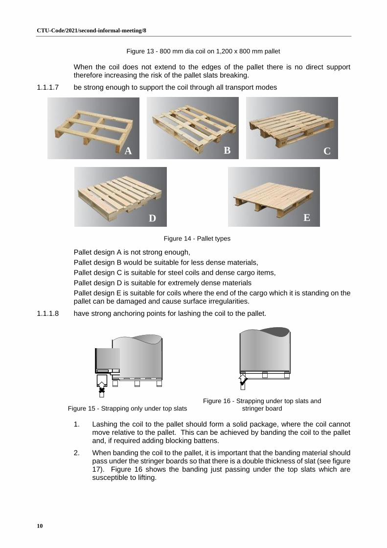
1.1.1.7 be strong enough to support the coil through all transport modes
Figure 14 - Pallet types
Pallet design A is not strong enough,
Pallet design B would be suitable for less dense materials,
Pallet design C is suitable for steel coils and dense cargo items,
Pallet design D is suitable for extremely dense materials
Pallet design E is suitable for coils where the end of the cargo which it is standing on the pallet can be damaged and cause surface irregularities.
1.1.1.8 have strong anchoring points for lashing the coil to the pallet.
Figure 15 - Strapping only under top slats
Figure 16 - Strapping under top slats and
stringer board
1. Lashing the coil to the pallet should form a solid package, where the coil cannot move relative to the pallet. This can be achieved by banding the coil to the pallet and, if required adding blocking battens.
2. When banding the coil to the pallet, it is important that the banding material should pass under the stringer boards so that there is a double thickness of slat (see figure 17). Figure 16 shows the banding just passing under the top slats which are susceptible to lifting.
✓
A B C
E D

CTU-Code/2021/second-informal-meeting/8
11
Figure 17 - Top over lashing
Figure 18 - Strengthening
doublers
Figure 19 - Loop lashing
3. Steel strapping can be used either in a Top over lashing (Figure 17) or with a loop lashing where the steel banding passes through the Eye of the coil (Figure 19). In general Top over lashing provides smaller securing forces and three lashings may be required, however only two pairs of Loop lashings would be required for most palletised coils. Where there is a risk of the coil sliding, then blocking batterns can be attached to the top slats as shown in Figure 20.
4. Where there is a risk that the pallet will not be capable of withstanding the forces expected during transport, full width doubler plates can be added under the slats of the pallet (see Figure 19). Failure to provide a pallet that is strong enough and / or where the lashings are not adequate can result in a failure:
Multi-layers of packages not extending to the edges of the pallet
Treating a multi-layer package the same way as a single layer by the application of top over lashings will produce a relatively high SI, however, where slip agent has been applied to the surfaces of the cardboard, the friction coefficient between the layers is greatly reduced.
Figure 20 - Plan view
Figure 21 - End elevation
Figure 22 - Side elevation
Figures 21 to 23 show a number of boxes with lids arranged in two (multiple) layers. In figures 23 there is a gap between the strapping and the bottom layer of boxes with lid. The strapping should:
1.1.1.9 be sufficiently tight to ensure that the resistance to sliding is maximised and there is no risk that boxes on the bottom layer may be displaced from the top layer.
1.1.1.10 not be over tightened so that the strapping damaged boxes with lid. However, insufficient force will not generate the necessary friction required to prevent the package from becoming unstable (SI).
In this case to maximise the stability of the package, the eight boxes with lid should be wrapped in stretch film or banded prior to placing on, and securing to, the pallet.
Single or multi-layer packages extending to the edges of the pallet.
Transport packages with a uniform shape and in the form of a rectangular cuboid (i.e., box shaped), whether including a pallet or not can be prepared using the same securing principles described in 2.2 and 2.3 which are to:
• ensure vertical stability,
BlockingBlocking
Over the top lashing
Doubler
BlockingBlocking
Loop lashing

CTU-Code/2021/second-informal-meeting/8
12
• ensure horizontal stability,
• ensure adequate external constraint, and
• ensure proper securing.
Vertical stability
1. It is far easier to stack one cube on top of another than to stack pyramids, and vertical stability (SV) refers to the ability of stacking similar packages in the same orientation one above another (Figure 23).
Figure 23 - Stack of boxes
with lids
Figure 24 - Stack of bottles with shrink wrap secondary
packaging
Figure 25 - Stack of bottle with
shrink wrap secondary packaging and incorporated
tray
2. A typical cargo that is often linked with poor package stability is water bottles. To minimise production costs, packers may simply wrap a number of bottle (6, 12 or 24 depending on size) in shrink wrap. Such secondary packaging needs to:
• be as heavy / thick as possible so that the caps of the underlaying bottles do not engage into the bottle’s push up (Figure 24),
• be sufficiently shrunk to ensure that the bottle remain in a tight configuration, and
• be of sufficient strength to ensure that the shrink-wrapping material cannot be easily torn.
3. Failure to so do may result in the bottles becoming lose and the stack becoming unstable. To improve stability a tray could be incorporated into the packaging to provide a strong and flat base (see figure 26).
4. Packages with a small top area relative to the bottom face or with rounded faces are more prone to vertical instability.
Horizontal stability
1.1.1.11 General
1. In a static condition the stack of boxes shown in Figure 23 is stable, but when subjected to dynamic horizontal forces the stack may topple. This type of stability failure relates to horizontal stability (SH).
2. Horizontal stability refers to the ability of one layer in a stack of packages or a single package to retain its position relative to the layer or package below and above.
3. When multiple layers are to be packed to form a transport package it is essential for horizontal stability to provide some form of anchoring of the secondary packages to ensure that they do not move and effect the integrity of the transport package. This can be achieved by:

CTU-Code/2021/second-informal-meeting/8
13
• Alternate layer orientation to provide cross-tie anchoring of packages,
• introduction of layer cards, and / or
• increased friction factor between layers.
1.1.1.12 Alternate layer orientation to provide cross-tie anchoring of packages
1. Packages whose length is more than 25% greater than the width can be formed into cross-tie arrangement. This is where packages are packed longitudinally and transversely. In this way, they are firmly interconnected. When packing sacks a form of cross-tie arrangement can be made, where the sacks are placed alternately longitudinally and transversely. However as can be seen in Complete transverse cross-tie (Appendix XXXX) this only brings stability to each pair of stacks. Other arrangements are also shown in the Appendix XXXX
2. However, some packages, like water secondary package of bottle are not suited to cross-tie due to the length to breath ratio and the small footprint that an overlapping package placed on the packages below.
3. In many transport packages, the packing arrangement may be complex and also may not fill up the entire plan area of the transport package. An example is shown in Mirror Stow (Appendix XXXX with three options. All are acceptable depending on the nature of the packaging (strength and coefficient of friction) and the outer transport packaging. Correctly applied stretch wrap around option 3 may provide the better solution, however, the decision about whether to spread, amalgamate or eliminate the gaps will depend on the size of the gaps and the packing arrangement.
1.1.1.13 Introduction of layer cards
1. Where there is a potential vertical or horizontal instability interlayer sheets (layer cards or tier sheets) can be introduced which has the effect of tying all the stacks together. This is particularly useful where the primary or secondary packaging cannot produce a high SI or where the packages cannot be packed in a cross-tie arrangement.
Figure 26 - Layer cards
Figure 27 - Layer cards in pallet
2. It is understood that the introduction of layer cards (see Figure 27 and 28) within a package is very rare due to the additional cost of the material and the inconvenience of their fitting.
1.1.1.14 Increased friction factor between layers
1. The majority of goods will be packed into a box or wrapped with a shrink wrap film, both of which can reduce the horizontal stability of a transport package.
2. The polyethene film (PE) products are used for industrial packaging, shrink or non-shrink, specifically created for bundling machines, wrappers, vertical and horizontal bag filling machines and L-sealers.
3. They can be used in a wide range of business fields such as beverages, cannery, brick, paper, pharmaceutical and food industries.
CTU-Code/2021/second-informal-meeting/8
14
4. Supplied in reels this film can be coloured, with the addition of UV inhibitors to resist degradation due to sunlight and UV Barrier inhibitors to protect the packed product.
5. More importantly the film may have different slip levels resulting from the introduction of a slip agent at the time of manufacture. The slip agent is useful to assist with the packing process, especially where automatic palletisers are used to assist with orientation and final placement. On the other hand, the slip agent reduces the coefficient of friction between the layers which in turn reduces SI.
6. Cardboard packaging can also have the slip agent applied to the surface coating.
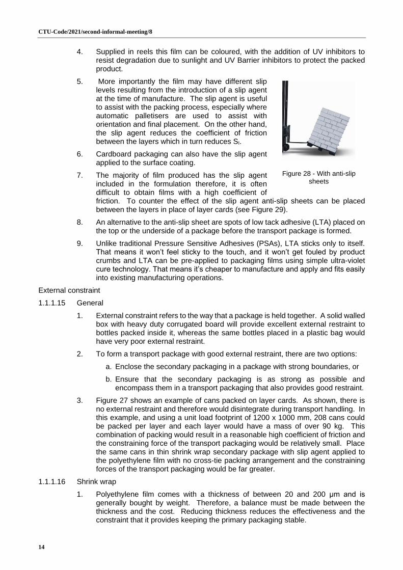
7. The majority of film produced has the slip agent included in the formulation therefore, it is often difficult to obtain films with a high coefficient of friction. To counter the effect of the slip agent anti-slip sheets can be placed between the layers in place of layer cards (see Figure 29).
8. An alternative to the anti-slip sheet are spots of low tack adhesive (LTA) placed on the top or the underside of a package before the transport package is formed.
9. Unlike traditional Pressure Sensitive Adhesives (PSAs), LTA sticks only to itself. That means it won’t feel sticky to the touch, and it won’t get fouled by product crumbs and LTA can be pre-applied to packaging films using simple ultra-violet cure technology. That means it’s cheaper to manufacture and apply and fits easily into existing manufacturing operations.
External constraint
1.1.1.15 General
1. External constraint refers to the way that a package is held together. A solid walled box with heavy duty corrugated board will provide excellent external restraint to bottles packed inside it, whereas the same bottles placed in a plastic bag would have very poor external restraint.
2. To form a transport package with good external restraint, there are two options:
a. Enclose the secondary packaging in a package with strong boundaries, or
b. Ensure that the secondary packaging is as strong as possible and encompass them in a transport packaging that also provides good restraint.
3. Figure 27 shows an example of cans packed on layer cards. As shown, there is no external restraint and therefore would disintegrate during transport handling. In this example, and using a unit load footprint of 1200 x 1000 mm, 208 cans could be packed per layer and each layer would have a mass of over 90 kg. This combination of packing would result in a reasonable high coefficient of friction and the constraining force of the transport packaging would be relatively small. Place the same cans in thin shrink wrap secondary package with slip agent applied to the polyethylene film with no cross-tie packing arrangement and the constraining forces of the transport packaging would be far greater.
1.1.1.16 Shrink wrap
1. Polyethylene film comes with a thickness of between 20 and 200 μm and is generally bought by weight. Therefore, a balance must be made between the thickness and the cost. Reducing thickness reduces the effectiveness and the constraint that it provides keeping the primary packaging stable.
Figure 28 - With anti-slip
sheets

CTU-Code/2021/second-informal-meeting/8
15
2. Many “economical” products use a very thin film that is easy to break when opening the package, but this ease of breaking can also have an adverse effect during transport. The more common thickness is 60 μm which appears to provide a good balance between cost and stability.
3. Without properly constraint provided by the secondary packaging, the primary packages may start to move and gradually build up sufficient momentum to damage the secondary packaging, which in turn could damage the transport packaging.
1.1.1.17 Stretch wrap
1. The most common stretch wrap material linear low-density polyethylene or LLDPE, which is produced by copolymerization of ethylene with alpha-olefins, the most common of which are butene, hexene and octene. The use of higher alpha-olefins (hexene or octene) gives rise to enhanced stretch film characteristics, particularly in respect of elongation at break and puncture resistance. Although films can be produced with about 500% stretch at break they are only stretched to about 100 – 300% in use.
2. It is the elastic recovery that keeps the secondary packages tightly bound.
3. When applying stretch wrap it is therefore essential that the film is properly stretched during application. Manually winding the film around a package will not generate a necessary elastic recovery and therefore the constraining forces will be low.
4. As the films provided are prepared with various levels of pre-stretch under or over stretching can result in a poor wrap.
1.1.1.18 Shrink and stretch hoods
1. Hoods are preformed transport packaging for unit loads, and generally perform similar to the film versions. Shrink hoods are suitable for applications in glass, brick, paper, ceramics, cement and adhesives industries.
2. Stretch hoods are similar to the shrink hoods except that they do not require heating instead relying on the pre-stretch qualities of the hood. It is useful for high speed packing, and suitable for any kind of products including heat sensitive materials. However, unlike the stretch film provides only 120% stretchability.
1.1.1.19 Edge protectors
1. Where the primary or secondary packaging may damage the transport packaging, such as secondary packaging with a low SI, or primary packaging with edges that may cut through films, it is worth considering placing edge protectors to the top edges or angle boards on the vertical corners of the package (see Figure 30).
2. Angle boards are thick moulded cardboard strips that create Protective Corners that can be used with stretch wrap or strapping to protect the edges of a package from being damage, preventing the tight strap digging into secondary packaging and as well as securing and help stabilise the package during transport. Angle boards are the perfect packaging solution for when you have small light boxes stacked on a pallet, as they can help to hold the cartons together securely in the package before it is strapped and or wrapped ready to be transport.
Properly securing an overpack or unit load
Figure 29 - Angle boards

CTU-Code/2021/second-informal-meeting/8
16
1.1.1.20 Typically, any damage incurred in the transport chain occurs because the cargo item was improperly packed, wrapped or secured for transport. In the previous sections (2.4.2 to 2.4.3) individual elements of the packaging have been discussed. To ensure that the transport package reaches its destination without failing, it is essential that all elements are secured together.
1.1.1.21 This is a particular issue with retail goods such as TVs and DVD players where there is no protection to the primary packaging. If there is cosmetic box damage, the consumer is likely to assume the contents are also damaged. As discussed earlier, package strength and stacking play an important role in freight shipment integrity. So do load protection, stretch wrapping and banding (see 2.4.4).
1.1.1.22 Top and bottom load-protector pads (corrugated pad/tray) help reduce damage to top and bottom layers of stacked the packages and the top pad provide additional containment from packages ‘popping’ out due to vertical acceleration. They also help distribute the superimposed mass or packages stacked on top. Bottom load protectors provide a level surface and help keep boxes from slipping into the gap between the boards on the pallet. Corner or edge boards should run the full length of the stack to help stabilize the load, increase vertical stacking strength and reduce damage to box edges that make up the load corners (see Figure 31).
Figure 30 - Package elements
Figure 31 - Completed package
1.1.1.23 Stretch wrap film is critical for bundling loads and also for securing and protecting large individual pieces of freight (e.g., shelf-ready electronic components).
1. Wrap packages tightly maximising the pre-stretch capability fully to prevent load shifting. Use the appropriate thickness of film that sticks to itself so it can be wipe-sealed as it is applied to the package. When machine wrapping, spiral wrap the cartons with a minimum 50 percent overlap.
2. Proper application includes at least a 75 mm overlap over the top of the package and the same overlap for un-palletised packages or fully cover the pallet where the package includes one (see Figure 32).
3. To manually apply stretch wrap, tuck the lead wrap between the pallet and the bottom box or round one of the pallet corner blocks. Apply at least 3 turns around the pallets and bottom of the packages to ensure good attachment. Spiral around the boxes in an upward direction, overlapping the film by 50 percent. When you reach the top, stretch the film diagonally over the top corners with a 75 mm overlap to anchor the stack vertically before spiralling back to the bottom to finish the load with a final 3 turns round the pallet and bottom packages.
4. Stretch wrapping may not provide sufficient securing of the packages to a pallet, especially where the primary packages are heavy. In such cases banding should be used to provide additional security. As a general rule, keep the banding close to the load to avoid exposure, damage or breakage.

CTU-Code/2021/second-informal-meeting/8
17
1.1.1.24 Individual pieces over 75 kg. and large boxes and containers should be secured on all sides with heavy-duty steel, rayon, polypropylene, nylon or polyester strapping.

CTU-Code/2021/second-informal-meeting/8
18
Appendix XXXX Packing arrangements
Style Description
Complete transverse cross-tie
This refers to stowage in which secondary packaging is designed to fill
the entire area of the transport package.
This stowage arrangement is generally associate with packages that
are twice as long as they are wide, however other ratios can be packed
using this arrangement.
However, layers are generally the same which means that the there is
a risk of the tied stacks becoming unstable. As the number of layers
increases so too does the risk of instability.
End elevation
Layer 1
Layer 2
Chimney style stow Chimney-style stowage is extremely well suited for forming pre-slung cargo. With palletised packages, it is suitable for certain bag sizes. The packages are arranged layer by layer so that they overlap around a cavity. Thus, each is connected to each other. This produces a square or rectangular footprint, which is very suitable for European pallets if it has the correct dimensions.
This design of stow is fairly stable however, is prone to each “chimney” moving independently from the remainder.
End elevation
Layer 1
Layer 2
Soldier stow A stow where packages are stood in lines within the transport package. Often used for drums, but rectangular packages can also be stowed using this method.
Solder stow can suffers from the same disadvantages as the stacking stow above insomuch as there is no opportunity for any tie between stacks.
End elevation
Layer 1
Layer 2
CTU-Code/2021/second-informal-meeting/8
19
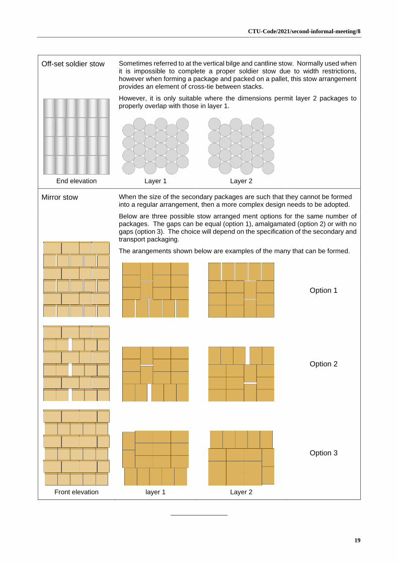
Off-set soldier stow Sometimes referred to at the vertical bilge and cantline stow. Normally used when it is impossible to complete a proper soldier stow due to width restrictions, however when forming a package and packed on a pallet, this stow arrangement provides an element of cross-tie between stacks.
However, it is only suitable where the dimensions permit layer 2 packages to properly overlap with those in layer 1.
End elevation
Layer 1
Layer 2
Mirror stow When the size of the secondary packages are such that they cannot be formed into a regular arrangement, then a more complex design needs to be adopted.
Below are three possible stow arranged ment options for the same number of packages. The gaps can be equal (option 1), amalgamated (option 2) or with no gaps (option 3). The choice will depend on the specification of the secondary and transport packaging.
The arangements shown below are examples of the many that can be formed.
Option 1
Option 2
Front elevation
layer 1
Layer 2
Option 3